EP3566731B1 - Intravenous fluid administration catheter assembly - Google Patents
Intravenous fluid administration catheter assemblyDownload PDFInfo
- Publication number
- EP3566731B1 EP3566731B1EP18171510.3AEP18171510AEP3566731B1EP 3566731 B1EP3566731 B1EP 3566731B1EP 18171510 AEP18171510 AEP 18171510AEP 3566731 B1EP3566731 B1EP 3566731B1
- Authority
- EP
- European Patent Office
- Prior art keywords
- inlet
- tubing
- connector
- tubings
- spike
- Prior art date
- Legal status (The legal status is an assumption and is not a legal conclusion. Google has not performed a legal analysis and makes no representation as to the accuracy of the status listed.)
- Active
Links
Images

Classifications
- A—HUMAN NECESSITIES
- A61—MEDICAL OR VETERINARY SCIENCE; HYGIENE
- A61M—DEVICES FOR INTRODUCING MEDIA INTO, OR ONTO, THE BODY; DEVICES FOR TRANSDUCING BODY MEDIA OR FOR TAKING MEDIA FROM THE BODY; DEVICES FOR PRODUCING OR ENDING SLEEP OR STUPOR
- A61M5/00—Devices for bringing media into the body in a subcutaneous, intra-vascular or intramuscular way; Accessories therefor, e.g. filling or cleaning devices, arm-rests
- A61M5/14—Infusion devices, e.g. infusing by gravity; Blood infusion; Accessories therefor
- A61M5/1407—Infusion of two or more substances
- A61M5/1408—Infusion of two or more substances in parallel, e.g. manifolds, sequencing valves
- A—HUMAN NECESSITIES
- A61—MEDICAL OR VETERINARY SCIENCE; HYGIENE
- A61J—CONTAINERS SPECIALLY ADAPTED FOR MEDICAL OR PHARMACEUTICAL PURPOSES; DEVICES OR METHODS SPECIALLY ADAPTED FOR BRINGING PHARMACEUTICAL PRODUCTS INTO PARTICULAR PHYSICAL OR ADMINISTERING FORMS; DEVICES FOR ADMINISTERING FOOD OR MEDICINES ORALLY; BABY COMFORTERS; DEVICES FOR RECEIVING SPITTLE
- A61J1/00—Containers specially adapted for medical or pharmaceutical purposes
- A61J1/14—Details; Accessories therefor
- A61J1/20—Arrangements for transferring or mixing fluids, e.g. from vial to syringe
- A61J1/2003—Accessories used in combination with means for transfer or mixing of fluids, e.g. for activating fluid flow, separating fluids, filtering fluid or venting
- A61J1/2048—Connecting means
- A61J1/2058—Connecting means having multiple connecting ports
- A—HUMAN NECESSITIES
- A61—MEDICAL OR VETERINARY SCIENCE; HYGIENE
- A61J—CONTAINERS SPECIALLY ADAPTED FOR MEDICAL OR PHARMACEUTICAL PURPOSES; DEVICES OR METHODS SPECIALLY ADAPTED FOR BRINGING PHARMACEUTICAL PRODUCTS INTO PARTICULAR PHYSICAL OR ADMINISTERING FORMS; DEVICES FOR ADMINISTERING FOOD OR MEDICINES ORALLY; BABY COMFORTERS; DEVICES FOR RECEIVING SPITTLE
- A61J1/00—Containers specially adapted for medical or pharmaceutical purposes
- A61J1/14—Details; Accessories therefor
- A61J1/20—Arrangements for transferring or mixing fluids, e.g. from vial to syringe
- A61J1/2003—Accessories used in combination with means for transfer or mixing of fluids, e.g. for activating fluid flow, separating fluids, filtering fluid or venting
- A61J1/2006—Piercing means
- A61J1/201—Piercing means having one piercing end
- A—HUMAN NECESSITIES
- A61—MEDICAL OR VETERINARY SCIENCE; HYGIENE
- A61M—DEVICES FOR INTRODUCING MEDIA INTO, OR ONTO, THE BODY; DEVICES FOR TRANSDUCING BODY MEDIA OR FOR TAKING MEDIA FROM THE BODY; DEVICES FOR PRODUCING OR ENDING SLEEP OR STUPOR
- A61M25/00—Catheters; Hollow probes
- A61M25/0097—Catheters; Hollow probes characterised by the hub
- A—HUMAN NECESSITIES
- A61—MEDICAL OR VETERINARY SCIENCE; HYGIENE
- A61M—DEVICES FOR INTRODUCING MEDIA INTO, OR ONTO, THE BODY; DEVICES FOR TRANSDUCING BODY MEDIA OR FOR TAKING MEDIA FROM THE BODY; DEVICES FOR PRODUCING OR ENDING SLEEP OR STUPOR
- A61M39/00—Tubes, tube connectors, tube couplings, valves, access sites or the like, specially adapted for medical use
- A61M39/22—Valves or arrangement of valves
- A61M39/26—Valves closing automatically on disconnecting the line and opening on reconnection thereof
- A—HUMAN NECESSITIES
- A61—MEDICAL OR VETERINARY SCIENCE; HYGIENE
- A61M—DEVICES FOR INTRODUCING MEDIA INTO, OR ONTO, THE BODY; DEVICES FOR TRANSDUCING BODY MEDIA OR FOR TAKING MEDIA FROM THE BODY; DEVICES FOR PRODUCING OR ENDING SLEEP OR STUPOR
- A61M5/00—Devices for bringing media into the body in a subcutaneous, intra-vascular or intramuscular way; Accessories therefor, e.g. filling or cleaning devices, arm-rests
- A61M5/14—Infusion devices, e.g. infusing by gravity; Blood infusion; Accessories therefor
- A61M5/162—Needle sets, i.e. connections by puncture between reservoir and tube ; Connections between reservoir and tube
- A—HUMAN NECESSITIES
- A61—MEDICAL OR VETERINARY SCIENCE; HYGIENE
- A61M—DEVICES FOR INTRODUCING MEDIA INTO, OR ONTO, THE BODY; DEVICES FOR TRANSDUCING BODY MEDIA OR FOR TAKING MEDIA FROM THE BODY; DEVICES FOR PRODUCING OR ENDING SLEEP OR STUPOR
- A61M39/00—Tubes, tube connectors, tube couplings, valves, access sites or the like, specially adapted for medical use
- A61M39/08—Tubes; Storage means specially adapted therefor
- A61M2039/082—Multi-lumen tubes
- A—HUMAN NECESSITIES
- A61—MEDICAL OR VETERINARY SCIENCE; HYGIENE
- A61M—DEVICES FOR INTRODUCING MEDIA INTO, OR ONTO, THE BODY; DEVICES FOR TRANSDUCING BODY MEDIA OR FOR TAKING MEDIA FROM THE BODY; DEVICES FOR PRODUCING OR ENDING SLEEP OR STUPOR
- A61M39/00—Tubes, tube connectors, tube couplings, valves, access sites or the like, specially adapted for medical use
- A61M39/10—Tube connectors; Tube couplings
- A61M2039/1083—Tube connectors; Tube couplings having a plurality of female connectors, e.g. Luer connectors
Definitions
- An intravenous lineis inserted into a blood vessel by means of a needle. Once the line, or the catheter, is in place, the needle is removed.
- An intravenous fluid administration catheter assemblycomprises a spike, to be introduced into a bag or bottle of a main fluid, a drip chamber, a roller clamp, to generate drops, and a flow regulator, to adjust the flow of the drops, a male luer lock and a female luer syringe, with a female luer lock, to be introduced into the patent and tubings in between.
- both setsbeing connected to an actuator receiving the two liquids for dispensing, at its output, a mixture, through a common tubing, to the syringe.
- Another way for dispensing several liquidswould be to use a manifold with as many inputs in a tubing, where the serum should flow, as liquids to dispense.
- the inventionaims to obviate at least part of these drawbacks.
- the inventionis an intravenous fluid administration catheter assembly as defined in claim 1. Additional features of preferred embodiments thereof are defined in the dependent claims.
- the following disclosurerelates to an intravenous fluid administration catheter assembly comprising
- the free end of the additional liquid inlet tubingsis closed by a non-return valve advantageously provided within a needleless connector.
- the valveis normally in a closed state and gets open when the additional liquid inlet tube is connected to a container.
- the assembly of the instant case, with respect to air,is a closed system. From the spike to the patient, no air can come into the assembly.
- US 4 512 764relates to an assembly with a manifold and cocks.
- CA 2 634 128relates to an assembly with a connector (junction housing), downstream of the luer connector provided at the end of the central tubing.
- the combination of features of the preamble of claim 1is e.g. known from DE 20 2016 100371 U1 .
- the outlet tubing 13which has a length of about 150 to 200 cm, compared with the inlet tubing 12, with a length of 30 cm, is about 5 to 7, 6 times longer.
- an outlet tubing only about three times longer than the inlet tubingwould already avoid the tubing traffic.
Landscapes
- Health & Medical Sciences (AREA)
- Life Sciences & Earth Sciences (AREA)
- Veterinary Medicine (AREA)
- Public Health (AREA)
- General Health & Medical Sciences (AREA)
- Animal Behavior & Ethology (AREA)
- Heart & Thoracic Surgery (AREA)
- Anesthesiology (AREA)
- Hematology (AREA)
- Biomedical Technology (AREA)
- Engineering & Computer Science (AREA)
- Pulmonology (AREA)
- Physics & Mathematics (AREA)
- Fluid Mechanics (AREA)
- Pharmacology & Pharmacy (AREA)
- Vascular Medicine (AREA)
- Biophysics (AREA)
- Infusion, Injection, And Reservoir Apparatuses (AREA)
Description
- The invention relates to intravenous fluid administration systems. More particularly, it relates to systems arranged for dispensing a main fluid, often serum, along with additional fluids, nutrient and medical fluids.
- An intravenous line is inserted into a blood vessel by means of a needle. Once the line, or the catheter, is in place, the needle is removed.
- An intravenous fluid administration catheter assembly comprises a spike, to be introduced into a bag or bottle of a main fluid, a drip chamber, a roller clamp, to generate drops, and a flow regulator, to adjust the flow of the drops, a male luer lock and a female luer syringe, with a female luer lock, to be introduced into the patent and tubings in between.
- When a second bottle of additional liquid has to be connected to the syringe, a similar set of equipment is used, both sets being connected to an actuator receiving the two liquids for dispensing, at its output, a mixture, through a common tubing, to the syringe.
- Other liquids may be dispensed, through other actuators connected in series to the first one.
- Another way for dispensing several liquids would be to use a manifold with as many inputs in a tubing, where the serum should flow, as liquids to dispense.
- Three problems are at the origin of the invention of the instant case.
- 1. While considering an intravenous catheter assembly with an actuator having two input tubings, for a main and an additional liquids, and one short output tubing for the mixture, prior to being in operation, the output tubing is closed by a cap. Inside the short output tubing of the actuator, there is air between the actuator and the cap and this is a source of infection. As many actuators, as many sources of infection.
- 2. While considering an intravenous catheter assembly with a series of tubings, all these tubings arrive onto the body of the patient and they intermingle. It is a mess.
- 3. An actuator, with two input tubings, includes a two way cock, to be actuated for allowing flow of just one of the two liquids, of both or none of them. Actuation of the cock may affect the good order of the actuator.
- The invention aims to obviate at least part of these drawbacks.
- The invention is an intravenous fluid administration catheter assembly as defined in
claim 1. Additional features of preferred embodiments thereof are defined in the dependent claims. The following disclosure relates to an intravenous fluid administration catheter assembly comprising - a stand with a hook for hanging a container of a main liquid,
- a spike to be introduced into the container of main liquid,
- a multi-inlet connector with inlet tubings, to be connected to containers of additional liquids and to the container of main liquid through the spike, and an outlet tubing to be connected to a luer syringe to be introduced into a patient,
- It should be right away clearly pointed out that the hanging situation of the connector in use, thanks to gravity, is not the result of the invention, but its functional means. The connector hanging on the stand, due to its weight, it remains close to the vertical column of the stand, this avoiding the mess of tubings of the prior art, just one single tubing extending away from the stand. And this is the result achieved by the assembly of the instant case, i.e. solving the problem of the tubing traffic.
- Preferably, the free end of the additional liquid inlet tubings is closed by a non-return valve advantageously provided within a needleless connector. The valve is normally in a closed state and gets open when the additional liquid inlet tube is connected to a container.
- Thus, when the main liquid flows from its container to the luer syringe, through the outlet tubing, the additional liquid inlet tubings, the air having been bailed out of them first, are filled up with the main liquid, so that, when a container of additional liquid is connected to its associated inlet tubing, through its connector and valve, there is no air coming in. The infection issue is thus solved.
- The assembly of the instant case, with respect to air, is a closed system. From the spike to the patient, no air can come into the assembly.
- Moreover, of great interest also is the fact that the assembly does not include any cock to be actuated.
- It should be here mentioned that
US 4 512 764 relates to an assembly with a manifold and cocks.CA 2 634 128claim 1 is e.g. known fromDE 20 2016 100371 U1 . - The invention shall be better understood upon reading the following description, with reference to the attached drawing, wherein
figure 1 is a general view of the intravenous fluid administration catheter assembly of the invention;figure 2 is a general view, at a larger scale, of the multi-inlet connector of the assembly offigure 1 andfigure 3 is a general view of "the sole administration" components of the assembly offigure 1 , downstream of all containers of main and additional liquids.- Referring to
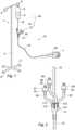
figure 1 , the intravenous (IV) fluid administration catheter assembly comprises astandard stand 1, here with avertical column 2, a four arm mounting base 3 with fourwheels 8 for moving the stand and, on top of the column, twohooks 4, 5, onto one 5 of which abottle 6 is hung up, the assembly being represented in use. Bottle 6 is a container filled up with amain liquid 9, usually serum to be delivered into a patient blood stream, here into one 7 of his hands. The line from thebottle 6 to thehand 7 is an IVline 10. The IV line, the end of which is called the catheter, is inserted into a vein by means of a needle which is removed after the insertion. Between thebottle 6 and thehand 7, there is amulti-inlet connector 11 and other components, not represented infigure 1 . Theconnector 11 is connected to thebottle 6 by aspike inlet tubing 12 and, to thehand 7, by anoutlet tubing 13. - Referring now to
figure 3 , the upstream end oftubing 12 of the assembly comprises aspike 14 to be introduced intobottle 6 and which, not in use, can be covered by acap 15. Spike 14 is connected here to a ventedchamber 16 including a filter.Chamber 16, downstream of it, is connected to aroller clamp 17, to generate a flow of drops, connected, still downstream, to aflow regulator 18, to adjust the flow of drops to be administered to the patient. Theflow regulator 18 is connected to theconnector 11. All the above introduced components are provided ontubing 12. - Tubing 13 includes here, but this is optional, a one-
inlet needleless connector 19 in case a further drug had to be administered to the patient. The end oftubing 13,opposite connector 11, includes, as is well known in the art, amale luer lock 20, to be secured, but not shown, to a female luer lock of a luer syringe 30 (figure 1 ) to be introduced into the body of the patient. When the assembly is not in use, themale luer lock 20 is covered by acap 21. - The
multi-inlet connector 11 comprises here four inlets 111-114 (figure 2 ). Tubing 12 is connected toinlet 111. Three othersmall tubings inlets - The ends of tubings 22-24 are provided, each, with a (small) needleless connector (25-27) including a non-return valve (35-37) for preventing air from getting into the connector. The valves of these connectors move to an open state when other connectors, along with partial mini assemblies of a similar nature as the one described above, with a
container 40 andtubing 41, are secured thereto, for administering additional medical fluids throughcatheter tubing 13. - The length of the various tubings is an important feature of the assembly described above.
- The length of
tubing 12, fromspike 14 toconnector 11, which is the spike inlet tubing of the connector, is determined for, during use of the assembly withbottle 6 filled up with amain liquid 9, keeping themulti-inlet connector 11 hung up onhook 5 ofstand 1 thanks to the weight of the components and the tubing. Thanks to that feature, all the tubings connected to themulti-inlet connector 11, upstream of it, do not interfere with theoutlet tubing 13. The space around it, up to the patient, is free, there is no tubing traffic close to the patient. - Just to give ideas and strictly by way of example, the length of
tubing 12, betweenchamber 16 andregulator 18 could be about 20cm, betweenregulator 18 andconnector 11, about 10cm. Thus, thespike inlet tubing 12, here, has a length of about 30cm. The height ofcolumn 2 ofstand 1 being about the height of a human being, it is clear thatconnector 11 hangs up onhook 5. The length of tubings 22-24 could be about 5cm and, oftubing 13, about 150 up 200cm. - According to the above example, the
outlet tubing 13, which has a length of about 150 to 200 cm, compared with theinlet tubing 12, with a length of 30 cm, is about 5 to 7, 6 times longer. However, it should be pointed out that an outlet tubing only about three times longer than the inlet tubing would already avoid the tubing traffic.
Claims (4)
- An intravenous fluid administration catheter assembly comprising- a spike (14), to be introduced into a container of main liquid (6),- a multi-inlet connector (11) with inlet tubings (12, 22-24), to be connected to containers (40) of additional liquids and to the container of main liquid (6) through the spike (14), and an outlet tubing (13) to be connected to a luer syringe (30) to be introduced into a patient (7),- the length of the spike inlet tubing (12) of the connector (11) having a length determined for, during use of the assembly with a container of main liquid (6), keeping the connector (11) hung up on a hook (5) of a stand (1) being about the height of a human being through the spike (14) and the container of main liquid (6),characterized in that
the length of the inlet tubings (22-24) to be connected to containers (40) of additional liquids being significantly shorter than the inlet tubing (12) to be connected to the container of main liquid (6) such that all the tubings connected to the multi-inlet connector 11, upstream of it, do not interfere with the outlet tubing (13). - Assembly according to claim 1, wherein the free end of the additional liquid inlet tubings (22-24) is closed by a non-return valve (35-37).
- Assembly according to claim 2, wherein the non-return valve (35-37) of the additional liquid inlet tubings (22-24) is provided within a needleless connector (25-27).
- Assembly according to one of claims 1 to 3, wherein the spike inlet tubing (12) has a length of about 30cm.
Priority Applications (7)
| Application Number | Priority Date | Filing Date | Title |
|---|---|---|---|
| RS20241073ARS66039B1 (en) | 2018-05-09 | 2018-05-09 | Intravenous fluid administration catheter assembly |
| HRP20241346TTHRP20241346T1 (en) | 2018-05-09 | 2018-05-09 | CATHETER ASSEMBLY FOR INTRAVENOUS FLUID ADMINISTRATION |
| ES18171510TES2988439T3 (en) | 2018-05-09 | 2018-05-09 | Intravenous fluid administration catheter set |
| SM20240440TSMT202400440T1 (en) | 2018-05-09 | 2018-05-09 | Intravenous fluid administration catheter assembly |
| EP18171510.3AEP3566731B1 (en) | 2018-05-09 | 2018-05-09 | Intravenous fluid administration catheter assembly |
| HUE18171510AHUE068395T2 (en) | 2018-05-09 | 2018-05-09 | Intravenous fluid administration catheter assembly |
| US16/384,115US11612544B2 (en) | 2018-05-09 | 2019-04-15 | Intravenous fluid administration catheter assembly |
Applications Claiming Priority (1)
| Application Number | Priority Date | Filing Date | Title |
|---|---|---|---|
| EP18171510.3AEP3566731B1 (en) | 2018-05-09 | 2018-05-09 | Intravenous fluid administration catheter assembly |
Publications (3)
| Publication Number | Publication Date |
|---|---|
| EP3566731A1 EP3566731A1 (en) | 2019-11-13 |
| EP3566731C0 EP3566731C0 (en) | 2024-07-03 |
| EP3566731B1true EP3566731B1 (en) | 2024-07-03 |
Family
ID=62245132
Family Applications (1)
| Application Number | Title | Priority Date | Filing Date |
|---|---|---|---|
| EP18171510.3AActiveEP3566731B1 (en) | 2018-05-09 | 2018-05-09 | Intravenous fluid administration catheter assembly |
Country Status (7)
| Country | Link |
|---|---|
| US (1) | US11612544B2 (en) |
| EP (1) | EP3566731B1 (en) |
| ES (1) | ES2988439T3 (en) |
| HR (1) | HRP20241346T1 (en) |
| HU (1) | HUE068395T2 (en) |
| RS (1) | RS66039B1 (en) |
| SM (1) | SMT202400440T1 (en) |
Family Cites Families (12)
| Publication number | Priority date | Publication date | Assignee | Title |
|---|---|---|---|---|
| US4191183A (en)* | 1977-10-31 | 1980-03-04 | Barry Mendelson | Mixing chamber for use in plural medical liquid intravenous administration set |
| US4512764A (en) | 1982-09-27 | 1985-04-23 | Wunsch Richard E | Manifold for controlling administration of multiple intravenous solutions and medications |
| US5078699A (en)* | 1989-09-22 | 1992-01-07 | Habley Medical Technology Corporation | Compact, easy to assemble, safety IV system |
| MXPA01012633A (en) | 1999-06-08 | 2002-06-21 | Edwards Lifesciences Corp | Multiple lumen access device. |
| IL152950A0 (en)* | 2002-11-19 | 2003-06-24 | Biometrix Ltd | A fluid administrating manifold |
| US20060089604A1 (en)* | 2004-10-26 | 2006-04-27 | Intrasafe Medical, Llc | Infusion device for administering fluids to a patient |
| US20090306621A1 (en)* | 2008-02-06 | 2009-12-10 | Gale H. Thome, JR. | Vial transfer convenience IV kits and methods |
| US20120203205A1 (en)* | 2011-02-08 | 2012-08-09 | Briggs David M | Retro-Primed Medication Delivery Bag System |
| US9345828B2 (en)* | 2011-06-27 | 2016-05-24 | Thomas Anthony Browne | Safety bag spike interface for hazardous drugs |
| US10444770B2 (en)* | 2013-02-05 | 2019-10-15 | Ivenix, Inc. | Fluid flow measurement and control |
| DE202016100371U1 (en)* | 2016-01-27 | 2017-05-02 | Ulrich Gmbh & Co. Kg | Hose system for an injection device |
| DE202017107087U1 (en)* | 2017-02-16 | 2018-03-20 | Eurozyto Gmbh | Container for providing patient-specific drugs |
- 2018
- 2018-05-09SMSM20240440Tpatent/SMT202400440T1/enunknown
- 2018-05-09HUHUE18171510Apatent/HUE068395T2/enunknown
- 2018-05-09ESES18171510Tpatent/ES2988439T3/enactiveActive
- 2018-05-09RSRS20241073Apatent/RS66039B1/enunknown
- 2018-05-09EPEP18171510.3Apatent/EP3566731B1/enactiveActive
- 2018-05-09HRHRP20241346TTpatent/HRP20241346T1/enunknown
- 2019
- 2019-04-15USUS16/384,115patent/US11612544B2/enactiveActive
Also Published As
| Publication number | Publication date |
|---|---|
| HUE068395T2 (en) | 2024-12-28 |
| RS66039B1 (en) | 2024-11-29 |
| US20190343724A1 (en) | 2019-11-14 |
| EP3566731A1 (en) | 2019-11-13 |
| ES2988439T3 (en) | 2024-11-20 |
| SMT202400440T1 (en) | 2024-11-15 |
| US11612544B2 (en) | 2023-03-28 |
| HRP20241346T1 (en) | 2024-12-20 |
| EP3566731C0 (en) | 2024-07-03 |
Similar Documents
| Publication | Publication Date | Title |
|---|---|---|
| JP7356487B2 (en) | Storage device for single or multiple containers | |
| US3941126A (en) | Apparatus for long term intravenous administration of diluted incompatible multiple medications | |
| US5807312A (en) | Bolus pump apparatus | |
| US20040073189A1 (en) | Vial access transfer set | |
| US4334535A (en) | Conduit device for rapid priming and flow of liquid | |
| AU2017302557B2 (en) | Systems, methods, and components for trapping air bubbles in medical fluid transfer modules and systems | |
| US5059173A (en) | IV apparatus | |
| US8267912B2 (en) | Infusion bag with needleless access port | |
| US6953450B2 (en) | Apparatus and method for administration of IV liquid medication and IV flush solutions | |
| US20070093764A1 (en) | Infusion device for administering fluids to a patient | |
| US20080004574A1 (en) | Selectable rate intravenous infusion set | |
| US5242392A (en) | Intravenous piggyback flush apparatus | |
| US4237880A (en) | Equipment sets for the sequential administration of medical liquids at dual flow rates employing a combined air barrier and liquid sequencing valve controlled by a common flexible membrane | |
| US8814829B2 (en) | Drug delivery device for fluid restricted patients | |
| KR20160001372U (en) | Liquid transfer devices for use with infusion liquid containers | |
| CN100379467C (en) | Administration container for indwelling feeding tube | |
| CN107249667B (en) | Infusion set | |
| AU2014334836A1 (en) | Sampling port | |
| CN105797240A (en) | Blunt needle safety drug delivery system | |
| US9114206B2 (en) | Device for infusion of prescription medicines or treatments | |
| TWI581789B (en) | Infusion group | |
| WO2015075221A1 (en) | Container system for intravenous therapy | |
| EP3566731B1 (en) | Intravenous fluid administration catheter assembly | |
| CN204637147U (en) | A kind of medical Transfusion device | |
| EP1270033B1 (en) | Device for controlling the flow volume of medication products |
Legal Events
| Date | Code | Title | Description |
|---|---|---|---|
| PUAI | Public reference made under article 153(3) epc to a published international application that has entered the european phase | Free format text:ORIGINAL CODE: 0009012 | |
| STAA | Information on the status of an ep patent application or granted ep patent | Free format text:STATUS: THE APPLICATION HAS BEEN PUBLISHED | |
| AK | Designated contracting states | Kind code of ref document:A1 Designated state(s):AL AT BE BG CH CY CZ DE DK EE ES FI FR GB GR HR HU IE IS IT LI LT LU LV MC MK MT NL NO PL PT RO RS SE SI SK SM TR | |
| AX | Request for extension of the european patent | Extension state:BA ME | |
| STAA | Information on the status of an ep patent application or granted ep patent | Free format text:STATUS: REQUEST FOR EXAMINATION WAS MADE | |
| 17P | Request for examination filed | Effective date:20200429 | |
| RBV | Designated contracting states (corrected) | Designated state(s):AL AT BE BG CH CY CZ DE DK EE ES FI FR GB GR HR HU IE IS IT LI LT LU LV MC MK MT NL NO PL PT RO RS SE SI SK SM TR | |
| STAA | Information on the status of an ep patent application or granted ep patent | Free format text:STATUS: EXAMINATION IS IN PROGRESS | |
| 17Q | First examination report despatched | Effective date:20221007 | |
| RAP3 | Party data changed (applicant data changed or rights of an application transferred) | Owner name:MEDWORKS SARL | |
| P01 | Opt-out of the competence of the unified patent court (upc) registered | Effective date:20230527 | |
| GRAP | Despatch of communication of intention to grant a patent | Free format text:ORIGINAL CODE: EPIDOSNIGR1 | |
| STAA | Information on the status of an ep patent application or granted ep patent | Free format text:STATUS: GRANT OF PATENT IS INTENDED | |
| INTG | Intention to grant announced | Effective date:20240402 | |
| GRAS | Grant fee paid | Free format text:ORIGINAL CODE: EPIDOSNIGR3 | |
| GRAA | (expected) grant | Free format text:ORIGINAL CODE: 0009210 | |
| STAA | Information on the status of an ep patent application or granted ep patent | Free format text:STATUS: THE PATENT HAS BEEN GRANTED | |
| AK | Designated contracting states | Kind code of ref document:B1 Designated state(s):AL AT BE BG CH CY CZ DE DK EE ES FI FR GB GR HR HU IE IS IT LI LT LU LV MC MK MT NL NO PL PT RO RS SE SI SK SM TR | |
| REG | Reference to a national code | Ref country code:CH Ref legal event code:EP | |
| REG | Reference to a national code | Ref country code:DE Ref legal event code:R096 Ref document number:602018071211 Country of ref document:DE | |
| U01 | Request for unitary effect filed | Effective date:20240710 | |
| P04 | Withdrawal of opt-out of the competence of the unified patent court (upc) registered | Free format text:CASE NUMBER: APP_48688/2024 Effective date:20240826 | |
| U07 | Unitary effect registered | Designated state(s):AT BE BG DE DK EE FI FR IT LT LU LV MT NL PT RO SE SI Effective date:20240902 | |
| REG | Reference to a national code | Ref country code:ES Ref legal event code:FG2A Ref document number:2988439 Country of ref document:ES Kind code of ref document:T3 Effective date:20241120 | |
| REG | Reference to a national code | Ref country code:GR Ref legal event code:EP Ref document number:20240402300 Country of ref document:GR Effective date:20241111 | |
| REG | Reference to a national code | Ref country code:SK Ref legal event code:T3 Ref document number:E 45060 Country of ref document:SK | |
| REG | Reference to a national code | Ref country code:HR Ref legal event code:T1PR Ref document number:P20241346 Country of ref document:HR | |
| REG | Reference to a national code | Ref country code:HU Ref legal event code:AG4A Ref document number:E068395 Country of ref document:HU | |
| P05 | Withdrawal of opt-out of the competence of the unified patent court (upc) changed | Free format text:CASE NUMBER: APP_48688/2024 Effective date:20240902 | |
| PG25 | Lapsed in a contracting state [announced via postgrant information from national office to epo] | Ref country code:IS Free format text:LAPSE BECAUSE OF FAILURE TO SUBMIT A TRANSLATION OF THE DESCRIPTION OR TO PAY THE FEE WITHIN THE PRESCRIBED TIME-LIMIT Effective date:20241103 | |
| PG25 | Lapsed in a contracting state [announced via postgrant information from national office to epo] | Ref country code:IS Free format text:LAPSE BECAUSE OF FAILURE TO SUBMIT A TRANSLATION OF THE DESCRIPTION OR TO PAY THE FEE WITHIN THE PRESCRIBED TIME-LIMIT Effective date:20241103 | |
| PLBE | No opposition filed within time limit | Free format text:ORIGINAL CODE: 0009261 | |
| STAA | Information on the status of an ep patent application or granted ep patent | Free format text:STATUS: NO OPPOSITION FILED WITHIN TIME LIMIT | |
| REG | Reference to a national code | Ref country code:HR Ref legal event code:ODRP Ref document number:P20241346 Country of ref document:HR Payment date:20250502 Year of fee payment:8 | |
| 26N | No opposition filed | Effective date:20250404 | |
| U20 | Renewal fee for the european patent with unitary effect paid | Year of fee payment:8 Effective date:20250526 | |
| PGFP | Annual fee paid to national office [announced via postgrant information from national office to epo] | Ref country code:SM Payment date:20250523 Year of fee payment:8 | |
| PGFP | Annual fee paid to national office [announced via postgrant information from national office to epo] | Ref country code:PL Payment date:20250505 Year of fee payment:8 | |
| PGFP | Annual fee paid to national office [announced via postgrant information from national office to epo] | Ref country code:GB Payment date:20250520 Year of fee payment:8 Ref country code:ES Payment date:20250606 Year of fee payment:8 | |
| PGFP | Annual fee paid to national office [announced via postgrant information from national office to epo] | Ref country code:RS Payment date:20250505 Year of fee payment:8 Ref country code:HU Payment date:20250514 Year of fee payment:8 Ref country code:NO Payment date:20250521 Year of fee payment:8 | |
| PGFP | Annual fee paid to national office [announced via postgrant information from national office to epo] | Ref country code:AL Payment date:20250527 Year of fee payment:8 | |
| PGFP | Annual fee paid to national office [announced via postgrant information from national office to epo] | Ref country code:HR Payment date:20250502 Year of fee payment:8 | |
| PGFP | Annual fee paid to national office [announced via postgrant information from national office to epo] | Ref country code:GR Payment date:20250523 Year of fee payment:8 | |
| PGFP | Annual fee paid to national office [announced via postgrant information from national office to epo] | Ref country code:CH Payment date:20250601 Year of fee payment:8 | |
| PGFP | Annual fee paid to national office [announced via postgrant information from national office to epo] | Ref country code:TR Payment date:20250505 Year of fee payment:8 Ref country code:SK Payment date:20250506 Year of fee payment:8 | |
| PGFP | Annual fee paid to national office [announced via postgrant information from national office to epo] | Ref country code:CZ Payment date:20250507 Year of fee payment:8 | |
| PGFP | Annual fee paid to national office [announced via postgrant information from national office to epo] | Ref country code:IE Payment date:20250522 Year of fee payment:8 |