EP3564900B1 - Method, device and system for a degree of blurring to be applied to image data in a privacy area of an image - Google Patents
Method, device and system for a degree of blurring to be applied to image data in a privacy area of an imageDownload PDFInfo
- Publication number
- EP3564900B1 EP3564900B1EP18170603.7AEP18170603AEP3564900B1EP 3564900 B1EP3564900 B1EP 3564900B1EP 18170603 AEP18170603 AEP 18170603AEP 3564900 B1EP3564900 B1EP 3564900B1
- Authority
- EP
- European Patent Office
- Prior art keywords
- image
- blurring
- capturing device
- spatial resolution
- degree
- Prior art date
- Legal status (The legal status is an assumption and is not a legal conclusion. Google has not performed a legal analysis and makes no representation as to the accuracy of the status listed.)
- Active
Links
Images


Classifications
- G—PHYSICS
- G06—COMPUTING OR CALCULATING; COUNTING
- G06F—ELECTRIC DIGITAL DATA PROCESSING
- G06F21/00—Security arrangements for protecting computers, components thereof, programs or data against unauthorised activity
- G06F21/60—Protecting data
- G06F21/62—Protecting access to data via a platform, e.g. using keys or access control rules
- G06F21/6218—Protecting access to data via a platform, e.g. using keys or access control rules to a system of files or objects, e.g. local or distributed file system or database
- G06F21/6245—Protecting personal data, e.g. for financial or medical purposes
- G—PHYSICS
- G06—COMPUTING OR CALCULATING; COUNTING
- G06T—IMAGE DATA PROCESSING OR GENERATION, IN GENERAL
- G06T5/00—Image enhancement or restoration
- G06T5/70—Denoising; Smoothing
- G—PHYSICS
- G06—COMPUTING OR CALCULATING; COUNTING
- G06T—IMAGE DATA PROCESSING OR GENERATION, IN GENERAL
- G06T11/00—2D [Two Dimensional] image generation
- G—PHYSICS
- G06—COMPUTING OR CALCULATING; COUNTING
- G06T—IMAGE DATA PROCESSING OR GENERATION, IN GENERAL
- G06T3/00—Geometric image transformations in the plane of the image
- G06T3/04—Context-preserving transformations, e.g. by using an importance map
- G—PHYSICS
- G06—COMPUTING OR CALCULATING; COUNTING
- G06T—IMAGE DATA PROCESSING OR GENERATION, IN GENERAL
- G06T5/00—Image enhancement or restoration
- G06T5/20—Image enhancement or restoration using local operators
- G—PHYSICS
- G06—COMPUTING OR CALCULATING; COUNTING
- G06T—IMAGE DATA PROCESSING OR GENERATION, IN GENERAL
- G06T7/00—Image analysis
- G06T7/10—Segmentation; Edge detection
- G06T7/11—Region-based segmentation
- G—PHYSICS
- G06—COMPUTING OR CALCULATING; COUNTING
- G06T—IMAGE DATA PROCESSING OR GENERATION, IN GENERAL
- G06T7/00—Image analysis
- G06T7/10—Segmentation; Edge detection
- G06T7/136—Segmentation; Edge detection involving thresholding
- H—ELECTRICITY
- H04—ELECTRIC COMMUNICATION TECHNIQUE
- H04N—PICTORIAL COMMUNICATION, e.g. TELEVISION
- H04N1/00—Scanning, transmission or reproduction of documents or the like, e.g. facsimile transmission; Details thereof
- H04N1/44—Secrecy systems
- H04N1/448—Rendering the image unintelligible, e.g. scrambling
- H—ELECTRICITY
- H04—ELECTRIC COMMUNICATION TECHNIQUE
- H04N—PICTORIAL COMMUNICATION, e.g. TELEVISION
- H04N23/00—Cameras or camera modules comprising electronic image sensors; Control thereof
- H04N23/60—Control of cameras or camera modules
- H04N23/67—Focus control based on electronic image sensor signals
- H04N23/675—Focus control based on electronic image sensor signals comprising setting of focusing regions
- H—ELECTRICITY
- H04—ELECTRIC COMMUNICATION TECHNIQUE
- H04N—PICTORIAL COMMUNICATION, e.g. TELEVISION
- H04N23/00—Cameras or camera modules comprising electronic image sensors; Control thereof
- H04N23/80—Camera processing pipelines; Components thereof
- G—PHYSICS
- G06—COMPUTING OR CALCULATING; COUNTING
- G06T—IMAGE DATA PROCESSING OR GENERATION, IN GENERAL
- G06T2207/00—Indexing scheme for image analysis or image enhancement
- G06T2207/20—Special algorithmic details
- G06T2207/20024—Filtering details
- G—PHYSICS
- G06—COMPUTING OR CALCULATING; COUNTING
- G06T—IMAGE DATA PROCESSING OR GENERATION, IN GENERAL
- G06T2207/00—Indexing scheme for image analysis or image enhancement
- G06T2207/30—Subject of image; Context of image processing
- G06T2207/30232—Surveillance
- H—ELECTRICITY
- H04—ELECTRIC COMMUNICATION TECHNIQUE
- H04N—PICTORIAL COMMUNICATION, e.g. TELEVISION
- H04N2201/00—Indexing scheme relating to scanning, transmission or reproduction of documents or the like, and to details thereof
- H04N2201/0077—Types of the still picture apparatus
- H04N2201/0084—Digital still camera
Definitions
- the present inventionrelates to the field of protecting personal privacy in captured image data.
- itrelates to methods and devices for controlling privacy masking of image and/or video content.
- Privacy maskingwhich enables selected areas of a scene to be blocked or masked from viewing and recording. It allows masking to be maintained even as a field of view of the image capturing device (e.g. a video camera) changes through panning, tilting and zooming as the masking moves with the coordinate system of the device. Privacy masking may be achieved by blurring pixels within a privacy area of the captured images, so specific details (such as a face of a person) in this area cannot be deciphered or interpreted by a user looking at the video stream.
- Thismay be achieved by limiting the degree of blurring applied to the privacy area of the image based on blur in the image already being present due to the current settings and hardware of the image capturing device (e.g. parts of the image being unfocused or having low spatial resolution).
- US2015085163discloses one solution to how to limit the degree of blurring. This document discloses a method where imaging data is analysed to determine if there is a privacy protection target present, i.e. a detected face. A focus range corresponding to the currently used F-number is determined. If the protection target is located within the focus range, a relatively large blur amount is added. If the protection target is located outside the focus range, a lower (or no) blur amount is added since the target will be blurred to some degree already. US2015085163 teaches that a predetermined look-up-table is used to determine the amount of added blur needed for different F-number settings and distances from the best focus position.
- US2015085163The method in US2015085163 is complex, since a protection target needs to be determined, and the distance to this target needs to be calculated, before the blurring of the area of the image where the protection target is present can be determined.
- the predetermined look-up-tablereduces the flexibility of the method and requires specific look-up table for every camera system.
- different use casesrequire different amount of blurring being present in a privacy area. For example, a use case involving blurring of number plates of a car may require a different amount of blurring to be impossible to decipher compared to a use case involving blurring of a face of a person.
- EP 2327055 A1discloses a method of reducing the spatial resolution of images, including: -acquiring an input image including image parts having a spatial resolution larger than SR pixels/meter; -acquiring a depth map associated with the input image; -determining for each pixel p(x,y) a spatial resolution value by means of the depth map; -processing a region of pixels of the input image for which holds that the spatial resolution value is larger than a predefined threshold corresponding to SR pixels/meter to obtain a corresponding region of pixels having a spatial resolution smaller than or equal to SR pixels/meter in an output image.
- a method of for determining a degree of blurring to be applied to image data in a privacy area of an image, the image depicting a scene and being captured by an image capturing devicecomprising the steps of:
- input relating to coordinates of the privacy area of the imageis generally meant any input which can be used for determining a privacy area of the image.
- the inputmay be based on real worlds coordinates of the captured scene, either global coordinates such as GPS coordinates, or coordinates being relative to the position of the image capturing device such as a range of angles (e.g. 35 - 45°).
- This inputmay then be translated to coordinates in the image which corresponds to the privacy area.
- the inputmay describe an area (coordinates) of the captured image, e.g. a pixel range such as Y:40-80, X: 100-500.
- degree of blurringis generally meant to what extent the image data is blurred.
- the blurringmay be performed using any suitable type of low-pass filter, also called a “blurring” or “smoothing” filter, which averages out rapid changes (i.e. details) in intensity in the image data.
- the determined degree of blurringwill thus reduce the spatial resolution of the image data which was low-pass filtered.
- the degree of blurringmay for example determine the kernel size in an average filter, or the radius of a Gaussian in a gaussian filter.
- threshold distanceis generally meant a distance value relative to the location of the image capturing device, e.g. 7 meters, 30 meters, 0.9 meters etc. (based on the use case).
- the threshold spatial resolutioncorresponds to an allowed sharpness of details for objects in the image located at the threshold distance or beyond in the scene.
- the threshold spatial resolutionmay also be called circle of confusion criterion, threshold angular resolution, threshold for number of independent pixel values per unit length etc.
- the spatial resolutiondescribes the ability of any image-forming device, such as a camera to distinguish small details of an object.
- the allowed spatial resolution at the threshold distance or beyondmay be based on the use case. For example, for ensuring the privacy of persons located in the privacy area (i.e. at or beyond the threshold distance, in a specific privacy area in the scene), the allowed (threshold) spatial resolution may be 1 pixel per decimeter of the scene at the threshold distance. At this spatial resolution, it may not possible to recognize the face of the person, thus the privacy of the person may be ensured.
- Other threshold spatial resolutionmay of course be applied, such as 2, 3, 10, etc. pixels per decimeter.
- the step of calculating a maximum spatial resolutionmay be done using any algorithm known to the skilled person, i.e. to determine the current maximum spatial resolution for content on or beyond the threshold distance in the scene, given by the current focus curve of the image capturing device.
- the present inventionis based on the realization that by using the methods presented herein, it may be achievable to set up a privacy area, where the blurring applied to the privacy area depends also on a threshold distance from the image capturing device, and what spatial resolution content of the scene at this distance have in the image.
- objects in the foregroundwhich are within the privacy area, but located closer to the image capturing device than the threshold distance (and thus not required to be blurred to an impossibility of recognition for privacy reasons) may in some cases not be blurred, or blurred to an lower degree, since, in these cases, the image data corresponding to content of the scene located beyond the threshold distance from the image capturing device in the scene will anyway be blurred to some degree due to e.g.
- the inherent blurring of the content beyond the threshold distancemay be enough to meet the threshold spatial resolution requirement (e.g. due to a high zoom level, and/or focus on an object in the foreground), and no additional degree of blurring may be needed to be applied (zero degree of blurring).
- no additional degree of blurringmay be needed to be applied (zero degree of blurring).
- only a low degree of blurringmay be needed to be applied to meet the spatial resolution requirement of image content beyond the threshold distance, resulting in that the object in the foreground may still be recognizable.
- the above advantagesmay be achieved.
- the degree of blurringbeing above zero
- the spatial resolution of the image data corresponding to content of the scene located beyond a threshold distance from the image capturing device in the scene (and within the privacy area of the image)will be reduced to be on or below the threshold spatial resolution.
- this requirementmay be based on the current use case.
- the degree of blurringis determined to be zero.
- the sharpness (focus) of the image data of the image corresponding to content of the scene located on or beyond the threshold distance from the image capturing deviceis low enough to meet the threshold spatial resolution and thus to ensure the privacy of objects in the privacy area (based on the use case). Consequently, no additional degree of blurring need to be applied to the image content. This reduces the required processing power for performing the method, as well as increases he possibility to recognize objects located closer to the image capturing device than the threshold distance, thus improving the usefulness of the captured image.
- the methodfurther comprises the steps of:
- a max blurring factor(predetermined value) may be implemented, e.g. a 128 ⁇ 128 pixels blurring.
- the degree of blurringis determined based on the difference, for example a step function being step wise correlated to the distance, or a continuous function correlated to the difference.
- the present embodimentmay provide a flexible method of determining the degree of blurring to be applied to the image data.
- the step of calculating the maximum spatial resolutionis performed based on a focal length of an optical system of the image capturing device, the F-number of the optical system of the image capturing device and a pixel pitch of an image sensor of the image capturing device.
- optical system of the image capturing deviceis generally meant the optical lens or assembly of lenses included in the image capturing device.
- pixel pitchis generally meant the approximate width of one pixel on the image sensor of the image capturing device, e.g. calculated by taking the width of active area of sensor divided by the number of pixels of the sensor in a horizontal direction.
- the pixel pitchmay thus be defined as the center-to-center distance between individual pixels, often defined in microns.
- a focus curvemay be calculated, defining the spatial resolution of all content of the scene in the image, based on the distance from the image capturing device.
- This curvecan then be used for calculating the maximum spatial resolution of the image data of the image corresponding to content of the scene located on or beyond the threshold distance from the image capturing device, to further determine the degree of blurring that needs to be applied to the privacy area of the image in order to meet the threshold spatial resolution.
- the step of applying the degree of blurring to the imagecomprises one from the list of: applying a gaussian filter, applying an average filter (mean filter), applying a pixelization filter, wherein the degree of blurring determines the size of the applied filter.
- the degree of blurring definesmay thus define the kernel size or similar for these filters. Other types of filters may be applied. A combination of filters may also be applied.
- the methodcomprises determining that the privacy area covers at least a threshold portion of the image, setting a focus limit of the image capturing device to the threshold distance or less.
- the knowledge of the threshold distancei.e. that objects on or beyond this distance from the image capturing device should not be represented by image data with too high spatial resolution for privacy reasons, can be used to set a focus limit of the image capturing device, especially when the privacy area covers a larger portion of the image such as 40%, 50%, 75% 90% etc. Objects at this distance have no reason to be in focus since the corresponding image data will be blurred anyway.
- thismay reduce the required processing power for ensuring privacy, as well as simplify the setting of focus for the image capturing device.
- the privacy areamust cover the center pixel of the image, for this embodiment to be applied, since in this case it can be assumed that it is the privacy area of the scene which is of most interest for a viewer of the captured image, and that the limited focus abilities of the camera thus not will affect the usefulness (from a surveillance perspective) of the captured images in a negative way.
- the step of setting the focus limitcomprises setting the focus limit of an autofocus (AF) algorithm of the image capturing device to the threshold distance or less.
- AFautofocus
- the required processing power for performing AFmay be reduced, since the AF only have to search for focus in a shorter range of distances from the image capturing device.
- the speed of execution of AFmay be increased.
- the chance of the AF focusing on an "interesting" objectis increased, thus improving surveillance functionality.
- the step of setting the focus limitcomprises setting the focus limit to the threshold distance minus a determined value, wherein the value is determined based on a current focal length of an optical system (zoom value) of the image capturing device, the F-number of the lens of the image capturing device and the threshold spatial resolution.
- the optical system of image capturing devicecan precisely focus at only one distance at a time, the decrease in sharpness is gradual on each side of the focused distance, so that within the depth of field, DOF, the unsharpness is imperceptible under normal viewing conditions.
- the F-number of the lens of the camera of the image capturing deviceBased on a current zoom level (focal length) of the image capturing device, the F-number of the lens of the camera of the image capturing device, the distance from the actual focus distance that will have a spatial resolution above the threshold spatial resolution can be determined. The determined distance may thus be used to set the focus limit.
- thismay reduce the required processing power for ensuring privacy, as well as simplify the setting of focus for the image capturing device.
- This embodimentmay further increase the speed of
- the step of calculating a maximum spatial resolutionconsists of calculating the spatial resolution of image data of the image corresponding to content of the scene located on the threshold distance from the image capturing device.
- a computer program productcomprising a computer-readable storage medium with instructions adapted to carry out the method of the first aspect when executed by a device having processing capability.
- the above objectis achieved by device adapted for determining a degree of blurring to be applied to image data in a privacy area of an image, the image depicting a scene and being captured by an image capturing device, the device comprising a processor configured to:
- the first and the second deviceis implemented in an image capturing device.
- the second, third and fourth aspectsmay generally have the same features and advantages as the first aspect. It is further noted that the invention relates to all possible combinations of features unless explicitly stated otherwise.
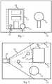
- Figure 1shows an image depicting a scene 100.
- the scene 100comprises several objects 102, 104, 106, 108.
- the scenecomprises a building 108, a tree 106, and two persons 102, 104.
- the building 108has privacy restrictions, and privacy masking (e.g. blurring) is thus required for image data showing the building 108, e.g. the image data showing the building must be blurred to an extent such that details (according to the privacy restrictions) is not visible in the image showing the scene 100.
- the privacy restrictionsmay define that the identity of persons entering the building 108 cannot be detected, or that the identity of persons that are visible through the windows of the building 108 is kept private for the viewer of the image.
- a privacy area 110is defined, surrounding the building 108.
- two persons 102, 104are depicted at least partly inside the privacy area 110, but clearly positioned in front of the building 108. This means that blurring applied to remove details (lower the spatial resolution) of image data corresponding to the building 108 will also affect the image data corresponding to the two persons 102, 104, since the blurring is applied to all pixels within the privacy area 110.
- a threshold distancemay be defined, which can be used for determining if, and how much, blurring should be applied to the privacy area of the image.
- Figure 2shows this concept.
- Figure 2shows the same scene 100 depicted in the image of figure 1 but seen from above.
- figure 2also shows an image capturing device 200, and the angle of view (AOV) 202 of the image capturing device 200.
- the image capturing device 200may for example be a video camera a still image camera.
- the privacy area 110is defined as an angular range originating from the image capturing device for ease of explaining.
- Figure 2further includes the threshold distance 204, which may be thought of as defining the privacy area 110 further in terms of a distance from the image capturing device 200.
- thiswill affect all content of the scene within the privacy area 110 e.g. as shown in figure 1.
- Figure 2shows that the rightmost person 104 in figure 1 is positioned quite far from the threshold distance 204, while the leftmost person 102 is positioned closer to the threshold distance 204, but still on the side of the image capturing device 200 with respect to the threshold distance 204.
- the spatial resolution of the image data showing the building 108is low enough (depending on the use case) to meet the privacy requirements.
- objectse.g. persons 102, 104 between the building 108 and the video capturing device 200 can be shown in as much details as possible.
- the inventive concept described hereinprovides a solution to this problem.
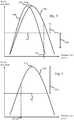
- Figure 3shows a schematic plot of two different focus curves 308a-b for the video capturing device 200 of figure 1 and 2 , depending on e.g. a focus point and a zoom value (focal length) of the image capturing device 200.
- the plot of figure 3shows spatial resolution of image data based on a distance from the image capturing device at which the content of the scene which the image data corresponds to is located. In other words, the plot shows the spatial resolution as a function of a distance from the camera, or depth in the image.
- the first curve 308ashows a focus curve when the leftmost person 102 is in focus for the image capturing device 200, at a first zoom level.
- the second curve 308bshows a focus curve when the rightmost person 104 is in focus for the image capturing device 200, at a second zoom level being lower than the first zoom level.
- a threshold spatial resolution 302is shown.
- the value of the threshold spatial resolution 302sets a limit for how large the spatial resolution of image data corresponding to content of the privacy area 110 may be.
- the value of the threshold spatial resolution 302sets a limit for the allowed spatial resolution of image data corresponding to content of the scene located beyond the threshold distance 204 from the image capturing device in the scene (the limit is set for image data being within the privacy area 110 of the image), such that the privacy requirements for such image data is met.
- the plots of figure 3also show the threshold distance 204.
- the focus curves 308a-bthus show, for different settings of the image capturing device, what spatial resolution different content of the image will have, depending on the depth in the image (i.e. distance from the image capturing device).
- the spatial resolution for content at the threshold distance 204differs from the threshold spatial resolution 302 with a positive value 306a.
- a degree of blurringwill be determined (as will be further discussed below in conjunction with figures 5a-d ) and applied to the image data in the privacy area 110 of the image.
- the spatial resolution for content at the threshold distance 204differs from the threshold spatial resolution 302 with a negative value 306b.
- the plotshows that peaks 310a-b of the focus curves 308a-b are closer to the image capturing device 200 than the threshold distance 204.
- the focal point 310a-b of the camerais between the threshold distance and the image capturing device 200, e.g. at threshold distance/1.5 or threshold distance/2.
- the maximum spatial resolution of the image data of the image corresponding to content of the scene located on or beyond the threshold distance 204 from the image capturing device 200will always be the spatial resolution at the threshold distance 204.
- Figure 4shows an example where the focus point 310c is beyond the threshold distance 204.
- the difference between the maximum spatial resolution and the threshold spatial resolution 302will be the difference 306c between the spatial resolution at the focus point 310c distance from the image capturing device 200, i.e. the focal length of the optical system of the image capturing device 200 when capturing the image.
- This difference 306cwill then be used to determine the degree of blurring to be applied to the image data of the privacy area 110 of the image.
- the maximum spatial resolution for objects in a scene located on or beyond a threshold distance from the image capturing devicemay be calculated using algorithms defined for calculation of the term "circle of confusion", e.g. as defined in the Wikipedia article on the subject at the date of filing of the present application
- the circle of confusion (CoC) diameteri.e. the blur circle, of diameter C
- Cabs S 2 ⁇ S 1 S 2 ⁇ f 2 N ⁇ S 1 ⁇ f
- Cdiameter of CoC
- S1the focal point of the image capturing device (i.e. the distance where the focus curve peaks, e.g. reference 310a-b in figure 3 )
- S2the threshold distance (e.g. reference 204 in figure 3 )
- Nthe F-number of a lens of the image capturing device
- fthe focal length of the optical system of the image capturing device.
- the equation 1-5specifies an exact way of calculating the degree of blurring to be applied.
- FIG 5aa continuous mapping function 502 between the degree of blurring and the calculated difference between the maximum spatial resolution and the threshold spatial resolution is shown.
- the mapping function 502may comprise a predetermined maximum degree of blurring as shown in figure 5b .
- the degree of blurringis set to a predetermined value 504 (for example a kernel size of 128 ⁇ 128 pixels for the used low-pass filter).
- the degree of blurringis determined to a value between zero and the predetermined value 504, wherein the value is related to the difference.
- the mapping function 502is continuous as in figure 5a .
- the degree of blurringis determined to be zero.
- the max blurring degree 504still applies as in figure 5b .
- the mapping function 502is a step function being step wise correlated to the distance.
- the mapping function between the calculated difference and the determined blurring factoris as shown in figure 5d .
- a predetermined degree of blurring 504is applied to the privacy area of the image.
- no degree of blurringis applied.
- the degree of blurring determined based on the first differenceis larger than the degree of blurring determined for the second difference.
- Figure 7shows by way of example a method for determining a degree of blurring to be applied to image data in a privacy area of an image, for example for the scenario shown in figures 1-2 .
- the methodcomprises the step of receiving, S702, input relating to coordinates of the privacy area of the image.
- the methodfurther comprises receiving, S704, input relating to a threshold spatial resolution of image data corresponding to content of the scene located beyond a threshold distance from the image capturing device in the scene.
- the threshold spatial resolutionmay be received e.g. in the form of an angular resolution for each pixel in the image (i.e. 1° or 0,5°), or a value describing how many pixels an object of a certain size should be represented by at the threshold distance (e.g. 15 ⁇ 15 pixels for a 1 ⁇ 1 meter large object) or any other suitable measure of spatial resolution.
- the methodcomprises calculating S706 a maximum spatial resolution of the image data of the image corresponding to content of the scene located on or beyond the threshold distance from the image capturing device, e.g. using equation 3 above, or adaptations of equation 3 based on the format of the received threshold spatial resolution.
- the two measures, the threshold spatial resolution and the maximum spatial resolutionis then used for calculating S708 a difference between the maximum spatial resolution and the threshold spatial resolution, and determining S710 a degree of blurring based on the calculated difference, such that for a first difference being larger than a second difference, the degree of blurring determined based on the first difference is larger than the degree of blurring determined based on the second difference.
- the determined degree of blurringis then applied to the pixels of the privacy area, for example using a gaussian filter, an average filter or a pixelization filter, wherein the degree of blurring determines the size of the applied filter.
- the determined degree of blurringis then applied S712 to the privacy area of the image, i.e. by applying the low pass filter with a kernel size according to the determined degree of blurring.
- the focus point of the image capturing devicecan be both closer to the image capturing device compared to the threshold distance, as well as beyond the threshold distance.
- the presence of a threshold distancecan be taken advantage of in the context of focus limits of the image capturing device, in that the focus limit can be set to the threshold distance or less. Since, from a privacy perspective, it may not be advantageous if the focus point is on or beyond the threshold distance (which will increase the spatial resolution of the image data of the image corresponding to content of the scene located on or beyond the threshold distance from the image capturing device as described above), the focus limit can advantageously be set to the threshold distance or less.
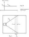
- the focus limitis set to the threshold distance minus a determined value. This is shown in figure 6 , where the focus limit 602 is set at a distance 604 from the threshold distance 204. As described above, also content at a certain distance beyond the actual focus point will appear acceptably sharp (e.g. having a spatial resolution above the threshold spatial resolution, also known as Depth of Field, DoF) in the captured image data, which can be taken advantage of when setting the focus limit.
- the determined value 604is calculated e.g. as described above, using the focal length, the F-number, and the threshold spatial resolution.
- the method for setting a focus limit of an image capturing devicecomprises the steps of receiving S802 input relating to a privacy threshold distance relating to a privacy requirement for images captured by the image capturing device.
- the privacy threshold distancemay be defined similar to what is described above, i.e. a distance from the camera beyond which privacy requirements applies.
- the methodfurther comprises the step of setting S808 a focus limit of the image capturing device to the threshold distance or less.
- This methodcan, according to embodiments, further take advantage of the DoF-concept as described above in conjunction with figure 6 .
- the methodfurther comprises receiving S804 input relating to a threshold spatial resolution of image data corresponding to content of the scene located beyond the threshold distance 204 from the image capturing device in a scene captured by the image capturing device.
- the threshold spatial resolutioncan then be used for calculating the DoF for the image capturing device (with its current settings, e.g. F-number) for focal points (focus points) at some distances from the privacy threshold distance.
- the threshold spatial resolutionalso known as Depth of Field, DoF
- DoFDepth of Field
- the focus limit of the image capturing devicecan be set at a distance from the privacy threshold, such that the spatial resolution on and beyond the privacy threshold distance always will be lower than the threshold spatial resolution.
- Determining at what distance from the privacy threshold distance the focus limit should bemay be an iterative process, where a plurality of focus points are used for calculation of DoF for the camera (where the threshold spatial resolution thus is used for defining the circle of confusion criteria), and where the focus point where the acceptably sharp area ends closest to the threshold distance is set S808 as the focus limit for the image capturing device.
- a focus limitis set S808 based on e.g. a predetermined table of focus limits.
Landscapes
- Engineering & Computer Science (AREA)
- Theoretical Computer Science (AREA)
- Physics & Mathematics (AREA)
- General Physics & Mathematics (AREA)
- Multimedia (AREA)
- Signal Processing (AREA)
- Computer Vision & Pattern Recognition (AREA)
- Bioethics (AREA)
- Health & Medical Sciences (AREA)
- General Health & Medical Sciences (AREA)
- Medical Informatics (AREA)
- Databases & Information Systems (AREA)
- Computer Hardware Design (AREA)
- Computer Security & Cryptography (AREA)
- Software Systems (AREA)
- General Engineering & Computer Science (AREA)
- Image Processing (AREA)
- Studio Devices (AREA)
- Studio Circuits (AREA)
Description
- The present invention relates to the field of protecting personal privacy in captured image data. In particular it relates to methods and devices for controlling privacy masking of image and/or video content.
- The right to feel safe and secure is one of the most important basic principles in society, and this is where surveillance systems have an important function, as long as they are used in accordance with prevailing legislation. There is an ongoing debate about the implications of surveillance on privacy. Recent developments in network camera technology have led to several different applications that can be implemented to limit surveillance and thus protect privacy. One such development is privacy masking, which enables selected areas of a scene to be blocked or masked from viewing and recording. It allows masking to be maintained even as a field of view of the image capturing device (e.g. a video camera) changes through panning, tilting and zooming as the masking moves with the coordinate system of the device. Privacy masking may be achieved by blurring pixels within a privacy area of the captured images, so specific details (such as a face of a person) in this area cannot be deciphered or interpreted by a user looking at the video stream.
- When applying privacy masking, care should be taken to not to blur image data in the privacy area more than necessary, to still be able use the captured video for surveillance purposes in the best possible way. This may be achieved by limiting the degree of blurring applied to the privacy area of the image based on blur in the image already being present due to the current settings and hardware of the image capturing device (e.g. parts of the image being unfocused or having low spatial resolution).
US2015085163 (Canon) discloses one solution to how to limit the degree of blurring. This document discloses a method where imaging data is analysed to determine if there is a privacy protection target present, i.e. a detected face. A focus range corresponding to the currently used F-number is determined. If the protection target is located within the focus range, a relatively large blur amount is added. If the protection target is located outside the focus range, a lower (or no) blur amount is added since the target will be blurred to some degree already.US2015085163 teaches that a predetermined look-up-table is used to determine the amount of added blur needed for different F-number settings and distances from the best focus position. The method inUS2015085163 is complex, since a protection target needs to be determined, and the distance to this target needs to be calculated, before the blurring of the area of the image where the protection target is present can be determined. Moreover, the predetermined look-up-table reduces the flexibility of the method and requires specific look-up table for every camera system. Furthermore, different use cases require different amount of blurring being present in a privacy area. For example, a use case involving blurring of number plates of a car may require a different amount of blurring to be impossible to decipher compared to a use case involving blurring of a face of a person.EP 2327055 A1 (Tele Atlas BV) discloses a method of reducing the spatial resolution of images, including: -acquiring an input image including image parts having a spatial resolution larger than SR pixels/meter; -acquiring a depth map associated with the input image; -determining for each pixel p(x,y) a spatial resolution value by means of the depth map; -processing a region of pixels of the input image for which holds that the spatial resolution value is larger than a predefined threshold corresponding to SR pixels/meter to obtain a corresponding region of pixels having a spatial resolution smaller than or equal to SR pixels/meter in an output image.- There is thus a need for improvements within this context.
- In view of the above, it is thus an object of the present invention to overcome or at least mitigate the problems discussed above. In particular, it is an object to provide an improved method for determining a degree of blurring to be applied to image data in a privacy area of an image.
- According to a first aspect of the invention, there is provided a method of for determining a degree of blurring to be applied to image data in a privacy area of an image, the image depicting a scene and being captured by an image capturing device, the method comprising the steps of:
- receiving input relating to coordinates of the privacy area of the image;
- receiving input relating to a threshold spatial resolution of image data corresponding to content of the scene located beyond a threshold distance from the image capturing device in the scene, said image data being within the privacy area of the image;
- calculating a maximum spatial resolution of the image data of the image corresponding to content of the scene located on or beyond the threshold distance from the image capturing device;
- calculating a difference between the maximum spatial resolution and the threshold spatial resolution;
- determining a degree of blurring based on the calculated difference, such that for a first difference being larger than a second difference, the degree of blurring determined based on the first difference is larger than the degree of blurring determined for the second difference;
- applying the degree of blurring to the image data in the privacy area of the image.
- As used herein, by "input relating to coordinates of the privacy area of the image" is generally meant any input which can be used for determining a privacy area of the image. For example, the input may be based on real worlds coordinates of the captured scene, either global coordinates such as GPS coordinates, or coordinates being relative to the position of the image capturing device such as a range of angles (e.g. 35 - 45°). This input may then be translated to coordinates in the image which corresponds to the privacy area. According to other embodiments, the input may describe an area (coordinates) of the captured image, e.g. a pixel range such as Y:40-80, X: 100-500.
- As used herein, by "degree of blurring" is generally meant to what extent the image data is blurred. The blurring may be performed using any suitable type of low-pass filter, also called a "blurring" or "smoothing" filter, which averages out rapid changes (i.e. details) in intensity in the image data. The determined degree of blurring will thus reduce the spatial resolution of the image data which was low-pass filtered. The degree of blurring may for example determine the kernel size in an average filter, or the radius of a Gaussian in a gaussian filter.
- As used herein, by "threshold distance" is generally meant a distance value relative to the location of the image capturing device, e.g. 7 meters, 30 meters, 0.9 meters etc. (based on the use case).
- The threshold spatial resolution corresponds to an allowed sharpness of details for objects in the image located at the threshold distance or beyond in the scene. The threshold spatial resolution may also be called circle of confusion criterion, threshold angular resolution, threshold for number of independent pixel values per unit length etc. The spatial resolution describes the ability of any image-forming device, such as a camera to distinguish small details of an object. By setting a threshold spatial resolution, the allowed spatial resolution at the threshold distance or beyond may be based on the use case. For example, for ensuring the privacy of persons located in the privacy area (i.e. at or beyond the threshold distance, in a specific privacy area in the scene), the allowed (threshold) spatial resolution may be 1 pixel per decimeter of the scene at the threshold distance. At this spatial resolution, it may not possible to recognize the face of the person, thus the privacy of the person may be ensured. Other threshold spatial resolution may of course be applied, such as 2, 3, 10, etc. pixels per decimeter.
- The step of calculating a maximum spatial resolution may be done using any algorithm known to the skilled person, i.e. to determine the current maximum spatial resolution for content on or beyond the threshold distance in the scene, given by the current focus curve of the image capturing device.
- The present invention is based on the realization that by using the methods presented herein, it may be achievable to set up a privacy area, where the blurring applied to the privacy area depends also on a threshold distance from the image capturing device, and what spatial resolution content of the scene at this distance have in the image. By doing this, objects in the foreground, which are within the privacy area, but located closer to the image capturing device than the threshold distance (and thus not required to be blurred to an impossibility of recognition for privacy reasons) may in some cases not be blurred, or blurred to an lower degree, since, in these cases, the image data corresponding to content of the scene located beyond the threshold distance from the image capturing device in the scene will anyway be blurred to some degree due to e.g. the current focus curve, or depth of field, of the image capturing device. In some cases, the inherent blurring of the content beyond the threshold distance may be enough to meet the threshold spatial resolution requirement (e.g. due to a high zoom level, and/or focus on an object in the foreground), and no additional degree of blurring may be needed to be applied (zero degree of blurring). In other cases, only a low degree of blurring may be needed to be applied to meet the spatial resolution requirement of image content beyond the threshold distance, resulting in that the object in the foreground may still be recognizable.
- By calculating a difference between the maximum spatial resolution of the image data of the image corresponding to content of the scene located on or beyond the threshold distance from the image capturing device and the threshold spatial resolution, and determine the degree of extra blurring to be applied to the image content in the privacy area of the image based on this distance, the above advantages may be achieved. By applying the degree of blurring (being above zero), the spatial resolution of the image data corresponding to content of the scene located beyond a threshold distance from the image capturing device in the scene (and within the privacy area of the image), will be reduced to be on or below the threshold spatial resolution.
- Moreover, by requiring input relating to the threshold spatial resolution, this requirement may be based on the current use case.
- According to some embodiments, if the calculated difference is zero or negative, the degree of blurring is determined to be zero. In this case, the sharpness (focus) of the image data of the image corresponding to content of the scene located on or beyond the threshold distance from the image capturing device is low enough to meet the threshold spatial resolution and thus to ensure the privacy of objects in the privacy area (based on the use case). Consequently, no additional degree of blurring need to be applied to the image content. This reduces the required processing power for performing the method, as well as increases he possibility to recognize objects located closer to the image capturing device than the threshold distance, thus improving the usefulness of the captured image.
- According to some embodiments, the method further comprises the steps of:
- when the difference is above a threshold difference, determining the degree of blurring to a predetermined value, and
- when the difference is between zero and the threshold difference, determining the degree of blurring to a value between zero and the predetermined value, wherein the value is related to the difference.
- In this embodiment, a max blurring factor (predetermined value) may be implemented, e.g. a 128∗128 pixels blurring. Between zero difference and the threshold difference, the degree of blurring is determined based on the difference, for example a step function being step wise correlated to the distance, or a continuous function correlated to the difference. The present embodiment may provide a flexible method of determining the degree of blurring to be applied to the image data.
- According to some embodiments, the step of calculating the maximum spatial resolution is performed based on a focal length of an optical system of the image capturing device, the F-number of the optical system of the image capturing device and a pixel pitch of an image sensor of the image capturing device.
- As used herein, by "optical system of the image capturing device" is generally meant the optical lens or assembly of lenses included in the image capturing device.
- As used herein, by "pixel pitch" is generally meant the approximate width of one pixel on the image sensor of the image capturing device, e.g. calculated by taking the width of active area of sensor divided by the number of pixels of the sensor in a horizontal direction. The pixel pitch may thus be defined as the center-to-center distance between individual pixels, often defined in microns. Using these properties of the camera, a focus curve may be calculated, defining the spatial resolution of all content of the scene in the image, based on the distance from the image capturing device. This curve can then be used for calculating the maximum spatial resolution of the image data of the image corresponding to content of the scene located on or beyond the threshold distance from the image capturing device, to further determine the degree of blurring that needs to be applied to the privacy area of the image in order to meet the threshold spatial resolution.
- According to some embodiments, the step of applying the degree of blurring to the image comprises one from the list of: applying a gaussian filter, applying an average filter (mean filter), applying a pixelization filter, wherein the degree of blurring determines the size of the applied filter.
- The degree of blurring defines may thus define the kernel size or similar for these filters. Other types of filters may be applied. A combination of filters may also be applied.
- According to some embodiments, the method comprises determining that the privacy area covers at least a threshold portion of the image, setting a focus limit of the image capturing device to the threshold distance or less. In this embodiment, the knowledge of the threshold distance, i.e. that objects on or beyond this distance from the image capturing device should not be represented by image data with too high spatial resolution for privacy reasons, can be used to set a focus limit of the image capturing device, especially when the privacy area covers a larger portion of the image such as 40%, 50%, 75% 90% etc. Objects at this distance have no reason to be in focus since the corresponding image data will be blurred anyway. Advantageously, this may reduce the required processing power for ensuring privacy, as well as simplify the setting of focus for the image capturing device. According to some embodiments, the privacy area must cover the center pixel of the image, for this embodiment to be applied, since in this case it can be assumed that it is the privacy area of the scene which is of most interest for a viewer of the captured image, and that the limited focus abilities of the camera thus not will affect the usefulness (from a surveillance perspective) of the captured images in a negative way.
- According to some embodiments, the step of setting the focus limit comprises setting the focus limit of an autofocus (AF) algorithm of the image capturing device to the threshold distance or less. Advantageously, the required processing power for performing AF may be reduced, since the AF only have to search for focus in a shorter range of distances from the image capturing device. Also, the speed of execution of AF may be increased. Furthermore, the chance of the AF focusing on an "interesting" object (i.e. an object which is not in the privacy area beyond the threshold distance) is increased, thus improving surveillance functionality.
- According to some embodiments, the step of setting the focus limit comprises setting the focus limit to the threshold distance minus a determined value, wherein the value is determined based on a current focal length of an optical system (zoom value) of the image capturing device, the F-number of the lens of the image capturing device and the threshold spatial resolution.
- Although the optical system of image capturing device can precisely focus at only one distance at a time, the decrease in sharpness is gradual on each side of the focused distance, so that within the depth of field, DOF, the unsharpness is imperceptible under normal viewing conditions. This means that also content at a certain distance beyond the actual focus distance (focal point) will appear acceptably sharp (e.g. having a spatial resolution above the threshold spatial resolution) in the captured image data, which can be taken advantage of when setting the focus limit. Based on a current zoom level (focal length) of the image capturing device, the F-number of the lens of the camera of the image capturing device, the distance from the actual focus distance that will have a spatial resolution above the threshold spatial resolution can be determined. The determined distance may thus be used to set the focus limit. Advantageously, this may reduce the required processing power for ensuring privacy, as well as simplify the setting of focus for the image capturing device. This embodiment may further increase the speed of execution of AF.
- According to some embodiments, when the focus limit is set as described above, the step of calculating a maximum spatial resolution consists of calculating the spatial resolution of image data of the image corresponding to content of the scene located on the threshold distance from the image capturing device. By setting the focus limit closer to the image capturing device than the threshold distance, it will be known that no image data of the image corresponding to content of the scene located beyond the threshold distance from the image capturing device will have a higher spatial resolution compared to content of the scene located on the threshold distance from the image capturing device. Consequently, step of calculating a maximum spatial resolution may be limited to calculating the spatial resolution of image data of the image corresponding to content of the scene located on the threshold distance from the image capturing device. This embodiment may simplify the method, as well as reducing the required processing power for determining a degree of blurring to be applied to the image data in the privacy area of the image.
- According to a second aspect of the invention, the above object is achieved by a computer program product comprising a computer-readable storage medium with instructions adapted to carry out the method of the first aspect when executed by a device having processing capability.
- According to a third aspect of the invention, the above object is achieved by device adapted for determining a degree of blurring to be applied to image data in a privacy area of an image, the image depicting a scene and being captured by an image capturing device, the device comprising a processor configured to:
- receive input relating to coordinates of the privacy area of the image; receive input relating to a threshold spatial resolution of image data corresponding to content of the scene located beyond a threshold distance from the image capturing device in the scene, said image data being within the privacy area of the image;
- calculate a maximum spatial resolution of the image data of the image corresponding to content of the scene located on or beyond the threshold distance from the image capturing device;
- calculate a difference between the maximum spatial resolution and the threshold spatial resolution;
- determine a degree of blurring based on the calculated difference, such that for a first difference being larger than a second difference, the degree of blurring determined based on the first difference is larger than the degree of blurring determined for the second difference;
- apply the degree of blurring to the image data in the privacy area of the image.
- According to a fourth aspect of the invention, the above object is achieved by system comprising
- a first device for continuously capturing data of a scene, and producing a video stream comprising a sequence of images based on the captured data;
- a second device according to the third aspect, adapted to continuously receiving the sequence of images from the first device.
- According to some embodiments, the first and the second device is implemented in an image capturing device.
- The second, third and fourth aspects may generally have the same features and advantages as the first aspect. It is further noted that the invention relates to all possible combinations of features unless explicitly stated otherwise.
- The above, as well as additional objects, features and advantages of the present invention, will be better understood through the following illustrative and non-limiting detailed description of preferred embodiments of the present invention, with reference to the appended drawings, where the same reference numerals will be used for similar elements, wherein:
Fig. 1 shows an image depicting scene and comprising a privacy area,Fig. 2 shows the scene offigure 1 from above, including an image capturing device, the privacy area and a privacy threshold distance,Figs. 3-4 show exemplary focus curves, and calculation of differences between maximum spatial resolution and a threshold spatial resolution according to embodiments,Figs. 5a-d each shows an embodiment of a mapping function between calculated differences according tofigs. 3-4 and a degree of blurring to be applied to the privacy area of the image,Fig. 6 shows a method for setting a focus limit of an image capturing device according to embodiments,Fig. 7 shows a method for determining a degree of blurring to be applied to image data in a privacy area of an image according to embodiments,Fig. 8 shows a method for setting a focus limit of an image capturing device according to embodiments.- The present invention will now be described more fully hereinafter with reference to the accompanying drawings, in which embodiments of the invention are shown. The systems and devices disclosed herein will be described during operation.
Figure 1 shows an image depicting ascene 100. Thescene 100 comprisesseveral objects building 108, atree 106, and twopersons building 108 has privacy restrictions, and privacy masking (e.g. blurring) is thus required for image data showing thebuilding 108, e.g. the image data showing the building must be blurred to an extent such that details (according to the privacy restrictions) is not visible in the image showing thescene 100. For example, the privacy restrictions may define that the identity of persons entering thebuilding 108 cannot be detected, or that the identity of persons that are visible through the windows of thebuilding 108 is kept private for the viewer of the image. For this reason, aprivacy area 110 is defined, surrounding thebuilding 108. As visible infigure 1 , twopersons privacy area 110, but clearly positioned in front of thebuilding 108. This means that blurring applied to remove details (lower the spatial resolution) of image data corresponding to thebuilding 108 will also affect the image data corresponding to the twopersons privacy area 110.- Using the inventive concept described herein, a threshold distance may be defined, which can be used for determining if, and how much, blurring should be applied to the privacy area of the image.
Figure 2 shows this concept.Figure 2 shows thesame scene 100 depicted in the image offigure 1 but seen from above. In addition to the objects 102-108 included infigure 1, figure 2 also shows animage capturing device 200, and the angle of view (AOV) 202 of theimage capturing device 200. Theimage capturing device 200 may for example be a video camera a still image camera. Infigure 2 , theprivacy area 110 is defined as an angular range originating from the image capturing device for ease of explaining.Figure 2 further includes thethreshold distance 204, which may be thought of as defining theprivacy area 110 further in terms of a distance from theimage capturing device 200. However, as understood by the skilled person, when applying the later determined blurring factor, this will affect all content of the scene within theprivacy area 110 e.g. as shown infigure 1. Figure 2 shows that therightmost person 104 infigure 1 is positioned quite far from thethreshold distance 204, while theleftmost person 102 is positioned closer to thethreshold distance 204, but still on the side of theimage capturing device 200 with respect to thethreshold distance 204. From a privacy perspective, it is important that the spatial resolution of the image data showing thebuilding 108 is low enough (depending on the use case) to meet the privacy requirements. However, from a surveillance perspective, it may be important that objects (e.g.persons 102, 104) between thebuilding 108 and thevideo capturing device 200 can be shown in as much details as possible. The inventive concept described herein provides a solution to this problem. Figure 3 shows a schematic plot of twodifferent focus curves 308a-b for thevideo capturing device 200 offigure 1 and 2 , depending on e.g. a focus point and a zoom value (focal length) of theimage capturing device 200. The plot offigure 3 shows spatial resolution of image data based on a distance from the image capturing device at which the content of the scene which the image data corresponds to is located. In other words, the plot shows the spatial resolution as a function of a distance from the camera, or depth in the image. In the example offigure 3 , thefirst curve 308a shows a focus curve when theleftmost person 102 is in focus for theimage capturing device 200, at a first zoom level. Thesecond curve 308b shows a focus curve when therightmost person 104 is in focus for theimage capturing device 200, at a second zoom level being lower than the first zoom level.- In the plot of
figure 3 , a thresholdspatial resolution 302 is shown. The value of the thresholdspatial resolution 302 sets a limit for how large the spatial resolution of image data corresponding to content of theprivacy area 110 may be. In other words, the value of the thresholdspatial resolution 302 sets a limit for the allowed spatial resolution of image data corresponding to content of the scene located beyond thethreshold distance 204 from the image capturing device in the scene (the limit is set for image data being within theprivacy area 110 of the image), such that the privacy requirements for such image data is met. - The plots of
figure 3 also show thethreshold distance 204. The focus curves 308a-b thus show, for different settings of the image capturing device, what spatial resolution different content of the image will have, depending on the depth in the image (i.e. distance from the image capturing device). For thefirst focus curve 308a, the spatial resolution for content at thethreshold distance 204 differs from the thresholdspatial resolution 302 with apositive value 306a. This means that the privacy requirements for the privacy area is not met. For example, this may mean that the faces of people in the windows of thebuilding 108 infigures 1-2 are identifiable. Based on thisdifference 306a between the maximum spatial resolution and the threshold spatial resolution, a degree of blurring will be determined (as will be further discussed below in conjunction withfigures 5a-d ) and applied to the image data in theprivacy area 110 of the image. - For the
second focus curve 308b, the spatial resolution for content at thethreshold distance 204 differs from the thresholdspatial resolution 302 with anegative value 306b. This means that the privacy requirements for the privacy area are indeed met. For example, this may mean that the faces of people in the windows of thebuilding 108 are not identifiable (e.g. the spatial resolution is less than 1 pixel per 0.1 meter on and beyond the threshold distance, or less than 2, 5, etc. pixels depending on the use case). Consequently, no blurring needs to be applied to theprivacy area 110, which may mean that the image data corresponding to theobjects - In
figure 3 , the plot shows thatpeaks 310a-b of the focus curves 308a-b are closer to theimage capturing device 200 than thethreshold distance 204. This means that thefocal point 310a-b of the camera is between the threshold distance and theimage capturing device 200, e.g. at threshold distance/1.5 or threshold distance/2. In this case, the maximum spatial resolution of the image data of the image corresponding to content of the scene located on or beyond thethreshold distance 204 from theimage capturing device 200 will always be the spatial resolution at thethreshold distance 204. However, this is not always the case.Figure 4 shows an example where thefocus point 310c is beyond thethreshold distance 204. In this case, the difference between the maximum spatial resolution and the thresholdspatial resolution 302 will be thedifference 306c between the spatial resolution at thefocus point 310c distance from theimage capturing device 200, i.e. the focal length of the optical system of theimage capturing device 200 when capturing the image. Thisdifference 306c will then be used to determine the degree of blurring to be applied to the image data of theprivacy area 110 of the image. - The maximum spatial resolution for objects in a scene located on or beyond a threshold distance from the image capturing device may be calculated using algorithms defined for calculation of the term "circle of confusion", e.g. as defined in the Wikipedia article on the subject at the date of filing of the present application
- Specifically, to calculate the diameter of the circle of confusion in the image plane for an out-of-focus subject, one method is to first calculate the diameter of the blur circle in a virtual image in the object plane and then multiply by the magnification of the system, which is calculated with the help of the lens equation. The circle of confusion (CoC) diameter, i.e. the blur circle, of diameter C, may be calculated using the formula:

e.g. reference 310a-b infigure 3 ), S2 = the threshold distance (e.g. reference 204 infigure 3 ), N = the F-number of a lens of the image capturing device and f= the focal length of the optical system of the image capturing device. - Given that


- If Equation 3 is evaluated at the threshold distance (S2), and by subtracting the threshold spatial resolution (th'), the degree of blurring (B) (in pixels) may be calculated by:

figure 3 ). For the case where S1 is beyond S2 (as described infigure 4 ), B may be calculated by:
- The equation 1-5 specifies an exact way of calculating the degree of blurring to be applied. This is schematically shown in
figure 5a , where acontinuous mapping function 502 between the degree of blurring and the calculated difference between the maximum spatial resolution and the threshold spatial resolution is shown. However, themapping function 502 may comprise a predetermined maximum degree of blurring as shown infigure 5b . In this case, when the difference is above athreshold difference 506, the degree of blurring is set to a predetermined value 504 (for example a kernel size of 128∗128 pixels for the used low-pass filter). When the difference is between zero and thethreshold difference 506, the degree of blurring is determined to a value between zero and thepredetermined value 504, wherein the value is related to the difference. Infigure 5b , between zero and thethreshold difference 506, themapping function 502 is continuous as infigure 5a . Just as for the example shown infigure 5a , for differences below zero, the degree of blurring is determined to be zero. - In
figure 5c , themax blurring degree 504 still applies as infigure 5b . However, infigure 5c , between zero and thethreshold difference 506, themapping function 502 is a step function being step wise correlated to the distance. - In the simplest form, the mapping function between the calculated difference and the determined blurring factor (degree of blurring) is as shown in
figure 5d . For differences above zero, a predetermined degree of blurring 504 is applied to the privacy area of the image. For differences below zero, no degree of blurring is applied. - In all examples shown in
figures 5a-d , for a first difference being larger than a second difference, the degree of blurring determined based on the first difference is larger than the degree of blurring determined for the second difference. Figure 7 shows by way of example a method for determining a degree of blurring to be applied to image data in a privacy area of an image, for example for the scenario shown infigures 1-2 .- According to embodiments, the method comprises the step of receiving, S702, input relating to coordinates of the privacy area of the image.
- The method further comprises receiving, S704, input relating to a threshold spatial resolution of image data corresponding to content of the scene located beyond a threshold distance from the image capturing device in the scene.
- The threshold spatial resolution may be received e.g. in the form of an angular resolution for each pixel in the image (i.e. 1° or 0,5°), or a value describing how many pixels an object of a certain size should be represented by at the threshold distance (e.g. 15∗15 pixels for a 1∗1 meter large object) or any other suitable measure of spatial resolution.
- Further, the method comprises calculating S706 a maximum spatial resolution of the image data of the image corresponding to content of the scene located on or beyond the threshold distance from the image capturing device, e.g. using equation 3 above, or adaptations of equation 3 based on the format of the received threshold spatial resolution.
- The two measures, the threshold spatial resolution and the maximum spatial resolution is then used for calculating S708 a difference between the maximum spatial resolution and the threshold spatial resolution, and determining S710 a degree of blurring based on the calculated difference, such that for a first difference being larger than a second difference, the degree of blurring determined based on the first difference is larger than the degree of blurring determined based on the second difference. The determined degree of blurring is then applied to the pixels of the privacy area, for example using a gaussian filter, an average filter or a pixelization filter, wherein the degree of blurring determines the size of the applied filter.
- The determined degree of blurring is then applied S712 to the privacy area of the image, i.e. by applying the low pass filter with a kernel size according to the determined degree of blurring.
- As described in
figure 3 and 4 , the focus point of the image capturing device can be both closer to the image capturing device compared to the threshold distance, as well as beyond the threshold distance. The presence of a threshold distance can be taken advantage of in the context of focus limits of the image capturing device, in that the focus limit can be set to the threshold distance or less. Since, from a privacy perspective, it may not be advantageous if the focus point is on or beyond the threshold distance (which will increase the spatial resolution of the image data of the image corresponding to content of the scene located on or beyond the threshold distance from the image capturing device as described above), the focus limit can advantageously be set to the threshold distance or less. This in turn will reduce the spatial resolution of the image data of the image corresponding to content of the scene located on or beyond the threshold distance from the image capturing device, and thus reduce the required additional blurring that needs to be applied to the privacy area. Moreover, by setting a focus limit, autofocus, AF, of the image capturing device may be achieved both faster and requiring less processing power, since the possible range for AF is reduced. - According to some embodiments, the focus limit is set to the threshold distance minus a determined value. This is shown in
figure 6 , where thefocus limit 602 is set at a distance 604 from thethreshold distance 204. As described above, also content at a certain distance beyond the actual focus point will appear acceptably sharp (e.g. having a spatial resolution above the threshold spatial resolution, also known as Depth of Field, DoF) in the captured image data, which can be taken advantage of when setting the focus limit. The determined value 604 is calculated e.g. as described above, using the focal length, the F-number, and the threshold spatial resolution. - It should be noted that the above strategy of setting of a focus limit may be performed independently of the method for determining a degree of blurring to be applied to image data in a privacy area of an image as described above. Such independently performed method is shown in
figure 8 . - In its simplest form, the method for setting a focus limit of an image capturing device comprises the steps of receiving S802 input relating to a privacy threshold distance relating to a privacy requirement for images captured by the image capturing device. The privacy threshold distance may be defined similar to what is described above, i.e. a distance from the camera beyond which privacy requirements applies.
- The method further comprises the step of setting S808 a focus limit of the image capturing device to the threshold distance or less.
- This method can, according to embodiments, further take advantage of the DoF-concept as described above in conjunction with
figure 6 . In this embodiment, the method further comprises receiving S804 input relating to a threshold spatial resolution of image data corresponding to content of the scene located beyond thethreshold distance 204 from the image capturing device in a scene captured by the image capturing device. - The threshold spatial resolution can then be used for calculating the DoF for the image capturing device (with its current settings, e.g. F-number) for focal points (focus points) at some distances from the privacy threshold distance. As described above, also content at a certain distance beyond the actual focus point will appear acceptably sharp (e.g. having a spatial resolution above the threshold spatial resolution, also known as Depth of Field, DoF) in the captured image data, which can be taken advantage of when setting the focus limit. By taking the DoF into account, the focus limit of the image capturing device can be set at a distance from the privacy threshold, such that the spatial resolution on and beyond the privacy threshold distance always will be lower than the threshold spatial resolution. Determining at what distance from the privacy threshold distance the focus limit should be may be an iterative process, where a plurality of focus points are used for calculation of DoF for the camera (where the threshold spatial resolution thus is used for defining the circle of confusion criteria), and where the focus point where the acceptably sharp area ends closest to the threshold distance is set S808 as the focus limit for the image capturing device.
- In other embodiments, depending on the threshold spatial resolution and the settings of the image capturing device, a focus limit is set S808 based on e.g. a predetermined table of focus limits.
- In the above the inventive concept has mainly been described with reference to a limited number of examples. However, as is readily appreciated by a person skilled in the art, other examples than the ones disclosed above are equally possible within the scope of the inventive concept, as defined by the appended claims.


Claims (13)
- A computer-implemented method for determining a degree of blurring (502) to be applied to image data in a privacy area (110) of an image, the image depicting a scene (100) and being captured by an image capturing device (200), the method comprising the steps of:receiving (S702) input relating to coordinates of the privacy area of the image;receiving (S704) input relating to a threshold spatial resolution (302) of image data corresponding to content of the scene located beyond a threshold distance (204) from the image capturing device in the scene, said image data being within the privacy area of the image;calculating (S706) a maximum spatial resolution of the image data of the image corresponding to content of the scene located on or beyond the threshold distance from the image capturing device;calculating (S708) a difference (306a-c) between the maximum spatial resolution and the threshold spatial resolution;determining (S710) a degree of blurring (502) based on the calculated difference, such that for a first difference being larger than a second difference, the degree of blurring determined based on the first difference is larger than the degree of blurring determined for the second difference;applying (S712) the degree of blurring to the image data in the privacy area of the image.
- The method according to claim 1, wherein if the calculated difference is zero or negative, the degree of blurring is determined to be zero.
- The method according to claim 2, further comprising
when the difference is above a threshold difference (506), determining the degree of blurring to a predetermined value (504), and
when the difference is between zero and the threshold difference, determining the degree of blurring to a value between zero and the predetermined value, wherein the value is related to the difference. - The method of any one of claims 1-3, wherein the step of calculating the maximum spatial resolution is performed based on a focal length of an optical system of the image capturing device, the F-number of the optical system of the image capturing device, and a pixel pitch of an image sensor of the image capturing device.
- The method of any one of claims 1-4, wherein the step of applying the degree of blurring to the image comprises one from the list of: applying a gaussian filter, applying an average filter, applying a pixelization filter; wherein the degree of blurring determines the size of the applied filter.
- The method of any one of claims 1-5, further comprising the step of:determining that the privacy area covers at least a threshold portion of the image,setting (S808) a focus limit of the image capturing device to the threshold distance or less.
- The method of claim 6, wherein the step of setting the focus limit comprises setting the focus limit of an autofocus algorithm of the image capturing device to the threshold distance or less.
- The method of any one of claims 6-7, wherein the step of setting a focus limit comprises:
setting the focus limit (602) to the threshold distance minus a determined value (604), wherein the value is determined based on a current focal length of an optical system of the image capturing device, the F-number of the optical system of the image capturing device and the threshold spatial resolution. - The method of any one of claims 6-8, wherein the step of calculating a maximum spatial resolution consist of calculating the spatial resolution of image data of the image corresponding to content of the scene located on the threshold distance from the image capturing device.
- A computer program product comprising a computer-readable storage medium with instructions adapted to carry out the method of any one of claims 1-9 when executed by a device having processing capability.
- A device adapted for determining a degree of blurring (502) to be applied to image data in a privacy area (110) of an image, the image depicting a scene (100) and being captured by an image capturing device (200), the device comprising a processor configured to:receive (S702) input relating to coordinates of the privacy area of the image;receive (S704) input relating to a threshold spatial resolution (302) of image data corresponding to content of the scene located beyond a threshold distance (204) from the image capturing device in the scene, said image data being within the privacy area of the image;calculate (S706) a maximum spatial resolution of the image data of the image corresponding to content of the scene located on or beyond the threshold distance from the image capturing device;calculate (S708) a difference (306a-c) between the maximum spatial resolution and the threshold spatial resolution;determine (S710) a degree of blurring (502) based on the calculated difference, such that for a first difference being larger than a second difference, the degree of blurring determined based on the first difference is larger than the degree of blurring determined for the second difference;apply (S712) the degree of blurring to the image data in the privacy area of the image.
- A system comprising
a first device for continuously capturing data of a scene, and producing a video stream comprising a sequence of images based on the captured data;
a second device according to claim 11, adapted to continuously receiving the sequence of images from the first device. - The system of claim 12, wherein the first and the second device is implemented in an image capturing device.
Priority Applications (6)
| Application Number | Priority Date | Filing Date | Title |
|---|---|---|---|
| EP18170603.7AEP3564900B1 (en) | 2018-05-03 | 2018-05-03 | Method, device and system for a degree of blurring to be applied to image data in a privacy area of an image |
| KR1020190039542AKR102118284B1 (en) | 2018-05-03 | 2019-04-04 | Method, device and system for a degree of blurring to be applied to image data in a privacy area of an image |
| TW108113354ATWI771580B (en) | 2018-05-03 | 2019-04-17 | Method, device and system for a degree of blurring to be applied to image data in a privacy area of an image |
| JP2019079099AJP6804584B2 (en) | 2018-05-03 | 2019-04-18 | Methods, devices and systems for the degree of blur applied to image data within the privacy area of the image |
| US16/393,916US10755388B2 (en) | 2018-05-03 | 2019-04-24 | Method, device and system for a degree of blurring to be applied to image data in a privacy area of an image |
| CN201910349850.5ACN110443744B (en) | 2018-05-03 | 2019-04-28 | Method, device and system for blur level to be applied to image data |
Applications Claiming Priority (1)
| Application Number | Priority Date | Filing Date | Title |
|---|---|---|---|
| EP18170603.7AEP3564900B1 (en) | 2018-05-03 | 2018-05-03 | Method, device and system for a degree of blurring to be applied to image data in a privacy area of an image |
Publications (2)
| Publication Number | Publication Date |
|---|---|
| EP3564900A1 EP3564900A1 (en) | 2019-11-06 |
| EP3564900B1true EP3564900B1 (en) | 2020-04-01 |
Family
ID=62134070
Family Applications (1)
| Application Number | Title | Priority Date | Filing Date |
|---|---|---|---|
| EP18170603.7AActiveEP3564900B1 (en) | 2018-05-03 | 2018-05-03 | Method, device and system for a degree of blurring to be applied to image data in a privacy area of an image |
Country Status (6)
| Country | Link |
|---|---|
| US (1) | US10755388B2 (en) |
| EP (1) | EP3564900B1 (en) |
| JP (1) | JP6804584B2 (en) |
| KR (1) | KR102118284B1 (en) |
| CN (1) | CN110443744B (en) |
| TW (1) | TWI771580B (en) |
Families Citing this family (13)
| Publication number | Priority date | Publication date | Assignee | Title |
|---|---|---|---|---|
| CN113906765B (en)* | 2019-05-29 | 2024-05-31 | 苹果公司 | Method and apparatus for blurring location-specific data associated with a physical environment |
| US11250606B2 (en)* | 2019-07-31 | 2022-02-15 | Grabango Co. | Privacy protection in vision systems |
| CN111340724B (en)* | 2020-02-24 | 2021-02-19 | 卡莱特(深圳)云科技有限公司 | Image jitter removing method and device in LED screen correction process |
| KR102500516B1 (en)* | 2020-08-27 | 2023-02-17 | 안양대학교 산학협력단 | A protection method of privacy using contextual blocking |
| EP4020981A1 (en) | 2020-12-22 | 2022-06-29 | Axis AB | A camera and a method therein for facilitating installation of the camera |
| US20220247887A1 (en)* | 2021-02-04 | 2022-08-04 | Avaya Management L.P. | Controlled sharing of content during a collaboration session |
| CN114815638A (en)* | 2021-08-25 | 2022-07-29 | 北京京东方技术开发有限公司 | Device configuration method, electronic apparatus, and computer-readable storage medium |
| CN115499703A (en)* | 2021-12-13 | 2022-12-20 | 中兴通讯股份有限公司 | Image processing method, device, equipment and storage medium |
| CN117319812A (en) | 2022-06-20 | 2023-12-29 | 北京小米移动软件有限公司 | Image processing method and device, mobile terminal and storage medium |
| CN117135307A (en)* | 2022-08-08 | 2023-11-28 | 惠州Tcl移动通信有限公司 | Camera monitoring method and device |
| CN117994121A (en)* | 2022-10-28 | 2024-05-07 | 华为技术有限公司 | Image processing method and electronic equipment |
| JP7615199B2 (en)* | 2023-03-31 | 2025-01-16 | キヤノン株式会社 | Image capture device, image capture device control method and program |
| US20250131538A1 (en)* | 2023-10-24 | 2025-04-24 | Genetec Inc. | Dynamic privacy protection from a calibrated camera system |
Family Cites Families (48)
| Publication number | Priority date | Publication date | Assignee | Title |
|---|---|---|---|---|
| DE10158990C1 (en)* | 2001-11-30 | 2003-04-10 | Bosch Gmbh Robert | Video surveillance system incorporates masking of identified object for maintaining privacy until entry of authorisation |
| JP4036051B2 (en)* | 2002-07-30 | 2008-01-23 | オムロン株式会社 | Face matching device and face matching method |
| JP3938127B2 (en)* | 2003-09-29 | 2007-06-27 | ソニー株式会社 | Imaging device |
| US9210312B2 (en)* | 2004-06-02 | 2015-12-08 | Bosch Security Systems, Inc. | Virtual mask for use in autotracking video camera images |
| US7493038B2 (en)* | 2004-12-15 | 2009-02-17 | Lg Electronics Inc. | Method and apparatus for controlling privacy mask display |
| KR100771137B1 (en)* | 2005-02-21 | 2007-10-30 | 삼성전자주식회사 | Surveillance system to mask privacy area and mask area setting method |
| KR100719120B1 (en)* | 2005-02-26 | 2007-05-17 | 삼성전자주식회사 | Monitoring system and method for masking privacy area |
| KR101113844B1 (en)* | 2005-03-08 | 2012-02-29 | 삼성테크윈 주식회사 | A supervisory camera and a privacy protecting method of the supervisory camera |
| JP4756357B2 (en)* | 2006-03-31 | 2011-08-24 | サクサ株式会社 | Video surveillance device |
| US8098282B2 (en)* | 2007-07-13 | 2012-01-17 | Honeywell International Inc. | Privacy zone algorithm for ptz dome cameras |
| US8358806B2 (en)* | 2007-08-02 | 2013-01-22 | Siemens Corporation | Fast crowd segmentation using shape indexing |
| US20100162285A1 (en)* | 2007-09-11 | 2010-06-24 | Yossef Gerard Cohen | Presence Detector and Method for Estimating an Audience |
| US8195598B2 (en)* | 2007-11-16 | 2012-06-05 | Agilence, Inc. | Method of and system for hierarchical human/crowd behavior detection |
| JP2009188697A (en)* | 2008-02-06 | 2009-08-20 | Fujifilm Corp | Multifocal camera device, image processing method and program used therefor |
| JP5088161B2 (en)* | 2008-02-15 | 2012-12-05 | ソニー株式会社 | Image processing apparatus, camera apparatus, communication system, image processing method, and program |
| JP2009239718A (en)* | 2008-03-27 | 2009-10-15 | Toshiba Corp | Moving image separating apparatus, moving image uniting apparatus, and moving image separating/uniting system |
| BRPI0822737A2 (en)* | 2008-09-25 | 2015-06-23 | Tele Atlas Bv | Method and disposition to obscure an image |
| US8576282B2 (en)* | 2008-12-12 | 2013-11-05 | Honeywell International Inc. | Security system with operator-side privacy zones |
| EP2381415A4 (en)* | 2008-12-22 | 2018-01-24 | NEC Corporation | Person-judging device, method, and program |
| JP5269033B2 (en)* | 2009-12-18 | 2013-08-21 | 韓國電子通信研究院 | Image privacy masking method and apparatus |
| JP2011130271A (en) | 2009-12-18 | 2011-06-30 | Canon Inc | Imaging device and video processing apparatus |
| CN102473283B (en)* | 2010-07-06 | 2015-07-15 | 松下电器(美国)知识产权公司 | Image delivery device |
| JP5493108B2 (en)* | 2010-09-09 | 2014-05-14 | オプテックス株式会社 | Human body identification method and human body identification device using range image camera |
| JP5791256B2 (en)* | 2010-10-21 | 2015-10-07 | キヤノン株式会社 | Display control apparatus and display control method |
| JP5389879B2 (en)* | 2011-09-20 | 2014-01-15 | 株式会社日立製作所 | Imaging apparatus, surveillance camera, and camera screen masking method |
| EP2600611A1 (en)* | 2011-11-29 | 2013-06-05 | Xovis AG | Method and device for surveillance of a surveillance area |
| JP5875463B2 (en)* | 2012-05-21 | 2016-03-02 | キヤノン株式会社 | Imaging apparatus, mask image setting method, and program |
| JP5973806B2 (en)* | 2012-06-28 | 2016-08-23 | キヤノン株式会社 | IMAGING DEVICE, IMAGING DEVICE CONTROL METHOD, AND PROGRAM |
| JP5888172B2 (en)* | 2012-08-02 | 2016-03-16 | ソニー株式会社 | Data storage device and program |
| KR101747219B1 (en)* | 2012-09-27 | 2017-06-15 | 한화테크윈 주식회사 | Camera and camera controlling method for generating privacy mask |
| US9124762B2 (en) | 2012-12-20 | 2015-09-01 | Microsoft Technology Licensing, Llc | Privacy camera |
| KR101875137B1 (en)* | 2013-03-26 | 2018-07-06 | 한화에어로스페이스 주식회사 | Process method and apparatus for privacy mask |
| US9420168B2 (en) | 2013-09-20 | 2016-08-16 | Canon Kabushiki Kaisha | Image processing apparatus, image processing method, and storage medium |
| EP3111332B1 (en)* | 2014-02-24 | 2018-08-29 | Hewlett-Packard Development Company, L.P. | Privacy zone |
| CN103942556B (en)* | 2014-04-22 | 2017-11-21 | 天津重方科技有限公司 | The identification of human body privacy and processing method based on X ray backscatter images |
| CN105096406A (en)* | 2014-04-30 | 2015-11-25 | 开利公司 | Video analysis system used for architectural energy consumption equipment and intelligent building management system |
| KR20170063897A (en)* | 2014-09-30 | 2017-06-08 | 코닌클리케 필립스 엔.브이. | Autostereoscopic display device and driving method |
| DE102014223433A1 (en) | 2014-11-17 | 2015-09-24 | Siemens Schweiz Ag | Dynamic masking of video recordings |
| KR101641646B1 (en)* | 2014-11-28 | 2016-07-21 | 전자부품연구원 | Video masking processing method and apparatus |
| JP6367102B2 (en)* | 2014-12-09 | 2018-08-01 | 株式会社キーエンス | Monitoring system |
| JP2019114821A (en)* | 2016-03-23 | 2019-07-11 | 日本電気株式会社 | Monitoring system, device, method, and program |
| CN106529339A (en)* | 2016-11-30 | 2017-03-22 | 广东欧珀移动通信有限公司 | Picture display method, device and terminal |
| CN108206930A (en)* | 2016-12-16 | 2018-06-26 | 杭州海康威视数字技术股份有限公司 | The method and device for showing image is covered based on privacy |
| US10169597B2 (en)* | 2016-12-31 | 2019-01-01 | Entefy Inc. | System and method of applying adaptive privacy control layers to encoded media file types |
| CN107623817B (en)* | 2017-09-11 | 2019-08-20 | Oppo广东移动通信有限公司 | Video background processing method, device and mobile terminal |
| US10440229B2 (en)* | 2017-11-15 | 2019-10-08 | Dean Drako | Aerial imaging privacy enhancement system |
| US10607462B2 (en)* | 2017-11-15 | 2020-03-31 | Eagle Eye Networks, Inc. | Aerial imaging privacy enhancement system |
| US10915995B2 (en)* | 2018-09-24 | 2021-02-09 | Movidius Ltd. | Methods and apparatus to generate masked images based on selective privacy and/or location tracking |
- 2018
- 2018-05-03EPEP18170603.7Apatent/EP3564900B1/enactiveActive
- 2019
- 2019-04-04KRKR1020190039542Apatent/KR102118284B1/enactiveActive
- 2019-04-17TWTW108113354Apatent/TWI771580B/enactive
- 2019-04-18JPJP2019079099Apatent/JP6804584B2/enactiveActive
- 2019-04-24USUS16/393,916patent/US10755388B2/enactiveActive
- 2019-04-28CNCN201910349850.5Apatent/CN110443744B/enactiveActive
Non-Patent Citations (1)
| Title |
|---|
| None* |
Also Published As
| Publication number | Publication date |
|---|---|
| TW202004659A (en) | 2020-01-16 |
| JP6804584B2 (en) | 2020-12-23 |
| JP2019220151A (en) | 2019-12-26 |
| KR20190127545A (en) | 2019-11-13 |
| TWI771580B (en) | 2022-07-21 |
| CN110443744B (en) | 2021-01-08 |
| EP3564900A1 (en) | 2019-11-06 |
| KR102118284B1 (en) | 2020-06-09 |
| US20190340731A1 (en) | 2019-11-07 |
| CN110443744A (en) | 2019-11-12 |
| US10755388B2 (en) | 2020-08-25 |
Similar Documents
| Publication | Publication Date | Title |
|---|---|---|
| EP3564900B1 (en) | Method, device and system for a degree of blurring to be applied to image data in a privacy area of an image | |
| JP6593629B2 (en) | Image processing apparatus, solid-state imaging device, and electronic device | |
| EP2566150B1 (en) | Image processing apparatus, image processing method, and program | |
| US9361680B2 (en) | Image processing apparatus, image processing method, and imaging apparatus | |
| US9398235B2 (en) | Apparatus and method for fusing images | |
| EP3048787B1 (en) | Image processing apparatus, image pickup apparatus, image processing method, program, and storage medium | |
| EP2698766B1 (en) | Motion estimation device, depth estimation device, and motion estimation method | |
| JP4957850B2 (en) | Imaging apparatus, warning method, and program | |
| US9076214B2 (en) | Image acquisition apparatus and image processing apparatus using selected in-focus image data | |
| CN105391932B (en) | Image processing device and control method thereof, imaging device and control method thereof | |
| WO2019105214A1 (en) | Image blurring method and apparatus, mobile terminal and storage medium | |
| KR100938195B1 (en) | Method for distance estimation and apparatus for the same using a stereo matching | |
| CN107395924B (en) | Image processing apparatus, image capturing apparatus, and image processing method | |
| CN105979135B (en) | Image processing equipment and image processing method | |
| CN107945105A (en) | Background blurring processing method, device and equipment | |
| US10764500B2 (en) | Image blur correction device and control method | |
| US10151933B2 (en) | Apparatus and optical system including an optical element | |
| US20210185231A1 (en) | Image stabilization apparatus, method of controlling same, and storage medium | |
| WO2014014135A1 (en) | Method and apparatus for refocusing captured images, and computer-readable recording medium | |
| JP2020009099A (en) | Image processing device, image processing method, and program | |
| CN106454066B (en) | Image processing apparatus and control method thereof | |
| KR102564038B1 (en) | Method and system for detecting target using time series images | |
| JP6818734B2 (en) | Image processing equipment, imaging equipment, image processing methods and programs | |
| JP6066765B2 (en) | Imaging device, control method thereof, and control program | |
| CN112312038A (en) | Composite lens for intelligent driving and vehicle |
Legal Events
| Date | Code | Title | Description |
|---|---|---|---|
| PUAI | Public reference made under article 153(3) epc to a published international application that has entered the european phase | Free format text:ORIGINAL CODE: 0009012 | |
| STAA | Information on the status of an ep patent application or granted ep patent | Free format text:STATUS: REQUEST FOR EXAMINATION WAS MADE | |
| 17P | Request for examination filed | Effective date:20180926 | |
| AK | Designated contracting states | Kind code of ref document:A1 Designated state(s):AL AT BE BG CH CY CZ DE DK EE ES FI FR GB GR HR HU IE IS IT LI LT LU LV MC MK MT NL NO PL PT RO RS SE SI SK SM TR | |
| AX | Request for extension of the european patent | Extension state:BA ME | |
| GRAP | Despatch of communication of intention to grant a patent | Free format text:ORIGINAL CODE: EPIDOSNIGR1 | |
| STAA | Information on the status of an ep patent application or granted ep patent | Free format text:STATUS: GRANT OF PATENT IS INTENDED | |
| INTG | Intention to grant announced | Effective date:20200103 | |
| GRAS | Grant fee paid | Free format text:ORIGINAL CODE: EPIDOSNIGR3 | |
| GRAA | (expected) grant | Free format text:ORIGINAL CODE: 0009210 | |
| STAA | Information on the status of an ep patent application or granted ep patent | Free format text:STATUS: THE PATENT HAS BEEN GRANTED | |
| AK | Designated contracting states | Kind code of ref document:B1 Designated state(s):AL AT BE BG CH CY CZ DE DK EE ES FI FR GB GR HR HU IE IS IT LI LT LU LV MC MK MT NL NO PL PT RO RS SE SI SK SM TR | |
| REG | Reference to a national code | Ref country code:GB Ref legal event code:FG4D | |
| REG | Reference to a national code | Ref country code:CH Ref legal event code:EP Ref country code:AT Ref legal event code:REF Ref document number:1252343 Country of ref document:AT Kind code of ref document:T Effective date:20200415 | |
| REG | Reference to a national code | Ref country code:DE Ref legal event code:R096 Ref document number:602018003366 Country of ref document:DE | |
| REG | Reference to a national code | Ref country code:IE Ref legal event code:FG4D | |
| REG | Reference to a national code | Ref country code:SE Ref legal event code:TRGR | |
| PG25 | Lapsed in a contracting state [announced via postgrant information from national office to epo] | Ref country code:BG Free format text:LAPSE BECAUSE OF FAILURE TO SUBMIT A TRANSLATION OF THE DESCRIPTION OR TO PAY THE FEE WITHIN THE PRESCRIBED TIME-LIMIT Effective date:20200701 | |
| REG | Reference to a national code | Ref country code:NL Ref legal event code:MP Effective date:20200401 | |
| REG | Reference to a national code | Ref country code:LT Ref legal event code:MG4D | |
| PG25 | Lapsed in a contracting state [announced via postgrant information from national office to epo] | Ref country code:IS Free format text:LAPSE BECAUSE OF FAILURE TO SUBMIT A TRANSLATION OF THE DESCRIPTION OR TO PAY THE FEE WITHIN THE PRESCRIBED TIME-LIMIT Effective date:20200801 Ref country code:GR Free format text:LAPSE BECAUSE OF FAILURE TO SUBMIT A TRANSLATION OF THE DESCRIPTION OR TO PAY THE FEE WITHIN THE PRESCRIBED TIME-LIMIT Effective date:20200702 Ref country code:NO Free format text:LAPSE BECAUSE OF FAILURE TO SUBMIT A TRANSLATION OF THE DESCRIPTION OR TO PAY THE FEE WITHIN THE PRESCRIBED TIME-LIMIT Effective date:20200701 Ref country code:FI Free format text:LAPSE BECAUSE OF FAILURE TO SUBMIT A TRANSLATION OF THE DESCRIPTION OR TO PAY THE FEE WITHIN THE PRESCRIBED TIME-LIMIT Effective date:20200401 Ref country code:LT Free format text:LAPSE BECAUSE OF FAILURE TO SUBMIT A TRANSLATION OF THE DESCRIPTION OR TO PAY THE FEE WITHIN THE PRESCRIBED TIME-LIMIT Effective date:20200401 Ref country code:CZ Free format text:LAPSE BECAUSE OF FAILURE TO SUBMIT A TRANSLATION OF THE DESCRIPTION OR TO PAY THE FEE WITHIN THE PRESCRIBED TIME-LIMIT Effective date:20200401 Ref country code:NL Free format text:LAPSE BECAUSE OF FAILURE TO SUBMIT A TRANSLATION OF THE DESCRIPTION OR TO PAY THE FEE WITHIN THE PRESCRIBED TIME-LIMIT Effective date:20200401 Ref country code:PT Free format text:LAPSE BECAUSE OF FAILURE TO SUBMIT A TRANSLATION OF THE DESCRIPTION OR TO PAY THE FEE WITHIN THE PRESCRIBED TIME-LIMIT Effective date:20200817 | |
| REG | Reference to a national code | Ref country code:AT Ref legal event code:MK05 Ref document number:1252343 Country of ref document:AT Kind code of ref document:T Effective date:20200401 | |
| PG25 | Lapsed in a contracting state [announced via postgrant information from national office to epo] | Ref country code:RS Free format text:LAPSE BECAUSE OF FAILURE TO SUBMIT A TRANSLATION OF THE DESCRIPTION OR TO PAY THE FEE WITHIN THE PRESCRIBED TIME-LIMIT Effective date:20200401 Ref country code:LV Free format text:LAPSE BECAUSE OF FAILURE TO SUBMIT A TRANSLATION OF THE DESCRIPTION OR TO PAY THE FEE WITHIN THE PRESCRIBED TIME-LIMIT Effective date:20200401 Ref country code:HR Free format text:LAPSE BECAUSE OF FAILURE TO SUBMIT A TRANSLATION OF THE DESCRIPTION OR TO PAY THE FEE WITHIN THE PRESCRIBED TIME-LIMIT Effective date:20200401 | |
| PG25 | Lapsed in a contracting state [announced via postgrant information from national office to epo] | Ref country code:AL Free format text:LAPSE BECAUSE OF FAILURE TO SUBMIT A TRANSLATION OF THE DESCRIPTION OR TO PAY THE FEE WITHIN THE PRESCRIBED TIME-LIMIT Effective date:20200401 | |
| REG | Reference to a national code | Ref country code:DE Ref legal event code:R097 Ref document number:602018003366 Country of ref document:DE | |
| PG25 | Lapsed in a contracting state [announced via postgrant information from national office to epo] | Ref country code:DK Free format text:LAPSE BECAUSE OF FAILURE TO SUBMIT A TRANSLATION OF THE DESCRIPTION OR TO PAY THE FEE WITHIN THE PRESCRIBED TIME-LIMIT Effective date:20200401 Ref country code:AT Free format text:LAPSE BECAUSE OF FAILURE TO SUBMIT A TRANSLATION OF THE DESCRIPTION OR TO PAY THE FEE WITHIN THE PRESCRIBED TIME-LIMIT Effective date:20200401 Ref country code:EE Free format text:LAPSE BECAUSE OF FAILURE TO SUBMIT A TRANSLATION OF THE DESCRIPTION OR TO PAY THE FEE WITHIN THE PRESCRIBED TIME-LIMIT Effective date:20200401 Ref country code:MC Free format text:LAPSE BECAUSE OF FAILURE TO SUBMIT A TRANSLATION OF THE DESCRIPTION OR TO PAY THE FEE WITHIN THE PRESCRIBED TIME-LIMIT Effective date:20200401 Ref country code:SM Free format text:LAPSE BECAUSE OF FAILURE TO SUBMIT A TRANSLATION OF THE DESCRIPTION OR TO PAY THE FEE WITHIN THE PRESCRIBED TIME-LIMIT Effective date:20200401 Ref country code:IT Free format text:LAPSE BECAUSE OF FAILURE TO SUBMIT A TRANSLATION OF THE DESCRIPTION OR TO PAY THE FEE WITHIN THE PRESCRIBED TIME-LIMIT Effective date:20200401 Ref country code:RO Free format text:LAPSE BECAUSE OF FAILURE TO SUBMIT A TRANSLATION OF THE DESCRIPTION OR TO PAY THE FEE WITHIN THE PRESCRIBED TIME-LIMIT Effective date:20200401 Ref country code:ES Free format text:LAPSE BECAUSE OF FAILURE TO SUBMIT A TRANSLATION OF THE DESCRIPTION OR TO PAY THE FEE WITHIN THE PRESCRIBED TIME-LIMIT Effective date:20200401 | |
| PLBE | No opposition filed within time limit | Free format text:ORIGINAL CODE: 0009261 | |
| STAA | Information on the status of an ep patent application or granted ep patent | Free format text:STATUS: NO OPPOSITION FILED WITHIN TIME LIMIT | |
| PG25 | Lapsed in a contracting state [announced via postgrant information from national office to epo] | Ref country code:PL Free format text:LAPSE BECAUSE OF FAILURE TO SUBMIT A TRANSLATION OF THE DESCRIPTION OR TO PAY THE FEE WITHIN THE PRESCRIBED TIME-LIMIT Effective date:20200401 Ref country code:SK Free format text:LAPSE BECAUSE OF FAILURE TO SUBMIT A TRANSLATION OF THE DESCRIPTION OR TO PAY THE FEE WITHIN THE PRESCRIBED TIME-LIMIT Effective date:20200401 | |
| RAP2 | Party data changed (patent owner data changed or rights of a patent transferred) | Owner name:AXIS AB | |
| 26N | No opposition filed | Effective date:20210112 | |
| REG | Reference to a national code | Ref country code:BE Ref legal event code:MM Effective date:20200531 | |
| PG25 | Lapsed in a contracting state [announced via postgrant information from national office to epo] | Ref country code:LU Free format text:LAPSE BECAUSE OF NON-PAYMENT OF DUE FEES Effective date:20200503 | |
| PG25 | Lapsed in a contracting state [announced via postgrant information from national office to epo] | Ref country code:IE Free format text:LAPSE BECAUSE OF NON-PAYMENT OF DUE FEES Effective date:20200503 | |
| PG25 | Lapsed in a contracting state [announced via postgrant information from national office to epo] | Ref country code:BE Free format text:LAPSE BECAUSE OF NON-PAYMENT OF DUE FEES Effective date:20200531 | |
| REG | Reference to a national code | Ref country code:CH Ref legal event code:PL | |
| PG25 | Lapsed in a contracting state [announced via postgrant information from national office to epo] | Ref country code:CH Free format text:LAPSE BECAUSE OF NON-PAYMENT OF DUE FEES Effective date:20210531 Ref country code:LI Free format text:LAPSE BECAUSE OF NON-PAYMENT OF DUE FEES Effective date:20210531 | |
| PG25 | Lapsed in a contracting state [announced via postgrant information from national office to epo] | Ref country code:TR Free format text:LAPSE BECAUSE OF FAILURE TO SUBMIT A TRANSLATION OF THE DESCRIPTION OR TO PAY THE FEE WITHIN THE PRESCRIBED TIME-LIMIT Effective date:20200401 Ref country code:MT Free format text:LAPSE BECAUSE OF FAILURE TO SUBMIT A TRANSLATION OF THE DESCRIPTION OR TO PAY THE FEE WITHIN THE PRESCRIBED TIME-LIMIT Effective date:20200401 Ref country code:CY Free format text:LAPSE BECAUSE OF FAILURE TO SUBMIT A TRANSLATION OF THE DESCRIPTION OR TO PAY THE FEE WITHIN THE PRESCRIBED TIME-LIMIT Effective date:20200401 | |
| PG25 | Lapsed in a contracting state [announced via postgrant information from national office to epo] | Ref country code:MK Free format text:LAPSE BECAUSE OF FAILURE TO SUBMIT A TRANSLATION OF THE DESCRIPTION OR TO PAY THE FEE WITHIN THE PRESCRIBED TIME-LIMIT Effective date:20200401 | |
| P01 | Opt-out of the competence of the unified patent court (upc) registered | Effective date:20230505 | |
| PG25 | Lapsed in a contracting state [announced via postgrant information from national office to epo] | Ref country code:SI Free format text:LAPSE BECAUSE OF FAILURE TO SUBMIT A TRANSLATION OF THE DESCRIPTION OR TO PAY THE FEE WITHIN THE PRESCRIBED TIME-LIMIT Effective date:20200401 | |
| PGFP | Annual fee paid to national office [announced via postgrant information from national office to epo] | Ref country code:DE Payment date:20250423 Year of fee payment:8 | |
| PGFP | Annual fee paid to national office [announced via postgrant information from national office to epo] | Ref country code:GB Payment date:20250423 Year of fee payment:8 | |
| PGFP | Annual fee paid to national office [announced via postgrant information from national office to epo] | Ref country code:FR Payment date:20250423 Year of fee payment:8 | |
| PGFP | Annual fee paid to national office [announced via postgrant information from national office to epo] | Ref country code:SE Payment date:20250423 Year of fee payment:8 |