EP3564124B1 - Launch and recovery system for unmanned aircraft - Google Patents
Launch and recovery system for unmanned aircraftDownload PDFInfo
- Publication number
- EP3564124B1 EP3564124B1EP19172607.4AEP19172607AEP3564124B1EP 3564124 B1EP3564124 B1EP 3564124B1EP 19172607 AEP19172607 AEP 19172607AEP 3564124 B1EP3564124 B1EP 3564124B1
- Authority
- EP
- European Patent Office
- Prior art keywords
- parachute
- line
- carriage
- aircraft
- uav
- Prior art date
- Legal status (The legal status is an assumption and is not a legal conclusion. Google has not performed a legal analysis and makes no representation as to the accuracy of the status listed.)
- Active
Links
Images


Classifications
- B—PERFORMING OPERATIONS; TRANSPORTING
- B64—AIRCRAFT; AVIATION; COSMONAUTICS
- B64U—UNMANNED AERIAL VEHICLES [UAV]; EQUIPMENT THEREFOR
- B64U70/00—Launching, take-off or landing arrangements
- B64U70/30—Launching, take-off or landing arrangements for capturing UAVs in flight by ground or sea-based arresting gear, e.g. by a cable or a net
- B—PERFORMING OPERATIONS; TRANSPORTING
- B64—AIRCRAFT; AVIATION; COSMONAUTICS
- B64C—AEROPLANES; HELICOPTERS
- B64C25/00—Alighting gear
- B64C25/02—Undercarriages
- B—PERFORMING OPERATIONS; TRANSPORTING
- B64—AIRCRAFT; AVIATION; COSMONAUTICS
- B64B—LIGHTER-THAN AIR AIRCRAFT
- B64B1/00—Lighter-than-air aircraft
- B64B1/40—Balloons
- B64B1/50—Captive balloons
- B—PERFORMING OPERATIONS; TRANSPORTING
- B64—AIRCRAFT; AVIATION; COSMONAUTICS
- B64C—AEROPLANES; HELICOPTERS
- B64C39/00—Aircraft not otherwise provided for
- B64C39/02—Aircraft not otherwise provided for characterised by special use
- B64C39/024—Aircraft not otherwise provided for characterised by special use of the remote controlled vehicle type, i.e. RPV
- B—PERFORMING OPERATIONS; TRANSPORTING
- B64—AIRCRAFT; AVIATION; COSMONAUTICS
- B64D—EQUIPMENT FOR FITTING IN OR TO AIRCRAFT; FLIGHT SUITS; PARACHUTES; ARRANGEMENT OR MOUNTING OF POWER PLANTS OR PROPULSION TRANSMISSIONS IN AIRCRAFT
- B64D1/00—Dropping, ejecting, releasing or receiving articles, liquids, or the like, in flight
- B64D1/02—Dropping, ejecting, or releasing articles
- B64D1/08—Dropping, ejecting, or releasing articles the articles being load-carrying devices
- B64D1/12—Releasing
- B—PERFORMING OPERATIONS; TRANSPORTING
- B64—AIRCRAFT; AVIATION; COSMONAUTICS
- B64D—EQUIPMENT FOR FITTING IN OR TO AIRCRAFT; FLIGHT SUITS; PARACHUTES; ARRANGEMENT OR MOUNTING OF POWER PLANTS OR PROPULSION TRANSMISSIONS IN AIRCRAFT
- B64D17/00—Parachutes
- B64D17/80—Parachutes in association with aircraft, e.g. for braking thereof
- B—PERFORMING OPERATIONS; TRANSPORTING
- B64—AIRCRAFT; AVIATION; COSMONAUTICS
- B64D—EQUIPMENT FOR FITTING IN OR TO AIRCRAFT; FLIGHT SUITS; PARACHUTES; ARRANGEMENT OR MOUNTING OF POWER PLANTS OR PROPULSION TRANSMISSIONS IN AIRCRAFT
- B64D25/00—Emergency apparatus or devices, not otherwise provided for
- B64D25/02—Supports or holding means for living bodies
- B64D25/06—Harnessing
- B—PERFORMING OPERATIONS; TRANSPORTING
- B64—AIRCRAFT; AVIATION; COSMONAUTICS
- B64D—EQUIPMENT FOR FITTING IN OR TO AIRCRAFT; FLIGHT SUITS; PARACHUTES; ARRANGEMENT OR MOUNTING OF POWER PLANTS OR PROPULSION TRANSMISSIONS IN AIRCRAFT
- B64D5/00—Aircraft transported by aircraft, e.g. for release or reberthing during flight
- B—PERFORMING OPERATIONS; TRANSPORTING
- B64—AIRCRAFT; AVIATION; COSMONAUTICS
- B64F—GROUND OR AIRCRAFT-CARRIER-DECK INSTALLATIONS SPECIALLY ADAPTED FOR USE IN CONNECTION WITH AIRCRAFT; DESIGNING, MANUFACTURING, ASSEMBLING, CLEANING, MAINTAINING OR REPAIRING AIRCRAFT, NOT OTHERWISE PROVIDED FOR; HANDLING, TRANSPORTING, TESTING OR INSPECTING AIRCRAFT COMPONENTS, NOT OTHERWISE PROVIDED FOR
- B64F1/00—Ground or aircraft-carrier-deck installations
- B64F1/02—Ground or aircraft-carrier-deck installations for arresting aircraft, e.g. nets or cables
- B64F1/029—Ground or aircraft-carrier-deck installations for arresting aircraft, e.g. nets or cables using a cable or tether
- B—PERFORMING OPERATIONS; TRANSPORTING
- B64—AIRCRAFT; AVIATION; COSMONAUTICS
- B64F—GROUND OR AIRCRAFT-CARRIER-DECK INSTALLATIONS SPECIALLY ADAPTED FOR USE IN CONNECTION WITH AIRCRAFT; DESIGNING, MANUFACTURING, ASSEMBLING, CLEANING, MAINTAINING OR REPAIRING AIRCRAFT, NOT OTHERWISE PROVIDED FOR; HANDLING, TRANSPORTING, TESTING OR INSPECTING AIRCRAFT COMPONENTS, NOT OTHERWISE PROVIDED FOR
- B64F1/00—Ground or aircraft-carrier-deck installations
- B64F1/02—Ground or aircraft-carrier-deck installations for arresting aircraft, e.g. nets or cables
- B64F1/0295—Ground or aircraft-carrier-deck installations for arresting aircraft, e.g. nets or cables aerodynamically or aerostatically supported, e.g. parafoil or balloon
- B—PERFORMING OPERATIONS; TRANSPORTING
- B64—AIRCRAFT; AVIATION; COSMONAUTICS
- B64F—GROUND OR AIRCRAFT-CARRIER-DECK INSTALLATIONS SPECIALLY ADAPTED FOR USE IN CONNECTION WITH AIRCRAFT; DESIGNING, MANUFACTURING, ASSEMBLING, CLEANING, MAINTAINING OR REPAIRING AIRCRAFT, NOT OTHERWISE PROVIDED FOR; HANDLING, TRANSPORTING, TESTING OR INSPECTING AIRCRAFT COMPONENTS, NOT OTHERWISE PROVIDED FOR
- B64F1/00—Ground or aircraft-carrier-deck installations
- B64F1/04—Ground or aircraft-carrier-deck installations for launching aircraft
- B64F1/06—Ground or aircraft-carrier-deck installations for launching aircraft using catapults
- B—PERFORMING OPERATIONS; TRANSPORTING
- B64—AIRCRAFT; AVIATION; COSMONAUTICS
- B64F—GROUND OR AIRCRAFT-CARRIER-DECK INSTALLATIONS SPECIALLY ADAPTED FOR USE IN CONNECTION WITH AIRCRAFT; DESIGNING, MANUFACTURING, ASSEMBLING, CLEANING, MAINTAINING OR REPAIRING AIRCRAFT, NOT OTHERWISE PROVIDED FOR; HANDLING, TRANSPORTING, TESTING OR INSPECTING AIRCRAFT COMPONENTS, NOT OTHERWISE PROVIDED FOR
- B64F1/00—Ground or aircraft-carrier-deck installations
- B64F1/04—Ground or aircraft-carrier-deck installations for launching aircraft
- B64F1/08—Ground or aircraft-carrier-deck installations for launching aircraft using winches
- B—PERFORMING OPERATIONS; TRANSPORTING
- B64—AIRCRAFT; AVIATION; COSMONAUTICS
- B64F—GROUND OR AIRCRAFT-CARRIER-DECK INSTALLATIONS SPECIALLY ADAPTED FOR USE IN CONNECTION WITH AIRCRAFT; DESIGNING, MANUFACTURING, ASSEMBLING, CLEANING, MAINTAINING OR REPAIRING AIRCRAFT, NOT OTHERWISE PROVIDED FOR; HANDLING, TRANSPORTING, TESTING OR INSPECTING AIRCRAFT COMPONENTS, NOT OTHERWISE PROVIDED FOR
- B64F1/00—Ground or aircraft-carrier-deck installations
- B64F1/04—Ground or aircraft-carrier-deck installations for launching aircraft
- B64F1/10—Ground or aircraft-carrier-deck installations for launching aircraft using self-propelled vehicles
- B—PERFORMING OPERATIONS; TRANSPORTING
- B64—AIRCRAFT; AVIATION; COSMONAUTICS
- B64F—GROUND OR AIRCRAFT-CARRIER-DECK INSTALLATIONS SPECIALLY ADAPTED FOR USE IN CONNECTION WITH AIRCRAFT; DESIGNING, MANUFACTURING, ASSEMBLING, CLEANING, MAINTAINING OR REPAIRING AIRCRAFT, NOT OTHERWISE PROVIDED FOR; HANDLING, TRANSPORTING, TESTING OR INSPECTING AIRCRAFT COMPONENTS, NOT OTHERWISE PROVIDED FOR
- B64F1/00—Ground or aircraft-carrier-deck installations
- B64F1/22—Ground or aircraft-carrier-deck installations for handling aircraft
- B64F1/223—Ground or aircraft-carrier-deck installations for handling aircraft for towing aircraft
- B64F1/225—Vehicles specially adapted therefor, e.g. aircraft tow tractors
- B—PERFORMING OPERATIONS; TRANSPORTING
- B64—AIRCRAFT; AVIATION; COSMONAUTICS
- B64U—UNMANNED AERIAL VEHICLES [UAV]; EQUIPMENT THEREFOR
- B64U10/00—Type of UAV
- B64U10/25—Fixed-wing aircraft
- B—PERFORMING OPERATIONS; TRANSPORTING
- B64—AIRCRAFT; AVIATION; COSMONAUTICS
- B64U—UNMANNED AERIAL VEHICLES [UAV]; EQUIPMENT THEREFOR
- B64U30/00—Means for producing lift; Empennages; Arrangements thereof
- B64U30/10—Wings
- B—PERFORMING OPERATIONS; TRANSPORTING
- B64—AIRCRAFT; AVIATION; COSMONAUTICS
- B64U—UNMANNED AERIAL VEHICLES [UAV]; EQUIPMENT THEREFOR
- B64U30/00—Means for producing lift; Empennages; Arrangements thereof
- B64U30/20—Rotors; Rotor supports
Definitions
- the present technologyis directed generally to launch and/or recovery for unmanned aircraft and/or other payloads, including via parachute assist, and associated systems and methods.
- Unmanned aircraft or aerial vehiclesprovide enhanced and economical access to areas where manned flight operations are unacceptably costly and/or dangerous.
- unmanned aircraft outfitted with remotely controlled camerascan perform a wide variety of surveillance missions, including spotting schools of fish for the fisheries industry, monitoring weather conditions, providing border patrols for national governments, and providing military surveillance before, during and/or after military operations.
- Existing unmanned aircraft systemssuffer from a variety of drawbacks.
- existing unmanned aircraft systems(which can include the aircraft itself along with launch devices, recovery devices, and storage devices) typically require a substantial amount of space. Accordingly, these systems can be difficult to install and operate in cramped quarters, such as the deck of a small fishing boat, land vehicle, or other craft.
- Another drawback with some existing unmanned aircraftis that, due to small size and low weight, they can be subjected to higher acceleration and deceleration forces than larger, manned air vehicles and can accordingly be prone to damage, particularly when manually handled during recovery and launch operations in hostile environments, such as a heaving ship deck.
- a capturing devicesuch as a ribbon parachute which may be annular is also movably secured to the tow line immediately below the ram-air parachute and may include a homing beacon therein such that capture of an air vehicle is achieved by it traveling into and collapsing this ribbon parachute.
- a winchis secured to the ship therebelow and is attached to the lower end of the tow line to control the inward and outward movement of the extended tow line. Once an air vehicle is captured in the ribbon parachute, the tow line is pulled in by the winch allowing the collapsed ribbon parachute and the captured air vehicle to be drawn into the ship to thereby be received by a landing net preferably of an open mesh nylon webbing.
- An initial launching devicecan be included such as an additional parachute or an explosive mortar device to provide the initial air-borne impetus to the ram-air parachute and ribbon capturing parachute.”
- UAVunmanned aerial vehicle
- the UAVmay be a first UAV and wherein the lifting device may include a second UAV.
- the lifting devicemay include at least one of a kite, a lighter-than-air device, or a rocket.
- the lifting devicemay include at least one of a kite, a lighter-than-air device, or a rocket.
- the systemmay further comprise a line control device connected to the capture line, the line control device including a tension device to apply tension to, and/or reel in, the capture line.
- the present disclosuredescribes systems and methods for launching and/or recovering aircraft, in particular, unmanned aircraft.
- Many specific details of some embodiments and examples not according to the claims of the disclosureare set forth in the following description and Figures 1 -10C to provide a thorough understanding of these embodiments and examples not according to the claims.
- Well-known structures, systems, and methods that are often associated with such embodiments and examples not according to the claims, but that may unnecessarily obscure some significant aspects of the disclosure,are not set forth in the following description for purposes of clarity.
- some embodiments and examples not according to the claims of the technologysome embodiments and examples not according to the claims of the technology can have different configurations and/or different components than those described in this section.
- the technologymay include embodiments and examples not according to the claims with additional elements, and/or without several of the elements described below with reference to Figures 1-13C .
- the scope of the inventionis defined by the appended claims.
- the relative scales of the system components described hereinmay be exaggerated.
- the relative sizes of multiple UAVs used in a single systeme.g., one UAV to loft and/or capture another to carry out a mission
- the relative sizes of multiple UAVs used in a single systemmay be different than what is shown in the Figures.
- Computer- or controller-executable instructionsmay take the form of computer- or controller-executable instructions, including routines executed by a programmable computer or controller.
- the technologycan be practiced on computer/controller systems other than those shown and described below.
- the technologycan be embodied in a special-purpose computer, controller or data processor that is specifically programmed, configured or constructed to perform one or more of the computer-executable instructions described below.
- the terms "computer” and “controller” as generally used hereinrefer to any data processor and can include Internet appliances and hand-held devices (including palm-top computers, wearable computers, cellular or mobile phones, multi-processor systems, processor-based or programmable consumer electronics, network computers, mini computers and the like). Information handled by these computers can be presented at any suitable display medium, including an LCD.
- the technologycan also be practiced in distributed environments, where tasks or modules are performed by remote processing devices that are linked through a communications network.
- program modules or subroutinesmay be located in local and remote memory storage devices.
- aspects of the technology described belowmay be stored or distributed on computer-readable media, including magnetic or optically readable or removable computer disks, as well as distributed electronically over networks. Data structures and transmissions of data particular to aspects of the technology are also encompassed within the scope of embodiments of the technology.
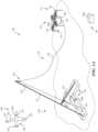
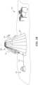
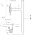
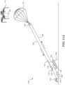
- FIG. 1Ais a partially schematic illustration of a system 100 that includes a first or mission aircraft 120, a lift device 110, and a line control device 130.
- the mission aircraft 120is typically an unmanned aerial vehicle that flies a reconnaissance, surveillance, and/or other mission under remote control, and/or autonomously.
- the lift device 110carries a capture line 116 aloft toward the end of the mission. The mission aircraft 120 then engages the capture line 116, and the line control device 130 guides the captured mission aircraft to a safe landing.
- the lift device 110can also include an aircraft, for example, a second aircraft 111 that carries a parachute 161. The parachute 161 can be used to control the motion of the capture line 116, as will be described in further detail below.
- the first or mission aircraft 120can include a fuselage 121, wings 122, and a propulsion system 124 that further includes one or more propellers 125 (e.g., a single propeller arranged in a pusher configuration).
- the mission aircraft 120can include one or more first capture devices 123, for example, hooks or cleats at the ends of the wings 122 that are used to engage with the capture line 116. Accordingly, capture line 116 represents an example of a second capture device 115.
- the capture line 116is attached to the parachute 161, which can be stowed in a canister or other receptacle 160 carried by the lift device 110.
- the lift device 110can further include an airframe 112, rotors 113, and landing gear 114.
- the landing gear 114are positioned and sized to allow the lift device 110 to land with the canister 160 attached.
- the capture line 116is also attached to the line control device 130.
- the line control device 130can include a boom 131 having a line support element 135 (e.g., a hook, pulley, or other suitable device) through or around which the capture line 116 passes.
- the capture line 116can be connected to a tension device 134 (e.g., a winch or other device that applies tension to, reels in, and/or otherwise applies forces to the capture line 116). Accordingly, the tension device 134 provides tension on the capture line 116 and/or can winch or reel in the capture line 116 to bring the captured mission aircraft 120 to a safe landing.
- the boom 131can extend upwardly at an angle and can be supported by boom supports 132.
- the line control device 130can be modular and can be broken down to fit into one or more shipping containers 133. Further details are described in copending U.S. Patent Publication No. 2018/0162528 .
- the overall system 100can include a control system 101, which in turn can include one or more controllers 102, four of which are shown in Figure 1A as first-fourth controllers 102a-102d.
- the control system 101can be used to control the operations of the line control device 130, the mission aircraft 120, and the lifting device 110, independently, or via a centralized controller 102a. Accordingly, any of the operational steps described herein can be conducted by, authorized by, initiated, and/or carried out via computer-executable instructions carried on any one or more of the components of the control system 101.
- the control system 101can receive any of a variety of suitable inputs, e.g., from sensors and/or human operators, and issue corresponding instructions. Representative inputs include, among others, velocity, altitude, pressure, tension, force, and/or winch rotation speeds.
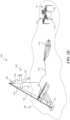
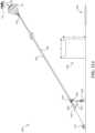
- Figure 1Billustrates the system 100 with the lift device 110 aloft, and with the capture line 116 positioned generally to intersect a flight path 126 of the mission aircraft 120.
- the mission aircraft 120can be captured in accordance with one or more of a variety of suitable techniques.
- the mission aircraft 120engages the first capture device 123 carried at one of the wingtips 122, with the second capture device 106 (e.g., the capture line 116) while the parachute 161 is carried in the canister 160.
- the tensile force placed on the parachute 161 by the mission aircraft 120 as it engages with the capture line 116pulls the parachute 161 out of the canister 160, so that the parachute 161 unfurls.
- the tension device 134reels in the capture line 116 after (and, optionally, before) the mission aircraft 120 engages the capture line 116 to provide/maintain tension on the capture line 116 as the parachute 161 descends.
- the descent of the captured mission aircraft 120is slowed by the deployed parachute 161, as will be described further with reference to Figure 1C .
- the parachute 161can be deployed by directing the lift device 110 upwardly while the capture line 116 is prevented from unspooling any further from the tension device 134. Accordingly, the upward trajectory of the lift device 110 pulls the canister 160 away from the parachute 161, e.g., before the mission aircraft 120 strikes the capture line 116.
- the tension device 134rapidly reels in the capture line 116 to pull the parachute 161 from the canister 160.
- the action of deploying the parachute 161 from the canister 160is expedited and/or made more reliable via an extraction device 162 carried in or proximate to the canister 160.
- the extraction device 162includes a spring-powered piston that propels the parachute 161 from the canister 160, in response to an actuator signal delivered by an operator, or (automatically) in response to an increase in tension on the capture line 116.
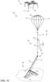
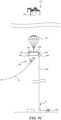
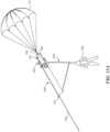
- Figure 1Cillustrates the system 100 after the parachute 161 has been deployed from the canister 160.
- the lift device 110stays in place or moves away from the parachute 161 (e.g., above the parachute 161) to avoid interfering with the process for capturing the mission aircraft 120.
- the parachute 161can include stays or struts 164 that aid in opening the parachute 161 and/or keeping the parachute 161 open, and that can be actuated via expansion devices 163 (e.g., springs or other suitable devices) to increase the speed with which the parachute 161 deploys.
- expansion devices 163e.g., springs or other suitable devices
- the tension device 134continues to reel in the capture line 116, against the drag force provided by the parachute 161. Accordingly, the mission aircraft 120 descends in a relatively slow, controlled manner.
- Figure 1Dillustrates the system 100 after the mission aircraft 120 has been brought to rest at the line control device 130.
- the parachute 161collapses and comes to rest on the ground (or other surface, e.g., a ship deck), or hangs suspended from the line support element 135.
- the lift device 110also returns to the ground (or other surface), landing with the canister 160 intact and ready to be reloaded with the parachute 161 for the next operation.
- the second aircraft 111 described above with reference to Figures 1A-1Drepresents one type of lift device that can be used to elevate and deploy the parachute 161 used to support the capture line 116.
- the systemcan include lift devices having other configurations.
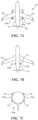
- Figure 2Aillustrates a lift device 210a that includes one or more rockets 270 attached to the canister 160 in which the parachute 161 is positioned.
- the rockets 270can include relatively small, solid propellant rockets that elevate the canister 160 to a suitable altitude at which the parachute 161 deploys.
- the parachute 161can deploy when the altitude of the lift device 201a exceeds the length of the deployed capture line 116, with or without assistance from the extraction device 162, and/or by reeling in the tension device 134, as discussed above.
- the elapsed time between launching the rocket or rockets 270 and deploying the parachute 161is relatively short. Accordingly, the rockets 270 will be launched shortly before the mission aircraft 120 ( Figure 1A ) is at the end of its mission. This is unlike the second aircraft 111 described above with reference to Figures 1A-1D , which can loiter for some period of time before deploying the parachute it carries.
- the lift devicecan have other configurations.
- Figure 2Billustrates a lift device 210b having the form of a kite 271 that carries the canister 160, parachute 161, and capture line 116 aloft.
- the kite 271can have a parasail-type configuration, or another suitable configuration, and the associated parachute 161 can be deployed in accordance with any of the methods described above.
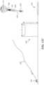
- Figure 2Cillustrates a lift device 210c that includes a balloon 272 filled with helium or another lighter-than-ambient-air gas (e.g., hot air).
- the balloon 272can be positioned aloft and can remain on station for a period of time before the parachute 161 is deployed from the canister 160, using any of the techniques described above.
- Figure 3Aillustrates a system 300 having several elements similar to corresponding elements described above, as well as a line control device 330 that includes a landing structure 336.
- the landing structure 336can include an inflatable or otherwise collapsible device 337, e.g., having a generally cone-shaped outer surface.
- the exterior of the landing structure 336can be formed from a heavy-duty plastic or other suitable material that is airtight, compliant, and resilient, so as to cushion the impact with the mission aircraft 120, without being punctured by the impact.
- the capture line 116can pass through first and second apertures 338a, 338b in the landing structure 336 to connect to the tension device 134.
- the parachute 161can be deployed from the canister 160 carried by the lift device 110, in accordance with any techniques described above.
- the tension device 134has drawn the capture line 116 downwardly until the mission aircraft 120 has engaged the landing structure 336.
- the flexible, resilient characteristics of the landing structure 336pad the impact of the mission aircraft 120, and the conical shape can act to spread the impact forces.
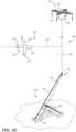
- figure 4ais a partially schematic illustration of a system 400 that may not include a parachute-assist for recovering the mission aircraft 120.
- the system 400can include a line control device 430 that in turn includes a carriage 450 to which the capture line 116 is attached.
- the carriage 450travels along a carriage track 445 after the mission aircraft 120 has engaged the capture line 116.
- the carriage track 445can include a flexible line 442 that is held in position by one or more supports 432, e.g., two supports, shown as a first support 432a and a second support 432b.
- Each support 432can include an upright portion 443, and one or more boom portions 431, illustrated as an upper boom portion 431a and a lower boom portion 431b.
- the upper boom portions 431acan be supported relative to the upright portion 443 with a guyline 441, and each upright portion 443 can be supported by a corresponding vehicle 439a, 439b.
- each upright portion 443can be supported relative to the corresponding vehicle 439a, 439b with one or more braces 440 providing for additional support.
- the vehicles 439a, 439bcan include pickup trucks or other suitable utility vehicles in which the components of the system 400 can be stowed when not in use.
- the carriage 450can be coupled to the capture line 116 via a restraint device 451 that can in turn include a restraint line 452, and one or more tension devices 434.
- a restraint device 451that can in turn include a restraint line 452, and one or more tension devices 434.
- the capture line 116can pass over a series of pulleys 444, which are connected to the tension devices 434. Accordingly, the tension devices 434 provide a braking force on the capture line 116, the carriage 450, and the mission aircraft 120 until the mission aircraft 120 comes to rest, hanging from the capture line 116.
- a brake or other devicecan secure the carriage 450 in position toward the end of the carriage track 445 until the tension in the tension device 434 is controllably released and the mission aircraft 120 is removed.
- the carriage track 445includes a flexible line 442.
- Figure 4Billustrates the flexible line 442 rolled up on a reel 446. Accordingly, the flexible line 442 can be easily stowed when not in use.
- the carriage track 445can have a rigid but collapsible configuration.
- the carriage track 445can be made from telescoping sections 447c, and as shown in Figure 4D , the carriage track 445 can be made from folding sections 447d.
- the systemcan be rapidly erected and taken down, and can be rapidly moved from one location to another via the vehicles 439a, 439b.
- figures 5A-5Dschematically illustrate a system 500 that includes a launcher 580 and a parachute that is used to land an element of the launcher 580 rather than landing the mission aircraft 120.
- the launcher 580can include a rocket 581 having a carriage 550 that releasably supports the mission aircraft 120.
- the launcher 580can further include a launch guide 582 that extends upwardly and engages with corresponding guide elements 583 carried by the rocket 581. During launch, the guide elements 583 slide along the launch guide 582 to properly orient the rocket 581 during launch.
- the rocket 581has been launched, and the mission aircraft 120 has been released from the carriage 550.
- the mission aircraft 120can be released from the carriage 550 at the apogee of the rocket trajectory, and can then perform a dive and recovery maneuver to gain sufficient airspeed to perform its mission.
- the rocket 581has deployed a parachute 561 so as to be reused for another mission.
- the mission aircraft 120has attained level flight and has begun its mission.
- Figure 5Dillustrates an example not according to the claims in which the launcher 580 includes two rockets 581, shown as a first rocket 581a and a second rocket 581b, each of which includes guide elements 583 engaged with corresponding launch guides 582a, 582b and corresponding portions of a centrally-positioned carriage 550d.
- the multi-rocket configurationcan provide increased stability and control when launching the mission aircraft 120.
- the system 500can include two rockets, and in other examples not according to the claims the system can include other numbers of rockets, for example, three rockets arranged in the manner generally described above with reference to Figure 2A .
- Figures 6-8illustrate further representative systems for launching the mission aircraft 120, in accordance with illustrative examples not according to the claims.
- Figure 6illustrates a launcher 680 that includes a carriage track 684 carried between first and second supports 685a, 685b.
- a corresponding carriage 650carries the mission aircraft 120 and is coupled to a carriage driver 686.
- the carriage driver 686propels the carriage 650 along the carriage track 684.
- the carriage 650rapidly decelerates at the end of the carriage track 684, and the mission aircraft 120 is released from the carriage 650 for flight.
- the carriage driver 686can propel the carriage 650 along the carriage track 684 using any of a variety of suitable techniques.
- the carriage driver 686can be filled with compressed gas or liquid, which is directed aft to accelerate the carriage 650 in a forward direction.
- the carriage driver 686can be made smaller by supplying it with additional propellant from a fixed, ground-based propellant source 687 coupled to the carriage driver 686 with a propellant supply line 688.
- the propellant source 687 and supply line 688can supply the carriage driver 686 with enough compressed gas and/or liquid to accelerate the carriage 650 to the target lift-off speed (of the mission aircraft 120) at the end of the carriage track 684.
- the carriage driver 686can include a chemical propellant, for example, a rocket engine that propels the carriage 650 along the carriage track 684.
- the carriage driver 686can be propelled using a mechanical device, for example, a spring or bungee, that can be connected to the first support 685a, and that can take the place of the propellant supply line 688 to accelerate the carriage 650 along the carriage track 684.
- the carriage 650supports the mission aircraft 120 during its acceleration, and is positioned and configured to release the mission aircraft at the end of its acceleration run.
- Figures 7A-7Dare partially schematic illustrations of representative carriages configured to carry out this operation.
- a representative carriage 750aincludes multiple upwardly extending engagement portions 753a that engage with the trailing edge of the mission aircraft wings 122.
- the engagement portions 753aare spaced apart by a distance at least as great as the diameter of the propeller 125 so that, upon release, the propeller 125 passes between the engagement portions 753a as the mission aircraft 120 is released for flight.
- figure 7B and 7Cillustrate a portion of another carriage 750b configured to engage with the fuselage 121 of the mission aircraft 120.
- the fuselage 121can include fuselage engagement portions 727 that extend outwardly from the main outer mold line of the fuselage 121.
- the carriage 750bcan include corresponding carriage engagement portions 753b that engage with the rearward facing surfaces of the fuselage engagement portions 727. Accordingly, the carriage 750b pushes on the fuselage 121 to accelerate it, and allows the mission aircraft 120 to release in a forward direction for flight.
- the carriage engagement portions 753bfold down (e.g., in a forward direction) as the mission aircraft is released, so as not to interfere with the propeller 125 as it passes by.
- figure 7Dillustrates another carriage 750d configured to engage with the propeller 125 of the mission aircraft 120.
- the propeller 125is attached to a hub 729 that is rotated relative to the fuselage 121 via a drive shaft 719.
- a rearward facing spinner 728projects rearwardly from the propeller 125 and can be releasably engaged with a carriage engagement portion 753d supported in position by the carriage 750d.
- An intermediate bearing 754allows the carriage engagement portion 753d to rotate with the propeller 125 relative to the carriage 750d during the carriage acceleration run.
- Additional supports 755engage the wings 122 of the mission aircraft 120 to support its weight.
- the supports 755are located far enough outboard along the wings 122 so as not to interfere with the propeller 125 as it passes by.
- figure 8illustrates another system 800 that includes a launcher 880 supported by two vehicles 839, shown as a first vehicle 839a, and a second vehicle 839b. Each vehicle can carry a corresponding support, shown as a first support 885a and a second support 885b.
- a carriage track 884is carried between the first and second supports 885a, 885b.
- the carriage track 884can include a pair of flexible lines, each generally similar to the line discussed above with reference to Figures 4A and 4B , or a rigid, but collapsible, structure, as described above with reference to Figures 4C and 4D .
- a corresponding carriage 850(shown schematically in Figure 8 ) is positioned to slide along the carriage track 884 and is connected to a driveline 892.
- the driveline 892can be connected to a tension device 834 (e.g., a winch) and can be guided via one or more guide pulleys 844.
- the carriage track 884can remain in tension as a result of the weights of the respective vehicles 839a, 839b, with the supports held in position via corresponding braces 889.
- the first and/or the second vehicle 839a, 839bcan be placed in "drive” so as to increase the tension on the carriage track 884.
- a block and tackle, or other suitable devicecan be used to provide a mechanical advantage for accelerating the carriage 850, and/or the tension device 834 can include a spring, bungee, and/or other suitable device, in addition to or in lieu of a winch.
- FIG. 9Aillustrates a system 900 that includes common elements suitable for both launching and capturing the mission aircraft 120, in accordance with embodiments of the present technology.
- the system 900can include a lift line/capture line 992 that can operate to lift the mission aircraft 120 and, optionally, capture the mission aircraft 120.
- the line 992is initially attached to the mission aircraft 120 via an attachment/release device 994, and passes over pulleys 944 carried by a pulley support 991.
- the two pulleys 944are spaced apart from each other so as to avoid contact between the portions of the line 992 passing over each pulley.
- the systemcan include a spreader 993 connected between the attachment/release device 994 and a slide guide 995 (e.g., an open-ended cylinder through which the line 992 passes).
- a slide guide 995e.g., an open-ended cylinder through which the line 992 passes.
- the spreader 993, the attachment/release device 994, and the slide guide 995form a unitary structure.
- the line 992is attached to a tension device 934 (e.g., a winch).
- the lift device 110lifts the pulley support 991 while the mission aircraft 120 remains in a generally fixed position on or near the ground.
- the tension device 934unspools the line 992, allowing the lift device 110 to gain altitude, while the slide guide 995 allows the unwinding line 992 to pass upwardly around the pulleys 944.
- the parachute 161is deployed from the canister 160, for example, using any of the techniques described above.
- the pulley support 991begins to descend, under the braking force supplied by the parachute 161, as indicated by arrow D.
- the tension device 934is activated, to rapidly draw in the line 992, as indicated by arrow B.
- the rate at which line 992 is drawn inis greater than the rate at which the pulley support 991 descends.
- the mission aircraft 120begins to ascend, as indicated by arrow C.
- the tension device 934can reel in the lift line/capture line 992 at a rate two or three times greater than the descent rate of the pulley support 991, causing the mission aircraft 120 to gain sufficient altitude for launch. Accordingly, the parachute 161 is deployed at an altitude significantly greater than the altitude at which the mission aircraft 120 is to be released. For example, if the mission aircraft 120 is to be released at an altitude of 200 feet, and the tension device 934 draws in the line 992 at three times the rate of descent of the pulley support 991, then the parachute 161 is deployed at an altitude of at least 600 feet. In other embodiments, other altitudes and winch-in rates can be used, depending on factors that include the target release altitude for the mission aircraft 120, the weight of the pulley support 991 and associated line 992, and the braking force applied by the parachute 161.
- the parachute 161 and pulley support 991have descended from the lift device 110, and the mission aircraft 120 has been elevated as a result of the differential between the rate at which the line 992 is taken up by the tension device 934, and the descent rate of the parachute 161.
- the mission aircraft 120can be released from the attachment/release device 994.
- the mission aircraft 120then dives, recovers, and flies its mission, as indicated by arrow E.
- the pulley support 991continues its descent under the braking force of the parachute 161, and the tension device 934 can simply reel in the resulting slack, or can actively pull on the pulley support 991 and the parachute 161 to increase the descent rate.
- the pulley support 991, the spreader 993, and the slide guide 995can be removed, and the attachment/release device 994 can be attached directly to the parachute 161, which is repackaged into the canister 160.
- the lift device 110lifts the line 992, which is now used as a capture line.
- the capture operationis then conducted in a manner generally similar to that described above with reference to Figures 1A-3B , using any of the ground-based line control devices or recovery devices described above. If the spreader 993, the slide guide 995 and the attach/release device 994 are manufactured as a unitary element, the entire element can be removed, and the line 992 can be attached to the parachute 161 via a separate attachment device.
- the same line 992can be used for both launch and capture.
- a different linecan be used for each operation, with the lines being swapped out while the mission aircraft 120 conducts its mission.
- the two linescan be the same (e.g., for enhanced commonality) or different (e.g., if the loads and/or other requirements for the line differ significantly between launch and capture).
- the hardware attached to the line 992is changed between the launch and recovery operations.
- the operatoruses different sets of hardware, one for launch and one for capture, but uses the same lift device 110 for both operations.
- the operatorcan also use the same tension device 934 in some embodiments, or a different tension device in other embodiments. Accordingly, the degree to which elements are used for both launch and capture can be selected depending on factors that may include the characteristics of the mission aircraft 120, the lift device 110, the line 992 and/or the tension device 934.
- Figures 10A-10Bare schematic illustrations of systems that include a ground- or ship-based launcher, with a parachute assist.
- the systemcan include a launcher 1080 that releasably supports the mission aircraft 120.
- the mission aircraft 120is coupled to a line 992 via a releasable attachment device 1094.
- the line 992is wrapped around a pulley 944 and connected to a tension device 934 toward one end, and to a parachute 161 toward the other end.
- the parachute 161is initially packed inside the canister 160 carried by the lifting device 110.
- the lifting device 110carries the parachute 161, the pulley 944 and the line 992 to a target altitude, at which the parachute 161 is then deployed.
- the lifting device 110can remain above the parachute 161 so as not to interfere with the launch operation.
- the tension device 934rapidly draws in the line 992 at a rate significantly faster than the rate at which the pulley 944 and parachute 161 descend.
- the mission aircraft 120accelerates off the launcher 1080 and into the air. As shown in Figure 10B , the mission aircraft 120 has achieved suitable velocity for flight, and can be released by disengaging the releasable attachment device 1094.
- the line 992can be sufficiently long that the mission aircraft 120 achieves a velocity suitable for flight well before it approaches the parachute 161, thus reducing or eliminating the likelihood for contact between the mission aircraft 120 and the parachute 120.
- the relative sizes of the system componentsmay be different than those shown in the Figures.
- the lifting device 110may be significantly smaller than the mission aircraft 120, and/or the parachute 161.
- the lifting device 110can include a quadcopter having a two-foot diameter, while the parachute 161 (when deployed) can have a twenty-foot diameter.
- Figure 10Cillustrates another representative arrangement in which the system includes a tension device 934 that is spaced further apart from the launcher 1080 than is shown in Figures 10A and 10B .
- the operation of the system shown in Figure 10Cis similar to that described above with reference to Figures 10A and 10B ; however, the load applied to the parachute 161 is expected to be reduced as a result of the increased spacing.
- the aircraftcan be released for its mission well before reaching the parachute 161 and the pulley 944, so as to avoid these elements (e.g., by flying under or around these elements).
- Figures 11A-11Billustrate another arrangement for lofting (e.g., launching) an aircraft, using a parachute, in which the aircraft passes beneath the parachute, rather than over the parachute, as shown in Figure 10B . It is expected that in at least some embodiments, launching the aircraft to pass beneath the parachute will reduce the likelihood for interference between the aircraft and the parachute.
- a representative system 1100can include a launcher 1080 from which the mission aircraft 120 is launched, and a carriage 1150 supported from and moveable along the line 992.
- the carriage 1150can releasably carry the mission aircraft 120 via one or more releasable attachment devices 1194.
- two releasable attachment devices 1194have gripper-type configurations.
- a release line 1195is attached to the carriage 1150, and is coupled to a release line actuator 1196.
- the lifting device 110carries the parachute 161 in the canister 160, with the parachute attached to the pulley 944, around which the line 992 is positioned.
- the tension device 934rapidly reels in the line 992, which pulls the carriage 1150 and the mission aircraft 120 off the launcher 1080.
- the line 992passes through apertures 1151 in the carriage 1150 so that the carriage 1150 can move upwardly along the line 992 as it carries the mission aircraft 120 aloft.
- the mission aircraft 120is released from the carriage 1150 via the releasable attachment devices 1194.
- the release line actuator 1196is activated, e.g., to brake the release line 1195, the releasable attachment devices 1194 release the mission aircraft 120.
- the released mission aircraft 120flies off, as indicated in Figure 11B .
- the release line actuator 1196can include one or more damping devices to reduce the impact on the overall system 1100 as the carriage 1150 is halted.
- the parachute 161can gently guide the carriage 1150 and pulley 944 to the ground, after which the system 1100 can be reloaded for the next aircraft launch.
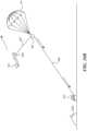
- Figure 12Aillustrates a representative system 1200 that includes a line 992 coupled to a tension device 934 and carried aloft via a lifting device 110, generally in the manner described above.
- the lifting device 110releases a parachute 161 and pulley 944 from a corresponding canister 160, also in a manner generally similar to that described above.
- the line 992is attached to a carriage 1250, extends around the pulley 944, passes through apertures 1251 in the carriage 1250, and is attached to the tension device 934.
- a person 1253is connected to the carriage 1250 via a harness 1252.
- the line 992is attached to the carriage 1250 via a releasable attachment device 1294.
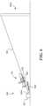
- the system 1200can be deployed to hoist the person 1253 up and over an obstruction 1202 for a parachute-controlled landing at a landing zone 1201 on the opposite side.
- the obstruction 1202can have a width W (e.g., 20 feet) and a height H (e.g., 50 feet).
- the length of the line 992, the altitude at which the parachute 161 is releasedcan be selected to account for obstructions 1202 having different widths W and/or heights H.
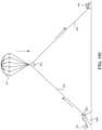
- the person 1253has been lofted via the carriage 1250 to a position above and beyond the obstruction 1202.
- the parachute 161is then used to gently guide the person 1253 to the landing zone 1201.
- the tension device 934can reel in the line 992 until the carriage 1250 engages with the pulley 944.
- the line 992can be released, and the person 1253 (hanging from the parachute 161 via the harness 1252, the carriage 1250, the pulley 944, and a parachute connector 1262) descends to the landing zone 1201, as shown in Figure 12C .
- the carriage 1250has engaged the pulley 944.
- the pulley 944is connected to the parachute 161 via the parachute connector 1262.
- the person 1253is connected to the carriage 1250 via the harness 1252. Accordingly, the person 1253, together with the carriage 1250 and the pulley 944, descend to the landing zone 1201, under the braking force provided by the parachute 161.
- the carriage 1250, pulley 994, and parachute 1261can be removed and discarded, or can be collected for reuse. Further details of a representative arrangement for connecting the carriage 1250 to the pulley 944, and releasing the line 992, are described below with reference to Figures 13A-13C .
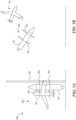
- Figure 13Ais a partially schematic illustration of the carriage 1250, illustrating the line 992 attached to the releasable attachment device 1294 of the carriage 1250.
- the line 992then passes around the pulley 944, and through the carriage 1250 (via apertures 1251) to the tension device 934 ( Figure 12C ).
- Figure 13Billustrates an enlarged view of a portion of the carriage 1250 shown in Figure 13A .
- One end of the line 992is attached to a pivotable line retainer 1391, which is in turn connected to a line release rod 1393.
- the line release rod 1393extends between two pulley capture jaws 1397, at least one of which is pivotable relative to the carriage 1250 via corresponding pivot pin 1398.
- both jaws 1397are shown as being pivotable in Figure 13B .
- the jaws 1397are shown in an open position in Figure 13B .
- One or more of the jaws 1397can include a lock receptacle 1389 which, when the jaw 1397 is pivoted to a closed position, engages with a lock 1399.
- Each jaw 1397can have a pulley contact region 1390, described further below.
- the jaws 1397close around the pulley 944, which triggers the line retainer 1391 to release the end of the line 992, as described in further detail below with reference to Figure 13C .
- the carriage 1250has moved up to engage with the pulley 944. More particularly, the pulley 944 presses against the pulley contact regions 1390, causing the jaws 1397 to rotate about the respective pivot pins 1398 to at least partially encircle the pulley 944. At least one of the jaws 1397 engages the lock 1399, thus locking the pulley 944 to the carriage 1250.
- the pulley 944contacts the line release rod 1393. This in turn pivots the line retainer 1391, causing an end 1388 of the line 992 to release from the carriage 1250.
- the line 992is then reeled in by the tension device 934 ( Figure 12C ).
- the now-released carriage 1250is firmly connected to the parachute 161 via the pulley 944 and the pulley connector 1262.
- the carriage 1250(and therefore the parachute 161) is firmly connected to the person 1253 ( Figure 12C ) via the harness 1252.
- the braking force provided by the parachute 161guides the connected carriage 1250 and person 1253 to a soft, controlled landing.
- An advantage of examples not according to the claims described above with reference to Figures 12A-13Cis that the overall system can be used not only to loft an aircraft, but, in addition to or in lieu of lofting an aircraft, can loft or deliver a non-flying payload, such as a person.
- This arrangementcan be used to loft personnel over obstructions, for example, to deliver military personnel and/or equipment into difficult-to-reach regions.
- the approachcan be more accurate and/or less detectable than using large fixed-wing aircraft or large rotorcraft to make such deliveries.
- the systemscan include a lifting device carrying a capture line that is attached to a parachute, so as to reduce the velocity with which the capture line descends during and after a capture maneuver.
- a lifting devicecan be made more compact and transportable than devices having a fixed capture line hanging therefrom.
- a relatively small UAVe.g., a quadcopter
- a kitee.g., a balloon
- the parachutecan be used in other contexts as well.
- the parachutecan be used to slow the descent of a launching apparatus, in addition to, or in lieu of slowing the descent of a captured mission aircraft.
- a parachutecan be used to launch the mission aircraft and, in some cases, the same parachute (or a different but similar or identical parachute) can be used to capture the mission aircraft after the mission has been performed.
- This approachcan reduce the amount of hardware required to both launch and capture the aircraft, e.g., by providing an increased level of commonality between the elements used for launch and the elements used for capture thus in turn can significantly reduce the overall cost of manufacturing and operating the UAV system.
- parachutescan be used to loft payloads other than unmanned aircraft, e.g., people and/or cargo.
- the lifting device(s)can have configurations other than those specifically described above.
- the carriage features described above for launching the mission aircraft (and/or other payloads)can have features other than those expressly described above.
- the releasable attachment devicescan engage the mission aircraft (and/or the pulley, and/or other system elements) in accordance with techniques not specifically described herein.
- the line control device shown in Figures 1A-1Dcan be used in the context of other systems described herein.
- the launch carriages described in the context of Figures 7A-7Dcan be used in combination with any of the launching devices described herein that include a carriage performing similar tasks.
- the controller shown in Figure 1Acan be used to control operation of any of the other elements shown and described herein.
Landscapes
- Engineering & Computer Science (AREA)
- Aviation & Aerospace Engineering (AREA)
- Mechanical Engineering (AREA)
- Physics & Mathematics (AREA)
- Fluid Mechanics (AREA)
- Business, Economics & Management (AREA)
- Emergency Management (AREA)
- Remote Sensing (AREA)
- Transportation (AREA)
- Toys (AREA)
- Control Of Position, Course, Altitude, Or Attitude Of Moving Bodies (AREA)
Description
- The present application claims priority to pending
U.S. Provisional Application No. 62/667,334, filed on May 4, 2018 - The present technology is directed generally to launch and/or recovery for unmanned aircraft and/or other payloads, including via parachute assist, and associated systems and methods.
- Unmanned aircraft or aerial vehicles (UAVs) provide enhanced and economical access to areas where manned flight operations are unacceptably costly and/or dangerous. For example, unmanned aircraft outfitted with remotely controlled cameras can perform a wide variety of surveillance missions, including spotting schools of fish for the fisheries industry, monitoring weather conditions, providing border patrols for national governments, and providing military surveillance before, during and/or after military operations.
- Existing unmanned aircraft systems suffer from a variety of drawbacks. For example, existing unmanned aircraft systems (which can include the aircraft itself along with launch devices, recovery devices, and storage devices) typically require a substantial amount of space. Accordingly, these systems can be difficult to install and operate in cramped quarters, such as the deck of a small fishing boat, land vehicle, or other craft. Another drawback with some existing unmanned aircraft is that, due to small size and low weight, they can be subjected to higher acceleration and deceleration forces than larger, manned air vehicles and can accordingly be prone to damage, particularly when manually handled during recovery and launch operations in hostile environments, such as a heaving ship deck. Yet another drawback with some existing unmanned aircraft systems is that they may not be suitable for recovering aircraft in tight quarters, without causing damage to either the aircraft or the platform from which the aircraft is launched and/or recovered. Accordingly, there remains a need for improved UAV launch and/or recovery systems.
US4753400A , in accordance with its abstract, states "A shipboard mounted apparatus for the retrieval of air vehicles, including remotely piloted, or automonous, unmanned vehicles, which includes a deployable lifting device such as a ram-air parachute which is secured through a tow line to the ship traveling upwind therebelow. A capturing device such as a ribbon parachute which may be annular is also movably secured to the tow line immediately below the ram-air parachute and may include a homing beacon therein such that capture of an air vehicle is achieved by it traveling into and collapsing this ribbon parachute. A winch is secured to the ship therebelow and is attached to the lower end of the tow line to control the inward and outward movement of the extended tow line. Once an air vehicle is captured in the ribbon parachute, the tow line is pulled in by the winch allowing the collapsed ribbon parachute and the captured air vehicle to be drawn into the ship to thereby be received by a landing net preferably of an open mesh nylon webbing. An initial launching device can be included such as an additional parachute or an explosive mortar device to provide the initial air-borne impetus to the ram-air parachute and ribbon capturing parachute." - There is described herein an unmanned aerial vehicle (UAV) system, comprising:
- an engagement element adapted to be carried by a UAV (120);
- a lifting device;
- a parachute (161) carried by the lifting device, wherein the lifting device includes a canister (160) in which the parachute (161) is carried;
- a capture line (116) attached to the parachute (161) and configured to engage with the engagement element carried by the UAV; and
- an extraction device (162) including a spring-powered piston configured to propel the parachute (161) from the canister (160) in response to an actuator signal delivered by an operator, or automatically in response to an increase in tension on the capture line (116).
- The UAV may be a first UAV and wherein the lifting device may include a second UAV.
- The lifting device may include at least one of a kite, a lighter-than-air device, or a rocket.
- The lifting device may include at least one of a kite, a lighter-than-air device, or a rocket.
- The system may further comprise a line control device connected to the capture line, the line control device including a tension device to apply tension to, and/or reel in, the capture line.
Figure 1A is a partially schematic illustration of a system that includes a mission aircraft, a lift device, and a line control device configured in accordance with embodiments of the present technology.Figure 1B is a partially schematic illustration of the system shown inFigure 1A with the lift device positioned for an aircraft capture operation in accordance with embodiments of the present technology.Figure 1C is a partially schematic illustration of the system shown inFigure 1A with the mission aircraft captured in accordance with embodiments of the present technology.Figure 1D is a partially schematic illustration of the system shown inFigure 1A with the lift device and mission aircraft landed, in accordance with embodiments of the present technology.Figure 2A is a partially schematic illustration of a lift device that includes one or more rockets in accordance with embodiments of the present technology.Figures 2B and 2C illustrate lift devices that include a kite (Figure 2B ) and a balloon (Figure 2C ), in accordance with embodiments of the present technology.Figure 3A is a partially schematic illustration of a system that includes a landing structure configured in accordance with embodiments of the present technology.Figure 3B is a partially schematic illustration of the system ofFigure 3A , with a mission aircraft landed on a landing structure in accordance with embodiments of the present technology.Figure 4A is a partially schematic, isometric illustration of a system that includes a line control device supported by multiple vehicles in accordance with an example not according to the claims.Figures 4B, 4C, and 4D illustrate representative carriage tracks for use with the system shown inFigure 4A , in accordance with an example not according to the claims.Figure 5A is partially schematic illustration of a launcher that includes a rocket, in accordance with an example not according to the claims.Figure 5B is a partially schematic illustration of the system shown inFigure 5A , with the aircraft released by the rocket in accordance with an example not according to the claims.Figure 5C is a partially schematic illustration of a process for retrieving the rocket shown inFigures 5A and 5B , in accordance with an example not according to the claims.Figure 5D is a partially schematic illustration of a system that includes multiple rockets for launching an aircraft, in accordance with an example not according to the claims.Figure 6 is a partially schematic illustration of a launcher having a carriage track and carriage propelled in accordance with an example not according to the claims.Figures 7A-7D illustrate representative techniques for carrying an aircraft with a carriage in accordance with an example not according to the claims.Figure 8 is a partially schematic illustration of a launcher having a carriage track supported by multiple vehicles in accordance with an example not according to the claims.Figures 9A-9C illustrate a representative system configured to both launch and recover an aircraft, using a parachute, in accordance with embodiments of the present technology.Figures 10A-10C illustrate another representative system for launching an aircraft using a parachute, in accordance with embodiments of the present technology.Figures 11A-11B illustrate still another representative system for launching an aircraft using a parachute, in accordance with embodiments of the present technology.Figures 12A-12C illustrate a system for lofting a person or other payload over an obstruction, in accordance with an example not according to the claims.Figures 13A-13C illustrate further details of a carriage configured to loft a person or other payload, in accordance with an example not according to the claims.- The present disclosure describes systems and methods for launching and/or recovering aircraft, in particular, unmanned aircraft. Many specific details of some embodiments and examples not according to the claims of the disclosure are set forth in the following description and
Figures 1 -10C to provide a thorough understanding of these embodiments and examples not according to the claims. Well-known structures, systems, and methods that are often associated with such embodiments and examples not according to the claims, but that may unnecessarily obscure some significant aspects of the disclosure, are not set forth in the following description for purposes of clarity. Moreover, although the following disclosure sets forth some embodiments and examples not according to the claims of the technology, some embodiments and examples not according to the claims of the technology can have different configurations and/or different components than those described in this section. As such, the technology may include embodiments and examples not according to the claims with additional elements, and/or without several of the elements described below with reference toFigures 1-13C . The scope of the invention is defined by the appended claims. - For purposes of illustration, the relative scales of the system components described herein may be exaggerated. For example, the relative sizes of multiple UAVs used in a single system (e.g., one UAV to loft and/or capture another to carry out a mission) may be different than what is shown in the Figures.
- Many embodiments of the technology described below may take the form of computer- or controller-executable instructions, including routines executed by a programmable computer or controller. Those skilled in the relevant art will appreciate that the technology can be practiced on computer/controller systems other than those shown and described below. The technology can be embodied in a special-purpose computer, controller or data processor that is specifically programmed, configured or constructed to perform one or more of the computer-executable instructions described below. Accordingly, the terms "computer" and "controller" as generally used herein refer to any data processor and can include Internet appliances and hand-held devices (including palm-top computers, wearable computers, cellular or mobile phones, multi-processor systems, processor-based or programmable consumer electronics, network computers, mini computers and the like). Information handled by these computers can be presented at any suitable display medium, including an LCD.
- The technology can also be practiced in distributed environments, where tasks or modules are performed by remote processing devices that are linked through a communications network. In a distributed computing environment, program modules or subroutines may be located in local and remote memory storage devices. Aspects of the technology described below may be stored or distributed on computer-readable media, including magnetic or optically readable or removable computer disks, as well as distributed electronically over networks. Data structures and transmissions of data particular to aspects of the technology are also encompassed within the scope of embodiments of the technology.
Figure 1A is a partially schematic illustration of asystem 100 that includes a first ormission aircraft 120, alift device 110, and aline control device 130. Themission aircraft 120 is typically an unmanned aerial vehicle that flies a reconnaissance, surveillance, and/or other mission under remote control, and/or autonomously. Thelift device 110 carries acapture line 116 aloft toward the end of the mission. Themission aircraft 120 then engages thecapture line 116, and theline control device 130 guides the captured mission aircraft to a safe landing. Thelift device 110 can also include an aircraft, for example, asecond aircraft 111 that carries aparachute 161. Theparachute 161 can be used to control the motion of thecapture line 116, as will be described in further detail below.- The first or
mission aircraft 120 can include afuselage 121,wings 122, and apropulsion system 124 that further includes one or more propellers 125 (e.g., a single propeller arranged in a pusher configuration). Themission aircraft 120 can include one or morefirst capture devices 123, for example, hooks or cleats at the ends of thewings 122 that are used to engage with thecapture line 116. Accordingly,capture line 116 represents an example of asecond capture device 115. - The
capture line 116 is attached to theparachute 161, which can be stowed in a canister orother receptacle 160 carried by thelift device 110. In systems for which thelift device 110 includes asecond aircraft 111, thelift device 110 can further include anairframe 112,rotors 113, andlanding gear 114. Thelanding gear 114 are positioned and sized to allow thelift device 110 to land with thecanister 160 attached. - The
capture line 116 is also attached to theline control device 130. Theline control device 130 can include aboom 131 having a line support element 135 (e.g., a hook, pulley, or other suitable device) through or around which thecapture line 116 passes. Thecapture line 116 can be connected to a tension device 134 (e.g., a winch or other device that applies tension to, reels in, and/or otherwise applies forces to the capture line 116). Accordingly, thetension device 134 provides tension on thecapture line 116 and/or can winch or reel in thecapture line 116 to bring the capturedmission aircraft 120 to a safe landing. Theboom 131 can extend upwardly at an angle and can be supported by boom supports 132. Theline control device 130 can be modular and can be broken down to fit into one ormore shipping containers 133. Further details are described in copendingU.S. Patent Publication No. 2018/0162528 . - The
overall system 100 can include acontrol system 101, which in turn can include one or more controllers 102, four of which are shown inFigure 1A as first-fourth controllers 102a-102d. Thecontrol system 101 can be used to control the operations of theline control device 130, themission aircraft 120, and thelifting device 110, independently, or via acentralized controller 102a. Accordingly, any of the operational steps described herein can be conducted by, authorized by, initiated, and/or carried out via computer-executable instructions carried on any one or more of the components of thecontrol system 101. Thecontrol system 101 can receive any of a variety of suitable inputs, e.g., from sensors and/or human operators, and issue corresponding instructions. Representative inputs include, among others, velocity, altitude, pressure, tension, force, and/or winch rotation speeds. Figure 1B illustrates thesystem 100 with thelift device 110 aloft, and with thecapture line 116 positioned generally to intersect aflight path 126 of themission aircraft 120. Themission aircraft 120 can be captured in accordance with one or more of a variety of suitable techniques. In a representative technique, themission aircraft 120 engages thefirst capture device 123 carried at one of thewingtips 122, with the second capture device 106 (e.g., the capture line 116) while theparachute 161 is carried in thecanister 160. The tensile force placed on theparachute 161 by themission aircraft 120 as it engages with thecapture line 116 pulls theparachute 161 out of thecanister 160, so that theparachute 161 unfurls. Thetension device 134 reels in thecapture line 116 after (and, optionally, before) themission aircraft 120 engages thecapture line 116 to provide/maintain tension on thecapture line 116 as theparachute 161 descends. The descent of the capturedmission aircraft 120 is slowed by the deployedparachute 161, as will be described further with reference toFigure 1C .- With continued reference to
Figure 1B , in other modes of operation, theparachute 161 can be deployed by directing thelift device 110 upwardly while thecapture line 116 is prevented from unspooling any further from thetension device 134. Accordingly, the upward trajectory of thelift device 110 pulls thecanister 160 away from theparachute 161, e.g., before themission aircraft 120 strikes thecapture line 116. In another mode of operation, thetension device 134 rapidly reels in thecapture line 116 to pull theparachute 161 from thecanister 160. In any of these embodiments, the action of deploying theparachute 161 from thecanister 160 is expedited and/or made more reliable via anextraction device 162 carried in or proximate to thecanister 160. Theextraction device 162 includes a spring-powered piston that propels theparachute 161 from thecanister 160, in response to an actuator signal delivered by an operator, or (automatically) in response to an increase in tension on thecapture line 116. - For any of the foregoing sequences,
Figure 1C illustrates thesystem 100 after theparachute 161 has been deployed from thecanister 160. Thelift device 110 stays in place or moves away from the parachute 161 (e.g., above the parachute 161) to avoid interfering with the process for capturing themission aircraft 120. Theparachute 161 can include stays or struts 164 that aid in opening theparachute 161 and/or keeping theparachute 161 open, and that can be actuated via expansion devices 163 (e.g., springs or other suitable devices) to increase the speed with which theparachute 161 deploys. Once theparachute 161 is fully opened, and themission aircraft 120 has been captured by engaging thefirst capture device 123 with thecapture line 116, thetension device 134 continues to reel in thecapture line 116, against the drag force provided by theparachute 161. Accordingly, themission aircraft 120 descends in a relatively slow, controlled manner. Figure 1D illustrates thesystem 100 after themission aircraft 120 has been brought to rest at theline control device 130. Theparachute 161 collapses and comes to rest on the ground (or other surface, e.g., a ship deck), or hangs suspended from theline support element 135. Thelift device 110 also returns to the ground (or other surface), landing with thecanister 160 intact and ready to be reloaded with theparachute 161 for the next operation.- The
second aircraft 111 described above with reference toFigures 1A-1D represents one type of lift device that can be used to elevate and deploy theparachute 161 used to support thecapture line 116. In other embodiments, the system can include lift devices having other configurations. For example,Figure 2A illustrates alift device 210a that includes one ormore rockets 270 attached to thecanister 160 in which theparachute 161 is positioned. Therockets 270 can include relatively small, solid propellant rockets that elevate thecanister 160 to a suitable altitude at which theparachute 161 deploys. Theparachute 161 can deploy when the altitude of the lift device 201a exceeds the length of the deployedcapture line 116, with or without assistance from theextraction device 162, and/or by reeling in thetension device 134, as discussed above. The elapsed time between launching the rocket orrockets 270 and deploying theparachute 161 is relatively short. Accordingly, therockets 270 will be launched shortly before the mission aircraft 120 (Figure 1A ) is at the end of its mission. This is unlike thesecond aircraft 111 described above with reference toFigures 1A-1D , which can loiter for some period of time before deploying the parachute it carries. - In still further embodiments, the lift device can have other configurations. For example,
Figure 2B illustrates alift device 210b having the form of akite 271 that carries thecanister 160,parachute 161, and captureline 116 aloft. Thekite 271 can have a parasail-type configuration, or another suitable configuration, and the associatedparachute 161 can be deployed in accordance with any of the methods described above. Figure 2C illustrates alift device 210c that includes aballoon 272 filled with helium or another lighter-than-ambient-air gas (e.g., hot air). Theballoon 272 can be positioned aloft and can remain on station for a period of time before theparachute 161 is deployed from thecanister 160, using any of the techniques described above.Figure 3A illustrates asystem 300 having several elements similar to corresponding elements described above, as well as aline control device 330 that includes alanding structure 336. Thelanding structure 336 can include an inflatable or otherwisecollapsible device 337, e.g., having a generally cone-shaped outer surface. The exterior of thelanding structure 336 can be formed from a heavy-duty plastic or other suitable material that is airtight, compliant, and resilient, so as to cushion the impact with themission aircraft 120, without being punctured by the impact. Thecapture line 116 can pass through first andsecond apertures landing structure 336 to connect to thetension device 134. Theparachute 161 can be deployed from thecanister 160 carried by thelift device 110, in accordance with any techniques described above.- Referring next to
Figure 3B , thetension device 134 has drawn thecapture line 116 downwardly until themission aircraft 120 has engaged thelanding structure 336. The flexible, resilient characteristics of thelanding structure 336 pad the impact of themission aircraft 120, and the conical shape can act to spread the impact forces. Once themission aircraft 120 has come to rest, it can be disengaged from thecapture line 116, and theparachute 161 can be restowed in thecanister 160 for another mission. - According to an illustrative example not as set out in the claims,
figure 4a is a partially schematic illustration of asystem 400 that may not include a parachute-assist for recovering themission aircraft 120. Instead, thesystem 400 can include aline control device 430 that in turn includes acarriage 450 to which thecapture line 116 is attached. Thecarriage 450 travels along acarriage track 445 after themission aircraft 120 has engaged thecapture line 116. Thecarriage track 445 can include aflexible line 442 that is held in position by one or more supports 432, e.g., two supports, shown as afirst support 432a and asecond support 432b. Each support 432 can include anupright portion 443, and one or more boom portions 431, illustrated as anupper boom portion 431a and alower boom portion 431b. Theupper boom portions 431a can be supported relative to theupright portion 443 with aguyline 441, and eachupright portion 443 can be supported by a correspondingvehicle upright portion 443 can be supported relative to thecorresponding vehicle more braces 440 providing for additional support. Thevehicles system 400 can be stowed when not in use. - The
carriage 450 can be coupled to thecapture line 116 via arestraint device 451 that can in turn include arestraint line 452, and one ormore tension devices 434. Once themission aircraft 120 has engaged with thecapture line 116, the impact drags thecarriage 450 along thecarriage track 445. Thecapture line 116 can pass over a series ofpulleys 444, which are connected to thetension devices 434. Accordingly, thetension devices 434 provide a braking force on thecapture line 116, thecarriage 450, and themission aircraft 120 until themission aircraft 120 comes to rest, hanging from thecapture line 116. A brake or other device can secure thecarriage 450 in position toward the end of thecarriage track 445 until the tension in thetension device 434 is controllably released and themission aircraft 120 is removed. - In the illustrative example not according to the claims shown in
Figure 4A , thecarriage track 445 includes aflexible line 442.Figure 4B illustrates theflexible line 442 rolled up on areel 446. Accordingly, theflexible line 442 can be easily stowed when not in use. In other examples not according to the claims, thecarriage track 445 can have a rigid but collapsible configuration. For example, as shown inFigure 4C , thecarriage track 445 can be made from telescopingsections 447c, and as shown inFigure 4D , thecarriage track 445 can be made fromfolding sections 447d. In any of these examples not according to the claims, the system can be rapidly erected and taken down, and can be rapidly moved from one location to another via thevehicles - According to an illustrative example not as set out in the claims,
figures 5A-5D schematically illustrate asystem 500 that includes alauncher 580 and a parachute that is used to land an element of thelauncher 580 rather than landing themission aircraft 120. Referring first toFigure 5A , thelauncher 580 can include arocket 581 having acarriage 550 that releasably supports themission aircraft 120. Thelauncher 580 can further include alaunch guide 582 that extends upwardly and engages withcorresponding guide elements 583 carried by therocket 581. During launch, theguide elements 583 slide along thelaunch guide 582 to properly orient therocket 581 during launch. - Referring next to
Figure 5B , therocket 581 has been launched, and themission aircraft 120 has been released from thecarriage 550. Themission aircraft 120 can be released from thecarriage 550 at the apogee of the rocket trajectory, and can then perform a dive and recovery maneuver to gain sufficient airspeed to perform its mission. - In
Figure 5C , therocket 581 has deployed aparachute 561 so as to be reused for another mission. Themission aircraft 120 has attained level flight and has begun its mission. Figure 5D illustrates an example not according to the claims in which thelauncher 580 includes tworockets 581, shown as afirst rocket 581a and asecond rocket 581b, each of which includesguide elements 583 engaged with corresponding launch guides 582a, 582b and corresponding portions of a centrally-positionedcarriage 550d. The multi-rocket configuration can provide increased stability and control when launching themission aircraft 120. In an example not according to the claims shown inFigure 5D , thesystem 500 can include two rockets, and in other examples not according to the claims the system can include other numbers of rockets, for example, three rockets arranged in the manner generally described above with reference toFigure 2A .Figures 6-8 illustrate further representative systems for launching themission aircraft 120, in accordance with illustrative examples not according to the claims.Figure 6 illustrates alauncher 680 that includes acarriage track 684 carried between first andsecond supports corresponding carriage 650 carries themission aircraft 120 and is coupled to acarriage driver 686. Thecarriage driver 686 propels thecarriage 650 along thecarriage track 684. Thecarriage 650 rapidly decelerates at the end of thecarriage track 684, and themission aircraft 120 is released from thecarriage 650 for flight.- The
carriage driver 686 can propel thecarriage 650 along thecarriage track 684 using any of a variety of suitable techniques. For example, thecarriage driver 686 can be filled with compressed gas or liquid, which is directed aft to accelerate thecarriage 650 in a forward direction. In some examples not according to the claims, thecarriage driver 686 can be made smaller by supplying it with additional propellant from a fixed, ground-basedpropellant source 687 coupled to thecarriage driver 686 with apropellant supply line 688. For example, thepropellant source 687 andsupply line 688 can supply thecarriage driver 686 with enough compressed gas and/or liquid to accelerate thecarriage 650 to the target lift-off speed (of the mission aircraft 120) at the end of thecarriage track 684. - In other examples not according to the claims, the
carriage driver 686 can include a chemical propellant, for example, a rocket engine that propels thecarriage 650 along thecarriage track 684. In still further embodiments, thecarriage driver 686 can be propelled using a mechanical device, for example, a spring or bungee, that can be connected to thefirst support 685a, and that can take the place of thepropellant supply line 688 to accelerate thecarriage 650 along thecarriage track 684. - In any of the foregoing examples not according to the claims, the
carriage 650 supports themission aircraft 120 during its acceleration, and is positioned and configured to release the mission aircraft at the end of its acceleration run.Figures 7A-7D are partially schematic illustrations of representative carriages configured to carry out this operation. - Beginning with
Figure 7A , arepresentative carriage 750a includes multiple upwardly extendingengagement portions 753a that engage with the trailing edge of themission aircraft wings 122. Theengagement portions 753a are spaced apart by a distance at least as great as the diameter of thepropeller 125 so that, upon release, thepropeller 125 passes between theengagement portions 753a as themission aircraft 120 is released for flight. - According to an illustrative example not according to the claims,
figure 7B and 7C illustrate a portion of anothercarriage 750b configured to engage with thefuselage 121 of themission aircraft 120. Thefuselage 121 can includefuselage engagement portions 727 that extend outwardly from the main outer mold line of thefuselage 121. Thecarriage 750b can include correspondingcarriage engagement portions 753b that engage with the rearward facing surfaces of thefuselage engagement portions 727. Accordingly, thecarriage 750b pushes on thefuselage 121 to accelerate it, and allows themission aircraft 120 to release in a forward direction for flight. In a particular aspect of this example, thecarriage engagement portions 753b fold down (e.g., in a forward direction) as the mission aircraft is released, so as not to interfere with thepropeller 125 as it passes by. - According to an illustrative example not according to the claims,
figure 7D illustrates anothercarriage 750d configured to engage with thepropeller 125 of themission aircraft 120. In one aspect of this example, thepropeller 125 is attached to ahub 729 that is rotated relative to thefuselage 121 via adrive shaft 719. A rearward facingspinner 728 projects rearwardly from thepropeller 125 and can be releasably engaged with acarriage engagement portion 753d supported in position by thecarriage 750d. Anintermediate bearing 754 allows thecarriage engagement portion 753d to rotate with thepropeller 125 relative to thecarriage 750d during the carriage acceleration run.Additional supports 755 engage thewings 122 of themission aircraft 120 to support its weight. Thesupports 755 are located far enough outboard along thewings 122 so as not to interfere with thepropeller 125 as it passes by. When thecarriage 750d is brought to a halt, themission aircraft 120 continues to travel forwardly, with thespinner 728 disengaging from thecarriage engagement portion 753d, and with thewings 122 lifting off thesupports 755. - According to an illustrative example not according to the claims,
figure 8 illustrates anothersystem 800 that includes alauncher 880 supported by two vehicles 839, shown as afirst vehicle 839a, and asecond vehicle 839b. Each vehicle can carry a corresponding support, shown as afirst support 885a and asecond support 885b. Acarriage track 884 is carried between the first andsecond supports carriage track 884 can include a pair of flexible lines, each generally similar to the line discussed above with reference toFigures 4A and4B , or a rigid, but collapsible, structure, as described above with reference toFigures 4C and 4D . In any of these examples not according to the claims, a corresponding carriage 850 (shown schematically inFigure 8 ) is positioned to slide along thecarriage track 884 and is connected to adriveline 892. Thedriveline 892 can be connected to a tension device 834 (e.g., a winch) and can be guided via one or more guide pulleys 844. Thecarriage track 884 can remain in tension as a result of the weights of therespective vehicles second vehicle carriage track 884. In further examples not according to the claims, a block and tackle, or other suitable device, can be used to provide a mechanical advantage for accelerating thecarriage 850, and/or thetension device 834 can include a spring, bungee, and/or other suitable device, in addition to or in lieu of a winch. Figure 9A illustrates asystem 900 that includes common elements suitable for both launching and capturing themission aircraft 120, in accordance with embodiments of the present technology. Thesystem 900 can include a lift line/capture line 992 that can operate to lift themission aircraft 120 and, optionally, capture themission aircraft 120. Theline 992 is initially attached to themission aircraft 120 via an attachment/release device 994, and passes overpulleys 944 carried by apulley support 991. The twopulleys 944 are spaced apart from each other so as to avoid contact between the portions of theline 992 passing over each pulley. To further avoid such contact, the system can include aspreader 993 connected between the attachment/release device 994 and a slide guide 995 (e.g., an open-ended cylinder through which theline 992 passes). In at least some arrangements, thespreader 993, the attachment/release device 994, and theslide guide 995 form a unitary structure. Theline 992 is attached to a tension device 934 (e.g., a winch).- To initiate the launch operation, the
lift device 110 lifts thepulley support 991 while themission aircraft 120 remains in a generally fixed position on or near the ground. As thelift device 110 ascends, thetension device 934 unspools theline 992, allowing thelift device 110 to gain altitude, while theslide guide 995 allows the unwindingline 992 to pass upwardly around thepulleys 944. - As shown in
Figure 9B , when thelift device 110 achieves a suitable altitude, theparachute 161 is deployed from thecanister 160, for example, using any of the techniques described above. Thepulley support 991 begins to descend, under the braking force supplied by theparachute 161, as indicated by arrow D. Thetension device 934 is activated, to rapidly draw in theline 992, as indicated by arrow B. In particular, the rate at whichline 992 is drawn in is greater than the rate at which thepulley support 991 descends. As a result, themission aircraft 120 begins to ascend, as indicated by arrow C. - In a representative embodiment, the
tension device 934 can reel in the lift line/capture line 992 at a rate two or three times greater than the descent rate of thepulley support 991, causing themission aircraft 120 to gain sufficient altitude for launch. Accordingly, theparachute 161 is deployed at an altitude significantly greater than the altitude at which themission aircraft 120 is to be released. For example, if themission aircraft 120 is to be released at an altitude of 200 feet, and thetension device 934 draws in theline 992 at three times the rate of descent of thepulley support 991, then theparachute 161 is deployed at an altitude of at least 600 feet. In other embodiments, other altitudes and winch-in rates can be used, depending on factors that include the target release altitude for themission aircraft 120, the weight of thepulley support 991 and associatedline 992, and the braking force applied by theparachute 161. - Referring next to
Figure 9C , theparachute 161 andpulley support 991 have descended from thelift device 110, and themission aircraft 120 has been elevated as a result of the differential between the rate at which theline 992 is taken up by thetension device 934, and the descent rate of theparachute 161. At this point, themission aircraft 120 can be released from the attachment/release device 994. Themission aircraft 120 then dives, recovers, and flies its mission, as indicated by arrow E.The pulley support 991 continues its descent under the braking force of theparachute 161, and thetension device 934 can simply reel in the resulting slack, or can actively pull on thepulley support 991 and theparachute 161 to increase the descent rate. - To perform the recovery operation, in accordance with some embodiments, the
pulley support 991, thespreader 993, and theslide guide 995 can be removed, and the attachment/release device 994 can be attached directly to theparachute 161, which is repackaged into thecanister 160. When themission aircraft 120 nears the end of its mission, thelift device 110 lifts theline 992, which is now used as a capture line. The capture operation is then conducted in a manner generally similar to that described above with reference toFigures 1A-3B , using any of the ground-based line control devices or recovery devices described above. If thespreader 993, theslide guide 995 and the attach/release device 994 are manufactured as a unitary element, the entire element can be removed, and theline 992 can be attached to theparachute 161 via a separate attachment device. - As described above, the
same line 992 can be used for both launch and capture. In other embodiments, a different line can be used for each operation, with the lines being swapped out while themission aircraft 120 conducts its mission. The two lines can be the same (e.g., for enhanced commonality) or different (e.g., if the loads and/or other requirements for the line differ significantly between launch and capture). In one aspect of the operation described above, the hardware attached to theline 992 is changed between the launch and recovery operations. In other embodiments, the operator uses different sets of hardware, one for launch and one for capture, but uses thesame lift device 110 for both operations. The operator can also use thesame tension device 934 in some embodiments, or a different tension device in other embodiments. Accordingly, the degree to which elements are used for both launch and capture can be selected depending on factors that may include the characteristics of themission aircraft 120, thelift device 110, theline 992 and/or thetension device 934. Figures 10A-10B are schematic illustrations of systems that include a ground- or ship-based launcher, with a parachute assist. Beginning withFigure 10A , the system can include alauncher 1080 that releasably supports themission aircraft 120. Themission aircraft 120 is coupled to aline 992 via areleasable attachment device 1094. Theline 992 is wrapped around apulley 944 and connected to atension device 934 toward one end, and to aparachute 161 toward the other end. Theparachute 161 is initially packed inside thecanister 160 carried by thelifting device 110.- In operation, the
lifting device 110 carries theparachute 161, thepulley 944 and theline 992 to a target altitude, at which theparachute 161 is then deployed. Thelifting device 110 can remain above theparachute 161 so as not to interfere with the launch operation. Thetension device 934 rapidly draws in theline 992 at a rate significantly faster than the rate at which thepulley 944 andparachute 161 descend. Accordingly, themission aircraft 120 accelerates off thelauncher 1080 and into the air. As shown inFigure 10B , themission aircraft 120 has achieved suitable velocity for flight, and can be released by disengaging thereleasable attachment device 1094. Although themission aircraft 120 is shown inFigure 10B relatively close to theparachute 161 prior to its release (for purposes of illustration), theline 992 can be sufficiently long that themission aircraft 120 achieves a velocity suitable for flight well before it approaches theparachute 161, thus reducing or eliminating the likelihood for contact between themission aircraft 120 and theparachute 120. Also, as noted above, the relative sizes of the system components may be different than those shown in the Figures. For example, thelifting device 110 may be significantly smaller than themission aircraft 120, and/or theparachute 161. For example, thelifting device 110 can include a quadcopter having a two-foot diameter, while the parachute 161 (when deployed) can have a twenty-foot diameter. Figure 10C illustrates another representative arrangement in which the system includes atension device 934 that is spaced further apart from thelauncher 1080 than is shown inFigures 10A and10B . Overall, the operation of the system shown inFigure 10C is similar to that described above with reference toFigures 10A and10B ; however, the load applied to theparachute 161 is expected to be reduced as a result of the increased spacing. As described above with reference toFigures 10A and10B , in any of the embodiments shown inFigures 10A-10C , the aircraft can be released for its mission well before reaching theparachute 161 and thepulley 944, so as to avoid these elements (e.g., by flying under or around these elements).Figures 11A-11B illustrate another arrangement for lofting (e.g., launching) an aircraft, using a parachute, in which the aircraft passes beneath the parachute, rather than over the parachute, as shown inFigure 10B . It is expected that in at least some embodiments, launching the aircraft to pass beneath the parachute will reduce the likelihood for interference between the aircraft and the parachute.- Beginning with
Figure 11A , arepresentative system 1100 can include alauncher 1080 from which themission aircraft 120 is launched, and acarriage 1150 supported from and moveable along theline 992. Thecarriage 1150 can releasably carry themission aircraft 120 via one or morereleasable attachment devices 1194. In a representative system, tworeleasable attachment devices 1194 have gripper-type configurations. Arelease line 1195 is attached to thecarriage 1150, and is coupled to arelease line actuator 1196. - In operation, the
lifting device 110 carries theparachute 161 in thecanister 160, with the parachute attached to thepulley 944, around which theline 992 is positioned. Once theparachute 161 is released, thetension device 934 rapidly reels in theline 992, which pulls thecarriage 1150 and themission aircraft 120 off thelauncher 1080. Theline 992 passes throughapertures 1151 in thecarriage 1150 so that thecarriage 1150 can move upwardly along theline 992 as it carries themission aircraft 120 aloft. - Once the
carriage 1150 achieves a suitable altitude, themission aircraft 120 is released from thecarriage 1150 via thereleasable attachment devices 1194. For example, when therelease line actuator 1196 is activated, e.g., to brake therelease line 1195, thereleasable attachment devices 1194 release themission aircraft 120. The releasedmission aircraft 120 flies off, as indicated inFigure 11B . Therelease line actuator 1196 can include one or more damping devices to reduce the impact on theoverall system 1100 as thecarriage 1150 is halted. Once themission aircraft 120 is released, theparachute 161 can gently guide thecarriage 1150 andpulley 944 to the ground, after which thesystem 1100 can be reloaded for the next aircraft launch. - In other examples not according to the claims, generally similar systems can be used to loft personnel and/or other payloads upwardly, e.g., up and over an obstacle, in addition to, or in lieu of, lofting an aircraft in the manner described above with reference to
Figures 10A-11B . For example,Figure 12A illustrates arepresentative system 1200 that includes aline 992 coupled to atension device 934 and carried aloft via alifting device 110, generally in the manner described above. Thelifting device 110 releases aparachute 161 andpulley 944 from acorresponding canister 160, also in a manner generally similar to that described above. Theline 992 is attached to acarriage 1250, extends around thepulley 944, passes throughapertures 1251 in thecarriage 1250, and is attached to thetension device 934. Aperson 1253 is connected to thecarriage 1250 via aharness 1252. Theline 992 is attached to thecarriage 1250 via areleasable attachment device 1294. In operation, thesystem 1200 can be deployed to hoist theperson 1253 up and over anobstruction 1202 for a parachute-controlled landing at alanding zone 1201 on the opposite side. Theobstruction 1202 can have a width W (e.g., 20 feet) and a height H (e.g., 50 feet). The length of theline 992, the altitude at which theparachute 161 is released (e.g., 500 feet above ground level, in some embodiments), and/or other factors, can be selected to account forobstructions 1202 having different widths W and/or heights H. - In
Figure 12B , theperson 1253 has been lofted via thecarriage 1250 to a position above and beyond theobstruction 1202. Theparachute 161 is then used to gently guide theperson 1253 to thelanding zone 1201. For example, thetension device 934 can reel in theline 992 until thecarriage 1250 engages with thepulley 944. At this point, theline 992 can be released, and the person 1253 (hanging from theparachute 161 via theharness 1252, thecarriage 1250, thepulley 944, and a parachute connector 1262) descends to thelanding zone 1201, as shown inFigure 12C . - Referring now to
Figure 12C , thecarriage 1250 has engaged thepulley 944. Thepulley 944 is connected to theparachute 161 via theparachute connector 1262. Theperson 1253 is connected to thecarriage 1250 via theharness 1252. Accordingly, theperson 1253, together with thecarriage 1250 and thepulley 944, descend to thelanding zone 1201, under the braking force provided by theparachute 161. At thelanding zone 1201, thecarriage 1250,pulley 994, and parachute 1261 can be removed and discarded, or can be collected for reuse. Further details of a representative arrangement for connecting thecarriage 1250 to thepulley 944, and releasing theline 992, are described below with reference toFigures 13A-13C . Figure 13A is a partially schematic illustration of thecarriage 1250, illustrating theline 992 attached to thereleasable attachment device 1294 of thecarriage 1250. Theline 992 then passes around thepulley 944, and through the carriage 1250 (via apertures 1251) to the tension device 934 (Figure 12C ).Figure 13B illustrates an enlarged view of a portion of thecarriage 1250 shown inFigure 13A . One end of theline 992 is attached to apivotable line retainer 1391, which is in turn connected to aline release rod 1393. Theline release rod 1393 extends between twopulley capture jaws 1397, at least one of which is pivotable relative to thecarriage 1250 via correspondingpivot pin 1398. For purposes of illustration, bothjaws 1397 are shown as being pivotable inFigure 13B . Thejaws 1397 are shown in an open position inFigure 13B . One or more of thejaws 1397 can include alock receptacle 1389 which, when thejaw 1397 is pivoted to a closed position, engages with alock 1399. Eachjaw 1397 can have apulley contact region 1390, described further below. When thecarriage 1250 is pulled up to thepulley 944, thejaws 1397 close around thepulley 944, which triggers theline retainer 1391 to release the end of theline 992, as described in further detail below with reference toFigure 13C .- Referring now to
Figure 13C , thecarriage 1250 has moved up to engage with thepulley 944. More particularly, thepulley 944 presses against thepulley contact regions 1390, causing thejaws 1397 to rotate about therespective pivot pins 1398 to at least partially encircle thepulley 944. At least one of thejaws 1397 engages thelock 1399, thus locking thepulley 944 to thecarriage 1250. - As the
carriage 1250 moves toward, and at least partially encloses, thepulley 944, thepulley 944 contacts theline release rod 1393. This in turn pivots theline retainer 1391, causing anend 1388 of theline 992 to release from thecarriage 1250. Theline 992 is then reeled in by the tension device 934 (Figure 12C ). The now-releasedcarriage 1250 is firmly connected to theparachute 161 via thepulley 944 and thepulley connector 1262. The carriage 1250 (and therefore the parachute 161) is firmly connected to the person 1253 (Figure 12C ) via theharness 1252. The braking force provided by theparachute 161 guides theconnected carriage 1250 andperson 1253 to a soft, controlled landing. - An advantage of examples not according to the claims described above with reference to
Figures 12A-13C is that the overall system can be used not only to loft an aircraft, but, in addition to or in lieu of lofting an aircraft, can loft or deliver a non-flying payload, such as a person. This arrangement can be used to loft personnel over obstructions, for example, to deliver military personnel and/or equipment into difficult-to-reach regions. In at least some examples not according to the claims, the approach can be more accurate and/or less detectable than using large fixed-wing aircraft or large rotorcraft to make such deliveries. - A feature of at least some of the embodiments described above is that the systems can include a lifting device carrying a capture line that is attached to a parachute, so as to reduce the velocity with which the capture line descends during and after a capture maneuver. An advantage of this arrangement is that a lifting device can be made more compact and transportable than devices having a fixed capture line hanging therefrom. For example, a relatively small UAV (e.g., a quadcopter) or a kite, or a balloon, can be used to lift the capture line and parachute from a space having a very small footprint. This allows the mission aircraft to be operated from tight quarters, as may be present in heavily forested areas, a boat deck, and/or other environments in which the mission aircraft is expected to perform.
- The parachute can be used in other contexts as well. For example, the parachute can be used to slow the descent of a launching apparatus, in addition to, or in lieu of slowing the descent of a captured mission aircraft. In still further embodiments, a parachute can be used to launch the mission aircraft and, in some cases, the same parachute (or a different but similar or identical parachute) can be used to capture the mission aircraft after the mission has been performed. This approach can reduce the amount of hardware required to both launch and capture the aircraft, e.g., by providing an increased level of commonality between the elements used for launch and the elements used for capture thus in turn can significantly reduce the overall cost of manufacturing and operating the UAV system. In yet further examples not according to the claims, as described above, parachutes can be used to loft payloads other than unmanned aircraft, e.g., people and/or cargo.
- From the foregoing, it will be appreciated that specific features of the disclosed technology have been described herein for purposes of illustration, but that various modifications may be made without deviating from the technology. For example, the lifting device(s) can have configurations other than those specifically described above. The carriage features described above for launching the mission aircraft (and/or other payloads) can have features other than those expressly described above. The releasable attachment devices can engage the mission aircraft (and/or the pulley, and/or other system elements) in accordance with techniques not specifically described herein.
- Certain aspects of the technology described in the context of particular embodiments may be combined or eliminated in other embodiments. For example, the line control device shown in
Figures 1A-1D can be used in the context of other systems described herein. The launch carriages described in the context ofFigures 7A-7D can be used in combination with any of the launching devices described herein that include a carriage performing similar tasks. The controller shown inFigure 1A can be used to control operation of any of the other elements shown and described herein. - While advantages associated with certain embodiments of the disclosed technology have been described in the context of those embodiments, other embodiments may also exhibit such advantages, and not all embodiments need necessarily exhibit such advantages to fall within the scope of the present technology. Accordingly, the present disclosure and associated technology can encompass other embodiments not expressly shown or described herein.
- Several elements are shown schematically herein, and are not necessarily drawn to scale so as to better illustrate certain elements of the disclosed technology. As used herein, the phrase "and/or," as used, for example in the phrase "A and/or B," refers to A alone, B alone, and A and B.
Claims (15)
- An unmanned aerial vehicle (UAV) system, comprising:an engagement element adapted to be carried by a UAV (120);a lifting device;a parachute (161) carried by the lifting device, wherein the lifting device includes a canister (160) in which the parachute (161) is carried;a capture line (116) attached to the parachute (161) and configured to engage with the engagement element carried by the UAV; andan extraction device (162) carried in or proximate to the canister (160), including a spring-powered piston configured to propel the parachute (161) from the canister (160) in response to an actuator signal delivered by an operator, or automatically in response to an increase in tension on the capture line (116).
- The system of claim 1 wherein the lifting device includes a UAV (110).
- The system of claim 1 or claim 2 wherein the lifting device includes at least one of a kite (271), a lighter-than-air device, or a rocket (581).
- The system according to any previous claim, further comprising a winch coupleable to the capture line (116), and wherein the parachute (161) is extractable from the canister (160) via tension applied to the capture line (116) via the winch.
- The system of claim 1, wherein the parachute (161) is extractable from the canister (160) via tension applied to the capture line (116) via the UAV (120).
- The system according to any of claims 1 to 3 or 5, further comprising a line control device (130) connected to the capture line (116), the line control device (130) including a tension device to apply tension to, and/or reel in, the capture line (116).
- The system according to any previous claim, further comprising the UAV (120).
- The system of claim 7 wherein the engagement element is positioned at a wingtip of the UAV.
- The system of claim 2 wherein the UAV (120) carrying the engagement element is a winged aircraft, and the UAV (110) included in the lifting device is a multi-rotor aircraft.
- The system according to any of claims 1 to 5 and 7 to 9, further comprising a line control device (130), and wherein the line control device (130) includes a deployable boom (131).
- The system according to any previous claim, further comprising a landing structure positioned proximate to the capture line (116).
- The system of claim 11 wherein the landing structure is collapsible.
- The system according to any previous claim, further comprising an attachment/release device configured to be attached to the capture line (116) and releasably carry the UAV during a launch operation.
- The system of claim 13, further comprising a pulley support connected to the parachute (161) and having multiple pulleys positioned to engage the capture line (116).
- The system according to any previous claim, wherein the parachute includes stays or struts (164) actuated via expansion devices (163).
Applications Claiming Priority (2)
| Application Number | Priority Date | Filing Date | Title |
|---|---|---|---|
| US201862667334P | 2018-05-04 | 2018-05-04 | |
| US16/230,220US11066185B2 (en) | 2018-05-04 | 2018-12-21 | Launch and/or recovery for unmanned aircraft and/or other payloads, including via parachute-assist, and associated systems and methods |
Publications (2)
| Publication Number | Publication Date |
|---|---|
| EP3564124A1 EP3564124A1 (en) | 2019-11-06 |
| EP3564124B1true EP3564124B1 (en) | 2023-07-05 |
Family
ID=66397164
Family Applications (1)
| Application Number | Title | Priority Date | Filing Date |
|---|---|---|---|
| EP19172607.4AActiveEP3564124B1 (en) | 2018-05-04 | 2019-05-03 | Launch and recovery system for unmanned aircraft |
Country Status (5)
| Country | Link |
|---|---|
| US (1) | US11066185B2 (en) |
| EP (1) | EP3564124B1 (en) |
| CN (1) | CN110435889A (en) |
| AU (1) | AU2019203017B2 (en) |
| IL (1) | IL266238B2 (en) |
Families Citing this family (18)
| Publication number | Priority date | Publication date | Assignee | Title |
|---|---|---|---|---|
| US10414493B2 (en)* | 2014-07-11 | 2019-09-17 | Aerovel Corporation | Apparatus and method for automated launch, retrieval, and servicing of a hovering aircraft |
| US11142339B2 (en) | 2018-05-04 | 2021-10-12 | Insitu, Inc. | Launch and/or recovery for unmanned aircraft and/or other payloads, including via parachute-assist, and associated systems and methods |
| US10858099B2 (en)* | 2018-07-14 | 2020-12-08 | Helmuth G. Bachmann | Retracting hand launching and landing pole for drones |
| US11518511B2 (en)* | 2019-03-06 | 2022-12-06 | Insitu, Inc. | Unmanned aerial vehicle (UAV) recovery |
| US11608192B2 (en)* | 2019-05-08 | 2023-03-21 | Ford Global Technologies, Llc | Drone elevator systems and methods |
| US11597534B2 (en)* | 2019-06-04 | 2023-03-07 | The Boeing Company | Aircraft launching systems and methods |
| US11542037B2 (en) | 2019-12-09 | 2023-01-03 | Insitu, Inc. | Methods and apparatus to deploy unmanned aerial vehicles (UAVs) by kites |
| US11745897B2 (en)* | 2019-12-09 | 2023-09-05 | Insitu, Inc. | Methods and apparatus to recover unmanned aerial vehicles (UAVs) with kites |
| CN111797276B (en)* | 2020-07-07 | 2023-07-21 | 江苏深蓝航天有限公司 | Rocket engine display control terminal control method |
| CN111846261B (en)* | 2020-07-27 | 2022-01-18 | 广东电网有限责任公司 | Unmanned aerial vehicle intercepting device and intercepting method |
| CN112455704B (en)* | 2020-12-07 | 2022-10-04 | 国网河北省电力有限公司雄安新区供电公司 | An anti-crash device for a single-propeller UAV |
| EP4079642B1 (en)* | 2021-04-20 | 2024-07-31 | INSITU, INC. a subsidiary of The Boeing Company | Rotatable masts to recover aircraft with kites |
| US11787561B2 (en)* | 2021-04-20 | 2023-10-17 | Insitu, Inc. | Adapter assemblies for aircraft and launchers for deploying aircraft |
| CN113277063B (en)* | 2021-06-03 | 2022-03-08 | 中国人民解放军军事科学院国防科技创新研究院 | Design method of folding wing unmanned aerial vehicle aerial delivery control system |
| US11772816B2 (en)* | 2021-07-01 | 2023-10-03 | Insitu, Inc. | Methods and apparatus to recover unmanned aerial vehicles with kites |
| US12134466B2 (en)* | 2021-08-09 | 2024-11-05 | Insitu, Inc. | Unmanned aerial vehicles including wing capture devices and related methods |
| CN114789797B (en)* | 2022-04-08 | 2022-11-15 | 江西翱翔星云科技有限公司 | A multi-station unmanned aerial vehicle for independent transmission and reception of unmanned aerial vehicles |
| CN116331771B (en)* | 2023-03-23 | 2025-08-22 | 亿航智能设备(广州)有限公司 | A material throwing dynamic control method, device and computer readable storage medium |
Family Cites Families (280)
| Publication number | Priority date | Publication date | Assignee | Title |
|---|---|---|---|---|
| US2735391A (en) | 1956-02-21 | H buschers | ||
| US1624188A (en) | 1927-04-12 | Airplanes eeom and upon suspended | ||
| US1317631A (en) | 1919-09-30 | kinser | ||
| USRE25406E (en) | 1963-06-25 | Aircraft arresting system | ||
| USRE16613E (en) | 1927-05-03 | Safety hook | ||
| US965881A (en) | 1909-12-03 | 1910-08-02 | George Otis Draper | Landing and starting apparatus for aeroplanes. |
| US968339A (en) | 1910-02-28 | 1910-08-23 | Gerald Geraldson | Aeroplane launcher and lander. |
| US975953A (en) | 1910-03-05 | 1910-11-15 | Iskander Hourwich | Aerial projecting apparatus. |
| US1164967A (en) | 1913-10-01 | 1915-12-21 | James M Thorp | Aeroplane alighting and launching apparatus. |
| US1144505A (en) | 1914-02-18 | 1915-06-29 | Frank Steffan | Aerial landing and launching appliance. |
| US1428163A (en) | 1917-06-23 | 1922-09-05 | James B Harriss | Launching and landing of aeroplanes |
| US1383595A (en) | 1920-02-25 | 1921-07-05 | Johnny S Black | Airplane landing and launching mechanism |
| US1384036A (en) | 1920-12-27 | 1921-07-12 | Anderson Gustaf | Device for launching aeroplanes from ships |
| US1716670A (en) | 1922-06-27 | 1929-06-11 | Lawrence Sperry Aircraft Compa | Device for launching and landing aeroplanes from and upon suspended positions |
| US1499472A (en) | 1922-07-14 | 1924-07-01 | Hazen C Pratt | Airplane-landing mechanism |
| US1738261A (en) | 1922-07-24 | 1929-12-03 | Willis B Perkins | Aeroplane-handling structure |
| US1816976A (en) | 1922-08-03 | 1931-08-04 | Eclipse Machine Co | Engine starting device for aeroplanes |
| US1532736A (en) | 1923-02-26 | 1925-04-07 | Flannery Bolt Co | Stay bolt for boilers |
| US1530010A (en) | 1924-10-01 | 1925-03-17 | Neilson Albert Howard | Safety hook |
| US1556348A (en) | 1925-02-14 | 1925-10-06 | Curtiss Aeroplane & Motor Co I | Aeroplane landing gear |
| US1869506A (en) | 1925-10-23 | 1932-08-02 | Holden C Richardson | Method of and apparatus for mooring an airplane while in flight to another aircraft |
| US1634964A (en) | 1925-12-29 | 1927-07-05 | Joseph A Steinmetz | Mooring dirigible aircraft |
| US1731091A (en) | 1926-08-05 | 1929-10-08 | Belleville Harry Clayton | Aircraft landing |
| US1749769A (en) | 1927-03-31 | 1930-03-11 | Fairchild Airplane Mfg Corp | Airplane-wing connection |
| US1712164A (en) | 1927-04-01 | 1929-05-07 | Peppin Joseph | Antiaircraft screen |
| US1686298A (en) | 1927-09-10 | 1928-10-02 | George E Ginter | Air or seaplane station |
| US1748663A (en) | 1927-09-20 | 1930-02-25 | Charles B Scoville Jr | Method and means for landing and launching aircraft and aircraft freight |
| US1680473A (en) | 1927-11-23 | 1928-08-14 | Parker Orin | Aeroplane landing and launching device |
| US1756747A (en) | 1928-06-12 | 1930-04-29 | Holland Lionel | Aeroplane-landing means |
| US1737483A (en) | 1928-09-18 | 1929-11-26 | Nicholas J Verret | Take-off and landing apparatus for aeroplanes |
| US1777167A (en) | 1928-11-09 | 1930-09-30 | Forbes William Archib Davidson | Apparatus for launching aircraft |
| US1825578A (en) | 1930-01-02 | 1931-09-29 | Cernuda Antonio | Airplane |
| US1836010A (en) | 1930-05-02 | 1931-12-15 | Constant A Audrain | Airplane landing and launching mechanism |
| US1842432A (en) | 1930-08-02 | 1932-01-26 | Samuel A Stanton | Landing and take-off apparatus for airplanes |
| US1925212A (en) | 1930-09-26 | 1933-09-05 | Arthur A Johnson | Means for facilitating the takingoff and landing of aircraft and refueling the same |
| US1940030A (en) | 1931-02-02 | 1933-12-19 | Arthur A Johnson | Means for facilitating the takingoff and landing of aircraft and refueling the same |
| US1912723A (en) | 1931-03-23 | 1933-06-06 | Willis B Perkins Jr | Airplane landing and launching appliance |
| US1892357A (en) | 1931-04-27 | 1932-12-27 | Edward E Moe | Airplane catapult |
| US1960264A (en) | 1931-10-11 | 1934-05-29 | Heinkel Ernst | Catapult for launching aeroplanes |
| US1909445A (en) | 1931-11-23 | 1933-05-16 | Hazel B Tidland | Parachute |
| US2211089A (en) | 1938-03-29 | 1940-08-13 | Curtiss Wright Corp | Wing and fuselage construction |
| US2515205A (en) | 1938-12-30 | 1950-07-18 | Fleux Jean | Catapult device for launching aerial machines |
| FR854371A (en) | 1938-12-30 | 1940-04-11 | Schneider & Cie | Improvements to catapulting devices |
| US2286381A (en) | 1939-03-14 | 1942-06-16 | Rubissow George Alexis | Method and device for forced takeoff and forced landing of airplanes and airships |
| US2296988A (en) | 1940-08-31 | 1942-09-29 | Waldemar A Endter | Hook type rotary latch |
| US2401853A (en) | 1941-06-23 | 1946-06-11 | Lockheed Aircraft Corp | Aerial torpedo |
| US2365827A (en) | 1941-08-05 | 1944-12-26 | Wingfoot Corp | Rigid airship |
| US2333559A (en) | 1941-08-15 | 1943-11-02 | Daniel W Grady | Airplane anchorage means |
| US2365778A (en) | 1941-09-16 | 1944-12-26 | Martin C Schwab | Mobile device for repelling the attack of enemy aircraft |
| US2342773A (en) | 1942-03-28 | 1944-02-29 | Samuel K Wellman | Landing platform for airplanes |
| US2390754A (en) | 1942-06-10 | 1945-12-11 | Diana Guest | Apparatus for handling airplanes |
| US2347561A (en) | 1942-07-02 | 1944-04-25 | Burton Rodgers Inc | Silhouette model |
| US2360220A (en) | 1943-01-16 | 1944-10-10 | Paul R Goldman | Knockdown decoy airplane and package |
| US2364527A (en) | 1943-04-13 | 1944-12-05 | Carroll M Haygood | Aircraft catching apparatus |
| US2436240A (en) | 1943-10-21 | 1948-02-17 | Anthony P Wiertz | Airplane landing gear |
| US2447945A (en) | 1944-05-05 | 1948-08-24 | Saunders Roe Ltd | Mooring gear for flying boats |
| US2380702A (en) | 1944-06-12 | 1945-07-31 | Meric C Persons | Airplane mooring appliance |
| US2435197A (en) | 1944-10-04 | 1948-02-03 | James H Brodie | Landing and launching apparatus for aircraft |
| US2465936A (en) | 1945-04-26 | 1949-03-29 | All American Airways Inc | Emergency arresting device for moving objects |
| US2526348A (en) | 1945-11-16 | 1950-10-17 | Saunders Roe Ltd | Pickup hook for flying boats |
| US2448209A (en) | 1946-01-23 | 1948-08-31 | Ail American Aviat Inc | Arresting unit for aircraft landing system |
| US2488051A (en) | 1948-01-15 | 1949-11-15 | James H Brodie | Aircraft landing apparatus |
| US2488050A (en) | 1948-01-15 | 1949-11-15 | James H Brodie | Aircraft landing system |
| US2814453A (en) | 1952-03-14 | 1957-11-26 | Glenn L Martin Co | Air base |
| US2671938A (en) | 1952-04-10 | 1954-03-16 | Roberts Malcolm | Self-locking hook |
| US2669403A (en) | 1952-07-21 | 1954-02-16 | Doris A Mckay | Glider carrying and releasing device for kites |
| US2787185A (en) | 1953-06-29 | 1957-04-02 | Boeing Co | Expansion fastener with sealing liner |
| US2843342A (en) | 1955-09-23 | 1958-07-15 | Task Corp | Mobile hydraulic catapulting apparatus |
| US2908240A (en) | 1956-02-07 | 1959-10-13 | Martin Co | Seaplane beaching apparatus |
| US2856139A (en) | 1956-04-05 | 1958-10-14 | Albert W Hainlin | Aircraft launcher |
| US2844340A (en) | 1956-10-16 | 1958-07-22 | All American Eng Co | Weight actuated arresting cable control means for aircraft |
| US2919871A (en) | 1956-11-15 | 1960-01-05 | All American Eng Co | Aircraft runway barriers |
| US2937827A (en) | 1957-01-28 | 1960-05-24 | Ralph E Duce | Counter-rotating propellers and dual engine safety system |
| US2933183A (en) | 1957-03-04 | 1960-04-19 | Vendo Co | Support structure for a missile or the like |
| US2954946A (en) | 1957-06-28 | 1960-10-04 | Edgar A O'neil | Apparatus for assisting the landing of aircraft |
| US3069118A (en) | 1959-05-28 | 1962-12-18 | Aerazur Constr Aeronaut | Means for arresting or stopping a landing aircraft such as compound net barriers |
| US3163380A (en) | 1961-06-02 | 1964-12-29 | James H Brodie | Aircraft launching apparatus |
| US3268090A (en) | 1965-08-23 | 1966-08-23 | Albert R Wirkkala | Articulated log skidder having a telescopic boom for throwing out the inhaul cable |
| DE1481982A1 (en) | 1965-12-01 | 1969-07-17 | Borgs Fabriks Ab | Aircraft barrier |
| GB1164371A (en) | 1966-03-31 | 1969-09-17 | Vsi Corp | Improvements in Blind Fasteners. |
| GB1117856A (en) | 1966-04-15 | 1968-06-26 | Karl Ove Torgny Walander | Arresting device for aircraft |
| US3484061A (en) | 1967-12-13 | 1969-12-16 | Bliss Co | Plural pendant vehicle arresting system |
| US3512447A (en) | 1968-09-09 | 1970-05-19 | Rudolph Marion Vaughn | Frangible nut fastener |
| GB1301097A (en) | 1969-03-28 | 1972-12-29 | Avdel Ltd | Blind fastener |
| US3939988A (en) | 1969-04-09 | 1976-02-24 | General Crane Industries Limited | Tower crane |
| US3516626A (en) | 1969-06-06 | 1970-06-23 | John S Strance | Aircraft launching system |
| US3589651A (en) | 1969-06-09 | 1971-06-29 | Gulf & Western Ind Prod Co | Aircraft arresting device |
| US3672214A (en) | 1969-10-09 | 1972-06-27 | Otis Elevator Co | Rope tension gauge for elevator system |
| SE347484B (en) | 1970-08-28 | 1972-08-07 | Borgs Fabriks Ab | |
| US3708200A (en) | 1970-12-17 | 1973-01-02 | D Richards | Combination house trailer and airplane hangar |
| US3684219A (en) | 1970-12-18 | 1972-08-15 | Robert W King | Glider launcher for kites |
| US3771484A (en) | 1972-04-14 | 1973-11-13 | Us Navy | Inflatable floating island |
| DE2330626A1 (en) | 1972-08-31 | 1974-03-07 | Industrial Acoustics Co | FASTENER WITH SECURITY |
| US4037807A (en) | 1972-09-01 | 1977-07-26 | Short Brothers And Harland Limited | Flight vehicle |
| GB1445835A (en) | 1972-10-04 | 1976-08-11 | Leckie R M P | Toy flying machines |
| US3827660A (en) | 1972-12-05 | 1974-08-06 | All American Ind | Aircraft arresting apparatus |
| GB1471583A (en) | 1974-04-03 | 1977-04-27 | British Aircraft Corp Ltd | Aircraft recovery means and method |
| US4079901A (en) | 1976-04-07 | 1978-03-21 | All American Industries, Inc. | Launching apparatus for flying device |
| US4067139A (en) | 1976-07-16 | 1978-01-10 | L. M. Cox Manufacturing Co., Inc. | Electric powered flying model airplane |
| FR2360467A1 (en) | 1976-08-05 | 1978-03-03 | Aerazur Constr Aeronaut | AIRCRAFT STOP NET |
| US4147317A (en) | 1977-06-23 | 1979-04-03 | All American Industries, Inc. | Mobile RPV landing deck |
| US4149840A (en) | 1977-11-08 | 1979-04-17 | Tippmann Eugene R | Apparatus for producing rigid foam plastic insulating panels |
| US4296898A (en) | 1977-12-23 | 1981-10-27 | Watson Ronald S | Anchor device for propeller rotator |
| USD256816S (en) | 1978-05-26 | 1980-09-09 | Cpg Products Corp. | Toy glider |
| US4236686A (en) | 1978-09-07 | 1980-12-02 | Grumman Aerospace Corporation | Ship compatible launch, retrieval and handling system for (VTOL) aircraft |
| DE2852220C2 (en) | 1978-12-02 | 1983-01-13 | Messerschmitt-Bölkow-Blohm GmbH, 8000 München | Horizontal landing arrangement for missiles |
| US4238093A (en) | 1978-12-21 | 1980-12-09 | The United States Of America As Represented By The Secretary Of The Navy | Aircraft launcher |
| US4279195A (en) | 1978-12-22 | 1981-07-21 | Fairchild Industries, Inc. | Collapsible launching system |
| DE2904749C2 (en) | 1979-02-08 | 1984-01-05 | Messerschmitt-Bölkow-Blohm GmbH, 8000 München | Missile in the manner of a drone |
| US4267987A (en) | 1979-03-29 | 1981-05-19 | Mcdonnell William R | Helicopter airborne load systems and composite aircraft configurations |
| DE2935044A1 (en) | 1979-08-30 | 1981-03-19 | Vereinigte Flugtechnische Werke Gmbh, 2800 Bremen | UNMANNED MISSILE TO BE LAUNCHED FROM A CONTAINER |
| US4311290A (en) | 1979-11-01 | 1982-01-19 | The United States Of America As Represented By The Secretary Of The Navy | Arrestment system |
| GB2080216A (en) | 1979-11-21 | 1982-02-03 | Elliott Brothers London Ltd | Apparatus for use in the recovery of a flying object |
| US4372016A (en) | 1980-07-03 | 1983-02-08 | Gulf & Western Manufacturing Company | Hardware snap and method of producing same |
| GB2093414A (en) | 1981-02-24 | 1982-09-02 | British Aerospace | Apparatus for the collection and retardation of a moving body |
| AU550608B2 (en) | 1981-06-04 | 1986-03-27 | British Aerospace Public Limited Company | Retrieving and launching vtol planes by crane |
| US4730793A (en) | 1981-08-12 | 1988-03-15 | E-Systems, Inc. | Ordnance delivery system and method including remotely piloted or programmable aircraft with yaw-to-turn guidance system |
| DE3133339A1 (en) | 1981-08-22 | 1983-03-10 | Vereinigte Flugtechnische Werke Gmbh, 2800 Bremen | "UNMANNED MISSILE TO START FROM A CONTAINER" |
| FR2521520A1 (en) | 1982-02-15 | 1983-08-19 | Daude Martine | MARGINAL FINS WITH VARIABLE ANGLES OF ATTACK |
| US4678143A (en) | 1982-12-17 | 1987-07-07 | Frazer-Nash Ltd. | Launcher for remotely piloted aircraft |
| FR2538342B1 (en) | 1982-12-23 | 1986-05-16 | Messerschmitt Boelkow Blohm | DEVICE FOR RECOVERING FLYING BODIES WITHOUT EQUIPMENT |
| US4566658A (en) | 1983-08-01 | 1986-01-28 | The United States Of America As Represented By The Secretary Of The Navy | Aircraft barricade |
| GB2150895A (en) | 1983-11-07 | 1985-07-10 | Gq Defence Equip Ltd | Load deployment device |
| US4809933A (en) | 1984-02-21 | 1989-03-07 | Wickes Manufacturing Company | Portable aircraft arresting apparatus |
| US4653706A (en) | 1985-07-29 | 1987-03-31 | Youssef Ragiab | Emergency aircaft landing device |
| IL76726A (en) | 1985-10-16 | 1991-01-31 | Meir Yoffe | Method for point-landing of fixed-wing aircraft by means of cable reel-in |
| US4753400A (en) | 1987-02-13 | 1988-06-28 | Pioneer Systems, Incorporated | Shipboard air vehicle retrieval apparatus |
| US5039034A (en) | 1987-06-01 | 1991-08-13 | Indal Technologies Inc. | Apparatus for capturing, securing and traversing remotely piloted vehicles and methods therefor |
| US4790497A (en) | 1987-06-05 | 1988-12-13 | Meir Yoffe | Point-landing method for non vertical take off and landing flying objects |
| US5007875A (en) | 1987-10-02 | 1991-04-16 | Madhava Dasa | Multiple configuration model aircraft |
| CH676453A5 (en) | 1987-12-10 | 1991-01-31 | Eidgenoess Flugzeugwerk Emmen | |
| GB8814178D0 (en) | 1988-06-15 | 1988-11-16 | Marconi Gec Ltd | Aircraft recovery systems |
| US4991739A (en) | 1988-08-10 | 1991-02-12 | Coin Acceptors, Inc. | Vending machine |
| US4842222A (en) | 1988-09-19 | 1989-06-27 | Baird Eric A | Kite load-releasing device |
| CN1032645A (en) | 1988-10-18 | 1989-05-03 | 黄泽荣 | Stol device for ultralight aircraft |
| US5687930A (en) | 1989-02-02 | 1997-11-18 | Indal Technologies Inc. | System and components useful in landing airborne craft |
| US4979701A (en) | 1989-03-01 | 1990-12-25 | Patron Inc. | Aircraft arresting elemental net with multiple independent bottom horizontal straps |
| DE3910621A1 (en) | 1989-04-01 | 1990-10-04 | Messerschmitt Boelkow Blohm | DEVICE FOR RECOVERING UNMANNED REUSABLE AIRCRAFT |
| GB8910108D0 (en) | 1989-05-03 | 1989-09-20 | Marconi Gec Ltd | Aircraft capture systems |
| FR2648199B1 (en) | 1989-06-09 | 1991-09-27 | Aerospatiale | TEMPORARY LINK DEVICE, PARTICULARLY FOR ARTIFICIAL SATELLITE APPENDIX, AND METHOD FOR RELEASING SUCH A LINK |
| US5042750A (en) | 1989-11-16 | 1991-08-27 | Datron, Inc. | Aircraft arresting system |
| FR2664233A1 (en) | 1990-07-06 | 1992-01-10 | Carrot Louis | SAFETY DEVICE FOR SURVIVAL OF STAFF ON BOARD AIRCRAFT. |
| US5119935A (en) | 1991-01-29 | 1992-06-09 | Grumman Aerospace Corporation | VTOL aircraft convertible shipping container and method of use |
| IL101069A (en) | 1991-02-25 | 1996-09-12 | Valsan Partners Purchase N Y | System for increasing airplane fuel mileage and airplane wing modification kit |
| US5145129A (en) | 1991-06-06 | 1992-09-08 | Grumman Aerospace Corporation | Unmanned boom/canard propeller v/stol aircraft |
| IT1251567B (en) | 1991-09-10 | 1995-05-17 | Riva Calzoni Spa | EQUIPMENT FOR TAKING, LOCKING AND HANDLING UNDERWATER AND SIMILAR VEHICLES. |
| US5176339A (en) | 1991-09-30 | 1993-01-05 | Lord Corporation | Resilient pivot type aircraft mounting |
| DE4301671A1 (en) | 1992-01-22 | 1993-07-29 | Nord Systemtechnik | Recovery system for drone etc. - has catch line held in frame to lock into hook held above drone, with retarding mounting for line. |
| WO1993015953A1 (en) | 1992-02-17 | 1993-08-19 | Takahashi, Toki | Device for landing airship or the like |
| US5222694A (en) | 1992-08-03 | 1993-06-29 | Atr International, Inc. | Aircraft interior panel noise dampening support brackets |
| CA2076151C (en) | 1992-08-14 | 1997-11-11 | John Brooke | System for handling a remotely operated vessel |
| US5253605A (en) | 1992-12-21 | 1993-10-19 | Applied Remote Technology, Inc. | Method and apparatus for deploying and recovering water borne vehicles |
| US5390550A (en) | 1993-05-26 | 1995-02-21 | Miller; George E. | Apparatus for measuring tension in stretched cables |
| DE4409424C1 (en) | 1994-03-18 | 1995-08-10 | Daimler Benz Aerospace Ag | Catchment device for flying objects |
| JPH07304498A (en) | 1994-05-13 | 1995-11-21 | Nec Corp | Recovering method and device for unmanned aircraft |
| US5603592A (en) | 1994-10-03 | 1997-02-18 | Huck International, Inc. | High strength blind bolt with uniform high clamp over an extended grip range |
| US5775289A (en) | 1995-05-12 | 1998-07-07 | Yamaha Hatsudoki Kabushiki Kaisha | Direct cylinder fuel injected engine |
| DE19602703A1 (en) | 1995-08-24 | 1997-02-27 | Udo Wagener | Twin=port, two=stroke, high=speed engine |
| US5816761A (en) | 1996-01-11 | 1998-10-06 | The Boeing Company | Lightweight structural blind fastener |
| US5655944A (en) | 1996-03-01 | 1997-08-12 | Fusselman; Robert M. | Packaging apparatus and aerial device formed from sheet material |
| US5762456A (en) | 1996-05-17 | 1998-06-09 | Asar Group, Inc. | Self tapping blind setting bolt rivet assembly |
| US5913479A (en) | 1996-09-18 | 1999-06-22 | Westwood, Iii; Samuel M. | Snap hook with pivotal gate |
| US6161797A (en) | 1996-11-25 | 2000-12-19 | Dugan Air Technologies, Inc. | Method and apparatus for reducing airplane noise |
| US5906336A (en) | 1997-11-14 | 1999-05-25 | Eckstein; Donald | Method and apparatus for temporarily interconnecting an unmanned aerial vehicle |
| DE69940161D1 (en) | 1998-06-18 | 2009-02-05 | Kline & Walker L L C | AUTOMATIC DEVICE FOR MONITORING EQUIPPED OPTIONS AND MACHINES WORLDWIDE |
| DE19837329C1 (en) | 1998-08-18 | 1999-11-11 | Daimler Chrysler Ag | Braking air bag for loading flight payloads |
| US6729275B2 (en) | 1999-02-05 | 2004-05-04 | Avl List Gmbh | Two-stroke internal combustion engine with crankcase scavenging |
| US20020100838A1 (en) | 1999-06-08 | 2002-08-01 | Mcgeer Brian T. | Method and apparatus for retrieving a flying object |
| US6264140B1 (en) | 1999-06-08 | 2001-07-24 | Mcgeer Brian T. | Method for retrieving a fixed-wing aircraft without a runway |
| US6874729B1 (en) | 1999-07-23 | 2005-04-05 | Advanced Aerospace Technologies, Inc. | Launch and recovery system for unmanned aerial vehicles |
| AU782704B2 (en) | 1999-07-23 | 2005-08-25 | Advanced Aerospace Technologies, Inc. | Launch and recovery system for unmanned aerial vehicles |
| US6343768B1 (en) | 2000-05-16 | 2002-02-05 | Patrick John Muldoon | Vertical/short take-off and landing aircraft |
| US6691649B2 (en) | 2000-07-19 | 2004-02-17 | Bombardier-Rotax Gmbh | Fuel injection system for a two-stroke engine |
| US6457673B1 (en) | 2000-08-16 | 2002-10-01 | Aai Corporation | Mobile aircraft launcher |
| US20020049447A1 (en) | 2000-08-29 | 2002-04-25 | Li Medical Technologies, Inc. | Expandable surgical fastener and method |
| US6442460B1 (en) | 2000-09-05 | 2002-08-27 | Hunter Engineering Company | Method and apparatus for networked wheel alignment communications and services |
| US6370455B1 (en) | 2000-09-05 | 2002-04-09 | Hunter Engineering Company | Method and apparatus for networked wheel alignment communications and service |
| US6371410B1 (en) | 2000-09-28 | 2002-04-16 | The United States Of America Represented By The Secretary Of The Navy | Emergency landing impact absorbing system for aircraft |
| US6416019B1 (en) | 2000-12-12 | 2002-07-09 | The United States Of America As Represented By The Secretary Of The Navy | Precision parachute recovery system |
| US6478650B1 (en) | 2001-09-28 | 2002-11-12 | 3E Enterprise Ltd. | Toy construction kit having movable members |
| AU2002334708A1 (en) | 2001-10-01 | 2003-04-14 | Kline And Walker, Llc | Pfn/trac system faa upgrades for accountable remote and robotics control |
| US6772488B1 (en) | 2001-10-11 | 2004-08-10 | Robert D. Jensen | Wire spring latch safety hook |
| CA2365754A1 (en) | 2001-12-14 | 2003-06-14 | S&C Electric Company | Rapid-release frangible fastener |
| US6908275B2 (en) | 2002-04-29 | 2005-06-21 | Charles Nelson | Fastener having supplemental support and retention capabilities |
| US6835045B1 (en) | 2002-05-10 | 2004-12-28 | Brent W. Barbee | Rotor blade protector |
| ITTO20020667A1 (en) | 2002-07-26 | 2004-01-26 | Fiat Ricerche | MICRO-AIRCRAFT VTOL |
| US7415917B2 (en) | 2002-08-29 | 2008-08-26 | Raytheon Company | Fixed deployed net for hit-to-kill vehicle |
| JP2004118370A (en) | 2002-09-25 | 2004-04-15 | Hitachi Ltd | Vehicle information collection system and method |
| US6626077B1 (en) | 2002-10-16 | 2003-09-30 | Mark David Gilbert | Intercept vehicle for airborne nuclear, chemical and biological weapons of mass destruction |
| US7121507B2 (en) | 2003-01-17 | 2006-10-17 | The Insitu Group, Inc. | Methods and apparatuses for capturing and storing unmanned aircraft, including methods and apparatuses for securing the aircraft after capture |
| US7114680B2 (en) | 2003-01-17 | 2006-10-03 | The Insitu Group, Inc. | Methods and apparatuses for launching and capturing unmanned aircraft, including a combined launch and recovery system |
| US7128294B2 (en) | 2003-01-17 | 2006-10-31 | The Insitu Group, Inc. | Methods and apparatuses for launching unmanned aircraft, including methods and apparatuses for launching aircraft with a wedge action |
| US7152827B2 (en) | 2003-01-17 | 2006-12-26 | The Insitu Group, Inc. | Methods and apparatuses for launching, capturing, and storing unmanned aircraft, including a container having a guide structure for aircraft components |
| US7090166B2 (en) | 2003-01-17 | 2006-08-15 | The Insitu Group, Inc. | Methods and apparatuses for launching unmanned aircraft, including methods and apparatuses for transmitting forces to the aircraft during launch |
| US7140575B2 (en) | 2003-01-17 | 2006-11-28 | The Insitu Group, Inc. | Methods and apparatuses for launching unmanned aircraft, including methods and apparatuses for releasably gripping aircraft during launch |
| US7059564B2 (en) | 2003-01-17 | 2006-06-13 | The Insitu Group, Inc. | Methods and apparatuses for capturing and recovering unmanned aircraft, including a cleat for capturing aircraft on a line |
| US7165745B2 (en) | 2003-01-17 | 2007-01-23 | The Insitu Group, Inc. | Methods and apparatuses for launching unmanned aircraft, including releasably gripping aircraft during launch and braking subsequent grip motion |
| US7066430B2 (en) | 2003-01-17 | 2006-06-27 | The Insitu Group, Inc. | Methods and apparatuses for capturing and recovering unmanned aircraft, including extendable capture devices |
| US7175135B2 (en) | 2003-01-17 | 2007-02-13 | The Insitu Group, Inc. | Methods and apparatuses for capturing unmanned aircraft and constraining motion of the captured aircraft |
| RU2235045C1 (en) | 2003-02-05 | 2004-08-27 | Редников Валерий Васильевич | Flying vehicle |
| US6695255B1 (en) | 2003-03-07 | 2004-02-24 | Mohamed T. Husain | Emergency aircraft landing system |
| US6758440B1 (en) | 2003-03-21 | 2004-07-06 | Curtiss-Wright Electro-Mechanical Corporation | Electromagnetic aircraft arrestor system |
| US7143974B2 (en) | 2003-04-01 | 2006-12-05 | The Insitu Group, Inc. | Methods and apparatuses for launching airborne devices along flexible elongated members |
| US6851647B1 (en) | 2003-04-03 | 2005-02-08 | The United States Of America As Represented By The Administrator Of The National Aeronautics And Space Administration | Portable catapult launcher for small aircraft |
| US6925690B2 (en) | 2003-07-07 | 2005-08-09 | Jt International Distributors Inc. | Bullsnap |
| US7472461B2 (en) | 2003-12-01 | 2009-01-06 | Edward David Anstee | Lockable coupling hook |
| IL162915A (en) | 2004-07-08 | 2008-11-03 | Elbit Systems Ltd | Unmanned air vehicles and method of landing same |
| US7422178B2 (en) | 2004-10-21 | 2008-09-09 | Lockheed Martin Corporation | Non-threaded structural insert for component attachment |
| US7237750B2 (en) | 2004-10-29 | 2007-07-03 | L3 Communications | Autonomous, back-packable computer-controlled breakaway unmanned aerial vehicle (UAV) |
| US7219856B2 (en) | 2005-02-04 | 2007-05-22 | Lockheed Martin Corporation | UAV recovery system |
| US7143976B2 (en) | 2005-02-04 | 2006-12-05 | Lockheed Martin Corp. | UAV arresting hook for use with UAV recovery system |
| US20060271251A1 (en) | 2005-02-17 | 2006-11-30 | Hopkins Jeffrey A | Unmanned vehicle control |
| FR2883938B1 (en) | 2005-04-05 | 2009-10-09 | Zedel Soc Par Actions Simplifiee | AUTOMATIC LOCKING CARABINER |
| US7410125B2 (en) | 2005-05-05 | 2008-08-12 | Lockheed Martin Corporation | Robotically assisted launch/capture platform for an unmanned air vehicle |
| US7542828B2 (en) | 2005-07-01 | 2009-06-02 | Lockheed Martin Corporation | Unmanned air vehicle, integrated weapon platform, avionics system and control method |
| US7264204B1 (en) | 2005-12-12 | 2007-09-04 | The United States Of America As Represented By The Secretary Of The Navy | Unmanned aerial vehicle catcher |
| GB0526084D0 (en) | 2005-12-21 | 2006-02-01 | Airbus Uk Ltd | An aircraft structure and a fastener for use therewith |
| US7510145B2 (en) | 2006-01-06 | 2009-03-31 | Lockheed Martin Corporation | UAV recovery system II |
| US7510142B2 (en) | 2006-02-24 | 2009-03-31 | Stealth Robotics | Aerial robot |
| US20070261542A1 (en) | 2006-05-09 | 2007-11-15 | Chang Industry, Inc. | Airborne platform protection apparatus and associated system and method |
| IL177185A0 (en) | 2006-07-31 | 2007-07-04 | Elbit Systems Ltd | An unmanned aerial vehicle launching and landing system |
| US7954758B2 (en) | 2006-08-24 | 2011-06-07 | Aerovel Corporation | Method and apparatus for retrieving a hovering aircraft |
| US20080065401A1 (en) | 2006-09-11 | 2008-03-13 | Abrahamson James A | Method for meeting u.s. government security controls under export control regimes |
| US7740210B2 (en) | 2006-09-15 | 2010-06-22 | Newfrey Llc | Break-away bundling device |
| US7578467B2 (en) | 2006-10-30 | 2009-08-25 | Insitu, Inc. | Methods and apparatuses for indicating and/or adjusting tension in pliant tension members, including aircraft recovery lines |
| US7786417B2 (en) | 2006-12-11 | 2010-08-31 | Dese Research, Inc. | RAM neutralization system and method |
| US7686247B1 (en) | 2006-12-22 | 2010-03-30 | Lockheed Martin Corporation | Vehicle recovery |
| US20080191091A1 (en) | 2007-02-09 | 2008-08-14 | Zachary Charles Hoisington | Method and device for retrieving aircraft |
| US7806366B2 (en) | 2007-07-10 | 2010-10-05 | Insitu, Inc. | Systems and methods for capturing and controlling post-recovery motion of unmanned aircraft |
| US8231083B2 (en) | 2007-10-18 | 2012-07-31 | The Boeing Company | System and methods for airborne launch and recovery of aircraft |
| US7798445B2 (en) | 2008-01-25 | 2010-09-21 | Insitu, Inc. | Systems and methods for recovering and controlling post-recovery motion of unmanned aircraft |
| US20090191019A1 (en) | 2008-01-29 | 2009-07-30 | Disney Enterprises, Inc. | Fastener safety retention |
| US8136766B2 (en) | 2008-02-01 | 2012-03-20 | Insitu, Inc. | Frangible fasteners for aircraft components and associated systems and methods |
| US8162256B2 (en) | 2008-03-19 | 2012-04-24 | Honeywell International Inc. | Launch and capture systems for vertical take-off and landing (VTOL) vehicles |
| US8028952B2 (en) | 2008-03-31 | 2011-10-04 | The Boeing Company | System for shipboard launch and recovery of unmanned aerial vehicle (UAV) aircraft and method therefor |
| US8348714B2 (en) | 2008-05-30 | 2013-01-08 | Mattel, Inc. | Toy flying aircraft |
| US8172177B2 (en) | 2008-06-02 | 2012-05-08 | Advanced Technology & Research Corp. | Stabilized UAV recovery system |
| US8205537B1 (en) | 2008-08-11 | 2012-06-26 | Raytheon Company | Interceptor projectile with net and tether |
| US8387540B2 (en) | 2008-08-11 | 2013-03-05 | Raytheon Company | Interceptor projectile and method of use |
| US8375837B2 (en) | 2009-01-19 | 2013-02-19 | Honeywell International Inc. | Catch and snare system for an unmanned aerial vehicle |
| US8038090B2 (en) | 2009-03-19 | 2011-10-18 | Aurora Flight Sciences Corporation | System and method for the retrieval of a smaller unmanned aerial vehicle by a larger unmanned aerial vehicle |
| US8100359B2 (en) | 2009-03-31 | 2012-01-24 | Qasem Awadh Al-Qaffas | Intercept system for falling bombs |
| EP2421757B1 (en) | 2009-04-24 | 2013-10-23 | Insitu, Inc. | Systems and methods for recovering and controlling post-recovery motion of unmanned aircraft |
| CN101549754B (en) | 2009-04-29 | 2012-05-23 | 北京航空航天大学 | A rotary-fixed-wing composite aircraft and its design method |
| DE102009033032A1 (en) | 2009-07-02 | 2011-01-05 | Gartner Steel And Glass Gmbh | Rope anchorage with overload protection |
| IL201681A (en) | 2009-10-22 | 2014-06-30 | Abraham Abershitz | Uav system and method |
| WO2011066400A1 (en) | 2009-11-25 | 2011-06-03 | Aerovironment, Inc. | Automatic configuration control of a device |
| US8683770B2 (en) | 2009-12-03 | 2014-04-01 | The Steel Network, Inc. | Connector assembly for connecting building members |
| DE102010010508B4 (en) | 2010-03-06 | 2013-11-07 | Diehl Bgt Defence Gmbh & Co. Kg | Unmanned aerial vehicle with a payload space |
| US8556223B2 (en) | 2010-06-28 | 2013-10-15 | Electric Motion Company, Inc. | Break-away hook assembly |
| CN102384702A (en) | 2010-08-30 | 2012-03-21 | 北京理工大学 | Method for intercepting aircrafts without collateral damage in unmanned way |
| US8944373B2 (en) | 2010-09-27 | 2015-02-03 | Insitu, Inc. | Line capture devices for unmanned aircraft, and associated systems and methods |
| AU2011312463B2 (en) | 2010-09-27 | 2016-08-18 | Insitu, Inc. | Line capture devices for unmanned aircraft, and associated systems and methods |
| US9010683B2 (en) | 2011-09-30 | 2015-04-21 | Aurora Flight Sciences Corporation | Rail recovery system for aircraft |
| EP3564882B1 (en) | 2011-11-15 | 2021-10-27 | Insitu, Inc. | Method for limiting flying range of an unmanned aerial vehicle |
| IL219836A (en) | 2012-05-16 | 2017-02-28 | Meir Yoffe | Point take-off and landing of unmanned flying objects |
| US8991793B1 (en) | 2012-05-29 | 2015-03-31 | The Boeing Company | UAV capture of micro cargo aloft |
| US9132916B2 (en) | 2012-10-30 | 2015-09-15 | The Boeing Company | Aircraft deployment and retrieval of unmanned aerial vehicles |
| US9085362B1 (en) | 2012-11-21 | 2015-07-21 | Lockheed Martin Corporation | Counter-unmanned aerial vehicle system and method |
| CN203222116U (en)* | 2013-01-18 | 2013-10-02 | 南京航空航天大学 | High pressure water powered ejecting apparatus |
| US9527392B2 (en) | 2013-03-14 | 2016-12-27 | Aurora Flight Sciences Corporation | Aerial system and vehicle for continuous operation |
| US9359075B1 (en) | 2013-04-02 | 2016-06-07 | Hood Technology Corporation | Helicopter-mediated system and method for launching and retrieving an aircraft |
| CN103693202B (en)* | 2013-08-30 | 2015-11-11 | 北京空间机电研究所 | A kind of recovery system of helicopter |
| US9434481B2 (en) | 2013-09-23 | 2016-09-06 | Aerovel Corporation | Apparatus and method for launch and retrieval of a hovering aircraft |
| AU2015248219A1 (en) | 2014-01-14 | 2016-07-28 | Advanced Product Development, Llc | Asymmetric aircraft and their launch and recovery systems from small ships |
| US10069200B2 (en) | 2014-03-19 | 2018-09-04 | Insitu, Inc. | Mechanically steered and horizontally polarized antenna for aerial vehicles, and associated systems and methods |
| CN106103276B (en) | 2014-03-25 | 2018-03-20 | 瓦斯菲·阿希达法特 | Air transportation service unmanned aerial vehicle |
| US20160251088A1 (en) | 2014-06-11 | 2016-09-01 | Engineered Arresting Systems Corporation | Unmanned air vehicle recovery system |
| US10414493B2 (en) | 2014-07-11 | 2019-09-17 | Aerovel Corporation | Apparatus and method for automated launch, retrieval, and servicing of a hovering aircraft |
| US9932110B2 (en) | 2014-07-22 | 2018-04-03 | Jonathan McNally | Method for installing an object using an unmanned aerial vehicle |
| US10399674B2 (en) | 2014-07-28 | 2019-09-03 | Insitu, Inc. | Systems and methods countering an unmanned air vehicle |
| US9896222B2 (en) | 2014-11-20 | 2018-02-20 | Insitu, Inc. | Capture devices for unmanned aerial vehicles, including track-borne capture lines, and associated systems and methods |
| US10133272B2 (en) | 2015-05-07 | 2018-11-20 | The Boeing Company | Methods and apparatus to deploy and recover a fixed wing unmanned aerial vehicle via a non-fixed wing aircraft |
| US10933997B2 (en) | 2015-10-02 | 2021-03-02 | Insitu, Inc. | Aerial launch and/or recovery for unmanned aircraft, and associated systems and methods |
| US10518903B2 (en) | 2016-05-02 | 2019-12-31 | Circor Aerospace, Inc. | Aerial vehicle launcher |
| US10407181B2 (en) | 2016-06-27 | 2019-09-10 | Insitu, Inc. | Locking line capture devices for unmanned aircraft, and associated systems and methods |
| US10836509B2 (en) | 2016-12-13 | 2020-11-17 | Insitu, Inc. | Aerial launch and/or recovery for unmanned aircraft, and associated systems and methods |
| US10767682B2 (en) | 2017-06-29 | 2020-09-08 | Insitu, Inc. | Frangible fasteners with flexible connectors for unmanned aircraft, and associated systems and methods |
| CN107444661A (en)* | 2017-08-28 | 2017-12-08 | 湖南城市学院 | A kind of fixed-wing unmanned plane parachute discharges system |
| US11142339B2 (en) | 2018-05-04 | 2021-10-12 | Insitu, Inc. | Launch and/or recovery for unmanned aircraft and/or other payloads, including via parachute-assist, and associated systems and methods |
- 2018
- 2018-12-21USUS16/230,220patent/US11066185B2/enactiveActive
- 2019
- 2019-04-24ILIL266238Apatent/IL266238B2/enunknown
- 2019-04-30AUAU2019203017Apatent/AU2019203017B2/enactiveActive
- 2019-04-30CNCN201910363041.XApatent/CN110435889A/enactivePending
- 2019-05-03EPEP19172607.4Apatent/EP3564124B1/enactiveActive
Also Published As
| Publication number | Publication date |
|---|---|
| AU2019203017A1 (en) | 2019-11-21 |
| IL266238B2 (en) | 2023-11-01 |
| CN110435889A (en) | 2019-11-12 |
| US20190337640A1 (en) | 2019-11-07 |
| AU2019203017B2 (en) | 2024-06-13 |
| IL266238A (en) | 2019-07-31 |
| US11066185B2 (en) | 2021-07-20 |
| IL266238B1 (en) | 2023-07-01 |
| EP3564124A1 (en) | 2019-11-06 |
Similar Documents
| Publication | Publication Date | Title |
|---|---|---|
| EP3564124B1 (en) | Launch and recovery system for unmanned aircraft | |
| US12071260B2 (en) | Launch and/or recovery for unmanned aircraft and/or other payloads, including via parachute-assist, and associated systems and methods | |
| US11542036B2 (en) | Aerial launch and/or recovery for unmanned aircraft, and associated systems and methods | |
| US6874729B1 (en) | Launch and recovery system for unmanned aerial vehicles | |
| CA2384557C (en) | Launch and recovery system for unmanned aerial vehicles | |
| US7264204B1 (en) | Unmanned aerial vehicle catcher | |
| US10611498B2 (en) | Rail recovery system for aircraft | |
| WO2007086055A1 (en) | Aircraft landing method, system and device | |
| EP1772375B1 (en) | Airship retrieval system | |
| EP3680181A1 (en) | Cable-assisted point take-off and landing of unmanned flying objects | |
| CN112556515A (en) | Recovery system and method for rocket fairing | |
| EP1827972B1 (en) | Aircraft landing method and device | |
| EP4112457B1 (en) | Methods and apparatus to recover unmanned aerial vehicles with kites |
Legal Events
| Date | Code | Title | Description |
|---|---|---|---|
| PUAI | Public reference made under article 153(3) epc to a published international application that has entered the european phase | Free format text:ORIGINAL CODE: 0009012 | |
| STAA | Information on the status of an ep patent application or granted ep patent | Free format text:STATUS: THE APPLICATION HAS BEEN PUBLISHED | |
| AK | Designated contracting states | Kind code of ref document:A1 Designated state(s):AL AT BE BG CH CY CZ DE DK EE ES FI FR GB GR HR HU IE IS IT LI LT LU LV MC MK MT NL NO PL PT RO RS SE SI SK SM TR | |
| AX | Request for extension of the european patent | Extension state:BA ME | |
| STAA | Information on the status of an ep patent application or granted ep patent | Free format text:STATUS: REQUEST FOR EXAMINATION WAS MADE | |
| 17P | Request for examination filed | Effective date:20200408 | |
| RBV | Designated contracting states (corrected) | Designated state(s):AL AT BE BG CH CY CZ DE DK EE ES FI FR GB GR HR HU IE IS IT LI LT LU LV MC MK MT NL NO PL PT RO RS SE SI SK SM TR | |
| STAA | Information on the status of an ep patent application or granted ep patent | Free format text:STATUS: EXAMINATION IS IN PROGRESS | |
| 17Q | First examination report despatched | Effective date:20210929 | |
| REG | Reference to a national code | Ref country code:DE Ipc:B64F0001020000 Ref country code:DE Ref legal event code:R079 Ref document number:602019031979 Country of ref document:DE Free format text:PREVIOUS MAIN CLASS: B64C0039020000 Ipc:B64F0001020000 | |
| GRAP | Despatch of communication of intention to grant a patent | Free format text:ORIGINAL CODE: EPIDOSNIGR1 | |
| STAA | Information on the status of an ep patent application or granted ep patent | Free format text:STATUS: GRANT OF PATENT IS INTENDED | |
| RIC1 | Information provided on ipc code assigned before grant | Ipc:B64C 39/02 20060101ALI20221206BHEP Ipc:B64F 1/02 20060101AFI20221206BHEP | |
| INTG | Intention to grant announced | Effective date:20230109 | |
| RIN1 | Information on inventor provided before grant (corrected) | Inventor name:KIEWIT, JESSE DRAKE Inventor name:ROYDS HAYES, ANDREW Inventor name:ALLEN, JACOB Inventor name:DENNIS, BRIAN D. | |
| GRAJ | Information related to disapproval of communication of intention to grant by the applicant or resumption of examination proceedings by the epo deleted | Free format text:ORIGINAL CODE: EPIDOSDIGR1 | |
| STAA | Information on the status of an ep patent application or granted ep patent | Free format text:STATUS: EXAMINATION IS IN PROGRESS | |
| REG | Reference to a national code | Ref country code:DE Ref legal event code:R079 Ref document number:602019031979 Country of ref document:DE Free format text:PREVIOUS MAIN CLASS: B64F0001020000 Ipc:B64U0070000000 Ref country code:DE Ref legal event code:R079 Free format text:PREVIOUS MAIN CLASS: B64F0001020000 Ipc:B64U0070000000 | |
| GRAP | Despatch of communication of intention to grant a patent | Free format text:ORIGINAL CODE: EPIDOSNIGR1 | |
| STAA | Information on the status of an ep patent application or granted ep patent | Free format text:STATUS: GRANT OF PATENT IS INTENDED | |
| INTC | Intention to grant announced (deleted) | ||
| RIC1 | Information provided on ipc code assigned before grant | Ipc:B64F 1/02 20060101ALI20230216BHEP Ipc:B64C 39/02 20060101ALI20230216BHEP Ipc:B64U 70/30 20230101ALI20230216BHEP Ipc:B64U 70/00 20230101AFI20230216BHEP | |
| INTG | Intention to grant announced | Effective date:20230228 | |
| GRAS | Grant fee paid | Free format text:ORIGINAL CODE: EPIDOSNIGR3 | |
| GRAA | (expected) grant | Free format text:ORIGINAL CODE: 0009210 | |
| STAA | Information on the status of an ep patent application or granted ep patent | Free format text:STATUS: THE PATENT HAS BEEN GRANTED | |
| AK | Designated contracting states | Kind code of ref document:B1 Designated state(s):AL AT BE BG CH CY CZ DE DK EE ES FI FR GB GR HR HU IE IS IT LI LT LU LV MC MK MT NL NO PL PT RO RS SE SI SK SM TR | |
| REG | Reference to a national code | Ref country code:CH Ref legal event code:EP | |
| REG | Reference to a national code | Ref country code:AT Ref legal event code:REF Ref document number:1584645 Country of ref document:AT Kind code of ref document:T Effective date:20230715 | |
| P01 | Opt-out of the competence of the unified patent court (upc) registered | Effective date:20230612 | |
| REG | Reference to a national code | Ref country code:DE Ref legal event code:R096 Ref document number:602019031979 Country of ref document:DE | |
| REG | Reference to a national code | Ref country code:IE Ref legal event code:FG4D | |
| REG | Reference to a national code | Ref country code:LT Ref legal event code:MG9D | |
| REG | Reference to a national code | Ref country code:NL Ref legal event code:MP Effective date:20230705 | |
| REG | Reference to a national code | Ref country code:AT Ref legal event code:MK05 Ref document number:1584645 Country of ref document:AT Kind code of ref document:T Effective date:20230705 | |
| PG25 | Lapsed in a contracting state [announced via postgrant information from national office to epo] | Ref country code:NL Free format text:LAPSE BECAUSE OF FAILURE TO SUBMIT A TRANSLATION OF THE DESCRIPTION OR TO PAY THE FEE WITHIN THE PRESCRIBED TIME-LIMIT Effective date:20230705 | |
| PG25 | Lapsed in a contracting state [announced via postgrant information from national office to epo] | Ref country code:GR Free format text:LAPSE BECAUSE OF FAILURE TO SUBMIT A TRANSLATION OF THE DESCRIPTION OR TO PAY THE FEE WITHIN THE PRESCRIBED TIME-LIMIT Effective date:20231006 | |
| PG25 | Lapsed in a contracting state [announced via postgrant information from national office to epo] | Ref country code:ES Free format text:LAPSE BECAUSE OF FAILURE TO SUBMIT A TRANSLATION OF THE DESCRIPTION OR TO PAY THE FEE WITHIN THE PRESCRIBED TIME-LIMIT Effective date:20230705 | |
| PG25 | Lapsed in a contracting state [announced via postgrant information from national office to epo] | Ref country code:IS Free format text:LAPSE BECAUSE OF FAILURE TO SUBMIT A TRANSLATION OF THE DESCRIPTION OR TO PAY THE FEE WITHIN THE PRESCRIBED TIME-LIMIT Effective date:20231105 | |
| PG25 | Lapsed in a contracting state [announced via postgrant information from national office to epo] | Ref country code:SE Free format text:LAPSE BECAUSE OF FAILURE TO SUBMIT A TRANSLATION OF THE DESCRIPTION OR TO PAY THE FEE WITHIN THE PRESCRIBED TIME-LIMIT Effective date:20230705 Ref country code:RS Free format text:LAPSE BECAUSE OF FAILURE TO SUBMIT A TRANSLATION OF THE DESCRIPTION OR TO PAY THE FEE WITHIN THE PRESCRIBED TIME-LIMIT Effective date:20230705 Ref country code:PT Free format text:LAPSE BECAUSE OF FAILURE TO SUBMIT A TRANSLATION OF THE DESCRIPTION OR TO PAY THE FEE WITHIN THE PRESCRIBED TIME-LIMIT Effective date:20231106 Ref country code:NO Free format text:LAPSE BECAUSE OF FAILURE TO SUBMIT A TRANSLATION OF THE DESCRIPTION OR TO PAY THE FEE WITHIN THE PRESCRIBED TIME-LIMIT Effective date:20231005 Ref country code:LV Free format text:LAPSE BECAUSE OF FAILURE TO SUBMIT A TRANSLATION OF THE DESCRIPTION OR TO PAY THE FEE WITHIN THE PRESCRIBED TIME-LIMIT Effective date:20230705 Ref country code:LT Free format text:LAPSE BECAUSE OF FAILURE TO SUBMIT A TRANSLATION OF THE DESCRIPTION OR TO PAY THE FEE WITHIN THE PRESCRIBED TIME-LIMIT Effective date:20230705 Ref country code:IS Free format text:LAPSE BECAUSE OF FAILURE TO SUBMIT A TRANSLATION OF THE DESCRIPTION OR TO PAY THE FEE WITHIN THE PRESCRIBED TIME-LIMIT Effective date:20231105 Ref country code:HR Free format text:LAPSE BECAUSE OF FAILURE TO SUBMIT A TRANSLATION OF THE DESCRIPTION OR TO PAY THE FEE WITHIN THE PRESCRIBED TIME-LIMIT Effective date:20230705 Ref country code:GR Free format text:LAPSE BECAUSE OF FAILURE TO SUBMIT A TRANSLATION OF THE DESCRIPTION OR TO PAY THE FEE WITHIN THE PRESCRIBED TIME-LIMIT Effective date:20231006 Ref country code:FI Free format text:LAPSE BECAUSE OF FAILURE TO SUBMIT A TRANSLATION OF THE DESCRIPTION OR TO PAY THE FEE WITHIN THE PRESCRIBED TIME-LIMIT Effective date:20230705 Ref country code:ES Free format text:LAPSE BECAUSE OF FAILURE TO SUBMIT A TRANSLATION OF THE DESCRIPTION OR TO PAY THE FEE WITHIN THE PRESCRIBED TIME-LIMIT Effective date:20230705 Ref country code:AT Free format text:LAPSE BECAUSE OF FAILURE TO SUBMIT A TRANSLATION OF THE DESCRIPTION OR TO PAY THE FEE WITHIN THE PRESCRIBED TIME-LIMIT Effective date:20230705 | |
| PG25 | Lapsed in a contracting state [announced via postgrant information from national office to epo] | Ref country code:PL Free format text:LAPSE BECAUSE OF FAILURE TO SUBMIT A TRANSLATION OF THE DESCRIPTION OR TO PAY THE FEE WITHIN THE PRESCRIBED TIME-LIMIT Effective date:20230705 | |
| REG | Reference to a national code | Ref country code:DE Ref legal event code:R097 Ref document number:602019031979 Country of ref document:DE | |
| PG25 | Lapsed in a contracting state [announced via postgrant information from national office to epo] | Ref country code:SM Free format text:LAPSE BECAUSE OF FAILURE TO SUBMIT A TRANSLATION OF THE DESCRIPTION OR TO PAY THE FEE WITHIN THE PRESCRIBED TIME-LIMIT Effective date:20230705 Ref country code:RO Free format text:LAPSE BECAUSE OF FAILURE TO SUBMIT A TRANSLATION OF THE DESCRIPTION OR TO PAY THE FEE WITHIN THE PRESCRIBED TIME-LIMIT Effective date:20230705 Ref country code:EE Free format text:LAPSE BECAUSE OF FAILURE TO SUBMIT A TRANSLATION OF THE DESCRIPTION OR TO PAY THE FEE WITHIN THE PRESCRIBED TIME-LIMIT Effective date:20230705 Ref country code:DK Free format text:LAPSE BECAUSE OF FAILURE TO SUBMIT A TRANSLATION OF THE DESCRIPTION OR TO PAY THE FEE WITHIN THE PRESCRIBED TIME-LIMIT Effective date:20230705 Ref country code:CZ Free format text:LAPSE BECAUSE OF FAILURE TO SUBMIT A TRANSLATION OF THE DESCRIPTION OR TO PAY THE FEE WITHIN THE PRESCRIBED TIME-LIMIT Effective date:20230705 Ref country code:SK Free format text:LAPSE BECAUSE OF FAILURE TO SUBMIT A TRANSLATION OF THE DESCRIPTION OR TO PAY THE FEE WITHIN THE PRESCRIBED TIME-LIMIT Effective date:20230705 | |
| PLBE | No opposition filed within time limit | Free format text:ORIGINAL CODE: 0009261 | |
| STAA | Information on the status of an ep patent application or granted ep patent | Free format text:STATUS: NO OPPOSITION FILED WITHIN TIME LIMIT | |
| PG25 | Lapsed in a contracting state [announced via postgrant information from national office to epo] | Ref country code:IT Free format text:LAPSE BECAUSE OF FAILURE TO SUBMIT A TRANSLATION OF THE DESCRIPTION OR TO PAY THE FEE WITHIN THE PRESCRIBED TIME-LIMIT Effective date:20230705 | |
| 26N | No opposition filed | Effective date:20240408 | |
| PG25 | Lapsed in a contracting state [announced via postgrant information from national office to epo] | Ref country code:SI Free format text:LAPSE BECAUSE OF FAILURE TO SUBMIT A TRANSLATION OF THE DESCRIPTION OR TO PAY THE FEE WITHIN THE PRESCRIBED TIME-LIMIT Effective date:20230705 | |
| PG25 | Lapsed in a contracting state [announced via postgrant information from national office to epo] | Ref country code:BG Free format text:LAPSE BECAUSE OF FAILURE TO SUBMIT A TRANSLATION OF THE DESCRIPTION OR TO PAY THE FEE WITHIN THE PRESCRIBED TIME-LIMIT Effective date:20230705 | |
| PG25 | Lapsed in a contracting state [announced via postgrant information from national office to epo] | Ref country code:BG Free format text:LAPSE BECAUSE OF FAILURE TO SUBMIT A TRANSLATION OF THE DESCRIPTION OR TO PAY THE FEE WITHIN THE PRESCRIBED TIME-LIMIT Effective date:20230705 | |
| REG | Reference to a national code | Ref country code:CH Ref legal event code:PL | |
| PG25 | Lapsed in a contracting state [announced via postgrant information from national office to epo] | Ref country code:MC Free format text:LAPSE BECAUSE OF FAILURE TO SUBMIT A TRANSLATION OF THE DESCRIPTION OR TO PAY THE FEE WITHIN THE PRESCRIBED TIME-LIMIT Effective date:20230705 | |
| PG25 | Lapsed in a contracting state [announced via postgrant information from national office to epo] | Ref country code:LU Free format text:LAPSE BECAUSE OF NON-PAYMENT OF DUE FEES Effective date:20240503 | |
| PG25 | Lapsed in a contracting state [announced via postgrant information from national office to epo] | Ref country code:MC Free format text:LAPSE BECAUSE OF FAILURE TO SUBMIT A TRANSLATION OF THE DESCRIPTION OR TO PAY THE FEE WITHIN THE PRESCRIBED TIME-LIMIT Effective date:20230705 Ref country code:LU Free format text:LAPSE BECAUSE OF NON-PAYMENT OF DUE FEES Effective date:20240503 Ref country code:CH Free format text:LAPSE BECAUSE OF NON-PAYMENT OF DUE FEES Effective date:20240531 | |
| REG | Reference to a national code | Ref country code:BE Ref legal event code:MM Effective date:20240531 | |
| PG25 | Lapsed in a contracting state [announced via postgrant information from national office to epo] | Ref country code:IE Free format text:LAPSE BECAUSE OF NON-PAYMENT OF DUE FEES Effective date:20240503 | |
| PG25 | Lapsed in a contracting state [announced via postgrant information from national office to epo] | Ref country code:BE Free format text:LAPSE BECAUSE OF NON-PAYMENT OF DUE FEES Effective date:20240531 | |
| PGFP | Annual fee paid to national office [announced via postgrant information from national office to epo] | Ref country code:DE Payment date:20250529 Year of fee payment:7 | |
| PGFP | Annual fee paid to national office [announced via postgrant information from national office to epo] | Ref country code:GB Payment date:20250527 Year of fee payment:7 | |
| PGFP | Annual fee paid to national office [announced via postgrant information from national office to epo] | Ref country code:FR Payment date:20250526 Year of fee payment:7 | |
| PG25 | Lapsed in a contracting state [announced via postgrant information from national office to epo] | Ref country code:CY Free format text:LAPSE BECAUSE OF FAILURE TO SUBMIT A TRANSLATION OF THE DESCRIPTION OR TO PAY THE FEE WITHIN THE PRESCRIBED TIME-LIMIT; INVALID AB INITIO Effective date:20190503 | |
| PG25 | Lapsed in a contracting state [announced via postgrant information from national office to epo] | Ref country code:HU Free format text:LAPSE BECAUSE OF FAILURE TO SUBMIT A TRANSLATION OF THE DESCRIPTION OR TO PAY THE FEE WITHIN THE PRESCRIBED TIME-LIMIT; INVALID AB INITIO Effective date:20190503 |