EP3564122B1 - Hybrid tiltrotor drive system - Google Patents
Hybrid tiltrotor drive systemDownload PDFInfo
- Publication number
- EP3564122B1 EP3564122B1EP18177619.6AEP18177619AEP3564122B1EP 3564122 B1EP3564122 B1EP 3564122B1EP 18177619 AEP18177619 AEP 18177619AEP 3564122 B1EP3564122 B1EP 3564122B1
- Authority
- EP
- European Patent Office
- Prior art keywords
- proprotor
- propulsion
- engine
- tiltrotor
- hybrid
- Prior art date
- Legal status (The legal status is an assumption and is not a legal conclusion. Google has not performed a legal analysis and makes no representation as to the accuracy of the status listed.)
- Active
Links
Images


Classifications
- B—PERFORMING OPERATIONS; TRANSPORTING
- B64—AIRCRAFT; AVIATION; COSMONAUTICS
- B64C—AEROPLANES; HELICOPTERS
- B64C29/00—Aircraft capable of landing or taking-off vertically, e.g. vertical take-off and landing [VTOL] aircraft
- B64C29/0008—Aircraft capable of landing or taking-off vertically, e.g. vertical take-off and landing [VTOL] aircraft having its flight directional axis horizontal when grounded
- B64C29/0016—Aircraft capable of landing or taking-off vertically, e.g. vertical take-off and landing [VTOL] aircraft having its flight directional axis horizontal when grounded the lift during taking-off being created by free or ducted propellers or by blowers
- B64C29/0033—Aircraft capable of landing or taking-off vertically, e.g. vertical take-off and landing [VTOL] aircraft having its flight directional axis horizontal when grounded the lift during taking-off being created by free or ducted propellers or by blowers the propellers being tiltable relative to the fuselage
- B—PERFORMING OPERATIONS; TRANSPORTING
- B64—AIRCRAFT; AVIATION; COSMONAUTICS
- B64D—EQUIPMENT FOR FITTING IN OR TO AIRCRAFT; FLIGHT SUITS; PARACHUTES; ARRANGEMENT OR MOUNTING OF POWER PLANTS OR PROPULSION TRANSMISSIONS IN AIRCRAFT
- B64D27/00—Arrangement or mounting of power plants in aircraft; Aircraft characterised by the type or position of power plants
- B64D27/02—Aircraft characterised by the type or position of power plants
- B64D27/10—Aircraft characterised by the type or position of power plants of gas-turbine type
- B—PERFORMING OPERATIONS; TRANSPORTING
- B64—AIRCRAFT; AVIATION; COSMONAUTICS
- B64D—EQUIPMENT FOR FITTING IN OR TO AIRCRAFT; FLIGHT SUITS; PARACHUTES; ARRANGEMENT OR MOUNTING OF POWER PLANTS OR PROPULSION TRANSMISSIONS IN AIRCRAFT
- B64D27/00—Arrangement or mounting of power plants in aircraft; Aircraft characterised by the type or position of power plants
- B64D27/02—Aircraft characterised by the type or position of power plants
- B64D27/30—Aircraft characterised by electric power plants
- B64D27/31—Aircraft characterised by electric power plants within, or attached to, wings
- B—PERFORMING OPERATIONS; TRANSPORTING
- B64—AIRCRAFT; AVIATION; COSMONAUTICS
- B64D—EQUIPMENT FOR FITTING IN OR TO AIRCRAFT; FLIGHT SUITS; PARACHUTES; ARRANGEMENT OR MOUNTING OF POWER PLANTS OR PROPULSION TRANSMISSIONS IN AIRCRAFT
- B64D27/00—Arrangement or mounting of power plants in aircraft; Aircraft characterised by the type or position of power plants
- B64D27/02—Aircraft characterised by the type or position of power plants
- B64D27/30—Aircraft characterised by electric power plants
- B64D27/33—Hybrid electric aircraft
- B—PERFORMING OPERATIONS; TRANSPORTING
- B64—AIRCRAFT; AVIATION; COSMONAUTICS
- B64D—EQUIPMENT FOR FITTING IN OR TO AIRCRAFT; FLIGHT SUITS; PARACHUTES; ARRANGEMENT OR MOUNTING OF POWER PLANTS OR PROPULSION TRANSMISSIONS IN AIRCRAFT
- B64D31/00—Power plant control systems; Arrangement of power plant control systems in aircraft
- B64D31/16—Power plant control systems; Arrangement of power plant control systems in aircraft for electric power plants
- B64D31/18—Power plant control systems; Arrangement of power plant control systems in aircraft for electric power plants for hybrid-electric power plants
- B—PERFORMING OPERATIONS; TRANSPORTING
- B64—AIRCRAFT; AVIATION; COSMONAUTICS
- B64D—EQUIPMENT FOR FITTING IN OR TO AIRCRAFT; FLIGHT SUITS; PARACHUTES; ARRANGEMENT OR MOUNTING OF POWER PLANTS OR PROPULSION TRANSMISSIONS IN AIRCRAFT
- B64D35/00—Transmitting power from power plants to propellers or rotors; Arrangements of transmissions
- B64D35/02—Transmitting power from power plants to propellers or rotors; Arrangements of transmissions specially adapted for specific power plants
- B64D35/021—Transmitting power from power plants to propellers or rotors; Arrangements of transmissions specially adapted for specific power plants for electric power plants
- B64D35/022—Transmitting power from power plants to propellers or rotors; Arrangements of transmissions specially adapted for specific power plants for electric power plants of hybrid-electric type
- B64D35/023—Transmitting power from power plants to propellers or rotors; Arrangements of transmissions specially adapted for specific power plants for electric power plants of hybrid-electric type of series-parallel type
- B—PERFORMING OPERATIONS; TRANSPORTING
- B64—AIRCRAFT; AVIATION; COSMONAUTICS
- B64D—EQUIPMENT FOR FITTING IN OR TO AIRCRAFT; FLIGHT SUITS; PARACHUTES; ARRANGEMENT OR MOUNTING OF POWER PLANTS OR PROPULSION TRANSMISSIONS IN AIRCRAFT
- B64D27/00—Arrangement or mounting of power plants in aircraft; Aircraft characterised by the type or position of power plants
- B64D27/02—Aircraft characterised by the type or position of power plants
- B64D27/026—Aircraft characterised by the type or position of power plants comprising different types of power plants, e.g. combination of a piston engine and a gas-turbine
Definitions
- Tiltrotor aircraftsuch as the Bell Boeing V-22 Osprey and Bell V-280 Valor
- proprotorson opposing sides of the aircraft that are selectively pivotable between a vertical orientation for rotor-borne flight (helicopter mode) and a horizontal orientation for wing-borne flight (airplane mode).
- Each proprotoris driven in rotation by an associated propulsion system comprising a turbine engine, a gearbox, and a transmission.
- the transmissions of the propulsion systemsare connected with an interconnect driveshaft that maintains the left and the right proprotor at an equivalent rotational speed, revolutions per minute (RPM), and ensures that both proprotors are always connected with one of the engines.
- RPMrevolutions per minute
- the interconnect driveshaft assemblyadds undesirable weight to the wing and drive system.
- WO 2010/123601discloses an electrically powered Vertical Takeoff and Landing (VTOL) aircraft.
- the VTOL aircraftcan include one or more electrical energy stores capable of delivering electrical power to one or more electric motors disposed within one or more rotor housings, where the motors can drive the rotors.
- the VTOL aircraftcan also include one or more sustainer energy/power sources (e.g., batteries, engines, generators, fuel-cells, semi-cells, etc.) capable of driving the motors should the energy stores fail or deplete.
- sustainer energy/power sourcese.g., batteries, engines, generators, fuel-cells, semi-cells, etc.
- US 2018/065739discloses an aircraft including a fuselage and a wing assembly attached to or formed integrally with the fuselage.
- the aircraftalso includes a hybrid electric propulsion system having a port propulsor and a starboard propulsor, with the port and starboard propulsors attached to the wing assembly on opposing sides of the fuselage and rotatable between a forward thrust position and a vertical thrust position.
- the hybrid electric propulsion systemadditionally includes an electric power source including a combustion engine and an electric generator, with the electric generator being driven by the combustion engine.
- the electric generatoris in electrical communication with each of the port and starboard propulsors for powering the port and starboard propulsors.
- US 2013/099065discloses a tilt-wing aircraft including a tail drive and control unit.
- the control unitis configured to generate a forward thrust.
- the control unitcan also generate an upwardly or downwardly directed thrust component and/or a laterally directed thrust component in hover flight and in climb flight of the aircraft.
- WO 2016/085610discloses a high speed vertical takeoff and landing (VTOL) aircraft that includes fixed wing flight capabilities.
- the high speed VTOL aircraftmay include at least two thrust producing rotors located equidistant from a longitudinal axis of the aircraft on a main wing, and at least two thrust producing rotors located equidistant from a longitudinal axis of the aircraft on a vertical wing.
- the rotorsmay be driven by electric motors. By adjusting the speed and/or the pitch of the rotors, the aircraft can transition from a vertical flight configuration to a horizontal flight configuration and back.
- US 2017/327219discloses a vertical take-off and landing aircraft including a wing structure including a wing, a rotor operatively supported by the wing, and a hybrid power system configured to drive the rotor, the hybrid power system including a first power system and a second power system, wherein a first energy source for the first power system is different than a second energy source for the second power system.
- WO 2016/016889discloses a propulsion system is including a first propulsion unit, a second propulsion unit, a rotor, a first coupling and a second coupling.
- the first propulsion unitis configured for being fixedly mounted to an airframe.
- the rotoris configured for being pivotably mounted with respect to the first propulsion unit to allow selectively pivoting of the rotor from a horizontal mode to a vertical mode.
- the first couplingis configured for selectively coupling and decoupling the rotor with respect to the first propulsion unit.
- the second couplingis configured for selectively coupling and decoupling the rotor with respect to the second propulsion unit, independently of the first coupling.
- EP 3369655discloses a hybrid propulsion system for an aircraft comprising: one or more turboshaft engines that provide shaft power and are capable of providing thrust; at least one of: one or more electrical generators or one or more hydraulic pumps connected to a shaft of the one or more turboshaft engines; and at least two rotatable nacelles, each nacelle housing at least one of: one or more electric motors or one or more hydraulic motors each connected to a proprotor, wherein the electric motor is electrically connected to the electric generator, or the hydraulic motor is connected to the hydraulic pump, respectively, wherein the proprotors provide lift whenever the aircraft is in vertical takeoff and landing and stationary flight, and provide thrust whenever the aircraft is in forward flight.
- Illustrative embodiments of a hybrid tiltrotor drive systeminclude a supplemental driver to supplement engine power, to account for engine lag, and to improve the responsiveness of the aircraft in particular in hover mode.
- the hybrid tiltrotor drive systemachieves the unexpected result of maintaining the proprotors at an essentially equivalent rotational speed without using an interconnect drive shaft between the left and right proprotors (i.e., a cross-wing driveshaft).
- FIG. 1is a schematic illustration of an exemplary hybrid tiltrotor drive system generally denoted by the numeral 10.
- Hybrid tiltrotor drive system 10includes two propulsion systems 12, 14. Each propulsion system 12, 14 includes a proprotor 16 that is responsive to torque and rotational energy provided by an associated drive system.
- the proprotor 16includes proprotor blades 18 coupled to a mast 20.
- the drive systemincludes an engine 22, such as a combustion-driven turboshaft engine, and a supplemental driver 24, such as one or more of an electric motor, generator, and brake.
- the engine 22 and supplemental driver 24are coupled to proprotor 16 through a gearbox 26 to transfer power and rotational speed to the proprotor 16.
- an interconnect driveshaftis used to connect the two propulsion systems 12, 14 so that transient power can be transferred from one propulsion system to the other to maintain an equivalent rotational speed of the proprotors 16.
- supplemental driver 24 of the respective propulsion systems 12, 14is operated to supplement the engine 22 power and to account for the engine 22 lag time to maintain an equivalent rotational speed of the proprotors 16.
- the supplemental driver 24may be actuated to increase or decrease the speed of the associated proprotor 16.
- the speed and actuation of the supplemental driver 24can be controlled via an electronic control system 76, which may be a component of the flight-control system.
- Electronic control system 76may operate supplemental driver 24 in response to measured or calculated rotational speeds.
- Rotational speed and torquecan be detected by any suitable means, including for example engine sensors 78, proprotor sensors 80, and supplemental driver sensors 82.
- Data connection 84provides for data transmission between the sensors and computer 86. All data connections according to this disclosure can be wired or wireless.
- Computer 86may be a standalone device or may be an integral component of the flight control system. In this or other ways, rotational speeds of each of the relevant components can be sensed and compared.
- Electronic control systemsare well known in the industry and can be easily adapted to suit desired applications in this disclosure.
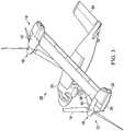
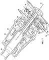
- FIGS 2 and 3illustrate an exemplary tiltrotor aircraft 28 that can incorporate the hybrid tiltrotor drive system 10.
- Tiltrotor aircraft 28includes a fuselage 30, a wing mount assembly 32 that is rotatable relative to fuselage 30 and a tail assembly 34 including rotatably mounted tail members having control surfaces operable for horizontal and/or vertical stabilization during forward flight.
- a wing 36is supported by wing mount assembly 32 and may rotate with wing mount assembly 32 relative to fuselage 30 to enable tiltrotor aircraft 28 convert to a storage configuration.
- fuselage 30, tail assembly 34 and wing 36as well as their various frames, longerons, stringers, bulkheads, spars, ribs, skins and the like may be considered to be the airframe of tiltrotor aircraft 28.
- propulsion system 12Located proximate the outboard ends of wing 36 are propulsion systems 12, 14.
- the propulsion system 12is substantially symmetric to propulsion system 14, therefore, for the sake of efficiency certain features will be disclosed only with regard to propulsion system 12. However, one of ordinary skill in the art would fully appreciate an understanding of propulsion system 14 based upon the disclosure herein of propulsion system 12.
- propulsion system 12includes a fixed nacelle 38 that houses the engine 22 and a fixed portion of the drive system.
- Propulsion system 12includes a pylon assembly 40 that is positioned inboard of fixed nacelle 38 and above wing 36.
- Pylon assembly 40is rotatable relative to fixed nacelle 38 and wing 36 between a generally vertical orientation, as best seen in Figure 2 , and a generally horizontal orientation, as best seen in Figure 3 .
- Pylon assembly 40includes a rotatable portion of the drive system and proprotor 16 that is rotatable responsive to torque and rotational energy provided via the engine and drive system.
- Supplemental driver 24may be located in the fixed or the rotatable portion of the drive system as will be understood by one of ordinary skill in the art with reference to the is disclosure.
- Figure 2illustrates aircraft 28 in helicopter or VTOL flight mode, in which proprotors 16 are rotating in a substantially horizontal plane to provide a lifting thrust, such that aircraft 28 flies much like a conventional helicopter.
- Figure 3illustrates aircraft 28 in an airplane or forward flight mode, in which proprotors 16 are rotating in a vertical plane to provide a forward thrust enabling wing 36 to provide a lifting force responsive to forward airspeed, such that aircraft 28 flies much like a conventional propeller driven aircraft. It should be appreciated that aircraft 28 can be operated such that proprotors 16 are selectively positioned between airplane mode and helicopter mode, which can be referred to as a conversion flight mode.
- proprotors 16rotate in opposite directions to provide torque balancing to aircraft 28.
- proprotors 16each include three twisted proprotor blades 18 that are equally spaced apart circumferentially at approximately 120-degree intervals. It should be understood by those having ordinary skill in the art, however, that the proprotors could have proprotor blades with other designs and other configurations including proprotors having four, five or more proprotor blades. Further, it should be understood by those having ordinary skill in the art that even though propulsion systems 12, 14 are illustrated in the context of tiltrotor aircraft 28, the propulsion systems of the present disclosure can be implemented on other types of tiltrotor aircraft including, for example, quad tiltrotor aircraft and unmanned tiltrotor aircraft, to name a few.
- transient torquemay be experienced from one proprotor 16 to the other proprotor 16 due to certain maneuvers, such as, for example, turns. These maneuvers can cause forces on proprotors 16 that cause one proprotor 16 to rotate faster than the other proprotor 16.
- Supplemental driver 24 of one or both of the propulsion systems 12, 13is actuated to supplement the engine 22 power to maintain the proprotors 16 of the propulsion systems 12, 14 at an equivalent rotational speed.
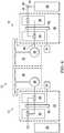
- FIGS 4 and 5are schematic illustrations of exemplary embodiments of the hybrid tiltrotor drive system 10. It should be understood by those having ordinary skill in the art that even though hybrid tiltrotor drive system 10 is illustrated in the context of fixed-engine tiltrotor aircraft, however, the hybrid tiltrotor drive system can be implemented on other types of tiltrotor aircraft.
- Engine 22has an engine output shaft 42 that is coupled to an input shaft 44 of a fixed gearbox 46.
- An output shaft 48 of the fixed gearbox 46is coupled to the proprotor 16.
- the engine output shaft 42can be coupled to the input shaft 44 of the fixed gearbox 46 through a spiral bevel gearbox 50 that includes spiral bevel gears to change torque direction by 90 degrees.
- the fixed gearbox 46includes a plurality of gears, such as helical gears 52, coupled to the output shaft 48.
- One or more auxiliary devicessuch as one or more pumps (e.g., a hydraulic pump, a coolant pump, etc.), blowers, electrical generators and the like, may be coupled to the gears 52.
- the fixed gearbox 46is a variable speed gearbox having a high-speed gear train 54 and a low-speed gear train 56.
- the fixed engine gearboxmay be a fixed-ratio gearbox in some embodiments. Torque is transferred from the output shaft 48 to an input of a proprotor gearbox 26 of the proprotor 16.
- supplemental driver 24is connected directly to the fixed-gearbox 46.
- supplemental driver 24is connected directly to proprotor gearbox 26.
- An exemplary embodiment of a proprotor gearboxis described below with reference to Figure 7 .
- turboshaft engines 22Upon a commanded power change, turboshaft engines 22 have a lag time or delay, for example, approximately one-half second, before the shaft and proprotor speed are changed.
- Supplemental driver 24can be actuated to increase or decrease the speed of the associated proprotor 16 to maintain the proprotors 16 of the propulsion systems 12, 14 at an equivalent rotational speed.
- supplemental driver 24is an electrically controlled device such a motor, generator or brake. It is contemplated that supplemental driver 24 can be controlled within fractions of a millisecond, for example in the range of 0.0001 to 0.1 seconds, from a signal to change speed.
- Figure 6graphically illustrates torque time response of a conventional turboshaft only drive system and a hybrid tiltrotor drive system.
- the supplemental driveris a 300-horsepower electric motor.
- the line 85shows the torque versus time response of a conventional turboshaft engine only drive system and a line 75 shows the torque versus time response of a hybrid tiltrotor drive system utilizing a turboshaft engine 22 and a supplemental driver 24.
- Figure 7illustrates an exemplary embodiment of a proprotor gearbox 26.
- Proprotor gearbox 26is configured to transfer power and rotation to mast 20.
- Proprotor gearbox 26includes a top case portion 58 and spindle gearbox 60.
- Speed reductionis accomplished by a low-speed planetary gear assembly 62 and a high-speed planetary gear assembly 64.
- a spiral bevel gear assemblyincludes spiral bevel input gear 66 and a spiral bevel output gear 68.
- the spiral bevel gear assemblychanges power direction from along longitudinal axis 70 of spiral bevel input gear 66 to a centerline axis 72 of spiral bevel output gear 68.
- An accessory drive 74can be coupled to spiral bevel output gear 68.
- the supplemental driver 24can be coupled to the accessory drive 74 to be actuated to increase the speed of rotation of mast 20 through the spiral bevel output gear 68 or actuated to apply a load to decrease the speed of rotation of the mast.
- substantiallyis defined as largely but not necessarily wholly what is specified (and includes what is specified; e.g., substantially 90 degrees includes 90 degrees and substantially parallel includes parallel), as understood by a person of ordinary skill in the art.
- the terms “substantially,” “approximately,” “generally,” and “about”may be substituted with “within [a percentage] of” what is specified, as recognized by a person of ordinary skill in the art.
Landscapes
- Engineering & Computer Science (AREA)
- Aviation & Aerospace Engineering (AREA)
- Mechanical Engineering (AREA)
- Retarders (AREA)
- Transmission Devices (AREA)
Description
- This section provides background information to facilitate a better understanding of the various aspects of the disclosure. It should be understood that the statements in this section of this document are to be read in this light, and not as admissions of prior art.
- Tiltrotor aircraft, such as the Bell Boeing V-22 Osprey and Bell V-280 Valor, have proprotors on opposing sides of the aircraft that are selectively pivotable between a vertical orientation for rotor-borne flight (helicopter mode) and a horizontal orientation for wing-borne flight (airplane mode). Each proprotor is driven in rotation by an associated propulsion system comprising a turbine engine, a gearbox, and a transmission. The transmissions of the propulsion systems are connected with an interconnect driveshaft that maintains the left and the right proprotor at an equivalent rotational speed, revolutions per minute (RPM), and ensures that both proprotors are always connected with one of the engines. However, the interconnect driveshaft assembly adds undesirable weight to the wing and drive system.
WO 2010/123601 discloses an electrically powered Vertical Takeoff and Landing (VTOL) aircraft. The VTOL aircraft can include one or more electrical energy stores capable of delivering electrical power to one or more electric motors disposed within one or more rotor housings, where the motors can drive the rotors. The VTOL aircraft can also include one or more sustainer energy/power sources (e.g., batteries, engines, generators, fuel-cells, semi-cells, etc.) capable of driving the motors should the energy stores fail or deplete.US 2018/065739 discloses an aircraft including a fuselage and a wing assembly attached to or formed integrally with the fuselage. The aircraft also includes a hybrid electric propulsion system having a port propulsor and a starboard propulsor, with the port and starboard propulsors attached to the wing assembly on opposing sides of the fuselage and rotatable between a forward thrust position and a vertical thrust position. The hybrid electric propulsion system additionally includes an electric power source including a combustion engine and an electric generator, with the electric generator being driven by the combustion engine. The electric generator is in electrical communication with each of the port and starboard propulsors for powering the port and starboard propulsors.US 2013/099065 discloses a tilt-wing aircraft including a tail drive and control unit. The control unit is configured to generate a forward thrust. The control unit can also generate an upwardly or downwardly directed thrust component and/or a laterally directed thrust component in hover flight and in climb flight of the aircraft.WO 2016/085610 discloses a high speed vertical takeoff and landing (VTOL) aircraft that includes fixed wing flight capabilities. The high speed VTOL aircraft may include at least two thrust producing rotors located equidistant from a longitudinal axis of the aircraft on a main wing, and at least two thrust producing rotors located equidistant from a longitudinal axis of the aircraft on a vertical wing. The rotors may be driven by electric motors. By adjusting the speed and/or the pitch of the rotors, the aircraft can transition from a vertical flight configuration to a horizontal flight configuration and back.US 2017/327219 discloses a vertical take-off and landing aircraft including a wing structure including a wing, a rotor operatively supported by the wing, and a hybrid power system configured to drive the rotor, the hybrid power system including a first power system and a second power system, wherein a first energy source for the first power system is different than a second energy source for the second power system.WO 2016/016889 discloses a propulsion system is including a first propulsion unit, a second propulsion unit, a rotor, a first coupling and a second coupling. The first propulsion unit is configured for being fixedly mounted to an airframe. The rotor is configured for being pivotably mounted with respect to the first propulsion unit to allow selectively pivoting of the rotor from a horizontal mode to a vertical mode. The first coupling is configured for selectively coupling and decoupling the rotor with respect to the first propulsion unit. The second coupling is configured for selectively coupling and decoupling the rotor with respect to the second propulsion unit, independently of the first coupling.EP 3369655 discloses a hybrid propulsion system for an aircraft comprising: one or more turboshaft engines that provide shaft power and are capable of providing thrust; at least one of: one or more electrical generators or one or more hydraulic pumps connected to a shaft of the one or more turboshaft engines; and at least two rotatable nacelles, each nacelle housing at least one of: one or more electric motors or one or more hydraulic motors each connected to a proprotor, wherein the electric motor is electrically connected to the electric generator, or the hydraulic motor is connected to the hydraulic pump, respectively, wherein the proprotors provide lift whenever the aircraft is in vertical takeoff and landing and stationary flight, and provide thrust whenever the aircraft is in forward flight.- According to the invention there is provided a hybrid tiltrotor drive system and a method of flying a tiltrotor aircraft, as defined by the appended claims.
- The disclosure is best understood from the following detailed description when read with the accompanying figures. It is emphasized that, in accordance with standard practice in the industry, various features are not drawn to scale. In fact, the dimensions of various features may be arbitrarily increased or reduced for clarity of discussion. As will be understood by those skilled in the art with the benefit of this disclosure, elements, and arrangements of the various figures can be used together and in configurations not specifically illustrated without departing from the scope of this disclosure.
Figure 1 is a schematic view of an illustrative hybrid tiltrotor drive system.Figures 2 and3 illustrate examples of tiltrotor aircraft that can implement hybrid tiltrotor drive systems according to aspects of the disclosure.Figure 4 is a schematic view of an illustrative hybrid tiltrotor drive system according to one or more aspects of the disclosure.Figure 5 is a schematic view of an illustrative hybrid tiltrotor drive system according to one or more aspects of the disclosure.Figure 6 is a graphical illustration of torque time response of a conventional turboshaft only drive system and a hybrid tiltrotor drive system according to one or more aspects of the disclosure.Figure 7 illustrates an exemplary embodiment of a proprotor gearbox according to one or more aspects of the disclosure.- It is to be understood that the following disclosure provides many different embodiments, or examples, for implementing different features of various illustrative embodiments. Specific examples of components and arrangements are described below to simplify the disclosure. These are, of course, merely examples and are not intended to be limiting. In addition, the disclosure may repeat reference numerals and/or letters in the various examples. This repetition is for the purpose of simplicity and clarity and does not in itself dictate a relationship between the various embodiments and/or configurations discussed.
- In the specification, reference may be made to the spatial relationships between various components and to the spatial orientation of various aspects of components as the devices are depicted in the attached drawings. However, as will be recognized by those skilled in the art after a complete reading of the present disclosure, the devices, members, apparatuses, etc. described herein may be positioned in any desired orientation. Thus, the use of terms such as "above," "below," "upper," "lower," or other like terms to describe a spatial relationship between various components or to describe the spatial orientation of aspects of such components should be understood to describe a relative relationship between the components or a spatial orientation of aspects of such components, respectively, as the device described herein may be oriented in any desired direction.
- Illustrative embodiments of a hybrid tiltrotor drive system include a supplemental driver to supplement engine power, to account for engine lag, and to improve the responsiveness of the aircraft in particular in hover mode. The hybrid tiltrotor drive system achieves the unexpected result of maintaining the proprotors at an essentially equivalent rotational speed without using an interconnect drive shaft between the left and right proprotors (i.e., a cross-wing driveshaft).
Figure 1 is a schematic illustration of an exemplary hybrid tiltrotor drive system generally denoted by thenumeral 10. Hybridtiltrotor drive system 10 includes twopropulsion systems propulsion system proprotor 16 that is responsive to torque and rotational energy provided by an associated drive system. Theproprotor 16 includesproprotor blades 18 coupled to amast 20. The drive system includes anengine 22, such as a combustion-driven turboshaft engine, and asupplemental driver 24, such as one or more of an electric motor, generator, and brake. Theengine 22 andsupplemental driver 24 are coupled toproprotor 16 through agearbox 26 to transfer power and rotational speed to theproprotor 16. In a conventional tiltrotor aircraft, an interconnect driveshaft is used to connect the twopropulsion systems proprotors 16. According to aspects of the hybridtiltrotor drive system 10,supplemental driver 24 of therespective propulsion systems engine 22 power and to account for theengine 22 lag time to maintain an equivalent rotational speed of theproprotors 16. Thesupplemental driver 24 may be actuated to increase or decrease the speed of the associatedproprotor 16.- The speed and actuation of the
supplemental driver 24 can be controlled via anelectronic control system 76, which may be a component of the flight-control system.Electronic control system 76 may operatesupplemental driver 24 in response to measured or calculated rotational speeds. Rotational speed and torque can be detected by any suitable means, including forexample engine sensors 78,proprotor sensors 80, andsupplemental driver sensors 82.Data connection 84 provides for data transmission between the sensors andcomputer 86. All data connections according to this disclosure can be wired or wireless.Computer 86 may be a standalone device or may be an integral component of the flight control system. In this or other ways, rotational speeds of each of the relevant components can be sensed and compared. Electronic control systems are well known in the industry and can be easily adapted to suit desired applications in this disclosure. Figures 2 and3 illustrate anexemplary tiltrotor aircraft 28 that can incorporate the hybridtiltrotor drive system 10.Tiltrotor aircraft 28 includes afuselage 30, awing mount assembly 32 that is rotatable relative tofuselage 30 and atail assembly 34 including rotatably mounted tail members having control surfaces operable for horizontal and/or vertical stabilization during forward flight. Awing 36 is supported bywing mount assembly 32 and may rotate withwing mount assembly 32 relative tofuselage 30 to enabletiltrotor aircraft 28 convert to a storage configuration. Together,fuselage 30,tail assembly 34 andwing 36 as well as their various frames, longerons, stringers, bulkheads, spars, ribs, skins and the like may be considered to be the airframe oftiltrotor aircraft 28.- Located proximate the outboard ends of
wing 36 arepropulsion systems propulsion system 12 is substantially symmetric topropulsion system 14, therefore, for the sake of efficiency certain features will be disclosed only with regard topropulsion system 12. However, one of ordinary skill in the art would fully appreciate an understanding ofpropulsion system 14 based upon the disclosure herein ofpropulsion system 12. - In this illustrated embodiment,
propulsion system 12 includes a fixednacelle 38 that houses theengine 22 and a fixed portion of the drive system.Propulsion system 12 includes apylon assembly 40 that is positioned inboard of fixednacelle 38 and abovewing 36.Pylon assembly 40 is rotatable relative to fixednacelle 38 andwing 36 between a generally vertical orientation, as best seen inFigure 2 , and a generally horizontal orientation, as best seen inFigure 3 .Pylon assembly 40 includes a rotatable portion of the drive system andproprotor 16 that is rotatable responsive to torque and rotational energy provided via the engine and drive system.Supplemental driver 24 may be located in the fixed or the rotatable portion of the drive system as will be understood by one of ordinary skill in the art with reference to the is disclosure. Figure 2 illustratesaircraft 28 in helicopter or VTOL flight mode, in which proprotors 16 are rotating in a substantially horizontal plane to provide a lifting thrust, such thataircraft 28 flies much like a conventional helicopter.Figure 3 illustratesaircraft 28 in an airplane or forward flight mode, in which proprotors 16 are rotating in a vertical plane to provide a forwardthrust enabling wing 36 to provide a lifting force responsive to forward airspeed, such thataircraft 28 flies much like a conventional propeller driven aircraft. It should be appreciated thataircraft 28 can be operated such thatproprotors 16 are selectively positioned between airplane mode and helicopter mode, which can be referred to as a conversion flight mode.- During all flight modes, proprotors 16 rotate in opposite directions to provide torque balancing to
aircraft 28. In the illustrated embodiment, proprotors 16 each include threetwisted proprotor blades 18 that are equally spaced apart circumferentially at approximately 120-degree intervals. It should be understood by those having ordinary skill in the art, however, that the proprotors could have proprotor blades with other designs and other configurations including proprotors having four, five or more proprotor blades. Further, it should be understood by those having ordinary skill in the art that even thoughpropulsion systems tiltrotor aircraft 28, the propulsion systems of the present disclosure can be implemented on other types of tiltrotor aircraft including, for example, quad tiltrotor aircraft and unmanned tiltrotor aircraft, to name a few. - During flight, transient torque may be experienced from one
proprotor 16 to theother proprotor 16 due to certain maneuvers, such as, for example, turns. These maneuvers can cause forces onproprotors 16 that cause oneproprotor 16 to rotate faster than theother proprotor 16.Supplemental driver 24 of one or both of thepropulsion systems 12, 13 is actuated to supplement theengine 22 power to maintain theproprotors 16 of thepropulsion systems Figures 4 and5 are schematic illustrations of exemplary embodiments of the hybridtiltrotor drive system 10. It should be understood by those having ordinary skill in the art that even though hybridtiltrotor drive system 10 is illustrated in the context of fixed-engine tiltrotor aircraft, however, the hybrid tiltrotor drive system can be implemented on other types of tiltrotor aircraft.Engine 22 has anengine output shaft 42 that is coupled to aninput shaft 44 of a fixedgearbox 46. Anoutput shaft 48 of the fixedgearbox 46 is coupled to theproprotor 16. Theengine output shaft 42 can be coupled to theinput shaft 44 of the fixedgearbox 46 through aspiral bevel gearbox 50 that includes spiral bevel gears to change torque direction by 90 degrees. The fixedgearbox 46 includes a plurality of gears, such ashelical gears 52, coupled to theoutput shaft 48. One or more auxiliary devices, such as one or more pumps (e.g., a hydraulic pump, a coolant pump, etc.), blowers, electrical generators and the like, may be coupled to thegears 52. InFigures 4 and5 , the fixedgearbox 46 is a variable speed gearbox having a high-speed gear train 54 and a low-speed gear train 56. The fixed engine gearbox may be a fixed-ratio gearbox in some embodiments. Torque is transferred from theoutput shaft 48 to an input of aproprotor gearbox 26 of theproprotor 16.- In
Figure 4 ,supplemental driver 24 is connected directly to the fixed-gearbox 46. InFigures 1 and5 ,supplemental driver 24 is connected directly toproprotor gearbox 26. An exemplary embodiment of a proprotor gearbox is described below with reference toFigure 7 . - Upon a commanded power change,
turboshaft engines 22 have a lag time or delay, for example, approximately one-half second, before the shaft and proprotor speed are changed.Supplemental driver 24 can be actuated to increase or decrease the speed of the associatedproprotor 16 to maintain theproprotors 16 of thepropulsion systems supplemental driver 24 is an electrically controlled device such a motor, generator or brake. It is contemplated thatsupplemental driver 24 can be controlled within fractions of a millisecond, for example in the range of 0.0001 to 0.1 seconds, from a signal to change speed. Figure 6 graphically illustrates torque time response of a conventional turboshaft only drive system and a hybrid tiltrotor drive system. In this example, the supplemental driver is a 300-horsepower electric motor. Theline 85 shows the torque versus time response of a conventional turboshaft engine only drive system and aline 75 shows the torque versus time response of a hybrid tiltrotor drive system utilizing aturboshaft engine 22 and asupplemental driver 24.Figure 7 illustrates an exemplary embodiment of aproprotor gearbox 26.Proprotor gearbox 26 is configured to transfer power and rotation tomast 20.Proprotor gearbox 26 includes atop case portion 58 andspindle gearbox 60. Speed reduction is accomplished by a low-speedplanetary gear assembly 62 and a high-speedplanetary gear assembly 64. A spiral bevel gear assembly includes spiralbevel input gear 66 and a spiralbevel output gear 68. The spiral bevel gear assembly changes power direction from alonglongitudinal axis 70 of spiralbevel input gear 66 to acenterline axis 72 of spiralbevel output gear 68. Anaccessory drive 74 can be coupled to spiralbevel output gear 68. With reference, in particular toFigures 1 and5 , thesupplemental driver 24 can be coupled to theaccessory drive 74 to be actuated to increase the speed of rotation ofmast 20 through the spiralbevel output gear 68 or actuated to apply a load to decrease the speed of rotation of the mast.- Conditional language used herein, such as, among others, "can," "might," "may," "e.g.," and the like, unless specifically stated otherwise, or otherwise understood within the context as used, is generally intended to convey that certain embodiments include, while other embodiments do not include, certain features, elements and/or states. Thus, such conditional language is not generally intended to imply that features, elements and/or states are in any way required for one or more embodiments or that one or more embodiments necessarily include such elements or features.
- The term "substantially" is defined as largely but not necessarily wholly what is specified (and includes what is specified; e.g., substantially 90 degrees includes 90 degrees and substantially parallel includes parallel), as understood by a person of ordinary skill in the art. In any disclosed embodiment, the terms "substantially," "approximately," "generally," and "about" may be substituted with "within [a percentage] of" what is specified, as recognized by a person of ordinary skill in the art. The foregoing outlines features of several embodiments so that those skilled in the art may better understand the aspects of the disclosure. Those skilled in the art should appreciate that they may readily use the disclosure as a basis for designing or modifying other processes and structures for carrying out the same purposes and/or achieving the same advantages of the embodiments introduced herein.
Claims (12)
- A hybrid tiltrotor drive system (10), comprising:two propulsion systems (12, 14), each propulsion system (12, 14) comprising:an engine (22) coupled to a proprotor (16);an electrically controlled supplemental driver (24) coupled to the proprotor (16); anda gearbox (26), the engine (22) and electrically controlled supplemental driver (24) coupled to the proprotor (16) through the gearbox (26);means (78, 80, 82) for detecting the rotational speeds;an electronic control system (76) configured to operate the supplemental driver (24) of each propulsion system (12, 14) in response to measured or calculated rotational speeds,wherein the electronic control system (76) is configured during a flight maneuver to actuate the supplemental driver (24) of one of the propulsion systems (12, 14) to increase or decrease the speed of the associated proprotor (16), supplementing the associated engine (22) to account for a lag time between the engines (22) of the propulsion systems (12, 14) and maintain the proprotors (16) of the propulsion systems (12, 14) at an equivalent rotational speed.
- The hybrid tiltrotor drive system (10) of claim 1, wherein the engine (22) in each propulsion system (12, 14) is a combustion-driven turboshaft engine and the supplemental driver (24) is an electric motor or a brake.
- The hybrid tiltrotor drive system (10) of claim 1, wherein the supplemental driver (24) in each propulsion system (12, 14) is an electric motor.
- The hybrid tiltrotor drive system (10) of claim 1, wherein the proprotors (16) of the two propulsion systems (12, 14) are not interconnected by a drive shaft.
- The hybrid tiltrotor drive system (10) of claim 4, wherein the supplemental driver (24) in each propulsion system (12, 14) is an electric motor.
- A tiltrotor aircraft (28), comprising a hybrid tiltrotor drive system according to any one of claims 1 to 3, the proprotor (16) of each propulsion system (12, 14) being operable between a helicopter mode and an airplane mode.
- The tiltrotor aircraft (28) of claim 6, wherein the two propulsion systems (12, 14) are not interconnected by a driveshaft.
- The tiltrotor aircraft (28) of claim 6 or claim 7, wherein:the two propulsion systems (12, 14) are located on opposing outboard ends of a wing (36);the engines of the two propulsion systems (12, 14) are fixed relative to the wing (36); andthe proprotors (16) of the two propulsion systems (12, 14) are rotatable relative to the wing (36).
- A method, comprising:
flying a tiltrotor aircraft (28), wherein the tiltrotor aircraft (28) comprises:a first propulsion system (12) comprising a first engine (22) and a first electrically controlled supplemental driver (24) coupled to a first proprotor (16) through a gearbox (26), the first propulsion system (12) being operable between a helicopter mode and an airplane mode; anda second propulsion system (14) comprising a second engine (22) and a second electrically controlled supplemental driver (24) coupled to a second proprotor (16) through a gearbox (26), the second propulsion system (14) being operable between a helicopter mode and an airplane mode, wherein the flying comprises:rotating the first proprotor (16) at a first rotational speed in response to operation of the first engine (22);rotating the second proprotor (16) at a second rotational speed in response to operation of the second engine (22); andduring a flight maneuver, actuating the first supplemental driver (24) to increase or decrease the speed of the first proprotor (16), supplementing the first engine (22) to account for a lag time between the first and second engines (22) and maintain the first proprotor (16) and the second proprotor (16) at an equivalent rotational speed. - The method of claim 9, wherein the first propulsion system (12) and the second propulsion system (14) are not interconnected by a driveshaft.
- The method of claim 9 or claim 10, wherein:the first and second engines (22) are combustion-driven turboshaft engines; andthe first and second supplemental drivers (24) comprise an electric motor.
- The method of any one of claims 9 to 11, wherein:the first and second propulsion systems (12, 14) are located on opposing outboard ends of a wing (36);the first and second engines (22) are fixed relative to the wing (36); andthe first and second proprotors (16) are rotatable relative to the wing (36).
Applications Claiming Priority (1)
| Application Number | Priority Date | Filing Date | Title |
|---|---|---|---|
| US15/967,831US10906656B2 (en) | 2018-05-01 | 2018-05-01 | Hybrid tiltrotor drive system |
Publications (2)
| Publication Number | Publication Date |
|---|---|
| EP3564122A1 EP3564122A1 (en) | 2019-11-06 |
| EP3564122B1true EP3564122B1 (en) | 2021-01-13 |
Family
ID=62636042
Family Applications (1)
| Application Number | Title | Priority Date | Filing Date |
|---|---|---|---|
| EP18177619.6AActiveEP3564122B1 (en) | 2018-05-01 | 2018-06-13 | Hybrid tiltrotor drive system |
Country Status (2)
| Country | Link |
|---|---|
| US (2) | US10906656B2 (en) |
| EP (1) | EP3564122B1 (en) |
Families Citing this family (19)
| Publication number | Priority date | Publication date | Assignee | Title |
|---|---|---|---|---|
| WO2019082043A2 (en)* | 2017-10-23 | 2019-05-02 | Flyworks Ltd | Vertical take-off and landing aircraft and transformation gear sets for same |
| US11148798B2 (en)* | 2018-06-22 | 2021-10-19 | Textron Innovations Inc. | Engine and rotatable proprotor configurations for a tiltrotor aircraft |
| US10913542B2 (en)* | 2018-07-27 | 2021-02-09 | Textron Innovations Inc. | Conversion actuator and downstop striker fitting for a tiltrotor aircraft |
| US10994839B2 (en) | 2018-07-31 | 2021-05-04 | Textron Innovations Inc. | System and method for rotating a rotor of a tiltrotor aircraft |
| FR3094314B1 (en)* | 2019-03-29 | 2021-07-09 | Airbus Helicopters | Method for optimizing the noise generated in flight by a rotorcraft. |
| FR3095806B1 (en)* | 2019-05-06 | 2021-08-20 | Safran Helicopter Engines | Hybrid propulsion system for vertical take-off and landing aircraft |
| US11884412B2 (en) | 2019-08-27 | 2024-01-30 | Pratt & Whitney Canada Corp. | Hybrid electric powerplant systems and controllers |
| EP4592189A3 (en) | 2019-10-09 | 2025-09-03 | Kitty Hawk Corporation | Hybrid power systems for different modes of flight |
| CN111348196B (en)* | 2019-11-25 | 2024-09-17 | 西安空天能源动力智能制造研究院有限公司 | Air-entraining combustion distributed power aeroengine of tiltrotor aircraft |
| US11975826B2 (en)* | 2021-02-01 | 2024-05-07 | Textron Innovations Inc | Electric tiltrotor aircraft with fixed motors |
| US11952105B2 (en) | 2021-03-10 | 2024-04-09 | BETA Technologies, Inc. | System and method for flight control in electric aircraft |
| US12434814B2 (en) | 2021-03-10 | 2025-10-07 | Beta Air Llc | System and methods for flight control for an electric aircraft |
| US11524767B2 (en)* | 2021-03-31 | 2022-12-13 | Beta Air, Llc | Methods and systems for flight control configured for use in an electric aircraft |
| US12379730B2 (en) | 2021-03-31 | 2025-08-05 | Beta Air Llc | Methods and systems for flight control configured for use in an electric aircraft |
| US20230174229A1 (en)* | 2021-12-03 | 2023-06-08 | Karem Aircraft, Inc. | Tiltrotor aircraft with centerline and wing mounted engines |
| US20230312115A1 (en)* | 2022-03-29 | 2023-10-05 | Pratt & Whitney Canada Corp. | Aircraft powerplant(s) for an aircraft with electric machine controlled propulsor speed |
| US11634232B1 (en)* | 2022-04-30 | 2023-04-25 | Beta Air, Llc | Hybrid propulsion systems for an electric aircraft |
| US12195192B2 (en)* | 2022-04-30 | 2025-01-14 | Beta Air Llc | Hybrid propulsion systems for an electric aircraft |
| US11639230B1 (en)* | 2022-04-30 | 2023-05-02 | Beta Air, Llc | System for an integral hybrid electric aircraft |
Family Cites Families (19)
| Publication number | Priority date | Publication date | Assignee | Title |
|---|---|---|---|---|
| US7866598B2 (en) | 2008-03-06 | 2011-01-11 | Karem Aircraft, Inc. | Rotorcraft engine and rotor speed synchronization |
| US8469306B2 (en) | 2009-01-27 | 2013-06-25 | Ira F. Kuhn, Jr. | Purebred and hybrid electric VTOL tilt rotor aircraft |
| US8708273B2 (en)* | 2009-10-09 | 2014-04-29 | Oliver Vtol, Llc | Three-wing, six tilt-propulsion unit, VTOL aircraft |
| US8616492B2 (en)* | 2009-10-09 | 2013-12-31 | Oliver Vtol, Llc | Three wing, six tilt-propulsion units, VTOL aircraft |
| DE102010021022A1 (en) | 2010-05-19 | 2011-11-24 | Eads Deutschland Gmbh | Flipper aircraft |
| US8939399B2 (en)* | 2012-07-31 | 2015-01-27 | Textron Innovations Inc. | System and method of augmenting power in a rotorcraft |
| US9218693B2 (en) | 2013-03-15 | 2015-12-22 | Bell Helicopter Textron Inc. | Drive system power measurement and diagnostic system |
| US9821908B2 (en) | 2013-06-07 | 2017-11-21 | Bell Helicopter Textron Inc. | System and method for assisting in rotor speed control |
| US9868541B2 (en) | 2013-08-14 | 2018-01-16 | Bell Helicopter Textron Inc. | Tiltrotor aircraft having journal bearing mounted pylon assemblies |
| US9663225B1 (en)* | 2013-08-14 | 2017-05-30 | Bell Helicopter Textron Inc. | Maintaining drive system alignment in tiltrotor aircraft |
| US10384765B2 (en) | 2014-02-06 | 2019-08-20 | Bell Helicopter Textron Inc. | Interconnect drive system |
| US9889927B2 (en) | 2014-02-06 | 2018-02-13 | Bell Helicopter Textron Inc. | Variable hub-to-hub phasing rotor system |
| IL233902B (en) | 2014-07-31 | 2020-07-30 | Israel Aerospace Ind Ltd | egnition system |
| US9994313B2 (en) | 2014-11-26 | 2018-06-12 | XCraft Enterprises, LLC | High speed multi-rotor vertical takeoff and landing aircraft |
| US20170327219A1 (en) | 2015-12-11 | 2017-11-16 | Sikorsky Aircraft Corporation | Vertical take-off and landing aircraft with hybrid power and method |
| US10011349B2 (en) | 2016-08-31 | 2018-07-03 | Bell Helicopter Textron Inc. | Tiltrotor aircraft having rotatable wing extensions |
| US20180065739A1 (en)* | 2016-09-08 | 2018-03-08 | General Electric Company | Tiltrotor propulsion system for an aircraft |
| US11731772B2 (en) | 2017-03-02 | 2023-08-22 | Textron Innovations Inc. | Hybrid propulsion drive train system for tiltrotor aircraft |
| US10981660B2 (en)* | 2018-04-19 | 2021-04-20 | The Boeing Company | Hybrid propulsion engines for aircraft |
- 2018
- 2018-05-01USUS15/967,831patent/US10906656B2/enactiveActive
- 2018-06-13EPEP18177619.6Apatent/EP3564122B1/enactiveActive
- 2021
- 2021-01-28USUS17/161,183patent/US11358729B2/enactiveActive
Non-Patent Citations (1)
| Title |
|---|
| None* |
Also Published As
| Publication number | Publication date |
|---|---|
| US11358729B2 (en) | 2022-06-14 |
| EP3564122A1 (en) | 2019-11-06 |
| US10906656B2 (en) | 2021-02-02 |
| US20210309381A1 (en) | 2021-10-07 |
| US20190337629A1 (en) | 2019-11-07 |
Similar Documents
| Publication | Publication Date | Title |
|---|---|---|
| EP3564122B1 (en) | Hybrid tiltrotor drive system | |
| US11370535B2 (en) | Tiltrotor with inboard engines | |
| EP3784570B1 (en) | Variable pitch rotor assembly for electrically driven vectored thrust aircraft applications | |
| US12006036B2 (en) | Distributed propulsion system | |
| US11505314B2 (en) | Vertical takeoff and landing aircraft with tiltable rotors | |
| KR102483971B1 (en) | Evtol aircraft using large, variable speed tilt rotors | |
| CN110267876B (en) | Multi-rotor lifting body aircraft with tiltrotor | |
| EP3299290B1 (en) | Rotating proprotor arrangement for a tiltrotor aircraft | |
| US11142309B2 (en) | Convertible airplane with exposable rotors | |
| US9475575B2 (en) | Convertible compounded rotorcraft | |
| US8113460B2 (en) | Fast hybrid helicopter with long range and an optimized lift rotor | |
| EP3663197B1 (en) | High-speed hybrid propulsion for aircraft | |
| EP3243750B1 (en) | Distributed propulsion | |
| US20050151001A1 (en) | Compound helicopter | |
| US20110042510A1 (en) | Lightweight Vertical Take-Off and Landing Aircraft and Flight Control Paradigm Using Thrust Differentials | |
| WO2018191083A1 (en) | Coaxial drive propulsion system for aerial vehicles, and associated systems and methods | |
| US20230234703A1 (en) | Convertiplane with stopped rotors, and repositionable rotor blades | |
| WO2021010915A1 (en) | A multi-function unmanned aerial vehicle with tilting co-axial, counter-rotating, folding propeller system | |
| US20200283139A1 (en) | Hybrid rotor propulsion for rotor aircraft | |
| RU127364U1 (en) | SPEED COMBINED HELICOPTER | |
| RU2539679C1 (en) | High-speed rotary-wing aircraft | |
| US11794886B2 (en) | Hybrid rotorcraft having at least one pusher or puller propeller, and an associated piloting method | |
| US20250172947A1 (en) | Flying apparatus, aircraft, and method for controlling flight of flying apparatus | |
| EP4559809A1 (en) | Flying apparatus, aircraft, and method for controlling flight of flying apparatus |
Legal Events
| Date | Code | Title | Description |
|---|---|---|---|
| STAA | Information on the status of an ep patent application or granted ep patent | Free format text:STATUS: EXAMINATION IS IN PROGRESS | |
| PUAI | Public reference made under article 153(3) epc to a published international application that has entered the european phase | Free format text:ORIGINAL CODE: 0009012 | |
| 17P | Request for examination filed | Effective date:20180613 | |
| AK | Designated contracting states | Kind code of ref document:A1 Designated state(s):AL AT BE BG CH CY CZ DE DK EE ES FI FR GB GR HR HU IE IS IT LI LT LU LV MC MK MT NL NO PL PT RO RS SE SI SK SM TR | |
| AX | Request for extension of the european patent | Extension state:BA ME | |
| GRAP | Despatch of communication of intention to grant a patent | Free format text:ORIGINAL CODE: EPIDOSNIGR1 | |
| STAA | Information on the status of an ep patent application or granted ep patent | Free format text:STATUS: GRANT OF PATENT IS INTENDED | |
| INTG | Intention to grant announced | Effective date:20201015 | |
| GRAS | Grant fee paid | Free format text:ORIGINAL CODE: EPIDOSNIGR3 | |
| GRAA | (expected) grant | Free format text:ORIGINAL CODE: 0009210 | |
| STAA | Information on the status of an ep patent application or granted ep patent | Free format text:STATUS: THE PATENT HAS BEEN GRANTED | |
| AK | Designated contracting states | Kind code of ref document:B1 Designated state(s):AL AT BE BG CH CY CZ DE DK EE ES FI FR GB GR HR HU IE IS IT LI LT LU LV MC MK MT NL NO PL PT RO RS SE SI SK SM TR | |
| REG | Reference to a national code | Ref country code:GB Ref legal event code:FG4D | |
| REG | Reference to a national code | Ref country code:CH Ref legal event code:EP | |
| REG | Reference to a national code | Ref country code:DE Ref legal event code:R096 Ref document number:602018011749 Country of ref document:DE | |
| REG | Reference to a national code | Ref country code:IE Ref legal event code:FG4D | |
| REG | Reference to a national code | Ref country code:AT Ref legal event code:REF Ref document number:1354382 Country of ref document:AT Kind code of ref document:T Effective date:20210215 | |
| REG | Reference to a national code | Ref country code:AT Ref legal event code:MK05 Ref document number:1354382 Country of ref document:AT Kind code of ref document:T Effective date:20210113 | |
| REG | Reference to a national code | Ref country code:NL Ref legal event code:MP Effective date:20210113 | |
| REG | Reference to a national code | Ref country code:LT Ref legal event code:MG9D | |
| PG25 | Lapsed in a contracting state [announced via postgrant information from national office to epo] | Ref country code:LT Free format text:LAPSE BECAUSE OF FAILURE TO SUBMIT A TRANSLATION OF THE DESCRIPTION OR TO PAY THE FEE WITHIN THE PRESCRIBED TIME-LIMIT Effective date:20210113 Ref country code:NO Free format text:LAPSE BECAUSE OF FAILURE TO SUBMIT A TRANSLATION OF THE DESCRIPTION OR TO PAY THE FEE WITHIN THE PRESCRIBED TIME-LIMIT Effective date:20210413 Ref country code:PT Free format text:LAPSE BECAUSE OF FAILURE TO SUBMIT A TRANSLATION OF THE DESCRIPTION OR TO PAY THE FEE WITHIN THE PRESCRIBED TIME-LIMIT Effective date:20210513 Ref country code:GR Free format text:LAPSE BECAUSE OF FAILURE TO SUBMIT A TRANSLATION OF THE DESCRIPTION OR TO PAY THE FEE WITHIN THE PRESCRIBED TIME-LIMIT Effective date:20210414 Ref country code:FI Free format text:LAPSE BECAUSE OF FAILURE TO SUBMIT A TRANSLATION OF THE DESCRIPTION OR TO PAY THE FEE WITHIN THE PRESCRIBED TIME-LIMIT Effective date:20210113 Ref country code:HR Free format text:LAPSE BECAUSE OF FAILURE TO SUBMIT A TRANSLATION OF THE DESCRIPTION OR TO PAY THE FEE WITHIN THE PRESCRIBED TIME-LIMIT Effective date:20210113 Ref country code:BG Free format text:LAPSE BECAUSE OF FAILURE TO SUBMIT A TRANSLATION OF THE DESCRIPTION OR TO PAY THE FEE WITHIN THE PRESCRIBED TIME-LIMIT Effective date:20210413 | |
| PG25 | Lapsed in a contracting state [announced via postgrant information from national office to epo] | Ref country code:AT Free format text:LAPSE BECAUSE OF FAILURE TO SUBMIT A TRANSLATION OF THE DESCRIPTION OR TO PAY THE FEE WITHIN THE PRESCRIBED TIME-LIMIT Effective date:20210113 Ref country code:PL Free format text:LAPSE BECAUSE OF FAILURE TO SUBMIT A TRANSLATION OF THE DESCRIPTION OR TO PAY THE FEE WITHIN THE PRESCRIBED TIME-LIMIT Effective date:20210113 Ref country code:LV Free format text:LAPSE BECAUSE OF FAILURE TO SUBMIT A TRANSLATION OF THE DESCRIPTION OR TO PAY THE FEE WITHIN THE PRESCRIBED TIME-LIMIT Effective date:20210113 Ref country code:RS Free format text:LAPSE BECAUSE OF FAILURE TO SUBMIT A TRANSLATION OF THE DESCRIPTION OR TO PAY THE FEE WITHIN THE PRESCRIBED TIME-LIMIT Effective date:20210113 Ref country code:SE Free format text:LAPSE BECAUSE OF FAILURE TO SUBMIT A TRANSLATION OF THE DESCRIPTION OR TO PAY THE FEE WITHIN THE PRESCRIBED TIME-LIMIT Effective date:20210113 | |
| PG25 | Lapsed in a contracting state [announced via postgrant information from national office to epo] | Ref country code:IS Free format text:LAPSE BECAUSE OF FAILURE TO SUBMIT A TRANSLATION OF THE DESCRIPTION OR TO PAY THE FEE WITHIN THE PRESCRIBED TIME-LIMIT Effective date:20210513 | |
| REG | Reference to a national code | Ref country code:DE Ref legal event code:R097 Ref document number:602018011749 Country of ref document:DE | |
| PG25 | Lapsed in a contracting state [announced via postgrant information from national office to epo] | Ref country code:SM Free format text:LAPSE BECAUSE OF FAILURE TO SUBMIT A TRANSLATION OF THE DESCRIPTION OR TO PAY THE FEE WITHIN THE PRESCRIBED TIME-LIMIT Effective date:20210113 Ref country code:EE Free format text:LAPSE BECAUSE OF FAILURE TO SUBMIT A TRANSLATION OF THE DESCRIPTION OR TO PAY THE FEE WITHIN THE PRESCRIBED TIME-LIMIT Effective date:20210113 Ref country code:CZ Free format text:LAPSE BECAUSE OF FAILURE TO SUBMIT A TRANSLATION OF THE DESCRIPTION OR TO PAY THE FEE WITHIN THE PRESCRIBED TIME-LIMIT Effective date:20210113 | |
| PLBE | No opposition filed within time limit | Free format text:ORIGINAL CODE: 0009261 | |
| STAA | Information on the status of an ep patent application or granted ep patent | Free format text:STATUS: NO OPPOSITION FILED WITHIN TIME LIMIT | |
| PG25 | Lapsed in a contracting state [announced via postgrant information from national office to epo] | Ref country code:RO Free format text:LAPSE BECAUSE OF FAILURE TO SUBMIT A TRANSLATION OF THE DESCRIPTION OR TO PAY THE FEE WITHIN THE PRESCRIBED TIME-LIMIT Effective date:20210113 Ref country code:DK Free format text:LAPSE BECAUSE OF FAILURE TO SUBMIT A TRANSLATION OF THE DESCRIPTION OR TO PAY THE FEE WITHIN THE PRESCRIBED TIME-LIMIT Effective date:20210113 Ref country code:SK Free format text:LAPSE BECAUSE OF FAILURE TO SUBMIT A TRANSLATION OF THE DESCRIPTION OR TO PAY THE FEE WITHIN THE PRESCRIBED TIME-LIMIT Effective date:20210113 | |
| 26N | No opposition filed | Effective date:20211014 | |
| PG25 | Lapsed in a contracting state [announced via postgrant information from national office to epo] | Ref country code:ES Free format text:LAPSE BECAUSE OF FAILURE TO SUBMIT A TRANSLATION OF THE DESCRIPTION OR TO PAY THE FEE WITHIN THE PRESCRIBED TIME-LIMIT Effective date:20210113 Ref country code:AL Free format text:LAPSE BECAUSE OF FAILURE TO SUBMIT A TRANSLATION OF THE DESCRIPTION OR TO PAY THE FEE WITHIN THE PRESCRIBED TIME-LIMIT Effective date:20210113 Ref country code:MC Free format text:LAPSE BECAUSE OF FAILURE TO SUBMIT A TRANSLATION OF THE DESCRIPTION OR TO PAY THE FEE WITHIN THE PRESCRIBED TIME-LIMIT Effective date:20210113 | |
| REG | Reference to a national code | Ref country code:CH Ref legal event code:PL | |
| PG25 | Lapsed in a contracting state [announced via postgrant information from national office to epo] | Ref country code:SI Free format text:LAPSE BECAUSE OF FAILURE TO SUBMIT A TRANSLATION OF THE DESCRIPTION OR TO PAY THE FEE WITHIN THE PRESCRIBED TIME-LIMIT Effective date:20210113 | |
| REG | Reference to a national code | Ref country code:BE Ref legal event code:MM Effective date:20210630 | |
| PG25 | Lapsed in a contracting state [announced via postgrant information from national office to epo] | Ref country code:LU Free format text:LAPSE BECAUSE OF NON-PAYMENT OF DUE FEES Effective date:20210613 | |
| PG25 | Lapsed in a contracting state [announced via postgrant information from national office to epo] | Ref country code:LI Free format text:LAPSE BECAUSE OF NON-PAYMENT OF DUE FEES Effective date:20210630 Ref country code:IE Free format text:LAPSE BECAUSE OF NON-PAYMENT OF DUE FEES Effective date:20210613 Ref country code:CH Free format text:LAPSE BECAUSE OF NON-PAYMENT OF DUE FEES Effective date:20210630 | |
| PG25 | Lapsed in a contracting state [announced via postgrant information from national office to epo] | Ref country code:IS Free format text:LAPSE BECAUSE OF FAILURE TO SUBMIT A TRANSLATION OF THE DESCRIPTION OR TO PAY THE FEE WITHIN THE PRESCRIBED TIME-LIMIT Effective date:20210513 | |
| PG25 | Lapsed in a contracting state [announced via postgrant information from national office to epo] | Ref country code:BE Free format text:LAPSE BECAUSE OF NON-PAYMENT OF DUE FEES Effective date:20210630 | |
| REG | Reference to a national code | Ref country code:GB Ref legal event code:732E Free format text:REGISTERED BETWEEN 20220922 AND 20220928 | |
| REG | Reference to a national code | Ref country code:DE Ref legal event code:R081 Ref document number:602018011749 Country of ref document:DE Owner name:TEXTRON INNOVATIONS INC., PROVIDENCE, US Free format text:FORMER OWNER: BELL HELICOPTER TEXTRON INC., FORT WORTH, TEX., US | |
| PG25 | Lapsed in a contracting state [announced via postgrant information from national office to epo] | Ref country code:NL Free format text:LAPSE BECAUSE OF NON-PAYMENT OF DUE FEES Effective date:20210113 Ref country code:CY Free format text:LAPSE BECAUSE OF FAILURE TO SUBMIT A TRANSLATION OF THE DESCRIPTION OR TO PAY THE FEE WITHIN THE PRESCRIBED TIME-LIMIT Effective date:20210113 | |
| P01 | Opt-out of the competence of the unified patent court (upc) registered | Effective date:20230602 | |
| PG25 | Lapsed in a contracting state [announced via postgrant information from national office to epo] | Ref country code:HU Free format text:LAPSE BECAUSE OF FAILURE TO SUBMIT A TRANSLATION OF THE DESCRIPTION OR TO PAY THE FEE WITHIN THE PRESCRIBED TIME-LIMIT; INVALID AB INITIO Effective date:20180613 | |
| PG25 | Lapsed in a contracting state [announced via postgrant information from national office to epo] | Ref country code:MK Free format text:LAPSE BECAUSE OF FAILURE TO SUBMIT A TRANSLATION OF THE DESCRIPTION OR TO PAY THE FEE WITHIN THE PRESCRIBED TIME-LIMIT Effective date:20210113 | |
| PG25 | Lapsed in a contracting state [announced via postgrant information from national office to epo] | Ref country code:MT Free format text:LAPSE BECAUSE OF FAILURE TO SUBMIT A TRANSLATION OF THE DESCRIPTION OR TO PAY THE FEE WITHIN THE PRESCRIBED TIME-LIMIT Effective date:20210113 | |
| PGFP | Annual fee paid to national office [announced via postgrant information from national office to epo] | Ref country code:IT Payment date:20240619 Year of fee payment:7 | |
| PGFP | Annual fee paid to national office [announced via postgrant information from national office to epo] | Ref country code:DE Payment date:20250627 Year of fee payment:8 | |
| PGFP | Annual fee paid to national office [announced via postgrant information from national office to epo] | Ref country code:GB Payment date:20250627 Year of fee payment:8 | |
| PGFP | Annual fee paid to national office [announced via postgrant information from national office to epo] | Ref country code:FR Payment date:20250625 Year of fee payment:8 |