EP3561185A1 - Hand-held control device with functional switch - Google Patents
Hand-held control device with functional switchDownload PDFInfo
- Publication number
- EP3561185A1 EP3561185A1EP19000172.7AEP19000172AEP3561185A1EP 3561185 A1EP3561185 A1EP 3561185A1EP 19000172 AEP19000172 AEP 19000172AEP 3561185 A1EP3561185 A1EP 3561185A1
- Authority
- EP
- European Patent Office
- Prior art keywords
- handle
- control device
- manual control
- function
- display
- Prior art date
- Legal status (The legal status is an assumption and is not a legal conclusion. Google has not performed a legal analysis and makes no representation as to the accuracy of the status listed.)
- Granted
Links
Images

Classifications
- G—PHYSICS
- G05—CONTROLLING; REGULATING
- G05G—CONTROL DEVICES OR SYSTEMS INSOFAR AS CHARACTERISED BY MECHANICAL FEATURES ONLY
- G05G9/00—Manually-actuated control mechanisms provided with one single controlling member co-operating with two or more controlled members, e.g. selectively, simultaneously
- G05G9/02—Manually-actuated control mechanisms provided with one single controlling member co-operating with two or more controlled members, e.g. selectively, simultaneously the controlling member being movable in different independent ways, movement in each individual way actuating one controlled member only
- G05G9/04—Manually-actuated control mechanisms provided with one single controlling member co-operating with two or more controlled members, e.g. selectively, simultaneously the controlling member being movable in different independent ways, movement in each individual way actuating one controlled member only in which movement in two or more ways can occur simultaneously
- G05G9/047—Manually-actuated control mechanisms provided with one single controlling member co-operating with two or more controlled members, e.g. selectively, simultaneously the controlling member being movable in different independent ways, movement in each individual way actuating one controlled member only in which movement in two or more ways can occur simultaneously the controlling member being movable by hand about orthogonal axes, e.g. joysticks
- E—FIXED CONSTRUCTIONS
- E02—HYDRAULIC ENGINEERING; FOUNDATIONS; SOIL SHIFTING
- E02F—DREDGING; SOIL-SHIFTING
- E02F9/00—Component parts of dredgers or soil-shifting machines, not restricted to one of the kinds covered by groups E02F3/00 - E02F7/00
- E02F9/20—Drives; Control devices
- E02F9/2004—Control mechanisms, e.g. control levers
- G—PHYSICS
- G05—CONTROLLING; REGULATING
- G05G—CONTROL DEVICES OR SYSTEMS INSOFAR AS CHARACTERISED BY MECHANICAL FEATURES ONLY
- G05G9/00—Manually-actuated control mechanisms provided with one single controlling member co-operating with two or more controlled members, e.g. selectively, simultaneously
- G05G9/02—Manually-actuated control mechanisms provided with one single controlling member co-operating with two or more controlled members, e.g. selectively, simultaneously the controlling member being movable in different independent ways, movement in each individual way actuating one controlled member only
- G05G9/04—Manually-actuated control mechanisms provided with one single controlling member co-operating with two or more controlled members, e.g. selectively, simultaneously the controlling member being movable in different independent ways, movement in each individual way actuating one controlled member only in which movement in two or more ways can occur simultaneously
- G05G9/047—Manually-actuated control mechanisms provided with one single controlling member co-operating with two or more controlled members, e.g. selectively, simultaneously the controlling member being movable in different independent ways, movement in each individual way actuating one controlled member only in which movement in two or more ways can occur simultaneously the controlling member being movable by hand about orthogonal axes, e.g. joysticks
- G05G2009/04766—Manually-actuated control mechanisms provided with one single controlling member co-operating with two or more controlled members, e.g. selectively, simultaneously the controlling member being movable in different independent ways, movement in each individual way actuating one controlled member only in which movement in two or more ways can occur simultaneously the controlling member being movable by hand about orthogonal axes, e.g. joysticks providing feel, e.g. indexing means, means to create counterforce
- G—PHYSICS
- G05—CONTROLLING; REGULATING
- G05G—CONTROL DEVICES OR SYSTEMS INSOFAR AS CHARACTERISED BY MECHANICAL FEATURES ONLY
- G05G9/00—Manually-actuated control mechanisms provided with one single controlling member co-operating with two or more controlled members, e.g. selectively, simultaneously
- G05G9/02—Manually-actuated control mechanisms provided with one single controlling member co-operating with two or more controlled members, e.g. selectively, simultaneously the controlling member being movable in different independent ways, movement in each individual way actuating one controlled member only
- G05G9/04—Manually-actuated control mechanisms provided with one single controlling member co-operating with two or more controlled members, e.g. selectively, simultaneously the controlling member being movable in different independent ways, movement in each individual way actuating one controlled member only in which movement in two or more ways can occur simultaneously
- G05G9/047—Manually-actuated control mechanisms provided with one single controlling member co-operating with two or more controlled members, e.g. selectively, simultaneously the controlling member being movable in different independent ways, movement in each individual way actuating one controlled member only in which movement in two or more ways can occur simultaneously the controlling member being movable by hand about orthogonal axes, e.g. joysticks
- G05G2009/04774—Manually-actuated control mechanisms provided with one single controlling member co-operating with two or more controlled members, e.g. selectively, simultaneously the controlling member being movable in different independent ways, movement in each individual way actuating one controlled member only in which movement in two or more ways can occur simultaneously the controlling member being movable by hand about orthogonal axes, e.g. joysticks with additional switches or sensors on the handle
Definitions
- Such hand control devices or manual control devicesare frequently used for controlling heavy machinery. For example, they are used to control cranes, excavators, forklifts or as a speed controller for rail vehicles and ships used. They can be operated like a joystick. Basically, many types of machines that are manually operated can be controlled with a hand control transmitter. Modular design supports the use of a manual control transmitter in many machine control arrangements.
- the controltakes place via the respective angular position of the control shaft, which is connected to the control lever. It is known to detect the angular position optically, for example by means of a coded disc. The angular position can also be determined electronically, for example via a potentiometer.
- the two-dimensional hand control transmittershave two non-parallel control shafts, which are driven by a suitable gear.
- the sensitivity of a manual control transmittercan be achieved with a suitable transmission between control lever and control shaft.
- the manual control transmittercontains a control lever which is actuated for control. Furthermore, it has at least one control shaft, which is rotatably mounted in a mounting device, and which directly and / or via a Transmission is connected to the control lever Actual.
- An inductively operating rotary encoderdetects the rotation angle, which is set with the control lever respectively and transmitted to the control shaft, and outputs a corresponding signal.
- the US 5,619,195describes a joystick or position controller, which is used in particular for controlling machines.
- the position controllerhas a control lever, which is mounted via a universal joint in two directions of rotation.
- the rotation anglesare detected by means of Hall effect sensors and magnetic bar.
- the respective Hall effect sensorBy actuating the control lever, the respective Hall effect sensor generates an electrical signal which corresponds to the respective angle of rotation of the control lever about the corresponding axis in the universal joint.
- Disadvantage of the position controller mentioned in this prior artis that the rotational angle recording is very sensitive to moisture and therefore susceptible to corrosion. Dirt or dust can impair the function.
- the DE 295 09 029 U1is a universally pivotable control handle known, for example, with the in the DE 42 27 353 C2 described control handle assembly can be used.
- the control handlehas a lower portion, which is connected to the control handle assembly, and an upper portion, which is intended to be touched by the operator.
- the upper portion of the control handleincludes a plurality of keys through which function switches are operable. These function switches are not intended to control the movement of the machine, but serve, for example, to trigger a horn signal.
- the object of the inventionis therefore to avoid the disadvantages of the prior art and to provide a manual control device with which the user can control as many functions in a machine.
- a manual control device for controlling machines of the type mentioned in a selector switchis provided with which the functions of the function switch and / or the functions of the handle are occupied differently when actuated.
- numerous functionscan be provided on the handle to save space. It is sufficient if the operator of the handle only relatively little function switch must operate.
- the respective required or desired assignment of the function switchis made by the selector switch. Several functions can be stored for each function switch. The selector switch can then recall each individual function of the associated function switch. In this way, not so many function switches are required, as it was previously necessary in the prior art. In principle, the function for the deflection of the control lever via the selection switch can be re-occupied.
- the manual control unitis therefore versatile. The programming of the function switches can be adapted to the respective machine.
- the manual control unithas a processor-controlled control unit for processing the signals of the function switches and generating control signals for the machine or system.
- An advantageous embodiment of the hand control device according to the invention for controlling machinesis that a display is provided which represents the selection of the selection switch. So that the user does not have to memorize all functional assignments of the function switches, the assignments of the function switches are displayed on a display. In addition to the presentation of these assignments, other information concerning the manual control device or the machine can also be displayed on the display.
- the displayis integrated in the handle. This makes the display always visible and present to the user. Information regarding the assignment of the function switches can be detected very quickly.
- the displayis designed as a touch-sensitive display.
- the selector switchis part of the touch-sensitive display. Functional switches can be assigned functions via the touch-sensitive display. If the touch-sensitive display is annoying during operation of the machine with the handle, the touch sensitivity of the display can be deactivated by means of a switch and reactivated as needed.
- a further preferred embodiment of the manual control deviceis that a status of the machine and / or the function assignments of the function switch on the display symbolically, color and / or alphanumeric can be displayed. This saves space and displays the status of the machine. This can be particularly useful in combination with the functions of the function switches, for example when the machine is accelerating into a critical area or, for example, when a jib of a crane comes to a critical position.
- a vibration mechanismis provided in the handle, with a user a state of the machine and / or the function of the function switch can be signaled.
- This measureserves to assist the user with additional aids in the operation of a machine.
- the vibration mechanismensures that the state of the machine to the user and / or the functions of the hand controller are signaled as further useful information in this way. Because a user can not always pay attention to the display of the manual control unit, as he, for example, has to observe the work of the machine.
- a return mechanismis provided for the deflection of the handle, which returns the handle after a deflection in an initial position.
- the handleIn order for the handle not to remain in its deflected position, it is often desirable for the handle to be returned to an original home position. For example, the handle is returned to its original position by means of the return mechanism as soon as the handle is released. This will stop the machine.
- a latching mechanism and / or a locking device for the deflection of the handleis provided. This measure serves to leave the handle in a defined deflected position so that the machine operates constantly in this position of the handle.
- a further advantageous embodiment of the hand control device according to the inventionis achieved in that the handle has a function switch, which is designed to be actuatable over the longitudinal axis of the handle.
- a function switchis provided in this embodiment, which is addressed via the longitudinal axis of the handle. To do this, push or push the entire handle downwards or upwards along the longitudinal axis.
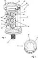
- FIG. 1an embodiment of an inventive hand control device 10 for controlling a machine is shown in perspective.
- the hand control unit 10comprises an ergonomic handle 12, which is mounted with a threaded hollow screw 14 on a deflection mechanism, not shown here for the handle 12.
- the deflection of the handle 12is from a position sensor, not shown here detected.
- the position sensorthen generates control signals which correspond to the deflection of the handle 12, whereby the machine is controlled in a suitable manner.
- the deflection mechanism for the handle 12usually also includes a return mechanism and a locking device, which returns the deflected handle 12 back to an initial position. With a locking mechanism, the handle can be locked in a specific deflected position.
- the deflection and locking mechanism and the generation of signals by means of position sensorsare well known to the skilled person and are therefore not shown for reasons of clarity.
- the handle 12has finger separators 16 in order to achieve optimal achievement of the function switch 18 as ease of use.
- the function switches 18are assigned to control the machine with various functions.
- the function switch 18are formed in this embodiment as an electronic pressure switch 20, which are covered with an elastic plastic cap 22 for protection.
- switchesare also conceivable here, which can be actuated over the longitudinal axis of the handle 12.
- one or more function switches 18may be designed so that they not only know two states "on / off" but are also infinitely variable.
- a selector switch 24is provided on the handle 12. With the help of the selection switch 24, the functions of the function switch 18 can be changed. The respective selection and occupancy of the switches is displayed on a display 26.
- the display 26is provided in the upper area 40 of the handle 12, so that it is always visible to a user for detecting the respectively set functions.
- In the upper region of the handle 12is a groove 28 in which an LED strip 30 is inserted.
- the LED tape 30is protected by a plastic cover 32.
- Fig. 2becomes the handle 12 according to Fig. 1 shown from above.
- the display 26is displayed.
- the respective set functions of the function switch 18can be displayed.
- the display 26is preferably designed as an OLED in order to obtain the most flat and space-saving possible design. It also shows which functions the function switch 18 is currently assigned by the selection switch 24.
- the display 26may be configured as a touch-sensitive display as needed. Then, the selector switch 24 for the function switches 18 can be integrated in this touch-sensitive display 26. This also allows each function switch 18 to be individually assigned a function.
- the Fig. 3shows the handle 12 according to the Fig. 1 in an exploded view.
- the handle 12consists in the present embodiment of two handles 34, 36.
- the front handle shell 34 and the rear handle shell 36are assembled with mounting screws 38.
- the display 26is inserted in the upper part 40 of the handle 12.
- recesses 42are provided in the handle shells 34, 36.
- Below the display 26are the electronic components 44, which are required for the manual control unit 10.
- the control unit 46processes as signal processing unit 48 of the manual control unit 10, the signals of the function switch 18 and a position sensor, not shown, for the deflection of the handle 12 and finally supplies corresponding control signals or control data to the machine or its machine control.
- the function switch 18 and the selector switch 24have connections 50 which are connected to the control unit 46.
- a vibration mechanism 51having a vibrator holder 52 and a thereto attached Vibrator 54 is provided. If necessary, the vibrator 54 signals the user by vibration of the handle 12, for example certain functions or conditions of the machine. This could also be supported by acoustic signals or instructions or instructions.
- the threaded hollow screw 14is guided through an opening 56 of a clamping washer 58 for a bellows, not shown.
- a mounting foot 60 for the two handles 34 and 36is also provided.
- the handles 34, 36are preferably made of plastic.
Landscapes
- Physics & Mathematics (AREA)
- General Physics & Mathematics (AREA)
- Engineering & Computer Science (AREA)
- Automation & Control Theory (AREA)
- Mechanical Control Devices (AREA)
Abstract
Translated fromGermanDescription
Translated fromGermanDie Erfindung betrifft ein Handsteuergerät zum Steuern von Maschinen, enthaltend
- a) einen Handgriff, welcher um wenigstens eine Achse schwenkbar ausgebildet ist,
- b) Signalerzeugungsmittel zur Erzeugung von Steuersignalen für eine Signalverarbeitungseinheit, wobei die Steuersignale in Bezug auf die jeweilige Auslenkung des Handgriffs erzeugt werden,
- c) Funktionsschalter, mit welchen jeweils eine zusätzliche Funktion zur Steuerung der Maschine geschaltet werden kann.
- a) a handle, which is designed to be pivotable about at least one axis,
- b) signal generating means for generating control signals for a signal processing unit, wherein the control signals are generated with respect to the respective deflection of the handle,
- c) Function switch with which an additional function for controlling the machine can be switched.
Solche Handsteuergeräte bzw. Handsteuergeber werden häufig zur Steuerung von schweren Maschinen eingesetzt. Beispielsweise werden sie zur Steuerung von Kränen, Baggern, Gabelstaplern oder als Fahrtenregler für Schienenfahrzeuge und Schiffe eingesetzt. Sie lassen sich wie ein Joystick bedienen. Grundsätzlich lassen sich viele Arten von Maschinen, die manuell bedient werden, mit einem Handsteuergeber steuern. Modulare Bauweise unterstützt die Verwendung eines Handsteuergebers in vielen Anordnungen für Maschinensteuerungen.Such hand control devices or manual control devices are frequently used for controlling heavy machinery. For example, they are used to control cranes, excavators, forklifts or as a speed controller for rail vehicles and ships used. They can be operated like a joystick. Basically, many types of machines that are manually operated can be controlled with a hand control transmitter. Modular design supports the use of a manual control transmitter in many machine control arrangements.
Die Steuerung erfolgt über die jeweilige Winkellage der Steuerwelle, die mit dem Steuerhebel verbunden ist. Es ist bekannt, die Winkellage optisch beispielsweise mittels einer kodierten Scheibe zu erfassen. Die Winkellage lässt sich aber auch elektronisch beispielsweise über ein Potentiometer ermitteln.The control takes place via the respective angular position of the control shaft, which is connected to the control lever. It is known to detect the angular position optically, for example by means of a coded disc. The angular position can also be determined electronically, for example via a potentiometer.
Es gibt eindimensionale Handsteuergeber, die nur über eine Achse betrieben werden. Aber auch zweidimensionale Handsteuergeber werden verwendet. Die zweidimensionalen Handsteuergeber verfügen dementsprechend über zwei nichtparallele Steuerwellen, die über ein geeignetes Getriebe angetrieben werden. Die Empfindlichkeit eines Handsteuergebers lässt sich mit einem geeigneten Getriebe zwischen Steuerhebel und Steuerwelle erzielen.There are one-dimensional manual control encoders which are only operated via one axis. But also two-dimensional hand control encoders are used. Accordingly, the two-dimensional hand control transmitters have two non-parallel control shafts, which are driven by a suitable gear. The sensitivity of a manual control transmitter can be achieved with a suitable transmission between control lever and control shaft.
An dem Handgriff sind häufig Funktionsschalter vorgesehen, die dem Handsteuergerät noch zusätzliche Funktionen zuordnen. Durch die Größe des Handgriffs bedingt ist die Anzahl der Funktionsschalter nur begrenzt. Zwar könnten die Funktionsschalter verkleinert werden, um mehr Funktionen unterzubringen, allerdings würde dies Fehlfunktionen nicht ausschließen, da der Bediener versehentlich den falschen oder mehrere Funktionsschalter gleichzeitig betätigen kann.On the handle often function switches are provided, which assign additional functions to the manual control unit. Due to the size of the handle, the number of function switches is limited. While the function switches could be downsized to accommodate more functions, this would not preclude malfunction as the operator may inadvertently actuate the wrong or multiple function switches simultaneously.
Aus der
Die
Durch die
Nachteil der bekannten Handsteuergeräte zur Steuerung ist, dass die Funktionsvielfalt bei immer komplexeren Maschinen eingeschränkt ist. Zusätzliche Funktionsschalter lassen das Handsteuergerät zudem unübersichtlicher werden, wodurch schneller Bedienfehler vorkommen können.Disadvantage of the known hand control devices for the control is that the variety of functions is limited in increasingly complex machines. Additional function switches also make the hand control unit more confusing, which can result in faster operating errors.
Aufgabe der Erfindung ist es daher, die Nachteile des Standes der Technik zu vermeiden und ein Handsteuergerät zu schaffen, mit welchem der Nutzer möglichst viele Funktionen bei einer Maschine ansteuern kann.The object of the invention is therefore to avoid the disadvantages of the prior art and to provide a manual control device with which the user can control as many functions in a machine.
Erfindungsgemäß wird die Aufgabe dadurch gelöst, dass bei einem Handsteuergerät zum Steuern von Maschinen der eingangs genannten Art ein Auswahlschalter vorgesehen ist, mit welchem bei Betätigung die Funktionen der Funktionsschalter und/oder die Funktionen des Handgriffs unterschiedlich belegt werden. Hierdurch können auf dem Handgriff platzsparend zahlreiche Funktionen vorgesehen sein. Es reicht aus, wenn der Bediener des Handgriffs nur relativ wenig Funktionsschalter betätigen muss. Die jeweils erforderliche bzw. gewünschte Belegung der Funktionsschalter wird durch den Auswahlschalter getätigt. Für jeden Funktionsschalter können mehrere Funktionen hinterlegt sein. Der Auswahlschalter kann dann jede einzelne Funktion des zugeordneten Funktionsschalters abrufen. Auf diese Weise sind nicht so viele Funktionsschalter erforderlich, wie es bisher beim bekannten Stand der Technik notwendig war. Prinzipiell lässt sich auch die Funktion für die Auslenkung des Steuerhebels über den Auswahlschalter neu belegen. Das Handsteuergerät ist damit vielfältig einsetzbar. Die Programmierung der Funktionsschalter lässt sich dabei auf die jeweilige Maschine anpassen. Das Handsteuergerät weist dafür eine prozessorgesteuerte Steuereinheit zur Verarbeitung der Signale der Funktionsschalter und Erzeugung von Steuersignalen für die Maschine bzw. Anlage auf.According to the invention the object is achieved in that in a manual control device for controlling machines of the type mentioned in a selector switch is provided with which the functions of the function switch and / or the functions of the handle are occupied differently when actuated. As a result, numerous functions can be provided on the handle to save space. It is sufficient if the operator of the handle only relatively little function switch must operate. The respective required or desired assignment of the function switch is made by the selector switch. Several functions can be stored for each function switch. The selector switch can then recall each individual function of the associated function switch. In this way, not so many function switches are required, as it was previously necessary in the prior art. In principle, the function for the deflection of the control lever via the selection switch can be re-occupied. The manual control unit is therefore versatile. The programming of the function switches can be adapted to the respective machine. For this purpose, the manual control unit has a processor-controlled control unit for processing the signals of the function switches and generating control signals for the machine or system.
Eine vorteilhafte Ausgestaltung des erfindungsgemäßen Handsteuergeräts zum Steuern von Maschinen besteht darin, dass eine Anzeige vorgesehen ist, welche die Auswahl des Auswahlschalters darstellt. Damit der Anwender nicht sämtliche Funktionsbelegungen der Funktionsschalter auswendig lernen muss, werden ihm die Belegungen der Funktionsschalter auf einer Anzeige dargestellt. Neben der Darstellung dieser Belegungen können auf der Anzeige auch andere das Handsteuergerät oder die Maschine betreffende Informationen angezeigt werden.An advantageous embodiment of the hand control device according to the invention for controlling machines is that a display is provided which represents the selection of the selection switch. So that the user does not have to memorize all functional assignments of the function switches, the assignments of the function switches are displayed on a display. In addition to the presentation of these assignments, other information concerning the manual control device or the machine can also be displayed on the display.
In einer zweckmäßigen Ausbildung des erfindungsgemäßen Handsteuergeräts ist dann die Anzeige in dem Handgriff integriert. Hierdurch ist die Anzeige für den Anwender immer sichtbar und präsent. Informationen bezüglich der Belegung der Funktionsschalter lassen sich sehr schnell erfassen.In an expedient embodiment of the hand control device according to the invention then the display is integrated in the handle. This makes the display always visible and present to the user. Information regarding the assignment of the function switches can be detected very quickly.
Vorzugsweise ist in einer besonderen Ausführung des erfindungsgemäßen Handsteuergeräts die Anzeige als berührungsempfindliche Anzeige ausgebildet. Mit dieser Maßnahme kann der Anwender nicht nur Funktionen bzw. Informationen sehen, sondern auch bestimmte Maßnahmen direkt durchführen. Dazu gehört auch, dass der Auswahlschalter Teil der berührungsempfindlichen Anzeige ist. Über die berührungsempfindliche Anzeige können Funktionsschalter mit Funktionen belegt werden. Sofern die berührungsempfindliche Anzeige während der Bedienung der Maschine mit dem Handgriff störend ist, kann die Berührungsempfindlichkeit der Anzeige mittels eines Schalters deaktiviert und bei Bedarf entsprechend wieder aktiviert werden.Preferably, in a particular embodiment of the hand control device according to the invention, the display is designed as a touch-sensitive display. With this measure, the user can not only see functions or information, but also perform certain measures directly. This also includes that the selector switch is part of the touch-sensitive display. Functional switches can be assigned functions via the touch-sensitive display. If the touch-sensitive display is annoying during operation of the machine with the handle, the touch sensitivity of the display can be deactivated by means of a switch and reactivated as needed.
Eine weitere bevorzugte Ausbildung des erfindungsgemäßen Handsteuergeräts besteht darin, dass ein Status der Maschine und/oder die Funktionsbelegungen der Funktionsschalter auf der Anzeige symbolisch, farblich und/oder alphanumerisch darstellbar sind. Hiermit lässt sich platzsparend der Status der Maschine anzeigen. Dies kann in Kombination mit den Funktionen der Funktionsschalter besonders sinnvoll sein, beispielsweise wenn die Maschine beim Gas geben in einen kritischen Bereich oder wenn beispielsweise ein Ausleger eines Krans in eine kritische Position kommt.A further preferred embodiment of the manual control device according to the invention is that a status of the machine and / or the function assignments of the function switch on the display symbolically, color and / or alphanumeric can be displayed. This saves space and displays the status of the machine. This can be particularly useful in combination with the functions of the function switches, for example when the machine is accelerating into a critical area or, for example, when a jib of a crane comes to a critical position.
In einer weiteren vorteilhaften Ausgestaltung des erfindungsgemäßen Handsteuergeräts ist ein Vibrationsmechanismus in dem Handgriff vorgesehen, mit weichem einem Anwender ein Zustand der Maschine und/oder oder die Funktion der Funktionsschalter signalisiert werden kann. Diese Maßnahme dient dazu, den Anwender mit noch zusätzlichen Hilfsmitteln in der Bedienung einer Maschine zu unterstützen, Der Vibrationsmechanismus sorgt dafür, dass dem Anwender der Zustand der Maschine und/oder die Funktionen des Handsteuergeräts als weitere nützliche Information auf diese Weise signalisiert werden. Denn nicht immer kann ein Anwender auf die Anzeige des Handsteuergeräts achten, da er beispielsweise die Arbeit der Maschine beobachten muss.In a further advantageous embodiment of the hand control device according to the invention, a vibration mechanism is provided in the handle, with a user a state of the machine and / or the function of the function switch can be signaled. This measure serves to assist the user with additional aids in the operation of a machine. The vibration mechanism ensures that the state of the machine to the user and / or the functions of the hand controller are signaled as further useful information in this way. Because a user can not always pay attention to the display of the manual control unit, as he, for example, has to observe the work of the machine.
Ein weiterer vorteilhafter Aspekt für das erfindungsgemäße Handsteuergerät ergibt sich dadurch, dass für die Auslenkung des Handgriffs ein Rückholmechanismus vorgesehen ist, der den Handgriff nach einer Auslenkung in eine Ausgangsstellung zurückführt. Damit der Handgriff nicht in seiner ausgelenkten Position verharrt, ist es oft wünschenswert, dass der Handgriff in eine ursprüngliche Ausgangsposition zurückgeführt wird. Der Handgriff wird beispielsweise in seine Ausgangsposition mit Hilfe des Rückholmechanismus zurückgeführt, sobald der Handgriff losgelassen wird. Dadurch wird die Maschine dann gestoppt.Another advantageous aspect of the hand control device according to the invention results from the fact that a return mechanism is provided for the deflection of the handle, which returns the handle after a deflection in an initial position. In order for the handle not to remain in its deflected position, it is often desirable for the handle to be returned to an original home position. For example, the handle is returned to its original position by means of the return mechanism as soon as the handle is released. This will stop the machine.
In einer bevorzugten Ausgestaltung des erfindungsgemäßen Handsteuergeräts ist ein Rastmechanismus und/oder eine Feststellvorrichtung für die Auslenkung des Handgriffs vorgesehen ist. Diese Maßnahme dient dazu, den Handgriff in einer definierten ausgelenkten Stellung zu belassen, damit die Maschine bei dieser Stellung des Handgriffs konstant arbeitet.In a preferred embodiment of the hand control device according to the invention, a latching mechanism and / or a locking device for the deflection of the handle is provided. This measure serves to leave the handle in a defined deflected position so that the machine operates constantly in this position of the handle.
Eine weitere vorteilhafte Ausbildung des erfindungsgemäßen Handsteuergeräts wird dadurch erzielt, dass der Handgriff einen Funktionsschalter aufweist, weicher über die Längsachse des Handgriffes betätigbar ausgebildet ist. Neben den Funktionsschaltern, die von den Fingern eines Anwenders direkt betätigt werden, ist bei diesem Ausführungsbeispiel ein Funktionsschalter vorgesehen, der über die Längsachse des Handgriffs angesprochen wird. Hierzu ist der gesamte Handgriff nach unten oder nach oben entlang der Längsachse zu drücken bzw. zu schieben.A further advantageous embodiment of the hand control device according to the invention is achieved in that the handle has a function switch, which is designed to be actuatable over the longitudinal axis of the handle. In addition to the function switches, which are actuated directly by the fingers of a user, a function switch is provided in this embodiment, which is addressed via the longitudinal axis of the handle. To do this, push or push the entire handle downwards or upwards along the longitudinal axis.
Eine vorteilhafte Ausgestaltung des erfindungsgemäßen Handsteuergeräts ergibt sich dadurch, dass ein Funktionsschalter stufenlos regelbar ist. Schalter lassen sich meist nur ein- bzw. ausschalten. Dies gilt auch für die Funktionsschalter, die meist zur Anwendung kommen. Mit dem stufenlosen Funktionsschalter lassen sich aber Funktionen wie Gas geben recht einfach realisieren.An advantageous embodiment of the hand control device according to the invention results from the fact that a function switch is infinitely variable. Switches can usually only be switched on or off. This also applies to the function switches, which are mostly for use come. With the stepless function switch, however, functions such as gas can be implemented quite easily.
Weitere Ausgestaltungen und Vorteile ergeben sich aus dem Gegenstand der Unteransprüche sowie den Zeichnungen mit den dazugehörigen Beschreibungen. Ein Ausführungsbeispiel ist nachstehend unter Bezugnahme auf die beigefügten Zeichnungen näher erläutert. Die Erfindung soll dabei nicht alleine auf diese aufgeführten Ausführungsbeispiele beschränkt werden. Vielmehr sind auch Ausführungen angedacht, die jetzt und zukünftig in äquivalenter Weise sich dem Fachmann grundsätzlich auch mit anderen technischen Hilfsmitteln erschließen würden.Further embodiments and advantages will become apparent from the subject of the dependent claims and the drawings with the accompanying descriptions. An embodiment is explained below with reference to the accompanying drawings. The invention should not be limited solely to these listed embodiments. Rather, embodiments are also considered, which would now and in the future in an equivalent way to the skilled person in principle also develop with other technical aids.
- Fig. 1Fig. 1
- zeigt in einer perspektivischen Darstellung ein Ausführungsbeispiel eines erfindungsgemäßen Handsteuergeräts zum Steuern von Maschinen.shows a perspective view of an embodiment of a hand control device according to the invention for controlling machines.
- Fig. 2Fig. 2
- zeigt die Anzeige des erfindungsgemäßen Handsteuergeräts zum Steuern von Maschinen gemäß
Fig. 1 .shows the display of the hand control device according to the invention for controlling machines according toFig. 1 , - Fig. 3Fig. 3
- zeigt in einer Explosionsdarstellung ein erfindungsgemäßes Handsteuergerät zum Steuern von Maschinen gemäß
Fig. 1 bzw.Fig. 2 .shows an exploded view of an inventive hand control device for controlling machines according toFig. 1 respectively.Fig. 2 ,
In
Durch die Gewindehohlschraube 14 werden elektrische Leitungen zur Spannungsversorgung und zum Signal- und Datenaustausch des Handgriffs 12 geführt. Der Handgriff 12 verfügt über Fingerseparatoren 16, um ein optimales Erreichen der Funktionsschalter 18 als Bedienungskomfort zu erhalten. Die Funktionsschalter 18 sind zum Steuern der Maschine mit verschiedenen Funktionen belegt. Die Funktionsschalter 18 sind in diesem Ausführungsbeispiel als elektronische Druckschalter 20 ausgebildet, welche mit einer elastischen Kunststoffkappe 22 zum Schutz abgedeckt sind. Denkbar sind hier allerdings auch Schalter, welche sich über die Längsachse des Handgriffs 12 betätigen lassen. Außerdem können einer oder mehrere Funktionsschalter 18 so ausgestaltet sein, dass sie nicht nur zwei Zustände "ein/aus" kennen, sondern auch stufenlos regelbar sind.Through the threaded
Ein Auswahlschalter 24 ist an dem Handgriff 12 vorgesehen. Mit Hilfe des Auswahlschalters 24 können die Funktionen der Funktionsschalter 18 verändert werden. Die jeweilige Auswahl und Belegung der Schalter wird auf einer Anzeige 26 dargestellt. Die Anzeige 26 ist im oberen Bereich 40 des Handgriffs 12 vorgesehen, so dass sie für einen Anwender zum Erfassen der jeweils eingestellten Funktionen immer sichtbar ist. Im oberen Bereich des Handgriffs 12 befindet sich eine Nut 28, in welcher ein LED-Band 30 eingelassen ist. Das LED-Band 30 wird von einer Kunststoffabdeckung 32 geschützt. Das LED=Band 30 signalisiert dem Anwender beispielsweise optisch eingestellte Funktionen, Einstellungen der Funktionsschalter 18 bzw. des Auswahlschalters 24, ohne die Anzeige 26 ablesen zu müssen.A
In
Die
Die Funktionsschalter 18 und der Auswahlschalter 24 haben dafür Anschlüsse 50, welche mit der Steuereinheit 46 verbunden werden. In dem Handgriff 12 ist ferner ein Vibrationsmechanismus 51 mit einem Vibratorhalter 52 und einem daran befestigten Vibrator 54 vorgesehen. Der Vibrator 54 signalisiert bei Bedarf dem Anwender per Vibration des Handgriffs 12 beispielsweise bestimmte Funktionen oder Zustände der Maschine. Dies könnte auch noch durch akustische Signale oder Anweisungen bzw. Hinweise unterstützt werden.The
Die Gewindehohlschraube 14 ist durch eine Öffnung 56 einer Klemmscheibe 58 für einen nicht dargestellten Faltenbalg geführt. An der Gewindehohlschraube 14 ist ferner ein Befestigungsfuß 60 für die beiden Griffschalen 34 und 36 vorgesehen. Die Griffschalen 34, 36 sind vorzugsweise aus Kunststoff hergestellt.The threaded
- 1010
- HandsteuergerätManual control unit
- 1212
- Handgriffhandle
- 1414
- GewindehohlschraubeThreaded hollow screw
- 1616
- FingerseparatorenFingerseparatoren
- 1818
- Funktionsschalterfunction switch
- 2020
- Elektronische DruckschalterElectronic pressure switch
- 2222
- elastische Kunststoffkappeelastic plastic cap
- 2424
- Auswahlschalterselector switch
- 2626
- Anzeigedisplay
- 2828
- Nutgroove
- 3030
- LED-BandLED tape
- 3232
- KunststoffabdeckungPlastic cover
- 3434
- Vordere GriffschaleFront handle shell
- 3636
- Hintere GriffschaleRear handle shell
- 3838
- Befestigungsschraubenmounting screws
- 4040
- oberer Teil des Handgriffsupper part of the handle
- 4242
- Aussparungrecess
- 4444
- elektronischen Bauteileelectronic components
- 4646
- Steuereinheitcontrol unit
- 4848
- SignalverarbeitungseinheitSignal processing unit
- 5050
- Anschlüsseconnections
- 5151
- Vibrationsmechanismusvibration mechanism
- 5252
- Vibratorhaltervibrator holder
- 5454
- Vibratorvibrator
- 5656
- Öffnungopening
- 5858
- Klemmscheibeclamping disc
- 6060
- BefestigungsfußMounting foot
Claims (10)
Translated fromGermandadurch gekennzeichnet, dass
characterized in that
Applications Claiming Priority (1)
| Application Number | Priority Date | Filing Date | Title |
|---|---|---|---|
| DE202018102255.5UDE202018102255U1 (en) | 2018-04-23 | 2018-04-23 | Manual control unit with function switch |
Publications (3)
| Publication Number | Publication Date |
|---|---|
| EP3561185A1true EP3561185A1 (en) | 2019-10-30 |
| EP3561185C0 EP3561185C0 (en) | 2024-01-24 |
| EP3561185B1 EP3561185B1 (en) | 2024-01-24 |
Family
ID=62983049
Family Applications (1)
| Application Number | Title | Priority Date | Filing Date |
|---|---|---|---|
| EP19000172.7AActiveEP3561185B1 (en) | 2018-04-23 | 2019-04-08 | Hand-held control device with function modifier switch |
Country Status (2)
| Country | Link |
|---|---|
| EP (1) | EP3561185B1 (en) |
| DE (1) | DE202018102255U1 (en) |
Citations (8)
| Publication number | Priority date | Publication date | Assignee | Title |
|---|---|---|---|---|
| DE4227353C2 (en) | 1992-08-14 | 1994-05-26 | Oelsch Fernsteuergeraete | Control handle arrangement, in particular for use with a pressure transmitter operated control transmitter arrangement |
| DE29509029U1 (en) | 1995-05-29 | 1995-08-17 | Fernsteuergeräte Kurt Oelsch GmbH, 12347 Berlin | Control handle with dead man's switch |
| US5619195A (en) | 1995-12-29 | 1997-04-08 | Charles D. Hayes | Multi-axial position sensing apparatus |
| US6354023B1 (en)* | 1998-12-15 | 2002-03-12 | Bombardier Inc. | Snow groomers and control system therefor |
| DE102008022850A1 (en) | 2007-11-27 | 2009-05-28 | Fernsteuergeräte Kurt Oelsch GmbH | Inductive manual control transmitter |
| JP2012234278A (en)* | 2011-04-28 | 2012-11-29 | Sakae Tsushin Kogyo Kk | Joystick and position input controller |
| EP2980317A1 (en)* | 2014-07-30 | 2016-02-03 | Caterpillar Inc. | Multiple control patterns for hydraulically operated machines with hand and foot controls |
| DE102016124493B3 (en)* | 2016-12-15 | 2017-12-28 | Elobau Gmbh & Co. Kg | Joystick with status display and procedure |
Family Cites Families (1)
| Publication number | Priority date | Publication date | Assignee | Title |
|---|---|---|---|---|
| KR100621982B1 (en)* | 2004-04-13 | 2006-09-14 | 볼보 컨스트럭션 이키프먼트 홀딩 스웨덴 에이비 | Function switch pattern setting device of heavy equipment |
- 2018
- 2018-04-23DEDE202018102255.5Upatent/DE202018102255U1/enactiveActive
- 2019
- 2019-04-08EPEP19000172.7Apatent/EP3561185B1/enactiveActive
Patent Citations (8)
| Publication number | Priority date | Publication date | Assignee | Title |
|---|---|---|---|---|
| DE4227353C2 (en) | 1992-08-14 | 1994-05-26 | Oelsch Fernsteuergeraete | Control handle arrangement, in particular for use with a pressure transmitter operated control transmitter arrangement |
| DE29509029U1 (en) | 1995-05-29 | 1995-08-17 | Fernsteuergeräte Kurt Oelsch GmbH, 12347 Berlin | Control handle with dead man's switch |
| US5619195A (en) | 1995-12-29 | 1997-04-08 | Charles D. Hayes | Multi-axial position sensing apparatus |
| US6354023B1 (en)* | 1998-12-15 | 2002-03-12 | Bombardier Inc. | Snow groomers and control system therefor |
| DE102008022850A1 (en) | 2007-11-27 | 2009-05-28 | Fernsteuergeräte Kurt Oelsch GmbH | Inductive manual control transmitter |
| JP2012234278A (en)* | 2011-04-28 | 2012-11-29 | Sakae Tsushin Kogyo Kk | Joystick and position input controller |
| EP2980317A1 (en)* | 2014-07-30 | 2016-02-03 | Caterpillar Inc. | Multiple control patterns for hydraulically operated machines with hand and foot controls |
| DE102016124493B3 (en)* | 2016-12-15 | 2017-12-28 | Elobau Gmbh & Co. Kg | Joystick with status display and procedure |
Also Published As
| Publication number | Publication date |
|---|---|
| EP3561185C0 (en) | 2024-01-24 |
| DE202018102255U1 (en) | 2018-07-06 |
| EP3561185B1 (en) | 2024-01-24 |
Similar Documents
| Publication | Publication Date | Title |
|---|---|---|
| EP3389943B1 (en) | Hand-held power tool comprising a percussion mechanism | |
| EP3389942B1 (en) | Hand-held power tool comprising a percussion mechanism | |
| EP1075979B1 (en) | Method of operating a multifunction operation device in motor vehicles and multifunction operating device | |
| DE102008017350A1 (en) | Control for truck mixer | |
| WO2007128633A1 (en) | Vehicle function control system and input method for a vehicle function control system | |
| DE102013009563A1 (en) | Agricultural machine e.g. tractor-loading wagon combination, has display unit comprising display elements that are directly arranged in control buttons for displaying key assignment directly to control buttons | |
| DE102010041345A1 (en) | Device for fastening a haptic surface | |
| WO2017102515A1 (en) | Hand-held power tool comprising a gearshift unit | |
| DE102004019893B4 (en) | Control element for a motor vehicle | |
| DE202017105886U1 (en) | switching device | |
| EP3513261B1 (en) | Control device for operating a machine tool, in particular a milling machine or lathe, and corresponding machine tool | |
| DE102004016121B4 (en) | Operating device for moving at least one machine axis of a tool or production machine | |
| WO2008064380A1 (en) | Portable operating and monitoring device for an industrial control device | |
| DE102021202073A1 (en) | Operating arrangement for a steer-by-wire steering system of a motor vehicle | |
| EP3561185B1 (en) | Hand-held control device with function modifier switch | |
| WO2008089802A1 (en) | Multi-functional operating device, particularly for a central control system in a motor vehicle | |
| DE202024100451U1 (en) | Control unit for a vehicle | |
| EP3755567B1 (en) | Input device and method for controlling at least one functional unit for a vehicle with a visual displacement of an operation icon | |
| EP3662345B1 (en) | Control device for industrial machines | |
| DE102017210442A1 (en) | Dehsteuervorrichtung | |
| WO2014076095A1 (en) | Control unit for a medical appliance | |
| DE10304985B3 (en) | Manually-operated switch e.g. for control panel of music mixer desk, using touch-control sensors spaced around mantle surface of operating knob | |
| EP3513259A2 (en) | Control device and control method for industrial machines with controlled motion drives | |
| WO2005029983A1 (en) | Operating unit for a machine in the tobacco-processing industry | |
| EP3662346B1 (en) | Control device for industrial machines |
Legal Events
| Date | Code | Title | Description |
|---|---|---|---|
| PUAI | Public reference made under article 153(3) epc to a published international application that has entered the european phase | Free format text:ORIGINAL CODE: 0009012 | |
| STAA | Information on the status of an ep patent application or granted ep patent | Free format text:STATUS: THE APPLICATION HAS BEEN PUBLISHED | |
| AK | Designated contracting states | Kind code of ref document:A1 Designated state(s):AL AT BE BG CH CY CZ DE DK EE ES FI FR GB GR HR HU IE IS IT LI LT LU LV MC MK MT NL NO PL PT RO RS SE SI SK SM TR | |
| AX | Request for extension of the european patent | Extension state:BA ME | |
| STAA | Information on the status of an ep patent application or granted ep patent | Free format text:STATUS: REQUEST FOR EXAMINATION WAS MADE | |
| 17P | Request for examination filed | Effective date:20200121 | |
| RBV | Designated contracting states (corrected) | Designated state(s):AL AT BE BG CH CY CZ DE DK EE ES FI FR GB GR HR HU IE IS IT LI LT LU LV MC MK MT NL NO PL PT RO RS SE SI SK SM TR | |
| STAA | Information on the status of an ep patent application or granted ep patent | Free format text:STATUS: EXAMINATION IS IN PROGRESS | |
| 17Q | First examination report despatched | Effective date:20201105 | |
| GRAP | Despatch of communication of intention to grant a patent | Free format text:ORIGINAL CODE: EPIDOSNIGR1 | |
| STAA | Information on the status of an ep patent application or granted ep patent | Free format text:STATUS: GRANT OF PATENT IS INTENDED | |
| INTG | Intention to grant announced | Effective date:20231024 | |
| GRAS | Grant fee paid | Free format text:ORIGINAL CODE: EPIDOSNIGR3 | |
| GRAA | (expected) grant | Free format text:ORIGINAL CODE: 0009210 | |
| STAA | Information on the status of an ep patent application or granted ep patent | Free format text:STATUS: THE PATENT HAS BEEN GRANTED | |
| AK | Designated contracting states | Kind code of ref document:B1 Designated state(s):AL AT BE BG CH CY CZ DE DK EE ES FI FR GB GR HR HU IE IS IT LI LT LU LV MC MK MT NL NO PL PT RO RS SE SI SK SM TR | |
| REG | Reference to a national code | Ref country code:GB Ref legal event code:FG4D Free format text:NOT ENGLISH | |
| REG | Reference to a national code | Ref country code:CH Ref legal event code:EP | |
| REG | Reference to a national code | Ref country code:DE Ref legal event code:R096 Ref document number:502019010429 Country of ref document:DE | |
| REG | Reference to a national code | Ref country code:IE Ref legal event code:FG4D Free format text:LANGUAGE OF EP DOCUMENT: GERMAN | |
| U01 | Request for unitary effect filed | Effective date:20240206 | |
| U07 | Unitary effect registered | Designated state(s):AT BE BG DE DK EE FI FR IT LT LU LV MT NL PT SE SI Effective date:20240214 | |
| U20 | Renewal fee for the european patent with unitary effect paid | Year of fee payment:6 Effective date:20240409 | |
| PG25 | Lapsed in a contracting state [announced via postgrant information from national office to epo] | Ref country code:IS Free format text:LAPSE BECAUSE OF FAILURE TO SUBMIT A TRANSLATION OF THE DESCRIPTION OR TO PAY THE FEE WITHIN THE PRESCRIBED TIME-LIMIT Effective date:20240524 | |
| PGFP | Annual fee paid to national office [announced via postgrant information from national office to epo] | Ref country code:GB Payment date:20240423 Year of fee payment:6 | |
| PG25 | Lapsed in a contracting state [announced via postgrant information from national office to epo] | Ref country code:GR Free format text:LAPSE BECAUSE OF FAILURE TO SUBMIT A TRANSLATION OF THE DESCRIPTION OR TO PAY THE FEE WITHIN THE PRESCRIBED TIME-LIMIT Effective date:20240425 | |
| PG25 | Lapsed in a contracting state [announced via postgrant information from national office to epo] | Ref country code:HR Free format text:LAPSE BECAUSE OF FAILURE TO SUBMIT A TRANSLATION OF THE DESCRIPTION OR TO PAY THE FEE WITHIN THE PRESCRIBED TIME-LIMIT Effective date:20240124 Ref country code:RS Free format text:LAPSE BECAUSE OF FAILURE TO SUBMIT A TRANSLATION OF THE DESCRIPTION OR TO PAY THE FEE WITHIN THE PRESCRIBED TIME-LIMIT Effective date:20240424 | |
| PGFP | Annual fee paid to national office [announced via postgrant information from national office to epo] | Ref country code:CH Payment date:20240501 Year of fee payment:6 | |
| PG25 | Lapsed in a contracting state [announced via postgrant information from national office to epo] | Ref country code:ES Free format text:LAPSE BECAUSE OF FAILURE TO SUBMIT A TRANSLATION OF THE DESCRIPTION OR TO PAY THE FEE WITHIN THE PRESCRIBED TIME-LIMIT Effective date:20240124 | |
| PG25 | Lapsed in a contracting state [announced via postgrant information from national office to epo] | Ref country code:RS Free format text:LAPSE BECAUSE OF FAILURE TO SUBMIT A TRANSLATION OF THE DESCRIPTION OR TO PAY THE FEE WITHIN THE PRESCRIBED TIME-LIMIT Effective date:20240424 Ref country code:IS Free format text:LAPSE BECAUSE OF FAILURE TO SUBMIT A TRANSLATION OF THE DESCRIPTION OR TO PAY THE FEE WITHIN THE PRESCRIBED TIME-LIMIT Effective date:20240524 Ref country code:HR Free format text:LAPSE BECAUSE OF FAILURE TO SUBMIT A TRANSLATION OF THE DESCRIPTION OR TO PAY THE FEE WITHIN THE PRESCRIBED TIME-LIMIT Effective date:20240124 Ref country code:GR Free format text:LAPSE BECAUSE OF FAILURE TO SUBMIT A TRANSLATION OF THE DESCRIPTION OR TO PAY THE FEE WITHIN THE PRESCRIBED TIME-LIMIT Effective date:20240425 Ref country code:ES Free format text:LAPSE BECAUSE OF FAILURE TO SUBMIT A TRANSLATION OF THE DESCRIPTION OR TO PAY THE FEE WITHIN THE PRESCRIBED TIME-LIMIT Effective date:20240124 | |
| PGFP | Annual fee paid to national office [announced via postgrant information from national office to epo] | Ref country code:NO Payment date:20240419 Year of fee payment:6 | |
| PG25 | Lapsed in a contracting state [announced via postgrant information from national office to epo] | Ref country code:PL Free format text:LAPSE BECAUSE OF FAILURE TO SUBMIT A TRANSLATION OF THE DESCRIPTION OR TO PAY THE FEE WITHIN THE PRESCRIBED TIME-LIMIT Effective date:20240124 | |
| PG25 | Lapsed in a contracting state [announced via postgrant information from national office to epo] | Ref country code:PL Free format text:LAPSE BECAUSE OF FAILURE TO SUBMIT A TRANSLATION OF THE DESCRIPTION OR TO PAY THE FEE WITHIN THE PRESCRIBED TIME-LIMIT Effective date:20240124 | |
| PGFP | Annual fee paid to national office [announced via postgrant information from national office to epo] | Ref country code:TR Payment date:20240417 Year of fee payment:6 | |
| PG25 | Lapsed in a contracting state [announced via postgrant information from national office to epo] | Ref country code:SM Free format text:LAPSE BECAUSE OF FAILURE TO SUBMIT A TRANSLATION OF THE DESCRIPTION OR TO PAY THE FEE WITHIN THE PRESCRIBED TIME-LIMIT Effective date:20240124 | |
| PG25 | Lapsed in a contracting state [announced via postgrant information from national office to epo] | Ref country code:CZ Free format text:LAPSE BECAUSE OF FAILURE TO SUBMIT A TRANSLATION OF THE DESCRIPTION OR TO PAY THE FEE WITHIN THE PRESCRIBED TIME-LIMIT Effective date:20240124 | |
| REG | Reference to a national code | Ref country code:DE Ref legal event code:R097 Ref document number:502019010429 Country of ref document:DE | |
| PG25 | Lapsed in a contracting state [announced via postgrant information from national office to epo] | Ref country code:SK Free format text:LAPSE BECAUSE OF FAILURE TO SUBMIT A TRANSLATION OF THE DESCRIPTION OR TO PAY THE FEE WITHIN THE PRESCRIBED TIME-LIMIT Effective date:20240124 | |
| PG25 | Lapsed in a contracting state [announced via postgrant information from national office to epo] | Ref country code:SM Free format text:LAPSE BECAUSE OF FAILURE TO SUBMIT A TRANSLATION OF THE DESCRIPTION OR TO PAY THE FEE WITHIN THE PRESCRIBED TIME-LIMIT Effective date:20240124 Ref country code:SK Free format text:LAPSE BECAUSE OF FAILURE TO SUBMIT A TRANSLATION OF THE DESCRIPTION OR TO PAY THE FEE WITHIN THE PRESCRIBED TIME-LIMIT Effective date:20240124 Ref country code:RO Free format text:LAPSE BECAUSE OF FAILURE TO SUBMIT A TRANSLATION OF THE DESCRIPTION OR TO PAY THE FEE WITHIN THE PRESCRIBED TIME-LIMIT Effective date:20240124 Ref country code:CZ Free format text:LAPSE BECAUSE OF FAILURE TO SUBMIT A TRANSLATION OF THE DESCRIPTION OR TO PAY THE FEE WITHIN THE PRESCRIBED TIME-LIMIT Effective date:20240124 | |
| PG25 | Lapsed in a contracting state [announced via postgrant information from national office to epo] | Ref country code:MC Free format text:LAPSE BECAUSE OF FAILURE TO SUBMIT A TRANSLATION OF THE DESCRIPTION OR TO PAY THE FEE WITHIN THE PRESCRIBED TIME-LIMIT Effective date:20240124 | |
| PG25 | Lapsed in a contracting state [announced via postgrant information from national office to epo] | Ref country code:MC Free format text:LAPSE BECAUSE OF FAILURE TO SUBMIT A TRANSLATION OF THE DESCRIPTION OR TO PAY THE FEE WITHIN THE PRESCRIBED TIME-LIMIT Effective date:20240124 | |
| PLBE | No opposition filed within time limit | Free format text:ORIGINAL CODE: 0009261 | |
| STAA | Information on the status of an ep patent application or granted ep patent | Free format text:STATUS: NO OPPOSITION FILED WITHIN TIME LIMIT | |
| 26N | No opposition filed | Effective date:20241025 | |
| PG25 | Lapsed in a contracting state [announced via postgrant information from national office to epo] | Ref country code:IE Free format text:LAPSE BECAUSE OF NON-PAYMENT OF DUE FEES Effective date:20240408 | |
| U20 | Renewal fee for the european patent with unitary effect paid | Year of fee payment:7 Effective date:20250423 | |
| PG25 | Lapsed in a contracting state [announced via postgrant information from national office to epo] | Ref country code:CY Free format text:LAPSE BECAUSE OF FAILURE TO SUBMIT A TRANSLATION OF THE DESCRIPTION OR TO PAY THE FEE WITHIN THE PRESCRIBED TIME-LIMIT; INVALID AB INITIO Effective date:20190408 | |
| PG25 | Lapsed in a contracting state [announced via postgrant information from national office to epo] | Ref country code:HU Free format text:LAPSE BECAUSE OF FAILURE TO SUBMIT A TRANSLATION OF THE DESCRIPTION OR TO PAY THE FEE WITHIN THE PRESCRIBED TIME-LIMIT; INVALID AB INITIO Effective date:20190408 |