EP3560874B1 - A method and apparatus for condition monitoring of an inductive brake of an elevator car - Google Patents
A method and apparatus for condition monitoring of an inductive brake of an elevator carDownload PDFInfo
- Publication number
- EP3560874B1 EP3560874B1EP18169392.0AEP18169392AEP3560874B1EP 3560874 B1EP3560874 B1EP 3560874B1EP 18169392 AEP18169392 AEP 18169392AEP 3560874 B1EP3560874 B1EP 3560874B1
- Authority
- EP
- European Patent Office
- Prior art keywords
- braking device
- determining
- inductive braking
- inductive
- elevator car
- Prior art date
- Legal status (The legal status is an assumption and is not a legal conclusion. Google has not performed a legal analysis and makes no representation as to the accuracy of the status listed.)
- Active
Links
Images
Classifications
- B—PERFORMING OPERATIONS; TRANSPORTING
- B66—HOISTING; LIFTING; HAULING
- B66B—ELEVATORS; ESCALATORS OR MOVING WALKWAYS
- B66B5/00—Applications of checking, fault-correcting, or safety devices in elevators
- B66B5/0087—Devices facilitating maintenance, repair or inspection tasks
- B66B5/0093—Testing of safety devices
- B—PERFORMING OPERATIONS; TRANSPORTING
- B66—HOISTING; LIFTING; HAULING
- B66B—ELEVATORS; ESCALATORS OR MOVING WALKWAYS
- B66B5/00—Applications of checking, fault-correcting, or safety devices in elevators
- B66B5/0006—Monitoring devices or performance analysers
- B66B5/0018—Devices monitoring the operating condition of the elevator system
- B66B5/0031—Devices monitoring the operating condition of the elevator system for safety reasons
- B—PERFORMING OPERATIONS; TRANSPORTING
- B66—HOISTING; LIFTING; HAULING
- B66B—ELEVATORS; ESCALATORS OR MOVING WALKWAYS
- B66B5/00—Applications of checking, fault-correcting, or safety devices in elevators
- B66B5/0006—Monitoring devices or performance analysers
- B66B5/0018—Devices monitoring the operating condition of the elevator system
- B—PERFORMING OPERATIONS; TRANSPORTING
- B66—HOISTING; LIFTING; HAULING
- B66B—ELEVATORS; ESCALATORS OR MOVING WALKWAYS
- B66B1/00—Control systems of elevators in general
- B66B1/34—Details, e.g. call counting devices, data transmission from car to control system, devices giving information to the control system
- B66B1/3407—Setting or modification of parameters of the control system
- B—PERFORMING OPERATIONS; TRANSPORTING
- B66—HOISTING; LIFTING; HAULING
- B66B—ELEVATORS; ESCALATORS OR MOVING WALKWAYS
- B66B1/00—Control systems of elevators in general
- B66B1/34—Details, e.g. call counting devices, data transmission from car to control system, devices giving information to the control system
- B66B1/3492—Position or motion detectors or driving means for the detector
- B—PERFORMING OPERATIONS; TRANSPORTING
- B66—HOISTING; LIFTING; HAULING
- B66B—ELEVATORS; ESCALATORS OR MOVING WALKWAYS
- B66B1/00—Control systems of elevators in general
- B66B1/34—Details, e.g. call counting devices, data transmission from car to control system, devices giving information to the control system
- B66B1/36—Means for stopping the cars, cages, or skips at predetermined levels
- B—PERFORMING OPERATIONS; TRANSPORTING
- B66—HOISTING; LIFTING; HAULING
- B66B—ELEVATORS; ESCALATORS OR MOVING WALKWAYS
- B66B11/00—Main component parts of lifts in, or associated with, buildings or other structures
- B66B11/04—Driving gear ; Details thereof, e.g. seals
- B66B11/043—Driving gear ; Details thereof, e.g. seals actuated by rotating motor; Details, e.g. ventilation
- B—PERFORMING OPERATIONS; TRANSPORTING
- B66—HOISTING; LIFTING; HAULING
- B66B—ELEVATORS; ESCALATORS OR MOVING WALKWAYS
- B66B11/00—Main component parts of lifts in, or associated with, buildings or other structures
- B66B11/04—Driving gear ; Details thereof, e.g. seals
- B66B11/08—Driving gear ; Details thereof, e.g. seals with hoisting rope or cable operated by frictional engagement with a winding drum or sheave
- B—PERFORMING OPERATIONS; TRANSPORTING
- B66—HOISTING; LIFTING; HAULING
- B66B—ELEVATORS; ESCALATORS OR MOVING WALKWAYS
- B66B19/00—Mining-hoist operation
- B—PERFORMING OPERATIONS; TRANSPORTING
- B66—HOISTING; LIFTING; HAULING
- B66B—ELEVATORS; ESCALATORS OR MOVING WALKWAYS
- B66B5/00—Applications of checking, fault-correcting, or safety devices in elevators
- B66B5/0006—Monitoring devices or performance analysers
- B66B5/0018—Devices monitoring the operating condition of the elevator system
- B66B5/0025—Devices monitoring the operating condition of the elevator system for maintenance or repair
Definitions
- Elevatorshave electromechanical brakes that apply to a traction sheave or rotating axis of a hoisting machine to stop movement of the hoisting machine and therefore an elevator car operated by the hoisting machine.
- the electromechanical brakesare dimensioned to hold the elevator car with an overload at standstill in the elevator shaft.
- the brakesmay be used in rescue situations and in emergency braking to stop the elevator car if an operational fault occurs, such as an overspeed situation of the elevator car. Due to this, the brakes may become large-sized and their control may become complicated.
- EP 1481933 A1discloses a solution in which an emergency stop is fixed to cage such that the cage grasps guide rail in abnormality condition.
- a torque detectordetects the torque of rope to confirm abnormality condition accordingly.
- EP 3106417 A1discloses a control arrangement of an elevator, comprising a safety gear, an over speed governor with a rope which is connected to the safety gear, a stopping device for generating an actuating force to the safety gear, and a drive unit for driving the elevator apparatus.
- the control arrangementcomprises a controller for controlling a triggered sequence to involve activating of the stopping device for braking with the safety gear, and controlling the drive unit to drive the elevator apparatus during braking with the safety gear until the safety gear stops the elevator apparatus.
- a solutionthat monitors a condition of an inductive braking device.
- the solutionenables using the inductive braking device for safety-related elevator braking functions.
- a monitoring operation of the inductive braking deviceenables using low cost and reliable mechanical brake opening systems for manual rescue operation.
- smaller electromechanical brakesmay be used, for example, in elevators in high-rise buildings, because the inductive braking device can be taken into account when dimensioning the braking system.
- a method for monitoring of an inductive braking device of an elevator car in an elevator shaftcomprises causing electromechanical brakes to hold the elevator car stationary in the elevator shaft; causing actuation of a braking condition for the elevator car with the inductive braking device; causing the electromechanical brakes to lift while the inductive braking device is in the braking condition; determining a value associated with the inductive braking device in response to causing the electromechanical brakes to lift while the inductive braking device is actuated; and determining an operating condition of the inductive braking device based on the value.
- determining the valuecomprises determining a speed of the elevator car; and wherein determining the operating condition of the inductive braking device further comprises comparing the speed to a predefined speed threshold; and wherein determining that the inductive braking device is operational when the speed does not exceed the predefined speed threshold.
- the methodfurther comprises determining a location of the elevator car in the elevator shaft; and applying a predefined speed threshold that is specific for the location of the elevator car in the elevator shaft.
- determining the valuecomprises determining a torque ripple based on at least one of signals from an accelerometer determining vibrations from the elevator car, signals from a motor encoder determining vibrations from a hoisting machine, signals from an encoder determining vibrations from an overspeed governor, or signals from a car encoder determining vibrations from the elevator car; and wherein determining the operating condition of the inductive braking device further comprises comparing the determined torque ripple to a reference torque ripple; and determining that the inductive braking device is not operational when the torque ripple has substantially increased compared to the reference torque ripple.
- determining the valuecomprises determining a three-phase current of a motor of a hoisting machinery of the elevator from current sensors of a frequency converter coupled to the motor; and wherein determining the operating condition of the inductive braking device further comprises determining that the inductive braking device is not operational when at least one of the current sensors indicates that a phase is missing current.
- determining the valuecomprises determining voltage from poles of a motor of a hoisting machine of the elevator; and wherein determining the operating condition of the inductive braking device further comprises determining that the inductive braking device is not operational when at least one pole shows voltage.
- the methodfurther comprises repeating the condition monitoring when the operation condition indicates that the inductive braking device is not operational.
- the methodfurther comprises repeating the condition monitoring of the inductive braking device at regular intervals.
- the methodfurther comprises, in response to determining the operating condition of the inductive braking device, taking the elevator car out of service when the inductive braking device is not operational.
- the methodfurther comprises, in response to determining the operating condition of the inductive braking device, enabling the use of the inductive braking device as an independent braking function or as an assistive brake when the inductive braking device is operational.
- causing actuation of a braking condition for the elevator car with the inductive braking devicecomprises providing a short-circuit to windings of an elevator hoisting motor.
- the methodfurther comprises generating a signal indicating the condition of the inductive braking device; and transmitting the signal to a remote maintenance server.
- the inductive braking devicecomprises a dynamic braking device comprising an elevator hoisting motor and one or more switches adapted to provide a short-circuit to windings of the elevator hoisting motor.
- an apparatus for condition monitoring of an inductive braking device of an elevator car in an elevator shaftcomprising at least one processor and at least one memory connected to the at least one processor.
- the at least one processor and the at least one memoryconstitute means for performing the steps of the method of any of the first aspect of the invention and its preferred embodiments.
- an elevator systemcomprising at least one elevator car and the apparatus of the second aspect of the invention.
- a computer programcomprising program code, which when executed by the at least one processor of the apparatus of the second aspect of the invention, causes the apparatus to perform the method of the first aspect of the invention.
- the computer programis embodied on the memory of the apparatus.
- the following descriptionillustrates a solution that monitors braking capability of an inductive braking device.
- Monitoring the operating condition of the inductive braking devicemay ensure safe use, and thus the inductive braking device may be used as part of a braking system of an elevator.
- the braking system of an elevatormay have electrical braking means, such as dynamic brakes.
- the braking system of an elevatormay also comprise other alternative or additional brakes, such as an eddy-current brake.
- the term "inductive braking device”may herein refer, for example, to a dynamic brake and/or an eddy-current brake.
- the term “inductive braking device”may refer to a braking device operated by inductive power, for example, by power generated by a braking/regenerating motor.
- a motor inverter operating in a regenerative mode, receiving electrical power from the motormay be an "inductive braking device".
- the inductive braking devicemay comprise a dynamic braking device comprising an elevator hoisting motor and one or more switches adapted to provide a short-circuit to windings of the elevator hoisting motor.
- a dynamic brakemay be implemented with a contactor, where contacts are used to put motor windings in a short circuit. When motor windings are short-circuited, the motor creates a braking torque when a rotor of the motor is rotated.
- the contactor used to implement the inductive braking device conditionmay get stuck or the contacts may not make contact. Therefore, the proper function of dynamic braking cannot be always guaranteed.
- FIG. 1illustrates a flow chart of a method for condition monitoring of an inductive braking device of an elevator car in an elevator shaft according to an aspect.
- the methodmay be performed, for example, by an apparatus, a controller or an elevator group controller of an elevator system. Further, the method may be a computer-implemented method.
- electromechanical brakes associated with the elevator carare caused to hold the elevator car stationary in the elevator shaft. Before applying the electromechanical brakes, a determination may be made whether the elevator car is empty or that there are no passengers in the elevator car. This ensures that the condition monitoring is performed only when the elevator car is not currently used to transport passengers. Further, a determination or check may be made that the doors of the elevator car are closed.
- a braking condition for the elevator car with the inductive braking deviceis caused to actuate.
- Actuation of the braking conditionmay be implemented, for example with an external contactor or with electronics, for example, by means of a solid state switch of a frequency converter of a motor of the elevator car.
- the braking conditionmay be implemented also with electromagnets or permanent magnets mounted to the elevator car in order to create eddy currents.
- causing actuation of the braking condition for the elevator car with the inductive braking devicecomprises providing a short-circuit to windings of an elevator hoisting motor.
- the electromechanical brakesare caused to lift while the inductive braking device is still in the braking condition.
- Control circuitsmay be designed in such a way that it is possible to lift the electromechanical brakes without activating a drive and without disabling the inductive braking device. If there is a counterweight associated with the elevator car, the elevator car should start moving upwards in response to the lifting of the electromechanical brakes. If there is no counterweight, the elevator car should start moving downwards in response to the lifting of the electromechanical brakes.
- a value associated with the inductive braking deviceis determined.
- the valueis determined in response to causing the electromechanical brakes to lift while the inductive braking device is in braking condition.
- the valuerepresents the capability of the inductive braking device to brake the elevator car when the electromechanical brakes are not applied any more.
- the operating condition of the inductive braking deviceis determined based on the value.
- determining the value associated with the inductive braking device at 106may comprise determining a speed of the elevator car. After the electromechanical brakes are lifted, the elevator car may start to move due to gravity. The speed of the elevator car is then determined while the inductive braking device is in the braking condition. Thereafter, the operating condition of the inductive braking device may be determined at operation 108 by comparing the speed of the elevator car to a predefined speed threshold.
- the predefined speed thresholdmay be set or selected, for example, based on a nominal speed of the elevator car, the highest acceptable buffer collision speed, an inspection speed or a rescue speed of the elevator. If the speed of the elevator car does not exceed the predefined speed threshold, it may be determined that the inductive braking device is operational. On the other hand, if the speed of the elevator car exceeds the predefined speed threshold, it may be determined that the inductive braking device is not operational.
- the location of the elevator car in the elevator shaftmay be determined, and a predefined speed threshold may be applied that is specific for the location of the elevator car in the elevator shaft. In other words, different speed thresholds may be applied in different parts of the elevator shaft.
- Determination of the operating condition of inductive braking devicemay be repeated when the operation condition indicates that the inductive braking device is not operational. For example, the determination of the operating condition of inductive braking device may be repeated when the determined speed exceeds the predetermined speed threshold. Thus, the earlier condition monitoring result may be confirmed.
- a signalin response to determining the operating condition of the inductive braking device, a signal may be generated indicating the condition of the inductive braking device. Further, the signal may be transmitted to a remote maintenance server.
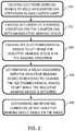
- FIG. 2Aillustrates an exemplary graph of torque values when the inductive braking device is applied.
- the value associated with the inductive braking devicemay be a torque ripple.
- the torque ripplemay be determined based on at least one of signals from an accelerometer determining vibrations from the elevator car, signals from a motor encoder determining vibrations from a hoisting machine, signals from an encoder determining vibrations from an overspeed governor, or signals from a car encoder determining vibrations from the elevator car.
- a curve 200illustrates a reference torque ripple that may be, for example, a torque ripple generated when a motor of a hoisting machine of the elevator receives three-phase current.
- the torquemay be substantially steady.
- the torque ripplemay increase substantially, as illustrated by a curve 202.
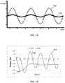
- the torque ripplemay be so high that motor torque actually momentarily changes polarity, as illustrated by a curve 204 in FIG. 2B ,.
- the operating condition of the inductive braking devicemay then be determined, for example, based on the comparison of the torque ripples 200 and 202. In response to the comparison, it may be determined that the inductive braking device is not operational when the determined torque ripple has substantially increased compared to the reference torque ripple.
- determining the value associated with the inductive braking devicecomprises determining a three-phase current of a motor of a hoisting machine of the elevator car from current sensors of a frequency converter coupled to the motor.
- the frequency convertermay have a current sensor at each phase feeding current to the motor.
- the operating condition of the inductive braking devicemay be determined based on an indication from the sensors that at least one phase of the motor current has dropped. If at least one of the current sensors of the frequency converter indicates that there is no current, a phase may have dropped.
- determining the value associated with the inductive braking devicemay comprise determining a voltage from poles of a motor of a hoisting machine of the elevator car.
- the operating condition of the inductive braking devicemay be determined based on the voltage by determining that the inductive braking device is not in operative condition when at least one of the poles shows voltage.
- the operating condition of the inductive braking devicemay be monitored at regular intervals.
- the monitoring processmay be repeated, for example, at the same time when the condition of the electromechanical brakes of the elevator car is monitored.
- the monitoring intervalmay be, for example, several hours or a day.
- the elevator carmay be taken out of service and/or a service call may be dispatched.
- the elevatormay be operated normally.
- the use of the inductive braking device as an independent braking function or as an assistive brakemay be enabled.
- the inductive braking devicemay be used to fulfill ascending car overspeed protection.
- the electromechanical brakesmay have to be lifted manually to move the elevator car to a landing floor by gravity.
- the inductive braking devicemay be independently used to limit the speed of the elevator car.
- Low cost and reliable mechanical brake opening systemsmay be used for manual rescue operations as the condition of the inductive braking device may be monitored.
- the inductive braking devicemay be as an assistive brake for the electromechanical brakes.
- ETSLEmergency Terminal Slowdown
- the inductive braking devicemay be used together with the electromechanical brakes.
- less braking forceis required from the electromechanical brakes, and the electromechanical brakes may be dimensioned to be smaller, in high-rise buildings.
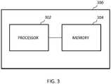
- FIG. 3illustrates a block diagram of an apparatus 300 for monitoring condition of inductive braking device according to an embodiment.
- the apparatus 300comprises at least one processor 302 connected to at least one memory 304.
- the at least one memory 304may comprise at least one computer program which, when executed by the processor 302 or processors, causes the apparatus 300 to perform the programmed functionality.
- the at least one memory 304may be an internal memory of the at least one processor 302.
- the apparatus 300may be a control entity configured to implement only the earlier discussed features, or it may be part of a larger elevator control entity, for example, an elevator controller or an elevator group controller.
- the at least one memory 304may store program instructions that, when executed by the at least one processor 302, cause the apparatus 300 to cause electromechanical brakes to hold the elevator car stationary in the elevator shaft; cause actuation of a braking condition for the elevator car with the inductive braking device; cause the electromechanical brakes to lift while the inductive braking device is in the operative condition; determine a value associated with the inductive braking device in response to causing the electromechanical brakes to lift while the inductive braking device is actuated; and determine an operating condition of the inductive braking device based on the value.
- the at least one memory 304may store program instructions that, when executed by the at least one processor 302, may cause the apparatus 300 to perform also any other above discussed step.
- the at least one processor 302 and the memory 304may constitute means for means for causing electromechanical brakes to hold the elevator car stationary in the elevator shaft; means for causing actuation of a braking condition for the elevator car with the inductive braking device; means for causing the electromechanical brakes to lift while the inductive braking device is in the operative condition; means for determining a value associated with the inductive braking device in response to causing the electromechanical brakes to lift while the inductive braking device is actuated; and means for determining an operating condition of the inductive braking device based on the value.
- the at least one of the processor 302 and the memory 304may constitute means for performing also any other above discussed step.
- the exemplary embodiments and aspects of the inventioncan be included within any suitable device, for example, including, servers, workstations, capable of performing the processes of the exemplary embodiments.
- the exemplary embodimentsmay also store information relating to various processes described herein.
- Example embodimentsmay be implemented in software, hardware, application logic or a combination of software, hardware and application logic.
- the example embodimentscan store information relating to various methods described herein. This information can be stored in one or more memories, such as a hard disk, optical disk, magneto-optical disk, RAM, and the like.
- One or more databasescan store the information used to implement the example embodiments.
- the databasescan be organized using data structures (e.g., records, tables, arrays, fields, graphs, trees, lists, and the like) included in one or more memories or storage devices listed herein.
- the methods described with respect to the example embodimentscan include appropriate data structures for storing data collected and/or generated by the methods of the devices and subsystems of the example embodiments in one or more databases.
- All or a portion of the example embodimentscan be conveniently implemented using one or more general purpose processors, microprocessors, digital signal processors, micro-controllers, and the like, programmed according to the teachings of the example embodiments, as will be appreciated by those skilled in the computer and/or software art(s).
- Appropriate softwarecan be readily prepared by programmers of ordinary skill based on the teachings of the example embodiments, as will be appreciated by those skilled in the software art.
- the example embodimentscan be implemented by the preparation of application-specific integrated circuits or by interconnecting an appropriate network of conventional component circuits, as will be appreciated by those skilled in the electrical art(s).
- the examplesare not limited to any specific combination of hardware and/or software.
- the examplescan include software for controlling the components of the example embodiments, for driving the components of the example embodiments, for enabling the components of the example embodiments to interact with a human user, and the like.
- Such computer readable mediafurther can include a computer program for performing all or a portion (if processing is distributed) of the processing performed in implementing the example embodiments.
- Computer code devices of the examplesmay include any suitable interpretable or executable code mechanism, including but not limited to scripts, interpretable programs, dynamic link libraries (DLLs), Java classes and applets, complete executable programs, and the like.
- the components of the example embodimentsmay include computer readable medium or memories for holding instructions programmed according to the teachings and for holding data structures, tables, records, and/or other data described herein.
- the application logic, software or an instruction setis maintained on any one of various conventional computer-readable media.
- a "computer-readable medium"may be any media or means that can contain, store, communicate, propagate or transport the instructions for use by or in connection with an instruction execution system, apparatus, or device, such as a computer.
- a computer-readable mediummay include a computer-readable storage medium that may be any media or means that can contain or store the instructions for use by or in connection with an instruction execution system, apparatus, or device, such as a computer.
- a computer readable mediumcan include any suitable medium that participates in providing instructions to a processor for execution. Such a medium can take many forms, including but not limited to, non-volatile media, volatile media, transmission media, and the like.
Landscapes
- Engineering & Computer Science (AREA)
- Automation & Control Theory (AREA)
- Computer Networks & Wireless Communication (AREA)
- Civil Engineering (AREA)
- Mechanical Engineering (AREA)
- Structural Engineering (AREA)
- Elevator Control (AREA)
Description
- Elevators have electromechanical brakes that apply to a traction sheave or rotating axis of a hoisting machine to stop movement of the hoisting machine and therefore an elevator car operated by the hoisting machine. The electromechanical brakes are dimensioned to hold the elevator car with an overload at standstill in the elevator shaft. In addition, the brakes may be used in rescue situations and in emergency braking to stop the elevator car if an operational fault occurs, such as an overspeed situation of the elevator car. Due to this, the brakes may become large-sized and their control may become complicated.
EP 1481933 A1 discloses a solution in which an emergency stop is fixed to cage such that the cage grasps guide rail in abnormality condition. A torque detector detects the torque of rope to confirm abnormality condition accordingly.EP 3106417 A1 discloses a control arrangement of an elevator, comprising a safety gear, an over speed governor with a rope which is connected to the safety gear, a stopping device for generating an actuating force to the safety gear, and a drive unit for driving the elevator apparatus. In order to facilitate easy and efficient maintenance the control arrangement comprises a controller for controlling a triggered sequence to involve activating of the stopping device for braking with the safety gear, and controlling the drive unit to drive the elevator apparatus during braking with the safety gear until the safety gear stops the elevator apparatus.- Thus, it would be beneficial to have a solution that would alleviate at least one of these drawbacks.
- According to at least some of the aspects, a solution is provided that monitors a condition of an inductive braking device. The solution enables using the inductive braking device for safety-related elevator braking functions. A monitoring operation of the inductive braking device enables using low cost and reliable mechanical brake opening systems for manual rescue operation. In addition, smaller electromechanical brakes may be used, for example, in elevators in high-rise buildings, because the inductive braking device can be taken into account when dimensioning the braking system.
- According to a first aspect of the invention, there is provided a method for monitoring of an inductive braking device of an elevator car in an elevator shaft. The method comprises causing electromechanical brakes to hold the elevator car stationary in the elevator shaft; causing actuation of a braking condition for the elevator car with the inductive braking device; causing the electromechanical brakes to lift while the inductive braking device is in the braking condition; determining a value associated with the inductive braking device in response to causing the electromechanical brakes to lift while the inductive braking device is actuated; and determining an operating condition of the inductive braking device based on the value.
- In a preferred embodiment, determining the value comprises determining a speed of the elevator car; and wherein determining the operating condition of the inductive braking device further comprises comparing the speed to a predefined speed threshold; and wherein determining that the inductive braking device is operational when the speed does not exceed the predefined speed threshold.
- In addition in the aforementioned preferred embodiment, the method further comprises determining a location of the elevator car in the elevator shaft; and applying a predefined speed threshold that is specific for the location of the elevator car in the elevator shaft.
- In another preferred embodiment, determining the value comprises determining a torque ripple based on at least one of signals from an accelerometer determining vibrations from the elevator car, signals from a motor encoder determining vibrations from a hoisting machine, signals from an encoder determining vibrations from an overspeed governor, or signals from a car encoder determining vibrations from the elevator car; and wherein determining the operating condition of the inductive braking device further comprises comparing the determined torque ripple to a reference torque ripple; and determining that the inductive braking device is not operational when the torque ripple has substantially increased compared to the reference torque ripple.
- In another preferred embodiment, determining the value comprises determining a three-phase current of a motor of a hoisting machinery of the elevator from current sensors of a frequency converter coupled to the motor; and wherein determining the operating condition of the inductive braking device further comprises determining that the inductive braking device is not operational when at least one of the current sensors indicates that a phase is missing current.
- In another preferred embodiment, determining the value comprises determining voltage from poles of a motor of a hoisting machine of the elevator; and wherein determining the operating condition of the inductive braking device further comprises determining that the inductive braking device is not operational when at least one pole shows voltage.
- In another preferred embodiment, the method further comprises repeating the condition monitoring when the operation condition indicates that the inductive braking device is not operational.
- In another preferred embodiment, the method further comprises repeating the condition monitoring of the inductive braking device at regular intervals.
- In another preferred embodiment, the method further comprises, in response to determining the operating condition of the inductive braking device, taking the elevator car out of service when the inductive braking device is not operational.
- In another preferred embodiment, the method further comprises, in response to determining the operating condition of the inductive braking device, enabling the use of the inductive braking device as an independent braking function or as an assistive brake when the inductive braking device is operational.
- In another preferred embodiment, causing actuation of a braking condition for the elevator car with the inductive braking device comprises providing a short-circuit to windings of an elevator hoisting motor.
- In another preferred embodiment, the method further comprises generating a signal indicating the condition of the inductive braking device; and transmitting the signal to a remote maintenance server.
- In another preferred embodiment, the inductive braking device comprises a dynamic braking device comprising an elevator hoisting motor and one or more switches adapted to provide a short-circuit to windings of the elevator hoisting motor.
- According to a second aspect of the invention, there is provided an apparatus for condition monitoring of an inductive braking device of an elevator car in an elevator shaft. The apparatus comprises at least one processor and at least one memory connected to the at least one processor. The at least one processor and the at least one memory constitute means for performing the steps of the method of any of the first aspect of the invention and its preferred embodiments.
- According to a third aspect of the invention, there is provided an elevator system comprising at least one elevator car and the apparatus of the second aspect of the invention.
- According to a fourth aspect of the invention, there is provided a computer program comprising program code, which when executed by the at least one processor of the apparatus of the second aspect of the invention, causes the apparatus to perform the method of the first aspect of the invention.
- In a preferred embodiment, the computer program is embodied on the memory of the apparatus.
- The accompanying drawings, which are included to provide a further understanding of the invention and constitute a part of this specification, illustrate embodiments of the invention and together with the description help to explain the principles of the invention. In the drawings:
FIG. 1 illustrates a flow chart of a method for condition monitoring of inductive braking device of an elevator car in an elevator shaft according to an embodiment.FIG. 2A illustrates an exemplary graph of torque values when the inductive braking device is applied.FIG. 2B illustrates an exemplary graph of torque values when the inductive braking device is applied.FIG. 3 illustrates a block diagram of an apparatus for condition monitoring of inductive braking device according to an embodiment.- The following description illustrates a solution that monitors braking capability of an inductive braking device. Monitoring the operating condition of the inductive braking device may ensure safe use, and thus the inductive braking device may be used as part of a braking system of an elevator.
- In addition to electromechanical brakes, the braking system of an elevator may have electrical braking means, such as dynamic brakes. The braking system of an elevator may also comprise other alternative or additional brakes, such as an eddy-current brake. The term "inductive braking device" may herein refer, for example, to a dynamic brake and/or an eddy-current brake. Further, in an example, the term "inductive braking device" may refer to a braking device operated by inductive power, for example, by power generated by a braking/regenerating motor. Further, in an embodiment, a motor inverter operating in a regenerative mode, receiving electrical power from the motor may be an "inductive braking device". Further, in an example, the inductive braking device may comprise a dynamic braking device comprising an elevator hoisting motor and one or more switches adapted to provide a short-circuit to windings of the elevator hoisting motor.
- A dynamic brake may be implemented with a contactor, where contacts are used to put motor windings in a short circuit. When motor windings are short-circuited, the motor creates a braking torque when a rotor of the motor is rotated. However, the contactor used to implement the inductive braking device condition may get stuck or the contacts may not make contact. Therefore, the proper function of dynamic braking cannot be always guaranteed.
FIG. 1 illustrates a flow chart of a method for condition monitoring of an inductive braking device of an elevator car in an elevator shaft according to an aspect. The method may be performed, for example, by an apparatus, a controller or an elevator group controller of an elevator system. Further, the method may be a computer-implemented method.- At 100 electromechanical brakes associated with the elevator car are caused to hold the elevator car stationary in the elevator shaft. Before applying the electromechanical brakes, a determination may be made whether the elevator car is empty or that there are no passengers in the elevator car. This ensures that the condition monitoring is performed only when the elevator car is not currently used to transport passengers. Further, a determination or check may be made that the doors of the elevator car are closed.
- At 102 a braking condition for the elevator car with the inductive braking device is caused to actuate. Actuation of the braking condition may be implemented, for example with an external contactor or with electronics, for example, by means of a solid state switch of a frequency converter of a motor of the elevator car. The braking condition may be implemented also with electromagnets or permanent magnets mounted to the elevator car in order to create eddy currents. In an embodiment, causing actuation of the braking condition for the elevator car with the inductive braking device comprises providing a short-circuit to windings of an elevator hoisting motor.
- At 104 the electromechanical brakes are caused to lift while the inductive braking device is still in the braking condition. Control circuits may be designed in such a way that it is possible to lift the electromechanical brakes without activating a drive and without disabling the inductive braking device. If there is a counterweight associated with the elevator car, the elevator car should start moving upwards in response to the lifting of the electromechanical brakes. If there is no counterweight, the elevator car should start moving downwards in response to the lifting of the electromechanical brakes.
- At 106 a value associated with the inductive braking device is determined. The value is determined in response to causing the electromechanical brakes to lift while the inductive braking device is in braking condition. The value represents the capability of the inductive braking device to brake the elevator car when the electromechanical brakes are not applied any more.
- At 108 the operating condition of the inductive braking device is determined based on the value.
- In an embodiment, determining the value associated with the inductive braking device at 106 may comprise determining a speed of the elevator car. After the electromechanical brakes are lifted, the elevator car may start to move due to gravity. The speed of the elevator car is then determined while the inductive braking device is in the braking condition. Thereafter, the operating condition of the inductive braking device may be determined at
operation 108 by comparing the speed of the elevator car to a predefined speed threshold. The predefined speed threshold may be set or selected, for example, based on a nominal speed of the elevator car, the highest acceptable buffer collision speed, an inspection speed or a rescue speed of the elevator. If the speed of the elevator car does not exceed the predefined speed threshold, it may be determined that the inductive braking device is operational. On the other hand, if the speed of the elevator car exceeds the predefined speed threshold, it may be determined that the inductive braking device is not operational. - Additionally, the location of the elevator car in the elevator shaft may be determined, and a predefined speed threshold may be applied that is specific for the location of the elevator car in the elevator shaft. In other words, different speed thresholds may be applied in different parts of the elevator shaft.
- Determination of the operating condition of inductive braking device, as illustrated by steps 100-108, may be repeated when the operation condition indicates that the inductive braking device is not operational. For example, the determination of the operating condition of inductive braking device may be repeated when the determined speed exceeds the predetermined speed threshold. Thus, the earlier condition monitoring result may be confirmed.
- In an embodiment, in response to determining the operating condition of the inductive braking device, a signal may be generated indicating the condition of the inductive braking device. Further, the signal may be transmitted to a remote maintenance server.
FIG. 2A illustrates an exemplary graph of torque values when the inductive braking device is applied. In an embodiment, the value associated with the inductive braking device may be a torque ripple. The torque ripple may be determined based on at least one of signals from an accelerometer determining vibrations from the elevator car, signals from a motor encoder determining vibrations from a hoisting machine, signals from an encoder determining vibrations from an overspeed governor, or signals from a car encoder determining vibrations from the elevator car.- The torque ripple may be compared to a reference torque ripple. In
FIG. 2A , acurve 200 illustrates a reference torque ripple that may be, for example, a torque ripple generated when a motor of a hoisting machine of the elevator receives three-phase current. When the motor receives current in all three phases, the torque may be substantially steady. When at least one phase is missing a current, the torque ripple may increase substantially, as illustrated by acurve 202. For example, when during dynamic braking one motor phase is missing, the torque ripple may be so high that motor torque actually momentarily changes polarity, as illustrated by acurve 204 inFIG. 2B ,. The operating condition of the inductive braking device may then be determined, for example, based on the comparison of the torque ripples 200 and 202. In response to the comparison, it may be determined that the inductive braking device is not operational when the determined torque ripple has substantially increased compared to the reference torque ripple. - In another embodiment, determining the value associated with the inductive braking device comprises determining a three-phase current of a motor of a hoisting machine of the elevator car from current sensors of a frequency converter coupled to the motor. The frequency converter may have a current sensor at each phase feeding current to the motor. The operating condition of the inductive braking device may be determined based on an indication from the sensors that at least one phase of the motor current has dropped. If at least one of the current sensors of the frequency converter indicates that there is no current, a phase may have dropped.
- In another embodiment, determining the value associated with the inductive braking device may comprise determining a voltage from poles of a motor of a hoisting machine of the elevator car. The operating condition of the inductive braking device may be determined based on the voltage by determining that the inductive braking device is not in operative condition when at least one of the poles shows voltage.
- Further, the operating condition of the inductive braking device may be monitored at regular intervals. The monitoring process may be repeated, for example, at the same time when the condition of the electromechanical brakes of the elevator car is monitored. The monitoring interval may be, for example, several hours or a day.
- In response to determining that the inductive braking device is not operational, the elevator car may be taken out of service and/or a service call may be dispatched.
- In response to determining that the inductive braking device is operational, the elevator may be operated normally. For example, in response to determining that the inductive braking device is operational, the use of the inductive braking device as an independent braking function or as an assistive brake may be enabled. For example, the inductive braking device may be used to fulfill ascending car overspeed protection. During a rescue operation, the electromechanical brakes may have to be lifted manually to move the elevator car to a landing floor by gravity. Then, the inductive braking device may be independently used to limit the speed of the elevator car. Low cost and reliable mechanical brake opening systems may be used for manual rescue operations as the condition of the inductive braking device may be monitored.
- As another example, the inductive braking device may be as an assistive brake for the electromechanical brakes. For example, when the elevator car in a high-rise elevator system moves with overspeed near an elevator shaft end, a so called ETSL (Emergency Terminal Slowdown) safety function activates the electromechanical brakes to the stop elevator car. In this situation, inductive braking device may be used together with the electromechanical brakes. Thus, less braking force is required from the electromechanical brakes, and the electromechanical brakes may be dimensioned to be smaller, in high-rise buildings.
FIG. 3 illustrates a block diagram of anapparatus 300 for monitoring condition of inductive braking device according to an embodiment.- The
apparatus 300 comprises at least oneprocessor 302 connected to at least onememory 304. The at least onememory 304 may comprise at least one computer program which, when executed by theprocessor 302 or processors, causes theapparatus 300 to perform the programmed functionality. In another embodiment, the at least onememory 304 may be an internal memory of the at least oneprocessor 302. - The
apparatus 300 may be a control entity configured to implement only the earlier discussed features, or it may be part of a larger elevator control entity, for example, an elevator controller or an elevator group controller. - In an embodiment, the at least one
memory 304 may store program instructions that, when executed by the at least oneprocessor 302, cause theapparatus 300 to cause electromechanical brakes to hold the elevator car stationary in the elevator shaft; cause actuation of a braking condition for the elevator car with the inductive braking device; cause the electromechanical brakes to lift while the inductive braking device is in the operative condition; determine a value associated with the inductive braking device in response to causing the electromechanical brakes to lift while the inductive braking device is actuated; and determine an operating condition of the inductive braking device based on the value. The at least onememory 304 may store program instructions that, when executed by the at least oneprocessor 302, may cause theapparatus 300 to perform also any other above discussed step. - Further, according to the invention, the at least one
processor 302 and thememory 304 may constitute means for means for causing electromechanical brakes to hold the elevator car stationary in the elevator shaft; means for causing actuation of a braking condition for the elevator car with the inductive braking device; means for causing the electromechanical brakes to lift while the inductive braking device is in the operative condition; means for determining a value associated with the inductive braking device in response to causing the electromechanical brakes to lift while the inductive braking device is actuated; and means for determining an operating condition of the inductive braking device based on the value. The at least one of theprocessor 302 and thememory 304 may constitute means for performing also any other above discussed step. - The exemplary embodiments and aspects of the invention can be included within any suitable device, for example, including, servers, workstations, capable of performing the processes of the exemplary embodiments. The exemplary embodiments may also store information relating to various processes described herein.
- Example embodiments may be implemented in software, hardware, application logic or a combination of software, hardware and application logic. The example embodiments can store information relating to various methods described herein. This information can be stored in one or more memories, such as a hard disk, optical disk, magneto-optical disk, RAM, and the like. One or more databases can store the information used to implement the example embodiments. The databases can be organized using data structures (e.g., records, tables, arrays, fields, graphs, trees, lists, and the like) included in one or more memories or storage devices listed herein. The methods described with respect to the example embodiments can include appropriate data structures for storing data collected and/or generated by the methods of the devices and subsystems of the example embodiments in one or more databases.
- All or a portion of the example embodiments can be conveniently implemented using one or more general purpose processors, microprocessors, digital signal processors, micro-controllers, and the like, programmed according to the teachings of the example embodiments, as will be appreciated by those skilled in the computer and/or software art(s). Appropriate software can be readily prepared by programmers of ordinary skill based on the teachings of the example embodiments, as will be appreciated by those skilled in the software art. In addition, the example embodiments can be implemented by the preparation of application-specific integrated circuits or by interconnecting an appropriate network of conventional component circuits, as will be appreciated by those skilled in the electrical art(s). Thus, the examples are not limited to any specific combination of hardware and/or software. Stored on any one or on a combination of computer readable media, the examples can include software for controlling the components of the example embodiments, for driving the components of the example embodiments, for enabling the components of the example embodiments to interact with a human user, and the like. Such computer readable media further can include a computer program for performing all or a portion (if processing is distributed) of the processing performed in implementing the example embodiments. Computer code devices of the examples may include any suitable interpretable or executable code mechanism, including but not limited to scripts, interpretable programs, dynamic link libraries (DLLs), Java classes and applets, complete executable programs, and the like.
- As stated above, the components of the example embodiments may include computer readable medium or memories for holding instructions programmed according to the teachings and for holding data structures, tables, records, and/or other data described herein. In an example embodiment, the application logic, software or an instruction set is maintained on any one of various conventional computer-readable media. In the context of this document, a "computer-readable medium" may be any media or means that can contain, store, communicate, propagate or transport the instructions for use by or in connection with an instruction execution system, apparatus, or device, such as a computer. A computer-readable medium may include a computer-readable storage medium that may be any media or means that can contain or store the instructions for use by or in connection with an instruction execution system, apparatus, or device, such as a computer. A computer readable medium can include any suitable medium that participates in providing instructions to a processor for execution. Such a medium can take many forms, including but not limited to, non-volatile media, volatile media, transmission media, and the like.
- While there have been shown and described and pointed out fundamental novel features as applied to preferred embodiments thereof, it will be understood that various omissions and substitutions and changes in the form and details of the devices and methods described may be made by those skilled in the art without departing from the scope of the claims.
Claims (14)
- A method for condition monitoring of an inductive braking device of an elevator car in an elevator shaft, wherein the method comprises:causing (100) electromechanical brakes to hold the elevator car stationary in the elevator shaft;causing (102) actuation of a braking condition for the elevator car with the inductive braking device;causing (104) the electromechanical brakes to lift while the inductive braking device is in the braking condition;determining (106) a value associated with the inductive braking device in response to causing the electromechanical brakes to lift while the inductive braking device is actuated; anddetermining (108) an operating condition of the inductive braking device based on the value.
- The method of claim 1, wherein determining the value comprises determining a speed of the elevator car; and wherein
determining the operating condition of the inductive braking device further comprises:comparing the speed to a predefined speed threshold; anddetermining that the inductive braking device is operational when the speed does not exceed the predefined speed threshold. - The method of claim 2, further comprising:determining a location of the elevator car in the elevator shaft; andapplying a predefined speed threshold that is specific for the location of the elevator car in the elevator shaft.
- The method of claim 1, wherein determining the value comprises:determining a torque ripple based on at least one of signals from an accelerometer determining vibrations from the elevator car, signals from a motor encoder determining vibrations from a hoisting machine, signals from an encoder determining vibrations from an overspeed governor, or signals from a car encoder determining vibrations from the elevator car; and whereindetermining the operating condition of the inductive braking device further comprises:comparing the determined torque ripple to a reference torque ripple; anddetermining that the inductive braking device is not operational when the torque ripple has substantially increased compared to the reference torque ripple.
- The method of claim 1, wherein determining the value comprises:determining a three-phase current of a motor of a hoisting machine of the elevator from current sensors of a frequency converter coupled to the motor; and whereindetermining the operating condition of the inductive braking device further comprises:
determining that the inductive braking device is not operational when at least one of the current sensors indicates that a phase is missing current. - The method of claim 1, wherein determining the value comprises:determining voltage from poles of a motor of a hoisting machine of the elevator; andwherein determining the operating condition of the inductive braking device further comprises:
determining that the inductive braking device is not operational when at least one pole shows voltage. - The method of any of the claims 1 - 6, further comprising:
repeating the condition monitoring when the operation condition indicates that the inductive braking device is not operational. - The method of any of the claims 1 - 7, further comprising:
repeating the condition monitoring of the inductive braking device at regular intervals. - The method according to any of the claims 1 - 8, further comprising:
in response to determining the operating condition of the inductive braking device, taking the elevator car out of service when the inductive braking device is not operational. - The method of any of the claims 1 - 8, further comprising:
in response to determining the operating condition of the inductive braking device, enabling the use of the inductive braking device as an independent braking function or as an assistive brake when the inductive braking device is operational. - An apparatus (300) for condition monitoring of an inductive braking device of an elevator car in an elevator shaft, the apparatus comprising:at least one processor (302);at least one memory (304) connected to the at least one processor (302),wherein the at least one processor (302) and the at least one memory (304) constitute means for performing the steps of the method of any of claims 1 - 10.
- An elevator system comprising:at least one elevator car; andthe apparatus (300) of claim 11.
- A computer program comprising program code, which when executed by the at least one processor (302) of the apparatus (300) of claim 11, causes the apparatus (300) of claim 11 to perform the method of any of claims 1 - 10.
- A computer program according to claim 13, wherein the computer program is embodied on the memory (304) of the apparatus (300).
Priority Applications (4)
| Application Number | Priority Date | Filing Date | Title |
|---|---|---|---|
| EP18169392.0AEP3560874B1 (en) | 2018-04-26 | 2018-04-26 | A method and apparatus for condition monitoring of an inductive brake of an elevator car |
| AU2019202357AAU2019202357B2 (en) | 2018-04-26 | 2019-04-04 | Condition monitoring of an inductive braking device |
| US16/379,435US12012306B2 (en) | 2018-04-26 | 2019-04-09 | Condition monitoring of an inductive braking device |
| CN201910342800.4ACN110407049B (en) | 2018-04-26 | 2019-04-26 | Condition monitoring of an inductive braking device |
Applications Claiming Priority (1)
| Application Number | Priority Date | Filing Date | Title |
|---|---|---|---|
| EP18169392.0AEP3560874B1 (en) | 2018-04-26 | 2018-04-26 | A method and apparatus for condition monitoring of an inductive brake of an elevator car |
Publications (2)
| Publication Number | Publication Date |
|---|---|
| EP3560874A1 EP3560874A1 (en) | 2019-10-30 |
| EP3560874B1true EP3560874B1 (en) | 2021-12-01 |
Family
ID=62067426
Family Applications (1)
| Application Number | Title | Priority Date | Filing Date |
|---|---|---|---|
| EP18169392.0AActiveEP3560874B1 (en) | 2018-04-26 | 2018-04-26 | A method and apparatus for condition monitoring of an inductive brake of an elevator car |
Country Status (4)
| Country | Link |
|---|---|
| US (1) | US12012306B2 (en) |
| EP (1) | EP3560874B1 (en) |
| CN (1) | CN110407049B (en) |
| AU (1) | AU2019202357B2 (en) |
Cited By (1)
| Publication number | Priority date | Publication date | Assignee | Title |
|---|---|---|---|---|
| US20200391976A1 (en)* | 2019-06-14 | 2020-12-17 | Kone Corporation | Elevator |
Families Citing this family (3)
| Publication number | Priority date | Publication date | Assignee | Title |
|---|---|---|---|---|
| EP3560874B1 (en)* | 2018-04-26 | 2021-12-01 | KONE Corporation | A method and apparatus for condition monitoring of an inductive brake of an elevator car |
| US12404147B2 (en) | 2021-05-17 | 2025-09-02 | Magnetek, Inc. | System and method of detecting a dragging brake in an elevator application |
| CN120112471A (en)* | 2022-11-04 | 2025-06-06 | 通力股份公司 | Elevator safety device and elevator having the same |
Citations (11)
| Publication number | Priority date | Publication date | Assignee | Title |
|---|---|---|---|---|
| WO2001046056A1 (en) | 1999-12-21 | 2001-06-28 | Otis Elevator Company | Dynamic braking system with speed control for an elevator cab |
| WO2007099913A1 (en) | 2006-02-27 | 2007-09-07 | Toshiba Elevator Kabushiki Kaisha | Elevator control device |
| US20100154527A1 (en) | 2006-02-14 | 2010-06-24 | Otis Elevator Company | Elevator Brake Condition Testing |
| WO2011051571A1 (en) | 2009-11-02 | 2011-05-05 | Kone Corporation | Braking apparatus, electric drive, and elevator system |
| CN102414110A (en) | 2009-05-01 | 2012-04-11 | 三菱电机株式会社 | Elevator device |
| US20140311257A1 (en) | 2011-11-02 | 2014-10-23 | Otis Elevator Company | Brake Torque Monitoring and Health Assessment |
| US20150191327A1 (en) | 2012-08-22 | 2015-07-09 | Otis Elevator Company | Elevator system using dynamic braking |
| JP2016074508A (en) | 2014-10-06 | 2016-05-12 | 株式会社日立製作所 | Elevator apparatus and vibration detection method for elevator apparatus |
| EP3072842A1 (en) | 2015-03-23 | 2016-09-28 | Kone Corporation | Elevator rescue system |
| US20170008730A1 (en) | 2014-03-26 | 2017-01-12 | Kone Corporation | Method and apparatus for automatic elevator drive configuration |
| WO2017118590A1 (en) | 2016-01-07 | 2017-07-13 | Kone Corporation | Motion feedback in an elevator |
Family Cites Families (22)
| Publication number | Priority date | Publication date | Assignee | Title |
|---|---|---|---|---|
| GB1034727A (en)* | 1964-09-22 | 1966-07-06 | Turnbull Elevator Ltd | Induction brake speed control for elevators |
| JP2559706B2 (en)* | 1986-05-08 | 1996-12-04 | 三菱電機株式会社 | AC elevator control device |
| JPH0697875B2 (en)* | 1987-05-20 | 1994-11-30 | 日本オ−チス・エレベ−タ株式会社 | Inverter for driving elevator |
| JPH058962A (en)* | 1991-07-04 | 1993-01-19 | Fuji Electric Co Ltd | Elevator abnormal speed protection circuit |
| CN1144752C (en)* | 1999-03-16 | 2004-04-07 | 西安高能电机控制技术有限责任公司 | Drive control system for non-brush DC elevator |
| JP4079886B2 (en)* | 2002-03-06 | 2008-04-23 | 三菱電機株式会社 | Elevator emergency stop test equipment |
| KR100621475B1 (en)* | 2002-07-10 | 2006-09-13 | 미쓰비시덴키 가부시키가이샤 | Elevator control |
| DE10300993A1 (en)* | 2003-01-14 | 2004-07-22 | Aufzugswerke M. Schmitt & Sohn Gmbh & Co. | Brake device for an elevator system |
| JP2005154082A (en)* | 2003-11-26 | 2005-06-16 | Mitsubishi Electric Corp | Brake device for elevator hoisting machine |
| JP4986541B2 (en)* | 2006-08-31 | 2012-07-25 | 東芝エレベータ株式会社 | Elevator control device |
| CN106255657B (en)* | 2014-04-30 | 2020-03-03 | 三菱电机株式会社 | Elevator device and elevator spot inspection method |
| CN104495547A (en)* | 2014-12-23 | 2015-04-08 | 重庆迈高电梯有限公司 | Detection method of lift traction machine brake |
| EP3106417B1 (en)* | 2015-06-16 | 2018-08-08 | KONE Corporation | A control arrangement and a method |
| CN105236223B (en)* | 2015-09-23 | 2018-01-02 | 日立电梯(中国)有限公司 | inertia measuring system and method |
| EP3239086B1 (en)* | 2016-04-28 | 2022-06-01 | KONE Corporation | Solution for monitoring an elevator brake |
| DE102016208857A1 (en)* | 2016-05-23 | 2017-11-23 | Thyssenkrupp Ag | Shaft change arrangement for an elevator installation |
| EP3323761B1 (en)* | 2016-11-16 | 2023-11-15 | Kone Corporation | Method, elevator control unit and elevator for moving an elevator car to landing floor in case of event related to main electrical power supply of the elevator |
| CN108516438A (en)* | 2017-02-05 | 2018-09-11 | 六安永贞匠道机电科技有限公司 | The elevator brake controller of multi-direction induction |
| ES2779768T3 (en)* | 2017-12-08 | 2020-08-19 | Kone Corp | Elevator apparatus and method |
| US11434104B2 (en)* | 2017-12-08 | 2022-09-06 | Otis Elevator Company | Continuous monitoring of rail and ride quality of elevator system |
| EP3560874B1 (en)* | 2018-04-26 | 2021-12-01 | KONE Corporation | A method and apparatus for condition monitoring of an inductive brake of an elevator car |
| EP3753891A1 (en)* | 2019-06-17 | 2020-12-23 | KONE Corporation | Emergency braking apparatus |
- 2018
- 2018-04-26EPEP18169392.0Apatent/EP3560874B1/enactiveActive
- 2019
- 2019-04-04AUAU2019202357Apatent/AU2019202357B2/enactiveActive
- 2019-04-09USUS16/379,435patent/US12012306B2/enactiveActive
- 2019-04-26CNCN201910342800.4Apatent/CN110407049B/enactiveActive
Patent Citations (11)
| Publication number | Priority date | Publication date | Assignee | Title |
|---|---|---|---|---|
| WO2001046056A1 (en) | 1999-12-21 | 2001-06-28 | Otis Elevator Company | Dynamic braking system with speed control for an elevator cab |
| US20100154527A1 (en) | 2006-02-14 | 2010-06-24 | Otis Elevator Company | Elevator Brake Condition Testing |
| WO2007099913A1 (en) | 2006-02-27 | 2007-09-07 | Toshiba Elevator Kabushiki Kaisha | Elevator control device |
| CN102414110A (en) | 2009-05-01 | 2012-04-11 | 三菱电机株式会社 | Elevator device |
| WO2011051571A1 (en) | 2009-11-02 | 2011-05-05 | Kone Corporation | Braking apparatus, electric drive, and elevator system |
| US20140311257A1 (en) | 2011-11-02 | 2014-10-23 | Otis Elevator Company | Brake Torque Monitoring and Health Assessment |
| US20150191327A1 (en) | 2012-08-22 | 2015-07-09 | Otis Elevator Company | Elevator system using dynamic braking |
| US20170008730A1 (en) | 2014-03-26 | 2017-01-12 | Kone Corporation | Method and apparatus for automatic elevator drive configuration |
| JP2016074508A (en) | 2014-10-06 | 2016-05-12 | 株式会社日立製作所 | Elevator apparatus and vibration detection method for elevator apparatus |
| EP3072842A1 (en) | 2015-03-23 | 2016-09-28 | Kone Corporation | Elevator rescue system |
| WO2017118590A1 (en) | 2016-01-07 | 2017-07-13 | Kone Corporation | Motion feedback in an elevator |
Cited By (2)
| Publication number | Priority date | Publication date | Assignee | Title |
|---|---|---|---|---|
| US20200391976A1 (en)* | 2019-06-14 | 2020-12-17 | Kone Corporation | Elevator |
| US11554933B2 (en)* | 2019-06-14 | 2023-01-17 | Kone Corporation | Elevator |
Also Published As
| Publication number | Publication date |
|---|---|
| AU2019202357B2 (en) | 2024-10-24 |
| US12012306B2 (en) | 2024-06-18 |
| CN110407049B (en) | 2022-08-19 |
| EP3560874A1 (en) | 2019-10-30 |
| AU2019202357A1 (en) | 2019-11-14 |
| CN110407049A (en) | 2019-11-05 |
| US20190330014A1 (en) | 2019-10-31 |
Similar Documents
| Publication | Publication Date | Title |
|---|---|---|
| US12258241B2 (en) | Elevator including safety monitoring that prevents excessive deceleration during slowdown failure | |
| US12012306B2 (en) | Condition monitoring of an inductive braking device | |
| EP2168901B1 (en) | Elevator | |
| US9771243B2 (en) | Elevator safety arrangement for controlling elevator movement | |
| US9873591B2 (en) | Brake controller, elevator system and a method for performing an emergency stop with an elevator hoisting machine driven with a frequency converter | |
| US9434575B2 (en) | Method and device for a safe emergency stop of an elevator | |
| EP3287404B1 (en) | Elevator system comprising braking apparatus and electric drive | |
| CN100548851C (en) | Elevator control gear | |
| JP4980058B2 (en) | Elevator equipment | |
| JP2011143982A (en) | Device and method for controlling brake of elevator | |
| EP4424624A1 (en) | An elevator and a method of energizing an elevator safety apparatus | |
| HK40013833B (en) | Condition monitoring of an inductive braking device | |
| HK40013833A (en) | Condition monitoring of an inductive braking device | |
| EP3239087A1 (en) | A rescue control system for an elevator | |
| JP2005247512A (en) | Elevator failure rescue operation device | |
| EP4370462B1 (en) | Safety solution for elevators | |
| KR100901229B1 (en) | Elevator device | |
| EP4545464A1 (en) | Elevator safety controller, elevator system, and method for causing emergency stop for elevator car | |
| JPH05294578A (en) | Elevator control device | |
| KR101261790B1 (en) | Method for controlling motor | |
| HK40022610B (en) | Elevator | |
| HK1133416A1 (en) | Elevator system |
Legal Events
| Date | Code | Title | Description |
|---|---|---|---|
| PUAI | Public reference made under article 153(3) epc to a published international application that has entered the european phase | Free format text:ORIGINAL CODE: 0009012 | |
| STAA | Information on the status of an ep patent application or granted ep patent | Free format text:STATUS: THE APPLICATION HAS BEEN PUBLISHED | |
| AK | Designated contracting states | Kind code of ref document:A1 Designated state(s):AL AT BE BG CH CY CZ DE DK EE ES FI FR GB GR HR HU IE IS IT LI LT LU LV MC MK MT NL NO PL PT RO RS SE SI SK SM TR | |
| AX | Request for extension of the european patent | Extension state:BA ME | |
| STAA | Information on the status of an ep patent application or granted ep patent | Free format text:STATUS: REQUEST FOR EXAMINATION WAS MADE | |
| 17P | Request for examination filed | Effective date:20200430 | |
| RBV | Designated contracting states (corrected) | Designated state(s):AL AT BE BG CH CY CZ DE DK EE ES FI FR GB GR HR HU IE IS IT LI LT LU LV MC MK MT NL NO PL PT RO RS SE SI SK SM TR | |
| STAA | Information on the status of an ep patent application or granted ep patent | Free format text:STATUS: EXAMINATION IS IN PROGRESS | |
| 17Q | First examination report despatched | Effective date:20201204 | |
| GRAP | Despatch of communication of intention to grant a patent | Free format text:ORIGINAL CODE: EPIDOSNIGR1 | |
| STAA | Information on the status of an ep patent application or granted ep patent | Free format text:STATUS: GRANT OF PATENT IS INTENDED | |
| INTG | Intention to grant announced | Effective date:20210628 | |
| GRAS | Grant fee paid | Free format text:ORIGINAL CODE: EPIDOSNIGR3 | |
| GRAA | (expected) grant | Free format text:ORIGINAL CODE: 0009210 | |
| STAA | Information on the status of an ep patent application or granted ep patent | Free format text:STATUS: THE PATENT HAS BEEN GRANTED | |
| AK | Designated contracting states | Kind code of ref document:B1 Designated state(s):AL AT BE BG CH CY CZ DE DK EE ES FI FR GB GR HR HU IE IS IT LI LT LU LV MC MK MT NL NO PL PT RO RS SE SI SK SM TR | |
| REG | Reference to a national code | Ref country code:GB Ref legal event code:FG4D | |
| REG | Reference to a national code | Ref country code:AT Ref legal event code:REF Ref document number:1451594 Country of ref document:AT Kind code of ref document:T Effective date:20211215 Ref country code:CH Ref legal event code:EP | |
| REG | Reference to a national code | Ref country code:IE Ref legal event code:FG4D | |
| REG | Reference to a national code | Ref country code:DE Ref legal event code:R096 Ref document number:602018027348 Country of ref document:DE | |
| REG | Reference to a national code | Ref country code:LT Ref legal event code:MG9D | |
| REG | Reference to a national code | Ref country code:NL Ref legal event code:MP Effective date:20211201 | |
| REG | Reference to a national code | Ref country code:AT Ref legal event code:MK05 Ref document number:1451594 Country of ref document:AT Kind code of ref document:T Effective date:20211201 | |
| PG25 | Lapsed in a contracting state [announced via postgrant information from national office to epo] | Ref country code:RS Free format text:LAPSE BECAUSE OF FAILURE TO SUBMIT A TRANSLATION OF THE DESCRIPTION OR TO PAY THE FEE WITHIN THE PRESCRIBED TIME-LIMIT Effective date:20211201 Ref country code:LT Free format text:LAPSE BECAUSE OF FAILURE TO SUBMIT A TRANSLATION OF THE DESCRIPTION OR TO PAY THE FEE WITHIN THE PRESCRIBED TIME-LIMIT Effective date:20211201 Ref country code:FI Free format text:LAPSE BECAUSE OF FAILURE TO SUBMIT A TRANSLATION OF THE DESCRIPTION OR TO PAY THE FEE WITHIN THE PRESCRIBED TIME-LIMIT Effective date:20211201 Ref country code:BG Free format text:LAPSE BECAUSE OF FAILURE TO SUBMIT A TRANSLATION OF THE DESCRIPTION OR TO PAY THE FEE WITHIN THE PRESCRIBED TIME-LIMIT Effective date:20220301 Ref country code:AT Free format text:LAPSE BECAUSE OF FAILURE TO SUBMIT A TRANSLATION OF THE DESCRIPTION OR TO PAY THE FEE WITHIN THE PRESCRIBED TIME-LIMIT Effective date:20211201 | |
| PG25 | Lapsed in a contracting state [announced via postgrant information from national office to epo] | Ref country code:SE Free format text:LAPSE BECAUSE OF FAILURE TO SUBMIT A TRANSLATION OF THE DESCRIPTION OR TO PAY THE FEE WITHIN THE PRESCRIBED TIME-LIMIT Effective date:20211201 Ref country code:PL Free format text:LAPSE BECAUSE OF FAILURE TO SUBMIT A TRANSLATION OF THE DESCRIPTION OR TO PAY THE FEE WITHIN THE PRESCRIBED TIME-LIMIT Effective date:20211201 Ref country code:NO Free format text:LAPSE BECAUSE OF FAILURE TO SUBMIT A TRANSLATION OF THE DESCRIPTION OR TO PAY THE FEE WITHIN THE PRESCRIBED TIME-LIMIT Effective date:20220301 Ref country code:LV Free format text:LAPSE BECAUSE OF FAILURE TO SUBMIT A TRANSLATION OF THE DESCRIPTION OR TO PAY THE FEE WITHIN THE PRESCRIBED TIME-LIMIT Effective date:20211201 Ref country code:HR Free format text:LAPSE BECAUSE OF FAILURE TO SUBMIT A TRANSLATION OF THE DESCRIPTION OR TO PAY THE FEE WITHIN THE PRESCRIBED TIME-LIMIT Effective date:20211201 Ref country code:GR Free format text:LAPSE BECAUSE OF FAILURE TO SUBMIT A TRANSLATION OF THE DESCRIPTION OR TO PAY THE FEE WITHIN THE PRESCRIBED TIME-LIMIT Effective date:20220302 Ref country code:ES Free format text:LAPSE BECAUSE OF FAILURE TO SUBMIT A TRANSLATION OF THE DESCRIPTION OR TO PAY THE FEE WITHIN THE PRESCRIBED TIME-LIMIT Effective date:20211201 | |
| PG25 | Lapsed in a contracting state [announced via postgrant information from national office to epo] | Ref country code:NL Free format text:LAPSE BECAUSE OF FAILURE TO SUBMIT A TRANSLATION OF THE DESCRIPTION OR TO PAY THE FEE WITHIN THE PRESCRIBED TIME-LIMIT Effective date:20211201 | |
| PG25 | Lapsed in a contracting state [announced via postgrant information from national office to epo] | Ref country code:SM Free format text:LAPSE BECAUSE OF FAILURE TO SUBMIT A TRANSLATION OF THE DESCRIPTION OR TO PAY THE FEE WITHIN THE PRESCRIBED TIME-LIMIT Effective date:20211201 Ref country code:SK Free format text:LAPSE BECAUSE OF FAILURE TO SUBMIT A TRANSLATION OF THE DESCRIPTION OR TO PAY THE FEE WITHIN THE PRESCRIBED TIME-LIMIT Effective date:20211201 Ref country code:RO Free format text:LAPSE BECAUSE OF FAILURE TO SUBMIT A TRANSLATION OF THE DESCRIPTION OR TO PAY THE FEE WITHIN THE PRESCRIBED TIME-LIMIT Effective date:20211201 Ref country code:PT Free format text:LAPSE BECAUSE OF FAILURE TO SUBMIT A TRANSLATION OF THE DESCRIPTION OR TO PAY THE FEE WITHIN THE PRESCRIBED TIME-LIMIT Effective date:20220401 Ref country code:EE Free format text:LAPSE BECAUSE OF FAILURE TO SUBMIT A TRANSLATION OF THE DESCRIPTION OR TO PAY THE FEE WITHIN THE PRESCRIBED TIME-LIMIT Effective date:20211201 Ref country code:CZ Free format text:LAPSE BECAUSE OF FAILURE TO SUBMIT A TRANSLATION OF THE DESCRIPTION OR TO PAY THE FEE WITHIN THE PRESCRIBED TIME-LIMIT Effective date:20211201 | |
| REG | Reference to a national code | Ref country code:DE Ref legal event code:R026 Ref document number:602018027348 Country of ref document:DE | |
| PLBI | Opposition filed | Free format text:ORIGINAL CODE: 0009260 | |
| PLAX | Notice of opposition and request to file observation + time limit sent | Free format text:ORIGINAL CODE: EPIDOSNOBS2 | |
| PG25 | Lapsed in a contracting state [announced via postgrant information from national office to epo] | Ref country code:IS Free format text:LAPSE BECAUSE OF FAILURE TO SUBMIT A TRANSLATION OF THE DESCRIPTION OR TO PAY THE FEE WITHIN THE PRESCRIBED TIME-LIMIT Effective date:20220401 | |
| 26 | Opposition filed | Opponent name:OTIS ELEVATOR COMPANY Effective date:20220901 | |
| PG25 | Lapsed in a contracting state [announced via postgrant information from national office to epo] | Ref country code:DK Free format text:LAPSE BECAUSE OF FAILURE TO SUBMIT A TRANSLATION OF THE DESCRIPTION OR TO PAY THE FEE WITHIN THE PRESCRIBED TIME-LIMIT Effective date:20211201 Ref country code:AL Free format text:LAPSE BECAUSE OF FAILURE TO SUBMIT A TRANSLATION OF THE DESCRIPTION OR TO PAY THE FEE WITHIN THE PRESCRIBED TIME-LIMIT Effective date:20211201 | |
| PG25 | Lapsed in a contracting state [announced via postgrant information from national office to epo] | Ref country code:SI Free format text:LAPSE BECAUSE OF FAILURE TO SUBMIT A TRANSLATION OF THE DESCRIPTION OR TO PAY THE FEE WITHIN THE PRESCRIBED TIME-LIMIT Effective date:20211201 | |
| REG | Reference to a national code | Ref country code:CH Ref legal event code:PL | |
| REG | Reference to a national code | Ref country code:BE Ref legal event code:MM Effective date:20220430 | |
| PLBB | Reply of patent proprietor to notice(s) of opposition received | Free format text:ORIGINAL CODE: EPIDOSNOBS3 | |
| PG25 | Lapsed in a contracting state [announced via postgrant information from national office to epo] | Ref country code:MC Free format text:LAPSE BECAUSE OF FAILURE TO SUBMIT A TRANSLATION OF THE DESCRIPTION OR TO PAY THE FEE WITHIN THE PRESCRIBED TIME-LIMIT Effective date:20211201 Ref country code:LU Free format text:LAPSE BECAUSE OF NON-PAYMENT OF DUE FEES Effective date:20220426 Ref country code:LI Free format text:LAPSE BECAUSE OF NON-PAYMENT OF DUE FEES Effective date:20220430 Ref country code:CH Free format text:LAPSE BECAUSE OF NON-PAYMENT OF DUE FEES Effective date:20220430 | |
| PG25 | Lapsed in a contracting state [announced via postgrant information from national office to epo] | Ref country code:BE Free format text:LAPSE BECAUSE OF NON-PAYMENT OF DUE FEES Effective date:20220430 | |
| PG25 | Lapsed in a contracting state [announced via postgrant information from national office to epo] | Ref country code:IE Free format text:LAPSE BECAUSE OF NON-PAYMENT OF DUE FEES Effective date:20220426 | |
| PG25 | Lapsed in a contracting state [announced via postgrant information from national office to epo] | Ref country code:IT Free format text:LAPSE BECAUSE OF FAILURE TO SUBMIT A TRANSLATION OF THE DESCRIPTION OR TO PAY THE FEE WITHIN THE PRESCRIBED TIME-LIMIT Effective date:20211201 | |
| P01 | Opt-out of the competence of the unified patent court (upc) registered | Effective date:20230525 | |
| PLCK | Communication despatched that opposition was rejected | Free format text:ORIGINAL CODE: EPIDOSNREJ1 | |
| REG | Reference to a national code | Ref country code:DE Ref legal event code:R100 Ref document number:602018027348 Country of ref document:DE | |
| PLBN | Opposition rejected | Free format text:ORIGINAL CODE: 0009273 | |
| STAA | Information on the status of an ep patent application or granted ep patent | Free format text:STATUS: OPPOSITION REJECTED | |
| 27O | Opposition rejected | Effective date:20231103 | |
| PG25 | Lapsed in a contracting state [announced via postgrant information from national office to epo] | Ref country code:HU Free format text:LAPSE BECAUSE OF FAILURE TO SUBMIT A TRANSLATION OF THE DESCRIPTION OR TO PAY THE FEE WITHIN THE PRESCRIBED TIME-LIMIT; INVALID AB INITIO Effective date:20180426 | |
| PG25 | Lapsed in a contracting state [announced via postgrant information from national office to epo] | Ref country code:MK Free format text:LAPSE BECAUSE OF FAILURE TO SUBMIT A TRANSLATION OF THE DESCRIPTION OR TO PAY THE FEE WITHIN THE PRESCRIBED TIME-LIMIT Effective date:20211201 Ref country code:CY Free format text:LAPSE BECAUSE OF FAILURE TO SUBMIT A TRANSLATION OF THE DESCRIPTION OR TO PAY THE FEE WITHIN THE PRESCRIBED TIME-LIMIT Effective date:20211201 | |
| PG25 | Lapsed in a contracting state [announced via postgrant information from national office to epo] | Ref country code:TR Free format text:LAPSE BECAUSE OF FAILURE TO SUBMIT A TRANSLATION OF THE DESCRIPTION OR TO PAY THE FEE WITHIN THE PRESCRIBED TIME-LIMIT Effective date:20211201 | |
| PG25 | Lapsed in a contracting state [announced via postgrant information from national office to epo] | Ref country code:MT Free format text:LAPSE BECAUSE OF FAILURE TO SUBMIT A TRANSLATION OF THE DESCRIPTION OR TO PAY THE FEE WITHIN THE PRESCRIBED TIME-LIMIT Effective date:20211201 | |
| PGFP | Annual fee paid to national office [announced via postgrant information from national office to epo] | Ref country code:DE Payment date:20250422 Year of fee payment:8 | |
| PGFP | Annual fee paid to national office [announced via postgrant information from national office to epo] | Ref country code:GB Payment date:20250423 Year of fee payment:8 | |
| PGFP | Annual fee paid to national office [announced via postgrant information from national office to epo] | Ref country code:FR Payment date:20250425 Year of fee payment:8 |