EP3558637B1 - Method for avoiding plume interference in additive manufacturing - Google Patents
Method for avoiding plume interference in additive manufacturingDownload PDFInfo
- Publication number
- EP3558637B1 EP3558637B1EP17883298.6AEP17883298AEP3558637B1EP 3558637 B1EP3558637 B1EP 3558637B1EP 17883298 AEP17883298 AEP 17883298AEP 3558637 B1EP3558637 B1EP 3558637B1
- Authority
- EP
- European Patent Office
- Prior art keywords
- plume
- build
- plumes
- energy beams
- powder
- Prior art date
- Legal status (The legal status is an assumption and is not a legal conclusion. Google has not performed a legal analysis and makes no representation as to the accuracy of the status listed.)
- Active
Links
- 238000000034methodMethods0.000titleclaimsdescription50
- 238000004519manufacturing processMethods0.000titleclaimsdescription27
- 239000000654additiveSubstances0.000titleclaimsdescription23
- 230000000996additive effectEffects0.000titleclaimsdescription23
- 239000000843powderSubstances0.000claimsdescription46
- 230000003993interactionEffects0.000claimsdescription6
- 239000007789gasSubstances0.000description44
- 230000008569processEffects0.000description18
- 239000000203mixtureSubstances0.000description9
- IJGRMHOSHXDMSA-UHFFFAOYSA-NAtomic nitrogenChemical compoundN#NIJGRMHOSHXDMSA-UHFFFAOYSA-N0.000description6
- 239000000155meltSubstances0.000description5
- 239000000463materialSubstances0.000description4
- 230000008018meltingEffects0.000description4
- 238000002844meltingMethods0.000description4
- 238000005286illuminationMethods0.000description3
- 229910052757nitrogenInorganic materials0.000description3
- 238000012545processingMethods0.000description3
- 238000012546transferMethods0.000description3
- XKRFYHLGVUSROY-UHFFFAOYSA-NArgonChemical compound[Ar]XKRFYHLGVUSROY-UHFFFAOYSA-N0.000description2
- 239000004035construction materialSubstances0.000description2
- 230000001627detrimental effectEffects0.000description2
- 230000000694effectsEffects0.000description2
- 239000012530fluidSubstances0.000description2
- 238000010438heat treatmentMethods0.000description2
- 239000013528metallic particleSubstances0.000description2
- 239000002245particleSubstances0.000description2
- 238000007493shaping processMethods0.000description2
- 238000011144upstream manufacturingMethods0.000description2
- 230000008016vaporizationEffects0.000description2
- 238000009834vaporizationMethods0.000description2
- 230000009471actionEffects0.000description1
- 229910052786argonInorganic materials0.000description1
- QVGXLLKOCUKJST-UHFFFAOYSA-Natomic oxygenChemical compound[O]QVGXLLKOCUKJST-UHFFFAOYSA-N0.000description1
- 239000004566building materialSubstances0.000description1
- 239000000919ceramicSubstances0.000description1
- 230000008859changeEffects0.000description1
- 238000006243chemical reactionMethods0.000description1
- 238000004891communicationMethods0.000description1
- 238000007596consolidation processMethods0.000description1
- 230000007423decreaseEffects0.000description1
- 230000003247decreasing effectEffects0.000description1
- 230000005670electromagnetic radiationEffects0.000description1
- 238000010894electron beam technologyMethods0.000description1
- 238000004836empirical methodMethods0.000description1
- 238000003384imaging methodMethods0.000description1
- 229910001026inconelInorganic materials0.000description1
- 229910001119inconels 625Inorganic materials0.000description1
- 238000003754machiningMethods0.000description1
- 239000000289melt materialSubstances0.000description1
- 239000002184metalSubstances0.000description1
- 229910001092metal group alloyInorganic materials0.000description1
- 230000003647oxidationEffects0.000description1
- 238000007254oxidation reactionMethods0.000description1
- 239000001301oxygenSubstances0.000description1
- 229910052760oxygenInorganic materials0.000description1
- 239000012254powdered materialSubstances0.000description1
- 238000007639printingMethods0.000description1
- 230000009467reductionEffects0.000description1
- 230000009834selective interactionEffects0.000description1
- 239000011265semifinished productSubstances0.000description1
- 238000005245sinteringMethods0.000description1
- 238000007711solidificationMethods0.000description1
- 230000008023solidificationEffects0.000description1
- 238000007619statistical methodMethods0.000description1
- 239000000758substrateSubstances0.000description1
- 230000003746surface roughnessEffects0.000description1
- 238000012360testing methodMethods0.000description1
- 238000007794visualization techniqueMethods0.000description1
- 238000003466weldingMethods0.000description1
Images


Classifications
- B—PERFORMING OPERATIONS; TRANSPORTING
- B23—MACHINE TOOLS; METAL-WORKING NOT OTHERWISE PROVIDED FOR
- B23K—SOLDERING OR UNSOLDERING; WELDING; CLADDING OR PLATING BY SOLDERING OR WELDING; CUTTING BY APPLYING HEAT LOCALLY, e.g. FLAME CUTTING; WORKING BY LASER BEAM
- B23K15/00—Electron-beam welding or cutting
- B23K15/0046—Welding
- B23K15/0086—Welding welding for purposes other than joining, e.g. built-up welding
- B—PERFORMING OPERATIONS; TRANSPORTING
- B22—CASTING; POWDER METALLURGY
- B22F—WORKING METALLIC POWDER; MANUFACTURE OF ARTICLES FROM METALLIC POWDER; MAKING METALLIC POWDER; APPARATUS OR DEVICES SPECIALLY ADAPTED FOR METALLIC POWDER
- B22F10/00—Additive manufacturing of workpieces or articles from metallic powder
- B22F10/20—Direct sintering or melting
- B22F10/28—Powder bed fusion, e.g. selective laser melting [SLM] or electron beam melting [EBM]
- B—PERFORMING OPERATIONS; TRANSPORTING
- B22—CASTING; POWDER METALLURGY
- B22F—WORKING METALLIC POWDER; MANUFACTURE OF ARTICLES FROM METALLIC POWDER; MAKING METALLIC POWDER; APPARATUS OR DEVICES SPECIALLY ADAPTED FOR METALLIC POWDER
- B22F10/00—Additive manufacturing of workpieces or articles from metallic powder
- B22F10/30—Process control
- B22F10/36—Process control of energy beam parameters
- B22F10/366—Scanning parameters, e.g. hatch distance or scanning strategy
- B—PERFORMING OPERATIONS; TRANSPORTING
- B22—CASTING; POWDER METALLURGY
- B22F—WORKING METALLIC POWDER; MANUFACTURE OF ARTICLES FROM METALLIC POWDER; MAKING METALLIC POWDER; APPARATUS OR DEVICES SPECIALLY ADAPTED FOR METALLIC POWDER
- B22F10/00—Additive manufacturing of workpieces or articles from metallic powder
- B22F10/80—Data acquisition or data processing
- B—PERFORMING OPERATIONS; TRANSPORTING
- B22—CASTING; POWDER METALLURGY
- B22F—WORKING METALLIC POWDER; MANUFACTURE OF ARTICLES FROM METALLIC POWDER; MAKING METALLIC POWDER; APPARATUS OR DEVICES SPECIALLY ADAPTED FOR METALLIC POWDER
- B22F12/00—Apparatus or devices specially adapted for additive manufacturing; Auxiliary means for additive manufacturing; Combinations of additive manufacturing apparatus or devices with other processing apparatus or devices
- B22F12/40—Radiation means
- B22F12/44—Radiation means characterised by the configuration of the radiation means
- B22F12/45—Two or more
- B—PERFORMING OPERATIONS; TRANSPORTING
- B22—CASTING; POWDER METALLURGY
- B22F—WORKING METALLIC POWDER; MANUFACTURE OF ARTICLES FROM METALLIC POWDER; MAKING METALLIC POWDER; APPARATUS OR DEVICES SPECIALLY ADAPTED FOR METALLIC POWDER
- B22F12/00—Apparatus or devices specially adapted for additive manufacturing; Auxiliary means for additive manufacturing; Combinations of additive manufacturing apparatus or devices with other processing apparatus or devices
- B22F12/70—Gas flow means
- B—PERFORMING OPERATIONS; TRANSPORTING
- B23—MACHINE TOOLS; METAL-WORKING NOT OTHERWISE PROVIDED FOR
- B23K—SOLDERING OR UNSOLDERING; WELDING; CLADDING OR PLATING BY SOLDERING OR WELDING; CUTTING BY APPLYING HEAT LOCALLY, e.g. FLAME CUTTING; WORKING BY LASER BEAM
- B23K15/00—Electron-beam welding or cutting
- B23K15/0046—Welding
- B23K15/0093—Welding characterised by the properties of the materials to be welded
- B—PERFORMING OPERATIONS; TRANSPORTING
- B23—MACHINE TOOLS; METAL-WORKING NOT OTHERWISE PROVIDED FOR
- B23K—SOLDERING OR UNSOLDERING; WELDING; CLADDING OR PLATING BY SOLDERING OR WELDING; CUTTING BY APPLYING HEAT LOCALLY, e.g. FLAME CUTTING; WORKING BY LASER BEAM
- B23K26/00—Working by laser beam, e.g. welding, cutting or boring
- B23K26/0006—Working by laser beam, e.g. welding, cutting or boring taking account of the properties of the material involved
- B—PERFORMING OPERATIONS; TRANSPORTING
- B23—MACHINE TOOLS; METAL-WORKING NOT OTHERWISE PROVIDED FOR
- B23K—SOLDERING OR UNSOLDERING; WELDING; CLADDING OR PLATING BY SOLDERING OR WELDING; CUTTING BY APPLYING HEAT LOCALLY, e.g. FLAME CUTTING; WORKING BY LASER BEAM
- B23K26/00—Working by laser beam, e.g. welding, cutting or boring
- B23K26/02—Positioning or observing the workpiece, e.g. with respect to the point of impact; Aligning, aiming or focusing the laser beam
- B23K26/03—Observing, e.g. monitoring, the workpiece
- B—PERFORMING OPERATIONS; TRANSPORTING
- B23—MACHINE TOOLS; METAL-WORKING NOT OTHERWISE PROVIDED FOR
- B23K—SOLDERING OR UNSOLDERING; WELDING; CLADDING OR PLATING BY SOLDERING OR WELDING; CUTTING BY APPLYING HEAT LOCALLY, e.g. FLAME CUTTING; WORKING BY LASER BEAM
- B23K26/00—Working by laser beam, e.g. welding, cutting or boring
- B23K26/02—Positioning or observing the workpiece, e.g. with respect to the point of impact; Aligning, aiming or focusing the laser beam
- B23K26/04—Automatically aligning, aiming or focusing the laser beam, e.g. using the back-scattered light
- B23K26/042—Automatically aligning the laser beam
- B—PERFORMING OPERATIONS; TRANSPORTING
- B23—MACHINE TOOLS; METAL-WORKING NOT OTHERWISE PROVIDED FOR
- B23K—SOLDERING OR UNSOLDERING; WELDING; CLADDING OR PLATING BY SOLDERING OR WELDING; CUTTING BY APPLYING HEAT LOCALLY, e.g. FLAME CUTTING; WORKING BY LASER BEAM
- B23K26/00—Working by laser beam, e.g. welding, cutting or boring
- B23K26/02—Positioning or observing the workpiece, e.g. with respect to the point of impact; Aligning, aiming or focusing the laser beam
- B23K26/06—Shaping the laser beam, e.g. by masks or multi-focusing
- B23K26/0604—Shaping the laser beam, e.g. by masks or multi-focusing by a combination of beams
- B—PERFORMING OPERATIONS; TRANSPORTING
- B23—MACHINE TOOLS; METAL-WORKING NOT OTHERWISE PROVIDED FOR
- B23K—SOLDERING OR UNSOLDERING; WELDING; CLADDING OR PLATING BY SOLDERING OR WELDING; CUTTING BY APPLYING HEAT LOCALLY, e.g. FLAME CUTTING; WORKING BY LASER BEAM
- B23K26/00—Working by laser beam, e.g. welding, cutting or boring
- B23K26/02—Positioning or observing the workpiece, e.g. with respect to the point of impact; Aligning, aiming or focusing the laser beam
- B23K26/06—Shaping the laser beam, e.g. by masks or multi-focusing
- B23K26/064—Shaping the laser beam, e.g. by masks or multi-focusing by means of optical elements, e.g. lenses, mirrors or prisms
- B23K26/0643—Shaping the laser beam, e.g. by masks or multi-focusing by means of optical elements, e.g. lenses, mirrors or prisms comprising mirrors
- B—PERFORMING OPERATIONS; TRANSPORTING
- B23—MACHINE TOOLS; METAL-WORKING NOT OTHERWISE PROVIDED FOR
- B23K—SOLDERING OR UNSOLDERING; WELDING; CLADDING OR PLATING BY SOLDERING OR WELDING; CUTTING BY APPLYING HEAT LOCALLY, e.g. FLAME CUTTING; WORKING BY LASER BEAM
- B23K26/00—Working by laser beam, e.g. welding, cutting or boring
- B23K26/08—Devices involving relative movement between laser beam and workpiece
- B23K26/082—Scanning systems, i.e. devices involving movement of the laser beam relative to the laser head
- B—PERFORMING OPERATIONS; TRANSPORTING
- B23—MACHINE TOOLS; METAL-WORKING NOT OTHERWISE PROVIDED FOR
- B23K—SOLDERING OR UNSOLDERING; WELDING; CLADDING OR PLATING BY SOLDERING OR WELDING; CUTTING BY APPLYING HEAT LOCALLY, e.g. FLAME CUTTING; WORKING BY LASER BEAM
- B23K26/00—Working by laser beam, e.g. welding, cutting or boring
- B23K26/12—Working by laser beam, e.g. welding, cutting or boring in a special atmosphere, e.g. in an enclosure
- B23K26/127—Working by laser beam, e.g. welding, cutting or boring in a special atmosphere, e.g. in an enclosure in an enclosure
- B—PERFORMING OPERATIONS; TRANSPORTING
- B23—MACHINE TOOLS; METAL-WORKING NOT OTHERWISE PROVIDED FOR
- B23K—SOLDERING OR UNSOLDERING; WELDING; CLADDING OR PLATING BY SOLDERING OR WELDING; CUTTING BY APPLYING HEAT LOCALLY, e.g. FLAME CUTTING; WORKING BY LASER BEAM
- B23K26/00—Working by laser beam, e.g. welding, cutting or boring
- B23K26/14—Working by laser beam, e.g. welding, cutting or boring using a fluid stream, e.g. a jet of gas, in conjunction with the laser beam; Nozzles therefor
- B—PERFORMING OPERATIONS; TRANSPORTING
- B23—MACHINE TOOLS; METAL-WORKING NOT OTHERWISE PROVIDED FOR
- B23K—SOLDERING OR UNSOLDERING; WELDING; CLADDING OR PLATING BY SOLDERING OR WELDING; CUTTING BY APPLYING HEAT LOCALLY, e.g. FLAME CUTTING; WORKING BY LASER BEAM
- B23K26/00—Working by laser beam, e.g. welding, cutting or boring
- B23K26/34—Laser welding for purposes other than joining
- B23K26/342—Build-up welding
- B—PERFORMING OPERATIONS; TRANSPORTING
- B23—MACHINE TOOLS; METAL-WORKING NOT OTHERWISE PROVIDED FOR
- B23K—SOLDERING OR UNSOLDERING; WELDING; CLADDING OR PLATING BY SOLDERING OR WELDING; CUTTING BY APPLYING HEAT LOCALLY, e.g. FLAME CUTTING; WORKING BY LASER BEAM
- B23K26/00—Working by laser beam, e.g. welding, cutting or boring
- B23K26/70—Auxiliary operations or equipment
- B—PERFORMING OPERATIONS; TRANSPORTING
- B29—WORKING OF PLASTICS; WORKING OF SUBSTANCES IN A PLASTIC STATE IN GENERAL
- B29C—SHAPING OR JOINING OF PLASTICS; SHAPING OF MATERIAL IN A PLASTIC STATE, NOT OTHERWISE PROVIDED FOR; AFTER-TREATMENT OF THE SHAPED PRODUCTS, e.g. REPAIRING
- B29C64/00—Additive manufacturing, i.e. manufacturing of three-dimensional [3D] objects by additive deposition, additive agglomeration or additive layering, e.g. by 3D printing, stereolithography or selective laser sintering
- B29C64/10—Processes of additive manufacturing
- B29C64/141—Processes of additive manufacturing using only solid materials
- B29C64/153—Processes of additive manufacturing using only solid materials using layers of powder being selectively joined, e.g. by selective laser sintering or melting
- B—PERFORMING OPERATIONS; TRANSPORTING
- B29—WORKING OF PLASTICS; WORKING OF SUBSTANCES IN A PLASTIC STATE IN GENERAL
- B29C—SHAPING OR JOINING OF PLASTICS; SHAPING OF MATERIAL IN A PLASTIC STATE, NOT OTHERWISE PROVIDED FOR; AFTER-TREATMENT OF THE SHAPED PRODUCTS, e.g. REPAIRING
- B29C64/00—Additive manufacturing, i.e. manufacturing of three-dimensional [3D] objects by additive deposition, additive agglomeration or additive layering, e.g. by 3D printing, stereolithography or selective laser sintering
- B29C64/20—Apparatus for additive manufacturing; Details thereof or accessories therefor
- B29C64/264—Arrangements for irradiation
- B29C64/268—Arrangements for irradiation using laser beams; using electron beams [EB]
- B—PERFORMING OPERATIONS; TRANSPORTING
- B29—WORKING OF PLASTICS; WORKING OF SUBSTANCES IN A PLASTIC STATE IN GENERAL
- B29C—SHAPING OR JOINING OF PLASTICS; SHAPING OF MATERIAL IN A PLASTIC STATE, NOT OTHERWISE PROVIDED FOR; AFTER-TREATMENT OF THE SHAPED PRODUCTS, e.g. REPAIRING
- B29C64/00—Additive manufacturing, i.e. manufacturing of three-dimensional [3D] objects by additive deposition, additive agglomeration or additive layering, e.g. by 3D printing, stereolithography or selective laser sintering
- B29C64/30—Auxiliary operations or equipment
- B29C64/364—Conditioning of environment
- B29C64/371—Conditioning of environment using an environment other than air, e.g. inert gas
- B—PERFORMING OPERATIONS; TRANSPORTING
- B29—WORKING OF PLASTICS; WORKING OF SUBSTANCES IN A PLASTIC STATE IN GENERAL
- B29C—SHAPING OR JOINING OF PLASTICS; SHAPING OF MATERIAL IN A PLASTIC STATE, NOT OTHERWISE PROVIDED FOR; AFTER-TREATMENT OF THE SHAPED PRODUCTS, e.g. REPAIRING
- B29C64/00—Additive manufacturing, i.e. manufacturing of three-dimensional [3D] objects by additive deposition, additive agglomeration or additive layering, e.g. by 3D printing, stereolithography or selective laser sintering
- B29C64/30—Auxiliary operations or equipment
- B29C64/386—Data acquisition or data processing for additive manufacturing
- B29C64/393—Data acquisition or data processing for additive manufacturing for controlling or regulating additive manufacturing processes
- B—PERFORMING OPERATIONS; TRANSPORTING
- B33—ADDITIVE MANUFACTURING TECHNOLOGY
- B33Y—ADDITIVE MANUFACTURING, i.e. MANUFACTURING OF THREE-DIMENSIONAL [3-D] OBJECTS BY ADDITIVE DEPOSITION, ADDITIVE AGGLOMERATION OR ADDITIVE LAYERING, e.g. BY 3-D PRINTING, STEREOLITHOGRAPHY OR SELECTIVE LASER SINTERING
- B33Y10/00—Processes of additive manufacturing
- B—PERFORMING OPERATIONS; TRANSPORTING
- B33—ADDITIVE MANUFACTURING TECHNOLOGY
- B33Y—ADDITIVE MANUFACTURING, i.e. MANUFACTURING OF THREE-DIMENSIONAL [3-D] OBJECTS BY ADDITIVE DEPOSITION, ADDITIVE AGGLOMERATION OR ADDITIVE LAYERING, e.g. BY 3-D PRINTING, STEREOLITHOGRAPHY OR SELECTIVE LASER SINTERING
- B33Y50/00—Data acquisition or data processing for additive manufacturing
- B33Y50/02—Data acquisition or data processing for additive manufacturing for controlling or regulating additive manufacturing processes
- B—PERFORMING OPERATIONS; TRANSPORTING
- B22—CASTING; POWDER METALLURGY
- B22F—WORKING METALLIC POWDER; MANUFACTURE OF ARTICLES FROM METALLIC POWDER; MAKING METALLIC POWDER; APPARATUS OR DEVICES SPECIALLY ADAPTED FOR METALLIC POWDER
- B22F10/00—Additive manufacturing of workpieces or articles from metallic powder
- B22F10/30—Process control
- B22F10/32—Process control of the atmosphere, e.g. composition or pressure in a building chamber
- B22F10/322—Process control of the atmosphere, e.g. composition or pressure in a building chamber of the gas flow, e.g. rate or direction
- B—PERFORMING OPERATIONS; TRANSPORTING
- B22—CASTING; POWDER METALLURGY
- B22F—WORKING METALLIC POWDER; MANUFACTURE OF ARTICLES FROM METALLIC POWDER; MAKING METALLIC POWDER; APPARATUS OR DEVICES SPECIALLY ADAPTED FOR METALLIC POWDER
- B22F10/00—Additive manufacturing of workpieces or articles from metallic powder
- B22F10/70—Recycling
- B22F10/77—Recycling of gas
- B—PERFORMING OPERATIONS; TRANSPORTING
- B22—CASTING; POWDER METALLURGY
- B22F—WORKING METALLIC POWDER; MANUFACTURE OF ARTICLES FROM METALLIC POWDER; MAKING METALLIC POWDER; APPARATUS OR DEVICES SPECIALLY ADAPTED FOR METALLIC POWDER
- B22F12/00—Apparatus or devices specially adapted for additive manufacturing; Auxiliary means for additive manufacturing; Combinations of additive manufacturing apparatus or devices with other processing apparatus or devices
- B22F12/40—Radiation means
- B22F12/44—Radiation means characterised by the configuration of the radiation means
- B—PERFORMING OPERATIONS; TRANSPORTING
- B22—CASTING; POWDER METALLURGY
- B22F—WORKING METALLIC POWDER; MANUFACTURE OF ARTICLES FROM METALLIC POWDER; MAKING METALLIC POWDER; APPARATUS OR DEVICES SPECIALLY ADAPTED FOR METALLIC POWDER
- B22F12/00—Apparatus or devices specially adapted for additive manufacturing; Auxiliary means for additive manufacturing; Combinations of additive manufacturing apparatus or devices with other processing apparatus or devices
- B22F12/90—Means for process control, e.g. cameras or sensors
- B—PERFORMING OPERATIONS; TRANSPORTING
- B22—CASTING; POWDER METALLURGY
- B22F—WORKING METALLIC POWDER; MANUFACTURE OF ARTICLES FROM METALLIC POWDER; MAKING METALLIC POWDER; APPARATUS OR DEVICES SPECIALLY ADAPTED FOR METALLIC POWDER
- B22F2998/00—Supplementary information concerning processes or compositions relating to powder metallurgy
- B22F2998/10—Processes characterised by the sequence of their steps
- B—PERFORMING OPERATIONS; TRANSPORTING
- B22—CASTING; POWDER METALLURGY
- B22F—WORKING METALLIC POWDER; MANUFACTURE OF ARTICLES FROM METALLIC POWDER; MAKING METALLIC POWDER; APPARATUS OR DEVICES SPECIALLY ADAPTED FOR METALLIC POWDER
- B22F2999/00—Aspects linked to processes or compositions used in powder metallurgy
- Y—GENERAL TAGGING OF NEW TECHNOLOGICAL DEVELOPMENTS; GENERAL TAGGING OF CROSS-SECTIONAL TECHNOLOGIES SPANNING OVER SEVERAL SECTIONS OF THE IPC; TECHNICAL SUBJECTS COVERED BY FORMER USPC CROSS-REFERENCE ART COLLECTIONS [XRACs] AND DIGESTS
- Y02—TECHNOLOGIES OR APPLICATIONS FOR MITIGATION OR ADAPTATION AGAINST CLIMATE CHANGE
- Y02P—CLIMATE CHANGE MITIGATION TECHNOLOGIES IN THE PRODUCTION OR PROCESSING OF GOODS
- Y02P10/00—Technologies related to metal processing
- Y02P10/25—Process efficiency
Definitions
- This inventionrelates generally to additive manufacturing, and more particularly to apparatus and methods for avoiding interference of an energy beam with an emissions plume in additive manufacturing.
- Additive manufacturingis a process in which material is built up layer-by-layer to form a component. Additive manufacturing is also referred to by terms such as “layered manufacturing,” “reverse machining,” “direct metal laser melting” (DMLM), and “3-D printing”. Such terms are treated as synonyms for purposes of the present invention.
- a "powder bed” machineincludes a build chamber that encloses a mass of powder which is selectively fused by a radiant energy beam to form a workpiece.
- the build chamberis enclosed in a housing that typically includes provisions for a flow of shielding gas therein.
- the shielding gasis used to transfer heat away from the surface of the powder bed, to prevent vaporized powder from condensing on the surface of the workpiece, and to control undesired chemical reactions, such as oxidation.
- the interaction of the radiant energy beam with the powdercauses vaporization of the powder, generating a plume which originates in the vicinity of the melt pool generated by the energy beam and travels downstream, entrained in the shielding gas flow.
- the composition of the plumeis mostly vaporized powder.
- the vaporcools and condenses so that the plume comprises a mixture of gas and metallic particles (condensate).
- US 2016/136731 A1relates to an additive manufacturing apparatus for building objects by layerwise consolidation of material.
- DE 102014217786 A1relates to a method of controlling the direction of gas suctioning carried out in a device for producing a three-dimensional object by selectively solidifying building material layer by layer.
- EP 3050666 A1relates to a method of material processing comprising applying a laser beam, directing the laser beam to a processing location to melt material at the processing location, and providing a shielding gas flow.
- DE102014212100 A1relates to a device and a method for the additive manufacture of components through the layered bonding of powder particles to one another and/or to a semi-finished product or substrate already produced, using selective interaction of the powder particles with a high-energy beam.
- DE 102013205724 A1relates to a method for producing a three-dimensional object by applying layers of pulverulent construction material and by selectively solidifying said material by action of energy.
- DE 102015207254 A1relates to a method for the production of a three-dimensional object by way of layered solidification of a powder construction material by way of electromagnetic radiation.
- K. A. Mumtaz et al"SELECTIVE LASER MELTING OF INCONEL 625 USING PULSE SHAPING", Rapid Prototyping Journal, vol. 16, no. 4, January 2010, pages 248-257 relates to the selective laser melting of Inconel 635 using pulse shaping to temporarily distribute energy with a single laser pulse.
- This problemis addressed by a method of using a model or a real-time understanding of the plume behavior and a controller to change the path of an energy beam being used in an additive manufacturing process so that it prevents or avoids emissions plumes.
- FIG. 1illustrates schematically an additive manufacturing machine 10 suitable for carrying out an additive manufacturing method.
- Basic components of the machine 10include a table 12, a powder supply 14, a recoater 16, an overflow container 18, a build platform 20 surrounded by a build chamber 22, and at least one beam generator 24, all surrounded by a housing 26. Each of these components will be described in more detail below.
- the table 12is a rigid structure defining a planar worksurface 28.
- the worksurface 28is coplanar with and defines a virtual workplane. In the illustrated example it includes a build opening 30 communicating with the build chamber 22 and exposing the build platform 20, a supply opening 32 communicating with the powder supply 14, and an overflow opening 34 communicating with the overflow container 18.
- the recoater 16is a rigid, laterally-elongated structure that lies on the worksurface 28. It is connected to an actuator 36 operable to selectively move the recoater 16 along the worksurface 28.
- the actuator 36is depicted schematically in FIG. 1 , with the understanding devices such as pneumatic or hydraulic cylinders, ballscrew or linear electric actuators, and so forth, may be used for this purpose.
- the powder supply 14comprises a supply container 38 underlying and communicating with the supply opening 32, and an elevator 40.
- the elevator 40is a plate-like structure that is vertically slidable within the supply container 38. It is connected to an actuator 42 operable to selectively move the elevator 40 up or down.
- the actuator 42is depicted schematically in FIG. 1 , with the understanding that devices such as pneumatic or hydraulic cylinders, ball screw or linear electric actuators, and so forth, may be used for this purpose.
- a supply of powder 44 of a desired compositionfor example, metallic, ceramic, polymeric, and/or organic powder
- Other types of powder suppliesmay be used; for example powder may be dropped into the build chamber 22 by an overhead device (not shown).
- the build platform 20is a plate-like structure that is vertically slidable below the build opening 30. It is connected to an actuator 46 operable to selectively move the build platform 20 up or down.
- the actuator 46is depicted schematically in FIG. 1 , with the understanding that devices such as pneumatic or hydraulic cylinders, ballscrew or linear electric actuators, and so forth, may be used for this purpose.
- the overflow container 18underlies and communicates with the overflow opening 34, and serves as a repository for excess powder 44.
- the apparatus 10incorporates at least one beam generator 24 operable to generate an energy beam and direct it as desired.
- multiple beam generators 24may be provided and used simultaneously in order to increase this production speed of the apparatus 10. In the illustrated example, two beam generators 24 are shown.
- Each beam generator 24includes a directed energy source 48 and a beam steering apparatus 50.
- the directed energy source 48may comprise any device operable to generate a beam of suitable power and other operating characteristics to melt and fuse the powder 44 during the build process, described in more detail below.
- the directed energy source 48may be a laser.
- Other directed-energy sourcessuch as electron beam guns are suitable alternatives to a laser.
- the beam steering apparatus 50may include one or more mirrors, prisms, and/or lenses and provided with suitable actuators, and arranged so that a beam from the directed energy source 48 can be focused to a desired spot size and steered to a desired position in plane coincident with the worksurface 28.
- this planemay be referred to as a X-Y plane, and a direction perpendicular to the X-Y plane is denoted as a Z-direction (X, Y, and Z being three mutually perpendicular directions).
- the beammay be referred to herein as a "build beam".
- one of the beam generators 24is operable to generate a first build beam 54, and the other of the beam generators 24 is operable to generate a second build beam 56.
- An exemplary basic build process for a workpiece 25 using the apparatus described aboveis as follows.
- the build platform 20is moved to an initial high position.
- the build platform 20is lowered below the worksurface 28 by a selected layer increment.
- the layer incrementaffects the speed of the additive manufacturing process and the resolution of the workpiece 25.
- the layer incrementmay be about 10 to 50 micrometers (0.0003 to 0.002 in.).
- Powder 44is then deposited over the build platform 20 for example, the elevator 40 of the supply container 38 may be raised to push powder through the supply opening 32, exposing it above the worksurface 28.
- the recoater 16is moved across the worksurface to spread the raised powder 44 horizontally over the build platform 20.
- the leveled powder 44may be referred to as a "build layer” and the exposed upper surface thereof may be referred to as a "build surface”, designated 45.
- One or more of the beam generators 24are used to melt a two-dimensional cross-section or layer of the workpiece 25 being built.
- the directed energy source 48emits a beam and the beam steering apparatus 50 is used to steer a focal spot of the build beam over the exposed powder surface in an appropriate pattern.
- a small portion of exposed layer of the powder 44 surrounding the focal spotreferred to herein as a "melt pool” is heated by the build beam to a temperature allowing it to sinter or melt, flow, and consolidate. This step may be referred to as "fusing" the powder 44.
- the melt poolmay be on the order of 100 micrometers (0.004 in.) wide.
- the first build beam 54generates a first melt pool 58 and the second build beam 56 generates a second melt pool 60.
- the build platform 20is moved vertically downward by the layer increment, and another layer of powder 44 is applied in a similar thickness.
- the beam generators 24again emit build beams 54, 56 and the beam steering apparatus 50 is used to steer the focal spots of the build beams 54, 56 over the exposed powder surface in an appropriate pattern.
- the exposed layer of the powder 44is heated by the build beams 54, 56 to a temperature allowing it to fuse as described above, and consolidate both within the top layer and with the lower, previously-solidified layer.
- This cycle of moving the build platform 20, applying powder 44, and then directed energy fusing the powder 44is repeated until the entire workpiece 25 is complete.
- the machine 10 and its operationare as representative example of a "powder bed machine". It will be understood that the principles described here are applicable to other configurations of powder bed machines.
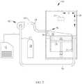
- the housing 26serves to isolate and protect the other components of the machine 10. During the build process described above, the housing 26 is provided with a flow of an appropriate shielding gas which, among other functions, excludes oxygen from the build environment. To provide this flow the machine 10 may be coupled to a gas flow apparatus 62, seen in FIG. 2 .
- the exemplary gas flow apparatus 62includes, in serial fluid flow communication, a variable-speed fan 64, a filter 66, an inlet duct 68 communicating with the housing 26, and a return duct 70 communicating with the housing 26. All of the components of the gas flow apparatus 62 are interconnected with suitable ducting and define a gas flow circuit in combination with the housing 26.
- the composition of the gas usedmay be similar to that used as shielding gas for conventional welding operations.
- gasessuch as nitrogen, argon, or mixtures thereof may be used.
- Any convenient source of gasmay be used.
- a conventional nitrogen generator 72may be connected to the gas flow apparatus 62.
- the gascould be supplied using one or more pressurized cylinders 74.
- the fan 64is used to recirculate the gas through the gas flow circuit in a substantially closed loop, so as to maintain positive pressure in the housing 26, with additional added makeup gas added as needed. Increasing the fan speed increases the velocity and flow rate of gas in the gas flow circuit; conversely, decreasing the fan speed decreases the velocity and flow rate of gas in the gas flow circuit.
- the gas flow apparatus 62could operate in a total loss mode; for example instead of the gas flowing through the return duct 70 and back to the fan 64, it could simply be vented to atmosphere after passing over the build chamber 22.
- the thermal mass of the gasprovides a heat transfer function, however an optional heat exchanger (not shown) could be incorporated into the gas flow apparatus 62.
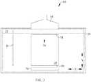
- the inlet duct 68is positioned near the bottom of the housing 26. During operation it provides a stream or flow of gas (see arrow 76). As seen in FIG. 1 , the inlet duct 68 has an elongated shape (for example rectangular) and discharges gas across the width of the build chamber 22. For reference purposes the width of the build chamber 22 may be considered parallel to the "X" direction. As shown in FIG. 3 , the edge of the build chamber 22 closest to the inlet duct 68 is referred to as a "leading edge” 78, and the opposite parallel edge is referred to as a "trailing edge" 80. For reference purposes the length of the build chamber (i.e. distance from leading edge 78 to trailing edge 80) may be considered parallel to the "Y" direction.
- the gas flow 76has two functions. First, it is used to effect heat transfer and carry heat away from the surface of the uppermost built layer within the build chamber 22. Second, during the build process, some of the powder 44 is vaporized. This vapor can cool and condense on the surface of the workpiece 25, in turn causing an undesirable surface roughness or "recast" layer. Part of the gas flow 76 is used to carry away the vapors and/or condensate.
- the interaction of the build beams 54, 56 with the powder 44causes heating and vaporization of the powder 44.
- thisgenerates first and second "plumes" 82, 84 respectively which originate in the vicinity of the melt pools 58, 60 and travel downstream, entrained in the gas flow 76.
- the composition of the plumes 82, 84 respectivelyis mostly vaporized powder.
- the vaporcan cool and condense so that the plumes 82, 84 comprises a mixture of gas and metallic particles.
- the presence of the condensatecan have numerous detrimental effects, for example blockage of the build beam 54, 56 and/or reduced beam intensity. These effects can be inconsistent because the condensate is scintillating. Accordingly, it is desirable to conduct the build process in such a manner that neither of the build beams 54, 56 passes through either of the plumes 82, 84. Several techniques for avoiding these intersections are described below.
- plumes 82, 84it is desirable to quantify the behavior of the plumes 82, 84. It is the object of the present invention to create a "plume map" describing the location and dimensions of each plume 82, 84 in 3-D space for any given time, and the propagation of the plumes 82, 84 over time. This process is also described as determining the trajectory of the plumes 82, 84.
- plume mapdescribing the location and dimensions of each plume 82, 84 in 3-D space for any given time, and the propagation of the plumes 82, 84 over time. This process is also described as determining the trajectory of the plumes 82, 84.
- One possible method for characterizing the plume 82involves modeling the plume 82. This may be done for example, using a commercially available computational fluid dynamics ("CFD") software package.
- the inputs to the softwareinclude, but are not limited to, the aerodynamic and thermal characteristics of the shielding gas flow 76 and the aerodynamic and thermal characteristics of the plume generation and propagation process.
- the inputsmay take into consideration factors such as: air flow rates, energy beam wavelength, intensity, or focus, consolidated or unconsolidated powdered material composition and physical characteristics, melt pool dimensions and thermal characteristics, the type of fusing process (e.g. heating, melting, or sintering), and the composition of the plume (e.g. gases/and/or metal alloys).
- the CFD softwareis then capable of producing as an output the above-mentioned plume map.
- Another possible method for characterizing the plume 82involves sensing the plume 82. Any visualization technique capable of distinguishing the plume 82 from the gas flow 76 may be used for this purpose.
- an illumination sourcemay be provided to illuminate the plume 82 in concert with one or more sensors to detect light scattered or reflected from the plume 82.
- suitable illumination sourcesinclude: a laser operated at a low output wattage (such as the beam generators 24); one or more additional dedicated low-power lasers (shown schematically at 85 in FIG. 5 ), a supplementary light-emitting diode ("LED”), or a chamber light in an appropriate wavelength (e.g. infrared or visible). Both backscatter and forward scatter sensing techniques may be used, and multiple images from multiple sensors may be combined to generate a 3-D plume map.
- an illumination source 86(shown schematically) is provided at a fixed location within the housing 26.
- Sensors 88are provided within the housing 26 with a clear field of view of the build surface 45.
- Each sensor 88is sensitive to forward scattered light 90 or backward scattered light 92.
- the sensors 88are of a type and configured such that they can produce a signal representative of the position of the plume 82. For example, they may be imaging sensors, or a plurality of simpler sensors arranged in an X-Y array may be provided in order to provide positional reference.
- the pattern of signals from the sensors 88is indicative of the location of the plume 82.
- the sensors 88may be used to generate a plume map in real time as the build process proceeds. Alternatively, the sensors 88 could be used as part of an empirical method of characterizing the plume 82. Initially, a test build would be performed using a nominal set of operating parameters, without any effort to avoid beam-plume interactions. The sensors 88 would be used to create a plume map as described above. In a second iteration, the plume map would be used to implement changes in the build parameters using one or more of the beam-plume avoidance methods described below. The sensors 88 could be used again to determine the effectiveness of the changes. A series of iterations may be performed until the operating parameters result in minimal beam-plume interactions. Once this set of iterations is complete, subsequent builds could be performed in an open loop using the optimized set of operating parameters.
- the machine 10is controlled in such a way as to prevent undesirable interaction between the build beams 54, 56 and the plumes 82, 84.
- Several of these techniquesinvolve controlling the build beams 54, 56 with reference to the plume maps described above.
- one possible methodinvolves controlling the operation of the beam generators 24 so that the build beams 54, 56 do not interact with the plumes 82, 84 by dividing the build surface 45 into virtual zones.
- the build surface 45is virtually divided into first and second zones 94, 96 by a virtual boundary 98 extending parallel to the direction of the gas flow 76 (i.e. parallel to the Y-direction).
- the build beam 54is limited to operation within the first zone 94 and the build beam 56 is limited to operation within the second zone 96.
- each build beam 54, 56would remain clear of its respective plume 82, 84 so long as the build beam 54, 56 consistently scans in the upstream direction relative to the gas flow 76.
- Another possible methodinvolves controlling the operation of the beam generators 24 so that the build beams 54, 56 are diverted away from or "skip over" the plumes 82, 84.
- build beam 54is shown generating plume 82 and build beam 56 is shown traversing an intended path 100 which would intersect the plume 82.
- the build beam 56is momentarily shut off at the point of predicted intersection with the plume 82, and then restarted to continue following the intended path 100 on the opposite side of the plume 82 (or possibly steered in a path completely avoiding the plume 82).
- the remaining portion of the path 100may then be fused at a subsequent time after the plume 82 has moved away.
- the build beam 56could be "skipped" away from its nominal path only when an actual intersection has been detected.
- Another possible methodinvolves coordinating the operation of the beam generators 24 so that the plume generation is momentarily interrupted providing a gap for a build beam.
- build beam 54is shown generating a plume 82 and build beam 56 is shown traversing an intended path 100 which would intersect the plume 82.
- the build beam 54is momentarily shut off at a time prior to the predicted intersection, thus creating a gap 102 in the plume 82.
- the timing and duration of the shut offis chosen such that the plume gap will allow the build beam 56 to traverse the intended path without interruption or encountering the plume 82.
- Any of these techniquesmay be implemented using a single beam generator 24 or multiple beam generators 24.
- the operation of the apparatus described above including the machine 10 and gas flow apparatus 62may be controlled, for example, by software running on one or more processors embodied in one or more devices such as a programmable logic controller ("PLC") or a microcomputer (not shown). Such processors may be coupled to the sensors and operating components, for example, through wired or wireless connections. The same processor or processors may be used to retrieve and analyze sensor data, for statistical analysis, and for feedback control.
- PLCprogrammable logic controller
- microcomputernot shown
- Such processorsmay be coupled to the sensors and operating components, for example, through wired or wireless connections.
- the same processor or processorsmay be used to retrieve and analyze sensor data, for statistical analysis, and for feedback control.
- the method described hereinhas several advantages over the prior art.
- itenables the use of multiple energy beams or rapidly-scanned energy beams in order to speed up an additive manufacturing process.
Landscapes
- Engineering & Computer Science (AREA)
- Physics & Mathematics (AREA)
- Optics & Photonics (AREA)
- Mechanical Engineering (AREA)
- Materials Engineering (AREA)
- Chemical & Material Sciences (AREA)
- Plasma & Fusion (AREA)
- Manufacturing & Machinery (AREA)
- Health & Medical Sciences (AREA)
- Toxicology (AREA)
- General Health & Medical Sciences (AREA)
- Automation & Control Theory (AREA)
- Environmental & Geological Engineering (AREA)
- Powder Metallurgy (AREA)
Description
- This invention relates generally to additive manufacturing, and more particularly to apparatus and methods for avoiding interference of an energy beam with an emissions plume in additive manufacturing.
- Additive manufacturing is a process in which material is built up layer-by-layer to form a component. Additive manufacturing is also referred to by terms such as "layered manufacturing," "reverse machining," "direct metal laser melting" (DMLM), and "3-D printing". Such terms are treated as synonyms for purposes of the present invention.
- One type of additive manufacturing machine is referred to as a "powder bed" machine and includes a build chamber that encloses a mass of powder which is selectively fused by a radiant energy beam to form a workpiece. The build chamber is enclosed in a housing that typically includes provisions for a flow of shielding gas therein. The shielding gas is used to transfer heat away from the surface of the powder bed, to prevent vaporized powder from condensing on the surface of the workpiece, and to control undesired chemical reactions, such as oxidation.
- In operation, the interaction of the radiant energy beam with the powder causes vaporization of the powder, generating a plume which originates in the vicinity of the melt pool generated by the energy beam and travels downstream, entrained in the shielding gas flow. In the immediate vicinity of the melt pool, the composition of the plume is mostly vaporized powder. At downstream locations, the vapor cools and condenses so that the plume comprises a mixture of gas and metallic particles (condensate).
US 2016/136731 A1 relates to an additive manufacturing apparatus for building objects by layerwise consolidation of material.DE 102014217786 A1 relates to a method of controlling the direction of gas suctioning carried out in a device for producing a three-dimensional object by selectively solidifying building material layer by layer.EP 3050666 A1 relates to a method of material processing comprising applying a laser beam, directing the laser beam to a processing location to melt material at the processing location, and providing a shielding gas flow.DE102014212100 A1 relates to a device and a method for the additive manufacture of components through the layered bonding of powder particles to one another and/or to a semi-finished product or substrate already produced, using selective interaction of the powder particles with a high-energy beam.DE 102013205724 A1 relates to a method for producing a three-dimensional object by applying layers of pulverulent construction material and by selectively solidifying said material by action of energy.DE 102015207254 A1 relates to a method for the production of a three-dimensional object by way of layered solidification of a powder construction material by way of electromagnetic radiation.K. A. Mumtaz et al "SELECTIVE LASER MELTING OF INCONEL 625 USING PULSE SHAPING", Rapid Prototyping Journal, vol. 16, no. 4, January 2010, pages 248-257 relates to the selective laser melting of Inconel 635 using pulse shaping to temporarily distribute energy with a single laser pulse.- One problem with the presence of the condensate is that it can have detrimental effects on the build process, for example blockage of the energy beam, or a reduction in beam intensity. This problem prevents rapid beam scanning or the use of multiple beams.
- This problem is addressed by a method of using a model or a real-time understanding of the plume behavior and a controller to change the path of an energy beam being used in an additive manufacturing process so that it prevents or avoids emissions plumes.
- The present technical problem is solved by the appended claims.
- The invention may be best understood by reference to the following description taken in conjunction with the accompanying drawing figures in which:
FIG. 1 is a schematic, partially-sectioned front elevation view of an exemplary additive manufacturing machine including a build chamber therein;FIG. 2 is a schematic, partially-sectioned side elevation view of the machine ofFIG. 1 ;FIG. 3 is a schematic, partially-sectioned top plan view of the machine ofFIG. 1 ;FIG. 4 is a schematic perspective view of an additive manufacturing build chamber showing a build process using two energy beams, with one beam intersecting a plume generated by the other beam;FIG. 5 is a schematic perspective view of an additive manufacturing build chamber showing a build process using two energy beams, with sensors positioned around the build chamber to detect plumes generated by the beams;FIG. 6 is a schematic perspective view of an additive manufacturing build chamber showing a build process using two energy beams, wherein each of the beams is steered to avoid a plume generated by other beam;FIG. 7 is a schematic perspective view of an additive manufacturing build chamber showing a build process using two energy beams, with a path of a second energy beam being steered to avoid a plume generated by the first beam; andFIG. 8 is a schematic perspective view of an additive manufacturing build chamber showing a build process using two energy beams, with a gap created in a plume generated by the first beam to permit the second beam to pass therethrough.- Referring to the drawings wherein identical reference numerals denote the same elements throughout the various views,
FIG. 1 illustrates schematically anadditive manufacturing machine 10 suitable for carrying out an additive manufacturing method. Basic components of themachine 10 include a table 12, apowder supply 14, arecoater 16, anoverflow container 18, abuild platform 20 surrounded by abuild chamber 22, and at least onebeam generator 24, all surrounded by ahousing 26. Each of these components will be described in more detail below. - The table 12 is a rigid structure defining a
planar worksurface 28. Theworksurface 28 is coplanar with and defines a virtual workplane. In the illustrated example it includes a build opening 30 communicating with thebuild chamber 22 and exposing thebuild platform 20, asupply opening 32 communicating with thepowder supply 14, and anoverflow opening 34 communicating with theoverflow container 18. - The
recoater 16 is a rigid, laterally-elongated structure that lies on theworksurface 28. It is connected to anactuator 36 operable to selectively move therecoater 16 along theworksurface 28. Theactuator 36 is depicted schematically inFIG. 1 , with the understanding devices such as pneumatic or hydraulic cylinders, ballscrew or linear electric actuators, and so forth, may be used for this purpose. - The
powder supply 14 comprises asupply container 38 underlying and communicating with the supply opening 32, and anelevator 40. Theelevator 40 is a plate-like structure that is vertically slidable within thesupply container 38. It is connected to anactuator 42 operable to selectively move theelevator 40 up or down. Theactuator 42 is depicted schematically inFIG. 1 , with the understanding that devices such as pneumatic or hydraulic cylinders, ball screw or linear electric actuators, and so forth, may be used for this purpose. When theelevator 40 is lowered, a supply ofpowder 44 of a desired composition (for example, metallic, ceramic, polymeric, and/or organic powder) may be loaded into thesupply container 38. When theelevator 40 is raised, it exposes thepowder 44 above theworksurface 28. Other types of powder supplies may be used; for example powder may be dropped into thebuild chamber 22 by an overhead device (not shown). - The
build platform 20 is a plate-like structure that is vertically slidable below the build opening 30. It is connected to anactuator 46 operable to selectively move thebuild platform 20 up or down. Theactuator 46 is depicted schematically inFIG. 1 , with the understanding that devices such as pneumatic or hydraulic cylinders, ballscrew or linear electric actuators, and so forth, may be used for this purpose. When thebuild platform 20 is lowered into thebuild chamber 22 during a build process, thebuild chamber 22 and thebuild platform 20 collectively surround and support a mass ofpowder 44 along with any components being built. This mass of powder is generally referred to as a "powder bed", and this specific category of additive manufacturing process may be referred to as a "powder bed process". - The
overflow container 18 underlies and communicates with the overflow opening 34, and serves as a repository forexcess powder 44. - The
apparatus 10 incorporates at least onebeam generator 24 operable to generate an energy beam and direct it as desired. As will be explained in more detail below,multiple beam generators 24 may be provided and used simultaneously in order to increase this production speed of theapparatus 10. In the illustrated example, twobeam generators 24 are shown. - Each
beam generator 24 includes a directedenergy source 48 and abeam steering apparatus 50. The directedenergy source 48 may comprise any device operable to generate a beam of suitable power and other operating characteristics to melt and fuse thepowder 44 during the build process, described in more detail below. For example, the directedenergy source 48 may be a laser. Other directed-energy sources such as electron beam guns are suitable alternatives to a laser. - The
beam steering apparatus 50 may include one or more mirrors, prisms, and/or lenses and provided with suitable actuators, and arranged so that a beam from the directedenergy source 48 can be focused to a desired spot size and steered to a desired position in plane coincident with theworksurface 28. For purposes of convenient description, this plane may be referred to as a X-Y plane, and a direction perpendicular to the X-Y plane is denoted as a Z-direction (X, Y, and Z being three mutually perpendicular directions). The beam may be referred to herein as a "build beam". - In the illustrated example, one of the
beam generators 24 is operable to generate afirst build beam 54, and the other of thebeam generators 24 is operable to generate asecond build beam 56. - An exemplary basic build process for a
workpiece 25 using the apparatus described above is as follows. Thebuild platform 20 is moved to an initial high position. Thebuild platform 20 is lowered below theworksurface 28 by a selected layer increment. The layer increment affects the speed of the additive manufacturing process and the resolution of theworkpiece 25. As an example, the layer increment may be about 10 to 50 micrometers (0.0003 to 0.002 in.).Powder 44 is then deposited over thebuild platform 20 for example, theelevator 40 of thesupply container 38 may be raised to push powder through thesupply opening 32, exposing it above theworksurface 28. Therecoater 16 is moved across the worksurface to spread the raisedpowder 44 horizontally over thebuild platform 20. Anyexcess powder 44 drops through theoverflow opening 34 into theoverflow container 18 as therecoater 16 passes from left to right. Subsequently, therecoater 16 may be moved back to a starting position. The leveledpowder 44 may be referred to as a "build layer" and the exposed upper surface thereof may be referred to as a "build surface", designated 45. - One or more of the
beam generators 24 are used to melt a two-dimensional cross-section or layer of theworkpiece 25 being built. Within thebeam generator 24, the directedenergy source 48 emits a beam and thebeam steering apparatus 50 is used to steer a focal spot of the build beam over the exposed powder surface in an appropriate pattern. A small portion of exposed layer of thepowder 44 surrounding the focal spot, referred to herein as a "melt pool" is heated by the build beam to a temperature allowing it to sinter or melt, flow, and consolidate. This step may be referred to as "fusing" thepowder 44. As an example, the melt pool may be on the order of 100 micrometers (0.004 in.) wide. In the illustrated example using twobeam generators 24, thefirst build beam 54 generates afirst melt pool 58 and thesecond build beam 56 generates asecond melt pool 60. - The
build platform 20 is moved vertically downward by the layer increment, and another layer ofpowder 44 is applied in a similar thickness. Thebeam generators 24 again emit build beams 54, 56 and thebeam steering apparatus 50 is used to steer the focal spots of the build beams 54, 56 over the exposed powder surface in an appropriate pattern. The exposed layer of thepowder 44 is heated by the build beams 54, 56 to a temperature allowing it to fuse as described above, and consolidate both within the top layer and with the lower, previously-solidified layer. - This cycle of moving the
build platform 20, applyingpowder 44, and then directed energy fusing thepowder 44 is repeated until theentire workpiece 25 is complete. - The
machine 10 and its operation are as representative example of a "powder bed machine". It will be understood that the principles described here are applicable to other configurations of powder bed machines. - The
housing 26 serves to isolate and protect the other components of themachine 10. During the build process described above, thehousing 26 is provided with a flow of an appropriate shielding gas which, among other functions, excludes oxygen from the build environment. To provide this flow themachine 10 may be coupled to agas flow apparatus 62, seen inFIG. 2 . The exemplarygas flow apparatus 62 includes, in serial fluid flow communication, a variable-speed fan 64, a filter 66, aninlet duct 68 communicating with thehousing 26, and areturn duct 70 communicating with thehousing 26. All of the components of thegas flow apparatus 62 are interconnected with suitable ducting and define a gas flow circuit in combination with thehousing 26. - The composition of the gas used may be similar to that used as shielding gas for conventional welding operations. For example, gases such as nitrogen, argon, or mixtures thereof may be used. Any convenient source of gas may be used. For example, if the gas is nitrogen, a
conventional nitrogen generator 72 may be connected to thegas flow apparatus 62. Alternatively, the gas could be supplied using one or morepressurized cylinders 74. - Once the
gas flow apparatus 62 andmachine 10 are initially purged with gas, thefan 64 is used to recirculate the gas through the gas flow circuit in a substantially closed loop, so as to maintain positive pressure in thehousing 26, with additional added makeup gas added as needed. Increasing the fan speed increases the velocity and flow rate of gas in the gas flow circuit; conversely, decreasing the fan speed decreases the velocity and flow rate of gas in the gas flow circuit. As an alternative to recirculation, thegas flow apparatus 62 could operate in a total loss mode; for example instead of the gas flowing through thereturn duct 70 and back to thefan 64, it could simply be vented to atmosphere after passing over thebuild chamber 22. In the illustrated example, the thermal mass of the gas provides a heat transfer function, however an optional heat exchanger (not shown) could be incorporated into thegas flow apparatus 62. - The
inlet duct 68 is positioned near the bottom of thehousing 26. During operation it provides a stream or flow of gas (see arrow 76). As seen inFIG. 1 , theinlet duct 68 has an elongated shape (for example rectangular) and discharges gas across the width of thebuild chamber 22. For reference purposes the width of thebuild chamber 22 may be considered parallel to the "X" direction. As shown inFIG. 3 , the edge of thebuild chamber 22 closest to theinlet duct 68 is referred to as a "leading edge" 78, and the opposite parallel edge is referred to as a "trailing edge" 80. For reference purposes the length of the build chamber (i.e. distance from leadingedge 78 to trailing edge 80) may be considered parallel to the "Y" direction. - The
gas flow 76 has two functions. First, it is used to effect heat transfer and carry heat away from the surface of the uppermost built layer within thebuild chamber 22. Second, during the build process, some of thepowder 44 is vaporized. This vapor can cool and condense on the surface of theworkpiece 25, in turn causing an undesirable surface roughness or "recast" layer. Part of thegas flow 76 is used to carry away the vapors and/or condensate. - In operation, the interaction of the build beams 54, 56 with the
powder 44 causes heating and vaporization of thepowder 44. As shown inFIG. 4 , this generates first and second "plumes" 82, 84 respectively which originate in the vicinity of the melt pools 58, 60 and travel downstream, entrained in thegas flow 76. In the immediate vicinity of the melt pools 58, 60 the composition of theplumes plumes - It will be understood that, so long as one of the build beams 54, 56 contacts the
powder 44 at a location upstream of theother build beam gas flow 76, there is a potential for an intersection of one of the build beams 54, 56 with one of theplume build surface 45 faster than theplumes build beam own plume - When one of the build beams 54, 56 intersects a
plume build beam plumes - To enable the avoidance techniques described elsewhere herein, it is desirable to quantify the behavior of the
plumes plume plumes plumes plumes plume 82 as an example with the understanding that the same methods may be used forplume 84 or for any additional plume, where multiple energy beams are used. - One possible method for characterizing the
plume 82 involves modeling theplume 82. This may be done for example, using a commercially available computational fluid dynamics ("CFD") software package. The inputs to the software include, but are not limited to, the aerodynamic and thermal characteristics of the shieldinggas flow 76 and the aerodynamic and thermal characteristics of the plume generation and propagation process. The inputs may take into consideration factors such as: air flow rates, energy beam wavelength, intensity, or focus, consolidated or unconsolidated powdered material composition and physical characteristics, melt pool dimensions and thermal characteristics, the type of fusing process (e.g. heating, melting, or sintering), and the composition of the plume (e.g. gases/and/or metal alloys). The CFD software is then capable of producing as an output the above-mentioned plume map. - Another possible method for characterizing the
plume 82 involves sensing theplume 82. Any visualization technique capable of distinguishing theplume 82 from thegas flow 76 may be used for this purpose. - For example, an illumination source may be provided to illuminate the
plume 82 in concert with one or more sensors to detect light scattered or reflected from theplume 82. Nonlimiting examples of suitable illumination sources include: a laser operated at a low output wattage (such as the beam generators 24); one or more additional dedicated low-power lasers (shown schematically at 85 inFIG. 5 ), a supplementary light-emitting diode ("LED"), or a chamber light in an appropriate wavelength (e.g. infrared or visible). Both backscatter and forward scatter sensing techniques may be used, and multiple images from multiple sensors may be combined to generate a 3-D plume map. - In the example shown in
FIG. 5 , an illumination source 86 (shown schematically) is provided at a fixed location within thehousing 26.Sensors 88 are provided within thehousing 26 with a clear field of view of thebuild surface 45. Eachsensor 88 is sensitive to forward scattered light 90 or backward scattered light 92. Thesensors 88 are of a type and configured such that they can produce a signal representative of the position of theplume 82. For example, they may be imaging sensors, or a plurality of simpler sensors arranged in an X-Y array may be provided in order to provide positional reference. The pattern of signals from thesensors 88 is indicative of the location of theplume 82. - The
sensors 88 may be used to generate a plume map in real time as the build process proceeds. Alternatively, thesensors 88 could be used as part of an empirical method of characterizing theplume 82. Initially, a test build would be performed using a nominal set of operating parameters, without any effort to avoid beam-plume interactions. Thesensors 88 would be used to create a plume map as described above. In a second iteration, the plume map would be used to implement changes in the build parameters using one or more of the beam-plume avoidance methods described below. Thesensors 88 could be used again to determine the effectiveness of the changes. A series of iterations may be performed until the operating parameters result in minimal beam-plume interactions. Once this set of iterations is complete, subsequent builds could be performed in an open loop using the optimized set of operating parameters. - Using the information provided by one or more of the methods described above of characterizing the plume, the
machine 10 is controlled in such a way as to prevent undesirable interaction between the build beams 54, 56 and theplumes - For example, one possible method involves controlling the operation of the
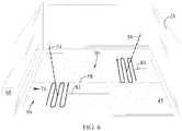
beam generators 24 so that the build beams 54, 56 do not interact with theplumes build surface 45 into virtual zones. Referring toFIG. 6 , thebuild surface 45 is virtually divided into first andsecond zones build beam 54 is limited to operation within thefirst zone 94 and thebuild beam 56 is limited to operation within thesecond zone 96. Using this method, it can be seen that theplume 82 from thefirst build beam 54 would inherently remain clear of thesecond build beam 56 and theplume 84 from thesecond build beam 56 would remain clear of thefirst build beam 54. Furthermore, eachbuild beam respective plume build beam gas flow 76. - Another possible method involves controlling the operation of the
beam generators 24 so that the build beams 54, 56 are diverted away from or "skip over" theplumes FIG. 7 , buildbeam 54 is shown generatingplume 82 and buildbeam 56 is shown traversing an intendedpath 100 which would intersect theplume 82. Using this method, thebuild beam 56 is momentarily shut off at the point of predicted intersection with theplume 82, and then restarted to continue following the intendedpath 100 on the opposite side of the plume 82 (or possibly steered in a path completely avoiding the plume 82). The remaining portion of thepath 100 may then be fused at a subsequent time after theplume 82 has moved away. Alternatively, thebuild beam 56 could be "skipped" away from its nominal path only when an actual intersection has been detected. - Another possible method involves coordinating the operation of the
beam generators 24 so that the plume generation is momentarily interrupted providing a gap for a build beam. Referring toFIG. 8 , buildbeam 54 is shown generating aplume 82 and buildbeam 56 is shown traversing an intendedpath 100 which would intersect theplume 82. Using this method, thebuild beam 54 is momentarily shut off at a time prior to the predicted intersection, thus creating agap 102 in theplume 82. The timing and duration of the shut off is chosen such that the plume gap will allow thebuild beam 56 to traverse the intended path without interruption or encountering theplume 82. - Any of these techniques may be implemented using a
single beam generator 24 ormultiple beam generators 24. - The operation of the apparatus described above including the
machine 10 andgas flow apparatus 62 may be controlled, for example, by software running on one or more processors embodied in one or more devices such as a programmable logic controller ("PLC") or a microcomputer (not shown). Such processors may be coupled to the sensors and operating components, for example, through wired or wireless connections. The same processor or processors may be used to retrieve and analyze sensor data, for statistical analysis, and for feedback control. - The method described herein has several advantages over the prior art. In particular, it enables the use of multiple energy beams or rapidly-scanned energy beams in order to speed up an additive manufacturing process.
- It will improve part quality by maintaining uniform energy beam density and focus.
- The foregoing has described an apparatus and method for plume avoidance in an additive manufacturing process.
Claims (5)
- A method of controlling an additive manufacturing process in which one or more energy beams (54,56) are used to selectively fuse a powder (44) to form a workpiece (25), in the presence of one or more plumes (82,84) generated by interaction of the one or more energy beams (54,56) with the powder (44), the method comprisingdetermining the trajectory of the one or more plumes (82,84) by sensing or modelling;creating a plume map describing the location and dimensions of each plume (82,84) in 3-D space for any given time, and the propagation of the plumes (82,84) over time;wherein an electronic controller with access to sensed or predicted plume trajectories applies this information from the plume map to determine when to steer or interrupt one of the one or more energy beams (54,56);controlling at least one of: a trajectory of the one or more plumes (82,84), and the one or more energy beams (54,56), so as to prevent the one or more energy beams (54,56) from intersecting the one or more plumes (82,84);wherein one or more of the energy beams (54,56) are steered so as to avoid intersecting the one or more plumes (82,84) and/or wherein one or more of the energy beams (54,56) are interrupted to create a gap in one or more of the plumes (82,84), so that one or more of the energy beams (54,56) may pass though the gap.
- The method of claim 1 wherein one of the energy beams (54,56) is steered to avoid one of the plumes (82,84) generated by the same energy beam (54,56); or wherein one of the energy beams (54,56) is steered to avoid one of the plumes (82,84) generated by a different one of the energy beams (54,56).
- The method of claim 1, wherein one of the energy beams (54,56) passes through a gap in one of the plumes (82,84) generated by the same energy beam (54,56); or wherein one of the energy beams (54,56) passes through a gap in one of the plumes (82,84) generated by a different one of the energy beams (82,84).
- The method of claim 1, wherein an intersection of one or more of the energy beams (54,56) with one or more of the plumes (82,84) is predicted prior to the intersection occurring; or wherein an intersection of one or more of the energy beams (54,56) with a plume (82,84) or condensate is not predicted prior to the intersection occurring.
- The method of claim 1, wherein a path is selected for each of the one or more energy beams (54,56) prior to beginning the additive manufacturing process.
Applications Claiming Priority (2)
| Application Number | Priority Date | Filing Date | Title |
|---|---|---|---|
| US15/389,986US11072025B2 (en) | 2016-12-23 | 2016-12-23 | Method for avoiding plume interference in additive manufacturing |
| PCT/US2017/062931WO2018118333A1 (en) | 2016-12-23 | 2017-11-22 | Method for avoiding plume interference in additive manufacturing |
Publications (3)
| Publication Number | Publication Date |
|---|---|
| EP3558637A1 EP3558637A1 (en) | 2019-10-30 |
| EP3558637A4 EP3558637A4 (en) | 2020-05-06 |
| EP3558637B1true EP3558637B1 (en) | 2021-09-29 |
Family
ID=62624837
Family Applications (1)
| Application Number | Title | Priority Date | Filing Date |
|---|---|---|---|
| EP17883298.6AActiveEP3558637B1 (en) | 2016-12-23 | 2017-11-22 | Method for avoiding plume interference in additive manufacturing |
Country Status (4)
| Country | Link |
|---|---|
| US (1) | US11072025B2 (en) |
| EP (1) | EP3558637B1 (en) |
| CN (1) | CN110087864B (en) |
| WO (1) | WO2018118333A1 (en) |
Families Citing this family (9)
| Publication number | Priority date | Publication date | Assignee | Title |
|---|---|---|---|---|
| EP3539754B1 (en)* | 2018-03-14 | 2023-04-26 | Concept Laser GmbH | Method for additively manufacturing at least one three-dimensional object |
| US10919115B2 (en)* | 2018-06-13 | 2021-02-16 | General Electric Company | Systems and methods for finishing additive manufacturing faces with different orientations |
| US11426818B2 (en) | 2018-08-10 | 2022-08-30 | The Research Foundation for the State University | Additive manufacturing processes and additively manufactured products |
| US12145215B2 (en) | 2019-03-04 | 2024-11-19 | Nikon Slm Solutions Ag | Control method, control device and production apparatus |
| DE102020210724A1 (en) | 2020-08-24 | 2022-02-24 | Trumpf Laser- Und Systemtechnik Gmbh | Manufacturing equipment, method and computer program product for the additive manufacturing of components from a powder material |
| JP2024518663A (en)* | 2021-05-07 | 2024-05-01 | ニコン エスエルエム ソリューションズ アーゲー | Process chamber for additive manufacturing device and method of operating the process chamber - Patents.com |
| US11845201B2 (en) | 2021-10-01 | 2023-12-19 | The Boeing Company | Methods of configuring gas flow in additive-manufacturing machines |
| US11987008B2 (en) | 2022-01-11 | 2024-05-21 | General Electric Company | Irradiation sequences for consolidating powder material in an additive manufacturing machine |
| EP4239426A1 (en) | 2022-03-03 | 2023-09-06 | TRUMPF Additive Manufacturing Italia S.r.l. | Method and planning device for planning a locally selective irradiation of a working area, computer program, method and manufacturing device for additively manufacturing an object from a powder material |
Family Cites Families (23)
| Publication number | Priority date | Publication date | Assignee | Title |
|---|---|---|---|---|
| WO1995007152A1 (en) | 1993-09-08 | 1995-03-16 | Uvtech Systems, Inc. | Surface processing |
| AU2001275164A1 (en) | 2000-06-01 | 2001-12-11 | Board Of Regents, The University Of Texas System | Direct selective laser sintering of metals |
| US6803938B2 (en) | 2002-05-07 | 2004-10-12 | Texas Instruments Incorporated | Dynamic laser printer scanning alignment using a torsional hinge mirror |
| US7105205B2 (en) | 2003-03-28 | 2006-09-12 | Research Foundation Of The State Of New York | Densification of thermal spray coatings |
| US8992816B2 (en)* | 2008-01-03 | 2015-03-31 | Arcam Ab | Method and apparatus for producing three-dimensional objects |
| FR2936177B1 (en) | 2008-09-24 | 2011-08-26 | Air Liquide | LASER WELDING PROCESS OF CO2 TYPE WITH DYNAMIC JET NOZZLE. |
| CN102460527B (en) | 2009-05-01 | 2015-06-03 | 爱克斯崔里斯科技有限公司 | Improvements to Particle Detectors |
| TWI523720B (en) | 2009-05-28 | 2016-03-01 | 伊雷克托科學工業股份有限公司 | Acousto-optic deflector applications in laser processing of features in a workpiece, and related laser processing method |
| WO2011100041A1 (en) | 2009-12-30 | 2011-08-18 | Resonetics Llc | Laser machining system and method for machining three-dimensional objects from a plurality of directions |
| US9174304B2 (en) | 2011-10-25 | 2015-11-03 | Eisuke Minehara | Laser decontamination device |
| DE102011085154A1 (en) | 2011-10-25 | 2013-04-25 | Evonik Industries Ag | Device for preventing deposits on optical components in laser sintering |
| DE102013205724A1 (en) | 2013-03-28 | 2014-10-02 | Eos Gmbh Electro Optical Systems | Method and device for producing a three-dimensional object |
| EP3007881B1 (en) | 2013-06-11 | 2020-04-29 | Renishaw Plc. | Additive manufacturing apparatus and method |
| GB201316815D0 (en) | 2013-09-23 | 2013-11-06 | Renishaw Plc | Additive manufacturing apparatus and method |
| EP2893994B1 (en) | 2014-01-14 | 2020-07-15 | General Electric Technology GmbH | Method for manufacturing a metallic or ceramic component by selective laser melting additive manufacturing |
| DE102014212100A1 (en) | 2014-06-24 | 2015-12-24 | MTU Aero Engines AG | Generative production process and device for this purpose with oppositely directed inert gas streams |
| DE102014217786A1 (en) | 2014-09-05 | 2016-03-10 | Eos Gmbh Electro Optical Systems | Method, apparatus and control unit for producing a three-dimensional object |
| EP3194108A1 (en) | 2014-09-19 | 2017-07-26 | Moog Inc. | Control of laser ablation condensate products within additive manufacturing systems |
| US10399911B2 (en) | 2015-01-27 | 2019-09-03 | Rolls-Royce Corporation | Forming a surface layer of a ceramic matrix composite article |
| EP3050666B2 (en)* | 2015-01-27 | 2022-08-10 | Ansaldo Energia IP UK Limited | Method of processing materials by applying a laser beam with adaptive shielding gas flow |
| WO2016138367A1 (en) | 2015-02-27 | 2016-09-01 | Electro Scientific Industries, Inc. | Fast beam manipulation for cross-axis micromachining |
| DE102015207254A1 (en) | 2015-04-21 | 2016-12-01 | Eos Gmbh Electro Optical Systems | Device and method for the generative production of a three-dimensional object |
| US20180126460A1 (en)* | 2016-11-07 | 2018-05-10 | Velo3D, Inc. | Gas flow in three-dimensional printing |
- 2016
- 2016-12-23USUS15/389,986patent/US11072025B2/enactiveActive
- 2017
- 2017-11-22CNCN201780079535.4Apatent/CN110087864B/enactiveActive
- 2017-11-22EPEP17883298.6Apatent/EP3558637B1/enactiveActive
- 2017-11-22WOPCT/US2017/062931patent/WO2018118333A1/ennot_activeCeased
Also Published As
| Publication number | Publication date |
|---|---|
| CN110087864A (en) | 2019-08-02 |
| CN110087864B (en) | 2021-11-12 |
| WO2018118333A1 (en) | 2018-06-28 |
| US20180178284A1 (en) | 2018-06-28 |
| EP3558637A4 (en) | 2020-05-06 |
| US11072025B2 (en) | 2021-07-27 |
| EP3558637A1 (en) | 2019-10-30 |
Similar Documents
| Publication | Publication Date | Title |
|---|---|---|
| EP3558637B1 (en) | Method for avoiding plume interference in additive manufacturing | |
| EP3558569B1 (en) | Method for emissions plume monitoring in additive manufacturing | |
| EP3558638B1 (en) | Method for process control in additive manufacturing | |
| EP3558636B1 (en) | Method for controlling plume trajectories in additive manufacturing | |
| EP3170593B1 (en) | Gas flow monitoring in additive manufacturing | |
| US10352750B2 (en) | Gas flow characterization in additive manufacturing | |
| EP3650141B1 (en) | Melt pool monitoring system and method for detecting errors in a multi-laser additive manufacturing process | |
| CN110612192A (en) | Device and method for generatively producing three-dimensional objects | |
| CN110722160B (en) | A powder curtain-based laser capture additive manufacturing device and manufacturing method | |
| CN116348224A (en) | Method of operating an irradiation system, irradiation system and apparatus for producing three-dimensional workpieces | |
| Xing et al. | Intelligent Metal Powder Laser Forming System |
Legal Events
| Date | Code | Title | Description |
|---|---|---|---|
| STAA | Information on the status of an ep patent application or granted ep patent | Free format text:STATUS: THE INTERNATIONAL PUBLICATION HAS BEEN MADE | |
| PUAI | Public reference made under article 153(3) epc to a published international application that has entered the european phase | Free format text:ORIGINAL CODE: 0009012 | |
| STAA | Information on the status of an ep patent application or granted ep patent | Free format text:STATUS: REQUEST FOR EXAMINATION WAS MADE | |
| 17P | Request for examination filed | Effective date:20190723 | |
| AK | Designated contracting states | Kind code of ref document:A1 Designated state(s):AL AT BE BG CH CY CZ DE DK EE ES FI FR GB GR HR HU IE IS IT LI LT LU LV MC MK MT NL NO PL PT RO RS SE SI SK SM TR | |
| AX | Request for extension of the european patent | Extension state:BA ME | |
| DAV | Request for validation of the european patent (deleted) | ||
| DAX | Request for extension of the european patent (deleted) | ||
| A4 | Supplementary search report drawn up and despatched | Effective date:20200407 | |
| RIC1 | Information provided on ipc code assigned before grant | Ipc:B33Y 30/00 20150101ALI20200401BHEP Ipc:B23K 26/082 20140101ALI20200401BHEP Ipc:B23K 26/12 20140101ALI20200401BHEP Ipc:B33Y 50/02 20150101ALI20200401BHEP Ipc:B29C 64/393 20170101ALI20200401BHEP Ipc:B23K 26/00 20140101ALI20200401BHEP Ipc:B22F 3/105 20060101ALI20200401BHEP Ipc:B23K 26/03 20060101ALI20200401BHEP Ipc:B29C 64/264 20170101ALI20200401BHEP Ipc:B23K 26/06 20140101ALI20200401BHEP Ipc:B29C 64/371 20170101ALI20200401BHEP Ipc:B23K 26/342 20140101ALI20200401BHEP Ipc:B29C 64/364 20170101ALI20200401BHEP Ipc:B29C 64/268 20170101ALI20200401BHEP Ipc:B29C 64/277 20170101ALI20200401BHEP Ipc:B33Y 10/00 20150101ALI20200401BHEP Ipc:B23K 15/00 20060101ALI20200401BHEP Ipc:B23K 26/14 20140101ALI20200401BHEP Ipc:B29C 64/153 20170101AFI20200401BHEP Ipc:B33Y 40/00 20200101ALI20200401BHEP | |
| REG | Reference to a national code | Ref country code:DE Ref legal event code:R079 Ref document number:602017046972 Country of ref document:DE Free format text:PREVIOUS MAIN CLASS: B29C0064153000 Ipc:B22F0010280000 | |
| GRAP | Despatch of communication of intention to grant a patent | Free format text:ORIGINAL CODE: EPIDOSNIGR1 | |
| STAA | Information on the status of an ep patent application or granted ep patent | Free format text:STATUS: GRANT OF PATENT IS INTENDED | |
| RIC1 | Information provided on ipc code assigned before grant | Ipc:B22F 12/70 20210101ALN20210312BHEP Ipc:B22F 10/77 20210101ALN20210312BHEP Ipc:B33Y 10/00 20150101ALI20210312BHEP Ipc:B23K 26/342 20140101ALI20210312BHEP Ipc:B29C 64/268 20170101ALI20210312BHEP Ipc:B29C 64/393 20170101ALI20210312BHEP Ipc:B29C 64/371 20170101ALI20210312BHEP Ipc:B23K 26/14 20140101ALI20210312BHEP Ipc:B23K 26/06 20140101ALI20210312BHEP Ipc:B23K 26/03 20060101ALI20210312BHEP Ipc:B23K 15/00 20060101ALI20210312BHEP Ipc:B22F 12/45 20210101ALI20210312BHEP Ipc:B22F 10/80 20210101ALI20210312BHEP Ipc:B33Y 50/02 20150101ALI20210312BHEP Ipc:B29C 64/153 20170101ALI20210312BHEP Ipc:B22F 12/90 20210101ALI20210312BHEP Ipc:B22F 10/38 20210101ALI20210312BHEP Ipc:B22F 10/366 20210101ALI20210312BHEP Ipc:B22F 10/322 20210101ALI20210312BHEP Ipc:B22F 10/28 20210101AFI20210312BHEP | |
| INTG | Intention to grant announced | Effective date:20210421 | |
| GRAS | Grant fee paid | Free format text:ORIGINAL CODE: EPIDOSNIGR3 | |
| GRAA | (expected) grant | Free format text:ORIGINAL CODE: 0009210 | |
| STAA | Information on the status of an ep patent application or granted ep patent | Free format text:STATUS: THE PATENT HAS BEEN GRANTED | |
| AK | Designated contracting states | Kind code of ref document:B1 Designated state(s):AL AT BE BG CH CY CZ DE DK EE ES FI FR GB GR HR HU IE IS IT LI LT LU LV MC MK MT NL NO PL PT RO RS SE SI SK SM TR | |
| REG | Reference to a national code | Ref country code:GB Ref legal event code:FG4D | |
| REG | Reference to a national code | Ref country code:CH Ref legal event code:EP Ref country code:AT Ref legal event code:REF Ref document number:1433771 Country of ref document:AT Kind code of ref document:T Effective date:20211015 | |
| REG | Reference to a national code | Ref country code:DE Ref legal event code:R096 Ref document number:602017046972 Country of ref document:DE | |
| REG | Reference to a national code | Ref country code:IE Ref legal event code:FG4D | |
| REG | Reference to a national code | Ref country code:LT Ref legal event code:MG9D | |
| PG25 | Lapsed in a contracting state [announced via postgrant information from national office to epo] | Ref country code:RS Free format text:LAPSE BECAUSE OF FAILURE TO SUBMIT A TRANSLATION OF THE DESCRIPTION OR TO PAY THE FEE WITHIN THE PRESCRIBED TIME-LIMIT Effective date:20210929 Ref country code:SE Free format text:LAPSE BECAUSE OF FAILURE TO SUBMIT A TRANSLATION OF THE DESCRIPTION OR TO PAY THE FEE WITHIN THE PRESCRIBED TIME-LIMIT Effective date:20210929 Ref country code:HR Free format text:LAPSE BECAUSE OF FAILURE TO SUBMIT A TRANSLATION OF THE DESCRIPTION OR TO PAY THE FEE WITHIN THE PRESCRIBED TIME-LIMIT Effective date:20210929 Ref country code:FI Free format text:LAPSE BECAUSE OF FAILURE TO SUBMIT A TRANSLATION OF THE DESCRIPTION OR TO PAY THE FEE WITHIN THE PRESCRIBED TIME-LIMIT Effective date:20210929 Ref country code:NO Free format text:LAPSE BECAUSE OF FAILURE TO SUBMIT A TRANSLATION OF THE DESCRIPTION OR TO PAY THE FEE WITHIN THE PRESCRIBED TIME-LIMIT Effective date:20211229 Ref country code:LT Free format text:LAPSE BECAUSE OF FAILURE TO SUBMIT A TRANSLATION OF THE DESCRIPTION OR TO PAY THE FEE WITHIN THE PRESCRIBED TIME-LIMIT Effective date:20210929 Ref country code:BG Free format text:LAPSE BECAUSE OF FAILURE TO SUBMIT A TRANSLATION OF THE DESCRIPTION OR TO PAY THE FEE WITHIN THE PRESCRIBED TIME-LIMIT Effective date:20211229 | |
| REG | Reference to a national code | Ref country code:NL Ref legal event code:MP Effective date:20210929 | |
| REG | Reference to a national code | Ref country code:AT Ref legal event code:MK05 Ref document number:1433771 Country of ref document:AT Kind code of ref document:T Effective date:20210929 | |
| PG25 | Lapsed in a contracting state [announced via postgrant information from national office to epo] | Ref country code:LV Free format text:LAPSE BECAUSE OF FAILURE TO SUBMIT A TRANSLATION OF THE DESCRIPTION OR TO PAY THE FEE WITHIN THE PRESCRIBED TIME-LIMIT Effective date:20210929 Ref country code:GR Free format text:LAPSE BECAUSE OF FAILURE TO SUBMIT A TRANSLATION OF THE DESCRIPTION OR TO PAY THE FEE WITHIN THE PRESCRIBED TIME-LIMIT Effective date:20211230 | |
| PG25 | Lapsed in a contracting state [announced via postgrant information from national office to epo] | Ref country code:AT Free format text:LAPSE BECAUSE OF FAILURE TO SUBMIT A TRANSLATION OF THE DESCRIPTION OR TO PAY THE FEE WITHIN THE PRESCRIBED TIME-LIMIT Effective date:20210929 | |
| PG25 | Lapsed in a contracting state [announced via postgrant information from national office to epo] | Ref country code:IS Free format text:LAPSE BECAUSE OF FAILURE TO SUBMIT A TRANSLATION OF THE DESCRIPTION OR TO PAY THE FEE WITHIN THE PRESCRIBED TIME-LIMIT Effective date:20220129 Ref country code:SK Free format text:LAPSE BECAUSE OF FAILURE TO SUBMIT A TRANSLATION OF THE DESCRIPTION OR TO PAY THE FEE WITHIN THE PRESCRIBED TIME-LIMIT Effective date:20210929 Ref country code:RO Free format text:LAPSE BECAUSE OF FAILURE TO SUBMIT A TRANSLATION OF THE DESCRIPTION OR TO PAY THE FEE WITHIN THE PRESCRIBED TIME-LIMIT Effective date:20210929 Ref country code:PT Free format text:LAPSE BECAUSE OF FAILURE TO SUBMIT A TRANSLATION OF THE DESCRIPTION OR TO PAY THE FEE WITHIN THE PRESCRIBED TIME-LIMIT Effective date:20220131 Ref country code:PL Free format text:LAPSE BECAUSE OF FAILURE TO SUBMIT A TRANSLATION OF THE DESCRIPTION OR TO PAY THE FEE WITHIN THE PRESCRIBED TIME-LIMIT Effective date:20210929 Ref country code:NL Free format text:LAPSE BECAUSE OF FAILURE TO SUBMIT A TRANSLATION OF THE DESCRIPTION OR TO PAY THE FEE WITHIN THE PRESCRIBED TIME-LIMIT Effective date:20210929 Ref country code:ES Free format text:LAPSE BECAUSE OF FAILURE TO SUBMIT A TRANSLATION OF THE DESCRIPTION OR TO PAY THE FEE WITHIN THE PRESCRIBED TIME-LIMIT Effective date:20210929 Ref country code:EE Free format text:LAPSE BECAUSE OF FAILURE TO SUBMIT A TRANSLATION OF THE DESCRIPTION OR TO PAY THE FEE WITHIN THE PRESCRIBED TIME-LIMIT Effective date:20210929 Ref country code:CZ Free format text:LAPSE BECAUSE OF FAILURE TO SUBMIT A TRANSLATION OF THE DESCRIPTION OR TO PAY THE FEE WITHIN THE PRESCRIBED TIME-LIMIT Effective date:20210929 Ref country code:AL Free format text:LAPSE BECAUSE OF FAILURE TO SUBMIT A TRANSLATION OF THE DESCRIPTION OR TO PAY THE FEE WITHIN THE PRESCRIBED TIME-LIMIT Effective date:20210929 | |
| PG25 | Lapsed in a contracting state [announced via postgrant information from national office to epo] | Ref country code:MC Free format text:LAPSE BECAUSE OF FAILURE TO SUBMIT A TRANSLATION OF THE DESCRIPTION OR TO PAY THE FEE WITHIN THE PRESCRIBED TIME-LIMIT Effective date:20210929 | |
| REG | Reference to a national code | Ref country code:DE Ref legal event code:R097 Ref document number:602017046972 Country of ref document:DE Ref country code:CH Ref legal event code:PL | |
| PG25 | Lapsed in a contracting state [announced via postgrant information from national office to epo] | Ref country code:LU Free format text:LAPSE BECAUSE OF NON-PAYMENT OF DUE FEES Effective date:20211122 Ref country code:DK Free format text:LAPSE BECAUSE OF FAILURE TO SUBMIT A TRANSLATION OF THE DESCRIPTION OR TO PAY THE FEE WITHIN THE PRESCRIBED TIME-LIMIT Effective date:20210929 Ref country code:BE Free format text:LAPSE BECAUSE OF NON-PAYMENT OF DUE FEES Effective date:20211130 | |
| REG | Reference to a national code | Ref country code:BE Ref legal event code:MM Effective date:20211130 | |
| PLBE | No opposition filed within time limit | Free format text:ORIGINAL CODE: 0009261 | |
| STAA | Information on the status of an ep patent application or granted ep patent | Free format text:STATUS: NO OPPOSITION FILED WITHIN TIME LIMIT | |
| PG25 | Lapsed in a contracting state [announced via postgrant information from national office to epo] | Ref country code:LI Free format text:LAPSE BECAUSE OF NON-PAYMENT OF DUE FEES Effective date:20211130 Ref country code:CH Free format text:LAPSE BECAUSE OF NON-PAYMENT OF DUE FEES Effective date:20211130 | |
| 26N | No opposition filed | Effective date:20220630 | |
| PG25 | Lapsed in a contracting state [announced via postgrant information from national office to epo] | Ref country code:IE Free format text:LAPSE BECAUSE OF NON-PAYMENT OF DUE FEES Effective date:20211122 | |
| PG25 | Lapsed in a contracting state [announced via postgrant information from national office to epo] | Ref country code:SI Free format text:LAPSE BECAUSE OF FAILURE TO SUBMIT A TRANSLATION OF THE DESCRIPTION OR TO PAY THE FEE WITHIN THE PRESCRIBED TIME-LIMIT Effective date:20210929 | |
| PG25 | Lapsed in a contracting state [announced via postgrant information from national office to epo] | Ref country code:IT Free format text:LAPSE BECAUSE OF FAILURE TO SUBMIT A TRANSLATION OF THE DESCRIPTION OR TO PAY THE FEE WITHIN THE PRESCRIBED TIME-LIMIT Effective date:20210929 | |
| P01 | Opt-out of the competence of the unified patent court (upc) registered | Effective date:20230411 | |
| PG25 | Lapsed in a contracting state [announced via postgrant information from national office to epo] | Ref country code:CY Free format text:LAPSE BECAUSE OF FAILURE TO SUBMIT A TRANSLATION OF THE DESCRIPTION OR TO PAY THE FEE WITHIN THE PRESCRIBED TIME-LIMIT Effective date:20210929 | |
| PG25 | Lapsed in a contracting state [announced via postgrant information from national office to epo] | Ref country code:SM Free format text:LAPSE BECAUSE OF FAILURE TO SUBMIT A TRANSLATION OF THE DESCRIPTION OR TO PAY THE FEE WITHIN THE PRESCRIBED TIME-LIMIT Effective date:20210929 Ref country code:HU Free format text:LAPSE BECAUSE OF FAILURE TO SUBMIT A TRANSLATION OF THE DESCRIPTION OR TO PAY THE FEE WITHIN THE PRESCRIBED TIME-LIMIT; INVALID AB INITIO Effective date:20171122 | |
| PG25 | Lapsed in a contracting state [announced via postgrant information from national office to epo] | Ref country code:MK Free format text:LAPSE BECAUSE OF FAILURE TO SUBMIT A TRANSLATION OF THE DESCRIPTION OR TO PAY THE FEE WITHIN THE PRESCRIBED TIME-LIMIT Effective date:20210929 | |
| PG25 | Lapsed in a contracting state [announced via postgrant information from national office to epo] | Ref country code:TR Free format text:LAPSE BECAUSE OF FAILURE TO SUBMIT A TRANSLATION OF THE DESCRIPTION OR TO PAY THE FEE WITHIN THE PRESCRIBED TIME-LIMIT Effective date:20210929 | |
| PG25 | Lapsed in a contracting state [announced via postgrant information from national office to epo] | Ref country code:MT Free format text:LAPSE BECAUSE OF FAILURE TO SUBMIT A TRANSLATION OF THE DESCRIPTION OR TO PAY THE FEE WITHIN THE PRESCRIBED TIME-LIMIT Effective date:20210929 | |
| PGFP | Annual fee paid to national office [announced via postgrant information from national office to epo] | Ref country code:DE Payment date:20241022 Year of fee payment:8 | |
| PGFP | Annual fee paid to national office [announced via postgrant information from national office to epo] | Ref country code:GB Payment date:20241023 Year of fee payment:8 | |
| PGFP | Annual fee paid to national office [announced via postgrant information from national office to epo] | Ref country code:FR Payment date:20241022 Year of fee payment:8 |