EP3558168B1 - Heart valve sealing devices - Google Patents
Heart valve sealing devicesDownload PDFInfo
- Publication number
- EP3558168B1 EP3558168B1EP18787709.7AEP18787709AEP3558168B1EP 3558168 B1EP3558168 B1EP 3558168B1EP 18787709 AEP18787709 AEP 18787709AEP 3558168 B1EP3558168 B1EP 3558168B1
- Authority
- EP
- European Patent Office
- Prior art keywords
- clasp
- barbed
- arm
- barbs
- moveable
- Prior art date
- Legal status (The legal status is an assumption and is not a legal conclusion. Google has not performed a legal analysis and makes no representation as to the accuracy of the status listed.)
- Active
Links
Images


Classifications
- A—HUMAN NECESSITIES
- A61—MEDICAL OR VETERINARY SCIENCE; HYGIENE
- A61B—DIAGNOSIS; SURGERY; IDENTIFICATION
- A61B17/00—Surgical instruments, devices or methods
- A61B17/12—Surgical instruments, devices or methods for ligaturing or otherwise compressing tubular parts of the body, e.g. blood vessels or umbilical cord
- A61B17/122—Clamps or clips, e.g. for the umbilical cord
- A61B17/1227—Spring clips
- A—HUMAN NECESSITIES
- A61—MEDICAL OR VETERINARY SCIENCE; HYGIENE
- A61B—DIAGNOSIS; SURGERY; IDENTIFICATION
- A61B17/00—Surgical instruments, devices or methods
- A61B17/12—Surgical instruments, devices or methods for ligaturing or otherwise compressing tubular parts of the body, e.g. blood vessels or umbilical cord
- A61B17/128—Surgical instruments, devices or methods for ligaturing or otherwise compressing tubular parts of the body, e.g. blood vessels or umbilical cord for applying or removing clamps or clips
- A61B17/1285—Surgical instruments, devices or methods for ligaturing or otherwise compressing tubular parts of the body, e.g. blood vessels or umbilical cord for applying or removing clamps or clips for minimally invasive surgery
- A—HUMAN NECESSITIES
- A61—MEDICAL OR VETERINARY SCIENCE; HYGIENE
- A61F—FILTERS IMPLANTABLE INTO BLOOD VESSELS; PROSTHESES; DEVICES PROVIDING PATENCY TO, OR PREVENTING COLLAPSING OF, TUBULAR STRUCTURES OF THE BODY, e.g. STENTS; ORTHOPAEDIC, NURSING OR CONTRACEPTIVE DEVICES; FOMENTATION; TREATMENT OR PROTECTION OF EYES OR EARS; BANDAGES, DRESSINGS OR ABSORBENT PADS; FIRST-AID KITS
- A61F2/00—Filters implantable into blood vessels; Prostheses, i.e. artificial substitutes or replacements for parts of the body; Appliances for connecting them with the body; Devices providing patency to, or preventing collapsing of, tubular structures of the body, e.g. stents
- A61F2/02—Prostheses implantable into the body
- A61F2/24—Heart valves ; Vascular valves, e.g. venous valves; Heart implants, e.g. passive devices for improving the function of the native valve or the heart muscle; Transmyocardial revascularisation [TMR] devices; Valves implantable in the body
- A61F2/2403—Heart valves ; Vascular valves, e.g. venous valves; Heart implants, e.g. passive devices for improving the function of the native valve or the heart muscle; Transmyocardial revascularisation [TMR] devices; Valves implantable in the body with pivoting rigid closure members
- A—HUMAN NECESSITIES
- A61—MEDICAL OR VETERINARY SCIENCE; HYGIENE
- A61F—FILTERS IMPLANTABLE INTO BLOOD VESSELS; PROSTHESES; DEVICES PROVIDING PATENCY TO, OR PREVENTING COLLAPSING OF, TUBULAR STRUCTURES OF THE BODY, e.g. STENTS; ORTHOPAEDIC, NURSING OR CONTRACEPTIVE DEVICES; FOMENTATION; TREATMENT OR PROTECTION OF EYES OR EARS; BANDAGES, DRESSINGS OR ABSORBENT PADS; FIRST-AID KITS
- A61F2/00—Filters implantable into blood vessels; Prostheses, i.e. artificial substitutes or replacements for parts of the body; Appliances for connecting them with the body; Devices providing patency to, or preventing collapsing of, tubular structures of the body, e.g. stents
- A61F2/02—Prostheses implantable into the body
- A61F2/24—Heart valves ; Vascular valves, e.g. venous valves; Heart implants, e.g. passive devices for improving the function of the native valve or the heart muscle; Transmyocardial revascularisation [TMR] devices; Valves implantable in the body
- A61F2/2409—Support rings therefor, e.g. for connecting valves to tissue
- A—HUMAN NECESSITIES
- A61—MEDICAL OR VETERINARY SCIENCE; HYGIENE
- A61F—FILTERS IMPLANTABLE INTO BLOOD VESSELS; PROSTHESES; DEVICES PROVIDING PATENCY TO, OR PREVENTING COLLAPSING OF, TUBULAR STRUCTURES OF THE BODY, e.g. STENTS; ORTHOPAEDIC, NURSING OR CONTRACEPTIVE DEVICES; FOMENTATION; TREATMENT OR PROTECTION OF EYES OR EARS; BANDAGES, DRESSINGS OR ABSORBENT PADS; FIRST-AID KITS
- A61F2/00—Filters implantable into blood vessels; Prostheses, i.e. artificial substitutes or replacements for parts of the body; Appliances for connecting them with the body; Devices providing patency to, or preventing collapsing of, tubular structures of the body, e.g. stents
- A61F2/02—Prostheses implantable into the body
- A61F2/24—Heart valves ; Vascular valves, e.g. venous valves; Heart implants, e.g. passive devices for improving the function of the native valve or the heart muscle; Transmyocardial revascularisation [TMR] devices; Valves implantable in the body
- A61F2/2427—Devices for manipulating or deploying heart valves during implantation
- A61F2/2436—Deployment by retracting a sheath
- A—HUMAN NECESSITIES
- A61—MEDICAL OR VETERINARY SCIENCE; HYGIENE
- A61F—FILTERS IMPLANTABLE INTO BLOOD VESSELS; PROSTHESES; DEVICES PROVIDING PATENCY TO, OR PREVENTING COLLAPSING OF, TUBULAR STRUCTURES OF THE BODY, e.g. STENTS; ORTHOPAEDIC, NURSING OR CONTRACEPTIVE DEVICES; FOMENTATION; TREATMENT OR PROTECTION OF EYES OR EARS; BANDAGES, DRESSINGS OR ABSORBENT PADS; FIRST-AID KITS
- A61F2/00—Filters implantable into blood vessels; Prostheses, i.e. artificial substitutes or replacements for parts of the body; Appliances for connecting them with the body; Devices providing patency to, or preventing collapsing of, tubular structures of the body, e.g. stents
- A61F2/02—Prostheses implantable into the body
- A61F2/24—Heart valves ; Vascular valves, e.g. venous valves; Heart implants, e.g. passive devices for improving the function of the native valve or the heart muscle; Transmyocardial revascularisation [TMR] devices; Valves implantable in the body
- A61F2/2442—Annuloplasty rings or inserts for correcting the valve shape; Implants for improving the function of a native heart valve
- A61F2/246—Devices for obstructing a leak through a native valve in a closed condition
- A—HUMAN NECESSITIES
- A61—MEDICAL OR VETERINARY SCIENCE; HYGIENE
- A61F—FILTERS IMPLANTABLE INTO BLOOD VESSELS; PROSTHESES; DEVICES PROVIDING PATENCY TO, OR PREVENTING COLLAPSING OF, TUBULAR STRUCTURES OF THE BODY, e.g. STENTS; ORTHOPAEDIC, NURSING OR CONTRACEPTIVE DEVICES; FOMENTATION; TREATMENT OR PROTECTION OF EYES OR EARS; BANDAGES, DRESSINGS OR ABSORBENT PADS; FIRST-AID KITS
- A61F2/00—Filters implantable into blood vessels; Prostheses, i.e. artificial substitutes or replacements for parts of the body; Appliances for connecting them with the body; Devices providing patency to, or preventing collapsing of, tubular structures of the body, e.g. stents
- A61F2/02—Prostheses implantable into the body
- A61F2/24—Heart valves ; Vascular valves, e.g. venous valves; Heart implants, e.g. passive devices for improving the function of the native valve or the heart muscle; Transmyocardial revascularisation [TMR] devices; Valves implantable in the body
- A61F2/2442—Annuloplasty rings or inserts for correcting the valve shape; Implants for improving the function of a native heart valve
- A61F2/2466—Delivery devices therefor
- A—HUMAN NECESSITIES
- A61—MEDICAL OR VETERINARY SCIENCE; HYGIENE
- A61B—DIAGNOSIS; SURGERY; IDENTIFICATION
- A61B17/00—Surgical instruments, devices or methods
- A61B17/00234—Surgical instruments, devices or methods for minimally invasive surgery
- A61B2017/00238—Type of minimally invasive operation
- A61B2017/00243—Type of minimally invasive operation cardiac
- A—HUMAN NECESSITIES
- A61—MEDICAL OR VETERINARY SCIENCE; HYGIENE
- A61B—DIAGNOSIS; SURGERY; IDENTIFICATION
- A61B17/00—Surgical instruments, devices or methods
- A61B17/00234—Surgical instruments, devices or methods for minimally invasive surgery
- A61B2017/00349—Needle-like instruments having hook or barb-like gripping means, e.g. for grasping suture or tissue
- A—HUMAN NECESSITIES
- A61—MEDICAL OR VETERINARY SCIENCE; HYGIENE
- A61B—DIAGNOSIS; SURGERY; IDENTIFICATION
- A61B17/00—Surgical instruments, devices or methods
- A61B2017/00743—Type of operation; Specification of treatment sites
- A61B2017/00778—Operations on blood vessels
- A61B2017/00783—Valvuloplasty
- A—HUMAN NECESSITIES
- A61—MEDICAL OR VETERINARY SCIENCE; HYGIENE
- A61B—DIAGNOSIS; SURGERY; IDENTIFICATION
- A61B17/00—Surgical instruments, devices or methods
- A61B2017/00831—Material properties
- A61B2017/00876—Material properties magnetic
- A—HUMAN NECESSITIES
- A61—MEDICAL OR VETERINARY SCIENCE; HYGIENE
- A61B—DIAGNOSIS; SURGERY; IDENTIFICATION
- A61B17/00—Surgical instruments, devices or methods
- A61B17/064—Surgical staples, i.e. penetrating the tissue
- A61B2017/0641—Surgical staples, i.e. penetrating the tissue having at least three legs as part of one single body
- A—HUMAN NECESSITIES
- A61—MEDICAL OR VETERINARY SCIENCE; HYGIENE
- A61F—FILTERS IMPLANTABLE INTO BLOOD VESSELS; PROSTHESES; DEVICES PROVIDING PATENCY TO, OR PREVENTING COLLAPSING OF, TUBULAR STRUCTURES OF THE BODY, e.g. STENTS; ORTHOPAEDIC, NURSING OR CONTRACEPTIVE DEVICES; FOMENTATION; TREATMENT OR PROTECTION OF EYES OR EARS; BANDAGES, DRESSINGS OR ABSORBENT PADS; FIRST-AID KITS
- A61F2/00—Filters implantable into blood vessels; Prostheses, i.e. artificial substitutes or replacements for parts of the body; Appliances for connecting them with the body; Devices providing patency to, or preventing collapsing of, tubular structures of the body, e.g. stents
- A61F2/0077—Special surfaces of prostheses, e.g. for improving ingrowth
- A—HUMAN NECESSITIES
- A61—MEDICAL OR VETERINARY SCIENCE; HYGIENE
- A61F—FILTERS IMPLANTABLE INTO BLOOD VESSELS; PROSTHESES; DEVICES PROVIDING PATENCY TO, OR PREVENTING COLLAPSING OF, TUBULAR STRUCTURES OF THE BODY, e.g. STENTS; ORTHOPAEDIC, NURSING OR CONTRACEPTIVE DEVICES; FOMENTATION; TREATMENT OR PROTECTION OF EYES OR EARS; BANDAGES, DRESSINGS OR ABSORBENT PADS; FIRST-AID KITS
- A61F2210/00—Particular material properties of prostheses classified in groups A61F2/00 - A61F2/26 or A61F2/82 or A61F9/00 or A61F11/00 or subgroups thereof
- A61F2210/0014—Particular material properties of prostheses classified in groups A61F2/00 - A61F2/26 or A61F2/82 or A61F9/00 or A61F11/00 or subgroups thereof using shape memory or superelastic materials, e.g. nitinol
- A—HUMAN NECESSITIES
- A61—MEDICAL OR VETERINARY SCIENCE; HYGIENE
- A61F—FILTERS IMPLANTABLE INTO BLOOD VESSELS; PROSTHESES; DEVICES PROVIDING PATENCY TO, OR PREVENTING COLLAPSING OF, TUBULAR STRUCTURES OF THE BODY, e.g. STENTS; ORTHOPAEDIC, NURSING OR CONTRACEPTIVE DEVICES; FOMENTATION; TREATMENT OR PROTECTION OF EYES OR EARS; BANDAGES, DRESSINGS OR ABSORBENT PADS; FIRST-AID KITS
- A61F2220/00—Fixations or connections for prostheses classified in groups A61F2/00 - A61F2/26 or A61F2/82 or A61F9/00 or A61F11/00 or subgroups thereof
- A61F2220/0008—Fixation appliances for connecting prostheses to the body
- A61F2220/0016—Fixation appliances for connecting prostheses to the body with sharp anchoring protrusions, e.g. barbs, pins, spikes
- A—HUMAN NECESSITIES
- A61—MEDICAL OR VETERINARY SCIENCE; HYGIENE
- A61F—FILTERS IMPLANTABLE INTO BLOOD VESSELS; PROSTHESES; DEVICES PROVIDING PATENCY TO, OR PREVENTING COLLAPSING OF, TUBULAR STRUCTURES OF THE BODY, e.g. STENTS; ORTHOPAEDIC, NURSING OR CONTRACEPTIVE DEVICES; FOMENTATION; TREATMENT OR PROTECTION OF EYES OR EARS; BANDAGES, DRESSINGS OR ABSORBENT PADS; FIRST-AID KITS
- A61F2220/00—Fixations or connections for prostheses classified in groups A61F2/00 - A61F2/26 or A61F2/82 or A61F9/00 or A61F11/00 or subgroups thereof
- A61F2220/0025—Connections or couplings between prosthetic parts, e.g. between modular parts; Connecting elements
- A61F2220/0033—Connections or couplings between prosthetic parts, e.g. between modular parts; Connecting elements made by longitudinally pushing a protrusion into a complementary-shaped recess, e.g. held by friction fit
- A—HUMAN NECESSITIES
- A61—MEDICAL OR VETERINARY SCIENCE; HYGIENE
- A61F—FILTERS IMPLANTABLE INTO BLOOD VESSELS; PROSTHESES; DEVICES PROVIDING PATENCY TO, OR PREVENTING COLLAPSING OF, TUBULAR STRUCTURES OF THE BODY, e.g. STENTS; ORTHOPAEDIC, NURSING OR CONTRACEPTIVE DEVICES; FOMENTATION; TREATMENT OR PROTECTION OF EYES OR EARS; BANDAGES, DRESSINGS OR ABSORBENT PADS; FIRST-AID KITS
- A61F2220/00—Fixations or connections for prostheses classified in groups A61F2/00 - A61F2/26 or A61F2/82 or A61F9/00 or A61F11/00 or subgroups thereof
- A61F2220/0025—Connections or couplings between prosthetic parts, e.g. between modular parts; Connecting elements
- A61F2220/0041—Connections or couplings between prosthetic parts, e.g. between modular parts; Connecting elements using additional screws, bolts, dowels or rivets, e.g. connecting screws
- A—HUMAN NECESSITIES
- A61—MEDICAL OR VETERINARY SCIENCE; HYGIENE
- A61F—FILTERS IMPLANTABLE INTO BLOOD VESSELS; PROSTHESES; DEVICES PROVIDING PATENCY TO, OR PREVENTING COLLAPSING OF, TUBULAR STRUCTURES OF THE BODY, e.g. STENTS; ORTHOPAEDIC, NURSING OR CONTRACEPTIVE DEVICES; FOMENTATION; TREATMENT OR PROTECTION OF EYES OR EARS; BANDAGES, DRESSINGS OR ABSORBENT PADS; FIRST-AID KITS
- A61F2220/00—Fixations or connections for prostheses classified in groups A61F2/00 - A61F2/26 or A61F2/82 or A61F9/00 or A61F11/00 or subgroups thereof
- A61F2220/0025—Connections or couplings between prosthetic parts, e.g. between modular parts; Connecting elements
- A61F2220/0075—Connections or couplings between prosthetic parts, e.g. between modular parts; Connecting elements sutured, ligatured or stitched, retained or tied with a rope, string, thread, wire or cable
- A—HUMAN NECESSITIES
- A61—MEDICAL OR VETERINARY SCIENCE; HYGIENE
- A61F—FILTERS IMPLANTABLE INTO BLOOD VESSELS; PROSTHESES; DEVICES PROVIDING PATENCY TO, OR PREVENTING COLLAPSING OF, TUBULAR STRUCTURES OF THE BODY, e.g. STENTS; ORTHOPAEDIC, NURSING OR CONTRACEPTIVE DEVICES; FOMENTATION; TREATMENT OR PROTECTION OF EYES OR EARS; BANDAGES, DRESSINGS OR ABSORBENT PADS; FIRST-AID KITS
- A61F2220/00—Fixations or connections for prostheses classified in groups A61F2/00 - A61F2/26 or A61F2/82 or A61F9/00 or A61F11/00 or subgroups thereof
- A61F2220/0025—Connections or couplings between prosthetic parts, e.g. between modular parts; Connecting elements
- A61F2220/0091—Connections or couplings between prosthetic parts, e.g. between modular parts; Connecting elements connected by a hinged linkage mechanism, e.g. of the single-bar or multi-bar linkage type
- A—HUMAN NECESSITIES
- A61—MEDICAL OR VETERINARY SCIENCE; HYGIENE
- A61F—FILTERS IMPLANTABLE INTO BLOOD VESSELS; PROSTHESES; DEVICES PROVIDING PATENCY TO, OR PREVENTING COLLAPSING OF, TUBULAR STRUCTURES OF THE BODY, e.g. STENTS; ORTHOPAEDIC, NURSING OR CONTRACEPTIVE DEVICES; FOMENTATION; TREATMENT OR PROTECTION OF EYES OR EARS; BANDAGES, DRESSINGS OR ABSORBENT PADS; FIRST-AID KITS
- A61F2230/00—Geometry of prostheses classified in groups A61F2/00 - A61F2/26 or A61F2/82 or A61F9/00 or A61F11/00 or subgroups thereof
- A61F2230/0002—Two-dimensional shapes, e.g. cross-sections
- A61F2230/0004—Rounded shapes, e.g. with rounded corners
- A61F2230/0006—Rounded shapes, e.g. with rounded corners circular
- A—HUMAN NECESSITIES
- A61—MEDICAL OR VETERINARY SCIENCE; HYGIENE
- A61F—FILTERS IMPLANTABLE INTO BLOOD VESSELS; PROSTHESES; DEVICES PROVIDING PATENCY TO, OR PREVENTING COLLAPSING OF, TUBULAR STRUCTURES OF THE BODY, e.g. STENTS; ORTHOPAEDIC, NURSING OR CONTRACEPTIVE DEVICES; FOMENTATION; TREATMENT OR PROTECTION OF EYES OR EARS; BANDAGES, DRESSINGS OR ABSORBENT PADS; FIRST-AID KITS
- A61F2230/00—Geometry of prostheses classified in groups A61F2/00 - A61F2/26 or A61F2/82 or A61F9/00 or A61F11/00 or subgroups thereof
- A61F2230/0002—Two-dimensional shapes, e.g. cross-sections
- A61F2230/0004—Rounded shapes, e.g. with rounded corners
- A61F2230/0008—Rounded shapes, e.g. with rounded corners elliptical or oval
- A—HUMAN NECESSITIES
- A61—MEDICAL OR VETERINARY SCIENCE; HYGIENE
- A61F—FILTERS IMPLANTABLE INTO BLOOD VESSELS; PROSTHESES; DEVICES PROVIDING PATENCY TO, OR PREVENTING COLLAPSING OF, TUBULAR STRUCTURES OF THE BODY, e.g. STENTS; ORTHOPAEDIC, NURSING OR CONTRACEPTIVE DEVICES; FOMENTATION; TREATMENT OR PROTECTION OF EYES OR EARS; BANDAGES, DRESSINGS OR ABSORBENT PADS; FIRST-AID KITS
- A61F2230/00—Geometry of prostheses classified in groups A61F2/00 - A61F2/26 or A61F2/82 or A61F9/00 or A61F11/00 or subgroups thereof
- A61F2230/0002—Two-dimensional shapes, e.g. cross-sections
- A61F2230/0004—Rounded shapes, e.g. with rounded corners
- A61F2230/0013—Horseshoe-shaped, e.g. crescent-shaped, C-shaped, U-shaped
- A—HUMAN NECESSITIES
- A61—MEDICAL OR VETERINARY SCIENCE; HYGIENE
- A61F—FILTERS IMPLANTABLE INTO BLOOD VESSELS; PROSTHESES; DEVICES PROVIDING PATENCY TO, OR PREVENTING COLLAPSING OF, TUBULAR STRUCTURES OF THE BODY, e.g. STENTS; ORTHOPAEDIC, NURSING OR CONTRACEPTIVE DEVICES; FOMENTATION; TREATMENT OR PROTECTION OF EYES OR EARS; BANDAGES, DRESSINGS OR ABSORBENT PADS; FIRST-AID KITS
- A61F2230/00—Geometry of prostheses classified in groups A61F2/00 - A61F2/26 or A61F2/82 or A61F9/00 or A61F11/00 or subgroups thereof
- A61F2230/0002—Two-dimensional shapes, e.g. cross-sections
- A61F2230/0028—Shapes in the form of latin or greek characters
- A61F2230/0045—Omega-shaped
- A—HUMAN NECESSITIES
- A61—MEDICAL OR VETERINARY SCIENCE; HYGIENE
- A61F—FILTERS IMPLANTABLE INTO BLOOD VESSELS; PROSTHESES; DEVICES PROVIDING PATENCY TO, OR PREVENTING COLLAPSING OF, TUBULAR STRUCTURES OF THE BODY, e.g. STENTS; ORTHOPAEDIC, NURSING OR CONTRACEPTIVE DEVICES; FOMENTATION; TREATMENT OR PROTECTION OF EYES OR EARS; BANDAGES, DRESSINGS OR ABSORBENT PADS; FIRST-AID KITS
- A61F2230/00—Geometry of prostheses classified in groups A61F2/00 - A61F2/26 or A61F2/82 or A61F9/00 or A61F11/00 or subgroups thereof
- A61F2230/0063—Three-dimensional shapes
- A61F2230/0069—Three-dimensional shapes cylindrical
Definitions
- the present applicationrelates generally to prosthetic devices and related methods for helping to seal native heart valves and prevent or reduce regurgitation therethrough, as well as devices and related methods for implanting such prosthetic devices.
- the native heart valvesi.e., the aortic, pulmonary, tricuspid, and mitral valves
- These heart valvescan be damaged, and thus rendered less effective, by congenital malformations, inflammatory processes, infectious conditions, or disease. Such damage to the valves can result in serious cardiovascular compromise or death.
- the definitive treatment for such damaged valveswas surgical repair or replacement of the valve during open heart surgery.
- open heart surgeriesare highly invasive and are prone to many complications. Therefore, elderly and frail patients with defective heart valves often went untreated. More recently, transvascular techniques have been developed for introducing and implanting prosthetic devices in a manner that is much less invasive than open heart surgery.
- trans-septal techniquecomprises inserting a catheter into the right femoral vein, up the inferior vena cava and into the right atrium. The septum is then punctured and the catheter passed into the left atrium.
- a healthy hearthas a generally conical shape that tapers to a lower apex.
- the heartis four-chambered and comprises the left atrium, right atrium, left ventricle, and right ventricle.
- the left and right sides of the heartare separated by a wall generally referred to as the septum.
- the native mitral valve of the human heartconnects the left atrium to the left ventricle.
- the mitral valvehas a very different anatomy than other native heart valves.
- the mitral valveincludes an annulus portion, which is an annular portion of the native valve tissue surrounding the mitral valve orifice, and a pair of cusps, or leaflets, extending downward from the annulus into the left ventricle.
- the mitral valve annuluscan form a "D"-shaped, oval, or otherwise out-of-round cross-sectional shape having major and minor axes.
- the anterior leafletcan be larger than the posterior leaflet, forming a generally "C"-shaped boundary between the abutting free edges of the leaflets when they are closed together.
- the anterior leaflet and the posterior leafletfunction together as a one-way valve to allow blood to flow only from the left atrium to the left ventricle.
- the left atriumreceives oxygenated blood from the pulmonary veins.
- the muscles of the left atriumcontract and the left ventricle dilates (also referred to as “ventricular diastole” or “diastole"), the oxygenated blood that is collected in the left atrium flows into the left ventricle.
- ventricular systoleWhen the muscles of the left atrium relax and the muscles of the left ventricle contract (also referred to as “ventricular systole” or “systole"), the increased blood pressure in the left ventricle urges the two leaflets together, thereby closing the one-way mitral valve so that blood cannot flow back to the left atrium and is instead expelled out of the left ventricle through the aortic valve.
- a plurality of fibrous cords called chordae tendineaetether the leaflets to papillary muscles in the left ventricle.
- Mitral regurgitationoccurs when the native mitral valve fails to close properly and blood flows into the left atrium from the left ventricle during the systolic phase of heart contraction. Mitral regurgitation is the most common form of valvular heart disease. Mitral regurgitation has different causes, such as leaflet prolapse, dysfunctional papillary muscles and/or stretching of the mitral valve annulus resulting from dilation of the left ventricle. Mitral regurgitation at a central portion of the leaflets can be referred to as central jet mitral regurgitation and mitral regurgitation nearer to one commissure (i.e., location where the leaflets meet) of the leaflets can be referred to as eccentric jet mitral regurgitation. Central jet regurgitation occurs when the edges of the leaflets do not meet in the middle and thus the valve does not close and regurgitation is present.
- Some prior techniques for treating mitral regurgitation in patientsinclude surgically stitching the edges of the native mitral valve leaflets directly to one another.
- a catheter delivered cliphas been used to attempt to clip the edges of the leaflets together, similar to the surgical stitching method.
- this cliphas shortcomings, since it can only be used to clip the middle edges of the leaflets where they overlap by about 2mm or more. Alternately, attempts have been made to use multiple clips on the commissures of the mitral valve, where there may be more overlap of the leaflets. This technique results in a longer operation time and also joins the patient's leaflets at the sides, restricting blood flow. Additionally, both the surgical and clip treatments are thought to create stress on patient leaflets.
- US Patent Application 2013/0066341 A1discloses, inter alia, an implantable prosthetic device for tissue approximation and repair at treatment sites.
- a fixation system for engaging tissue disclosed thereincomprises an implantable fixation device including a pair of fixation elements each having a first end, a free end opposite the first end, and an engagement surface therebetween for engaging the tissue.
- the first endsare movably coupled together such that the fixation elements are movable between a closed position, wherein the engagement surfaces face each other, to a first open position wherein the engagement surfaces are positioned away from each other.
- the fixation systemalso comprises an actuation mechanism coupled to the fixation elements adapted to move the fixation elements between the closed position and the first open position and a pair of gripping elements comprising a first gripping element and a second gripping element.
- Each of the gripping elementsis movable with respect to one of the fixation elements and configured to be moved in opposition to one of the engagement surfaces so as to capture tissue therebetween.
- the fixation systemalso comprises a first gripper actuator releasably coupled to the implantable fixation device and configured to individually actuate the gripping elements. The free ends of the fixation elements are moveably coupled to one another to move between the closed position where the engagement surfaces face each other and a closed position where the engagement surfaces face away from one another.
- An implantable prosthetic device as defined in claim 1includes, inter alia, a coaption portion, paddles, and clasps.
- the paddlesare moveable from a closed position to an open position.
- the claspsare also moveable from an open position to a closed position.
- the implantable prosthetic devicecan be used to repair a naitive valve, such as a native mitral valve.
- interconnectionwhen one or more components are described as being connected, joined, affixed, coupled, attached, or otherwise interconnected, such interconnection may be direct as between the components or may be indirect such as through the use of one or more intermediary components.
- reference to a "member,” “component,” or “portion”shall not be limited to a single structural member, component, or element but can include an assembly of components, members, or elements.
- the terms “substantially” and “about”are defined as at least close to (and includes) a given value or state (preferably within 10% of, more preferably within 1% of, and most preferably within 0.1% of).
- a prosthetic devicehas a coaptation means or coaption element and at least one anchoring means or anchor.
- the coaption elementis configured to be positioned within the native heart valve orifice to help form a more effective seal between the native leaflets, thereby reducing or preventing regurgitation.
- the coaption elementcan have a structure that is impervious to blood and that allows the native leaflets to close together on each side of the coaption element during ventricular systole to block blood from flowing from the left or right ventricle back into the left or right atrium, respectively.
- the prosthetic devicecan be configured to seal against two or three native valve leaflets; that is, the device may be used in the native mitral (bicuspid) and tricuspid valves.
- the coaption elementis sometimes referred to herein as a spacer because the coaption element can fill a space between improperly functioning native mitral or tricuspid leaflets that do not close completely.
- the coaption elementcan have various shapes.
- the coaption elementcan have an elongated cylindrical shape having a round cross-sectional shape.
- the coaption elementcan have an oval cross-sectional shape, a crescent cross-sectional shape, or various other non-cylindrical shapes.
- the coaption elementcan have an atrial or upper end positioned in or adjacent to the left atrium, a ventricular or lower end positioned in or adjacent to the left ventricle, and a side surface that extends between the native mitral leaflets.
- the atrial or upper endis positioned in or adjacent to the right atrium, and the ventricular or lower end is positioned in or adjacent to the right ventricle, and the side surface that extends between the native tricuspid leaflets.
- the anchorcan be configured to secure the device to one or both of the native mitral leaflets such that the coaption element is positioned between the two native leaflets.
- the anchoris configured to secure the device to one, two, or three of the tricuspid leaflets such that the coaption element is positioned between the three native leaflets.
- the anchorcan attach to the coaption element at a location adjacent the ventricular end of the coaption element.
- the anchorcan attach to an actuation means such as a shaft or actuation wire, to which the coaption element is also attached.
- the anchor and the coaption elementcan be positioned independently with respect to each other by separately moving each of the anchor and the coaption element along the longitudinal axis of the shaft or actuation wire. In some embodiments, the anchor and the coaption element can be positioned simultaneously by moving the anchor and the coaption element together along the longitudinal axis of the shaft or actuation wire.
- the anchorcan be configured to be positioned behind a native leaflet when implanted such that the leaflet is captured by the anchor.
- the prosthetic devicecan be configured to be implanted via a delivery means such as a delivery sheath.
- the coaption element and the anchorcan be compressible to a radially compressed state and can be self-expandable to a radially expanded state when compressive pressure is released.
- the devicecan be configured for the anchor to be expanded radially away from the still-compressed coaption element initially in order to create a gap between the coaption element and the anchor. A native leaflet can then be positioned in the gap.
- the coaption elementcan be expanded radially, closing the gap between the coaption element and the anchor and capturing the leaflet between the coaption element and the anchor.
- the anchor and coaption elementare optionally configured to self-expand.
- the implantation methods for various embodiments of the prosthetic devicecan be different, and are more fully discussed below with respect to each embodiment. Additional information regarding these and other delivery methods can be found in U.S. Pat. No. 8,449,599 and U.S. Patent Application Publication Nos. 2014/0222136 , and 2014/0067052 , 2016/0331523 .
- the disclosed prosthetic devicesare prevented from atrial embolization by having the anchor hooked to a leaflet, taking advantage of the tension from native chordae tendineae to resist high systolic pressure urging the device toward the left atrium.
- the devicescan rely on the compressive and retention forces exerted on the leaflet that is captured by the anchor to resist embolization into the left ventricle.
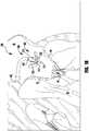
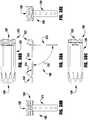
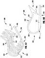
- an implantable prosthetic device 100is shown in various stages of deployment.
- the device 100is deployed from a delivery sheath 102 and includes a coaption portion 104 and an anchor portion 106.
- the coaption portion 104 of the device 100includes a coaption element 110 that is adapted to be implanted between the leaflets of the native mitral valve and is slideably attached to an actuation wire or shaft 112.
- the anchor portion 106is actuatable between open and closed conditions and can take a wide variety of forms, such as, for example, paddles, gripping elements, or the like. Actuation of the actuation wire 112 opens and closes the anchor portion 106 of the device 100 to capture the mitral valve leaflets during implantation.
- the actuation wire or shaft 112may take a wide variety of different forms.
- the actuation wire or shaftmay be threaded such that rotation of the actuation wire or shaft moves the anchor portion 106 relative to the coaption portion 104.
- the actuation wire or shaftmay be unthreaded, such that pushing or pulling the actuation wire or shaft 112 moves the anchor portion 106 relative to the coaption portion 104.
- the anchor portion 106 of the device 100includes outer paddles or gripping elements 120 and inner paddles or gripping elements 122 that are connected between a cap 114 and the coaption element 110 by portions 124, 126, 128.
- the portions 124, 126, 128may be hinged and/or flexible to move between all of the positions described below.
- the actuation wire 112extends through the delivery sheath and the coaption element 110 to the cap 114 at the distal end of the anchor portion 106. Extending and retracting the actuation wire 112 increases and decreases the spacing between the coaption element 110 and the cap 114, respectively.
- An attaching means or collar(not shown) removably attaches the coaption element 110 to the delivery sheath 102 so that the coaption element 110 slides along the actuation wire 112 during actuation to open and close the paddles 120, 122 of the anchor portion 106.
- the barbed clasps 130include a base or fixed arm 132, a moveable arm 134, barbs 136, and a hinge portion 138.
- the fixed arms 132are attached to the inner paddles 122, with the hinge portion 138 disposed proximate the coaption element 110.
- the hinge portion 138provides a spring force between the fixed and moveable arms 132, 134 of the barbed clasp 130.
- the hinge portion 138can be any suitable hinge, such as a flexible hinge, a spring hinge, a pivot hinge, or the like.
- the hinge portion 138is a flexible piece of material integrally formed with the fixed and moveable arms 132, 134.
- the fixed arms 132are attached to the inner paddles 122 and remain stationary relative to the inner paddles 122 when the moveable arms 134 are opened to open the barbed clasps 130 and expose the barbs 136.
- the barbed clasps 130are opened by applying tension to actuation lines 116 attached to the ends of the moveable arms 134, thereby causing the moveable arms 134 to pivot on the hinge portions 138.
- the paddles 120, 122are opened and closed to capture the native mitral valve leaflets between the paddles 120, 122 and the coaption element 110.
- the barbed clasps 130further secure the native leaflets by engaging the leaflets with barbs 136 and pinching the leaflets between the moveable and fixed arms 134, 132.
- the barbs 136 of the barbed clasps 130increase friction with the leaflets or may partially or completely puncture the leaflets.
- the actuation lines 116can be actuated independently so that each barbed clasp 130 can be opened and closed independently. Independent operation allows one leaflet to be captured at a time, or for the repositioning of a clasp 130 on a leaflet that was insufficiently captured, without altering a successful grasp on the other leaflet.
- the barbed clasps 130not only open and close independent from each other but can fully be opened and closed independent from the position of the inner paddle 122, thereby allowing leaflets to be captured in a variety of positions as the particular situation requires.
- the barbed clasps 130can be opened independently by pulling on an attached actuating means or actuation line 116 that extends through the delivery sheath 102 to the end of the barbed clasp 130.
- the actuation line 116can take a wide variety of forms, such as, for example, a line, a suture, a wire, a rod, a catheter, or the like.
- the barbed clasps 130can be spring loaded so that in the closed position the barbed clasps 130 continue to provide a pinching force on the captured native leaflet. This pinching force remains constant regardless of the position of the inner paddles 122. Barbs 136 of the barbed clasps 130 can pierce the native leaflets to further secure the native leaflets.
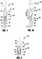
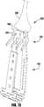
- the device 100is shown in an elongated or fully open condition for deployment from the delivery sheath.
- the device 100is loaded in the delivery sheath in the fully open position, because the fully open position takes up the least space and allows the smallest catheter to be used (or the largest device 100 to be used for a given catheter size).
- the cap 114is spaced apart from the coaption element 110 such that the paddles 120, 122 of the anchor portion 106 are inverted or fully open.
- an angle formed between the interior of the outer and inner paddles 120, 122is approximately 180 degrees.
- the barbed clasps 130are kept in a closed condition during deployment through the delivery sheath 102 so that the barbs 136 ( Fig. 3 ) do not catch or damage the sheath or tissue in the patient's heart.
- the device 100is shown in an elongated detangling condition, similar to Figure 1 , but with the barbed clasps 130 in a fully open position, ranging from about 140 degrees to about 200 degrees, to about 170 degrees to about 190 degrees, or about 180 degrees between fixed and moveable portions of the barbed clasps 130. Fully opening the device 100 and the clasps 130 has been found to improve ease of detanglement from anatomy of the patient during implantation of the device 100.
- the device 100is shown in a shortened or fully closed condition.
- the compact size of the device 100 in the shortened conditionallows for easier maneuvering and placement within the heart.
- the actuation wire 112is retracted to pull the cap 114 towards the coaption element 110.
- the hinges or flexible connections 126 between the outer paddle 120 and inner paddle 122are limited in movement such that compression forces acting on the outer paddle 120 from the cap 114 being retracted towards the coaption element 110 cause the paddles or gripping elements 120, 122 to move radially outward.
- the outer paddles 120maintain an acute angle with the actuation wire 112.
- the outer paddles 120can optionally be biased toward a closed position.
- the inner paddles 122 during the same motionmove through a considerably larger angle as they are oriented away from the coaption element 110 in the open condition and collapse along the sides of the coaption element 110 in the closed condition.
- the inner paddles 122are thinner and/or narrower than the outer paddles 120, and the hinge or flexible portions 126, 128 connected to the inner paddles 122 are thinner and/or more flexible to allow more movement than the hinge or flexible portion 124 connecting the outer paddle 124 to the cap 114.
- the device 100is shown in a partially open, capture-ready condition.
- the actuation wire 112is extended to push the cap 114 away from the coaption element 110, thereby pulling on the outer paddles 120, which in turn pulls on the inner paddles 122, causing the anchor portion 106 to partially unfold.
- the actuation lines 116are also retracted to open the clasps 130 so that the leaflets can be captured.
- one of the actuation lines 116is extended to allow one of the clasps 130 to close.
- the other actuation line 116is extended to allow the other clasp 130 to close. Either or both of the actuation lines 116 may be repeatedly actuated to repeatedly open and close the barbed clasps 130.
- the device 100is shown in a fully closed and deployed condition.
- the delivery sheath 102 and actuation wire 112are retracted and the paddles 120, 122 and clasps 130 remain in a fully closed position.
- the device 100may be maintained in the fully closed position with a mechanical latch or may be biased to remain closed through the use of spring materials, such as steel, other metals, plastics, composites, etc. or shape-memory alloys such as Nitinol.
- the hinged or flexible portions 124, 126, 128, 138, and/or the inner and outer paddles 122, and/or an additional biasing componentmay be formed of metals such as steel or shape-memory alloy, such as Nitinol-produced in a wire, sheet, tubing, or laser sintered powder-and are biased to hold the outer paddles 120 closed around the coaption element 110 and the barbed clasps 130 pinched around native leaflets.
- the fixed and moveable arms 132, 134 of the barbed clasps 130are biased to pinch the leaflets.
- the hinge portions 124, 126, 128, 138, and/or the inner and outer paddles 122, and/or an additional biasing componentmay be formed of any other suitably elastic material, such as a metal or polymer material, to maintain the device in the closed condition after implantation.
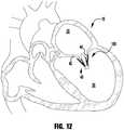
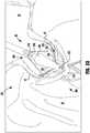
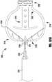
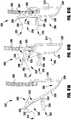
- the implantable device 100 of Figures 1-6is shown being delivered and implanted within a native mitral valve 40 of a heart 10.
- the delivery sheathis inserted into the left atrium 20 through the septum and the device 100 is deployed from the delivery sheath in the fully open condition.
- the actuation wire 112is then retracted to move the device 100 into the fully closed condition shown in Figure 8 .
- the device 100is moved into position within the mitral valve 40 into the ventricle 30 and partially opened so that the leaflets 42, 44 can be captured.
- an actuation line 116is extended to close one of the clasps 130, capturing a leaflet 42.
- Figure 11shows the other actuation line 116 being then extended to close the other clasp 130, capturing the remaining leaflet 44.
- the delivery sheath 102 and actuation wire 112are then retracted and the device 100 is fully closed and deployed in the native mitral valve 400.
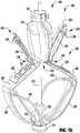
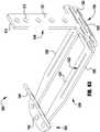
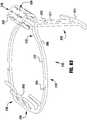
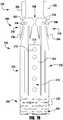
- the implantable device 200is one of the many different configurations that the device 100 that is schematically illustrated in Figures 1-12 can take.
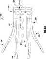
- the device 200is deployed from a delivery sheath (not shown) and includes a coaption portion 204 and an anchor portion 206.
- the device 200is loaded in the delivery sheath in the fully open position, because the fully open position takes up the least space and allows the smallest catheter to be used (or the largest device 200 to be used for a given catheter size).
- the coaption portion 204 of the deviceincludes a coaption element 210 for implantation between the leaflets of the native mitral valve that is slideably attached to an actuation wire or shaft 212. Actuation of the actuation wire 212 opens and closes the anchor portion 206 of the device 200 to capture the mitral valve leaflets during implantation.
- the anchor portion 206 of the device 200includes outer paddles 220 and inner paddles 222 that are hingeably connected to the cap 214 and the coaption element 210.
- the actuation wire 212extends through the delivery sheath (not shown), a collar 211, and the coaption element 210 to the cap 214 at the distal end of the anchor portion 206. Extending and retracting the actuation wire 212 increases and decreases the spacing between the coaption element 210 and the cap 214, respectively.
- the collar 211optionally includes a collar seal 213 that forms a seal around the actuation wire or shaft 212 during implantation of the device 200, and that seals shut when the actuation wire 212 is removed to substantially close the device 200 to blood flow through the interior of the coaption element 210 after implantation.
- the collar 2011removably engages and attaches the coaption element 200 to the delivery sheath so that the coaption element 210 slides along the actuation wire 212 during actuation to open and close the paddles 220, 222 of the anchor portion 206.
- the collar 2011is held closed around the coaption element 2010 by the actuation wire 212, such that removal of the actuation wire 212 allows fingers (not shown) of the collar to open, releasing the coaption element 210.
- the cap 2014optionally includes a seal 216 and/or an insert 218 that fit inside an opening 215 of the coaption element 210, the coaption element 210 having a hollow interior. The seal 216 and/or insert 218 maintain the coaption element 210 substantially closed to blood flow when the actuation wire 212 is withdrawn and the device 200 is implanted.
- the coaption element 210 and paddles 220, 222are formed from a covering that may be a mesh, woven, braided, or formed in any other suitable way.
- the coveringmay be cloth, shape-memory alloy wire-such as Nitinol-to provide shape setting capability, or any other flexible material suitable for implantation in the human body.
- Paddle frames 224provide additional pinching force between the outer paddles 222 and the coaption element 210, and assist in wrapping the leaflets around the sides of the coaption element 210 for a better seal between the coaption element 210 and the leaflets.
- the coveringextends around the paddle frames 224.
- the barbed clasps 230include a base or fixed arm 232, a moveable arm 234, barbs 236, and a hinge portion 238.
- the fixed arms 232are attached to the inner paddles 222, with the hinge portion 238 disposed proximate the coaption element 210.
- the fixed arms 232are attached to the inner paddles 222 through holes or slots 233 with sutures (not shown).
- the fixed arms 232may be attached to the inner paddles 222 with any suitable means, such as screws or other fasteners, crimped sleeves, mechanical latches or snaps, welding, adhesive, or the like.
- the fixed arms 232remain stationary relative to the inner paddles 222 when the moveable arms 234 are opened to open the barbed clasps 230 and expose the barbs 236.
- the barbed clasps 230are opened by applying tension to actuation lines (not shown) attached to holes 235 disposed at ends of the moveable arms 234, thereby causing the moveable arms 234 to pivot on the hinge portions 2
- the paddles 220, 222are opened and closed to capture the native mitral valve leaflets between the paddles 220, 222 and the coaption element 210.
- the barbed clasps 230further secure the native leaflets by engaging the leaflets with barbs 236 and pinching the leaflets between the moveable and fixed arms 234, 232.
- the barbs 236 of the barbed clasps 230increase friction with the leaflets or may partially or completely puncture the leaflets.
- the actuation linescan be actuated independently so that each barbed clasp 230 can be opened and closed independently.
- Independent operationallows one leaflet to be captured at a time, or for the repositioning of a clasp 230 on a leaflet that was insufficiently captured, without altering a successful grasp on the other leaflet.
- the barbed clasps 230not only open and close independent from each other but can be fully opened and closed independent from the position of the inner paddle 222, thereby allowing leaflets to be captured in a variety of positions as the particular situation requires.
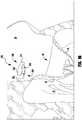
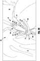
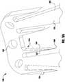
- an implantable device 300is shown being delivered and implanted within the native mitral valve 40 of the heart 10.
- the device 300is similar to implantable device 200 of Figure 13 , though device 300 has a covering over the coaption element 310, clasps 330, inner paddles 322 and/or the outer paddles 320.
- the device 300is deployed from a delivery sheath 302 and includes a coaption portion 304 and an anchor portion 306.
- the coaption portion 304 of the deviceincludes a coaption element 310 for implantation between the leaflets of the native mitral valve that is slideably attached to an actuation wire or shaft 312. Actuation of the actuation wire or shaft 312 opens and closes the anchor portion 306 of the device 300 to capture the mitral valve leaflets during implantation.
- the anchor portion 306 of the device 300includes outer paddles 320 and inner paddles 322 that are flexibly connected to the cap 314 and the coaption element 310.
- the actuation wire 312extends through a collar 303 (see Figure 20 ), delivery sheath 302, and the coaption element 310 to the cap 314 at the distal end of the anchor portion 306. Extending and retracting the actuation wire 312 increases and decreases the spacing between the coaption element 310 and the cap 314, respectively.
- Fingers of the collar 303removably attach the coaption element 310 to the delivery sheath 302 so that the coaption element 310 slides along the actuation wire 312 during actuation to open and close the paddles 320, 322 of the anchor portion 306.
- the collar 303is held closed around the coaption element 310 by the actuation wire 312, such that removal of the actuation wire 312 allows the fingers of the collar 303 to open, releasing the coaption element 310.
- the coaption element 310 and paddles 320, 322are formed from a flexible material that may be a mesh, woven, braided, or formed in any other suitable way.
- the flexible materialmay be cloth, shape-memory alloy wire-such as Nitinol-to provide shape setting capability, or any other flexible material suitable for implantation in the human body.
- the barbed clasps 330include a base or fixed arm 332, a moveable arm 334, barbs 336 (see Figure 20 ), and a hinge portion 338.
- the fixed arms 332are attached to the inner paddles 322, with the hinge portion 338 disposed proximate the coaption element 310. Sutures (not shown) attach the fixed arms 332 to the inner paddles 322.
- the fixed arms 332may be attached to the inner paddles 322 with any suitable means, such as screws or other fasteners, crimped sleeves, mechanical latches or snaps, welding, adhesive, or the like.
- the fixed arms 332remain stationary when the moveable arms 334 are opened to open the barbed clasps 330 and expose the barbs 336.
- the barbed clasps 330are opened by applying tension to actuation lines 316 attached to the ends of the moveable arms 334, thereby causing the moveable arms 334 to pivot on the hinge portions 338.
- the paddles 320, 322are opened and closed to capture the native mitral valve leaflets between the paddles 320, 322 and the coaption element 310.
- the outer paddles 320have a wide curved shape that fits around the curved shape of the coaption element 310 to more securely grip the leaflets.
- the curved shape and rounded edges of the outer paddle 320also prohibits tearing of the leaflet tissue.
- the barbed clasps 330further secure the native leaflets by engaging the leaflets with barbs 336 and pinching the leaflets between the moveable and fixed arms 334, 332.
- the barbs 336 of the barbed clasps 330increase friction with the leaflets or may partially or completely puncture the leaflets.
- the actuation linescan be actuated independently so that each barbed clasp 330 can be opened and closed independently. Independent operation allows one leaflet to be captured at a time, or for the repositioning of a clasp 330 on a leaflet that was insufficiently captured, without altering a successful grasp on the other leaflet.
- the barbed clasps 330not only open and close independent from each other but can be fully opened and closed independent from the position of the inner paddle 322, thereby allowing leaflets to be captured in a variety of positions as the particular situation requires.
- the device 300is loaded in the delivery sheath in the fully open position, because the fully open position takes up the least space and allows the smallest catheter to be used (or the largest device 300 to be used for a given catheter size).
- the delivery sheathis inserted into the left atrium 20 through the septum and the device 300 is deployed from the delivery sheath 302 in the fully open condition.
- the actuation wire 312is then retracted to move the device 300 into the fully closed condition shown in Figures 15-16 and then maneuvered towards the mitral valve 40 as shown in Figure 17 .
- the actuation wire 312is extended to open the paddles 320, 322 into the partially opened position and the actuation lines 316 are retracted to open the barbed clasps 330 to prepare for leaflet capture.
- the partially open device 300is inserted through the mitral valve 40 until leaflets are properly positioned in between the inner paddles 322 and the coaption element 310 and inside the open barbed clasps 330.
- Figure 21shows the device 300 with both clasps 330 closed, though the barbs 336 of one clasp 330 missed one of the leaflets 44.
- the out of position clasp 330is opened and closed again to properly capture the missed leaflet 44.
- the actuation wire 312is retracted to move the device 300 into the fully closed position shown in Figure 24 .
- the actuation wire 312is withdrawn to release the collar 303 from an upper end or plate 311 of the coaption element 310.
- the device 300may be maintained in the fully closed position with a mechanical means such as a latch or may be biased to remain closed through the use of spring material, such as steel, and/or shape-memory alloys such as Nitinol.
- the paddles 320, 322may be formed of steel or Nitinol shape-memory alloy-produced in a wire, sheet, tubing, or laser sintered powder-and are biased to hold the outer paddles 320 closed around the coaption element 310 and the barbed clasps 330 pinched around native leaflets.
- FIG. 23Aa close-up view of one of the leaflets 42, 44 captured by one of the clasps 330 is shown.
- the leaflet 42, 44is captured between the moveable and fixed arms 334, 332 of the clasp 330.
- the tissue of the leaflet 42, 44is not pierced by the barbs 336, though in some embodiments the barbs 336 may partially or fully pierce through the leaflet 42, 44.
- the angle and height of the barbs 336 relative to the moveable arm 334helps to secure the leaflet 42, 44 within the clasp 330.
- a force pulling the implant off of the native leafletwill encourage the barbs 336 to further engage the tissue, thereby ensuring better retention.
- Retention of the leaflet 42, 44 in the clasp 330is further improved by the position of fixed arm 332 near the barbs 336 when the clasp 330 is closed.
- the tissueis formed by the fixed and moveable arms 332, 334 and the barbs 336 into an S-shaped torturous path.
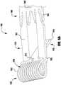
- the barbed clasp 400is formed from a top layer 402 and a bottom layer 404.
- the two-layer design of the clasp 400allow thinner sheets of material to be used, thereby improving the flexibility of the clasp 400 over a clasp formed from a single thicker sheet, while maintaining the strength of the clasp 400 needed to successfully retain a native valve leaflet.
- the barbed clasp 400includes a fixed arm 410, a hinged portion 420, and a movable arm 430 having a barbed portion 440.
- the top and bottom layers 402, 404have a similar shape and in certain embodiments are attached to each other at the barbed end 440.
- the hinged portion 420is spring-loaded so that the fixed and moveable arms 410, 430 are biased toward each other when the barbed clasp 400 is in a closed condition.
- the fixed arm 410is attached to a portion of the prosthetic device.
- the clasp 400is opened by pulling on an actuation line attached to the moveable arm 430 until the spring force of the hinge portion 420 is overcome.
- the fixed arm 410is formed from a tongue 411 of material extending from the hinged portion 420 between two side beams 431 of the moveable arm 430.
- the tongue 411is biased between the side beams 431 by the hinge portion 420 such that force must be applied to move the tongue 411 from a neutral position located beyond the side beams 431 to a preloaded position substantially parallel with the side beams 431.
- the tongue 411is held in the preloaded position by a T-shaped cross-bar 414 that is attached to the tongue 411 and extends outward to engage the side beams 431.
- the angle between the fixed and moveable arms 410, 430 when the tongue is in the neutral positionis about 30 to about 100 degrees, 30 to about 90 degrees, or about 30 to about 60 degrees, or about 40 to about 50 degrees, or about 45 degrees.
- the tongue 411includes holes 412 for receiving sutures (not shown) that attach the fixed arm 410 to an implantable device.
- the fixed arm 410may be attached to an implantable device by various attaching means, such as screws or other fasteners, crimped sleeves, mechanical latches or snaps, welding, adhesive, or the like.
- the holes 412are elongated slots or oval-shaped holes to accommodate sliding of the layers 402, 404 without damaging the sutures attaching the clasp 400 to an implantable device.
- the hinge portion 420is formed by two beam loops 422 that extend from the tongue 411 of the fixed arm 410 to the side beams 431 of the moveable arm 430.
- the beam loops 422are narrower than the tongue 411 and side beam 431 to provide additional flexibility.
- the beam loops 422each include a center portion 424 extending from the tongue 411 and an outer portion 426 extending to the side beams 431.
- the beam loops 422are bent into a somewhat spiral or helical shape by bending the center and outer portions 424, 426 in opposite directions, thereby forming an offset or step distance 428 between the tongue 411 and side beams 431.
- the step distance 428provides space between the arms 410, 430 to accommodate the native leaflet of the mitral valve after it is captured.
- the step distance 428is about 0.5 millimeter to about 1 millimeters, or about 0.75 millimeters.
- the beam loopsWhen viewed in a top plan view, the beam loops have an "omega-like" shape.
- This shape of the beam loops 422allows the fixed and moveable arms 410, 430 to move considerably relative to each other without plastically deforming the clasp material.
- the tongue 411can be pivoted from a neutral position that is approximately 45 degrees beyond the moveable arm 430 to a fully open position that ranges from about 140 degrees to about 200 degrees, to about 170 degrees to about 190 degrees, or about 180 degrees from the moveable arm 430 without plastically deforming the clasp material.
- the clasp materialplastically deforms during opening without reducing or without substantially reducing the pinch force exerted between the fixed and moveable arms in the closed position.
- Preloading the tongue 411enables the clasp 400 to maintain a pinching or clipping force on the native leaflet when closed while also being able to be opened wide to more easily capture the native leaflet.
- the preloading of the tongue 411provides a significant advantage over prior art clips that provide little or no pinching force when closed. Additionally, closing the clasp 400 with spring force is a significant improvement over clips that use a one-time locking closure mechanism, as the clasp 400 can be repeatedly opened and closed for repositioning on the leaflet while still maintaining sufficient pinching force when closed.
- the barbed portion 440 of the moveable arm 430includes an eyelet 442, barbs 444, and barb supports 446. Positioning the barbed portion of the clasp 400 at an end of the moveable arm 430 increases the space between the barbs 444 and the fixed arm 410 when the clasp 400 is opened, thereby improving the ability of the clasp 400 to successfully capture a leaflet during implantation. This distance also allows the barbs 444 to more reliably disengage from the leaflet for repositioning.
- the barbs of the claspsmay be staggered longitudinally to further distribute pinch forces and local leaflet stress.
- the barbs 444are laterally spaced apart at the same distance from the hinge portion 420, providing a superior distribution of pinching forces on the leaflet tissue while also making the clasp more robust to leaflet capture than barbs arranged in a longitudinal row.
- the barbs 444can be staggered to further distribute pinch forces and local leaflet stress.
- the barbs 444are formed from the bottom layer 404 and the barb supports 446 are formed from the top layer. In certain embodiments, the barbs are formed from the top layer 402 and the barb supports are formed from the bottom layer 404. Forming the barbs 444 only in one of the two layers 402, 404 allows the barbs to be thinner and therefore effectively sharper than a barb formed from the same material that is twice as thick.
- the barb supports 446extend along a lower portion of the barbs 444 to stiffen the barbs 444, further improving penetration and retention of the leaflet tissue. In certain embodiments, the ends of the barbs 444 are further sharpened using any suitable sharpening means.
- the barbs 444are angled away from the moveable arm 430 such that they easily penetrate tissue of the native leaflets with minimal pinching or clipping force.
- the barbs 444extend from the moveable arm at an angle of about 45 degrees to about 75 degrees, or about 45 degrees to about 60 degrees, or about 48 to about 56 degrees, or about 52 degrees.
- the angle of the barbs 444provides further benefits, in that force pulling the implant off of the native leaflet will encourage the barbs 444 to further engage the tissue, thereby ensuring better retention. Retention of the leaflet in the clasp 400 is further improved by the position of the T-shaped cross bar 414 near the barbs 444 when the clasp 400 is closed.
- the tissue pierced by the barbs 444is pinched against the moveable arm 430 at the cross bar 414 location, thereby forming the tissue into an S-shaped torturous path as it passes over the barbs 444.
- forces pulling the leaflet away from the clasp 400will encourage the tissue to further engage the barbs 444 before the leaflets can escape.
- Each layer 402, 404 of the clasp 400is laser cut from a sheet of shape-memory alloy, such as Nitinol.
- the top layer 402is aligned and attached to the bottom layer 404.
- the layers 402, 404are attached at the barbed end 440 of the moveable arm 430.
- the layers 402, 404may be attached only at the barbed end 440, to allow the remainder of the layers to slide relative to one another.
- Portions of the combined layers 402, 404, such as a fixed arm 410, barbs 444 and barb supports 446, and beam loops 422are bent into a desired position.
- the layers 402, 404may be bent and shapeset together or may be bent and shapeset separately and then joined together.
- the clasp 400is then subjected to a shape-setting process so that internal forces of the material will tend to return to the set shape after being subjected to deformation by external forces.
- shape settingthe tongue 411 is moved to its preloaded position so that the cross-bar 414 can be attached. Consequently, the clasp 400 can be completely flattened for delivery through a delivery sheath and allowed to expand once deployed within the heart.
- the clasp 400is opened and closed by applying and releasing tension on an actuation means such as an actuation line, suture, wire, rod, catheter, or the like (not shown) attached to the moveable arm 430.
- the sutureis inserted through an eyelet 442 near the barbed portion 440 of the moveable arm 430 and wraps around the end of the moveable arm 430 before returning to the delivery sheath.
- an intermediate suture loopis made through the eyelet and the suture is inserted through the intermediate loop.
- An intermediate loop of suture materialreduces friction experienced by the actuation suture relative to the friction between the actuation suture and the clasp material.
- both ends of the actuation sutureextend back into and through the delivery sheath 102 (see Figure 1 ).
- the suturecan be removed by pulling one end of the suture proximally until the other end of the suture pulls through the eyelet or intermediate loop and back into the delivery sheath.
- the barbed clasp 500is substantially the same as the barbed clasp 400, except the barbed clasp 500 includes a suture pin 543 disposed across an opening 542, instead of the hole 442.
- the barbed clasp 500is formed from a top layer 502 and a bottom layer 504.
- the two-layer design of the clasp 500allow thinner sheets of material to be used, thereby improving the flexibility of the clasp 500 over a clasp formed from a single thicker sheet, while maintaining the strength of the clasp 500 needed to successfully retain a native valve leaflet.
- the barbed clasp 500includes a fixed arm 510, a hinged portion 520, and a movable arm 530 having a barbed portion 540.
- the top and bottom layers 502, 504have a similar shape and in certain embodiments are attached to each other at the barbed end 540.
- the hinged portion 520is spring-loaded so that the fixed and moveable arms 510, 530 are biased toward each other when in the barbed clasp 500 is in a closed condition.
- the fixed arm 510is attached to a portion of the prosthetic device.
- the clasp 500is opened by pulling on an actuation means or actuation line attached to the moveable arm 530 until the spring force of the hinge portion 520 is overcome.
- the fixed arm 510is formed from a tongue 511 of material extending from the hinged portion 520 between two side beams 531 of the moveable arm 530.
- the tongue 511is biased between the side beams 531 by the hinge portion 520 such that force must be applied to move the tongue 511 from a neutral position located beyond the side beams 531 to a preloaded position substantially parallel with the side beams 531.
- the tongue 511is held in the preloaded position by a T-shaped cross-bar 514 that is attached to the tongue 511 and extends outward to engage the side beams 531.
- the angle between the fixed and moveable arms 510, 530 when the tongue is in the neutral positionis about 30 to about 100 degrees, or about 30 to about 90 degrees, or about 30 to about 60 degrees, or about 40 to about 50 degrees, or about 45 degrees.
- the tongue 511includes holes 512 for receiving sutures (not shown) that attach the fixed arm 510 to an implantable device.
- the fixed arm 510may be attached to an implantable device by various attaching means, such as screws or other fasteners, crimped sleeves, mechanical latches or snaps, welding, adhesive, or the like.
- the holes 512are elongated slots or oval-shaped holes to accommodate sliding of the layers 502, 504 without damaging the sutures attaching the clasp 500 to an implantable device.
- the hinge portion 520is formed by two beam loops 522 that extend from the tongue 511 of the fixed arm 510 to the side beams 531 of the moveable arm 530.
- the beam loops 522are narrower than the tongue 511 and side beam 531 to provide additional flexibility.
- the beam loops 522each include a center portion 524 extending from the tongue 511 and an outer portion 526 extending to the side beams 531.
- the beam loops 522are bent into a somewhat spiral or helical shape by bending the center and outer portions 524, 526 in opposite directions, thereby forming a step distance 528 between the tongue 511 and side beams 531.
- the step distance 528provides space between the arms 510, 530 to accommodate the native leaflet of the mitral valve after it is captured.
- the step distance 528is about 0.5 millimeter to about 1 millimeters, or about 0.75 millimeters.
- the beam loopsWhen viewed in a top plan view, the beam loops have an "omega-like" shape.
- This shape of the beam loops 522allows the fixed and moveable arms 510, 530 to move considerably relative to each other without plastically deforming the clasp material.
- the tongue 511can be pivoted from a neutral position that is approximately 45 degrees beyond the moveable arm 530 to a fully open position that ranges from about 140 degrees to about 200 degrees, to about 170 degrees to about 190 degrees, or about 180 degrees from the moveable arm 530 without plastically deforming the clasp material.
- the clasp materialplastically deforms during opening without reducing the pinch force exerted between the fixed and moveable arms in the closed position.
- Preloading the tongue 511enables the clasp 500 to maintain a pinching or clipping force on the native leaflet when closed while also being able to be opened wide to more easily capture the native leaflet.
- the preloading of the tongue 511provides a significant advantage over prior art clips that provide little or no pinching force when closed. Additionally, closing the clasp 500 with spring force is a significant improvement over clips that use a one-time locking closure mechanism, as the clasp 500 can be repeatedly opened and closed for repositioning on the leaflet while still maintaining sufficient pinching force when closed.
- the barbed portion 540 of the moveable arm 530includes an eyelet 542, barbs 544, and barb supports 546. Positioning the barbed portion of the clasp 500 at an end of the moveable arm 530 increases the space between the barbs 544 and the fixed arm 510 when the clasp 500 is opened, thereby improving the ability of the clasp 500 to successfully capture a leaflet during implantation. This distance also allows the barbs 544 to more reliably disengage from the leaflet for repositioning.
- the barbs of the claspsmay be staggered longitudinally to further distribute pinch forces and local leaflet stress.
- the barbs 544are laterally spaced apart at the same distance from the hinge portion 520, providing a superior distribution of pinching forces on the leaflet tissue while also making the clasp more robust to leaflet capture than barbs arranged in a longitudinal row.
- the barbs 544are formed from the bottom layer 504 and the barb supports 546 are formed from the top layer. Forming the barbs 544 only in one of the two layers 502, 504 allows the barbs to be thinner and therefore effectively sharper than a barb formed from the same material that is twice as thick.
- the barb supports 546extend along a lower portion of the barbs 544 to stiffen the barbs 544, further improving penetration and retention of the leaflet tissue. In certain embodiments, the ends of the barbs 544 are further sharpened using any suitable sharpening means.
- the barbs 544are angled away from the moveable arm 530 such that they easily penetrate tissue of the native leaflets with minimal pinching or clipping force.
- the barbs 544extend from the moveable arm at an angle of about 45 to about 75 degrees, or about 45 to about 60 degrees, or about 48 to about 56 degrees, or about 52 degrees.
- the angle of the barbs 544provides further benefits, in that force pulling the implant off of the native leaflet will encourage the barbs 544 to further engage the tissue, thereby ensuring better retention. Retention of the leaflet in the clasp 500 is further improved by the position of the T-shaped cross bar 514 near the barbs 544 when the clasp 500 is closed.
- the tissue pierced by the barbs 544is pinched against the moveable arm 530 at the cross bar 514 location, thereby forming the tissue into an S-shaped torturous path as it passes over the barbs 544.
- forces pulling the leaflet away from the clasp 500will encourage the tissue to further engage the barbs 544 before the leaflets can escape.
- Each layer 502, 504 of the clasp 500is laser cut from a sheet of shape-memory alloy, such as Nitinol.
- the top layer 502is aligned and attached to the bottom layer 504.
- the layers 502, 504are attached at the barbed end 540 of the moveable arm 530.
- the layers 402, 404may be attached only at the barbed end 440, to allow the remainder of the layers to slide relative to one another. Portions of the combined layers 502, 504, such as a fixed arm 510, barbs 544 and barb supports 546, and beam loops 522 are bent into a desired position.
- the clasp 500is then subjected to a shape-setting process so that internal forces of the material will tend to return to the set shape after being subjected to deformation by external forces.
- shape settingthe tongue 511 is moved to its preloaded position so that the cross-bar 514 can be attached. Consequently, the clasp 500 can be completely flattened for delivery through a delivery sheath and allowed to expand once deployed within the heart.
- the clasp 500is opened and closed by applying and releasing tension on an actuating means such as an actuation line, suture, wire, rod, catheter, or the like (not shown) attached to the moveable arm 530.
- the sutureis inserted through an opening 542 in the moveable arm 530 and looped around a pin 543 disposed in the opening 542.
- the smooth round shape of the pin 543allows tension to be applied to the moveable arm 530 from many directions without causing the suture to wear.
- an intermediate suture loopis made through the opening and around the pin and the suture is inserted through the intermediate loop.
- An intermediate loop of suture materialreduces friction experienced by the actuation suture relative to the friction between the actuation suture and the clasp material.
- both ends of the sutureextend back into and through the delivery sheath 102 (see Figure 1 ).
- the suturecan be removed by pulling one end of the suture proximally, until the other end of the suture pulls around the pin 543 and back into the delivery sheath.
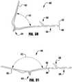
- an exemplary barbed clasp 600 similar to barbed clasps 400 and 500is shown in a variety of bent positions to illustrate the independent movement of the layers forming the barb clasps 400, 500, and 600.
- the barbed clasp 600is formed from a top layer 602 and a bottom layer 604.
- the barbed clasp 600includes a moveable arm 620, a fixed arm 622, a hinge portion 624.
- the moveable arm 620includes a barbed portion 626 with barbs 628.
- the barbed clasp 600does not include a cross-bar to prevent the moveable arm 620 from moving past the fixed arm 622. Instead of a cross-bar, the moveable arm 620 is held in a closed position with the fixed arm 622 by the inner paddle (not shown).
- Figures 28-31show the fixed arm 622 moving relative to a stationary moveable arm 620.
- the moveable arm 620When assembled to an implantable device, however, the moveable arm 620 would move relative to the fixed arm 622 that is attached to the device.
- the clasp 600is shown in a preloading or shape setting condition.
- the fixed arm 622is bent below the moveable arm 620 by an angle 610 before the shape setting operation is performed.
- Forcemust be applied then to return the fixed arm 622 to a parallel relationship with the moveable arm 620.
- increasing the preloading angle 610increases the force required to move the fixed arm 622, thereby increasing the preloading spring force pinching the arms 620, 622 together when the clasp 600 is closed.
- the greater the angle 610the greater the spring force applied to captured tissue by the arms 620, 622.
- the clasp 600is shown being opened to an opening angle 612.
- the beam loops of the hinge portion 624tend to separate as the clasp 600 is opened. Allowing the layers 602, 604 to separate during bending decreases strain on the material, thereby further increasing the maximum opening angle 612 that can be achieved before plastic deformation of the clasp material.
- the hinge portion 624is shaped to form somewhat spiral or helical beam loops, thereby forming a gap or step distance 614 between the arms 620, 622 ( Figure 29 ) that allows the leaflet tissue to be captured.
- the layers 602, 604 in the fixed arm 622slide relative to each other.
- holes through the fixed arm 622are elongated so that sutures securing the fixed arm 622 to the implantable device are not pinched by the sliding movement of the layers, nor are the layers 602, 604 constrained from sliding, which reduces strain experienced by the clasp material.
- exemplary barb clasps 700, 800, 900, and 1000are shown.
- Barb clasps 700, 800, 900, and 1000like clasps 400, 500, 600 can be used in the implantable devices 100, 200, and 300 described above.
- barbed clasps 400, 500, 600barbed clasps 700, 800, 900, and 1000 are formed by laser cutting material from the side of the clasp rather than from the top. Laser cutting from the side reduces the operations required to manufacture the clasp and allows the thickness of the clasp to be varied to vary the bending properties of portions of the clasp based on the function of each portion. For example, hinge portions may be thinner to provide more flexibility while arms may be thickened to provide more stiffness.
- the barb clasp 700has thick and thin portions 702, 704 and is formed from alternating spacer layers 706 and barbed layers 708 to form a laminated structure.
- the clasp 700includes a moveable arm 720, a fixed arm 722, and a hinge portion 724.
- the moveable arm 720includes a barbed portion 726 having barbs 728 formed in the barbed layers 708. Forming the layers 706, 708 by laser cutting from a side profile allows the barbs 728 to be tapered, thereby providing a stiff barb with a sharp point.
- the fixed arm 722includes holes to secure the clasp 700 to an implantable device.
- the fixed arm 722When assembled to an implantable device, the fixed arm 722 is extended by the attached inner paddle, thus the native tissue is pinched between the moveable arm 720 and the inner paddle of the device.
- the moveable and fixed arms 720, 722are formed at an angle relative to each other such that an extension of the fixed arm 722 would intersect with the moveable arm 720. Attaching the fixed arm 722 to the inner paddle effectively extends the end of the fixed arm 722 such that the inner paddle would interfere with the moveable arm 720.
- the interference of the componentscauses the moveable arm 720 to be moved relative to the fixed arm 722 such that the clasp 700 is opened, thereby preloading the moveable arm 722 such that a pinch force is applied against the inner paddle when the clasp 700 is in the closed position.
- a pinch forceis created between the moveable and fixed arms 720, 722 without shapesetting the moveable and fixed arms 720, 722 of the clasp 700.
- the individual layersare formed with the moveable and fixed arms 720, 722 parallel to each other and are then bent and shapeset such that the moveable arm 720 is biased toward the fixed arm 722 when the clasp 700 is affixed to the inner paddle.
- exemplary barb clasps 800, 900, 1000are shown.
- the clasps 800, 900, 1000are similar in overall shape while illustrating the variety of thicknesses possible when laser cutting clasps from the side.
- the clasps 800, 900, 1000have a thin portion 804, 904, 1004 and a thick portion 802, 902, 1002.
- the clasps 800, 900, 1000include a moveable arm 820, 920, 1020, a fixed arm 822, 922, 1022, a hinge portion 824, 924, 1024.
- the moveable arm 820, 920, 1020includes a barb portion 826, 926, 1026 having barbs (not shown) similar to the barbs 728 of the barb portion 726 of clasp 700.
- holescan be provided in the fixed arm 822, 922, 1022 to secure the clasp 800, 900, 1000 to an implantable device.
- the fixed arm 822, 922, 1022When assembled to an implantable device, the fixed arm 822, 922, 1022 is extended by the attached inner paddle, thus the native tissue is pinched between the moveable arm 820, 920, 1020 and the inner paddle of the device.
- barbed clasp 1100similar to barbed clasps 400, 500, 600 is shown. Unlike barbed clasps 400, 500, 600, however, barbed clasp 1100 is formed from a single layer of material that varies in thickness between a thick portion 1102 and a thin portion 1104.
- the barbed clasp 1100includes a fixed arm 1110, a hinge portion 1120, and a moveable arm 1130.
- the fixed arm 1110includes attachment holes 1112 and an optional integrated crossbar 1114.
- the hinge portion 1120includes an arcuate hinge 1122 formed from the thin portion 1104.
- the moveable arm 1130includes a barbed portion 1140 with barbs 1144.
- a suture(not shown) can be attached to an eyelet 1142 near the barbed portion 1140 to open and close the clasp 1100.
- a sheet of materialis thinned to form the thin portion 1104.
- the shape of the clasp 1100is then laser cut from the sheet of material so that the hinge portion 1120 is aligned with the thin portion 1104.
- the barbs 1144 and fixed arm 1110are then bent into the position shown in Figure 36 before shape setting.
- the optional T-shaped crossbar 1114 of the fixed arm 1110must be twisted to insert it through the slot in the moveable arm 1130 for shape setting and to move the arms 1110, 1130 from the preloading position to a closed position.
- the optional T-shaped crossbar 1114is omitted, is smaller, or is alternatively replaced with a relief in the moveable arm 1130, to facilitate ease of manufacture and shape setting.
- the crossbaris twisted, moved back through the slot, and positioned on top of the thick portion 1102.
- the crossbar 1114is positioned in generally the same manner as the crossbar 414 (see Figure 26 ).
- the clasp 1100can be opened fully without plastically deforming the clasp material while still providing pinching force when closed. Fewer steps are required to manufacture the clasp 1100 as compared to the clasps above, as the clasp 1100 is cut from a single sheet of material and no welding step is needed to weld layers of material together.
- the barbed clasp 1200is formed from a single layer 1202 of material.
- the barbed clasp 1200includes a fixed arm 1210, a hinged portion 1220, and a movable arm 1230 having a barbed portion 1240.
- the hinged portion 1220is spring-loaded so that the fixed and moveable arms 1210, 1230 are biased toward each other when the barbed clasp 1200 is in a closed condition.
- the fixed arm 1210is attached to a portion of the prosthetic device.
- the clasp 1200is opened by pulling on an actuating mans such as an actuation line or suture attached to the moveable arm 1230 until the spring force of the hinge portion 1220 is overcome.
- the fixed arm 1210is formed from a tongue 1211 of material extending from the hinged portion 1220 between two side beams 1231 of the moveable arm 1230 to an end 1214.
- the moveable armis formed from a tongue of material that extends between two side beams of the fixed arm.
- the tongue 1211is biased between the side beams 1231 by the hinge portion 1220 such that force must be applied to move the tongue 1211 from a neutral position located beyond the side beams 1231 to a preloaded position that is nearly parallel or parallel with the side beams 1231, as can be seen in Figures 39-40E .
- the tongue 1211is held in the preloaded position when it is attached to a paddle of an implantable prosthetic device.
- the end 1214 of the tongue 1211may optionally have a T-shape cross-member that engages the side beams 1231 to hold the tongue 1211 in the preloaded position.
- the angle between the fixed and moveable arms 1210, 1230 when the tongue 1211 is in the neutral positionis about 30 to about 120 degrees, 40 to about 110 degrees, or about 50 to about 100 degrees, or about 60 to about 90 degrees, or about 90 degrees.
- the tongue 1211includes holes 1212 for receiving sutures (not shown) that attach the fixed arm 1210 to an implantable device.
- the hinge portion 1220is formed by a plurality of torsional spring segments 1222 arranged in a repeating pattern extending from the tongue 1211 of the fixed arm 1210 to the side beams 1231 of the moveable arm 1230.
- Each spring segment 1222is joined with other spring segments 1222 to form a repeating pattern. Joining multiple segments 1222 together allows the hinge portion 1220 to bend a considerable amount while avoiding plastic deformation of the material as the individual torsional spring segments 1222 are twisted.
- the tongue 1211can be pivoted from the neutral position that is approximately 90 degrees beyond the moveable arm 1230 to a fully open position that ranges from about 140 degrees to about 200 degrees, to about 170 degrees to about 190 degrees, or about 180 degrees.
- the pattern spring segments 1222are formed from open and closed cutouts 1224 in the hinge portion 1220. Exemplary spring segments and their arrangement in a pattern are described below and shown in Figures 51A-52 .
- Preloading the tongue 1211enables the clasp 1200 to maintain a pinching or clipping force on the native leaflet when closed while also being able to be opened wide to more easily capture the native leaflet.
- the preloading of the tongue 1211provides a significant advantage over prior art clips that provide little or no pinching force when closed. Additionally, closing the clasp 1200 with spring force is a significant improvement over clips that use a one-time locking closure mechanism, as the clasp 1200 can be repeatedly opened and closed for repositioning on the leaflet while still maintaining sufficient pinching force when closed.
- the barbed portion 1240 of the moveable arm 1230includes eyelets 1242 and barbs 1244. Positioning the barbed portion of the clasp 1200 at an end of the moveable arm 1230 increases the space between the barbs 1244 and the fixed arm 1210 when the clasp 1200 is opened, thereby improving the ability of the clasp 1200 to successfully capture a leaflet during implantation. This distance also allows the barbs 1244 to more reliably disengage from the leaflet for repositioning.
- the barbs of the claspsmay be staggered longitudinally to further distribute pinch forces and local leaflet stress.
- the ends of the barbs 1244are further sharpened using any suitable sharpening means.
- the barbs 1244are laterally spaced apart at the same distance from the hinge portion 1220, providing a superior distribution of pinching forces on the leaflet tissue while also making the clasp more robust to leaflet capture than barbs arranged in a longitudinal row.
- the barbs 1244can be staggered to further distribute pinch forces and local leaflet stress.
- the barbs 1244are angled away from the moveable arm 1230 at an angle 1246 ( Figure 38A ) such that they easily engage tissue of the native leaflets with minimal pinching or clipping force. During use, the barbs 1244 may penetrate the native leaflet tissue, though penetration of the tissue is not necessary for the clasp 1200 to securely grasp the leaflets.
- the barbs 1244extend from the moveable arm at an angle 1246 of about 20 degrees to about 90 degrees, or about 40 degrees to about 70 degrees, or about 50 to about 60 degrees, or about 53 degrees.
- the angle of the barbs 1244provides further benefits, in that force pulling the implant off of the native leaflet will encourage the barbs 1244 to further engage the tissue, thereby ensuring better retention.
- Retention of the leaflet in the clasp 1200is further improved by the position of the end 1214 of the fixed arm 1210 when the clasp 1200 is closed.
- the tissue engaged by the barbs 1244is pinched against the moveable arm 1230 at the end 1214 location, thereby forming the tissue into an S-shaped torturous path as it passes over the barbs 1244.
- forces pulling the leaflet away from the clasp 1200will encourage the tissue to further engage the barbs 1244 before the leaflets can escape.
- the end 1214can optionally be shapeset with a slight bend toward the moveable arm 1230 to accentuate the S-shape of the tortuous path of the tissue captured between the fixed and moveable arms 1210, 1230.
- the layer of material 1202 of the clasp 1200is laser cut from a sheet of shape-memory alloy, such as Nitinol. Portions of the layer 1202, such as the fixed arm 1210, hinge portion 1220 and barbs 1244 are bent into a desired position.
- the clasp 1200is then subjected to a shape-setting process so that internal forces of the material will tend to return to the set shape after being subjected to deformation by external forces.
- the tongue 1211is moved to its preloaded, closed, or open positions to be attached to the implantable device. Consequently, the clasp 1200 can be substantially flattened in the closed position for delivery through a delivery sheath and allowed to expand once deployed within the heart.
- the clasp 1200is opened and closed by applying and releasing tension on an actuation line or suture (e.g., suture 2504 of Figure 71 ) attached to the moveable arm 1230.
- the sutureis inserted through at least one of the eyelets 1242 located near the barbed portion 1240 of the moveable arm 1230 before returning to the delivery sheath.
- an intermediate suture loopis made through one or more of the eyelets 1242 and the actuation suture is inserted through one or more of the intermediate loops.
- An intermediate loop of suture materialreduces friction experienced by the actuation suture relative to the friction between the actuation suture and the clasp material.
- both ends of the actuation sutureextend back into and through the delivery sheath 102 (see, e.g., Figure 1 ).
- the suturecan be removed by pulling one end of the suture proximally until the other end of the suture pulls through the eyelet or intermediate loop and back into the delivery sheath.
- the clasp 1200can be opened fully without plastically deforming the clasp material while still providing pinching force when closed. Fewer steps are required to manufacture the clasp 1100 as compared to the clasps above, as the clasp 1200 is cut from a single sheet of material and no welding step is needed to weld layers of material together.
- the clasp 1200is shown in various bending positions ranging from a neutral position ( Figures 37-38E ) to a fully open position ( Figures 47-48E ).
- the fixed arm 1210is shown in different positions in Figures 37-48E , once installed in an implantable device, the moveable arm 1230 is actuated by the surgeon to move relative to the device while the fixed arm 1210 remains stationary relative to the device.
- Figures 37-38Eshow the clasp 1200 in the neutral position for shape-setting.
- the tongue 1211 of the fixed arm 1210is bent to a tongue angle 1216 that is about 60 degrees to about 120 degrees, or about 90 degrees below the side beams 1231 of the moveable arm 1230.
- the tongue 1211remains in the shape-setting or neutral position unless acted upon by forces to move the tongue 1211 into other positions.
- a preloading or closed positionFigures 39-40E
- internal forces of the clasp materialare exerted in the closing direction, thereby generating a pinching force when the clasp 1200 is in the closed or preloaded condition.
- the moveable arm 1230is actuated with a suture (not shown) to change the angle 1216 between the fixed and moveable arms 1210, 1230.
- the clasp 1200is shown in a one-quarter open condition in Figures 41-42E , a half open condition in Figures 43-44E , a three-quarter open condition in Figures 45-46E , and a fully open condition in Figures 47-48E .
- the angle 1216 between the fixed and moveable arms 1210, 1230 in the fully open positionmay be about 140 degrees to about 200 degrees, to about 170 degrees to about 190 degrees, or about 180 degrees. That is, the clasp 1200 is capable of being opened substantially completely flat without plastic deformation of the clasp material.
- the layer 1202 of material for forming the clasp 1200is shown in a pre-shape setting condition, that is, in a substantially flat condition after being laser cut from a sheet of material.
- Figure 50in particular clearly shows the repeating nature of the pattern of spring segments 1222 and cutouts 1224 that form the hinge portion 1220.
- exemplary torsional spring segments 1300, 1400, 1500, 1600 for a patterned hinge portione.g., hinge portion 1220 of the clasp 1200
- the spring segments 1300, 1400, 1500, 1600are arrangeable in a repeating pattern that is cut out of a single piece so that there are no physical seams between the individual segments.
- the shape of the spring segments 1300, 1400, 1500, 1600is defined by the cutouts in the hinge portion and imaginary boundaries at the "joints" between segments.
- the spring segment 1300is formed by cutouts 1301 made in a layer 1302 of material resulting in a substantially rotationally symmetric, S-like shape.
- Each spring segment 1300extends from a first end 1310 to a second end 1320 between a first side 1330 and a second side 1340.
- a first end joining location 1312is located at the first end 1310 adjacent the first side 1330.
- a first side joining location 1332is located at the first side 1330 adjacent the first end 1310.
- a second end joining location 1322is located at the second end 1320 adjacent the second side 1340.
- a second side joining location 1342is located at the second side 1340 adjacent the second end 1320.
- Side surface 1304extend between the first end joining location 1312 and the second side joining location 1342, and between the second end joining location 1322 and the first side joining location 1332.
- An inner corner 1306is formed near each side joining location 1332, 1342.
- spring segments 1400, 1500, 1600are shown. These spring segments 1400, 1500, 1600 are similar in structure to the spring segment 1300 described above, though spring segments 1400, 1500, 1600 include an outer corner 1408, 1508, 1608 near each end joining location opposite the side joining location.
- the shapes of the spring segments 1300, 1400, 1500, 1600vary in the size and shape of the side surfaces 1304, 1404, 1504, 1604, rounded inner corners 1306, 1406, 1506, 1606 and rounded outer corners 1408, 1508, 1608.
- the side surfaces 1304, 1404are substantially straight, while the side surfaces 1504, 1604 are concave.
- FIG. 52an exemplary spring grouping 1700 of spring segments 1300 is shown.
- side joining locations 1332, 1342are joined to other side joining locations 1332, 1342 and end joining locations 1312, 1322 are joined to other end joining locations 1312, 1322.
- the substantially rotationally symmetric shape of the spring segments 1300allows either end 1310, 1320 or side 1330, 1340 of one segment to be joined to either end 1310, 1320 or side 1330, 1340 of another segment.
- Various patternsmay then be formed, such as the H-pattern formed by the grouping 1700 in Figure 52 . While the segments 1300, 1400, 1500, 1600 are substantially rotationally symmetric, individual segments in a pattern of segments may be modified to form rounded outer edges of a hinge portion or to adapt to the fixed or moveable arm of a clasp.
- each of the segments 1300is twisted in the direction indicated by the arrows 1720. Consequently, the individual spring segments 1300 are subjected to torsional strain and not bending strain.
- the deformation of the material 1302is reduced relative to the bending of a flat sheet of material being bent in a similar manner while maintaining the spring force of the hinge portion of the clasp.
- a hinge portion formed from a pattern of torsional spring segmentsis strong and flexible.
- a pattern comprising plurality of spring segmentsare arranged in rows and columns.
- the spring segmentsare arranged with their longitudinal and lateral axes in the same orientation, as can be seen in Figures 49-50 and 52 .
- the spring segmentsmay be rotated relative to each other to form different spring patterns.
- the spring segmentsare organized into columns and rows. Columns are defined along the longitudinal axis of the clasp, while rows are defined along the lateral axis of the clasp.
- a column of spring segmentsis as wide as the longest dimension of an individual spring segment, while a row of spring segments has a height equal to the shortest dimension of an individual spring segment.
- the clasp 1200 shown in Figure 50includes three columns and seven rows of spring segments (not including partial rows connecting the hinge portion to the fixed and moveable arms). Where the ends of segments border an edge of the clasp, two segments in adjacent rows are joined together at one location, forming a U-shaped grouping. Individual spring segments or groupings of spring segments may be modified away from their rotational symmetry to increase the smoothness and/or robustness of the edges of the hinge portion. Where the ends of segments are located at an intersection of two columns, the segments may join up to three other segments, forming an X-shaped grouping, like the grouping 1700 shown in Figure 62 .
- the patterned hingemay include any suitable number of rows and columns of spring segments. The size and shape of each segment may be adjusted to adjust the spring parameters of the patterned hinge. The size and shape of the spring segments may be uniform throughout the patterned hinge or may vary based on the location of the spring segment within the pattern.
- an exemplary barb clasp 1800is shown that is cut from a tube of material 1802 using four-axis laser cutting (X, Y, Z, and rotation axes) and five-axis laser cutting (X, Y, Z, and two tilt-axes for the laser head).
- the tubecan first be cut into segments and then each segment is cut in generally the same way that a flat piece of stock or blank material is cut; that is, the tube provides a curved blank instead of a flat blank.
- the additional degrees of freedom of the laser cutterallow the tube to be rotated or the head of the laser cutter to be tilted during laser cutting.
- the clasp 1800is similar in structure to the clasp 1200, described in detail above.
- the tube of material 802has an inner radius 1804, an inner surface 1801, and an outer surface 1803. Cutting the clasp 1800 from a tube of material 1802 provides a cupped or concave profile when viewed from the end, as shown in Figure 54 .
- One effect of the concave profileis that the elongated portions of the fixed and moving arms 1810, 1830 increasing their stiffness, without substantially impacting the flexibility of the hinge portion 1820.
- the concave profilealso results in barbs 1844 with sharper points or tips 1846 without a separate sharpening operation-i.e, the barbs are formed with a beveled edge without sharpening.
- the sharp points 1846enable improved engagement with the native leaflet tissue.
- the sharp points 1846are formed during laser cutting because the cutting planes that form first and second sides 1847, 1848 of the barbs 1844 to intersect at the tip 1846, thereby forming a triangular pyramid shape that comes to a point that is not possible when the cutting planes that form the sides of the barb are parallel and do not intersect.
- the barbs 1844 of the clasp 1800have a strong base 1845 and a sharp point 1846 in a single layer of material, without any secondary sharpening operation.
- FIG. 56an exemplary clasp 1900 is shown.
- the clasp 1900is similar in structure to the clasp 1200, described in detail above with a differently structured hinge portion 1920.
- the hinge portion 1920includes a plurality of beams 1922 formed by a series of elongated cuts 1924.
- Figures 56A-56Balternate embodiments of the beams 1922 of the hinge portion 1920 are shown.
- Figure 56Ashows the rectangular beam 1922 having a bent portion 1926.
- Figure 56Bshows the rectangular beam 1922 having a bent portion 1926 that is also twisted about 90 degrees such that the cross-section of the beam in the bent portion 1926 is perpendicular to the portions of the beam 1922 at its ends. Twisting the beam 1922, as shown in Figure 56B , reduces the bending strain in the beam 1922 thereby increasing its flexibility.
- the barbed clasp 2000for use in implantable prosthetic devices, such as devices 100, 200, 300 described above, is shown.
- the barbed clasp 2000includes a fixed arm 2010 that is attached to the implantable device.
- the barbed clasp 2000differs from other clasps in that the clasp 2000 includes a plurality of movable arms 2030 that each have a hinged portion 2020 and a barbed portion 2040 having a single barb 2042.
- the independent arms 2030 of the clasp 2000individually pinch the tissue of the native leaflet which allows for improved engagement of tissue that is not uniform in thickness.
- the arms 2030can also be shape set in a wide or spread out arrangement and crimped down into a narrow configuration for deployment so that the barbs 2042 can be spaced apart laterally more than would be possible if the arms were rigidly connected.
- the arms 2030include an optional hole or notch (not shown) that can be engaged by an actuation suture to cinch the arms 2030 together during deployment.
- the fixed arm 2010is formed from a tongue 2011 from which beams 2031 that form the moveable arms 2030 extend.
- the hinge portions 2020are formed by bending each of the beams 2031 to form a bent portion 2022.
- the hinged portions 2020are spring-loaded so that the fixed and moveable arms 2010, 2030 are biased toward each other when the barbed clasp 2000 is in a closed condition.
- the tongue 2011is formed from a wide plate of material to provide a larger lateral area as a pinching location for the independent arms 2030.
- the barbed clasp 2000is laser cut from a layer 2002 of shape-memory alloy, such as Nitinol. As is shown in Figure 57A , the barbs 2042 lay flat in the same plane as the rest of the clasp 2000 when cut out of the layer 2002 of material.
- the moveable arms 2030 and barbs 2040are then bent and twisted into the shape shown in Figure 57 and are then subjected to a shape setting process.
- the independent arms 2030 of the clasp 2000can be shape set as wide or narrow as desired. In certain embodiments individual arms 2030 may be longer or shorter than others, and the spacing of the arms 2030 may vary or be uniform.
- the barbed portions 2040may include multiple smaller barbs arranged in series that may or may not be facing in the same direction.
- the ends of the barbs 2042are further sharpened using any suitable sharpening means.
- the hinge portions 2020 of the beams 2031include twisted portions 2024. The twisted portions 2024 may act as torsional springs that resist lateral forces applied to the ends of the barbs 2042, thereby helping to maintain the alignment of the barbs 2042 when engaging the tissue of the native leaflets.
- an exemplary clasp 2100 for use in implantable prosthetic devicessuch as devices 100, 200, 300 described above, is shown.
- the clasp 2100is expandable between a collapsed condition and an expanded condition and is shape set in the expanded condition so that the clasp 2100 automatically expands from the collapsed condition to the expanded condition.
- the clasp 2100can be deployed from a delivery sheath 2150 in the collapsed condition and allowed to self-expand into the expanded condition.
- the clasp 2100has many features that are similar to the clasp 1200, described in detail above, such as a patterned hinge portion 2120 formed by a plurality of spring segments 2122 and cutouts 2124 and a fixed arm 2110 that includes a tongue 2111 having holes 2112 for attaching the fixed arm 2110 to the implantable device and an end 2114 having a T-shape to retain the fixed arm 2110 in a preloaded position.
- the clasp 2100also has a moveable arm 2130 that includes a barbed portion 2140 with a plurality of barbs 2142.
- the hoop-like shape of the moveable arm 2130provides for a wider barbed portion 2140 that can include more barbs 2142 with the same or greater lateral spacing than other clasps.
- the wider spacing of the barbs 2142improves capture of the native leaflets.
- the hoop shape of the moveable arm 2130is similar to the shape of wide outer paddles of an implantable device so that pinching forces of the paddles are spread out evenly on the barbs, further improving the retention of the native leaflets.
- Some of the barbs 2142may also be longitudinally staggered as a result of their position on the hoop-like shape of the moveable arm 2130.
- the ends of the barbs 2042are further sharpened using any suitable sharpening means.
- the tongue 2111is formed from a wide plate of material to provide a larger lateral area as a pinching location.
- the moveable arm 2130is provided in the shape of a hoop or loop.
- the moveable arm 2130includes side beams 2131 that are thinner and more flexible, particularly in the lateral direction, than the side beams 1231 of the clasp 1200 described above.
- the side beams 2131include a first hinge portion 2132 arranged toward the proximate end of the moveable arm 2130 and a second hinge portion 2136 arranged at the distal end of the moveable arm 2130.
- the first hinge portion 2132is formed by one or more bends in the side beams 2132.
- the second hinge portion 2136includes a thinner-and therefore more flexible-portion to reduce the force required to collapse the clasp 2100.
- the moveable arm 2130includes holes 2134 arranged between the first and second hinge portions 2132, 2136 for receiving the actuation sutures 2152 that are used to collapse the moveable arm 2130.
- the holes 2134are arranged further laterally from the center of the clasp 2130 than the hinge portions 2132, 2136 to provide mechanical advantage when force is applied via the sutures 2152.
- the holes 2134are located at the lateral-most location of the side beams 2131.
- the rounded hoop shape of the clasp 2100allows the clasp 2100 to be collapse by merely retracting the clasp 2100 into the delivery sheath.
- the expansion and contraction of the clasp 2100is controlled by actuation sutures 2152.
- the sutures 2152may be routed through an aperture 2156 of a guide 2154 to holes 2134 in the moveable arm 2130 to control the direction in which the force applied along the suture 2152 is applied to cinch the moveable arm 2130 into a collapsed position.
- arranging the guide 2154 closer to the connection point to the sutures 2152 to the clasp 2100causes the forces applied to the clasp 2100 by the sutures 2152 to be directed in a more lateral rather than longitudinal direction.
- a single suture loop 2153can be routed through the aperture 2156 of the guide 2154, through each of the holes 2134 in the moveable arm 2130, and then back through the guide 2154 so that actuation of the single loop 2153 cinches the moveable arm 2130 into a collapsed position.
- the barbed clasp 2200includes elements of clasps 1200, 2000 described above.
- the barbed clasp 2200includes a fixed arm 2210 that is attached to the implantable device and a hinge portion 2220 that allows the clasp 2200 to open and close.
- the hinge portion 2220is formed from a repeating pattern of spring segments 2222 and cutouts 2224, like that of the clasp 1200.
- the barbed clasp 2200also includes features similar to the clasp 2000, such as a plurality of independent movable arms 2230 that each have a barbed portion 2240 having a single barb 2244.
- the independent arms 2230 of the clasp 2200individually pinch the tissue of the native leaflet which allows for improved engagement of tissue that is not uniform in thickness.
- the arms 2230can also be shape set in a wide or spread out arrangement and crimped down into a narrow configuration for deployment so that the barbs 2244 can be spaced apart laterally more than would be possible if the arms were rigidly connected.
- the barbed portion 2240 of each arm 2230includes a hole 2242 for receiving an actuation suture 2252 ( Figure 65A ).
- the clasp 2200is expandable between a collapsed condition and an expanded condition and is shape set in the expanded condition so that the clasp 2200 automatically expands from the collapsed condition to the expanded condition.
- the clasp 2200can be deployed from a delivery sheath 2250 in the collapsed condition and allowed to self-expand into the expanded condition.
- the expansion and contraction of the clasp 2200is controlled by the actuation suture 2252 that cinches the independent arms 2230 together to collapse the clasp 2200 so that it fits within the delivery sheath 2250.
- the independent armscollapse together by merely retracting the clasp 2100 into the delivery sheath.
- the fixed arm 2210is formed from a tongue 2211 extending from the hinge portion 2220 to an end 2214.
- the tongue 2211includes holes 2212 for securing the tongue 2211 to the implantable device.
- the tongue 2211is formed from a wide plate of material to provide a larger lateral area as a pinching location.
- the end 2214 of the tongue 2211includes a T-shape cross-member like that of clasp 2100.
- the barbed clasp 2200is laser cut from a layer 2202 of shape-memory alloy, such as Nitinol. Like the clasp 2100 shown in Figure 57A , the barbs 2242 lay flat in the same plane as the rest of the clasp 2200 when cut out of the layer 2202 of material.
- the moveable arms 2230 and barbed portions 2240are then bent and twisted into the shape shown in Figures 64-68 and are then subjected to a shape setting process.
- the barbs of the independent armsare [?] cut so that the barbs are bent upwards like the barbs of clasp 1200, thereby not requiring the twisting of the independent arms.
- the independent arms 2230 of the clasp 2200can be shape set as wide or narrow as desired. In certain embodiments, individual arms 2230 may be longer or shorter than others, and the spacing of the arms 2230 may vary or be uniform.
- the barbed portions 2240may include multiple smaller barbs arranged in series that may or may not be facing in the same direction.
- the ends of the barbs 2244are further sharpened using any suitable sharpening means.
- the beams 2231include twisted portions 2232. The twisted portions 2232 may act as torsional springs that resist lateral forces applied to the ends of the barbs 2244, thereby helping to maintain the alignment of the barbs 2244 when engaging the tissue of the native leaflets.
- an intermediate suture loopis made through one or more of the eyelets in the barbed clasp and the actuation suture is inserted through one or more of the intermediate loops.
- Connecting to the clasp through an intermediate loop of suture materialreduces friction experienced by the actuation suture relative to the friction between the actuation suture and the clasp material.
- Both ends of the actuation sutureextend back into and through the delivery sheath (not shown). The suture can be removed by pulling one end of the suture proximally until the other end of the suture pulls through the eyelet or intermediate loop and back into the delivery sheath.
- the suture arrangement 2300includes an intermediate suture loop 2302 inserted through the eyelet 442 and around the end of the barbed portion 440.
- the intermediate suture loop 2302may be inserted through the eyelet 442 and between the side beams of the moveable arm.
- An actuation suture 2304is threaded from the delivery sheath through the intermediate suture loop 2302 and back into the delivery sheath. Tension applied to the actuation suture 2304 opens the clasp 400 when the spring forces keeping the clasp 400 closed are overcome. Releasing tension on the actuation suture 2304 allows the clasp 400 to spring shut.
- the rounded shape of the barbed portion 440 of the clasp 400prohibits the clasp 400 from catching on native tissue or other portions of the implantable device.
- the suture arrangement 2400includes an intermediate suture loop 2402 inserted through the center eyelet 1242 and between the side beams 1231 of the moveable arm 1230.
- An actuation suture 2404is threaded from the delivery sheath through the intermediate suture loop 2402 and back into the delivery sheath. Tension applied to the actuation suture 2404 opens the clasp 1200 when the spring forces keeping the clasp 1200 closed are overcome. Releasing tension on the actuation suture 2404 allows the clasp 1200 to spring shut.
- Figure 70Ais a side view of the suture arrangement 2400 showing that a gap or recess 2406 may form between the end of the clasp and the actuating suture 2404 of the suture arrangement 2400 described above.
- the gap 2406may form when the actuation suture 2404 is at an angle with the barbed portion of the clasp 1200.
- Figure 70Bis a front view of the suture arrangement 2400 showing that side gaps or recesses 2408 are formed between the actuation suture 2404 and the sides of the barbed portion 1240 of the clasp 1200.
- the gaps or recesses 2406, 2408may become catch points-i.e., a location that has a potential to catch or snag native tissue or other portions of the implantable device during deployment and installation and/or on a catheter wall during retrieval.
- sharp angles and edgesmay become catch points. Rounding the corners of the clasp 1200, as can be seen in Figure 70B , reduces the chance that the clasp 1200 will catch.
- the devicedoes not include any recesses having a depth greater than one third of the width of the device.
- FIG. 71a front view of an exemplary suture arrangement 2500 is shown attached to the barb clasp 1200 described above.
- the suture arrangement 2500includes an intermediate suture loop 2502 inserted through the center eyelet 1242 and around the end of the barbed portion 1240.
- An actuation suture 2504is threaded from the delivery sheath through the intermediate suture loop 2502 and back into the delivery sheath. Tension applied to the actuation suture 2504 opens the clasp 1200 when the spring forces keeping the clasp 1200 closed are overcome. Releasing tension on the actuation suture 2504 allows the clasp 1200 to spring shut.
- FIG. 71shows that side gaps 2508 are formed between the actuation suture 2504 and the sides of the barbed portion 1240 of the clasp 1200.
- the gaps 2508may become catch points-i.e., a location that has a potential to catch or snag native tissue or other portions of the implantable device during deployment and installation and/or on the catheter during retrieval. In particular, sharp angles and edges may become catch points. Rounding the corners of the clasp 1200, as can be seen in Figure 71 , reduces the chance that the clasp 1200 will catch on native tissue or other portions of the device.
- the suture arrangement 2600includes intermediate suture loops 2602 inserted through the eyelets 1242 proximate the sides of the clasp 1200 and around the end of the barbed portion 1240.
- An actuation suture 2604is threaded from the delivery sheath through the intermediate suture loops 2602 and back into the delivery sheath. Tension applied to the actuation suture 2604 opens the clasp 1200 when the spring forces keeping the clasp 1200 closed are overcome. Releasing tension on the actuation suture 2604 allows the clasp 1200 to spring shut.
- the suture arrangement 2600reduces or eliminates the gaps shown in Figures 70A-71 that can become catch points. Forming the intermediate suture loops 2602 around the end of the barbed portion 1240 eliminates the possibility of a gap, such as the gap 2406 shown in Figure 70A , from forming between the clasp 1200 and the actuation suture 2604. The suture arrangement 2600 also reduces or eliminates side gaps, such as the side gaps 2508 shown in Figures 70B and 71 , between the actuation suture 2604 and the sides of the clasp 1200.
- catch pointsare locations on the implantable device that have a potential to catch or snag native tissue, other portions of the implantable device, and/or delivery catheter during deployment and installation and/or during recapture or retrieval.
- catch pointsmay also be formed by the assembly of two or more components.
- an exemplary implantable device 2700is shown assembled with two barb clasps 400.
- the barb clasps 400are attached to inner paddles 2720 of the implantable device 2700 that extend from a coaption element 2710.
- a suture arrangement 2730includes intermediate suture loops 2732 attached to the barbed portion 440 of the clasps 400, and actuation sutures 2734 extending from a delivery sheath 2702, through the intermediate suture loops 2732, and back into the sheath 2702.
- the offset of the hinge portions 420forms a gap 2740 between the clasps 400 and coaption element 2710 that can become a catch point.
- the gap 2740is reduced or eliminated when the clasps 400 are opened partially, though the overall width of the device 2700 increases because of the opening of the clasps 400.
- the catch pointcan be eliminated during recapture or retrieval by partially opening the clasps 400 as shown in Figure 74B .
- Partially opening the clasps when retracting the device into the sheathhas an additional benefit of causing the actuation lines or sutures to engage an opening 2703 of the delivery sheath 2702, thereby causing the opening 2703 to flair open and provide a larger opening through which the device 2700 can be withdrawn.
- Suture configurations like those shown in Figures 70B and 71engage the opening 2703 in two locations as the sutures extend from the clasps in two locations, thereby widening the opening 2703 in a substantially diamond shape.
- Suture configurations like those shown in Figure 72engage the opening 2703 in four locations because the sutures extend from the clasps in four locations, thereby widening the opening 2703 in a substantially rectangular shape.
- the actuation sutures 2734can be relaxed after the hinge portions 420 are in the catheter.
- an exemplary implantable device 2800is shown assembled with two barb clasps 1200.
- the barb clasps 1200are attached to inner paddles 2820 of the implantable device 2800 that extend from a coaption element 2810.
- a suture arrangement 2830includes intermediate suture loops 2832 attached to the barbed portion 1240 of the clasps 1200, and actuation sutures 2834 extending from a delivery sheath 2802, through the intermediate suture loops 2832, and back into the sheath 2802.
- the round shape of the hinge portion 1220 of the clasp 1200prevents a catch point from forming at an intersection 2840 between the hinge portion 1220 and the coaption element 2810.
- the shape of the clasp 1200reduces or eliminates gaps, such as the gap 2740 shown in Figure 74B that may become catch points, without needing to partially open the clasps 1200 during retrieval or recapture.
- the actuation line or sutureis attached to a portion of a covering surrounding a clasp of an implantable device.
- the actuation line or suturemay be threaded through a loop or openings in the covering.
- the coveringmay be formed from a flexible material that may be a mesh, woven, braided, or formed in any other suitable way.
- the flexible materialmay be cloth, shape-memory alloy wire-such as Nitinol-to provide shape setting capability, or any other flexible material suitable for implantation in the human body.
- FIG. 76a side view of an exemplary barb clasp 2900 is shown. While the clasp 2900 is shown in the shape of the clasp 1200 described above, the clasp 2900 can have any shape suitable for use as a barbed clasp formed from laminated layers of material, such as any of the clasps described above.
- the clasp 2900has a fixed arm 2910, hinged portion 2920, moveable arm 2930, and barbed portion 2940.
- the clasp 2900is formed from a first layer 2902 and a second layer 2904 of material.
- the layers 2902, 2904may be formed from similar or different materials, and may have the same or different thicknesses. In certain embodiments, additional layers of material may also be provided.
- the double-ended clasp 3000has a fixed arm 3010 with hinge portions 3020 and moveable arms 3030 extending from both ends.
- Each moveable arm 3030includes a barbed portion 3040 including at least one barb 3042. While the barbs 3042 are shown facing outwards, in other embodiments the barbs 3042 face inwards.
- the clasp 3000is formed from first and second layers of material 3002, 3004, though, in certain embodiments, the clasp is formed from a single layer, and in certain other embodiments, is formed from more than two layers.
- the hinge portions 3020, movable arms 3030, and barbed portions 3040may be formed in the shape of any of the clasps described above.
- the barbed clasp 3102includes elements of clasp 1200 described above.
- the barbed clasp 3102includes a fixed arm 3110 that is attached to the implantable device and a hinge portion 3120 that allows the clasp 3102 to open and close.
- the hinge portion 3120is formed from a repeating pattern of spring segments 3122 and cutouts 3124, like that of the clasp 1200.
- the barbed clasp 3102also includes a pair of independent first and second movable arms 3130, 3132 extending from the hinge portion 3120 to a barbed portion 3140 having barbs 3144.
- the fixed arm 3110is formed from a tongue 3111 extending from the hinge portion 3120 to an end 3114.
- the tongue 3111includes holes 3112 for securing the tongue 3111 to the implantable device.
- the tongue 3111is formed from a wide plate of material to provide a larger lateral area as a pinching location.
- the end 3114 of the tongue 3111includes a T-shape cross-member like that of clasp 3102.
- the moveable arms 3130, 3132 of the clasp 3102individually pinch the tissue of the native leaflet which allows for improved engagement of tissue that is not uniform in thickness.
- the moveable arms 3130, 3132are formed from a single moveable arm similar to the moveable arm 1230 of clasp 1200 that is separated into first and second moveable arms 3130, 3132 by a cut 3148 so that the first and second moveable arms 3130, 3132 are allowed to open and close independent from each other.
- the hinge portion 3120is also separated into first and second hinge portions (not shown).
- an exemplary implantable device 3100is shown assembled with two barb clasps 3102.
- the barb clasps 3102are attached to inner paddles 3108 of the implantable device 3100 that extend from a coaption element 3106.
- An actuation arrangement 3150includes intermediate suture loops 3152 attached to holes 3146 in the barbed portion 3140 of the first and second moveable arms 3130, 3132 and first and second actuation sutures 3154, 3156.
- the first and second actuation sutures 3154, 3156extend from the delivery sheath 3104, through the intermediate suture loops 3152, and back into the delivery sheath 3104.
- Each of the moveable arms 3130, 3132can be separately opened by applying tension to the first and second actuation sutures 3154, 3156, respectively. Opening the first and second moveable arms 3130, 3132 separately allows the grip of the clasp 3102 on native tissue to be adjusted based on the thickness of the tissue and the orientation of the clasp 3100.
- an exemplary barbed clasp 3200 for use in implantable prosthetic devicessuch as devices 100, 200, 300 described above, is shown.
- the clasp 3200is configured to place a tensioning force on the native tissue when the implantable prosthetic device-e.g., any device described in the present application-is attached to the native tissue.
- the barbed clasp 3200includes a fixed arm 3210, a hinge portion 3220, and a moveable arm 3230 having a barbed portion 3240.
- the fixed arm 3210 of the clasp 3200is slideably connected to a paddle 3202 of an implantable device such that the clasp 3200 can be moved along the paddle 3202 in the direction 3204.
- an actuation line 3250can be used to move the clasp 3200 along the paddle 3202 in the direction 3204.
- the actuation line 3250can also be used move the moveable arm 3230 between the closed position (as shown in Figure 80A ) and the open position (as shown in Figure 80B ).
- the actuation line 3250can take any form described in the present application.
- the clasp 3200includes an optional biasing member 3260 (e.g., a spring) configured to maintain the clasp 3200 in a desired position along the paddle 3202 (e.g., the position shown in Figures 80A and 80E ).
- the clasp 3200is shown in a first position on the paddle 3202 and in a closed position.
- the clasp 3200is shown after the moveable arm 3230 has been moved in a direction 3203 to an open position by the actuation line 3250.
- the clasp 3200is shown after having been moved along the paddle 3202 in a direction 3205 to a second position. In some embodiments, the clasp 3200 is moved along the paddle 3202 in the direction 3205 by the actuation line 3250 or a separate mechanism.
- clasp 3200enough force is applied to the clasp 3200 to move the clasp 3200 in the direction 3205, causing the biasing member 3260 to expand and create a tension force on the clasp 3200 in a direction 3206 opposite to the direction 3205. While the illustrated embodiment shows the clasp 3200 being moved to an open position (as shown in Figure 80B ) prior to the clasp 3200 being moved along the paddle 3202 in the direction 3205 to the second position (as shown in Figure 80C ), it should be understood that clasp 3200 can be moved in the direction 3205 to the second position prior to the moveable arm 3230 of the clasp 3200 being moved in the direction 3203 to an open position or the movements can be simultaneous.
- the moveable arm 3230is moved to a closed position in the direction 3207 by the actuation line 3250 to secure the barbed portion 3240 of the clasp 3200 to valve tissue (not shown).
- the biasing member 3260is being maintained in an extended position (e.g., as a result of the force applied to the clasp 3200 by the actuation line 3250, or another mechanism, to keep the clasp 3200 in the second position), which means the biasing member 3260 is placing a tensioning force on the clasp 3200 in the direction 3206.
- the force maintaining the clasp 3200 in the second positionis released, which causes the tensioning force applied by the biasing member 3260 to move the clasp 3200 along the paddle 3202 in the direction 3208.
- the movement of the clasp 3200 in the direction 3208causes the barbed portion 3240 to create a tensioning force on the native tissue in the direction 3209. This tensioning force on the native tissue allows the implantable device to maintain a secure connection to the native tissue.
- an exemplary barbed clasp 3300 for use in implantable prosthetic devicessuch as devices 100, 200, 300 described above, is shown.
- the clasp 3300is configured to place a tensioning force on the native tissue when the implantable prosthetic device-e.g., any device described in the present application-is attached to the native tissue.
- the barbed clasp 3300includes a fixed arm 3310, a hinge portion 3320, and a moveable arm 3330 having a barbed portion 3340.
- the moveable arm 3330includes a flexible portion 3332 arranged between the hinge portion 3320 and the barbed portion 3340.
- the flexible portion 3332may comprise, for example, a cutout in the moveable arm 3330, a different material than the remainder of the moveable arm 3330, or can take any other suitable form that allows the flexible portion 3332 to be more flexible than the remainder of the moveable arm 3330.
- the flexible portion 3332is omitted and an actuation mechanism 3350 is still capable of flexing the barbed portion 3340 of the moveable arm 3330 as illustrated by Figures 81A-81C .
- the actuation mechanism 3350includes an actuation line 3352 (e.g., a suture) and a push-pull link 3354 configured to receive the line 3352.
- the push-pull link 3354can be a catheter, a wire with a loop (as shown in Figure 82 ), or any other link that is capable of receiving the line 3352 and pushing or pulling the moveable arm 3330 of the clasp 3300.
- the actuation line 3352extends at a first end 3351 from a delivery sheath (not shown) and is removably attached to the moveable arm 3330 at a first connection point 3356 arranged proximate the barbed portion 3340.
- the actuation line 3352also extends from the first connection point 3356 and is removably attached to the moveable arm 3330 at a second connection point 3358 arranged between the flexible portion 3332 and the hinge portion 3320. The actuation line 3352 then extends from the second connection point 3358 and through the push-pull link 3354 at a second end 3353.
- the clasp 3300is shown in an open position with native tissue 3302 disposed in an opening 3304 between the moveable arm 3330 and the fixed arm 3310.
- the clasp 3300can be moved to the open position by pulling on the line 3352.
- the link 3354 and the line 3352 of the actuation mechanism 3350is used to move the moveable arm 3330 in the closing direction 3306 to the closed position and flex the barbed portion 3340 in the opening direction 3308.
- the first end 3351 of the line 3352is pulled in the opening direction 3308 while the link 3354 is pushed in the closing direction 3306 such that the barbed portion 3340 of the moveable arm 3330 pivots or flexes at the flexible portion 3332 in the upward direction 3303 as it opens.
- the link 3354 and the line 3352are moved such that the barbed portion 3340 engages or pierces the native tissue 3302 as the moveable arm 3330 is moved into the closed position and the barbed portion 3340 is in the flexed position.
- the first end 3351 of the line 3352is released, allowing the barbed portion 3340 of the moveable arm 3330 to pivot about the flexible portion 3332.
- the native tissue 3302is retracted in the downward or inward direction 3305, thereby creating a tensioning force on the native tissue in the inward direction 3305.
- the link 3354 and the line 3352are removed from the clasp 3300.
- the mechanism 3400includes first and second control members 3410, 3420 that extend from a delivery device 3402.
- the delivery device 3402may be any suitable device, such as a sheath or catheter.
- the first and second control members 3410, 3420include first and second sutures 3412, 3422 and first and second flexible wires 3414, 3424.
- the first and second flexible wires 3414, 3424extend from the delivery device 3402 and each include a loop 3416, 3426 for receiving the first and second sutures 3412, 3422 and for engaging a clasp (e.g., clasp 1200 described above).
- Each of the first and second sutures 3412, 3422extends from the delivery device 3402, through a one of the first and second loops 3416, 3426, respectively, and back into the delivery device 3402.
- the first and second control members 3412, 3422extend through separate delivery devices 3402.
- the sutures 3412, 3422are removably attached to moveable arms of exemplary barbed clasps described above.
- the first and second loops 3416, 3426 of the respective wires 3414, 3424are able to move along the corresponding sutures 3412, 3422 such that the loops 3416, 3426 can engage the corresponding barbed clasps to engage the moveable arms.
- the sutures 3412, 3422are used to pull the moveable arms in an opening direction and the wires 3414, 3424 are used to push the moveable arms in a closing direction.
- the wires 3414, 3424can be made of, for example, steel alloy, nickel-titanium alloy, or any other metal or plastic material.
- the wires 3414, 3424can have a diameter between about 0.10 mm and about 0.35 mm, between about 0.15 mm and about 0.30 mm, and between about 0.20 mm and about 0.25 mm.
Landscapes
- Health & Medical Sciences (AREA)
- Cardiology (AREA)
- Life Sciences & Earth Sciences (AREA)
- Engineering & Computer Science (AREA)
- Biomedical Technology (AREA)
- Animal Behavior & Ethology (AREA)
- Veterinary Medicine (AREA)
- Heart & Thoracic Surgery (AREA)
- Vascular Medicine (AREA)
- General Health & Medical Sciences (AREA)
- Public Health (AREA)
- Surgery (AREA)
- Transplantation (AREA)
- Oral & Maxillofacial Surgery (AREA)
- Medical Informatics (AREA)
- Reproductive Health (AREA)
- Nuclear Medicine, Radiotherapy & Molecular Imaging (AREA)
- Molecular Biology (AREA)
- Prostheses (AREA)
- Infusion, Injection, And Reservoir Apparatuses (AREA)
- Temperature-Responsive Valves (AREA)
Description
- The present application is related to and claims any benefit of
U.S. Patent Application No. 15/884,193, filed January 30, 2018 US 2018-0296327 ),U.S. Patent Application No. 15/909,803, filed March 1, 2018 US 2018-0296326 ),U.S. Application No. 15/910,951 filed March 2, 2018 US 2018-0296328 ),U.S. Application No. 15/914,143 filed March 7, 2018 US 2018-0296329 ),U.S. Application No. 15/927,814 filed March 21, 2018 US 2018-0296330 ),U.S. Patent Application No. 15/946,604 filed April 5, 2018 US 2018-0296331 ),U.S. Patent Application No. 15/953,220 filed April 13, 2018 US 2018-0296332 ),U.S. Patent Application No. 15/953,263 filed April 13, 2018 US 2018-0296333 ),U.S. Patent Application No. 15/953,283 filed April 13, 2018 US 2018-0296334 ),U.S. Provisional Application Serial No. 62/486,835, filed on April 18, 2017 - The present application relates generally to prosthetic devices and related methods for helping to seal native heart valves and prevent or reduce regurgitation therethrough, as well as devices and related methods for implanting such prosthetic devices.
- The native heart valves (i.e., the aortic, pulmonary, tricuspid, and mitral valves) serve critical functions in assuring the forward flow of an adequate supply of blood through the cardiovascular system. These heart valves can be damaged, and thus rendered less effective, by congenital malformations, inflammatory processes, infectious conditions, or disease. Such damage to the valves can result in serious cardiovascular compromise or death. For many years the definitive treatment for such damaged valves was surgical repair or replacement of the valve during open heart surgery. However, open heart surgeries are highly invasive and are prone to many complications. Therefore, elderly and frail patients with defective heart valves often went untreated. More recently, transvascular techniques have been developed for introducing and implanting prosthetic devices in a manner that is much less invasive than open heart surgery. One particular transvascular technique that is used for accessing the native mitral and aortic valves is the trans-septal technique. The trans septal technique comprises inserting a catheter into the right femoral vein, up the inferior vena cava and into the right atrium. The septum is then punctured and the catheter passed into the left atrium.
- A healthy heart has a generally conical shape that tapers to a lower apex. The heart is four-chambered and comprises the left atrium, right atrium, left ventricle, and right ventricle. The left and right sides of the heart are separated by a wall generally referred to as the septum. The native mitral valve of the human heart connects the left atrium to the left ventricle. The mitral valve has a very different anatomy than other native heart valves. The mitral valve includes an annulus portion, which is an annular portion of the native valve tissue surrounding the mitral valve orifice, and a pair of cusps, or leaflets, extending downward from the annulus into the left ventricle. The mitral valve annulus can form a "D"-shaped, oval, or otherwise out-of-round cross-sectional shape having major and minor axes. The anterior leaflet can be larger than the posterior leaflet, forming a generally "C"-shaped boundary between the abutting free edges of the leaflets when they are closed together.
- When operating properly, the anterior leaflet and the posterior leaflet function together as a one-way valve to allow blood to flow only from the left atrium to the left ventricle. The left atrium receives oxygenated blood from the pulmonary veins. When the muscles of the left atrium contract and the left ventricle dilates (also referred to as "ventricular diastole" or "diastole"), the oxygenated blood that is collected in the left atrium flows into the left ventricle. When the muscles of the left atrium relax and the muscles of the left ventricle contract (also referred to as "ventricular systole" or "systole"), the increased blood pressure in the left ventricle urges the two leaflets together, thereby closing the one-way mitral valve so that blood cannot flow back to the left atrium and is instead expelled out of the left ventricle through the aortic valve. To prevent the two leaflets from prolapsing under pressure and folding back through the mitral annulus toward the left atrium, a plurality of fibrous cords called chordae tendineae tether the leaflets to papillary muscles in the left ventricle.
- Mitral regurgitation occurs when the native mitral valve fails to close properly and blood flows into the left atrium from the left ventricle during the systolic phase of heart contraction. Mitral regurgitation is the most common form of valvular heart disease. Mitral regurgitation has different causes, such as leaflet prolapse, dysfunctional papillary muscles and/or stretching of the mitral valve annulus resulting from dilation of the left ventricle. Mitral regurgitation at a central portion of the leaflets can be referred to as central jet mitral regurgitation and mitral regurgitation nearer to one commissure (i.e., location where the leaflets meet) of the leaflets can be referred to as eccentric jet mitral regurgitation. Central jet regurgitation occurs when the edges of the leaflets do not meet in the middle and thus the valve does not close and regurgitation is present.
- Some prior techniques for treating mitral regurgitation in patients include surgically stitching the edges of the native mitral valve leaflets directly to one another. A catheter delivered clip has been used to attempt to clip the edges of the leaflets together, similar to the surgical stitching method. However, this clip has shortcomings, since it can only be used to clip the middle edges of the leaflets where they overlap by about 2mm or more. Alternately, attempts have been made to use multiple clips on the commissures of the mitral valve, where there may be more overlap of the leaflets. This technique results in a longer operation time and also joins the patient's leaflets at the sides, restricting blood flow. Additionally, both the surgical and clip treatments are thought to create stress on patient leaflets.
US Patent Application 2013/0066341 A1 discloses, inter alia, an implantable prosthetic device for tissue approximation and repair at treatment sites. A fixation system for engaging tissue disclosed therein comprises an implantable fixation device including a pair of fixation elements each having a first end, a free end opposite the first end, and an engagement surface therebetween for engaging the tissue. The first ends are movably coupled together such that the fixation elements are movable between a closed position, wherein the engagement surfaces face each other, to a first open position wherein the engagement surfaces are positioned away from each other. The fixation system also comprises an actuation mechanism coupled to the fixation elements adapted to move the fixation elements between the closed position and the first open position and a pair of gripping elements comprising a first gripping element and a second gripping element. Each of the gripping elements is movable with respect to one of the fixation elements and configured to be moved in opposition to one of the engagement surfaces so as to capture tissue therebetween. The fixation system also comprises a first gripper actuator releasably coupled to the implantable fixation device and configured to individually actuate the gripping elements. The free ends of the fixation elements are moveably coupled to one another to move between the closed position where the engagement surfaces face each other and a closed position where the engagement surfaces face away from one another.- Despite these prior techniques, there is a continuing need for improved devices and methods for treating mitral valve regurgitation.
- An implantable prosthetic device as defined in claim 1, includes, inter alia, a coaption portion, paddles, and clasps. The paddles are moveable from a closed position to an open position. The clasps are also moveable from an open position to a closed position. The implantable prosthetic device can be used to repair a naitive valve, such as a native mitral valve.
- A further understanding of the nature and advantages of the present invention are set forth in the following description and claims, particularly when considered in conjunction with the accompanying drawings in which like parts bear like reference numerals.
- These and other features and advantages of the present invention will become better understood with regard to the following description and accompanying drawings in which:
Figures 1-6 show an implantable prosthetic device according to a first embodiment, in various stages of deployment;Figures 7-12 show the implantable prosthetic device ofFigures 1-6 being delivered and implanted within the native mitral valve;Figures 13-13A show another implantable prosthetic device according to a second embodiment;Figures 14-25 show another implantable prosthetic device according to a third embodiment being delivered and implanted within the native mitral valve;Figure 23A shows a portion of mitral valve tissue captured by a barbed clasp;Figure 26 shows a barbed clasp for an implantable prosthetic device according to one embodiment;Figure 27 shows a barbed clasp for an implantable prosthetic device according to a second embodiment;Figure 28 shows a barbed clasp for an implantable prosthetic device according to a third embodiment;Figures 29-31 show a side view of a barbed clasp for an implantable prosthetic device in various stages of bending;Figure 32 shows a barbed clasp for an implantable prosthetic device according to a fourth embodiment;Figure 33 shows a barbed clasp for an implantable prosthetic device according to a fifth embodiment;Figure 34 shows a barbed clasp for an implantable prosthetic device according to a sixth embodiment;Figure 35 shows a barbed clasp for an implantable prosthetic device according to a seventh embodiment;Figure 36 shows a barbed clasp for an implantable prosthetic device according to an eighth embodiment;Figures 37-52 show a barbed clasp for an implantable prosthetic device according to a ninth embodiment;Figures 53-55 show a barbed clasp for an implantable prosthetic device according to a tenth embodiment;Figure 56 shows a barbed clasp for an implantable prosthetic device according to an eleventh embodiment;Figures 56A-56B show alternate embodiments of hinge portions of the barbed clasp ofFigure 56 ;Figures 57-58 show a barbed clasp for an implantable prosthetic device according to a twelfth embodiment;Figure 57A shows a flat cutout used to make the barbed clasp shown inFigures 57 and 58 ;Figures 59-63 show a barbed clasp for an implantable prosthetic device according to a thirteenth embodiment;Figures 64-68 show a barbed clasp for an implantable prosthetic device according to a fourteenth embodiment;Figures 69-73B show exemplary arrangements for securing actuating lines to an exemplary barbed clasp for an implantable prosthetic;Figures 74A-74B show an exemplary barbed clasp being opened with actuating lines;Figure 75 shows an exemplary barbed clasp of the ninth or tenth embodiments with actuating lines;Figure 76 shows a barbed clasp for an implantable prosthetic device according to a fifteenth embodiment;Figure 77 shows a barbed clasp for an implantable prosthetic device according to a sixteenth embodiment;Figures 78-79 shows a barbed clasp for an implantable device according to a seventeenth embodiment;Figure 80A-80E shows a barbed clasp for an implantable device according to an eighteenth embodiment;Figure 81A-81C shows a barbed clasp for an implantable device according to a nineteenth embodiment;Figure 82 shows an exemplary actuation mechanism for use with implantable devices described herein.- As described herein, when one or more components are described as being connected, joined, affixed, coupled, attached, or otherwise interconnected, such interconnection may be direct as between the components or may be indirect such as through the use of one or more intermediary components. Also as described herein, reference to a "member," "component," or "portion" shall not be limited to a single structural member, component, or element but can include an assembly of components, members, or elements. Also as described herein, the terms "substantially" and "about" are defined as at least close to (and includes) a given value or state (preferably within 10% of, more preferably within 1% of, and most preferably within 0.1% of).
- A prosthetic device has a coaptation means or coaption element and at least one anchoring means or anchor. The coaption element is configured to be positioned within the native heart valve orifice to help form a more effective seal between the native leaflets, thereby reducing or preventing regurgitation. The coaption element can have a structure that is impervious to blood and that allows the native leaflets to close together on each side of the coaption element during ventricular systole to block blood from flowing from the left or right ventricle back into the left or right atrium, respectively. The prosthetic device can be configured to seal against two or three native valve leaflets; that is, the device may be used in the native mitral (bicuspid) and tricuspid valves. The coaption element is sometimes referred to herein as a spacer because the coaption element can fill a space between improperly functioning native mitral or tricuspid leaflets that do not close completely.
- The coaption element can have various shapes. In some embodiments, the coaption element can have an elongated cylindrical shape having a round cross-sectional shape. In other embodiments, the coaption element can have an oval cross-sectional shape, a crescent cross-sectional shape, or various other non-cylindrical shapes. The coaption element can have an atrial or upper end positioned in or adjacent to the left atrium, a ventricular or lower end positioned in or adjacent to the left ventricle, and a side surface that extends between the native mitral leaflets. In embodiments configured for use in the tricuspid valve, the atrial or upper end is positioned in or adjacent to the right atrium, and the ventricular or lower end is positioned in or adjacent to the right ventricle, and the side surface that extends between the native tricuspid leaflets.
- The anchor can be configured to secure the device to one or both of the native mitral leaflets such that the coaption element is positioned between the two native leaflets. In embodiments configured for use in the tricuspid valve, the anchor is configured to secure the device to one, two, or three of the tricuspid leaflets such that the coaption element is positioned between the three native leaflets. In some embodiments, the anchor can attach to the coaption element at a location adjacent the ventricular end of the coaption element. In some embodiments, the anchor can attach to an actuation means such as a shaft or actuation wire, to which the coaption element is also attached. In some embodiments, the anchor and the coaption element can be positioned independently with respect to each other by separately moving each of the anchor and the coaption element along the longitudinal axis of the shaft or actuation wire. In some embodiments, the anchor and the coaption element can be positioned simultaneously by moving the anchor and the coaption element together along the longitudinal axis of the shaft or actuation wire. The anchor can be configured to be positioned behind a native leaflet when implanted such that the leaflet is captured by the anchor.
- The prosthetic device can be configured to be implanted via a delivery means such as a delivery sheath. The coaption element and the anchor can be compressible to a radially compressed state and can be self-expandable to a radially expanded state when compressive pressure is released. The device can be configured for the anchor to be expanded radially away from the still-compressed coaption element initially in order to create a gap between the coaption element and the anchor. A native leaflet can then be positioned in the gap. The coaption element can be expanded radially, closing the gap between the coaption element and the anchor and capturing the leaflet between the coaption element and the anchor. In some embodiments, the anchor and coaption element are optionally configured to self-expand. The implantation methods for various embodiments of the prosthetic device can be different, and are more fully discussed below with respect to each embodiment. Additional information regarding these and other delivery methods can be found in
U.S. Pat. No. 8,449,599 and U.S. Patent Application Publication Nos.2014/0222136 , and2014/0067052 ,2016/0331523 . - The disclosed prosthetic devices are prevented from atrial embolization by having the anchor hooked to a leaflet, taking advantage of the tension from native chordae tendineae to resist high systolic pressure urging the device toward the left atrium. During diastole, the devices can rely on the compressive and retention forces exerted on the leaflet that is captured by the anchor to resist embolization into the left ventricle.
- Referring now to
Figures 1-6 , an implantableprosthetic device 100 is shown in various stages of deployment. Thedevice 100 is deployed from adelivery sheath 102 and includes acoaption portion 104 and ananchor portion 106. Thecoaption portion 104 of thedevice 100 includes acoaption element 110 that is adapted to be implanted between the leaflets of the native mitral valve and is slideably attached to an actuation wire orshaft 112. Theanchor portion 106 is actuatable between open and closed conditions and can take a wide variety of forms, such as, for example, paddles, gripping elements, or the like. Actuation of theactuation wire 112 opens and closes theanchor portion 106 of thedevice 100 to capture the mitral valve leaflets during implantation. The actuation wire orshaft 112 may take a wide variety of different forms. For example, the actuation wire or shaft may be threaded such that rotation of the actuation wire or shaft moves theanchor portion 106 relative to thecoaption portion 104. Or, the actuation wire or shaft may be unthreaded, such that pushing or pulling the actuation wire orshaft 112 moves theanchor portion 106 relative to thecoaption portion 104. - The
anchor portion 106 of thedevice 100 includes outer paddles orgripping elements 120 and inner paddles orgripping elements 122 that are connected between acap 114 and thecoaption element 110 byportions portions actuation wire 112 extends through the delivery sheath and thecoaption element 110 to thecap 114 at the distal end of theanchor portion 106. Extending and retracting theactuation wire 112 increases and decreases the spacing between thecoaption element 110 and thecap 114, respectively. An attaching means or collar (not shown) removably attaches thecoaption element 110 to thedelivery sheath 102 so that thecoaption element 110 slides along theactuation wire 112 during actuation to open and close thepaddles anchor portion 106. - Referring to
Figure 3 , thebarbed clasps 130 include a base or fixedarm 132, amoveable arm 134,barbs 136, and ahinge portion 138. The fixedarms 132 are attached to theinner paddles 122, with thehinge portion 138 disposed proximate thecoaption element 110. Thehinge portion 138 provides a spring force between the fixed andmoveable arms barbed clasp 130. Thehinge portion 138 can be any suitable hinge, such as a flexible hinge, a spring hinge, a pivot hinge, or the like. In certain embodiments, thehinge portion 138 is a flexible piece of material integrally formed with the fixed andmoveable arms arms 132 are attached to theinner paddles 122 and remain stationary relative to theinner paddles 122 when themoveable arms 134 are opened to open thebarbed clasps 130 and expose thebarbs 136. Thebarbed clasps 130 are opened by applying tension toactuation lines 116 attached to the ends of themoveable arms 134, thereby causing themoveable arms 134 to pivot on thehinge portions 138. - During implantation, the
paddles paddles coaption element 110. Thebarbed clasps 130 further secure the native leaflets by engaging the leaflets withbarbs 136 and pinching the leaflets between the moveable and fixedarms barbs 136 of thebarbed clasps 130 increase friction with the leaflets or may partially or completely puncture the leaflets. The actuation lines 116 can be actuated independently so that eachbarbed clasp 130 can be opened and closed independently. Independent operation allows one leaflet to be captured at a time, or for the repositioning of aclasp 130 on a leaflet that was insufficiently captured, without altering a successful grasp on the other leaflet. Thebarbed clasps 130 not only open and close independent from each other but can fully be opened and closed independent from the position of theinner paddle 122, thereby allowing leaflets to be captured in a variety of positions as the particular situation requires. - The
barbed clasps 130 can be opened independently by pulling on an attached actuating means oractuation line 116 that extends through thedelivery sheath 102 to the end of thebarbed clasp 130. Theactuation line 116 can take a wide variety of forms, such as, for example, a line, a suture, a wire, a rod, a catheter, or the like. Thebarbed clasps 130 can be spring loaded so that in the closed position thebarbed clasps 130 continue to provide a pinching force on the captured native leaflet. This pinching force remains constant regardless of the position of theinner paddles 122.Barbs 136 of thebarbed clasps 130 can pierce the native leaflets to further secure the native leaflets. - Referring now to
Figure 1 , thedevice 100 is shown in an elongated or fully open condition for deployment from the delivery sheath. Thedevice 100 is loaded in the delivery sheath in the fully open position, because the fully open position takes up the least space and allows the smallest catheter to be used (or thelargest device 100 to be used for a given catheter size). In the elongated condition thecap 114 is spaced apart from thecoaption element 110 such that thepaddles anchor portion 106 are inverted or fully open. In some embodiments, an angle formed between the interior of the outer andinner paddles barbed clasps 130 are kept in a closed condition during deployment through thedelivery sheath 102 so that the barbs 136 (Fig. 3 ) do not catch or damage the sheath or tissue in the patient's heart. - Referring now to
Figure 1A , thedevice 100 is shown in an elongated detangling condition, similar toFigure 1 , but with thebarbed clasps 130 in a fully open position, ranging from about 140 degrees to about 200 degrees, to about 170 degrees to about 190 degrees, or about 180 degrees between fixed and moveable portions of thebarbed clasps 130. Fully opening thedevice 100 and theclasps 130 has been found to improve ease of detanglement from anatomy of the patient during implantation of thedevice 100. - Referring now to
Figure 2 , thedevice 100 is shown in a shortened or fully closed condition. The compact size of thedevice 100 in the shortened condition allows for easier maneuvering and placement within the heart. To move thedevice 100 from the elongated condition to the shortened condition, theactuation wire 112 is retracted to pull thecap 114 towards thecoaption element 110. The hinges orflexible connections 126 between theouter paddle 120 andinner paddle 122 are limited in movement such that compression forces acting on theouter paddle 120 from thecap 114 being retracted towards thecoaption element 110 cause the paddles orgripping elements outer paddles 120 maintain an acute angle with theactuation wire 112. Theouter paddles 120 can optionally be biased toward a closed position. Theinner paddles 122 during the same motion move through a considerably larger angle as they are oriented away from thecoaption element 110 in the open condition and collapse along the sides of thecoaption element 110 in the closed condition. In certain embodiments, theinner paddles 122 are thinner and/or narrower than theouter paddles 120, and the hinge orflexible portions inner paddles 122 are thinner and/or more flexible to allow more movement than the hinge orflexible portion 124 connecting theouter paddle 124 to thecap 114. - Referring now to
Figures 3-5 , thedevice 100 is shown in a partially open, capture-ready condition. To transition from the fully closed to the partially open condition, theactuation wire 112 is extended to push thecap 114 away from thecoaption element 110, thereby pulling on theouter paddles 120, which in turn pulls on theinner paddles 122, causing theanchor portion 106 to partially unfold. The actuation lines 116 are also retracted to open theclasps 130 so that the leaflets can be captured. - Referring now to
Figure 4 , one of theactuation lines 116 is extended to allow one of theclasps 130 to close. Referring now toFigure 5 , theother actuation line 116 is extended to allow theother clasp 130 to close. Either or both of theactuation lines 116 may be repeatedly actuated to repeatedly open and close thebarbed clasps 130. - Referring now to
Figure 6 , thedevice 100 is shown in a fully closed and deployed condition. Thedelivery sheath 102 andactuation wire 112 are retracted and thepaddles device 100 may be maintained in the fully closed position with a mechanical latch or may be biased to remain closed through the use of spring materials, such as steel, other metals, plastics, composites, etc. or shape-memory alloys such as Nitinol. For example, the hinged orflexible portions outer paddles 122, and/or an additional biasing component (seecomponent 224 inFigure 13 ) may be formed of metals such as steel or shape-memory alloy, such as Nitinol-produced in a wire, sheet, tubing, or laser sintered powder-and are biased to hold theouter paddles 120 closed around thecoaption element 110 and thebarbed clasps 130 pinched around native leaflets. Similarly, the fixed andmoveable arms barbed clasps 130 are biased to pinch the leaflets. In certain embodiments, thehinge portions outer paddles 122, and/or an additional biasing component (seecomponent 224 inFigure 13 ) may be formed of any other suitably elastic material, such as a metal or polymer material, to maintain the device in the closed condition after implantation. - Referring now to
Figures 7-12 , theimplantable device 100 ofFigures 1-6 is shown being delivered and implanted within a nativemitral valve 40 of aheart 10. Referring now toFigure 7 , the delivery sheath is inserted into theleft atrium 20 through the septum and thedevice 100 is deployed from the delivery sheath in the fully open condition. Theactuation wire 112 is then retracted to move thedevice 100 into the fully closed condition shown inFigure 8 . As can be seen inFigure 9 , thedevice 100 is moved into position within themitral valve 40 into theventricle 30 and partially opened so that theleaflets Figure 10 , anactuation line 116 is extended to close one of theclasps 130, capturing aleaflet 42.Figure 11 shows theother actuation line 116 being then extended to close theother clasp 130, capturing the remainingleaflet 44. Lastly, as can be seen inFigure 12 , thedelivery sheath 102 andactuation wire 112 are then retracted and thedevice 100 is fully closed and deployed in the nativemitral valve 400. - Referring now to
Figure 13 , an implantableprosthetic device 200 is shown. Theimplantable device 200 is one of the many different configurations that thedevice 100 that is schematically illustrated inFigures 1-12 can take. Thedevice 200 is deployed from a delivery sheath (not shown) and includes acoaption portion 204 and ananchor portion 206. Thedevice 200 is loaded in the delivery sheath in the fully open position, because the fully open position takes up the least space and allows the smallest catheter to be used (or thelargest device 200 to be used for a given catheter size). Thecoaption portion 204 of the device includes acoaption element 210 for implantation between the leaflets of the native mitral valve that is slideably attached to an actuation wire orshaft 212. Actuation of theactuation wire 212 opens and closes theanchor portion 206 of thedevice 200 to capture the mitral valve leaflets during implantation. - The
anchor portion 206 of thedevice 200 includesouter paddles 220 andinner paddles 222 that are hingeably connected to thecap 214 and thecoaption element 210. Theactuation wire 212 extends through the delivery sheath (not shown), acollar 211, and thecoaption element 210 to thecap 214 at the distal end of theanchor portion 206. Extending and retracting theactuation wire 212 increases and decreases the spacing between thecoaption element 210 and thecap 214, respectively. Thecollar 211 optionally includes acollar seal 213 that forms a seal around the actuation wire orshaft 212 during implantation of thedevice 200, and that seals shut when theactuation wire 212 is removed to substantially close thedevice 200 to blood flow through the interior of thecoaption element 210 after implantation. In some embodiments, thecollar 2011 removably engages and attaches thecoaption element 200 to the delivery sheath so that thecoaption element 210 slides along theactuation wire 212 during actuation to open and close thepaddles anchor portion 206. In some embodiments, thecollar 2011 is held closed around thecoaption element 2010 by theactuation wire 212, such that removal of theactuation wire 212 allows fingers (not shown) of the collar to open, releasing thecoaption element 210. In some embodiments, the cap 2014 optionally includes aseal 216 and/or aninsert 218 that fit inside anopening 215 of thecoaption element 210, thecoaption element 210 having a hollow interior. Theseal 216 and/or insert 218 maintain thecoaption element 210 substantially closed to blood flow when theactuation wire 212 is withdrawn and thedevice 200 is implanted. - The
coaption element 210 and paddles 220, 222 are formed from a covering that may be a mesh, woven, braided, or formed in any other suitable way. The covering may be cloth, shape-memory alloy wire-such as Nitinol-to provide shape setting capability, or any other flexible material suitable for implantation in the human body. Paddle frames 224 provide additional pinching force between theouter paddles 222 and thecoaption element 210, and assist in wrapping the leaflets around the sides of thecoaption element 210 for a better seal between thecoaption element 210 and the leaflets. In some embodiments, the covering extends around the paddle frames 224. - The
barbed clasps 230 include a base or fixedarm 232, amoveable arm 234,barbs 236, and ahinge portion 238. The fixedarms 232 are attached to theinner paddles 222, with thehinge portion 238 disposed proximate thecoaption element 210. The fixedarms 232 are attached to theinner paddles 222 through holes orslots 233 with sutures (not shown). The fixedarms 232 may be attached to theinner paddles 222 with any suitable means, such as screws or other fasteners, crimped sleeves, mechanical latches or snaps, welding, adhesive, or the like. The fixedarms 232 remain stationary relative to theinner paddles 222 when themoveable arms 234 are opened to open thebarbed clasps 230 and expose thebarbs 236. Thebarbed clasps 230 are opened by applying tension to actuation lines (not shown) attached toholes 235 disposed at ends of themoveable arms 234, thereby causing themoveable arms 234 to pivot on thehinge portions 238. - During implantation, the
paddles paddles coaption element 210. Thebarbed clasps 230 further secure the native leaflets by engaging the leaflets withbarbs 236 and pinching the leaflets between the moveable and fixedarms barbs 236 of thebarbed clasps 230 increase friction with the leaflets or may partially or completely puncture the leaflets. The actuation lines can be actuated independently so that eachbarbed clasp 230 can be opened and closed independently. Independent operation allows one leaflet to be captured at a time, or for the repositioning of aclasp 230 on a leaflet that was insufficiently captured, without altering a successful grasp on the other leaflet. Thebarbed clasps 230 not only open and close independent from each other but can be fully opened and closed independent from the position of theinner paddle 222, thereby allowing leaflets to be captured in a variety of positions as the particular situation requires. - Referring now to
Figures 14-25 , animplantable device 300 is shown being delivered and implanted within the nativemitral valve 40 of theheart 10. Thedevice 300 is similar toimplantable device 200 ofFigure 13 , thoughdevice 300 has a covering over thecoaption element 310, clasps 330,inner paddles 322 and/or theouter paddles 320. Thedevice 300 is deployed from adelivery sheath 302 and includes acoaption portion 304 and ananchor portion 306. Thecoaption portion 304 of the device includes acoaption element 310 for implantation between the leaflets of the native mitral valve that is slideably attached to an actuation wire orshaft 312. Actuation of the actuation wire orshaft 312 opens and closes theanchor portion 306 of thedevice 300 to capture the mitral valve leaflets during implantation. - The
anchor portion 306 of thedevice 300 includesouter paddles 320 andinner paddles 322 that are flexibly connected to thecap 314 and thecoaption element 310. Theactuation wire 312 extends through a collar 303 (seeFigure 20 ),delivery sheath 302, and thecoaption element 310 to thecap 314 at the distal end of theanchor portion 306. Extending and retracting theactuation wire 312 increases and decreases the spacing between thecoaption element 310 and thecap 314, respectively. Fingers of thecollar 303 removably attach thecoaption element 310 to thedelivery sheath 302 so that thecoaption element 310 slides along theactuation wire 312 during actuation to open and close thepaddles anchor portion 306. In some embodiments, thecollar 303 is held closed around thecoaption element 310 by theactuation wire 312, such that removal of theactuation wire 312 allows the fingers of thecollar 303 to open, releasing thecoaption element 310. - The
coaption element 310 and paddles 320, 322 are formed from a flexible material that may be a mesh, woven, braided, or formed in any other suitable way. The flexible material may be cloth, shape-memory alloy wire-such as Nitinol-to provide shape setting capability, or any other flexible material suitable for implantation in the human body. - The
barbed clasps 330 include a base or fixedarm 332, amoveable arm 334, barbs 336 (seeFigure 20 ), and ahinge portion 338. The fixedarms 332 are attached to theinner paddles 322, with thehinge portion 338 disposed proximate thecoaption element 310. Sutures (not shown) attach the fixedarms 332 to theinner paddles 322. The fixedarms 332 may be attached to theinner paddles 322 with any suitable means, such as screws or other fasteners, crimped sleeves, mechanical latches or snaps, welding, adhesive, or the like. The fixedarms 332 remain stationary when themoveable arms 334 are opened to open thebarbed clasps 330 and expose thebarbs 336. Thebarbed clasps 330 are opened by applying tension toactuation lines 316 attached to the ends of themoveable arms 334, thereby causing themoveable arms 334 to pivot on thehinge portions 338. - During implantation, the
paddles paddles coaption element 310. Theouter paddles 320 have a wide curved shape that fits around the curved shape of thecoaption element 310 to more securely grip the leaflets. The curved shape and rounded edges of theouter paddle 320 also prohibits tearing of the leaflet tissue. Thebarbed clasps 330 further secure the native leaflets by engaging the leaflets withbarbs 336 and pinching the leaflets between the moveable and fixedarms barbs 336 of thebarbed clasps 330 increase friction with the leaflets or may partially or completely puncture the leaflets. The actuation lines can be actuated independently so that eachbarbed clasp 330 can be opened and closed independently. Independent operation allows one leaflet to be captured at a time, or for the repositioning of aclasp 330 on a leaflet that was insufficiently captured, without altering a successful grasp on the other leaflet. Thebarbed clasps 330 not only open and close independent from each other but can be fully opened and closed independent from the position of theinner paddle 322, thereby allowing leaflets to be captured in a variety of positions as the particular situation requires. - The
device 300 is loaded in the delivery sheath in the fully open position, because the fully open position takes up the least space and allows the smallest catheter to be used (or thelargest device 300 to be used for a given catheter size). Referring now toFigure 14 , the delivery sheath is inserted into theleft atrium 20 through the septum and thedevice 300 is deployed from thedelivery sheath 302 in the fully open condition. Theactuation wire 312 is then retracted to move thedevice 300 into the fully closed condition shown inFigures 15-16 and then maneuvered towards themitral valve 40 as shown inFigure 17 . Referring now toFigure 18 , when thedevice 300 is aligned with themitral valve 40, theactuation wire 312 is extended to open thepaddles actuation lines 316 are retracted to open thebarbed clasps 330 to prepare for leaflet capture. Next, as shown inFigures 19-20 , the partiallyopen device 300 is inserted through themitral valve 40 until leaflets are properly positioned in between theinner paddles 322 and thecoaption element 310 and inside the openbarbed clasps 330.Figure 21 shows thedevice 300 with bothclasps 330 closed, though thebarbs 336 of oneclasp 330 missed one of theleaflets 44. As can be seen inFigures 22-23 , the out ofposition clasp 330 is opened and closed again to properly capture the missedleaflet 44. When bothleaflets actuation wire 312 is retracted to move thedevice 300 into the fully closed position shown inFigure 24 . With thedevice 300 fully implanted in the nativemitral valve 40, theactuation wire 312 is withdrawn to release thecollar 303 from an upper end orplate 311 of thecoaption element 310. Once deployed, thedevice 300 may be maintained in the fully closed position with a mechanical means such as a latch or may be biased to remain closed through the use of spring material, such as steel, and/or shape-memory alloys such as Nitinol. For example, thepaddles outer paddles 320 closed around thecoaption element 310 and thebarbed clasps 330 pinched around native leaflets. - Referring now to
Figure 23A , a close-up view of one of theleaflets clasps 330 is shown. Theleaflet arms clasp 330. As shown inFigure 23A , the tissue of theleaflet barbs 336, though in some embodiments thebarbs 336 may partially or fully pierce through theleaflet barbs 336 relative to themoveable arm 334 helps to secure theleaflet clasp 330. In particular, a force pulling the implant off of the native leaflet will encourage thebarbs 336 to further engage the tissue, thereby ensuring better retention. Retention of theleaflet clasp 330 is further improved by the position of fixedarm 332 near thebarbs 336 when theclasp 330 is closed. In this arrangement, the tissue is formed by the fixed andmoveable arms barbs 336 into an S-shaped torturous path. Thus, forces pulling the leaflet away from theclasp 330 will encourage the tissue to further engage thebarbs 336 before the leaflets can escape - Referring now to
Figure 26 , an exemplarybarbed clasp 400 for use in implantable prosthetic devices, such asdevices barbed clasp 400 is formed from atop layer 402 and abottom layer 404. The two-layer design of theclasp 400 allow thinner sheets of material to be used, thereby improving the flexibility of theclasp 400 over a clasp formed from a single thicker sheet, while maintaining the strength of theclasp 400 needed to successfully retain a native valve leaflet. - The
barbed clasp 400 includes a fixedarm 410, a hingedportion 420, and amovable arm 430 having abarbed portion 440. The top andbottom layers barbed end 440. The hingedportion 420 is spring-loaded so that the fixed andmoveable arms barbed clasp 400 is in a closed condition. When assembled to an implantable prosthetic device, the fixedarm 410 is attached to a portion of the prosthetic device. Theclasp 400 is opened by pulling on an actuation line attached to themoveable arm 430 until the spring force of thehinge portion 420 is overcome. - The fixed
arm 410 is formed from atongue 411 of material extending from the hingedportion 420 between twoside beams 431 of themoveable arm 430. Thetongue 411 is biased between the side beams 431 by thehinge portion 420 such that force must be applied to move thetongue 411 from a neutral position located beyond the side beams 431 to a preloaded position substantially parallel with the side beams 431. Thetongue 411 is held in the preloaded position by a T-shaped cross-bar 414 that is attached to thetongue 411 and extends outward to engage the side beams 431. In certain embodiments, the angle between the fixed andmoveable arms - The
tongue 411 includesholes 412 for receiving sutures (not shown) that attach the fixedarm 410 to an implantable device. The fixedarm 410 may be attached to an implantable device by various attaching means, such as screws or other fasteners, crimped sleeves, mechanical latches or snaps, welding, adhesive, or the like. In certain embodiments, theholes 412 are elongated slots or oval-shaped holes to accommodate sliding of thelayers clasp 400 to an implantable device. - The
hinge portion 420 is formed by twobeam loops 422 that extend from thetongue 411 of the fixedarm 410 to the side beams 431 of themoveable arm 430. In certain embodiments, thebeam loops 422 are narrower than thetongue 411 andside beam 431 to provide additional flexibility. Thebeam loops 422 each include acenter portion 424 extending from thetongue 411 and anouter portion 426 extending to the side beams 431. Thebeam loops 422 are bent into a somewhat spiral or helical shape by bending the center andouter portions step distance 428 between thetongue 411 and side beams 431. Thestep distance 428 provides space between thearms step distance 428 is about 0.5 millimeter to about 1 millimeters, or about 0.75 millimeters. - When viewed in a top plan view, the beam loops have an "omega-like" shape. This shape of the
beam loops 422 allows the fixed andmoveable arms tongue 411 can be pivoted from a neutral position that is approximately 45 degrees beyond themoveable arm 430 to a fully open position that ranges from about 140 degrees to about 200 degrees, to about 170 degrees to about 190 degrees, or about 180 degrees from themoveable arm 430 without plastically deforming the clasp material. In certain embodiments, the clasp material plastically deforms during opening without reducing or without substantially reducing the pinch force exerted between the fixed and moveable arms in the closed position. - Preloading the
tongue 411 enables theclasp 400 to maintain a pinching or clipping force on the native leaflet when closed while also being able to be opened wide to more easily capture the native leaflet. The preloading of thetongue 411 provides a significant advantage over prior art clips that provide little or no pinching force when closed. Additionally, closing theclasp 400 with spring force is a significant improvement over clips that use a one-time locking closure mechanism, as theclasp 400 can be repeatedly opened and closed for repositioning on the leaflet while still maintaining sufficient pinching force when closed. - The
barbed portion 440 of themoveable arm 430 includes aneyelet 442,barbs 444, and barb supports 446. Positioning the barbed portion of theclasp 400 at an end of themoveable arm 430 increases the space between thebarbs 444 and the fixedarm 410 when theclasp 400 is opened, thereby improving the ability of theclasp 400 to successfully capture a leaflet during implantation. This distance also allows thebarbs 444 to more reliably disengage from the leaflet for repositioning. In certain embodiments, the barbs of the clasps may be staggered longitudinally to further distribute pinch forces and local leaflet stress. - The
barbs 444 are laterally spaced apart at the same distance from thehinge portion 420, providing a superior distribution of pinching forces on the leaflet tissue while also making the clasp more robust to leaflet capture than barbs arranged in a longitudinal row. In some embodiments, thebarbs 444 can be staggered to further distribute pinch forces and local leaflet stress. - The
barbs 444 are formed from thebottom layer 404 and the barb supports 446 are formed from the top layer. In certain embodiments, the barbs are formed from thetop layer 402 and the barb supports are formed from thebottom layer 404. Forming thebarbs 444 only in one of the twolayers barbs 444 to stiffen thebarbs 444, further improving penetration and retention of the leaflet tissue. In certain embodiments, the ends of thebarbs 444 are further sharpened using any suitable sharpening means. - The
barbs 444 are angled away from themoveable arm 430 such that they easily penetrate tissue of the native leaflets with minimal pinching or clipping force. Thebarbs 444 extend from the moveable arm at an angle of about 45 degrees to about 75 degrees, or about 45 degrees to about 60 degrees, or about 48 to about 56 degrees, or about 52 degrees. The angle of thebarbs 444 provides further benefits, in that force pulling the implant off of the native leaflet will encourage thebarbs 444 to further engage the tissue, thereby ensuring better retention. Retention of the leaflet in theclasp 400 is further improved by the position of the T-shapedcross bar 414 near thebarbs 444 when theclasp 400 is closed. In this arrangement, the tissue pierced by thebarbs 444 is pinched against themoveable arm 430 at thecross bar 414 location, thereby forming the tissue into an S-shaped torturous path as it passes over thebarbs 444. Thus, forces pulling the leaflet away from theclasp 400 will encourage the tissue to further engage thebarbs 444 before the leaflets can escape. - Each
layer clasp 400 is laser cut from a sheet of shape-memory alloy, such as Nitinol. Thetop layer 402 is aligned and attached to thebottom layer 404. In certain embodiments, thelayers barbed end 440 of themoveable arm 430. For example, thelayers barbed end 440, to allow the remainder of the layers to slide relative to one another. Portions of the combinedlayers fixed arm 410,barbs 444 and barb supports 446, andbeam loops 422 are bent into a desired position. Thelayers clasp 400 is then subjected to a shape-setting process so that internal forces of the material will tend to return to the set shape after being subjected to deformation by external forces. After shape setting, thetongue 411 is moved to its preloaded position so that the cross-bar 414 can be attached. Consequently, theclasp 400 can be completely flattened for delivery through a delivery sheath and allowed to expand once deployed within the heart. - The
clasp 400 is opened and closed by applying and releasing tension on an actuation means such as an actuation line, suture, wire, rod, catheter, or the like (not shown) attached to themoveable arm 430. The suture is inserted through aneyelet 442 near thebarbed portion 440 of themoveable arm 430 and wraps around the end of themoveable arm 430 before returning to the delivery sheath. In certain embodiments, an intermediate suture loop is made through the eyelet and the suture is inserted through the intermediate loop. An intermediate loop of suture material reduces friction experienced by the actuation suture relative to the friction between the actuation suture and the clasp material. When the suture is looped through theeyelet 442 or intermediate loop, both ends of the actuation suture extend back into and through the delivery sheath 102 (seeFigure 1 ). The suture can be removed by pulling one end of the suture proximally until the other end of the suture pulls through the eyelet or intermediate loop and back into the delivery sheath. - Referring now to
Figure 27 , an exemplarybarbed clasp 500 for use in implantable prosthetic devices, such asdevices barbed clasp 500 is substantially the same as thebarbed clasp 400, except thebarbed clasp 500 includes asuture pin 543 disposed across anopening 542, instead of thehole 442. Thebarbed clasp 500 is formed from atop layer 502 and abottom layer 504. The two-layer design of theclasp 500 allow thinner sheets of material to be used, thereby improving the flexibility of theclasp 500 over a clasp formed from a single thicker sheet, while maintaining the strength of theclasp 500 needed to successfully retain a native valve leaflet. - The
barbed clasp 500 includes a fixedarm 510, a hingedportion 520, and amovable arm 530 having abarbed portion 540. The top andbottom layers barbed end 540. The hingedportion 520 is spring-loaded so that the fixed andmoveable arms barbed clasp 500 is in a closed condition. When assembled to an implantable prosthetic device, the fixedarm 510 is attached to a portion of the prosthetic device. Theclasp 500 is opened by pulling on an actuation means or actuation line attached to themoveable arm 530 until the spring force of thehinge portion 520 is overcome. - The fixed
arm 510 is formed from atongue 511 of material extending from the hingedportion 520 between twoside beams 531 of themoveable arm 530. Thetongue 511 is biased between the side beams 531 by thehinge portion 520 such that force must be applied to move thetongue 511 from a neutral position located beyond the side beams 531 to a preloaded position substantially parallel with the side beams 531. Thetongue 511 is held in the preloaded position by a T-shaped cross-bar 514 that is attached to thetongue 511 and extends outward to engage the side beams 531. In certain embodiments, the angle between the fixed andmoveable arms - The
tongue 511 includesholes 512 for receiving sutures (not shown) that attach the fixedarm 510 to an implantable device. The fixedarm 510 may be attached to an implantable device by various attaching means, such as screws or other fasteners, crimped sleeves, mechanical latches or snaps, welding, adhesive, or the like. In certain embodiments, theholes 512 are elongated slots or oval-shaped holes to accommodate sliding of thelayers clasp 500 to an implantable device. - The
hinge portion 520 is formed by twobeam loops 522 that extend from thetongue 511 of the fixedarm 510 to the side beams 531 of themoveable arm 530. In certain embodiments, thebeam loops 522 are narrower than thetongue 511 andside beam 531 to provide additional flexibility. Thebeam loops 522 each include acenter portion 524 extending from thetongue 511 and anouter portion 526 extending to the side beams 531. Thebeam loops 522 are bent into a somewhat spiral or helical shape by bending the center andouter portions step distance 528 between thetongue 511 and side beams 531. Thestep distance 528 provides space between thearms step distance 528 is about 0.5 millimeter to about 1 millimeters, or about 0.75 millimeters. - When viewed in a top plan view, the beam loops have an "omega-like" shape. This shape of the
beam loops 522 allows the fixed andmoveable arms tongue 511 can be pivoted from a neutral position that is approximately 45 degrees beyond themoveable arm 530 to a fully open position that ranges from about 140 degrees to about 200 degrees, to about 170 degrees to about 190 degrees, or about 180 degrees from themoveable arm 530 without plastically deforming the clasp material. In certain embodiments, the clasp material plastically deforms during opening without reducing the pinch force exerted between the fixed and moveable arms in the closed position. - Preloading the
tongue 511 enables theclasp 500 to maintain a pinching or clipping force on the native leaflet when closed while also being able to be opened wide to more easily capture the native leaflet. The preloading of thetongue 511 provides a significant advantage over prior art clips that provide little or no pinching force when closed. Additionally, closing theclasp 500 with spring force is a significant improvement over clips that use a one-time locking closure mechanism, as theclasp 500 can be repeatedly opened and closed for repositioning on the leaflet while still maintaining sufficient pinching force when closed. - The
barbed portion 540 of themoveable arm 530 includes aneyelet 542,barbs 544, and barb supports 546. Positioning the barbed portion of theclasp 500 at an end of themoveable arm 530 increases the space between thebarbs 544 and the fixedarm 510 when theclasp 500 is opened, thereby improving the ability of theclasp 500 to successfully capture a leaflet during implantation. This distance also allows thebarbs 544 to more reliably disengage from the leaflet for repositioning. In certain embodiments, the barbs of the clasps may be staggered longitudinally to further distribute pinch forces and local leaflet stress. - The
barbs 544 are laterally spaced apart at the same distance from thehinge portion 520, providing a superior distribution of pinching forces on the leaflet tissue while also making the clasp more robust to leaflet capture than barbs arranged in a longitudinal row. - The
barbs 544 are formed from thebottom layer 504 and the barb supports 546 are formed from the top layer. Forming thebarbs 544 only in one of the twolayers barbs 544 to stiffen thebarbs 544, further improving penetration and retention of the leaflet tissue. In certain embodiments, the ends of thebarbs 544 are further sharpened using any suitable sharpening means. - The
barbs 544 are angled away from themoveable arm 530 such that they easily penetrate tissue of the native leaflets with minimal pinching or clipping force. Thebarbs 544 extend from the moveable arm at an angle of about 45 to about 75 degrees, or about 45 to about 60 degrees, or about 48 to about 56 degrees, or about 52 degrees. The angle of thebarbs 544 provides further benefits, in that force pulling the implant off of the native leaflet will encourage thebarbs 544 to further engage the tissue, thereby ensuring better retention. Retention of the leaflet in theclasp 500 is further improved by the position of the T-shapedcross bar 514 near thebarbs 544 when theclasp 500 is closed. In this arrangement, the tissue pierced by thebarbs 544 is pinched against themoveable arm 530 at thecross bar 514 location, thereby forming the tissue into an S-shaped torturous path as it passes over thebarbs 544. Thus, forces pulling the leaflet away from theclasp 500 will encourage the tissue to further engage thebarbs 544 before the leaflets can escape. - Each
layer clasp 500 is laser cut from a sheet of shape-memory alloy, such as Nitinol. Thetop layer 502 is aligned and attached to thebottom layer 504. In certain embodiments, thelayers barbed end 540 of themoveable arm 530. For example, thelayers barbed end 440, to allow the remainder of the layers to slide relative to one another. Portions of the combinedlayers fixed arm 510,barbs 544 and barb supports 546, andbeam loops 522 are bent into a desired position. Theclasp 500 is then subjected to a shape-setting process so that internal forces of the material will tend to return to the set shape after being subjected to deformation by external forces. After shape setting, thetongue 511 is moved to its preloaded position so that the cross-bar 514 can be attached. Consequently, theclasp 500 can be completely flattened for delivery through a delivery sheath and allowed to expand once deployed within the heart. - The
clasp 500 is opened and closed by applying and releasing tension on an actuating means such as an actuation line, suture, wire, rod, catheter, or the like (not shown) attached to themoveable arm 530. The suture is inserted through anopening 542 in themoveable arm 530 and looped around apin 543 disposed in theopening 542. The smooth round shape of thepin 543 allows tension to be applied to themoveable arm 530 from many directions without causing the suture to wear. In certain embodiments, an intermediate suture loop is made through the opening and around the pin and the suture is inserted through the intermediate loop. An intermediate loop of suture material reduces friction experienced by the actuation suture relative to the friction between the actuation suture and the clasp material. When the actuation suture is looped around thepin 543, both ends of the suture extend back into and through the delivery sheath 102 (seeFigure 1 ). The suture can be removed by pulling one end of the suture proximally, until the other end of the suture pulls around thepin 543 and back into the delivery sheath. - Referring now to
Figures 28-31 , an exemplarybarbed clasp 600 similar tobarbed clasps barbed clasp 600 is formed from atop layer 602 and abottom layer 604. Thebarbed clasp 600 includes amoveable arm 620, afixed arm 622, ahinge portion 624. Themoveable arm 620 includes abarbed portion 626 withbarbs 628. Thebarbed clasp 600 does not include a cross-bar to prevent themoveable arm 620 from moving past the fixedarm 622. Instead of a cross-bar, themoveable arm 620 is held in a closed position with the fixedarm 622 by the inner paddle (not shown). To better illustrate the preloading of theclasp 600,Figures 28-31 show thefixed arm 622 moving relative to a stationarymoveable arm 620. When assembled to an implantable device, however, themoveable arm 620 would move relative to the fixedarm 622 that is attached to the device. - Referring now to
Figures 28-29 , theclasp 600 is shown in a preloading or shape setting condition. The fixedarm 622 is bent below themoveable arm 620 by anangle 610 before the shape setting operation is performed. Force must be applied then to return the fixedarm 622 to a parallel relationship with themoveable arm 620. Thus, increasing thepreloading angle 610 increases the force required to move the fixedarm 622, thereby increasing the preloading spring force pinching thearms clasp 600 is closed. In other words, the greater theangle 610, the greater the spring force applied to captured tissue by thearms - Referring now to
Figures 30-31 , theclasp 600 is shown being opened to anopening angle 612. As can be seen inFigures 30 and 31 , the beam loops of thehinge portion 624 tend to separate as theclasp 600 is opened. Allowing thelayers maximum opening angle 612 that can be achieved before plastic deformation of the clasp material. As noted above, thehinge portion 624 is shaped to form somewhat spiral or helical beam loops, thereby forming a gap orstep distance 614 between thearms 620, 622 (Figure 29 ) that allows the leaflet tissue to be captured. - As the
clasp 600 is opened, thelayers arm 622 slide relative to each other. In some embodiments, holes through the fixedarm 622 are elongated so that sutures securing the fixedarm 622 to the implantable device are not pinched by the sliding movement of the layers, nor are thelayers - Referring now to
Figures 32-35 , exemplary barb clasps 700, 800, 900, and 1000 are shown. Barb clasps 700, 800, 900, and 1000, likeclasps implantable devices barbed clasps barbed clasps - Referring now to
Figure 32 , alaminated barb clasp 700 is shown. Thebarb clasp 700 has thick andthin portions spacer layers 706 andbarbed layers 708 to form a laminated structure. Theclasp 700 includes a moveable arm 720, afixed arm 722, and ahinge portion 724. The moveable arm 720 includes abarbed portion 726 havingbarbs 728 formed in thebarbed layers 708. Forming thelayers barbs 728 to be tapered, thereby providing a stiff barb with a sharp point. The fixedarm 722 includes holes to secure theclasp 700 to an implantable device. When assembled to an implantable device, the fixedarm 722 is extended by the attached inner paddle, thus the native tissue is pinched between the moveable arm 720 and the inner paddle of the device. The moveable and fixedarms 720, 722 are formed at an angle relative to each other such that an extension of the fixedarm 722 would intersect with the moveable arm 720. Attaching the fixedarm 722 to the inner paddle effectively extends the end of the fixedarm 722 such that the inner paddle would interfere with the moveable arm 720. The interference of the components causes the moveable arm 720 to be moved relative to the fixedarm 722 such that theclasp 700 is opened, thereby preloading themoveable arm 722 such that a pinch force is applied against the inner paddle when theclasp 700 is in the closed position. Thus, a pinch force is created between the moveable and fixedarms 720, 722 without shapesetting the moveable and fixedarms 720, 722 of theclasp 700. Alternatively, the individual layers are formed with the moveable and fixedarms 720, 722 parallel to each other and are then bent and shapeset such that the moveable arm 720 is biased toward the fixedarm 722 when theclasp 700 is affixed to the inner paddle. - Referring now to
Figures 33-35 , exemplary barb clasps 800, 900, 1000 are shown. Theclasps clasps thin portion thick portion clasps moveable arm fixed arm hinge portion moveable arm barb portion barbs 728 of thebarb portion 726 ofclasp 700. As can be seen inFigures 33-35 , holes can be provided in the fixedarm clasp arm moveable arm - Referring now to
Figure 36 , an exemplarybarbed clasp 1100 similar tobarbed clasps barbed clasps barbed clasp 1100 is formed from a single layer of material that varies in thickness between athick portion 1102 and athin portion 1104. Thebarbed clasp 1100 includes a fixedarm 1110, ahinge portion 1120, and amoveable arm 1130. The fixedarm 1110 includes attachment holes 1112 and an optionalintegrated crossbar 1114. Thehinge portion 1120 includes anarcuate hinge 1122 formed from thethin portion 1104. Themoveable arm 1130 includes abarbed portion 1140 withbarbs 1144. A suture (not shown) can be attached to aneyelet 1142 near thebarbed portion 1140 to open and close theclasp 1100. - To form the
barbed clasp 1100, a sheet of material is thinned to form thethin portion 1104. The shape of theclasp 1100 is then laser cut from the sheet of material so that thehinge portion 1120 is aligned with thethin portion 1104. Thebarbs 1144 and fixedarm 1110 are then bent into the position shown inFigure 36 before shape setting. The optional T-shapedcrossbar 1114 of the fixedarm 1110 must be twisted to insert it through the slot in themoveable arm 1130 for shape setting and to move thearms crossbar 1114 is omitted, is smaller, or is alternatively replaced with a relief in themoveable arm 1130, to facilitate ease of manufacture and shape setting. After the shape setting, the crossbar is twisted, moved back through the slot, and positioned on top of thethick portion 1102. Thecrossbar 1114 is positioned in generally the same manner as the crossbar 414 (seeFigure 26 ). - Like the
clasps clasp 1100 can be opened fully without plastically deforming the clasp material while still providing pinching force when closed. Fewer steps are required to manufacture theclasp 1100 as compared to the clasps above, as theclasp 1100 is cut from a single sheet of material and no welding step is needed to weld layers of material together. - Referring now to
Figures 37-52 , an exemplarybarbed clasp 1200 for use in implantable prosthetic devices, such asdevices barbed clasp 1200 is formed from asingle layer 1202 of material. Thebarbed clasp 1200 includes a fixedarm 1210, a hingedportion 1220, and amovable arm 1230 having abarbed portion 1240. The hingedportion 1220 is spring-loaded so that the fixed andmoveable arms barbed clasp 1200 is in a closed condition. When assembled to an implantable prosthetic device, the fixedarm 1210 is attached to a portion of the prosthetic device. Theclasp 1200 is opened by pulling on an actuating mans such as an actuation line or suture attached to themoveable arm 1230 until the spring force of thehinge portion 1220 is overcome. - The fixed
arm 1210 is formed from atongue 1211 of material extending from the hingedportion 1220 between twoside beams 1231 of themoveable arm 1230 to anend 1214. In some embodiments, the moveable arm is formed from a tongue of material that extends between two side beams of the fixed arm. Thetongue 1211 is biased between theside beams 1231 by thehinge portion 1220 such that force must be applied to move thetongue 1211 from a neutral position located beyond theside beams 1231 to a preloaded position that is nearly parallel or parallel with theside beams 1231, as can be seen inFigures 39-40E . Thetongue 1211 is held in the preloaded position when it is attached to a paddle of an implantable prosthetic device. Theend 1214 of thetongue 1211 may optionally have a T-shape cross-member that engages theside beams 1231 to hold thetongue 1211 in the preloaded position. - In certain embodiments, the angle between the fixed and
moveable arms tongue 1211 is in the neutral position is about 30 to about 120 degrees, 40 to about 110 degrees, or about 50 to about 100 degrees, or about 60 to about 90 degrees, or about 90 degrees. Thetongue 1211 includesholes 1212 for receiving sutures (not shown) that attach the fixedarm 1210 to an implantable device. - The
hinge portion 1220 is formed by a plurality oftorsional spring segments 1222 arranged in a repeating pattern extending from thetongue 1211 of the fixedarm 1210 to theside beams 1231 of themoveable arm 1230. Eachspring segment 1222 is joined withother spring segments 1222 to form a repeating pattern. Joiningmultiple segments 1222 together allows thehinge portion 1220 to bend a considerable amount while avoiding plastic deformation of the material as the individualtorsional spring segments 1222 are twisted. For example, in certain embodiments, thetongue 1211 can be pivoted from the neutral position that is approximately 90 degrees beyond themoveable arm 1230 to a fully open position that ranges from about 140 degrees to about 200 degrees, to about 170 degrees to about 190 degrees, or about 180 degrees. from themoveable arm 1230 without plastically deforming the clasp material. In certain embodiments, the clasp material can plastically deform during opening without reducing or without substantially reducing the pinch force exerted between the fixed and moveable arms in the closed position. Thepattern spring segments 1222 are formed from open andclosed cutouts 1224 in thehinge portion 1220. Exemplary spring segments and their arrangement in a pattern are described below and shown inFigures 51A-52 . - Preloading the
tongue 1211 enables theclasp 1200 to maintain a pinching or clipping force on the native leaflet when closed while also being able to be opened wide to more easily capture the native leaflet. The preloading of thetongue 1211 provides a significant advantage over prior art clips that provide little or no pinching force when closed. Additionally, closing theclasp 1200 with spring force is a significant improvement over clips that use a one-time locking closure mechanism, as theclasp 1200 can be repeatedly opened and closed for repositioning on the leaflet while still maintaining sufficient pinching force when closed. - The
barbed portion 1240 of themoveable arm 1230 includeseyelets 1242 andbarbs 1244. Positioning the barbed portion of theclasp 1200 at an end of themoveable arm 1230 increases the space between thebarbs 1244 and the fixedarm 1210 when theclasp 1200 is opened, thereby improving the ability of theclasp 1200 to successfully capture a leaflet during implantation. This distance also allows thebarbs 1244 to more reliably disengage from the leaflet for repositioning. In certain embodiments, the barbs of the clasps may be staggered longitudinally to further distribute pinch forces and local leaflet stress. In certain embodiments, the ends of thebarbs 1244 are further sharpened using any suitable sharpening means. - The
barbs 1244 are laterally spaced apart at the same distance from thehinge portion 1220, providing a superior distribution of pinching forces on the leaflet tissue while also making the clasp more robust to leaflet capture than barbs arranged in a longitudinal row. In some embodiments, thebarbs 1244 can be staggered to further distribute pinch forces and local leaflet stress. - The
barbs 1244 are angled away from themoveable arm 1230 at an angle 1246 (Figure 38A ) such that they easily engage tissue of the native leaflets with minimal pinching or clipping force. During use, thebarbs 1244 may penetrate the native leaflet tissue, though penetration of the tissue is not necessary for theclasp 1200 to securely grasp the leaflets. Thebarbs 1244 extend from the moveable arm at anangle 1246 of about 20 degrees to about 90 degrees, or about 40 degrees to about 70 degrees, or about 50 to about 60 degrees, or about 53 degrees. The angle of thebarbs 1244 provides further benefits, in that force pulling the implant off of the native leaflet will encourage thebarbs 1244 to further engage the tissue, thereby ensuring better retention. Retention of the leaflet in theclasp 1200 is further improved by the position of theend 1214 of the fixedarm 1210 when theclasp 1200 is closed. In this arrangement, the tissue engaged by thebarbs 1244 is pinched against themoveable arm 1230 at theend 1214 location, thereby forming the tissue into an S-shaped torturous path as it passes over thebarbs 1244. Thus, forces pulling the leaflet away from theclasp 1200 will encourage the tissue to further engage thebarbs 1244 before the leaflets can escape. Theend 1214 can optionally be shapeset with a slight bend toward themoveable arm 1230 to accentuate the S-shape of the tortuous path of the tissue captured between the fixed andmoveable arms - The layer of
material 1202 of theclasp 1200 is laser cut from a sheet of shape-memory alloy, such as Nitinol. Portions of thelayer 1202, such as the fixedarm 1210,hinge portion 1220 andbarbs 1244 are bent into a desired position. Theclasp 1200 is then subjected to a shape-setting process so that internal forces of the material will tend to return to the set shape after being subjected to deformation by external forces. After shape setting, thetongue 1211 is moved to its preloaded, closed, or open positions to be attached to the implantable device. Consequently, theclasp 1200 can be substantially flattened in the closed position for delivery through a delivery sheath and allowed to expand once deployed within the heart. - The
clasp 1200 is opened and closed by applying and releasing tension on an actuation line or suture (e.g.,suture 2504 ofFigure 71 ) attached to themoveable arm 1230. The suture is inserted through at least one of theeyelets 1242 located near thebarbed portion 1240 of themoveable arm 1230 before returning to the delivery sheath. In certain embodiments, an intermediate suture loop is made through one or more of theeyelets 1242 and the actuation suture is inserted through one or more of the intermediate loops. An intermediate loop of suture material reduces friction experienced by the actuation suture relative to the friction between the actuation suture and the clasp material. When the suture is looped through theeyelet 1242 or intermediate loop, both ends of the actuation suture extend back into and through the delivery sheath 102 (see, e.g.,Figure 1 ). The suture can be removed by pulling one end of the suture proximally until the other end of the suture pulls through the eyelet or intermediate loop and back into the delivery sheath. - Like the
clasps clasp 1200 can be opened fully without plastically deforming the clasp material while still providing pinching force when closed. Fewer steps are required to manufacture theclasp 1100 as compared to the clasps above, as theclasp 1200 is cut from a single sheet of material and no welding step is needed to weld layers of material together. - Referring now to
Figures 37-48E , theclasp 1200 is shown in various bending positions ranging from a neutral position (Figures 37-38E ) to a fully open position (Figures 47-48E ). Though the fixedarm 1210 is shown in different positions inFigures 37-48E , once installed in an implantable device, themoveable arm 1230 is actuated by the surgeon to move relative to the device while the fixedarm 1210 remains stationary relative to the device. Figures 37-38E show theclasp 1200 in the neutral position for shape-setting. During shape-setting, thetongue 1211 of the fixedarm 1210 is bent to atongue angle 1216 that is about 60 degrees to about 120 degrees, or about 90 degrees below theside beams 1231 of themoveable arm 1230. After shape-setting, thetongue 1211 remains in the shape-setting or neutral position unless acted upon by forces to move thetongue 1211 into other positions. Thus, when thetongue 1211 is moved to a preloading or closed position (Figures 39-40E ) internal forces of the clasp material are exerted in the closing direction, thereby generating a pinching force when theclasp 1200 is in the closed or preloaded condition. During implantation of a medical device including theclasp 1200, themoveable arm 1230 is actuated with a suture (not shown) to change theangle 1216 between the fixed andmoveable arms clasp 1200 is shown in a one-quarter open condition inFigures 41-42E , a half open condition inFigures 43-44E , a three-quarter open condition inFigures 45-46E , and a fully open condition inFigures 47-48E . Theangle 1216 between the fixed andmoveable arms clasp 1200 is capable of being opened substantially completely flat without plastic deformation of the clasp material.- Referring now to
Figures 49-50 , thelayer 1202 of material for forming theclasp 1200 is shown in a pre-shape setting condition, that is, in a substantially flat condition after being laser cut from a sheet of material.Figure 50 in particular clearly shows the repeating nature of the pattern ofspring segments 1222 andcutouts 1224 that form thehinge portion 1220. - Referring now to
Figures 51A-51D , exemplarytorsional spring segments hinge portion 1220 of the clasp 1200) are shown. Thespring segments spring segments - Referring now to
Figure 51A , thespring segment 1300 is formed bycutouts 1301 made in alayer 1302 of material resulting in a substantially rotationally symmetric, S-like shape. Eachspring segment 1300 extends from afirst end 1310 to asecond end 1320 between afirst side 1330 and asecond side 1340. A firstend joining location 1312 is located at thefirst end 1310 adjacent thefirst side 1330. A firstside joining location 1332 is located at thefirst side 1330 adjacent thefirst end 1310. A secondend joining location 1322 is located at thesecond end 1320 adjacent thesecond side 1340. A secondside joining location 1342 is located at thesecond side 1340 adjacent thesecond end 1320.Side surface 1304 extend between the firstend joining location 1312 and the secondside joining location 1342, and between the secondend joining location 1322 and the firstside joining location 1332. Aninner corner 1306 is formed near eachside joining location - Referring now to
Figures 51B-51D ,spring segments spring segments spring segment 1300 described above, thoughspring segments outer corner spring segments inner corners outer corners - Referring now to
Figure 52 , anexemplary spring grouping 1700 ofspring segments 1300 is shown. As can be seen inFigure 52 ,side joining locations side joining locations locations end joining locations spring segments 1300 allows eitherend side end side grouping 1700 inFigure 52 . While thesegments - When the
spring grouping 1700 is subjected to a bendingforce 1710 each of thesegments 1300 is twisted in the direction indicated by thearrows 1720. Consequently, theindividual spring segments 1300 are subjected to torsional strain and not bending strain. One can also see that the deformation of thematerial 1302 is reduced relative to the bending of a flat sheet of material being bent in a similar manner while maintaining the spring force of the hinge portion of the clasp. As a result, a hinge portion formed from a pattern of torsional spring segments is strong and flexible. - To form a patterned hinge portion, such as the
hinge portion 1220 described above, a pattern comprising plurality of spring segments are arranged in rows and columns. The spring segments are arranged with their longitudinal and lateral axes in the same orientation, as can be seen inFigures 49-50 and52 . In certain embodiments, the spring segments may be rotated relative to each other to form different spring patterns. The spring segments are organized into columns and rows. Columns are defined along the longitudinal axis of the clasp, while rows are defined along the lateral axis of the clasp. Thus, a column of spring segments is as wide as the longest dimension of an individual spring segment, while a row of spring segments has a height equal to the shortest dimension of an individual spring segment. For example, theclasp 1200 shown inFigure 50 includes three columns and seven rows of spring segments (not including partial rows connecting the hinge portion to the fixed and moveable arms). Where the ends of segments border an edge of the clasp, two segments in adjacent rows are joined together at one location, forming a U-shaped grouping. Individual spring segments or groupings of spring segments may be modified away from their rotational symmetry to increase the smoothness and/or robustness of the edges of the hinge portion. Where the ends of segments are located at an intersection of two columns, the segments may join up to three other segments, forming an X-shaped grouping, like thegrouping 1700 shown inFigure 62 . The patterned hinge may include any suitable number of rows and columns of spring segments. The size and shape of each segment may be adjusted to adjust the spring parameters of the patterned hinge. The size and shape of the spring segments may be uniform throughout the patterned hinge or may vary based on the location of the spring segment within the pattern. - Referring now to
Figures 53-55 , anexemplary barb clasp 1800 is shown that is cut from a tube of material 1802 using four-axis laser cutting (X, Y, Z, and rotation axes) and five-axis laser cutting (X, Y, Z, and two tilt-axes for the laser head). The tube can first be cut into segments and then each segment is cut in generally the same way that a flat piece of stock or blank material is cut; that is, the tube provides a curved blank instead of a flat blank. The additional degrees of freedom of the laser cutter allow the tube to be rotated or the head of the laser cutter to be tilted during laser cutting. Rotating the tube or tilting the laser cutting head allows the barbs to be cut in the sharper barb configuration shown inFigure 55 without requiring a separate sharpening operation. Theclasp 1800 is similar in structure to theclasp 1200, described in detail above. The tube ofmaterial 802 has aninner radius 1804, aninner surface 1801, and anouter surface 1803. Cutting theclasp 1800 from a tube ofmaterial 1802 provides a cupped or concave profile when viewed from the end, as shown inFigure 54 . One effect of the concave profile is that the elongated portions of the fixed and movingarms hinge portion 1820. The concave profile also results inbarbs 1844 with sharper points ortips 1846 without a separate sharpening operation-i.e, the barbs are formed with a beveled edge without sharpening. Thesharp points 1846 enable improved engagement with the native leaflet tissue. Referring toFigure 55 , thesharp points 1846 are formed during laser cutting because the cutting planes that form first andsecond sides barbs 1844 to intersect at thetip 1846, thereby forming a triangular pyramid shape that comes to a point that is not possible when the cutting planes that form the sides of the barb are parallel and do not intersect. Thus, thebarbs 1844 of theclasp 1800 have astrong base 1845 and asharp point 1846 in a single layer of material, without any secondary sharpening operation. - Referring now to
Figure 56 , anexemplary clasp 1900 is shown. Theclasp 1900 is similar in structure to theclasp 1200, described in detail above with a differently structuredhinge portion 1920. Thehinge portion 1920 includes a plurality ofbeams 1922 formed by a series ofelongated cuts 1924. Referring now toFigures 56A-56B , alternate embodiments of thebeams 1922 of thehinge portion 1920 are shown.Figure 56A shows therectangular beam 1922 having abent portion 1926.Figure 56B shows therectangular beam 1922 having abent portion 1926 that is also twisted about 90 degrees such that the cross-section of the beam in thebent portion 1926 is perpendicular to the portions of thebeam 1922 at its ends. Twisting thebeam 1922, as shown inFigure 56B , reduces the bending strain in thebeam 1922 thereby increasing its flexibility. - Referring now to
Figures 57-58 , an exemplarybarbed clasp 2000 for use in implantable prosthetic devices, such asdevices barbed clasp 2000 includes a fixedarm 2010 that is attached to the implantable device. Thebarbed clasp 2000 differs from other clasps in that theclasp 2000 includes a plurality ofmovable arms 2030 that each have a hingedportion 2020 and abarbed portion 2040 having asingle barb 2042. Theindependent arms 2030 of theclasp 2000 individually pinch the tissue of the native leaflet which allows for improved engagement of tissue that is not uniform in thickness. Thearms 2030 can also be shape set in a wide or spread out arrangement and crimped down into a narrow configuration for deployment so that thebarbs 2042 can be spaced apart laterally more than would be possible if the arms were rigidly connected. In certain embodiments, thearms 2030 include an optional hole or notch (not shown) that can be engaged by an actuation suture to cinch thearms 2030 together during deployment. - The fixed
arm 2010 is formed from atongue 2011 from which beams 2031 that form themoveable arms 2030 extend. Thehinge portions 2020 are formed by bending each of thebeams 2031 to form abent portion 2022. The hingedportions 2020 are spring-loaded so that the fixed andmoveable arms barbed clasp 2000 is in a closed condition. In certain embodiments, thetongue 2011 is formed from a wide plate of material to provide a larger lateral area as a pinching location for theindependent arms 2030. - The
barbed clasp 2000 is laser cut from alayer 2002 of shape-memory alloy, such as Nitinol. As is shown inFigure 57A , thebarbs 2042 lay flat in the same plane as the rest of theclasp 2000 when cut out of thelayer 2002 of material. Themoveable arms 2030 andbarbs 2040 are then bent and twisted into the shape shown inFigure 57 and are then subjected to a shape setting process. As noted above, theindependent arms 2030 of theclasp 2000 can be shape set as wide or narrow as desired. In certain embodimentsindividual arms 2030 may be longer or shorter than others, and the spacing of thearms 2030 may vary or be uniform. - Cutting the
barbs 2042 out of the sheet of material and then twisting them into position also allows larger barbs of a variety of shapes to be formed. In certain embodiments, thebarbed portions 2040 may include multiple smaller barbs arranged in series that may or may not be facing in the same direction. In certain embodiments, the ends of thebarbs 2042 are further sharpened using any suitable sharpening means. In certain embodiments, thehinge portions 2020 of thebeams 2031 include twistedportions 2024. Thetwisted portions 2024 may act as torsional springs that resist lateral forces applied to the ends of thebarbs 2042, thereby helping to maintain the alignment of thebarbs 2042 when engaging the tissue of the native leaflets. - Referring now to
Figures 59-63 , anexemplary clasp 2100 for use in implantable prosthetic devices, such asdevices clasp 2100 is expandable between a collapsed condition and an expanded condition and is shape set in the expanded condition so that theclasp 2100 automatically expands from the collapsed condition to the expanded condition. As can be seen inFigure 61A , theclasp 2100 can be deployed from adelivery sheath 2150 in the collapsed condition and allowed to self-expand into the expanded condition. - The
clasp 2100 has many features that are similar to theclasp 1200, described in detail above, such as apatterned hinge portion 2120 formed by a plurality ofspring segments 2122 andcutouts 2124 and a fixedarm 2110 that includes atongue 2111 havingholes 2112 for attaching the fixedarm 2110 to the implantable device and anend 2114 having a T-shape to retain the fixedarm 2110 in a preloaded position. Theclasp 2100 also has amoveable arm 2130 that includes abarbed portion 2140 with a plurality ofbarbs 2142. - The hoop-like shape of the
moveable arm 2130 provides for a widerbarbed portion 2140 that can includemore barbs 2142 with the same or greater lateral spacing than other clasps. The wider spacing of thebarbs 2142 improves capture of the native leaflets. In certain embodiments, the hoop shape of themoveable arm 2130 is similar to the shape of wide outer paddles of an implantable device so that pinching forces of the paddles are spread out evenly on the barbs, further improving the retention of the native leaflets. Some of thebarbs 2142 may also be longitudinally staggered as a result of their position on the hoop-like shape of themoveable arm 2130. In certain embodiments, the ends of thebarbs 2042 are further sharpened using any suitable sharpening means. In certain embodiments, thetongue 2111 is formed from a wide plate of material to provide a larger lateral area as a pinching location. - The
moveable arm 2130 is provided in the shape of a hoop or loop. Themoveable arm 2130 includesside beams 2131 that are thinner and more flexible, particularly in the lateral direction, than theside beams 1231 of theclasp 1200 described above. The side beams 2131 include afirst hinge portion 2132 arranged toward the proximate end of themoveable arm 2130 and asecond hinge portion 2136 arranged at the distal end of themoveable arm 2130. Thefirst hinge portion 2132 is formed by one or more bends in the side beams 2132. In certain embodiments, thesecond hinge portion 2136 includes a thinner-and therefore more flexible-portion to reduce the force required to collapse theclasp 2100. Themoveable arm 2130 includesholes 2134 arranged between the first andsecond hinge portions actuation sutures 2152 that are used to collapse themoveable arm 2130. Theholes 2134 are arranged further laterally from the center of theclasp 2130 than thehinge portions sutures 2152. In certain embodiments, theholes 2134 are located at the lateral-most location of the side beams 2131. - The rounded hoop shape of the
clasp 2100 allows theclasp 2100 to be collapse by merely retracting theclasp 2100 into the delivery sheath. In certain embodiments, the expansion and contraction of theclasp 2100 is controlled byactuation sutures 2152. Thesutures 2152 may be routed through anaperture 2156 of aguide 2154 toholes 2134 in themoveable arm 2130 to control the direction in which the force applied along thesuture 2152 is applied to cinch themoveable arm 2130 into a collapsed position. For example, arranging theguide 2154 closer to the connection point to thesutures 2152 to theclasp 2100 causes the forces applied to theclasp 2100 by thesutures 2152 to be directed in a more lateral rather than longitudinal direction. Alternatively, as can be seen inFigure 61B , asingle suture loop 2153 can be routed through theaperture 2156 of theguide 2154, through each of theholes 2134 in themoveable arm 2130, and then back through theguide 2154 so that actuation of thesingle loop 2153 cinches themoveable arm 2130 into a collapsed position. - Referring now to
Figures 64-68 , an exemplarybarbed clasp 2200 for use in implantable prosthetic devices, such asdevices barbed clasp 2200 includes elements ofclasps barbed clasp 2200 includes a fixedarm 2210 that is attached to the implantable device and ahinge portion 2220 that allows theclasp 2200 to open and close. Thehinge portion 2220 is formed from a repeating pattern ofspring segments 2222 andcutouts 2224, like that of theclasp 1200. - The
barbed clasp 2200 also includes features similar to theclasp 2000, such as a plurality of independentmovable arms 2230 that each have abarbed portion 2240 having asingle barb 2244. Theindependent arms 2230 of theclasp 2200 individually pinch the tissue of the native leaflet which allows for improved engagement of tissue that is not uniform in thickness. Thearms 2230 can also be shape set in a wide or spread out arrangement and crimped down into a narrow configuration for deployment so that thebarbs 2244 can be spaced apart laterally more than would be possible if the arms were rigidly connected. Thebarbed portion 2240 of eacharm 2230 includes ahole 2242 for receiving an actuation suture 2252 (Figure 65A ). - The
clasp 2200 is expandable between a collapsed condition and an expanded condition and is shape set in the expanded condition so that theclasp 2200 automatically expands from the collapsed condition to the expanded condition. As can be seen inFigure 65A , theclasp 2200 can be deployed from adelivery sheath 2250 in the collapsed condition and allowed to self-expand into the expanded condition. The expansion and contraction of theclasp 2200 is controlled by theactuation suture 2252 that cinches theindependent arms 2230 together to collapse theclasp 2200 so that it fits within thedelivery sheath 2250. In some embodiments, the independent arms collapse together by merely retracting theclasp 2100 into the delivery sheath. - The fixed
arm 2210 is formed from atongue 2211 extending from thehinge portion 2220 to anend 2214. Thetongue 2211 includesholes 2212 for securing thetongue 2211 to the implantable device. In certain embodiments, thetongue 2211 is formed from a wide plate of material to provide a larger lateral area as a pinching location. In certain embodiments, theend 2214 of thetongue 2211 includes a T-shape cross-member like that ofclasp 2100. - The
barbed clasp 2200 is laser cut from alayer 2202 of shape-memory alloy, such as Nitinol. Like theclasp 2100 shown inFigure 57A , thebarbs 2242 lay flat in the same plane as the rest of theclasp 2200 when cut out of thelayer 2202 of material. Themoveable arms 2230 andbarbed portions 2240 are then bent and twisted into the shape shown inFigures 64-68 and are then subjected to a shape setting process. In some embodiments, the barbs of the independent arms are[?] cut so that the barbs are bent upwards like the barbs ofclasp 1200, thereby not requiring the twisting of the independent arms. As noted above, theindependent arms 2230 of theclasp 2200 can be shape set as wide or narrow as desired. In certain embodiments,individual arms 2230 may be longer or shorter than others, and the spacing of thearms 2230 may vary or be uniform. - Cutting the
barbs 2244 out of the sheet of material and then twisting them into position also allows larger barbs of a variety of shapes to be formed. In certain embodiments, thebarbed portions 2240 may include multiple smaller barbs arranged in series that may or may not be facing in the same direction. In certain embodiments, the ends of thebarbs 2244 are further sharpened using any suitable sharpening means. In certain embodiments, thebeams 2231 include twistedportions 2232. Thetwisted portions 2232 may act as torsional springs that resist lateral forces applied to the ends of thebarbs 2244, thereby helping to maintain the alignment of thebarbs 2244 when engaging the tissue of the native leaflets. - Referring now to
Figures 69-73B , various arrangements for attaching an actuating suture to exemplary barb clasps are shown. In these embodiments, an intermediate suture loop is made through one or more of the eyelets in the barbed clasp and the actuation suture is inserted through one or more of the intermediate loops. Connecting to the clasp through an intermediate loop of suture material reduces friction experienced by the actuation suture relative to the friction between the actuation suture and the clasp material. Both ends of the actuation suture extend back into and through the delivery sheath (not shown). The suture can be removed by pulling one end of the suture proximally until the other end of the suture pulls through the eyelet or intermediate loop and back into the delivery sheath. - Referring now to
Figure 69 , anexemplary suture arrangement 2300 is shown attached to thebarb clasp 400 described above. Thesuture arrangement 2300 includes anintermediate suture loop 2302 inserted through theeyelet 442 and around the end of thebarbed portion 440. Alternatively, theintermediate suture loop 2302 may be inserted through theeyelet 442 and between the side beams of the moveable arm. Anactuation suture 2304 is threaded from the delivery sheath through theintermediate suture loop 2302 and back into the delivery sheath. Tension applied to theactuation suture 2304 opens theclasp 400 when the spring forces keeping theclasp 400 closed are overcome. Releasing tension on theactuation suture 2304 allows theclasp 400 to spring shut. The rounded shape of thebarbed portion 440 of theclasp 400 prohibits theclasp 400 from catching on native tissue or other portions of the implantable device. - Referring now to
Figures 70A-70B , anexemplary suture arrangement 2400 is shown attached to thebarb clasp 1200 described above. Thesuture arrangement 2400 includes anintermediate suture loop 2402 inserted through thecenter eyelet 1242 and between theside beams 1231 of themoveable arm 1230. Anactuation suture 2404 is threaded from the delivery sheath through theintermediate suture loop 2402 and back into the delivery sheath. Tension applied to theactuation suture 2404 opens theclasp 1200 when the spring forces keeping theclasp 1200 closed are overcome. Releasing tension on theactuation suture 2404 allows theclasp 1200 to spring shut. Figure 70A is a side view of thesuture arrangement 2400 showing that a gap orrecess 2406 may form between the end of the clasp and theactuating suture 2404 of thesuture arrangement 2400 described above. In particular, thegap 2406 may form when theactuation suture 2404 is at an angle with the barbed portion of theclasp 1200.Figure 70B is a front view of thesuture arrangement 2400 showing that side gaps orrecesses 2408 are formed between theactuation suture 2404 and the sides of thebarbed portion 1240 of theclasp 1200. Under certain conditions, the gaps orrecesses clasp 1200, as can be seen inFigure 70B , reduces the chance that theclasp 1200 will catch. In some embodiments, the device does not include any recesses having a depth greater than one third of the width of the device.- Referring now to
Figure 71 , a front view of anexemplary suture arrangement 2500 is shown attached to thebarb clasp 1200 described above. Thesuture arrangement 2500 includes anintermediate suture loop 2502 inserted through thecenter eyelet 1242 and around the end of thebarbed portion 1240. Anactuation suture 2504 is threaded from the delivery sheath through theintermediate suture loop 2502 and back into the delivery sheath. Tension applied to theactuation suture 2504 opens theclasp 1200 when the spring forces keeping theclasp 1200 closed are overcome. Releasing tension on theactuation suture 2504 allows theclasp 1200 to spring shut. - Forming the
intermediate suture loop 2502 around the end of thebarbed portion 1240 eliminates the possibility that a gap (e.g., thegap 2406 shown inFigure 70A ) will form between the actuation suture and the clasp. Like thesuture arrangement 2400 described above and shown inFigure 70B, Figure 71 shows thatside gaps 2508 are formed between theactuation suture 2504 and the sides of thebarbed portion 1240 of theclasp 1200. Under certain conditions, thegaps 2508 may become catch points-i.e., a location that has a potential to catch or snag native tissue or other portions of the implantable device during deployment and installation and/or on the catheter during retrieval. In particular, sharp angles and edges may become catch points. Rounding the corners of theclasp 1200, as can be seen inFigure 71 , reduces the chance that theclasp 1200 will catch on native tissue or other portions of the device. - Referring now to
Figures 72-73B , anexemplary suture arrangement 2600 is shown attached to thebarb clasp 1200 described above. Thesuture arrangement 2600 includesintermediate suture loops 2602 inserted through theeyelets 1242 proximate the sides of theclasp 1200 and around the end of thebarbed portion 1240. Anactuation suture 2604 is threaded from the delivery sheath through theintermediate suture loops 2602 and back into the delivery sheath. Tension applied to theactuation suture 2604 opens theclasp 1200 when the spring forces keeping theclasp 1200 closed are overcome. Releasing tension on theactuation suture 2604 allows theclasp 1200 to spring shut. - The
suture arrangement 2600 reduces or eliminates the gaps shown inFigures 70A-71 that can become catch points. Forming theintermediate suture loops 2602 around the end of thebarbed portion 1240 eliminates the possibility of a gap, such as thegap 2406 shown inFigure 70A , from forming between theclasp 1200 and theactuation suture 2604. Thesuture arrangement 2600 also reduces or eliminates side gaps, such as theside gaps 2508 shown inFigures 70B and 71 , between theactuation suture 2604 and the sides of theclasp 1200. - Referring now to
Figures 74A-75 , exemplary barb clasps and implantable devices are shown. As noted above, catch points are locations on the implantable device that have a potential to catch or snag native tissue, other portions of the implantable device, and/or delivery catheter during deployment and installation and/or during recapture or retrieval. In addition to catch points that may be formed on individual components of the implantable device, such as the catch points described above, catch points may also be formed by the assembly of two or more components. - Referring now to
Figures 74A-74B , an exemplaryimplantable device 2700 is shown assembled with two barb clasps 400. The barb clasps 400 are attached toinner paddles 2720 of theimplantable device 2700 that extend from acoaption element 2710. Asuture arrangement 2730 includesintermediate suture loops 2732 attached to thebarbed portion 440 of theclasps 400, andactuation sutures 2734 extending from adelivery sheath 2702, through theintermediate suture loops 2732, and back into thesheath 2702. When theclasps 400 are in a closed condition, the offset of thehinge portions 420 forms agap 2740 between theclasps 400 andcoaption element 2710 that can become a catch point. As can be seen inFigure 74B , thegap 2740 is reduced or eliminated when theclasps 400 are opened partially, though the overall width of thedevice 2700 increases because of the opening of theclasps 400. As such, the catch point can be eliminated during recapture or retrieval by partially opening theclasps 400 as shown inFigure 74B . Partially opening the clasps when retracting the device into the sheath has an additional benefit of causing the actuation lines or sutures to engage anopening 2703 of thedelivery sheath 2702, thereby causing theopening 2703 to flair open and provide a larger opening through which thedevice 2700 can be withdrawn. Suture configurations like those shown inFigures 70B and 71 engage theopening 2703 in two locations as the sutures extend from the clasps in two locations, thereby widening theopening 2703 in a substantially diamond shape. Suture configurations like those shown inFigure 72 engage theopening 2703 in four locations because the sutures extend from the clasps in four locations, thereby widening theopening 2703 in a substantially rectangular shape. The actuation sutures 2734 can be relaxed after thehinge portions 420 are in the catheter. - Referring now to
Figure 75 , an exemplaryimplantable device 2800 is shown assembled with twobarb clasps 1200. The barb clasps 1200 are attached toinner paddles 2820 of theimplantable device 2800 that extend from acoaption element 2810. Asuture arrangement 2830 includesintermediate suture loops 2832 attached to thebarbed portion 1240 of theclasps 1200, andactuation sutures 2834 extending from adelivery sheath 2802, through theintermediate suture loops 2832, and back into thesheath 2802. The round shape of thehinge portion 1220 of theclasp 1200 prevents a catch point from forming at anintersection 2840 between thehinge portion 1220 and thecoaption element 2810. Thus, the shape of theclasp 1200 reduces or eliminates gaps, such as thegap 2740 shown inFigure 74B that may become catch points, without needing to partially open theclasps 1200 during retrieval or recapture. - In certain embodiments, rather than an intermediate suture loop, the actuation line or suture is attached to a portion of a covering surrounding a clasp of an implantable device. For example, the actuation line or suture may be threaded through a loop or openings in the covering. The covering may be formed from a flexible material that may be a mesh, woven, braided, or formed in any other suitable way. The flexible material may be cloth, shape-memory alloy wire-such as Nitinol-to provide shape setting capability, or any other flexible material suitable for implantation in the human body.
- Referring now to
Figure 76 , a side view of anexemplary barb clasp 2900 is shown. While theclasp 2900 is shown in the shape of theclasp 1200 described above, theclasp 2900 can have any shape suitable for use as a barbed clasp formed from laminated layers of material, such as any of the clasps described above. Theclasp 2900 has a fixedarm 2910, hingedportion 2920,moveable arm 2930, andbarbed portion 2940. Theclasp 2900 is formed from afirst layer 2902 and asecond layer 2904 of material. Thelayers - Referring now to
Figure 77 , a side view of an exemplary double-endedbarb clasp 3000 is shown. The double-endedclasp 3000 has a fixedarm 3010 withhinge portions 3020 andmoveable arms 3030 extending from both ends. Eachmoveable arm 3030 includes abarbed portion 3040 including at least onebarb 3042. While thebarbs 3042 are shown facing outwards, in other embodiments thebarbs 3042 face inwards. Theclasp 3000 is formed from first and second layers ofmaterial hinge portions 3020,movable arms 3030, andbarbed portions 3040 may be formed in the shape of any of the clasps described above. - Referring now to
Figures 78-79 , an exemplarybarbed clasp 3102 for use in implantable prosthetic devices, such asdevices barbed clasp 3102 includes elements ofclasp 1200 described above. Thebarbed clasp 3102 includes a fixedarm 3110 that is attached to the implantable device and ahinge portion 3120 that allows theclasp 3102 to open and close. Thehinge portion 3120 is formed from a repeating pattern ofspring segments 3122 andcutouts 3124, like that of theclasp 1200. Thebarbed clasp 3102 also includes a pair of independent first and secondmovable arms hinge portion 3120 to abarbed portion 3140 havingbarbs 3144. - The fixed
arm 3110 is formed from atongue 3111 extending from thehinge portion 3120 to anend 3114. Thetongue 3111 includesholes 3112 for securing thetongue 3111 to the implantable device. In certain embodiments, thetongue 3111 is formed from a wide plate of material to provide a larger lateral area as a pinching location. In certain embodiments, theend 3114 of thetongue 3111 includes a T-shape cross-member like that ofclasp 3102. - The
moveable arms clasp 3102 individually pinch the tissue of the native leaflet which allows for improved engagement of tissue that is not uniform in thickness. In some embodiments, themoveable arms moveable arm 1230 ofclasp 1200 that is separated into first and secondmoveable arms cut 3148 so that the first and secondmoveable arms hinge portion 3120 is also separated into first and second hinge portions (not shown). - Referring now to
Figure 79 , an exemplaryimplantable device 3100 is shown assembled with twobarb clasps 3102. The barb clasps 3102 are attached toinner paddles 3108 of theimplantable device 3100 that extend from acoaption element 3106. Anactuation arrangement 3150 includesintermediate suture loops 3152 attached toholes 3146 in thebarbed portion 3140 of the first and secondmoveable arms second actuation sutures second actuation sutures delivery sheath 3104, through theintermediate suture loops 3152, and back into thedelivery sheath 3104. Each of themoveable arms second actuation sutures moveable arms clasp 3102 on native tissue to be adjusted based on the thickness of the tissue and the orientation of theclasp 3100. - Referring now to
Figures 80A-80E , an exemplarybarbed clasp 3200 for use in implantable prosthetic devices, such asdevices clasp 3200 is configured to place a tensioning force on the native tissue when the implantable prosthetic device-e.g., any device described in the present application-is attached to the native tissue. Like the barbed clasps described above, thebarbed clasp 3200 includes a fixedarm 3210, ahinge portion 3220, and amoveable arm 3230 having abarbed portion 3240. The fixedarm 3210 of theclasp 3200 is slideably connected to apaddle 3202 of an implantable device such that theclasp 3200 can be moved along thepaddle 3202 in thedirection 3204. For example, anactuation line 3250 can be used to move theclasp 3200 along thepaddle 3202 in thedirection 3204. Theactuation line 3250 can also be used move themoveable arm 3230 between the closed position (as shown inFigure 80A ) and the open position (as shown inFigure 80B ). Theactuation line 3250 can take any form described in the present application. In some embodiments, theclasp 3200 includes an optional biasing member 3260 (e.g., a spring) configured to maintain theclasp 3200 in a desired position along the paddle 3202 (e.g., the position shown inFigures 80A and 80E ). - Referring to
Figure 80A , theclasp 3200 is shown in a first position on thepaddle 3202 and in a closed position. Referring toFigure 80B , theclasp 3200 is shown after themoveable arm 3230 has been moved in adirection 3203 to an open position by theactuation line 3250. Referring toFigure 80C , theclasp 3200 is shown after having been moved along thepaddle 3202 in adirection 3205 to a second position. In some embodiments, theclasp 3200 is moved along thepaddle 3202 in thedirection 3205 by theactuation line 3250 or a separate mechanism. In embodiments that include the biasingmember 3260, enough force is applied to theclasp 3200 to move theclasp 3200 in thedirection 3205, causing the biasingmember 3260 to expand and create a tension force on theclasp 3200 in adirection 3206 opposite to thedirection 3205. While the illustrated embodiment shows theclasp 3200 being moved to an open position (as shown inFigure 80B ) prior to theclasp 3200 being moved along thepaddle 3202 in thedirection 3205 to the second position (as shown inFigure 80C ), it should be understood thatclasp 3200 can be moved in thedirection 3205 to the second position prior to themoveable arm 3230 of theclasp 3200 being moved in thedirection 3203 to an open position or the movements can be simultaneous. Referring toFigure 80D , themoveable arm 3230 is moved to a closed position in thedirection 3207 by theactuation line 3250 to secure thebarbed portion 3240 of theclasp 3200 to valve tissue (not shown). In the position shown inFigure 80D , the biasingmember 3260 is being maintained in an extended position (e.g., as a result of the force applied to theclasp 3200 by theactuation line 3250, or another mechanism, to keep theclasp 3200 in the second position), which means the biasingmember 3260 is placing a tensioning force on theclasp 3200 in thedirection 3206. Referring toFigure 80E , after thebarbed portion 3240 of theclasp 3200 is secured to the native tissue, the force maintaining theclasp 3200 in the second position is released, which causes the tensioning force applied by the biasingmember 3260 to move theclasp 3200 along thepaddle 3202 in thedirection 3208. The movement of theclasp 3200 in thedirection 3208 causes thebarbed portion 3240 to create a tensioning force on the native tissue in thedirection 3209. This tensioning force on the native tissue allows the implantable device to maintain a secure connection to the native tissue. - Referring now to
Figures 81A-81C , an exemplarybarbed clasp 3300 for use in implantable prosthetic devices, such asdevices clasp 3300 is configured to place a tensioning force on the native tissue when the implantable prosthetic device-e.g., any device described in the present application-is attached to the native tissue. Like the barbed clasps described above, thebarbed clasp 3300 includes a fixedarm 3310, ahinge portion 3320, and amoveable arm 3330 having abarbed portion 3340. Themoveable arm 3330 includes aflexible portion 3332 arranged between thehinge portion 3320 and thebarbed portion 3340. Theflexible portion 3332 may comprise, for example, a cutout in themoveable arm 3330, a different material than the remainder of themoveable arm 3330, or can take any other suitable form that allows theflexible portion 3332 to be more flexible than the remainder of themoveable arm 3330. In some embodiments, theflexible portion 3332 is omitted and anactuation mechanism 3350 is still capable of flexing thebarbed portion 3340 of themoveable arm 3330 as illustrated byFigures 81A-81C . - The
actuation mechanism 3350 includes an actuation line 3352 (e.g., a suture) and a push-pull link 3354 configured to receive theline 3352. The push-pull link 3354 can be a catheter, a wire with a loop (as shown inFigure 82 ), or any other link that is capable of receiving theline 3352 and pushing or pulling themoveable arm 3330 of theclasp 3300. Theactuation line 3352 extends at afirst end 3351 from a delivery sheath (not shown) and is removably attached to themoveable arm 3330 at afirst connection point 3356 arranged proximate thebarbed portion 3340. Theactuation line 3352 also extends from thefirst connection point 3356 and is removably attached to themoveable arm 3330 at asecond connection point 3358 arranged between theflexible portion 3332 and thehinge portion 3320. Theactuation line 3352 then extends from thesecond connection point 3358 and through the push-pull link 3354 at asecond end 3353. - Referring to
Figure 81A , theclasp 3300 is shown in an open position withnative tissue 3302 disposed in anopening 3304 between themoveable arm 3330 and the fixedarm 3310. Theclasp 3300 can be moved to the open position by pulling on theline 3352. Referring toFigure 81B , thelink 3354 and theline 3352 of theactuation mechanism 3350 is used to move themoveable arm 3330 in theclosing direction 3306 to the closed position and flex thebarbed portion 3340 in theopening direction 3308. In doing so, thefirst end 3351 of theline 3352 is pulled in theopening direction 3308 while thelink 3354 is pushed in theclosing direction 3306 such that thebarbed portion 3340 of themoveable arm 3330 pivots or flexes at theflexible portion 3332 in theupward direction 3303 as it opens. Still referring toFigure 81B , thelink 3354 and theline 3352 are moved such that thebarbed portion 3340 engages or pierces thenative tissue 3302 as themoveable arm 3330 is moved into the closed position and thebarbed portion 3340 is in the flexed position. - Referring now to
Figure 81C , thefirst end 3351 of theline 3352 is released, allowing thebarbed portion 3340 of themoveable arm 3330 to pivot about theflexible portion 3332. As thebarbed portion 3340 pivots, thenative tissue 3302 is retracted in the downward orinward direction 3305, thereby creating a tensioning force on the native tissue in theinward direction 3305. After themoveable arm 3330 is secured to the native tissue 3302 (as shown inFigure 81C ) thelink 3354 and theline 3352 are removed from theclasp 3300. - Referring now to
Figure 82 , anactuation mechanism 3400 for use in implantable prosthetic devices, such asdevices mechanism 3400 includes first andsecond control members delivery device 3402. Thedelivery device 3402 may be any suitable device, such as a sheath or catheter. The first andsecond control members second sutures flexible wires flexible wires delivery device 3402 and each include aloop second sutures clasp 1200 described above). Each of the first andsecond sutures delivery device 3402, through a one of the first andsecond loops delivery device 3402. In some embodiments, the first andsecond control members separate delivery devices 3402. Thesutures second loops respective wires sutures loops sutures wires wires wires - While various inventive aspects, concepts and features of the disclosures may be described and illustrated herein as embodied in combination in the exemplary embodiments, these various aspects, concepts, and features may be used in many alternative embodiments, either individually or in various combinations and sub-combinations thereof. Unless expressly excluded herein all such combinations and sub-combinations are intended to be disclosed with the present application. Still further, while various alternative embodiments as to the various aspects, concepts, and features of the disclosures-such as alternative materials, structures, configurations, devices, and components, alternatives as to form, fit, and function, and so on-may be described herein, such descriptions are not intended to be a complete or exhaustive list of available alternative embodiments. While the disclosure is not limited in any such way, the scope of protection is defined by the claims.
- Additionally, even though some features, concepts, or aspects of the disclosures may be described herein as being a preferred arrangement, such description is not intended to suggest that such feature is required or necessary unless expressly so stated. Still further, exemplary or representative values and ranges may be included to assist in understanding the present application, however, such values and ranges are not to be construed in a limiting sense and are intended to be critical values or ranges only if so expressly stated. While the disclosure is not limited in any such way, the scope of protection is defined by the claims.
- Moreover, while various aspects, features and concepts may be expressly identified herein as being inventive or forming part of a disclosure, such identification is not intended to be exclusive, but rather there may be inventive aspects, concepts, and features that are fully described herein without being expressly identified as such or as part of a specific disclosure, the disclosures instead being set forth in the claims. Descriptions of exemplary methods or processes are not limited to inclusion of all steps as being required in all cases, nor is the order that the steps are presented to be construed as required or necessary unless expressly so stated. The words used in the claims have their full ordinary meanings. While the disclosure is not limited in any such way, the scope of protection is defined by the claims
Claims (15)
- An implantable prosthetic device (100) for helping to seal native heart valves and prevent or reduce regurgitation therethrough comprising:a coaption portion (104);an anchor portion (106) comprising a plurality of paddles (120, 122), the paddles having an outer (122) and inner portion (120) and being extendable from a folded closed position to an open position; anda clasp (130, 400, 600) attached to each of the plurality of paddles (120, 122), the clasp (130) comprising:a fixed arm (132, 410) attached to the inner portion of the paddle (120);a moveable arm (134, 430, 530) having a barbed portion (136, 440) for engaging and pinching native leaflets between the movable arm (134) and the fixed arm (132); anda hinge portion (138, 520) ingeably connecting the fixed arm (132) to the moveable arm (134);wherein the fixed arm (132) remains stationary relative to the inner portion of the paddle (120) when the movable arm (134) is opened to open the clasp (130) and expose the barbed portion (136);wherein the moveable arm (134) is substantially parallel to the fixed arm (132) when the clasp (130) is in a closed position.
- The implantable prosthetic device (100) according to claim 1, wherein the clasp (600) is formed from a top layer (602) and a bottom layer (604), the top (602) and bottom (604) layers formed of shape memory material.
- The implantable prosthetic device (100) according to claim 2, wherein the top (602) and bottom (604) layers are only joined in one location to allow the top (602) and bottom (604) layers to slide relative to one another during opening of the clasp (600).
- The implantable prosthetic device (100) according to claim 3, wherein the top (602) and bottom (604) layers are joined at an end of the moveable arm (134).
- The implantable prosthetic device (100) according to any of claims 2 to 4, wherein the barbed portion (440) includes barbs (444) and barb supports (446), and wherein the barbs (444) are formed from the bottom layer (404) or the top layer (402) and the barb supports (446) are formed from the top layer (402) or the bottom layer (404).
- The implantable prosthetic device (100) according to claims 2 to 4, wherein the barbed portion (440) includes barbs (444) and barb supports (446), and wherein the barbs (444) are formed from the top layer (402) and the barb supports (446) are formed from the bottom layer (404).
- The implantable prosthetic device (100) according to any of the above claims, wherein:the moveable arm (530) comprises two side beams (531); andthe hinge portion (520) comprises two beam loops (522), each beam loop (522) comprising:a center portion (524) extending from the fixed arm (510); andan outer portion (526) extending from the center portion (524) to one of the two side beams (531) of the moveable arm (530).
- The implantable prosthetic device (100) according to any of the above claims, wherein ends of the fixed (410) and moveable arms (430) adjacent to the hinge portion (420) are offset from each other by an offset distance (428).
- The implantable prosthetic device (100) according to any of the above claims, wherein the clasp is formed from shape memory material and the fixed (410) and moveable arms (430) are shape set in a preloading position so that a pinch force exists between the fixed (410) and moveable arms (430) when the fixed arm (410) is approximately parallel with the moveable arm (430).
- The implantable prosthetic device (100) according to any of claims 8 to 9, wherein the fixed arm (410) is bent in the closing direction beyond the closed position to the preloading position.
- The implantable prosthetic device (100) according to claim 9, wherein the fixed arm (410) is bent in the closing direction to about 45 degrees beyond the closed position to the preloading position or to about 90 degrees beyond the closed position to the preloading position.
- The implantable prosthetic device (100) according to claim 9, wherein after shape setting, the fixed arm (1210) is prohibited from returning to the preloading position by a cross-member (1214).
- The implantable prosthetic device (100) according to any of the above claims, wherein the hinge portion (520) is formed of a portion of a generally circular loop (522).
- The implantable prosthetic device (100) according to any of the above claims, wherein holes (412) in the clasp (400) extend across the width of the clasp (400).
- The implantable prosthetic device (100) according to any of the above claims, wherein the coaption portion (104) includes a coaption element (110) that is configured to be positioned within the native heart valve orifice.
Priority Applications (13)
| Application Number | Priority Date | Filing Date | Title |
|---|---|---|---|
| EP23186998.3AEP4238510B1 (en) | 2017-04-18 | 2018-04-18 | Heart valve sealing devices and delivery devices therefor |
| EP25181924.9AEP4609805A2 (en) | 2017-04-18 | 2018-04-18 | Heart valve sealing devices and delivery devices therefor |
| EP23187000.7AEP4238511B1 (en) | 2017-04-18 | 2018-04-18 | Heart valve sealing devices and delivery devices therefor |
| EP24223661.0AEP4509066A3 (en) | 2017-04-18 | 2018-04-18 | Heart valve sealing devices and delivery devices therefor |
| EP20161693.5AEP3689299B1 (en) | 2017-04-18 | 2018-04-18 | Heart valve sealing devices |
| EP23186999.1AEP4241700B1 (en) | 2017-04-18 | 2018-04-18 | Heart valve sealing devices and delivery devices therefor |
| EP21214617.9AEP4005534B1 (en) | 2017-04-18 | 2018-04-18 | Heart valve sealing devices and delivery devices therefor |
| HRP20210803TTHRP20210803T1 (en) | 2017-04-18 | 2018-04-18 | Heart valve sealing devices |
| EP21214620.3AEP4005535B1 (en) | 2017-04-18 | 2018-04-18 | Heart valve sealing devices and delivery devices therefor |
| PL18787709TPL3558168T3 (en) | 2017-04-18 | 2018-04-18 | HEART RATE SEALING DEVICES |
| EP21214615.3AEP4005533B1 (en) | 2017-04-18 | 2018-04-18 | Heart valve sealing devices and delivery devices therefor |
| SI201830254TSI3558168T1 (en) | 2017-04-18 | 2018-04-18 | Heart valve sealing devices |
| RS20210429ARS61708B1 (en) | 2017-04-18 | 2018-04-18 | Heart valve sealing devices |
Applications Claiming Priority (11)
| Application Number | Priority Date | Filing Date | Title |
|---|---|---|---|
| US201762486835P | 2017-04-18 | 2017-04-18 | |
| US15/884,193US11224511B2 (en) | 2017-04-18 | 2018-01-30 | Heart valve sealing devices and delivery devices therefor |
| US15/909,803US11096784B2 (en) | 2017-04-18 | 2018-03-01 | Heart valve sealing devices and delivery devices therefor |
| US15/910,951US11058539B2 (en) | 2017-04-18 | 2018-03-02 | Heart valve sealing devices and delivery devices therefor |
| US15/914,143US10932908B2 (en) | 2017-04-18 | 2018-03-07 | Heart valve sealing devices and delivery devices therefor |
| US15/927,814US10905552B2 (en) | 2017-04-18 | 2018-03-21 | Heart valve sealing devices and delivery devices therefor |
| US15/946,604US10667912B2 (en) | 2017-04-18 | 2018-04-05 | Heart valve sealing devices and delivery devices therefor |
| US15/953,283US10898327B2 (en) | 2017-04-18 | 2018-04-13 | Heart valve sealing devices and delivery devices therefor |
| US15/953,220US10940005B2 (en) | 2017-04-18 | 2018-04-13 | Heart valve sealing devices and delivery devices therefor |
| US15/953,263US10874514B2 (en) | 2017-04-18 | 2018-04-13 | Heart valve sealing devices and delivery devices therefor |
| PCT/US2018/028171WO2018195201A1 (en) | 2017-04-18 | 2018-04-18 | Heart valve sealing devices and delivery devices therefor |
Related Child Applications (10)
| Application Number | Title | Priority Date | Filing Date |
|---|---|---|---|
| EP21214617.9ADivisionEP4005534B1 (en) | 2017-04-18 | 2018-04-18 | Heart valve sealing devices and delivery devices therefor |
| EP23187000.7ADivisionEP4238511B1 (en) | 2017-04-18 | 2018-04-18 | Heart valve sealing devices and delivery devices therefor |
| EP23186999.1ADivisionEP4241700B1 (en) | 2017-04-18 | 2018-04-18 | Heart valve sealing devices and delivery devices therefor |
| EP24223661.0ADivisionEP4509066A3 (en) | 2017-04-18 | 2018-04-18 | Heart valve sealing devices and delivery devices therefor |
| EP23186998.3ADivisionEP4238510B1 (en) | 2017-04-18 | 2018-04-18 | Heart valve sealing devices and delivery devices therefor |
| EP20161693.5ADivision-IntoEP3689299B1 (en) | 2017-04-18 | 2018-04-18 | Heart valve sealing devices |
| EP20161693.5ADivisionEP3689299B1 (en) | 2017-04-18 | 2018-04-18 | Heart valve sealing devices |
| EP21214615.3ADivisionEP4005533B1 (en) | 2017-04-18 | 2018-04-18 | Heart valve sealing devices and delivery devices therefor |
| EP21214620.3ADivisionEP4005535B1 (en) | 2017-04-18 | 2018-04-18 | Heart valve sealing devices and delivery devices therefor |
| EP25181924.9ADivisionEP4609805A2 (en) | 2017-04-18 | 2018-04-18 | Heart valve sealing devices and delivery devices therefor |
Publications (3)
| Publication Number | Publication Date |
|---|---|
| EP3558168A1 EP3558168A1 (en) | 2019-10-30 |
| EP3558168A4 EP3558168A4 (en) | 2019-12-11 |
| EP3558168B1true EP3558168B1 (en) | 2021-02-24 |
Family
ID=63791262
Family Applications (10)
| Application Number | Title | Priority Date | Filing Date |
|---|---|---|---|
| EP21214615.3AActiveEP4005533B1 (en) | 2017-04-18 | 2018-04-18 | Heart valve sealing devices and delivery devices therefor |
| EP23187000.7AActiveEP4238511B1 (en) | 2017-04-18 | 2018-04-18 | Heart valve sealing devices and delivery devices therefor |
| EP18787709.7AActiveEP3558168B1 (en) | 2017-04-18 | 2018-04-18 | Heart valve sealing devices |
| EP21214620.3AActiveEP4005535B1 (en) | 2017-04-18 | 2018-04-18 | Heart valve sealing devices and delivery devices therefor |
| EP24223661.0APendingEP4509066A3 (en) | 2017-04-18 | 2018-04-18 | Heart valve sealing devices and delivery devices therefor |
| EP23186998.3AActiveEP4238510B1 (en) | 2017-04-18 | 2018-04-18 | Heart valve sealing devices and delivery devices therefor |
| EP20161693.5AActiveEP3689299B1 (en) | 2017-04-18 | 2018-04-18 | Heart valve sealing devices |
| EP25181924.9APendingEP4609805A2 (en) | 2017-04-18 | 2018-04-18 | Heart valve sealing devices and delivery devices therefor |
| EP23186999.1AActiveEP4241700B1 (en) | 2017-04-18 | 2018-04-18 | Heart valve sealing devices and delivery devices therefor |
| EP21214617.9AActiveEP4005534B1 (en) | 2017-04-18 | 2018-04-18 | Heart valve sealing devices and delivery devices therefor |
Family Applications Before (2)
| Application Number | Title | Priority Date | Filing Date |
|---|---|---|---|
| EP21214615.3AActiveEP4005533B1 (en) | 2017-04-18 | 2018-04-18 | Heart valve sealing devices and delivery devices therefor |
| EP23187000.7AActiveEP4238511B1 (en) | 2017-04-18 | 2018-04-18 | Heart valve sealing devices and delivery devices therefor |
Family Applications After (7)
| Application Number | Title | Priority Date | Filing Date |
|---|---|---|---|
| EP21214620.3AActiveEP4005535B1 (en) | 2017-04-18 | 2018-04-18 | Heart valve sealing devices and delivery devices therefor |
| EP24223661.0APendingEP4509066A3 (en) | 2017-04-18 | 2018-04-18 | Heart valve sealing devices and delivery devices therefor |
| EP23186998.3AActiveEP4238510B1 (en) | 2017-04-18 | 2018-04-18 | Heart valve sealing devices and delivery devices therefor |
| EP20161693.5AActiveEP3689299B1 (en) | 2017-04-18 | 2018-04-18 | Heart valve sealing devices |
| EP25181924.9APendingEP4609805A2 (en) | 2017-04-18 | 2018-04-18 | Heart valve sealing devices and delivery devices therefor |
| EP23186999.1AActiveEP4241700B1 (en) | 2017-04-18 | 2018-04-18 | Heart valve sealing devices and delivery devices therefor |
| EP21214617.9AActiveEP4005534B1 (en) | 2017-04-18 | 2018-04-18 | Heart valve sealing devices and delivery devices therefor |
Country Status (26)
| Country | Link |
|---|---|
| US (14) | US11224511B2 (en) |
| EP (10) | EP4005533B1 (en) |
| JP (3) | JP7248587B2 (en) |
| KR (7) | KR20250114435A (en) |
| CN (5) | CN212346817U (en) |
| AU (4) | AU2018255337B2 (en) |
| BR (1) | BR122023020402A2 (en) |
| CA (2) | CA3240581A1 (en) |
| CO (1) | CO2019012584A2 (en) |
| CR (5) | CR20190368A (en) |
| CY (1) | CY1124099T1 (en) |
| DK (5) | DK3558168T3 (en) |
| ES (8) | ES2965470T3 (en) |
| FI (4) | FI4241700T3 (en) |
| HR (6) | HRP20210803T1 (en) |
| HU (6) | HUE068888T2 (en) |
| IL (4) | IL269654B2 (en) |
| LT (4) | LT4241700T (en) |
| MX (9) | MX2019010331A (en) |
| PL (7) | PL4005534T3 (en) |
| PT (5) | PT4238511T (en) |
| RS (2) | RS66158B1 (en) |
| SG (1) | SG11201907077UA (en) |
| SI (4) | SI4005534T1 (en) |
| SM (1) | SMT202400429T1 (en) |
| WO (2) | WO2018195015A1 (en) |
Cited By (6)
| Publication number | Priority date | Publication date | Assignee | Title |
|---|---|---|---|---|
| US11389291B2 (en) | 2013-04-04 | 2022-07-19 | Neovase Tiara Inc. | Methods and apparatus for delivering a prosthetic valve to a beating heart |
| US11389294B2 (en) | 2012-05-30 | 2022-07-19 | Neovasc Tiara Inc. | Methods and apparatus for loading a prosthesis onto a delivery system |
| US11413139B2 (en) | 2011-11-23 | 2022-08-16 | Neovasc Tiara Inc. | Sequentially deployed transcatheter mitral valve prosthesis |
| US11419720B2 (en) | 2010-05-05 | 2022-08-23 | Neovasc Tiara Inc. | Transcatheter mitral valve prosthesis |
| US11497602B2 (en) | 2012-02-14 | 2022-11-15 | Neovasc Tiara Inc. | Methods and apparatus for engaging a valve prosthesis with tissue |
| US12036117B2 (en) | 2019-04-10 | 2024-07-16 | Neovasc Tiara Inc. | Prosthetic valve with natural blood flow |
Families Citing this family (151)
| Publication number | Priority date | Publication date | Assignee | Title |
|---|---|---|---|---|
| US8652202B2 (en) | 2008-08-22 | 2014-02-18 | Edwards Lifesciences Corporation | Prosthetic heart valve and delivery apparatus |
| US10517719B2 (en) | 2008-12-22 | 2019-12-31 | Valtech Cardio, Ltd. | Implantation of repair devices in the heart |
| US9968452B2 (en) | 2009-05-04 | 2018-05-15 | Valtech Cardio, Ltd. | Annuloplasty ring delivery cathethers |
| AU2010326311B2 (en) | 2009-12-02 | 2014-07-03 | Conocophillips Company | Extraction of discrete records from continuous seismic recordings |
| US8449599B2 (en) | 2009-12-04 | 2013-05-28 | Edwards Lifesciences Corporation | Prosthetic valve for replacing mitral valve |
| US8870950B2 (en) | 2009-12-08 | 2014-10-28 | Mitral Tech Ltd. | Rotation-based anchoring of an implant |
| US20110224785A1 (en) | 2010-03-10 | 2011-09-15 | Hacohen Gil | Prosthetic mitral valve with tissue anchors |
| US9763657B2 (en) | 2010-07-21 | 2017-09-19 | Mitraltech Ltd. | Techniques for percutaneous mitral valve replacement and sealing |
| US11653910B2 (en) | 2010-07-21 | 2023-05-23 | Cardiovalve Ltd. | Helical anchor implantation |
| EP3345573B1 (en) | 2011-06-23 | 2020-01-29 | Valtech Cardio, Ltd. | Closure element for use with annuloplasty structure |
| WO2013021374A2 (en) | 2011-08-05 | 2013-02-14 | Mitraltech Ltd. | Techniques for percutaneous mitral valve replacement and sealing |
| US8852272B2 (en) | 2011-08-05 | 2014-10-07 | Mitraltech Ltd. | Techniques for percutaneous mitral valve replacement and sealing |
| EP2739214B1 (en) | 2011-08-05 | 2018-10-10 | Cardiovalve Ltd | Percutaneous mitral valve replacement and sealing |
| US12151092B2 (en) | 2012-11-06 | 2024-11-26 | Procardia Llc | Mechanical circulatory support device with centrifugal impeller designed for implantation in the descending aorta |
| US10857274B2 (en) | 2012-11-06 | 2020-12-08 | Queen Mary University Of London | Mechanical circulatory support device with centrifugal impeller designed for implantation in the descending aorta |
| US20150351906A1 (en) | 2013-01-24 | 2015-12-10 | Mitraltech Ltd. | Ventricularly-anchored prosthetic valves |
| US9439763B2 (en) | 2013-02-04 | 2016-09-13 | Edwards Lifesciences Corporation | Prosthetic valve for replacing mitral valve |
| US9622863B2 (en) | 2013-11-22 | 2017-04-18 | Edwards Lifesciences Corporation | Aortic insufficiency repair device and method |
| EP3174502B1 (en) | 2014-07-30 | 2022-04-06 | Cardiovalve Ltd | Apparatus for implantation of an articulatable prosthetic valve |
| GB2536538B (en) | 2014-09-17 | 2018-07-18 | Cardiomech As | Anchor for implantation in body tissue |
| WO2016090308A1 (en) | 2014-12-04 | 2016-06-09 | Edwards Lifesciences Corporation | Percutaneous clip for repairing a heart valve |
| CN110141399B (en) | 2015-02-05 | 2021-07-27 | 卡迪尔维尔福股份有限公司 | Prosthetic valve with axial sliding frame |
| US9974651B2 (en) | 2015-02-05 | 2018-05-22 | Mitral Tech Ltd. | Prosthetic valve with axially-sliding frames |
| EP3294219B1 (en) | 2015-05-14 | 2020-05-13 | Edwards Lifesciences Corporation | Heart valve sealing devices and delivery devices therefor |
| CA3007660A1 (en) | 2015-12-15 | 2017-06-22 | Neovasc Tiara Inc. | Transseptal delivery system |
| US10433952B2 (en) | 2016-01-29 | 2019-10-08 | Neovasc Tiara Inc. | Prosthetic valve for avoiding obstruction of outflow |
| US10531866B2 (en) | 2016-02-16 | 2020-01-14 | Cardiovalve Ltd. | Techniques for providing a replacement valve and transseptal communication |
| US11219746B2 (en) | 2016-03-21 | 2022-01-11 | Edwards Lifesciences Corporation | Multi-direction steerable handles for steering catheters |
| US10835714B2 (en) | 2016-03-21 | 2020-11-17 | Edwards Lifesciences Corporation | Multi-direction steerable handles for steering catheters |
| US10799676B2 (en) | 2016-03-21 | 2020-10-13 | Edwards Lifesciences Corporation | Multi-direction steerable handles for steering catheters |
| US10799677B2 (en) | 2016-03-21 | 2020-10-13 | Edwards Lifesciences Corporation | Multi-direction steerable handles for steering catheters |
| US10799675B2 (en) | 2016-03-21 | 2020-10-13 | Edwards Lifesciences Corporation | Cam controlled multi-direction steerable handles |
| US10973638B2 (en) | 2016-07-07 | 2021-04-13 | Edwards Lifesciences Corporation | Device and method for treating vascular insufficiency |
| US20190231525A1 (en) | 2016-08-01 | 2019-08-01 | Mitraltech Ltd. | Minimally-invasive delivery systems |
| CA3031187A1 (en) | 2016-08-10 | 2018-02-15 | Cardiovalve Ltd. | Prosthetic valve with concentric frames |
| US12090310B2 (en) | 2016-10-03 | 2024-09-17 | Procardia Llc | Mechanical circulatory support device with axial flow turbomachine optimized for heart failure and cardio-renal syndrome by implantation in the descending aorta |
| US11524153B2 (en) | 2016-10-03 | 2022-12-13 | Queen Mary University Of London | Mechanical circulatory support device with axial flow turbomachine optimized for heart failure and cardio-renal syndrome by implantation in the descending aorta |
| US10653862B2 (en) | 2016-11-07 | 2020-05-19 | Edwards Lifesciences Corporation | Apparatus for the introduction and manipulation of multiple telescoping catheters |
| CA3042588A1 (en) | 2016-11-21 | 2018-05-24 | Neovasc Tiara Inc. | Methods and systems for rapid retraction of a transcatheter heart valve delivery system |
| US10905554B2 (en) | 2017-01-05 | 2021-02-02 | Edwards Lifesciences Corporation | Heart valve coaptation device |
| EP4613214A2 (en) | 2017-04-18 | 2025-09-10 | Edwards Lifesciences Corporation | Heart valve sealing devices and delivery devices therefor |
| US11224511B2 (en) | 2017-04-18 | 2022-01-18 | Edwards Lifesciences Corporation | Heart valve sealing devices and delivery devices therefor |
| US10799312B2 (en) | 2017-04-28 | 2020-10-13 | Edwards Lifesciences Corporation | Medical device stabilizing apparatus and method of use |
| US10959846B2 (en) | 2017-05-10 | 2021-03-30 | Edwards Lifesciences Corporation | Mitral valve spacer device |
| US10842619B2 (en) | 2017-05-12 | 2020-11-24 | Edwards Lifesciences Corporation | Prosthetic heart valve docking assembly |
| US11402625B2 (en)* | 2017-06-29 | 2022-08-02 | Materion Precision Optics (Shanghai) Limited | Phosphor wheel having a balancing piece |
| EP3648678A4 (en) | 2017-07-06 | 2021-03-24 | Raghuveer Basude | TISSUE GRIPPING DEVICES AND RELATED PROCEDURES |
| US11571305B2 (en) | 2017-07-24 | 2023-02-07 | Emory University | Cardiac valve leaflet enhancer devices and systems |
| US12064347B2 (en) | 2017-08-03 | 2024-08-20 | Cardiovalve Ltd. | Prosthetic heart valve |
| US11793633B2 (en) | 2017-08-03 | 2023-10-24 | Cardiovalve Ltd. | Prosthetic heart valve |
| US10888421B2 (en) | 2017-09-19 | 2021-01-12 | Cardiovalve Ltd. | Prosthetic heart valve with pouch |
| CA3073834A1 (en) | 2017-08-25 | 2019-02-28 | Neovasc Tiara Inc. | Sequentially deployed transcatheter mitral valve prosthesis |
| US11051940B2 (en) | 2017-09-07 | 2021-07-06 | Edwards Lifesciences Corporation | Prosthetic spacer device for heart valve |
| US11065117B2 (en) | 2017-09-08 | 2021-07-20 | Edwards Lifesciences Corporation | Axisymmetric adjustable device for treating mitral regurgitation |
| US11040174B2 (en) | 2017-09-19 | 2021-06-22 | Edwards Lifesciences Corporation | Multi-direction steerable handles for steering catheters |
| US20190083242A1 (en) | 2017-09-19 | 2019-03-21 | Cardiovalve Ltd. | Systems and methods for implanting a prosthetic valve within a native heart valve |
| US9895226B1 (en) | 2017-10-19 | 2018-02-20 | Mitral Tech Ltd. | Techniques for use with prosthetic valve leaflets |
| GB201720803D0 (en) | 2017-12-13 | 2018-01-24 | Mitraltech Ltd | Prosthetic Valve and delivery tool therefor |
| US10136993B1 (en) | 2018-01-09 | 2018-11-27 | Edwards Lifesciences Corporation | Native valve repair devices and procedures |
| US10973639B2 (en) | 2018-01-09 | 2021-04-13 | Edwards Lifesciences Corporation | Native valve repair devices and procedures |
| US10231837B1 (en) | 2018-01-09 | 2019-03-19 | Edwards Lifesciences Corporation | Native valve repair devices and procedures |
| US10076415B1 (en) | 2018-01-09 | 2018-09-18 | Edwards Lifesciences Corporation | Native valve repair devices and procedures |
| US10238493B1 (en) | 2018-01-09 | 2019-03-26 | Edwards Lifesciences Corporation | Native valve repair devices and procedures |
| US10105222B1 (en) | 2018-01-09 | 2018-10-23 | Edwards Lifesciences Corporation | Native valve repair devices and procedures |
| US10123873B1 (en) | 2018-01-09 | 2018-11-13 | Edwards Lifesciences Corporation | Native valve repair devices and procedures |
| FI3964175T3 (en) | 2018-01-09 | 2024-12-03 | Edwards Lifesciences Corp | Native valve repair devices |
| US10507109B2 (en) | 2018-01-09 | 2019-12-17 | Edwards Lifesciences Corporation | Native valve repair devices and procedures |
| US10111751B1 (en)* | 2018-01-09 | 2018-10-30 | Edwards Lifesciences Corporation | Native valve repair devices and procedures |
| US10159570B1 (en) | 2018-01-09 | 2018-12-25 | Edwards Lifesciences Corporation | Native valve repair devices and procedures |
| US10245144B1 (en) | 2018-01-09 | 2019-04-02 | Edwards Lifesciences Corporation | Native valve repair devices and procedures |
| GB201800399D0 (en) | 2018-01-10 | 2018-02-21 | Mitraltech Ltd | Temperature-control during crimping of an implant |
| JP7349997B2 (en)* | 2018-01-16 | 2023-09-25 | メドフリー, インコーポレイテッド | Tissue grasping devices and related methods |
| WO2019157331A1 (en)* | 2018-02-08 | 2019-08-15 | Spence Paul A | Methods, apparatus and devices to treat heart valves |
| JP7566724B2 (en) | 2018-04-04 | 2024-10-15 | セオドシオス・アレクサンダー | Removable mechanical circulatory support units for short-term use |
| US11389297B2 (en) | 2018-04-12 | 2022-07-19 | Edwards Lifesciences Corporation | Mitral valve spacer device |
| US11207181B2 (en) | 2018-04-18 | 2021-12-28 | Edwards Lifesciences Corporation | Heart valve sealing devices and delivery devices therefor |
| CN119700378A (en) | 2018-04-24 | 2025-03-28 | 拉古维尔·巴苏德 | Retrievable tissue grasping device, spacer, artificial valve and related methods |
| US10779946B2 (en) | 2018-09-17 | 2020-09-22 | Cardiovalve Ltd. | Leaflet-testing apparatus |
| US10945844B2 (en) | 2018-10-10 | 2021-03-16 | Edwards Lifesciences Corporation | Heart valve sealing devices and delivery devices therefor |
| CN113271890B (en) | 2018-11-08 | 2024-08-30 | 内奥瓦斯克迪亚拉公司 | Ventricular deployment of transcatheter mitral valve prosthesis |
| CN113226223A (en) | 2018-11-20 | 2021-08-06 | 爱德华兹生命科学公司 | Deployment tools and methods for delivering devices to native heart valves |
| CA3118988A1 (en) | 2018-11-21 | 2020-05-28 | Edwards Lifesciences Corporation | Heart valve sealing devices, delivery devices therefor, and retrieval devices |
| CR20210312A (en) | 2018-11-29 | 2021-09-14 | Edwards Lifesciences Corp | Catheterization method and apparatus |
| US20220015906A1 (en) | 2018-11-29 | 2022-01-20 | Cardiomech As | Device for Heart Repair |
| GB201901887D0 (en) | 2019-02-11 | 2019-04-03 | Cardiovalve Ltd | Device for conditioning ex vivo pericardial tissue |
| ES2969252T3 (en) | 2019-02-14 | 2024-05-17 | Edwards Lifesciences Corp | Heart valve sealing devices and delivery devices therefor |
| JP7531504B2 (en)* | 2019-02-25 | 2024-08-09 | エドワーズ ライフサイエンシーズ コーポレイション | Devices and methods for repairing valvular insufficiency - Patents.com |
| CA3132873A1 (en) | 2019-03-08 | 2020-09-17 | Neovasc Tiara Inc. | Retrievable prosthesis delivery system |
| CA3135753C (en) | 2019-04-01 | 2023-10-24 | Neovasc Tiara Inc. | Controllably deployable prosthetic valve |
| US11779742B2 (en) | 2019-05-20 | 2023-10-10 | Neovasc Tiara Inc. | Introducer with hemostasis mechanism |
| JP7520897B2 (en) | 2019-06-20 | 2024-07-23 | ニオバスク ティアラ インコーポレイテッド | Thin prosthetic mitral valve |
| EP3990095A4 (en) | 2019-06-28 | 2023-07-12 | Theodosios Alexander | DETACHABLE MECHANICAL CIRCULATION SUPPORT FOR SHORT-TERM USE |
| WO2021003387A1 (en)* | 2019-07-03 | 2021-01-07 | Boston Scientific Scimed, Inc. | Devices, systems, and methods for artificial chordae tendineae |
| EP4454611A3 (en)* | 2019-07-03 | 2024-11-20 | Boston Scientific Scimed, Inc. | System for anchoring an artificial chordae tendineae to a papillary muscle or heart wall |
| CN112206075B (en)* | 2019-07-12 | 2025-08-05 | 上海形状记忆合金材料有限公司 | A transcatheter implantable heart valve clip |
| JP7566004B2 (en) | 2019-07-15 | 2024-10-11 | エバルブ,インコーポレイティド | Wide clip with non-deforming wings |
| JP2022546160A (en)* | 2019-08-30 | 2022-11-04 | エドワーズ ライフサイエンシーズ イノベーション (イスラエル) リミテッド | Anchor channel tip |
| EP4037613A1 (en)* | 2019-09-30 | 2022-08-10 | Edwards Lifesciences Corporation | Heart valve sealing devices and delivery devices therefor |
| MX2021014819A (en)* | 2019-10-09 | 2022-01-18 | Edwards Lifesciences Corp | SEALING DEVICES FOR HEART VALVES AND SUPPLY DEVICES THEREFORE. |
| BR112021024928A2 (en)* | 2019-10-15 | 2022-04-26 | Edwards Lifesciences Corp | Heart valve sealing devices and delivery devices therefor |
| US12109115B2 (en) | 2019-12-18 | 2024-10-08 | Evalve, Inc. | Wide clip with deformable width |
| CN111134901B (en)* | 2020-02-27 | 2021-12-07 | 宁波珈禾整形专科医院有限公司 | Traceless implanting device for nasal bone prosthesis and using method of traceless implanting device |
| EP3915493B1 (en)* | 2020-03-30 | 2022-08-10 | Lepu Medical Technology (Beijing) Co., Ltd. | Heart valve clip |
| CN113456295B (en)* | 2020-03-30 | 2025-03-11 | 乐普(北京)医疗器械股份有限公司 | Heart valve clip |
| KR20220155380A (en)* | 2020-03-31 | 2022-11-22 | 상하이 뉴메드 메디컬 씨오., 엘티디. | tissue clamping device |
| CN111281606B (en)* | 2020-03-31 | 2025-06-06 | 上海纽脉医疗科技有限公司 | Tissue clamping device |
| CN111281607A (en)* | 2020-03-31 | 2020-06-16 | 上海纽脉医疗科技有限公司 | A kind of barb clip and tissue holding device |
| CN111317596B (en)* | 2020-03-31 | 2025-06-17 | 上海纽脉医疗科技有限公司 | A tissue clamping device and an elastic support thereof |
| CN111265341B (en)* | 2020-03-31 | 2025-01-28 | 上海纽脉医疗科技有限公司 | Tissue clamping device with locking mechanism |
| WO2022068188A1 (en)* | 2020-09-29 | 2022-04-07 | 上海捍宇医疗科技股份有限公司 | Clamping device |
| CN116710029A (en)* | 2020-11-20 | 2023-09-05 | 半月医疗有限公司 | Tricuspid valve repair device and related systems and methods |
| US12357459B2 (en) | 2020-12-03 | 2025-07-15 | Cardiovalve Ltd. | Transluminal delivery system |
| CN114680955B (en)* | 2020-12-30 | 2024-05-14 | 沛嘉医疗科技(苏州)有限公司 | Tissue fixing device with self-locking function |
| EP4082481B1 (en)* | 2021-04-30 | 2024-04-17 | Evalve Inc. | Fixation device having a flexure portion |
| CN113331996A (en)* | 2021-05-25 | 2021-09-03 | 北京领健医疗科技有限公司 | Anchoring clamp and valve closing instrument using same |
| CN113288517A (en)* | 2021-05-25 | 2021-08-24 | 北京领健医疗科技有限公司 | Valve closing apparatus |
| CN113288516A (en)* | 2021-05-25 | 2021-08-24 | 北京领健医疗科技有限公司 | Anchoring clamp and valve closing instrument using same |
| WO2023278663A2 (en) | 2021-07-01 | 2023-01-05 | Edwards Lifesciences Corporation | Heart valve repair devices and delivery devices therefor |
| EP4122425A1 (en) | 2021-07-23 | 2023-01-25 | The Provost, Fellows, Foundation Scholars, and the other members of Board, of the College of the Holy & Undiv. Trinity of Queen Elizabeth near Dublin | A fixation device for implantation |
| CN113679512A (en)* | 2021-08-11 | 2021-11-23 | 上海傲流医疗科技有限公司 | Repair device for treating tricuspid valve regurgitation |
| JP7728963B2 (en)* | 2021-09-01 | 2025-08-25 | ボストン サイエンティフィック サイムド,インコーポレイテッド | Devices, systems, and methods for clamping the leaflets of a heart valve |
| CN113749822B (en)* | 2021-09-16 | 2022-11-22 | 上海汇禾医疗器械有限公司 | Implantable medical device |
| WO2023086340A1 (en) | 2021-11-12 | 2023-05-19 | Edwards Lifesciences Corporation | Heart valve sealing devices and delivery devices therefor |
| CN118382408A (en) | 2021-11-19 | 2024-07-23 | 爱德华兹生命科学公司 | Heart valve repair device |
| EP4193962A1 (en)* | 2021-12-07 | 2023-06-14 | AVVie GmbH | Implant for improving coaptation of an atrioventricular valve |
| JP2024546738A (en)* | 2021-12-09 | 2024-12-26 | エドワーズ ライフサイエンシーズ コーポレイション | HEART VALVE SEALING DEVICE AND DELIVERY APPARATUS THEREFOR - Patent application |
| EP4478990A1 (en) | 2022-02-15 | 2024-12-25 | Edwards Lifesciences Corporation | Heart valve repair devices |
| CN118973519A (en) | 2022-02-15 | 2024-11-15 | 爱德华兹生命科学公司 | Heart valve repair device and delivery device thereof |
| WO2023167825A1 (en) | 2022-03-02 | 2023-09-07 | Edwards Lifesciences Corporation | Heart valve repair devices and delivery devices therefor |
| CN119053301A (en) | 2022-03-21 | 2024-11-29 | 爱德华兹生命科学公司 | Heart valve repair device and delivery device therefor |
| JP2025511411A (en) | 2022-04-04 | 2025-04-15 | エドワーズ ライフサイエンシーズ コーポレイション | HEART VALVE REPAIR DEVICE AND DELIVERY DEVICE THEREFOR - Patent application |
| WO2023200706A1 (en) | 2022-04-15 | 2023-10-19 | Edwards Lifesciences Corporation | Methods and apparatus for removal of valve repair devices |
| TW202409558A (en) | 2022-07-22 | 2024-03-01 | 美商愛德華生命科學公司 | Bioimpedance-based feedback for medical procedures |
| AU2023335894A1 (en) | 2022-09-02 | 2025-02-27 | Edwards Lifesciences Corporation | Heart valve repair devices and delivery devices therefor |
| EP4608331A1 (en) | 2022-10-28 | 2025-09-03 | Edwards Lifesciences Corporation | Heart valve repair devices and methods |
| US11654024B1 (en)* | 2022-10-31 | 2023-05-23 | Capstan Medical Inc. | Heart valve clip |
| EP4374826A1 (en) | 2022-11-23 | 2024-05-29 | The Provost, Fellows, Foundation Scholars, and The Other Members of Board, of The College of The Holy and Undivided Trinity of Queen Elizabeth | A fixation device for implantation |
| CN120435269A (en) | 2023-01-11 | 2025-08-05 | 爱德华兹生命科学公司 | Methods and systems for repairing native valves |
| WO2024226578A2 (en) | 2023-04-26 | 2024-10-31 | Edwards Lifesciences Corporation | Heart valve treatment devices and delivery devices therefor |
| WO2024254087A1 (en) | 2023-06-07 | 2024-12-12 | Edwards Lifesciences Corporation | Heart valve repair devices and delivery devices therefor |
| USD1071198S1 (en) | 2023-06-28 | 2025-04-15 | Edwards Lifesciences Corporation | Cradle |
| CN119326462B (en)* | 2023-07-19 | 2025-09-19 | 杭州德晋医疗科技有限公司 | Anchor, anchor delivery device, implant and repair system |
| WO2025019677A1 (en) | 2023-07-20 | 2025-01-23 | Edwards Lifesciences Corporation | Heart valve repair devices and delivery devices therefor |
| US12433749B2 (en) | 2023-08-25 | 2025-10-07 | Emory University | Systems, devices, and methods for reducing heart valve regurgitation |
| WO2025059278A1 (en) | 2023-09-13 | 2025-03-20 | Edwards Lifesciences Corporation | Heart valve repair devices and delivery devices therefor |
| WO2025064233A1 (en) | 2023-09-18 | 2025-03-27 | Edwards Lifesciences Corporation | Heart valve repair devices and delivery devices therefor |
| WO2025085321A1 (en) | 2023-10-19 | 2025-04-24 | Edwards Lifesciences Corporation | Systems and methods for treating a native valve |
| WO2025106329A1 (en) | 2023-11-16 | 2025-05-22 | Edwards Lifesciences Corporation | Heart valve repair devices and delivery devices therefor |
| WO2025155480A1 (en) | 2024-01-17 | 2025-07-24 | Edward Slifesciences Corporation | Systems and methods for implantable medical devices |
| WO2025207671A1 (en) | 2024-03-26 | 2025-10-02 | Edwards Lifesciences Corporation | Heart valve repair devices and methods |
| US12396855B1 (en) | 2024-07-25 | 2025-08-26 | Nyra Medical, Inc. | Systems, devices, and methods for reducing heart valve regurgitation |
Family Cites Families (643)
| Publication number | Priority date | Publication date | Assignee | Title |
|---|---|---|---|---|
| US519297A (en) | 1894-05-01 | Bauer | ||
| US3779234A (en) | 1971-06-30 | 1973-12-18 | Intersc Res Inst | Ultrasonic catheter with rotating transducers |
| DE2232914A1 (en) | 1971-07-12 | 1973-02-08 | Jeanette Lois Rubricius | SURGICAL CLAMP |
| US3874388A (en) | 1973-02-12 | 1975-04-01 | Ochsner Med Found Alton | Shunt defect closure system |
| US4340091A (en) | 1975-05-07 | 1982-07-20 | Albany International Corp. | Elastomeric sheet materials for heart valve and other prosthetic implants |
| US4035849A (en) | 1975-11-17 | 1977-07-19 | William W. Angell | Heart valve stent and process for preparing a stented heart valve prosthesis |
| JPS5936A (en) | 1982-06-24 | 1984-01-05 | オリンパス光学工業株式会社 | Flexible tube of endoscope |
| US4506669A (en) | 1982-09-22 | 1985-03-26 | Blake Joseph W Iii | Skin approximator |
| US4693248A (en) | 1983-06-20 | 1987-09-15 | Ethicon, Inc. | Two-piece tissue fastener with deformable retaining receiver |
| US4592340A (en) | 1984-05-02 | 1986-06-03 | Boyles Paul W | Artificial catheter means |
| US4590937A (en) | 1985-01-07 | 1986-05-27 | American Cyanamid Company | Nonmetallic surgical clip |
| US5125895A (en) | 1986-07-22 | 1992-06-30 | Medtronic Versaflex, Inc. | Steerable catheter |
| JPS63158064A (en) | 1986-12-23 | 1988-07-01 | テルモ株式会社 | Blood vessel dilating catheter |
| US4803983A (en) | 1987-03-23 | 1989-02-14 | Siegel Irwin M | Muscle biopsy clamp |
| US5478353A (en) | 1987-05-14 | 1995-12-26 | Yoon; Inbae | Suture tie device system and method for suturing anatomical tissue proximate an opening |
| US5266073A (en) | 1987-12-08 | 1993-11-30 | Wall W Henry | Angioplasty stent |
| CA1330285C (en) | 1987-12-22 | 1994-06-21 | Geoffrey S. Martin | Triple lumen catheter |
| US4994077A (en) | 1989-04-21 | 1991-02-19 | Dobben Richard L | Artificial heart valve for implantation in a blood vessel |
| US5318529A (en) | 1989-09-06 | 1994-06-07 | Boston Scientific Corporation | Angioplasty balloon catheter and adaptor |
| US5059177A (en) | 1990-04-19 | 1991-10-22 | Cordis Corporation | Triple lumen balloon catheter |
| US5411552A (en) | 1990-05-18 | 1995-05-02 | Andersen; Henning R. | Valve prothesis for implantation in the body and a catheter for implanting such valve prothesis |
| DK124690D0 (en) | 1990-05-18 | 1990-05-18 | Henning Rud Andersen | FAT PROTECTION FOR IMPLEMENTATION IN THE BODY FOR REPLACEMENT OF NATURAL FLEET AND CATS FOR USE IN IMPLEMENTING A SUCH FAT PROTECTION |
| CA2049123C (en) | 1990-09-13 | 2002-01-15 | David T. Green | Apparatus and method for subcuticular stapling of body tissue |
| US5611794A (en) | 1990-10-11 | 1997-03-18 | Lasersurge, Inc. | Clamp for approximating tissue sections |
| US5176698A (en) | 1991-01-09 | 1993-01-05 | Scimed Life Systems, Inc. | Vented dilatation cathether and method for venting |
| US5171252A (en) | 1991-02-05 | 1992-12-15 | Friedland Thomas W | Surgical fastening clip formed of a shape memory alloy, a method of making such a clip and a method of using such a clip |
| US5370685A (en) | 1991-07-16 | 1994-12-06 | Stanford Surgical Technologies, Inc. | Endovascular aortic valve replacement |
| AU658932B2 (en) | 1991-10-18 | 1995-05-04 | Ethicon Inc. | Endoscopic tissue manipulator |
| US5363861A (en) | 1991-11-08 | 1994-11-15 | Ep Technologies, Inc. | Electrode tip assembly with variable resistance to bending |
| US5192297A (en) | 1991-12-31 | 1993-03-09 | Medtronic, Inc. | Apparatus and method for placement and implantation of a stent |
| US5327905A (en) | 1992-02-14 | 1994-07-12 | Boaz Avitall | Biplanar deflectable catheter for arrhythmogenic tissue ablation |
| US5325845A (en) | 1992-06-08 | 1994-07-05 | Adair Edwin Lloyd | Steerable sheath for use with selected removable optical catheter |
| US6010531A (en) | 1993-02-22 | 2000-01-04 | Heartport, Inc. | Less-invasive devices and methods for cardiac valve surgery |
| US5797960A (en) | 1993-02-22 | 1998-08-25 | Stevens; John H. | Method and apparatus for thoracoscopic intracardiac procedures |
| JPH08502438A (en) | 1993-02-22 | 1996-03-19 | ヴァリーラブ・インコーポレーテッド | Laparoscopic distraction tension retractor device and method |
| US5389077A (en) | 1993-03-03 | 1995-02-14 | Uresil Corporation | Minimally invasive body cavity penetrating instruments |
| NL9300572A (en) | 1993-03-31 | 1994-10-17 | Cordis Europ | Method for manufacturing an extrusion profile with length-varying properties and catheter manufactured therewith. |
| US5456400A (en) | 1993-04-22 | 1995-10-10 | United States Surgical Corporation | Apparatus and clip for fastening body tissue |
| US5450860A (en) | 1993-08-31 | 1995-09-19 | W. L. Gore & Associates, Inc. | Device for tissue repair and method for employing same |
| US5607462A (en) | 1993-09-24 | 1997-03-04 | Cardiac Pathways Corporation | Catheter assembly, catheter and multi-catheter introducer for use therewith |
| US5824044A (en) | 1994-05-12 | 1998-10-20 | Endovascular Technologies, Inc. | Bifurcated multicapsule intraluminal grafting system |
| US5728068A (en) | 1994-06-14 | 1998-03-17 | Cordis Corporation | Multi-purpose balloon catheter |
| JP3970341B2 (en) | 1994-06-20 | 2007-09-05 | テルモ株式会社 | Vascular catheter |
| US5554185A (en) | 1994-07-18 | 1996-09-10 | Block; Peter C. | Inflatable prosthetic cardiovascular valve for percutaneous transluminal implantation of same |
| US5632760A (en) | 1994-10-20 | 1997-05-27 | Cordis Corporation | Balloon catheter for stent implantation |
| US5599305A (en) | 1994-10-24 | 1997-02-04 | Cardiovascular Concepts, Inc. | Large-diameter introducer sheath having hemostasis valve and removable steering mechanism |
| US5779688A (en) | 1994-10-28 | 1998-07-14 | Intella Interventional Systems, Inc. | Low profile balloon-on-a-wire catheter with shapeable and/or deflectable tip and method |
| US5487746A (en) | 1994-11-23 | 1996-01-30 | Yu; George W. | Surgical clip having a longitudinal opening through which clamped tissue protrudes |
| US5609598A (en) | 1994-12-30 | 1997-03-11 | Vnus Medical Technologies, Inc. | Method and apparatus for minimally invasive treatment of chronic venous insufficiency |
| US5695504A (en) | 1995-02-24 | 1997-12-09 | Heartport, Inc. | Devices and methods for performing a vascular anastomosis |
| US5626607A (en) | 1995-04-03 | 1997-05-06 | Heartport, Inc. | Clamp assembly and method of use |
| US5888247A (en) | 1995-04-10 | 1999-03-30 | Cardiothoracic Systems, Inc | Method for coronary artery bypass |
| US5891112A (en) | 1995-04-28 | 1999-04-06 | Target Therapeutics, Inc. | High performance superelastic alloy braid reinforced catheter |
| US5565004A (en) | 1995-05-30 | 1996-10-15 | Christoudias; George C. | Christoudias twin forceps approximator |
| US5639274A (en) | 1995-06-02 | 1997-06-17 | Fischell; Robert E. | Integrated catheter system for balloon angioplasty and stent delivery |
| US5716417A (en) | 1995-06-07 | 1998-02-10 | St. Jude Medical, Inc. | Integral supporting structure for bioprosthetic heart valve |
| JP3782113B2 (en) | 1995-06-12 | 2006-06-07 | コーディス ウェブスター,インコーポレイティド | Catheter with electromagnetic guidance sensor |
| US5836311A (en) | 1995-09-20 | 1998-11-17 | Medtronic, Inc. | Method and apparatus for temporarily immobilizing a local area of tissue |
| US5591195A (en) | 1995-10-30 | 1997-01-07 | Taheri; Syde | Apparatus and method for engrafting a blood vessel |
| US6579305B1 (en) | 1995-12-07 | 2003-06-17 | Medtronic Ave, Inc. | Method and apparatus for delivery deployment and retrieval of a stent comprising shape-memory material |
| CN1142351A (en) | 1996-01-09 | 1997-02-12 | 郑宏 | Closing device for atrial septal defect |
| US5782746A (en) | 1996-02-15 | 1998-07-21 | Wright; John T. M. | Local cardiac immobilization surgical device |
| US6182664B1 (en) | 1996-02-19 | 2001-02-06 | Edwards Lifesciences Corporation | Minimally invasive cardiac valve surgery procedure |
| US5727569A (en) | 1996-02-20 | 1998-03-17 | Cardiothoracic Systems, Inc. | Surgical devices for imposing a negative pressure to fix the position of cardiac tissue during surgery |
| US5894843A (en) | 1996-02-20 | 1999-04-20 | Cardiothoracic Systems, Inc. | Surgical method for stabilizing the beating heart during coronary artery bypass graft surgery |
| US6132370A (en) | 1996-04-26 | 2000-10-17 | Genzyme Corporation | Retractor-mounted coronary stabilizer |
| DE19627992A1 (en) | 1996-07-11 | 1998-01-22 | Storz Karl Gmbh & Co | Instrument with two independent jaws |
| US6217585B1 (en) | 1996-08-16 | 2001-04-17 | Converge Medical, Inc. | Mechanical stent and graft delivery system |
| JP3968444B2 (en) | 1996-08-23 | 2007-08-29 | ボストン サイエンティフィック サイムド,インコーポレイテッド | Stent delivery mechanism with stent fixation device |
| US5741297A (en) | 1996-08-28 | 1998-04-21 | Simon; Morris | Daisy occluder and method for septal defect repair |
| US5968068A (en) | 1996-09-12 | 1999-10-19 | Baxter International Inc. | Endovascular delivery system |
| US5749890A (en) | 1996-12-03 | 1998-05-12 | Shaknovich; Alexander | Method and system for stent placement in ostial lesions |
| US5921979A (en) | 1996-12-18 | 1999-07-13 | Guidant Corporation | Apparatus and method for tissue and organ stabilization |
| US5776142A (en) | 1996-12-19 | 1998-07-07 | Medtronic, Inc. | Controllable stent delivery system and method |
| EP0850607A1 (en) | 1996-12-31 | 1998-07-01 | Cordis Corporation | Valve prosthesis for implantation in body channels |
| US5938616A (en) | 1997-01-31 | 1999-08-17 | Acuson Corporation | Steering mechanism and steering line for a catheter-mounted ultrasonic transducer |
| US5891017A (en) | 1997-01-31 | 1999-04-06 | Baxter Research Medical, Inc. | Surgical stabilizer and method for isolating and immobilizing cardiac tissue |
| US5972020A (en) | 1997-02-14 | 1999-10-26 | Cardiothoracic Systems, Inc. | Surgical instrument for cardiac valve repair on the beating heart |
| US6508825B1 (en) | 1997-02-28 | 2003-01-21 | Lumend, Inc. | Apparatus for treating vascular occlusions |
| US5885271A (en) | 1997-03-14 | 1999-03-23 | Millennium Cardiac Strategies, Inc. | Device for regional immobilization of a compliant body |
| US6019777A (en) | 1997-04-21 | 2000-02-01 | Advanced Cardiovascular Systems, Inc. | Catheter and method for a stent delivery system |
| US6143016A (en) | 1997-04-21 | 2000-11-07 | Advanced Cardiovascular Systems, Inc. | Sheath and method of use for a stent delivery system |
| US6017358A (en) | 1997-05-01 | 2000-01-25 | Inbae Yoon | Surgical instrument with multiple rotatably mounted offset end effectors |
| US5957835A (en) | 1997-05-16 | 1999-09-28 | Guidant Corporation | Apparatus and method for cardiac stabilization and arterial occlusion |
| US6004329A (en) | 1997-05-29 | 1999-12-21 | Baxter International Inc. | Shape-adjustable surgical implement handle |
| US5861024A (en) | 1997-06-20 | 1999-01-19 | Cardiac Assist Devices, Inc | Electrophysiology catheter and remote actuator therefor |
| EP2133030A1 (en) | 1997-06-27 | 2009-12-16 | The Trustees of Columbia University of the City of New York | Method and apparatus for circulatory valve repair |
| AU9478498A (en) | 1997-09-11 | 1999-03-29 | Genzyme Corporation | Articulating endoscopic implant rotator surgical apparatus and method for using same |
| FR2768324B1 (en) | 1997-09-12 | 1999-12-10 | Jacques Seguin | SURGICAL INSTRUMENT FOR PERCUTANEOUSLY FIXING TWO AREAS OF SOFT TISSUE, NORMALLY MUTUALLY REMOTE, TO ONE ANOTHER |
| US5916147A (en) | 1997-09-22 | 1999-06-29 | Boury; Harb N. | Selectively manipulable catheter |
| US6120496A (en) | 1998-05-05 | 2000-09-19 | Scimed Life Systems, Inc. | Surgical method and apparatus for positioning a diagnostic or therapeutic element within the body and coupling device for use with same |
| US5961536A (en) | 1997-10-14 | 1999-10-05 | Scimed Life Systems, Inc. | Catheter having a variable length balloon and method of using the same |
| US6086600A (en) | 1997-11-03 | 2000-07-11 | Symbiosis Corporation | Flexible endoscopic surgical instrument for invagination and fundoplication |
| US6027510A (en) | 1997-12-08 | 2000-02-22 | Inflow Dynamics Inc. | Stent delivery system |
| US6200315B1 (en) | 1997-12-18 | 2001-03-13 | Medtronic, Inc. | Left atrium ablation catheter |
| US6530952B2 (en) | 1997-12-29 | 2003-03-11 | The Cleveland Clinic Foundation | Bioprosthetic cardiovascular valve system |
| US6251092B1 (en) | 1997-12-30 | 2001-06-26 | Medtronic, Inc. | Deflectable guiding catheter |
| US6193734B1 (en) | 1998-01-23 | 2001-02-27 | Heartport, Inc. | System for performing vascular anastomoses |
| US5944738A (en) | 1998-02-06 | 1999-08-31 | Aga Medical Corporation | Percutaneous catheter directed constricting occlusion device |
| US6949106B2 (en) | 1998-02-24 | 2005-09-27 | Endovia Medical, Inc. | Surgical instrument |
| US6174327B1 (en) | 1998-02-27 | 2001-01-16 | Scimed Life Systems, Inc. | Stent deployment apparatus and method |
| US6165183A (en) | 1998-07-15 | 2000-12-26 | St. Jude Medical, Inc. | Mitral and tricuspid valve repair |
| US7569062B1 (en)* | 1998-07-15 | 2009-08-04 | St. Jude Medical, Inc. | Mitral and tricuspid valve repair |
| US6527979B2 (en) | 1999-08-27 | 2003-03-04 | Corazon Technologies, Inc. | Catheter systems and methods for their use in the treatment of calcified vascular occlusions |
| US6468285B1 (en) | 1998-09-03 | 2002-10-22 | The Cleveland Clinic Foundation | Surgical instruments and procedures |
| US6544215B1 (en) | 1998-10-02 | 2003-04-08 | Scimed Life Systems, Inc. | Steerable device for introducing diagnostic and therapeutic apparatus into the body |
| US5980534A (en) | 1998-10-07 | 1999-11-09 | Gimpelson; Richard J. | Cervical clamp |
| CA2358387C (en) | 1998-12-31 | 2007-11-13 | Jeffrey E. Yeung | Tissue fastening devices and delivery means |
| US6193732B1 (en) | 1999-01-08 | 2001-02-27 | Cardiothoracic System | Surgical clips and apparatus and method for clip placement |
| US6500147B2 (en) | 1999-02-22 | 2002-12-31 | Medtronic Percusurge, Inc. | Flexible catheter |
| US6514228B1 (en) | 1999-03-05 | 2003-02-04 | Scimed Life Systems, Inc. | Balloon catheter having high flow tip |
| US20040044350A1 (en) | 1999-04-09 | 2004-03-04 | Evalve, Inc. | Steerable access sheath and methods of use |
| US7811296B2 (en) | 1999-04-09 | 2010-10-12 | Evalve, Inc. | Fixation devices for variation in engagement of tissue |
| US10327743B2 (en) | 1999-04-09 | 2019-06-25 | Evalve, Inc. | Device and methods for endoscopic annuloplasty |
| WO2006116558A2 (en) | 1999-04-09 | 2006-11-02 | Evalve, Inc. | Device and methods for endoscopic annuloplasty |
| US8216256B2 (en) | 1999-04-09 | 2012-07-10 | Evalve, Inc. | Detachment mechanism for implantable fixation devices |
| US7226467B2 (en) | 1999-04-09 | 2007-06-05 | Evalve, Inc. | Fixation device delivery catheter, systems and methods of use |
| US6752813B2 (en) | 1999-04-09 | 2004-06-22 | Evalve, Inc. | Methods and devices for capturing and fixing leaflets in valve repair |
| AU770243B2 (en) | 1999-04-09 | 2004-02-19 | Evalve, Inc. | Methods and apparatus for cardiac valve repair |
| WO2000067641A1 (en) | 1999-05-11 | 2000-11-16 | Williamson Warren P Iv | Surgical clamp devices and methods especially useful in cardiac surgery |
| US6241743B1 (en) | 1999-05-13 | 2001-06-05 | Intellicardia, Inc. | Anastomosis device and method |
| US6858034B1 (en) | 1999-05-20 | 2005-02-22 | Scimed Life Systems, Inc. | Stent delivery system for prevention of kinking, and method of loading and using same |
| US20040039342A1 (en) | 2000-06-08 | 2004-02-26 | Jonathan Eppstein | Transdermal integrated actuator device, methods of making and using same |
| US6544279B1 (en) | 2000-08-09 | 2003-04-08 | Incept, Llc | Vascular device for emboli, thrombus and foreign body removal and methods of use |
| US6383171B1 (en) | 1999-10-12 | 2002-05-07 | Allan Will | Methods and devices for protecting a passageway in a body when advancing devices through the passageway |
| US6312447B1 (en) | 1999-10-13 | 2001-11-06 | The General Hospital Corporation | Devices and methods for percutaneous mitral valve repair |
| US6626930B1 (en) | 1999-10-21 | 2003-09-30 | Edwards Lifesciences Corporation | Minimally invasive mitral valve repair method and apparatus |
| US6471672B1 (en) | 1999-11-10 | 2002-10-29 | Scimed Life Systems | Selective high pressure dilation balloon |
| US7018406B2 (en) | 1999-11-17 | 2006-03-28 | Corevalve Sa | Prosthetic valve for transluminal delivery |
| FR2800984B1 (en) | 1999-11-17 | 2001-12-14 | Jacques Seguin | DEVICE FOR REPLACING A HEART VALVE PERCUTANEOUSLY |
| US6458153B1 (en) | 1999-12-31 | 2002-10-01 | Abps Venture One, Ltd. | Endoluminal cardiac and venous valve prostheses and methods of manufacture and delivery thereof |
| MXPA02007426A (en) | 2000-01-31 | 2003-10-14 | Cook Biotech Inc | Stent valves and uses of same. |
| US6454799B1 (en) | 2000-04-06 | 2002-09-24 | Edwards Lifesciences Corporation | Minimally-invasive heart valves and methods of use |
| US7083628B2 (en) | 2002-09-03 | 2006-08-01 | Edwards Lifesciences Corporation | Single catheter mitral valve repair device and method for use |
| JP4940390B2 (en) | 2000-07-14 | 2012-05-30 | クック メディカル テクノロジーズ エルエルシー | Medical device having knitted structure and coil |
| SE0002878D0 (en) | 2000-08-11 | 2000-08-11 | Kimblad Ola | Device and method of treatment of atrioventricular regurgitation |
| US7510572B2 (en) | 2000-09-12 | 2009-03-31 | Shlomo Gabbay | Implantation system for delivery of a heart valve prosthesis |
| US7381220B2 (en) | 2000-09-20 | 2008-06-03 | Ample Medical, Inc. | Devices, systems, and methods for supplementing, repairing, or replacing a native heart valve leaflet |
| US6893459B1 (en)* | 2000-09-20 | 2005-05-17 | Ample Medical, Inc. | Heart valve annulus device and method of using same |
| US6461382B1 (en) | 2000-09-22 | 2002-10-08 | Edwards Lifesciences Corporation | Flexible heart valve having moveable commissures |
| US6269829B1 (en) | 2000-09-29 | 2001-08-07 | Industrial Technology Research Institute | Integrated gas meter |
| US6723038B1 (en) | 2000-10-06 | 2004-04-20 | Myocor, Inc. | Methods and devices for improving mitral valve function |
| US6508806B1 (en) | 2000-12-13 | 2003-01-21 | Advanced Cardiovascular Systems, Inc. | Catheter with multi-layer wire reinforced wall construction |
| US6764504B2 (en) | 2001-01-04 | 2004-07-20 | Scimed Life Systems, Inc. | Combined shaped balloon and stent protector |
| US20020107531A1 (en) | 2001-02-06 | 2002-08-08 | Schreck Stefan G. | Method and system for tissue repair using dual catheters |
| ES2257539T3 (en) | 2001-02-28 | 2006-08-01 | Rex Medical, L.P. | APPLIANCE TO SUPPLY ABLATIVE FLUID FOR THE TREATMENT OF INJURIES. |
| US7011094B2 (en) | 2001-03-02 | 2006-03-14 | Emphasys Medical, Inc. | Bronchial flow control devices and methods of use |
| US6537290B2 (en) | 2001-03-05 | 2003-03-25 | Edwards Lifesciences Corporation | Sealing access cannula system |
| US7374571B2 (en) | 2001-03-23 | 2008-05-20 | Edwards Lifesciences Corporation | Rolled minimally-invasive heart valves and methods of manufacture |
| US6733525B2 (en) | 2001-03-23 | 2004-05-11 | Edwards Lifesciences Corporation | Rolled minimally-invasive heart valves and methods of use |
| US7556646B2 (en) | 2001-09-13 | 2009-07-07 | Edwards Lifesciences Corporation | Methods and apparatuses for deploying minimally-invasive heart valves |
| US6837867B2 (en) | 2001-04-30 | 2005-01-04 | Biosense Webster, Inc. | Steerable catheter with reinforced tip |
| US6585718B2 (en) | 2001-05-02 | 2003-07-01 | Cardiac Pacemakers, Inc. | Steerable catheter with shaft support system for resisting axial compressive loads |
| US20020173811A1 (en) | 2001-05-21 | 2002-11-21 | Hosheng Tu | Apparatus and methods for valve removal |
| US7338514B2 (en) | 2001-06-01 | 2008-03-04 | St. Jude Medical, Cardiology Division, Inc. | Closure devices, related delivery methods and tools, and related methods of use |
| FR2828263B1 (en) | 2001-08-03 | 2007-05-11 | Philipp Bonhoeffer | DEVICE FOR IMPLANTATION OF AN IMPLANT AND METHOD FOR IMPLANTATION OF THE DEVICE |
| US6776765B2 (en) | 2001-08-21 | 2004-08-17 | Synovis Life Technologies, Inc. | Steerable stylet |
| EP1432369B1 (en) | 2001-08-31 | 2008-02-27 | Mitral Interventions | Apparatus for valve repair |
| US20070112358A1 (en) | 2001-09-06 | 2007-05-17 | Ryan Abbott | Systems and Methods for Treating Septal Defects |
| US20030050693A1 (en) | 2001-09-10 | 2003-03-13 | Quijano Rodolfo C. | Minimally invasive delivery system for annuloplasty rings |
| US6893460B2 (en) | 2001-10-11 | 2005-05-17 | Percutaneous Valve Technologies Inc. | Implantable prosthetic valve |
| US6866669B2 (en) | 2001-10-12 | 2005-03-15 | Cordis Corporation | Locking handle deployment mechanism for medical device and method |
| US6962597B2 (en) | 2001-10-24 | 2005-11-08 | Scimed Life Systems, Inc. | Inner member support block |
| US7594926B2 (en) | 2001-11-09 | 2009-09-29 | Boston Scientific Scimed, Inc. | Methods, systems and devices for delivering stents |
| US6575971B2 (en) | 2001-11-15 | 2003-06-10 | Quantum Cor, Inc. | Cardiac valve leaflet stapler device and methods thereof |
| MXPA04004603A (en) | 2001-11-16 | 2005-03-07 | Merial Ltd | Automatic poultry injection delivery apparatus. |
| US7147657B2 (en) | 2003-10-23 | 2006-12-12 | Aptus Endosystems, Inc. | Prosthesis delivery systems and methods |
| US20070073389A1 (en) | 2001-11-28 | 2007-03-29 | Aptus Endosystems, Inc. | Endovascular aneurysm devices, systems, and methods |
| US20070198038A1 (en) | 2001-12-03 | 2007-08-23 | Cohen Adam L | Microdevices for Tissue Approximation and Retention, Methods for Using, and Methods for Making |
| US7137993B2 (en) | 2001-12-03 | 2006-11-21 | Xtent, Inc. | Apparatus and methods for delivery of multiple distributed stents |
| WO2003053256A1 (en) | 2001-12-13 | 2003-07-03 | Sumitomo Bakelite Company Limited | Clip device for endoscope and clip for endoscope for use therein |
| US20030144573A1 (en) | 2001-12-19 | 2003-07-31 | Heilman Marlin S. | Back-flow limiting valve member |
| US20030120341A1 (en) | 2001-12-21 | 2003-06-26 | Hani Shennib | Devices and methods of repairing cardiac valves |
| US7189258B2 (en) | 2002-01-02 | 2007-03-13 | Medtronic, Inc. | Heart valve system |
| US6764510B2 (en) | 2002-01-09 | 2004-07-20 | Myocor, Inc. | Devices and methods for heart valve treatment |
| US7048754B2 (en) | 2002-03-01 | 2006-05-23 | Evalve, Inc. | Suture fasteners and methods of use |
| US6855137B2 (en) | 2002-03-07 | 2005-02-15 | Visionary Biomedical, Inc. | Catheter shaft with coextruded stiffener |
| US20070185376A1 (en) | 2002-03-11 | 2007-08-09 | Wilson Roger F | System and method for positioning a laparoscopic device |
| US7094244B2 (en) | 2002-03-26 | 2006-08-22 | Edwards Lifesciences Corporation | Sequential heart valve leaflet repair device and method of use |
| US7052511B2 (en) | 2002-04-04 | 2006-05-30 | Scimed Life Systems, Inc. | Delivery system and method for deployment of foreshortening endoluminal devices |
| US7105016B2 (en) | 2002-04-23 | 2006-09-12 | Medtronic Vascular, Inc. | Integrated mechanical handle with quick slide mechanism |
| US7101395B2 (en) | 2002-06-12 | 2006-09-05 | Mitral Interventions, Inc. | Method and apparatus for tissue connection |
| US8348963B2 (en) | 2002-07-03 | 2013-01-08 | Hlt, Inc. | Leaflet reinforcement for regurgitant valves |
| KR100624877B1 (en) | 2002-07-08 | 2006-09-18 | 한국과학기술연구원 | Surface treatment method of wet surface heat exchanger for improving wettability |
| AU2003252721A1 (en) | 2002-07-30 | 2004-04-30 | Sekisui Chemical Co., Ltd. | Resin composition for tonor, and toners |
| US8172856B2 (en) | 2002-08-02 | 2012-05-08 | Cedars-Sinai Medical Center | Methods and apparatus for atrioventricular valve repair |
| FR2843297B1 (en) | 2002-08-09 | 2004-12-31 | Braun Medical | MEDICAL ASSEMBLY AND METHOD FOR THE CONTROLLED EXIT OF AN EXPANDABLE PROSTHESIS IN A BODY CONDUIT |
| EP1534146B1 (en) | 2002-08-13 | 2008-01-23 | The General Hospital Corporation | Cardiac devices for percutaneous repair of atrioventricular valves |
| US20040034365A1 (en) | 2002-08-16 | 2004-02-19 | Lentz David J. | Catheter having articulation system |
| US7727247B2 (en) | 2002-08-21 | 2010-06-01 | Olympus Corporation | Living tissue ligation device |
| EP1531762B1 (en)* | 2002-08-29 | 2010-04-14 | St. Jude Medical, Cardiology Division, Inc. | Implantable devices for controlling the internal circumference of an anatomic orifice or lumen |
| US7322995B2 (en) | 2002-09-13 | 2008-01-29 | Damage Control Surgical Technologies, Inc. | Method and apparatus for vascular and visceral clipping |
| US7137184B2 (en) | 2002-09-20 | 2006-11-21 | Edwards Lifesciences Corporation | Continuous heart valve support frame and method of manufacture |
| US8454628B2 (en) | 2002-09-20 | 2013-06-04 | Syntheon, Llc | Surgical fastener aligning instrument particularly for transoral treatment of gastroesophageal reflux disease |
| CN100553590C (en) | 2002-10-01 | 2009-10-28 | 安普尔医药公司 | The device of finishing semilunar valve annulus |
| AU2003277118A1 (en) | 2002-10-01 | 2004-04-23 | Ample Medical, Inc. | Devices for retaining native heart valve leaflet |
| US20040097979A1 (en) | 2002-11-14 | 2004-05-20 | Oleg Svanidze | Aortic valve implantation device |
| AU2003290979A1 (en) | 2002-11-15 | 2004-06-15 | The Government Of The United States Of America As Represented By The Secretary Of Health And Human Services | Method and device for catheter-based repair of cardiac valves |
| EP1572009A2 (en) | 2002-12-17 | 2005-09-14 | Applied Medical Resources Corporation | Surgical staple-clip and applier |
| US6945956B2 (en) | 2002-12-23 | 2005-09-20 | Medtronic, Inc. | Steerable catheter |
| US20070156197A1 (en) | 2005-12-15 | 2007-07-05 | Cardiac Pacemakers, Inc. | Method and apparatus for improved medical device profile |
| JP4145149B2 (en) | 2003-01-17 | 2008-09-03 | オリンパス株式会社 | Biological tissue clip device |
| US6987995B2 (en) | 2003-03-12 | 2006-01-17 | Biosense Webster, Inc. | Multifunctional catheter handle |
| US7250041B2 (en) | 2003-03-12 | 2007-07-31 | Abbott Cardiovascular Systems Inc. | Retrograde pressure regulated infusion |
| US7381210B2 (en) | 2003-03-14 | 2008-06-03 | Edwards Lifesciences Corporation | Mitral valve repair system and method for use |
| US7399315B2 (en) | 2003-03-18 | 2008-07-15 | Edwards Lifescience Corporation | Minimally-invasive heart valve with cusp positioners |
| US7175656B2 (en) | 2003-04-18 | 2007-02-13 | Alexander Khairkhahan | Percutaneous transcatheter heart valve replacement |
| AU2004233848B2 (en) | 2003-04-24 | 2010-03-04 | Cook Medical Technologies Llc | Artificial valve prosthesis with improved flow dynamics |
| US20040220593A1 (en) | 2003-05-01 | 2004-11-04 | Secant Medical, Llc | Restraining clip for mitral valve repair |
| US6913614B2 (en) | 2003-05-08 | 2005-07-05 | Cardia, Inc. | Delivery system with safety tether |
| US10631871B2 (en) | 2003-05-19 | 2020-04-28 | Evalve, Inc. | Fixation devices, systems and methods for engaging tissue |
| US20070084897A1 (en)* | 2003-05-20 | 2007-04-19 | Shelton Frederick E Iv | Articulating surgical stapling instrument incorporating a two-piece e-beam firing mechanism |
| US7972347B2 (en) | 2003-06-27 | 2011-07-05 | Surgical Security, Llc | Device for surgical repair, closure, and reconstruction |
| US7621948B2 (en) | 2003-07-21 | 2009-11-24 | The Trustees Of The University Of Pennsylvania | Percutaneous heart valve |
| US8500792B2 (en) | 2003-09-03 | 2013-08-06 | Bolton Medical, Inc. | Dual capture device for stent graft delivery system and method for capturing a stent graft |
| US7758625B2 (en) | 2003-09-12 | 2010-07-20 | Abbott Vascular Solutions Inc. | Delivery system for medical devices |
| US7452363B2 (en) | 2003-09-30 | 2008-11-18 | Ethicon Endo-Surgery, Inc. | Applier for fastener for single lumen access anastomosis |
| US7967829B2 (en) | 2003-10-09 | 2011-06-28 | Boston Scientific Scimed, Inc. | Medical device delivery system |
| US7553324B2 (en) | 2003-10-14 | 2009-06-30 | Xtent, Inc. | Fixed stent delivery devices and methods |
| US20050137686A1 (en) | 2003-12-23 | 2005-06-23 | Sadra Medical, A Delaware Corporation | Externally expandable heart valve anchor and method |
| US7381219B2 (en) | 2003-12-23 | 2008-06-03 | Sadra Medical, Inc. | Low profile heart valve and delivery system |
| US8828078B2 (en) | 2003-12-23 | 2014-09-09 | Sadra Medical, Inc. | Methods and apparatus for endovascular heart valve replacement comprising tissue grasping elements |
| US8603160B2 (en) | 2003-12-23 | 2013-12-10 | Sadra Medical, Inc. | Method of using a retrievable heart valve anchor with a sheath |
| US7887574B2 (en) | 2003-12-23 | 2011-02-15 | Scimed Life Systems, Inc. | Stent delivery catheter |
| US7959666B2 (en) | 2003-12-23 | 2011-06-14 | Sadra Medical, Inc. | Methods and apparatus for endovascularly replacing a heart valve |
| US7824443B2 (en) | 2003-12-23 | 2010-11-02 | Sadra Medical, Inc. | Medical implant delivery and deployment tool |
| US7780725B2 (en) | 2004-06-16 | 2010-08-24 | Sadra Medical, Inc. | Everting heart valve |
| US7748389B2 (en) | 2003-12-23 | 2010-07-06 | Sadra Medical, Inc. | Leaflet engagement elements and methods for use thereof |
| US8840663B2 (en) | 2003-12-23 | 2014-09-23 | Sadra Medical, Inc. | Repositionable heart valve method |
| US8123757B2 (en)* | 2003-12-31 | 2012-02-28 | Depuy Spine, Inc. | Inserter instrument and implant clip |
| US20050165429A1 (en) | 2004-01-23 | 2005-07-28 | Peter Douglas | Surgical clamp possessing a combined parallel and scissor style clamp head |
| US8337545B2 (en) | 2004-02-09 | 2012-12-25 | Cook Medical Technologies Llc | Woven implantable device |
| CA2813136A1 (en) | 2004-02-27 | 2005-09-15 | Aortx, Inc. | Prosthetic heart valve delivery systems and methods |
| GB0404982D0 (en) | 2004-03-05 | 2004-04-07 | Smart Light Devices Ireland Lt | Fluorometer |
| US7753932B2 (en) | 2004-03-25 | 2010-07-13 | Boston Scientific Scimed, Inc. | Medical device and related methods of packaging |
| NL1025830C2 (en) | 2004-03-26 | 2005-02-22 | Eric Berreklouw | Prosthesis e.g. heart valve secured in place by ring with shape memory material anchor, includes anchor temperature control system |
| US20050240219A1 (en) | 2004-04-22 | 2005-10-27 | Henry Kahle | Peripheral vascular occlusion devices |
| BRPI0510107A (en) | 2004-04-23 | 2007-09-25 | 3F Therapeutics Inc | implantable protein valve |
| CA2563426C (en) | 2004-05-05 | 2013-12-24 | Direct Flow Medical, Inc. | Unstented heart valve with formed in place support structure |
| US7704268B2 (en) | 2004-05-07 | 2010-04-27 | Nmt Medical, Inc. | Closure device with hinges |
| US8444657B2 (en) | 2004-05-07 | 2013-05-21 | Usgi Medical, Inc. | Apparatus and methods for rapid deployment of tissue anchors |
| JP4774048B2 (en) | 2004-05-14 | 2011-09-14 | エヴァルヴ インコーポレイテッド | Locking mechanism of fixing device engaged with tissue and tissue engaging method |
| US7645285B2 (en) | 2004-05-26 | 2010-01-12 | Idx Medical, Ltd | Apparatus and methods for occluding a hollow anatomical structure |
| US9061120B2 (en) | 2004-08-05 | 2015-06-23 | Oscor Inc. | Catheter control mechanism and steerable catheter |
| US7704277B2 (en) | 2004-09-14 | 2010-04-27 | Edwards Lifesciences Ag | Device and method for treatment of heart valve regurgitation |
| EP1827247B8 (en) | 2004-09-24 | 2020-05-06 | W.L. Gore & Associates, Inc. | Occluder device double securement system for delivery/recovery of such occluder device |
| US8052592B2 (en)* | 2005-09-27 | 2011-11-08 | Evalve, Inc. | Methods and devices for tissue grasping and assessment |
| WO2006037073A2 (en)* | 2004-09-27 | 2006-04-06 | Evalve, Inc. | Methods and devices for tissue grasping and assessment |
| US20060178700A1 (en) | 2004-12-15 | 2006-08-10 | Martin Quinn | Medical device suitable for use in treatment of a valve |
| WO2009053952A2 (en) | 2007-10-26 | 2009-04-30 | Mednua Limited | A medical device for use in treatment of a valve |
| JP4758173B2 (en) | 2004-12-24 | 2011-08-24 | オリンパス株式会社 | Ligation device |
| US7691095B2 (en) | 2004-12-28 | 2010-04-06 | St. Jude Medical, Atrial Fibrillation Division, Inc. | Bi-directional steerable catheter control handle |
| US7869865B2 (en) | 2005-01-07 | 2011-01-11 | Biosense Webster, Inc. | Current-based position sensing |
| US7578838B2 (en) | 2005-01-12 | 2009-08-25 | Cook Incorporated | Delivery system with helical shaft |
| US20100298929A1 (en) | 2005-02-07 | 2010-11-25 | Thornton Troy L | Methods, systems and devices for cardiac valve repair |
| CA2597066C (en) | 2005-02-07 | 2014-04-15 | Evalve, Inc. | Methods, systems and devices for cardiac valve repair |
| WO2011034628A1 (en) | 2005-02-07 | 2011-03-24 | Evalve, Inc. | Methods, systems and devices for cardiac valve repair |
| US7708748B2 (en) | 2005-03-30 | 2010-05-04 | Ethicon Endo-Surgery, Inc. | Anastomosis device |
| JP2006319455A (en) | 2005-05-10 | 2006-11-24 | Fuji Photo Film Co Ltd | Imaging apparatus |
| WO2006127509A2 (en) | 2005-05-20 | 2006-11-30 | Mayo Foundation For Medical Education And Research | Devices and methods for reducing cardiac valve regurgitation |
| JP4912395B2 (en) | 2005-05-24 | 2012-04-11 | エドワーズ ライフサイエンシーズ コーポレイション | Rapid placement prosthetic heart valve |
| US8157851B2 (en) | 2005-06-08 | 2012-04-17 | Xtent, Inc. | Apparatus and methods for deployment of multiple custom-length prostheses |
| US7938851B2 (en) | 2005-06-08 | 2011-05-10 | Xtent, Inc. | Devices and methods for operating and controlling interventional apparatus |
| US7780723B2 (en) | 2005-06-13 | 2010-08-24 | Edwards Lifesciences Corporation | Heart valve delivery system |
| US7618413B2 (en) | 2005-06-22 | 2009-11-17 | Boston Scientific Scimed, Inc. | Medical device control system |
| US7970870B2 (en) | 2005-06-24 | 2011-06-28 | Microsoft Corporation | Extending digital artifacts through an interactive surface |
| EA014026B1 (en) | 2005-07-29 | 2010-08-30 | Крка, Товарна Здравил, Д.Д., Ново Место | Process for the preparation of olmesartan medoxomil |
| US8147506B2 (en) | 2005-08-05 | 2012-04-03 | Ethicon Endo-Surgery, Inc. | Method and clamp for gastric reduction surgery |
| US8167932B2 (en) | 2005-10-18 | 2012-05-01 | Edwards Lifesciences Corporation | Heart valve delivery system with valve catheter |
| US8449606B2 (en) | 2005-10-26 | 2013-05-28 | Cardiosolutions, Inc. | Balloon mitral spacer |
| US9259317B2 (en) | 2008-06-13 | 2016-02-16 | Cardiosolutions, Inc. | System and method for implanting a heart implant |
| US8092525B2 (en) | 2005-10-26 | 2012-01-10 | Cardiosolutions, Inc. | Heart valve implant |
| US8778017B2 (en) | 2005-10-26 | 2014-07-15 | Cardiosolutions, Inc. | Safety for mitral valve implant |
| JP2009513255A (en) | 2005-10-26 | 2009-04-02 | ザ・ブリガム・アンド・ウイメンズ・ホスピタル・インコーポレイテッド | Apparatus and method for treating mitral regurgitation |
| US7785366B2 (en) | 2005-10-26 | 2010-08-31 | Maurer Christopher W | Mitral spacer |
| US8764820B2 (en) | 2005-11-16 | 2014-07-01 | Edwards Lifesciences Corporation | Transapical heart valve delivery system and method |
| WO2007083288A2 (en) | 2006-01-23 | 2007-07-26 | Atria Medical Inc. | Heart anchor device |
| US20070191154A1 (en) | 2006-02-10 | 2007-08-16 | Genereux Dana A | Racquet sport apparatus & method |
| EP1988851A2 (en) | 2006-02-14 | 2008-11-12 | Sadra Medical, Inc. | Systems and methods for delivering a medical implant |
| EP1991168B1 (en) | 2006-02-16 | 2016-01-27 | Transcatheter Technologies GmbH | Minimally invasive heart valve replacement |
| US8147541B2 (en) | 2006-02-27 | 2012-04-03 | Aortx, Inc. | Methods and devices for delivery of prosthetic heart valves and other prosthetics |
| WO2007109621A2 (en) | 2006-03-20 | 2007-09-27 | Xtent, Inc. | Apparatus and methods for deployment of linked prosthetic segments |
| US20140066736A1 (en) | 2006-03-31 | 2014-03-06 | Abbott Diabetes Care Inc. | Analyte Sensor Calibration Management |
| US20070239254A1 (en) | 2006-04-07 | 2007-10-11 | Chris Chia | System for percutaneous delivery and removal of a prosthetic valve |
| US20070244546A1 (en) | 2006-04-18 | 2007-10-18 | Medtronic Vascular, Inc. | Stent Foundation for Placement of a Stented Valve |
| US8518024B2 (en) | 2006-04-24 | 2013-08-27 | Transenterix, Inc. | System and method for multi-instrument surgical access using a single access port |
| EP2366364B1 (en) | 2006-04-27 | 2014-09-10 | Cook Medical Technologies LLC | Deploying medical implants |
| US20080234660A2 (en) | 2006-05-16 | 2008-09-25 | Sarah Cumming | Steerable Catheter Using Flat Pull Wires and Method of Making Same |
| US20080091169A1 (en) | 2006-05-16 | 2008-04-17 | Wayne Heideman | Steerable catheter using flat pull wires and having torque transfer layer made of braided flat wires |
| US8052731B2 (en) | 2006-06-02 | 2011-11-08 | Cardiac Pacemakers, Inc. | Medical electrical lead with expandable fixation features |
| IE20070428A1 (en) | 2006-06-15 | 2007-12-21 | Mednua Ltd | A medical device suitable for use in treatment of a valve |
| US8167894B2 (en) | 2006-08-09 | 2012-05-01 | Coherex Medical, Inc. | Methods, systems and devices for reducing the size of an internal tissue opening |
| US9220487B2 (en) | 2006-08-09 | 2015-12-29 | Coherex Medical, Inc. | Devices for reducing the size of an internal tissue opening |
| US8529597B2 (en) | 2006-08-09 | 2013-09-10 | Coherex Medical, Inc. | Devices for reducing the size of an internal tissue opening |
| EP2397108B1 (en) | 2006-09-08 | 2013-08-07 | Edwards Lifesciences Corporation | Apparatus for treating a defective heart valve |
| US8894682B2 (en) | 2006-09-11 | 2014-11-25 | Boston Scientific Scimed, Inc. | PFO clip |
| US7713284B2 (en) | 2006-09-13 | 2010-05-11 | Crofford Theodore W | Self-opening skin staple |
| US8834564B2 (en) | 2006-09-19 | 2014-09-16 | Medtronic, Inc. | Sinus-engaging valve fixation member |
| US8876894B2 (en) | 2006-09-19 | 2014-11-04 | Medtronic Ventor Technologies Ltd. | Leaflet-sensitive valve fixation member |
| US8029556B2 (en) | 2006-10-04 | 2011-10-04 | Edwards Lifesciences Corporation | Method and apparatus for reshaping a ventricle |
| US7749235B2 (en) | 2006-10-20 | 2010-07-06 | Ethicon Endo-Surgery, Inc. | Stomach invagination method and apparatus |
| US20110257723A1 (en) | 2006-11-07 | 2011-10-20 | Dc Devices, Inc. | Devices and methods for coronary sinus pressure relief |
| EP2097012A4 (en) | 2006-11-07 | 2012-08-15 | David Stephen Celermajer | Devices and methods for the treatment of heart failure |
| US8585716B2 (en) | 2006-12-13 | 2013-11-19 | Boston Scientific Scimed, Inc. | Apparatus for applying hemostatic clips |
| US8070799B2 (en) | 2006-12-19 | 2011-12-06 | Sorin Biomedica Cardio S.R.L. | Instrument and method for in situ deployment of cardiac valve prostheses |
| US20080177389A1 (en) | 2006-12-21 | 2008-07-24 | Rob Gene Parrish | Intervertebral disc spacer |
| US7731706B2 (en) | 2006-12-29 | 2010-06-08 | St. Jude Medical, Atrial Fibrillation Division, Inc. | True angular catheter shaft deflection apparatus |
| US9192471B2 (en) | 2007-01-08 | 2015-11-24 | Millipede, Inc. | Device for translumenal reshaping of a mitral valve annulus |
| US20080173691A1 (en) | 2007-01-24 | 2008-07-24 | Medtronic Vascular, Inc. | Low-Profile Vascular Closure Systems and Methods of Using Same |
| US8986326B2 (en) | 2007-01-26 | 2015-03-24 | Olympus Medical Systems Corp. | Gasper and grasping tool |
| US7753949B2 (en) | 2007-02-23 | 2010-07-13 | The Trustees Of The University Of Pennsylvania | Valve prosthesis systems and methods |
| US8070802B2 (en) | 2007-02-23 | 2011-12-06 | The Trustees Of The University Of Pennsylvania | Mitral valve system |
| US8979872B2 (en) | 2007-03-13 | 2015-03-17 | Longevity Surgical, Inc. | Devices for engaging, approximating and fastening tissue |
| US20100121425A1 (en) | 2007-04-05 | 2010-05-13 | Tamotsu Shimada | Stent delivery system |
| ATE545392T1 (en) | 2007-04-27 | 2012-03-15 | Terumo Corp | SYSTEM FOR APPLYING A STENT |
| US8480730B2 (en) | 2007-05-14 | 2013-07-09 | Cardiosolutions, Inc. | Solid construct mitral spacer |
| EP2659861B1 (en) | 2007-05-15 | 2019-03-13 | JenaValve Technology, Inc. | Handle for manipulating a catheter tip, catheter system and medical insertion system for inserting a self-expandable heart valve stent |
| EP3375479B1 (en) | 2007-05-18 | 2023-03-22 | Boston Scientific Scimed, Inc. | Medical drive systems |
| EP2148623A1 (en) | 2007-05-21 | 2010-02-03 | Epitek, Inc. | Left atrial appendage closure |
| US20080294230A1 (en) | 2007-05-24 | 2008-11-27 | Cook Incorporated | Apparatus and methods for deploying self-expanding stents |
| US20080294247A1 (en) | 2007-05-25 | 2008-11-27 | Medical Entrepreneurs Ii, Inc. | Prosthetic Heart Valve |
| ES2788453T3 (en) | 2007-06-04 | 2020-10-21 | St Jude Medical Llc | Prosthetic heart valves |
| MX2009013568A (en) | 2007-06-11 | 2010-04-21 | Valentx Inc | Endoscopic delivery devices and methods. |
| US7771416B2 (en) | 2007-06-14 | 2010-08-10 | Ethicon Endo-Surgery, Inc. | Control mechanism for flexible endoscopic device and method of use |
| CA2690936A1 (en) | 2007-06-22 | 2008-12-31 | Noah Roth | Heatable delivery device |
| US7914515B2 (en) | 2007-07-18 | 2011-03-29 | St. Jude Medical, Atrial Fibrillation Division, Inc. | Catheter and introducer catheter having torque transfer layer and method of manufacture |
| US8326878B2 (en) | 2007-07-19 | 2012-12-04 | Carnegie Research, Inc. | System for and method of processing business personnel information |
| DE202008018557U1 (en) | 2007-08-21 | 2015-10-26 | Symetis Sa | A replacement flap |
| WO2009026563A2 (en) | 2007-08-23 | 2009-02-26 | Direct Flow Medical, Inc. | Translumenally implantable heart valve with formed in place support |
| US8114154B2 (en) | 2007-09-07 | 2012-02-14 | Sorin Biomedica Cardio S.R.L. | Fluid-filled delivery system for in situ deployment of cardiac valve prostheses |
| US20090138079A1 (en) | 2007-10-10 | 2009-05-28 | Vector Technologies Ltd. | Prosthetic heart valve for transfemoral delivery |
| US8597347B2 (en) | 2007-11-15 | 2013-12-03 | Cardiosolutions, Inc. | Heart regurgitation method and apparatus |
| ES2781686T3 (en) | 2007-12-14 | 2020-09-04 | Edwards Lifesciences Corp | Leaflet Junction Frame for a Prosthetic Valve |
| US8366603B2 (en) | 2007-12-21 | 2013-02-05 | Boston Scientific Scimed, Inc. | Endoscope including a multifunction conductor |
| US8431057B2 (en) | 2007-12-30 | 2013-04-30 | St. Jude Medical, Atrial Fibrillation Division, Inc. | Catheter shaft and method of its manufacture |
| US8157853B2 (en) | 2008-01-24 | 2012-04-17 | Medtronic, Inc. | Delivery systems and methods of implantation for prosthetic heart valves |
| US8968393B2 (en) | 2008-02-28 | 2015-03-03 | Medtronic, Inc. | System and method for percutaneous mitral valve repair |
| EP3912597A1 (en) | 2008-02-29 | 2021-11-24 | Edwards Lifesciences Corporation | Expandable member for deploying a prosthetic device |
| US8048024B2 (en) | 2008-03-17 | 2011-11-01 | Boston Scientific Scimed, Inc. | Steering mechanism |
| US8313525B2 (en) | 2008-03-18 | 2012-11-20 | Medtronic Ventor Technologies, Ltd. | Valve suturing and implantation procedures |
| US20090276040A1 (en) | 2008-05-01 | 2009-11-05 | Edwards Lifesciences Corporation | Device and method for replacing mitral valve |
| US8128642B2 (en) | 2008-05-02 | 2012-03-06 | Tyco Healthcare Group Lp | Fluid delivery system for surgical instruments |
| US8096985B2 (en) | 2008-05-07 | 2012-01-17 | Guided Delivery Systems Inc. | Deflectable guide |
| US9061119B2 (en) | 2008-05-09 | 2015-06-23 | Edwards Lifesciences Corporation | Low profile delivery system for transcatheter heart valve |
| US20090287304A1 (en) | 2008-05-13 | 2009-11-19 | Kardium Inc. | Medical Device for Constricting Tissue or a Bodily Orifice, for example a mitral valve |
| US8323335B2 (en) | 2008-06-20 | 2012-12-04 | Edwards Lifesciences Corporation | Retaining mechanisms for prosthetic valves and methods for using |
| US7976574B2 (en) | 2008-08-08 | 2011-07-12 | Advanced Cardiovascular Systems, Inc. | Delivery system with variable delivery rate for deploying a medical device |
| US8652202B2 (en) | 2008-08-22 | 2014-02-18 | Edwards Lifesciences Corporation | Prosthetic heart valve and delivery apparatus |
| US8137308B2 (en) | 2008-09-16 | 2012-03-20 | Biosense Webster, Inc. | Catheter with adjustable deflection sensitivity |
| CA2737272A1 (en) | 2008-09-22 | 2010-03-25 | Boston Scientific Scimed, Inc. | Biasing a catheter balloon |
| WO2010040009A1 (en) | 2008-10-01 | 2010-04-08 | Cardiaq Valve Technologies, Inc. | Delivery system for vascular implant |
| US9149376B2 (en) | 2008-10-06 | 2015-10-06 | Cordis Corporation | Reconstrainable stent delivery system |
| EP3238661B1 (en) | 2008-10-10 | 2019-05-22 | Boston Scientific Scimed, Inc. | Medical devices and delivery systems for delivering medical devices |
| EP2367504B1 (en) | 2008-10-30 | 2014-08-06 | St. Jude Medical, Inc. | Collapsible/expandable prosthetic heart valve delivery system and methods |
| EP3613383B1 (en)* | 2008-11-21 | 2023-08-30 | Percutaneous Cardiovascular Solutions Pty Limited | Heart valve prosthesis |
| JP2010125200A (en) | 2008-11-28 | 2010-06-10 | Mizutec:Kk | Medical grasping device |
| US8308798B2 (en) | 2008-12-19 | 2012-11-13 | Edwards Lifesciences Corporation | Quick-connect prosthetic heart valve and methods |
| US8147542B2 (en) | 2008-12-22 | 2012-04-03 | Valtech Cardio, Ltd. | Adjustable repair chords and spool mechanism therefor |
| US8715342B2 (en) | 2009-05-07 | 2014-05-06 | Valtech Cardio, Ltd. | Annuloplasty ring with intra-ring anchoring |
| US8808368B2 (en) | 2008-12-22 | 2014-08-19 | Valtech Cardio, Ltd. | Implantation of repair chords in the heart |
| US20100174363A1 (en) | 2009-01-07 | 2010-07-08 | Endovalve, Inc. | One Piece Prosthetic Valve Support Structure and Related Assemblies |
| US8366767B2 (en) | 2009-03-30 | 2013-02-05 | Causper Medical Inc. | Methods and devices for transapical delivery of a sutureless valve prosthesis |
| US20100249497A1 (en) | 2009-03-30 | 2010-09-30 | Peine William J | Surgical instrument |
| AU2010242820B2 (en) | 2009-05-01 | 2014-12-11 | Cayenne Medical, Inc. | Meniscal repair systems and methods |
| US8439970B2 (en) | 2009-07-14 | 2013-05-14 | Edwards Lifesciences Corporation | Transapical delivery system for heart valves |
| US8647350B2 (en)* | 2009-08-11 | 2014-02-11 | Raptor Ridge, Llc | Delivery device and method for compliant tissue fasteners |
| EP2477555B1 (en) | 2009-09-15 | 2013-12-25 | Evalve, Inc. | Device for cardiac valve repair |
| ES2592173T3 (en) | 2009-09-25 | 2016-11-28 | Boston Scientific Scimed, Inc. | Tissue approach devices |
| WO2011041571A2 (en) | 2009-10-01 | 2011-04-07 | Kardium Inc. | Medical device, kit and method for constricting tissue or a bodily orifice, for example, a mitral valve |
| US8377115B2 (en)* | 2009-11-16 | 2013-02-19 | Medtronic Vascular, Inc. | Implantable valve prosthesis for treating venous valve insufficiency |
| US8449599B2 (en) | 2009-12-04 | 2013-05-28 | Edwards Lifesciences Corporation | Prosthetic valve for replacing mitral valve |
| US20130190861A1 (en) | 2012-01-23 | 2013-07-25 | Tendyne Holdings, Inc. | Prosthetic Valve for Replacing Mitral Valve |
| US20110137331A1 (en) | 2009-12-07 | 2011-06-09 | Michael Walsh | Perfusion device |
| US8870950B2 (en) | 2009-12-08 | 2014-10-28 | Mitral Tech Ltd. | Rotation-based anchoring of an implant |
| US8475523B2 (en) | 2010-02-17 | 2013-07-02 | Medtronic, Inc. | Distal tip assembly for a heart valve delivery catheter |
| HUE059497T2 (en)* | 2010-03-05 | 2022-11-28 | Edwards Lifesciences Corp | Support structures for heart valve prosthesis |
| US8795354B2 (en) | 2010-03-05 | 2014-08-05 | Edwards Lifesciences Corporation | Low-profile heart valve and delivery system |
| JP5588711B2 (en) | 2010-03-30 | 2014-09-10 | 富士フイルム株式会社 | Ligation device |
| US9763657B2 (en) | 2010-07-21 | 2017-09-19 | Mitraltech Ltd. | Techniques for percutaneous mitral valve replacement and sealing |
| US8992604B2 (en) | 2010-07-21 | 2015-03-31 | Mitraltech Ltd. | Techniques for percutaneous mitral valve replacement and sealing |
| US9326853B2 (en) | 2010-07-23 | 2016-05-03 | Edwards Lifesciences Corporation | Retaining mechanisms for prosthetic valves |
| DE102010039304A1 (en) | 2010-08-13 | 2012-02-16 | Siemens Aktiengesellschaft | Fastening device for a mitral valve and method |
| US10076327B2 (en) | 2010-09-14 | 2018-09-18 | Evalve, Inc. | Flexible actuator mandrel for tissue apposition systems |
| US8104149B1 (en) | 2010-09-22 | 2012-01-31 | Geraghty, Llc | Money clip |
| DK4233795T3 (en) | 2010-10-05 | 2024-08-26 | Edwards Lifesciences Corp | Prosthetic heart valve |
| US9149607B2 (en) | 2010-10-08 | 2015-10-06 | Greatbatch Ltd. | Bi-directional catheter steering handle |
| EP2627264B1 (en) | 2010-10-11 | 2015-06-17 | Cook Medical Technologies LLC | Medical devices with detachable pivotable jaws |
| JP5989653B2 (en) | 2010-11-03 | 2016-09-07 | バイオカーディア, インコーポレイテッドBiocardia, Inc. | Steerable introducer sheath system |
| US8764774B2 (en) | 2010-11-09 | 2014-07-01 | Cook Medical Technologies Llc | Clip system having tether segments for closure |
| US9072517B2 (en) | 2010-11-15 | 2015-07-07 | Wake Forest University Health Sciences | Natural orifice transluminal endoscopic devices for closure of luminal perforations and associated methods |
| RU2485908C2 (en) | 2010-12-07 | 2013-06-27 | Компания с ограниченной ответственностью Глобитек 2000 | Method of creating hemostasis with possibility of blood flow recovery in tubular elastic structures of organism and devices for its realisation |
| US10398445B2 (en) | 2011-01-11 | 2019-09-03 | Amsel Medical Corporation | Method and apparatus for clamping tissue layers and occluding tubular body structures |
| EP2478868A1 (en) | 2011-01-25 | 2012-07-25 | The Provost, Fellows, Foundation Scholars, and the other Members of Board, of the College of the Holy and Undivided Trinity of Queen Elizabeth | Implant device |
| US9155619B2 (en) | 2011-02-25 | 2015-10-13 | Edwards Lifesciences Corporation | Prosthetic heart valve delivery apparatus |
| US9554897B2 (en) | 2011-04-28 | 2017-01-31 | Neovasc Tiara Inc. | Methods and apparatus for engaging a valve prosthesis with tissue |
| US8685319B2 (en) | 2011-04-29 | 2014-04-01 | Medtronic, Inc. | Combination oxygenator and arterial filter device with a fiber bundle of continuously wound hollow fibers for treating blood in an extracorporeal blood circuit |
| US8771347B2 (en) | 2011-05-23 | 2014-07-08 | California Institute Of Technology | Accommodating intraocular lens |
| JP5872692B2 (en) | 2011-06-21 | 2016-03-01 | トゥエルヴ, インコーポレイテッド | Artificial therapy device |
| US9039732B2 (en) | 2011-07-11 | 2015-05-26 | Covidien Lp | Surgical forceps |
| US9119716B2 (en) | 2011-07-27 | 2015-09-01 | Edwards Lifesciences Corporation | Delivery systems for prosthetic heart valve |
| US9161837B2 (en) | 2011-07-27 | 2015-10-20 | The Cleveland Clinic Foundation | Apparatus, system, and method for treating a regurgitant heart valve |
| US20140324164A1 (en) | 2011-08-05 | 2014-10-30 | Mitraltech Ltd. | Techniques for percutaneous mitral valve replacement and sealing |
| EP2739214B1 (en) | 2011-08-05 | 2018-10-10 | Cardiovalve Ltd | Percutaneous mitral valve replacement and sealing |
| US8852272B2 (en) | 2011-08-05 | 2014-10-07 | Mitraltech Ltd. | Techniques for percutaneous mitral valve replacement and sealing |
| WO2013021374A2 (en) | 2011-08-05 | 2013-02-14 | Mitraltech Ltd. | Techniques for percutaneous mitral valve replacement and sealing |
| US20130041314A1 (en) | 2011-08-11 | 2013-02-14 | Cook Medical Technologies Llc | Steerable Catheters |
| EP2747709A4 (en) | 2011-09-09 | 2015-04-15 | Univ Emory | SYSTEMS, DEVICES AND METHODS FOR REPAIRING CARDIAC VALVE LESIONS |
| US9387075B2 (en) | 2011-09-12 | 2016-07-12 | Highlife Sas | Transcatheter valve prosthesis |
| US9011468B2 (en) | 2011-09-13 | 2015-04-21 | Abbott Cardiovascular Systems Inc. | Independent gripper |
| US8945177B2 (en) | 2011-09-13 | 2015-02-03 | Abbott Cardiovascular Systems Inc. | Gripper pusher mechanism for tissue apposition systems |
| JP5343113B2 (en) | 2011-09-15 | 2013-11-13 | 富士フイルム株式会社 | Clip unit and ligating apparatus using the same |
| WO2013037005A1 (en)* | 2011-09-16 | 2013-03-21 | Prosthexis Pty Ltd | Prosthetic valve |
| JP6133309B2 (en) | 2011-10-19 | 2017-05-24 | トゥエルヴ, インコーポレイテッド | Prosthetic heart valve device |
| US9039757B2 (en) | 2011-10-19 | 2015-05-26 | Twelve, Inc. | Prosthetic heart valve devices, prosthetic mitral valves and associated systems and methods |
| US9827093B2 (en) | 2011-10-21 | 2017-11-28 | Edwards Lifesciences Cardiaq Llc | Actively controllable stent, stent graft, heart valve and method of controlling same |
| CN104023656B (en) | 2011-12-05 | 2017-02-15 | Pi-R-方形有限公司 | Calcium deposits in broken heart valves |
| US20150094802A1 (en) | 2012-02-28 | 2015-04-02 | Mvalve Technologies Ltd. | Single-ring cardiac valve support |
| US20130304197A1 (en) | 2012-02-28 | 2013-11-14 | Mvalve Technologies Ltd. | Cardiac valve modification device |
| CA2872611C (en) | 2012-05-16 | 2020-09-15 | Edwards Lifesciences Corporation | Systems and methods for placing a coapting member between valvular leaflets |
| US9474605B2 (en) | 2012-05-16 | 2016-10-25 | Edwards Lifesciences Corporation | Devices and methods for reducing cardiac valve regurgitation |
| US10327810B2 (en) | 2016-07-05 | 2019-06-25 | Mainstay Medical Limited | Systems and methods for enhanced implantation of electrode leads between tissue layers |
| US20150157268A1 (en) | 2012-07-04 | 2015-06-11 | Vectorious Medical Technologies Ltd | Organ wall retention mechanism for implants |
| US9662205B2 (en) | 2012-08-02 | 2017-05-30 | St. Jude Medical, Cardiology Division, Inc. | Apparatus and method for heart valve repair |
| ES2735536T3 (en) | 2012-08-10 | 2019-12-19 | Sorin Group Italia Srl | A valve prosthesis and a kit |
| US9468525B2 (en) | 2012-08-13 | 2016-10-18 | Medtronic, Inc. | Heart valve prosthesis |
| WO2014034254A1 (en) | 2012-08-30 | 2014-03-06 | オリンパスメディカルシステムズ株式会社 | Opening closer |
| CN102860846B (en)* | 2012-09-05 | 2015-08-12 | 中国人民解放军第一0一医院 | A kind of Tricuspid valve edge-to-edge jaw device can implanted through conduit |
| US9510946B2 (en) | 2012-09-06 | 2016-12-06 | Edwards Lifesciences Corporation | Heart valve sealing devices |
| US9220507B1 (en) | 2012-10-14 | 2015-12-29 | Manoj B. Patel | Tissue spreading vascular clips with locking mechanism and non-slip clamping surfaces |
| US9282972B1 (en) | 2012-10-14 | 2016-03-15 | Innovative Urololy, Llc | Surgical clips with penetrating locking mechanism and non-slip clamping surfaces |
| EP2722412B1 (en) | 2012-10-17 | 2018-04-25 | Solmates B.V. | Method for depositing a target material onto a sensitive material |
| WO2014064694A2 (en) | 2012-10-23 | 2014-05-01 | Valtech Cardio, Ltd. | Controlled steering functionality for implant-delivery tool |
| US10029073B2 (en) | 2012-11-13 | 2018-07-24 | Abbott Cardiovascular Systems, Inc. | Steerable assembly for surgical catheter |
| FR2999069B1 (en) | 2012-12-06 | 2016-03-11 | In2Bones | COMPRESSION STAPLE WITH CONVERGENT LEGS |
| US8986371B2 (en) | 2013-01-08 | 2015-03-24 | Medtronic CV Luxembourg S.a.r.l. | Method of treating paravalvular leakage after prosthetic valve implantation |
| US20140200662A1 (en) | 2013-01-16 | 2014-07-17 | Mvalve Technologies Ltd. | Anchoring elements for intracardiac devices |
| US20150351906A1 (en) | 2013-01-24 | 2015-12-10 | Mitraltech Ltd. | Ventricularly-anchored prosthetic valves |
| US9439763B2 (en) | 2013-02-04 | 2016-09-13 | Edwards Lifesciences Corporation | Prosthetic valve for replacing mitral valve |
| US9926719B2 (en) | 2013-02-13 | 2018-03-27 | Nabors Drilling Technologies Usa, Inc. | Slingshot side saddle substructure |
| WO2014138482A1 (en) | 2013-03-07 | 2014-09-12 | Cedars-Sinai Medical Center | Method and apparatus for percutaneous delivery and deployment of a cardiovascular prosthesis |
| US9119713B2 (en)* | 2013-03-11 | 2015-09-01 | St. Jude Medical, Cardiology Division, Inc. | Transcatheter valve replacement |
| US9657817B2 (en) | 2013-03-11 | 2017-05-23 | Boston Scientific Scimed, Inc. | Deflection mechanism |
| US20140277427A1 (en) | 2013-03-14 | 2014-09-18 | Cardiaq Valve Technologies, Inc. | Prosthesis for atraumatically grasping intralumenal tissue and methods of delivery |
| US9232998B2 (en) | 2013-03-15 | 2016-01-12 | Cardiosolutions Inc. | Trans-apical implant systems, implants and methods |
| JP6221300B2 (en) | 2013-03-28 | 2017-11-01 | 住友ベークライト株式会社 | Catheter and catheter operation part |
| WO2014162306A2 (en)* | 2013-04-02 | 2014-10-09 | Tendyne Holdings, Inc. | Improved devices and methods for transcatheter prosthetic heart valves |
| WO2014179763A1 (en) | 2013-05-03 | 2014-11-06 | Medtronic Inc. | Valve delivery tool |
| US9763781B2 (en) | 2013-05-07 | 2017-09-19 | George Kramer | Inflatable transcatheter intracardiac devices and methods for treating incompetent atrioventricular valves |
| US10149759B2 (en) | 2013-05-09 | 2018-12-11 | Mitrassist Medical Ltd. | Heart valve assistive prosthesis |
| EP3003220A1 (en) | 2013-05-29 | 2016-04-13 | Mvalve Technologies Ltd. | Cardiac valve support device fitted with valve leaflets |
| WO2014201452A1 (en) | 2013-06-14 | 2014-12-18 | Cardiosolutions, Inc. | Mitral valve spacer and system and method for implanting the same |
| WO2014204257A2 (en) | 2013-06-19 | 2014-12-24 | 주식회사 엘지화학 | Bag material film |
| US20150005874A1 (en)* | 2013-06-27 | 2015-01-01 | Tendyne Holdings, Inc. | Atrial Thrombogenic Sealing Pockets for Prosthetic Mitral Valves |
| US9393111B2 (en) | 2014-01-15 | 2016-07-19 | Sino Medical Sciences Technology Inc. | Device and method for mitral valve regurgitation treatment |
| US20150100116A1 (en) | 2013-10-07 | 2015-04-09 | Medizinische Universitat Wien | Implant and method for improving coaptation of an atrioventricular valve |
| EP3062744B1 (en) | 2013-10-28 | 2020-01-22 | Tendyne Holdings, Inc. | Prosthetic heart valve and systems for delivering the same |
| US9622863B2 (en) | 2013-11-22 | 2017-04-18 | Edwards Lifesciences Corporation | Aortic insufficiency repair device and method |
| JP2016538076A (en) | 2013-11-28 | 2016-12-08 | ムバルブ・テクノロジーズ・リミテッド | Intracardiac device comprising a stabilizing element with improved fatigue resistance |
| WO2015112645A1 (en) | 2014-01-21 | 2015-07-30 | Levita Magnetics International Corp. | Laparoscopic graspers and systems therefor |
| CN108836414B (en) | 2014-02-14 | 2021-06-29 | 爱德华兹生命科学公司 | Percutaneous leaflet augmentation |
| EP3782585B1 (en) | 2014-02-21 | 2023-06-28 | Mitral Valve Technologies Sàrl | Prosthetic mitral valve and anchoring device |
| US20150257683A1 (en) | 2014-03-13 | 2015-09-17 | Audiology-Online Ltd | Apparatus for testing hearing |
| JP6358532B2 (en) | 2014-03-13 | 2018-07-18 | パナソニックIpマネジメント株式会社 | Massage measuring device and massage measuring method |
| US20150257756A1 (en) | 2014-03-13 | 2015-09-17 | Lsi Solutions, Inc. | Surgical clamping device and methods thereof |
| US20150257757A1 (en) | 2014-03-14 | 2015-09-17 | Boston Scientific Scimed, Inc. | Methods and apparatus for clipping tissue |
| US9572666B2 (en) | 2014-03-17 | 2017-02-21 | Evalve, Inc. | Mitral valve fixation device removal devices and methods |
| US10390943B2 (en) | 2014-03-17 | 2019-08-27 | Evalve, Inc. | Double orifice device for transcatheter mitral valve replacement |
| USRE49792E1 (en)* | 2014-05-14 | 2024-01-09 | Corcym S.R.L. | Implant device and implantation kit |
| US9532870B2 (en) | 2014-06-06 | 2017-01-03 | Edwards Lifesciences Corporation | Prosthetic valve for replacing a mitral valve |
| US10111749B2 (en) | 2014-06-11 | 2018-10-30 | Medtronic Vascular, Inc. | Prosthetic valve with flow director |
| EP3157469B2 (en) | 2014-06-18 | 2024-10-02 | Polares Medical Inc. | Mitral valve implants for the treatment of valvular regurgitation |
| JP6799526B2 (en) | 2014-07-23 | 2020-12-16 | コルヴィア メディカル インコーポレイテッド | Equipment and methods for the treatment of heart failure |
| US10123608B2 (en) | 2014-08-11 | 2018-11-13 | Apple Inc. | Wearable band including magnets |
| WO2016040526A1 (en) | 2014-09-10 | 2016-03-17 | Cedars-Sinai Medical Center | Method and apparatus for percutaneous delivery and deployment of a cardiac valve prosthesis |
| US10016272B2 (en)* | 2014-09-12 | 2018-07-10 | Mitral Valve Technologies Sarl | Mitral repair and replacement devices and methods |
| US10105225B2 (en) | 2014-10-22 | 2018-10-23 | Medtronic, Inc. | Devices, systems and methods for tissue approximation, including approximating mitral valve leaflets |
| US9750605B2 (en) | 2014-10-23 | 2017-09-05 | Caisson Interventional, LLC | Systems and methods for heart valve therapy |
| US9700445B2 (en) | 2014-11-04 | 2017-07-11 | Abbott Cardiovascular Systems, Inc. | One-way actuator knob |
| US11173031B2 (en) | 2014-11-17 | 2021-11-16 | Mitrassist Medical Ltd. | Assistive device for a cardiac valve |
| US9901352B2 (en) | 2014-12-12 | 2018-02-27 | Atricure, Inc. | Occlusion clip |
| US10188392B2 (en) | 2014-12-19 | 2019-01-29 | Abbott Cardiovascular Systems, Inc. | Grasping for tissue repair |
| RU2708222C2 (en) | 2015-01-05 | 2019-12-04 | Стрейт Эксесс Текнолоджиз Холдингз (Пти) Лтд | Heart valve leaflet capture device |
| WO2016110760A1 (en) | 2015-01-05 | 2016-07-14 | Strait Access Technologies Holdings (Pty) Ltd | Heart valve leaflet capture device |
| CN104546056B (en)* | 2015-01-08 | 2015-11-18 | 江苏海泽医疗科技发展有限公司 | Running fire vascular clamp |
| KR101653481B1 (en) | 2015-01-16 | 2016-09-01 | 엘지전자 주식회사 | Vacuum cleaner and dust collecting apparatus |
| US10188833B2 (en) | 2015-01-21 | 2019-01-29 | Medtronic Vascular, Inc. | Guide catheter with steering mechanisms |
| US10524912B2 (en)* | 2015-04-02 | 2020-01-07 | Abbott Cardiovascular Systems, Inc. | Tissue fixation devices and methods |
| EP3294219B1 (en)* | 2015-05-14 | 2020-05-13 | Edwards Lifesciences Corporation | Heart valve sealing devices and delivery devices therefor |
| KR101785384B1 (en) | 2015-06-02 | 2017-10-16 | 황규성 | Coating composition for glitter sheet, printable glitter sheet using the same and method for manufacturing thereof |
| US10376673B2 (en) | 2015-06-19 | 2019-08-13 | Evalve, Inc. | Catheter guiding system and methods |
| US10238494B2 (en) | 2015-06-29 | 2019-03-26 | Evalve, Inc. | Self-aligning radiopaque ring |
| US10667815B2 (en)* | 2015-07-21 | 2020-06-02 | Evalve, Inc. | Tissue grasping devices and related methods |
| EP3324855B1 (en) | 2015-07-23 | 2024-03-20 | Cedars-Sinai Medical Center | Device for securing heart valve leaflets |
| US10413408B2 (en) | 2015-08-06 | 2019-09-17 | Evalve, Inc. | Delivery catheter systems, methods, and devices |
| EP3334382B1 (en)* | 2015-08-14 | 2020-12-16 | Caisson Interventional, LLC | Systems and methods for heart valve therapy |
| US10588744B2 (en) | 2015-09-04 | 2020-03-17 | Edwards Lifesciences Corporation | Delivery system for prosthetic heart valve |
| CN106491245B (en) | 2015-09-06 | 2018-08-07 | 先健科技(深圳)有限公司 | Valve clamping device |
| US10226309B2 (en) | 2015-10-09 | 2019-03-12 | Evalve, Inc. | Devices, systems, and methods to support, stabilize, and position a medical device |
| USD809139S1 (en) | 2015-10-09 | 2018-01-30 | Evalve, Inc. | Handle for a medical device |
| US10456243B2 (en) | 2015-10-09 | 2019-10-29 | Medtronic Vascular, Inc. | Heart valves prostheses and methods for percutaneous heart valve replacement |
| US10238495B2 (en) | 2015-10-09 | 2019-03-26 | Evalve, Inc. | Delivery catheter handle and methods of use |
| CA3002062C (en)* | 2015-10-15 | 2020-07-21 | Tepha, Inc. | Implantable fastener for attachment of a medical device to tissue |
| FR3043907A1 (en) | 2015-11-23 | 2017-05-26 | Alain Dibie | ASSEMBLY FOR REPLACING THE TRICUSPID ATRIO-VENTRICULAR VALVE |
| US10111660B2 (en) | 2015-12-03 | 2018-10-30 | Covidien Lp | Surgical stapler flexible distal tip |
| PL3184081T3 (en) | 2015-12-22 | 2021-10-04 | Medira Ag | Prosthetic mitral valve coaptation enhancement device |
| US10099050B2 (en)* | 2016-01-21 | 2018-10-16 | Medtronic, Inc. | Interventional medical devices, device systems, and fixation components thereof |
| US10675442B2 (en) | 2016-02-08 | 2020-06-09 | Nextern, Inc. | Robotically augmented catheter manipulation handle |
| US10299924B2 (en) | 2016-02-10 | 2019-05-28 | Abbott Cardiovascular Systems Inc. | System and method for implant delivery |
| WO2017153603A1 (en) | 2016-03-11 | 2017-09-14 | Cerus Endovascular Limited | Occlusion device |
| US11219746B2 (en) | 2016-03-21 | 2022-01-11 | Edwards Lifesciences Corporation | Multi-direction steerable handles for steering catheters |
| US10799675B2 (en) | 2016-03-21 | 2020-10-13 | Edwards Lifesciences Corporation | Cam controlled multi-direction steerable handles |
| US10307243B2 (en) | 2016-03-29 | 2019-06-04 | Spiration, Inc. | Dual membrane airway valve |
| CN105726072B (en) | 2016-04-14 | 2018-02-27 | 江苏大学 | A kind of bicuspid valve air bag closure plate occluder and method for implantation being implanted into through the apex of the heart |
| US10244992B2 (en) | 2016-06-09 | 2019-04-02 | Yibao Wu | Interface for positron emission tomography (PET) scanner detector module |
| WO2018013856A1 (en) | 2016-07-13 | 2018-01-18 | Medfree, Inc. | Tissue grasping devices and related methods |
| US11185413B2 (en) | 2016-07-13 | 2021-11-30 | Medfree, Inc. | Tissue grasping devices and related methods |
| US10478304B2 (en)* | 2016-07-20 | 2019-11-19 | Abbott Cardiovascular Systems Inc. | Independent system for tricuspid valve repair |
| US10350062B2 (en) | 2016-07-21 | 2019-07-16 | Edwards Lifesciences Corporation | Replacement heart valve prosthesis |
| CN106175986B (en) | 2016-07-26 | 2017-12-01 | 复旦大学附属中山医院 | A kind of valve clamping machine |
| WO2018022919A1 (en) | 2016-07-28 | 2018-02-01 | Evalve, Inc. | Systems and methods for intra-procedural cardiac pressure monitoring |
| CN106175845B (en) | 2016-08-01 | 2019-01-15 | 上海纽脉医疗科技有限公司 | A kind of mitral leaflet reparation closing device |
| CN107789017B (en) | 2016-08-31 | 2020-12-01 | 上海锦葵医疗器械股份有限公司 | Mitral valve clip |
| WO2018050200A1 (en) | 2016-09-16 | 2018-03-22 | Coramaze Technologies Gmbh | Heart implant |
| WO2018050203A1 (en) | 2016-09-16 | 2018-03-22 | Coramaze Technologies Gmbh | Heart implant |
| US10420574B2 (en) | 2016-09-19 | 2019-09-24 | Richard Devere Thrasher, III | Double forceps |
| US11071564B2 (en) | 2016-10-05 | 2021-07-27 | Evalve, Inc. | Cardiac valve cutting device |
| US10653862B2 (en) | 2016-11-07 | 2020-05-19 | Edwards Lifesciences Corporation | Apparatus for the introduction and manipulation of multiple telescoping catheters |
| US10398552B2 (en) | 2016-11-15 | 2019-09-03 | Abbott Cardiovascular Systems Inc. | Fixation devices, systems and methods for heart valve leaf repair |
| US10420565B2 (en) | 2016-11-29 | 2019-09-24 | Abbott Cardiovascular Systems Inc. | Cinch and post for tricuspid valve repair |
| US10548614B2 (en)* | 2016-11-29 | 2020-02-04 | Evalve, Inc. | Tricuspid valve repair system |
| US10575841B1 (en) | 2016-11-29 | 2020-03-03 | The Lonnie and Shannon Paulos Trust | Soft locking suture anchor assembly and methods of use |
| WO2018106710A1 (en) | 2016-12-06 | 2018-06-14 | Boston Scientific Scimed, Inc. | Compressive coupler for reloadable hemostasis clipping device |
| US10603165B2 (en) | 2016-12-06 | 2020-03-31 | Edwards Lifesciences Corporation | Mechanically expanding heart valve and delivery apparatus therefor |
| US10779837B2 (en)* | 2016-12-08 | 2020-09-22 | Evalve, Inc. | Adjustable arm device for grasping tissues |
| WO2018119192A1 (en) | 2016-12-21 | 2018-06-28 | TriFlo Cardiovascular Inc. | Heart valve support device and methods for making and using the same |
| US10905554B2 (en)* | 2017-01-05 | 2021-02-02 | Edwards Lifesciences Corporation | Heart valve coaptation device |
| US11013600B2 (en) | 2017-01-23 | 2021-05-25 | Edwards Lifesciences Corporation | Covered prosthetic heart valve |
| WO2018145055A1 (en) | 2017-02-06 | 2018-08-09 | Caisson Interventional Llc | Systems and methods for heart valve therapy |
| US10675439B2 (en) | 2017-02-21 | 2020-06-09 | Abbott Cardiovascular Systems Inc. | High torsion delivery catheter element |
| US10952852B2 (en) | 2017-02-24 | 2021-03-23 | Abbott Cardiovascular Systems Inc. | Double basket assembly for valve repair |
| EP4613214A2 (en) | 2017-04-18 | 2025-09-10 | Edwards Lifesciences Corporation | Heart valve sealing devices and delivery devices therefor |
| US11224511B2 (en) | 2017-04-18 | 2022-01-18 | Edwards Lifesciences Corporation | Heart valve sealing devices and delivery devices therefor |
| US10959846B2 (en) | 2017-05-10 | 2021-03-30 | Edwards Lifesciences Corporation | Mitral valve spacer device |
| WO2018209313A1 (en) | 2017-05-12 | 2018-11-15 | Evalve, Inc. | Long arm valve repair clip |
| US10869759B2 (en) | 2017-06-05 | 2020-12-22 | Edwards Lifesciences Corporation | Mechanically expandable heart valve |
| US10779829B2 (en) | 2017-06-07 | 2020-09-22 | Evalve, Inc. | Tissue compression device for cardiac valve repair |
| EP3417831B2 (en) | 2017-06-19 | 2023-05-24 | HVR Cardio Oy | Delivery device for an annuloplasty implant |
| EP3648678A4 (en) | 2017-07-06 | 2021-03-24 | Raghuveer Basude | TISSUE GRIPPING DEVICES AND RELATED PROCEDURES |
| US20190030285A1 (en) | 2017-07-27 | 2019-01-31 | Evalve, Inc. | Intravascular delivery system with centralized steering |
| JP6951145B2 (en) | 2017-07-28 | 2021-10-20 | キヤノンメディカルシステムズ株式会社 | Medical information processing system |
| PL422397A1 (en) | 2017-07-29 | 2019-02-11 | Endoscope Spółka Z Ograniczoną Odpowiedzialnością | System for controlling the medical probe tip, preferably the endoscope probe and the endoscope handle |
| US11173032B2 (en) | 2017-08-28 | 2021-11-16 | Edwards Lifesciences Corporation | Transcatheter device for treating mitral regurgitation |
| US11051940B2 (en) | 2017-09-07 | 2021-07-06 | Edwards Lifesciences Corporation | Prosthetic spacer device for heart valve |
| CA3078412C (en) | 2017-10-19 | 2022-05-24 | Shanghai Hanyu Medical Technology Co., Ltd | Valve clamping device |
| WO2019083999A1 (en) | 2017-10-24 | 2019-05-02 | St. Jude Medical, Cardiology Division, Inc. | System for measuring impedance between a plurality of electrodes of a medical device |
| US20190159782A1 (en) | 2017-11-28 | 2019-05-30 | Covidien Lp | Surgical ligation clip with tissue stop member |
| CN109953779B (en) | 2017-12-26 | 2021-08-31 | 先健科技(深圳)有限公司 | Clamping device and system for securing tissue |
| US10136993B1 (en) | 2018-01-09 | 2018-11-27 | Edwards Lifesciences Corporation | Native valve repair devices and procedures |
| US10159570B1 (en) | 2018-01-09 | 2018-12-25 | Edwards Lifesciences Corporation | Native valve repair devices and procedures |
| FI3964175T3 (en) | 2018-01-09 | 2024-12-03 | Edwards Lifesciences Corp | Native valve repair devices |
| US10507109B2 (en) | 2018-01-09 | 2019-12-17 | Edwards Lifesciences Corporation | Native valve repair devices and procedures |
| DE102018100321B9 (en) | 2018-01-09 | 2021-01-07 | Edwards Lifesciences Corporation | Heart valve repair system |
| US10123873B1 (en) | 2018-01-09 | 2018-11-13 | Edwards Lifesciences Corporation | Native valve repair devices and procedures |
| US10238493B1 (en) | 2018-01-09 | 2019-03-26 | Edwards Lifesciences Corporation | Native valve repair devices and procedures |
| US10130475B1 (en) | 2018-01-09 | 2018-11-20 | Edwards Lifesciences Corporation | Native valve repair devices and procedures |
| US10973639B2 (en)* | 2018-01-09 | 2021-04-13 | Edwards Lifesciences Corporation | Native valve repair devices and procedures |
| US10105222B1 (en)* | 2018-01-09 | 2018-10-23 | Edwards Lifesciences Corporation | Native valve repair devices and procedures |
| US10076415B1 (en)* | 2018-01-09 | 2018-09-18 | Edwards Lifesciences Corporation | Native valve repair devices and procedures |
| US10231837B1 (en) | 2018-01-09 | 2019-03-19 | Edwards Lifesciences Corporation | Native valve repair devices and procedures |
| US10245144B1 (en)* | 2018-01-09 | 2019-04-02 | Edwards Lifesciences Corporation | Native valve repair devices and procedures |
| US10111751B1 (en)* | 2018-01-09 | 2018-10-30 | Edwards Lifesciences Corporation | Native valve repair devices and procedures |
| WO2019157331A1 (en) | 2018-02-08 | 2019-08-15 | Spence Paul A | Methods, apparatus and devices to treat heart valves |
| US11389297B2 (en) | 2018-04-12 | 2022-07-19 | Edwards Lifesciences Corporation | Mitral valve spacer device |
| US11207181B2 (en)* | 2018-04-18 | 2021-12-28 | Edwards Lifesciences Corporation | Heart valve sealing devices and delivery devices therefor |
| CN119700378A (en) | 2018-04-24 | 2025-03-28 | 拉古维尔·巴苏德 | Retrievable tissue grasping device, spacer, artificial valve and related methods |
| CN110495972B (en) | 2018-05-17 | 2025-04-25 | 杭州德晋医疗科技有限公司 | Valve clip and valve clip system |
| KR102747261B1 (en) | 2018-07-29 | 2024-12-26 | 쿠스파 엘티디. | Transcatheter artificial leaflet for valvular regurgitation |
| US10945844B2 (en) | 2018-10-10 | 2021-03-16 | Edwards Lifesciences Corporation | Heart valve sealing devices and delivery devices therefor |
| US11364117B2 (en) | 2018-10-15 | 2022-06-21 | St. Jude Medical, Cardiology Division, Inc. | Braid connections for prosthetic heart valves |
| CN209996540U (en) | 2018-11-04 | 2020-01-31 | 上海汇挚医疗科技有限公司 | Clamp, valve annulus clamp assembly and valve annulus repair system |
| CN113226223A (en) | 2018-11-20 | 2021-08-06 | 爱德华兹生命科学公司 | Deployment tools and methods for delivering devices to native heart valves |
| CA3118988A1 (en) | 2018-11-21 | 2020-05-28 | Edwards Lifesciences Corporation | Heart valve sealing devices, delivery devices therefor, and retrieval devices |
| CR20210312A (en) | 2018-11-29 | 2021-09-14 | Edwards Lifesciences Corp | Catheterization method and apparatus |
| WO2020163112A1 (en) | 2019-02-08 | 2020-08-13 | Edwards Lifesciences Corporation | Direct cardiac pressure monitoring |
| JP2022520377A (en) | 2019-02-11 | 2022-03-30 | エドワーズ ライフサイエンシーズ コーポレイション | Heart valve sealing device and its delivery device |
| ES2969252T3 (en) | 2019-02-14 | 2024-05-17 | Edwards Lifesciences Corp | Heart valve sealing devices and delivery devices therefor |
| SG11202108429PA (en) | 2019-02-20 | 2021-09-29 | Edwards Lifesciences Corp | Counterflexing steerable catheter for transcatheter heart valve therapy |
| CN113660916A (en) | 2019-02-25 | 2021-11-16 | 爱德华兹生命科学公司 | heart valve sealing device |
| JP7531504B2 (en) | 2019-02-25 | 2024-08-09 | エドワーズ ライフサイエンシーズ コーポレイション | Devices and methods for repairing valvular insufficiency - Patents.com |
| EP4585166A3 (en) | 2019-04-22 | 2025-10-15 | Edwards Lifesciences Corporation | Heart valve repair |
| US11701227B2 (en) | 2019-05-06 | 2023-07-18 | The Regents Of The University Of California | Delivery system for transcatheter valves |
| JP7147079B2 (en) | 2019-05-17 | 2022-10-04 | ボストン サイエンティフィック サイムド,インコーポレイテッド | Medical imaging device and system |
| MX2021013557A (en) | 2019-05-20 | 2021-12-10 | Edwards Lifesciences Corp | Heart valve sealing devices, delivery devices therefor, and retrieval devices. |
| US10842628B1 (en) | 2019-05-22 | 2020-11-24 | TriFlo Cardiovascular Inc. | Heart valve support device |
| EP4005532A4 (en) | 2019-07-31 | 2022-09-28 | Hangzhou Valgen Medtech Co., Ltd. | Valve clamp having membrane and valve clamping system |
| CN110338857B (en) | 2019-08-02 | 2024-03-29 | 上海纽脉医疗科技有限公司 | Clamp holder for repairing valve leaflet |
| CN211723546U (en) | 2019-08-06 | 2020-10-23 | 上海捍宇医疗科技有限公司 | A valve clamp and its clamping system |
| CN211243911U (en) | 2019-08-12 | 2020-08-14 | 杭州德晋医疗科技有限公司 | Recoverable valve clamping device and valve clamping device recovery system |
| EP4014894A4 (en) | 2019-08-13 | 2022-08-31 | Hangzhou Valgen Medtech Co., Ltd. | Adjustable valve clamping device and valve clamping system |
| US11497506B2 (en) | 2019-08-28 | 2022-11-15 | Shanghai Huihe Healthcare Technology Co., Ltd. | Clamping instrument and clamping assembly |
| CN110537946B (en) | 2019-09-26 | 2024-07-26 | 上海纽脉医疗科技有限公司 | Tissue clamping device and application method thereof |
| EP4037613A1 (en) | 2019-09-30 | 2022-08-10 | Edwards Lifesciences Corporation | Heart valve sealing devices and delivery devices therefor |
| MX2021014819A (en) | 2019-10-09 | 2022-01-18 | Edwards Lifesciences Corp | SEALING DEVICES FOR HEART VALVES AND SUPPLY DEVICES THEREFORE. |
| CN110664515A (en) | 2019-10-15 | 2020-01-10 | 北京航天卡迪技术开发研究所 | Transverse and vertical clamping mitral valve clamp and conveying system |
| BR112021024928A2 (en) | 2019-10-15 | 2022-04-26 | Edwards Lifesciences Corp | Heart valve sealing devices and delivery devices therefor |
| CN212346813U (en) | 2019-10-31 | 2021-01-15 | 杭州德晋医疗科技有限公司 | Valve clamping device capable of detecting clamping state of valve and valve clamping system |
| WO2021098371A1 (en) | 2019-11-19 | 2021-05-27 | 杭州德晋医疗科技有限公司 | Independently controllable valve clamping system |
| US12109115B2 (en) | 2019-12-18 | 2024-10-08 | Evalve, Inc. | Wide clip with deformable width |
| CR20210634A (en) | 2019-12-23 | 2022-05-30 | Edwards Lifesciences Corp | HEART VALVE SEALING DEVICES AND ADMINISTRATION DEVICES THEREOF |
| CN116211543A (en) | 2020-03-18 | 2023-06-06 | 杭州德晋医疗科技有限公司 | Valve clamping device and valve clamping system |
| KR20220155380A (en) | 2020-03-31 | 2022-11-22 | 상하이 뉴메드 메디컬 씨오., 엘티디. | tissue clamping device |
| EP4591910A3 (en) | 2020-03-31 | 2025-09-17 | Edwards Lifesciences Corporation | High flexibility implant catheter with low compression |
| CN212415988U (en) | 2020-04-02 | 2021-01-29 | 科凯(南通)生命科学有限公司 | Valve repair clamp |
| EP4125723B1 (en) | 2020-05-11 | 2024-09-04 | Shanghai Newmed Medical Co., Ltd. | Mitral valve repair device and control handle thereof |
| US20210401434A1 (en) | 2020-06-24 | 2021-12-30 | Medtronic Vascular, Inc. | Apparatus and methods for removal of heart valve ligation clip |
| WO2022006087A2 (en) | 2020-06-30 | 2022-01-06 | Edwards Lifesciences Corporation | Systems and methods for heart valve leaflet repair |
| US20230270549A1 (en) | 2020-07-22 | 2023-08-31 | Mtex Cardio Ag | Cardiac leaflet coapters |
| EP4196052A1 (en) | 2020-08-14 | 2023-06-21 | Edwards Lifesciences Corporation | Valve repair implant with leaflet tension indication |
| CN212490263U (en) | 2020-08-17 | 2021-02-09 | 杭州德晋医疗科技有限公司 | Valve clamping device with adjustable supporting force and valve clamping system |
| AU2021336779A1 (en) | 2020-09-01 | 2023-03-16 | Edwards Lifesciences Corporation | Medical device stabilizing systems |
| CN111870399A (en) | 2020-09-07 | 2020-11-03 | 上海捍宇医疗科技有限公司 | A valve clamp with occlusion function |
| CN111870398B (en) | 2020-09-07 | 2025-06-06 | 上海捍宇医疗科技股份有限公司 | Valve clamp |
| CN111920549A (en) | 2020-09-10 | 2020-11-13 | 上海纽脉医疗科技有限公司 | Clip body of mitral valve clamping device, mitral valve clamping device and repair equipment |
| CN112120831A (en) | 2020-09-25 | 2020-12-25 | 上海捍宇医疗科技有限公司 | A clamp with expandable arms |
| WO2022068188A1 (en) | 2020-09-29 | 2022-04-07 | 上海捍宇医疗科技股份有限公司 | Clamping device |
| CN112168427A (en) | 2020-11-02 | 2021-01-05 | 上海竑宇医疗科技有限公司 | Heart apex implantation cusp clamping device and heart apex implantation cusp clamping method |
| JP2023549243A (en) | 2020-11-13 | 2023-11-22 | エドワーズ ライフサイエンシーズ イノベーション (イスラエル) リミテッド | Valve leaflet treatment system and method |
| KR20230124011A (en) | 2020-12-23 | 2023-08-24 | 에드워즈 라이프사이언시스 코포레이션 | Heart valve repair device and delivery device therefor |
| JP2024502674A (en) | 2021-01-15 | 2024-01-22 | エドワーズ ライフサイエンシーズ イノベーション (イスラエル) リミテッド | Leaflet support between commissures |
| JP2024503697A (en) | 2021-01-15 | 2024-01-26 | エドワーズ ライフサイエンシーズ コーポレイション | Heart valve sealing device and delivery device therefor |
| JP2024504346A (en) | 2021-01-21 | 2024-01-31 | エドワーズ ライフサイエンシーズ イノベーション (イスラエル) リミテッド | Fasteners for percutaneous devices |
| WO2022177640A1 (en) | 2021-02-18 | 2022-08-25 | St. Jude Medical, Cardiology Division, Inc. | A contact quality system and method |
| EP4308042A1 (en) | 2021-03-19 | 2024-01-24 | Evalve, Inc. | Systems for tissue grasping and assessment |
| WO2022212172A1 (en) | 2021-03-30 | 2022-10-06 | Edwards Lifesciences Corporation | Medical device support and method of use |
| CN215019733U (en) | 2021-04-02 | 2021-12-07 | 上海汇禾医疗科技有限公司 | Clamping apparatus |
| WO2023278663A2 (en) | 2021-07-01 | 2023-01-05 | Edwards Lifesciences Corporation | Heart valve repair devices and delivery devices therefor |
| EP4370065A1 (en) | 2021-07-16 | 2024-05-22 | Edwards Lifesciences Corporation | Devices and methods for addressing valve leaflet problems |
| EP4373393A1 (en) | 2021-07-20 | 2024-05-29 | Edwards Lifesciences Corporation | Sensing heart valve repair devices |
| MX2024000291A (en) | 2021-07-23 | 2024-03-14 | Edwards Lifesciences Corp | Heart valve repair devices. |
| US20230218291A1 (en) | 2021-08-13 | 2023-07-13 | Ventrimend, Inc | Edge to edge repair of the mitral valve |
| CN113476182B (en) | 2021-09-06 | 2021-11-19 | 上海汇禾医疗器械有限公司 | Conveying interface of human heart implantation instrument and using method |
| CN113855328A (en) | 2021-09-30 | 2021-12-31 | 宁波健世科技股份有限公司 | A transcatheter heart valve replacement system |
| EP4432933A1 (en) | 2021-11-15 | 2024-09-25 | Boston Scientific Scimed Inc. | Devices, systems, and methods for positioning a leaflet clip |
- 2018
- 2018-01-30USUS15/884,193patent/US11224511B2/enactiveActive
- 2018-03-01USUS15/909,803patent/US11096784B2/enactiveActive
- 2018-03-02USUS15/910,951patent/US11058539B2/enactiveActive
- 2018-03-07USUS15/914,143patent/US10932908B2/enactiveActive
- 2018-03-21USUS15/927,814patent/US10905552B2/enactiveActive
- 2018-04-05USUS15/946,604patent/US10667912B2/enactiveActive
- 2018-04-13USUS15/953,220patent/US10940005B2/enactiveActive
- 2018-04-13USUS15/953,283patent/US10898327B2/enactiveActive
- 2018-04-13USUS15/953,263patent/US10874514B2/enactiveActive
- 2018-04-17CNCN202020150423.2Upatent/CN212346817U/enactiveActive
- 2018-04-17CNCN201820542088.3Upatent/CN210077948U/enactiveActive
- 2018-04-17WOPCT/US2018/027870patent/WO2018195015A1/ennot_activeCeased
- 2018-04-18KRKR1020257023692Apatent/KR20250114435A/enactivePending
- 2018-04-18ILIL269654Apatent/IL269654B2/enunknown
- 2018-04-18CRCR20190368Apatent/CR20190368A/enunknown
- 2018-04-18ESES21214617Tpatent/ES2965470T3/enactiveActive
- 2018-04-18EPEP21214615.3Apatent/EP4005533B1/enactiveActive
- 2018-04-18ESES21214615Tpatent/ES2961724T3/enactiveActive
- 2018-04-18PLPL21214617.9Tpatent/PL4005534T3/enunknown
- 2018-04-18PLPL21214620.3Tpatent/PL4005535T3/enunknown
- 2018-04-18PLPL21214615.3Tpatent/PL4005533T3/enunknown
- 2018-04-18MXMX2019010331Apatent/MX2019010331A/enunknown
- 2018-04-18EPEP23187000.7Apatent/EP4238511B1/enactiveActive
- 2018-04-18EPEP18787709.7Apatent/EP3558168B1/enactiveActive
- 2018-04-18DKDK18787709.7Tpatent/DK3558168T3/enactive
- 2018-04-18DKDK23186999.1Tpatent/DK4241700T3/enactive
- 2018-04-18SMSM20240429Tpatent/SMT202400429T1/enunknown
- 2018-04-18KRKR1020237025931Apatent/KR102670091B1/enactiveActive
- 2018-04-18PTPT231870007Tpatent/PT4238511T/enunknown
- 2018-04-18KRKR1020247027303Apatent/KR102836376B1/enactiveActive
- 2018-04-18WOPCT/US2018/028171patent/WO2018195201A1/ennot_activeCeased
- 2018-04-18PTPT212146203Tpatent/PT4005535T/enunknown
- 2018-04-18HUHUE23186998Apatent/HUE068888T2/enunknown
- 2018-04-18PTPT231869991Tpatent/PT4241700T/enunknown
- 2018-04-18PLPL23186999.1Tpatent/PL4241700T3/enunknown
- 2018-04-18BRBR122023020402-6Apatent/BR122023020402A2/enunknown
- 2018-04-18ILIL311529Apatent/IL311529B2/enunknown
- 2018-04-18ESES23186998Tpatent/ES2994865T3/enactiveActive
- 2018-04-18DKDK21214620.3Tpatent/DK4005535T3/enactive
- 2018-04-18SISI201831028Tpatent/SI4005534T1/enunknown
- 2018-04-18EPEP21214620.3Apatent/EP4005535B1/enactiveActive
- 2018-04-18HRHRP20210803TTpatent/HRP20210803T1/enunknown
- 2018-04-18FIFIEP23186999.1Tpatent/FI4241700T3/enactive
- 2018-04-18PLPL23187000.7Tpatent/PL4238511T3/enunknown
- 2018-04-18HUHUE21214620Apatent/HUE064383T2/enunknown
- 2018-04-18DKDK21214617.9Tpatent/DK4005534T3/enactive
- 2018-04-18CRCR20230393Apatent/CR20230393A/enunknown
- 2018-04-18ESES20161693Tpatent/ES2907236T3/enactiveActive
- 2018-04-18LTLTEP23186999.1Tpatent/LT4241700T/enunknown
- 2018-04-18LTLTEP21214620.3Tpatent/LT4005535T/enunknown
- 2018-04-18PTPT212146179Tpatent/PT4005534T/enunknown
- 2018-04-18ESES23186999Tpatent/ES2994866T3/enactiveActive
- 2018-04-18PLPL23186998.3Tpatent/PL4238510T3/enunknown
- 2018-04-18DKDK23187000.7Tpatent/DK4238511T3/enactive
- 2018-04-18CRCR20230391Apatent/CR20230391A/enunknown
- 2018-04-18FIFIEP21214617.9Tpatent/FI4005534T3/enactive
- 2018-04-18EPEP24223661.0Apatent/EP4509066A3/enactivePending
- 2018-04-18CNCN201880018036.9Apatent/CN110418623B/enactiveActive
- 2018-04-18SGSG11201907077UApatent/SG11201907077UA/enunknown
- 2018-04-18CNCN202111140165.5Apatent/CN113827300B/enactiveActive
- 2018-04-18EPEP23186998.3Apatent/EP4238510B1/enactiveActive
- 2018-04-18SISI201830254Tpatent/SI3558168T1/enunknown
- 2018-04-18CNCN202111140144.3Apatent/CN113827299A/enactivePending
- 2018-04-18EPEP20161693.5Apatent/EP3689299B1/enactiveActive
- 2018-04-18RSRS20241165Apatent/RS66158B1/enunknown
- 2018-04-18LTLTEP18787709.7Tpatent/LT3558168T/enunknown
- 2018-04-18ESES23187000Tpatent/ES3016357T3/enactiveActive
- 2018-04-18LTLTEP21214617.9Tpatent/LT4005534T/enunknown
- 2018-04-18HRHRP20230892TTpatent/HRP20230892T1/enunknown
- 2018-04-18ILIL315528Apatent/IL315528A/enunknown
- 2018-04-18HRHRP20231518TTpatent/HRP20231518T1/enunknown
- 2018-04-18ILIL304645Apatent/IL304645B2/enunknown
- 2018-04-18KRKR1020237025916Apatent/KR102696661B1/enactiveActive
- 2018-04-18JPJP2019555463Apatent/JP7248587B2/enactiveActive
- 2018-04-18KRKR1020237025934Apatent/KR102678517B1/enactiveActive
- 2018-04-18SISI201831161Tpatent/SI4241700T1/enunknown
- 2018-04-18HUHUE21214617Apatent/HUE064380T2/enunknown
- 2018-04-18FIFIEP21214620.3Tpatent/FI4005535T3/enactive
- 2018-04-18RSRS20210429Apatent/RS61708B1/enunknown
- 2018-04-18PLPL18787709Tpatent/PL3558168T3/enunknown
- 2018-04-18HRHRP20241350TTpatent/HRP20241350T1/enunknown
- 2018-04-18AUAU2018255337Apatent/AU2018255337B2/enactiveActive
- 2018-04-18HRHRP20241351TTpatent/HRP20241351T1/enunknown
- 2018-04-18ESES18787709Tpatent/ES2870635T3/enactiveActive
- 2018-04-18CACA3240581Apatent/CA3240581A1/enactivePending
- 2018-04-18EPEP25181924.9Apatent/EP4609805A2/enactivePending
- 2018-04-18EPEP23186999.1Apatent/EP4241700B1/enactiveActive
- 2018-04-18HRHRP20231488TTpatent/HRP20231488T1/enunknown
- 2018-04-18HUHUE23186999Apatent/HUE068815T2/enunknown
- 2018-04-18CACA3052680Apatent/CA3052680A1/enactivePending
- 2018-04-18CRCR20230394Apatent/CR20230394A/enunknown
- 2018-04-18KRKR1020237025921Apatent/KR102669017B1/enactiveActive
- 2018-04-18ESES21214620Tpatent/ES2965191T3/enactiveActive
- 2018-04-18EPEP21214617.9Apatent/EP4005534B1/enactiveActive
- 2018-04-18PTPT187877097Tpatent/PT3558168T/enunknown
- 2018-04-18CRCR20230392Apatent/CR20230392A/enunknown
- 2018-04-18SISI201831029Tpatent/SI4005535T1/enunknown
- 2018-04-18HUHUE18787709Apatent/HUE053767T2/enunknown
- 2018-04-18KRKR1020197025526Apatent/KR102563189B1/enactiveActive
- 2018-04-18FIFIEP23187000.7Tpatent/FI4238511T3/enactive
- 2018-04-18HUHUE21214615Apatent/HUE063349T2/enunknown
- 2019
- 2019-08-29MXMX2023008505Apatent/MX2023008505A/enunknown
- 2019-08-29MXMX2023007784Apatent/MX2023007784A/enunknown
- 2019-08-29MXMX2023008461Apatent/MX2023008461A/enunknown
- 2019-08-29MXMX2023003265Apatent/MX2023003265A/enunknown
- 2019-08-29MXMX2023008038Apatent/MX2023008038A/enunknown
- 2019-08-29MXMX2023008039Apatent/MX2023008039A/enunknown
- 2019-08-29MXMX2023007785Apatent/MX2023007785A/enunknown
- 2019-08-29MXMX2023007786Apatent/MX2023007786A/enunknown
- 2019-10-04USUS16/593,373patent/US11234822B2/enactiveActive
- 2019-11-12COCONC2019/0012584Apatent/CO2019012584A2/enunknown
- 2021
- 2021-04-28CYCY20211100369Tpatent/CY1124099T1/enunknown
- 2022
- 2022-01-14USUS17/576,903patent/US11723772B2/enactiveActive
- 2022-01-31USUS17/589,527patent/US12220315B2/enactiveActive
- 2023
- 2023-01-11JPJP2023002453Apatent/JP7467698B2/enactiveActive
- 2023-06-15AUAU2023203729Apatent/AU2023203729B2/enactiveActive
- 2023-08-02AUAU2023210578Apatent/AU2023210578B2/enactiveActive
- 2024
- 2024-04-02JPJP2024059408Apatent/JP2024091655A/enactivePending
- 2024-05-02USUS18/653,022patent/US12274621B2/enactiveActive
- 2025
- 2025-01-07AUAU2025200086Apatent/AU2025200086A1/enactivePending
- 2025-01-13USUS19/018,069patent/US20250143881A1/enactivePending
Non-Patent Citations (1)
| Title |
|---|
| None* |
Cited By (9)
| Publication number | Priority date | Publication date | Assignee | Title |
|---|---|---|---|---|
| US11419720B2 (en) | 2010-05-05 | 2022-08-23 | Neovasc Tiara Inc. | Transcatheter mitral valve prosthesis |
| US11413139B2 (en) | 2011-11-23 | 2022-08-16 | Neovasc Tiara Inc. | Sequentially deployed transcatheter mitral valve prosthesis |
| US12053369B2 (en) | 2011-11-23 | 2024-08-06 | Neovasc Tiara Inc. | Sequentially deployed transcatheter mitral valve prosthesis |
| US11497602B2 (en) | 2012-02-14 | 2022-11-15 | Neovasc Tiara Inc. | Methods and apparatus for engaging a valve prosthesis with tissue |
| US12138159B2 (en) | 2012-02-14 | 2024-11-12 | Neovasc Tiara Inc. | Methods and apparatus for engaging a valve prosthesis with tissue |
| US11389294B2 (en) | 2012-05-30 | 2022-07-19 | Neovasc Tiara Inc. | Methods and apparatus for loading a prosthesis onto a delivery system |
| US11617650B2 (en) | 2012-05-30 | 2023-04-04 | Neovasc Tiara Inc. | Methods and apparatus for loading a prosthesis onto a delivery system |
| US11389291B2 (en) | 2013-04-04 | 2022-07-19 | Neovase Tiara Inc. | Methods and apparatus for delivering a prosthetic valve to a beating heart |
| US12036117B2 (en) | 2019-04-10 | 2024-07-16 | Neovasc Tiara Inc. | Prosthetic valve with natural blood flow |
Also Published As
Similar Documents
| Publication | Publication Date | Title |
|---|---|---|
| AU2023210578B2 (en) | Heart valve sealing devices and delivery devices therefor | |
| HK40098940B (en) | Heart valve sealing devices and delivery devices therefor | |
| HK40098940A (en) | Heart valve sealing devices and delivery devices therefor | |
| HK40099421A (en) | Heart valve sealing devices and delivery devices therefor | |
| HK40099421B (en) | Heart valve sealing devices and delivery devices therefor |
Legal Events
| Date | Code | Title | Description |
|---|---|---|---|
| STAA | Information on the status of an ep patent application or granted ep patent | Free format text:STATUS: THE INTERNATIONAL PUBLICATION HAS BEEN MADE | |
| PUAI | Public reference made under article 153(3) epc to a published international application that has entered the european phase | Free format text:ORIGINAL CODE: 0009012 | |
| STAA | Information on the status of an ep patent application or granted ep patent | Free format text:STATUS: REQUEST FOR EXAMINATION WAS MADE | |
| 17P | Request for examination filed | Effective date:20190626 | |
| AK | Designated contracting states | Kind code of ref document:A1 Designated state(s):AL AT BE BG CH CY CZ DE DK EE ES FI FR GB GR HR HU IE IS IT LI LT LU LV MC MK MT NL NO PL PT RO RS SE SI SK SM TR | |
| AX | Request for extension of the european patent | Extension state:BA ME | |
| A4 | Supplementary search report drawn up and despatched | Effective date:20191113 | |
| RIC1 | Information provided on ipc code assigned before grant | Ipc:A61B 17/12 20060101ALI20191107BHEP Ipc:A61B 17/00 20060101ALN20191107BHEP Ipc:A61F 2/24 20060101AFI20191107BHEP Ipc:A61B 17/064 20060101ALN20191107BHEP | |
| DAV | Request for validation of the european patent (deleted) | ||
| DAX | Request for extension of the european patent (deleted) | ||
| GRAJ | Information related to disapproval of communication of intention to grant by the applicant or resumption of examination proceedings by the epo deleted | Free format text:ORIGINAL CODE: EPIDOSDIGR1 | |
| GRAP | Despatch of communication of intention to grant a patent | Free format text:ORIGINAL CODE: EPIDOSNIGR1 | |
| STAA | Information on the status of an ep patent application or granted ep patent | Free format text:STATUS: GRANT OF PATENT IS INTENDED | |
| GRAP | Despatch of communication of intention to grant a patent | Free format text:ORIGINAL CODE: EPIDOSNIGR1 | |
| GRAJ | Information related to disapproval of communication of intention to grant by the applicant or resumption of examination proceedings by the epo deleted | Free format text:ORIGINAL CODE: EPIDOSDIGR1 | |
| GRAP | Despatch of communication of intention to grant a patent | Free format text:ORIGINAL CODE: EPIDOSNIGR1 | |
| STAA | Information on the status of an ep patent application or granted ep patent | Free format text:STATUS: REQUEST FOR EXAMINATION WAS MADE | |
| GRAJ | Information related to disapproval of communication of intention to grant by the applicant or resumption of examination proceedings by the epo deleted | Free format text:ORIGINAL CODE: EPIDOSDIGR1 | |
| RIC1 | Information provided on ipc code assigned before grant | Ipc:A61B 17/00 20060101ALN20200716BHEP Ipc:A61B 17/12 20060101ALI20200716BHEP Ipc:A61B 17/064 20060101ALN20200716BHEP Ipc:A61F 2/24 20060101AFI20200716BHEP | |
| INTG | Intention to grant announced | Effective date:20200804 | |
| INTG | Intention to grant announced | Effective date:20200813 | |
| GRAP | Despatch of communication of intention to grant a patent | Free format text:ORIGINAL CODE: EPIDOSNIGR1 | |
| STAA | Information on the status of an ep patent application or granted ep patent | Free format text:STATUS: GRANT OF PATENT IS INTENDED | |
| INTC | Intention to grant announced (deleted) | ||
| RIC1 | Information provided on ipc code assigned before grant | Ipc:A61B 17/064 20060101ALN20200811BHEP Ipc:A61B 17/00 20060101ALN20200811BHEP Ipc:A61F 2/24 20060101AFI20200811BHEP Ipc:A61B 17/12 20060101ALI20200811BHEP | |
| INTG | Intention to grant announced | Effective date:20200911 | |
| GRAS | Grant fee paid | Free format text:ORIGINAL CODE: EPIDOSNIGR3 | |
| GRAA | (expected) grant | Free format text:ORIGINAL CODE: 0009210 | |
| STAA | Information on the status of an ep patent application or granted ep patent | Free format text:STATUS: THE PATENT HAS BEEN GRANTED | |
| AK | Designated contracting states | Kind code of ref document:B1 Designated state(s):AL AT BE BG CH CY CZ DE DK EE ES FI FR GB GR HR HU IE IS IT LI LT LU LV MC MK MT NL NO PL PT RO RS SE SI SK SM TR | |
| REG | Reference to a national code | Ref country code:CH Ref legal event code:EP | |
| REG | Reference to a national code | Ref country code:AT Ref legal event code:REF Ref document number:1363539 Country of ref document:AT Kind code of ref document:T Effective date:20210315 | |
| REG | Reference to a national code | Ref country code:IE Ref legal event code:FG4D | |
| REG | Reference to a national code | Ref country code:DE Ref legal event code:R096 Ref document number:602018013146 Country of ref document:DE | |
| REG | Reference to a national code | Ref country code:DK Ref legal event code:T3 Effective date:20210319 | |
| REG | Reference to a national code | Ref country code:PT Ref legal event code:SC4A Ref document number:3558168 Country of ref document:PT Date of ref document:20210405 Kind code of ref document:T Free format text:AVAILABILITY OF NATIONAL TRANSLATION Effective date:20210329 | |
| REG | Reference to a national code | Ref country code:RO Ref legal event code:EPE | |
| REG | Reference to a national code | Ref country code:SE Ref legal event code:TRGR | |
| REG | Reference to a national code | Ref country code:FI Ref legal event code:FGE | |
| REG | Reference to a national code | Ref country code:HR Ref legal event code:TUEP Ref document number:P20210803 Country of ref document:HR Ref country code:NL Ref legal event code:FP | |
| REG | Reference to a national code | Ref country code:EE Ref legal event code:FG4A Ref document number:E020648 Country of ref document:EE Effective date:20210416 | |
| REG | Reference to a national code | Ref country code:SK Ref legal event code:T3 Ref document number:E 37206 Country of ref document:SK | |
| REG | Reference to a national code | Ref country code:HR Ref legal event code:ODRP Ref document number:P20210803 Country of ref document:HR Payment date:20210531 Year of fee payment:4 | |
| REG | Reference to a national code | Ref country code:GR Ref legal event code:EP Ref document number:20210401099 Country of ref document:GR Effective date:20210614 | |
| REG | Reference to a national code | Ref country code:NO Ref legal event code:T2 Effective date:20210224 | |
| REG | Reference to a national code | Ref country code:HR Ref legal event code:T1PR Ref document number:P20210803 Country of ref document:HR | |
| REG | Reference to a national code | Ref country code:HU Ref legal event code:AG4A Ref document number:E053767 Country of ref document:HU | |
| REG | Reference to a national code | Ref country code:ES Ref legal event code:FG2A Ref document number:2870635 Country of ref document:ES Kind code of ref document:T3 Effective date:20211027 | |
| PG25 | Lapsed in a contracting state [announced via postgrant information from national office to epo] | Ref country code:SM Free format text:LAPSE BECAUSE OF FAILURE TO SUBMIT A TRANSLATION OF THE DESCRIPTION OR TO PAY THE FEE WITHIN THE PRESCRIBED TIME-LIMIT Effective date:20210224 | |
| REG | Reference to a national code | Ref country code:DE Ref legal event code:R097 Ref document number:602018013146 Country of ref document:DE | |
| PG25 | Lapsed in a contracting state [announced via postgrant information from national office to epo] | Ref country code:MC Free format text:LAPSE BECAUSE OF FAILURE TO SUBMIT A TRANSLATION OF THE DESCRIPTION OR TO PAY THE FEE WITHIN THE PRESCRIBED TIME-LIMIT Effective date:20210224 | |
| PLBE | No opposition filed within time limit | Free format text:ORIGINAL CODE: 0009261 | |
| STAA | Information on the status of an ep patent application or granted ep patent | Free format text:STATUS: NO OPPOSITION FILED WITHIN TIME LIMIT | |
| PG25 | Lapsed in a contracting state [announced via postgrant information from national office to epo] | Ref country code:AL Free format text:LAPSE BECAUSE OF FAILURE TO SUBMIT A TRANSLATION OF THE DESCRIPTION OR TO PAY THE FEE WITHIN THE PRESCRIBED TIME-LIMIT Effective date:20210224 | |
| 26N | No opposition filed | Effective date:20211125 | |
| REG | Reference to a national code | Ref country code:HR Ref legal event code:ODRP Ref document number:P20210803 Country of ref document:HR Payment date:20220414 Year of fee payment:5 | |
| REG | Reference to a national code | Ref country code:AT Ref legal event code:UEP Ref document number:1363539 Country of ref document:AT Kind code of ref document:T Effective date:20210224 | |
| REG | Reference to a national code | Ref country code:HR Ref legal event code:ODRP Ref document number:P20210803 Country of ref document:HR Payment date:20230302 Year of fee payment:6 | |
| P01 | Opt-out of the competence of the unified patent court (upc) registered | Effective date:20230524 | |
| REG | Reference to a national code | Ref country code:HR Ref legal event code:ODRP Ref document number:P20210803 Country of ref document:HR Payment date:20240301 Year of fee payment:7 | |
| PG25 | Lapsed in a contracting state [announced via postgrant information from national office to epo] | Ref country code:MK Free format text:LAPSE BECAUSE OF FAILURE TO SUBMIT A TRANSLATION OF THE DESCRIPTION OR TO PAY THE FEE WITHIN THE PRESCRIBED TIME-LIMIT Effective date:20210224 | |
| PGFP | Annual fee paid to national office [announced via postgrant information from national office to epo] | Ref country code:CY Payment date:20240312 Year of fee payment:7 | |
| PG25 | Lapsed in a contracting state [announced via postgrant information from national office to epo] | Ref country code:MT Free format text:LAPSE BECAUSE OF FAILURE TO SUBMIT A TRANSLATION OF THE DESCRIPTION OR TO PAY THE FEE WITHIN THE PRESCRIBED TIME-LIMIT Effective date:20210224 | |
| PGFP | Annual fee paid to national office [announced via postgrant information from national office to epo] | Ref country code:NL Payment date:20250227 Year of fee payment:8 | |
| PGFP | Annual fee paid to national office [announced via postgrant information from national office to epo] | Ref country code:HR Payment date:20250314 Year of fee payment:8 Ref country code:IS Payment date:20250318 Year of fee payment:8 | |
| PGFP | Annual fee paid to national office [announced via postgrant information from national office to epo] | Ref country code:RO Payment date:20250312 Year of fee payment:8 Ref country code:LT Payment date:20250318 Year of fee payment:8 | |
| PGFP | Annual fee paid to national office [announced via postgrant information from national office to epo] | Ref country code:BG Payment date:20250228 Year of fee payment:8 | |
| PGFP | Annual fee paid to national office [announced via postgrant information from national office to epo] | Ref country code:IE Payment date:20250224 Year of fee payment:8 Ref country code:SE Payment date:20250227 Year of fee payment:8 | |
| PGFP | Annual fee paid to national office [announced via postgrant information from national office to epo] | Ref country code:LV Payment date:20250219 Year of fee payment:8 Ref country code:EE Payment date:20250304 Year of fee payment:8 Ref country code:GR Payment date:20250318 Year of fee payment:8 Ref country code:SI Payment date:20250225 Year of fee payment:8 Ref country code:BE Payment date:20250318 Year of fee payment:8 | |
| PGFP | Annual fee paid to national office [announced via postgrant information from national office to epo] | Ref country code:FR Payment date:20250224 Year of fee payment:8 Ref country code:PL Payment date:20250228 Year of fee payment:8 | |
| REG | Reference to a national code | Ref country code:HR Ref legal event code:ODRP Ref document number:P20210803 Country of ref document:HR Payment date:20250314 Year of fee payment:8 | |
| PGFP | Annual fee paid to national office [announced via postgrant information from national office to epo] | Ref country code:IT Payment date:20250320 Year of fee payment:8 Ref country code:SK Payment date:20250312 Year of fee payment:8 Ref country code:GB Payment date:20250227 Year of fee payment:8 | |
| PGFP | Annual fee paid to national office [announced via postgrant information from national office to epo] | Ref country code:TR Payment date:20250328 Year of fee payment:8 | |
| PGFP | Annual fee paid to national office [announced via postgrant information from national office to epo] | Ref country code:LU Payment date:20250416 Year of fee payment:8 | |
| PGFP | Annual fee paid to national office [announced via postgrant information from national office to epo] | Ref country code:FI Payment date:20250421 Year of fee payment:8 | |
| PGFP | Annual fee paid to national office [announced via postgrant information from national office to epo] | Ref country code:DE Payment date:20250218 Year of fee payment:8 | |
| PGFP | Annual fee paid to national office [announced via postgrant information from national office to epo] | Ref country code:DK Payment date:20250411 Year of fee payment:8 Ref country code:ES Payment date:20250508 Year of fee payment:8 | |
| PGFP | Annual fee paid to national office [announced via postgrant information from national office to epo] | Ref country code:HU Payment date:20250305 Year of fee payment:8 Ref country code:RS Payment date:20250403 Year of fee payment:8 Ref country code:NO Payment date:20250409 Year of fee payment:8 | |
| PGFP | Annual fee paid to national office [announced via postgrant information from national office to epo] | Ref country code:PT Payment date:20250414 Year of fee payment:8 | |
| PGFP | Annual fee paid to national office [announced via postgrant information from national office to epo] | Ref country code:CH Payment date:20250501 Year of fee payment:8 | |
| PGFP | Annual fee paid to national office [announced via postgrant information from national office to epo] | Ref country code:AT Payment date:20250325 Year of fee payment:8 | |
| PGFP | Annual fee paid to national office [announced via postgrant information from national office to epo] | Ref country code:CZ Payment date:20250331 Year of fee payment:8 |