EP3555550B1 - Device for locating a target by stellar resetting, intended to be on board a mobile carrier - Google Patents
Device for locating a target by stellar resetting, intended to be on board a mobile carrierDownload PDFInfo
- Publication number
- EP3555550B1 EP3555550B1EP17811327.0AEP17811327AEP3555550B1EP 3555550 B1EP3555550 B1EP 3555550B1EP 17811327 AEP17811327 AEP 17811327AEP 3555550 B1EP3555550 B1EP 3555550B1
- Authority
- EP
- European Patent Office
- Prior art keywords
- camera
- orientation
- target
- star
- uncertainty
- Prior art date
- Legal status (The legal status is an assumption and is not a legal conclusion. Google has not performed a legal analysis and makes no representation as to the accuracy of the status listed.)
- Active
Links
Images

Classifications
- G—PHYSICS
- G01—MEASURING; TESTING
- G01S—RADIO DIRECTION-FINDING; RADIO NAVIGATION; DETERMINING DISTANCE OR VELOCITY BY USE OF RADIO WAVES; LOCATING OR PRESENCE-DETECTING BY USE OF THE REFLECTION OR RERADIATION OF RADIO WAVES; ANALOGOUS ARRANGEMENTS USING OTHER WAVES
- G01S5/00—Position-fixing by co-ordinating two or more direction or position line determinations; Position-fixing by co-ordinating two or more distance determinations
- G01S5/16—Position-fixing by co-ordinating two or more direction or position line determinations; Position-fixing by co-ordinating two or more distance determinations using electromagnetic waves other than radio waves
- B—PERFORMING OPERATIONS; TRANSPORTING
- B64—AIRCRAFT; AVIATION; COSMONAUTICS
- B64D—EQUIPMENT FOR FITTING IN OR TO AIRCRAFT; FLIGHT SUITS; PARACHUTES; ARRANGEMENT OR MOUNTING OF POWER PLANTS OR PROPULSION TRANSMISSIONS IN AIRCRAFT
- B64D47/00—Equipment not otherwise provided for
- B64D47/08—Arrangements of cameras
- F—MECHANICAL ENGINEERING; LIGHTING; HEATING; WEAPONS; BLASTING
- F41—WEAPONS
- F41G—WEAPON SIGHTS; AIMING
- F41G3/00—Aiming or laying means
- F41G3/06—Aiming or laying means with rangefinder
- F—MECHANICAL ENGINEERING; LIGHTING; HEATING; WEAPONS; BLASTING
- F41—WEAPONS
- F41G—WEAPON SIGHTS; AIMING
- F41G3/00—Aiming or laying means
- F41G3/22—Aiming or laying means for vehicle-borne armament, e.g. on aircraft
- F—MECHANICAL ENGINEERING; LIGHTING; HEATING; WEAPONS; BLASTING
- F41—WEAPONS
- F41G—WEAPON SIGHTS; AIMING
- F41G3/00—Aiming or laying means
- F41G3/32—Devices for testing or checking
- G—PHYSICS
- G01—MEASURING; TESTING
- G01P—MEASURING LINEAR OR ANGULAR SPEED, ACCELERATION, DECELERATION, OR SHOCK; INDICATING PRESENCE, ABSENCE, OR DIRECTION, OF MOVEMENT
- G01P15/00—Measuring acceleration; Measuring deceleration; Measuring shock, i.e. sudden change of acceleration
- G—PHYSICS
- G01—MEASURING; TESTING
- G01S—RADIO DIRECTION-FINDING; RADIO NAVIGATION; DETERMINING DISTANCE OR VELOCITY BY USE OF RADIO WAVES; LOCATING OR PRESENCE-DETECTING BY USE OF THE REFLECTION OR RERADIATION OF RADIO WAVES; ANALOGOUS ARRANGEMENTS USING OTHER WAVES
- G01S17/00—Systems using the reflection or reradiation of electromagnetic waves other than radio waves, e.g. lidar systems
- G01S17/87—Combinations of systems using electromagnetic waves other than radio waves
- G—PHYSICS
- G01—MEASURING; TESTING
- G01S—RADIO DIRECTION-FINDING; RADIO NAVIGATION; DETERMINING DISTANCE OR VELOCITY BY USE OF RADIO WAVES; LOCATING OR PRESENCE-DETECTING BY USE OF THE REFLECTION OR RERADIATION OF RADIO WAVES; ANALOGOUS ARRANGEMENTS USING OTHER WAVES
- G01S3/00—Direction-finders for determining the direction from which infrasonic, sonic, ultrasonic, or electromagnetic waves, or particle emission, not having a directional significance, are being received
- G01S3/78—Direction-finders for determining the direction from which infrasonic, sonic, ultrasonic, or electromagnetic waves, or particle emission, not having a directional significance, are being received using electromagnetic waves other than radio waves
- G01S3/782—Systems for determining direction or deviation from predetermined direction
- G01S3/785—Systems for determining direction or deviation from predetermined direction using adjustment of orientation of directivity characteristics of a detector or detector system to give a desired condition of signal derived from that detector or detector system
- G01S3/786—Systems for determining direction or deviation from predetermined direction using adjustment of orientation of directivity characteristics of a detector or detector system to give a desired condition of signal derived from that detector or detector system the desired condition being maintained automatically
- G01S3/7864—T.V. type tracking systems
- G01S3/7865—T.V. type tracking systems using correlation of the live video image with a stored image
- G—PHYSICS
- G01—MEASURING; TESTING
- G01S—RADIO DIRECTION-FINDING; RADIO NAVIGATION; DETERMINING DISTANCE OR VELOCITY BY USE OF RADIO WAVES; LOCATING OR PRESENCE-DETECTING BY USE OF THE REFLECTION OR RERADIATION OF RADIO WAVES; ANALOGOUS ARRANGEMENTS USING OTHER WAVES
- G01S3/00—Direction-finders for determining the direction from which infrasonic, sonic, ultrasonic, or electromagnetic waves, or particle emission, not having a directional significance, are being received
- G01S3/78—Direction-finders for determining the direction from which infrasonic, sonic, ultrasonic, or electromagnetic waves, or particle emission, not having a directional significance, are being received using electromagnetic waves other than radio waves
- G01S3/782—Systems for determining direction or deviation from predetermined direction
- G01S3/785—Systems for determining direction or deviation from predetermined direction using adjustment of orientation of directivity characteristics of a detector or detector system to give a desired condition of signal derived from that detector or detector system
- G01S3/786—Systems for determining direction or deviation from predetermined direction using adjustment of orientation of directivity characteristics of a detector or detector system to give a desired condition of signal derived from that detector or detector system the desired condition being maintained automatically
- G01S3/7867—Star trackers
- G—PHYSICS
- G06—COMPUTING OR CALCULATING; COUNTING
- G06T—IMAGE DATA PROCESSING OR GENERATION, IN GENERAL
- G06T7/00—Image analysis
- G06T7/70—Determining position or orientation of objects or cameras
- H—ELECTRICITY
- H04—ELECTRIC COMMUNICATION TECHNIQUE
- H04N—PICTORIAL COMMUNICATION, e.g. TELEVISION
- H04N23/00—Cameras or camera modules comprising electronic image sensors; Control thereof
- H04N23/60—Control of cameras or camera modules
- H04N23/66—Remote control of cameras or camera parts, e.g. by remote control devices
- H—ELECTRICITY
- H04—ELECTRIC COMMUNICATION TECHNIQUE
- H04N—PICTORIAL COMMUNICATION, e.g. TELEVISION
- H04N23/00—Cameras or camera modules comprising electronic image sensors; Control thereof
- H04N23/60—Control of cameras or camera modules
- H04N23/695—Control of camera direction for changing a field of view, e.g. pan, tilt or based on tracking of objects
- G—PHYSICS
- G06—COMPUTING OR CALCULATING; COUNTING
- G06T—IMAGE DATA PROCESSING OR GENERATION, IN GENERAL
- G06T2207/00—Indexing scheme for image analysis or image enhancement
- G06T2207/10—Image acquisition modality
- G06T2207/10032—Satellite or aerial image; Remote sensing
- G—PHYSICS
- G06—COMPUTING OR CALCULATING; COUNTING
- G06T—IMAGE DATA PROCESSING OR GENERATION, IN GENERAL
- G06T2207/00—Indexing scheme for image analysis or image enhancement
- G06T2207/10—Image acquisition modality
- G06T2207/10048—Infrared image
Definitions
- the present inventionrelates to a device for locating a target intended to be carried on board a carrier and implementing stellar registration.
- the deviceis generally mounted on a wall of the aircraft, so as to allow the location of targets on the ground when the aircraft is in flight.
- the data supplied by the inertial unitcan be marred by drifts, so that the position estimated by the location module can be very far from the real position of the target.
- the star viewfinderis mounted on an upper wall of the aircraft, so as to be facing the sky.
- the stellar viewfindercomprises a camera which acquires images of at least one star whose position is predetermined, and a module configured to apply to the data supplied by the inertial unit a processing called in the literature “stellar registration” or “registration by sighting. stellar ”.
- the images acquired by the star finder camerareveal a difference between the supposed position of the star and its real position. By virtue of stellar registration, this difference is used to correct drift errors affecting the data calculated by the inertial unit. This correction is effective due to the fact that the star is a reliable reference point.
- the star finderis a relatively bulky device which weighs down the wearer, which is particularly detrimental when the carrier is a light aircraft of the drone type.
- An object of the inventionis to improve the location performance of a location device intended to be carried on board a carrier, without, however, making the carrier heavy.
- the same camerais used to observe the target to be located and to acquire the image or images showing at least one predetermined star which is used for the implementation of the stellar registration. Since an additional camera is saved, the overall size of the locating device is reduced.
- the location performance of the deviceis not interfered with by mechanical deformations of the wearer.
- the locating devicemay include rendering an uncertainty estimation module configured to estimate an uncertainty on an error likely to affect the accuracy of the position estimated by the locating module, and the camera being configured to change from the first orientation. to the second orientation when the uncertainty crosses a first predetermined threshold.
- the uncertaintycan be an uncertainty about a position error affecting the position of the target estimated by the location module.
- the uncertaintycan alternatively be an uncertainty about a camera heading error affecting a heading data calculated by the inertial unit.
- the first thresholdcan be less than or equal to 0.3 milliradians.
- the cameracan be configured to switch from the second orientation to the first orientation when the second uncertainty crosses a second predetermined threshold.
- the second thresholdcan be less than or equal to the first threshold.
- the cameracan be configured to acquire the image of the predetermined star in an infrared acquisition mode in which the camera is sensitive to infrared wavelengths.
- an aircraftsuch as a drone, comprising a device for locating a target according to the first aspect of the invention.
- a mobile carriersuch as an aircraft A comprises a device 1 for locating a target T. Is also represented on the figure. figure 1 an S.
- Aircraft Ais a drone, helicopter, airplane, etc. On the figure 1 , the aircraft is a helicopter.
- the location device 1comprises a camera 2, an inertial unit 4, a stellar registration module 6 and a target location module 8 T.
- the location device 1is mounted on a lower wall P of the aircraft A, that is to say a wall intended to be facing the ground when the aircraft A is in flight.
- the location device 1can be mounted on another wall of the aircraft A, for example an upper wall of the aircraft A, that is to say a wall intended to be facing the sky when the aircraft A is in flight.
- the location device 1further comprises a housing 10 rotatably mounted on the wall of the aircraft A, for example via a ball joint 12.
- the camera 2, the inertial unit 4, the registration module 6 and the location module 8are housed in the housing 10 and, for example, fixed with respect to the latter.
- the inertial unit 4is preferably integral with the camera 2.
- Camera 2is mobile between several orientations relative to carrier A.
- the camera 2is on the one hand capable of being oriented towards the ground.
- the camera 2is also likely to be oriented towards the sky.
- the camera 2is likely to assume an orientation in which the optical axis of the camera 2 has a maximum elevation of 30 degrees (i.e. the optical axis of the camera 2 forms a positive angle 30 degrees from a horizontal plane parallel to the ground and not going higher towards the zenith).
- the camera 2is mounted on the aircraft A so that the optical axis of the camera 2 can be oriented towards the ground or towards the sky, without being hampered by the wall to which the device is mounted, nor more generally be hampered by the body of the aircraft A.
- the camerais for example mounted on the front edge of the lower wall P of the aircraft A, as shown in figure 1 , or on the side edge of this wall P.
- the location device 1as a whole which is movable in rotation relative to the wall of the aircraft and capable of adopting such an elevation.
- Camera 2comprises a lens provided with a reticle.
- the reticlepasses through the optical axis O of camera 2.
- the camera 2has an instantaneous field of view (“instantaneous field of view” or IFOV) less than or equal to 0.1 milliradians.
- IFOV fieldis the field of view associated with a pixel of an image acquired by the camera 2. Such a camera 2 is suitable for locating targets at a very great distance.
- the camera 2is sensitive to wavelengths in the visible and / or infrared range, for example infrared lengths in the SWIR (Short-Wavelength infrared) band ranging from 1 to 2 micrometers.
- SWIRShort-Wavelength infrared
- Camera 2can for example be configured in several acquisition modes, each acquisition mode making camera 2 sensitive to wavelengths specific to this acquisition mode.
- the camera 2is for example configurable not only in an infrared acquisition mode, in which it is made sensitive to said wavelengths in the infrared domain, but also configurable in other acquisition modes (visible, UV, etc. .).
- the inertial unit 4is a device known in itself comprising a plurality of inertial sensors, typically accelerometers and gyrometers.
- the inertial unit 4is configured to calculate position and orientation data of the camera 2.
- the stellar registration module 6is known from the state of the art, for example from document EP 3 073 223 A1 .
- the location module 8is configured to estimate a position of the target T, also known from the state of the art.
- the location module 8comprises a range finder.
- the range finderis configured to estimate the distance between camera 2 and a target T seen by camera 2.
- the range findercan be an active range finder, for example a laser, known per se.
- the rangefinderis of the passive type. It calculates the distance between camera 2 and target T based on a digital model of the terrain in which target T. is located.
- the devicefurther comprises an uncertainty estimation module 14 configured to estimate an uncertainty on an error liable to affect the accuracy of a target position T estimated by the location module 8.
- the registration, location and estimation modulescan be distinct physical devices, the same physical device, be different computer programs executed by one or more processor (s) of the device, or else be different parts of the same. computer program executed by one or more processor (s) of the device.
- the devicefurther comprises a motor 16 for rotating the device relative to the carrier.
- the device, and in particular the motor 16,is supplied with electrical energy by the wearer.
- the devicefurther comprises a communication interface with an operator station.
- the operator stationcan be an aircraft A station: the communication interface is for example a wired communication interface or a wireless radio communication interface .
- the operator stationmay alternatively be in a ground station or in a carrier other than that which carries the device on board.
- the communication interfaceis a wireless radio communication interface.
- the devicetypically forms a gyro-stabilized ball (BGS) operating autonomously with respect to the aircraft A except for its power supply by the aircraft A.
- BGSgyro-stabilized ball
- the modules 6, 8, 14can be deported within the aircraft.
- the camera 2is oriented towards the target T, according to a first orientation (step 100).
- the inertial unit 4calculates position and / or orientation data of the camera 2 (step 102).
- the cameraacquires at least one image of the target T (step 104).
- the rangefinder(active by laser or passive) estimates the distance between the target T seen by the camera 2 and the camera 2.
- the location module 8estimates a position of the target T by combining the distance estimated by the range finder with the orientation and position data of the camera 2 and with the acquired image (step 118).
- an angular difference between the optical axis of the camera 2 and an axis passing through a point of the camera 2 and a point of the target Tis calculated as a function of a difference in pixels, in an image acquired by the camera 2 in the first orientation during step 104, between the reticle of the camera 2 passing through the axis optical and a pixel of the target T.
- This differenceis zero when the reticle is superimposed on the target T in the acquired image. It is for example conceivable to orient the camera 2 so as to obtain such a superposition, which makes it possible not to have to take this difference into account in the estimate implemented by the location module 8.
- the data produced by the inertial unit 4 during step 102may be marred by errors, in particular drift errors.
- the estimation moduleestimates an uncertainty on a heading error made by the inertial unit 4 (step 106).
- the estimation modulecan be the inertial unit 4 itself: the inertial unit 4 then provides directly, in addition to the position and orientation data of the camera 2, an uncertainty datum on a heading error.
- the estimation modulecommands a displacement of the camera 2 towards a second orientation adapted so that a predetermined star S is in view of the camera 2 (step 108) .
- the first thresholdis less than or equal to 0.3 milliradians, for example 0.1 milliradians.
- the second orientationis determined by the estimation module as a function of the orientation data supplied by the inertial unit 4, and the positioning information of the star S which are predetermined.
- the camera 2acquires at least one image showing the star S (step 110).
- the registration module 6implements a stellar registration known from the state of the art on the basis of the position and / or orientation data of the camera 2, so as to produce position and / or position data. orientation readjusted (step 114).
- the location module 8uses the readjusted data instead of the data vitiated by errors supplied by the inertial unit 4, to estimate the position of the target T during the previously mentioned step 118.
- the camera 2is configured in its infrared acquisition mode to acquire the images showing the star S.
- This infrared acquisition modeis that which makes it possible to obtain the most sensitive images of the star S and therefore to improve the stellar registration correction capacity, in particular by reducing the time during which the target T is not observed.
- the image acquisition steps 110 and 114are repeated for one star, and may further be implemented for at least one other star, after reorienting the camera towards this other star during step 108.
- the uncertainty estimation step 106is furthermore also repeated over time, for example at regular intervals, even while the camera is pointed towards a star.
- the estimation module 14When the estimation module 14 detects that the heading error drops below a second predetermined threshold, the estimation module orders a movement of the camera 2 towards the first orientation (which it will have previously memorized at the time of exit) (step 116).
- the second thresholdis less than or equal to the first threshold.
- the camera 2was configured in an acquisition mode different from the infrared acquisition mode when the crossing of the first threshold was detected, the camera 2 is reconfigured in this original acquisition mode to observe the target T.
- the camera 2can for example be configured to switch from one of the first and second orientations to the other orientation (steps 108, 116) in response to the reception by the communication interface of a command sent by the station. operator. For example, it may indeed be urgent to reorient the camera 2 towards the target T in order to observe it while the uncertainty has not fallen below the second threshold, and this despite the fact that the conditions are not yet optimal to calculate a precise position of this target T.
- the cameracan execute this command in a delayed manner.
- the camerawould not be able to see the star if it was immediately reoriented to the second position, for example when the aircraft is on its back or the sky is not in the area of possible orientations of the star. camera.
- the targetbe out of view of the camera, but stellar registration would also not be able to function properly.
- the camerais advantageously configured to wait, following receipt of the command, for the mobile carrier to have an orientation relative to the star allowing the camera to see the star in the second orientation, before switching from the first to the second orientation.
- the cameracan for example comprise means for detecting the orientation of the aircraft with respect to the ground or the sky, or else receive, via its communication interface, information enabling it to take cognizance of this orientation in order to manage this wait, from the information available at the level of the mobile carrier.
- an uncertainty other than the uncertainty of the heading errorcan be used as criteria for triggering a passage from one orientation to another.
- the first thresholdis preferably chosen less than or equal to 10 meters.
- This equationis a simple sum, because the errors are independent.
- the location device 1is advantageously implemented in a carrier of aircraft type A, this type of carrier generally having the task of locating targets at a very great distance, in particular a drone.
- this devicecan be mounted on other types of carriers: land vehicle, ship, etc.
Landscapes
- Engineering & Computer Science (AREA)
- Physics & Mathematics (AREA)
- Radar, Positioning & Navigation (AREA)
- Remote Sensing (AREA)
- General Physics & Mathematics (AREA)
- Electromagnetism (AREA)
- General Engineering & Computer Science (AREA)
- Aviation & Aerospace Engineering (AREA)
- Multimedia (AREA)
- Signal Processing (AREA)
- Computer Networks & Wireless Communication (AREA)
- Theoretical Computer Science (AREA)
- Computer Vision & Pattern Recognition (AREA)
- Navigation (AREA)
- Length Measuring Devices By Optical Means (AREA)
- Control Of Position, Course, Altitude, Or Attitude Of Moving Bodies (AREA)
- Studio Devices (AREA)
Description
Translated fromFrenchLa présente invention concerne un dispositif de localisation d'une cible destiné à être embarqué sur un porteur et mettant en oeuvre un recalage stellaire.The present invention relates to a device for locating a target intended to be carried on board a carrier and implementing stellar registration.
On connaît de l'état de la technique un dispositif de localisation d'une cible destiné à être embarqué sur un aéronef, le dispositif comprenant :
- une caméra mobile configurée pour être orientée vers une cible,
- une centrale inertielle configurée pour calculer des données de position et/ou d'orientation de la caméra,
- un module de localisation configuré pour estimer une position de la cible à partir des données fournies par la centrale inertielle.
- a mobile camera configured to be oriented towards a target,
- an inertial unit configured to calculate position and / or orientation data of the camera,
- a location module configured to estimate a position of the target from the data supplied by the inertial unit.
Le dispositif est généralement monté sur une paroi de l'aéronef, de sorte à permettre la localisation de cibles au sol lorsque l'aéronef est en vol.The device is generally mounted on a wall of the aircraft, so as to allow the location of targets on the ground when the aircraft is in flight.
Or, les données fournies par la centrale inertielle peuvent être entachées de dérives, si bien que la position estimée par le module de localisation peut être très éloignée de la position réelle de la cible.However, the data supplied by the inertial unit can be marred by drifts, so that the position estimated by the location module can be very far from the real position of the target.
Pour corriger de telles dérives, il est connu d'embarquer un viseur stellaire dans l'aéronef. Le viseur stellaire est monté sur une paroi supérieure de l'aéronef, de sorte à être en regard du ciel.To correct such drifts, it is known practice to embed a stellar sight in the aircraft. The star viewfinder is mounted on an upper wall of the aircraft, so as to be facing the sky.
Le viseur stellaire comprend une caméra qui acquiert des images d'au moins une étoile dont la position est prédéterminée, et un module configuré pour appliquer aux données fournies par la centrale inertielle un traitement appelé dans la littérature « recalage stellaire » ou « recalage par visée stellaire ». Les images acquises par la caméra du viseur stellaire permettent de révéler un écart entre la position supposée de l'étoile et sa position réelle. En vertu du recalage stellaire, cet écart est utilisé pour corriger des erreurs de dérive affectant les données calculées par la centrale inertielle. Cette correction est efficace en raison du fait que l'étoile est un point de référence fiable.The stellar viewfinder comprises a camera which acquires images of at least one star whose position is predetermined, and a module configured to apply to the data supplied by the inertial unit a processing called in the literature “stellar registration” or “registration by sighting. stellar ”. The images acquired by the star finder camera reveal a difference between the supposed position of the star and its real position. By virtue of stellar registration, this difference is used to correct drift errors affecting the data calculated by the inertial unit. This correction is effective due to the fact that the star is a reliable reference point.
Toutefois, un porteur est sujet à des déformations mécaniques si bien que la position relative de la caméra utilisée pour observer la cible par rapport au viseur stellaire peut varier de façon imprédictible, et ainsi nuire à l'efficacité du recalage stellaire.However, a wearer is subject to mechanical deformations so that the relative position of the camera used to observe the target relative to the star finder can vary unpredictably, and thus adversely affect the effectiveness of star registration.
Par ailleurs, le viseur stellaire est un dispositif relativement encombrant et qui alourdit le porteur, ce qui est particulièrement préjudiciable lorsque le porteur est un aéronef léger de type drone.Furthermore, the star finder is a relatively bulky device which weighs down the wearer, which is particularly detrimental when the carrier is a light aircraft of the drone type.
Ainsi, il a été proposé dans le document
Un but de l'invention est d'améliorer les performances de localisation d'un dispositif de localisation destiné à être embarqué sur un porteur, sans pour autant alourdir le porteur.An object of the invention is to improve the location performance of a location device intended to be carried on board a carrier, without, however, making the carrier heavy.
Il est dès lors proposé, selon un premier aspect de l'invention, un dispositif de localisation d'une cible destiné à être embarqué sur un porteur mobile, le dispositif comprenant :
- une caméra orientable par rapport au porteur dans
- o une première orientation en vue de la cible pour que la caméra acquière une image de la cible, et
- o une deuxième orientation en vue d'au moins une étoile prédéterminée pour que la caméra acquière au moins une image de l'étoile,
- une centrale inertielle configurée pour calculer des données de position et d'orientation de la caméra,
- un module de recalage stellaire configuré pour appliquer un recalage stellaire aux données calculées par la centrale inertielle sur la base de l'image de l'étoile, de sorte à produire des données de position et d'orientation recalées,
- un module de localisation configuré pour estimer une position de la cible à partir de l'image de la cible et des données recalées,
- une interface de communication avec un poste d'opérateur, la caméra étant en outre configurée pour passer d'une des première et deuxième orientations à l'autre des première et deuxième orientations en réponse à la réception par l'interface de communication d'une commande émise par le poste d'opérateur.
- a camera that can be rotated relative to the wearer in
- o a first orientation in view of the target so that the camera acquires an image of the target, and
- o a second orientation with a view to at least one predetermined star so that the camera acquires at least one image of the star,
- an inertial unit configured to calculate position and orientation data of the camera,
- a stellar registration module configured to apply a stellar registration to the data calculated by the inertial unit on the basis of the image of the star, so as to produce registered position and orientation data,
- a location module configured to estimate a position of the target from the image of the target and the registered data,
- a communication interface with an operator station, the camera being further configured to switch from one of the first and second orientations to the other of the first and second orientations in response to the reception by the communication interface of a command issued by the operator station.
Dans le dispositif proposé, la même caméra sert à observer la cible à localiser et acquérir la ou les images montrant au moins une étoile prédéterminée qui est utilisée pour la mise en œuvre du recalage stellaire. Comme il est fait l'économie d'une caméra supplémentaire, l'encombrement total du dispositif de localisation est réduit.In the proposed device, the same camera is used to observe the target to be located and to acquire the image or images showing at least one predetermined star which is used for the implementation of the stellar registration. Since an additional camera is saved, the overall size of the locating device is reduced.
De plus, les performances de localisation du dispositif ne sont pas parasitées par des déformations mécaniques du porteur.In addition, the location performance of the device is not interfered with by mechanical deformations of the wearer.
Le procédé selon le premier aspect de l'invention peut être complété à l'aide des caractéristiques suivantes, prises seules ou en combinaison lorsque cela est techniquement possible.The method according to the first aspect of the invention can be supplemented with the aid of the following features, taken alone or in combination when this is technically possible.
Le dispositif de localisation peut comprendre rend un module d'estimation d'incertitude configuré pour estimer une incertitude sur une erreur susceptible d'affecter la précision de la position estimée par le module de localisation, et la caméra être configurée pour passer de la première orientation à la deuxième orientation lorsque l'incertitude franchit un premier seuil prédéterminé.The locating device may include rendering an uncertainty estimation module configured to estimate an uncertainty on an error likely to affect the accuracy of the position estimated by the locating module, and the camera being configured to change from the first orientation. to the second orientation when the uncertainty crosses a first predetermined threshold.
L'incertitude peut être une incertitude sur une erreur de position entachant la position de la cible estimée par le module de localisation.The uncertainty can be an uncertainty about a position error affecting the position of the target estimated by the location module.
L'incertitude peut alternativement être une incertitude sur une erreur de cap de la caméra entachant une donnée de cap calculée par la centrale inertielle.The uncertainty can alternatively be an uncertainty about a camera heading error affecting a heading data calculated by the inertial unit.
Le premier seuil peut être inférieur ou égal à 0,3 milliradians.The first threshold can be less than or equal to 0.3 milliradians.
La caméra peut être configurée pour passer de la deuxième orientation à la première orientation lorsque la deuxième incertitude franchit un deuxième seuil prédéterminé.The camera can be configured to switch from the second orientation to the first orientation when the second uncertainty crosses a second predetermined threshold.
Le deuxième seuil peut être inférieur ou égal au premier seuil.The second threshold can be less than or equal to the first threshold.
La caméra peut être configurée pour acquérir l'image de l'étoile prédéterminée dans un mode d'acquisition infrarouge dans lequel la caméra est sensible à des longueurs d'onde infrarouge.The camera can be configured to acquire the image of the predetermined star in an infrared acquisition mode in which the camera is sensitive to infrared wavelengths.
Il est en outre proposé, selon un troisième aspect de l'invention, un aéronef, tel qu'un drone, comprenant un dispositif de localisation d'une cible selon le premier aspect de l'invention.It is also proposed, according to a third aspect of the invention, an aircraft, such as a drone, comprising a device for locating a target according to the first aspect of the invention.
Il est en outre proposé, selon un troisième aspect de l'invention, un procédé de localisation d'une cible, comprenant des étapes de :
- orientation d'une caméra mobile embarquée dans un porteur mobile dans une première orientation dans laquelle la cible est en vue de la caméra,
- calcul, par une centrale inertielle, de données de position et d'orientation de la caméra,
- acquisition par la caméra d'au moins une image de la cible,
- orientation de la caméra dans une deuxième orientation par rapport au porteur dans laquelle une étoile prédéterminée est en vue de la caméra,
- acquisition d'au moins une image de l'étoile par la caméra,
- recalage stellaire appliqué aux données calculées par la centrale inertielle sur la base de l'image de l'étoile, de sorte à produire des données de position et d'orientation recalées,
- estimation d'une position de la cible à partir de l'image de la cible et des données recalées,
- orientation of a mobile camera on board a mobile carrier in a first orientation in which the target is in view of the camera,
- calculation, by an inertial unit, of position and orientation data of the camera,
- acquisition by the camera of at least one image of the target,
- orientation of the camera in a second orientation with respect to the wearer in which a predetermined star is in view of the camera,
- acquisition of at least one image of the star by the camera,
- stellar registration applied to the data calculated by the inertial unit on the basis of the image of the star, so as to produce registered position and orientation data,
- estimation of a position of the target from the image of the target and the readjusted data,
D'autres caractéristiques, buts et avantages de l'invention ressortiront de la description qui suit, qui est purement illustrative et non limitative, et qui doit être lue en regard des dessins annexés sur lesquels :
- La
figure 1 est une vue dans un plan vertical par rapport au sol d'une cible, d'un porteur embarquant un dispositif de localisation de la cible, et d'une étoile. - La
figure 2 est une vue schématique montrant les composants internes du dispositif de localisation, selon un mode de réalisation de l'invention. - La
figure 3 est une vue dans un plan horizontal par rapport au sol du porteur et de la cible déjà représentés enfigure 1 . - La
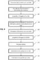
figure 4 est un organigramme d'étapes d'un procédé de localisation d'une cible selon un mode de réalisation de l'invention.
- The
figure 1 is a view in a vertical plane with respect to the ground of a target, of a carrier carrying a device for locating the target, and of a star. - The
figure 2 is a schematic view showing the internal components of the localization device, according to one embodiment of the invention. - The
figure 3 is a view in a horizontal plane with respect to the ground of the carrier and the target already represented infigure 1 . - The
figure 4 is a flowchart of steps in a method for locating a target according to one embodiment of the invention.
En référence à la
L'aéronef A est un drone, un hélicoptère, un avion, etc. Sur la
En référence à la
Le dispositif de localisation 1 est monté à une paroi inférieure P de l'aéronef A, c'est-à-dire une paroi destinée à être en regard du sol lorsque l'aéronef A est en vol.The
En variante, le dispositif de localisation 1 peut être monté sur une autre paroi de l'aéronef A, par exemple une paroi supérieure de l'aéronef A, c'est-à-dire une paroi destinée à être en regard du ciel lorsque l'aéronef A est en vol.As a variant, the
Le dispositif de localisation 1 comprend en outre un boîtier 10 monté à rotation sur la paroi de l'aéronef A, via par exemple une liaison rotule 12.The
La caméra 2, la centrale inertielle 4, le module de recalage 6 et le module de localisation 8 sont logés dans le boîtier 10 et par exemple fixes par rapport à celui-ci.The
En particulier, la centrale inertielle 4 est de préférence solidaire de la caméra 2.In particular, the
La caméra 2 est mobile entre plusieurs orientations par rapport au porteur A.
La caméra 2 est d'une part susceptible d'être orientée vers le sol.The
La caméra 2 est d'autre part susceptible d'être orientée vers le ciel. De préférence, la caméra 2 est susceptible de prendre une orientation dans laquelle l'axe optique de la caméra 2 a une élévation maximale de 30 degrés (c'est-à-dire que l'axe optique de la caméra 2 forme un angle positif de 30 degrés par rapport à un plan horizontal parallèle au sol et ne va pas plus haut vers le zénith).The
La caméra 2 est montée à l'aéronef A de sorte que l'axe optique de la caméra 2 puisse être orientée vers le sol ou vers le ciel, sans pour autant être gênée par la paroi à laquelle le dispositif est monté, ni plus généralement être gênée par le corps de l'aéronef A. La caméra est par exemple monté à bord avant de la paroi inférieure P de l'aéronef A, comme représenté en
En fait, comme la caméra 2 est solidaire du boîtier 10, c'est le dispositif de localisation 1 dans son ensemble qui est mobile en rotation par rapport à la paroi de l'aéronef et susceptible d'adopter une telle élévation.In fact, as the
La caméra 2 comprend un objectif pourvu d'un réticule. Le réticule passe par l'axe optique O de la caméra 2.
La caméra 2 présente un champ de vue instantané (« instantaneous field of view » ou IFOV en anglais) inférieur ou égal à 0,1 milliradians. Le champ IFOV est le champ de vue associé à un pixel d'une image acquise par la caméra 2. Une telle caméra 2 est adaptée à la localisation de cibles à très grande distance.The
Par ailleurs, la caméra 2 est sensible à des longueurs d'onde dans le domaine visible et/ou infrarouge, par exemple des longueurs infrarouges dans la bande SWIR (Short-Wavelength infrared) allant de 1 à 2 micromètres.Furthermore, the
La caméra 2 est par exemple configurable dans plusieurs modes d'acquisition, chaque mode d'acquisition rendant la caméra 2 sensible à des longueurs d'ondes propres à ce mode d'acquisition. La caméra 2 est par exemple configurable non seulement dans un mode d'acquisition infrarouge, dans lequel elle est rendue sensible auxdites longueurs d'ondes dans le domaine infrarouge, mais également configurable dans d'autres mode d'acquisitions (visible, UV, etc.).
Par ailleurs, la centrale inertielle 4 est un dispositif connu en lui-même comprenant une pluralité de capteurs inertiels, typiquement des accéléromètres et des gyromètres.Moreover, the
La centrale inertielle 4 est configurée pour calculer des données de position et d'orientation de la caméra 2.The
Le module de recalage stellaire 6 est connu de l'état de la technique, par exemple du document
Le module de localisation 8 est configuré pour estimer une position de la cible T, également connu de l'état de la technique.The
Le module de localisation 8 comprend un télémètre. Le télémètre est configuré pour estimer la distance entre la caméra 2 et une cible T vue par la caméra 2.The
Le télémètre peut être un télémètre actif, par exemple laser, connu en lui-même.The range finder can be an active range finder, for example a laser, known per se.
Alternativement, le télémètre est de type passif. Il calcule la distance entre la caméra 2 et la cible T en se basant sur un modèle numérique du terrain dans lequel se trouve la cible T.Alternatively, the rangefinder is of the passive type. It calculates the distance between
Le dispositif comprend en outre un module d'estimation d'incertitude 14 configuré pour estimer une incertitude sur une erreur susceptible d'affecter la précision d'une position de cible T estimée par le module de localisation 8.The device further comprises an
Les modules de recalage, de localisation et d'estimation peuvent être des dispositifs physiques distincts, un même dispositif physique, être différents programmes d'ordinateurs exécutés par un ou plusieurs processeur(s) du dispositif, ou bien être différentes parties d'un même programme d'ordinateur exécuté par un ou plusieurs processeur(s) du dispositif.The registration, location and estimation modules can be distinct physical devices, the same physical device, be different computer programs executed by one or more processor (s) of the device, or else be different parts of the same. computer program executed by one or more processor (s) of the device.
Le dispositif comprend par ailleurs un moteur 16 pour mettre en rotation le dispositif par rapport au porteur. Le dispositif, et notamment le moteur 16, est alimenté en énergie électrique par le porteur.The device further comprises a
Le dispositif comprend en outre une interface de communication avec un poste d'opérateur.The device further comprises a communication interface with an operator station.
Dans le cas d'un aéronef A autre qu'un drone, le poste d'opérateur peut être un poste de l'aéronef A : l'interface de communication est par exemple une interface de communication filaire ou une interface de communication radio sans fil.In the case of an aircraft A other than a drone, the operator station can be an aircraft A station: the communication interface is for example a wired communication interface or a wireless radio communication interface .
Le poste d'opérateur peut être alternativement dans une station au sol ou dans un autre porteur que celui qui embarque le dispositif. Dans ce cas, l'interface de communication est une interface de communication radio sans fil.The operator station may alternatively be in a ground station or in a carrier other than that which carries the device on board. In this case, the communication interface is a wireless radio communication interface.
Le dispositif forme typiquement une boule gyro-stabilisée (BGS) fonctionnant de façon autonome par rapport à l'aéronef A hormis son alimentation en énergie par l'aéronef A.The device typically forms a gyro-stabilized ball (BGS) operating autonomously with respect to the aircraft A except for its power supply by the aircraft A.
Dans d'autres variantes de réalisation, les modules 6, 8, 14 peuvent être déportés au sein de l'aéronef.In other variant embodiments, the
On suppose que l'aéronef A est en vol. Une cible T se trouve au sol.It is assumed that aircraft A is in flight. A target T is on the ground.
En référence à la
Pour localiser la cible T, les étapes suivantes sont mises en œuvre par le dispositif.To locate the target T, the following steps are implemented by the device.
La centrale inertielle 4 calcule des données de position et/ou d'orientation de la caméra 2 (étape 102).The
La caméra acquiert au moins une image de la cible T (étape 104).The camera acquires at least one image of the target T (step 104).
Le télémètre (actif par laser ou passif) estime la distance entre la cible T vue par la caméra 2 et la caméra 2.The rangefinder (active by laser or passive) estimates the distance between the target T seen by the
Le module de localisation 8 estime une position de la cible T en combinant la distance estimée par le télémètre aux données d'orientation et de position de la caméra 2 et à l'image acquise (étape 118).The
De façon optionnelle, est également pris en compte dans l'estimation mise en œuvre par le module de localisation 8, un écart angulaire entre l'axe optique de la caméra 2 et un axe passant par un point de la caméra 2 et un point de la cible T. Cet écart angulaire est calculé en fonction d'un écart en pixels, dans une image acquise par la caméra 2 dans la première orientation au cours de l'étape 104, entre le réticule de la caméra 2 passant par l'axe optique et un pixel de la cible T. Cet écart est nul lorsque le réticule se superpose à la cible T dans l'image acquise. Il est par exemple envisageable d'orienter la caméra 2 de sorte à obtenir une telle superposition, ce qui permet de ne pas avoir à prendre en compte cet écart dans l'estimation mise en œuvre par le module de localisation 8.Optionally, is also taken into account in the estimate implemented by the
Le module de localisation 8 peut ainsi utiliser une formule du type suivant pour une telle estimation :
- Pcible est la position de la cible T estimée par le module de
localisation 8, cette position étant exprimée dans un repère lié à la Terre, - E est un état de navigation estimé par la centrale inertielle 4 comprenant au moins une donnée de positionPBGS et au moins une donnée d'orientationOrientationBGS de la caméra 2 fournies par la centrale inertielle 4, ces données étant par exemple exprimées dans un repère géographique centré sur le dispositif et comprend un axe pointant vers le nord de la Terre, un axe pointant vers l'est, et un troisième axe, les trois axes formant un repère orthonormé,
- θ est un écart angulaire entre l'axe optique de la caméra 2 et un axe passant par un point de la caméra 2 et un point cible T. Cet écart angulaire est fonction d'un écart en pixels, dans une image acquise par la caméra 2 dans la première orientation, entre le réticule de la caméra 2 et un pixel de la cible T (optionnel comme indiqué ci-dessus),
- D est la distance mesurée par le télémètre,
- Les fonctionsfi sont des fonctions prédéterminées.
- Ptarget is the position of the target T estimated by the
location module 8, this position being expressed in a reference frame linked to the Earth, - E is a navigation state estimated by the
inertial unit 4 comprising at least one position datumPBGS and at least one orientation datumBGS orientation of thecamera 2 supplied by theinertial unit 4, these data being for example expressed in a geographical landmark centered on the device and comprises an axis pointing north of the Earth, an axis pointing east, and a third axis, the three axes forming an orthonormal reference, - θ is an angular difference between the optical axis of the
camera 2 and an axis passing through a point of thecamera 2 and a target point T. This angular difference is a function of a difference in pixels, in an image acquired by thecamera 2 in the first orientation, between the reticle of thecamera 2 and a pixel of the target T (optional as indicated above), - D is the distance measured by the rangefinder,
- The functionsfi are predetermined functions.
Comme indiqué en introduction, les données produites par la centrale inertielle 4 au cours de l'étape 102 peuvent être entachées d'erreurs, notamment des erreurs de dérive.As indicated in the introduction, the data produced by the
Une erreur particulièrement préjudiciable à la précision de localisation offerte par le dispositif est une erreur entachant un cap de la caméra 2 calculé par la centrale inertielle 4. En référence à la
- L'axe O de la caméra 2 projeté dans un plan horizontal parallèle au sol (le plan de la
figure 3 , qui montre l'aéronef et la cible vus de dessus) et - un axe N pointant vers le nord compris dans ce plan horizontal (sachant que l'axe E représenté sur la
figure 3 est un axe pointant vers l'est).
- The O axis of
camera 2 projected in a horizontal plane parallel to the ground (the plane of thefigure 3 , which shows the aircraft and target seen from above) and - an axis N pointing towards the north included in this horizontal plane (knowing that the axis E represented on the
figure 3 is an axis pointing east).
Ainsi, lorsque la cible T se trouve à une grande distance de l'aéronef A, une erreur de cap, même minime, influe de manière très importante sur l'erreur finale de localisation commise par le dispositif.Thus, when the target T is located at a great distance from the aircraft A, a heading error, even a small one, has a very significant influence on the final location error made by the device.
Alors que la caméra 2 adopte la première orientation (vers la cible T), le module d'estimation estime une incertitude sur une erreur de cap commise par la centrale inertielle 4 (étape 106). Le module d'estimation peut être la centrale inertielle 4 elle-même : la centrale inertielle 4 fournit alors directement, en sus des données de position et d'orientation de la caméra 2, une donnée d'incertitude sur une erreur de cap.While the
Lorsque l'incertitude sur l'erreur de cap dépasse un seuil prédéterminé, le module d'estimation commande un déplacement de la caméra 2 vers une deuxième orientation adaptée pour qu'une étoile S prédéterminée soit en vue de la caméra 2 (étape 108).When the uncertainty on the heading error exceeds a predetermined threshold, the estimation module commands a displacement of the
De préférence, le premier seuil est inférieur ou égal à 0,3 milliradians, par exemple 0,1 milliradians.Preferably, the first threshold is less than or equal to 0.3 milliradians, for example 0.1 milliradians.
La deuxième orientation est déterminée par le module d'estimation en fonction des données d'orientation fournie par la centrale inertielle 4, et des informations de positionnement de l'étoile S qui sont prédéterminées.The second orientation is determined by the estimation module as a function of the orientation data supplied by the
Dans la deuxième orientation, la caméra 2 acquiert au moins une image montrant l'étoile S (étape 110).In the second orientation, the
A cause des erreurs qui entachent les données d'orientation de la centrale inertielle 4, il existe un certain écart en pixels, dans l'image acquise par la caméra 2 dans la deuxième orientation, entre un pixel montrant le réticule de la caméra 2 et un pixel montrant l'étoile S. Cet écart est donc représentatif des erreurs de positionnement et d'orientation de la centrale inertielle 4.Because of the errors that mar the orientation data of the
Le module de recalage 6 met en œuvre un recalage stellaire connu de l'état de la technique sur la base des données de position et/ou d'orientation de la caméra 2, de sorte à produire des données de position et/ou d'orientation recalées (étape 114).The
Le module de localisation 8 utilise les données recalées en lieu et place des données entachées d'erreurs fournies par la centrale inertielle 4, pour estimer la position de la cible T au cours de l'étape 118 précédemment mentionnée.The
De préférence, la caméra 2 est configurée dans son mode d'acquisition infrarouge pour acquérir les images montrant l'étoile S. Ce mode d'acquisition infrarouge est celui qui permet d'obtenir des images de l'étoile S les plus sensibles et donc d'améliorer la capacité de correction du recalage stellaire notamment en réduisant la durée pendant laquelle la cible T n'est pas observée.Preferably, the
Pendant que la caméra 2 se trouve dans la deuxième orientation, les étapes d'acquisition d'image 110 et 114 sont répétées pour une étoile, et peuvent en outre être mises en œuvre pour au moins une autre étoile, après réorientation de la caméra vers cette autre étoile au cours de l'étape 108.While the
L'étape d'estimation d'incertitude 106 est en outre également répétée dans le temps, par exemple à intervalles réguliers, même pendant que la caméra est orientée vers une étoile.The
Lorsque le module d'estimation 14 détecte que l'erreur de cap redescend en dessous d'un deuxième seuil prédéterminé, le module d'estimation commande un déplacement de la caméra 2 vers la première orientation (qu'il aura préalablement mémorisée au moment de la quitter) (étape 116).When the
Le deuxième seuil est inférieur ou égal au premier seuil.The second threshold is less than or equal to the first threshold.
Si la caméra 2 était configurée dans un mode d'acquisition différent du mode d'acquisition infrarouge lorsque le franchissement du premier seuil a été détecté, la caméra 2 est reconfigurée dans ce mode d'acquisition d'origine pour observer la cible T.If the
D'autres critères de passage d'une orientation de la caméra 2 à l'autre peuvent être utilisés.Other criteria for switching from one orientation of the
La caméra 2 peut par exemple être configurée pour passer d'une des première et deuxième orientations à l'autre orientation (étapes 108, 116) en réponse à la réception par l'interface de communication d'une commande émise par le poste d'opérateur. Par exemple, Il se peut en effet s'avérer urgent de réorienter la caméra 2 vers la cible T afin de l'observer alors que l'incertitude n'est pas redescendue en dessous du deuxième seuil, et ce en dépit du fait que les conditions ne sont pas encore optimales pour calculer une position précise de cette cible T.The
Dans le cas particulier où l'interface de communication reçoit une commande de réorientation de la première orientation à la deuxième orientation, la caméra peut exécuter cette commande de manière différée. Dans certaines situations, la caméra ne pourrait pas voir l'étoile si elle était immédiatement réorientée dans la deuxième position, par exemple lorsque l'aéronef est sur le dos ou que le ciel n'est pas dans la zone d'orientations possibles de la caméra. En conséquence, non seulement la cible ne serait plus en vue de la caméra, mais le recalage stellaire ne pourrait également pas fonctionner correctement.In the particular case where the communication interface receives a command to reorientate from the first orientation to the second orientation, the camera can execute this command in a delayed manner. In some situations, the camera would not be able to see the star if it was immediately reoriented to the second position, for example when the aircraft is on its back or the sky is not in the area of possible orientations of the star. camera. As a result, not only would the target be out of view of the camera, but stellar registration would also not be able to function properly.
Dès lors, la caméra est avantageusement configurée pour attendre, suite à la réception de la commande, que le porteur mobile ait une orientation par rapport à l'étoile permettant à la caméra de voir l'étoile dans la deuxième orientation, avant de passer de la première à la deuxième orientation. La caméra peut par exemple comprendre des moyens de détection d'orientation de l'aéronef par rapport au sol ou au ciel, ou bien recevoir, par son interface de communication, des informations lui permettant de prendre connaissance de cette orientation pour gérer cette attente, à partir des informations disponibles au niveau du porteur mobile.Therefore, the camera is advantageously configured to wait, following receipt of the command, for the mobile carrier to have an orientation relative to the star allowing the camera to see the star in the second orientation, before switching from the first to the second orientation. The camera can for example comprise means for detecting the orientation of the aircraft with respect to the ground or the sky, or else receive, via its communication interface, information enabling it to take cognizance of this orientation in order to manage this wait, from the information available at the level of the mobile carrier.
Par ailleurs, une incertitude autre que l'incertitude sur l'erreur de cap peut être utilisée comme critères de déclenchement d'un passage d'une orientation à l'autre.Furthermore, an uncertainty other than the uncertainty of the heading error can be used as criteria for triggering a passage from one orientation to another.
Par exemple, il peut être prévu d'utiliser à cet effet une incertitude sur la position de la cible T, cette incertitude étant calculée par le module de localisation 8 en sus de l'estimation de position de la cible T elle-même. Dans ce cas, le premier seuil est de préférence choisi inférieur ou égal à 10 mètres.For example, provision can be made to use for this purpose an uncertainty on the position of the target T, this uncertainty being calculated by the
Une telle incertitude d'erreur de position, se présentant sous la forme d'une covarianceCoνPOS_cible, est calculée typiquement comme suit par le module d'estimation 14 :


- CoνINS : covariance de l'état E de navigation estimé par la centrale inertiel (cet état comprenant les données de position et d'orientation estimées au cours de l'étape 102)
- Coνerr_cam : covariance des bruits de mesures de désignation du point d'intérêt dans le repère de la caméra 2,
- Coνerr_telem : covariance des bruits de mesures de désignation de la distance D entre la caméra 2 et la cible (le télémètre laser en général).
- CoνINS : covariance of the navigation state E estimated by the inertial unit (this state comprising the position and orientation data estimated during step 102)
- Coνerr _cam : covariance of the measurement noises for designation of the point of interest in the frame of the
camera 2, - Coνerr_telem : covariance of measurement noise designating the distance D between
camera 2 and the target (the laser rangefinder in general).
Cette équation est une simple somme, car les erreurs sont indépendantes.This equation is a simple sum, because the errors are independent.
Le dispositif de localisation 1 est avantageusement mise en œuvre dans un porteur de type aéronef A, ce type de porteur ayant généralement pour mission de localiser des cibles à très grande distance, en particulier un drone. Toutefois, ce dispositif peut être embarqué sur d'autres types de porteurs : véhicule terrestre, navire, etc.The
Claims (13)
- A device for locating (1) a target (T) intended to be embedded on a mobile carrier (A), the device comprising:• a camera (2) orientable relative to the carrier (A) in:o a first orientation in sight of the target so that the camera acquires an image of the target (T), ando a second orientation in sight of at least one predetermined star so that the camera acquires at least one image of the star,• an inertial unit (4) configured to calculate position and orientation data of the camera (2),• a stellar resetting module (6) configured to apply a stellar resetting to the data calculated by the inertial unit (4) based on the image of the star, so as to produce reset position and orientation data,• a location module (8) configured to estimate a position of the target (T) from the image of the target (T) and the reset data,the device beingcharacterized in that it comprises a communication interface with an operator station, andin that the camera (2) is further configured to switch from one of the first and second orientations to the other in response to the receipt by the communication interface of a command emitted by the operator station.
- The device (1) according to the preceding claim, wherein the camera is configured to wait, following the receipt of the command, for the mobile carrier to have an orientation relative to the star allowing the camera to see the star in the second orientation, before switching from the first to the second orientation.
- The device (1) according to any of the preceding claims, comprising an uncertainty estimation module (14) configured to estimate an uncertainty on an error likely to affect the accuracy of the position estimated by the location module (8), and wherein the camera (2) is configured to switch from the first orientation to the second orientation when the uncertainty crosses a first predetermined threshold.
- The device (1) according to the preceding claim, wherein the uncertainty is an uncertainty on a position error altering the position of the target (T) estimated by the location module (8).
- The device (1) according to any of claims 3 to 4, wherein the uncertainty is an uncertainty on a heading error of the camera (2) altering a heading data calculated by the inertial unit (4).
- The device (1) according to the preceding claim, wherein the first threshold is less than or equal to 0.3 milliradians.
- The device (1) according to any of the preceding claims, comprising an uncertainty estimation module (14) configured to estimate an uncertainty on an error likely to affect the accuracy of the position estimated by the location module (8), and wherein the camera (2) is configured to switch from the second orientation to the first orientation when the second uncertainty crosses a second predetermined threshold.
- The device (1) according to claim 3 and claim 7 taken in combination, wherein the second threshold is less than or equal to the first threshold.
- The device (1) according to any of the preceding claims, wherein the camera (2) is configured to acquire the image of the predetermined star in an infrared acquisition mode in which the camera (2) is sensitive to infrared wavelengths.
- An aircraft (A), such as a drone, comprising a device for locating (1) a target (T) according to any of the preceding claims.
- A method for locating a target (T), comprising the steps of:• orienting (100) a mobile camera (2) embedded on a mobile carrier (A) in a first orientation in which the target (T) is in sight of the camera (2),• calculating (102), by an inertial unit (4), position and orientation data of the camera (2),• acquiring (104) by the camera (2) at least one image of the target (T),• orienting (108) the camera (2) in a second orientation relative to the carrier (A) in which a predetermined star is in sight of the camera (2),• acquiring (110) at least one image of the star by the camera (2),• stellar resetting (114) applied to the data calculated by the inertial unit (4) based on the image of the star, so as to produce reset position and orientation data,• estimating (118) a position of the target (T) from the image of the target (T) and the reset data,the method beingcharacterized in that the camera (2) switches from one of the first and second orientations to the other in response to the receipt of a command emitted from an operator station.
- The method according to the preceding claim, wherein the camera waits, following the receipt of the command, for the mobile carrier to have an orientation relative to the star allowing the camera to see the star in the second orientation, before switching from the first to the second orientation.
- The method according to any of claims 11 and 12, wherein the carrier (A) is an aircraft, for example a drone.
Applications Claiming Priority (2)
| Application Number | Priority Date | Filing Date | Title |
|---|---|---|---|
| FR1662631AFR3060769B1 (en) | 2016-12-16 | 2016-12-16 | DEVICE FOR THE LOCALIZATION BY STELLAR RECALLING OF A TARGET, INTENDED TO BE SHIPPED ON A MOBILE CARRIER |
| PCT/EP2017/082409WO2018108897A1 (en) | 2016-12-16 | 2017-12-12 | Device for locating a target by stellar resetting, intended to be on board a mobile carrier |
Publications (2)
| Publication Number | Publication Date |
|---|---|
| EP3555550A1 EP3555550A1 (en) | 2019-10-23 |
| EP3555550B1true EP3555550B1 (en) | 2021-02-24 |
Family
ID=58501529
Family Applications (1)
| Application Number | Title | Priority Date | Filing Date |
|---|---|---|---|
| EP17811327.0AActiveEP3555550B1 (en) | 2016-12-16 | 2017-12-12 | Device for locating a target by stellar resetting, intended to be on board a mobile carrier |
Country Status (9)
| Country | Link |
|---|---|
| US (1) | US10964047B2 (en) |
| EP (1) | EP3555550B1 (en) |
| CN (1) | CN110088561B (en) |
| CA (1) | CA3047131C (en) |
| FR (1) | FR3060769B1 (en) |
| IL (1) | IL267163B (en) |
| RU (1) | RU2713250C1 (en) |
| WO (1) | WO2018108897A1 (en) |
| ZA (1) | ZA201903878B (en) |
Family Cites Families (14)
| Publication number | Priority date | Publication date | Assignee | Title |
|---|---|---|---|---|
| WO1995003214A1 (en)* | 1993-07-22 | 1995-02-02 | Honeywell Inc. | Star acquisition and identification method |
| RU2182313C2 (en)* | 1999-08-25 | 2002-05-10 | Сафьян Дмитрий Анатольевич | Complex navigational system for flying vehicles of various classes (versions) |
| RU2155323C1 (en)* | 2000-02-24 | 2000-08-27 | Государственное унитарное предприятие Научно-технический производственный комплекс "Геофизика-АРТ" дочернее предприятие НПО "Геофизика" | Optoelectronic target search and tracking system |
| FR2831273B1 (en)* | 2001-10-23 | 2004-03-12 | Thales Sa | TARGET ACQUISITION DEVICE, AIRCRAFT, TRAJECTORY ESTIMATION SYSTEM AND DEFENSE SYSTEM THEREOF |
| FR2890755B1 (en)* | 2005-09-09 | 2007-12-28 | Thales Sa | OPTICAL DEVICE FOR OBSERVING A TARGET, MULTIFUNCTION |
| ES2440252T3 (en) | 2007-10-23 | 2014-01-28 | Selex Es S.P.A | System for accurately locating a target on the ground using a flight platform and associated method of operation |
| US7961301B2 (en)* | 2008-05-09 | 2011-06-14 | Ball Aerospace & Technologies Corp. | Flash LADAR system |
| US20160097857A1 (en)* | 2012-02-07 | 2016-04-07 | Michael Cem Gokay | Integrated Targeting Device |
| CN103076015B (en)* | 2013-01-04 | 2015-10-28 | 北京航空航天大学 | A kind of SINS/CNS integrated navigation system based on optimum correction comprehensively and air navigation aid thereof |
| JP2014241584A (en)* | 2013-05-14 | 2014-12-25 | パナソニックIpマネジメント株式会社 | Image processing method and image processing system |
| CN103674021B (en)* | 2013-11-25 | 2016-08-17 | 哈尔滨工业大学 | Integrated navigation system based on inertial navigation and star sensor and method |
| US10175358B2 (en)* | 2014-08-04 | 2019-01-08 | Elbit Systems Of America, Llc | Systems and methods for northfinding |
| RU2571530C1 (en)* | 2014-08-12 | 2015-12-20 | Сергей Петрович Мелющенок | Increasing self-propelled craft weapons fire efficiency |
| US9791278B2 (en)* | 2015-03-24 | 2017-10-17 | Honeywell International Inc. | Navigating with star tracking sensors |
- 2016
- 2016-12-16FRFR1662631Apatent/FR3060769B1/enactiveActive
- 2017
- 2017-12-12CACA3047131Apatent/CA3047131C/enactiveActive
- 2017-12-12CNCN201780077555.8Apatent/CN110088561B/enactiveActive
- 2017-12-12EPEP17811327.0Apatent/EP3555550B1/enactiveActive
- 2017-12-12WOPCT/EP2017/082409patent/WO2018108897A1/ennot_activeCeased
- 2017-12-12USUS16/469,134patent/US10964047B2/enactiveActive
- 2017-12-12RURU2019122186Apatent/RU2713250C1/enactive
- 2019
- 2019-06-06ILIL267163Apatent/IL267163B/enunknown
- 2019-06-14ZAZA2019/03878Apatent/ZA201903878B/enunknown
Also Published As
| Publication number | Publication date |
|---|---|
| CN110088561A (en) | 2019-08-02 |
| FR3060769B1 (en) | 2019-07-26 |
| CA3047131A1 (en) | 2018-06-21 |
| IL267163A (en) | 2019-08-29 |
| RU2713250C1 (en) | 2020-02-04 |
| ZA201903878B (en) | 2020-07-29 |
| US20190385333A1 (en) | 2019-12-19 |
| CN110088561B (en) | 2020-04-07 |
| CA3047131C (en) | 2020-03-24 |
| US10964047B2 (en) | 2021-03-30 |
| EP3555550A1 (en) | 2019-10-23 |
| IL267163B (en) | 2022-04-01 |
| WO2018108897A1 (en) | 2018-06-21 |
| FR3060769A1 (en) | 2018-06-22 |
Similar Documents
| Publication | Publication Date | Title |
|---|---|---|
| EP2932182B1 (en) | Method for accurately geolocating an image sensor installed on board an aircraft | |
| US10302433B2 (en) | Daytime and nighttime stellar sensor with active polarizer | |
| FR3054336A1 (en) | SELF-CONTAINING DRONE-CONDUCTED VIEWING SYSTEM WITH TARGET TRACKING AND IMPROVED TARGET LOCATION. | |
| FR3075987A1 (en) | METHOD AND SYSTEM FOR DUAL HARMONIZATION OF A HIGH HEAD DISPLAY SYSTEM WITH AN INERTIAL DEVICE OF REMOVABLE ATTITUDE IN THE COCKPIT | |
| FR3087134A1 (en) | OBSTACLE DETECTION ASSEMBLY FOR DRONE, DRONE HAVING SUCH AN OBSTACLE DETECTION ASSEMBLY, AND OBSTACLE DETECTION METHOD | |
| WO2014199073A1 (en) | Electronic sextant with a triaxial inertial system and method for position determination | |
| FR3007832A1 (en) | NAVIGATION AND POINTING SYSTEM AND METHOD OF CALIBRATING A NAVIGATION AND POINTING SYSTEM | |
| FR3075985B1 (en) | METHOD AND SYSTEM FOR DUAL HARMONIZATION OF A HIGH-DOOR HEAD DISPLAY SYSTEM TO REALIZE AIRCRAFT DRIVING INFORMATION DISPLAY WITH THE REAL WORLD OUTSIDE | |
| EP3555550B1 (en) | Device for locating a target by stellar resetting, intended to be on board a mobile carrier | |
| FR3075355A1 (en) | METHOD FOR ESTIMATING NAVIGATION DATA OF A GROUND VEHICLE USING GEOMETRY PARAMETERS AND ROUTE ORIENTATION | |
| EP3895127B1 (en) | Device and method for inertial/video hybridisation | |
| FR3071624B1 (en) | DISPLAY SYSTEM, DISPLAY METHOD, AND COMPUTER PROGRAM | |
| FR2979022A1 (en) | STEERING NORTHERN SEARCHING DEVICE AND METHOD OF REPLACING A MAGNETIC COMPASS OF SUCH A DEVICE | |
| EP3620852B1 (en) | Method of capturing aerial images of a geographical area, method for three-dimensional mapping of a geographical area and aircraft for implementing such methods | |
| CA3004825C (en) | Method for designing a navigation path and method for orienting a sighting member from said navigation path | |
| FR3097958A1 (en) | Method of correcting a previously estimated position of a vehicle | |
| FR3041769A1 (en) | GEOLOCATION PROCESS | |
| EP3980720B1 (en) | Method and device for resetting an inertial unit of a transport means on the basis of information delivered by a viewfinder of the transport means | |
| EP4006491A1 (en) | Navigation assistance system of a landmark assistance carrier | |
| FR3075354A1 (en) | METHOD FOR REPERTING A PLAN, DEVICES AND ASSOCIATED METHODS | |
| WO2024009048A1 (en) | Method for correcting an attitude provided by a dead reckoning navigation system by means of a relative positioning system | |
| FR3132142A1 (en) | ELECTRONIC ASTRAL DAY AND NIGHT SEXTANT WITH INERTIAL PLATFORM |
Legal Events
| Date | Code | Title | Description |
|---|---|---|---|
| STAA | Information on the status of an ep patent application or granted ep patent | Free format text:STATUS: UNKNOWN | |
| STAA | Information on the status of an ep patent application or granted ep patent | Free format text:STATUS: THE INTERNATIONAL PUBLICATION HAS BEEN MADE | |
| PUAI | Public reference made under article 153(3) epc to a published international application that has entered the european phase | Free format text:ORIGINAL CODE: 0009012 | |
| STAA | Information on the status of an ep patent application or granted ep patent | Free format text:STATUS: REQUEST FOR EXAMINATION WAS MADE | |
| 17P | Request for examination filed | Effective date:20190716 | |
| AK | Designated contracting states | Kind code of ref document:A1 Designated state(s):AL AT BE BG CH CY CZ DE DK EE ES FI FR GB GR HR HU IE IS IT LI LT LU LV MC MK MT NL NO PL PT RO RS SE SI SK SM TR | |
| AX | Request for extension of the european patent | Extension state:BA ME | |
| DAV | Request for validation of the european patent (deleted) | ||
| DAX | Request for extension of the european patent (deleted) | ||
| GRAP | Despatch of communication of intention to grant a patent | Free format text:ORIGINAL CODE: EPIDOSNIGR1 | |
| STAA | Information on the status of an ep patent application or granted ep patent | Free format text:STATUS: GRANT OF PATENT IS INTENDED | |
| RIN1 | Information on inventor provided before grant (corrected) | Inventor name:REYMOND, GEORGES-OLIVIER Inventor name:DAVENEL, ARNAUD Inventor name:ROBERFROID, DAVID Inventor name:ROLAND, FLAVIEN Inventor name:DELEAUX, BENJAMIN Inventor name:ROBERT, EMMANUEL | |
| INTG | Intention to grant announced | Effective date:20201022 | |
| GRAS | Grant fee paid | Free format text:ORIGINAL CODE: EPIDOSNIGR3 | |
| GRAA | (expected) grant | Free format text:ORIGINAL CODE: 0009210 | |
| STAA | Information on the status of an ep patent application or granted ep patent | Free format text:STATUS: THE PATENT HAS BEEN GRANTED | |
| AK | Designated contracting states | Kind code of ref document:B1 Designated state(s):AL AT BE BG CH CY CZ DE DK EE ES FI FR GB GR HR HU IE IS IT LI LT LU LV MC MK MT NL NO PL PT RO RS SE SI SK SM TR | |
| REG | Reference to a national code | Ref country code:CH Ref legal event code:EP | |
| REG | Reference to a national code | Ref country code:AT Ref legal event code:REF Ref document number:1365027 Country of ref document:AT Kind code of ref document:T Effective date:20210315 | |
| REG | Reference to a national code | Ref country code:IE Ref legal event code:FG4D Free format text:LANGUAGE OF EP DOCUMENT: FRENCH | |
| REG | Reference to a national code | Ref country code:DE Ref legal event code:R096 Ref document number:602017033442 Country of ref document:DE | |
| REG | Reference to a national code | Ref country code:SE Ref legal event code:TRGR | |
| REG | Reference to a national code | Ref country code:LT Ref legal event code:MG9D | |
| REG | Reference to a national code | Ref country code:NL Ref legal event code:MP Effective date:20210224 | |
| PG25 | Lapsed in a contracting state [announced via postgrant information from national office to epo] | Ref country code:NO Free format text:LAPSE BECAUSE OF FAILURE TO SUBMIT A TRANSLATION OF THE DESCRIPTION OR TO PAY THE FEE WITHIN THE PRESCRIBED TIME-LIMIT Effective date:20210524 Ref country code:PT Free format text:LAPSE BECAUSE OF FAILURE TO SUBMIT A TRANSLATION OF THE DESCRIPTION OR TO PAY THE FEE WITHIN THE PRESCRIBED TIME-LIMIT Effective date:20210624 Ref country code:GR Free format text:LAPSE BECAUSE OF FAILURE TO SUBMIT A TRANSLATION OF THE DESCRIPTION OR TO PAY THE FEE WITHIN THE PRESCRIBED TIME-LIMIT Effective date:20210525 Ref country code:HR Free format text:LAPSE BECAUSE OF FAILURE TO SUBMIT A TRANSLATION OF THE DESCRIPTION OR TO PAY THE FEE WITHIN THE PRESCRIBED TIME-LIMIT Effective date:20210224 Ref country code:FI Free format text:LAPSE BECAUSE OF FAILURE TO SUBMIT A TRANSLATION OF THE DESCRIPTION OR TO PAY THE FEE WITHIN THE PRESCRIBED TIME-LIMIT Effective date:20210224 Ref country code:BG Free format text:LAPSE BECAUSE OF FAILURE TO SUBMIT A TRANSLATION OF THE DESCRIPTION OR TO PAY THE FEE WITHIN THE PRESCRIBED TIME-LIMIT Effective date:20210524 Ref country code:LT Free format text:LAPSE BECAUSE OF FAILURE TO SUBMIT A TRANSLATION OF THE DESCRIPTION OR TO PAY THE FEE WITHIN THE PRESCRIBED TIME-LIMIT Effective date:20210224 | |
| REG | Reference to a national code | Ref country code:AT Ref legal event code:MK05 Ref document number:1365027 Country of ref document:AT Kind code of ref document:T Effective date:20210224 | |
| PG25 | Lapsed in a contracting state [announced via postgrant information from national office to epo] | Ref country code:RS Free format text:LAPSE BECAUSE OF FAILURE TO SUBMIT A TRANSLATION OF THE DESCRIPTION OR TO PAY THE FEE WITHIN THE PRESCRIBED TIME-LIMIT Effective date:20210224 Ref country code:NL Free format text:LAPSE BECAUSE OF FAILURE TO SUBMIT A TRANSLATION OF THE DESCRIPTION OR TO PAY THE FEE WITHIN THE PRESCRIBED TIME-LIMIT Effective date:20210224 Ref country code:PL Free format text:LAPSE BECAUSE OF FAILURE TO SUBMIT A TRANSLATION OF THE DESCRIPTION OR TO PAY THE FEE WITHIN THE PRESCRIBED TIME-LIMIT Effective date:20210224 Ref country code:LV Free format text:LAPSE BECAUSE OF FAILURE TO SUBMIT A TRANSLATION OF THE DESCRIPTION OR TO PAY THE FEE WITHIN THE PRESCRIBED TIME-LIMIT Effective date:20210224 | |
| PG25 | Lapsed in a contracting state [announced via postgrant information from national office to epo] | Ref country code:IS Free format text:LAPSE BECAUSE OF FAILURE TO SUBMIT A TRANSLATION OF THE DESCRIPTION OR TO PAY THE FEE WITHIN THE PRESCRIBED TIME-LIMIT Effective date:20210624 | |
| PG25 | Lapsed in a contracting state [announced via postgrant information from national office to epo] | Ref country code:CZ Free format text:LAPSE BECAUSE OF FAILURE TO SUBMIT A TRANSLATION OF THE DESCRIPTION OR TO PAY THE FEE WITHIN THE PRESCRIBED TIME-LIMIT Effective date:20210224 Ref country code:EE Free format text:LAPSE BECAUSE OF FAILURE TO SUBMIT A TRANSLATION OF THE DESCRIPTION OR TO PAY THE FEE WITHIN THE PRESCRIBED TIME-LIMIT Effective date:20210224 Ref country code:AT Free format text:LAPSE BECAUSE OF FAILURE TO SUBMIT A TRANSLATION OF THE DESCRIPTION OR TO PAY THE FEE WITHIN THE PRESCRIBED TIME-LIMIT Effective date:20210224 Ref country code:SM Free format text:LAPSE BECAUSE OF FAILURE TO SUBMIT A TRANSLATION OF THE DESCRIPTION OR TO PAY THE FEE WITHIN THE PRESCRIBED TIME-LIMIT Effective date:20210224 | |
| REG | Reference to a national code | Ref country code:DE Ref legal event code:R097 Ref document number:602017033442 Country of ref document:DE | |
| PG25 | Lapsed in a contracting state [announced via postgrant information from national office to epo] | Ref country code:DK Free format text:LAPSE BECAUSE OF FAILURE TO SUBMIT A TRANSLATION OF THE DESCRIPTION OR TO PAY THE FEE WITHIN THE PRESCRIBED TIME-LIMIT Effective date:20210224 Ref country code:SK Free format text:LAPSE BECAUSE OF FAILURE TO SUBMIT A TRANSLATION OF THE DESCRIPTION OR TO PAY THE FEE WITHIN THE PRESCRIBED TIME-LIMIT Effective date:20210224 Ref country code:RO Free format text:LAPSE BECAUSE OF FAILURE TO SUBMIT A TRANSLATION OF THE DESCRIPTION OR TO PAY THE FEE WITHIN THE PRESCRIBED TIME-LIMIT Effective date:20210224 | |
| PLBE | No opposition filed within time limit | Free format text:ORIGINAL CODE: 0009261 | |
| STAA | Information on the status of an ep patent application or granted ep patent | Free format text:STATUS: NO OPPOSITION FILED WITHIN TIME LIMIT | |
| PG25 | Lapsed in a contracting state [announced via postgrant information from national office to epo] | Ref country code:AL Free format text:LAPSE BECAUSE OF FAILURE TO SUBMIT A TRANSLATION OF THE DESCRIPTION OR TO PAY THE FEE WITHIN THE PRESCRIBED TIME-LIMIT Effective date:20210224 Ref country code:ES Free format text:LAPSE BECAUSE OF FAILURE TO SUBMIT A TRANSLATION OF THE DESCRIPTION OR TO PAY THE FEE WITHIN THE PRESCRIBED TIME-LIMIT Effective date:20210224 | |
| 26N | No opposition filed | Effective date:20211125 | |
| PG25 | Lapsed in a contracting state [announced via postgrant information from national office to epo] | Ref country code:SI Free format text:LAPSE BECAUSE OF FAILURE TO SUBMIT A TRANSLATION OF THE DESCRIPTION OR TO PAY THE FEE WITHIN THE PRESCRIBED TIME-LIMIT Effective date:20210224 | |
| PG25 | Lapsed in a contracting state [announced via postgrant information from national office to epo] | Ref country code:IS Free format text:LAPSE BECAUSE OF FAILURE TO SUBMIT A TRANSLATION OF THE DESCRIPTION OR TO PAY THE FEE WITHIN THE PRESCRIBED TIME-LIMIT Effective date:20210624 | |
| PG25 | Lapsed in a contracting state [announced via postgrant information from national office to epo] | Ref country code:MC Free format text:LAPSE BECAUSE OF FAILURE TO SUBMIT A TRANSLATION OF THE DESCRIPTION OR TO PAY THE FEE WITHIN THE PRESCRIBED TIME-LIMIT Effective date:20210224 | |
| REG | Reference to a national code | Ref country code:CH Ref legal event code:PL | |
| REG | Reference to a national code | Ref country code:BE Ref legal event code:MM Effective date:20211231 | |
| PG25 | Lapsed in a contracting state [announced via postgrant information from national office to epo] | Ref country code:LU Free format text:LAPSE BECAUSE OF NON-PAYMENT OF DUE FEES Effective date:20211212 Ref country code:IE Free format text:LAPSE BECAUSE OF NON-PAYMENT OF DUE FEES Effective date:20211212 | |
| PG25 | Lapsed in a contracting state [announced via postgrant information from national office to epo] | Ref country code:BE Free format text:LAPSE BECAUSE OF NON-PAYMENT OF DUE FEES Effective date:20211231 | |
| PG25 | Lapsed in a contracting state [announced via postgrant information from national office to epo] | Ref country code:LI Free format text:LAPSE BECAUSE OF NON-PAYMENT OF DUE FEES Effective date:20211231 Ref country code:CH Free format text:LAPSE BECAUSE OF NON-PAYMENT OF DUE FEES Effective date:20211231 | |
| PG25 | Lapsed in a contracting state [announced via postgrant information from national office to epo] | Ref country code:CY Free format text:LAPSE BECAUSE OF FAILURE TO SUBMIT A TRANSLATION OF THE DESCRIPTION OR TO PAY THE FEE WITHIN THE PRESCRIBED TIME-LIMIT Effective date:20210224 | |
| PG25 | Lapsed in a contracting state [announced via postgrant information from national office to epo] | Ref country code:HU Free format text:LAPSE BECAUSE OF FAILURE TO SUBMIT A TRANSLATION OF THE DESCRIPTION OR TO PAY THE FEE WITHIN THE PRESCRIBED TIME-LIMIT; INVALID AB INITIO Effective date:20171212 | |
| PG25 | Lapsed in a contracting state [announced via postgrant information from national office to epo] | Ref country code:MK Free format text:LAPSE BECAUSE OF FAILURE TO SUBMIT A TRANSLATION OF THE DESCRIPTION OR TO PAY THE FEE WITHIN THE PRESCRIBED TIME-LIMIT Effective date:20210224 | |
| PG25 | Lapsed in a contracting state [announced via postgrant information from national office to epo] | Ref country code:MT Free format text:LAPSE BECAUSE OF FAILURE TO SUBMIT A TRANSLATION OF THE DESCRIPTION OR TO PAY THE FEE WITHIN THE PRESCRIBED TIME-LIMIT Effective date:20210224 | |
| PGFP | Annual fee paid to national office [announced via postgrant information from national office to epo] | Ref country code:DE Payment date:20241121 Year of fee payment:8 | |
| PGFP | Annual fee paid to national office [announced via postgrant information from national office to epo] | Ref country code:GB Payment date:20241122 Year of fee payment:8 | |
| PGFP | Annual fee paid to national office [announced via postgrant information from national office to epo] | Ref country code:FR Payment date:20241121 Year of fee payment:8 | |
| PGFP | Annual fee paid to national office [announced via postgrant information from national office to epo] | Ref country code:SE Payment date:20241121 Year of fee payment:8 | |
| PGFP | Annual fee paid to national office [announced via postgrant information from national office to epo] | Ref country code:IT Payment date:20241121 Year of fee payment:8 |