EP3554299B1 - Cushion with shear force management - Google Patents
Cushion with shear force managementDownload PDFInfo
- Publication number
- EP3554299B1 EP3554299B1EP17881374.7AEP17881374AEP3554299B1EP 3554299 B1EP3554299 B1EP 3554299B1EP 17881374 AEP17881374 AEP 17881374AEP 3554299 B1EP3554299 B1EP 3554299B1
- Authority
- EP
- European Patent Office
- Prior art keywords
- cushion
- helmet
- liquid
- bladder
- pad
- Prior art date
- Legal status (The legal status is an assumption and is not a legal conclusion. Google has not performed a legal analysis and makes no representation as to the accuracy of the status listed.)
- Active
Links
- 239000007788liquidSubstances0.000claimsdescription49
- 239000006260foamSubstances0.000claimsdescription22
- 239000000463materialSubstances0.000claimsdescription20
- 239000007787solidSubstances0.000claimsdescription12
- 210000003625skullAnatomy0.000claimsdescription10
- 208000014674injuryDiseases0.000claimsdescription7
- 208000027418Wounds and injuryDiseases0.000claimsdescription6
- 230000006378damageEffects0.000claimsdescription6
- 230000003116impacting effectEffects0.000claimsdescription5
- 238000000034methodMethods0.000claimsdescription5
- 239000011257shell materialSubstances0.000description37
- 230000001133accelerationEffects0.000description13
- 239000012530fluidSubstances0.000description8
- -1vinyl nitrileChemical class0.000description8
- 210000004027cellAnatomy0.000description7
- 230000033001locomotionEffects0.000description7
- 229920002554vinyl polymerPolymers0.000description6
- 239000004433Thermoplastic polyurethaneSubstances0.000description5
- 230000006835compressionEffects0.000description5
- 238000007906compressionMethods0.000description5
- 230000001351cycling effectEffects0.000description5
- 239000003921oilSubstances0.000description5
- 235000019198oilsNutrition0.000description5
- 239000011148porous materialSubstances0.000description5
- 229920002803thermoplastic polyurethanePolymers0.000description5
- 238000005516engineering processMethods0.000description4
- 229920006395saturated elastomerPolymers0.000description4
- 206010010254ConcussionDiseases0.000description3
- 238000010521absorption reactionMethods0.000description3
- 239000011324beadSubstances0.000description3
- 230000009514concussionEffects0.000description3
- 239000002480mineral oilSubstances0.000description3
- 235000010446mineral oilNutrition0.000description3
- 238000010008shearingMethods0.000description3
- 206010019196Head injuryDiseases0.000description2
- 208000028979Skull fractureDiseases0.000description2
- 208000002667Subdural HematomaDiseases0.000description2
- 230000002238attenuated effectEffects0.000description2
- 239000013078crystalSubstances0.000description2
- 230000003247decreasing effectEffects0.000description2
- 230000000694effectsEffects0.000description2
- 239000013536elastomeric materialSubstances0.000description2
- 239000004744fabricSubstances0.000description2
- 238000007917intracranial administrationMethods0.000description2
- 238000005259measurementMethods0.000description2
- 239000012528membraneSubstances0.000description2
- 239000004800polyvinyl chlorideSubstances0.000description2
- 230000001681protective effectEffects0.000description2
- 230000035939shockEffects0.000description2
- 235000015112vegetable and seed oilNutrition0.000description2
- 239000008158vegetable oilSubstances0.000description2
- 238000003466weldingMethods0.000description2
- 208000010392Bone FracturesDiseases0.000description1
- 229920000049Carbon (fiber)Polymers0.000description1
- 206010017076FractureDiseases0.000description1
- 239000004677NylonSubstances0.000description1
- 239000004698PolyethyleneSubstances0.000description1
- 239000004743PolypropyleneSubstances0.000description1
- 239000004793PolystyreneSubstances0.000description1
- 229920005830Polyurethane FoamPolymers0.000description1
- 229920002334SpandexPolymers0.000description1
- 239000000853adhesiveSubstances0.000description1
- 238000004026adhesive bondingMethods0.000description1
- 230000001070adhesive effectEffects0.000description1
- 230000004075alterationEffects0.000description1
- 230000008901benefitEffects0.000description1
- 239000004917carbon fiberSubstances0.000description1
- 230000015556catabolic processEffects0.000description1
- 210000003850cellular structureAnatomy0.000description1
- 230000009194climbingEffects0.000description1
- 238000004891communicationMethods0.000description1
- 239000002131composite materialSubstances0.000description1
- 238000006731degradation reactionMethods0.000description1
- 239000005038ethylene vinyl acetateSubstances0.000description1
- 239000011152fibreglassSubstances0.000description1
- 238000007667floatingMethods0.000description1
- 239000006261foam materialSubstances0.000description1
- 238000009434installationMethods0.000description1
- 230000010354integrationEffects0.000description1
- 239000007791liquid phaseSubstances0.000description1
- 239000004620low density foamSubstances0.000description1
- VNWKTOKETHGBQD-UHFFFAOYSA-NmethaneChemical compoundCVNWKTOKETHGBQD-UHFFFAOYSA-N0.000description1
- 230000000116mitigating effectEffects0.000description1
- 238000012986modificationMethods0.000description1
- 230000004048modificationEffects0.000description1
- 229920001778nylonPolymers0.000description1
- 230000009965odorless effectEffects0.000description1
- 230000036961partial effectEffects0.000description1
- 239000004417polycarbonateSubstances0.000description1
- 229920000515polycarbonatePolymers0.000description1
- 229920000728polyesterPolymers0.000description1
- 229920000573polyethylenePolymers0.000description1
- 229920001155polypropylenePolymers0.000description1
- 229920002223polystyrenePolymers0.000description1
- 239000011496polyurethane foamSubstances0.000description1
- 230000008569processEffects0.000description1
- 230000002829reductive effectEffects0.000description1
- 230000002441reversible effectEffects0.000description1
- 238000007789sealingMethods0.000description1
- 239000007779soft materialSubstances0.000description1
- 210000004872soft tissueAnatomy0.000description1
- 239000004759spandexSubstances0.000description1
- 239000000126substanceSubstances0.000description1
- 229920002994synthetic fiberPolymers0.000description1
- 230000009967tasteless effectEffects0.000description1
- 238000012360testing methodMethods0.000description1
- 229920001169thermoplasticPolymers0.000description1
- 239000004416thermosoftening plasticSubstances0.000description1
- 230000008719thickeningEffects0.000description1
- 230000008733traumaEffects0.000description1
- 125000000391vinyl groupChemical group[H]C([*])=C([H])[H]0.000description1
Images


Classifications
- A—HUMAN NECESSITIES
- A42—HEADWEAR
- A42B—HATS; HEAD COVERINGS
- A42B3/00—Helmets; Helmet covers ; Other protective head coverings
- A42B3/04—Parts, details or accessories of helmets
- A42B3/10—Linings
- A42B3/12—Cushioning devices
- A42B3/121—Cushioning devices with at least one layer or pad containing a fluid
- A—HUMAN NECESSITIES
- A42—HEADWEAR
- A42B—HATS; HEAD COVERINGS
- A42B3/00—Helmets; Helmet covers ; Other protective head coverings
- A42B3/04—Parts, details or accessories of helmets
- A42B3/06—Impact-absorbing shells, e.g. of crash helmets
- A42B3/062—Impact-absorbing shells, e.g. of crash helmets with reinforcing means
- A42B3/063—Impact-absorbing shells, e.g. of crash helmets with reinforcing means using layered structures
- A42B3/064—Impact-absorbing shells, e.g. of crash helmets with reinforcing means using layered structures with relative movement between layers
- A—HUMAN NECESSITIES
- A42—HEADWEAR
- A42B—HATS; HEAD COVERINGS
- A42B3/00—Helmets; Helmet covers ; Other protective head coverings
- A42B3/04—Parts, details or accessories of helmets
- A42B3/10—Linings
- A42B3/12—Cushioning devices
- A42B3/125—Cushioning devices with a padded structure, e.g. foam
Definitions
- the present disclosurerelates to body impact protection equipment such as helmets, and in particular to a helmet having the ability to manage shear and rotational forces when impacted.
- a helmettypically includes a hard outer shell and an energy absorbing liner.
- the outer shellis designed to distribute forces in order to engage a greater volume of the energy absorbing liner.
- the linerusually comprises a compressible material that absorbs impact energy by distorting and absorbing the impact using the resilient and/or compressible properties of the material or by crushing and absorbing energy by material fracture.
- Head injuriestypically result from linear and/or rotational forces acting on the head.
- Certain types of head injuriessuch as skull fractures and intracranial bleeds usually arise from linear accelerations. Injuries such as concussions and subdural hematomas are thought to arise from rotational accelerations.
- Conventional helmetsare primarily designed to manage linear forces and are less effective at managing shear or rotational forces. This has resulted in successful mitigation of injuries associated with linear forces such as skull fractures and intracranial hemorrhaging, but less success in reducing injuries such as concussions that are more closely associated with rotational or shear forces.
- US 2012/186003 A1discloses an energy-absorbing device comprising a first layer; a second layer; the second layer being opposedly disposed to the first layer and in slideable communication with the first layer; the first layer and the second layer enclosing a space therebetween; the space being filled with a shear thickening fluid.
- protective gearsuch as head gear including a one-piece molded protective outer shell such as a helmet shell with a hydraulic energy absorbing liner which has an array of interconnected compressible vinyl walled compartments arranged around a central crown compartment with shock and energy dissipating fluid in the interconnected compartments. Each of the compartments is provided with a porous insert or surge mitigator of open-celled foam.
- US 5 599 290 Adiscloses a garment having an arrangement for shunting a substantial portion of the impact energy from a vulnerable region to a soft tissue region, where such energy may be safely absorbed and/or dissipated.
- a dilatent materialthat is relatively stiff near the time of impact and relatively fluid at other times
- a drawback of at least some conventional solutions that permit independent rotation of the helmet shellis added weight which increases fatigue and can also increase the moment of inertia of the helmet, as well as other drawbacks.
- a body armor systemsuch as a helmet that includes an energy absorbing layer or a shell, and a cushion for installed within the inside (body facing) side thereof.
- the cushionconsists of a bladder comprising a flexible, liquid-filled membrane which houses a compressible and resilient pad.
- the padhas pores or other interstices that are open to the exterior of the pad (such as open cell foam) to permit the liquid to be secreted and absorbed by the pad when the pad is compressed and decompressed.
- the padBefore an impact occurs, the pad is in an expanded position whereby the liquid is fully or substantially absorbed within the pad and the pad is at least partially saturated.
- the padOn impact, the pad is compressed. This in turn squeezes the liquid from the pad, which then forms a liquid layer within the bladder around the pad, which in turn increases the ability of the pad to manage shear forces.
- the padreturns to its expanded, saturated status wherein it is more resistant to shear.
- the cushionprovides a combination of some or all of the following:
- a cushion for installation between opposing layerscomprising:
- the bladdercomprises an elastomeric material such as thermoplastic polyurethane (TPU) or polyvinyl chloride (PVC).
- TPUthermoplastic polyurethane
- PVCpolyvinyl chloride
- the liquidmay comprise an oil or a gel.
- the padmay comprise an open cell foam such as a vinyl nitrile foam or may comprise a closed cell foam.
- a helmetcomprising an outer shell and/or an energy absorbing layer such as rigid foam and an array of cushions as described herein mounted against the user's head.
- a method of attenuating the impact energy from an incoming force to decrease trauma to a body partcomprising using a body protection system such as a helmet that includes and outer shell and/or energy absorbing layer and an array of cushions as described herein mounted against the user.
- a body protection systemsuch as a helmet that includes and outer shell and/or energy absorbing layer and an array of cushions as described herein mounted against the user.
- shear forcesare generated between the shell or energy absorbing layer and the user which are managed and attenuated by the cushions.
- a body armor systemcomprising an outer impact-receiving layer and an at least one cushion interior to said layer for managing shear forces impacting the outer impact-receiving layer, said cushion comprising a sealed flexible bladder filled with a liquid and containing a compressible and resilient solid element therein, wherein the solid element is configured to permit the liquid to flow at least partially around the element.
- a cushion for managing shear forces in a body armorcomprising a sealed flexible bladder filled with a liquid and containing a compressible and resilient solid element therein, wherein the solid element is detached from at least an upper or lower surface of the bladder to permit the liquid to flow at least partially around the element.
- Helmet 100for protecting a user's head 10.
- Helmet 100may be configured for essentially any activity in which a wearer may be subject to impact, including contact sports such as football and hockey, bicycling, motorcycling and other motor sports, climbing, equestrian, snow sports and work helmets.
- Helmet 100includes an outer shell 102 which is normally (but not necessarily) relatively rigid and may comprise polycarbonate, polyethylene or other suitable material.
- the shell material and its thickness and other parameterswill depend on the functional requirements of the intended use.
- the shell of a snow sports or downhill cycling helmetmay comprise a relatively thick and rigid fiberglass or carbon fiber layer, while a road cycling helmet shell may comprise a thin, somewhat flexible material.
- Outer shell 102may be intended for disposal after a single hard impact or for withstanding repeated impacts.
- Shell 102has an inner layer or liner 104 for absorbing energy.
- Liner 104may comprise a compressible material such as vinyl nitrile, polystyrene (EPS) or polypropylene (EPP) foam.
- Liner 104may substantially line the entire interior surface of shell 102 or alternatively may have windows or other gaps in the structure.
- An array of cushions 200is installed inside shell 102.
- Cushions 102may be attached directly to shell 102 whereby they are located between shell 102 and liner 104 or alternatively, cushions 200 may be attached to the inside surface of liner 104 to more directly contact the user's head 10.
- a further innermost linersuch as a thin fabric or mesh material may be provided for user comfort.
- cushion 200comprises a bladder 202 housing a liquid 204 and a compressible pad 206.
- Bladder 202forms a sealed envelope that comprises a sheet of highly flexible material. Examples include thermoplastic elastomeric material, such as thermoplastic polyurethane (TPU) or polyvinyl chloride (PVC). The TPU may have a shore hardness of about 85A.
- TPUthermoplastic polyurethane
- PVCpolyvinyl chloride
- the TPUmay have a shore hardness of about 85A.
- Bladder 202should be sufficiently robust to minimize the risk of puncture or other leakage over a wide range of conditions such as temperature fluctuations, compression during normal use and upon impact, exposure to various substances, etc.
- the edges of bladder 202can be sealed using an adhesive to form a flange 203.
- Liquid 204can be oil, a gel or an aqueous liquid that remains in the liquid phase over a wide range of ambient temperature conditions. Suitable examples include oils, preferably a low viscosity oil such as vegetable or mineral oil. A suitable mineral oil is crystal plus oil, which is is an odorless, tasteless, crystal clear, food-grade white mineral oil.
- pad 206is a solid element and comprises a generally flat, disk or puck-like configuration having opposing upper and lower surfaces 208 and 210. As discussed below, pad 206 may comprise other configurations.
- pad 206is fabricated from a resilient, compressible material, such as open cell foam which may have a shore OO hardness of about 20.
- the open structure of pad 206is provided by pores 212 or other interstices for absorbing liquid 204, which and allow pad 206 to sequentially absorb and squeeze out liquid 204 when expanded and compressed, respectively.
- Pad 206is highly compressible whereby it can be easily compressed to a small percentage of its original thickness.
- Suitable open cell foam materialshave relatively low density, firm support, good durability, good shock absorption and vibration dampening, and resistance against degradation by exposure to the selected liquid 204. Examples include open cell vinyl nitrile or polyurethane foam. Other suitable foams include K329 or similar low density foams.
- pad 206comprises a compressible lattice structure, for example a structure formed from beads or other units fused together, in which the beads can individually compress or distort.
- This structurehas interstices between the beads that alternately retain and expel liquid as the structure is decompressed and compressed.
- pad 206may comprise a lattice-like structure that is compressible to absorb or expel liquid from the interstices/pores 212 between solid members.
- a structure of this typecan absorb a large quantity of liquid whilst being lightweight and also capable of rapid compression and expansion.
- the thickness, shape and, type of material of pad 206can be adjusted based on desired levels of liquid absorption characteristics and impact attenuation characteristics.
- pad 206may comprise a closed cell foam such as ethylene-vinyl acetate (EVA) foam, or a composite of open and closed cell components.
- EVAethylene-vinyl acetate
- pad 206substantially fills the interior of bladder 202 when uncompressed.
- Pad 206may be fully detached from bladder 202 whereby it is free-floating within bladder 202 or alternatively at least one of an upper or lower surface 208 or 210 of pad 206 may be attached to bladder 202.
- a gap 214exists between one or both of sides 208/210 of pad 206 and the corresponding inside surface of bladder 202.
- Gap 214permits sufficient liquid 204 to be present between pad 206 and bladder 202 to permit slippage to easily occur between these components when subjected to shear forces; it will be appreciated that this gap 214 may be very small to still permit such movement.
- Gap 214can range from slightly above zero to up to about 1 mm, or between about 1 mm and about 3 mm.
- Pad 206is normally uncompressed or only lightly compressed when helmet 100 is worn during normal use, prior to any impact thereon.
- the term "uncompressed” as used hereinincludes, unless otherwise stated, a small amount of compression that might occur during such normal wearing of the helmet. In this state, at least a portion and preferably most of liquid is absorbed within pad 206. Pad 206 may be substantially saturated with liquid 204 whereby an impact on helmet 100 quickly releases a substantial portion of liquid 204 from pad 206, whereby liquid 204 is then free-flowing within bladder 202.
- the terms "absorption” and similar termsrefer to the property of pad 206 to draw in and retain liquid 204 within pores 212 in a reversible fashion in a physical process.
- force (F)is transmitted from shell 102 towards the user's head 10.
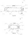
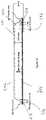
- This forcemay arrive at an oblique angle to the surface of shell 102 at the point of impact in a manner which imparts a rotational force to shell 102 as shown in figure 7b or be directly perpendicular to surface of shell 102 at the point of impact as shown in figure 7c .
- at least some compressive forceis applied to cushion 200, which initially compresses pad 206 whilst this is in a saturated state. In this state, pad 206 is somewhat resistant to compression. As pad 206 is compressed, liquid 204 is released from pores 212 into gap 214 where it can flow generally freely.
- liquid 204As liquid 204 is released, it forms liquid layer 216 which permits the upper and lower portions of bladder 202 to slip easily relative to each other. In this fashion, liquid 204 is transformed from a trapped, non free-flowing state into a free-flowing state within bladder 202 whereby bladder 202 can easily manage shear forces.
- An oblique (i.e. "angled") or rotational force acting on shell 102generates shear forces on cushion 200.
- the resulting rotational acceleration imparted to the user's head 10 in a conventional helmetcan increase the risk of subdural haematomas or concussions.
- cushion 200attenuates these rotatational forces by uncoupling the movement of shell 102 from head 10, which in turn permits shell 102 to rotate relative to the user's head 10.
- a rotational force on shell 102generates shearing force acting on cushion 200.
- Liquid layer 216 generated within cushion 200 following an impactacts as a slip plane which allows opposing upper and lower portions of bladder 202 to be freely displaced relative to each other, effectively allowing cushion 200 to "roll", thereby allowing a degree of rotational freedom of shell 102 relative to the user's head. It will be seen that the degree of "roll” is based in part on the thickness of cushion 200.
- Cushion 200also serves to attenuate linear forces directed radially inwardly towards the center of the user's head 10 by compression of pad 206 and flexibility and distortion of bladder 202 when compressed.
- pad 206After the initial force of the impact is removed, the resilience of pad 206 causes it to expand back to its pre-impact thickness, which in turn re-absorbs liquid 204 into pad 206, as shown in figure 7a .
- Cushion 200 and pad 206may comprise a range of configurations, as required for different applications.
- cushions 200 and pad 206may be oval, or as shown in figure 5 , pad 206 may be disc-shaped.
- cushions 200 and pad 206can assume different configuration.
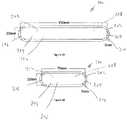
- cushion 200can range from about 50mm to about 150mm in length and the about 20mm to about 50mm in width.
- the thickness of cushions 200can based in part on the desired degree of offset.
- the thickness of cushions 200range from about 3 to 5 mm, and more preferably about 4 mm.
- pad 206is about 3 mm to 4 mm, and more preferably about 3 mm.
- the wall thickness of the bladder 202is about 0.5 to 1 mm.
- Flange 203can have any dimension suitable for sealing bladder 202 and may be about 3 mm in width.
- Suitable dimensionsinclude, for cushion 200 is round may be provided having a diameter of about 65 mm and a height of about 4 mm, a bladder thickness of about 0.5 mm, a flange length of about 3 mm, a foam diameter of about 59 mm and foam thickness of about 4 mm, and a gap distance of about 3 mm.
- bladder 202is filled with about 3.0 ml of vegetable oil.
- cushions 200is round with a diameter of about 35 mm, a height of about 5 mm, a bladder thickness of about 0.5 mm, a flange length of about 3 mm, a foam diameter of about 29 mm, a foam thickness of about 4 mm, a gap 214 of about 3 mm, and about 1.2 ml of fluid 204.
- cushion 200should be suitable to permit sufficient lateral movement between upper and lower surfaces of bladder 202 to attenuate shear forces to a degree that is effective for the body armour. It will be seen that different uses and applications will require different configurations and dimensions, especially when taking into account additional requirements such as weight limitations and the overall thickness of the helmet or other armour. The configuration of cushion may thus be optimized for any given application.
- cushion 200is reduced weight as compared to a similarly dimensioned bladder filled with liquid alone.
- the present exampleis estimated to be about half the weight of a bladder having similar dimensions that houses only liquid.
- Cushion 200may be covered with material 300 to enhance user comfort, protect bladder 202, improve attachment to other helmet components, etc. As shown in figures 9 and 10 , a combination of different fabric materials 302 and 304 may cover cushion 200 and may be fused thereto by high frequency welding or other means.
- Material 300can be a natural or synthetic material, such as for example, Nylon, polyester, or spandex.
- Cushions 200can be configured for use in a variety of body armor devices, including helmets for many activities. The numbers, placement and configurations of cushions 200 will reflect the desired properties of the body armor device. For example, figures 1 , 11 and 12 show six cushions 200 in a snow sports helmet 100 distributed around the user's head. Cushions 200 can be fixed or removably secured to liner 104 to contact the user's head either directly or with a thin layer of material covering cushions 200. In this configuration, the slip plane created by the cushion 200 upon impact with an oblique force is located between the user's head and energy absorbing liner 104. The thickness (and other properties) of the cushions 200 can be configured to function seamlessly with any comfort liners 106 that may be secured to the interior of the helmet 100.
- FIGS 13 and 14show the integration of five cushions 200 in a cycling helmet 100.
- Helmet 100comprises, from the outside in, an outer shell 102, a crushable rigid foam liner 104, an adjustable skull grip 108 and an array of cushions 200.
- Cushions 200are located in an array at the front, rear, sides and top of the helmet.
- Cushions 200are attached to the inside surface of skull grip 108, for example by gluing or welding.
- Cushions 200contact the user's head either directly or with a thin layer of material interposed (not shown).
- an oblique forceimpacts helmet 100, cushion 200 generates a slip plane between the user's head and skull grip 108.
- an oblique forceis applied to shell 102, which is directly transmitted to liner 104 and skull grip 108.
- this oblique (shear/rotational) forcebecomes attenuated by cushions 200 thereby lessening these oblique forces against the user's head.
- helmet 100comprises an array of cushions 200 located around the periphery of the skull, such as distributed at the front, rear and sides of the helmet, as well as the top.
- cushions 200serve to maintain a spacing between the user's head and the next-in-line helmet component, such as a skull grip or rigid foam liner.
- Table 1shows the measurements of linear and rotational acceleration at four locations (front, side, rear, and crown) around a conventional helmet and a helmet according to the present invention including four cushions 200 installed on a skull grip 108 with a 6 mm cushion at crown and 4 mm cushions at each side and the front (all with vinyl nitrile foam).
- a helmet according to the present inventionprovides an average decrease in linear acceleration of about 13.9% and an average decrease of rotational acceleration of about 14.7%, as compared to the conventional helmet.
- Table 1Linear Acceleration (g) Rotational Acceleration (radians/s2) regular Fluid regular Fluid Technology type baseline P4 Technology type baseline P4 Helmet # 1 1 Helmet # 1 1 mass (g) 1387 g 1452 g mass (g) 1387 g 1452 g Front 136.5 124.8 Front 9919.3 8722.6 Side 95.4 88.6 Side 7498.2 7389.8 Rear 147.8 115.3 Rear 4031.9 3066.8 Crown 114.7 97.1 Crown 8664.1 6495.1 Average 123.6 106.45 Average 7528.375 6418.575 % Difference from RPHA baseline helmet - -13.875 % Difference from RPHA baseline helmet - -14.742
- Table 2shows the measurements of linear and rotational acceleration at four locations (front, side, rear, and crown) around a conventional helmet and a helmet according to the present invention including two cushions 200 installed on a skull grip with a 6 mm cushion at the crown and a 4 mm cushion at the front (all with vinyl nitrile foam).
- a helmet according to the present inventionprovides an average decrease in linear acceleration of about 12.3% and an average decrease of rotational acceleration of about 9.4%, as compared to the conventional helmet.
- Table 2Linear Acceleration (g) Rotational Acceleration (radians/s2) regular Fluid regular fluid Technology type baseline P3 Technology type baseline P3 Helmet # 1 1 Helmet # 1 1 mass (g) 1387 g 1418 g mass (g) 1387 g 1418 g Front 136.5 118.6 Front 9919.3 8362.4 Side 95.4 79.7 Side 7498.2 6815.9 Rear 147.8 136.9 Rear 4031.9 3724 Crown 114.7 98.3 Crown 8664.1 8371.2 Average 123.6 108.375 Average 7528.375 6818.375 % Difference from RPHA baseline helmet - -12.318 % Difference from RPHA baseline helmet - -9.431
- helmet 100may also include other components for decreasing and/or redirecting rotational or shear forces such as force redirection cushions 400 of the type disclosed in applicant's PCT application WO 2017/132758 .
Landscapes
- Helmets And Other Head Coverings (AREA)
Description
- The present disclosure relates to body impact protection equipment such as helmets, and in particular to a helmet having the ability to manage shear and rotational forces when impacted.
- The primary purpose of a helmet is to protect the user's head from injury. A helmet typically includes a hard outer shell and an energy absorbing liner. The outer shell is designed to distribute forces in order to engage a greater volume of the energy absorbing liner. The liner usually comprises a compressible material that absorbs impact energy by distorting and absorbing the impact using the resilient and/or compressible properties of the material or by crushing and absorbing energy by material fracture.
- Head injuries typically result from linear and/or rotational forces acting on the head. Certain types of head injuries such as skull fractures and intracranial bleeds usually arise from linear accelerations. Injuries such as concussions and subdural hematomas are thought to arise from rotational accelerations. Conventional helmets are primarily designed to manage linear forces and are less effective at managing shear or rotational forces. This has resulted in successful mitigation of injuries associated with linear forces such as skull fractures and intracranial hemorrhaging, but less success in reducing injuries such as concussions that are more closely associated with rotational or shear forces.
- Various solutions intended to manage rotational motions have been developed and proposed, such as providing a slippery surface material to cover the helmet thereby decreasing friction between the surface of the helmet and the impacting object. Other solutions include the use of low friction layer between the helmet shell and an inner head-gripping member, or a layer that consists of a gel, liquid or other soft material between the shell and liner, or other layers of materials, to allow the outer shell to rotate and/or slide horizontally independent of the liner or the user's head.
- Similar principles apply to body armor used for protecting other areas, but particularly serious injuries are often to the head.
US 2012/186003 A1 discloses an energy-absorbing device comprising a first layer; a second layer; the second layer being opposedly disposed to the first layer and in slideable communication with the first layer; the first layer and the second layer enclosing a space therebetween; the space being filled with a shear thickening fluid.US 3 849 801 A discloses protective gear such as head gear including a one-piece molded protective outer shell such as a helmet shell with a hydraulic energy absorbing liner which has an array of interconnected compressible vinyl walled compartments arranged around a central crown compartment with shock and energy dissipating fluid in the interconnected compartments. Each of the compartments is provided with a porous insert or surge mitigator of open-celled foam.US 5 599 290 A discloses a garment having an arrangement for shunting a substantial portion of the impact energy from a vulnerable region to a soft tissue region, where such energy may be safely absorbed and/or dissipated. In a further embodiment, there is utilized a dilatent material that is relatively stiff near the time of impact and relatively fluid at other times- A drawback of at least some conventional solutions that permit independent rotation of the helmet shell is added weight which increases fatigue and can also increase the moment of inertia of the helmet, as well as other drawbacks.
- We disclose a body armor system such as a helmet that includes an energy absorbing layer or a shell, and a cushion for installed within the inside (body facing) side thereof. The cushion consists of a bladder comprising a flexible, liquid-filled membrane which houses a compressible and resilient pad.
- In one embodiment, the pad has pores or other interstices that are open to the exterior of the pad (such as open cell foam) to permit the liquid to be secreted and absorbed by the pad when the pad is compressed and decompressed. Before an impact occurs, the pad is in an expanded position whereby the liquid is fully or substantially absorbed within the pad and the pad is at least partially saturated. On impact, the pad is compressed. This in turn squeezes the liquid from the pad, which then forms a liquid layer within the bladder around the pad, which in turn increases the ability of the pad to manage shear forces. When the pressure is then released from the cushion, the pad returns to its expanded, saturated status wherein it is more resistant to shear. This combination of properties permits the helmet to remain comfortably seated on the user's head during normal use, without undue rotation, but to have increased rotational freedom when the helmet is impacted.
- The presence of free-flowing liquid within the bladder when compressed permits opposing surfaces of the bladder to be displaced in a shearing motion relative to each other, effectively permitting the bladder to "roll", when the cushion is subjected to a shear force. This allows the cushion to decouple at least a portion of the shear forces that arise between the shell and the user's body when the equipment is subjected to an obliquely-directed impact.
- The cushion provides a combination of some or all of the following:
- a) The liquid-filled bladder is less compressive than a conventional foam pad and thus provides improved impact protection to attenuate linear (radial) forces.
- b) Prior to receiving an impact, the liquid within the cushion is absorbed and/or displaced within the bladder, thereby minimizing rotational movement of the cushion. This improves user comfort and stabilizes the helmet during use.
- c) Upon receiving an oblique impact, the liquid within the bladder permits opposing sides of the bladder to slip relative to each other, thereby allowing the shell of the helmet to move laterally relative to the user's head. This permits the helmet to rotate upon impact to attenuate rotational/shear forces imparted to the head. This result occurs because the liquid layer within the cushion creates a slip plane which shifts freely under a shear-type force.
- In one aspect, we disclose a cushion for installation between opposing layers, comprising:
- a sealed bladder comprising a flexible membrane;
- a pad housed within the bladder, said pad comprising a compressible member having interstices open to the exterior of the pad; and
- a liquid within the interior of the bladder;
- wherein said pad absorbs at least some of said liquid when uncompressed and expels said liquid when compressed; and
- wherein the volume of liquid within the bladder is sufficient to allow opposing surfaces of the bladder to be displaced in a shearing motion relative to each other when the cushion is compressed and subjected to shear forces, to decouple shear forces between said opposing layers.
- According to an aspect, the bladder comprises an elastomeric material such as thermoplastic polyurethane (TPU) or polyvinyl chloride (PVC). The liquid may comprise an oil or a gel. The pad may comprise an open cell foam such as a vinyl nitrile foam or may comprise a closed cell foam.
- We further disclose a helmet comprising an outer shell and/or an energy absorbing layer such as rigid foam and an array of cushions as described herein mounted against the user's head.
- We further disclose a method of attenuating the impact energy from an incoming force to decrease trauma to a body part, the method comprising using a body protection system such as a helmet that includes and outer shell and/or energy absorbing layer and an array of cushions as described herein mounted against the user. Upon receiving an oblique impact, shear forces are generated between the shell or energy absorbing layer and the user which are managed and attenuated by the cushions.
- In one embodiment, we disclose a body armor system comprising an outer impact-receiving layer and an at least one cushion interior to said layer for managing shear forces impacting the outer impact-receiving layer, said cushion comprising a sealed flexible bladder filled with a liquid and containing a compressible and resilient solid element therein, wherein the solid element is configured to permit the liquid to flow at least partially around the element.
- In one embodiment, we disclose a cushion for managing shear forces in a body armor, the cushion comprising a sealed flexible bladder filled with a liquid and containing a compressible and resilient solid element therein, wherein the solid element is detached from at least an upper or lower surface of the bladder to permit the liquid to flow at least partially around the element.
- Unless otherwise specified, directional references herein refer to the helmet and head in an upright position. Furthermore, the detailed description herein is only intended to provide examples and representative embodiments of the invention and is not intended to limit the scope of the invention, which is defined by the appended claims.
Figure 1 is a side elevational view of a helmet, in partial transparency to show the internal structure, including energy-absorbing cushions attached to the helmet shell;Figure 2 is a perspective view of a cushion according to an embodiment of the invention;Figure 3 is a top plan view of the cushion offigure 2 ;Figure 4 a sectional view along line 4-4 offigure 3 ;Figure 5 is a perspective view of an internal pad component of the cushion;Figure 6 is a top plan view of the pad according to a further embodiment;Figures 7a, 7b, and 7c show cross sectional views along line 4-4 offigure 3 , showing the cushion subjected to various impacts;Figures 8a to 8h show top plan views of various embodiments of the cushions;Figure 9 is an exploded view of a pad, according to another embodiment in which the pad is wrapped with a material;Figure 10 is a sectional view of the pad offigure 9 ;Figure 11 is a perspective view of a snow sports helmet which is transparent to show internal structure;Figure 12 is a bottom plan view of the snowsports helmet;Figure 13 is a perspective view of a cycling helmet, in which the outer shell is transparent; andFigure 14 is a bottom plan view of the cycling helmet.- Shown in
figure 1 is ahelmet 100 for protecting a user'shead 10.Helmet 100 may be configured for essentially any activity in which a wearer may be subject to impact, including contact sports such as football and hockey, bicycling, motorcycling and other motor sports, climbing, equestrian, snow sports and work helmets. Helmet 100 includes anouter shell 102 which is normally (but not necessarily) relatively rigid and may comprise polycarbonate, polyethylene or other suitable material. The shell material and its thickness and other parameters will depend on the functional requirements of the intended use. For example, the shell of a snow sports or downhill cycling helmet may comprise a relatively thick and rigid fiberglass or carbon fiber layer, while a road cycling helmet shell may comprise a thin, somewhat flexible material.Outer shell 102 may be intended for disposal after a single hard impact or for withstanding repeated impacts.Shell 102 has an inner layer orliner 104 for absorbing energy.Liner 104 may comprise a compressible material such as vinyl nitrile, polystyrene (EPS) or polypropylene (EPP) foam.Liner 104 may substantially line the entire interior surface ofshell 102 or alternatively may have windows or other gaps in the structure.- An array of
cushions 200 is installed insideshell 102.Cushions 102 may be attached directly to shell 102 whereby they are located betweenshell 102 andliner 104 or alternatively, cushions 200 may be attached to the inside surface ofliner 104 to more directly contact the user'shead 10. A further innermost liner such as a thin fabric or mesh material may be provided for user comfort. - As shown in
figures 2 to 4 ,cushion 200 comprises abladder 202 housing a liquid 204 and acompressible pad 206.Bladder 202 forms a sealed envelope that comprises a sheet of highly flexible material. Examples include thermoplastic elastomeric material, such as thermoplastic polyurethane (TPU) or polyvinyl chloride (PVC). The TPU may have a shore hardness of about 85A.Bladder 202 should be sufficiently robust to minimize the risk of puncture or other leakage over a wide range of conditions such as temperature fluctuations, compression during normal use and upon impact, exposure to various substances, etc. In order to sealbladder 202, its edges are welded or otherwise sealed in a robust fashion, as is known in the art. For example, the edges ofbladder 202 can be sealed using an adhesive to form aflange 203. - Liquid 204 can be oil, a gel or an aqueous liquid that remains in the liquid phase over a wide range of ambient temperature conditions. Suitable examples include oils, preferably a low viscosity oil such as vegetable or mineral oil. A suitable mineral oil is crystal plus oil, which is is an odorless, tasteless, crystal clear, food-grade white mineral oil.
- Referring to
Figure 5 ,pad 206 is a solid element and comprises a generally flat, disk or puck-like configuration having opposing upper andlower surfaces pad 206 may comprise other configurations. - According to one example,
pad 206 is fabricated from a resilient, compressible material, such as open cell foam which may have a shore OO hardness of about 20. The open structure ofpad 206 is provided bypores 212 or other interstices for absorbing liquid 204, which and allowpad 206 to sequentially absorb and squeeze out liquid 204 when expanded and compressed, respectively.Pad 206 is highly compressible whereby it can be easily compressed to a small percentage of its original thickness. Suitable open cell foam materials have relatively low density, firm support, good durability, good shock absorption and vibration dampening, and resistance against degradation by exposure to the selectedliquid 204. Examples include open cell vinyl nitrile or polyurethane foam. Other suitable foams include K329 or similar low density foams. - In another example,
pad 206 comprises a compressible lattice structure, for example a structure formed from beads or other units fused together, in which the beads can individually compress or distort. This structure has interstices between the beads that alternately retain and expel liquid as the structure is decompressed and compressed. For example, as shown infigure 6 ,pad 206 may comprise a lattice-like structure that is compressible to absorb or expel liquid from the interstices/pores 212 between solid members. A structure of this type can absorb a large quantity of liquid whilst being lightweight and also capable of rapid compression and expansion. The thickness, shape and, type of material ofpad 206 can be adjusted based on desired levels of liquid absorption characteristics and impact attenuation characteristics. - In an alternative example, pad 206 may comprise a closed cell foam such as ethylene-vinyl acetate (EVA) foam, or a composite of open and closed cell components.
- As shown in
figure 7a ,pad 206 substantially fills the interior ofbladder 202 when uncompressed.Pad 206 may be fully detached frombladder 202 whereby it is free-floating withinbladder 202 or alternatively at least one of an upper orlower surface pad 206 may be attached tobladder 202. Agap 214 exists between one or both ofsides 208/210 ofpad 206 and the corresponding inside surface ofbladder 202.Gap 214 permitssufficient liquid 204 to be present betweenpad 206 andbladder 202 to permit slippage to easily occur between these components when subjected to shear forces; it will be appreciated that thisgap 214 may be very small to still permit such movement.Gap 214 can range from slightly above zero to up to about 1 mm, or between about 1 mm and about 3 mm. Pad 206 is normally uncompressed or only lightly compressed whenhelmet 100 is worn during normal use, prior to any impact thereon. The term "uncompressed" as used herein includes, unless otherwise stated, a small amount of compression that might occur during such normal wearing of the helmet. In this state, at least a portion and preferably most of liquid is absorbed withinpad 206.Pad 206 may be substantially saturated withliquid 204 whereby an impact onhelmet 100 quickly releases a substantial portion of liquid 204 frompad 206, whereby liquid 204 is then free-flowing withinbladder 202.- As used herein, the terms "absorption" and similar terms refer to the property of
pad 206 to draw in and retain liquid 204 withinpores 212 in a reversible fashion in a physical process. - With reference to
figures 7b and 7c , upon impact, force (F) is transmitted fromshell 102 towards the user'shead 10. This force may arrive at an oblique angle to the surface ofshell 102 at the point of impact in a manner which imparts a rotational force to shell 102 as shown infigure 7b or be directly perpendicular to surface ofshell 102 at the point of impact as shown infigure 7c . In either case, at least some compressive force is applied to cushion 200, which initially compressespad 206 whilst this is in a saturated state. In this state,pad 206 is somewhat resistant to compression. Aspad 206 is compressed, liquid 204 is released frompores 212 intogap 214 where it can flow generally freely. Asliquid 204 is released, it formsliquid layer 216 which permits the upper and lower portions ofbladder 202 to slip easily relative to each other. In this fashion, liquid 204 is transformed from a trapped, non free-flowing state into a free-flowing state withinbladder 202 wherebybladder 202 can easily manage shear forces. - An oblique (i.e. "angled") or rotational force acting on
shell 102 generates shear forces oncushion 200. Depending on the direction of the impact, the resulting rotational acceleration imparted to the user'shead 10 in a conventional helmet can increase the risk of subdural haematomas or concussions. In the case ofhelmet 100,cushion 200 attenuates these rotatational forces by uncoupling the movement ofshell 102 fromhead 10, which in turn permits shell 102 to rotate relative to the user'shead 10. A rotational force onshell 102 generates shearing force acting oncushion 200.Liquid layer 216 generated withincushion 200 following an impact acts as a slip plane which allows opposing upper and lower portions ofbladder 202 to be freely displaced relative to each other, effectively allowingcushion 200 to "roll", thereby allowing a degree of rotational freedom ofshell 102 relative to the user's head. It will be seen that the degree of "roll" is based in part on the thickness ofcushion 200. Cushion 200 also serves to attenuate linear forces directed radially inwardly towards the center of the user'shead 10 by compression ofpad 206 and flexibility and distortion ofbladder 202 when compressed.- After the initial force of the impact is removed, the resilience of
pad 206 causes it to expand back to its pre-impact thickness, which in turn re-absorbs liquid 204 intopad 206, as shown infigure 7a . Cushion 200 andpad 206 may comprise a range of configurations, as required for different applications. By way of example, as shown infigures 1 through 4 , cushions 200 andpad 206 may be oval, or as shown infigure 5 ,pad 206 may be disc-shaped.- As shown in
figures 8a to 8h , cushions 200 and pad 206 can assume different configuration. For example, cushion 200 can range from about 50mm to about 150mm in length and the about 20mm to about 50mm in width. The thickness ofcushions 200 can based in part on the desired degree of offset. Typically, the thickness ofcushions 200 range from about 3 to 5 mm, and more preferably about 4 mm. Typically,pad 206 is about 3 mm to 4 mm, and more preferably about 3 mm. Typically, the wall thickness of thebladder 202 is about 0.5 to 1 mm.Flange 203 can have any dimension suitable for sealingbladder 202 and may be about 3 mm in width. - Suitable dimensions include, for
cushion 200 is round may be provided having a diameter of about 65 mm and a height of about 4 mm, a bladder thickness of about 0.5 mm, a flange length of about 3 mm, a foam diameter of about 59 mm and foam thickness of about 4 mm, and a gap distance of about 3 mm. In this example,bladder 202 is filled with about 3.0 ml of vegetable oil. In other examples, cushions 200 is round with a diameter of about 35 mm, a height of about 5 mm, a bladder thickness of about 0.5 mm, a flange length of about 3 mm, a foam diameter of about 29 mm, a foam thickness of about 4 mm, agap 214 of about 3 mm, and about 1.2 ml offluid 204. - Dimensions of
cushion 200 should be suitable to permit sufficient lateral movement between upper and lower surfaces ofbladder 202 to attenuate shear forces to a degree that is effective for the body armour. It will be seen that different uses and applications will require different configurations and dimensions, especially when taking into account additional requirements such as weight limitations and the overall thickness of the helmet or other armour. The configuration of cushion may thus be optimized for any given application. - An advantage of
cushion 200 is reduced weight as compared to a similarly dimensioned bladder filled with liquid alone. The present example is estimated to be about half the weight of a bladder having similar dimensions that houses only liquid. Cushion 200 may be covered withmaterial 300 to enhance user comfort, protectbladder 202, improve attachment to other helmet components, etc. As shown infigures 9 and10 , a combination ofdifferent fabric materials cushion 200 and may be fused thereto by high frequency welding or other means.Material 300 can be a natural or synthetic material, such as for example, Nylon, polyester, or spandex.Cushions 200 can be configured for use in a variety of body armor devices, including helmets for many activities. The numbers, placement and configurations ofcushions 200 will reflect the desired properties of the body armor device. For example,figures 1 ,11 and12 show sixcushions 200 in asnow sports helmet 100 distributed around the user's head.Cushions 200 can be fixed or removably secured toliner 104 to contact the user's head either directly or with a thin layer of material covering cushions 200. In this configuration, the slip plane created by thecushion 200 upon impact with an oblique force is located between the user's head andenergy absorbing liner 104. The thickness (and other properties) of thecushions 200 can be configured to function seamlessly with anycomfort liners 106 that may be secured to the interior of thehelmet 100.Figures 13 and14 show the integration of fivecushions 200 in acycling helmet 100.Helmet 100 comprises, from the outside in, anouter shell 102, a crushablerigid foam liner 104, anadjustable skull grip 108 and an array ofcushions 200.Cushions 200 are located in an array at the front, rear, sides and top of the helmet.Cushions 200 are attached to the inside surface ofskull grip 108, for example by gluing or welding.Cushions 200 contact the user's head either directly or with a thin layer of material interposed (not shown). When an obliqueforce impacts helmet 100,cushion 200 generates a slip plane between the user's head andskull grip 108. As such, an oblique force is applied to shell 102, which is directly transmitted toliner 104 andskull grip 108. However, this oblique (shear/rotational) force becomes attenuated bycushions 200 thereby lessening these oblique forces against the user's head.- As shown in
Figures 1 and11-14 ,helmet 100 comprises an array ofcushions 200 located around the periphery of the skull, such as distributed at the front, rear and sides of the helmet, as well as the top. Alternative configurations may be provided in which cushions 200 serve to maintain a spacing between the user's head and the next-in-line helmet component, such as a skull grip or rigid foam liner. - Table 1 shows the measurements of linear and rotational acceleration at four locations (front, side, rear, and crown) around a conventional helmet and a helmet according to the present invention including four
cushions 200 installed on askull grip 108 with a 6 mm cushion at crown and 4 mm cushions at each side and the front (all with vinyl nitrile foam). In table 1, a helmet according to the present invention provides an average decrease in linear acceleration of about 13.9% and an average decrease of rotational acceleration of about 14.7%, as compared to the conventional helmet.Table 1: Linear Acceleration (g) Rotational Acceleration (radians/s2) regular Fluid regular Fluid Technology type baseline P4 Technology type baseline P4 Helmet # 1 1 Helmet # 1 1 mass (g) 1387 g 1452 g mass (g) 1387 g 1452 g Front 136.5 124.8 Front 9919.3 8722.6 Side 95.4 88.6 Side 7498.2 7389.8 Rear 147.8 115.3 Rear 4031.9 3066.8 Crown 114.7 97.1 Crown 8664.1 6495.1 Average 123.6 106.45 Average 7528.375 6418.575 % Difference from RPHA baseline helmet - -13.875 % Difference from RPHA baseline helmet - -14.742 - Table 2 shows the measurements of linear and rotational acceleration at four locations (front, side, rear, and crown) around a conventional helmet and a helmet according to the present invention including two
cushions 200 installed on a skull grip with a 6 mm cushion at the crown and a 4 mm cushion at the front (all with vinyl nitrile foam). In table 2, a helmet according to the present invention provides an average decrease in linear acceleration of about 12.3% and an average decrease of rotational acceleration of about 9.4%, as compared to the conventional helmet.Table 2: Linear Acceleration (g) Rotational Acceleration (radians/s2) regular Fluid regular fluid Technology type baseline P3 Technology type baseline P3 Helmet # 1 1 Helmet # 1 1 mass (g) 1387 g 1418 g mass (g) 1387 g 1418 g Front 136.5 118.6 Front 9919.3 8362.4 Side 95.4 79.7 Side 7498.2 6815.9 Rear 147.8 136.9 Rear 4031.9 3724 Crown 114.7 98.3 Crown 8664.1 8371.2 Average 123.6 108.375 Average 7528.375 6818.375 % Difference from RPHA baseline helmet - -12.318 % Difference from RPHA baseline helmet - -9.431 - The experimental results of tables 1 and 2 were obtained under testing conditions performed in accordance with CE-1077/1078.
- In other embodiments,
helmet 100 may also include other components for decreasing and/or redirecting rotational or shear forces such as force redirection cushions 400 of the type disclosed in applicant'sPCT application WO 2017/132758 . - The embodiments described herein are intended merely to provide examples of the invention. Various alterations, modifications and variations to these embodiments may be made without departing from the intended scope of the invention as defined by the amended claims.
Claims (13)
- A cushion (200) for managing shear forces in a body armor, the cushion (200) comprising a sealed flexible bladder (202) filled with a liquid (204) and containing a compressible and resilient solid element (206) therein,
characterised in that the solid element (206) is detached from at least an upper or lower surface of the bladder (202) to permit the liquid to flow at least partially around the element (206). - The cushion (200) of claim 1 wherein the liquid (204) is oil.
- The cushion (200) of claim 1 or 2 wherein the solid element (206) has a density that is less than the liquid (204).
- The cushion of any one of claims 1 to 3 wherein:the solid element (206) comprises open cell foam or an open lattice whereby the liquid (204) is expelled and absorbed from the element (206) when compressed and decompressed; orwherein the solid element (206) comprises a closed cell material.
- The cushion (200) of any one of claims 1 to 4, wherein the solid element (206) substantially fills the interior of the bladder (202) when uncompressed.
- A body armor system comprising an outer impact-receiving layer (102) and at least one cushion (200) according to any one of claims 1 to 5 interior to said layer for managing shear forces impacting the outer impact-receiving layer (102).
- The system of claim 6 further comprising an energy absorbing layer (104) between the outer impact-receiving layer (102) and the at least one cushion (200), wherein the energy absorbing layer (104) optionally comprises rigid foam.
- The system of claim 6 or 7 wherein the outer impact-receiving layer (102) comprises a rigid shell.
- The system of any one of claims 6 to 8, comprising a helmet (100).
- The system of claim 9 wherein the helmet (100) further comprises an inner skull grip (108) and the at least one cushion (200) is located between the skull grip (108) and the wearer's head.
- The system of claim 9 or 10, comprising an array of cushions (200) according to any one of claims 1 to 5 arranged at the front, sides and rear of the helmet, wherein the array of cushions (200) optionally comprises at least one cushion (200) at the top of the helmet.
- The system of any one of claims 6 to 11 further comprising at least one force redirection cushion configured for redirecting a force impacting the outer impact-receiving layer in a direction away from the direction which causes the highest risk of injury.
- A method of decoupling the body of a user from angular or rotational forces impacting on body armor worn by the user, the method comprising use of the system of any one of claims 6 to 12.
Applications Claiming Priority (2)
| Application Number | Priority Date | Filing Date | Title |
|---|---|---|---|
| US201662433551P | 2016-12-13 | 2016-12-13 | |
| PCT/CA2017/051507WO2018107286A1 (en) | 2016-12-13 | 2017-12-12 | Helmet with shear force management |
Publications (3)
| Publication Number | Publication Date |
|---|---|
| EP3554299A1 EP3554299A1 (en) | 2019-10-23 |
| EP3554299A4 EP3554299A4 (en) | 2020-07-15 |
| EP3554299B1true EP3554299B1 (en) | 2022-06-29 |
Family
ID=62557846
Family Applications (1)
| Application Number | Title | Priority Date | Filing Date |
|---|---|---|---|
| EP17881374.7AActiveEP3554299B1 (en) | 2016-12-13 | 2017-12-12 | Cushion with shear force management |
Country Status (4)
| Country | Link |
|---|---|
| US (1) | US11324272B2 (en) |
| EP (1) | EP3554299B1 (en) |
| CN (1) | CN110545686B (en) |
| WO (1) | WO2018107286A1 (en) |
Families Citing this family (14)
| Publication number | Priority date | Publication date | Assignee | Title |
|---|---|---|---|---|
| US9925440B2 (en) | 2014-05-13 | 2018-03-27 | Bauer Hockey, Llc | Sporting goods including microlattice structures |
| US11517062B2 (en)* | 2018-05-15 | 2022-12-06 | Brian Timlick | Helmet with unique impact absorption and redirection features |
| TWI680727B (en)* | 2018-06-12 | 2020-01-01 | 豐閣行銷設計有限公司 | Hard hat capable of absorbing multi-directional impact |
| US11766083B2 (en) | 2019-03-25 | 2023-09-26 | Tianqi Technology Co (Ningbo) Ltd | Helmet |
| US11684104B2 (en) | 2019-05-21 | 2023-06-27 | Bauer Hockey Llc | Helmets comprising additively-manufactured components |
| CA3177316A1 (en) | 2020-05-12 | 2021-11-18 | Joseph R. WORPLE | Hard hat with impact protection material |
| USD1004850S1 (en) | 2021-03-17 | 2023-11-14 | Studson, Inc. | Protective helmet |
| USD995924S1 (en) | 2021-03-17 | 2023-08-15 | Studson, Inc. | Protective helmet |
| USD995925S1 (en) | 2020-09-23 | 2023-08-15 | Studson, Inc. | Protective helmet |
| WO2022066857A1 (en)* | 2020-09-24 | 2022-03-31 | Kuji Sports Co Ltd | Helmet |
| US20230011210A1 (en)* | 2021-07-07 | 2023-01-12 | Peach Protex LLC | Abrasion Preventing Pad |
| IT202100021623A1 (en)* | 2021-08-10 | 2023-02-10 | Univ Bologna Alma Mater Studiorum | IMPACT-ABSORBING DEVICE ON HELMETS AND RELATED HELMET |
| WO2023053038A1 (en)* | 2021-09-29 | 2023-04-06 | Abram Daniel | A novel protective helmet |
| WO2023060209A1 (en)* | 2021-10-06 | 2023-04-13 | 100% Speedlab, Llc | Impact protection systems |
Family Cites Families (37)
| Publication number | Priority date | Publication date | Assignee | Title |
|---|---|---|---|---|
| US3494607A (en)* | 1967-10-02 | 1970-02-10 | Ford Motor Co | Impact energy absorbing fluid cushion structure |
| US3849801A (en) | 1972-12-20 | 1974-11-26 | Medalist Ind Inc | Protective gear with hydraulic liner |
| IT1177490B (en) | 1984-12-21 | 1987-08-26 | Sonda Srl | BUMPER PROTECTIVE PADDING ELEMENT |
| US5121962A (en)* | 1989-10-13 | 1992-06-16 | Spenco Medical Corporation | Cushion for absorbing shock damping vibration and distributing pressure |
| US5599290A (en)* | 1992-11-20 | 1997-02-04 | Beth Israel Hospital | Bone fracture prevention garment and method |
| US5741568A (en)* | 1995-08-18 | 1998-04-21 | Robert C. Bogert | Shock absorbing cushion |
| US5815846A (en)* | 1996-11-27 | 1998-10-06 | Tecno-Fluidos, S.L. | Resistant helmet assembly |
| WO2000013881A1 (en)* | 1998-09-03 | 2000-03-16 | Mike Dennis | Body-contact cushioning interface structure |
| US6701529B1 (en)* | 1999-02-05 | 2004-03-09 | Extrude Hone Corporation | Smart padding system utilizing an energy absorbent medium and articles made therefrom |
| US6234988B1 (en)* | 1999-12-15 | 2001-05-22 | I-Tek, Inc. | Heel locking, energy absorbing, support and cushioning device |
| US6591456B2 (en)* | 2001-07-09 | 2003-07-15 | Bic Corporation | Cushioning device |
| EP1489934B1 (en)* | 2001-09-13 | 2010-05-26 | Daniel James Plant | Flexible energy absorbing material and methods of manufacture thereof |
| GB0130834D0 (en)* | 2001-12-22 | 2002-02-06 | Design Blue Ltd | Energy absorbing material |
| US8091692B2 (en)* | 2003-03-03 | 2012-01-10 | Massachusetts Institute Of Technology | Fluid-filled cellular solids for controlled |
| US20060234572A1 (en)* | 2004-10-27 | 2006-10-19 | Ud Technology Corporation | Shear thickening fluid containment in polymer composites |
| US20080263772A1 (en)* | 2007-04-30 | 2008-10-30 | Li-Ya Chiu | Adjustable pad according user's weight |
| WO2009029806A2 (en)* | 2007-08-29 | 2009-03-05 | Brock Usa, Llc | Improved lightweight fluid |
| JP4172720B1 (en)* | 2007-11-14 | 2008-10-29 | 株式会社ブイオーシーダイレクト | Riding and working helmets |
| US8252412B2 (en)* | 2009-06-16 | 2012-08-28 | Ppg Industries Ohio, Inc | Angle switchable crystalline colloidal array films |
| US8524338B2 (en) | 2009-11-16 | 2013-09-03 | 9Lives Llc | Impact energy attenuation system |
| JP5761546B2 (en)* | 2010-03-29 | 2015-08-12 | 株式会社ジェイテクト | Motor control device |
| US8679047B2 (en)* | 2010-05-21 | 2014-03-25 | Presidium Athletics LLC | Impact resistant, torsion-reducing protective athletic gear using shear thickening fluid |
| WO2012103088A2 (en)* | 2011-01-24 | 2012-08-02 | University Of Florida Research Foundation, Inc. | Energy-absorbing system, methods of manufacturing thereof and articles comprising the same |
| WO2012148582A2 (en)* | 2011-04-29 | 2012-11-01 | Roho, Inc. | Multilayer impact attenuating insert for headgear |
| US9032558B2 (en)* | 2011-05-23 | 2015-05-19 | Lionhead Helmet Intellectual Properties, Lp | Helmet system |
| US9439469B2 (en)* | 2011-09-08 | 2016-09-13 | Emerson Spalding Phipps | Protective helmet |
| CA2864522C (en) | 2012-01-12 | 2015-09-29 | University Of Ottawa | Head protection for reducing angular accelerations |
| US9462842B2 (en)* | 2012-04-04 | 2016-10-11 | University Of Ottawa | Head protection for reducing linear acceleration |
| BR112015016922B1 (en) | 2013-01-18 | 2022-09-13 | Windpact, Inc | APPARATUS FOR IMPACT ABSORPTION |
| US9596894B2 (en)* | 2013-03-14 | 2017-03-21 | Larry E. Carlson | Pad incorporating shear-thickening material |
| US10813401B2 (en)* | 2013-07-31 | 2020-10-27 | Zymplr LC | Headband to reduce concussions and traumatic brain injuries |
| US9839251B2 (en)* | 2013-07-31 | 2017-12-12 | Zymplr LC | Football helmet liner to reduce concussions and traumatic brain injuries |
| US9249274B2 (en)* | 2013-11-01 | 2016-02-02 | New Aegis Corporation | Shock absorption material |
| US8898818B1 (en)* | 2013-11-13 | 2014-12-02 | John E. Whitcomb | Helmet having blunt force trauma protection |
| US9486029B2 (en)* | 2014-03-31 | 2016-11-08 | Raytheon Company | Solid-liquid energy dissipation system, and helmet using the same |
| US10384394B2 (en)* | 2017-03-15 | 2019-08-20 | Carbon, Inc. | Constant force compression lattice |
| US20200221804A1 (en)* | 2019-01-10 | 2020-07-16 | Tate Technology, Llc | Article of headwear including non-newtonian fluid |
- 2017
- 2017-12-12EPEP17881374.7Apatent/EP3554299B1/enactiveActive
- 2017-12-12WOPCT/CA2017/051507patent/WO2018107286A1/ennot_activeCeased
- 2017-12-12CNCN201780086376.0Apatent/CN110545686B/enactiveActive
- 2017-12-12USUS16/468,932patent/US11324272B2/enactiveActive
Also Published As
| Publication number | Publication date |
|---|---|
| EP3554299A4 (en) | 2020-07-15 |
| EP3554299A1 (en) | 2019-10-23 |
| CN110545686A (en) | 2019-12-06 |
| WO2018107286A1 (en) | 2018-06-21 |
| CN110545686B (en) | 2022-05-24 |
| US11324272B2 (en) | 2022-05-10 |
| US20190335838A1 (en) | 2019-11-07 |
Similar Documents
| Publication | Publication Date | Title |
|---|---|---|
| EP3554299B1 (en) | Cushion with shear force management | |
| US20220061447A1 (en) | Impact absorbing apparatus | |
| US8756719B2 (en) | Method and apparatus for an adaptive impact absorbing helmet system | |
| EP0790787B1 (en) | Protective headgear and protective armour and a method of modifying protective headgear and protective armour | |
| US7341776B1 (en) | Protective foam with skin | |
| US7832023B2 (en) | Protective headgear with improved shell construction | |
| AU2017228415B2 (en) | Protective liner for helmets and other articles | |
| US10813401B2 (en) | Headband to reduce concussions and traumatic brain injuries | |
| EP3410881B1 (en) | Helmet | |
| US20020184699A1 (en) | Protective helmet | |
| US20130232668A1 (en) | Helmet with multiple protective zones | |
| CN102892320A (en) | Recoil-resistant and energy-absorbing hard hat liner with positioning features | |
| US11632999B2 (en) | Constant force impact protection device | |
| US20140076767A1 (en) | Energy Absorbent Protective Structure | |
| US20100282554A1 (en) | Multi-chamber impact absorption system to protect individual | |
| EP3363313A1 (en) | Helmet | |
| WO2024240888A1 (en) | Helmet | |
| US20170280812A1 (en) | Multi-chamber impact absorption system to protect individual |
Legal Events
| Date | Code | Title | Description |
|---|---|---|---|
| STAA | Information on the status of an ep patent application or granted ep patent | Free format text:STATUS: THE INTERNATIONAL PUBLICATION HAS BEEN MADE | |
| PUAI | Public reference made under article 153(3) epc to a published international application that has entered the european phase | Free format text:ORIGINAL CODE: 0009012 | |
| STAA | Information on the status of an ep patent application or granted ep patent | Free format text:STATUS: REQUEST FOR EXAMINATION WAS MADE | |
| 17P | Request for examination filed | Effective date:20190708 | |
| AK | Designated contracting states | Kind code of ref document:A1 Designated state(s):AL AT BE BG CH CY CZ DE DK EE ES FI FR GB GR HR HU IE IS IT LI LT LU LV MC MK MT NL NO PL PT RO RS SE SI SK SM TR | |
| AX | Request for extension of the european patent | Extension state:BA ME | |
| RAP1 | Party data changed (applicant data changed or rights of an application transferred) | Owner name:MIPS AB | |
| RIN1 | Information on inventor provided before grant (corrected) | Inventor name:HOSHIZAKI, THOMAS BLAINE | |
| RAP1 | Party data changed (applicant data changed or rights of an application transferred) | Owner name:MIPS AB | |
| DAV | Request for validation of the european patent (deleted) | ||
| DAX | Request for extension of the european patent (deleted) | ||
| A4 | Supplementary search report drawn up and despatched | Effective date:20200617 | |
| RIC1 | Information provided on ipc code assigned before grant | Ipc:A42B 3/12 20060101AFI20200610BHEP Ipc:A42B 3/06 20060101ALI20200610BHEP | |
| GRAP | Despatch of communication of intention to grant a patent | Free format text:ORIGINAL CODE: EPIDOSNIGR1 | |
| STAA | Information on the status of an ep patent application or granted ep patent | Free format text:STATUS: GRANT OF PATENT IS INTENDED | |
| INTG | Intention to grant announced | Effective date:20210823 | |
| GRAJ | Information related to disapproval of communication of intention to grant by the applicant or resumption of examination proceedings by the epo deleted | Free format text:ORIGINAL CODE: EPIDOSDIGR1 | |
| STAA | Information on the status of an ep patent application or granted ep patent | Free format text:STATUS: REQUEST FOR EXAMINATION WAS MADE | |
| INTC | Intention to grant announced (deleted) | ||
| GRAP | Despatch of communication of intention to grant a patent | Free format text:ORIGINAL CODE: EPIDOSNIGR1 | |
| STAA | Information on the status of an ep patent application or granted ep patent | Free format text:STATUS: GRANT OF PATENT IS INTENDED | |
| INTG | Intention to grant announced | Effective date:20220110 | |
| GRAS | Grant fee paid | Free format text:ORIGINAL CODE: EPIDOSNIGR3 | |
| GRAA | (expected) grant | Free format text:ORIGINAL CODE: 0009210 | |
| STAA | Information on the status of an ep patent application or granted ep patent | Free format text:STATUS: THE PATENT HAS BEEN GRANTED | |
| AK | Designated contracting states | Kind code of ref document:B1 Designated state(s):AL AT BE BG CH CY CZ DE DK EE ES FI FR GB GR HR HU IE IS IT LI LT LU LV MC MK MT NL NO PL PT RO RS SE SI SK SM TR | |
| REG | Reference to a national code | Ref country code:CH Ref legal event code:EP | |
| REG | Reference to a national code | Ref country code:AT Ref legal event code:REF Ref document number:1500694 Country of ref document:AT Kind code of ref document:T Effective date:20220715 | |
| REG | Reference to a national code | Ref country code:IE Ref legal event code:FG4D | |
| REG | Reference to a national code | Ref country code:DE Ref legal event code:R096 Ref document number:602017059108 Country of ref document:DE | |
| REG | Reference to a national code | Ref country code:SE Ref legal event code:TRGR | |
| REG | Reference to a national code | Ref country code:LT Ref legal event code:MG9D | |
| PG25 | Lapsed in a contracting state [announced via postgrant information from national office to epo] | Ref country code:NO Free format text:LAPSE BECAUSE OF FAILURE TO SUBMIT A TRANSLATION OF THE DESCRIPTION OR TO PAY THE FEE WITHIN THE PRESCRIBED TIME-LIMIT Effective date:20220929 Ref country code:LT Free format text:LAPSE BECAUSE OF FAILURE TO SUBMIT A TRANSLATION OF THE DESCRIPTION OR TO PAY THE FEE WITHIN THE PRESCRIBED TIME-LIMIT Effective date:20220629 Ref country code:HR Free format text:LAPSE BECAUSE OF FAILURE TO SUBMIT A TRANSLATION OF THE DESCRIPTION OR TO PAY THE FEE WITHIN THE PRESCRIBED TIME-LIMIT Effective date:20220629 Ref country code:GR Free format text:LAPSE BECAUSE OF FAILURE TO SUBMIT A TRANSLATION OF THE DESCRIPTION OR TO PAY THE FEE WITHIN THE PRESCRIBED TIME-LIMIT Effective date:20220930 Ref country code:FI Free format text:LAPSE BECAUSE OF FAILURE TO SUBMIT A TRANSLATION OF THE DESCRIPTION OR TO PAY THE FEE WITHIN THE PRESCRIBED TIME-LIMIT Effective date:20220629 Ref country code:BG Free format text:LAPSE BECAUSE OF FAILURE TO SUBMIT A TRANSLATION OF THE DESCRIPTION OR TO PAY THE FEE WITHIN THE PRESCRIBED TIME-LIMIT Effective date:20220929 | |
| REG | Reference to a national code | Ref country code:NL Ref legal event code:MP Effective date:20220629 | |
| REG | Reference to a national code | Ref country code:AT Ref legal event code:MK05 Ref document number:1500694 Country of ref document:AT Kind code of ref document:T Effective date:20220629 | |
| PG25 | Lapsed in a contracting state [announced via postgrant information from national office to epo] | Ref country code:RS Free format text:LAPSE BECAUSE OF FAILURE TO SUBMIT A TRANSLATION OF THE DESCRIPTION OR TO PAY THE FEE WITHIN THE PRESCRIBED TIME-LIMIT Effective date:20220629 Ref country code:LV Free format text:LAPSE BECAUSE OF FAILURE TO SUBMIT A TRANSLATION OF THE DESCRIPTION OR TO PAY THE FEE WITHIN THE PRESCRIBED TIME-LIMIT Effective date:20220629 | |
| PG25 | Lapsed in a contracting state [announced via postgrant information from national office to epo] | Ref country code:NL Free format text:LAPSE BECAUSE OF FAILURE TO SUBMIT A TRANSLATION OF THE DESCRIPTION OR TO PAY THE FEE WITHIN THE PRESCRIBED TIME-LIMIT Effective date:20220629 | |
| PG25 | Lapsed in a contracting state [announced via postgrant information from national office to epo] | Ref country code:SM Free format text:LAPSE BECAUSE OF FAILURE TO SUBMIT A TRANSLATION OF THE DESCRIPTION OR TO PAY THE FEE WITHIN THE PRESCRIBED TIME-LIMIT Effective date:20220629 Ref country code:SK Free format text:LAPSE BECAUSE OF FAILURE TO SUBMIT A TRANSLATION OF THE DESCRIPTION OR TO PAY THE FEE WITHIN THE PRESCRIBED TIME-LIMIT Effective date:20220629 Ref country code:RO Free format text:LAPSE BECAUSE OF FAILURE TO SUBMIT A TRANSLATION OF THE DESCRIPTION OR TO PAY THE FEE WITHIN THE PRESCRIBED TIME-LIMIT Effective date:20220629 Ref country code:PT Free format text:LAPSE BECAUSE OF FAILURE TO SUBMIT A TRANSLATION OF THE DESCRIPTION OR TO PAY THE FEE WITHIN THE PRESCRIBED TIME-LIMIT Effective date:20221031 Ref country code:ES Free format text:LAPSE BECAUSE OF FAILURE TO SUBMIT A TRANSLATION OF THE DESCRIPTION OR TO PAY THE FEE WITHIN THE PRESCRIBED TIME-LIMIT Effective date:20220629 Ref country code:EE Free format text:LAPSE BECAUSE OF FAILURE TO SUBMIT A TRANSLATION OF THE DESCRIPTION OR TO PAY THE FEE WITHIN THE PRESCRIBED TIME-LIMIT Effective date:20220629 Ref country code:AT Free format text:LAPSE BECAUSE OF FAILURE TO SUBMIT A TRANSLATION OF THE DESCRIPTION OR TO PAY THE FEE WITHIN THE PRESCRIBED TIME-LIMIT Effective date:20220629 | |
| PG25 | Lapsed in a contracting state [announced via postgrant information from national office to epo] | Ref country code:PL Free format text:LAPSE BECAUSE OF FAILURE TO SUBMIT A TRANSLATION OF THE DESCRIPTION OR TO PAY THE FEE WITHIN THE PRESCRIBED TIME-LIMIT Effective date:20220629 Ref country code:IS Free format text:LAPSE BECAUSE OF FAILURE TO SUBMIT A TRANSLATION OF THE DESCRIPTION OR TO PAY THE FEE WITHIN THE PRESCRIBED TIME-LIMIT Effective date:20221029 | |
| REG | Reference to a national code | Ref country code:DE Ref legal event code:R097 Ref document number:602017059108 Country of ref document:DE | |
| PG25 | Lapsed in a contracting state [announced via postgrant information from national office to epo] | Ref country code:AL Free format text:LAPSE BECAUSE OF FAILURE TO SUBMIT A TRANSLATION OF THE DESCRIPTION OR TO PAY THE FEE WITHIN THE PRESCRIBED TIME-LIMIT Effective date:20220629 | |
| PG25 | Lapsed in a contracting state [announced via postgrant information from national office to epo] | Ref country code:DK Free format text:LAPSE BECAUSE OF FAILURE TO SUBMIT A TRANSLATION OF THE DESCRIPTION OR TO PAY THE FEE WITHIN THE PRESCRIBED TIME-LIMIT Effective date:20220629 Ref country code:CZ Free format text:LAPSE BECAUSE OF FAILURE TO SUBMIT A TRANSLATION OF THE DESCRIPTION OR TO PAY THE FEE WITHIN THE PRESCRIBED TIME-LIMIT Effective date:20220629 | |
| PLBE | No opposition filed within time limit | Free format text:ORIGINAL CODE: 0009261 | |
| STAA | Information on the status of an ep patent application or granted ep patent | Free format text:STATUS: NO OPPOSITION FILED WITHIN TIME LIMIT | |
| 26N | No opposition filed | Effective date:20230330 | |
| REG | Reference to a national code | Ref country code:CH Ref legal event code:PL | |
| REG | Reference to a national code | Ref country code:BE Ref legal event code:MM Effective date:20221231 | |
| PG25 | Lapsed in a contracting state [announced via postgrant information from national office to epo] | Ref country code:SI Free format text:LAPSE BECAUSE OF FAILURE TO SUBMIT A TRANSLATION OF THE DESCRIPTION OR TO PAY THE FEE WITHIN THE PRESCRIBED TIME-LIMIT Effective date:20220629 Ref country code:LU Free format text:LAPSE BECAUSE OF NON-PAYMENT OF DUE FEES Effective date:20221212 | |
| PG25 | Lapsed in a contracting state [announced via postgrant information from national office to epo] | Ref country code:LI Free format text:LAPSE BECAUSE OF NON-PAYMENT OF DUE FEES Effective date:20221231 Ref country code:IE Free format text:LAPSE BECAUSE OF NON-PAYMENT OF DUE FEES Effective date:20221212 Ref country code:CH Free format text:LAPSE BECAUSE OF NON-PAYMENT OF DUE FEES Effective date:20221231 | |
| PG25 | Lapsed in a contracting state [announced via postgrant information from national office to epo] | Ref country code:BE Free format text:LAPSE BECAUSE OF NON-PAYMENT OF DUE FEES Effective date:20221231 | |
| PG25 | Lapsed in a contracting state [announced via postgrant information from national office to epo] | Ref country code:IT Free format text:LAPSE BECAUSE OF FAILURE TO SUBMIT A TRANSLATION OF THE DESCRIPTION OR TO PAY THE FEE WITHIN THE PRESCRIBED TIME-LIMIT Effective date:20220629 | |
| PG25 | Lapsed in a contracting state [announced via postgrant information from national office to epo] | Ref country code:HU Free format text:LAPSE BECAUSE OF FAILURE TO SUBMIT A TRANSLATION OF THE DESCRIPTION OR TO PAY THE FEE WITHIN THE PRESCRIBED TIME-LIMIT; INVALID AB INITIO Effective date:20171212 | |
| PG25 | Lapsed in a contracting state [announced via postgrant information from national office to epo] | Ref country code:CY Free format text:LAPSE BECAUSE OF FAILURE TO SUBMIT A TRANSLATION OF THE DESCRIPTION OR TO PAY THE FEE WITHIN THE PRESCRIBED TIME-LIMIT Effective date:20220629 | |
| PG25 | Lapsed in a contracting state [announced via postgrant information from national office to epo] | Ref country code:MK Free format text:LAPSE BECAUSE OF FAILURE TO SUBMIT A TRANSLATION OF THE DESCRIPTION OR TO PAY THE FEE WITHIN THE PRESCRIBED TIME-LIMIT Effective date:20220629 | |
| PG25 | Lapsed in a contracting state [announced via postgrant information from national office to epo] | Ref country code:MC Free format text:LAPSE BECAUSE OF FAILURE TO SUBMIT A TRANSLATION OF THE DESCRIPTION OR TO PAY THE FEE WITHIN THE PRESCRIBED TIME-LIMIT Effective date:20220629 | |
| PG25 | Lapsed in a contracting state [announced via postgrant information from national office to epo] | Ref country code:MC Free format text:LAPSE BECAUSE OF FAILURE TO SUBMIT A TRANSLATION OF THE DESCRIPTION OR TO PAY THE FEE WITHIN THE PRESCRIBED TIME-LIMIT Effective date:20220629 | |
| PG25 | Lapsed in a contracting state [announced via postgrant information from national office to epo] | Ref country code:MT Free format text:LAPSE BECAUSE OF FAILURE TO SUBMIT A TRANSLATION OF THE DESCRIPTION OR TO PAY THE FEE WITHIN THE PRESCRIBED TIME-LIMIT Effective date:20220629 | |
| PG25 | Lapsed in a contracting state [announced via postgrant information from national office to epo] | Ref country code:BG Free format text:LAPSE BECAUSE OF FAILURE TO SUBMIT A TRANSLATION OF THE DESCRIPTION OR TO PAY THE FEE WITHIN THE PRESCRIBED TIME-LIMIT Effective date:20220629 | |
| PG25 | Lapsed in a contracting state [announced via postgrant information from national office to epo] | Ref country code:BG Free format text:LAPSE BECAUSE OF FAILURE TO SUBMIT A TRANSLATION OF THE DESCRIPTION OR TO PAY THE FEE WITHIN THE PRESCRIBED TIME-LIMIT Effective date:20220629 | |
| PGFP | Annual fee paid to national office [announced via postgrant information from national office to epo] | Ref country code:DE Payment date:20241001 Year of fee payment:8 | |
| PGFP | Annual fee paid to national office [announced via postgrant information from national office to epo] | Ref country code:GB Payment date:20241001 Year of fee payment:8 | |
| PGFP | Annual fee paid to national office [announced via postgrant information from national office to epo] | Ref country code:FR Payment date:20241001 Year of fee payment:8 | |
| PGFP | Annual fee paid to national office [announced via postgrant information from national office to epo] | Ref country code:SE Payment date:20241010 Year of fee payment:8 |