EP3554291B1 - Aerosol-generating system comprising multiple aerosol-forming substrates and a liquid transfer element - Google Patents
Aerosol-generating system comprising multiple aerosol-forming substrates and a liquid transfer elementDownload PDFInfo
- Publication number
- EP3554291B1 EP3554291B1EP17804928.4AEP17804928AEP3554291B1EP 3554291 B1EP3554291 B1EP 3554291B1EP 17804928 AEP17804928 AEP 17804928AEP 3554291 B1EP3554291 B1EP 3554291B1
- Authority
- EP
- European Patent Office
- Prior art keywords
- aerosol
- cartridge
- generating system
- forming substrate
- liquid
- Prior art date
- Legal status (The legal status is an assumption and is not a legal conclusion. Google has not performed a legal analysis and makes no representation as to the accuracy of the status listed.)
- Active
Links
Images


Classifications
- A—HUMAN NECESSITIES
- A24—TOBACCO; CIGARS; CIGARETTES; SIMULATED SMOKING DEVICES; SMOKERS' REQUISITES
- A24F—SMOKERS' REQUISITES; MATCH BOXES; SIMULATED SMOKING DEVICES
- A24F40/00—Electrically operated smoking devices; Component parts thereof; Manufacture thereof; Maintenance or testing thereof; Charging means specially adapted therefor
- A24F40/30—Devices using two or more structurally separated inhalable precursors, e.g. using two liquid precursors in two cartridges
- A—HUMAN NECESSITIES
- A24—TOBACCO; CIGARS; CIGARETTES; SIMULATED SMOKING DEVICES; SMOKERS' REQUISITES
- A24F—SMOKERS' REQUISITES; MATCH BOXES; SIMULATED SMOKING DEVICES
- A24F40/00—Electrically operated smoking devices; Component parts thereof; Manufacture thereof; Maintenance or testing thereof; Charging means specially adapted therefor
- A24F40/40—Constructional details, e.g. connection of cartridges and battery parts
- A24F40/44—Wicks
- A—HUMAN NECESSITIES
- A24—TOBACCO; CIGARS; CIGARETTES; SIMULATED SMOKING DEVICES; SMOKERS' REQUISITES
- A24F—SMOKERS' REQUISITES; MATCH BOXES; SIMULATED SMOKING DEVICES
- A24F40/00—Electrically operated smoking devices; Component parts thereof; Manufacture thereof; Maintenance or testing thereof; Charging means specially adapted therefor
- A24F40/40—Constructional details, e.g. connection of cartridges and battery parts
- A24F40/42—Cartridges or containers for inhalable precursors
- A—HUMAN NECESSITIES
- A24—TOBACCO; CIGARS; CIGARETTES; SIMULATED SMOKING DEVICES; SMOKERS' REQUISITES
- A24B—MANUFACTURE OR PREPARATION OF TOBACCO FOR SMOKING OR CHEWING; TOBACCO; SNUFF
- A24B15/00—Chemical features or treatment of tobacco; Tobacco substitutes, e.g. in liquid form
- A24B15/10—Chemical features of tobacco products or tobacco substitutes
- A24B15/16—Chemical features of tobacco products or tobacco substitutes of tobacco substitutes
- A24B15/167—Chemical features of tobacco products or tobacco substitutes of tobacco substitutes in liquid or vaporisable form, e.g. liquid compositions for electronic cigarettes
- A—HUMAN NECESSITIES
- A24—TOBACCO; CIGARS; CIGARETTES; SIMULATED SMOKING DEVICES; SMOKERS' REQUISITES
- A24F—SMOKERS' REQUISITES; MATCH BOXES; SIMULATED SMOKING DEVICES
- A24F40/00—Electrically operated smoking devices; Component parts thereof; Manufacture thereof; Maintenance or testing thereof; Charging means specially adapted therefor
- A24F40/40—Constructional details, e.g. connection of cartridges and battery parts
- A24F40/46—Shape or structure of electric heating means
- A—HUMAN NECESSITIES
- A24—TOBACCO; CIGARS; CIGARETTES; SIMULATED SMOKING DEVICES; SMOKERS' REQUISITES
- A24F—SMOKERS' REQUISITES; MATCH BOXES; SIMULATED SMOKING DEVICES
- A24F40/00—Electrically operated smoking devices; Component parts thereof; Manufacture thereof; Maintenance or testing thereof; Charging means specially adapted therefor
- A24F40/40—Constructional details, e.g. connection of cartridges and battery parts
- A24F40/48—Fluid transfer means, e.g. pumps
- A—HUMAN NECESSITIES
- A24—TOBACCO; CIGARS; CIGARETTES; SIMULATED SMOKING DEVICES; SMOKERS' REQUISITES
- A24F—SMOKERS' REQUISITES; MATCH BOXES; SIMULATED SMOKING DEVICES
- A24F47/00—Smokers' requisites not otherwise provided for
- A—HUMAN NECESSITIES
- A61—MEDICAL OR VETERINARY SCIENCE; HYGIENE
- A61M—DEVICES FOR INTRODUCING MEDIA INTO, OR ONTO, THE BODY; DEVICES FOR TRANSDUCING BODY MEDIA OR FOR TAKING MEDIA FROM THE BODY; DEVICES FOR PRODUCING OR ENDING SLEEP OR STUPOR
- A61M11/00—Sprayers or atomisers specially adapted for therapeutic purposes
- A61M11/04—Sprayers or atomisers specially adapted for therapeutic purposes operated by the vapour pressure of the liquid to be sprayed or atomised
- A61M11/041—Sprayers or atomisers specially adapted for therapeutic purposes operated by the vapour pressure of the liquid to be sprayed or atomised using heaters
- A61M11/042—Sprayers or atomisers specially adapted for therapeutic purposes operated by the vapour pressure of the liquid to be sprayed or atomised using heaters electrical
- A—HUMAN NECESSITIES
- A61—MEDICAL OR VETERINARY SCIENCE; HYGIENE
- A61M—DEVICES FOR INTRODUCING MEDIA INTO, OR ONTO, THE BODY; DEVICES FOR TRANSDUCING BODY MEDIA OR FOR TAKING MEDIA FROM THE BODY; DEVICES FOR PRODUCING OR ENDING SLEEP OR STUPOR
- A61M15/00—Inhalators
- A61M15/0028—Inhalators using prepacked dosages, one for each application, e.g. capsules to be perforated or broken-up
- A61M15/003—Inhalators using prepacked dosages, one for each application, e.g. capsules to be perforated or broken-up using capsules, e.g. to be perforated or broken-up
- A61M15/0033—Details of the piercing or cutting means
- A61M15/0035—Piercing means
- A61M15/0036—Piercing means hollow piercing means
- A—HUMAN NECESSITIES
- A61—MEDICAL OR VETERINARY SCIENCE; HYGIENE
- A61M—DEVICES FOR INTRODUCING MEDIA INTO, OR ONTO, THE BODY; DEVICES FOR TRANSDUCING BODY MEDIA OR FOR TAKING MEDIA FROM THE BODY; DEVICES FOR PRODUCING OR ENDING SLEEP OR STUPOR
- A61M15/00—Inhalators
- A61M15/06—Inhaling appliances shaped like cigars, cigarettes or pipes
- A—HUMAN NECESSITIES
- A24—TOBACCO; CIGARS; CIGARETTES; SIMULATED SMOKING DEVICES; SMOKERS' REQUISITES
- A24F—SMOKERS' REQUISITES; MATCH BOXES; SIMULATED SMOKING DEVICES
- A24F40/00—Electrically operated smoking devices; Component parts thereof; Manufacture thereof; Maintenance or testing thereof; Charging means specially adapted therefor
- A24F40/10—Devices using liquid inhalable precursors
- A—HUMAN NECESSITIES
- A24—TOBACCO; CIGARS; CIGARETTES; SIMULATED SMOKING DEVICES; SMOKERS' REQUISITES
- A24F—SMOKERS' REQUISITES; MATCH BOXES; SIMULATED SMOKING DEVICES
- A24F40/00—Electrically operated smoking devices; Component parts thereof; Manufacture thereof; Maintenance or testing thereof; Charging means specially adapted therefor
- A24F40/20—Devices using solid inhalable precursors
- A—HUMAN NECESSITIES
- A61—MEDICAL OR VETERINARY SCIENCE; HYGIENE
- A61M—DEVICES FOR INTRODUCING MEDIA INTO, OR ONTO, THE BODY; DEVICES FOR TRANSDUCING BODY MEDIA OR FOR TAKING MEDIA FROM THE BODY; DEVICES FOR PRODUCING OR ENDING SLEEP OR STUPOR
- A61M16/00—Devices for influencing the respiratory system of patients by gas treatment, e.g. ventilators; Tracheal tubes
- A61M16/10—Preparation of respiratory gases or vapours
- A61M16/105—Filters
- A61M16/106—Filters in a path
- A61M16/107—Filters in a path in the inspiratory path
- A—HUMAN NECESSITIES
- A61—MEDICAL OR VETERINARY SCIENCE; HYGIENE
- A61M—DEVICES FOR INTRODUCING MEDIA INTO, OR ONTO, THE BODY; DEVICES FOR TRANSDUCING BODY MEDIA OR FOR TAKING MEDIA FROM THE BODY; DEVICES FOR PRODUCING OR ENDING SLEEP OR STUPOR
- A61M2205/00—General characteristics of the apparatus
- A61M2205/82—Internal energy supply devices
- A61M2205/8206—Internal energy supply devices battery-operated
Definitions
- the present inventionrelates to an aerosol-generating system, the aerosol-generating system comprising a cartridge having both solid and liquid aerosol-forming substrates, and an aerosol-generating device having a liquid transfer element.
- the inventionfinds particular application as an electrically operated smoking system.
- Aerosol-generating systemis an electrically operated smoking system.
- Known handheld electrically operated smoking systemstypically comprise an aerosol-generating device comprising a battery, control electronics and an electric heater for heating an aerosol-forming substrate.
- the aerosol-forming substratemay be contained within part of the aerosol-generating device.
- the aerosol-generating devicemay comprise a liquid storage portion in which a liquid aerosol-forming substrate, such as a nicotine solution, is stored.
- a liquid aerosol-forming substratesuch as a nicotine solution
- Such devicesoften referred to as 'e-cigarettes', typically contain sufficient liquid aerosol-forming substrate to provide a number of puffs equivalent to consuming multiple conventional cigarettes.
- WO 2016/079151 A1describes an electronic nicotine delivery system comprising a power source and an electric heater contained within a housing.
- the housingdefines a receptacle for receiving a disposable cartridge comprising a reservoir containing a nicotine solution.
- the electronic nicotine delivery systemalso comprises an elongate wick between the reservoir and the electric heater.
- an aerosol-generating systemcomprising a cartridge and an aerosol-generating device.
- the cartridgecomprises a cartridge housing, a solid aerosol-forming substrate positioned within the cartridge housing and a liquid aerosol-forming substrate positioned within the cartridge housing.
- the aerosol-generating devicecomprises a cavity for receiving at least a portion of the cartridge, wherein the cavity is configured for insertion of the cartridge into the cavity along a first direction.
- the aerosol-generating devicefurther comprises a liquid transfer element extending from an end wall of the cavity, the liquid transfer element having a longitudinal axis extending substantially parallel to the first direction, wherein the aerosol-generating system is configured so that a portion of the liquid transfer element contacts the liquid aerosol-forming substrate when the cartridge is received within the cavity.
- the aerosol-generating devicealso comprises an electric heater comprising a resistive heating coil wrapped around a portion of the liquid transfer element, wherein the resistive heating coil is wrapped around the longitudinal axis of the liquid transfer element.
- the aerosol-generating devicefurther comprises a power supply and a controller for controlling a supply of electrical power from the power supply to the electric heater.
- aerosol-forming substrateis used to describe a substrate capable of releasing volatile compounds, which can form an aerosol.
- the aerosols generated from aerosol-forming substrates of aerosol-generating systems according to the inventionmay be visible or invisible and may include vapours (for example, fine particles of substances, which are in a gaseous state, that are ordinarily liquid or solid at room temperature) as well as gases and liquid droplets of condensed vapours.
- Aerosol-generating systemsfacilitate simultaneous replacement of a solid aerosol-forming substrate and a liquid aerosol-forming substrate by providing both substrates in a single cartridge.
- thismay simplify use of the aerosol-generating system for a user when compared to known devices in which a tobacco-based substrate and a nicotine solution must be replaced or replenished separately.
- Providing a solid aerosol-forming substrate and a liquid aerosol-forming substrate in a single cartridgemay simplify replenishment of the liquid aerosol-forming substrate when compared to known devices in which a user may be required to refill a reservoir forming part of the device itself.
- Simplifying replenishment of the liquid aerosol-forming substratemay advantageously facilitate a reduction in the amount of liquid aerosol-forming substrate provided in the cartridge when compared to the amount of liquid aerosol-forming substrate provided in known devices.
- thismay allow aerosol-generating systems according to the present invention to be smaller than known devices.
- Aerosol-generating systemsprovide a heater section that is separate from the cartridge.
- thismay reduce the cost and simplify the manufacture of the cartridge when compared to known devices in which a heater and a liquid aerosol-forming substrate are combined into a single part of an aerosol-generating device.
- providing a heater section that is separate from the cartridgemay facilitate cleaning of the electric heater, which may facilitate use of the heater section with multiple cartridges.
- the liquid transfer elementmay facilitate contact between the liquid aerosol-forming substrate and the electric heater during use of the aerosol-generating system. That is, the liquid transfer element facilitates transfer of the liquid aerosol-forming substrate from the cartridge to the electric heater, for example by capillary action.
- the liquid transfer elementmay comprise any suitable material or combination of materials which is able to convey the liquid aerosol-forming substrate along its length.
- the liquid transfer elementmay be formed from a porous material, but this need not be the case.
- the liquid transfer elementmay be formed from a material having a fibrous or spongy structure.
- the liquid transfer elementpreferably comprises a bundle of capillaries.
- the liquid transfer elementmay comprise a plurality of fibres or threads or other fine bore tubes.
- the liquid transfer elementmay comprise sponge-like or foam-like material.
- the structure of the liquid transfer elementforms a plurality of small bores or tubes, through which the liquid aerosol-forming substrate can be transported by capillary action.
- the particular preferred material or materialswill depend on the physical properties of the liquid aerosol-forming substrate.
- capillary materialsexamples include a sponge or foam material, ceramic- or graphite-based materials in the form of fibres or sintered powders, foamed metal or plastics material, a fibrous material, for example made of spun or extruded fibres, such as cellulose acetate, polyester, or bonded polyolefin, polyethylene, terylene or polypropylene fibres, nylon fibres, ceramic, glass fibres, silica glass fibres, carbon fibres, metallic fibres of medical grade stainless steel alloys such as austenitic 316 stainless steel and martensitic 440 and 420 stainless steels.
- the liquid transfer elementmay have any suitable capillarity so as to be used with different liquid physical properties.
- the liquid aerosol-forming substratehas physical properties, including but not limited to viscosity, surface tension, density, thermal conductivity, boiling point and vapour pressure, which allow the liquid aerosol-forming substrate to be transported through the liquid transfer element.
- the liquid transfer elementmay be formed from heat-resistant material.
- the liquid transfer elementmay comprise a plurality of fibre strands. The plurality of fibre strands may be generally aligned along a length of the liquid transfer element.
- the aerosol-generating systemcomprises at least one airflow inlet and at least one airflow outlet.
- airflows through the aerosol-generating system along a flow path from the airflow inlet to the airflow outlet. Air flows along the flow path from an upstream end of the flow path at the airflow inlet to a downstream end of the flow path at the airflow outlet.
- the aerosol-generating systemis configured so that, in use, the solid aerosol-generating substrate is positioned downstream of the liquid aerosol-generating substrate.
- the cartridgemay comprises a porous carrier material, wherein the liquid aerosol-forming substrate is provided on the porous carrier material.
- providing the liquid aerosol-forming substrate on a porous carrier materialmay reduce the risk of the liquid aerosol-forming substrate leaking from the cartridge.
- the porous carrier material and the liquid transfer elementmay comprise the same material.
- the porous carrier material and the liquid transfer elementcomprise different materials.
- the porous carrier materialmay comprise any suitable material or combination of materials which is permeable to the liquid aerosol-forming substrate and allows the liquid aerosol-forming substrate to migrate through the porous carrier material.
- the material or combination of materialsis inert with respect to the liquid aerosol-forming substrate.
- the porous carrier materialmay or may not be a capillary material.
- the porous carrier materialmay comprise a hydrophilic material to improve distribution and spread of the liquid aerosol-forming substrate. This may assist with consistent aerosol formation. The particular preferred material or materials will depend on the physical properties of the liquid aerosol-forming substrate.
- Suitable materialsare a capillary material, for example a sponge or foam material, ceramic- or graphite-based materials in the form of fibres or sintered powders, a foamed metal or plastics material, a fibrous material, for example made of spun or extruded fibres, such as cellulose acetate, polyester, or bonded polyolefin, polyethylene, terylene or polypropylene fibres, nylon fibres or ceramic.
- the porous carrier materialmay have any suitable porosity so as to be used with different liquid physical properties.
- the aerosol-generating systemis configured so that, in use, the liquid transfer element contacts the porous carrier material.
- the cartridgemay comprise a removable seal overlying the porous carrier material at a first end of the cartridge housing.
- the first endis the upstream end of the cartridge housing.
- the removable sealmay be secured to the cartridge housing about a periphery of the removable seal.
- the removable sealmay be secured to the cartridge housing by at least one of an adhesive and a weld, such as an ultrasonic weld.
- the removable sealis preferably formed from a sheet material.
- the sheet materialmay comprise at least one of a polymeric film and a metallic foil.
- the removable sealmay be configured for removal from the cartridge by a user before combining the cartridge with the aerosol-generating device.
- the removable sealmay comprise a pull tab to facilitate removal of the seal.
- the cartridgemay comprise a frangible seal.
- a frangible sealmay prevent the loss of volatile compounds from one or both of the solid aerosol-forming substrate and the liquid aerosol-forming substrate.
- the frangible sealmay extend across an opening defined by the cartridge housing.
- the frangible sealmay extend across an end of the cartridge housing.
- the frangible sealextends across an upstream end of the cartridge housing.
- the frangible sealmay be secured to the cartridge housing about a periphery of the frangible seal.
- the frangible sealmay be secured to the cartridge housing by at least one of an adhesive and a weld, such as an ultrasonic weld.
- the frangible sealis preferably formed from a sheet material.
- the sheet materialmay comprise at least one of a polymeric film and a metallic foil.
- the liquid transfer elementis configured to pierce the frangible seal when the aerosol-generating device receives the cartridge.
- the liquid transfer elementmay automatically pierce the frangible seal when the aerosol-generating device and the heater section are combined with the cartridge.
- the liquid transfer elementmay comprise a first end connected to the end wall of the cavity and a second end opposite the first end.
- the second end of the liquid transfer elementdefines a piercing portion configured to pierce the frangible seal when the aerosol-generating device receives the cartridge.
- the diameter of the piercing portiondecreases in a direction along the longitudinal axis and towards the second end. That is, the second end of the liquid transfer element may comprise a tapered portion.
- thismay reduce the force required for the liquid transfer element to pierce the frangible seal.
- the second end of the liquid transfer elementtapers to a point.
- the porous carrier materialmay have an annular shape defining a passage through the porous carrier material.
- the passagemay be a through-passage extending completely through the porous carrier material.
- the passagemay be a blind-passage having an open end and a closed end.
- the open endis positioned at the upstream end of the porous carrier material.
- the aerosol-generating systemis configured so that the liquid transfer element is at least partially received within the passage when the aerosol-generating device receives the cartridge.
- thismay maximise the contact area between the liquid transfer element and the porous carrier material.
- the cartridgecomprises an airflow channel positioned between the porous carrier material and the cartridge housing.
- an airflow inlet of the aerosol-generating systemis in fluid communication with an upstream end of the airflow channel.
- the electric heateris in fluid communication with both the airflow inlet and the upstream end of the airflow channel.
- a downstream end of the airflow channelis in fluid communication with the solid aerosol-forming substrate.
- the downstream end of the airflow channelis in fluid communication with an upstream end of the solid aerosol-forming substrate.
- a downstream end of the solid aerosol-forming substrateis in fluid communication with an airflow outlet of the aerosol-generating system.
- the resistive heating coilis wound around a first end of the liquid transfer element.
- the aerosol-generating systemis configured so that the resistive heating coil does not contact the porous carrier material when the cartridge is received within the cavity.
- the porous carrier materialhas an annular shape and comprises a passage extending through the porous carrier material, preferably the resistive heating coil is wound around a first end of the liquid transfer element, wherein only a second end of the liquid transfer element is received within the passage when the cartridge is received within the cavity.
- the pitch of the resistive heating coilis preferably between about 0.5 millimetres and about 1.5 millimetres, and most preferably about 1.5 millimetres.
- the pitch of the resistive heating coilmeans the spacing between adjacent turns of the coil.
- the coilmay comprise fewer than six turns, and preferably has fewer than five turns.
- the coilmay be formed from an electrically resistive wire having a diameter of between about 0.10 millimetres and about 0.15 millimetres, preferably about 0.125 millimetres.
- the electrically resistive wireis preferably formed of 904 or 301 stainless steel. Examples of other suitable metals include titanium, zirconium, tantalum and metals from the platinum group.
- Examples of other suitable metal alloysinclude, Constantan, nickel-, cobalt-, chromium-, aluminium- titanium- zirconium-, hafnium-, niobium-, molybdenum-, tantalum-, tungsten-, tin-, gallium-, manganese- and iron-containing alloys, and super-alloys based on nickel, iron, cobalt, stainless steel, Timetal®, iron-aluminium based alloys and iron-manganese-aluminium based alloys.
- the resistive heating coilmay also comprise a metal foil, such as an aluminium foil, which is provided in the form of a ribbon.
- the cartridge housingis preferably tubular and comprises a first, upstream end and a second, downstream end.
- the solid aerosol-forming substrateis positioned within the downstream end.
- the porous carrier materialis positioned within the upstream end.
- the porous carrier materialmay be positioned directly within the cartridge housing.
- the porous carrier materialis retained within the cartridge housing by an interference fit.
- the porous carrier materialmay be positioned within a liquid storage housing, wherein the liquid storage housing is positioned within the cartridge housing.
- the liquid storage housingis retained within the cartridge housing by an interference fit.
- an outer surface of the liquid storage housingmay be shaped to define the airflow channel between the cartridge housing and the liquid storage housing when the liquid storage housing is received within the cartridge housing.
- the outer surface of the liquid storage housingmay comprise a groove to define the airflow channel when the liquid storage housing is received within the cartridge housing.
- the liquid storage housingmay be tubular.
- the sealmay extend across the upstream end of the liquid storage housing.
- the sealis secured to the liquid storage housing instead of the cartridge housing.
- the tubular liquid storage housingmay have an open upstream end and a closed downstream end.
- the sealmay extend across the upstream end of the liquid storage housing so that the porous carrier material is positioned between the seal and the closed end.
- the solid aerosol-forming substratemay be retained in the cartridge housing by an interference fit.
- the cartridgemay comprise a filter positioned downstream of the solid aerosol-forming substrate.
- the filtermay comprise a plug of filter material positioned within the downstream end of the cartridge housing.
- the plug of filter materialmay be retained within the cartridge housing by an interference fit.
- the filtermay comprise a sheet material extending across a downstream opening of the cartridge housing.
- the sheet materialmay comprise a mesh.
- the sheet materialmay be secured to the cartridge housing by at least one of an adhesive and a weld, such as an ultrasonic weld.
- the filtermay retain the solid aerosol-forming substrate in the cartridge housing.
- the aerosol-generating systemmay comprise a mouthpiece.
- the mouthpiececomprises the at least one airflow outlet.
- the mouthpiecemay form part of the cartridge.
- the mouthpiecemay form part of the aerosol-generating device.
- the mouthpiecemay be formed separately from the cartridge and the aerosol-generating device, wherein at least one of the cartridge and the aerosol-generating device is configured to receive the mouthpiece.
- the solid aerosol-forming substratemay comprise tobacco.
- the solid aerosol-forming substratemay comprise a tobacco-containing material containing volatile tobacco flavour compounds which are released from the substrate upon heating.
- the solid aerosol-forming substratemay comprise tobacco containing deprotonated nicotine.
- Deprotonating the nicotine within tobaccomay advantageously increase the volatility of the nicotine.
- Nicotinemay be deprotonated by subjecting the tobacco to an alkalising treatment.
- the solid aerosol-forming substratemay comprise a non-tobacco material.
- the solid aerosol-forming substratemay comprise tobacco-containing material and non-tobacco containing material.
- the solid aerosol-forming substratemay include at least one aerosol-former.
- aerosol-formersinclude, but are not limited to: polyhydric alcohols, such as propylene glycol, triethylene glycol, 1,3-butanediol and glycerine; esters of polyhydric alcohols, such as glycerol mono-, di- or triacetate; and aliphatic esters of mono-, di- or polycarboxylic acids, such as dimethyl dodecanedioate and dimethyl tetradecanedioate
- Preferred aerosol formersare polyhydric alcohols or mixtures thereof, such as propylene glycol, triethylene glycol, 1,3-butanediol and, most preferred, glycerine.
- the solid aerosol-forming substratemay comprise a single aerosol former.
- the solid aerosol-forming substratemay comprise a combination of two or more aerosol formers.
- the solid aerosol-forming substratemay have an aerosol former content of greater than 5 percent on a dry weight basis.
- the solid aerosol-forming substratemay have an aerosol former content of between approximately 5 percent and approximately 30 percent on a dry weight basis.
- the solid aerosol-forming substratemay have an aerosol former content of approximately 20 percent on a dry weight basis.
- the liquid aerosol-forming substratemay comprise a tobacco-containing material comprising volatile tobacco flavour compounds which are released from the liquid upon heating.
- the liquid aerosol-forming substratemay comprise a non-tobacco material.
- the liquid aerosol-forming substratemay include water, solvents, ethanol, plant extracts and natural or artificial flavours.
- the liquid aerosol-forming substratecomprises an aerosol former. Suitable aerosol formers include polyhydric alcohols or mixtures thereof, such as propylene glycol, triethylene glycol, 1,3-butanediol and glycerine.
- the liquid aerosol-forming substratemay comprise nicotine.
- the liquid aerosol-forming substratemay be free from nicotine.
- the vaporised liquid aerosol-forming substratemay be drawn through the solid aerosol-forming substrate during use to strip one or more volatile compounds from the solid aerosol-forming substrate.
- the vaporised liquid aerosol-forming substratemay strip nicotine from the solid-aerosol-forming substrate.
- a solid aerosol-forming substrate comprising tobacco containing deprotonated nicotinemay be particularly suited to embodiments in which the liquid aerosol-forming substrate is free from nicotine.
- the power supplymay comprise a battery.
- the power supplymay be a nickel-metal hydride battery, a nickel cadmium battery, or a lithium based battery, for example a lithium-cobalt, a lithium-iron-phosphate or a lithium-polymer battery.
- the power supplymay alternatively be another form of charge storage device such as a capacitor.
- the power supplymay require recharging and may have a capacity that allows for the storage of enough energy for use of the aerosol-generating device with more than one cartridge.
- FIGS 1 and 2show an aerosol-generating system 10 according to an embodiment of the present invention.
- the aerosol-generating system 10comprises an aerosol-generating device 12 and a cartridge 14.
- the aerosol-generating device 10comprises a device housing 16 defining a cavity 18 for receiving an upstream end of the cartridge 14.
- Figure 1shows the cartridge 14 separate from the aerosol-generating device 12 and
- Figure 2shows the cartridge 14 received within the cavity 18 of the aerosol-generating device 12.
- the cavity 18is configured for insertion of the cartridge 14 into the cavity 18 along a first direction 19.
- FIG. 3shows a cross-sectional view of the aerosol-generating system 10.
- the aerosol-generating device 12comprises an airflow inlet 20 positioned at an upstream end of the device housing 16.
- a power supply 22 and a controller 24are positioned within the upstream end of the device housing 16.
- the aerosol-generating system 10further comprises an electric heater 28 comprising a resistive heating coil, and a liquid transfer element 30 extending from an end wall 31 of the cavity 18.
- the resistive heating coilis wound around a first, upstream end of the liquid transfer element 30.
- the liquid transfer element 30has a longitudinal axis 33 that extends substantially parallel to the first direction 19, and the resistive heating coil is wound around the longitudinal axis 33.
- the controller 24controls a supply of electrical power from the power supply 22 to the electric heater 28.
- the cartridge 14comprises a cartridge housing 36, and a solid aerosol-forming substrate 38 and a liquid aerosol-forming substrate 40 both positioned within the cartridge housing 36.
- Figure 5shows an exploded view of the cartridge 14.
- the solid aerosol-forming substrate 38comprises a tobacco plug positioned within the downstream end of the cartridge housing 36.
- a mesh filter 42is attached to a downstream end of the cartridge housing 36 to retain the tobacco plug within the cartridge housing 36.
- the liquid aerosol-forming substrate 40is contained within a liquid storage assembly 44 positioned within the upstream end of the cartridge housing 36.
- the liquid storage assembly 44is shown in more detail in a further exploded view in Figure 6 .
- the liquid storage assembly 44comprises a tubular liquid storage housing 46 that is retained within the upstream end of the cartridge housing 36 by an interference fit.
- a frangible seal 48extends across and is secured to the upstream end of the tubular liquid storage housing 46.
- the tubular liquid storage housing 46has a closed downstream end 50 and a porous carrier material 52 is positioned within the tubular liquid storage housing 46 between the frangible seal 48 and the closed downstream end 50 of the tubular liquid storage housing 46.
- the liquid aerosol-forming substrate 40is sorbed into the porous carrier material 52.
- the porous carrier material 52has an annular shape and defines a passage 54 through the porous carrier material 52, the passage 54 extending between the frangible seal 48 and the closed downstream end 50 of the tubular liquid storage housing 46.
- the downstream end of the cartridge housing 36forms a mouthpiece 56, the mouthpiece 56 defining an airflow outlet 58 of the aerosol-generating system 10.
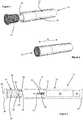
- Figure 4shows a cross-sectional view of the aerosol-generating system 10 after the cartridge 14 has been inserted into the cavity 18 of the aerosol-generating device 12.
- a second, downstream end of the liquid transfer elementpierces the frangible seal 48 of the liquid storage assembly 44.
- Liquid aerosol-forming substrate 40is wicked along the liquid transfer element 30 to the electric heater 28 where it is vaporised for inhalation by a user.
Landscapes
- Health & Medical Sciences (AREA)
- Engineering & Computer Science (AREA)
- Life Sciences & Earth Sciences (AREA)
- Public Health (AREA)
- Anesthesiology (AREA)
- Biomedical Technology (AREA)
- Heart & Thoracic Surgery (AREA)
- Hematology (AREA)
- Veterinary Medicine (AREA)
- Animal Behavior & Ethology (AREA)
- General Health & Medical Sciences (AREA)
- Pulmonology (AREA)
- Bioinformatics & Cheminformatics (AREA)
- Chemical & Material Sciences (AREA)
- Chemical Kinetics & Catalysis (AREA)
- General Chemical & Material Sciences (AREA)
- Catching Or Destruction (AREA)
- Containers And Packaging Bodies Having A Special Means To Remove Contents (AREA)
- Nozzles (AREA)
Description
- The present invention relates to an aerosol-generating system, the aerosol-generating system comprising a cartridge having both solid and liquid aerosol-forming substrates, and an aerosol-generating device having a liquid transfer element. The invention finds particular application as an electrically operated smoking system.
- One type of aerosol-generating system is an electrically operated smoking system. Known handheld electrically operated smoking systems typically comprise an aerosol-generating device comprising a battery, control electronics and an electric heater for heating an aerosol-forming substrate. The aerosol-forming substrate may be contained within part of the aerosol-generating device. For example, the aerosol-generating device may comprise a liquid storage portion in which a liquid aerosol-forming substrate, such as a nicotine solution, is stored. Such devices, often referred to as 'e-cigarettes', typically contain sufficient liquid aerosol-forming substrate to provide a number of puffs equivalent to consuming multiple conventional cigarettes.
WO 2016/079151 A1 describes an electronic nicotine delivery system comprising a power source and an electric heater contained within a housing. The housing defines a receptacle for receiving a disposable cartridge comprising a reservoir containing a nicotine solution. The electronic nicotine delivery system also comprises an elongate wick between the reservoir and the electric heater.- In an attempt to provide e-cigarette users with an experience that more closely simulates the experience of consuming a conventional cigarette some devices have attempted to combine an e-cigarette configuration with a tobacco-based substrate to impart a tobacco taste to the aerosol inhaled by the user. However, such devices may be impractically large and require the user to change a tobacco component and a liquid component at different times.
- It would be desirable to provide an aerosol-generating system that mitigates or eliminates at least some of these problems with known devices.
- According to a first aspect of the present invention there is provided an aerosol-generating system comprising a cartridge and an aerosol-generating device. The cartridge comprises a cartridge housing, a solid aerosol-forming substrate positioned within the cartridge housing and a liquid aerosol-forming substrate positioned within the cartridge housing. The aerosol-generating device comprises a cavity for receiving at least a portion of the cartridge, wherein the cavity is configured for insertion of the cartridge into the cavity along a first direction. The aerosol-generating device further comprises a liquid transfer element extending from an end wall of the cavity, the liquid transfer element having a longitudinal axis extending substantially parallel to the first direction, wherein the aerosol-generating system is configured so that a portion of the liquid transfer element contacts the liquid aerosol-forming substrate when the cartridge is received within the cavity. The aerosol-generating device also comprises an electric heater comprising a resistive heating coil wrapped around a portion of the liquid transfer element, wherein the resistive heating coil is wrapped around the longitudinal axis of the liquid transfer element. The aerosol-generating device further comprises a power supply and a controller for controlling a supply of electrical power from the power supply to the electric heater.
- As used herein, the term "aerosol-forming substrate" is used to describe a substrate capable of releasing volatile compounds, which can form an aerosol. The aerosols generated from aerosol-forming substrates of aerosol-generating systems according to the invention may be visible or invisible and may include vapours (for example, fine particles of substances, which are in a gaseous state, that are ordinarily liquid or solid at room temperature) as well as gases and liquid droplets of condensed vapours.
- Aerosol-generating systems according to the present invention facilitate simultaneous replacement of a solid aerosol-forming substrate and a liquid aerosol-forming substrate by providing both substrates in a single cartridge. Advantageously, this may simplify use of the aerosol-generating system for a user when compared to known devices in which a tobacco-based substrate and a nicotine solution must be replaced or replenished separately.
- Providing a solid aerosol-forming substrate and a liquid aerosol-forming substrate in a single cartridge may simplify replenishment of the liquid aerosol-forming substrate when compared to known devices in which a user may be required to refill a reservoir forming part of the device itself. Simplifying replenishment of the liquid aerosol-forming substrate may advantageously facilitate a reduction in the amount of liquid aerosol-forming substrate provided in the cartridge when compared to the amount of liquid aerosol-forming substrate provided in known devices. Advantageously, this may allow aerosol-generating systems according to the present invention to be smaller than known devices.
- Aerosol-generating systems according to the present invention provide a heater section that is separate from the cartridge. Advantageously, this may reduce the cost and simplify the manufacture of the cartridge when compared to known devices in which a heater and a liquid aerosol-forming substrate are combined into a single part of an aerosol-generating device. Advantageously, providing a heater section that is separate from the cartridge may facilitate cleaning of the electric heater, which may facilitate use of the heater section with multiple cartridges.
- Advantageously, the liquid transfer element may facilitate contact between the liquid aerosol-forming substrate and the electric heater during use of the aerosol-generating system. That is, the liquid transfer element facilitates transfer of the liquid aerosol-forming substrate from the cartridge to the electric heater, for example by capillary action.
- The liquid transfer element may comprise any suitable material or combination of materials which is able to convey the liquid aerosol-forming substrate along its length. The liquid transfer element may be formed from a porous material, but this need not be the case. The liquid transfer element may be formed from a material having a fibrous or spongy structure. The liquid transfer element preferably comprises a bundle of capillaries. For example, the liquid transfer element may comprise a plurality of fibres or threads or other fine bore tubes. The liquid transfer element may comprise sponge-like or foam-like material. Preferably, the structure of the liquid transfer element forms a plurality of small bores or tubes, through which the liquid aerosol-forming substrate can be transported by capillary action. The particular preferred material or materials will depend on the physical properties of the liquid aerosol-forming substrate. Examples of suitable capillary materials include a sponge or foam material, ceramic- or graphite-based materials in the form of fibres or sintered powders, foamed metal or plastics material, a fibrous material, for example made of spun or extruded fibres, such as cellulose acetate, polyester, or bonded polyolefin, polyethylene, terylene or polypropylene fibres, nylon fibres, ceramic, glass fibres, silica glass fibres, carbon fibres, metallic fibres of medical grade stainless steel alloys such as austenitic 316 stainless steel and martensitic 440 and 420 stainless steels. The liquid transfer element may have any suitable capillarity so as to be used with different liquid physical properties. The liquid aerosol-forming substrate has physical properties, including but not limited to viscosity, surface tension, density, thermal conductivity, boiling point and vapour pressure, which allow the liquid aerosol-forming substrate to be transported through the liquid transfer element. The liquid transfer element may be formed from heat-resistant material. The liquid transfer element may comprise a plurality of fibre strands. The plurality of fibre strands may be generally aligned along a length of the liquid transfer element.
- Preferably, the aerosol-generating system comprises at least one airflow inlet and at least one airflow outlet. During use, air flows through the aerosol-generating system along a flow path from the airflow inlet to the airflow outlet. Air flows along the flow path from an upstream end of the flow path at the airflow inlet to a downstream end of the flow path at the airflow outlet. Preferably, the aerosol-generating system is configured so that, in use, the solid aerosol-generating substrate is positioned downstream of the liquid aerosol-generating substrate.
- The cartridge may comprises a porous carrier material, wherein the liquid aerosol-forming substrate is provided on the porous carrier material. Advantageously, providing the liquid aerosol-forming substrate on a porous carrier material may reduce the risk of the liquid aerosol-forming substrate leaking from the cartridge.
- The porous carrier material and the liquid transfer element may comprise the same material. Preferably, the porous carrier material and the liquid transfer element comprise different materials.
- The porous carrier material may comprise any suitable material or combination of materials which is permeable to the liquid aerosol-forming substrate and allows the liquid aerosol-forming substrate to migrate through the porous carrier material. Preferably, the material or combination of materials is inert with respect to the liquid aerosol-forming substrate. The porous carrier material may or may not be a capillary material. The porous carrier material may comprise a hydrophilic material to improve distribution and spread of the liquid aerosol-forming substrate. This may assist with consistent aerosol formation. The particular preferred material or materials will depend on the physical properties of the liquid aerosol-forming substrate. Examples of suitable materials are a capillary material, for example a sponge or foam material, ceramic- or graphite-based materials in the form of fibres or sintered powders, a foamed metal or plastics material, a fibrous material, for example made of spun or extruded fibres, such as cellulose acetate, polyester, or bonded polyolefin, polyethylene, terylene or polypropylene fibres, nylon fibres or ceramic. The porous carrier material may have any suitable porosity so as to be used with different liquid physical properties.
- Preferably, the aerosol-generating system is configured so that, in use, the liquid transfer element contacts the porous carrier material.
- The cartridge may comprise a removable seal overlying the porous carrier material at a first end of the cartridge housing. Preferably, the first end is the upstream end of the cartridge housing. The removable seal may be secured to the cartridge housing about a periphery of the removable seal. The removable seal may be secured to the cartridge housing by at least one of an adhesive and a weld, such as an ultrasonic weld. The removable seal is preferably formed from a sheet material. The sheet material may comprise at least one of a polymeric film and a metallic foil. The removable seal may be configured for removal from the cartridge by a user before combining the cartridge with the aerosol-generating device. The removable seal may comprise a pull tab to facilitate removal of the seal.
- The cartridge may comprise a frangible seal. Advantageously, a frangible seal may prevent the loss of volatile compounds from one or both of the solid aerosol-forming substrate and the liquid aerosol-forming substrate. The frangible seal may extend across an opening defined by the cartridge housing. The frangible seal may extend across an end of the cartridge housing. Preferably, the frangible seal extends across an upstream end of the cartridge housing. The frangible seal may be secured to the cartridge housing about a periphery of the frangible seal. The frangible seal may be secured to the cartridge housing by at least one of an adhesive and a weld, such as an ultrasonic weld. The frangible seal is preferably formed from a sheet material. The sheet material may comprise at least one of a polymeric film and a metallic foil.
- Preferably, the liquid transfer element is configured to pierce the frangible seal when the aerosol-generating device receives the cartridge. Advantageously, the liquid transfer element may automatically pierce the frangible seal when the aerosol-generating device and the heater section are combined with the cartridge.
- The liquid transfer element may comprise a first end connected to the end wall of the cavity and a second end opposite the first end. Preferably, the second end of the liquid transfer element defines a piercing portion configured to pierce the frangible seal when the aerosol-generating device receives the cartridge. Preferably, the diameter of the piercing portion decreases in a direction along the longitudinal axis and towards the second end. That is, the second end of the liquid transfer element may comprise a tapered portion. Advantageously, this may reduce the force required for the liquid transfer element to pierce the frangible seal. Preferably, the second end of the liquid transfer element tapers to a point.
- The porous carrier material may have an annular shape defining a passage through the porous carrier material. The passage may be a through-passage extending completely through the porous carrier material. The passage may be a blind-passage having an open end and a closed end. Preferably, the open end is positioned at the upstream end of the porous carrier material.
- Preferably, the aerosol-generating system is configured so that the liquid transfer element is at least partially received within the passage when the aerosol-generating device receives the cartridge. Advantageously, this may maximise the contact area between the liquid transfer element and the porous carrier material.
- Preferably, the cartridge comprises an airflow channel positioned between the porous carrier material and the cartridge housing. Preferably, an airflow inlet of the aerosol-generating system is in fluid communication with an upstream end of the airflow channel. Preferably, the electric heater is in fluid communication with both the airflow inlet and the upstream end of the airflow channel. Preferably, a downstream end of the airflow channel is in fluid communication with the solid aerosol-forming substrate. Preferably, the downstream end of the airflow channel is in fluid communication with an upstream end of the solid aerosol-forming substrate. Preferably, a downstream end of the solid aerosol-forming substrate is in fluid communication with an airflow outlet of the aerosol-generating system.
- Preferably, the resistive heating coil is wound around a first end of the liquid transfer element. In embodiments in which the cartridge comprises a porous carrier material, preferably the aerosol-generating system is configured so that the resistive heating coil does not contact the porous carrier material when the cartridge is received within the cavity. In embodiments in which the porous carrier material has an annular shape and comprises a passage extending through the porous carrier material, preferably the resistive heating coil is wound around a first end of the liquid transfer element, wherein only a second end of the liquid transfer element is received within the passage when the cartridge is received within the cavity.
- The pitch of the resistive heating coil is preferably between about 0.5 millimetres and about 1.5 millimetres, and most preferably about 1.5 millimetres. The pitch of the resistive heating coil means the spacing between adjacent turns of the coil. The coil may comprise fewer than six turns, and preferably has fewer than five turns. The coil may be formed from an electrically resistive wire having a diameter of between about 0.10 millimetres and about 0.15 millimetres, preferably about 0.125 millimetres. The electrically resistive wire is preferably formed of 904 or 301 stainless steel. Examples of other suitable metals include titanium, zirconium, tantalum and metals from the platinum group. Examples of other suitable metal alloys include, Constantan, nickel-, cobalt-, chromium-, aluminium- titanium- zirconium-, hafnium-, niobium-, molybdenum-, tantalum-, tungsten-, tin-, gallium-, manganese- and iron-containing alloys, and super-alloys based on nickel, iron, cobalt, stainless steel, Timetal®, iron-aluminium based alloys and iron-manganese-aluminium based alloys. The resistive heating coil may also comprise a metal foil, such as an aluminium foil, which is provided in the form of a ribbon.
- The cartridge housing is preferably tubular and comprises a first, upstream end and a second, downstream end. Preferably, the solid aerosol-forming substrate is positioned within the downstream end. Preferably, the porous carrier material is positioned within the upstream end.
- The porous carrier material may be positioned directly within the cartridge housing. Preferably, the porous carrier material is retained within the cartridge housing by an interference fit.
- The porous carrier material may be positioned within a liquid storage housing, wherein the liquid storage housing is positioned within the cartridge housing. Preferably, the liquid storage housing is retained within the cartridge housing by an interference fit.
- In embodiments in which the cartridge comprises an airflow channel positioned between the porous carrier material and the cartridge housing, an outer surface of the liquid storage housing may be shaped to define the airflow channel between the cartridge housing and the liquid storage housing when the liquid storage housing is received within the cartridge housing. The outer surface of the liquid storage housing may comprise a groove to define the airflow channel when the liquid storage housing is received within the cartridge housing.
- The liquid storage housing may be tubular. In embodiments in which the cartridge comprises a removable seal or a frangible seal, the seal may extend across the upstream end of the liquid storage housing. Preferably, the seal is secured to the liquid storage housing instead of the cartridge housing.
- The tubular liquid storage housing may have an open upstream end and a closed downstream end. In embodiments in which the cartridge comprises a removable seal or a frangible seal, the seal may extend across the upstream end of the liquid storage housing so that the porous carrier material is positioned between the seal and the closed end.
- The solid aerosol-forming substrate may be retained in the cartridge housing by an interference fit.
- The cartridge may comprise a filter positioned downstream of the solid aerosol-forming substrate. The filter may comprise a plug of filter material positioned within the downstream end of the cartridge housing. The plug of filter material may be retained within the cartridge housing by an interference fit. The filter may comprise a sheet material extending across a downstream opening of the cartridge housing. The sheet material may comprise a mesh. The sheet material may be secured to the cartridge housing by at least one of an adhesive and a weld, such as an ultrasonic weld. The filter may retain the solid aerosol-forming substrate in the cartridge housing.
- The aerosol-generating system may comprise a mouthpiece. In embodiments in which the aerosol-generating system comprises at least one airflow outlet, preferably the mouthpiece comprises the at least one airflow outlet. The mouthpiece may form part of the cartridge. The mouthpiece may form part of the aerosol-generating device. The mouthpiece may be formed separately from the cartridge and the aerosol-generating device, wherein at least one of the cartridge and the aerosol-generating device is configured to receive the mouthpiece.
- The solid aerosol-forming substrate may comprise tobacco. The solid aerosol-forming substrate may comprise a tobacco-containing material containing volatile tobacco flavour compounds which are released from the substrate upon heating.
- The solid aerosol-forming substrate may comprise tobacco containing deprotonated nicotine. Deprotonating the nicotine within tobacco may advantageously increase the volatility of the nicotine. Nicotine may be deprotonated by subjecting the tobacco to an alkalising treatment.
- The solid aerosol-forming substrate may comprise a non-tobacco material. The solid aerosol-forming substrate may comprise tobacco-containing material and non-tobacco containing material.
- The solid aerosol-forming substrate may include at least one aerosol-former. As used herein, the term 'aerosol former' is used to describe any suitable known compound or mixture of compounds that, in use, facilitates formation of an aerosol. Suitable aerosol-formers include, but are not limited to: polyhydric alcohols, such as propylene glycol, triethylene glycol, 1,3-butanediol and glycerine; esters of polyhydric alcohols, such as glycerol mono-, di- or triacetate; and aliphatic esters of mono-, di- or polycarboxylic acids, such as dimethyl dodecanedioate and dimethyl tetradecanedioate
- Preferred aerosol formers are polyhydric alcohols or mixtures thereof, such as propylene glycol, triethylene glycol, 1,3-butanediol and, most preferred, glycerine.
- The solid aerosol-forming substrate may comprise a single aerosol former. Alternatively, the solid aerosol-forming substrate may comprise a combination of two or more aerosol formers.
- The solid aerosol-forming substrate may have an aerosol former content of greater than 5 percent on a dry weight basis.
- The solid aerosol-forming substrate may have an aerosol former content of between approximately 5 percent and approximately 30 percent on a dry weight basis.
- The solid aerosol-forming substrate may have an aerosol former content of approximately 20 percent on a dry weight basis.
- The liquid aerosol-forming substrate may comprise a tobacco-containing material comprising volatile tobacco flavour compounds which are released from the liquid upon heating. The liquid aerosol-forming substrate may comprise a non-tobacco material. The liquid aerosol-forming substrate may include water, solvents, ethanol, plant extracts and natural or artificial flavours. Preferably, the liquid aerosol-forming substrate comprises an aerosol former. Suitable aerosol formers include polyhydric alcohols or mixtures thereof, such as propylene glycol, triethylene glycol, 1,3-butanediol and glycerine.
- The liquid aerosol-forming substrate may comprise nicotine.
- The liquid aerosol-forming substrate may be free from nicotine. In such embodiments, the vaporised liquid aerosol-forming substrate may be drawn through the solid aerosol-forming substrate during use to strip one or more volatile compounds from the solid aerosol-forming substrate. The vaporised liquid aerosol-forming substrate may strip nicotine from the solid-aerosol-forming substrate. A solid aerosol-forming substrate comprising tobacco containing deprotonated nicotine may be particularly suited to embodiments in which the liquid aerosol-forming substrate is free from nicotine.
- The power supply may comprise a battery. For example, the power supply may be a nickel-metal hydride battery, a nickel cadmium battery, or a lithium based battery, for example a lithium-cobalt, a lithium-iron-phosphate or a lithium-polymer battery. The power supply may alternatively be another form of charge storage device such as a capacitor. The power supply may require recharging and may have a capacity that allows for the storage of enough energy for use of the aerosol-generating device with more than one cartridge.
- The invention is further described, by way of example only, with reference to the accompanying drawings in which:
Figure 1 shows a perspective view of an aerosol-generating system according to an embodiment of the invention and with the cartridge separate from the aerosol-generating device;Figure 2 shows a perspective view of the aerosol-generating system ofFigure 1 with the cartridge inserted into the aerosol-generating device;Figure 3 shows a cross-sectional view of the aerosol-generating system ofFigure 1 with the cartridge separate from the aerosol-generating device;Figure 4 shows a cross-sectional view of the aerosol-generating system ofFigure 1 with the cartridge inserted into the aerosol-generating device;Figure 5 shows an exploded view of the cartridge of the aerosol-generating system ofFigure 1 ; andFigure 6 shows an exploded view of a portion of the cartridge ofFigure 5 to show the porous carrier material and the liquid aerosol-forming substrate.Figures 1 and 2 show an aerosol-generatingsystem 10 according to an embodiment of the present invention. The aerosol-generatingsystem 10 comprises an aerosol-generatingdevice 12 and acartridge 14. The aerosol-generatingdevice 10 comprises adevice housing 16 defining acavity 18 for receiving an upstream end of thecartridge 14.Figure 1 shows thecartridge 14 separate from the aerosol-generatingdevice 12 andFigure 2 shows thecartridge 14 received within thecavity 18 of the aerosol-generatingdevice 12. Thecavity 18 is configured for insertion of thecartridge 14 into thecavity 18 along afirst direction 19.Figure 3 shows a cross-sectional view of the aerosol-generatingsystem 10. The aerosol-generatingdevice 12 comprises anairflow inlet 20 positioned at an upstream end of thedevice housing 16. Apower supply 22 and acontroller 24 are positioned within the upstream end of thedevice housing 16.- The aerosol-generating
system 10 further comprises anelectric heater 28 comprising a resistive heating coil, and aliquid transfer element 30 extending from anend wall 31 of thecavity 18. The resistive heating coil is wound around a first, upstream end of theliquid transfer element 30. Theliquid transfer element 30 has alongitudinal axis 33 that extends substantially parallel to thefirst direction 19, and the resistive heating coil is wound around thelongitudinal axis 33. During use, thecontroller 24 controls a supply of electrical power from thepower supply 22 to theelectric heater 28. - The
cartridge 14 comprises acartridge housing 36, and a solid aerosol-formingsubstrate 38 and a liquid aerosol-formingsubstrate 40 both positioned within thecartridge housing 36.Figure 5 shows an exploded view of thecartridge 14. - The solid aerosol-forming
substrate 38 comprises a tobacco plug positioned within the downstream end of thecartridge housing 36. Amesh filter 42 is attached to a downstream end of thecartridge housing 36 to retain the tobacco plug within thecartridge housing 36. - The liquid aerosol-forming
substrate 40 is contained within aliquid storage assembly 44 positioned within the upstream end of thecartridge housing 36. Theliquid storage assembly 44 is shown in more detail in a further exploded view inFigure 6 . - The
liquid storage assembly 44 comprises a tubularliquid storage housing 46 that is retained within the upstream end of thecartridge housing 36 by an interference fit. Afrangible seal 48 extends across and is secured to the upstream end of the tubularliquid storage housing 46. The tubularliquid storage housing 46 has a closeddownstream end 50 and aporous carrier material 52 is positioned within the tubularliquid storage housing 46 between thefrangible seal 48 and the closeddownstream end 50 of the tubularliquid storage housing 46. The liquid aerosol-formingsubstrate 40 is sorbed into theporous carrier material 52. Theporous carrier material 52 has an annular shape and defines apassage 54 through theporous carrier material 52, thepassage 54 extending between thefrangible seal 48 and the closeddownstream end 50 of the tubularliquid storage housing 46. When theliquid storage assembly 44 is received within thecartridge housing 36,planar side walls 51 of thetubular cartridge housing 46 are spaced apart from thecartridge housing 36 to createairflow passages 45 between theliquid storage assembly 44 and thecartridge housing 36. - The downstream end of the
cartridge housing 36 forms amouthpiece 56, themouthpiece 56 defining anairflow outlet 58 of the aerosol-generatingsystem 10. Figure 4 shows a cross-sectional view of the aerosol-generatingsystem 10 after thecartridge 14 has been inserted into thecavity 18 of the aerosol-generatingdevice 12. When thecartridge 14 is inserted into the cavity 18 a second, downstream end of the liquid transfer element pierces thefrangible seal 48 of theliquid storage assembly 44. Liquid aerosol-formingsubstrate 40 is wicked along theliquid transfer element 30 to theelectric heater 28 where it is vaporised for inhalation by a user. When a user draws on themouthpiece 56, air is drawn into the aerosol-generatingsystem 10 through theairflow inlet 20, through the aerosol-generatingdevice 12, across theelectric heater 28 where liquid aerosol-forming substrate vapour is entrained in the airflow, through theairflow passages 45 and through the solid aerosol-formingsubstrate 38 where further volatile compounds are entrained in the airflow, and out through theairflow outlet 58.
Claims (12)
- An aerosol-generating system (10) comprising:a cartridge (14) comprising a cartridge housing (36), a solid aerosol-forming substrate (38) positioned within the cartridge housing (36) and a liquid aerosol-forming substrate (40) positioned within the cartridge housing (36); andan aerosol-generating device (12) comprising:a cavity (18) for receiving at least a portion of the cartridge (14), wherein the cavity (18) is configured for insertion of the cartridge (14) into the cavity (18) along a first direction (19);a liquid transfer element (30) extending from an end wall (31) of the cavity (18), the liquid transfer element (30) having a longitudinal axis (33) extending substantially parallel to the first direction (19), wherein the aerosol-generating system (10) is configured so that a portion of the liquid transfer element (30) contacts the liquid aerosol-forming substrate (40) when the cartridge (14) is received within the cavity (18);an electric heater (28) comprising a resistive heating coil wrapped around a portion of the liquid transfer element (30), wherein the resistive heating coil is wrapped around the longitudinal axis (33) of the liquid transfer element (30); anda power supply (22) and a controller (24) for controlling a supply of electrical power from the power supply (22) to the electric heater (28).
- An aerosol-generating system (10) according to claim 1, wherein the cartridge (14) further comprises a porous carrier material (52), and wherein the liquid aerosol-forming substrate (40) is provided on the porous carrier material (52).
- An aerosol-generating system (10) according to claim 2, wherein the aerosol-generating system (10) is configured so that, in use, the liquid transfer element (30) contacts the porous carrier material (52).
- An aerosol-generating system (10) according to claim 2 or 3, wherein the cartridge (14) comprises a removable seal overlying the porous carrier material (52) at a first end of the cartridge housing (36).
- An aerosol-generating system (10) according to claim 2 or 3, wherein the cartridge (14) comprises a frangible seal (48), and wherein the liquid transfer element (30) is configured to pierce the frangible seal (48) when the aerosol-generating device (12) receives the cartridge (14).
- An aerosol-generating system (10) according to claim 5, wherein the liquid transfer element (30) comprises a first end connected to the end wall (31) of the cavity (18) and a second end opposite the first end, and wherein the second end of the liquid transfer element (30) defines a piercing portion configured to pierce the frangible seal (48) when the aerosol-generating device (12) receives the cartridge (14).
- An aerosol-generating system (10) according to claim 6, wherein the diameter of the piercing portion decreases in a direction along the longitudinal axis (33) and towards the second end.
- An aerosol-generating system (10) according to any of claims 2 to 7, wherein the porous carrier material (52) has an annular shape defining a passage (54) within the porous carrier material (52), wherein the aerosol-generating system (10) is configured so that the liquid transfer element (30) is at least partially received within the passage (54) when the aerosol-generating device (12) receives the cartridge (14).
- An aerosol-generating system (10) according to any of claims 2 to 8, wherein the cartridge (14) comprises an airflow channel (45) positioned between the porous carrier material (52) and the cartridge housing (36), and wherein a downstream end of the airflow channel (45) is in fluid communication with the solid aerosol-forming substrate (38).
- An aerosol-generating system (10) according to any preceding claim, wherein the solid aerosol-forming substrate (38) comprises tobacco.
- An aerosol-generating system (10) according to any preceding claim, wherein the liquid aerosol-forming substrate (40) comprises nicotine.
- An aerosol-generating system (10) according to any of claims 1 to 10, wherein the liquid aerosol-forming substrate (40) is substantially free from nicotine.
Applications Claiming Priority (2)
| Application Number | Priority Date | Filing Date | Title |
|---|---|---|---|
| EP16205101 | 2016-12-19 | ||
| PCT/EP2017/081409WO2018114312A1 (en) | 2016-12-19 | 2017-12-04 | Aerosol-generating system comprising multiple aerosol-forming substrates and a liquid transfer element |
Publications (2)
| Publication Number | Publication Date |
|---|---|
| EP3554291A1 EP3554291A1 (en) | 2019-10-23 |
| EP3554291B1true EP3554291B1 (en) | 2020-11-04 |
Family
ID=57570716
Family Applications (1)
| Application Number | Title | Priority Date | Filing Date |
|---|---|---|---|
| EP17804928.4AActiveEP3554291B1 (en) | 2016-12-19 | 2017-12-04 | Aerosol-generating system comprising multiple aerosol-forming substrates and a liquid transfer element |
Country Status (7)
| Country | Link |
|---|---|
| US (1) | US20250249189A1 (en) |
| EP (1) | EP3554291B1 (en) |
| JP (1) | JP7066710B2 (en) |
| KR (1) | KR102526266B1 (en) |
| CN (1) | CN109982587B (en) |
| RU (1) | RU2747612C2 (en) |
| WO (1) | WO2018114312A1 (en) |
Families Citing this family (18)
| Publication number | Priority date | Publication date | Assignee | Title |
|---|---|---|---|---|
| JP4771420B2 (en)* | 2006-01-12 | 2011-09-14 | 本田技研工業株式会社 | Side stand switch |
| WO2017167610A1 (en) | 2016-03-31 | 2017-10-05 | Philip Morris Products S.A. | Vaporizing assembly comprising a viewable heating element and liquid delivery device for an aerosol generating system |
| GB201812498D0 (en)* | 2018-07-31 | 2018-09-12 | Nicoventures Holdings Ltd | Aerosol generation |
| JP6818003B2 (en) | 2018-11-19 | 2021-01-20 | インテレクチュアルディスカバリーシーオー.,エルティーディー | Smoking jig |
| EP4570092A1 (en)* | 2018-12-17 | 2025-06-18 | Philip Morris Products S.A. | Cartridge for use with aerosol generating device |
| US11602164B2 (en)* | 2019-03-14 | 2023-03-14 | Rai Strategic Holdings, Inc. | Aerosol delivery device with graded porosity from inner to outer wall surfaces |
| JP2020171229A (en)* | 2019-04-11 | 2020-10-22 | インテレクチュアルディスカバリーシーオー.,エルティーディー | Tobacco leaf mounting method of heating type tobacco |
| US11517688B2 (en)* | 2019-05-10 | 2022-12-06 | Rai Strategic Holdings, Inc. | Flavor article for an aerosol delivery device |
| JP7593954B2 (en)* | 2019-07-04 | 2024-12-03 | フィリップ・モーリス・プロダクツ・ソシエテ・アノニム | Induction heating device having gas permeable segmented induction heating element - Patents.com |
| KR102341841B1 (en)* | 2019-08-08 | 2021-12-21 | 주식회사 케이티앤지 | Aerosol generating article comprising thermally conductive wrapper |
| KR20220043156A (en)* | 2019-08-12 | 2022-04-05 | 제이티 인터내셔널 소시에떼 아노님 | Cartridge for electronic cigarette, electronic cigarette, and method of assembling electronic cigarette |
| WO2021073971A1 (en)* | 2019-10-14 | 2021-04-22 | Philip Morris Products S.A. | Method of applying a coating to an aerosol generating assembly |
| WO2021083130A1 (en)* | 2019-10-28 | 2021-05-06 | 深圳麦克韦尔科技有限公司 | Electronic atomization device, cartridge and cartridge base |
| KR102428411B1 (en)* | 2020-03-31 | 2022-08-02 | 주식회사 케이티앤지 | Aerosol generating device including deteachable heater module |
| JP2024505799A (en) | 2021-02-09 | 2024-02-08 | ジェイティー インターナショナル エスエイ | Cartridges for aerosol generation systems |
| IL309757A (en)* | 2021-07-19 | 2024-02-01 | Nicoventures Trading Ltd | Aerosol provision system |
| US20240324673A1 (en)* | 2021-07-23 | 2024-10-03 | Jt International Sa | An Aerosol Generating Article and an Aerosol Generating System |
| GB202215606D0 (en)* | 2022-10-21 | 2022-12-07 | Nicoventures Trading Ltd | A consumable |
Family Cites Families (19)
| Publication number | Priority date | Publication date | Assignee | Title |
|---|---|---|---|---|
| CN201067079Y (en)* | 2006-05-16 | 2008-06-04 | 韩力 | Simulated aerosol inhaler |
| US7726320B2 (en)* | 2006-10-18 | 2010-06-01 | R. J. Reynolds Tobacco Company | Tobacco-containing smoking article |
| CN100594809C (en)* | 2008-02-29 | 2010-03-24 | 修运强 | Electronic simulation cigarette and atomized liquid thereof |
| EP2113178A1 (en)* | 2008-04-30 | 2009-11-04 | Philip Morris Products S.A. | An electrically heated smoking system having a liquid storage portion |
| EP2399636A1 (en)* | 2010-06-23 | 2011-12-28 | Philip Morris Products S.A. | An improved aerosol generator and liquid storage portion for use with the aerosol generator |
| CN201878765U (en)* | 2010-11-01 | 2011-06-29 | 常州市富艾发进出口有限公司 | Mouth suction type portable atomizer |
| EP2460424A1 (en)* | 2010-12-03 | 2012-06-06 | Philip Morris Products S.A. | An aerosol generating system with leakage prevention |
| UA113744C2 (en)* | 2011-12-08 | 2017-03-10 | DEVICE FOR FORMATION OF AEROSOL WITH INTERNAL HEATER | |
| KR102398476B1 (en)* | 2014-03-19 | 2022-05-16 | 필립모리스 프로덕츠 에스.에이. | Aerosol-generating devices incorporating an intertwined wick and heating element |
| CN203828070U (en)* | 2014-03-27 | 2014-09-17 | 深圳市麦克韦尔科技有限公司 | Electronic cigarette |
| PT3125706T (en)* | 2014-03-31 | 2018-10-18 | Philip Morris Products Sa | Electrically heated aerosol-generating system |
| US20160073695A1 (en)* | 2014-05-20 | 2016-03-17 | R. J. Reynolds Tobacco Company | Electrically-powered aerosol delivery system |
| TWI669073B (en)* | 2014-06-24 | 2019-08-21 | 瑞士商菲利浦莫里斯製品股份有限公司 | Aerosol-generating system, aerosol-generating article, aerosol-generating device and method of controlling the reaction stoichiometry |
| PL3750583T3 (en)* | 2014-10-14 | 2022-06-27 | Fontem Holdings 1 B.V. | Electronic smoking device and cartridge |
| BR112017010106A2 (en)* | 2014-11-17 | 2018-01-02 | Mcneil Ab | disposable cartridge for use in an electronic nicotine release system |
| WO2016079151A1 (en)* | 2014-11-17 | 2016-05-26 | Mcneil Ab | Child-resistant container for nicotine-containing cartridges |
| JP6637486B2 (en)* | 2015-04-02 | 2020-01-29 | 日本たばこ産業株式会社 | Flavor inhaler |
| IL279264B (en)* | 2015-05-06 | 2022-09-01 | Altria Client Services Llc | A non-flammable smoking device and its components |
| CN104970444B (en)* | 2015-06-30 | 2018-03-13 | 深圳麦克韦尔股份有限公司 | The assemble method of electronic cigarette and its atomising device and atomising device |
- 2017
- 2017-12-04EPEP17804928.4Apatent/EP3554291B1/enactiveActive
- 2017-12-04RURU2019119017Apatent/RU2747612C2/enactive
- 2017-12-04CNCN201780072704.1Apatent/CN109982587B/enactiveActive
- 2017-12-04KRKR1020197015642Apatent/KR102526266B1/enactiveActive
- 2017-12-04JPJP2019529237Apatent/JP7066710B2/enactiveActive
- 2017-12-04WOPCT/EP2017/081409patent/WO2018114312A1/ennot_activeCeased
- 2025
- 2025-04-23USUS19/186,821patent/US20250249189A1/enactivePending
Non-Patent Citations (1)
| Title |
|---|
| None* |
Also Published As
| Publication number | Publication date |
|---|---|
| RU2747612C2 (en) | 2021-05-11 |
| CN109982587A (en) | 2019-07-05 |
| JP2020501539A (en) | 2020-01-23 |
| CN109982587B (en) | 2022-06-24 |
| JP7066710B2 (en) | 2022-05-13 |
| US20250249189A1 (en) | 2025-08-07 |
| KR20190089896A (en) | 2019-07-31 |
| RU2019119017A3 (en) | 2021-03-15 |
| RU2019119017A (en) | 2021-01-19 |
| EP3554291A1 (en) | 2019-10-23 |
| WO2018114312A1 (en) | 2018-06-28 |
| KR102526266B1 (en) | 2023-04-27 |
Similar Documents
| Publication | Publication Date | Title |
|---|---|---|
| EP3554291B1 (en) | Aerosol-generating system comprising multiple aerosol-forming substrates and a liquid transfer element | |
| EP3554294B1 (en) | An aerosol-generating system comprising multiple aerosol-forming substrates and a piercing element | |
| EP3537901B1 (en) | Aerosol-generating system comprising solid and liquid aerosol-forming substrates | |
| EP3554289B1 (en) | Aerosol-generating system having a cartridge with a side aperture | |
| EP3554290B1 (en) | An aerosol-generating system having a cartridge and a bypass air inlet | |
| US12350423B2 (en) | Aerosol-generating system comprising multiple aerosol-forming substrates and a transfer element | |
| EP3537903B1 (en) | Aerosol-generating system having variable airflow | |
| EP3554292B1 (en) | Aerosol-generating system comprising a modular assembly | |
| EP3554293B1 (en) | Aerosol-generating system having an external cartridge |
Legal Events
| Date | Code | Title | Description |
|---|---|---|---|
| STAA | Information on the status of an ep patent application or granted ep patent | Free format text:STATUS: UNKNOWN | |
| STAA | Information on the status of an ep patent application or granted ep patent | Free format text:STATUS: THE INTERNATIONAL PUBLICATION HAS BEEN MADE | |
| PUAI | Public reference made under article 153(3) epc to a published international application that has entered the european phase | Free format text:ORIGINAL CODE: 0009012 | |
| STAA | Information on the status of an ep patent application or granted ep patent | Free format text:STATUS: REQUEST FOR EXAMINATION WAS MADE | |
| 17P | Request for examination filed | Effective date:20190614 | |
| AK | Designated contracting states | Kind code of ref document:A1 Designated state(s):AL AT BE BG CH CY CZ DE DK EE ES FI FR GB GR HR HU IE IS IT LI LT LU LV MC MK MT NL NO PL PT RO RS SE SI SK SM TR | |
| AX | Request for extension of the european patent | Extension state:BA ME | |
| DAV | Request for validation of the european patent (deleted) | ||
| DAX | Request for extension of the european patent (deleted) | ||
| REG | Reference to a national code | Ref country code:DE Ref legal event code:R079 Ref document number:602017027037 Country of ref document:DE Free format text:PREVIOUS MAIN CLASS: A24F0047000000 Ipc:A24F0040300000 | |
| GRAP | Despatch of communication of intention to grant a patent | Free format text:ORIGINAL CODE: EPIDOSNIGR1 | |
| STAA | Information on the status of an ep patent application or granted ep patent | Free format text:STATUS: GRANT OF PATENT IS INTENDED | |
| RIC1 | Information provided on ipc code assigned before grant | Ipc:A24F 40/42 20200101ALI20200429BHEP Ipc:A24F 40/30 20200101AFI20200429BHEP | |
| INTG | Intention to grant announced | Effective date:20200525 | |
| GRAS | Grant fee paid | Free format text:ORIGINAL CODE: EPIDOSNIGR3 | |
| GRAA | (expected) grant | Free format text:ORIGINAL CODE: 0009210 | |
| STAA | Information on the status of an ep patent application or granted ep patent | Free format text:STATUS: THE PATENT HAS BEEN GRANTED | |
| AK | Designated contracting states | Kind code of ref document:B1 Designated state(s):AL AT BE BG CH CY CZ DE DK EE ES FI FR GB GR HR HU IE IS IT LI LT LU LV MC MK MT NL NO PL PT RO RS SE SI SK SM TR | |
| REG | Reference to a national code | Ref country code:GB Ref legal event code:FG4D | |
| REG | Reference to a national code | Ref country code:CH Ref legal event code:EP | |
| REG | Reference to a national code | Ref country code:AT Ref legal event code:REF Ref document number:1329660 Country of ref document:AT Kind code of ref document:T Effective date:20201115 | |
| REG | Reference to a national code | Ref country code:DE Ref legal event code:R096 Ref document number:602017027037 Country of ref document:DE | |
| REG | Reference to a national code | Ref country code:IE Ref legal event code:FG4D | |
| REG | Reference to a national code | Ref country code:NL Ref legal event code:FP | |
| REG | Reference to a national code | Ref country code:CH Ref legal event code:NV Representative=s name:VENI GMBH, CH | |
| REG | Reference to a national code | Ref country code:AT Ref legal event code:MK05 Ref document number:1329660 Country of ref document:AT Kind code of ref document:T Effective date:20201104 | |
| PG25 | Lapsed in a contracting state [announced via postgrant information from national office to epo] | Ref country code:GR Free format text:LAPSE BECAUSE OF FAILURE TO SUBMIT A TRANSLATION OF THE DESCRIPTION OR TO PAY THE FEE WITHIN THE PRESCRIBED TIME-LIMIT Effective date:20210205 Ref country code:NO Free format text:LAPSE BECAUSE OF FAILURE TO SUBMIT A TRANSLATION OF THE DESCRIPTION OR TO PAY THE FEE WITHIN THE PRESCRIBED TIME-LIMIT Effective date:20210204 Ref country code:FI Free format text:LAPSE BECAUSE OF FAILURE TO SUBMIT A TRANSLATION OF THE DESCRIPTION OR TO PAY THE FEE WITHIN THE PRESCRIBED TIME-LIMIT Effective date:20201104 Ref country code:RS Free format text:LAPSE BECAUSE OF FAILURE TO SUBMIT A TRANSLATION OF THE DESCRIPTION OR TO PAY THE FEE WITHIN THE PRESCRIBED TIME-LIMIT Effective date:20201104 Ref country code:PT Free format text:LAPSE BECAUSE OF FAILURE TO SUBMIT A TRANSLATION OF THE DESCRIPTION OR TO PAY THE FEE WITHIN THE PRESCRIBED TIME-LIMIT Effective date:20210304 | |
| PG25 | Lapsed in a contracting state [announced via postgrant information from national office to epo] | Ref country code:IS Free format text:LAPSE BECAUSE OF FAILURE TO SUBMIT A TRANSLATION OF THE DESCRIPTION OR TO PAY THE FEE WITHIN THE PRESCRIBED TIME-LIMIT Effective date:20210304 Ref country code:PL Free format text:LAPSE BECAUSE OF FAILURE TO SUBMIT A TRANSLATION OF THE DESCRIPTION OR TO PAY THE FEE WITHIN THE PRESCRIBED TIME-LIMIT Effective date:20201104 Ref country code:LV Free format text:LAPSE BECAUSE OF FAILURE TO SUBMIT A TRANSLATION OF THE DESCRIPTION OR TO PAY THE FEE WITHIN THE PRESCRIBED TIME-LIMIT Effective date:20201104 Ref country code:SE Free format text:LAPSE BECAUSE OF FAILURE TO SUBMIT A TRANSLATION OF THE DESCRIPTION OR TO PAY THE FEE WITHIN THE PRESCRIBED TIME-LIMIT Effective date:20201104 Ref country code:BG Free format text:LAPSE BECAUSE OF FAILURE TO SUBMIT A TRANSLATION OF THE DESCRIPTION OR TO PAY THE FEE WITHIN THE PRESCRIBED TIME-LIMIT Effective date:20210204 Ref country code:AT Free format text:LAPSE BECAUSE OF FAILURE TO SUBMIT A TRANSLATION OF THE DESCRIPTION OR TO PAY THE FEE WITHIN THE PRESCRIBED TIME-LIMIT Effective date:20201104 Ref country code:ES Free format text:LAPSE BECAUSE OF FAILURE TO SUBMIT A TRANSLATION OF THE DESCRIPTION OR TO PAY THE FEE WITHIN THE PRESCRIBED TIME-LIMIT Effective date:20201104 | |
| REG | Reference to a national code | Ref country code:LT Ref legal event code:MG9D | |
| PG25 | Lapsed in a contracting state [announced via postgrant information from national office to epo] | Ref country code:HR Free format text:LAPSE BECAUSE OF FAILURE TO SUBMIT A TRANSLATION OF THE DESCRIPTION OR TO PAY THE FEE WITHIN THE PRESCRIBED TIME-LIMIT Effective date:20201104 | |
| PG25 | Lapsed in a contracting state [announced via postgrant information from national office to epo] | Ref country code:SK Free format text:LAPSE BECAUSE OF FAILURE TO SUBMIT A TRANSLATION OF THE DESCRIPTION OR TO PAY THE FEE WITHIN THE PRESCRIBED TIME-LIMIT Effective date:20201104 Ref country code:RO Free format text:LAPSE BECAUSE OF FAILURE TO SUBMIT A TRANSLATION OF THE DESCRIPTION OR TO PAY THE FEE WITHIN THE PRESCRIBED TIME-LIMIT Effective date:20201104 Ref country code:SM Free format text:LAPSE BECAUSE OF FAILURE TO SUBMIT A TRANSLATION OF THE DESCRIPTION OR TO PAY THE FEE WITHIN THE PRESCRIBED TIME-LIMIT Effective date:20201104 Ref country code:EE Free format text:LAPSE BECAUSE OF FAILURE TO SUBMIT A TRANSLATION OF THE DESCRIPTION OR TO PAY THE FEE WITHIN THE PRESCRIBED TIME-LIMIT Effective date:20201104 Ref country code:CZ Free format text:LAPSE BECAUSE OF FAILURE TO SUBMIT A TRANSLATION OF THE DESCRIPTION OR TO PAY THE FEE WITHIN THE PRESCRIBED TIME-LIMIT Effective date:20201104 Ref country code:LT Free format text:LAPSE BECAUSE OF FAILURE TO SUBMIT A TRANSLATION OF THE DESCRIPTION OR TO PAY THE FEE WITHIN THE PRESCRIBED TIME-LIMIT Effective date:20201104 | |
| REG | Reference to a national code | Ref country code:DE Ref legal event code:R097 Ref document number:602017027037 Country of ref document:DE | |
| PG25 | Lapsed in a contracting state [announced via postgrant information from national office to epo] | Ref country code:MC Free format text:LAPSE BECAUSE OF FAILURE TO SUBMIT A TRANSLATION OF THE DESCRIPTION OR TO PAY THE FEE WITHIN THE PRESCRIBED TIME-LIMIT Effective date:20201104 Ref country code:DK Free format text:LAPSE BECAUSE OF FAILURE TO SUBMIT A TRANSLATION OF THE DESCRIPTION OR TO PAY THE FEE WITHIN THE PRESCRIBED TIME-LIMIT Effective date:20201104 | |
| REG | Reference to a national code | Ref country code:BE Ref legal event code:MM Effective date:20201231 | |
| PLBE | No opposition filed within time limit | Free format text:ORIGINAL CODE: 0009261 | |
| STAA | Information on the status of an ep patent application or granted ep patent | Free format text:STATUS: NO OPPOSITION FILED WITHIN TIME LIMIT | |
| 26N | No opposition filed | Effective date:20210805 | |
| PG25 | Lapsed in a contracting state [announced via postgrant information from national office to epo] | Ref country code:AL Free format text:LAPSE BECAUSE OF FAILURE TO SUBMIT A TRANSLATION OF THE DESCRIPTION OR TO PAY THE FEE WITHIN THE PRESCRIBED TIME-LIMIT Effective date:20201104 Ref country code:IE Free format text:LAPSE BECAUSE OF NON-PAYMENT OF DUE FEES Effective date:20201204 Ref country code:LU Free format text:LAPSE BECAUSE OF NON-PAYMENT OF DUE FEES Effective date:20201204 | |
| PG25 | Lapsed in a contracting state [announced via postgrant information from national office to epo] | Ref country code:SI Free format text:LAPSE BECAUSE OF FAILURE TO SUBMIT A TRANSLATION OF THE DESCRIPTION OR TO PAY THE FEE WITHIN THE PRESCRIBED TIME-LIMIT Effective date:20201104 | |
| PG25 | Lapsed in a contracting state [announced via postgrant information from national office to epo] | Ref country code:IS Free format text:LAPSE BECAUSE OF FAILURE TO SUBMIT A TRANSLATION OF THE DESCRIPTION OR TO PAY THE FEE WITHIN THE PRESCRIBED TIME-LIMIT Effective date:20210304 Ref country code:TR Free format text:LAPSE BECAUSE OF FAILURE TO SUBMIT A TRANSLATION OF THE DESCRIPTION OR TO PAY THE FEE WITHIN THE PRESCRIBED TIME-LIMIT Effective date:20201104 Ref country code:MT Free format text:LAPSE BECAUSE OF FAILURE TO SUBMIT A TRANSLATION OF THE DESCRIPTION OR TO PAY THE FEE WITHIN THE PRESCRIBED TIME-LIMIT Effective date:20201104 Ref country code:CY Free format text:LAPSE BECAUSE OF FAILURE TO SUBMIT A TRANSLATION OF THE DESCRIPTION OR TO PAY THE FEE WITHIN THE PRESCRIBED TIME-LIMIT Effective date:20201104 | |
| PG25 | Lapsed in a contracting state [announced via postgrant information from national office to epo] | Ref country code:MK Free format text:LAPSE BECAUSE OF FAILURE TO SUBMIT A TRANSLATION OF THE DESCRIPTION OR TO PAY THE FEE WITHIN THE PRESCRIBED TIME-LIMIT Effective date:20201104 | |
| PG25 | Lapsed in a contracting state [announced via postgrant information from national office to epo] | Ref country code:BE Free format text:LAPSE BECAUSE OF NON-PAYMENT OF DUE FEES Effective date:20201231 | |
| P01 | Opt-out of the competence of the unified patent court (upc) registered | Effective date:20230529 | |
| PGFP | Annual fee paid to national office [announced via postgrant information from national office to epo] | Ref country code:DE Payment date:20241210 Year of fee payment:8 | |
| PGFP | Annual fee paid to national office [announced via postgrant information from national office to epo] | Ref country code:NL Payment date:20241219 Year of fee payment:8 | |
| PGFP | Annual fee paid to national office [announced via postgrant information from national office to epo] | Ref country code:GB Payment date:20241226 Year of fee payment:8 | |
| PGFP | Annual fee paid to national office [announced via postgrant information from national office to epo] | Ref country code:FR Payment date:20241224 Year of fee payment:8 | |
| PGFP | Annual fee paid to national office [announced via postgrant information from national office to epo] | Ref country code:IT Payment date:20241220 Year of fee payment:8 | |
| PGFP | Annual fee paid to national office [announced via postgrant information from national office to epo] | Ref country code:CH Payment date:20250101 Year of fee payment:8 |