EP3552639A1 - Automatic injection devices having overmolded gripping surfaces - Google Patents
Automatic injection devices having overmolded gripping surfacesDownload PDFInfo
- Publication number
- EP3552639A1 EP3552639A1EP19173950.7AEP19173950AEP3552639A1EP 3552639 A1EP3552639 A1EP 3552639A1EP 19173950 AEP19173950 AEP 19173950AEP 3552639 A1EP3552639 A1EP 3552639A1
- Authority
- EP
- European Patent Office
- Prior art keywords
- housing
- gripping
- overmolded
- injection device
- exemplary
- Prior art date
- Legal status (The legal status is an assumption and is not a legal conclusion. Google has not performed a legal analysis and makes no representation as to the accuracy of the status listed.)
- Withdrawn
Links
- 238000002347injectionMethods0.000titleclaimsabstractdescription220
- 239000007924injectionSubstances0.000titleclaimsabstractdescription220
- 238000000034methodMethods0.000claimsabstractdescription38
- 238000010304firingMethods0.000claimsdescription49
- 238000007689inspectionMethods0.000claimsdescription16
- 230000000994depressogenic effectEffects0.000claimsdescription4
- 238000003825pressingMethods0.000claimsdescription3
- 239000000463materialSubstances0.000description42
- 239000003814drugSubstances0.000description38
- 229940124597therapeutic agentDrugs0.000description34
- 238000012360testing methodMethods0.000description31
- 230000008447perceptionEffects0.000description26
- 229920002725thermoplastic elastomerPolymers0.000description24
- 229940046728tumor necrosis factor alpha inhibitorDrugs0.000description14
- 230000007246mechanismEffects0.000description11
- 239000002452tumor necrosis factor alpha inhibitorSubstances0.000description10
- 229920006342thermoplastic vulcanizatePolymers0.000description9
- 206010039073rheumatoid arthritisDiseases0.000description7
- 230000000007visual effectEffects0.000description6
- 108010081589BecaplerminProteins0.000description5
- 230000004913activationEffects0.000description5
- 229960002964adalimumabDrugs0.000description5
- 230000008878couplingEffects0.000description5
- 238000010168coupling processMethods0.000description5
- 238000005859coupling reactionMethods0.000description5
- 230000002093peripheral effectEffects0.000description5
- -1polypropylenePolymers0.000description5
- 229920001169thermoplasticPolymers0.000description5
- 239000004416thermosoftening plasticSubstances0.000description5
- 108010050904InterferonsProteins0.000description4
- 102000014150InterferonsHuman genes0.000description4
- 208000037265diseases, disorders, signs and symptomsDiseases0.000description4
- 108010067396dornase alfaProteins0.000description4
- 230000004064dysfunctionEffects0.000description4
- 229940079322interferonDrugs0.000description4
- 239000000126substanceSubstances0.000description4
- 230000007704transitionEffects0.000description4
- 239000002451tumor necrosis factor inhibitorSubstances0.000description4
- 102100040990Platelet-derived growth factor subunit BHuman genes0.000description3
- 238000004026adhesive bondingMethods0.000description3
- 229960004787becaplerminDrugs0.000description3
- HYNPZTKLUNHGPM-KKERQHFVSA-NbecaplerminChemical compoundCC[C@H](C)[C@@H](C(=O)N[C@@H](Cc1ccccc1)C(=O)N[C@@H](CCCCN)C(=O)N[C@@H](CCCCN)C(=O)N[C@@H](C)C(=O)N[C@@H]([C@@H](C)O)C(=O)N[C@@H](C(C)C)C(=O)N[C@@H]([C@@H](C)O)C(=O)N[C@@H](CC(C)C)C(=O)N[C@@H](CCC(=O)O)C(=O)N[C@@H](CC(=O)O)C(=O)N[C@@H](Cc2cnc[nH]2)C(=O)N[C@@H](CC(C)C)C(=O)N[C@@H](C)C(=O)N[C@@H](CS)C(=O)N[C@@H](CCCCN)C(=O)N[C@@H](CS)C(=O)N[C@@H](CCC(=O)O)C(=O)N[C@@H]([C@@H](C)O)C(=O)N[C@@H](C(C)C)C(=O)N[C@@H](C)C(=O)N[C@@H](C)C(=O)N[C@@H](C)C(=O)N[C@@H](CCCNC(=N)N)C(=O)N3CCC[C@H]3C(=O)N[C@@H](C(C)C)C(=O)N[C@@H]([C@@H](C)O)C(=O)O)NC(=O)[C@@H]4CCCN4C(=O)[C@H](CCCCN)NC(=O)[C@H](CCCCN)NC(=O)[C@H](CCCNC(=N)N)NC(=O)[C@H](C(C)C)NC(=O)[C@H]([C@@H](C)CC)NC(=O)[C@H](CCC(=O)O)NC(=O)[C@H]([C@@H](C)CC)NC(=O)[C@H](CCCCN)NC(=O)[C@H](CCCNC(=N)N)NC(=O)[C@H](C(C)C)NC(=O)[C@H](CCC(=O)N)NC(=O)[C@H](C(C)C)NC(=O)[C@@H]5CCCN5C(=O)[C@H](CCCNC(=N)N)NC(=O)[C@H](CC(C)C)NC(=O)[C@H](CCC(=O)N)NC(=O)[C@H](C(C)C)NC(=O)[C@H](CCC(=O)N)NC(=O)[C@H]([C@@H](C)O)NC(=O)[C@@H]6CCCN6C(=O)[C@H](CCCNC(=N)N)NC(=O)[C@H](CS)NC(=O)[C@H](CCC(=O)N)NC(=O)[C@H](C(C)C)NC(=O)[C@H](CC(=O)N)NC(=O)[C@H](CCCNC(=N)N)NC(=O)[C@H](CC(=O)N)NC(=O)[C@H](CC(=O)N)NC(=O)[C@H](CS)NC(=O)[C@H](CS)NC(=O)CNC(=O)[C@H](CO)NC(=O)[C@H](CS)NC(=O)[C@H](CCCNC(=N)N)NC(=O)[C@H](CCC(=O)N)NC(=O)[C@H](C(C)C)NC(=O)[C@H](CCC(=O)O)NC(=O)[C@H](C(C)C)NC(=O)[C@H](CS)NC(=O)[C@H](CCCNC(=N)N)NC(=O)[C@@H]7CCCN7C(=O)[C@H](Cc8c[nH]c9c8cccc9)NC(=O)[C@H](C(C)C)NC(=O)[C@H](CC(C)C)NC(=O)[C@H](Cc1ccccc1)NC(=O)[C@H](CC(=O)N)NC(=O)[C@H](C)NC(=O)[C@H](CC(=O)N)NC(=O)[C@H]([C@@H](C)O)NC(=O)[C@H](CCCNC(=N)N)NC(=O)[C@H](CC(=O)O)NC(=O)[C@H]([C@@H](C)CC)NC(=O)[C@H](CC(C)C)NC(=O)[C@H](CCCNC(=N)N)NC(=O)[C@H](CCCNC(=N)N)NC(=O)[C@H](CO)NC(=O)[C@H]([C@@H](C)CC)NC(=O)[C@H](CCC(=O)O)NC(=O)[C@H](Cc1ccccc1)NC(=O)[C@H](C(C)C)NC(=O)[C@H](CCC(=O)O)NC(=O)[C@H]([C@@H](C)O)NC(=O)[C@H](CCCNC(=N)N)NC(=O)[C@H]([C@@H](C)O)NC(=O)[C@H](CCCCN)NC(=O)[C@H](CS)NC(=O)[C@H](CCC(=O)O)NC(=O)[C@H](C)NC(=O)[C@H]([C@@H](C)CC)NC(=O)[C@H](CCSC)NC(=O)[C@H](C)NC(=O)[C@@H]1CCCN1C(=O)[C@H](CCC(=O)O)NC(=O)[C@H](C)NC(=O)[C@H]([C@@H](C)CC)NC(=O)[C@H]([C@@H](C)O)NC(=O)[C@H](CC(C)C)NC(=O)[C@H](CO)NC(=O)CNC(=O)[C@H](CC(C)C)NC(=O)[C@H](CO)NHYNPZTKLUNHGPM-KKERQHFVSA-N0.000description3
- 239000003795chemical substances by applicationSubstances0.000description3
- 229940079593drugDrugs0.000description3
- 229920001971elastomerPolymers0.000description3
- 230000000069prophylactic effectEffects0.000description3
- 239000005060rubberSubstances0.000description3
- 230000021317sensory perceptionEffects0.000description3
- 230000001225therapeutic effectEffects0.000description3
- 238000003466weldingMethods0.000description3
- 102000015790AsparaginaseHuman genes0.000description2
- 108010024976AsparaginaseProteins0.000description2
- 108010019673Darbepoetin alfaProteins0.000description2
- 108010074604Epoetin AlfaProteins0.000description2
- 108010008165EtanerceptProteins0.000description2
- 108010029961FilgrastimProteins0.000description2
- 101001018026Homo sapiens Lysosomal alpha-glucosidaseProteins0.000description2
- 101000611183Homo sapiens Tumor necrosis factorProteins0.000description2
- 108010078049Interferon alpha-2Proteins0.000description2
- 102000051628Interleukin-1 receptor antagonistHuman genes0.000description2
- 108700021006Interleukin-1 receptor antagonistProteins0.000description2
- 239000004952PolyamideSubstances0.000description2
- 239000004698PolyethyleneSubstances0.000description2
- 239000004743PolypropyleneSubstances0.000description2
- 239000004793PolystyreneSubstances0.000description2
- 108010039185TenecteplaseProteins0.000description2
- 108090000373Tissue Plasminogen ActivatorProteins0.000description2
- 102000003978Tissue Plasminogen ActivatorHuman genes0.000description2
- 108010056760agalsidase betaProteins0.000description2
- 108700025316aldesleukinProteins0.000description2
- 108010084052continuous erythropoietin receptor activatorProteins0.000description2
- 230000006378damageEffects0.000description2
- 108010017271denileukin diftitoxProteins0.000description2
- 230000001627detrimental effectEffects0.000description2
- 201000010099diseaseDiseases0.000description2
- 208000035475disorderDiseases0.000description2
- 229960000533dornase alfaDrugs0.000description2
- 230000006870functionEffects0.000description2
- 108010089296galsulfaseProteins0.000description2
- 229920005669high impact polystyrenePolymers0.000description2
- 239000004797high-impact polystyreneSubstances0.000description2
- 102000045921human GAAHuman genes0.000description2
- 102000057041human TNFHuman genes0.000description2
- 229940048921humiraDrugs0.000description2
- 108010072166idursulfaseProteins0.000description2
- 108010010648interferon alfacon-1Proteins0.000description2
- 238000005304joiningMethods0.000description2
- 238000004519manufacturing processMethods0.000description2
- 238000002483medicationMethods0.000description2
- 239000000203mixtureSubstances0.000description2
- 108010046821oprelvekinProteins0.000description2
- 108010044644pegfilgrastimProteins0.000description2
- 108010092853peginterferon alfa-2aProteins0.000description2
- 229920002647polyamidePolymers0.000description2
- 239000004417polycarbonateSubstances0.000description2
- 229920000515polycarbonatePolymers0.000description2
- 229920000573polyethylenePolymers0.000description2
- 229920000139polyethylene terephthalatePolymers0.000description2
- 239000005020polyethylene terephthalateSubstances0.000description2
- 229920001155polypropylenePolymers0.000description2
- 102000004169proteins and genesHuman genes0.000description2
- 108090000623proteins and genesProteins0.000description2
- 229940107568pulmozymeDrugs0.000description2
- 108010084837rasburicaseProteins0.000description2
- 229940116157regranexDrugs0.000description2
- 230000000717retained effectEffects0.000description2
- 108010051412reteplaseProteins0.000description2
- 108010074523rimabotulinumtoxinBProteins0.000description2
- 108010017584romiplostimProteins0.000description2
- HMLGSIZOMSVISS-ONJSNURVSA-N(7r)-7-[[(2z)-2-(2-amino-1,3-thiazol-4-yl)-2-(2,2-dimethylpropanoyloxymethoxyimino)acetyl]amino]-3-ethenyl-8-oxo-5-thia-1-azabicyclo[4.2.0]oct-2-ene-2-carboxylic acidChemical compoundN([C@@H]1C(N2C(=C(C=C)CSC21)C(O)=O)=O)C(=O)\C(=N/OCOC(=O)C(C)(C)C)C1=CSC(N)=N1HMLGSIZOMSVISS-ONJSNURVSA-N0.000description1
- UCTWMZQNUQWSLP-VIFPVBQESA-N(R)-adrenalineChemical compoundCNC[C@H](O)C1=CC=C(O)C(O)=C1UCTWMZQNUQWSLP-VIFPVBQESA-N0.000description1
- 229930182837(R)-adrenalineNatural products0.000description1
- 101710117542Botulinum neurotoxin type AProteins0.000description1
- 208000011231Crohn diseaseDiseases0.000description1
- 102000004190EnzymesHuman genes0.000description1
- 108090000790EnzymesProteins0.000description1
- 102000003972Fibroblast growth factor 7Human genes0.000description1
- 108090000385Fibroblast growth factor 7Proteins0.000description1
- 102100039619Granulocyte colony-stimulating factorHuman genes0.000description1
- 101001081555Homo sapiens Plasma protease C1 inhibitorProteins0.000description1
- 206010020751HypersensitivityDiseases0.000description1
- 102100029199Iduronate 2-sulfataseHuman genes0.000description1
- 108010005716Interferon beta-1aProteins0.000description1
- 108010005714Interferon beta-1bProteins0.000description1
- 102100030694Interleukin-11Human genes0.000description1
- 241001465754MetazoaSpecies0.000description1
- 229920007019PC/ABSPolymers0.000description1
- GYDJEQRTZSCIOI-UHFFFAOYSA-NTranexamic acidChemical compoundNCC1CCC(C(O)=O)CC1GYDJEQRTZSCIOI-UHFFFAOYSA-N0.000description1
- 108060008682Tumor Necrosis FactorProteins0.000description1
- 102000000852Tumor Necrosis Factor-alphaHuman genes0.000description1
- 108010057266Type A Botulinum ToxinsProteins0.000description1
- 208000027418Wounds and injuryDiseases0.000description1
- 229960003697abataceptDrugs0.000description1
- 230000004308accommodationEffects0.000description1
- 229940099550actimmuneDrugs0.000description1
- 229940099983activaseDrugs0.000description1
- 230000003213activating effectEffects0.000description1
- 239000013543active substanceSubstances0.000description1
- 229960004470agalsidase betaDrugs0.000description1
- 229960005310aldesleukinDrugs0.000description1
- 229940022705aldurazymeDrugs0.000description1
- 229960002459alefaceptDrugs0.000description1
- 229960004593alglucosidase alfaDrugs0.000description1
- 208000030961allergic reactionDiseases0.000description1
- 229960003318alteplaseDrugs0.000description1
- 230000004075alterationEffects0.000description1
- 229960004238anakinraDrugs0.000description1
- 230000003288anthiarrhythmic effectEffects0.000description1
- 239000003416antiarrhythmic agentSubstances0.000description1
- 239000000427antigenSubstances0.000description1
- 102000036639antigensHuman genes0.000description1
- 108091007433antigensProteins0.000description1
- 229940115115aranespDrugs0.000description1
- 229940094361arcalystDrugs0.000description1
- 229960003272asparaginaseDrugs0.000description1
- DCXYFEDJOCDNAF-UHFFFAOYSA-MasparaginateChemical compound[O-]C(=O)C(N)CC(N)=ODCXYFEDJOCDNAF-UHFFFAOYSA-M0.000description1
- 229940090047auto-injectorDrugs0.000description1
- 230000009286beneficial effectEffects0.000description1
- 229940021459betaseronDrugs0.000description1
- 229940089093botoxDrugs0.000description1
- 229940094657botulinum toxin type aDrugs0.000description1
- 229940009550c1 esterase inhibitorDrugs0.000description1
- 229940088949cinryzeDrugs0.000description1
- 239000003086colorantSubstances0.000description1
- 238000004891communicationMethods0.000description1
- 230000000052comparative effectEffects0.000description1
- 239000012141concentrateSubstances0.000description1
- 238000011109contaminationMethods0.000description1
- 238000010219correlation analysisMethods0.000description1
- 229960005029darbepoetin alfaDrugs0.000description1
- 229960002923denileukin diftitoxDrugs0.000description1
- 230000000881depressing effectEffects0.000description1
- 238000003745diagnosisMethods0.000description1
- 238000009826distributionMethods0.000description1
- 229940056176drotrecogin alfaDrugs0.000description1
- 108010008250drotrecogin alfa activatedProteins0.000description1
- 230000000694effectsEffects0.000description1
- 229940012882elapraseDrugs0.000description1
- KUBARPMUNHKBIQ-VTHUDJRQSA-Neliglustat tartrateChemical compoundOC(=O)[C@H](O)[C@@H](O)C(O)=O.C([C@@H](NC(=O)CCCCCCC)[C@H](O)C=1C=C2OCCOC2=CC=1)N1CCCC1.C([C@@H](NC(=O)CCCCCCC)[C@H](O)C=1C=C2OCCOC2=CC=1)N1CCCC1KUBARPMUNHKBIQ-VTHUDJRQSA-N0.000description1
- 229940053603elitekDrugs0.000description1
- 229940073038elsparDrugs0.000description1
- 229940073621enbrelDrugs0.000description1
- 229940088598enzymeDrugs0.000description1
- 229960005139epinephrineDrugs0.000description1
- 229960003388epoetin alfaDrugs0.000description1
- 229940089118epogenDrugs0.000description1
- 229960000403etanerceptDrugs0.000description1
- 229940014516fabrazymeDrugs0.000description1
- 239000003527fibrinolytic agentSubstances0.000description1
- 229960004177filgrastimDrugs0.000description1
- 239000012530fluidSubstances0.000description1
- 108020001507fusion proteinsProteins0.000description1
- 102000037865fusion proteinsHuman genes0.000description1
- 229960005390galsulfaseDrugs0.000description1
- 229960001743golimumabDrugs0.000description1
- 102000044507human SERPING1Human genes0.000description1
- 229960002396idursulfaseDrugs0.000description1
- 238000010348incorporationMethods0.000description1
- 229940090438infergenDrugs0.000description1
- 238000001746injection mouldingMethods0.000description1
- 208000014674injuryDiseases0.000description1
- 229960003521interferon alfa-2aDrugs0.000description1
- 229960003358interferon alfacon-1Drugs0.000description1
- 108010042414interferon gamma-1bProteins0.000description1
- 229940065638intron aDrugs0.000description1
- 230000001788irregularEffects0.000description1
- 229940065223kepivanceDrugs0.000description1
- 229940054136kineretDrugs0.000description1
- 229960002486laronidaseDrugs0.000description1
- 239000007788liquidSubstances0.000description1
- 239000006193liquid solutionSubstances0.000description1
- 230000013011matingEffects0.000description1
- 239000002184metalSubstances0.000description1
- 229910052751metalInorganic materials0.000description1
- 150000002739metalsChemical class0.000description1
- 229960001046methoxy polyethylene glycol-epoetin betaDrugs0.000description1
- 229940029238mirceraDrugs0.000description1
- 229940112646myoblocDrugs0.000description1
- 208000010125myocardial infarctionDiseases0.000description1
- 229940103023myozymeDrugs0.000description1
- 229940068704naglazymeDrugs0.000description1
- 229940071846neulastaDrugs0.000description1
- 229940082926neumegaDrugs0.000description1
- 229940029345neupogenDrugs0.000description1
- 229940100027ontakDrugs0.000description1
- 229960001840oprelvekinDrugs0.000description1
- 229940035567orenciaDrugs0.000description1
- 229960002404paliferminDrugs0.000description1
- HQQSBEDKMRHYME-UHFFFAOYSA-Npefloxacin mesylateChemical compound[H+].CS([O-])(=O)=O.C1=C2N(CC)C=C(C(O)=O)C(=O)C2=CC(F)=C1N1CCN(C)CC1HQQSBEDKMRHYME-UHFFFAOYSA-N0.000description1
- 229940002988pegasysDrugs0.000description1
- 229960001373pegfilgrastimDrugs0.000description1
- 229960003930peginterferon alfa-2aDrugs0.000description1
- 239000004033plasticSubstances0.000description1
- 229920003023plasticPolymers0.000description1
- 229920002223polystyrenePolymers0.000description1
- 229940071643prefilled syringeDrugs0.000description1
- 229940087463proleukinDrugs0.000description1
- 230000002035prolonged effectEffects0.000description1
- 229960000424rasburicaseDrugs0.000description1
- 229940038850rebifDrugs0.000description1
- 230000004044responseEffects0.000description1
- 229940116243retavaseDrugs0.000description1
- 229960002917reteplaseDrugs0.000description1
- 108010046141rilonaceptProteins0.000description1
- 229960001886rilonaceptDrugs0.000description1
- 229960004262romiplostimDrugs0.000description1
- WUWDLXZGHZSWQZ-WQLSENKSSA-NsemaxanibChemical compoundN1C(C)=CC(C)=C1\C=C/1C2=CC=CC=C2NC\1=OWUWDLXZGHZSWQZ-WQLSENKSSA-N0.000description1
- 239000000243solutionSubstances0.000description1
- 238000006467substitution reactionMethods0.000description1
- 239000000758substrateSubstances0.000description1
- 229960000216tenecteplaseDrugs0.000description1
- 238000010998test methodMethods0.000description1
- 239000012815thermoplastic materialSubstances0.000description1
- 229960000103thrombolytic agentDrugs0.000description1
- 229940113038tnkaseDrugs0.000description1
- 231100000331toxicToxicity0.000description1
- 230000002588toxic effectEffects0.000description1
- 238000012546transferMethods0.000description1
Images


Classifications
- A—HUMAN NECESSITIES
- A61—MEDICAL OR VETERINARY SCIENCE; HYGIENE
- A61M—DEVICES FOR INTRODUCING MEDIA INTO, OR ONTO, THE BODY; DEVICES FOR TRANSDUCING BODY MEDIA OR FOR TAKING MEDIA FROM THE BODY; DEVICES FOR PRODUCING OR ENDING SLEEP OR STUPOR
- A61M5/00—Devices for bringing media into the body in a subcutaneous, intra-vascular or intramuscular way; Accessories therefor, e.g. filling or cleaning devices, arm-rests
- A61M5/178—Syringes
- A61M5/20—Automatic syringes, e.g. with automatically actuated piston rod, with automatic needle injection, filling automatically
- A—HUMAN NECESSITIES
- A61—MEDICAL OR VETERINARY SCIENCE; HYGIENE
- A61M—DEVICES FOR INTRODUCING MEDIA INTO, OR ONTO, THE BODY; DEVICES FOR TRANSDUCING BODY MEDIA OR FOR TAKING MEDIA FROM THE BODY; DEVICES FOR PRODUCING OR ENDING SLEEP OR STUPOR
- A61M5/00—Devices for bringing media into the body in a subcutaneous, intra-vascular or intramuscular way; Accessories therefor, e.g. filling or cleaning devices, arm-rests
- A61M5/178—Syringes
- A61M5/31—Details
- A61M5/3129—Syringe barrels
- A61M5/3137—Specially designed finger grip means, e.g. for easy manipulation of the syringe rod
- A—HUMAN NECESSITIES
- A61—MEDICAL OR VETERINARY SCIENCE; HYGIENE
- A61M—DEVICES FOR INTRODUCING MEDIA INTO, OR ONTO, THE BODY; DEVICES FOR TRANSDUCING BODY MEDIA OR FOR TAKING MEDIA FROM THE BODY; DEVICES FOR PRODUCING OR ENDING SLEEP OR STUPOR
- A61M5/00—Devices for bringing media into the body in a subcutaneous, intra-vascular or intramuscular way; Accessories therefor, e.g. filling or cleaning devices, arm-rests
- A61M5/178—Syringes
- A61M5/31—Details
- A—HUMAN NECESSITIES
- A61—MEDICAL OR VETERINARY SCIENCE; HYGIENE
- A61B—DIAGNOSIS; SURGERY; IDENTIFICATION
- A61B5/00—Measuring for diagnostic purposes; Identification of persons
- A61B5/15—Devices for taking samples of blood
- A61B5/150007—Details
- A61B5/150206—Construction or design features not otherwise provided for; manufacturing or production; packages; sterilisation of piercing element, piercing device or sampling device
- A61B5/150259—Improved gripping, e.g. with high friction pattern or projections on the housing surface or an ergonometric shape
- A—HUMAN NECESSITIES
- A61—MEDICAL OR VETERINARY SCIENCE; HYGIENE
- A61B—DIAGNOSIS; SURGERY; IDENTIFICATION
- A61B5/00—Measuring for diagnostic purposes; Identification of persons
- A61B5/15—Devices for taking samples of blood
- A61B5/150007—Details
- A61B5/150206—Construction or design features not otherwise provided for; manufacturing or production; packages; sterilisation of piercing element, piercing device or sampling device
- A61B5/150274—Manufacture or production processes or steps for blood sampling devices
- A—HUMAN NECESSITIES
- A61—MEDICAL OR VETERINARY SCIENCE; HYGIENE
- A61M—DEVICES FOR INTRODUCING MEDIA INTO, OR ONTO, THE BODY; DEVICES FOR TRANSDUCING BODY MEDIA OR FOR TAKING MEDIA FROM THE BODY; DEVICES FOR PRODUCING OR ENDING SLEEP OR STUPOR
- A61M5/00—Devices for bringing media into the body in a subcutaneous, intra-vascular or intramuscular way; Accessories therefor, e.g. filling or cleaning devices, arm-rests
- A61M5/178—Syringes
- A61M5/20—Automatic syringes, e.g. with automatically actuated piston rod, with automatic needle injection, filling automatically
- A61M2005/2006—Having specific accessories
- A—HUMAN NECESSITIES
- A61—MEDICAL OR VETERINARY SCIENCE; HYGIENE
- A61M—DEVICES FOR INTRODUCING MEDIA INTO, OR ONTO, THE BODY; DEVICES FOR TRANSDUCING BODY MEDIA OR FOR TAKING MEDIA FROM THE BODY; DEVICES FOR PRODUCING OR ENDING SLEEP OR STUPOR
- A61M5/00—Devices for bringing media into the body in a subcutaneous, intra-vascular or intramuscular way; Accessories therefor, e.g. filling or cleaning devices, arm-rests
- A61M5/178—Syringes
- A61M5/20—Automatic syringes, e.g. with automatically actuated piston rod, with automatic needle injection, filling automatically
- A61M2005/2026—Semi-automatic, e.g. user activated piston is assisted by additional source of energy
- A—HUMAN NECESSITIES
- A61—MEDICAL OR VETERINARY SCIENCE; HYGIENE
- A61M—DEVICES FOR INTRODUCING MEDIA INTO, OR ONTO, THE BODY; DEVICES FOR TRANSDUCING BODY MEDIA OR FOR TAKING MEDIA FROM THE BODY; DEVICES FOR PRODUCING OR ENDING SLEEP OR STUPOR
- A61M5/00—Devices for bringing media into the body in a subcutaneous, intra-vascular or intramuscular way; Accessories therefor, e.g. filling or cleaning devices, arm-rests
- A61M5/178—Syringes
- A61M5/20—Automatic syringes, e.g. with automatically actuated piston rod, with automatic needle injection, filling automatically
- A61M2005/206—With automatic needle insertion
- A—HUMAN NECESSITIES
- A61—MEDICAL OR VETERINARY SCIENCE; HYGIENE
- A61M—DEVICES FOR INTRODUCING MEDIA INTO, OR ONTO, THE BODY; DEVICES FOR TRANSDUCING BODY MEDIA OR FOR TAKING MEDIA FROM THE BODY; DEVICES FOR PRODUCING OR ENDING SLEEP OR STUPOR
- A61M5/00—Devices for bringing media into the body in a subcutaneous, intra-vascular or intramuscular way; Accessories therefor, e.g. filling or cleaning devices, arm-rests
- A61M5/178—Syringes
- A61M5/31—Details
- A61M2005/3125—Details specific display means, e.g. to indicate dose setting
- A—HUMAN NECESSITIES
- A61—MEDICAL OR VETERINARY SCIENCE; HYGIENE
- A61M—DEVICES FOR INTRODUCING MEDIA INTO, OR ONTO, THE BODY; DEVICES FOR TRANSDUCING BODY MEDIA OR FOR TAKING MEDIA FROM THE BODY; DEVICES FOR PRODUCING OR ENDING SLEEP OR STUPOR
- A61M2205/00—General characteristics of the apparatus
- A61M2205/58—Means for facilitating use, e.g. by people with impaired vision
- A61M2205/583—Means for facilitating use, e.g. by people with impaired vision by visual feedback
- A61M2205/584—Means for facilitating use, e.g. by people with impaired vision by visual feedback having a color code
- A—HUMAN NECESSITIES
- A61—MEDICAL OR VETERINARY SCIENCE; HYGIENE
- A61M—DEVICES FOR INTRODUCING MEDIA INTO, OR ONTO, THE BODY; DEVICES FOR TRANSDUCING BODY MEDIA OR FOR TAKING MEDIA FROM THE BODY; DEVICES FOR PRODUCING OR ENDING SLEEP OR STUPOR
- A61M2205/00—General characteristics of the apparatus
- A61M2205/58—Means for facilitating use, e.g. by people with impaired vision
- A61M2205/586—Ergonomic details therefor, e.g. specific ergonomics for left or right-handed users
- A—HUMAN NECESSITIES
- A61—MEDICAL OR VETERINARY SCIENCE; HYGIENE
- A61M—DEVICES FOR INTRODUCING MEDIA INTO, OR ONTO, THE BODY; DEVICES FOR TRANSDUCING BODY MEDIA OR FOR TAKING MEDIA FROM THE BODY; DEVICES FOR PRODUCING OR ENDING SLEEP OR STUPOR
- A61M2207/00—Methods of manufacture, assembly or production
- A—HUMAN NECESSITIES
- A61—MEDICAL OR VETERINARY SCIENCE; HYGIENE
- A61M—DEVICES FOR INTRODUCING MEDIA INTO, OR ONTO, THE BODY; DEVICES FOR TRANSDUCING BODY MEDIA OR FOR TAKING MEDIA FROM THE BODY; DEVICES FOR PRODUCING OR ENDING SLEEP OR STUPOR
- A61M5/00—Devices for bringing media into the body in a subcutaneous, intra-vascular or intramuscular way; Accessories therefor, e.g. filling or cleaning devices, arm-rests
- A61M5/178—Syringes
- A61M5/31—Details
- A61M5/315—Pistons; Piston-rods; Guiding, blocking or restricting the movement of the rod or piston; Appliances on the rod for facilitating dosing ; Dosing mechanisms
- A61M5/31565—Administration mechanisms, i.e. constructional features, modes of administering a dose
- A61M5/31566—Means improving security or handling thereof
- A61M5/3157—Means providing feedback signals when administration is completed
- A—HUMAN NECESSITIES
- A61—MEDICAL OR VETERINARY SCIENCE; HYGIENE
- A61M—DEVICES FOR INTRODUCING MEDIA INTO, OR ONTO, THE BODY; DEVICES FOR TRANSDUCING BODY MEDIA OR FOR TAKING MEDIA FROM THE BODY; DEVICES FOR PRODUCING OR ENDING SLEEP OR STUPOR
- A61M5/00—Devices for bringing media into the body in a subcutaneous, intra-vascular or intramuscular way; Accessories therefor, e.g. filling or cleaning devices, arm-rests
- A61M5/178—Syringes
- A61M5/31—Details
- A61M5/32—Needles; Details of needles pertaining to their connection with syringe or hub; Accessories for bringing the needle into, or holding the needle on, the body; Devices for protection of needles
- A61M5/3202—Devices for protection of the needle before use, e.g. caps
- Y—GENERAL TAGGING OF NEW TECHNOLOGICAL DEVELOPMENTS; GENERAL TAGGING OF CROSS-SECTIONAL TECHNOLOGIES SPANNING OVER SEVERAL SECTIONS OF THE IPC; TECHNICAL SUBJECTS COVERED BY FORMER USPC CROSS-REFERENCE ART COLLECTIONS [XRACs] AND DIGESTS
- Y10—TECHNICAL SUBJECTS COVERED BY FORMER USPC
- Y10T—TECHNICAL SUBJECTS COVERED BY FORMER US CLASSIFICATION
- Y10T29/00—Metal working
- Y10T29/49—Method of mechanical manufacture
- Y10T29/49826—Assembling or joining
Definitions
- Automatic injection devicesoffer an alternative to manually-operated syringes for administering therapeutic agents into patients' bodies and allowing patients to self-administer therapeutic agents.
- Automatic injection devicesmay be used to administer medications under emergency conditions, for example, to administer epinephrine to counteract the effects of a severe allergic reaction.
- Automatic injection deviceshave also been described for use in administering anti-arrhythmic medications and selective thrombolytic agents during a heart attack. See, for example, U.S. Patent Nos. 3,910,260 ; 4,004,577 ; 4,689,042 ; 4,755,169 ; and 4,795,433 , the entire contents of which are incorporated herein in their entirety by reference.
- Various types of automatic injection devicesare also described in, for example, U.S.
- an automatic injection devicehouses a syringe and, when operated, causes the syringe to move forwardly and a needle to project from the housing so that a therapeutic agent contained in the syringe is ejected into a patient's body.
- Exemplary embodimentsprovide automatic injection devices, housing components for automatic injection devices and methods for fabricating the same.
- An exemplary housing of an automatic injection devicemay be overmolded with one or more gripping surfaces to facilitate gripping and manipulation of the automatic injection device by a user when performing an injection.
- an overmolded left gripping surfacemay extend along a left side of the housing and an overmolded right gripping surface may extend along a right side of the housing opposite to the left side.
- an automatic injection deviceis provided with a housing enclosing a cavity for accommodating a container.
- a first overmolded gripping surfaceis provided to extend longitudinally along a portion of the housing on a first exterior surface of the housing.
- a second overmolded griping surfaceis provided to extend longitudinally along a portion of the housing on a second exterior surface of the housing opposite to the first exterior surface.
- the first and second overmolded gripping surfaces on the housingare formed of a first material having a first touch perception, and non-gripping surfaces on the housing are formed of a second material having a second touch perception.
- the first and second overmolded gripping surfaces on the housingare formed of a first material having a first hardness, and non-gripping surfaces on the housing are formed of a second material having a second higher hardness.
- the automatic injection deviceincludes a removable distal cap for protectively covering an injection needle couplable to the container, an exterior surface of the distal cap including an overmolded gripping surface for facilitating gripping and removal of the distal cap.
- the automatic injection deviceincludes a firing button protruding from an aperture in the housing and including an overmolded contact surface for facilitating actuation of the firing button by a user.
- the automatic injection deviceincludes a proximal terminal end for covering a proximal end of the automatic injection device, the proximal terminal end having an overmolded exterior surface.
- a top surface of the proximal terminal endincludes a recessed surface for directing and facilitating accommodation of a user's hand or finger for gripping the automatic injection device.
- a methodfor assembling an automatic injection device.
- the methodincludes providing a housing enclosing a cavity for accommodating a container.
- the methodincludes overmolding, on the housing, a first gripping surface extending longitudinally along a portion of the housing on a first exterior surface of the housing.
- the methodalso includes overmolding, on the housing, a second gripping surface extending longitudinally along a portion of the housing on a second exterior surface of the housing opposite to the first exterior surface.
- the first and second gripping surfaces on the housingare formed of a first material having a first touch perception, and non-gripping surfaces on the housing are formed of a second material having a second touch perception.
- the first and second gripping surfaces on the housingare formed of a first material having a first hardness, and non-gripping surfaces on the housing are formed of a second material having a second higher hardness.
- the methodincludes overmolding a gripping surface on an exterior surface of a distal cap to facilitate gripping and removal of the distal cap, and coupling the distal cap to a distal end of the housing for protectively covering an injection needle.
- the methodincludes overmolding a gripping surface on a firing button to facilitate activation of the firing button, and providing the firing button within the cavity so that part of the firing button protrudes from an aperture in the housing.
- the methodincludes overmolding a gripping surface on an exterior surface of a proximal terminal end, and coupling the proximal terminal end to a proximal end of the housing.
- a top surface of the proximal terminal endincludes a recessed surface for directing a user's hand or finger for gripping the automatic injection device.
- an automatic injection deviceincluding a housing enclosing a cavity for accommodating a container.
- the housingincludes a first overmolded gripping region, a second overmolded gripping region, and a recessed region abutting the first and second overmolded gripping regions.
- the recessed regionis disposed between the first and second overmolded gripping regions. In an exemplary embodiment, a width of the housing at the recessed region is smaller than a width of the housing at the first overmolded gripping region and a width of the housing at the second overmolded gripping region. In an exemplary embodiment, the recessed region lacks a gripping surface.
- the first overmolded gripping regionis formed by a proximal terminal end of the housing having an exterior surface that is overmolded with a gripping surface.
- the second overmolded gripping region of the housinghas a tapered tubular structure.
- Exemplary embodimentsprovide automatic injection devices having housings that are particularly designed and configured for reliable, safe, ergonomic and comfortable handling by users. Exemplary embodiments also provide housing components for automatic injection devices that are particularly designed and configured for reliable, safe, ergonomic and comfortable handling by users. Exemplary embodiments also provide methods for fabricating exemplary housings for automatic injection devices and automatic injection devices including exemplary housings.
- one or more overmolded gripping surfacesmay be provided on an exterior surface of an exemplary automatic injection device housing in order to allow the device to be easily, comfortably and reliably gripped and manipulated by a user.
- the exemplary overmolded gripping surfacesare particularly configured and positioned on the housing to prevent slippage from the hands of the user, and thereby to avoid injury to the user and others in the vicinity.
- the exemplary overmolded gripping surfacesare particularly configured and positioned to be ergonomic and comfortable to use, particularly by physically weak users, for example, older users, users who suffer from rheumatoid arthritis, and the like.
- test participantsIn user tests performed using exemplary automatic injection devices, test participants appreciated exemplary overmolded gripping surfaces on the sides of the devices and the relatively large size and ergonomic shape of the device.
- the test participantsprovided high ratings for handling and grip of exemplary devices, in which the overmolded gripping surfaces were the primary factor in test participants' high ratings of exemplary device configurations for handling and grip, compared to devices without overmolded gripping surfaces.
- Cochin scoresthere was a significant positive correlation between Cochin scores and exemplary device configurations, which indicates that exemplary devices are well-suited for use by users with hand dysfunction.
- An exemplary automatic injections devicemay contain and may be used to administer a dose of a TNF ⁇ inhibitor.
- the TNF ⁇ inhibitormay be a human TNF ⁇ antibody or antigen-biding portion thereof.
- the human TNF ⁇ antibody or antigen-binding portion thereofmay be adalimumab (HUMIRA®) or golimumab.
- automated injection deviceand "autoinjector,” as used herein, refer to a device that enables a patient to self-administer a therapeutically effective dose of a therapeutic agent, wherein the device differs from a conventional syringe by the inclusion of a mechanism for automatically delivering the therapeutic agent to the patient by injection when the mechanism is engaged.
- vesseland “container,” as used herein, refer to a syringe or cartridge that may be used in an exemplary automatic injection device for holding a dose of a therapeutic agent.
- syringeand “cartridge,” as used herein, refer to a sterile barrel portion of an automatic injection device that is filled with a dose of a therapeutic agent prior to distribution or sale of the device to a patient or other non-medical professional for administration of the therapeutic agent to a patient.
- a distal end of the barrel portion of a syringemay be coupled to a sterile hypodermic injection needle.
- a distal end of the barrel portion of a cartridgemay not be coupled to an injection needle. That is, in exemplary embodiments, a syringe may be a cartridge with a pre-attached injection needle coupled to its barrel portion.
- Exemplary embodiments described herein with reference to a syringe assemblymay also be implemented using a cartridge assembly.
- exemplary embodiments described herein with reference to a cartridge assemblymay also be implemented using a syringe assembly.
- pre-filled syringerefers to a syringe that is filled with a therapeutic agent immediately prior to administration of the therapeutic agent to a patient, and a syringe that is filled with a therapeutic agent and stored in this pre-filled form for a period of time before administration of the therapeutic agent to a patient.
- injection needleand "needle,” as used herein, refer to a needle in an automatic injection device that is inserted into a patient's body to deliver a dose of a therapeutic agent into the patient's body.
- the injection needlemay be directly coupled to or may otherwise be in contact with a syringe assembly or a cartridge assembly that holds a dose of the therapeutic agent.
- the injection needlemay be indirectly coupled to the syringe or cartridge assembly, for example, via a syringe needle and/or a transfer mechanism that provides fluid communication between the syringe or cartridge assembly and the injection needle.
- pre-injection staterefers to a state of an automatic injection device prior to activation of the device, i.e., prior to the start of delivery of a therapeutic agent contained in the device.
- injection staterefers to one or more states of an automatic injection device during the delivery of a therapeutic agent contained in the device.
- post-injection staterefers to completion of delivery of a therapeutically effective dose of a therapeutic agent contained in the device, or removal of the device from the patient prior to completion of delivery of a therapeutically effective dose of the therapeutic agent.
- An automatic injection devicemay include a "therapeutically effective amount” or a “prophylactically effective amount” of an antibody or antibody portion of the invention.
- a “therapeutically effective amount,” as used herein,refers to an amount effective, at dosages and for periods of time necessary, to achieve the desired therapeutic result.
- a therapeutically effective amount of the antibody, antibody portion, or other TNF ⁇ inhibitormay vary according to factors such as the disease state, age, sex, and weight of the patient, and the ability of the antibody, antibody portion, or other TNF ⁇ inhibitor to elicit a desired response in the patient.
- a therapeutically effective amountis also one in which any toxic or detrimental effects of the antibody, antibody portion, or other TNF ⁇ inhibitor are outweighed by the therapeutically beneficial effects.
- prophylactically effective amountrefers to an amount effective, at dosages and for periods of time necessary, to achieve the desired prophylactic result. Typically, since a prophylactic dose is used in patients prior to or at an earlier stage of disease, the prophylactically effective amount will be less than the therapeutically effective amount.
- exemplary therapeutic agentrefers to any type of drug, biologically active agent, biological substance, chemical substance or biochemical substance that is capable of being administered in a therapeutically effective amount to a patient employing exemplary automatic injection devices.
- exemplary therapeutic agents usable in exemplary automatic injection devicesmay include, but are not limited to, agents in a liquid state. Such agents may include, but are not limited to, adalimumab (HUMIRA®) and proteins that are in a liquid solution, e.g., fusion proteins and enzymes.
- proteins in solutioninclude, but are not limited to, Pulmozyme (Dornase alfa), Regranex (Becaplermin), Activase (Alteplase), Aldurazyme (Laronidase), Amevive (Alefacept), Aranesp (Darbepoetin alfa), Becaplermin Concentrate, Betaseron (Interferon beta-lb), BOTOX (Botulinum Toxin Type A), Elitek (Rasburicase), Elspar (Asparaginase), Epogen (Epoetin alfa), Enbrel (Etanercept), Fabrazyme (Agalsidase beta), Infergen (Interferon alfacon-1), Intron A (Interferon alfa-2a), Kineret (Anakinra), MYOBLOC (Botulinum Toxin Type B), Neulasta (Pegfilgrastim), Neumega (Oprel
- doserefers to an amount of a therapeutic agent, such as a TNF ⁇ inhibitor, which is administered to a patient preferably using the wearable automatic injection device of the invention.
- the dosecomprises an effective amount, for example, including, but not limited to, 20 mg, 30 mg, 40 mg, 50 mg, 60 mg, 70 mg, 80 mg, 90 mg, 100 mg, 110 mg, 120 mg, 130 mg, 140 mg, 150 mg, and 160 mg, of the TNF ⁇ inhibitor adalimumab.
- dosingrefers to the administration of a therapeutic agent (e.g., an anti-TNFa antibody) to achieve a therapeutic objective (e.g., treatment of rheumatoid arthritis).
- a therapeutic agente.g., an anti-TNFa antibody
- a therapeutic objectivee.g., treatment of rheumatoid arthritis
- dosing regimenrefers to a treatment schedule for a therapeutic agent, such as a TNF ⁇ inhibitor, e.g., a treatment schedule over a prolonged period of time and/or throughout the course of treatment, e.g. administering a first dose of a TNF ⁇ inhibitor at week 0 followed by a second dose of a TNF ⁇ inhibitor on a biweekly dosing regimen.
- a therapeutic agentsuch as a TNF ⁇ inhibitor
- treatmentrefers to therapeutic treatment, as well as prophylactic or suppressive measures, for the treatment of a disorder, such as a disorder in which TNF ⁇ is detrimental, e.g., rheumatoid arthritis.
- patientor “user,” as used herein, refers to any type of animal, human or non-human, that may be administered a therapeutic agent using exemplary automatic injection devices.
- proximalrefers to a portion or end or component of an exemplary automatic injection device that is farthest from an injection site on a patient's body when the device is held against the patient for an injection or for mimicking an injection.
- distalrefers to a portion or end or component of an exemplary automatic injection device that is closest to an injection site on a patient's body when the device is held against the patient for an injection or for mimicking an injection.
- planaris used herein, in a broad lay sense, to mean exactly planar or approximately planar within some tolerance from the exactly planar.
- concaveis used herein, in a broad lay sense, to mean exactly concave or approximately concave within some tolerance from the exactly concave.
- convexis used herein, in a broad lay sense, to mean exactly convex or approximately convex within some tolerance from the exactly convex.
- ellipticalis used herein, in a broad lay sense, to mean exactly elliptical or approximately elliptical within some tolerance from the exactly elliptical.
- ovalis used herein, in a broad lay sense, to mean exactly oval or approximately oval within some tolerance from the exactly oval.
- rectangularis used herein, in a broad lay sense, to mean exactly rectangular or approximately rectangular within some tolerance from the exactly rectangular.
- parallelis used herein, in a broad lay sense, to mean exactly parallel or approximately parallel within some tolerance from the exactly parallel.
- straightis used herein, in a broad lay sense, to mean exactly straight or approximately straight within some tolerance from the exactly straight.
- adjacentis used herein, in a broad lay sense, to mean immediately adjacent or approximately adjacent within some tolerance.
- abutis used herein, in a broad lay sense, to mean immediately abutting or approximately abutting within some tolerance.
- transverse axisis used herein to refer to an axis that is substantially perpendicular to a longitudinal axis.
- Exemplary embodimentsare described below with reference to certain illustrative embodiments. While exemplary embodiments are described with respect to using an automatic injection device to provide an injection of a dose of a therapeutic agent, one of ordinary skill in the art will recognize that exemplary embodiments are not limited to the illustrative embodiments and that exemplary automatic injection devices may be used to inject any suitable therapeutic agent into a patient. In addition, components of exemplary automatic injection devices and methods of making and using exemplary automatic injection devices are not limited to the illustrative embodiments described below.
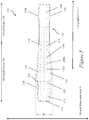
- Figures 1-8illustrate an exemplary automatic injection device 100 having one or more overmolded gripping surfaces for facilitating gripping and manipulation of the device.
- the figuresindicate a longitudinal axis L that runs substantially along the length of the device 100, a first transverse axis H that runs substantially perpendicular to the longitudinal axis L of the device, and a second transverse axis V that runs substantially perpendicular to both longitudinal axis L and first transverse axis H.
- an exemplary length of the device 100may be about 4, 4.5, 4.8, 5, 5.5, 6, 6.5, 6.6, 6.7, 6.8, 6.9, 7, 7.5, 8, 8.5, 9, 9.5, 10 inches, but is not limited to these exemplary lengths.
- an exemplary width of the device 100(at its widest location) may be about 0.5, 0.6, 0.7, 0.8, 0.9, 1.0, 1.1, 1.2, 1.3, 1.4, 1.5, 1.6, 1.7, 1.8, 1.9, 2, 2.1, 2.2, 2.3, 2.4, 2.5, 2.6, 2.7, 2.8, 2.9, 3.0 inches, but is not limited to these exemplary widths.
- an exemplary thickness of the device 100may be about 0.1, 0.2, 0.3, 0.4, 0.5, 0.6, 0.7, 0.8, 0.9, 1.0, 1.1, 1.11, 1.12, 1.13, 1.14, 1.15, 1.16, 1.17, 1.18, 1.19, 1.2, 1.3, 1.4, 1.5, 1.6, 1.7, 1.8, 1.9, 2, 2.1, 2.2, 2.3, 2.4, 2.5, 2.6, 2.7, 2.8, 2.9, 3.0 inches, but is not limited to these exemplary thicknesses.
- the device 100may have an exemplary length of about 6.69 inches, an exemplary width of about 1.46 inches at the widest portion, and an exemplary thickness of about 1.15 inches at the thickest portion. In another exemplary embodiment, the device 100 may have an exemplary length of about 4.8 inches, an exemplary width of about 0.8 inches at the widest portion, and an exemplary thickness of about 0.6 inches at the thickest portion.
- the exemplary dimensions of the recited exemplary devicesallow the device to be conformably and ergonomically held in the grip of a user's hand. This allows a user to reliably and comfortably grip and manipulate the device in order to perform an injection.
- Exemplary automatic injection device 100may include an outer housing 101 for housing a container, such as a syringe or cartridge.
- the containermay be pre-filled with a dose of a therapeutic agent to be injected into a patient's body.
- the housing 101 of the devicein its assembled form, may have any suitable size and shape for storing and dispensing the dose of the therapeutic agent.
- the assembled housing 101may have a shape that is designed and configured to be conformable to a user's hand and so that the user can comfortably and reliably hold the device 100 during an injection.
- the assembled housing 101may have an elongated structure so that its length taken along the longitudinal axis L is much greater than its width taken along the first transverse axis H and its thickness taken along a second transverse axis V.
- An exemplary ratio of the length to the width (at the widest location) of the devicemay be, but is not limited to, 2:1, 3:1, 4:1, 5:1, 6:1, 7:1, 8:1, 9:1, 10:1, all intermediate ratios, and the like.
- An exemplary ratio of the length to the thickness (at the thickest location) of the devicemay be, but is not limited to, 2:1, 3:1, 4:1, 5:1, 6:1, 7:1, 8:1, 9:1, 10:1, all intermediate ratios, and the like.
- Figure 1is a left side perspective view illustrating an exemplary automatic injection device 100 having an outer housing 101.
- Figure 2is a right side perspective view of the exemplary automatic injection device 100 of Figure 1 .
- the housing 101 of the device 100may have a tapered tubular structure with a substantially elliptical or oval cross-section.
- the width of the housing 101may be larger at a proximal portion 106 of the housing 101 than at a distal portion 104 of the housing 101.
- the tapered tubular shape of the exemplary housingallows the device to be streamlined and to be conformably and ergonomically held in and manipulated by a user's hand.
- the housing 101 of the device 100may be formed of a plurality of body components that are assembled together.
- the housing 101may be formed from a first body portion 116 and a second body portion 118 that, when cooperatively engaged to each other along their peripheral edges, enclose and provide a cavity therebetween.
- the first and second body portionsmay be cooperatively engaged to each other using any suitable technique including, but not limited to, bonding, gluing, ultrasonic welding, friction fit, snap fit, interference fit, screws, attachment between corresponding protrusions and recesses, and the like.
- the cavity of the devicemay be enclosed in a single body component or in three or more body components when assembled together.
- a firing button 120may extend from a surface of the first body portion 116.
- the firing button 120when activated by a user, may cause an injection to be performed by the device 100.
- a recessed or concave portion 126may be provided on the first body portion 116 abutting the firing button 120 to facilitate activation of the firing button 120.
- the recessed portion 126may surround the firing button 120 in an exemplary embodiment to accommodate a user's finger as the user presses on the firing button 120.
- a transparent inspection window 128may be provided in a surface of the first body portion 116 to allow a user to view the contents of the device 100.
- the transparent inspection window 128may allow the user to view a therapeutic agent contained in the device 100, for example, to ensure clarity of the agent, and to view an end-of-injection indicator that materializes at the end of a successful injection.
- An exemplary inspection window 128may be substantially elongated in shape, for example, an elongated rectangle (with sharp or rounded edges), an elongated elliptical shape, and the like, although other shapes are possible.
- the length extending along the longitudinal axis Lmay be substantially greater than the width extending along the first transverse axis H.
- a ratio between the length and the width of the inspection windowmay include, but is not limited to, 1.5:1, 2.0:1, 2.5:1, 3.0:1, 3.5:1, 4.0:1, 4.5:1, 5:1, all intermediate ratios, and the like.
- a proximal terminal end 172 of the device housingmay be provided to cover the proximal end of the device 100.
- the proximal terminal end 172may be coupled to the proximal end of the assembled first and second body portions.
- the proximal terminal end 172may take any suitable size and shape.
- the proximal terminal end 172may have a substantially tubular configuration with a substantially oval or elliptical shape.
- at least part of the exterior surface of the proximal terminal end 172may be overmolded with one or more gripping surfaces 173 to facilitate gripping of the proximal portion of the device.
- the entire exterior surface of the proximal terminal end 172may be covered by an overmolded gripping surface 173. Corresponding recesses may be provided on the exterior surface of the proximal terminal end 172 to accommodate the gripping surfaces.
- a removable distal cap 164may be coupled to the distal end of the assembled first and second body portions to cover the distal end of the device 100 in order to prevent exposure of the injection needle prior to an injection.
- the distal cap 164protects against accidental and/or unwanted contact of a user with the injection needle.
- the distal cap 164also protects against damage to and contamination of the injection needle when the device is not in use.
- the distal cap 164may take any suitable size and shape.
- the distal cap 164may have a substantially tubular configuration with a substantially oval or elliptical shape.
- a front surface of the distal cap 164may have a concave cutout portion 168 for accommodating part of the inspection window 128.
- the exterior surface of the distal cap 164may lack overmolded gripping surfaces. In other exemplary embodiments, the exterior surface of the distal cap 164 may be overmolded with one or more gripping surfaces 165 for facilitating gripping and removal of the distal cap 164 from the device. In an exemplary embodiment, the entire exterior surface of the distal cap 164 may be covered by an overmolded gripping surface 165. Corresponding recesses may be provided on the exterior surface of the distal cap 164 to accommodate the gripping surfaces.
- one or more ridgesmay be provided at the gripping surfaces 165 on the distal cap 164 to further facilitate gripping and manipulation of the device.
- the shapes and locations of the ridges and/or groovesmay be altered as desired, and any desired number of ridges and/or grooves may be provided.
- the ridges and/or groovesmay extend substantially perpendicularly to the longitudinal axis L of the device.
- the gripping surfaces 165may include textured surfaces to improve the tactile feel and further facilitate firm gripping of the device.
- the distal cap 164may include one or more protrusions 170a, 170b (shown in Figure 5 ) that extend outwardly from the front surface and the back surface of the distal cap 164 to further facilitate gripping of the cap 164.
- the distal cap 164may frictionally engage a recessed or stepped portion of the housing in order to be retained in position on the housing when the device is not in use.
- the distal cap 164may include a boss for locking and/or joining the cap to the housing until the user is ready to perform an injection. Any suitable mating mechanism may be used in accordance with the teachings of exemplary embodiments.
- proximal terminal end 172When the proximal terminal end 172, the first body portion 116 and the second body portion 118 are assembled together, they form a tapered tubular structure.
- Side surfaces of the body portions 116, 118 abutting the gripping surfaces 173 on the proximal terminal end 172may include one or more recessed or concave portions 122, 124.
- two recessed portions 122, 124may be provided at opposite sides of the device abutting the firing button 120. The recessed portions allow the hand of the user to be accommodated in a comfortable position when pressing the firing button 120.
- a portion of the body portions 116, 118 abutting the recessed portions 122, 124may be overmolded with one or more gripping surfaces 154, 156 to facilitate holding and manipulation of the device.
- two gripping surfaces 154, 156may be provided at opposite side surfaces of the device.
- a first gripping surface 154may abut a first recessed portion 122
- a second gripping surfaces 156may abut a second recessed portion 124.
- Corresponding recessesmay be provided on the exterior surface of the first body portion 116 to accommodate the gripping surfaces.
- a first overmolded gripping region, a second overmolded gripping region and a recessed region abutting the first and second overmolded gripping regionsmay be provided.
- the first overmolded gripping region, the second overmolded gripping region and the recessed regionmay cooperatively provide an ergonomic and comfortable gripping area at which a user may grip the automatic injection device in order to perform an injection.
- the first overmolded gripping regionmay be formed by the proximal terminal end 172 having an overmolded outer surface or covering.
- the second overmolded gripping regionmay be formed part of the assembly of the first body portion 116 and the second body portion 118 having one or more overmolded gripping surfaces (for example, gripping surfaces 154, 156).
- the second overmolded gripping regionmay have a substantially tapered tubular structure for providing an ergonomic fit with a user's hand.
- the recessed region abutting the first and second overmolded gripping regionsmay be formed by a portion of the assembly of the first body portion 116 and the second body portion 118 that is narrower in width than the first overmolded gripping region and the second overmolded gripping region.
- the recessed regionmay be provided between the first and second overmolded gripping regions.
- the recessed regionmay lack any overmolded gripping surfaces.
- Figure 3illustrates an exploded view of the exemplary automatic injection device 100 of Figures 1 and 2 .
- the first body portion 116may include a substantially planar front surface (extending substantially along the L-H plane) and left and right side surfaces (extending substantially along the L-V plane).
- the front surface of the first body portion 116may contiguously and integrally transition to left and right side surfaces of the first body portion 116.
- the edges at which the front surface transitions to the side surfacesmay be sharp, or smooth and rounded in order to maintain a streamlined shape of the device and for ergonomic handling of the device.
- the front and/or side surfaces of the first body portion 116may be substantially flat or slightly convex so that the assembled housing ergonomically fits within a user's hand.
- the front surfacemay be wider at the proximal portion 106 of the device than at the distal portion 104.
- One of ordinary skill in the artwill recognize that other exemplary shapes are possible for the first body portion 116 of the device.
- the second body portion 118may include a substantially planar front surface (extending substantially along the L-H plane) and left and right side surfaces (extending substantially along the L-V plane).
- the front surface of the second body portion 118may contiguously and integrally transition to left and right side surfaces of the second body portion 118.
- the edges at which the front surface transitions to the side surfacesmay be sharp, or smooth and rounded in order to maintain a streamlined shape of the device and for ergonomic handling of the device.
- the front and/or side surfaces of the second body portion 118may be substantially flat or slightly convex so that the assembled housing ergonomically fits within a user's hand.
- the front surfacemay be wider at the proximal portion 106 of the device than at the distal portion 104.
- One of ordinary skill in the artwill recognize that other exemplary shapes are possible for the second body portion 118 of the device.
- the first body portion 116 and the second body portion 118may be cooperatively engaged to each other along their peripheral edges to enclose and provide a cavity 102 therebetween.
- the upper and second body portionsmay be cooperatively engaged to each other using any suitable technique including, but not limited to, bonding, gluing, ultrasonic welding, friction fit, snap fit, interference fit, screws, attachment between corresponding protrusions and recesses, and the like.
- the cavity 102 of the devicemay be enclosed in a single body component or in three or more body components when assembled together.
- An exemplary container 160is preferably slidably positioned in the cavity 102 and is coupled to an injection needle (not shown) at a distal end.
- the injection needlemay be covered by a needle shield 162, for example, a soft needle shield and/or a rigid needle shield.
- a container advancement mechanismmay be provided within the housing to mechanically advance the container 160 within and relative to the housing and to eject the therapeutic agent from the container 160 for performing an injection.
- the container advancement mechanismmay include one or more actuators (e.g., one or more biasing members) that move the container from a sheathed position to a projecting position. When the device is in a pre-injection state, the container 160 may be in a sheathed position, i.e., retracted within the housing.
- the container advancement mechanismmay advance the container 160 to a projecting position so that the injection needle projects from a distal end of the housing to allow ejection of the therapeutic agent into a patient's body.
- the distal end of the housingmay include an aperture through which the needle may project.
- the cavity 102 within the housingmay also accommodate a firing engagement mechanism, for example, the firing button 120.
- the firing button 120when actuated by depressing, activates the container advancement mechanism that, in turn, advances the container 160 toward the injection site, drives the injection needle into the injection site and delivers the therapeutic agent into the injection site.
- at least a portion of the exterior surface of the firing button 120may be overmolded with one or more rubberized gripping surfaces to facilitate pressing of the firing button by a user's finger or hand.
- the entire exterior surface of the firing buttonmay be covered by an overmolded gripping surface.
- the gripping surfaces on the firing button 120may be colored differently from the non-gripping surfaces to provide a visual affordance to indicate which area of the device should be gripped.
- the one or more gripping surfaces on the firing button 120may be green, while all other surfaces on the device may be one or more colors that are not green.
- Figure 3shows that a front surface of the first body portion 116 may include a first aperture 119 through which the firing button 120 may protrude outside the front surface.
- An exemplary aperture 119may be circular to accommodate the firing button 120 with a circular cross-section, although other shapes are possible.
- the front surface of the first body portion 116may include a second aperture 127 for accommodating the transparent inspection window 128.
- the removable distal cap 164may frictionally engage a recessed or stepped portion 166 of the housing in order to be retained in position on the housing when the device is not in use.
- Figure 4illustrates a front surface of the first body portion 116 of the exemplary automatic injection device 100.
- Figure 5illustrates a left side view of the first body portion 116 and the second body portion 118 as assembled in the device 100.
- an exemplary automatic injection device 100may have a tapered tubular shape with a substantially elongated, elliptical cross-section.
- the proximal terminal end 172 of the devicemay have a narrower proximal end (width w1) that broadens slightly and gradually to a larger width (width w2) at the distal end of the proximal terminal end 172.
- the proximal end of the first body portion 116 abutting the proximal terminal end 172may include one or more recessed portions 122, 124 at the sides.
- the recessed portions 122, 124may create a narrow necked portion (width w3) that is narrower than the adjacent width (width w2) of the proximal terminal end 172.
- the first body portion 116may widen to the largest width of the device (width W) and may gradually taper to a narrower width (width w4) near the mid-portion of the device.
- the first body portion 116may have a substantially uniform narrow width (width w4).
- the second body portion 118may have a substantially similar shape and configuration as the first body portion 116.
- the removable distal cap 164may include one or more protrusions 170a, 170b (shown in Figure 5 ) that extend outwardly from the front surface and the back surface of the distal cap 164 to further facilitate gripping of the distal cap.
- a left gripping surface 130may be provided to partly cover and extend across the left side surface of the first body portion 116, and a right gripping surface 132 may be provided to partly cover and extend across the right side surface of the first body portion 116.
- each gripping surface 130, 132may be disposed between the firing button 120 and the inspection window 128.
- One of ordinary skillwill recognize that other placements of the gripping surfaces 130, 132 are possible.
- a left gripping surface 152may be provided to partly cover and extend across the left side surface of the second body portion 118
- a right gripping surface 153may be provided to partly cover and extend across the right side surface of the second body portion 118.
- the left gripping surfaces 130, 152may form a contiguous left gripping surface 154 on the housing
- the right gripping surfaces 132, 153may form a contiguous right gripping surface 156 on the housing.
- the left and right contiguous gripping surfaces 154, 156facilitate reliable and comfortable gripping and manipulation of the device by a user's hand, which markedly and surprisingly improves the user experience of physically weak users, for example, older users and users suffering from rheumatoid arthritis.
- test participantsliked the overmolded gripping surfaces on the sides of the device, the ridges on the overmolded gripping surfaces, and the relatively large size and ergonomic shape of the device. Most test participants (58%) strongly preferred the handling and grip of an example automatic injection device of the present invention. Overall, the example device configuration received a high average rating of 8.1 out of 10.0.
- the overmolded gripping surfaceswere the primary factor in the participants' high ratings of the example device for handling and grip. For several usability factors, there was a significant positive correlation between Cochin scores and the example device of the present invention with the overmolded gripping surfaces, which indicates that the example device of the present invention is well-suited for those with hand dysfunction.
- the left and right gripping surfacesmay have different sizes, shapes and configurations than the exemplary sizes, shapes and configurations shown in Figures 1-8 .
- One of ordinary skill in the artwill recognize that more or fewer gripping surfaces may be provided on exemplary automatic injection devices that the exemplary left and right gripping surfaces shown in Figures 1-8 .
- One of ordinary skill in the artwill also recognize that one or more gripping surfaces may be positioned on exemplary automatic injection devices in positions other than the exemplary positions shown in Figures 1-8 .
- the outline of each gripping surfacemay have a smooth, rounded, streamlined configuration in some exemplary embodiments.
- the overmolded gripping surfaces provided in exemplary embodimentsmay be formed of any suitable material that provides a first soft and high-friction touch perception to a user, as compared to the portions of the device that lack an overmolded gripping surface which provide a second hard and low-friction touch perception to a user.
- the difference in the sensory perceptionsprovides a touch affordance to a user, indicating that the device is to be gripped at regions provided with the overmolded gripping surfaces.
- the overmolded gripping surfacesmay be formed of a first type of material having a soft, high-friction touch perception to a user, while the portions of the device lacking overmolded gripping surfaces may be formed of a second type of material having a harder, lower-friction touch perception to a user.
- the overmolded gripping surfacesmay be formed of a first material with a lower hardness, while the non-gripping surfaces may be formed of a second material with a higher hardness.
- the non-gripping surfacesmay be formed of any rigid thermoplastic material or rigid substrate suitable for use in a medical device application and suitable for providing a hard, low-friction touch perception to the user.
- Rigid thermoplasticscan include materials such as polypropylene (PP), polyethylene (PE), polystyrene (PS), high impact polystyrene (HIPS), polycarbonate (PC), acrynitrile-butadiene-styrene (ABS), poly(ethylene terephthalate) (PET), polyamide (PA), PC/ABS blend and PPO/PS blends.
- Exemplary overmolded gripping surfacesmay be formed of materials having any suitable material grade and hardness for providing a soft, high-friction touch perception to the user.
- Exemplary overmolded gripping surface materialsmay include, but are not limited to, rubber (for example, having a durometer of 50A in one embodiment), thermoplastic elastomers (TPEs), thermoplastic vulcanizate (TPV), and the like.
- Exemplary thermoplastic elastomers that may be used to form exemplary overmolded gripping surfacesinclude, but are not limited to, TPEs from KRAIBURG, the DynaflexTM TPE from PolyOne, the VersaflexTM TPE from PolyOne, the VersollanTM TPE from PolyOne, the OnElexTM TPE from Polyone, and the like.
- Exemplary thermoplastic vulcanizates that may be used to form exemplary overmolded gripping surfacesinclude, but are not limited to, the SantopreneTM thermoplastic from ExxonMobil and the like.
- the overmolded gripping surfacesmay be colored differently from the non-gripping surfaces to provide a visual affordance to indicate which area of the device should be gripped.
- the left and right overmolded gripping surfacesmay be maroon in color while the non-gripping surfaces on the housing may be grey in color.
- one or more ridgesthat protrude from the exterior surface
- one or more grooves or divotsthat are depressed into the exterior surface
- 158a, 158b, 158cmay be provided at the left overmolded gripping surface 154 and/or the right overmolded gripping surface 156 to further facilitate gripping and manipulation of the device.
- the shapes and locations of the ridges and/or groovesmay be altered as desired, and any desired number of ridges and/or grooves may be provided.
- the ridges and/or groovesmay extend substantially perpendicularly to the longitudinal axis L of the device.
- the overmolded gripping surfacesmay include textured surfaces to improve the tactile feel and further facilitate firm gripping of the device.
- Figure 6Ais a front close-up view of an exemplary left overmolded gripping surface 130 provided on a first body portion 116 of the device 100 of Figure 1 .
- Figure 6Bis a left side close-up view of the exemplary left overmolded gripping surface 130 of Figure 6A .
- the right overmolded gripping surface 132 of the first body portion 116, the left overmolded gripping surface 152 of the second body portion 118, and the right overmolded gripping surface 153 of the second body portion 118may be similar in structure and configuration.
- the left overmolded gripping surface 130may have a first longitudinal side 134 that extends on the front surface of the first body portion 116 substantially along the longitudinal axis L.
- the first longitudinal side 134 of the left overmolded gripping surface 130may be substantially linear, while in another exemplary embodiment, the first longitudinal side 134 may be slightly concave or convex.
- a proximal end 136 of the first longitudinal side 134may extend toward and connect with an end 138 of a first horizontal side 140 of the left overmolded gripping surface 130.
- the first horizontal side 140may extend across the left side surface of the first body portion 116 substantially along the second transverse axis V, ending at the peripheral edge of the first body portion 116.
- a connecting side 142 extending between ends 136, 138may connect the first longitudinal side 134 to the first horizontal side 140.
- the first horizontal side 140may include a beveled edge extending to the first longitudinal side 134 at an angle to both longitudinal axis L and the first transverse axis H.
- the first longitudinal side 134 of the left overmolded gripping surface 130may be substantially longer than the first horizontal side 140.
- An exemplary ratio of the length of the first longitudinal side 134 to the length of the first horizontal side 140may include, but is not limited to, about 2:1, 2.5:1, 3:1, 3.5:1, 4:1, 4.5:1, 5:1, all intermediate ratios, and the like.
- a distal end 144 of the first longitudinal side 134may extend toward and connect with an end 146 of a second horizontal side 148 of the left overmolded gripping surface 130.
- a connecting side 150extending between the ends 144, 146 may connect the first longitudinal side 134 to the second horizontal side 148.
- the connecting side 150may have a length greater than that of the connecting side 142.
- a ratio of the length of the connecting side 150 to the length of the connecting side 142may include, but is not limited to, 1.5:1, 1.75:1, 2:1, 2.25:1, 2.5:1, 2.75:1, 3:1, 3.25:1, 3.5:1, 3.75:1, 4:1, all intermediate ratios, and the like, but is not limited to these exemplary ratios.
- the second horizontal side 148may extend across the left side surface of the first body portion 116 substantially along the second transverse axis V, ending at the peripheral edge of the first body portion 116.
- the first longitudinal side 134may be substantially longer than either the first horizontal side 140 or the second horizontal side 148.
- An exemplary ratio of the length of the first longitudinal side 134 to the length of either horizontal sidemay include, but is not limited to, about 2:1, 2.5:1, 3:1, 3.5:1, 4:1, 4.5:1, 5:1, 5.5:1, 6:1, 6.5:1, 7:1, all intermediate ratios, and the like.
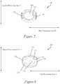
- FIG. 7is a bottom view of an exemplary removable distal cap 164 showing the overmolded gripping surface 165.
- the overmolded gripping surfaces 165may be formed of any suitable material that provides first a soft and high-friction touch perception to a user, as compared to the portions of the device that lack an overmolded gripping surface which provide a hard and low-friction touch perception to a user. The difference in the sensory perceptions provides a touch affordance to a user, indicating that the device is to be gripped at regions provided with the overmolded gripping surfaces.
- the overmolded gripping surfacesmay be formed of a first type of material having a soft, high-friction touch perception, while the non-gripping surfaces are formed of a second type of material having a harder, lower-friction touch perception.
- Exemplary overmolded gripping surfaces 165may be formed of materials having any suitable material grade and hardness for providing a soft, high-friction touch perception to the user.
- Exemplary overmolded gripping surface materialsmay include, but are not limited to, rubber (for example, having a durometer of 50A in one embodiment), thermoplastic elastomers (TPEs), thermoplastic vulcanizate (TPV), and the like.
- Exemplary thermoplastic elastomers that may be used to form exemplary overmolded gripping surfacesinclude, but are not limited to, TPEs from KRAIBURG, the DynaflexTM TPE from PolyOne, the VersaflexTM TPE from PolyOne, the VersollanTM TPE from PolyOne, the OnElexTM TPE from Polyone, and the like.
- Exemplary thermoplastic vulcanizates that may be used to form exemplary overmolded gripping surfacesinclude, but are not limited to, the SantopreneTM thermoplastic from ExxonMobil and the like.
- the overmolded gripping surfaces 165may be colored differently from the non-gripping surfaces to provide a visual affordance to indicate which area of the device should be gripped.
- the one or more overmolded gripping surfaces 165 on the distal cap 164may be maroon in color while the non-gripping surfaces on the housing may be grey in color.
- Figure 8is a top view of an exemplary proximal terminal end 172 for covering the proximal end of the housing.
- the exterior surface of the proximal terminal end 172may lack any overmolded gripping surfaces.
- at least part of the exterior surface of the proximal terminal end 172may be overmolded with one or more gripping surfaces 173 to facilitate gripping of the proximal portion of the device.
- the entire exterior surface of the proximal terminal end 172may be covered by an overmolded gripping surface 173.
- the overmolded gripping surfaces 173may be formed of any suitable material that provides a first soft and high-friction touch perception to a user, as compared to the portions of the device that lack an overmolded gripping surface which provide a second soft and low-friction touch perception to a user.
- the difference in the sensory perceptionsprovides a touch affordance to a user, indicating that the device is to be gripped at regions provided with the overmolded gripping surfaces.
- the overmolded gripping surfaces 173may be formed of a first type of material having a soft, high-friction touch perception, while the non-gripping surfaces are formed of a second type of material having a harder, lower-friction touch perception.
- Exemplary overmolded gripping surfaces 173may be formed of materials having any suitable material grade and hardness for providing a soft, high-friction touch perception to the user.
- Exemplary overmolded gripping surface materialsmay include, but are not limited to, rubber (for example, having a durometer of 50A in one embodiment), thermoplastic elastomers (TPEs), thermoplastic vulcanizate (TPV), and the like.
- Exemplary thermoplastic elastomers that may be used to form exemplary overmolded gripping surfacesinclude, but are not limited to, TPEs from KRAIBURG, the DynaflexTM TPE from PolyOne, the VersaflexTM TPE from PolyOne, the VersollanTM TPE from PolyOne, the OnFlexTM TPE from Polyone, and the like.
- Exemplary thermoplastic vulcanizates that may be used to form exemplary overmolded gripping surfacesinclude, but are not limited to, the SantopreneTM thermoplastic from ExxonMobil and the like.
- the overmolded gripping surfaces 173may be colored differently from the non-gripping surfaces to provide a visual affordance to indicate which area of the device should be gripped.
- the one or more overmolded gripping surfaces 173 on the proximal terminal end 172may be maroon in color while the non-gripping surfaces on the housing may be grey in color.
- one or more ridgesmay be provided on the exterior surface of the proximal terminal end 172 to further facilitate gripping of the proximal portion of the device.
- the shapes and locations of the ridges and/or groovesmay be altered as desired, and any desired number of ridges and/or grooves may be provided.
- the overmolded gripping surfaces 173may include textured surfaces to improve the tactile feel and further facilitate firm gripping of the device.
- a wrap-around groove 174may be provided around the circumference of the proximal terminal end 172 and a concave or recessed surface 176 may be provided at the top of the proximal terminal end 172 in order to orient and guide a user's hand and fingers to the device.
- the concave or recessed surface 176may accommodate a finger on the surface 176 while the user is performing an injection using the device.
- the housing 101, the removable distal cap 164 and/or the proximal terminal end 172 of the device 100may further include graphics, symbols and/or numbers to facilitate use of the automatic injection device.
- the distal cap 164may include a depiction of an arrow on an outer surface pointing towards the distal end of the device to indicate how the device should be held relative to the patient (i.e., with the distal end adjacent to the injection site).
- the automatic injection devicemay have any suitable graphics, symbols and/or numbers to facilitate patient instruction, or the automatic injection device may omit such graphics, symbols and/or numbers.
- Figure 9is a flowchart of an exemplary method of assembling an exemplary automatic injection device.
- a housing of an exemplary automatic injection devicemay be provided in two or more separate housing components (for example, first and second body portion) that may be coupled together during assembly of the device.
- a first body portion of the housingis provided or formed.
- one or more gripping surfacesare overmolded on corresponding recesses on the exterior surface of the first body portion to facilitate gripping and manipulation of the device during an injection.
- a second body portion of the housingis provided or formed.
- one or more gripping surfacesare overmolded on corresponding recesses on the exterior surface of the second body portion to facilitate gripping and manipulation of the device during an injection.
- a proximal terminal end of the housingis provided or formed.
- one or more gripping surfacesare overmolded on corresponding recesses on the exterior surface of the proximal terminal end to facilitate gripping and manipulation of the device.
- a removable distal cap of the housingis provided or formed.
- one or more gripping surfacesare overmolded on corresponding recesses on the exterior surface of the distal cap to facilitate removal of the distal cap before performing an injection.
- a firing button of the housingis provided or formed.
- one or more gripping surfacesare overmolded on the exterior surface of the firing button to facilitate activation of the firing button to perform an injection.
- one or more internal components of the automatic injection devicemay be positioned in a cavity defined between the upper and second body portions.
- Exemplary device componentsmay include, but are not limited to, a container (e.g., a syringe) pre-filled with a therapeutic agent for injecting into a patient, an injection needle coupled to a distal end of the container, a container advancement mechanism for advancing the container within and relative to the housing toward the injection site and for ejecting the therapeutic agent from the container during an injection, a firing button for activating the container advancement mechanism, and the like.
- a containere.g., a syringe
- a container advancement mechanismfor advancing the container within and relative to the housing toward the injection site and for ejecting the therapeutic agent from the container during an injection
- a firing buttonfor activating the container advancement mechanism, and the like.
- the upper and second body portionsmay be cooperatively engaged to form a body assembly that encloses and holds the internal components within the cavity.
- the body portionsmay be coupled at their peripheral edges. Any suitable coupling or joining may be used in step 924 including, but not limited to, bonding, gluing, ultrasonic welding, friction fit, snap fit, interference fit, screws, corresponding protrusions and recesses, and the like.
- the removable distal capmay be removably coupled at a distal end of the body assembly to cover an injection needle or a needle shield that, in turn, covers the injection needle.
- the proximal terminal endmay be coupled at a proximal end of the body assembly.
- any suitable fabrication techniquemay be used to form any of the device components including, but not limited to, injection molding.
- the device componentsmay be formed of any suitable material including, but not limited to, plastics, thermoplastics, polycarbonates, metals, and the like.
- test participantsForty-four test participants were recruited to test both the exemplary automatic injection devices having overmolded gripping surfaces of the present invention and four alternate automatic injection devices without such gripping surfaces.
- a majority of the participantswere suffering from rheumatoid arthritis (RA) at the time of the test.
- the participantswere diagnosed with RA from 1 to 40 years ago, with an average age of diagnosis of 9 years ago.
- Four participantswere suffering from Crohn's disease at the time of the test.
- each test participanttested the different exemplary automatic injection device configurations.
- each test participantperformed a simulated injection (i.e., an injection with clipped needles and no medicament) using the devices.
- a simulated injectioni.e., an injection with clipped needles and no medicament
- each test participantwas asked a series of follow-up questions designed to assess the participant's approval of the form and function of the devices. These questions included questions on, for example, the size, shape, ease of handling, comfort of holding, overall user experience, and the like.
- test participantsUpon performing simulated injections using the different device configurations, test participants were asked to provide feedback and comparative ratings on handling and grip, overall ease of use, and comfort in performing the injection steps. All device configurations were rated on a scale of 1 (very negative) to 10 (very positive).
- test participants(58%) strongly preferred the handling and grip of the example device configuration of the present invention, compared to four alternate device configurations that did not include overmolded gripping surfaces.
- Test participantsparticularly liked the rubberized overmolded grips on the side of the example device and its relatively large size, which made the example device easy and comfortable to hold.
- the rubberized overmolded gripswere the primary factor in participants' high ratings of the example device configuration for handling and grip as taught herein.
- test participantsUpon performing simulated injections in the example device use phase, test participants were asked to rate the comfort of holding the example device configuration of the present invention and four alternate device configurations that did not include any overmolded gripping surfaces. Test participants rated each device configuration on a scale from 1 (very low confidence) to 7 (very high confidence). Most test participants favored the example device configuration of the present invention for comfort in performing injection steps, with 45% rating it the highest.
- test participantsUpon initial exposure to the example device and before receiving instructions or a demonstration on use, test participants were asked about the perceived ease of use of the example device configuration of the present invention and four alternate device configurations that did not include any overmolded gripping surfaces. Test participants rated each device configuration on a scale from 1 (very difficult) to 7 (very easy). All of the device configurations received high ratings for their perceived ease of use.
- test participantsUpon performing simulated injections in the actual device use phase, test participants were asked to rate the ease of handling each device configuration. Test participants rated each device configuration on a scale from 1 (very low confidence) to 7 (very high confidence). Furthermore, upon performing simulated injections using the device configuration in the third actual device use phase, test participants were also asked to rate the configurations on their overall ease of use on a scale of 1 (very difficult) to 10 (very easy).
- the example device configuration of the present inventionMost test participants (42%) found the example device configuration of the present invention easiest to use compared to four alternate device configurations that did not include overmolded gripping surfaces. Overall, the example device configuration of the present invention received a high average rating of 7.97 out of 10.0.
- test participantsUpon performing simulated injections in the example device use phase, test participants were asked to rate the overall size of the example device configuration of the present invention and four alternate device configurations that did not include any overmolded gripping surfaces on a scale of 1 (very low confidence) to 7 (very high confidence). All of the device configurations generally received positive ratings for their overall shape. In general, test participants who struggled to form a tight fist preferred larger devices. The example device configuration of the present invention generally received the highest ratings.
- test participantsUpon performing simulated injections in the actual device use phase, test participants were asked to rate the overall shape of the example device configuration of the present invention and four alternate device configurations that did not include any overmolded gripping surfaces on a scale of 1 (very low confidence) to 7 (very high confidence).
- Exemplary flowchartsare provided herein for illustrative purposes and are nonlimiting examples of methods.
- One of ordinary skill in the artwill recognize that exemplary methods may include more or fewer steps than those illustrated in the exemplary flowcharts, and that the steps in the exemplary flowcharts may be performed in a different order than shown.
Landscapes
- Health & Medical Sciences (AREA)
- Life Sciences & Earth Sciences (AREA)
- Engineering & Computer Science (AREA)
- Biomedical Technology (AREA)
- Heart & Thoracic Surgery (AREA)
- Hematology (AREA)
- Animal Behavior & Ethology (AREA)
- General Health & Medical Sciences (AREA)
- Public Health (AREA)
- Veterinary Medicine (AREA)
- Vascular Medicine (AREA)
- Anesthesiology (AREA)
- Manufacturing & Machinery (AREA)
- Physics & Mathematics (AREA)
- Biophysics (AREA)
- Pathology (AREA)
- Medical Informatics (AREA)
- Molecular Biology (AREA)
- Surgery (AREA)
- Infusion, Injection, And Reservoir Apparatuses (AREA)
- Knitting Machines (AREA)
- Injection Moulding Of Plastics Or The Like (AREA)
- Medicines Containing Antibodies Or Antigens For Use As Internal Diagnostic Agents (AREA)
- Passenger Equipment (AREA)
- Catching Or Destruction (AREA)
- Moulds For Moulding Plastics Or The Like (AREA)
Abstract
Description
- This application is a non-provisional of and claims priority to
U.S. Provisional Patent Application No. 61/435,465, filed January 24, 2011 - Automatic injection devices offer an alternative to manually-operated syringes for administering therapeutic agents into patients' bodies and allowing patients to self-administer therapeutic agents. Automatic injection devices may be used to administer medications under emergency conditions, for example, to administer epinephrine to counteract the effects of a severe allergic reaction. Automatic injection devices have also been described for use in administering anti-arrhythmic medications and selective thrombolytic agents during a heart attack.See, for example,
U.S. Patent Nos. 3,910,260 ;4,004,577 ;4,689,042 ;4,755,169 ; and4,795,433 , the entire contents of which are incorporated herein in their entirety by reference. Various types of automatic injection devices are also described in, for example,U.S. Patent Nos. 3,941,130 ;4,261,358 ;5,085,642 ;5,092,843 ;5,102,393 ;5,267,963 ;6,149,626 ;6,270,479 ; and6,371,939 ; and International Patent Publication No.WO/2008/005315 , the entire contents of which are incorporated herein in their entirety by reference. - Conventionally, an automatic injection device houses a syringe and, when operated, causes the syringe to move forwardly and a needle to project from the housing so that a therapeutic agent contained in the syringe is ejected into a patient's body.
- Exemplary embodiments provide automatic injection devices, housing components for automatic injection devices and methods for fabricating the same. An exemplary housing of an automatic injection device may be overmolded with one or more gripping surfaces to facilitate gripping and manipulation of the automatic injection device by a user when performing an injection. In an exemplary embodiment, an overmolded left gripping surface may extend along a left side of the housing and an overmolded right gripping surface may extend along a right side of the housing opposite to the left side.
- In accordance with an exemplary embodiment, an automatic injection device is provided with a housing enclosing a cavity for accommodating a container. A first overmolded gripping surface is provided to extend longitudinally along a portion of the housing on a first exterior surface of the housing. A second overmolded griping surface is provided to extend longitudinally along a portion of the housing on a second exterior surface of the housing opposite to the first exterior surface.
- In an exemplary embodiment, the first and second overmolded gripping surfaces on the housing are formed of a first material having a first touch perception, and non-gripping surfaces on the housing are formed of a second material having a second touch perception. In an exemplary embodiment, the first and second overmolded gripping surfaces on the housing are formed of a first material having a first hardness, and non-gripping surfaces on the housing are formed of a second material having a second higher hardness.
- In an exemplary embodiment, the automatic injection device includes a removable distal cap for protectively covering an injection needle couplable to the container, an exterior surface of the distal cap including an overmolded gripping surface for facilitating gripping and removal of the distal cap. In an exemplary embodiment, the automatic injection device includes a firing button protruding from an aperture in the housing and including an overmolded contact surface for facilitating actuation of the firing button by a user. In an exemplary embodiment, the automatic injection device includes a proximal terminal end for covering a proximal end of the automatic injection device, the proximal terminal end having an overmolded exterior surface. In an exemplary embodiment, a top surface of the proximal terminal end includes a recessed surface for directing and facilitating accommodation of a user's hand or finger for gripping the automatic injection device.
- In accordance with another exemplary embodiment, a method is provided for assembling an automatic injection device. The method includes providing a housing enclosing a cavity for accommodating a container. The method includes overmolding, on the housing, a first gripping surface extending longitudinally along a portion of the housing on a first exterior surface of the housing. The method also includes overmolding, on the housing, a second gripping surface extending longitudinally along a portion of the housing on a second exterior surface of the housing opposite to the first exterior surface.
- In an exemplary embodiment, the first and second gripping surfaces on the housing are formed of a first material having a first touch perception, and non-gripping surfaces on the housing are formed of a second material having a second touch perception. In an exemplary embodiment, the first and second gripping surfaces on the housing are formed of a first material having a first hardness, and non-gripping surfaces on the housing are formed of a second material having a second higher hardness.
- In an exemplary embodiment, the method includes overmolding a gripping surface on an exterior surface of a distal cap to facilitate gripping and removal of the distal cap, and coupling the distal cap to a distal end of the housing for protectively covering an injection needle. In an exemplary embodiment, the method includes overmolding a gripping surface on a firing button to facilitate activation of the firing button, and providing the firing button within the cavity so that part of the firing button protrudes from an aperture in the housing.
- In an exemplary embodiment, the method includes overmolding a gripping surface on an exterior surface of a proximal terminal end, and coupling the proximal terminal end to a proximal end of the housing. In an exemplary embodiment, a top surface of the proximal terminal end includes a recessed surface for directing a user's hand or finger for gripping the automatic injection device.
- In accordance with another exemplary embodiment, an automatic injection device is provided including a housing enclosing a cavity for accommodating a container. The housing includes a first overmolded gripping region, a second overmolded gripping region, and a recessed region abutting the first and second overmolded gripping regions.
- In an exemplary embodiment, the recessed region is disposed between the first and second overmolded gripping regions. In an exemplary embodiment, a width of the housing at the recessed region is smaller than a width of the housing at the first overmolded gripping region and a width of the housing at the second overmolded gripping region. In an exemplary embodiment, the recessed region lacks a gripping surface.
- In an exemplary embodiment, the first overmolded gripping region is formed by a proximal terminal end of the housing having an exterior surface that is overmolded with a gripping surface. In an exemplary embodiment, the second overmolded gripping region of the housing has a tapered tubular structure.
- The foregoing and other objects, aspects, features, and advantages of exemplary embodiments will become more apparent and may be better understood by referring to the following description taken in conjunction with the accompanying drawings, in which:
Figure 1 is a left side perspective view illustrating an exemplary automatic injection device in which a removable distal cap is removed and pictured separately from the housing of the device.Figure 2 is a right side perspective view illustrating the exemplary automatic injection device ofFigure 1 .Figure 3 is a left side exploded perspective view of the exemplary automatic injection device ofFigures 1 and2 .Figure 4 is a front view of the exemplary automatic injection device ofFigures 1-3 .Figure 5 is a left side view of the exemplary automatic injection device ofFigures 1-3 , the right side view being a mirror image of the left side view.Figure 6A is a front close-up view of an exemplary left gripping surface provided on a first body portion of the device ofFigures 1-3 .Figure 6B is a left side close-up view of the exemplary left gripping surface ofFigure 6A .Figure 7 is a bottom view of an exemplary removable distal cap of the exemplary automatic injection device ofFigures 1-3 .Figure 8 is a top view of an exemplary proximal terminal end of the exemplary automatic injection device ofFigures 1-3 .Figure 9 is a flowchart of an exemplary method for forming an exemplary automatic injection device.- Exemplary embodiments provide automatic injection devices having housings that are particularly designed and configured for reliable, safe, ergonomic and comfortable handling by users. Exemplary embodiments also provide housing components for automatic injection devices that are particularly designed and configured for reliable, safe, ergonomic and comfortable handling by users. Exemplary embodiments also provide methods for fabricating exemplary housings for automatic injection devices and automatic injection devices including exemplary housings.
- In one exemplary embodiment, one or more overmolded gripping surfaces may be provided on an exterior surface of an exemplary automatic injection device housing in order to allow the device to be easily, comfortably and reliably gripped and manipulated by a user. The exemplary overmolded gripping surfaces are particularly configured and positioned on the housing to prevent slippage from the hands of the user, and thereby to avoid injury to the user and others in the vicinity. Furthermore, the exemplary overmolded gripping surfaces are particularly configured and positioned to be ergonomic and comfortable to use, particularly by physically weak users, for example, older users, users who suffer from rheumatoid arthritis, and the like.
- In user tests performed using exemplary automatic injection devices, test participants appreciated exemplary overmolded gripping surfaces on the sides of the devices and the relatively large size and ergonomic shape of the device. The test participants provided high ratings for handling and grip of exemplary devices, in which the overmolded gripping surfaces were the primary factor in test participants' high ratings of exemplary device configurations for handling and grip, compared to devices without overmolded gripping surfaces. For several usability factors, there was a significant positive correlation between Cochin scores and exemplary device configurations, which indicates that exemplary devices are well-suited for use by users with hand dysfunction.
- An exemplary automatic injections device may contain and may be used to administer a dose of a TNFα inhibitor. In an exemplary embodiment, the TNFα inhibitor may be a human TNFα antibody or antigen-biding portion thereof. In an exemplary embodiment, the human TNFα antibody or antigen-binding portion thereof may be adalimumab (HUMIRA®) or golimumab.
- Certain terms are defined in this section to facilitate understanding of exemplary embodiments.
- The terms "automatic injection device" and "autoinjector," as used herein, refer to a device that enables a patient to self-administer a therapeutically effective dose of a therapeutic agent, wherein the device differs from a conventional syringe by the inclusion of a mechanism for automatically delivering the therapeutic agent to the patient by injection when the mechanism is engaged.
- The terms "vessel" and "container," as used herein, refer to a syringe or cartridge that may be used in an exemplary automatic injection device for holding a dose of a therapeutic agent.
- The terms "syringe" and "cartridge," as used herein, refer to a sterile barrel portion of an automatic injection device that is filled with a dose of a therapeutic agent prior to distribution or sale of the device to a patient or other non-medical professional for administration of the therapeutic agent to a patient. In an exemplary embodiment, a distal end of the barrel portion of a syringe may be coupled to a sterile hypodermic injection needle. In an exemplary embodiment, a distal end of the barrel portion of a cartridge may not be coupled to an injection needle. That is, in exemplary embodiments, a syringe may be a cartridge with a pre-attached injection needle coupled to its barrel portion.
- Exemplary embodiments described herein with reference to a syringe assembly may also be implemented using a cartridge assembly. Similarly, exemplary embodiments described herein with reference to a cartridge assembly may also be implemented using a syringe assembly.
- The term "pre-filled syringe," as used herein, refers to a syringe that is filled with a therapeutic agent immediately prior to administration of the therapeutic agent to a patient, and a syringe that is filled with a therapeutic agent and stored in this pre-filled form for a period of time before administration of the therapeutic agent to a patient.
- The terms "injection needle" and "needle," as used herein, refer to a needle in an automatic injection device that is inserted into a patient's body to deliver a dose of a therapeutic agent into the patient's body. In an exemplary embodiment, the injection needle may be directly coupled to or may otherwise be in contact with a syringe assembly or a cartridge assembly that holds a dose of the therapeutic agent. In another exemplary embodiment, the injection needle may be indirectly coupled to the syringe or cartridge assembly, for example, via a syringe needle and/or a transfer mechanism that provides fluid communication between the syringe or cartridge assembly and the injection needle.
- The term "pre-injection state," as used herein, refers to a state of an automatic injection device prior to activation of the device, i.e., prior to the start of delivery of a therapeutic agent contained in the device.
- The term "injection state," as used herein, refers to one or more states of an automatic injection device during the delivery of a therapeutic agent contained in the device.
- The term "post-injection state," as used herein, refers to completion of delivery of a therapeutically effective dose of a therapeutic agent contained in the device, or removal of the device from the patient prior to completion of delivery of a therapeutically effective dose of the therapeutic agent.
- An automatic injection device provided in accordance with exemplary embodiments may include a "therapeutically effective amount" or a "prophylactically effective amount" of an antibody or antibody portion of the invention. A "therapeutically effective amount," as used herein, refers to an amount effective, at dosages and for periods of time necessary, to achieve the desired therapeutic result. A therapeutically effective amount of the antibody, antibody portion, or other TNFα inhibitor may vary according to factors such as the disease state, age, sex, and weight of the patient, and the ability of the antibody, antibody portion, or other TNFα inhibitor to elicit a desired response in the patient. A therapeutically effective amount is also one in which any toxic or detrimental effects of the antibody, antibody portion, or other TNFα inhibitor are outweighed by the therapeutically beneficial effects. A "prophylactically effective amount," as used herein, refers to an amount effective, at dosages and for periods of time necessary, to achieve the desired prophylactic result. Typically, since a prophylactic dose is used in patients prior to or at an earlier stage of disease, the prophylactically effective amount will be less than the therapeutically effective amount.
- The terms "substance" and "therapeutic agent," as used herein, refer to any type of drug, biologically active agent, biological substance, chemical substance or biochemical substance that is capable of being administered in a therapeutically effective amount to a patient employing exemplary automatic injection devices. Exemplary therapeutic agents usable in exemplary automatic injection devices may include, but are not limited to, agents in a liquid state. Such agents may include, but are not limited to, adalimumab (HUMIRA®) and proteins that are in a liquid solution, e.g., fusion proteins and enzymes. Examples of proteins in solution include, but are not limited to, Pulmozyme (Dornase alfa), Regranex (Becaplermin), Activase (Alteplase), Aldurazyme (Laronidase), Amevive (Alefacept), Aranesp (Darbepoetin alfa), Becaplermin Concentrate, Betaseron (Interferon beta-lb), BOTOX (Botulinum Toxin Type A), Elitek (Rasburicase), Elspar (Asparaginase), Epogen (Epoetin alfa), Enbrel (Etanercept), Fabrazyme (Agalsidase beta), Infergen (Interferon alfacon-1), Intron A (Interferon alfa-2a), Kineret (Anakinra), MYOBLOC (Botulinum Toxin Type B), Neulasta (Pegfilgrastim), Neumega (Oprelvekin), Neupogen (Filgrastim), Ontak (Denileukin diftitox), PEGASYS (Peginterferon alfa-2a), Proleukin (Aldesleukin), Pulmozyme (Dornase alfa), Rebif (Interferon beta-la), Regranex (Becaplermin), Retavase (Reteplase), Roferon-A (Interferon alfa-2), TNKase (Tenecteplase), and Xigris (Drotrecogin alfa), Arcalyst (Rilonacept), NPlate (Romiplostim), Mircera (methoxypolyethylene glycol-epoetin beta), Cinryze (C1 esterase inhibitor), Elaprase (idursulfase), Myozyme (alglucosidase alfa), Orencia (abatacept), Naglazyme (galsulfase), Kepivance (palifermin) and Actimmune (interferon gamma-lb).
- The term "dose" or "dosage," as used herein, refers to an amount of a therapeutic agent, such as a TNFα inhibitor, which is administered to a patient preferably using the wearable automatic injection device of the invention. In one embodiment, the dose comprises an effective amount, for example, including, but not limited to, 20 mg, 30 mg, 40 mg, 50 mg, 60 mg, 70 mg, 80 mg, 90 mg, 100 mg, 110 mg, 120 mg, 130 mg, 140 mg, 150 mg, and 160 mg, of the TNFα inhibitor adalimumab.
- The term "dosing," as used herein, refers to the administration of a therapeutic agent (e.g., an anti-TNFa antibody) to achieve a therapeutic objective (e.g., treatment of rheumatoid arthritis).
- The term "dosing regimen," as used herein, refers to a treatment schedule for a therapeutic agent, such as a TNFα inhibitor, e.g., a treatment schedule over a prolonged period of time and/or throughout the course of treatment, e.g. administering a first dose of a TNFα inhibitor at week 0 followed by a second dose of a TNFα inhibitor on a biweekly dosing regimen.
- The term "treatment," as used herein, refers to therapeutic treatment, as well as prophylactic or suppressive measures, for the treatment of a disorder, such as a disorder in which TNFα is detrimental, e.g., rheumatoid arthritis.
- The term "patient" or "user," as used herein, refers to any type of animal, human or non-human, that may be administered a therapeutic agent using exemplary automatic injection devices.
- The term "proximal" refers to a portion or end or component of an exemplary automatic injection device that is farthest from an injection site on a patient's body when the device is held against the patient for an injection or for mimicking an injection.
- The term "distal" refers to a portion or end or component of an exemplary automatic injection device that is closest to an injection site on a patient's body when the device is held against the patient for an injection or for mimicking an injection.
- The term "planar" is used herein, in a broad lay sense, to mean exactly planar or approximately planar within some tolerance from the exactly planar.
- The term "concave" is used herein, in a broad lay sense, to mean exactly concave or approximately concave within some tolerance from the exactly concave.
- The term "convex" is used herein, in a broad lay sense, to mean exactly convex or approximately convex within some tolerance from the exactly convex.
- The term "elliptical" is used herein, in a broad lay sense, to mean exactly elliptical or approximately elliptical within some tolerance from the exactly elliptical.
- The term "oval" is used herein, in a broad lay sense, to mean exactly oval or approximately oval within some tolerance from the exactly oval.
- The term "rectangular" is used herein, in a broad lay sense, to mean exactly rectangular or approximately rectangular within some tolerance from the exactly rectangular.
- The term "parallel" is used herein, in a broad lay sense, to mean exactly parallel or approximately parallel within some tolerance from the exactly parallel.
- The term "straight" is used herein, in a broad lay sense, to mean exactly straight or approximately straight within some tolerance from the exactly straight.
- The term "equal" is used herein, in a broad lay sense, to mean exactly equal or approximately equal within some tolerance.
- The term "adjacent" is used herein, in a broad lay sense, to mean immediately adjacent or approximately adjacent within some tolerance.
- The term "abut" is used herein, in a broad lay sense, to mean immediately abutting or approximately abutting within some tolerance.
- The term "transverse axis" is used herein to refer to an axis that is substantially perpendicular to a longitudinal axis.
- Exemplary embodiments are described below with reference to certain illustrative embodiments. While exemplary embodiments are described with respect to using an automatic injection device to provide an injection of a dose of a therapeutic agent, one of ordinary skill in the art will recognize that exemplary embodiments are not limited to the illustrative embodiments and that exemplary automatic injection devices may be used to inject any suitable therapeutic agent into a patient. In addition, components of exemplary automatic injection devices and methods of making and using exemplary automatic injection devices are not limited to the illustrative embodiments described below.
Figures 1-8 illustrate an exemplaryautomatic injection device 100 having one or more overmolded gripping surfaces for facilitating gripping and manipulation of the device. The figures indicate a longitudinal axis L that runs substantially along the length of thedevice 100, a first transverse axis H that runs substantially perpendicular to the longitudinal axis L of the device, and a second transverse axis V that runs substantially perpendicular to both longitudinal axis L and first transverse axis H.- In some exemplary embodiments, an exemplary length of the
device 100 may be about 4, 4.5, 4.8, 5, 5.5, 6, 6.5, 6.6, 6.7, 6.8, 6.9, 7, 7.5, 8, 8.5, 9, 9.5, 10 inches, but is not limited to these exemplary lengths. In some exemplary embodiments, an exemplary width of the device 100 (at its widest location) may be about 0.5, 0.6, 0.7, 0.8, 0.9, 1.0, 1.1, 1.2, 1.3, 1.4, 1.5, 1.6, 1.7, 1.8, 1.9, 2, 2.1, 2.2, 2.3, 2.4, 2.5, 2.6, 2.7, 2.8, 2.9, 3.0 inches, but is not limited to these exemplary widths. In some exemplary embodiments, an exemplary thickness of the device 100 (at its thickest location) may be about 0.1, 0.2, 0.3, 0.4, 0.5, 0.6, 0.7, 0.8, 0.9, 1.0, 1.1, 1.11, 1.12, 1.13, 1.14, 1.15, 1.16, 1.17, 1.18, 1.19, 1.2, 1.3, 1.4, 1.5, 1.6, 1.7, 1.8, 1.9, 2, 2.1, 2.2, 2.3, 2.4, 2.5, 2.6, 2.7, 2.8, 2.9, 3.0 inches, but is not limited to these exemplary thicknesses. In an exemplary embodiment, thedevice 100 may have an exemplary length of about 6.69 inches, an exemplary width of about 1.46 inches at the widest portion, and an exemplary thickness of about 1.15 inches at the thickest portion. In another exemplary embodiment, thedevice 100 may have an exemplary length of about 4.8 inches, an exemplary width of about 0.8 inches at the widest portion, and an exemplary thickness of about 0.6 inches at the thickest portion. The exemplary dimensions of the recited exemplary devices allow the device to be conformably and ergonomically held in the grip of a user's hand. This allows a user to reliably and comfortably grip and manipulate the device in order to perform an injection. - Exemplary
automatic injection device 100 may include anouter housing 101 for housing a container, such as a syringe or cartridge. The container may be pre-filled with a dose of a therapeutic agent to be injected into a patient's body. Thehousing 101 of the device, in its assembled form, may have any suitable size and shape for storing and dispensing the dose of the therapeutic agent. The assembledhousing 101 may have a shape that is designed and configured to be conformable to a user's hand and so that the user can comfortably and reliably hold thedevice 100 during an injection. In an exemplary embodiment, the assembledhousing 101 may have an elongated structure so that its length taken along the longitudinal axis L is much greater than its width taken along the first transverse axis H and its thickness taken along a second transverse axis V. An exemplary ratio of the length to the width (at the widest location) of the device may be, but is not limited to, 2:1, 3:1, 4:1, 5:1, 6:1, 7:1, 8:1, 9:1, 10:1, all intermediate ratios, and the like. An exemplary ratio of the length to the thickness (at the thickest location) of the device may be, but is not limited to, 2:1, 3:1, 4:1, 5:1, 6:1, 7:1, 8:1, 9:1, 10:1, all intermediate ratios, and the like. Figure 1 is a left side perspective view illustrating an exemplaryautomatic injection device 100 having anouter housing 101.Figure 2 is a right side perspective view of the exemplaryautomatic injection device 100 ofFigure 1 . In an exemplary embodiment, thehousing 101 of thedevice 100 may have a tapered tubular structure with a substantially elliptical or oval cross-section. In the tapered tubular structure, the width of thehousing 101 may be larger at aproximal portion 106 of thehousing 101 than at adistal portion 104 of thehousing 101. The tapered tubular shape of the exemplary housing allows the device to be streamlined and to be conformably and ergonomically held in and manipulated by a user's hand.- The
housing 101 of thedevice 100 may be formed of a plurality of body components that are assembled together. In an exemplary embodiment, thehousing 101 may be formed from afirst body portion 116 and asecond body portion 118 that, when cooperatively engaged to each other along their peripheral edges, enclose and provide a cavity therebetween. The first and second body portions may be cooperatively engaged to each other using any suitable technique including, but not limited to, bonding, gluing, ultrasonic welding, friction fit, snap fit, interference fit, screws, attachment between corresponding protrusions and recesses, and the like. One of ordinary skill in the art will recognize that, in other exemplary embodiments, the cavity of the device may be enclosed in a single body component or in three or more body components when assembled together. - A
firing button 120 may extend from a surface of thefirst body portion 116. Thefiring button 120, when activated by a user, may cause an injection to be performed by thedevice 100. In an exemplary embodiment, a recessed orconcave portion 126 may be provided on thefirst body portion 116 abutting thefiring button 120 to facilitate activation of thefiring button 120. The recessedportion 126 may surround thefiring button 120 in an exemplary embodiment to accommodate a user's finger as the user presses on thefiring button 120. - A
transparent inspection window 128 may be provided in a surface of thefirst body portion 116 to allow a user to view the contents of thedevice 100. Thetransparent inspection window 128 may allow the user to view a therapeutic agent contained in thedevice 100, for example, to ensure clarity of the agent, and to view an end-of-injection indicator that materializes at the end of a successful injection. Anexemplary inspection window 128 may be substantially elongated in shape, for example, an elongated rectangle (with sharp or rounded edges), an elongated elliptical shape, and the like, although other shapes are possible. In theelongated inspection window 128, the length extending along the longitudinal axis L may be substantially greater than the width extending along the first transverse axis H. In exemplary embodiments, a ratio between the length and the width of the inspection window may include, but is not limited to, 1.5:1, 2.0:1, 2.5:1, 3.0:1, 3.5:1, 4.0:1, 4.5:1, 5:1, all intermediate ratios, and the like. - A proximal
terminal end 172 of the device housing may be provided to cover the proximal end of thedevice 100. In an exemplary embodiment, the proximalterminal end 172 may be coupled to the proximal end of the assembled first and second body portions. The proximalterminal end 172 may take any suitable size and shape. In an exemplary embodiment, the proximalterminal end 172 may have a substantially tubular configuration with a substantially oval or elliptical shape. In an exemplary embodiment, at least part of the exterior surface of the proximalterminal end 172 may be overmolded with one or moregripping surfaces 173 to facilitate gripping of the proximal portion of the device. In an exemplary embodiment, the entire exterior surface of the proximalterminal end 172 may be covered by an overmoldedgripping surface 173. Corresponding recesses may be provided on the exterior surface of the proximalterminal end 172 to accommodate the gripping surfaces. - A removable
distal cap 164 may be coupled to the distal end of the assembled first and second body portions to cover the distal end of thedevice 100 in order to prevent exposure of the injection needle prior to an injection. Thedistal cap 164 protects against accidental and/or unwanted contact of a user with the injection needle. Thedistal cap 164 also protects against damage to and contamination of the injection needle when the device is not in use. Thedistal cap 164 may take any suitable size and shape. In an exemplary embodiment, thedistal cap 164 may have a substantially tubular configuration with a substantially oval or elliptical shape. In an exemplary embodiment, a front surface of thedistal cap 164 may have aconcave cutout portion 168 for accommodating part of theinspection window 128. - In an exemplary embodiment, the exterior surface of the
distal cap 164 may lack overmolded gripping surfaces. In other exemplary embodiments, the exterior surface of thedistal cap 164 may be overmolded with one or moregripping surfaces 165 for facilitating gripping and removal of thedistal cap 164 from the device. In an exemplary embodiment, the entire exterior surface of thedistal cap 164 may be covered by an overmoldedgripping surface 165. Corresponding recesses may be provided on the exterior surface of thedistal cap 164 to accommodate the gripping surfaces. - In an exemplary embodiment, one or more ridges (that protrude from the exterior surface) and/or one or more grooves or divots (that are depressed into the exterior surface) may be provided at the
gripping surfaces 165 on thedistal cap 164 to further facilitate gripping and manipulation of the device. The shapes and locations of the ridges and/or grooves may be altered as desired, and any desired number of ridges and/or grooves may be provided. In an exemplary embodiment, the ridges and/or grooves may extend substantially perpendicularly to the longitudinal axis L of the device. In an exemplary embodiment, the grippingsurfaces 165 may include textured surfaces to improve the tactile feel and further facilitate firm gripping of the device. In an exemplary embodiment, thedistal cap 164 may include one ormore protrusions Figure 5 ) that extend outwardly from the front surface and the back surface of thedistal cap 164 to further facilitate gripping of thecap 164. - In an exemplary embodiment, the
distal cap 164 may frictionally engage a recessed or stepped portion of the housing in order to be retained in position on the housing when the device is not in use. In an exemplary embodiment, thedistal cap 164 may include a boss for locking and/or joining the cap to the housing until the user is ready to perform an injection. Any suitable mating mechanism may be used in accordance with the teachings of exemplary embodiments. - When the proximal
terminal end 172, thefirst body portion 116 and thesecond body portion 118 are assembled together, they form a tapered tubular structure. Side surfaces of thebody portions surfaces 173 on the proximalterminal end 172 may include one or more recessed orconcave portions portions firing button 120. The recessed portions allow the hand of the user to be accommodated in a comfortable position when pressing thefiring button 120. - A portion of the
body portions portions gripping surfaces surfaces gripping surface 154 may abut a first recessedportion 122, and a secondgripping surfaces 156 may abut a second recessedportion 124. Corresponding recesses may be provided on the exterior surface of thefirst body portion 116 to accommodate the gripping surfaces. - In an exemplary housing for an automatic injection device, a first overmolded gripping region, a second overmolded gripping region and a recessed region abutting the first and second overmolded gripping regions may be provided. The first overmolded gripping region, the second overmolded gripping region and the recessed region may cooperatively provide an ergonomic and comfortable gripping area at which a user may grip the automatic injection device in order to perform an injection.
- In this exemplary embodiment, the first overmolded gripping region may be formed by the proximal
terminal end 172 having an overmolded outer surface or covering. The second overmolded gripping region may be formed part of the assembly of thefirst body portion 116 and thesecond body portion 118 having one or more overmolded gripping surfaces (for example, grippingsurfaces 154, 156). In an exemplary embodiment, the second overmolded gripping region may have a substantially tapered tubular structure for providing an ergonomic fit with a user's hand. The recessed region abutting the first and second overmolded gripping regions may be formed by a portion of the assembly of thefirst body portion 116 and thesecond body portion 118 that is narrower in width than the first overmolded gripping region and the second overmolded gripping region. In an exemplary embodiment, the recessed region may be provided between the first and second overmolded gripping regions. In an exemplary embodiment, the recessed region may lack any overmolded gripping surfaces. Figure 3 illustrates an exploded view of the exemplaryautomatic injection device 100 ofFigures 1 and2 . In an exemplary embodiment, thefirst body portion 116 may include a substantially planar front surface (extending substantially along the L-H plane) and left and right side surfaces (extending substantially along the L-V plane). The front surface of thefirst body portion 116 may contiguously and integrally transition to left and right side surfaces of thefirst body portion 116. The edges at which the front surface transitions to the side surfaces may be sharp, or smooth and rounded in order to maintain a streamlined shape of the device and for ergonomic handling of the device. The front and/or side surfaces of thefirst body portion 116 may be substantially flat or slightly convex so that the assembled housing ergonomically fits within a user's hand. The front surface may be wider at theproximal portion 106 of the device than at thedistal portion 104. One of ordinary skill in the art will recognize that other exemplary shapes are possible for thefirst body portion 116 of the device.- In an exemplary embodiment, the
second body portion 118 may include a substantially planar front surface (extending substantially along the L-H plane) and left and right side surfaces (extending substantially along the L-V plane). The front surface of thesecond body portion 118 may contiguously and integrally transition to left and right side surfaces of thesecond body portion 118. The edges at which the front surface transitions to the side surfaces may be sharp, or smooth and rounded in order to maintain a streamlined shape of the device and for ergonomic handling of the device. The front and/or side surfaces of thesecond body portion 118 may be substantially flat or slightly convex so that the assembled housing ergonomically fits within a user's hand. The front surface may be wider at theproximal portion 106 of the device than at thedistal portion 104. One of ordinary skill in the art will recognize that other exemplary shapes are possible for thesecond body portion 118 of the device. - As illustrated in
Figure 3 , thefirst body portion 116 and thesecond body portion 118 may be cooperatively engaged to each other along their peripheral edges to enclose and provide acavity 102 therebetween. The upper and second body portions may be cooperatively engaged to each other using any suitable technique including, but not limited to, bonding, gluing, ultrasonic welding, friction fit, snap fit, interference fit, screws, attachment between corresponding protrusions and recesses, and the like. One of ordinary skill in the art will recognize that, in other exemplary embodiments, thecavity 102 of the device may be enclosed in a single body component or in three or more body components when assembled together. - An
exemplary container 160 is preferably slidably positioned in thecavity 102 and is coupled to an injection needle (not shown) at a distal end. The injection needle may be covered by aneedle shield 162, for example, a soft needle shield and/or a rigid needle shield. A container advancement mechanism may be provided within the housing to mechanically advance thecontainer 160 within and relative to the housing and to eject the therapeutic agent from thecontainer 160 for performing an injection. The container advancement mechanism may include one or more actuators (e.g., one or more biasing members) that move the container from a sheathed position to a projecting position. When the device is in a pre-injection state, thecontainer 160 may be in a sheathed position, i.e., retracted within the housing. When the device is actuated, the container advancement mechanism may advance thecontainer 160 to a projecting position so that the injection needle projects from a distal end of the housing to allow ejection of the therapeutic agent into a patient's body. The distal end of the housing may include an aperture through which the needle may project. - The
cavity 102 within the housing may also accommodate a firing engagement mechanism, for example, thefiring button 120. Thefiring button 120, when actuated by depressing, activates the container advancement mechanism that, in turn, advances thecontainer 160 toward the injection site, drives the injection needle into the injection site and delivers the therapeutic agent into the injection site. In an exemplary embodiment, at least a portion of the exterior surface of thefiring button 120 may be overmolded with one or more rubberized gripping surfaces to facilitate pressing of the firing button by a user's finger or hand. In an exemplary embodiment, the entire exterior surface of the firing button may be covered by an overmolded gripping surface. In an exemplary embodiment, the gripping surfaces on thefiring button 120 may be colored differently from the non-gripping surfaces to provide a visual affordance to indicate which area of the device should be gripped. For example, the one or more gripping surfaces on thefiring button 120 may be green, while all other surfaces on the device may be one or more colors that are not green. Figure 3 shows that a front surface of thefirst body portion 116 may include afirst aperture 119 through which thefiring button 120 may protrude outside the front surface. Anexemplary aperture 119 may be circular to accommodate thefiring button 120 with a circular cross-section, although other shapes are possible. The front surface of thefirst body portion 116 may include asecond aperture 127 for accommodating thetransparent inspection window 128.- As illustrated in
Figure 3 , in an exemplary embodiment, the removabledistal cap 164 may frictionally engage a recessed or stepped portion 166 of the housing in order to be retained in position on the housing when the device is not in use. Figure 4 illustrates a front surface of thefirst body portion 116 of the exemplaryautomatic injection device 100.Figure 5 illustrates a left side view of thefirst body portion 116 and thesecond body portion 118 as assembled in thedevice 100.- As illustrated in
Figure 4 , an exemplaryautomatic injection device 100 may have a tapered tubular shape with a substantially elongated, elliptical cross-section. The proximalterminal end 172 of the device may have a narrower proximal end (width w1) that broadens slightly and gradually to a larger width (width w2) at the distal end of the proximalterminal end 172. The proximal end of thefirst body portion 116 abutting the proximalterminal end 172 may include one or more recessedportions portions terminal end 172. At the distal end of the recessedportions first body portion 116 may widen to the largest width of the device (width W) and may gradually taper to a narrower width (width w4) near the mid-portion of the device. At thedistal portion 104 of the device, thefirst body portion 116 may have a substantially uniform narrow width (width w4). Thesecond body portion 118 may have a substantially similar shape and configuration as thefirst body portion 116. As illustrated inFigure 5 , in an exemplary embodiment, the removabledistal cap 164 may include one ormore protrusions Figure 5 ) that extend outwardly from the front surface and the back surface of thedistal cap 164 to further facilitate gripping of the distal cap. - One of ordinary skill in the art will recognize that other shapes are possible in exemplary
automatic injection device 100. - As illustrated in
Figures 4 and5 , in an exemplary embodiment, a leftgripping surface 130 may be provided to partly cover and extend across the left side surface of thefirst body portion 116, and a rightgripping surface 132 may be provided to partly cover and extend across the right side surface of thefirst body portion 116. In an exemplary embodiment, eachgripping surface firing button 120 and theinspection window 128. One of ordinary skill will recognize that other placements of thegripping surfaces gripping surface 152 may be provided to partly cover and extend across the left side surface of thesecond body portion 118, and a right gripping surface 153 may be provided to partly cover and extend across the right side surface of thesecond body portion 118. When the first and second body portions are assembled, the left grippingsurfaces left gripping surface 154 on the housing, and the right grippingsurfaces 132, 153 may form a contiguousright gripping surface 156 on the housing. The left and right contiguous grippingsurfaces - In user tests performed using exemplary automatic injection devices, test participants liked the overmolded gripping surfaces on the sides of the device, the ridges on the overmolded gripping surfaces, and the relatively large size and ergonomic shape of the device. Most test participants (58%) strongly preferred the handling and grip of an example automatic injection device of the present invention. Overall, the example device configuration received a high average rating of 8.1 out of 10.0. The overmolded gripping surfaces were the primary factor in the participants' high ratings of the example device for handling and grip. For several usability factors, there was a significant positive correlation between Cochin scores and the example device of the present invention with the overmolded gripping surfaces, which indicates that the example device of the present invention is well-suited for those with hand dysfunction.
- One of ordinary skill in the art will recognize that the left and right gripping surfaces may have different sizes, shapes and configurations than the exemplary sizes, shapes and configurations shown in
Figures 1-8 . One of ordinary skill in the art will recognize that more or fewer gripping surfaces may be provided on exemplary automatic injection devices that the exemplary left and right gripping surfaces shown inFigures 1-8 . One of ordinary skill in the art will also recognize that one or more gripping surfaces may be positioned on exemplary automatic injection devices in positions other than the exemplary positions shown inFigures 1-8 . Further, one of ordinary skill in the art will recognize that the outline of each gripping surface may have a smooth, rounded, streamlined configuration in some exemplary embodiments. - The overmolded gripping surfaces provided in exemplary embodiments may be formed of any suitable material that provides a first soft and high-friction touch perception to a user, as compared to the portions of the device that lack an overmolded gripping surface which provide a second hard and low-friction touch perception to a user. The difference in the sensory perceptions provides a touch affordance to a user, indicating that the device is to be gripped at regions provided with the overmolded gripping surfaces.
- In an exemplary embodiment, the overmolded gripping surfaces may be formed of a first type of material having a soft, high-friction touch perception to a user, while the portions of the device lacking overmolded gripping surfaces may be formed of a second type of material having a harder, lower-friction touch perception to a user. In an exemplary embodiment, the overmolded gripping surfaces may be formed of a first material with a lower hardness, while the non-gripping surfaces may be formed of a second material with a higher hardness.
- For example, the non-gripping surfaces may be formed of any rigid thermoplastic material or rigid substrate suitable for use in a medical device application and suitable for providing a hard, low-friction touch perception to the user. Rigid thermoplastics can include materials such as polypropylene (PP), polyethylene (PE), polystyrene (PS), high impact polystyrene (HIPS), polycarbonate (PC), acrynitrile-butadiene-styrene (ABS), poly(ethylene terephthalate) (PET), polyamide (PA), PC/ABS blend and PPO/PS blends.
- Exemplary overmolded gripping surfaces may be formed of materials having any suitable material grade and hardness for providing a soft, high-friction touch perception to the user. Exemplary overmolded gripping surface materials may include, but are not limited to, rubber (for example, having a durometer of 50A in one embodiment), thermoplastic elastomers (TPEs), thermoplastic vulcanizate (TPV), and the like. Exemplary thermoplastic elastomers that may be used to form exemplary overmolded gripping surfaces include, but are not limited to, TPEs from KRAIBURG, the Dynaflex™ TPE from PolyOne, the Versaflex™ TPE from PolyOne, the Versollan™ TPE from PolyOne, the OnElex™ TPE from Polyone, and the like. Exemplary thermoplastic vulcanizates that may be used to form exemplary overmolded gripping surfaces include, but are not limited to, the Santoprene™ thermoplastic from ExxonMobil and the like.
- In an exemplary embodiment, the overmolded gripping surfaces may be colored differently from the non-gripping surfaces to provide a visual affordance to indicate which area of the device should be gripped. For example, the left and right overmolded gripping surfaces may be maroon in color while the non-gripping surfaces on the housing may be grey in color.
- As illustrated in
Figure 5 , in an exemplary embodiment, one or more ridges (that protrude from the exterior surface) and/or one or more grooves or divots (that are depressed into the exterior surface) 158a, 158b, 158c (as illustrated inFigures 5 and6B ) may be provided at the leftovermolded gripping surface 154 and/or the rightovermolded gripping surface 156 to further facilitate gripping and manipulation of the device. The shapes and locations of the ridges and/or grooves may be altered as desired, and any desired number of ridges and/or grooves may be provided. In an exemplary embodiment, the ridges and/or grooves may extend substantially perpendicularly to the longitudinal axis L of the device. In an exemplary embodiment, the overmolded gripping surfaces may include textured surfaces to improve the tactile feel and further facilitate firm gripping of the device. Figure 6A is a front close-up view of an exemplary left overmoldedgripping surface 130 provided on afirst body portion 116 of thedevice 100 ofFigure 1 .Figure 6B is a left side close-up view of the exemplary left overmoldedgripping surface 130 ofFigure 6A . The rightovermolded gripping surface 132 of thefirst body portion 116, the leftovermolded gripping surface 152 of thesecond body portion 118, and the right overmolded gripping surface 153 of thesecond body portion 118 may be similar in structure and configuration.- Referring to
Figures 6A and 6B , the leftovermolded gripping surface 130 may have a firstlongitudinal side 134 that extends on the front surface of thefirst body portion 116 substantially along the longitudinal axis L. In an exemplary embodiment, the firstlongitudinal side 134 of the leftovermolded gripping surface 130 may be substantially linear, while in another exemplary embodiment, the firstlongitudinal side 134 may be slightly concave or convex. Aproximal end 136 of the firstlongitudinal side 134 may extend toward and connect with anend 138 of a firsthorizontal side 140 of the leftovermolded gripping surface 130. The firsthorizontal side 140 may extend across the left side surface of thefirst body portion 116 substantially along the second transverse axis V, ending at the peripheral edge of thefirst body portion 116. - In an exemplary embodiment, a connecting
side 142 extending betweenends longitudinal side 134 to the firsthorizontal side 140. In an exemplary embodiment, the firsthorizontal side 140 may include a beveled edge extending to the firstlongitudinal side 134 at an angle to both longitudinal axis L and the first transverse axis H. - In an exemplary embodiment, the first
longitudinal side 134 of the leftovermolded gripping surface 130 may be substantially longer than the firsthorizontal side 140. An exemplary ratio of the length of the firstlongitudinal side 134 to the length of the firsthorizontal side 140 may include, but is not limited to, about 2:1, 2.5:1, 3:1, 3.5:1, 4:1, 4.5:1, 5:1, all intermediate ratios, and the like. - A
distal end 144 of the firstlongitudinal side 134 may extend toward and connect with anend 146 of a secondhorizontal side 148 of the leftovermolded gripping surface 130. In an exemplary embodiment, a connectingside 150 extending between theends longitudinal side 134 to the secondhorizontal side 148. In an exemplary embodiment, the connectingside 150 may have a length greater than that of the connectingside 142. In exemplary embodiments, a ratio of the length of the connectingside 150 to the length of the connectingside 142 may include, but is not limited to, 1.5:1, 1.75:1, 2:1, 2.25:1, 2.5:1, 2.75:1, 3:1, 3.25:1, 3.5:1, 3.75:1, 4:1, all intermediate ratios, and the like, but is not limited to these exemplary ratios. The secondhorizontal side 148 may extend across the left side surface of thefirst body portion 116 substantially along the second transverse axis V, ending at the peripheral edge of thefirst body portion 116. - In an exemplary embodiment, the first
longitudinal side 134 may be substantially longer than either the firsthorizontal side 140 or the secondhorizontal side 148. An exemplary ratio of the length of the firstlongitudinal side 134 to the length of either horizontal side may include, but is not limited to, about 2:1, 2.5:1, 3:1, 3.5:1, 4:1, 4.5:1, 5:1, 5.5:1, 6:1, 6.5:1, 7:1, all intermediate ratios, and the like. Figure 7 is a bottom view of an exemplary removabledistal cap 164 showing the overmoldedgripping surface 165. The overmoldedgripping surfaces 165 may be formed of any suitable material that provides first a soft and high-friction touch perception to a user, as compared to the portions of the device that lack an overmolded gripping surface which provide a hard and low-friction touch perception to a user. The difference in the sensory perceptions provides a touch affordance to a user, indicating that the device is to be gripped at regions provided with the overmolded gripping surfaces.- In an exemplary embodiment, the overmolded gripping surfaces may be formed of a first type of material having a soft, high-friction touch perception, while the non-gripping surfaces are formed of a second type of material having a harder, lower-friction touch perception. Exemplary
overmolded gripping surfaces 165 may be formed of materials having any suitable material grade and hardness for providing a soft, high-friction touch perception to the user. Exemplary overmolded gripping surface materials may include, but are not limited to, rubber (for example, having a durometer of 50A in one embodiment), thermoplastic elastomers (TPEs), thermoplastic vulcanizate (TPV), and the like. Exemplary thermoplastic elastomers that may be used to form exemplary overmolded gripping surfaces include, but are not limited to, TPEs from KRAIBURG, the Dynaflex™ TPE from PolyOne, the Versaflex™ TPE from PolyOne, the Versollan™ TPE from PolyOne, the OnElex™ TPE from Polyone, and the like. Exemplary thermoplastic vulcanizates that may be used to form exemplary overmolded gripping surfaces include, but are not limited to, the Santoprene™ thermoplastic from ExxonMobil and the like. In an exemplary embodiment, the overmoldedgripping surfaces 165 may be colored differently from the non-gripping surfaces to provide a visual affordance to indicate which area of the device should be gripped. For example, the one or more overmoldedgripping surfaces 165 on thedistal cap 164 may be maroon in color while the non-gripping surfaces on the housing may be grey in color. Figure 8 is a top view of an exemplary proximalterminal end 172 for covering the proximal end of the housing. In an exemplary embodiment, the exterior surface of the proximalterminal end 172 may lack any overmolded gripping surfaces. In other exemplary embodiments, at least part of the exterior surface of the proximalterminal end 172 may be overmolded with one or moregripping surfaces 173 to facilitate gripping of the proximal portion of the device. In an exemplary embodiment, the entire exterior surface of the proximalterminal end 172 may be covered by an overmoldedgripping surface 173.- The overmolded
gripping surfaces 173 may be formed of any suitable material that provides a first soft and high-friction touch perception to a user, as compared to the portions of the device that lack an overmolded gripping surface which provide a second soft and low-friction touch perception to a user. The difference in the sensory perceptions provides a touch affordance to a user, indicating that the device is to be gripped at regions provided with the overmolded gripping surfaces. - In an exemplary embodiment, the overmolded
gripping surfaces 173 may be formed of a first type of material having a soft, high-friction touch perception, while the non-gripping surfaces are formed of a second type of material having a harder, lower-friction touch perception. Exemplaryovermolded gripping surfaces 173 may be formed of materials having any suitable material grade and hardness for providing a soft, high-friction touch perception to the user. Exemplary overmolded gripping surface materials may include, but are not limited to, rubber (for example, having a durometer of 50A in one embodiment), thermoplastic elastomers (TPEs), thermoplastic vulcanizate (TPV), and the like. Exemplary thermoplastic elastomers that may be used to form exemplary overmolded gripping surfaces include, but are not limited to, TPEs from KRAIBURG, the Dynaflex™ TPE from PolyOne, the Versaflex™ TPE from PolyOne, the Versollan™ TPE from PolyOne, the OnFlex™ TPE from Polyone, and the like. Exemplary thermoplastic vulcanizates that may be used to form exemplary overmolded gripping surfaces include, but are not limited to, the Santoprene™ thermoplastic from ExxonMobil and the like. In an exemplary embodiment, the overmoldedgripping surfaces 173 may be colored differently from the non-gripping surfaces to provide a visual affordance to indicate which area of the device should be gripped. For example, the one or more overmoldedgripping surfaces 173 on the proximalterminal end 172 may be maroon in color while the non-gripping surfaces on the housing may be grey in color. - In an exemplary embodiment, one or more ridges (that protrude from the exterior surface) and/or one or more grooves or divots (that are depressed into the exterior surface) may be provided on the exterior surface of the proximal
terminal end 172 to further facilitate gripping of the proximal portion of the device. The shapes and locations of the ridges and/or grooves may be altered as desired, and any desired number of ridges and/or grooves may be provided. In an exemplary embodiment, the overmoldedgripping surfaces 173 may include textured surfaces to improve the tactile feel and further facilitate firm gripping of the device. In an exemplary embodiment, a wrap-aroundgroove 174 may be provided around the circumference of the proximalterminal end 172 and a concave or recessedsurface 176 may be provided at the top of the proximalterminal end 172 in order to orient and guide a user's hand and fingers to the device. For example, the concave or recessedsurface 176 may accommodate a finger on thesurface 176 while the user is performing an injection using the device. - In some exemplary embodiments, the
housing 101, the removabledistal cap 164 and/or the proximalterminal end 172 of thedevice 100 may further include graphics, symbols and/or numbers to facilitate use of the automatic injection device. For example, thedistal cap 164 may include a depiction of an arrow on an outer surface pointing towards the distal end of the device to indicate how the device should be held relative to the patient (i.e., with the distal end adjacent to the injection site). One of ordinary skill in the art will recognize that the automatic injection device may have any suitable graphics, symbols and/or numbers to facilitate patient instruction, or the automatic injection device may omit such graphics, symbols and/or numbers. Figure 9 is a flowchart of an exemplary method of assembling an exemplary automatic injection device. In an exemplary embodiment, a housing of an exemplary automatic injection device may be provided in two or more separate housing components (for example, first and second body portion) that may be coupled together during assembly of the device.- In
step 902, a first body portion of the housing is provided or formed. Instep 904, one or more gripping surfaces are overmolded on corresponding recesses on the exterior surface of the first body portion to facilitate gripping and manipulation of the device during an injection. - In
step 906, a second body portion of the housing is provided or formed. Instep 908, one or more gripping surfaces are overmolded on corresponding recesses on the exterior surface of the second body portion to facilitate gripping and manipulation of the device during an injection. - In
step 910, a proximal terminal end of the housing is provided or formed. Instep 912, one or more gripping surfaces are overmolded on corresponding recesses on the exterior surface of the proximal terminal end to facilitate gripping and manipulation of the device. - In step 914, a removable distal cap of the housing is provided or formed. In step 916, one or more gripping surfaces are overmolded on corresponding recesses on the exterior surface of the distal cap to facilitate removal of the distal cap before performing an injection.
- In step 918, a firing button of the housing is provided or formed. In step 920, one or more gripping surfaces are overmolded on the exterior surface of the firing button to facilitate activation of the firing button to perform an injection.
- In
step 922, one or more internal components of the automatic injection device may be positioned in a cavity defined between the upper and second body portions. Exemplary device components may include, but are not limited to, a container (e.g., a syringe) pre-filled with a therapeutic agent for injecting into a patient, an injection needle coupled to a distal end of the container, a container advancement mechanism for advancing the container within and relative to the housing toward the injection site and for ejecting the therapeutic agent from the container during an injection, a firing button for activating the container advancement mechanism, and the like. - In
step 924, the upper and second body portions may be cooperatively engaged to form a body assembly that encloses and holds the internal components within the cavity. In an exemplary embodiment, the body portions may be coupled at their peripheral edges. Any suitable coupling or joining may be used instep 924 including, but not limited to, bonding, gluing, ultrasonic welding, friction fit, snap fit, interference fit, screws, corresponding protrusions and recesses, and the like. - In
step 926, the removable distal cap may be removably coupled at a distal end of the body assembly to cover an injection needle or a needle shield that, in turn, covers the injection needle. - In
step 928, the proximal terminal end may be coupled at a proximal end of the body assembly. - Any suitable fabrication technique may be used to form any of the device components including, but not limited to, injection molding. The device components may be formed of any suitable material including, but not limited to, plastics, thermoplastics, polycarbonates, metals, and the like.
- It is noted that the order of the steps discussed herein may be altered as desired and that other fabrication steps/techniques are possible and are considered within the spirit and scope of the present invention.
- Forty-four test participants were recruited to test both the exemplary automatic injection devices having overmolded gripping surfaces of the present invention and four alternate automatic injection devices without such gripping surfaces. A majority of the participants were suffering from rheumatoid arthritis (RA) at the time of the test. The participants were diagnosed with RA from 1 to 40 years ago, with an average age of diagnosis of 9 years ago. Four participants were suffering from Crohn's disease at the time of the test.
- Each test participant tested the different exemplary automatic injection device configurations. In particular, in an example device use phase, each test participant performed a simulated injection (i.e., an injection with clipped needles and no medicament) using the devices. After he/she performed a simulated injection, each test participant was asked a series of follow-up questions designed to assess the participant's approval of the form and function of the devices. These questions included questions on, for example, the size, shape, ease of handling, comfort of holding, overall user experience, and the like.
- Upon performing simulated injections using the different device configurations, test participants were asked to provide feedback and comparative ratings on handling and grip, overall ease of use, and comfort in performing the injection steps. All device configurations were rated on a scale of 1 (very negative) to 10 (very positive).
- Most test participants (58%) strongly preferred the handling and grip of the example device configuration of the present invention, compared to four alternate device configurations that did not include overmolded gripping surfaces. Test participants particularly liked the rubberized overmolded grips on the side of the example device and its relatively large size, which made the example device easy and comfortable to hold. The rubberized overmolded grips were the primary factor in participants' high ratings of the example device configuration for handling and grip as taught herein.
- Furthermore, a correlation analysis was performed on hand dysfunction using the Cochin hand disability scale with the ratings provided for certain usability factors: handling and gripping, ease of use, ease of starting and performing an injection, comfort of performing injection, acceptability and overall preference. For several usability factors, there was a significant positive correlation between Cochin scores and the example device configuration of the present invention, which indicates that this example device configuration is well-suited for those with hand dysfunction.
- Upon performing simulated injections in the example device use phase, test participants were asked to rate the comfort of holding the example device configuration of the present invention and four alternate device configurations that did not include any overmolded gripping surfaces. Test participants rated each device configuration on a scale from 1 (very low confidence) to 7 (very high confidence). Most test participants favored the example device configuration of the present invention for comfort in performing injection steps, with 45% rating it the highest.
- Upon initial exposure to the example device and before receiving instructions or a demonstration on use, test participants were asked about the perceived ease of use of the example device configuration of the present invention and four alternate device configurations that did not include any overmolded gripping surfaces. Test participants rated each device configuration on a scale from 1 (very difficult) to 7 (very easy). All of the device configurations received high ratings for their perceived ease of use.
- Upon performing simulated injections in the actual device use phase, test participants were asked to rate the ease of handling each device configuration. Test participants rated each device configuration on a scale from 1 (very low confidence) to 7 (very high confidence). Furthermore, upon performing simulated injections using the device configuration in the third actual device use phase, test participants were also asked to rate the configurations on their overall ease of use on a scale of 1 (very difficult) to 10 (very easy).
- Most test participants (42%) found the example device configuration of the present invention easiest to use compared to four alternate device configurations that did not include overmolded gripping surfaces. Overall, the example device configuration of the present invention received a high average rating of 7.97 out of 10.0.
- Upon performing simulated injections in the example device use phase, test participants were asked to rate the overall size of the example device configuration of the present invention and four alternate device configurations that did not include any overmolded gripping surfaces on a scale of 1 (very low confidence) to 7 (very high confidence). All of the device configurations generally received positive ratings for their overall shape. In general, test participants who struggled to form a tight fist preferred larger devices. The example device configuration of the present invention generally received the highest ratings.
- Upon performing simulated injections in the actual device use phase, test participants were asked to rate the overall shape of the example device configuration of the present invention and four alternate device configurations that did not include any overmolded gripping surfaces on a scale of 1 (very low confidence) to 7 (very high confidence).
- All of the device configurations generally received positive ratings for their overall size. In general, test participants who struggled to form a tight fist preferred larger devices. With respect to the example device configuration of the present invention, many participants found that the shape fit nicely in their hand.
- The contents of all references, including patents and patent applications, cited throughout this application are hereby incorporated herein by reference in their entirety. The appropriate components and methods of those references may be selected for the invention and embodiments thereof. Still further, the components and methods identified in the Background section are integral to this disclosure and can be used in conjunction with or substituted for components and methods described elsewhere in the disclosure within the scope of the invention.
- In describing exemplary embodiments, specific terminology is used for the sake of clarity. For purposes of description, each specific term is intended to, at least, include all technical and functional equivalents that operate in a similar manner to accomplish a similar purpose. Additionally, in some instances where a particular exemplary embodiment includes a plurality of system elements or method steps, those elements or steps may be replaced with a single element or step. Likewise, a single element or step may be replaced with a plurality of elements or steps that serve the same purpose. Further, where parameters for various properties are specified herein for exemplary embodiments, those parameters may be adjusted up or down by 1/20th, 1/10th, 1/5th, 1/3rd, 1/2nd, and the like, or by rounded-off approximations thereof, unless otherwise specified. Moreover, while exemplary embodiments have been shown and described with references to particular embodiments thereof, those of ordinary skill in the art will understand that various substitutions and alterations in form and details may be made therein without departing from the scope of the invention. Further still, other aspects, functions and advantages are also within the scope of the invention.
- Exemplary flowcharts are provided herein for illustrative purposes and are nonlimiting examples of methods. One of ordinary skill in the art will recognize that exemplary methods may include more or fewer steps than those illustrated in the exemplary flowcharts, and that the steps in the exemplary flowcharts may be performed in a different order than shown.
- The invention regards also the following aspects:
- 1. An automatic injection device, comprising:
- a housing enclosing a cavity for accommodating a container;
- a first overmolded gripping surface extending longitudinally along a portion of the housing on a first exterior surface of the housing; and
- a second overmolded gripping surface extending longitudinally along a portion of the housing on a second exterior surface of the housing opposite to the first exterior surface.
- 2. The automatic injection device of aspect 1, wherein the first and second overmolded gripping surfaces on the housing include one or more grooves and/or ridges for facilitating gripping and manipulation of the automatic injection device.
- 3. The automatic injection device of aspect 1, wherein the first and second overmolded gripping surfaces on the housing are formed of a first material having a first touch perception, and non-gripping surfaces on the housing are formed of a second material having a second touch perception.
- 4. The automatic injection device of aspect 1, wherein the first and second overmolded gripping surfaces on the housing are formed of a first material having a first hardness, and non-gripping surfaces on the housing are formed of a second material having a second, higher hardness.
- 5. The automatic injection device of aspect 1, wherein the first and second overmolded gripping surfaces on the housing have a different color than non-gripping surfaces on the housing.
- 6. The automatic injection device of aspect 1, further comprising:
a removable distal cap for protectively covering an injection needle couplable to the container, an exterior surface of the distal cap including an overmolded gripping surface for facilitating gripping and removal of the distal cap. - 7. The automatic injection device of aspect 6, wherein the exterior surface of the distal cap includes one or more grooves and/or ridges for facilitating gripping and removal of the distal cap.
- 8. The automatic injection device of aspect 1, further comprising:
a firing button protruding from an aperture in the housing and including an overmolded contact surface for facilitating actuation of the firing button by a user. - 9. The automatic injection device of aspect 8, wherein the firing button is positioned along a transverse axis perpendicular to a longitudinal axis of the device.
- 10. The automatic injection device of aspect 9, further comprising:
a recessed surface provided adjacent to the firing button. - 11. The automatic injection device of aspect 10, wherein the recessed surface is provided surrounding the firing button.
- 12. The automatic injection device of aspect 1, further comprising:
a proximal terminal end for covering a proximal end of the automatic injection device, the proximal terminal end having an overmolded exterior surface. - 13. The automatic injection device of aspect 12, wherein a top surface of the proximal terminal end includes a recessed surface for directing and facilitating gripping of the automatic injection device.
- 14. The automatic injection device of aspect 1, further comprising:
a transparent inspection window disposed in the housing to allow inspection of the contents of the container. - 15. The automatic injection device of aspect 14, wherein, at the end of an injection, the inspection window is filled with a visual indicator.
- 16. The automatic injection device of aspect 1, wherein a proximal portion of the device configured for gripping by a user's hand has an irregular tubular shape in which a front face and an opposite back face are planar and in which first and second side faces are convex, for ergonomic and reliable gripping of the proximal portion by a user's hand.
- 17. The automatic injection device of aspect 16, wherein the first and second overmolded gripping surfaces are disposed at the proximal portion of the device and extend across portions of the first and second side faces.
- 18. The automatic injection device of aspect 1, wherein the housing comprises a plurality of housing components cooperatively engaged to define the cavity therein.
- 19. The automatic injection device of aspect 1, wherein the container holds a dose of a TNF inhibitor.
- 20. The automatic injection device of aspect 19, wherein the TNF inhibitor is adalimumab.
- 21. A method for assembling an automatic injection device, the method comprising:
- providing a housing enclosing a cavity for accommodating a container; overmolding, on the housing, a first gripping surface extending longitudinally along a portion of the housing on a first exterior surface of the housing; and
- overmolding, on the housing, a second gripping surface extending longitudinally along a portion of the housing on a second exterior surface of the housing opposite to the first exterior surface.
- 22. The method of aspect 21, wherein the first and second gripping surfaces on the housing include one or more grooves and/or ridges for facilitating gripping and manipulation of the automatic injection device.
- 23. The method of aspect 21, wherein the first and second gripping surfaces on the housing are formed of a first material having a first touch perception, and non-gripping surfaces on the housing are formed of a second material having a second touch perception.
- 24. The method of aspect 21, wherein the first and second gripping surfaces on the housing are formed of a first material having a first hardness, and non- gripping surfaces on the housing are formed of a second material having a second, higher hardness.
- 25. The method of aspect 21, further comprising:
- overmolding a gripping surface on an exterior surface of a distal cap to facilitate gripping and removal of the distal cap; and
- coupling the distal cap to a distal end of the housing for protectively covering an injection needle.
- 26. The method of aspect 25, wherein the exterior surface of the distal cap includes one or more grooves and/or ridges for facilitating gripping and removal of the distal cap.
- 27. The method of aspect 21, further comprising:
- overmolding a gripping surface on a firing button to facilitate activation of the firing button; and
- providing the firing button within the cavity so that part of the firing button protrudes from an aperture in the housing.
- 28. The method of aspect 27, wherein the firing button is positioned along a transverse axis perpendicular to a longitudinal axis of the device.
- 29. The method of aspect 27, further comprising:
forming a recessed surface abutting the firing button. - 30. The method of aspect 29, wherein the recessed surface is provided surrounding the firing button.
- 31. The method of aspect 21, further comprising:
- overmolding a gripping surface on an exterior surface of a proximal terminal end; and
- coupling the proximal terminal end to a proximal end of the housing.
- 32. The method of aspect 31, wherein a top surface of the proximal terminal end includes a recessed surface for facilitating gripping of the automatic injection device.
- 33. An automatic injection device, comprising:
a housing enclosing a cavity for accommodating a container, the housing comprising:- a first overmolded gripping region,
- a second overmolded gripping region, and
- a recessed region abutting the first and second overmolded gripping regions.
- 34. The automatic injection device of aspect 33, wherein the recessed region of the housing is disposed between the first and second overmolded gripping regions of the housing.
- 35. The automatic injection device of aspect 33, wherein a width of the housing at the recessed region is smaller than a width of the housing at the first overmolded gripping region and a width of the housing at the second overmolded gripping region.
- 36. The automatic injection device of aspect 33, wherein the recessed region of the housing lacks a gripping surface.
- 37. The automatic injection device of aspect 33, wherein the first overmolded gripping region is formed by a proximal terminal end of the housing having an exterior surface that is overmolded with a gripping surface.
- 38. The automatic injection device of aspect 33, wherein the second overmolded gripping region of the housing has a tapered tubular structure.
- Further embodiments of the invention are specified herebelow:
- Item 1. An automatic injection device, comprising:
- a housing (101) enclosing a cavity (102) for accommodating a container (160), the housing having a proximal portion (106) adapted to be gripped by a hand of a user and a distal portion (104) adapted to perform an injection, the proximal portion having a front face and an opposite back face that are planar, and first and second side faces that are convex;
- a first overmolded gripping surface (130) extending longitudinally along a portion of the housing (101) on a first exterior surface (116) of the housing;
- a second overmolded gripping surface (132) extending longitudinally along a portion of the housing (101) on the second exterior surface (118) of the housing opposite to the first exterior surface; and
- a firing button (120) located on the front face or the back face of the proximal portion (106) of the device.
- Item 2. The automatic injection device of item 1, wherein the first and second overmolded gripping surfaces (130, 132) on the housing (101) include one or more grooves or ridges (158) for facilitating gripping and manipulation of the automatic injection device.
- Item 3. The automatic injection device of item 1, wherein the first and second overmolded gripping surfaces (130, 132) on the housing (101) are formed of a first material having a first touch perception, and non-gripping surfaces on the housing are formed of a second material having a second touch perception.
- Item 4. The automatic injection device of item 1, wherein the first and second overmolded gripping surfaces (130, 132) on the housing (101) are formed of a first material having a first hardness, and non-gripping surfaces on the housing are formed of a second material having a second, higher hardness.
- Item 5. The automatic injection device of item 1, further comprising:
a removable distal cap (164) for protectively covering an injection needle couplable to the container (160), an exterior surface of the distal cap including an overmolded gripping surface (165) for facilitating gripping and removal of the distal cap. - Item 6. The automatic injection device of item 5, wherein the exterior surface of the distal cap includes one or more grooves or ridges (165) for facilitating gripping and removal of the distal cap.
- Item 7. The automatic injection device of item 1, wherein the firing button (120) protrudes from an aperture (119) in the housing (101) and includes an overmolded contact surface for facilitating actuation of the firing button (120) by a user.
- Item 8. The automatic injection device of item 7, wherein the firing button (120) is positioned along a transverse axis perpendicular to a longitudinal axis of the device.
- Item 9. The automatic injection device of item 8, further comprising:
a recessed surface (126) provided adjacent tc the firing button (120). - Item 10. The automatic injection device of item 9, wherein the recessed surface (126) is provided surrounding the firing button (120).
- Item 11. The automatic injection device of item 1, further comprising:
a proximal terminal end (172) for covering a proximal end of the automatic injection device, the proximal terminal end having an overmolded exterior surface (173). - Item 12. The automatic injection device of item 11, wherein a top surface of the proximal terminal end includes a recessed surface (176) for directing and facilitating gripping of the automatic injection device.
- Item 13. The automatic injection device of item 1, further comprising:
a transparent inspection window (128) disposed in the housing (101) to allow inspection of the contents of the container (160). - Item 14. The automatic injection device of item 13, wherein, at the end of an injection, the inspection window (128) is filled with a visual indicator.
- Item 15. The automatic injection device of item 1, wherein the first and second overmolded gripping surfaces (130,132) are disposed at the proximal portion (106) of the device and extend across portions of the first and second side faces (116, 118).
- Item 16. The automatic injection device of item 1, wherein the container (160) holds a dose of a TNF inhibitor.
- Item 17. The automatic injection device of item 16, wherein the TNF inhibitor is adalimumab.
- Item 18. The automatic injection device of item 1, further comprising:
- a first concave portion (122, 124) disposed in the first exterior surface of the housing between the first overmolded gripping surface and a proximal terminal end (172) of the housing; and
- a second concave portion (122, 124) disposed in the second exterior surface of the housing between the second overmolded gripping surface and the proximal terminal end of the housing.
Claims (9)
- An injection device, comprising:a first body portion (116);a second body portion (118) cooperatively engageable to the first body portion to form a gripping region of the device at a proximal portion (106) thereof and to define an injection region of the device at a distal portion (104) thereof;a first overmolded gripping surface (130) disposed along a first length of the gripping region;a second overmolded gripping surface (132) disposed along a second length of the gripping region opposite the first overmolded gripping surface;a first recessed portion (122) abutting the first overmolded gripping surface;a second recessed portion (124) abutting the second overmolded gripping surface;a firing button (120) that extends from a recessed surface of the first body portion;an inspection window (128) disposed in the injection region to allow a user to view a content of a container (160) disposed within the injection device;a removable cap (164) couplable to the distal portion of the device, the removable cap having a concave cutout portion (168) for accommodating part of the inspection window; anda third overmolded gripping surface disposed over an exterior surface of the removable cap.
- The injection device of claim 1, further comprising one or more grooves or divots (158a, 158b, 158c) depressed into the first overmolded gripping surface and the second overmolded gripping surface.
- The injection device of claim 1, further comprising one or more protrusions (170a, 170b) extending outwardly from a front surface and a back surface of the removable cap.
- The injection device of claim 1, wherein the gripping region has a tapered structure.
- The injection device of claim 1, wherein a front surface of the first body portion is flat.
- The injection device of claim 5, wherein a front surface of the second body portion is flat.
- The injection device of claim 6, wherein side surfaces of the first body portion are convex.
- The injection device of claim 7, wherein side surfaces of the second body portion are convex.
- A method of using an injection device, the method comprising:providing an injection device according to claim 1,grasping the gripping region of the injection device,holding the distal portion of the injection device against an injection site, andpressing on the firing button.
Priority Applications (1)
| Application Number | Priority Date | Filing Date | Title |
|---|---|---|---|
| EP23185913.3AEP4245219A3 (en) | 2011-01-24 | 2012-01-24 | Automatic injection devices having overmolded gripping surfaces |
Applications Claiming Priority (4)
| Application Number | Priority Date | Filing Date | Title |
|---|---|---|---|
| US201161435465P | 2011-01-24 | 2011-01-24 | |
| EP17155792.9AEP3187216B1 (en) | 2011-01-24 | 2012-01-24 | Automatic injection devices having overmolded gripping surfaces |
| PCT/US2012/022433WO2012103141A1 (en) | 2011-01-24 | 2012-01-24 | Automatic injection devices having overmolded gripping surfaces |
| EP12701430.6AEP2667918B1 (en) | 2011-01-24 | 2012-01-24 | Automatic injection devices having overmolded gripping surfaces |
Related Parent Applications (3)
| Application Number | Title | Priority Date | Filing Date |
|---|---|---|---|
| EP17155792.9ADivisionEP3187216B1 (en) | 2011-01-24 | 2012-01-24 | Automatic injection devices having overmolded gripping surfaces |
| EP17155792.9ADivision-IntoEP3187216B1 (en) | 2011-01-24 | 2012-01-24 | Automatic injection devices having overmolded gripping surfaces |
| EP12701430.6ADivisionEP2667918B1 (en) | 2011-01-24 | 2012-01-24 | Automatic injection devices having overmolded gripping surfaces |
Related Child Applications (1)
| Application Number | Title | Priority Date | Filing Date |
|---|---|---|---|
| EP23185913.3ADivisionEP4245219A3 (en) | 2011-01-24 | 2012-01-24 | Automatic injection devices having overmolded gripping surfaces |
Publications (1)
| Publication Number | Publication Date |
|---|---|
| EP3552639A1true EP3552639A1 (en) | 2019-10-16 |
Family
ID=45541128
Family Applications (5)
| Application Number | Title | Priority Date | Filing Date |
|---|---|---|---|
| EP12701430.6AActiveEP2667918B1 (en) | 2011-01-24 | 2012-01-24 | Automatic injection devices having overmolded gripping surfaces |
| EP17155792.9AActiveEP3187216B1 (en) | 2011-01-24 | 2012-01-24 | Automatic injection devices having overmolded gripping surfaces |
| EP23185913.3AWithdrawnEP4245219A3 (en) | 2011-01-24 | 2012-01-24 | Automatic injection devices having overmolded gripping surfaces |
| EP19173950.7AWithdrawnEP3552639A1 (en) | 2011-01-24 | 2012-01-24 | Automatic injection devices having overmolded gripping surfaces |
| EP14161292.9AActiveEP2749305B1 (en) | 2011-01-24 | 2012-01-24 | Automatic injection devices having overmolded gripping surfaces |
Family Applications Before (3)
| Application Number | Title | Priority Date | Filing Date |
|---|---|---|---|
| EP12701430.6AActiveEP2667918B1 (en) | 2011-01-24 | 2012-01-24 | Automatic injection devices having overmolded gripping surfaces |
| EP17155792.9AActiveEP3187216B1 (en) | 2011-01-24 | 2012-01-24 | Automatic injection devices having overmolded gripping surfaces |
| EP23185913.3AWithdrawnEP4245219A3 (en) | 2011-01-24 | 2012-01-24 | Automatic injection devices having overmolded gripping surfaces |
Family Applications After (1)
| Application Number | Title | Priority Date | Filing Date |
|---|---|---|---|
| EP14161292.9AActiveEP2749305B1 (en) | 2011-01-24 | 2012-01-24 | Automatic injection devices having overmolded gripping surfaces |
Country Status (25)
| Country | Link |
|---|---|
| US (4) | US9265887B2 (en) |
| EP (5) | EP2667918B1 (en) |
| JP (2) | JP6478214B2 (en) |
| KR (2) | KR102053291B1 (en) |
| CN (2) | CN106075664B (en) |
| AU (3) | AU2012209223B2 (en) |
| BR (1) | BR112013018905B1 (en) |
| CA (1) | CA2825316C (en) |
| CL (3) | CL2013002111A1 (en) |
| CO (1) | CO6791589A2 (en) |
| CR (1) | CR20130399A (en) |
| DO (1) | DOP2013000167A (en) |
| EC (1) | ECSP13012820A (en) |
| ES (2) | ES2662004T3 (en) |
| GT (1) | GT201300185A (en) |
| IL (2) | IL227519A (en) |
| MX (3) | MX337208B (en) |
| MY (1) | MY166835A (en) |
| PE (1) | PE20141436A1 (en) |
| PH (2) | PH12013501532A1 (en) |
| RU (2) | RU2727040C2 (en) |
| SG (2) | SG192119A1 (en) |
| UA (1) | UA115423C2 (en) |
| WO (1) | WO2012103141A1 (en) |
| ZA (2) | ZA201305507B (en) |
Families Citing this family (46)
| Publication number | Priority date | Publication date | Assignee | Title |
|---|---|---|---|---|
| GB0414054D0 (en) | 2004-06-23 | 2004-07-28 | Owen Mumford Ltd | Improvements relating to automatic injection devices |
| KR101396797B1 (en) | 2006-06-30 | 2014-05-26 | 애브비 바이오테크놀로지 리미티드 | Automatic injection device |
| US12097357B2 (en) | 2008-09-15 | 2024-09-24 | West Pharma. Services IL, Ltd. | Stabilized pen injector |
| WO2010127146A1 (en) | 2009-04-29 | 2010-11-04 | Abbott Biotechnology Ltd | Automatic injection device |
| EP2512558A4 (en) | 2009-12-15 | 2014-08-13 | Abbvie Biotechnology Ltd | IMPROVED TRIP PUSHER FOR AUTOMATIC INJECTION DEVICE |
| NZ702172A (en) | 2010-04-21 | 2016-03-31 | Abbvie Biotechnology Ltd | Wearable automatic injection device for controlled delivery of therapeutic agents |
| ES2710905T3 (en) | 2011-01-24 | 2019-04-29 | E3D Agricultural Coop Association Ltd | Injector |
| BR112013018905B1 (en) | 2011-01-24 | 2021-07-13 | Abbvie Biotechnology Ltd | AUTOMATIC INJECTION DEVICES THAT HAVE OVERMOLDED HANDLE SURFACES. |
| KR101989342B1 (en) | 2011-01-24 | 2019-06-14 | 애브비 바이오테크놀로지 리미티드 | Removal of needle shields from syringes and automatic injection devices |
| RU2620351C2 (en)* | 2011-09-22 | 2017-05-24 | Эббви Инк. | Automated injector |
| CA2849806A1 (en) | 2011-09-22 | 2013-03-28 | Abbvie Inc. | Automatic injection device |
| USD808010S1 (en)* | 2012-04-20 | 2018-01-16 | Amgen Inc. | Injection device |
| WO2013164031A1 (en)* | 2012-05-03 | 2013-11-07 | Sofic (Sté Francaise D'instruments De Chirurgie) | Sheath protecting a cannula, and safety syringe comprising said sheath |
| EP2919836A2 (en) | 2012-11-13 | 2015-09-23 | IN.Tool ApS | Protective cap for a device |
| BR112015022042B1 (en)* | 2013-03-15 | 2023-01-10 | Amgen Inc | INJECTOR FOR INJECTING A THERAPEUTIC PRODUCT |
| GB201313888D0 (en) | 2013-08-02 | 2013-09-18 | Consort Medical Plc | Assembly for an autoinjector device |
| EP2868338A1 (en)* | 2013-10-31 | 2015-05-06 | Sanofi-Aventis Deutschland GmbH | Medicament delivery device |
| ES2821905T3 (en)* | 2013-11-28 | 2021-04-28 | Shl Medical Ag | Coverage for a drug delivery device |
| JP6543250B2 (en)* | 2013-12-05 | 2019-07-10 | ノボ・ノルデイスク・エー/エス | Housing for medical injection device |
| EP2910204B1 (en)* | 2014-02-24 | 2016-05-04 | S & T Ag | Medical instrument |
| EP3177914B1 (en)* | 2014-08-08 | 2024-10-30 | Sanofi-Aventis Deutschland GmbH | Method and system for acoustically testing the mechanical integrity of a cartridge |
| GB201416985D0 (en)* | 2014-09-26 | 2014-11-12 | Ucb Biopharma Sprl And Bespak Europ Ltd | Housing part for an auto-injector |
| US9415176B1 (en) | 2015-01-22 | 2016-08-16 | West Pharmaceutical Services, Inc. | Autoinjector having an end-of-dose visual indicator |
| CN107530502B (en) | 2015-02-20 | 2021-01-15 | 里珍纳龙药品有限公司 | Syringe system, piston sealing system, stopper system |
| CH711066A2 (en)* | 2015-05-13 | 2016-11-15 | Tecpharma Licensing Ag | Improved injection device. |
| US10799644B2 (en) | 2015-06-01 | 2020-10-13 | Novo Nordisk A/S | Method for moulding a polymeric housing for a medical injection device |
| CN109310827B (en)* | 2016-04-08 | 2021-09-07 | 阿勒根公司 | Suction and Injection Devices |
| WO2018073424A2 (en)* | 2016-10-21 | 2018-04-26 | Sanofi-Aventis Deutschland Gmbh | Liquid medicament administration device |
| CN110049694A (en) | 2016-12-09 | 2019-07-23 | Boa科技股份有限公司 | Reel based closure system |
| MA47106A (en) | 2016-12-21 | 2019-10-30 | Amgen Inc | ANTI-TNF ALPHA ANTIBODY FORMULATIONS |
| US9731103B1 (en) | 2017-01-13 | 2017-08-15 | Berkshire Biomedical, LLC | Computerized oral prescription administration devices and associated systems and methods |
| GB201706697D0 (en)* | 2017-04-27 | 2017-06-14 | Ucb Biopharma Sprl | Cap for an injector |
| DE102017110205A1 (en)* | 2017-05-11 | 2018-11-15 | Northrop Grumman Litef Gmbh | INERTIAL METER |
| US10792226B2 (en) | 2017-06-07 | 2020-10-06 | Berkshire Biomedical, LLC | Refill and dosage management devices and associated systems and methods for use with computerized oral prescription administration devices |
| KR20240055848A (en)* | 2017-06-30 | 2024-04-29 | 리제너론 파아마슈티컬스, 인크. | Auto-injector with anti-roll features |
| US10441509B2 (en) | 2018-03-16 | 2019-10-15 | Berkshire Biomedical, LLC | Computerized oral prescription administration with refillable medication dispensing devices and associated systems and methods |
| CN112188907A (en) | 2018-05-24 | 2021-01-05 | 诺华股份有限公司 | Automatic drug delivery device |
| USD946141S1 (en) | 2018-09-20 | 2022-03-15 | Janssen Pharmaceuticals, Inc. | Autoinjector |
| US11266779B2 (en)* | 2019-03-04 | 2022-03-08 | Carefusion 303, Inc. | IV set spike with enhanced removal force |
| US10729860B1 (en) | 2019-05-22 | 2020-08-04 | Berkshire Biomedical, LLC | Computerized oral prescription administration for securely dispensing a medication and associated systems and methods |
| JP2022542182A (en)* | 2019-07-31 | 2022-09-29 | ヤンセン ファーマシューティカルズ,インコーポレーテッド | Infusion device with ergonomic housing form factor |
| TW202237207A (en) | 2020-12-31 | 2022-10-01 | 美商再生元醫藥公司 | Auto-injector and related methods of use |
| CN117597164A (en)* | 2021-07-01 | 2024-02-23 | 伊莱利利公司 | Drug delivery device with dose button |
| USD1042803S1 (en) | 2021-12-31 | 2024-09-17 | Alvotech Hf | Autoinjector housing |
| USD1042805S1 (en) | 2022-05-06 | 2024-09-17 | Alvotech Hf | Autoinjector housing |
| WO2024256275A1 (en)* | 2023-06-12 | 2024-12-19 | Boehringer Ingelheim International Gmbh | Holding device for dispensing devices for substance dispensing of at least one therapeutically and/or diagnostically effective substance |
Citations (18)
| Publication number | Priority date | Publication date | Assignee | Title |
|---|---|---|---|---|
| US3496937A (en)* | 1967-05-18 | 1970-02-24 | John E Balson | Hypodermic syringe |
| US3910260A (en) | 1972-03-01 | 1975-10-07 | Survival Technology | Method and apparatus of treating heart attack patients prior to the establishment of qualified direct contact personal care |
| US3941130A (en) | 1975-03-18 | 1976-03-02 | Tibbs Robert C | Sequential trigger release for injection device |
| US4004577A (en) | 1972-12-04 | 1977-01-25 | Survival Technology, Inc. | Method of treating heart attack patients prior to the establishment of qualified direct contact personal care |
| US4261358A (en) | 1979-10-01 | 1981-04-14 | Walter Vargas | Automatic syringe plunger |
| US4689042A (en) | 1985-05-20 | 1987-08-25 | Survival Technology, Inc. | Automatic medicament ingredient mixing and injecting apparatus |
| US4795433A (en) | 1985-05-20 | 1989-01-03 | Survival Technology, Inc. | Automatic injector for emergency treatment |
| US5085642A (en) | 1989-07-17 | 1992-02-04 | Survival Technology, Inc. | Conveniently carried frequent use autoinjector |
| US5092843A (en) | 1990-04-12 | 1992-03-03 | Survival Technology, Inc. | Dispersion multichamber auto-injector |
| US5102393A (en) | 1989-07-17 | 1992-04-07 | Survival Technology, Inc. | Autoinjector converted from intramuscular to subcutaneous mode of injection |
| US5267963A (en) | 1992-08-21 | 1993-12-07 | Nicholas Bachynsky | Medication injection device |
| US6149626A (en) | 1997-10-03 | 2000-11-21 | Bachynsky; Nicholas | Automatic injecting syringe apparatus |
| US6270479B1 (en) | 1998-10-26 | 2001-08-07 | Pharmacia Ab | Autoinjector |
| US20030161744A1 (en)* | 2002-02-28 | 2003-08-28 | Vilks Clinton S. | Cartridge and pump with axial loading |
| WO2003099358A2 (en)* | 2002-05-23 | 2003-12-04 | Seedlings Life Science Ventures, Llc. | Apparatus for rapid auto-injection of medication |
| WO2005115509A1 (en)* | 2004-05-28 | 2005-12-08 | Cilag Gmbh International | Injection device |
| WO2005115508A1 (en)* | 2004-05-28 | 2005-12-08 | Cilag Gmbh International | Injection device |
| WO2008005315A2 (en) | 2006-06-30 | 2008-01-10 | Abbott Biotechnology Ltd. | Automatic injection device |
Family Cites Families (513)
| Publication number | Priority date | Publication date | Assignee | Title |
|---|---|---|---|---|
| US2219089A (en) | 1937-03-12 | 1940-10-22 | Everett Samuel James | Hypodermic needle mount |
| US2459875A (en) | 1944-09-11 | 1949-01-25 | Marvin L Folkman | Syringe and ampoule |
| US2398544A (en) | 1945-01-06 | 1946-04-16 | Marshall L Lockhart | Hypodermic injector |
| US2591457A (en) | 1948-09-15 | 1952-04-01 | Emma C Maynes | Syringe operating device |
| US2565081A (en) | 1948-09-15 | 1951-08-21 | Emma C Maynes | Device for operating hypodermic syringes |
| FR1078911A (en) | 1949-08-17 | 1954-11-24 | Automatic hypodermic syringe and its ampoule | |
| US2701566A (en) | 1950-02-07 | 1955-02-08 | Becton Dickinson Co | Injection apparatus |
| BE531562A (en) | 1953-09-02 | |||
| US2960087A (en) | 1954-02-16 | 1960-11-15 | Auguste Rooseboom | Hypodermic injection apparatus |
| DK97966C (en) | 1954-10-27 | 1964-02-10 | Astra Apotekarnes Kem Fab | Syringe. |
| US3055362A (en) | 1956-05-16 | 1962-09-25 | Auguste Rooseboom | Hypodermic injection apparatus |
| NL106573C (en) | 1957-05-31 | |||
| US2888924A (en) | 1958-02-25 | 1959-06-02 | Russell P Dunmire | Hypodermic syringes |
| US3051173A (en) | 1960-05-12 | 1962-08-28 | Alvin P Johnson | Veterinary hypodermic syringe |
| US3330279A (en) | 1963-10-18 | 1967-07-11 | Sarnoff | Automatic hypodermic syringe |
| US3314428A (en) | 1963-12-04 | 1967-04-18 | Alvin P Johnson | Veterinary hypodermic syringe |
| US3403679A (en) | 1964-12-11 | 1968-10-01 | Secr Defence Brit | Hypodermic injection apparatus with a secondary capsule-collapsing means |
| US3543603A (en) | 1968-01-10 | 1970-12-01 | Rex Chainbelt Inc | Automatic quick release mechanism |
| US3541663A (en) | 1968-08-21 | 1970-11-24 | Roman Szpur | Syringe needle attachment device |
| US3605743A (en) | 1968-10-14 | 1971-09-20 | Raul Olvera Arce | Hypodermic syringe |
| DE1957833A1 (en) | 1968-11-21 | 1970-07-02 | Maurice Steiner | Injection syringe, especially injection syringe handled by the patient himself |
| US3618603A (en) | 1969-01-29 | 1971-11-09 | Levenson M F | Syringe |
| FR2040830A5 (en)* | 1969-04-15 | 1971-01-22 | Ben Moura Pierre | |
| BE755224A (en) | 1969-08-25 | 1971-02-24 | Philips Nv | INJECTION SYRINGE |
| JPS5014835Y1 (en) | 1969-11-18 | 1975-05-09 | ||
| DE2019296A1 (en) | 1970-04-22 | 1971-11-04 | Walter Dr Stein | Injection device, in particular injection syringe with portioned pack |
| US3712301A (en) | 1971-01-11 | 1973-01-23 | Survival Technology | Gun type hypodermic injector with rapid cartridge displacement within holder |
| BE795162A (en) | 1972-02-10 | 1973-08-08 | Philips Nv | INJEKTIE-INRICHTING |
| US3797488A (en) | 1972-07-10 | 1974-03-19 | Ampoules Inc | Ampoule applicator with one-way clutch |
| FR2237643B1 (en) | 1973-07-17 | 1978-03-17 | Steiner Maurice | |
| US3882863A (en) | 1973-08-01 | 1975-05-13 | Survival Technology | Hypodermic injection device having cannula covered with resilient sheath |
| US4031893A (en) | 1976-05-14 | 1977-06-28 | Survival Technology, Inc. | Hypodermic injection device having means for varying the medicament capacity thereof |
| US4106770A (en) | 1976-09-01 | 1978-08-15 | Gray John M | Hypodermic syringe projectile |
| US4178928A (en) | 1977-08-10 | 1979-12-18 | Tischlinger Edward A | Self injector |
| SU787035A1 (en) | 1978-01-11 | 1980-12-15 | Всесоюзный научно-исследовательский и испытательный институт медицинской техники | Device for injection of medical preparations |
| US4202314A (en) | 1978-11-20 | 1980-05-13 | Busygin Valery P | Device for injection of medicinal preparations |
| US4226235A (en) | 1979-01-25 | 1980-10-07 | Survival Technology, Inc. | Plural injecting device |
| US4258713A (en) | 1979-07-23 | 1981-03-31 | Wardlaw Stephen C | Automatic disposable hypodermic syringe |
| US4275729A (en) | 1979-10-29 | 1981-06-30 | Jules Silver | Adjustable dosage syringe |
| US4399216A (en) | 1980-02-25 | 1983-08-16 | The Trustees Of Columbia University | Processes for inserting DNA into eucaryotic cells and for producing proteinaceous materials |
| US4634665A (en) | 1980-02-25 | 1987-01-06 | The Trustees Of Columbia University In The City Of New York | Processes for inserting DNA into eucaryotic cells and for producing proteinaceous materials |
| US5179017A (en) | 1980-02-25 | 1993-01-12 | The Trustees Of Columbia University In The City Of New York | Processes for inserting DNA into eucaryotic cells and for producing proteinaceous materials |
| US4356828A (en) | 1980-03-03 | 1982-11-02 | Khosrow Jamshidi | Bone marrow aspiration needle |
| AU549690B2 (en) | 1981-06-29 | 1986-02-06 | Sherwood Services Ag | Pin prick device to pierce skin |
| ATE15860T1 (en) | 1981-07-27 | 1985-10-15 | Duphar Int Res | AUTOMATIC INJECTION SYRINGE. |
| US4437859A (en) | 1981-08-03 | 1984-03-20 | Drs Infusion Systems, Inc. | Hydraulic syringe drive |
| US4394863A (en) | 1981-10-23 | 1983-07-26 | Survival Technology, Inc. | Automatic injector with cartridge having separate sequentially injectable medicaments |
| US4425120A (en) | 1982-04-15 | 1984-01-10 | Sampson Norma A | Shielded hypodermic syringe |
| ATE23802T1 (en) | 1982-10-27 | 1986-12-15 | Duphar Int Res | AUTOMATIC INJECTION DEVICE. |
| US4510245A (en) | 1982-11-18 | 1985-04-09 | Chiron Corporation | Adenovirus promoter system |
| US4530695A (en) | 1982-12-31 | 1985-07-23 | N.J. Phillips Pty. Limited | Injector |
| GB8308235D0 (en) | 1983-03-25 | 1983-05-05 | Celltech Ltd | Polypeptides |
| US4816567A (en) | 1983-04-08 | 1989-03-28 | Genentech, Inc. | Recombinant immunoglobin preparations |
| US4578064A (en) | 1983-12-21 | 1986-03-25 | Survival Technology Inc. | Plural dosage automatic injector with improved safety |
| EP0154316B1 (en) | 1984-03-06 | 1989-09-13 | Takeda Chemical Industries, Ltd. | Chemically modified lymphokine and production thereof |
| US4610254A (en) | 1984-03-08 | 1986-09-09 | Physio-Control Corporation | Interactive portable defibrillator |
| US4619265A (en) | 1984-03-08 | 1986-10-28 | Physio-Control Corporation | Interactive portable defibrillator including ECG detection circuit |
| US4573976A (en) | 1984-05-24 | 1986-03-04 | Dolores A. Smith | Shielded needle |
| JPS6147500A (en) | 1984-08-15 | 1986-03-07 | Res Dev Corp Of Japan | Chimeric monoclonal antibody and its production method |
| EP0173494A3 (en) | 1984-08-27 | 1987-11-25 | The Board Of Trustees Of The Leland Stanford Junior University | Chimeric receptors by dna splicing and expression |
| GB8422238D0 (en) | 1984-09-03 | 1984-10-10 | Neuberger M S | Chimeric proteins |
| US4678461A (en) | 1984-11-01 | 1987-07-07 | Survival Technology, Inc. | Automatic injector with improved glass container protector |
| ATE39325T1 (en) | 1984-11-02 | 1989-01-15 | Duphar Int Res | AUTOMATIC INJECTION DEVICE. |
| JPS61134325A (en) | 1984-12-04 | 1986-06-21 | Teijin Ltd | Expression of hybrid antibody gene |
| US5168062A (en) | 1985-01-30 | 1992-12-01 | University Of Iowa Research Foundation | Transfer vectors and microorganisms containing human cytomegalovirus immediate-early promoter-regulatory DNA sequence |
| US4627445A (en) | 1985-04-08 | 1986-12-09 | Garid, Inc. | Glucose medical monitoring system |
| US4723937A (en) | 1985-05-20 | 1988-02-09 | Survival Technology, Inc. | Plural dosage automatic injector with a by-pass fitment |
| EP0242373A1 (en) | 1985-10-11 | 1987-10-28 | Physionic Gesellschaft Für Medizin- Und Systemtechnik Gmbh | Injection syringe |
| DE3673317D1 (en) | 1985-10-11 | 1990-09-13 | Duphar Int Res | AUTOMATIC SYRINGE. |
| EP0247091B1 (en) | 1985-11-01 | 1993-09-29 | Xoma Corporation | Modular assembly of antibody genes, antibodies prepared thereby and use |
| US4968615A (en) | 1985-12-18 | 1990-11-06 | Ciba-Geigy Corporation | Deoxyribonucleic acid segment from a virus |
| US4640686A (en) | 1986-02-24 | 1987-02-03 | Survival Technology, Inc. | Audible signal autoinjector training device |
| US4664653A (en) | 1986-02-24 | 1987-05-12 | Sagstetter William E | Manually operated reusable injection apparatus |
| US5225539A (en) | 1986-03-27 | 1993-07-06 | Medical Research Council | Recombinant altered antibodies and methods of making altered antibodies |
| ATE67414T1 (en) | 1986-05-15 | 1991-10-15 | Duphar Int Res | AUTOMATIC INJECTION SYRINGE. |
| DE3631229A1 (en) | 1986-09-13 | 1988-03-24 | Basf Ag | MONOCLONAL ANTIBODIES AGAINST HUMAN TUMORNESCROSE FACTOR (TNF) AND THEIR USE |
| DE3638984C3 (en) | 1986-11-14 | 1993-11-18 | Haselmeier Wilhelm Fa | Injection device |
| US4795432A (en) | 1987-02-19 | 1989-01-03 | Karczmer Claude M | Shield assembly for hypodermic injection devices |
| DE3709783C1 (en) | 1987-03-25 | 1988-04-14 | Blendax Werke Schneider Co | Dosing syringe |
| DE3715258C2 (en) | 1987-05-08 | 1996-10-31 | Haselmeier Wilhelm Fa | Injection device |
| DE3715340C2 (en) | 1987-05-08 | 1995-10-19 | Haselmeier Wilhelm Fa | Injection device |
| US4927416A (en) | 1987-12-02 | 1990-05-22 | National Medical Device Corporation | User-protective hypodermic syringe holder |
| GB8809115D0 (en) | 1988-04-18 | 1988-05-18 | Turner R C | Syringes |
| DE68929427T2 (en) | 1988-07-28 | 2003-07-03 | Idemitsu Petrochemical Co., Ltd. | RUBBER STYRENE COMPOSITION MODIFIED WITH RUBBER |
| GB8819977D0 (en) | 1988-08-23 | 1988-09-21 | Medimech Ltd | Automatic injectors |
| US5223409A (en) | 1988-09-02 | 1993-06-29 | Protein Engineering Corp. | Directed evolution of novel binding proteins |
| US4902279A (en) | 1988-10-05 | 1990-02-20 | Autoject Systems Inc. | Liquid medicament safety injector |
| US5244465A (en) | 1988-10-19 | 1993-09-14 | Byk Gulden Lomberg Chemische Fabrik Gmbh | Reusable injection device for distributing a preselected dose |
| US4929237A (en) | 1988-11-07 | 1990-05-29 | David Medway | Hypodermic needle protection device |
| US4955868A (en) | 1988-11-28 | 1990-09-11 | Edward Klein | Disposable safety medical syringe |
| IT1227658B (en) | 1988-12-01 | 1991-04-23 | Vittorio Boschetti B | DISPOSABLE SYRINGE WITH RETURN AND NEEDLE LOCK AT THE END OF INJECTION FOR THE PURPOSE OF AVOID RE-USE |
| DE68925966T2 (en) | 1988-12-22 | 1996-08-29 | Kirin Amgen Inc | CHEMICALLY MODIFIED GRANULOCYTE COLONY EXCITING FACTOR |
| IL162181A (en) | 1988-12-28 | 2006-04-10 | Pdl Biopharma Inc | A method of producing humanized immunoglubulin, and polynucleotides encoding the same |
| US5530101A (en) | 1988-12-28 | 1996-06-25 | Protein Design Labs, Inc. | Humanized immunoglobulins |
| ES2019792A6 (en) | 1990-01-17 | 1991-07-01 | Caralt Batlle Jaime | Disposable hypodermic syringe. |
| ES2009709A6 (en) | 1989-01-24 | 1989-10-01 | Villar Pascual Jose Antonio | Single-use safety syringe |
| US4923447A (en) | 1989-02-17 | 1990-05-08 | Morgan Michael W | Syringe assembly |
| ES2036885T3 (en) | 1989-03-28 | 1993-06-01 | Duphar International Research B.V | A PRE-LOADED INJECTION DEVICE COMPRISING A CYLINDRICAL BODY IN WHICH A LIQUID FORMULATION OF DIAZEPAM IS ACCOMMODATED. |
| US4966592A (en) | 1989-05-05 | 1990-10-30 | Burns Cameron A | Protective sleeve for hypodermic needle |
| USD322479S (en) | 1989-06-02 | 1991-12-17 | Terumo Kabushiki Kaisha | Holder for lancet |
| US5407431A (en) | 1989-07-11 | 1995-04-18 | Med-Design Inc. | Intravenous catheter insertion device with retractable needle |
| US4994034A (en) | 1989-07-11 | 1991-02-19 | Botich Michael J | Retractable needle hypodermic syringe system |
| US5085641A (en) | 1989-07-17 | 1992-02-04 | Survival Technology, Inc. | Conveniently carried frequent use auto-injector with improved cap structure |
| US5959087A (en) | 1989-08-07 | 1999-09-28 | Peptide Technology, Ltd. | Tumour necrosis factor binding ligands |
| US6498237B2 (en) | 1989-08-07 | 2002-12-24 | Peptech Limited | Tumor necrosis factor antibodies |
| CA2485553A1 (en) | 1989-09-05 | 1991-03-21 | Immunex Corporation | Tumor necrosis factor - .alpha. and - .beta. receptors |
| EP0423864A1 (en) | 1989-10-16 | 1991-04-24 | Duphar International Research B.V | Training device for an automatic injector |
| GB8926825D0 (en) | 1989-11-28 | 1990-01-17 | Glaxo Group Ltd | Device |
| ES2074168T3 (en) | 1990-03-08 | 1995-09-01 | Blue Star Corp Sa | SELF-SWEEPING NEEDLE SYRINGE. |
| GB2243552A (en) | 1990-03-21 | 1991-11-06 | Transfertec Limited | Improvements in or relating to single-use syringes |
| US5427908A (en) | 1990-05-01 | 1995-06-27 | Affymax Technologies N.V. | Recombinant library screening methods |
| GB9015198D0 (en) | 1990-07-10 | 1990-08-29 | Brien Caroline J O | Binding substance |
| WO1992020791A1 (en) | 1990-07-10 | 1992-11-26 | Cambridge Antibody Technology Limited | Methods for producing members of specific binding pairs |
| DK0467173T3 (en) | 1990-07-19 | 1996-03-11 | Nardino Righi | Disposable Safety Syringe |
| DK285990A (en) | 1990-11-30 | 1992-05-31 | Nujenko Pty Ltd | SPRAY UNIT |
| ES2113940T3 (en) | 1990-12-03 | 1998-05-16 | Genentech Inc | ENRICHMENT METHOD FOR PROTEIN VARIANTS WITH ALTERED UNION PROPERTIES. |
| AU114410S (en) | 1990-12-21 | 1992-06-29 | Glaxo Group Ltd | An injector |
| GB9100819D0 (en) | 1991-01-15 | 1991-02-27 | Medimech Int Ltd | Subcutaneous injector |
| US5376080A (en) | 1991-01-30 | 1994-12-27 | Petrussa; Gian L. | Single use retractable needle syringe |
| EP0575485A1 (en) | 1991-03-01 | 1993-12-29 | Dyax Corp. | Process for the development of binding mini-proteins |
| US5656272A (en) | 1991-03-18 | 1997-08-12 | New York University Medical Center | Methods of treating TNF-α-mediated Crohn's disease using chimeric anti-TNF antibodies |
| DE69233750D1 (en) | 1991-04-10 | 2009-01-02 | Scripps Research Inst | Libraries of heterodimeric receptors using phagemids |
| GB9111600D0 (en) | 1991-05-30 | 1991-07-24 | Owen Mumford Ltd | Improvements relating to injection devices |
| EP0518416A1 (en) | 1991-06-13 | 1992-12-16 | Duphar International Research B.V | Injection device |
| RU2004256C1 (en) | 1991-06-26 | 1993-12-15 | Липов Борис Петрович, Сафронов Игорь Николаевич | Injector |
| DE4122599C2 (en) | 1991-07-08 | 1993-11-11 | Deutsches Krebsforsch | Phagemid for screening antibodies |
| DK0525525T3 (en) | 1991-07-24 | 1995-10-02 | Medico Dev Investment Co | Injector |
| US5259840A (en) | 1991-09-03 | 1993-11-09 | Boris Craig R | Locking syringe |
| DK0605522T3 (en) | 1991-09-23 | 2000-01-17 | Medical Res Council | Process for producing humanized antibodies |
| US5242240A (en) | 1991-10-17 | 1993-09-07 | Minnesota Scientific, Inc. | Clamping device for a surgical retractor |
| USD346219S (en) | 1991-11-25 | 1994-04-19 | Actimed Plast AB | Erection pump |
| US5263934A (en) | 1991-11-28 | 1993-11-23 | Haak Abraham Van Den | Stroke limiting syringe with retractable needle |
| DK194291D0 (en) | 1991-11-29 | 1991-11-29 | Novo Nordisk As | SPRAY FOR AUTOMATIC INJECTION. |
| GB9200219D0 (en) | 1992-01-07 | 1992-02-26 | Medimech Int Ltd | Automatic injectors |
| WO1993013819A1 (en) | 1992-01-07 | 1993-07-22 | Sti International Limited | Automatic injectors |
| AT398037B (en) | 1992-01-10 | 1994-08-25 | Med Plastic Ag | DEVICE FOR SELF-INJECTION |
| US5201708A (en) | 1992-02-03 | 1993-04-13 | Timothy A. Kershenstine | Self-locking safety syringe |
| EP0562671B1 (en) | 1992-03-27 | 1996-05-29 | Duphar International Research B.V | Automatic injector |
| DE69331265T2 (en) | 1992-04-02 | 2002-08-08 | Smithkline Beecham Corp., Philadelphia | COMPOUNDS FOR TREATING INFLAMMABLE DISEASES AND INHIBITING THE PRODUCTION OF TUMORNESCROSE FACTOR |
| US5267972A (en) | 1992-07-20 | 1993-12-07 | Anderson Wayne W | Hypodermic syringe with needle guard |
| WO1994006476A1 (en) | 1992-09-15 | 1994-03-31 | Immunex Corporation | Method of treating tnf-dependent inflammation using tumor necrosis factor antagonists |
| GB9219849D0 (en) | 1992-09-19 | 1992-10-28 | Hypoguard Uk Ltd | Device |
| US5224936A (en) | 1992-10-15 | 1993-07-06 | Brian Gallagher | Automatic self-protecting hypodermic needle assembly |
| AU682156B2 (en) | 1992-10-15 | 1997-09-25 | Dana-Farber Cancer Institute, Inc. | Treatment of insulin resistance in obesity linked type II diabetes using antagonists to TNF-alpha function |
| US5295975A (en) | 1992-10-28 | 1994-03-22 | Lockwood Jr Hanford N | Hypodermic needle safety device with sliding outer cover |
| US5334144A (en) | 1992-10-30 | 1994-08-02 | Becton, Dickinson And Company | Single use disposable needleless injector |
| GB9223183D0 (en) | 1992-11-05 | 1992-12-16 | Medimech Int Ltd | Improvements related to auto injectors |
| US5378233A (en) | 1992-11-18 | 1995-01-03 | Habley Medical Technology Corporation | Selected dose pharmaceutical dispenser |
| US5681291A (en) | 1992-11-19 | 1997-10-28 | Tebro S.A. | Disposable auto-injector for prefilled syringes |
| US5320609A (en) | 1992-12-07 | 1994-06-14 | Habley Medical Technology Corporation | Automatic pharmaceutical dispensing syringe |
| IT1256577B (en) | 1992-12-11 | 1995-12-11 | Ermanno Greco | DEVICE PREPARED FOR THE AUTOMATIC ADMINISTRATION OF A DRUG VIA INTRADERMIC. |
| US5346480A (en) | 1992-12-14 | 1994-09-13 | Q-Med, Inc. | Syringe with retractable needle |
| US5298024A (en) | 1992-12-28 | 1994-03-29 | Frank Richmond | Multi-liquid medicament delivery system with reflex valves |
| FR2701211B1 (en) | 1993-02-08 | 1995-05-24 | Aguettant Lab | DOSING INSTRUMENT, ESPECIALLY INJECTION |
| US5383865A (en) | 1993-03-15 | 1995-01-24 | Eli Lilly And Company | Medication dispensing device |
| EP0693946B1 (en) | 1993-03-24 | 2001-05-16 | Owen Mumford Limited | Improvements relating to injection devices |
| DK55693D0 (en) | 1993-05-13 | 1993-05-13 | Radiometer As | SHOOTING MECHANISM FOR SHOOTING A CANNEL LOCATED IN CONNECTION WITH A CONTAINER, AND A CONTAINER TOPIC INCLUDING SUCH A SHOOTING MECHANISM |
| US5540664A (en) | 1993-05-27 | 1996-07-30 | Washington Biotech Corporation | Reloadable automatic or manual emergency injection system |
| US5358489A (en) | 1993-05-27 | 1994-10-25 | Washington Biotech Corporation | Reloadable automatic or manual emergency injection system |
| US5433712A (en) | 1993-06-10 | 1995-07-18 | Donald E. Stiles | Self-sheathing hypodermic syringe |
| US5425715A (en) | 1993-08-05 | 1995-06-20 | Survival Technology, Inc. | Reloadable injector |
| US5620421A (en) | 1993-12-09 | 1997-04-15 | Schmitz; William L. | Syringe injector system |
| FR2715071B1 (en) | 1994-01-17 | 1996-03-01 | Aguettant Lab | Automatic drug injector. |
| US5478316A (en) | 1994-02-02 | 1995-12-26 | Becton, Dickinson And Company | Automatic self-injection device |
| ATE225197T1 (en) | 1994-05-30 | 2002-10-15 | B D Medico S A R L | INJECTION DEVICE |
| GB9412301D0 (en) | 1994-06-17 | 1994-08-10 | Safe T Ltd | Hollow-needle drugs etc applicators |
| US5645534A (en) | 1994-06-24 | 1997-07-08 | Becton Dickinson And Company | Time of last injection indicator for medication delivery pen |
| JP3687975B2 (en) | 1994-07-01 | 2005-08-24 | エドワーズ ライフサイエンシーズ コーポレイション | Method for collecting adipose tissue containing autologous microvascular endothelial cells |
| US5637094A (en) | 1994-11-04 | 1997-06-10 | Pos-T-Vac, Inc. | Multiple dosage syringe |
| RU2069584C1 (en) | 1994-11-24 | 1996-11-27 | Виктор Владимирович Барелко | Catalyst for chemical processes, in particular, for conversion of ammonia, oxidation of hydrocarbons, sulfur dioxide, and for purification of gases |
| US5993421A (en) | 1994-12-02 | 1999-11-30 | Science Incorporated | Medicament dispenser |
| GB9504878D0 (en) | 1995-03-10 | 1995-04-26 | Weston Medical Ltd | Viscously coupled actuator |
| US6319011B1 (en) | 1995-04-06 | 2001-11-20 | Michael J. Motti | Automatic training defibrillator simulator and method |
| FR2733155B1 (en) | 1995-04-18 | 1997-09-19 | Tebro | RECHARGEABLE SELF-INJECTOR |
| FR2736553B1 (en) | 1995-07-12 | 1998-01-09 | Soc Et Et D Applic Tech Sedat | INJECTION SYRINGE, IN PARTICULAR LIQUID MEDICAL PRODUCTS, WITH MOBILE NEEDLE PROTECTOR |
| US5797969A (en) | 1995-08-01 | 1998-08-25 | Survivalink Corporation | One button lid activated automatic external defibrillator |
| US5645571B1 (en) | 1995-08-01 | 1999-08-24 | Surviva Link Corp | Automated external defibrillator with lid activated self-test system |
| EP1637181A1 (en) | 1995-08-08 | 2006-03-22 | Cardiac Science, Inc. | Automated external defibrillator |
| US5591138A (en) | 1995-08-10 | 1997-01-07 | Vaillancourt; Vincent L. | Protected needle assembly |
| US5735818A (en) | 1995-10-11 | 1998-04-07 | Science Incorporated | Fluid delivery device with conformable ullage |
| US5658259A (en) | 1995-10-19 | 1997-08-19 | Meridian Medical Technologies, Inc. | Dental cartridge assembly auto-injector with protective needle cover |
| US5567160A (en) | 1995-10-26 | 1996-10-22 | Survival Technology, Inc. | Autoinjector training device |
| US6090382A (en) | 1996-02-09 | 2000-07-18 | Basf Aktiengesellschaft | Human antibodies that bind human TNFα |
| US5807335A (en) | 1995-12-22 | 1998-09-15 | Science Incorporated | Fluid delivery device with conformable ullage and fill assembly |
| US5634906A (en) | 1995-12-27 | 1997-06-03 | Habley Medical Technology Corporation | Needle hiding shield for a dose metering syringe |
| CN103275221B (en) | 1996-02-09 | 2016-08-17 | 艾伯维生物技术有限公司 | People's antibody in conjunction with human TNF alpha |
| DE19604838A1 (en) | 1996-02-12 | 1997-08-14 | Alfred Von Schuckmann | Device for dispensing liquid in divided quantities |
| DE69740097D1 (en) | 1996-03-12 | 2011-02-17 | Novo Nordisk As | Injection device with electronic display of the selected dose |
| US5817111A (en) | 1996-03-28 | 1998-10-06 | Riza; Erol D. | Open loop suture snare |
| IT1284642B1 (en) | 1996-05-02 | 1998-05-21 | Ermanno Greco | REFINEMENTS FOR AUTOMATIC SYRINGES FOR INJECTION |
| EP1579814A3 (en) | 1996-05-17 | 2006-06-14 | Roche Diagnostics Operations, Inc. | Methods and apparatus for sampling and analyzing body fluid |
| GB9612724D0 (en) | 1996-06-18 | 1996-08-21 | Owen Mumford Ltd | Improvements relating to injection devices |
| DE59611288D1 (en) | 1996-07-05 | 2005-12-01 | Tecpharma Licensing Ag | INJECTION DEVICE FOR INJECTING LIQUID |
| US5843036A (en) | 1996-08-23 | 1998-12-01 | Becton Dickinson And Company | Non-dosing cartridge for an injection device |
| US6325066B1 (en) | 1996-08-26 | 2001-12-04 | Charles B. Hughes | Bladder and bowel training system with removable voice module system |
| US5845644A (en) | 1996-08-26 | 1998-12-08 | Hughes; Charles B. | Bladder and bowel training system |
| JPH1086586A (en)* | 1996-09-12 | 1998-04-07 | Hideo Hoshino | Propelling pencil fitted with slipping pusher |
| JP2001508648A (en) | 1996-11-06 | 2001-07-03 | ザ リージェンツ オブ ザ ユニバーシティ オブ カリフォルニア | Tumor necrosis factor receptor releasing enzyme, composition containing the enzyme, and method of using the same |
| US6593456B1 (en) | 1996-11-06 | 2003-07-15 | The Regents Of The University Of California | Tumor necrosis factor receptor releasing enzyme |
| SE9604162D0 (en) | 1996-11-13 | 1996-11-13 | Astra Ab | membrane |
| US6203530B1 (en) | 1997-01-28 | 2001-03-20 | Pos-T-Vac, Inc. | Auto-injection device |
| US20070142776A9 (en) | 1997-02-05 | 2007-06-21 | Medtronic Minimed, Inc. | Insertion device for an insertion set and method of using the same |
| BR9700930A (en) | 1997-02-07 | 1998-12-08 | Rhone Poulenc Rorer Gmbh | Unit for sale intended for parenteral application a device for the execution of parenteral application as well as a refill unit for the above mentioned unit for sale |
| US5860957A (en) | 1997-02-07 | 1999-01-19 | Sarcos, Inc. | Multipathway electronically-controlled drug delivery system |
| US6319234B1 (en) | 1997-02-12 | 2001-11-20 | Sergio Restelli | Disposable safety syringe |
| DE29703820U1 (en) | 1997-03-03 | 1998-07-02 | Medico Development Investment Co., Ascona | Injection device |
| US6277097B1 (en) | 1997-03-25 | 2001-08-21 | Novo Nordisk A/S | Injection system |
| US6454746B1 (en) | 1997-06-04 | 2002-09-24 | Eli Lilly And Company | Medication delivery apparatus |
| US6500150B1 (en) | 1997-06-16 | 2002-12-31 | Elan Pharma International Limited | Pre-filled drug-delivery device and method of manufacture and assembly of same |
| US6979307B2 (en) | 1997-06-24 | 2005-12-27 | Cascade Medical Enterprises Llc | Systems and methods for preparing autologous fibrin glue |
| GB9714948D0 (en) | 1997-07-16 | 1997-09-17 | Owen Mumford Ltd | Improvements relating to injection devices |
| GB9716065D0 (en) | 1997-07-31 | 1997-10-01 | Owen Mumford Ltd | Improvements relating to injection devices |
| ES2210799T3 (en) | 1997-08-21 | 2004-07-01 | Ares Trading S.A. | INJECTION DEVICE. |
| AU9202398A (en) | 1997-09-29 | 1999-04-23 | Becton Dickinson & Company | Injection device and drug cartridge for preventing cross-use of the device and drug cartridge |
| US5931817A (en) | 1997-09-12 | 1999-08-03 | Becton Dickinson And Company | Pen needle assembly |
| AU4883797A (en) | 1997-11-03 | 1999-05-24 | Ermanno Greco | Self-injection device |
| FR2770404B1 (en) | 1997-11-05 | 2000-01-28 | Sedat | AUTOMATIC INJECTOR WITH NEEDLE RETRACTION AT THE END OF INJECTION |
| WO1999030759A2 (en) | 1997-12-16 | 1999-06-24 | Meridian Medical Technologies, Inc. | Automatic injector for administrating a medicament |
| IT1304761B1 (en) | 1998-01-20 | 2001-03-29 | Nardino Righi | DISPOSABLE SAFETY SYRINGE. |
| DE29801168U1 (en) | 1998-01-24 | 1999-08-12 | Medico Dev Investment Co | Injection device |
| FR2774294B1 (en) | 1998-02-04 | 2000-04-14 | Marc Brunel | DEVICE FOR AUTOMATICALLY INJECTING A DOSE OF MEDICINAL PRODUCT |
| US7056306B1 (en) | 1998-02-05 | 2006-06-06 | Mdc Investment Holdings, Inc. | Fluid sampling device with retractable needle |
| GB9803084D0 (en) | 1998-02-14 | 1998-04-08 | Owen Mumford Ltd | Improvements relating to medical injection devices |
| FI109272B (en) | 1998-02-26 | 2002-06-28 | Raimo Juselius | Indicator for intake and method for indication of intake |
| US6319233B1 (en) | 1998-04-17 | 2001-11-20 | Becton, Dickinson And Company | Safety shield system for prefilled syringes |
| GB9808408D0 (en) | 1998-04-18 | 1998-06-17 | Owen Mumford Ltd | Improvements relating to injection devices |
| US6601272B2 (en)* | 1998-05-08 | 2003-08-05 | John O. Butler Company | Dental hygiene system handle |
| DE19822031C2 (en) | 1998-05-15 | 2000-03-23 | Disetronic Licensing Ag | Auto injection device |
| DE19821933C1 (en) | 1998-05-15 | 1999-11-11 | Disetronic Licensing Ag | Device for administering an injectable product |
| USD428651S (en) | 1998-10-26 | 2000-07-25 | Pharmacia & Upjohn Ab | Autoinjector for standardized single dose syringes |
| US6125299A (en) | 1998-10-29 | 2000-09-26 | Survivalink Corporation | AED with force sensor |
| WO2000029049A1 (en) | 1998-11-13 | 2000-05-25 | Elan Pharma International Limited | Drug delivery systems and methods |
| US6334070B1 (en) | 1998-11-20 | 2001-12-25 | Medtronic Physio-Control Manufacturing Corp. | Visual and aural user interface for an automated external defibrillator |
| US20060058848A1 (en) | 1998-11-20 | 2006-03-16 | Medtronic Emergency Response Systems, Inc. | AED with user inputs in response to prompts |
| US6312412B1 (en) | 1998-12-02 | 2001-11-06 | V. C. Saied, M.D. | Apparatus and method for painless intramuscular or subcutaneous injections |
| US6406455B1 (en)* | 1998-12-18 | 2002-06-18 | Biovalve Technologies, Inc. | Injection devices |
| US6872080B2 (en) | 1999-01-29 | 2005-03-29 | Cardiac Science, Inc. | Programmable AED-CPR training device |
| GB9903475D0 (en) | 1999-02-17 | 1999-04-07 | Owen Mumford Ltd | Improvements relating to injection devices |
| ES2197108T3 (en) | 1999-07-27 | 2004-01-01 | Pharma Consult Ges.M.B.H. | DEVICES FOR AUTOMATICALLY INJECTING INJECTION LIQUIDS. |
| US6213987B1 (en) | 1999-08-02 | 2001-04-10 | Michael N. Hirsch | Shroud for a used hypodermic syringe needle |
| US6277099B1 (en) | 1999-08-06 | 2001-08-21 | Becton, Dickinson And Company | Medication delivery pen |
| US6656164B1 (en) | 1999-09-07 | 2003-12-02 | Computer Controlled Syringe, Inc. | Retractable needle device |
| US6102896A (en) | 1999-09-08 | 2000-08-15 | Cambridge Biostability Limited | Disposable injector device |
| EP1257307A2 (en) | 1999-09-13 | 2002-11-20 | Vitro Diagnostics, Inc. | Multi-dose syringe driver |
| US6171285B1 (en) | 1999-10-06 | 2001-01-09 | R. Steven Johnson | Retractable syringe |
| US6673035B1 (en) | 1999-10-22 | 2004-01-06 | Antares Pharma, Inc. | Medical injector and medicament loading system for use therewith |
| PT1607115E (en) | 1999-11-18 | 2009-11-30 | Tyco Healthcare | Safety needle autosheath |
| GB9927715D0 (en) | 1999-11-24 | 2000-01-19 | Safe T Ltd | Hollow-needle devices |
| CA2382459C (en) | 1999-11-29 | 2009-12-29 | Mdc Investment Holdings, Inc. | Combination safety needle assembly and medical apparatus |
| US6328699B1 (en) | 2000-01-11 | 2001-12-11 | Cedars-Sinai Medical Center | Permanently implantable system and method for detecting, diagnosing and treating congestive heart failure |
| US7483743B2 (en) | 2000-01-11 | 2009-01-27 | Cedars-Sinai Medical Center | System for detecting, diagnosing, and treating cardiovascular disease |
| US8298150B2 (en) | 2000-01-11 | 2012-10-30 | Cedars-Sinai Medical Center | Hemodynamic waveform-based diagnosis and treatment |
| RU2169584C1 (en) | 2000-01-17 | 2001-06-27 | Лисовой Дмитрий Григорьевич | Injector |
| GB0003790D0 (en) | 2000-02-18 | 2000-04-05 | Astrazeneca Uk Ltd | Medical device |
| WO2001062319A2 (en) | 2000-02-23 | 2001-08-30 | Abbott Laboratories | Syringes and syringe systems for selectively dispensing controlled amounts of a therapeutic substance |
| DE10009814B4 (en) | 2000-03-01 | 2008-03-06 | Tecpharma Licensing Ag | Disposable injector |
| DE10009815B4 (en) | 2000-03-01 | 2009-07-16 | Tecpharma Licensing Ag | Injection device with a needle cover |
| US6322540B1 (en) | 2000-03-10 | 2001-11-27 | International Technology Group | Safe needle device for syringe |
| US6475194B2 (en) | 2000-04-05 | 2002-11-05 | Gem Plastics, Inc. | Safety syringe |
| US6547763B2 (en) | 2000-05-18 | 2003-04-15 | Novo Nordisk A/S | Dose display for injection device |
| USD461555S1 (en) | 2000-05-25 | 2002-08-13 | Jean Marc Binet | Safety syringe |
| US6517517B1 (en) | 2000-06-08 | 2003-02-11 | Mayo Foundation For Medical Education And Research | Automated injection device for administration of liquid medicament |
| JP2003534879A (en) | 2000-06-08 | 2003-11-25 | メリディアン メディカル テクノロジーズ,インコーポレイテッド | Wet / dry automatic injection assembly |
| US6502699B1 (en) | 2000-06-21 | 2003-01-07 | Robert L. Watson | Method and kit for making injections and withdrawing blood without the use of protective gloves |
| NO312059B1 (en) | 2000-06-23 | 2002-03-11 | Syringus As | A cannula cover mechanism, a cannula holder and an injection syringe |
| BR0112825A (en) | 2000-07-28 | 2003-07-01 | Mdc Invest Holdings Inc | Process for injecting medicine from a medical device that has a needle with a sharp tip and medical device |
| US6986760B2 (en) | 2000-08-02 | 2006-01-17 | Becton, Dickinson And Company | Pen needle and safety shield system |
| UA81743C2 (en) | 2000-08-07 | 2008-02-11 | Центокор, Инк. | HUMAN MONOCLONAL ANTIBODY WHICH SPECIFICALLY BINDS TUMOR NECROSIS FACTOR ALFA (TNFα), PHARMACEUTICAL MIXTURE CONTAINING THEREOF, AND METHOD FOR TREATING ARTHRITIS |
| AU2001281753A1 (en) | 2000-08-29 | 2002-03-13 | Novo-Nordisk A/S | Automatic injection device with torsion function for retraction of needle |
| US6413237B1 (en) | 2000-08-31 | 2002-07-02 | Becton, Dickinson And Company | Hypodermic syringe with selectively retractable needle |
| US6964647B1 (en) | 2000-10-06 | 2005-11-15 | Ellaz Babaev | Nozzle for ultrasound wound treatment |
| US6953445B2 (en) | 2000-10-10 | 2005-10-11 | Meridian Medical Technologies, Inc. | Wet/dry automatic injector assembly |
| FR2815543B1 (en) | 2000-10-19 | 2003-10-24 | Sedat | SELF-INJECTION SYRINGE OF AN EXTEMPORANEOUS MIXTURE |
| US20040229854A1 (en) | 2000-11-28 | 2004-11-18 | Pieter Haan De | Immediate release dosage form for HRT |
| SE518981C2 (en) | 2000-12-14 | 2002-12-17 | Shl Medical Ab | autoinjector |
| US6387078B1 (en) | 2000-12-21 | 2002-05-14 | Gillespie, Iii Richard D. | Automatic mixing and injecting apparatus |
| IL156245A0 (en)* | 2000-12-22 | 2004-01-04 | Dca Design Int Ltd | Drive mechanism for an injection device |
| WO2002072636A2 (en) | 2000-12-28 | 2002-09-19 | Altus Biologics Inc. | Crystals of whole antibodies and fragments thereof and methods for making and using them |
| USD453569S1 (en) | 2001-01-08 | 2002-02-12 | Pharmacia Ab | Injection device |
| US6673049B2 (en) | 2001-02-15 | 2004-01-06 | Disetronic Licensing Ag | Injection device for injecting fluid |
| AUPR373001A0 (en) | 2001-03-14 | 2001-04-12 | Glenord Pty Ltd | Improved non-reusable syringe |
| BR0206160A (en) | 2001-05-25 | 2004-10-26 | Abbott Gmbh & Co Kg | Use of anti-TNF antibodies as medicines in the treatment of septic disorders of anemic patients. |
| CA2385745C (en) | 2001-06-08 | 2015-02-17 | Abbott Laboratories (Bermuda) Ltd. | Methods of administering anti-tnf.alpha. antibodies |
| US6802827B2 (en) | 2001-06-26 | 2004-10-12 | Stig O. Andersson | Hypodermic implant device |
| GB0118419D0 (en) | 2001-07-28 | 2001-09-19 | Owen Mumford Ltd | Improvements relating to injection devices |
| JP4337286B2 (en)* | 2001-07-31 | 2009-09-30 | ぺんてる株式会社 | Side knock mechanical pencil |
| EP1281410A1 (en) | 2001-08-03 | 2003-02-05 | Sergio Restelli | Automatic safety syringe |
| US7163943B2 (en) | 2001-09-21 | 2007-01-16 | Reddy Us Therapeutics, Inc. | Methods and compositions of novel triazine compounds |
| FR2830765B1 (en) | 2001-10-15 | 2004-07-23 | Plastic Omnium Cie | SAFETY DEVICE FOR A SYRINGE |
| US6494863B1 (en) | 2001-10-15 | 2002-12-17 | Retractable Technologies, Inc. | One-use retracting syringe with positive needle retention |
| JP2003122442A (en) | 2001-10-16 | 2003-04-25 | Sony Corp | Wireless data communication method and apparatus for software download system |
| US6796967B2 (en) | 2001-10-22 | 2004-09-28 | Nps Pharmaceuticals, Inc. | Injection needle assembly |
| US7569035B1 (en) | 2001-11-02 | 2009-08-04 | Meridian Medical Technologies, Inc. | Automatic injector with anti-coring needle |
| AUPR867901A0 (en) | 2001-11-05 | 2001-11-29 | University of Newcastel Research Associates Limited, The | 'Liquid dispenser' |
| CA2465901C (en) | 2001-11-09 | 2010-10-26 | Pedro De La Serna | Collapsible syringe cartridge |
| US20030105430A1 (en) | 2001-11-30 | 2003-06-05 | Elan Pharma International Limited Wil House | Automatic injector |
| GB0200637D0 (en) | 2002-01-12 | 2002-02-27 | Dca Design Int Ltd | Improvements in and relating to medicament injection apparatus |
| US6872194B2 (en) | 2002-01-31 | 2005-03-29 | Safety Syringes, Inc. | Disposable self-shielding syringe guard |
| EP1334740A1 (en) | 2002-02-11 | 2003-08-13 | Sergio Restelli | Glass safety syringe and relative safety kit for glass syringe |
| KR20040096561A (en) | 2002-02-15 | 2004-11-16 | 앤태어스 파머, 인코퍼레이티드 | Injector with bypass channel |
| US20030161828A1 (en) | 2002-02-19 | 2003-08-28 | Abbott Gmbh & Co. Kg | Use of TNF antagonists as drugs for the treatment of patients with an inflammatory reaction and without suffering from total organ failure |
| GB0205066D0 (en) | 2002-03-05 | 2002-04-17 | Owen Mumford Ltd | Improvements relating to injection devices |
| USD479325S1 (en)* | 2002-03-08 | 2003-09-02 | Dca Design International Limited | Medicament delivery device |
| WO2003077968A2 (en) | 2002-03-13 | 2003-09-25 | Eli Lilly And Company | Method of treating a medical condition with a portable medication delivery device |
| CA2479212A1 (en) | 2002-03-15 | 2003-09-25 | Brigham And Women's Hospital, Inc. | Central airway administration for systemic delivery of therapeutics |
| US20040154133A1 (en)* | 2002-03-15 | 2004-08-12 | Trostel Specialty Elastomers Group, Inc. | Separable apparatus to cushion and dampen vibration and method |
| JP4350525B2 (en) | 2002-03-18 | 2009-10-21 | イーライ リリー アンド カンパニー | Drug dispensing device with gear set giving mechanical advantages |
| US20030187401A1 (en) | 2002-03-27 | 2003-10-02 | Safety Syringes, Inc. | Syringe with integral safety system |
| US6976976B2 (en) | 2002-03-27 | 2005-12-20 | Safety Syringes, Inc. | Syringe with needle guard injection device |
| US7004929B2 (en) | 2002-03-29 | 2006-02-28 | Mdc Investment Holdings, Inc. | Safety pre-filled cartridge injector |
| US20040010233A1 (en)* | 2002-04-16 | 2004-01-15 | Birger Hjertman | System and a method for modification of a device and a device suitable for modification |
| US20030206898A1 (en) | 2002-04-26 | 2003-11-06 | Steven Fischkoff | Use of anti-TNFalpha antibodies and another drug |
| US20040009172A1 (en) | 2002-04-26 | 2004-01-15 | Steven Fischkoff | Use of anti-TNFalpha antibodies and another drug |
| DK1503816T3 (en) | 2002-05-02 | 2007-04-23 | Pa Consulting Services | injection device |
| GB2388033A (en) | 2002-05-02 | 2003-11-05 | Pa Consulting Services | Automatic injection device |
| US7247151B2 (en) | 2002-05-09 | 2007-07-24 | Adam Slawson | Injector with shielded needle |
| US6808507B2 (en) | 2002-05-10 | 2004-10-26 | Cambridge Biostability Ltd. | Safety injectors |
| US8527044B2 (en) | 2002-05-15 | 2013-09-03 | Physio-Control, Inc. | User interface method and apparatus for a medical device |
| GB0211294D0 (en) | 2002-05-17 | 2002-06-26 | Owen Mumford Ltd | Improvements relating to injection devices |
| EP1511526A1 (en) | 2002-05-24 | 2005-03-09 | Eli Lilly And Company | Medical syringe pump with motor driven piston |
| US20030229308A1 (en) | 2002-06-05 | 2003-12-11 | Israil Tsals | Injector adapter and combination thereof |
| GB0214452D0 (en) | 2002-06-22 | 2002-07-31 | Liversidge Barry P | Medical needle assemblies |
| US20100160869A1 (en) | 2002-06-22 | 2010-06-24 | Barry Peter Liversidge | Medical Needle Assemblies |
| MY139059A (en) | 2002-06-24 | 2009-08-28 | Alza Corp | Reusable, spring driven autoinjector |
| DE10229138B4 (en) | 2002-06-28 | 2008-01-31 | Tecpharma Licensing Ag | Product diverter with piston rod emergency reset |
| EP3610909A1 (en) | 2002-07-02 | 2020-02-19 | PHC Holdings Corporation | Automatic administration instrument for medical use |
| FR2842428B1 (en) | 2002-07-19 | 2004-10-08 | Becton Dickinson France | DEVICE FOR INJECTING A PRODUCT, ESPECIALLY FOR MEDICAL USE |
| US20090280065A1 (en) | 2006-04-10 | 2009-11-12 | Willian Mary K | Uses and Compositions for Treatment of Psoriasis |
| PT1944322E (en) | 2002-07-19 | 2015-07-01 | Abbvie Biotechnology Ltd | Treatment of tnf alpha related disorders |
| CN100479875C (en)* | 2002-07-22 | 2009-04-22 | 贝克顿·迪金森公司 | Patch-like infusion device |
| AU2003257994A1 (en) | 2002-07-31 | 2004-02-16 | Alza Corporation | Injection device providing automatic needle retraction |
| US20040033228A1 (en) | 2002-08-16 | 2004-02-19 | Hans-Juergen Krause | Formulation of human antibodies for treating TNF-alpha associated disorders |
| US20040039337A1 (en) | 2002-08-21 | 2004-02-26 | Letzing Michael Alexander | Portable safety auto-injector |
| US8240937B2 (en)* | 2002-09-05 | 2012-08-14 | Colgate-Palmolive Company | Oral care implement with bead retention |
| CN1723053A (en) | 2002-09-12 | 2006-01-18 | 儿童医院医疗中心 | Method and device for painless drug injection |
| JP4448448B2 (en) | 2002-09-24 | 2010-04-07 | エス・ホー・エル・グループ・アクチボラゲット | Injection device |
| US7699816B2 (en) | 2002-10-15 | 2010-04-20 | Tecpharma Licensing Ag | Injection device with priming stroke |
| GB0224505D0 (en)* | 2002-10-22 | 2002-11-27 | Medical House The Plc | Needles injection device |
| MY150740A (en) | 2002-10-24 | 2014-02-28 | Abbvie Biotechnology Ltd | Low dose methods for treating disorders in which tnf? activity is detrimental |
| CN1726059A (en) | 2002-11-05 | 2006-01-25 | M2医药有限公司 | Disposable wearable insulin dispensing device, combination of the device and a program controller and method for controlling the operation of the device |
| JP4339260B2 (en) | 2002-11-25 | 2009-10-07 | テクファーマ・ライセンシング・アクチェンゲゼルシャフト | Injection device with needle protection device |
| AU2003275893B2 (en) | 2002-11-25 | 2008-11-13 | Tecpharma Licensing Ag | Device for automatically injecting an active agent |
| JP2006507061A (en) | 2002-11-25 | 2006-03-02 | テクファーマ・ライセンシング・アクチェンゲゼルシャフト | Automatic injection device with resettable release safety device |
| GB2396816A (en) | 2002-12-17 | 2004-07-07 | Pa Consulting Services | Injection device |
| GB0229345D0 (en) | 2002-12-17 | 2003-01-22 | Safe T Ltd | Hollow needle applicators |
| US6767336B1 (en) | 2003-01-09 | 2004-07-27 | Sheldon Kaplan | Automatic injector |
| WO2004067068A1 (en) | 2003-01-24 | 2004-08-12 | Alza Corporation | Collapsible syringe cartridge |
| USD494270S1 (en) | 2003-02-04 | 2004-08-10 | Sherwood Services Ag | Electrosurgical pencil with multiple scallops |
| US6932794B2 (en) | 2003-04-03 | 2005-08-23 | Becton, Dickinson And Company | Medication delivery pen |
| US7534107B2 (en) | 2003-04-14 | 2009-05-19 | The General Hospital Corporation | Inoculation training kit |
| US6805686B1 (en) | 2003-05-06 | 2004-10-19 | Abbott Laboratories | Autoinjector with extendable needle protector shroud |
| US6926697B2 (en) | 2003-05-13 | 2005-08-09 | Robert Malenchek | Adaptor for converting a non-safety syringe into a safety syringe |
| GB0315600D0 (en) | 2003-07-04 | 2003-08-13 | Owen Mumford Ltd | Improvements relating to automatic injection devices |
| US7500963B2 (en) | 2003-07-22 | 2009-03-10 | Safety Syringes, Inc. | Systems and methods for automatic medical injection with safeguard |
| US20050027255A1 (en) | 2003-07-31 | 2005-02-03 | Sid Technologies, Llc | Automatic injector |
| EP1502613A1 (en) | 2003-08-01 | 2005-02-02 | Novo Nordisk A/S | Needle device with retraction means |
| DE10339794A1 (en) | 2003-08-28 | 2005-04-07 | Tecpharma Licensing Ag | Administering device with a protective cap removal device and a needle protection sleeve blocking device |
| DE10340586A1 (en) | 2003-09-03 | 2005-04-07 | Tecpharma Licensing Ag | Mixing device for multi-chamber ampoule |
| IL157981A (en) | 2003-09-17 | 2014-01-30 | Elcam Medical Agricultural Cooperative Ass Ltd | Auto-injector |
| FR2860162B1 (en) | 2003-09-26 | 2006-06-02 | Becton Dickinson France | DEVICE FOR PROTECTING AN INJECTION APPARATUS |
| GB0406458D0 (en) | 2003-10-09 | 2004-04-28 | Liversidge Barry P | Safety medical needle assemblies |
| US20050085776A1 (en) | 2003-10-16 | 2005-04-21 | Edgar Hommann | Injection device for administering a fluid product |
| USD518175S1 (en) | 2003-10-31 | 2006-03-28 | Wilson-Cook Medical Inc. | Handle for medical devices, and medical device assemblies using a handle |
| US20050096597A1 (en) | 2003-11-03 | 2005-05-05 | Becton, Dickinson And Company | Safety shield system for a syringe |
| US7497847B2 (en) | 2003-11-03 | 2009-03-03 | Becton, Dickinson And Company | Safety shield system for a syringe |
| US9554984B2 (en) | 2003-11-03 | 2017-01-31 | Jaleva Pharmaceuticals, Llc | Oral care compositions for topical application |
| US7635348B2 (en) | 2003-11-04 | 2009-12-22 | Meridian Medical Technologies, Inc. | Container for medicament automatic injector and automatic injector adapted therefor |
| US20050101919A1 (en) | 2003-11-07 | 2005-05-12 | Lennart Brunnberg | Device for an injector |
| US20050115508A1 (en) | 2003-12-01 | 2005-06-02 | Little Cynthia L. | Healthy pet appropriate food and drink table |
| GB2410188B (en) | 2004-01-23 | 2006-01-25 | Medical House Plc | Injection device |
| GB0403335D0 (en) | 2004-02-14 | 2004-03-17 | Liversidge Barry P | Medical injector handling device |
| ITTO20040169A1 (en) | 2004-03-15 | 2004-06-15 | Teksid Aluminum S R L | SEALING SYSTEM FOR HIGH PRESSURE AND HIGH TEMPERATURE CONTAINERS |
| US20050222539A1 (en) | 2004-03-30 | 2005-10-06 | Pediamed Pharmaceuticals, Inc. | Automatic injection device |
| EP1732629B1 (en)* | 2004-03-30 | 2019-04-24 | Eli Lilly And Company | Medication dispensing apparatus with spring-driven locking feature enabled by administration of final dose |
| JP4507671B2 (en)* | 2004-03-31 | 2010-07-21 | パナソニック株式会社 | Medical dosing device |
| JP2007530235A (en)* | 2004-03-31 | 2007-11-01 | クック インコーポレイテッド | High pressure dispenser for medicine |
| TWI439284B (en) | 2004-04-09 | 2014-06-01 | Abbvie Biotechnology Ltd | Multiple-variable dose regimen for treating tnfα-related disorders |
| EP3470099A1 (en) | 2004-04-29 | 2019-04-17 | AbbVie Inc. | Autoinjector with extendable needle protector shroud |
| GB2414399B (en) | 2004-05-28 | 2008-12-31 | Cilag Ag Int | Injection device |
| GB2414406B (en) | 2004-05-28 | 2009-03-18 | Cilag Ag Int | Injection device |
| GB2414404B (en) | 2004-05-28 | 2009-06-03 | Cilag Ag Int | Injection device |
| GB2414405B (en) | 2004-05-28 | 2009-01-14 | Cilag Ag Int | Injection device |
| GB2414403B (en) | 2004-05-28 | 2009-01-07 | Cilag Ag Int | Injection device |
| US20050273054A1 (en) | 2004-06-03 | 2005-12-08 | Florida Atlantic University | Epinephrine auto-injector |
| GB0414054D0 (en) | 2004-06-23 | 2004-07-28 | Owen Mumford Ltd | Improvements relating to automatic injection devices |
| AU2005263180B2 (en) | 2004-07-16 | 2010-05-27 | Unitract Syringe Pty Ltd | Syringe needle sheath |
| US20060100588A1 (en) | 2004-07-23 | 2006-05-11 | Lennart Brunnberg | Needle handling device |
| US20060037158A1 (en)* | 2004-08-04 | 2006-02-23 | Kevin Foley | Toothbrush and method of brushing |
| US7449012B2 (en) | 2004-08-06 | 2008-11-11 | Meridian Medical Technologies, Inc. | Automatic injector |
| US20060074519A1 (en) | 2004-08-27 | 2006-04-06 | Barker Kenneth N | Medication accuracy comparison system |
| US20060047250A1 (en) | 2004-08-30 | 2006-03-02 | Hickingbotham Dyson W | Fluid delivery device |
| DE102004042581B4 (en) | 2004-09-02 | 2022-09-15 | Ypsomed Ag | Auto-Pen for dual-chamber ampoule |
| US20060069354A1 (en) | 2004-09-30 | 2006-03-30 | Buenger David R | Syringe activation device |
| US20060069350A1 (en) | 2004-09-30 | 2006-03-30 | Buenger David R | Medical syringe injector pen |
| WO2006041970A2 (en) | 2004-10-08 | 2006-04-20 | Abbott Biotechnology Ltd. | Treatment of respiratory syncytial virus (rsv) infection |
| US20060089540A1 (en) | 2004-10-27 | 2006-04-27 | Alan Meissner | Device for diabetes management |
| US20060178865A1 (en) | 2004-10-29 | 2006-08-10 | Edwards D Craig | Multilingual user interface for a medical device |
| WO2006057636A1 (en) | 2004-11-22 | 2006-06-01 | Intelliject, Llc | Devices, systems, and methods for medicament delivery |
| US7648482B2 (en) | 2004-11-22 | 2010-01-19 | Intelliject, Inc. | Devices, systems, and methods for medicament delivery |
| US7648483B2 (en) | 2004-11-22 | 2010-01-19 | Intelliject, Inc. | Devices, systems and methods for medicament delivery |
| US7947017B2 (en) | 2004-11-22 | 2011-05-24 | Intelliject, Inc. | Devices, systems and methods for medicament delivery |
| CN101087626B (en) | 2004-11-24 | 2012-11-14 | 贝克顿·迪金森公司 | Automatic reconstitution injector device |
| US20060129122A1 (en) | 2004-12-06 | 2006-06-15 | Wyrick Ronald E | Method and apparatus for delivering epinephrine |
| US7905352B2 (en) | 2004-12-06 | 2011-03-15 | Washington Biotech Corporation | Kits containing medicine injection devices and containers |
| US8361026B2 (en) | 2005-02-01 | 2013-01-29 | Intelliject, Inc. | Apparatus and methods for self-administration of vaccines and other medicaments |
| US9022980B2 (en) | 2005-02-01 | 2015-05-05 | Kaleo, Inc. | Medical injector simulation device |
| US8206360B2 (en) | 2005-02-01 | 2012-06-26 | Intelliject, Inc. | Devices, systems and methods for medicament delivery |
| US8231573B2 (en) | 2005-02-01 | 2012-07-31 | Intelliject, Inc. | Medicament delivery device having an electronic circuit system |
| US7731686B2 (en) | 2005-02-01 | 2010-06-08 | Intelliject, Inc. | Devices, systems and methods for medicament delivery |
| AU2006210865B2 (en) | 2005-02-01 | 2008-12-04 | Kaleo, Inc. | Devices, systems, and methods for medicament delivery |
| US8062252B2 (en) | 2005-02-18 | 2011-11-22 | Becton, Dickinson And Company | Safety shield system for a syringe |
| US20090240210A1 (en) | 2005-03-14 | 2009-09-24 | Global Medisafe Holdings Limited | Auto retractable syringe |
| GB2424837B (en) | 2005-04-06 | 2010-10-06 | Cilag Ag Int | Injection device |
| USD545439S1 (en) | 2005-04-15 | 2007-06-26 | Becton, Dickinson And Company | Blood glucose meter |
| FR2884723B1 (en) | 2005-04-20 | 2008-03-14 | Becton Dickinson France Soc Pa | DEVICE FOR PROTECTING AN INJECTION DEVICE |
| CN100544784C (en) | 2005-04-26 | 2009-09-30 | 刘文杰 | Barrel push rod of needle retractable syringe and syringe with controllable needle retraction |
| US7694828B2 (en) | 2005-04-27 | 2010-04-13 | Biomet Manufacturing Corp. | Method and apparatus for producing autologous clotting components |
| US7905868B2 (en) | 2006-08-23 | 2011-03-15 | Medtronic Minimed, Inc. | Infusion medium delivery device and method with drive device for driving plunger in reservoir |
| BRPI0610058A2 (en) | 2005-05-16 | 2010-05-25 | Abbott Biotech Ltd | use of tnf inhibitor for treatment of erosive polyarthritis |
| US20080195056A1 (en)* | 2005-06-21 | 2008-08-14 | Steven Bishop | Apparatus And Method For Injecting A Pharmaceutical |
| US20070041905A1 (en) | 2005-08-19 | 2007-02-22 | Hoffman Rebecca S | Method of treating depression using a TNF-alpha antibody |
| WO2007047200A1 (en) | 2005-10-11 | 2007-04-26 | Eli Lilly And Company | Apparatus for injecting a pharmaceutical |
| DK1948235T3 (en) | 2005-11-01 | 2013-11-25 | Abbvie Biotechnology Ltd | Methods to determine the effectiveness of adalimumab in patients with Bechterew's disease with CTX-II and MMP3 as biomarkers |
| US7682155B2 (en) | 2005-11-03 | 2010-03-23 | Meridian Medical Technologies, Inc. | Training device for an automatic injector |
| GB0524604D0 (en)* | 2005-12-02 | 2006-01-11 | Owen Mumford Ltd | Injection method and apparatus |
| US20070161960A1 (en) | 2006-01-12 | 2007-07-12 | Fu-Yuan Li | Lancet device |
| CA2645485A1 (en) | 2006-03-21 | 2007-09-27 | Tyco Healthcare Group Lp | Passive latch ring safety shield for injection devices |
| WO2007126851A2 (en) | 2006-03-29 | 2007-11-08 | Intelliject, Llc | Devices, systems and methods for medicament delivery |
| KR20150064254A (en) | 2006-04-05 | 2015-06-10 | 애브비 바이오테크놀로지 리미티드 | Antibody purification |
| WO2007120626A2 (en) | 2006-04-10 | 2007-10-25 | Abbott Biotechnology Ltd. | Uses and compositions for treatment of ankylosing spondylitis |
| EP2007426A4 (en) | 2006-04-10 | 2010-06-16 | Abbott Biotech Ltd | Uses and compositions for treatment of psoriatic arthritis |
| EP2010214A4 (en) | 2006-04-10 | 2010-06-16 | Abbott Biotech Ltd | Uses and compositions for treatment of rheumatoid arthritis |
| US9605064B2 (en) | 2006-04-10 | 2017-03-28 | Abbvie Biotechnology Ltd | Methods and compositions for treatment of skin disorders |
| US20090317399A1 (en) | 2006-04-10 | 2009-12-24 | Pollack Paul F | Uses and compositions for treatment of CROHN'S disease |
| US20080118496A1 (en) | 2006-04-10 | 2008-05-22 | Medich John R | Uses and compositions for treatment of juvenile rheumatoid arthritis |
| US20080131374A1 (en) | 2006-04-19 | 2008-06-05 | Medich John R | Uses and compositions for treatment of rheumatoid arthritis |
| GB2438593B (en)* | 2006-06-01 | 2011-03-30 | Cilag Gmbh Int | Injection device (cap removal feature) |
| US20100021451A1 (en) | 2006-06-08 | 2010-01-28 | Wong Robert L | Uses and compositions for treatment of ankylosing spondylitis |
| US20080311043A1 (en) | 2006-06-08 | 2008-12-18 | Hoffman Rebecca S | Uses and compositions for treatment of psoriatic arthritis |
| RU2438721C2 (en)* | 2006-06-30 | 2012-01-10 | Эбботт Байотекнолоджи Лтд. | Automatic injection device |
| US20100093829A1 (en) | 2006-07-07 | 2010-04-15 | Gorman James R | Methods for preventing, postponing or improving the outcome of spinal device and fusion procedures |
| DE102006038101A1 (en)* | 2006-08-14 | 2008-02-21 | Tecpharma Licensing Ag | Injection device with jaw safety |
| USD622374S1 (en) | 2006-09-06 | 2010-08-24 | Abbott Biotechnology Ltd. | Automatic injection device |
| USD629509S1 (en) | 2006-09-06 | 2010-12-21 | Abbott Biotechnology Ltd. | Automatic injection device |
| MX346523B (en) | 2006-09-13 | 2017-03-23 | Abbvie Inc | Cell culture improvements. |
| CN100563740C (en) | 2006-09-28 | 2009-12-02 | 明辰股份有限公司 | Medical drug safety injection device and push rod assembly for medical drug injection |
| CN104072612A (en) | 2006-10-27 | 2014-10-01 | 艾伯维生物技术有限公司 | Crystalline anti-hTNFalpha antibodies |
| GB2458586B (en) | 2006-11-21 | 2011-10-12 | Intelliject Llc | Injection device for medicament delivery |
| JP2008154986A (en)* | 2006-12-25 | 2008-07-10 | Tomio Kono | Electric shaver with light |
| EP2125075A2 (en) | 2007-01-22 | 2009-12-02 | Intelliject, Inc. | Medical injector with compliance tracking and monitoring |
| JP5014835B2 (en) | 2007-02-28 | 2012-08-29 | 株式会社山越 | Rainwater infiltration dredging and rainwater infiltration hatching method for existing rainwater dredging |
| US20080228147A1 (en) | 2007-03-15 | 2008-09-18 | Bristol-Myers Squibb Company | Injector for use with pre-filled syringes and method of assembly |
| WO2008150491A2 (en) | 2007-05-31 | 2008-12-11 | Abbott Laboratories | BIOMARKERS PREDICTIVE OF THE RESPONSIVENESS TO TNFα INHIBITORS IN AUTOIMMUNE DISORDERS |
| US9044378B2 (en) | 2007-05-31 | 2015-06-02 | Safety Syringes, Inc. | Anti-needle stick safety device or system for use with drugs requiring reconstitution |
| WO2008150490A2 (en) | 2007-06-01 | 2008-12-11 | Abbott Biotechnology Ltd. | Uses and compositions for treatment of psoriasis and crohn's disease |
| US8999337B2 (en) | 2007-06-11 | 2015-04-07 | Abbvie Biotechnology Ltd. | Methods for treating juvenile idiopathic arthritis by inhibition of TNFα |
| CN101848733A (en) | 2007-07-13 | 2010-09-29 | 艾博特生物技术有限公司 | The method and composition that is used for pulmonary administration TNF alpha inhibitor |
| US8753839B2 (en) | 2007-08-08 | 2014-06-17 | Abbvie Inc. | Compositions and methods for crystallizing antibodies |
| WO2009040603A1 (en) | 2007-09-25 | 2009-04-02 | Becton Dickinson France | Autoinjector with deshielder comprising tamper evidence means |
| BRPI0817907B8 (en) | 2007-10-02 | 2021-06-22 | Lamodel Ltd | apparatus for administering a substance to an individual |
| USD619702S1 (en) | 2007-11-15 | 2010-07-13 | Tecpharma Licensing Ag | Medicine injector |
| CA2707483A1 (en) | 2007-11-30 | 2009-06-11 | Wolfgang Fraunhofer | Protein formulations and methods of making same |
| US20090157012A1 (en)* | 2007-12-13 | 2009-06-18 | University Of Victoria Innovation And Development Corporation | Syringe with extendable and retractable needle |
| US20090271164A1 (en) | 2008-01-03 | 2009-10-29 | Peng Joanna Z | Predicting long-term efficacy of a compound in the treatment of psoriasis |
| DK2240222T3 (en) | 2008-01-11 | 2018-06-25 | Ucb Biopharma Sprl | SYSTEMS FOR THE ADMINISTRATION OF PHARMACEUTICALS FOR PATIENTS WITH RHEUMATOID ARTHRITIS |
| TWI478937B (en) | 2008-01-15 | 2015-04-01 | Abbvie Inc | Improved mammalian expression vectors and uses thereof |
| RU2537139C2 (en) | 2008-01-15 | 2014-12-27 | Эбботт Гмбх Унд Ко.Кг | Protein powder compositions and methods for preparing them |
| US20100080087A1 (en)* | 2008-03-10 | 2010-04-01 | Shupp William A | Multifunction Sports and Recreation Device |
| EP2271671A2 (en) | 2008-03-24 | 2011-01-12 | Abbott Biotechnology Ltd. | Tnf-alpha inhibitors for treating bone loss |
| CN103041478B (en)* | 2008-04-10 | 2015-01-21 | 松下健康医疗控股株式会社 | Medication administering device |
| MX337305B (en) | 2008-05-12 | 2016-02-24 | Kaleo Inc | Medicament delivery device having an electronic circuit system. |
| US8021344B2 (en) | 2008-07-28 | 2011-09-20 | Intelliject, Inc. | Medicament delivery device configured to produce an audible output |
| US20090299328A1 (en) | 2008-05-30 | 2009-12-03 | Allergan, Inc. | Injection device for soft-tissue augmentation fillers, bioactive agents and other biocompatible materials in liquid or gel form |
| US8069097B2 (en) | 2008-06-05 | 2011-11-29 | Harris Corporation | Media inventory service |
| WO2009155277A1 (en) | 2008-06-20 | 2009-12-23 | West Pharmaceutical Services, Inc. | Automatic injection mechanism with frontal buttress |
| JP5161712B2 (en) | 2008-09-03 | 2013-03-13 | キヤノン株式会社 | Imaging apparatus and imaging method |
| US8303535B2 (en) | 2008-09-10 | 2012-11-06 | Hoffman-La Roche Inc. | Delivery device for use with a therapeutic drug |
| USD641077S1 (en) | 2008-09-15 | 2011-07-05 | Sanofi-Aventis Deutschland Gmbh | Medical injector |
| EP2180459A1 (en) | 2008-10-24 | 2010-04-28 | Sanofi-Aventis Deutschland GmbH | Device for simulating the operation of a medication delivery device |
| CN102202703B (en)* | 2008-11-14 | 2014-08-27 | 松下健康医疗器械株式会社 | Carrying case and syringe system with same |
| GB2465389A (en) | 2008-11-17 | 2010-05-19 | Owen Mumford Ltd | Syringe needle cover remover |
| AU2009326325B2 (en)* | 2008-12-12 | 2013-01-17 | Shl Medical Ag | Medicament delivery device |
| EP2359881B1 (en)* | 2008-12-16 | 2022-07-20 | PHC Holdings Corporation | Medication administering device |
| CN102256644B (en)* | 2008-12-22 | 2015-04-29 | 松下健康医疗控股株式会社 | drug delivery device |
| USD621932S1 (en) | 2009-03-23 | 2010-08-17 | Karl Storz Gmbh & Co. Kg | Videolaparoscope |
| USD629098S1 (en) | 2009-03-23 | 2010-12-14 | Karl Storz Gmbh & Co. Kg | Videolaparoscope |
| WO2010127146A1 (en) | 2009-04-29 | 2010-11-04 | Abbott Biotechnology Ltd | Automatic injection device |
| CN102458469B (en) | 2009-05-04 | 2014-12-24 | 艾伯维生物技术有限公司 | Stable high protein concentration formulations of human anti-TNF-α antibodies |
| US7771397B1 (en) | 2009-05-26 | 2010-08-10 | Shl Group Ab | Needle cover assembly |
| EP2724739B1 (en) | 2009-07-30 | 2015-07-01 | Tandem Diabetes Care, Inc. | Portable infusion pump system |
| EP3354312A1 (en) | 2009-07-31 | 2018-08-01 | 3M Innovative Properties Co. | Hollow microneedle arrays |
| USD633199S1 (en) | 2009-10-05 | 2011-02-22 | Pyng Medical Corp. | Insertion tool for bone portals |
| WO2011057065A1 (en)* | 2009-11-06 | 2011-05-12 | The Uab Research Foundation | Apparatuses and methods for delivering substances to the inner eye |
| EP2335755A1 (en)* | 2009-12-17 | 2011-06-22 | Sanofi-Aventis Deutschland GmbH | Device and method for delivery of two or more drug agents |
| EP2512558A4 (en) | 2009-12-15 | 2014-08-13 | Abbvie Biotechnology Ltd | IMPROVED TRIP PUSHER FOR AUTOMATIC INJECTION DEVICE |
| US8549691B2 (en)* | 2009-12-18 | 2013-10-08 | Colgate-Palmolive Company | Oral care implement having multi-component handle |
| BR112012014998A2 (en)* | 2009-12-18 | 2018-05-08 | Colgate Palmolive Co | oral care implement that has a dispsoto body inside the handle |
| CA2786538A1 (en)* | 2010-01-13 | 2011-07-21 | Facet Technologies, Llc | Lancing device with improved guidance mechanism |
| WO2011097301A2 (en) | 2010-02-02 | 2011-08-11 | Abbott Biotechnology Ltd. | METHODS AND COMPOSITIONS FOR PREDICTING RESPONSIVENESS TO TREATMENT WITH TNF-α INHIBITOR |
| EP2361648A1 (en) | 2010-02-18 | 2011-08-31 | Sanofi-Aventis Deutschland GmbH | Remover for a protective needle shield |
| NZ702172A (en) | 2010-04-21 | 2016-03-31 | Abbvie Biotechnology Ltd | Wearable automatic injection device for controlled delivery of therapeutic agents |
| USD645139S1 (en) | 2010-05-11 | 2011-09-13 | Discus Dental, Llc | Dental composite syringe |
| WO2011153477A2 (en) | 2010-06-03 | 2011-12-08 | Abbott Biotechnology Ltd. | Uses and compositions for treatment of hidradenitis suppurativa (hs) |
| USD638935S1 (en)* | 2010-06-25 | 2011-05-31 | Abbott Cardiovascular Systems Inc. | Medical device handle |
| USD650070S1 (en) | 2010-09-16 | 2011-12-06 | Panasonic Corporation | Injector |
| USD647613S1 (en) | 2010-12-30 | 2011-10-25 | Kimberly-Clark, Inc. | Ergonomic handle for medical device |
| BR112013018905B1 (en) | 2011-01-24 | 2021-07-13 | Abbvie Biotechnology Ltd | AUTOMATIC INJECTION DEVICES THAT HAVE OVERMOLDED HANDLE SURFACES. |
| USD677380S1 (en) | 2011-01-24 | 2013-03-05 | Abbvie Biotechnology Ltd. | Automatic injection device |
| ES2710905T3 (en) | 2011-01-24 | 2019-04-29 | E3D Agricultural Coop Association Ltd | Injector |
| KR101989342B1 (en) | 2011-01-24 | 2019-06-14 | 애브비 바이오테크놀로지 리미티드 | Removal of needle shields from syringes and automatic injection devices |
| MX2013010699A (en) | 2011-03-18 | 2014-03-27 | Abbvie Inc | Systems, devices and methods for assembling automatic injection devices and sub-assemblies thereof. |
| MX2013011263A (en) | 2011-03-29 | 2014-03-27 | Abbvie Inc | Improved shroud deployment in automatic injection devices. |
| USD653329S1 (en) | 2011-05-11 | 2012-01-31 | Femasys Inc. | Device for relieving fluid pressure |
- 2012
- 2012-01-24BRBR112013018905-3Apatent/BR112013018905B1/enactiveIP Right Grant
- 2012-01-24SGSG2013056452Apatent/SG192119A1/enunknown
- 2012-01-24MXMX2013008611Apatent/MX337208B/enactiveIP Right Grant
- 2012-01-24JPJP2013550668Apatent/JP6478214B2/enactiveActive
- 2012-01-24SGSG10201600576QApatent/SG10201600576QA/enunknown
- 2012-01-24EPEP12701430.6Apatent/EP2667918B1/enactiveActive
- 2012-01-24EPEP17155792.9Apatent/EP3187216B1/enactiveActive
- 2012-01-24AUAU2012209223Apatent/AU2012209223B2/ennot_activeCeased
- 2012-01-24PHPH1/2013/501532Apatent/PH12013501532A1/enunknown
- 2012-01-24ESES14161292.9Tpatent/ES2662004T3/enactiveActive
- 2012-01-24CNCN201610707010.8Apatent/CN106075664B/enactiveActive
- 2012-01-24EPEP23185913.3Apatent/EP4245219A3/ennot_activeWithdrawn
- 2012-01-24EPEP19173950.7Apatent/EP3552639A1/ennot_activeWithdrawn
- 2012-01-24KRKR1020137022177Apatent/KR102053291B1/ennot_activeExpired - Fee Related
- 2012-01-24USUS13/357,507patent/US9265887B2/enactiveActive
- 2012-01-24WOPCT/US2012/022433patent/WO2012103141A1/ennot_activeApplication Discontinuation
- 2012-01-24PEPE2013001589Apatent/PE20141436A1/enactiveIP Right Grant
- 2012-01-24CACA2825316Apatent/CA2825316C/enactiveActive
- 2012-01-24MYMYPI2013701267Apatent/MY166835A/enunknown
- 2012-01-24RURU2016139357Apatent/RU2727040C2/enactiveIP Right Revival
- 2012-01-24ESES12701430.6Tpatent/ES2637979T3/enactiveActive
- 2012-01-24EPEP14161292.9Apatent/EP2749305B1/enactiveActive
- 2012-01-24KRKR1020197035593Apatent/KR102202772B1/enactiveActive
- 2012-01-24MXMX2016002081Apatent/MX360402B/enunknown
- 2012-01-24CNCN201280014851.0Apatent/CN103533975B/enactiveActive
- 2012-01-24RURU2013139378/14Apatent/RU2602039C2/enactive
- 2012-01-24UAUAA201310367Apatent/UA115423C2/enunknown
- 2013
- 2013-07-17ILIL227519Apatent/IL227519A/enactiveIP Right Grant
- 2013-07-19ZAZA2013/05507Apatent/ZA201305507B/enunknown
- 2013-07-23DODO2013000167Apatent/DOP2013000167A/enunknown
- 2013-07-23CLCL2013002111Apatent/CL2013002111A1/enunknown
- 2013-07-23GTGT201300185Apatent/GT201300185A/enunknown
- 2013-07-24MXMX2022004250Apatent/MX2022004250A/enunknown
- 2013-08-12ECECSP13012820patent/ECSP13012820A/enunknown
- 2013-08-19CRCR20130399Apatent/CR20130399A/enunknown
- 2013-08-21COCO13198257Apatent/CO6791589A2/enunknown
- 2016
- 2016-02-05AUAU2016200762Apatent/AU2016200762B2/ennot_activeCeased
- 2016-02-18USUS15/047,262patent/US9878102B2/enactiveActive
- 2016-10-05PHPH12016501981Apatent/PH12016501981B1/enunknown
- 2016-11-17ZAZA2016/07947Apatent/ZA201607947B/enunknown
- 2016-11-30ILIL249316Apatent/IL249316B/enactiveIP Right Grant
- 2017
- 2017-03-29CLCL2017000762Apatent/CL2017000762A1/enunknown
- 2017-04-20JPJP2017083649Apatent/JP6556182B2/ennot_activeExpired - Fee Related
- 2018
- 2018-01-26USUS15/880,980patent/US11565048B2/enactiveActive
- 2018-03-23AUAU2018202115Apatent/AU2018202115C1/ennot_activeCeased
- 2018-04-19CLCL2018001009Apatent/CL2018001009A1/enunknown
- 2023
- 2023-01-10USUS18/095,356patent/US20230158243A1/enactivePending
Patent Citations (20)
| Publication number | Priority date | Publication date | Assignee | Title |
|---|---|---|---|---|
| US3496937A (en)* | 1967-05-18 | 1970-02-24 | John E Balson | Hypodermic syringe |
| US3910260A (en) | 1972-03-01 | 1975-10-07 | Survival Technology | Method and apparatus of treating heart attack patients prior to the establishment of qualified direct contact personal care |
| US4004577A (en) | 1972-12-04 | 1977-01-25 | Survival Technology, Inc. | Method of treating heart attack patients prior to the establishment of qualified direct contact personal care |
| US3941130A (en) | 1975-03-18 | 1976-03-02 | Tibbs Robert C | Sequential trigger release for injection device |
| US4261358A (en) | 1979-10-01 | 1981-04-14 | Walter Vargas | Automatic syringe plunger |
| US4689042A (en) | 1985-05-20 | 1987-08-25 | Survival Technology, Inc. | Automatic medicament ingredient mixing and injecting apparatus |
| US4755169A (en) | 1985-05-20 | 1988-07-05 | Survival Technology, Inc. | Automatic medicament ingredient mixing and injecting apparatus |
| US4795433A (en) | 1985-05-20 | 1989-01-03 | Survival Technology, Inc. | Automatic injector for emergency treatment |
| US5102393A (en) | 1989-07-17 | 1992-04-07 | Survival Technology, Inc. | Autoinjector converted from intramuscular to subcutaneous mode of injection |
| US5085642A (en) | 1989-07-17 | 1992-02-04 | Survival Technology, Inc. | Conveniently carried frequent use autoinjector |
| US5092843A (en) | 1990-04-12 | 1992-03-03 | Survival Technology, Inc. | Dispersion multichamber auto-injector |
| US5267963A (en) | 1992-08-21 | 1993-12-07 | Nicholas Bachynsky | Medication injection device |
| US6149626A (en) | 1997-10-03 | 2000-11-21 | Bachynsky; Nicholas | Automatic injecting syringe apparatus |
| US6270479B1 (en) | 1998-10-26 | 2001-08-07 | Pharmacia Ab | Autoinjector |
| US6371939B2 (en) | 1998-10-26 | 2002-04-16 | Pharmacia Ab | Autoinjector |
| US20030161744A1 (en)* | 2002-02-28 | 2003-08-28 | Vilks Clinton S. | Cartridge and pump with axial loading |
| WO2003099358A2 (en)* | 2002-05-23 | 2003-12-04 | Seedlings Life Science Ventures, Llc. | Apparatus for rapid auto-injection of medication |
| WO2005115509A1 (en)* | 2004-05-28 | 2005-12-08 | Cilag Gmbh International | Injection device |
| WO2005115508A1 (en)* | 2004-05-28 | 2005-12-08 | Cilag Gmbh International | Injection device |
| WO2008005315A2 (en) | 2006-06-30 | 2008-01-10 | Abbott Biotechnology Ltd. | Automatic injection device |
Also Published As
Similar Documents
| Publication | Publication Date | Title |
|---|---|---|
| US20230158243A1 (en) | Automatic injection devices having overmolded gripping surfaces | |
| HK40014988A (en) | Automatic injection devices having overmolded gripping surfaces | |
| HK1240154A1 (en) | Automatic injection devices having overmolded gripping surfaces | |
| HK1199417B (en) | Automatic injection devices having overmolded gripping surfaces | |
| HK1191276B (en) | Automatic injection devices having overmolded gripping surfaces | |
| HK1191276A (en) | Automatic injection devices having overmolded gripping surfaces | |
| NZ711444B2 (en) | Housing for an automatic injection device having overmolded gripping surfaces | |
| NZ722287B2 (en) | Automatic injection devices having overmolded gripping surfaces | |
| NZ739694B2 (en) | Automatic injection devices having overmolded gripping surfaces | |
| NZ613299B2 (en) | Automatic injection devices having overmolded gripping surfaces |
Legal Events
| Date | Code | Title | Description |
|---|---|---|---|
| PUAI | Public reference made under article 153(3) epc to a published international application that has entered the european phase | Free format text:ORIGINAL CODE: 0009012 | |
| STAA | Information on the status of an ep patent application or granted ep patent | Free format text:STATUS: REQUEST FOR EXAMINATION WAS MADE | |
| 17P | Request for examination filed | Effective date:20190510 | |
| AC | Divisional application: reference to earlier application | Ref document number:2667918 Country of ref document:EP Kind code of ref document:P Ref document number:3187216 Country of ref document:EP Kind code of ref document:P | |
| AK | Designated contracting states | Kind code of ref document:A1 Designated state(s):AL AT BE BG CH CY CZ DE DK EE ES FI FR GB GR HR HU IE IS IT LI LT LU LV MC MK MT NL NO PL PT RO RS SE SI SK SM TR | |
| REG | Reference to a national code | Ref country code:HK Ref legal event code:DE Ref document number:40014988 Country of ref document:HK | |
| STAA | Information on the status of an ep patent application or granted ep patent | Free format text:STATUS: EXAMINATION IS IN PROGRESS | |
| 17Q | First examination report despatched | Effective date:20201105 | |
| GRAP | Despatch of communication of intention to grant a patent | Free format text:ORIGINAL CODE: EPIDOSNIGR1 | |
| STAA | Information on the status of an ep patent application or granted ep patent | Free format text:STATUS: GRANT OF PATENT IS INTENDED | |
| INTG | Intention to grant announced | Effective date:20220324 | |
| RIN1 | Information on inventor provided before grant (corrected) | Inventor name:STANGO, JAMES, C. Inventor name:CALLIF, ADAM Inventor name:KATZ, SABRINA Inventor name:KURTH, MARK Inventor name:EIGER, AARON, B. Inventor name:LI, CHUAN Inventor name:JULIAN, JOSEPH, F. | |
| GRAJ | Information related to disapproval of communication of intention to grant by the applicant or resumption of examination proceedings by the epo deleted | Free format text:ORIGINAL CODE: EPIDOSDIGR1 | |
| STAA | Information on the status of an ep patent application or granted ep patent | Free format text:STATUS: EXAMINATION IS IN PROGRESS | |
| INTC | Intention to grant announced (deleted) | ||
| GRAP | Despatch of communication of intention to grant a patent | Free format text:ORIGINAL CODE: EPIDOSNIGR1 | |
| STAA | Information on the status of an ep patent application or granted ep patent | Free format text:STATUS: GRANT OF PATENT IS INTENDED | |
| RIN1 | Information on inventor provided before grant (corrected) | Inventor name:STANGO, JAMES, C. Inventor name:CALLIF, ADAM Inventor name:KATZ, SABRINA Inventor name:KURTH, MARK Inventor name:EIGER, AARON, B. Inventor name:LI, CHUAN Inventor name:JULIAN, JOSEPH, F. | |
| INTG | Intention to grant announced | Effective date:20230307 | |
| P01 | Opt-out of the competence of the unified patent court (upc) registered | Effective date:20230331 | |
| STAA | Information on the status of an ep patent application or granted ep patent | Free format text:STATUS: THE APPLICATION IS DEEMED TO BE WITHDRAWN | |
| 18D | Application deemed to be withdrawn | Effective date:20230718 |