EP3549126B1 - Service control and user identity authentication based on virtual reality - Google Patents
Service control and user identity authentication based on virtual realityDownload PDFInfo
- Publication number
- EP3549126B1 EP3549126B1EP17875636.7AEP17875636AEP3549126B1EP 3549126 B1EP3549126 B1EP 3549126B1EP 17875636 AEP17875636 AEP 17875636AEP 3549126 B1EP3549126 B1EP 3549126B1
- Authority
- EP
- European Patent Office
- Prior art keywords
- user
- computer
- eye
- service
- physiological characteristics
- Prior art date
- Legal status (The legal status is an assumption and is not a legal conclusion. Google has not performed a legal analysis and makes no representation as to the accuracy of the status listed.)
- Active
Links
Images
Classifications
- G—PHYSICS
- G06—COMPUTING OR CALCULATING; COUNTING
- G06V—IMAGE OR VIDEO RECOGNITION OR UNDERSTANDING
- G06V40/00—Recognition of biometric, human-related or animal-related patterns in image or video data
- G06V40/10—Human or animal bodies, e.g. vehicle occupants or pedestrians; Body parts, e.g. hands
- G06V40/18—Eye characteristics, e.g. of the iris
- G06V40/197—Matching; Classification
- G—PHYSICS
- G06—COMPUTING OR CALCULATING; COUNTING
- G06F—ELECTRIC DIGITAL DATA PROCESSING
- G06F3/00—Input arrangements for transferring data to be processed into a form capable of being handled by the computer; Output arrangements for transferring data from processing unit to output unit, e.g. interface arrangements
- G06F3/01—Input arrangements or combined input and output arrangements for interaction between user and computer
- G06F3/011—Arrangements for interaction with the human body, e.g. for user immersion in virtual reality
- A—HUMAN NECESSITIES
- A61—MEDICAL OR VETERINARY SCIENCE; HYGIENE
- A61B—DIAGNOSIS; SURGERY; IDENTIFICATION
- A61B3/00—Apparatus for testing the eyes; Instruments for examining the eyes
- A61B3/0008—Apparatus for testing the eyes; Instruments for examining the eyes provided with illuminating means
- A—HUMAN NECESSITIES
- A61—MEDICAL OR VETERINARY SCIENCE; HYGIENE
- A61B—DIAGNOSIS; SURGERY; IDENTIFICATION
- A61B3/00—Apparatus for testing the eyes; Instruments for examining the eyes
- A61B3/0016—Operational features thereof
- A61B3/0025—Operational features thereof characterised by electronic signal processing, e.g. eye models
- A—HUMAN NECESSITIES
- A61—MEDICAL OR VETERINARY SCIENCE; HYGIENE
- A61B—DIAGNOSIS; SURGERY; IDENTIFICATION
- A61B3/00—Apparatus for testing the eyes; Instruments for examining the eyes
- A61B3/10—Objective types, i.e. instruments for examining the eyes independent of the patients' perceptions or reactions
- A61B3/14—Arrangements specially adapted for eye photography
- A61B3/145—Arrangements specially adapted for eye photography by video means
- G—PHYSICS
- G06—COMPUTING OR CALCULATING; COUNTING
- G06F—ELECTRIC DIGITAL DATA PROCESSING
- G06F21/00—Security arrangements for protecting computers, components thereof, programs or data against unauthorised activity
- G06F21/30—Authentication, i.e. establishing the identity or authorisation of security principals
- G06F21/31—User authentication
- G06F21/32—User authentication using biometric data, e.g. fingerprints, iris scans or voiceprints
- G—PHYSICS
- G06—COMPUTING OR CALCULATING; COUNTING
- G06T—IMAGE DATA PROCESSING OR GENERATION, IN GENERAL
- G06T19/00—Manipulating 3D models or images for computer graphics
- G06T19/006—Mixed reality
- G—PHYSICS
- G06—COMPUTING OR CALCULATING; COUNTING
- G06V—IMAGE OR VIDEO RECOGNITION OR UNDERSTANDING
- G06V20/00—Scenes; Scene-specific elements
- G06V20/20—Scenes; Scene-specific elements in augmented reality scenes
- G—PHYSICS
- G06—COMPUTING OR CALCULATING; COUNTING
- G06V—IMAGE OR VIDEO RECOGNITION OR UNDERSTANDING
- G06V40/00—Recognition of biometric, human-related or animal-related patterns in image or video data
- G06V40/10—Human or animal bodies, e.g. vehicle occupants or pedestrians; Body parts, e.g. hands
- G06V40/18—Eye characteristics, e.g. of the iris
- G06V40/19—Sensors therefor
- G—PHYSICS
- G06—COMPUTING OR CALCULATING; COUNTING
- G06V—IMAGE OR VIDEO RECOGNITION OR UNDERSTANDING
- G06V40/00—Recognition of biometric, human-related or animal-related patterns in image or video data
- G06V40/20—Movements or behaviour, e.g. gesture recognition
- H—ELECTRICITY
- H04—ELECTRIC COMMUNICATION TECHNIQUE
- H04L—TRANSMISSION OF DIGITAL INFORMATION, e.g. TELEGRAPHIC COMMUNICATION
- H04L63/00—Network architectures or network communication protocols for network security
- H04L63/08—Network architectures or network communication protocols for network security for authentication of entities
- H04L63/0861—Network architectures or network communication protocols for network security for authentication of entities using biometrical features, e.g. fingerprint, retina-scan
- H—ELECTRICITY
- H04—ELECTRIC COMMUNICATION TECHNIQUE
- H04N—PICTORIAL COMMUNICATION, e.g. TELEVISION
- H04N23/00—Cameras or camera modules comprising electronic image sensors; Control thereof
- H04N23/20—Cameras or camera modules comprising electronic image sensors; Control thereof for generating image signals from infrared radiation only
- H—ELECTRICITY
- H04—ELECTRIC COMMUNICATION TECHNIQUE
- H04N—PICTORIAL COMMUNICATION, e.g. TELEVISION
- H04N23/00—Cameras or camera modules comprising electronic image sensors; Control thereof
- H04N23/56—Cameras or camera modules comprising electronic image sensors; Control thereof provided with illuminating means
- G—PHYSICS
- G06—COMPUTING OR CALCULATING; COUNTING
- G06V—IMAGE OR VIDEO RECOGNITION OR UNDERSTANDING
- G06V40/00—Recognition of biometric, human-related or animal-related patterns in image or video data
- G06V40/10—Human or animal bodies, e.g. vehicle occupants or pedestrians; Body parts, e.g. hands
- G06V40/15—Biometric patterns based on physiological signals, e.g. heartbeat, blood flow
Definitions
- This disclosurerelates to virtual reality applications, and more particularly to service control and user identity authentication based on virtual reality.
- VRvirtual reality
- VR devicessuch as headsets, sometimes in combination with physical spaces or multi-projected environments, to generate realistic images, sounds, and other sensations that simulate a user's physical presence in a three dimensional (3D) virtual environment and allows the VR user to interact with the virtual environment.
- Many applicationssuch as those for gaming, content consumption, and productivity, have been developed to provide user an immersive experience using VR technology.
- Many VR applicationsallow in-application purchases, user customization, or parental control. These operations should require user identity authentication for security purposes.
- WO 2016/183541 A1describes a method of conducting a transaction through an augmented reality display device comprises capturing biometric data from a user, determining, based at least in part on the captured biometric data, an identity of the user, and authenticating the user for the transaction based on the determined identity.
- US 2014/125574 A1describes authenticating a user of a display device, including displaying one or more virtual images on the display device, wherein the one or more virtual images include a set of augmented reality features, identifying one or more movements of the user via data received from a sensor of the display device, and comparing the identified movements of the user to a predefined set of authentication information for the user that links user authentication to a predefined order of the augmented reality features.
- WO 2016/168814 A1describes a system for authenticating a user of a device.
- the systemincludes a first image sensor, a determination unit, and an authentication unit.
- the first image sensorcaptures at least one image of at least part of a user.
- the determination unitdetermines information relating to the user's eye based at least in part on at least one image captured by the first image sensor.
- the authentication unitauthenticates the user using the information relating to the user's eye.
- CN 103455746 Adescribes head-wearing display equipment comprising a biological feature scanning unit and a certification interface unit.
- the biological feature scanning unitis used for scanning the biological features of a user wearing the head-wearing display equipment.
- the certification interface unitis used for receiving a biological feature scanning result from the biological feature scanning unit and for sending the biological feature scanning result to a remote server, so the remote server can certificate the biological features of the user.
- the present disclosuredescribes methods and systems, including computer-implemented methods, computer program products, and computer systems for service control and user identity authentication based on virtual reality (VR).
- VRvirtual reality
- Implementations of the described subject mattercan be implemented using a computer-implemented method; a non-transitory, computer-readable medium storing computer-readable instructions to perform the computer-implemented method; and a computer-implemented system comprising one or more computer memory devices interoperably coupled with one or more computers and having tangible, non-transitory, machine-readable media storing instructions that, when executed by the one or more computers, perform the computer-implemented method/the computer-readable instructions stored on the non-transitory, computer-readable medium.
- the subject matter described in this specificationcan be implemented in particular implementations, so as to realize efficient user identity authentication in a virtual environment to provide faster, more convenient operations, and more immersive experience to VR users.
- VRis a computer technology that uses VR devices, such as headsets, sometimes in combination with physical spaces or multi-projected environments, to generate realistic images, sounds, and other sensations that simulate a user's physical presence in a three-dimensional (3D) virtual environment and allows the VR user to interact with the virtual environment.
- VR devicessuch as headsets, sometimes in combination with physical spaces or multi-projected environments, to generate realistic images, sounds, and other sensations that simulate a user's physical presence in a three-dimensional (3D) virtual environment and allows the VR user to interact with the virtual environment.
- Many applicationssuch as those for gaming, content consumption, and productivity, have been developed to provide user an immersive experience using VR technology.
- Many VR applicationsallow in-application purchases, user customization, or parental control. These operations should require user identity authentication for security purposes.
- the present disclosuredescribes technologies for faster and more convenient user identity authentication based on a VR device user's eye physiological characteristics.
- the VR devicecan identify user interaction operations with virtual elements rendered in the virtual reality scenario using one or more sensors.
- the VR devicecan invoke biometric authentication based on the user's eye physiological characteristics for user identity verification. If the biometric authentication is successful, the user can perform a service interaction to complete the service.
- the VR devicecan collect a user's eye physiological characteristics to quickly perform biometric authentication in the VR environment, to simplify the user identity authentication procedure and ensure account security. For example, when using a payment service in a VR environment, biometric authentication through the VR device can allow faster user identity authentication, as compared to entering a password through complicated user interactions with a virtual keyboard.
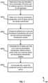
- FIG. 1is a flowchart illustrating an example method for performing user identity authentication based on eye physiological characteristics in a virtual reality scenario, according to an implementation of the present disclosure.
- method 100can be performed, for example, by any suitable system, environment, software, and hardware, or a combination of systems, environments, software, and hardware, as appropriate.
- various steps of method 100can be run in parallel, in combination, in loops, or in any order.
- the VR softwarecan be developed to provide a 3D immersive VR user experience.
- the servicecan be any service or task offered in a VR application performed by the user that requires user identity authentication.
- the servicecan be a local task performed by a user computing device or an online task performed by a server.
- the servicecan be an online payment service, such as payment made in VR applications such as VR shopping, VR games, VR based video-on-demand, or donation to a VR live cast.
- the servicecan be a local service that requires user account login or password protected unlock.
- the VR applicationcan be any software or application that is developed based on VR. The VR application can render a VR scenario through the VR device to provide user with immersive 3D experience.
- the VR scenario or VR environmentcan be created by VR modeling using a modeling tool, such as UNITY, 3DSMAX, or PHOTOSHOP.
- a modeling toolsuch as UNITY, 3DSMAX, or PHOTOSHOP.
- the VR modeling and VR scenario texture mappingcan be based on real life scenarios.
- texture maps of materials and real life scenario modelscan first be collected by photographing real life objects or scenarios.
- Modeling toolssuch as PHOTOSHOP or 3DMAX can then be used for texture processing and real-life 3D model creation.
- the 3D modelcan then be imported to a UNITY3D (U3D) platform and multi-dimensionally rendered through sound effects, graphical interfaces, plug-ins, and lighting.
- Interaction codecan then be executed to convert the 3D model to the VR scenario model.
- the VR devicecan present the VR scenario and the service interface to the user.
- the VR scenario model and a virtual element for triggering the service interfacecan be presented to the user.
- the usercan interact with the virtual element to trigger the service interface.
- the usercan interact with the virtual element through any movements or gestures, such as a head movement and hand gesture.
- the usercan move their head to control the movement of their visual focus, which can be used as the operation focus (for example, a cursor) in the VR scenario.
- the VR devicecan use a sensor to track the movement of the head, and use the sensed movement to change the operational focus in the VR scenario.
- the VR devicecan determine that the virtual element is selected and trigger the service interface in the VR scenario.
- the usercan position the operation focus on the virtual element by moving their hand, and then using a predetermined 3D gesture to select the virtual element.
- the VR devicecan use a sensor to track the user's hand movement, calculate depth information of the user's hand with respect to the VR scenario based on the user's hand displacement sensed by the sensor, and then restore a 3D gesture made by the user in the VR scenario. If the 3D gesture is the same as one of the pre-stored gestures, the VR device can select the virtual element and trigger the service interface in the VR scenario.
- the one or more user interactionscan include a voice command.
- the VR devicecan use voice recognition software to recognize a user's voice command. As such, when the user needs to perform a service while having an immersive experience in the VR scenario, the user can use voice command to initiate the service instead of interacting with one or more virtual elements to trigger the service interface.
- the VR devicecan collect the voice input from the VR user and use the voice recognition software to recognize voice commands dictated by the user.
- voice recognitioncan be performed by a server that provides the service.
- a service platform formed by a server clustercan designate a server for voice recognition service and provide an access interface for the VR device to access the voice recognition service.
- the VR devicecan construct a voice recognition request based on the collected voice input, and send the voice recognition request through the access interface to the server.
- the servercan parse the voice recognition request, identify the voice command, and recognize the voice command using a voice recognition algorithm. After recognizing the voice command, the server can convert the voice command to a character string instruction recognizable by the VR device, and send the character string instruction to the VR device. After receiving the character string instruction, the VR device can determine whether the character string instruction is an executable instruction corresponding to the service. If yes, the VR device can initiate the service in response to the instruction.
- the serviceis a payment service based on a VR application
- the usercan send a voice command of "start to pay.”
- the servercan convert the voice command into a character string instruction recognizable by the VR device, and the VR device can initiate the payment process in response to the instruction.
- voice commandscan be used to perform other voice controls, such as cancellation of a service, as long as those control functions are available to the service.
- the VR devicecan respond to the cancellation instruction and cancel the service.
- the serviceis a payment service based on a VR application
- the usercan cancel the payment service after the service being initiated by the voice command "start to pay.”
- the usercan dictate a voice command "cancel payment.”
- the VR devicecan respond to the instruction and terminate the payment process.
- the VR device usercan also use voice command to control how the service is performed.
- voice commandto control how the service is performed.
- a usercan switch the payment method from debit card to credit card by dictating "switch to credit card,” and sending the additional voice command "please pay by credit card” to perform the credit card payment. From 110, method 100 proceeds to 120.
- one or more eye physiological characteristics of the VR device userare obtained for user identity authentication.
- the VR devicecan present a UI in a virtual scenario for user identity authentication.
- the VR devicecan include eye recognition function to facilitate user identity authentication.
- the eye recognition functioncan be performed based on eye physiological characteristics sampling algorithm.
- the eye physiological characteristics sampling algorithmcan use one or more of the user's eye physiological characteristics gathered by an eye sensor to verify the user's identity.
- Example eye physiological characteristicscan include iris characteristics.
- the eye physiological characteristics sampling algorithmcan include an iris sampling algorithm.
- the eye sensorcan be built-in to the VR device, separate from, but communicably coupled to, the VR device, or integrated on a mobile device such as a smartphone.
- the VR devicecan be a slide-in type VR headset, which can function by inserting or sliding in a smartphone that can communicate with the headset, and convert the images displayed on the cell phone to VR scenarios.
- the VR devicecan rely on the built-in eye sensor to perform eye recognition.
- the eye sensorcan include an optical lens, installed relative to the positions of the VR device user's eyes, and one or more cameras distributed around the optical lens.
- the camerascan be uniformly distributed around the lens.
- the camerascan be positioned on an external surface of the lens, or in other suitable places, to ensure that the lens is located between the user's eyes and the cameras.
- the physiological characteristic of the eyeis the user's iris.
- the user's iriscan be imaged under an infrared light source.
- the cameras distributed around the lensescan then be infrared cameras.
- the VR devicewhen invoking the eye sensor to collect the eye physiological characteristics, can be affected by the internal ambient light of the VR device.
- the eye sensorcan further include one or more LED light sources that have a one-to-one correspondence with the one or more cameras uniformly distributed around the lenses.
- the LED light sourcewhen the iris is used as the physiological characteristic of the eye, can be an infrared LED light source.
- the VR devicecan also include a light sensor to detect the brightness of the ambient light inside the VR device. If the brightness is lower than a predetermined value that can affect the imaging of eye physiological characteristics, the VR device can turn one or more of the LED light sources on, to perform one-to-one light compensation to the one or more cameras, to compensate for relatively poor light condition inside the VR device.
- the physical dimension of the VR devicecan cause insufficient depth of field between the cameras and the user's eyes, such that the cameras cannot be accurately focused on the iris.
- one or more macro lens camerascan be used.
- one or more additional, optical lensescan be installed at a position between the user's eyes and the lens to reflect or refract light rays coming from the user's eyes, based on the internal shape of the VR device (for example, the cavity of a VR headset).
- special lensessuch as an endoscope, can be used to collect the user's iris features.
- a usercan manually adjust the focal length of the cameras to obtain accurate iris images. From 120, method 100 proceeds to 130.
- the obtained one or more eye physiological characteristicsare compared with one or more pre-stored eye physiological characteristics samples.
- the usercan use the VR device to obtain one or more eye physiological characteristics samples during service account registration.
- the one or more eye physiological characteristics samplescan be saved locally for applications that allow offline biometric authentication or included in an authentication request to be sent to a service server for online authentication.
- the serviceis a VR payment service
- the service account of the usercan be a payment account.
- the VR devicecan use an integrated eye sensor to obtain the user's eye physiological characteristics sample during payment account registration and save the sample locally, or on the payment server.
- the eye physiological characteristics sampleis associated with the user's payment account.
- the usercan log into the user account to use the VR device.
- the VR devicecan send the eye physiological characteristics sample and VR device user account login information as a registration message to the service server.
- the servercan use the received information to associate the user's eye physiological characteristics sample to its service account and save the eye physiological characteristics sample to a biometric characteristics database.
- the user accountcan be the same as the service account.
- the VR devicecan generate a biometric recognition request to the service server.
- the biometric recognition requestcan include the user's user or service account information and eye physiological characteristics obtained by the eye sensor.
- the service servercan provide a biometric recognition interface to the VR device for receiving the request and submit the request to the server.
- the service servercan cooperate with a biometric recognition server and the biometric recognition interface can be provided by the biometric recognition server. From 130, method 100 proceeds to 140.
- the VR device useris authenticated if the one or more eye physiological characteristics match at least a portion of the one or more pre-stored eye physiological characteristics samples.
- the service servercan parse the request, acquire the eye physiological characteristics and the user account information, and compare the eye physiological characteristics with eye physiological characteristics samples stored in a biometric characteristic database. In some cases, if the eye physiological characteristics match at least a portion of the eye physiological characteristics samples, the service server can further verify whether the received user account information matches the account associated with the matching biometric sample. After comparing the biometric information and user account information with the corresponding information stored in the biometric characteristic database, the service server can return an authentication result to the VR device.
- the authentication resultcan be returned as a Boolean-type return value (that is, false or true). If one or both the biometric information and user account information match the corresponding information stored in the biometric characteristic database, a "true” value can be returned to indicate that the biometric authentication succeeded. Otherwise, a "false” value can be returned to indicate that the biometric authentication failed.
- the VR devicecan perform biometric authentication locally.
- the user's eye physiological characteristicscan be saved in the VR device during biometric information registration.
- the VR devicecan collect the eye physiological characteristics of the user, and compare the eye physiological characteristics with the eye physiological characteristics samples saved during biometric information registration. If the eye physiological characteristics match at least a portion of the saved information, the biometric authentication for the service succeeds. Otherwise, the biometric authentication fails.
- the VR devicecan perform additional biometric authentication before sending the registration message to the service server for enhanced security. For example, the VR device can prompt the user to input a password or other security information to verify the user's identity before sending the user's registration message to the service server. This process can prevent unauthorized users from fraudulently registering their biometric information to bind with the authorized user's user account.
- the VR devicecan initiate biometric authentication based on the user's eye physiological characteristics sample, after the user initiates the service.
- the VR devicecan perform a user detection process, before collecting biometric information, to ensure that the VR device is currently used by a real person.
- This processcan prevent unauthorized users from using iris images of the authorized user for biometrical authentication and illegally accessing the authorized user's service account.
- Example user detection processescan include eye-blinking or heartbeat recognition.
- the VR devicecan prompt the user to perform biometric authentication for accessing the service account.
- biometric authenticationfor accessing the service account.
- the VR devicecan present a text prompt in the VR scenario such as "Please scan your iris for payment authentication.”
- a serveris communicated with to perform the service. If the biometric authentication is successful (for example, a returned value is "true"), the VR device can present the service interface corresponding to the service to gather data related to the service, establish a service request, submit the service request to the service server through a service access interface, and perform further interactions with the service server, if needed, to perform the service.
- the VR devicecan present a payment interface to gather payment related data, such as user name, order information, and price, and then generate a payment processing request and send the payment processing request to the service server.
- the service servercan process the request and complete the payment.
- the service for the VR shoppingcan be a payment service such as ALIPAY.
- the virtual elementcan be a virtual button presented in the VR shopping scenario.
- the server for the payment servicecan be a payment server such as the ALIPAY platform based on a server cluster.
- the usercan first log in to the VR device using the user account or payment account, and complete eye print registration on the VR device to associate the user's eye print to the payment account.
- the user's account information and corresponding eye print informationcan be stored in a biometric characteristic database on a payment server. After eye print registration, the user can use their finger for biometric authentication in a VR environment.
- the items for salecan be presented to the user in the VR scenario and the user can flip through the item list, select items, or add items to the shopping cart using gestures or head movements.
- a virtual buttonthat is, the virtual element
- a virtual button for checkout or paycan be provided when an item is selected or added to the user's shopping cart.
- the usercan, again, use gesture or head movements to move the operation focus (for example, a cursor) to the virtual button and use a predetermined gesture or head movement to select the virtual button.
- the payment servicecan be initiated after the service is initiated by the user's voice command.
- the VR devicecan perform a user detection process to determine whether a real user of the VR device is present. If so, the VR device can prompt a message "Please keep your eyes open for payment authentication" in the VR scenario.
- the VR devicecan send a biometric authentication request including the collected eye print information and the user's user or payment account information to the payment server.
- the payment servercan compare the eye print information with the eye print information stored in the biometric characteristic database during eye print registration. If the received eye print information matches the eye print associated with the user account stored in the database, and the payment account information is consistent with the stored user account information, the payment server can return a Boolean-type "true" value to the VR device to indicate that the eye print authentication is successful.
- the VR devicecan present a payment interface for the user to input payment data, such as user name, order information, and payment amount related to the payment service, and generate and send a payment processing request to the payment server.
- the payment servercan process the payment and complete the purchase.
- an "authentication-free for small amount” payment processcan be used to further facilitate payment speed.
- the VR devicecan check the price of the items and determine whether the payment amount is less than a preset amount (for example, 20USD). If the payment amount is less than the preset amount, the VR device can directly generate and send the payment processing request to the payment server without biometric authentication. Otherwise, the user may need to perform biometric authentication before the payment service can be used. After 130, method 100 ends.
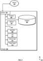
- FIG. 2is a block diagram illustrating an example of a computer-implemented System 200 used to provide computational functionalities associated with described algorithms, methods, functions, processes, flows, and procedures, according to an implementation of the present disclosure.
- System 200includes a Computer 202 and a Network 230.
- the illustrated Computer 202is intended to encompass any computing device such as a server, desktop computer, laptop/notebook computer, wireless data port, smart phone, personal data assistant (PDA), tablet computer, one or more processors within these devices, another computing device, or a combination of computing devices, including physical or virtual instances of the computing device, or a combination of physical or virtual instances of the computing device. Additionally, the Computer 202 can include an input device, such as a keypad, keyboard, touch screen, another input device, or a combination of input devices that can accept user information, and an output device that conveys information associated with the operation of the Computer 202, including digital data, visual, audio, another type of information, or a combination of types of information, on a graphical-type user interface (UI) (or GUI) or other UI.
- UIgraphical-type user interface
- the Computer 202can serve in a role in a distributed computing system as a client, network component, a server, a database or another persistency, another role, or a combination of roles for performing the subject matter described in the present disclosure.
- the illustrated Computer 202is communicably coupled with aNetwork 230.
- one or more components of the Computer 202can be configured to operate within an environment, including cloud-computing-based, local, global, another environment, or a combination of environments.
- the Computer 202is an electronic computing device operable to receive, transmit, process, store, or manage data and information associated with the described subject matter. According to some implementations, the Computer 202 can also include or be communicably coupled with a server, including an application server, e-mail server, web server, caching server, streaming data server, another server, or a combination of servers.
- a serverincluding an application server, e-mail server, web server, caching server, streaming data server, another server, or a combination of servers.
- the Computer 202can receive requests over Network 230 (for example, from a client software application executing on another Computer 202) and respond to the received requests by processing the received requests using a software application or a combination of software applications.
- requestscan also be sent to the Computer 202 from internal users (for example, from a command console or by another internal access method), external or third-parties, or other entities, individuals, systems, or computers.
- Each of the components of the Computer 202can communicate using a System Bus 203.
- any or all of the components of the Computer 202can interface over the System Bus 203 using an application programming interface (API) 212, a Service Layer 213, or a combination of the API 212 and Service Layer 213.
- the API 212can include specifications for routines, data structures, and object classes.
- the API 212can be either computer-language independent or dependent and refer to a complete interface, a single function, or even a set of APIs.
- the Service Layer 213provides software services to the Computer 202 or other components (whether illustrated or not) that are communicably coupled to the Computer 202.
- the functionality of the Computer 202can be accessible for all service consumers using the Service Layer 213.
- Software services, such as those provided by the Service Layer 213,provide reusable, defined functionalities through a defined interface.
- the interfacecan be software written in JAVA, C++, another computing language, or a combination of computing languages providing data in extensible markup language (XML) format, another format, or a combination of formats.
- XMLextensible markup language
- alternative implementationscan illustrate the API 212 or the Service Layer 213 as stand-alone components in relation to other components of the Computer 202 or other components (whether illustrated or not) that are communicably coupled to the Computer 202.
- any or all parts of the API 212 or the Service Layer 213can be implemented as a child or a sub-module of another software module, enterprise application, or hardware module.
- the Computer 202includes an Interface 204. Although illustrated as a single Interface 204, two or more Interfaces 204 can be used according to particular needs, desires, or particular implementations of the Computer 202.
- the Interface 204is used by the Computer 202 for communicating with another computing system (whether illustrated or not) that is communicatively linked to the Network 230 in a distributed environment.
- the Interface 204is operable to communicate with the Network 230 and includes logic encoded in software, hardware, or a combination of software and hardware. More specifically, the Interface 204 can include software supporting one or more communication protocols associated with communications such that the Network 230 or hardware of Interface 204 is operable to communicate physical signals within and outside of the illustrated Computer 202.
- the Computer 202includes a Processor 205. Although illustrated as a single Processor 205, two or more Processors 205 can be used according to particular needs, desires, or particular implementations of the Computer 202. Generally, the Processor 205 executes instructions and manipulates data to perform the operations of the Computer 202 and any algorithms, methods, functions, processes, flows, and procedures as described in the present disclosure.
- the Computer 202also includes a Database 206 that can hold data for the Computer 202, another component communicatively linked to the Network 230 (whether illustrated or not), or a combination of the Computer 202 and another component.
- Database 206can be an in-memory, conventional, or another type of database storing data consistent with the present disclosure.
- Database 206can be a combination of two or more different database types (for example, a hybrid in-memory and conventional database) according to particular needs, desires, or particular implementations of the Computer 202 and the described functionality.
- two or more databases of similar or differing typescan be used according to particular needs, desires, or particular implementations of the Computer 202 and the described functionality. While Database 206 is illustrated as an integral component of the Computer 202, in alternative implementations, Database 206 can be external to the Computer 202.
- the Computer 202also includes a Memory 207 that can hold data for the Computer 202, another component or components communicatively linked to the Network 230 (whether illustrated or not), or a combination of the Computer 202 and another component.
- Memory 207can store any data consistent with the present disclosure.
- Memory 207can be a combination of two or more different types of memory (for example, a combination of semiconductor and magnetic storage) according to particular needs, desires, or particular implementations of the Computer 202 and the described functionality.
- two or more Memories 207 or similar or differing typescan be used according to particular needs, desires, or particular implementations of the Computer 202 and the described functionality.
- Memory 207is illustrated as an integral component of the Computer 202, in alternative implementations, Memory 207 can be external to the Computer 202.
- the Application 208is an algorithmic software engine providing functionality according to particular needs, desires, or particular implementations of the Computer 202, particularly with respect to functionality described in the present disclosure.
- Application 208can serve as one or more components, modules, or applications.
- the Application 208can be implemented as multiple Applications 208 on the Computer 202.
- the Application 208can be external to the Computer 202.
- the Computer 202can also include a Power Supply 214.
- the Power Supply 214can include a rechargeable or non-rechargeable battery that can be configured to be either user- or non-user-replaceable.
- the Power Supply 214can include power-conversion or management circuits (including recharging, standby, or another power management functionality).
- the Power Supply 214can include a power plug to allow the Computer 202 to be plugged into a wall socket or another power source to, for example, power the Computer 202 or recharge a rechargeable battery.
- Computers 202there can be any number of Computers 202 associated with, or external to, a computer system containing Computer 202, each Computer 202 communicating over Network 230. Further, the term “client,” “user,” or other appropriate terminology can be used interchangeably, as appropriate. Moreover, the present disclosure contemplates that many users can use one Computer 202, or that one user can use multiple computers 202.
- Implementations of the subject matter and the functional operations described in this specificationcan be implemented in digital electronic circuitry, in tangibly embodied computer software or firmware, in computer hardware, including the structures disclosed in this specification and their structural equivalents, or in combinations of one or more of them.
- Software implementations of the described subject mattercan be implemented as one or more computer programs, that is, one or more modules of computer program instructions encoded on a tangible, non transitory, computer-readable medium for execution by, or to control the operation of, a computer or computer-implemented system.
- the program instructionscan be encoded in/on an artificially generated propagated signal, for example, a machine-generated electrical, optical, or electromagnetic signal that is generated to encode information for transmission to a receiver apparatus for execution by a computer or computer-implemented system.
- the computer-storage mediumcan be a machine-readable storage device, a machine-readable storage substrate, a random or serial access memory device, or a combination of computer-storage mediums.
- Configuring one or more computersmeans that the one or more computers have installed hardware, firmware, or software (or combinations of hardware, firmware, and software) so that when the software is executed by the one or more computers, particular computing operations are performed.
- real-timemeans that an action and a response are temporally proximate such that an individual perceives the action and the response occurring substantially simultaneously.
- time difference for a response to display (or for an initiation of a display) of data following the individual's action to access the datacan be less than 1 millisecond (ms), less than 1 second (s), or less than 5 s.
- data processing apparatusrefers to data processing hardware and encompass all kinds of apparatus, devices, and machines for processing data, including by way of example, a programmable processor, a computer, or multiple processors or computers.
- the computercan also be, or further include special purpose logic circuitry, for example, a central processing unit (CPU), an FPGA (field programmable gate array), or an ASIC (application-specific integrated circuit).
- CPUcentral processing unit
- FPGAfield programmable gate array
- ASICapplication-specific integrated circuit
- the computer or computer-implemented system or special purpose logic circuitrycan be hardware- or software-based (or a combination of both hardware- and software-based).
- the computercan optionally include code that creates an execution environment for computer programs, for example, code that constitutes processor firmware, a protocol stack, a database management system, an operating system, or a combination of execution environments.
- code that constitutes processor firmwarefor example, code that constitutes processor firmware, a protocol stack, a database management system, an operating system, or a combination of execution environments.
- the present disclosurecontemplates the use of a computer or computer-implemented system with an operating system of some type, for example LINUX, UNIX, WINDOWS, MAC OS, ANDROID, IOS, another operating system, or a combination of operating systems.
- a computer programwhich can also be referred to or described as a program, software, a software application, a unit, a module, a software module, a script, code, or other component can be written in any form of programming language, including compiled or interpreted languages, or declarative or procedural languages, and it can be deployed in any form, including, for example, as a stand-alone program, module, component, or subroutine, for use in a computing environment.
- a computer programcan, but need not, correspond to a file in a file system.
- a programcan be stored in a portion of a file that holds other programs or data, for example, one or more scripts stored in a markup language document, in a single file dedicated to the program in question, or in multiple coordinated files, for example, files that store one or more modules, sub-programs, or portions of code.
- a computer programcan be deployed to be executed on one computer or on multiple computers that are located at one site or distributed across multiple sites and interconnected by a communication network.
- While portions of the programs illustrated in the various figurescan be illustrated as individual components, such as units or modules, that implement described features and functionality using various objects, methods, or other processes, the programs can instead include a number of sub-units, sub-modules, third-party services, components, libraries, and other components, as appropriate. Conversely, the features and functionality of various components can be combined into single components, as appropriate. Thresholds used to make computational determinations can be statically, dynamically, or both statically and dynamically determined.
- Described methods, processes, or logic flowsrepresent one or more examples of functionality consistent with the present disclosure and are not intended to limit the disclosure to the described or illustrated implementations.
- the described methods, processes, or logic flowscan be performed by one or more programmable computers executing one or more computer programs to perform functions by operating on input data and generating output data.
- the methods, processes, or logic flowscan also be performed by, and computers can also be implemented as, special purpose logic circuitry, for example, a CPU, an FPGA, or an ASIC.
- Computers for the execution of a computer programcan be based on general or special purpose microprocessors, both, or another type of CPU.
- a CPUwill receive instructions and data from and write to a memory.
- the essential elements of a computerare a CPU, for performing or executing instructions, and one or more memory devices for storing instructions and data.
- a computerwill also include, or be operatively coupled to, receive data from or transfer data to, or both, one or more mass storage devices for storing data, for example, magnetic, magneto-optical disks, or optical disks.
- mass storage devicesfor storing data, for example, magnetic, magneto-optical disks, or optical disks.
- a computerneed not have such devices.
- a computercan be embedded in another device, for example, a mobile telephone, a personal digital assistant (PDA), a mobile audio or video player, a game console, a global positioning system (GPS) receiver, or a portable memory storage device.
- PDApersonal digital assistant
- GPSglobal positioning system
- Non-transitory computer-readable media for storing computer program instructions and datacan include all forms of permanent/non-permanent or volatile/non-volatile memory, media and memory devices, including by way of example semiconductor memory devices, for example, random access memory (RAM), read-only memory (ROM), phase change memory (PRAM), static random access memory (SRAM), dynamic random access memory (DRAM), erasable programmable read-only memory (EPROM), electrically erasable programmable read-only memory (EEPROM), and flash memory devices; magnetic devices, for example, tape, cartridges, cassettes, intemal/removable disks; magneto-optical disks; and optical memory devices, for example, digital versatile/video disc (DVD), compact disc (CD)-ROM, DVD+/-R, DVD-RAM, DVD-ROM, high-definition/density (HD)-DVD, and BLU-RAY/BLU-RAY DISC (BD), and other optical memory technologies.
- semiconductor memory devicesfor example, random access memory (
- the memorycan store various objects or data, including caches, classes, frameworks, applications, modules, backup data, jobs, web pages, web page templates, data structures, database tables, repositories storing dynamic information, or other appropriate information including any parameters, variables, algorithms, instructions, rules, constraints, or references. Additionally, the memory can include other appropriate data, such as logs, policies, security or access data, or reporting files.
- the processor and the memorycan be supplemented by, or incorporated in, special purpose logic circuitry.
- implementations of the subject matter described in this specificationcan be implemented on a computer having a display device, for example, a CRT (cathode ray tube), LCD (liquid crystal display), LED (Light Emitting Diode), or plasma monitor, for displaying information to the user and a keyboard and a pointing device, for example, a mouse, trackball, or trackpad by which the user can provide input to the computer.
- a display devicefor example, a CRT (cathode ray tube), LCD (liquid crystal display), LED (Light Emitting Diode), or plasma monitor
- a keyboard and a pointing devicefor example, a mouse, trackball, or trackpad by which the user can provide input to the computer.
- Inputcan also be provided to the computer using a touchscreen, such as a tablet computer surface with pressure sensitivity, a multi-touch screen using capacitive or electric sensing, or another type of touchscreen.
- Other types of devicescan be used to interact with the user.
- feedback provided to the usercan be any form of sensory feedback (such as, visual, auditory, tactile, or a combination of feedback types).
- Input from the usercan be received in any form, including acoustic, speech, or tactile input.
- a computercan interact with the user by sending documents to and receiving documents from a client computing device that is used by the user (for example, by sending web pages to a web browser on a user's mobile computing device in response to requests received from the web browser).
- GUIgraphical user interface
- GUIcan be used in the singular or the plural to describe one or more graphical user interfaces and each of the displays of a particular graphical user interface. Therefore, a GUI can represent any graphical user interface, including but not limited to, a web browser, a touch screen, or a command line interface (CLI) that processes information and efficiently presents the information results to the user.
- a GUIcan include a number of user interface (UI) elements, some or all associated with a web browser, such as interactive fields, pull-down lists, and buttons. These and other UI elements can be related to or represent the functions of the web browser.
- UIuser interface
- Implementations of the subject matter described in this specificationcan be implemented in a computing system that includes a back-end component, for example, as a data server, or that includes a middleware component, for example, an application server, or that includes a front-end component, for example, a client computer having a graphical user interface or a Web browser through which a user can interact with an implementation of the subject matter described in this specification, or any combination of one or more such back-end, middleware, or front-end components.
- the components of the systemcan be interconnected by any form or medium of wireline or wireless digital data communication (or a combination of data communication), for example, a communication network.
- Examples of communication networksinclude a local area network (LAN), a radio access network (RAN), a metropolitan area network (MAN), a wide area network (WAN), Worldwide Interoperability for Microwave Access (WIMAX), a wireless local area network (WLAN) using, for example, 802.11 a/b/g/n or 802.20 (or a combination of 802.11x and 802.20 or other protocols consistent with the present disclosure), all or a portion of the Internet, another communication network, or a combination of communication networks.
- the communication networkcan communicate with, for example, Internet Protocol (IP) packets, Frame Relay frames, Asynchronous Transfer Mode (ATM) cells, voice, video, data, or other information between network nodes.
- IPInternet Protocol
- ATMAsynchronous Transfer Mode
- the computing systemcan include clients and servers.
- a client and serverare generally remote from each other and typically interact through a communication network.
- the relationship of client and serverarises by virtue of computer programs running on the respective computers and having a client-server relationship to each other.
- any claimed implementationis considered to be applicable to at least a computer-implemented method; a non-transitory, computer-readable medium storing computer-readable instructions to perform the computer-implemented method; and a computer system comprising a computer memory interoperably coupled with a hardware processor configured to perform the computer-implemented method or the instructions stored on the non-transitory, computer-readable medium.
Landscapes
- Engineering & Computer Science (AREA)
- Health & Medical Sciences (AREA)
- Life Sciences & Earth Sciences (AREA)
- Physics & Mathematics (AREA)
- Theoretical Computer Science (AREA)
- Multimedia (AREA)
- General Health & Medical Sciences (AREA)
- General Physics & Mathematics (AREA)
- Ophthalmology & Optometry (AREA)
- Signal Processing (AREA)
- Human Computer Interaction (AREA)
- Biophysics (AREA)
- Heart & Thoracic Surgery (AREA)
- Biomedical Technology (AREA)
- General Engineering & Computer Science (AREA)
- Veterinary Medicine (AREA)
- Public Health (AREA)
- Animal Behavior & Ethology (AREA)
- Surgery (AREA)
- Molecular Biology (AREA)
- Medical Informatics (AREA)
- Computer Hardware Design (AREA)
- Computer Security & Cryptography (AREA)
- Software Systems (AREA)
- Computer Graphics (AREA)
- Computing Systems (AREA)
- Computer Networks & Wireless Communication (AREA)
- Cardiology (AREA)
- Physiology (AREA)
- Computer Vision & Pattern Recognition (AREA)
- Psychiatry (AREA)
- Social Psychology (AREA)
- Measurement Of The Respiration, Hearing Ability, Form, And Blood Characteristics Of Living Organisms (AREA)
- User Interface Of Digital Computer (AREA)
- Collating Specific Patterns (AREA)
Description
- This disclosure relates to virtual reality applications, and more particularly to service control and user identity authentication based on virtual reality.
- Virtual reality (VR) is a computer technology that uses VR devices, such as headsets, sometimes in combination with physical spaces or multi-projected environments, to generate realistic images, sounds, and other sensations that simulate a user's physical presence in a three dimensional (3D) virtual environment and allows the VR user to interact with the virtual environment. Many applications, such as those for gaming, content consumption, and productivity, have been developed to provide user an immersive experience using VR technology. Many VR applications allow in-application purchases, user customization, or parental control. These operations should require user identity authentication for security purposes.
WO 2016/183541 A1 describes a method of conducting a transaction through an augmented reality display device comprises capturing biometric data from a user, determining, based at least in part on the captured biometric data, an identity of the user, and authenticating the user for the transaction based on the determined identity.US 2014/125574 A1 describes authenticating a user of a display device, including displaying one or more virtual images on the display device, wherein the one or more virtual images include a set of augmented reality features, identifying one or more movements of the user via data received from a sensor of the display device, and comparing the identified movements of the user to a predefined set of authentication information for the user that links user authentication to a predefined order of the augmented reality features. If the identified movements indicate that the user selected the augmented reality features in the predefined order, then the user is authenticated, and if the identified movements indicate that the user did not select the augmented reality features in the predefined order, then the user is not authenticated.WO 2016/168814 A1 describes a system for authenticating a user of a device. The system includes a first image sensor, a determination unit, and an authentication unit. The first image sensor captures at least one image of at least part of a user. The determination unit determines information relating to the user's eye based at least in part on at least one image captured by the first image sensor. The authentication unit authenticates the user using the information relating to the user's eye.CN 103455746 A describes head-wearing display equipment comprising a biological feature scanning unit and a certification interface unit. The biological feature scanning unit is used for scanning the biological features of a user wearing the head-wearing display equipment. The certification interface unit is used for receiving a biological feature scanning result from the biological feature scanning unit and for sending the biological feature scanning result to a remote server, so the remote server can certificate the biological features of the user. - The present disclosure describes methods and systems, including computer-implemented methods, computer program products, and computer systems for service control and user identity authentication based on virtual reality (VR). The invention is defined by the appended claims.
- In an implementation, it is determined whether the VR device is currently used by a real person. If it is determined that the VR device is currently used by a real person, one or more user interactions from the VR device user for initiating a service in a VR scenario of a VR application are detected. One or more eye physiological characteristics of the VR device user are obtained for user identity authentication. The obtained one or more eye physiological characteristics are compared with one or more pre-stored eye physiological characteristics samples. The VR device user is authenticated if the one or more eye physiological characteristics match at least a portion of the one or more pre-stored eye physiological characteristics samples, and a server that provides and performs the service is communicated with.
- Implementations of the described subject matter, including the previously described implementation, can be implemented using a computer-implemented method; a non-transitory, computer-readable medium storing computer-readable instructions to perform the computer-implemented method; and a computer-implemented system comprising one or more computer memory devices interoperably coupled with one or more computers and having tangible, non-transitory, machine-readable media storing instructions that, when executed by the one or more computers, perform the computer-implemented method/the computer-readable instructions stored on the non-transitory, computer-readable medium.
- The subject matter described in this specification can be implemented in particular implementations, so as to realize efficient user identity authentication in a virtual environment to provide faster, more convenient operations, and more immersive experience to VR users.
- The details of one or more implementations of the subject matter of this specification are set forth in the Detailed Description, the Claims, and the accompanying drawings. Other features, aspects, and advantages of the subject matter will become apparent to those of ordinary skill in the art from the Detailed Description, the Claims, and the accompanying drawings.
FIG. 1 is a flowchart illustrating an example of a method for performing user identity authentication based on eye physiological characteristics in a virtual reality scenario, according to an implementation of the present disclosure.FIG. 2 is a block diagram illustrating an example of a computer-implemented system used to provide computational functionalities associated with described algorithms, methods, functions, processes, flows, and procedures, according to an implementation of the present disclosure.- Like reference numbers and designations in the various drawings indicate like elements.
- The following detailed description describes technologies related to performing biometric authentication based on a virtual reality (VR) device user's eye physiological characteristics, and is presented to enable any person skilled in the art to make and use the disclosed subject matter in the context of one or more particular implementations. Various modifications, alterations, and permutations of the disclosed implementations can be made and will be readily apparent to those or ordinary skill in the art, and the general principles defined can be applied to other implementations and applications. In some instances, one or more technical details that are unnecessary to obtain an understanding of the described subject matter and that are within the skill of one of ordinary skill in the art may be omitted so as to not obscure one or more described implementations.
- VR is a computer technology that uses VR devices, such as headsets, sometimes in combination with physical spaces or multi-projected environments, to generate realistic images, sounds, and other sensations that simulate a user's physical presence in a three-dimensional (3D) virtual environment and allows the VR user to interact with the virtual environment. Many applications, such as those for gaming, content consumption, and productivity, have been developed to provide user an immersive experience using VR technology. Many VR applications allow in-application purchases, user customization, or parental control. These operations should require user identity authentication for security purposes.
- The present disclosure describes technologies for faster and more convenient user identity authentication based on a VR device user's eye physiological characteristics. When a user uses a VR device to perform a service, the VR device can identify user interaction operations with virtual elements rendered in the virtual reality scenario using one or more sensors. When it is identified that the user interaction operations match one or more pre-stored operations, the VR device can invoke biometric authentication based on the user's eye physiological characteristics for user identity verification. If the biometric authentication is successful, the user can perform a service interaction to complete the service. As such, the VR device can collect a user's eye physiological characteristics to quickly perform biometric authentication in the VR environment, to simplify the user identity authentication procedure and ensure account security. For example, when using a payment service in a VR environment, biometric authentication through the VR device can allow faster user identity authentication, as compared to entering a password through complicated user interactions with a virtual keyboard.
FIG. 1 is a flowchart illustrating an example method for performing user identity authentication based on eye physiological characteristics in a virtual reality scenario, according to an implementation of the present disclosure. For clarity of presentation, the description that follows generally describesmethod 100 in the context of the other figures in this description. However, it will be understood thatmethod 100 can be performed, for example, by any suitable system, environment, software, and hardware, or a combination of systems, environments, software, and hardware, as appropriate. In some implementations, various steps ofmethod 100 can be run in parallel, in combination, in loops, or in any order. The VR software can be developed to provide a 3D immersive VR user experience.- At 110, one or more user interactions from a VR device user for initiating a service in a VR scenario of a VR application are detected. The service can be any service or task offered in a VR application performed by the user that requires user identity authentication. In some cases, the service can be a local task performed by a user computing device or an online task performed by a server. For example, the service can be an online payment service, such as payment made in VR applications such as VR shopping, VR games, VR based video-on-demand, or donation to a VR live cast. Alternatively, the service can be a local service that requires user account login or password protected unlock. The VR application can be any software or application that is developed based on VR. The VR application can render a VR scenario through the VR device to provide user with immersive 3D experience.
- The VR scenario or VR environment can be created by VR modeling using a modeling tool, such as UNITY, 3DSMAX, or PHOTOSHOP. In some cases, the VR modeling and VR scenario texture mapping can be based on real life scenarios. For example, texture maps of materials and real life scenario models can first be collected by photographing real life objects or scenarios. Modeling tools such as PHOTOSHOP or 3DMAX can then be used for texture processing and real-life 3D model creation. The 3D model can then be imported to a UNITY3D (U3D) platform and multi-dimensionally rendered through sound effects, graphical interfaces, plug-ins, and lighting. Interaction code can then be executed to convert the 3D model to the VR scenario model.
- After the VR scenario and service interface modeling, the VR device can present the VR scenario and the service interface to the user. In some cases, the VR scenario model and a virtual element for triggering the service interface can be presented to the user. When a user needs to perform the service while having an immersive experience in the VR scenario, the user can interact with the virtual element to trigger the service interface.
- The user can interact with the virtual element through any movements or gestures, such as a head movement and hand gesture. For example, the user can move their head to control the movement of their visual focus, which can be used as the operation focus (for example, a cursor) in the VR scenario. The VR device can use a sensor to track the movement of the head, and use the sensed movement to change the operational focus in the VR scenario. When the user moves their head to change the operation focus to a virtual element and stay focused on the virtual element for a predetermined amount of time (for example, three seconds), the VR device can determine that the virtual element is selected and trigger the service interface in the VR scenario.
- As another example, the user can position the operation focus on the virtual element by moving their hand, and then using a predetermined 3D gesture to select the virtual element. The VR device can use a sensor to track the user's hand movement, calculate depth information of the user's hand with respect to the VR scenario based on the user's hand displacement sensed by the sensor, and then restore a 3D gesture made by the user in the VR scenario. If the 3D gesture is the same as one of the pre-stored gestures, the VR device can select the virtual element and trigger the service interface in the VR scenario.
- In some cases, the one or more user interactions can include a voice command. The VR device can use voice recognition software to recognize a user's voice command. As such, when the user needs to perform a service while having an immersive experience in the VR scenario, the user can use voice command to initiate the service instead of interacting with one or more virtual elements to trigger the service interface.
- In some cases, the VR device can collect the voice input from the VR user and use the voice recognition software to recognize voice commands dictated by the user. In some other cases, voice recognition can be performed by a server that provides the service. For example, a service platform formed by a server cluster can designate a server for voice recognition service and provide an access interface for the VR device to access the voice recognition service. After collecting the voice input from the user, the VR device can construct a voice recognition request based on the collected voice input, and send the voice recognition request through the access interface to the server.
- After receiving the voice recognition request, the server can parse the voice recognition request, identify the voice command, and recognize the voice command using a voice recognition algorithm. After recognizing the voice command, the server can convert the voice command to a character string instruction recognizable by the VR device, and send the character string instruction to the VR device. After receiving the character string instruction, the VR device can determine whether the character string instruction is an executable instruction corresponding to the service. If yes, the VR device can initiate the service in response to the instruction.
- For example, when the service is a payment service based on a VR application, the user can send a voice command of "start to pay." After performing voice recognition, the server can convert the voice command into a character string instruction recognizable by the VR device, and the VR device can initiate the payment process in response to the instruction.
- In addition to using voice command to initiate services, voice commands can be used to perform other voice controls, such as cancellation of a service, as long as those control functions are available to the service. When the cancellation voice command is successfully recognized and converted into a character string instruction, the VR device can respond to the cancellation instruction and cancel the service. For example, when the service is a payment service based on a VR application, the user can cancel the payment service after the service being initiated by the voice command "start to pay." The user can dictate a voice command "cancel payment." After the voice command "cancel payment" is recognized by the server and converted to a character string instruction, the VR device can respond to the instruction and terminate the payment process.
- The VR device user can also use voice command to control how the service is performed. Using again the payment service based on a VR application for example, a user can switch the payment method from debit card to credit card by dictating "switch to credit card," and sending the additional voice command "please pay by credit card" to perform the credit card payment. From 110,
method 100 proceeds to 120. - At 120, one or more eye physiological characteristics of the VR device user are obtained for user identity authentication. After a service is initiated, the VR device can present a UI in a virtual scenario for user identity authentication. In some cases, the VR device can include eye recognition function to facilitate user identity authentication. The eye recognition function can be performed based on eye physiological characteristics sampling algorithm. The eye physiological characteristics sampling algorithm can use one or more of the user's eye physiological characteristics gathered by an eye sensor to verify the user's identity. Example eye physiological characteristics can include iris characteristics. The eye physiological characteristics sampling algorithm can include an iris sampling algorithm.
- The eye sensor can be built-in to the VR device, separate from, but communicably coupled to, the VR device, or integrated on a mobile device such as a smartphone. In some cases, the VR device can be a slide-in type VR headset, which can function by inserting or sliding in a smartphone that can communicate with the headset, and convert the images displayed on the cell phone to VR scenarios. In such cases, the VR device can rely on the built-in eye sensor to perform eye recognition.
- The eye sensor can include an optical lens, installed relative to the positions of the VR device user's eyes, and one or more cameras distributed around the optical lens. In some cases, the cameras can be uniformly distributed around the lens. The cameras can be positioned on an external surface of the lens, or in other suitable places, to ensure that the lens is located between the user's eyes and the cameras.
- In some cases, the physiological characteristic of the eye is the user's iris. The user's iris can be imaged under an infrared light source. The cameras distributed around the lenses can then be infrared cameras.
- In some cases, when invoking the eye sensor to collect the eye physiological characteristics, the VR device can be affected by the internal ambient light of the VR device. The eye sensor can further include one or more LED light sources that have a one-to-one correspondence with the one or more cameras uniformly distributed around the lenses. In some cases, when the iris is used as the physiological characteristic of the eye, the LED light source can be an infrared LED light source.
- The VR device can also include a light sensor to detect the brightness of the ambient light inside the VR device. If the brightness is lower than a predetermined value that can affect the imaging of eye physiological characteristics, the VR device can turn one or more of the LED light sources on, to perform one-to-one light compensation to the one or more cameras, to compensate for relatively poor light condition inside the VR device.
- In some cases, the physical dimension of the VR device can cause insufficient depth of field between the cameras and the user's eyes, such that the cameras cannot be accurately focused on the iris. In such cases, one or more macro lens cameras can be used. Alternatively, to adaptively adjust the focal length, one or more additional, optical lenses can be installed at a position between the user's eyes and the lens to reflect or refract light rays coming from the user's eyes, based on the internal shape of the VR device (for example, the cavity of a VR headset). In some cases, special lenses, such as an endoscope, can be used to collect the user's iris features. In some cases, a user can manually adjust the focal length of the cameras to obtain accurate iris images. From 120,
method 100 proceeds to 130. - At 130, the obtained one or more eye physiological characteristics are compared with one or more pre-stored eye physiological characteristics samples. In some cases, the user can use the VR device to obtain one or more eye physiological characteristics samples during service account registration. The one or more eye physiological characteristics samples can be saved locally for applications that allow offline biometric authentication or included in an authentication request to be sent to a service server for online authentication. For example, when the service is a VR payment service, the service account of the user can be a payment account. The VR device can use an integrated eye sensor to obtain the user's eye physiological characteristics sample during payment account registration and save the sample locally, or on the payment server. The eye physiological characteristics sample is associated with the user's payment account.
- In some cases, the user can log into the user account to use the VR device. The VR device can send the eye physiological characteristics sample and VR device user account login information as a registration message to the service server. The server can use the received information to associate the user's eye physiological characteristics sample to its service account and save the eye physiological characteristics sample to a biometric characteristics database. In some cases, the user account can be the same as the service account.
- In some cases, after eye physiological characteristics is collected by the VR device, the VR device can generate a biometric recognition request to the service server. The biometric recognition request can include the user's user or service account information and eye physiological characteristics obtained by the eye sensor. The service server can provide a biometric recognition interface to the VR device for receiving the request and submit the request to the server. In some cases, the service server can cooperate with a biometric recognition server and the biometric recognition interface can be provided by the biometric recognition server. From 130,
method 100 proceeds to 140. - At 140, the VR device user is authenticated if the one or more eye physiological characteristics match at least a portion of the one or more pre-stored eye physiological characteristics samples. After receiving the biometric recognition request, the service server can parse the request, acquire the eye physiological characteristics and the user account information, and compare the eye physiological characteristics with eye physiological characteristics samples stored in a biometric characteristic database. In some cases, if the eye physiological characteristics match at least a portion of the eye physiological characteristics samples, the service server can further verify whether the received user account information matches the account associated with the matching biometric sample. After comparing the biometric information and user account information with the corresponding information stored in the biometric characteristic database, the service server can return an authentication result to the VR device. The authentication result can be returned as a Boolean-type return value (that is, false or true). If one or both the biometric information and user account information match the corresponding information stored in the biometric characteristic database, a "true" value can be returned to indicate that the biometric authentication succeeded. Otherwise, a "false" value can be returned to indicate that the biometric authentication failed.
- In some cases, the VR device can perform biometric authentication locally. The user's eye physiological characteristics can be saved in the VR device during biometric information registration. After the user initiates the service in the VR scenario, the VR device can collect the eye physiological characteristics of the user, and compare the eye physiological characteristics with the eye physiological characteristics samples saved during biometric information registration. If the eye physiological characteristics match at least a portion of the saved information, the biometric authentication for the service succeeds. Otherwise, the biometric authentication fails.
- In some cases, the VR device can perform additional biometric authentication before sending the registration message to the service server for enhanced security. For example, the VR device can prompt the user to input a password or other security information to verify the user's identity before sending the user's registration message to the service server. This process can prevent unauthorized users from fraudulently registering their biometric information to bind with the authorized user's user account. After service registration, the VR device can initiate biometric authentication based on the user's eye physiological characteristics sample, after the user initiates the service.
- In some cases, the VR device can perform a user detection process, before collecting biometric information, to ensure that the VR device is currently used by a real person. This process can prevent unauthorized users from using iris images of the authorized user for biometrical authentication and illegally accessing the authorized user's service account. Example user detection processes can include eye-blinking or heartbeat recognition.
- After a real user is detected using the user detection process, the VR device can prompt the user to perform biometric authentication for accessing the service account. Using again a VR payment service for example, the VR device can present a text prompt in the VR scenario such as "Please scan your iris for payment authentication." After 140,
method 100 proceeds to 150. - At 150, a server is communicated with to perform the service. If the biometric authentication is successful (for example, a returned value is "true"), the VR device can present the service interface corresponding to the service to gather data related to the service, establish a service request, submit the service request to the service server through a service access interface, and perform further interactions with the service server, if needed, to perform the service.
- Using again the VR payment service for example, the VR device can present a payment interface to gather payment related data, such as user name, order information, and price, and then generate a payment processing request and send the payment processing request to the service server. The service server can process the request and complete the payment.
- The following example not covered by the claims uses VR shopping to illustrate how biometric authentication based on eye physiological characteristics can provide safer, faster, and simpler service experience to the user. It is assumed that the physiological characteristic of the eye used is the eye print. The service for the VR shopping can be a payment service such as ALIPAY. The virtual element can be a virtual button presented in the VR shopping scenario. The server for the payment service can be a payment server such as the ALIPAY platform based on a server cluster.
- The user can first log in to the VR device using the user account or payment account, and complete eye print registration on the VR device to associate the user's eye print to the payment account. The user's account information and corresponding eye print information can be stored in a biometric characteristic database on a payment server. After eye print registration, the user can use their finger for biometric authentication in a VR environment.
- When wearing the VR device for VR shopping, the items for sale can be presented to the user in the VR scenario and the user can flip through the item list, select items, or add items to the shopping cart using gestures or head movements. In some cases, a virtual button (that is, the virtual element) for checkout or pay can be provided when an item is selected or added to the user's shopping cart. The user can, again, use gesture or head movements to move the operation focus (for example, a cursor) to the virtual button and use a predetermined gesture or head movement to select the virtual button.
- The payment service can be initiated after the service is initiated by the user's voice command. In some cases, The VR device can perform a user detection process to determine whether a real user of the VR device is present. If so, the VR device can prompt a message "Please keep your eyes open for payment authentication" in the VR scenario.
- After the eye physiological characteristics are collected, the VR device can send a biometric authentication request including the collected eye print information and the user's user or payment account information to the payment server. The payment server can compare the eye print information with the eye print information stored in the biometric characteristic database during eye print registration. If the received eye print information matches the eye print associated with the user account stored in the database, and the payment account information is consistent with the stored user account information, the payment server can return a Boolean-type "true" value to the VR device to indicate that the eye print authentication is successful.
- After having acknowledged that the payment was successful, the VR device can present a payment interface for the user to input payment data, such as user name, order information, and payment amount related to the payment service, and generate and send a payment processing request to the payment server. The payment server can process the payment and complete the purchase.
- In some cases, an "authentication-free for small amount" payment process can be used to further facilitate payment speed. For example, when the user initiates the payment service using voice command, the VR device can check the price of the items and determine whether the payment amount is less than a preset amount (for example, 20USD). If the payment amount is less than the preset amount, the VR device can directly generate and send the payment processing request to the payment server without biometric authentication. Otherwise, the user may need to perform biometric authentication before the payment service can be used. After 130,
method 100 ends. FIG. 2 is a block diagram illustrating an example of a computer-implementedSystem 200 used to provide computational functionalities associated with described algorithms, methods, functions, processes, flows, and procedures, according to an implementation of the present disclosure. In the illustrated implementation,System 200 includes aComputer 202 and aNetwork 230.- The illustrated
Computer 202 is intended to encompass any computing device such as a server, desktop computer, laptop/notebook computer, wireless data port, smart phone, personal data assistant (PDA), tablet computer, one or more processors within these devices, another computing device, or a combination of computing devices, including physical or virtual instances of the computing device, or a combination of physical or virtual instances of the computing device. Additionally, theComputer 202 can include an input device, such as a keypad, keyboard, touch screen, another input device, or a combination of input devices that can accept user information, and an output device that conveys information associated with the operation of theComputer 202, including digital data, visual, audio, another type of information, or a combination of types of information, on a graphical-type user interface (UI) (or GUI) or other UI. - The
Computer 202 can serve in a role in a distributed computing system as a client, network component, a server, a database or another persistency, another role, or a combination of roles for performing the subject matter described in the present disclosure. The illustratedComputer 202 is communicably coupled withaNetwork 230. In some implementations, one or more components of theComputer 202 can be configured to operate within an environment, including cloud-computing-based, local, global, another environment, or a combination of environments. - At a high level, the
Computer 202 is an electronic computing device operable to receive, transmit, process, store, or manage data and information associated with the described subject matter. According to some implementations, theComputer 202 can also include or be communicably coupled with a server, including an application server, e-mail server, web server, caching server, streaming data server, another server, or a combination of servers. - The
Computer 202 can receive requests over Network 230 (for example, from a client software application executing on another Computer 202) and respond to the received requests by processing the received requests using a software application or a combination of software applications. In addition, requests can also be sent to theComputer 202 from internal users (for example, from a command console or by another internal access method), external or third-parties, or other entities, individuals, systems, or computers. - Each of the components of the
Computer 202 can communicate using aSystem Bus 203. In some implementations, any or all of the components of theComputer 202, including hardware, software, or a combination of hardware and software, can interface over theSystem Bus 203 using an application programming interface (API) 212, aService Layer 213, or a combination of theAPI 212 andService Layer 213. TheAPI 212 can include specifications for routines, data structures, and object classes. TheAPI 212 can be either computer-language independent or dependent and refer to a complete interface, a single function, or even a set of APIs. TheService Layer 213 provides software services to theComputer 202 or other components (whether illustrated or not) that are communicably coupled to theComputer 202. The functionality of theComputer 202 can be accessible for all service consumers using theService Layer 213. Software services, such as those provided by theService Layer 213, provide reusable, defined functionalities through a defined interface. For example, the interface can be software written in JAVA, C++, another computing language, or a combination of computing languages providing data in extensible markup language (XML) format, another format, or a combination of formats. While illustrated as an integrated component of theComputer 202, alternative implementations can illustrate theAPI 212 or theService Layer 213 as stand-alone components in relation to other components of theComputer 202 or other components (whether illustrated or not) that are communicably coupled to theComputer 202. Moreover, any or all parts of theAPI 212 or theService Layer 213 can be implemented as a child or a sub-module of another software module, enterprise application, or hardware module. - The
Computer 202 includes anInterface 204. Although illustrated as asingle Interface 204, two ormore Interfaces 204 can be used according to particular needs, desires, or particular implementations of theComputer 202. TheInterface 204 is used by theComputer 202 for communicating with another computing system (whether illustrated or not) that is communicatively linked to theNetwork 230 in a distributed environment. Generally, theInterface 204 is operable to communicate with theNetwork 230 and includes logic encoded in software, hardware, or a combination of software and hardware. More specifically, theInterface 204 can include software supporting one or more communication protocols associated with communications such that theNetwork 230 or hardware ofInterface 204 is operable to communicate physical signals within and outside of the illustratedComputer 202. - The
Computer 202 includes aProcessor 205. Although illustrated as asingle Processor 205, two ormore Processors 205 can be used according to particular needs, desires, or particular implementations of theComputer 202. Generally, theProcessor 205 executes instructions and manipulates data to perform the operations of theComputer 202 and any algorithms, methods, functions, processes, flows, and procedures as described in the present disclosure. - The
Computer 202 also includes aDatabase 206 that can hold data for theComputer 202, another component communicatively linked to the Network 230 (whether illustrated or not), or a combination of theComputer 202 and another component. For example,Database 206 can be an in-memory, conventional, or another type of database storing data consistent with the present disclosure. In some implementations,Database 206 can be a combination of two or more different database types (for example, a hybrid in-memory and conventional database) according to particular needs, desires, or particular implementations of theComputer 202 and the described functionality. Although illustrated as asingle Database 206, two or more databases of similar or differing types can be used according to particular needs, desires, or particular implementations of theComputer 202 and the described functionality. WhileDatabase 206 is illustrated as an integral component of theComputer 202, in alternative implementations,Database 206 can be external to theComputer 202. - The
Computer 202 also includes aMemory 207 that can hold data for theComputer 202, another component or components communicatively linked to the Network 230 (whether illustrated or not), or a combination of theComputer 202 and another component.Memory 207 can store any data consistent with the present disclosure. In some implementations,Memory 207 can be a combination of two or more different types of memory (for example, a combination of semiconductor and magnetic storage) according to particular needs, desires, or particular implementations of theComputer 202 and the described functionality. Although illustrated as asingle Memory 207, two ormore Memories 207 or similar or differing types can be used according to particular needs, desires, or particular implementations of theComputer 202 and the described functionality. WhileMemory 207 is illustrated as an integral component of theComputer 202, in alternative implementations,Memory 207 can be external to theComputer 202. - The
Application 208 is an algorithmic software engine providing functionality according to particular needs, desires, or particular implementations of theComputer 202, particularly with respect to functionality described in the present disclosure. For example,Application 208 can serve as one or more components, modules, or applications. Further, although illustrated as asingle Application 208, theApplication 208 can be implemented asmultiple Applications 208 on theComputer 202. In addition, although illustrated as integral to theComputer 202, in alternative implementations, theApplication 208 can be external to theComputer 202. - The
Computer 202 can also include aPower Supply 214. ThePower Supply 214 can include a rechargeable or non-rechargeable battery that can be configured to be either user- or non-user-replaceable. In some implementations, thePower Supply 214 can include power-conversion or management circuits (including recharging, standby, or another power management functionality). In some implementations, thePower Supply 214 can include a power plug to allow theComputer 202 to be plugged into a wall socket or another power source to, for example, power theComputer 202 or recharge a rechargeable battery. - There can be any number of
Computers 202 associated with, or external to, a computersystem containing Computer 202, eachComputer 202 communicating overNetwork 230. Further, the term "client," "user," or other appropriate terminology can be used interchangeably, as appropriate. Moreover, the present disclosure contemplates that many users can use oneComputer 202, or that one user can usemultiple computers 202. - Implementations of the subject matter and the functional operations described in this specification can be implemented in digital electronic circuitry, in tangibly embodied computer software or firmware, in computer hardware, including the structures disclosed in this specification and their structural equivalents, or in combinations of one or more of them. Software implementations of the described subject matter can be implemented as one or more computer programs, that is, one or more modules of computer program instructions encoded on a tangible, non transitory, computer-readable medium for execution by, or to control the operation of, a computer or computer-implemented system. Alternatively, or additionally, the program instructions can be encoded in/on an artificially generated propagated signal, for example, a machine-generated electrical, optical, or electromagnetic signal that is generated to encode information for transmission to a receiver apparatus for execution by a computer or computer-implemented system. The computer-storage medium can be a machine-readable storage device, a machine-readable storage substrate, a random or serial access memory device, or a combination of computer-storage mediums. Configuring one or more computers means that the one or more computers have installed hardware, firmware, or software (or combinations of hardware, firmware, and software) so that when the software is executed by the one or more computers, particular computing operations are performed.
- The term "real-time," "real time," "realtime," "real (fast) time (RFT)," "near(ly) real-time (NRT)," "quasi real-time," or similar terms (as understood by one of ordinary skill in the art), means that an action and a response are temporally proximate such that an individual perceives the action and the response occurring substantially simultaneously. For example, the time difference for a response to display (or for an initiation of a display) of data following the individual's action to access the data can be less than 1 millisecond (ms), less than 1 second (s), or less than 5 s. While the requested data need not be displayed (or initiated for display) instantaneously, it is displayed (or initiated for display) without any intentional delay, taking into account processing limitations of a described computing system and time required to, for example, gather, accurately measure, analyze, process, store, or transmit the data.
- The terms "data processing apparatus," "computer," or "electronic computer device" (or an equivalent term as understood by one of ordinary skill in the art) refer to data processing hardware and encompass all kinds of apparatus, devices, and machines for processing data, including by way of example, a programmable processor, a computer, or multiple processors or computers. The computer can also be, or further include special purpose logic circuitry, for example, a central processing unit (CPU), an FPGA (field programmable gate array), or an ASIC (application-specific integrated circuit). In some implementations, the computer or computer-implemented system or special purpose logic circuitry (or a combination of the computer or computer-implemented system and special purpose logic circuitry) can be hardware- or software-based (or a combination of both hardware- and software-based). The computer can optionally include code that creates an execution environment for computer programs, for example, code that constitutes processor firmware, a protocol stack, a database management system, an operating system, or a combination of execution environments. The present disclosure contemplates the use of a computer or computer-implemented system with an operating system of some type, for example LINUX, UNIX, WINDOWS, MAC OS, ANDROID, IOS, another operating system, or a combination of operating systems.
- A computer program, which can also be referred to or described as a program, software, a software application, a unit, a module, a software module, a script, code, or other component can be written in any form of programming language, including compiled or interpreted languages, or declarative or procedural languages, and it can be deployed in any form, including, for example, as a stand-alone program, module, component, or subroutine, for use in a computing environment. A computer program can, but need not, correspond to a file in a file system. A program can be stored in a portion of a file that holds other programs or data, for example, one or more scripts stored in a markup language document, in a single file dedicated to the program in question, or in multiple coordinated files, for example, files that store one or more modules, sub-programs, or portions of code. A computer program can be deployed to be executed on one computer or on multiple computers that are located at one site or distributed across multiple sites and interconnected by a communication network.
- While portions of the programs illustrated in the various figures can be illustrated as individual components, such as units or modules, that implement described features and functionality using various objects, methods, or other processes, the programs can instead include a number of sub-units, sub-modules, third-party services, components, libraries, and other components, as appropriate. Conversely, the features and functionality of various components can be combined into single components, as appropriate. Thresholds used to make computational determinations can be statically, dynamically, or both statically and dynamically determined.
- Described methods, processes, or logic flows represent one or more examples of functionality consistent with the present disclosure and are not intended to limit the disclosure to the described or illustrated implementations.
The described methods, processes, or logic flows can be performed by one or more programmable computers executing one or more computer programs to perform functions by operating on input data and generating output data. The methods, processes, or logic flows can also be performed by, and computers can also be implemented as, special purpose logic circuitry, for example, a CPU, an FPGA, or an ASIC. - Computers for the execution of a computer program can be based on general or special purpose microprocessors, both, or another type of CPU. Generally, a CPU will receive instructions and data from and write to a memory. The essential elements of a computer are a CPU, for performing or executing instructions, and one or more memory devices for storing instructions and data. Generally, a computer will also include, or be operatively coupled to, receive data from or transfer data to, or both, one or more mass storage devices for storing data, for example, magnetic, magneto-optical disks, or optical disks. However, a computer need not have such devices. Moreover, a computer can be embedded in another device, for example, a mobile telephone, a personal digital assistant (PDA), a mobile audio or video player, a game console, a global positioning system (GPS) receiver, or a portable memory storage device.
- Non-transitory computer-readable media for storing computer program instructions and data can include all forms of permanent/non-permanent or volatile/non-volatile memory, media and memory devices, including by way of example semiconductor memory devices, for example, random access memory (RAM), read-only memory (ROM), phase change memory (PRAM), static random access memory (SRAM), dynamic random access memory (DRAM), erasable programmable read-only memory (EPROM), electrically erasable programmable read-only memory (EEPROM), and flash memory devices; magnetic devices, for example, tape, cartridges, cassettes, intemal/removable disks; magneto-optical disks; and optical memory devices, for example, digital versatile/video disc (DVD), compact disc (CD)-ROM, DVD+/-R, DVD-RAM, DVD-ROM, high-definition/density (HD)-DVD, and BLU-RAY/BLU-RAY DISC (BD), and other optical memory technologies. The memory can store various objects or data, including caches, classes, frameworks, applications, modules, backup data, jobs, web pages, web page templates, data structures, database tables, repositories storing dynamic information, or other appropriate information including any parameters, variables, algorithms, instructions, rules, constraints, or references. Additionally, the memory can include other appropriate data, such as logs, policies, security or access data, or reporting files. The processor and the memory can be supplemented by, or incorporated in, special purpose logic circuitry.
- To provide for interaction with a user, implementations of the subject matter described in this specification can be implemented on a computer having a display device, for example, a CRT (cathode ray tube), LCD (liquid crystal display), LED (Light Emitting Diode), or plasma monitor, for displaying information to the user and a keyboard and a pointing device, for example, a mouse, trackball, or trackpad by which the user can provide input to the computer. Input can also be provided to the computer using a touchscreen, such as a tablet computer surface with pressure sensitivity, a multi-touch screen using capacitive or electric sensing, or another type of touchscreen. Other types of devices can be used to interact with the user. For example, feedback provided to the user can be any form of sensory feedback (such as, visual, auditory, tactile, or a combination of feedback types). Input from the user can be received in any form, including acoustic, speech, or tactile input. In addition, a computer can interact with the user by sending documents to and receiving documents from a client computing device that is used by the user (for example, by sending web pages to a web browser on a user's mobile computing device in response to requests received from the web browser).
- The term "graphical user interface," or "GUI," can be used in the singular or the plural to describe one or more graphical user interfaces and each of the displays of a particular graphical user interface. Therefore, a GUI can represent any graphical user interface, including but not limited to, a web browser, a touch screen, or a command line interface (CLI) that processes information and efficiently presents the information results to the user. In general, a GUI can include a number of user interface (UI) elements, some or all associated with a web browser, such as interactive fields, pull-down lists, and buttons. These and other UI elements can be related to or represent the functions of the web browser.
- Implementations of the subject matter described in this specification can be implemented in a computing system that includes a back-end component, for example, as a data server, or that includes a middleware component, for example, an application server, or that includes a front-end component, for example, a client computer having a graphical user interface or a Web browser through which a user can interact with an implementation of the subject matter described in this specification, or any combination of one or more such back-end, middleware, or front-end components. The components of the system can be interconnected by any form or medium of wireline or wireless digital data communication (or a combination of data communication), for example, a communication network. Examples of communication networks include a local area network (LAN), a radio access network (RAN), a metropolitan area network (MAN), a wide area network (WAN), Worldwide Interoperability for Microwave Access (WIMAX), a wireless local area network (WLAN) using, for example, 802.11 a/b/g/n or 802.20 (or a combination of 802.11x and 802.20 or other protocols consistent with the present disclosure), all or a portion of the Internet, another communication network, or a combination of communication networks. The communication network can communicate with, for example, Internet Protocol (IP) packets, Frame Relay frames, Asynchronous Transfer Mode (ATM) cells, voice, video, data, or other information between network nodes.
- The computing system can include clients and servers. A client and server are generally remote from each other and typically interact through a communication network. The relationship of client and server arises by virtue of computer programs running on the respective computers and having a client-server relationship to each other.
- While this specification contains many specific implementation details, these should not be construed as limitations, but rather as descriptions of features that can be specific to particular implementations of particular inventions. Certain features that are described in this specification in the context of separate implementations can also be implemented, in combination, in a single implementation. Conversely, various features that are described in the context of a single implementation can also be implemented in multiple implementations, separately, or in any sub-combination. Moreover, although previously described features can be described as acting in certain combinations and even initially claimed as such, one or more features from a claimed combination can, in some cases, be excised from the combination, and the claimed combination can be
directed to a sub-combination or variation of a sub-combination. - Particular implementations of the subject matter have been described. While operations are depicted in the drawings or claims in a particular order, this should not be understood as requiring that such operations be performed in the particular order shown or in sequential order, or that all illustrated operations be performed (some operations can be considered optional), to achieve desirable results. In certain circumstances, multitasking or parallel processing (or a combination of multitasking and parallel processing) can be advantageous and performed as deemed appropriate.
- Moreover, the separation or integration of various system modules and components in the previously described implementations should not be understood as requiring such separation or integration in all implementations, and it should be understood that the described program components and systems can generally be integrated together in a single software product or packaged into multiple software products.
- Furthermore, any claimed implementation is considered to be applicable to at least a computer-implemented method; a non-transitory, computer-readable medium storing computer-readable instructions to perform the computer-implemented method; and a computer system comprising a computer memory interoperably coupled with a hardware processor configured to perform the computer-implemented method or the instructions stored on the non-transitory, computer-readable medium.
Claims (10)
- A computer-implemented method, comprising:detecting (110) one or more user interactions from a virtual reality (VR) device user for initiating a service in a VR scenario of a VR application;determining, based on eye-blinking recognition performed using an eye sensor, whether the VR device is currently used by a real person, wherein a real person is detected when eye-blinking is recognized using the eye sensor, wherein the eye sensor is built in to the VR device and includes a macro lens and one or more cameras; andif it is determined that the VR device is currently used by a real person:presenting a notification in the VR scenario to notify the user that user identity authentication is performed;obtaining (120) one or more eye physiological characteristics of the VR device user for user identity authentication, wherein the one or more eye physiological characteristics are obtained using the eye sensor;comparing (130) the obtained one or more eye physiological characteristics with one or more pre-stored eye physiological characteristics samples;authenticating (140) the VR device user if the one or more eye physiological characteristics match at least a portion of the one or more pre-stored eye physiological characteristics samples; andcommunicating (150) with a server that provides and performs the service.
- The computer-implemented method of claim 1, wherein the one or more user interactions include a gesture, a body movement, or a body posture.
- The computer-implemented method of claim 1, wherein the one or more user interactions include a voice command.
- The computer-implemented method of claim 1, wherein the one or more eye physiological characteristics include iris characteristics.
- The computer-implemented method of claim 1, further comprising presenting virtual guidance in the VR scenario to obtain the one or more eye physiological characteristics.
- The computer-implemented method of claim 1, wherein the one or more cameras are infrared cameras.
- The computer-implemented method of claim 1, wherein the one or more cameras are paired with one or more LED lights.
- The computer-implemented method of any one of claims 1 to 7, wherein the eye sensor is integrated into the VR device and wherein determining whether the VR device is currently used by a real person is performed by the VR device.
- A non-transitory, computer-readable medium storing one or more instructions executable by a computer system to perform the method of any one of claims 1 to 8.
- A computer-implemented system in communication with a server, the system comprising:one or more computers;an eye sensor including a macro lens and one or more cameras; andone or more computer memory devices interoperably coupled with the one or more computers and having tangible, non-transitory, machine-readable media storing one or more instructions that, when executed by the one or more computers, perform the method of any one of claims 1 to 8.
Applications Claiming Priority (3)
| Application Number | Priority Date | Filing Date | Title |
|---|---|---|---|
| CN201611079020.8ACN107066079A (en) | 2016-11-29 | 2016-11-29 | Service implementation method and device based on virtual reality scenario |
| US15/819,041US11348369B2 (en) | 2016-11-29 | 2017-11-21 | Service control and user identity authentication based on virtual reality |
| PCT/US2017/063226WO2018102246A1 (en) | 2016-11-29 | 2017-11-27 | Service control and user identity authentication based on virtual reality |
Publications (4)
| Publication Number | Publication Date |
|---|---|
| EP3549126A1 EP3549126A1 (en) | 2019-10-09 |
| EP3549126A4 EP3549126A4 (en) | 2019-11-27 |
| EP3549126C0 EP3549126C0 (en) | 2023-07-12 |
| EP3549126B1true EP3549126B1 (en) | 2023-07-12 |
Family
ID=59619860
Family Applications (1)
| Application Number | Title | Priority Date | Filing Date |
|---|---|---|---|
| EP17875636.7AActiveEP3549126B1 (en) | 2016-11-29 | 2017-11-27 | Service control and user identity authentication based on virtual reality |
Country Status (9)
| Country | Link |
|---|---|
| US (2) | US11348369B2 (en) |
| EP (1) | EP3549126B1 (en) |
| JP (1) | JP6869365B2 (en) |
| KR (1) | KR20190090818A (en) |
| CN (1) | CN107066079A (en) |
| MY (1) | MY199088A (en) |
| PH (1) | PH12019501168A1 (en) |
| TW (1) | TW201820223A (en) |
| WO (1) | WO2018102246A1 (en) |
Families Citing this family (15)
| Publication number | Priority date | Publication date | Assignee | Title |
|---|---|---|---|---|
| CN107038361B (en)* | 2016-10-13 | 2020-05-12 | 创新先进技术有限公司 | Service realization method and device based on virtual reality scene |
| CN107066079A (en) | 2016-11-29 | 2017-08-18 | 阿里巴巴集团控股有限公司 | Service implementation method and device based on virtual reality scenario |
| CN106980983A (en)* | 2017-02-23 | 2017-07-25 | 阿里巴巴集团控股有限公司 | Service authentication method and device based on virtual reality scenario |
| CN107122642A (en) | 2017-03-15 | 2017-09-01 | 阿里巴巴集团控股有限公司 | Identity identifying method and device based on reality environment |
| CN109426713B (en)* | 2017-08-28 | 2022-05-24 | 关楗股份有限公司 | Fake biometric filtering device for use in identity verification systems |
| CN108334324B (en)* | 2018-01-26 | 2021-03-30 | 烽火通信科技股份有限公司 | VR home page popup implementation method and system |
| CN108416592B (en)* | 2018-03-19 | 2022-08-05 | 成都信达智胜科技有限公司 | High-speed voice recognition method |
| CN109032353A (en)* | 2018-07-20 | 2018-12-18 | 爱驰汽车有限公司 | Interior virtual reality experience method and system based on car-mounted terminal, car-mounted terminal |
| US20210357484A1 (en)* | 2018-08-13 | 2021-11-18 | Hewlett-Packard Development Company, L.P. | Authentication in virtual environments |
| CN110941639B (en)* | 2018-09-21 | 2023-03-31 | 阿里巴巴集团控股有限公司 | Data processing method, data query method, device and equipment |
| CN109497929A (en)* | 2018-12-28 | 2019-03-22 | 杭州精飞光学仪器制造有限公司 | Eyesight measurement method, information control center equipment and computer storage medium |
| CN111932272B (en)* | 2020-08-14 | 2024-02-27 | 中国工商银行股份有限公司 | VR (virtual reality) -device-based payment method and device |
| CN113807860A (en)* | 2021-09-29 | 2021-12-17 | 中国银行股份有限公司 | A head-mounted device-based banking business handling system and method |
| CN115793848B (en)* | 2022-11-04 | 2023-11-24 | 浙江舜为科技有限公司 | Virtual reality information interaction method, virtual reality device and storage medium |
| US20240323340A1 (en)* | 2023-03-20 | 2024-09-26 | Apple Inc. | Systems and methods for specifying configurations of an electronic device |
Citations (3)
| Publication number | Priority date | Publication date | Assignee | Title |
|---|---|---|---|---|
| US20130169683A1 (en)* | 2011-08-30 | 2013-07-04 | Kathryn Stone Perez | Head mounted display with iris scan profiling |
| CN103455746B (en)* | 2013-09-10 | 2016-10-05 | 百度在线网络技术(北京)有限公司 | head-mounted display apparatus |
| WO2016168814A1 (en)* | 2015-04-16 | 2016-10-20 | Tobii Ab | Identification and/or authentication of a user using gaze information |
Family Cites Families (109)
| Publication number | Priority date | Publication date | Assignee | Title |
|---|---|---|---|---|
| US2528010A (en) | 1947-06-13 | 1950-10-31 | Victor O Lothman | Calculator |
| US6714665B1 (en)* | 1994-09-02 | 2004-03-30 | Sarnoff Corporation | Fully automated iris recognition system utilizing wide and narrow fields of view |
| GB2317528B (en) | 1995-12-04 | 1998-09-02 | Sharp Kk | Image display device |
| JP3610234B2 (en)* | 1998-07-17 | 2005-01-12 | 株式会社メディア・テクノロジー | Iris information acquisition device and iris identification device |
| US7057647B1 (en)* | 2000-06-14 | 2006-06-06 | E-Watch, Inc. | Dual-mode camera system for day/night or variable zoom operation |
| DK1285409T3 (en) | 2000-05-16 | 2005-08-22 | Swisscom Mobile Ag | Process of biometric identification and authentication |
| US7345277B2 (en)* | 2000-08-09 | 2008-03-18 | Evan Zhang | Image intensifier and LWIR fusion/combination system |
| JP2003030469A (en) | 2001-07-16 | 2003-01-31 | Ricoh Co Ltd | Product sales system, product sales system, program, and recording medium by virtual department store using virtual reality space |
| US9576285B2 (en) | 2002-10-01 | 2017-02-21 | Dylan T X Zhou | One gesture, one blink, and one-touch payment and buying using haptic control via messaging and calling multimedia system on mobile and wearable device, currency token interface, point of sale device, and electronic payment card |
| EP1582038A4 (en)* | 2003-01-07 | 2008-11-12 | Home Box Office Inc | Integrated media viewing environment |
| JP2004261515A (en) | 2003-03-04 | 2004-09-24 | Matsushita Electric Ind Co Ltd | Iris imaging device |
| JP2004337348A (en) | 2003-05-15 | 2004-12-02 | New Opto Corp | Eye movement analysis system |
| NO319858B1 (en)* | 2003-09-26 | 2005-09-26 | Tandberg Telecom As | Identification procedure |
| US10039445B1 (en)* | 2004-04-01 | 2018-08-07 | Google Llc | Biosensors, communicators, and controllers monitoring eye movement and methods for using them |
| US8976160B2 (en)* | 2005-03-01 | 2015-03-10 | Eyesmatch Ltd | User interface and authentication for a virtual mirror |
| TW200701104A (en) | 2005-06-28 | 2007-01-01 | Royal Planet Co Ltd | Virtual live shopping system |
| WO2007101276A1 (en)* | 2006-03-03 | 2007-09-07 | Honeywell International, Inc. | Single lens splitter camera |
| KR100852629B1 (en)* | 2006-06-02 | 2008-08-18 | 연세대학교 산학협력단 | Iris recognizing system and method using multifocus image sequence |
| JP4650386B2 (en) | 2006-09-29 | 2011-03-16 | 沖電気工業株式会社 | Personal authentication system and personal authentication method |
| KR20200090943A (en) | 2007-09-24 | 2020-07-29 | 애플 인크. | Embedded authentication systems in an electronic device |
| JP5537008B2 (en) | 2007-11-29 | 2014-07-02 | 株式会社東芝 | Appearance inspection device |
| CN101904106A (en) | 2007-12-18 | 2010-12-01 | 西门子公司 | Method for transferring data sets |
| JP2009199392A (en) | 2008-02-22 | 2009-09-03 | Oki Electric Ind Co Ltd | Iris authentication method and iris authentication apparatus |
| WO2009107704A1 (en) | 2008-02-26 | 2009-09-03 | 沖電気工業株式会社 | Iris authentication device |
| KR100995885B1 (en) | 2008-11-17 | 2010-11-23 | 휴잇테크놀러지스 주식회사 | Eye Recognition Emergency Rescue System and Method |
| US8752153B2 (en) | 2009-02-05 | 2014-06-10 | Wwpass Corporation | Accessing data based on authenticated user, provider and system |
| US20110213664A1 (en) | 2010-02-28 | 2011-09-01 | Osterhout Group, Inc. | Local advertising content on an interactive head-mounted eyepiece |
| US20120019557A1 (en) | 2010-07-22 | 2012-01-26 | Sony Ericsson Mobile Communications Ab | Displaying augmented reality information |
| US9584735B2 (en)* | 2010-11-12 | 2017-02-28 | Arcsoft, Inc. | Front and back facing cameras |
| US9690099B2 (en) | 2010-12-17 | 2017-06-27 | Microsoft Technology Licensing, Llc | Optimized focal area for augmented reality displays |
| EP2499964B1 (en) | 2011-03-18 | 2015-04-15 | SensoMotoric Instruments Gesellschaft für innovative Sensorik mbH | Optical measuring device and system |
| US8625847B2 (en) | 2011-03-21 | 2014-01-07 | Blackberry Limited | Login method based on direction of gaze |
| US9070242B2 (en) | 2011-07-01 | 2015-06-30 | Digital Creations, LLC | Techniques for controlling game event influence and/or outcome in multi-player gaming environments |
| US9153195B2 (en) | 2011-08-17 | 2015-10-06 | Microsoft Technology Licensing, Llc | Providing contextual personal information by a mixed reality device |
| US20130232430A1 (en) | 2011-08-26 | 2013-09-05 | Reincloud Corporation | Interactive user interface |
| US20130197968A1 (en)* | 2011-09-24 | 2013-08-01 | Elwha LLC, a limited liability corporation of the State of Delaware | Behavioral fingerprinting with retail monitoring |
| US8929589B2 (en) | 2011-11-07 | 2015-01-06 | Eyefluence, Inc. | Systems and methods for high-resolution gaze tracking |
| KR101471488B1 (en) | 2012-03-23 | 2014-12-10 | 경북대학교 산학협력단 | Device and Method for Tracking Sight Line |
| US8411909B1 (en)* | 2012-06-26 | 2013-04-02 | Google Inc. | Facial recognition |
| US9164580B2 (en) | 2012-08-24 | 2015-10-20 | Microsoft Technology Licensing, Llc | Calibration of eye tracking system |
| JP2014092940A (en) | 2012-11-02 | 2014-05-19 | Sony Corp | Image display device and image display method and computer program |
| US9092600B2 (en) | 2012-11-05 | 2015-07-28 | Microsoft Technology Licensing, Llc | User authentication on augmented reality display device |
| US20140197922A1 (en) | 2013-01-16 | 2014-07-17 | Cygnus Broadband, Inc. | System and method for positive identification on a mobile device |
| US9274599B1 (en)* | 2013-02-11 | 2016-03-01 | Google Inc. | Input detection |
| JP2015012304A (en) | 2013-06-26 | 2015-01-19 | ソニー株式会社 | Image processing apparatus, image processing method, and program |
| US9971937B1 (en)* | 2013-09-30 | 2018-05-15 | Samsung Electronics Co., Ltd. | Biometric camera |
| US10038691B2 (en)* | 2013-10-08 | 2018-07-31 | Princeton Identity, Inc. | Authorization of a financial transaction |
| US9305225B2 (en)* | 2013-10-14 | 2016-04-05 | Daon Holdings Limited | Methods and systems for determining user liveness |
| WO2015066332A1 (en) | 2013-10-30 | 2015-05-07 | Technology Against Als | Communication and control system and method |
| TWI498769B (en) | 2013-11-18 | 2015-09-01 | Quanta Comp Inc | Head mounted display apparatus and login method thereof |
| KR101569268B1 (en) | 2014-01-02 | 2015-11-13 | 아이리텍 잉크 | Acquisition System and Method of Iris image for iris recognition by using facial component distance |
| US10191279B2 (en) | 2014-03-17 | 2019-01-29 | Osterhout Group, Inc. | Eye imaging in head worn computing |
| US9811152B2 (en) | 2014-01-21 | 2017-11-07 | Osterhout Group, Inc. | Eye imaging in head worn computing |
| US9836122B2 (en) | 2014-01-21 | 2017-12-05 | Osterhout Group, Inc. | Eye glint imaging in see-through computer display systems |
| US9740280B2 (en) | 2014-01-21 | 2017-08-22 | Osterhout Group, Inc. | Eye imaging in head worn computing |
| US9615742B2 (en) | 2014-01-21 | 2017-04-11 | Osterhout Group, Inc. | Eye imaging in head worn computing |
| US20160018651A1 (en) | 2014-01-24 | 2016-01-21 | Osterhout Group, Inc. | See-through computer display systems |
| US10203762B2 (en) | 2014-03-11 | 2019-02-12 | Magic Leap, Inc. | Methods and systems for creating virtual and augmented reality |
| KR102080747B1 (en) | 2014-03-28 | 2020-02-24 | 엘지전자 주식회사 | Mobile terminal and control method thereof |
| CN103870738A (en)* | 2014-04-10 | 2014-06-18 | 宫雅卓 | Wearable identity authentication device based on iris identification |
| WO2015168167A1 (en) | 2014-04-28 | 2015-11-05 | Invodo, Inc. | System and method of three-dimensional virtual commerce environments |
| US9360682B1 (en)* | 2014-05-07 | 2016-06-07 | Remote Xccess, LLC | Camera headband device and system with attachable apparatus |
| WO2016018487A2 (en) | 2014-05-09 | 2016-02-04 | Eyefluene, Inc. | Systems and methods for biomechanically-based eye signals for interacting with real and virtual objects |
| KR101645087B1 (en) | 2014-07-10 | 2016-08-02 | 아이리텍 잉크 | High security set using hand attached-type wearable device for iris recognition with wearing detection sensor and control method of the same set |
| US20170091550A1 (en) | 2014-07-15 | 2017-03-30 | Qualcomm Incorporated | Multispectral eye analysis for identity authentication |
| US20160019423A1 (en)* | 2014-07-15 | 2016-01-21 | Luis M. Ortiz | Methods and systems for wearable computing device |
| KR102244222B1 (en) | 2014-09-02 | 2021-04-26 | 삼성전자주식회사 | A method for providing a visual reality service and apparatuses therefor |
| CN104252622A (en) | 2014-10-15 | 2014-12-31 | 倪蔚民 | Mobile terminal front-mounting and iris identification integration photoelectric imaging system and method |
| US9746913B2 (en) | 2014-10-31 | 2017-08-29 | The United States Of America As Represented By The Secretary Of The Navy | Secured mobile maintenance and operator system including wearable augmented reality interface, voice command interface, and visual recognition systems and related methods |
| KR20160056589A (en) | 2014-11-12 | 2016-05-20 | 삼성전자주식회사 | Method and apparatus for managing function in wearable device |
| US20170364732A1 (en) | 2014-12-05 | 2017-12-21 | Texas State University | Eye tracking via patterned contact lenses |
| CN107003734B (en) | 2014-12-23 | 2019-12-17 | 美达视野股份有限公司 | Device, method and system for coupling visual accommodation and visual convergence to the same plane at any depth of an object of interest |
| US9779512B2 (en) | 2015-01-29 | 2017-10-03 | Microsoft Technology Licensing, Llc | Automatic generation of virtual materials from real-world materials |
| US9747500B2 (en)* | 2015-01-30 | 2017-08-29 | Raytheon Company | Wearable retina/iris scan authentication system |
| TWI540522B (en) | 2015-02-26 | 2016-07-01 | 宅妝股份有限公司 | Virtual shopping system and method utilizing virtual reality and augmented reality technology |
| KR102376954B1 (en) | 2015-03-06 | 2022-03-21 | 삼성전자주식회사 | Method for irradiating litght for capturing iris and device thereof |
| US10290156B2 (en) | 2015-03-11 | 2019-05-14 | Facebook Technologies, Llc | Display device with dual data drivers |
| US9392324B1 (en)* | 2015-03-30 | 2016-07-12 | Rovi Guides, Inc. | Systems and methods for identifying and storing a portion of a media asset |
| US9779554B2 (en)* | 2015-04-10 | 2017-10-03 | Sony Interactive Entertainment Inc. | Filtering and parental control methods for restricting visual activity on a head mounted display |
| CN106156578B (en) | 2015-04-22 | 2020-02-14 | 深圳市腾讯计算机系统有限公司 | Identity verification method and device |
| US10275902B2 (en) | 2015-05-11 | 2019-04-30 | Magic Leap, Inc. | Devices, methods and systems for biometric user recognition utilizing neural networks |
| KR102393271B1 (en) | 2015-05-14 | 2022-04-29 | 매직 립, 인코포레이티드 | Augmented reality systems and methods for tracking biometric data |
| US20160342782A1 (en)* | 2015-05-18 | 2016-11-24 | Daqri, Llc | Biometric authentication in a head mounted device |
| WO2016187477A1 (en) | 2015-05-20 | 2016-11-24 | Daqri, Llc | Virtual personification for augmented reality system |
| CN105635093B (en)* | 2015-05-28 | 2019-06-11 | 宇龙计算机通信科技(深圳)有限公司 | An access method, wearable smart device, authentication method and terminal |
| JP6735778B2 (en)* | 2015-06-16 | 2020-08-05 | アイベリファイ インコーポレイテッド | System, method and non-transitory computer readable medium for spoof detection and liveness analysis |
| CN105183147A (en) | 2015-08-03 | 2015-12-23 | 众景视界(北京)科技有限公司 | Head-mounted smart device and method thereof for modeling three-dimensional virtual limb |
| TWM514608U (en) | 2015-09-21 | 2015-12-21 | 佐臻股份有限公司 | Intelligent glasses with fingerprint identification function |
| CN105427107B (en)* | 2015-11-03 | 2020-01-31 | 中国联合网络通信集团有限公司 | Payment method and device based on smart glasses |
| US20170236330A1 (en)* | 2016-02-15 | 2017-08-17 | Julie Maria Seif | Novel dual hmd and vr device with novel control methods and software |
| CN105825107A (en) | 2016-03-11 | 2016-08-03 | 宇龙计算机通信科技(深圳)有限公司 | Authentication method for VR equipment, authentication device for VR equipment and VR equipment |
| CN105912110B (en)* | 2016-04-06 | 2019-09-06 | 北京锤子数码科技有限公司 | A kind of method, apparatus and system carrying out target selection in virtual reality space |
| CN105930816A (en) | 2016-05-05 | 2016-09-07 | 上海聚虹光电科技有限公司 | Iris identification system based on virtual reality device |
| CN106022036A (en) | 2016-05-05 | 2016-10-12 | 北京行云时空科技有限公司 | Retina recognition based intelligent glasses operation interface security verification method and intelligent glasses |
| US10395428B2 (en)* | 2016-06-13 | 2019-08-27 | Sony Interactive Entertainment Inc. | HMD transitions for focusing on specific content in virtual-reality environments |
| CN109478227B (en)* | 2016-06-28 | 2024-01-05 | 英特尔公司 | Iris or other body part recognition on computing devices |
| CN105955491B (en)* | 2016-06-30 | 2020-07-10 | 北京上古视觉科技有限公司 | VR glasses with eye accuse and iris recognition function |
| CN106203372A (en) | 2016-07-19 | 2016-12-07 | 奇酷互联网络科技(深圳)有限公司 | Eye-based living body detection method and device and terminal equipment |
| US10315371B2 (en) | 2016-07-28 | 2019-06-11 | Microsoft Technology Licensing, Llc | Multiphase optical grating |
| CN106183147A (en) | 2016-08-28 | 2016-12-07 | 成都君华睿道科技有限公司 | A kind of guard shield plate of intelligent traffic signal system test equipment |
| CN106203410B (en) | 2016-09-21 | 2023-10-17 | 上海星寰投资有限公司 | Identity verification method and system |
| CN107066079A (en) | 2016-11-29 | 2017-08-18 | 阿里巴巴集团控股有限公司 | Service implementation method and device based on virtual reality scenario |
| CN206301289U (en) | 2016-11-29 | 2017-07-04 | 阿里巴巴集团控股有限公司 | VR terminal equipment |
| JP6212667B1 (en) | 2016-12-26 | 2017-10-11 | 株式会社コロプラ | Method executed by computer to communicate via virtual space, program causing computer to execute the method, and information processing apparatus |
| CN107122642A (en) | 2017-03-15 | 2017-09-01 | 阿里巴巴集团控股有限公司 | Identity identifying method and device based on reality environment |
| US10880086B2 (en) | 2017-05-02 | 2020-12-29 | PracticalVR Inc. | Systems and methods for authenticating a user on an augmented, mixed and/or virtual reality platform to deploy experiences |
| US9785250B1 (en)* | 2017-05-15 | 2017-10-10 | Newtonoid Technologies, L.L.C. | Intelligent gesture based security system and method |
| US10701342B2 (en) | 2018-02-17 | 2020-06-30 | Varjo Technologies Oy | Imaging system and method for producing images using cameras and processor |
| US11100346B2 (en)* | 2018-12-26 | 2021-08-24 | Here Global B.V. | Method and apparatus for determining a location of a shared vehicle park position |
- 2016
- 2016-11-29CNCN201611079020.8Apatent/CN107066079A/enactivePending
- 2017
- 2017-08-07TWTW106126592Apatent/TW201820223A/enunknown
- 2017-11-21USUS15/819,041patent/US11348369B2/enactiveActive
- 2017-11-27WOPCT/US2017/063226patent/WO2018102246A1/ennot_activeCeased
- 2017-11-27JPJP2019548528Apatent/JP6869365B2/enactiveActive
- 2017-11-27EPEP17875636.7Apatent/EP3549126B1/enactiveActive
- 2017-11-27KRKR1020197018012Apatent/KR20190090818A/ennot_activeCeased
- 2017-11-27MYMYPI2019002967Apatent/MY199088A/enunknown
- 2019
- 2019-05-27PHPH12019501168Apatent/PH12019501168A1/enunknown
- 2022
- 2022-05-27USUS17/827,453patent/US11783632B2/enactiveActive
Patent Citations (3)
| Publication number | Priority date | Publication date | Assignee | Title |
|---|---|---|---|---|
| US20130169683A1 (en)* | 2011-08-30 | 2013-07-04 | Kathryn Stone Perez | Head mounted display with iris scan profiling |
| CN103455746B (en)* | 2013-09-10 | 2016-10-05 | 百度在线网络技术(北京)有限公司 | head-mounted display apparatus |
| WO2016168814A1 (en)* | 2015-04-16 | 2016-10-20 | Tobii Ab | Identification and/or authentication of a user using gaze information |
Non-Patent Citations (2)
| Title |
|---|
| BHARDWAJ1 P. ET AL: "Liveness Detection Using Eye Blink A case Study", 3 November 2012 (2012-11-03), International Journal of Application or Innovation in Engineering & Management (IJAIEM), pages 1 - 8, XP055886992, Retrieved from the Internet <URL:https://www.ijaiem.org/volume1Issue3/IJAIEM-2012-11-07-009.pdf> [retrieved on 20220203]* |
| GANG PAN ET AL: "Eyeblink-based Anti-Spoofing in Face Recognition from a Generic Webcamera", 2007 IEEE 11TH INTERNATIONAL CONFERENCE ON COMPUTER VISION, 1 January 2007 (2007-01-01), pages 1 - 8, XP055182421, ISBN: 978-1-42-441630-1, DOI: 10.1109/ICCV.2007.4409068* |
Also Published As
| Publication number | Publication date |
|---|---|
| US11348369B2 (en) | 2022-05-31 |
| PH12019501168A1 (en) | 2021-02-08 |
| JP6869365B2 (en) | 2021-05-12 |
| US20220284733A1 (en) | 2022-09-08 |
| US11783632B2 (en) | 2023-10-10 |
| TW201820223A (en) | 2018-06-01 |
| JP2020514897A (en) | 2020-05-21 |
| CN107066079A (en) | 2017-08-18 |
| EP3549126C0 (en) | 2023-07-12 |
| US20180150691A1 (en) | 2018-05-31 |
| MY199088A (en) | 2023-10-12 |
| EP3549126A1 (en) | 2019-10-09 |
| KR20190090818A (en) | 2019-08-02 |
| WO2018102246A1 (en) | 2018-06-07 |
| EP3549126A4 (en) | 2019-11-27 |
Similar Documents
| Publication | Publication Date | Title |
|---|---|---|
| US11783632B2 (en) | Service control and user identity authentication based on virtual reality | |
| US20220138301A1 (en) | User identity authentication using virtual reality | |
| EP3526720B1 (en) | Service control and user identity authentication based on virtual reality | |
| US10915619B2 (en) | Virtual reality identity verification | |
| US20180150690A1 (en) | Virtual reality device using eye physiological characteristics for user identity authentication |
Legal Events
| Date | Code | Title | Description |
|---|---|---|---|
| STAA | Information on the status of an ep patent application or granted ep patent | Free format text:STATUS: THE INTERNATIONAL PUBLICATION HAS BEEN MADE | |
| PUAI | Public reference made under article 153(3) epc to a published international application that has entered the european phase | Free format text:ORIGINAL CODE: 0009012 | |
| STAA | Information on the status of an ep patent application or granted ep patent | Free format text:STATUS: REQUEST FOR EXAMINATION WAS MADE | |
| 17P | Request for examination filed | Effective date:20190618 | |
| AK | Designated contracting states | Kind code of ref document:A1 Designated state(s):AL AT BE BG CH CY CZ DE DK EE ES FI FR GB GR HR HU IE IS IT LI LT LU LV MC MK MT NL NO PL PT RO RS SE SI SK SM TR | |
| AX | Request for extension of the european patent | Extension state:BA ME | |
| A4 | Supplementary search report drawn up and despatched | Effective date:20191028 | |
| RIC1 | Information provided on ipc code assigned before grant | Ipc:G06K 9/00 20060101AFI20191022BHEP Ipc:G09G 5/00 20060101ALI20191022BHEP | |
| DAV | Request for validation of the european patent (deleted) | ||
| DAX | Request for extension of the european patent (deleted) | ||
| RAP1 | Party data changed (applicant data changed or rights of an application transferred) | Owner name:ADVANCED NEW TECHNOLOGIES CO., LTD. | |
| STAA | Information on the status of an ep patent application or granted ep patent | Free format text:STATUS: EXAMINATION IS IN PROGRESS | |
| 17Q | First examination report despatched | Effective date:20210205 | |
| REG | Reference to a national code | Ref country code:DE Ref legal event code:R079 Free format text:PREVIOUS MAIN CLASS: G09G0005000000 Ipc:G06V0020200000 Ref document number:602017071326 Country of ref document:DE | |
| GRAP | Despatch of communication of intention to grant a patent | Free format text:ORIGINAL CODE: EPIDOSNIGR1 | |
| STAA | Information on the status of an ep patent application or granted ep patent | Free format text:STATUS: GRANT OF PATENT IS INTENDED | |
| RIC1 | Information provided on ipc code assigned before grant | Ipc:G06V 20/20 20220101AFI20230117BHEP | |
| INTG | Intention to grant announced | Effective date:20230208 | |
| GRAS | Grant fee paid | Free format text:ORIGINAL CODE: EPIDOSNIGR3 | |
| GRAA | (expected) grant | Free format text:ORIGINAL CODE: 0009210 | |
| STAA | Information on the status of an ep patent application or granted ep patent | Free format text:STATUS: THE PATENT HAS BEEN GRANTED | |
| AK | Designated contracting states | Kind code of ref document:B1 Designated state(s):AL AT BE BG CH CY CZ DE DK EE ES FI FR GB GR HR HU IE IS IT LI LT LU LV MC MK MT NL NO PL PT RO RS SE SI SK SM TR | |
| REG | Reference to a national code | Ref country code:CH Ref legal event code:EP | |
| REG | Reference to a national code | Ref country code:IE Ref legal event code:FG4D | |
| REG | Reference to a national code | Ref country code:DE Ref legal event code:R096 Ref document number:602017071326 Country of ref document:DE | |
| U01 | Request for unitary effect filed | Effective date:20230803 | |
| U07 | Unitary effect registered | Designated state(s):AT BE BG DE DK EE FI FR IT LT LU LV MT NL PT SE SI Effective date:20230828 | |
| REG | Reference to a national code | Ref country code:LT Ref legal event code:MG9D | |
| U20 | Renewal fee for the european patent with unitary effect paid | Year of fee payment:7 Effective date:20231127 | |
| PG25 | Lapsed in a contracting state [announced via postgrant information from national office to epo] | Ref country code:GR Free format text:LAPSE BECAUSE OF FAILURE TO SUBMIT A TRANSLATION OF THE DESCRIPTION OR TO PAY THE FEE WITHIN THE PRESCRIBED TIME-LIMIT Effective date:20231013 | |
| PG25 | Lapsed in a contracting state [announced via postgrant information from national office to epo] | Ref country code:ES Free format text:LAPSE BECAUSE OF FAILURE TO SUBMIT A TRANSLATION OF THE DESCRIPTION OR TO PAY THE FEE WITHIN THE PRESCRIBED TIME-LIMIT Effective date:20230712 | |
| PG25 | Lapsed in a contracting state [announced via postgrant information from national office to epo] | Ref country code:IS Free format text:LAPSE BECAUSE OF FAILURE TO SUBMIT A TRANSLATION OF THE DESCRIPTION OR TO PAY THE FEE WITHIN THE PRESCRIBED TIME-LIMIT Effective date:20231112 | |
| PG25 | Lapsed in a contracting state [announced via postgrant information from national office to epo] | Ref country code:RS Free format text:LAPSE BECAUSE OF FAILURE TO SUBMIT A TRANSLATION OF THE DESCRIPTION OR TO PAY THE FEE WITHIN THE PRESCRIBED TIME-LIMIT Effective date:20230712 Ref country code:NO Free format text:LAPSE BECAUSE OF FAILURE TO SUBMIT A TRANSLATION OF THE DESCRIPTION OR TO PAY THE FEE WITHIN THE PRESCRIBED TIME-LIMIT Effective date:20231012 Ref country code:IS Free format text:LAPSE BECAUSE OF FAILURE TO SUBMIT A TRANSLATION OF THE DESCRIPTION OR TO PAY THE FEE WITHIN THE PRESCRIBED TIME-LIMIT Effective date:20231112 Ref country code:HR Free format text:LAPSE BECAUSE OF FAILURE TO SUBMIT A TRANSLATION OF THE DESCRIPTION OR TO PAY THE FEE WITHIN THE PRESCRIBED TIME-LIMIT Effective date:20230712 Ref country code:GR Free format text:LAPSE BECAUSE OF FAILURE TO SUBMIT A TRANSLATION OF THE DESCRIPTION OR TO PAY THE FEE WITHIN THE PRESCRIBED TIME-LIMIT Effective date:20231013 Ref country code:ES Free format text:LAPSE BECAUSE OF FAILURE TO SUBMIT A TRANSLATION OF THE DESCRIPTION OR TO PAY THE FEE WITHIN THE PRESCRIBED TIME-LIMIT Effective date:20230712 | |
| PG25 | Lapsed in a contracting state [announced via postgrant information from national office to epo] | Ref country code:PL Free format text:LAPSE BECAUSE OF FAILURE TO SUBMIT A TRANSLATION OF THE DESCRIPTION OR TO PAY THE FEE WITHIN THE PRESCRIBED TIME-LIMIT Effective date:20230712 | |
| REG | Reference to a national code | Ref country code:DE Ref legal event code:R097 Ref document number:602017071326 Country of ref document:DE | |
| PG25 | Lapsed in a contracting state [announced via postgrant information from national office to epo] | Ref country code:SM Free format text:LAPSE BECAUSE OF FAILURE TO SUBMIT A TRANSLATION OF THE DESCRIPTION OR TO PAY THE FEE WITHIN THE PRESCRIBED TIME-LIMIT Effective date:20230712 Ref country code:RO Free format text:LAPSE BECAUSE OF FAILURE TO SUBMIT A TRANSLATION OF THE DESCRIPTION OR TO PAY THE FEE WITHIN THE PRESCRIBED TIME-LIMIT Effective date:20230712 Ref country code:CZ Free format text:LAPSE BECAUSE OF FAILURE TO SUBMIT A TRANSLATION OF THE DESCRIPTION OR TO PAY THE FEE WITHIN THE PRESCRIBED TIME-LIMIT Effective date:20230712 Ref country code:SK Free format text:LAPSE BECAUSE OF FAILURE TO SUBMIT A TRANSLATION OF THE DESCRIPTION OR TO PAY THE FEE WITHIN THE PRESCRIBED TIME-LIMIT Effective date:20230712 | |
| PLBE | No opposition filed within time limit | Free format text:ORIGINAL CODE: 0009261 | |
| STAA | Information on the status of an ep patent application or granted ep patent | Free format text:STATUS: NO OPPOSITION FILED WITHIN TIME LIMIT | |
| 26N | No opposition filed | Effective date:20240415 | |
| REG | Reference to a national code | Ref country code:CH Ref legal event code:PL | |
| PG25 | Lapsed in a contracting state [announced via postgrant information from national office to epo] | Ref country code:MC Free format text:LAPSE BECAUSE OF FAILURE TO SUBMIT A TRANSLATION OF THE DESCRIPTION OR TO PAY THE FEE WITHIN THE PRESCRIBED TIME-LIMIT Effective date:20230712 | |
| PG25 | Lapsed in a contracting state [announced via postgrant information from national office to epo] | Ref country code:CH Free format text:LAPSE BECAUSE OF NON-PAYMENT OF DUE FEES Effective date:20231130 | |
| GBPC | Gb: european patent ceased through non-payment of renewal fee | Effective date:20231127 | |
| PG25 | Lapsed in a contracting state [announced via postgrant information from national office to epo] | Ref country code:MC Free format text:LAPSE BECAUSE OF FAILURE TO SUBMIT A TRANSLATION OF THE DESCRIPTION OR TO PAY THE FEE WITHIN THE PRESCRIBED TIME-LIMIT Effective date:20230712 Ref country code:CH Free format text:LAPSE BECAUSE OF NON-PAYMENT OF DUE FEES Effective date:20231130 | |
| REG | Reference to a national code | Ref country code:IE Ref legal event code:MM4A | |
| PG25 | Lapsed in a contracting state [announced via postgrant information from national office to epo] | Ref country code:IE Free format text:LAPSE BECAUSE OF NON-PAYMENT OF DUE FEES Effective date:20231127 | |
| PG25 | Lapsed in a contracting state [announced via postgrant information from national office to epo] | Ref country code:GB Free format text:LAPSE BECAUSE OF NON-PAYMENT OF DUE FEES Effective date:20231127 | |
| PG25 | Lapsed in a contracting state [announced via postgrant information from national office to epo] | Ref country code:IE Free format text:LAPSE BECAUSE OF NON-PAYMENT OF DUE FEES Effective date:20231127 Ref country code:GB Free format text:LAPSE BECAUSE OF NON-PAYMENT OF DUE FEES Effective date:20231127 | |
| U20 | Renewal fee for the european patent with unitary effect paid | Year of fee payment:8 Effective date:20241021 | |
| PG25 | Lapsed in a contracting state [announced via postgrant information from national office to epo] | Ref country code:CY Free format text:LAPSE BECAUSE OF FAILURE TO SUBMIT A TRANSLATION OF THE DESCRIPTION OR TO PAY THE FEE WITHIN THE PRESCRIBED TIME-LIMIT; INVALID AB INITIO Effective date:20171127 | |
| PG25 | Lapsed in a contracting state [announced via postgrant information from national office to epo] | Ref country code:HU Free format text:LAPSE BECAUSE OF FAILURE TO SUBMIT A TRANSLATION OF THE DESCRIPTION OR TO PAY THE FEE WITHIN THE PRESCRIBED TIME-LIMIT; INVALID AB INITIO Effective date:20171127 |