EP3546108A1 - Laser cutting system - Google Patents
Laser cutting systemDownload PDFInfo
- Publication number
- EP3546108A1 EP3546108A1EP19166048.9AEP19166048AEP3546108A1EP 3546108 A1EP3546108 A1EP 3546108A1EP 19166048 AEP19166048 AEP 19166048AEP 3546108 A1EP3546108 A1EP 3546108A1
- Authority
- EP
- European Patent Office
- Prior art keywords
- laser beam
- laser
- cutting head
- cutting
- detector
- Prior art date
- Legal status (The legal status is an assumption and is not a legal conclusion. Google has not performed a legal analysis and makes no representation as to the accuracy of the status listed.)
- Granted
Links
Images


Classifications
- B—PERFORMING OPERATIONS; TRANSPORTING
- B23—MACHINE TOOLS; METAL-WORKING NOT OTHERWISE PROVIDED FOR
- B23K—SOLDERING OR UNSOLDERING; WELDING; CLADDING OR PLATING BY SOLDERING OR WELDING; CUTTING BY APPLYING HEAT LOCALLY, e.g. FLAME CUTTING; WORKING BY LASER BEAM
- B23K26/00—Working by laser beam, e.g. welding, cutting or boring
- B23K26/36—Removing material
- B23K26/38—Removing material by boring or cutting
- B—PERFORMING OPERATIONS; TRANSPORTING
- B23—MACHINE TOOLS; METAL-WORKING NOT OTHERWISE PROVIDED FOR
- B23K—SOLDERING OR UNSOLDERING; WELDING; CLADDING OR PLATING BY SOLDERING OR WELDING; CUTTING BY APPLYING HEAT LOCALLY, e.g. FLAME CUTTING; WORKING BY LASER BEAM
- B23K26/00—Working by laser beam, e.g. welding, cutting or boring
- B23K26/02—Positioning or observing the workpiece, e.g. with respect to the point of impact; Aligning, aiming or focusing the laser beam
- B23K26/03—Observing, e.g. monitoring, the workpiece
- B23K26/032—Observing, e.g. monitoring, the workpiece using optical means
- B—PERFORMING OPERATIONS; TRANSPORTING
- B23—MACHINE TOOLS; METAL-WORKING NOT OTHERWISE PROVIDED FOR
- B23K—SOLDERING OR UNSOLDERING; WELDING; CLADDING OR PLATING BY SOLDERING OR WELDING; CUTTING BY APPLYING HEAT LOCALLY, e.g. FLAME CUTTING; WORKING BY LASER BEAM
- B23K26/00—Working by laser beam, e.g. welding, cutting or boring
- B23K26/14—Working by laser beam, e.g. welding, cutting or boring using a fluid stream, e.g. a jet of gas, in conjunction with the laser beam; Nozzles therefor
- B23K26/1435—Working by laser beam, e.g. welding, cutting or boring using a fluid stream, e.g. a jet of gas, in conjunction with the laser beam; Nozzles therefor involving specially adapted flow control means
- B23K26/1438—Working by laser beam, e.g. welding, cutting or boring using a fluid stream, e.g. a jet of gas, in conjunction with the laser beam; Nozzles therefor involving specially adapted flow control means for directional control
- B—PERFORMING OPERATIONS; TRANSPORTING
- B23—MACHINE TOOLS; METAL-WORKING NOT OTHERWISE PROVIDED FOR
- B23K—SOLDERING OR UNSOLDERING; WELDING; CLADDING OR PLATING BY SOLDERING OR WELDING; CUTTING BY APPLYING HEAT LOCALLY, e.g. FLAME CUTTING; WORKING BY LASER BEAM
- B23K26/00—Working by laser beam, e.g. welding, cutting or boring
- B23K26/14—Working by laser beam, e.g. welding, cutting or boring using a fluid stream, e.g. a jet of gas, in conjunction with the laser beam; Nozzles therefor
- B23K26/1462—Nozzles; Features related to nozzles
- B23K26/1464—Supply to, or discharge from, nozzles of media, e.g. gas, powder, wire
- B23K26/1476—Features inside the nozzle for feeding the fluid stream through the nozzle
Definitions
- the present inventionrelates to a laser cutting system, comprising a cutting head and a laser source, the cutting head comprising an optical output, the laser source being configured to generate a power laser beam, the cutting head and the laser source. being configured so that the power laser beam opens out of the cutting head by the optical output propagating along a propagation axis.
- the inventionapplies to the field of cutting, in particular non-emergent cutting, gouging, machining, in particular by means of a laser.
- the inventionis in particular likely to be implemented for dismantling operations, in particular in the event of a serious accident.
- a laser cutting systemfor cutting parts.
- a cutting head of the laser cutting systemis placed opposite a surface of a part to be cut, and said area surface is irradiated with a power laser beam having a sufficient energy density to drive the melting of the material in which the piece is made.
- the cutting headis moved parallel to the surface to form a kerf.
- a melting of the materialis likely to be obtained over the entire thickness of the workpiece (open laser cut) or only part of the workpiece thickness (non-through laser cut).
- Non-emerging cutoutsare, for example, made in parts that rest on a support too thick, or parts in which a through cut must not be made for reasons of mechanical integrity or safety.
- the boundary between the bleeding and the not yet melted material of the part, in the direction of travel of the cutting headwill be called “cutting edge”.
- the part of the groove which is farthest from the surface of the roomwill be called the “bottom of the groove”; in the case of an opening cutout, it is the surface facing the room, located opposite the surface location.
- the fluid that is the meltis usually discharged through the impact and shear forces of a jet of gas directed to the intersection of the cutting edge with the bottom of the groove.
- the jet of gasintercepts the power laser beam at the bleed bottom during the emission of the power laser beam.
- the cutting headis brought closer to the surface of the room so that the jet of gas is again directed towards the point of impact of the power laser beam with the bottom of the groove.
- the bleedingdoes not usually reboot spontaneously, or then reboots to a depth different from its depth before defusing. It is then necessary to repeat the priming procedure described above to ensure a controlled depth of bleeding.
- An object of the inventionis therefore to provide a laser cutting device with which such a bleeding initiation procedure is not required.
- the subject of the inventionis a laser cutting system of the aforementioned type, in which the cutting head further comprises at least one auxiliary nozzle remote from the optical output and configured to emit a jet of gas.
- planar planeextending in an emission plane, the axis of propagation of the power laser beam belonging to the emission plane.
- the jet of gasrushes in the bleeding regardless of the stage of formation of the bleeding, and ejects the material melted by the power laser beam, in particular out of the bleeding.
- the approximation or relative spacing of the cutting head and a workpieceis not required during the priming of the kerf.
- no particular procedureis required to start the bleeding again, such a reboot being directly obtained by the normal operation of the cutting system.
- a laser cutting system 2 according to the inventionis represented on the figure 1 .
- On this figure 1is also shown a part 4 to cut.
- the laser cutting system 2is shown in operation, when making a groove 6 in the room 4.
- the groove 6extends along a longitudinal axis XX.
- the groove 6has a groove bottom 8, at a distance from a surface 10 of the piece 4.
- the laser cutting system 2comprises a laser source 20 and a cutting head 22.
- the laser source 20is configured to generate a power laser beam 24.
- the power laser beam 24is intended for cutting the workpiece 4.
- the wavelength of the power beam 24is between 900 nm (nanometers) and 1200 nm, preferably between 950 nm and 1150 nm.
- the laser source 20is configured so that the power of the power laser beam 24 can be modified over time, for example controlled by means of a control signal applied at the input of the laser source 20.
- the cutting head 22has an optical output 26, the laser source 20 and the cutting head 22 cooperating so that the power laser beam 24 opens out of the cutting head 22 by the optical output 26 propagating along an axis AA propagation.
- the power laser beam 24is conveyed through an optical fiber 25 to an optical focusing and collimating member 27 for shaping the power laser beam 24, preferably to collimate the laser beam of the laser beam. power 24. Then, the power laser beam 24 propagates advantageously to the optical output 26 through a channel 29 formed in the cutting head 22 and opening out of the cutting head 22 by the optical output 26 .
- the cutting head 22is movable, preferably in the three directions of space.
- the cutting headis able to move along the longitudinal axis XX, so as to allow the formation of the groove 6 extending along the longitudinal axis XX, under the action of the laser beam power 24.
- the cutting head 22further comprises at least one auxiliary nozzle.
- the cutting head 22has a single auxiliary nozzle 28.
- the auxiliary nozzle 28is remote from the optical output 26.
- the auxiliary nozzle 28is configured to emit a planar gas jet extending in a transmission plane P (shown in FIG. figure 2 ) and corresponding to the section plane of the figure 1 , the axis of propagation AA of the power laser beam 24 belonging to the emission plane P.
- planar gas jet extending in an emission plane Pit is understood, in the sense of the present invention, a jet of gas 30 which is flattened in a direction orthogonal to the emission plane P.
- Such a planar gas jetis illustrated on the figure 2 . He appears on this figure 2 that the propagation axis AA of the power laser beam 24 belongs to the emission plane P defined by the planar gas jet coming from the auxiliary nozzle 28.
- the jet of gas 30defines, in the emission plane P, an angular sector ⁇ ( figure 1 ) whose auxiliary nozzle 28 is the top.
- the angle at the apex of such an angular sector ⁇is, for example, between 60 ° and 120 °, and preferably 70 °.
- the angle ⁇ ( figure 1 ) formed by the bisector of said angular sector and the axis of propagation AAhas a value between 50 and 70 °, preferably 60 °.
- the auxiliary nozzle 28is configured so that the gas jet 30 scans the optical output 26.
- the cutting system 2also comprises an analysis stage 32 for analyzing the cut.
- the analysis stage 32comprises an optical device 34 for collecting light, a detector 36 and a computer 38.
- the optical device 34is configured to collect light from the groove 6, and more particularly light from an area of the groove 6 including the cutting edge 12.
- the optical device 34comprises a light collection member 40 defining a collection field 41 of the optical device 34.
- the light collection member 40is arranged so that the collection field 41 intercepts at least a part of an intersection zone of the propagation axis AA with the emission plane P, preferably a zone d intersection of the axis AA propagation with the jet of gas 30.
- the cutting edge 12preferably the entire cutting edge 12 is in the field of collection 41 of the light collection member 40, that is to say in the collection field 41 of the optical device 34.
- the light collection member 40is housed in the auxiliary nozzle 28. This is advantageous, insofar as the jet of gas emitted by the auxiliary nozzle 28 protects the light collection member by ensuring its cooling and by repelling fumes, dusts and incandescent materials generated during cutting by means of the power laser beam 24.
- the collection field 41is superimposed at least partially on the jet of gas 30 coming from the auxiliary nozzle 28.
- the optical device 34is preferably a fiberscope.
- the fiberscopeis advantageously housed in a supply circuit of the auxiliary nozzle 28 with gas. This is advantageous insofar as, due to the small dimensions of the fiberscope, in particular the small diameter thereof, the disturbances induced by the fiberscope on the jet of gas emitted by the auxiliary nozzle 28 are negligible.
- the use of a fiberscopemakes it possible to deport the detector 36 and / or the computer 38 away from the cutting head 22, which makes it possible to reduce the bulk of the cutting head 22.
- Such an offsetprotects in addition, the detector 36 of ionizing radiation generated during cutting, and to which the detector 36 is likely to be sensitive.
- the detector 36is configured to generate an electrical detection signal representative of a light collected by the optical device 34.
- the detector 36is insensitive to the wavelength of the power laser beam 24.
- wavelength-insensitive detectorit is understood in the sense of the present invention that the sensitivity of the detector to radiation having said wavelength is less than or equal to one hundredth of the maximum sensitivity of the detector .
- the detector 36is formed by a photodetector array in front of which is arranged an optical filter configured to reject and / or absorb the photons whose wavelength is equal to the wavelength of the power laser beam 24.
- the computer 38is configured to determine, from the electrical detection signal, information relating to the part 4 and / or the unwinding of the cut.
- the computer 38is configured to operate in a so-called "depth gauge” mode.
- the computer 38measures an irradiance profile in the collection field of the optical device 34.
- the detector 36is configured to generate a detection electrical signal encoding an image.
- the detector 38is configured to associate, at each pixel of the image, an irradiance value of the corresponding point of the collection field of the optical device 34.
- a valueis, for example, a function of the pixel intensity.
- the computer 38detects the cutting edge 12 of the groove 6 as being a zone whose irradiance is greater than or equal to a threshold. Indeed, since the melt of the cutting face 12 is hotter than the material present at the bottom of the groove 8, the irradiance of the former is greater.
- the computer 38determines information relating to a geometry and / or a position in the space of the cutting edge 12 detected.
- such informationincludes a location of a beginning of the cutting edge 12 (i.e., the intersection of the cutting edge 12 with the surface area 10), the length of the cutting edge 12, or its orientation in a predetermined reference.
- the computer 38transmits the determined information to an operator, for example to allow the operator to guide the displacement of the cutting head 22.
- the laser source 20is also configured to generate, in addition to the power laser beam 24, a pilot laser beam.
- the pilot laser beamhas a wavelength distinct from the wavelength of the power laser beam 24.
- the laser source 20 and the cutting head 22cooperate so that the pilot laser beam is coaxial with the beam power laser 24.
- the detectoris sensitive to the wavelength of the pilot laser beam.
- wavelength sensitive detectorit is understood in the sense of the present invention that the sensitivity of the detector to radiation having said wavelength is greater than one hundredth of the maximum sensitivity of the detector.
- the computer 38is configured to operate in a so-called "rangefinder" mode.
- the computerdetects, from the electrical detection signal, a point of impact of the pilot laser beam with a surface of the part 4.
- the detector 36is configured to generate a detection electrical signal encoding an image.
- the detector 38detects a set of pixels which have the greatest intensity as corresponding to the zone, in the collection field of the optical device 34, where the pilot laser beam irradiates the surface of the workpiece 4.
- the computer 38determines the position of the point of impact in a predetermined coordinate system, for example by means of an optical triangulation algorithm.
- the position of the point of impact which has been determinedis representative of the distance separating the cutting head 22 from the surface of the part 4.
- the computer 38transmits the position of the point of impact that has been determined and / or the distance separating the cutting head 22 from the surface of the part 4 to an operator, for example to allow the operator to guide the operator. moving the cutting head 22.
- the ability of the computer 38 to operate in rangefinder modedoes not require its ability to operate in the gauge mode, and vice versa.
- the cutting head 22is positioned at a predetermined distance from the surface 10 of the workpiece 4.
- the distance between the cutting head 22 and the location surface 10 of the part 4is determined by the computer 38 operating in " rangefinder ".
- the auxiliary nozzle 28is supplied with gas, for example air, from a gas supply circuit.
- gasfor example air
- the pressure of the gas at the auxiliary nozzle 28is preferably a few bars, for example 10 bar.
- planar gas jet from the auxiliary nozzle 28impinges on the surface location 10 of the workpiece 4 and splits into a gas stream before 42 discharged in a first direction in the plane of impact P and a rear gas flow 44 discharged in a second direction in the plane of impact P opposite the first direction.
- the laser source 20is switched on, and the power laser beam 24 irradiates the workpiece 4, melting the material of the workpiece 4.
- the cutting head 22is set in motion.
- the movement of the cutting head 22is illustrated by the arrow S.
- the jet of gas 30,because of its planar nature, rushes into the groove 6 during initiation and ejects the material melted by the power laser beam 24.
- the approximation or the relative spacing of the cutting head 22 and the part 4is not required during the priming of the groove 6.
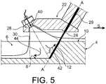
- said groove 6After initiation of the groove 6, said groove 6 has a desired depth ( figure 5 ). Such depth is, in particular, a function of the speed of displacement of the cutting head 22 and the power of the power laser beam 24.
- the gas flow 30Due to the relative orientations between the jet of gas 30 and the axis of propagation AA, for example because of the angle ⁇ between the bisector of the jet of gas 30 and the axis of propagation AA, in the emission plane P, the gas flow 30, in particular the flow of gas before, leads to the rise of the melt along the cutting edge 12, which leads to the advantageous effect that the melt does not redeposit in the bleeding 6 as the groove 6 is formed due to the displacement of the cutting head 22.
- the jet of gas 30,because of its planar nature, engulfs the groove 6 regardless of the stage of formation of the bleeding, and ejects the material melted by the laser beam of power 24.
- the approximation or the relative spacing of the cutting head 22 and the part 4is not required during the priming of the groove 6. In particular, in case of defusing the bleeding, no procedure This is required to restart the bleeding.
- the cutting head 22has a second auxiliary nozzle 50.
- the second auxiliary nozzle 50is, for example, arranged between the auxiliary nozzle 28 and the optical output 26.
- the second auxiliary nozzle 50is configured to generate a gas jet 52 which scans the optical output 26.
- the gas jet 52is a planar gas jet extending into the emission plane P of the jet gas 30 from the auxiliary nozzle 28.
- the auxiliary nozzles 28, 50are configured so that there is a continuity between the jet of gas 30 coming from the auxiliary nozzle 28 and the gas jet 52 issuing from the second auxiliary nozzle 50.
- the gas jets from the auxiliary nozzles 28, 50form between the optical output 26 and the surface location 10 of the part 4 , a dry cavity in which the power laser beam 24 is caused to propagate.
- the power laser beam 24propagates, from the optical output 26 to the part 4, only in the gas from the auxiliary nozzles 28, 50.
- the formation of such a dry cavityis particularly advantageous insofar as water has an unacceptable absorption coefficient in the wavelength ranges used for laser cutting.
- the absorption coefficient of waterhas a value of about 0.1 cm -1 (per centimeter) to 0.2 cm -1 .
- auxiliary nozzles 28, 50are arranged so that a portion 54 of the gas jets 30, 52 from the cutting head 22 goes up along the cutting edge 12, from the bottom of the groove 8 to the surface 10 of the part 4, to evacuate the melt along the cutting edge 12 to the outside of the groove 6.
Landscapes
- Engineering & Computer Science (AREA)
- Physics & Mathematics (AREA)
- Optics & Photonics (AREA)
- Plasma & Fusion (AREA)
- Mechanical Engineering (AREA)
- Laser Beam Processing (AREA)
Abstract
Translated fromFrenchDescription
Translated fromFrenchLa présente invention concerne un système de découpe laser, comportant une tête de découpe et une source laser, la tête de découpe comprenant une sortie optique, la source laser étant configurée pour générer un faisceau laser de puissance, la tête de découpe et la source laser étant configurées de sorte que le faisceau laser de puissance débouche hors de la tête de découpe par la sortie optique en se propageant suivant un axe de propagation.The present invention relates to a laser cutting system, comprising a cutting head and a laser source, the cutting head comprising an optical output, the laser source being configured to generate a power laser beam, the cutting head and the laser source. being configured so that the power laser beam opens out of the cutting head by the optical output propagating along a propagation axis.
L'invention s'applique au domaine de la découpe, notamment la découpe non débouchante, du gougeage, de l'usinage, en particulier au moyen d'un laser. L'invention est notamment susceptible d'être mise en oeuvre pour des opérations de démantèlement, en particulier en cas d'accident grave.The invention applies to the field of cutting, in particular non-emergent cutting, gouging, machining, in particular by means of a laser. The invention is in particular likely to be implemented for dismantling operations, in particular in the event of a serious accident.
Il est connu d'avoir recours à un système de découpe laser pour découper des pièces. Dans ce cas, une tête de découpe du système de découpe laser est mise en regard d'une surface endroit d'une pièce à découper, et ladite surface endroit est irradiée avec un faisceau laser de puissance présentant une densité d'énergie suffisante pour entraîner la fusion du matériau dans lequel la pièce est réalisée. En outre, la tête de découpe est mise en mouvement parallèlement à la surface endroit pour former une saignée.It is known to use a laser cutting system for cutting parts. In this case, a cutting head of the laser cutting system is placed opposite a surface of a part to be cut, and said area surface is irradiated with a power laser beam having a sufficient energy density to drive the melting of the material in which the piece is made. In addition, the cutting head is moved parallel to the surface to form a kerf.
En fonction de la vitesse d'avancée de la tête de découpe par rapport à la pièce, ainsi que de la densité d'énergie du faisceau laser de puissance, une fusion du matériau est susceptible d'être obtenue sur la totalité de l'épaisseur de la pièce (découpe laser débouchante) ou sur une partie seulement de l'épaisseur de la pièce (découpe laser non débouchante).Depending on the speed of advance of the cutting head relative to the workpiece, as well as the energy density of the power laser beam, a melting of the material is likely to be obtained over the entire thickness of the workpiece (open laser cut) or only part of the workpiece thickness (non-through laser cut).
Les découpes non débouchantes sont, par exemple, réalisées dans des pièces qui reposent sur un support trop épais, ou encore des pièces dans lesquelles une découpe traversante ne doit pas être réalisée pour des motifs d'intégrité mécanique ou de sureté.Non-emerging cutouts are, for example, made in parts that rest on a support too thick, or parts in which a through cut must not be made for reasons of mechanical integrity or safety.
Dans ce qui suit, la limite entre la saignée et la matière non encore fondue de la pièce, suivant la direction de déplacement de la tête de découpe sera appelée « front de coupe ». En outre, la partie de la saignée qui est la plus éloignée de la surface endroit de la pièce sera appelée « fond de saignée » ; dans le cas d'une découpe débouchante, il s'agit de la surface envers de la pièce, située à l'opposé de la surface endroit.In what follows, the boundary between the bleeding and the not yet melted material of the part, in the direction of travel of the cutting head will be called "cutting edge". In addition, the part of the groove which is farthest from the surface of the room will be called the "bottom of the groove"; in the case of an opening cutout, it is the surface facing the room, located opposite the surface location.
Dans les deux cas, le fluide que constitue la matière fondue est généralement évacué grâce aux forces d'impact et de cisaillement d'un jet de gaz dirigé vers l'intersection du front de coupe avec le fond de saignée. En d'autres termes, le jet de gaz intercepte le faisceau laser de puissance au niveau du fond de saignée durant l'émission du faisceau laser de puissance.In both cases, the fluid that is the melt is usually discharged through the impact and shear forces of a jet of gas directed to the intersection of the cutting edge with the bottom of the groove. In other words, the jet of gas intercepts the power laser beam at the bleed bottom during the emission of the power laser beam.
Néanmoins, un tel système de découpe laser ne donne pas entière satisfaction.Nevertheless, such a laser cutting system does not give complete satisfaction.
En effet, avec un tel système de découpe laser, pour amorcer la saignée, il est nécessaire de mettre la tête de découpe à distance de la pièce de façon à ce que le jet de gaz soit dirigé vers le point d'impact du faisceau laser de puissance avec la surface endroit de la pièce à découper, sans quoi la matière fondue à la surface ne serait pas évacuée, et la saignée ne s'amorcerait pas.Indeed, with such a laser cutting system, to initiate the bleeding, it is necessary to put the cutting head away from the workpiece so that the jet of gas is directed to the point of impact of the laser beam of power with the surface area of the piece to be cut, otherwise the melted material on the surface would not be evacuated, and the bleeding would not start.
Puis, au fur et à mesure que la profondeur de la saignée (c'est-à-dire la distance entre le fond de saignée et la surface endroit) augmente, la tête de découpe est rapprochée de la surface endroit de la pièce de façon à ce que le jet de gaz soit encore dirigé vers le point d'impact du faisceau laser de puissance avec le fond de saignée.Then, as the depth of the kerf (ie the distance between the kerf bottom and the surface area) increases, the cutting head is brought closer to the surface of the room so that the jet of gas is again directed towards the point of impact of the power laser beam with the bottom of the groove.
Une telle procédure d'amorçage de saignée est fastidieuse.Such a bleeding initiation procedure is tedious.
En outre, si un désamorçage de la saignée a lieu, par exemple en raison d'un dysfonctionnement ponctuel, la saignée ne se réamorce généralement pas spontanément, ou alors se réamorce à une profondeur différente de sa profondeur avant désamorçage. Il est alors nécessaire de répéter la procédure d'amorçage précédemment décrite de façon à garantir une profondeur de saignée contrôlée.In addition, if a defusing of the bleeding takes place, for example due to a punctual dysfunction, the bleeding does not usually reboot spontaneously, or then reboots to a depth different from its depth before defusing. It is then necessary to repeat the priming procedure described above to ensure a controlled depth of bleeding.
Un but de l'invention est donc de proposer un dispositif de découpe laser avec lequel une telle procédure d'amorçage de saignée n'est pas requise.An object of the invention is therefore to provide a laser cutting device with which such a bleeding initiation procedure is not required.
A cet effet, l'invention a pour objet un système de découpe laser du type précité, dans lequel que la tête de découpe comprend, en outre, au moins une buse auxiliaire, distante de la sortie optique et configurée pour émettre un jet de gaz planaire s'étendant dans un plan d'émission, l'axe de propagation du faisceau laser de puissance appartenant au plan d'émission.To this end, the subject of the invention is a laser cutting system of the aforementioned type, in which the cutting head further comprises at least one auxiliary nozzle remote from the optical output and configured to emit a jet of gas. planar plane extending in an emission plane, the axis of propagation of the power laser beam belonging to the emission plane.
En effet, du fait de son caractère planaire, le jet de gaz s'engouffre dans la saignée quel que soit le stade de formation de la saignée, et éjecte la matière mise en fusion par le faisceau laser de puissance, en particulier hors de la saignée. Le rapprochement ou l'écartement relatif de la tête de découpe et d'une pièce à découper n'est pas requis au cours de l'amorçage de la saignée. En outre, en cas de désamorçage de la saignée, aucune procédure particulière n'est requise pour amorcer de nouveau la saignée, un tel réamorçage étant directement obtenu par le fonctionnement normal du système de découpe.Indeed, because of its planar nature, the jet of gas rushes in the bleeding regardless of the stage of formation of the bleeding, and ejects the material melted by the power laser beam, in particular out of the bleeding. The approximation or relative spacing of the cutting head and a workpiece is not required during the priming of the kerf. In addition, in case of defusing the kerf, no particular procedure is required to start the bleeding again, such a reboot being directly obtained by the normal operation of the cutting system.
Suivant d'autres aspects avantageux de l'invention, le système de découpe laser comporte une ou plusieurs des caractéristiques suivantes, prise(s) isolément ou suivant toutes les combinaisons techniquement possibles :
- l'au moins une buse auxiliaire est configurée de sorte que le jet de gaz correspondant balaye la sortie optique ;
- le système de découpe laser comporte, en outre, un dispositif optique, de préférence un fibroscope, comprenant un organe de collection de lumière présentant un champ de collection, le dispositif optique étant agencé de sorte que le champ de collection de l'organe de collection de lumière intercepte au moins une partie d'une zone d'intersection de l'axe de propagation avec le plan d'émission ;
- l'organe de collection de lumière est agencé dans l'une parmi l'au moins une buse auxiliaire ;
- le système de découpe laser comprend, en outre, un détecteur et un calculateur, le détecteur étant configuré pour générer un signal électrique de détection représentatif d'une lumière collectée par l'organe de collection de lumière, le détecteur étant insensible à la longueur d'onde du faisceau laser de puissance, le calculateur étant configuré pour fonctionner dans un mode dit « profondimètre », dans lequel le calculateur :
- mesure un profil d'irradiance dans le champ de collection de l'organe de collection de lumière ;
- détecte un front de coupe d'une saignée comme étant une zone dont l'irradiance est supérieure ou égale à un seuil ;
- détermine des informations relatives à une géométrie et/ou une position dans l'espace du front de coupe détecté.
- la source laser est configurée pour générer un faisceau laser pilote présentant une longueur d'onde distincte de la longueur d'onde du faisceau laser de puissance, le faisceau laser pilote étant coaxial avec le faisceau laser de puissance, le système de découpe laser comprenant, en outre, un détecteur et un calculateur, le détecteur étant configuré pour générer un signal électrique de détection représentatif d'une lumière collectée par l'organe de collection de lumière, le détecteur étant sensible à la longueur d'onde du faisceau laser pilote, le calculateur étant configuré pour fonctionner dans un mode dit « télémètre », dans lequel le calculateur :
- détecte, à partir du signal de détection, un point d'impact du faisceau laser pilote avec une surface d'une pièce à découper; et
- détermine la position du point d'impact dans un repère prédéterminé.
- the at least one auxiliary nozzle is configured so that the corresponding gas jet scans the optical output;
- the laser cutting system further comprises an optical device, preferably a fiberscope, comprising a light collection member having a collection field, the optical device being arranged so that the collection field of the collection member of light intercepts at least a portion of an intersection area of the propagation axis with the transmission plane;
- the light collection member is arranged in one of the at least one auxiliary nozzle;
- the laser cutting system further comprises a detector and a calculator, the detector being configured to generate an electrical detection signal representative of a light collected by the light collection member, the detector being insensitive to the length of the light, wave of the power laser beam, the computer being configured to operate in a so-called "depth gauge" mode, in which the computer:
- measuring an irradiance profile in the collection field of the light collection member;
- detects a cutting edge of a kerf as being an area whose irradiance is greater than or equal to a threshold;
- determines information relating to a geometry and / or position in the space of the detected cutting edge.
- the laser source is configured to generate a pilot laser beam having a wavelength distinct from the wavelength of the power laser beam, the pilot laser beam being coaxial with the power laser beam, the laser cutting system comprising, in addition, a detector and a computer, the detector being configured to generate an electrical detection signal representative of a light collected by the light collection member, the detector being sensitive to the wavelength of the pilot laser beam, the computer being configured to operate in a so-called "rangefinder" mode, in which the computer:
- detects, from the detection signal, a point of impact of the pilot laser beam with a surface of a piece to be cut; and
- determines the position of the point of impact in a predetermined coordinate system.
L'invention sera mieux comprise à l'aide de la description qui va suivre, donnée uniquement à titre d'exemple non limitatif et faite en se référant aux dessins annexés sur lesquels :
- la
figure 1 est une représentation schématique d'un système de découpe laser selon l'invention, dont une tête de découpe est représentée en section suivant un plan d'émission associé à une buse de la tête de découpe ; - la
figure 2 est une vue en coupe de la tête de détection de lafigure 1 , dans un plan orthogonal à un plan d'émission de la tête de découpe ; - la
figure 3 est une vue analogue à la vue de lafigure 1 , le système de découpe laser étant représenté en fonctionnement, au démarrage d'une procédure de réalisation d'une saignée dans une pièce à découper; - la
figure 4 est similaire à lafigure 3 , la saignée étant en cours d'amorçage ; - la
figure 5 est similaire à lafigure 3 , la saignée ayant été amorcée ; - la
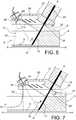
figure 6 est une représentation schématique d'une variante de la tête de découpe du système de découpe laser selon l'invention, la tête de découpe étant représentée en section suivant un plan d'émission associé à une buse de la tête de découpe ; et - la
figure 7 est une vue analogue à la vue de lafigure 6 , le système de découpe laser étant représenté en fonctionnement, après l'amorçage d'une saignée dans une pièce à découper.
- the
figure 1 is a schematic representation of a laser cutting system according to the invention, including a cutting head is shown in section along an emission plane associated with a nozzle of the cutting head; - the
figure 2 is a sectional view of the detection head of thefigure 1 in a plane orthogonal to an emission plane of the cutting head; - the
figure 3 is a view similar to the view of thefigure 1 , the laser cutting system being shown in operation, at the start of a procedure for producing a groove in a workpiece; - the
figure 4 is similar to thefigure 3 , bleeding being in the process of priming; - the
figure 5 is similar to thefigure 3 bleeding having been initiated; - the
figure 6 is a schematic representation of a variant of the cutting head of the laser cutting system according to the invention, the cutting head being shown in section along an emission plane associated with a nozzle of the cutting head; and - the
figure 7 is a view similar to the view of thefigure 6 , the laser cutting system being shown in operation, after the initiation of a kerf in a piece to be cut.
Un système de découpe laser 2 selon l'invention est représenté sur la
Dans l'exemple de la
La saignée 6 présente un fond de saignée 8, à distance d'une surface endroit 10 de la pièce 4. Un front de coupe 12, formant la limite entre la saignée 6 et la partie non fondue de la pièce 4, suivant l'axe longitudinal X-X, est également représentée.The
Le système de découpe laser 2 comporte une source laser 20 et une tête de découpe 22.The
La source laser 20 est configurée pour générer un faisceau laser de puissance 24. Le faisceau laser de puissance 24 est destiné à la découpe de la pièce 4.The
Parexemple, la longueur d'onde du faisceau de puissance 24 est comprise entre 900 nm (nanomètres) et 1200 nm, de préférence entre 950 nm et 1150 nm.For example, the wavelength of the
Avantageusement, la source laser 20 est configurée de sorte que la puissance du faisceau laser de puissance 24 puisse être modifiée au cours du temps, par exemple commandée au moyen d'un signal de commande appliqué en entrée de la source laser 20.Advantageously, the
La tête de découpe 22 comporte une sortie optique 26, la source laser 20 et la tête de découpe 22 coopérant de sorte que le faisceau laser de puissance 24 débouche hors de la tête de découpe 22 par la sortie optique 26 en se propageant suivant un axe de propagation A-A.The cutting
Par exemple, le faisceau laser de puissance 24 est acheminé à travers une fibre optique 25 jusqu'à un organe optique 27 de focalisation et de collimation, destiné à mettre en forme le faisceau laser de puissance 24, de préférence à collimater le faisceau laser de puissance 24. Puis, le faisceau laser de puissance 24 se propage avantageusement jusqu'à la sortie optique 26 à travers un canal 29 ménagé dans la tête de découpe 22 et débouchant à l'extérieur de la tête de découpe 22 par la sortie optique 26.For example, the
La tête de découpe 22 est mobile, de préférence selon les trois directions de l'espace. En particulier, la tête de découpe est apte à se déplacer le long de l'axe longitudinal X-X, de façon à permettre la formation de la saignée 6 s'étendant le long de l'axe longitudinal X-X, sous l'action du faisceau laser de puissance 24.The cutting
La tête de découpe 22 comporte, en outre, au moins une buse auxiliaire. Par exemple, sur la
La buse auxiliaire 28 est distante de la sortie optique 26.The
La buse auxiliaire 28 est configurée pour émettre un jet de gaz 30 planaire s'étendant dans un plan d'émission P (représenté sur la
Par « jet de gaz planaire s'étendant dans un plan d'émission P », il est entendu, au sens de la présente invention, un jet de gaz 30 qui est aplati suivant une direction orthogonale au plan d'émission P.By "planar gas jet extending in an emission plane P", it is understood, in the sense of the present invention, a jet of
Un tel jet de gaz 30 planaire est illustré sur la
Le jet de gaz 30 définit, dans le plan d'émission P, un secteur angulaire α (
De préférence, l'angle β (
De préférence encore, la buse auxiliaire 28 est configurée de sorte que le jet de gaz 30 balaye la sortie optique 26.More preferably, the
De préférence, le système de découpe 2 comporte également un étage d'analyse 32 pour analyser la découpe.Preferably, the
L'étage d'analyse 32 comporte un dispositif optique 34 de collection de lumière, un détecteur 36 et un calculateur 38.The
Le dispositif optique 34 est configuré pour collecter de la lumière en provenance de la saignée 6, et plus particulièrement de la lumière provenant d'une zone de la saignée 6 comprenant le front de coupe 12.The
En particulier, le dispositif optique 34 comporte un organe de collection de lumière 40 définissant un champ de collection 41 du dispositif optique 34.In particular, the
L'organe de collection de lumière 40 est agencé de sorte que le champ de collection 41 intercepte au moins une partie d'une zone d'intersection de l'axe de propagation A-A avec le plan d'émission P, de préférence une zone d'intersection de l'axe de propagation A-A avec le jet de gaz 30. Dans ce cas, lors du fonctionnement du système de découpe 2, au moins une partie du front de coupe 12, de préférence la totalité du front de coupe 12, se trouve dans le champ de collection 41 de l'organe de collection de lumière 40, c'est-à-dire dans le champ de collection 41 du dispositif optique 34.The
Avantageusement, l'organe de collection de lumière 40 est logé dans la buse auxiliaire 28. Ceci est avantageux, dans la mesure où le jet de gaz émis par la buse auxiliaire 28 protège l'organe de collection de lumière en assurant son refroidissement et en repoussant les fumées, poussières et matières incandescentes générées lors de la découpe au moyen du faisceau laser de puissance 24.Advantageously, the
Dans ce cas, dans le plan d'émission P, le champ de collection 41 se superpose au moins partiellement au jet de gaz 30 issu de la buse auxiliaire 28.In this case, in the emission plane P, the
Le dispositif optique 34 est, de préférence, un fibroscope. Dans ce cas, le fibroscope est, avantageusement, logé dans un circuit d'alimentation du la buse auxiliaire 28 en gaz. Ceci est avantageux, dans la mesure où, de par les faibles dimensions du fibroscope, en particulier le faible diamètre de celui-ci, les perturbations induites pas le fibroscope sur le jet de gaz émis par la buse auxiliaire 28 sont négligeables.The
En outre, le recours à un fibroscope permet de déporter le détecteur 36 et/ou le calculateur 38 à l'écart de la tête de découpe 22, ce qui permet de réduire l'encombrement de la tête de découpe 22. Un tel déport protège, en outre, le détecteur 36 des rayonnements ionisants générés au cours de la découpe, et auxquels le détecteur 36 est susceptible d'être sensible.In addition, the use of a fiberscope makes it possible to deport the
Le détecteur 36 est configuré pour générer un signal électrique de détection représentatif d'une lumière collectée par le dispositif optique 34.The
Avantageusement, le détecteur 36 est insensible à la longueur d'onde du faisceau laser de puissance 24.Advantageously, the
Par « détecteur insensible à une longueur d'onde », il est entendu, au sens de la présente invention, que la sensibilité du détecteur à un rayonnement présentant ladite longueur d'onde est inférieure ou égale à un centième de la sensibilité maximale du détecteur.By "wavelength-insensitive detector", it is understood in the sense of the present invention that the sensitivity of the detector to radiation having said wavelength is less than or equal to one hundredth of the maximum sensitivity of the detector .
Par exemple, le détecteur 36 est formé par une matrice de photodétecteurs devant laquelle est agencé un filtre optique configuré pour rejeter et/ou absorber les photons dont la longueur d'onde est égale à la longueur d'onde du faisceau laser de puissance 24.For example, the
Le calculateur 38 est configuré pour déterminer, à partir du signal électrique de détection, des informations relatives à la pièce 4 et/ou au déroulement de la découpe.The
Notamment, le calculateur 38 est configuré pour fonctionner dans un mode dit « profondimètre ».In particular, the
Dans un tel mode, le calculateur 38 mesure un profil d'irradiance dans le champ de collection du dispositif optique 34.In such a mode, the
Par exemple, le détecteur 36 est configuré pour générer un signal électrique de détection codant une image. Dans ce cas, le détecteur 38 est configuré pour associer, à chaque pixel de l'image, une valeur d'irradiance du point correspondant du champ de collection du dispositif optique 34. Une telle valeur est, par exemple, une fonction de l'intensité du pixel.For example, the
Puis, après la mesure du profil d'irradiance, le calculateur 38 détecte le front de coupe 12 de la saignée 6 comme étant une zone dont l'irradiance est supérieure ou égale à un seuil. En effet, la matière fondue du front de coupe 12 étant plus chaude que la matière présente au niveau du fond de saignée 8, l'irradiance de la première est plus importante.Then, after measuring the irradiance profile, the
Puis, le calculateur 38 détermine des informations relatives à une géométrie et/ou une position dans l'espace du front de coupe 12 détecté.Then, the
Par exemple, de telles informations comprennent une localisation d'un début du front de coupe 12 (c'est-à-dire l'intersection du front de coupe 12 avec la surface endroit 10), la longueur du front de coupe 12 ou encore son orientation dans un repère prédéterminé.For example, such information includes a location of a beginning of the cutting edge 12 (i.e., the intersection of the
Puis, le calculateur 38 transmet les informations déterminées à un opérateur, par exemple pour permettre à l'opérateur de guider le déplacement de la tête de découpe 22.Then, the
En variante, le calculateur 38 est configuré pour utiliser les informations déterminées afin de :
- réguler une distance entre la tête de découpe 22 et la
surface endroit 10 de la pièce 4, par exemple au moyen d'un asservissement de distance ; et/ou - pour réguler une trajectoire de la tête de découpe 22, par exemple au moyen d'un asservissement de position ;
- pour réguler une profondeur de la saignée 6, par exemple au moyen d'un asservissement de la vitesse d'avancée de la tête de découpe 22 et/ou un asservissement de la puissance du faisceau laser de puissance 24 généré par
la source laser 20.
- regulating a distance between the cutting
head 22 and thesurface location 10 of theworkpiece 4, for example by means of distance control; and or - for regulating a path of the cutting
head 22, for example by means of position control; - to regulate a depth of the
groove 6, for example by means of a slaving of the advancing speed of the cuttinghead 22 and / or a control of the power of thepower laser beam 24 generated by thelaser source 20.
Avantageusement, la source laser 20 est également configurée pour générer, outre le faisceau laser de puissance 24, un faisceau laser pilote.Advantageously, the
Le faisceau laser pilote présente une longueur d'onde distincte de la longueur d'onde du faisceau laser de puissance 24. En outre, la source laser 20 et la tête de découpe 22 coopèrent de sorte que le faisceau laser pilote soit coaxial avec le faisceau laser de puissance 24.The pilot laser beam has a wavelength distinct from the wavelength of the
Dans ce cas, le détecteur est sensible à la longueur d'onde du faisceau laser pilote.In this case, the detector is sensitive to the wavelength of the pilot laser beam.
Par « détecteur sensible à une longueur d'onde », il est entendu, au sens de la présente invention, que la sensibilité du détecteur à un rayonnement présentant ladite longueur d'onde est supérieure à un centième de la sensibilité maximale du détecteur.By "wavelength sensitive detector", it is understood in the sense of the present invention that the sensitivity of the detector to radiation having said wavelength is greater than one hundredth of the maximum sensitivity of the detector.
Dans ce cas, le calculateur 38 est configuré pour fonctionner dans un mode dit « télémètre ».In this case, the
Dans un tel mode, le calculateur détecte, à partir du signal électrique de détection, un point d'impact du faisceau laser pilote avec une surface de la pièce 4.In such a mode, the computer detects, from the electrical detection signal, a point of impact of the pilot laser beam with a surface of the
Par exemple, le détecteur 36 est configuré pour générer un signal électrique de détection codant une image. Dans ce cas, le détecteur 38 détecte un ensemble de pixels qui présentent la plus grande intensité comme correspondant à la zone, dans le champ de collection du dispositif optique 34, où le faisceau laser pilote irradie la surface de la pièce 4.For example, the
Puis, le calculateur 38 détermine la position du point d'impact dans un repère prédéterminé, par exemple grâce à un algorithme de triangulation optique.Then, the
La position du point d'impact qui a été déterminée est représentative de la distance séparant la tête de découpe 22 de la surface de la pièce 4.The position of the point of impact which has been determined is representative of the distance separating the cutting
Puis, le calculateur 38 transmet la position du point d'impact qui a été déterminée et/ou la distance séparant la tête de découpe 22 de la surface de la pièce 4 à un opérateur, par exemple pour permettre à l'opérateur de guider le déplacement de la tête de découpe 22.Then, the
En variante, le calculateur 38 est configuré pour utiliser les informations déterminées afin de
- réguler une distance entre la tête de découpe 22 et la surface de la pièce 4, par exemple au moyen d'un asservissement de distance ; et/ou
- effectuer un relevé de profil de la pièce 4 en déplaçant la tête de découpe 22.
- regulating a distance between the cutting
head 22 and the surface of theworkpiece 4, for example by means of distance control; and or - perform a profile survey of the
part 4 by moving the cuttinghead 22.
L'aptitude du fonctionnement du calculateur 38 dans le mode télémètre ne requiert pas son aptitude à fonctionner dans le mode profondimètre, et inversement.The ability of the
Le fonctionnement du système de découpe 2 va maintenant être décrit en référence aux
Comme illustré par la
A titre d'exemple, dans le cas où le système de découpe 2 comporte un étage d'analyse 32, la distance entre la tête de découpe 22 et la surface endroit 10 de la pièce 4 est déterminée par le calculateur 38 fonctionnant en mode « télémètre ».By way of example, in the case where the
La buse auxiliaire 28 est alimentée en gaz, par exemple de l'air, depuis un circuit d'alimentation en gaz. La pression du gaz au niveau de la buse auxiliaire 28 vaut, de préférence, quelques bars, par exemple 10 bar.The
Le jet de gaz 30 planaire issu de la buse auxiliaire 28 impacte la surface endroit 10 de la pièce 4 et se scinde en un flux de gaz avant 42 évacué dans une première direction dans le plan d'impact P et un flux de gaz arrière 44 évacué dans une deuxième direction dans le plan d'impact P opposée à la première direction.The planar gas jet from the
La source laser 20 est enclenchée, et le faisceau laser de puissance 24 irradie la pièce 4, faisant fondre la matière de la pièce 4.The
Puis la tête de découpe 22 est mise en mouvement. Par exemple, sur les
Au cours de l'amorçage de la saignée 6, illustré par la
Après l'amorçage de la saignée 6, ladite saignée 6 présente une profondeur voulue (
Du fait des orientations relatives entre le jet de gaz 30 et l'axe de propagation A-A, par exemple du fait de l'angle β entre la bissectrice du jet de gaz 30 et l'axe de propagation A-A, dans le plan d'émission P, le flux de gaz 30, en particulier le flux de gaz avant, conduit à la remontée de la matière fondue le long du front de coupe 12, ce qui conduit à l'effet avantageux que la matière fondue ne se redépose pas dans la saignée 6 au fur et à mesure que la saignée 6 est formée du fait du déplacement de la tête de découpe 22.Due to the relative orientations between the jet of
Il ressort de ce qui précède que le jet de gaz 30, du fait de son caractère planaire, s'engouffre dans la saignée 6 quel que soit le stade de formation de la saignée, et éjecte la matière mise en fusion par le faisceau laser de puissance 24. Le rapprochement ou l'écartement relatif de la tête de découpe 22 et de la pièce 4 n'est pas requis au cours de l'amorçage de la saignée 6. En particulier, en cas de désamorçage de la saignée, aucune procédure particulière n'est requise pour amorcer de nouveau la saignée.It follows from the above that the jet of
Selon une variante du système de découpe 2 précédemment décrit, illustrée par la
La deuxième buse auxiliaire 50 est, par exemple, agencée entre la buse auxiliaire 28 et la sortie optique 26.The second
En outre, la deuxième buse auxiliaire 50 est configurée pour générer un jet de gaz 52 qui balaye la sortie optique 26. De préférence, le jet de gaz 52 est un jet de gaz planaire s'étendant dans le plan d'émission P du jet de gaz 30 issu de la buse auxiliaire 28.In addition, the second
Avantageusement, les buses auxiliaires 28, 50 sont configurées de sorte qu'il existe une continuité entre le jet de gaz 30 issu de la buse auxiliaire 28 et le jet de gaz 52 issu de la deuxième buse auxiliaire 50.Advantageously, the
Grâce à une telle tête de découpe 22, dans des conditions où la pièce 4 se trouve dans l'eau, les jets de gaz issus des buses auxiliaires 28, 50 forment, entre la sortie optique 26 et la surface endroit 10 de la pièce 4, une cavité sèche dans laquelle le faisceau laser de puissance 24 est amené à se propager. Dans ce cas, le faisceau laser de puissance 24 se propage, depuis la sortie optique 26 jusqu'à la pièce 4, uniquement dans le gaz issu des buses auxiliaires 28, 50.With such a
La formation d'une telle cavité sèche est particulièrement avantageuse, dans la mesure où l'eau présente un coefficient d'absorption inacceptable dans les gammes de longueurs d'onde utilisées pour la découpe laser. Par exemple, pour une longueur d'onde comprise entre 1000 nm (nanomètres) et 1100 nm, le coefficient d'absorption de l'eau présente une valeur d'environ 0,1 cm-1 (par centimètre) à 0,2 cm-1.The formation of such a dry cavity is particularly advantageous insofar as water has an unacceptable absorption coefficient in the wavelength ranges used for laser cutting. For example, for a wavelength of between 1000 nm (nanometers) and 1100 nm, the absorption coefficient of water has a value of about 0.1 cm-1 (per centimeter) to 0.2 cm-1 .
En outre, sous l'effet du faisceau laser de puissance, l'eau se vaporise, la vapeur d'eau perturbant le trajet du faisceau laser de puissance. En outre, l'eau favorise la formation d'oxydes; la modification locale des propriétés chimiques de la pièce 4 complique le contrôle de la découpe. En outre, une telle cavité sèche limite la formation de scories dans la saignée 6 et son obstruction par celles-ci.In addition, under the effect of the power laser beam, the water vaporizes, the water vapor disturbing the path of the power laser beam. In addition, water promotes the formation of oxides; the local modification of the chemical properties of the
La formation d'une cavité sèche entre la sortie optique 26 et la pièce 4 permet de s'affranchir de ces inconvénients généralement liés à la découpe laser dans l'eau.The formation of a dry cavity between the
En outre, et comme illustré par la
Claims (5)
Translated fromFrenchle système de découpe laser (2) étantcaractérisé en ce que la tête de découpe (22) comprend, en outre, au moins une buse auxiliaire (28, 50), distante de la sortie optique (26) et configurée pour émettre un jet de gaz (30, 52) planaire s'étendant dans un plan d'émission (P), l'axe de propagation (A-A) du faisceau laser de puissance (24) appartenant au plan d'émission (P), et
au moins une buse auxiliaire (28, 50) étant configurée de sorte que le jet de gaz (30, 52) correspondant balaye la sortie optique (26).A laser cutting system (2) comprising a cutting head (22) and a laser source (20), the cutting head (22) comprising an optical output (26), the laser source (20) being configured to generate a laser beam (24), the cutting head (22) and the laser source (20) being configured so that the power laser beam (24) opens out of the cutting head (22) through the optical output ( 26) propagating along an axis of propagation (AA),
the laser cutting system (2) beingcharacterized in that the cutting head (22) further comprises at least one auxiliary nozzle (28, 50), remote from the optical output (26) and configured to emit a jet planar gas (30, 52) extending in an emission plane (P), the propagation axis (AA) of the power laser beam (24) belonging to the emission plane (P), and
at least one auxiliary nozzle (28, 50) being configured so that the corresponding gas jet (30, 52) scans the optical output (26).
le système de découpe laser (2) comprenant, en outre, un détecteur (36) et un calculateur (38), le détecteur (36) étant configuré pour générer un signal électrique de détection représentatif d'une lumière collectée par l'organe de collection de lumière (40), le détecteur (36) étant sensible à la longueur d'onde du faisceau laser pilote,
le calculateur (38) étant configuré pour fonctionner dans un mode dit « télémètre », dans lequel le calculateur (38) :
the laser cutting system (2) further comprising a detector (36) and a computer (38), the detector (36) being configured to generate an electrical detection signal representative of a light collected by the light collection (40), the detector (36) being sensitive to the wavelength of the pilot laser beam,
the computer (38) being configured to operate in a so-called "rangefinder" mode, wherein the computer (38):
Applications Claiming Priority (1)
| Application Number | Priority Date | Filing Date | Title |
|---|---|---|---|
| FR1852763AFR3079435B1 (en) | 2018-03-29 | 2018-03-29 | LASER CUTTING SYSTEM |
Publications (2)
| Publication Number | Publication Date |
|---|---|
| EP3546108A1true EP3546108A1 (en) | 2019-10-02 |
| EP3546108B1 EP3546108B1 (en) | 2024-05-01 |
Family
ID=63014672
Family Applications (1)
| Application Number | Title | Priority Date | Filing Date |
|---|---|---|---|
| EP19166048.9AActiveEP3546108B1 (en) | 2018-03-29 | 2019-03-29 | Laser cutting system |
Country Status (2)
| Country | Link |
|---|---|
| EP (1) | EP3546108B1 (en) |
| FR (1) | FR3079435B1 (en) |
Cited By (1)
| Publication number | Priority date | Publication date | Assignee | Title |
|---|---|---|---|---|
| CN113681174A (en)* | 2021-08-24 | 2021-11-23 | 苏州科韵激光科技有限公司 | A laser cutting device |
Citations (3)
| Publication number | Priority date | Publication date | Assignee | Title |
|---|---|---|---|---|
| JPH11179570A (en)* | 1997-12-22 | 1999-07-06 | Ishikawajima Harima Heavy Ind Co Ltd | Underwater laser weld visualization device |
| WO2013053832A1 (en)* | 2011-10-13 | 2013-04-18 | Commissariat à l'énergie atomique et aux énergies alternatives | Apparatus and method for laser cutting with a laser implementing gas pulses, the frequency or pressure of which is controlled |
| FR2982185A1 (en)* | 2011-11-07 | 2013-05-10 | Air Liquide | Cutting part using laser beam, comprises focusing laser beam along propagation axis in direction of part to be cut, bringing focused laser beam to part by first pipe provided with output orifice, and distributing gas jet by second pipe |
- 2018
- 2018-03-29FRFR1852763Apatent/FR3079435B1/enactiveActive
- 2019
- 2019-03-29EPEP19166048.9Apatent/EP3546108B1/enactiveActive
Patent Citations (3)
| Publication number | Priority date | Publication date | Assignee | Title |
|---|---|---|---|---|
| JPH11179570A (en)* | 1997-12-22 | 1999-07-06 | Ishikawajima Harima Heavy Ind Co Ltd | Underwater laser weld visualization device |
| WO2013053832A1 (en)* | 2011-10-13 | 2013-04-18 | Commissariat à l'énergie atomique et aux énergies alternatives | Apparatus and method for laser cutting with a laser implementing gas pulses, the frequency or pressure of which is controlled |
| FR2982185A1 (en)* | 2011-11-07 | 2013-05-10 | Air Liquide | Cutting part using laser beam, comprises focusing laser beam along propagation axis in direction of part to be cut, bringing focused laser beam to part by first pipe provided with output orifice, and distributing gas jet by second pipe |
Cited By (1)
| Publication number | Priority date | Publication date | Assignee | Title |
|---|---|---|---|---|
| CN113681174A (en)* | 2021-08-24 | 2021-11-23 | 苏州科韵激光科技有限公司 | A laser cutting device |
Also Published As
| Publication number | Publication date |
|---|---|
| FR3079435B1 (en) | 2021-01-15 |
| FR3079435A1 (en) | 2019-10-04 |
| EP3546108B1 (en) | 2024-05-01 |
Similar Documents
| Publication | Publication Date | Title |
|---|---|---|
| EP0469948B1 (en) | Apparatus for evaluating the degree of wear of vehicle tyres | |
| EP0921895B1 (en) | Method for welding coated sheets with an energy beam, such as a laser beam | |
| EP3352974B1 (en) | System and method for additively manufacturing by laser melting of a powder bed | |
| EP0119883B1 (en) | Method and apparatus for the alignment of a laser beam by optical aiming means, and method of using the apparatus for controlling the alignment | |
| EP2709793B1 (en) | Laser nozzle having a movable piece | |
| CN113798672A (en) | Laser welding device and laser welding method | |
| EP3546108B1 (en) | Laser cutting system | |
| EP2916992A1 (en) | Laser nozzle having an internal mobile element and an external cover | |
| EP0934797B1 (en) | Thermographic camera position control method used in the welding field | |
| EP0998369B1 (en) | Device and method for extended remote laser cutting in pulse mode | |
| EP2834035B1 (en) | Laser nozzle with mobile element of improved external profile | |
| WO2017001027A1 (en) | Head for a welding device | |
| EP2916991A1 (en) | Laser nozzle having a modular mobile element made of electrically insulating material and an insert made of electrically conductive material | |
| FR2733707A1 (en) | METHOD AND DEVICE FOR CHECKING AND ADJUSTING THE POSITION OF THE FIREPLACE DURING THE MACHINING OF A LASER MATERIAL | |
| EP1718957A1 (en) | Method and device for control by ombroscopy | |
| FR2973725A1 (en) | Drilling and cutting metallic material by laser beam by subjecting metal material to impact of laser beam to operate onset of melting localized from material, and continuing localized melting of material started in subjecting step | |
| EP4196317B1 (en) | Method for measuring on a part and apparatus such as a device for a machining tool | |
| KR100602382B1 (en) | Arc welding apparatus and method | |
| FR2694633A1 (en) | Method and device for controlling the contact of two plates placed edge to edge | |
| FR2969520A1 (en) | SYSTEM FOR CUTTING A PIECE BY RADIATION AND CORRESPONDING CONTROL METHOD | |
| Pfluger et al. | The application of optical signal detection for characterizing transitions during laser beam welding | |
| FR2982185A1 (en) | Cutting part using laser beam, comprises focusing laser beam along propagation axis in direction of part to be cut, bringing focused laser beam to part by first pipe provided with output orifice, and distributing gas jet by second pipe | |
| WO2016207030A1 (en) | Method for laser welding with a solid laser generator and dynamic gas jet | |
| FR2769529A1 (en) | On site method and device for automatically and precisely following a curvilinear profile of the edge of a metallic chassis. |
Legal Events
| Date | Code | Title | Description |
|---|---|---|---|
| PUAI | Public reference made under article 153(3) epc to a published international application that has entered the european phase | Free format text:ORIGINAL CODE: 0009012 | |
| STAA | Information on the status of an ep patent application or granted ep patent | Free format text:STATUS: REQUEST FOR EXAMINATION WAS MADE | |
| 17P | Request for examination filed | Effective date:20190329 | |
| AK | Designated contracting states | Kind code of ref document:A1 Designated state(s):AL AT BE BG CH CY CZ DE DK EE ES FI FR GB GR HR HU IE IS IT LI LT LU LV MC MK MT NL NO PL PT RO RS SE SI SK SM TR | |
| AX | Request for extension of the european patent | Extension state:BA ME | |
| STAA | Information on the status of an ep patent application or granted ep patent | Free format text:STATUS: EXAMINATION IS IN PROGRESS | |
| RIC1 | Information provided on ipc code assigned before grant | Ipc:B23K 26/38 20140101ALI20220728BHEP Ipc:B23K 26/14 20140101ALI20220728BHEP Ipc:B23K 26/03 20060101AFI20220728BHEP | |
| 17Q | First examination report despatched | Effective date:20220826 | |
| GRAP | Despatch of communication of intention to grant a patent | Free format text:ORIGINAL CODE: EPIDOSNIGR1 | |
| STAA | Information on the status of an ep patent application or granted ep patent | Free format text:STATUS: GRANT OF PATENT IS INTENDED | |
| INTG | Intention to grant announced | Effective date:20231121 | |
| GRAS | Grant fee paid | Free format text:ORIGINAL CODE: EPIDOSNIGR3 | |
| GRAA | (expected) grant | Free format text:ORIGINAL CODE: 0009210 | |
| STAA | Information on the status of an ep patent application or granted ep patent | Free format text:STATUS: THE PATENT HAS BEEN GRANTED | |
| AK | Designated contracting states | Kind code of ref document:B1 Designated state(s):AL AT BE BG CH CY CZ DE DK EE ES FI FR GB GR HR HU IE IS IT LI LT LU LV MC MK MT NL NO PL PT RO RS SE SI SK SM TR | |
| REG | Reference to a national code | Ref country code:GB Ref legal event code:FG4D Free format text:NOT ENGLISH | |
| REG | Reference to a national code | Ref country code:CH Ref legal event code:EP | |
| REG | Reference to a national code | Ref country code:DE Ref legal event code:R096 Ref document number:602019051215 Country of ref document:DE | |
| REG | Reference to a national code | Ref country code:IE Ref legal event code:FG4D Free format text:LANGUAGE OF EP DOCUMENT: FRENCH | |
| REG | Reference to a national code | Ref country code:LT Ref legal event code:MG9D | |
| REG | Reference to a national code | Ref country code:NL Ref legal event code:MP Effective date:20240501 | |
| PG25 | Lapsed in a contracting state [announced via postgrant information from national office to epo] | Ref country code:IS Free format text:LAPSE BECAUSE OF FAILURE TO SUBMIT A TRANSLATION OF THE DESCRIPTION OR TO PAY THE FEE WITHIN THE PRESCRIBED TIME-LIMIT Effective date:20240901 | |
| PG25 | Lapsed in a contracting state [announced via postgrant information from national office to epo] | Ref country code:BG Free format text:LAPSE BECAUSE OF FAILURE TO SUBMIT A TRANSLATION OF THE DESCRIPTION OR TO PAY THE FEE WITHIN THE PRESCRIBED TIME-LIMIT Effective date:20240501 | |
| PG25 | Lapsed in a contracting state [announced via postgrant information from national office to epo] | Ref country code:HR Free format text:LAPSE BECAUSE OF FAILURE TO SUBMIT A TRANSLATION OF THE DESCRIPTION OR TO PAY THE FEE WITHIN THE PRESCRIBED TIME-LIMIT Effective date:20240501 Ref country code:FI Free format text:LAPSE BECAUSE OF FAILURE TO SUBMIT A TRANSLATION OF THE DESCRIPTION OR TO PAY THE FEE WITHIN THE PRESCRIBED TIME-LIMIT Effective date:20240501 | |
| PG25 | Lapsed in a contracting state [announced via postgrant information from national office to epo] | Ref country code:GR Free format text:LAPSE BECAUSE OF FAILURE TO SUBMIT A TRANSLATION OF THE DESCRIPTION OR TO PAY THE FEE WITHIN THE PRESCRIBED TIME-LIMIT Effective date:20240802 | |
| PG25 | Lapsed in a contracting state [announced via postgrant information from national office to epo] | Ref country code:PT Free format text:LAPSE BECAUSE OF FAILURE TO SUBMIT A TRANSLATION OF THE DESCRIPTION OR TO PAY THE FEE WITHIN THE PRESCRIBED TIME-LIMIT Effective date:20240902 | |
| REG | Reference to a national code | Ref country code:AT Ref legal event code:MK05 Ref document number:1681677 Country of ref document:AT Kind code of ref document:T Effective date:20240501 | |
| PG25 | Lapsed in a contracting state [announced via postgrant information from national office to epo] | Ref country code:NL Free format text:LAPSE BECAUSE OF FAILURE TO SUBMIT A TRANSLATION OF THE DESCRIPTION OR TO PAY THE FEE WITHIN THE PRESCRIBED TIME-LIMIT Effective date:20240501 | |
| PG25 | Lapsed in a contracting state [announced via postgrant information from national office to epo] | Ref country code:ES Free format text:LAPSE BECAUSE OF FAILURE TO SUBMIT A TRANSLATION OF THE DESCRIPTION OR TO PAY THE FEE WITHIN THE PRESCRIBED TIME-LIMIT Effective date:20240501 | |
| PG25 | Lapsed in a contracting state [announced via postgrant information from national office to epo] | Ref country code:AT Free format text:LAPSE BECAUSE OF FAILURE TO SUBMIT A TRANSLATION OF THE DESCRIPTION OR TO PAY THE FEE WITHIN THE PRESCRIBED TIME-LIMIT Effective date:20240501 | |
| PG25 | Lapsed in a contracting state [announced via postgrant information from national office to epo] | Ref country code:PL Free format text:LAPSE BECAUSE OF FAILURE TO SUBMIT A TRANSLATION OF THE DESCRIPTION OR TO PAY THE FEE WITHIN THE PRESCRIBED TIME-LIMIT Effective date:20240501 | |
| PG25 | Lapsed in a contracting state [announced via postgrant information from national office to epo] | Ref country code:LV Free format text:LAPSE BECAUSE OF FAILURE TO SUBMIT A TRANSLATION OF THE DESCRIPTION OR TO PAY THE FEE WITHIN THE PRESCRIBED TIME-LIMIT Effective date:20240501 | |
| RAP4 | Party data changed (patent owner data changed or rights of a patent transferred) | Owner name:COMMISSARIAT A L'ENERGIE ATOMIQUE ET AUX ENERGIESALTERNATIVES | |
| PG25 | Lapsed in a contracting state [announced via postgrant information from national office to epo] | Ref country code:PT Free format text:LAPSE BECAUSE OF FAILURE TO SUBMIT A TRANSLATION OF THE DESCRIPTION OR TO PAY THE FEE WITHIN THE PRESCRIBED TIME-LIMIT Effective date:20240902 Ref country code:PL Free format text:LAPSE BECAUSE OF FAILURE TO SUBMIT A TRANSLATION OF THE DESCRIPTION OR TO PAY THE FEE WITHIN THE PRESCRIBED TIME-LIMIT Effective date:20240501 Ref country code:NO Free format text:LAPSE BECAUSE OF FAILURE TO SUBMIT A TRANSLATION OF THE DESCRIPTION OR TO PAY THE FEE WITHIN THE PRESCRIBED TIME-LIMIT Effective date:20240801 Ref country code:NL Free format text:LAPSE BECAUSE OF FAILURE TO SUBMIT A TRANSLATION OF THE DESCRIPTION OR TO PAY THE FEE WITHIN THE PRESCRIBED TIME-LIMIT Effective date:20240501 Ref country code:LV Free format text:LAPSE BECAUSE OF FAILURE TO SUBMIT A TRANSLATION OF THE DESCRIPTION OR TO PAY THE FEE WITHIN THE PRESCRIBED TIME-LIMIT Effective date:20240501 Ref country code:IS Free format text:LAPSE BECAUSE OF FAILURE TO SUBMIT A TRANSLATION OF THE DESCRIPTION OR TO PAY THE FEE WITHIN THE PRESCRIBED TIME-LIMIT Effective date:20240901 Ref country code:HR Free format text:LAPSE BECAUSE OF FAILURE TO SUBMIT A TRANSLATION OF THE DESCRIPTION OR TO PAY THE FEE WITHIN THE PRESCRIBED TIME-LIMIT Effective date:20240501 Ref country code:GR Free format text:LAPSE BECAUSE OF FAILURE TO SUBMIT A TRANSLATION OF THE DESCRIPTION OR TO PAY THE FEE WITHIN THE PRESCRIBED TIME-LIMIT Effective date:20240802 Ref country code:FI Free format text:LAPSE BECAUSE OF FAILURE TO SUBMIT A TRANSLATION OF THE DESCRIPTION OR TO PAY THE FEE WITHIN THE PRESCRIBED TIME-LIMIT Effective date:20240501 Ref country code:ES Free format text:LAPSE BECAUSE OF FAILURE TO SUBMIT A TRANSLATION OF THE DESCRIPTION OR TO PAY THE FEE WITHIN THE PRESCRIBED TIME-LIMIT Effective date:20240501 Ref country code:BG Free format text:LAPSE BECAUSE OF FAILURE TO SUBMIT A TRANSLATION OF THE DESCRIPTION OR TO PAY THE FEE WITHIN THE PRESCRIBED TIME-LIMIT Effective date:20240501 Ref country code:AT Free format text:LAPSE BECAUSE OF FAILURE TO SUBMIT A TRANSLATION OF THE DESCRIPTION OR TO PAY THE FEE WITHIN THE PRESCRIBED TIME-LIMIT Effective date:20240501 Ref country code:RS Free format text:LAPSE BECAUSE OF FAILURE TO SUBMIT A TRANSLATION OF THE DESCRIPTION OR TO PAY THE FEE WITHIN THE PRESCRIBED TIME-LIMIT Effective date:20240801 | |
| PG25 | Lapsed in a contracting state [announced via postgrant information from national office to epo] | Ref country code:DK Free format text:LAPSE BECAUSE OF FAILURE TO SUBMIT A TRANSLATION OF THE DESCRIPTION OR TO PAY THE FEE WITHIN THE PRESCRIBED TIME-LIMIT Effective date:20240501 | |
| PG25 | Lapsed in a contracting state [announced via postgrant information from national office to epo] | Ref country code:EE Free format text:LAPSE BECAUSE OF FAILURE TO SUBMIT A TRANSLATION OF THE DESCRIPTION OR TO PAY THE FEE WITHIN THE PRESCRIBED TIME-LIMIT Effective date:20240501 | |
| PG25 | Lapsed in a contracting state [announced via postgrant information from national office to epo] | Ref country code:RO Free format text:LAPSE BECAUSE OF FAILURE TO SUBMIT A TRANSLATION OF THE DESCRIPTION OR TO PAY THE FEE WITHIN THE PRESCRIBED TIME-LIMIT Effective date:20240501 Ref country code:SK Free format text:LAPSE BECAUSE OF FAILURE TO SUBMIT A TRANSLATION OF THE DESCRIPTION OR TO PAY THE FEE WITHIN THE PRESCRIBED TIME-LIMIT Effective date:20240501 | |
| PG25 | Lapsed in a contracting state [announced via postgrant information from national office to epo] | Ref country code:SM Free format text:LAPSE BECAUSE OF FAILURE TO SUBMIT A TRANSLATION OF THE DESCRIPTION OR TO PAY THE FEE WITHIN THE PRESCRIBED TIME-LIMIT Effective date:20240501 | |
| PG25 | Lapsed in a contracting state [announced via postgrant information from national office to epo] | Ref country code:SM Free format text:LAPSE BECAUSE OF FAILURE TO SUBMIT A TRANSLATION OF THE DESCRIPTION OR TO PAY THE FEE WITHIN THE PRESCRIBED TIME-LIMIT Effective date:20240501 Ref country code:SK Free format text:LAPSE BECAUSE OF FAILURE TO SUBMIT A TRANSLATION OF THE DESCRIPTION OR TO PAY THE FEE WITHIN THE PRESCRIBED TIME-LIMIT Effective date:20240501 Ref country code:RO Free format text:LAPSE BECAUSE OF FAILURE TO SUBMIT A TRANSLATION OF THE DESCRIPTION OR TO PAY THE FEE WITHIN THE PRESCRIBED TIME-LIMIT Effective date:20240501 Ref country code:EE Free format text:LAPSE BECAUSE OF FAILURE TO SUBMIT A TRANSLATION OF THE DESCRIPTION OR TO PAY THE FEE WITHIN THE PRESCRIBED TIME-LIMIT Effective date:20240501 Ref country code:DK Free format text:LAPSE BECAUSE OF FAILURE TO SUBMIT A TRANSLATION OF THE DESCRIPTION OR TO PAY THE FEE WITHIN THE PRESCRIBED TIME-LIMIT Effective date:20240501 | |
| REG | Reference to a national code | Ref country code:DE Ref legal event code:R097 Ref document number:602019051215 Country of ref document:DE | |
| PG25 | Lapsed in a contracting state [announced via postgrant information from national office to epo] | Ref country code:IT Free format text:LAPSE BECAUSE OF FAILURE TO SUBMIT A TRANSLATION OF THE DESCRIPTION OR TO PAY THE FEE WITHIN THE PRESCRIBED TIME-LIMIT Effective date:20240501 | |
| PLBE | No opposition filed within time limit | Free format text:ORIGINAL CODE: 0009261 | |
| STAA | Information on the status of an ep patent application or granted ep patent | Free format text:STATUS: NO OPPOSITION FILED WITHIN TIME LIMIT | |
| 26N | No opposition filed | Effective date:20250204 | |
| PGFP | Annual fee paid to national office [announced via postgrant information from national office to epo] | Ref country code:DE Payment date:20250319 Year of fee payment:7 | |
| PG25 | Lapsed in a contracting state [announced via postgrant information from national office to epo] | Ref country code:SI Free format text:LAPSE BECAUSE OF FAILURE TO SUBMIT A TRANSLATION OF THE DESCRIPTION OR TO PAY THE FEE WITHIN THE PRESCRIBED TIME-LIMIT Effective date:20240501 | |
| PGFP | Annual fee paid to national office [announced via postgrant information from national office to epo] | Ref country code:BE Payment date:20250320 Year of fee payment:7 | |
| PGFP | Annual fee paid to national office [announced via postgrant information from national office to epo] | Ref country code:FR Payment date:20250324 Year of fee payment:7 Ref country code:CZ Payment date:20250314 Year of fee payment:7 | |
| PGFP | Annual fee paid to national office [announced via postgrant information from national office to epo] | Ref country code:GB Payment date:20250324 Year of fee payment:7 | |
| PG25 | Lapsed in a contracting state [announced via postgrant information from national office to epo] | Ref country code:SE Free format text:LAPSE BECAUSE OF FAILURE TO SUBMIT A TRANSLATION OF THE DESCRIPTION OR TO PAY THE FEE WITHIN THE PRESCRIBED TIME-LIMIT Effective date:20240501 |