EP3544217B1 - Wireless communication apparatus and wireless communication method - Google Patents
Wireless communication apparatus and wireless communication methodDownload PDFInfo
- Publication number
- EP3544217B1 EP3544217B1EP19157248.6AEP19157248AEP3544217B1EP 3544217 B1EP3544217 B1EP 3544217B1EP 19157248 AEP19157248 AEP 19157248AEP 3544217 B1EP3544217 B1EP 3544217B1
- Authority
- EP
- European Patent Office
- Prior art keywords
- subcarriers
- frequency
- terminal
- band
- frequency channels
- Prior art date
- Legal status (The legal status is an assumption and is not a legal conclusion. Google has not performed a legal analysis and makes no representation as to the accuracy of the status listed.)
- Active
Links
- 238000004891communicationMethods0.000titleclaimsdescription80
- 238000000034methodMethods0.000titleclaimsdescription20
- 230000008054signal transmissionEffects0.000claimsdescription3
- 230000007274generation of a signal involved in cell-cell signalingEffects0.000claimsdescription2
- 238000010586diagramMethods0.000description33
- 230000005540biological transmissionEffects0.000description30
- 238000012545processingMethods0.000description15
- 230000003247decreasing effectEffects0.000description12
- 230000000694effectsEffects0.000description11
- 239000000969carrierSubstances0.000description9
- 238000006243chemical reactionMethods0.000description6
- 230000003595spectral effectEffects0.000description5
- 230000001965increasing effectEffects0.000description4
- 238000005070samplingMethods0.000description4
- 230000002829reductive effectEffects0.000description3
- 230000007423decreaseEffects0.000description2
- 230000010365information processingEffects0.000description2
- 238000005259measurementMethods0.000description2
- 238000010295mobile communicationMethods0.000description2
- 238000012913prioritisationMethods0.000description2
- 101150012579ADSL geneProteins0.000description1
- 102100020775Adenylosuccinate lyaseHuman genes0.000description1
- 108700040193Adenylosuccinate lyasesProteins0.000description1
- 230000002411adverseEffects0.000description1
- 230000003321amplificationEffects0.000description1
- 230000006866deteriorationEffects0.000description1
- 230000002542deteriorative effectEffects0.000description1
- 230000002708enhancing effectEffects0.000description1
- 238000005562fadingMethods0.000description1
- 230000005764inhibitory processEffects0.000description1
- 230000002452interceptive effectEffects0.000description1
- 230000000670limiting effectEffects0.000description1
- 238000003199nucleic acid amplification methodMethods0.000description1
- 230000035515penetrationEffects0.000description1
- 230000009467reductionEffects0.000description1
- 230000011664signalingEffects0.000description1
- 230000001360synchronised effectEffects0.000description1
- 238000012546transferMethods0.000description1
Images


Classifications
- H—ELECTRICITY
- H04—ELECTRIC COMMUNICATION TECHNIQUE
- H04L—TRANSMISSION OF DIGITAL INFORMATION, e.g. TELEGRAPHIC COMMUNICATION
- H04L5/00—Arrangements affording multiple use of the transmission path
- H04L5/0001—Arrangements for dividing the transmission path
- H04L5/0003—Two-dimensional division
- H04L5/0005—Time-frequency
- H04L5/0007—Time-frequency the frequencies being orthogonal, e.g. OFDM(A) or DMT
- H—ELECTRICITY
- H04—ELECTRIC COMMUNICATION TECHNIQUE
- H04J—MULTIPLEX COMMUNICATION
- H04J1/00—Frequency-division multiplex systems
- H—ELECTRICITY
- H04—ELECTRIC COMMUNICATION TECHNIQUE
- H04L—TRANSMISSION OF DIGITAL INFORMATION, e.g. TELEGRAPHIC COMMUNICATION
- H04L5/00—Arrangements affording multiple use of the transmission path
- H04L5/003—Arrangements for allocating sub-channels of the transmission path
- H04L5/0037—Inter-user or inter-terminal allocation
- H—ELECTRICITY
- H04—ELECTRIC COMMUNICATION TECHNIQUE
- H04L—TRANSMISSION OF DIGITAL INFORMATION, e.g. TELEGRAPHIC COMMUNICATION
- H04L5/00—Arrangements affording multiple use of the transmission path
- H04L5/003—Arrangements for allocating sub-channels of the transmission path
- H04L5/0044—Allocation of payload; Allocation of data channels, e.g. PDSCH or PUSCH
- H04L5/0046—Determination of the number of bits transmitted on different sub-channels
- H—ELECTRICITY
- H04—ELECTRIC COMMUNICATION TECHNIQUE
- H04L—TRANSMISSION OF DIGITAL INFORMATION, e.g. TELEGRAPHIC COMMUNICATION
- H04L5/00—Arrangements affording multiple use of the transmission path
- H04L5/003—Arrangements for allocating sub-channels of the transmission path
- H04L5/0058—Allocation criteria
- H04L5/006—Quality of the received signal, e.g. BER, SNR, water filling
- H—ELECTRICITY
- H04—ELECTRIC COMMUNICATION TECHNIQUE
- H04L—TRANSMISSION OF DIGITAL INFORMATION, e.g. TELEGRAPHIC COMMUNICATION
- H04L5/00—Arrangements affording multiple use of the transmission path
- H04L5/003—Arrangements for allocating sub-channels of the transmission path
- H04L5/0058—Allocation criteria
- H04L5/0064—Rate requirement of the data, e.g. scalable bandwidth, data priority
- H—ELECTRICITY
- H04—ELECTRIC COMMUNICATION TECHNIQUE
- H04L—TRANSMISSION OF DIGITAL INFORMATION, e.g. TELEGRAPHIC COMMUNICATION
- H04L5/00—Arrangements affording multiple use of the transmission path
- H04L5/003—Arrangements for allocating sub-channels of the transmission path
- H04L5/0058—Allocation criteria
- H04L5/0066—Requirements on out-of-channel emissions
- H—ELECTRICITY
- H04—ELECTRIC COMMUNICATION TECHNIQUE
- H04W—WIRELESS COMMUNICATION NETWORKS
- H04W52/00—Power management, e.g. Transmission Power Control [TPC] or power classes
- H04W52/02—Power saving arrangements
- H04W52/0209—Power saving arrangements in terminal devices
- H04W52/0212—Power saving arrangements in terminal devices managed by the network, e.g. network or access point is leader and terminal is follower
- H—ELECTRICITY
- H04—ELECTRIC COMMUNICATION TECHNIQUE
- H04W—WIRELESS COMMUNICATION NETWORKS
- H04W52/00—Power management, e.g. Transmission Power Control [TPC] or power classes
- H04W52/04—Transmission power control [TPC]
- H04W52/18—TPC being performed according to specific parameters
- H04W52/24—TPC being performed according to specific parameters using SIR [Signal to Interference Ratio] or other wireless path parameters
- H04W52/247—TPC being performed according to specific parameters using SIR [Signal to Interference Ratio] or other wireless path parameters where the output power of a terminal is based on a path parameter sent by another terminal
- H—ELECTRICITY
- H04—ELECTRIC COMMUNICATION TECHNIQUE
- H04W—WIRELESS COMMUNICATION NETWORKS
- H04W52/00—Power management, e.g. Transmission Power Control [TPC] or power classes
- H04W52/04—Transmission power control [TPC]
- H04W52/30—Transmission power control [TPC] using constraints in the total amount of available transmission power
- H04W52/34—TPC management, i.e. sharing limited amount of power among users or channels or data types, e.g. cell loading
- H04W52/346—TPC management, i.e. sharing limited amount of power among users or channels or data types, e.g. cell loading distributing total power among users or channels
- H—ELECTRICITY
- H04—ELECTRIC COMMUNICATION TECHNIQUE
- H04W—WIRELESS COMMUNICATION NETWORKS
- H04W52/00—Power management, e.g. Transmission Power Control [TPC] or power classes
- H04W52/04—Transmission power control [TPC]
- H04W52/38—TPC being performed in particular situations
- H04W52/42—TPC being performed in particular situations in systems with time, space, frequency or polarisation diversity
- H—ELECTRICITY
- H04—ELECTRIC COMMUNICATION TECHNIQUE
- H04W—WIRELESS COMMUNICATION NETWORKS
- H04W72/00—Local resource management
- H04W72/04—Wireless resource allocation
- H04W72/044—Wireless resource allocation based on the type of the allocated resource
- H04W72/0473—Wireless resource allocation based on the type of the allocated resource the resource being transmission power
- H—ELECTRICITY
- H04—ELECTRIC COMMUNICATION TECHNIQUE
- H04W—WIRELESS COMMUNICATION NETWORKS
- H04W72/00—Local resource management
- H04W72/20—Control channels or signalling for resource management
- H04W72/21—Control channels or signalling for resource management in the uplink direction of a wireless link, i.e. towards the network
- H—ELECTRICITY
- H04—ELECTRIC COMMUNICATION TECHNIQUE
- H04W—WIRELESS COMMUNICATION NETWORKS
- H04W72/00—Local resource management
- H04W72/50—Allocation or scheduling criteria for wireless resources
- H04W72/51—Allocation or scheduling criteria for wireless resources based on terminal or device properties
- H—ELECTRICITY
- H04—ELECTRIC COMMUNICATION TECHNIQUE
- H04W—WIRELESS COMMUNICATION NETWORKS
- H04W72/00—Local resource management
- H04W72/50—Allocation or scheduling criteria for wireless resources
- H04W72/54—Allocation or scheduling criteria for wireless resources based on quality criteria
- H04W72/542—Allocation or scheduling criteria for wireless resources based on quality criteria using measured or perceived quality
- H—ELECTRICITY
- H04—ELECTRIC COMMUNICATION TECHNIQUE
- H04W—WIRELESS COMMUNICATION NETWORKS
- H04W52/00—Power management, e.g. Transmission Power Control [TPC] or power classes
- H04W52/04—Transmission power control [TPC]
- H04W52/06—TPC algorithms
- H04W52/16—Deriving transmission power values from another channel
- H—ELECTRICITY
- H04—ELECTRIC COMMUNICATION TECHNIQUE
- H04W—WIRELESS COMMUNICATION NETWORKS
- H04W88/00—Devices specially adapted for wireless communication networks, e.g. terminals, base stations or access point devices
- H04W88/02—Terminal devices
- H—ELECTRICITY
- H04—ELECTRIC COMMUNICATION TECHNIQUE
- H04W—WIRELESS COMMUNICATION NETWORKS
- H04W88/00—Devices specially adapted for wireless communication networks, e.g. terminals, base stations or access point devices
- H04W88/08—Access point devices
- Y—GENERAL TAGGING OF NEW TECHNOLOGICAL DEVELOPMENTS; GENERAL TAGGING OF CROSS-SECTIONAL TECHNOLOGIES SPANNING OVER SEVERAL SECTIONS OF THE IPC; TECHNICAL SUBJECTS COVERED BY FORMER USPC CROSS-REFERENCE ART COLLECTIONS [XRACs] AND DIGESTS
- Y02—TECHNOLOGIES OR APPLICATIONS FOR MITIGATION OR ADAPTATION AGAINST CLIMATE CHANGE
- Y02D—CLIMATE CHANGE MITIGATION TECHNOLOGIES IN INFORMATION AND COMMUNICATION TECHNOLOGIES [ICT], I.E. INFORMATION AND COMMUNICATION TECHNOLOGIES AIMING AT THE REDUCTION OF THEIR OWN ENERGY USE
- Y02D30/00—Reducing energy consumption in communication networks
- Y02D30/70—Reducing energy consumption in communication networks in wireless communication networks
Definitions
- the present inventionrelates to a wireless communication apparatus, mobile terminal and wireless communication method for performing wireless communication in a multicarrier transmission scheme using a plurality of frequency channels each of a group of a predetermined number of subcarriers among a plurality of subcarriers arranged successively at regular frequency intervals in a system band.
- OFDMAOrthogonal Frequency Division Multiple Access
- OFDMAis an access scheme receiving attention in terms of spectral efficiency, and fading resistance.
- OFDMAis the scheme for by using characteristics of OFDM for arranging densely a large number of orthogonal subcarriers at intervals of a reciprocal of a signal duration, allocating an arbitrary number of subcarriers (or a frequency channel comprised of a group of successive subcarriers) with good characteristics to each terminal corresponding to reception characteristics varying with terminals in multipath environments, and thereby further increasing substantial spectral efficiency.
- the OFDM modulation schemeis adopted in wireless LAN specifications such as 5GHz-band IEEE802.11a and the like, where channels having an occupied bandwidth of 16MHz or more are arranged at intervals of 20MHz. Accordingly, a region of 3MHz or more without carriers exists between channels. Further, basically, a single terminal uses a single channel, a band for each terminal to be able to modulate and demodulate is the same as a band to communicate and is always constant, and therefore, this scheme does not correspond to OFDMA.
- OFDMAFor OFDMA, any system put into practical use has not existed at the present time, but OFDMA is the system for allocating subcarriers and frequency channel of optimal reception states to each terminal from a wide band, and therefore, any proposals agree with one another in the concept that a band for a terminal to use in communication varies with a band for the terminal to be able to modulate and demodulate being the maximum band. Accordingly, a required frequency band is determined from the maximum transmission rate requested in a system, and communication apparatuses in the system are required to be able to collectively modulate and demodulate the frequency band.
- US 2004/106412 A1discloses a type of diversity, referred to as multiple carrier diversity by utilizing multiple carriers, assigning different power levels to each carrier frequency at each base station, and/or offsetting sector antennas.
- the cell and/or sector coverage areascan be set so as to minimize or eliminate overlap between cell and/or sector boundary regions of different carrier frequencies.
- Mobile nodes travelling throughout the systemcan exploit multiple carrier diversity by detecting carriers and selecting to use a non-boundary carrier based on other system criteria in order to improve performance.
- US 2004/166887 A1discloses a pilot signal transmission sequence and method for use in a multisector cell. Pilots in different sectors are transmitted at different known power levels. In adjacent sectors a pilot is transmitted while no pilot is transmitted in the adjoining sector. This represents transmission of a NULL pilot signal. A cell NULL is also supported in which NULL pilots are transmitted in each sector of a cell at the same time. Multiple pilot signal measurements are made. At least two channel quality indicator values are generated from measurements corresponding to at least two pilot signals of different power levels. The two values are transmitted back to the base station which uses both values to determine the transmit power required to achieve a desired SNR at the wireless terminal. The wireless terminal also reports information indicating its location to a sector boundary.
- US 6 721 569 B1discloses a method and apparatus for selecting and signalling the identity of subcarriers to be used for transmission of data in a radio communication system, and for using other sub-carriers.
- a remote unitdetermines which sub-carriers are acceptable for use in data transmission by comparing the signal to interference ratio of each sub-carrier with a threshold.
- a base stationtransmits data over the acceptable sub-carriers at the optimum Link Mode or Link Modes. The transmission power any unused unacceptable sub-carriers can be diverted to other sub-carriers.
- US 2004/019538 A2discloses power control methods and apparatus for use in a sectorized cell of an OFDM communications system.
- Each sector of a celluses the same frequencies and transmission times and is synchronized with the other sectors in the cell in terms of tone frequencies used at any given time and symbol transmission times.
- Tonesare allocated to channels in each cell in the same manner so that each channel in a sector has a corresponding channel in another sector. Power differences between channels in different sectors are maintained to be within a pre-selected power difference.
- US 2004/009783 A1discloses a subcarrier transmission ON/OFF control system based on an MCCDMA system capable of improving information transmission efficiency and reception performance while keeping the number of transmission bits constant, and a subcarrier transmit power control system based on an MC-CDMA system or OFDM system capable of improving information transmission efficiency and reception performance.
- the OFDMA scheme as described aboveis a scheme for selecting a frequency channel that is a group of an arbitrary number of successive subcarriers or carriers with good reception characteristics of a terminal from the entire band to allocate, and therefore, a transmitter/receiver basically needs to adopt a configuration capable of performing modulation and demodulation over the entire band. Accordingly, the need is eliminated of providing a frequency region without subcarriers between channels as in IEEE802.11a. Reversely, providing a frequency region without subcarriers between channels leads to reductions in spectral efficiency in the entire system, and to further severe requirements for hardware with expansion of a processing bandwidth of the communication apparatus.
- the transmitter/receiverimplements broadband transmission by being able to modulate and demodulate over the entire band, devices used therein are required to have high performance, resulting in increases in terminal size and current consumption, and it is feared that such increases affect the cost.
- the present inventionis carried out in view of such circumstances, and it is an object of the invention to provide a wireless communication apparatus and wireless communication method for enabling wireless communication to be implemented also with a communicating apparatus that is a limited band terminal capable of receiving only part of frequencies.
- the transmit poweris set to zero in part of the subcarriers of a frequency channel that is adjacent to a reception band allocated to the communicating apparatus and that is allocated to another communicating apparatus or set to zero in all of the subcarriers of a frequency channel that is adjacent to a reception band allocated to the communication apparatus. Therefore, in the case of using a low sampling frequency for low power consumption in the communicating apparatus, it is also possible to reduce an effect of an adjacent communication slot in the frequency channel direction. It is thereby possible to implement wireless communication also with the limited band terminal capable of receiving only part of frequencies.
- the frequency channel allocating sectionis characterized by when the communicating apparatus is the limited band terminal, preferentially performing a frequency channel allocation so that at least one edge of the reception band of the communicating apparatus is a frequency channel at an edge of the system band.
- the frequency channel allocationis preferentially performed so that at least one edge of the reception band of the communicating apparatus is a frequency channel at an edge of the system band. Therefore, it is possible to limit the communication slot, where the levels of transmit power are decreased in all or part of the subcarriers, or the level of transmit power is set at zero, only to one side in the frequency channel direction.
- the communication slotscan thus be used effectively.
- the inventionis also defined by a wireless communication method according to independent claim 5.
- Wireless transmission apparatusesaccording to embodiments will be described below. These embodiments are predicted on the above-mentioned communication scheme by OFDMA.
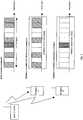
- FIG. 1is a diagram showing an example of a frequency channel arrangement on downlink (hereinafter, referred to as "DL") in an OFDMA communication system.
- DLdownlink
- OFDMAfrequency channel arrangement on downlink
- subcarriersare arranged uniformly at intervals to be orthogonal to one another on the frequency axis.
- OFDMAis a scheme for allocating an optimal number of subcarriers corresponding to a required band of each user.
- OFDMAthere is a case where a single frequency channel comprised of an arbitrary number of subcarriers is formed, and allocations are made on a frequency channel basis.
- a range for a receiver to be able to collectively perform demodulationis comprised of ten frequency channels.
- the frequency channelsare arranged successively inprinciple.
- guard bandsare arranged at opposite sides of the entire band.
- Thisis a typical DL structure, but this structure may be one unit to form the band comprised of a plurality of units.
- the entire reception bandmeans this one unit, and the full band terminal means a terminal capable of collectively processing the entire band.
- FIG.2is a diagram illustrating channels used by a base station and terminals in the OFDMA communication system. Shown herein is a state where in the system comprised of ten frequency channels as shown in FIG.1 , terminals A and B perform communication while respectively requesting five frequency channels and one frequency channel. Both A and B are capable of performing demodulation over the entire band, and by concurrently using respectively allocated five channels and one channel, implement multiple access. Thus, one channel is sometimes enough for each terminal, and it is also possible to support broadband transmission requesting maximum ten frequency channels.
- limited band terminalseach of which is limited in the number of processable frequency channels and has a reception band narrower than the system bandwidth
- requirements for functions necessary for the terminalsare lowered, and it is possible to realize power saving and low cost.
- needs of usersare considered existing to a large extent such that speech conversation and low-rate data communication is sufficient, and introduction of the limited band terminals is thought to be significant.
- FIG.3shows a state where limited terminals with the reception band of one frequency channel (abbreviated as SC in the figure) and with the reception band of three frequency channels exist in the system band, while showing at the lower side the processing on the reception side of the one-frequency channel limited band terminal.
- SCreception band of one frequency channel
- the maximum frequency desired to demodulateagrees with half the sampling frequency of an analog/digital converter (hereinafter, referred to as "ADC"), and the filter attenuates with the bandwidth of the adjacent channel.
- ADCanalog/digital converter
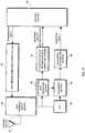
- FIG.4is a block diagram illustrating a schematic configuration of a base station according to the first embodiment.
- a radio signal received in an antenna section 1is converted from a radio signal to an electrical signal by a high-frequency circuit and analog signal processing section 2, and subjected to FFT (Fast Fourier Transform) in an FFT section 3.
- FFTFast Fourier Transform
- an equalizing section 4corrects a reception waveform deteriorating due to delay distortion in multipath and the like, and a subcarrier demodulation section 5 performs demodulation for each subcarrier.
- a terminal reception quality information processing section 6analyzes reception quality information received from each terminal.
- the reception quality informationof frequency channels with better reception conditions on downlink, frequency channels predetermined in the system or the like
- the reception quality that the terminal is capable of measuring onceis only of the limited band.
- the terminalnotifies the base station of the reception information on the limited band.
- such a methodmay be adopted that channels are monitored and notified in a time division manner.
- the full band terminalis naturally capable of measuring the reception quality over the entire band, and reports all the results to the base station.
- such a methodmay be adopted that a terminal reports only the information of a better frequency channel for the terminal.
- a "base station control apparatus”via a control section 7 that controls the entire base station, inputs information to a user information storage section 8.
- the informationis to determine whether a terminal accessing the base station is a full band terminal or a limited band terminal, and further includes a terminal type indicative of channels that the terminal supports and service contract information when the terminal is the limited band terminal.
- data to be transmitted to each terminal from the base stationis once stored in a transmission data buffer 9 together with information indicating whether the data is of real time or not.
- a scheduling section 10performs prioritization based on these pieces of information so as to transmit the data.
- factors for prioritization of frequency channel allocationare as follows: "Whether the data is of real time or non-real time”...a higher priority is given to real time data communication; "Optimal bandwidth”... a higher priority is given to a larger request data transfer amount; "Reception characteristics due to distance and multipath”...the quality of a reception state of a frequency channel transmitted from each terminal is compared with one another, and the frequency channel is allocated to a terminal to which data can be transmitted as much as possible; and "Type of used service”...the priority varies with differences in used service systems of subscribers. For example, priorities are given in consideration of a user that suppress a basic fee per month and does not request high quality during busy hours, and service for selecting and designating quality for each call. Further, for example, in the case that the data is a real-time broadcast but the quality is not required, a lower priority is given.
- a subcarrier modulation section 11performs modulation for each subcarrier, and a subcarrier power control section 12 controls the transmit power for each subcarrier.
- an IFFT section 13performs IFFT (Inverse Fast Fourier Transform) processing, an electrical signal is converted into a digital signal in the high-freguency circuit and analog signal processing section 2, and the radio signal is transmitted from the antenna section 1.
- IFFTInverse Fast Fourier Transform
- FIG.5is a block diagram illustrating a configuration of the scheduling section 10 in the base station according to the first embodiment.
- Information of a terminal under communicationsis input to a determining section 10-1 and a terminal priority determining section 10-2 from the user information storage section 8 that has information of all terminals accessing the base station.
- the determining section 10-1determines whether the terminal is a limited band terminal or full band terminal. Based on the real time characteristic of the data, data amounts stored in the transmission buffer 9 and the like, the terminal priority determining section 10-2 determines allocation priorities among terminals.
- a frequency channel allocating section 10-3allocates a frequency channel for each terminal to use, modulation mode of each subcarrier, and transmit power, and outputs these items to a control signal generating section 10-4.
- the control signal generating section 10-4outputs the frequency channel for each terminal to use, modulation mode of each subcarrier, and transmit power allocated by the frequency channel allocating section 10-3 to the transmission data buffer 9, subcarrier modulation section 11 and subcarrier power control section 12, in synchronization with the control section 7.
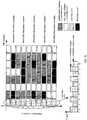
- FIG.6is a diagram showing an example of a frequency channel arrangement on DL in the OFDMA communication system according to the first embodiment.
- the base stationrecognizes that the frequency channel allocation is for the limited band terminal, and decreases levels of the transmit power of an arbitrary number of subcarriers from the adjacent side of a frequency channel adjacent to the reception band of the terminal, or sets zero on levels of the transmit power of the subcarriers.
- the levels of the transmit power of an arbitrary number of subcarriersare decreased in opposite adjacent frequency channels of the range enabling reception of the terminal limited in the number of processable frequency channels to one frequency channel (1SC).
- the levels of the transmit power of an arbitrary number of subcarriersare decreased in opposite adjacent frequency channels of the range enabling reception of the terminal limited in the number of processable frequency channels to three frequency channels (3SC).
- FIG.7is a diagram showing an example of attenuation characteristics of a filter.
- LPFlow-pass filter
- the type and the order of the filterare determined depending on properties, circuit scale and the like.
- the attenuation gradient (dB/oct.) of 6dB x orderis generally obtained.
- Gain (attenuation)is 0dB from 0Hz to 5MHz and flat, and since the fifth order is used, is -30dB at 10MHz. Further, intervals of subcarriers are assumed to be 50kHz.
- aliasingis -0.15dB, next -0.45dB, -0.75dB,... at the maximum frequency, and thus overlaps as interfering signals.
- LPFthere are Butterworth, Bessel, Chebyshev, elliptic types and the like, and it is considered that the elliptic filter with steeper attenuation characteristics is suitable for the limited band terminal in the first embodiment. Even when the characteristics become steeper, it is also impossible to attenuate subcarriers close to the boarder, and it is understood that the adverse effect is produced.
- modulation ratesmay be decreased.
- the transmit power of a level such that a predetermined signal to noise ratio is obtainedis allocated to a subcarrier to be modulated at a low modulation rate.
- FIG.8is a diagram illustrating the relationship between the level of transmit power and the modulation rate.
- SNRsignal to noise ratio
- BERbit error rate
- FIG.8shown on the right side as viewed in the figure is an example of implementing the first embodiment in the BER characteristic and filter characteristics as shown in FIG.7 . This is a case that the limited band terminal is allocated to frequency channel #n, and that the full band terminal is allocated to frequency channel #n+1.
- the power of -9.15, -8.85, -8.55dB...-0.45, -0.15, 0dBis allocated successively to subcarriers closer to #n in #n+1.
- the thirty-second subcarrieris 0dB.
- modulationis allocated in the order of no modulation, BPSK, QPSK and 16QAM which is first allocated in the thirty-second subcarrier. Only one side of the frequency channel is described in the foregoing, and when a frequency channel at either edge of the entire band is not allocated, similar processing is naturally performed on opposite adjacent frequency channels to the frequency channel allocated to the limited band terminal.
- the limited band terminal allocated frequency channel #nis capable of obtaining a reception signal as shown in FIG.9 .
- the SNRis obtained that enables 16QAM to be ensured in the band.
- FIG.10is a diagram showing an example of a frequency channel arrangement on DL in an OFDMA communication system according to the second embodiment.
- the base stationrecognizes that the frequency channel allocation is for a frequency channel limited band terminal, and sets zero on levels of the transmit power of all the subcarriers of a frequency channel adjacent to the reception band of the terminal. In other words, subcarriers to handle are expanded to the entire frequency channel, and it is equivalent to not allocating the power.
- the second embodimentdiffers from the first embodiment. In the first embodiment, another user is allocated to the adjacent frequency channel to perform the processing. In contrast thereto, in the second embodiment, any user is not allocated to the adjacent frequency channel from the beginning.
- the levels of the transmit power of all the subcarriersare set at zero in opposite adjacent frequency channels of the range enabling reception of the limited band terminal limited in the number of processable frequency channels to one frequency channel (1SC).
- the levels of the transmit power of all the subcarriersare set at zero in opposite adjacent frequency channels of the range enabling reception of the limited band terminal limited in the number of processable frequency channels to three frequency channels (3SC).
- FIG. 11is a diagram showing an example o f a communication frame in an OFDMA communication system according to the third embodiment.
- the first and second embodimentsbasically describe the allocation on the frequency axis.
- the methodis to allocate an optimal slot to each communicating apparatus among communication slots specified by time channels and frequency channels in a single frame, and subsequently, explanations are given including the case that the present invention is applied to such an allocation on a communication frame basis.
- the communication frameis formed of ten frequency channels as frequency channels, and ten time slots as time channels. Then, as the limited band terminal, allocations are made to two one-frequency channel limited band terminals, and one two-frequency channel limited band terminal. The fifth to seventh time slots of frequency channel #2 are allocated to a user of the one-frequency channel limited band terminal, and the tenth time slot is allocated to the other user.
- the base station notified of the limited band terminal from the terminalallocates communication slots as described in the first or second embodiment to time slots 5 to 7 and 10 in frequency channels #1 and #3.
- the levels of transmit power allocated to an arbitrary number of subcarriersare decreased among subcarriers of communication slots adjacent in the frequency channel direction to the communication slot allocated to the limited band terminal.
- the levels of transmit power allocated to all the subcarriersare set at zero in communication slots adjacent in the frequency channel direction to the communication slot allocated to the limited band terminal.
- the communication slots as described in the first and second embodimentsare called measures slots.
- time slots 4 of frequency channels #9 and #10are allocated to a user of the two-frequency channel limited band terminal.
- a guard bandexists out of frequency channel #10 (opposite side to frequency channel #9 in the frequency channel direction)
- only frequency channel #8is a measures slot.
- by adaptively applying measures to adjacent slotsit is possible to enhance the spectral efficiency, and introduce the limited band terminal to the same system.
- FIG.12is a diagram illustrating frequency channel allocations to terminals limited to n frequency channels.
- frequency channels at opposite edges of the entire frequency bandare preferentially allocated to the limited band terminals.
- channelsare allocated starting with frequency channel #1 or #10.
- frequency channels with the need of measures slotsare of only one adjacent side, and slots can be used more effectively.
- FIG.13is a diagram illustrating frequency channel allocations to limited band terminals according to the fifth embodiment.
- a predetermined limited number of subcarriersare set for dedicated frequency channels.
- limited band terminalsare allocated to be adjacent to one another to use the same time slots as possible. By this means, the measures slots can be shared, and the use efficiency of communication slots is enhanced.
- a control slotis provided at the beginning of a frame. This is because of the need of information such that what slot is allocated to which user for each frequency channel, and all the users need to be able to demodulate the control information corresponding to respective frequency channels. Since this data is modulated at a low modulation rate, it is considered that all the terminals are able to demodulate the data without particular problems even in environments that limited band terminals exist. However, by allocating as shown in FIG.13 , frequency channels with measures slots inserted therein can be fixed, and the power and the like of the control slot can be different from that of the measures slot.
- FIG.14shows two types of specific examples of power control of the control slot.
- FIG.14differs from FIG.13 , and shows an example of a frame structure where slots for one-limited band terminals are arranged over the entire band i.e. a frame structure where a measures slot is inserted every other frequency channel.
- a frame structurewhere a measures slot is inserted every other frequency channel.
- the measures frequency channelsare fixed, by decreasing the power in the measures frequency channel to a certain level, or decreasing the power toward opposite edges in the band, measures are taken for making the power of the measures slot relatively lower than the power near boundaries adjacent to adjacent frequency channels near the frequency channel boundaries. It is thereby possible to compensate for the effect of aliasing also in the control information of the limited band terminal, and further improve the demodulation capability. Moreover, as can be seen from FIG.14 , it is possible to arrange selection candidate frequency channels for limited band terminals over the entire band, and frequency channels with good reception states can be selected easier from the entire band. For the full band terminal, it is also considered that the terminal is not affected by low power due to the low modulation rate.
- even-numbered frequency channelsare measures frequency channels, and it is naturally considered that the odd number and the even number are switched at any timing. Further, when the number of all frequency channels is an odd number, it is possible to perform optimal allocations.
- FIG.15is a diagram showing an example of power control of control slots and a terminal allocation method.
- the allocation of frequency channelsis the same as in FIG.14 . Accordingly, the power of the control channel is made high and low repeatedly every frequency channel.
- FIG.15shows allocations of one-limited, three-limited and five-limited band terminals in this frame. By performing power control of the control channel in this pattern, it is possible to send the control information on all the channels, and the limited band terminals can exist almost evenly over the entire band.
- FIG. 16is a diagram showing an example of a communication frame in an OFDMA communication system according to the sixth embodiment.
- the base stationIn allocating a frequency channel adjacent to a frequency channel allocated to an n-limited band terminal to another terminal, the base station does not give the power to an arbitrary number of subcarriers inward from the opposite edges of the frequency range that the limited band terminal is capable of receiving.
- Thisis a scheme that the terminal notifies the base station of the information that the quality is poor in an arbitrary number of subcarriers, and that the power is thereby not allocated to the subcarriers under the initiative of the limited band terminal.
- FIG.17is a block diagram illustrating a schematic configuration of a mobile terminal according to the six embodiment.
- a radio signal received in an antenna section 161is converted from a high-frequency signal to a baseband signal in a high-frequency circuit section 162 and delivered to a propagation path estimating section 163 that estimates distortion on the propagation path and an FFT section 164 that performs FFT (Fast Fourier Transform).
- an equalizing section 165compensates a reception signal for deterioration due to delay distortion by multipath and the like based on the propagation path estimation result, and a subcarrier demodulation section 166 performs demodulation for each subcarrier.
- a terminal reception quality information data generating section 167generates reception quality information based on the information from the propagation path estimating section 163.
- the data generated in the terminal reception quality information data generating section 167is output as part of transmission data from a control section 168 to a transmission signal processing section 169, and via the high-frequency circuit section 162, and antenna section 161, transmitted to a communicating apparatus.
- the mobile terminal as shown in FIG.17transmits to the base station a desired frequency channel and the information that lower b subcarriers and upper b subcarriers on the frequency channel are always poor in reception state. By this means, the base station does not need to consider allocations to adjacent frequency channels.
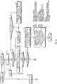
- FIGs.18 and 19are flowcharts illustrating the operation of the base station according to the sixth embodiment.
- "k”is “0” or “1”, and immediately after starting the allocation, is only “0". Using k, required transmission bands are obtained for all the terminals, while provisional allocations are made to limited band terminals.
- "i”is an integer, the loop is circulated in the number of terminals, and priorities are determined.
- "j”is an integer, and used in searching for a terminal with the highest priority at this point.
- Bindicates the total requested transmission band from terminals left without allocations.
- a priorityis determined for each terminal, while entire required bit rates are obtained.
- MT (i)is not FSCT i.e. is LSCT
- required time slots of a desired frequency channelare provisionally allocated to the LSCT (limited band terminal) (step T5) .
- MT (i)is given the first priority to NMT (the number of terminal in access).
- B>TLIM(criterion by which to judge a degree of traffic congestion) holds (step T10)
- B>TLIMthe provisionally allocated slots of all LSCTs are determined to be actually allocated (step T11).
- Cis set at NMT-the number of all LSCTs.
- required time slots of a desired frequency channelare allocated to FSCT, and in the case of shortage, a frequency channel that is not desired is also allocated to compensate (step T12). Then, the processing is finished.
- the terminalis FSCT, it is determined whether a desired vacant frequency channel exists (step T17), and when the desired vacant frequency channel exists, a slot of the desired frequency channel is allocated (step T18). In other words, bit rate b obtained by this allocation is entered at one slot allocation ARB.
- step T16it is determined whether a provisionally allocated slot of MT(j) exists, and when the provisionally allocated slot of MT(j) exists, the provisionally allocated slot is determined to be actually allocated (step T20). Meanwhile, when any provisionally allocated slot does not exist in step T19, no allocation is determined (step T21). In other words, bit rate z obtained by this allocation is entered at one slot allocation ARB.
- step T17it is determined whether another vacant frequency channel of a good reception state exists (step T22).
- step T23a slot of the frequency channel is allocated (step T23). In other words, bit rate c obtained by this allocation is entered at one slot allocation ARB.
- step T24it is determined whether a reception state is good in the frequency channel provisionally allocated to the LSCT (step T24).
- a slot of the frequency channelis allocated (step T25). In other words, bit rate d obtained by this allocation is entered at one slot allocation ARB.
- FIG. 20is a diagram showing an example of a communication frame in an OFDMA communication system according to the seventh embodiment.
- the base stationdetects the reception power for each terminal . Then, in allocating another terminal to an adjacent channel of the frequency channel allocated to a limited band terminal, the base station allocates a terminal with high reception power because the terminal exists closer to the base station and the like. Then, the transmit power of the slot is set to be lower than the power of the frequency channel allocated to the limited band terminal. It is possible to use such control of transmit power together with each of the above-mentioned embodiments.
- FIGs.21 and 22are flowcharts illustrating the operation of the base station according to the eighth embodiment.
- "k”is to increment a priority to handle for each loop.
- "i”is an integer and used in a loop to determine a priority of a terminal and handle in the order of priority.
- Bindicates the total requested transmission band from terminals left without allocations.
- “NLSC”indicates the number of limited frequency channels of a limited band terminal.
- NRSCindicates the number of frequency channels that each terminal requests.
- GSHis "0” or “1”, and represents implementing measures for an upper (higher frequency) adjacent frequency channel when "1", while representing no need of such measures when "0".
- GBLis "0” or "1”, and represents implementing measures for a lower (lower frequency) adjacent frequency channel when "1", while representing no need of such measures when "0".
- "k” and “i” in FIGs.21 and 22are used in different meaning from that of "k” and “i” in FIGs.18 and 19 .
- a priority for each terminalis determined in a first loop, while entire required bit rates are obtained.
- step S6it is determined whether B ⁇ TLIM (criterion by which to judge a degree of traffic congestion) holds (step S6).
- B ⁇ TLIMcriteria by which to judge a degree of traffic congestion
- step S11when the terminal is not FSCT i.e. is LSCT (limited band terminal), in the case that an interval between the maximum and minimum requested channels is narrower than a number of limited channels by two frequency channels or more, the need is eliminated of providing measures frequency channels out of the band by setting an allocation not to allocate opposite sides of the limited band, and GBH and GBL are also zero.
- FSCTi.e. is LSCT
- GBH and GBLare also zero.
- step S19it is determined whether RSC# includes SCH#min (step S19).
- time slotsare allocated so that the terminal secures requested frequency channels up to a required bit rate.
- the levels of transmit powerare decreased in all or part of subcarriers of a communication slot that is adjacent on the frequency channel side to a communication slot allocated to the communicating apparatus and that is not allocated to the communicating apparatus in a communication frame. Therefore, in the case of using a low sampling frequency for low power consumption in the communicating apparatus, it is also possible to reduce an effect of the adjacent communication slot in the frequency channel direction. It is thereby possible to implement wireless communication also with the communicating apparatus limited in the frequency band that the communicating apparatus is capable of collectively process.
Landscapes
- Engineering & Computer Science (AREA)
- Signal Processing (AREA)
- Computer Networks & Wireless Communication (AREA)
- Quality & Reliability (AREA)
- Mobile Radio Communication Systems (AREA)
Description
- The present invention relates to a wireless communication apparatus, mobile terminal and wireless communication method for performing wireless communication in a multicarrier transmission scheme using a plurality of frequency channels each of a group of a predetermined number of subcarriers among a plurality of subcarriers arranged successively at regular frequency intervals in a system band.
- In recent years, with rapid penetration of cable broadband service such as ADSL, FTTH and the like in ordinary homes, the so-called rich content service has become widespread using speech, video and music beyond textual information, and an information amount for a person to handle has increased. Also in mobile communication, rates of using non-speech conversation service have been sharply increasing such as mobile Web, music distribution and the like, and demands for broadband wireless communication have grown as in cable communication.
- For such requests for broadband mobile communication, various studies have been made. Among the studies, OFDMA (Orthogonal Frequency Division Multiple Access) is an access scheme receiving attention in terms of spectral efficiency, and fading resistance. OFDMA is the scheme for by using characteristics of OFDM for arranging densely a large number of orthogonal subcarriers at intervals of a reciprocal of a signal duration, allocating an arbitrary number of subcarriers (or a frequency channel comprised of a group of successive subcarriers) with good characteristics to each terminal corresponding to reception characteristics varying with terminals in multipath environments, and thereby further increasing substantial spectral efficiency.
- The OFDM modulation scheme is adopted in wireless LAN specifications such as 5GHz-band IEEE802.11a and the like, where channels having an occupied bandwidth of 16MHz or more are arranged at intervals of 20MHz. Accordingly, a region of 3MHz or more without carriers exists between channels. Further, basically, a single terminal uses a single channel, a band for each terminal to be able to modulate and demodulate is the same as a band to communicate and is always constant, and therefore, this scheme does not correspond to OFDMA.
- For OFDMA, any system put into practical use has not existed at the present time, but OFDMA is the system for allocating subcarriers and frequency channel of optimal reception states to each terminal from a wide band, and therefore, any proposals agree with one another in the concept that a band for a terminal to use in communication varies with a band for the terminal to be able to modulate and demodulate being the maximum band. Accordingly, a required frequency band is determined from the maximum transmission rate requested in a system, and communication apparatuses in the system are required to be able to collectively modulate and demodulate the frequency band. For example, in "IEICE Technical Report RCS2004-85(2004-06)", "2004 IEICE General Conference B-5-64" and the like, a frequency band of 100MHz is expected to be required per user to realize 100Mbps, and it is proposed to arrange subcarriers evenly in the band.
- Non-patent Document 1:IEICE Technical Report RCS2004-85(2004-06)
- Non-patent Document 2 :2004 IEICE General Conference B-5-64
US 2004/106412 A1 discloses a type of diversity, referred to as multiple carrier diversity by utilizing multiple carriers, assigning different power levels to each carrier frequency at each base station, and/or offsetting sector antennas. The cell and/or sector coverage areas can be set so as to minimize or eliminate overlap between cell and/or sector boundary regions of different carrier frequencies. Mobile nodes travelling throughout the system can exploit multiple carrier diversity by detecting carriers and selecting to use a non-boundary carrier based on other system criteria in order to improve performance.US 2004/166887 A1 discloses a pilot signal transmission sequence and method for use in a multisector cell. Pilots in different sectors are transmitted at different known power levels. In adjacent sectors a pilot is transmitted while no pilot is transmitted in the adjoining sector. This represents transmission of a NULL pilot signal. A cell NULL is also supported in which NULL pilots are transmitted in each sector of a cell at the same time. Multiple pilot signal measurements are made. At least two channel quality indicator values are generated from measurements corresponding to at least two pilot signals of different power levels. The two values are transmitted back to the base station which uses both values to determine the transmit power required to achieve a desired SNR at the wireless terminal. The wireless terminal also reports information indicating its location to a sector boundary.US 6 721 569 B1 discloses a method and apparatus for selecting and signalling the identity of subcarriers to be used for transmission of data in a radio communication system, and for using other sub-carriers. A remote unit determines which sub-carriers are acceptable for use in data transmission by comparing the signal to interference ratio of each sub-carrier with a threshold. A base station transmits data over the acceptable sub-carriers at the optimum Link Mode or Link Modes. The transmission power any unused unacceptable sub-carriers can be diverted to other sub-carriers.US 2004/019538 A2 discloses power control methods and apparatus for use in a sectorized cell of an OFDM communications system. Each sector of a cell uses the same frequencies and transmission times and is synchronized with the other sectors in the cell in terms of tone frequencies used at any given time and symbol transmission times. Tones are allocated to channels in each cell in the same manner so that each channel in a sector has a corresponding channel in another sector. Power differences between channels in different sectors are maintained to be within a pre-selected power difference.US 2004/009783 A1 discloses a subcarrier transmission ON/OFF control system based on an MCCDMA system capable of improving information transmission efficiency and reception performance while keeping the number of transmission bits constant, and a subcarrier transmit power control system based on an MC-CDMA system or OFDM system capable of improving information transmission efficiency and reception performance.- The OFDMA scheme as described above is a scheme for selecting a frequency channel that is a group of an arbitrary number of successive subcarriers or carriers with good reception characteristics of a terminal from the entire band to allocate, and therefore, a transmitter/receiver basically needs to adopt a configuration capable of performing modulation and demodulation over the entire band. Accordingly, the need is eliminated of providing a frequency region without subcarriers between channels as in IEEE802.11a. Reversely, providing a frequency region without subcarriers between channels leads to reductions in spectral efficiency in the entire system, and to further severe requirements for hardware with expansion of a processing bandwidth of the communication apparatus. Although the transmitter/receiver implements broadband transmission by being able to modulate and demodulate over the entire band, devices used therein are required to have high performance, resulting in increases in terminal size and current consumption, and it is feared that such increases affect the cost.
- However, users have various needs, and it is obvious that speech conversion and low-rate data communication is used mainly and that demands for low power consumption, small-size and inexpensive terminals exist rather than the functions. Accordingly, although broadband communication receives attention, it is important for the next-generation system to be able to absorb these needs. To realize inexpensive terminals, it is first considered limiting the band on which a terminal is able to perform collective processing. In this case, it is possible to suppress the band and current consumption in digital/analog conversion, power amplification and the like independently on the transmission side, but in order for the reception side to extract a specific band from subcarriers densely arranged, the need arises of tightening requirements for specifications of filters, analog/digital conversion, sampling clock of the conversion and the like to cancel adjacent channel interference, and is feared to be inhibition in providing inexpensive terminals.
- The present invention is carried out in view of such circumstances, and it is an object of the invention to provide a wireless communication apparatus and wireless communication method for enabling wireless communication to be implemented also with a communicating apparatus that is a limited band terminal capable of receiving only part of frequencies.
- (1) To achieve the above-mentioned object, the present invention takes following measures. In other words, a wireless communication apparatus according to the invention is a transmitting apparatus according to
independent claim 1 and configured for transmitting orthogonal frequency division multiplexing, OFDM, signals for communication in a wireless communication system, the transmitting apparatus comprising: signal generation and transmission components configured to: generate and transmit OFDM signals by using a part or all of a frequency system band comprising more than three frequency channels, wherein each of the more than three frequency channels comprises a plurality of subcarriers, generate and transmit an OFDM signal to a receiving apparatus that is a limited band apparatus capable of receiving only part of the frequency system band and having a limited reception bandwidth of a number of frequency channels, wherein the OFDM signal is transmitted to the receiving apparatus by using less than or equal to the number of frequency channels, and allocate (i) the OFDM signal to one or more frequency channels that the receiving apparatus supports and (ii) no power to a first number of subcarriers at a first edge of the one or more frequency channels and a to second number of subcarriers at a second, opposite edge of the one or more frequency channels, wherein the first number of subcarriers and the second number of subcarriers are determined as a function of reception capabilities of the receiving apparatus comprising the limited reception bandwidth, and the reception capabilities indicate that the first number of subcarriers and the second number of subcarriers are not usable by the receiving apparatus. - Thus, when the communicating apparatus is the limited band terminal, the transmit power is set to zero in part of the subcarriers of a frequency channel that is adjacent to a reception band allocated to the communicating apparatus and that is allocated to another communicating apparatus or set to zero in all of the subcarriers of a frequency channel that is adjacent to a reception band allocated to the communication apparatus. Therefore, in the case of using a low sampling frequency for low power consumption in the communicating apparatus, it is also possible to reduce an effect of an adjacent communication slot in the frequency channel direction. It is thereby possible to implement wireless communication also with the limited band terminal capable of receiving only part of frequencies.
- (4) Further, in the wireless communication apparatus according to the invention, the frequency channel allocating section is characterized by when the communicating apparatus is the limited band terminal, preferentially performing a frequency channel allocation so that at least one edge of the reception band of the communicating apparatus is a frequency channel at an edge of the system band.
- Thus, when the communicating apparatus is the limited band terminal, the frequency channel allocation is preferentially performed so that at least one edge of the reception band of the communicating apparatus is a frequency channel at an edge of the system band. Therefore, it is possible to limit the communication slot, where the levels of transmit power are decreased in all or part of the subcarriers, or the level of transmit power is set at zero, only to one side in the frequency channel direction. The communication slots can thus be used effectively.
- (13) Further, the invention is also defined by a wireless communication method according to
independent claim 5. - Wireless transmission apparatuses according to embodiments will be described below. These embodiments are predicted on the above-mentioned communication scheme by OFDMA.
FIG. 1 is a diagram showing an example of a frequency channel arrangement on downlink (hereinafter, referred to as "DL") in an OFDMA communication system. InFIG. 1 , as shown at the right end as viewed in figure, in OFDMA, subcarriers are arranged uniformly at intervals to be orthogonal to one another on the frequency axis. OFDMA is a scheme for allocating an optimal number of subcarriers corresponding to a required band of each user. Further, as shown in the center ofFIG.1 , in OFDMA, there is a case where a single frequency channel comprised of an arbitrary number of subcarriers is formed, and allocations are made on a frequency channel basis. Shown herein is an example where a range for a receiver to be able to collectively perform demodulation is comprised of ten frequency channels. As shown inFIG.1 , the frequency channels are arranged successively inprinciple. Further, to suppress interference with adjacent other systems, guard bands are arranged at opposite sides of the entire band. This is a typical DL structure, but this structure may be one unit to form the band comprised of a plurality of units. In this embodiment, the entire reception band means this one unit, and the full band terminal means a terminal capable of collectively processing the entire band.FIG.2 is a diagram illustrating channels used by a base station and terminals in the OFDMA communication system. Shown herein is a state where in the system comprised of ten frequency channels as shown inFIG.1 , terminals A and B perform communication while respectively requesting five frequency channels and one frequency channel. Both A and B are capable of performing demodulation over the entire band, and by concurrently using respectively allocated five channels and one channel, implement multiple access. Thus, one channel is sometimes enough for each terminal, and it is also possible to support broadband transmission requesting maximum ten frequency channels.- Meanwhile, by introducing terminals (hereinafter, referred to as "limited band terminals") each of which is limited in the number of processable frequency channels and has a reception band narrower than the system bandwidth, requirements for functions necessary for the terminals are lowered, and it is possible to realize power saving and low cost. Further, needs of users are considered existing to a large extent such that speech conversation and low-rate data communication is sufficient, and introduction of the limited band terminals is thought to be significant.
- However, as shown in
FIGs .1 and2 , OFDMA is the system introduced for the purpose of enhancing the spectral efficiency, and a region corresponding to a guard band as in wireless LAN of IEEE802.11a is not provided between frequency channels. Therefore, it is feared to undergo interference from adjacent frequency channels in the frequency channel direction. This state is shown inFIG.3. FIG.3 shows a state where limited terminals with the reception band of one frequency channel (abbreviated as SC in the figure) and with the reception band of three frequency channels exist in the system band, while showing at the lower side the processing on the reception side of the one-frequency channel limited band terminal. Herein, the maximum frequency desired to demodulate agrees with half the sampling frequency of an analog/digital converter (hereinafter, referred to as "ADC"), and the filter attenuates with the bandwidth of the adjacent channel. As a result, as shown at the lower side ofFIG.3 , the effect of aliasing is imposed. Therefore, in the embodiments, the effects from the adjacent channels are reduced by methods as described below. FIG.4 is a block diagram illustrating a schematic configuration of a base station according to the first embodiment. A radio signal received in anantenna section 1 is converted from a radio signal to an electrical signal by a high-frequency circuit and analogsignal processing section 2, and subjected to FFT (Fast Fourier Transform) in anFFT section 3. Next, an equalizingsection 4 corrects a reception waveform deteriorating due to delay distortion in multipath and the like, and asubcarrier demodulation section 5 performs demodulation for each subcarrier.- Then, a terminal reception quality
information processing section 6 analyzes reception quality information received from each terminal. In other words, in the above-mentioned limited band terminal, for the reception quality information of frequency channels with better reception conditions on downlink, frequency channels predetermined in the system or the like, the reception quality that the terminal is capable of measuring once is only of the limited band. Then, the terminal notifies the base station of the reception information on the limited band. Further, such a method may be adopted that channels are monitored and notified in a time division manner. The full band terminal is naturally capable of measuring the reception quality over the entire band, and reports all the results to the base station. Furthermore, such a method may be adopted that a terminal reports only the information of a better frequency channel for the terminal. - Further, in
FIG.4 , via acontrol section 7 that controls the entire base station, a "base station control apparatus" inputs information to a userinformation storage section 8. The information is to determine whether a terminal accessing the base station is a full band terminal or a limited band terminal, and further includes a terminal type indicative of channels that the terminal supports and service contract information when the terminal is the limited band terminal. Meanwhile, data to be transmitted to each terminal from the base station is once stored in atransmission data buffer 9 together with information indicating whether the data is of real time or not. Ascheduling section 10 performs prioritization based on these pieces of information so as to transmit the data. - Herein, factors for prioritization of frequency channel allocation are as follows: "Whether the data is of real time or non-real time"...a higher priority is given to real time data communication;
"Optimal bandwidth"... a higher priority is given to a larger request data transfer amount;
"Reception characteristics due to distance and multipath"...the quality of a reception state of a frequency channel transmitted from each terminal is compared with one another, and the frequency channel is allocated to a terminal to which data can be transmitted as much as possible; and "Type of used service"...the priority varies with differences in used service systems of subscribers. For example, priorities are given in consideration of a user that suppress a basic fee per month and does not request high quality during busy hours, and service for selecting and designating quality for each call. Further, for example, in the case that the data is a real-time broadcast but the quality is not required, a lower priority is given. - In
FIG.4 , asubcarrier modulation section 11 performs modulation for each subcarrier, and a subcarrierpower control section 12 controls the transmit power for each subcarrier. Then, anIFFT section 13 performs IFFT (Inverse Fast Fourier Transform) processing, an electrical signal is converted into a digital signal in the high-freguency circuit and analogsignal processing section 2, and the radio signal is transmitted from theantenna section 1. FIG.5 is a block diagram illustrating a configuration of thescheduling section 10 in the base station according to the first embodiment. Information of a terminal under communications is input to a determining section 10-1 and a terminal priority determining section 10-2 from the userinformation storage section 8 that has information of all terminals accessing the base station. The determining section 10-1 determines whether the terminal is a limited band terminal or full band terminal. Based on the real time characteristic of the data, data amounts stored in thetransmission buffer 9 and the like, the terminal priority determining section 10-2 determines allocation priorities among terminals. Based on the result determined by the determining section 10-1 and the allocation priorities determined by the terminal priority determining section 10-2, a frequency channel allocating section 10-3 allocates a frequency channel for each terminal to use, modulation mode of each subcarrier, and transmit power, and outputs these items to a control signal generating section 10-4.- The control signal generating section 10-4 outputs the frequency channel for each terminal to use, modulation mode of each subcarrier, and transmit power allocated by the frequency channel allocating section 10-3 to the
transmission data buffer 9,subcarrier modulation section 11 and subcarrierpower control section 12, in synchronization with thecontrol section 7. FIG.6 is a diagram showing an example of a frequency channel arrangement on DL in the OFDMA communication system according to the first embodiment. The base station recognizes that the frequency channel allocation is for the limited band terminal, and decreases levels of the transmit power of an arbitrary number of subcarriers from the adjacent side of a frequency channel adjacent to the reception band of the terminal, or sets zero on levels of the transmit power of the subcarriers. For example, inFIG.6 , the levels of the transmit power of an arbitrary number of subcarriers are decreased in opposite adjacent frequency channels of the range enabling reception of the terminal limited in the number of processable frequency channels to one frequency channel (1SC). Similarly, the levels of the transmit power of an arbitrary number of subcarriers are decreased in opposite adjacent frequency channels of the range enabling reception of the terminal limited in the number of processable frequency channels to three frequency channels (3SC). By this means, even when the effect of aliasing is produced in performing A/D conversion, since the transmit power is decreased, the effect of aliasing is reduced. In addition, the number of subcarriers of which the transmit power levels are decreased can be set arbitrarily in the OFDMA communication system.FIG.7 is a diagram showing an example of attenuation characteristics of a filter. In a low-pass filter (LPF) prior to the ADC, the type and the order of the filter are determined depending on properties, circuit scale and the like. In a Butterworth type filter, the attenuation gradient (dB/oct.) of 6dB x order is generally obtained. Herein, for simplicity, explanations are given while assuming that a signal band is 5MHz by performing quadrature demodulation on 10MHz, the cutoff frequency is 5MHz, and that a fifth order Butterworth filter is used. Gain (attenuation) is 0dB from 0Hz to 5MHz and flat, and since the fifth order is used, is -30dB at 10MHz. Further, intervals of subcarriers are assumed to be 50kHz.- When a virtual model with the reception power assumed to be flat is considered, aliasing is -0.15dB, next -0.45dB, -0.75dB,... at the maximum frequency, and thus overlaps as interfering signals. As types of LPF, there are Butterworth, Bessel, Chebyshev, elliptic types and the like, and it is considered that the elliptic filter with steeper attenuation characteristics is suitable for the limited band terminal in the first embodiment. Even when the characteristics become steeper, it is also impossible to attenuate subcarriers close to the boarder, and it is understood that the adverse effect is produced.
- In addition, when decreasing the levels of the transmit power of an arbitrary number of subcarriers from the adjacent side of a frequency channel adjacent to the reception band of the band limited terminal, modulation rates may be decreased. In other words, the transmit power of a level such that a predetermined signal to noise ratio is obtained is allocated to a subcarrier to be modulated at a low modulation rate. By this means, it is possible to decrease the level of transmit power, while making the communicating apparatus demodulate correctly the communication slot, and to further reduce the effect of an adjacent communication slot in the frequency axis direction.
FIG.8 is a diagram illustrating the relationship between the level of transmit power and the modulation rate. InFIG.8 , shown on the left side as viewed in the figure is an example of the signal to noise ratio (SNR) enabling bit error rate (BER) 10-5 to be obtained. The horizontal axis in the figure is no meaning, and it is shown that SNR of 17dB, 9dB,... is able to achieve BER=10-5 at 64QAM, 16QAM,..., respectively. InFIG.8 , shown on the right side as viewed in the figure is an example of implementing the first embodiment in the BER characteristic and filter characteristics as shown inFIG.7 . This is a case that the limited band terminal is allocated to frequency channel #n, and that the full band terminal is allocated to frequency channel #n+1.- At this point, in order for the limitedband terminal to be able to secure 16QAM, the power of -9.15, -8.85, -8.55dB...-0.45, -0.15, 0dB is allocated successively to subcarriers closer to #n in #n+1. In this example, the thirty-second subcarrier is 0dB. Further, modulation is allocated in the order of no modulation, BPSK, QPSK and 16QAM which is first allocated in the thirty-second subcarrier. Only one side of the frequency channel is described in the foregoing, and when a frequency channel at either edge of the entire band is not allocated, similar processing is naturally performed on opposite adjacent frequency channels to the frequency channel allocated to the limited band terminal.
- The above-mentioned descriptions are of an example, and as described previously, when a further steeper filter is applied, the increment rate of power allocation is increased, while the number of subcarriers requiring support is decreased. Further, different cases are obtained also depending on the interval of subcarriers, difference in SNR required by a receiver, margin of SNR and the like. Further, there is a case that a limited band terminal does not need subcarriers at the edge of the band according to the required transmission amount of each terminal, and it is considered that the subcarriers are allocated to a full band terminal. This is determined in each system in designing the system.
- By allocating the transmit power as shown in
FIG.8 , the limited band terminal allocated frequency channel #n is capable of obtaining a reception signal as shown inFIG.9 . By this means, in this example, the SNR is obtained that enables 16QAM to be ensured in the band. FIG.10 is a diagram showing an example of a frequency channel arrangement on DL in an OFDMA communication system according to the second embodiment. The base station recognizes that the frequency channel allocation is for a frequency channel limited band terminal, and sets zero on levels of the transmit power of all the subcarriers of a frequency channel adjacent to the reception band of the terminal. In other words, subcarriers to handle are expanded to the entire frequency channel, and it is equivalent to not allocating the power. In this respect, the second embodiment differs from the first embodiment. In the first embodiment, another user is allocated to the adjacent frequency channel to perform the processing. In contrast thereto, in the second embodiment, any user is not allocated to the adjacent frequency channel from the beginning.- For example, in
FIG.10 , the levels of the transmit power of all the subcarriers are set at zero in opposite adjacent frequency channels of the range enabling reception of the limited band terminal limited in the number of processable frequency channels to one frequency channel (1SC). Similarly, the levels of the transmit power of all the subcarriers are set at zero in opposite adjacent frequency channels of the range enabling reception of the limited band terminal limited in the number of processable frequency channels to three frequency channels (3SC). By this means, in performing A/D conversion, since the levels are zero in the transmit power of the subcarriers targeted for aliasing, the effect of aliasing is reduced. FIG. 11 is a diagram showing an example o f a communication frame in an OFDMA communication system according to the third embodiment. The first and second embodiments basically describe the allocation on the frequency axis. However, in the allocation of frequency channel to each user, there is a method of regarding a period defined by a plurality of symbols each with a predetermined duration as a time channel, and performing the allocation on a basis of a unit called a communication frame comprised of a plurality of time channels and a plurality of frequency channels. In other words, the method is to allocate an optimal slot to each communicating apparatus among communication slots specified by time channels and frequency channels in a single frame, and subsequently, explanations are given including the case that the present invention is applied to such an allocation on a communication frame basis. In the following descriptions, the communication frame is formed of ten frequency channels as frequency channels, and ten time slots as time channels. Then, as the limited band terminal, allocations are made to two one-frequency channel limited band terminals, and one two-frequency channel limited band terminal. The fifth to seventh time slots offrequency channel # 2 are allocated to a user of the one-frequency channel limited band terminal, and the tenth time slot is allocated to the other user. The base station notified of the limited band terminal from the terminal allocates communication slots as described in the first or second embodiment totime slots 5 to 7 and 10 infrequency channels # 1 and #3.- In other words, in the first embodiment, the levels of transmit power allocated to an arbitrary number of subcarriers are decreased among subcarriers of communication slots adjacent in the frequency channel direction to the communication slot allocated to the limited band terminal. In the second embodiment, the levels of transmit power allocated to all the subcarriers are set at zero in communication slots adjacent in the frequency channel direction to the communication slot allocated to the limited band terminal. In
FIG.11 , the communication slots as described in the first and second embodiments are called measures slots. - Similarly,
time slots 4 offrequency channels # 9 and #10 are allocated to a user of the two-frequency channel limited band terminal. At this point, since a guard band exists out of frequency channel #10 (opposite side tofrequency channel # 9 in the frequency channel direction), onlyfrequency channel # 8 is a measures slot. As in the first and second embodiments, by adaptively applying measures to adjacent slots, it is possible to enhance the spectral efficiency, and introduce the limited band terminal to the same system. FIG.12 is a diagram illustrating frequency channel allocations to terminals limited to n frequency channels. Herein, frequency channels at opposite edges of the entire frequency band are preferentially allocated to the limited band terminals. InFIG.12 , channels are allocated starting withfrequency channel # 1 or #10. According to the fourth embodiment, frequency channels with the need of measures slots are of only one adjacent side, and slots can be used more effectively.FIG.13 is a diagram illustrating frequency channel allocations to limited band terminals according to the fifth embodiment. InFIG.13 , as shown at the left side as viewed in the figure, a predetermined limited number of subcarriers are set for dedicated frequency channels. Further, limited band terminals are allocated to be adjacent to one another to use the same time slots as possible. By this means, the measures slots can be shared, and the use efficiency of communication slots is enhanced.- Generally, a control slot is provided at the beginning of a frame. This is because of the need of information such that what slot is allocated to which user for each frequency channel, and all the users need to be able to demodulate the control information corresponding to respective frequency channels. Since this data is modulated at a low modulation rate, it is considered that all the terminals are able to demodulate the data without particular problems even in environments that limited band terminals exist. However, by allocating as shown in
FIG.13 , frequency channels with measures slots inserted therein can be fixed, and the power and the like of the control slot can be different from that of the measures slot. FIG.14 shows two types of specific examples of power control of the control slot. Herein,FIG.14 differs fromFIG.13 , and shows an example of a frame structure where slots for one-limited band terminals are arranged over the entire band i.e. a frame structure where a measures slot is inserted every other frequency channel. By arranging in such a manner, it is possible to support terminals limited to odd-numberedfrequency channels - Thus, since the measures frequency channels (measures slots) are fixed, by decreasing the power in the measures frequency channel to a certain level, or decreasing the power toward opposite edges in the band, measures are taken for making the power of the measures slot relatively lower than the power near boundaries adjacent to adjacent frequency channels near the frequency channel boundaries. It is thereby possible to compensate for the effect of aliasing also in the control information of the limited band terminal, and further improve the demodulation capability. Moreover, as can be seen from
FIG.14 , it is possible to arrange selection candidate frequency channels for limited band terminals over the entire band, and frequency channels with good reception states can be selected easier from the entire band. For the full band terminal, it is also considered that the terminal is not affected by low power due to the low modulation rate. - In
FIG.14 , even-numbered frequency channels are measures frequency channels, and it is naturally considered that the odd number and the even number are switched at any timing. Further, when the number of all frequency channels is an odd number, it is possible to perform optimal allocations. FIG.15 is a diagram showing an example of power control of control slots and a terminal allocation method. The allocation of frequency channels is the same as inFIG.14 . Accordingly, the power of the control channel is made high and low repeatedly every frequency channel.FIG.15 shows allocations of one-limited, three-limited and five-limited band terminals in this frame. By performing power control of the control channel in this pattern, it is possible to send the control information on all the channels, and the limited band terminals can exist almost evenly over the entire band.FIG. 16 is a diagram showing an example of a communication frame in an OFDMA communication system according to the sixth embodiment. In allocating a frequency channel adjacent to a frequency channel allocated to an n-limited band terminal to another terminal, the base station does not give the power to an arbitrary number of subcarriers inward from the opposite edges of the frequency range that the limited band terminal is capable of receiving. This is a scheme that the terminal notifies the base station of the information that the quality is poor in an arbitrary number of subcarriers, and that the power is thereby not allocated to the subcarriers under the initiative of the limited band terminal.- Such a terminal will be described with reference to
FIG.17. FIG.17 is a block diagram illustrating a schematic configuration of a mobile terminal according to the six embodiment. A radio signal received in anantenna section 161 is converted from a high-frequency signal to a baseband signal in a high-frequency circuit section 162 and delivered to a propagationpath estimating section 163 that estimates distortion on the propagation path and anFFT section 164 that performs FFT (Fast Fourier Transform). Next, an equalizingsection 165 compensates a reception signal for deterioration due to delay distortion by multipath and the like based on the propagation path estimation result, and asubcarrier demodulation section 166 performs demodulation for each subcarrier. - Then, a terminal reception quality information
data generating section 167 generates reception quality information based on the information from the propagationpath estimating section 163. The data generated in the terminal reception quality informationdata generating section 167 is output as part of transmission data from acontrol section 168 to a transmissionsignal processing section 169, and via the high-frequency circuit section 162, andantenna section 161, transmitted to a communicating apparatus. - The mobile terminal as shown in
FIG.17 transmits to the base station a desired frequency channel and the information that lower b subcarriers and upper b subcarriers on the frequency channel are always poor in reception state. By this means, the base station does not need to consider allocations to adjacent frequency channels. FIGs.18 and19 are flowcharts illustrating the operation of the base station according to the sixth embodiment. In the figures, "k" is "0" or "1", and immediately after starting the allocation, is only "0". Using k, required transmission bands are obtained for all the terminals, while provisional allocations are made to limited band terminals. "i" is an integer, the loop is circulated in the number of terminals, and priorities are determined. "j" is an integer, and used in searching for a terminal with the highest priority at this point. "B" indicates the total requested transmission band from terminals left without allocations.- First, in a first loop, a priority is determined for each terminal, while entire required bit rates are obtained. In other words, k=0 and B=0 is set (step T1), and i=1 is set (step T2). Next, it is determined whether k=0 holds (step T3), and when k=0 holds, it is determined whether MT(i)=FSCT (full band terminal) holds (step T4). When MT (i) is not FSCT i.e. is LSCT, required time slots of a desired frequency channel are provisionally allocated to the LSCT (limited band terminal) (step T5) . In step T4, when MT(i)=FSCT holds, the flow proceeds to step T6.
- Next, B=B+RBR(j) (requested transmission band of the ith terminal) is set, and MT (i) is given the first priority to NMT (the number of terminal in access). Next, it is determined whether i=NMT holds (step T8), and when i=NMT does not hold, i=i+1 is set (step T9) to shift to step T3. Meanwhile, when i=NMT holds in step T8, it is determined whether B>TLIM (criterion by which to judge a degree of traffic congestion) holds (step T10), and when B>TLIM does not hold, the provisionally allocated slots of all LSCTs are determined to be actually allocated (step T11). In other words, C is set at NMT-the number of all LSCTs. Then, required time slots of a desired frequency channel are allocated to FSCT, and in the case of shortage, a frequency channel that is not desired is also allocated to compensate (step T12). Then, the processing is finished.
- Next, when B>TLIM holds in step T10, j=1 is set (step T13), and it is determined whether MT(j)=1 holds (step T14). When MT (j)=1 does not hold, j=j+1 is set (step T15), and the flow proceeds to step T14. Meanwhile, when MT(j)=1 holds in step T14, it is determined whether the terminal is FSCT (step T16). When the terminal is FSCT, it is determined whether a desired vacant frequency channel exists (step T17), and when the desired vacant frequency channel exists, a slot of the desired frequency channel is allocated (step T18). In other words, bit rate b obtained by this allocation is entered at one slot allocation ARB.
- When the terminal is not FSCT in step T16, it is determined whether a provisionally allocated slot of MT(j) exists, and when the provisionally allocated slot of MT(j) exists, the provisionally allocated slot is determined to be actually allocated (step T20). Meanwhile, when any provisionally allocated slot does not exist in step T19, no allocation is determined (step T21). In other words, bit rate z obtained by this allocation is entered at one slot allocation ARB.
- When any desired vacant frequency channel does not exist in step T17, it is determined whether another vacant frequency channel of a good reception state exists (step T22). When another vacant frequency channel of a good reception state exists, a slot of the frequency channel is allocated (step T23). In other words, bit rate c obtained by this allocation is entered at one slot allocation ARB.
- When another vacant frequency channel of a good reception state does not exist in step T22, it is determined whether a reception state is good in the frequency channel provisionally allocated to the LSCT (step T24). When the reception state is good in the frequency channel provisionally allocated to the LSCT, a slot of the frequency channel is allocated (step T25). In other words, bit rate d obtained by this allocation is entered at one slot allocation ARB.
- Next, B=B-ABR and RBR(j)=RBR(j)-ABR are set (step T26), and it is determined whether B=0 holds (step T27). When B=0 does not hold, it is determined whether a vacant slot that can be allocated exists (step T28), and when the vacant slot that can be allocated exists, k=1 is set (step T29), while shifting to step T2. Meanwhile, when B=0 holds in step T27, or when any vacant slot that can be allocated does not exist in step T28, the processing is finished.
FIG. 20 is a diagram showing an example of a communication frame in an OFDMA communication system according to the seventh embodiment. In the seventh embodiment, the base station detects the reception power for each terminal . Then, in allocating another terminal to an adjacent channel of the frequency channel allocated to a limited band terminal, the base station allocates a terminal with high reception power because the terminal exists closer to the base station and the like. Then, the transmit power of the slot is set to be lower than the power of the frequency channel allocated to the limited band terminal. It is possible to use such control of transmit power together with each of the above-mentioned embodiments.- It is a feature of the eighth embodiment to have functions of the first, second and seventh embodiments.
FIGs.21 and22 are flowcharts illustrating the operation of the base station according to the eighth embodiment. In the figures, "k" is to increment a priority to handle for each loop. "i" is an integer and used in a loop to determine a priority of a terminal and handle in the order of priority. "B" indicates the total requested transmission band from terminals left without allocations. "NLSC" indicates the number of limited frequency channels of a limited band terminal. "NRSC" indicates the number of frequency channels that each terminal requests. "GBH" is "0" or "1", and represents implementing measures for an upper (higher frequency) adjacent frequency channel when "1", while representing no need of such measures when "0". "GBL" is "0" or "1", and represents implementing measures for a lower (lower frequency) adjacent frequency channel when "1", while representing no need of such measures when "0". In addition, "k" and "i" inFIGs.21 and22 are used in different meaning from that of "k" and "i" inFIGs.18 and19 . - As shown in
FIGs.21 and22 , first, a priority for each terminal is determined in a first loop, while entire required bit rates are obtained. In other words, terminal symbol i=1 and the terminal requested transmission band B=0 are set (step S1), andpriority 1 to NMT (the number of terminals in access) is given to terminal MT(i) in access (step S2). Next, B=B+RBR(i) (requested transmission band of the ith terminal) is calculated (step S3), and it is determined whether i=NMT holds (step S4). When i=NMT does not hold, i=i+1 is set (step S5), and the flow shifts to step S2. - Meanwhile, when i=NMT holds in step S4, it is determined whether B<TLIM (criterion by which to judge a degree of traffic congestion) holds (step S6). When B<TLIM does not hold, in other words, when the traffic is congested, it is notified that frequency channels at opposite edges of the entire band are allocated to limited band terminals, and that frequency channels inward of the band are allocated to full band terminals (step S7). When this notification is not transmitted, each terminal uses a frequency channel of a good reception condition.
- Next, i=1 and k=1 are set (step S8), and it is determined whether MT(i)=k holds (step S9). When MT(i)=k does not hold, i=i+1 is set (step S10), and the flow shifts to step S9. Meanwhile, when MT(i) =k holds, it is determined whether the terminal is FSCT (full band terminal) (step S11), and when the terminal is FSCT, GBH and GBL are set at zero (step S12).
- Meanwhile, in step S11, when the terminal is not FSCT i.e. is LSCT (limited band terminal), in the case that an interval between the maximum and minimum requested channels is narrower than a number of limited channels by two frequency channels or more, the need is eliminated of providing measures frequency channels out of the band by setting an allocation not to allocate opposite sides of the limited band, and GBH and GBL are also zero. In other words, it is determined whether (RSC#max-RSC#min)≤(NLSC-2) holds (step S13), and when (RSC#max-RSC#min)≤(NLSC-2) holds, GBH=0 and GBL=0 are set (step S14), and NRSC=NRSC+2 is set, while RSC#max+1 and RSC#min-1 are added to RSC# (step S15).
- Further, when an interval between the maximum and minimum requested channels is one frequency channel, and the requested frequency channel does not include an edge of the entire band, it is necessary to provide measures frequency channels at opposite sides, and GBH and GBL are set both at "1". In other words, when(RSC#max-RSC#min)≤(NLSC-2) does not hold in step S13, it is determined whether RSC# includes SCH#min or SCH#max (step S16), and when RSC# includes neither SCH#min nor SCH#max, GBH=1 and GBL=1 are set (step S17).
- Meanwhile, when RSC# includes SCH#min or SCH#max in step S16, it is determined whether RSC# includes SCH#min (step S19). When RSC# includes SCH#min, GBH=1 and GBL=0 are set (step S19). When RSC# does not include SCH#min, GBH=0 and GBL=1 are set (step S20).
- Then, time slots are allocated so that the terminal secures requested frequency channels up to a required bit rate. In other words, it is determined whether GBL=0 holds (step S21), and when GBL=0 holds, it is determined GBH=0 holds (step S22). When GBH=0 does not hold, the terminal requested SCH (frequency channel) and SCH adjacent on the upper side to the limited bandwidth including the requested SCH are allocated corresponding to required time slots (step S24). Meanwhile, when GBH=0 holds in step S22, the terminal requested SCH is allocated corresponding to required time slots (step S25).
- When GBL=0 does not hold in step S21, it is determined whether GBH=0 holds (step S23). When GBH=0 holds, the terminal requested SCH (frequency channel) and SCH adjacent on the lower side to the limited bandwidth including the requested SCH are allocated corresponding to required time slots (step S26). Meanwhile, when GBH=0 does not hold in step S23, the terminal requested SCH and SCH adjacent on the opposite sides to the limited bandwidth including the requested SCH are allocated corresponding to required time slots (step S27).
- Next, when vacant slots are not present in the requested frequency channel, it is checked whether the full band terminal allocated the frequency channel can be allocated another frequency channel, and when a candidate exists, the frequency channels are switched (step S28). This series of operations is repeated corresponding to the number of terminals. In other words, it is determined whether k=NMT holds (step S29), and when k=NMT does not hold, k=k+1 and i=1 are set (step S30), while shifting to step S9. Meanwhile, when k=NMT holds in step S29, the processing is finished.
- As described above, according to this embodiment, when a communicating apparatus is capable of using only a limited number of frequency channels in a communication frame, the levels of transmit power are decreased in all or part of subcarriers of a communication slot that is adjacent on the frequency channel side to a communication slot allocated to the communicating apparatus and that is not allocated to the communicating apparatus in a communication frame. Therefore, in the case of using a low sampling frequency for low power consumption in the communicating apparatus, it is also possible to reduce an effect of the adjacent communication slot in the frequency channel direction. It is thereby possible to implement wireless communication also with the communicating apparatus limited in the frequency band that the communicating apparatus is capable of collectively process.
FIG.1 is a diagram showing an example of a frequency channel arrangement on downlink in an OFDMA communication system;FIG.2 is a diagram illustrating channels used by a base station and terminals in the OFDMA communication system;FIG.3 is a diagram illustrating the effect of aliasing in a terminal limited in the number of processable frequency channels;FIG.4 is a block diagram illustrating a schematic configuration of a base station according to the first embodiment;FIG.5 is a block diagram illustrating a configuration of a scheduling section in the base station according to the first embodiment;FIG.6 is a diagram showing an example of a frequency channel arrangement on DL in the OFDMA communication system according to the first embodiment;FIG.7 is a diagram showing an example of attenuation characteristics of a filter;FIG.8 is a diagram illustrating the relationship between the level of transmit power and the modulation rate;FIG.9 is a diagram illustrating the relationship between subcarriers and transmit power;FIG.10 is a diagram showing an example of a frequency channel arrangement on DL in an OFDMA communication system according to the second embodiment;FIG. 11 is a diagram showing an example of a communication frame in an OFDMA communication system according to the third embodiment;FIG.12 is a diagram illustrating frequency channel allocations to terminals limited to n frequency channels according to the fourth embodiment;FIG.13 is a diagram illustrating frequency channel allocations to limited band terminals according to the fifth embodiment;FIG.14 is a diagram showing two types of specific examples of power control of control slots in the fifth embodiment;FIG.15 is a diagram showing an example of power control of control slots and a terminal allocation method in the fifth embodiment;FIG. 16 is a diagram showing an example of a communication frame in an OFDMA communication system according to the sixth embodiment;FIG.17 is a block diagram illustrating a schematic configuration of a mobile terminal according to the six embodiment;FIG.18 is a flowchart illustrating the operation of a base station according to the sixth embodiment;FIG.19 is another flowchart illustrating the operation of the base station according to the sixth embodiment;FIG. 20 is a diagram showing an example of a communication frame in an OFDMA communication system according to the seventh embodiment;FIG.21 is a flowchart illustrating the operation of a base station according to the eighth embodiment; andFIG.22 is another flowchart illustrating the operation of the base station according to the eighth embodiment.- 1 Antenna section
- 2 High-frequency circuit and analog signal processing section
- 3 FFT section
- 4 Equalizing section
- 5 Subcarrier demodulation section
- 6 Terminal reception quality information processing section
- 7 Control section
- 8 User information storage section
- 9 Transmission data buffer
- 10 Scheduling section
- 10-1 Determining section
- 10-3 Frequency channel allocating section
- 11 Subcarrier modulation section
- 12 Subcarrier power control section
- 13 IFFT section
- 161 Antenna section
- 162 High-frequency circuit section
- 163 Propagation path estimating section
- 164 FFT section
- 165 Equalizing section
- 166 Subcarrier demodulation section
- 167 Reception quality information data generating section
- 168 Control section
- 169 Transmission signal processing section
Claims (8)
- A transmitting apparatus configured for transmitting orthogonal frequency division multiplexing, OFDM, signals for communication in a wireless communication system, the transmitting apparatus comprising:
signal generation and transmission components configured to:generate and transmit OFDM signals by using a part or all of a frequency system band comprising more than three frequency channels, wherein each of the more than three frequency channels comprises a plurality of subcarriers,generate and transmit an OFDM signal to a receiving apparatus that is a limited band apparatus capable of receiving only part of the frequency system band and having a limited reception bandwidth of a number of frequency channels, wherein the OFDM signal is transmitted to the receiving apparatus by using less than or equal to the number of frequency channels, andallocate (i) the OFDM signal to one or more frequency channels that the receiving apparatus supports and and (ii) no transmit power to a first number of subcarriers at a first edge of the one or more frequency channels and to al a second number of subcarriers at a second, opposite,edge of the one or more frequency channels,wherein the first number of subcarriers and the second number of subcarriers are determined as a function of reception capabilities of the receiving apparatus comprising the limited reception bandwidth, andthe reception capabilities indicate that the first number of subcarriers and the second number of subcarriers are not usable by the receiving apparatus. - The transmitting apparatus of claim 1, further comprising; one or more signal reception components configured for receiving a signal indicating reception capabilities of the receiving apparatus that is configured for communication in the wireless communication system.
- The transmitting apparatus of claim 1, wherein the transmitting apparatus comprises a base station.
- The transmitting apparatus of claim 1, wherein the receiving apparatus comprises a mobile terminal.
- A method for transmitting performed by a transmitting apparatus configured for transmitting orthogonal frequency division multiplexing, OFDM, signals for
communication in a wireless communication system, the method comprising:generating and transmitting OFDM signals by using a part or all of a frequency system band comprising more than three frequency channels, wherein each of the more than three frequency channels comprises a plurality of subcarriers, andbased on a receiving apparatus being a limited band apparatus capable of receiving only part of the frequency system band and having a limited reception bandwidth of a number of frequency channels, generating and transmitting an OFDM signal to the receiving apparatus by using less than or equal to the number of frequency channels; andallocating (i) the OFDM signal to one or more frequency channels a that the receiving apparatus supports and (ii) no transmit power to a first number of subcarriers at a first edge of the one or more frequency channels and to a second number of subcarriers at a second, opposite, edge of the one or more frequency channels,wherein the first number of subcarriers and the second number of subcarriers are determined as a function of reception capabilities of the receiving apparatus having the limited reception bandwidth, andthe reception capabilities indicate that the first number of subcarriers and the second number of subcarriers are not usable by the receiving apparatus. - The method of claim 5, further comprising;
receiving a signal indicating reception capabilities of the receiving apparatus configured for communication in the wireless communication system. - The method of claim 5, wherein the transmitting apparatus comprises a base station.
- The method of claim 5, wherein the receiving apparatus comprises a mobile terminal.
Applications Claiming Priority (4)
| Application Number | Priority Date | Filing Date | Title |
|---|---|---|---|
| JP2005010252 | 2005-01-18 | ||
| PCT/JP2005/022212WO2006077696A1 (en) | 2005-01-18 | 2005-12-02 | Wireless communication apparatus, mobile terminal and wireless communication method |
| EP12190896.6AEP2555464B1 (en) | 2005-01-18 | 2005-12-02 | Wireless communication apparatus and wireless communication method |
| EP05811779.7AEP1843497B1 (en) | 2005-01-18 | 2005-12-02 | Wireless communication apparatus and wireless communication method |
Related Parent Applications (2)
| Application Number | Title | Priority Date | Filing Date |
|---|---|---|---|
| EP12190896.6ADivisionEP2555464B1 (en) | 2005-01-18 | 2005-12-02 | Wireless communication apparatus and wireless communication method |
| EP05811779.7ADivisionEP1843497B1 (en) | 2005-01-18 | 2005-12-02 | Wireless communication apparatus and wireless communication method |
Publications (2)
| Publication Number | Publication Date |
|---|---|
| EP3544217A1 EP3544217A1 (en) | 2019-09-25 |
| EP3544217B1true EP3544217B1 (en) | 2021-04-07 |
Family
ID=36692090
Family Applications (3)
| Application Number | Title | Priority Date | Filing Date |
|---|---|---|---|
| EP19157248.6AActiveEP3544217B1 (en) | 2005-01-18 | 2005-12-02 | Wireless communication apparatus and wireless communication method |
| EP05811779.7AActiveEP1843497B1 (en) | 2005-01-18 | 2005-12-02 | Wireless communication apparatus and wireless communication method |
| EP12190896.6AActiveEP2555464B1 (en) | 2005-01-18 | 2005-12-02 | Wireless communication apparatus and wireless communication method |
Family Applications After (2)
| Application Number | Title | Priority Date | Filing Date |
|---|---|---|---|
| EP05811779.7AActiveEP1843497B1 (en) | 2005-01-18 | 2005-12-02 | Wireless communication apparatus and wireless communication method |
| EP12190896.6AActiveEP2555464B1 (en) | 2005-01-18 | 2005-12-02 | Wireless communication apparatus and wireless communication method |
Country Status (5)
| Country | Link |
|---|---|
| US (7) | US8150442B2 (en) |
| EP (3) | EP3544217B1 (en) |
| JP (6) | JPWO2006077696A1 (en) |
| CN (3) | CN103731924B (en) |
| WO (1) | WO2006077696A1 (en) |
Families Citing this family (74)
| Publication number | Priority date | Publication date | Assignee | Title |
|---|---|---|---|---|
| US9130810B2 (en) | 2000-09-13 | 2015-09-08 | Qualcomm Incorporated | OFDM communications methods and apparatus |
| US7295509B2 (en) | 2000-09-13 | 2007-11-13 | Qualcomm, Incorporated | Signaling method in an OFDM multiple access system |
| US9137822B2 (en) | 2004-07-21 | 2015-09-15 | Qualcomm Incorporated | Efficient signaling over access channel |
| US9148256B2 (en) | 2004-07-21 | 2015-09-29 | Qualcomm Incorporated | Performance based rank prediction for MIMO design |
| US8488688B2 (en)* | 2004-10-29 | 2013-07-16 | Sharp Kabushiki Kaisha | Communication method and radio transmitter |
| EP2683108B1 (en)* | 2004-10-29 | 2018-03-14 | Fujitsu Limited | Communications apparatus and communications system using multicarrier transmission mode |
| JPWO2006077696A1 (en)* | 2005-01-18 | 2008-06-19 | シャープ株式会社 | Wireless communication device, portable terminal, and wireless communication method |
| US9246560B2 (en) | 2005-03-10 | 2016-01-26 | Qualcomm Incorporated | Systems and methods for beamforming and rate control in a multi-input multi-output communication systems |
| US9154211B2 (en) | 2005-03-11 | 2015-10-06 | Qualcomm Incorporated | Systems and methods for beamforming feedback in multi antenna communication systems |
| US8446892B2 (en) | 2005-03-16 | 2013-05-21 | Qualcomm Incorporated | Channel structures for a quasi-orthogonal multiple-access communication system |
| US9520972B2 (en) | 2005-03-17 | 2016-12-13 | Qualcomm Incorporated | Pilot signal transmission for an orthogonal frequency division wireless communication system |
| US9143305B2 (en) | 2005-03-17 | 2015-09-22 | Qualcomm Incorporated | Pilot signal transmission for an orthogonal frequency division wireless communication system |
| US9461859B2 (en) | 2005-03-17 | 2016-10-04 | Qualcomm Incorporated | Pilot signal transmission for an orthogonal frequency division wireless communication system |
| US9184870B2 (en) | 2005-04-01 | 2015-11-10 | Qualcomm Incorporated | Systems and methods for control channel signaling |
| US9408220B2 (en) | 2005-04-19 | 2016-08-02 | Qualcomm Incorporated | Channel quality reporting for adaptive sectorization |
| US9036538B2 (en) | 2005-04-19 | 2015-05-19 | Qualcomm Incorporated | Frequency hopping design for single carrier FDMA systems |
| US8879511B2 (en) | 2005-10-27 | 2014-11-04 | Qualcomm Incorporated | Assignment acknowledgement for a wireless communication system |
| US8611284B2 (en) | 2005-05-31 | 2013-12-17 | Qualcomm Incorporated | Use of supplemental assignments to decrement resources |
| US8565194B2 (en) | 2005-10-27 | 2013-10-22 | Qualcomm Incorporated | Puncturing signaling channel for a wireless communication system |
| US8462859B2 (en) | 2005-06-01 | 2013-06-11 | Qualcomm Incorporated | Sphere decoding apparatus |
| US8599945B2 (en) | 2005-06-16 | 2013-12-03 | Qualcomm Incorporated | Robust rank prediction for a MIMO system |
| US9179319B2 (en) | 2005-06-16 | 2015-11-03 | Qualcomm Incorporated | Adaptive sectorization in cellular systems |
| US8885628B2 (en) | 2005-08-08 | 2014-11-11 | Qualcomm Incorporated | Code division multiplexing in a single-carrier frequency division multiple access system |
| US9209956B2 (en) | 2005-08-22 | 2015-12-08 | Qualcomm Incorporated | Segment sensitive scheduling |
| US20070041457A1 (en) | 2005-08-22 | 2007-02-22 | Tamer Kadous | Method and apparatus for providing antenna diversity in a wireless communication system |
| US8644292B2 (en) | 2005-08-24 | 2014-02-04 | Qualcomm Incorporated | Varied transmission time intervals for wireless communication system |
| US9136974B2 (en) | 2005-08-30 | 2015-09-15 | Qualcomm Incorporated | Precoding and SDMA support |
| US9088384B2 (en) | 2005-10-27 | 2015-07-21 | Qualcomm Incorporated | Pilot symbol transmission in wireless communication systems |
| US9210651B2 (en) | 2005-10-27 | 2015-12-08 | Qualcomm Incorporated | Method and apparatus for bootstraping information in a communication system |
| US9225416B2 (en) | 2005-10-27 | 2015-12-29 | Qualcomm Incorporated | Varied signaling channels for a reverse link in a wireless communication system |
| US8582509B2 (en) | 2005-10-27 | 2013-11-12 | Qualcomm Incorporated | Scalable frequency band operation in wireless communication systems |
| US8693405B2 (en) | 2005-10-27 | 2014-04-08 | Qualcomm Incorporated | SDMA resource management |
| US9225488B2 (en) | 2005-10-27 | 2015-12-29 | Qualcomm Incorporated | Shared signaling channel |
| US9172453B2 (en) | 2005-10-27 | 2015-10-27 | Qualcomm Incorporated | Method and apparatus for pre-coding frequency division duplexing system |
| US8477684B2 (en) | 2005-10-27 | 2013-07-02 | Qualcomm Incorporated | Acknowledgement of control messages in a wireless communication system |
| US8045512B2 (en) | 2005-10-27 | 2011-10-25 | Qualcomm Incorporated | Scalable frequency band operation in wireless communication systems |
| US9144060B2 (en) | 2005-10-27 | 2015-09-22 | Qualcomm Incorporated | Resource allocation for shared signaling channels |
| US8582548B2 (en) | 2005-11-18 | 2013-11-12 | Qualcomm Incorporated | Frequency division multiple access schemes for wireless communication |
| US8831607B2 (en) | 2006-01-05 | 2014-09-09 | Qualcomm Incorporated | Reverse link other sector communication |
| AU2007200144A1 (en)* | 2006-01-18 | 2007-08-02 | Nec Australia Pty Ltd | Method and system for supporting scalable bandwidth |
| JP2009526496A (en)* | 2006-02-08 | 2009-07-16 | クゥアルコム・インコーポレイテッド | Methods for multiplexing unicast and multicast transmissions |
| US9622190B2 (en) | 2006-07-25 | 2017-04-11 | Google Technology Holdings LLC | Spectrum emission level variation in schedulable wireless communication terminal |
| US9167423B2 (en)* | 2006-09-29 | 2015-10-20 | Rosemount Inc. | Wireless handheld configuration device for a securable wireless self-organizing mesh network |
| CN101558583B (en)* | 2006-09-29 | 2014-03-12 | 罗斯蒙德公司 | Wireless mesh network with multisized timeslots for TDMA communication |
| JP4891752B2 (en)* | 2006-12-19 | 2012-03-07 | 株式会社東芝 | Wireless communication apparatus and wireless communication method |
| WO2008126550A1 (en)* | 2007-03-13 | 2008-10-23 | Sharp Kabushiki Kaisha | Scheduling method, radio transmitter, and radio receiver |
| JP4912936B2 (en)* | 2007-03-29 | 2012-04-11 | 京セラ株式会社 | Wireless communication method, wireless communication system, and base station |
| JP5185561B2 (en) | 2007-04-16 | 2013-04-17 | 株式会社エヌ・ティ・ティ・ドコモ | Communication apparatus and communication method |
| JP4874178B2 (en)* | 2007-07-02 | 2012-02-15 | シャープ株式会社 | Radio transmission method, propagation path estimation method, radio transmitter, radio receiver, and radio communication system |
| CN101843151B (en)* | 2007-10-31 | 2013-03-20 | 艾利森电话股份有限公司 | Transmission behaviour for support of cell measurements |
| JP4911780B2 (en)* | 2007-12-20 | 2012-04-04 | シャープ株式会社 | Wireless communication system, receiving apparatus and receiving method |
| EP2292028B1 (en) | 2008-04-30 | 2015-05-20 | Alexander Poltorak | Mutli-tier quality of service wireless communications networks |
| JP5156485B2 (en)* | 2008-05-28 | 2013-03-06 | 株式会社エヌ・ティ・ティ・ドコモ | Wireless communication system |
| CN101399772B (en)* | 2008-10-20 | 2012-07-04 | 中兴通讯股份有限公司 | Bandwidth allocation method and device based on multi-carrier |
| US8014326B2 (en)* | 2009-01-26 | 2011-09-06 | Mitsubishi Electric Research Laboratories, Inc. | Joint carrier allocation and time sharing for OFDMA/TDMA networks |
| EP2408129B1 (en)* | 2009-03-10 | 2021-05-19 | Sharp Kabushiki Kaisha | Radio communication system, radio transmission device and radio transmission method |
| AU2010347796B2 (en) | 2010-03-12 | 2015-11-19 | Guangdong Oppo Mobile Telecommunications Corp., Ltd. | Methods and apparatuses for multiple access in a wireless communication network using DCT-OFDM |
| KR101671287B1 (en)* | 2010-08-13 | 2016-11-01 | 삼성전자 주식회사 | Method and apparatus for transmission and reception reference signal in wireless communication system |
| FR2968149B1 (en) | 2010-11-30 | 2013-03-15 | Thales Sa | METHOD AND SYSTEM FOR ADAPTIVE HF BAND COMMUNICATIONS |
| US8626227B2 (en)* | 2010-12-13 | 2014-01-07 | Fujitsu Limited | Method and system for power allocation in a transmission system |
| US8638742B2 (en) | 2011-01-12 | 2014-01-28 | Telefonaktiebolaget L M Ericsson (Publ) | Data resource mapping for frequency-coded symbols |
| GB2487909B8 (en)* | 2011-02-04 | 2015-01-21 | Sca Ipla Holdings Inc | Telecommunications method and system |
| US9565655B2 (en)* | 2011-04-13 | 2017-02-07 | Google Technology Holdings LLC | Method and apparatus to detect the transmission bandwidth configuration of a channel in connection with reducing interference between channels in wireless communication systems |
| EP2533453B1 (en)* | 2011-06-10 | 2015-08-19 | Sony Corporation | Apparatus and method for transmitting and receiving in a multi carrier transmission system |
| RU2576390C2 (en)* | 2011-07-13 | 2016-03-10 | Хуавэй Текнолоджиз Ко., Лтд. | Method and device for controlling multi-carrier frequency power amplifier resources |
| US8918136B2 (en) | 2012-11-29 | 2014-12-23 | At&T Mobility Ii Llc | Adjustment of transmit power parameter |
| US9204385B2 (en) | 2013-10-09 | 2015-12-01 | Netgear, Inc. | Wireless router or residential gateway capable of distinguishing power-sensitive wireless sensors and providing separate treatment thereto |
| EP2963971B1 (en)* | 2014-07-02 | 2017-08-30 | Nec Corporation | Method and system for controlling messages between communicating entities |
| EP3202183A1 (en)* | 2014-09-30 | 2017-08-09 | Nokia Solutions and Networks Oy | Method and apparatus for tracking idle devices |
| US10797918B2 (en)* | 2015-07-06 | 2020-10-06 | Telefonaktiebolaget Lm Ericsson (Publ) | Resource allocation for data transmission in wireless systems |
| JP6801914B2 (en)* | 2016-02-03 | 2020-12-16 | Necプラットフォームズ株式会社 | Mobile router, communication method of mobile router and program to realize the communication method |
| TWI699093B (en)* | 2018-11-07 | 2020-07-11 | 聯發科技股份有限公司 | Communication receiving apparatus and signal processing method thereof |
| EP3998789A4 (en) | 2019-07-12 | 2023-08-09 | Sony Group Corporation | Communication device and communication method |
| US11711862B1 (en) | 2021-07-15 | 2023-07-25 | T-Mobile Usa, Inc. | Dual connectivity and carrier aggregation band selection |
Family Cites Families (154)
| Publication number | Priority date | Publication date | Assignee | Title |
|---|---|---|---|---|
| US4122415A (en)* | 1977-03-21 | 1978-10-24 | Rca Corporation | AM transmitter with an offset voltage to the RF stage to compensate for switching time of the modulators |
| JPH01127231A (en) | 1987-11-11 | 1989-05-19 | Hoden Seimitsu Kako Kenkyusho Ltd | Wire waste disposal device for wire electric discharge machine |
| US6334219B1 (en)* | 1994-09-26 | 2001-12-25 | Adc Telecommunications Inc. | Channel selection for a hybrid fiber coax network |
| US5621723A (en)* | 1994-09-27 | 1997-04-15 | Gte Laboratories Incorporated | Power control in a CDMA network |
| US20010055320A1 (en)* | 1994-12-15 | 2001-12-27 | Pierzga Wayne Francis | Multiplex communication |
| US5857153A (en)* | 1995-10-13 | 1999-01-05 | Telefonaktiebolaget Lm Ericsson (Publ) | Cellular telecommunications network having seamless interoperability between exchanges while providing voice, asynchronous data and facsimile services in multiple frequency hyperbands |
| JP3780551B2 (en) | 1996-01-29 | 2006-05-31 | ソニー株式会社 | Signal transmission method and apparatus by multiple access |
| US6014412A (en) | 1996-04-19 | 2000-01-11 | Amati Communications Corporation | Digital radio frequency interference canceller |
| US6035000A (en) | 1996-04-19 | 2000-03-07 | Amati Communications Corporation | Mitigating radio frequency interference in multi-carrier transmission systems |
| US5995567A (en) | 1996-04-19 | 1999-11-30 | Texas Instruments Incorporated | Radio frequency noise canceller |
| JPH1066039A (en)* | 1996-08-23 | 1998-03-06 | Sony Corp | Communication method, transmitter, transmission method, receiver and reception method |
| JP2001359152A (en)* | 2000-06-14 | 2001-12-26 | Sony Corp | Radio communication system and radio base station device and radio mobile station device and radio zone assigning method and radio communication method |
| JP4040125B2 (en)* | 1996-09-18 | 2008-01-30 | ソニー株式会社 | Audio signal recording device |
| US6061568A (en) | 1996-10-01 | 2000-05-09 | Ericsson Inc. | Method and apparatus for mitigating intermodulation effects in multiple-signal transmission systems |
| JPH10190612A (en)* | 1996-12-26 | 1998-07-21 | Sony Corp | Communication method and receiving device |
| JPH10191431A (en)* | 1996-12-26 | 1998-07-21 | Sony Corp | Communication method, base station and terminal device |
| DE19654955C2 (en)* | 1996-12-27 | 2000-11-16 | Albert Bauer | Air conditioning device |
| JPH10276165A (en) | 1997-03-27 | 1998-10-13 | Sanyo Electric Co Ltd | Ofdm signal receiver |
| JP3565537B2 (en) | 1997-06-18 | 2004-09-15 | 株式会社日立国際電気 | Orthogonal frequency division multiplex modulation signal transmission system |
| JP3615909B2 (en) | 1997-06-30 | 2005-02-02 | 三菱重工業株式会社 | Moving object detection device |
| JP3670445B2 (en) | 1997-06-30 | 2005-07-13 | 株式会社東芝 | Wireless communication system |
| EP0899923A1 (en)* | 1997-08-29 | 1999-03-03 | Sony International (Europe) GmbH | Transmission of power control signals in a multicarrier modulation system |
| EP0915586B1 (en)* | 1997-11-07 | 2005-05-18 | Sony International (Europe) GmbH | Multicarrier transmission, compatible with the existing GSM system |
| JPH11154925A (en) | 1997-11-21 | 1999-06-08 | Hitachi Denshi Ltd | Digital transmission equipment |
| JP3647628B2 (en) | 1997-12-26 | 2005-05-18 | 昭和電線電纜株式会社 | Satellite-type full-duplex infrared LAN system |
| JP3778397B2 (en) | 1997-12-27 | 2006-05-24 | ソニー株式会社 | Transmission method, transmission power control method, and base station apparatus |
| JPH11205276A (en) | 1998-01-20 | 1999-07-30 | Nippon Telegr & Teleph Corp <Ntt> | Multi-carrier modulator |
| BRPI9815801B1 (en)* | 1998-04-14 | 2015-08-25 | Fraunhofer Ges Zur Förderung Der Angewand Ten Forschung E V | Echo phase offset correction in a multi-carrier demodulation system |
| JP3515690B2 (en) | 1998-06-02 | 2004-04-05 | 松下電器産業株式会社 | OFDMA signal transmission apparatus and method |
| JP3957882B2 (en)* | 1998-06-17 | 2007-08-15 | 株式会社日立コミュニケーションテクノロジー | Power control method and power control apparatus |
| CN1241880A (en)* | 1998-07-01 | 2000-01-19 | 诺基亚流动电话有限公司 | Data transmission method and radio system |
| JP4287536B2 (en)* | 1998-11-06 | 2009-07-01 | パナソニック株式会社 | OFDM transmitter / receiver and OFDM transmitter / receiver method |
| US6741551B1 (en)* | 1999-01-11 | 2004-05-25 | International Business Machines Corporation | Hybrid TDMA/CDMA system based on filtered multitone modulation |
| JP2000354266A (en) | 1999-06-11 | 2000-12-19 | Sony Corp | Radio communication terminal |
| JP4315530B2 (en)* | 1999-07-29 | 2009-08-19 | 富士通株式会社 | Detection circuit for contactless IC card device |
| JP2001238251A (en) | 2000-02-23 | 2001-08-31 | Nec Corp | Adjacent carrier frequency interference avoidance method for cellular system, mobile station, and base station controller |
| JP4323669B2 (en)* | 2000-03-15 | 2009-09-02 | パナソニック株式会社 | Data transmission apparatus and data transmission method |
| JP2001313628A (en) | 2000-04-28 | 2001-11-09 | Sony Corp | Ofdm receiver and ofm reception method |
| US7013145B1 (en)* | 2000-08-22 | 2006-03-14 | Cellco Partnership | Methods and apparatus for utilizing radio frequency spectrum simultaneously and concurrently in the presence of co-channel and/or adjacent channel television signals by adjusting transmitter power or receiver sensitivity |
| US7009931B2 (en)* | 2000-09-01 | 2006-03-07 | Nortel Networks Limited | Synchronization in a multiple-input/multiple-output (MIMO) orthogonal frequency division multiplexing (OFDM) system for wireless applications |
| US6721569B1 (en)* | 2000-09-29 | 2004-04-13 | Nortel Networks Limited | Dynamic sub-carrier assignment in OFDM systems |
| US6834079B1 (en)* | 2000-10-20 | 2004-12-21 | 3Com Corporation | Efficient implementation for equalization of multicarrier channels |
| JP3550085B2 (en)* | 2000-11-01 | 2004-08-04 | 松下電器産業株式会社 | Wireless transmission device and wireless transmission method |
| US6947748B2 (en)* | 2000-12-15 | 2005-09-20 | Adaptix, Inc. | OFDMA with adaptive subcarrier-cluster configuration and selective loading |
| US7054375B2 (en) | 2000-12-22 | 2006-05-30 | Nokia Corporation | Method and apparatus for error reduction in an orthogonal modulation system |
| JP4242553B2 (en)* | 2000-12-28 | 2009-03-25 | ヤマハ株式会社 | Digital audio signal recording device |
| US20020085641A1 (en)* | 2000-12-29 | 2002-07-04 | Motorola, Inc | Method and system for interference averaging in a wireless communication system |
| US7002934B2 (en) | 2001-01-22 | 2006-02-21 | Unique Broadband Systems, Inc. | OFDM multiple upstream receiver network |
| JP4496673B2 (en) | 2001-06-07 | 2010-07-07 | 株式会社デンソー | OFDM transceiver |
| CA2390253A1 (en)* | 2001-06-11 | 2002-12-11 | Unique Broadband Systems, Inc. | Ofdm multiple sub-channel communication system |
| WO2003003672A2 (en) | 2001-06-28 | 2003-01-09 | King's College London | Electronic data communication system |
| JP2003087218A (en)* | 2001-06-29 | 2003-03-20 | Matsushita Electric Ind Co Ltd | Multicarrier transmitting device, multicarrier receiving device, and multicarrier wireless communication method |
| JP3607643B2 (en) | 2001-07-13 | 2005-01-05 | 松下電器産業株式会社 | Multicarrier transmission apparatus, multicarrier reception apparatus, and multicarrier radio communication method |
| US7272175B2 (en) | 2001-08-16 | 2007-09-18 | Dsp Group Inc. | Digital phase locked loop |
| US20030039226A1 (en)* | 2001-08-24 | 2003-02-27 | Kwak Joseph A. | Physical layer automatic repeat request (ARQ) |
| TWI261984B (en)* | 2001-08-24 | 2006-09-11 | Interdigital Tech Corp | Implementing a physical layer automatic repeat request for a subscriber unit |
| EP1424788A1 (en)* | 2001-09-03 | 2004-06-02 | Mitsubishi Denki Kabushiki Kaisha | Transmission power control method in wireless mobile device |
| JP2003101499A (en) | 2001-09-25 | 2003-04-04 | Victor Co Of Japan Ltd | Method and device for generating multi-carrier signal and method and device for decoding the same |
| US7289476B2 (en) | 2001-10-16 | 2007-10-30 | Nokia Corporation | Method and system to increase QoS and range in a multicarrier system |
| US6563885B1 (en)* | 2001-10-24 | 2003-05-13 | Texas Instruments Incorporated | Decimated noise estimation and/or beamforming for wireless communications |
| US20030093526A1 (en) | 2001-11-13 | 2003-05-15 | Koninklijke Philips Electronics N. V. | Apparatus and method for providing quality of service signaling for wireless mac layer |
| JP3727283B2 (en)* | 2001-11-26 | 2005-12-14 | 松下電器産業株式会社 | Wireless transmission device, wireless reception device, and wireless transmission method |
| JP3875086B2 (en) | 2001-11-30 | 2007-01-31 | ソフトバンクテレコム株式会社 | Orthogonal frequency division multiplexing system and transmitter / receiver |
| JP3693025B2 (en) | 2002-02-21 | 2005-09-07 | ソニー株式会社 | Wireless communication method, wireless communication system, wireless base station, wireless communication terminal, program, and medium |
| JP2003259448A (en) | 2002-02-28 | 2003-09-12 | Sony Corp | Radio communication method, radio communication system, radio base station, radio communication terminal, program and medium |
| US7630403B2 (en) | 2002-03-08 | 2009-12-08 | Texas Instruments Incorporated | MAC aggregation frame with MSDU and fragment of MSDU |
| US7224704B2 (en) | 2002-04-01 | 2007-05-29 | Texas Instruments Incorporated | Wireless network scheduling data frames including physical layer configuration |
| US20050199654A1 (en) | 2002-04-10 | 2005-09-15 | Disop Nordic Holding Aps | Tube with self-closing mechanism for liquid container |
| US20030193889A1 (en)* | 2002-04-11 | 2003-10-16 | Intel Corporation | Wireless device and method for interference and channel adaptation in an OFDM communication system |
| JP2003309533A (en) | 2002-04-17 | 2003-10-31 | Matsushita Electric Ind Co Ltd | Wireless transmitting device, wireless receiving device and method thereof |
| JP2003333008A (en) | 2002-05-10 | 2003-11-21 | Sony Corp | Communication system and its method, receiving apparatus and its method, communication apparatus and its method, and program |
| US7200178B2 (en) | 2002-06-12 | 2007-04-03 | Texas Instruments Incorporated | Methods for optimizing time variant communication channels |
| US7095709B2 (en) | 2002-06-24 | 2006-08-22 | Qualcomm, Incorporated | Diversity transmission modes for MIMO OFDM communication systems |
| US7363039B2 (en)* | 2002-08-08 | 2008-04-22 | Qualcomm Incorporated | Method of creating and utilizing diversity in multiple carrier communication system |
| US7133354B2 (en)* | 2002-08-26 | 2006-11-07 | Qualcomm Incorporated | Synchronization techniques for a wireless system |
| JP3940414B2 (en)* | 2002-08-28 | 2007-07-04 | 富士通株式会社 | Reception apparatus and frame timing detection method thereof |
| DE10239810A1 (en)* | 2002-08-29 | 2004-03-11 | Siemens Ag | Method and transmission device for transmitting data in a multi-carrier system |
| JP4115784B2 (en) | 2002-09-11 | 2008-07-09 | 三菱電機株式会社 | Retransmission control method and communication apparatus |
| US20050105593A1 (en)* | 2002-10-07 | 2005-05-19 | Takashi Dateki | Transmission power control method and transmission power control apparatus in OFDM-CDMA |
| JP3732830B2 (en) | 2002-10-10 | 2006-01-11 | 松下電器産業株式会社 | Multicarrier transmission apparatus and multicarrier transmission method |
| US7324429B2 (en) | 2002-10-25 | 2008-01-29 | Qualcomm, Incorporated | Multi-mode terminal in a wireless MIMO system |
| US6928062B2 (en) | 2002-10-29 | 2005-08-09 | Qualcomm, Incorporated | Uplink pilot and signaling transmission in wireless communication systems |
| US7039001B2 (en) | 2002-10-29 | 2006-05-02 | Qualcomm, Incorporated | Channel estimation for OFDM communication systems |
| US7633924B2 (en)* | 2002-11-20 | 2009-12-15 | Ntt Docomo, Inc. | Communications system, communications method, transmitting apparatus, receiving apparatus and control program to variably adjust a symbol length |
| KR100511559B1 (en)* | 2002-11-28 | 2005-08-31 | 한국전자통신연구원 | Transmitting and Receiving Method having Distortion Reduction Caused by a Time-varying Channel in an Orthogonal Frequency Division Multiplex System |
| US7027527B2 (en)* | 2002-12-04 | 2006-04-11 | Motorola, Inc. | Excess delay spread detection method for multi-carrier communication systems |
| JP4154229B2 (en) | 2002-12-27 | 2008-09-24 | 富士通株式会社 | Adaptive array antenna controller |
| WO2004066104A2 (en)* | 2003-01-23 | 2004-08-05 | Flarion Technologies, Inc. | Methods of providing transmit traversity in wireless |
| US7277493B2 (en)* | 2003-01-28 | 2007-10-02 | Agere Systems Inc. | Equalization in orthogonal frequency domain multiplexing |
| US7756002B2 (en) | 2003-01-30 | 2010-07-13 | Texas Instruments Incorporated | Time-frequency interleaved orthogonal frequency division multiplexing ultra wide band physical layer |
| JP4163018B2 (en) | 2003-02-03 | 2008-10-08 | Kddi株式会社 | Transmission path characteristic estimation apparatus, transmission path characteristic estimation method, radio demodulation apparatus, and computer program |
| US8422434B2 (en)* | 2003-02-18 | 2013-04-16 | Qualcomm Incorporated | Peak-to-average power ratio management for multi-carrier modulation in wireless communication systems |
| CN101951677B (en)* | 2003-02-24 | 2013-03-27 | 高通股份有限公司 | Channel quality report method used by wireless terminal, wireless terminal and base station |
| US9544860B2 (en)* | 2003-02-24 | 2017-01-10 | Qualcomm Incorporated | Pilot signals for use in multi-sector cells |
| US7095790B2 (en)* | 2003-02-25 | 2006-08-22 | Qualcomm, Incorporated | Transmission schemes for multi-antenna communication systems utilizing multi-carrier modulation |
| JP4131177B2 (en)* | 2003-02-27 | 2008-08-13 | 株式会社デンソー | Wireless communication system and communication station |
| US7983355B2 (en)* | 2003-07-09 | 2011-07-19 | Broadcom Corporation | System and method for RF signal combining and adaptive bit loading for data rate maximization in multi-antenna communication systems |
| CN101771445B (en)* | 2003-04-23 | 2013-05-01 | 高通股份有限公司 | Methods and apparatus of enhancing performance in wireless communication systems |
| US20040213185A1 (en)* | 2003-04-25 | 2004-10-28 | Seong-Jun Oh | System and method of controlling forward link transmit power |
| US7640373B2 (en) | 2003-04-25 | 2009-12-29 | Motorola, Inc. | Method and apparatus for channel quality feedback within a communication system |
| US8477592B2 (en) | 2003-05-14 | 2013-07-02 | Qualcomm Incorporated | Interference and noise estimation in an OFDM system |
| JP3847733B2 (en) | 2003-06-12 | 2006-11-22 | 松下電器産業株式会社 | Multi-carrier communication method and communication apparatus therefor |
| KR20050000709A (en) | 2003-06-24 | 2005-01-06 | 삼성전자주식회사 | Apparatus and method for transmitting/receiving data according to channel states in communication systems using multiple access scheme |
| DE10336312B4 (en)* | 2003-08-07 | 2007-08-30 | Siemens Ag | Method for the synchronization of a wireless communication system divided into radio cells, and a base and mobile station in such a system |
| CN102932125B (en)* | 2003-08-20 | 2016-01-13 | 松下电器(美国)知识产权公司 | Base station apparatus and the method for reseptance for base station apparatus |
| US7702037B2 (en)* | 2003-08-26 | 2010-04-20 | Agere Systems Inc. | Method and apparatus for estimating DC offset in an orthogonal frequency division multiplexing system |
| US7230942B2 (en)* | 2003-10-03 | 2007-06-12 | Qualcomm, Incorporated | Method of downlink resource allocation in a sectorized environment |
| KR100561472B1 (en)* | 2003-10-21 | 2006-03-16 | 삼성전자주식회사 | Apparatus and method for comprehensive transmission and reception of multiple signals |
| KR101015736B1 (en)* | 2003-11-19 | 2011-02-22 | 삼성전자주식회사 | Selective Power Control Device and Method in Orthogonal Frequency Division Multiplexing Mobile Communication System |
| KR100566274B1 (en) | 2003-11-20 | 2006-03-30 | 삼성전자주식회사 | Apparatus and Method for Subcarrier Allocation in Orthogonal Frequency Division Multiplexing System |
| KR100507541B1 (en) | 2003-12-19 | 2005-08-09 | 삼성전자주식회사 | Data and pilot carrier allocation method and receiving method, receiving apparatus and, sending method, sending apparatus in ofdm system |
| KR100534594B1 (en)* | 2003-12-27 | 2005-12-07 | 한국전자통신연구원 | Method for Adaptive Downlink Packet Transmission in a Multicarrier CDMA System |
| JP4043442B2 (en)* | 2004-01-09 | 2008-02-06 | 株式会社東芝 | Wireless transmission device, wireless reception device, wireless transmission method, wireless reception method, and wireless communication system |
| TWI262694B (en)* | 2004-01-13 | 2006-09-21 | Interdigital Tech Corp | Code division multiple access (CDMA) method and apparatus for protecting and authenticating wirelessly transmitted digital information |
| KR20050075477A (en) | 2004-01-15 | 2005-07-21 | 삼성전자주식회사 | Communicating method between mimo stations |
| US7519035B2 (en)* | 2004-02-23 | 2009-04-14 | Sharp Laboratories Of America, Inc. | Method to negotiate consumed power versus medium occupancy time in MIMO based WLAN systems using admission control |
| US7826435B1 (en)* | 2004-03-05 | 2010-11-02 | Zte (Usa) Inc. | Power control in OFDM and OFDMA wireless communication networks |
| JP2005260337A (en)* | 2004-03-09 | 2005-09-22 | Renesas Technology Corp | Demodulation circuit and radio communication system |
| US7509047B2 (en)* | 2004-03-12 | 2009-03-24 | Futurewei Technologies, Inc. | System and method for subcarrier modulation in ISM band as supervisory channel |
| US7447268B2 (en) | 2004-03-31 | 2008-11-04 | Intel Corporation | OFDM system with per subcarrier phase rotation |
| US7417974B2 (en) | 2004-04-14 | 2008-08-26 | Broadcom Corporation | Transmitting high rate data within a MIMO WLAN |
| KR100663489B1 (en) | 2004-04-16 | 2007-01-02 | 삼성전자주식회사 | Cell detection method and apparatus in orthogonal division multiple access system |
| US7826438B1 (en)* | 2004-04-26 | 2010-11-02 | Marvell International Ltd. | Circuits, architectures, systems, methods, algorithms and software for reducing contention and/or handling channel access in a network |
| US7047006B2 (en)* | 2004-04-28 | 2006-05-16 | Motorola, Inc. | Method and apparatus for transmission and reception of narrowband signals within a wideband communication system |
| JP4515155B2 (en) | 2004-05-25 | 2010-07-28 | 株式会社エヌ・ティ・ティ・ドコモ | Transmitter |
| US7580630B2 (en)* | 2004-06-07 | 2009-08-25 | Nortel Networks Limited | Spectral shaping for optical OFDM transmission |
| US8014781B2 (en)* | 2004-06-08 | 2011-09-06 | Qualcomm Incorporated | Intra-cell common reuse for a wireless communications system |
| EP2993851B1 (en) | 2004-06-24 | 2019-04-24 | Apple Inc. | Preambles in ofdma system |
| JP2008505567A (en)* | 2004-07-01 | 2008-02-21 | テキサス インスツルメンツ インコーポレイテッド | Time-domain windowing of multiband OFDM systems enabling spectral sculpting |
| US8891349B2 (en)* | 2004-07-23 | 2014-11-18 | Qualcomm Incorporated | Method of optimizing portions of a frame |
| US7333456B2 (en)* | 2004-08-02 | 2008-02-19 | Beceem Communications Inc. | Training information transmission method in a block transmission system |
| US20060045192A1 (en)* | 2004-08-25 | 2006-03-02 | Hiroshi Hayashi | Method and apparatus for pilot channel transmission and reception within a multi-carrier communication system |
| EP1798884A4 (en)* | 2004-10-07 | 2012-12-19 | Sharp Kk | Base station device, radio communication system and radio transmission method |
| CN101951679B (en)* | 2004-10-19 | 2013-08-21 | 夏普株式会社 | Base station apparatus, wireless communication system, and wireless transmission method |
| US7593472B2 (en)* | 2004-10-22 | 2009-09-22 | Integrated System Solution Corp. | Methods and apparatus for circulation transmissions for OFDM-based MIMO systems |
| KR100974326B1 (en)* | 2004-10-28 | 2010-08-05 | 삼성전자주식회사 | Dynamic resource allocation device and method in communication system using orthogonal frequency division multiple access |
| US8488688B2 (en) | 2004-10-29 | 2013-07-16 | Sharp Kabushiki Kaisha | Communication method and radio transmitter |
| WO2006062428A1 (en)* | 2004-11-29 | 2006-06-15 | Intel Corporation | Method and system for multicarrier communication between a base station and subscribers of different bandwidths |
| US7573851B2 (en)* | 2004-12-07 | 2009-08-11 | Adaptix, Inc. | Method and system for switching antenna and channel assignments in broadband wireless networks |
| US7519845B2 (en) | 2005-01-05 | 2009-04-14 | Microsoft Corporation | Software-based audio rendering |
| JPWO2006077696A1 (en)* | 2005-01-18 | 2008-06-19 | シャープ株式会社 | Wireless communication device, portable terminal, and wireless communication method |
| US7809342B2 (en)* | 2005-02-08 | 2010-10-05 | E-Radio Usa, Inc. | Systems and methods for providing product information over a carrier wave |
| WO2006107037A1 (en) | 2005-04-04 | 2006-10-12 | Nec Corporation | Ofdm communication system, method for generating feedback information thereof, and communication apparatus |
| US7860174B2 (en)* | 2005-05-31 | 2010-12-28 | Agere Systems Inc. | Method and apparatus for frequency domain compensation of DC offset in an orthogonal frequency division multiplexing system |
| US20070004465A1 (en) | 2005-06-29 | 2007-01-04 | Aris Papasakellariou | Pilot Channel Design for Communication Systems |
| US7983350B1 (en)* | 2005-10-25 | 2011-07-19 | Altera Corporation | Downlink subchannelization module |
| US8009751B2 (en) | 2005-10-28 | 2011-08-30 | Sharp Kabushiki Kaisha | Transmitter, communication system and transmission method |
| CN101211710A (en)* | 2006-12-26 | 2008-07-02 | 鸿富锦精密工业(深圳)有限公司 | Electromagnetic induction switch |
| KR100877750B1 (en) | 2006-12-27 | 2009-01-12 | 포스데이타 주식회사 | Pilot tone generation method and apparatus in orthogonal frequency division multiple access system and channel estimation method and apparatus using same |
| US8131218B2 (en)* | 2007-04-13 | 2012-03-06 | General Dynamics C4 Systems, Inc. | Methods and apparatus for wirelessly communicating signals that include embedded synchronization/pilot sequences |
| US8447265B2 (en)* | 2009-02-03 | 2013-05-21 | Integrity Tracking, Llc | Proximity based emergency communication system |
| US20100309046A1 (en)* | 2009-02-03 | 2010-12-09 | Integrity Tracking, Llc | Communications method |
| US8086250B2 (en)* | 2009-02-03 | 2011-12-27 | Integrity Tracking, Llc | Communications method |
| US8270938B2 (en)* | 2009-02-03 | 2012-09-18 | Integrity Tracking, Llc | Managing battery power for mobile emergency communication device |
- 2005
- 2005-12-02JPJP2006553831Apatent/JPWO2006077696A1/enactivePending
- 2005-12-02CNCN201310566526.1Apatent/CN103731924B/enactiveActive
- 2005-12-02WOPCT/JP2005/022212patent/WO2006077696A1/enactiveApplication Filing
- 2005-12-02EPEP19157248.6Apatent/EP3544217B1/enactiveActive
- 2005-12-02EPEP05811779.7Apatent/EP1843497B1/enactiveActive
- 2005-12-02CNCN201110303322.XApatent/CN102307379B/ennot_activeExpired - Fee Related
- 2005-12-02USUS11/795,408patent/US8150442B2/ennot_activeExpired - Fee Related
- 2005-12-02EPEP12190896.6Apatent/EP2555464B1/enactiveActive
- 2005-12-02CNCN2005800468186Apatent/CN101103571B/ennot_activeExpired - Fee Related
- 2010
- 2010-02-05JPJP2010024593Apatent/JP4933634B2/enactiveActive
- 2010-07-02JPJP2010152461Apatent/JP2010226770A/enactivePending
- 2011
- 2011-01-04USUS12/984,457patent/US9295067B2/ennot_activeExpired - Fee Related
- 2011-06-30JPJP2011146339Apatent/JP5171998B2/enactiveActive
- 2011-10-12USUS13/272,048patent/US8279809B2/enactiveActive
- 2011-12-26JPJP2011283920Apatent/JP5059965B2/enactiveActive
- 2011-12-26JPJP2011283912Apatent/JP4997342B2/enactiveActive
- 2011-12-27USUS13/337,876patent/US8355391B2/enactiveActive
- 2011-12-27USUS13/337,809patent/US8351414B2/enactiveActive
- 2016
- 2016-01-28USUS15/009,351patent/US10375697B2/enactiveActive
- 2019
- 2019-07-22USUS16/517,826patent/US11277843B2/enactiveActive
Non-Patent Citations (1)
| Title |
|---|
| None* |
Also Published As
Similar Documents
| Publication | Publication Date | Title |
|---|---|---|
| US11277843B2 (en) | Wireless communication apparatus, mobile terminal and wireless communication method | |
| AU2005234350B2 (en) | Apparatus and method for controlling transmission power in communication systems using orthogonal frequency division multiple access scheme | |
| US7379741B2 (en) | Sub-carrier allocation method for reducing inter-cell interference in OFDM cellular environment | |
| EP1408710B1 (en) | Apparatus and method for allocating resources of a virtual cell in an OFDM mobile communication system | |
| EP2338311B1 (en) | Radio resource allocation to reduce uplink interference | |
| US8565778B2 (en) | Apparatus and method for uplink scheduling in a broadband wireless communication system | |
| HK1194908A (en) | Transceiver apparatus | |
| HK1194908B (en) | Transceiver apparatus |
Legal Events
| Date | Code | Title | Description |
|---|---|---|---|
| PUAI | Public reference made under article 153(3) epc to a published international application that has entered the european phase | Free format text:ORIGINAL CODE: 0009012 | |
| STAA | Information on the status of an ep patent application or granted ep patent | Free format text:STATUS: THE APPLICATION HAS BEEN PUBLISHED | |
| AC | Divisional application: reference to earlier application | Ref document number:2555464 Country of ref document:EP Kind code of ref document:P Ref document number:1843497 Country of ref document:EP Kind code of ref document:P | |
| AK | Designated contracting states | Kind code of ref document:A1 Designated state(s):DE FR GB | |
| STAA | Information on the status of an ep patent application or granted ep patent | Free format text:STATUS: REQUEST FOR EXAMINATION WAS MADE | |
| 17P | Request for examination filed | Effective date:20200319 | |
| RBV | Designated contracting states (corrected) | Designated state(s):DE FR GB | |
| GRAP | Despatch of communication of intention to grant a patent | Free format text:ORIGINAL CODE: EPIDOSNIGR1 | |
| STAA | Information on the status of an ep patent application or granted ep patent | Free format text:STATUS: GRANT OF PATENT IS INTENDED | |
| INTG | Intention to grant announced | Effective date:20201022 | |
| GRAS | Grant fee paid | Free format text:ORIGINAL CODE: EPIDOSNIGR3 | |
| GRAA | (expected) grant | Free format text:ORIGINAL CODE: 0009210 | |
| STAA | Information on the status of an ep patent application or granted ep patent | Free format text:STATUS: THE PATENT HAS BEEN GRANTED | |
| AC | Divisional application: reference to earlier application | Ref document number:1843497 Country of ref document:EP Kind code of ref document:P Ref document number:2555464 Country of ref document:EP Kind code of ref document:P | |
| AK | Designated contracting states | Kind code of ref document:B1 Designated state(s):DE FR GB | |
| REG | Reference to a national code | Ref country code:GB Ref legal event code:FG4D | |
| REG | Reference to a national code | Ref country code:DE Ref legal event code:R096 Ref document number:602005057188 Country of ref document:DE | |
| REG | Reference to a national code | Ref country code:DE Ref legal event code:R097 Ref document number:602005057188 Country of ref document:DE | |
| PLBE | No opposition filed within time limit | Free format text:ORIGINAL CODE: 0009261 | |
| STAA | Information on the status of an ep patent application or granted ep patent | Free format text:STATUS: NO OPPOSITION FILED WITHIN TIME LIMIT | |
| 26N | No opposition filed | Effective date:20220110 | |
| PGFP | Annual fee paid to national office [announced via postgrant information from national office to epo] | Ref country code:DE Payment date:20241210 Year of fee payment:20 | |
| PGFP | Annual fee paid to national office [announced via postgrant information from national office to epo] | Ref country code:GB Payment date:20241226 Year of fee payment:20 | |
| PGFP | Annual fee paid to national office [announced via postgrant information from national office to epo] | Ref country code:FR Payment date:20241224 Year of fee payment:20 |