EP3543045B1 - Suspension system for a vehicle - Google Patents
Suspension system for a vehicleDownload PDFInfo
- Publication number
- EP3543045B1 EP3543045B1EP19155995.4AEP19155995AEP3543045B1EP 3543045 B1EP3543045 B1EP 3543045B1EP 19155995 AEP19155995 AEP 19155995AEP 3543045 B1EP3543045 B1EP 3543045B1
- Authority
- EP
- European Patent Office
- Prior art keywords
- valve
- controller
- vehicle
- power
- sensor
- Prior art date
- Legal status (The legal status is an assumption and is not a legal conclusion. Google has not performed a legal analysis and makes no representation as to the accuracy of the status listed.)
- Active
Links
- 239000000725suspensionSubstances0.000titleclaimsdescription41
- 238000013016dampingMethods0.000claimsdescription77
- 230000004044responseEffects0.000claimsdescription13
- 230000001133accelerationEffects0.000claimsdescription5
- 230000035939shockEffects0.000description49
- 239000006096absorbing agentSubstances0.000description35
- 239000012530fluidSubstances0.000description23
- 230000033001locomotionEffects0.000description14
- XEEYBQQBJWHFJM-UHFFFAOYSA-NIronChemical compound[Fe]XEEYBQQBJWHFJM-UHFFFAOYSA-N0.000description10
- 230000006870functionEffects0.000description10
- 230000007246mechanismEffects0.000description10
- 230000006835compressionEffects0.000description9
- 238000007906compressionMethods0.000description9
- 229910052742ironInorganic materials0.000description5
- 238000004804windingMethods0.000description4
- 230000003466anti-cipated effectEffects0.000description3
- 125000004122cyclic groupChemical group0.000description3
- 238000005516engineering processMethods0.000description3
- 230000003287optical effectEffects0.000description3
- 241000083700Ambystoma tigrinum virusSpecies0.000description2
- BXNJHAXVSOCGBA-UHFFFAOYSA-NHarmineChemical compoundN1=CC=C2C3=CC=C(OC)C=C3NC2=C1CBXNJHAXVSOCGBA-UHFFFAOYSA-N0.000description2
- 230000008901benefitEffects0.000description2
- 230000008859changeEffects0.000description2
- 238000010586diagramMethods0.000description2
- 238000000034methodMethods0.000description2
- 230000004075alterationEffects0.000description1
- 230000005540biological transmissionEffects0.000description1
- 239000003990capacitorSubstances0.000description1
- 238000004891communicationMethods0.000description1
- 150000001875compoundsChemical class0.000description1
- 230000008602contractionEffects0.000description1
- 230000001351cycling effectEffects0.000description1
- 230000000694effectsEffects0.000description1
- 230000007717exclusionEffects0.000description1
- 239000000835fiberSubstances0.000description1
- 238000007667floatingMethods0.000description1
- 239000007788liquidSubstances0.000description1
- 230000004048modificationEffects0.000description1
- 238000012986modificationMethods0.000description1
- 238000009877renderingMethods0.000description1
- 230000035945sensitivityEffects0.000description1
- 239000007787solidSubstances0.000description1
- 230000000007visual effectEffects0.000description1
Images


Classifications
- B—PERFORMING OPERATIONS; TRANSPORTING
- B60—VEHICLES IN GENERAL
- B60G—VEHICLE SUSPENSION ARRANGEMENTS
- B60G17/00—Resilient suspensions having means for adjusting the spring or vibration-damper characteristics, for regulating the distance between a supporting surface and a sprung part of vehicle or for locking suspension during use to meet varying vehicular or surface conditions, e.g. due to speed or load
- B60G17/06—Characteristics of dampers, e.g. mechanical dampers
- B60G17/08—Characteristics of fluid dampers
- B—PERFORMING OPERATIONS; TRANSPORTING
- B60—VEHICLES IN GENERAL
- B60G—VEHICLE SUSPENSION ARRANGEMENTS
- B60G15/00—Resilient suspensions characterised by arrangement, location or type of combined spring and vibration damper, e.g. telescopic type
- B60G15/08—Resilient suspensions characterised by arrangement, location or type of combined spring and vibration damper, e.g. telescopic type having fluid spring
- B60G15/12—Resilient suspensions characterised by arrangement, location or type of combined spring and vibration damper, e.g. telescopic type having fluid spring and fluid damper
- B—PERFORMING OPERATIONS; TRANSPORTING
- B60—VEHICLES IN GENERAL
- B60G—VEHICLE SUSPENSION ARRANGEMENTS
- B60G17/00—Resilient suspensions having means for adjusting the spring or vibration-damper characteristics, for regulating the distance between a supporting surface and a sprung part of vehicle or for locking suspension during use to meet varying vehicular or surface conditions, e.g. due to speed or load
- B60G17/015—Resilient suspensions having means for adjusting the spring or vibration-damper characteristics, for regulating the distance between a supporting surface and a sprung part of vehicle or for locking suspension during use to meet varying vehicular or surface conditions, e.g. due to speed or load the regulating means comprising electric or electronic elements
- B60G17/016—Resilient suspensions having means for adjusting the spring or vibration-damper characteristics, for regulating the distance between a supporting surface and a sprung part of vehicle or for locking suspension during use to meet varying vehicular or surface conditions, e.g. due to speed or load the regulating means comprising electric or electronic elements characterised by their responsiveness, when the vehicle is travelling, to specific motion, a specific condition, or driver input
- B60G17/0165—Resilient suspensions having means for adjusting the spring or vibration-damper characteristics, for regulating the distance between a supporting surface and a sprung part of vehicle or for locking suspension during use to meet varying vehicular or surface conditions, e.g. due to speed or load the regulating means comprising electric or electronic elements characterised by their responsiveness, when the vehicle is travelling, to specific motion, a specific condition, or driver input to an external condition, e.g. rough road surface, side wind
- B—PERFORMING OPERATIONS; TRANSPORTING
- B62—LAND VEHICLES FOR TRAVELLING OTHERWISE THAN ON RAILS
- B62K—CYCLES; CYCLE FRAMES; CYCLE STEERING DEVICES; RIDER-OPERATED TERMINAL CONTROLS SPECIALLY ADAPTED FOR CYCLES; CYCLE AXLE SUSPENSIONS; CYCLE SIDE-CARS, FORECARS, OR THE LIKE
- B62K25/00—Axle suspensions
- B62K25/04—Axle suspensions for mounting axles resiliently on cycle frame or fork
- B62K25/28—Axle suspensions for mounting axles resiliently on cycle frame or fork with pivoted chain-stay
- B62K25/286—Axle suspensions for mounting axles resiliently on cycle frame or fork with pivoted chain-stay the shock absorber being connected to the chain-stay via a linkage mechanism
- F—MECHANICAL ENGINEERING; LIGHTING; HEATING; WEAPONS; BLASTING
- F16—ENGINEERING ELEMENTS AND UNITS; GENERAL MEASURES FOR PRODUCING AND MAINTAINING EFFECTIVE FUNCTIONING OF MACHINES OR INSTALLATIONS; THERMAL INSULATION IN GENERAL
- F16F—SPRINGS; SHOCK-ABSORBERS; MEANS FOR DAMPING VIBRATION
- F16F9/00—Springs, vibration-dampers, shock-absorbers, or similarly-constructed movement-dampers using a fluid or the equivalent as damping medium
- F16F9/06—Springs, vibration-dampers, shock-absorbers, or similarly-constructed movement-dampers using a fluid or the equivalent as damping medium using both gas and liquid
- F16F9/064—Units characterised by the location or shape of the expansion chamber
- F16F9/065—Expansion chamber provided on the upper or lower end of a damper, separately there from or laterally on the damper
- F—MECHANICAL ENGINEERING; LIGHTING; HEATING; WEAPONS; BLASTING
- F16—ENGINEERING ELEMENTS AND UNITS; GENERAL MEASURES FOR PRODUCING AND MAINTAINING EFFECTIVE FUNCTIONING OF MACHINES OR INSTALLATIONS; THERMAL INSULATION IN GENERAL
- F16F—SPRINGS; SHOCK-ABSORBERS; MEANS FOR DAMPING VIBRATION
- F16F9/00—Springs, vibration-dampers, shock-absorbers, or similarly-constructed movement-dampers using a fluid or the equivalent as damping medium
- F16F9/32—Details
- F16F9/44—Means on or in the damper for manual or non-automatic adjustment; such means combined with temperature correction
- F16F9/46—Means on or in the damper for manual or non-automatic adjustment; such means combined with temperature correction allowing control from a distance, i.e. location of means for control input being remote from site of valves, e.g. on damper external wall
- F16F9/464—Control of valve bias or pre-stress, e.g. electromagnetically
- B—PERFORMING OPERATIONS; TRANSPORTING
- B60—VEHICLES IN GENERAL
- B60G—VEHICLE SUSPENSION ARRANGEMENTS
- B60G2202/00—Indexing codes relating to the type of spring, damper or actuator
- B60G2202/10—Type of spring
- B60G2202/15—Fluid spring
- B60G2202/154—Fluid spring with an accumulator
- B—PERFORMING OPERATIONS; TRANSPORTING
- B60—VEHICLES IN GENERAL
- B60G—VEHICLE SUSPENSION ARRANGEMENTS
- B60G2300/00—Indexing codes relating to the type of vehicle
- B60G2300/12—Cycles; Motorcycles
- B—PERFORMING OPERATIONS; TRANSPORTING
- B60—VEHICLES IN GENERAL
- B60G—VEHICLE SUSPENSION ARRANGEMENTS
- B60G2400/00—Indexing codes relating to detected, measured or calculated conditions or factors
- B60G2400/10—Acceleration; Deceleration
- B60G2400/102—Acceleration; Deceleration vertical
- B—PERFORMING OPERATIONS; TRANSPORTING
- B60—VEHICLES IN GENERAL
- B60G—VEHICLE SUSPENSION ARRANGEMENTS
- B60G2400/00—Indexing codes relating to detected, measured or calculated conditions or factors
- B60G2400/20—Speed
- B60G2400/202—Piston speed; Relative velocity between vehicle body and wheel
- B—PERFORMING OPERATIONS; TRANSPORTING
- B60—VEHICLES IN GENERAL
- B60G—VEHICLE SUSPENSION ARRANGEMENTS
- B60G2400/00—Indexing codes relating to detected, measured or calculated conditions or factors
- B60G2400/25—Stroke; Height; Displacement
- B60G2400/252—Stroke; Height; Displacement vertical
- B—PERFORMING OPERATIONS; TRANSPORTING
- B60—VEHICLES IN GENERAL
- B60G—VEHICLE SUSPENSION ARRANGEMENTS
- B60G2500/00—Indexing codes relating to the regulated action or device
- B60G2500/10—Damping action or damper
- B60G2500/104—Damping action or damper continuous
- B—PERFORMING OPERATIONS; TRANSPORTING
- B60—VEHICLES IN GENERAL
- B60G—VEHICLE SUSPENSION ARRANGEMENTS
- B60G2500/00—Indexing codes relating to the regulated action or device
- B60G2500/10—Damping action or damper
- B60G2500/11—Damping valves
- B—PERFORMING OPERATIONS; TRANSPORTING
- B60—VEHICLES IN GENERAL
- B60G—VEHICLE SUSPENSION ARRANGEMENTS
- B60G2600/00—Indexing codes relating to particular elements, systems or processes used on suspension systems or suspension control systems
- B60G2600/18—Automatic control means
- B—PERFORMING OPERATIONS; TRANSPORTING
- B60—VEHICLES IN GENERAL
- B60G—VEHICLE SUSPENSION ARRANGEMENTS
- B60G2600/00—Indexing codes relating to particular elements, systems or processes used on suspension systems or suspension control systems
- B60G2600/20—Manual control or setting means
- B60G2600/202—Manual control or setting means using a remote, e.g. cordless, transmitter or receiver unit
- B—PERFORMING OPERATIONS; TRANSPORTING
- B60—VEHICLES IN GENERAL
- B60G—VEHICLE SUSPENSION ARRANGEMENTS
- B60G2800/00—Indexing codes relating to the type of movement or to the condition of the vehicle and to the end result to be achieved by the control action
- B60G2800/16—Running
- B60G2800/162—Reducing road induced vibrations
- B—PERFORMING OPERATIONS; TRANSPORTING
- B60—VEHICLES IN GENERAL
- B60G—VEHICLE SUSPENSION ARRANGEMENTS
- B60G2800/00—Indexing codes relating to the type of movement or to the condition of the vehicle and to the end result to be achieved by the control action
- B60G2800/90—System Controller type
- B60G2800/91—Suspension Control
- B60G2800/916—Body Vibration Control
Definitions
- the present inventionrelates to a suspension system and to a vehicle comprising the suspension system.
- Integrated damper / spring vehicle shock absorbersoften include a damper body surrounded by a mechanical spring.
- the damperoften consists of a piston and shaft telescopically mounted in a fluid filled cylinder.
- the mechanical springmay be a helically wound spring that surrounds the damper body.
- Various integrated shock absorber configurationsare described in U.S. patent nos. 5,044,614 ; 5,803,443 ; 5,553,836 ; and 7,293,764 .
- the shock absorber of U.S. Patent 7,293,764is shown, in exploded view, therein in Figure 7. As shown, the shock absorber comprises a damper assembly 60 and a helical spring 65. Noteworthy is that the wound wire forming the helical spring 65 includes abrupt ends 70.
- U.S. Patent No. 5,044,614(“614 patent”) shows a damper body carrying a thread 42.
- a helical spring 18surrounds the damper body.
- the compression in the helical spring 18may be pre-set by means of a nut 48 and a lock nut 50.
- the nut 48may be translated axially relative to the body ("tube") 16 and thread 42 by rotating the nut 48 around the threaded sleeve 42.
- Rotation of the nut 48 in a given directione.g. clockwise as viewed from end 44 for a right hand thread 42
- lock nut 50is rotated, using a wrench, up against nut 48 and tightened in a binding relation therewith.
- shock absorbersutilize gas as a spring medium in place of, or in addition to, mechanical springs.
- Gas spring type shock absorbers, having integral dampers,are described in U.S. patent nos. 6,135,434 ; 6,360,857 and 6,311,962 .
- Patent number 6,360,857shows a shock absorber having selectively adjustable damping characteristics.
- US Patent no 7,163,222describes a gas sprung front shock absorber for a bicycle (a "fork") having a selective mechanical "lock out” and adjustable mechanical "blow off' function.
- a shock absorberincludes front shock absorbers, or forks, of two (or some three) wheeled vehicles.
- the spring mechanism (gas or mechanical) of some shock absorbersis adjustable so that it can be preset to varying initial states of compression.
- the shock spring (gas or mechanical)may comprise different stages having varying spring or damping rates thereby giving the overall shock absorber a compound spring rate depending varying through the stroke length. In that way the shock absorber can be adjusted to accommodate heavier or lighter carried weight, or greater or lesser anticipated impact loads.
- shock absorbersare pre-adjusted to account for varying terrain and anticipated speeds and jumps. Shocks are also adjusted according to certain rider preferences (e.g. soft - firm).
- FIG 28A type of integrated spring / damper shock absorber, having a gas spring, is shown in Figure 28, for example, of US patent no. 7,374,028 .
- the shock of Figure 28also includes an "adjustable intensifier assembly 510." That intensifier or “reservoir” accepts damping fluid from chamber 170 as the fluid is displaced from that chamber by the incursion of rod 620 into chamber 170 during a compression stroke of the shock.
- the intensifier valve assemblyregulates flow of damping fluid into and out of the reservoir and an embodiment of the valve assembly is shown in Figure 17 of that document.
- damping fluidis excluded from entering the reservoir and, the damping fluid being a relatively incompressible liquid, such exclusion prevents the volume of chamber 170 from being reduced and thereby prevents the shock absorber from compressing telescopically.
- damping fluidis selectively provided via an external direct mechanical manual adjuster, such as for example knob 512 of Figure 17 of US 7,374,028 .
- Any such vehicle that is capable of driving both on road and off roadi.e. on one type of terrain that is relatively smooth compared to another type of surface that can be relatively rough
- Any such vehicle that is capable of driving both on road and off roadusually has suspension with a larger range of travel than a vehicle intended exclusively for on road use.
- On moving from off-road to on road and vice versathere is no way, absent stopping and dismounting or exiting the vehicle, for the driver to lock and unlock the suspension to provide for better ride and handling according to the terrain.
- US 2004/222056 A1discloses a damper closest to that of the invention including a valve movable between an open position and a closed position to selectively alter the compression damping rate of the shock absorber.
- the valvemay include a self-centering feature that operates to keep the valve body centered about the valve shaft.
- the dampermay also include a timer feature, which retains the valve in an open position for a predetermined period of time after it is initially opened.
- suspension systemfor a vehicle, which suspension system comprises:
- said controlleris arranged to control said actuator so that said damping assembly is either locked or unlocked, whereby in use, operation of said signal generating device switches said damping assembly rate only between a desired damping rate and a minimum damping rate.
- the user of the vehiclemay very easily lock (minimum) and unlock (regular or desired damping) the damping assembly, and there may be no intermediate adjustment positions of the damping rate based on the signals from the device(s) (i.e. the adjustment of the damping assembly is either locked or unlocked).
- the signal generating devicemay comprise a button that toggles the damping assembly between locked and unlocked.
- each individual wheel suspensionmay be controlled based on a discreet signal generated by the device where the device includes, in addition to the signal generating trigger switch, a selector switch for designating a channel or mode corresponding to the immediately desired suspension unit or units.
- a bicyclemay include a signal generating switch having a toggle for selecting between the front and rear shock absorbers or for selecting "both" (thereby allowing the signal to trigger the actuator in each with only one operation of the switch).
- said controllere.g. circuit 65
- said controlleris arranged to control said actuator so that said damping assembly may be moved to at least one position between a locked position and an unlocked position, whereby said signal generating device (such as manual override switch 50) may be used to set said damping rate at values between a maximum (or regular/desired) and a minimum.
- the userhas more fine control over the damping rate of the damping assembly, and may choose to position the damping assembly somewhere between unlocked and locked positions.
- the signal generating devicemay comprise an analogue or digital interface for achieving this functionality.
- the signal generating devicemay comprise a lever whose position between two limits corresponds to the position of the damping assembly.
- the signal generating devicemay comprise a digital display indicating the amount that the damping assembly is open/closed, with 'up' and 'down' buttons (e.g. on touch screen display, or physical buttons) for changing the damping rate.
- said at least one positioncomprises a number of indexed positions between said locked and unlocked positions.
- the ridermay have a number of preset positions and the signal generating device may switch the damping assembly between these positions in a similar way to index shift gears.
- said damping assemblymay be moved to substantially any position between said locked and fully unlocked positions. In this way the damping rate may be 'infinitely' adjustable between the fully open and closed positions. This may be achieved with an analogue or digital user-operable switch as described above.
- the signal generating devicecomprises a sensor for providing a movement signal indicating movement of one part of the vehicle relative to another part during movement across terrain, said controller configured to receive said movement signal and to automatically control said damping rate in response thereto.
- the sensorcomprises one or more vibration or impact sensor (or sensors such as sensor 5, sensor 35, pedal force sensor or any suitable combination), such as a single axis accelerometer, although accelerometers with more than one axis are useable.
- the automatic controlmay be to lock or unlock the damping assembly in response to sensed movement. For example, it may be provided automatically in response to some predetermined and sensed vehicle operation condition (e.g. smooth terrain).
- a "lock out" conditionmay be the default mode for the suspension whereby the suspension becomes active only upon some predetermined and sensed vehicle operation condition (e.g. rough terrain).
- the automatic controlmay adjust the damping rate either between indexed positions or anywhere between ('infinitely' variable) the unlocked and locked conditions as described above.
- said automatic controlmay be overridden and/or adjusted by a user-operable device (e.g. manual override switch 50) remote from said signal generating device.
- a user-operable devicee.g. manual override switch 50
- said signal generating devicecomprises a user-operable device reachable during use of the vehicle.
- said signal generating devicecomprises a wireless device for transmitting said output signal (e.g. as an electromagnetic signal) and said controller comprises a wireless receiver for receiving said output signal.
- the suspension systemcomprises a wired connection between said signal generating device and said controller, said wired connection useable to transmit said output signal therebetween.
- said damping assemblycomprises an intensifier and said actuator is moveable to adjust the effect of said intensifier on said damping rate.
- said actuatorcomprises a coil and a winding for moving a member, the position of said member controlling rate of fluid flow during compression/expansion of said damping assembly.
- the controllermay cause a current to be passed through the winding in response to the output electric signal from the user-operable switch, thereby locking or unlocking the damping assembly (or setting its damping rate somewhere between),
- said vehiclecomprises a bicycle, such as a trail bike, mountain bike or ATB, and said signal generating device is located in a position on said bicycle reachable by the rider during use.
- a bicyclesuch as a trail bike, mountain bike or ATB
- the application of the inventionis not limited to bicycles, but may also find application in other off road vehicles such as motorcycles, ATVs, 4WD dune buggies, watercraft, snowmobiles, etc.
- a vehicle suspension lock out systemcomprising:
- the signal generatorcomprises a manually operable control mounted in proximity to an operator of the vehicle.
- the locking mechanismcomprises a damping fluid valve.
- the damping fluid valveseparates a damping fluid compression chamber and a damping fluid reservoir.
- the damping fluid valveseparates a damping fluid compression chamber and a damping fluid rebound chamber.
- a movable piston within the damping fluid chambercomprises the damping fluid valve
- the actuatorcomprises a magnet and a winding.
- the signal generatorcomprises an accelerometer.
- the signal generatorcomprises at least one sensor and at least one manually operable control.
- the manually operable controlcomprises a selector for directing a channel or mode of operation of the control.
- the operative connectioncomprises a damping fluid flow tube.
- a vehicle suspension systemcomprising:
- the deviceis a switch and the condition includes manual manipulation of the switch by a user.
- the deviceis a sensor and the condition is a road condition acting upon the suspension system.
- the senoris an accelerometer and the condition is an impact force on the suspension system.
- a first valveoperates in conjunction with a rear shock and a second valve operates in conjunction with a front shock of the vehicle.
- a vehicle suspensioncomprising:
- a method for adjusting a vehicle suspensioncomprising:
- a bicyclegenerally identified by reference numeral 101 comprises a frame 40 and front forks 80.
- the frame 40has a suspension system comprising a swing arm assembly 10 that, in use, is able to move relative to the rest of the frame; this movement is permitted by inter alia a rear shock absorber or damping assembly 25.
- the front forks 80also provide a suspension function via a damping assembly in each fork leg; as such the bicycle 101 is a full suspension bicycle (such as an ATB or mountain bike), although the invention is not limited to use on full suspension bicycles.
- the term 'suspension system'is intended to include bicycles having front suspension or rear suspension only, or both.
- a sensor 5is positioned proximate a rear axle 15 of a bicycle 101 for sensing changes in terrain. As shown in Figure 1 , the sensor 5 is mounted on the swing arm assembly 10 proximate the rear axle 15 of the bicycle 101. The angular orientation of the sensor 5 is movable through range 20 (and is shown in each of two possible limit positions), thereby allowing alteration of a force component sensed by the sensor in relation to a force (vector) input into the swing arm assembly 10.
- a preferred value for the range 20is approximately 120°, and more preferably 100°. It is understood that the sensor 5 may be moved or mounted in any suitable configuration and allowing for any suitable range of adjustment as may be desirable.
- the bicycle speedaffects the vector magnitude of a force input to the bicycle wheel for constant amplitude terrain disparity or "bump / dip.” Varying size bumps and dips also affect the vector input angle to the wheel for constant bicycle speed).
- the sensor 5may be any suitable force or acceleration transducer (e.g. strain gage, wheatstone bridge, accelerometer, hydraulic, interferometer based, optical, thermal or any suitable combination thereof).
- the sensor 5may utilize solid state electronics, electro-mechanical principles or MEMS, or any other suitable mechanisms.
- the sensor 5comprises a single axis self powered accelerometer, such as for example ENDEVCO(RTM) model 2229C.
- the 2229Cis a comparatively small device with overall dimensions of approximately 15mm height by 10mm diameter, and weighs 4.9g. Its power is self-generated and therefore the total power requirements for the bicycle 101 are reduced; this is an important advantage, at least for some types of bicycle, where overall weight is a concern.
- An alternative single axis accelerometeris the ENDEVCO(RTM) 12M1A, which is of the surface-mount type.
- the 12M1Ais a single axis accelerometer comprising a bimorph sending element which operates in the bender mode. This accelerometer is particularly small and light, measuring about 4.5mm by 3.8mm by 0.85mm, and weighs 0.12g.
- the sensor 5may be a triaxial accelerometer such as the ENDEVCO(RTM) 67-100. This device has overall dimensions of about 23mm length and 15mm width, and weighs 14g.
- the sensor 5may be attached to the swing arm assembly 10 directly, to any link thereof, to an intermediate mounting member (not shown) or to any other portion or portions of the bicycle 101 as may be useful.
- a sensor 5is fixed to an unsprung portion of the bicycle 101, such as for example the swing arm assembly 10, and another sensor 35 (such as an accelerometer as described above) is fixed to a sprung portion of the bicycle 101, such as the frame 40.
- Sensorsmay be integrated with the vehicle structure and data processing system as described in US patent nos. 6,863,291 ; 4,773,671 ; 4,984,819 ; 5,390,949 ; 5,105,918 ; 6,427,812 ; 6,244,398 ; 5,027,303 and 6,935,157 .
- Sensors and valve actuatorsmay be integrated herein utilizing principles outlined in SP-861-Vehicle Dynamics and Electronic Controlled Suspensions SAE Technical Paper Series no. 910661 by Shiozaki et. al. for the International Congress and Exposition, Detroit, Michigan, February 25 - March 1, 1991 .
- the rear shock absorber 25is operatively mounted between an unsprung portion of the bicycle 101, such as the swing arm assembly 10 and rear axle 15, and a sprung portion of the bicycle 101 such as the frame 40.
- a representative example embodiment of shock absorber 25derives from a modification, as disclosed herein, of the shock absorber shown in Figure 28 of, and elsewhere in, US patent no. 7,374,028 (the "'028" patent) .
- intensifier assembly 510is shown in conjunction with damper assembly 630.
- Figure 2Bshows an embodiment of an intensifier valve 511 for use with the principles disclosed herein. As shown in Fig. 2A the intensifier valve 511 of Figure 2B replaces the assembly 510, as shown in Figures 15, 17 and elsewhere in the '028 patent.
- the intensifier valve 511is operable in response to electric signal and is capable of being modulated or throttled for selective full opening, closing and intermediate opening or "throttle" positions.
- the intensifier valve 511comprises a valve portion 110 and an actuator portion 120.
- the valve portion 110may include a cylinder 112 with one or more variable orifices 114 and a member (e.g.
- the valve 100is in a closed position when the piston 116 is covering the orifice(s) 114.
- the valve 100is in an open position when the piston 116 moves away from the orifice(s) 114 such that at least a portion of the orifice(s) 114 is opened. In the open position, fluid may flow into the valve portion 110 and may flow out of the valve portion 110.
- the position of the piston 116 relative to the orifice(s) 114varies the orifice opening and the flow through the valve portion 110.
- the valve 100may thus provide an output pressure in response to an input flow.
- the valve portion 110may also include a spring 118 that applies a force against the piston 116 to bias the piston 116 toward the closed position. Fluid pressure against the piston 116 may result in a force that exceeds the spring force causing the piston 116 to move and open the orifice(s) 114.
- the actuator portion 120may also apply a force to the piston 116.
- the actuator portion 120may advantageously be back drivable to permit the pressure term to push open the valve, for example, during the onset of a high shock event.
- One embodiment of the actuator portion 120is a voice coil type linear actuator including a voice coil 122, a magnet 124, and a back iron 126.
- the back iron 126is coupled to the piston 116 such that linear movement of the back iron 126 causes linear movement of the piston 116.
- the actuator portion 120may be controlled using a command such as a voltage command, for example, provided by drive electronics (not shown).
- a voltage command or signal to the actuator portion 120causes current to flow through the coil 122, creating a magnetic field that applies a force to the magnet 124 and back iron 126.
- Different voltage commandsmay thus correspond to different amounts of force applied to the piston 116 in the valve 100.
- the signals and actuatorare configured to move the valve completely between a full open ('unlocked') and a full closed position ('locked') thereby allowing the damper to move or substantially locking it, i.e. adjusting the damping rate of the damping assembly 630 between minimum and maximum respectively.
- the exemplary actuator 120is a voice coil type linear actuator, those skilled in the art will recognize that other types of actuator technologies may be used.
- the sensors, switches, controllers, actuators and other operative elements hereofmay comprise optical circuitry and as such the power source may comprises an optical (or other electromagnetic) generator such as a "LASER" and wiring and circuits used herein may comprises fiber optic and optic circuitry including Bragg grating technology and other suitable "electrical equivalents.”
- the elements hereofmay be operable in whole or in part based on sonic wave or microwave transmission and suitable waveguide technology may be employed.
- 122 and 124are interchangeable such that the voice coil may be either 122 or 124 and the magnet may be the other of 122 and 124 respectively.
- the voice coil 122 or 124responds to input current from the power circuit (e.g. position control circuit or other suitable electrical input as described herein). As such input wiring is desirable.
- the input wiring and terminals for the 122 version of the voice coilis shown at 150.
- the input wiring and terminals for the 124 version of the voice coilis shown at 151 and includes windings 152 to accommodate extension and contraction of the throughput wires 152 during operation of the valve 100
- the valve 100is shown in a closed, or downward 156, position.
- piston 116fully obstructs orifices 114 thereby preventing fluid from flowing from damper assembly 630, through channel 636, into upper chamber 153, through orifice 114, through valve outlet 157 and into floating piston compensator chamber 154.
- current of an appropriate magnitudeis applied to the voice coil 122 or 124
- the magnet electromagnet combination of 122 and 124causes the back iron 126, and correspondingly the valve piston 116, to move upward 155 in an amount proportional to the voice coil input.
- Such upward 155 movementis against spring 118, which biases the valve piston 116 downward 156 (i.e. toward closed), and therefore when the voice coil input balances with the force of spring 118, movement of the piston 116 will stop and the valve 100 will be correspondingly throttled.
- the senor 5(and / or 35) outputs a voltage change corresponding to an input force (for example the outputs from both sensors may be reconciled in a controller (described in greater detail below), such as a microprocessor, having an algorithm for weighting their respective inputs and generating a resulting singular command or signal based on a predetermined logic).
- a controllersuch as a microprocessor, having an algorithm for weighting their respective inputs and generating a resulting singular command or signal based on a predetermined logic.
- the sensor 5senses input force along a prescribed axis 20.
- a bump in the terrain 45typically exerts a force 55 on a bicycle wheel.
- the angle of the resolved force 55 relative to the tire/wheel 60is typically normal (substantially) to the tire/wheel 60 at the point of impact. That force 55 then imparts a component of the impact 55 to the axle 15 as dictated by the swing arm assembly 10.
- That componentcan be sensed by the sensor 5 at a magnitude corresponding to the orientation of the sensor axis 20.
- the sensor axis orientationcan be adjusted by the user and/or bicycle manufacturer to make the sensor more or less sensitive (by imparting more or less of the impact 55 to the axis 20) to bumps and dips in the terrain.
- remote lock/unlock function of the rear shock absorber 25 and/or front shock absorber 80may be provided on the bicycle 101.
- remote lock/unlockmay be entirely automatically controlled by a controller 65 in response to the input from the sensor 5 when the bicycle 101 is in use.
- the usermay be able override and/or adjust this automatic control using a device 50.
- the remote lock/unlock of the rear shock absorber 25 (and/or front shock absorber 80)may be entirely controlled at the user's discretion using the device 50; in such an embodiment the sensor 5 need not be provided on the bicycle 101 and the user locks and unlocks the suspension system according to his or her own preferences at the time.
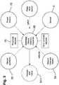
- a block diagramshows components of embodiments used to implement fully automatic control with optional manual override.
- the controller 65e.g. comprising a memory and a processor/microprocessor, or an ASIC.
- the rear shock absorber 25(comprising damper 630 and intensifier 510) of Figures 2 , including valve 511, is responsive to signals and power transmitted from the controller 65.
- the valve 511is default in the closed position and will throttle open corresponding to power input received at terminals 150.
- the controller 65compares the output voltage of sensor 5 to a preset (by means of threshold adjuster 75 such as, for example, a potentiometer) voltage value and if that value is exceeded, the controller 65 routes a predetermined amount of power from the power source 70 (e.g. suitable battery, capacitor, photovoltaic generator or other suitable mechanism or combination thereof) to the valve 511.
- the controller 65compares the output voltage to a magnitude comparator value over time (the time constant is also user adjustable). In that option the magnitude of the output voltage must remain above a given threshold value for a predetermined amount of time before the controller 65 will route power to the valve 511. When the output voltage falls below the threshold value, power to the valve 511 is shut off.
- the controller 65may taper power off over a selectable period of time as part of the shut off function.
- multiple threshold valuesmay be set in the controller 65. At each threshold value may direct a differing amount of power from the source 70 to the valve 511. If, for example, only a lower threshold is met, the controller 65 may direct an amount of power only corresponding to a partial opening of the valve 511. If a higher threshold is met the directed amount of power may correspond to a full open valve 511. Multiple time constants may also (independently or additionally) be preset for different corresponding valve 511 function levels.
- the valve 511may be of a type described in US patent no. 6,073,736 .
- the valve control / power circuitmay be configured and operable in a manner such as disclosed in US patent nos. 5,971,116 and 6,073,736 , or by any other means or method disclosed herein or any suitable combinations or portions thereof.
- a manual lock (or unlock or both) deviceis provided in a location convenient for user manipulation during vehicle operation.
- a signal generating device 50is provided on the handlebar of a bicycle 101 (or other part of the bicycle 101 that is reachable during use).
- the signal generating device 50includes the functions of locking and unlocking valve 511, and (if applicable) adjusting threshold(s) 75 and adjusting time constant(s) all as shown in Figure 3 .
- the device 50allows the user to remotely lock/unlock the rear shock 25 (and/or the front shock 80) at will.
- the signal generating device 50may cause both front and rear shocks to lock/unlock together, or it may permit the user to lock/unlock each shock independently.
- the signal generating device 50comprises a lever that is shiftable by the user of the vehicle.
- the levermay shift between first and second positions (each corresponding to a 'lock' and 'unlock' command to the damping assembly).
- the levermay move away from a first position and then back to that position to switch between locked and unlocked; such movement may be similar to the way indexed gear shifters operate.
- the signal generating device 50comprises a digital device provided with buttons and/or a touchscreen enabling the user to lock and unlock the damping assembly at will.
- the functionality of the signal generating device 50may be incorporated into performance recording devices, such as, but not limited to, the GARMIN EDGE(RTM) series of devices.
- the signal generating device 50may provide additional functionality to enable to user to remotely control the rear and/or front shock more finely.
- the signal generating device 50may permit the user to remotely set a shock (i.e. the amount that the intensifier valve 511 is open/closed) at one of a number of predefined indexed positions between locked and unlocked, or may permit the user set the shock at substantially any position between those two limits.
- the position of the valve 100may correspond with a position of an indicator on the signal generating device 50.
- the indicatormay be a visual indication (e.g. digital indicator), or a physical indicator (e.g. position of a lever between two limit positions).
- the default position of the intensifier valve 511may be either open or closed, or somewhere in between.
- valve 511is default set open.
- the actuatormoves the valve in one direction from its default or bias and it returns to bias by means of a spring or other suitable biasing mechanism when the actuator ceases to function.
- Controller 65monitors sensor 5 and/or 35 and after a time period of input corresponding to below threshold sensor output the processor direct power to 511 sufficient to close the valve (the electromagnetic or voice coil being reversed by power input and the spring 118 set as a tensile spring to hold the valve 511 open by default).
- the manual switch 50communicates a signal to the controller 65 and that causes the controller 65 to direct power from source 70 to valve 511 thereby closing valve 511 completely or partially as desired.
- a rider of the bicycle 101may manipulate the signal generating device 50 to direct the valve 511 (100) to close, to open, to throttle at intermediate positions, as desired while operating the bicycle 101 or varying terrain (to eliminate pedal bob or maximize ride comfort or traction).
- Some or all of components of embodiments herein including sensors and switches, controller 65, shock absorber 25, and valve 511/100 at terminals 150 or 151,may be interconnected or connected by wire 30, wireless, WAN, LAN, Bluetooth, WiFi, ANT, GARMIN(RTM) low power usage protocol, or any suitable power or signal transmitting mechanism. It is particularly desirable in certain embodiments that the signal generating device 50 can communicate wirelessly with the controller 65. An output electric signal from the signal generating device 50 is transmitted to the controller 65. The controller 65 responds to that signal by adjusting the damping rate of the damping assembly to lock or unlock, and/or set at some intermediate level according to the output electric signal.
- the rear shock absorber 25further operates with mechanically variable damping and/or spring features when the valve 511 is open or partially open.
- the "lock out" valve 511is positioned in series with the intensifier valve 510 of US patent 7,374,028 so that fluid must traverse both valves between the damper channel 636 and the compensator chamber 154.
- the damping function of the shock absorber 25is consistent with the operation of the intensifier valve 510 when the lock valve 511 is open.
- Other mechanical shock absorber functionsmay also be integrated with the present disclosure such that the shock absorber 25 is highly versatile and functional when valve 511 is open.
- the controller 65takes a derivative of the acceleration for forecasting and implementing adjustment of valve 511 (rebound issue is a big deal). For example, if a bump is encountered followed immediately by a dip, it may be desirable to have the rebound of the tire into the dip (terrain following for traction advantage) occur very rapidly. If the valve 511 were opened to an intermediate state as determined by the controller 65, for the bump an immediately following large magnitude reversal of the derivative of the acceleration (as input from the sensor 5) may indicate that the processor direct the power source to full opening of the valve 511 to allow maximum rebound velocity. The controller 65 may also compare input from sensor 35 and sensor 5 to determine optimum setting position for valve 511.
- the processormay open valve 511 gradually until some increase in 35 is noted and then close 511 back slightly from that.
- the controller 65may direct a closure of valve 511 until such synchronization is eliminated or reduced.
- shock absorber 25 and related systemsare equally applicable to vehicle, such as bicycle, front forks 80. Further, it is contemplated that a bicycle 101 may include both shock absorber 25 and fork 80, both of which having some or all of the features disclosed herein.
Landscapes
- Engineering & Computer Science (AREA)
- Mechanical Engineering (AREA)
- General Engineering & Computer Science (AREA)
- Physics & Mathematics (AREA)
- Electromagnetism (AREA)
- Axle Suspensions And Sidecars For Cycles (AREA)
- Vehicle Body Suspensions (AREA)
Description
- The present invention relates to a suspension system and to a vehicle comprising the suspension system.
- Integrated damper / spring vehicle shock absorbers often include a damper body surrounded by a mechanical spring. The damper often consists of a piston and shaft telescopically mounted in a fluid filled cylinder. The mechanical spring may be a helically wound spring that surrounds the damper body. Various integrated shock absorber configurations are described in
U.S. patent nos. 5,044,614 ;5,803,443 ;5,553,836 ; and7,293,764 . The shock absorber ofU.S. Patent 7,293,764 is shown, in exploded view, therein in Figure 7. As shown, the shock absorber comprises adamper assembly 60 and ahelical spring 65. Noteworthy is that the wound wire forming thehelical spring 65 includes abrupt ends 70. U.S. Patent No. 5,044,614 ("614 patent") shows a damper body carrying a thread 42. A helical spring 18 surrounds the damper body. The compression in the helical spring 18 may be pre-set by means of a nut 48 and alock nut 50. The nut 48 may be translated axially relative to the body ("tube") 16 and thread 42 by rotating the nut 48 around the threaded sleeve 42. Rotation of the nut 48 in a given direction (e.g. clockwise as viewed from end 44 for a right hand thread 42) will cause the nut to move toward the retainer clip 26 thereby compressing spring 18 between the nut 48 and the retainer clip 26. Once the spring 18 is in a desired state of compression,lock nut 50 is rotated, using a wrench, up against nut 48 and tightened in a binding relation therewith.- Some shock absorbers utilize gas as a spring medium in place of, or in addition to, mechanical springs. Gas spring type shock absorbers, having integral dampers, are described in
U.S. patent nos. 6,135,434 ;6,360,857 and6,311,962 . Patent number6,360,857 shows a shock absorber having selectively adjustable damping characteristics.US Patent no 7,163,222 describes a gas sprung front shock absorber for a bicycle (a "fork") having a selective mechanical "lock out" and adjustable mechanical "blow off' function. For purposes herein reference to a shock absorber includes front shock absorbers, or forks, of two (or some three) wheeled vehicles. - The spring mechanism (gas or mechanical) of some shock absorbers is adjustable so that it can be preset to varying initial states of compression. In some instances the shock spring (gas or mechanical) may comprise different stages having varying spring or damping rates thereby giving the overall shock absorber a compound spring rate depending varying through the stroke length. In that way the shock absorber can be adjusted to accommodate heavier or lighter carried weight, or greater or lesser anticipated impact loads. In vehicle applications including motorcycle and bicycle applications and particularly off-road applications, shock absorbers are pre-adjusted to account for varying terrain and anticipated speeds and jumps. Shocks are also adjusted according to certain rider preferences (e.g. soft - firm).
- A type of integrated spring / damper shock absorber, having a gas spring, is shown in Figure 28, for example, of
US patent no. 7,374,028 . The shock of Figure 28 also includes an "adjustable intensifier assembly 510." That intensifier or "reservoir" accepts damping fluid fromchamber 170 as the fluid is displaced from that chamber by the incursion ofrod 620 intochamber 170 during a compression stroke of the shock. The intensifier valve assembly regulates flow of damping fluid into and out of the reservoir and an embodiment of the valve assembly is shown in Figure 17 of that document. - It is desirable to "lock" the suspension, thereby rendering it substantially rigid, on certain vehicles at certain times. Such a lock may be particularly desirable on bicycles to reduce or eliminate so called "pedal bob" or "chain squat" (the cyclic compression and extension of suspension caused by the cyclic tension of the drive chain and the cyclic motion of the pedals, cranks and power input generally), often caused when cycling uphill. Once the period of pedal bob has finished it is desirable to "unlock" the suspension, so that a flat or downhill section can be negotiated at higher speed. It is noteworthy that the valve assembly of Figure 17 of
US 7,374,028 may be replaced with any suitable valve assembly depending on the desired result. For example, when the valve is configured (as will be further described herein) with a selectable and correspondingly selected "lock out" (i.e. functionally absolute valve closure) damping fluid is excluded from entering the reservoir and, the damping fluid being a relatively incompressible liquid, such exclusion prevents the volume ofchamber 170 from being reduced and thereby prevents the shock absorber from compressing telescopically. Such "lock out" is selectively provided via an external direct mechanical manual adjuster, such as for example knob 512 of Figure 17 ofUS 7,374,028 . - One particular problem with direct adjust selective lock out functionality on bicycles is that it is very difficult (in some cases impossible) for a rider to lock and unlock the damping function of the front and/or rear damper whilst riding the bicycle. It is difficult and dangerous to release grip on the handlebars particularly when the terrain is changing but that is often precisely the time when locking or locking of suspension would be desirable. Usually the rider has to stop, possibly dismount, and then lock or unlock the damper.
- A similar problem also exists on other vehicles such as trucks, ATVs, off-road motorcycles, etc. Any such vehicle that is capable of driving both on road and off road (i.e. on one type of terrain that is relatively smooth compared to another type of surface that can be relatively rough) usually has suspension with a larger range of travel than a vehicle intended exclusively for on road use. When moving from off-road to on road and vice versa there is no way, absent stopping and dismounting or exiting the vehicle, for the driver to lock and unlock the suspension to provide for better ride and handling according to the terrain.
US 2004/222056 A1 discloses a damper closest to that of the invention including a valve movable between an open position and a closed position to selectively alter the compression damping rate of the shock absorber. The valve may include a self-centering feature that operates to keep the valve body centered about the valve shaft. The damper may also include a timer feature, which retains the valve in an open position for a predetermined period of time after it is initially opened.- According to the present invention there is provide a vehicle as set out in claim 1. Further features of the vehicle are set out in claims 2 to 11 to which attention is hereby directed.
- According to another aspect of the present invention there is provide a vehicle suspension system as set out in claim 12. Further features of the vehicle are set out in claims 13 to 15 to which attention is hereby directed.
- According to some embodiments there is provided a suspension system for a vehicle, which suspension system comprises:
- a damping assembly operatively connected to an actuator;
- a controller for controlling movement of said actuator whereby a damping rate of said damping assembly is adjusted by movement of the actuator; and
- a signal generating device remote from said damping assembly, which device, in use, provides an output signal representing a desired adjustment to the damping rate of said damping assembly, said controller adapted to receive said signal and control said actuator to adjust said damping rate according to said signal, whereby said damping rate may be remotely altered during use of said vehicle. In some embodiments the controller may be a microcontroller or other processing device e.g. ASIC. In some aspects the controller may be of a simpler form and might be integrated with the actuator; for example the controller can be a circuit that controls the actuator in response to 'high' and 'low' voltage from the device. In some embodiments the device is a user operable device such as a manual switch or lever triggering a circuit to send an electrical signal. In some embodiments the device comprises an accelerometer for sensing changes in the terrain being traversed and sending a damping change signal to the controller in response to such changes. In some embodiments the device comprises both a sensor (e.g. accelerometer) or sensors and a manually operable switch in parallel where the sensor may signal the controller or the manual switch may be operated to signal the controller.
- In certain aspects said controller is arranged to control said actuator so that said damping assembly is either locked or unlocked, whereby in use, operation of said signal generating device switches said damping assembly rate only between a desired damping rate and a minimum damping rate. In this way the user of the vehicle may very easily lock (minimum) and unlock (regular or desired damping) the damping assembly, and there may be no intermediate adjustment positions of the damping rate based on the signals from the device(s) (i.e. the adjustment of the damping assembly is either locked or unlocked). The signal generating device may comprise a button that toggles the damping assembly between locked and unlocked. For vehicles having multiple wheels, each individual wheel suspension may be controlled based on a discreet signal generated by the device where the device includes, in addition to the signal generating trigger switch, a selector switch for designating a channel or mode corresponding to the immediately desired suspension unit or units. As an example a bicycle may include a signal generating switch having a toggle for selecting between the front and rear shock absorbers or for selecting "both" (thereby allowing the signal to trigger the actuator in each with only one operation of the switch). These easy-to-operate arrangements are particularly advantageous in off-road conditions where the user (e.g. a rider to a trail bike, mountain bike or other ATB or vehicle) must keep full concentration (and both hands engaged) on steering the vehicle.
- In some aspects said controller (e.g. circuit 65) is arranged to control said actuator so that said damping assembly may be moved to at least one position between a locked position and an unlocked position, whereby said signal generating device (such as manual override switch 50) may be used to set said damping rate at values between a maximum (or regular/desired) and a minimum. In these embodiments, the user has more fine control over the damping rate of the damping assembly, and may choose to position the damping assembly somewhere between unlocked and locked positions. The signal generating device may comprise an analogue or digital interface for achieving this functionality. For example, the signal generating device may comprise a lever whose position between two limits corresponds to the position of the damping assembly. Alternatively, the signal generating device may comprise a digital display indicating the amount that the damping assembly is open/closed, with 'up' and 'down' buttons (e.g. on touch screen display, or physical buttons) for changing the damping rate.
- In certain aspects said at least one position comprises a number of indexed positions between said locked and unlocked positions. Thus the rider may have a number of preset positions and the signal generating device may switch the damping assembly between these positions in a similar way to index shift gears.
- In other embodiments said damping assembly may be moved to substantially any position between said locked and fully unlocked positions. In this way the damping rate may be 'infinitely' adjustable between the fully open and closed positions. This may be achieved with an analogue or digital user-operable switch as described above.
- In some aspects the signal generating device comprises a sensor for providing a movement signal indicating movement of one part of the vehicle relative to another part during movement across terrain, said controller configured to receive said movement signal and to automatically control said damping rate in response thereto. In certain embodiments, the sensor comprises one or more vibration or impact sensor (or sensors such as
sensor 5,sensor 35, pedal force sensor or any suitable combination), such as a single axis accelerometer, although accelerometers with more than one axis are useable. The automatic control may be to lock or unlock the damping assembly in response to sensed movement. For example, it may be provided automatically in response to some predetermined and sensed vehicle operation condition (e.g. smooth terrain). Alternatively, a "lock out" condition may be the default mode for the suspension whereby the suspension becomes active only upon some predetermined and sensed vehicle operation condition (e.g. rough terrain). In other embodiments the automatic control may adjust the damping rate either between indexed positions or anywhere between ('infinitely' variable) the unlocked and locked conditions as described above. - In certain aspects said automatic control may be overridden and/or adjusted by a user-operable device (e.g. manual override switch 50) remote from said signal generating device.
- In some aspects said signal generating device comprises a user-operable device reachable during use of the vehicle.
- In some aspects said signal generating device comprises a wireless device for transmitting said output signal (e.g. as an electromagnetic signal) and said controller comprises a wireless receiver for receiving said output signal.
- In some aspects the suspension system comprises a wired connection between said signal generating device and said controller, said wired connection useable to transmit said output signal therebetween.
- In certain embodiments said damping assembly comprises an intensifier and said actuator is moveable to adjust the effect of said intensifier on said damping rate.
- In some aspects said actuator comprises a coil and a winding for moving a member, the position of said member controlling rate of fluid flow during compression/expansion of said damping assembly. The controller may cause a current to be passed through the winding in response to the output electric signal from the user-operable switch, thereby locking or unlocking the damping assembly (or setting its damping rate somewhere between),
- In some aspects said vehicle comprises a bicycle, such as a trail bike, mountain bike or ATB, and said signal generating device is located in a position on said bicycle reachable by the rider during use.
- The application of the invention is not limited to bicycles, but may also find application in other off road vehicles such as motorcycles, ATVs, 4WD dune buggies, watercraft, snowmobiles, etc.
- According to some other aspects there is provided a vehicle suspension lock out system comprising:
- a suspension having an outer tube and an inner shaft, or tube, the outer and inner tubes disposed telescopically relative to each other;
- a locking mechanism operatively connected to one of the outer and inner tubes and having a first position wherein the outer and inner tubes are relatively movable and a second position wherein the outer and inner tubes are substantially immovable relatively;
- an actuator configured to move the locking mechanism between the first and second positions in at least one direction;
- a signal generator remote from the actuator wherein an output from the signal generator is receivable by the a receiving portion of the actuator and the actuator moves the locking mechanism in response to receipt of the output; and
- a power source for providing power to the actuator. In certain aspects the power source may comprise a power generating mechanism that converts kinetic energy into electrical energy during use of the vehicle, e.g. bicycle.
- In certain aspects the signal generator comprises a manually operable control mounted in proximity to an operator of the vehicle.
- In some aspects the locking mechanism comprises a damping fluid valve.
- In some aspects the damping fluid valve separates a damping fluid compression chamber and a damping fluid reservoir.
- In some aspects the damping fluid valve separates a damping fluid compression chamber and a damping fluid rebound chamber.
- In some aspects a movable piston within the damping fluid chamber comprises the damping fluid valve
- In certain embodiments the actuator comprises a magnet and a winding.
- In other aspects the signal generator comprises an accelerometer.
- In some aspects the signal generator comprises at least one sensor and at least one manually operable control.
- In some aspects the manually operable control comprises a selector for directing a channel or mode of operation of the control.
- In some embodiments the operative connection comprises a damping fluid flow tube.
- According to some other aspects there is provided a vehicle suspension system comprising:
- at least one damper for metering fluid;
- at least one remotely operable valve adjacent to and in fluid communication with the damper, the valve movable between open and closed positions for affecting the operation of the damper;
- at least one device for operating the valve from a remote location on the vehicle, the device constructed and arranged to communicate with the valve via at least one electronic signal based upon a condition at the device.
- In certain aspects the device is a switch and the condition includes manual manipulation of the switch by a user.
- In other aspects the device is a sensor and the condition is a road condition acting upon the suspension system.
- In some embodiments the sensor is an accelerometer and the condition is an impact force on the suspension system.
- In some aspects a first valve operates in conjunction with a rear shock and a second valve operates in conjunction with a front shock of the vehicle.
- According to certain aspects there is provided a vehicle suspension comprising:
- a terrain sensor;
- an adjustable damping assembly; and
- a processor directing a position of the damping assembly in response to input from the terrain sensor.
- According to another aspect there is provided a method for adjusting a vehicle suspension comprising:
- manually adjusting a suspension adjuster;
- wirelessly sending a signal from the adjuster to a processor; and
- directing a power source to alter a power output to the suspension.
- For a better understanding of how the invention may be put into practice, preferred embodiments of the invention applied to a bicycle will be described, by of example only, with reference to the accompanying drawings, in which:
Fig. 1 is a schematic side view of a bicycle comprising a damper according to the present invention;Fig. 2A is a side view in cross section of one embodiment of a damper according to the present invention;Fig. 2B is an enlarged view of part of the damper ofFig. 2A ; andFig. 3 is a schematic block diagram of components of one embodiment of an electric lock out apparatus according to the present invention.- Referring to
Figure 1 , a bicycle generally identified byreference numeral 101 comprises aframe 40 andfront forks 80. In this embodiment theframe 40 has a suspension system comprising aswing arm assembly 10 that, in use, is able to move relative to the rest of the frame; this movement is permitted by inter alia a rear shock absorber or dampingassembly 25. Thefront forks 80 also provide a suspension function via a damping assembly in each fork leg; as such thebicycle 101 is a full suspension bicycle (such as an ATB or mountain bike), although the invention is not limited to use on full suspension bicycles. In particular the term 'suspension system' is intended to include bicycles having front suspension or rear suspension only, or both. - A
sensor 5 is positioned proximate arear axle 15 of abicycle 101 for sensing changes in terrain. As shown inFigure 1 , thesensor 5 is mounted on theswing arm assembly 10 proximate therear axle 15 of thebicycle 101. The angular orientation of thesensor 5 is movable through range 20 (and is shown in each of two possible limit positions), thereby allowing alteration of a force component sensed by the sensor in relation to a force (vector) input into theswing arm assembly 10. A preferred value for therange 20 is approximately 120°, and more preferably 100°. It is understood that thesensor 5 may be moved or mounted in any suitable configuration and allowing for any suitable range of adjustment as may be desirable. That is useful for adjusting the sensitivity of the sensor to various anticipated terrain and bicycle speed conditions (the bicycle speed affects the vector magnitude of a force input to the bicycle wheel for constant amplitude terrain disparity or "bump / dip." Varying size bumps and dips also affect the vector input angle to the wheel for constant bicycle speed). - The sensor 5 (and
sensor 35 and pedal force sensor) may be any suitable force or acceleration transducer (e.g. strain gage, wheatstone bridge, accelerometer, hydraulic, interferometer based, optical, thermal or any suitable combination thereof). Thesensor 5 may utilize solid state electronics, electro-mechanical principles or MEMS, or any other suitable mechanisms. In one embodiment thesensor 5 comprises a single axis self powered accelerometer, such as for example ENDEVCO(RTM) model 2229C. The 2229C is a comparatively small device with overall dimensions of approximately 15mm height by 10mm diameter, and weighs 4.9g. Its power is self-generated and therefore the total power requirements for thebicycle 101 are reduced; this is an important advantage, at least for some types of bicycle, where overall weight is a concern. An alternative single axis accelerometer is the ENDEVCO(RTM) 12M1A, which is of the surface-mount type. The 12M1A is a single axis accelerometer comprising a bimorph sending element which operates in the bender mode. This accelerometer is particularly small and light, measuring about 4.5mm by 3.8mm by 0.85mm, and weighs 0.12g. In other embodiments, thesensor 5 may be a triaxial accelerometer such as the ENDEVCO(RTM) 67-100. This device has overall dimensions of about 23mm length and 15mm width, and weighs 14g. - The
sensor 5 may be attached to theswing arm assembly 10 directly, to any link thereof, to an intermediate mounting member (not shown) or to any other portion or portions of thebicycle 101 as may be useful. In one embodiment asensor 5 is fixed to an unsprung portion of thebicycle 101, such as for example theswing arm assembly 10, and another sensor 35 (such as an accelerometer as described above) is fixed to a sprung portion of thebicycle 101, such as theframe 40. Sensors may be integrated with the vehicle structure and data processing system as described inUS patent nos. 6,863,291 ;4,773,671 ;4,984,819 ;5,390,949 ;5,105,918 ;6,427,812 ;6,244,398 ;5,027,303 and6,935,157 . Sensors and valve actuators (e.g. electric solenoid or linear motor type - note that a rotary motor may also be used with a rotary actuated valve) may be integrated herein utilizing principles outlined in SP-861-Vehicle Dynamics and Electronic Controlled Suspensions SAE Technical Paper Series no. 910661 byShiozaki et. al. for the International Congress and Exposition, Detroit, Michigan, February 25 - March 1, 1991. - As mentioned above, the
rear shock absorber 25 is operatively mounted between an unsprung portion of thebicycle 101, such as theswing arm assembly 10 andrear axle 15, and a sprung portion of thebicycle 101 such as theframe 40. A representative example embodiment ofshock absorber 25 derives from a modification, as disclosed herein, of the shock absorber shown in Figure 28 of, and elsewhere in,US patent no. 7,374,028 (the "'028" patent) . - Referring to
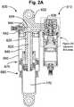
Figure 2A herein (from the '028 patent),intensifier assembly 510 is shown in conjunction withdamper assembly 630.Figure 2B shows an embodiment of anintensifier valve 511 for use with the principles disclosed herein. As shown inFig. 2A theintensifier valve 511 ofFigure 2B replaces theassembly 510, as shown in Figures 15, 17 and elsewhere in the '028 patent. Theintensifier valve 511 is operable in response to electric signal and is capable of being modulated or throttled for selective full opening, closing and intermediate opening or "throttle" positions. Theintensifier valve 511 comprises avalve portion 110 and anactuator portion 120. Thevalve portion 110 may include acylinder 112 with one or morevariable orifices 114 and a member (e.g. piston) 116 that moves within thecylinder 112 to control the opening of the orifice(s) 114. Thevalve 100 is in a closed position when thepiston 116 is covering the orifice(s) 114. Thevalve 100 is in an open position when thepiston 116 moves away from the orifice(s) 114 such that at least a portion of the orifice(s) 114 is opened. In the open position, fluid may flow into thevalve portion 110 and may flow out of thevalve portion 110. The position of thepiston 116 relative to the orifice(s) 114 varies the orifice opening and the flow through thevalve portion 110. Thevalve 100 may thus provide an output pressure in response to an input flow. - The
valve portion 110 may also include aspring 118 that applies a force against thepiston 116 to bias thepiston 116 toward the closed position. Fluid pressure against thepiston 116 may result in a force that exceeds the spring force causing thepiston 116 to move and open the orifice(s) 114. - The
actuator portion 120 may also apply a force to thepiston 116. Theactuator portion 120 may advantageously be back drivable to permit the pressure term to push open the valve, for example, during the onset of a high shock event. One embodiment of theactuator portion 120 is a voice coil type linear actuator including avoice coil 122, amagnet 124, and aback iron 126. Theback iron 126 is coupled to thepiston 116 such that linear movement of theback iron 126 causes linear movement of thepiston 116. - The
actuator portion 120 may be controlled using a command such as a voltage command, for example, provided by drive electronics (not shown). A voltage command or signal to theactuator portion 120 causes current to flow through thecoil 122, creating a magnetic field that applies a force to themagnet 124 and backiron 126. Different voltage commands may thus correspond to different amounts of force applied to thepiston 116 in thevalve 100. In one embodiment the signals and actuator are configured to move the valve completely between a full open ('unlocked') and a full closed position ('locked') thereby allowing the damper to move or substantially locking it, i.e. adjusting the damping rate of the dampingassembly 630 between minimum and maximum respectively. - Although one exemplary valve is shown, those skilled in the art will recognize that other types of pressure relief valves may be used. Although the
exemplary actuator 120 is a voice coil type linear actuator, those skilled in the art will recognize that other types of actuator technologies may be used. For example, the sensors, switches, controllers, actuators and other operative elements hereof may comprise optical circuitry and as such the power source may comprises an optical (or other electromagnetic) generator such as a "LASER" and wiring and circuits used herein may comprises fiber optic and optic circuitry including Bragg grating technology and other suitable "electrical equivalents." The elements hereof may be operable in whole or in part based on sonic wave or microwave transmission and suitable waveguide technology may be employed. - It should also be noted that 122 and 124 are interchangeable such that the voice coil may be either 122 or 124 and the magnet may be the other of 122 and 124 respectively. The
voice coil windings 152 to accommodate extension and contraction of thethroughput wires 152 during operation of thevalve 100 - The
valve 100 is shown in a closed, or downward 156, position. As such,piston 116 fully obstructsorifices 114 thereby preventing fluid from flowing fromdamper assembly 630, throughchannel 636, intoupper chamber 153, throughorifice 114, throughvalve outlet 157 and into floatingpiston compensator chamber 154. When current of an appropriate magnitude is applied to thevoice coil back iron 126, and correspondingly thevalve piston 116, to move upward 155 in an amount proportional to the voice coil input. Such upward 155 movement is againstspring 118, which biases thevalve piston 116 downward 156 (i.e. toward closed), and therefore when the voice coil input balances with the force ofspring 118, movement of thepiston 116 will stop and thevalve 100 will be correspondingly throttled. - In operation, the sensor 5 (and / or 35) outputs a voltage change corresponding to an input force (for example the outputs from both sensors may be reconciled in a controller (described in greater detail below), such as a microprocessor, having an algorithm for weighting their respective inputs and generating a resulting singular command or signal based on a predetermined logic). In one embodiment the
sensor 5 senses input force along aprescribed axis 20. A bump in theterrain 45 typically exerts aforce 55 on a bicycle wheel. The angle of the resolvedforce 55 relative to the tire/wheel 60 is typically normal (substantially) to the tire/wheel 60 at the point of impact. Thatforce 55 then imparts a component of theimpact 55 to theaxle 15 as dictated by theswing arm assembly 10. That component can be sensed by thesensor 5 at a magnitude corresponding to the orientation of thesensor axis 20. The sensor axis orientation can be adjusted by the user and/or bicycle manufacturer to make the sensor more or less sensitive (by imparting more or less of theimpact 55 to the axis 20) to bumps and dips in the terrain. - It is envisaged that there are various ways the remote lock/unlock function of the
rear shock absorber 25 and/orfront shock absorber 80 may be provided on thebicycle 101. In particular, remote lock/unlock may be entirely automatically controlled by acontroller 65 in response to the input from thesensor 5 when thebicycle 101 is in use. Optionally, the user may be able override and/or adjust this automatic control using adevice 50. In another embodiment, the remote lock/unlock of the rear shock absorber 25 (and/or front shock absorber 80) may be entirely controlled at the user's discretion using thedevice 50; in such an embodiment thesensor 5 need not be provided on thebicycle 101 and the user locks and unlocks the suspension system according to his or her own preferences at the time. - Referring additionally to Figure 4, a block diagram shows components of embodiments used to implement fully automatic control with optional manual override. In use, when the
sensor 5 puts out, for example, a voltage corresponding to a bump (and/or optionally a dip) that voltage is transmitted to the controller 65 (e.g. comprising a memory and a processor/microprocessor, or an ASIC). In one embodiment the rear shock absorber 25 (comprisingdamper 630 and intensifier 510) ofFigures 2 , includingvalve 511, is responsive to signals and power transmitted from thecontroller 65. Thevalve 511 is default in the closed position and will throttle open corresponding to power input received atterminals 150. Thecontroller 65 compares the output voltage ofsensor 5 to a preset (by means ofthreshold adjuster 75 such as, for example, a potentiometer) voltage value and if that value is exceeded, thecontroller 65 routes a predetermined amount of power from the power source 70 (e.g. suitable battery, capacitor, photovoltaic generator or other suitable mechanism or combination thereof) to thevalve 511. Optionally thecontroller 65 compares the output voltage to a magnitude comparator value over time (the time constant is also user adjustable). In that option the magnitude of the output voltage must remain above a given threshold value for a predetermined amount of time before thecontroller 65 will route power to thevalve 511. When the output voltage falls below the threshold value, power to thevalve 511 is shut off. Optionally, thecontroller 65 may taper power off over a selectable period of time as part of the shut off function. Optionally, multiple threshold values may be set in thecontroller 65. At each threshold value may direct a differing amount of power from the source 70 to thevalve 511. If, for example, only a lower threshold is met, thecontroller 65 may direct an amount of power only corresponding to a partial opening of thevalve 511. If a higher threshold is met the directed amount of power may correspond to a fullopen valve 511. Multiple time constants may also (independently or additionally) be preset for differentcorresponding valve 511 function levels. Optionally thevalve 511 may be of a type described inUS patent no. 6,073,736 . Optionally, the valve control / power circuit may be configured and operable in a manner such as disclosed inUS patent nos. 5,971,116 and6,073,736 , or by any other means or method disclosed herein or any suitable combinations or portions thereof. - In one embodiment, a manual lock (or unlock or both) device is provided in a location convenient for user manipulation during vehicle operation. In one embodiment such a
signal generating device 50 is provided on the handlebar of a bicycle 101 (or other part of thebicycle 101 that is reachable during use). Optionally thesignal generating device 50 includes the functions of locking and unlockingvalve 511, and (if applicable) adjusting threshold(s) 75 and adjusting time constant(s) all as shown inFigure 3 . Thus at its simplest, thedevice 50 allows the user to remotely lock/unlock the rear shock 25 (and/or the front shock 80) at will. Thesignal generating device 50 may cause both front and rear shocks to lock/unlock together, or it may permit the user to lock/unlock each shock independently. - In one embodiment the
signal generating device 50 comprises a lever that is shiftable by the user of the vehicle. The lever may shift between first and second positions (each corresponding to a 'lock' and 'unlock' command to the damping assembly). Alternatively the lever may move away from a first position and then back to that position to switch between locked and unlocked; such movement may be similar to the way indexed gear shifters operate. - In one embodiment, the
signal generating device 50 comprises a digital device provided with buttons and/or a touchscreen enabling the user to lock and unlock the damping assembly at will. The functionality of thesignal generating device 50 may be incorporated into performance recording devices, such as, but not limited to, the GARMIN EDGE(RTM) series of devices. - In other embodiments, the
signal generating device 50 may provide additional functionality to enable to user to remotely control the rear and/or front shock more finely. For example, thesignal generating device 50 may permit the user to remotely set a shock (i.e. the amount that theintensifier valve 511 is open/closed) at one of a number of predefined indexed positions between locked and unlocked, or may permit the user set the shock at substantially any position between those two limits. For example the position of thevalve 100 may correspond with a position of an indicator on thesignal generating device 50. The indicator may be a visual indication (e.g. digital indicator), or a physical indicator (e.g. position of a lever between two limit positions). - The default position of the
intensifier valve 511 may be either open or closed, or somewhere in between. In oneembodiment valve 511 is default set open. In one embodiment the actuator moves the valve in one direction from its default or bias and it returns to bias by means of a spring or other suitable biasing mechanism when the actuator ceases to function.Controller 65monitors sensor 5 and/or 35 and after a time period of input corresponding to below threshold sensor output the processor direct power to 511 sufficient to close the valve (the electromagnetic or voice coil being reversed by power input and thespring 118 set as a tensile spring to hold thevalve 511 open by default). Optionally (or independently and absent thesensors 5 and 35) themanual switch 50 communicates a signal to thecontroller 65 and that causes thecontroller 65 to direct power from source 70 tovalve 511 thereby closingvalve 511 completely or partially as desired. Optionally, a rider of thebicycle 101 may manipulate thesignal generating device 50 to direct the valve 511 (100) to close, to open, to throttle at intermediate positions, as desired while operating thebicycle 101 or varying terrain (to eliminate pedal bob or maximize ride comfort or traction). - Some or all of components of embodiments herein including sensors and switches,
controller 65,shock absorber 25, andvalve 511/100 atterminals wire 30, wireless, WAN, LAN, Bluetooth, WiFi, ANT, GARMIN(RTM) low power usage protocol, or any suitable power or signal transmitting mechanism. It is particularly desirable in certain embodiments that thesignal generating device 50 can communicate wirelessly with thecontroller 65. An output electric signal from thesignal generating device 50 is transmitted to thecontroller 65. Thecontroller 65 responds to that signal by adjusting the damping rate of the damping assembly to lock or unlock, and/or set at some intermediate level according to the output electric signal. - In one embodiment the
rear shock absorber 25 further operates with mechanically variable damping and/or spring features when thevalve 511 is open or partially open. In one embodiment the "lock out"valve 511 is positioned in series with theintensifier valve 510 ofUS patent 7,374,028 so that fluid must traverse both valves between thedamper channel 636 and thecompensator chamber 154. In operation, the damping function of theshock absorber 25 is consistent with the operation of theintensifier valve 510 when thelock valve 511 is open. Other mechanical shock absorber functions may also be integrated with the present disclosure such that theshock absorber 25 is highly versatile and functional whenvalve 511 is open. Such features are disclosed for example inUS provisional patent application serial number 61/157,541 - In one embodiment, the
controller 65 takes a derivative of the acceleration for forecasting and implementing adjustment of valve 511 (rebound issue is a big deal). For example, if a bump is encountered followed immediately by a dip, it may be desirable to have the rebound of the tire into the dip (terrain following for traction advantage) occur very rapidly. If thevalve 511 were opened to an intermediate state as determined by thecontroller 65, for the bump an immediately following large magnitude reversal of the derivative of the acceleration (as input from the sensor 5) may indicate that the processor direct the power source to full opening of thevalve 511 to allow maximum rebound velocity. Thecontroller 65 may also compare input fromsensor 35 andsensor 5 to determine optimum setting position forvalve 511. For example, if input fromsensor 35 is relatively low in magnitude the processor may openvalve 511 gradually until some increase in 35 is noted and then close 511 back slightly from that. In one embodiment if input fromsensor 35 is consistent in frequency with input from a pedal force sensor (e.g.US patent no. 5,027,303 ), thecontroller 65 may direct a closure ofvalve 511 until such synchronization is eliminated or reduced. - It is noted that embodiments herein of
shock absorber 25 and related systems are equally applicable to vehicle, such as bicycle,front forks 80. Further, it is contemplated that abicycle 101 may include bothshock absorber 25 andfork 80, both of which having some or all of the features disclosed herein. - While the foregoing is directed to embodiments of the present invention, other and further embodiments of the invention may be implemented without departing from the scope of the invention, and the scope thereof is determined by the claims that follow.
Claims (15)
- A vehicle comprising a sprung portion (40), an unsprung portion (60) and a vehicle suspension system, which vehicle suspension system comprises:a terrain sensor (5) mounted on the unsprung part of the vehicle, which terrain sensor, in use, provides an output indicating the acceleration of the unsprung part of the vehicle caused by bumps and dips in terrain;an electronically adjustable damping assembly (30; 510; 511) mounted between the sprung portion and the unsprung portion, said electronically adjustable damping assembly comprising an electronically adjustable valve for controlling a damping rate of the electronically adjustable damping assembly;a power source (70) for providing power to adjust the electronically adjustable valve; anda controller (65) comprising a processor for directing a position of the electronically adjustable valve (511) in response to input from the terrain sensor, wherein a default position of the valve (511) is a closed position and the valve will throttle open corresponding to power routed by controller from the power source to the valve;characterised in that, in use, the controller (65) compares the output from the sensor (5) to a magnitude comparator value over time, the magnitude comparator value having a user-adjustable time constant, and if the output remains above the magnitude comparator value for a time period set by the user-adjustable time constant, the controller (65) routes power from the power source (70) to the valve (511) to throttle it open and, when the output from the sensor (5) falls below the magnitude comparator value, the controller shuts off the power to the valve.
- A vehicle as claimed in claim 1, wherein the controller (65) is adapted to taper power off over a selectable period of time as part of the shut off.
- A vehicle as claimed in claim in claim 1 or 2, wherein multiple magnitude comparator values may be set in the controller (65) wherein, in use, different amounts of power are routed by the controller (65) from the power source (70) to the valve (511) according to which magnitude comparator value is exceeded for the time period by the output from the sensor (5).
- A vehicle as claimed in claim 3, wherein in use if only a lower magnitude comparator value is exceeded, the controller (65) routes an amount of power from the power source (70) to cause a partial opening of the valve (511), and if a higher magnitude comparator value is exceeded the directed amount of power may correspond to a full opening of the valve (511).
- A vehicle as claimed in claim 3 or 4, wherein the controller stores multiple user-adjustable time constants, each user-adjustable time constant corresponding to one of said magnitude comparator values, whereby different valve function levels are provided.
- A vehicle as claimed in any preceding claim, further comprising a user-operable device remote from said controller, wherein control of said electronically adjustable damping assembly by said controller may be overridden and/or adjusted using said user-operable device.
- A vehicle as claimed in claim 6, wherein said user-operable device is reachable by the user during use of the vehicle.
- A vehicle as claimed in claim 6 or 7, wherein said user-operable device comprises a wireless transmitter for transmitting an output signal and said controller comprises a wireless receiver for receiving said output signal.
- A vehicle as claimed in claim 6, 7 or 8, wherein said user-operable device comprises a digital device provided with buttons and/or a touchscreen enabling the user to lock and unlock the electronically adjustable damping assembly at will.
- A vehicle as claimed in claim 6, wherein said user-operable device comprises a performance recording device.
- A vehicle as claimed in any preceding claim, wherein said vehicle is a bicycle, trail bike, mountain bike, all-terrain bike, motorcycle, all-terrain vehicle, 4 wheel drive dune buggy, watercraft or snowmobile.
- A vehicle suspension system comprising:a terrain sensor (5) mountable on an unsprung part of a vehicle, which terrain sensor, in use, provides an output indicating the acceleration of the unsprung part of the vehicle caused by bumps and dips in terrain;an electronically adjustable damping assembly (30; 510; 511) mountable between the sprung portion and the unsprung portion, said electronically adjustable damping assembly comprising an electronically adjustable valve for controlling a damping rate of the electronically adjustable damping assembly;a power source (70) for providing power to adjust the electronically adjustable valve; anda controller (65) comprising a processor for directing a position of the electronically adjustable valve (511) in response to input from the terrain sensor, wherein a default position of the valve (511) is a closed position and the valve will throttle open corresponding to power routed by controller from the power source to the valve;characterised in that, in use, the controller (65) compares the output from the sensor (5) to a magnitude comparator value over time, the magnitude comparator value having a user-adjustable time constant, and if the output remains above the magnitude comparator value for a time period set by the user-adjustable time constant, the controller (65) routes power from the power source (70) to the valve (511) to throttle it open and, when the output from the sensor (5) falls below the magnitude comparator value, the controller shuts off the power to the valve.
- A vehicle suspension system as claimed in claim 12, wherein the controller (65) is adapted to taper power off over a selectable period of time as part of the shut off.
- A vehicle suspension system as claimed in claim in claim 12 or 13, wherein multiple magnitude comparator values may be set in the controller (65) wherein, in use, different amounts of power are routed by the controller (65) from the power source (70) to the valve (511) according to which magnitude comparator value is exceeded for the time period by the output from the sensor (5).
- A vehicle suspension system as claimed in claim 14, wherein in use if only a lower magnitude comparator value is exceeded, the controller (65) routes an amount of power from the power source (70) to cause a partial opening of the valve (511), and if a higher magnitude comparator value is exceeded the directed amount of power may correspond to a full opening of the valve (511).
Priority Applications (1)
| Application Number | Priority Date | Filing Date | Title |
|---|---|---|---|
| EP21170685.8AEP3919298A1 (en) | 2009-05-04 | 2010-05-04 | Suspension system for a vehicle |
Applications Claiming Priority (4)
| Application Number | Priority Date | Filing Date | Title |
|---|---|---|---|
| US17542209P | 2009-05-04 | 2009-05-04 | |
| EP15167426.4AEP2933125B1 (en) | 2009-05-04 | 2010-05-04 | Suspension system for a vehicle |
| EP20130158034EP2620303B1 (en) | 2009-05-04 | 2010-05-04 | Suspension System for a Vehicle |
| EP10161906AEP2248691A1 (en) | 2009-05-04 | 2010-05-04 | Suspension system for a vehicle |
Related Parent Applications (4)
| Application Number | Title | Priority Date | Filing Date |
|---|---|---|---|
| EP20130158034DivisionEP2620303B1 (en) | 2009-05-04 | 2010-05-04 | Suspension System for a Vehicle |
| EP10161906ADivisionEP2248691A1 (en) | 2009-05-04 | 2010-05-04 | Suspension system for a vehicle |
| EP15167426.4ADivisionEP2933125B1 (en) | 2009-05-04 | 2010-05-04 | Suspension system for a vehicle |
| EP15167426.4ADivision-IntoEP2933125B1 (en) | 2009-05-04 | 2010-05-04 | Suspension system for a vehicle |
Related Child Applications (2)
| Application Number | Title | Priority Date | Filing Date |
|---|---|---|---|
| EP21170685.8ADivisionEP3919298A1 (en) | 2009-05-04 | 2010-05-04 | Suspension system for a vehicle |
| EP21170685.8ADivision-IntoEP3919298A1 (en) | 2009-05-04 | 2010-05-04 | Suspension system for a vehicle |
Publications (2)
| Publication Number | Publication Date |
|---|---|
| EP3543045A1 EP3543045A1 (en) | 2019-09-25 |
| EP3543045B1true EP3543045B1 (en) | 2021-06-16 |
Family
ID=42635019
Family Applications (5)
| Application Number | Title | Priority Date | Filing Date |
|---|---|---|---|
| EP19155995.4AActiveEP3543045B1 (en) | 2009-05-04 | 2010-05-04 | Suspension system for a vehicle |
| EP21170685.8APendingEP3919298A1 (en) | 2009-05-04 | 2010-05-04 | Suspension system for a vehicle |
| EP15167426.4AActiveEP2933125B1 (en) | 2009-05-04 | 2010-05-04 | Suspension system for a vehicle |
| EP10161906ACeasedEP2248691A1 (en) | 2009-05-04 | 2010-05-04 | Suspension system for a vehicle |
| EP20130158034ActiveEP2620303B1 (en) | 2009-05-04 | 2010-05-04 | Suspension System for a Vehicle |
Family Applications After (4)
| Application Number | Title | Priority Date | Filing Date |
|---|---|---|---|
| EP21170685.8APendingEP3919298A1 (en) | 2009-05-04 | 2010-05-04 | Suspension system for a vehicle |
| EP15167426.4AActiveEP2933125B1 (en) | 2009-05-04 | 2010-05-04 | Suspension system for a vehicle |
| EP10161906ACeasedEP2248691A1 (en) | 2009-05-04 | 2010-05-04 | Suspension system for a vehicle |
| EP20130158034ActiveEP2620303B1 (en) | 2009-05-04 | 2010-05-04 | Suspension System for a Vehicle |
Country Status (2)
| Country | Link |
|---|---|
| US (1) | US20100276906A1 (en) |
| EP (5) | EP3543045B1 (en) |
Families Citing this family (83)
| Publication number | Priority date | Publication date | Assignee | Title |
|---|---|---|---|---|
| JP5212794B2 (en)* | 2008-04-25 | 2013-06-19 | 日立オートモティブシステムズ株式会社 | Cylinder device and stabilizer device using the same. |
| US20120305350A1 (en) | 2011-05-31 | 2012-12-06 | Ericksen Everet O | Methods and apparatus for position sensitive suspension damping |
| US11306798B2 (en) | 2008-05-09 | 2022-04-19 | Fox Factory, Inc. | Position sensitive suspension damping with an active valve |
| US20100170760A1 (en) | 2009-01-07 | 2010-07-08 | John Marking | Remotely Operated Bypass for a Suspension Damper |
| US9452654B2 (en) | 2009-01-07 | 2016-09-27 | Fox Factory, Inc. | Method and apparatus for an adjustable damper |
| US9033122B2 (en) | 2009-01-07 | 2015-05-19 | Fox Factory, Inc. | Method and apparatus for an adjustable damper |
| US8857580B2 (en) | 2009-01-07 | 2014-10-14 | Fox Factory, Inc. | Remotely operated bypass for a suspension damper |
| US8627932B2 (en) | 2009-01-07 | 2014-01-14 | Fox Factory, Inc. | Bypass for a suspension damper |
| US10060499B2 (en) | 2009-01-07 | 2018-08-28 | Fox Factory, Inc. | Method and apparatus for an adjustable damper |
| US10047817B2 (en) | 2009-01-07 | 2018-08-14 | Fox Factory, Inc. | Method and apparatus for an adjustable damper |
| US8328454B2 (en) | 2008-06-30 | 2012-12-11 | Specialized Bicycle Components, Inc. | Vertically adjustable bicycle assembly |
| US8393446B2 (en) | 2008-08-25 | 2013-03-12 | David M Haugen | Methods and apparatus for suspension lock out and signal generation |
| US9140325B2 (en) | 2009-03-19 | 2015-09-22 | Fox Factory, Inc. | Methods and apparatus for selective spring pre-load adjustment |
| EP3666347B1 (en) | 2008-11-25 | 2021-10-20 | Fox Factory, Inc. | Computer usable storage medium for virtual competition |
| US9422018B2 (en) | 2008-11-25 | 2016-08-23 | Fox Factory, Inc. | Seat post |
| US10036443B2 (en) | 2009-03-19 | 2018-07-31 | Fox Factory, Inc. | Methods and apparatus for suspension adjustment |
| US11299233B2 (en) | 2009-01-07 | 2022-04-12 | Fox Factory, Inc. | Method and apparatus for an adjustable damper |
| US9556925B2 (en) | 2009-01-07 | 2017-01-31 | Fox Factory, Inc. | Suspension damper with by-pass valves |
| US10821795B2 (en) | 2009-01-07 | 2020-11-03 | Fox Factory, Inc. | Method and apparatus for an adjustable damper |
| US9038791B2 (en) | 2009-01-07 | 2015-05-26 | Fox Factory, Inc. | Compression isolator for a suspension damper |
| US12122205B2 (en) | 2009-01-07 | 2024-10-22 | Fox Factory, Inc. | Active valve for an internal bypass |
| US8936139B2 (en) | 2009-03-19 | 2015-01-20 | Fox Factory, Inc. | Methods and apparatus for suspension adjustment |
| WO2011021164A2 (en)* | 2009-08-20 | 2011-02-24 | James Buchheim | Electric motorized bicycle components and a wireless control system including such |
| US8616351B2 (en) | 2009-10-06 | 2013-12-31 | Tenneco Automotive Operating Company Inc. | Damper with digital valve |
| EP2312180B1 (en) | 2009-10-13 | 2019-09-18 | Fox Factory, Inc. | Apparatus for controlling a fluid damper |
| US8672106B2 (en) | 2009-10-13 | 2014-03-18 | Fox Factory, Inc. | Self-regulating suspension |
| US10697514B2 (en) | 2010-01-20 | 2020-06-30 | Fox Factory, Inc. | Remotely operated bypass for a suspension damper |
| US9162573B2 (en) | 2010-06-03 | 2015-10-20 | Polaris Industries Inc. | Electronic throttle control |
| EP2402239B1 (en) | 2010-07-02 | 2020-09-02 | Fox Factory, Inc. | Adjustable seat post |
| US8480064B2 (en) | 2010-07-09 | 2013-07-09 | Specialized Bicycle Components, Inc. | Bicycle with suspension |
| DE102010055828A1 (en)* | 2010-12-23 | 2012-06-28 | Dt Swiss Ag | Suspension control for a bicycle |
| DE102011009405A1 (en)* | 2011-01-25 | 2012-07-26 | Dt Swiss Ag | Shock absorber for bicycle |
| JP2012179974A (en)* | 2011-02-28 | 2012-09-20 | Shimano Inc | Suspension control device for bicycle |
| EP2683599B1 (en) | 2011-03-11 | 2019-04-24 | Specialized Bicycle Components, Inc. | Adjustable assembly for a bicycle |
| US10246155B2 (en) | 2011-03-11 | 2019-04-02 | Specialized Bicycle Components, Inc. | Adjustable assembly for a bicycle |
| US9127738B2 (en)* | 2011-03-14 | 2015-09-08 | Oshkosh Defense, Llc | Damper assembly |
| US8429061B2 (en)* | 2011-03-30 | 2013-04-23 | Shimano Inc. | Bicycle suspension control apparatus |
| DE202011104974U1 (en)* | 2011-08-30 | 2012-12-03 | Canyon Bicycles Gmbh | bicycle frame |
| EP3929459A1 (en) | 2011-09-12 | 2021-12-29 | Fox Factory, Inc. | Methods and apparatus for suspension set up |
| US8740237B2 (en) | 2011-09-23 | 2014-06-03 | Specialized Bicycle Components, Inc. | Bicycle with suspension |
| US11279199B2 (en) | 2012-01-25 | 2022-03-22 | Fox Factory, Inc. | Suspension damper with by-pass valves |
| US10330171B2 (en) | 2012-05-10 | 2019-06-25 | Fox Factory, Inc. | Method and apparatus for an adjustable damper |
| US8843273B2 (en)* | 2012-09-24 | 2014-09-23 | Sram, Llc | Bicycle suspension |
| EP2906916A4 (en)* | 2012-10-11 | 2017-05-17 | Silicon Audio Seismic, LLC | Closed loop control techniques for displacement sensors with optical readout |
| US9205717B2 (en) | 2012-11-07 | 2015-12-08 | Polaris Industries Inc. | Vehicle having suspension with continuous damping control |
| US20150343290A1 (en)* | 2012-12-12 | 2015-12-03 | Michael Freiberg | Cycling training device |
| US9884533B2 (en) | 2013-02-28 | 2018-02-06 | Tenneco Automotive Operating Company Inc. | Autonomous control damper |
| US9217483B2 (en) | 2013-02-28 | 2015-12-22 | Tenneco Automotive Operating Company Inc. | Valve switching controls for adjustable damper |
| JP6346908B2 (en) | 2013-02-28 | 2018-06-20 | テネコ オートモティブ オペレーティング カンパニー インコーポレイテッドTenneco Automotive Operating Company Inc. | Damper with integrated electronic circuit |
| US9879748B2 (en) | 2013-03-15 | 2018-01-30 | Tenneco Automotive Operating Company Inc. | Two position valve with face seal and pressure relief port |
| US9879746B2 (en) | 2013-03-15 | 2018-01-30 | Tenneco Automotive Operating Company Inc. | Rod guide system and method with multiple solenoid valve cartridges and multiple pressure regulated valve assemblies |
| US9518630B2 (en)* | 2013-08-01 | 2016-12-13 | Specialized Bicycle Components, Inc. | Bicycle air spring |
| CN107097892B (en)* | 2013-11-12 | 2019-06-11 | 巨大机械工业股份有限公司 | Automatic control shock absorber system for bicycle |
| US9676441B2 (en)* | 2013-11-12 | 2017-06-13 | Giant Manufacturing Co. Ltd | Automatic shock absorber system for bicycle |
| FI125110B (en)* | 2013-11-27 | 2015-06-15 | Teknologian Tutkimuskeskus Vtt Oy | Suspension arrangement |
| US9428242B2 (en) | 2014-02-24 | 2016-08-30 | Harley-Davidson Motor Company Group, LLC | Variable ride height systems and methods |
| EP3929008A1 (en)* | 2014-04-11 | 2021-12-29 | Fox Factory, Inc. | Method and apparatus for an adjustable damper |
| CN107406094B (en) | 2014-10-31 | 2020-04-14 | 北极星工业有限公司 | System and method for controlling a vehicle |
| US10145436B2 (en)* | 2015-12-04 | 2018-12-04 | Eko Sport, Inc. | Rear suspension having an air component and an oil component |
| US10737546B2 (en) | 2016-04-08 | 2020-08-11 | Fox Factory, Inc. | Electronic compression and rebound control |
| CN110121438B (en) | 2016-11-18 | 2023-01-31 | 北极星工业有限公司 | vehicles with adjustable suspension |
| US10358180B2 (en) | 2017-01-05 | 2019-07-23 | Sram, Llc | Adjustable seatpost |
| US10588233B2 (en) | 2017-06-06 | 2020-03-10 | Tenneco Automotive Operating Company Inc. | Damper with printed circuit board carrier |
| US10479160B2 (en) | 2017-06-06 | 2019-11-19 | Tenneco Automotive Operating Company Inc. | Damper with printed circuit board carrier |
| US10406884B2 (en)* | 2017-06-09 | 2019-09-10 | Polaris Industries Inc. | Adjustable vehicle suspension system |
| US10493975B2 (en)* | 2017-07-05 | 2019-12-03 | Shimano Inc. | Bicycle electric system |
| JP7236799B2 (en) | 2017-07-11 | 2023-03-10 | 株式会社シマノ | Bicycle control device and bicycle suspension system provided with the same |
| US20190092421A1 (en)* | 2017-09-28 | 2019-03-28 | Sram, Llc | Controllable cycle suspension |
| TWI847427B (en)* | 2017-09-28 | 2024-07-01 | 美商速聯有限責任公司 | Controllable cycle suspension |
| US10661855B2 (en)* | 2018-01-26 | 2020-05-26 | Specialized Bicycle Componenets, Inc. | Bicycle suspension with shock strut |
| US10882582B2 (en)* | 2018-07-13 | 2021-01-05 | Shimano Inc. | Suspension control device for a human-powered vehicle |
| US10987987B2 (en) | 2018-11-21 | 2021-04-27 | Polaris Industries Inc. | Vehicle having adjustable compression and rebound damping |
| DE102019104575A1 (en)* | 2019-02-22 | 2020-08-27 | Shimano Inc. | CONTROL DEVICE OF A TELESCOPIC DEVICE |
| IT201900007881A1 (en)* | 2019-06-03 | 2020-12-03 | Piaggio & C Spa | ROLLING MOTORCYCLE WITH ROLLING BLOCK SYSTEM ACTING ON THE SHOCK ABSORBER |
| US11311765B2 (en) | 2019-07-01 | 2022-04-26 | Paradox Holdings, Llc | Electronically enabled road bicycle with dynamic loading |
| CN110486406B (en) | 2019-08-02 | 2020-12-04 | 北京京西重工有限公司 | Hydraulic damper |
| US11724769B2 (en) | 2019-12-17 | 2023-08-15 | Sram, Llc | Bicycle suspension components and electronic control devices |
| US12397878B2 (en) | 2020-05-20 | 2025-08-26 | Polaris Industries Inc. | Systems and methods of adjustable suspensions for off-road recreational vehicles |
| MX2022015902A (en) | 2020-07-17 | 2023-01-24 | Polaris Inc | Adjustable suspensions and vehicle operation for off-road recreational vehicles. |
| US20220266939A1 (en)* | 2021-02-23 | 2022-08-25 | Fox Factory, Inc. | Orientationally flexible bump sensor |
| US12429106B2 (en)* | 2021-09-14 | 2025-09-30 | Fox Factory, Inc. | Wireless active suspension system with at least one wireless sensor coupled with at least one unsprung mass |
| US12330734B2 (en)* | 2022-04-15 | 2025-06-17 | Fox Factory, Inc. | Active suspension and body wearable device integration |
| US20240092135A1 (en)* | 2022-07-18 | 2024-03-21 | Fox Factory, Inc. | Wireless electronic shock assembly |
Family Cites Families (73)
| Publication number | Priority date | Publication date | Assignee | Title |
|---|---|---|---|---|
| US2492331A (en)* | 1947-03-27 | 1949-12-27 | Spring Russell Mason | Shock absorber valve regulator |
| US2991804A (en)* | 1959-05-27 | 1961-07-11 | Gen Motors Corp | Air suspension and control apparatus therefor |
| US4334711A (en)* | 1980-10-27 | 1982-06-15 | American Standard Inc. | System for automatically delaying application of a snow brake for a railway vehicle |
| JPS57173632A (en)* | 1981-04-21 | 1982-10-26 | Kayaba Ind Co Ltd | Hydraulic buffer |
| JPS57182506A (en)* | 1981-05-01 | 1982-11-10 | Kayaba Ind Co Ltd | Damping force controller of hydraulic pressure buffer |
| US4491207A (en)* | 1983-07-15 | 1985-01-01 | Lord Corporation | Fluid control means for vehicle suspension system |
| JPS6092916A (en)* | 1983-10-27 | 1985-05-24 | Honda Motor Co Ltd | Control unit for car suspension |
| US4647068A (en)* | 1985-01-16 | 1987-03-03 | Toyota Jidosha Kabushiki Kaisha | Rear suspension controller |
| JPS62194921A (en) | 1986-02-21 | 1987-08-27 | Honda Motor Co Ltd | Damping force control method for damper |
| US4846317A (en)* | 1987-08-25 | 1989-07-11 | Trw Inc. | Strut with controlled variable damping rate |
| DE3738048C2 (en)* | 1987-11-09 | 1996-09-26 | Rexroth Mannesmann Gmbh | Device for damping the natural movements of the masses of a linear dual mass oscillator |
| US4984819A (en) | 1988-04-14 | 1991-01-15 | Atsugi Motor Parts Company, Limited | Automotive suspension system and shock absorber therefor |
| US4949989A (en)* | 1988-04-19 | 1990-08-21 | Atsugi Motor Parts Co., Ltd. | Automotive suspension system with variable suspension characteristics and variable damping force shock absorber therefor |
| US4892328A (en)* | 1988-05-27 | 1990-01-09 | Aura Systems, Inc. | Electromagnetic strut assembly |
| US4936424A (en)* | 1989-05-09 | 1990-06-26 | Costa Vince F | Hydraulic shock absorber with pressure sensitive external valving |
| US5027303A (en) | 1989-07-17 | 1991-06-25 | Witte Don C | Measuring apparatus for pedal-crank assembly |
| US5105918A (en) | 1989-10-23 | 1992-04-21 | Nippondenso Co., Ltd. | Detection of damping force for shock absorber control |
| US5044614A (en) | 1990-02-22 | 1991-09-03 | Rau John A | Shock absorber spring adjuster |
| DE4007360A1 (en)* | 1990-03-08 | 1991-09-12 | Daimler Benz Ag | METHOD FOR DISTRIBUTING BRAKE PRESSURE ON THE AXLES OF A MOTOR VEHICLE WITH ABS PRESSURE BRAKE |
| US5203584A (en)* | 1990-04-17 | 1993-04-20 | Mazada Motor Corporation | Suspension system for a vehicle |
| US5152547A (en)* | 1990-11-02 | 1992-10-06 | Davis Leo W | Dual piston strut |
| EP0552568B1 (en)* | 1991-12-27 | 1997-07-16 | Bridgestone Corporation | A process and an apparatus for controlling vibration damping force in a vibration damping device |
| JP3131049B2 (en)* | 1992-09-30 | 2001-01-31 | マツダ株式会社 | Vehicle suspension device |
| US5390949A (en) | 1993-03-08 | 1995-02-21 | The University Of Toledo | Active suspension systems and components using piezoelectric sensing and actuation devices |
| US5390121A (en)* | 1993-08-19 | 1995-02-14 | Lord Corporation | Banded on-off control method for semi-active dampers |
| US6058340A (en)* | 1993-12-28 | 2000-05-02 | Tokico Ltd. | Suspension control apparatus |
| US5553836A (en) | 1995-05-11 | 1996-09-10 | Patentials Incorporated | Adjustable suspension system |
| DE19624898C2 (en)* | 1996-06-21 | 1998-07-02 | Mannesmann Sachs Ag | Damping valve with variable damping force |
| FR2751713B1 (en)* | 1996-07-24 | 1998-09-18 | Donerre Amortisseur Soc | OIL SHOCK ABSORBER SYSTEM |
| DE19633736A1 (en)* | 1996-08-21 | 1998-02-26 | Teves Gmbh Alfred | Automatically activated brake system |
| JPH1067215A (en)* | 1996-08-29 | 1998-03-10 | Toyota Motor Corp | Control device for damping force generator |
| US5971116A (en) | 1997-03-13 | 1999-10-26 | Cannondale Corporation | Electronic suspension system for a wheeled vehicle |
| JPH10278529A (en)* | 1997-04-08 | 1998-10-20 | Unisia Jecs Corp | Vehicle suspension system |
| US6244398B1 (en) | 1997-05-15 | 2001-06-12 | K2 Bike Inc. | Shock absorber with variable bypass damping |
| US6193029B1 (en) | 1997-07-08 | 2001-02-27 | Active Control Experts, Inc. | Damper and valve |
| US5803443A (en) | 1997-09-24 | 1998-09-08 | Chang; Wu-Sung | Shock absorber for motor vehicles |
| US6311962B1 (en) | 1998-02-03 | 2001-11-06 | Fox Factory, Inc. | Shock absorber with external air cylinder spring |
| US6135434A (en) | 1998-02-03 | 2000-10-24 | Fox Factory, Inc. | Shock absorber with positive and negative gas spring chambers |
| US6360857B1 (en) | 1999-03-19 | 2002-03-26 | Fox Factory, Inc. | Damping adjuster for shock absorber |
| JP4200404B2 (en)* | 1999-03-31 | 2008-12-24 | 株式会社日立製作所 | Suspension control device |
| US6267400B1 (en)* | 1999-04-06 | 2001-07-31 | Specialized Bicycle Components, Inc. | Bicycle damping enhancement system |
| US6254067B1 (en)* | 1999-08-02 | 2001-07-03 | Giant Manufacturing Co., Ltd. | Fluid regulating device for use with a hydraulic cylinder to obtain a variable shock absorbing effect |
| US6543799B2 (en) | 2000-01-13 | 2003-04-08 | Shimano Inc. | Bicycle suspension |
| GB0004649D0 (en)* | 2000-02-29 | 2000-04-19 | Gkn Westland Helicopters Ltd | Vibration damping apparatus |
| EP2277725B1 (en)* | 2000-03-27 | 2015-04-08 | Bose Corporation | Surface vehicle vertical trajectory planning |
| US7195250B2 (en)* | 2000-03-27 | 2007-03-27 | Bose Corporation | Surface vehicle vertical trajectory planning |
| US20020113347A1 (en)* | 2000-05-08 | 2002-08-22 | Lorin Robbins | Adjustable shock absorber |
| JP4747436B2 (en)* | 2000-07-31 | 2011-08-17 | 日立オートモティブシステムズ株式会社 | Suspension control device |
| EP1241087B1 (en)* | 2001-03-13 | 2006-05-31 | Shimano Inc. | Bicycle suspension |
| US6592136B2 (en)* | 2001-07-02 | 2003-07-15 | Fox Factory, Inc. | Bicycle fork cartridge assembly |
| US7273137B2 (en)* | 2001-08-30 | 2007-09-25 | Fox Factory, Inc. | Inertia valve shock absorber |
| US7128192B2 (en)* | 2001-08-30 | 2006-10-31 | Fox Factory, Inc. | Inertia valve shock absorber |
| CA2473140C (en)* | 2002-01-11 | 2010-05-04 | John A. Laplante | Semi-active shock absorber control system |
| EP1355209A1 (en)* | 2002-04-18 | 2003-10-22 | Ford Global Technologies, LLC | Vehicle control system |
| DE10240568A1 (en)* | 2002-08-29 | 2004-03-11 | Fludicon Gmbh | Shock absorption system for two-wheelers |
| US6935157B2 (en) | 2002-10-11 | 2005-08-30 | Larry D. Miller | Anti-bob system for cycles |
| US7374028B2 (en)* | 2003-07-08 | 2008-05-20 | Fox Factory, Inc. | Damper with pressure-sensitive compression damping |
| KR100670631B1 (en)* | 2003-10-16 | 2007-01-17 | 미츠비시 후소 트럭 앤드 버스 코포레이션 | Garage adjustment device |
| JP2005119548A (en)* | 2003-10-17 | 2005-05-12 | Nissan Motor Co Ltd | Electric vehicle suspension system |
| US7299112B2 (en)* | 2004-11-03 | 2007-11-20 | Activeshock, Inc. | Electrically controlled pressure relief valve and system and method for controlling same |
| US20070272458A1 (en)* | 2004-12-09 | 2007-11-29 | Kabushikikaisha Equos Research | Wheel Supporting and Driving Device |
| US7441638B2 (en)* | 2004-12-09 | 2008-10-28 | Kayaba Industry Co., Ltd. | Front fork |
| US7397355B2 (en)* | 2005-05-14 | 2008-07-08 | Randy Lee Tracy | Reversibly mountable acceleration/de-acceleration warning light |
| DE102005025811A1 (en)* | 2005-06-02 | 2006-12-07 | Kamm, Thomas, Dipl.-Wirtsch.-Ing. (FH) | Electronically controlled/regulated chassis for e.g. bicycle, has sensors measuring front wheel oscillating systems acceleration and chassis`s body acceleration, and adjusting damping coefficients of wheel damping unit or rear damper |
| US7293764B2 (en) | 2006-02-03 | 2007-11-13 | Neotek Co., Ltd. | Adjusting mechanism with a helical spring of large diameter |
| JP4953281B2 (en)* | 2006-05-15 | 2012-06-13 | トヨタ自動車株式会社 | Suspension system |
| US7340334B2 (en)* | 2006-06-07 | 2008-03-04 | Honda Motor Co., Ltd. | Control device of variable damping force damper |
| US7287760B1 (en)* | 2006-08-21 | 2007-10-30 | Bfs Diversified Products, Llc | Vehicle suspension system and method |
| JP4199273B2 (en)* | 2006-08-29 | 2008-12-17 | 本田技研工業株式会社 | Vehicle state estimation device |
| JP4972440B2 (en)* | 2007-03-27 | 2012-07-11 | 本田技研工業株式会社 | Control device for damping force variable damper |
| US20100010709A1 (en)* | 2008-01-24 | 2010-01-14 | Cannondale Bicycle Corporation | Bicycle distributed computing arrangement and method of operation |
| US8336683B2 (en)* | 2008-05-09 | 2012-12-25 | Specialized Bicycle Components, Inc. | Bicycle damper |
| US8458080B2 (en)* | 2011-03-30 | 2013-06-04 | Shimano Inc. | Bicycle suspension control apparatus |
- 2010
- 2010-05-04EPEP19155995.4Apatent/EP3543045B1/enactiveActive
- 2010-05-04USUS12/773,671patent/US20100276906A1/ennot_activeAbandoned
- 2010-05-04EPEP21170685.8Apatent/EP3919298A1/enactivePending
- 2010-05-04EPEP15167426.4Apatent/EP2933125B1/enactiveActive
- 2010-05-04EPEP10161906Apatent/EP2248691A1/ennot_activeCeased
- 2010-05-04EPEP20130158034patent/EP2620303B1/enactiveActive
Non-Patent Citations (1)
| Title |
|---|
| None* |
Also Published As
| Publication number | Publication date |
|---|---|
| EP2933125A1 (en) | 2015-10-21 |
| US20100276906A1 (en) | 2010-11-04 |
| EP2620303B1 (en) | 2015-05-13 |
| EP3919298A1 (en) | 2021-12-08 |
| EP3543045A1 (en) | 2019-09-25 |
| EP2933125B1 (en) | 2019-03-20 |
| EP2620303A1 (en) | 2013-07-31 |
| EP2248691A1 (en) | 2010-11-10 |
Similar Documents
| Publication | Publication Date | Title |
|---|---|---|
| EP3543045B1 (en) | Suspension system for a vehicle | |
| EP3895966A1 (en) | Integrated active valve assembly | |
| US11549565B2 (en) | Method and apparatus for an adjustable damper | |
| US12163569B2 (en) | Methods and apparatus for suspension adjustment | |
| US20200018376A1 (en) | Remotely operated bypass for a suspension damper | |
| EP2357098B1 (en) | Method and apparatus for suspension adjustment | |
| TWI453349B (en) | Electronic suspension control apparatus | |
| US9120362B2 (en) | Bypass for a suspension damper | |
| EP2939857B1 (en) | Method and apparatus for an adjustable damper | |
| US11459050B2 (en) | Connected component platform | |
| US9273747B2 (en) | Suspension control apparatus for a bicycle and suspension control method | |
| US20100170760A1 (en) | Remotely Operated Bypass for a Suspension Damper | |
| EP4025487A1 (en) | Connected component platform | |
| US9126652B2 (en) | Steering damper control apparatus, and a saddle riding type vehicle having the same | |
| EP2402626B1 (en) | Bypass for a Suspension Damper | |
| US20240124092A1 (en) | Variably damped flow control solenoid | |
| JPH048614A (en) | Damping device control device for damper |
Legal Events
| Date | Code | Title | Description |
|---|---|---|---|
| PUAI | Public reference made under article 153(3) epc to a published international application that has entered the european phase | Free format text:ORIGINAL CODE: 0009012 | |
| STAA | Information on the status of an ep patent application or granted ep patent | Free format text:STATUS: THE APPLICATION HAS BEEN PUBLISHED | |
| AC | Divisional application: reference to earlier application | Ref document number:2933125 Country of ref document:EP Kind code of ref document:P Ref document number:2620303 Country of ref document:EP Kind code of ref document:P Ref document number:2248691 Country of ref document:EP Kind code of ref document:P | |
| AK | Designated contracting states | Kind code of ref document:A1 Designated state(s):AL AT BE BG CH CY CZ DE DK EE ES FI FR GB GR HR HU IE IS IT LI LT LU LV MC MK MT NL NO PL PT RO SE SI SK SM TR | |
| STAA | Information on the status of an ep patent application or granted ep patent | Free format text:STATUS: REQUEST FOR EXAMINATION WAS MADE | |
| 17P | Request for examination filed | Effective date:20200124 | |
| RBV | Designated contracting states (corrected) | Designated state(s):AL AT BE BG CH CY CZ DE DK EE ES FI FR GB GR HR HU IE IS IT LI LT LU LV MC MK MT NL NO PL PT RO SE SI SK SM TR | |
| RIC1 | Information provided on ipc code assigned before grant | Ipc:B60G 17/08 20060101ALI20201021BHEP Ipc:B62K 25/04 20060101ALI20201021BHEP Ipc:B60G 17/016 20060101ALN20201021BHEP Ipc:F16F 9/06 20060101ALI20201021BHEP Ipc:B62K 25/28 20060101ALI20201021BHEP Ipc:F16F 9/46 20060101ALI20201021BHEP Ipc:F16F 9/44 20060101ALI20201021BHEP Ipc:B60G 17/0165 20060101AFI20201021BHEP Ipc:B60G 15/12 20060101ALN20201021BHEP | |
| RIC1 | Information provided on ipc code assigned before grant | Ipc:F16F 9/06 20060101ALI20201113BHEP Ipc:B60G 17/08 20060101ALI20201113BHEP Ipc:B60G 17/0165 20060101AFI20201113BHEP Ipc:F16F 9/44 20060101ALI20201113BHEP Ipc:B60G 15/12 20060101ALN20201113BHEP Ipc:F16F 9/46 20060101ALI20201113BHEP Ipc:B62K 25/04 20060101ALI20201113BHEP Ipc:B62K 25/28 20060101ALI20201113BHEP Ipc:B60G 17/016 20060101ALN20201113BHEP | |
| RIC1 | Information provided on ipc code assigned before grant | Ipc:F16F 9/44 20060101ALI20201217BHEP Ipc:B60G 17/016 20060101ALN20201217BHEP Ipc:B60G 17/0165 20060101AFI20201217BHEP Ipc:F16F 9/06 20060101ALI20201217BHEP Ipc:B60G 15/12 20060101ALN20201217BHEP Ipc:B62K 25/28 20060101ALI20201217BHEP Ipc:B60G 17/08 20060101ALI20201217BHEP Ipc:B62K 25/04 20060101ALI20201217BHEP Ipc:F16F 9/46 20060101ALI20201217BHEP | |
| GRAP | Despatch of communication of intention to grant a patent | Free format text:ORIGINAL CODE: EPIDOSNIGR1 | |
| STAA | Information on the status of an ep patent application or granted ep patent | Free format text:STATUS: GRANT OF PATENT IS INTENDED | |
| INTG | Intention to grant announced | Effective date:20210126 | |
| GRAS | Grant fee paid | Free format text:ORIGINAL CODE: EPIDOSNIGR3 | |
| GRAA | (expected) grant | Free format text:ORIGINAL CODE: 0009210 | |
| STAA | Information on the status of an ep patent application or granted ep patent | Free format text:STATUS: THE PATENT HAS BEEN GRANTED | |
| AC | Divisional application: reference to earlier application | Ref document number:2248691 Country of ref document:EP Kind code of ref document:P Ref document number:2933125 Country of ref document:EP Kind code of ref document:P Ref document number:2620303 Country of ref document:EP Kind code of ref document:P | |
| AK | Designated contracting states | Kind code of ref document:B1 Designated state(s):AL AT BE BG CH CY CZ DE DK EE ES FI FR GB GR HR HU IE IS IT LI LT LU LV MC MK MT NL NO PL PT RO SE SI SK SM TR | |
| REG | Reference to a national code | Ref country code:GB Ref legal event code:FG4D | |
| REG | Reference to a national code | Ref country code:CH Ref legal event code:EP | |
| REG | Reference to a national code | Ref country code:DE Ref legal event code:R096 Ref document number:602010067144 Country of ref document:DE | |
| REG | Reference to a national code | Ref country code:AT Ref legal event code:REF Ref document number:1402037 Country of ref document:AT Kind code of ref document:T Effective date:20210715 | |
| REG | Reference to a national code | Ref country code:IE Ref legal event code:FG4D | |
| REG | Reference to a national code | Ref country code:LT Ref legal event code:MG9D | |
| PG25 | Lapsed in a contracting state [announced via postgrant information from national office to epo] | Ref country code:BG Free format text:LAPSE BECAUSE OF FAILURE TO SUBMIT A TRANSLATION OF THE DESCRIPTION OR TO PAY THE FEE WITHIN THE PRESCRIBED TIME-LIMIT Effective date:20210916 Ref country code:LT Free format text:LAPSE BECAUSE OF FAILURE TO SUBMIT A TRANSLATION OF THE DESCRIPTION OR TO PAY THE FEE WITHIN THE PRESCRIBED TIME-LIMIT Effective date:20210616 Ref country code:HR Free format text:LAPSE BECAUSE OF FAILURE TO SUBMIT A TRANSLATION OF THE DESCRIPTION OR TO PAY THE FEE WITHIN THE PRESCRIBED TIME-LIMIT Effective date:20210616 Ref country code:FI Free format text:LAPSE BECAUSE OF FAILURE TO SUBMIT A TRANSLATION OF THE DESCRIPTION OR TO PAY THE FEE WITHIN THE PRESCRIBED TIME-LIMIT Effective date:20210616 | |
| REG | Reference to a national code | Ref country code:AT Ref legal event code:MK05 Ref document number:1402037 Country of ref document:AT Kind code of ref document:T Effective date:20210616 | |
| REG | Reference to a national code | Ref country code:NL Ref legal event code:MP Effective date:20210616 | |
| PG25 | Lapsed in a contracting state [announced via postgrant information from national office to epo] | Ref country code:GR Free format text:LAPSE BECAUSE OF FAILURE TO SUBMIT A TRANSLATION OF THE DESCRIPTION OR TO PAY THE FEE WITHIN THE PRESCRIBED TIME-LIMIT Effective date:20210917 Ref country code:SE Free format text:LAPSE BECAUSE OF FAILURE TO SUBMIT A TRANSLATION OF THE DESCRIPTION OR TO PAY THE FEE WITHIN THE PRESCRIBED TIME-LIMIT Effective date:20210616 Ref country code:NO Free format text:LAPSE BECAUSE OF FAILURE TO SUBMIT A TRANSLATION OF THE DESCRIPTION OR TO PAY THE FEE WITHIN THE PRESCRIBED TIME-LIMIT Effective date:20210916 Ref country code:LV Free format text:LAPSE BECAUSE OF FAILURE TO SUBMIT A TRANSLATION OF THE DESCRIPTION OR TO PAY THE FEE WITHIN THE PRESCRIBED TIME-LIMIT Effective date:20210616 | |
| PG25 | Lapsed in a contracting state [announced via postgrant information from national office to epo] | Ref country code:AT Free format text:LAPSE BECAUSE OF FAILURE TO SUBMIT A TRANSLATION OF THE DESCRIPTION OR TO PAY THE FEE WITHIN THE PRESCRIBED TIME-LIMIT Effective date:20210616 Ref country code:CZ Free format text:LAPSE BECAUSE OF FAILURE TO SUBMIT A TRANSLATION OF THE DESCRIPTION OR TO PAY THE FEE WITHIN THE PRESCRIBED TIME-LIMIT Effective date:20210616 Ref country code:RO Free format text:LAPSE BECAUSE OF FAILURE TO SUBMIT A TRANSLATION OF THE DESCRIPTION OR TO PAY THE FEE WITHIN THE PRESCRIBED TIME-LIMIT Effective date:20210616 Ref country code:PT Free format text:LAPSE BECAUSE OF FAILURE TO SUBMIT A TRANSLATION OF THE DESCRIPTION OR TO PAY THE FEE WITHIN THE PRESCRIBED TIME-LIMIT Effective date:20211018 Ref country code:NL Free format text:LAPSE BECAUSE OF FAILURE TO SUBMIT A TRANSLATION OF THE DESCRIPTION OR TO PAY THE FEE WITHIN THE PRESCRIBED TIME-LIMIT Effective date:20210616 Ref country code:SM Free format text:LAPSE BECAUSE OF FAILURE TO SUBMIT A TRANSLATION OF THE DESCRIPTION OR TO PAY THE FEE WITHIN THE PRESCRIBED TIME-LIMIT Effective date:20210616 Ref country code:ES Free format text:LAPSE BECAUSE OF FAILURE TO SUBMIT A TRANSLATION OF THE DESCRIPTION OR TO PAY THE FEE WITHIN THE PRESCRIBED TIME-LIMIT Effective date:20210616 Ref country code:EE Free format text:LAPSE BECAUSE OF FAILURE TO SUBMIT A TRANSLATION OF THE DESCRIPTION OR TO PAY THE FEE WITHIN THE PRESCRIBED TIME-LIMIT Effective date:20210616 Ref country code:SK Free format text:LAPSE BECAUSE OF FAILURE TO SUBMIT A TRANSLATION OF THE DESCRIPTION OR TO PAY THE FEE WITHIN THE PRESCRIBED TIME-LIMIT Effective date:20210616 | |
| PG25 | Lapsed in a contracting state [announced via postgrant information from national office to epo] | Ref country code:PL Free format text:LAPSE BECAUSE OF FAILURE TO SUBMIT A TRANSLATION OF THE DESCRIPTION OR TO PAY THE FEE WITHIN THE PRESCRIBED TIME-LIMIT Effective date:20210616 | |
| REG | Reference to a national code | Ref country code:DE Ref legal event code:R097 Ref document number:602010067144 Country of ref document:DE | |
| PLBE | No opposition filed within time limit | Free format text:ORIGINAL CODE: 0009261 | |
| STAA | Information on the status of an ep patent application or granted ep patent | Free format text:STATUS: NO OPPOSITION FILED WITHIN TIME LIMIT | |
| PG25 | Lapsed in a contracting state [announced via postgrant information from national office to epo] | Ref country code:DK Free format text:LAPSE BECAUSE OF FAILURE TO SUBMIT A TRANSLATION OF THE DESCRIPTION OR TO PAY THE FEE WITHIN THE PRESCRIBED TIME-LIMIT Effective date:20210616 | |
| 26N | No opposition filed | Effective date:20220317 | |
| PG25 | Lapsed in a contracting state [announced via postgrant information from national office to epo] | Ref country code:AL Free format text:LAPSE BECAUSE OF FAILURE TO SUBMIT A TRANSLATION OF THE DESCRIPTION OR TO PAY THE FEE WITHIN THE PRESCRIBED TIME-LIMIT Effective date:20210616 | |
| PG25 | Lapsed in a contracting state [announced via postgrant information from national office to epo] | Ref country code:IT Free format text:LAPSE BECAUSE OF FAILURE TO SUBMIT A TRANSLATION OF THE DESCRIPTION OR TO PAY THE FEE WITHIN THE PRESCRIBED TIME-LIMIT Effective date:20210616 | |
| REG | Reference to a national code | Ref country code:CH Ref legal event code:PL | |
| REG | Reference to a national code | Ref country code:BE Ref legal event code:MM Effective date:20220531 | |
| PG25 | Lapsed in a contracting state [announced via postgrant information from national office to epo] | Ref country code:MC Free format text:LAPSE BECAUSE OF FAILURE TO SUBMIT A TRANSLATION OF THE DESCRIPTION OR TO PAY THE FEE WITHIN THE PRESCRIBED TIME-LIMIT Effective date:20210616 Ref country code:LU Free format text:LAPSE BECAUSE OF NON-PAYMENT OF DUE FEES Effective date:20220504 Ref country code:LI Free format text:LAPSE BECAUSE OF NON-PAYMENT OF DUE FEES Effective date:20220531 Ref country code:CH Free format text:LAPSE BECAUSE OF NON-PAYMENT OF DUE FEES Effective date:20220531 | |
| PG25 | Lapsed in a contracting state [announced via postgrant information from national office to epo] | Ref country code:IE Free format text:LAPSE BECAUSE OF NON-PAYMENT OF DUE FEES Effective date:20220504 Ref country code:FR Free format text:LAPSE BECAUSE OF NON-PAYMENT OF DUE FEES Effective date:20220531 | |
| PG25 | Lapsed in a contracting state [announced via postgrant information from national office to epo] | Ref country code:BE Free format text:LAPSE BECAUSE OF NON-PAYMENT OF DUE FEES Effective date:20220531 | |
| P01 | Opt-out of the competence of the unified patent court (upc) registered | Effective date:20230522 | |
| PG25 | Lapsed in a contracting state [announced via postgrant information from national office to epo] | Ref country code:HU Free format text:LAPSE BECAUSE OF FAILURE TO SUBMIT A TRANSLATION OF THE DESCRIPTION OR TO PAY THE FEE WITHIN THE PRESCRIBED TIME-LIMIT; INVALID AB INITIO Effective date:20100504 | |
| PG25 | Lapsed in a contracting state [announced via postgrant information from national office to epo] | Ref country code:MK Free format text:LAPSE BECAUSE OF FAILURE TO SUBMIT A TRANSLATION OF THE DESCRIPTION OR TO PAY THE FEE WITHIN THE PRESCRIBED TIME-LIMIT Effective date:20210616 Ref country code:CY Free format text:LAPSE BECAUSE OF FAILURE TO SUBMIT A TRANSLATION OF THE DESCRIPTION OR TO PAY THE FEE WITHIN THE PRESCRIBED TIME-LIMIT Effective date:20210616 | |
| PGFP | Annual fee paid to national office [announced via postgrant information from national office to epo] | Ref country code:GB Payment date:20240521 Year of fee payment:15 | |
| PGFP | Annual fee paid to national office [announced via postgrant information from national office to epo] | Ref country code:DE Payment date:20240521 Year of fee payment:15 | |
| PG25 | Lapsed in a contracting state [announced via postgrant information from national office to epo] | Ref country code:MT Free format text:LAPSE BECAUSE OF FAILURE TO SUBMIT A TRANSLATION OF THE DESCRIPTION OR TO PAY THE FEE WITHIN THE PRESCRIBED TIME-LIMIT Effective date:20210616 |