EP3539495B1 - Supplying electrical energy to electrosurgical instruments - Google Patents
Supplying electrical energy to electrosurgical instrumentsDownload PDFInfo
- Publication number
- EP3539495B1 EP3539495B1EP19162353.7AEP19162353AEP3539495B1EP 3539495 B1EP3539495 B1EP 3539495B1EP 19162353 AEP19162353 AEP 19162353AEP 3539495 B1EP3539495 B1EP 3539495B1
- Authority
- EP
- European Patent Office
- Prior art keywords
- end effector
- surgical tool
- clevis
- conductor
- electrical conductor
- Prior art date
- Legal status (The legal status is an assumption and is not a legal conclusion. Google has not performed a legal analysis and makes no representation as to the accuracy of the status listed.)
- Active
Links
Images


Classifications
- A—HUMAN NECESSITIES
- A61—MEDICAL OR VETERINARY SCIENCE; HYGIENE
- A61B—DIAGNOSIS; SURGERY; IDENTIFICATION
- A61B18/00—Surgical instruments, devices or methods for transferring non-mechanical forms of energy to or from the body
- A61B18/04—Surgical instruments, devices or methods for transferring non-mechanical forms of energy to or from the body by heating
- A61B18/12—Surgical instruments, devices or methods for transferring non-mechanical forms of energy to or from the body by heating by passing a current through the tissue to be heated, e.g. high-frequency current
- A61B18/14—Probes or electrodes therefor
- A61B18/1442—Probes having pivoting end effectors, e.g. forceps
- A61B18/1445—Probes having pivoting end effectors, e.g. forceps at the distal end of a shaft, e.g. forceps or scissors at the end of a rigid rod
- A—HUMAN NECESSITIES
- A61—MEDICAL OR VETERINARY SCIENCE; HYGIENE
- A61B—DIAGNOSIS; SURGERY; IDENTIFICATION
- A61B18/00—Surgical instruments, devices or methods for transferring non-mechanical forms of energy to or from the body
- A61B18/04—Surgical instruments, devices or methods for transferring non-mechanical forms of energy to or from the body by heating
- A61B18/12—Surgical instruments, devices or methods for transferring non-mechanical forms of energy to or from the body by heating by passing a current through the tissue to be heated, e.g. high-frequency current
- A61B18/1206—Generators therefor
- A—HUMAN NECESSITIES
- A61—MEDICAL OR VETERINARY SCIENCE; HYGIENE
- A61B—DIAGNOSIS; SURGERY; IDENTIFICATION
- A61B18/00—Surgical instruments, devices or methods for transferring non-mechanical forms of energy to or from the body
- A61B18/04—Surgical instruments, devices or methods for transferring non-mechanical forms of energy to or from the body by heating
- A61B18/12—Surgical instruments, devices or methods for transferring non-mechanical forms of energy to or from the body by heating by passing a current through the tissue to be heated, e.g. high-frequency current
- A61B18/14—Probes or electrodes therefor
- A61B18/1482—Probes or electrodes therefor having a long rigid shaft for accessing the inner body transcutaneously in minimal invasive surgery, e.g. laparoscopy
- A—HUMAN NECESSITIES
- A61—MEDICAL OR VETERINARY SCIENCE; HYGIENE
- A61B—DIAGNOSIS; SURGERY; IDENTIFICATION
- A61B34/00—Computer-aided surgery; Manipulators or robots specially adapted for use in surgery
- A61B34/30—Surgical robots
- A—HUMAN NECESSITIES
- A61—MEDICAL OR VETERINARY SCIENCE; HYGIENE
- A61B—DIAGNOSIS; SURGERY; IDENTIFICATION
- A61B34/00—Computer-aided surgery; Manipulators or robots specially adapted for use in surgery
- A61B34/70—Manipulators specially adapted for use in surgery
- A61B34/71—Manipulators operated by drive cable mechanisms
- A—HUMAN NECESSITIES
- A61—MEDICAL OR VETERINARY SCIENCE; HYGIENE
- A61B—DIAGNOSIS; SURGERY; IDENTIFICATION
- A61B17/00—Surgical instruments, devices or methods
- A61B17/00234—Surgical instruments, devices or methods for minimally invasive surgery
- A—HUMAN NECESSITIES
- A61—MEDICAL OR VETERINARY SCIENCE; HYGIENE
- A61B—DIAGNOSIS; SURGERY; IDENTIFICATION
- A61B17/00—Surgical instruments, devices or methods
- A61B17/28—Surgical forceps
- A61B17/29—Forceps for use in minimally invasive surgery
- A—HUMAN NECESSITIES
- A61—MEDICAL OR VETERINARY SCIENCE; HYGIENE
- A61B—DIAGNOSIS; SURGERY; IDENTIFICATION
- A61B17/00—Surgical instruments, devices or methods
- A61B17/32—Surgical cutting instruments
- A61B17/3201—Scissors
- A—HUMAN NECESSITIES
- A61—MEDICAL OR VETERINARY SCIENCE; HYGIENE
- A61B—DIAGNOSIS; SURGERY; IDENTIFICATION
- A61B17/00—Surgical instruments, devices or methods
- A61B2017/00477—Coupling
- A—HUMAN NECESSITIES
- A61—MEDICAL OR VETERINARY SCIENCE; HYGIENE
- A61B—DIAGNOSIS; SURGERY; IDENTIFICATION
- A61B17/00—Surgical instruments, devices or methods
- A61B17/28—Surgical forceps
- A61B17/29—Forceps for use in minimally invasive surgery
- A61B2017/2926—Details of heads or jaws
- A61B2017/2927—Details of heads or jaws the angular position of the head being adjustable with respect to the shaft
- A—HUMAN NECESSITIES
- A61—MEDICAL OR VETERINARY SCIENCE; HYGIENE
- A61B—DIAGNOSIS; SURGERY; IDENTIFICATION
- A61B18/00—Surgical instruments, devices or methods for transferring non-mechanical forms of energy to or from the body
- A61B2018/00053—Mechanical features of the instrument of device
- A61B2018/00059—Material properties
- A61B2018/00071—Electrical conductivity
- A61B2018/00083—Electrical conductivity low, i.e. electrically insulating
- A—HUMAN NECESSITIES
- A61—MEDICAL OR VETERINARY SCIENCE; HYGIENE
- A61B—DIAGNOSIS; SURGERY; IDENTIFICATION
- A61B18/00—Surgical instruments, devices or methods for transferring non-mechanical forms of energy to or from the body
- A61B2018/00053—Mechanical features of the instrument of device
- A61B2018/00107—Coatings on the energy applicator
- A—HUMAN NECESSITIES
- A61—MEDICAL OR VETERINARY SCIENCE; HYGIENE
- A61B—DIAGNOSIS; SURGERY; IDENTIFICATION
- A61B18/00—Surgical instruments, devices or methods for transferring non-mechanical forms of energy to or from the body
- A61B2018/00053—Mechanical features of the instrument of device
- A61B2018/00172—Connectors and adapters therefor
- A61B2018/00178—Electrical connectors
- A—HUMAN NECESSITIES
- A61—MEDICAL OR VETERINARY SCIENCE; HYGIENE
- A61B—DIAGNOSIS; SURGERY; IDENTIFICATION
- A61B18/00—Surgical instruments, devices or methods for transferring non-mechanical forms of energy to or from the body
- A61B2018/00571—Surgical instruments, devices or methods for transferring non-mechanical forms of energy to or from the body for achieving a particular surgical effect
- A61B2018/00601—Cutting
- A—HUMAN NECESSITIES
- A61—MEDICAL OR VETERINARY SCIENCE; HYGIENE
- A61B—DIAGNOSIS; SURGERY; IDENTIFICATION
- A61B18/00—Surgical instruments, devices or methods for transferring non-mechanical forms of energy to or from the body
- A61B2018/00571—Surgical instruments, devices or methods for transferring non-mechanical forms of energy to or from the body for achieving a particular surgical effect
- A61B2018/0063—Sealing
- A—HUMAN NECESSITIES
- A61—MEDICAL OR VETERINARY SCIENCE; HYGIENE
- A61B—DIAGNOSIS; SURGERY; IDENTIFICATION
- A61B18/00—Surgical instruments, devices or methods for transferring non-mechanical forms of energy to or from the body
- A61B2018/00636—Sensing and controlling the application of energy
- A61B2018/00696—Controlled or regulated parameters
- A61B2018/00702—Power or energy
- A—HUMAN NECESSITIES
- A61—MEDICAL OR VETERINARY SCIENCE; HYGIENE
- A61B—DIAGNOSIS; SURGERY; IDENTIFICATION
- A61B18/00—Surgical instruments, devices or methods for transferring non-mechanical forms of energy to or from the body
- A61B18/04—Surgical instruments, devices or methods for transferring non-mechanical forms of energy to or from the body by heating
- A61B18/12—Surgical instruments, devices or methods for transferring non-mechanical forms of energy to or from the body by heating by passing a current through the tissue to be heated, e.g. high-frequency current
- A61B18/1206—Generators therefor
- A61B2018/1226—Generators therefor powered by a battery
- A—HUMAN NECESSITIES
- A61—MEDICAL OR VETERINARY SCIENCE; HYGIENE
- A61B—DIAGNOSIS; SURGERY; IDENTIFICATION
- A61B18/00—Surgical instruments, devices or methods for transferring non-mechanical forms of energy to or from the body
- A61B18/04—Surgical instruments, devices or methods for transferring non-mechanical forms of energy to or from the body by heating
- A61B18/12—Surgical instruments, devices or methods for transferring non-mechanical forms of energy to or from the body by heating by passing a current through the tissue to be heated, e.g. high-frequency current
- A61B18/1206—Generators therefor
- A61B2018/1246—Generators therefor characterised by the output polarity
- A61B2018/1253—Generators therefor characterised by the output polarity monopolar
- A—HUMAN NECESSITIES
- A61—MEDICAL OR VETERINARY SCIENCE; HYGIENE
- A61B—DIAGNOSIS; SURGERY; IDENTIFICATION
- A61B18/00—Surgical instruments, devices or methods for transferring non-mechanical forms of energy to or from the body
- A61B18/04—Surgical instruments, devices or methods for transferring non-mechanical forms of energy to or from the body by heating
- A61B18/12—Surgical instruments, devices or methods for transferring non-mechanical forms of energy to or from the body by heating by passing a current through the tissue to be heated, e.g. high-frequency current
- A61B18/1206—Generators therefor
- A61B2018/1246—Generators therefor characterised by the output polarity
- A61B2018/126—Generators therefor characterised by the output polarity bipolar
- A—HUMAN NECESSITIES
- A61—MEDICAL OR VETERINARY SCIENCE; HYGIENE
- A61B—DIAGNOSIS; SURGERY; IDENTIFICATION
- A61B34/00—Computer-aided surgery; Manipulators or robots specially adapted for use in surgery
- A61B34/30—Surgical robots
- A61B2034/302—Surgical robots specifically adapted for manipulations within body cavities, e.g. within abdominal or thoracic cavities
- A—HUMAN NECESSITIES
- A61—MEDICAL OR VETERINARY SCIENCE; HYGIENE
- A61B—DIAGNOSIS; SURGERY; IDENTIFICATION
- A61B34/00—Computer-aided surgery; Manipulators or robots specially adapted for use in surgery
- A61B34/30—Surgical robots
- A61B2034/305—Details of wrist mechanisms at distal ends of robotic arms
- A—HUMAN NECESSITIES
- A61—MEDICAL OR VETERINARY SCIENCE; HYGIENE
- A61B—DIAGNOSIS; SURGERY; IDENTIFICATION
- A61B34/00—Computer-aided surgery; Manipulators or robots specially adapted for use in surgery
- A61B34/30—Surgical robots
- A61B34/35—Surgical robots for telesurgery
Definitions
- MISMinimally invasive surgical
- Laparoscopic surgeryis one type of MIS procedure in which one or more small incisions are formed in the abdomen of a patient and a trocar is inserted through the incision to form a pathway that provides access to the abdominal cavity.
- a trocarThrough the trocar, a variety of instruments and surgical tools can be introduced into the abdominal cavity.
- the trocaralso helps facilitate insufflation to elevate the abdominal wall above the organs.
- the instruments and tools introduced into the abdominal cavity via the trocarcan be used to engage and/or treat tissue in a number of ways to achieve a diagnostic or therapeutic effect.
- Robotic systemscan allow for more intuitive hand movements by maintaining natural eye-hand axis. Robotic systems can also allow for more degrees of freedom in movement by including a "wrist" joint that creates a more natural hand-like articulation.
- the instrument's end effectorcan be articulated (moved) using a cable driven motion system having one or more drive cables that extend through the wrist joint.
- a usere.g., a surgeon
- a useris able to remotely operate an instrument's end effector by grasping and manipulating in space one or more controllers that communicate with a tool driver coupled to the surgical instrument.
- User inputsare processed by a computer system incorporated into the robotic surgical system and the tool driver responds by actuating the cable driven motion system and, more particularly, the drive cables. Moving the drive cables articulates the end effector to desired positions and configurations.
- An electrosurgical instrumenthas a distally mounted end effector that includes one or more electrodes. When supplied with electrical energy, the end effector electrodes are able to generate heat sufficient to cut, cauterize, and/or seal tissue.
- Electrosurgical instrumentscan be configured for bipolar or monopolar operation.
- bipolar operationcurrent is introduced into and returned from the tissue by active and return electrodes, respectively, of the end effector. Electrical current in bipolar operation is not required to travel long distances through the patient before returning to the return electrode. Consequently, the amount of electrical current required is minimal, which greatly reduces the risk of accidental ablations and/or burns.
- the two electrodesare closely spaced and generally within the surgeon's field of view, which further reduces the risk of unintended ablations and burns.
- Monopolar electrosurgical instrumentsfacilitate several surgical functions, such as cutting tissue, coagulating tissue to stop bleeding, or concurrently cutting and coagulating tissue. The surgeon can apply a current whenever the conductive portion of the instrument is in electrical proximity with the patient, permitting the surgeon to operate with monopolar electrosurgical instruments from many different angles.
- WO 2010/009223 A2describes a cautery instrument which includes a brush-type contact providing a sliding electrical connection to a jaw of the instrument.
- the jawsmay have ends in cavities in a clevis made of an insulating material.
- Non-conducting drive cablescan be attached to the jaws using high friction paths that prevent or resist slippage of the cables relative to the jaws.
- Patent publication US 2009/326530 A1describes a vessel sealer has a stepped jaw that allows the jaw to have an overall shape and a width that provides desired strength, shape, and functionality while permitting a smaller raised portion to apply the sealing pressure.
- the smaller area applying the sealing pressureaims to allow an actuating mechanism to apply a clinically desired sealing pressure without exceeding the force or torque limitations of the actuating mechanism and aims to limit thermal spread during a sealing procedure.
- US Patent No. 6,840,938describes a bipolar surgical instrument that includes opposing grips for engaging the tissue. A current is delivered from an electrosurgical power source to electrodes disposed on the grips to cauterize the tissue.
- the positive and negative electrodeswill be offset from each other to prevent shorting and to provide a thin line of coagulation heating to the gripped tissue.
- the electrodesare removably coupled to the grips through nonconductive sleeves.
- the first electrodeis disposed in a groove and the second electrode is disposed on a boss.
- WO2014/134034discloses a surgical instrument which includes a drive member movable by a drive motor between a home position and an end of stroke.
- a mechanical stopis disposed at or near the end of stroke and is structured to increase resistance to movement of the drive member from a first position to a second position.
- a control systemdetects a current spike associated with the increased resistance and interrupts power to the drive motor.
- a surgical tool end effectoras defined in claim 1
- a surgical toolcomprising such an end effector as defined in claim 4.
- the present disclosureis related to robotic surgical systems and, more particularly, to electrosurgical instruments having an end effector with a wrist and an electrical conductor that terminates at a distal clevis of the wrist.
- Embodiments discussed hereindescribe electrosurgical instruments that use electrical energy to perform a variety of surgical procedures.
- End effectorsthat may be used with the electrosurgical instruments include a distal clevis, first and second jaws rotatably mounted to the distal clevis at a first axle, and a proximal clevis rotatably coupled to the distal clevis at a second axle.
- An electrical conductormay extend through the proximal clevis and terminates at the distal clevis to supply electrical energy to at least one of the first and second jaws. Accordingly, the electrical conductor may be configured to supply electrical energy directly to the distal clevis and otherwise bypass energizing the proximal clevis.
- FIG. 1is a block diagram of an example robotic surgical system 100 that may incorporate some or all of the principles of the present disclosure.
- the system 100can include at least one master controller 102a and at least one arm cart 104.
- the arm cart 104may be mechanically and/or electrically coupled to a robotic manipulator and, more particularly, to one or more robotic arms 106 or "tool drivers".
- Each robotic arm 106may include and otherwise provide a location for mounting one or more surgical tools or instruments 108 for performing various surgical tasks on a patient 110. Operation of the robotic arms 106 and instruments 108 may be directed by a clinician 112a (e.g., a surgeon) from the master controller 102a.
- a clinician 112ae.g., a surgeon
- a second master controller 102b(shown in dashed lines) operated by a second clinician 112b may also direct operation of the robotic arms 106 and instruments 108 in conjunction with the first clinician 112a.
- each clinician 102a,bmay control different robotic arms 106 or, in some cases, complete control of the robotic arms 106 may be passed between the clinicians 102a,b.
- additional arm carts(not shown) having additional robotic arms (not shown) may be utilized during surgery on a patient 110, and these additional robotic arms may be controlled by one or more of the master controllers 102a,b.
- the arm cart 104 and the master controllers 102a,bmay be in communication with one another via a communications link 114, which may be any type of wired or wireless telecommunications means configured to carry a variety of communication signals (e.g., electrical, optical, infrared, etc.) according to any communications protocol.
- a communications link 114may be any type of wired or wireless telecommunications means configured to carry a variety of communication signals (e.g., electrical, optical, infrared, etc.) according to any communications protocol.
- the master controllers 102a,bgenerally include one or more physical controllers that can be grasped by the clinicians 112a,b and manipulated in space while the surgeon views the procedure via a stereo display.
- the physical controllersgenerally comprise manual input devices movable in multiple degrees of freedom, and which often include an actuatable handle for actuating the surgical instrument(s) 108, for example, for opening and closing opposing jaws, applying an electrical potential (current) to an electrode, or the like.
- the master controllers 102a,bcan also include an optional feedback meter viewable by the clinicians 112a,b via a display to provide a visual indication of various surgical instrument metrics, such as the amount of force being applied to the surgical instrument (i.e., a cutting instrument or dynamic clamping member).
- FIG. 2is side view of an example surgical tool 200 that may incorporate some or all of the principles of the present disclosure.
- the surgical tool 200may be the same as or similar to the surgical instrument(s) 108 of FIG. 1 and, therefore, may be used in conjunction with a robotic surgical system, such as the robotic surgical system 100 of FIG. 1 . Accordingly, the surgical tool 200 may be designed to be releasably coupled to a tool driver included in the robotic surgical system 100. In other embodiments, however, the surgical tool 200 may be adapted for use in a manual or hand-operated manner, without departing from the scope of the disclosure.
- the surgical tool 200includes an elongate shaft 202, an end effector 204, a wrist 206 (alternately referred to as a "wrist joint") that couples the end effector 204 to the distal end of the shaft 202, and a drive housing 208 coupled to the proximal end of the shaft 202.
- the drive housing 208can include coupling features that releasably couple the surgical tool 200 to the robotic surgical system.
- proximal and distalare defined herein relative to a robotic surgical system having an interface configured to mechanically and electrically couple the surgical tool 200 (e.g., the housing 208) to a robotic manipulator.
- proximalrefers to the position of an element closer to the robotic manipulator and the term “distal” refers to the position of an element closer to the end effector 204 and thus further away from the robotic manipulator.
- distalrefers to the position of an element closer to the end effector 204 and thus further away from the robotic manipulator.
- proximal and distalare defined herein relative to a user, such as a surgeon or clinician.
- proximalrefers to the position of an element closer to the user and the term “distal” refers to the position of an element closer to the end effector 204 and thus further away from the user.
- distalrefers to the position of an element closer to the end effector 204 and thus further away from the user.
- use of directional terms such as above, below, upper, lower, upward, downward, left, right, and the likeare used in relation to the illustrative embodiments as they are depicted in the figures, the upward or upper direction being toward the top of the corresponding figure and the downward or lower direction being toward the bottom of the corresponding figure.
- the end effector 204is configured to move (pivot) relative to the shaft 202 at the wrist 206 to position the end effector 204 at desired orientations and locations relative to a surgical site.
- the housing 208includes (contains) various mechanisms designed to control operation of various features associated with the end effector 204 (e.g., clamping, firing, rotation, articulation, energy delivery, etc.).
- the shaft 202, and hence the end effector 204 coupled theretois configured to rotate about a longitudinal axis A 1 of the shaft 202.
- at least one of the mechanisms included (housed) in the housing 208is configured to control rotational movement of the shaft 202 about the longitudinal axis A 1 .
- the surgical tool 200can have any of a variety of configurations capable of performing at least one surgical function.
- the surgical tool 200may include, but is not limited to, forceps, a grasper, a needle driver, scissors, an electrocautery tool, a stapler, a clip applier, a hook, a spatula, a suction tool, an irrigation tool, an imaging device (e.g., an endoscope or ultrasonic probe), or any combination thereof.
- the surgical tool 200may be configured to apply energy to tissue, such as radio frequency (RF) energy.
- RFradio frequency
- the shaft 202is an elongate member extending distally from the housing 208 and has at least one lumen extending therethrough along its axial length.
- the shaft 202may be fixed to the housing 208, but could alternatively be rotatably mounted to the housing 208 to allow the shaft 202 to rotate about the longitudinal axis A 1 .
- the shaft 202may be releasably coupled to the housing 208, which may allow a single housing 208 to be adaptable to various shafts having different end effectors.
- the end effector 204can have a variety of sizes, shapes, and configurations.
- the end effector 204comprises surgical scissors that include opposing jaws 210, 212 (alternately referred to as "blades") configured to move (articulate) between open and closed positions.
- the opposing jaws 210, 212may alternatively form part of other types of end effectors such as, but not limited to, a tissue grasper, a clip applier, a needle driver, a babcock including a pair of opposed grasping jaws, bipolar jaws (e.g., bipolar Maryland grasper, forceps, a fenestrated grasper, etc.), etc.
- One or both of the jaws 210, 212may be configured to pivot at the wrist 206 to articulate the end effector 204 between the open and closed positions.
- FIG. 3illustrates the potential degrees of freedom in which the wrist 206 may be able to articulate (pivot).
- the wrist 206can have any of a variety of configurations.
- the wrist 206comprises a joint configured to allow pivoting movement of the end effector 204 relative to the shaft 202.
- the degrees of freedom of the wrist 206are represented by three translational variables (i.e., surge, heave, and sway), and by three rotational variables (i.e., Euler angles or roll, pitch, and yaw).
- the translational and rotational variablesdescribe the position and orientation of a component of a surgical system (e.g., the end effector 204) with respect to a given reference Cartesian frame. As depicted in FIG.
- the pivoting motioncan include pitch movement about a first axis of the wrist 206 (e.g., X-axis), yaw movement about a second axis of the wrist 206 (e.g., Y-axis), and combinations thereof to allow for 360° rotational movement of the end effector 204 about the wrist 206.
- the pivoting motioncan be limited to movement in a single plane, e.g., only pitch movement about the first axis of the wrist 206 or only yaw movement about the second axis of the wrist 206, such that the end effector 204 moves only in a single plane.
- the surgical tool 200may also include a plurality of drive cables (obscured in FIG. 2 ) that form part of a cable driven motion system configured to facilitate movement and articulation of the end effector 204 relative to the shaft 202.
- Moving (actuating) at least some of the drive cablesmoves the end effector 204 between an unarticulated position and an articulated position.
- the end effector 204is depicted in FIG. 2 in the unarticulated position where a longitudinal axis A 2 of the end effector 204 is substantially aligned with the longitudinal axis A 1 of the shaft 202, such that the end effector 204 is at a substantially zero angle relative to the shaft 202.
- the end effector 204may not be at a precise zero angle relative to the shaft 202 in the unarticulated position, but nevertheless be considered “substantially aligned" thereto.
- the longitudinal axes A 1 , A 2would be angularly offset from each other such that the end effector 204 is at a non-zero angle relative to the shaft 202.
- the surgical tool 200may be supplied with electrical power (current) via a power cable 214 coupled to the housing 208.
- the power cable 214may be omitted and electrical power may be supplied to the surgical tool 200 via an internal power source, such as one or more batteries or fuel cells.
- an internal power sourcesuch as one or more batteries or fuel cells.
- the surgical tool 200may alternatively be characterized and otherwise referred to herein as an "electrosurgical instrument" capable of providing electrical energy to the end effector 204.
- the power cable 214may place the surgical tool 200 in communication with a generator 216 that supplies energy, such as electrical energy (e.g., radio frequency energy), ultrasonic energy, microwave energy, heat energy, or any combination thereof, to the surgical tool 200 and, more particularly, to the end effector 204.
- energysuch as electrical energy (e.g., radio frequency energy), ultrasonic energy, microwave energy, heat energy, or any combination thereof, to the surgical tool 200 and, more particularly, to the end effector 204.
- the generator 216may comprise a radio frequency (RF) source, an ultrasonic source, a direct current source, and/or any other suitable type of electrical energy source that may be activated independently or simultaneously.
- RFradio frequency
- the power cable 214will include a supply conductor and a return conductor.
- Currentcan be supplied from the generator 216 to an active (or source) electrode located at the end effector 204 via the supply conductor, and current can flow back to the generator 216 via a return conductor located at the end effector 204 via the return conductor.
- the jawsserve as the electrodes where the proximal end of the jaws are isolated from one another and the inner surface of the jaws (i.e., the area of the jaws that grasp tissue) apply the current in a controlled path through the tissue.
- the generator 216transmits current through a supply conductor to an active electrode located at the end effector 204, and current is returned (dissipated) through a return electrode (e.g., a grounding pad) separately coupled to a patient's body.
- a return electrodee.g., a grounding pad
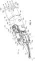
- FIG. 4is an enlarged isometric view of the distal end of the surgical tool 200 of FIG. 2 . More specifically, FIG. 4 depicts enlarged views of the end effector 204 and the wrist 206, with the end effector 204 in the unarticulated position.
- the wrist 206operatively couples the end effector 204 to the shaft 202.
- a shaft adaptermay be directly coupled to the wrist 206 and otherwise interpose the shaft 202 and the wrist 206. Accordingly, in at least one embodiment, the shaft 202 shown in FIG. 4 may be replaced with a shaft adapter.
- the shaft adaptermay be directly coupled to the wrist 206 at its distal end and directly coupled to the shaft 202 at its proximal end, without departing from the scope of the disclosure.
- the term "operatively couple"refers to a direct or indirect coupling engagement.
- the wrist 206may be operatively coupled to the shaft 202 either through a direct coupling engagement where the wrist 206 is directly coupled to the distal end of the shaft 202, or an indirect coupling engagement where a shaft adapter interposes the wrist 206 and the distal end of the shaft 202.
- the wrist 206To operatively couple the end effector 204 to the shaft 202, the wrist 206 includes a distal clevis 402a and a proximal clevis 402b.
- the end effector 204i.e., the jaws 210, 212
- the end effector 204is rotatably mounted to the distal clevis 402a at a first axle 404a
- the distal clevis 402ais rotatably mounted to the proximal clevis 402b at a second axle 404b
- the proximal clevis 402bis coupled to a distal end 406 of the shaft 202 (or alternatively a shaft adapter).
- the wrist 206provides a first pivot axis P 1 that extends through the first axle 404a and a second pivot axis P 2 that extends through the second axle 404b.
- the first pivot axis P 1is substantially perpendicular (orthogonal) to the longitudinal axis A 2 of the end effector 204
- the second pivot axis P 2is substantially perpendicular (orthogonal) to both the longitudinal axis A 2 and the first pivot axis P 1 . Movement about the first pivot axis P 1 provides "yaw” articulation of the end effector 204
- movement about the second pivot axis P 2provides "pitch” articulation of the end effector 204.
- the jaws 210, 212are mounted at the first pivot axis P 1 , thereby allowing the jaws 210, 212 to pivot relative to each other to open and close the end effector 204 or alternatively pivot in tandem to articulate the orientation of the end effector 204.
- a plurality of drive cablesextend longitudinally within a lumen 410 defined by the shaft 202 (and/or a shaft adapter) and pass through the wrist 206 to be operatively coupled to the end effector 204. While four drive cables 408a-d are depicted in FIG. 4 , more or less than four drive cables 408a-d may be included, without departing from the scope of the disclosure.
- the drive cables 408a-dform part of the cable driven motion system briefly described above, and may be referred to and otherwise characterized as cables, bands, lines, cords, wires, ropes, strings, twisted strings, elongate members, etc.
- the drive cables 408a-dcan be made from a variety of materials including, but not limited to, metal (e.g., tungsten, stainless steel, etc.) or a polymer.
- Example drive cablesare described in U.S. Patent Pub. No. 2015/0209965 entitled "Compact Robotic Wrist," and U.S. Patent Pub. No. 2015/0025549 entitled "Hyperdexterous Surgical System".
- the lumen 410can be a single lumen, as illustrated, or can alternatively comprise a plurality of independent lumens that each receive one or more of the drive cables 408a-d.
- the drive cables 408a-dextend proximally from the end effector 204 to the drive housing 208 ( FIG. 2 ) where they are operatively coupled to various actuation mechanisms or devices housed (contained) therein to facilitate longitudinal movement (translation) of the drive cables 408a-d within the lumen 410.
- Selective actuation of all or a portion of the drive cables 408a-dcauses the end effector 204 (e.g., one or both of the jaws 210, 212) to articulate (pivot) relative to the shaft 202. More specifically, selective actuation causes a corresponding drive cable 408a-d to translate longitudinally within the lumen 410 and thereby cause pivoting movement of the end effector 204.
- One or more drive cables 408a-dmay translate longitudinally to cause the end effector 204 to articulate (e.g., both of the jaws 210, 212 angled in a same direction), to cause the end effector 204 to open (e.g., one or both of the jaws 210, 212 move away from the other), or to cause the end effector 204 to close (e.g., one or both of the jaws 210, 212 move toward the other).
- Moving the drive cables 408a-dcan be accomplished in a variety of ways, such as by triggering an associated actuator or mechanism operatively coupled to or housed within the drive housing 208 ( FIG. 2 ).
- Moving a given drive cable 408a-dconstitutes applying tension (i.e., pull force) to the given drive cable 408a-d in a proximal direction, which causes the given drive cable 408a-d to translate and thereby cause the end effector 204 to move (articulate) relative to the shaft 202.
- the wrist 206includes a first plurality of pulleys 412a and a second plurality of pulleys 412b, each configured to interact with and redirect the drive cables 408a-d for engagement with the end effector 204.
- the first plurality of pulleys 412ais mounted to the proximal clevis 402b at the second axle 404b and the second plurality of pulleys 412b is also mounted to the proximal clevis 402b but at a third axle 404c located proximal to the second axle 404b.
- the first and second pluralities of pulleys 412a,bcooperatively redirect the drive cables 408a-d through an "S" shaped pathway before the drive cables 408a-d are operatively coupled to the end effector 204.
- one pair of drive cables 408a-dis operatively coupled to each jaw 210, 212 and configured to "antagonistically" operate the corresponding jaw 210, 212.
- the first and second drive cables 408a,bare coupled with a connector (not shown) at the first jaw 210
- the third and fourth drive cables 408c,dare coupled with a connector (not shown) at the second jaw 212. Consequently, actuation of the first drive cable 408a pivots the first jaw 210 about the first pivot axis P 1 toward the open position, and actuation of the second drive cable 408b pivots the first jaw 210 about the first pivot axis P 1 in the opposite direction and toward the closed position.
- actuation of the third drive cable 408cpivots the second jaw 212 about the first pivot axis P 1 toward the open position
- actuation of the fourth drive cable 408dpivots the second jaw 212 about the first pivot axis P 1 in the opposite direction and toward the closed position.
- the drive cables 408a-dmay be characterized or otherwise referred to as "antagonistic" cables that cooperatively (yet antagonistically) operate to cause relative or tandem movement of the first and second jaws 210, 212.
- the first drive cable 408aWhen the first drive cable 408a is actuated (moved), the second drive cable 408b naturally follows as coupled to the first drive cable 408a, and when the third drive cable 408c is actuated, the fourth drive cable 408d naturally follows as coupled to the third drive cable 408c, and vice versa.
- the end effector 204further includes a first jaw holder 414a and a second jaw holder 414b laterally offset from the first jaw holder 414a.
- the first jaw holder 414ais mounted to the first axle 404a and configured to receive and seat the first jaw 210 such that movement (rotation) of the first jaw holder 414a about the first pivot axis P 1 correspondingly moves (rotates) the first jaw 210.
- the first jaw holder 414amay also provide and otherwise define a first pulley 416a configured to receive and seat one or more drive cables, such as the first and second drive cables 408a,b to effect such movement (rotation).
- the second jaw holder 414bis similarly mounted to the first axle 404a and is configured to receive and seat the second jaw 212 such that movement (rotation) of the second jaw holder 414b about the first pivot axis P 1 correspondingly moves (rotates) the second jaw 212.
- the second jaw holder 414bmay also provide and otherwise define a second pulley 416b configured to receive and seat one or more drive cables, such as the third and fourth drive cables 408c,d, to effect such movement (rotation).
- jaw holderis intended to apply to a variety of types of end effectors having opposing jaws or blades that are movable relative to one another.
- the jaws 210, 212comprise opposing scissor blades of a surgical scissors end effector. Accordingly, the jaw holders 414a,b may alternately be referred to as “blade holders”. In other embodiments, however, the jaws 210, 212 may alternatively comprise opposing jaws used in a grasper end effector, or the like, and the term “jaw holder” similarly applies, without departing from the scope of the disclosure.
- the term “holder” in “jaw holder”may be replaced with "mount,” “drive member,” or "actuation member.”
- the surgical tool 200may also include an electrical conductor 418 that supplies electrical energy to the end effector 204, thereby converting the surgical tool 200 into an "electrosurgical instrument". Similar to the drive cables 408a-d, the electrical conductor 418 may extend longitudinally within the lumen 410. In some embodiments, the electrical conductor 418 and the power cable 214 ( FIG. 2 ) may comprise the same structure. In other embodiments, however, the electrical conductor 418 may be electrically coupled to the power cable 214, such as at the drive housing 208 ( FIG. 2 ). In yet other embodiments, the electrical conductor 418 may extend to the drive housing 208 where it is electrically coupled to an internal power source, such as batteries or fuel cells.
- an internal power sourcesuch as batteries or fuel cells.
- the electrical conductor 418may comprise a wire. In other embodiments, however, the electrical conductor 418 may comprise a rigid or semi-rigid shaft, rod, or strip (ribbon) made of a conductive material. In some embodiments, the electrical conductor 418 may be partially covered with an insulative covering 420 made of a non-conductive material.
- the insulative covering 420may comprise a plastic applied to the electrical conductor 418 via heat shrinking, but could alternatively be any other non-conductive material.
- the end effector 204may be configured for monopolar or bipolar operation, without departing from the scope of the disclosure.
- Electrical energyis transmitted by the electrical conductor 418 to the end effector 204, which acts as an active (or source) electrode.
- the electrical energy conducted through the electrical conductor 418may comprise radio frequency ("RF") energy exhibiting a frequency between about 100 kHz and 1 MHz.
- RF energycauses ultrasonic agitation or friction, in effect resistive heating, thereby increasing the temperature of target tissue.
- electrical energy supplied to the end effector 204is converted to heat and transferred to adjacent tissue to cut, cauterize, and/or coagulate the tissue (dependent upon the localized heating of the tissue), and thus may be particularly useful for sealing blood vessels or diffusing bleeding.
- Conventional electrosurgical instruments with an articulable wristwill commonly include an electrical conductor that terminates at the proximal clevis, and the structural interconnection between the distal and proximal clevises provides the required electrical energy to energize the end effector for operation. Terminating the electrical conductor at the proximal clevis allows the wrist to articulate without being obstructed by the electrical conductor. According to embodiments of the present disclosure, however, the electrical conductor 418 may extend through and otherwise bypass the proximal clevis 402b to terminate at the distal clevis 402a. Consequently, the electrical conductor 418 may deliver electrical energy to the distal clevis 402a, which may be transmitted to one or both of the jaws 210, 212 via conduction.
- a seal 422may be arranged at the interface between the proximal clevis 402b and the shaft 102 (or alternatively a shaft adapter).
- the seal 422may be configured to substantially isolate the interior of the shaft 102 from the end effector 204 by preventing the migration of contaminants and fluid therethrough in either direction.
- the electrical conductor 418may extend through the seal 422 and the proximal clevis 402b before terminating at the proximal end of the distal clevis 402a.
- the electrical conductor 418may provide or otherwise define an arcuate section 424 that allows the electrical conductor 418 to pass through the proximal clevis 402b without coming into contact with (engaging) some or all of the proximal clevis 402b, the second axle 404b, or the second plurality of pulleys 412b.
- the arcuate section 424may be omitted and the electrical conductor 418 may nonetheless be arranged to pass through the proximal clevis 402b without engaging these structural components.
- the electrical conductor 418terminates at a conductor adapter 426.
- the conductor adapter 426is made of a conductive material, such as a conductive metal, and configured to transmit (conduct) electrical energy from the electrical conductor 418 to the distal clevis 402a.
- the conductor adapter 426is assembled on the second axle 404b and interposes the first plurality of pulleys 412a and a proximal end of the distal clevis 402a.
- the first plurality of pulleys 412amay be made of a conductive material and may be suitably insulated from conducting electrical energy to the proximal clevis 402b.
- the first plurality of pulleys 412amay be made of any electrically insulating or non-conductive material to insulate the distal end of the proximal pulley 402b from the conductor adapter 426 and the electrical energy supplied to the distal clevis 402a.
- Suitable non-conductive materialsinclude, but are not limited to, a ceramic (e.g., zirconia, alumina, aluminum nitride, a silicate, silicon nitride, etc.), high temperature and high strength plastics, a thermoplastic or thermosetting polymer (e.g., polyether ether ketone, ULTEM TM , VESPEL ® , a polyphenylsulfone, a polysulfone, RADEL ® , a polyamide-imide, a polyimide, an epoxy, etc.), a composite material (e.g., fiberglass), hard rubber (e.g., ebonite), a metal with an insulative coating, or any combination thereof.
- a ceramice.g., zirconia, alumina, aluminum nitride, a silicate, silicon nitride, etc.
- high temperature and high strength plasticse.g., a thermoplastic or thermosetting polymer (e.
- the conductor adapter 426contacts or is otherwise in electrical engagement (communication) with the distal clevis 402a, which transmits (conducts) the electrical energy supplied by the electrical conductor 418 to at least one of the jaws 210, 212 to energize one or both of the jaws 210, 212 for operation.
- the electrical energyis conducted to the jaws 210, 212 through one or both of the first axle 404a and the jaw holders 414a,b, which may be made of a conductive material.
- the jaw holders 414a,bmay be made of a non-conductive material and the electrical energy may alternatively be conducted to one or both of the jaws 210, 212 through the first axle 404a.
- FIG. 5is an enlarged, partially exploded view of the end effector 204, according to one or more embodiments. More specifically, FIG. 5 shows the end effector 204, including the jaws 210, 212 and the corresponding jaw holders 414a,b, mounted to the distal clevis 402a at the first axle 404a. FIG. 5 also shows the electrical conductor 418 and a portion of the first plurality of pulleys 412a exploded or otherwise removed from the second axle 404b.
- the insulative covering 420extends to and terminates adjacent the conductor adapter 426.
- the insulative covering 420may prove advantageous in preventing electrical discharge or communication between the electrical conductor 418 and the proximal clevis 402b ( FIG. 4 ), the second axle 404b ( FIG. 4 ), or the second plurality of pulleys 412b ( FIG. 4 ).
- the insulative covering 420may terminate proximal to the proximal clevis 402b and nonetheless be arranged and/or designed to circumvent the proximal clevis 402b, the second axle 404b, and the second plurality of pulleys 412b so as to not inadvertently conduct electrical energy thereto.
- the distal clevis 402amay include a bushing 502 that may be seated and otherwise received within an aperture 504 defined in the proximal end of the distal clevis 402a.
- the bushing 502may be made of any of the non-conductive materials mentioned herein, but may alternatively be made of a conductive material and electrical energy may be transmitted to at least one of the jaws 210, 212 via at least a portion of the bushing 502.
- the bushing 502may be configured to receive the second axle 404b such that the second axle 404b is able to rotate relative to the bushing 502 during articulation of the end effector 204.
- the first plurality of pulleys 412a and the conductor adapter 426may be mounted to the bushing 502 and may be able to rotate relative to the bushing 502 during articulation of the end effector 204. Accordingly, the conductor adapter 426 may be able to slidingly engage and otherwise ride on the bushing 502 during operation. Consequently, and in contrast to prior electrosurgical instrument, the conductor adapter 426 does not terminate in a solder point or a crimp, but is instead able to "float" on the bushing 502 while providing electrical energy to the distal clevis 402a.
- the bushing 502provides and otherwise defines varying diameters configured to receive and seat the first plurality of pulleys 412a and the conductor adapter 426, but may alternatively comprise a constant diameter, without departing from the scope of the disclosure.
- the conductor adapter 426encompasses or otherwise comprises the distal end of the electrical conductor 418 and can assume any shape or design capable of facilitating electrical communication between the electrical conductor 418 and the distal clevis 402a.
- the conductor adapter 426comprises a stamped fisheye connector that defines or provides a continuous annular ring.
- the conductor adapter 426may be extended about the bushing 502 to allow the electrical conductor 418 to transmit electrical energy to the distal clevis 402a.
- the conductor adapter 426may alternatively comprise a discontinuous annular ring.
- the conductor adapter 426may alternatively terminate at a bent portion arranged to be in constant engagement with the bushing 502, without departing from the scope of the disclosure.
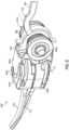
- FIG. 6is an enlarged isometric view of another embodiment of the end effector 204, according to one or more embodiments. Similar to FIG. 5 , FIG. 6 shows the end effector 204, including the jaws 210, 212 and the corresponding jaw holders 414a,b, mounted to the distal clevis 402a at the first axle 404a. Moreover, the first plurality of pulleys 412a is mounted to the second axle 404b for relative rotation.
- the electrical conductor 418extends to and terminates at or near the proximal end of the distal clevis 402a and the insulative covering 420 (shown in dashed lines) may extend along some or all of the length of the electrical conductor 418.
- the electrical conductor 418terminates in a conductor adapter 602 that is dissimilar to the conductor adapter 426 of FIGS. 4 and 5 .
- the conductor adapter 602may comprise an arcuate member or "saddle" arranged to engage a corresponding arcuate surface 604 of the distal clevis 402a.
- the arcuate surface 604is defined at the proximal end of the distal clevis 402a, but may alternatively be provided at any other location, without departing from the scope of the disclosure.
- the conductor adapter 602is made of a conductive material, such as a conductive metal (e.g., spring steel, beryllium copper, etc.), and configured to transmit (conduct) electrical energy from the electrical conductor 418 to the distal clevis 402a.
- a conductive metale.g., spring steel, beryllium copper, etc.
- the distal clevis 402amay articulate about the second pivot axis P 2 of the second axle 404b and the conductor adapter 602 may maintain engagement with the arcuate surface 604 during such movement.
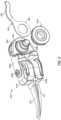
- FIG. 7is an enlarged isometric view of another embodiment of the end effector 204 and the wrist joint 206, according to one or more additional embodiments.
- the end effector 204including the jaws 210, 212 and the corresponding jaw holders 414a,b, is mounted to the distal clevis 402a at the first axle 404a, and the proximal clevis 402b is shown in phantom (dashed lines).
- the first and second pluralities of pulleys 412a,bare mounted to the second and third axles 404b,c, respectively, as generally described above.
- the electrical conductor 418extends through the seal 422 and terminates at the distal clevis 402a with a conductor adapter 702.
- the conductor adapter 702effectively couples the electrical conductor 418 to the distal clevis 402a such that electrical energy transmitted (conveyed) through the electrical conductor 418 is correspondingly transmitted (conveyed) to the distal clevis 402a during operation.
- the conductor adapter 702may comprise, for example, a type of connector such as, but not limited to, a crimp, a solder, a weld, or any combination thereof.
- the electrical conductor 418may include an insulative covering (not shown) that covers some or all of the electrical conductor 418 so that the electrical conductor 418 does not inadvertently conduct electrical energy to the proximal clevis 402b, the second axle 404b, or the second plurality of pulleys 412b.
- the electrical conductor 418may include or otherwise define a conductive spring member 704.
- the conductive spring member 704may comprise a flexible or elastic section of the electrical conductor 418 that allows the end effector 204 to articulate about the second pivot axis P 2 of the second axle 404b without losing electrical conductivity through the electrical conductor 418 to the distal clevis 402a.
- the conductive spring member 704may comprise a tightly wound coil of a conductive material, such as Nitinol wire or the like.
- the conductive spring member 704may comprise a flexible, but flat ribbon made of a conductive material. During operation, the conductive spring member 704 may be configured to flex or bend to allow the distal clevis 402a to articulate while still supplying electrical energy thereto.
- FIG. 8Ais an enlarged cross-sectional view of another embodiment of the end effector 204 and the wrist joint 206, according to one or more embodiments.
- the end effector 204including the jaws 210, 212 and the corresponding jaw holders 414a,b, is mounted to the distal clevis 402a at the first axle 404a.
- the first and second pluralities of pulleys 412a,bare mounted to the second and third axles 404b,c respectively, which are mounted to the proximal clevis 402b.
- the electrical conductor 418extends through the seal 422 and is coupled to a flex circuit 802 that extends through the proximal clevis 402b and terminates at the distal clevis 402a.
- the flex circuit 802effectively couples the electrical conductor 418 to the distal clevis 402a such that electrical energy transmitted (conveyed) through the electrical conductor 418 is correspondingly transmitted (conveyed) to the distal clevis 402a during operation.
- the flex circuit 802may comprise, for example, a polyimide flexible circuit, but may alternatively be made of polyether ether ketone (PEEK), without departing from the scope of the disclosure.
- FIG. 8Bis a schematic diagram of an example embodiment of the flex circuit 802 of FIG. 8A , according to one or more embodiments of the present disclosure.
- the flex circuit 802comprises a substantially flat film with a printed circuit 804 embedded therein.
- the printed circuit 804extends from and is communicably coupled to the electrical conductor 418 to convey electrical energy to the distal clevis 402a ( FIG. 8A ).
- the flex circuit 802may include a first aperture 806a configured to accommodate the second axle 404b and a second aperture 806b configured to accommodate the third axle 404c.
- the flex circuit 802may include an annular conductive pad 808 that places the printed circuit 804 into communication with the distal clevis 402a ( FIG. 8A ).
- the conductive pad 808may be made of silver, gold, or another conductive metal that forms an annular ring. Trapping the flex circuit 804 between the bushing 502 ( FIG. 5 ) and the first plurality of pulleys 412a ( FIG. 8A ) provides the electrical conduction path. Accordingly, the conductive pad 808 transfers the energy to the distal clevis 402a, which is able to convey the electrical energy to one or both of the jaws 210, 212.
Landscapes
- Health & Medical Sciences (AREA)
- Surgery (AREA)
- Engineering & Computer Science (AREA)
- Life Sciences & Earth Sciences (AREA)
- Biomedical Technology (AREA)
- Public Health (AREA)
- Nuclear Medicine, Radiotherapy & Molecular Imaging (AREA)
- Veterinary Medicine (AREA)
- General Health & Medical Sciences (AREA)
- Heart & Thoracic Surgery (AREA)
- Medical Informatics (AREA)
- Molecular Biology (AREA)
- Animal Behavior & Ethology (AREA)
- Physics & Mathematics (AREA)
- Otolaryngology (AREA)
- Plasma & Fusion (AREA)
- Robotics (AREA)
- Surgical Instruments (AREA)
Description
- Minimally invasive surgical (MIS) instruments are often preferred over traditional open surgical devices due to reduced post-operative recovery time and minimal scarring. Laparoscopic surgery is one type of MIS procedure in which one or more small incisions are formed in the abdomen of a patient and a trocar is inserted through the incision to form a pathway that provides access to the abdominal cavity. Through the trocar, a variety of instruments and surgical tools can be introduced into the abdominal cavity. The trocar also helps facilitate insufflation to elevate the abdominal wall above the organs. The instruments and tools introduced into the abdominal cavity via the trocar can be used to engage and/or treat tissue in a number of ways to achieve a diagnostic or therapeutic effect.
- Various robotic systems have recently been developed to assist in MIS procedures. Robotic systems can allow for more intuitive hand movements by maintaining natural eye-hand axis. Robotic systems can also allow for more degrees of freedom in movement by including a "wrist" joint that creates a more natural hand-like articulation. The instrument's end effector can be articulated (moved) using a cable driven motion system having one or more drive cables that extend through the wrist joint. A user (e.g., a surgeon) is able to remotely operate an instrument's end effector by grasping and manipulating in space one or more controllers that communicate with a tool driver coupled to the surgical instrument. User inputs are processed by a computer system incorporated into the robotic surgical system and the tool driver responds by actuating the cable driven motion system and, more particularly, the drive cables. Moving the drive cables articulates the end effector to desired positions and configurations.
- Some surgical tools, commonly referred to as electrosurgical instruments, are electrically energized. An electrosurgical instrument has a distally mounted end effector that includes one or more electrodes. When supplied with electrical energy, the end effector electrodes are able to generate heat sufficient to cut, cauterize, and/or seal tissue.
- Electrosurgical instruments can be configured for bipolar or monopolar operation. In bipolar operation, current is introduced into and returned from the tissue by active and return electrodes, respectively, of the end effector. Electrical current in bipolar operation is not required to travel long distances through the patient before returning to the return electrode. Consequently, the amount of electrical current required is minimal, which greatly reduces the risk of accidental ablations and/or burns. In addition, the two electrodes are closely spaced and generally within the surgeon's field of view, which further reduces the risk of unintended ablations and burns.
- In monopolar operation, current is introduced into the tissue by an active end effector electrode (alternately referred to as a "source electrode") and returned through a return electrode (e.g., a grounding pad) separately located on a patient's body. Monopolar electrosurgical instruments facilitate several surgical functions, such as cutting tissue, coagulating tissue to stop bleeding, or concurrently cutting and coagulating tissue. The surgeon can apply a current whenever the conductive portion of the instrument is in electrical proximity with the patient, permitting the surgeon to operate with monopolar electrosurgical instruments from many different angles.
- International patent publication
WO 2010/009223 A2 describes a cautery instrument which includes a brush-type contact providing a sliding electrical connection to a jaw of the instrument. To provide isolation, the jaws may have ends in cavities in a clevis made of an insulating material. Non-conducting drive cables can be attached to the jaws using high friction paths that prevent or resist slippage of the cables relative to the jaws. - Patent publication
US 2009/326530 A1 describes a vessel sealer has a stepped jaw that allows the jaw to have an overall shape and a width that provides desired strength, shape, and functionality while permitting a smaller raised portion to apply the sealing pressure. The smaller area applying the sealing pressure aims to allow an actuating mechanism to apply a clinically desired sealing pressure without exceeding the force or torque limitations of the actuating mechanism and aims to limit thermal spread during a sealing procedure. US Patent No. 6,840,938 describes a bipolar surgical instrument that includes opposing grips for engaging the tissue. A current is delivered from an electrosurgical power source to electrodes disposed on the grips to cauterize the tissue. In some examples, the positive and negative electrodes will be offset from each other to prevent shorting and to provide a thin line of coagulation heating to the gripped tissue. In some examples the electrodes are removably coupled to the grips through nonconductive sleeves. In some examples, the first electrode is disposed in a groove and the second electrode is disposed on a boss.WO2014/134034 discloses a surgical instrument which includes a drive member movable by a drive motor between a home position and an end of stroke. A mechanical stop is disposed at or near the end of stroke and is structured to increase resistance to movement of the drive member from a first position to a second position. A control system detects a current spike associated with the increased resistance and interrupts power to the drive motor.- According to the invention, there is provided a surgical tool end effector as defined in claim 1, and a surgical tool comprising such an end effector as defined in claim 4.
FIG. 1 is a block diagram of an example robotic surgical system that may incorporate some or all of the principles of the present disclosure.FIG. 2 is an isometric view of an example surgical tool that may incorporate some or all of the principles of the present disclosure.FIG. 3 illustrates potential degrees of freedom in which the wrist ofFIG. 1 may be able to articulate (pivot).FIG. 4 is an enlarged isometric view of the distal end of the surgical tool ofFIG. 1 .FIG. 5 is an enlarged, partially exploded view of the end effector ofFIG. 4 .FIG. 6 is an enlarged isometric view of another embodiment of the end effector ofFIG. 4 .FIG. 7 is an enlarged isometric view of another embodiment of the end effector and the wrist joint ofFIG. 4 .FIG. 8A is an enlarged cross-sectional view of another embodiment of the end effector and the wrist joint ofFIG. 4 FIG. 8B is a schematic diagram of an example embodiment of the flex circuit ofFIG. 8A .- The present disclosure is related to robotic surgical systems and, more particularly, to electrosurgical instruments having an end effector with a wrist and an electrical conductor that terminates at a distal clevis of the wrist.
- Embodiments discussed herein describe electrosurgical instruments that use electrical energy to perform a variety of surgical procedures. End effectors that may be used with the electrosurgical instruments include a distal clevis, first and second jaws rotatably mounted to the distal clevis at a first axle, and a proximal clevis rotatably coupled to the distal clevis at a second axle. An electrical conductor may extend through the proximal clevis and terminates at the distal clevis to supply electrical energy to at least one of the first and second jaws. Accordingly, the electrical conductor may be configured to supply electrical energy directly to the distal clevis and otherwise bypass energizing the proximal clevis.
FIG. 1 is a block diagram of an example roboticsurgical system 100 that may incorporate some or all of the principles of the present disclosure. As illustrated, thesystem 100 can include at least onemaster controller 102a and at least onearm cart 104. Thearm cart 104 may be mechanically and/or electrically coupled to a robotic manipulator and, more particularly, to one or morerobotic arms 106 or "tool drivers". Eachrobotic arm 106 may include and otherwise provide a location for mounting one or more surgical tools orinstruments 108 for performing various surgical tasks on apatient 110. Operation of therobotic arms 106 andinstruments 108 may be directed by aclinician 112a (e.g., a surgeon) from themaster controller 102a.- In some embodiments, a
second master controller 102b (shown in dashed lines) operated by asecond clinician 112b may also direct operation of therobotic arms 106 andinstruments 108 in conjunction with thefirst clinician 112a. In such embodiments, for example, eachclinician 102a,b may control differentrobotic arms 106 or, in some cases, complete control of therobotic arms 106 may be passed between theclinicians 102a,b. In some embodiments, additional arm carts (not shown) having additional robotic arms (not shown) may be utilized during surgery on apatient 110, and these additional robotic arms may be controlled by one or more of themaster controllers 102a,b. - The
arm cart 104 and themaster controllers 102a,b may be in communication with one another via acommunications link 114, which may be any type of wired or wireless telecommunications means configured to carry a variety of communication signals (e.g., electrical, optical, infrared, etc.) according to any communications protocol. - The
master controllers 102a,b generally include one or more physical controllers that can be grasped by theclinicians 112a,b and manipulated in space while the surgeon views the procedure via a stereo display. The physical controllers generally comprise manual input devices movable in multiple degrees of freedom, and which often include an actuatable handle for actuating the surgical instrument(s) 108, for example, for opening and closing opposing jaws, applying an electrical potential (current) to an electrode, or the like. Themaster controllers 102a,b can also include an optional feedback meter viewable by theclinicians 112a,b via a display to provide a visual indication of various surgical instrument metrics, such as the amount of force being applied to the surgical instrument (i.e., a cutting instrument or dynamic clamping member). - Example implementations of robotic surgical systems, such as the
system 100, are disclosed inU.S. Patent No. 7,524,320 . The various particularities of such devices will not be described in detail herein beyond that which may be necessary to understand the various embodiments and forms of the various embodiments of robotic surgery apparatus, systems, and methods disclosed herein. FIG. 2 is side view of an examplesurgical tool 200 that may incorporate some or all of the principles of the present disclosure. Thesurgical tool 200 may be the same as or similar to the surgical instrument(s) 108 ofFIG. 1 and, therefore, may be used in conjunction with a robotic surgical system, such as the roboticsurgical system 100 ofFIG. 1 . Accordingly, thesurgical tool 200 may be designed to be releasably coupled to a tool driver included in the roboticsurgical system 100. In other embodiments, however, thesurgical tool 200 may be adapted for use in a manual or hand-operated manner, without departing from the scope of the disclosure.- As illustrated, the
surgical tool 200 includes anelongate shaft 202, anend effector 204, a wrist 206 (alternately referred to as a "wrist joint") that couples theend effector 204 to the distal end of theshaft 202, and adrive housing 208 coupled to the proximal end of theshaft 202. In applications where the surgical tool is used in conjunction with a robotic surgical system (e.g., the roboticsurgical system 100 ofFIG. 1 ), thedrive housing 208 can include coupling features that releasably couple thesurgical tool 200 to the robotic surgical system. - The terms "proximal" and "distal" are defined herein relative to a robotic surgical system having an interface configured to mechanically and electrically couple the surgical tool 200 (e.g., the housing 208) to a robotic manipulator. The term "proximal" refers to the position of an element closer to the robotic manipulator and the term "distal" refers to the position of an element closer to the
end effector 204 and thus further away from the robotic manipulator. Alternatively, in manual or hand-operated applications, the terms "proximal" and "distal" are defined herein relative to a user, such as a surgeon or clinician. The term "proximal" refers to the position of an element closer to the user and the term "distal" refers to the position of an element closer to theend effector 204 and thus further away from the user. Moreover, the use of directional terms such as above, below, upper, lower, upward, downward, left, right, and the like are used in relation to the illustrative embodiments as they are depicted in the figures, the upward or upper direction being toward the top of the corresponding figure and the downward or lower direction being toward the bottom of the corresponding figure. - During use of the
surgical tool 200, theend effector 204 is configured to move (pivot) relative to theshaft 202 at thewrist 206 to position theend effector 204 at desired orientations and locations relative to a surgical site. Thehousing 208 includes (contains) various mechanisms designed to control operation of various features associated with the end effector 204 (e.g., clamping, firing, rotation, articulation, energy delivery, etc.). In at least some embodiments, theshaft 202, and hence theend effector 204 coupled thereto, is configured to rotate about a longitudinal axis A1 of theshaft 202. In such embodiments, at least one of the mechanisms included (housed) in thehousing 208 is configured to control rotational movement of theshaft 202 about the longitudinal axis A1. - The
surgical tool 200 can have any of a variety of configurations capable of performing at least one surgical function. For example, thesurgical tool 200 may include, but is not limited to, forceps, a grasper, a needle driver, scissors, an electrocautery tool, a stapler, a clip applier, a hook, a spatula, a suction tool, an irrigation tool, an imaging device (e.g., an endoscope or ultrasonic probe), or any combination thereof. In some embodiments, thesurgical tool 200 may be configured to apply energy to tissue, such as radio frequency (RF) energy. - The
shaft 202 is an elongate member extending distally from thehousing 208 and has at least one lumen extending therethrough along its axial length. In some embodiments, theshaft 202 may be fixed to thehousing 208, but could alternatively be rotatably mounted to thehousing 208 to allow theshaft 202 to rotate about the longitudinal axis A1. In yet other embodiments, theshaft 202 may be releasably coupled to thehousing 208, which may allow asingle housing 208 to be adaptable to various shafts having different end effectors. - The
end effector 204 can have a variety of sizes, shapes, and configurations. In the illustrated embodiment, theend effector 204 comprises surgical scissors that include opposingjaws 210, 212 (alternately referred to as "blades") configured to move (articulate) between open and closed positions. As will be appreciated, however, the opposingjaws jaws wrist 206 to articulate theend effector 204 between the open and closed positions. FIG. 3 illustrates the potential degrees of freedom in which thewrist 206 may be able to articulate (pivot). Thewrist 206 can have any of a variety of configurations. In general, thewrist 206 comprises a joint configured to allow pivoting movement of theend effector 204 relative to theshaft 202. The degrees of freedom of thewrist 206 are represented by three translational variables (i.e., surge, heave, and sway), and by three rotational variables (i.e., Euler angles or roll, pitch, and yaw). The translational and rotational variables describe the position and orientation of a component of a surgical system (e.g., the end effector 204) with respect to a given reference Cartesian frame. As depicted inFIG. 3 , "surge" refers to forward and backward translational movement, "heave" refers to translational movement up and down, and "sway" refers to translational movement left and right. With regard to the rotational terms, "roll" refers to tilting about an axis, "pitch" refers to tilting forward and backward, and "yaw" refers to turning left and right.- The pivoting motion can include pitch movement about a first axis of the wrist 206 (e.g., X-axis), yaw movement about a second axis of the wrist 206 (e.g., Y-axis), and combinations thereof to allow for 360° rotational movement of the
end effector 204 about thewrist 206. In other applications, the pivoting motion can be limited to movement in a single plane, e.g., only pitch movement about the first axis of thewrist 206 or only yaw movement about the second axis of thewrist 206, such that theend effector 204 moves only in a single plane. - Referring again to
FIG. 2 , thesurgical tool 200 may also include a plurality of drive cables (obscured inFIG. 2 ) that form part of a cable driven motion system configured to facilitate movement and articulation of theend effector 204 relative to theshaft 202. Moving (actuating) at least some of the drive cables moves theend effector 204 between an unarticulated position and an articulated position. Theend effector 204 is depicted inFIG. 2 in the unarticulated position where a longitudinal axis A2 of theend effector 204 is substantially aligned with the longitudinal axis A1 of theshaft 202, such that theend effector 204 is at a substantially zero angle relative to theshaft 202. Due to factors such as manufacturing tolerance and precision of measurement devices, theend effector 204 may not be at a precise zero angle relative to theshaft 202 in the unarticulated position, but nevertheless be considered "substantially aligned" thereto. In the articulated position, the longitudinal axes A1, A2 would be angularly offset from each other such that theend effector 204 is at a non-zero angle relative to theshaft 202. - Still referring to
FIG. 2 , thesurgical tool 200 may be supplied with electrical power (current) via apower cable 214 coupled to thehousing 208. In other embodiments, thepower cable 214 may be omitted and electrical power may be supplied to thesurgical tool 200 via an internal power source, such as one or more batteries or fuel cells. For purposes of the present description, however, it will be assumed that electrical power is provided to thesurgical tool 200 via thepower cable 214. In either case, thesurgical tool 200 may alternatively be characterized and otherwise referred to herein as an "electrosurgical instrument" capable of providing electrical energy to theend effector 204. - The
power cable 214 may place thesurgical tool 200 in communication with agenerator 216 that supplies energy, such as electrical energy (e.g., radio frequency energy), ultrasonic energy, microwave energy, heat energy, or any combination thereof, to thesurgical tool 200 and, more particularly, to theend effector 204. Accordingly, thegenerator 216 may comprise a radio frequency (RF) source, an ultrasonic source, a direct current source, and/or any other suitable type of electrical energy source that may be activated independently or simultaneously. - In applications where the
surgical tool 200 is configured for bipolar operation, thepower cable 214 will include a supply conductor and a return conductor. Current can be supplied from thegenerator 216 to an active (or source) electrode located at theend effector 204 via the supply conductor, and current can flow back to thegenerator 216 via a return conductor located at theend effector 204 via the return conductor. In the case of a bipolar grasper with opposing jaws, for example, the jaws serve as the electrodes where the proximal end of the jaws are isolated from one another and the inner surface of the jaws (i.e., the area of the jaws that grasp tissue) apply the current in a controlled path through the tissue. In applications where thesurgical tool 200 is configured for monopolar operation, thegenerator 216 transmits current through a supply conductor to an active electrode located at theend effector 204, and current is returned (dissipated) through a return electrode (e.g., a grounding pad) separately coupled to a patient's body. FIG. 4 is an enlarged isometric view of the distal end of thesurgical tool 200 ofFIG. 2 . More specifically,FIG. 4 depicts enlarged views of theend effector 204 and thewrist 206, with theend effector 204 in the unarticulated position. Thewrist 206 operatively couples theend effector 204 to theshaft 202. In some embodiments, however, a shaft adapter may be directly coupled to thewrist 206 and otherwise interpose theshaft 202 and thewrist 206. Accordingly, in at least one embodiment, theshaft 202 shown inFIG. 4 may be replaced with a shaft adapter. In such embodiments, the shaft adapter may be directly coupled to thewrist 206 at its distal end and directly coupled to theshaft 202 at its proximal end, without departing from the scope of the disclosure. As used herein, the term "operatively couple" refers to a direct or indirect coupling engagement. Accordingly, thewrist 206 may be operatively coupled to theshaft 202 either through a direct coupling engagement where thewrist 206 is directly coupled to the distal end of theshaft 202, or an indirect coupling engagement where a shaft adapter interposes thewrist 206 and the distal end of theshaft 202.- To operatively couple the
end effector 204 to theshaft 202, thewrist 206 includes adistal clevis 402a and aproximal clevis 402b. The end effector 204 (i.e., thejaws 210, 212) is rotatably mounted to thedistal clevis 402a at afirst axle 404a, thedistal clevis 402a is rotatably mounted to theproximal clevis 402b at asecond axle 404b, and theproximal clevis 402b is coupled to adistal end 406 of the shaft 202 (or alternatively a shaft adapter). - The
wrist 206 provides a first pivot axis P1 that extends through thefirst axle 404a and a second pivot axis P2 that extends through thesecond axle 404b. The first pivot axis P1 is substantially perpendicular (orthogonal) to the longitudinal axis A2 of theend effector 204, and the second pivot axis P2 is substantially perpendicular (orthogonal) to both the longitudinal axis A2 and the first pivot axis P1. Movement about the first pivot axis P1 provides "yaw" articulation of theend effector 204, and movement about the second pivot axis P2 provides "pitch" articulation of theend effector 204. In the illustrated embodiment, thejaws jaws end effector 204 or alternatively pivot in tandem to articulate the orientation of theend effector 204. - A plurality of drive cables, shown as
drive cables lumen 410 defined by the shaft 202 (and/or a shaft adapter) and pass through thewrist 206 to be operatively coupled to theend effector 204. While fourdrive cables 408a-d are depicted inFIG. 4 , more or less than fourdrive cables 408a-d may be included, without departing from the scope of the disclosure. - The
drive cables 408a-d form part of the cable driven motion system briefly described above, and may be referred to and otherwise characterized as cables, bands, lines, cords, wires, ropes, strings, twisted strings, elongate members, etc. Thedrive cables 408a-d can be made from a variety of materials including, but not limited to, metal (e.g., tungsten, stainless steel, etc.) or a polymer. Example drive cables are described inU.S. Patent Pub. No. 2015/0209965 entitled "Compact Robotic Wrist," andU.S. Patent Pub. No. 2015/0025549 entitled "Hyperdexterous Surgical System". Thelumen 410 can be a single lumen, as illustrated, or can alternatively comprise a plurality of independent lumens that each receive one or more of thedrive cables 408a-d. - The
drive cables 408a-d extend proximally from theend effector 204 to the drive housing 208 (FIG. 2 ) where they are operatively coupled to various actuation mechanisms or devices housed (contained) therein to facilitate longitudinal movement (translation) of thedrive cables 408a-d within thelumen 410. Selective actuation of all or a portion of thedrive cables 408a-d causes the end effector 204 (e.g., one or both of thejaws 210, 212) to articulate (pivot) relative to theshaft 202. More specifically, selective actuation causes acorresponding drive cable 408a-d to translate longitudinally within thelumen 410 and thereby cause pivoting movement of theend effector 204. One ormore drive cables 408a-d, for example, may translate longitudinally to cause theend effector 204 to articulate (e.g., both of thejaws end effector 204 to open (e.g., one or both of thejaws end effector 204 to close (e.g., one or both of thejaws - Moving the
drive cables 408a-d can be accomplished in a variety of ways, such as by triggering an associated actuator or mechanism operatively coupled to or housed within the drive housing 208 (FIG. 2 ). Moving a givendrive cable 408a-d constitutes applying tension (i.e., pull force) to the givendrive cable 408a-d in a proximal direction, which causes the givendrive cable 408a-d to translate and thereby cause theend effector 204 to move (articulate) relative to theshaft 202. - The
wrist 206 includes a first plurality ofpulleys 412a and a second plurality ofpulleys 412b, each configured to interact with and redirect thedrive cables 408a-d for engagement with theend effector 204. The first plurality ofpulleys 412a is mounted to theproximal clevis 402b at thesecond axle 404b and the second plurality ofpulleys 412b is also mounted to theproximal clevis 402b but at athird axle 404c located proximal to thesecond axle 404b. The first and second pluralities of pulleys 412a,b cooperatively redirect thedrive cables 408a-d through an "S" shaped pathway before thedrive cables 408a-d are operatively coupled to theend effector 204. - In at least one embodiment, one pair of
drive cables 408a-d is operatively coupled to eachjaw corresponding jaw second drive cables 408a,b are coupled with a connector (not shown) at thefirst jaw 210, and the third andfourth drive cables 408c,d are coupled with a connector (not shown) at thesecond jaw 212. Consequently, actuation of thefirst drive cable 408a pivots thefirst jaw 210 about the first pivot axis P1 toward the open position, and actuation of thesecond drive cable 408b pivots thefirst jaw 210 about the first pivot axis P1 in the opposite direction and toward the closed position. Similarly, actuation of thethird drive cable 408c pivots thesecond jaw 212 about the first pivot axis P1 toward the open position, while actuation of thefourth drive cable 408d pivots thesecond jaw 212 about the first pivot axis P1 in the opposite direction and toward the closed position. - Accordingly, the
drive cables 408a-d may be characterized or otherwise referred to as "antagonistic" cables that cooperatively (yet antagonistically) operate to cause relative or tandem movement of the first andsecond jaws first drive cable 408a is actuated (moved), thesecond drive cable 408b naturally follows as coupled to thefirst drive cable 408a, and when thethird drive cable 408c is actuated, thefourth drive cable 408d naturally follows as coupled to thethird drive cable 408c, and vice versa. - The
end effector 204 further includes afirst jaw holder 414a and asecond jaw holder 414b laterally offset from thefirst jaw holder 414a. Thefirst jaw holder 414a is mounted to thefirst axle 404a and configured to receive and seat thefirst jaw 210 such that movement (rotation) of thefirst jaw holder 414a about the first pivot axis P1 correspondingly moves (rotates) thefirst jaw 210. Thefirst jaw holder 414a may also provide and otherwise define afirst pulley 416a configured to receive and seat one or more drive cables, such as the first andsecond drive cables 408a,b to effect such movement (rotation). Thesecond jaw holder 414b is similarly mounted to thefirst axle 404a and is configured to receive and seat thesecond jaw 212 such that movement (rotation) of thesecond jaw holder 414b about the first pivot axis P1 correspondingly moves (rotates) thesecond jaw 212. Thesecond jaw holder 414b may also provide and otherwise define asecond pulley 416b configured to receive and seat one or more drive cables, such as the third andfourth drive cables 408c,d, to effect such movement (rotation). - The term "jaw holder," as used herein, is intended to apply to a variety of types of end effectors having opposing jaws or blades that are movable relative to one another. In the illustrated embodiment, the
jaws jaw holders 414a,b may alternately be referred to as "blade holders". In other embodiments, however, thejaws - The
surgical tool 200 may also include anelectrical conductor 418 that supplies electrical energy to theend effector 204, thereby converting thesurgical tool 200 into an "electrosurgical instrument". Similar to thedrive cables 408a-d, theelectrical conductor 418 may extend longitudinally within thelumen 410. In some embodiments, theelectrical conductor 418 and the power cable 214 (FIG. 2 ) may comprise the same structure. In other embodiments, however, theelectrical conductor 418 may be electrically coupled to thepower cable 214, such as at the drive housing 208 (FIG. 2 ). In yet other embodiments, theelectrical conductor 418 may extend to thedrive housing 208 where it is electrically coupled to an internal power source, such as batteries or fuel cells. - In some embodiments, the
electrical conductor 418 may comprise a wire. In other embodiments, however, theelectrical conductor 418 may comprise a rigid or semi-rigid shaft, rod, or strip (ribbon) made of a conductive material. In some embodiments, theelectrical conductor 418 may be partially covered with an insulative covering 420 made of a non-conductive material. The insulative covering 420, for example, may comprise a plastic applied to theelectrical conductor 418 via heat shrinking, but could alternatively be any other non-conductive material. - In operation, the
end effector 204 may be configured for monopolar or bipolar operation, without departing from the scope of the disclosure. Electrical energy is transmitted by theelectrical conductor 418 to theend effector 204, which acts as an active (or source) electrode. In at least one embodiment, the electrical energy conducted through theelectrical conductor 418 may comprise radio frequency ("RF") energy exhibiting a frequency between about 100 kHz and 1 MHz. The RF energy causes ultrasonic agitation or friction, in effect resistive heating, thereby increasing the temperature of target tissue. Accordingly, electrical energy supplied to theend effector 204 is converted to heat and transferred to adjacent tissue to cut, cauterize, and/or coagulate the tissue (dependent upon the localized heating of the tissue), and thus may be particularly useful for sealing blood vessels or diffusing bleeding. - Conventional electrosurgical instruments with an articulable wrist will commonly include an electrical conductor that terminates at the proximal clevis, and the structural interconnection between the distal and proximal clevises provides the required electrical energy to energize the end effector for operation. Terminating the electrical conductor at the proximal clevis allows the wrist to articulate without being obstructed by the electrical conductor. According to embodiments of the present disclosure, however, the
electrical conductor 418 may extend through and otherwise bypass theproximal clevis 402b to terminate at thedistal clevis 402a. Consequently, theelectrical conductor 418 may deliver electrical energy to thedistal clevis 402a, which may be transmitted to one or both of thejaws - As illustrated, a seal 422 (shown in dashed lines) may be arranged at the interface between the
proximal clevis 402b and the shaft 102 (or alternatively a shaft adapter). Theseal 422 may be configured to substantially isolate the interior of the shaft 102 from theend effector 204 by preventing the migration of contaminants and fluid therethrough in either direction. As illustrated in dashed lines, theelectrical conductor 418 may extend through theseal 422 and theproximal clevis 402b before terminating at the proximal end of thedistal clevis 402a. - In at least one embodiment, the
electrical conductor 418 may provide or otherwise define anarcuate section 424 that allows theelectrical conductor 418 to pass through theproximal clevis 402b without coming into contact with (engaging) some or all of theproximal clevis 402b, thesecond axle 404b, or the second plurality ofpulleys 412b. In other embodiments, thearcuate section 424 may be omitted and theelectrical conductor 418 may nonetheless be arranged to pass through theproximal clevis 402b without engaging these structural components. - As illustrated, the
electrical conductor 418 terminates at aconductor adapter 426. Theconductor adapter 426 is made of a conductive material, such as a conductive metal, and configured to transmit (conduct) electrical energy from theelectrical conductor 418 to thedistal clevis 402a. In the illustrated embodiment, theconductor adapter 426 is assembled on thesecond axle 404b and interposes the first plurality ofpulleys 412a and a proximal end of thedistal clevis 402a. The first plurality ofpulleys 412a may be made of a conductive material and may be suitably insulated from conducting electrical energy to theproximal clevis 402b. In other embodiments, however, the first plurality ofpulleys 412a may be made of any electrically insulating or non-conductive material to insulate the distal end of theproximal pulley 402b from theconductor adapter 426 and the electrical energy supplied to thedistal clevis 402a. Suitable non-conductive materials include, but are not limited to, a ceramic (e.g., zirconia, alumina, aluminum nitride, a silicate, silicon nitride, etc.), high temperature and high strength plastics, a thermoplastic or thermosetting polymer (e.g., polyether ether ketone, ULTEM™, VESPEL®, a polyphenylsulfone, a polysulfone, RADEL®, a polyamide-imide, a polyimide, an epoxy, etc.), a composite material (e.g., fiberglass), hard rubber (e.g., ebonite), a metal with an insulative coating, or any combination thereof. - The
conductor adapter 426 contacts or is otherwise in electrical engagement (communication) with thedistal clevis 402a, which transmits (conducts) the electrical energy supplied by theelectrical conductor 418 to at least one of thejaws jaws jaws first axle 404a and thejaw holders 414a,b, which may be made of a conductive material. In other embodiments, however, thejaw holders 414a,b may be made of a non-conductive material and the electrical energy may alternatively be conducted to one or both of thejaws first axle 404a. FIG. 5 is an enlarged, partially exploded view of theend effector 204, according to one or more embodiments. More specifically,FIG. 5 shows theend effector 204, including thejaws corresponding jaw holders 414a,b, mounted to thedistal clevis 402a at thefirst axle 404a.FIG. 5 also shows theelectrical conductor 418 and a portion of the first plurality ofpulleys 412a exploded or otherwise removed from thesecond axle 404b.- In the illustrated embodiment, the insulative covering 420 (shown in dashed lines) extends to and terminates adjacent the
conductor adapter 426. In such embodiments, the insulative covering 420 may prove advantageous in preventing electrical discharge or communication between theelectrical conductor 418 and theproximal clevis 402b (FIG. 4 ), thesecond axle 404b (FIG. 4 ), or the second plurality ofpulleys 412b (FIG. 4 ). In other embodiments, however, the insulative covering 420 may terminate proximal to theproximal clevis 402b and nonetheless be arranged and/or designed to circumvent theproximal clevis 402b, thesecond axle 404b, and the second plurality ofpulleys 412b so as to not inadvertently conduct electrical energy thereto. - As illustrated, the
distal clevis 402a may include abushing 502 that may be seated and otherwise received within anaperture 504 defined in the proximal end of thedistal clevis 402a. In some embodiments, thebushing 502 may be made of any of the non-conductive materials mentioned herein, but may alternatively be made of a conductive material and electrical energy may be transmitted to at least one of thejaws bushing 502. Thebushing 502 may be configured to receive thesecond axle 404b such that thesecond axle 404b is able to rotate relative to thebushing 502 during articulation of theend effector 204. - The first plurality of
pulleys 412a and theconductor adapter 426 may be mounted to thebushing 502 and may be able to rotate relative to thebushing 502 during articulation of theend effector 204. Accordingly, theconductor adapter 426 may be able to slidingly engage and otherwise ride on thebushing 502 during operation. Consequently, and in contrast to prior electrosurgical instrument, theconductor adapter 426 does not terminate in a solder point or a crimp, but is instead able to "float" on thebushing 502 while providing electrical energy to thedistal clevis 402a. In the illustrated embodiment, thebushing 502 provides and otherwise defines varying diameters configured to receive and seat the first plurality ofpulleys 412a and theconductor adapter 426, but may alternatively comprise a constant diameter, without departing from the scope of the disclosure. - The
conductor adapter 426 encompasses or otherwise comprises the distal end of theelectrical conductor 418 and can assume any shape or design capable of facilitating electrical communication between theelectrical conductor 418 and thedistal clevis 402a. In the illustrated embodiment, for example, theconductor adapter 426 comprises a stamped fisheye connector that defines or provides a continuous annular ring. Theconductor adapter 426 may be extended about thebushing 502 to allow theelectrical conductor 418 to transmit electrical energy to thedistal clevis 402a. In other embodiments, however, theconductor adapter 426 may alternatively comprise a discontinuous annular ring. In yet other embodiments, theconductor adapter 426 may alternatively terminate at a bent portion arranged to be in constant engagement with thebushing 502, without departing from the scope of the disclosure. FIG. 6 is an enlarged isometric view of another embodiment of theend effector 204, according to one or more embodiments. Similar toFIG. 5 ,FIG. 6 shows theend effector 204, including thejaws corresponding jaw holders 414a,b, mounted to thedistal clevis 402a at thefirst axle 404a. Moreover, the first plurality ofpulleys 412a is mounted to thesecond axle 404b for relative rotation. In addition, theelectrical conductor 418 extends to and terminates at or near the proximal end of thedistal clevis 402a and the insulative covering 420 (shown in dashed lines) may extend along some or all of the length of theelectrical conductor 418.- Unlike the embodiment of
FIG. 5 , however, theelectrical conductor 418 terminates in aconductor adapter 602 that is dissimilar to theconductor adapter 426 ofFIGS. 4 and5 . More specifically, theconductor adapter 602 may comprise an arcuate member or "saddle" arranged to engage a correspondingarcuate surface 604 of thedistal clevis 402a. In the illustrated embodiment, thearcuate surface 604 is defined at the proximal end of thedistal clevis 402a, but may alternatively be provided at any other location, without departing from the scope of the disclosure. Theconductor adapter 602 is made of a conductive material, such as a conductive metal (e.g., spring steel, beryllium copper, etc.), and configured to transmit (conduct) electrical energy from theelectrical conductor 418 to thedistal clevis 402a. In example operation, thedistal clevis 402a may articulate about the second pivot axis P2 of thesecond axle 404b and theconductor adapter 602 may maintain engagement with thearcuate surface 604 during such movement. FIG. 7 is an enlarged isometric view of another embodiment of theend effector 204 and the wrist joint 206, according to one or more additional embodiments. In the illustrated embodiment, theend effector 204, including thejaws corresponding jaw holders 414a,b, is mounted to thedistal clevis 402a at thefirst axle 404a, and theproximal clevis 402b is shown in phantom (dashed lines). Moreover, the first and second pluralities of pulleys 412a,b are mounted to the second andthird axles 404b,c, respectively, as generally described above.- In the illustrated embodiment, the
electrical conductor 418 extends through theseal 422 and terminates at thedistal clevis 402a with aconductor adapter 702. Theconductor adapter 702 effectively couples theelectrical conductor 418 to thedistal clevis 402a such that electrical energy transmitted (conveyed) through theelectrical conductor 418 is correspondingly transmitted (conveyed) to thedistal clevis 402a during operation. Theconductor adapter 702 may comprise, for example, a type of connector such as, but not limited to, a crimp, a solder, a weld, or any combination thereof. In some embodiments, theelectrical conductor 418 may include an insulative covering (not shown) that covers some or all of theelectrical conductor 418 so that theelectrical conductor 418 does not inadvertently conduct electrical energy to theproximal clevis 402b, thesecond axle 404b, or the second plurality ofpulleys 412b. - In some embodiments, at least a portion of the
electrical conductor 418 may include or otherwise define aconductive spring member 704. Theconductive spring member 704 may comprise a flexible or elastic section of theelectrical conductor 418 that allows theend effector 204 to articulate about the second pivot axis P2 of thesecond axle 404b without losing electrical conductivity through theelectrical conductor 418 to thedistal clevis 402a. In some embodiments, theconductive spring member 704 may comprise a tightly wound coil of a conductive material, such as Nitinol wire or the like. In other embodiments, theconductive spring member 704 may comprise a flexible, but flat ribbon made of a conductive material. During operation, theconductive spring member 704 may be configured to flex or bend to allow thedistal clevis 402a to articulate while still supplying electrical energy thereto. FIG. 8A is an enlarged cross-sectional view of another embodiment of theend effector 204 and the wrist joint 206, according to one or more embodiments. In the illustrated embodiment, theend effector 204, including thejaws corresponding jaw holders 414a,b, is mounted to thedistal clevis 402a at thefirst axle 404a. Moreover, the first and second pluralities of pulleys 412a,b are mounted to the second andthird axles 404b,c respectively, which are mounted to theproximal clevis 402b.- In the illustrated embodiment, the
electrical conductor 418 extends through theseal 422 and is coupled to aflex circuit 802 that extends through theproximal clevis 402b and terminates at thedistal clevis 402a. Theflex circuit 802 effectively couples theelectrical conductor 418 to thedistal clevis 402a such that electrical energy transmitted (conveyed) through theelectrical conductor 418 is correspondingly transmitted (conveyed) to thedistal clevis 402a during operation. Theflex circuit 802 may comprise, for example, a polyimide flexible circuit, but may alternatively be made of polyether ether ketone (PEEK), without departing from the scope of the disclosure. FIG. 8B is a schematic diagram of an example embodiment of theflex circuit 802 ofFIG. 8A , according to one or more embodiments of the present disclosure. As illustrated, theflex circuit 802 comprises a substantially flat film with a printedcircuit 804 embedded therein. The printedcircuit 804 extends from and is communicably coupled to theelectrical conductor 418 to convey electrical energy to thedistal clevis 402a (FIG. 8A ).- The
flex circuit 802 may include afirst aperture 806a configured to accommodate thesecond axle 404b and asecond aperture 806b configured to accommodate thethird axle 404c. At thefirst aperture 806a, theflex circuit 802 may include an annularconductive pad 808 that places the printedcircuit 804 into communication with thedistal clevis 402a (FIG. 8A ). Theconductive pad 808 may be made of silver, gold, or another conductive metal that forms an annular ring. Trapping theflex circuit 804 between the bushing 502 (FIG. 5 ) and the first plurality of pulleys 412a (FIG. 8A ) provides the electrical conduction path. Accordingly, theconductive pad 808 transfers the energy to thedistal clevis 402a, which is able to convey the electrical energy to one or both of thejaws
Claims (13)
- A surgical tool end effector, comprising:a distal clevis (402a);first and second jaws (210, 212) rotatably mounted to the distal clevis (402a) at a first axle (404a);a proximal clevis (402b) rotatably coupled to the distal clevis (402a) at a second axle (404b);an electrical conductor (418) extending through the proximal clevis (402b) and terminating at the distal clevis (402a) to supply electrical energy to at least one of the first and second jaws (210, 212); anda conductor adapter (426, 602, 702) arranged at a distal end of the electrical conductor (418) to place the electrical conductor (418) in electrical communication with the distal clevis (402a).
- The surgical tool end effector of claim 1, wherein the electrical conductor (418) is selected from the group consisting of a wire, a shaft, a rod, or a strip made of a conductive material.
- The surgical tool end effector of claim 1 or claim 2, further comprising an insulative covering partially covering the electrical conductor (418).
- A surgical tool, comprising:a drive housing (208);an elongate shaft (202) that extends from the drive housing (208);an end effector according to claim 1 arranged at a distal end of the elongate shaft (202); a wrist (206) that interposes the end effector and the elongate shaft (202), wherein the wrist includes the distal clevis (404a) and the proximal clevis (404b);wherein the electrical conductor (418) extends from the drive housing (208).
- The surgical tool of claim 4, wherein the end effector is configured for monopolar or bipolar operation.
- The surgical tool of claim 4 or claim 5, further comprising a seal (422) arranged at a proximal end of the proximal clevis (404b), wherein the electrical conductor (418) extends through the seal (422).
- The surgical tool of any one of claims 4 to 6, wherein a shaft adapter interposes the wrist (206) and the elongate shaft (202).
- The surgical tool end effector of claim 1 or the surgical tool of claim 4, wherein the conductor adaptor (426, 602, 702) is assembled on the second axle (404b).
- The surgical tool end effector of claim 1 or the surgical tool of claim 4, wherein the conductor adapter (426, 602, 702) comprises an arcuate member arranged to engage a corresponding arcuate surface (604) of the distal clevis (402a).
- The surgical tool end effector of claim 1, wherein the second axle (404b) extends through a bushing (502) seated within an aperture (504) defined in a proximal end of the distal clevis (402a), and wherein the conductor adapter (426, 602, 702) is mounted to the bushing (502).
- The surgical tool end effector of claim 10, wherein the bushing (502) is made of a non-conductive material selected from the group consisting of a ceramic, a plastic, a thermoplastic or thermosetting polymer, a composite material, hard rubber, a metal with an insulative coating, and any combination thereof.
- The surgical tool end effector of claim 1, wherein the conductor adapter (426, 602, 702) comprises a continuous annular ring.
- The surgical tool end effector of claim 1, wherein a portion of the electrical conductor (426, 602, 702) defines a conductive spring member.
Applications Claiming Priority (1)
| Application Number | Priority Date | Filing Date | Title |
|---|---|---|---|
| US15/919,512US11160601B2 (en) | 2018-03-13 | 2018-03-13 | Supplying electrical energy to electrosurgical instruments |
Publications (3)
| Publication Number | Publication Date |
|---|---|
| EP3539495A1 EP3539495A1 (en) | 2019-09-18 |
| EP3539495C0 EP3539495C0 (en) | 2024-04-10 |
| EP3539495B1true EP3539495B1 (en) | 2024-04-10 |
Family
ID=65801922
Family Applications (1)
| Application Number | Title | Priority Date | Filing Date |
|---|---|---|---|
| EP19162353.7AActiveEP3539495B1 (en) | 2018-03-13 | 2019-03-12 | Supplying electrical energy to electrosurgical instruments |
Country Status (7)
| Country | Link |
|---|---|
| US (3) | US11160601B2 (en) |
| EP (1) | EP3539495B1 (en) |
| JP (1) | JP7350763B2 (en) |
| KR (1) | KR102729909B1 (en) |
| CN (1) | CN111836595B (en) |
| ES (1) | ES2982747T3 (en) |
| WO (1) | WO2019175812A1 (en) |
Families Citing this family (264)
| Publication number | Priority date | Publication date | Assignee | Title |
|---|---|---|---|---|
| US20070084897A1 (en) | 2003-05-20 | 2007-04-19 | Shelton Frederick E Iv | Articulating surgical stapling instrument incorporating a two-piece e-beam firing mechanism |
| US9060770B2 (en) | 2003-05-20 | 2015-06-23 | Ethicon Endo-Surgery, Inc. | Robotically-driven surgical instrument with E-beam driver |
| US9072535B2 (en) | 2011-05-27 | 2015-07-07 | Ethicon Endo-Surgery, Inc. | Surgical stapling instruments with rotatable staple deployment arrangements |
| US11890012B2 (en) | 2004-07-28 | 2024-02-06 | Cilag Gmbh International | Staple cartridge comprising cartridge body and attached support |
| US11998198B2 (en) | 2004-07-28 | 2024-06-04 | Cilag Gmbh International | Surgical stapling instrument incorporating a two-piece E-beam firing mechanism |
| US7669746B2 (en) | 2005-08-31 | 2010-03-02 | Ethicon Endo-Surgery, Inc. | Staple cartridges for forming staples having differing formed staple heights |
| US11484312B2 (en) | 2005-08-31 | 2022-11-01 | Cilag Gmbh International | Staple cartridge comprising a staple driver arrangement |
| US7934630B2 (en) | 2005-08-31 | 2011-05-03 | Ethicon Endo-Surgery, Inc. | Staple cartridges for forming staples having differing formed staple heights |
| US10159482B2 (en) | 2005-08-31 | 2018-12-25 | Ethicon Llc | Fastener cartridge assembly comprising a fixed anvil and different staple heights |
| US11246590B2 (en) | 2005-08-31 | 2022-02-15 | Cilag Gmbh International | Staple cartridge including staple drivers having different unfired heights |
| US20070106317A1 (en) | 2005-11-09 | 2007-05-10 | Shelton Frederick E Iv | Hydraulically and electrically actuated articulation joints for surgical instruments |
| US8186555B2 (en) | 2006-01-31 | 2012-05-29 | Ethicon Endo-Surgery, Inc. | Motor-driven surgical cutting and fastening instrument with mechanical closure system |
| US20110295295A1 (en) | 2006-01-31 | 2011-12-01 | Ethicon Endo-Surgery, Inc. | Robotically-controlled surgical instrument having recording capabilities |
| US7845537B2 (en) | 2006-01-31 | 2010-12-07 | Ethicon Endo-Surgery, Inc. | Surgical instrument having recording capabilities |
| US20120292367A1 (en) | 2006-01-31 | 2012-11-22 | Ethicon Endo-Surgery, Inc. | Robotically-controlled end effector |
| US11793518B2 (en) | 2006-01-31 | 2023-10-24 | Cilag Gmbh International | Powered surgical instruments with firing system lockout arrangements |
| US8820603B2 (en) | 2006-01-31 | 2014-09-02 | Ethicon Endo-Surgery, Inc. | Accessing data stored in a memory of a surgical instrument |
| US8708213B2 (en) | 2006-01-31 | 2014-04-29 | Ethicon Endo-Surgery, Inc. | Surgical instrument having a feedback system |
| US8992422B2 (en) | 2006-03-23 | 2015-03-31 | Ethicon Endo-Surgery, Inc. | Robotically-controlled endoscopic accessory channel |
| US10568652B2 (en) | 2006-09-29 | 2020-02-25 | Ethicon Llc | Surgical staples having attached drivers of different heights and stapling instruments for deploying the same |
| US11980366B2 (en) | 2006-10-03 | 2024-05-14 | Cilag Gmbh International | Surgical instrument |
| US8684253B2 (en) | 2007-01-10 | 2014-04-01 | Ethicon Endo-Surgery, Inc. | Surgical instrument with wireless communication between a control unit of a robotic system and remote sensor |
| US8632535B2 (en) | 2007-01-10 | 2014-01-21 | Ethicon Endo-Surgery, Inc. | Interlock and surgical instrument including same |
| US20080169333A1 (en) | 2007-01-11 | 2008-07-17 | Shelton Frederick E | Surgical stapler end effector with tapered distal end |
| US8931682B2 (en) | 2007-06-04 | 2015-01-13 | Ethicon Endo-Surgery, Inc. | Robotically-controlled shaft based rotary drive systems for surgical instruments |
| US11564682B2 (en) | 2007-06-04 | 2023-01-31 | Cilag Gmbh International | Surgical stapler device |
| US7753245B2 (en) | 2007-06-22 | 2010-07-13 | Ethicon Endo-Surgery, Inc. | Surgical stapling instruments |
| US11849941B2 (en) | 2007-06-29 | 2023-12-26 | Cilag Gmbh International | Staple cartridge having staple cavities extending at a transverse angle relative to a longitudinal cartridge axis |
| JP5410110B2 (en) | 2008-02-14 | 2014-02-05 | エシコン・エンド−サージェリィ・インコーポレイテッド | Surgical cutting / fixing instrument with RF electrode |
| US7819298B2 (en) | 2008-02-14 | 2010-10-26 | Ethicon Endo-Surgery, Inc. | Surgical stapling apparatus with control features operable with one hand |
| US9179912B2 (en) | 2008-02-14 | 2015-11-10 | Ethicon Endo-Surgery, Inc. | Robotically-controlled motorized surgical cutting and fastening instrument |
| US8636736B2 (en) | 2008-02-14 | 2014-01-28 | Ethicon Endo-Surgery, Inc. | Motorized surgical cutting and fastening instrument |
| US7866527B2 (en) | 2008-02-14 | 2011-01-11 | Ethicon Endo-Surgery, Inc. | Surgical stapling apparatus with interlockable firing system |
| US8573465B2 (en) | 2008-02-14 | 2013-11-05 | Ethicon Endo-Surgery, Inc. | Robotically-controlled surgical end effector system with rotary actuated closure systems |
| US11986183B2 (en) | 2008-02-14 | 2024-05-21 | Cilag Gmbh International | Surgical cutting and fastening instrument comprising a plurality of sensors to measure an electrical parameter |
| US9585657B2 (en) | 2008-02-15 | 2017-03-07 | Ethicon Endo-Surgery, Llc | Actuator for releasing a layer of material from a surgical end effector |
| US8210411B2 (en) | 2008-09-23 | 2012-07-03 | Ethicon Endo-Surgery, Inc. | Motor-driven surgical cutting instrument |
| US9386983B2 (en) | 2008-09-23 | 2016-07-12 | Ethicon Endo-Surgery, Llc | Robotically-controlled motorized surgical instrument |
| US11648005B2 (en) | 2008-09-23 | 2023-05-16 | Cilag Gmbh International | Robotically-controlled motorized surgical instrument with an end effector |
| US9005230B2 (en) | 2008-09-23 | 2015-04-14 | Ethicon Endo-Surgery, Inc. | Motorized surgical instrument |
| US8608045B2 (en) | 2008-10-10 | 2013-12-17 | Ethicon Endo-Sugery, Inc. | Powered surgical cutting and stapling apparatus with manually retractable firing system |
| US8220688B2 (en) | 2009-12-24 | 2012-07-17 | Ethicon Endo-Surgery, Inc. | Motor-driven surgical cutting instrument with electric actuator directional control assembly |
| US9386988B2 (en) | 2010-09-30 | 2016-07-12 | Ethicon End-Surgery, LLC | Retainer assembly including a tissue thickness compensator |
| US12213666B2 (en) | 2010-09-30 | 2025-02-04 | Cilag Gmbh International | Tissue thickness compensator comprising layers |
| US9016542B2 (en) | 2010-09-30 | 2015-04-28 | Ethicon Endo-Surgery, Inc. | Staple cartridge comprising compressible distortion resistant components |
| US10945731B2 (en) | 2010-09-30 | 2021-03-16 | Ethicon Llc | Tissue thickness compensator comprising controlled release and expansion |
| US9788834B2 (en) | 2010-09-30 | 2017-10-17 | Ethicon Llc | Layer comprising deployable attachment members |
| US11925354B2 (en) | 2010-09-30 | 2024-03-12 | Cilag Gmbh International | Staple cartridge comprising staples positioned within a compressible portion thereof |
| US9351730B2 (en) | 2011-04-29 | 2016-05-31 | Ethicon Endo-Surgery, Llc | Tissue thickness compensator comprising channels |
| US9629814B2 (en) | 2010-09-30 | 2017-04-25 | Ethicon Endo-Surgery, Llc | Tissue thickness compensator configured to redistribute compressive forces |
| US11812965B2 (en) | 2010-09-30 | 2023-11-14 | Cilag Gmbh International | Layer of material for a surgical end effector |
| US8695866B2 (en) | 2010-10-01 | 2014-04-15 | Ethicon Endo-Surgery, Inc. | Surgical instrument having a power control circuit |
| AU2012250197B2 (en) | 2011-04-29 | 2017-08-10 | Ethicon Endo-Surgery, Inc. | Staple cartridge comprising staples positioned within a compressible portion thereof |
| US11207064B2 (en) | 2011-05-27 | 2021-12-28 | Cilag Gmbh International | Automated end effector component reloading system for use with a robotic system |
| BR112014024098B1 (en) | 2012-03-28 | 2021-05-25 | Ethicon Endo-Surgery, Inc. | staple cartridge |
| MX358135B (en) | 2012-03-28 | 2018-08-06 | Ethicon Endo Surgery Inc | Tissue thickness compensator comprising a plurality of layers. |
| US9101358B2 (en) | 2012-06-15 | 2015-08-11 | Ethicon Endo-Surgery, Inc. | Articulatable surgical instrument comprising a firing drive |
| US9289256B2 (en) | 2012-06-28 | 2016-03-22 | Ethicon Endo-Surgery, Llc | Surgical end effectors having angled tissue-contacting surfaces |
| US12383267B2 (en) | 2012-06-28 | 2025-08-12 | Cilag Gmbh International | Robotically powered surgical device with manually-actuatable reversing system |
| US9282974B2 (en) | 2012-06-28 | 2016-03-15 | Ethicon Endo-Surgery, Llc | Empty clip cartridge lockout |
| US9408606B2 (en) | 2012-06-28 | 2016-08-09 | Ethicon Endo-Surgery, Llc | Robotically powered surgical device with manually-actuatable reversing system |
| US20140001231A1 (en) | 2012-06-28 | 2014-01-02 | Ethicon Endo-Surgery, Inc. | Firing system lockout arrangements for surgical instruments |
| RU2672520C2 (en) | 2013-03-01 | 2018-11-15 | Этикон Эндо-Серджери, Инк. | Hingedly turnable surgical instruments with conducting ways for signal transfer |
| BR112015021082B1 (en) | 2013-03-01 | 2022-05-10 | Ethicon Endo-Surgery, Inc | surgical instrument |
| US9629629B2 (en) | 2013-03-14 | 2017-04-25 | Ethicon Endo-Surgey, LLC | Control systems for surgical instruments |
| BR112015026109B1 (en) | 2013-04-16 | 2022-02-22 | Ethicon Endo-Surgery, Inc | surgical instrument |
| US9826976B2 (en) | 2013-04-16 | 2017-11-28 | Ethicon Llc | Motor driven surgical instruments with lockable dual drive shafts |
| US9775609B2 (en) | 2013-08-23 | 2017-10-03 | Ethicon Llc | Tamper proof circuit for surgical instrument battery pack |
| US10013049B2 (en) | 2014-03-26 | 2018-07-03 | Ethicon Llc | Power management through sleep options of segmented circuit and wake up control |
| US12232723B2 (en) | 2014-03-26 | 2025-02-25 | Cilag Gmbh International | Systems and methods for controlling a segmented circuit |
| US20150272580A1 (en) | 2014-03-26 | 2015-10-01 | Ethicon Endo-Surgery, Inc. | Verification of number of battery exchanges/procedure count |
| BR112016021943B1 (en) | 2014-03-26 | 2022-06-14 | Ethicon Endo-Surgery, Llc | SURGICAL INSTRUMENT FOR USE BY AN OPERATOR IN A SURGICAL PROCEDURE |
| CN106456159B (en) | 2014-04-16 | 2019-03-08 | 伊西康内外科有限责任公司 | Fastener Cartridge Assembly and Nail Retainer Cover Arrangement |
| US20150297225A1 (en) | 2014-04-16 | 2015-10-22 | Ethicon Endo-Surgery, Inc. | Fastener cartridges including extensions having different configurations |
| BR112016023825B1 (en) | 2014-04-16 | 2022-08-02 | Ethicon Endo-Surgery, Llc | STAPLE CARTRIDGE FOR USE WITH A SURGICAL STAPLER AND STAPLE CARTRIDGE FOR USE WITH A SURGICAL INSTRUMENT |
| CN106456176B (en) | 2014-04-16 | 2019-06-28 | 伊西康内外科有限责任公司 | Fastener Cartridge Including Extensions With Different Configurations |
| US10327764B2 (en) | 2014-09-26 | 2019-06-25 | Ethicon Llc | Method for creating a flexible staple line |
| US10135242B2 (en) | 2014-09-05 | 2018-11-20 | Ethicon Llc | Smart cartridge wake up operation and data retention |
| US11311294B2 (en) | 2014-09-05 | 2022-04-26 | Cilag Gmbh International | Powered medical device including measurement of closure state of jaws |
| BR112017004361B1 (en) | 2014-09-05 | 2023-04-11 | Ethicon Llc | ELECTRONIC SYSTEM FOR A SURGICAL INSTRUMENT |
| US10105142B2 (en) | 2014-09-18 | 2018-10-23 | Ethicon Llc | Surgical stapler with plurality of cutting elements |
| US11523821B2 (en) | 2014-09-26 | 2022-12-13 | Cilag Gmbh International | Method for creating a flexible staple line |
| US9924944B2 (en) | 2014-10-16 | 2018-03-27 | Ethicon Llc | Staple cartridge comprising an adjunct material |
| US11141153B2 (en) | 2014-10-29 | 2021-10-12 | Cilag Gmbh International | Staple cartridges comprising driver arrangements |
| US10517594B2 (en) | 2014-10-29 | 2019-12-31 | Ethicon Llc | Cartridge assemblies for surgical staplers |
| US10736636B2 (en) | 2014-12-10 | 2020-08-11 | Ethicon Llc | Articulatable surgical instrument system |
| US10085748B2 (en) | 2014-12-18 | 2018-10-02 | Ethicon Llc | Locking arrangements for detachable shaft assemblies with articulatable surgical end effectors |
| US9987000B2 (en) | 2014-12-18 | 2018-06-05 | Ethicon Llc | Surgical instrument assembly comprising a flexible articulation system |
| MX389118B (en) | 2014-12-18 | 2025-03-20 | Ethicon Llc | SURGICAL INSTRUMENT WITH AN ANVIL THAT CAN BE SELECTIVELY MOVED ON A DISCRETE, NON-MOBILE AXIS RELATIVE TO A STAPLE CARTRIDGE. |
| US9943309B2 (en) | 2014-12-18 | 2018-04-17 | Ethicon Llc | Surgical instruments with articulatable end effectors and movable firing beam support arrangements |
| US9844374B2 (en) | 2014-12-18 | 2017-12-19 | Ethicon Llc | Surgical instrument systems comprising an articulatable end effector and means for adjusting the firing stroke of a firing member |
| US9844375B2 (en) | 2014-12-18 | 2017-12-19 | Ethicon Llc | Drive arrangements for articulatable surgical instruments |
| US11154301B2 (en) | 2015-02-27 | 2021-10-26 | Cilag Gmbh International | Modular stapling assembly |
| JP2020121162A (en) | 2015-03-06 | 2020-08-13 | エシコン エルエルシーEthicon LLC | Time dependent evaluation of sensor data to determine stability element, creep element and viscoelastic element of measurement |
| US9993248B2 (en) | 2015-03-06 | 2018-06-12 | Ethicon Endo-Surgery, Llc | Smart sensors with local signal processing |
| US10441279B2 (en) | 2015-03-06 | 2019-10-15 | Ethicon Llc | Multiple level thresholds to modify operation of powered surgical instruments |
| US10433844B2 (en) | 2015-03-31 | 2019-10-08 | Ethicon Llc | Surgical instrument with selectively disengageable threaded drive systems |
| US10105139B2 (en) | 2015-09-23 | 2018-10-23 | Ethicon Llc | Surgical stapler having downstream current-based motor control |
| US10238386B2 (en) | 2015-09-23 | 2019-03-26 | Ethicon Llc | Surgical stapler having motor control based on an electrical parameter related to a motor current |
| US10299878B2 (en) | 2015-09-25 | 2019-05-28 | Ethicon Llc | Implantable adjunct systems for determining adjunct skew |
| US10433846B2 (en) | 2015-09-30 | 2019-10-08 | Ethicon Llc | Compressible adjunct with crossing spacer fibers |
| US11890015B2 (en) | 2015-09-30 | 2024-02-06 | Cilag Gmbh International | Compressible adjunct with crossing spacer fibers |
| US10478188B2 (en) | 2015-09-30 | 2019-11-19 | Ethicon Llc | Implantable layer comprising a constricted configuration |
| US10265068B2 (en) | 2015-12-30 | 2019-04-23 | Ethicon Llc | Surgical instruments with separable motors and motor control circuits |
| US10292704B2 (en) | 2015-12-30 | 2019-05-21 | Ethicon Llc | Mechanisms for compensating for battery pack failure in powered surgical instruments |
| US11213293B2 (en) | 2016-02-09 | 2022-01-04 | Cilag Gmbh International | Articulatable surgical instruments with single articulation link arrangements |
| BR112018016098B1 (en) | 2016-02-09 | 2023-02-23 | Ethicon Llc | SURGICAL INSTRUMENT |
| US10448948B2 (en) | 2016-02-12 | 2019-10-22 | Ethicon Llc | Mechanisms for compensating for drivetrain failure in powered surgical instruments |
| US11607239B2 (en) | 2016-04-15 | 2023-03-21 | Cilag Gmbh International | Systems and methods for controlling a surgical stapling and cutting instrument |
| US10426467B2 (en) | 2016-04-15 | 2019-10-01 | Ethicon Llc | Surgical instrument with detection sensors |
| US10828028B2 (en) | 2016-04-15 | 2020-11-10 | Ethicon Llc | Surgical instrument with multiple program responses during a firing motion |
| US10357247B2 (en) | 2016-04-15 | 2019-07-23 | Ethicon Llc | Surgical instrument with multiple program responses during a firing motion |
| US20170296173A1 (en) | 2016-04-18 | 2017-10-19 | Ethicon Endo-Surgery, Llc | Method for operating a surgical instrument |
| US10363037B2 (en) | 2016-04-18 | 2019-07-30 | Ethicon Llc | Surgical instrument system comprising a magnetic lockout |
| US10500000B2 (en) | 2016-08-16 | 2019-12-10 | Ethicon Llc | Surgical tool with manual control of end effector jaws |
| MX2019007295A (en) | 2016-12-21 | 2019-10-15 | Ethicon Llc | Surgical instrument system comprising an end effector lockout and a firing assembly lockout. |
| US20180168615A1 (en) | 2016-12-21 | 2018-06-21 | Ethicon Endo-Surgery, Llc | Method of deforming staples from two different types of staple cartridges with the same surgical stapling instrument |
| US20180168625A1 (en) | 2016-12-21 | 2018-06-21 | Ethicon Endo-Surgery, Llc | Surgical stapling instruments with smart staple cartridges |
| US11090048B2 (en) | 2016-12-21 | 2021-08-17 | Cilag Gmbh International | Method for resetting a fuse of a surgical instrument shaft |
| JP7010957B2 (en) | 2016-12-21 | 2022-01-26 | エシコン エルエルシー | Shaft assembly with lockout |
| US10813638B2 (en) | 2016-12-21 | 2020-10-27 | Ethicon Llc | Surgical end effectors with expandable tissue stop arrangements |
| US10973516B2 (en) | 2016-12-21 | 2021-04-13 | Ethicon Llc | Surgical end effectors and adaptable firing members therefor |
| US10582928B2 (en) | 2016-12-21 | 2020-03-10 | Ethicon Llc | Articulation lock arrangements for locking an end effector in an articulated position in response to actuation of a jaw closure system |
| US10542982B2 (en) | 2016-12-21 | 2020-01-28 | Ethicon Llc | Shaft assembly comprising first and second articulation lockouts |
| JP2020501815A (en) | 2016-12-21 | 2020-01-23 | エシコン エルエルシーEthicon LLC | Surgical stapling system |
| US11419606B2 (en) | 2016-12-21 | 2022-08-23 | Cilag Gmbh International | Shaft assembly comprising a clutch configured to adapt the output of a rotary firing member to two different systems |
| JP7010956B2 (en) | 2016-12-21 | 2022-01-26 | エシコン エルエルシー | How to staple tissue |
| US10779820B2 (en) | 2017-06-20 | 2020-09-22 | Ethicon Llc | Systems and methods for controlling motor speed according to user input for a surgical instrument |
| US10307170B2 (en) | 2017-06-20 | 2019-06-04 | Ethicon Llc | Method for closed loop control of motor velocity of a surgical stapling and cutting instrument |
| US10881399B2 (en) | 2017-06-20 | 2021-01-05 | Ethicon Llc | Techniques for adaptive control of motor velocity of a surgical stapling and cutting instrument |
| US11653914B2 (en) | 2017-06-20 | 2023-05-23 | Cilag Gmbh International | Systems and methods for controlling motor velocity of a surgical stapling and cutting instrument according to articulation angle of end effector |
| US11517325B2 (en) | 2017-06-20 | 2022-12-06 | Cilag Gmbh International | Closed loop feedback control of motor velocity of a surgical stapling and cutting instrument based on measured displacement distance traveled over a specified time interval |
| US11266405B2 (en) | 2017-06-27 | 2022-03-08 | Cilag Gmbh International | Surgical anvil manufacturing methods |
| US10993716B2 (en) | 2017-06-27 | 2021-05-04 | Ethicon Llc | Surgical anvil arrangements |
| US10758232B2 (en) | 2017-06-28 | 2020-09-01 | Ethicon Llc | Surgical instrument with positive jaw opening features |
| US10765427B2 (en) | 2017-06-28 | 2020-09-08 | Ethicon Llc | Method for articulating a surgical instrument |
| USD906355S1 (en) | 2017-06-28 | 2020-12-29 | Ethicon Llc | Display screen or portion thereof with a graphical user interface for a surgical instrument |
| EP3420947B1 (en) | 2017-06-28 | 2022-05-25 | Cilag GmbH International | Surgical instrument comprising selectively actuatable rotatable couplers |
| US11564686B2 (en) | 2017-06-28 | 2023-01-31 | Cilag Gmbh International | Surgical shaft assemblies with flexible interfaces |
| US11484310B2 (en) | 2017-06-28 | 2022-11-01 | Cilag Gmbh International | Surgical instrument comprising a shaft including a closure tube profile |
| US10932772B2 (en) | 2017-06-29 | 2021-03-02 | Ethicon Llc | Methods for closed loop velocity control for robotic surgical instrument |
| US11471155B2 (en) | 2017-08-03 | 2022-10-18 | Cilag Gmbh International | Surgical system bailout |
| US11974742B2 (en) | 2017-08-03 | 2024-05-07 | Cilag Gmbh International | Surgical system comprising an articulation bailout |
| US11944300B2 (en) | 2017-08-03 | 2024-04-02 | Cilag Gmbh International | Method for operating a surgical system bailout |
| US11134944B2 (en) | 2017-10-30 | 2021-10-05 | Cilag Gmbh International | Surgical stapler knife motion controls |
| US10842490B2 (en) | 2017-10-31 | 2020-11-24 | Ethicon Llc | Cartridge body design with force reduction based on firing completion |
| US10779826B2 (en) | 2017-12-15 | 2020-09-22 | Ethicon Llc | Methods of operating surgical end effectors |
| US10835330B2 (en) | 2017-12-19 | 2020-11-17 | Ethicon Llc | Method for determining the position of a rotatable jaw of a surgical instrument attachment assembly |
| US11179151B2 (en) | 2017-12-21 | 2021-11-23 | Cilag Gmbh International | Surgical instrument comprising a display |
| US12336705B2 (en) | 2017-12-21 | 2025-06-24 | Cilag Gmbh International | Continuous use self-propelled stapling instrument |
| US11160601B2 (en)* | 2018-03-13 | 2021-11-02 | Cilag Gmbh International | Supplying electrical energy to electrosurgical instruments |
| US20200054321A1 (en) | 2018-08-20 | 2020-02-20 | Ethicon Llc | Surgical instruments with progressive jaw closure arrangements |
| US11207065B2 (en) | 2018-08-20 | 2021-12-28 | Cilag Gmbh International | Method for fabricating surgical stapler anvils |
| US11291440B2 (en) | 2018-08-20 | 2022-04-05 | Cilag Gmbh International | Method for operating a powered articulatable surgical instrument |
| US11696761B2 (en) | 2019-03-25 | 2023-07-11 | Cilag Gmbh International | Firing drive arrangements for surgical systems |
| US11903581B2 (en) | 2019-04-30 | 2024-02-20 | Cilag Gmbh International | Methods for stapling tissue using a surgical instrument |
| US11648009B2 (en) | 2019-04-30 | 2023-05-16 | Cilag Gmbh International | Rotatable jaw tip for a surgical instrument |
| US20200345359A1 (en) | 2019-04-30 | 2020-11-05 | Ethicon Llc | Tissue stop for a surgical instrument |
| US11638587B2 (en) | 2019-06-28 | 2023-05-02 | Cilag Gmbh International | RFID identification systems for surgical instruments |
| US11426167B2 (en) | 2019-06-28 | 2022-08-30 | Cilag Gmbh International | Mechanisms for proper anvil attachment surgical stapling head assembly |
| US11627959B2 (en) | 2019-06-28 | 2023-04-18 | Cilag Gmbh International | Surgical instruments including manual and powered system lockouts |
| US11771419B2 (en) | 2019-06-28 | 2023-10-03 | Cilag Gmbh International | Packaging for a replaceable component of a surgical stapling system |
| US12004740B2 (en) | 2019-06-28 | 2024-06-11 | Cilag Gmbh International | Surgical stapling system having an information decryption protocol |
| US11241235B2 (en) | 2019-06-28 | 2022-02-08 | Cilag Gmbh International | Method of using multiple RFID chips with a surgical assembly |
| US11464601B2 (en) | 2019-06-28 | 2022-10-11 | Cilag Gmbh International | Surgical instrument comprising an RFID system for tracking a movable component |
| US11553971B2 (en) | 2019-06-28 | 2023-01-17 | Cilag Gmbh International | Surgical RFID assemblies for display and communication |
| US11497492B2 (en) | 2019-06-28 | 2022-11-15 | Cilag Gmbh International | Surgical instrument including an articulation lock |
| US11478241B2 (en) | 2019-06-28 | 2022-10-25 | Cilag Gmbh International | Staple cartridge including projections |
| US11660163B2 (en) | 2019-06-28 | 2023-05-30 | Cilag Gmbh International | Surgical system with RFID tags for updating motor assembly parameters |
| US11684434B2 (en) | 2019-06-28 | 2023-06-27 | Cilag Gmbh International | Surgical RFID assemblies for instrument operational setting control |
| US11523822B2 (en) | 2019-06-28 | 2022-12-13 | Cilag Gmbh International | Battery pack including a circuit interrupter |
| JP7009428B2 (en)* | 2019-09-26 | 2022-01-25 | 株式会社メディカロイド | Surgical instruments |
| US11504122B2 (en) | 2019-12-19 | 2022-11-22 | Cilag Gmbh International | Surgical instrument comprising a nested firing member |
| US11607219B2 (en) | 2019-12-19 | 2023-03-21 | Cilag Gmbh International | Staple cartridge comprising a detachable tissue cutting knife |
| US11844520B2 (en) | 2019-12-19 | 2023-12-19 | Cilag Gmbh International | Staple cartridge comprising driver retention members |
| US11559304B2 (en) | 2019-12-19 | 2023-01-24 | Cilag Gmbh International | Surgical instrument comprising a rapid closure mechanism |
| US11446029B2 (en) | 2019-12-19 | 2022-09-20 | Cilag Gmbh International | Staple cartridge comprising projections extending from a curved deck surface |
| US11576672B2 (en) | 2019-12-19 | 2023-02-14 | Cilag Gmbh International | Surgical instrument comprising a closure system including a closure member and an opening member driven by a drive screw |
| US11464512B2 (en) | 2019-12-19 | 2022-10-11 | Cilag Gmbh International | Staple cartridge comprising a curved deck surface |
| US11529139B2 (en) | 2019-12-19 | 2022-12-20 | Cilag Gmbh International | Motor driven surgical instrument |
| US11529137B2 (en) | 2019-12-19 | 2022-12-20 | Cilag Gmbh International | Staple cartridge comprising driver retention members |
| US12035913B2 (en) | 2019-12-19 | 2024-07-16 | Cilag Gmbh International | Staple cartridge comprising a deployable knife |
| US11701111B2 (en) | 2019-12-19 | 2023-07-18 | Cilag Gmbh International | Method for operating a surgical stapling instrument |
| US11911032B2 (en) | 2019-12-19 | 2024-02-27 | Cilag Gmbh International | Staple cartridge comprising a seating cam |
| CN111166468B (en)* | 2020-02-21 | 2024-11-05 | 哈尔滨思哲睿智能医疗设备股份有限公司 | A surgical electrocoagulation hook |
| USD975278S1 (en) | 2020-06-02 | 2023-01-10 | Cilag Gmbh International | Staple cartridge |
| USD976401S1 (en) | 2020-06-02 | 2023-01-24 | Cilag Gmbh International | Staple cartridge |
| USD975851S1 (en) | 2020-06-02 | 2023-01-17 | Cilag Gmbh International | Staple cartridge |
| USD975850S1 (en) | 2020-06-02 | 2023-01-17 | Cilag Gmbh International | Staple cartridge |
| USD974560S1 (en) | 2020-06-02 | 2023-01-03 | Cilag Gmbh International | Staple cartridge |
| US11871925B2 (en) | 2020-07-28 | 2024-01-16 | Cilag Gmbh International | Surgical instruments with dual spherical articulation joint arrangements |
| JP7520678B2 (en)* | 2020-10-07 | 2024-07-23 | 株式会社メディカロイド | Surgical instruments |
| US11517390B2 (en) | 2020-10-29 | 2022-12-06 | Cilag Gmbh International | Surgical instrument comprising a limited travel switch |
| USD980425S1 (en) | 2020-10-29 | 2023-03-07 | Cilag Gmbh International | Surgical instrument assembly |
| US11896217B2 (en) | 2020-10-29 | 2024-02-13 | Cilag Gmbh International | Surgical instrument comprising an articulation lock |
| US11931025B2 (en) | 2020-10-29 | 2024-03-19 | Cilag Gmbh International | Surgical instrument comprising a releasable closure drive lock |
| US12053175B2 (en) | 2020-10-29 | 2024-08-06 | Cilag Gmbh International | Surgical instrument comprising a stowed closure actuator stop |
| USD1013170S1 (en) | 2020-10-29 | 2024-01-30 | Cilag Gmbh International | Surgical instrument assembly |
| US11779330B2 (en) | 2020-10-29 | 2023-10-10 | Cilag Gmbh International | Surgical instrument comprising a jaw alignment system |
| US11452526B2 (en) | 2020-10-29 | 2022-09-27 | Cilag Gmbh International | Surgical instrument comprising a staged voltage regulation start-up system |
| US11717289B2 (en) | 2020-10-29 | 2023-08-08 | Cilag Gmbh International | Surgical instrument comprising an indicator which indicates that an articulation drive is actuatable |
| US11617577B2 (en) | 2020-10-29 | 2023-04-04 | Cilag Gmbh International | Surgical instrument comprising a sensor configured to sense whether an articulation drive of the surgical instrument is actuatable |
| US11534259B2 (en) | 2020-10-29 | 2022-12-27 | Cilag Gmbh International | Surgical instrument comprising an articulation indicator |
| US11844518B2 (en) | 2020-10-29 | 2023-12-19 | Cilag Gmbh International | Method for operating a surgical instrument |
| EP4000541B1 (en)* | 2020-11-12 | 2023-05-03 | Erbe Elektromedizin GmbH | Surgical instrument |
| US11737751B2 (en) | 2020-12-02 | 2023-08-29 | Cilag Gmbh International | Devices and methods of managing energy dissipated within sterile barriers of surgical instrument housings |
| US11653920B2 (en) | 2020-12-02 | 2023-05-23 | Cilag Gmbh International | Powered surgical instruments with communication interfaces through sterile barrier |
| US11849943B2 (en) | 2020-12-02 | 2023-12-26 | Cilag Gmbh International | Surgical instrument with cartridge release mechanisms |
| US11744581B2 (en) | 2020-12-02 | 2023-09-05 | Cilag Gmbh International | Powered surgical instruments with multi-phase tissue treatment |
| US11653915B2 (en) | 2020-12-02 | 2023-05-23 | Cilag Gmbh International | Surgical instruments with sled location detection and adjustment features |
| US11627960B2 (en) | 2020-12-02 | 2023-04-18 | Cilag Gmbh International | Powered surgical instruments with smart reload with separately attachable exteriorly mounted wiring connections |
| US11890010B2 (en) | 2020-12-02 | 2024-02-06 | Cllag GmbH International | Dual-sided reinforced reload for surgical instruments |
| US11678882B2 (en) | 2020-12-02 | 2023-06-20 | Cilag Gmbh International | Surgical instruments with interactive features to remedy incidental sled movements |
| US11944296B2 (en) | 2020-12-02 | 2024-04-02 | Cilag Gmbh International | Powered surgical instruments with external connectors |
| US12035993B2 (en) | 2021-01-21 | 2024-07-16 | Cilag Gmbh International | Multi-function actuation and articulation end effectors |
| US12035984B2 (en) | 2021-01-21 | 2024-07-16 | Cilag Gmbh International | End effectors for surgical tools with split clevis articulable wrists |
| US11730473B2 (en) | 2021-02-26 | 2023-08-22 | Cilag Gmbh International | Monitoring of manufacturing life-cycle |
| US12324580B2 (en) | 2021-02-26 | 2025-06-10 | Cilag Gmbh International | Method of powering and communicating with a staple cartridge |
| US11744583B2 (en) | 2021-02-26 | 2023-09-05 | Cilag Gmbh International | Distal communication array to tune frequency of RF systems |
| US11793514B2 (en) | 2021-02-26 | 2023-10-24 | Cilag Gmbh International | Staple cartridge comprising sensor array which may be embedded in cartridge body |
| US11925349B2 (en) | 2021-02-26 | 2024-03-12 | Cilag Gmbh International | Adjustment to transfer parameters to improve available power |
| US11950779B2 (en) | 2021-02-26 | 2024-04-09 | Cilag Gmbh International | Method of powering and communicating with a staple cartridge |
| US12108951B2 (en) | 2021-02-26 | 2024-10-08 | Cilag Gmbh International | Staple cartridge comprising a sensing array and a temperature control system |
| US11812964B2 (en) | 2021-02-26 | 2023-11-14 | Cilag Gmbh International | Staple cartridge comprising a power management circuit |
| US11696757B2 (en) | 2021-02-26 | 2023-07-11 | Cilag Gmbh International | Monitoring of internal systems to detect and track cartridge motion status |
| US11749877B2 (en) | 2021-02-26 | 2023-09-05 | Cilag Gmbh International | Stapling instrument comprising a signal antenna |
| US11751869B2 (en) | 2021-02-26 | 2023-09-12 | Cilag Gmbh International | Monitoring of multiple sensors over time to detect moving characteristics of tissue |
| US11723657B2 (en) | 2021-02-26 | 2023-08-15 | Cilag Gmbh International | Adjustable communication based on available bandwidth and power capacity |
| US11701113B2 (en) | 2021-02-26 | 2023-07-18 | Cilag Gmbh International | Stapling instrument comprising a separate power antenna and a data transfer antenna |
| US11950777B2 (en) | 2021-02-26 | 2024-04-09 | Cilag Gmbh International | Staple cartridge comprising an information access control system |
| US11980362B2 (en) | 2021-02-26 | 2024-05-14 | Cilag Gmbh International | Surgical instrument system comprising a power transfer coil |
| US11826042B2 (en) | 2021-03-22 | 2023-11-28 | Cilag Gmbh International | Surgical instrument comprising a firing drive including a selectable leverage mechanism |
| US11759202B2 (en) | 2021-03-22 | 2023-09-19 | Cilag Gmbh International | Staple cartridge comprising an implantable layer |
| US11826012B2 (en) | 2021-03-22 | 2023-11-28 | Cilag Gmbh International | Stapling instrument comprising a pulsed motor-driven firing rack |
| US11737749B2 (en) | 2021-03-22 | 2023-08-29 | Cilag Gmbh International | Surgical stapling instrument comprising a retraction system |
| US11723658B2 (en) | 2021-03-22 | 2023-08-15 | Cilag Gmbh International | Staple cartridge comprising a firing lockout |
| US11717291B2 (en) | 2021-03-22 | 2023-08-08 | Cilag Gmbh International | Staple cartridge comprising staples configured to apply different tissue compression |
| US11806011B2 (en) | 2021-03-22 | 2023-11-07 | Cilag Gmbh International | Stapling instrument comprising tissue compression systems |
| US11849944B2 (en) | 2021-03-24 | 2023-12-26 | Cilag Gmbh International | Drivers for fastener cartridge assemblies having rotary drive screws |
| US11903582B2 (en) | 2021-03-24 | 2024-02-20 | Cilag Gmbh International | Leveraging surfaces for cartridge installation |
| US11744603B2 (en) | 2021-03-24 | 2023-09-05 | Cilag Gmbh International | Multi-axis pivot joints for surgical instruments and methods for manufacturing same |
| US11896219B2 (en) | 2021-03-24 | 2024-02-13 | Cilag Gmbh International | Mating features between drivers and underside of a cartridge deck |
| US11849945B2 (en) | 2021-03-24 | 2023-12-26 | Cilag Gmbh International | Rotary-driven surgical stapling assembly comprising eccentrically driven firing member |
| US11793516B2 (en) | 2021-03-24 | 2023-10-24 | Cilag Gmbh International | Surgical staple cartridge comprising longitudinal support beam |
| US11786243B2 (en) | 2021-03-24 | 2023-10-17 | Cilag Gmbh International | Firing members having flexible portions for adapting to a load during a surgical firing stroke |
| US11944336B2 (en) | 2021-03-24 | 2024-04-02 | Cilag Gmbh International | Joint arrangements for multi-planar alignment and support of operational drive shafts in articulatable surgical instruments |
| US11786239B2 (en) | 2021-03-24 | 2023-10-17 | Cilag Gmbh International | Surgical instrument articulation joint arrangements comprising multiple moving linkage features |
| US11896218B2 (en) | 2021-03-24 | 2024-02-13 | Cilag Gmbh International | Method of using a powered stapling device |
| US12102323B2 (en) | 2021-03-24 | 2024-10-01 | Cilag Gmbh International | Rotary-driven surgical stapling assembly comprising a floatable component |
| US11832816B2 (en) | 2021-03-24 | 2023-12-05 | Cilag Gmbh International | Surgical stapling assembly comprising nonplanar staples and planar staples |
| US11857183B2 (en) | 2021-03-24 | 2024-01-02 | Cilag Gmbh International | Stapling assembly components having metal substrates and plastic bodies |
| US11826047B2 (en) | 2021-05-28 | 2023-11-28 | Cilag Gmbh International | Stapling instrument comprising jaw mounts |
| IT202100016175A1 (en)* | 2021-06-21 | 2022-12-21 | Medical Microinstruments Inc | Surgical cutting tool, rotational joint and method, particularly for robotic surgery and/or micro-surgery |
| IT202100016154A1 (en)* | 2021-06-21 | 2022-12-21 | Medical Microinstruments Inc | SURGICAL INSTRUMENT FOR ROBOTIC SURGERY |
| GB2609033B (en)* | 2021-07-19 | 2025-05-21 | Cmr Surgical Ltd | A robotic surgical instrument |
| GB2611346B (en)* | 2021-10-01 | 2024-08-07 | Cmr Surgical Ltd | A robotic surgical instrument |
| US11980363B2 (en) | 2021-10-18 | 2024-05-14 | Cilag Gmbh International | Row-to-row staple array variations |
| US12432790B2 (en) | 2021-10-28 | 2025-09-30 | Cilag Gmbh International | Method and device for transmitting UART communications over a security short range wireless communication |
| US11937816B2 (en) | 2021-10-28 | 2024-03-26 | Cilag Gmbh International | Electrical lead arrangements for surgical instruments |
| US12089841B2 (en) | 2021-10-28 | 2024-09-17 | Cilag CmbH International | Staple cartridge identification systems |
| US20230133039A1 (en)* | 2021-11-01 | 2023-05-04 | Nala Robotics, Inc. | Automated Food Preparation System |
| GB202213947D0 (en)* | 2022-09-23 | 2022-11-09 | Creo Medical Ltd | Joint and articulation mechanism |
| IT202300012834A1 (en) | 2023-06-21 | 2024-12-21 | Medical Microinstruments Inc | ACTIVE ELECTROSURGICAL INSTRUMENT AND PROTECTIVE CAP, PARTICULARLY FOR MEDICAL-SURGICAL TELEOPERATION, AND RELATED ROBOTIC SYSTEM |
| IT202300017115A1 (en) | 2023-08-10 | 2025-02-10 | Medical Microinstruments Inc | BIPOLAR ELECTROSURGICAL INSTRUMENT FOR MEDICAL-SURGICAL TELEOPERATION AND MANUFACTURING METHOD |
Citations (2)
| Publication number | Priority date | Publication date | Assignee | Title |
|---|---|---|---|---|
| WO2014134034A2 (en)* | 2013-03-01 | 2014-09-04 | Ethicon Endo-Surgery, Inc. | Surgical instrument soft stop |
| EP3466362A1 (en)* | 2017-10-06 | 2019-04-10 | Ethicon LLC | Electrical isolation of electrosurgical instruments |
Family Cites Families (18)
| Publication number | Priority date | Publication date | Assignee | Title |
|---|---|---|---|---|
| US6331181B1 (en) | 1998-12-08 | 2001-12-18 | Intuitive Surgical, Inc. | Surgical robotic tools, data architecture, and use |
| US7267677B2 (en)* | 1998-10-23 | 2007-09-11 | Sherwood Services Ag | Vessel sealing instrument |
| US6623500B1 (en)* | 2000-10-20 | 2003-09-23 | Ethicon Endo-Surgery, Inc. | Ring contact for rotatable connection of switch assembly for use in a surgical system |
| US6840938B1 (en)* | 2000-12-29 | 2005-01-11 | Intuitive Surgical, Inc. | Bipolar cauterizing instrument |
| US7824401B2 (en)* | 2004-10-08 | 2010-11-02 | Intuitive Surgical Operations, Inc. | Robotic tool with wristed monopolar electrosurgical end effectors |
| US6994708B2 (en)* | 2001-04-19 | 2006-02-07 | Intuitive Surgical | Robotic tool with monopolar electro-surgical scissors |
| US20050182298A1 (en)* | 2002-12-06 | 2005-08-18 | Intuitive Surgical Inc. | Cardiac tissue ablation instrument with flexible wrist |
| ES2381560T3 (en) | 2005-09-30 | 2012-05-29 | Covidien Ag | Insulating sleeve for electrosurgical forceps |
| US7879035B2 (en) | 2005-09-30 | 2011-02-01 | Covidien Ag | Insulating boot for electrosurgical forceps |
| AU2008221509B2 (en) | 2007-09-28 | 2013-10-10 | Covidien Lp | Dual durometer insulating boot for electrosurgical forceps |
| US9265567B2 (en)* | 2008-06-30 | 2016-02-23 | Intuitive Surgical Operations, Inc. | Vessel sealing instrument with stepped jaw |
| US8771270B2 (en)* | 2008-07-16 | 2014-07-08 | Intuitive Surgical Operations, Inc. | Bipolar cautery instrument |
| US9339341B2 (en) | 2010-02-08 | 2016-05-17 | Intuitive Surgical Operations, Inc. | Direct pull surgical gripper |
| US9138284B2 (en) | 2010-07-09 | 2015-09-22 | Intuitive Surgical Operations, Inc. | Electrosurgical tool cover |
| US20150105701A1 (en)* | 2013-08-22 | 2015-04-16 | Energize Medical Llc | Therapeutic energy systems |
| EP2967623B1 (en) | 2013-03-14 | 2021-07-21 | SRI International | Compact robotic wrist |
| JP6396987B2 (en) | 2013-03-15 | 2018-09-26 | エスアールアイ インターナショナルSRI International | Super elaborate surgical system |
| US11160601B2 (en)* | 2018-03-13 | 2021-11-02 | Cilag Gmbh International | Supplying electrical energy to electrosurgical instruments |
- 2018
- 2018-03-13USUS15/919,512patent/US11160601B2/enactiveActive
- 2019
- 2019-03-12ESES19162353Tpatent/ES2982747T3/enactiveActive
- 2019-03-12EPEP19162353.7Apatent/EP3539495B1/enactiveActive
- 2019-03-13CNCN201980018050.3Apatent/CN111836595B/enactiveActive
- 2019-03-13KRKR1020207025920Apatent/KR102729909B1/enactiveActive
- 2019-03-13WOPCT/IB2019/052055patent/WO2019175812A1/ennot_activeCeased
- 2019-03-13JPJP2020548649Apatent/JP7350763B2/enactiveActive
- 2021
- 2021-10-25USUS17/509,555patent/US12178493B2/enactiveActive
- 2024
- 2024-12-10USUS18/975,122patent/US20250099158A1/enactivePending
Patent Citations (2)
| Publication number | Priority date | Publication date | Assignee | Title |
|---|---|---|---|---|
| WO2014134034A2 (en)* | 2013-03-01 | 2014-09-04 | Ethicon Endo-Surgery, Inc. | Surgical instrument soft stop |
| EP3466362A1 (en)* | 2017-10-06 | 2019-04-10 | Ethicon LLC | Electrical isolation of electrosurgical instruments |
Also Published As
| Publication number | Publication date |
|---|---|
| US20220133388A1 (en) | 2022-05-05 |
| JP7350763B2 (en) | 2023-09-26 |
| KR102729909B1 (en) | 2024-11-15 |
| EP3539495C0 (en) | 2024-04-10 |
| ES2982747T3 (en) | 2024-10-17 |
| JP2021515659A (en) | 2021-06-24 |
| WO2019175812A1 (en) | 2019-09-19 |
| US11160601B2 (en) | 2021-11-02 |
| KR20200131827A (en) | 2020-11-24 |
| CN111836595B (en) | 2024-11-22 |
| US20190282291A1 (en) | 2019-09-19 |
| EP3539495A1 (en) | 2019-09-18 |
| US20250099158A1 (en) | 2025-03-27 |
| CN111836595A (en) | 2020-10-27 |
| US12178493B2 (en) | 2024-12-31 |
Similar Documents
| Publication | Publication Date | Title |
|---|---|---|
| EP3539495B1 (en) | Supplying electrical energy to electrosurgical instruments | |
| US12343066B2 (en) | Electrical isolation of electrosurgical instruments | |
| CN113226209B (en) | Distal closure mechanism for surgical instrument | |
| US11406442B2 (en) | Articulate wrist with flexible central member | |
| EP3773302B1 (en) | Articulable medical devices having flexible wire routing | |
| US7083615B2 (en) | Surgical tool having electrocautery energy supply conductor with inhibited current leakage | |
| US7824401B2 (en) | Robotic tool with wristed monopolar electrosurgical end effectors | |
| EP2341847B1 (en) | Bipolar cautery instrument | |
| US8224484B2 (en) | Methods of user interface with alternate tool mode for robotic surgical tools | |
| US11553939B2 (en) | Surgical instruments with a retention feature that retains a cutting element | |
| US11364052B2 (en) | Scissor sleeve assembly protection | |
| US20240293171A1 (en) | Knife housing for surgical tool end effectors | |
| US20240293170A1 (en) | Thermally and mechanically symmetric electrodes for end effectors | |
| US20240293138A1 (en) | Jaw mechanism for end effectors | |
| US20250049461A1 (en) | Surgical tool end effectors with replaceable blades |
Legal Events
| Date | Code | Title | Description |
|---|---|---|---|
| PUAI | Public reference made under article 153(3) epc to a published international application that has entered the european phase | Free format text:ORIGINAL CODE: 0009012 | |
| STAA | Information on the status of an ep patent application or granted ep patent | Free format text:STATUS: THE APPLICATION HAS BEEN PUBLISHED | |
| AK | Designated contracting states | Kind code of ref document:A1 Designated state(s):AL AT BE BG CH CY CZ DE DK EE ES FI FR GB GR HR HU IE IS IT LI LT LU LV MC MK MT NL NO PL PT RO RS SE SI SK SM TR | |
| AX | Request for extension of the european patent | Extension state:BA ME | |
| STAA | Information on the status of an ep patent application or granted ep patent | Free format text:STATUS: REQUEST FOR EXAMINATION WAS MADE | |
| 17P | Request for examination filed | Effective date:20200320 | |
| RBV | Designated contracting states (corrected) | Designated state(s):AL AT BE BG CH CY CZ DE DK EE ES FI FR GB GR HR HU IE IS IT LI LT LU LV MC MK MT NL NO PL PT RO RS SE SI SK SM TR | |
| R17P | Request for examination filed (corrected) | Effective date:20200320 | |
| STAA | Information on the status of an ep patent application or granted ep patent | Free format text:STATUS: EXAMINATION IS IN PROGRESS | |
| 17Q | First examination report despatched | Effective date:20210726 | |
| GRAP | Despatch of communication of intention to grant a patent | Free format text:ORIGINAL CODE: EPIDOSNIGR1 | |
| STAA | Information on the status of an ep patent application or granted ep patent | Free format text:STATUS: GRANT OF PATENT IS INTENDED | |
| RIC1 | Information provided on ipc code assigned before grant | Ipc:A61B 17/29 20060101ALN20230515BHEP Ipc:A61B 34/30 20160101ALN20230515BHEP Ipc:A61B 18/00 20060101ALN20230515BHEP Ipc:A61B 18/14 20060101AFI20230515BHEP | |
| INTG | Intention to grant announced | Effective date:20230605 | |
| GRAJ | Information related to disapproval of communication of intention to grant by the applicant or resumption of examination proceedings by the epo deleted | Free format text:ORIGINAL CODE: EPIDOSDIGR1 | |
| STAA | Information on the status of an ep patent application or granted ep patent | Free format text:STATUS: EXAMINATION IS IN PROGRESS | |
| GRAP | Despatch of communication of intention to grant a patent | Free format text:ORIGINAL CODE: EPIDOSNIGR1 | |
| STAA | Information on the status of an ep patent application or granted ep patent | Free format text:STATUS: GRANT OF PATENT IS INTENDED | |
| INTC | Intention to grant announced (deleted) | ||
| RIC1 | Information provided on ipc code assigned before grant | Ipc:A61B 17/29 20060101ALN20231018BHEP Ipc:A61B 34/30 20160101ALN20231018BHEP Ipc:A61B 18/00 20060101ALN20231018BHEP Ipc:A61B 18/14 20060101AFI20231018BHEP | |
| INTG | Intention to grant announced | Effective date:20231103 | |
| GRAS | Grant fee paid | Free format text:ORIGINAL CODE: EPIDOSNIGR3 | |
| GRAA | (expected) grant | Free format text:ORIGINAL CODE: 0009210 | |
| STAA | Information on the status of an ep patent application or granted ep patent | Free format text:STATUS: THE PATENT HAS BEEN GRANTED | |
| AK | Designated contracting states | Kind code of ref document:B1 Designated state(s):AL AT BE BG CH CY CZ DE DK EE ES FI FR GB GR HR HU IE IS IT LI LT LU LV MC MK MT NL NO PL PT RO RS SE SI SK SM TR | |
| REG | Reference to a national code | Ref country code:GB Ref legal event code:FG4D | |
| REG | Reference to a national code | Ref country code:CH Ref legal event code:EP | |
| REG | Reference to a national code | Ref country code:DE Ref legal event code:R096 Ref document number:602019049852 Country of ref document:DE | |
| REG | Reference to a national code | Ref country code:IE Ref legal event code:FG4D | |
| U01 | Request for unitary effect filed | Effective date:20240510 | |
| U07 | Unitary effect registered | Designated state(s):AT BE BG DE DK EE FI FR IT LT LU LV MT NL PT SE SI Effective date:20240521 | |
| PG25 | Lapsed in a contracting state [announced via postgrant information from national office to epo] | Ref country code:IS Free format text:LAPSE BECAUSE OF FAILURE TO SUBMIT A TRANSLATION OF THE DESCRIPTION OR TO PAY THE FEE WITHIN THE PRESCRIBED TIME-LIMIT Effective date:20240810 | |
| PG25 | Lapsed in a contracting state [announced via postgrant information from national office to epo] | Ref country code:HR Free format text:LAPSE BECAUSE OF FAILURE TO SUBMIT A TRANSLATION OF THE DESCRIPTION OR TO PAY THE FEE WITHIN THE PRESCRIBED TIME-LIMIT Effective date:20240410 | |
| PG25 | Lapsed in a contracting state [announced via postgrant information from national office to epo] | Ref country code:GR Free format text:LAPSE BECAUSE OF FAILURE TO SUBMIT A TRANSLATION OF THE DESCRIPTION OR TO PAY THE FEE WITHIN THE PRESCRIBED TIME-LIMIT Effective date:20240711 | |
| REG | Reference to a national code | Ref country code:ES Ref legal event code:FG2A Ref document number:2982747 Country of ref document:ES Kind code of ref document:T3 Effective date:20241017 | |
| PG25 | Lapsed in a contracting state [announced via postgrant information from national office to epo] | Ref country code:PL Free format text:LAPSE BECAUSE OF FAILURE TO SUBMIT A TRANSLATION OF THE DESCRIPTION OR TO PAY THE FEE WITHIN THE PRESCRIBED TIME-LIMIT Effective date:20240410 | |
| PG25 | Lapsed in a contracting state [announced via postgrant information from national office to epo] | Ref country code:PL Free format text:LAPSE BECAUSE OF FAILURE TO SUBMIT A TRANSLATION OF THE DESCRIPTION OR TO PAY THE FEE WITHIN THE PRESCRIBED TIME-LIMIT Effective date:20240410 Ref country code:NO Free format text:LAPSE BECAUSE OF FAILURE TO SUBMIT A TRANSLATION OF THE DESCRIPTION OR TO PAY THE FEE WITHIN THE PRESCRIBED TIME-LIMIT Effective date:20240710 Ref country code:IS Free format text:LAPSE BECAUSE OF FAILURE TO SUBMIT A TRANSLATION OF THE DESCRIPTION OR TO PAY THE FEE WITHIN THE PRESCRIBED TIME-LIMIT Effective date:20240810 Ref country code:HR Free format text:LAPSE BECAUSE OF FAILURE TO SUBMIT A TRANSLATION OF THE DESCRIPTION OR TO PAY THE FEE WITHIN THE PRESCRIBED TIME-LIMIT Effective date:20240410 Ref country code:GR Free format text:LAPSE BECAUSE OF FAILURE TO SUBMIT A TRANSLATION OF THE DESCRIPTION OR TO PAY THE FEE WITHIN THE PRESCRIBED TIME-LIMIT Effective date:20240711 Ref country code:RS Free format text:LAPSE BECAUSE OF FAILURE TO SUBMIT A TRANSLATION OF THE DESCRIPTION OR TO PAY THE FEE WITHIN THE PRESCRIBED TIME-LIMIT Effective date:20240710 | |
| REG | Reference to a national code | Ref country code:DE Ref legal event code:R097 Ref document number:602019049852 Country of ref document:DE | |
| PG25 | Lapsed in a contracting state [announced via postgrant information from national office to epo] | Ref country code:CZ Free format text:LAPSE BECAUSE OF FAILURE TO SUBMIT A TRANSLATION OF THE DESCRIPTION OR TO PAY THE FEE WITHIN THE PRESCRIBED TIME-LIMIT Effective date:20240410 | |
| PG25 | Lapsed in a contracting state [announced via postgrant information from national office to epo] | Ref country code:RO Free format text:LAPSE BECAUSE OF FAILURE TO SUBMIT A TRANSLATION OF THE DESCRIPTION OR TO PAY THE FEE WITHIN THE PRESCRIBED TIME-LIMIT Effective date:20240410 Ref country code:SK Free format text:LAPSE BECAUSE OF FAILURE TO SUBMIT A TRANSLATION OF THE DESCRIPTION OR TO PAY THE FEE WITHIN THE PRESCRIBED TIME-LIMIT Effective date:20240410 | |
| PG25 | Lapsed in a contracting state [announced via postgrant information from national office to epo] | Ref country code:SM Free format text:LAPSE BECAUSE OF FAILURE TO SUBMIT A TRANSLATION OF THE DESCRIPTION OR TO PAY THE FEE WITHIN THE PRESCRIBED TIME-LIMIT Effective date:20240410 | |
| PG25 | Lapsed in a contracting state [announced via postgrant information from national office to epo] | Ref country code:SM Free format text:LAPSE BECAUSE OF FAILURE TO SUBMIT A TRANSLATION OF THE DESCRIPTION OR TO PAY THE FEE WITHIN THE PRESCRIBED TIME-LIMIT Effective date:20240410 Ref country code:SK Free format text:LAPSE BECAUSE OF FAILURE TO SUBMIT A TRANSLATION OF THE DESCRIPTION OR TO PAY THE FEE WITHIN THE PRESCRIBED TIME-LIMIT Effective date:20240410 Ref country code:RO Free format text:LAPSE BECAUSE OF FAILURE TO SUBMIT A TRANSLATION OF THE DESCRIPTION OR TO PAY THE FEE WITHIN THE PRESCRIBED TIME-LIMIT Effective date:20240410 Ref country code:CZ Free format text:LAPSE BECAUSE OF FAILURE TO SUBMIT A TRANSLATION OF THE DESCRIPTION OR TO PAY THE FEE WITHIN THE PRESCRIBED TIME-LIMIT Effective date:20240410 | |
| PLBE | No opposition filed within time limit | Free format text:ORIGINAL CODE: 0009261 | |
| STAA | Information on the status of an ep patent application or granted ep patent | Free format text:STATUS: NO OPPOSITION FILED WITHIN TIME LIMIT | |
| U20 | Renewal fee for the european patent with unitary effect paid | Year of fee payment:7 Effective date:20250205 | |
| 26N | No opposition filed | Effective date:20250113 | |
| PGFP | Annual fee paid to national office [announced via postgrant information from national office to epo] | Ref country code:GB Payment date:20250130 Year of fee payment:7 | |
| PGFP | Annual fee paid to national office [announced via postgrant information from national office to epo] | Ref country code:ES Payment date:20250414 Year of fee payment:7 |