EP3538746B1 - System and method for power production with integrated production of hydrogen - Google Patents
System and method for power production with integrated production of hydrogenDownload PDFInfo
- Publication number
- EP3538746B1 EP3538746B1EP17817105.4AEP17817105AEP3538746B1EP 3538746 B1EP3538746 B1EP 3538746B1EP 17817105 AEP17817105 AEP 17817105AEP 3538746 B1EP3538746 B1EP 3538746B1
- Authority
- EP
- European Patent Office
- Prior art keywords
- stream
- hydrogen
- heat exchanger
- power production
- heat
- Prior art date
- Legal status (The legal status is an assumption and is not a legal conclusion. Google has not performed a legal analysis and makes no representation as to the accuracy of the status listed.)
- Active
Links
Images

Classifications
- F—MECHANICAL ENGINEERING; LIGHTING; HEATING; WEAPONS; BLASTING
- F02—COMBUSTION ENGINES; HOT-GAS OR COMBUSTION-PRODUCT ENGINE PLANTS
- F02C—GAS-TURBINE PLANTS; AIR INTAKES FOR JET-PROPULSION PLANTS; CONTROLLING FUEL SUPPLY IN AIR-BREATHING JET-PROPULSION PLANTS
- F02C6/00—Plural gas-turbine plants; Combinations of gas-turbine plants with other apparatus; Adaptations of gas-turbine plants for special use
- F02C6/18—Plural gas-turbine plants; Combinations of gas-turbine plants with other apparatus; Adaptations of gas-turbine plants for special use using the waste heat of gas-turbine plants outside the plants themselves, e.g. gas-turbine power heat plants
- B—PERFORMING OPERATIONS; TRANSPORTING
- B01—PHYSICAL OR CHEMICAL PROCESSES OR APPARATUS IN GENERAL
- B01D—SEPARATION
- B01D53/00—Separation of gases or vapours; Recovering vapours of volatile solvents from gases; Chemical or biological purification of waste gases, e.g. engine exhaust gases, smoke, fumes, flue gases, aerosols
- B01D53/02—Separation of gases or vapours; Recovering vapours of volatile solvents from gases; Chemical or biological purification of waste gases, e.g. engine exhaust gases, smoke, fumes, flue gases, aerosols by adsorption, e.g. preparative gas chromatography
- B01D53/04—Separation of gases or vapours; Recovering vapours of volatile solvents from gases; Chemical or biological purification of waste gases, e.g. engine exhaust gases, smoke, fumes, flue gases, aerosols by adsorption, e.g. preparative gas chromatography with stationary adsorbents
- B01D53/047—Pressure swing adsorption
- B—PERFORMING OPERATIONS; TRANSPORTING
- B01—PHYSICAL OR CHEMICAL PROCESSES OR APPARATUS IN GENERAL
- B01J—CHEMICAL OR PHYSICAL PROCESSES, e.g. CATALYSIS OR COLLOID CHEMISTRY; THEIR RELEVANT APPARATUS
- B01J7/00—Apparatus for generating gases
- B—PERFORMING OPERATIONS; TRANSPORTING
- B01—PHYSICAL OR CHEMICAL PROCESSES OR APPARATUS IN GENERAL
- B01J—CHEMICAL OR PHYSICAL PROCESSES, e.g. CATALYSIS OR COLLOID CHEMISTRY; THEIR RELEVANT APPARATUS
- B01J7/00—Apparatus for generating gases
- B01J7/02—Apparatus for generating gases by wet methods
- C—CHEMISTRY; METALLURGY
- C01—INORGANIC CHEMISTRY
- C01B—NON-METALLIC ELEMENTS; COMPOUNDS THEREOF; METALLOIDS OR COMPOUNDS THEREOF NOT COVERED BY SUBCLASS C01C
- C01B3/00—Hydrogen; Gaseous mixtures containing hydrogen; Separation of hydrogen from mixtures containing it; Purification of hydrogen
- C01B3/02—Production of hydrogen or of gaseous mixtures containing a substantial proportion of hydrogen
- C01B3/32—Production of hydrogen or of gaseous mixtures containing a substantial proportion of hydrogen by reaction of gaseous or liquid organic compounds with gasifying agents, e.g. water, carbon dioxide, air
- C01B3/34—Production of hydrogen or of gaseous mixtures containing a substantial proportion of hydrogen by reaction of gaseous or liquid organic compounds with gasifying agents, e.g. water, carbon dioxide, air by reaction of hydrocarbons with gasifying agents
- C01B3/36—Production of hydrogen or of gaseous mixtures containing a substantial proportion of hydrogen by reaction of gaseous or liquid organic compounds with gasifying agents, e.g. water, carbon dioxide, air by reaction of hydrocarbons with gasifying agents using oxygen or mixtures containing oxygen as gasifying agents
- C—CHEMISTRY; METALLURGY
- C01—INORGANIC CHEMISTRY
- C01B—NON-METALLIC ELEMENTS; COMPOUNDS THEREOF; METALLOIDS OR COMPOUNDS THEREOF NOT COVERED BY SUBCLASS C01C
- C01B3/00—Hydrogen; Gaseous mixtures containing hydrogen; Separation of hydrogen from mixtures containing it; Purification of hydrogen
- C01B3/02—Production of hydrogen or of gaseous mixtures containing a substantial proportion of hydrogen
- C01B3/32—Production of hydrogen or of gaseous mixtures containing a substantial proportion of hydrogen by reaction of gaseous or liquid organic compounds with gasifying agents, e.g. water, carbon dioxide, air
- C01B3/34—Production of hydrogen or of gaseous mixtures containing a substantial proportion of hydrogen by reaction of gaseous or liquid organic compounds with gasifying agents, e.g. water, carbon dioxide, air by reaction of hydrocarbons with gasifying agents
- C01B3/38—Production of hydrogen or of gaseous mixtures containing a substantial proportion of hydrogen by reaction of gaseous or liquid organic compounds with gasifying agents, e.g. water, carbon dioxide, air by reaction of hydrocarbons with gasifying agents using catalysts
- C01B3/382—Multi-step processes
- C—CHEMISTRY; METALLURGY
- C01—INORGANIC CHEMISTRY
- C01B—NON-METALLIC ELEMENTS; COMPOUNDS THEREOF; METALLOIDS OR COMPOUNDS THEREOF NOT COVERED BY SUBCLASS C01C
- C01B3/00—Hydrogen; Gaseous mixtures containing hydrogen; Separation of hydrogen from mixtures containing it; Purification of hydrogen
- C01B3/02—Production of hydrogen or of gaseous mixtures containing a substantial proportion of hydrogen
- C01B3/32—Production of hydrogen or of gaseous mixtures containing a substantial proportion of hydrogen by reaction of gaseous or liquid organic compounds with gasifying agents, e.g. water, carbon dioxide, air
- C01B3/34—Production of hydrogen or of gaseous mixtures containing a substantial proportion of hydrogen by reaction of gaseous or liquid organic compounds with gasifying agents, e.g. water, carbon dioxide, air by reaction of hydrocarbons with gasifying agents
- C01B3/48—Production of hydrogen or of gaseous mixtures containing a substantial proportion of hydrogen by reaction of gaseous or liquid organic compounds with gasifying agents, e.g. water, carbon dioxide, air by reaction of hydrocarbons with gasifying agents followed by reaction of water vapour with carbon monoxide
- C—CHEMISTRY; METALLURGY
- C01—INORGANIC CHEMISTRY
- C01B—NON-METALLIC ELEMENTS; COMPOUNDS THEREOF; METALLOIDS OR COMPOUNDS THEREOF NOT COVERED BY SUBCLASS C01C
- C01B3/00—Hydrogen; Gaseous mixtures containing hydrogen; Separation of hydrogen from mixtures containing it; Purification of hydrogen
- C01B3/50—Separation of hydrogen or hydrogen containing gases from gaseous mixtures, e.g. purification
- C01B3/56—Separation of hydrogen or hydrogen containing gases from gaseous mixtures, e.g. purification by contacting with solids; Regeneration of used solids
- C—CHEMISTRY; METALLURGY
- C07—ORGANIC CHEMISTRY
- C07C—ACYCLIC OR CARBOCYCLIC COMPOUNDS
- C07C29/00—Preparation of compounds having hydroxy or O-metal groups bound to a carbon atom not belonging to a six-membered aromatic ring
- C—CHEMISTRY; METALLURGY
- C10—PETROLEUM, GAS OR COKE INDUSTRIES; TECHNICAL GASES CONTAINING CARBON MONOXIDE; FUELS; LUBRICANTS; PEAT
- C10K—PURIFYING OR MODIFYING THE CHEMICAL COMPOSITION OF COMBUSTIBLE GASES CONTAINING CARBON MONOXIDE
- C10K3/00—Modifying the chemical composition of combustible gases containing carbon monoxide to produce an improved fuel, e.g. one of different calorific value, which may be free from carbon monoxide
- C10K3/02—Modifying the chemical composition of combustible gases containing carbon monoxide to produce an improved fuel, e.g. one of different calorific value, which may be free from carbon monoxide by catalytic treatment
- C10K3/04—Modifying the chemical composition of combustible gases containing carbon monoxide to produce an improved fuel, e.g. one of different calorific value, which may be free from carbon monoxide by catalytic treatment reducing the carbon monoxide content, e.g. water-gas shift [WGS]
- F—MECHANICAL ENGINEERING; LIGHTING; HEATING; WEAPONS; BLASTING
- F01—MACHINES OR ENGINES IN GENERAL; ENGINE PLANTS IN GENERAL; STEAM ENGINES
- F01K—STEAM ENGINE PLANTS; STEAM ACCUMULATORS; ENGINE PLANTS NOT OTHERWISE PROVIDED FOR; ENGINES USING SPECIAL WORKING FLUIDS OR CYCLES
- F01K13/00—General layout or general methods of operation of complete plants
- F—MECHANICAL ENGINEERING; LIGHTING; HEATING; WEAPONS; BLASTING
- F01—MACHINES OR ENGINES IN GENERAL; ENGINE PLANTS IN GENERAL; STEAM ENGINES
- F01K—STEAM ENGINE PLANTS; STEAM ACCUMULATORS; ENGINE PLANTS NOT OTHERWISE PROVIDED FOR; ENGINES USING SPECIAL WORKING FLUIDS OR CYCLES
- F01K23/00—Plants characterised by more than one engine delivering power external to the plant, the engines being driven by different fluids
- F01K23/02—Plants characterised by more than one engine delivering power external to the plant, the engines being driven by different fluids the engine cycles being thermally coupled
- F01K23/06—Plants characterised by more than one engine delivering power external to the plant, the engines being driven by different fluids the engine cycles being thermally coupled combustion heat from one cycle heating the fluid in another cycle
- F01K23/10—Plants characterised by more than one engine delivering power external to the plant, the engines being driven by different fluids the engine cycles being thermally coupled combustion heat from one cycle heating the fluid in another cycle with exhaust fluid of one cycle heating the fluid in another cycle
- F—MECHANICAL ENGINEERING; LIGHTING; HEATING; WEAPONS; BLASTING
- F02—COMBUSTION ENGINES; HOT-GAS OR COMBUSTION-PRODUCT ENGINE PLANTS
- F02C—GAS-TURBINE PLANTS; AIR INTAKES FOR JET-PROPULSION PLANTS; CONTROLLING FUEL SUPPLY IN AIR-BREATHING JET-PROPULSION PLANTS
- F02C3/00—Gas-turbine plants characterised by the use of combustion products as the working fluid
- F02C3/20—Gas-turbine plants characterised by the use of combustion products as the working fluid using a special fuel, oxidant, or dilution fluid to generate the combustion products
- F02C3/22—Gas-turbine plants characterised by the use of combustion products as the working fluid using a special fuel, oxidant, or dilution fluid to generate the combustion products the fuel or oxidant being gaseous at standard temperature and pressure
- F—MECHANICAL ENGINEERING; LIGHTING; HEATING; WEAPONS; BLASTING
- F02—COMBUSTION ENGINES; HOT-GAS OR COMBUSTION-PRODUCT ENGINE PLANTS
- F02C—GAS-TURBINE PLANTS; AIR INTAKES FOR JET-PROPULSION PLANTS; CONTROLLING FUEL SUPPLY IN AIR-BREATHING JET-PROPULSION PLANTS
- F02C3/00—Gas-turbine plants characterised by the use of combustion products as the working fluid
- F02C3/20—Gas-turbine plants characterised by the use of combustion products as the working fluid using a special fuel, oxidant, or dilution fluid to generate the combustion products
- F02C3/26—Gas-turbine plants characterised by the use of combustion products as the working fluid using a special fuel, oxidant, or dilution fluid to generate the combustion products the fuel or oxidant being solid or pulverulent, e.g. in slurry or suspension
- F02C3/28—Gas-turbine plants characterised by the use of combustion products as the working fluid using a special fuel, oxidant, or dilution fluid to generate the combustion products the fuel or oxidant being solid or pulverulent, e.g. in slurry or suspension using a separate gas producer for gasifying the fuel before combustion
- F—MECHANICAL ENGINEERING; LIGHTING; HEATING; WEAPONS; BLASTING
- F02—COMBUSTION ENGINES; HOT-GAS OR COMBUSTION-PRODUCT ENGINE PLANTS
- F02C—GAS-TURBINE PLANTS; AIR INTAKES FOR JET-PROPULSION PLANTS; CONTROLLING FUEL SUPPLY IN AIR-BREATHING JET-PROPULSION PLANTS
- F02C3/00—Gas-turbine plants characterised by the use of combustion products as the working fluid
- F02C3/34—Gas-turbine plants characterised by the use of combustion products as the working fluid with recycling of part of the working fluid, i.e. semi-closed cycles with combustion products in the closed part of the cycle
- F—MECHANICAL ENGINEERING; LIGHTING; HEATING; WEAPONS; BLASTING
- F25—REFRIGERATION OR COOLING; COMBINED HEATING AND REFRIGERATION SYSTEMS; HEAT PUMP SYSTEMS; MANUFACTURE OR STORAGE OF ICE; LIQUEFACTION SOLIDIFICATION OF GASES
- F25J—LIQUEFACTION, SOLIDIFICATION OR SEPARATION OF GASES OR GASEOUS OR LIQUEFIED GASEOUS MIXTURES BY PRESSURE AND COLD TREATMENT OR BY BRINGING THEM INTO THE SUPERCRITICAL STATE
- F25J3/00—Processes or apparatus for separating the constituents of gaseous or liquefied gaseous mixtures involving the use of liquefaction or solidification
- F25J3/02—Processes or apparatus for separating the constituents of gaseous or liquefied gaseous mixtures involving the use of liquefaction or solidification by rectification, i.e. by continuous interchange of heat and material between a vapour stream and a liquid stream
- F25J3/04—Processes or apparatus for separating the constituents of gaseous or liquefied gaseous mixtures involving the use of liquefaction or solidification by rectification, i.e. by continuous interchange of heat and material between a vapour stream and a liquid stream for air
- F25J3/04006—Providing pressurised feed air or process streams within or from the air fractionation unit
- F25J3/04012—Providing pressurised feed air or process streams within or from the air fractionation unit by compression of warm gaseous streams; details of intake or interstage cooling
- F25J3/04018—Providing pressurised feed air or process streams within or from the air fractionation unit by compression of warm gaseous streams; details of intake or interstage cooling of main feed air
- F—MECHANICAL ENGINEERING; LIGHTING; HEATING; WEAPONS; BLASTING
- F25—REFRIGERATION OR COOLING; COMBINED HEATING AND REFRIGERATION SYSTEMS; HEAT PUMP SYSTEMS; MANUFACTURE OR STORAGE OF ICE; LIQUEFACTION SOLIDIFICATION OF GASES
- F25J—LIQUEFACTION, SOLIDIFICATION OR SEPARATION OF GASES OR GASEOUS OR LIQUEFIED GASEOUS MIXTURES BY PRESSURE AND COLD TREATMENT OR BY BRINGING THEM INTO THE SUPERCRITICAL STATE
- F25J3/00—Processes or apparatus for separating the constituents of gaseous or liquefied gaseous mixtures involving the use of liquefaction or solidification
- F25J3/02—Processes or apparatus for separating the constituents of gaseous or liquefied gaseous mixtures involving the use of liquefaction or solidification by rectification, i.e. by continuous interchange of heat and material between a vapour stream and a liquid stream
- F25J3/04—Processes or apparatus for separating the constituents of gaseous or liquefied gaseous mixtures involving the use of liquefaction or solidification by rectification, i.e. by continuous interchange of heat and material between a vapour stream and a liquid stream for air
- F25J3/04006—Providing pressurised feed air or process streams within or from the air fractionation unit
- F25J3/04012—Providing pressurised feed air or process streams within or from the air fractionation unit by compression of warm gaseous streams; details of intake or interstage cooling
- F25J3/04036—Providing pressurised feed air or process streams within or from the air fractionation unit by compression of warm gaseous streams; details of intake or interstage cooling of oxygen
- F—MECHANICAL ENGINEERING; LIGHTING; HEATING; WEAPONS; BLASTING
- F25—REFRIGERATION OR COOLING; COMBINED HEATING AND REFRIGERATION SYSTEMS; HEAT PUMP SYSTEMS; MANUFACTURE OR STORAGE OF ICE; LIQUEFACTION SOLIDIFICATION OF GASES
- F25J—LIQUEFACTION, SOLIDIFICATION OR SEPARATION OF GASES OR GASEOUS OR LIQUEFIED GASEOUS MIXTURES BY PRESSURE AND COLD TREATMENT OR BY BRINGING THEM INTO THE SUPERCRITICAL STATE
- F25J3/00—Processes or apparatus for separating the constituents of gaseous or liquefied gaseous mixtures involving the use of liquefaction or solidification
- F25J3/02—Processes or apparatus for separating the constituents of gaseous or liquefied gaseous mixtures involving the use of liquefaction or solidification by rectification, i.e. by continuous interchange of heat and material between a vapour stream and a liquid stream
- F25J3/04—Processes or apparatus for separating the constituents of gaseous or liquefied gaseous mixtures involving the use of liquefaction or solidification by rectification, i.e. by continuous interchange of heat and material between a vapour stream and a liquid stream for air
- F25J3/04521—Coupling of the air fractionation unit to an air gas-consuming unit, so-called integrated processes
- F25J3/04527—Integration with an oxygen consuming unit, e.g. glass facility, waste incineration or oxygen based processes in general
- F25J3/04533—Integration with an oxygen consuming unit, e.g. glass facility, waste incineration or oxygen based processes in general for the direct combustion of fuels in a power plant, so-called "oxyfuel combustion"
- F—MECHANICAL ENGINEERING; LIGHTING; HEATING; WEAPONS; BLASTING
- F25—REFRIGERATION OR COOLING; COMBINED HEATING AND REFRIGERATION SYSTEMS; HEAT PUMP SYSTEMS; MANUFACTURE OR STORAGE OF ICE; LIQUEFACTION SOLIDIFICATION OF GASES
- F25J—LIQUEFACTION, SOLIDIFICATION OR SEPARATION OF GASES OR GASEOUS OR LIQUEFIED GASEOUS MIXTURES BY PRESSURE AND COLD TREATMENT OR BY BRINGING THEM INTO THE SUPERCRITICAL STATE
- F25J3/00—Processes or apparatus for separating the constituents of gaseous or liquefied gaseous mixtures involving the use of liquefaction or solidification
- F25J3/02—Processes or apparatus for separating the constituents of gaseous or liquefied gaseous mixtures involving the use of liquefaction or solidification by rectification, i.e. by continuous interchange of heat and material between a vapour stream and a liquid stream
- F25J3/04—Processes or apparatus for separating the constituents of gaseous or liquefied gaseous mixtures involving the use of liquefaction or solidification by rectification, i.e. by continuous interchange of heat and material between a vapour stream and a liquid stream for air
- F25J3/04521—Coupling of the air fractionation unit to an air gas-consuming unit, so-called integrated processes
- F25J3/04612—Heat exchange integration with process streams, e.g. from the air gas consuming unit
- F25J3/04618—Heat exchange integration with process streams, e.g. from the air gas consuming unit for cooling an air stream fed to the air fractionation unit
- B—PERFORMING OPERATIONS; TRANSPORTING
- B01—PHYSICAL OR CHEMICAL PROCESSES OR APPARATUS IN GENERAL
- B01D—SEPARATION
- B01D2256/00—Main component in the product gas stream after treatment
- B01D2256/16—Hydrogen
- B—PERFORMING OPERATIONS; TRANSPORTING
- B01—PHYSICAL OR CHEMICAL PROCESSES OR APPARATUS IN GENERAL
- B01D—SEPARATION
- B01D2257/00—Components to be removed
- B01D2257/50—Carbon oxides
- B01D2257/502—Carbon monoxide
- B—PERFORMING OPERATIONS; TRANSPORTING
- B01—PHYSICAL OR CHEMICAL PROCESSES OR APPARATUS IN GENERAL
- B01D—SEPARATION
- B01D2257/00—Components to be removed
- B01D2257/50—Carbon oxides
- B01D2257/504—Carbon dioxide
- B—PERFORMING OPERATIONS; TRANSPORTING
- B01—PHYSICAL OR CHEMICAL PROCESSES OR APPARATUS IN GENERAL
- B01D—SEPARATION
- B01D2259/00—Type of treatment
- B01D2259/40—Further details for adsorption processes and devices
- B01D2259/402—Further details for adsorption processes and devices using two beds
- C—CHEMISTRY; METALLURGY
- C01—INORGANIC CHEMISTRY
- C01B—NON-METALLIC ELEMENTS; COMPOUNDS THEREOF; METALLOIDS OR COMPOUNDS THEREOF NOT COVERED BY SUBCLASS C01C
- C01B2203/00—Integrated processes for the production of hydrogen or synthesis gas
- C01B2203/02—Processes for making hydrogen or synthesis gas
- C01B2203/0205—Processes for making hydrogen or synthesis gas containing a reforming step
- C01B2203/0227—Processes for making hydrogen or synthesis gas containing a reforming step containing a catalytic reforming step
- C01B2203/0233—Processes for making hydrogen or synthesis gas containing a reforming step containing a catalytic reforming step the reforming step being a steam reforming step
- C—CHEMISTRY; METALLURGY
- C01—INORGANIC CHEMISTRY
- C01B—NON-METALLIC ELEMENTS; COMPOUNDS THEREOF; METALLOIDS OR COMPOUNDS THEREOF NOT COVERED BY SUBCLASS C01C
- C01B2203/00—Integrated processes for the production of hydrogen or synthesis gas
- C01B2203/02—Processes for making hydrogen or synthesis gas
- C01B2203/0205—Processes for making hydrogen or synthesis gas containing a reforming step
- C01B2203/0227—Processes for making hydrogen or synthesis gas containing a reforming step containing a catalytic reforming step
- C01B2203/0244—Processes for making hydrogen or synthesis gas containing a reforming step containing a catalytic reforming step the reforming step being an autothermal reforming step, e.g. secondary reforming processes
- C—CHEMISTRY; METALLURGY
- C01—INORGANIC CHEMISTRY
- C01B—NON-METALLIC ELEMENTS; COMPOUNDS THEREOF; METALLOIDS OR COMPOUNDS THEREOF NOT COVERED BY SUBCLASS C01C
- C01B2203/00—Integrated processes for the production of hydrogen or synthesis gas
- C01B2203/02—Processes for making hydrogen or synthesis gas
- C01B2203/025—Processes for making hydrogen or synthesis gas containing a partial oxidation step
- C01B2203/0255—Processes for making hydrogen or synthesis gas containing a partial oxidation step containing a non-catalytic partial oxidation step
- C—CHEMISTRY; METALLURGY
- C01—INORGANIC CHEMISTRY
- C01B—NON-METALLIC ELEMENTS; COMPOUNDS THEREOF; METALLOIDS OR COMPOUNDS THEREOF NOT COVERED BY SUBCLASS C01C
- C01B2203/00—Integrated processes for the production of hydrogen or synthesis gas
- C01B2203/02—Processes for making hydrogen or synthesis gas
- C01B2203/025—Processes for making hydrogen or synthesis gas containing a partial oxidation step
- C01B2203/0261—Processes for making hydrogen or synthesis gas containing a partial oxidation step containing a catalytic partial oxidation step [CPO]
- C—CHEMISTRY; METALLURGY
- C01—INORGANIC CHEMISTRY
- C01B—NON-METALLIC ELEMENTS; COMPOUNDS THEREOF; METALLOIDS OR COMPOUNDS THEREOF NOT COVERED BY SUBCLASS C01C
- C01B2203/00—Integrated processes for the production of hydrogen or synthesis gas
- C01B2203/02—Processes for making hydrogen or synthesis gas
- C01B2203/0283—Processes for making hydrogen or synthesis gas containing a CO-shift step, i.e. a water gas shift step
- C01B2203/0288—Processes for making hydrogen or synthesis gas containing a CO-shift step, i.e. a water gas shift step containing two CO-shift steps
- C—CHEMISTRY; METALLURGY
- C01—INORGANIC CHEMISTRY
- C01B—NON-METALLIC ELEMENTS; COMPOUNDS THEREOF; METALLOIDS OR COMPOUNDS THEREOF NOT COVERED BY SUBCLASS C01C
- C01B2203/00—Integrated processes for the production of hydrogen or synthesis gas
- C01B2203/04—Integrated processes for the production of hydrogen or synthesis gas containing a purification step for the hydrogen or the synthesis gas
- C01B2203/042—Purification by adsorption on solids
- C01B2203/043—Regenerative adsorption process in two or more beds, one for adsorption, the other for regeneration
- C—CHEMISTRY; METALLURGY
- C01—INORGANIC CHEMISTRY
- C01B—NON-METALLIC ELEMENTS; COMPOUNDS THEREOF; METALLOIDS OR COMPOUNDS THEREOF NOT COVERED BY SUBCLASS C01C
- C01B2203/00—Integrated processes for the production of hydrogen or synthesis gas
- C01B2203/04—Integrated processes for the production of hydrogen or synthesis gas containing a purification step for the hydrogen or the synthesis gas
- C01B2203/0465—Composition of the impurity
- C01B2203/047—Composition of the impurity the impurity being carbon monoxide
- C—CHEMISTRY; METALLURGY
- C01—INORGANIC CHEMISTRY
- C01B—NON-METALLIC ELEMENTS; COMPOUNDS THEREOF; METALLOIDS OR COMPOUNDS THEREOF NOT COVERED BY SUBCLASS C01C
- C01B2203/00—Integrated processes for the production of hydrogen or synthesis gas
- C01B2203/04—Integrated processes for the production of hydrogen or synthesis gas containing a purification step for the hydrogen or the synthesis gas
- C01B2203/0465—Composition of the impurity
- C01B2203/0475—Composition of the impurity the impurity being carbon dioxide
- C—CHEMISTRY; METALLURGY
- C01—INORGANIC CHEMISTRY
- C01B—NON-METALLIC ELEMENTS; COMPOUNDS THEREOF; METALLOIDS OR COMPOUNDS THEREOF NOT COVERED BY SUBCLASS C01C
- C01B2203/00—Integrated processes for the production of hydrogen or synthesis gas
- C01B2203/04—Integrated processes for the production of hydrogen or synthesis gas containing a purification step for the hydrogen or the synthesis gas
- C01B2203/0465—Composition of the impurity
- C01B2203/0495—Composition of the impurity the impurity being water
- C—CHEMISTRY; METALLURGY
- C01—INORGANIC CHEMISTRY
- C01B—NON-METALLIC ELEMENTS; COMPOUNDS THEREOF; METALLOIDS OR COMPOUNDS THEREOF NOT COVERED BY SUBCLASS C01C
- C01B2203/00—Integrated processes for the production of hydrogen or synthesis gas
- C01B2203/08—Methods of heating or cooling
- C01B2203/0805—Methods of heating the process for making hydrogen or synthesis gas
- C01B2203/0833—Heating by indirect heat exchange with hot fluids, other than combustion gases, product gases or non-combustive exothermic reaction product gases
- C—CHEMISTRY; METALLURGY
- C01—INORGANIC CHEMISTRY
- C01B—NON-METALLIC ELEMENTS; COMPOUNDS THEREOF; METALLOIDS OR COMPOUNDS THEREOF NOT COVERED BY SUBCLASS C01C
- C01B2203/00—Integrated processes for the production of hydrogen or synthesis gas
- C01B2203/08—Methods of heating or cooling
- C01B2203/0805—Methods of heating the process for making hydrogen or synthesis gas
- C01B2203/0838—Methods of heating the process for making hydrogen or synthesis gas by heat exchange with exothermic reactions, other than by combustion of fuel
- C—CHEMISTRY; METALLURGY
- C01—INORGANIC CHEMISTRY
- C01B—NON-METALLIC ELEMENTS; COMPOUNDS THEREOF; METALLOIDS OR COMPOUNDS THEREOF NOT COVERED BY SUBCLASS C01C
- C01B2203/00—Integrated processes for the production of hydrogen or synthesis gas
- C01B2203/08—Methods of heating or cooling
- C01B2203/0872—Methods of cooling
- C01B2203/0883—Methods of cooling by indirect heat exchange
- C—CHEMISTRY; METALLURGY
- C01—INORGANIC CHEMISTRY
- C01B—NON-METALLIC ELEMENTS; COMPOUNDS THEREOF; METALLOIDS OR COMPOUNDS THEREOF NOT COVERED BY SUBCLASS C01C
- C01B2203/00—Integrated processes for the production of hydrogen or synthesis gas
- C01B2203/08—Methods of heating or cooling
- C01B2203/0872—Methods of cooling
- C01B2203/0888—Methods of cooling by evaporation of a fluid
- C01B2203/0894—Generation of steam
- C—CHEMISTRY; METALLURGY
- C01—INORGANIC CHEMISTRY
- C01B—NON-METALLIC ELEMENTS; COMPOUNDS THEREOF; METALLOIDS OR COMPOUNDS THEREOF NOT COVERED BY SUBCLASS C01C
- C01B2203/00—Integrated processes for the production of hydrogen or synthesis gas
- C01B2203/12—Feeding the process for making hydrogen or synthesis gas
- C01B2203/1205—Composition of the feed
- C01B2203/1211—Organic compounds or organic mixtures used in the process for making hydrogen or synthesis gas
- C01B2203/1235—Hydrocarbons
- C01B2203/1241—Natural gas or methane
- C—CHEMISTRY; METALLURGY
- C01—INORGANIC CHEMISTRY
- C01B—NON-METALLIC ELEMENTS; COMPOUNDS THEREOF; METALLOIDS OR COMPOUNDS THEREOF NOT COVERED BY SUBCLASS C01C
- C01B2203/00—Integrated processes for the production of hydrogen or synthesis gas
- C01B2203/14—Details of the flowsheet
- C01B2203/141—At least two reforming, decomposition or partial oxidation steps in parallel
- C—CHEMISTRY; METALLURGY
- C01—INORGANIC CHEMISTRY
- C01B—NON-METALLIC ELEMENTS; COMPOUNDS THEREOF; METALLOIDS OR COMPOUNDS THEREOF NOT COVERED BY SUBCLASS C01C
- C01B2203/00—Integrated processes for the production of hydrogen or synthesis gas
- C01B2203/14—Details of the flowsheet
- C01B2203/142—At least two reforming, decomposition or partial oxidation steps in series
- C—CHEMISTRY; METALLURGY
- C01—INORGANIC CHEMISTRY
- C01B—NON-METALLIC ELEMENTS; COMPOUNDS THEREOF; METALLOIDS OR COMPOUNDS THEREOF NOT COVERED BY SUBCLASS C01C
- C01B2203/00—Integrated processes for the production of hydrogen or synthesis gas
- C01B2203/14—Details of the flowsheet
- C01B2203/146—At least two purification steps in series
- C—CHEMISTRY; METALLURGY
- C01—INORGANIC CHEMISTRY
- C01B—NON-METALLIC ELEMENTS; COMPOUNDS THEREOF; METALLOIDS OR COMPOUNDS THEREOF NOT COVERED BY SUBCLASS C01C
- C01B2203/00—Integrated processes for the production of hydrogen or synthesis gas
- C01B2203/80—Aspect of integrated processes for the production of hydrogen or synthesis gas not covered by groups C01B2203/02 - C01B2203/1695
- C01B2203/84—Energy production
- C—CHEMISTRY; METALLURGY
- C10—PETROLEUM, GAS OR COKE INDUSTRIES; TECHNICAL GASES CONTAINING CARBON MONOXIDE; FUELS; LUBRICANTS; PEAT
- C10J—PRODUCTION OF PRODUCER GAS, WATER-GAS, SYNTHESIS GAS FROM SOLID CARBONACEOUS MATERIAL, OR MIXTURES CONTAINING THESE GASES; CARBURETTING AIR OR OTHER GASES
- C10J2300/00—Details of gasification processes
- C10J2300/18—Details of the gasification process, e.g. loops, autothermal operation
- C10J2300/1846—Partial oxidation, i.e. injection of air or oxygen only
- F—MECHANICAL ENGINEERING; LIGHTING; HEATING; WEAPONS; BLASTING
- F05—INDEXING SCHEMES RELATING TO ENGINES OR PUMPS IN VARIOUS SUBCLASSES OF CLASSES F01-F04
- F05D—INDEXING SCHEME FOR ASPECTS RELATING TO NON-POSITIVE-DISPLACEMENT MACHINES OR ENGINES, GAS-TURBINES OR JET-PROPULSION PLANTS
- F05D2220/00—Application
- F05D2220/30—Application in turbines
- F05D2220/32—Application in turbines in gas turbines
- F—MECHANICAL ENGINEERING; LIGHTING; HEATING; WEAPONS; BLASTING
- F05—INDEXING SCHEMES RELATING TO ENGINES OR PUMPS IN VARIOUS SUBCLASSES OF CLASSES F01-F04
- F05D—INDEXING SCHEME FOR ASPECTS RELATING TO NON-POSITIVE-DISPLACEMENT MACHINES OR ENGINES, GAS-TURBINES OR JET-PROPULSION PLANTS
- F05D2260/00—Function
- F05D2260/60—Fluid transfer
- F05D2260/61—Removal of CO2
- F—MECHANICAL ENGINEERING; LIGHTING; HEATING; WEAPONS; BLASTING
- F25—REFRIGERATION OR COOLING; COMBINED HEATING AND REFRIGERATION SYSTEMS; HEAT PUMP SYSTEMS; MANUFACTURE OR STORAGE OF ICE; LIQUEFACTION SOLIDIFICATION OF GASES
- F25J—LIQUEFACTION, SOLIDIFICATION OR SEPARATION OF GASES OR GASEOUS OR LIQUEFIED GASEOUS MIXTURES BY PRESSURE AND COLD TREATMENT OR BY BRINGING THEM INTO THE SUPERCRITICAL STATE
- F25J2230/00—Processes or apparatus involving steps for increasing the pressure of gaseous process streams
- F25J2230/06—Adiabatic compressor, i.e. without interstage cooling
- F—MECHANICAL ENGINEERING; LIGHTING; HEATING; WEAPONS; BLASTING
- F25—REFRIGERATION OR COOLING; COMBINED HEATING AND REFRIGERATION SYSTEMS; HEAT PUMP SYSTEMS; MANUFACTURE OR STORAGE OF ICE; LIQUEFACTION SOLIDIFICATION OF GASES
- F25J—LIQUEFACTION, SOLIDIFICATION OR SEPARATION OF GASES OR GASEOUS OR LIQUEFIED GASEOUS MIXTURES BY PRESSURE AND COLD TREATMENT OR BY BRINGING THEM INTO THE SUPERCRITICAL STATE
- F25J2260/00—Coupling of processes or apparatus to other units; Integrated schemes
- F25J2260/80—Integration in an installation using carbon dioxide, e.g. for EOR, sequestration, refrigeration etc.
- Y—GENERAL TAGGING OF NEW TECHNOLOGICAL DEVELOPMENTS; GENERAL TAGGING OF CROSS-SECTIONAL TECHNOLOGIES SPANNING OVER SEVERAL SECTIONS OF THE IPC; TECHNICAL SUBJECTS COVERED BY FORMER USPC CROSS-REFERENCE ART COLLECTIONS [XRACs] AND DIGESTS
- Y02—TECHNOLOGIES OR APPLICATIONS FOR MITIGATION OR ADAPTATION AGAINST CLIMATE CHANGE
- Y02E—REDUCTION OF GREENHOUSE GAS [GHG] EMISSIONS, RELATED TO ENERGY GENERATION, TRANSMISSION OR DISTRIBUTION
- Y02E20/00—Combustion technologies with mitigation potential
- Y02E20/14—Combined heat and power generation [CHP]
- Y—GENERAL TAGGING OF NEW TECHNOLOGICAL DEVELOPMENTS; GENERAL TAGGING OF CROSS-SECTIONAL TECHNOLOGIES SPANNING OVER SEVERAL SECTIONS OF THE IPC; TECHNICAL SUBJECTS COVERED BY FORMER USPC CROSS-REFERENCE ART COLLECTIONS [XRACs] AND DIGESTS
- Y02—TECHNOLOGIES OR APPLICATIONS FOR MITIGATION OR ADAPTATION AGAINST CLIMATE CHANGE
- Y02E—REDUCTION OF GREENHOUSE GAS [GHG] EMISSIONS, RELATED TO ENERGY GENERATION, TRANSMISSION OR DISTRIBUTION
- Y02E20/00—Combustion technologies with mitigation potential
- Y02E20/16—Combined cycle power plant [CCPP], or combined cycle gas turbine [CCGT]
- Y—GENERAL TAGGING OF NEW TECHNOLOGICAL DEVELOPMENTS; GENERAL TAGGING OF CROSS-SECTIONAL TECHNOLOGIES SPANNING OVER SEVERAL SECTIONS OF THE IPC; TECHNICAL SUBJECTS COVERED BY FORMER USPC CROSS-REFERENCE ART COLLECTIONS [XRACs] AND DIGESTS
- Y02—TECHNOLOGIES OR APPLICATIONS FOR MITIGATION OR ADAPTATION AGAINST CLIMATE CHANGE
- Y02E—REDUCTION OF GREENHOUSE GAS [GHG] EMISSIONS, RELATED TO ENERGY GENERATION, TRANSMISSION OR DISTRIBUTION
- Y02E20/00—Combustion technologies with mitigation potential
- Y02E20/32—Direct CO2 mitigation
- Y—GENERAL TAGGING OF NEW TECHNOLOGICAL DEVELOPMENTS; GENERAL TAGGING OF CROSS-SECTIONAL TECHNOLOGIES SPANNING OVER SEVERAL SECTIONS OF THE IPC; TECHNICAL SUBJECTS COVERED BY FORMER USPC CROSS-REFERENCE ART COLLECTIONS [XRACs] AND DIGESTS
- Y02—TECHNOLOGIES OR APPLICATIONS FOR MITIGATION OR ADAPTATION AGAINST CLIMATE CHANGE
- Y02P—CLIMATE CHANGE MITIGATION TECHNOLOGIES IN THE PRODUCTION OR PROCESSING OF GOODS
- Y02P20/00—Technologies relating to chemical industry
- Y02P20/10—Process efficiency
- Y02P20/129—Energy recovery, e.g. by cogeneration, H2recovery or pressure recovery turbines
Definitions
- the present inventionrelates to a system and to a method for combined power and hydrogen production.
- US 2013/0205746 A1discloses a power production system that is adapted to achieve high-efficiency power production with complete carbon capture when using a solid or liquid hydrocarbon or carbonaceous fuel.
- the solid or liquid fuelfirst is partially oxidized in a partial oxidation reactor.
- the resulting partially oxidized stream that comprises fuel gasis quenched, filtered, cooled, and then directed to a combustor of a power production system as the combustion fuel.
- the partially oxidized streamis combined with a compressed recycle CO 2 stream and oxygen.
- the combustion streamis expanded across a turbine to produce power and passed through a recuperator heat exchanger.
- the expanded and cooled exhaust streamis scrubbed to provide the recycle CO 2 stream, which is compressed and passed through the recuperator heat exchanger, and the POX heat exchanger in a manner useful to provide increased efficiency to the combined system.
- US 2007/0130957 A1discloses a power generation system including a first gas turbine system and a second gas turbine system.
- DE 10 2009 032 718 A1discloses a method of separating CO 2 in connection with a steam injected gas turbine.
- WO 2009/105305 A2discloses a gasifier system including a gasifier including a syngas cooler configured to transfer heat from a reactive zone of the gasifier to a flow of fluid through the syngas cooler, a reaction vessel coupled in flow communication with the syngas cooler wherein the reaction vessel is adapted to receive the flow of fluid and generate heat in an exothermic shift reaction.
- US 4,725,380discloses the production of ammonia synthesis gases by partial oxidation of a hydrocarbon feedstock, using air, oxygen enriched air, or oxygen depleted air, in admixture with steam, followed by shift and the removal of the excess of nitrogen, and also impurities such as carbon oxides and methane, by pressure swing adsorption.
- Hydrogensuch as for use in fuel cells, has long been viewed as a desirable energy source because of its clean conversion to and from a source of stored energy.
- hydrogencan be used as a fuel for electric vehicle propulsion using fuel cells advantageously coupled to high capacity electric storage batteries.
- use of hydrogen as a fuelcan eliminate CO 2 , NOx, CO, and hydrocarbon emissions and thus significantly reduce air pollution.
- Any path to implementation of a hydrogen-based world economy, however,would require a very large hydrogen production capacity.
- such hydrogen production methodwould need to be capable of achieving simultaneously low hydrogen production cost together with the capture of near 100% of the CO 2 derived from the fossil fuel utilized.
- Hydrogen use as a fuel sourcecan also be beneficial to reduce or eliminate carbon dioxide emissions associated with more conventional power production processes.
- hydrogencan be diluted with nitrogen and/or steam and used as the fuel in a gas turbine combined cycle power generation system.
- Gas turbine combined cycle power generation systemsare a major source of electrical power generation worldwide in light of their ability to produce power from natural gas with an efficiency in the range of 60%, on a lower heating value (LHV) basis.
- LHVheating value
- Such systemsare still problematic since the carbon in the fuel is emitted to the atmosphere as carbon dioxide.
- the present disclosurerelates to a system, defined by appended independent claim 1, and to a method, defined by appended independent claim 6, that combine power production and hydrogen production.
- power productione.g., electrical power
- hydrogen productioncan be simultaneously achieved with combustion of a hydrocarbon fuel.
- a hydrocarbon fuelcan be combusted to provide combustion products that include and/or are converted into hydrogen.
- the hydrogencan be produced with substantially zero carbon emissions, and the hydrogen can be utilized as a fuel for power production.
- the present disclosurefurther can relate to systems and methods for generation of hydrogen (H 2 ) and carbon monoxide (CO) utilizing oxygen for partial oxidation of a hydrocarbon fuel in a catalytic and/or non-catalytic reaction.
- a partial oxidation, non-catalytic reactor (POX) or a catalytic auto-thermal reactor (ATR)can be used.
- Partial oxidation of the hydrocarbon fuelcan be followed by the use of a gas heated reformer (GHR) in either a series or parallel mode to the POX or ATR reactor to produce additional H 2 and CO (i.e., synthesis gas) by utilizing the exhaust sensible heat in the POX and/or ATR reactor system to provide the heat for endothermic catalytic steam plus natural gas reforming reactions taking place in the GHR.
- GHRgas heated reformer
- the present systems and methodscan utilize the excess heat generated in the hydrogen plant (e.g., at a temperature level below 400°C) to provide additional heat input to the power production system and method. Such added heat can be beneficial to assist in achieving high electrical generation efficiency.
- the present disclosureencompasses the provision of heat required for superheating one or both of a fuel stream (e.g., natural gas) and a steam feed stream to an H 2 + CO synthesis gas generation reactor. This can be achieved, for example, using heat derived from the turbine discharge stream from the power production system and method.
- a fuel streame.g., natural gas
- a steam feed streamto an H 2 + CO synthesis gas generation reactor.
- the present systems and methodscan utilize a pressure swing adsorption (PSA) system to separate pure high pressure hydrogen from a cooled, crude hydrogen stream.
- PSApressure swing adsorption
- Thiscan be implemented, for example, following the conversion of CO to H 2 by catalytic shift reaction with steam.
- the present disclosurecan provide for the recovery of substantially all the carbon present in the fuel for the hydrogen plant. For example, this can be achieved by compressing the waste gas from the PSA and using it as part of the fuel gas for the power production cycle system and method where the CO 2 is recovered from the cooled turbine exhaust stream.
- part or all of the oxygen used in the power production cycle system and methodcan be supplied from a cryogenic air separation plant or from an oxygen ion transport membrane (ITM) oxy-fuel combustor with a low-pressure air feed.
- the hydrogen plantcan utilize a stream of high pressure gaseous oxygen at pressures up to 105 bar as feed to the POX and/or ATR producing substantially pure H 2 at up to 95 bar from the PSA.
- a cryogenic air separation plant supplying high pressure oxygencan be particularly useful to provide the oxygen.
- a second fuel oxygen combustorcan be used to heat the gas turbine exhaust to provide preheat for any one or more of the H 2 plant fuel, oxygen, and steam feed streams. It can be supplied with a gaseous oxygen stream at turbine discharge pressure, but this preferentially can be diluted with CO 2 in the O 2 burner injection system to control the adiabatic flame temperature.
- a second alternativeis to use an ITM combustor fed with preheated low-pressure air to preheat the turbine exhaust using a preheated natural gas stream blended with the gas turbine exhaust which will burn with the diffusing oxygen and provide the necessary superheating for the natural gas stream and steam feed stream for the synthesis gas reactor.
- the present disclosureprovides a power production system or unit that can be configured for simultaneous power production and hydrogen production.
- the systemcomprises: a combustor; a turbine; a recuperative heat exchanger; a water separator; a compressor; and an integrated hydrogen production system or unit.
- the present disclosureprovides a method for power production.
- the methodcomprises the following:
- Hydrogen productionmay specifically be carried out using at least two reactors, such as a partial oxidation reactor and a gas heated reformer reactor.
- High temperature heating of a hydrocarbon feed stream and/or a steam feed stream for use in synthesis gas productioncan utilize heat derived from the power production cycle.
- the heatcan be derived from at least part of the power production cycle turbine exhaust.
- the hydrogencan be separated from one or more waste components in a multi-bed pressure swing absorption unit.
- One or more waste components separated from the hydrogencan be compressed and used as part of the fuel in the power production cycle.
- Substantially all carbon derived from the hydrocarbon fuel used as the fuel feed in the hydrogen production system and methodcan be recovered as high pressure CO 2 stream, which can be suited for introduction into a CO 2 pipeline.
- Substantially all low temperature heati.e., heat at a temperature above ambient but at a temperature of about 400°C or less
- heat at a temperature above ambient but at a temperature of about 400°C or lesscan be recovered for heat input into the power production cycle.
- the present disclosurecan provide for the integration of hydrogen production from a fuel (for example, from natural gas), the capture of substantially all of the CO 2 derived from carbon in the fuel, and the efficient integration of heat between a power system and the hydrogen production.
- a fuelfor example, from natural gas
- the efficient integration of heat between a power system and the hydrogen productioncan achieve the production of electrical power from the fuel at a high efficiency (e.g., >60% LHV) with near zero emission of CO 2 to the atmosphere and with a cost of electricity substantially similar to the cost arising from current processes that do not provide for partial or complete CO 2 capture.
- the present disclosurecan provide a system for power production, the system comprising: a power production unit configured for continuous compression, heating, expansion, cooling, and recycling of a CO 2 working fluid with no atmospheric exhaust of CO 2 ; a hydrogen production system or unit including a partial oxidation combustor configured to form synthesis gas stream and a separator configured to separate H 2 from the synthesis gas stream; and a gas turbine combined cycle unit configured to receive and combust the H 2 from the hydrogen production system or unit.
- the present inventionrelates to a power production process and integrated H 2 production process comprising, as specific embodiment of or in addition to all features and method steps of the system or method of at least one of the appended independent claims :
- the present disclosurecan particularly provide a system for combined power production and hydrogen production, the system comprising: a power production unit wherein pressurized carbon dioxide is expanded for power production; a hydrogen production unit wherein a hydrocarbon fuel is partially oxidized to produce a synthesis gas from which hydrogen is separated; and one or more flow components configured for passage of one or more streams between the power production unit and the hydrogen production unit.
- the power production unit in accordance with the inventioncomprises all features of appended independent claim 1, including inter alia: a combustor configured to receive a hydrocarbon fuel and oxygen and output a heated stream comprising at least the pressurized carbon dioxide; a turbine configured to receive and expand the heated stream comprising the pressurized carbon dioxide from the combustor to produce the power and form a heated stream comprising the expanded carbon dioxide; a recuperative heat exchanger configured to receive the heated stream comprising the expanded carbon dioxide and form a cooled stream comprising carbon dioxide; a separator configured to receive the cooled stream comprising the carbon dioxide from the recuperative heat exchanger and provide a stream of the carbon dioxide; and a compressor configured to receive the stream of the carbon dioxide from the separator and compress the carbon dioxide.
- a combustorconfigured to receive a hydrocarbon fuel and oxygen and output a heated stream comprising at least the pressurized carbon dioxide
- a turbineconfigured to receive and expand the heated stream comprising the pressurized carbon dioxide from the combustor to produce the power and form
- the hydrogen production unitfurther comprises: a partial oxidation combustor configured to receive oxygen and a portion of the hydrocarbon fuel and output the synthesis gas; a reformer in fluid communication with the partial oxidation combustor and configured to receive the synthesis gas from the partial oxidation combustor and to receive a portion of the hydrocarbon fuel; a shift reactor in fluid communication with the reformer; a shift stream heat exchanger in fluid communication with the shift reactor; a separator in fluid communication with the shift stream heat exchanger; and a pressure swing adsorption unit in fluid communication with the separator; wherein the pressure swing adsorption unit is configured to output a stream of substantially pure hydrogen.
- the hydrocarbon fuelis provided to the partial oxidation combustor and the reformer from a hydrocarbon fuel line that passes through the shift stream heat exchanger.
- the hydrocarbon fuel linecan pass through a supplemental heat exchanger that is configured to receive and cool the heated stream comprising the expanded carbon dioxide exiting the turbine of the power production unit.
- the systemcan further comprise a water line that can be configured for passing water to the reformer.
- the water linecan pass through the shift stream heat exchanger.
- the water linecan pass through a supplemental heat exchanger that is configured to receive and cool the heated stream comprising the expanded carbon dioxide exiting the turbine of the power production unit.
- the pressure swing adsorption unitcan be configured to output a waste stream that is separated from the stream of substantially pure hydrogen, wherein the waste stream comprises one or more or carbon monoxide, carbon dioxide, hydrogen, methane, argon, and nitrogen.
- One or more flow components configured for passage of one or more streams between the power production unit and the hydrogen production unitcan include a line for passage of at least a portion of the waste stream from the pressure swing adsorption unit to the combustor of the power production unit.
- the power production unitfurther comprises an additive heat exchanger configured to heat a stream of substantially pure carbon dioxide against one or more compressed streams from the power production unit.
- the additive heat exchangercan be further configured to heat the stream of substantially pure carbon dioxide against a stream from the hydrogen production unit.
- the present inventionparticularly provides a method for combined power production and hydrogen production, the method, which is defined by appended independent claim 6, inter alia comprising: carrying out power production in a power production unit comprising: combusting a first hydrocarbon fuel in a first combustor with an oxidant in the presence of a recycled CO 2 stream at a combustion pressure to provide a combustion product stream including CO 2 ; expanding the combustion product stream including CO 2 across a turbine to produce power and form a turbine discharge stream including CO 2 ; cooling the turbine discharge stream including CO 2 , in a recuperative heat exchanger; separating CO 2 from any further components of the turbine discharge stream to provide a stream comprising the recycled CO 2 ; compressing the stream comprising the recycled CO 2 to substantially the combustion pressure; heating the compressed recycled CO 2 stream in the recuperative heat exchanger, with heat withdrawn from the turbine exhaust stream to provide a heated stream comprising the recycled CO 2 ; and passing the heated stream comprising the recycled CO 2 to the first combustor; and carrying out hydrogen production in
- the methodcan further comprise passing at least the carbon monoxide from the waste stream to the first combustor.
- the processing of the synthesis gascomprises passing the synthesis gas through a reformer that is also configured to receive a stream of the second hydrocarbon fuel gas and a stream of heated water.
- One or more of the stream of the second hydrocarbon fuel passing through the partial oxidation reactor, the stream of the second hydrocarbon fuel received by the reformer, and the stream of the heated water that is received by the reformedcan be heated in a supplemental heat exchanger utilizing heat transferred from the turbine discharge stream including CO 2 .
- Processing the synthesis gascomprises passing reformed synthesis gas from the reformer through a shift reactor followed by a shift stream heat exchanger.
- the stream of the hydrocarbon fuelis provided to one or both of the partial oxidation combustor and the reformer via a hydrocarbon fuel line that passes through the shift stream heat exchanger.
- the stream of heated water received in the reformercan be provided through a water line that passes through the shift stream heat exchanger.
- the methodfurther comprises passing a stream exiting the shift stream heat exchanger through a water separator to remove water and form a crude hydrogen stream including hydrogen and impurities.
- the methodcan further comprise passing the crude hydrogen stream through a pressure swing adsorption unit that outputs the substantially pure hydrogen and the waste stream.
- the waste streamcan be compressed to a pressure suitable for input to the combustor of the power production unit and then passed to the combustor of the power production unit.
- the power production unitcan comprise an additive heat exchanger that heats a stream of the recycled CO 2 against one or more compressed streams from the power production unit.
- the methodcan further comprise passing a heated stream from the hydrogen production unit through the additive heat exchanger such that heat from the hydrogen production unit is transferred to the stream of the recycled CO 2 .
- the heat that is transferred from the hydrogen production unit to the stream of the recycled CO 2can be at a temperature level below about 400 °C.
- At least a portion of the turbine discharge stream including CO 2can be passed through a second combustor with a stream of the first hydrocarbon fuel and oxygen so that the firs hydrocarbon fuel is combusted to provide additional heat to at least a portion of the turbine discharge stream including CO 2 .
- At least part of the additional heat provided to at least a portion of the turbine discharge stream including CO 2can be provided to one or more streams in the hydrogen production unit.
- the methodcan further comprise carrying out power production in a gas turbine that is separate from the power production unit wherein at least a portion of the substantially pure hydrogen is combusted in the gas turbine to produce power.
- the present disclosurefurther can provide a system for power production, the system comprising: a power production unit configured for continuous compression, heating, expansion, cooling, and recycling of a CO 2 working fluid with no atmospheric exhaust of CO 2 ; a hydrogen production unit including a partial oxidation combustor configured to form a synthesis gas stream and one or more additional components configured to process the synthesis gas to form a stream a substantially pure hydrogen and a waste stream; and a gas turbine combined cycle unit configured to receive and combust at least a portion of the substantially pure hydrogen from the hydrogen production unit.
- a power production unitconfigured for continuous compression, heating, expansion, cooling, and recycling of a CO 2 working fluid with no atmospheric exhaust of CO 2
- a hydrogen production unitincluding a partial oxidation combustor configured to form a synthesis gas stream and one or more additional components configured to process the synthesis gas to form a stream a substantially pure hydrogen and a waste stream
- a gas turbine combined cycle unitconfigured to receive and combust at least a portion of the substantially pure hydrogen
- the present inventionprovides systems and methods wherein power production and hydrogen production are simultaneously achieved.
- Previous effortshave been undertaken to provide for simultaneous production of power and hydrogen, and one or more elements from such previous endeavors may be integrated into the presently disclosed systems and methods.
- US Patent No. 6,534,551 to Allam et al.describes the combination of: 1) a hydrocarbon fuel gas reaction with steam and or oxygen; and 2) a power system utilizing a compressed oxidant gas in which a fuel gas is burned with combustor products producing power by work expansion and in which the expanded combustion product gas is used to superheat the steam used in hydrogen synthesis reactions and in which the oxygen production unit is driven by at least a portion of the power produced by the expansion of the combustion product gas.
- the present systems and methodscan beneficially provide for hydrogen production in combination with power production with capture of substantially all of the carbon produced, particularly substantially all of the CO 2 produced.
- the combinationcan be a single system with a combination of elements suitable to achieve the simultaneous production of hydrogen and power.
- a hydrogen production system or unitcan be operated in parallel with a power production system or unit with the appropriate crossover of elements so that the two systems or units are functioning as a single, integrated system.
- a power production cycle useful according to the present inventioncan include any system and method wherein CO 2 (particularly supercritical CO 2 - or sCO 2 ) is used in a work stream.
- CO 2particularly supercritical CO 2 - or sCO 2
- U.S. Pat. No. 8,596,075 to Allam et al.describes a prior art system and method wherein a recycle CO 2 stream is directly heated and used in power production.
- the recycle CO 2 streamis provided at high temperature and high pressure, is provided to a combustor wherein a carbonaceous fuel is combusted in oxygen, is expanded across a turbine to produce power, is cooled in a heat exchanger, is purified to remove water and any other impurities, is pressurized, is re-heated using the heat taken from the turbine exhaust, and is again passed to the combustor to repeat the cycle.
- a carbonaceous fuelis combusted in oxygen
- is expanded across a turbine to produce poweris cooled in a heat exchanger
- is purified to remove water and any other impuritiesis pressurized, is re-heated using the heat taken from the turbine exhaust, and is again passed to the combustor to repeat the cycle.
- Such system and methodare beneficial in that all fuel and combustion derived impurities, excess CO 2 , and water are removed as a gaseous or supercritical fluid, a liquid or a solid (e.g., ash), and there is virtually zero atmospheric emission
- the system and methodachieves high efficiency through, for example, the use of low temperature level (i.e., less than 500°C) heat input after the recycle CO 2 stream has been re-pressurized and before combustion (i.e., low temperature level heat added to the recycle CO 2 stream in addition to the recuperated heat from the turbine exhaust stream).
- low temperature leveli.e., less than 500°C
- combustioni.e., low temperature level heat added to the recycle CO 2 stream in addition to the recuperated heat from the turbine exhaust stream.
- a power production cycle useful according to the present inventionincludes at least the steps defined by appended independent claims. Besides this, it can include more steps or fewer steps than described above and can generally include any cycle wherein a high pressure recycle CO 2 stream is expanded for power production and recycled again for further power production.
- a high pressure recycle CO 2 streamcan have a pressure of at least 100 bar (10 MPa), at least 200 bar (20 MPa), or at least 300 bar (30 MPa). In all instances, the upper limit on pressure may be dictated by the limits of the available equipment at the time of implementation of a system and/or method according to the present invention.
- a high pressure recycle CO 2 streamcan, in some embodiments, have a pressure of about 100 bar (10 MPa) to about 500 bar (50 MPa), about 150 bar to about 450 bar (45 MPa), or about 200 bar (20 MPa) to about 400 bar (40 MPa).
- Reference to a high pressure recycle CO 2 stream hereinmay thus be a CO 2 stream at a pressure within the foregoing ranges.
- Such pressuresalso apply to references to other high pressure streams described herein, such as a high pressure work stream comprising CO 2 .
- Combustionmay be carried out at a temperature of about 400 °C or greater, about 500 °C or greater, about 600 °C or greater, about 800 °C or greater, or about 1000 °C or greater.
- the upper limit on temperaturemay be dictated by the limits of the available equipment at the time of implementation of a system and/or method according to the present disclosure.
- the first combustor outlet temperature following mixing with recycle CO 2can be about 400°C to about 1,500 °C, about 500°C to about 1200 °C, or about 600°C to about 1000 °C.
- integration of a power production cycle as described above with a hydrogen production facilitycan utilize the excess low temperature level heat produced by the hydrogen plant in order to increase the efficiency of power production.
- superheating of the steam and hydrocarbon feed in the turbine exhaust streamcan be carried out with an increase in turbine power output in the power production system and method.
- the hydrogen plantcan be integrated with the power production cycle so that substantially all of the CO 2 derived from carbon present in the hydrocarbon fuel feed into the hydrogen plant or system is captured and, optionally, combined with the CO 2 captured from the power production cycle plant or system.
- the integrated systemcaptures up to 100% of the CO 2 produced from both the power and H 2 plants with zero emission to the atmosphere.
- a hydrogen production plant for use according to the present disclosurecan incorporate any variety of elements known to be suitable in prior hydrogen production plants.
- a hydrogen production plantcan comprises a two stage reactor system including a first stage reactor which converts a hydrocarbon feed to a CO+H 2 gas using partial oxidation of the hydrocarbon with oxygen and optionally with the additional use of steam.
- partial oxidation (POX) of a natural gas feed with pure oxygencan be carried out at an outlet temperature of about 1300°C to about 1500°C at typical pressures of about 30 bar to about 150 bar.
- An auto-thermal reformercan add steam and excess hydrocarbon, generally natural gas, after the partial oxidation burner so that the high temperature gases can then pass through a bed of catalyst where subsequent steam-hydrocarbon reforming reactions take place yielding further H 2 +CO and cooling the gas mixture to an outlet temperature of about 1000°C to about 1100°C at pressures of about 30 bar to about 150 bar.
- the second stage reactorcan comprise a steam/hydrocarbon catalytic reformer in which the total H 2 +CO gas product from both reactors (e.g., at a temperature of about 1000°C or greater) is used to provide the endothermic heat of the reforming reactions in a convectively heated shell side flow with catalyst in the tubes.
- the two reactorscan operate in a series or parallel mode.
- a favorable configurationuses a vertical gas heated reformer (GHR) with catalyst filled open ended tubes hanging from a single tube sheet at the top of the vessel, with the product H 2 +CO leaving the reformer tubes and mixing with the product gas from a POX reactor or an ATR in the base of the GHR, and the total product H 2 +CO stream passing through the shell side and cooling typically from about 1050°C to 550°C to 800°C.
- GHRvertical gas heated reformer
- An advantage of the two reactor configurationis that the yield of H 2 +CO from hydrocarbon feed is maximized, and all CO 2 formed in the reactions is contained within the high-pressure system.
- the product CO+H 2 gasis further cooled in a steam generating waste heat boiler (WHB), and a further advantage is that this steam quantity is only sufficient to provide the required steam flow to the two H 2 +CO reactors with only a small excess flow.
- the systemhas no large by-product steam production.
- the H 2 +CO product leaving the WHB at a typical temperature of about 240°C to about 290°C and containing typically about 20% to about 40% (molar) steamis passed through one or more catalytic shift converters where CO reacts with steam to produce CO 2 and additional H 2 .
- the reactions for the whole H 2 production process sequenceare shown below (using CH 4 as the hydrocarbon) CH 4 +1 ⁇ 2O 2 ⁇ CO+2H 2 Partial oxidation CH 4 +2O 2 ⁇ CO 2 +2H 2 O Heat generation CH 4 +H 2 O ⁇ CO+3H 2 Reforming CH 4 +CO 2 ⁇ 2CO+2H 2 Reforming CO+H 2 O ⁇ CO 2 +H 2 CO shift
- the total CO+H 2 product passing through the CO shift reactorsis cooled, and a significant amount of heat is released generally at a temperature level of about 290°C or lower as the gas cools and steam condenses. This heat is released not at a single temperature level but over a temperature range down to near ambient temperature. Part of this heat release can be used to preheat boiler feed water, but there is a large excess quantity that is at a low temperature level and only available over a temperature range.
- the efficiency of the H 2 +CO generation in the two reactorscan be significantly increased by preheating the hydrocarbon and steam feeds to typically about 400°C to about 550°C and preferably to about 500°C to about 550°C. This preferably is done using an external heat source since no excess heat at these temperature levels is available within the H 2 +CO generation reactors plus WHB.
- the cooled H 2 rich gas streamis next passed through a cooler (e.g., an ambient cooler) where condensed water is removed.
- the gas streamis then passed to a separator wherein substantially pure hydrogen can be isolated.
- the gas streamcan be passed through a conventional multi-bed pressure swing adsorber which separates typically about 85% to about 90% (molar) of the hydrogen as a pure stream having typically about 10 ppm to about 50 ppm total impurities and having a drop in pressure from feed to product H 2 of typically about 1 bar to about 2 bar.
- waste fuel gas streamcan comprise any combination of components, such as H 2 , CO, CO 2 , CH 4 , N 2 , argon, and a small quantity of vapor phase H 2 O.
- the pressureis typically about 1.1 bar to about 1.5 bar.
- This waste gastypically has about 20% of the total hydrocarbon reactor hydrocarbon feed lower heating value (LHV) so its efficient use is advantageous to the overall economics of H 2 production.
- the waste gascontains all the carbon from the total hydrocarbon feed as CO 2 +CO and the recovery of this carbon as pure CO 2 at pipeline high pressure is likewise advantageous to meet climate change emission objectives.
- the integration of the high-pressure, two-reactor hydrogen generation system with power production cycle utilizing a CO 2 working streamcan achieve a variety of benefits.
- the turbine exhaust from the power production cycleis typically in the range of about 700°C to about 800°C.
- the steam and hydrocarbon feeds to the two reactorscan be preheated to a range of about 500°C to about 550°C utilizing part of the turbine exhaust flow in a separate heat exchanger. This simply requires an increase in the fuel burned in the turbine combustor to provide the extra heat required. This increases the turbine inlet temperature and flow rate and provides a significant additional power output from the turbine.
- the steam and hydrocarbon or carbonaceous fuelcan be heated to a typical temperature of about 400 °C to about 550 °C while the turbine exhaust can be cooled to a typical temperature of about 700 °C to about 800 °C before entering the recuperative heat exchanger.
- a second combustorcan be provided to preheat at least part of the turbine exhaust stream to deliver the heat required for preheating the fuel and steam required for the generation of synthesis gas in the two stage reactor system.
- One combustor arrangementuses an oxidant comprising substantially pure O 2 diluted with CO 2 to produce an oxidant containing 20% to 30% molar O 2 to burn the fuel.
- a second combustor arrangementuses an O 2 ion transport membrane reactor that diffuses substantially pure O 2 derived from a preheated low pressure air stream into at least a portion of the turbine exhaust to which has been added a controlled portion of the fuel so that the temperature is increased as desired for H 2 plant preheat duty.
- the waste gas from the PSAcan be compressed to typically about 200 bar to about 400 bar and mixed with the feed hydrocarbon and used very efficiently as fuel gas in the power production cycle.
- An additional advantageis that the carbon from the hydrocarbon reactor feeds can be captured as CO 2 within the power production cycle system.
- a further advantageis the large mass flow of the waste gas due to its high CO+CO 2 content of typically about 50% to about 70% (molar) that increases extra turbine power.
- the waste gas from the PSAcan be compressed to the inlet pressure of the first PSA, the CO 2 can be removed in one of a number of known processes, and the CO 2 depleted gas stream can be sent to a second PSA to separate more H 2 to add to the total H 2 product stream.
- the waste gascan be preheated in an economizer heat exchanger, steam can be added, and more H 2 can be produced in an additional catalytic CO shift reactor.
- the gascan then be cooled in the economizer heat exchanger before being processed to separate more H 2 in the second PSA.
- the significant quantity of low grade heat available from the cooling H 2 +CO streamis ideally suited to provide the low temperature level heat that can be added to the power production cycle to augment the recuperated heat from the turbine exhaust and thus achieve a high efficiency.
- the "low grade" heat from the cooling H 2 +CO streamcan be at a temperature level of about 200°C to about 400°C, about 220°C to about 350°C, and particularly about 240°C to about 290°C.
- thiscan result in the power production cycle oxygen plant main air compressor being a conventional inter-cooled compressor rather than an adiabatic unit with significant parasitic power reduction in the power production cycle. It will also lead to lower hot CO 2 compressor flow with further parasitic power reductions.
- the integration system definedis equally applicable to power production cycle systems utilizing conventional cryogenic oxygen production plus an oxy-fuel combustor or to systems utilizing oxygen ion combustors.
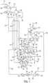
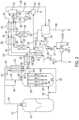
- FIG. 1illustrates a power production cycle system having a cryogenic oxygen plant and using a natural gas fuel.
- the power production cyclecan be as defined otherwise herein.
- the power production cyclecan incorporate elements and/or operating parameters as otherwise described in U.S. Pat. No. 9,068,743 to Palmer et al. , U.S. Pat. No. 9,062,608 to Allam et al. , U.S. Pat. No. 8,986,002 to Palmer et al. , U.S. Pat. No.
- a power production cycle according to the present disclosurecan be configure such that a working fluid comprising CO 2 is repeatedly cycled at least through stages of compressing, heating, expanding, and cooling.
- the CO 2in particular can be supercritical through at least some of these steps, although it can transition between supercritical and liquid and/or gaseous states in some embodiments.
- a power production cycle for which efficiency can be improvedmay include combinations of the following steps:
- a power production unit suitable for combination with a hydrogen production unitis exemplified. It is understood that a power production unit is intended to encompass a combination of individual components that, when operated together, are effective for power production and, as such, is intended to have the same meaning as a power production system. Likewise, it is understood that a hydrogen production unit is intended to encompass a combination of individual components that, when operated together, are effective for hydrogen production and, as such, is intended to have the same meaning as a hydrogen production system.
- the exemplified power production unitis described in relation to specific operating parameters, it is understood that the power production unit can be operated across a range of parameters consistent with the overall disclosure herein. In the power production unit exemplified in FIG.
- a CO 2 stream 107 at 304 bar, heated to 715°C in heat exchanger 101enters a combustor 102 where it mixes with the combustion products derived from a methane stream 112 compressed to 305 bar (251°C) in compressor 105 driven by electric motor 106 burning in an oxidant stream 108 which has a composition of about 25% oxygen and about 75% CO 2 molar and has been heated to 715°C in heat exchanger 101.
- the resulting mixed stream 110enters the turbine 103 at 1150°C and 300 bar and is expanded to 30 bar and 725°C leaving as stream 109 and generating power in generator 104.
- the 30 bar streamcools in the heat exchanger 101 and transfers heat to the high pressure CO 2 stream and leaves at 65°C as stream 113. It is further cooled in direct contact water cooler 115 that has a packed section 114 and a circulating water section comprising a pump 116 and an indirect water-cooled heat exchanger 117, which directs water flows 119, 120 and 121 to the top of the packing section.
- the excess liquid water produced from CH 4 combustion, stream 118,is removed from the base of water cooler 115.
- the cooled stream of substantially pure CO 2 122 leaving the top of the cooler 115splits into multiple streams.
- a first portion 123 of the substantially pure CO 2 stream 122is divided into a net CO 2 product stream 161, which is drawn off for export or other use and a diluent stream 163.
- diluent stream 163blends with the combustor oxygen flow 150 at 29 bar to form the combustor oxidant stream 151 containing 25% (molar) oxygen.
- the main portion 124 of the cooled, substantially pure CO 2enters a two stage intercooled CO 2 compressor (with first compressor stage 159, intercooler 160, and second compressor state 125) where it is compressed to 67.5 bar, leaving as stream 162.
- the CO 2 stream exiting the cooler 115is substantially pure in that it comprises less than 3 mol%, less than 2 mol%, less than 1 mol%, less than 0.5 mol%, less than 0.1 mol%, or less than 0.01 mol% impurities.
- the power production cyclerequires a significant quantity of additionally generated heat to be provided to the high pressure CO 2 stream at a temperature level below 400°C.
- the heatis derived from two sources that provide heat of compression.
- the first sourceis the adiabatically compressed cryogenic oxygen plant feed air stream 142 at 5.6 bar and 226°C from air compressor 140, which compresses air stream 139 driven by electric motor 141.
- the second sourceis a stream 135 of 29.3 bar CO 2 taken from heat exchanger 101 at a temperature of 135°C and adiabatically compressed in compressor 136 to produce stream 137 at 226°C.
- additive heat exchanger 134provides additive heat to a 304 bar CO 2 stream 131 split from discharge stream 130 that is taken directly from the multi-stage pump 129.
- the additive heat from the additive heat exchange 134raises the temperature of the CO 2 from 50°C in stream 131 to 221°C in stream 133.
- the cooled CO 2 stream 138 and the CO 2 recycle compressor discharge stream 162combine to form the total CO 2 stream 127 that is cooled in the cooling water heat exchanger 126 to produce CO 2 recycle stream 128 at 19.7°C.
- This stream of high-density CO 2 liquidis compressed to 305 bar in a multi-stage pump 129.
- the discharge stream 130 at 50°Cdivides into a main portion 132 which enters the recuperative heat exchanger 101 and a minor stream 131 that is heated in heat exchanger 134 to 221°C against the cooling adiabatically compressed streams 137 and 142 producing stream 133 as noted above.
- the stream 133rejoins the main portion 132 of the high pressure CO 2 flow in heat exchanger 101.
- additive heatingis provided to the recycled CO 2 stream (i.e., in addition to the recuperated heat from the turbine discharge stream 109) in order to achieve a high level of operating efficiency.
- a side stream 179can be taken from the main portion 132 of the high pressure CO 2 stream and directed to the turbine 103 as a turbine blade cooling stream.
- the cooled air stream 143 at 56°Centers the cryogenic air separation system.
- Thiscomprises an air purification unit 144 that has a direct contact air cooler, a water chiller, and a switching duel bed thermally regenerated adsorption unit that delivers a dry CO 2 free stream of air at 5.6 bar and 12°C. Part of this air (stream 145) is compressed to 70 bar in compressor 146 driven by electric motor 178, and air streams 148 and 147 enter a pumped liquid oxygen cycle air separation cryogenic system 149.
- the products from the air separatorare a waste nitrogen stream 160 and a 30 bar product oxygen stream 150, which blends with a cooled portion of the CO 2 stream (the diluent stream 163) leaving the direct contact CO 2 cooler 115 to produce the oxidant stream 151.
- Thisis compressed to 304 bar in the CO 2 /O 2 compression train.
- the oxidant stream 151is compressed in compressor 152 driven by electric motor 153 leaving as stream 155, which is cooled in intercooler 154, leaving as stream 156, which is compressed further in pump 157.
- the resulting compressed oxidant stream 158is heated to 715°C in heat exchanger 101 leaving as stream 108 to enter the combustor 102.
- the power production cyclerequires a separate cryogenic air separator plant to produce oxygen. This must be delivered to the combustor at a controlled concentration of about 20% to about 30% molar preheated to typically over 700°C diluted with CO 2 which in general involves a separate O 2 /CO 2 compressor train or alternatively a more complex cryogenic air separation plant with a significantly high power consumption.
- the CH 4 fuel 111is compressed to 305 bar in a high-pressure compressor 105 as discussed above.
- the integration of the hydrogen plant with the power production cycle systemis shown in FIG 2 .
- the systemhas a partial oxidation (POX) reactor 201 with a feed stream 221 of 99.5% pure O 2 at 270°C and a natural gas stream 246 at 500°C, both at 85 bar pressure.
- the POX reactor 201provides a product H 2+ CO stream 222 at 1446°C (which can optionally be quenched and cooled by the addition of a saturated steam stream 223 to 1350°C) enters the base 203 of the gas heated reformer reactor 202.
- the product H 2 +CO stream 222mixes with reformed H 2 +CO product stream leaving each of the open ended catalyst filled tubes 204, and the total product CO+H 2 stream passes upwards through the shell side, providing heat for the endothermic reforming reactions and leaving as stream 224 at 600°C.
- the tubesare free to expand downwards at operating temperatures and the pressure difference at the hot end and hence stresses in the tube walls are negligible.
- the tubes plus any exposed metal partsare fabricated from an alloy such as INCONEL ® 693, which is resistant to metal dusting corrosion caused by Boudouard reaction depositing carbon. Additionally, the metal surfaces can be further protected by coating with alumina.
- Stream 224is cooled by passage through a waste heat boiler 236 and leaves as product gas stream 254 at 320°C.
- the product gas stream 254passes through two catalyst filled CO shift reactors 207 and 208 in series.
- the outlet streams 226 and 228enter the shift stream heat recovery heat exchangers 209 and 210 where heat is used for boiler feed-water preheating and natural gas stream preheating.
- stream 226 leaving CO shift reactor 207passes through shift stream heat exchanger 209 leaving as stream 227 to enter CO shift reactor 208.
- the stream 228 leaving CO shift reactor 208passes through shift stream heat exchanger 210 before passing through water cooler 235 to leave as stream 229.
- Boiler feedwater streams 256 and 257are heated in shift stream heat exchangers 210 and 209, respectively to provide heated water stream 258.
- Natural gas streams 241 and 242are heated in the shift stream heat exchangers 210 and 209, respectively, to provide natural gas stream 243 at 290°C.
- the boiler feed-water stream 258divides into a waste heat boiler feed stream 260 and a large excess stream 259 at 290°C which is cooled to 60°C in the heat exchanger 134 (see FIG. 1 ) releasing its heat to a portion of the power production cycle recycle high pressure CO 2 stream 131 to 133 (shown in FIG. 1 ).
- the crude H 2 stream 271 leaving heat exchanger 210(which contains substantially all of the CO 2 derived from combustion of carbon in the hydrocarbon or carbonaceous feed together with water vapor and minor amounts of CO, CH 4 , N 2 and Ar) is cooled to near ambient in water cooler 235. Condensed water is separated from stream 229 in separator 212. water stream 262 leaving the separator 212 and the cooled water stream 253 leaving the heat exchanger 134 enter a water treatment unit 214, which produces purified water 255 and an excess water stream 261. The purified water 255 functions as the boiler feed-water stream and is pumped to about 87 bar pressure in pump 213. The pressurized boiler feedwater stream 256 leaving the pump 213 enters the heat exchanger 210.
- the waste heat boiler feed stream 260is heated in the waste heat boiler 236 leaving as saturated steam stream 249, which splits into steam stream 250 and quenching stream 223.
- the saturated steam stream 250 and the preheated natural gas stream 243, both at 290°Center a supplemental heat exchanger 237 where they are heated to 500°C against stream 247, which corresponds to stream 109, the turbine exhaust stream in FIG 1 .
- the outlet stream 248enters the recuperative heat exchanger 101 (in the power production unit of FIG. 1 ) at about 725 °C. In this case the inlet temperature for the turbine 103 in the power production unit of FIG. 1 is elevated to provide the required heat transferred in heat exchanger 237, and the turbine power output is increased.
- the supplemental heat exchanger 237is thus configured to provide supplemental heating to the saturated steam stream 250 and the natural gas stream 243, the supplemental heating being provided by a stream from the power production unit.
- the hot natural gas stream 244 leaving the heat exchanger 237splits to provide feed at 500°C to the POX reactor 201 as stream 246 and to the GHR 202 as stream 245, which mixes with the steam stream 251 to form total GHR feed stream 252.
- the steam stream 251 fed to the GHR reactor 202provides a steam to carbon ratio (carbon combined with hydrogen in the GHR reactor feed) of 6:1 in this case. This high ratio allows 80 bar H 2 +CO production pressure with a low quantity of unconverted methane in the total product H 2 +CO stream 224.
- the crude hydrogen product stream 230 leaving the water separator 212passes into a multi-bed pressure swing adsorption unit 215 that produces a substantially pure H 2 product stream 239 with 50 ppm impurity level comprising 88% of the hydrogen present in stream 230.
- a substantially pure H 2 product streamthus can comprise less than 500 ppm impurities, less than 250 ppm impurities, less than 100 ppm impurities, or less than 75 ppm impurities (e.g., down to 0 impurities).
- the waste stream 232 at 1.2 bar pressure that contains all the CO 2 plus various contents of CO, H 2 , CH 4 , Argon, N 2 and traces of water vaporis compressed to 30 bar in compressor 216 driven by electric motor 219 to leave as stream 238.
- the discharge stream 238is cooled in cooler 217 to near ambient and added to the power production system natural gas compressor 105 (see FIG. 1 ) as part of inlet stream 111 (see FIG. 1 ).
- the compressor discharge stream 112 (see FIG. 1 ) at 320 barprovides the feed to the power production unit combustor 102 (see FIG. 1 ).
- the natural gas feed stream 241 at 85 barcan also be produced from a separate natural gas compressor stage, which would be part of the compressor 105 from FIG. 1 .
- H 2is produced at 50 ppm total impurity level at a pressure of 74 bar.
- CO 2 production from the integrated systemis 6,437.1 MT/D
- the CO 2is produced at 150 bar pressure
- the use of substantially pure oxygen in the combustorcan have the side benefit of providing a large quantity of substantially pure nitrogen.
- the nitrogencan be provided at relatively high pressure directly from the air separation unit that can be associated with the power production unit to provide the necessary stream of substantially pure oxygen. At least a portion of this nitrogen can be blended with the hydrogen that can be produced as described herein.
- the end resultis an H 2 + N 2 fuel gas that is suitable for use in a conventional gas turbine combined cycle power generation system. This is exemplified in FIG. 3 , wherein nitrogen gas 160 from an air separation unit (see FIG. 1 ) and hydrogen gas 239 from a hydrogen production facility (see FIG. 2 ) are input to a gas turbine combined cycle unit 300.
- the H 2 + N 2 fuel gascan be utilized in any gas turbine combined cycle power generation system.
- Known systemscan be modified as necessary to remove, decommission, or otherwise forego the use of elements that would otherwise be required for removal of CO 2 .
- Known gas turbine combined cycle power generation systemsthat can be utilized according to the present invention or an embodiment thereof are described in US Pat. No. 8,726,628 to Wichmann et al. , US Pat. No. 8,671,688 to Rogers et al. , US Pat. No. 8,375,723 to Benz et al. , US Pat. No. 7,950,239 to Lilley et al. , US Pat. No. 7,908,842 to Eroglu et al. , US Pat. No.
- the combination of systems providedwhereby hydrogen gas and nitrogen gas are provided from a combustion power system wherein a hydrocarbon fuel is combusted with substantially no atmospheric discharge of CO 2 , provides a distinct advantage over the conventional operation of a gas turbine combined cycle system.
- the present combination of systemscan eliminate the natural gas fuel typically required in a gas turbine and substitute a fuel with no CO 2 production when combusted.
- the present disclosureprovides a combination of: 1) an oxygen based hydrogen production unit; 2) a power generation unit that captures substantially all of the CO 2 produced; and a conventional gas turbine combined cycle power generation unit that provides for additional power generation.
- Combined systems as described hereincan provide a surprisingly high efficiency, low cost power generation, and approximately 100% CO 2 capture. The result is thus a heretofore unknown manner for providing power production from natural gas combustion with approximately 100% CO 2 capture and operating costs that are equal to or lower than known power productions methods that do not provide for 100% CO 2 capture.
- an existing combined cycle power stationcan be converted to eliminate all CO 2 emissions and simultaneously increase the power generation capacity.
- Such conversioncan include addition of the further system components described herein for production of power using a CO 2 circulating fluid and production of H 2 + N 2 fuel gas.
- Performance calculations for a combined system as described abovecan be based on a GE PG9371(FB) gas turbine cogeneration system that is adapted to produce 432.25 Mw of power at iso conditions. Calculated values according to embodiments are provided below considering the combination of a natural gas combustion power production unit with 100% CO 2 capture, H 2 production, N 2 production, and combustion of H 2 + N 2 fuel gas in the gas turbine.
Landscapes
- Chemical & Material Sciences (AREA)
- Engineering & Computer Science (AREA)
- Combustion & Propulsion (AREA)
- Organic Chemistry (AREA)
- Chemical Kinetics & Catalysis (AREA)
- Mechanical Engineering (AREA)
- General Engineering & Computer Science (AREA)
- Inorganic Chemistry (AREA)
- Health & Medical Sciences (AREA)
- General Health & Medical Sciences (AREA)
- General Chemical & Material Sciences (AREA)
- Oil, Petroleum & Natural Gas (AREA)
- Life Sciences & Earth Sciences (AREA)
- Sustainable Development (AREA)
- Physics & Mathematics (AREA)
- Thermal Sciences (AREA)
- Analytical Chemistry (AREA)
- Emergency Medicine (AREA)
- Hydrogen, Water And Hydrids (AREA)
Description
- The present invention relates to a system and to a method for combined power and hydrogen production.
US 2013/0205746 A1 discloses a power production system that is adapted to achieve high-efficiency power production with complete carbon capture when using a solid or liquid hydrocarbon or carbonaceous fuel. The solid or liquid fuel first is partially oxidized in a partial oxidation reactor. The resulting partially oxidized stream that comprises fuel gas is quenched, filtered, cooled, and then directed to a combustor of a power production system as the combustion fuel. The partially oxidized stream is combined with a compressed recycle CO2 stream and oxygen. The combustion stream is expanded across a turbine to produce power and passed through a recuperator heat exchanger. The expanded and cooled exhaust stream is scrubbed to provide the recycle CO2 stream, which is compressed and passed through the recuperator heat exchanger, and the POX heat exchanger in a manner useful to provide increased efficiency to the combined system.US 2007/0130957 A1 discloses a power generation system including a first gas turbine system and a second gas turbine system.DE 10 2009 032 718 A1 discloses a method of separating CO2 in connection with a steam injected gas turbine.WO 2009/105305 A2 discloses a gasifier system including a gasifier including a syngas cooler configured to transfer heat from a reactive zone of the gasifier to a flow of fluid through the syngas cooler, a reaction vessel coupled in flow communication with the syngas cooler wherein the reaction vessel is adapted to receive the flow of fluid and generate heat in an exothermic shift reaction.US 4,725,380 discloses the production of ammonia synthesis gases by partial oxidation of a hydrocarbon feedstock, using air, oxygen enriched air, or oxygen depleted air, in admixture with steam, followed by shift and the removal of the excess of nitrogen, and also impurities such as carbon oxides and methane, by pressure swing adsorption.- Hydrogen, such as for use in fuel cells, has long been viewed as a desirable energy source because of its clean conversion to and from a source of stored energy. For example, hydrogen can be used as a fuel for electric vehicle propulsion using fuel cells advantageously coupled to high capacity electric storage batteries. Beneficially, use of hydrogen as a fuel can eliminate CO2, NOx, CO, and hydrocarbon emissions and thus significantly reduce air pollution. Any path to implementation of a hydrogen-based world economy, however, would require a very large hydrogen production capacity. Moreover, such hydrogen production method would need to be capable of achieving simultaneously low hydrogen production cost together with the capture of near 100% of the CO2 derived from the fossil fuel utilized.
- Hydrogen use as a fuel source can also be beneficial to reduce or eliminate carbon dioxide emissions associated with more conventional power production processes. For example, hydrogen can be diluted with nitrogen and/or steam and used as the fuel in a gas turbine combined cycle power generation system.
- Gas turbine combined cycle power generation systems are a major source of electrical power generation worldwide in light of their ability to produce power from natural gas with an efficiency in the range of 60%, on a lower heating value (LHV) basis. Despite the desirable efficiency, such systems are still problematic since the carbon in the fuel is emitted to the atmosphere as carbon dioxide. To overcome this problem, it is possible to operate the gas turbine with CO2 in place of air as the working fluid by recycling the turbine exhaust CO2 gas following cooling and product CO2 removal to the inlet of the gas turbine compressor section. This, too, is problematic because the fuel must be combusted in pure oxygen to produce only CO2 and water as combustion product, and this requires the addition of an air separation plant, which functions as a drain on process efficiency. Chemical and/or physical solvent scrubbing processes are often used to treat the gas turbine exhaust to remove CO2; however, such processes can provide mixed results and again reduce process efficiency due to the added costs of the exhaust treatment systems and upkeep. As discussed above, it is possible to eliminate carbon emissions by utilizing hydrogen as the fuel in the gas turbine; however, such approach requires a consistent hydrogen source that is preferentially provided without associated CO2 production. Because of the desirability of the use of hydrogen as a fuel source, there remains a need for means to provide hydrogen fuel at a low cost substantially without CO2 emission to the atmosphere.
- The present disclosure relates to a system, defined by appended independent claim 1, and to a method, defined by appended independent claim 6, that combine power production and hydrogen production. In particular, power production (e.g., electrical power) and hydrogen production can be simultaneously achieved with combustion of a hydrocarbon fuel. More particularly, a hydrocarbon fuel can be combusted to provide combustion products that include and/or are converted into hydrogen. Moreover, the hydrogen can be produced with substantially zero carbon emissions, and the hydrogen can be utilized as a fuel for power production.
- In some embodiments, the present disclosure further can relate to systems and methods for generation of hydrogen (H2) and carbon monoxide (CO) utilizing oxygen for partial oxidation of a hydrocarbon fuel in a catalytic and/or non-catalytic reaction. For example, a partial oxidation, non-catalytic reactor (POX) or a catalytic auto-thermal reactor (ATR) can be used. Partial oxidation of the hydrocarbon fuel can be followed by the use of a gas heated reformer (GHR) in either a series or parallel mode to the POX or ATR reactor to produce additional H2 and CO (i.e., synthesis gas) by utilizing the exhaust sensible heat in the POX and/or ATR reactor system to provide the heat for endothermic catalytic steam plus natural gas reforming reactions taking place in the GHR.
- In one or more embodiments, the present systems and methods can utilize the excess heat generated in the hydrogen plant (e.g., at a temperature level below 400°C) to provide additional heat input to the power production system and method. Such added heat can be beneficial to assist in achieving high electrical generation efficiency.
- In other embodiments, the present disclosure encompasses the provision of heat required for superheating one or both of a fuel stream (e.g., natural gas) and a steam feed stream to an H2 + CO synthesis gas generation reactor. This can be achieved, for example, using heat derived from the turbine discharge stream from the power production system and method.
- In further embodiments, the present systems and methods can utilize a pressure swing adsorption (PSA) system to separate pure high pressure hydrogen from a cooled, crude hydrogen stream. This can be implemented, for example, following the conversion of CO to H2 by catalytic shift reaction with steam.
- In additional embodiments, the present disclosure can provide for the recovery of substantially all the carbon present in the fuel for the hydrogen plant. For example, this can be achieved by compressing the waste gas from the PSA and using it as part of the fuel gas for the power production cycle system and method where the CO2 is recovered from the cooled turbine exhaust stream.
- If desired, part or all of the oxygen used in the power production cycle system and method can be supplied from a cryogenic air separation plant or from an oxygen ion transport membrane (ITM) oxy-fuel combustor with a low-pressure air feed. The hydrogen plant can utilize a stream of high pressure gaseous oxygen at pressures up to 105 bar as feed to the POX and/or ATR producing substantially pure H2 at up to 95 bar from the PSA. A cryogenic air separation plant supplying high pressure oxygen can be particularly useful to provide the oxygen.
- Further, if desired, a second fuel oxygen combustor can be used to heat the gas turbine exhaust to provide preheat for any one or more of the H2 plant fuel, oxygen, and steam feed streams. It can be supplied with a gaseous oxygen stream at turbine discharge pressure, but this preferentially can be diluted with CO2 in the O2 burner injection system to control the adiabatic flame temperature. A second alternative is to use an ITM combustor fed with preheated low-pressure air to preheat the turbine exhaust using a preheated natural gas stream blended with the gas turbine exhaust which will burn with the diffusing oxygen and provide the necessary superheating for the natural gas stream and steam feed stream for the synthesis gas reactor.
- In one or more embodiments, the present disclosure provides a power production system or unit that can be configured for simultaneous power production and hydrogen production. In particular, the system comprises: a combustor; a turbine; a recuperative heat exchanger; a water separator; a compressor; and an integrated hydrogen production system or unit.
- In one or more embodiments, the present disclosure provides a method for power production. The method comprises the following:
- combusting a carbonaceous fuel in a first combustor with an oxidant in the presence of a recycled CO2 stream at a combustion pressure to provide a combustion product stream including CO2;
- expanding the combustion product stream across a turbine to produce power and form a turbine discharge stream including CO2;
- cooling the turbine discharge stream including CO2, in a recuperative heat exchanger;
- separating CO2 from any further components of the turbine discharge stream to provide a recycled CO2 stream;
- compressing the recycled CO2 stream to substantially the combustion pressure;
- removing from the recycled CO2 stream the CO2 derived from combustion of carbon in the hydrocarbon or carbonaceous fuel;
- heating the compressed recycled CO2 stream in the recuperative heat exchanger, with heat withdrawn from the turbine exhaust stream and/or with external heat supplied at a temperature level below about 400 °C;
- passing an optionally preheated carbonaceous fuel (and optionally oxygen and/or steam) through a POX or ATR optionally followed by a GHR to form a synthesis gas stream that particularly can comprise H2 and CO;
- cooling the synthesis gas to generate high pressure steam;
- passing the synthesis gas through one or more catalytic shift reactors effective to convert CO and H2O to H2 and CO2;
- separating H2 from the synthesis gas stream; and
- passing the remaining fuel gas following H2 separation from the synthesis gas stream to one or both of the first combustor and the second combustor.
- In the foregoing method, it is understood that not all of the recited steps must be carried in every possible embodiment, as long as these embodiments still comprise at least all features and method steps of at least one of the appended independent claims.
- Further to the foregoing, the presently disclosed systems and method can be further defined in relation to additional elements and configurations. For example, any one or more of the following can apply.
- Hydrogen production may specifically be carried out using at least two reactors, such as a partial oxidation reactor and a gas heated reformer reactor.
- High temperature heating of a hydrocarbon feed stream and/or a steam feed stream for use in synthesis gas production can utilize heat derived from the power production cycle. In particular, the heat can be derived from at least part of the power production cycle turbine exhaust.
- The hydrogen can be separated from one or more waste components in a multi-bed pressure swing absorption unit.
- One or more waste components separated from the hydrogen can be compressed and used as part of the fuel in the power production cycle.
- Substantially all carbon derived from the hydrocarbon fuel used as the fuel feed in the hydrogen production system and method can be recovered as high pressure CO2 stream, which can be suited for introduction into a CO2 pipeline.
- Substantially all low temperature heat (i.e., heat at a temperature above ambient but at a temperature of about 400°C or less) that is rejected from the H2 plant can be recovered for heat input into the power production cycle.
- In one or more embodiments, the present disclosure can provide for the integration of hydrogen production from a fuel (for example, from natural gas), the capture of substantially all of the CO2 derived from carbon in the fuel, and the efficient integration of heat between a power system and the hydrogen production. Preferably, such integration can achieve the production of electrical power from the fuel at a high efficiency (e.g., >60% LHV) with near zero emission of CO2 to the atmosphere and with a cost of electricity substantially similar to the cost arising from current processes that do not provide for partial or complete CO2 capture.
- In some embodiments, the present disclosure can provide a system for power production, the system comprising: a power production unit configured for continuous compression, heating, expansion, cooling, and recycling of a CO2 working fluid with no atmospheric exhaust of CO2; a hydrogen production system or unit including a partial oxidation combustor configured to form synthesis gas stream and a separator configured to separate H2 from the synthesis gas stream; and a gas turbine combined cycle unit configured to receive and combust the H2 from the hydrogen production system or unit.
- In some embodiments, the present invention relates to a power production process and integrated H2 production process comprising, as specific embodiment of or in addition to all features and method steps of the system or method of at least one of the appended independent claims :
- combusting a gaseous fuel in a combustor with substantially pure O2 at an elevated pressure in the presence of recycled, heated CO2 to form a combustion product stream;
- expanding the combustion product stream in a turbine to a lower pressure to produce shaft power and form a turbine exhaust stream;
- cooling the turbine exhaust stream in a recuperative heat exchanger to form a cooled turbine exhaust stream while heating a recycled CO2 stream to form the recycled, heated CO2;
- optionally adding heat at a temperature level below about 400 °C from an external source into the recycled CO2 stream;
- separating condensed water from the cooled turbine exhaust stream to provide the recycled CO2 stream; and
- compressing the recycled CO2 stream to a pressure suitable for input to the combustor; wherein one or more of the following conditions apply:
- one or both of a hydrocarbon or carbonaceous fuel stream and a steam stream that is fed to an H2 synthesis plant reactor is heated utilizing heat transferred from the turbine exhaust stream;
- the turbine combustor fuel inlet flow and the turbine inlet temperature are increased to provide additional power from the turbine plus the heat required for the preheating of hydrocarbon or carbonaceous and steam feeds to the H2 plant synthesis reactors and with substantially the same turbine inlet temperature to the recuperative heat exchanger as in a stand-alone CO2 power cycle;
- excess heat from the H2 synthesis plant at a temperature level below about 400 °C is transferred from the H2 synthesis plant to the recycled CO2 stream;
- hydrogen is separated from a total impure H2 product stream in the H2 synthesis plant following CO conversion to H2 in one or more CO catalytic shift reactors, followed by cooling to near ambient temperature and liquid water removal;
- a waste fuel gas remaining after H2 separation in the H2 synthesis plant is compressed to a pressure suitable for input to the combustor;
- H2 separation in the H2 synthesis plant is carried out in a plurality of stages;
- H2 separation in the H2 synthesis plant includes intermediate CO2 removal and catalytic CO shift conversion to H2;
- a second combustor is utilized, the second combustor using substantially pure oxygen and a fuel gas plus at least part of the turbine exhaust to provide at least part of the heat required for preheating hydrocarbon or carbonaceous and steam feeds to the H2 plant synthesis reactors;
- a heated, pressurized water and/or steam stream at a temperature below about 400 °C is provided and carries excess heat from the H2 synthesis plant to the recycled CO2 stream;
- produced H2 from the H2 synthesis plant is combined with N2 and/or steam to produce a fuel gas suitable for combustion in a gas turbine to produce power.
- In one or more embodiments, the present disclosure can particularly provide a system for combined power production and hydrogen production, the system comprising: a power production unit wherein pressurized carbon dioxide is expanded for power production; a hydrogen production unit wherein a hydrocarbon fuel is partially oxidized to produce a synthesis gas from which hydrogen is separated; and one or more flow components configured for passage of one or more streams between the power production unit and the hydrogen production unit.
- The power production unit in accordance with the invention comprises all features of appended independent claim 1, including inter alia: a combustor configured to receive a hydrocarbon fuel and oxygen and output a heated stream comprising at least the pressurized carbon dioxide; a turbine configured to receive and expand the heated stream comprising the pressurized carbon dioxide from the combustor to produce the power and form a heated stream comprising the expanded carbon dioxide; a recuperative heat exchanger configured to receive the heated stream comprising the expanded carbon dioxide and form a cooled stream comprising carbon dioxide; a separator configured to receive the cooled stream comprising the carbon dioxide from the recuperative heat exchanger and provide a stream of the carbon dioxide; and a compressor configured to receive the stream of the carbon dioxide from the separator and compress the carbon dioxide.
- The hydrogen production unit further comprises: a partial oxidation combustor configured to receive oxygen and a portion of the hydrocarbon fuel and output the synthesis gas; a reformer in fluid communication with the partial oxidation combustor and configured to receive the synthesis gas from the partial oxidation combustor and to receive a portion of the hydrocarbon fuel; a shift reactor in fluid communication with the reformer; a shift stream heat exchanger in fluid communication with the shift reactor; a separator in fluid communication with the shift stream heat exchanger; and a pressure swing adsorption unit in fluid communication with the separator; wherein the pressure swing adsorption unit is configured to output a stream of substantially pure hydrogen.
- The hydrocarbon fuel is provided to the partial oxidation combustor and the reformer from a hydrocarbon fuel line that passes through the shift stream heat exchanger.
- The hydrocarbon fuel line can pass through a supplemental heat exchanger that is configured to receive and cool the heated stream comprising the expanded carbon dioxide exiting the turbine of the power production unit.
- The system can further comprise a water line that can be configured for passing water to the reformer.
- The water line can pass through the shift stream heat exchanger.
- The water line can pass through a supplemental heat exchanger that is configured to receive and cool the heated stream comprising the expanded carbon dioxide exiting the turbine of the power production unit.
- The pressure swing adsorption unit can be configured to output a waste stream that is separated from the stream of substantially pure hydrogen, wherein the waste stream comprises one or more or carbon monoxide, carbon dioxide, hydrogen, methane, argon, and nitrogen.
- One or more flow components configured for passage of one or more streams between the power production unit and the hydrogen production unit can include a line for passage of at least a portion of the waste stream from the pressure swing adsorption unit to the combustor of the power production unit.
- The power production unit further comprises an additive heat exchanger configured to heat a stream of substantially pure carbon dioxide against one or more compressed streams from the power production unit.
- The additive heat exchanger can be further configured to heat the stream of substantially pure carbon dioxide against a stream from the hydrogen production unit.
- In one or more embodiments, the present invention particularly provides a method for combined power production and hydrogen production, the method, which is defined by appended independent claim 6, inter alia comprising: carrying out power production in a power production unit comprising: combusting a first hydrocarbon fuel in a first combustor with an oxidant in the presence of a recycled CO2 stream at a combustion pressure to provide a combustion product stream including CO2; expanding the combustion product stream including CO2 across a turbine to produce power and form a turbine discharge stream including CO2; cooling the turbine discharge stream including CO2, in a recuperative heat exchanger; separating CO2 from any further components of the turbine discharge stream to provide a stream comprising the recycled CO2; compressing the stream comprising the recycled CO2 to substantially the combustion pressure; heating the compressed recycled CO2 stream in the recuperative heat exchanger, with heat withdrawn from the turbine exhaust stream to provide a heated stream comprising the recycled CO2; and passing the heated stream comprising the recycled CO2 to the first combustor; and carrying out hydrogen production in a hydrogen production unit comprising: passing a stream of a second hydrocarbon fuel through a partial oxidation reactor to form a synthesis gas stream; and processing the synthesis gas to provide a stream of substantially pure hydrogen and a waste stream comprising at least carbon monoxide.
- The method can further comprise passing at least the carbon monoxide from the waste stream to the first combustor.
- The processing of the synthesis gas comprises passing the synthesis gas through a reformer that is also configured to receive a stream of the second hydrocarbon fuel gas and a stream of heated water.
- One or more of the stream of the second hydrocarbon fuel passing through the partial oxidation reactor, the stream of the second hydrocarbon fuel received by the reformer, and the stream of the heated water that is received by the reformed can be heated in a supplemental heat exchanger utilizing heat transferred from the turbine discharge stream including CO2.
- Processing the synthesis gas comprises passing reformed synthesis gas from the reformer through a shift reactor followed by a shift stream heat exchanger.
- The stream of the hydrocarbon fuel is provided to one or both of the partial oxidation combustor and the reformer via a hydrocarbon fuel line that passes through the shift stream heat exchanger.
- The stream of heated water received in the reformer can be provided through a water line that passes through the shift stream heat exchanger.
- The method further comprises passing a stream exiting the shift stream heat exchanger through a water separator to remove water and form a crude hydrogen stream including hydrogen and impurities.
- The method can further comprise passing the crude hydrogen stream through a pressure swing adsorption unit that outputs the substantially pure hydrogen and the waste stream.
- The waste stream can be compressed to a pressure suitable for input to the combustor of the power production unit and then passed to the combustor of the power production unit.
- The power production unit can comprise an additive heat exchanger that heats a stream of the recycled CO2 against one or more compressed streams from the power production unit.
- The method can further comprise passing a heated stream from the hydrogen production unit through the additive heat exchanger such that heat from the hydrogen production unit is transferred to the stream of the recycled CO2.
- The heat that is transferred from the hydrogen production unit to the stream of the recycled CO2 can be at a temperature level below about 400 °C.
- At least a portion of the turbine discharge stream including CO2 can be passed through a second combustor with a stream of the first hydrocarbon fuel and oxygen so that the firs hydrocarbon fuel is combusted to provide additional heat to at least a portion of the turbine discharge stream including CO2.
- At least part of the additional heat provided to at least a portion of the turbine discharge stream including CO2 can be provided to one or more streams in the hydrogen production unit.
- The method can further comprise carrying out power production in a gas turbine that is separate from the power production unit wherein at least a portion of the substantially pure hydrogen is combusted in the gas turbine to produce power.
- In one or more embodiments, the present disclosure further can provide a system for power production, the system comprising: a power production unit configured for continuous compression, heating, expansion, cooling, and recycling of a CO2 working fluid with no atmospheric exhaust of CO2; a hydrogen production unit including a partial oxidation combustor configured to form a synthesis gas stream and one or more additional components configured to process the synthesis gas to form a stream a substantially pure hydrogen and a waste stream; and a gas turbine combined cycle unit configured to receive and combust at least a portion of the substantially pure hydrogen from the hydrogen production unit.
- Having thus described the invention, which is defined by appended independent claims 1 and 6, in the foregoing general terms, reference will now be made to the accompanying drawings, which are not necessarily drawn to scale, and wherein:
FIG. 1 is a flow diagram of an exemplary system and method of power production using a CO2 working fluid and including a cryogenic oxygen plant;FIG. 2 is a flow diagram of a hydrogen production facility including elements for integration with a power production system and method, such as illustrated inFIG. 1 ; andFIG. 3 is a flow diagram illustrating a combined system wherein nitrogen gas from the air separation unit and hydrogen gas from the hydrogen generation unit are input to a gas turbine combined cycle unit.- The present subject matter will now be described more fully hereinafter with reference to exemplary embodiments thereof.
- The present invention provides systems and methods wherein power production and hydrogen production are simultaneously achieved. Previous efforts have been undertaken to provide for simultaneous production of power and hydrogen, and one or more elements from such previous endeavors may be integrated into the presently disclosed systems and methods. For example,
US Patent No. 6,534,551 to Allam et al. describes the combination of: 1) a hydrocarbon fuel gas reaction with steam and or oxygen; and 2) a power system utilizing a compressed oxidant gas in which a fuel gas is burned with combustor products producing power by work expansion and in which the expanded combustion product gas is used to superheat the steam used in hydrogen synthesis reactions and in which the oxygen production unit is driven by at least a portion of the power produced by the expansion of the combustion product gas. - In one or more embodiments, the present systems and methods can beneficially provide for hydrogen production in combination with power production with capture of substantially all of the carbon produced, particularly substantially all of the CO2 produced. The combination can be a single system with a combination of elements suitable to achieve the simultaneous production of hydrogen and power. In some embodiments, a hydrogen production system or unit can be operated in parallel with a power production system or unit with the appropriate crossover of elements so that the two systems or units are functioning as a single, integrated system.
- A power production cycle useful according to the present invention can include any system and method wherein CO2 (particularly supercritical CO2 - or sCO2) is used in a work stream. As a non-limiting example,
U.S. Pat. No. 8,596,075 to Allam et al. , describes a prior art system and method wherein a recycle CO2 stream is directly heated and used in power production. - Specifically, the recycle CO2 stream is provided at high temperature and high pressure, is provided to a combustor wherein a carbonaceous fuel is combusted in oxygen, is expanded across a turbine to produce power, is cooled in a heat exchanger, is purified to remove water and any other impurities, is pressurized, is re-heated using the heat taken from the turbine exhaust, and is again passed to the combustor to repeat the cycle. Such system and method are beneficial in that all fuel and combustion derived impurities, excess CO2, and water are removed as a gaseous or supercritical fluid, a liquid or a solid (e.g., ash), and there is virtually zero atmospheric emission of any streams. The system and method achieves high efficiency through, for example, the use of low temperature level (i.e., less than 500°C) heat input after the recycle CO2 stream has been re-pressurized and before combustion (i.e., low temperature level heat added to the recycle CO2 stream in addition to the recuperated heat from the turbine exhaust stream). It is understood that reference to a power production cycle herein indicates a power production cycle utilizing a CO2 working fluid and the combination of elements and method steps described herein and in the incorporated documents.
- A power production cycle useful according to the present invention includes at least the steps defined by appended independent claims. Besides this, it can include more steps or fewer steps than described above and can generally include any cycle wherein a high pressure recycle CO2 stream is expanded for power production and recycled again for further power production. As used herein, a high pressure recycle CO2 stream can have a pressure of at least 100 bar (10 MPa), at least 200 bar (20 MPa), or at least 300 bar (30 MPa). In all instances, the upper limit on pressure may be dictated by the limits of the available equipment at the time of implementation of a system and/or method according to the present invention.
- A high pressure recycle CO2 stream can, in some embodiments, have a pressure of about 100 bar (10 MPa) to about 500 bar (50 MPa), about 150 bar to about 450 bar (45 MPa), or about 200 bar (20 MPa) to about 400 bar (40 MPa). Reference to a high pressure recycle CO2 stream herein may thus be a CO2 stream at a pressure within the foregoing ranges. Such pressures also apply to references to other high pressure streams described herein, such as a high pressure work stream comprising CO2. Combustion may be carried out at a temperature of about 400 °C or greater, about 500 °C or greater, about 600 °C or greater, about 800 °C or greater, or about 1000 °C or greater. In all instances, the upper limit on temperature may be dictated by the limits of the available equipment at the time of implementation of a system and/or method according to the present disclosure. In some embodiments, the first combustor outlet temperature following mixing with recycle CO2 can be about 400°C to about 1,500 °C, about 500°C to about 1200 °C, or about 600°C to about 1000 °C.
- In some embodiments, integration of a power production cycle as described above with a hydrogen production facility can utilize the excess low temperature level heat produced by the hydrogen plant in order to increase the efficiency of power production. For example, superheating of the steam and hydrocarbon feed in the turbine exhaust stream can be carried out with an increase in turbine power output in the power production system and method. Further, the hydrogen plant can be integrated with the power production cycle so that substantially all of the CO2 derived from carbon present in the hydrocarbon fuel feed into the hydrogen plant or system is captured and, optionally, combined with the CO2 captured from the power production cycle plant or system. The integrated system captures up to 100% of the CO2 produced from both the power and H2 plants with zero emission to the atmosphere.
- A hydrogen production plant for use according to the present disclosure can incorporate any variety of elements known to be suitable in prior hydrogen production plants. For example, a hydrogen production plant can comprises a two stage reactor system including a first stage reactor which converts a hydrocarbon feed to a CO+H2 gas using partial oxidation of the hydrocarbon with oxygen and optionally with the additional use of steam. In some embodiments, such partial oxidation (POX) of a natural gas feed with pure oxygen can be carried out at an outlet temperature of about 1300°C to about 1500°C at typical pressures of about 30 bar to about 150 bar. An auto-thermal reformer (ATR) can add steam and excess hydrocarbon, generally natural gas, after the partial oxidation burner so that the high temperature gases can then pass through a bed of catalyst where subsequent steam-hydrocarbon reforming reactions take place yielding further H2+CO and cooling the gas mixture to an outlet temperature of about 1000°C to about 1100°C at pressures of about 30 bar to about 150 bar. The second stage reactor can comprise a steam/hydrocarbon catalytic reformer in which the total H2+CO gas product from both reactors (e.g., at a temperature of about 1000°C or greater) is used to provide the endothermic heat of the reforming reactions in a convectively heated shell side flow with catalyst in the tubes. Optionally the two reactors can operate in a series or parallel mode. A favorable configuration uses a vertical gas heated reformer (GHR) with catalyst filled open ended tubes hanging from a single tube sheet at the top of the vessel, with the product H2+CO leaving the reformer tubes and mixing with the product gas from a POX reactor or an ATR in the base of the GHR, and the total product H2+CO stream passing through the shell side and cooling typically from about 1050°C to 550°C to 800°C.
- An advantage of the two reactor configuration is that the yield of H2+CO from hydrocarbon feed is maximized, and all CO2 formed in the reactions is contained within the high-pressure system. The product CO+H2 gas is further cooled in a steam generating waste heat boiler (WHB), and a further advantage is that this steam quantity is only sufficient to provide the required steam flow to the two H2+CO reactors with only a small excess flow. The system has no large by-product steam production.
- To generate hydrogen, the H2+CO product leaving the WHB at a typical temperature of about 240°C to about 290°C and containing typically about 20% to about 40% (molar) steam is passed through one or more catalytic shift converters where CO reacts with steam to produce CO2 and additional H2. The reactions for the whole H2 production process sequence are shown below (using CH4 as the hydrocarbon)
CH4+½O2 → CO+2H2 Partial oxidation CH4+2O2 → CO2+2H2O Heat generation CH4+H2O → CO+3H2 Reforming CH4+CO2 → 2CO+2H2 Reforming CO+H2O → CO2+H2 CO shift - The total CO+H2 product passing through the CO shift reactors is cooled, and a significant amount of heat is released generally at a temperature level of about 290°C or lower as the gas cools and steam condenses. This heat is released not at a single temperature level but over a temperature range down to near ambient temperature. Part of this heat release can be used to preheat boiler feed water, but there is a large excess quantity that is at a low temperature level and only available over a temperature range.
- The efficiency of the H2+CO generation in the two reactors can be significantly increased by preheating the hydrocarbon and steam feeds to typically about 400°C to about 550°C and preferably to about 500°C to about 550°C. This preferably is done using an external heat source since no excess heat at these temperature levels is available within the H2+CO generation reactors plus WHB.
- The cooled H2 rich gas stream is next passed through a cooler (e.g., an ambient cooler) where condensed water is removed. The gas stream is then passed to a separator wherein substantially pure hydrogen can be isolated. For example, the gas stream can be passed through a conventional multi-bed pressure swing adsorber which separates typically about 85% to about 90% (molar) of the hydrogen as a pure stream having typically about 10 ppm to about 50 ppm total impurities and having a drop in pressure from feed to product H2 of typically about 1 bar to about 2 bar. All the impurities in the crude H2 feed stream are separated as a waste fuel gas stream, which waste stream can comprise any combination of components, such as H2, CO, CO2, CH4, N2, argon, and a small quantity of vapor phase H2O. The pressure is typically about 1.1 bar to about 1.5 bar. This waste gas typically has about 20% of the total hydrocarbon reactor hydrocarbon feed lower heating value (LHV) so its efficient use is advantageous to the overall economics of H2 production. The waste gas contains all the carbon from the total hydrocarbon feed as CO2+CO and the recovery of this carbon as pure CO2 at pipeline high pressure is likewise advantageous to meet climate change emission objectives.
- The integration of the high-pressure, two-reactor hydrogen generation system with power production cycle utilizing a CO2 working stream can achieve a variety of benefits. The turbine exhaust from the power production cycle is typically in the range of about 700°C to about 800°C. The steam and hydrocarbon feeds to the two reactors can be preheated to a range of about 500°C to about 550°C utilizing part of the turbine exhaust flow in a separate heat exchanger. This simply requires an increase in the fuel burned in the turbine combustor to provide the extra heat required. This increases the turbine inlet temperature and flow rate and provides a significant additional power output from the turbine. The steam and hydrocarbon or carbonaceous fuel can be heated to a typical temperature of about 400 °C to about 550 °C while the turbine exhaust can be cooled to a typical temperature of about 700 °C to about 800 °C before entering the recuperative heat exchanger.
- As an alternative arrangement, a second combustor can be provided to preheat at least part of the turbine exhaust stream to deliver the heat required for preheating the fuel and steam required for the generation of synthesis gas in the two stage reactor system. One combustor arrangement uses an oxidant comprising substantially pure O2 diluted with CO2 to produce an oxidant containing 20% to 30% molar O2 to burn the fuel. A second combustor arrangement uses an O2 ion transport membrane reactor that diffuses substantially pure O2 derived from a preheated low pressure air stream into at least a portion of the turbine exhaust to which has been added a controlled portion of the fuel so that the temperature is increased as desired for H2 plant preheat duty.
- The waste gas from the PSA can be compressed to typically about 200 bar to about 400 bar and mixed with the feed hydrocarbon and used very efficiently as fuel gas in the power production cycle. An additional advantage is that the carbon from the hydrocarbon reactor feeds can be captured as CO2 within the power production cycle system. A further advantage is the large mass flow of the waste gas due to its high CO+CO2 content of typically about 50% to about 70% (molar) that increases extra turbine power. Alternatively the waste gas from the PSA can be compressed to the inlet pressure of the first PSA, the CO2 can be removed in one of a number of known processes, and the CO2 depleted gas stream can be sent to a second PSA to separate more H2 to add to the total H2 product stream. Optionally the waste gas can be preheated in an economizer heat exchanger, steam can be added, and more H2 can be produced in an additional catalytic CO shift reactor. The gas can then be cooled in the economizer heat exchanger before being processed to separate more H2 in the second PSA.
- The significant quantity of low grade heat available from the cooling H2+CO stream is ideally suited to provide the low temperature level heat that can be added to the power production cycle to augment the recuperated heat from the turbine exhaust and thus achieve a high efficiency. Specifically, the "low grade" heat from the cooling H2+CO stream can be at a temperature level of about 200°C to about 400°C, about 220°C to about 350°C, and particularly about 240°C to about 290°C. Depending on H2 output, this can result in the power production cycle oxygen plant main air compressor being a conventional inter-cooled compressor rather than an adiabatic unit with significant parasitic power reduction in the power production cycle. It will also lead to lower hot CO2 compressor flow with further parasitic power reductions. The availability of this excess heat over a temperature range as noted above (and down to near ambient) suits the heating of a side-stream of high pressure recycle CO2 over a similar temperature range. The integration system defined is equally applicable to power production cycle systems utilizing conventional cryogenic oxygen production plus an oxy-fuel combustor or to systems utilizing oxygen ion combustors.
- Integrated power production and hydrogen production according to the present invention, as defined by appended independent claims 1 and 6, is described hereafter in relation the various figures. In particular,
FIG. 1 illustrates a power production cycle system having a cryogenic oxygen plant and using a natural gas fuel. Although the system is described below in relation to operating parameters corresponding to an exemplary embodiment, it is understood that the power production cycle can be as defined otherwise herein. Further, the power production cycle can incorporate elements and/or operating parameters as otherwise described inU.S. Pat. No. 9,068,743 to Palmer et al. U.S. Pat. No. 9,062,608 to Allam et al. U.S. Pat. No. 8,986,002 to Palmer et al. ,U.S. Pat. No. 8,959,887 to Allam et al. ,U.S. Pat. No. 8,869,889 to Palmer et al. ,U.S. Pat. No. 8,776,532 to Allam et al. , andU.S. Pat. No. 8,596,075 to Allam et al. . - In one or more embodiments, a power production cycle according to the present disclosure can be configure such that a working fluid comprising CO2 is repeatedly cycled at least through stages of compressing, heating, expanding, and cooling. The CO2 in particular can be supercritical through at least some of these steps, although it can transition between supercritical and liquid and/or gaseous states in some embodiments. In various embodiments, a power production cycle for which efficiency can be improved may include combinations of the following steps:
- combustion of a carbonaceous fuel with an oxidant in the presence of a recycled CO2 stream to provide a combustion product stream at a temperature of at least about 500°C or at least about 700°C (e.g., about 500°C to about 2000°C or about 600°C to about 1500°C) and a pressure of at least about 100 bar (10 MPa) or at least about 200 bar (20 MPa) (e.g., about 100 bar (10 MPa) to about 500 bar (50 MPa) or about 150 bar (15 MPa) to about 400 bar (40 MPa));
- expansion of a high pressure recycled CO2 stream (e.g., at a pressure as noted above) across a turbine for power production;
- cooling of a high temperature recycled CO2 stream (e.g., at a pressure as noted above), particularly of a turbine discharge stream, in a recuperative heat exchanger;
- condensing of one or more combustion products (e.g., water) in the recuperative heat exchange and in an ambient cooler, the combustion products being present particularly in a combustion product stream that has been expanded and cooled;
- separating water and/or further materials from CO2 to form a recycled CO2 stream;
- compressing a recycled CO2 stream to a high pressure (e.g., a pressure as noted above), optionally being carried out in multiple stages with inter-cooling to increase stream density;
- heating a compressed recycled CO2 stream in a recuperative heat exchanger, particularly heating against a cooling turbine exhaust stream; and
- optionally adding heat to the recycled CO2 stream in addition to the heat recuperated from the cooling turbine exhaust stream, said heat being from another source, such as low grade heat taken from the hydrogen production system or unit as described herein.
- Turning more specifically to
FIG. 1 , a power production unit suitable for combination with a hydrogen production unit is exemplified. It is understood that a power production unit is intended to encompass a combination of individual components that, when operated together, are effective for power production and, as such, is intended to have the same meaning as a power production system. Likewise, it is understood that a hydrogen production unit is intended to encompass a combination of individual components that, when operated together, are effective for hydrogen production and, as such, is intended to have the same meaning as a hydrogen production system. Although the exemplified power production unit is described in relation to specific operating parameters, it is understood that the power production unit can be operated across a range of parameters consistent with the overall disclosure herein. In the power production unit exemplified inFIG. 1 , a CO2 stream 107 at 304 bar, heated to 715°C inheat exchanger 101 enters acombustor 102 where it mixes with the combustion products derived from amethane stream 112 compressed to 305 bar (251°C) incompressor 105 driven byelectric motor 106 burning in anoxidant stream 108 which has a composition of about 25% oxygen and about 75% CO2 molar and has been heated to 715°C inheat exchanger 101. The resultingmixed stream 110 enters theturbine 103 at 1150°C and 300 bar and is expanded to 30 bar and 725°C leaving asstream 109 and generating power ingenerator 104. The 30 bar stream cools in theheat exchanger 101 and transfers heat to the high pressure CO2 stream and leaves at 65°C asstream 113. It is further cooled in directcontact water cooler 115 that has a packedsection 114 and a circulating water section comprising apump 116 and an indirect water-cooledheat exchanger 117, which directs water flows 119, 120 and 121 to the top of the packing section. The excess liquid water produced from CH4 combustion,stream 118, is removed from the base ofwater cooler 115. The cooled stream of substantiallypure CO 2 122 leaving the top of the cooler 115 splits into multiple streams. Afirst portion 123 of the substantially pure CO2 stream 122 is divided into a net CO2 product stream 161, which is drawn off for export or other use and adiluent stream 163. In preferred embodiments,diluent stream 163 blends with thecombustor oxygen flow 150 at 29 bar to form thecombustor oxidant stream 151 containing 25% (molar) oxygen. Themain portion 124 of the cooled, substantially pure CO2 enters a two stage intercooled CO2 compressor (withfirst compressor stage 159,intercooler 160, and second compressor state 125) where it is compressed to 67.5 bar, leaving asstream 162. The CO2 stream exiting the cooler 115 is substantially pure in that it comprises less than 3 mol%, less than 2 mol%, less than 1 mol%, less than 0.5 mol%, less than 0.1 mol%, or less than 0.01 mol% impurities. - The power production cycle requires a significant quantity of additionally generated heat to be provided to the high pressure CO2 stream at a temperature level below 400°C. In this exemplified embodiment, the heat is derived from two sources that provide heat of compression. The first source is the adiabatically compressed cryogenic oxygen plant
feed air stream 142 at 5.6 bar and 226°C fromair compressor 140, which compressesair stream 139 driven byelectric motor 141. The second source is astream 135 of 29.3 bar CO2 taken fromheat exchanger 101 at a temperature of 135°C and adiabatically compressed incompressor 136 to produce stream 137 at 226°C. These two streams are passed through additive heat exchanger 134 where they provide additive heat to a 304 bar CO2 stream 131 split fromdischarge stream 130 that is taken directly from themulti-stage pump 129. The additive heat from the additive heat exchange 134 raises the temperature of the CO2 from 50°C instream 131 to 221°C instream 133. The cooled CO2 stream 138 and the CO2 recyclecompressor discharge stream 162 combine to form the total CO2 stream 127 that is cooled in the coolingwater heat exchanger 126 to produce CO2 recycle stream 128 at 19.7°C. This stream of high-density CO2 liquid is compressed to 305 bar in amulti-stage pump 129. Thedischarge stream 130 at 50°C divides into a main portion 132 which enters therecuperative heat exchanger 101 and aminor stream 131 that is heated in heat exchanger 134 to 221°C against the cooling adiabaticallycompressed streams 137 and 142 producingstream 133 as noted above. Thestream 133 rejoins the main portion 132 of the high pressure CO2 flow inheat exchanger 101. In this manner, additive heating is provided to the recycled CO2 stream (i.e., in addition to the recuperated heat from the turbine discharge stream 109) in order to achieve a high level of operating efficiency. Aside stream 179 can be taken from the main portion 132 of the high pressure CO2 stream and directed to theturbine 103 as a turbine blade cooling stream. - The cooled
air stream 143 at 56°C enters the cryogenic air separation system. This comprises anair purification unit 144 that has a direct contact air cooler, a water chiller, and a switching duel bed thermally regenerated adsorption unit that delivers a dry CO2 free stream of air at 5.6 bar and 12°C. Part of this air (stream 145) is compressed to 70 bar incompressor 146 driven by electric motor 178, andair streams cryogenic system 149. The products from the air separator are awaste nitrogen stream 160 and a 30 barproduct oxygen stream 150, which blends with a cooled portion of the CO2 stream (the diluent stream 163) leaving the direct contact CO2 cooler 115 to produce theoxidant stream 151. This is compressed to 304 bar in the CO2/O2 compression train. Specifically, theoxidant stream 151 is compressed incompressor 152 driven byelectric motor 153 leaving asstream 155, which is cooled inintercooler 154, leaving asstream 156, which is compressed further inpump 157. The resultingcompressed oxidant stream 158 is heated to 715°C inheat exchanger 101 leaving asstream 108 to enter thecombustor 102. - The power production cycle requires a separate cryogenic air separator plant to produce oxygen. This must be delivered to the combustor at a controlled concentration of about 20% to about 30% molar preheated to typically over 700°C diluted with CO2 which in general involves a separate O2/CO2 compressor train or alternatively a more complex cryogenic air separation plant with a significantly high power consumption. The CH4 fuel 111 is compressed to 305 bar in a high-
pressure compressor 105 as discussed above. - The integration of the hydrogen plant with the power production cycle system (fueled with natural gas in the exemplified embodiment) is shown in
FIG 2 . The system has a partial oxidation (POX)reactor 201 with afeed stream 221 of 99.5% pure O2 at 270°C and anatural gas stream 246 at 500°C, both at 85 bar pressure. ThePOX reactor 201 provides a product H2+CO stream 222 at 1446°C (which can optionally be quenched and cooled by the addition of a saturatedsteam stream 223 to 1350°C) enters thebase 203 of the gas heatedreformer reactor 202. The product H2+CO stream 222 mixes with reformed H2+CO product stream leaving each of the open ended catalyst filledtubes 204, and the total product CO+H2 stream passes upwards through the shell side, providing heat for the endothermic reforming reactions and leaving asstream 224 at 600°C. The tubes are free to expand downwards at operating temperatures and the pressure difference at the hot end and hence stresses in the tube walls are negligible. The tubes plus any exposed metal parts are fabricated from an alloy such as INCONEL® 693, which is resistant to metal dusting corrosion caused by Boudouard reaction depositing carbon. Additionally, the metal surfaces can be further protected by coating with alumina. Stream 224 is cooled by passage through awaste heat boiler 236 and leaves asproduct gas stream 254 at 320°C. Theproduct gas stream 254 passes through two catalyst filledCO shift reactors recovery heat exchangers stream 226 leavingCO shift reactor 207 passes through shiftstream heat exchanger 209 leaving asstream 227 to enterCO shift reactor 208. Thestream 228 leavingCO shift reactor 208 passes through shiftstream heat exchanger 210 before passing throughwater cooler 235 to leave asstream 229. Boiler feedwater streams 256 and 257 are heated in shiftstream heat exchangers heated water stream 258. Natural gas streams 241 and 242 are heated in the shiftstream heat exchangers natural gas stream 243 at 290°C. The boiler feed-water stream 258 divides into a waste heatboiler feed stream 260 and a largeexcess stream 259 at 290°C which is cooled to 60°C in the heat exchanger 134 (seeFIG. 1 ) releasing its heat to a portion of the power production cycle recycle high pressure CO2 stream 131 to 133 (shown inFIG. 1 ).- The crude H2 stream 271 leaving heat exchanger 210 (which contains substantially all of the CO2 derived from combustion of carbon in the hydrocarbon or carbonaceous feed together with water vapor and minor amounts of CO, CH4, N2 and Ar) is cooled to near ambient in
water cooler 235. Condensed water is separated fromstream 229 inseparator 212.water stream 262 leaving theseparator 212 and the cooledwater stream 253 leaving the heat exchanger 134 enter awater treatment unit 214, which produces purifiedwater 255 and anexcess water stream 261. Thepurified water 255 functions as the boiler feed-water stream and is pumped to about 87 bar pressure inpump 213. The pressurizedboiler feedwater stream 256 leaving thepump 213 enters theheat exchanger 210. - The waste heat
boiler feed stream 260 is heated in thewaste heat boiler 236 leaving as saturatedsteam stream 249, which splits intosteam stream 250 and quenchingstream 223. The saturatedsteam stream 250 and the preheatednatural gas stream 243, both at 290°C enter asupplemental heat exchanger 237 where they are heated to 500°C againststream 247, which corresponds to stream 109, the turbine exhaust stream inFIG 1 . Theoutlet stream 248 enters the recuperative heat exchanger 101 (in the power production unit ofFIG. 1 ) at about 725 °C. In this case the inlet temperature for theturbine 103 in the power production unit ofFIG. 1 is elevated to provide the required heat transferred inheat exchanger 237, and the turbine power output is increased. Thesupplemental heat exchanger 237 is thus configured to provide supplemental heating to the saturatedsteam stream 250 and thenatural gas stream 243, the supplemental heating being provided by a stream from the power production unit. - The hot
natural gas stream 244 leaving theheat exchanger 237 splits to provide feed at 500°C to thePOX reactor 201 asstream 246 and to theGHR 202 asstream 245, which mixes with thesteam stream 251 to form totalGHR feed stream 252. Thesteam stream 251 fed to theGHR reactor 202 provides a steam to carbon ratio (carbon combined with hydrogen in the GHR reactor feed) of 6:1 in this case. This high ratio allows 80 bar H2+CO production pressure with a low quantity of unconverted methane in the total product H2+CO stream 224. - The crude
hydrogen product stream 230 leaving thewater separator 212 passes into a multi-bed pressureswing adsorption unit 215 that produces a substantially pure H2 product stream 239 with 50 ppm impurity level comprising 88% of the hydrogen present instream 230. A substantially pure H2 product stream thus can comprise less than 500 ppm impurities, less than 250 ppm impurities, less than 100 ppm impurities, or less than 75 ppm impurities (e.g., down to 0 impurities). Thewaste stream 232 at 1.2 bar pressure that contains all the CO2 plus various contents of CO, H2, CH4, Argon, N2 and traces of water vapor is compressed to 30 bar incompressor 216 driven byelectric motor 219 to leave asstream 238. Thedischarge stream 238 is cooled in cooler 217 to near ambient and added to the power production system natural gas compressor 105 (seeFIG. 1 ) as part of inlet stream 111 (seeFIG. 1 ). The compressor discharge stream 112 (seeFIG. 1 ) at 320 bar provides the feed to the power production unit combustor 102 (seeFIG. 1 ). The naturalgas feed stream 241 at 85 bar can also be produced from a separate natural gas compressor stage, which would be part of thecompressor 105 fromFIG. 1 . - The integration of a hydrogen production unit operating 246,151 Nm3/hr with a power production cycle system producing 290.3 MW of power, both having pure CH4 or natural gas feed, gives the following calculated performance data.
- H2 is produced at 50 ppm total impurity level at a pressure of 74 bar.
- Power production = 234.23 MW from the integrated system.
- CH4 for hydrogen production = 92,851.2 Nm3/hr (equal to 923.2 Mw).
- CH4 for power production at 43,773.9 Nm3/hr (equal to 435.2 Mw).
- Recovery of carbon derived from CH4 feed to the hydrogen plant and power plant, as CO2 is 100%.
- CO2 production from the integrated system is 6,437.1 MT/D
- The CO2 is produced at 150 bar pressure
- In systems and methods as described herein, the use of substantially pure oxygen in the combustor can have the side benefit of providing a large quantity of substantially pure nitrogen. The nitrogen can be provided at relatively high pressure directly from the air separation unit that can be associated with the power production unit to provide the necessary stream of substantially pure oxygen. At least a portion of this nitrogen can be blended with the hydrogen that can be produced as described herein. The end result is an H2 + N2 fuel gas that is suitable for use in a conventional gas turbine combined cycle power generation system. This is exemplified in
FIG. 3 , whereinnitrogen gas 160 from an air separation unit (seeFIG. 1 ) andhydrogen gas 239 from a hydrogen production facility (seeFIG. 2 ) are input to a gas turbine combinedcycle unit 300. - The H2 + N2 fuel gas can be utilized in any gas turbine combined cycle power generation system. Known systems can be modified as necessary to remove, decommission, or otherwise forego the use of elements that would otherwise be required for removal of CO2. Known gas turbine combined cycle power generation systems that can be utilized according to the present invention or an embodiment thereof are described in
US Pat. No. 8,726,628 to Wichmann et al. ,US Pat. No. 8,671,688 to Rogers et al. ,US Pat. No. 8,375,723 to Benz et al. ,US Pat. No. 7,950,239 to Lilley et al. ,US Pat. No. 7,908,842 to Eroglu et al. ,US Pat. No. 7,611,676 to Inage et al. ,US Pat. No. 7,574,855 to Benz et al. ,US 7,089,727 to Schutz ,US Pat. No. 6,966,171 to Uematsu et al. , andUS Pat. No. 6,474,069 to Smith . - The combination of systems provided, whereby hydrogen gas and nitrogen gas are provided from a combustion power system wherein a hydrocarbon fuel is combusted with substantially no atmospheric discharge of CO2, provides a distinct advantage over the conventional operation of a gas turbine combined cycle system. In particular, the present combination of systems can eliminate the natural gas fuel typically required in a gas turbine and substitute a fuel with no CO2 production when combusted. As such, in some embodiments, the present disclosure provides a combination of: 1) an oxygen based hydrogen production unit; 2) a power generation unit that captures substantially all of the CO2 produced; and a conventional gas turbine combined cycle power generation unit that provides for additional power generation. Combined systems as described herein can provide a surprisingly high efficiency, low cost power generation, and approximately 100% CO2 capture. The result is thus a heretofore unknown manner for providing power production from natural gas combustion with approximately 100% CO2 capture and operating costs that are equal to or lower than known power productions methods that do not provide for 100% CO2 capture.
- The combination of systems can be implemented in a variety of manners. In some embodiments, an existing combined cycle power station can be converted to eliminate all CO2 emissions and simultaneously increase the power generation capacity. Such conversion can include addition of the further system components described herein for production of power using a CO2 circulating fluid and production of H2 + N2 fuel gas.
- Performance calculations for a combined system as described above can be based on a GE PG9371(FB) gas turbine cogeneration system that is adapted to produce432.25 Mw of power at iso conditions. Calculated values according to embodiments are provided below considering the combination of a natural gas combustion power production unit with 100% CO2 capture, H2 production, N2 production, and combustion of H2 + N2 fuel gas in the gas turbine.
- Total net power production from the combined system is697 Mw
- Fuel to the gas turbine is assumed to be50% H2 + 50% N2 (molar)
- Total methane feed is1,368.6 Mw (LHV)
- Oxygen required is4979 MT/day
- CO2 produced at 150 bar pressure is6,437Mt/day
- Overall efficiency is50.9% (LHV basis)
- Many modifications and other embodiments of the presently disclosed subject matter will come to mind to one skilled in the art to which this subject matter pertains having the benefit of the teachings presented in the foregoing descriptions and the associated drawings. Therefore, it is to be understood that the present invention is only limited by the appended claims.
Claims (13)
- A system for combined power production and hydrogen production, the system comprising:
a power production unit wherein pressurized carbon dioxide is expanded for power production, the power production unit comprising:a combustor (102) configured to receive a hydrocarbon fuel and oxygen and output a heated stream comprising at least the pressurized carbon dioxide;a turbine (103) configured to receive and expand the heated stream comprising the pressurized carbon dioxide from the combustor (102) to produce the power and form a heated stream comprising the expanded carbon dioxide;a recuperative heat exchanger (101) configured to receive the heated stream comprising the expanded carbon dioxide and form a cooled stream comprising carbon dioxide;a separator (115) configured to receive the cooled stream comprising the carbon dioxide from the recuperative heat exchanger and provide a stream of the carbon dioxide; anda compressor (159, 125) configured to receive the stream of the carbon dioxide from the separator and compress the carbon dioxide;a hydrogen production unit wherein a hydrocarbon fuel is partially oxidized to produce a synthesis gas from which hydrogen is separated, the hydrogen production unit comprising:a partial oxidation combustor (201) configured to receive oxygen and a portion of the hydrocarbon fuel and output the synthesis gas;a reformer (202) in fluid communication with the partial oxidation combustor (201) and configured to receive the synthesis gas from the partial oxidation combustor and to receive a portion of the hydrocarbon fuel;a shift reactor (207, 208) in fluid communication with the reformer (202);a shift stream heat exchanger (209, 210) in fluid communication with the shift reactor (207, 208);a separator (212) in fluid communication with the shift stream heat exchanger (209, 210); anda pressure swing adsorption unit (215) in fluid communication with the separator (212);wherein the pressure swing adsorption unit (215) is configured to output a stream of substantially pure hydrogen; andone or more flow components configured for passage of one or more streams between the power production unit and the hydrogen production unit;wherein the hydrocarbon fuel input to the partial oxidation combustor (201) and the reformer (202) is provided through a fuel line that is heated at least by passage through a supplemental heat exchanger (237) that is configured to receive and cool the heated stream comprising the expanded carbon dioxide exiting the turbine (103) of the power production unit. - The system of claim 1, wherein
the hydrocarbon fuel line is also heated by passage through the shift stream heat exchanger (209, 210). - The system of claim 1, further comprising a water line configured for passing water to the reformer (202); optionally wherein the water line passes through the shift stream heat exchanger (209, 210); and further optionally wherein the water line passes through the supplemental heat exchanger (237) that is configured to receive and cool the heated stream comprising the expanded carbon dioxide exiting the turbine (103) of the power production unit.
- The system of claim 1, wherein the pressure swing adsorption unit (215) is configured to output a waste stream that is separated from the stream of substantially pure hydrogen, wherein the waste stream comprises one or more or carbon monoxide, carbon dioxide, hydrogen, methane, argon, and nitrogen; optionally wherein the one or more flow components configured for passage of one or more streams between the power production unit and the hydrogen production unit includes a line for passage of at least a portion of the waste stream from the pressure swing adsorption unit to the combustor of the power production unit.
- The system of claim 1, wherein the power production unit further comprises an additive heat exchanger (134) configured to heat a stream of substantially pure carbon dioxide against one or more compressed streams from the power production unit; optionally wherein the additive heat exchanger is further configured to heat the stream of substantially pure carbon dioxide against a stream from the hydrogen production unit.
- A method for combined power production and hydrogen production, the method comprising:
carrying out power production in a power production unit comprising:combusting a first hydrocarbon fuel in a first combustor (102) with an oxidant in the presence of a recycled CO2 stream at a combustion pressure to provide a combustion product stream including CO2;expanding the combustion product stream including CO2 across a turbine (103) to produce power and form a turbine discharge stream including CO2;cooling the turbine discharge stream including CO2, in a recuperative heat exchanger (101);separating CO2 from any further components of the turbine discharge stream to provide a stream comprising the recycled CO2;compressing the stream comprising the recycled CO2 to substantially the combustion pressure;heating the compressed recycled CO2 stream in the recuperative heat exchanger (101) using heat withdrawn from the turbine exhaust stream and also heat at least a portion of the compressed recycled CO2 stream in an additive heat exchanger (134) using excess heat recovered from hydrogen production to provide a heated stream comprising the recycled CO2; andpassing the heated stream comprising the recycled CO2 to the first combustor (102); andcarrying out hydrogen production in a hydrogen production unit comprising:passing a stream of a second hydrocarbon fuel through a partialoxidation reactor (201) to form a synthesis gas stream; andprocessing the synthesis gas to provide a stream of substantially pure hydrogen and a waste stream comprising at least carbon monoxide;
wherein the processing of the synthesis gas includes:passing the synthesis gas through a reformer (202) that is also configured to receive a stream of the second hydrocarbon fuel gas and a stream of heated water;passing reformed synthesis gas from the reformer (202) through the one or more shift reactors (207, 208) followed by a shift stream heat exchanger (209, 210) wherein the stream of the hydrocarbon fuel that is provided to one or both of the partial oxidation combustor (201) and the reformer (202) is heated using heat formed in the one or more shift reactors (207, 208) and wherein the stream of heated water that is provided to the reformer (202) is heated using heat formed in the one or more shift reactors (207, 208); andheating one or more of the stream of the second hydrocarbon fuel used in the partial oxidation reactor (201), the stream of the second hydrocarbon fuel used in the reformer (202), and the stream of the heated water used in the reformer in a supplemental heat exchanger (237) utilizing heat transferred from the turbine discharge stream of the power production unit. - The method of claim 6, wherein the heat produced in the shift reactor is at a temperature level below about 400 °C.
- The method of claim 6, further comprising passing at least the carbon monoxide from the waste stream to the first combustor (102).
- The method of claim 6, further comprising passing a stream exiting the shift stream heat exchanger (209, 210) through a water separator (212) to remove water and form a crude hydrogen stream including hydrogen and impurities, preferably wherein the method also further comprises passing the crude hydrogen stream through a pressure swing adsorption unit (214) that outputs the substantially pure hydrogen and the waste stream.
- The method of claim 6, wherein the waste stream is compressed to a pressure suitable for input to the combustor (102) of the power production unit and then passed to the combustor (102) of the power production unit.
- The method of claim 6, wherein at least a portion of the turbine discharge stream including CO2 is passed through a second combustor with a stream of the first hydrocarbon fuel and oxygen so that the first hydrocarbon fuel is combusted to provide additional heat to at least a portion of the turbine discharge stream including CO2; optionally wherein at least part of the additional heat provided to at least a portion of the turbine discharge stream including CO2 is provided to one or more streams in the hydrogen production unit.
- The method of claim 6, further comprising carrying out power production in a gas turbine that is separate from the power production unit wherein at least a portion of the substantially pure hydrogen is combusted in the gas turbine to produce power.
- The method of claim 6, wherein the heating of the at least a portion of the compressed recycled CO2 stream in the additive heat exchanger (134) comprises transferring heat from a portion of the stream of water that is heated using heat formed in the one or more shift reactors (207, 208).
Priority Applications (1)
| Application Number | Priority Date | Filing Date | Title |
|---|---|---|---|
| EP25150632.5AEP4517239A3 (en) | 2016-11-09 | 2017-11-09 | Systems and methods for power production with integrated production of hydrogen |
Applications Claiming Priority (2)
| Application Number | Priority Date | Filing Date | Title |
|---|---|---|---|
| US201662419552P | 2016-11-09 | 2016-11-09 | |
| PCT/IB2017/057017WO2018087694A1 (en) | 2016-11-09 | 2017-11-09 | Systems and methods for power production with integrated production of hydrogen |
Related Child Applications (2)
| Application Number | Title | Priority Date | Filing Date |
|---|---|---|---|
| EP25150632.5ADivision-IntoEP4517239A3 (en) | 2016-11-09 | 2017-11-09 | Systems and methods for power production with integrated production of hydrogen |
| EP25150632.5ADivisionEP4517239A3 (en) | 2016-11-09 | 2017-11-09 | Systems and methods for power production with integrated production of hydrogen |
Publications (3)
| Publication Number | Publication Date |
|---|---|
| EP3538746A1 EP3538746A1 (en) | 2019-09-18 |
| EP3538746B1true EP3538746B1 (en) | 2025-02-19 |
| EP3538746C0 EP3538746C0 (en) | 2025-02-19 |
Family
ID=60702870
Family Applications (2)
| Application Number | Title | Priority Date | Filing Date |
|---|---|---|---|
| EP25150632.5APendingEP4517239A3 (en) | 2016-11-09 | 2017-11-09 | Systems and methods for power production with integrated production of hydrogen |
| EP17817105.4AActiveEP3538746B1 (en) | 2016-11-09 | 2017-11-09 | System and method for power production with integrated production of hydrogen |
Family Applications Before (1)
| Application Number | Title | Priority Date | Filing Date |
|---|---|---|---|
| EP25150632.5APendingEP4517239A3 (en) | 2016-11-09 | 2017-11-09 | Systems and methods for power production with integrated production of hydrogen |
Country Status (13)
| Country | Link |
|---|---|
| US (3) | US11506122B2 (en) |
| EP (2) | EP4517239A3 (en) |
| JP (3) | JP7113394B2 (en) |
| KR (4) | KR102397390B1 (en) |
| CN (1) | CN110121586B (en) |
| AU (3) | AU2017356668B2 (en) |
| CA (1) | CA3042969A1 (en) |
| EA (1) | EA039539B1 (en) |
| ES (1) | ES3018207T3 (en) |
| MX (1) | MX2019005429A (en) |
| MY (1) | MY193298A (en) |
| WO (1) | WO2018087694A1 (en) |
| ZA (2) | ZA201902932B (en) |
Families Citing this family (22)
| Publication number | Priority date | Publication date | Assignee | Title |
|---|---|---|---|---|
| KR101294108B1 (en)* | 2011-11-17 | 2013-08-08 | 자동차부품연구원 | Suspension system and vehicle including the same |
| KR102397390B1 (en) | 2016-11-09 | 2022-05-16 | 8 리버스 캐피탈, 엘엘씨 | Systems and methods for power generation with integrated hydrogen production |
| WO2019092654A2 (en) | 2017-11-09 | 2019-05-16 | 8 Rivers Capital, Llc | Systems and methods for production and separation of hydrogen and carbon dioxide |
| EP3759322B9 (en)* | 2018-03-02 | 2024-02-14 | 8 Rivers Capital, LLC | Systems and methods for power production using a carbon dioxide working fluid |
| CN109337715B (en)* | 2018-10-31 | 2024-02-27 | 上海发电设备成套设计研究院有限责任公司 | Biomass gasification power generation system and method |
| US10730749B2 (en)* | 2018-11-07 | 2020-08-04 | L'Air Liquide, Société Anonyme pour l'Etude et l'Exploitation des Procédés Georges Claude | Process for integrating a partial oxidation plant with an oxy-combustion plant utilizing a steam turbine |
| AU2020292848A1 (en) | 2019-06-13 | 2022-02-03 | 8 Rivers Capital, Llc | Power production with cogeneration of further products |
| US12264069B2 (en)* | 2019-09-27 | 2025-04-01 | Oxy Low Carbon Venture, Llc | Process for the conversion of carbon dioxide |
| GB201917011D0 (en) | 2019-11-22 | 2020-01-08 | Rolls Royce Plc | Power generation system with carbon capture |
| US11661866B2 (en) | 2020-01-30 | 2023-05-30 | Mitsubishi Power Americas, Inc. | Hydrogen and oxygen supplemental firing for combined cycle facility |
| CA3238616A1 (en)* | 2021-11-18 | 2023-05-25 | Rodney John Allam | Method for hydrogen production |
| KR102496594B1 (en)* | 2022-02-03 | 2023-02-07 | 주식회사 에이피그린 | Method and apparatus for producing hydrogen and polymerized carbon compound |
| CN115142952A (en)* | 2022-07-27 | 2022-10-04 | 国能浙江南浔天然气热电有限公司 | A control system and method for improving the efficiency of hydrogen-mixed gas generating units based on emission standards |
| CN115288853A (en)* | 2022-07-29 | 2022-11-04 | 华电电力科学研究院有限公司 | Gas turbine and carbon dioxide emission reduction system thereof |
| US12359613B2 (en) | 2023-01-13 | 2025-07-15 | Arbor Energy and Resources Corporation | Integrated carbon sequestration and power generation system and methods of use |
| US12181153B2 (en)* | 2023-02-23 | 2024-12-31 | Rtx Corporation | Fuel injector assembly for gas turbine engine |
| WO2024226806A1 (en)* | 2023-04-25 | 2024-10-31 | Nucor Corporation | Attenuated combustion for clean power and hydrogen capture |
| WO2025003824A1 (en)* | 2023-06-27 | 2025-01-02 | 8 Rivers Capital, Llc | Systems and methods for heat utilization from gasification of carbonaceous feedstocks |
| WO2025078974A2 (en) | 2023-10-09 | 2025-04-17 | 8 Rivers Capital, Llc | Systems and methods for producing hydrogen with integrated capture of carbon dioxide |
| CN117282212B (en)* | 2023-10-26 | 2024-04-26 | 陕西美兰德新材料股份有限公司 | Deposition furnace tail gas power generation system and tail gas treatment method |
| WO2025114832A1 (en)* | 2023-12-01 | 2025-06-05 | 8 Rivers Capital, Llc | Ammonia cracking system and process |
| US12428296B1 (en) | 2024-05-10 | 2025-09-30 | Nucor Corporation | Process for generating clean power and hydrogen |
Family Cites Families (305)
| Publication number | Priority date | Publication date | Assignee | Title |
|---|---|---|---|---|
| US4185456A (en)* | 1976-07-02 | 1980-01-29 | Cummings Donald Ray | Providing energy from the combustion of methanol |
| US4498289A (en)* | 1982-12-27 | 1985-02-12 | Ian Osgerby | Carbon dioxide power cycle |
| GB8520892D0 (en)* | 1985-08-21 | 1985-09-25 | Ici Plc | Ammonia synthesis gas |
| US4725380A (en)* | 1984-03-02 | 1988-02-16 | Imperial Chemical Industries Plc | Producing ammonia synthesis gas |
| US5724805A (en)* | 1995-08-21 | 1998-03-10 | University Of Massachusetts-Lowell | Power plant with carbon dioxide capture and zero pollutant emissions |
| US6077323A (en) | 1997-06-06 | 2000-06-20 | Air Products And Chemicals, Inc. | Synthesis gas production by ion transport membranes |
| EP1051587A4 (en) | 1998-01-08 | 2002-08-21 | Satish Reddy | Autorefrigeration separation of carbon dioxide |
| GB0025150D0 (en) | 2000-10-13 | 2000-11-29 | Air Prod & Chem | A process and apparatus for the production of synthesis gas |
| US6306917B1 (en)* | 1998-12-16 | 2001-10-23 | Rentech, Inc. | Processes for the production of hydrocarbons, power and carbon dioxide from carbon-containing materials |
| US6921595B2 (en)* | 2000-05-31 | 2005-07-26 | Nuvera Fuel Cells, Inc. | Joint-cycle high-efficiency fuel cell system with power generating turbine |
| CA2413388C (en)* | 2000-06-29 | 2009-12-22 | H2Gen Innovations Inc. | Improved system for hydrogen generation through steam reforming of hydrocarbons and integrated chemical reactor for hydrogen production from hydrocarbons |
| US6474069B1 (en) | 2000-10-18 | 2002-11-05 | General Electric Company | Gas turbine having combined cycle power augmentation |
| JP4395254B2 (en) | 2000-11-13 | 2010-01-06 | 三菱重工業株式会社 | Combined cycle gas turbine |
| US6500241B2 (en) | 2000-12-19 | 2002-12-31 | Fluor Corporation | Hydrogen and carbon dioxide coproduction |
| US7182921B2 (en) | 2001-06-04 | 2007-02-27 | Tokyo Gas Co., Ltd. | Cylindrical steam reforming unit |
| JP3778038B2 (en) | 2001-09-19 | 2006-05-24 | 日産自動車株式会社 | Fuel reforming system |
| GB0130145D0 (en) | 2001-12-17 | 2002-02-06 | Ici Plc | Metal passivation |
| EP1455926A4 (en) | 2001-12-18 | 2006-10-04 | Fluor Corp | Psa sharing |
| US8177868B2 (en) | 2002-01-04 | 2012-05-15 | Meggitt (Uk) Limited | Reforming apparatus and method |
| GB0200891D0 (en) | 2002-01-16 | 2002-03-06 | Ici Plc | Hydrocarbons |
| AU2003212554A1 (en) | 2002-03-12 | 2003-09-22 | Hy9 Corporation | Steam-reforming catalytic structures |
| US20030223926A1 (en) | 2002-04-14 | 2003-12-04 | Edlund David J. | Steam reforming fuel processor, burner assembly, and methods of operating the same |
| ES2284750T3 (en) | 2002-07-08 | 2007-11-16 | Siemens Aktiengesellschaft | GAS TURBINE INSTALLATION WITH A FIREPLACE FOR EXHAUST GASES. |
| JP2004113898A (en)* | 2002-09-25 | 2004-04-15 | Toyota Central Res & Dev Lab Inc | Hydrogen generation catalyst |
| US7341609B2 (en) | 2002-10-03 | 2008-03-11 | Genesis Fueltech, Inc. | Reforming and hydrogen purification system |
| US7914764B2 (en) | 2003-02-28 | 2011-03-29 | Exxonmobil Research And Engineering Company | Hydrogen manufacture using pressure swing reforming |
| US7932296B2 (en) | 2003-03-16 | 2011-04-26 | Kellogg Brown & Root Llc | Catalytic partial oxidation reforming for syngas processing and products made therefrom |
| US8273139B2 (en) | 2003-03-16 | 2012-09-25 | Kellogg Brown & Root Llc | Catalytic partial oxidation reforming |
| US7138001B2 (en) | 2003-03-16 | 2006-11-21 | Kellogg Brown & Root Llc | Partial oxidation reformer-reforming exchanger arrangement for hydrogen production |
| CA2507922C (en) | 2003-03-18 | 2012-08-14 | Kellogg Brown & Root, Inc. | Autothermal reformer-reforming exchanger arrangement for hydrogen production |
| US6932958B2 (en) | 2003-03-26 | 2005-08-23 | Gas Technology Institute | Simplified three-stage fuel processor |
| EP1613552A1 (en) | 2003-04-15 | 2006-01-11 | Shell Internationale Researchmaatschappij B.V. | Process to prepare synthesis gas |
| CA2530373A1 (en) | 2003-06-27 | 2005-01-06 | Ebara Ballard Corporation | Fuel reformer |
| US7192569B2 (en) | 2003-06-30 | 2007-03-20 | Pratt & Whitney | Hydrogen generation with efficient byproduct recycle |
| US7252692B2 (en) | 2004-01-21 | 2007-08-07 | Min-Hon Rei | Process and reactor module for quick start hydrogen production |
| US7326482B2 (en) | 2004-03-04 | 2008-02-05 | Delphi Technologies, Inc. | Apparatus and method for operation of a high temperature fuel cell system using recycled anode exhaust |
| US7752848B2 (en)* | 2004-03-29 | 2010-07-13 | General Electric Company | System and method for co-production of hydrogen and electrical energy |
| US7179324B2 (en) | 2004-05-19 | 2007-02-20 | Praxair Technology, Inc. | Continuous feed three-bed pressure swing adsorption system |
| JP2005342689A (en)* | 2004-06-07 | 2005-12-15 | Nissan Motor Co Ltd | Carbon monoxide selective oxidation catalyst and method for producing the same |
| CA2573476C (en) | 2004-07-12 | 2013-12-24 | Sumitomo Seika Chemicals Co., Ltd. | Hydrogen production system and reforming apparatus |
| US7419648B2 (en) | 2004-07-16 | 2008-09-02 | Shell Oil Company | Process for the production of hydrogen and carbon dioxide |
| FR2877939B1 (en) | 2004-11-16 | 2007-02-02 | Air Liquide | PROCESS AND PLANT FOR THE COMBINED PRODUCTION OF HYDROGEN AND CARBON DIOXIDE |
| KR101127688B1 (en) | 2004-12-07 | 2012-03-23 | 에스케이이노베이션 주식회사 | Small-sized reformer of cylinder type |
| US7833311B2 (en) | 2004-12-20 | 2010-11-16 | Idatech, Llc | Temperature-based breakthrough detection and pressure swing adsorption systems and fuel processing systems including the same |
| US7393382B2 (en) | 2004-12-20 | 2008-07-01 | Idatech Llc | Temperature-based breakthrough detection and pressure swing adsorption systems and fuel processing systems including the same |
| DE102004062687A1 (en) | 2004-12-21 | 2006-06-29 | Uhde Gmbh | Process for generating hydrogen and energy from synthesis gas |
| US7399342B2 (en) | 2004-12-22 | 2008-07-15 | Idatech, Llc | Systems and methods for regulating heating assembly operation through pressure swing adsorption purge control |
| JP4767543B2 (en) | 2005-01-07 | 2011-09-07 | Jx日鉱日石エネルギー株式会社 | Starting method of solid oxide fuel cell system |
| EP1623957B1 (en) | 2005-02-10 | 2008-02-06 | Electrovac AG | Process and apparatus for the production of hydrogen |
| US7247656B2 (en) | 2005-02-25 | 2007-07-24 | L'Air Liquide, Société Anonyme à Directoire et Conseil de Surveillance pour l'Étude et l'Exploitation des Procedes Georges Claude | Membrane-enhanced liquid production for syngas hubs |
| GB0507269D0 (en) | 2005-04-11 | 2005-05-18 | Johnson Matthey Plc | Steam reforming |
| US7404846B2 (en) | 2005-04-26 | 2008-07-29 | Air Products And Chemicals, Inc. | Adsorbents for rapid cycle pressure swing adsorption processes |
| GB0509670D0 (en) | 2005-05-11 | 2005-06-15 | Prototech As | Fuel processing system |
| US7632322B2 (en) | 2005-06-07 | 2009-12-15 | Idatech, Llc | Hydrogen-producing fuel processing assemblies, heating assemblies, and methods of operating the same |
| US7574855B2 (en) | 2005-08-10 | 2009-08-18 | Alstom Technology Ltd. | Method for operating a gas turbine and a gas turbine for implementing the method |
| US7427368B2 (en) | 2005-08-16 | 2008-09-23 | Praxair Technology, Inc. | Synthesis gas and carbon dioxide generation method |
| FR2890955B1 (en) | 2005-09-21 | 2008-02-01 | Inst Francais Du Petrole | PROCESS FOR PRODUCING SYNTHESIS GAS BY VAPOREFORMING IN REACTOR-EXCHANGER |
| JP4627468B2 (en) | 2005-09-26 | 2011-02-09 | 株式会社日立製作所 | Gas turbine fuel manufacturing method, gas turbine power generation method, and power generation apparatus |
| US7763098B2 (en) | 2005-11-18 | 2010-07-27 | Xebec Adsorption Inc. | Rapid cycle syngas pressure swing adsorption system |
| US7634915B2 (en)* | 2005-12-13 | 2009-12-22 | General Electric Company | Systems and methods for power generation and hydrogen production with carbon dioxide isolation |
| EP1996533B1 (en) | 2006-03-10 | 2016-07-06 | Intelligent Energy, Inc. | Hydrogen purification process and system |
| JP4490383B2 (en) | 2006-03-13 | 2010-06-23 | 日本碍子株式会社 | Hydrogen gas separator fixing structure and hydrogen gas separator using the same |
| US7666251B2 (en) | 2006-04-03 | 2010-02-23 | Praxair Technology, Inc. | Carbon dioxide purification method |
| WO2007119736A1 (en) | 2006-04-11 | 2007-10-25 | Panasonic Corporation | Hydrogen generator, fuel cell system equipped therewith and method of operating the same |
| WO2007141101A1 (en) | 2006-06-07 | 2007-12-13 | Alstom Technology Ltd | Method of operating a gas turbine, application of the method in a combined cycle power plant, and combined cycle power plant for carrying out the method |
| US8273489B2 (en) | 2006-06-12 | 2012-09-25 | Fuji Electric Co., Ltd. | Hydrogen generator and fuel cell system including the same |
| US7686856B2 (en) | 2006-06-19 | 2010-03-30 | Praxair Technology, Inc. | Method and apparatus for producing synthesis gas |
| DE102006035893A1 (en) | 2006-07-31 | 2008-02-07 | Wolf, Bodo M., Dr. | Process for the reprocessing of combustion products of fossil fuels |
| EP2085354B1 (en) | 2006-09-05 | 2019-02-20 | Panasonic Corporation | Hydrogen generating apparatus and fuel cell system |
| ATE540213T1 (en) | 2006-10-16 | 2012-01-15 | Alstom Technology Ltd | METHOD FOR OPERATING A GAS TURBINE SYSTEM |
| JP5415276B2 (en) | 2006-12-01 | 2014-02-12 | アルストム テクノロジー リミテッド | How to operate a gas turbine |
| US7850763B2 (en) | 2007-01-23 | 2010-12-14 | Air Products And Chemicals, Inc. | Purification of carbon dioxide |
| US7695708B2 (en) | 2007-03-26 | 2010-04-13 | Air Products And Chemicals, Inc. | Catalytic steam reforming with recycle |
| JP5121269B2 (en)* | 2007-03-27 | 2013-01-16 | 京セラ株式会社 | Fuel cell device |
| EP2366447B1 (en) | 2007-03-29 | 2014-12-17 | Nippon Oil Corporation | Method and apparatus for producing hydrogen and recovering carbon dioxide |
| US7837973B2 (en) | 2007-05-08 | 2010-11-23 | Air Products And Chemicals, Inc. | Hydrogen production method |
| EP2022754A1 (en) | 2007-08-08 | 2009-02-11 | Ammonia Casale S.A. | Process for producing ammonia synthesis gas |
| US20090084035A1 (en)* | 2007-09-28 | 2009-04-02 | General Electric Company | Polygeneration systems |
| KR101300331B1 (en) | 2007-11-01 | 2013-08-28 | 에스케이이노베이션 주식회사 | Hydrogen generator with easy start-up and stable operation and high efficiency |
| EP2065337A1 (en) | 2007-11-27 | 2009-06-03 | Ammonia Casale S.A. | Process for producing ammonia synthesis gas |
| US8070841B2 (en) | 2007-12-12 | 2011-12-06 | Idatech, Llc | Systems and methods for supplying auxiliary fuel streams during intermittent byproduct discharge from pressure swing adsorption assemblies |
| US7837765B2 (en) | 2007-12-12 | 2010-11-23 | Idatech, Llc | Systems and methods for supplying auxiliary fuel streams during intermittent byproduct discharge from pressure swing adsorption assemblies |
| US8673034B2 (en)* | 2008-02-21 | 2014-03-18 | General Electric Company | Methods and systems for integrated boiler feed water heating |
| US7988948B2 (en) | 2008-03-17 | 2011-08-02 | Air Products And Chemicals, Inc. | Steam-hydrocarbon reforming method with limited steam export |
| US7985399B2 (en) | 2008-03-27 | 2011-07-26 | Praxair Technology, Inc. | Hydrogen production method and facility |
| US8080070B2 (en) | 2008-04-29 | 2011-12-20 | Air Liquide Process & Construction, Inc. | Hydrogenation of unsaturated hydrocarbons for syngas production |
| WO2009152050A1 (en) | 2008-06-09 | 2009-12-17 | University Of Toledo | A gradiator reformer |
| ES2711529T3 (en)* | 2008-08-21 | 2019-05-06 | High pressure ultrapure hydrogen production process | |
| US7931888B2 (en) | 2008-09-22 | 2011-04-26 | Praxair Technology, Inc. | Hydrogen production method |
| US8124049B2 (en) | 2008-10-29 | 2012-02-28 | Air Liquide Process & Construction, Inc. | Zero steam export with CO2 recovery in a high thermal efficiency hydrogen plant |
| EP2420472B1 (en) | 2008-11-20 | 2019-09-18 | Panasonic Intellectual Property Management Co., Ltd. | Hydrogen generation and fuel cell system comprising the same |
| US8916304B2 (en) | 2008-11-20 | 2014-12-23 | Panasonic Corporation | Hydrogen generator and fuel cell system including same |
| JP5604309B2 (en) | 2009-01-19 | 2014-10-08 | パナソニック株式会社 | Hydrogen generator, fuel cell system, and method for stopping hydrogen generator |
| GB0901472D0 (en) | 2009-01-30 | 2009-03-11 | Johnson Matthey Plc | Hydrogen process |
| US10018115B2 (en) | 2009-02-26 | 2018-07-10 | 8 Rivers Capital, Llc | System and method for high efficiency power generation using a carbon dioxide circulating working fluid |
| US9068743B2 (en) | 2009-02-26 | 2015-06-30 | 8 Rivers Capital, LLC & Palmer Labs, LLC | Apparatus for combusting a fuel at high pressure and high temperature, and associated system |
| US8596075B2 (en) | 2009-02-26 | 2013-12-03 | Palmer Labs, Llc | System and method for high efficiency power generation using a carbon dioxide circulating working fluid |
| US8986002B2 (en) | 2009-02-26 | 2015-03-24 | 8 Rivers Capital, Llc | Apparatus for combusting a fuel at high pressure and high temperature, and associated system |
| ES2733083T3 (en) | 2009-02-26 | 2019-11-27 | 8 Rivers Capital Llc | Apparatus and method for burning a fuel at high pressure and high temperature, and associated system and device |
| US8110022B2 (en) | 2009-04-16 | 2012-02-07 | Genesis Fueltech, Inc. | Hydrogen purifier module and method for forming the same |
| ES2554610T3 (en) | 2009-04-17 | 2015-12-22 | Gtl Petrol Llc | Power generation from natural gas with carbon dioxide capture |
| US8394174B2 (en) | 2009-05-18 | 2013-03-12 | American Air Liquide, Inc. | Processes for the recovery of high purity hydrogen and high purity carbon dioxide |
| US8137422B2 (en) | 2009-06-03 | 2012-03-20 | Air Products And Chemicals, Inc. | Steam-hydrocarbon reforming with reduced carbon dioxide emissions |
| DE102009032718A1 (en)* | 2009-07-14 | 2011-02-17 | Kirchner, Hans Walter, Dipl.-Ing. | Separating carbon dioxide in steam injected gas turbine process, involves using residual air for combustion, where temperature level of air is managed with water vapor and raw material in combustion chamber of gas turbine |
| WO2011016030A1 (en) | 2009-08-03 | 2011-02-10 | Technion Research & Development Foundation Ltd. | Hydrogen production by an autothermal heat exchanger packed-bed membrane gas reformer |
| US9132402B2 (en) | 2009-08-20 | 2015-09-15 | Kellogg Brown & Root Llc | Apparatus, systems, and processes for producing syngas and products therefrom |
| US9321655B2 (en) | 2009-08-20 | 2016-04-26 | Kellogg Brown & Root Llc | Systems and methods for producing syngas and products therefrom |
| CN102482079B (en) | 2009-09-04 | 2016-05-11 | 国际壳牌研究有限公司 | Prepare the method for dilute hydrogen admixture of gas |
| US8187363B2 (en) | 2009-11-05 | 2012-05-29 | Air Liquide Process & Construction, Inc. | PSA tail gas preheating |
| FR2953505B1 (en) | 2009-12-03 | 2012-02-10 | Air Liquide | PROCESS FOR THE PRODUCTION OF HYDROGEN COMBINED WITH CARBON DIOXIDE CAPTURE |
| IT1398292B1 (en) | 2009-12-16 | 2013-02-22 | Eni Spa | PROCESS FOR THE PRODUCTION OF HYDROGEN FROM LIQUID HYDROCARBONS, GASEOUS HYDROCARBONS AND / OR OXYGENATED COMPOUNDS ALSO DERIVING FROM BIOMASS |
| US8790618B2 (en) | 2009-12-17 | 2014-07-29 | Dcns Sa | Systems and methods for initiating operation of pressure swing adsorption systems and hydrogen-producing fuel processing systems incorporating the same |
| US8240370B2 (en) | 2009-12-18 | 2012-08-14 | Air Products And Chemicals, Inc. | Integrated hydrogen production and hydrocarbon extraction |
| GB0922411D0 (en) | 2009-12-22 | 2010-02-03 | Johnson Matthey Plc | Conversion of hydrocarbons to carbon dioxide and electrical power |
| BR112012017774B1 (en) | 2010-01-19 | 2021-09-21 | Haldor Topsoe A/S | APPLIANCE FOR CONDUCTING A PROCESS FOR THE PRODUCTION OF SYNTHESIS GAS, PROCESS FOR THE PRODUCTION OF SYNTHESIS GAS FROM A FEEDING LOAD OF HYDROCARBONS, AND, USE OF THE APPLIANCE |
| KR20130004320A (en) | 2010-03-04 | 2013-01-09 | 파나소닉 주식회사 | Hydrogen generator and fuel cell power generation system |
| FR2958280A1 (en) | 2010-03-30 | 2011-10-07 | Air Liquide | PROCESS FOR HYDROGEN PRODUCTION WITH REDUCED CO2 EMISSIONS |
| ES2378610B2 (en) | 2010-04-16 | 2012-11-06 | Her Majesty The Queen In Right Of Canada As Represented By The Minister Of Natural Resources | System for the separation of self-refrigerated gases for the capture and compression of carbon dioxide |
| ITRM20100216A1 (en) | 2010-05-04 | 2011-11-05 | Technip Kti Spa | "PROCESS FOR THE PRODUCTION OF SYNTHESIS AND HYDROGEN GAS FROM LIQUID HYDROCARBONS, GASEOUS HYDROCARBONS AND / OR OXYGENATED COMPOUNDS ALSO ARISING FROM BIOMASS THROUGH NON-INTEGRATED MEMBRANE REACTOR" |
| US8449649B2 (en) | 2010-05-11 | 2013-05-28 | Idatech, Llc | Systems and methods for starting up pressure swing adsorption assemblies and hydrogen-producing fuel processing systems including the same |
| AU2011258329A1 (en)* | 2010-05-25 | 2012-12-20 | Gtlpetrol Llc | Generating methanol using ultrapure, high pressure hydrogen |
| CA2800508A1 (en) | 2010-05-26 | 2011-12-01 | Gtlpetrol Llc | Producing ammonia using ultrapure, high pressure hydrogen |
| US8673135B2 (en) | 2010-05-28 | 2014-03-18 | Axens | Coal liquefaction complex with minimal carbon dioxide emissions |
| WO2011152408A1 (en) | 2010-05-31 | 2011-12-08 | Jx日鉱日石エネルギー株式会社 | Hydrogen separation membrane module and hydrogen separation method using same |
| KR101106195B1 (en) | 2010-06-07 | 2012-01-20 | 대성산업가스 주식회사 | CO2 Purification and Liquefaction Apparatus and Method |
| BR112012032800B1 (en) | 2010-06-24 | 2019-01-29 | Haldor Topsøe A/S | methanol and ammonia co-production |
| US8636922B2 (en) | 2010-06-30 | 2014-01-28 | L'air Liquide Societe Anonyme Pour L'etude Et L'exploitation Des Procedes Georges Claude | Process for recovering hydrogen and carbon dioxide from a syngas stream |
| US8752390B2 (en) | 2010-07-13 | 2014-06-17 | Air Products And Chemicals, Inc. | Method and apparatus for producing power and hydrogen |
| US8206669B2 (en) | 2010-07-27 | 2012-06-26 | Air Products And Chemicals, Inc. | Method and apparatus for treating a sour gas |
| AU2011300352B2 (en)* | 2010-09-07 | 2015-02-05 | Yeda Research And Development Co. Ltd. | An energy generation system and method thereof |
| US8869889B2 (en) | 2010-09-21 | 2014-10-28 | Palmer Labs, Llc | Method of using carbon dioxide in recovery of formation deposits |
| US8486180B2 (en) | 2010-10-15 | 2013-07-16 | American Air Liquide, Inc. | Process for the recovery of a concentrated carbon dioxide stream |
| US8726628B2 (en) | 2010-10-22 | 2014-05-20 | General Electric Company | Combined cycle power plant including a carbon dioxide collection system |
| US8419829B2 (en) | 2010-10-27 | 2013-04-16 | General Electric Company | Method and system for treating Fishcher-Tropsch reactor tail gas |
| US8287763B2 (en) | 2010-10-28 | 2012-10-16 | Air Products And Chemicals, Inc. | Steam-hydrocarbon reforming with limited steam export |
| US8535638B2 (en) | 2010-11-11 | 2013-09-17 | Air Liquide Large Industries U.S. | Process for recovering hydrogen and carbon dioxide |
| US8784531B2 (en) | 2010-12-24 | 2014-07-22 | Renaissance Energy Research Corporation | Gas separation apparatus, membrane reactor, and hydrogen production apparatus |
| US8551217B2 (en) | 2011-01-11 | 2013-10-08 | Praxair Technology, Inc. | Six bed pressure swing adsorption process operating in normal and turndown modes |
| CN103459784A (en)* | 2011-02-01 | 2013-12-18 | 阿尔斯通技术有限公司 | Combined cycle power plant with CO2 capture plant |
| GB2490476B (en) | 2011-03-16 | 2014-09-24 | Costain Oil Gas & Process Ltd | Process and apparatus for the separation of carbon dioxide and hydrogen |
| US9745191B2 (en) | 2011-04-11 | 2017-08-29 | Saudi Arabian Oil Company | Auto thermal reforming (ATR) catalytic structures |
| US8597383B2 (en) | 2011-04-11 | 2013-12-03 | Saudi Arabian Oil Company | Metal supported silica based catalytic membrane reactor assembly |
| US8671688B2 (en) | 2011-04-13 | 2014-03-18 | General Electric Company | Combined cycle power plant with thermal load reduction system |
| US20120291484A1 (en) | 2011-05-18 | 2012-11-22 | Air Liquide Large Industries U.S. Lp | Process For The Production Of Hydrogen And Carbon Dioxide |
| CA2835470C (en) | 2011-06-16 | 2020-06-23 | Stamicarbon B.V. Acting Under The Name Of Mt Innovation Center | Plant for hydrogen production using palladium-based membrane |
| US8808425B2 (en) | 2011-08-30 | 2014-08-19 | Air Products And Chemicals, Inc. | Process and apparatus for producing hydrogen and carbon monoxide |
| EP3741723A1 (en) | 2011-09-02 | 2020-11-25 | Battelle Memorial Institute | Sweep membrane separator and and fuel processing systems |
| US9101899B2 (en) | 2011-10-20 | 2015-08-11 | Kellogg Brown & Root Llc | Reforming exchanger with integrated shift conversion |
| CA2854402C (en) | 2011-11-02 | 2020-03-24 | 8 Rivers Capital, Llc | Power generating system and corresponding method |
| CA2855780C (en)* | 2011-11-21 | 2018-05-08 | Saudi Arabian Oil Company | Method and a system for combined hydrogen and electricity production using petroleum fuels |
| FR2984297B1 (en) | 2011-12-14 | 2014-08-08 | Air Liquide | PROCESS FOR PRODUCTION OF SYNTHESIS GAS WITH CONSERVATION OF FUME ENERGY TRANSFER |
| US8263274B2 (en) | 2012-01-18 | 2012-09-11 | Clearedge Power, Inc. | Steam reformer with recuperative heat exchanger |
| US11607657B2 (en) | 2012-02-06 | 2023-03-21 | Helbio S.A. | Heat integrated reformer with catalytic combustion for hydrogen production |
| EP2812278B1 (en) | 2012-02-06 | 2023-04-19 | Helbio Societé Anonyme Hydrogen and Energy Production Systems | Heat integrated reformer with catalytic combustion for hydrogen production |
| US8771637B2 (en) | 2012-02-10 | 2014-07-08 | Membrane Technology And Research, Inc. | Gas separation process for production of hydrogen by autothermal reforming of natural gas, with carbon dioxide recovery |
| CN104302743B (en)* | 2012-02-11 | 2016-11-09 | 帕尔默实验室有限责任公司 | Partial Oxidation Reactions with Closed Cycle Quenching |
| US9073007B2 (en) | 2012-02-15 | 2015-07-07 | Samsung Electronics Co., Ltd. | Separation membrane, hydrogen separation membrane including the separation membrane, and hydrogen purifier including the hydrogen separation membrane |
| EP2631213A1 (en) | 2012-02-24 | 2013-08-28 | Ammonia Casale S.A. | Process for producing ammonia synthesis gas and a related front-end of an ammonia plant |
| EP2823527A1 (en) | 2012-03-08 | 2015-01-14 | Helbio Societé Anonyme Hydrogen and Energy Production Systems | Catalytically heated fuel processor with replaceable structured supports bearing catalyst for fuel cell |
| US8715617B2 (en) | 2012-03-15 | 2014-05-06 | Air Products And Chemicals, Inc. | Hydrogen production process with low CO2 emissions |
| ES2780385T3 (en) | 2012-03-16 | 2020-08-25 | Stamicarbon Bv Acting Under The Name Of Mt Innovation Center | Method and system for the production of hydrogen |
| US20130269358A1 (en)* | 2012-04-12 | 2013-10-17 | General Electric Company | Methods, systems and apparatus relating to reheat combustion turbine engines with exhaust gas recirculation |
| FR2999555B1 (en) | 2012-12-13 | 2015-01-30 | Air Liquide | PROCESS FOR HYDROGEN PRODUCTION BY HYDROCARBON REFORMING USING STEAM, ASSOCIATED WITH CARBON DIOXIDE CAPTURE AND STEAM PRODUCTION |
| FR2999556B1 (en) | 2012-12-13 | 2015-01-30 | Air Liquide | PROCESS FOR HYDROGEN PRODUCTION BY HYDROCARBON REFORMING USING STEAM, ASSOCIATED WITH CARBON DIOXIDE CAPTURE AND STEAM PRODUCTION |
| EP2808298B1 (en) | 2012-12-19 | 2017-08-02 | Panasonic Intellectual Property Management Co., Ltd. | Method for operating hydrogen generation device and method for operating a fuel cell system |
| KR102345585B1 (en)* | 2013-03-15 | 2021-12-30 | 팔머 랩스, 엘엘씨 | System and method for high efficiency power generation using a carbon dioxide circulating working fluid |
| FI127821B (en) | 2013-05-17 | 2019-03-15 | Lm Instr Oy | A medical or a dental instrument and a method for manufacturing the same |
| AU2014303935B2 (en) | 2013-08-06 | 2018-05-24 | Chiyoda Corporation | Hydrogen supply system and hydrogen supply method |
| US9944522B2 (en) | 2013-08-29 | 2018-04-17 | V-GRID Energy Systems | Hydrogen separation from synthesis gas near STP |
| US9358506B2 (en) | 2013-08-29 | 2016-06-07 | V-GRID Energy Systems | Hydrogen separation from synthesis gas near STP |
| JP6307238B2 (en)* | 2013-10-02 | 2018-04-04 | 三菱日立パワーシステムズ株式会社 | CO shift reactor and method of operating the CO shift reactor |
| US9309130B2 (en) | 2013-10-23 | 2016-04-12 | Air Products And Chemicals, Inc. | Integrated process for the production of hydrogen and water |
| US8956587B1 (en) | 2013-10-23 | 2015-02-17 | Air Products And Chemicals, Inc. | Hydrogen production process with high export steam |
| EP2873939B1 (en) | 2013-11-19 | 2019-02-27 | L'air Liquide, Societe Anonyme Pour L'etude Et L'exploitation Des Procedes Georges Claude | Process and apparatus for the production of CO and CO2 |
| WO2015084729A1 (en) | 2013-12-02 | 2015-06-11 | Praxair Technology, Inc. | Method and system for producing hydrogen using an oxygen transport membrane based reforming system with secondary reforming |
| GB201403787D0 (en) | 2014-03-04 | 2014-04-16 | Johnson Matthey Plc | Steam reforming |
| US10988379B2 (en) | 2014-03-27 | 2021-04-27 | Georgia Tech Research Corporation | Reactor for steam reforming and methods of use thereof |
| TWI691644B (en)* | 2014-07-08 | 2020-04-21 | 美商八河資本有限公司 | Method and system for power production with improved efficiency |
| US11231224B2 (en) | 2014-09-09 | 2022-01-25 | 8 Rivers Capital, Llc | Production of low pressure liquid carbon dioxide from a power production system and method |
| US9415298B1 (en) | 2014-09-17 | 2016-08-16 | University Of South Florida | Modern dice |
| US9327973B1 (en) | 2014-10-27 | 2016-05-03 | Uop Llc | Methods and apparatuses for reforming of hydrocarbons including recovery of products using a recovery zone, an absorption zone and a pressure swing adsorption zone |
| US9399607B2 (en) | 2014-10-27 | 2016-07-26 | Uop Llc | Methods and apparatuses for reforming of hydrocarbons including recovery of products using a recovery zone, a pressure swing adsorption zone, and a membrane separation zone |
| US9637427B2 (en) | 2014-10-27 | 2017-05-02 | Uop Llc | Methods and apparatuses for reforming of hydrocarbons including recovery of products using a recovery zone and a pressure swing adsorption zone |
| JP6473345B2 (en) | 2015-02-26 | 2019-02-20 | 株式会社神戸製鋼所 | Hydrogen production apparatus and hydrogen production method |
| WO2016135302A1 (en) | 2015-02-27 | 2016-09-01 | Haldor Topsøe A/S | Method for production of a hydrogen rich gas |
| US9914643B2 (en) | 2015-05-15 | 2018-03-13 | Gtlpetrol Holding Co. Llc | Incremental hydrogen production from an existing steam/natural gas reformer |
| US9586819B2 (en) | 2015-05-15 | 2017-03-07 | Air Products And Chemicals, Inc. | Process for producing hydrogen |
| JP6678327B2 (en) | 2015-08-28 | 2020-04-08 | パナソニックIpマネジメント株式会社 | Hydrogen generator and fuel cell system |
| JP6746689B2 (en) | 2015-09-01 | 2020-08-26 | 8 リバーズ キャピタル,エルエルシー | System and method for power production using a nested CO2 cycle |
| US9556026B1 (en) | 2015-09-03 | 2017-01-31 | Air Products And Chemicals, Inc. | Hydrogen production process for cold climates |
| DE102015012317A1 (en) | 2015-09-23 | 2017-03-23 | Linde Aktiengesellschaft | Process and installation for the separating process of a gas mixture |
| CA3015050C (en) | 2016-02-18 | 2024-01-02 | 8 Rivers Capital, Llc | System and method for power production including methanation |
| CN105756782A (en) | 2016-04-15 | 2016-07-13 | 浙江大学 | Solar chemically recuperated gas turbine system and method implemented by same |
| US10308508B2 (en) | 2016-05-06 | 2019-06-04 | Air Products And Chemicals, Inc. | Method and apparatus for producing a hydrogen-containing product |
| PL3266739T3 (en) | 2016-07-07 | 2019-05-31 | Air Liquide | Corrosion protected reformer tube with internal heat exchanger |
| US10288346B2 (en) | 2016-08-05 | 2019-05-14 | L'air Liquide Societe Anonyme Pour L'etude Et L'exploitation Des Procedes Georges Claude | Method for liquefaction of industrial gas by integration of methanol plant and air separation unit |
| US10393431B2 (en) | 2016-08-05 | 2019-08-27 | L'air Liquide Societe Anonyme Pour L'etude Et L'exploitation Des Procedes Georges Claude | Method for the integration of liquefied natural gas and syngas production |
| US10281203B2 (en) | 2016-08-05 | 2019-05-07 | L'air Liquide Societe Anonyme Pour L'etude Et L'exploitation Des Procedes Georges Claude | Method for liquefaction of industrial gas by integration of methanol plant and air separation unit |
| US10634425B2 (en) | 2016-08-05 | 2020-04-28 | L'air Liquide, Societe Anonyme Pour L'etude Et L'exploitation Des Procedes Georges Claude | Integration of industrial gas site with liquid hydrogen production |
| US10746461B2 (en) | 2016-08-30 | 2020-08-18 | 8 Rivers Capital, Llc | Cryogenic air separation method for producing oxygen at high pressures |
| EA039851B1 (en) | 2016-09-13 | 2022-03-21 | 8 Риверз Кэпитл, Ллк | System and method for power production using partial oxidation |
| EP3296255A1 (en) | 2016-09-14 | 2018-03-21 | L'air Liquide, Société Anonyme Pour L'Étude Et L'exploitation Des Procédés Georges Claude | Reformer tube with structured catalyst and improved temperature control |
| BR112019008432B1 (en) | 2016-10-25 | 2023-01-31 | Technip France | CATALYST TUBE FOR RENOVATION |
| KR102397390B1 (en) | 2016-11-09 | 2022-05-16 | 8 리버스 캐피탈, 엘엘씨 | Systems and methods for power generation with integrated hydrogen production |
| KR101866500B1 (en) | 2016-11-14 | 2018-07-04 | 한국에너지기술연구원 | Hydrogen production rector including carbon monoxide removing unit |
| US11345593B2 (en) | 2016-12-13 | 2022-05-31 | Haldor Topsøe A/S | System and process for synthesis gas production |
| DK3336055T3 (en) | 2016-12-19 | 2019-08-05 | Air Liquide | CORROSION PROTECTED REFORMER PIPE WITH INTERNAL HEAT EXCHANGE |
| US10370248B2 (en) | 2017-01-27 | 2019-08-06 | L'air Liquide Societe Anonyme Pour L'etude | Maximizing steam methane reformer combustion efficiency by pre-heating pre-reformed fuel gas |
| US10155661B2 (en) | 2017-01-27 | 2018-12-18 | L'air Liquide Societe Anonyme Pour L'etude Et L'exploitation Des Procedes Georges Claude | System and methods for improving natural gas usage in steam methane reformers |
| US10046673B1 (en) | 2017-02-06 | 2018-08-14 | Aisin Technical Center Of America, Inc | Seat rail end stop |
| US10160704B2 (en) | 2017-03-13 | 2018-12-25 | L'Air Liquide, Société Anonyme pour l'Etude et l'Exploitation des Procédés Georges Claude | Method and apparatus for improving the efficiency of reforming process for producing syngas and methanol while reducing the CO2 in a gaseous stream |
| US10626014B2 (en) | 2017-07-25 | 2020-04-21 | Praxiar Technology, Inc. | Reactor packing with preferential flow catalyst |
| FR3069787B1 (en) | 2017-08-03 | 2019-08-09 | L'air Liquide, Societe Anonyme Pour L'etude Et L'exploitation Des Procedes Georges Claude | PROCESS FOR THE CONTINUOUS PRODUCTION OF A GASEOUS FLOW OF HYDROGEN |
| KR20250005509A (en) | 2017-08-28 | 2025-01-09 | 8 리버스 캐피탈, 엘엘씨 | Oxidative dehydrogenation of ethane using carbon dioxide |
| JP6944349B2 (en) | 2017-11-09 | 2021-10-06 | エア・ウォーター株式会社 | Hydrogen generator |
| WO2019092654A2 (en) | 2017-11-09 | 2019-05-16 | 8 Rivers Capital, Llc | Systems and methods for production and separation of hydrogen and carbon dioxide |
| FR3073835B1 (en) | 2017-11-22 | 2022-10-21 | Air Liquide | METHOD AND APPARATUS FOR THE COMBINED PRODUCTION OF HYDROGEN AND CARBON DIOXIDE FROM A MIXTURE OF HYDROCARBONS |
| KR102683554B1 (en) | 2017-12-08 | 2024-07-11 | 토프쉐 에이/에스 | Systems and methods for producing synthesis gas |
| US11091704B2 (en) | 2018-01-25 | 2021-08-17 | Uop Llc | Integration of pressure swing adsorption with hydrocracking for improved hydrogen and liquids recovery |
| JP6697014B2 (en) | 2018-02-09 | 2020-05-20 | Jxtgエネルギー株式会社 | Pressure swing adsorption (PSA) device and pressure swing adsorption method |
| US11207649B2 (en) | 2018-03-14 | 2021-12-28 | West Biofuels, Llc | Synthesis gas reactor tubes and reactors and related systems and processes |
| BR112020024532A2 (en) | 2018-06-08 | 2021-03-02 | Casale Sa | process for the production of methanol |
| US10745276B2 (en) | 2018-06-29 | 2020-08-18 | Praxair Technology, Inc. | Tail gas heating within PSA surge tank |
| JP7218155B2 (en) | 2018-11-07 | 2023-02-06 | 三菱重工業株式会社 | Reformer, method for producing reformed gas, and reforming system |
| EP3656736A1 (en) | 2018-11-22 | 2020-05-27 | L'air Liquide, Société Anonyme Pour L'Étude Et L'exploitation Des Procédés Georges Claude | Method and system for the production of a converted synthesis gas |
| KR102644556B1 (en) | 2018-12-04 | 2024-03-07 | 현대자동차주식회사 | Method And System For Producing Hydrogen Using Waste Gas |
| US11441838B2 (en) | 2019-02-15 | 2022-09-13 | Uop Llc | Processes for recovering LPG from a reforming-zone effluent |
| GB2581385B (en) | 2019-02-15 | 2021-08-04 | Amtech As | Gas turbine fuel and gas turbine system |
| US11149636B2 (en) | 2019-03-01 | 2021-10-19 | Richard Alan Callahan | Turbine powered electricity generation |
| US11149634B2 (en) | 2019-03-01 | 2021-10-19 | Richard Alan Callahan | Turbine powered electricity generation |
| US10633313B1 (en) | 2019-03-27 | 2020-04-28 | L'Air Liquide, Société Anonyme pour l'Etude et l'Exploitation des Procédés Georges Claude | Method for maximizing the value of gas streams containing carbon monoxide, carbon dioxide, and hydrogen |
| JP7174486B2 (en) | 2019-03-27 | 2022-11-17 | 大阪瓦斯株式会社 | Hydrogen production device operating method and hydrogen production device |
| EP3733264A1 (en) | 2019-05-02 | 2020-11-04 | Casale Sa | A pressure swing adsorption process for producing hydrogen and carbon dioxide |
| CN113795460A (en) | 2019-05-02 | 2021-12-14 | 托普索公司 | ATR-based hydrogen method and equipment |
| KR20220005074A (en) | 2019-05-03 | 2022-01-12 | 8 리버스 캐피탈, 엘엘씨 | Systems and methods for carbon capture |
| AU2020292848A1 (en) | 2019-06-13 | 2022-02-03 | 8 Rivers Capital, Llc | Power production with cogeneration of further products |
| KR20220052909A (en) | 2019-06-28 | 2022-04-28 | 테크니프 에너지스 프랑스 | Method of loading catalyst tube assembly into tubular reactor and catalyst tube assembly for tubular reactor |
| WO2021001189A1 (en) | 2019-07-03 | 2021-01-07 | Haldor Topsøe A/S | Combination of structured catalyst elements and pellets |
| WO2021055185A1 (en) | 2019-09-16 | 2021-03-25 | Exxonmobil Research And Engineering Company | Processes and systems for making synthesis gas |
| WO2021055186A1 (en) | 2019-09-18 | 2021-03-25 | Exxonmobil Research And Engineering Company | Processes and systems for making synthesis gas |
| KR102094646B1 (en) | 2019-10-14 | 2020-03-30 | 주식회사 트리신 | Highly efficient steam reforming hydrogen production apparatus with hydrodesulfurization |
| WO2021083776A1 (en) | 2019-10-28 | 2021-05-06 | Haldor Topsøe A/S | Green method for the preparation of synthesis gas |
| ZA202006924B (en) | 2019-11-11 | 2021-09-29 | Indian Oil Corp Ltd | A process for producing hydrogen and light olefins from resid fluid catalytic cracking |
| KR20210057559A (en) | 2019-11-12 | 2021-05-21 | 현대자동차주식회사 | Reforming System Linked to Raw Material Gas Vaporization System |
| EP3828132A1 (en) | 2019-11-26 | 2021-06-02 | L'air Liquide, Société Anonyme Pour L'Étude Et L'exploitation Des Procédés Georges Claude | Method and system for producing pure hydrogen |
| KR20210069783A (en) | 2019-12-03 | 2021-06-14 | 현대자동차주식회사 | Reforming System and Reforming Method Using Off Gas as Refrigerant |
| KR102107135B1 (en) | 2019-12-06 | 2020-05-06 | 주식회사 한울엔지니어링 | Integrated PSA System with Water Gas Shift Process and Process |
| EP3835258B1 (en) | 2019-12-11 | 2023-08-09 | L'air Liquide, Société Anonyme Pour L'Étude Et L'exploitation Des Procédés Georges Claude | Method and system for producing a synthesis gas product flow with adjustable h2/ co ratio and a pure hydrogen stream |
| JPWO2021117875A1 (en) | 2019-12-13 | 2021-06-17 | ||
| US11583798B2 (en) | 2019-12-18 | 2023-02-21 | Praxair Technology, Inc. | Intensified pressure swing adsorption system and process cycles |
| KR20210103677A (en) | 2020-02-14 | 2021-08-24 | 현대자동차주식회사 | Hydrogen Reforming System |
| US11535514B2 (en) | 2020-02-26 | 2022-12-27 | Gas Technology Institute | System and method for recycling pressure swing absorber off-gas |
| GB2592681B (en) | 2020-03-06 | 2022-06-22 | Reinertsen New Energy As | Hydrogen and/or ammonia production process |
| KR20210114231A (en) | 2020-03-10 | 2021-09-23 | 현대자동차주식회사 | Hydrogen Reforming System |
| US11597649B2 (en) | 2020-03-17 | 2023-03-07 | Bayotech, Inc. | Steam methane reformer hydrogen generation systems |
| CA3175713A1 (en) | 2020-03-23 | 2021-09-30 | G4 Insights Inc. | Hydrogen production with sequestration |
| HUE061228T2 (en) | 2020-03-26 | 2023-05-28 | Air Liquide | Process and equipment for the production of pure carbon monoxide and hydrogen |
| US11492255B2 (en) | 2020-04-03 | 2022-11-08 | Saudi Arabian Oil Company | Steam methane reforming with steam regeneration |
| CN113620244B (en) | 2020-05-07 | 2023-04-07 | 中国石油化工股份有限公司 | System and method for hydrogen production by reforming natural gas steam |
| US11999619B2 (en) | 2020-06-18 | 2024-06-04 | Saudi Arabian Oil Company | Hydrogen production with membrane reactor |
| US11583824B2 (en) | 2020-06-18 | 2023-02-21 | Saudi Arabian Oil Company | Hydrogen production with membrane reformer |
| WO2021257944A1 (en) | 2020-06-18 | 2021-12-23 | Air Products And Chemicals, Inc. | Ammonia cracking for green hydrogen |
| US11492254B2 (en) | 2020-06-18 | 2022-11-08 | Saudi Arabian Oil Company | Hydrogen production with membrane reformer |
| GB202009970D0 (en) | 2020-06-30 | 2020-08-12 | Johnson Matthey Plc | Low-carbon hydrogen process |
| US11485637B2 (en) | 2020-08-10 | 2022-11-01 | Praxair Technology, Inc. | Process for purifying a synthesis gas |
| US11731075B2 (en) | 2020-08-10 | 2023-08-22 | Praxair Technology, Inc. | High recovery process for purification of multicomponent gases |
| EP3954650B1 (en) | 2020-08-11 | 2024-10-02 | L'air Liquide, Société Anonyme Pour L'Étude Et L'exploitation Des Procédés Georges Claude | Method and system for the production of hydrogen and deposition of carbon dioxide |
| GB202012614D0 (en) | 2020-08-13 | 2020-09-30 | Johnson Matthey Plc | Steam reforming |
| GB202012616D0 (en) | 2020-08-13 | 2020-09-30 | Johnson Matthey Plc | Steam reforming |
| GB202012613D0 (en) | 2020-08-13 | 2020-09-30 | Johnson Matthey Plc | Steam reforming |
| WO2022040677A1 (en) | 2020-08-17 | 2022-02-24 | Jonathan Jay Feinstein | Steam reforming with carbon capture |
| CN116133982A (en) | 2020-08-17 | 2023-05-16 | 托普索公司 | low carbon hydrogen fuel |
| EP3974379A1 (en) | 2020-09-23 | 2022-03-30 | L'air Liquide, Société Anonyme Pour L'Étude Et L'exploitation Des Procédés Georges Claude | Method for producing pure hydrogen with low steam export |
| US11618676B2 (en) | 2020-10-23 | 2023-04-04 | H2 Powertech, Llc | Systems and methods for increasing the hydrogen permeance of hydrogen-separation membranes in situ |
| ES2964552T3 (en) | 2020-11-11 | 2024-04-08 | Air Liquide | Procedure for transporting hydrogen |
| EP4000714A1 (en) | 2020-11-11 | 2022-05-25 | L'Air Liquide Société Anonyme pour l'Etude et l'Exploitation des Procédés Georges Claude | Method and system for the production of hydrogen and deposition of carbon dioxide from synthesis gas |
| US20230416085A1 (en) | 2020-11-13 | 2023-12-28 | Technip Energies France | A process for producing a hydrogen-comprising product gas from a hydrocarbon |
| EP4247533A1 (en) | 2020-11-19 | 2023-09-27 | L'air Liquide, Societe Anonyme Pour L'etude Et L'exploitation Des Procedes Georges Claude | Reforming reactor comprising reformer tubes with enlarged outer surface area and structured catalyst |
| KR20220075958A (en) | 2020-11-30 | 2022-06-08 | 현대자동차주식회사 | System for synthesegas reforming and method for controlling the same |
| US11712655B2 (en) | 2020-11-30 | 2023-08-01 | H2 Powertech, Llc | Membrane-based hydrogen purifiers |
| KR102316259B1 (en) | 2020-12-30 | 2021-10-21 | 고등기술연구원연구조합 | Fuel reformer system and reforming method for fuel |
| US11820658B2 (en) | 2021-01-04 | 2023-11-21 | Saudi Arabian Oil Company | Black powder catalyst for hydrogen production via autothermal reforming |
| US11724943B2 (en) | 2021-01-04 | 2023-08-15 | Saudi Arabian Oil Company | Black powder catalyst for hydrogen production via dry reforming |
| US11814289B2 (en) | 2021-01-04 | 2023-11-14 | Saudi Arabian Oil Company | Black powder catalyst for hydrogen production via steam reforming |
| US11718522B2 (en) | 2021-01-04 | 2023-08-08 | Saudi Arabian Oil Company | Black powder catalyst for hydrogen production via bi-reforming |
| WO2022150619A1 (en) | 2021-01-08 | 2022-07-14 | Lummus Technology Llc | Enhanced hydrogen recovery utilizing gas separation membranes integrated with pressure swing adsorption unit and/or cryogenic separation system |
| KR102588840B1 (en) | 2021-02-14 | 2023-10-20 | 엄환섭 | Apparatus and method of hydrogen production from reforming of plastic waste by microwave plasma torch |
| US11505462B2 (en) | 2021-02-15 | 2022-11-22 | Fluor Technologies Corporation | Pre-combustion CO2 removal in a natural gas fed steam methane reformer (SMR) based hydrogen plant |
| US20220267147A1 (en) | 2021-02-22 | 2022-08-25 | Fluor Technologies Corporation | Gas reformer for producing hydrogen |
| JP6951613B1 (en) | 2021-02-25 | 2021-10-20 | 株式会社 ユーリカ エンジニアリング | Carbon dioxide recovery hydrogen production system utilizing LNG |
| US11814287B2 (en) | 2021-03-29 | 2023-11-14 | Uop Llc | Method of producing a hydrogen-enriched product and recovering CO2 in a hydrogen production process unit |
| US11807532B2 (en) | 2021-03-29 | 2023-11-07 | Uop Llc | Method of recovering a hydrogen enriched product and CO2 in a hydrogen production unit |
| US11772966B2 (en) | 2021-03-29 | 2023-10-03 | Uop Llc | Integrated hydrogen production and bio-renewable conversion process |
| KR20220143246A (en) | 2021-04-16 | 2022-10-25 | 현대자동차주식회사 | Lng reformer system |
| CN116322992B (en) | 2021-04-16 | 2025-09-26 | 千代田化工建设株式会社 | Hydrogen station and hydrogen production method |
| IT202100010631A1 (en) | 2021-04-27 | 2022-10-27 | Energean Italy S P A | PROCESS FOR PRODUCING HYDROGEN FROM A HYDROCARBON RAW MATERIAL. |
| WO2022241593A1 (en) | 2021-05-17 | 2022-11-24 | 广东赛瑞新能源有限公司 | Hydrogen recovery system using gas as raw material gas, recovery method therefor and use thereof |
| EP4098610A1 (en) | 2021-05-31 | 2022-12-07 | L'Air Liquide Société Anonyme pour l'Etude et l'Exploitation des Procédés Georges Claude | Method and installation for producing pure hydrogen by steam reforming with low carbon dioxide emissions |
| KR102725906B1 (en) | 2021-10-06 | 2024-11-06 | 두산에너빌리티 주식회사 | Combined reformer |
| US20230061332A1 (en) | 2021-08-27 | 2023-03-02 | L'Air Liquide, Société Anonyme pour Etude et Exploitation des Procaédés Georges Claude | Method for co-production of decarbonized methanol and ammonia |
| EP4155259A1 (en) | 2021-09-22 | 2023-03-29 | L'Air Liquide Société Anonyme pour l'Etude et l'Exploitation des Procédés Georges Claude | Method for producing synthesis gas with reduced steam export |
| US11479462B1 (en) | 2021-09-24 | 2022-10-25 | Exxonmobil Chemical Patents Inc. | Hydrocarbon reforming processes with shaft power production |
| US11512257B1 (en) | 2021-09-24 | 2022-11-29 | Exxonmobil Chemical Patents Inc. | Integration of hydrogen-rich fuel-gas production with olefins production plant |
| KR102701705B1 (en) | 2021-10-06 | 2024-09-03 | 두산에너빌리티 주식회사 | Combined reformer |
| KR102602141B1 (en) | 2021-10-06 | 2023-11-14 | 두산에너빌리티 주식회사 | Combined reformer |
- 2017
- 2017-11-09KRKR1020197016283Apatent/KR102397390B1/enactiveActive
- 2017-11-09CNCN201780078537.1Apatent/CN110121586B/enactiveActive
- 2017-11-09ESES17817105Tpatent/ES3018207T3/enactiveActive
- 2017-11-09KRKR1020257014530Apatent/KR20250069689A/ennot_activeWithdrawn
- 2017-11-09EPEP25150632.5Apatent/EP4517239A3/enactivePending
- 2017-11-09MXMX2019005429Apatent/MX2019005429A/enunknown
- 2017-11-09KRKR1020227015570Apatent/KR102605432B1/enactiveActive
- 2017-11-09KRKR1020237039806Apatent/KR102804535B1/enactiveActive
- 2017-11-09USUS15/807,803patent/US11506122B2/enactiveActive
- 2017-11-09EAEA201991115Apatent/EA039539B1/enunknown
- 2017-11-09AUAU2017356668Apatent/AU2017356668B2/enactiveActive
- 2017-11-09EPEP17817105.4Apatent/EP3538746B1/enactiveActive
- 2017-11-09WOPCT/IB2017/057017patent/WO2018087694A1/ennot_activeCeased
- 2017-11-09MYMYPI2019002580Apatent/MY193298A/enunknown
- 2017-11-09JPJP2019545396Apatent/JP7113394B2/enactiveActive
- 2017-11-09CACA3042969Apatent/CA3042969A1/enactivePending
- 2019
- 2019-05-10ZAZA2019/02932Apatent/ZA201902932B/enunknown
- 2022
- 2022-06-15JPJP2022096398Apatent/JP2022130486A/enactivePending
- 2022-10-21USUS17/971,128patent/US11891950B2/enactiveActive
- 2023
- 2023-06-20AUAU2023203880Apatent/AU2023203880B2/enactiveActive
- 2023-08-08ZAZA2023/07819Apatent/ZA202307819B/enunknown
- 2023-12-21USUS18/393,133patent/US20240125270A1/enactivePending
- 2024
- 2024-09-26AUAU2024220133Apatent/AU2024220133A1/enactivePending
- 2024-12-24JPJP2024227868Apatent/JP2025060818A/ennot_activeWithdrawn
Also Published As
Similar Documents
| Publication | Publication Date | Title |
|---|---|---|
| US11891950B2 (en) | Systems and methods for power production with integrated production of hydrogen | |
| AU2018221479B2 (en) | Process for the synthesis of ammonia with low emissions of CO2 in atmosphere | |
| AU2018389971B2 (en) | Process for producing a hydrogen-containing synthesis gas | |
| Medrano et al. | Thermodynamic analysis of a membrane-assisted chemical looping reforming reactor concept for combined H2 production and CO2 capture | |
| US20170044013A1 (en) | Method and system for oxygen transport membrane enhanced integrated gasifier combined cycle (igcc) | |
| BR112019009408B1 (en) | SYSTEM AND METHOD FOR THE PRODUCTION OF COMBINED ENERGY AND THE PRODUCTION OF HYDROGEN |
Legal Events
| Date | Code | Title | Description |
|---|---|---|---|
| STAA | Information on the status of an ep patent application or granted ep patent | Free format text:STATUS: UNKNOWN | |
| STAA | Information on the status of an ep patent application or granted ep patent | Free format text:STATUS: THE INTERNATIONAL PUBLICATION HAS BEEN MADE | |
| PUAI | Public reference made under article 153(3) epc to a published international application that has entered the european phase | Free format text:ORIGINAL CODE: 0009012 | |
| STAA | Information on the status of an ep patent application or granted ep patent | Free format text:STATUS: REQUEST FOR EXAMINATION WAS MADE | |
| 17P | Request for examination filed | Effective date:20190520 | |
| AK | Designated contracting states | Kind code of ref document:A1 Designated state(s):AL AT BE BG CH CY CZ DE DK EE ES FI FR GB GR HR HU IE IS IT LI LT LU LV MC MK MT NL NO PL PT RO RS SE SI SK SM TR | |
| AX | Request for extension of the european patent | Extension state:BA ME | |
| DAV | Request for validation of the european patent (deleted) | ||
| DAX | Request for extension of the european patent (deleted) | ||
| STAA | Information on the status of an ep patent application or granted ep patent | Free format text:STATUS: EXAMINATION IS IN PROGRESS | |
| 17Q | First examination report despatched | Effective date:20210924 | |
| GRAP | Despatch of communication of intention to grant a patent | Free format text:ORIGINAL CODE: EPIDOSNIGR1 | |
| STAA | Information on the status of an ep patent application or granted ep patent | Free format text:STATUS: GRANT OF PATENT IS INTENDED | |
| RIC1 | Information provided on ipc code assigned before grant | Ipc:F25J 3/04 20060101ALI20240802BHEP Ipc:F02C 3/22 20060101ALI20240802BHEP Ipc:C10K 3/04 20060101ALI20240802BHEP Ipc:C01B 3/56 20060101ALI20240802BHEP Ipc:C01B 3/48 20060101ALI20240802BHEP Ipc:C01B 3/38 20060101ALI20240802BHEP Ipc:C01B 3/36 20060101ALI20240802BHEP Ipc:F02C 3/28 20060101ALI20240802BHEP Ipc:C10J 3/72 20060101ALI20240802BHEP Ipc:F02C 6/18 20060101ALI20240802BHEP Ipc:F02C 3/34 20060101ALI20240802BHEP Ipc:F01K 23/10 20060101ALI20240802BHEP Ipc:F01K 13/00 20060101AFI20240802BHEP | |
| INTG | Intention to grant announced | Effective date:20240911 | |
| GRAS | Grant fee paid | Free format text:ORIGINAL CODE: EPIDOSNIGR3 | |
| GRAA | (expected) grant | Free format text:ORIGINAL CODE: 0009210 | |
| STAA | Information on the status of an ep patent application or granted ep patent | Free format text:STATUS: THE PATENT HAS BEEN GRANTED | |
| AK | Designated contracting states | Kind code of ref document:B1 Designated state(s):AL AT BE BG CH CY CZ DE DK EE ES FI FR GB GR HR HU IE IS IT LI LT LU LV MC MK MT NL NO PL PT RO RS SE SI SK SM TR | |
| REG | Reference to a national code | Ref country code:GB Ref legal event code:FG4D | |
| REG | Reference to a national code | Ref country code:CH Ref legal event code:EP | |
| REG | Reference to a national code | Ref country code:IE Ref legal event code:FG4D | |
| REG | Reference to a national code | Ref country code:DE Ref legal event code:R096 Ref document number:602017087886 Country of ref document:DE | |
| U01 | Request for unitary effect filed | Effective date:20250318 | |
| U07 | Unitary effect registered | Designated state(s):AT BE BG DE DK EE FI FR IT LT LU LV MT NL PT RO SE SI Effective date:20250325 | |
| PG25 | Lapsed in a contracting state [announced via postgrant information from national office to epo] | Ref country code:RS Free format text:LAPSE BECAUSE OF FAILURE TO SUBMIT A TRANSLATION OF THE DESCRIPTION OR TO PAY THE FEE WITHIN THE PRESCRIBED TIME-LIMIT Effective date:20250519 | |
| PG25 | Lapsed in a contracting state [announced via postgrant information from national office to epo] | Ref country code:PL Free format text:LAPSE BECAUSE OF FAILURE TO SUBMIT A TRANSLATION OF THE DESCRIPTION OR TO PAY THE FEE WITHIN THE PRESCRIBED TIME-LIMIT Effective date:20250219 | |
| PG25 | Lapsed in a contracting state [announced via postgrant information from national office to epo] | Ref country code:IS Free format text:LAPSE BECAUSE OF FAILURE TO SUBMIT A TRANSLATION OF THE DESCRIPTION OR TO PAY THE FEE WITHIN THE PRESCRIBED TIME-LIMIT Effective date:20250619 | |
| PG25 | Lapsed in a contracting state [announced via postgrant information from national office to epo] | Ref country code:HR Free format text:LAPSE BECAUSE OF FAILURE TO SUBMIT A TRANSLATION OF THE DESCRIPTION OR TO PAY THE FEE WITHIN THE PRESCRIBED TIME-LIMIT Effective date:20250219 | |
| PG25 | Lapsed in a contracting state [announced via postgrant information from national office to epo] | Ref country code:GR Free format text:LAPSE BECAUSE OF FAILURE TO SUBMIT A TRANSLATION OF THE DESCRIPTION OR TO PAY THE FEE WITHIN THE PRESCRIBED TIME-LIMIT Effective date:20250520 | |
| PG25 | Lapsed in a contracting state [announced via postgrant information from national office to epo] | Ref country code:SM Free format text:LAPSE BECAUSE OF FAILURE TO SUBMIT A TRANSLATION OF THE DESCRIPTION OR TO PAY THE FEE WITHIN THE PRESCRIBED TIME-LIMIT Effective date:20250219 |