EP3537159B1 - Method of operating a laboratory sample distribution system, laboratory sample distribution system and laboratory automation system - Google Patents
Method of operating a laboratory sample distribution system, laboratory sample distribution system and laboratory automation systemDownload PDFInfo
- Publication number
- EP3537159B1 EP3537159B1EP18160474.5AEP18160474AEP3537159B1EP 3537159 B1EP3537159 B1EP 3537159B1EP 18160474 AEP18160474 AEP 18160474AEP 3537159 B1EP3537159 B1EP 3537159B1
- Authority
- EP
- European Patent Office
- Prior art keywords
- sample container
- transport plane
- time
- laboratory
- nodes
- Prior art date
- Legal status (The legal status is an assumption and is not a legal conclusion. Google has not performed a legal analysis and makes no representation as to the accuracy of the status listed.)
- Active
Links
Images


Classifications
- G—PHYSICS
- G01—MEASURING; TESTING
- G01N—INVESTIGATING OR ANALYSING MATERIALS BY DETERMINING THEIR CHEMICAL OR PHYSICAL PROPERTIES
- G01N35/00—Automatic analysis not limited to methods or materials provided for in any single one of groups G01N1/00 - G01N33/00; Handling materials therefor
- G01N35/00584—Control arrangements for automatic analysers
- G—PHYSICS
- G01—MEASURING; TESTING
- G01N—INVESTIGATING OR ANALYSING MATERIALS BY DETERMINING THEIR CHEMICAL OR PHYSICAL PROPERTIES
- G01N35/00—Automatic analysis not limited to methods or materials provided for in any single one of groups G01N1/00 - G01N33/00; Handling materials therefor
- G01N35/02—Automatic analysis not limited to methods or materials provided for in any single one of groups G01N1/00 - G01N33/00; Handling materials therefor using a plurality of sample containers moved by a conveyor system past one or more treatment or analysis stations
- G01N35/04—Details of the conveyor system
- G01N2035/0401—Sample carriers, cuvettes or reaction vessels
- G01N2035/0406—Individual bottles or tubes
- G—PHYSICS
- G01—MEASURING; TESTING
- G01N—INVESTIGATING OR ANALYSING MATERIALS BY DETERMINING THEIR CHEMICAL OR PHYSICAL PROPERTIES
- G01N35/00—Automatic analysis not limited to methods or materials provided for in any single one of groups G01N1/00 - G01N33/00; Handling materials therefor
- G01N35/02—Automatic analysis not limited to methods or materials provided for in any single one of groups G01N1/00 - G01N33/00; Handling materials therefor using a plurality of sample containers moved by a conveyor system past one or more treatment or analysis stations
- G01N35/04—Details of the conveyor system
- G01N2035/0474—Details of actuating means for conveyors or pipettes
- G01N2035/0477—Magnetic
Definitions
- the inventionrelates to a method of operating a laboratory sample distribution system, a laboratory sample distribution system and a laboratory automation system comprising such a laboratory sample distribution system.
- Known laboratory sample distribution systemsare typically used in laboratory automation systems in order to distribute laboratory samples contained in laboratory sample containers by sample container carriers between laboratory stations.
- a laboratory sample distribution systemis disclosed in document EP 3 095 739 A1 .
- pre-calculating, in particular fixed, routes and moving the sample container carriers along the pre-calculated routesis disclosed.
- KR 101 740 529 B1discloses a path planning and determination and allocation method of driverless ground vehicle.
- the inventionrelates to a, in particular automatic, method of operating a laboratory sample distribution system.
- the laboratory sample distribution systemcomprises a plurality (e.g. 2 to 5000) of sample container carriers, a transport plane and a plurality (e.g. 10 to 1000000) of drive elements.
- the sample container carriersare, in particular respectively, adapted or embodied to carry a laboratory sample container.
- the transport planeis adapted or embodied to support the sample container carriers.
- the drive elementsare adapted or embodied to move the sample container carriers on or over the transport plane.
- the methodcomprises the steps:
- This methodenables an improved, in particular an efficient and reliable, planning and executing of the movement or the drive of the, in particular one, sample container carrier.
- this methodis advantageous for implementation on a real-time system, in particular on a real-time laboratory sample distribution system, in which during or simultaneously to the planning of a movement path or a drive of one of the sample container carriers the executing of at least one movement path or drive of at least another one of the sample container carriers may be performed.
- the planning of the time windowsmay lead to the proper, in particular strict, separation of step a), namely the planning, and step b), the executing.
- reservingmay be performed or take only place during the planning step a), in particular before the drive. Thereby. a real-time capability may not be affected.
- the drive no reserving or no changing of a reservationmay be performed or take place and/or a sequence of reserved time-windows of sample container carriers on at least one of the nodes may not be changed.
- this methodmay enable finding the best, in particular fastest, movement path considering a current traffic situation in real-time. Additionally or alternatively this method may enable considering changes and/or unexpected obstacles during runtime. In particular a transport infrastructure and/or the reachability of goals may change. Additionally or alternatively another one of the sample container carriers, the transport plane and/or one of the drive elements may have an error and cause an obstacle.
- this methodmay enable a relatively accurate drive time calculation or estimation and/or a handling of a variability of drive times.
- this methodmay enable a relatively short planning period of step a).
- the movement or the drive planned according to the inventionmay comprise at least one nonstop movement or segment. Thereby, the one sample container carrier may reach a relatively high speed and a relatively fast movement or drive may be enabled.
- sample container carriermay be adapted or embodied to carry only one or a single laboratory sample container.
- the sample container carriermay be denoted as single sample container carrier.
- the laboratory sample containermay be designed as a tube and/or may have an opening at an upper, top and/or face end.
- the laboratory sample containermay be made of glass or transparent plastic or any other, in particular somewhat, solid material.
- the laboratory sample container or its opening, respectivelymay be closed by a closure or a cap, respectively.
- the closuremay comprise rubber and/or plastic or may completely consist of rubber and/or plastic.
- the closuremay be embodied as a foil, in particular a flexible foil, or film or tape or as a lid, in particular as a rigid lid.
- the laboratory sample containermay be adapted or embodied to contain a laboratory sample.
- the laboratory samplemay be a blood sample, a serum sample, a plasma sample, a urine sample, a CFS sample, a body sample, a water sample or a chemical sample.
- the laboratory samplemay be a liquid.
- the laboratory sample container or its opening, respectively,may be open for processing, in particular analyzing, the laboratory sample, if present.
- the transport planemay be denoted as transport surface.
- To support the sample container carriersmay be denoted to carry the sample container carriers.
- the sample container carriersmay be translationally moved on or over the transport plane.
- the sample container carriersmay be adapted to move in two dimensions on the transport plane.
- the sample container carriersmay slide over the transport plane.
- the drive elementsmay be electric drive elements.
- a movement or movements of the sample container carrier forming the movement pathmay be denoted as drive.
- the movement pathmay be planned iteratively or in sections or segments, respectively.
- the movement path of the one sample container carriermay be individual, in particular unique. In particular a next time, even though the start and the goal may be the same ones as before, a next planned movement path may be different from the one before.
- the start and the goal of the sample container carriermay be individual, in particular unique.
- the startmay be the current location of the sample container carrier.
- the transport planemay comprise a plurality of, in particular logical, transfer locations, wherein the start and/or the goal, respectively, may be one of the transfer locations.
- the transfer locationsmay be, in particular logically, assigned or allocated to laboratory stations. E.g. each laboratory station may have a single corresponding transfer location. Alternatively, more than one transfer location may be assigned to a corresponding laboratory station. Additionally or alternatively the transfer locations may be, in particular logically, assigned or allocated to buffer areas, in particular located on the transport plane. E.g. each buffer area may have a single corresponding transfer location. Alternatively, more than one transfer location may be assigned to a corresponding buffer area.
- the transfer locationsmay be statically or dynamically assigned to the laboratory stations and/or the buffer areas. In other words, during operation the transfer locations may be changed, if necessary.
- the start and the goal, and in particular the transfer locations, if present,may be, in particular logically, assigned or correspond to nodes or be represented by nodes.
- the nodesmay represent fields or areas, in particular of identical size and outline, on the transport plane.
- a respective size of the nodes or the fieldsmay correspond to a respective size, in particular to a respective footprint, of the sample container carriers on the transport plane.
- the nodes or the fieldsmay be arranged in two dimensions, in particular in a grid having rows and columns.
- the nodesmay form a graph, in particular a directed graph, in the sense of graph theory or a data structure of nodes, respectively, in particular in form of a table.
- a graphin particular a directed graph, in the sense of graph theory or a data structure of nodes, respectively, in particular in form of a table.
- the movement pathmay be planned by an, in particular iterative, search algorithm.
- a list of free time-windows and reserved time-windowsmay be maintained or stored, in particular by the search algorithm.
- a free time-window of a nodemay be defined by an end of a previous or antecent reserved time-window of the node and a beginning of a following or subsequent reserved time-window of the node.
- the nodemay be reserved, in particular occupied, by at least one another of the sample container carriers.
- a nodemay be, in particular permanently, reserved in case of an unexpected obstacle, by a buffer area and/or in order to represent the, in particular specific, layout of the transport plane.
- the nodes, in particular the graph or the data structure of the nodes, respectivelymay be modified, in particular by the search algorithm.
- the nodes and their time-windowsmay form a time-window graph or a data structure of the nodes and/or the time-windows, respectively, in particular in form of a table.
- the search algorithmmay, in particular read and, search in the time-window graph or the data structure, respectively, in particular in space and time, the movement path.
- At least one iteration or loop, in particular a plurality of iterations, in particular all iterations, of the search algorithmmay comprise analyzing the reachability out of a free time-window of one of the nodes to free time-windows of at least one next node and at least one at least over-next node, such that a planned movement or segment of the one sample container carrier is nonstop from the one node over the next node to the at least one at least over-next node.
- the planningdoes not have to comprise analyzing an over-next node.
- the planningmay comprise analyzing the reachability out of a free time-window of one of the nodes to a free time-window of at least one next node, and if reachable, the reachability out of the free time-window of the next node to a free time-window of at least one at least over-next node, and if reachable, and so on.
- the at least one next nodemay be denoted as neighboring or contiguous node.
- the at least one at least over-next nodemay be denoted as non-neighboring or non-contiguous node.
- at least over-next nodemay comprise an over-next node, an over-over-next node, an over-over-over-next node and so on.
- the planningmay be such that the planned nonstop movement extends over at least three nodes, in particular over at least four nodes, in particular over at least five nodes, in particular over at least ten nodes, in particular over at least twenty nodes.
- the nonstop movementmay be a straight movement. In other words: a movement or segment length of the planned nonstop movement may be limited or bounded by a, in particular necessary, movement turn.
- a next, in particular nonstop, movement for the movement path, in particular towards the goal or the start,may be planned.
- a conditionmay be a sufficient overlapping, in particular between free time-windows.
- a conditionmay be a minimal period or size of the free time-window. In particular the minimal free time-window period may depend or be based on an average movement or drive time or speed of the sample container carriers.
- a conditionmay be a movement direction or an orientation, along which a node can be moved or driven.
- the reachabilitymay be restricted or limited, in particular by defined one-ways, in particular defined in determined areas of the transport plane or in between determined nodes, respectively. In other words: a movement of a sample container carrier from one node to a next node may be allowed, but a movement of a sample container carrier from the next node to the one node may be forbidden.
- the result of the planningmay be a list that comprises or contains all the nodes along the movement path and the corresponding time-windows, which may be defined by the entry times and the exit times at the nodes or the occupation, respectively.
- the time-windows of the nodesmay be reserved, in particular for the first time for the movement path or the drive.
- the reservationmay be written to the time-window graph or a data structure of the time-windows, respectively.
- the methoddoes not have to require simultaneous write, in particular read and write, access to the time-window graph or the data structure, respectively, from planning step a) of the one sample container carrier and from the executing step b) of at least one another of the sample container carriers.
- Analyzingmay comprise reading reserved time-windows from and/or searching free time-windows in the time-window graph or the data structure, respectively.
- Stepmay be denoted as phase.
- Step b)is performed after step a).
- step a)comprises: planning, in particular automatically planning, the nonstop movement or segment in dependence of an acceleration and/or a maximum speed, in particular if reached, and/or a deceleration, in particular of a sample container carrier. This enables to increase an efficiency, in particular a throughput, of the laboratory sample distribution system.
- a length of the nonstop movement or segmentin particular a first node, a last node and at least one node in between or on the transport plane, respectively, may be known during the planning step a)
- the acceleration on the first node or the corresponding part of the transport plane and/or the deceleration on the last node or the corresponding part of the transport plane and/or the maximum speed, if reached, on nodes in betweenmay be considered. This may enable a relatively accurate drive time calculation. Furthermore, this may enable to plan and to reserve relatively short time-windows for the movement path.
- the accelerationmay be an average, in particular constant, acceleration and/or may comprise a value from 0,1 meter per square second (m/s 2 ) to 100 m/s 2 , in particular from 1 m/s 2 to 10 m/s 2 .
- the maximum speedmay be an average, in particular constant, speed and/or may comprise a value from 0,01 meter per second (m/s) to 100 m/s, in particular from 0,1 m/s to 10 m/s.
- the decelerationmay be an average, in particular constant, deceleration and/or may comprise a value from 0,1 m/s 2 to 100 m/s 2 , in particular from 1 m/s 2 to 10 m/s 2 .
- step a)comprises: reserving, in particular automatically reserving, for the planned nonstop movement or segment, in particular of the one sample container carrier, time-windows with same beginning or entry time, in particular of all nodes of the nonstop movement.
- a distance number of the at least over-next nodesis limited or bounded, such that the planned nonstop movement or segment has a limited movement or segment length, in particular on the transport plane.
- the distance numbermay define a distance from a node to a next node.
- the distance number twomay mean considering only the at least one next node and the at least one over-next node, but not an over-over-next node.
- the distance numbermay be maximal nineteen, in particular maximal nine, in particular maximal four. Additionally or alternatively the distance number may be minimal one.
- step a)comprises: analyzing, in particular automatically analyzing, the reachability to, in particular free, time-windows only in the future after a planning period.
- Thisenables to ensure that the planning step a) is performed or finished or completed before the executing step b) should be or is performed or started.
- the planning periodmay be denoted as anticipation horizon time.
- the planning periodmay comprise a, in particular minimal and/or maximal, value from 0,1 milliseconds (ms) to 10000 ms, in particular from 1 ms to 1000 ms.
- the methodcomprises: performing step a), in particular for the transport plane or the nodes, for, in particular only, one of the sample container carriers at a time, and in particular for no other sample container at the same time.
- the multi-agent path problemis solved sequentially for the sample containers carriers.
- the planning steps a) of the movement paths for the sample container carriersmay be done one after another.
- the executing steps b) of the movement pathsmay take place simultaneously.
- simultaneous reservationsmay interfere, in particular a same node/s may be reserved, and thus may lead to a conflict.
- the laboratory sample distribution systemcomprises different, in particular not interfering and/or independent, transport planes logically modelled by different nodes, respectively, for the different transport planes or their nodes step a) may be performed simultaneously.
- step a)comprises: planning, in particular automatically planning, the movement path, such that a movement path period, a movement path length, and/or a number of movement turns are/is minimized and/or such that a wear of the transport plane and/or a wear of the drive elements are/is balanced.
- Thismay enable that the planned movement path is the fastest or the shortest and/or the shortest movement path through the free time-windows. Additionally or alternatively this may enable that an aging effect/s may be balanced. This may be denoted as taking into account one or more criteria into a cost function of the planning, in particular which may dynamically change in real-time (e.g. take into account the wear to balance the aging effect/s).
- step a)comprises: planning, in particular automatically planning, the movement path using an informed search algorithm, in particular an A*-algorithm or a D*-algorithm.
- the A*-algorithmis an algorithm that is used in path finding and graph traversal, to efficiently calculate a traversable path between different nodes, e.g. in the form of the start, the goal, and in particular the transfer locations, if present.
- the A*-algorithmuses a best-first search and finds a least-cost path from a given start node to one goal node. As the A*-algorithm traverses the graph, it follows a path of the lowest expected total cost, keeping a sorted priority queue of alternate path segments along the way.
- the D*-algorithmis a refined A*-algorithm.
- step b)comprises: executing, in particular automatically executing, in particular of the reserved movement path or a movement of the reserved movement path, when a start time, in particular the beginning time, has come.
- start time or the beginning timemay be different from the current time plus the planning period, if present, in particular later.
- step b)comprises: executing, in particular automatically executing, in particular of the reserved movement path or a movement of the reserved movement path, such that a sequence of reserved time-windows of, in particular different, sample container carriers on at least one, in particular on a plurality, in particular on all, of the nodes is maintained, in particular as planned.
- step b)comprises: executing, in particular automatically executing, in particular of the reserved movement path or a movement of the reserved movement path, such that a sequence of reserved time-windows of, in particular different, sample container carriers on at least one, in particular on a plurality, in particular on all, of the nodes is maintained, in particular as planned.
- the executing step/s b) or the movement/s of the reserved movement path or its/their start time/s or beginning time/s, if present,may be decoupled from the planned and/or reserved time-windows or times, respectively.
- An unexpected delay of one of the sample container carriers on a part of the transport plane logically modelled by the one nodemay occur and thus there may be a deviation from the planned time-windows or times, respectively, of the sample container carriers, in particular the planned time-windows may not be met.
- the methodcomprises: determining, in particular automatically determining, a waiting period for executing the reserved movement path or a movement or segment of the reserved movement path and, if the determined waiting period exceeds or upon exceedance of a waiting period limit, re-planning, in particular automatically re-planning, a movement path, in particular for the one sample container carreir.
- the methodmay comprise: repeating step a), in particular only for the waiting sample container carrier, in particular for a plurality of the sample container carriers, in particular for all of the sample container carriers. This enables to react on unexpected obstacles, in particular that may introduce major delays to the executing step b) of the planned and reserved movement path or a movement of the reserved movement path.
- the waiting period limitmay comprise a, in particular minimal and/or maximal, value from 0,1 seconds (s) to 1000 s, in particular from 1 s to 100 s.
- step b)comprises: deleting a reserved time-window of a node or releasing the reserved node, respectively, in particular in the time-window graph or the data structure, respectively, after leaving or passing the, in particular reserved, node by the one sample container carrier.
- the sample container carriersin particular respectively, comprise a magnetically active device.
- the drive elementscomprise a plurality (e.g. 10 to 1000000) of electro-magnetic actuators.
- the electro-magnetic actuatorsare stationary arranged below the transport plane and are adapted or embodied to move the sample container carriers on the transport plane by applying a magnetic move force to the sample container carriers.
- the nodesare, in particular logically, assigned to the electro-magnetic actuators, in particular to their locations or positions.
- Step b)comprises: executing, in particular automatically executing, by controlling, in particular by automatically controlling, the electro-magnetic actuators, such that the one sample container carrier moves along the reserved movement path on the transport plane.
- the electro-magnetic actuatorsmay be adapted to generate a magnetic field to move the, in particular one, sample container carrier on the transport plane.
- the magnetically active devicemay be adapted to interact with the magnetic field generated by the electro-magnetic actuators, such that the magnetic move force is applied to the sample container carrier.
- the magnetically active devicemay be a permanent magnet or an electromagnet.
- the magnetically active devicemay comprise a magnetically soft material.
- the electro-magnetic actuatorsmay be solenoids or coils surrounding ferromagnetic cores. Furthermore, the electro-magnetic actuators may be driven or energized individually in order to generate or to provide the magnetic field.
- the electro-magnetic actuatorsmay be arranged in two dimensions, in particular in a grid having rows and columns, along which the electro-magnetic actuators are arranged. Further, the electro-magnetic actuators may be arranged in a plane parallel to the transport plane.
- One, in particular a plurality, in particular all, of the nodes or fieldsmay be defined or located on the transport plane above the corresponding electro-magnetic actuator/s or may cover the corresponding electro-magnetic actuator/s.
- the drive elementsmay comprise a plurality of wheels and drive motors, respectively, to drive the wheels.
- the drive motors and the wheelsmay be adapted to move the sample container carriers on the transport plane.
- Step b)may comprise: executing, in particular automatically executing, by controlling, in particular by automatically controlling, the wheels and/or the drive motors, such that the one sample container carrier moves along the reserved movement path on the transport plane.
- the sample container carriersrespectively, may comprise at least one of the wheels and/or at least one of the drive motors.
- the inventionfurther relates to a laboratory sample distribution system.
- the laboratory sample distribution systemcomprises: a plurality of sample container carriers, a transport plane, a plurality of drive elements and a control device.
- the sample container carriersare adapted to carry a laboratory sample container.
- the transport planeis adapted to support the sample container carriers.
- the drive elementsare adapted to move the sample container carriers on the transport plane.
- the control deviceis adapted or configured to plan, in particular to automatically plan, a movement path for one of the sample container carriers from a start to a goal on the transport plane.
- the transport planeis logically modelled by a plurality of nodes. The nodes are free for at least one time-window or reserved for at least one-time window.
- the planningcomprises analyzing, in particular automatically analyzing, the reachability out of a free time-window of one of the nodes to free time-windows of at least one next node and at least one at least over-next node, such that a planned movement of the one sample container carrier is nonstop from the one node over the next node to the at least one over-next node.
- the control deviceis adapted or configured to reserve, in particular to automatically reserve, the planned movement path comprising a sequence of time-windows of nodes.
- the control deviceis adapted or configured to execute, in particular to automatically execute, by controlling, in particular by automatically controlling, at least one of the drive elements, such that the one sample container carrier moves along the reserved movement path on the transport plane.
- laboratory sample distribution systemin particular its control device, may be adapted or configured to perform the method as described above.
- laboratory sample distribution systemmay be embodied as described above for the method.
- the control devicemay comprise or be an integrated circuit, a tablet computer, a smartphone or a computer. Additionally or alternatively the control device may comprise or be a microprocessor and a method or program storage.
- the sample container carrierscomprise a magnetically active device.
- the drive elementscomprise a plurality of electro-magnetic actuators.
- the electro-magnetic actuatorsare stationary arranged below the transport plane and are adapted or embodied to move the sample container carriers on the transport plane by applying a magnetic move force to the sample container carriers.
- the nodesare, in particular logically, assigned to the electro-magnetic actuators.
- the control deviceis adapted or configured to execute, in particular to automatically execute, by controlling, in particular by automatically controlling, the electro-magnetic actuators, such that the one sample container carrier moves along the reserved movement path on the transport plane.
- the inventionfurther relates to a laboratory automation system.
- the laboratory automation systemcomprises a plurality (e.g. 2 to 50) of laboratory stations and a laboratory sample distribution system as described above.
- the laboratory sample distribution systemis adapted or embodied to move the sample container carriers to the laboratory stations or to distribute the sample container carriers in between the laboratory stations, respectively.
- the laboratory stationsmay comprise pre-analytical, analytical and/or post-analytical laboratory stations.
- Pre-analytical laboratory stationsmay be adapted to perform any kind of pre-processing of a laboratory sample, a laboratory sample container and/or a sample container carrier.
- Analytical laboratory stationsmay be adapted to use a laboratory sample or a part of a laboratory sample and a reagent to generate a measuring signal, the measuring signal indicating if and in which concentration, if any, an analyte is existing.
- Post-analytical laboratory stationsmay be adapted to perform any kind of post-processing of a laboratory sample, a laboratory sample container and/or a sample container carrier.
- the pre-analytical, analytical and/or post-analytical laboratory stationsmay comprise at least one of a decapping station, a recapping station, an aliquot station, a centrifugation station, an archiving station, a pipetting station, a sorting station, a tube type identification station, a sample quality determining station, an add-on buffer station, a liquid level detection station, a sealing/desealing station, a pushing station, a belt station, a conveying system station and/or a gripper station for moving a laboratory sample container to or from ta sample container carrier.
- laboratory stationsmay be arranged adjacent or directly next to the laboratory sample distribution system, in particular to its transport plane.
- the transport planemay comprise a plurality of transfer locations, wherein the transfer locations may be, in particular logically, assigned to the laboratory stations.
- Laboratory samples, and/or laboratory sample containers, and/or the sample container carriersmay be transferred to/from the laboratory stations using the transfer locations.
- a pick-and-place devicemay pick a laboratory sample container comprised in or carried by one of the sample container carriers located at or on one of the transfer locations and may transfer the laboratory sample container to the laboratory station.
- a laboratory sample containermay be transferred from one of the laboratory stations to one, in particular empty, of the sample container carriers located on one of the transfer locations.
- Fig. 1shows an inventive laboratory automation system 10.
- the laboratory automation system 10comprises a plurality of laboratory stations 20, 21, 22 and an inventive laboratory sample distribution system 100.
- the laboratory automation system 10comprises three laboratory stations 20, 21, 22. In alternative embodiments the laboratory automation system may comprise more than three laboratory stations.
- the laboratory sample distribution 100 systemcomprises a plurality of sample container carriers 140, a transport plane 110, a plurality of drive elements 120 and a control device 150.
- the sample container carriers 140are adapted to carry a laboratory sample container 145.
- the transport plane 110is adapted to support the sample container carriers 140.
- the drive elements 120are adapted to move the sample container carriers 140 on the transport plane 110.
- the laboratory sample distribution 100comprises three sample container carriers 140. In alternative embodiments the laboratory sample distribution system may comprise more than three sample container carriers.
- the laboratory sample containers 145respectively contain laboratory samples to be analyzed by means of the laboratory stations 20, 21, 22.
- the laboratory sample distribution system 100is adapted to move the sample container carriers 140 to the laboratory stations 20, 21, 22.
- laboratory stations 20, 21, 22are arranged adjacent to the laboratory sample distribution system 100, in particular to its transport plane 110.
- sample container carriers 140can be translationally moved in two dimensions x, y being perpendicular to each other on the transport plane 110.
- sample container carriers 140respectively comprise a sliding surface being adapted to be in, in particular direct, contact with the transport plane 110 and enables performing movements, in particular slides, of the sample container carriers 140 on the transport plane 110.
- the sample container carriers 140comprise a magnetically active device 141, as shown in Fig. 2 , in particular in form of a permanent magnet.
- the drive elements 120comprise a plurality of electro-magnetic actuators 121.
- the electro-magnetic actuators 121are stationary arranged below the transport plane 110 and are adapted to move the sample container carriers 140 on the transport plane 110 by applying a magnetic move force to the sample container carriers 140.
- the electro-magnetic actuators 121respectively comprise a solenoid surrounding a ferromagnetic core 122.
- the electro-magnetic actuators 121are quadratically arranged in a grid having rows 126 and columns 127, in particular in a plane parallel to the transport plane 110. In each center of a quadrat formed by corresponding electro-magnetic actuators 121 no electro-magnetic actuator is arranged. In other words: in each second row in each second position there is no electro-magnetic actuator 121.
- the laboratory sample distribution system 100comprises a plurality of position sensors 125, in particular in form of Hall-sensors and/or inductive sensors.
- the position sensors 125are arranged, such that a position or a location of a respective sample container carrier 140, in particular of its magnetically active device 141, on the transport plane 110 can be detected.
- the control device 150is functionally coupled to, in particular in signal connection with, the position sensors 125 for detecting the position of the sample container carrier 140.
- the control device 150is adapted to control the drive elements 120, in particular the electro-magnetic actuators 121, in response to the detected position.
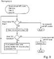
- Fig. 3shows an inventive method of operating the laboratory sample distribution system 100.
- the methodcomprises the steps: a) planning a movement path MP for one of the sample container carriers 140 from a start ST to a goal GA on the transport plane 110, as shown in Fig. 1 and 9 .
- the transport plane 110is logically modelled by a plurality nodes 111, as shown in Fig. 4 .
- the nodes 111are free for at least one time-window fTW or reserved for at least one-time window rTW, as shown in Fig. 5 .
- the planningcomprises analyzing the reachability out of a free time-window fTW of one of the nodes ni to free time-windows fTW of at least one next node nj and at least one at least over-next node nk, such that a planned movement of the one sample container carrier 140 is nonstop from the one node ni over the next node nj to the at least one at least over-next node nk, as shown in Fig. 6 .
- Reserving the planned movement path MPcomprising a sequence of time-windows TW of nodes 111, ni, nj, nk.
- b)executing by controlling at least one of the drive elements 120, such that the one sample container carrier 140 moves along the reserved movement path MP on the transport plane 110, as shown in Fig. 1 and 10 .
- the control device 150is adapted to plan the movement path MP for the one of the sample container carriers 140 from the start ST to the goal GA on the transport plane 110.
- the transport plane 110is logically modelled by the plurality of nodes 111.
- the nodes 111are free for at least one time-window fTW or reserved for at least one-time window rTW.
- the planningcomprises analyzing the reachability out of the free time-window fTW of the one of the nodes ni to free time-windows fTW of the at least one next node nj and the at least one at least over-next node nk, such that the planned movement of the one sample container carrier 140 is nonstop from the one node ni over the next node nj to the at least one over-next node nk.
- the control device 150is adapted to reserve the planned movement path MP comprising the sequence of time-windows TW of nodes 111, ni, nj, nk.
- the control device 150is adapted to execute by controlling the at least one of the drive elements 120, such that the one sample container carrier 140 moves along the reserved movement path MP on the transport plane 110.
- the laboratory sample distribution system 100in particular its control device 150, is adapted to perform the method as described above.
- sample container carriers 140respectively move simultaneously and independently from one another along corresponding, in particular individual, reserved movement paths MP on the transport plane 110.
- control device 150is embodied for this purpose.
- nodes 111are assigned to or cover the electro-magnetic actuators 121, as shown in Fig. 1 and 4 .
- the control device 150is adapted to execute by controlling the electro-magnetic actuators 121, such that the one sample container carrier 140 moves along the reserved movement path MP on the transport plane 110.
- Step b)comprises: executing by controlling the electro-magnetic actuators 121, such that the one sample container carrier 140 moves along the reserved movement path MP on the transport plane 110.
- a respective size or footprint, in particular a diameter, of the sample container carriers 140 on the transport plane 110corresponds to or is twice a distance of neighboring electro-magnetic actuators 121.
- the respective size of the sample container carriers with respect to the distance of neighboring electro-magnetic actuatorsmay be different.
- the respective size of the sample container carriers on the transport planemay correspond to or be the distance of neighboring electro-magnetic actuators.
- the transport plane 110comprises a plurality of transfer locations 30, 31, 32.
- the transfer location 30is assigned to the laboratory station 20
- the transfer location 31is assigned to the laboratory station 21
- the transfer location 32is assigned to the laboratory station 22.
- the start ST of the movement path MPis the transfer location 30.
- the goal GA of the movement path MPis the transfer location 32.
- a next time for a next to be planned movement path of the one sample container carrier the start and/or the goalmay be a different transfer location/s.
- start ST and the goal GAare assigned or correspond to nodes 111 or are represented by nodes 111.
- the nodes 111form a graph or a data structure, as shown in Fig. 4 on the right side.
- nodes 111 and their time-windows TWform a time-window graph or a data structure, as partially shown in Fig. 6 and 8 .
- Step a)comprises: planning the movement path using an informed search algorithm, in the shown embodiment using an A*-algorithm, as shown in Fig. 6 left, in particular by the control device 150.
- an informed search algorithmin the shown embodiment using an A*-algorithm, as shown in Fig. 6 left, in particular by the control device 150.
- a different informed search algorithmmay be used, in particular a D*-algorithm.
- step a)comprises: planning the movement path MP, such that a movement path period MPP, a movement path length MPL, and/or a number of movement turns MT are/is minimized and/or such that a wear of the transport plane 110 and/or a wear of the drive elements 120 are/is balanced, in particular by the control device 150 or the informed search algorithm, respectively.
- the movement path period MPPin particular by avoiding or keeping distance to the another sample container carriers 140, the movement path length MPL and the number of movement turns MT, in particular which is three, could be minimized. Furthermore, the wear of the transport plane 110 and the wear of the drive elements 120 could be balanced.
- movement path MP or the driveis planned iteratively or in sections, respectively, in particular by the, in particular iterative, search algorithm.
- At least one iteration of the search algorithmcomprises analyzing the reachability out of the free time-window fTW of the one of the nodes ni to free time-windows fTW of the at least one next node nj and the at least one at least over-next node nk, such that the planned movement of the one sample container carrier 140 is nonstop from the one node ni over the next node nj to the at least one at least over-next node nk, as shown in Fig. 6 and 8 .
- the search algorithmtries to extend a move through several free time windows fTW, in particular in a straight direction or a, in particular one, dimension x, y.
- the planned and being executed movement path MP or drive of the one sample container carrier 140comprises four movements, in particular movement sections. Three of the movements respectively extend over at least three nodes 111 or electro-magnetic actuators 121, respectively, and are planned nonstop movements. Between the, in particular nonstop, movements the one sample container carrier 140 has to stop, in particular for the movement turns MT. The longest planned nonstop movement extends over eleven nodes 111 or electro-magnetic actuators 121, respectively, in particular along one of the columns 127.
- a distance number of the at least over-next nodes nkis limited, such that the planned nonstop movement has a limited movement length LML.
- the distance numberis maximal nineteen. In alternative embodiments the distance number may be different.
- step a)comprises: reserving for the planned nonstop movement time-windows TW with same beginning time BT, as shown in Fig. 6 right, in particular by the control device 150.
- the reservations or the reserved time-windows rTW, respectively,have a triangular shape.
- step a)comprises: planning the nonstop movement in dependence of an acceleration AC and/or a maximum speed MSP, in particular if reached, and/or a deceleration DC, in particular by the control device 150.
- step a)comprises: analyzing the reachability to time-windows TW only in the future after a planning period PP, as shown in Fig. 7 , in particular by the control device 150.
- the methodcomprises: performing step a) for one of the sample container carriers 140 at a time, in particular by the control device 150.
- the result of the planningis a list that comprises all the nodes 111, ni, nj, nk along the movement path MP and the corresponding time-windows TW, which are defined by the entry times and the exit times at the nodes 111, ni, nj, nk.
- the time-windows TW of the nodes 111, ni, nj, nkare reserved, as shown in Fig. 6 right, 8 and 9, in particular by the control device 150. In detail the reservation is written to the time-window graph or the data structure, respectively.
- step b)comprises: executing, in particular of the reserved movement path MP or a movement of the reserved movement path MP, when a start time STT, in particular the beginning time BT, has come, in particular by the control device 150.
- step b)comprises: executing, in particular of the reserved movement path MP or a movement of the reserved movement path MP, such that a sequence of reserved time-windows rTW of, in particular the, sample container carriers 140 on at least one, in particular on all, of the nodes 111, ni, nj, nk is maintained, in particular by the control device 150.
- the entire movement or segment of the one sample container carrier 140is executed, in particular without any interference of one another of the sample container carriers 140.
- the executing step/s b) or the movement/s of the reserved movement path MP or its/their start time/s STT or beginning time/s BTcan be decoupled from the planned and/or reserved time-windows rTW or times, respectively.
- the methodcomprises: determining a waiting period WP for executing the reserved movement path MP or a movement of the reserved movement path MP, in particular for the conditions start time STT or beginning time BT, respectively, and reserved time windows TW of the next movement or segment are the first ones to be fulfilled, and, if the determined waiting period WP exceeds a waiting period limit WPL, re-planning a movement path MP, as shown in Fig. 7 and 10 , in particular by the control device 150.
- one another of the sample container carriers 140was longer than planned on a reserved node 111 or a reserved part of the transport plane 110 or above the corresponding electro-magnetic actuator 121, respectively, of the next movement or segment of the one sample container carrier 140.
- the waiting period WPwas shorter than the waiting period limit WPL, so a re-planning action is not triggered.
- step b)comprises: deleting a reserved time-window rTW of a node 111, ni, nj, nk, in particular in the time-window graph or the data structure, respectively, after leaving the, in particular reserved, node 111, ni, nj, nk by the one sample container carrier 140, as shown in Fig. 8 , in particular by the control device 150.
- the planning step a) of the movement path MP of the one of the sample container carriers 140 and the executing step/s b) of at least one movement of the at least another one of the sample container carriers 140is performed simultaneously, as shown in Fig. 8 , in particular by the control device 150.
- the inventionprovides a method of operating a laboratory sample distribution system, a laboratory sample distribution system and a laboratory automation system comprising such a laboratory sample distribution system enabling an improved, in particular an efficient and reliable, planning and executing of a movement of a sample container carrier.
Landscapes
- Physics & Mathematics (AREA)
- Health & Medical Sciences (AREA)
- Life Sciences & Earth Sciences (AREA)
- Chemical & Material Sciences (AREA)
- Analytical Chemistry (AREA)
- Biochemistry (AREA)
- General Health & Medical Sciences (AREA)
- General Physics & Mathematics (AREA)
- Immunology (AREA)
- Pathology (AREA)
- Automatic Analysis And Handling Materials Therefor (AREA)
- Non-Mechanical Conveyors (AREA)
Description
- The invention relates to a method of operating a laboratory sample distribution system, a laboratory sample distribution system and a laboratory automation system comprising such a laboratory sample distribution system.
- Known laboratory sample distribution systems are typically used in laboratory automation systems in order to distribute laboratory samples contained in laboratory sample containers by sample container carriers between laboratory stations. For example, a laboratory sample distribution system is disclosed in document
EP 3 095 739 A1 . In particular pre-calculating, in particular fixed, routes and moving the sample container carriers along the pre-calculated routes is disclosed. - Furthermore,
KR 101 740 529 B1 - It is the object of the invention to provide a method of operating a laboratory sample distribution system, a laboratory sample distribution system and a laboratory automation system comprising such a laboratory sample distribution system enabling an improved, in particular an efficient and reliable, calculating and performing of a movement of a sample container carrier.
- This object is solved by a method of operating a laboratory sample distribution system according to claim 1, a laboratory sample distribution system according to claim 13 and a laboratory automation system according to claim 15. Preferred embodiments are defined in the dependent claims.
- The invention relates to a, in particular automatic, method of operating a laboratory sample distribution system. The laboratory sample distribution system comprises a plurality (e.g. 2 to 5000) of sample container carriers, a transport plane and a plurality (e.g. 10 to 1000000) of drive elements. The sample container carriers are, in particular respectively, adapted or embodied to carry a laboratory sample container. The transport plane is adapted or embodied to support the sample container carriers. The drive elements are adapted or embodied to move the sample container carriers on or over the transport plane. The method comprises the steps:
- a) planning, in particular automatically planning, or calculating or searching, respectively, a movement path for one of the sample container carriers from a start or an origin to a goal or a destination on the transport plane. The transport plane, in particular its layout, is logically modelled or abstracted by a plurality (e.g. 10 to 1000000) of nodes. The nodes are free or available for at least one time-window or reserved or unavailable for at least one-time window. The planning comprises analyzing, in particular automatically analyzing, the reachability or the accessibility out of a free time-window of one of the nodes to free time-windows of at least one next node, in particular of all next nodes, and at least one at least over-next node, in particular all at least over-next nodes, such that a planned movement or segment of the one sample container carrier is nonstop or uninterrupted from the one node over the next node to the at least one at least over-next node. Reserving, in particular automatically or logically reserving, the planned movement path comprising a sequence of, in particular until then free, time-windows of nodes. b) executing, in particular automatically executing, by controlling, in particular by automatically controlling, at least one of the drive elements, such that the one sample container carrier moves along the reserved movement path on the transport plane.
- This method enables an improved, in particular an efficient and reliable, planning and executing of the movement or the drive of the, in particular one, sample container carrier.
- In particular this method is advantageous for implementation on a real-time system, in particular on a real-time laboratory sample distribution system, in which during or simultaneously to the planning of a movement path or a drive of one of the sample container carriers the executing of at least one movement path or drive of at least another one of the sample container carriers may be performed. In other words: the planning of the time windows may lead to the proper, in particular strict, separation of step a), namely the planning, and step b), the executing. Differently formulated: reserving may be performed or take only place during the planning step a), in particular before the drive. Thereby. a real-time capability may not be affected. In other words: during the executing step b) or the drive no reserving or no changing of a reservation may be performed or take place and/or a sequence of reserved time-windows of sample container carriers on at least one of the nodes may not be changed.
- Furthermore, this method may enable finding the best, in particular fastest, movement path considering a current traffic situation in real-time. Additionally or alternatively this method may enable considering changes and/or unexpected obstacles during runtime. In particular a transport infrastructure and/or the reachability of goals may change. Additionally or alternatively another one of the sample container carriers, the transport plane and/or one of the drive elements may have an error and cause an obstacle.
- Moreover, this method may enable a relatively accurate drive time calculation or estimation and/or a handling of a variability of drive times.
- Further, this method may enable a relatively short planning period of step a). Additionally, the movement or the drive planned according to the invention may comprise at least one nonstop movement or segment. Thereby, the one sample container carrier may reach a relatively high speed and a relatively fast movement or drive may be enabled.
- In detail the, in particular one, sample container carrier may be adapted or embodied to carry only one or a single laboratory sample container. The sample container carrier may be denoted as single sample container carrier.
- The laboratory sample container may be designed as a tube and/or may have an opening at an upper, top and/or face end. Furthermore, the laboratory sample container may be made of glass or transparent plastic or any other, in particular somewhat, solid material. Moreover, the laboratory sample container or its opening, respectively, may be closed by a closure or a cap, respectively. The closure may comprise rubber and/or plastic or may completely consist of rubber and/or plastic. Further, the closure may be embodied as a foil, in particular a flexible foil, or film or tape or as a lid, in particular as a rigid lid.
- Furthermore, the laboratory sample container may be adapted or embodied to contain a laboratory sample. The laboratory sample may be a blood sample, a serum sample, a plasma sample, a urine sample, a CFS sample, a body sample, a water sample or a chemical sample. In particular the laboratory sample may be a liquid.
- The laboratory sample container or its opening, respectively, may be open for processing, in particular analyzing, the laboratory sample, if present.
- The transport plane may be denoted as transport surface. To support the sample container carriers may be denoted to carry the sample container carriers. The sample container carriers may be translationally moved on or over the transport plane. Furthermore, the sample container carriers may be adapted to move in two dimensions on the transport plane. Moreover, the sample container carriers may slide over the transport plane.
- The drive elements may be electric drive elements.
- In particular a movement or movements of the sample container carrier forming the movement path may be denoted as drive. The movement path may be planned iteratively or in sections or segments, respectively.
- The movement path of the one sample container carrier may be individual, in particular unique. In particular a next time, even though the start and the goal may be the same ones as before, a next planned movement path may be different from the one before.
- The start and the goal of the sample container carrier may be individual, in particular unique. In particular the start may be the current location of the sample container carrier.
- The transport plane may comprise a plurality of, in particular logical, transfer locations, wherein the start and/or the goal, respectively, may be one of the transfer locations.
- The transfer locations may be, in particular logically, assigned or allocated to laboratory stations. E.g. each laboratory station may have a single corresponding transfer location. Alternatively, more than one transfer location may be assigned to a corresponding laboratory station. Additionally or alternatively the transfer locations may be, in particular logically, assigned or allocated to buffer areas, in particular located on the transport plane. E.g. each buffer area may have a single corresponding transfer location. Alternatively, more than one transfer location may be assigned to a corresponding buffer area. The transfer locations may be statically or dynamically assigned to the laboratory stations and/or the buffer areas. In other words, during operation the transfer locations may be changed, if necessary.
- The start and the goal, and in particular the transfer locations, if present, may be, in particular logically, assigned or correspond to nodes or be represented by nodes.
- The nodes may represent fields or areas, in particular of identical size and outline, on the transport plane. In particular a respective size of the nodes or the fields may correspond to a respective size, in particular to a respective footprint, of the sample container carriers on the transport plane. Additionally or alternatively the nodes or the fields may be arranged in two dimensions, in particular in a grid having rows and columns.
- Furthermore, the nodes may form a graph, in particular a directed graph, in the sense of graph theory or a data structure of nodes, respectively, in particular in form of a table. Regarding further details, reference is made to the corresponding technical literature.
- The movement path may be planned by an, in particular iterative, search algorithm.
- For each node a list of free time-windows and reserved time-windows may be maintained or stored, in particular by the search algorithm.
- A free time-window of a node may be defined by an end of a previous or antecent reserved time-window of the node and a beginning of a following or subsequent reserved time-window of the node. In particular the node may be reserved, in particular occupied, by at least one another of the sample container carriers. Additionally or alternatively a node may be, in particular permanently, reserved in case of an unexpected obstacle, by a buffer area and/or in order to represent the, in particular specific, layout of the transport plane. Additionally or alternatively in case of an unexpected obstacle the nodes, in particular the graph or the data structure of the nodes, respectively, may be modified, in particular by the search algorithm.
- The nodes and their time-windows may form a time-window graph or a data structure of the nodes and/or the time-windows, respectively, in particular in form of a table. Furthermore, the search algorithm may, in particular read and, search in the time-window graph or the data structure, respectively, in particular in space and time, the movement path.
- At least one iteration or loop, in particular a plurality of iterations, in particular all iterations, of the search algorithm may comprise analyzing the reachability out of a free time-window of one of the nodes to free time-windows of at least one next node and at least one at least over-next node, such that a planned movement or segment of the one sample container carrier is nonstop from the one node over the next node to the at least one at least over-next node.
- In particular with the exception, that if the next node is the final node, in particular the goal and/or reachable, the planning does not have to comprise analyzing an over-next node.
- In other words: the planning may comprise analyzing the reachability out of a free time-window of one of the nodes to a free time-window of at least one next node, and if reachable, the reachability out of the free time-window of the next node to a free time-window of at least one at least over-next node, and if reachable, and so on.
- The at least one next node may be denoted as neighboring or contiguous node. The at least one at least over-next node may be denoted as non-neighboring or non-contiguous node. Additionally or alternatively at least over-next node may comprise an over-next node, an over-over-next node, an over-over-over-next node and so on.
- In particular the planning may be such that the planned nonstop movement extends over at least three nodes, in particular over at least four nodes, in particular over at least five nodes, in particular over at least ten nodes, in particular over at least twenty nodes. The nonstop movement may be a straight movement. In other words: a movement or segment length of the planned nonstop movement may be limited or bounded by a, in particular necessary, movement turn.
- Following the planning of the nonstop movement a next, in particular nonstop, movement for the movement path, in particular towards the goal or the start, may be planned.
- In detail for a free time-window to be reachable, it may be necessary, that one or more conditions have to be met. A condition may be a sufficient overlapping, in particular between free time-windows. Furthermore, a condition may be a minimal period or size of the free time-window. In particular the minimal free time-window period may depend or be based on an average movement or drive time or speed of the sample container carriers. Additionally or alternatively a condition may be a movement direction or an orientation, along which a node can be moved or driven. In particular the reachability may be restricted or limited, in particular by defined one-ways, in particular defined in determined areas of the transport plane or in between determined nodes, respectively. In other words: a movement of a sample container carrier from one node to a next node may be allowed, but a movement of a sample container carrier from the next node to the one node may be forbidden.
- The result of the planning may be a list that comprises or contains all the nodes along the movement path and the corresponding time-windows, which may be defined by the entry times and the exit times at the nodes or the occupation, respectively.
- The time-windows of the nodes may be reserved, in particular for the first time for the movement path or the drive. In detail the reservation may be written to the time-window graph or a data structure of the time-windows, respectively.
- During the executing step b) or the drive no reserving or no changing of a reservation may be performed or take place and/or a sequence of reserved time-windows of sample container carriers on at least one of the nodes may not be changed. In other words: the method does not have to require simultaneous write, in particular read and write, access to the time-window graph or the data structure, respectively, from planning step a) of the one sample container carrier and from the executing step b) of at least one another of the sample container carriers.
- Analyzing may comprise reading reserved time-windows from and/or searching free time-windows in the time-window graph or the data structure, respectively.
- Step may be denoted as phase.
- Step b) is performed after step a).
- According to an embodiment of the invention step a) comprises: planning, in particular automatically planning, the nonstop movement or segment in dependence of an acceleration and/or a maximum speed, in particular if reached, and/or a deceleration, in particular of a sample container carrier. This enables to increase an efficiency, in particular a throughput, of the laboratory sample distribution system. In particular as a length of the nonstop movement or segment, in particular a first node, a last node and at least one node in between or on the transport plane, respectively, may be known during the planning step a), the acceleration on the first node or the corresponding part of the transport plane and/or the deceleration on the last node or the corresponding part of the transport plane and/or the maximum speed, if reached, on nodes in between may be considered. This may enable a relatively accurate drive time calculation. Furthermore, this may enable to plan and to reserve relatively short time-windows for the movement path. In particular the acceleration may be an average, in particular constant, acceleration and/or may comprise a value from 0,1 meter per square second (m/s2) to 100 m/s2, in particular from 1 m/s2 to 10 m/s2. The maximum speed may be an average, in particular constant, speed and/or may comprise a value from 0,01 meter per second (m/s) to 100 m/s, in particular from 0,1 m/s to 10 m/s. The deceleration may be an average, in particular constant, deceleration and/or may comprise a value from 0,1 m/s2 to 100 m/s2, in particular from 1 m/s2 to 10 m/s2.
- According to an embodiment of the invention step a) comprises: reserving, in particular automatically reserving, for the planned nonstop movement or segment, in particular of the one sample container carrier, time-windows with same beginning or entry time, in particular of all nodes of the nonstop movement. This enables to avoid or to prevent a reservation/s of a movement/s of at least one another of the sample container carriers, in particular of a node after the first node of the planned nonstop movement or segment, which executing might interfere with the executing of the nonstop movement or segment of the one sample container carrier, in particular causing an interruption of the movement, such that it may not be nonstop anymore. According to an embodiment of the invention a distance number of the at least over-next nodes is limited or bounded, such that the planned nonstop movement or segment has a limited movement or segment length, in particular on the transport plane. This enables that not too many nodes are reserved and thus to avoid that at least one another of the sample container carriers may be hindered or blocked, in particular in its/their movement path planning, in particular if the same beginning time is reserved for the planned nonstop movement of the one sample container carrier. In particular the distance number may define a distance from a node to a next node. E.g. the distance number two may mean considering only the at least one next node and the at least one over-next node, but not an over-over-next node. In particular the distance number may be maximal nineteen, in particular maximal nine, in particular maximal four. Additionally or alternatively the distance number may be minimal one.
- According to an embodiment of the invention step a) comprises: analyzing, in particular automatically analyzing, the reachability to, in particular free, time-windows only in the future after a planning period. This enables to ensure that the planning step a) is performed or finished or completed before the executing step b) should be or is performed or started. In other words: for the executing step b) or its start time not time-windows at the current or actual time may be considered, but time-windows at or after the current time plus the planning period may be considered. The planning period may be denoted as anticipation horizon time. In particular the planning period may comprise a, in particular minimal and/or maximal, value from 0,1 milliseconds (ms) to 10000 ms, in particular from 1 ms to 1000 ms.
- According to an embodiment of the invention the method comprises: performing step a), in particular for the transport plane or the nodes, for, in particular only, one of the sample container carriers at a time, and in particular for no other sample container at the same time. In other words: the multi-agent path problem is solved sequentially for the sample containers carriers. Differently formulated: the planning steps a) of the movement paths for the sample container carriers may be done one after another. However, the executing steps b) of the movement paths may take place simultaneously. This, in particular sequential approach, enables to avoid or to prevent simultaneously reserving for at least two, in particular different, of the sample container carriers. In particular simultaneous reservations may interfere, in particular a same node/s may be reserved, and thus may lead to a conflict. However, if the laboratory sample distribution system comprises different, in particular not interfering and/or independent, transport planes logically modelled by different nodes, respectively, for the different transport planes or their nodes step a) may be performed simultaneously.
- According to an embodiment of the invention step a) comprises: planning, in particular automatically planning, the movement path, such that a movement path period, a movement path length, and/or a number of movement turns are/is minimized and/or such that a wear of the transport plane and/or a wear of the drive elements are/is balanced. This may enable that the planned movement path is the fastest or the shortest and/or the shortest movement path through the free time-windows. Additionally or alternatively this may enable that an aging effect/s may be balanced. This may be denoted as taking into account one or more criteria into a cost function of the planning, in particular which may dynamically change in real-time (e.g. take into account the wear to balance the aging effect/s).
- According to an embodiment step a) comprises: planning, in particular automatically planning, the movement path using an informed search algorithm, in particular an A*-algorithm or a D*-algorithm. In particular the A*-algorithm is an algorithm that is used in path finding and graph traversal, to efficiently calculate a traversable path between different nodes, e.g. in the form of the start, the goal, and in particular the transfer locations, if present. The A*-algorithm uses a best-first search and finds a least-cost path from a given start node to one goal node. As the A*-algorithm traverses the graph, it follows a path of the lowest expected total cost, keeping a sorted priority queue of alternate path segments along the way. The D*-algorithm is a refined A*-algorithm. Regarding further details, reference is made to the corresponding technical literature.
- According to an embodiment of the invention step b) comprises: executing, in particular automatically executing, in particular of the reserved movement path or a movement of the reserved movement path, when a start time, in particular the beginning time, has come. In particular the start time or the beginning time, if present, may be different from the current time plus the planning period, if present, in particular later.
- According to an embodiment of the invention step b) comprises: executing, in particular automatically executing, in particular of the reserved movement path or a movement of the reserved movement path, such that a sequence of reserved time-windows of, in particular different, sample container carriers on at least one, in particular on a plurality, in particular on all, of the nodes is maintained, in particular as planned. This enables to avoid or to prevent deadlocks, situations where one or more of the sample container carriers could be blocked forever, or collisions and thus a steady-state throughput of the sample container carriers and/or laboratory sample containers may be ensured. Additionally, this enables providing information of an arrival sequence, in particular before the executing step b) or the drive starts. In particular the executing step/s b) or the movement/s of the reserved movement path or its/their start time/s or beginning time/s, if present, may be decoupled from the planned and/or reserved time-windows or times, respectively. An unexpected delay of one of the sample container carriers on a part of the transport plane logically modelled by the one node may occur and thus there may be a deviation from the planned time-windows or times, respectively, of the sample container carriers, in particular the planned time-windows may not be met.
- According to an embodiment of the invention the method comprises: determining, in particular automatically determining, a waiting period for executing the reserved movement path or a movement or segment of the reserved movement path and, if the determined waiting period exceeds or upon exceedance of a waiting period limit, re-planning, in particular automatically re-planning, a movement path, in particular for the one sample container carreir. In particular the method may comprise: repeating step a), in particular only for the waiting sample container carrier, in particular for a plurality of the sample container carriers, in particular for all of the sample container carriers. This enables to react on unexpected obstacles, in particular that may introduce major delays to the executing step b) of the planned and reserved movement path or a movement of the reserved movement path. In particular the waiting period limit may comprise a, in particular minimal and/or maximal, value from 0,1 seconds (s) to 1000 s, in particular from 1 s to 100 s.
- According to an embodiment of the invention step b) comprises: deleting a reserved time-window of a node or releasing the reserved node, respectively, in particular in the time-window graph or the data structure, respectively, after leaving or passing the, in particular reserved, node by the one sample container carrier.
- According to an embodiment of the invention the sample container carriers, in particular respectively, comprise a magnetically active device. The drive elements comprise a plurality (e.g. 10 to 1000000) of electro-magnetic actuators. The electro-magnetic actuators are stationary arranged below the transport plane and are adapted or embodied to move the sample container carriers on the transport plane by applying a magnetic move force to the sample container carriers. The nodes are, in particular logically, assigned to the electro-magnetic actuators, in particular to their locations or positions. Step b) comprises: executing, in particular automatically executing, by controlling, in particular by automatically controlling, the electro-magnetic actuators, such that the one sample container carrier moves along the reserved movement path on the transport plane.
- In particular the electro-magnetic actuators may be adapted to generate a magnetic field to move the, in particular one, sample container carrier on the transport plane. The magnetically active device may be adapted to interact with the magnetic field generated by the electro-magnetic actuators, such that the magnetic move force is applied to the sample container carrier. In particular the magnetically active device may be a permanent magnet or an electromagnet. Additionally or alternatively the magnetically active device may comprise a magnetically soft material. The electro-magnetic actuators may be solenoids or coils surrounding ferromagnetic cores. Furthermore, the electro-magnetic actuators may be driven or energized individually in order to generate or to provide the magnetic field. Moreover, the electro-magnetic actuators may be arranged in two dimensions, in particular in a grid having rows and columns, along which the electro-magnetic actuators are arranged. Further, the electro-magnetic actuators may be arranged in a plane parallel to the transport plane.
- One, in particular a plurality, in particular all, of the nodes or fields may be defined or located on the transport plane above the corresponding electro-magnetic actuator/s or may cover the corresponding electro-magnetic actuator/s.
- Additionally or alternatively the drive elements may comprise a plurality of wheels and drive motors, respectively, to drive the wheels. The drive motors and the wheels may be adapted to move the sample container carriers on the transport plane. Step b) may comprise: executing, in particular automatically executing, by controlling, in particular by automatically controlling, the wheels and/or the drive motors, such that the one sample container carrier moves along the reserved movement path on the transport plane. In particular the sample container carriers, respectively, may comprise at least one of the wheels and/or at least one of the drive motors.
- The invention further relates to a laboratory sample distribution system. The laboratory sample distribution system comprises: a plurality of sample container carriers, a transport plane, a plurality of drive elements and a control device. The sample container carriers are adapted to carry a laboratory sample container. The transport plane is adapted to support the sample container carriers. The drive elements are adapted to move the sample container carriers on the transport plane. The control device is adapted or configured to plan, in particular to automatically plan, a movement path for one of the sample container carriers from a start to a goal on the transport plane. The transport plane is logically modelled by a plurality of nodes. The nodes are free for at least one time-window or reserved for at least one-time window. The planning comprises analyzing, in particular automatically analyzing, the reachability out of a free time-window of one of the nodes to free time-windows of at least one next node and at least one at least over-next node, such that a planned movement of the one sample container carrier is nonstop from the one node over the next node to the at least one over-next node. Furthermore, the control device is adapted or configured to reserve, in particular to automatically reserve, the planned movement path comprising a sequence of time-windows of nodes. Moreover, the control device is adapted or configured to execute, in particular to automatically execute, by controlling, in particular by automatically controlling, at least one of the drive elements, such that the one sample container carrier moves along the reserved movement path on the transport plane.
- In particular the laboratory sample distribution system, in particular its control device, may be adapted or configured to perform the method as described above.
- By means of the method according to the invention, the advantages of the method according to the invention, as discussed above, may be made applicable for the laboratory sample distribution system.
- Furthermore, the laboratory sample distribution system may be embodied as described above for the method.
- The control device may comprise or be an integrated circuit, a tablet computer, a smartphone or a computer. Additionally or alternatively the control device may comprise or be a microprocessor and a method or program storage.
- According to an embodiment of the invention the sample container carriers comprise a magnetically active device. The drive elements comprise a plurality of electro-magnetic actuators. The electro-magnetic actuators are stationary arranged below the transport plane and are adapted or embodied to move the sample container carriers on the transport plane by applying a magnetic move force to the sample container carriers. The nodes are, in particular logically, assigned to the electro-magnetic actuators. The control device is adapted or configured to execute, in particular to automatically execute, by controlling, in particular by automatically controlling, the electro-magnetic actuators, such that the one sample container carrier moves along the reserved movement path on the transport plane.
- The invention further relates to a laboratory automation system. The laboratory automation system comprises a plurality (e.g. 2 to 50) of laboratory stations and a laboratory sample distribution system as described above. The laboratory sample distribution system is adapted or embodied to move the sample container carriers to the laboratory stations or to distribute the sample container carriers in between the laboratory stations, respectively.
- By means of the laboratory sample distribution system according to the invention, the advantages of the laboratory sample distribution system according to the invention, as discussed above, may be made applicable for the laboratory automation system.
- In particular the laboratory stations may comprise pre-analytical, analytical and/or post-analytical laboratory stations. Pre-analytical laboratory stations may be adapted to perform any kind of pre-processing of a laboratory sample, a laboratory sample container and/or a sample container carrier. Analytical laboratory stations may be adapted to use a laboratory sample or a part of a laboratory sample and a reagent to generate a measuring signal, the measuring signal indicating if and in which concentration, if any, an analyte is existing. Post-analytical laboratory stations may be adapted to perform any kind of post-processing of a laboratory sample, a laboratory sample container and/or a sample container carrier. The pre-analytical, analytical and/or post-analytical laboratory stations may comprise at least one of a decapping station, a recapping station, an aliquot station, a centrifugation station, an archiving station, a pipetting station, a sorting station, a tube type identification station, a sample quality determining station, an add-on buffer station, a liquid level detection station, a sealing/desealing station, a pushing station, a belt station, a conveying system station and/or a gripper station for moving a laboratory sample container to or from ta sample container carrier.
- Furthermore, the laboratory stations may be arranged adjacent or directly next to the laboratory sample distribution system, in particular to its transport plane.
- The transport plane may comprise a plurality of transfer locations, wherein the transfer locations may be, in particular logically, assigned to the laboratory stations.
- Laboratory samples, and/or laboratory sample containers, and/or the sample container carriers may be transferred to/from the laboratory stations using the transfer locations. E.g. a pick-and-place device may pick a laboratory sample container comprised in or carried by one of the sample container carriers located at or on one of the transfer locations and may transfer the laboratory sample container to the laboratory station. Additionally or alternatively a laboratory sample container may be transferred from one of the laboratory stations to one, in particular empty, of the sample container carriers located on one of the transfer locations.
- In the following, an embodiment of the invention will be described in detail with reference to the drawings. Throughout the drawings, the same elements will be denoted by the same reference numerals.
- Fig. 1
- schematically shows a perspective view of a laboratory automation system according to the invention comprising a laboratory sample distribution system according to the invention,
- Fig. 2
- schematically shows a longitudinal section view of a sample container of the laboratory sample distribution system of
Fig. 1 , - Fig. 3
- schematically shows a method according to the invention of operating the laboratory sample distribution system of
Fig. 1 , - Fig. 4
- schematically shows a top view of a transport plane of the laboratory sample distribution system of
Fig. 1 logically modelled by a plurality of nodes by the method ofFig. 3 , - Fig. 5
- schematically shows a list of free time-windows and reserved time-windows of a node,
- Fig. 6
- schematically shows a part of a time-window graph or a data structure, respectively, comprising reserved time-windows of a planned nonstop movement by the method of
Fig. 3 , - Fig. 7
- schematically shows a timing of a planning step and an executing step of the method of
Fig. 3 , - Fig. 8
- schematically shows the planning step reading from and writing to the time-window graph or the data structure, respectively, and the executing step reading from and deleting in the time-window graph or the data structure, respectively, of the method of
Fig. 3 , - Fig. 9
- schematically shows a flowchart of the planning step of the method of
Fig. 3 , and - Fig. 10
- schematically shows a flowchart of the executing step of the method of
Fig. 3 . Fig. 1 shows an inventivelaboratory automation system 10. Thelaboratory automation system 10 comprises a plurality oflaboratory stations sample distribution system 100.- In the shown embodiment the
laboratory automation system 10 comprises threelaboratory stations - The
laboratory sample distribution 100 system comprises a plurality ofsample container carriers 140, atransport plane 110, a plurality ofdrive elements 120 and acontrol device 150. Thesample container carriers 140 are adapted to carry alaboratory sample container 145. Thetransport plane 110 is adapted to support thesample container carriers 140. Thedrive elements 120 are adapted to move thesample container carriers 140 on thetransport plane 110. - In the embodiment shown in
Fig. 1 thelaboratory sample distribution 100 comprises threesample container carriers 140. In alternative embodiments the laboratory sample distribution system may comprise more than three sample container carriers. - The
laboratory sample containers 145 respectively contain laboratory samples to be analyzed by means of thelaboratory stations - The laboratory
sample distribution system 100 is adapted to move thesample container carriers 140 to thelaboratory stations - In the shown embodiment the
laboratory stations sample distribution system 100, in particular to itstransport plane 110. - In detail the
sample container carriers 140 can be translationally moved in two dimensions x, y being perpendicular to each other on thetransport plane 110. - In the shown embodiment the
sample container carriers 140 respectively comprise a sliding surface being adapted to be in, in particular direct, contact with thetransport plane 110 and enables performing movements, in particular slides, of thesample container carriers 140 on thetransport plane 110. - In detail the
sample container carriers 140 comprise a magneticallyactive device 141, as shown inFig. 2 , in particular in form of a permanent magnet. Thedrive elements 120 comprise a plurality of electro-magnetic actuators 121. The electro-magnetic actuators 121 are stationary arranged below thetransport plane 110 and are adapted to move thesample container carriers 140 on thetransport plane 110 by applying a magnetic move force to thesample container carriers 140. - In the shown embodiment the electro-
magnetic actuators 121 respectively comprise a solenoid surrounding aferromagnetic core 122. - Furthermore, the electro-
magnetic actuators 121 are quadratically arranged in agrid having rows 126 andcolumns 127, in particular in a plane parallel to thetransport plane 110. In each center of a quadrat formed by corresponding electro-magnetic actuators 121 no electro-magnetic actuator is arranged. In other words: in each second row in each second position there is no electro-magnetic actuator 121. - Moreover, the laboratory
sample distribution system 100 comprises a plurality ofposition sensors 125, in particular in form of Hall-sensors and/or inductive sensors. Theposition sensors 125 are arranged, such that a position or a location of a respectivesample container carrier 140, in particular of its magneticallyactive device 141, on thetransport plane 110 can be detected. Thecontrol device 150 is functionally coupled to, in particular in signal connection with, theposition sensors 125 for detecting the position of thesample container carrier 140. Thecontrol device 150 is adapted to control thedrive elements 120, in particular the electro-magnetic actuators 121, in response to the detected position. Fig. 3 shows an inventive method of operating the laboratorysample distribution system 100. The method comprises the steps: a) planning a movement path MP for one of thesample container carriers 140 from a start ST to a goal GA on thetransport plane 110, as shown inFig. 1 and9 . Thetransport plane 110 is logically modelled by aplurality nodes 111, as shown inFig. 4 . Thenodes 111 are free for at least one time-window fTW or reserved for at least one-time window rTW, as shown inFig. 5 . The planning comprises analyzing the reachability out of a free time-window fTW of one of the nodes ni to free time-windows fTW of at least one next node nj and at least one at least over-next node nk, such that a planned movement of the onesample container carrier 140 is nonstop from the one node ni over the next node nj to the at least one at least over-next node nk, as shown inFig. 6 . Reserving the planned movement path MP comprising a sequence of time-windows TW ofnodes 111, ni, nj, nk. b) executing by controlling at least one of thedrive elements 120, such that the onesample container carrier 140 moves along the reserved movement path MP on thetransport plane 110, as shown inFig. 1 and10 .- The
control device 150 is adapted to plan the movement path MP for the one of thesample container carriers 140 from the start ST to the goal GA on thetransport plane 110. Thetransport plane 110 is logically modelled by the plurality ofnodes 111. Thenodes 111 are free for at least one time-window fTW or reserved for at least one-time window rTW. The planning comprises analyzing the reachability out of the free time-window fTW of the one of the nodes ni to free time-windows fTW of the at least one next node nj and the at least one at least over-next node nk, such that the planned movement of the onesample container carrier 140 is nonstop from the one node ni over the next node nj to the at least one over-next node nk. Furthermore, thecontrol device 150 is adapted to reserve the planned movement path MP comprising the sequence of time-windows TW ofnodes 111, ni, nj, nk. Moreover, thecontrol device 150 is adapted to execute by controlling the at least one of thedrive elements 120, such that the onesample container carrier 140 moves along the reserved movement path MP on thetransport plane 110. - In the shown embodiment the laboratory
sample distribution system 100, in particular itscontrol device 150, is adapted to perform the method as described above. - Furthermore, in the shown embodiment the
sample container carriers 140 respectively move simultaneously and independently from one another along corresponding, in particular individual, reserved movement paths MP on thetransport plane 110. In particular thecontrol device 150 is embodied for this purpose. - In detail the
nodes 111 are assigned to or cover the electro-magnetic actuators 121, as shown inFig. 1 and4 . - The
control device 150 is adapted to execute by controlling the electro-magnetic actuators 121, such that the onesample container carrier 140 moves along the reserved movement path MP on thetransport plane 110. - Step b) comprises: executing by controlling the electro-
magnetic actuators 121, such that the onesample container carrier 140 moves along the reserved movement path MP on thetransport plane 110. - In the embodiment shown in
Fig. 1 a respective size or footprint, in particular a diameter, of thesample container carriers 140 on thetransport plane 110 corresponds to or is twice a distance of neighboring electro-magnetic actuators 121. In alternative embodiments the respective size of the sample container carriers with respect to the distance of neighboring electro-magnetic actuators may be different. In particular the respective size of the sample container carriers on the transport plane may correspond to or be the distance of neighboring electro-magnetic actuators. - Furthermore, in the shown embodiment the
transport plane 110 comprises a plurality oftransfer locations transfer location 30 is assigned to thelaboratory station 20, thetransfer location 31 is assigned to thelaboratory station 21 and thetransfer location 32 is assigned to thelaboratory station 22. - In the embodiment shown in
Fig. 1 the start ST of the movement path MP is thetransfer location 30. The goal GA of the movement path MP is thetransfer location 32. A next time for a next to be planned movement path of the one sample container carrier the start and/or the goal may be a different transfer location/s. - In detail the start ST and the goal GA, and in particular the
transfer locations nodes 111 or are represented bynodes 111. - The
nodes 111 form a graph or a data structure, as shown inFig. 4 on the right side. - In detail the
nodes 111 and their time-windows TW form a time-window graph or a data structure, as partially shown inFig. 6 and8 . - Step a) comprises: planning the movement path using an informed search algorithm, in the shown embodiment using an A*-algorithm, as shown in
Fig. 6 left, in particular by thecontrol device 150. In alternative embodiments a different informed search algorithm may be used, in particular a D*-algorithm. - In detail step a) comprises: planning the movement path MP, such that a movement path period MPP, a movement path length MPL, and/or a number of movement turns MT are/is minimized and/or such that a wear of the
transport plane 110 and/or a wear of thedrive elements 120 are/is balanced, in particular by thecontrol device 150 or the informed search algorithm, respectively. - In the embodiment shown in
Fig. 1 for the planned movement path MP of the onesample container carrier 140 the movement path period MPP, in particular by avoiding or keeping distance to the anothersample container carriers 140, the movement path length MPL and the number of movement turns MT, in particular which is three, could be minimized. Furthermore, the wear of thetransport plane 110 and the wear of thedrive elements 120 could be balanced. - In detail the movement path MP or the drive is planned iteratively or in sections, respectively, in particular by the, in particular iterative, search algorithm.
- At least one iteration of the search algorithm comprises analyzing the reachability out of the free time-window fTW of the one of the nodes ni to free time-windows fTW of the at least one next node nj and the at least one at least over-next node nk, such that the planned movement of the one
sample container carrier 140 is nonstop from the one node ni over the next node nj to the at least one at least over-next node nk, as shown inFig. 6 and8 . - In other words: in particular within each iteration, the search algorithm tries to extend a move through several free time windows fTW, in particular in a straight direction or a, in particular one, dimension x, y.
- For the embodiment shown in
Fig. 1 the planned and being executed movement path MP or drive of the onesample container carrier 140 comprises four movements, in particular movement sections. Three of the movements respectively extend over at least threenodes 111 or electro-magnetic actuators 121, respectively, and are planned nonstop movements. Between the, in particular nonstop, movements the onesample container carrier 140 has to stop, in particular for the movement turns MT. The longest planned nonstop movement extends over elevennodes 111 or electro-magnetic actuators 121, respectively, in particular along one of thecolumns 127. - In detail a distance number of the at least over-next nodes nk is limited, such that the planned nonstop movement has a limited movement length LML. In the shown embodiment the distance number is maximal nineteen. In alternative embodiments the distance number may be different.
- Furthermore, step a) comprises: reserving for the planned nonstop movement time-windows TW with same beginning time BT, as shown in
Fig. 6 right, in particular by thecontrol device 150. - As a result, the reservations or the reserved time-windows rTW, respectively, have a triangular shape.
- Moreover, step a) comprises: planning the nonstop movement in dependence of an acceleration AC and/or a maximum speed MSP, in particular if reached, and/or a deceleration DC, in particular by the
control device 150. - Further, step a) comprises: analyzing the reachability to time-windows TW only in the future after a planning period PP, as shown in
Fig. 7 , in particular by thecontrol device 150. - In detail step a) starts or begins at the current time t0. Only time-windows in the future after the current time t0 plus the planning period PP time t = t0 + PP are analyzed or considered.
- Furthermore, the method comprises: performing step a) for one of the
sample container carriers 140 at a time, in particular by thecontrol device 150. - The result of the planning is a list that comprises all the
nodes 111, ni, nj, nk along the movement path MP and the corresponding time-windows TW, which are defined by the entry times and the exit times at thenodes 111, ni, nj, nk. The time-windows TW of thenodes 111, ni, nj, nk are reserved, as shown inFig. 6 right, 8 and 9, in particular by thecontrol device 150. In detail the reservation is written to the time-window graph or the data structure, respectively. - Moreover, step b) comprises: executing, in particular of the reserved movement path MP or a movement of the reserved movement path MP, when a start time STT, in particular the beginning time BT, has come, in particular by the
control device 150. - Further, step b) comprises: executing, in particular of the reserved movement path MP or a movement of the reserved movement path MP, such that a sequence of reserved time-windows rTW of, in particular the,
sample container carriers 140 on at least one, in particular on all, of thenodes 111, ni, nj, nk is maintained, in particular by thecontrol device 150. - In detail the next, in particular nonstop, movement or its
nodes 111, ni, nj, nk or segment, respectively, of the onesample container carrier 140 are read, in particular from the time-window graph or the data structure, respectively, as shown inFig. 8 and10 , in particular by thecontrol device 150. - As soon as the start time STT, in particular the beginning time BT, has come and all the time windows TW of the next movement or segment are the first reserved ones on the
respective nodes 111, ni, nj, nk, the entire movement or segment of the onesample container carrier 140 is executed, in particular without any interference of one another of thesample container carriers 140. - In particular the executing step/s b) or the movement/s of the reserved movement path MP or its/their start time/s STT or beginning time/s BT can be decoupled from the planned and/or reserved time-windows rTW or times, respectively.
- Furthermore, the method comprises: determining a waiting period WP for executing the reserved movement path MP or a movement of the reserved movement path MP, in particular for the conditions start time STT or beginning time BT, respectively, and reserved time windows TW of the next movement or segment are the first ones to be fulfilled, and, if the determined waiting period WP exceeds a waiting period limit WPL, re-planning a movement path MP, as shown in
Fig. 7 and10 , in particular by thecontrol device 150. - In the shown embodiment one another of the
sample container carriers 140 was longer than planned on areserved node 111 or a reserved part of thetransport plane 110 or above the corresponding electro-magnetic actuator 121, respectively, of the next movement or segment of the onesample container carrier 140. However, the waiting period WP was shorter than the waiting period limit WPL, so a re-planning action is not triggered. - Moreover, in the embodiment shown in
Fig. 7 the start time STT is later than the current time t0 plus the planning period PP time t = t0 + PP. - Further, step b) comprises: deleting a reserved time-window rTW of a
node 111, ni, nj, nk, in particular in the time-window graph or the data structure, respectively, after leaving the, in particular reserved,node 111, ni, nj, nk by the onesample container carrier 140, as shown inFig. 8 , in particular by thecontrol device 150. - In detail the planning step a) of the movement path MP of the one of the
sample container carriers 140 and the executing step/s b) of at least one movement of the at least another one of thesample container carriers 140 is performed simultaneously, as shown inFig. 8 , in particular by thecontrol device 150. - As the shown and above discussed embodiments reveal, the invention provides a method of operating a laboratory sample distribution system, a laboratory sample distribution system and a laboratory automation system comprising such a laboratory sample distribution system enabling an improved, in particular an efficient and reliable, planning and executing of a movement of a sample container carrier.
Claims (15)
- Method of operating a laboratory sample distribution system (100), wherein the laboratory sample distribution system (100) comprises:- a plurality of sample container carriers (140), wherein the sample container carriers (140) are adapted to carry a laboratory sample container (145),- a transport plane (110), wherein the transport plane (110) is adapted to support the sample container carriers (140), and- a plurality of drive elements (120), wherein the drive elements (120) are adapted to move the sample container carriers (140) on the transport plane (110),characterized in that the method comprises the steps:- a) planning a movement path (MP) for one of the sample container carriers (140) from a start (ST) to a goal (GA) on the transport plane (110), wherein the transport plane (110) is logically modelled by a plurality of nodes (111), wherein the nodes (111) are free for at least one time-window (fTW) or reserved for at least one-time window (rTW), wherein the planning comprises analyzing the reachability out of a free time-window (fTW) of one of the nodes (ni) to free time-windows (fTW) of at least one next node (nj) and at least one at least over-next node (nk), such that a planned movement of the one sample container carrier (140) is nonstop from the one node (ni) over the next node (nj) to the at least one at least over-next node (nk), and reserving the planned movement path (MP) comprising a sequence of time-windows (TW) of nodes (111, ni, nj, nk), and- b) executing by controlling at least one of the drive elements (120), such that the one sample container carrier (140) moves along the reserved movement path (MP) on the transport plane (110).
- Method according to claim 1, wherein step a) comprises:- planning the nonstop movement in dependence of an acceleration (AC) and/or a maximum speed (MSP) and/or a deceleration (DC).
- Method according to any one of the preceding claims, wherein step a) comprises:- reserving for the planned nonstop movement time-windows (TW) with same beginning time (BT).
- Method according to any one of the preceding claims,- wherein a distance number of the at least over-next nodes (nk) is limited, such that the planned nonstop movement has a limited movement length (LML).
- Method according to any one of the preceding claims, wherein step a) comprises:- analyzing the reachability to time-windows (TW) only in the future after a planning period (PP).
- Method according to any one of the preceding claims, wherein the method comprises:- performing step a) for one of the sample container carriers (140) at a time.
- Method according to any one of the preceding claims, wherein step a) comprises:- planning the movement path (MP), such that a movement path period (MPP), a movement path length (MPL), and/or a number of movement turns (MT) are/is minimized and/or such that a wear of the transport plane (110) and/or a wear of the drive elements (120) are/is balanced.
- Method according to any one of the preceding claims, wherein step a) comprises:- planning the movement path (MP) using an informed search algorithm, in particular an A*-algorithm or a D*-algorithm.
- Method according to any one of the preceding claims, wherein step b) comprises:- executing, when a start time (STT) has come.
- Method according to any one of the preceding claims, wherein step b) comprises:- executing, such that a sequence of reserved time-windows (rTW) of sample container carriers (140) on at least one of the nodes (111, ni, nj, nk) is maintained.
- Method according any one of the preceding claims, wherein the method comprises:- determining a waiting period (WP) for executing the reserved movement path (MP) or a movement of the reserved movement path (MP), and- , if the determined waiting period (WP) exceeds a waiting period limit (WPL), re-planning a movement path (MP).
- Method according to any one of the preceding claims,- wherein the sample container carriers (140) comprise a magnetically active device (141),- wherein the drive elements (120) comprise a plurality of electro-magnetic actuators (121), wherein the electro-magnetic actuators (121) are stationary arranged below the transport plane (110) and are adapted to move the sample container carriers (140) on the transport plane (110) by applying a magnetic move force to the sample container carriers (140),- wherein the nodes (111) are assigned to the electro-magnetic actuators (121), and- wherein step b) comprises: executing by controlling the electro-magnetic actuators (121), such that the one sample container carrier (140) moves along the reserved movement path (MP) on the transport plane (110)
- Laboratory sample distribution system (100), wherein the laboratory sample distribution system (100) comprises:- a plurality of sample container carriers (140), wherein the sample container carriers (140) are adapted to carry a laboratory sample container (145),- a transport plane (110), wherein the transport plane (110) is adapted to support the sample container carriers (140), and- a plurality of drive elements (120), wherein the drive elements (120) are adapted to move the sample container carriers (140) on the transport plane (110),
characterized by- a control device (150), wherein the control device (150) is adapted:- to plan a movement path (MP) for one of the sample container carriers (140) from a start (ST) to a goal (GA) on the transport plane (110), wherein the transport plane (110) is logically modelled by a plurality of nodes (111, ni, nj, nk), wherein the nodes (111, ni, nj, nk) are free for at least one time-window (fTW) or reserved for at least one-time window (rTW), wherein the planning comprises analyzing the reachability out of a free time-window (fTW) of one of the nodes (ni) to free time-windows (fTW) of at least one next node (nj) and at least one at least over-next node (nk), such that a planned movement of the one sample container carrier (140) is nonstop from the one node (ni) over the next node (nj) to the at least one over-next node (nk), and to reserve the planned movement path (MP) comprising a sequence of time-windows (TW) of nodes (111, ni, nj, nk), and- to execute by controlling at least one of the drive elements (120), such that the one sample container carrier (140) moves along the reserved movement path (MP) on the transport plane (110). - Laboratory sample distribution system (100) according to claim 13,- wherein the sample container carriers (140) comprise a magnetically active device (141),- wherein the drive elements (120) comprise a plurality of electro-magnetic actuators (121), wherein the electro-magnetic actuators (121) are stationary arranged below the transport plane (110) and are adapted to move the sample container carriers (140) on the transport plane (110) by applying a magnetic move force to the sample container carriers (140),- wherein the nodes (111) are assigned to the electro-magnetic actuators (121), and- wherein the control device (150) is adapted to execute by controlling the electro-magnetic actuators (121), such that the one sample container carrier (140) moves along the reserved movement path (MP) on the transport plane (110).
- Laboratory automation system (10), wherein the laboratory automation system (10) comprises:- a plurality of laboratory stations (20, 21, 22), and- a laboratory sample distribution system (100) according to claim 13 or 14, wherein the laboratory sample distribution system (100) is adapted to move the sample container carriers (140) to the laboratory stations (20, 21, 22).
Priority Applications (5)
| Application Number | Priority Date | Filing Date | Title |
|---|---|---|---|
| EP18160474.5AEP3537159B1 (en) | 2018-03-07 | 2018-03-07 | Method of operating a laboratory sample distribution system, laboratory sample distribution system and laboratory automation system |
| CN201980016382.8ACN111819445B (en) | 2018-03-07 | 2019-02-27 | Method of operating a laboratory sample distribution system, laboratory sample distribution system and laboratory automation system |
| PCT/EP2019/054830WO2019170488A1 (en) | 2018-03-07 | 2019-02-27 | Method of operating a laboratory sample distribution system, laboratory sample distribution system and laboratory automation system |
| JP2020546877AJP7052060B2 (en) | 2018-03-07 | 2019-02-27 | How to operate the laboratory sample distribution system, laboratory sample distribution system, and laboratory automation system |
| US17/012,675US11971420B2 (en) | 2018-03-07 | 2020-09-04 | Method of operating a laboratory sample distribution system, laboratory sample distribution system and laboratory automation system |
Applications Claiming Priority (1)
| Application Number | Priority Date | Filing Date | Title |
|---|---|---|---|
| EP18160474.5AEP3537159B1 (en) | 2018-03-07 | 2018-03-07 | Method of operating a laboratory sample distribution system, laboratory sample distribution system and laboratory automation system |
Publications (2)
| Publication Number | Publication Date |
|---|---|
| EP3537159A1 EP3537159A1 (en) | 2019-09-11 |
| EP3537159B1true EP3537159B1 (en) | 2022-08-31 |
Family
ID=61598927
Family Applications (1)
| Application Number | Title | Priority Date | Filing Date |
|---|---|---|---|
| EP18160474.5AActiveEP3537159B1 (en) | 2018-03-07 | 2018-03-07 | Method of operating a laboratory sample distribution system, laboratory sample distribution system and laboratory automation system |
Country Status (5)
| Country | Link |
|---|---|
| US (1) | US11971420B2 (en) |
| EP (1) | EP3537159B1 (en) |
| JP (1) | JP7052060B2 (en) |
| CN (1) | CN111819445B (en) |
| WO (1) | WO2019170488A1 (en) |
Families Citing this family (22)
| Publication number | Priority date | Publication date | Assignee | Title |
|---|---|---|---|---|
| EP3357842B1 (en) | 2017-02-03 | 2022-03-23 | Roche Diagnostics GmbH | Laboratory automation system |
| DE102018129727A1 (en) | 2018-11-26 | 2020-05-28 | Beckhoff Automation Gmbh | Device and method for avoiding a collision when driving at least two movers on a drive surface |
| DE102018129738A1 (en) | 2018-11-26 | 2020-05-28 | Beckhoff Automation Gmbh | Device and method for path planning for a mover of a drive device |
| DE102018129739A1 (en) | 2018-11-26 | 2020-05-28 | Beckhoff Automation Gmbh | Device for driving at least one mover on a drive surface |
| DE102018129732A1 (en) | 2018-11-26 | 2020-05-28 | Beckhoff Automation Gmbh | Device and method for avoiding a collision when driving at least two movers on a drive surface |
| DE102018129731A1 (en) | 2018-11-26 | 2020-05-28 | Beckhoff Automation Gmbh | Method for driving a rotor of a planar drive system |
| JP7236981B2 (en)* | 2019-10-28 | 2023-03-10 | 株式会社日立ハイテク | Transported object, container carrier and transport device |
| EP3925911B1 (en) | 2020-06-19 | 2023-05-24 | Roche Diagnostics GmbH | Laboratory sample distribution system and corresponding method of operation |
| EP3940388B1 (en)* | 2020-07-15 | 2024-04-10 | Roche Diagnostics GmbH | Laboratory sample distribution system and method for operating the same |
| CN116249659A (en) | 2020-09-22 | 2023-06-09 | 豪夫迈·罗氏有限公司 | distribution system |
| EP4001923B1 (en) | 2020-11-23 | 2024-06-05 | Roche Diagnostics GmbH | Laboratory sample distribution system and laboratory automation system |
| US11747356B2 (en) | 2020-12-21 | 2023-09-05 | Roche Diagnostics Operations, Inc. | Support element for a modular transport plane, modular transport plane, and laboratory distribution system |
| WO2022137857A1 (en)* | 2020-12-23 | 2022-06-30 | 株式会社日立ハイテク | Specimen conveyance device and specimen conveyance method |
| WO2022208988A1 (en)* | 2021-03-29 | 2022-10-06 | 株式会社日立ハイテク | Specimen inspection system, and conveyance method |
| CN113504382B (en)* | 2021-05-20 | 2024-03-19 | 珠海丽珠试剂股份有限公司 | Sample rack distribution method, device and system |
| EP4092423B1 (en) | 2021-05-21 | 2025-02-26 | F. Hoffmann-La Roche AG | Method and distribution system to move carriers on a transport plane |
| EP4155737A1 (en)* | 2021-09-28 | 2023-03-29 | F. Hoffmann-La Roche AG | Distribution system and method for distributing carriers |
| JP2025521840A (en) | 2022-06-28 | 2025-07-10 | エフ ホフマン-ラ ロッシュ アクチェン ゲゼルシャフト | Distribution system and method for distributing multiple carriers - Patents.com |
| JP2025524550A (en) | 2022-06-28 | 2025-07-30 | エフ ホフマン-ラ ロッシュ アクチェン ゲゼルシャフト | Safe Spot Pattern |
| EP4307193A1 (en)* | 2022-07-12 | 2024-01-17 | Roche Diagnostics GmbH | Method of operating a laboratory sample distribution system, laboratory sample distribution system, and laboratory automation system |
| EP4306966A1 (en)* | 2022-07-12 | 2024-01-17 | Roche Diagnostics GmbH | Method of operating a laboratory sample distribution system, laboratory sample distribution system, and laboratory automation system |
| EP4393598A1 (en)* | 2022-12-27 | 2024-07-03 | TECAN Trading AG | Temperature equalizing plate for a microplate reader and microplate reader with such a temperature equalizing plate |
Family Cites Families (268)
| Publication number | Priority date | Publication date | Assignee | Title |
|---|---|---|---|---|
| US3273727A (en) | 1966-09-20 | Load handling apparatus | ||
| US3653485A (en) | 1971-03-05 | 1972-04-04 | Transportation Technology | An air bearing conveyor |
| US3901656A (en) | 1972-08-24 | 1975-08-26 | American Monitor Corp | Apparatus and method for preparing and presenting serum chemistries for analyzation |
| DE2722865C2 (en) | 1977-05-20 | 1986-06-19 | Krupp Polysius Ag, 4720 Beckum | Pneumatic tube conveyor system for fine material samples |
| US4150666A (en) | 1977-06-27 | 1979-04-24 | Sherwood Medical Industries Inc. | Tube holder for blood collection tubes of different sizes |
| SU685591A1 (en) | 1977-08-01 | 1979-09-15 | Украинский Государственный Институт По Проектированию Металлургических Заводов | Tube mail despatch carrier |
| JPS56147209A (en) | 1980-04-16 | 1981-11-16 | Hitachi Kiden Kogyo Ltd | Automatic steering method for unattended carrying vehicle |
| US4544068A (en) | 1983-08-16 | 1985-10-01 | The United States Of America As Represented By The Administrator Of The National Aeronautics And Space Administration | Laboratory glassware rack for seismic safety |
| JPS60223481A (en) | 1984-04-18 | 1985-11-07 | Nippon Telegr & Teleph Corp <Ntt> | Magnetically levitating guide device |
| JPH0761814B2 (en) | 1984-09-10 | 1995-07-05 | 三菱化学株式会社 | Carrier |
| JPS6181323A (en) | 1984-09-27 | 1986-04-24 | Mitsubishi Chem Ind Ltd | Aligned object moving device |
| GB2165515A (en) | 1984-10-12 | 1986-04-16 | Mitsubishi Chem Ind | Conveyor |
| JPS61217434A (en) | 1985-03-20 | 1986-09-27 | Mitsubishi Chem Ind Ltd | Conveying device |
| JPS6194925A (en) | 1984-10-12 | 1986-05-13 | Mitsubishi Chem Ind Ltd | Transport equipment |
| JPS61174031A (en) | 1985-01-29 | 1986-08-05 | Youichi Oohira | Conveying device aimed at divergence, using linear induction motor type x-y actuator |
| JPS62100161A (en) | 1985-10-23 | 1987-05-09 | Shin Etsu Chem Co Ltd | Planar motor |
| US4771237A (en) | 1986-02-19 | 1988-09-13 | Panametrics | Method and apparatus for calibrating a displacement probe using a polynomial equation to generate a displacement look-up table |
| JPH0338704Y2 (en) | 1986-04-30 | 1991-08-15 | ||
| JPS6331918A (en) | 1986-07-16 | 1988-02-10 | フエコ・エンジニア−ド・システムズ・インコ−ポレ−テツド | Rotatable and retractable vessel holder and conveyor thereof |
| JPS6348169A (en) | 1986-08-14 | 1988-02-29 | Fuji Elelctrochem Co Ltd | piezoelectric actuator |
| JPH0239554Y2 (en) | 1986-11-15 | 1990-10-23 | ||
| JPS63290101A (en) | 1987-05-22 | 1988-11-28 | Toshiba Corp | Linear motor type conveyor system |
| JPH01148966A (en) | 1987-12-04 | 1989-06-12 | Hitachi Kiden Kogyo Ltd | Sample transport device |
| JPH01266860A (en) | 1988-04-19 | 1989-10-24 | Yukitaka Furukawa | Test tube holding tool permitting cooling of the test tube |
| JP2585747B2 (en) | 1988-09-21 | 1997-02-26 | 株式会社ダイフク | Transfer equipment using linear motor |
| JPH02163637A (en) | 1988-12-16 | 1990-06-22 | Fuji Photo Film Co Ltd | Liquid chemical analyzing device |
| DE3909786A1 (en) | 1989-03-24 | 1990-09-27 | Schlafhorst & Co W | Apparatus for transporting cops and tubes between planes changing in the course of transport |
| DE4011797C2 (en) | 1989-06-10 | 1998-02-12 | Schlafhorst & Co W | Transport system for an automatic textile machine for the controlled guidance of pallets along specified transport routes |
| JPH03112393A (en) | 1989-09-21 | 1991-05-13 | Kao Corp | Conveyance device |
| US5457368A (en) | 1993-03-09 | 1995-10-10 | University Of Utah Research Foundation | Mechanical/electrical displacement transducer |
| JPH03192013A (en) | 1989-12-21 | 1991-08-21 | Toshiba Corp | display device |
| JP2973133B2 (en) | 1990-09-19 | 1999-11-08 | 株式会社日立製作所 | Sample sorting device for clinical test |
| EP0529157A1 (en) | 1991-08-22 | 1993-03-03 | Mitsubishi Jukogyo Kabushiki Kaisha | Alternating current magnetic levitation transport system |
| JPH0569350A (en) | 1991-09-11 | 1993-03-23 | Toshiba Corp | Orbital robotic equipment maintenance equipment |
| JP3047571B2 (en) | 1991-11-20 | 2000-05-29 | 株式会社日立製作所 | Clinical test equipment |
| JPH05180847A (en) | 1991-12-31 | 1993-07-23 | Hiranuma Sangyo Kk | Automatic cycler for analyzer |
| DE69308493T2 (en) | 1992-06-29 | 1997-10-23 | Dade Int Inc | SUPPORT FOR TEST TUBES |
| WO1994001354A1 (en) | 1992-07-07 | 1994-01-20 | Ebara Corporation | Magnetically levitated carrying apparatus |
| JPH0626808A (en) | 1992-07-09 | 1994-02-04 | Ebara Corp | Sensor target |
| EP0590222A1 (en) | 1992-09-30 | 1994-04-06 | STMicroelectronics S.r.l. | Magnetic position sensor |
| EP0601213A1 (en) | 1992-10-29 | 1994-06-15 | Hamilton Bonaduz AG | Transportdevice for goods |
| JPH06148198A (en) | 1992-11-05 | 1994-05-27 | Hitachi Ltd | Contamination preventing device for analyzing equipment |
| JPH06156730A (en) | 1992-11-13 | 1994-06-03 | Ebara Corp | Conveying device |
| JP3387951B2 (en) | 1993-01-19 | 2003-03-17 | 株式会社荏原製作所 | Substrate storage device |
| JPH07228345A (en) | 1994-02-14 | 1995-08-29 | Ebara Corp | Tunnel conveyer |
| JP2574126B2 (en) | 1994-02-28 | 1997-01-22 | 照明 伊藤 | Sample centrifugation method and apparatus |
| JPH07301637A (en) | 1994-04-29 | 1995-11-14 | Syst Sutatsuku:Kk | Testee conveyor device |
| US5636548A (en) | 1994-05-16 | 1997-06-10 | Tesoro Alaska Petroleum Company | Analog hall-effect liquid level detector and method |
| US5523131A (en) | 1994-11-01 | 1996-06-04 | Innovative Premiums Inc. | Self-propelled table novelty device |
| IL118232A (en) | 1995-05-15 | 2001-07-24 | Smithkline Beecham Corp | Vial holder |
| US5925956A (en) | 1995-06-30 | 1999-07-20 | Nikon Corporation | Stage construction incorporating magnetically levitated movable stage |
| JPH0917848A (en) | 1995-06-30 | 1997-01-17 | Nikon Corp | Magnetically levitated stage |
| US5735387A (en) | 1995-07-14 | 1998-04-07 | Chiron Diagnostics Corporation | Specimen rack handling system |
| US5720377A (en) | 1995-07-14 | 1998-02-24 | Chiron Diagnostics Corporation | Magnetic conveyor system |
| JP3063584B2 (en) | 1995-09-05 | 2000-07-12 | 株式会社日立製作所 | Automatic analyzer |
| EP0775650A1 (en) | 1995-11-24 | 1997-05-28 | André Dr. von Froreich | Conveyor system, especially for material carriers to be used in medical laboratories |
| US5788929A (en) | 1996-03-12 | 1998-08-04 | Nesti; Edmund D. | Sample temperature protection rack |
| ATE304458T1 (en) | 1997-05-02 | 2005-09-15 | Automation Tooling Syst | MODULAR CONVEYOR SYSTEM WITH MULTIPLE MOVING ELEMENTS WITH INDEPENDENT CONTROL |
| JPH1159901A (en) | 1997-08-11 | 1999-03-02 | Murata Mach Ltd | Carrier moving device |
| JP3444760B2 (en) | 1997-09-11 | 2003-09-08 | 株式会社日立製作所 | Sample transport system |
| US6838051B2 (en) | 1999-05-03 | 2005-01-04 | Ljl Biosystems, Inc. | Integrated sample-processing system |
| US6141602A (en) | 1997-09-25 | 2000-10-31 | Hitachi, Ltd. | Specimen processing system |
| US5897090A (en) | 1997-11-13 | 1999-04-27 | Bayer Corporation | Puck for a sample tube |
| GB2331838A (en) | 1997-11-24 | 1999-06-02 | Coolbox | Portable,thermoelectric,temperature controlled receptacles. |
| JPH11264828A (en) | 1998-03-19 | 1999-09-28 | Hitachi Ltd | Sample transport system |
| JPH11304812A (en) | 1998-04-20 | 1999-11-05 | Hitachi Ltd | Sample processing system |
| DE19819813C2 (en) | 1998-05-04 | 2000-11-02 | Olympus Diagnostica Gmbh | Use of a laboratory primary sample distributor for archiving |
| JP3301965B2 (en) | 1998-05-19 | 2002-07-15 | アロカ株式会社 | Label reader |
| US6206176B1 (en) | 1998-05-20 | 2001-03-27 | Applied Komatsu Technology, Inc. | Substrate transfer shuttle having a magnetic drive |
| CA2273729A1 (en) | 1998-07-14 | 2000-01-14 | Bayer Corporation | Robotics for transporting containers and objects within an automated analytical instrument and service tool for servicing robotics |
| US6279728B1 (en) | 1998-07-20 | 2001-08-28 | Norbert G Jung | Electro-magnetic conveyor |
| JP3930977B2 (en) | 1998-07-31 | 2007-06-13 | 株式会社日立製作所 | Sample processing system |
| JP2000105243A (en) | 1998-09-29 | 2000-04-11 | Hitachi Ltd | Rack transport device |
| JP3668618B2 (en) | 1998-09-29 | 2005-07-06 | 株式会社日立製作所 | Automatic analyzer |
| JP4136187B2 (en) | 1999-05-14 | 2008-08-20 | シスメックス株式会社 | Sample transfer device |
| US6062398A (en) | 1999-07-21 | 2000-05-16 | Thalmayr; Hermann | Insert for holding test tubes in a conveyor capsule of a pneumatic tube conveyor system |
| US6429016B1 (en) | 1999-10-01 | 2002-08-06 | Isis Pharmaceuticals, Inc. | System and method for sample positioning in a robotic system |
| JP3424623B2 (en) | 1999-10-29 | 2003-07-07 | 日立エンジニアリング株式会社 | Sample sorting device |
| AR027340A1 (en) | 2000-02-01 | 2003-03-26 | Johnson & Johnson Vision Care | APPLIANCE FOR HANDLING PRODUCTS AND METHOD PERFORMED BY A COMPUTER PROCESSING SYSTEM FOR HANDLING PRODUCTS. |
| JP2001240245A (en) | 2000-03-01 | 2001-09-04 | Auto Cs Engineering Co Ltd | Conveying system and conveying device by compressed air |
| AU2002211074A1 (en) | 2000-09-29 | 2002-04-08 | Avantium International B.V. | Assembly of an integrated vessel transporter and at least one reaction vessel for transporting a chemical substance |
| DE10050085C1 (en) | 2000-10-10 | 2001-10-31 | Jochem Koetting | Container closure element e.g. for analysis or reaction tube, provided as sphere, sphere segment, section or layer with paramagnetic core |
| US6825041B2 (en) | 2001-03-16 | 2004-11-30 | Beckman Coulter, Inc. | Method and system for automated immunochemistry analysis |
| AUPR854301A0 (en) | 2001-10-29 | 2001-11-29 | Martin Gessner Pty Ltd | Conveying apparatus |
| US6571934B1 (en) | 2001-11-14 | 2003-06-03 | Dade Behring Inc. | Bi-directional magnetic sample rack conveying system |
| JP3527904B2 (en) | 2002-02-28 | 2004-05-17 | 照明 伊藤 | Test tube holder |
| BR0215830A (en) | 2002-09-26 | 2005-06-07 | Biopath Automation Llc | Automated machines and methods for wrapping tissue samples in microtome sectional holders |
| JP3675791B2 (en) | 2002-11-01 | 2005-07-27 | 照明 伊藤 | Bar coding device |
| TWI249574B (en) | 2002-11-19 | 2006-02-21 | Sanyo Electric Co | Preserving device |
| JP3765788B2 (en) | 2002-11-29 | 2006-04-12 | 照明 伊藤 | Sample dispensing system |
| GB2402481A (en) | 2003-06-04 | 2004-12-08 | Genial Genetic Solutions Ltd | Multi-well rotatable analyser |
| US7648835B2 (en) | 2003-06-06 | 2010-01-19 | Micronics, Inc. | System and method for heating, cooling and heat cycling on microfluidic device |
| JP3910157B2 (en) | 2003-06-11 | 2007-04-25 | ファナック株式会社 | Robot equipment |
| DE10340143A1 (en) | 2003-08-26 | 2005-03-31 | SSI Schäfer PEEM GmbH | Picking station and picking process |
| US20050079103A1 (en) | 2003-10-14 | 2005-04-14 | Merrit Jacobs | Moving evaporation control cover |
| US6971503B2 (en) | 2003-11-26 | 2005-12-06 | Cynthia Thompson | Conveyor belt cleaning apparatus |
| JP4680935B2 (en) | 2004-01-08 | 2011-05-11 | ジクスト、ベルンハルト | Transport container for cooling and holding frozen materials |
| US7078082B2 (en) | 2004-01-15 | 2006-07-18 | Sonoco Development, Inc. | Dual-functioning mechanism for startup during winding of web material and for splicing during unwinding |
| US7028831B2 (en) | 2004-03-05 | 2006-04-18 | Beckman Coulter, Inc. | Magnetic specimen-transport system for automated clinical instrument |
| US7331474B2 (en) | 2004-03-05 | 2008-02-19 | Beckman Coulter, Inc. | Specimen-container rack for automated clinical instrument |
| US7850914B2 (en) | 2004-03-05 | 2010-12-14 | Beckman Coulter, Inc. | Specimen-transport module for a multi-instrument clinical workcell |
| JP2005249740A (en) | 2004-03-08 | 2005-09-15 | Olympus Corp | Sample rack conveyer, and sample rack conveying method |
| US7382258B2 (en) | 2004-03-19 | 2008-06-03 | Applera Corporation | Sample carrier device incorporating radio frequency identification, and method |
| US20070276558A1 (en) | 2004-03-27 | 2007-11-29 | Kyeong-Keun Kim | Navigation system for position self control robot and floor materials for providing absolute coordinates used thereof |
| JP3905094B2 (en) | 2004-04-07 | 2007-04-18 | 株式会社アイディエス | Self-propelled specimen holder transport system |
| JP4098272B2 (en) | 2004-04-26 | 2008-06-11 | 株式会社アイディエス | Bar code reader for test tubes |
| US20060000296A1 (en) | 2004-07-02 | 2006-01-05 | Salter Jason P | Synchronization of sample and data collection |
| WO2006006730A1 (en) | 2004-07-15 | 2006-01-19 | Nikon Corporation | Planar motor equipment, stage equipment, exposure equipment and device manufacturing method |
| US7879070B2 (en) | 2004-07-28 | 2011-02-01 | Ethicon Endo-Surgery, Inc. | Electroactive polymer-based actuation mechanism for grasper |
| KR100827738B1 (en) | 2004-12-20 | 2008-05-07 | 고쿠리츠 다이가쿠 호진 큐슈 코교 다이가쿠 | Non-contact convey device by superconducting magnetic levitation |
| US7225915B2 (en) | 2005-04-05 | 2007-06-05 | Carol Lynn Kelly | Mountable cleaning apparatus for commercial conveyors |
| US20060246576A1 (en) | 2005-04-06 | 2006-11-02 | Affymetrix, Inc. | Fluidic system and method for processing biological microarrays in personal instrumentation |
| FR2888328B1 (en) | 2005-07-08 | 2013-09-20 | Horiba Abx Sas | AUTOMATED PROCESS FOR THE PREPARATION OF TOTAL BLOOD SAMPLING ANALYSIS AND AUTOMATED DEVICE FOR ITS IMPLEMENTATION |
| US7566168B2 (en) | 2005-08-19 | 2009-07-28 | Shake Awake Products, LLC | Apparatus and method for determining the amount of time until a desired temperature is reached |
| US8346382B2 (en) | 2005-08-25 | 2013-01-01 | Coldtrack, Llc | Hierarchical sample storage system |
| US20070116611A1 (en) | 2005-11-14 | 2007-05-24 | Demarco Nicholas | Fraction collection system |
| JP4113891B2 (en) | 2005-12-20 | 2008-07-09 | ジェイ・エス・ケー株式会社 | Capacitance type detection device |
| CN201045617Y (en) | 2006-04-21 | 2008-04-09 | 北京赛科希德科技发展有限公司 | Test cup continuous conveyer for full-automatic cruor measurement |
| US7776270B2 (en) | 2006-04-25 | 2010-08-17 | Ecocap's S.R.L. | Resealer of test tubes for clinical analyses fed from ready-to-use containers of sealing tape |
| JP2007309675A (en) | 2006-05-16 | 2007-11-29 | Olympus Corp | Sample rack supply-and-recovery system |
| JP4586992B2 (en) | 2006-05-23 | 2010-11-24 | 株式会社ダイフク | Article processing equipment |
| JP2007322289A (en) | 2006-06-01 | 2007-12-13 | Olympus Corp | Conveyer |
| US7666366B2 (en) | 2006-07-10 | 2010-02-23 | Exxonmobil Chemical Patents Inc. | Internal loop reactor and Oxo process using same |
| DE102006032435A1 (en) | 2006-07-13 | 2008-01-17 | Sixt, Bernhard, Dr. | Transport container for keeping refrigerated frozen goods |
| JP2008058202A (en) | 2006-08-31 | 2008-03-13 | Ids Co Ltd | Specimen transfer system |
| JP4336360B2 (en) | 2006-09-20 | 2009-09-30 | 株式会社アイディエス | Sample pretreatment transport device |
| DE102007013237A1 (en) | 2007-03-15 | 2008-09-18 | Joint Analytical Systems Gmbh | storage system |
| DE102007014876B4 (en) | 2007-03-26 | 2010-04-08 | Kba-Metronic Aktiengesellschaft | transport system |
| US8210343B2 (en) | 2007-04-16 | 2012-07-03 | Crisplant A/S | Sorting system with linear synchronous motor drive |
| US7681466B2 (en) | 2007-05-01 | 2010-03-23 | Siemens Healthcare Diagnostics Inc. | Programmable random access sample handler for use within and automated laboratory system |
| JP3133890U (en) | 2007-05-16 | 2007-07-26 | 株式会社日立ハイテクノロジーズ | Sample processing system |
| DE102007025822A1 (en) | 2007-06-02 | 2008-12-18 | Lars Bergmann | Combinable surface element with a plurality of controllable transducer elements |
| EP2153295B1 (en) | 2007-06-06 | 2014-11-05 | Path | Chemical temperature control |
| EP2148117A4 (en) | 2007-06-19 | 2014-11-12 | Kitz Corp | TREE SEALING DEVICE AND VALVE STRUCTURE USING THE DEVICE |
| US8556564B2 (en) | 2007-06-26 | 2013-10-15 | Siemens Healthcare Diagnostics Inc. | Mobile sample storage and retrieval unit for a laboratory automated sample handling worksystem |
| KR101307859B1 (en) | 2007-07-19 | 2013-09-12 | 삼성전자주식회사 | Bio-chemical analyzer and method for controlling inside temperatures thereof |
| JP2009036643A (en) | 2007-08-01 | 2009-02-19 | Astec Corp:Kk | Control device for test tube input pattern to rack |
| JP2009062188A (en) | 2007-09-10 | 2009-03-26 | Tsubakimoto Chain Co | Sorting device using linear guide motor type x-y actuator |
| US20090180931A1 (en) | 2007-09-17 | 2009-07-16 | Sequenom, Inc. | Integrated robotic sample transfer device |
| US20090128139A1 (en) | 2007-11-20 | 2009-05-21 | Drenth Joseph B | Magnet position locator |
| ITMI20072255A1 (en) | 2007-11-30 | 2009-06-01 | Dachi S R L | "AUTOMATIC LOADING AND UNLOADING OF BIOLOGICAL MATERIAL TUBES IN A PNEUMATIC MAIL SYSTEM" |
| ITMI20072254A1 (en) | 2007-11-30 | 2009-06-01 | Dachi S R L | "PLANT FOR IDENTIFICATION, TRANSPORT AND AUTOMATIC ADDRESSING OF SAMPLES OF BIOLOGICAL MATERIAL" |
| ITFI20070275A1 (en) | 2007-12-07 | 2009-06-08 | Diesse Diagnostica Senese Spa | "DEVICE AND METHOD OF MICROBIOLOGICAL ANALYSIS OF BIOLOGICAL SAMPLES" |
| JP4863983B2 (en) | 2007-12-13 | 2012-01-25 | 株式会社堀場製作所 | Test tube holder and sample suction device |
| JP5258306B2 (en) | 2008-01-16 | 2013-08-07 | 株式会社ブリヂストン | Belt monitoring system |
| AT506886A1 (en) | 2008-05-16 | 2009-12-15 | Tgw Mechanics Gmbh | METHOD AND STORAGE SYSTEM FOR CONSOLIDATING SHIPPING UNITS |
| JP5140497B2 (en) | 2008-06-17 | 2013-02-06 | ベックマン コールター, インコーポレイテッド | Analysis apparatus and analysis method |
| CA2737068A1 (en) | 2008-09-12 | 2010-03-18 | Anthony Davies | A multi-well device for use in culturing or assaying samples |
| US8459462B2 (en) | 2008-10-10 | 2013-06-11 | Quest Diagnostics Investments Incorporated | System and method for sorting specimen |
| US20100152895A1 (en) | 2008-12-05 | 2010-06-17 | Zhengshan Dai | Shock freezer and system for preparing samples for analysis using the same |
| US8616134B2 (en) | 2009-01-23 | 2013-12-31 | Magnemotion, Inc. | Transport system powered by short block linear synchronous motors |
| US8997589B2 (en) | 2009-01-27 | 2015-04-07 | Hitachi High-Technologies Corporation | Automatic analysis apparatus and automatic analysis method |
| US8024069B2 (en)* | 2009-01-28 | 2011-09-20 | Ge Intelligent Platforms, Inc. | System and method for path planning |
| CA2754560C (en) | 2009-03-03 | 2019-04-09 | Ats Automation Tooling Systems Inc. | Multi-mode and multi-pitch conveyor system |
| JP5275119B2 (en) | 2009-04-06 | 2013-08-28 | 日本電子株式会社 | Automatic analyzer |
| CN102461330A (en) | 2009-05-05 | 2012-05-16 | 赛普拉斯半导体公司 | Spill-over detection method and system |
| GB2473868A (en) | 2009-09-28 | 2011-03-30 | Invitrogen Dynal As | Apparatus and method of automated processing of biological samples |
| US9783839B2 (en) | 2009-05-15 | 2017-10-10 | BIOMéRIEUX, INC. | Automated container management device for microbial detection apparatus |
| JP5393255B2 (en) | 2009-05-22 | 2014-01-22 | 株式会社日立ハイテクノロジーズ | Sample transport system |
| BE1018828A3 (en) | 2009-07-16 | 2011-09-06 | Praet Peter Van | INTELLIGENT RACK FOR SPECIMEN TUBES AND METHOD OF LOADING THE TUBES INTO THE RACK. |
| JP5481122B2 (en) | 2009-07-28 | 2014-04-23 | 株式会社日立ハイテクノロジーズ | Centrifuge |
| US7939484B1 (en) | 2009-10-27 | 2011-05-10 | Clariant International, Ltd. | Method for reducing the adhesion forces between hard surfaces and subsequently occurring soil |
| ES2381540T3 (en) | 2009-11-26 | 2012-05-29 | Glp Systems Gmbh | Needle arranged on a branch of a transport band for laboratory samples in an analytical laboratory |
| JP5372732B2 (en) | 2009-12-28 | 2013-12-18 | シスメックス株式会社 | Sample analyzer and sample rack transport method |
| JP2013518251A (en) | 2010-01-21 | 2013-05-20 | シーメンス・ヘルスケア・ダイアグノスティックス・インコーポレーテッド | Magnetic conveyor system, apparatus and method including moving magnets |
| WO2011089966A1 (en) | 2010-01-21 | 2011-07-28 | シスメックス株式会社 | Sample analysis device |
| US8141695B2 (en) | 2010-01-29 | 2012-03-27 | Ecolab Usa Inc. | Clean conveyor sensing system |
| US8240460B1 (en) | 2010-02-18 | 2012-08-14 | Michael James Bleau | Apparatus for cleaning a conveyor belt |
| DE102010028769A1 (en) | 2010-05-07 | 2011-11-10 | Pvt Probenverteiltechnik Gmbh | System for transporting containers between different stations and container carriers |
| US8915421B2 (en) | 2010-08-13 | 2014-12-23 | Lear Sirous Lavi | Transfer, link, bind, specimen tube barcode information to RFID specimen transport puck in a continuous moving binding process method |
| WO2012032503A1 (en) | 2010-09-07 | 2012-03-15 | University Of Limerick | A liquid droplet dispenser |
| JP5715378B2 (en) | 2010-10-28 | 2015-05-07 | シスメックス株式会社 | Sample processing system |
| DE102012000665A1 (en) | 2011-02-07 | 2012-08-09 | Sew-Eurodrive Gmbh & Co. Kg | sorter |
| IT1403938B1 (en) | 2011-02-16 | 2013-11-08 | Inpeco Ip Ltd Ora Inpeco Holding Ltd | INTERFACE SYSTEM BETWEEN A PNEUMATIC MAIL PLANT AND A SYSTEM OF FEEDING CONTAINERS OF BIOLOGICAL PRODUCTS TOWARDS A LABORATORY AUTOMATION PLANT. |
| US8624203B2 (en) | 2011-02-23 | 2014-01-07 | JLT & Associates, Inc. | Conveyor sterilization |
| US9547945B2 (en) | 2011-03-18 | 2017-01-17 | The Raymond Corporation | Integration of an autonomous industrial vehicle into an asset management system |
| PT2502675E (en) | 2011-03-25 | 2014-04-23 | Symbion Medical Systems S Rl | Container holder and container carrier |
| EP2518514B1 (en) | 2011-04-29 | 2014-06-18 | F. Hoffmann-La Roche AG | A method for operating an automated sample workcell |
| EP2707726B1 (en) | 2011-05-13 | 2018-07-18 | Beckman Coulter, Inc. | System and method including laboratory product transport element |
| JP6014123B2 (en) | 2011-05-13 | 2016-10-25 | ベックマン コールター, インコーポレイテッド | Laboratory product transport elements and pathway arrays |
| US8920720B2 (en) | 2011-06-03 | 2014-12-30 | Rushabh Instruments, Inc. | Rotary tissue processor with configurable stations |
| KR101668925B1 (en) | 2011-06-07 | 2016-10-24 | 마그네모션, 인코포레이티드 | Versatile control of a linear synchronous motor propulsion system |
| CN103748472B (en) | 2011-09-05 | 2016-08-17 | 株式会社日立高新技术 | Automatic analysis device |
| US10012664B2 (en) | 2011-09-25 | 2018-07-03 | Theranos Ip Company, Llc | Systems and methods for fluid and component handling |
| EP2589967A1 (en) | 2011-11-04 | 2013-05-08 | Roche Diagnostics GmbH | Laboratory sample distribution system and corresponding method of operation |
| EP2589966A1 (en) | 2011-11-04 | 2013-05-08 | Roche Diagnostics GmbH | Laboratory sample distribution system and corresponding method of operation |
| EP2589968A1 (en) | 2011-11-04 | 2013-05-08 | Roche Diagnostics GmbH | Laboratory sample distribution system, laboratory system and method of operating |
| KR20140091032A (en) | 2011-11-07 | 2014-07-18 | 베크만 컬터, 인코포레이티드 | Magnetic damping for specimen transport system |
| DE102011118977A1 (en) | 2011-11-19 | 2013-05-23 | Robert Bosch Gmbh | conveyor |
| DE102011090044A1 (en) | 2011-12-28 | 2013-07-04 | Siemens Healthcare Diagnostics Products Gmbh | Transport system and method of operation |
| CN106000509B (en) | 2011-12-28 | 2018-06-22 | 株式会社日立高新技术 | Single physical container stent |
| DE102012200951A1 (en) | 2012-01-24 | 2013-07-25 | Robert Bosch Gmbh | Transport device with articulated conveyor element |
| WO2013116638A1 (en)* | 2012-02-03 | 2013-08-08 | Siemens Healthcare Diagnostics Inc | Intelligent bidirectional multifunctional carrier and integrated automation system for material distribution and transportation |
| EP2629100B1 (en) | 2012-02-15 | 2016-09-14 | GLP systems GmbH | Conveying system for material samples, in particular medical samples |
| JP2013172009A (en) | 2012-02-21 | 2013-09-02 | Hitachi Ltd | Flow soldering device and solder liquid surface adjustment method |
| US9664431B2 (en) | 2012-03-12 | 2017-05-30 | The World Egg Bank, Inc | Cryogenic sample holder |
| JP2013190400A (en) | 2012-03-15 | 2013-09-26 | Hitachi High-Technologies Corp | Autoanalyzer |
| JP2015512527A (en) | 2012-04-04 | 2015-04-27 | シーメンス・ヘルスケア・ダイアグノスティックス・インコーポレーテッドSiemens Healthcare Diagnostics Inc. | Method for processing priority samples holding a FIFO processing queue |
| US9316659B2 (en) | 2012-05-11 | 2016-04-19 | Siemens Healthcare Diagnostics Inc. | Method and system for transporting sample tubes |
| US9511947B2 (en) | 2012-05-22 | 2016-12-06 | Siemens Healthcare Diagnostics Inc. | Linear random access queue |
| EP2856150B1 (en) | 2012-05-24 | 2022-04-20 | Siemens Healthcare Diagnostics Inc. | Authomatic analyser comprising self-propelled intelligent carriers |
| CA2882339C (en) | 2012-08-20 | 2020-08-18 | Siemens Healthcare Diagnostics Inc. | Ascertaining specimen container characteristics while in transit |
| CA2887635C (en) | 2012-10-11 | 2021-01-26 | Siemens Healthcare Diagnostics Inc. | Automation maintenance carrier |
| US10001499B2 (en) | 2012-10-11 | 2018-06-19 | Siemens Healthcare Diagnostics Inc. | Modular workcells for lab automation |
| CA2890131C (en) | 2012-11-01 | 2020-12-29 | Siemens Healthcare Diagnostics Inc. | Multiple carrier and sleeve tray |
| BR112015010349A2 (en) | 2012-11-07 | 2017-07-11 | Beckman Coulter Inc | automated sample processing system |
| CA2903013C (en) | 2013-03-08 | 2021-05-11 | Siemens Healthcare Diagnostics Inc. | Tube characterization station |
| CH708820A1 (en) | 2013-11-07 | 2015-05-15 | Tecan Trading Ag | Inkubationskassette. |
| EP2887071B1 (en) | 2013-12-19 | 2018-12-05 | F. Hoffmann-La Roche AG | Storage and supply of vessel holders |
| NO340313B1 (en) | 2014-01-08 | 2017-03-27 | Jakob Hatteland Logistics As | Remote controlled vehicle for picking up storage containers from a storage system, storage system for storage of containers and method for replacing a power source |
| DE102014202838B3 (en) | 2014-02-17 | 2014-11-06 | Roche Pvt Gmbh | Transport device, sample distribution system and laboratory automation system |
| DE102014202843B3 (en) | 2014-02-17 | 2014-11-06 | Roche Pvt Gmbh | Transport device, sample distribution system and laboratory automation system |
| US10493457B2 (en) | 2014-03-28 | 2019-12-03 | Brooks Automation, Inc. | Sample storage and retrieval system |
| EP2927167B1 (en) | 2014-03-31 | 2018-04-18 | F. Hoffmann-La Roche AG | Dispatch device, sample distribution system and laboratory automation system |
| EP2927163B1 (en) | 2014-03-31 | 2018-02-28 | Roche Diagnostics GmbH | Vertical conveyor, sample distribution system and laboratory automation system |
| EP2927168A1 (en) | 2014-03-31 | 2015-10-07 | Roche Diagniostics GmbH | Transport device, sample distribution system and laboratory automation system |
| EP2927695B1 (en) | 2014-03-31 | 2018-08-22 | Roche Diagniostics GmbH | Sample distribution system and laboratory automation system |
| EP2927625A1 (en) | 2014-03-31 | 2015-10-07 | Roche Diagniostics GmbH | Sample distribution system and laboratory automation system |
| EP2957914B1 (en) | 2014-06-17 | 2018-01-03 | Roche Diagnostics GmbH | Laboratory sample distribution system and laboratory automation system |
| EP2977765A1 (en) | 2014-07-23 | 2016-01-27 | Roche Diagniostics GmbH | Sample container carrier, laboratory sample distribution system and laboratory automation system |
| EP2977842A1 (en) | 2014-07-23 | 2016-01-27 | F. Hoffmann-La Roche AG | Laboratory sample distribution system and laboratory automation system |
| EP2977766A1 (en) | 2014-07-24 | 2016-01-27 | Roche Diagniostics GmbH | Laboratory sample distribution system and laboratory automation system |
| EP2988134A1 (en) | 2014-08-21 | 2016-02-24 | Roche Diagniostics GmbH | Sample container carrier for a laboratory sample distribution system, laboratory sample distribution system and laboratory automation system |
| EP2995381A1 (en) | 2014-09-09 | 2016-03-16 | Roche Diagniostics GmbH | Set of sample container carriers for a laboratory sample distribution system, laboratory sample distribution system and laboratory automation system |
| EP2995580A1 (en)* | 2014-09-09 | 2016-03-16 | Roche Diagniostics GmbH | Laboratory sample distribution system and laboratory automation system |
| EP2995960B1 (en) | 2014-09-09 | 2020-07-15 | Roche Diagniostics GmbH | Laboratory sample distribution system and method for calibrating magnetic sensors |
| US9952242B2 (en) | 2014-09-12 | 2018-04-24 | Roche Diagnostics Operations, Inc. | Laboratory sample distribution system and laboratory automation system |
| EP2995958A1 (en) | 2014-09-15 | 2016-03-16 | Roche Diagniostics GmbH | Method of operating a laboratory sample distribution system, laboratory sample distribution system and laboratory automation system |
| EP3006943B1 (en) | 2014-10-07 | 2020-04-22 | Roche Diagniostics GmbH | Module for a laboratory sample distribution system, laboratory sample distribution system and laboratory automation system |
| EP3016116A1 (en) | 2014-11-03 | 2016-05-04 | Roche Diagniostics GmbH | Printed circuit board arrangement, coil for a laboratory sample distribution system, laboratory sample distribution system and laboratory automation system |
| EP3056907B1 (en) | 2015-02-11 | 2020-03-18 | F. Hoffmann-La Roche AG | Method and device for handling test tubes in a laboratory automation system |
| EP3070479B1 (en) | 2015-03-16 | 2019-07-03 | Roche Diagniostics GmbH | Transport carrier, laboratory cargo distribution system and laboratory automation system |
| EP3073270B1 (en) | 2015-03-23 | 2019-05-29 | Roche Diagniostics GmbH | Laboratory sample distribution system and laboratory automation system |
| EP3096145B1 (en) | 2015-05-22 | 2019-09-04 | Roche Diagniostics GmbH | Method of operating a laboratory automation system and laboratory automation system |
| EP3096146A1 (en) | 2015-05-22 | 2016-11-23 | Roche Diagniostics GmbH | Method of operating a laboratory sample distribution system, laboratory sample distribution system and laboratory automation system |
| EP3096144A1 (en)* | 2015-05-22 | 2016-11-23 | Roche Diagnostics GmbH | Method of operating a laboratory automation system and laboratory automation system |
| EP3095739A1 (en) | 2015-05-22 | 2016-11-23 | Roche Diagniostics GmbH | Method of operating a laboratory sample distribution system, laboratory sample distribution system and laboratory automation system |
| EP3112874A1 (en) | 2015-07-02 | 2017-01-04 | Roche Diagnostics GmbH | Storage module, method of operating a laboratory automation system and laboratory automation system |
| EP3121603A1 (en) | 2015-07-22 | 2017-01-25 | Roche Diagnostics GmbH | Sample container carrier, laboratory sample distribution system and laboratory automation system |
| EP3139175B1 (en) | 2015-09-01 | 2021-12-15 | Roche Diagnostics GmbH | Laboratory cargo distribution system, laboratory automation system and method of operating a laboratory cargo distribution system |
| EP3153866A1 (en) | 2015-10-06 | 2017-04-12 | Roche Diagnostics GmbH | Method of determining a handover position and laboratory automation system |
| EP3153867B1 (en) | 2015-10-06 | 2018-11-14 | Roche Diagniostics GmbH | Method of configuring a laboratory automation system, laboratory sample distribution system and laboratory automation system |
| EP3156352B1 (en) | 2015-10-13 | 2019-02-27 | Roche Diagniostics GmbH | Laboratory sample distribution system and laboratory automation system |
| EP3156353B1 (en) | 2015-10-14 | 2019-04-03 | Roche Diagniostics GmbH | Method of rotating a sample container carrier, laboratory sample distribution system and laboratory automation system |
| KR101740529B1 (en)* | 2015-12-30 | 2017-05-30 | 한국철도기술연구원 | Path planning determination and allocation method of driverless ground vehicle |
| EP3211427A1 (en) | 2016-02-25 | 2017-08-30 | Roche Diagnostics GmbH | Sample container carrier |
| EP3211426A1 (en) | 2016-02-25 | 2017-08-30 | Roche Diagnostics GmbH | Sample container carrier |
| EP3211429A1 (en) | 2016-02-26 | 2017-08-30 | Roche Diagnostics GmbH | Transport device having a tiled driving surface |
| EP3211428A1 (en) | 2016-02-26 | 2017-08-30 | Roche Diagnostics GmbH | Transport device unit for a laboratory sample distribution system |
| EP3211430A1 (en) | 2016-02-26 | 2017-08-30 | Roche Diagnostics GmbH | Transport device with base plate modules |
| EP3211431B1 (en) | 2016-02-26 | 2022-10-12 | Roche Diagnostics GmbH | Transport device for a laboratory sample distribution system comprising a plurality of actuator modules mounted in a grid pattern |
| CN109196363A (en) | 2016-06-03 | 2019-01-11 | 豪夫迈·罗氏有限公司 | Laboratory sample distribution system and laboratory automation system |
| EP3255519B1 (en) | 2016-06-09 | 2019-02-20 | Roche Diagniostics GmbH | Laboratory sample distribution system and method of operating a laboratory sample distribution system |
| EP3260867A1 (en) | 2016-06-21 | 2017-12-27 | Roche Diagnostics GmbH | Method of setting a handover position and laboratory automation system |
| EP3330717B1 (en) | 2016-12-01 | 2022-04-06 | Roche Diagnostics GmbH | Laboratory sample distribution system and laboratory automation system |
| EP3343232B1 (en) | 2016-12-29 | 2021-09-15 | Roche Diagnostics GmbH | Laboratory sample distribution system and laboratory automation system |
| EP3351940A1 (en) | 2017-01-24 | 2018-07-25 | Roche Diagnostics GmbH | Laboratory with sample distribution in underfloor chamber |
| EP3355064A1 (en) | 2017-01-25 | 2018-08-01 | Roche Diagnostics GmbH | Laboratory sample distribution system and laboratory automation system |
| EP3355065B1 (en) | 2017-01-31 | 2021-08-18 | Roche Diagnostics GmbH | Laboratory sample distribution system and laboratory automation system |
| EP3357842B1 (en) | 2017-02-03 | 2022-03-23 | Roche Diagnostics GmbH | Laboratory automation system |
| EP3410123B1 (en) | 2017-06-02 | 2023-09-20 | Roche Diagnostics GmbH | Method of operating a laboratory sample distribution system, laboratory sample distribution system and laboratory automation system |
| EP3428653B1 (en) | 2017-07-13 | 2021-09-15 | Roche Diagnostics GmbH | Method of operating a laboratory sample distribution system, laboratory sample distribution system and laboratory automation system |
| EP3456415B1 (en) | 2017-09-13 | 2021-10-20 | Roche Diagnostics GmbH | Sample container carrier, laboratory sample distribution system and laboratory automation system |
| EP3457144B1 (en) | 2017-09-13 | 2021-10-20 | Roche Diagnostics GmbH | Sample container carrier, laboratory sample distribution system and laboratory automation system |
| EP3460482B1 (en) | 2017-09-25 | 2022-08-31 | Roche Diagnostics GmbH | Method of handling a laboratory sample container, laboratory apparatus and laboratory automation system |
| EP3467513A1 (en) | 2017-10-04 | 2019-04-10 | Roche Diagnostics GmbH | Detector for a laboratory liquid distribution system, detector system for a laboratory liquid distribution system, laboratory liquid distribution system, laboratory automation system and use of a detector |
| EP3540443B1 (en) | 2018-03-16 | 2023-08-30 | Roche Diagnostics GmbH | Laboratory system, laboratory sample distribution system and laboratory automation system |
| EP3669987A1 (en) | 2018-12-21 | 2020-06-24 | Roche Diagnostics GmbH | Sample container carrier, laboratory sample distribution system and laboratory automation system |
- 2018
- 2018-03-07EPEP18160474.5Apatent/EP3537159B1/enactiveActive
- 2019
- 2019-02-27CNCN201980016382.8Apatent/CN111819445B/enactiveActive
- 2019-02-27JPJP2020546877Apatent/JP7052060B2/enactiveActive
- 2019-02-27WOPCT/EP2019/054830patent/WO2019170488A1/ennot_activeCeased
- 2020
- 2020-09-04USUS17/012,675patent/US11971420B2/enactiveActive
Also Published As
| Publication number | Publication date |
|---|---|
| US11971420B2 (en) | 2024-04-30 |
| JP2021515892A (en) | 2021-06-24 |
| CN111819445B (en) | 2023-08-01 |
| CN111819445A (en) | 2020-10-23 |
| JP7052060B2 (en) | 2022-04-11 |
| US20200400698A1 (en) | 2020-12-24 |
| EP3537159A1 (en) | 2019-09-11 |
| WO2019170488A1 (en) | 2019-09-12 |
Similar Documents
| Publication | Publication Date | Title |
|---|---|---|
| EP3537159B1 (en) | Method of operating a laboratory sample distribution system, laboratory sample distribution system and laboratory automation system | |
| JP6802643B2 (en) | How to operate a laboratory sample delivery system, a laboratory sample delivery system, and a laboratory automation system | |
| US10006927B2 (en) | Method of operating a laboratory automation system and a laboratory automation system | |
| US10989725B2 (en) | Method of operating a laboratory sample distribution system, laboratory sample distribution system, and laboratory automation system | |
| CN107636471B (en) | Methods of operating laboratory sample distribution systems, laboratory sample distribution systems and laboratory automation systems | |
| EP3191224B1 (en) | Set of sample container carriers for a laboratory sample distribution system, laboratory sample distribution system and laboratory automation system | |
| US9511947B2 (en) | Linear random access queue | |
| US20160274137A1 (en) | Transport carrier, laboratory cargo distribution system, and laboratory automation system | |
| EP3096144A1 (en) | Method of operating a laboratory automation system and laboratory automation system | |
| US20150355207A1 (en) | Test menu expansion system and method | |
| EP4187253B1 (en) | Distribution system | |
| WO2021140788A1 (en) | Specimen transport device, specimen analysis system, specimen pretreatment system, and specimen transport method | |
| EP3385718A1 (en) | Method of operating a laboratory sample distribution system, laboratory sample distribution system and laboratory automation system | |
| US20250182041A1 (en) | Distribution system and method for distributing a plurality of carriers | |
| JP7459145B2 (en) | Specimen transport system and specimen transport method | |
| EP4092423A1 (en) | Method and distribution system to move carriers on a transport plane | |
| WO2024013073A1 (en) | Method of operating a laboratory sample distribution system, laboratory sample distribution system, and laboratory automation system |
Legal Events
| Date | Code | Title | Description |
|---|---|---|---|
| PUAI | Public reference made under article 153(3) epc to a published international application that has entered the european phase | Free format text:ORIGINAL CODE: 0009012 | |
| STAA | Information on the status of an ep patent application or granted ep patent | Free format text:STATUS: THE APPLICATION HAS BEEN PUBLISHED | |
| AK | Designated contracting states | Kind code of ref document:A1 Designated state(s):AL AT BE BG CH CY CZ DE DK EE ES FI FR GB GR HR HU IE IS IT LI LT LU LV MC MK MT NL NO PL PT RO RS SE SI SK SM TR | |
| AX | Request for extension of the european patent | Extension state:BA ME | |
| STAA | Information on the status of an ep patent application or granted ep patent | Free format text:STATUS: REQUEST FOR EXAMINATION WAS MADE | |
| 17P | Request for examination filed | Effective date:20200305 | |
| RBV | Designated contracting states (corrected) | Designated state(s):AL AT BE BG CH CY CZ DE DK EE ES FI FR GB GR HR HU IE IS IT LI LT LU LV MC MK MT NL NO PL PT RO RS SE SI SK SM TR | |
| RAP1 | Party data changed (applicant data changed or rights of an application transferred) | Owner name:F. HOFFMANN-LA ROCHE AG Owner name:ROCHE DIAGNOSTICS GMBH | |
| GRAP | Despatch of communication of intention to grant a patent | Free format text:ORIGINAL CODE: EPIDOSNIGR1 | |
| STAA | Information on the status of an ep patent application or granted ep patent | Free format text:STATUS: GRANT OF PATENT IS INTENDED | |
| INTG | Intention to grant announced | Effective date:20220310 | |
| GRAS | Grant fee paid | Free format text:ORIGINAL CODE: EPIDOSNIGR3 | |
| GRAA | (expected) grant | Free format text:ORIGINAL CODE: 0009210 | |
| STAA | Information on the status of an ep patent application or granted ep patent | Free format text:STATUS: THE PATENT HAS BEEN GRANTED | |
| AK | Designated contracting states | Kind code of ref document:B1 Designated state(s):AL AT BE BG CH CY CZ DE DK EE ES FI FR GB GR HR HU IE IS IT LI LT LU LV MC MK MT NL NO PL PT RO RS SE SI SK SM TR | |
| REG | Reference to a national code | Ref country code:CH Ref legal event code:EP Ref country code:GB Ref legal event code:FG4D | |
| REG | Reference to a national code | Ref country code:AT Ref legal event code:REF Ref document number:1515667 Country of ref document:AT Kind code of ref document:T Effective date:20220915 | |
| REG | Reference to a national code | Ref country code:DE Ref legal event code:R096 Ref document number:602018039898 Country of ref document:DE | |
| REG | Reference to a national code | Ref country code:IE Ref legal event code:FG4D | |
| REG | Reference to a national code | Ref country code:LT Ref legal event code:MG9D | |
| REG | Reference to a national code | Ref country code:NL Ref legal event code:MP Effective date:20220831 | |
| PG25 | Lapsed in a contracting state [announced via postgrant information from national office to epo] | Ref country code:SE Free format text:LAPSE BECAUSE OF FAILURE TO SUBMIT A TRANSLATION OF THE DESCRIPTION OR TO PAY THE FEE WITHIN THE PRESCRIBED TIME-LIMIT Effective date:20220831 Ref country code:RS Free format text:LAPSE BECAUSE OF FAILURE TO SUBMIT A TRANSLATION OF THE DESCRIPTION OR TO PAY THE FEE WITHIN THE PRESCRIBED TIME-LIMIT Effective date:20220831 Ref country code:NO Free format text:LAPSE BECAUSE OF FAILURE TO SUBMIT A TRANSLATION OF THE DESCRIPTION OR TO PAY THE FEE WITHIN THE PRESCRIBED TIME-LIMIT Effective date:20221130 Ref country code:LV Free format text:LAPSE BECAUSE OF FAILURE TO SUBMIT A TRANSLATION OF THE DESCRIPTION OR TO PAY THE FEE WITHIN THE PRESCRIBED TIME-LIMIT Effective date:20220831 Ref country code:LT Free format text:LAPSE BECAUSE OF FAILURE TO SUBMIT A TRANSLATION OF THE DESCRIPTION OR TO PAY THE FEE WITHIN THE PRESCRIBED TIME-LIMIT Effective date:20220831 Ref country code:FI Free format text:LAPSE BECAUSE OF FAILURE TO SUBMIT A TRANSLATION OF THE DESCRIPTION OR TO PAY THE FEE WITHIN THE PRESCRIBED TIME-LIMIT Effective date:20220831 | |
| REG | Reference to a national code | Ref country code:AT Ref legal event code:MK05 Ref document number:1515667 Country of ref document:AT Kind code of ref document:T Effective date:20220831 | |
| PG25 | Lapsed in a contracting state [announced via postgrant information from national office to epo] | Ref country code:PL Free format text:LAPSE BECAUSE OF FAILURE TO SUBMIT A TRANSLATION OF THE DESCRIPTION OR TO PAY THE FEE WITHIN THE PRESCRIBED TIME-LIMIT Effective date:20220831 Ref country code:IS Free format text:LAPSE BECAUSE OF FAILURE TO SUBMIT A TRANSLATION OF THE DESCRIPTION OR TO PAY THE FEE WITHIN THE PRESCRIBED TIME-LIMIT Effective date:20221231 Ref country code:HR Free format text:LAPSE BECAUSE OF FAILURE TO SUBMIT A TRANSLATION OF THE DESCRIPTION OR TO PAY THE FEE WITHIN THE PRESCRIBED TIME-LIMIT Effective date:20220831 Ref country code:GR Free format text:LAPSE BECAUSE OF FAILURE TO SUBMIT A TRANSLATION OF THE DESCRIPTION OR TO PAY THE FEE WITHIN THE PRESCRIBED TIME-LIMIT Effective date:20221201 | |
| PG25 | Lapsed in a contracting state [announced via postgrant information from national office to epo] | Ref country code:SM Free format text:LAPSE BECAUSE OF FAILURE TO SUBMIT A TRANSLATION OF THE DESCRIPTION OR TO PAY THE FEE WITHIN THE PRESCRIBED TIME-LIMIT Effective date:20220831 Ref country code:RO Free format text:LAPSE BECAUSE OF FAILURE TO SUBMIT A TRANSLATION OF THE DESCRIPTION OR TO PAY THE FEE WITHIN THE PRESCRIBED TIME-LIMIT Effective date:20220831 Ref country code:PT Free format text:LAPSE BECAUSE OF FAILURE TO SUBMIT A TRANSLATION OF THE DESCRIPTION OR TO PAY THE FEE WITHIN THE PRESCRIBED TIME-LIMIT Effective date:20230102 Ref country code:ES Free format text:LAPSE BECAUSE OF FAILURE TO SUBMIT A TRANSLATION OF THE DESCRIPTION OR TO PAY THE FEE WITHIN THE PRESCRIBED TIME-LIMIT Effective date:20220831 Ref country code:DK Free format text:LAPSE BECAUSE OF FAILURE TO SUBMIT A TRANSLATION OF THE DESCRIPTION OR TO PAY THE FEE WITHIN THE PRESCRIBED TIME-LIMIT Effective date:20220831 Ref country code:CZ Free format text:LAPSE BECAUSE OF FAILURE TO SUBMIT A TRANSLATION OF THE DESCRIPTION OR TO PAY THE FEE WITHIN THE PRESCRIBED TIME-LIMIT Effective date:20220831 Ref country code:AT Free format text:LAPSE BECAUSE OF FAILURE TO SUBMIT A TRANSLATION OF THE DESCRIPTION OR TO PAY THE FEE WITHIN THE PRESCRIBED TIME-LIMIT Effective date:20220831 | |
| PG25 | Lapsed in a contracting state [announced via postgrant information from national office to epo] | Ref country code:SK Free format text:LAPSE BECAUSE OF FAILURE TO SUBMIT A TRANSLATION OF THE DESCRIPTION OR TO PAY THE FEE WITHIN THE PRESCRIBED TIME-LIMIT Effective date:20220831 Ref country code:EE Free format text:LAPSE BECAUSE OF FAILURE TO SUBMIT A TRANSLATION OF THE DESCRIPTION OR TO PAY THE FEE WITHIN THE PRESCRIBED TIME-LIMIT Effective date:20220831 | |
| REG | Reference to a national code | Ref country code:DE Ref legal event code:R097 Ref document number:602018039898 Country of ref document:DE | |
| PG25 | Lapsed in a contracting state [announced via postgrant information from national office to epo] | Ref country code:NL Free format text:LAPSE BECAUSE OF FAILURE TO SUBMIT A TRANSLATION OF THE DESCRIPTION OR TO PAY THE FEE WITHIN THE PRESCRIBED TIME-LIMIT Effective date:20220831 Ref country code:AL Free format text:LAPSE BECAUSE OF FAILURE TO SUBMIT A TRANSLATION OF THE DESCRIPTION OR TO PAY THE FEE WITHIN THE PRESCRIBED TIME-LIMIT Effective date:20220831 | |
| PLBE | No opposition filed within time limit | Free format text:ORIGINAL CODE: 0009261 | |
| STAA | Information on the status of an ep patent application or granted ep patent | Free format text:STATUS: NO OPPOSITION FILED WITHIN TIME LIMIT | |
| 26N | No opposition filed | Effective date:20230601 | |
| PG25 | Lapsed in a contracting state [announced via postgrant information from national office to epo] | Ref country code:SI Free format text:LAPSE BECAUSE OF FAILURE TO SUBMIT A TRANSLATION OF THE DESCRIPTION OR TO PAY THE FEE WITHIN THE PRESCRIBED TIME-LIMIT Effective date:20220831 | |
| PG25 | Lapsed in a contracting state [announced via postgrant information from national office to epo] | Ref country code:MC Free format text:LAPSE BECAUSE OF FAILURE TO SUBMIT A TRANSLATION OF THE DESCRIPTION OR TO PAY THE FEE WITHIN THE PRESCRIBED TIME-LIMIT Effective date:20220831 | |
| REG | Reference to a national code | Ref country code:CH Ref legal event code:PL | |
| REG | Reference to a national code | Ref country code:BE Ref legal event code:MM Effective date:20230331 | |
| PG25 | Lapsed in a contracting state [announced via postgrant information from national office to epo] | Ref country code:LU Free format text:LAPSE BECAUSE OF NON-PAYMENT OF DUE FEES Effective date:20230307 | |
| REG | Reference to a national code | Ref country code:IE Ref legal event code:MM4A | |
| PG25 | Lapsed in a contracting state [announced via postgrant information from national office to epo] | Ref country code:LI Free format text:LAPSE BECAUSE OF NON-PAYMENT OF DUE FEES Effective date:20230331 Ref country code:IE Free format text:LAPSE BECAUSE OF NON-PAYMENT OF DUE FEES Effective date:20230307 Ref country code:CH Free format text:LAPSE BECAUSE OF NON-PAYMENT OF DUE FEES Effective date:20230331 | |
| PG25 | Lapsed in a contracting state [announced via postgrant information from national office to epo] | Ref country code:BE Free format text:LAPSE BECAUSE OF NON-PAYMENT OF DUE FEES Effective date:20230331 | |
| PG25 | Lapsed in a contracting state [announced via postgrant information from national office to epo] | Ref country code:BG Free format text:LAPSE BECAUSE OF FAILURE TO SUBMIT A TRANSLATION OF THE DESCRIPTION OR TO PAY THE FEE WITHIN THE PRESCRIBED TIME-LIMIT Effective date:20220831 | |
| PG25 | Lapsed in a contracting state [announced via postgrant information from national office to epo] | Ref country code:BG Free format text:LAPSE BECAUSE OF FAILURE TO SUBMIT A TRANSLATION OF THE DESCRIPTION OR TO PAY THE FEE WITHIN THE PRESCRIBED TIME-LIMIT Effective date:20220831 | |
| PGFP | Annual fee paid to national office [announced via postgrant information from national office to epo] | Ref country code:DE Payment date:20250218 Year of fee payment:8 | |
| PGFP | Annual fee paid to national office [announced via postgrant information from national office to epo] | Ref country code:FR Payment date:20250219 Year of fee payment:8 | |
| PGFP | Annual fee paid to national office [announced via postgrant information from national office to epo] | Ref country code:IT Payment date:20250218 Year of fee payment:8 Ref country code:GB Payment date:20250221 Year of fee payment:8 | |
| PG25 | Lapsed in a contracting state [announced via postgrant information from national office to epo] | Ref country code:CY Free format text:LAPSE BECAUSE OF FAILURE TO SUBMIT A TRANSLATION OF THE DESCRIPTION OR TO PAY THE FEE WITHIN THE PRESCRIBED TIME-LIMIT; INVALID AB INITIO Effective date:20180307 | |
| PG25 | Lapsed in a contracting state [announced via postgrant information from national office to epo] | Ref country code:HU Free format text:LAPSE BECAUSE OF FAILURE TO SUBMIT A TRANSLATION OF THE DESCRIPTION OR TO PAY THE FEE WITHIN THE PRESCRIBED TIME-LIMIT; INVALID AB INITIO Effective date:20180307 |