EP3536271A1 - Polyaxial bone anchoring device and system of an instrument and a polyaxial bone anchoring device - Google Patents
Polyaxial bone anchoring device and system of an instrument and a polyaxial bone anchoring deviceDownload PDFInfo
- Publication number
- EP3536271A1 EP3536271A1EP18160167.5AEP18160167AEP3536271A1EP 3536271 A1EP3536271 A1EP 3536271A1EP 18160167 AEP18160167 AEP 18160167AEP 3536271 A1EP3536271 A1EP 3536271A1
- Authority
- EP
- European Patent Office
- Prior art keywords
- bone anchoring
- head
- lower member
- anchoring device
- upper member
- Prior art date
- Legal status (The legal status is an assumption and is not a legal conclusion. Google has not performed a legal analysis and makes no representation as to the accuracy of the status listed.)
- Granted
Links
Images


Classifications
- A—HUMAN NECESSITIES
- A61—MEDICAL OR VETERINARY SCIENCE; HYGIENE
- A61B—DIAGNOSIS; SURGERY; IDENTIFICATION
- A61B17/00—Surgical instruments, devices or methods
- A61B17/56—Surgical instruments or methods for treatment of bones or joints; Devices specially adapted therefor
- A61B17/58—Surgical instruments or methods for treatment of bones or joints; Devices specially adapted therefor for osteosynthesis, e.g. bone plates, screws or setting implements
- A61B17/68—Internal fixation devices, including fasteners and spinal fixators, even if a part thereof projects from the skin
- A61B17/70—Spinal positioners or stabilisers, e.g. stabilisers comprising fluid filler in an implant
- A61B17/7001—Screws or hooks combined with longitudinal elements which do not contact vertebrae
- A61B17/7002—Longitudinal elements, e.g. rods
- A—HUMAN NECESSITIES
- A61—MEDICAL OR VETERINARY SCIENCE; HYGIENE
- A61B—DIAGNOSIS; SURGERY; IDENTIFICATION
- A61B17/00—Surgical instruments, devices or methods
- A61B17/56—Surgical instruments or methods for treatment of bones or joints; Devices specially adapted therefor
- A61B17/58—Surgical instruments or methods for treatment of bones or joints; Devices specially adapted therefor for osteosynthesis, e.g. bone plates, screws or setting implements
- A61B17/68—Internal fixation devices, including fasteners and spinal fixators, even if a part thereof projects from the skin
- A61B17/70—Spinal positioners or stabilisers, e.g. stabilisers comprising fluid filler in an implant
- A61B17/7001—Screws or hooks combined with longitudinal elements which do not contact vertebrae
- A61B17/7035—Screws or hooks, wherein a rod-clamping part and a bone-anchoring part can pivot relative to each other
- A61B17/7037—Screws or hooks, wherein a rod-clamping part and a bone-anchoring part can pivot relative to each other wherein pivoting is blocked when the rod is clamped
- A—HUMAN NECESSITIES
- A61—MEDICAL OR VETERINARY SCIENCE; HYGIENE
- A61B—DIAGNOSIS; SURGERY; IDENTIFICATION
- A61B17/00—Surgical instruments, devices or methods
- A61B17/56—Surgical instruments or methods for treatment of bones or joints; Devices specially adapted therefor
- A61B17/58—Surgical instruments or methods for treatment of bones or joints; Devices specially adapted therefor for osteosynthesis, e.g. bone plates, screws or setting implements
- A61B17/68—Internal fixation devices, including fasteners and spinal fixators, even if a part thereof projects from the skin
- A61B17/70—Spinal positioners or stabilisers, e.g. stabilisers comprising fluid filler in an implant
- A61B17/7001—Screws or hooks combined with longitudinal elements which do not contact vertebrae
- A61B17/7032—Screws or hooks with U-shaped head or back through which longitudinal rods pass
- A—HUMAN NECESSITIES
- A61—MEDICAL OR VETERINARY SCIENCE; HYGIENE
- A61B—DIAGNOSIS; SURGERY; IDENTIFICATION
- A61B17/00—Surgical instruments, devices or methods
- A61B17/56—Surgical instruments or methods for treatment of bones or joints; Devices specially adapted therefor
- A61B17/58—Surgical instruments or methods for treatment of bones or joints; Devices specially adapted therefor for osteosynthesis, e.g. bone plates, screws or setting implements
- A61B17/68—Internal fixation devices, including fasteners and spinal fixators, even if a part thereof projects from the skin
- A61B17/70—Spinal positioners or stabilisers, e.g. stabilisers comprising fluid filler in an implant
- A61B17/7074—Tools specially adapted for spinal fixation operations other than for bone removal or filler handling
- A61B17/7076—Tools specially adapted for spinal fixation operations other than for bone removal or filler handling for driving, positioning or assembling spinal clamps or bone anchors specially adapted for spinal fixation
- A61B17/7077—Tools specially adapted for spinal fixation operations other than for bone removal or filler handling for driving, positioning or assembling spinal clamps or bone anchors specially adapted for spinal fixation for moving bone anchors attached to vertebrae, thereby displacing the vertebrae
- A—HUMAN NECESSITIES
- A61—MEDICAL OR VETERINARY SCIENCE; HYGIENE
- A61B—DIAGNOSIS; SURGERY; IDENTIFICATION
- A61B17/00—Surgical instruments, devices or methods
- A61B17/56—Surgical instruments or methods for treatment of bones or joints; Devices specially adapted therefor
- A61B17/58—Surgical instruments or methods for treatment of bones or joints; Devices specially adapted therefor for osteosynthesis, e.g. bone plates, screws or setting implements
- A61B17/68—Internal fixation devices, including fasteners and spinal fixators, even if a part thereof projects from the skin
- A61B17/70—Spinal positioners or stabilisers, e.g. stabilisers comprising fluid filler in an implant
- A61B17/7074—Tools specially adapted for spinal fixation operations other than for bone removal or filler handling
- A61B17/7091—Tools specially adapted for spinal fixation operations other than for bone removal or filler handling for applying, tightening or removing longitudinal element-to-bone anchor locking elements, e.g. caps, set screws, nuts or wedges
- A—HUMAN NECESSITIES
- A61—MEDICAL OR VETERINARY SCIENCE; HYGIENE
- A61B—DIAGNOSIS; SURGERY; IDENTIFICATION
- A61B17/00—Surgical instruments, devices or methods
- A61B17/56—Surgical instruments or methods for treatment of bones or joints; Devices specially adapted therefor
- A61B17/58—Surgical instruments or methods for treatment of bones or joints; Devices specially adapted therefor for osteosynthesis, e.g. bone plates, screws or setting implements
- A61B17/68—Internal fixation devices, including fasteners and spinal fixators, even if a part thereof projects from the skin
- A61B17/70—Spinal positioners or stabilisers, e.g. stabilisers comprising fluid filler in an implant
- A61B17/7074—Tools specially adapted for spinal fixation operations other than for bone removal or filler handling
- A61B17/7076—Tools specially adapted for spinal fixation operations other than for bone removal or filler handling for driving, positioning or assembling spinal clamps or bone anchors specially adapted for spinal fixation
- A—HUMAN NECESSITIES
- A61—MEDICAL OR VETERINARY SCIENCE; HYGIENE
- A61B—DIAGNOSIS; SURGERY; IDENTIFICATION
- A61B17/00—Surgical instruments, devices or methods
- A61B2017/00831—Material properties
- A—HUMAN NECESSITIES
- A61—MEDICAL OR VETERINARY SCIENCE; HYGIENE
- A61B—DIAGNOSIS; SURGERY; IDENTIFICATION
- A61B17/00—Surgical instruments, devices or methods
- A61B17/56—Surgical instruments or methods for treatment of bones or joints; Devices specially adapted therefor
- A61B2017/564—Methods for bone or joint treatment
- A—HUMAN NECESSITIES
- A61—MEDICAL OR VETERINARY SCIENCE; HYGIENE
- A61B—DIAGNOSIS; SURGERY; IDENTIFICATION
- A61B90/00—Instruments, implements or accessories specially adapted for surgery or diagnosis and not covered by any of the groups A61B1/00 - A61B50/00, e.g. for luxation treatment or for protecting wound edges
- A61B90/03—Automatic limiting or abutting means, e.g. for safety
- A61B2090/037—Automatic limiting or abutting means, e.g. for safety with a frangible part, e.g. by reduced diameter
Definitions
- the inventionrelates to a polyaxial bone anchoring device and a system of a polyaxial bone anchoring device and an instrument for use with the device. More specifically, the bone anchoring device includes a receiving part for coupling a rod to a bone anchoring element and a pressure member for exerting pressure onto an inserted head.
- the receiving partcomprises an upper and a lower member that can be mounted together to clamp the head.
- WO 2011/077511 A1describes a spine fixing device capable of being used as both, a pivotable type and a fixed type.
- the spine fixing deviceis provided with a screw and a head to which the screw and the rod can be fixed.
- the headis provided with a head body and a fixing nut which fixes the screw at a screw disposing section of the head body.
- the state of mounting of the fixing nut to the head bodyis adapted to be switchable between a first state in which the screw is able to pivot and a second state in which the screw is not able to pivot.
- US 9,333,016 B2describes a polyaxial bone anchoring device including an anchoring element and a receiving part for coupling the anchoring element to a rod wherein the receiving part comprises an upper member and a lower member and a clamping member at or near the bottom end of the upper member.
- the headWhen the head is inserted and the lower member screwed towards the upper member the head abuts against a stop in the upper member so that the head is held by friction in an adjustable angular position in the receiving part.
- a pressure memberis also provided that transfers the pressure exerted by the locking screw via the rod onto the head for locking the head.
- the polyaxial bone anchoring deviceincludes a receiving part having an upper member and a lower member connectable to the upper member, the lower member including a seat for a head of a bone anchoring element, the receiving part further comprising a pressure member for exerting pressure onto an inserted head; wherein when the lower member is connected to the upper member, the lower member can assume a first position in which an inserted had is pivotable and a second position in which an inserted head is clamped between the lower member and the pressure member.
- the locking and unlocking of the headcan be effected, for example using an instrument.
- the lower memberremains in the locking position even after removing the instrument. Locking of the head is achieved by clamping with such a force that the head is not able to pivot under operating conditions.
- the locking and unlocking of the head during surgerycan also be carried out with the rod being not yet inserted or being at an elevated position in the receiving part away from the bottom of the rod receiving recess. This increases the possibilities of carrying out correction steps during surgery.
- the locking and unlocking of the headcan be effected independently from the fixation of the rod. Hence, the locking of the head can be maintained while adjustments on the position of the rod can be made.
- the polyaxial bone anchoring devicepermits various adjustments and re-adjustments of the angular position and/or rod position during surgery.
- the polyaxial bone anchoring devicecan also be used as a polyaxial bone anchoring device having a frictional clamping of the head in the receiving part that allows to temporarily hold the bone anchoring element in an adjustable angular position of the head prior to the final locking of the bone anchoring device.
- the legs of the upper membermay each comprise a separable portion that forms extended tabs.
- the extended tabsallow convenient manipulation of the polyaxial bone anchoring device during surgery. Furthermore, the extended tabs permit guiding and/or supplying elements of an implant or instruments to the implantation site. This is particularly useful in the case of minimally-invasive surgery (MIS).
- MISminimally-invasive surgery
- the extended tabsmay be broken off after locking the head and the rod.
- the polyaxial bone anchoring devicemay be used in a pre-assembled manner, with the bone anchoring element being pre-assembled with the receiving part before inserting the bone anchoring element into bone.
- the polyaxial bone anchoring devicemay be a bottom-loading bone anchoring device in which the bone anchoring element is inserted from the bottom into the receiving part. This allows to first place the bone anchoring element into the bone and thereafter mount the receiving part.
- a modular systemmay be provided that allows to combine various anchoring elements with the receiving part on demand, depending on the actual clinical requirements.
- the polyaxial bone anchoring devicecomprises a bone anchoring element 1 in the form of a bone screw having a shank with a threaded portion and a head 3 comprising a spherically shaped outer surface portion.
- the head 3has a largest diameter E and comprises a recess 4 for engagement with a screwdriver at a free end surface.
- the bone anchoring devicefurther includes a receiving part 5 for receiving the head of the anchoring element 1 and for receiving a rod 100 in order to couple the bone anchoring element 1 to the rod 100.
- a pressure element 6is arranged for exerting pressure onto the head 3, when the head 3 is inserted into the receiving part 5.
- the bone anchoring devicecomprises a fixation element 7 for securing the rod 100 and for locking the head 3 in the receiving part 5.
- the receiving part 5is a two part piece with an upper member 8 and a lower member 10 that is connectable to the upper member 8.
- the upper memberincludes a first end 8a forming an upper end and an opposite second end 8b forming a lower end. Due to its symmetry, the upper member 8 comprises a central axis C extending through the upper member 8 from the first end 8a to the second end 8b. Adjacent to the first end 8a, there is a first substantially cylindrical portion 81 with a first maximum outer diameter, and adjacent to the second end 8b, there is a second substantially cylindrical portion 82 with a second outer diameter that is smaller than the first outer diameter of the first portion 81.
- the first portion 81 of the upper member 8comprises a substantially U-shaped recess 83 that extends from the first end 8a towards the second end 8b to a depth such that a bottom of the recess 83 is close to the junction of the first portion 81 and the second portion 82.
- the substantially U-shaped recess 83 to upstanding free legs 84are formed that are the sidewalls of a channel for receiving the rod 100.
- the upper member 8further comprises a coaxial passage 85 extending completely through the upper member 8 from the first end 8a to the second end 8b.
- the passage 85may be a bore that may have different inner diameters along the axial direction. More specifically, the passage 85 may have a first portion 85a that extends from the first end 8a to a distance from the bottom of the substantially U-shaped recess 83 and that comprises a width sufficient to insert and advance the fixation member 7 therein.
- the passage 85continues from the first portion 85a to a second portion 85b with a smaller width, wherein the second portion 85b is configured to receive a portion of the pressure member 6 in a sliding manner therein.
- the second portion 85bextends up to a short distance from the junction of the first portion 81 and the second portion 82 of the upper member 8. Adjacent to the second portion 85b, there is a third portion 85c of the passage 85 that has a greater diameter than the second portion 85b and that is configured to receive the head 3 therein. Hence, between the second portion 85b and the third portion 85c of the passage 85 a step is provided that forms a stop 800 for the pressure member 6 as explained below. Between the third portion 85c and the second end 8b a spherically-shaped section 85d may exist that is configured to match the outer spherical surface portion of the head 3 so as to accommodate and clamp a portion of the head 3 therein.
- the second portion 82 of the upper member 8comprises at least in a section thereof an external thread 86 functioning as a advancement structure for advancing the lower member 10 towards the upper member 8.
- a plurality of longitudinal slits 87 that extend substantially parallel to the central axis Care provided in the second portion 82.
- the slits 87are preferably arranged at equidistant positions and are open towards the second end 8b.
- the second portion 82 of the upper member 8is rendered slightly extendable and compressible. This permits to hold and clamp an inserted head 3 by friction in the spherically-shaped section 85d, for example during assembly of the polyaxial bone anchoring device.
- the slits 87are preferably arranged mirror symmetrical to a longitudinal axis of the U-shaped recess 83 in a circumferential direction, in particular, two of the slits 87 are aligned with the U-shaped recess 83 and at others are 90° offset thereto.
- a weakened sectionthat permits to break-away of break-off a portion of the legs 84.
- the weakened sectionincludes a circumferentially extending groove 88 on the outer surface of the upper member 8 that divides the legs 84 into a first or upper portion 84a extending above the groove 88 and a second or lower portion 84b extending below the groove 88 to a base of the recess 83.
- the lower wall of the grooveprojects beyond of the upper wall in an axial direction thereby forming a narrow shoulder 88a.
- the wall thickness of the legs 84is reduced.
- the upper portions 84aform extended legs, also called extended tabs of the bone anchoring device.
- Such extended tabsmay be particularly suitable to define a pathway, for example in minimally-invasive surgery (MIS) to guide an implant component, for example the fixation element 7 to the implantation site beneath the skin of the patient.
- MISminimally-invasive surgery
- Any other means for providing a weakened section for permitting to break-away the upper portion 84a from the lower portion 84bmay be contemplated, such as, for example, perforations, etc.
- an outer diameter of the upper member 8may be slightly smaller than an outer diameter of the region of the lower portion of the legs 84b. The free end of the lower portion of the legs forms the upper end of the receiving part 5 after breaking-off the extended legs 84a.
- An internal thread 89is provided along at least a portion of the upper portion 84a and the lower portion 84b of the legs 84, so that the fixation element 7 can be screwed down along the pathway defined by the first portion 85a of the passage 83.
- the depth of the substantially U-shaped recess 83is such that when the rod 100 is placed into the recess 83 and the fixation member 7 is screwed between the legs 84, the fixation member 7 does not substantially protrude out of the upper member 8 when the upper portions 84a of the legs have been broken-off.
- an undercut 89amay be present.
- cut-outs 90may be formed that can be engaged by an instrument in order to hold the upper member 8 in a rotationally fixed manner.
- the lower member 10is a nut-like part that has a first end 10a forming an upper end and a second end 10b forming a lower end and a passage that extends fully from the first end 10a to the second end 10b.
- the passagecomprises a first portion 101 with an internal thread so that the lower member 10 can be screwed onto the second portion 82 of the upper member 8.
- an undercut 101amay be provided at the end of the threaded first portion 101.
- a seat for the head 3 of the bone anchoring element 1is formed.
- An inner diameter of the opening provided by the passage at the second end 10bis greater than a maximum outer diameter of the shank 2 of the bone anchoring element 1, so that the shank 2 can be passed through the opening.
- the outer surface of the lower member 10comprises an engagement structure 103 that may be, as shown, a plurality of flat portions, arranged for example in a polygonal manner, that can be gripped by hand, for example when mounting the lower member 10 or with an instrument, for example when the bone anchoring device is in use.
- the engagement structure 101may have any other shape that is suitable to be engaged by an instrument.
- a maximum outer diameter of the lower member 10is the same or only slightly greater than a maximum outer diameter of the upper member 8.
- An axial height of the lower member 10is such that the lower member 10 can accommodate the head 3 of the bone anchoring element when the lower member 10 is connected in the final configuration to the upper member 8.
- a ring-shaped insert member 9is provided for narrowing the opening at the second end 10b of the lower member 10.
- the insert member 9has a first end 9a or upper end and a second end 9b or lower end.
- An outer surface 91 between the first end 9a and the second end 9bis tapered, for example conical in such a manner that the insert member 9 fits into the narrowing second portion 102 of the lower member 10.
- An inner surface 92 of the ring-shaped insert member 9has a spherical shape that is adapted to the shape of the spherical outer surface portion of the head 3.
- the inner surface 92 of the insert member 9forms the seat for the head 3.
- the insert member 9is slotted with a single slot 93 that renders the ring-shaped insert member 9 compressible such that it can be mounted to the lower member 10 and held in the second portion 102 in a biased manner.
- the ring-shaped insert member 9may have a small bevelled inner surface portion 94a adjacent to the first end 9a and another small bevelled inner surface portion 94b adjacent to the second end 9b.
- the outer surface 91can have a narrowing shape other than a conical shape, in particular a shape that is adapted to any narrowing surface of the second portion 102 of the passage in the lower member 10.
- the opening provided by the passage at the second end 10b of the lower memberis narrowed in such a manner that the head 3 cannot pass through the lower opening.
- the ring-shaped insert member 9can be used when the maximum outer diameter of the shank 2 is greater than the maximum outer diameter E of the head 3. In such a case, the insert member 9 is mounted after passing the shank 2 through the passage,
- a modified insert member 9'comprises two slots 93 extending completely through the insert member 9' which slots 93 are provided on diagonally opposite sides such that the insert member 9' is a two-piece part.
- the modified insert member 9'can be used instead of the insert member 9.
- the modified insert member 9'may have a recess or cut-out 95 that enlarges the space for the pivoting of the shank 2 to a specific side.
- the maximum pivot angle to the side where the recess 95 is locatedis greater than in other pivot directions. More than one recess or cut-out to enlarge the pivot angle can also be provided at other circumferential locations to enlarge the pivot angle in other directions.
- the ring-shaped insert member 9 according to Figs. 12 and 13can be provided with such a cut-out or recess 95.
- the pressure member 6comprises a first end 6a or upper end and an opposite second end 6b or lower end. Adjacent to the first end 6a, the pressure member 6 has a first portion 61 that is substantially cylindrical with an outer diameter that is only slightly smaller than the inner diameter of the second portion 85b of the passage 85 in the upper member 8, so that the first portion 61 can slide in the second portion 85b of the passage 85. Perpendicular to the cylinder axis of the first portion, a substantially cylinder segment-shaped recess is formed that provides a rod support surface 62. Adjacent to the second end 6b, the pressure member 6 comprises a substantially cylindrical second portion 63 that has an outer diameter greater than that of the first portion 61.
- a shoulder 63aexists between the second portion 63 and the first portion 61.
- the shoulder 63ais configured to abut against the stop 800 in the upper member 8 of the receiving part 5 to limit an upward movement of the pressure member 6 towards the first end 8a.
- a coaxial through-hole 65is provided for allowing access to the recess 4 of the head 3.
- a protrusion 66is formed at the outer surface of the second portion 63.
- the protrusion 66extends in an axial direction. It may have the shape of a semi-cylinder or be otherwise rounded with a rounded top portion 66a.
- the protrusion 66is configured to engage one of the slits 87 in the second portion 82 of the upper member 8 so that the pressure member 6 is prevented from rotating.
- the rod support surface 62is aligned with the substantially U-shaped recess 83 so that the rod 100 can be placed.
- the polyaxial bone anchoring device according to the first embodimentcan be used in a pre-assembled manner,
- the shank 2is passed through the passage in the lower member 10 so that the shank 2 goes through the opening at the second end 10b.
- the ring-shaped insert member 9is inserted until it rests in the second portion 102 of the passage in the lower member 10.
- the pressure member 6is mounted to the upper member 8 from the second end 8b of the upper member 8 and oriented in such a manner that the protrusion 66 can enter into one 90° offset slit 87 to align the rod support surface 62 with the U-shaped recess 83.
- the head 3can be held by friction in the spherical portion 85d of the upper member 8.
- the lower member 10is screwed onto the second portion 82 of the upper member 8 until the head 3 rests in the seat 92.
- the head 3is loosely held between the seat 92 and the pressure member 6 so that it is pivotable.
- the largest external diameter of the shankis greater than or the same as the largest diameter E of the head 3, the above procedure may be used.
- the ring-shaped insert 9may be mounted before the shank is passed through or max be omitted at all. In this case. the opening is designed to be smaller than the largest diameter of the head.
- the instrumentcomprises an inner sleeve 200 that is disposed in an outer sleeve 300.
- the inner sleevecomprises a front portion with a free end 200a and a substantially elongate recess 201 that divides the front portion into two opposite arms 202.
- the width of the elongate recess 201is at least as large as the diameter of the rod 100.
- an inner taper 203is provided that narrows the diameter from the front portion toward the rearward sleeve portion.
- an inner first sleeve portion 204Adjacent to the taper 203 in the direction to the free end 200a, an inner first sleeve portion 204 follows that is adapted to an outer shape of the upper portions 84a of the legs 84.
- the first portion 204has such an axial length that it extends at least up to the circumferential shoulder 88a provided by the groove 88.
- the first sleeve portion 204is followed by an inner second sleeve portion 205 with a slightly larger inner diameter so that a step 204a between the first sleeve portion 204 and the second sleeve portion 205 is formed which step 204a is configured to rest on the projection 88a of the upper member 8.
- the second sleeve portion 205has an inner diameter such that the lower portion 84b of the legs can be at least partially accommodated therein. Thickened side portions 205b are provided on each side of each of the arms 202 which side portions 205b are configured to engage the sides of the substantially U-shaped recess 83 in the upper member 8 at the positions of the cut-outs 90, respectively. Thereby, when the inner sleeve 200 is attached to the upper member 8, the upper member 8 is prevented to rotate relative to the inner sleeve 200. Moreover, the inner sleeve 200 is configured to receive a fixation member therethrough, so that the fixation member 7 can be moved down through the inner sleeve 200.
- the outer sleeve 300comprises a front portion with a free end 300a.
- a substantially rectangular recess 301divides the front portion into two opposite arms 302.
- the width of the rectangular recess 301is such that when the outer sleeve is placed onto the receiving part 5, the arms 302 can rotate to some extent before they abut against an inserted rod as explained below.
- a width of the arms 302 in a circumferential directionis smaller than a width of the legs 84 of the upper member 8 in the circumferential direction.
- the outer sleevecomprises an inner first sleeve portion 303 that extends up to a distance from the free end 300a and that has an inner diameter sufficient to accommodate the inner sleeve 200 therein, Following the first inner sleeve portion 303, there is an inner second sleeve portion 304 with an inner diameter smaller than the first inner sleeve portion such that a shoulder 303a is formed between the first sleeve portion 303 and the second sleeve portion 304.
- the second sleeve portion 304encompasses the lower member 10 and the free end 200a of the inner sleeve abuts against the shoulder 303 a of the outer sleeve 300 ( Fig. 27 ).
- the second sleeve portion 304comprises a plurality of axially extending flat surfaces 304a, arranged in a polygonal manner, that are configured to engage the engagement structure in form of the flat surfaces 103 of the lower member 10.
- the parts of the polyaxial bone anchoring device and the instrumentmay each be made of a bio-compatible material, for example of titanium or stainless steel, of a bio-compatible alloy, such as NiTi-alloys, for example Nitinol, of magnesium or magnesium alloys, or from a bio-compatible plastic material, such as, for example, polyether ether ketone (PEEK) or poly-L-lactide acid (PLLA).
- a bio-compatible materialfor example of titanium or stainless steel
- a bio-compatible alloysuch as NiTi-alloys, for example Nitinol, of magnesium or magnesium alloys
- a bio-compatible plastic materialsuch as, for example, polyether ether ketone (PEEK) or poly-L-lactide acid (PLLA).
- PEEKpolyether ether ketone
- PLLApoly-L-lactide acid
- Figs. 26a to 26cthe steps of operating the instrument in connection with the polyaxial bone anchoring device according to the first embodiment are shown.
- the polyaxial bone anchoring deviceis pre-assembled.
- the rod 100 and the fixation member 7may be inserted into the upper member 8.
- the instrumentis assembled in such a manner that the arms 302 of the outer sleeve 300 overlap the arms 202 of the inner sleeve 200.
- One of the longitudinal edges of one arm 202 of the inner sleeve and one of the edges of the corresponding arm 302 of the outer sleeveare substantially aligned. As depicted in Fig.
- the instrumentis placed onto the upper member 8 until the step 204a abuts against the projection 88a at the groove 88 and the thickened portions 205b of the arms 202 encompass the lower portion 84b of the legs 84 to rotationally fix the upper member 8.
- the arms 302 of the outer sleeveextend beneath the free end of the inner sleeve 200a and engage with the flat surface portions 304a the flat surface portions 103 of the lower member 10 in a form-fit manner ( Fig. 26b ).
- the outer sleeve 300is rotated and thereby rotates the lower member 10 so that the lower member 10 is further screwed onto the second portion 82 of the upper member 8.
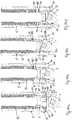
- Figs. 27a to 27dthe locking and unlocking of the head 3 will be explained.
- the lower member 10is screwed onto the upper member 8 to such an extent that the head 3 is still pivotable relative to the receiving part.
- a gap 500is provided between the first end 10a of the lower member 10 and the lower end 81a of the upper member 8.
- the lower member 10can be screwed to such an extent onto the second portion 82 of the upper member 8 that the head 3 is held either completely loose or that the head 3 is slightly clamped between the surfaces 92 of the insert member 9 and the surface 64 of the pressure member 6 so that the head is held by friction in an adjustable angular position.
- the clamping force exerted onto the head 3is adjustable.
- the lower memberis in a first position in which the head is pivotable.
- the rod 100 and the fixation member 7may already be inserted into the upper member 8.
- the instrumentis placed onto the upper member 8.
- the instrumentis moved further downward until the upper member 8 is rotationally fixed by the inner sleeve 200 and the outer sleeve 300 engages the engagement structure of the lower member 10
- the lower member 10is rotated with the outer sleeve 300 so that the bottom of the lower member 10 with the ring-shaped insert 9 presses the head 3 against the pressure member 6.
- the pressure member 6abuts with the shoulder 63a against the stop 800 which exerts a counter-force and prevents upward movement of the pressure member 6.
- the head 3is locked.
- the rod 100is freely movable in a direction along the rod axis and also in an axial direction along the central axis, only limited by the fixation member 7. In the second positon, there is still a gap 500 between the lower end 81a of the first portion 81 of the upper member 8 and the first end 10a of the lower member.
- the rod 100is seated in the rod support surface 62 of the pressure member 6 and the fixation member 7 is tightened with a screwdriver 400 until it presses onto the rod 100 which in turn presses onto the pressure member 6 to finally lock the head 3 and the rod 100.
- the instrumentcan be pulled away.
- the instrumentcan be removed without loosening the locking of the head 3. Also, rotating the outer sleeve 300 in the opposite direction releases the locking of the head 3 so that the head 3 is pivotable
- Figs. 28 to 30depict a second embodiment of the polyaxial bone anchoring device.
- the polyaxial bone anchoring devicediffers from the polyaxial bone anchoring device according to the first embodiment in that it is designed as a bottom-loading polyaxial bone anchoring device, i.e. the head 3 of the bone anchoring element is insertable through the bottom end of the lower member 10'.
- the polyaxial bone anchoring devicecomprises a receiving part 5' including an upper member 8' and a lower member 10'. Further, a pressure member 6' is provided in the upper member 8' and the lower member 10'.
- the upper member 8'is a substantially cylindrical part between the first end 8a ands the second end 8b. Adjacent to the second end 8b, an external thread 86 is provided at the outer surface that serves for connecting the lower member 10' to the upper member 8'.
- the passage 85'comprises a first portion 85a adjacent to the first end 8a that extends to a distance above the bottom of the substantially U-shaped recess 83 and a second portion 85b with a slightly smaller diameter that widens towards the second end 8b in a widened portion 85e to permit expansion of the pressure member 6' as explained below.
- a circumferential groove 800'is provided in an inner wall of the legs 84, more specifically of the lower portion of the legs 84b.
- An upper edge of the groove 800'serves as a stop for the pressure member 6'.
- a lower edge of the groove 800'may be inclined to permit further downward movement of the pressure member 6'.
- An outer groove 88' that divides the legs 84 into an upper portion 84a and a lower portion 84b and provides a break-off sectionmay have, for example, a V-shaped cross-section in a circumferential direction.
- the lower member 10'is a nut-like piece similar to the lower member of the first embodiment.
- the first portion 101 of the passage which comprises the internal threadhas a greater inner diameter so that it fits onto the external thread 86 of the upper member 8'.
- the second portion 102 of the passagealso narrows towards the second end 10b.
- the second portion 102is configured to receive a lower end of the pressure member 6' therein. Between the first portion 101 and the second portion 102, a flat annular surface 101b is formed.
- the pressure member 6'includes an upper or first portion 61' with a first or upper end 6a and a lower or second portion 62' with a second or lower end 6b.
- the second portion 62'has a hollow interior 63' that may be substantially spherically-shaped to clamp the spherical head 3 therein.
- the second portion 62'comprises a plurality of slits 64' that are open at the lower end 6b and extend through the second portion 62'.
- the number and dimensions of the slits 64'are such that the wall of the second portion 62' is flexible, more specifically that it can expand to snap onto the head 3 when the head 3 is inserted.
- An outer surface portion 65' adjacent to the lower end 6b of the pressure member 6'may be tapered, for example conically tapered.
- the outer surface portion 65'is configured to cooperate with the second portion 102 of the lower member 10' that narrows towards the second end 10b of the lower member 10'.
- Another outer surface portion 66' of the second portion 62' of the pressure member 6'may be spherically-shaped. Hence an overall shape of the second portion is cap-like. It shall be noted that the outer surface portions 65', 66' can have any other shape.
- the first portion 61' of the pressure member 6'may have a substantially cylindrical outer surface adjacent to the second portion 62'.
- the second portion 62'is recessed with respect to the cylindrical first portion 62', however, any other shape may also be possible.
- a rod support surface 68'may be provided in the first portion 61' that is configured to support an inserted rod 100.
- the rod support surface 68'may have a V-shaped cross-section in the direction transverse to the central axis C to permit support of rods of different diameter.
- the rod support surfacecan also be flat or cylindrical or can have any other shape.
- the longitudinal axis L of the rod support surface 68'extends transverse to the central axis C.
- upstanding legs 69'are formed that have a substantially flat inner surface and a substantially cylindrical outer surface.
- the upstanding legs 69'have outwardly directed portions 70 at their free ends, respectively, which are configured to engage the groove 800' of the upper member 8'.
- grooves 71extending parallel to the rod support surface 68', are formed that render the upstanding legs 69' more flexible.
- the grooves 71may have a circular segment-shaped cross-section.
- through-holes 72may be provided, the longitudinal axis of which is parallel to the central axis C.
- the through-holes 72may be adapted to be engaged by pins (not shown) or other holding means to hold the pressure member 6' inside the upper member 8' to hold the pressure member 6' aligned with the U-shaped recess 83.
- a coaxial bore 73is provided in the pressure member 6'.
- the dimensions of the pressure member 6'are such that the second portion 62' can expand in the enlarged portion 85e of the passage 85' of the upper member 8' when the head 3 of the bone anchoring element 1 is inserted.
- An outer diameter of the cylindrical first portion 61'is slightly smaller than an inner diameter of the second portion 85b of the passage 85' in the upper member 8' of the receiving part 5 such that the pressure member 6' can slide therein, wherein during insertion the flexible second portion 62' and the upstanding legs 69' may be slightly compressed until the second portion 62' is arranged in the accommodation space of the widening section 85e.
- the bone anchoring device of the second embodimentmay be pre-assembled in such a manner that the pressure member 6' is inserted into the upper member 8' and the lower member 10' is connected to the upper member 8'.
- the bone anchoring element 1can thus be inserted from the bottom end 10b of the lower member 10' into the receiving part 5'.
- Figs. 43a to 43dshow steps of use of the bone anchoring device according to the second embodiment in connection with the instrument.
- the instrument with the inner sleeve 200 and outer sleeve 300 as described in connection with Figs. 20 to 25can be used.
- the instrumentis attached by downward movement of the front portions ( Fig. 43b ) until the inner sleeve 200 engages the upper member 8' in a rotationally fixed manner and the outer sleeve 300 engages the engagement structure 103 on the outer surface of the lower member 10' ( Fig. 43c ).
- the outer sleeve 300is rotated to screw the lower member 10' towards the upper member 8' ( Fig. 43d ).
- the pressure member 6'is in the upper member 8' in an insertion position where the outwardly directed portions 70 extend into the undercut 801 at the lower end of the internal thread 89.
- the lower member 10'has been screwed onto the upper member 8' to such an extent that there is a gap 500' between the second end 8b of the upper member 8' and the bottom surface 101a of the first portion 101 of the passage in the lower member 10'.
- the flexible portion 62' of the pressure memberis at least partially located in the widening portion 85e of the passage 85' of the upper member 8' so that it can expand therein.
- the head 3 of the bone anchoring element 1is inserted from the second end 10b of the lower member 10' and enters into the hollow interior 63' of the pressure member 6'.
- the head 3pushes the pressure member 6' upward so that the outwardly directed portions 70 abut against the lowermost thread turn of the internal thread 89.
- the flexible second portion 62' of the pressure membersnaps onto the head 3 as shown in Fig. 44c .
- the pressure member 6'can be moved downward until the outwardly extending portions 70 engage the groove 800'.
- the lowermost outer conical portion 65 of the pressure member 6'is moved into the second portion 102 of the passage in the lower member 10', thereby narrowing the lower opening ( Fig. 44d ). In this pre-locking position, the pressure member 6' is prevented from moving upward and the head 3 is prevented from slipping out of the lower opening while the head 3 is still pivotable.
- Steps of unlocking and locking using the instrumentare shown in Figs. 45a to 45c .
- the headis unlocked, i.e. it is in the first position of the lower member 10' relative to the upper member 8' in which the head 3 is pivotable with respect to the components of the receiving part 5.
- the instrumentis attached such that the inner sleeve 200 engages the upper member 8' and the outer sleeve engages the engagement structure at the lower member 10'.
- Fig. 45athe head is unlocked, i.e. it is in the first position of the lower member 10' relative to the upper member 8' in which the head 3 is pivotable with respect to the components of the receiving part 5.
- the instrumentis attached such that the inner sleeve 200 engages the upper member 8' and the outer sleeve engages the engagement structure at the lower member 10'.
- the outer sleeve 300has been rotated so that the lower member 10' is screwed further towards the upper member 8', whereby the lower conical outer surface portion 65' of the pressure member 6' is pressed deeper into the second portion 102 of the passage of the lower member and thereby the compression force by the flexible portion 62' onto the head 3 is increased until the lower member is in a second position in which the head 3 is locked.
- the clamping force exerted onto the head 3is adjustable.
- Fig 45cshows the bone anchoring device and the instrument with an inserted rod 100 and a fixation member 7. In the second or locking position of the lower member 10' the gap 500' is smaller compared to the first or unlocking position.
- At least two bone anchoring elementsare inserted into, for example, the pedicles of adjacent vertebrae and the receiving parts are mounted onto the heads as described before. Thereafter, either the instrument is attached or the rod and the fixation member are inserted prior to attaching the instrument. With the bone anchoring device a plurality of manipulations can be carried out by locking and unlocking the head with or without the rod being placed into the receiving part.
- connection between the lower member and the upper memberis shown to be a threaded connection, other types of connections could be used, for example a bayonet connection or others.
- the bone anchoring devicecan be provided in further modified forms.
- the head of the bone anchoring elementcan have any other shape, such as, for example, a cylindrical shape or a spherical shape with flattened sides wherein a monoplanar device is provided that allows to pivot the anchoring element in a single plane.
- the pressure membercan have different shape.
- the extended tabs on the receiving partcan be omitted.
- fixation elementscan also be used, for example, non-threaded locking elements that have an alternative advancement structure.
- all kinds of bone anchoring elementscan be used, such as, for example, nails or bone anchors with barbs.
Landscapes
- Health & Medical Sciences (AREA)
- Orthopedic Medicine & Surgery (AREA)
- Neurology (AREA)
- Life Sciences & Earth Sciences (AREA)
- Surgery (AREA)
- Heart & Thoracic Surgery (AREA)
- Engineering & Computer Science (AREA)
- Biomedical Technology (AREA)
- Nuclear Medicine, Radiotherapy & Molecular Imaging (AREA)
- Medical Informatics (AREA)
- Molecular Biology (AREA)
- Animal Behavior & Ethology (AREA)
- General Health & Medical Sciences (AREA)
- Public Health (AREA)
- Veterinary Medicine (AREA)
- Surgical Instruments (AREA)
Abstract
Description
- The invention relates to a polyaxial bone anchoring device and a system of a polyaxial bone anchoring device and an instrument for use with the device. More specifically, the bone anchoring device includes a receiving part for coupling a rod to a bone anchoring element and a pressure member for exerting pressure onto an inserted head. The receiving part comprises an upper and a lower member that can be mounted together to clamp the head.
WO 2011/077511 A1 describes a spine fixing device capable of being used as both, a pivotable type and a fixed type. The spine fixing device is provided with a screw and a head to which the screw and the rod can be fixed. The head is provided with a head body and a fixing nut which fixes the screw at a screw disposing section of the head body. The state of mounting of the fixing nut to the head body is adapted to be switchable between a first state in which the screw is able to pivot and a second state in which the screw is not able to pivot.US 9,333,016 B2 - In spinal surgery often multiple segments of the spinal column have to be corrected and/or stabilized using a spinal rod and polyaxial bone anchors. During such a procedure repeated adjustments of the bone anchoring element and the rod relative to the receiving part of a polyaxial bone anchoring device may become necessary.
- It is the therefore object of the invention to provide a further improved polyaxial bone anchoring device that allows a safe and convenient handling during surgery and to provide a system consisting of such a polyaxial bone anchoring device and an instrument adapted for use therewith.
- The object is solved by a polyaxial bone anchoring device according to
claim 1 and by a system of an instrument and the polyaxial bone anchoring device according to claim 15. Further developments are given in the dependent claims. - More generally, according to an embodiment, the polyaxial bone anchoring device includes a receiving part having an upper member and a lower member connectable to the upper member, the lower member including a seat for a head of a bone anchoring element, the receiving part further comprising a pressure member for exerting pressure onto an inserted head; wherein when the lower member is connected to the upper member, the lower member can assume a first position in which an inserted had is pivotable and a second position in which an inserted head is clamped between the lower member and the pressure member.
- By moving the lower member, more particularly, by rotating the lower member relative to the upper member, the locking and unlocking of the head can be effected, for example using an instrument. The lower member remains in the locking position even after removing the instrument. Locking of the head is achieved by clamping with such a force that the head is not able to pivot under operating conditions.
- The locking and unlocking of the head during surgery can also be carried out with the rod being not yet inserted or being at an elevated position in the receiving part away from the bottom of the rod receiving recess. This increases the possibilities of carrying out correction steps during surgery.
- Moreover the locking and unlocking of the head can be effected independently from the fixation of the rod. Hence, the locking of the head can be maintained while adjustments on the position of the rod can be made.
- When the head of the bone anchoring element is locked in the receiving part and the rod is still movable, it is possible to pull the bone anchoring device with the instrument towards the inserted rod and thereby also to pull the associated vertebra towards the rod for correcting a position of the vertebra. Therefore, the polyaxial bone anchoring device permits various adjustments and re-adjustments of the angular position and/or rod position during surgery.
- The polyaxial bone anchoring device can also be used as a polyaxial bone anchoring device having a frictional clamping of the head in the receiving part that allows to temporarily hold the bone anchoring element in an adjustable angular position of the head prior to the final locking of the bone anchoring device.
- The legs of the upper member may each comprise a separable portion that forms extended tabs. The extended tabs allow convenient manipulation of the polyaxial bone anchoring device during surgery. Furthermore, the extended tabs permit guiding and/or supplying elements of an implant or instruments to the implantation site. This is particularly useful in the case of minimally-invasive surgery (MIS). The extended tabs may be broken off after locking the head and the rod.
- According to one embodiment, the polyaxial bone anchoring device may be used in a pre-assembled manner, with the bone anchoring element being pre-assembled with the receiving part before inserting the bone anchoring element into bone. In another embodiment, the polyaxial bone anchoring device may be a bottom-loading bone anchoring device in which the bone anchoring element is inserted from the bottom into the receiving part. This allows to first place the bone anchoring element into the bone and thereafter mount the receiving part. By means of this, a modular system may be provided that allows to combine various anchoring elements with the receiving part on demand, depending on the actual clinical requirements.
- Further features and advantages of the invention will become apparent from the description of embodiments by means of the accompanying drawings. In the drawings:
- Fig. 1
- shows a perspective exploded view of the polyaxial bone anchoring device according to a first embodiment;
- Fig. 2
- shows a perspective view of the polyaxial bone anchoring device of
Fig. 1 in an assembled state; - Fig. 3
- shows a cross-sectional view of the polyaxial bone anchoring device of
Figs. 1 and 2 in an assembled state, the section taken in a plane perpendicular to the rod axis; - Fig. 4
- shows a perspective view from the top of an upper member of the receiving part of the bone anchoring device of
Figs. 1 to 3 ; - Fig. 5
- shows a perspective view from the bottom of the upper member of
Fig. 4 ; - Fig. 6
- shows a top view of the upper member of the receiving part according to
Figs. 4 and 5 ; - Fig. 7a
- shows a cross-sectional view of the upper member of
Figs. 4 to 6 along line A-A inFig. 6 ; - Fig. 7b
- shows an enlarged view of a detail of
Fig. 7a ; - Fig. 8
- shows a perspective view from the top of a lower member of the receiving part of the bone anchoring device according to
Figs. 1 to 3 ; - Fig. 9
- shows a perspective view from the bottom of the lower member of
Fig. 8 ; - Fig. 10
- shows a top view of the lower member of
Figs. 8 and 9 ; - Fig. 11
- shows a cross-sectional view of the lower member along line B-B in
Fig. 10 ; - Fig. 12
- shows a perspective view of an insert member of the receiving part of the polyaxial bone anchoring device according to
Figs. 1 to 3 ; - Fig. 13
- shows a cross-sectional view of the insert member of
Fig. 12 ; - Fig. 14
- shows a perspective view of another insert member that can be used in the polyaxial bone anchoring device of
Figs. 1 to 3 ; - Fig. 15
- shows a perspective view from the bottom of a modified portion of the insert member of
Fig. 14 ; - Fig. 16
- shows a perspective view from the top of a pressure member of the polyaxial bone anchoring device according to
Figs. 1 to 3 ; - Fig. 17
- shows a perspective view from the bottom of the pressure member of
Fig. 16 ; - Fig. 18
- shows a top view of the pressure member of
Figs. 16 and 17 ; - Fig. 19
- shows a cross-sectional view of the pressure member of
Figs. 16 to 18 along line D-D inFig. 18 ; - Fig. 20
- shows a perspective view from the bottom of an inner sleeve of an instrument adapted to be used with the polyaxial bone anchoring device according to
Figs. 1 to 3 ; - Fig. 21
- shows a bottom view of the inner sleeve of
Fig. 20 ; - Fig. 22
- shows a cross-sectional view of the inner sleeve of
Figs. 20 and 21 ; - Fig. 23
- shows a perspective view of an outer sleeve of the instrument adapted to be used with the polyaxial bone anchoring device of
Figs. 1 to 3 ; - Fig. 24
- shows a bottom view of the outer sleeve of
Fig. 23 ; - Fig. 25
- shows a perspective view of a front portion of the outer sleeve of
Figs. 23 and 24 ; - Figs. 26a to 26c
- show steps of attaching and operating the instrument of
Figs. 20 to 25 in connection with the polyaxial bone anchoring device ofFigs. 1 to 3 ; - Fig. 27a to 27d
- show steps of operating the instrument and the polyaxial bone anchoring device according to
Figs. 1 to 25 ; - Fig. 28
- shows a perspective exploded view of a second embodiment of the polyaxial bone anchoring device;
- Fig. 29
- shows a perspective view of the polyaxial bone anchoring device of
Fig. 28 in an assembled state; - Fig. 30
- shows a cross-sectional view of the polyaxial bone anchoring device of
Figs. 28 and 29 , the section taken in a plane perpendicular to the rod axis; - Fig. 31
- shows a perspective view from the top of an upper member of the receiving part of the polyaxial bone anchoring device of
Figs. 28 to 30 ; - Fig. 32
- shows a perspective view from the bottom of the upper member of
Fig. 31 ; - Fig. 33
- shows a top view of the upper member of
Figs. 31 and 32 ; - Fig. 34
- shows a cross-sectional view of the upper member of
Figs. 31 to 33 along line F-F inFig. 33 ; - Fig. 35
- shows a perspective view from the top of a lower member of the receiving part of the polyaxial bone anchoring device according to
Figs. 28 to 30 ; - Fig. 36
- shows a perspective view from the bottom of the lower member of
Fig. 35 ; - Fig. 37
- shows a top view of the lower member of
Figs. 35 and 36 ; - Fig. 38
- shows a cross-sectional view of the lower member of
Figs. 35 to 37 along line G-G inFig. 37 ; - Fig. 39
- shows a perspective view from the top of a pressure member of the polyaxial bone anchoring device of
Figs. 28 to 30 ; - Fig. 40
- shows a perspective view from the bottom of the pressure member of
Fig. 39 ; - Fig. 41
- shows a top view of the pressure member of
Figs. 39 and 40 ; - Fig. 42
- shows a cross-sectional view of the pressure member of
Figs. 39 to 41 along line H-H inFig. 41 ; - Fig. 43a to 43d
- show steps of attaching and operating the instrument in connection with the polyaxial bone anchoring device according to
Figs. 28 to 30 ; - Figs. 44a to 44d
- show cross-sectional views of steps of using the polyaxial bone anchoring device according to
Figs. 28 to 42 ; - Figs. 45a to 45c
- show cross-sectional views of operating states of the polyaxial bone anchoring device according to
Figs. 28 to 42 . - As shown in
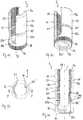
Figs. 1 to 3 , the polyaxial bone anchoring device according to a first embodiment comprises abone anchoring element 1 in the form of a bone screw having a shank with a threaded portion and ahead 3 comprising a spherically shaped outer surface portion. Thehead 3 has a largest diameter E and comprises a recess 4 for engagement with a screwdriver at a free end surface. The bone anchoring device further includes a receivingpart 5 for receiving the head of theanchoring element 1 and for receiving arod 100 in order to couple thebone anchoring element 1 to therod 100. In the receivingpart 5, apressure element 6 is arranged for exerting pressure onto thehead 3, when thehead 3 is inserted into the receivingpart 5. In addition, the bone anchoring device comprises afixation element 7 for securing therod 100 and for locking thehead 3 in the receivingpart 5. - As shown in
Fig. 1 , the receivingpart 5 is a two part piece with anupper member 8 and alower member 10 that is connectable to theupper member 8. Referring further toFigs. 4 to 7b , the upper member includes afirst end 8a forming an upper end and an oppositesecond end 8b forming a lower end. Due to its symmetry, theupper member 8 comprises a central axis C extending through theupper member 8 from thefirst end 8a to thesecond end 8b. Adjacent to thefirst end 8a, there is a first substantiallycylindrical portion 81 with a first maximum outer diameter, and adjacent to thesecond end 8b, there is a second substantiallycylindrical portion 82 with a second outer diameter that is smaller than the first outer diameter of thefirst portion 81. Thereby, a shoulder with alower surface 81a is formed between thefirst portion 81 and thesecond portion 82. Thefirst portion 81 of theupper member 8 comprises a substantiallyU-shaped recess 83 that extends from thefirst end 8a towards thesecond end 8b to a depth such that a bottom of therecess 83 is close to the junction of thefirst portion 81 and thesecond portion 82. By means of the substantiallyU-shaped recess 83 to upstandingfree legs 84 are formed that are the sidewalls of a channel for receiving therod 100. - The
upper member 8 further comprises acoaxial passage 85 extending completely through theupper member 8 from thefirst end 8a to thesecond end 8b. Thepassage 85 may be a bore that may have different inner diameters along the axial direction. More specifically, thepassage 85 may have afirst portion 85a that extends from thefirst end 8a to a distance from the bottom of the substantiallyU-shaped recess 83 and that comprises a width sufficient to insert and advance thefixation member 7 therein. Thepassage 85 continues from thefirst portion 85a to asecond portion 85b with a smaller width, wherein thesecond portion 85b is configured to receive a portion of thepressure member 6 in a sliding manner therein. Thesecond portion 85b extends up to a short distance from the junction of thefirst portion 81 and thesecond portion 82 of theupper member 8. Adjacent to thesecond portion 85b, there is a third portion 85c of thepassage 85 that has a greater diameter than thesecond portion 85b and that is configured to receive thehead 3 therein. Hence, between thesecond portion 85b and the third portion 85c of thepassage 85 a step is provided that forms astop 800 for thepressure member 6 as explained below. Between the third portion 85c and thesecond end 8b a spherically-shapedsection 85d
may exist that is configured to match the outer spherical surface portion of thehead 3 so as to accommodate and clamp a portion of thehead 3 therein. - The
second portion 82 of theupper member 8 comprises at least in a section thereof anexternal thread 86 functioning as a advancement structure for advancing thelower member 10 towards theupper member 8. A plurality oflongitudinal slits 87 that extend substantially parallel to the central axis C are provided in thesecond portion 82. Theslits 87 are preferably arranged at equidistant positions and are open towards thesecond end 8b. By means of theslits 87, thesecond portion 82 of theupper member 8 is rendered slightly extendable and compressible. This permits to hold and clamp an insertedhead 3 by friction in the spherically-shapedsection 85d, for example during assembly of the polyaxial bone anchoring device. Theslits 87 are preferably arranged mirror symmetrical to a longitudinal axis of theU-shaped recess 83 in a circumferential direction, in particular, two of theslits 87 are aligned with theU-shaped recess 83 and at others are 90° offset thereto. - At a distance from the
first end 8a, a weakened section that permits to break-away of break-off a portion of thelegs 84, is provided. The weakened section includes acircumferentially extending groove 88 on the outer surface of theupper member 8 that divides thelegs 84 into a first orupper portion 84a extending above thegroove 88 and a second orlower portion 84b extending below thegroove 88 to a base of therecess 83. The lower wall of the groove projects beyond of the upper wall in an axial direction thereby forming anarrow shoulder 88a. At thegroove 88, the wall thickness of thelegs 84 is reduced. By means of this, theupper portions 84a form extended legs, also called extended tabs of the bone anchoring device. Such extended tabs may be particularly suitable to define a pathway, for example in minimally-invasive surgery (MIS) to guide an implant component, for example thefixation element 7 to the implantation site beneath the skin of the patient. Any other means for providing a weakened section for permitting to break-away theupper portion 84a from thelower portion 84b may be contemplated, such as, for example, perforations, etc. In the region of theextended legs 84a an outer diameter of theupper member 8 may be slightly smaller than an outer diameter of the region of the lower portion of thelegs 84b. The free end of the lower portion of the legs forms the upper end of the receivingpart 5 after breaking-off theextended legs 84a. - An
internal thread 89 is provided along at least a portion of theupper portion 84a and thelower portion 84b of thelegs 84, so that thefixation element 7 can be screwed down along the pathway defined by thefirst portion 85a of thepassage 83. The depth of the substantiallyU-shaped recess 83 is such that when therod 100 is placed into therecess 83 and thefixation member 7 is screwed between thelegs 84, thefixation member 7 does not substantially protrude out of theupper member 8 when theupper portions 84a of the legs have been broken-off. At a lower end of theinternal thread 89 an undercut 89a may be present. - At the outer surface of the
first portion 81 to the left and the right of theU-shaped recess 83 cut-outs 90 may be formed that can be engaged by an instrument in order to hold theupper member 8 in a rotationally fixed manner. - Referring in particular to
Figs. 8 to 11 , thelower member 10 is a nut-like part that has afirst end 10a forming an upper end and a second end 10b forming a lower end and a passage that extends fully from thefirst end 10a to the second end 10b. The passage comprises afirst portion 101 with an internal thread so that thelower member 10 can be screwed onto thesecond portion 82 of theupper member 8. At the end of the threadedfirst portion 101 an undercut 101a may be provided. Between thefirst portion 101 and the second end 10b, there is asecond portion 102 that is threadless and that narrows towards the second end 10b, in the specific example, it narrows conically. By means of thesecond portion 102, a seat for thehead 3 of thebone anchoring element 1 is formed. An inner diameter of the opening provided by the passage at the second end 10b is greater than a maximum outer diameter of theshank 2 of thebone anchoring element 1, so that theshank 2 can be passed through the opening. - The outer surface of the
lower member 10 comprises anengagement structure 103 that may be, as shown, a plurality of flat portions, arranged for example in a polygonal manner, that can be gripped by hand, for example when mounting thelower member 10 or with an instrument, for example when the bone anchoring device is in use. Theengagement structure 101 may have any other shape that is suitable to be engaged by an instrument. - As shown in
Figs. 2 and3 , when thelower member 10 is mounted to theupper member 8, a maximum outer diameter of thelower member 10 is the same or only slightly greater than a maximum outer diameter of theupper member 8. An axial height of thelower member 10 is such that thelower member 10 can accommodate thehead 3 of the bone anchoring element when thelower member 10 is connected in the final configuration to theupper member 8. - Next, referring in more detail to
Figs. 12 and 13 , in thelower member 10, a ring-shapedinsert member 9 is provided for narrowing the opening at the second end 10b of thelower member 10. Theinsert member 9 has a first end 9a or upper end and asecond end 9b or lower end. Anouter surface 91 between the first end 9a and thesecond end 9b is tapered, for example conical in such a manner that theinsert member 9 fits into the narrowingsecond portion 102 of thelower member 10. Aninner surface 92 of the ring-shapedinsert member 9 has a spherical shape that is adapted to the shape of the spherical outer surface portion of thehead 3. Hence, when the ring-shapedinsert member 9 is mounted to thelower member 10 theinner surface 92 of theinsert member 9 forms the seat for thehead 3. Theinsert member 9 is slotted with asingle slot 93 that renders the ring-shapedinsert member 9 compressible such that it can be mounted to thelower member 10 and held in thesecond portion 102 in a biased manner. Moreover, the ring-shapedinsert member 9 may have a small bevelledinner surface portion 94a adjacent to the first end 9a and another small bevelledinner surface portion 94b adjacent to thesecond end 9b. It should be noted that theouter surface 91 can have a narrowing shape other than a conical shape, in particular a shape that is adapted to any narrowing surface of thesecond portion 102 of the passage in thelower member 10. - When the ring-shaped
insert member 9 is mounted to thelower member 10, the opening provided by the passage at the second end 10b of the lower member is narrowed in such a manner that thehead 3 cannot pass through the lower opening. The ring-shapedinsert member 9 can be used when the maximum outer diameter of theshank 2 is greater than the maximum outer diameter E of thehead 3. In such a case, theinsert member 9 is mounted after passing theshank 2 through the passage, - As shown in
Fig. 14 , a modified insert member 9' comprises twoslots 93 extending completely through the insert member 9' whichslots 93 are provided on diagonally opposite sides such that the insert member 9' is a two-piece part. The modified insert member 9' can be used instead of theinsert member 9. Referring toFig. 15 , the modified insert member 9' may have a recess or cut-out 95 that enlarges the space for the pivoting of theshank 2 to a specific side. Thus, the maximum pivot angle to the side where therecess 95 is located, is greater than in other pivot directions. More than one recess or cut-out to enlarge the pivot angle can also be provided at other circumferential locations to enlarge the pivot angle in other directions. Also the ring-shapedinsert member 9 according toFigs. 12 and 13 can be provided with such a cut-out orrecess 95. - Turning now to
Figs. 16 to 19 , thepressure member 6 comprises a first end 6a or upper end and an opposite second end 6b or lower end. Adjacent to the first end 6a, thepressure member 6 has afirst portion 61 that is substantially cylindrical with an outer diameter that is only slightly smaller than the inner diameter of thesecond portion 85b of thepassage 85 in theupper member 8, so that thefirst portion 61 can slide in thesecond portion 85b of thepassage 85. Perpendicular to the cylinder axis of the first portion, a substantially cylinder segment-shaped recess is formed that provides arod support surface 62. Adjacent to the second end 6b, thepressure member 6 comprises a substantially cylindricalsecond portion 63 that has an outer diameter greater than that of thefirst portion 61. Hence, ashoulder 63a exists between thesecond portion 63 and thefirst portion 61. Theshoulder 63a is configured to abut against thestop 800 in theupper member 8 of the receivingpart 5 to limit an upward movement of thepressure member 6 towards thefirst end 8a. Adjacent to the second end 6b, there is a substantially spherical segment-shapedrecess 64 with a radius corresponding to the radius of thehead 3, so that, when thepressure member 6 is placed onto thehead 3 and presses onto the head, the load is distributed onto thehead 3. Furthermore, a coaxial through-hole 65 is provided for allowing access to the recess 4 of thehead 3. - As best seen in the top view of
Fig. 18 , at 90 degree from an axis L corresponding to a cylinder axis of therod support surface 62, aprotrusion 66 is formed at the outer surface of thesecond portion 63. Theprotrusion 66 extends in an axial direction. It may have the shape of a semi-cylinder or be otherwise rounded with a roundedtop portion 66a. Theprotrusion 66 is configured to engage one of theslits 87 in thesecond portion 82 of theupper member 8 so that thepressure member 6 is prevented from rotating. When theprotrusion 66 engages one of theslits 87 that is 90° offset from the rod axis, therod support surface 62 is aligned with the substantiallyU-shaped recess 83 so that therod 100 can be placed. - The polyaxial bone anchoring device according to the first embodiment can be used in a pre-assembled manner, The
shank 2 is passed through the passage in thelower member 10 so that theshank 2 goes through the opening at the second end 10b. Thereafter, the ring-shapedinsert member 9 is inserted until it rests in thesecond portion 102 of the passage in thelower member 10. Thepressure member 6 is mounted to theupper member 8 from thesecond end 8b of theupper member 8 and oriented in such a manner that theprotrusion 66 can enter into one 90° offset slit 87 to align therod support surface 62 with theU-shaped recess 83. For mounting thelower member 10 to theupper member 8, thehead 3 can be held by friction in thespherical portion 85d of theupper member 8. Then, thelower member 10 is screwed onto thesecond portion 82 of theupper member 8 until thehead 3 rests in theseat 92. Thehead 3 is loosely held between theseat 92 and thepressure member 6 so that it is pivotable. If the largest external diameter of the shank is greater than or the same as the largest diameter E of thehead 3, the above procedure may be used. If the largest diameter of theshank 2 is smaller than the largest diameter E of the head, the ring-shapedinsert 9 may be mounted before the shank is passed through or max be omitted at all. In this case. the opening is designed to be smaller than the largest diameter of the head. - Referring to
Figs. 20 to 25 , an instrument will be described that is adapted for use with the polyaxial bone anchoring device. The instrument comprises aninner sleeve 200 that is disposed in anouter sleeve 300. As shown inFigs. 20 to 22 , the inner sleeve comprises a front portion with afree end 200a and a substantiallyelongate recess 201 that divides the front portion into twoopposite arms 202. The width of theelongate recess 201 is at least as large as the diameter of therod 100. At a distance from thefree end 200a aninner taper 203 is provided that narrows the diameter from the front portion toward the rearward sleeve portion. Adjacent to thetaper 203 in the direction to thefree end 200a, an innerfirst sleeve portion 204 follows that is adapted to an outer shape of theupper portions 84a of thelegs 84. Thefirst portion 204 has such an axial length that it extends at least up to thecircumferential shoulder 88a provided by thegroove 88. Thefirst sleeve portion 204 is followed by an innersecond sleeve portion 205 with a slightly larger inner diameter so that astep 204a between thefirst sleeve portion 204 and thesecond sleeve portion 205 is formed whichstep 204a is configured to rest on theprojection 88a of theupper member 8. Thesecond sleeve portion 205 has an inner diameter such that thelower portion 84b of the legs can be at least partially accommodated therein.Thickened side portions 205b are provided on each side of each of thearms 202 whichside portions 205b are configured to engage the sides of the substantiallyU-shaped recess 83 in theupper member 8 at the positions of the cut-outs 90, respectively. Thereby, when theinner sleeve 200 is attached to theupper member 8, theupper member 8 is prevented to rotate relative to theinner sleeve 200. Moreover, theinner sleeve 200 is configured to receive a fixation member therethrough, so that thefixation member 7 can be moved down through theinner sleeve 200. - The
outer sleeve 300 comprises a front portion with afree end 300a. A substantiallyrectangular recess 301 divides the front portion into twoopposite arms 302. The width of therectangular recess 301 is such that when the outer sleeve is placed onto the receivingpart 5, thearms 302 can rotate to some extent before they abut against an inserted rod as explained below. Hence, a width of thearms 302 in a circumferential direction is smaller than a width of thelegs 84 of theupper member 8 in the circumferential direction. - The outer sleeve comprises an inner
first sleeve portion 303 that extends up to a distance from thefree end 300a and that has an inner diameter sufficient to accommodate theinner sleeve 200 therein, Following the firstinner sleeve portion 303, there is an innersecond sleeve portion 304 with an inner diameter smaller than the first inner sleeve portion such that ashoulder 303a is formed between thefirst sleeve portion 303 and thesecond sleeve portion 304. In the mounted state, when theouter sleeve 300 is placed over theinner sleeve 200 and the instrument is attached to the polyaxial bone anchoring device, thesecond sleeve portion 304 encompasses thelower member 10 and thefree end 200a of the inner sleeve abuts against theshoulder 303 a of the outer sleeve 300 (Fig. 27 ). Thesecond sleeve portion 304 comprises a plurality of axially extendingflat surfaces 304a, arranged in a polygonal manner, that are configured to engage the engagement structure in form of theflat surfaces 103 of thelower member 10. Thereby, a form-fit engagement between theouter sleeve 300 and thelower member 10 is achieved that permits to rotate thelower member 10 with theouter sleeve 300 while theupper member 8 is rotationally fixed by theinner sleeve 200. - The parts of the polyaxial bone anchoring device and the instrument may each be made of a bio-compatible material, for example of titanium or stainless steel, of a bio-compatible alloy, such as NiTi-alloys, for example Nitinol, of magnesium or magnesium alloys, or from a bio-compatible plastic material, such as, for example, polyether ether ketone (PEEK) or poly-L-lactide acid (PLLA). In addition, the parts can be made of the same or of different materials from one another.
- In
Figs. 26a to 26c , the steps of operating the instrument in connection with the polyaxial bone anchoring device according to the first embodiment are shown. As explained above, the polyaxial bone anchoring device is pre-assembled. Therod 100 and thefixation member 7 may be inserted into theupper member 8. The instrument is assembled in such a manner that thearms 302 of theouter sleeve 300 overlap thearms 202 of theinner sleeve 200. One of the longitudinal edges of onearm 202 of the inner sleeve and one of the edges of thecorresponding arm 302 of the outer sleeve are substantially aligned. As depicted inFig. 26a , the instrument is placed onto theupper member 8 until thestep 204a abuts against theprojection 88a at thegroove 88 and the thickenedportions 205b of thearms 202 encompass thelower portion 84b of thelegs 84 to rotationally fix theupper member 8. Thearms 302 of the outer sleeve extend beneath the free end of theinner sleeve 200a and engage with theflat surface portions 304a theflat surface portions 103 of thelower member 10 in a form-fit manner (Fig. 26b ). As shown inFig. 26c , theouter sleeve 300 is rotated and thereby rotates thelower member 10 so that thelower member 10 is further screwed onto thesecond portion 82 of theupper member 8. - Turning now to
Figs. 27a to 27d , the locking and unlocking of thehead 3 will be explained. As shown inFig. 27a , thelower member 10 is screwed onto theupper member 8 to such an extent that thehead 3 is still pivotable relative to the receiving part. Agap 500 is provided between thefirst end 10a of thelower member 10 and thelower end 81a of theupper member 8. It shall be noted that thelower member 10 can be screwed to such an extent onto thesecond portion 82 of theupper member 8 that thehead 3 is held either completely loose or that thehead 3 is slightly clamped between thesurfaces 92 of theinsert member 9 and thesurface 64 of thepressure member 6 so that the head is held by friction in an adjustable angular position. As thelower member 10 can be rotated in a step-less manner, the clamping force exerted onto thehead 3 is adjustable. Hence, the lower member is in a first position in which the head is pivotable. Therod 100 and thefixation member 7 may already be inserted into theupper member 8. The instrument is placed onto theupper member 8. - As illustrated in
Fig. 27b , the instrument is moved further downward until theupper member 8 is rotationally fixed by theinner sleeve 200 and theouter sleeve 300 engages the engagement structure of thelower member 10 - Then, as shown in
Fig. 27c , thelower member 10 is rotated with theouter sleeve 300 so that the bottom of thelower member 10 with the ring-shapedinsert 9 presses thehead 3 against thepressure member 6. Thepressure member 6 abuts with theshoulder 63a against thestop 800 which exerts a counter-force and prevents upward movement of thepressure member 6. In a second position of thelower member 10 relative to theupper member 8 thehead 3 is locked. Therod 100 is freely movable in a direction along the rod axis and also in an axial direction along the central axis, only limited by thefixation member 7. In the second positon, there is still agap 500 between thelower end 81a of thefirst portion 81 of theupper member 8 and thefirst end 10a of the lower member. - As shown in
Fig. 27d , finally, therod 100 is seated in therod support surface 62 of thepressure member 6 and thefixation member 7 is tightened with ascrewdriver 400 until it presses onto therod 100 which in turn presses onto thepressure member 6 to finally lock thehead 3 and therod 100. The instrument can be pulled away. - In the second position of the
lower member 10, the instrument can be removed without loosening the locking of thehead 3. Also, rotating theouter sleeve 300 in the opposite direction releases the locking of thehead 3 so that thehead 3 is pivotable Figs. 28 to 30 depict a second embodiment of the polyaxial bone anchoring device. The description of parts and portions that are highly identical or similar to that of the first embodiment, will not be repeated and the reference numerals of those parts or portions are the same as in the first embodiment. The polyaxial bone anchoring device differs from the polyaxial bone anchoring device according to the first embodiment in that it is designed as a bottom-loading polyaxial bone anchoring device, i.e. thehead 3 of the bone anchoring element is insertable through the bottom end of the lower member 10'. The polyaxial bone anchoring device comprises a receiving part 5' including an upper member 8' and a lower member 10'. Further, a pressure member 6' is provided in the upper member 8' and the lower member 10'.- Referring more in detail to
Figs. 31 to 34 , the upper member 8' is a substantially cylindrical part between thefirst end 8a ands thesecond end 8b. Adjacent to thesecond end 8b, anexternal thread 86 is provided at the outer surface that serves for connecting the lower member 10' to the upper member 8'. The passage 85' comprises afirst portion 85a adjacent to thefirst end 8a that extends to a distance above the bottom of the substantiallyU-shaped recess 83 and asecond portion 85b with a slightly smaller diameter that widens towards thesecond end 8b in a widenedportion 85e to permit expansion of the pressure member 6' as explained below. At a distance from the bottom of the U-shaped recess 83 a circumferential groove 800' is provided in an inner wall of thelegs 84, more specifically of the lower portion of thelegs 84b. An upper edge of the groove 800' serves as a stop for the pressure member 6'. A lower edge of the groove 800' may be inclined to permit further downward movement of the pressure member 6'. An outer groove 88' that divides thelegs 84 into anupper portion 84a and alower portion 84b and provides a break-off section may have, for example, a V-shaped cross-section in a circumferential direction. - As depicted in
Figs. 35 to 38 , the lower member 10' is a nut-like piece similar to the lower member of the first embodiment. Thefirst portion 101 of the passage which comprises the internal thread has a greater inner diameter so that it fits onto theexternal thread 86 of the upper member 8'. Thesecond portion 102 of the passage also narrows towards the second end 10b. Thesecond portion 102 is configured to receive a lower end of the pressure member 6' therein. Between thefirst portion 101 and thesecond portion 102, a flat annular surface 101b is formed. - Turning now to
Figs. 39 to 42 , the pressure member 6' will be described more in detail referring additionally toFigs. 39 to 42 . The pressure member 6' includes an upper orfirst portion 61' with a first or upper end 6a and a lower orsecond portion 62' with a second or lower end 6b. Thesecond portion 62' has a hollow interior 63' that may be substantially spherically-shaped to clamp thespherical head 3 therein. Thesecond portion 62' comprises a plurality of slits 64' that are open at the lower end 6b and extend through thesecond portion 62'. The number and dimensions of the slits 64' are such that the wall of thesecond portion 62' is flexible, more specifically that it can expand to snap onto thehead 3 when thehead 3 is inserted. An outer surface portion 65' adjacent to the lower end 6b of the pressure member 6' may be tapered, for example conically tapered. The outer surface portion 65' is configured to cooperate with thesecond portion 102 of the lower member 10' that narrows towards the second end 10b of the lower member 10'. Another outer surface portion 66' of thesecond portion 62' of the pressure member 6' may be spherically-shaped. Hence an overall shape of the second portion is cap-like. It shall be noted that the outer surface portions 65', 66' can have any other shape. - The
first portion 61' of the pressure member 6' may have a substantially cylindrical outer surface adjacent to thesecond portion 62'. In the embodiment shown, thesecond portion 62' is recessed with respect to the cylindricalfirst portion 62', however, any other shape may also be possible. A rod support surface 68' may be provided in thefirst portion 61' that is configured to support an insertedrod 100. The rod support surface 68' may have a V-shaped cross-section in the direction transverse to the central axis C to permit support of rods of different diameter. However, the rod support surface can also be flat or cylindrical or can have any other shape. - The longitudinal axis L of the rod support surface 68' extends transverse to the central axis C. To the left and to the right of the rod support surface 68' upstanding legs 69' are formed that have a substantially flat inner surface and a substantially cylindrical outer surface. The upstanding legs 69' have outwardly directed
portions 70 at their free ends, respectively, which are configured to engage the groove 800' of the upper member 8'. Between the rod support surface 68' and the upstanding legs 69'grooves 71 extending parallel to the rod support surface 68', are formed that render the upstanding legs 69' more flexible. Thegrooves 71 may have a circular segment-shaped cross-section. At the center of the upstanding legs 69' elongate through-holes 72 may be provided, the longitudinal axis of which is parallel to the central axis C. The through-holes 72 may be adapted to be engaged by pins (not shown) or other holding means to hold the pressure member 6' inside the upper member 8' to hold the pressure member 6' aligned with theU-shaped recess 83. To allow access to thehead 3 with a driver or a tool, acoaxial bore 73 is provided in the pressure member 6'. - The dimensions of the pressure member 6' are such that the
second portion 62' can expand in theenlarged portion 85e of the passage 85' of the upper member 8' when thehead 3 of thebone anchoring element 1 is inserted. An outer diameter of the cylindricalfirst portion 61' is slightly smaller than an inner diameter of thesecond portion 85b of the passage 85' in the upper member 8' of the receivingpart 5 such that the pressure member 6' can slide therein, wherein during insertion the flexiblesecond portion 62' and the upstanding legs 69' may be slightly compressed until thesecond portion 62' is arranged in the accommodation space of the wideningsection 85e. - The bone anchoring device of the second embodiment may be pre-assembled in such a manner that the pressure member 6' is inserted into the upper member 8' and the lower member 10' is connected to the upper member 8'. The
bone anchoring element 1 can thus be inserted from the bottom end 10b of the lower member 10' into the receiving part 5'. Figs. 43a to 43d show steps of use of the bone anchoring device according to the second embodiment in connection with the instrument. The instrument with theinner sleeve 200 andouter sleeve 300 as described in connection withFigs. 20 to 25 can be used. To the assembled bone anchoring device with insertedrod 100 and fixation member 7 (Fig. 43a ) the instrument is attached by downward movement of the front portions (Fig. 43b ) until theinner sleeve 200 engages the upper member 8' in a rotationally fixed manner and theouter sleeve 300 engages theengagement structure 103 on the outer surface of the lower member 10' (Fig. 43c ). For locking the head, theouter sleeve 300 is rotated to screw the lower member 10' towards the upper member 8' (Fig. 43d ).- Referring to
Figs. 44a to 44d , the assembly of the bone anchoring device will be explained more in detail. As shown inFig. 44a , the pressure member 6' is in the upper member 8' in an insertion position where the outwardly directedportions 70 extend into the undercut 801 at the lower end of theinternal thread 89. The lower member 10' has been screwed onto the upper member 8' to such an extent that there is a gap 500' between thesecond end 8b of the upper member 8' and the bottom surface 101a of thefirst portion 101 of the passage in the lower member 10'. Theflexible portion 62' of the pressure member is at least partially located in the wideningportion 85e of the passage 85' of the upper member 8' so that it can expand therein. - As depicted in
Fig. 44b , thehead 3 of thebone anchoring element 1 is inserted from the second end 10b of the lower member 10' and enters into the hollow interior 63' of the pressure member 6'. Thehead 3 pushes the pressure member 6' upward so that the outwardly directedportions 70 abut against the lowermost thread turn of theinternal thread 89. The flexiblesecond portion 62' of the pressure member snaps onto thehead 3 as shown inFig. 44c . Thereafter, the pressure member 6' can be moved downward until the outwardly extendingportions 70 engage the groove 800'. The lowermost outerconical portion 65 of the pressure member 6' is moved into thesecond portion 102 of the passage in the lower member 10', thereby narrowing the lower opening (Fig. 44d ). In this pre-locking position, the pressure member 6' is prevented from moving upward and thehead 3 is prevented from slipping out of the lower opening while thehead 3 is still pivotable. - Steps of unlocking and locking using the instrument are shown in
Figs. 45a to 45c . As depicted inFig. 45a , the head is unlocked, i.e. it is in the first position of the lower member 10' relative to the upper member 8' in which thehead 3 is pivotable with respect to the components of the receivingpart 5. The instrument is attached such that theinner sleeve 200 engages the upper member 8' and the outer sleeve engages the engagement structure at the lower member 10'. InFig. 45b , theouter sleeve 300 has been rotated so that the lower member 10' is screwed further towards the upper member 8', whereby the lower conical outer surface portion 65' of the pressure member 6' is pressed deeper into thesecond portion 102 of the passage of the lower member and thereby the compression force by theflexible portion 62' onto thehead 3 is increased until the lower member is in a second position in which thehead 3 is locked. As the lower member 10' can be rotated in a step-less manner, the clamping force exerted onto thehead 3 is adjustable.Fig 45c shows the bone anchoring device and the instrument with an insertedrod 100 and afixation member 7. In the second or locking position of the lower member 10' the gap 500' is smaller compared to the first or unlocking position. - In the clinical use, at least two bone anchoring elements are inserted into, for example, the pedicles of adjacent vertebrae and the receiving parts are mounted onto the heads as described before. Thereafter, either the instrument is attached or the rod and the fixation member are inserted prior to attaching the instrument. With the bone anchoring device a plurality of manipulations can be carried out by locking and unlocking the head with or without the rod being placed into the receiving part.
- Modifications of the above described embodiments are conceivable. While the connection between the lower member and the upper member is shown to be a threaded connection, other types of connections could be used, for example a bayonet connection or others.
- Other engagement structures of the lower member and the instrument may also be contemplated that provide a connection between the instrument and the lower member. Any firm connection that is able to transmit a force onto the lower member such as any form fit-connection or friction-fit connection may be used.
- Any instrument that holds the upper member rotationally fixed and permits to move the lower member may be used.
- The bone anchoring device according to other embodiments of the invention can be provided in further modified forms. For example, the head of the bone anchoring element can have any other shape, such as, for example, a cylindrical shape or a spherical shape with flattened sides wherein a monoplanar device is provided that allows to pivot the anchoring element in a single plane. The pressure member can have different shape.
- The extended tabs on the receiving part can be omitted.
- In addition, in some embodiments, other kinds of fixation elements can also be used, for example, non-threaded locking elements that have an alternative advancement structure. In addition, all kinds of bone anchoring elements can be used, such as, for example, nails or bone anchors with barbs.
- The features of the embodiments can be combined and/or interchanged to produce a variety of further embodiments.
Claims (15)
- A polyaxial bone anchoring device including
a receiving part (5, 5') for coupling a rod (100) to a bone anchoring element (1), the receiving part (5,5') comprising:an upper member (8, 8') with a first end (8a) and a second end (8b), a central axis (C) extending through the first end ad the second end, a passage (85, 85') extending along the central axis from the first end to the second end and a recess (83) for receiving the rod at the first end;a lower member (10, 10') having a first end (10a) and a second end (10b) and a passage (101, 102; 102') extending in axial direction from the first end to the second end, the lower member being connectable to the upper member from the second end (8b) of the upper member, wherein the lower member comprises a seat (92, 102') for a head (3) of the bone anchoring element;a pressure member (6, 6') for exerting pressure onto an inserted head (3), the pressure member being at least partially arranged in the upper member (8, 8');wherein when the lower member (10, 10') is connected to the upper member (8, 8'), the lower member can assume a first position in which an inserted head (3) is pivotable in the seat (92, 102) and a second position in which an inserted head (3) is locked relative to the lower member and to the upper member. - The polyaxial bone anchoring device of claim 1, wherein a stop (800, 800') is provided in the upper member (8, 8') against which the pressure member (6, 6') is configured to abut when the lower member (10, 10') is moved from the first position to the second position with a head (3) of the bone anchoring element being inserted.
- The polyaxial bone anchoring device of claim 1 or 2, wherein the lower member (10, 10') is movable from the first position to the second position by advancing the lower member (10, 10') in the axial direction and wherein when the lower member (10, 10') is moved from the first position to the second position, a clamping force exerted onto an inserted head (3) increases.
- The polyaxial bone anchoring device of one of claims 1 to 3, wherein the lower member (10, 10') is configured to be moved from the first position into the second position and vice versa by the aid of an instrument and wherein the lower member is configured to stay in the first and in the second position without the aid of an instrument.
- The polyaxial bone anchoring device of one of claims 1 to 4, wherein the lower member (10, 10') is connectable to the upper member (8, 8') by means of a threaded connection (86).
- The polyaxial bone anchoring device of one of claims 1 to 5, wherein the lower member (10, 10') comprises an outer engagement structure (103) for engagement with an instrument (200, 300) that is configured to move the lower member (10, 10') from the first to the second position.
- The polyaxial bone anchoring device of one of claims 1 to 6, wherein a fixation element (7) is provided that engages the recess (83) for the rod, preferably which is configured to exert pressure through an inserted rod (100) onto the pressure member (6, 6').
- The polyaxial bone anchoring device of one of claims 1 to 7, wherein the lower member (10, 10') comprises an opening at the second end (10b) end and wherein an inner diameter of the opening is greater than a largest diameter (E) of a head (3) of the bone anchoring element.
- The polyaxial bone anchoring device of claim 8, wherein the lower member (10) comprises an insert member (9, 9') that is configured to be inserted into the lower member (10) to narrow the opening to a diameter smaller than a largest diameter of the head (3).
- The polyaxial bone anchoring device of one of claims 1 to 9, wherein the upper member (8) comprises adjacent or close to the second end (8b) an inner wall portion (85d) with a spherical shape adapted to the shape of a spherical outer surface portion of a head (3) and wherein preferably the wall of the upper member (8) adjacent to the second end (8b) is expandable when the head (3) enters the upper member, preferably the wall of the upper member (8) adjacent to the second end (8b) comprising at least one slit (87).
- The polyaxial bone anchoring device of claim 8, wherein the pressure member (6') comprises a flexible portion (62') encompassing an inserted head (3) and wherein a lower edge (65) of the pressure member (6') is configured to narrow the opening at the second end (10b) of the lower member (10') when a head is inserted.
- The polyaxial bone anchoring device of claim 11, wherein the head (3) of the bone anchoring element (1) is insertable into the lower member (10') from the second end (10b).
- The polyaxial bone anchoring device of one of claims 1 to 12, further comprising a bone anchoring element (1) having a shank (2) for anchoring in bone and a head (3) with a spherically-shaped outer surface portion.
- The polyaxial bone anchoring device of one of claims 1 to 13, wherein the upper member (8, 8') comprises a lower surface (8b, 81a) and the lower member (10, 10') comprises an upper surface (10a, 101b) that faces the lower surface (8b, 81a) of the upper member (8, 8') and wherein in the second position there is a gap (500, 500') between the lower surface (8b, 81a) and the upper surface (10a, 101b).
- A system of an instrument and a bone anchoring device according to one of claims 1 to 14, the instrument comprising
an outer sleeve (300) configured to engage the lower member (10, 10');
an inner sleeve (200) provided at least partially in the outer sleeve (300) and being configured to engage the upper member (8, 8') in a rotationally fixed manner;
wherein the outer sleeve (300) is movable relative to the inner sleeve (200) to move the lower member (10, 10') relative to the upper member (8, 8') when the outer sleeve (300) engages the lower member (10, 10') and the inner sleeve (200) engages the upper member (8, 8').
Priority Applications (6)
| Application Number | Priority Date | Filing Date | Title |
|---|---|---|---|
| EP18160167.5AEP3536271B1 (en) | 2018-03-06 | 2018-03-06 | Polyaxial bone anchoring device and system of an instrument and a polyaxial bone anchoring device |
| US16/287,896US11090088B2 (en) | 2018-03-06 | 2019-02-27 | Polyaxial bone anchoring device and system including an instrument and a polyaxial bone anchoring device |
| CN201910153704.5ACN110226957B (en) | 2018-03-06 | 2019-03-01 | Polyaxial bone anchoring device and system of polyaxial bone anchoring devices and instruments |
| JP2019037468AJP7312575B2 (en) | 2018-03-06 | 2019-03-01 | Polyaxial bone anchoring device and system of instrument and polyaxial bone anchoring device |
| US17/365,430US12070248B2 (en) | 2018-03-06 | 2021-07-01 | Polyaxial bone anchoring device and system including an instrument and a polyaxial bone anchoring device |
| US18/782,469US20250000553A1 (en) | 2018-03-06 | 2024-07-24 | Polyaxial bone anchoring device and system including an instrument and a polyaxial bone anchoring device |
Applications Claiming Priority (1)
| Application Number | Priority Date | Filing Date | Title |
|---|---|---|---|
| EP18160167.5AEP3536271B1 (en) | 2018-03-06 | 2018-03-06 | Polyaxial bone anchoring device and system of an instrument and a polyaxial bone anchoring device |
Publications (2)
| Publication Number | Publication Date |
|---|---|
| EP3536271A1true EP3536271A1 (en) | 2019-09-11 |
| EP3536271B1 EP3536271B1 (en) | 2022-05-04 |
Family
ID=61580954
Family Applications (1)
| Application Number | Title | Priority Date | Filing Date |
|---|---|---|---|
| EP18160167.5AActiveEP3536271B1 (en) | 2018-03-06 | 2018-03-06 | Polyaxial bone anchoring device and system of an instrument and a polyaxial bone anchoring device |
Country Status (4)
| Country | Link |
|---|---|
| US (3) | US11090088B2 (en) |
| EP (1) | EP3536271B1 (en) |
| JP (1) | JP7312575B2 (en) |
| CN (1) | CN110226957B (en) |
Families Citing this family (7)
| Publication number | Priority date | Publication date | Assignee | Title |
|---|---|---|---|---|
| EP3476340B1 (en)* | 2017-10-25 | 2021-06-02 | Biedermann Technologies GmbH & Co. KG | Polyaxial bone anchoring device |
| US11571244B2 (en)* | 2019-05-22 | 2023-02-07 | Nuvasive, Inc. | Posterior spinal fixation screws |
| EP3821834B1 (en)* | 2019-11-14 | 2024-05-01 | Biedermann Technologies GmbH & Co. KG | Receiving part for coupling a rod to a bone anchor |
| EP4129220B1 (en)* | 2021-08-04 | 2024-07-03 | Biedermann Technologies GmbH & Co. KG | Coupling device for coupling a rod to a bone anchoring element and method of manufacturing the same |
| US20240398444A1 (en)* | 2021-09-14 | 2024-12-05 | Agmspine, Sia | A polyaxial spinal screw |
| CN114343815B (en)* | 2022-03-17 | 2022-06-03 | 长沙市第三医院 | Multi-plane cortical bone screw, bone positioning device and positioning and using method |
| KR102821011B1 (en)* | 2023-02-24 | 2025-06-23 | (주)지씨 | Rod holder, vertebra fixation member comprising the same and vertebra implant comprising the same |
Citations (6)
| Publication number | Priority date | Publication date | Assignee | Title |
|---|---|---|---|---|
| US20070233078A1 (en)* | 2006-01-27 | 2007-10-04 | Justis Jeff R | Pivoting joints for spinal implants including designed resistance to motion and methods of use |
| US20100168796A1 (en)* | 2008-07-29 | 2010-07-01 | Kenneth Arden Eliasen | Bone anchoring member with clamp mechanism |
| WO2011077511A1 (en) | 2009-12-22 | 2011-06-30 | 株式会社ロバート・リード商会 | Spine fixing device, embedding device, embedding member fixing device, and spine fixing system |
| EP2574297A1 (en)* | 2011-09-30 | 2013-04-03 | Biedermann Technologies GmbH & Co. KG | Bone anchoring device and tool cooperating with such a bone anchoring device |
| US20150134006A1 (en)* | 2013-11-08 | 2015-05-14 | Blackstone Medical, Inc. | Lockable Pedicle Fastener |
| US9333016B2 (en) | 2012-07-03 | 2016-05-10 | Biedermann Technologies Gmbh & Co. Kg | Polyaxial bone anchoring device |
Family Cites Families (102)
| Publication number | Priority date | Publication date | Assignee | Title |
|---|---|---|---|---|
| GB9014817D0 (en) | 1990-07-04 | 1990-08-22 | Mehdian Seyed M H | Improvements in or relating to apparatus for use in the treatment of spinal disorders |
| DE4307633C1 (en) | 1993-03-11 | 1994-05-19 | Pennig Dietmar | Screw for locking marrow-cavity pin in position - has threaded section of shank near head and opposite thread on head with unthreaded section of shank between |
| DE19509332C1 (en) | 1995-03-15 | 1996-08-14 | Harms Juergen | Anchoring element |
| US5882350A (en) | 1995-04-13 | 1999-03-16 | Fastenetix, Llc | Polyaxial pedicle screw having a threaded and tapered compression locking mechanism |
| US5549608A (en) | 1995-07-13 | 1996-08-27 | Fastenetix, L.L.C. | Advanced polyaxial locking screw and coupling element device for use with rod fixation apparatus |
| US5586984A (en) | 1995-07-13 | 1996-12-24 | Fastenetix, L.L.C. | Polyaxial locking screw and coupling element assembly for use with rod fixation apparatus |
| US5575792A (en) | 1995-07-14 | 1996-11-19 | Fastenetix, L.L.C. | Extending hook and polyaxial coupling element device for use with top loading rod fixation devices |
| US5728098A (en) | 1996-11-07 | 1998-03-17 | Sdgi Holdings, Inc. | Multi-angle bone screw assembly using shape-memory technology |
| ES2191775T3 (en) | 1996-12-12 | 2003-09-16 | Synthes Ag | DEVICE FOR CONNECTING A LONGITUDINAL SUPPORT WITH A PEDICULAR SCREW. |
| US6248105B1 (en) | 1997-05-17 | 2001-06-19 | Synthes (U.S.A.) | Device for connecting a longitudinal support with a pedicle screw |
| PT1117336E (en) | 1998-09-29 | 2004-10-29 | Synthes Ag | DEVICE FOR CONNECTING A LONGITUDINAL SUPPORT TO A BONUS FIXATION MEANS |
| DE19851370C2 (en) | 1998-11-07 | 2000-09-21 | Aesculap Ag & Co Kg | Endoscopic insertion instruments |
| US6254602B1 (en) | 1999-05-28 | 2001-07-03 | Sdgi Holdings, Inc. | Advanced coupling device using shape-memory technology |
| US6273888B1 (en) | 1999-05-28 | 2001-08-14 | Sdgi Holdings, Inc. | Device and method for selectively preventing the locking of a shape-memory alloy coupling system |
| FR2796545B1 (en) | 1999-07-22 | 2002-03-15 | Dimso Sa | POLY-AXIAL LINK FOR OSTEOSYNTHESIS SYSTEM, ESPECIALLY FOR THE RACHIS |
| US6743231B1 (en) | 2000-10-02 | 2004-06-01 | Sulzer Spine-Tech Inc. | Temporary spinal fixation apparatuses and methods |
| US7862587B2 (en) | 2004-02-27 | 2011-01-04 | Jackson Roger P | Dynamic stabilization assemblies, tool set and method |
| US7335201B2 (en) | 2003-09-26 | 2008-02-26 | Zimmer Spine, Inc. | Polyaxial bone screw with torqueless fastening |
| US7156849B2 (en) | 2003-06-16 | 2007-01-02 | Depuy Spine, Inc. | Rod reduction nut and driver tool |
| US8366753B2 (en) | 2003-06-18 | 2013-02-05 | Jackson Roger P | Polyaxial bone screw assembly with fixed retaining structure |
| US20050080415A1 (en) | 2003-10-14 | 2005-04-14 | Keyer Thomas R. | Polyaxial bone anchor and method of spinal fixation |
| US7967826B2 (en) | 2003-10-21 | 2011-06-28 | Theken Spine, Llc | Connector transfer tool for internal structure stabilization systems |
| US7588575B2 (en) | 2003-10-21 | 2009-09-15 | Innovative Spinal Technologies | Extension for use with stabilization systems for internal structures |
| US7090674B2 (en) | 2003-11-03 | 2006-08-15 | Spinal, Llc | Bone fixation system with low profile fastener |
| US7179261B2 (en) | 2003-12-16 | 2007-02-20 | Depuy Spine, Inc. | Percutaneous access devices and bone anchor assemblies |
| US7503924B2 (en) | 2004-04-08 | 2009-03-17 | Globus Medical, Inc. | Polyaxial screw |
| US7186255B2 (en) | 2004-08-12 | 2007-03-06 | Atlas Spine, Inc. | Polyaxial screw |
| US7666189B2 (en) | 2004-09-29 | 2010-02-23 | Synthes Usa, Llc | Less invasive surgical system and methods |
| US7604655B2 (en) | 2004-10-25 | 2009-10-20 | X-Spine Systems, Inc. | Bone fixation system and method for using the same |
| WO2006057837A1 (en) | 2004-11-23 | 2006-06-01 | Jackson Roger P | Spinal fixation tool attachment structure |
| US20060241600A1 (en) | 2005-03-23 | 2006-10-26 | Ensign Michael D | Percutaneous pedicle screw assembly |
| US20060247631A1 (en) | 2005-04-27 | 2006-11-02 | Ahn Sae Y | Spinal pedicle screw assembly |
| US7491208B2 (en) | 2005-04-28 | 2009-02-17 | Warsaw Orthopedic, Inc. | Instrument and method for guiding surgical implants and instruments during surgery |
| EP1769761B1 (en) | 2005-07-12 | 2008-09-10 | BIEDERMANN MOTECH GmbH | Bone anchoring device |
| US7625394B2 (en) | 2005-08-05 | 2009-12-01 | Warsaw Orthopedic, Inc. | Coupling assemblies for spinal implants |
| EP1926443B1 (en) | 2005-09-23 | 2013-04-03 | Synthes GmbH | Bone support apparatus |
| US7988694B2 (en) | 2005-09-29 | 2011-08-02 | K2M, Inc. | Spinal fixation system having locking and unlocking devices for use with a multi-planar, taper lock screw |
| US8029546B2 (en) | 2005-12-15 | 2011-10-04 | Warsaw Orthopedic, Inc. | Variable angle offset spinal connector assembly |
| US7722652B2 (en)* | 2006-01-27 | 2010-05-25 | Warsaw Orthopedic, Inc. | Pivoting joints for spinal implants including designed resistance to motion and methods of use |
| WO2007121271A2 (en) | 2006-04-11 | 2007-10-25 | Synthes (U.S.A) | Minimally invasive fixation system |
| US8133262B2 (en) | 2006-04-28 | 2012-03-13 | Depuy Spine, Inc. | Large diameter bone anchor assembly |
| US20080015576A1 (en) | 2006-04-28 | 2008-01-17 | Whipple Dale E | Large diameter bone anchor assembly |
| US8821506B2 (en) | 2006-05-11 | 2014-09-02 | Michael David Mitchell | Bone screw |
| WO2008024373A2 (en) | 2006-08-21 | 2008-02-28 | Abdou M Samy | Bone screw systems and methods of use |
| US8167910B2 (en) | 2006-10-16 | 2012-05-01 | Innovative Delta Technology Llc | Bone screw and associated assembly and methods of use thereof |
| US7699876B2 (en) | 2006-11-08 | 2010-04-20 | Ebi, Llc | Multi-axial bone fixation apparatus |
| US8740941B2 (en) | 2006-11-10 | 2014-06-03 | Lanx, Inc. | Pedicle based spinal stabilization with adjacent vertebral body support |
| US7947065B2 (en) | 2008-11-14 | 2011-05-24 | Ortho Innovations, Llc | Locking polyaxial ball and socket fastener |
| ES2348814T3 (en) | 2007-07-31 | 2010-12-15 | Biedermann Motech Gmbh | ANCHORAGE DEVICE Ã “SEO. |
| US8888819B2 (en) | 2007-08-31 | 2014-11-18 | DePuy Synthes Products, LLC | Connector for securing an offset spinal fixation element |
| US20090069852A1 (en) | 2007-09-06 | 2009-03-12 | Warsaw Orthopedic, Inc. | Multi-Axial Bone Anchor Assembly |
| US8128635B2 (en) | 2007-10-23 | 2012-03-06 | Zimmer Spine S.A.S. | Bone fixation tensioning tool and method |
| US20090105756A1 (en) | 2007-10-23 | 2009-04-23 | Marc Richelsoph | Spinal implant |
| WO2009055400A1 (en) | 2007-10-23 | 2009-04-30 | K2M, Inc. | Polyaxial screw assembly |
| AU2010260521C1 (en) | 2008-08-01 | 2013-08-01 | Roger P. Jackson | Longitudinal connecting member with sleeved tensioned cords |
| US8506601B2 (en) | 2008-10-14 | 2013-08-13 | Pioneer Surgical Technology, Inc. | Low profile dual locking fixation system and offset anchor member |
| US8075603B2 (en) | 2008-11-14 | 2011-12-13 | Ortho Innovations, Llc | Locking polyaxial ball and socket fastener |
| ES2403194T3 (en) | 2008-11-28 | 2013-05-16 | Biedermann Technologies Gmbh & Co. Kg | Receiving component to receive a rod for coupling with a bone anchoring element and a bone anchoring system with this receiving component |
| ES2375879T3 (en) | 2008-12-23 | 2012-03-07 | Biedermann Motech Gmbh | RECEPTION AREA OF A ROD FOR COUPLING THE ROD IN AN BONE ANCHORAGE ELEMENT AND BONE ANCHORAGE DEVICE WITH SUCH RECEPTION AREA. |
| ES2378588T3 (en) | 2008-12-30 | 2012-04-16 | Biedermann Motech Gmbh | Receiving part for receiving a rod for coupling the rod in a bone anchoring element and bone anchoring device with such receiving part |
| US9005260B2 (en) | 2009-01-15 | 2015-04-14 | Aesculap Implant Systems, Llc | Receiver body for spinal fixation system |
| US8636778B2 (en) | 2009-02-11 | 2014-01-28 | Pioneer Surgical Technology, Inc. | Wide angulation coupling members for bone fixation system |
| EP2548525B1 (en)* | 2009-09-25 | 2014-04-02 | Biedermann Technologies GmbH & Co. KG | Bone anchoring device |
| WO2011043799A1 (en) | 2009-10-05 | 2011-04-14 | Coligne Ag | Spinal fixation system and screwdriver tool for use with the same |
| US8298275B2 (en) | 2009-10-30 | 2012-10-30 | Warsaw Orthopedic, Inc. | Direct control spinal implant |
| WO2011063410A1 (en) | 2009-11-23 | 2011-05-26 | Felix Quevedo | Cam lock pedicle screw |
| EP2606842B1 (en)* | 2010-03-29 | 2018-08-29 | Biedermann Technologies GmbH & Co. KG | Bone anchoring device |
| EP2384709B1 (en) | 2010-05-05 | 2012-09-05 | Biedermann Technologies GmbH & Co. KG | Receiving part for receiving a rod for coupling the rod to a bone anchoring element, bone anchoring device, method and tool for assembling the same |
| US8882817B2 (en) | 2010-08-20 | 2014-11-11 | K2M, Inc. | Spinal fixation system |
| WO2012030712A1 (en)* | 2010-08-30 | 2012-03-08 | Zimmer Spine, Inc. | Polyaxial pedicle screw |
| US8974501B2 (en) | 2010-10-18 | 2015-03-10 | Alphatec Spine, Inc. | Distal loading receiver for a polyaxial bone screw and method for implantation thereof |
| EP2457527B1 (en)* | 2010-11-24 | 2014-04-16 | Biedermann Technologies GmbH & Co. KG | Polyaxial bone anchoring device with enlarged pivot angle |
| EP2462888B1 (en) | 2010-12-10 | 2015-02-18 | Biedermann Technologies GmbH & Co. KG | Receiving part for receiving a rod for coupling the rod to a bone anchoring element and bone anchoring device with such a receiving part |
| EP2737864B1 (en) | 2010-12-10 | 2017-04-12 | Biedermann Technologies GmbH & Co. KG | Receiving part for receiving a rod for coupling the rod to a bone anchoring element and a bone anchoring device |
| CN102133132B (en) | 2010-12-31 | 2013-01-02 | 上海微创骨科医疗科技有限公司 | Dynamic screw implant for pedicle of vertebral arch |
| US8579949B2 (en) | 2011-01-28 | 2013-11-12 | Warsaw Orthopedic, Inc. | Provisional fixation for a multi-axial screw assembly |
| US9504495B2 (en) | 2011-02-11 | 2016-11-29 | Blackstone Medical, Inc. | Multi-axial pedicle fixation assembly and method for use |
| US9186184B2 (en) | 2011-02-14 | 2015-11-17 | Pioneer Surgical Technology, Inc. | Spinal fixation system and method |
| US20120310284A1 (en) | 2011-06-03 | 2012-12-06 | Royal Oak Industries | Polyaxial pedicle screw |
| US9155580B2 (en) | 2011-08-25 | 2015-10-13 | Medos International Sarl | Multi-threaded cannulated bone anchors |
| EP2918237A1 (en)* | 2011-09-15 | 2015-09-16 | Biedermann Technologies GmbH & Co. KG | Polyaxial bone anchoring device with enlarged pivot angle |
| US9060814B2 (en) | 2011-10-28 | 2015-06-23 | Ortho Innovations, Llc | Spring clip bottom loading polyaxial ball and socket fastener |
| US8663290B2 (en) | 2011-10-28 | 2014-03-04 | Ortho Innovations, Llc | Top loading polyaxial ball and socket fastener with saddle |
| EP2591738A1 (en) | 2011-11-14 | 2013-05-15 | Biedermann Technologies GmbH & Co. KG | Polyaxial bone anchoring device |
| EP2591739A1 (en) | 2011-11-14 | 2013-05-15 | Biedermann Technologies GmbH & Co. KG | Polyaxial bone anchoring device |
| EP2689734B1 (en) | 2012-07-27 | 2016-09-14 | Biedermann Technologies GmbH & Co. KG | Polyaxial bone anchoring device with enlarged pivot angle |
| WO2014062694A1 (en)* | 2012-10-18 | 2014-04-24 | Deroyal Industries, Inc. | Pedicle screw assembly |
| US10058354B2 (en) | 2013-01-28 | 2018-08-28 | Roger P. Jackson | Pivotal bone anchor assembly with frictional shank head seating surfaces |
| EP2764840B1 (en) | 2013-02-11 | 2017-05-03 | Biedermann Technologies GmbH & Co. KG | Coupling assembly for coupling a rod to a bone anchoring element and bone anchoring device with such a coupling assembly |
| EP2851021B1 (en) | 2013-09-19 | 2016-12-14 | Biedermann Technologies GmbH & Co. KG | Coupling assembly for coupling a rod to a bone anchoring element, polyaxial bone anchoring device and modular stabilization device |
| US9566092B2 (en) | 2013-10-29 | 2017-02-14 | Roger P. Jackson | Cervical bone anchor with collet retainer and outer locking sleeve |
| EP2873383B1 (en)* | 2013-11-14 | 2016-10-19 | Biedermann Technologies GmbH & Co. KG | Polyaxial bone anchoring device with enlarged pivot angle |
| EP2881053B1 (en) | 2013-12-09 | 2018-01-31 | Biedermann Technologies GmbH & Co. KG | Extension device for a bone anchor, in particular for minimally invasive surgery |
| US9895171B2 (en) | 2014-07-29 | 2018-02-20 | Transcendental Spine, Llc | Modular polyaxial bone screw |
| EP2985001B1 (en) | 2014-08-11 | 2017-04-19 | Biedermann Technologies GmbH & Co. KG | Polyaxial bone anchoring device |
| EP3092963B1 (en) | 2015-05-12 | 2017-07-12 | Biedermann Technologies GmbH & Co. KG | Coupling device for coupling a rod to a bone anchoring element and bone anchoring device with such a coupling device |
| EP3120791B1 (en) | 2015-07-24 | 2017-11-22 | Biedermann Technologies GmbH & Co. KG | Polyaxial bone anchoring device and instrument for use with the same |
| EP3184063B1 (en) | 2015-12-21 | 2019-07-10 | Biedermann Technologies GmbH & Co. KG | Polyaxial bone anchoring device |
| EP3278750B1 (en) | 2016-08-04 | 2018-12-12 | Biedermann Technologies GmbH & Co. KG | Polyaxial bone anchoring device and system of an instrument and a polyaxial bone anchoring device |
| EP3287089B1 (en) | 2016-08-24 | 2019-07-24 | Biedermann Technologies GmbH & Co. KG | Polyaxial bone anchoring device and system of an instrument and a polyaxial bone anchoring device |
| EP3476340B1 (en)* | 2017-10-25 | 2021-06-02 | Biedermann Technologies GmbH & Co. KG | Polyaxial bone anchoring device |
| EP3501436B1 (en) | 2017-12-22 | 2020-06-03 | Biedermann Technologies GmbH & Co. KG | Polyaxial bone anchoring device and system of an instrument and a polyaxial bone anchoring device |
- 2018
- 2018-03-06EPEP18160167.5Apatent/EP3536271B1/enactiveActive
- 2019
- 2019-02-27USUS16/287,896patent/US11090088B2/enactiveActive
- 2019-03-01CNCN201910153704.5Apatent/CN110226957B/enactiveActive
- 2019-03-01JPJP2019037468Apatent/JP7312575B2/enactiveActive
- 2021
- 2021-07-01USUS17/365,430patent/US12070248B2/enactiveActive
- 2024
- 2024-07-24USUS18/782,469patent/US20250000553A1/enactivePending
Patent Citations (6)
| Publication number | Priority date | Publication date | Assignee | Title |
|---|---|---|---|---|
| US20070233078A1 (en)* | 2006-01-27 | 2007-10-04 | Justis Jeff R | Pivoting joints for spinal implants including designed resistance to motion and methods of use |
| US20100168796A1 (en)* | 2008-07-29 | 2010-07-01 | Kenneth Arden Eliasen | Bone anchoring member with clamp mechanism |
| WO2011077511A1 (en) | 2009-12-22 | 2011-06-30 | 株式会社ロバート・リード商会 | Spine fixing device, embedding device, embedding member fixing device, and spine fixing system |
| EP2574297A1 (en)* | 2011-09-30 | 2013-04-03 | Biedermann Technologies GmbH & Co. KG | Bone anchoring device and tool cooperating with such a bone anchoring device |
| US9333016B2 (en) | 2012-07-03 | 2016-05-10 | Biedermann Technologies Gmbh & Co. Kg | Polyaxial bone anchoring device |
| US20150134006A1 (en)* | 2013-11-08 | 2015-05-14 | Blackstone Medical, Inc. | Lockable Pedicle Fastener |
Also Published As
| Publication number | Publication date |
|---|---|
| US12070248B2 (en) | 2024-08-27 |
| JP2019155089A (en) | 2019-09-19 |
| US20250000553A1 (en) | 2025-01-02 |
| CN110226957B (en) | 2024-07-05 |
| CN110226957A (en) | 2019-09-13 |
| US20190274737A1 (en) | 2019-09-12 |
| EP3536271B1 (en) | 2022-05-04 |
| US20210401466A1 (en) | 2021-12-30 |
| JP7312575B2 (en) | 2023-07-21 |
| US11090088B2 (en) | 2021-08-17 |
Similar Documents
| Publication | Publication Date | Title |
|---|---|---|
| US12402918B2 (en) | Coupling assembly for coupling a rod to a bone anchoring element, polyaxial bone anchoring device and modular stabilization device | |
| US11793552B2 (en) | Receiving part for receiving a rod for coupling the rod to a bone anchoring element and a bone anchoring device with such a receiving part | |
| EP3536271B1 (en) | Polyaxial bone anchoring device and system of an instrument and a polyaxial bone anchoring device | |
| US10022158B2 (en) | Coupling assembly for coupling a rod to a bone anchoring element, kit of such a coupling assembly different rod receiving elements and bone anchoring device | |
| US11937850B2 (en) | Polyaxial bone anchoring device and system including an instrument and a polyaxial bone anchoring device | |
| EP3473198A1 (en) | Polyaxial bone anchoring device and system of an instrument and a polyaxial bone anchoring device | |
| EP2668918A1 (en) | Receiving part for receiving a rod for coupling the rod to a bone anchoring element and a bone anchoring device with such a receiving part | |
| EP3476340A1 (en) | Polyaxial bone anchoring device |
Legal Events
| Date | Code | Title | Description |
|---|---|---|---|
| PUAI | Public reference made under article 153(3) epc to a published international application that has entered the european phase | Free format text:ORIGINAL CODE: 0009012 | |
| STAA | Information on the status of an ep patent application or granted ep patent | Free format text:STATUS: REQUEST FOR EXAMINATION WAS MADE | |
| 17P | Request for examination filed | Effective date:20190130 | |
| AK | Designated contracting states | Kind code of ref document:A1 Designated state(s):AL AT BE BG CH CY CZ DE DK EE ES FI FR GB GR HR HU IE IS IT LI LT LU LV MC MK MT NL NO PL PT RO RS SE SI SK SM TR | |
| AX | Request for extension of the european patent | Extension state:BA ME | |
| GRAP | Despatch of communication of intention to grant a patent | Free format text:ORIGINAL CODE: EPIDOSNIGR1 | |
| STAA | Information on the status of an ep patent application or granted ep patent | Free format text:STATUS: GRANT OF PATENT IS INTENDED | |
| INTG | Intention to grant announced | Effective date:20210302 | |
| GRAJ | Information related to disapproval of communication of intention to grant by the applicant or resumption of examination proceedings by the epo deleted | Free format text:ORIGINAL CODE: EPIDOSDIGR1 | |
| STAA | Information on the status of an ep patent application or granted ep patent | Free format text:STATUS: REQUEST FOR EXAMINATION WAS MADE | |
| INTC | Intention to grant announced (deleted) | ||
| GRAP | Despatch of communication of intention to grant a patent | Free format text:ORIGINAL CODE: EPIDOSNIGR1 | |
| STAA | Information on the status of an ep patent application or granted ep patent | Free format text:STATUS: GRANT OF PATENT IS INTENDED | |
| INTG | Intention to grant announced | Effective date:20211123 | |
| GRAS | Grant fee paid | Free format text:ORIGINAL CODE: EPIDOSNIGR3 | |
| GRAA | (expected) grant | Free format text:ORIGINAL CODE: 0009210 | |
| STAA | Information on the status of an ep patent application or granted ep patent | Free format text:STATUS: THE PATENT HAS BEEN GRANTED | |
| AK | Designated contracting states | Kind code of ref document:B1 Designated state(s):AL AT BE BG CH CY CZ DE DK EE ES FI FR GB GR HR HU IE IS IT LI LT LU LV MC MK MT NL NO PL PT RO RS SE SI SK SM TR | |
| REG | Reference to a national code | Ref country code:GB Ref legal event code:FG4D | |
| REG | Reference to a national code | Ref country code:CH Ref legal event code:EP | |
| REG | Reference to a national code | Ref country code:AT Ref legal event code:REF Ref document number:1488197 Country of ref document:AT Kind code of ref document:T Effective date:20220515 | |
| REG | Reference to a national code | Ref country code:IE Ref legal event code:FG4D Ref country code:DE Ref legal event code:R096 Ref document number:602018034748 Country of ref document:DE | |
| REG | Reference to a national code | Ref country code:LT Ref legal event code:MG9D | |
| REG | Reference to a national code | Ref country code:NL Ref legal event code:MP Effective date:20220504 | |
| REG | Reference to a national code | Ref country code:AT Ref legal event code:MK05 Ref document number:1488197 Country of ref document:AT Kind code of ref document:T Effective date:20220504 | |
| PG25 | Lapsed in a contracting state [announced via postgrant information from national office to epo] | Ref country code:SE Free format text:LAPSE BECAUSE OF FAILURE TO SUBMIT A TRANSLATION OF THE DESCRIPTION OR TO PAY THE FEE WITHIN THE PRESCRIBED TIME-LIMIT Effective date:20220504 Ref country code:PT Free format text:LAPSE BECAUSE OF FAILURE TO SUBMIT A TRANSLATION OF THE DESCRIPTION OR TO PAY THE FEE WITHIN THE PRESCRIBED TIME-LIMIT Effective date:20220905 Ref country code:NO Free format text:LAPSE BECAUSE OF FAILURE TO SUBMIT A TRANSLATION OF THE DESCRIPTION OR TO PAY THE FEE WITHIN THE PRESCRIBED TIME-LIMIT Effective date:20220804 Ref country code:NL Free format text:LAPSE BECAUSE OF FAILURE TO SUBMIT A TRANSLATION OF THE DESCRIPTION OR TO PAY THE FEE WITHIN THE PRESCRIBED TIME-LIMIT Effective date:20220504 Ref country code:LT Free format text:LAPSE BECAUSE OF FAILURE TO SUBMIT A TRANSLATION OF THE DESCRIPTION OR TO PAY THE FEE WITHIN THE PRESCRIBED TIME-LIMIT Effective date:20220504 Ref country code:HR Free format text:LAPSE BECAUSE OF FAILURE TO SUBMIT A TRANSLATION OF THE DESCRIPTION OR TO PAY THE FEE WITHIN THE PRESCRIBED TIME-LIMIT Effective date:20220504 Ref country code:GR Free format text:LAPSE BECAUSE OF FAILURE TO SUBMIT A TRANSLATION OF THE DESCRIPTION OR TO PAY THE FEE WITHIN THE PRESCRIBED TIME-LIMIT Effective date:20220805 Ref country code:FI Free format text:LAPSE BECAUSE OF FAILURE TO SUBMIT A TRANSLATION OF THE DESCRIPTION OR TO PAY THE FEE WITHIN THE PRESCRIBED TIME-LIMIT Effective date:20220504 Ref country code:ES Free format text:LAPSE BECAUSE OF FAILURE TO SUBMIT A TRANSLATION OF THE DESCRIPTION OR TO PAY THE FEE WITHIN THE PRESCRIBED TIME-LIMIT Effective date:20220504 Ref country code:BG Free format text:LAPSE BECAUSE OF FAILURE TO SUBMIT A TRANSLATION OF THE DESCRIPTION OR TO PAY THE FEE WITHIN THE PRESCRIBED TIME-LIMIT Effective date:20220804 Ref country code:AT Free format text:LAPSE BECAUSE OF FAILURE TO SUBMIT A TRANSLATION OF THE DESCRIPTION OR TO PAY THE FEE WITHIN THE PRESCRIBED TIME-LIMIT Effective date:20220504 | |
| PG25 | Lapsed in a contracting state [announced via postgrant information from national office to epo] | Ref country code:RS Free format text:LAPSE BECAUSE OF FAILURE TO SUBMIT A TRANSLATION OF THE DESCRIPTION OR TO PAY THE FEE WITHIN THE PRESCRIBED TIME-LIMIT Effective date:20220504 Ref country code:PL Free format text:LAPSE BECAUSE OF FAILURE TO SUBMIT A TRANSLATION OF THE DESCRIPTION OR TO PAY THE FEE WITHIN THE PRESCRIBED TIME-LIMIT Effective date:20220504 Ref country code:LV Free format text:LAPSE BECAUSE OF FAILURE TO SUBMIT A TRANSLATION OF THE DESCRIPTION OR TO PAY THE FEE WITHIN THE PRESCRIBED TIME-LIMIT Effective date:20220504 Ref country code:IS Free format text:LAPSE BECAUSE OF FAILURE TO SUBMIT A TRANSLATION OF THE DESCRIPTION OR TO PAY THE FEE WITHIN THE PRESCRIBED TIME-LIMIT Effective date:20220904 | |
| PG25 | Lapsed in a contracting state [announced via postgrant information from national office to epo] | Ref country code:SM Free format text:LAPSE BECAUSE OF FAILURE TO SUBMIT A TRANSLATION OF THE DESCRIPTION OR TO PAY THE FEE WITHIN THE PRESCRIBED TIME-LIMIT Effective date:20220504 Ref country code:SK Free format text:LAPSE BECAUSE OF FAILURE TO SUBMIT A TRANSLATION OF THE DESCRIPTION OR TO PAY THE FEE WITHIN THE PRESCRIBED TIME-LIMIT Effective date:20220504 Ref country code:RO Free format text:LAPSE BECAUSE OF FAILURE TO SUBMIT A TRANSLATION OF THE DESCRIPTION OR TO PAY THE FEE WITHIN THE PRESCRIBED TIME-LIMIT Effective date:20220504 Ref country code:EE Free format text:LAPSE BECAUSE OF FAILURE TO SUBMIT A TRANSLATION OF THE DESCRIPTION OR TO PAY THE FEE WITHIN THE PRESCRIBED TIME-LIMIT Effective date:20220504 Ref country code:DK Free format text:LAPSE BECAUSE OF FAILURE TO SUBMIT A TRANSLATION OF THE DESCRIPTION OR TO PAY THE FEE WITHIN THE PRESCRIBED TIME-LIMIT Effective date:20220504 Ref country code:CZ Free format text:LAPSE BECAUSE OF FAILURE TO SUBMIT A TRANSLATION OF THE DESCRIPTION OR TO PAY THE FEE WITHIN THE PRESCRIBED TIME-LIMIT Effective date:20220504 | |
| REG | Reference to a national code | Ref country code:DE Ref legal event code:R097 Ref document number:602018034748 Country of ref document:DE | |
| PLBE | No opposition filed within time limit | Free format text:ORIGINAL CODE: 0009261 | |
| STAA | Information on the status of an ep patent application or granted ep patent | Free format text:STATUS: NO OPPOSITION FILED WITHIN TIME LIMIT | |
| PG25 | Lapsed in a contracting state [announced via postgrant information from national office to epo] | Ref country code:AL Free format text:LAPSE BECAUSE OF FAILURE TO SUBMIT A TRANSLATION OF THE DESCRIPTION OR TO PAY THE FEE WITHIN THE PRESCRIBED TIME-LIMIT Effective date:20220504 | |
| 26N | No opposition filed | Effective date:20230207 | |
| PG25 | Lapsed in a contracting state [announced via postgrant information from national office to epo] | Ref country code:SI Free format text:LAPSE BECAUSE OF FAILURE TO SUBMIT A TRANSLATION OF THE DESCRIPTION OR TO PAY THE FEE WITHIN THE PRESCRIBED TIME-LIMIT Effective date:20220504 | |
| P01 | Opt-out of the competence of the unified patent court (upc) registered | Effective date:20230525 | |
| PG25 | Lapsed in a contracting state [announced via postgrant information from national office to epo] | Ref country code:MC Free format text:LAPSE BECAUSE OF FAILURE TO SUBMIT A TRANSLATION OF THE DESCRIPTION OR TO PAY THE FEE WITHIN THE PRESCRIBED TIME-LIMIT Effective date:20220504 | |
| REG | Reference to a national code | Ref country code:BE Ref legal event code:MM Effective date:20230331 | |
| PG25 | Lapsed in a contracting state [announced via postgrant information from national office to epo] | Ref country code:LU Free format text:LAPSE BECAUSE OF NON-PAYMENT OF DUE FEES Effective date:20230306 | |
| REG | Reference to a national code | Ref country code:IE Ref legal event code:MM4A | |
| PG25 | Lapsed in a contracting state [announced via postgrant information from national office to epo] | Ref country code:IT Free format text:LAPSE BECAUSE OF FAILURE TO SUBMIT A TRANSLATION OF THE DESCRIPTION OR TO PAY THE FEE WITHIN THE PRESCRIBED TIME-LIMIT Effective date:20220504 Ref country code:IE Free format text:LAPSE BECAUSE OF NON-PAYMENT OF DUE FEES Effective date:20230306 Ref country code:FR Free format text:LAPSE BECAUSE OF NON-PAYMENT OF DUE FEES Effective date:20230331 | |
| PG25 | Lapsed in a contracting state [announced via postgrant information from national office to epo] | Ref country code:BE Free format text:LAPSE BECAUSE OF NON-PAYMENT OF DUE FEES Effective date:20230331 | |
| PG25 | Lapsed in a contracting state [announced via postgrant information from national office to epo] | Ref country code:BG Free format text:LAPSE BECAUSE OF FAILURE TO SUBMIT A TRANSLATION OF THE DESCRIPTION OR TO PAY THE FEE WITHIN THE PRESCRIBED TIME-LIMIT Effective date:20220504 | |
| PG25 | Lapsed in a contracting state [announced via postgrant information from national office to epo] | Ref country code:BG Free format text:LAPSE BECAUSE OF FAILURE TO SUBMIT A TRANSLATION OF THE DESCRIPTION OR TO PAY THE FEE WITHIN THE PRESCRIBED TIME-LIMIT Effective date:20220504 | |
| PGFP | Annual fee paid to national office [announced via postgrant information from national office to epo] | Ref country code:DE Payment date:20250326 Year of fee payment:8 | |
| PGFP | Annual fee paid to national office [announced via postgrant information from national office to epo] | Ref country code:GB Payment date:20250221 Year of fee payment:8 | |
| PGFP | Annual fee paid to national office [announced via postgrant information from national office to epo] | Ref country code:CH Payment date:20250401 Year of fee payment:8 | |
| PG25 | Lapsed in a contracting state [announced via postgrant information from national office to epo] | Ref country code:CY Free format text:LAPSE BECAUSE OF FAILURE TO SUBMIT A TRANSLATION OF THE DESCRIPTION OR TO PAY THE FEE WITHIN THE PRESCRIBED TIME-LIMIT; INVALID AB INITIO Effective date:20180306 | |
| PG25 | Lapsed in a contracting state [announced via postgrant information from national office to epo] | Ref country code:HU Free format text:LAPSE BECAUSE OF FAILURE TO SUBMIT A TRANSLATION OF THE DESCRIPTION OR TO PAY THE FEE WITHIN THE PRESCRIBED TIME-LIMIT; INVALID AB INITIO Effective date:20180306 |