EP3536079B1 - Semi-persistent transmission scheduling - Google Patents
Semi-persistent transmission schedulingDownload PDFInfo
- Publication number
- EP3536079B1 EP3536079B1EP17794944.3AEP17794944AEP3536079B1EP 3536079 B1EP3536079 B1EP 3536079B1EP 17794944 AEP17794944 AEP 17794944AEP 3536079 B1EP3536079 B1EP 3536079B1
- Authority
- EP
- European Patent Office
- Prior art keywords
- node
- transmitting
- dci
- radio node
- transmission
- Prior art date
- Legal status (The legal status is an assumption and is not a legal conclusion. Google has not performed a legal analysis and makes no representation as to the accuracy of the status listed.)
- Active
Links
Images


Classifications
- H—ELECTRICITY
- H04—ELECTRIC COMMUNICATION TECHNIQUE
- H04W—WIRELESS COMMUNICATION NETWORKS
- H04W72/00—Local resource management
- H04W72/50—Allocation or scheduling criteria for wireless resources
- H04W72/535—Allocation or scheduling criteria for wireless resources based on resource usage policies
- H—ELECTRICITY
- H04—ELECTRIC COMMUNICATION TECHNIQUE
- H04L—TRANSMISSION OF DIGITAL INFORMATION, e.g. TELEGRAPHIC COMMUNICATION
- H04L1/00—Arrangements for detecting or preventing errors in the information received
- H04L1/12—Arrangements for detecting or preventing errors in the information received by using return channel
- H04L1/16—Arrangements for detecting or preventing errors in the information received by using return channel in which the return channel carries supervisory signals, e.g. repetition request signals
- H04L1/18—Automatic repetition systems, e.g. Van Duuren systems
- H04L1/1812—Hybrid protocols; Hybrid automatic repeat request [HARQ]
- H04L1/1819—Hybrid protocols; Hybrid automatic repeat request [HARQ] with retransmission of additional or different redundancy
- H—ELECTRICITY
- H04—ELECTRIC COMMUNICATION TECHNIQUE
- H04L—TRANSMISSION OF DIGITAL INFORMATION, e.g. TELEGRAPHIC COMMUNICATION
- H04L5/00—Arrangements affording multiple use of the transmission path
- H04L5/003—Arrangements for allocating sub-channels of the transmission path
- H04L5/0053—Allocation of signalling, i.e. of overhead other than pilot signals
- H04L5/0055—Physical resource allocation for ACK/NACK
- H—ELECTRICITY
- H04—ELECTRIC COMMUNICATION TECHNIQUE
- H04W—WIRELESS COMMUNICATION NETWORKS
- H04W72/00—Local resource management
- H04W72/20—Control channels or signalling for resource management
- H04W72/23—Control channels or signalling for resource management in the downlink direction of a wireless link, i.e. towards a terminal
- H—ELECTRICITY
- H04—ELECTRIC COMMUNICATION TECHNIQUE
- H04W—WIRELESS COMMUNICATION NETWORKS
- H04W80/00—Wireless network protocols or protocol adaptations to wireless operation
- H04W80/02—Data link layer protocols
Definitions
- Embodiments of the present disclosuregenerally relate to semi-persistent scheduling of radio transmissions, and more particularly to control signaling between a transmitting node and a radio node to enable the radio node to decode periodic transmission of data.
- a first nodesets the transmission schedule, and other nodes communicating with the first node adhere to the transmission schedule.
- One example of such a transmission scheduledefines when the other nodes may expect the first node to transmit on a downlink.
- Another example of such a transmission scheduledefines when the other nodes are permitted to transmit on an uplink.
- the first nodemay inform the other nodes of the transmission scheduling using Downlink Control Information (DCI).
- DCIDownlink Control Information
- DCIDownlink Control Information
- DCIDownlink Control Information
- DCIDownlink Control Information
- Such DCImay include, for example, a resource allocation, modulation and coding scheme, and other information useful for decoding transmissions. Other examples of such DCI may be particular proprietary to the particular wireless technology used for the communication, or may be defined by other standards organizations.
- the first nodemay coordinate communication between the nodes over a shared wireless medium (e.g., a particular time and/or frequency domain of an air interface).
- PDCCHPhysical Downlink Control Channel
- the DCI received in the activation grantis used in the transmissions on the SPS resources.
- the present inventionprovides a method according to claim 1, a transmitting node according to claim 6, a method according to claim 8, a radio node according to claim 13, a computer program according to claim 15, and a carrier according to claim 16.
- the dependent claimsdefine further embodiments.
- Some embodiments hereininclude transmission scheduling in which a transmitting node instructs a radio node that data will be transmitted to the radio node according to the same Downlink Control Information (DCI) each period. The transmitting then transmits the DCI to the radio node for the periodic transmission.
- a transmitting nodeinclude a base station (e.g., a NodeB, an eNodeB).
- a radio nodeinclude user equipment (UE) (e.g., a mobile phone, a smartphone, a data modem, a mobile computer, a vehicle, an actuator, a sensor, or any other kind of terminal device).
- UEuser equipment
- the transmitting nodemay configure the period of the periodic transmission in the radio node by appropriate signaling by specifying a duration of the period, e.g., in terms of any number of time or transmission units (e.g., milliseconds, seconds, subframes).
- embodiments hereininclude a method of transmission scheduling implemented by a transmitting node.
- the methodcomprises transmitting a message instructing a radio node that data will be transmitted to the radio node according to the same Downlink Control Information (DCI) each period.
- the messagecomprises a duration of the period.
- the methodfurther comprises transmitting the DCI to the radio node for the periodic transmission.
- DCIDownlink Control Information
- the methodfurther comprises switching between dynamic and semi-persistent scheduling modes, transmitting a specific DCI for each data transmission transmitted to the radio node while in the dynamic scheduling mode, and transmitting the message and the DCI for the semi-persistent scheduling mode.
- the duration of the periodis an integer number of milliseconds less than 10 milliseconds.
- the methodfurther comprises only receiving a HARQ ACK from the radio node in response to transmitting padding data to the radio node according to the DCI in an initial data transmission of the periodic transmission or in response to transmitting a particular MAC Control Element to the radio node according to the DCI in an initial data transmission of the periodic transmission.
- the messagefurther instructs the radio node to deactivate HARQ negative ACK (NACK) transmission without deactivating HARQ ACK transmission.
- NACKHARQ negative ACK
- the methodfurther comprises only receiving a HARQ NACK from the radio node in response to retransmitting, to the radio node, a previous transmission for which an expected HARQ ACK was not received, wherein the HARQ NACK indicates to the transmitting node that the radio node encountered a decoding error with respect to the retransmitting.
- the methodcomprises receiving a message, from a transmitting node, instructing the radio node that data will be transmitted from the transmitting node to the radio node according to the same Downlink Control Information (DCI) each period.
- the messagecomprises a duration of the period.
- the methodfurther comprises receiving, from the transmitting node, the DCI for the periodic transmission, and decoding each of a plurality of transmissions of the periodic transmission according to the DCI.
- DCIDownlink Control Information
- the methodfurther comprises switching between dynamic and semi-persistent scheduling modes, receiving a specific DCI for each data transmission received from the transmitting node while in the dynamic scheduling mode, and receiving the message and the DCI for the semi-persistent scheduling mode.
- the duration of the periodis an integer number of milliseconds less than 10 milliseconds.
- the methodfurther comprises refraining from transmitting any HARQ ACK to the transmitting node unless padding data is received from the transmitting node according to the DCI in an initial data transmission of the periodic transmission or a particular MAC Control Element is received from the transmitting node according to the DCI in an initial data transmission of the periodic transmission
- the methodfurther comprises deactivating HARQ negative ACK (NACK) transmission without deactivating HARQ ACK transmission responsive to receiving the message.
- the methodfurther comprises refraining from transmitting any HARQ NACK to the transmitting node unless the radio node encounters a decoding error with respect to a retransmission of a previous data transmission of the periodic transmission, the radio node having encountered a previous decoding error with respect to the previous data transmission.
- NACKHARQ negative ACK
- Embodimentsalso include apparatus, systems, computer program products, software, and/or carriers that correspond to one or more of the methods described herein.
- a reference numeralcomprises a letter designation in the drawings
- discussion of a specific instance of an illustrated elementwill use the appropriate corresponding letter designation (e.g., radio node 105a).
- the letter designationwill be omitted in order to refer generically to the illustrated subject matter (e.g., discussion of a radio node 105 (generally), rather than discussion of particular radio nodes 105a, 105b).
- aspects of the present disclosuremay be implemented entirely as hardware units, entirely as software modules (including firmware, resident software, micro-code, etc.), or as a combination of hardware units and software modules.
- embodiments of the present disclosuremay take the form of a non-transitory computer readable medium storing software instructions in the form of a computer program that, when executed on a programmable device, configures the programmable device to execute the various methods described below.
- the present disclosurerefers to any item in the list or any combination of the items in the list (e.g., an A only, a B only, or both an A and a B). Such a phrase does not refer to one or more of each of the items in the list (e.g., one or more of A, and one or more of B).
- FIG. 1illustrates an example communication system 100 according to one or more embodiments of the present disclosure.
- LTELong-Term Evolution
- NR5G Next Radio
- Wi-FiWireless Fidelity
- the communication system 100comprises a plurality of wireless communication nodes.
- One of the wireless communication nodesin particular is a transmitting node 110 that serves a cell 115 to radio nodes 105a-b.
- radio nodes 105a-bmay each be referred to as a User Equipment (UE), whereas the transmitting node 110 may be a base station (such as an eNodeB), for example.
- UEUser Equipment
- eNodeBeNodeB
- FIG. 1other examples of the communication system 100 may include any number of transmitting nodes 110, each of which may serve one or more cells 115 to any number of radio nodes 105.
- radio nodes 105a-bhave been described in the context of UEs, the radio nodes 105 may themselves be base stations (e.g., femtocells, relay base stations), according to other embodiments.
- transmitting node 110is itself a type of radio node, in that the transmitting node 110 is a network node capable of radio communication.
- Wireless communication between the transmitting node 110 and each of the radio nodes 105a-bis performed using radio resources across a time and frequency domain.
- LTEin particular uses OFDM in the downlink and Discrete Fourier Transform (DFT) spread OFDM in the uplink.
- the basic LTE downlink physical resourcecan be viewed as a time-frequency grid.
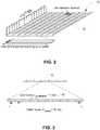
- Fig. 2illustrates a portion of an example OFDM time-frequency grid 50 for LTE.
- the time-frequency grid 50is divided into one millisecond subframes.
- Each subframeincludes a number of OFDM symbols.
- CPcyclic prefix
- a subframemay comprise fourteen OFDM symbols.
- a subframemay comprise twelve OFDM symbols if an extended cyclic prefix is used.
- the physical resources shown in Figure 2are divided into adjacent subcarriers with a spacing of 15 kHz.
- the number of subcarriersmay vary according to the allocated system bandwidth.
- the smallest element of the time-frequency grid 50is typically referred to as a resource element, which comprises one OFDM subcarrier during one OFDM symbol interval.
- the PDSCHis a time and frequency multiplexed channel shared by a plurality of radio nodes 105.
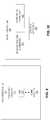
- the downlink transmissionsare typically organized into ten millisecond radio frames 60.
- Each radio frametypically comprises ten equally-sized subframes 62.
- the downlink time-frequency resourcesare allocated in units called resource blocks (RBs).
- RBsresource blocks
- Each resource blocktypically spans twelve subcarriers (which may be adjacent or distributed across the frequency spectrum) and one 0.5 ms slot (one half of one subframe).
- the transmitting node 110may dynamically schedule downlink transmissions to one or more of the radio nodes 105a-b, according to one or more embodiments. For such dynamic scheduling, the transmitting node 110 may transmit downlink control information (DCI) in each subframe 62.
- the DCIidentifies one or more radio nodes 105 that have been scheduled to receive data in the current downlink subframe 62 and the resource blocks on which the data is being transmitted to the scheduled radio nodes 105.
- the DCIis typically transmitted on the Physical Downlink Control Channel (PDCCH) or enhanced PDCCH (ePDCCH), e.g., in the first two, three, or four OFDM symbols in each subframe 62.
- the resources on which the data is carriedis typically transmitted in a corresponding Physical Downlink Shared Channel (PDSCH).
- PDSCHPhysical Downlink Shared Channel
- Transmitting node 110may additionally or alternatively perform semi-persistent scheduling (SPS) of the downlink, according to one or more embodiments.
- SPSgenerally requires less signaling overhead than dynamic scheduling.
- the resource blocks on which data is being transmitted to one or more radio nodes 105is not identified in DCI transmitted in each subframe 62 (as is the case in dynamic scheduling). Rather, the resource blocks may be identified in DCI transmitted in a particular subframe 62 for multiple subframes (e.g., the present subframe and one or more subsequent subframes).
- the multiple subframesmay be contiguous or discontiguous.
- the spacing between subframe occasions to which the DCI appliesmay, in some embodiments, be a periodicity of the SPS.
- This SPS periodmay be expressed in terms of time (e.g., every 10 milliseconds) and/or in terms of subframes (e.g., every tenth subframe). According to embodiments, this period may be adapted by the transmitting node 110, e.g., by appropriate signaling as will be discussed below. Further, this period may be of a duration that is less than, equal to, or greater than the duration of a radio frame 60, according to various embodiments.
- the transmitting node 110may switch between dynamic scheduling and SPS, and may configure one or more radio nodes 105 accordingly.
- the transmitting node 110may transmit Radio Resource Control signaling to indicate that SPS of a particular periodicity is to be used. Thereafter, a resource assignment may be sent in DCI to a radio node 105 to activate SPS.
- the radio node 110may store this DCI and expect a downlink transmission at each SPS occasion accordingly.
- each subframe 62comprises an initial control region (i.e., a PDCCH) 230 and a subsequent data region 240 (i.e., a PDSCH).
- the schedulingmay previously have been dynamic (not shown), such that DCI is transmitted in the control region 230 indicates resources of the corresponding data region 240 in which data will be transmitted by the transmitting node 110 to a radio node 105.
- the transmitting node 110may transmit a configuration message 210 via RRC signaling to configure the radio node 105 for SPS.
- the configuration message 210indicates a periodicity of the SPS (in this example, two subframes).
- the transmitting node 110transmits an activation message 220 in the control region 230 of a particular subframe 62 to activate SPS (i.e., as configured by the configuration message 210) at a future time.
- activationis preconfigured to occur in the fourth subframe 62 after the subframe 62 carrying the activation message 220.
- the time to activationmay be configured by the configuration message 210 or by other signaling. This activation may, in some embodiments, switch the scheduling mode of the radio node 105, e.g., if the radio node 105 was previously configured for dynamic scheduling.
- the activation message 220includes DCI indicating the resources on which data will be transmitted to the radio node 105 periodically in the relevant subframes.
- the transmitting node 110then transmits data 260a in the data region 240 of the fourth subframe 62 after the subframe 62 carrying the activation message 220 (which is the first subframe 62 in the initial SPS period 250a), and continues transmitting data 260b, 260c in every SPS period 250b, 250c of two subframes thereafter (as configured by the configuration message 210).
- the single message to configure and activate SPSmay include DCI identifying the resources on which data will be transmitted, and a duration between instances of subframes carrying such resources (i.e., a periodicity of the SPS).
- the configuration and/or activation message 210, 220may be transmitted using different channels and/or signaling according to other embodiments.
- the configuration and/or activation message 210, 220may be transmitted using a Medium Access Control (MAC) Control Element, e.g., in a PDSCH transmission.
- MACMedium Access Control
- embodimentsinclude switching from dynamic scheduling to SPS.
- Other embodimentsinclude switching from SPS to dynamic scheduling.
- Such embodimentsmay similarly include a configuration and/or activation message 210, 220 for the dynamic scheduling.
- embodimentsinclude a transmitting node 110 and radio node 105 that may switch scheduling modes freely between dynamic scheduling and SPS, e.g., responsive to conditions in the radio environment, mobility of the radio nodes 105, and/or other factors.
- the ability to freely switch between scheduling modesmay allow the transmitting node 110 to reduce signaling overhead to more efficiently use transmission resources during high traffic times by switching to SPS, and allow the transmitting node 110 to use a more flexible scheduling mechanism during lower traffic times by switching to dynamic scheduling.
- Other embodimentsinclude activating, or switching between, SPS and/or dynamic scheduling for other reasons.
- FIG. 4Aillustrates an SPS period 250 of two subframes
- other embodimentsinclude SPS periods 250 of other durations.
- particular radio nodes 105may have very low latency requirements.
- Such radio nodes 105may be devices participating in Critical Machine Type Communication (CMTC), for example.
- CMTCCritical Machine Type Communication
- Such a systemmay, for example, have an SPS period 250 of less than two subframes.
- Less critical systemsmay have an SPS period 250 of more than two subframes but less than 10 milliseconds (i.e., less than one typical LTE radio frame 60).
- Systems that involve very infrequent and/or low priority communicationfor example, may have SPS periods 250 of more than ten subframes.
- the SPS period specified by the transmitting node 110may be dependent upon the particular system, devices, and/or conditions that are present.
- the example of Figure 4Aillustrates an activation message 220 in which DCI is used for multiple transmissions of data 260a-c according to the configured SPS period
- this DCImay be replaced, e.g., without changing when data transmissions 260 are expected to occur.
- the transmitting node 110may transmit a replacement DCI to the radio node 105 in the control region 230 of the first subframe 62 of SPS period 250c, and the immediately subsequent data region 240 in SPS period 250c, previously configured for SPS by configuration message 210, would carry data according to the replacement DCI.
- the radio node 105may provide Hybrid Automatic Request (HARQ) feedback to the transmitting node 110, according to one or more embodiments.
- a radio node 105may provide HARQ acknowledgements (ACKs) in response to messages that are received and successfully decoded, and negative acknowledgements (NACKs) in response to messages that are either expected and not received, or are received and not successfully decoded.
- ACKsHARQ acknowledgements
- NACKsnegative acknowledgements
- a radio node 105may generate and transmit HARQ feedback to the transmitting node 110 depending on the outcome of decoding each periodic SPS data transmission 260, in some embodiments.
- the radio node 105may similarly respond to DCI addressed to the radio node 105 with such HARQ feedback, according to one or more embodiments.
- SPSgenerally requires less signaling overhead than dynamic scheduling. Thus, SPS may be used when less signaling overhead is required or advantageous.
- particular HARQ feedback from the radio node 105 to the transmitting node 110may be disabled and/or limited, e.g., to reduce signaling overhead when SPS is used.
- the configuration and/or activation message 210, 220may instruct the radio node 105 to deactivate HARQ NACK transmission (i.e., without deactivating HARQ ACK transmission).
- the radio node 105may be required to send a HARQ NACK after failing to decode a data region 240 while in dynamic scheduling mode, such a NACK may only be useful to the transmitting node 110 to distinguish between situations in which the corresponding DCI is not received and situations in which the data region 240 is not decodable. Since DCI is not transmitted in each subframe according to SPS, the transmitting node 110 may consider the absence of an expected HARQ ACK from radio node 105 to indicate that a decoding error has occurred.
- the radio node 105does not transmit a HARQ NACK in response to a data region 240 decoding error, and does transmit a HARQ ACK in response to successfully decoding the data region 240, for each of the SPS periodic transmissions 260.
- FIG. 4BAn example in which HARQ NACK transmission is deactivated is illustrated in Figure 4B .
- SPSactivates four subframes after activation message 220.
- the SPS period 250dwas previously configured (e.g., by a configuration message 210) with a duration of one subframe.
- the transmitting node 110begins periodically transmitting data 260d-e each subframe.
- the radio node 105successfully receives these data transmissions 260d-e, and sends HARQ ACK feedback accordingly.
- the transmitting node 110may not have any data to send to the radio node 105 at that time. Accordingly, the transmitting node 110 does not transmit data in the next subframe, resulting in an empty SPS data region 270.
- the radio node 105has been configured to deactivate HARQ NACK transmission. Accordingly, the radio node 105 does not send a HARQ NACK to the transmitting node 110 in response to the empty SPS data region 270.
- the transmitting node 110in this case, expects not to receive HARQ feedback. Accordingly, the transmitting node 110 proceeds to transmit further data 260f in the next SPS period 250.
- the radio node 105subsequently experiences a decoding error when attempting to decode data transmission 260g from the transmitting node 110, according to this example. Again, HARQ NACK transmission is disabled for the radio node 105. Accordingly, the radio node 105 again does not transmit HARQ NACK feedback.
- the transmitting node 110expects to receive a HARQ ACK in response to data transmission 260g. Having failed to receive the expected HARQ ACK, the transmitting node 110 retransmits data transmission 260g as data transmission 260h.
- the radio node 105successfully decodes the retransmission 260h, and transmits a HARQ ACK to the transmitting node 110 in response.
- the transmitting node 110having received the expected HARQ ACK this time, proceeds to send new data in data transmission 260i, which the radio node 105 correspondingly acknowledges after successful decoding thereof.
- Figure 4Billustrates an example in which HARQ NACK transmission is deactivated (while HARQ ACK transmission remains active)
- other embodimentsmay instruct the radio node 105 to deactivate HARQ ACK transmission (i.e., without deactivating HARQ NACK transmission).
- Yet other embodimentsmay instruct the radio node 105 to deactivate both HARQ ACK and HARQ NACK transmission.
- the radio node 105may only send a HARQ NACK in response to encountering multiple decoding failures. For example, in some embodiments, the radio node 105 may only transmit a HARQ NACK in response to a retransmission of a previous transmission for which a decoding error was encountered. In one such example, the radio node 105 may encounter a decoding error when decoding initial SPS data transmission 260a and silently discard this SPS data transmission 260a (i.e., without transmitting a HARQ ACK to the transmitting node 110 in response).
- the transmitting node 110expecting (and failing) to receive this HARQ ACK may retransmit data transmission 260a as data transmission 260b.
- the radio node 105again encountering a decoding error (this time when attempting to decode the retransmission), may then transmit a HARQ NACK to the transmitting node 110.
- the radio node 105may transmit a HARQ ACK only when the radio node 105 receives padding data in an SPS data transmission 260a of an initial SPS period 250a.
- the radio node 105may transmit a HARQ ACK only when the radio node 105 receives a particular MAC Control Element in an SPS data transmission 260a of an initial SPS period 250a according to the DCI in the activation message 220.
- the MAC Control Elementmay be any one of the MAC Control Elements as described in 3GPP TS 36.321 V14.0.0 (2016-09 ), for example.
- the radio node 105may transmit a HARQ ACK only when the radio node 105 receives a particular MAC Control Element separately from the SPS periodic data transmissions 260.
- each control region 230may include an identifier of the radio node 205 (e.g., a Radio Network Temporary Identifier (RNTI)) which notifies the radio node to decode the corresponding data region 240.
- RNTIRadio Network Temporary Identifier
- the configuration message 210may include such an RNTI transmitted via RRC signaling to radio node 105a, and the DCI (indicating the SPS resources) may be transmitted in the activation message 220 (e.g., on a PDCCH) addressed to radio node 105a using the RNTI.
- radio nodes 105a-bmay each only receive data very infrequently. Thus, the likelihood that the transmitting node 110 will have data to transmit to either radio node 105a-b may be quite low. Far less likely may be the probability of the transmitting node having data to transmit to both of the radio nodes 105a-b. In order to efficiently utilize data channel resources while still using SPS to keep signaling overhead and latency low, the transmitting node 110 may, in some particular embodiments, allocate the same resource to more than one radio node 105.
- the transmitting node 110may, in some embodiments, transmit a first DCI to radio node 105a, and a different DCI to radio node 105b.
- the two DCIboth allocate at least one same resource, and each allocates at least one different resource from the other.
- the DCI to radio node 105a, and the different DCI to radio node 105bpartially, but not completely, overlap with respect to the resources that they each identify.
- the transmitting node 110may transmit additional information that enables each radio node 105a-b to successfully decode the corresponding data region 240 when that data region 240 is intended for that radio node 105a-b.
- the transmitting node 110transmits a cyclic redundancy check (CRC) code that is computed according to the DCI or the different DCI based on whether the data transmitted on the at least one same resource is intended for the radio node 105a or the other radio node 105b. Since the different DCIs each allocate at least one different resource from the other, when each of the radio nodes 105a-b performs a CRC check based on the data carried by the resources specified in their respective DCI, the CRC will generally check for the radio node 105 for which the data on the shared resource is intended, whereas any other radio nodes 105 (for which the shared resource data is not intended) will encounter a decoding error.
- CRCcyclic redundancy check
- the transmitting node 110sends the same DCI to multiple radio nodes 105a-b.
- the transmitting node 110may encode a CRC code for a data transmission 260 using an identifier of the radio node to which the data transmission 260 is intended.
- An example of such an identifiermay be, for example, an RNTI that the transmitting node previously transmitted to the intended radio node 105a in a previous SPS configuration message 210.
- each radio node 105a-bmay receive a scrambled CRC code, which must be descrambled using that radio node's identifier before attempting to perform a CRC check.
- the CRC codewill generally check for the intended radio node 105a, whereas any other radio nodes 105b will encounter a decoding error.
- the scrambled CRC codeis transmitted by the transmitting node 110 in an abbreviated DCI in the control region 230 corresponding to the data transmission 260.
- inventions of the present disclosureinclude the example method 300 of transmission scheduling illustrated in Figure 5 .
- the method 300may be implemented by a transmitting node 110 and comprises transmitting a message 210 instructing a radio node 105 that data will be transmitted to the radio node 105 according to the same Downlink Control Information (DCI) each period 250, the message comprising a duration of the period (block 310).
- the method 300further comprises transmitting the DCI to the radio node 105 for the periodic transmission 260 (block 320).
- DCIDownlink Control Information
- the method 400may be implemented by a radio node 105 and comprises receiving a message 210, from a transmitting node 110, instructing the radio node 105 that data will be transmitted from the transmitting node 110 to the radio node 105 according to the same Downlink Control Information (DCI) each period 250, the message 210 comprising a duration of the period 250 (block 410).
- the method 400further comprises receiving, from the transmitting node 110, the DCI for the periodic transmission 260 (block 420), and decoding each of a plurality of transmissions of the periodic transmission 260 according to the DCI (block 430).
- DCIDownlink Control Information
- a transmitting node 110 and/or radio node 105 as described abovemay perform the methods described herein (and any other processing herein) by implementing any functional means, units, or modules.
- the transmitting node 110comprises respective circuits or circuitry configured to perform the steps of method 300 shown in Figure 5 .
- the radio node 105comprises respective circuits or circuitry configured to perform the steps of method 400 shown in Figure 6 .
- the circuits or circuitry in this regardmay comprise circuits dedicated to performing certain functional processing and/or may comprise one or more microprocessors in conjunction with memory.
- memorywhich may comprise one or several types of memory such as read-only memory (ROM), random-access memory, cache memory, flash memory devices, optical storage devices, etc.
- the memorymay store program code that, when executed by the one or more processors, carries out the techniques described herein.
- FIG. 7illustrates an example transmitting node 110, implemented in accordance with one or more embodiments.
- the transmitting node 110includes processing circuitry 510 and communication circuitry 530.
- the communication circuitry 530is configured to transmit and/or receive information to and/or from one or more other nodes, e.g., via any communication technology. Such communication may occur via one or more antennas that are either internal or external to the transmitting node 110.
- the processing circuitry 510is configured to perform processing described above, e.g., in Figure 5 , such as by executing instructions stored in memory 520.
- the processing circuitry 510in this regard may implement certain functional means, units, or modules.
- FIG 8illustrates an example transmitting node 110, implemented in accordance with one or more other embodiments.
- the transmitting node 110implements various functional means, units, or modules, e.g., via the processing circuitry 510 in Figure 7 and/or via software code.
- These functional means, units, or modules, e.g., for implementing the method 300 in Figure 5include for instance a message-transmitting unit or module 610 for transmitting a message 210 instructing a radio node 105 that data 260a-c will be transmitted to the radio node 105 according to the same Downlink Control Information (DCI) each period 250a-c, the message 210 comprising a duration of the period.
- DCIDownlink Control Information
- Also includedis a DCI-transmitting unit or module 620 for transmitting, to the radio node 105, the DCI for the periodic transmission 260a-c.
- FIG 9illustrates an example radio node 105, implemented in accordance with one or more embodiments.
- the radio node 105includes processing circuitry 710 and communication circuitry 730.
- the communication circuitry 730is configured to transmit and/or receive information to and/or from one or more other nodes, e.g., via any communication technology. Such communication may occur via one or more antennas that are either internal or external to the radio node 105.
- the processing circuitry 710is configured to perform processing described above, e.g., in Figure 6 , such as by executing instructions stored in memory 720.
- the processing circuitry 710in this regard may implement certain functional means, units, or modules.
- FIG 10illustrates an example radio node 105, implemented in accordance with one or more other embodiments.
- the radio node 105implements various functional means, units, or modules, e.g., via the processing circuitry 710 in Figure 9 and/or via software code.
- These functional means, units, or modules, e.g., for implementing the method 400 in Figure 6include for instance a message-receiving unit or module 810 for receiving a message 210, from a transmitting node 110, instructing the radio node 105 that data 260a-c will be transmitted from the transmitting node 110 to the radio node 105 according to the same Downlink Control Information (DCI) each period 250a-c, the message 210 comprising a duration of the period.
- DCIDownlink Control Information
- a DCI-receiving unit or module 820for receiving, from the transmitting node 110, the DCI for the periodic transmission 260a-c. Also included is a decoding unit or module 830 for decoding each of a plurality of transmissions of the periodic transmission 260a-c according to the DCI.
- embodiments hereinfurther include methods and devices that initiate any of the methods described above, e.g., via one or more corresponding control commands issued over an appropriate signaling medium.
- Embodimentsfurther include a computer program that comprises instructions which, when executed on at least one processor of a transmitting node 110 or radio node 105, cause the transmitting node 110 or radio node 105 to carry out any of the respective processing described above.
- a computer program in this regardmay comprise one or more code modules corresponding to the means or units described above.
- Embodimentsfurther include a carrier containing such a computer program.
- This carriermay comprise one of an electronic signal, optical signal, radio signal, or computer readable storage medium.
- embodiments hereinalso include a computer program product stored on a non-transitory computer readable (storage or recording) medium and comprising instructions that, when executed by a processor of a transmitting node 110 or radio node 105, cause the transmitting node 110 or radio node 105 to perform as described above.
- Embodimentsfurther include a computer program product comprising program code portions for performing the steps of any of the embodiments herein when the computer program product is executed by a transmitting node 110 or radio node 105.
- This computer program productmay be stored on a computer readable recording medium.
Landscapes
- Engineering & Computer Science (AREA)
- Signal Processing (AREA)
- Computer Networks & Wireless Communication (AREA)
- Mobile Radio Communication Systems (AREA)
Description
- Embodiments of the present disclosure generally relate to semi-persistent scheduling of radio transmissions, and more particularly to control signaling between a transmitting node and a radio node to enable the radio node to decode periodic transmission of data.
- Many wireless communication systems involve transmission scheduling between wireless nodes. In some such systems, a first node sets the transmission schedule, and other nodes communicating with the first node adhere to the transmission schedule. One example of such a transmission schedule defines when the other nodes may expect the first node to transmit on a downlink. Another example of such a transmission schedule defines when the other nodes are permitted to transmit on an uplink. The first node may inform the other nodes of the transmission scheduling using Downlink Control Information (DCI). One particular example of such DCI may be DCI as defined by the 3GPP standards organization, e.g., according to3GPP TS 36.212 V14.0.0 (2016-09). Such DCI may include, for example, a resource allocation, modulation and coding scheme, and other information useful for decoding transmissions. Other examples of such DCI may be particular proprietary to the particular wireless technology used for the communication, or may be defined by other standards organizations. By scheduling transmissions, the first node may coordinate communication between the nodes over a shared wireless medium (e.g., a particular time and/or frequency domain of an air interface).
- 3GPP contribution "Acknowledgements for SPS commands", Tdoc R2-163781, 3GPP TSG-RAN WG2 meeting #94, Nanjing, China, 23-27 May 2016, describes activation of SPS (semi-persistent scheduling) by an activation grant transmitted on a PDCCH (Physical Downlink Control Channel). The DCI received in the activation grant is used in the transmissions on the SPS resources.
- 3GPP contribution "Feedback for SPS activation and deactivation", Tdoc R2-163475, 3GPP TSG-RAN WG2 meeting #94, Nanjing, China, 23-27 May 2016, discusses feedback mechanisms for SPS activation and deactivation.
- The present invention provides a method according to
claim 1, a transmitting node according to claim 6, a method according to claim 8, a radio node according to claim 13, a computer program according toclaim 15, and a carrier according to claim 16. The dependent claims define further embodiments. - Some embodiments herein include transmission scheduling in which a transmitting node instructs a radio node that data will be transmitted to the radio node according to the same Downlink Control Information (DCI) each period. The transmitting then transmits the DCI to the radio node for the periodic transmission. Examples of a transmitting node include a base station (e.g., a NodeB, an eNodeB). Examples of a radio node include user equipment (UE) (e.g., a mobile phone, a smartphone, a data modem, a mobile computer, a vehicle, an actuator, a sensor, or any other kind of terminal device). The transmitting node may configure the period of the periodic transmission in the radio node by appropriate signaling by specifying a duration of the period, e.g., in terms of any number of time or transmission units (e.g., milliseconds, seconds, subframes).
- Consistent with the above, embodiments herein include a method of transmission scheduling implemented by a transmitting node. The method comprises transmitting a message instructing a radio node that data will be transmitted to the radio node according to the same Downlink Control Information (DCI) each period. The message comprises a duration of the period. The method further comprises transmitting the DCI to the radio node for the periodic transmission.
- In some embodiments, the method further comprises switching between dynamic and semi-persistent scheduling modes, transmitting a specific DCI for each data transmission transmitted to the radio node while in the dynamic scheduling mode, and transmitting the message and the DCI for the semi-persistent scheduling mode.
- In some embodiments, the the duration of the period is an integer number of milliseconds less than 10 milliseconds.
- The method further comprises only receiving a HARQ ACK from the radio node in response to transmitting padding data to the radio node according to the DCI in an initial data transmission of the periodic transmission or in response to transmitting a particular MAC Control Element to the radio node according to the DCI in an initial data transmission of the periodic transmission.
- In some embodiments, the message further instructs the radio node to deactivate HARQ negative ACK (NACK) transmission without deactivating HARQ ACK transmission.
- In some embodiments, the method further comprises only receiving a HARQ NACK from the radio node in response to retransmitting, to the radio node, a previous transmission for which an expected HARQ ACK was not received, wherein the HARQ NACK indicates to the transmitting node that the radio node encountered a decoding error with respect to the retransmitting.
- Other embodiments include of transmission scheduling implemented by a radio node. The method comprises receiving a message, from a transmitting node, instructing the radio node that data will be transmitted from the transmitting node to the radio node according to the same Downlink Control Information (DCI) each period. The message comprises a duration of the period. The method further comprises receiving, from the transmitting node, the DCI for the periodic transmission, and decoding each of a plurality of transmissions of the periodic transmission according to the DCI.
- In some embodiments, the method further comprises switching between dynamic and semi-persistent scheduling modes, receiving a specific DCI for each data transmission received from the transmitting node while in the dynamic scheduling mode, and receiving the message and the DCI for the semi-persistent scheduling mode.
- In some embodiments, the duration of the period is an integer number of milliseconds less than 10 milliseconds.
- The method further comprises refraining from transmitting any HARQ ACK to the transmitting node unless padding data is received from the transmitting node according to the DCI in an initial data transmission of the periodic transmission or a particular MAC Control Element is received from the transmitting node according to the DCI in an initial data transmission of the periodic transmission
- In some embodiments, the method further comprises deactivating HARQ negative ACK (NACK) transmission without deactivating HARQ ACK transmission responsive to receiving the message. In other embodiments, the method further comprises refraining from transmitting any HARQ NACK to the transmitting node unless the radio node encounters a decoding error with respect to a retransmission of a previous data transmission of the periodic transmission, the radio node having encountered a previous decoding error with respect to the previous data transmission.
- Embodiments also include apparatus, systems, computer program products, software, and/or carriers that correspond to one or more of the methods described herein.
Figure 1 illustrates an example wireless communication system, according to one or more embodiments of the present disclosure.Figure 2 illustrates an example of downlink physical resources as may be used for Orthogonal Frequency-Division Multiplexing (OFDM) communication, according to one or more embodiments of the present disclosure.Figure 3 illustrates an example time-domain structure as may be used for OFDM communication, according to one or more embodiments of the present disclosure.Figure 4A illustrates an example time-domain structure in which SPS is activated, according to one or more embodiments of the present disclosure.Figure 4B illustrates an example HARQ feedback scheme as applied to another example time-domain structure in which SPS is activated, according to one or more embodiments of the present disclosure.Figure 5 illustrates an example method implemented by a transmitting node, according to one or more embodiments of the present disclosure.Figure 6 illustrates an example method implemented by a radio node, according to one or more embodiments of the present disclosure.Figure 7 is a block diagram illustrating example hardware of a transmitting node useful for implementing one or more of the methods described herein, according to one or more embodiments of the present disclosure.Figure 8 is a block diagram illustrating example means, physical units, or software modules of a transmitting node useful for implementing one or more of the methods described herein, according to one or more embodiments of the present disclosure.Figure 9 is a block diagram illustrating example hardware of a radio node useful for implementing one or more of the methods described herein, according to one or more embodiments of the present disclosure.Figure 10 is a block diagram illustrating example means, physical units, or software modules of a radio node useful for implementing one or more of the methods described herein, according to one or more embodiments of the present disclosure.- Note that, as used herein, when a reference numeral comprises a letter designation in the drawings, discussion of a specific instance of an illustrated element will use the appropriate corresponding letter designation (e.g.,
radio node 105a). However, the letter designation will be omitted in order to refer generically to the illustrated subject matter (e.g., discussion of a radio node 105 (generally), rather than discussion ofparticular radio nodes - As will be described in detail below, aspects of the present disclosure may be implemented entirely as hardware units, entirely as software modules (including firmware, resident software, micro-code, etc.), or as a combination of hardware units and software modules. For example, embodiments of the present disclosure may take the form of a non-transitory computer readable medium storing software instructions in the form of a computer program that, when executed on a programmable device, configures the programmable device to execute the various methods described below.
- For clarity in understanding the disclosure below, to the extent that "one of" a conjunctive list of items (e.g., "one of A and B") is discussed, the present disclosure refers to one (but not both) of the items in the list (e.g., an A or a B, but not both A and B). Such a phrase does not refer to one of each of the list items (e.g., one A and one B), nor does such a phrase refer to only one of a single item in the list (e.g., only one A, or only one B). Similarly, to the extent that "at least one of" a conjunctive list of items is discussed (and similarly for "one or more of" such a list), the present disclosure refers to any item in the list or any combination of the items in the list (e.g., an A only, a B only, or both an A and a B). Such a phrase does not refer to one or more of each of the items in the list (e.g., one or more of A, and one or more of B).
- Turning now to the drawings,
Figure 1 illustrates anexample communication system 100 according to one or more embodiments of the present disclosure. Although thecommunication system 100 will be described in the context of a Long-Term Evolution (LTE) communication network, the discussion throughout this disclosure may similarly be applied to other wireless communication systems and/or combinations thereof, including but not limited to 5G Next Radio (NR) and/or Wi-Fi. - The
communication system 100 comprises a plurality of wireless communication nodes. One of the wireless communication nodes in particular is a transmittingnode 110 that serves acell 115 toradio nodes 105a-b. In the context of LTE,radio nodes 105a-b may each be referred to as a User Equipment (UE), whereas the transmittingnode 110 may be a base station (such as an eNodeB), for example. Although only one transmittingnode 110 and tworadio nodes 105a-b are illustrated inFigure 1 , other examples of thecommunication system 100 may include any number of transmittingnodes 110, each of which may serve one ormore cells 115 to any number ofradio nodes 105. Further, althoughradio nodes 105a-b have been described in the context of UEs, theradio nodes 105 may themselves be base stations (e.g., femtocells, relay base stations), according to other embodiments. Further, transmittingnode 110 is itself a type of radio node, in that the transmittingnode 110 is a network node capable of radio communication. - Wireless communication between the transmitting
node 110 and each of theradio nodes 105a-b is performed using radio resources across a time and frequency domain. LTE in particular uses OFDM in the downlink and Discrete Fourier Transform (DFT) spread OFDM in the uplink. The basic LTE downlink physical resource can be viewed as a time-frequency grid.Fig. 2 illustrates a portion of an example OFDM time-frequency grid 50 for LTE. Generally speaking, the time-frequency grid 50 is divided into one millisecond subframes. Each subframe includes a number of OFDM symbols. For a normal cyclic prefix (CP) length, suitable for use in situations where multipath dispersion is not expected to be extremely severe, a subframe may comprise fourteen OFDM symbols. A subframe may comprise twelve OFDM symbols if an extended cyclic prefix is used. In the frequency domain, the physical resources shown inFigure 2 are divided into adjacent subcarriers with a spacing of 15 kHz. The number of subcarriers may vary according to the allocated system bandwidth. The smallest element of the time-frequency grid 50 is typically referred to as a resource element, which comprises one OFDM subcarrier during one OFDM symbol interval. - In LTE systems, data is transmitted to the mobile terminals over a downlink transport channel known as the Physical Downlink Shared Channel (PDSCH). The PDSCH is a time and frequency multiplexed channel shared by a plurality of
radio nodes 105. As shown inFigure 3 , the downlink transmissions are typically organized into ten millisecond radio frames 60. Each radio frame typically comprises ten equally-sized subframes 62. For purposes of scheduling users to receive downlink transmissions, the downlink time-frequency resources are allocated in units called resource blocks (RBs). Each resource block typically spans twelve subcarriers (which may be adjacent or distributed across the frequency spectrum) and one 0.5 ms slot (one half of one subframe). - Within a
cell 115 the transmittingnode 110 may dynamically schedule downlink transmissions to one or more of theradio nodes 105a-b, according to one or more embodiments. For such dynamic scheduling, the transmittingnode 110 may transmit downlink control information (DCI) in eachsubframe 62. The DCI identifies one ormore radio nodes 105 that have been scheduled to receive data in thecurrent downlink subframe 62 and the resource blocks on which the data is being transmitted to the scheduledradio nodes 105. The DCI is typically transmitted on the Physical Downlink Control Channel (PDCCH) or enhanced PDCCH (ePDCCH), e.g., in the first two, three, or four OFDM symbols in eachsubframe 62. The resources on which the data is carried is typically transmitted in a corresponding Physical Downlink Shared Channel (PDSCH). - Transmitting
node 110 may additionally or alternatively perform semi-persistent scheduling (SPS) of the downlink, according to one or more embodiments. SPS generally requires less signaling overhead than dynamic scheduling. For SPS scheduling, the resource blocks on which data is being transmitted to one ormore radio nodes 105 is not identified in DCI transmitted in each subframe 62 (as is the case in dynamic scheduling). Rather, the resource blocks may be identified in DCI transmitted in aparticular subframe 62 for multiple subframes (e.g., the present subframe and one or more subsequent subframes). According to one or more embodiments, the multiple subframes may be contiguous or discontiguous. The spacing between subframe occasions to which the DCI applies may, in some embodiments, be a periodicity of the SPS. This SPS period may be expressed in terms of time (e.g., every 10 milliseconds) and/or in terms of subframes (e.g., every tenth subframe). According to embodiments, this period may be adapted by the transmittingnode 110, e.g., by appropriate signaling as will be discussed below. Further, this period may be of a duration that is less than, equal to, or greater than the duration of aradio frame 60, according to various embodiments. - The transmitting
node 110 may switch between dynamic scheduling and SPS, and may configure one ormore radio nodes 105 accordingly. In particular, the transmittingnode 110 may transmit Radio Resource Control signaling to indicate that SPS of a particular periodicity is to be used. Thereafter, a resource assignment may be sent in DCI to aradio node 105 to activate SPS. Theradio node 110 may store this DCI and expect a downlink transmission at each SPS occasion accordingly. - An example of SPS is illustrated in
Figure 4A . As shown inFigure 4A , eachsubframe 62 comprises an initial control region (i.e., a PDCCH) 230 and a subsequent data region 240 (i.e., a PDSCH). In some embodiments, the scheduling may previously have been dynamic (not shown), such that DCI is transmitted in thecontrol region 230 indicates resources of the correspondingdata region 240 in which data will be transmitted by the transmittingnode 110 to aradio node 105. - The transmitting
node 110 may transmit aconfiguration message 210 via RRC signaling to configure theradio node 105 for SPS. Theconfiguration message 210 indicates a periodicity of the SPS (in this example, two subframes). Later, according to this example, the transmittingnode 110 transmits anactivation message 220 in thecontrol region 230 of aparticular subframe 62 to activate SPS (i.e., as configured by the configuration message 210) at a future time. In this particular example, activation is preconfigured to occur in thefourth subframe 62 after thesubframe 62 carrying theactivation message 220. In some other examples, the time to activation may be configured by theconfiguration message 210 or by other signaling. This activation may, in some embodiments, switch the scheduling mode of theradio node 105, e.g., if theradio node 105 was previously configured for dynamic scheduling. - The
activation message 220 includes DCI indicating the resources on which data will be transmitted to theradio node 105 periodically in the relevant subframes. The transmittingnode 110 then transmitsdata 260a in thedata region 240 of thefourth subframe 62 after thesubframe 62 carrying the activation message 220 (which is thefirst subframe 62 in theinitial SPS period 250a), and continues transmittingdata SPS period 250b, 250c of two subframes thereafter (as configured by the configuration message 210). - Although some embodiments may use separate configuration and
activation messages radio node 105 for SPS, respectively, other embodiments may use a single message to both configure and activate SPS in the radio node. In an example of such an embodiment, the single message to configure and activate SPS may include DCI identifying the resources on which data will be transmitted, and a duration between instances of subframes carrying such resources (i.e., a periodicity of the SPS). - Further, the configuration and/or
activation message activation message - In view of the above, embodiments include switching from dynamic scheduling to SPS. Other embodiments include switching from SPS to dynamic scheduling. Such embodiments may similarly include a configuration and/or
activation message node 110 andradio node 105 that may switch scheduling modes freely between dynamic scheduling and SPS, e.g., responsive to conditions in the radio environment, mobility of theradio nodes 105, and/or other factors. In some embodiments, the ability to freely switch between scheduling modes may allow the transmittingnode 110 to reduce signaling overhead to more efficiently use transmission resources during high traffic times by switching to SPS, and allow the transmittingnode 110 to use a more flexible scheduling mechanism during lower traffic times by switching to dynamic scheduling. Other embodiments include activating, or switching between, SPS and/or dynamic scheduling for other reasons. - Further, although the example of
Figure 4A illustrates an SPS period 250 of two subframes, other embodiments include SPS periods 250 of other durations. For example,particular radio nodes 105 may have very low latency requirements.Such radio nodes 105 may be devices participating in Critical Machine Type Communication (CMTC), for example. Such a system may, for example, have an SPS period 250 of less than two subframes. Less critical systems may have an SPS period 250 of more than two subframes but less than 10 milliseconds (i.e., less than one typical LTE radio frame 60). Systems that involve very infrequent and/or low priority communication, for example, may have SPS periods 250 of more than ten subframes. The SPS period specified by the transmittingnode 110 may be dependent upon the particular system, devices, and/or conditions that are present. - Further still, although the example of
Figure 4A illustrates anactivation message 220 in which DCI is used for multiple transmissions ofdata 260a-c according to the configured SPS period, in some embodiments, this DCI may be replaced, e.g., without changing when data transmissions 260 are expected to occur. In one such example, the transmittingnode 110 may transmit a replacement DCI to theradio node 105 in thecontrol region 230 of thefirst subframe 62 ofSPS period 250c, and the immediatelysubsequent data region 240 inSPS period 250c, previously configured for SPS byconfiguration message 210, would carry data according to the replacement DCI. - According to various embodiments, the
radio node 105 may provide Hybrid Automatic Request (HARQ) feedback to the transmittingnode 110, according to one or more embodiments. In particular, aradio node 105 may provide HARQ acknowledgements (ACKs) in response to messages that are received and successfully decoded, and negative acknowledgements (NACKs) in response to messages that are either expected and not received, or are received and not successfully decoded. Thus, aradio node 105 may generate and transmit HARQ feedback to the transmittingnode 110 depending on the outcome of decoding each periodic SPS data transmission 260, in some embodiments. Theradio node 105 may similarly respond to DCI addressed to theradio node 105 with such HARQ feedback, according to one or more embodiments. - As previously discussed, SPS generally requires less signaling overhead than dynamic scheduling. Thus, SPS may be used when less signaling overhead is required or advantageous. According to some embodiments, particular HARQ feedback from the
radio node 105 to the transmittingnode 110 may be disabled and/or limited, e.g., to reduce signaling overhead when SPS is used. For example, the configuration and/oractivation message radio node 105 to deactivate HARQ NACK transmission (i.e., without deactivating HARQ ACK transmission). - For example, while the
radio node 105 may be required to send a HARQ NACK after failing to decode adata region 240 while in dynamic scheduling mode, such a NACK may only be useful to the transmittingnode 110 to distinguish between situations in which the corresponding DCI is not received and situations in which thedata region 240 is not decodable. Since DCI is not transmitted in each subframe according to SPS, the transmittingnode 110 may consider the absence of an expected HARQ ACK fromradio node 105 to indicate that a decoding error has occurred. Accordingly, in some embodiments, theradio node 105 does not transmit a HARQ NACK in response to adata region 240 decoding error, and does transmit a HARQ ACK in response to successfully decoding thedata region 240, for each of the SPS periodic transmissions 260. - An example in which HARQ NACK transmission is deactivated is illustrated in
Figure 4B . According to the example ofFigure 4B , SPS activates four subframes afteractivation message 220. In this example, theSPS period 250d was previously configured (e.g., by a configuration message 210) with a duration of one subframe. In this example, beginning with the initial onesubframe SPS period 250d, the transmittingnode 110 begins periodically transmittingdata 260d-e each subframe. Theradio node 105 successfully receives thesedata transmissions 260d-e, and sends HARQ ACK feedback accordingly. - Although the next subframe after
data transmission 260e is also configured for data transmission, the transmittingnode 110 may not have any data to send to theradio node 105 at that time. Accordingly, the transmittingnode 110 does not transmit data in the next subframe, resulting in an emptySPS data region 270. As previously mentioned, theradio node 105 has been configured to deactivate HARQ NACK transmission. Accordingly, theradio node 105 does not send a HARQ NACK to the transmittingnode 110 in response to the emptySPS data region 270. The transmittingnode 110, in this case, expects not to receive HARQ feedback. Accordingly, the transmittingnode 110 proceeds to transmitfurther data 260f in the next SPS period 250. - The
radio node 105 subsequently experiences a decoding error when attempting to decodedata transmission 260g from the transmittingnode 110, according to this example. Again, HARQ NACK transmission is disabled for theradio node 105. Accordingly, theradio node 105 again does not transmit HARQ NACK feedback. The transmittingnode 110 expects to receive a HARQ ACK in response todata transmission 260g. Having failed to receive the expected HARQ ACK, the transmittingnode 110 retransmitsdata transmission 260g asdata transmission 260h. Theradio node 105 successfully decodes theretransmission 260h, and transmits a HARQ ACK to the transmittingnode 110 in response. The transmittingnode 110, having received the expected HARQ ACK this time, proceeds to send new data in data transmission 260i, which theradio node 105 correspondingly acknowledges after successful decoding thereof. - Although
Figure 4B illustrates an example in which HARQ NACK transmission is deactivated (while HARQ ACK transmission remains active), other embodiments may instruct theradio node 105 to deactivate HARQ ACK transmission (i.e., without deactivating HARQ NACK transmission). Yet other embodiments may instruct theradio node 105 to deactivate both HARQ ACK and HARQ NACK transmission. - Other embodiments may limit NACK transmission to particular situations. According to such other embodiments, the
radio node 105 may only send a HARQ NACK in response to encountering multiple decoding failures. For example, in some embodiments, theradio node 105 may only transmit a HARQ NACK in response to a retransmission of a previous transmission for which a decoding error was encountered. In one such example, theradio node 105 may encounter a decoding error when decoding initialSPS data transmission 260a and silently discard thisSPS data transmission 260a (i.e., without transmitting a HARQ ACK to the transmittingnode 110 in response). The transmittingnode 110, expecting (and failing) to receive this HARQ ACK may retransmitdata transmission 260a asdata transmission 260b. Theradio node 105, again encountering a decoding error (this time when attempting to decode the retransmission), may then transmit a HARQ NACK to the transmittingnode 110. - Further embodiments may limit HARQ ACK transmission during SPS. For example, in some embodiments, the
radio node 105 may transmit a HARQ ACK only when theradio node 105 receives padding data in anSPS data transmission 260a of aninitial SPS period 250a. In other embodiments, theradio node 105 may transmit a HARQ ACK only when theradio node 105 receives a particular MAC Control Element in anSPS data transmission 260a of aninitial SPS period 250a according to the DCI in theactivation message 220. The MAC Control Element may be any one of the MAC Control Elements as described in3GPP TS 36.321 V14.0.0 (2016-09), for example. In a comparative example, theradio node 105 may transmit a HARQ ACK only when theradio node 105 receives a particular MAC Control Element separately from the SPS periodic data transmissions 260. - As touched upon earlier, the transmissions of the transmitting
node 110 may be received bymultiple radio nodes control region 230 signaling may be used to indicate which of theradio nodes data region 240 is intended for. According to dynamic signaling, eachcontrol region 230 may include an identifier of the radio node 205 (e.g., a Radio Network Temporary Identifier (RNTI)) which notifies the radio node to decode the correspondingdata region 240. As applied to SPS, theconfiguration message 210 may include such an RNTI transmitted via RRC signaling toradio node 105a, and the DCI (indicating the SPS resources) may be transmitted in the activation message 220 (e.g., on a PDCCH) addressed toradio node 105a using the RNTI. - In some particular, embodiments,
radio nodes 105a-b may each only receive data very infrequently. Thus, the likelihood that the transmittingnode 110 will have data to transmit to eitherradio node 105a-b may be quite low. Far less likely may be the probability of the transmitting node having data to transmit to both of theradio nodes 105a-b. In order to efficiently utilize data channel resources while still using SPS to keep signaling overhead and latency low, the transmittingnode 110 may, in some particular embodiments, allocate the same resource to more than oneradio node 105. - For example, the transmitting
node 110 may, in some embodiments, transmit a first DCI toradio node 105a, and a different DCI toradio node 105b. In this example, the two DCI both allocate at least one same resource, and each allocates at least one different resource from the other. Thus, the DCI toradio node 105a, and the different DCI toradio node 105b partially, but not completely, overlap with respect to the resources that they each identify. In such embodiments, the transmittingnode 110 may transmit additional information that enables eachradio node 105a-b to successfully decode the correspondingdata region 240 when thatdata region 240 is intended for thatradio node 105a-b. - In some embodiments, the transmitting
node 110 transmits a cyclic redundancy check (CRC) code that is computed according to the DCI or the different DCI based on whether the data transmitted on the at least one same resource is intended for theradio node 105a or theother radio node 105b. Since the different DCIs each allocate at least one different resource from the other, when each of theradio nodes 105a-b performs a CRC check based on the data carried by the resources specified in their respective DCI, the CRC will generally check for theradio node 105 for which the data on the shared resource is intended, whereas any other radio nodes 105 (for which the shared resource data is not intended) will encounter a decoding error. - According to other embodiments, the transmitting
node 110 sends the same DCI tomultiple radio nodes 105a-b. In some such embodiments, the transmittingnode 110 may encode a CRC code for a data transmission 260 using an identifier of the radio node to which the data transmission 260 is intended. An example of such an identifier may be, for example, an RNTI that the transmitting node previously transmitted to the intendedradio node 105a in a previousSPS configuration message 210. Accordingly, eachradio node 105a-b may receive a scrambled CRC code, which must be descrambled using that radio node's identifier before attempting to perform a CRC check. The CRC code will generally check for the intendedradio node 105a, whereas anyother radio nodes 105b will encounter a decoding error. In some embodiments, the scrambled CRC code is transmitted by the transmittingnode 110 in an abbreviated DCI in thecontrol region 230 corresponding to the data transmission 260. - Other embodiments applying a similar approach may alternatively scramble the data transmission 260 itself (rather than the CRC code) with the identifier of the intended
radio node 105. Such embodiments may achieve a similar result (i.e., the CRC code may generally check for the intendedradio node 105a, but not others). - In view of the above, embodiments of the present disclosure include the
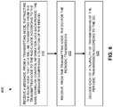
example method 300 of transmission scheduling illustrated inFigure 5 . Themethod 300 may be implemented by a transmittingnode 110 and comprises transmitting amessage 210 instructing aradio node 105 that data will be transmitted to theradio node 105 according to the same Downlink Control Information (DCI) each period 250, the message comprising a duration of the period (block 310). Themethod 300 further comprises transmitting the DCI to theradio node 105 for the periodic transmission 260 (block 320). - Other embodiments of the present disclosure include the
example method 400 of transmission scheduling illustrated inFigure 6 . Themethod 400 may be implemented by aradio node 105 and comprises receiving amessage 210, from a transmittingnode 110, instructing theradio node 105 that data will be transmitted from the transmittingnode 110 to theradio node 105 according to the same Downlink Control Information (DCI) each period 250, themessage 210 comprising a duration of the period 250 (block 410). Themethod 400 further comprises receiving, from the transmittingnode 110, the DCI for the periodic transmission 260 (block 420), and decoding each of a plurality of transmissions of the periodic transmission 260 according to the DCI (block 430). - Note that a transmitting
node 110 and/orradio node 105 as described above may perform the methods described herein (and any other processing herein) by implementing any functional means, units, or modules. In one embodiment, for example, the transmittingnode 110 comprises respective circuits or circuitry configured to perform the steps ofmethod 300 shown inFigure 5 . In another embodiment, for example, theradio node 105 comprises respective circuits or circuitry configured to perform the steps ofmethod 400 shown inFigure 6 . The circuits or circuitry in this regard may comprise circuits dedicated to performing certain functional processing and/or may comprise one or more microprocessors in conjunction with memory. In embodiments that employ memory, which may comprise one or several types of memory such as read-only memory (ROM), random-access memory, cache memory, flash memory devices, optical storage devices, etc., the memory may store program code that, when executed by the one or more processors, carries out the techniques described herein. Figure 7 illustrates anexample transmitting node 110, implemented in accordance with one or more embodiments. As shown, the transmittingnode 110 includesprocessing circuitry 510 andcommunication circuitry 530. Thecommunication circuitry 530 is configured to transmit and/or receive information to and/or from one or more other nodes, e.g., via any communication technology. Such communication may occur via one or more antennas that are either internal or external to the transmittingnode 110. Theprocessing circuitry 510 is configured to perform processing described above, e.g., inFigure 5 , such as by executing instructions stored inmemory 520. Theprocessing circuitry 510 in this regard may implement certain functional means, units, or modules.Figure 8 illustrates anexample transmitting node 110, implemented in accordance with one or more other embodiments. As shown, the transmittingnode 110 implements various functional means, units, or modules, e.g., via theprocessing circuitry 510 inFigure 7 and/or via software code. These functional means, units, or modules, e.g., for implementing themethod 300 inFigure 5 , include for instance a message-transmitting unit ormodule 610 for transmitting amessage 210 instructing aradio node 105 thatdata 260a-c will be transmitted to theradio node 105 according to the same Downlink Control Information (DCI) eachperiod 250a-c, themessage 210 comprising a duration of the period. Also included is a DCI-transmitting unit ormodule 620 for transmitting, to theradio node 105, the DCI for theperiodic transmission 260a-c.Figure 9 illustrates anexample radio node 105, implemented in accordance with one or more embodiments. As shown, theradio node 105 includesprocessing circuitry 710 andcommunication circuitry 730. Thecommunication circuitry 730 is configured to transmit and/or receive information to and/or from one or more other nodes, e.g., via any communication technology. Such communication may occur via one or more antennas that are either internal or external to theradio node 105. Theprocessing circuitry 710 is configured to perform processing described above, e.g., inFigure 6 , such as by executing instructions stored inmemory 720. Theprocessing circuitry 710 in this regard may implement certain functional means, units, or modules.Figure 10 illustrates anexample radio node 105, implemented in accordance with one or more other embodiments. As shown, theradio node 105 implements various functional means, units, or modules, e.g., via theprocessing circuitry 710 inFigure 9 and/or via software code. These functional means, units, or modules, e.g., for implementing themethod 400 inFigure 6 , include for instance a message-receiving unit ormodule 810 for receiving amessage 210, from a transmittingnode 110, instructing theradio node 105 thatdata 260a-c will be transmitted from the transmittingnode 110 to theradio node 105 according to the same Downlink Control Information (DCI) eachperiod 250a-c, themessage 210 comprising a duration of the period. Also included is a DCI-receiving unit ormodule 820 for receiving, from the transmittingnode 110, the DCI for theperiodic transmission 260a-c. Also included is a decoding unit ormodule 830 for decoding each of a plurality of transmissions of theperiodic transmission 260a-c according to the DCI.- Those skilled in the art will also appreciate that embodiments herein further include methods and devices that initiate any of the methods described above, e.g., via one or more corresponding control commands issued over an appropriate signaling medium.
- Those skilled in the art will also appreciate that embodiments herein further include corresponding computer programs.
- Embodiments further include a computer program that comprises instructions which, when executed on at least one processor of a transmitting
node 110 orradio node 105, cause the transmittingnode 110 orradio node 105 to carry out any of the respective processing described above. A computer program in this regard may comprise one or more code modules corresponding to the means or units described above. - Embodiments further include a carrier containing such a computer program. This carrier may comprise one of an electronic signal, optical signal, radio signal, or computer readable storage medium.
- In this regard, embodiments herein also include a computer program product stored on a non-transitory computer readable (storage or recording) medium and comprising instructions that, when executed by a processor of a transmitting
node 110 orradio node 105, cause the transmittingnode 110 orradio node 105 to perform as described above. - Embodiments further include a computer program product comprising program code portions for performing the steps of any of the embodiments herein when the computer program product is executed by a transmitting
node 110 orradio node 105. This computer program product may be stored on a computer readable recording medium. - The present disclosure may be carried out in other ways than those specifically set forth herein without departing from the essential characteristics thereof. For example, additional physical units or software modules may be included in the various embodiments to perform any of the additional functions discussed above.
Claims (16)
- A method (300) of transmission scheduling implemented by a transmitting node (110), the method comprising:transmitting (310) a message (210) instructing a radio node (105) that data will be transmitted to the radio node (105) according to the same Downlink Control Information (DCI) each period (250), the message (210) comprising a duration of the period (250);transmitting (320) the DCI to the radio node (105) for the periodic transmission (260); andcharacterized byonly receiving a Hybrid Automatic Repeat Request (HARQ) acknowledgement (ACK) from the radio node (105) in response to transmitting padding data to the radio node (105) according to the DCI in an initial data transmission of the periodic transmission (260) or in response to transmitting a particular MAC Control Element to the radio node (105) according to the DCI in the initial data transmission of the periodic transmission (260).
- The method of claim 1, further comprising:switching between dynamic and semi-persistent scheduling modes;transmitting a specific DCI for each data transmission transmitted to the radio node (105) while in the dynamic scheduling mode;transmitting the message (210) and the DCI for the semi-persistent scheduling mode.
- The method of any one of claims 1-2, wherein the duration of the period (250) is an integer number of milliseconds less than 10 milliseconds.
- The method of any one of claims 1-3, wherein the message (210) further instructs the radio node (105) to deactivate HARQ negative ACK (NACK) transmission without deactivating HARQ ACK transmission.
- The method of any one of claims 1-3 further comprising only receiving a HARQ NACK from the radio node (105) in response to retransmitting, to the radio node (105), a previous transmission for which an expected HARQ ACK was not received, wherein the HARQ NACK indicates to the transmitting node (110) that the radio node (105) encountered a decoding error with respect to the retransmitting.
- A transmitting node (110) configured to:transmit (310) a message (210) instructing a radio node (105) that data will be transmitted to the radio node (105) according to the same Downlink Control Information (DCI) each period (250), the message (210) comprising a duration of the period (250);transmit (320), to the radio node (105), the DCI for the periodic transmission (260); andcharacterized in that it is further configured to only receive a HARQ ACK from the radio node (105) in response to transmitting padding data to the radio node (105) according to the DCI in an initial data transmission of the periodic transmission (260) or in response to transmitting a particular MAC Control Element to the radio node (105) according to the DCI in the initial data transmission of the periodic transmission (260).
- The transmitting node (110) of claim 6, configured to perform the method of any one of claims 2-5.
- A method (400) of transmission scheduling implemented by a radio node (105), the method comprising:receiving (410) a message (210), from a transmitting node (110), instructing the radio node (105) that data will be transmitted from the transmitting node (110) to the radio node (105) according to the same Downlink Control Information (DCI) each period (250), the message (210) comprising a duration of the period (250);receiving (420), from the transmitting node (110), the DCI for the periodic transmission (260);decoding (430) each of a plurality of transmissions of the periodic transmission (260) according to the DCI; andcharacterized byrefraining from transmitting any HARQ ACK to the transmitting node (110) unless padding data is received from the transmitting node (110) according to the DCI in an initial data transmission of the periodic transmission (260) or a particular MAC Control Element is received from the transmitting node (110) according to the DCI in the initial data transmission of the periodic transmission (260).
- The method of claim 8, further comprising:switching between dynamic and semi-persistent scheduling modes;receiving a specific DCI for each data transmission received from the transmitting node (110) while in the dynamic scheduling mode;receiving the message (210) and the DCI for the semi-persistent scheduling mode.
- The method of any one of claims 8-9, wherein the duration of the period (250) is an integer number of milliseconds less than 10 milliseconds.
- The method of any one of claims 8-10, further comprising deactivating HARQ negative ACK (NACK) transmission without deactivating HARQ ACK transmission responsive to receiving the message (210).
- The method of any one of claims 8-10, further comprising refraining from transmitting any HARQ NACK to the transmitting node (110) unless the radio node (105) encounters a decoding error with respect to a retransmission of a previous data transmission of the periodic transmission (260), the radio node (105) having encountered a previous decoding error with respect to the previous data transmission.
- A radio node (105) configured to:receive (410) a message (210), from a transmitting node (110), instructing the radio node (105) that data will be transmitted from the transmitting node (110) to the radio node (105) according to the same Downlink Control Information (DCI) each period (250), the message (210) comprising a duration of the period (250);receive (420), from the transmitting node (110), the DCI for the periodic transmission (260);decode (430) each of a plurality of transmissions of the periodic transmission (260) according to the DCI; andcharacterized in that it is further configured torefrain from transmitting any HARQ ACK to the transmitting node (110) unless padding data is received from the transmitting node (110) according to the DCI in an initial data transmission of the periodic transmission (260) or a particular MAC Control Element is received from the transmitting node (110) according to the DCI in the initial data transmission of the periodic transmission (260).
- The radio node (105) of claim 13, configured to perform the method of any one of claims 9-12.
- A computer program, comprising instructions which, when executed on at least one processor (510, 710) of a network node (110, 105), cause the at least one processor (510, 710) to carry out the method according to any one of claims 1-5 or 8-12.
- A carrier containing the computer program of claim 15, wherein the carrier is one of an electronic signal, optical signal, radio signal, or computer readable storage medium.
Applications Claiming Priority (2)
| Application Number | Priority Date | Filing Date | Title |
|---|---|---|---|
| US201662417370P | 2016-11-04 | 2016-11-04 | |
| PCT/EP2017/078099WO2018083198A1 (en) | 2016-11-04 | 2017-11-02 | Semi-persistent transmission scheduling |
Publications (2)
| Publication Number | Publication Date |
|---|---|
| EP3536079A1 EP3536079A1 (en) | 2019-09-11 |
| EP3536079B1true EP3536079B1 (en) | 2020-08-19 |
Family
ID=60269817
Family Applications (1)
| Application Number | Title | Priority Date | Filing Date |
|---|---|---|---|
| EP17794944.3AActiveEP3536079B1 (en) | 2016-11-04 | 2017-11-02 | Semi-persistent transmission scheduling |
Country Status (4)
| Country | Link |
|---|---|
| US (1) | US11071127B2 (en) |
| EP (1) | EP3536079B1 (en) |
| CN (1) | CN110115081B (en) |
| WO (1) | WO2018083198A1 (en) |
Families Citing this family (9)
| Publication number | Priority date | Publication date | Assignee | Title |
|---|---|---|---|---|
| JP6918105B2 (en) | 2016-11-04 | 2021-08-11 | テレフオンアクチーボラゲット エルエム エリクソン(パブル) | Semi-persistent scheduling in sub-subframe operation |
| EP3536079B1 (en)* | 2016-11-04 | 2020-08-19 | Telefonaktiebolaget LM Ericsson (publ) | Semi-persistent transmission scheduling |
| US11956788B2 (en)* | 2018-07-30 | 2024-04-09 | Qualcomm Incorporated | Expiration periods for low latency communications |
| CN110830151B (en)* | 2018-08-07 | 2021-06-15 | 华为技术有限公司 | Method and device for transmitting feedback information |
| WO2021223078A1 (en)* | 2020-05-06 | 2021-11-11 | Qualcomm Incorporated | Multiple communication opportunities for semi-persistent scheduling occasion |
| US12167392B2 (en)* | 2020-09-21 | 2024-12-10 | Qualcomm Incorporated | NACK based feedback for semi-persistent scheduling transmissions |
| CN114362899B (en)* | 2020-10-13 | 2024-12-13 | 北京三星通信技术研究有限公司 | Method executed by user terminal or base station, user terminal and base station |
| US20230327818A1 (en)* | 2020-10-23 | 2023-10-12 | Qualcomm Incorporated | Resource allocations for repetitions of non-acknowledgement feedback |
| EP4272354A4 (en)* | 2021-04-01 | 2024-10-09 | ZTE Corporation | Method, device and computer program product for wireless communication |
Family Cites Families (67)
| Publication number | Priority date | Publication date | Assignee | Title |
|---|---|---|---|---|
| AU2006321552B2 (en)* | 2005-12-08 | 2012-05-31 | Vidyo, Inc. | Systems and methods for error resilience and random access in video communication systems |
| US8144589B2 (en)* | 2007-05-07 | 2012-03-27 | Qualcomm Incorporated | Learning-based semi-persistent scheduling in wireless communications |
| KR101399783B1 (en)* | 2008-03-20 | 2014-05-27 | 삼성전자주식회사 | Method and apparutus for retrnansmission mode selection in a mimo communication system |
| JP5091347B2 (en)* | 2008-03-20 | 2012-12-05 | ノキア コーポレイション | New data indicator for persistently assigned packets in a communication system |
| KR101235397B1 (en)* | 2008-04-25 | 2013-02-20 | 리서치 인 모션 리미티드 | Method and system for the control of discontinuous reception in a wireless network |
| JP4511611B2 (en)* | 2008-05-29 | 2010-07-28 | 株式会社エヌ・ティ・ティ・ドコモ | Radio resource selection method, radio base station, and mobile station |
| US8271842B2 (en)* | 2008-06-13 | 2012-09-18 | Qualcomm Incorporated | Reducing harq retransmissions using peak power management techniques |
| US9100179B2 (en)* | 2008-09-10 | 2015-08-04 | Qualcomm Incorporated | Method and apparatus for managing a new data indicator in a wireless communication system |
| EP2166804A1 (en)* | 2008-09-17 | 2010-03-24 | Panasonic Corporation | Deactivation of semi-persistent resource allocations in a mobile communication network |
| CN102160320B (en)* | 2008-09-19 | 2014-01-29 | 爱立信电话股份有限公司 | Method and arrangement in a telecommunications system |
| US8649320B2 (en)* | 2008-09-22 | 2014-02-11 | Htc Corporation | Method and related device of scheduling request behavior in a wireless communication system |
| US8249010B2 (en)* | 2008-11-05 | 2012-08-21 | Huawei Technologies Co., Ltd. | Method and apparatus for feeding back and receiving acknowledgement information of semi-persistent scheduling data packets |
| EP2368401B1 (en)* | 2008-11-21 | 2018-10-03 | Telefonaktiebolaget LM Ericsson (publ) | Transmission method and devices in a communication system with contention-based data transmission |
| CN101938840B (en)* | 2009-07-01 | 2013-11-06 | 中兴通讯股份有限公司 | Sending method and system of cache status report |
| US9025517B2 (en)* | 2009-08-14 | 2015-05-05 | Nokia Coporation | Flexible ways to indicate downlink/uplink backhaul subframe configurations in a relay system |
| US8582638B2 (en)* | 2010-04-30 | 2013-11-12 | Blackberry Limited | System and method for channel state feedback in carrier aggregation |
| US20120052899A1 (en)* | 2010-08-30 | 2012-03-01 | Xiaoqiu Wang | Wireless Communication System, Base Station Device, and Program |
| CN102594493B (en)* | 2011-01-17 | 2014-08-20 | 华为技术有限公司 | Response message encoding, process method and device |
| CN102264039B (en)* | 2011-04-29 | 2013-12-11 | 电信科学技术研究院 | Method and device for implementing semi-continuous scheduling transmission |
| JP6039652B2 (en)* | 2011-05-06 | 2016-12-07 | エルジー エレクトロニクス インコーポレイティド | Method and apparatus for adjusting transmission timing in wireless connection system supporting carrier aggregation |
| WO2013079114A1 (en)* | 2011-12-01 | 2013-06-06 | Nokia Siemens Networks Oy | Resource allocation for small data volume packet switched service messages in a mobile communications network system |
| CN103199961A (en)* | 2012-01-06 | 2013-07-10 | 北京三星通信技术研究有限公司 | Method adopting transmission diversity technique to transmit HARQ-ACK information |
| US9781701B2 (en)* | 2012-04-02 | 2017-10-03 | Intel Deutschland Gmbh | Radio communication device and method for operating a radio communication device |
| US9019882B2 (en)* | 2012-05-14 | 2015-04-28 | Telefonaktiebolaget L M Ericsson (Publ) | Apparatuses and methods for managing pending HARQ retransmissions |
| US9191828B2 (en)* | 2012-08-03 | 2015-11-17 | Intel Corporation | High efficiency distributed device-to-device (D2D) channel access |
| US9706539B2 (en)* | 2012-09-27 | 2017-07-11 | Sun Patent Trust | Wireless communication terminal, base station device, and resource allocation method |
| US9439095B2 (en)* | 2012-09-28 | 2016-09-06 | Intel Corporation | Hybrid automatic repeat request (HARQ) mapping for carrier aggregation (CA) |
| US9844045B2 (en)* | 2012-10-25 | 2017-12-12 | Lg Electronics Inc. | Method for transceiving downlink signal in wireless communication system and apparatus therefor |
| CN104871627B (en)* | 2012-12-21 | 2019-01-18 | 瑞典爱立信有限公司 | Method and apparatus for the scheduling in communication network |
| CN110086588B (en)* | 2013-01-10 | 2021-11-02 | 韩国电子通信研究院 | Carrier aggregation method |
| CN103973391A (en)* | 2013-01-24 | 2014-08-06 | 北京三星通信技术研究有限公司 | Method and equipment for reporting channel state information (CSI) |
| WO2015051504A1 (en)* | 2013-10-09 | 2015-04-16 | 华为技术有限公司 | Method and apparatus for scheduling semi-persistent shared resources |
| US20150109997A1 (en)* | 2013-10-21 | 2015-04-23 | Alexander Sirotkin | Apparatus, system and method of interfacing between a cellular manager and a wlan access device |
| US9408144B2 (en)* | 2013-11-07 | 2016-08-02 | Apple Inc. | Shortened HARQ timelines for low bandwidth applications |
| US9537612B2 (en)* | 2013-12-09 | 2017-01-03 | Apple Inc. | Restrictions on transmissions of control plane data with carrier aggregation |
| KR101689864B1 (en)* | 2013-12-24 | 2017-01-03 | 한국전자통신연구원 | Method and apparatus for controlling cross-carrier scheduling |
| WO2016034193A1 (en)* | 2014-09-01 | 2016-03-10 | Telefonaktiebolaget L M Ericsson (Publ) | Conditional uplink radio resource utilization in a cellular network |
| US11057921B2 (en)* | 2014-10-01 | 2021-07-06 | Samsung Electronics Co., Ltd. | System and method for improving spectral efficiency and coverage for user equipments |
| WO2016121567A1 (en)* | 2015-01-28 | 2016-08-04 | 京セラ株式会社 | User terminal and base station |
| WO2016190593A1 (en)* | 2015-05-22 | 2016-12-01 | Lg Electronics Inc. | Method for triggering a buffer status reporting in a wireless communication system and a device therefor |
| WO2017033840A1 (en)* | 2015-08-21 | 2017-03-02 | 株式会社Nttドコモ | User terminal, wireless base station, and wireless communication method |
| CN108029107B (en)* | 2015-10-26 | 2022-04-08 | 富士通株式会社 | Uplink data transmission method and device for shortening time delay and communication system |
| US10321447B2 (en)* | 2015-10-26 | 2019-06-11 | Qualcomm Incorporated | Determining a DRX configuration parameter based in part on an M-PDCCH parameter |
| KR102648835B1 (en)* | 2015-10-27 | 2024-03-19 | 삼성전자 주식회사 | Cell selection and reselection method using multiple PMAX parameters |
| JP6771479B2 (en)* | 2015-11-13 | 2020-10-21 | 株式会社Nttドコモ | Wireless communication device |
| US11202282B2 (en)* | 2015-12-16 | 2021-12-14 | Qualcomm Incorporated | Contention-based physical uplink shared channel |
| US10383147B2 (en)* | 2015-12-28 | 2019-08-13 | Samsung Electronics Co., Ltd. | Methods and apparatus for resource collision avoidance in vehicle to vehicle communication |
| US9847853B1 (en)* | 2016-01-28 | 2017-12-19 | Mbit Wireless, Inc. | Method and apparatus for reduced HARQ buffer storage |
| JP6696192B2 (en)* | 2016-02-04 | 2020-05-20 | ソニー株式会社 | Communication device and communication method |
| US10517051B2 (en)* | 2016-03-09 | 2019-12-24 | Lg Electronics Inc. | Method for receiving downlink signal by terminal in wireless communication system, and device therefor |
| CN108293250B (en)* | 2016-03-18 | 2020-11-03 | Oppo广东移动通信有限公司 | Communication method, terminal equipment and network equipment |
| US10568081B2 (en)* | 2016-03-21 | 2020-02-18 | Samsung Electronics Co., Ltd. | Scheduling uplink transmissions |
| US10798693B2 (en)* | 2016-04-01 | 2020-10-06 | Nokia Technologies Oy | Method for confirming uplink semi-persistent scheduling deactivation and terminal device |
| TWI643510B (en)* | 2016-04-01 | 2018-12-01 | 華碩電腦股份有限公司 | Method and device for improving transmission of configuration resources in a wireless communication system |
| CN107277738B (en)* | 2016-04-08 | 2021-02-12 | 华为技术有限公司 | V2V communication method, device and system |
| CN108886785B (en)* | 2016-04-12 | 2023-09-19 | 摩托罗拉移动有限责任公司 | Scheduling of transmission time intervals |
| WO2017196086A1 (en)* | 2016-05-12 | 2017-11-16 | Samsung Electronics Co., Ltd. | Method and apparatus for assigning uplink resource for cellular network using unlicensed bands |
| CN107370576B (en)* | 2016-05-12 | 2019-11-19 | 中国移动通信有限公司研究院 | Method and device for determining hybrid automatic repeat request feedback timing |
| WO2018012874A1 (en)* | 2016-07-12 | 2018-01-18 | 엘지전자 주식회사 | Uplink signal transmission method and user equipment |
| JP2019153824A (en)* | 2016-07-22 | 2019-09-12 | シャープ株式会社 | Terminal device, base station device, communication method, and integrated circuit |
| JP2019169750A (en)* | 2016-08-10 | 2019-10-03 | 株式会社Nttドコモ | User equipment, and retransmission control method |
| JP2018029323A (en)* | 2016-08-10 | 2018-02-22 | ソニー株式会社 | Communication device and communication method |
| TWI683561B (en)* | 2016-08-11 | 2020-01-21 | 弗勞恩霍夫爾協會 | Scheduling enhancements for latency-constrained and reliable wireless communication systems |
| US10819475B2 (en)* | 2016-08-12 | 2020-10-27 | Qualcomm Incorporated | Uplink semi-persistent scheduling for low latency communications |
| US20180123767A1 (en)* | 2016-11-02 | 2018-05-03 | Huawei Technologies Co., Ltd. | System and Method for Reliable Transmission in Communications Systems |
| JP6918105B2 (en) | 2016-11-04 | 2021-08-11 | テレフオンアクチーボラゲット エルエム エリクソン(パブル) | Semi-persistent scheduling in sub-subframe operation |
| EP3536079B1 (en)* | 2016-11-04 | 2020-08-19 | Telefonaktiebolaget LM Ericsson (publ) | Semi-persistent transmission scheduling |
- 2017
- 2017-11-02EPEP17794944.3Apatent/EP3536079B1/enactiveActive
- 2017-11-02USUS16/346,394patent/US11071127B2/enactiveActive
- 2017-11-02WOPCT/EP2017/078099patent/WO2018083198A1/ennot_activeCeased
- 2017-11-02CNCN201780080960.5Apatent/CN110115081B/enactiveActive
Non-Patent Citations (1)
| Title |
|---|
| None* |
Also Published As
| Publication number | Publication date |
|---|---|
| WO2018083198A1 (en) | 2018-05-11 |
| EP3536079A1 (en) | 2019-09-11 |
| CN110115081A (en) | 2019-08-09 |
| US11071127B2 (en) | 2021-07-20 |
| CN110115081B (en) | 2023-04-28 |
| US20200092900A1 (en) | 2020-03-19 |
Similar Documents
| Publication | Publication Date | Title |
|---|---|---|
| EP3536079B1 (en) | Semi-persistent transmission scheduling | |
| US12309806B2 (en) | Determination of search space sets for physical downlink control channel (PDCCH) monitoring | |
| US11553515B2 (en) | Semi-persistent scheduling in sub-subframe operation | |
| EP3654722B1 (en) | Method and apparatus for channel access in unlicensed band in wireless communication system | |
| CN111106921B (en) | Delay Reduction Techniques in Wireless Communication | |
| KR101749479B1 (en) | Control channel for wireless communication | |
| US12047800B2 (en) | Terminal device, base station device, communication method, and integrated circuit | |
| US9144066B2 (en) | Method and system for hybrid automatic repeat request combining on an lte downlink control channel | |
| EP2983403B1 (en) | Terminal device, integrated circuit, and wireless communication method | |
| EP3726915B1 (en) | Reduction of crc field in compact dci message on m-pdcch for low cost mtc devices | |
| CN107710804A (en) | Terminal installation, base station apparatus, communication means and integrated circuit | |
| CN107736050A (en) | Terminal device, base station device, communication method, and integrated circuit | |
| US11212058B2 (en) | Command acknowledgment in a wireless communication system |
Legal Events
| Date | Code | Title | Description |
|---|---|---|---|
| STAA | Information on the status of an ep patent application or granted ep patent | Free format text:STATUS: UNKNOWN | |
| STAA | Information on the status of an ep patent application or granted ep patent | Free format text:STATUS: THE INTERNATIONAL PUBLICATION HAS BEEN MADE | |
| PUAI | Public reference made under article 153(3) epc to a published international application that has entered the european phase | Free format text:ORIGINAL CODE: 0009012 | |
| STAA | Information on the status of an ep patent application or granted ep patent | Free format text:STATUS: REQUEST FOR EXAMINATION WAS MADE | |
| 17P | Request for examination filed | Effective date:20190604 | |
| AK | Designated contracting states | Kind code of ref document:A1 Designated state(s):AL AT BE BG CH CY CZ DE DK EE ES FI FR GB GR HR HU IE IS IT LI LT LU LV MC MK MT NL NO PL PT RO RS SE SI SK SM TR | |
| AX | Request for extension of the european patent | Extension state:BA ME | |
| DAV | Request for validation of the european patent (deleted) | ||
| DAX | Request for extension of the european patent (deleted) | ||
| GRAP | Despatch of communication of intention to grant a patent | Free format text:ORIGINAL CODE: EPIDOSNIGR1 | |
| STAA | Information on the status of an ep patent application or granted ep patent | Free format text:STATUS: GRANT OF PATENT IS INTENDED | |
| INTG | Intention to grant announced | Effective date:20200504 | |
| GRAS | Grant fee paid | Free format text:ORIGINAL CODE: EPIDOSNIGR3 | |
| GRAA | (expected) grant | Free format text:ORIGINAL CODE: 0009210 | |
| STAA | Information on the status of an ep patent application or granted ep patent | Free format text:STATUS: THE PATENT HAS BEEN GRANTED | |
| AK | Designated contracting states | Kind code of ref document:B1 Designated state(s):AL AT BE BG CH CY CZ DE DK EE ES FI FR GB GR HR HU IE IS IT LI LT LU LV MC MK MT NL NO PL PT RO RS SE SI SK SM TR | |
| REG | Reference to a national code | Ref country code:CH Ref legal event code:EP | |
| REG | Reference to a national code | Ref country code:DE Ref legal event code:R096 Ref document number:602017022109 Country of ref document:DE | |
| REG | Reference to a national code | Ref country code:AT Ref legal event code:REF Ref document number:1305386 Country of ref document:AT Kind code of ref document:T Effective date:20200915 | |
| REG | Reference to a national code | Ref country code:IE Ref legal event code:FG4D | |
| REG | Reference to a national code | Ref country code:LT Ref legal event code:MG4D | |
| REG | Reference to a national code | Ref country code:NL Ref legal event code:MP Effective date:20200819 | |
| PG25 | Lapsed in a contracting state [announced via postgrant information from national office to epo] | Ref country code:BG Free format text:LAPSE BECAUSE OF FAILURE TO SUBMIT A TRANSLATION OF THE DESCRIPTION OR TO PAY THE FEE WITHIN THE PRESCRIBED TIME-LIMIT Effective date:20201119 Ref country code:GR Free format text:LAPSE BECAUSE OF FAILURE TO SUBMIT A TRANSLATION OF THE DESCRIPTION OR TO PAY THE FEE WITHIN THE PRESCRIBED TIME-LIMIT Effective date:20201120 Ref country code:LT Free format text:LAPSE BECAUSE OF FAILURE TO SUBMIT A TRANSLATION OF THE DESCRIPTION OR TO PAY THE FEE WITHIN THE PRESCRIBED TIME-LIMIT Effective date:20200819 Ref country code:HR Free format text:LAPSE BECAUSE OF FAILURE TO SUBMIT A TRANSLATION OF THE DESCRIPTION OR TO PAY THE FEE WITHIN THE PRESCRIBED TIME-LIMIT Effective date:20200819 Ref country code:PT Free format text:LAPSE BECAUSE OF FAILURE TO SUBMIT A TRANSLATION OF THE DESCRIPTION OR TO PAY THE FEE WITHIN THE PRESCRIBED TIME-LIMIT Effective date:20201221 Ref country code:SE Free format text:LAPSE BECAUSE OF FAILURE TO SUBMIT A TRANSLATION OF THE DESCRIPTION OR TO PAY THE FEE WITHIN THE PRESCRIBED TIME-LIMIT Effective date:20200819 Ref country code:FI Free format text:LAPSE BECAUSE OF FAILURE TO SUBMIT A TRANSLATION OF THE DESCRIPTION OR TO PAY THE FEE WITHIN THE PRESCRIBED TIME-LIMIT Effective date:20200819 Ref country code:NO Free format text:LAPSE BECAUSE OF FAILURE TO SUBMIT A TRANSLATION OF THE DESCRIPTION OR TO PAY THE FEE WITHIN THE PRESCRIBED TIME-LIMIT Effective date:20201119 | |
| REG | Reference to a national code | Ref country code:AT Ref legal event code:MK05 Ref document number:1305386 Country of ref document:AT Kind code of ref document:T Effective date:20200819 | |
| PG25 | Lapsed in a contracting state [announced via postgrant information from national office to epo] | Ref country code:NL Free format text:LAPSE BECAUSE OF FAILURE TO SUBMIT A TRANSLATION OF THE DESCRIPTION OR TO PAY THE FEE WITHIN THE PRESCRIBED TIME-LIMIT Effective date:20200819 Ref country code:RS Free format text:LAPSE BECAUSE OF FAILURE TO SUBMIT A TRANSLATION OF THE DESCRIPTION OR TO PAY THE FEE WITHIN THE PRESCRIBED TIME-LIMIT Effective date:20200819 Ref country code:LV Free format text:LAPSE BECAUSE OF FAILURE TO SUBMIT A TRANSLATION OF THE DESCRIPTION OR TO PAY THE FEE WITHIN THE PRESCRIBED TIME-LIMIT Effective date:20200819 Ref country code:PL Free format text:LAPSE BECAUSE OF FAILURE TO SUBMIT A TRANSLATION OF THE DESCRIPTION OR TO PAY THE FEE WITHIN THE PRESCRIBED TIME-LIMIT Effective date:20200819 Ref country code:IS Free format text:LAPSE BECAUSE OF FAILURE TO SUBMIT A TRANSLATION OF THE DESCRIPTION OR TO PAY THE FEE WITHIN THE PRESCRIBED TIME-LIMIT Effective date:20201219 | |
| PG25 | Lapsed in a contracting state [announced via postgrant information from national office to epo] | Ref country code:RO Free format text:LAPSE BECAUSE OF FAILURE TO SUBMIT A TRANSLATION OF THE DESCRIPTION OR TO PAY THE FEE WITHIN THE PRESCRIBED TIME-LIMIT Effective date:20200819 Ref country code:DK Free format text:LAPSE BECAUSE OF FAILURE TO SUBMIT A TRANSLATION OF THE DESCRIPTION OR TO PAY THE FEE WITHIN THE PRESCRIBED TIME-LIMIT Effective date:20200819 Ref country code:CZ Free format text:LAPSE BECAUSE OF FAILURE TO SUBMIT A TRANSLATION OF THE DESCRIPTION OR TO PAY THE FEE WITHIN THE PRESCRIBED TIME-LIMIT Effective date:20200819 Ref country code:EE Free format text:LAPSE BECAUSE OF FAILURE TO SUBMIT A TRANSLATION OF THE DESCRIPTION OR TO PAY THE FEE WITHIN THE PRESCRIBED TIME-LIMIT Effective date:20200819 Ref country code:SM Free format text:LAPSE BECAUSE OF FAILURE TO SUBMIT A TRANSLATION OF THE DESCRIPTION OR TO PAY THE FEE WITHIN THE PRESCRIBED TIME-LIMIT Effective date:20200819 | |
| REG | Reference to a national code | Ref country code:DE Ref legal event code:R097 Ref document number:602017022109 Country of ref document:DE | |
| PG25 | Lapsed in a contracting state [announced via postgrant information from national office to epo] | Ref country code:AT Free format text:LAPSE BECAUSE OF FAILURE TO SUBMIT A TRANSLATION OF THE DESCRIPTION OR TO PAY THE FEE WITHIN THE PRESCRIBED TIME-LIMIT Effective date:20200819 Ref country code:AL Free format text:LAPSE BECAUSE OF FAILURE TO SUBMIT A TRANSLATION OF THE DESCRIPTION OR TO PAY THE FEE WITHIN THE PRESCRIBED TIME-LIMIT Effective date:20200819 Ref country code:ES Free format text:LAPSE BECAUSE OF FAILURE TO SUBMIT A TRANSLATION OF THE DESCRIPTION OR TO PAY THE FEE WITHIN THE PRESCRIBED TIME-LIMIT Effective date:20200819 | |
| PLBE | No opposition filed within time limit | Free format text:ORIGINAL CODE: 0009261 | |
| STAA | Information on the status of an ep patent application or granted ep patent | Free format text:STATUS: NO OPPOSITION FILED WITHIN TIME LIMIT | |
| PG25 | Lapsed in a contracting state [announced via postgrant information from national office to epo] | Ref country code:MC Free format text:LAPSE BECAUSE OF FAILURE TO SUBMIT A TRANSLATION OF THE DESCRIPTION OR TO PAY THE FEE WITHIN THE PRESCRIBED TIME-LIMIT Effective date:20200819 Ref country code:SK Free format text:LAPSE BECAUSE OF FAILURE TO SUBMIT A TRANSLATION OF THE DESCRIPTION OR TO PAY THE FEE WITHIN THE PRESCRIBED TIME-LIMIT Effective date:20200819 | |
| REG | Reference to a national code | Ref country code:CH Ref legal event code:PL | |
| 26N | No opposition filed | Effective date:20210520 | |
| PG25 | Lapsed in a contracting state [announced via postgrant information from national office to epo] | Ref country code:IT Free format text:LAPSE BECAUSE OF FAILURE TO SUBMIT A TRANSLATION OF THE DESCRIPTION OR TO PAY THE FEE WITHIN THE PRESCRIBED TIME-LIMIT Effective date:20200819 Ref country code:LU Free format text:LAPSE BECAUSE OF NON-PAYMENT OF DUE FEES Effective date:20201102 | |
| REG | Reference to a national code | Ref country code:BE Ref legal event code:MM Effective date:20201130 | |
| PG25 | Lapsed in a contracting state [announced via postgrant information from national office to epo] | Ref country code:SI Free format text:LAPSE BECAUSE OF FAILURE TO SUBMIT A TRANSLATION OF THE DESCRIPTION OR TO PAY THE FEE WITHIN THE PRESCRIBED TIME-LIMIT Effective date:20200819 Ref country code:LI Free format text:LAPSE BECAUSE OF NON-PAYMENT OF DUE FEES Effective date:20201130 Ref country code:CH Free format text:LAPSE BECAUSE OF NON-PAYMENT OF DUE FEES Effective date:20201130 | |
| PG25 | Lapsed in a contracting state [announced via postgrant information from national office to epo] | Ref country code:IE Free format text:LAPSE BECAUSE OF NON-PAYMENT OF DUE FEES Effective date:20201102 | |
| PG25 | Lapsed in a contracting state [announced via postgrant information from national office to epo] | Ref country code:TR Free format text:LAPSE BECAUSE OF FAILURE TO SUBMIT A TRANSLATION OF THE DESCRIPTION OR TO PAY THE FEE WITHIN THE PRESCRIBED TIME-LIMIT Effective date:20200819 Ref country code:MT Free format text:LAPSE BECAUSE OF FAILURE TO SUBMIT A TRANSLATION OF THE DESCRIPTION OR TO PAY THE FEE WITHIN THE PRESCRIBED TIME-LIMIT Effective date:20200819 Ref country code:CY Free format text:LAPSE BECAUSE OF FAILURE TO SUBMIT A TRANSLATION OF THE DESCRIPTION OR TO PAY THE FEE WITHIN THE PRESCRIBED TIME-LIMIT Effective date:20200819 | |
| PG25 | Lapsed in a contracting state [announced via postgrant information from national office to epo] | Ref country code:MK Free format text:LAPSE BECAUSE OF FAILURE TO SUBMIT A TRANSLATION OF THE DESCRIPTION OR TO PAY THE FEE WITHIN THE PRESCRIBED TIME-LIMIT Effective date:20200819 | |
| PG25 | Lapsed in a contracting state [announced via postgrant information from national office to epo] | Ref country code:BE Free format text:LAPSE BECAUSE OF NON-PAYMENT OF DUE FEES Effective date:20201130 | |
| PGFP | Annual fee paid to national office [announced via postgrant information from national office to epo] | Ref country code:GB Payment date:20231127 Year of fee payment:7 | |
| PGFP | Annual fee paid to national office [announced via postgrant information from national office to epo] | Ref country code:FR Payment date:20231127 Year of fee payment:7 Ref country code:DE Payment date:20231129 Year of fee payment:7 | |
| REG | Reference to a national code | Ref country code:DE Ref legal event code:R119 Ref document number:602017022109 Country of ref document:DE | |
| GBPC | Gb: european patent ceased through non-payment of renewal fee | Effective date:20241102 |