EP3534843B1 - Transcatheter valve prosthesis - Google Patents
Transcatheter valve prosthesisDownload PDFInfo
- Publication number
- EP3534843B1 EP3534843B1EP17829689.3AEP17829689AEP3534843B1EP 3534843 B1EP3534843 B1EP 3534843B1EP 17829689 AEP17829689 AEP 17829689AEP 3534843 B1EP3534843 B1EP 3534843B1
- Authority
- EP
- European Patent Office
- Prior art keywords
- tubular body
- valve
- fabric
- beams
- outflow
- Prior art date
- Legal status (The legal status is an assumption and is not a legal conclusion. Google has not performed a legal analysis and makes no representation as to the accuracy of the status listed.)
- Active
Links
Images


Classifications
- A—HUMAN NECESSITIES
- A61—MEDICAL OR VETERINARY SCIENCE; HYGIENE
- A61F—FILTERS IMPLANTABLE INTO BLOOD VESSELS; PROSTHESES; DEVICES PROVIDING PATENCY TO, OR PREVENTING COLLAPSING OF, TUBULAR STRUCTURES OF THE BODY, e.g. STENTS; ORTHOPAEDIC, NURSING OR CONTRACEPTIVE DEVICES; FOMENTATION; TREATMENT OR PROTECTION OF EYES OR EARS; BANDAGES, DRESSINGS OR ABSORBENT PADS; FIRST-AID KITS
- A61F2/00—Filters implantable into blood vessels; Prostheses, i.e. artificial substitutes or replacements for parts of the body; Appliances for connecting them with the body; Devices providing patency to, or preventing collapsing of, tubular structures of the body, e.g. stents
- A61F2/02—Prostheses implantable into the body
- A61F2/24—Heart valves ; Vascular valves, e.g. venous valves; Heart implants, e.g. passive devices for improving the function of the native valve or the heart muscle; Transmyocardial revascularisation [TMR] devices; Valves implantable in the body
- A61F2/2412—Heart valves ; Vascular valves, e.g. venous valves; Heart implants, e.g. passive devices for improving the function of the native valve or the heart muscle; Transmyocardial revascularisation [TMR] devices; Valves implantable in the body with soft flexible valve members, e.g. tissue valves shaped like natural valves
- A61F2/2418—Scaffolds therefor, e.g. support stents
- A—HUMAN NECESSITIES
- A61—MEDICAL OR VETERINARY SCIENCE; HYGIENE
- A61F—FILTERS IMPLANTABLE INTO BLOOD VESSELS; PROSTHESES; DEVICES PROVIDING PATENCY TO, OR PREVENTING COLLAPSING OF, TUBULAR STRUCTURES OF THE BODY, e.g. STENTS; ORTHOPAEDIC, NURSING OR CONTRACEPTIVE DEVICES; FOMENTATION; TREATMENT OR PROTECTION OF EYES OR EARS; BANDAGES, DRESSINGS OR ABSORBENT PADS; FIRST-AID KITS
- A61F2/00—Filters implantable into blood vessels; Prostheses, i.e. artificial substitutes or replacements for parts of the body; Appliances for connecting them with the body; Devices providing patency to, or preventing collapsing of, tubular structures of the body, e.g. stents
- A61F2/02—Prostheses implantable into the body
- A61F2/24—Heart valves ; Vascular valves, e.g. venous valves; Heart implants, e.g. passive devices for improving the function of the native valve or the heart muscle; Transmyocardial revascularisation [TMR] devices; Valves implantable in the body
- A61F2/2412—Heart valves ; Vascular valves, e.g. venous valves; Heart implants, e.g. passive devices for improving the function of the native valve or the heart muscle; Transmyocardial revascularisation [TMR] devices; Valves implantable in the body with soft flexible valve members, e.g. tissue valves shaped like natural valves
- A61F2/2415—Manufacturing methods
- A—HUMAN NECESSITIES
- A61—MEDICAL OR VETERINARY SCIENCE; HYGIENE
- A61F—FILTERS IMPLANTABLE INTO BLOOD VESSELS; PROSTHESES; DEVICES PROVIDING PATENCY TO, OR PREVENTING COLLAPSING OF, TUBULAR STRUCTURES OF THE BODY, e.g. STENTS; ORTHOPAEDIC, NURSING OR CONTRACEPTIVE DEVICES; FOMENTATION; TREATMENT OR PROTECTION OF EYES OR EARS; BANDAGES, DRESSINGS OR ABSORBENT PADS; FIRST-AID KITS
- A61F2/00—Filters implantable into blood vessels; Prostheses, i.e. artificial substitutes or replacements for parts of the body; Appliances for connecting them with the body; Devices providing patency to, or preventing collapsing of, tubular structures of the body, e.g. stents
- A61F2/02—Prostheses implantable into the body
- A61F2/24—Heart valves ; Vascular valves, e.g. venous valves; Heart implants, e.g. passive devices for improving the function of the native valve or the heart muscle; Transmyocardial revascularisation [TMR] devices; Valves implantable in the body
- A61F2/2442—Annuloplasty rings or inserts for correcting the valve shape; Implants for improving the function of a native heart valve
- A61F2/2454—Means for preventing inversion of the valve leaflets, e.g. chordae tendineae prostheses
- A61F2/2457—Chordae tendineae prostheses
- A—HUMAN NECESSITIES
- A61—MEDICAL OR VETERINARY SCIENCE; HYGIENE
- A61F—FILTERS IMPLANTABLE INTO BLOOD VESSELS; PROSTHESES; DEVICES PROVIDING PATENCY TO, OR PREVENTING COLLAPSING OF, TUBULAR STRUCTURES OF THE BODY, e.g. STENTS; ORTHOPAEDIC, NURSING OR CONTRACEPTIVE DEVICES; FOMENTATION; TREATMENT OR PROTECTION OF EYES OR EARS; BANDAGES, DRESSINGS OR ABSORBENT PADS; FIRST-AID KITS
- A61F2/00—Filters implantable into blood vessels; Prostheses, i.e. artificial substitutes or replacements for parts of the body; Appliances for connecting them with the body; Devices providing patency to, or preventing collapsing of, tubular structures of the body, e.g. stents
- A61F2/82—Devices providing patency to, or preventing collapsing of, tubular structures of the body, e.g. stents
- A61F2002/828—Means for connecting a plurality of stents allowing flexibility of the whole structure
- A—HUMAN NECESSITIES
- A61—MEDICAL OR VETERINARY SCIENCE; HYGIENE
- A61F—FILTERS IMPLANTABLE INTO BLOOD VESSELS; PROSTHESES; DEVICES PROVIDING PATENCY TO, OR PREVENTING COLLAPSING OF, TUBULAR STRUCTURES OF THE BODY, e.g. STENTS; ORTHOPAEDIC, NURSING OR CONTRACEPTIVE DEVICES; FOMENTATION; TREATMENT OR PROTECTION OF EYES OR EARS; BANDAGES, DRESSINGS OR ABSORBENT PADS; FIRST-AID KITS
- A61F2220/00—Fixations or connections for prostheses classified in groups A61F2/00 - A61F2/26 or A61F2/82 or A61F9/00 or A61F11/00 or subgroups thereof
- A61F2220/0025—Connections or couplings between prosthetic parts, e.g. between modular parts; Connecting elements
- A61F2220/0075—Connections or couplings between prosthetic parts, e.g. between modular parts; Connecting elements sutured, ligatured or stitched, retained or tied with a rope, string, thread, wire or cable
- A—HUMAN NECESSITIES
- A61—MEDICAL OR VETERINARY SCIENCE; HYGIENE
- A61F—FILTERS IMPLANTABLE INTO BLOOD VESSELS; PROSTHESES; DEVICES PROVIDING PATENCY TO, OR PREVENTING COLLAPSING OF, TUBULAR STRUCTURES OF THE BODY, e.g. STENTS; ORTHOPAEDIC, NURSING OR CONTRACEPTIVE DEVICES; FOMENTATION; TREATMENT OR PROTECTION OF EYES OR EARS; BANDAGES, DRESSINGS OR ABSORBENT PADS; FIRST-AID KITS
- A61F2230/00—Geometry of prostheses classified in groups A61F2/00 - A61F2/26 or A61F2/82 or A61F9/00 or A61F11/00 or subgroups thereof
- A61F2230/0002—Two-dimensional shapes, e.g. cross-sections
- A61F2230/0004—Rounded shapes, e.g. with rounded corners
- A61F2230/001—Figure-8-shaped, e.g. hourglass-shaped
- A—HUMAN NECESSITIES
- A61—MEDICAL OR VETERINARY SCIENCE; HYGIENE
- A61F—FILTERS IMPLANTABLE INTO BLOOD VESSELS; PROSTHESES; DEVICES PROVIDING PATENCY TO, OR PREVENTING COLLAPSING OF, TUBULAR STRUCTURES OF THE BODY, e.g. STENTS; ORTHOPAEDIC, NURSING OR CONTRACEPTIVE DEVICES; FOMENTATION; TREATMENT OR PROTECTION OF EYES OR EARS; BANDAGES, DRESSINGS OR ABSORBENT PADS; FIRST-AID KITS
- A61F2230/00—Geometry of prostheses classified in groups A61F2/00 - A61F2/26 or A61F2/82 or A61F9/00 or A61F11/00 or subgroups thereof
- A61F2230/0002—Two-dimensional shapes, e.g. cross-sections
- A61F2230/0028—Shapes in the form of latin or greek characters
- A61F2230/005—Rosette-shaped, e.g. star-shaped
- A—HUMAN NECESSITIES
- A61—MEDICAL OR VETERINARY SCIENCE; HYGIENE
- A61F—FILTERS IMPLANTABLE INTO BLOOD VESSELS; PROSTHESES; DEVICES PROVIDING PATENCY TO, OR PREVENTING COLLAPSING OF, TUBULAR STRUCTURES OF THE BODY, e.g. STENTS; ORTHOPAEDIC, NURSING OR CONTRACEPTIVE DEVICES; FOMENTATION; TREATMENT OR PROTECTION OF EYES OR EARS; BANDAGES, DRESSINGS OR ABSORBENT PADS; FIRST-AID KITS
- A61F2230/00—Geometry of prostheses classified in groups A61F2/00 - A61F2/26 or A61F2/82 or A61F9/00 or A61F11/00 or subgroups thereof
- A61F2230/0002—Two-dimensional shapes, e.g. cross-sections
- A61F2230/0028—Shapes in the form of latin or greek characters
- A61F2230/0054—V-shaped
- A—HUMAN NECESSITIES
- A61—MEDICAL OR VETERINARY SCIENCE; HYGIENE
- A61F—FILTERS IMPLANTABLE INTO BLOOD VESSELS; PROSTHESES; DEVICES PROVIDING PATENCY TO, OR PREVENTING COLLAPSING OF, TUBULAR STRUCTURES OF THE BODY, e.g. STENTS; ORTHOPAEDIC, NURSING OR CONTRACEPTIVE DEVICES; FOMENTATION; TREATMENT OR PROTECTION OF EYES OR EARS; BANDAGES, DRESSINGS OR ABSORBENT PADS; FIRST-AID KITS
- A61F2230/00—Geometry of prostheses classified in groups A61F2/00 - A61F2/26 or A61F2/82 or A61F9/00 or A61F11/00 or subgroups thereof
- A61F2230/0063—Three-dimensional shapes
- A61F2230/0073—Quadric-shaped
- A61F2230/0078—Quadric-shaped hyperboloidal
- A—HUMAN NECESSITIES
- A61—MEDICAL OR VETERINARY SCIENCE; HYGIENE
- A61F—FILTERS IMPLANTABLE INTO BLOOD VESSELS; PROSTHESES; DEVICES PROVIDING PATENCY TO, OR PREVENTING COLLAPSING OF, TUBULAR STRUCTURES OF THE BODY, e.g. STENTS; ORTHOPAEDIC, NURSING OR CONTRACEPTIVE DEVICES; FOMENTATION; TREATMENT OR PROTECTION OF EYES OR EARS; BANDAGES, DRESSINGS OR ABSORBENT PADS; FIRST-AID KITS
- A61F2230/00—Geometry of prostheses classified in groups A61F2/00 - A61F2/26 or A61F2/82 or A61F9/00 or A61F11/00 or subgroups thereof
- A61F2230/0063—Three-dimensional shapes
- A61F2230/0073—Quadric-shaped
- A61F2230/008—Quadric-shaped paraboloidal
- A—HUMAN NECESSITIES
- A61—MEDICAL OR VETERINARY SCIENCE; HYGIENE
- A61F—FILTERS IMPLANTABLE INTO BLOOD VESSELS; PROSTHESES; DEVICES PROVIDING PATENCY TO, OR PREVENTING COLLAPSING OF, TUBULAR STRUCTURES OF THE BODY, e.g. STENTS; ORTHOPAEDIC, NURSING OR CONTRACEPTIVE DEVICES; FOMENTATION; TREATMENT OR PROTECTION OF EYES OR EARS; BANDAGES, DRESSINGS OR ABSORBENT PADS; FIRST-AID KITS
- A61F2250/00—Special features of prostheses classified in groups A61F2/00 - A61F2/26 or A61F2/82 or A61F9/00 or A61F11/00 or subgroups thereof
- A61F2250/0014—Special features of prostheses classified in groups A61F2/00 - A61F2/26 or A61F2/82 or A61F9/00 or A61F11/00 or subgroups thereof having different values of a given property or geometrical feature, e.g. mechanical property or material property, at different locations within the same prosthesis
- A61F2250/0029—Special features of prostheses classified in groups A61F2/00 - A61F2/26 or A61F2/82 or A61F9/00 or A61F11/00 or subgroups thereof having different values of a given property or geometrical feature, e.g. mechanical property or material property, at different locations within the same prosthesis differing in bending or flexure capacity
- A—HUMAN NECESSITIES
- A61—MEDICAL OR VETERINARY SCIENCE; HYGIENE
- A61F—FILTERS IMPLANTABLE INTO BLOOD VESSELS; PROSTHESES; DEVICES PROVIDING PATENCY TO, OR PREVENTING COLLAPSING OF, TUBULAR STRUCTURES OF THE BODY, e.g. STENTS; ORTHOPAEDIC, NURSING OR CONTRACEPTIVE DEVICES; FOMENTATION; TREATMENT OR PROTECTION OF EYES OR EARS; BANDAGES, DRESSINGS OR ABSORBENT PADS; FIRST-AID KITS
- A61F2250/00—Special features of prostheses classified in groups A61F2/00 - A61F2/26 or A61F2/82 or A61F9/00 or A61F11/00 or subgroups thereof
- A61F2250/0014—Special features of prostheses classified in groups A61F2/00 - A61F2/26 or A61F2/82 or A61F9/00 or A61F11/00 or subgroups thereof having different values of a given property or geometrical feature, e.g. mechanical property or material property, at different locations within the same prosthesis
- A61F2250/0036—Special features of prostheses classified in groups A61F2/00 - A61F2/26 or A61F2/82 or A61F9/00 or A61F11/00 or subgroups thereof having different values of a given property or geometrical feature, e.g. mechanical property or material property, at different locations within the same prosthesis differing in thickness
- A—HUMAN NECESSITIES
- A61—MEDICAL OR VETERINARY SCIENCE; HYGIENE
- A61F—FILTERS IMPLANTABLE INTO BLOOD VESSELS; PROSTHESES; DEVICES PROVIDING PATENCY TO, OR PREVENTING COLLAPSING OF, TUBULAR STRUCTURES OF THE BODY, e.g. STENTS; ORTHOPAEDIC, NURSING OR CONTRACEPTIVE DEVICES; FOMENTATION; TREATMENT OR PROTECTION OF EYES OR EARS; BANDAGES, DRESSINGS OR ABSORBENT PADS; FIRST-AID KITS
- A61F2250/00—Special features of prostheses classified in groups A61F2/00 - A61F2/26 or A61F2/82 or A61F9/00 or A61F11/00 or subgroups thereof
- A61F2250/0014—Special features of prostheses classified in groups A61F2/00 - A61F2/26 or A61F2/82 or A61F9/00 or A61F11/00 or subgroups thereof having different values of a given property or geometrical feature, e.g. mechanical property or material property, at different locations within the same prosthesis
- A61F2250/0039—Special features of prostheses classified in groups A61F2/00 - A61F2/26 or A61F2/82 or A61F9/00 or A61F11/00 or subgroups thereof having different values of a given property or geometrical feature, e.g. mechanical property or material property, at different locations within the same prosthesis differing in diameter
- A—HUMAN NECESSITIES
- A61—MEDICAL OR VETERINARY SCIENCE; HYGIENE
- A61F—FILTERS IMPLANTABLE INTO BLOOD VESSELS; PROSTHESES; DEVICES PROVIDING PATENCY TO, OR PREVENTING COLLAPSING OF, TUBULAR STRUCTURES OF THE BODY, e.g. STENTS; ORTHOPAEDIC, NURSING OR CONTRACEPTIVE DEVICES; FOMENTATION; TREATMENT OR PROTECTION OF EYES OR EARS; BANDAGES, DRESSINGS OR ABSORBENT PADS; FIRST-AID KITS
- A61F2250/00—Special features of prostheses classified in groups A61F2/00 - A61F2/26 or A61F2/82 or A61F9/00 or A61F11/00 or subgroups thereof
- A61F2250/0014—Special features of prostheses classified in groups A61F2/00 - A61F2/26 or A61F2/82 or A61F9/00 or A61F11/00 or subgroups thereof having different values of a given property or geometrical feature, e.g. mechanical property or material property, at different locations within the same prosthesis
- A61F2250/0048—Special features of prostheses classified in groups A61F2/00 - A61F2/26 or A61F2/82 or A61F9/00 or A61F11/00 or subgroups thereof having different values of a given property or geometrical feature, e.g. mechanical property or material property, at different locations within the same prosthesis differing in mechanical expandability, e.g. in mechanical, self- or balloon expandability
Definitions
- Heart valve diseasesaffect approximately 300,000 people worldwide each year. Those diseases translate in abnormal leaflet tissue, for example, excess tissue growth, tissue degradation/rupture, or tissue hardening/calcifying. Those diseases may also translate in abnormal tissue position through the cardiac cycle of the heart, for example, annular dilation or ventricular reshaping. Such abnormal leaflet tissue and abnormal tissue position may lead to degradation in valve function including leakage/blood backflow (valve insufficiency) or a resistance to blood forward flow (valve stenosis).
- abnormal leaflet tissue and abnormal tissue positionmay lead to degradation in valve function including leakage/blood backflow (valve insufficiency) or a resistance to blood forward flow (valve stenosis).
- a valve replacement procedureis a minimally invasive surgical procedure in which a patient's defective heart valve is repaired.
- the abnormal leaflet tissue or the abnormal tissue positionmay be repaired in order to restore operability of the heart valve.
- a valve prosthesisis delivered to the patient's native heart valve without removing the patient's native heart valve. Instead, the valve prosthesis replaces the functions of the native heart valve.
- US 2012/078357 A1discloses a prosthetic heart valve.
- US2003109923 A1discloses a polymer heart valve with perforated stent and sewing cuff.
- the inventionprovides a heart valve system according to claim 1. Further embodiments are described in the dependent claims.
- An exemplary method for implanting a heart valve in a patientmay include delivering from a delivery catheter a radially self-expandable tubular body having an inflow end and an outflow end.
- a valveis coupled to the tubular body, the valve including a plurality of valve leaflets.
- the tubular bodyincludes a proximal-most end at the inflow end and a distal-most end at the outflow end, and the tubular body includes a plurality of arched beams at the outflow end of the tubular body such that the arched beams form the distal-most end of the tubular body.
- Connection pointslink the inflow end of the tubular body and the arched beams, a number of connection points being equivalent to a number of the valve leaflets.
- Each arched beamis directly attached to an adjacent arched beam such that the arched beams are continuous along the entire circumference of the tubular body at the outflow end.
- the methodmay further include expanding the tubular body such that the arched beams are disposed against tissue of a connection channel of the patient between an atrial and a ventricular chamber of a heart.
- the disclosed embodimentsare directed toward a transcatheter valve prosthesis 1 for functional replacement of a patient's native heart valve in a connection channel.
- the patient's native heart valvemay be, for example, a mitral valve or a tricuspid valve.
- Transcatheter valve prosthesis 1may serve as an artificial replacement valve for the patient's native valve.
- transcatheter valve prosthesis 1includes a radially, self-expandable tubular body 5 having an inflow end 10 and an outflow end 15 (according to the direction of blood flow when the system is implanted in a patient) extending along longitudinal axis 20.
- tubular body 5may be balloon expandable.
- Tubular body 5may include a circumferential portion 3, formed of a mesh-like structure, which is delivered within a patient via a delivery catheter.
- the mesh-like structure of tubular body 5may include a plurality of struts 9 formed of a superalloy and/or a shape memory alloy including nickel, titanium, and/or precious metals (e.g., gold).
- tubular body 5is formed of Nitinol. In other embodiments, tubular body 5 is formed of polymers including polyvinyl-chloride, polystyrene, polypropylene, and/or another polymer. For example, tubular body 5 may be formed of one or more bioabsorbable polymers.
- Tubular body 5may be generally cylindrical in shape. Outflow end 15 of tubular body 5 may also include a frustoconical shape that slopes radially outward. Alternatively, outflow end 15 of tubular body 5 may be tapered inward. Furthermore, Figures 1-16 show various configurations of struts 9 of tubular body 5. Thus, it is within the scope of the present disclosure to further modify the structure and configuration of struts 9.
- one or more retaining rings 4may be connected to circumferential portion 3 at inflow end 10 of tubular body 5. Retaining rings 4 may aid in the delivery and removal of valve prosthesis 1 within a patient.
- Tubular body 5may include an outer preformed groove 7 that is open to the radial outside of tubular body 5.
- Preformed groove 7may be an indentation in the mesh-like structure of tubular body 5 that defines a channel. As shown in Figure 1 , preformed groove 7 may extend around an entire outer circumference of tubular body 5. In other embodiments, preformed groove 7 may extend less than the entire outer circumference of tubular body 5.
- Preformed groove 7may be a continuous, non-interrupted groove, or may be an interrupted groove having, for example, two or more groove portions.
- preformed groove 7may be located at an axial distance, along axis 20, from both inflow end 10 and outflow end 15 of tubular body 5. Thus, preformed groove 7 may be axially spaced apart from proximal-most and distal-most ends of tubular body 5.
- Preformed groove 7may be delimited by projections (not shown) that protrude outward from tubular body 5.
- tubular body 5may include a first set of projections that are disposed above preformed groove 7, in an inflow direction, and a second set of projections that are disposed below preformed groove 7, in an outflow direction.
- the first and second set of projectionsmay surround a top and bottom portion of preformed groove 7.
- the first and second set of projectionsmay be directed toward each other.
- the first and second set of projectionsmay be members configured to pierce tissue such as, for example, spikes, triangular projections, barbs, etc.
- a tubular fabric 25may be disposed on an outer surface of tubular body 5 such that fabric 25 has an inflow end 30 and an outflow end 35. Fabric 25 may cover an entire outer surface of circumferential portion 3 of tubular body 5, or only a portion of the outer surface of circumferential portion 3. As shown in Figure 1 , fabric 25 may be disposed within preformed groove 7 such that fabric 25 follows the contours of preformed groove 7. Fabric 25 may be slack or tightly disposed on tubular body 5. As discussed further below, a trapping member 150 may be disposed around tubular body 5. Fabric 25 may be disposed on tubular body 25 such that it is in a slack state until trapping member 150 is disposed around tubular body 25. Thus, trapping member 150 may cause fabric 25 to be moved into preformed groove such that fabric 25 is in a tensioned state.
- Fabric 25may be formed of a polymer material including, for example, polyester fabric (e.g., DACRON ® or other PTFE graft material). Additionally or alternatively, fabric 25 may formed of pericardium and/or a metal mesh material (e.g., a metal mesh formed of Nitinol). In some embodiments, fabric 25 may include one or more segments of material. For example, fabric 25 may include two, four, or six segments of material. The segments may be spaced apart, providing gaps between adjacent segments. Alternatively or in addition, some or all adjacent segments may overlap. Fabric 25 may include one layer of material or multiple layers of materials. In some embodiments, fabric 25 may include a coating or a liner.
- polyester fabrice.g., DACRON ® or other PTFE graft material
- fabric 25may include pericardium and/or a metal mesh material (e.g., a metal mesh formed of Nitinol).
- fabric 25may include one or more segments of material.
- fabric 25may include two, four
- Fabric 25may be attached to tubular body 5 through any known securing mechanism.
- fabric 25 and tubular body 5may be secured through an adhesive and/or sutures.
- fabric 25may be configured to assume a deployed, expanded configuration and a contracted, reduced configuration with tubular body 5.
- fabric 25may be expanded and contracted based on the state of tubular body 5.
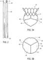
- Tubular body 5may be coupled to an artificial heart valve 40 such that at least a portion of valve 40 extends distally beyond outflow end 15 of tubular body 5 ( Figure 3A ).
- valve 40may include a plurality of valve leaflets 45.
- Valve 40may serve as an artificial replacement for a patient's native heart valve (for example, a mitral and/or a tricuspid valve).
- Tubular body 5may be coupled to valve 40 such that an outer circumferential edge 50 of leaflets 45 is directly connected to outflow end 35 of fabric 25 ( Figures 4A and 4B ).
- valve leaflets 45may extend distally of outflow end 15 of tubular body 5 in an outflow direction.
- Valve leaflets 45may also be distal of preformed groove 7 in an outflow direction.
- Outer circumferential edge 50 of leaflets 45may axially overlap with outflow end 35 of fabric 25 such that outer circumferential edge 50 is connected to outflow end 35 with one or more sutures 55.
- outer circumferential edge 50may be connected to outflow end 35 with any suitable securing mechanism, such as, for example, an adhesive, clips, clamps, etc.
- tubular body 5may be directly connected to fabric 25 such that struts 9 of tubular body 5 are connected to fabric 25 with one or more sutures 55 ( Figure 4A ).
- struts 9may be connected to fabric 25 with any suitable securing mechanism, such as, for example, an adhesive, clips, clamps, etc.
- valve leaflets 45are not directly connected to tubular body 5. Therefore, valve 40 is also not directly connected to tubular body 5. Instead, valve 40 is indirectly connected to tubular body 5 through fabric 25.
- outer circumferential edge 50 of valve leaflets 45may be disposed on an inflow side of valve 40.
- outer circumferential edge 50 of valve leaflets 45may be directly connected to outflow end 35 of fabric 25 such that outer circumferential edge 50 of valve leaflets 45 axially overlaps with outflow end 35 of fabric 25 in order to provide the direct connection between valve 40 and fabric 25.
- struts 9 of tubular body 5 that are directly connected to fabric 25may be struts 12 located at outflow end 15 of tubular body 5 ( Figures 1 and 4A ). Struts 12 may axially overlap with fabric 25. Thus, struts 12 may provide the direct connection between tubular body 5 and fabric 25.
- connection between fabric 25 and struts 12 of tubular body 5may be located closer to inflow end 10 of tubular body 5 than the connection between fabric 25 and outer circumferential edge 50 of valve leaflets 45 ( Figures 4A and 4B ).
- connection between fabric 25 and tubular body 5may be proximal of the connection between fabric 25 and valve 40 ( Figures 4A and 4B ). It is further contemplated that the connection between fabric 25 and tubular body 5 may be located at the same axial position as the connection between fabric 25 and valve 40 such that the connections axially overlap.
- outer circumferential edge 50 of valve leaflets 45may be disposed distal of, in an outflow direction, of struts 12.
- outer circumferential edge 50may be disposed distal of, in an outflow direction, of circumferential portion 3 of tubular body 5. Accordingly, outer circumferential edge 50 of valve leaflets 45 may not radially overlap with circumferential portion 3 of tubular body 5.
- valve 40may not axially overlap with circumferential portion 5 of tubular body 5, and tubular body 5 advantageously has an increased compression capability. Therefore, tubular body 5 may be compressed further than conventional valve prostheses, allowing tubular body 5 to assume a smaller delivery profile.
- valve 40may be directly connected to outflow end 15 of tubular body 5 through one or more sutures 55. Additionally or alternatively, valve 40 may be directly connected to outflow end 15 of tubular body 5 with any suitable securing mechanism, such as, for example, an adhesive, clips, clamps, etc.
- valve leaflets 45may be directly connected to struts 12 such that valve leaflets 45 are connected to outflow end 15 of tubular body 5. Additionally, valve leaflets 45 may be directly connected to fabric 25 and/or fabric 25 may be directly connected to struts 12.
- outflow end 35 of fabric 25may not extend distally, in an outflow direction, beyond outer circumferential edge 50 of leaflets 45. Thus, outflow end 35 may terminate at the location of outer circumferential edge 50.
- outflow end 35 of fabric 25may extend distally beyond struts 12 of tubular body 5, outflow end 35 of fabric 25 does not wrap around struts 12. Thus, fabric 25 does not wrap around outflow end 15 of tubular body 5.
- outflow end 35 of fabric 25only wraps partially around struts 12 (and, thus, partially around outflow end 15 of tubular body 5). In these embodiments, outflow end 35 of fabric 25 does not completely wrap around struts 12. In yet other alternative embodiments, outflow end 35 of fabric 25 wraps completely around outflow end 15 of tubular body 5.
- struts 12 of tubular body 5may form a plurality of arched beams 60 at outflow end 15 of tubular body 5.
- Beams 60may be directly connected to fabric 25, as discussed above.
- beams 60may be connected to fabric 25 such that valve leaflets 45 extend distally of beams 60 in an outflow direction, as discussed above.
- Each beam 60may be directly connected to an adjacent beam 60 so that the plurality of beams 60 extends around the entire circumferential length of tubular body 5 at outflow end 15.
- adjacent beams 60may be directly attached such that beams 60 are continuous along the entire circumference of tubular body 5 at outflow end 15.
- Tubular body 5may include a proximal-most end 13 at inflow end 10 and a distal-most end 14 at outflow end 15.
- arched beams 60may form distal-most end 14 of tubular body 5.
- beams 60may each include a first end 67 and a second end 69 such that second ends 69 are distal of first ends 67 in an outflow direction.
- First and second ends 67, 69may form the arched shape of beams 60.
- second ends 69may form a commissural attachment area for attachment to valve leaflets 45.
- second ends 69 of beams 60may be connected to one or more retaining components 78.
- distal-most end 14 of tubular body 5may also be connected to retaining components 78.
- retaining components 78are distal of circumferential portion 3 of tubular body 5 in an outflow direction.
- Retaining components 78may aid in anchoring tubular body 5 within a patient.
- Fabric 25may disposed over tubular body 5 such that fabric 25 is not disposed over retaining components 78.
- fabric 25may not extend distally of distal-most end 14 of tubular body 5 in an outflow direction.
- fabric 25may not extend distally of retaining components 78.
- each valve leaflet 45may be supported by only two beams 60 of the plurality of beams 60.
- a single valve leaflet 45may be supported by first beam 61 and second beam 63.
- Each valve leaflet 45may be supported by beams 61 and 63 such that the valve leaflet 45 is directly connected to fabric 25 that is directly connected to beams 61 and 63, as discussed above.
- the connections between valve leaflets 45, fabric 25, and beams 60provide the support between beams 60 and valve leaflets 45.
- each valve leaflet 45may be supported by two, three, or more beams 60.
- Figures 5-7show six beams, it is also contemplated that more or less beams may be used.
- tubular body 5may include at least six beams 60.
- connection points 65may directly link inflow end 10 of tubular body 5 with beams 60. All direct links between inflow end 10 and beams 60 may be provided only by connection points 65. In the embodiments of Figure 5-7 , three connection points 65 are provided. The number of connection points 65 may be equivalent to the number of valve leaflets 45, as shown in Figure 3B . Thus, in other embodiments, four, five or more connection pointes 65 may be provided, depending on the number of valve leaflets 45. It is also contemplated that the number of connection points 65 is a multiple of the number of valve leaflets. In some embodiment, as shown in Figures 5-7 , first ends 67 of beams 60 provide connection points 65.
- connection points 65may provide a decorrelation of movement between inflow end 10 of tubular body 5 and beams 60.
- connection points 65may dissociate axial and radial movements between inflow end 10 and beams 60.
- connection points 65may be configured to attenuate movement of inflow end 10 of tubular body 5.
- movement of inflow end 10is not completely transferred to beams 60.
- connection points 65may absorb movement of inflow end 10, thus providing the decorrelation effect.
- connection points 65absorb all movement of inflow end 10. In other embodiments, connection points 65 absorb only partial movement of inflow end 10.
- inflow end 10 of tubular body 5includes struts 9 with peaks 70 and valleys 75. Peaks 70 are disposed proximally of valleys 75 such that valleys 75 are located closer to outflow end 15 of tubular body 5 than peaks 70. Furthermore, peaks 70 and valleys 75 may form proximal-most end 13 of tubular body 5.
- peaks 70 and valleys 75may be configured such that movement of peaks 70 radially inward may cause valleys 75 to flare radially outward ( Figure 8 ).
- the patient's atrial wallmay push radially inward on peaks 70 (due to normal systolic movement of the patient's native valve). This causes peaks 70 to deform and move radially inward, as shown in Figure 8 .
- the inward movement by peaks 70causes valleys 75 to deform and move radially outward.
- the deformation of valleys 75 radially outwardpushes inflow end 10 further into contact with the patient's atrial wall, thus improving the sealing effect of inflow end 10 within the patient.
- outflow end 15 of tubular body 5may include beams 60 and a proximal section 80. Both beams 60 and proximal section 80 may be disposed distal, in an outflow direction, of preformed groove 7. Proximal section 80 may also be disposed distally of peaks 70 and valleys 75 in an outflow direction. Furthermore, beams 60 may be disposed distal, in an outflow direction, of proximal section 80. Accordingly, as shown in Figure 10 , movement of proximal section 80 radially inward may cause inflow end 10 of tubular body 5 to flare radially outward. For example, natural movement of a patient's native valve may cause an inward compression on tubular body 5.
- the patient's native valvemay cause an inward compression on valve leaflets 45, which in turn may cause an inward compression on tubular body 5.
- a compressionmay cause proximal section 80 to be compressed radially inward.
- movement of proximal section 80 radially inwardcauses inflow end 10 to flare radially outward.
- the outward movement of inflow end 10may increase the sealing effect between inflow end 10 and a patient's atrial wall, thus advantageously providing a tighter seal between tubular body 5 and the patient's atrial wall.
- beams 60may not move.
- connection points 65may dissociate such movement of proximal section 80 from beams 60.
- connection points 65may be disposed in proximal section 80.
- connection points 65may be disposed distal of proximal section 80 in an outflow direction.
- valve leaflets 45may extend entirely distal of proximal section 80 in an outflow direction. In other embodiments, valve leaflets 45 may axially overlap with proximal section 80.
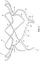
- Figure 11shows an additional configuration of struts 9 in which inflow end 10 of tubular body 5 includes struts 9 with an S-shape.
- the S-shaped strutsmay be directly connected to peaks 70 such that both peaks 70 and valleys 75 are disposed above the S-shaped struts in an inflow direction, when tubular body 5 is in an expanded state.
- the S-shaped strutsmay each form a decorrelation portion that dissociates movements between proximal-most end 13 of tubular body 6 and outflow end 15 of tubular body 5.
- the S-shaped strutsmay be configured to stress and compress in reaction to movement in inflow end 10 or outflow end 15.
- the S-shaped strutsstretch and/or compress, movement from one end of the tubular body 5 does not translate/communicate to the other end of the tubular body 5.
- the S-shaped strutsmay be disposed entirely proximal of preformed groove 7 in an inflow direction.
- tubular body 5may include a motion buffer component 90 integrated in tubular body 5 ( Figures 11-13B ).
- Motion buffer component 90may include one or more struts 9 formed into, for example, a droplet shape ( Figure 11 ) or a triangular shape ( Figure 12 ).
- Motion buffer component 90may be integral with the remainder of tubular body 5 such that tubular body 5 forms one unitary member.
- fabric 25may be disposed over an outer surface of motion buffer component 90.
- valve leaflets 45may move inward and outward when replacing the functions of the native valve within a patient. Such movement may cause, for example, outflow end 15 of tubular body 5 to be pushed radially inward and outward with regard to the patient's atrial wall. Such movement of outflow end 15 also causes fabric 25 to be pushed radially inward and outward with regard to the patient's atrial wall. This movement of fabric 25 against the patient's native valve may cause friction and wear on fabric 25. Furthermore, tubular body 5 may also suffer from friction and wear by continued contact with the patient's native valve.
- Motion buffer component 90may create a bumper effect to reduce such friction and wear on fabric 25 and tubular body 5.
- motion buffer component 90may be configured to not move radially inward with outflow end 15. Instead, motion buffer component 90 may move radially outward or may stay in its position in reaction to the inward movement of outflow end 15.
- motion buffer component 90may push radially outward, against fabric 25 and against the patient's native valve leaflets, when outflow end 15 moves radially inward.
- Such radially outward pushing by motion buffer component 90may create the bumper effect.
- motion buffer component 90when outflow end 15 and fabric 25 are pushed from the radially inward position to the radially outward position (due to movement of valve leaflets 45), because motion buffer component 90 already protrudes outward, motion buffer component 90 provides a cushioning effect to soften the radially outward force of outflow end 15 and fabric 25 on the patient's native valve leaflets.
- motion buffer component 90may absorb friction and wear on tubular body 5 that are caused from movement of valve leaflets 45.
- motion buffer component 90may advantageously make tubular body 5, especially beams 60, more durable.
- motion buffer component 90may absorb friction and wear on fabric 25 that are caused from movement of valve leaflets 45.
- motion buffer component 90may also advantageously make fabric 25 more durable.
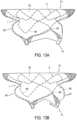
- Figure 13Ashows a neutral state of tubular body 5
- Figure 13Bshows a state of tubular body 5 in which outflow end 15 is moved radially inward and motion buffer component 90 is moved radially outward.
- the structure and/or location of motion buffer component 90may enable motion buffer component 90 to move radially outward or to stay in its position in response to the inward movement by outflow end 15.
- motion buffer component 90may be disposed adjacent to beams 60 and distal of preformed groove 7 in an outflow direction.
- Motion buffer component 90may be disposed within proximal section 80.
- a strut width of motion buffer component 90may be smaller than a strut width of beams 60.
- motion buffer component 90may have sufficient flexibility to move radially outward or to stay in its position, as discussed above.
- motion buffer component 90may be located at the same cross-section as valve leaflets 45 in a radial direction. Thus, motion buffer component 90 and valve leaflets 45 may overlap axially along longitudinal axis 20. Additionally, motion buffer component 90 may be located at least in part at the same cross-section as connection points 65 in a radial direction. Thus, motion buffer component 90 and connection points 65 may overlap axially along longitudinal axis 20.
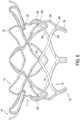
- Figure 14shows an embodiment in which tubular body 5 includes struts 9 with different thicknesses.
- struts 9may include relatively smaller thicknesses 100 and relatively larger thicknesses 110.
- struts 9may be curved in order to form first cells 120 and second cells 130.
- first cells 120are formed by the struts with relatively smaller thicknesses 100
- second cells 130are formed by the struts with the relatively larger thicknesses 110.
- third cells 140may be disposed between first cells 120 and second cells 130.
- Third cellsmay be formed by both the struts with the relatively smaller thicknesses 100 and the struts with the relatively larger thicknesses 110.
- First cells 120, second cells 130, and third cells 140may be configured to open and expand uniformly when tubular body 5 is opened and expanded.
- the struts with relatively smaller and larger thicknesses 100, 110allow all cells 120, 130, 140 to open together at the same rate.
- some strut cellsmay require less outward force to open, depending on their placement in the mesh structure of the prosthesis device. Therefore, some struts cells may open easier and quicker than other strut cells. Such results in the prosthesis being expanded and opened non-uniformly. For example, the strut cells that open easier may fully open before the strut cells that are harder to open.
- valve prosthesis 1expands uniformly during manufacturing (e.g., during its heat shaping process). Accordingly, cells 120, 130, 140 provide a prosthesis device that is easier to manufacture compared to traditional prosthesis devices.
- the struts with the relatively larger thicknesses 110may be placed at locations on tubular body 5 that open relatively easier.
- the struts with the relatively smaller thicknesses 100may be placed at locations on tubular body 5 that open with relatively more difficultly.
- the thickness of the strutsmay counter balance with the ease of opening in order to provide uniform expansion across all cells of tubular body 5.
- valve prosthesis 1may include positioning and/or orientation devices (not shown) to facilitate relative and/or absolute positioning of tubular body 5.
- These devicesmay include passive markers that are fixedly attached to tubular body 5.
- the passive markersmay be made from materials different from the materials of tubular body 5 in order to improve contrast during medical imaging, e.g., using magnetic resonance or X-ray based imaging techniques.
- the passive markersmay, for example, be made of highly radio-opaque materials thereby allowing one to precisely acquire the relative and/or absolute position of the components of valve prosthesis 1 with respect to the patient's body.
- valve prosthesis 1may allow for a smaller outer profile than conventional prosthesis.
- valve prosthesis 1may be sized according to human anatomies and may be compressed into a 26F ID tubing catheter for delivery within a patient.
- valve leaflets 45extend distally beyond tubular body 5, the size of the frame of tubular body 5 required to support valve 40 may be reduced.
- the number of struts 9may be reduced, thus providing a more flexible structure.
- the configuration of valve prosthesis 1provides a better geometrical stability for valve leaflets 45 compared to conventional prosthesis.
- valve prosthesis 1may be deployed, via a catheter, to a patient.
- the method of delivering valve prosthesis 1may include delivering, from a delivery catheter, tubular body 5 and valve 40.
- tubular body 5 and valve 40may be expanded such that beams 60 of tubular 5 are disposed against tissue of a patient's connection channel between an atrial and a ventricular chamber of a heart.
- valve prosthesis 1may be delivered to a patient's defective mitral or tricuspid valve in order to restore operability.
- Valve prosthesis 1may be delivered to a patient so that the preformed groove 7 is located on the ventricular side of the annulus of the native valve (e.g., having a distance from the native valve annulus).
- valve prosthesis 1within the patient's heart valve, the following approaches may be applied: (1) an arterial retrograde approach entering the heart cavity over the aorta, (2) through a venous access and through a puncture through the inter atrial septum (trans-septal approach), (3) over a puncture through the apex of the heart (trans- apical approach), (4) over a puncture through the atrial wall from outside the heart, (5) arterial access (e.g., from the femoral artery through a puncture in the groin), (6) directly through the vena cava and into the right atrium (for a tricuspid valve replacement, for example), or (7) any other approach known to a skilled person.
- arterial accesse.g., from the femoral artery through a puncture in the groin
- (6) directly through the vena cava and into the right atriumfor a tricuspid valve replacement, for example
- any other approach known to a skilled personmay be applied: (1) an
- valve prosthesis 1may be fixed relative to the patient's connection channel wall structure such that an exterior of valve prosthesis 1 is sealed against blood flow.
- tissue of the patient's connection channel wall structure adjacent to the preformed groove 7may be forced or placed inside preformed groove 7.
- the methodmay further include advancing a trapping member 150 around tubular body 5 and around preformed groove 7.
- trapping member 150may trap portions of native valve leaflets 160 and/or chords 170 in preformed groove 7. Such may help secure tubular body 5 in a patient.
- Trapping member 150may include a full or partial loop. Additionally, trapping member 150 may be moved around tubular body 5 after tubular body 5 is fully expanded or when tubular body 5 is only partially expanded. Trapping member 150 may be loosely disposed within preformed groove such that an interference fit between trapping member 150 and preformed groove 7 secures tubular body 5 in place. Thus, trapping member 150 may serve to anchor valve prosthesis 1 within the patient.
- trapping member 150may exert an inward, radial force on tubular body 5 in order to anchor valve prosthesis 1 within the patient.
- trapping member 150may exert a frictional force on the native valve leaflets 160 and/or chords 170.
- Trapping member 150may include a delivery configuration within a delivery catheter and a deployment configuration wherein trapping member 150 is deployed from the delivery catheter. In embodiments, trapping member 150 may be biased to the deployment configuration.
- trapping member 150may include a shape-memory alloy such as a Nitinol or a Nitinol-based alloy.
- an elongate outer member 180may also be advanced around tubular body 5 and around preformed groove 7.
- Elongate outer member 180may encircle tubular body 5 after tubular body 5 is fully expanded or when tubular body 5 is only partially expanded.
- Elongate outer member 180may force the patient's native valve leaflets 160 and/or chords 170 in preformed groove 7.
- Trapping member 150may then be disposed over and along elongate outer member 180 in order to advance trapping member 150 around tubular body 5 and into preformed groove 7.
- Elongate outer member 180may then be removed from the patient after trapping member 150 is disposed around tubular body 5. After elongate outer member 180 is removed from the patient, trapping member 150 may maintain the patient's native valve leaflets 160 and/or chords 170 in preformed groove 7.
- elongate outer member 180may be a guidewire. Elongate outer member 180 may have a diameter smaller than a diameter of trapping member 150.
- valve prosthesis 1may result in fixation of tubular body 5 in the patient's connection channel wall structure with minimal occlusion of the patient's native valve.
- the disclosed embodimentsalso include a method for manufacturing valve prosthesis 1.
- the method for manufacturingmay include directly connecting outer circumferential edge 50 of valve 40 with outflow end 35 of fabric 25 to form a sub-assembly.
- tubular body 5may be slid into the sub-assembly.
- tubular body 5may be connected to the sub-assembly to form an assembly such that valve leaflets 45 extend distally of outflow end 15 of tubular body 5 in an outflow direction.
- Tubular body 5may be directly connected to the sub-assembly by connecting outflow end 15 of tubular body 5 with fabric 25.
- fabric 25may be directly connected to outer circumferential edge 50 and directly connected to tubular body 5 with one or more sutures 55.
Landscapes
- Health & Medical Sciences (AREA)
- Engineering & Computer Science (AREA)
- Biomedical Technology (AREA)
- Cardiology (AREA)
- Oral & Maxillofacial Surgery (AREA)
- Transplantation (AREA)
- Heart & Thoracic Surgery (AREA)
- Vascular Medicine (AREA)
- Life Sciences & Earth Sciences (AREA)
- Animal Behavior & Ethology (AREA)
- General Health & Medical Sciences (AREA)
- Public Health (AREA)
- Veterinary Medicine (AREA)
- Prostheses (AREA)
Description
- Heart valve diseases affect approximately 300,000 people worldwide each year. Those diseases translate in abnormal leaflet tissue, for example, excess tissue growth, tissue degradation/rupture, or tissue hardening/calcifying. Those diseases may also translate in abnormal tissue position through the cardiac cycle of the heart, for example, annular dilation or ventricular reshaping. Such abnormal leaflet tissue and abnormal tissue position may lead to degradation in valve function including leakage/blood backflow (valve insufficiency) or a resistance to blood forward flow (valve stenosis).
- A valve replacement procedure is a minimally invasive surgical procedure in which a patient's defective heart valve is repaired. Thus, the abnormal leaflet tissue or the abnormal tissue position may be repaired in order to restore operability of the heart valve. In a valve replacement procedure, a valve prosthesis is delivered to the patient's native heart valve without removing the patient's native heart valve. Instead, the valve prosthesis replaces the functions of the native heart valve.
US 2012/078357 A1 discloses a prosthetic heart valve.US2003109923 A1 discloses a polymer heart valve with perforated stent and sewing cuff.- The invention provides a heart valve system according to
claim 1. Further embodiments are described in the dependent claims. - An exemplary method (the method not being part of the invention) for implanting a heart valve in a patient may include delivering from a delivery catheter a radially self-expandable tubular body having an inflow end and an outflow end. A valve is coupled to the tubular body, the valve including a plurality of valve leaflets. The tubular body includes a proximal-most end at the inflow end and a distal-most end at the outflow end, and the tubular body includes a plurality of arched beams at the outflow end of the tubular body such that the arched beams form the distal-most end of the tubular body. Connection points link the inflow end of the tubular body and the arched beams, a number of connection points being equivalent to a number of the valve leaflets. Each arched beam is directly attached to an adjacent arched beam such that the arched beams are continuous along the entire circumference of the tubular body at the outflow end. The method may further include expanding the tubular body such that the arched beams are disposed against tissue of a connection channel of the patient between an atrial and a ventricular chamber of a heart.
- In the drawings, like reference characters generally refer to the same parts throughout the different views. The drawings are not necessarily to scale, emphasis instead generally being placed upon illustrating the principles of the invention. In the following description, various embodiments are described with reference to the following drawings, in which:
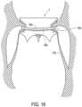
Figure 1 schematically shows a transcatheter valve prosthesis according to embodiments.Figure 2 schematically shows a transcatheter valve prosthesis in a contracted configuration according to embodiments.Figures 3A and 3B schematically show a transcatheter valve prosthesis according to embodiments.Figures 4A and4B schematically show close-up views of transcatheter valve prostheses according to embodiments.Figure 5 schematically shows a tubular body of a transcatheter valve prosthesis according to embodiments.Figure 6 schematically shows a tubular body of a transcatheter valve prosthesis according to embodiments.Figure 7 schematically shows a tubular body of a transcatheter valve prosthesis according to embodiments.Figure 8 schematically shows a close-up of a tubular body of a transcatheter valve prosthesis according to embodiments.Figure 9 schematically shows a transcatheter valve prosthesis according to embodiments.Figure 10 schematically shows a transcatheter valve prosthesis according to embodiments.Figure 11 schematically shows a tubular body of a transcatheter valve prosthesis according to embodiments.Figure 12 schematically shows a tubular body of a transcatheter valve prosthesis according to embodiments.Figures 13A and 13B schematically show a transcatheter valve prosthesis according to embodiments.Figure 14 schematically shows a close-up of a tubular body of a transcatheter valve prosthesis according to embodiments.Figure 15 schematically shows a transcatheter valve prosthesis implanted in a patient according to embodiments.Figure 16 schematically shows a transcatheter valve prosthesis implanted in a patient according to embodiments.- The following detailed description refers to the accompanying drawings that show, by way of illustration, specific details in which the disclosed embodiments may be practiced. Other embodiments may be utilized and structural and logical changes may be made without departing from the scope of the present disclosure. The various embodiments are not necessarily mutually exclusive, as some aspects of embodiments can be combined with one or more aspects of other embodiments to form additional embodiments.
- The disclosed embodiments are directed toward a
transcatheter valve prosthesis 1 for functional replacement of a patient's native heart valve in a connection channel. The patient's native heart valve may be, for example, a mitral valve or a tricuspid valve.Transcatheter valve prosthesis 1 may serve as an artificial replacement valve for the patient's native valve. - As shown in
Figure 1 ,transcatheter valve prosthesis 1 includes a radially, self-expandabletubular body 5 having aninflow end 10 and an outflow end 15 (according to the direction of blood flow when the system is implanted in a patient) extending alonglongitudinal axis 20. In some embodiments,tubular body 5 may be balloon expandable.Tubular body 5 may include a circumferential portion 3, formed of a mesh-like structure, which is delivered within a patient via a delivery catheter. The mesh-like structure oftubular body 5 may include a plurality ofstruts 9 formed of a superalloy and/or a shape memory alloy including nickel, titanium, and/or precious metals (e.g., gold). In some embodiments,tubular body 5 is formed of Nitinol. In other embodiments,tubular body 5 is formed of polymers including polyvinyl-chloride, polystyrene, polypropylene, and/or another polymer. For example,tubular body 5 may be formed of one or more bioabsorbable polymers. Tubular body 5 may be generally cylindrical in shape.Outflow end 15 oftubular body 5 may also include a frustoconical shape that slopes radially outward. Alternatively,outflow end 15 oftubular body 5 may be tapered inward. Furthermore,Figures 1-16 show various configurations ofstruts 9 oftubular body 5. Thus, it is within the scope of the present disclosure to further modify the structure and configuration ofstruts 9.- As shown in
Figure 1 , one ormore retaining rings 4 may be connected to circumferential portion 3 atinflow end 10 oftubular body 5. Retainingrings 4 may aid in the delivery and removal ofvalve prosthesis 1 within a patient. Tubular body 5 may include an outerpreformed groove 7 that is open to the radial outside oftubular body 5.Preformed groove 7 may be an indentation in the mesh-like structure oftubular body 5 that defines a channel. As shown inFigure 1 ,preformed groove 7 may extend around an entire outer circumference oftubular body 5. In other embodiments,preformed groove 7 may extend less than the entire outer circumference oftubular body 5.Preformed groove 7 may be a continuous, non-interrupted groove, or may be an interrupted groove having, for example, two or more groove portions. In some embodiments, preformedgroove 7 may be located at an axial distance, alongaxis 20, from bothinflow end 10 and outflow end 15 oftubular body 5. Thus, preformedgroove 7 may be axially spaced apart from proximal-most and distal-most ends oftubular body 5.Preformed groove 7 may be delimited by projections (not shown) that protrude outward fromtubular body 5. Thus, in some embodiments,tubular body 5 may include a first set of projections that are disposed above preformedgroove 7, in an inflow direction, and a second set of projections that are disposed below preformedgroove 7, in an outflow direction. Thus, the first and second set of projections may surround a top and bottom portion ofpreformed groove 7. The first and second set of projections may be directed toward each other. Additionally, the first and second set of projections may be members configured to pierce tissue such as, for example, spikes, triangular projections, barbs, etc.- A
tubular fabric 25 may be disposed on an outer surface oftubular body 5 such thatfabric 25 has aninflow end 30 and anoutflow end 35.Fabric 25 may cover an entire outer surface of circumferential portion 3 oftubular body 5, or only a portion of the outer surface of circumferential portion 3. As shown inFigure 1 ,fabric 25 may be disposed within preformedgroove 7 such thatfabric 25 follows the contours ofpreformed groove 7.Fabric 25 may be slack or tightly disposed ontubular body 5. As discussed further below, a trappingmember 150 may be disposed aroundtubular body 5.Fabric 25 may be disposed ontubular body 25 such that it is in a slack state until trappingmember 150 is disposed aroundtubular body 25. Thus, trappingmember 150 may causefabric 25 to be moved into preformed groove such thatfabric 25 is in a tensioned state. Fabric 25 may be formed of a polymer material including, for example, polyester fabric (e.g., DACRON® or other PTFE graft material). Additionally or alternatively,fabric 25 may formed of pericardium and/or a metal mesh material (e.g., a metal mesh formed of Nitinol). In some embodiments,fabric 25 may include one or more segments of material. For example,fabric 25 may include two, four, or six segments of material. The segments may be spaced apart, providing gaps between adjacent segments. Alternatively or in addition, some or all adjacent segments may overlap.Fabric 25 may include one layer of material or multiple layers of materials. In some embodiments,fabric 25 may include a coating or a liner.Fabric 25 may be attached totubular body 5 through any known securing mechanism. For example,fabric 25 andtubular body 5 may be secured through an adhesive and/or sutures. As shown inFigures 1 and2 ,fabric 25 may be configured to assume a deployed, expanded configuration and a contracted, reduced configuration withtubular body 5. Thus,fabric 25 may be expanded and contracted based on the state oftubular body 5.Tubular body 5 may be coupled to anartificial heart valve 40 such that at least a portion ofvalve 40 extends distally beyondoutflow end 15 of tubular body 5 (Figure 3A ). As shown inFigure 3B ,valve 40 may include a plurality ofvalve leaflets 45.Valve 40 may serve as an artificial replacement for a patient's native heart valve (for example, a mitral and/or a tricuspid valve).Tubular body 5 may be coupled tovalve 40 such that an outercircumferential edge 50 ofleaflets 45 is directly connected to outflow end 35 of fabric 25 (Figures 4A and4B ). Thus, as shown inFigures 3A ,4A , and4B valve leaflets 45 may extend distally ofoutflow end 15 oftubular body 5 in an outflow direction.Valve leaflets 45 may also be distal ofpreformed groove 7 in an outflow direction. Outercircumferential edge 50 ofleaflets 45 may axially overlap withoutflow end 35 offabric 25 such that outercircumferential edge 50 is connected to outflow end 35 with one or more sutures 55. Additionally or alternatively, outercircumferential edge 50 may be connected to outflow end 35 with any suitable securing mechanism, such as, for example, an adhesive, clips, clamps, etc.- Furthermore,
tubular body 5 may be directly connected tofabric 25 such that struts 9 oftubular body 5 are connected tofabric 25 with one or more sutures 55 (Figure 4A ). Additionally or alternatively, struts 9 may be connected tofabric 25 with any suitable securing mechanism, such as, for example, an adhesive, clips, clamps, etc. Thus, as shown inFigure 4A ,valve leaflets 45 are not directly connected totubular body 5. Therefore,valve 40 is also not directly connected totubular body 5. Instead,valve 40 is indirectly connected totubular body 5 throughfabric 25. - As shown in
Figures 4A and4B , outercircumferential edge 50 ofvalve leaflets 45 may be disposed on an inflow side ofvalve 40. Thus, outercircumferential edge 50 ofvalve leaflets 45 may be directly connected to outflow end 35 offabric 25 such that outercircumferential edge 50 ofvalve leaflets 45 axially overlaps withoutflow end 35 offabric 25 in order to provide the direct connection betweenvalve 40 andfabric 25. - Furthermore, struts 9 of
tubular body 5 that are directly connected tofabric 25 may bestruts 12 located atoutflow end 15 of tubular body 5 (Figures 1 and4A ).Struts 12 may axially overlap withfabric 25. Thus, struts 12 may provide the direct connection betweentubular body 5 andfabric 25. - In some embodiments, the connection between
fabric 25 and struts 12 oftubular body 5 may be located closer to inflow end 10 oftubular body 5 than the connection betweenfabric 25 and outercircumferential edge 50 of valve leaflets 45 (Figures 4A and4B ). Thus, the connection betweenfabric 25 andtubular body 5 may be proximal of the connection betweenfabric 25 and valve 40 (Figures 4A and4B ). It is further contemplated that the connection betweenfabric 25 andtubular body 5 may be located at the same axial position as the connection betweenfabric 25 andvalve 40 such that the connections axially overlap. - Additionally, as shown in
Figures 4A and4B , outercircumferential edge 50 ofvalve leaflets 45 may be disposed distal of, in an outflow direction, ofstruts 12. Thus, outercircumferential edge 50 may be disposed distal of, in an outflow direction, of circumferential portion 3 oftubular body 5. Accordingly, outercircumferential edge 50 ofvalve leaflets 45 may not radially overlap with circumferential portion 3 oftubular body 5. - As discussed above, outer
circumferential edge 50 ofvalve 40 is connected to outflow end 35 offabric 25 such thatvalve leaflets 45 extend distally ofoutflow end 15 oftubular body 5 in an outflow direction (Figures 3A and4B ). Thus,valve 40 may not axially overlap withcircumferential portion 5 oftubular body 5, andtubular body 5 advantageously has an increased compression capability. Therefore,tubular body 5 may be compressed further than conventional valve prostheses, allowingtubular body 5 to assume a smaller delivery profile. - In other alternative embodiments,
valve 40 may be directly connected to outflow end 15 oftubular body 5 through one or more sutures 55. Additionally or alternatively,valve 40 may be directly connected to outflow end 15 oftubular body 5 with any suitable securing mechanism, such as, for example, an adhesive, clips, clamps, etc. In these embodiments,valve leaflets 45 may be directly connected to struts 12 such thatvalve leaflets 45 are connected to outflow end 15 oftubular body 5. Additionally,valve leaflets 45 may be directly connected tofabric 25 and/orfabric 25 may be directly connected to struts 12. - As shown in
Figures 4A and4B ,outflow end 35 offabric 25 may not extend distally, in an outflow direction, beyond outercircumferential edge 50 ofleaflets 45. Thus,outflow end 35 may terminate at the location of outercircumferential edge 50. Although outflow end 35 offabric 25 may extend distally beyondstruts 12 oftubular body 5,outflow end 35 offabric 25 does not wrap around struts 12. Thus,fabric 25 does not wrap aroundoutflow end 15 oftubular body 5. In some embodiments,outflow end 35 offabric 25 only wraps partially around struts 12 (and, thus, partially aroundoutflow end 15 of tubular body 5). In these embodiments,outflow end 35 offabric 25 does not completely wrap around struts 12. In yet other alternative embodiments,outflow end 35 offabric 25 wraps completely aroundoutflow end 15 oftubular body 5. - As shown in
Figure 5 , struts 12 oftubular body 5 may form a plurality ofarched beams 60 atoutflow end 15 oftubular body 5.Beams 60 may be directly connected tofabric 25, as discussed above. Thus, beams 60 may be connected tofabric 25 such thatvalve leaflets 45 extend distally ofbeams 60 in an outflow direction, as discussed above. Eachbeam 60 may be directly connected to anadjacent beam 60 so that the plurality ofbeams 60 extends around the entire circumferential length oftubular body 5 atoutflow end 15. Additionally,adjacent beams 60 may be directly attached such that beams 60 are continuous along the entire circumference oftubular body 5 atoutflow end 15. Tubular body 5 may include aproximal-most end 13 atinflow end 10 and adistal-most end 14 atoutflow end 15. As shown inFigures 5-7 ,arched beams 60 may formdistal-most end 14 oftubular body 5. Furthermore, beams 60 may each include afirst end 67 and asecond end 69 such that second ends 69 are distal of first ends 67 in an outflow direction. First and second ends 67, 69 may form the arched shape ofbeams 60. Additionally, second ends 69 may form a commissural attachment area for attachment tovalve leaflets 45.- As shown in
Figures 5-7 , for example, second ends 69 ofbeams 60 may be connected to one ormore retaining components 78. Thus,distal-most end 14 oftubular body 5 may also be connected to retainingcomponents 78. In some embodiments, retainingcomponents 78 are distal of circumferential portion 3 oftubular body 5 in an outflow direction. Retainingcomponents 78 may aid in anchoringtubular body 5 within a patient.Fabric 25 may disposed overtubular body 5 such thatfabric 25 is not disposed over retainingcomponents 78. In some embodiments,fabric 25 may not extend distally ofdistal-most end 14 oftubular body 5 in an outflow direction. Thus,fabric 25 may not extend distally of retainingcomponents 78. - In some embodiments, each
valve leaflet 45 may be supported by only twobeams 60 of the plurality ofbeams 60. Thus, for example, as shown inFigures 3B and5 , asingle valve leaflet 45 may be supported byfirst beam 61 andsecond beam 63. Eachvalve leaflet 45 may be supported bybeams valve leaflet 45 is directly connected tofabric 25 that is directly connected tobeams valve leaflets 45,fabric 25, and beams 60 provide the support betweenbeams 60 andvalve leaflets 45. In other embodiments, eachvalve leaflet 45 may be supported by two, three, or more beams 60. AlthoughFigures 5-7 show six beams, it is also contemplated that more or less beams may be used. Thus,tubular body 5 may include at least six beams 60. - As shown in
Figures 5-7 , connection points 65 may directly linkinflow end 10 oftubular body 5 withbeams 60. All direct links betweeninflow end 10 and beams 60 may be provided only by connection points 65. In the embodiments ofFigure 5-7 , threeconnection points 65 are provided. The number of connection points 65 may be equivalent to the number ofvalve leaflets 45, as shown inFigure 3B . Thus, in other embodiments, four, five ormore connection pointes 65 may be provided, depending on the number ofvalve leaflets 45. It is also contemplated that the number of connection points 65 is a multiple of the number of valve leaflets. In some embodiment, as shown inFigures 5-7 , first ends 67 ofbeams 60 provide connection points 65. - By providing a direct link between
inflow end 10 and beams 60, connection points 65 may provide a decorrelation of movement betweeninflow end 10 oftubular body 5 and beams 60. Thus, connection points 65 may dissociate axial and radial movements betweeninflow end 10 and beams 60. For example, connection points 65 may be configured to attenuate movement ofinflow end 10 oftubular body 5. Thus, movement ofinflow end 10 is not completely transferred to beams 60. Instead, connection points 65 may absorb movement ofinflow end 10, thus providing the decorrelation effect. In some embodiments, connection points 65 absorb all movement ofinflow end 10. In other embodiments, connection points 65 absorb only partial movement ofinflow end 10. - As shown in
Figures 5-7 ,inflow end 10 oftubular body 5 includesstruts 9 withpeaks 70 andvalleys 75.Peaks 70 are disposed proximally ofvalleys 75 such thatvalleys 75 are located closer to outflow end 15 oftubular body 5 than peaks 70. Furthermore, peaks 70 andvalleys 75 may formproximal-most end 13 oftubular body 5. - In some embodiments, peaks 70 and
valleys 75 may be configured such that movement ofpeaks 70 radially inward may causevalleys 75 to flare radially outward (Figure 8 ). For example, whentubular body 5 is implanted in a patient, the patient's atrial wall may push radially inward on peaks 70 (due to normal systolic movement of the patient's native valve). This causes peaks 70 to deform and move radially inward, as shown inFigure 8 . Accordingly, the inward movement bypeaks 70causes valleys 75 to deform and move radially outward. The deformation ofvalleys 75 radially outward pushesinflow end 10 further into contact with the patient's atrial wall, thus improving the sealing effect ofinflow end 10 within the patient. - When
fabric 25 is disposed overtubular body 5, as discussed above, movement ofpeaks 70 radially inward may cause bothvalleys 75 andfabric 25 to flare radially outward. Thus,fabric 25 is pushed further into contact with the patient's atrial wall, along withvalleys 70, in order to further increase the sealing effect oftubular body 5 within the patient. - As shown in
Figures 1 and9 , for example,outflow end 15 oftubular body 5 may includebeams 60 and aproximal section 80. Both beams 60 andproximal section 80 may be disposed distal, in an outflow direction, ofpreformed groove 7.Proximal section 80 may also be disposed distally ofpeaks 70 andvalleys 75 in an outflow direction. Furthermore, beams 60 may be disposed distal, in an outflow direction, ofproximal section 80. Accordingly, as shown inFigure 10 , movement ofproximal section 80 radially inward may causeinflow end 10 oftubular body 5 to flare radially outward. For example, natural movement of a patient's native valve may cause an inward compression ontubular body 5. More specifically, in some examples, the patient's native valve may cause an inward compression onvalve leaflets 45, which in turn may cause an inward compression ontubular body 5. Thus, such a compression may causeproximal section 80 to be compressed radially inward. Due to the structure oftubular body 5, movement ofproximal section 80 radially inward causesinflow end 10 to flare radially outward. The outward movement ofinflow end 10 may increase the sealing effect betweeninflow end 10 and a patient's atrial wall, thus advantageously providing a tighter seal betweentubular body 5 and the patient's atrial wall. Furthermore, whenproximal section 80 moves radially inward and inflow end 10 flares radially outward, beams 60 may not move. Thus, connection points 65 may dissociate such movement ofproximal section 80 from beams 60. - As shown in
Figures 9 and 10 , connection points 65 may be disposed inproximal section 80. Alternatively, connection points 65 may be disposed distal ofproximal section 80 in an outflow direction. Furthermore, in some embodiments,valve leaflets 45 may extend entirely distal ofproximal section 80 in an outflow direction. In other embodiments,valve leaflets 45 may axially overlap withproximal section 80. Figure 11 shows an additional configuration ofstruts 9 in which inflow end 10 oftubular body 5 includesstruts 9 with an S-shape. The S-shaped struts may be directly connected topeaks 70 such that bothpeaks 70 andvalleys 75 are disposed above the S-shaped struts in an inflow direction, whentubular body 5 is in an expanded state. The S-shaped struts may each form a decorrelation portion that dissociates movements betweenproximal-most end 13 of tubular body 6 and outflow end 15 oftubular body 5. Thus, the S-shaped struts may be configured to stress and compress in reaction to movement ininflow end 10 oroutflow end 15. Thus, because the S-shaped struts stretch and/or compress, movement from one end of thetubular body 5 does not translate/communicate to the other end of thetubular body 5. The S-shaped struts may be disposed entirely proximal ofpreformed groove 7 in an inflow direction.- In some embodiments,
tubular body 5 may include amotion buffer component 90 integrated in tubular body 5 (Figures 11-13B ).Motion buffer component 90 may include one ormore struts 9 formed into, for example, a droplet shape (Figure 11 ) or a triangular shape (Figure 12 ).Motion buffer component 90 may be integral with the remainder oftubular body 5 such thattubular body 5 forms one unitary member. Additionally,fabric 25 may be disposed over an outer surface ofmotion buffer component 90. - Movement of
valve leaflets 45 within a patient may causetubular body 5 to also move within the patient. More specifically,valve leaflets 45 may move inward and outward when replacing the functions of the native valve within a patient. Such movement may cause, for example,outflow end 15 oftubular body 5 to be pushed radially inward and outward with regard to the patient's atrial wall. Such movement ofoutflow end 15 also causesfabric 25 to be pushed radially inward and outward with regard to the patient's atrial wall. This movement offabric 25 against the patient's native valve may cause friction and wear onfabric 25. Furthermore,tubular body 5 may also suffer from friction and wear by continued contact with the patient's native valve. Motion buffer component 90 may create a bumper effect to reduce such friction and wear onfabric 25 andtubular body 5. For example, as shown inFigures 13A and 13B , whenoutflow end 15 oftubular body 5 moves radially inward from movement ofvalve leaflets 45,motion buffer component 90 may be configured to not move radially inward withoutflow end 15. Instead,motion buffer component 90 may move radially outward or may stay in its position in reaction to the inward movement ofoutflow end 15. Thus,motion buffer component 90 may push radially outward, againstfabric 25 and against the patient's native valve leaflets, whenoutflow end 15 moves radially inward. Such radially outward pushing bymotion buffer component 90 may create the bumper effect. Thus, whenoutflow end 15 andfabric 25 are pushed from the radially inward position to the radially outward position (due to movement of valve leaflets 45), becausemotion buffer component 90 already protrudes outward,motion buffer component 90 provides a cushioning effect to soften the radially outward force ofoutflow end 15 andfabric 25 on the patient's native valve leaflets.- Accordingly,
motion buffer component 90 may absorb friction and wear ontubular body 5 that are caused from movement ofvalve leaflets 45. Thus,motion buffer component 90 may advantageously maketubular body 5, especially beams 60, more durable. Additionally,motion buffer component 90 may absorb friction and wear onfabric 25 that are caused from movement ofvalve leaflets 45. Thus,motion buffer component 90 may also advantageously makefabric 25 more durable. Figure 13A shows a neutral state oftubular body 5, andFigure 13B shows a state oftubular body 5 in whichoutflow end 15 is moved radially inward andmotion buffer component 90 is moved radially outward. The structure and/or location ofmotion buffer component 90 may enablemotion buffer component 90 to move radially outward or to stay in its position in response to the inward movement byoutflow end 15. As shown inFigures 11-13B ,motion buffer component 90 may be disposed adjacent tobeams 60 and distal ofpreformed groove 7 in an outflow direction.Motion buffer component 90 may be disposed withinproximal section 80. Additionally, a strut width ofmotion buffer component 90 may be smaller than a strut width ofbeams 60. Thus,motion buffer component 90 may have sufficient flexibility to move radially outward or to stay in its position, as discussed above.- In some embodiments,
motion buffer component 90 may be located at the same cross-section asvalve leaflets 45 in a radial direction. Thus,motion buffer component 90 andvalve leaflets 45 may overlap axially alonglongitudinal axis 20. Additionally,motion buffer component 90 may be located at least in part at the same cross-section as connection points 65 in a radial direction. Thus,motion buffer component 90 and connection points 65 may overlap axially alonglongitudinal axis 20. Figure 14 shows an embodiment in whichtubular body 5 includesstruts 9 with different thicknesses. Thus, for example, struts 9 may include relativelysmaller thicknesses 100 and relativelylarger thicknesses 110. Furthermore, struts 9 may be curved in order to formfirst cells 120 andsecond cells 130. As shown inFigure 14 ,first cells 120 are formed by the struts with relativelysmaller thicknesses 100 andsecond cells 130 are formed by the struts with the relativelylarger thicknesses 110. Additionally,third cells 140 may be disposed betweenfirst cells 120 andsecond cells 130. Third cells may be formed by both the struts with the relativelysmaller thicknesses 100 and the struts with the relativelylarger thicknesses 110.First cells 120,second cells 130, andthird cells 140 may be configured to open and expand uniformly whentubular body 5 is opened and expanded. Thus, the struts with relatively smaller andlarger thicknesses cells cells valve prosthesis 1 expands uniformly during manufacturing (e.g., during its heat shaping process). Accordingly,cells - In the embodiment of
Figure 14 , the struts with the relativelylarger thicknesses 110 may be placed at locations ontubular body 5 that open relatively easier. The struts with the relativelysmaller thicknesses 100 may be placed at locations ontubular body 5 that open with relatively more difficultly. Thus, the thickness of the struts may counter balance with the ease of opening in order to provide uniform expansion across all cells oftubular body 5. - All embodiments of
valve prosthesis 1 may include positioning and/or orientation devices (not shown) to facilitate relative and/or absolute positioning oftubular body 5. These devices may include passive markers that are fixedly attached totubular body 5. The passive markers may be made from materials different from the materials oftubular body 5 in order to improve contrast during medical imaging, e.g., using magnetic resonance or X-ray based imaging techniques. The passive markers may, for example, be made of highly radio-opaque materials thereby allowing one to precisely acquire the relative and/or absolute position of the components ofvalve prosthesis 1 with respect to the patient's body. - The structure of
valve prosthesis 1 may allow for a smaller outer profile than conventional prosthesis. Thus, for example,valve prosthesis 1 may be sized according to human anatomies and may be compressed into a 26F ID tubing catheter for delivery within a patient. Additionally, becausevalve leaflets 45 extend distally beyondtubular body 5, the size of the frame oftubular body 5 required to supportvalve 40 may be reduced. For example, the number ofstruts 9 may be reduced, thus providing a more flexible structure. Additionally, the configuration ofvalve prosthesis 1 provides a better geometrical stability forvalve leaflets 45 compared to conventional prosthesis. - As shown in
Figure 15 ,valve prosthesis 1 may be deployed, via a catheter, to a patient. The method of deliveringvalve prosthesis 1 may include delivering, from a delivery catheter,tubular body 5 andvalve 40. Next,tubular body 5 andvalve 40 may be expanded such that beams 60 oftubular 5 are disposed against tissue of a patient's connection channel between an atrial and a ventricular chamber of a heart. Thus, for example,valve prosthesis 1 may be delivered to a patient's defective mitral or tricuspid valve in order to restore operability.Valve prosthesis 1 may be delivered to a patient so that the preformedgroove 7 is located on the ventricular side of the annulus of the native valve (e.g., having a distance from the native valve annulus). - To place
valve prosthesis 1 within the patient's heart valve, the following approaches may be applied: (1) an arterial retrograde approach entering the heart cavity over the aorta, (2) through a venous access and through a puncture through the inter atrial septum (trans-septal approach), (3) over a puncture through the apex of the heart (trans- apical approach), (4) over a puncture through the atrial wall from outside the heart, (5) arterial access (e.g., from the femoral artery through a puncture in the groin), (6) directly through the vena cava and into the right atrium (for a tricuspid valve replacement, for example), or (7) any other approach known to a skilled person. - For functional replacement of a patient's heart valve,
valve prosthesis 1 may be fixed relative to the patient's connection channel wall structure such that an exterior ofvalve prosthesis 1 is sealed against blood flow. To achieve this, tissue of the patient's connection channel wall structure adjacent to the preformedgroove 7 may be forced or placed inside preformedgroove 7. - The method may further include advancing a trapping
member 150 aroundtubular body 5 and around preformedgroove 7. Thus, trappingmember 150 may trap portions ofnative valve leaflets 160 and/orchords 170 inpreformed groove 7. Such may help securetubular body 5 in a patient. Trappingmember 150 may include a full or partial loop. Additionally, trappingmember 150 may be moved aroundtubular body 5 aftertubular body 5 is fully expanded or whentubular body 5 is only partially expanded. Trappingmember 150 may be loosely disposed within preformed groove such that an interference fit between trappingmember 150 and preformedgroove 7 securestubular body 5 in place. Thus, trappingmember 150 may serve to anchorvalve prosthesis 1 within the patient. In other embodiments, trappingmember 150 may exert an inward, radial force ontubular body 5 in order to anchorvalve prosthesis 1 within the patient. Thus, in this embodiment, trappingmember 150 may exert a frictional force on thenative valve leaflets 160 and/orchords 170. - Trapping
member 150 may include a delivery configuration within a delivery catheter and a deployment configuration wherein trappingmember 150 is deployed from the delivery catheter. In embodiments, trappingmember 150 may be biased to the deployment configuration. For example, trappingmember 150 may include a shape-memory alloy such as a Nitinol or a Nitinol-based alloy. - In some embodiments, an elongate
outer member 180 may also be advanced aroundtubular body 5 and around preformedgroove 7. Elongateouter member 180 may encircletubular body 5 aftertubular body 5 is fully expanded or whentubular body 5 is only partially expanded. Elongateouter member 180 may force the patient'snative valve leaflets 160 and/orchords 170 inpreformed groove 7. Trappingmember 150 may then be disposed over and along elongateouter member 180 in order to advance trappingmember 150 aroundtubular body 5 and into preformedgroove 7. Elongateouter member 180 may then be removed from the patient after trappingmember 150 is disposed aroundtubular body 5. After elongateouter member 180 is removed from the patient, trappingmember 150 may maintain the patient'snative valve leaflets 160 and/orchords 170 inpreformed groove 7. - In some embodiments, elongate
outer member 180 may be a guidewire. Elongateouter member 180 may have a diameter smaller than a diameter of trappingmember 150. - The disclosed methods of using
valve prosthesis 1 may result in fixation oftubular body 5 in the patient's connection channel wall structure with minimal occlusion of the patient's native valve. - The disclosed embodiments also include a method for manufacturing
valve prosthesis 1. The method for manufacturing may include directly connecting outercircumferential edge 50 ofvalve 40 withoutflow end 35 offabric 25 to form a sub-assembly. Next,tubular body 5 may be slid into the sub-assembly. Then,tubular body 5 may be connected to the sub-assembly to form an assembly such thatvalve leaflets 45 extend distally ofoutflow end 15 oftubular body 5 in an outflow direction.Tubular body 5 may be directly connected to the sub-assembly by connectingoutflow end 15 oftubular body 5 withfabric 25. As shown inFigures 4A and4B ,fabric 25 may be directly connected to outercircumferential edge 50 and directly connected totubular body 5 with one or more sutures 55.
Claims (8)
- A heart valve system (1), the system (1) comprising:a radially self-expandable tubular body (5) having an inflow end (10) and an outflow end (15); anda valve (40) coupled to the tubular body (5), the valve (40) including a plurality of valve leaflets (45),wherein:the tubular body (5) includes a proximal-most end (13) at the inflow end (10) and a distal-most end (14) at the outflow end (15),the tubular body (5) includes a plurality of arched beams (60) at the outflow end (15) of the tubular body (5) such that the arched beams (60) form the distal-most end (14) of the tubular body (5),connection points (65) link the inflow end (10) of the tubular body (5) and the arched beams (60), a number of connection points (65) being equivalent to a number of the valve leaflets (45), andeach arched beam (60) is directly attached to an adjacent arched beam (60) such that the arched beams (60) are continuous along the entire circumference of the tubular body (5) at the outflow end (15), the system (1) further comprisinga fabric (25) disposed over an outer surface of the tubular body (5), wherein the fabric (25) is directly connected to the arched beams (60) and the fabric (25) is directly connected to an outer circumferential edge (50) of the valve (40), but the fabric (25) does not wrap around the outflow end (15) of the tubular body (5).
- The system (1) according to claim 1, wherein the valve leaflets (45) extend distally of the arched beams (60) in an outflow direction.
- The system (1) according to claim 1, wherein the arched beams (60) each include a first end (67) and a second end (69), the first end (67) providing the connection points (65) and the second end (69) forming a commissural attachment area, the second end (69) being distal of the first end (67) in an outflow direction.
- The system (1) according to claim 1, wherein each valve leaflet (45) is supported by at least two beams (60) of the plurality of arched beams (60).
- The system (1) according to claim 4, wherein each valve leaflet (45) is supported by the at least two beams (60) such that the outer circumferential edge (50) of the valve (40) is connected to the at least two beams (60).
- The system (1) according to claim 1, wherein the fabric (25) does not extend distally of the distal-most end (14) the tubular body (5) in an outflow direction.
- The system (1) according to claim 1, wherein the plurality of arched beams (60) includes at least six beams.
- The system (1) according to claim 1, wherein the distal-most end (14) of the tubular body (5) is connected to one or more retaining components (78).
Applications Claiming Priority (2)
| Application Number | Priority Date | Filing Date | Title |
|---|---|---|---|
| US15/343,936US10456247B2 (en) | 2016-11-04 | 2016-11-04 | Transcatheter valve prosthesis |
| PCT/IB2017/001561WO2018083544A1 (en) | 2016-11-04 | 2017-11-06 | Transcatheter valve prosthesis |
Publications (3)
| Publication Number | Publication Date |
|---|---|
| EP3534843A1 EP3534843A1 (en) | 2019-09-11 |
| EP3534843B1true EP3534843B1 (en) | 2023-09-13 |
| EP3534843C0 EP3534843C0 (en) | 2023-09-13 |
Family
ID=60990829
Family Applications (1)
| Application Number | Title | Priority Date | Filing Date |
|---|---|---|---|
| EP17829689.3AActiveEP3534843B1 (en) | 2016-11-04 | 2017-11-06 | Transcatheter valve prosthesis |
Country Status (7)
| Country | Link |
|---|---|
| US (2) | US10456247B2 (en) |
| EP (1) | EP3534843B1 (en) |
| JP (1) | JP7051842B2 (en) |
| CN (1) | CN110049745B (en) |
| AU (1) | AU2017353945B2 (en) |
| CA (1) | CA3042844A1 (en) |
| WO (1) | WO2018083544A1 (en) |
Families Citing this family (15)
| Publication number | Priority date | Publication date | Assignee | Title |
|---|---|---|---|---|
| US10231827B2 (en)* | 2015-03-18 | 2019-03-19 | Medtronic Vascular, Inc. | Valve prostheses having an integral centering mechanism and methods of use thereof |
| US9999502B2 (en) | 2016-11-04 | 2018-06-19 | Highlife Sas | Transcather valve prosthesis |
| US10188514B2 (en)* | 2016-11-04 | 2019-01-29 | Highlife Sas | Transcatheter valve prosthesis |
| US11666444B2 (en) | 2017-08-03 | 2023-06-06 | The Regents Of The University Of California | Atrial cage for placement, securing and anchoring of atrioventricular valves |
| CN109966023B (en)* | 2017-12-28 | 2024-09-27 | 上海微创心通医疗科技有限公司 | Heart valve prosthesis and stent thereof |
| CN117481869A (en) | 2018-01-25 | 2024-02-02 | 爱德华兹生命科学公司 | Delivery system for assisting in recapture and repositioning of replacement valves after deployment |
| CN113260337A (en) | 2018-10-05 | 2021-08-13 | 施菲姆德控股有限责任公司 | Prosthetic heart valve devices, systems, and methods |
| CN113056302B (en) | 2018-10-19 | 2023-03-28 | 施菲姆德控股有限责任公司 | Adjustable medical device |
| JP7555919B2 (en) | 2018-11-14 | 2024-09-25 | シェバ インパクト リミテッド | Atrioventricular valve repair |
| WO2020150378A1 (en)* | 2019-01-17 | 2020-07-23 | Edwards Lifesciences Corporation | Frame for prosthetic heart valve |
| CA3149527A1 (en)* | 2019-08-14 | 2021-02-18 | Innovalve Bio Medical Ltd. | Atrioventricular valve replacement |
| US11484407B2 (en)* | 2020-01-07 | 2022-11-01 | Highlife Sas | Transcatheter valve prosthesis |
| EP4114313B1 (en)* | 2020-03-03 | 2025-10-01 | Shifamed Holdings, LLC | Prosthetic cardiac valve devices, systems |
| WO2021232022A1 (en)* | 2020-05-15 | 2021-11-18 | ReValve Solutions Inc. | Devices, systems, and methods for a collapsible and expandable replacement heart valve |
| US12329635B2 (en)* | 2020-12-04 | 2025-06-17 | Shifamed Holdings, Llc | Flared prosthetic cardiac valve delivery devices and systems |
Citations (3)
| Publication number | Priority date | Publication date | Assignee | Title |
|---|---|---|---|---|
| WO2010141847A1 (en)* | 2009-06-05 | 2010-12-09 | Ats Medical, Inc. | Flexible commissure structure for attaching valve bioprosthesis |
| US20140296966A1 (en)* | 2009-02-27 | 2014-10-02 | St. Jude Medical, Inc. | Stent features for collapsible prosthetic heart valves |
| WO2015128741A2 (en)* | 2014-02-28 | 2015-09-03 | Highlife Sas | Transcatheter valve prosthesis |
Family Cites Families (53)
| Publication number | Priority date | Publication date | Assignee | Title |
|---|---|---|---|---|
| JP4292710B2 (en) | 1997-09-24 | 2009-07-08 | エム イー ディ インスチィチュート インク | Radially expandable stent |
| US6395019B2 (en) | 1998-02-09 | 2002-05-28 | Trivascular, Inc. | Endovascular graft |
| US6264700B1 (en) | 1998-08-27 | 2001-07-24 | Endonetics, Inc. | Prosthetic gastroesophageal valve |
| US6139575A (en) | 1999-04-02 | 2000-10-31 | Medtronic, Inc. | Hybrid mechanical heart valve prosthesis |
| US6325825B1 (en) | 1999-04-08 | 2001-12-04 | Cordis Corporation | Stent with variable wall thickness |
| US6458153B1 (en) | 1999-12-31 | 2002-10-01 | Abps Venture One, Ltd. | Endoluminal cardiac and venous valve prostheses and methods of manufacture and delivery thereof |
| US6454799B1 (en) | 2000-04-06 | 2002-09-24 | Edwards Lifesciences Corporation | Minimally-invasive heart valves and methods of use |
| US20030109923A1 (en) | 2001-12-12 | 2003-06-12 | Chinn Joseph A. | Polymer heart valve with perforated stent and sewing cuff |
| WO2005011535A2 (en) | 2003-07-31 | 2005-02-10 | Cook Incorporated | Prosthetic valve for implantation in a body vessel |
| US8007528B2 (en) | 2004-03-17 | 2011-08-30 | Boston Scientific Scimed, Inc. | Bifurcated stent |
| DE102005052628B4 (en)* | 2005-11-04 | 2014-06-05 | Jenavalve Technology Inc. | Self-expanding, flexible wire mesh with integrated valvular prosthesis for the transvascular heart valve replacement and a system with such a device and a delivery catheter |
| US20080275550A1 (en) | 2006-02-24 | 2008-11-06 | Arash Kheradvar | Implantable small percutaneous valve and methods of delivery |
| US8500799B2 (en) | 2006-06-20 | 2013-08-06 | Cardiacmd, Inc. | Prosthetic heart valves, support structures and systems and methods for implanting same |
| ES2788453T3 (en) | 2007-06-04 | 2020-10-21 | St Jude Medical Llc | Prosthetic heart valves |
| US8728154B2 (en) | 2007-08-24 | 2014-05-20 | St. Jude Medical, Inc. | Prosthetic aortic heart valves |
| EP3443938B1 (en) | 2007-09-26 | 2024-01-24 | St. Jude Medical, LLC | Collapsible prosthetic heart valves |
| EP2679198B1 (en)* | 2007-10-25 | 2021-03-24 | Symetis SA | Valved-stents and systems for delivery thereof |
| CN102292053A (en) | 2008-09-29 | 2011-12-21 | 卡迪尔克阀门技术公司 | Heart valve |
| US20100217382A1 (en) | 2009-02-25 | 2010-08-26 | Edwards Lifesciences | Mitral valve replacement with atrial anchoring |
| US8449599B2 (en) | 2009-12-04 | 2013-05-28 | Edwards Lifesciences Corporation | Prosthetic valve for replacing mitral valve |
| US10433956B2 (en) | 2010-02-24 | 2019-10-08 | Medtronic Ventor Technologies Ltd. | Mitral prosthesis and methods for implantation |
| US9522062B2 (en) | 2010-02-24 | 2016-12-20 | Medtronic Ventor Technologies, Ltd. | Mitral prosthesis and methods for implantation |
| US8795354B2 (en) | 2010-03-05 | 2014-08-05 | Edwards Lifesciences Corporation | Low-profile heart valve and delivery system |
| WO2012030598A2 (en)* | 2010-09-01 | 2012-03-08 | Medtronic Vascular Galway Limited | Prosthetic valve support structure |
| AU2011300644B2 (en)* | 2010-09-10 | 2015-08-20 | Symetis Sa | Valve replacement devices and a system comprising the valve replacement device and a delivery device therefor |
| US8845720B2 (en)* | 2010-09-27 | 2014-09-30 | Edwards Lifesciences Corporation | Prosthetic heart valve frame with flexible commissures |
| DK4233795T3 (en) | 2010-10-05 | 2024-08-26 | Edwards Lifesciences Corp | Prosthetic heart valve |
| JP5872692B2 (en) | 2011-06-21 | 2016-03-01 | トゥエルヴ, インコーポレイテッド | Artificial therapy device |
| US9216076B2 (en) | 2011-09-09 | 2015-12-22 | Endoluminal Sciences Pty. Ltd. | Means for controlled sealing of endovascular devices |
| DE102014102653A1 (en) | 2014-02-28 | 2015-09-03 | Highlife Sas | Transcatheter valve prosthesis |
| JP6133309B2 (en) | 2011-10-19 | 2017-05-24 | トゥエルヴ, インコーポレイテッド | Prosthetic heart valve device |
| US20140350669A1 (en) | 2011-12-01 | 2014-11-27 | The Trustees if The University of Pennsylvania | Percutaneous valve replacement devices |
| US20150094802A1 (en) | 2012-02-28 | 2015-04-02 | Mvalve Technologies Ltd. | Single-ring cardiac valve support |
| US9289292B2 (en) | 2012-06-28 | 2016-03-22 | St. Jude Medical, Cardiology Division, Inc. | Valve cuff support |
| US9918837B2 (en) | 2012-06-29 | 2018-03-20 | St. Jude Medical, Cardiology Division, Inc. | System to assist in the release of a collapsible stent from a delivery device |
| US10206775B2 (en) | 2012-08-13 | 2019-02-19 | Medtronic, Inc. | Heart valve prosthesis |
| CN202801864U (en)* | 2012-09-21 | 2013-03-20 | 沛嘉医疗科技(上海)有限公司 | Artificial heart valves |
| US9066801B2 (en) | 2013-01-08 | 2015-06-30 | Medtronic, Inc. | Valve prosthesis and method for delivery |
| US9439763B2 (en) | 2013-02-04 | 2016-09-13 | Edwards Lifesciences Corporation | Prosthetic valve for replacing mitral valve |
| US20140277427A1 (en) | 2013-03-14 | 2014-09-18 | Cardiaq Valve Technologies, Inc. | Prosthesis for atraumatically grasping intralumenal tissue and methods of delivery |
| US9326856B2 (en) | 2013-03-14 | 2016-05-03 | St. Jude Medical, Cardiology Division, Inc. | Cuff configurations for prosthetic heart valve |
| GB2513195A (en) | 2013-04-19 | 2014-10-22 | Strait Access Tech Holdings Pty Ltd | A stent for a prosthetic heart valve |
| EP3003220A1 (en) | 2013-05-29 | 2016-04-13 | Mvalve Technologies Ltd. | Cardiac valve support device fitted with valve leaflets |
| US20150005874A1 (en) | 2013-06-27 | 2015-01-01 | Tendyne Holdings, Inc. | Atrial Thrombogenic Sealing Pockets for Prosthetic Mitral Valves |
| US9901444B2 (en) | 2013-12-17 | 2018-02-27 | Edwards Lifesciences Corporation | Inverted valve structure |
| US9889003B2 (en) | 2014-03-11 | 2018-02-13 | Highlife Sas | Transcatheter valve prosthesis |
| US9763779B2 (en) | 2014-03-11 | 2017-09-19 | Highlife Sas | Transcatheter valve prosthesis |
| US10064719B2 (en) | 2014-03-11 | 2018-09-04 | Highlife Sas | Transcatheter valve prosthesis |
| US9687343B2 (en) | 2014-03-11 | 2017-06-27 | Highlife Sas | Transcatheter valve prosthesis |
| US10085834B2 (en) | 2014-03-18 | 2018-10-02 | St. Jude Medical, Cardiology Divsion, Inc. | Mitral valve replacement toggle cell securement |
| WO2015179473A1 (en) | 2014-05-22 | 2015-11-26 | St. Jude Medical, Cardiology Division, Inc. | Stents with anchoring sections |
| US9693860B2 (en) | 2014-12-01 | 2017-07-04 | Medtronic, Inc. | Segmented transcatheter valve prosthesis having an unsupported valve segment |
| US9788942B2 (en) | 2015-02-03 | 2017-10-17 | Boston Scientific Scimed Inc. | Prosthetic heart valve having tubular seal |
- 2016
- 2016-11-04USUS15/343,936patent/US10456247B2/enactiveActive
- 2017
- 2017-11-06AUAU2017353945Apatent/AU2017353945B2/enactiveActive
- 2017-11-06CNCN201780076330.0Apatent/CN110049745B/enactiveActive
- 2017-11-06EPEP17829689.3Apatent/EP3534843B1/enactiveActive
- 2017-11-06JPJP2019523658Apatent/JP7051842B2/enactiveActive
- 2017-11-06CACA3042844Apatent/CA3042844A1/enactivePending
- 2017-11-06WOPCT/IB2017/001561patent/WO2018083544A1/ennot_activeCeased
- 2019
- 2019-09-19USUS16/575,623patent/US11141266B2/enactiveActive
Patent Citations (3)
| Publication number | Priority date | Publication date | Assignee | Title |
|---|---|---|---|---|
| US20140296966A1 (en)* | 2009-02-27 | 2014-10-02 | St. Jude Medical, Inc. | Stent features for collapsible prosthetic heart valves |
| WO2010141847A1 (en)* | 2009-06-05 | 2010-12-09 | Ats Medical, Inc. | Flexible commissure structure for attaching valve bioprosthesis |
| WO2015128741A2 (en)* | 2014-02-28 | 2015-09-03 | Highlife Sas | Transcatheter valve prosthesis |
Also Published As
| Publication number | Publication date |
|---|---|
| US20200008940A1 (en) | 2020-01-09 |
| WO2018083544A1 (en) | 2018-05-11 |
| JP7051842B2 (en) | 2022-04-11 |
| EP3534843A1 (en) | 2019-09-11 |
| JP2019533534A (en) | 2019-11-21 |
| US11141266B2 (en) | 2021-10-12 |
| CN110049745A (en) | 2019-07-23 |
| AU2017353945B2 (en) | 2022-09-22 |
| CN110049745B (en) | 2021-08-24 |
| CA3042844A1 (en) | 2018-05-11 |
| EP3534843C0 (en) | 2023-09-13 |
| US20180125651A1 (en) | 2018-05-10 |
| AU2017353945A1 (en) | 2019-05-23 |
| US10456247B2 (en) | 2019-10-29 |
Similar Documents
| Publication | Publication Date | Title |
|---|---|---|
| EP3534841B1 (en) | Transcatheter valve prosthesis | |
| EP3534840B2 (en) | Transcatheter valve prosthesis | |
| US11141266B2 (en) | Transcatheter valve prosthesis | |
| EP3534844B1 (en) | Transcatheter valve prosthesis | |
| EP3534842B1 (en) | Transcatheter valve prosthesis |
Legal Events
| Date | Code | Title | Description |
|---|---|---|---|
| STAA | Information on the status of an ep patent application or granted ep patent | Free format text:STATUS: UNKNOWN | |
| STAA | Information on the status of an ep patent application or granted ep patent | Free format text:STATUS: THE INTERNATIONAL PUBLICATION HAS BEEN MADE | |
| PUAI | Public reference made under article 153(3) epc to a published international application that has entered the european phase | Free format text:ORIGINAL CODE: 0009012 | |
| STAA | Information on the status of an ep patent application or granted ep patent | Free format text:STATUS: REQUEST FOR EXAMINATION WAS MADE | |
| 17P | Request for examination filed | Effective date:20190506 | |
| AK | Designated contracting states | Kind code of ref document:A1 Designated state(s):AL AT BE BG CH CY CZ DE DK EE ES FI FR GB GR HR HU IE IS IT LI LT LU LV MC MK MT NL NO PL PT RO RS SE SI SK SM TR | |
| AX | Request for extension of the european patent | Extension state:BA ME | |
| DAV | Request for validation of the european patent (deleted) | ||
| DAX | Request for extension of the european patent (deleted) | ||
| STAA | Information on the status of an ep patent application or granted ep patent | Free format text:STATUS: EXAMINATION IS IN PROGRESS | |
| 17Q | First examination report despatched | Effective date:20220324 | |
| RAP3 | Party data changed (applicant data changed or rights of an application transferred) | Owner name:HIGHLIFE SAS | |
| RAP3 | Party data changed (applicant data changed or rights of an application transferred) | Owner name:HIGHLIFE SAS | |
| GRAP | Despatch of communication of intention to grant a patent | Free format text:ORIGINAL CODE: EPIDOSNIGR1 | |
| STAA | Information on the status of an ep patent application or granted ep patent | Free format text:STATUS: GRANT OF PATENT IS INTENDED | |
| INTG | Intention to grant announced | Effective date:20230403 | |
| GRAS | Grant fee paid | Free format text:ORIGINAL CODE: EPIDOSNIGR3 | |
| GRAA | (expected) grant | Free format text:ORIGINAL CODE: 0009210 | |
| STAA | Information on the status of an ep patent application or granted ep patent | Free format text:STATUS: THE PATENT HAS BEEN GRANTED | |
| AK | Designated contracting states | Kind code of ref document:B1 Designated state(s):AL AT BE BG CH CY CZ DE DK EE ES FI FR GB GR HR HU IE IS IT LI LT LU LV MC MK MT NL NO PL PT RO RS SE SI SK SM TR | |
| REG | Reference to a national code | Ref country code:GB Ref legal event code:FG4D | |
| REG | Reference to a national code | Ref country code:CH Ref legal event code:EP | |
| REG | Reference to a national code | Ref country code:DE Ref legal event code:R096 Ref document number:602017074246 Country of ref document:DE | |
| REG | Reference to a national code | Ref country code:IE Ref legal event code:FG4D | |
| U01 | Request for unitary effect filed | Effective date:20231002 | |
| U07 | Unitary effect registered | Designated state(s):AT BE BG DE DK EE FI FR IT LT LU LV MT NL PT SE SI Effective date:20231011 | |
| U20 | Renewal fee for the european patent with unitary effect paid | Year of fee payment:7 Effective date:20231103 | |
| PG25 | Lapsed in a contracting state [announced via postgrant information from national office to epo] | Ref country code:GR Free format text:LAPSE BECAUSE OF FAILURE TO SUBMIT A TRANSLATION OF THE DESCRIPTION OR TO PAY THE FEE WITHIN THE PRESCRIBED TIME-LIMIT Effective date:20231214 | |
| PG25 | Lapsed in a contracting state [announced via postgrant information from national office to epo] | Ref country code:RS Free format text:LAPSE BECAUSE OF FAILURE TO SUBMIT A TRANSLATION OF THE DESCRIPTION OR TO PAY THE FEE WITHIN THE PRESCRIBED TIME-LIMIT Effective date:20230913 Ref country code:NO Free format text:LAPSE BECAUSE OF FAILURE TO SUBMIT A TRANSLATION OF THE DESCRIPTION OR TO PAY THE FEE WITHIN THE PRESCRIBED TIME-LIMIT Effective date:20231213 Ref country code:HR Free format text:LAPSE BECAUSE OF FAILURE TO SUBMIT A TRANSLATION OF THE DESCRIPTION OR TO PAY THE FEE WITHIN THE PRESCRIBED TIME-LIMIT Effective date:20230913 Ref country code:GR Free format text:LAPSE BECAUSE OF FAILURE TO SUBMIT A TRANSLATION OF THE DESCRIPTION OR TO PAY THE FEE WITHIN THE PRESCRIBED TIME-LIMIT Effective date:20231214 | |
| PG25 | Lapsed in a contracting state [announced via postgrant information from national office to epo] | Ref country code:IS Free format text:LAPSE BECAUSE OF FAILURE TO SUBMIT A TRANSLATION OF THE DESCRIPTION OR TO PAY THE FEE WITHIN THE PRESCRIBED TIME-LIMIT Effective date:20240113 | |
| PG25 | Lapsed in a contracting state [announced via postgrant information from national office to epo] | Ref country code:ES Free format text:LAPSE BECAUSE OF FAILURE TO SUBMIT A TRANSLATION OF THE DESCRIPTION OR TO PAY THE FEE WITHIN THE PRESCRIBED TIME-LIMIT Effective date:20230913 | |
| PG25 | Lapsed in a contracting state [announced via postgrant information from national office to epo] | Ref country code:SM Free format text:LAPSE BECAUSE OF FAILURE TO SUBMIT A TRANSLATION OF THE DESCRIPTION OR TO PAY THE FEE WITHIN THE PRESCRIBED TIME-LIMIT Effective date:20230913 Ref country code:RO Free format text:LAPSE BECAUSE OF FAILURE TO SUBMIT A TRANSLATION OF THE DESCRIPTION OR TO PAY THE FEE WITHIN THE PRESCRIBED TIME-LIMIT Effective date:20230913 Ref country code:IS Free format text:LAPSE BECAUSE OF FAILURE TO SUBMIT A TRANSLATION OF THE DESCRIPTION OR TO PAY THE FEE WITHIN THE PRESCRIBED TIME-LIMIT Effective date:20240113 Ref country code:ES Free format text:LAPSE BECAUSE OF FAILURE TO SUBMIT A TRANSLATION OF THE DESCRIPTION OR TO PAY THE FEE WITHIN THE PRESCRIBED TIME-LIMIT Effective date:20230913 Ref country code:CZ Free format text:LAPSE BECAUSE OF FAILURE TO SUBMIT A TRANSLATION OF THE DESCRIPTION OR TO PAY THE FEE WITHIN THE PRESCRIBED TIME-LIMIT Effective date:20230913 Ref country code:SK Free format text:LAPSE BECAUSE OF FAILURE TO SUBMIT A TRANSLATION OF THE DESCRIPTION OR TO PAY THE FEE WITHIN THE PRESCRIBED TIME-LIMIT Effective date:20230913 | |
| PG25 | Lapsed in a contracting state [announced via postgrant information from national office to epo] | Ref country code:PL Free format text:LAPSE BECAUSE OF FAILURE TO SUBMIT A TRANSLATION OF THE DESCRIPTION OR TO PAY THE FEE WITHIN THE PRESCRIBED TIME-LIMIT Effective date:20230913 | |
| REG | Reference to a national code | Ref country code:DE Ref legal event code:R097 Ref document number:602017074246 Country of ref document:DE | |
| REG | Reference to a national code | Ref country code:CH Ref legal event code:PL | |
| PG25 | Lapsed in a contracting state [announced via postgrant information from national office to epo] | Ref country code:MC Free format text:LAPSE BECAUSE OF FAILURE TO SUBMIT A TRANSLATION OF THE DESCRIPTION OR TO PAY THE FEE WITHIN THE PRESCRIBED TIME-LIMIT Effective date:20230913 | |
| PG25 | Lapsed in a contracting state [announced via postgrant information from national office to epo] | Ref country code:CH Free format text:LAPSE BECAUSE OF NON-PAYMENT OF DUE FEES Effective date:20231130 | |
| PLBE | No opposition filed within time limit | Free format text:ORIGINAL CODE: 0009261 | |
| STAA | Information on the status of an ep patent application or granted ep patent | Free format text:STATUS: NO OPPOSITION FILED WITHIN TIME LIMIT | |
| PG25 | Lapsed in a contracting state [announced via postgrant information from national office to epo] | Ref country code:MC Free format text:LAPSE BECAUSE OF FAILURE TO SUBMIT A TRANSLATION OF THE DESCRIPTION OR TO PAY THE FEE WITHIN THE PRESCRIBED TIME-LIMIT Effective date:20230913 Ref country code:CH Free format text:LAPSE BECAUSE OF NON-PAYMENT OF DUE FEES Effective date:20231130 | |
| 26N | No opposition filed | Effective date:20240614 | |
| GBPC | Gb: european patent ceased through non-payment of renewal fee | Effective date:20231213 | |
| REG | Reference to a national code | Ref country code:IE Ref legal event code:MM4A | |
| PG25 | Lapsed in a contracting state [announced via postgrant information from national office to epo] | Ref country code:IE Free format text:LAPSE BECAUSE OF NON-PAYMENT OF DUE FEES Effective date:20231106 | |
| PG25 | Lapsed in a contracting state [announced via postgrant information from national office to epo] | Ref country code:GB Free format text:LAPSE BECAUSE OF NON-PAYMENT OF DUE FEES Effective date:20231213 | |
| PG25 | Lapsed in a contracting state [announced via postgrant information from national office to epo] | Ref country code:IE Free format text:LAPSE BECAUSE OF NON-PAYMENT OF DUE FEES Effective date:20231106 Ref country code:GB Free format text:LAPSE BECAUSE OF NON-PAYMENT OF DUE FEES Effective date:20231213 | |
| U20 | Renewal fee for the european patent with unitary effect paid | Year of fee payment:8 Effective date:20241104 | |
| PG25 | Lapsed in a contracting state [announced via postgrant information from national office to epo] | Ref country code:CY Free format text:LAPSE BECAUSE OF FAILURE TO SUBMIT A TRANSLATION OF THE DESCRIPTION OR TO PAY THE FEE WITHIN THE PRESCRIBED TIME-LIMIT; INVALID AB INITIO Effective date:20171106 | |
| PG25 | Lapsed in a contracting state [announced via postgrant information from national office to epo] | Ref country code:HU Free format text:LAPSE BECAUSE OF FAILURE TO SUBMIT A TRANSLATION OF THE DESCRIPTION OR TO PAY THE FEE WITHIN THE PRESCRIBED TIME-LIMIT; INVALID AB INITIO Effective date:20171106 |