EP3533424B1 - Wearable device for controlling position and provide feedbck to the user - Google Patents
Wearable device for controlling position and provide feedbck to the userDownload PDFInfo
- Publication number
- EP3533424B1 EP3533424B1EP19156894.8AEP19156894AEP3533424B1EP 3533424 B1EP3533424 B1EP 3533424B1EP 19156894 AEP19156894 AEP 19156894AEP 3533424 B1EP3533424 B1EP 3533424B1
- Authority
- EP
- European Patent Office
- Prior art keywords
- user
- feedback
- ptd
- data
- sleep
- Prior art date
- Legal status (The legal status is an assumption and is not a legal conclusion. Google has not performed a legal analysis and makes no representation as to the accuracy of the status listed.)
- Active
Links
Images


Classifications
- A—HUMAN NECESSITIES
- A61—MEDICAL OR VETERINARY SCIENCE; HYGIENE
- A61B—DIAGNOSIS; SURGERY; IDENTIFICATION
- A61B5/00—Measuring for diagnostic purposes; Identification of persons
- A61B5/48—Other medical applications
- A61B5/486—Biofeedback
- A—HUMAN NECESSITIES
- A61—MEDICAL OR VETERINARY SCIENCE; HYGIENE
- A61B—DIAGNOSIS; SURGERY; IDENTIFICATION
- A61B5/00—Measuring for diagnostic purposes; Identification of persons
- A61B5/103—Measuring devices for testing the shape, pattern, colour, size or movement of the body or parts thereof, for diagnostic purposes
- A61B5/11—Measuring movement of the entire body or parts thereof, e.g. head or hand tremor or mobility of a limb
- A61B5/1116—Determining posture transitions
- A—HUMAN NECESSITIES
- A61—MEDICAL OR VETERINARY SCIENCE; HYGIENE
- A61B—DIAGNOSIS; SURGERY; IDENTIFICATION
- A61B5/00—Measuring for diagnostic purposes; Identification of persons
- A61B5/48—Other medical applications
- A61B5/4806—Sleep evaluation
- A—HUMAN NECESSITIES
- A61—MEDICAL OR VETERINARY SCIENCE; HYGIENE
- A61B—DIAGNOSIS; SURGERY; IDENTIFICATION
- A61B5/00—Measuring for diagnostic purposes; Identification of persons
- A61B5/48—Other medical applications
- A61B5/4806—Sleep evaluation
- A61B5/4818—Sleep apnoea
- A—HUMAN NECESSITIES
- A61—MEDICAL OR VETERINARY SCIENCE; HYGIENE
- A61B—DIAGNOSIS; SURGERY; IDENTIFICATION
- A61B5/00—Measuring for diagnostic purposes; Identification of persons
- A61B5/68—Arrangements of detecting, measuring or recording means, e.g. sensors, in relation to patient
- A61B5/6801—Arrangements of detecting, measuring or recording means, e.g. sensors, in relation to patient specially adapted to be attached to or worn on the body surface
- A61B5/6813—Specially adapted to be attached to a specific body part
- A61B5/6822—Neck
- A—HUMAN NECESSITIES
- A61—MEDICAL OR VETERINARY SCIENCE; HYGIENE
- A61B—DIAGNOSIS; SURGERY; IDENTIFICATION
- A61B5/00—Measuring for diagnostic purposes; Identification of persons
- A61B5/68—Arrangements of detecting, measuring or recording means, e.g. sensors, in relation to patient
- A61B5/6801—Arrangements of detecting, measuring or recording means, e.g. sensors, in relation to patient specially adapted to be attached to or worn on the body surface
- A61B5/6813—Specially adapted to be attached to a specific body part
- A61B5/6823—Trunk, e.g., chest, back, abdomen, hip
- A—HUMAN NECESSITIES
- A61—MEDICAL OR VETERINARY SCIENCE; HYGIENE
- A61B—DIAGNOSIS; SURGERY; IDENTIFICATION
- A61B5/00—Measuring for diagnostic purposes; Identification of persons
- A61B5/72—Signal processing specially adapted for physiological signals or for diagnostic purposes
- A61B5/7271—Specific aspects of physiological measurement analysis
- A61B5/7282—Event detection, e.g. detecting unique waveforms indicative of a medical condition
- A—HUMAN NECESSITIES
- A61—MEDICAL OR VETERINARY SCIENCE; HYGIENE
- A61B—DIAGNOSIS; SURGERY; IDENTIFICATION
- A61B5/00—Measuring for diagnostic purposes; Identification of persons
- A61B5/74—Details of notification to user or communication with user or patient; User input means
- A61B5/7405—Details of notification to user or communication with user or patient; User input means using sound
- A—HUMAN NECESSITIES
- A61—MEDICAL OR VETERINARY SCIENCE; HYGIENE
- A61B—DIAGNOSIS; SURGERY; IDENTIFICATION
- A61B7/00—Instruments for auscultation
- A61B7/003—Detecting lung or respiration noise
- A—HUMAN NECESSITIES
- A61—MEDICAL OR VETERINARY SCIENCE; HYGIENE
- A61B—DIAGNOSIS; SURGERY; IDENTIFICATION
- A61B7/00—Instruments for auscultation
- A61B7/02—Stethoscopes
- A61B7/04—Electric stethoscopes
- A—HUMAN NECESSITIES
- A61—MEDICAL OR VETERINARY SCIENCE; HYGIENE
- A61F—FILTERS IMPLANTABLE INTO BLOOD VESSELS; PROSTHESES; DEVICES PROVIDING PATENCY TO, OR PREVENTING COLLAPSING OF, TUBULAR STRUCTURES OF THE BODY, e.g. STENTS; ORTHOPAEDIC, NURSING OR CONTRACEPTIVE DEVICES; FOMENTATION; TREATMENT OR PROTECTION OF EYES OR EARS; BANDAGES, DRESSINGS OR ABSORBENT PADS; FIRST-AID KITS
- A61F5/00—Orthopaedic methods or devices for non-surgical treatment of bones or joints; Nursing devices ; Anti-rape devices
- A61F5/56—Devices for preventing snoring
- A—HUMAN NECESSITIES
- A61—MEDICAL OR VETERINARY SCIENCE; HYGIENE
- A61M—DEVICES FOR INTRODUCING MEDIA INTO, OR ONTO, THE BODY; DEVICES FOR TRANSDUCING BODY MEDIA OR FOR TAKING MEDIA FROM THE BODY; DEVICES FOR PRODUCING OR ENDING SLEEP OR STUPOR
- A61M21/00—Other devices or methods to cause a change in the state of consciousness; Devices for producing or ending sleep by mechanical, optical, or acoustical means, e.g. for hypnosis
- A61M21/02—Other devices or methods to cause a change in the state of consciousness; Devices for producing or ending sleep by mechanical, optical, or acoustical means, e.g. for hypnosis for inducing sleep or relaxation, e.g. by direct nerve stimulation, hypnosis, analgesia
- A—HUMAN NECESSITIES
- A61—MEDICAL OR VETERINARY SCIENCE; HYGIENE
- A61B—DIAGNOSIS; SURGERY; IDENTIFICATION
- A61B5/00—Measuring for diagnostic purposes; Identification of persons
- A61B5/103—Measuring devices for testing the shape, pattern, colour, size or movement of the body or parts thereof, for diagnostic purposes
- A61B5/11—Measuring movement of the entire body or parts thereof, e.g. head or hand tremor or mobility of a limb
- A61B5/113—Measuring movement of the entire body or parts thereof, e.g. head or hand tremor or mobility of a limb occurring during breathing
- A—HUMAN NECESSITIES
- A61—MEDICAL OR VETERINARY SCIENCE; HYGIENE
- A61B—DIAGNOSIS; SURGERY; IDENTIFICATION
- A61B5/00—Measuring for diagnostic purposes; Identification of persons
- A61B5/48—Other medical applications
- A61B5/4806—Sleep evaluation
- A61B5/4809—Sleep detection, i.e. determining whether a subject is asleep or not
- A—HUMAN NECESSITIES
- A61—MEDICAL OR VETERINARY SCIENCE; HYGIENE
- A61B—DIAGNOSIS; SURGERY; IDENTIFICATION
- A61B5/00—Measuring for diagnostic purposes; Identification of persons
- A61B5/48—Other medical applications
- A61B5/4833—Assessment of subject's compliance to treatment
- A—HUMAN NECESSITIES
- A61—MEDICAL OR VETERINARY SCIENCE; HYGIENE
- A61B—DIAGNOSIS; SURGERY; IDENTIFICATION
- A61B5/00—Measuring for diagnostic purposes; Identification of persons
- A61B5/68—Arrangements of detecting, measuring or recording means, e.g. sensors, in relation to patient
- A61B5/6801—Arrangements of detecting, measuring or recording means, e.g. sensors, in relation to patient specially adapted to be attached to or worn on the body surface
- A61B5/6813—Specially adapted to be attached to a specific body part
- A61B5/6814—Head
- A61B5/6819—Nose
- A—HUMAN NECESSITIES
- A61—MEDICAL OR VETERINARY SCIENCE; HYGIENE
- A61B—DIAGNOSIS; SURGERY; IDENTIFICATION
- A61B5/00—Measuring for diagnostic purposes; Identification of persons
- A61B5/68—Arrangements of detecting, measuring or recording means, e.g. sensors, in relation to patient
- A61B5/6801—Arrangements of detecting, measuring or recording means, e.g. sensors, in relation to patient specially adapted to be attached to or worn on the body surface
- A61B5/683—Means for maintaining contact with the body
- A61B5/6831—Straps, bands or harnesses
- A—HUMAN NECESSITIES
- A61—MEDICAL OR VETERINARY SCIENCE; HYGIENE
- A61M—DEVICES FOR INTRODUCING MEDIA INTO, OR ONTO, THE BODY; DEVICES FOR TRANSDUCING BODY MEDIA OR FOR TAKING MEDIA FROM THE BODY; DEVICES FOR PRODUCING OR ENDING SLEEP OR STUPOR
- A61M21/00—Other devices or methods to cause a change in the state of consciousness; Devices for producing or ending sleep by mechanical, optical, or acoustical means, e.g. for hypnosis
- A61M2021/0005—Other devices or methods to cause a change in the state of consciousness; Devices for producing or ending sleep by mechanical, optical, or acoustical means, e.g. for hypnosis by the use of a particular sense, or stimulus
- A61M2021/0022—Other devices or methods to cause a change in the state of consciousness; Devices for producing or ending sleep by mechanical, optical, or acoustical means, e.g. for hypnosis by the use of a particular sense, or stimulus by the tactile sense, e.g. vibrations
- A—HUMAN NECESSITIES
- A61—MEDICAL OR VETERINARY SCIENCE; HYGIENE
- A61M—DEVICES FOR INTRODUCING MEDIA INTO, OR ONTO, THE BODY; DEVICES FOR TRANSDUCING BODY MEDIA OR FOR TAKING MEDIA FROM THE BODY; DEVICES FOR PRODUCING OR ENDING SLEEP OR STUPOR
- A61M21/00—Other devices or methods to cause a change in the state of consciousness; Devices for producing or ending sleep by mechanical, optical, or acoustical means, e.g. for hypnosis
- A61M2021/0005—Other devices or methods to cause a change in the state of consciousness; Devices for producing or ending sleep by mechanical, optical, or acoustical means, e.g. for hypnosis by the use of a particular sense, or stimulus
- A61M2021/0027—Other devices or methods to cause a change in the state of consciousness; Devices for producing or ending sleep by mechanical, optical, or acoustical means, e.g. for hypnosis by the use of a particular sense, or stimulus by the hearing sense
- A—HUMAN NECESSITIES
- A61—MEDICAL OR VETERINARY SCIENCE; HYGIENE
- A61M—DEVICES FOR INTRODUCING MEDIA INTO, OR ONTO, THE BODY; DEVICES FOR TRANSDUCING BODY MEDIA OR FOR TAKING MEDIA FROM THE BODY; DEVICES FOR PRODUCING OR ENDING SLEEP OR STUPOR
- A61M21/00—Other devices or methods to cause a change in the state of consciousness; Devices for producing or ending sleep by mechanical, optical, or acoustical means, e.g. for hypnosis
- A61M2021/0005—Other devices or methods to cause a change in the state of consciousness; Devices for producing or ending sleep by mechanical, optical, or acoustical means, e.g. for hypnosis by the use of a particular sense, or stimulus
- A61M2021/0044—Other devices or methods to cause a change in the state of consciousness; Devices for producing or ending sleep by mechanical, optical, or acoustical means, e.g. for hypnosis by the use of a particular sense, or stimulus by the sight sense
- A—HUMAN NECESSITIES
- A61—MEDICAL OR VETERINARY SCIENCE; HYGIENE
- A61M—DEVICES FOR INTRODUCING MEDIA INTO, OR ONTO, THE BODY; DEVICES FOR TRANSDUCING BODY MEDIA OR FOR TAKING MEDIA FROM THE BODY; DEVICES FOR PRODUCING OR ENDING SLEEP OR STUPOR
- A61M21/00—Other devices or methods to cause a change in the state of consciousness; Devices for producing or ending sleep by mechanical, optical, or acoustical means, e.g. for hypnosis
- A61M2021/0005—Other devices or methods to cause a change in the state of consciousness; Devices for producing or ending sleep by mechanical, optical, or acoustical means, e.g. for hypnosis by the use of a particular sense, or stimulus
- A61M2021/0083—Other devices or methods to cause a change in the state of consciousness; Devices for producing or ending sleep by mechanical, optical, or acoustical means, e.g. for hypnosis by the use of a particular sense, or stimulus especially for waking up
- A—HUMAN NECESSITIES
- A61—MEDICAL OR VETERINARY SCIENCE; HYGIENE
- A61M—DEVICES FOR INTRODUCING MEDIA INTO, OR ONTO, THE BODY; DEVICES FOR TRANSDUCING BODY MEDIA OR FOR TAKING MEDIA FROM THE BODY; DEVICES FOR PRODUCING OR ENDING SLEEP OR STUPOR
- A61M2205/00—General characteristics of the apparatus
- A61M2205/33—Controlling, regulating or measuring
- A61M2205/3375—Acoustical, e.g. ultrasonic, measuring means
- A—HUMAN NECESSITIES
- A61—MEDICAL OR VETERINARY SCIENCE; HYGIENE
- A61M—DEVICES FOR INTRODUCING MEDIA INTO, OR ONTO, THE BODY; DEVICES FOR TRANSDUCING BODY MEDIA OR FOR TAKING MEDIA FROM THE BODY; DEVICES FOR PRODUCING OR ENDING SLEEP OR STUPOR
- A61M2205/00—General characteristics of the apparatus
- A61M2205/35—Communication
- A61M2205/3546—Range
- A61M2205/3569—Range sublocal, e.g. between console and disposable
- A—HUMAN NECESSITIES
- A61—MEDICAL OR VETERINARY SCIENCE; HYGIENE
- A61M—DEVICES FOR INTRODUCING MEDIA INTO, OR ONTO, THE BODY; DEVICES FOR TRANSDUCING BODY MEDIA OR FOR TAKING MEDIA FROM THE BODY; DEVICES FOR PRODUCING OR ENDING SLEEP OR STUPOR
- A61M2205/00—General characteristics of the apparatus
- A61M2205/35—Communication
- A61M2205/3576—Communication with non implanted data transmission devices, e.g. using external transmitter or receiver
- A61M2205/3592—Communication with non implanted data transmission devices, e.g. using external transmitter or receiver using telemetric means, e.g. radio or optical transmission
- A—HUMAN NECESSITIES
- A61—MEDICAL OR VETERINARY SCIENCE; HYGIENE
- A61M—DEVICES FOR INTRODUCING MEDIA INTO, OR ONTO, THE BODY; DEVICES FOR TRANSDUCING BODY MEDIA OR FOR TAKING MEDIA FROM THE BODY; DEVICES FOR PRODUCING OR ENDING SLEEP OR STUPOR
- A61M2205/00—General characteristics of the apparatus
- A61M2205/50—General characteristics of the apparatus with microprocessors or computers
- A61M2205/502—User interfaces, e.g. screens or keyboards
- A—HUMAN NECESSITIES
- A61—MEDICAL OR VETERINARY SCIENCE; HYGIENE
- A61M—DEVICES FOR INTRODUCING MEDIA INTO, OR ONTO, THE BODY; DEVICES FOR TRANSDUCING BODY MEDIA OR FOR TAKING MEDIA FROM THE BODY; DEVICES FOR PRODUCING OR ENDING SLEEP OR STUPOR
- A61M2205/00—General characteristics of the apparatus
- A61M2205/58—Means for facilitating use, e.g. by people with impaired vision
- A61M2205/581—Means for facilitating use, e.g. by people with impaired vision by audible feedback
- A—HUMAN NECESSITIES
- A61—MEDICAL OR VETERINARY SCIENCE; HYGIENE
- A61M—DEVICES FOR INTRODUCING MEDIA INTO, OR ONTO, THE BODY; DEVICES FOR TRANSDUCING BODY MEDIA OR FOR TAKING MEDIA FROM THE BODY; DEVICES FOR PRODUCING OR ENDING SLEEP OR STUPOR
- A61M2205/00—General characteristics of the apparatus
- A61M2205/58—Means for facilitating use, e.g. by people with impaired vision
- A61M2205/583—Means for facilitating use, e.g. by people with impaired vision by visual feedback
- A—HUMAN NECESSITIES
- A61—MEDICAL OR VETERINARY SCIENCE; HYGIENE
- A61M—DEVICES FOR INTRODUCING MEDIA INTO, OR ONTO, THE BODY; DEVICES FOR TRANSDUCING BODY MEDIA OR FOR TAKING MEDIA FROM THE BODY; DEVICES FOR PRODUCING OR ENDING SLEEP OR STUPOR
- A61M2205/00—General characteristics of the apparatus
- A61M2205/82—Internal energy supply devices
- A61M2205/8206—Internal energy supply devices battery-operated
- A—HUMAN NECESSITIES
- A61—MEDICAL OR VETERINARY SCIENCE; HYGIENE
- A61M—DEVICES FOR INTRODUCING MEDIA INTO, OR ONTO, THE BODY; DEVICES FOR TRANSDUCING BODY MEDIA OR FOR TAKING MEDIA FROM THE BODY; DEVICES FOR PRODUCING OR ENDING SLEEP OR STUPOR
- A61M2209/00—Ancillary equipment
- A61M2209/08—Supports for equipment
- A61M2209/088—Supports for equipment on the body
- A—HUMAN NECESSITIES
- A61—MEDICAL OR VETERINARY SCIENCE; HYGIENE
- A61M—DEVICES FOR INTRODUCING MEDIA INTO, OR ONTO, THE BODY; DEVICES FOR TRANSDUCING BODY MEDIA OR FOR TAKING MEDIA FROM THE BODY; DEVICES FOR PRODUCING OR ENDING SLEEP OR STUPOR
- A61M2230/00—Measuring parameters of the user
- A61M2230/63—Motion, e.g. physical activity
- A—HUMAN NECESSITIES
- A61—MEDICAL OR VETERINARY SCIENCE; HYGIENE
- A61N—ELECTROTHERAPY; MAGNETOTHERAPY; RADIATION THERAPY; ULTRASOUND THERAPY
- A61N1/00—Electrotherapy; Circuits therefor
- A61N1/18—Applying electric currents by contact electrodes
- A61N1/32—Applying electric currents by contact electrodes alternating or intermittent currents
- A61N1/36—Applying electric currents by contact electrodes alternating or intermittent currents for stimulation
- A61N1/3601—Applying electric currents by contact electrodes alternating or intermittent currents for stimulation of respiratory organs
- A—HUMAN NECESSITIES
- A61—MEDICAL OR VETERINARY SCIENCE; HYGIENE
- A61N—ELECTROTHERAPY; MAGNETOTHERAPY; RADIATION THERAPY; ULTRASOUND THERAPY
- A61N1/00—Electrotherapy; Circuits therefor
- A61N1/18—Applying electric currents by contact electrodes
- A61N1/32—Applying electric currents by contact electrodes alternating or intermittent currents
- A61N1/36—Applying electric currents by contact electrodes alternating or intermittent currents for stimulation
- A61N1/36014—External stimulators, e.g. with patch electrodes
- A61N1/3603—Control systems
- A61N1/36031—Control systems using physiological parameters for adjustment
- A—HUMAN NECESSITIES
- A61—MEDICAL OR VETERINARY SCIENCE; HYGIENE
- A61N—ELECTROTHERAPY; MAGNETOTHERAPY; RADIATION THERAPY; ULTRASOUND THERAPY
- A61N5/00—Radiation therapy
- A61N5/06—Radiation therapy using light
- A61N2005/065—Light sources therefor
- A61N2005/0651—Diodes
- A61N2005/0653—Organic light emitting diodes
Definitions
- the present inventiongenerally relates to the field of treating sleep disorders and more specifically to systems using position therapy (PDT) to treat sleep disorders.
- PDTposition therapy
- OSAObstructive Sleep Apnea
- Snoringis the first indication of an airway susceptible to collapse and can lead to inspiratory flow limitation. Greater obstruction resulting in a partial collapse of the airway causes hypopneas and recognizable changes in tidal volume. Full collapse results in a cessation in breathing, events commonly referred to as apneas.
- the apnea/hypopnea index (AHI)is the measure used to define OSA severity and is based on the total number of sleep disordered breathing events per hour of sleep.
- a susceptible airwaymay result in loud snoring in the supine position and limited or no snoring the non-supine position.
- a more compromised airwaymay exhibit loud snoring in the non-supine position and repeated hypopneas (partial collapse) or apneas (full collapse) in the supine position.
- This patternis typically associated with patients with 'positional' sleep disordered breathing.
- patients with severely compromised airwaysknown as 'non-positional' OSA
- the pharynxmay partially collapse during non-supine sleep and fully collapses in the supine position.
- the influence of gravity during supine sleepcontributes to a reduction in lung volume and oxygen stores and contributes to increased levels of oxygen desaturation during obstructive breathing.
- position therapycan contribute to a significant drop in blood pressure in patients with Obstructive Sleep Apnea (OSA) because supine sleep increases the severity of OSA.
- OSAObstructive Sleep Apnea
- Position therapycan be combined with other therapies to enhance outcomes in the treatment of sleep disordered breathing.
- CPAPnasal continuous positive airway pressure
- Positional therapyholds the potential to provide important therapeutic benefit for a number of medical conditions. For example, over 63% of patients with acute ischemic stroke sleep the entire night in the supine position. Sleep in the supine position also increases the severity of Cheyne-Stokes i.e., respiration i.e., central sleep apnea. Avoiding supine sleep during the second and third trimesters of pregnancy would reduce pressure on a vena cava vein and improve blood flow to the fetus. An adjustment in the application of position feedback would assist patients recovering from hip surgery avoid sleep in the non-supine position.
- the inventionsets out a wearable position therapy device according to claim 1. Preferred embodiments are set out in the dependent claims.
- the wearable position therapy deviceis configured to monitor and store physiological signals that can be used to assess sleep quality and sleeping position of a user as well as during other activities.
- the devicecan be configured to be worn around the head, the neck, or body of the user and/or can comprise of more than one unit that are connected wirelessly to share information.
- the devicecan be configured to provide feedback to a user if the user is sleeping or is positioned in a target position to induce the user to change positions.
- the devicecan be configured to limit the amount of time that the user spends sleeping in a supine position for users for whom it is not recommended to sleep in a supine position, such as OSA patients and users who are pregnant.
- the feedbackcan be provided by one or more haptic motors that can be configured to provide various levels of feedback and the level of feedback can be customized based on the user's reaction to the feedback.
- a wearable position therapy devicefor influencing the position of a user.
- the deviceincludes a position detector configured to generate positional signal data that can be used to determine a position of the user, a haptic feedback device configured to generate tactile feedback to the user of the device, and a microcontroller.
- the microcontrolleris configured to receive and analyze the signal data from the position detector, determine whether the user of the device is in a target position, and generate a control signal to cause the haptic feedback device to provide tactile feedback to the user to induce the user to change to a different, non-target position if the user of the device is in a target position.
- the position therapy devicecan be configured to influence a sleeping position of a user and can be worn while the user sleeps.
- the target positioncan be a target sleep position
- the microcontrollercan be configured to generate a control signal to cause the haptic feedback device to provide tactile feedback to the user to induce the user to change to a different, non-target sleep position if the user of the device is in a target sleep position.
- a method for influencing the position of a user using a wearable position therapy deviceincludes applying the position therapy devices to the head, neck, body, torso, hand, wrist or knee of the user, collecting positional signal data to determine a position and manner of the user while the user is wearing the device, determining whether the positional signal data indicates that the user is positioned in a target position, and generating haptic feedback to the user to induce the user to change to a different, non-target position if the user is in the target position.
- the methodcan be used to influence a sleeping position of a user of the wearable position therapy device, and the positional signal data can be used to determine whether the user is in a target sleep position, and to provide haptic feedback to the user if the user is in the target sleep position to influence the user to change to a different, non-target sleep position.
- Embodimentscan be used to control the influence the position of a user's body, and some embodiments can be used to influence a sleeping position of the user.
- the devicecan be configured to be worn around the head, the neck, or body of the user.
- the devicecan be configured to provide feedback to a user if the user is sleeping or is positioned in a target position to induce the user to change positions.
- the devicecan be configured to limit the amount of time that the user spends sleeping in a supine position for users for whom it is not recommended to sleep in a supine position, such as OSA patients and users who are pregnant.
- the feedbackcan be provided by one or more haptic motors that can be configured to provide various levels of feedback and the level of feedback can be customized based on the user's reaction to the feedback.
- a wearable position therapy deviceconfigured to monitor and store physiological signals that can be used to assess sleep quality and sleeping position of a user.
- the devicecan be worn around the head, the neck, or body of the user.
- the devicecan be configured to provide haptic feedback to induce the user change sleeping positions if the position therapy device determines that the user is sleeping in a target position.
- the form factor of the deviceis comfortable so as to not disturb the user's ability to sleep while wearing the device.
- the deviceis also easy for a user to self-apply.
- the devicecan be configured to provide feedback, including haptic feedback, to influence the user's sleep positions.
- Adaptive feedback routinescan be included to minimize the disruption of sleep continuity while reducing the likelihood that the user does not return to the target sleep position.
- the application of feedbackcan be provisionally set so the device can worn to first obtain baseline sleep data for comparison to the changes in sleep position after initiation of feedback.
- the signals recorded during the night(s)can be analyzed to assess parameters useful in assessing treatment compliance and efficacy, such as total sleep time and sleep efficiency, snoring frequency and loudness, and percentage of sleep time by position.
- Embodiments and arrangements of the position therapy devicecan also be used in applications where the user is not sleeping but it is desirable for the user to avoid specific positions. For example, a pregnant user experiencing pre-eclampsia might be confined to bed rest by a physician and instructed to avoid laying in a supine position when both asleep and awake in order to avoid aggravating the condition.
- the target positioncan also be defined as a position that the position therapy device will discourage the user from being in that position.
- a set of allowable positionscan be defined and if the user moves to a position that is not included in the set of allowable positions that position can be considered a target position, and the position therapy device can be configured to provide feedback to the user to induce the user to change positions to one of the allowed positions. This approach can be useful in teaching or training exercises where the position therapy device can be used to train a user to be in a certain position.
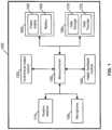
- Fig. 1is a block diagram identifying functional components and circuits of a Position Therapy Device ("PTD") 100 according to an embodiment.
- the PTD 100can be configured to be worn on the head, neck, or body of a user. In some arrangements, the PTD 100 can be worn during sleep to influence the position of the user's body. In other arrangements, the PTD 100 can be worn while the user is awake to provide feedback to the user if the user positions his or her body in a predetermined target position to be avoided.
- the PTD 100includes a microcontroller 130, a haptic feedback device 140, power supply 150, battery 155, recharging circuit 160, and position detector 110.
- Fig. 1illustrates the various components of the PTD 100 as being in communication with one another. The components can be in communication with one another via a wired or wireless connection.
- the position detector 110is configured to generate signal data that can be analyzed by the PTD 100 to determine the sleeping position of the user.
- the position detector 110can be used to determine whether the user is in a supine position.
- the position detector 110can comprise an accelerometer.
- a pressure switch or sensorcan be used instead of an accelerometer. When the PTD 100 is worn on the user's the neck or against the user's back, the pressure switch or sensor can be used to detect when the user is sleeping or laying in a supine position.
- the PTD 100can include a microphone 105 that can be configured to capture audio data while the user is sleeping. This audio data can be analyzed by the PTD 100 to detect snoring and/or other audible symptoms that can be causing sleep disruption. Snoring can be an indicator of obstructed breathing, and the PTD 100 can be used in a therapy regime for OSA in which a user is discouraged from sleeping in a supine position.
- microphone 105can be used to capture audio signals to assess snoring magnitude and frequency, which are likely to be position dependent. In a preferred arrangement an acoustic microphone is used to obtain quantified levels of snoring.
- a vibration microphonecan be used instead of an acoustic microphone.
- the PTD 100can be configured to correlate the audio data captured by microphone 105 with positional data generated by the position detector 110 to determine whether to provide haptic and/or audiovisual feedback to the user to induce the user to shift to a different sleep position. For example, a user having OSA can be induced to sleep in a non-supine position if severe snoring is detected by the PTD 100.
- the PTD 100includes a power component 160 that includes a rechargeable battery 155 and a power supply 150 for receiving power from an external source for recharging battery 155 via recharging circuit 260 and/or powering the PTD 100.
- the battery 155allows the PTD 100 to operate without requiring the PTD 100 to be tethered to an external power cord or power supply, which could be inconvenient and uncomfortable for a user of the device.
- the battery capacityis sufficient to allow the PTD 100 to acquire data from multiple nights while providing the required haptic feedback to the user.
- battery 155can be a rechargeable lithium polymer battery. According to other arrangements, battery 155 can be another type of battery, either rechargeable or non-rechargeable, and in some arrangements, battery 155 can be removable and replaceable. According to one arrangement, battery 155 is a rechargeable battery that includes a micro-USB connector that allows battery 155 to be recharged using a standard USB charger that plugs into an electrical outlet or a standard USB host. In an arrangement, the recharging circuit 160 comprises a standard USB wall charger that plugs into a standard wall outlet in order to power the PTD 100 and/or recharge battery 155 using mains power. According to some arrangements, an external power supply can be used to power the device.
- the PTD 100can include a memory 170 for data storage.
- the memory 170can comprise a removable Multimedia Memory card (MMC) or Secure Digital card (SD) car or other types of removable persistent memory.
- the memory 170can comprise a fixed flash chip.
- a data transfer interface 175is provided.
- the data transfer interface 175can comprise a micro-USB or similar type of connector that can be used facilitate downloading data from the PTD to an external computer system or web portal, for uploading firmware executable by microcontroller 130 to memory 170, or both.
- the data transfer interface 175can also include a mechanical interface for providing power to the recharging component 160 to recharge the battery 155.
- the microcontroller 130is an inexpensive, small, low-powered chip.
- the PTD 100can include firmware executable by the microcontroller 130.
- the firmwarecan be stored in data storage 170 or in a flash memory of microcontroller 130. According to some arrangements, the firmware can be updated by downloading new firmware from an external computer system via data transfer interface 175.
- the firmwarecan be configured to minimize the power requirements of the microcontroller 130 while the PTD 100 is being used in recording mode to capture data from the position detector 110, the microphone 105, and/or other sensors.
- the firmwarecan be configured to analyze data received from the position detector 110, microphone 105, and/or other sensors and to provide feedback to the user of the device via audiovisual output module 120 and/or haptic feedback device 140 for providing tactile feedback to the user of the PTD 100.
- the haptic feedback devicecan comprise one or more haptic motors for providing tactile feedback to the user of the PTD 100.
- the PTD 100can be configured to store various position therapy (PDT) data to the memory 170.
- PDTposition therapy
- the PDT datacan include data received from the position detector 110 and/or the microphone 105.
- the PDT datacan include data, such as the sleep position at various times, the changes to the sleep position of the user, sleep state and arousals, snoring data, and/or other data that can be recorded and/or generated by the PDT 100.
- the PTD 100can be configured to store various position therapy (PDT) data to the memory 170.
- the PDT datacan include data received from the position detector 110 and/or the microphone 105.
- the PDT datacan include data, such as the sleep position at various times, the changes to the sleep position of the user, sleep state and arousals, snoring data, and/or other data that can be recorded and/or generated by the PDT 100.
- the PTD 100can be configured to write an action history to the memory 170 to assist customer service support. For example, information regarding when the battery 155 of the PTD 100 has been charged, when the device has been powered on and off, when the device has started and stopped recording sleep assessment data about the user, and other information can be included in the action history that is written to memory 170.
- the data transfer interfacecomprises a Universal Serial Bus (USB) data transfer chip to facilitate transferring of data captured by the PTD 100 to an external computer system or web portal.
- USB transfer capabilitiescan be incorporated into microcontroller 130.
- the memory 170can be used to store data collected by the PTD 100 while the device is being worn by a user. Alternatively, this information can be stored to the flash of the microcontroller 130. To avoid data loss when saving to flash memory, the firmware can identify when the battery power is low and can conserve power until the data is downloaded.
- a USB flash drive chipcan be included in the PTD 100.
- the capability to transfer data via USB or native USBis provided by the microcontroller 130.
- the PTD 100can be connected to an external computer system via a USB connection, and the PTD 100 can be recognized as a USB Human Interface device, which can allow direct control of the device by the Microsoft Windows operating system and/or by Web-based software.
- the PTD 100includes one or more haptic motors 140 that can be configured to elicit vibrations in response to control signals from the to provide haptic feedback to the user when the PTD 100 recognizes that the user is in the target position.
- the haptic feedbackcan be used to alert the user that the user needs to change positions from the target position.
- an electronic feedback modulethat is configured to provide electrical stimulation to the user in response to control signals from the microcontroller can be used instead of haptic feedback in order to influence the sleep position of the user.
- an audio emittercan used as an alternative to or in addition to haptic feedback to influence sleep position.
- audiovisual output module 120can be used as a means to communicate with the user.
- voice messagescan be provided via an audio circuit or speaker to provide feedback to user.
- a voice messagemight be provided to indicate that the PTD 100 has slipped out of position or has fallen off.
- a voice messagemight be provided to indicate that the battery 155 is low or that the PTD 100 is running out of memory for storing data.
- an audio emittercan be used to project audio patterns that the user can be trained to recognize.
- the audio emittercould be configured to emit a specific signal if the device is turned on or if the device has fallen off.
- a light emitting diodecan be used to identify when the PTD 100 is powered on, when the battery 155 is being charged, or alternatively when the battery 155 needs to be recharged, or when data is available for transfer from the PTD 100 or when data is being transferred from the PTD 100.
- a displaycan be provided for displaying text messages, icons, or other visual indicators to the user regarding the operation of usages of the device.
- the PTD 100can include a liquid crystal (LCD) display, an LED display, or an organic light emitting diode (OLED) display for displaying information to the user of the device.
- LCDliquid crystal
- LEDLED display
- OLEDorganic light emitting diode
- the PTD 100can comprise low profile chips to minimize the profile of the PTD 100.
- low profile chipscan be used to implement microcontroller 130, position detector 110 (e.g., an accelerometer).
- microcontroller 130, flash memory for data storage 170, and a USB chip for data transfer interface 175can be mounted on a printed circuit board (PCB), and a triple-axis accelerometer for position detector 110 can be centered on the top of the PCB.
- Connectors for battery 155, haptic motor 140, a mini-USB connector for data transfer interface 175, light emitting diodes for audiovisual output module 120, and an on-off switchcan be mounted on the bottom of the PCB.
- Passive componentscan be mounted in the available space around these components.
- the on-off switchcan be located where the user can readily switch on the PTD 100, but the switch can be sufficiently recessed so that the device cannot easily be inadvertently turned off during use (e.g., by catching the switch on bedding or a pillow or the user's head or body). Because the haptic motor utilizes can use a substantial amount of current, the number of nights of use for a given size battery prior to recharging can depend on how often the haptic motor is used to provide feedback to the user. In a preferred arrangement, haptic motor 140 is physically located within the enclosure of the PTD 100 such that the haptic motor 140 can transmit a maximum level of vibration with a minimal amount of power consumption.
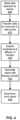
- Fig. 2is a flow diagram of a method for using the PTD 100 to monitor and control the sleep position of a user.
- the PTD 100can be self-applied by a user and can be positioned on the head, neck, or body and is worn by the user during sleep.
- the PTD 100can use a set of algorithms included in the firmware executed by microcontroller 130 to assess data collected by the position detector 110 to assess the sleeping position of the user (step 210).
- the position detector 110comprises one or more accelerometers that can be used to assess the sleep position of the user.
- the PTD 100monitors data received from the position detector 110 in order to make real-time assessments of the sleep position of the user.
- the PTD 100can also include a microphone 105 that can be used to capture audio signals indicative of whether the user is snoring.
- the audio data captured by microphone 105can be analyzed by the firmware to determine whether the user is snoring, and the microcontroller 130 can write the data to data storage 170.
- the audio data captured by the microcontroller 130can be written to the data storage 170 and the stored audio data can be transferred from the PTD 100 to an external computer system for further analysis and processing.
- the microcontroller 130can be configured to execute one or more analysis algorithms implemented in the firmware on the data received from the microphone 105 to identify whether the user of the device is snoring.
- the microcontroller 130can also be configured to write snoring event data to the data storage 170, and the stored snoring event data can later be transferred to an external computer system or web portal for further analysis and processing.
- the target sleep positionis a sleep position to be avoided.
- the target sleep position for a patient with OSAmay be a supine position, because sleeping on the back can cause the airway to be susceptible to collapse and can lead to inspiratory flow limitation.
- the PTD 100can provide haptic feedback to the user (step 230) to influence the user's sleep position. For example, if the user is sleeping in a supine position and the target position is the supine position, haptic feedback can be provided to encourage the user to change position. According to an arrangement, haptic feedback can be elicited until the PTD 100 detects that the user has changed position.
- the PTD 100can be worn for multiple nights between battery charges and over the course of the multiple nights, the PTD 100 can monitor compliance, the impact of the feedback on sleep continuity, behavioral arousals and sleep efficacy, and snoring.
- the method illustrated in Fig. 2can be adapted for use with users who are using the PTD 100 while awake.
- the PTD 100can be used to assess the position of the user (step 210) who is awake and to determine whether the user is in a target position (step 220) and provide haptic feedback to the user (step 230).
- the PTD 100could be used by a pregnant user to warn the user to avoid lying down in a supine position.
- the PTD 100could be used to warn a patient with an arm or shoulder injury from lying on the injured side of the body.
- the PTD 100can be used to assist a person locate or avoid the appropriate position.
- the precise position of the head, neck body or torsomay be important for use in the rehabilitation of in injury.
- Haptic feedbackcan be used for positive reinforcement when a particular position is achieved, or for negative reinforcement, as described previously to avoid a particular position.
- Fig. 9illustrates an alternative embodiment of the position therapy device illustrated in Fig. 1 that includes a wireless transceiver.
- the wireless arrangement of the PTD 100 illustrated in Fig. 9can be used with any of various methods described herein in which the non-wireless version of the PTD 100 can be used.
- the arrangement of PTD 100 illustrated in Fig. 9can remotely monitor the position of the user's body and provide haptic feedback to the user.
- the components of the PTD 100 illustrated in Fig. 9are similar to those of Fig. 1 , but the embodiment illustrated in Fig. 9 includes a wireless transceiver 980 that can be configured to allow the PTD 100 to communicate with one more remote position sensors 990.
- the wireless transceivercan be a Bluetooth transceiver, a Zigbee transceiver, or other type of wireless transceiver that can provide wireless communications between the PTD 100 and the remote position sensor 990.
- Fig. 9illustrates the various components of the PTD 100 as being in communication with one another. The components can be in communication with one another via a wired or wireless connection.
- the remote position sensor 990includes a microcontroller 995, a position sensor 993, and a wireless transceiver 997.
- the microcontroller 995can be similar to microcontroller 130 of PTD 100 or can be of a different configuration.
- Position detector 993can also be of a similar configuration as position detector 110 of PTD 100 or can be of a different configuration.
- the PTD 100can also include the wireless position detector 110 when the remote position sensor 990 is used, while in other arrangements, the PTD 100 can be configured to not include a wireless position sensor 110 when one or more wireless position sensors 990 are used.
- Information collected by the remote position sensor 990can be transmitted to the PTD 100.
- the microcontroller 130can use this information to determine whether to generate a control signal to provide haptic feedback to the user with haptic feedback module 140.
- the remote sensor 990can include a power supply 150, battery 155, and recharging circuit 160 similar to that of PTD 100. In other arrangements, the remote sensor 990 can include a non-rechargeable, replaceable battery to provide power to the remote sensor.
- more than one remote position sensors 990can be used to provide information relating a position or positions of the head, torso, or extremities of a user.
- One skilled in the artwill recognize the potential benefit of an athlete having multiple remote position sensors attached to key aspects of his body to ensure complex positions are maintained prior to execution of an action (e.g., preparing to hit a baseball, drive or put a golf ball, shoot a free throw, etc.).
- This approachallows for position information obtained during performance modeling, video taping, etc. to be translated to positions or angles of the body or extremities and in which haptic feedback can be used to assist the user to achieve that exact position (or similar position) during practice without access to the more sophisticated measurement approaches.
- the one or more remote sensorscan be attached or woven into clothing, a glove(s), wristbands, socks, etc. to allow more accurate placement of the sensor relative to a part of the user's body.
- multiple remote sensors 990can be attached or incorporated into a garment or accessory, allowing more than one sensor to share use the same battery and/or transceiver.
- an energy-harvesting modulecan be used to provide power to the battery of the remote sensor 990 and/or the PTD 100. The energy-harvesting module can generate power based on movements of the user during the use of the PTD 100.
- the remote sensor 990can be connected to the PTD 100 using a wired interface, and the PTD 100 and the remote sensor 990 can include appropriate physical interfaces for the wired connection.
- the remote sensor 990 and the PTD 100can include data ports into which a data cable can be plugged to provide a wired communication connection between the remote sensor 990 and the PTD 100.
- Fig. 3illustrates another method for monitoring and influencing the sleep position of PTD 100 using conditional positional feedback.
- the method illustrated in Fig. 3is similar to that of Fig. 2 , but the method illustrated in Fig. 3 is adapted to assist sleepers that have difficulty falling asleep in a position other than the target position.
- the method illustrated in Fig. 3can be used to assist predominantly supine sleepers that may have difficulty falling asleep on their sides by allowing the user to initially fall asleep in a supine position.
- the methodprovides the patient with an opportunity to fall asleep before using conditional feedback to influence the sleep position of the patient.
- This approachavoids compromising the sleep efficiency of the user by forcing the user to attempt to fall asleep in a non-target position when the user is typically unable to fall asleep in a non-target position. For example, if a user who is typically a supine sleeper will not be forced to attempt to fall asleep on her side.
- the PTD 100can be self-applied by a user and can be positioned on the head, neck, or body and is worn by the user during sleep. Once the PTD 100 has been applied by the user, the PTD 100 can use a set of algorithms included in the firmware executed by microcontroller 130 to assess data collected by the position detector 110 to assess the sleeping position of the user (step 305). A determination can then be made whether the user has had a sufficient amount of time in bed to make an assessment (step 310). Positional feedback will be initiated only after a predetermined or configurable elapsed time period with the PTD 100 on (e.g., 15-minutes).
- the user and/or a doctor or therapist treating the patientcan configure the amount of time that PTD 100 will wait before making an initial assessment, while in other arrangements, the PTD 100 can be configured to wait for a predetermined time period before making an initial assessment. If the user has not had a sufficient amount of time in bed prior to making an assessment, the method returns to step 305 where a new assessment can be made.
- a determination can be made whether movement is detected(step 320). For example, the user is moving his or her head or other parts of the body, then the user may still be awake. If movement is detected, the user is likely not to be asleep and positional feedback would not be effective. Therefore, the method returns to step 305 where a new assessment can be made.
- a usercan reset the time period on the PTD 100 if the user has trouble falling asleep. For example, a user might be awakened during the night by the need to use the bathroom, and upon returning from the nocturnal use of the bathroom, the user can turn the PTD 100 off and then back on in order to reset the feedback delay.
- the microcontroller 130can include a real-time clock that can be used to timestamp the on/off mark in the data captured by the PTD 100 so that the data can be appended into a single of information when a compliance and efficacy report is generated from the data.
- the PTD 100can include a microphone 105 that can be used to capture an audio signal that can be analyzed to determine whether the user is snoring. While lack of snoring is not indicative of whether the user is asleep, snoring is indicative that the user is asleep and can also be indicative of an airway susceptible to collapse and can lead to inspiratory flow limitation. If no snoring is detected, the user may not be sleeping, and thus positional feedback could be counterproductive.
- the methodreturns to step 305 where a new assessment can be made.
- Step 330can be optional if the user has satisfied the conditions of steps 310 and 320 and has been in bed for a sufficient amount of time and no movement has been detected.
- the PTD 100can be configured to track how much time has passed since the movement was detected in step 320, and if a predetermined period of time has passed since the last movement was detected, the method can proceed to step 340 even if no snoring is detected. For example, in one arrangement, if the user has been in bed for at least 15 minutes, the condition of step 310 is satisfied. No movement is detected at step 320 so the step is also satisfied, but if no snoring is detected, the method would return to step 305 even thought the user might be asleep.
- the PTD 100can begin keeping track of how long it has been since movement was last detected (or when step 320 was first performed if no movement has been detected since the method began), and if a predetermined time period (e.g., five minutes) passes an no movement is detected and no snoring is present, the method can proceed to step 340, because it is likely that the user is asleep but is not snoring.
- a predetermined time periode.g., five minutes
- step 340if snoring is detected even if some movement is present, the snoring is indicative that the user is asleep, and the method can proceed to step 340.
- the order of steps 320 and 330can be reversed, so that the PTD 100 is configured to check for snoring before checking for user movements.
- the feedback stimulation routinebegins at a low intensity level two-second haptic feedback interval when the supine position is detected.
- an assessmentcan then be performed on data collected by the position detector 110 to assess the sleeping position of the user (step 360), and a determination can be made whether the user is in a supine position (step 370).
- an additional feedback routine sequencecan be applied. For example, in an arrangement, if the PTD 100 does not detect that the patient has begun to change position within four seconds of the termination of the previous feedback routine, another 2 second long feedback routing can be presented at a higher intensity level than the previous feedback routine. The sequence of steps 350, 360, and 370 can be repeated until the user finally changes positions and settles into a non-supine position 370.
- the PTD 100can also be configured to store the data received from the position detector 110 and the microphone 105 (step 380).
- the data received by the microphone 105can be analyzed by the PTD 100 to determine whether the user is snoring, and data indicating whether the user was snoring and a particular data and time can be stored in the data storage 170.
- other datacan also be collected by the PTD 100 and stored in the data storage 170.
- the PDT 100can configured to determine a current sleep state of the user, a current sleep position of the user, feedback that was provided to the user, and/or other information that can be used to determine the quality of the user's sleep and the efficacy of the PTD treatment.
- the final intensity of the haptic feedback provided to the user that resulted in the user changing positioncan be saved to data storage 170 and can be used as a starting level for the haptic feedback provided the next time that feedback is required.
- the patterns of haptic feedback described aboveare merely one example of the pattern of feedback that can be used to influence the sleeping of the user.
- different patterns of haptic feedbackincluding different haptic feedback intervals and lengths of pauses between intervals of increasing intensity of feedback can be used.
- a different number of haptic motors 140can also be used to create a subjective perception of increased levels of feedback.
- the firmware of PTD 100can be configured to store data representing the average feedback intensity levels and range of feedback intensity levels required to initiate position changes. This data can be stored in data storage 170, and the PTD 100 can utilize this information the next time the PTD 100 is used to establish the initial feedback pattern.
- the patterns and intensity of the feedbackcan be tailored to the individual user in order to encourage positional behavior without over-stimulation. For example, by using the techniques described above, the PTD 100 will not stimulate a light sleeper fully awake, and the PTD 100 won't under stimulate a heavy sleeper, such that the feedback produced by the PTD 100 is ignored.
- the feedback intensityis adaptive so that the therapy can also be efficacious in patients who are taking analgesic medications, sleeping pills, or consuming alcohol prior to bed.
- the conditional algorithmscan accommodate changes in the user's sensitivity to the feedback based on sleep stage or adaptation to continued use of the PTD 100.
- PTD 100can be configured to use various numbers of feedback intensity levels, as well as various lengths of the feedback and durations between feedback events without negatively impacting the functionality of the PTD 100.
- the position detector 110comprise accelerometers that are sensitive enough provide data that can be used to monitor the breathing of the user.
- the breathing pattern of the usercan be collected as part of the position therapy data collected by the PTD 100 and can be used to identify interruptions and arousals in the sleep pattern of the user. For example, in an OSA patient, the patient's breathing can be interrupted resulting in the patient gasping for air.
- the data collected by the accelerometerscan be analyzed to identify such events.
- the breathing data collected by the PTD 100can also be used in determining whether the user is asleep, and can in some arrangements, be used in addition to or instead of the detection of user movement in step 330.
- the user's breathing patterncan change when the user falls asleep and this change in breathing pattern can be identified in real time by monitoring and analyzing the signal data from the accelerometer or accelerometers.
- Fig. 4illustrates a method for processing the data acquired by the PTD 100.
- the PTD 100captures and stores data regarding the sleep state of the user (step 405). In one arrangement, this data can be stored in the data storage 170 of the PTD 100.
- the data acquired by the PTD 100can be transferred to an external computer system or web portal (step 410) for additional processing to assess various parameters useful in assessing compliance and efficacy (step 420).
- the datacan be transferred from the PTD 100 using the data transfer interface 175.
- the data transfer interface 175can comprise a USB interface for transferring the data acquired by the PTD 100 to an external computer system or a web portal.
- the frequency of use of the PTD 100can provide useful measures for assessing the user's compliance with PTD therapy.
- Other data captured by the PTD 100such as the response time to positional feedback and length of time, the number of times per night the patient attempts to sleep supine, the total and percentage of time the patients user supine, and whether the user turn the device off in the night to eliminate feedback can also provide useful measures of treatment efficacy.
- the positional signal data from position detector 110 of thecan represent actigraphic data. Actigraphy is a non-invasive method for monitoring the rest and activity cycles of a patient.
- the PTD 100can measure the motor activity of the user and this data can be captured and stored by the PTD 100 as part of the position therapy data.
- the motor activity datacan be analyzed to measure the behavioral sleep patterns of the user and sleep efficiency. This data can be incorporated into a position therapy report generated for the user. In some arrangements, night to night differences in the amplitude and frequency of snoring are additional measures which can also incorporated into a position therapy report to assist the user or their clinician assess the benefits of the PTD 100.
- the external computer system or web portalcan generate a report based on the position therapy data collected and/or generated by the PTD 100.
- the position therapy report position therapy reportcan assist the user or a clinician to assess the benefits of the positional therapy regime.
- the reportcan be downloaded or printed (step 440) or viewed online.
- Fig. 8is an example of a report that can be generated using the data captured by the PTD 100.
- the example reportincludes two graphs of data captured by the user device over time.
- the upper graph portion of the reportincludes positional data indicating the body position of the user over time.
- the lower graphillustrates the whether the user was awake or asleep over time and whether the user experienced an arousal event.
- This reportcan be downloaded for review by the patient or a clinician to assess the efficacy of the PTD therapy.
- the PTD 100can be interfaced with an external computer system or web portal to provide additional capabilities for monitoring treatment efficacy.
- the PTD 100can be configured to record sleep position of the user without applying feedback for a predetermined number period of time, such as one or more nights, to create baseline information about the user's preference for sleeping positions and other sleeping habits. Once the baseline data has been recorded, positional feedback can be initiated. The baseline data can later be compared to data collected after positional feedback has been initiated to determine whether the positional therapy is having an affect on the user's sleep habits.
- the PTD 100can be configured via a user interface provided by the external computer system or web portal.
- the user interfaceis configured to allow the user to select a sleep position that the user wishes to avoid.
- the usermight configure the PTD 100 to avoid the supine position for OSA or for pregnancy, or non-supine sleep for patients with shoulder or arm injuries.
- the user interfacecan also be configured to allow the user or a clinician to configure other parameters affecting haptic feedback or the algorithms used to make the various determinations described used in the method described above, such as the date and time.
- Fig. 5illustrates an example embodiment of the PTD 100.
- the PTD 100comprises a small injection-molded silicon enclosure 505.
- the silicon enclosure 505encapsulates the electronic components of the PTD 100 and the enclosure is thick enough to protect the electronic components.
- a thinner, more comfortable durometer siliconecan be used for the enclosure extensions 510.
- a thin strip of coppercan be molded inside of the extensions to allow the PTD 100 to be adjusted to conform to the neck or back of the user and to decrease the likelihood that the PTD 100 might accidentally be repositioned during sleep and result in false positive feedback.
- the silicone enclosure 505 and enclosure extensions 510can be easily cleaned and maintained with alcohol.
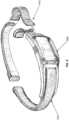
- Fig. 6illustrates the PTD 100 design illustrated in Fig. 5 that has been placed around the neck of a user according to an embodiment.
- a thin, round silicone enclosure strap 610holds the enclosure 605 of the PTD 100 in place round the user's neck.
- the length of the left and right strapscan be adjusted over the enclosure 605.
- a low profile magnetic clasp(not shown), similar to that used in some wrist bracelets, can be used on the front of the strap of the PTD 100 to allow the PTD 100 to be easily applied or taken off by the user.
- the strength of the magnet included in the magnetic claspcan be selected to ensure that the magnetic clasp will automatically release in the event that the PTD 100 were to get caught in the clothing of the user or the bedding.
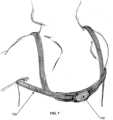
- Fig. 7illustrates another embodiment of the PTD illustrated in Figs. 5 and 6 where the enclosure 705 can be worn over the spine and can be held in place with the use of a longer, thicker enclosure strap 705 than is used in the embodiments illustrated in Figs. 5 and 6 .
- the enclosure strapwraps around the chest and over the shoulders of the user to hold the PTD 100 in place.
- DSPdigital signal processor
- ASICapplication specific integrated circuit
- FPGAfield programmable gate array
- a general-purpose processoris hardware and can be a microprocessor, but in the alternative, the processor can be any hardware processor or controller, microcontroller.
- a processorcan also be implemented as a combination of computing devices, for example, a combination of a DSP and a microprocessor, a plurality of microprocessors, one or more microprocessors in conjunction with a DSP core, or any other such configuration.
- a software modulecan reside in computer or controller accessible on computer-readable storage media including RAM memory, flash memory, ROM memory, EPROM memory, EEPROM memory, registers, hard disk, a removable disk, a CD-ROM, or any other form of storage medium including a network storage medium.
- An exemplary storage mediumcan be coupled to the processor such the processor can read information from, and write information to, the storage medium.
- the storage mediumcan be integral to the processor.
- the processor and the storage mediumcan also reside in an ASIC.
Landscapes
- Health & Medical Sciences (AREA)
- Life Sciences & Earth Sciences (AREA)
- Engineering & Computer Science (AREA)
- Animal Behavior & Ethology (AREA)
- Veterinary Medicine (AREA)
- Biomedical Technology (AREA)
- Heart & Thoracic Surgery (AREA)
- Public Health (AREA)
- General Health & Medical Sciences (AREA)
- Physics & Mathematics (AREA)
- Medical Informatics (AREA)
- Surgery (AREA)
- Molecular Biology (AREA)
- Pathology (AREA)
- Biophysics (AREA)
- Acoustics & Sound (AREA)
- Physiology (AREA)
- Dentistry (AREA)
- Oral & Maxillofacial Surgery (AREA)
- Anesthesiology (AREA)
- Pulmonology (AREA)
- Pain & Pain Management (AREA)
- Psychology (AREA)
- Otolaryngology (AREA)
- Nursing (AREA)
- Orthopedic Medicine & Surgery (AREA)
- Vascular Medicine (AREA)
- Biodiversity & Conservation Biology (AREA)
- Hematology (AREA)
- Artificial Intelligence (AREA)
- Signal Processing (AREA)
- Computer Vision & Pattern Recognition (AREA)
- Psychiatry (AREA)
- Measurement Of The Respiration, Hearing Ability, Form, And Blood Characteristics Of Living Organisms (AREA)
- Orthopedics, Nursing, And Contraception (AREA)
- Measuring And Recording Apparatus For Diagnosis (AREA)
- User Interface Of Digital Computer (AREA)
Description
- The present invention generally relates to the field of treating sleep disorders and more specifically to systems using position therapy (PDT) to treat sleep disorders.
- Sleep disordered breathing which results in the diagnosis of Obstructive Sleep Apnea ("OSA") occurs as a result of a partial or complete collapse of the upper airway during sleep. Snoring is the first indication of an airway susceptible to collapse and can lead to inspiratory flow limitation. Greater obstruction resulting in a partial collapse of the airway causes hypopneas and recognizable changes in tidal volume. Full collapse results in a cessation in breathing, events commonly referred to as apneas. The apnea/hypopnea index (AHI) is the measure used to define OSA severity and is based on the total number of sleep disordered breathing events per hour of sleep.
- When a patient with OSA is in the supine position, gravity increases the susceptibility of the airway to partial or full collapse during sleep. The most frequently cited effect of gravity on the soft tissue of the pharynx is tendency of the tongue to fall back against the palate causing the narrowing of an already compromised airway. A susceptible airway, by way of example, may result in loud snoring in the supine position and limited or no snoring the non-supine position. A more compromised airway may exhibit loud snoring in the non-supine position and repeated hypopneas (partial collapse) or apneas (full collapse) in the supine position. This pattern is typically associated with patients with 'positional' sleep disordered breathing. In patients with severely compromised airways, known as 'non-positional' OSA, the pharynx may partially collapse during non-supine sleep and fully collapses in the supine position. The influence of gravity during supine sleep contributes to a reduction in lung volume and oxygen stores and contributes to increased levels of oxygen desaturation during obstructive breathing.
- Evidence suggest that patients with positional and non-positional OSA form two distinct but overlapping etiologies in which airway length and craniofacial features influence genioglossal responsiveness to negative pressure pulses in the lateral position. Estimate of the prevalence of positional OSA (i.e., the supine AHI is at least two times greater than the non-supine AHI) among all those diagnosed with OSA range from 55 to 65%), and after excluding those who sleep almost exclusively on their back (e.g., > 95% of the night), over 50% of patients diagnosed with sleep could reduce their AHI by at least 50% and/or into a normal range by avoiding sleep in the supine position. Studies have shown that position therapy can contribute to a significant drop in blood pressure in patients with Obstructive Sleep Apnea (OSA) because supine sleep increases the severity of OSA. Position therapy can be combined with other therapies to enhance outcomes in the treatment of sleep disordered breathing. Several investigators have demonstrated nasal continuous positive airway pressure (CPAP) pressures can be reduced if patients sleep lateral instead of supine and increased CPAP compliance has been associated with lower pressures.
- A plethora of shirts, vests, belts, pillows and other inventions have attempted to address the need for positional therapy to reduce the severity of snoring or sleep apnea by using mechanical means that essentially makes it uncomfortable for a user to sleep supine. Some examples of these devices include a knapsack stuffed with Styrofoam to provide a bulky alternative to tennis balls, which makes it impossible to sleep supine. At least one study has demonstrated that this type of position restriction provides limited to no clinical efficacy due to non-compliance. The greatest limitation of these approaches is that the therapy is initiated prior to the patient falling asleep. As shown with CPAP therapy, patients are much more tolerant of therapy if it is initiated after the patients have fallen asleep.
- The number of electronic devices invented to limit supine sleep is substantially less. One device, described in
U.S. Patent No. 5,081,447 , employs the use of two gravity position sensors and an audio alarm to trigger the user to change position. One of the limitations of this approach is a bed-partner of the user would also be awakened each time the alarm is triggered. An alternative approach, described inU.S. Patent No. 5,381,801 , limits supine sleep by applying electromechanical vibration using motors inserted into pockets of a belt worn by a user. Application of the tactile stimulus is dependent on the closing of an electronic switch within the pocket of the belt that is triggered by contact with the underlying surface of the sleeper. - Positional therapy holds the potential to provide important therapeutic benefit for a number of medical conditions. For example, over 63% of patients with acute ischemic stroke sleep the entire night in the supine position. Sleep in the supine position also increases the severity of Cheyne-Stokes i.e., respiration i.e., central sleep apnea. Avoiding supine sleep during the second and third trimesters of pregnancy would reduce pressure on a vena cava vein and improve blood flow to the fetus. An adjustment in the application of position feedback would assist patients recovering from hip surgery avoid sleep in the non-supine position. The measurement of and feedback related to the position of the elements of the body (e.g., arm, leg, hand, wrist, ankle, knee, etc.) could be useful in injury rehabilitation or in training or performance which requires the user to find or maintain a specific position/posture. Thus, the potential benefit of positional therapy is clear, but conventional systems and methods to affect or influence sleep position have been largely ineffective.
- The invention sets out a wearable position therapy device according to claim 1. Preferred embodiments are set out in the dependent claims.
- Systems for controlling the position of a user of a wearable positional therapy device are provided. In one arrangement, the wearable position therapy device is configured to monitor and store physiological signals that can be used to assess sleep quality and sleeping position of a user as well as during other activities. The device can be configured to be worn around the head, the neck, or body of the user and/or can comprise of more than one unit that are connected wirelessly to share information. The device can be configured to provide feedback to a user if the user is sleeping or is positioned in a target position to induce the user to change positions. For example, the device can be configured to limit the amount of time that the user spends sleeping in a supine position for users for whom it is not recommended to sleep in a supine position, such as OSA patients and users who are pregnant. The feedback can be provided by one or more haptic motors that can be configured to provide various levels of feedback and the level of feedback can be customized based on the user's reaction to the feedback.
- In an arrangement, a wearable position therapy device for influencing the position of a user is provided. The device includes a position detector configured to generate positional signal data that can be used to determine a position of the user, a haptic feedback device configured to generate tactile feedback to the user of the device, and a microcontroller. The microcontroller is configured to receive and analyze the signal data from the position detector, determine whether the user of the device is in a target position, and generate a control signal to cause the haptic feedback device to provide tactile feedback to the user to induce the user to change to a different, non-target position if the user of the device is in a target position. In an arrangement, the position therapy device can be configured to influence a sleeping position of a user and can be worn while the user sleeps. The target position can be a target sleep position, and the microcontroller can be configured to generate a control signal to cause the haptic feedback device to provide tactile feedback to the user to induce the user to change to a different, non-target sleep position if the user of the device is in a target sleep position.
- A method for influencing the position of a user using a wearable position therapy device is provided; however, such a method is not part of the claimed invention. The method includes applying the position therapy devices to the head, neck, body, torso, hand, wrist or knee of the user, collecting positional signal data to determine a position and manner of the user while the user is wearing the device, determining whether the positional signal data indicates that the user is positioned in a target position, and generating haptic feedback to the user to induce the user to change to a different, non-target position if the user is in the target position. The method can be used to influence a sleeping position of a user of the wearable position therapy device, and the positional signal data can be used to determine whether the user is in a target sleep position, and to provide haptic feedback to the user if the user is in the target sleep position to influence the user to change to a different, non-target sleep position.
Fig. 1 identifies the primary electronic components and circuits of a position therapy device configure to monitor and reduce sleep in a target position according to an embodiment;Fig. 2 is a flow diagram of a basic approach to reduce sleep in a target position using a the position therapy device illustrated inFig. 1 to provide haptic feedback to induce a user to change sleep positions according to an embodiment;Fig. 3 illustrates another method for monitoring and influencing the sleep position using the position therapy device ofFig 1 to provide haptic feedback to induce a user to change sleep positions;Fig. 4 illustrates a method for processing and analyzing the data acquired by the position therapy device ofFig. 1 .Fig. 5 provides an illustration of the position therapy device according to an embodiment;Fig. 6 shows the position therapy device worn around the neck according to an embodiment;Fig. 7 shows the position therapy device worn on the back;Fig. 8 uses a sample hypnogram to illustrate the clinical information that can be derived from accelerometers with the position therapy device and can be included in a position therapy report generated from data collected by the position therapy device according to an embodiment; andFig. 9 illustrates an alternative embodiment of the position therapy device illustrated inFig. 1 that includes a wireless transceiver.- Systems and methods for influence position of a user are provided; however, such methods are not part of the claimed invention. Embodiments can be used to control the influence the position of a user's body, and some embodiments can be used to influence a sleeping position of the user. The device can be configured to be worn around the head, the neck, or body of the user. The device can be configured to provide feedback to a user if the user is sleeping or is positioned in a target position to induce the user to change positions. For example, the device can be configured to limit the amount of time that the user spends sleeping in a supine position for users for whom it is not recommended to sleep in a supine position, such as OSA patients and users who are pregnant. The feedback can be provided by one or more haptic motors that can be configured to provide various levels of feedback and the level of feedback can be customized based on the user's reaction to the feedback.
- According to one arrangement, a wearable position therapy device is provided that is configured to monitor and store physiological signals that can be used to assess sleep quality and sleeping position of a user. The device can be worn around the head, the neck, or body of the user. The device can be configured to provide haptic feedback to induce the user change sleeping positions if the position therapy device determines that the user is sleeping in a target position. In an arrangement, the form factor of the device is comfortable so as to not disturb the user's ability to sleep while wearing the device. The device is also easy for a user to self-apply. The device can be configured to provide feedback, including haptic feedback, to influence the user's sleep positions. Adaptive feedback routines can be included to minimize the disruption of sleep continuity while reducing the likelihood that the user does not return to the target sleep position. The application of feedback can be provisionally set so the device can worn to first obtain baseline sleep data for comparison to the changes in sleep position after initiation of feedback. The signals recorded during the night(s) can be analyzed to assess parameters useful in assessing treatment compliance and efficacy, such as total sleep time and sleep efficiency, snoring frequency and loudness, and percentage of sleep time by position.
- Embodiments and arrangements of the position therapy device can also be used in applications where the user is not sleeping but it is desirable for the user to avoid specific positions. For example, a pregnant user experiencing pre-eclampsia might be confined to bed rest by a physician and instructed to avoid laying in a supine position when both asleep and awake in order to avoid aggravating the condition.
- According to an arrangement, the target position can also be defined as a position that the position therapy device will discourage the user from being in that position. In some arrangements, a set of allowable positions can be defined and if the user moves to a position that is not included in the set of allowable positions that position can be considered a target position, and the position therapy device can be configured to provide feedback to the user to induce the user to change positions to one of the allowed positions. This approach can be useful in teaching or training exercises where the position therapy device can be used to train a user to be in a certain position.
Fig. 1 is a block diagram identifying functional components and circuits of a Position Therapy Device ("PTD") 100 according to an embodiment. ThePTD 100 can be configured to be worn on the head, neck, or body of a user. In some arrangements, thePTD 100 can be worn during sleep to influence the position of the user's body. In other arrangements, thePTD 100 can be worn while the user is awake to provide feedback to the user if the user positions his or her body in a predetermined target position to be avoided. In an arrangement, thePTD 100 includes amicrocontroller 130, ahaptic feedback device 140,power supply 150,battery 155, rechargingcircuit 160, andposition detector 110.Fig. 1 illustrates the various components of thePTD 100 as being in communication with one another. The components can be in communication with one another via a wired or wireless connection.- The
position detector 110 is configured to generate signal data that can be analyzed by thePTD 100 to determine the sleeping position of the user. For example, theposition detector 110 can be used to determine whether the user is in a supine position. According to an arrangement, theposition detector 110 can comprise an accelerometer. According to an alternative arrangement, a pressure switch or sensor can be used instead of an accelerometer. When thePTD 100 is worn on the user's the neck or against the user's back, the pressure switch or sensor can be used to detect when the user is sleeping or laying in a supine position. - According to an embodiment, the
PTD 100 can include amicrophone 105 that can be configured to capture audio data while the user is sleeping. This audio data can be analyzed by thePTD 100 to detect snoring and/or other audible symptoms that can be causing sleep disruption. Snoring can be an indicator of obstructed breathing, and thePTD 100 can be used in a therapy regime for OSA in which a user is discouraged from sleeping in a supine position. In an example,microphone 105 can be used to capture audio signals to assess snoring magnitude and frequency, which are likely to be position dependent. In a preferred arrangement an acoustic microphone is used to obtain quantified levels of snoring. In an alternative arrangement, a vibration microphone can be used instead of an acoustic microphone. In an arrangement, thePTD 100 can be configured to correlate the audio data captured bymicrophone 105 with positional data generated by theposition detector 110 to determine whether to provide haptic and/or audiovisual feedback to the user to induce the user to shift to a different sleep position. For example, a user having OSA can be induced to sleep in a non-supine position if severe snoring is detected by thePTD 100. - In the embodiment illustrated in
Fig. 1 , thePTD 100 includes apower component 160 that includes arechargeable battery 155 and apower supply 150 for receiving power from an external source for rechargingbattery 155 via recharging circuit 260 and/or powering thePTD 100. Thebattery 155 allows thePTD 100 to operate without requiring thePTD 100 to be tethered to an external power cord or power supply, which could be inconvenient and uncomfortable for a user of the device. In the preferred arrangement, the battery capacity is sufficient to allow thePTD 100 to acquire data from multiple nights while providing the required haptic feedback to the user. - In one arrangement,
battery 155 can be a rechargeable lithium polymer battery. According to other arrangements,battery 155 can be another type of battery, either rechargeable or non-rechargeable, and in some arrangements,battery 155 can be removable and replaceable. According to one arrangement,battery 155 is a rechargeable battery that includes a micro-USB connector that allowsbattery 155 to be recharged using a standard USB charger that plugs into an electrical outlet or a standard USB host. In an arrangement, therecharging circuit 160 comprises a standard USB wall charger that plugs into a standard wall outlet in order to power thePTD 100 and/or rechargebattery 155 using mains power. According to some arrangements, an external power supply can be used to power the device. - The
PTD 100 can include amemory 170 for data storage. In an arrangement, thememory 170 can comprise a removable Multimedia Memory card (MMC) or Secure Digital card (SD) car or other types of removable persistent memory. In another arrangement, thememory 170 can comprise a fixed flash chip. According to an arrangement, adata transfer interface 175 is provided. According to an arrangement, thedata transfer interface 175 can comprise a micro-USB or similar type of connector that can be used facilitate downloading data from the PTD to an external computer system or web portal, for uploading firmware executable bymicrocontroller 130 tomemory 170, or both. In an arrangement, thedata transfer interface 175 can also include a mechanical interface for providing power to therecharging component 160 to recharge thebattery 155. - According to an arrangement, most commercially available microcontrollers or
microprocessor 130 would be appropriate for thePTD 100. However, in a preferred arrangement, themicrocontroller 130 is an inexpensive, small, low-powered chip. ThePTD 100 can include firmware executable by themicrocontroller 130. The firmware can be stored indata storage 170 or in a flash memory ofmicrocontroller 130. According to some arrangements, the firmware can be updated by downloading new firmware from an external computer system viadata transfer interface 175. - According to an arrangement, the firmware can be configured to minimize the power requirements of the
microcontroller 130 while thePTD 100 is being used in recording mode to capture data from theposition detector 110, themicrophone 105, and/or other sensors. The firmware can be configured to analyze data received from theposition detector 110,microphone 105, and/or other sensors and to provide feedback to the user of the device viaaudiovisual output module 120 and/orhaptic feedback device 140 for providing tactile feedback to the user of thePTD 100. In an arrangement, the haptic feedback device can comprise one or more haptic motors for providing tactile feedback to the user of thePTD 100. In an arrangement, thePTD 100 can be configured to store various position therapy (PDT) data to thememory 170. The PDT data can include data received from theposition detector 110 and/or themicrophone 105. The PDT data can include data, such as the sleep position at various times, the changes to the sleep position of the user, sleep state and arousals, snoring data, and/or other data that can be recorded and/or generated by thePDT 100. - In an arrangement, the
PTD 100 can be configured to store various position therapy (PDT) data to thememory 170. The PDT data can include data received from theposition detector 110 and/or themicrophone 105. The PDT data can include data, such as the sleep position at various times, the changes to the sleep position of the user, sleep state and arousals, snoring data, and/or other data that can be recorded and/or generated by thePDT 100. - According to an arrangement, the
PTD 100 can be configured to write an action history to thememory 170 to assist customer service support. For example, information regarding when thebattery 155 of thePTD 100 has been charged, when the device has been powered on and off, when the device has started and stopped recording sleep assessment data about the user, and other information can be included in the action history that is written tomemory 170. - In an arrangement, the data transfer interface comprises a Universal Serial Bus (USB) data transfer chip to facilitate transferring of data captured by the
PTD 100 to an external computer system or web portal. In another arrangement, USB transfer capabilities can be incorporated intomicrocontroller 130. - The
memory 170 can be used to store data collected by thePTD 100 while the device is being worn by a user. Alternatively, this information can be stored to the flash of themicrocontroller 130. To avoid data loss when saving to flash memory, the firmware can identify when the battery power is low and can conserve power until the data is downloaded. - In an arrangement, to improve the ease and speed of transfer of files from the data storage device, a USB flash drive chip can be included in the
PTD 100. In some arrangements, the capability to transfer data via USB or native USB is provided by themicrocontroller 130. According to an arrangement, thePTD 100 can be connected to an external computer system via a USB connection, and thePTD 100 can be recognized as a USB Human Interface device, which can allow direct control of the device by the Microsoft Windows operating system and/or by Web-based software. - In an arrangement, the
PTD 100 includes one or morehaptic motors 140 that can be configured to elicit vibrations in response to control signals from the to provide haptic feedback to the user when thePTD 100 recognizes that the user is in the target position. The haptic feedback can be used to alert the user that the user needs to change positions from the target position. In one arrangement, an electronic feedback module that is configured to provide electrical stimulation to the user in response to control signals from the microcontroller can be used instead of haptic feedback in order to influence the sleep position of the user. In one arrangement, an audio emitter can used as an alternative to or in addition to haptic feedback to influence sleep position. - According to an arrangement, in order to improve the ease of use of
PTD 100,audiovisual output module 120 can be used as a means to communicate with the user. In one arrangement, voice messages can be provided via an audio circuit or speaker to provide feedback to user. For example, a voice message might be provided to indicate that thePTD 100 has slipped out of position or has fallen off. In another example, a voice message might be provided to indicate that thebattery 155 is low or that thePTD 100 is running out of memory for storing data. One skilled in the art will recognize that other types of audio messages can be provided to user of the device to facilitate use of the device. In an alternative arrangement, an audio emitter can be used to project audio patterns that the user can be trained to recognize. For example, the audio emitter could be configured to emit a specific signal if the device is turned on or if the device has fallen off. - According to another arrangement, a light emitting diode (LED) can be used to identify when the
PTD 100 is powered on, when thebattery 155 is being charged, or alternatively when thebattery 155 needs to be recharged, or when data is available for transfer from thePTD 100 or when data is being transferred from thePTD 100. In another arrangement, a display can be provided for displaying text messages, icons, or other visual indicators to the user regarding the operation of usages of the device. For example, thePTD 100 can include a liquid crystal (LCD) display, an LED display, or an organic light emitting diode (OLED) display for displaying information to the user of the device. One skilled in the art will recognize that microcontroller and firmware provides the means to apply any number of notifications or feedback using various combinations audio and visual feedback. - According to an arrangement, the
PTD 100 can comprise low profile chips to minimize the profile of thePTD 100. For example, low profile chips can be used to implementmicrocontroller 130, position detector 110 (e.g., an accelerometer). In one arrangement,microcontroller 130, flash memory fordata storage 170, and a USB chip fordata transfer interface 175 can be mounted on a printed circuit board (PCB), and a triple-axis accelerometer forposition detector 110 can be centered on the top of the PCB. Connectors forbattery 155,haptic motor 140, a mini-USB connector fordata transfer interface 175, light emitting diodes foraudiovisual output module 120, and an on-off switch can be mounted on the bottom of the PCB. Passive components can be mounted in the available space around these components. - According to an arrangement, the on-off switch can be located where the user can readily switch on the
PTD 100, but the switch can be sufficiently recessed so that the device cannot easily be inadvertently turned off during use (e.g., by catching the switch on bedding or a pillow or the user's head or body). Because the haptic motor utilizes can use a substantial amount of current, the number of nights of use for a given size battery prior to recharging can depend on how often the haptic motor is used to provide feedback to the user. In a preferred arrangement,haptic motor 140 is physically located within the enclosure of thePTD 100 such that thehaptic motor 140 can transmit a maximum level of vibration with a minimal amount of power consumption. Fig. 2 is a flow diagram of a method for using thePTD 100 to monitor and control the sleep position of a user. As described above, thePTD 100 can be self-applied by a user and can be positioned on the head, neck, or body and is worn by the user during sleep.- Once the
PTD 100 has been applied by the user, thePTD 100 can use a set of algorithms included in the firmware executed bymicrocontroller 130 to assess data collected by theposition detector 110 to assess the sleeping position of the user (step 210). According to an arrangement, theposition detector 110 comprises one or more accelerometers that can be used to assess the sleep position of the user. ThePTD 100 monitors data received from theposition detector 110 in order to make real-time assessments of the sleep position of the user. As described above, thePTD 100 can also include amicrophone 105 that can be used to capture audio signals indicative of whether the user is snoring. In an arrangement, the audio data captured bymicrophone 105 can be analyzed by the firmware to determine whether the user is snoring, and themicrocontroller 130 can write the data todata storage 170. In one arrangement, the audio data captured by themicrocontroller 130 can be written to thedata storage 170 and the stored audio data can be transferred from thePTD 100 to an external computer system for further analysis and processing. In some arrangements, themicrocontroller 130 can be configured to execute one or more analysis algorithms implemented in the firmware on the data received from themicrophone 105 to identify whether the user of the device is snoring. Themicrocontroller 130 can also be configured to write snoring event data to thedata storage 170, and the stored snoring event data can later be transferred to an external computer system or web portal for further analysis and processing. - A determination is made whether a target sleep position is detected based on the assessment of the data from the position detector 110 (step 220). The target sleep position is a sleep position to be avoided. For example, the target sleep position for a patient with OSA may be a supine position, because sleeping on the back can cause the airway to be susceptible to collapse and can lead to inspiratory flow limitation. If the target position is the supine position and the
PTD 100 determines that the user is sleeping in the target position, thePTD 100 can provide haptic feedback to the user (step 230) to influence the user's sleep position. For example, if the user is sleeping in a supine position and the target position is the supine position, haptic feedback can be provided to encourage the user to change position. According to an arrangement, haptic feedback can be elicited until thePTD 100 detects that the user has changed position. - According to an arrangement, the
PTD 100 can be worn for multiple nights between battery charges and over the course of the multiple nights, thePTD 100 can monitor compliance, the impact of the feedback on sleep continuity, behavioral arousals and sleep efficacy, and snoring. - The method illustrated in
Fig. 2 can be adapted for use with users who are using thePTD 100 while awake. For example, thePTD 100 can be used to assess the position of the user (step 210) who is awake and to determine whether the user is in a target position (step 220) and provide haptic feedback to the user (step 230). For example, thePTD 100 could be used by a pregnant user to warn the user to avoid lying down in a supine position. In another example, thePTD 100 could be used to warn a patient with an arm or shoulder injury from lying on the injured side of the body. - Alternatively, the
PTD 100 can be used to assist a person locate or avoid the appropriate position. For example, the precise position of the head, neck body or torso may be important for use in the rehabilitation of in injury. Haptic feedback can be used for positive reinforcement when a particular position is achieved, or for negative reinforcement, as described previously to avoid a particular position. Fig. 9 illustrates an alternative embodiment of the position therapy device illustrated inFig. 1 that includes a wireless transceiver. The wireless arrangement of thePTD 100 illustrated inFig. 9 can be used with any of various methods described herein in which the non-wireless version of thePTD 100 can be used. The arrangement ofPTD 100 illustrated inFig. 9 can remotely monitor the position of the user's body and provide haptic feedback to the user. The components of thePTD 100 illustrated inFig. 9 are similar to those ofFig. 1 , but the embodiment illustrated inFig. 9 includes awireless transceiver 980 that can be configured to allow thePTD 100 to communicate with one moreremote position sensors 990. According to an arrangement, the wireless transceiver can be a Bluetooth transceiver, a Zigbee transceiver, or other type of wireless transceiver that can provide wireless communications between thePTD 100 and theremote position sensor 990.Fig. 9 illustrates the various components of thePTD 100 as being in communication with one another. The components can be in communication with one another via a wired or wireless connection.- The
remote position sensor 990 includes amicrocontroller 995, aposition sensor 993, and awireless transceiver 997. In an arrangement, themicrocontroller 995 can be similar tomicrocontroller 130 ofPTD 100 or can be of a different configuration.Position detector 993 can also be of a similar configuration asposition detector 110 ofPTD 100 or can be of a different configuration. In an arrangement, thePTD 100 can also include thewireless position detector 110 when theremote position sensor 990 is used, while in other arrangements, thePTD 100 can be configured to not include awireless position sensor 110 when one or morewireless position sensors 990 are used. - Information collected by the
remote position sensor 990 can be transmitted to thePTD 100. Themicrocontroller 130 can use this information to determine whether to generate a control signal to provide haptic feedback to the user withhaptic feedback module 140. - In an arrangement, the
remote sensor 990 can include apower supply 150,battery 155, and rechargingcircuit 160 similar to that ofPTD 100. In other arrangements, theremote sensor 990 can include a non-rechargeable, replaceable battery to provide power to the remote sensor. - In one arrangement, more than one
remote position sensors 990 can be used to provide information relating a position or positions of the head, torso, or extremities of a user. One skilled in the art will recognize the potential benefit of an athlete having multiple remote position sensors attached to key aspects of his body to ensure complex positions are maintained prior to execution of an action (e.g., preparing to hit a baseball, drive or put a golf ball, shoot a free throw, etc.). This approach allows for position information obtained during performance modeling, video taping, etc. to be translated to positions or angles of the body or extremities and in which haptic feedback can be used to assist the user to achieve that exact position (or similar position) during practice without access to the more sophisticated measurement approaches. In one arrangement the one or more remote sensors can be attached or woven into clothing, a glove(s), wristbands, socks, etc. to allow more accurate placement of the sensor relative to a part of the user's body. In one arrangement, multipleremote sensors 990 can be attached or incorporated into a garment or accessory, allowing more than one sensor to share use the same battery and/or transceiver. In one arrangement, an energy-harvesting module can be used to provide power to the battery of theremote sensor 990 and/or thePTD 100. The energy-harvesting module can generate power based on movements of the user during the use of thePTD 100. - In an alternative arrangement, the
remote sensor 990 can be connected to thePTD 100 using a wired interface, and thePTD 100 and theremote sensor 990 can include appropriate physical interfaces for the wired connection. For example, in an arrangement, theremote sensor 990 and thePTD 100 can include data ports into which a data cable can be plugged to provide a wired communication connection between theremote sensor 990 and thePTD 100. Fig. 3 illustrates another method for monitoring and influencing the sleep position ofPTD 100 using conditional positional feedback. The method illustrated inFig. 3 is similar to that ofFig. 2 , but the method illustrated inFig. 3 is adapted to assist sleepers that have difficulty falling asleep in a position other than the target position. For example, the method illustrated inFig. 3 can be used to assist predominantly supine sleepers that may have difficulty falling asleep on their sides by allowing the user to initially fall asleep in a supine position. The method provides the patient with an opportunity to fall asleep before using conditional feedback to influence the sleep position of the patient. This approach avoids compromising the sleep efficiency of the user by forcing the user to attempt to fall asleep in a non-target position when the user is typically unable to fall asleep in a non-target position. For example, if a user who is typically a supine sleeper will not be forced to attempt to fall asleep on her side.- As described above, the
PTD 100 can be self-applied by a user and can be positioned on the head, neck, or body and is worn by the user during sleep. Once thePTD 100 has been applied by the user, thePTD 100 can use a set of algorithms included in the firmware executed bymicrocontroller 130 to assess data collected by theposition detector 110 to assess the sleeping position of the user (step 305). A determination can then be made whether the user has had a sufficient amount of time in bed to make an assessment (step 310). Positional feedback will be initiated only after a predetermined or configurable elapsed time period with thePTD 100 on (e.g., 15-minutes). For example, in some arrangements, the user and/or a doctor or therapist treating the patient can configure the amount of time that PTD 100 will wait before making an initial assessment, while in other arrangements, thePTD 100 can be configured to wait for a predetermined time period before making an initial assessment. If the user has not had a sufficient amount of time in bed prior to making an assessment, the method returns to step 305 where a new assessment can be made. - Otherwise, if the predetermined or configurable time period has elapsed a determination can be made whether movement is detected (step 320). For example, the user is moving his or her head or other parts of the body, then the user may still be awake. If movement is detected, the user is likely not to be asleep and positional feedback would not be effective. Therefore, the method returns to step 305 where a new assessment can be made.
- According to the invention, a user can reset the time period on the
PTD 100 if the user has trouble falling asleep. For example, a user might be awakened during the night by the need to use the bathroom, and upon returning from the nocturnal use of the bathroom, the user can turn thePTD 100 off and then back on in order to reset the feedback delay. Themicrocontroller 130 can include a real-time clock that can be used to timestamp the on/off mark in the data captured by thePTD 100 so that the data can be appended into a single of information when a compliance and efficacy report is generated from the data. - Otherwise, if no movement is detected, then the user is more likely to be asleep, and a determination can be made whether snoring is detected (step 330). As described above, the
PTD 100 can include amicrophone 105 that can be used to capture an audio signal that can be analyzed to determine whether the user is snoring. While lack of snoring is not indicative of whether the user is asleep, snoring is indicative that the user is asleep and can also be indicative of an airway susceptible to collapse and can lead to inspiratory flow limitation. If no snoring is detected, the user may not be sleeping, and thus positional feedback could be counterproductive. If the user is asleep and is not snoring, the user is likely to be in a non-target position (in this example, a non-supine position), and applying positional feedback might simply wake the user. Otherwise, if the user is not asleep, applying positional feedback could prevent the user from falling asleep. Therefore, the method returns to step 305 where a new assessment can be made. - Step 330 can be optional if the user has satisfied the conditions of
steps PTD 100 can be configured to track how much time has passed since the movement was detected instep 320, and if a predetermined period of time has passed since the last movement was detected, the method can proceed to step 340 even if no snoring is detected. For example, in one arrangement, if the user has been in bed for at least 15 minutes, the condition ofstep 310 is satisfied. No movement is detected atstep 320 so the step is also satisfied, but if no snoring is detected, the method would return to step 305 even thought the user might be asleep. Therefore, thePTD 100 can begin keeping track of how long it has been since movement was last detected (or whenstep 320 was first performed if no movement has been detected since the method began), and if a predetermined time period (e.g., five minutes) passes an no movement is detected and no snoring is present, the method can proceed to step 340, because it is likely that the user is asleep but is not snoring. - Furthermore, in an alternative arrangement, if snoring is detected even if some movement is present, the snoring is indicative that the user is asleep, and the method can proceed to step 340. The order of
steps PTD 100 is configured to check for snoring before checking for user movements. - A determination can be made whether the user is in a supine position for arrangements where the target position is a supine position (step 340). According to an arrangement, a determination could be made whether the user is in other non-supine target positions depending upon the individual needs of the user and the condition for which the user is being treated. If the user is in the target position, haptic feedback can be provided to the user (step 350). In a preferred arrangement, once the user is asleep, feedback is provided immediately after a position change so as to not alter or disrupt the continuity of sleep more than what would normally occur when a sleeper changes position. In an arrangement, the
position detector 110 can be used to detect that the user has changed position. For example, in one arrangement, theposition detector 110 comprises one or more accelerometers that can be used to determine that the user's body position. - In one arrangement, the feedback stimulation routine begins at a low intensity level two-second haptic feedback interval when the supine position is detected. After applying the feedback to the user, an assessment can then be performed on data collected by the
position detector 110 to assess the sleeping position of the user (step 360), and a determination can be made whether the user is in a supine position (step 370). According to an arrangement, if gross movement of the user's body position is not identified, an additional feedback routine sequence can be applied. For example, in an arrangement, if thePTD 100 does not detect that the patient has begun to change position within four seconds of the termination of the previous feedback routine, another 2 second long feedback routing can be presented at a higher intensity level than the previous feedback routine. The sequence ofsteps non-supine position 370. - According to an arrangement, the
PTD 100 can also be configured to store the data received from theposition detector 110 and the microphone 105 (step 380). According to an arrangement, the data received by themicrophone 105 can be analyzed by thePTD 100 to determine whether the user is snoring, and data indicating whether the user was snoring and a particular data and time can be stored in thedata storage 170. According to an arrangement, other data can also be collected by thePTD 100 and stored in thedata storage 170. For example, thePDT 100 can configured to determine a current sleep state of the user, a current sleep position of the user, feedback that was provided to the user, and/or other information that can be used to determine the quality of the user's sleep and the efficacy of the PTD treatment. - According to an arrangement, the final intensity of the haptic feedback provided to the user that resulted in the user changing position can be saved to
data storage 170 and can be used as a starting level for the haptic feedback provided the next time that feedback is required. The patterns of haptic feedback described above are merely one example of the pattern of feedback that can be used to influence the sleeping of the user. In other arrangements, different patterns of haptic feedback including different haptic feedback intervals and lengths of pauses between intervals of increasing intensity of feedback can be used. According to an arrangement, a different number ofhaptic motors 140 can also be used to create a subjective perception of increased levels of feedback. - According to an arrangement, the firmware of
PTD 100 can be configured to store data representing the average feedback intensity levels and range of feedback intensity levels required to initiate position changes. This data can be stored indata storage 170, and thePTD 100 can utilize this information the next time thePTD 100 is used to establish the initial feedback pattern. Thus, the patterns and intensity of the feedback can be tailored to the individual user in order to encourage positional behavior without over-stimulation. For example, by using the techniques described above, thePTD 100 will not stimulate a light sleeper fully awake, and thePTD 100 won't under stimulate a heavy sleeper, such that the feedback produced by thePTD 100 is ignored. - The feedback intensity is adaptive so that the therapy can also be efficacious in patients who are taking analgesic medications, sleeping pills, or consuming alcohol prior to bed. The conditional algorithms can accommodate changes in the user's sensitivity to the feedback based on sleep stage or adaptation to continued use of the
PTD 100.PTD 100 can be configured to use various numbers of feedback intensity levels, as well as various lengths of the feedback and durations between feedback events without negatively impacting the functionality of thePTD 100. - According to an arrangement, the
position detector 110 comprise accelerometers that are sensitive enough provide data that can be used to monitor the breathing of the user. The breathing pattern of the user can be collected as part of the position therapy data collected by thePTD 100 and can be used to identify interruptions and arousals in the sleep pattern of the user. For example, in an OSA patient, the patient's breathing can be interrupted resulting in the patient gasping for air. The data collected by the accelerometers can be analyzed to identify such events. The breathing data collected by thePTD 100 can also be used in determining whether the user is asleep, and can in some arrangements, be used in addition to or instead of the detection of user movement instep 330. For example, the user's breathing pattern can change when the user falls asleep and this change in breathing pattern can be identified in real time by monitoring and analyzing the signal data from the accelerometer or accelerometers. Fig. 4 illustrates a method for processing the data acquired by thePTD 100. As described above with respect toFigs. 2 and3 , thePTD 100 captures and stores data regarding the sleep state of the user (step 405). In one arrangement, this data can be stored in thedata storage 170 of thePTD 100. The data acquired by thePTD 100 can be transferred to an external computer system or web portal (step 410) for additional processing to assess various parameters useful in assessing compliance and efficacy (step 420). According to one arrangement, the data can be transferred from thePTD 100 using thedata transfer interface 175. As described above thedata transfer interface 175 can comprise a USB interface for transferring the data acquired by thePTD 100 to an external computer system or a web portal.- The frequency of use of the
PTD 100, based on hours per night and nights per week can provide useful measures for assessing the user's compliance with PTD therapy. Other data captured by thePTD 100, such as the response time to positional feedback and length of time, the number of times per night the patient attempts to sleep supine, the total and percentage of time the patients user supine, and whether the user turn the device off in the night to eliminate feedback can also provide useful measures of treatment efficacy. According to an arrangement, the positional signal data fromposition detector 110 of the can represent actigraphic data. Actigraphy is a non-invasive method for monitoring the rest and activity cycles of a patient. ThePTD 100 can measure the motor activity of the user and this data can be captured and stored by thePTD 100 as part of the position therapy data. The motor activity data can be analyzed to measure the behavioral sleep patterns of the user and sleep efficiency. This data can be incorporated into a position therapy report generated for the user. In some arrangements, night to night differences in the amplitude and frequency of snoring are additional measures which can also incorporated into a position therapy report to assist the user or their clinician assess the benefits of thePTD 100. - The external computer system or web portal can generate a report based on the position therapy data collected and/or generated by the
PTD 100. The position therapy report position therapy report can assist the user or a clinician to assess the benefits of the positional therapy regime. Once the report has been generated, the report can be downloaded or printed (step 440) or viewed online.Fig. 8 is an example of a report that can be generated using the data captured by thePTD 100. The example report includes two graphs of data captured by the user device over time. The upper graph portion of the report includes positional data indicating the body position of the user over time. The lower graph illustrates the whether the user was awake or asleep over time and whether the user experienced an arousal event. This report can be downloaded for review by the patient or a clinician to assess the efficacy of the PTD therapy. - According to an arrangement, the
PTD 100 can be interfaced with an external computer system or web portal to provide additional capabilities for monitoring treatment efficacy. For example, thePTD 100 can be configured to record sleep position of the user without applying feedback for a predetermined number period of time, such as one or more nights, to create baseline information about the user's preference for sleeping positions and other sleeping habits. Once the baseline data has been recorded, positional feedback can be initiated. The baseline data can later be compared to data collected after positional feedback has been initiated to determine whether the positional therapy is having an affect on the user's sleep habits. - In some arrangements, the
PTD 100 can be configured via a user interface provided by the external computer system or web portal. For example, in some arrangements, the user interface is configured to allow the user to select a sleep position that the user wishes to avoid. In an example, the user might configure thePTD 100 to avoid the supine position for OSA or for pregnancy, or non-supine sleep for patients with shoulder or arm injuries. According to an arrangement, the user interface can also be configured to allow the user or a clinician to configure other parameters affecting haptic feedback or the algorithms used to make the various determinations described used in the method described above, such as the date and time. Fig. 5 illustrates an example embodiment of thePTD 100. In the embodiment illustrated inFig. 5 , thePTD 100 comprises a small injection-moldedsilicon enclosure 505. Thesilicon enclosure 505 encapsulates the electronic components of thePTD 100 and the enclosure is thick enough to protect the electronic components. A thinner, more comfortable durometer silicone can be used for theenclosure extensions 510. In an arrangement, a thin strip of copper can be molded inside of the extensions to allow thePTD 100 to be adjusted to conform to the neck or back of the user and to decrease the likelihood that thePTD 100 might accidentally be repositioned during sleep and result in false positive feedback. Thesilicone enclosure 505 andenclosure extensions 510 can be easily cleaned and maintained with alcohol.Fig. 6 illustrates thePTD 100 design illustrated inFig. 5 that has been placed around the neck of a user according to an embodiment. In the embodiment illustrated inFig. 6 , a thin, roundsilicone enclosure strap 610 holds theenclosure 605 of thePTD 100 in place round the user's neck. The length of the left and right straps can be adjusted over theenclosure 605. According to an arrangement, a low profile magnetic clasp (not shown), similar to that used in some wrist bracelets, can be used on the front of the strap of thePTD 100 to allow thePTD 100 to be easily applied or taken off by the user. According to an arrangement, to cover safety concerns regarding wearing a collar during sleep, the strength of the magnet included in the magnetic clasp can be selected to ensure that the magnetic clasp will automatically release in the event that thePTD 100 were to get caught in the clothing of the user or the bedding.Fig. 7 illustrates another embodiment of the PTD illustrated inFigs. 5 and6 where theenclosure 705 can be worn over the spine and can be held in place with the use of a longer,thicker enclosure strap 705 than is used in the embodiments illustrated inFigs. 5 and6 . The enclosure strap wraps around the chest and over the shoulders of the user to hold thePTD 100 in place.- Those of skill in the art will appreciate that the various illustrative modules and method steps described in connection with the above described figures and the embodiments and arrangements disclosed herein can often be implemented as electronic hardware, software, firmware or combinations of the foregoing. To clearly illustrate this interchangeability of hardware and software, various illustrative modules and method steps have been described above generally in terms of their functionality. Whether such functionality is implemented as hardware or software depends upon the particular application and design constraints imposed on the overall system. Skilled persons can implement the described functionality in varying ways for each particular application, but such implementation decisions should not be interpreted as causing a departure from the scope of the invention. In addition, the grouping of functions within a module or step is for ease of description. Specific functions can be moved from one module or step to another without departing from the invention.
- Moreover, the various illustrative modules and method steps described in connection with the embodiments and arrangements disclosed herein can be implemented or performed with hardware such as a general purpose processor, a digital signal processor ("DSP"), an application specific integrated circuit ("ASIC"), field programmable gate array ("FPGA") or other programmable logic device, discrete gate or transistor logic, discrete hardware components, or any combination thereof designed to perform the functions described herein. A general-purpose processor is hardware and can be a microprocessor, but in the alternative, the processor can be any hardware processor or controller, microcontroller. A processor can also be implemented as a combination of computing devices, for example, a combination of a DSP and a microprocessor, a plurality of microprocessors, one or more microprocessors in conjunction with a DSP core, or any other such configuration.
- Additionally, the steps of a method or algorithm described in connection with the embodiments and arrangements disclosed herein can be embodied directly in hardware, in a software module executed by a processor, or in a combination of the two. A software module can reside in computer or controller accessible on computer-readable storage media including RAM memory, flash memory, ROM memory, EPROM memory, EEPROM memory, registers, hard disk, a removable disk, a CD-ROM, or any other form of storage medium including a network storage medium. An exemplary storage medium can be coupled to the processor such the processor can read information from, and write information to, the storage medium. In the alternative, the storage medium can be integral to the processor. The processor and the storage medium can also reside in an ASIC.
- The above description of the disclosed embodiments and arrangements is provided to enable any person skilled in the art to make or use the invention. Various modifications to these embodiments will be readily apparent to those skilled in the art, and the generic principles described herein can be applied to other embodiments without departing from the scope of the invention as defined in the appended claims. Thus, it is to be understood that the description and drawings presented herein represent exemplary embodiments of the invention and are therefore representative of the subject matter which is broadly contemplated by the present invention. It is further understood that the scope of the present invention fully encompasses other embodiments and that the scope of the present invention is accordingly limited by nothing other than the appended claims.
Claims (9)
- A wearable position therapy device (100) for influencing the position of a user, the device (100) comprising:a position detector (110) configured to generate positional signal data based on a position or movement of the user;a feedback device (140) configured to generate a feedback stimuli; anda microcontroller (130) in communication with the position detector (110) and the feedback device, wherein the microcontroller (130) is configured to:receive the positional signal data from the position detector (110),determine whether the user is in a target position based, at least in part, on the positional signal data, andgenerate a control signal to cause the feedback device (140) to provide the feedback stimulus to the user to induce the user to change to a different, non-target position if the user of the wearable position therapy device is in the target position,characterised in that the feedback stimuli is generated only after a delay period has elapsed in response to the device being turned on or a reset operation.
- The device (100) of claim 1, wherein the position detector (110) can be worn around at least one of the neck, back, head, or torso of the user.
- The device (100) of any preceding claim, wherein the position detector (110) is configured to be worn around the at least one of the neck, back, head, or torso of the user, and the position detector (110) is included in an enclosure strap for holding the device around the at least one of the neck, back, head, or torso of the user, wherein the enclosure strap includes a detachable magnetic clasp that is configured to automatically release if the position detector (110) is snagged while the user is wearing the position detector (110).
- The device (100) of any preceding claim, wherein the device is configured to provide adaptive feedback to increase the level of the feedback stimuli to the user based on the user's reaction to previously applied feedback stimuli.
- The device (100) of any preceding claim, wherein the target position comprises a target sleeping position and the different, non-target position comprises a different, non-target sleeping position.
- The device (100) of any preceding claim, further comprising a microphone for capturing snoring event data, and wherein the device is configured to determine whether the user is asleep based on the snoring event data.
- The device (100) of claim 6, wherein the device is configured to correlate the snoring event data with positional data received from the position detector (110) to determine whether the feedback stimuli provided to the user induced the user to change to a different position.
- The device (100) of any preceding claim, wherein the device is configured to detect user movement based on positional data received from the position detector (110) indicative of the user being in a non-sleep state, and wherein the device is configured to not cause the feedback device (140) to provide the feedback stimuli to the user if the user is in a non-sleep state.
- The device (100) of any preceding claim, wherein the feedback device (140) comprises a haptic motor configured to provide tactile feedback via haptic vibration feedback based, in part, on the control signal.
Priority Applications (1)
| Application Number | Priority Date | Filing Date | Title |
|---|---|---|---|
| EP24204076.4AEP4509165A3 (en) | 2009-06-05 | 2010-06-04 | Systems and methods for controlling position |
Applications Claiming Priority (3)
| Application Number | Priority Date | Filing Date | Title |
|---|---|---|---|
| US18463109P | 2009-06-05 | 2009-06-05 | |
| PCT/US2010/037507WO2010141893A2 (en) | 2009-06-05 | 2010-06-04 | Systems and methods for controlling position |
| EP10784198.3AEP2437696B2 (en) | 2009-06-05 | 2010-06-04 | Systems and methods for controlling position |
Related Parent Applications (2)
| Application Number | Title | Priority Date | Filing Date |
|---|---|---|---|
| EP10784198.3ADivision-IntoEP2437696B2 (en) | 2009-06-05 | 2010-06-04 | Systems and methods for controlling position |
| EP10784198.3ADivisionEP2437696B2 (en) | 2009-06-05 | 2010-06-04 | Systems and methods for controlling position |
Related Child Applications (1)
| Application Number | Title | Priority Date | Filing Date |
|---|---|---|---|
| EP24204076.4ADivisionEP4509165A3 (en) | 2009-06-05 | 2010-06-04 | Systems and methods for controlling position |
Publications (3)
| Publication Number | Publication Date |
|---|---|
| EP3533424A1 EP3533424A1 (en) | 2019-09-04 |
| EP3533424C0 EP3533424C0 (en) | 2024-10-02 |
| EP3533424B1true EP3533424B1 (en) | 2024-10-02 |
Family
ID=43298573
Family Applications (3)
| Application Number | Title | Priority Date | Filing Date |
|---|---|---|---|
| EP19156894.8AActiveEP3533424B1 (en) | 2009-06-05 | 2010-06-04 | Wearable device for controlling position and provide feedbck to the user |
| EP10784198.3AActiveEP2437696B2 (en) | 2009-06-05 | 2010-06-04 | Systems and methods for controlling position |
| EP24204076.4APendingEP4509165A3 (en) | 2009-06-05 | 2010-06-04 | Systems and methods for controlling position |
Family Applications After (2)
| Application Number | Title | Priority Date | Filing Date |
|---|---|---|---|
| EP10784198.3AActiveEP2437696B2 (en) | 2009-06-05 | 2010-06-04 | Systems and methods for controlling position |
| EP24204076.4APendingEP4509165A3 (en) | 2009-06-05 | 2010-06-04 | Systems and methods for controlling position |
Country Status (6)
| Country | Link |
|---|---|
| US (8) | US8783264B2 (en) |
| EP (3) | EP3533424B1 (en) |
| JP (1) | JP5559877B2 (en) |
| CN (1) | CN102448409B (en) |
| AU (1) | AU2010256401B2 (en) |
| WO (1) | WO2010141893A2 (en) |
Families Citing this family (75)
| Publication number | Priority date | Publication date | Assignee | Title |
|---|---|---|---|---|
| WO2008037020A1 (en) | 2006-09-27 | 2008-04-03 | Resmed Ltd | Methods and apparatus for assessing sleep quality |
| US8647287B2 (en) | 2008-12-07 | 2014-02-11 | Andrew Greenberg | Wireless synchronized movement monitoring apparatus and system |
| EP3533424B1 (en) | 2009-06-05 | 2024-10-02 | Advanced Brain Monitoring, Inc. | Wearable device for controlling position and provide feedbck to the user |
| WO2011082349A1 (en)* | 2009-12-31 | 2011-07-07 | Nicolaas De Vries | Devices, systems, and methods for monitoring sleep position |
| CA3012029A1 (en)* | 2010-05-04 | 2011-11-10 | Nightbalance B.V. | Sleep state detection for interrupting a sleep-in period |
| US9993179B2 (en)* | 2012-10-29 | 2018-06-12 | Nightbalance B.V. | Method and device for sleep posture correction |
| AU2016269519B2 (en)* | 2010-05-04 | 2018-11-08 | Koninklijke Philips N.V. | Method and device for sleep posture correction |
| US20120025945A1 (en)* | 2010-07-27 | 2012-02-02 | Cyberglove Systems, Llc | Motion capture data glove |
| US11314344B2 (en)* | 2010-12-03 | 2022-04-26 | Razer (Asia-Pacific) Pte. Ltd. | Haptic ecosystem |
| US20140213937A1 (en)* | 2011-02-15 | 2014-07-31 | The General Hospital Corporation | Systems and methods to monitor and quantify physiological stages |
| JP5767833B2 (en)* | 2011-03-09 | 2015-08-19 | 株式会社日立製作所 | Saddle position estimation apparatus, heel position estimation system, and heel position estimation method |
| US20120240941A1 (en)* | 2011-03-22 | 2012-09-27 | Restorics, Inc. | Methods and systems for monitoring sleep positions |
| KR101110639B1 (en) | 2011-06-22 | 2012-06-12 | 팅크웨어(주) | Safe service system and method thereof |
| US20130108995A1 (en)* | 2011-10-31 | 2013-05-02 | C&D Research Group LLC. | System and method for monitoring and influencing body position |
| WO2013064933A2 (en)* | 2011-11-02 | 2013-05-10 | Koninklijke Philips Electronics N.V. | An apparatus and a method for eliminating the intensity variance of a snoring sound signal due to a subject's head movement during sleep |
| NL2008359C2 (en)* | 2012-02-27 | 2013-08-28 | Nightbalance B V | Sleep posture alerting apparatus and method. |
| US9384639B2 (en)* | 2012-07-05 | 2016-07-05 | Michael Joseph White | Rigid fixture for coupling one or more transducers to the upper back of the human body |
| CN104582661B (en)* | 2012-08-18 | 2017-11-28 | 有限会社知财经营社 | Sleep Position Control Bed System |
| EP2908770B1 (en) | 2012-10-16 | 2019-04-24 | Cook Medical Technologies LLC | Apparatus for treating obstructive sleep apnea (osa) |
| US20140142442A1 (en) | 2012-11-19 | 2014-05-22 | Judy Sibille SNOW | Audio Feedback for Medical Conditions |
| WO2014127970A1 (en) | 2013-02-25 | 2014-08-28 | Bayan Hamid | Device for detecting an unhealthy situation of a person lying down, in particular anti-snoring device |
| US9486272B2 (en) | 2013-03-12 | 2016-11-08 | Biosense Webster (Israel) Ltd. | Force feedback device and method for catheters |
| US9189098B2 (en)* | 2013-03-14 | 2015-11-17 | Immersion Corporation | Systems and methods for syncing haptic feedback calls |
| US20140276227A1 (en)* | 2013-03-14 | 2014-09-18 | Aliphcom | Sleep management implementing a wearable data-capable device for snoring-related conditions and other sleep disturbances |
| US20140267076A1 (en)* | 2013-03-15 | 2014-09-18 | Immersion Corporation | Systems and Methods for Parameter Modification of Haptic Effects |
| US10548760B2 (en) | 2013-03-15 | 2020-02-04 | Somne Llc | Correlating a condition of a subject with a degree of sleep apnea being experienced by the subject |
| KR20150139865A (en) | 2013-03-15 | 2015-12-14 | 잔소르스 엘엘씨 | Health monitoring, surveillance and anomaly detection |
| US10874577B2 (en) | 2013-03-15 | 2020-12-29 | Somne Llc | Obtaining, with a sleep-apnea device, information related to sleep-apnea events and sleep-apnea treatment, and correlating sleep apnea events and sleep-apnea treatment with subject lifestyle and wellbeing |
| US9699278B2 (en) | 2013-06-06 | 2017-07-04 | Zih Corp. | Modular location tag for a real time location system network |
| US20140365194A1 (en)* | 2013-06-06 | 2014-12-11 | Zih Corp. | Method, apparatus, and computer program product for dynamics/kinetics model selection |
| US10437658B2 (en) | 2013-06-06 | 2019-10-08 | Zebra Technologies Corporation | Method, apparatus, and computer program product for collecting and displaying sporting event data based on real time data for proximity and movement of objects |
| AU2014306232B2 (en) | 2013-08-05 | 2018-12-06 | C2Dx, Inc. | Medical devices having a releasable tubular member and methods of using the same |
| CN103705333A (en)* | 2013-08-30 | 2014-04-09 | 李峰 | Method and device for intelligently stopping snoring |
| US9443401B2 (en)* | 2013-09-06 | 2016-09-13 | Immersion Corporation | Automatic remote sensing and haptic conversion system |
| CN107374748B (en)* | 2013-10-29 | 2020-12-01 | 上海联影医疗科技股份有限公司 | Scanning bed position control system |
| KR101580317B1 (en)* | 2013-11-14 | 2016-01-05 | 울산과학기술원 산학협력단 | Pose recognition apparatus using smartphone |
| TW201535254A (en)* | 2014-01-06 | 2015-09-16 | Imation Corp | Wearable data storage and caching |
| WO2015107737A1 (en)* | 2014-01-20 | 2015-07-23 | ソニー株式会社 | Information processing device, information processing method, and program |
| WO2015138317A1 (en) | 2014-03-10 | 2015-09-17 | Stryker Corporation | Limb positioning system |
| US11819334B2 (en) | 2014-03-27 | 2023-11-21 | Smart Human Dynamics, Inc. | Systems, devices, and methods for tracking abdominal orientation and activity for prevention of poor respiratory disease outcomes |
| WO2015148018A1 (en) | 2014-03-27 | 2015-10-01 | Bellybit, Inc. | Systems, devices, and methods for tracking abdominal orientation and activity |
| US9974563B2 (en) | 2014-05-28 | 2018-05-22 | Cook Medical Technologies Llc | Medical devices having a releasable member and methods of using the same |
| US9759803B2 (en)* | 2014-06-06 | 2017-09-12 | Zih Corp. | Method, apparatus, and computer program product for employing a spatial association model in a real time location system |
| KR102127390B1 (en)* | 2014-06-10 | 2020-06-26 | 엘지전자 주식회사 | Wireless receiver and method for controlling the same |
| US20160029962A1 (en)* | 2014-07-29 | 2016-02-04 | Elwha Llc | Medically active toys |
| WO2016022454A1 (en) | 2014-08-04 | 2016-02-11 | Darin Schaeffer | Medical devices having a releasable tubular member and methods of using the same |
| CN104127188A (en)* | 2014-08-08 | 2014-11-05 | 沈迪 | Method and device for monitoring amount of exercise of neck |
| US10722147B2 (en) | 2014-08-13 | 2020-07-28 | Nightbalance B.V. | Activation by temperature sensor |
| US10197417B2 (en)* | 2014-09-09 | 2019-02-05 | Twin Harbor Labs, LLC | Monitoring activity with intelligent fabrics |
| US10292881B2 (en)* | 2014-10-31 | 2019-05-21 | Hill-Rom Services, Inc. | Dynamic apnea therapy surface |
| US9951904B2 (en) | 2015-03-24 | 2018-04-24 | Stryker Corporation | Rotatable seat clamps for rail clamp |
| EP3277163B1 (en)* | 2015-03-31 | 2019-12-04 | ZST Holdings, Inc. | Systems for providing an automated titration for oral appliance therapy |
| CN104837083B (en)* | 2015-04-11 | 2019-01-11 | 黄银桃 | Multifunctional intellectual neck ring |
| US10653366B2 (en)* | 2015-06-26 | 2020-05-19 | Andrew Michael Levine | Haptic feedback device, system and method |
| US9984540B2 (en)* | 2015-12-17 | 2018-05-29 | Harman International Industries, Incorporated | Fan-driven force device |
| US9763621B1 (en)* | 2016-03-15 | 2017-09-19 | Marjan Hafezi | Pregnancy belt |
| NL2017406B1 (en)* | 2016-09-02 | 2018-03-09 | Nightbalance B V | Sleep trainer with heart rate measurement band |
| US20180078178A1 (en)* | 2016-09-19 | 2018-03-22 | Jkl Ip Company, Llc | Wearable maternity article |
| JP6737833B2 (en)* | 2018-05-02 | 2020-08-12 | ナイトバランス ベー.フェー.Nightbalance B.V. | Sleep state detection that blocks the sleep-in period |
| US20200113483A1 (en)* | 2018-10-12 | 2020-04-16 | IDA Health, Inc. | System and method for monitoring breathing and movement |
| EP3698715A1 (en)* | 2019-02-19 | 2020-08-26 | Koninklijke Philips N.V. | A sleep monitoring and position therapy system and method |
| CN111558139B (en)* | 2019-09-30 | 2021-09-24 | 未来穿戴技术有限公司 | Neck massager |
| FR3101550B3 (en)* | 2019-10-07 | 2022-01-28 | Side Sleep Tech B V | Sleep position learning device |
| US11583226B2 (en)* | 2020-01-05 | 2023-02-21 | Kelly Huang | Method and system of monitoring and alerting patient with sleep disorder |
| JP7389474B2 (en)* | 2020-02-06 | 2023-11-30 | 株式会社oneA | Sleep state measuring device |
| EP4120910A1 (en)* | 2020-03-16 | 2023-01-25 | Starkey Laboratories, Inc. | Posture detection using hearing instruments |
| EP4240241A4 (en) | 2020-11-04 | 2024-05-29 | Invicta Medical, Inc. | REMOTE POWER DELIVERY IMPLANTABLE ELECTRODES FOR THE TREATMENT OF SLEEP APNEA AND RELATED SYSTEMS AND METHODS |
| US12427278B1 (en) | 2020-12-15 | 2025-09-30 | Anthony LaCorte | Hose retaining device for retaining a sleep apnea tubing or other medical hose against the body of a user |
| US11020266B1 (en)* | 2021-01-05 | 2021-06-01 | Jose B Molina | Anti-snoring system |
| US20220299792A1 (en)* | 2021-03-18 | 2022-09-22 | Meta Platforms Technologies, Llc | Lanyard for smart frames and mixed reality devices |
| AU2022279242A1 (en)* | 2021-05-20 | 2023-12-07 | Invicta Medical, Inc. | Techniques for placing implantable electrodes to treat sleep apnea, and associated systems |
| IT202100020471A1 (en)* | 2021-07-30 | 2023-01-30 | Macripo Giuliano | ANTI-SNORING AND/OR ANTI-SLEEP APNEA DEVICE AND METHOD |
| AU2024241518A1 (en) | 2023-03-17 | 2025-10-02 | Invicta Medical, Inc. | Methods for positioning signal delivery devices to treat sleep apnea, and associated devices and treatments |
| CN116712243B (en)* | 2023-07-03 | 2024-01-23 | 凯瑞威尔(苏州)科技有限公司 | Snore relieving equipment and control method |
| WO2025085801A1 (en)* | 2023-10-20 | 2025-04-24 | Invicta Medical, Inc. | Wearable device for sleep apnea treatment system, and associated methods |
Citations (8)
| Publication number | Priority date | Publication date | Assignee | Title |
|---|---|---|---|---|
| JPH0349748A (en) | 1989-07-18 | 1991-03-04 | Minako Kobayashi | Snore preventing device |
| US5081447A (en) | 1990-10-19 | 1992-01-14 | Echols Wilford R | Keep off your back alarm |
| US5381801A (en) | 1993-08-17 | 1995-01-17 | Mcshane; Jerry M. | Electromechanical tactile stimulation device worn on a belt for the prevention of snoring |
| US5540733A (en) | 1994-09-21 | 1996-07-30 | Medtronic, Inc. | Method and apparatus for detecting and treating obstructive sleep apnea |
| US6057767A (en) | 1998-07-30 | 2000-05-02 | Barnoach; Izhak | Snoring prevention and sleep posture alert apparatus |
| US20060173257A1 (en) | 2005-01-31 | 2006-08-03 | Konica Minolta Sensing, Inc. | Sleep evaluation method, sleep evaluation system, operation program for sleep evaluation system, pulse oximeter, and sleep support system |
| US20100057148A1 (en) | 2008-08-22 | 2010-03-04 | Dymedix Corporation | Stimulus timer for a closed loop neuromodulator |
| WO2011139141A1 (en) | 2010-05-04 | 2011-11-10 | Nightbalance | Method and device for sleep posture correction |
Family Cites Families (61)
| Publication number | Priority date | Publication date | Assignee | Title |
|---|---|---|---|---|
| US4220142A (en)† | 1977-09-01 | 1980-09-02 | Raymond C. Rosen | Behavioral shaping device for eliminating nocturnal sounds |
| FR2568397B1 (en)* | 1984-07-27 | 1987-08-14 | Mequignon Jean Claude | PROCESS FOR STOPPING THE HUMAN SNORING OF ITS EMISSIONS AND APPARATUS NECESSARY FOR THE IMPLEMENTATION OF THIS PROCESS |
| SE451232C (en)* | 1985-10-25 | 1992-06-01 | Carl Eric Persson | DEVICE FOR THE PREVENTION OF SNORING FROM A SLEEPING PERSON |
| US4715367A (en) | 1986-09-15 | 1987-12-29 | Crossley Robert B | Multifunctional behavioral modification device for snoring, bruxism, and apnea |
| US4830008A (en)* | 1987-04-24 | 1989-05-16 | Meer Jeffrey A | Method and system for treatment of sleep apnea |
| US4802485A (en)* | 1987-09-02 | 1989-02-07 | Sentel Technologies, Inc. | Sleep apnea monitor |
| US5265624A (en)* | 1990-09-06 | 1993-11-30 | Edentec | Stimulation collar |
| DE4226972A1 (en)* | 1992-08-14 | 1994-02-17 | Vladimir Dr Blazek | Non-invasive measurement of venous and arterial blood pressure in finger or toe - correlating slow increase from zero air pressure in cuff, caused by electronically-controlled pump, with change in venous signal from reflection or transmission photoplethysmograph sensor |
| US7081095B2 (en)* | 2001-05-17 | 2006-07-25 | Lynn Lawrence A | Centralized hospital monitoring system for automatically detecting upper airway instability and for preventing and aborting adverse drug reactions |
| JPH07213546A (en) | 1994-02-02 | 1995-08-15 | Matsushita Electric Ind Co Ltd | Snoring detector |
| US5555891A (en) | 1994-05-20 | 1996-09-17 | Hartford Hospital | Vibrotactile stimulator system for detecting and interrupting apnea in infants |
| AU768822B2 (en)* | 1996-06-26 | 2004-01-08 | Medtronic, Inc. | Method and apparatus for operating therapy system |
| US6093158A (en)* | 1997-05-15 | 2000-07-25 | Morris; Donald E. | Systems for modifying behavioral disorders |
| US6584445B2 (en)* | 1998-10-22 | 2003-06-24 | Computerized Health Evaluation Systems, Inc. | Medical system for shared patient and physician decision making |
| DE50007627D1 (en)* | 1999-05-04 | 2004-10-07 | Map Medizin Technologie Gmbh | APPARATUS FOR DETECTING ELECTRICAL POTENTIAL IN THE HEART AREA OF A PATIENT |
| NZ518142A (en)* | 1999-10-07 | 2003-11-28 | Alexander K | Optical determination of blood characteristics accounting for heart/limb relative height |
| US6600949B1 (en)* | 1999-11-10 | 2003-07-29 | Pacesetter, Inc. | Method for monitoring heart failure via respiratory patterns |
| US6440066B1 (en)* | 1999-11-16 | 2002-08-27 | Cardiac Intelligence Corporation | Automated collection and analysis patient care system and method for ordering and prioritizing multiple health disorders to identify an index disorder |
| US6641571B2 (en)* | 2000-01-05 | 2003-11-04 | Ed. Geistlich Soehne Ag Fuer Chemische Industrie | Reduction of postoperative complications of cardiopulmonary bypass (CPB) surgery |
| US6935335B1 (en)* | 2000-08-17 | 2005-08-30 | Ilife Systems, Inc. | System and method for treating obstructive sleep apnea |
| WO2002065901A2 (en) | 2000-12-29 | 2002-08-29 | Ares Medical, Inc. | Sleep apnea risk evaluation |
| US7118534B2 (en)* | 2001-09-21 | 2006-10-10 | Virginia Commonwealth University | Methods for monitoring and optimizing central venous pressure and intravascular volume |
| WO2003057011A2 (en)* | 2002-01-04 | 2003-07-17 | Canswers Llc | Systems and methods for predicting disease behavior |
| US20030199945A1 (en)* | 2002-02-11 | 2003-10-23 | James Ciulla | Device and method for treating disordered breathing |
| EP1356762A1 (en)* | 2002-04-22 | 2003-10-29 | UbiCom Gesellschaft für Telekommunikation mbH | Device for remote monitoring of body functions |
| US7523310B2 (en) | 2002-06-28 | 2009-04-21 | Microsoft Corporation | Domain-based trust models for rights management of content |
| US6970792B1 (en)* | 2002-12-04 | 2005-11-29 | Masimo Laboratories, Inc. | Systems and methods for determining blood oxygen saturation values using complex number encoding |
| US8672852B2 (en) | 2002-12-13 | 2014-03-18 | Intercure Ltd. | Apparatus and method for beneficial modification of biorhythmic activity |
| US7207948B2 (en) | 2004-06-24 | 2007-04-24 | Vivometrics, Inc. | Systems and methods for monitoring cough |
| KR200341804Y1 (en) | 2003-10-29 | 2004-02-14 | 조경행 | A cut cloth wrapper |
| JP4342298B2 (en)† | 2003-12-26 | 2009-10-14 | 株式会社山武 | Device usage status determination method and device usage status determination device |
| JP2005270627A (en)* | 2004-02-25 | 2005-10-06 | Paramount Bed Co Ltd | Airway securing bed and airway securing method |
| US20050197588A1 (en) | 2004-03-04 | 2005-09-08 | Scott Freeberg | Sleep disordered breathing alert system |
| US7717848B2 (en)* | 2004-03-16 | 2010-05-18 | Medtronic, Inc. | Collecting sleep quality information via a medical device |
| JP3981961B2 (en) | 2004-03-31 | 2007-09-26 | 拓也 岡本 | Infant prone sleep detection device |
| US7162294B2 (en)* | 2004-04-15 | 2007-01-09 | Ge Medical Systems Information Technologies, Inc. | System and method for correlating sleep apnea and sudden cardiac death |
| JP2005318907A (en) | 2004-05-06 | 2005-11-17 | Iom Kk | Detector for direction of human body in recumbent state |
| US20070208269A1 (en)* | 2004-05-18 | 2007-09-06 | Mumford John R | Mask assembly, system and method for determining the occurrence of respiratory events using frontal electrode array |
| US7311666B2 (en)* | 2004-07-10 | 2007-12-25 | Trigeminal Solutions, Inc. | Apparatus for collecting information |
| JP2008011865A (en)* | 2004-10-27 | 2008-01-24 | Sharp Corp | Health management device and program for functioning the same |
| US20080319277A1 (en) | 2005-06-13 | 2008-12-25 | Braebon Medical Corporation | Sleep disorder monitoring and diagnostic system |
| KR200398619Y1 (en) | 2005-07-18 | 2005-10-13 | 이승목 | Magnetic Apron |
| CN100505759C (en) | 2005-11-15 | 2009-06-24 | 中兴通讯股份有限公司 | A method for negotiating the security level of non-peer entities |
| JP2009519802A (en) | 2005-12-20 | 2009-05-21 | コーニンクレッカ フィリップス エレクトロニクス エヌ ヴィ | System and method for reducing snoring and / or sleep apnea in a sleeping person |
| JP5106781B2 (en) | 2006-01-30 | 2012-12-26 | 学校法人日本大学 | Body wearing device with sleep sensor and sleep notification control method |
| US8170888B2 (en)* | 2006-02-13 | 2012-05-01 | Silverman David G | Method and system for assessing, quantifying, coding and communicating a patient's health and perioperative risk |
| CN101400296B (en)* | 2006-02-28 | 2012-11-07 | 皇家飞利浦电子股份有限公司 | Biometric monitor with electronics disposed on or in a neck collar |
| KR100711701B1 (en)* | 2006-04-14 | 2007-05-02 | 바이오슬립메드 주식회사 | Sleep breathing prevention pillow |
| JP2007294143A (en) | 2006-04-21 | 2007-11-08 | Daikin Ind Ltd | LIGHTING DEVICE AND BED HAVING THE LIGHTING DEVICE |
| WO2007147069A2 (en)* | 2006-06-14 | 2007-12-21 | Advanced Brain Monitoring, Inc. | Method for measuring central venous pressure or respiratory effort |
| WO2008008905A2 (en) | 2006-07-12 | 2008-01-17 | Arbitron Inc. | Methods and systems for compliance confirmation and incentives |
| US7599892B1 (en)* | 2007-02-26 | 2009-10-06 | Mk3Sd, Ltd. | Method for secure diagnostic screening, servicing, treatment, and compliance monitoring for sleep apnea in truck drivers |
| US8036736B2 (en)* | 2007-03-21 | 2011-10-11 | Neuro Vista Corporation | Implantable systems and methods for identifying a contra-ictal condition in a subject |
| US20080264426A1 (en)* | 2007-04-29 | 2008-10-30 | James Walker | Device to treat snoring and obstructive sleep apnea in adults and to prevent infants from sleeping non-supine |
| US8122890B2 (en)* | 2007-11-13 | 2012-02-28 | Apnicure, Inc. | Methods and systems for saliva management with an oral device |
| KR100925329B1 (en) | 2007-12-03 | 2009-11-04 | 한국전자통신연구원 | Method and device for mutual authentication and key sharing for downloadable conditional access system in digital cable broadcasting network |
| EP3533424B1 (en)* | 2009-06-05 | 2024-10-02 | Advanced Brain Monitoring, Inc. | Wearable device for controlling position and provide feedbck to the user |
| US20140189063A1 (en) | 2012-12-27 | 2014-07-03 | Dropbox, Inc. | Content delivery via an online synchronized content management system |
| JP5945512B2 (en) | 2013-02-13 | 2016-07-05 | 株式会社日立製作所 | Computer system and virtual computer management method |
| MX2022001584A (en) | 2019-08-06 | 2022-05-30 | Duration Media LLC | Technologies for content presentation. |
| CN113485825A (en) | 2021-05-25 | 2021-10-08 | 特瓦特能源科技有限公司 | Server load balancing method and related equipment |
- 2010
- 2010-06-04EPEP19156894.8Apatent/EP3533424B1/enactiveActive
- 2010-06-04JPJP2012514198Apatent/JP5559877B2/enactiveActive
- 2010-06-04AUAU2010256401Apatent/AU2010256401B2/ennot_activeWithdrawn - After Issue
- 2010-06-04WOPCT/US2010/037507patent/WO2010141893A2/enactiveApplication Filing
- 2010-06-04EPEP10784198.3Apatent/EP2437696B2/enactiveActive
- 2010-06-04CNCN201080022673.7Apatent/CN102448409B/enactiveActive
- 2010-06-04USUS12/794,498patent/US8783264B2/enactiveActive
- 2010-06-04EPEP24204076.4Apatent/EP4509165A3/enactivePending
- 2014
- 2014-06-24USUS14/313,185patent/US9198615B2/enactiveActive
- 2014-06-24USUS14/313,213patent/US9855006B2/enactiveActive
- 2017
- 2017-11-29USUS15/825,772patent/US10638973B2/enactiveActive
- 2020
- 2020-05-04USUS16/866,143patent/US11571166B2/enactiveActive
- 2023
- 2023-02-02USUS18/105,120patent/US12036039B2/enactiveActive
- 2024
- 2024-07-02USUS18/762,279patent/US12350066B2/enactiveActive
- 2025
- 2025-06-03USUS19/227,307patent/US20250288248A1/enactivePending
Patent Citations (8)
| Publication number | Priority date | Publication date | Assignee | Title |
|---|---|---|---|---|
| JPH0349748A (en) | 1989-07-18 | 1991-03-04 | Minako Kobayashi | Snore preventing device |
| US5081447A (en) | 1990-10-19 | 1992-01-14 | Echols Wilford R | Keep off your back alarm |
| US5381801A (en) | 1993-08-17 | 1995-01-17 | Mcshane; Jerry M. | Electromechanical tactile stimulation device worn on a belt for the prevention of snoring |
| US5540733A (en) | 1994-09-21 | 1996-07-30 | Medtronic, Inc. | Method and apparatus for detecting and treating obstructive sleep apnea |
| US6057767A (en) | 1998-07-30 | 2000-05-02 | Barnoach; Izhak | Snoring prevention and sleep posture alert apparatus |
| US20060173257A1 (en) | 2005-01-31 | 2006-08-03 | Konica Minolta Sensing, Inc. | Sleep evaluation method, sleep evaluation system, operation program for sleep evaluation system, pulse oximeter, and sleep support system |
| US20100057148A1 (en) | 2008-08-22 | 2010-03-04 | Dymedix Corporation | Stimulus timer for a closed loop neuromodulator |
| WO2011139141A1 (en) | 2010-05-04 | 2011-11-10 | Nightbalance | Method and device for sleep posture correction |
Also Published As
| Publication number | Publication date |
|---|---|
| CN102448409B (en) | 2014-06-04 |
| AU2010256401A1 (en) | 2012-01-19 |
| EP2437696B2 (en) | 2024-12-25 |
| US9198615B2 (en) | 2015-12-01 |
| US20200261020A1 (en) | 2020-08-20 |
| CN102448409A (en) | 2012-05-09 |
| EP3533424C0 (en) | 2024-10-02 |
| US12350066B2 (en) | 2025-07-08 |
| AU2010256401B2 (en) | 2014-08-14 |
| US20240398340A1 (en) | 2024-12-05 |
| US20140309483A1 (en) | 2014-10-16 |
| US9855006B2 (en) | 2018-01-02 |
| EP4509165A2 (en) | 2025-02-19 |
| US20140309502A1 (en) | 2014-10-16 |
| US10638973B2 (en) | 2020-05-05 |
| EP2437696A4 (en) | 2013-07-17 |
| US20180078196A1 (en) | 2018-03-22 |
| US11571166B2 (en) | 2023-02-07 |
| US20110132378A1 (en) | 2011-06-09 |
| JP5559877B2 (en) | 2014-07-23 |
| US8783264B2 (en) | 2014-07-22 |
| EP4509165A3 (en) | 2025-04-16 |
| US20250288248A1 (en) | 2025-09-18 |
| JP2012528701A (en) | 2012-11-15 |
| WO2010141893A3 (en) | 2011-04-21 |
| EP3533424A1 (en) | 2019-09-04 |
| WO2010141893A2 (en) | 2010-12-09 |
| EP2437696A2 (en) | 2012-04-11 |
| EP2437696B1 (en) | 2019-04-03 |
| US20230277127A1 (en) | 2023-09-07 |
| US12036039B2 (en) | 2024-07-16 |
Similar Documents
| Publication | Publication Date | Title |
|---|---|---|
| US12350066B2 (en) | Systems and methods for controlling position | |
| US9629572B2 (en) | Sleep disorder diagnostic system and method | |
| US20110295083A1 (en) | Devices, systems, and methods for monitoring, analyzing, and/or adjusting sleep conditions | |
| EP2598090B1 (en) | System for prediction of obstructive sleep apnea | |
| WO2016176668A1 (en) | Breathing disorder detection and treatment device and methods | |
| CN113423366A (en) | Method and apparatus for treating sleep apnea | |
| JP7477513B2 (en) | Systems and methods for providing mandibular advancement and sleep position therapy - Patents.com | |
| US20160095740A1 (en) | Methods and devices for monitoring bruxism and/or sleep apnea and alleviating associated conditions | |
| US20120101399A1 (en) | Respiratory Monitoring System | |
| US20120212345A1 (en) | Device for the treatment of sleep-related conditions | |
| TWM599630U (en) | Sleep physiological system | |
| AU2018200573B2 (en) | Systems and methods for controlling position | |
| US20230320893A1 (en) | Systems, apparatuses, and methods for treating bruxism, apnea, and sleep disorders | |
| AU2015218521A1 (en) | Diagnosis and prediction of obstructive sleep apnea |
Legal Events
| Date | Code | Title | Description |
|---|---|---|---|
| PUAI | Public reference made under article 153(3) epc to a published international application that has entered the european phase | Free format text:ORIGINAL CODE: 0009012 | |
| STAA | Information on the status of an ep patent application or granted ep patent | Free format text:STATUS: THE APPLICATION HAS BEEN PUBLISHED | |
| AC | Divisional application: reference to earlier application | Ref document number:2437696 Country of ref document:EP Kind code of ref document:P | |
| AK | Designated contracting states | Kind code of ref document:A1 Designated state(s):AL AT BE BG CH CY CZ DE DK EE ES FI FR GB GR HR HU IE IS IT LI LT LU LV MC MK MT NL NO PL PT RO SE SI SK SM TR | |
| STAA | Information on the status of an ep patent application or granted ep patent | Free format text:STATUS: REQUEST FOR EXAMINATION WAS MADE | |
| 17P | Request for examination filed | Effective date:20200302 | |
| RBV | Designated contracting states (corrected) | Designated state(s):AL AT BE BG CH CY CZ DE DK EE ES FI FR GB GR HR HU IE IS IT LI LT LU LV MC MK MT NL NO PL PT RO SE SI SK SM TR | |
| STAA | Information on the status of an ep patent application or granted ep patent | Free format text:STATUS: EXAMINATION IS IN PROGRESS | |
| 17Q | First examination report despatched | Effective date:20210129 | |
| P01 | Opt-out of the competence of the unified patent court (upc) registered | Effective date:20230530 | |
| GRAP | Despatch of communication of intention to grant a patent | Free format text:ORIGINAL CODE: EPIDOSNIGR1 | |
| STAA | Information on the status of an ep patent application or granted ep patent | Free format text:STATUS: GRANT OF PATENT IS INTENDED | |
| INTG | Intention to grant announced | Effective date:20240117 | |
| RIN1 | Information on inventor provided before grant (corrected) | Inventor name:VELJKOVIC, BRATISLAV Inventor name:MITROVIC, MIRKO Inventor name:WESTBROOK, PHILIP R. Inventor name:ZAVORA, TIMOTHY Inventor name:LEVENDOWSKI, DANIEL J. Inventor name:BERKA, CHRIS Inventor name:TREJO, JONNY | |
| INTG | Intention to grant announced | Effective date:20240122 | |
| GRAJ | Information related to disapproval of communication of intention to grant by the applicant or resumption of examination proceedings by the epo deleted | Free format text:ORIGINAL CODE: EPIDOSDIGR1 | |
| STAA | Information on the status of an ep patent application or granted ep patent | Free format text:STATUS: EXAMINATION IS IN PROGRESS | |
| GRAS | Grant fee paid | Free format text:ORIGINAL CODE: EPIDOSNIGR3 | |
| STAA | Information on the status of an ep patent application or granted ep patent | Free format text:STATUS: GRANT OF PATENT IS INTENDED | |
| GRAP | Despatch of communication of intention to grant a patent | Free format text:ORIGINAL CODE: EPIDOSNIGR1 | |
| INTC | Intention to grant announced (deleted) | ||
| INTG | Intention to grant announced | Effective date:20240606 | |
| GRAA | (expected) grant | Free format text:ORIGINAL CODE: 0009210 | |
| STAA | Information on the status of an ep patent application or granted ep patent | Free format text:STATUS: THE PATENT HAS BEEN GRANTED | |
| AC | Divisional application: reference to earlier application | Ref document number:2437696 Country of ref document:EP Kind code of ref document:P | |
| AK | Designated contracting states | Kind code of ref document:B1 Designated state(s):AL AT BE BG CH CY CZ DE DK EE ES FI FR GB GR HR HU IE IS IT LI LT LU LV MC MK MT NL NO PL PT RO SE SI SK SM TR | |
| REG | Reference to a national code | Ref country code:GB Ref legal event code:FG4D | |
| REG | Reference to a national code | Ref country code:CH Ref legal event code:EP | |
| REG | Reference to a national code | Ref country code:DE Ref legal event code:R096 Ref document number:602010069529 Country of ref document:DE | |
| REG | Reference to a national code | Ref country code:IE Ref legal event code:FG4D | |
| U01 | Request for unitary effect filed | Effective date:20241002 | |
| P04 | Withdrawal of opt-out of the competence of the unified patent court (upc) registered | Free format text:CASE NUMBER: APP_55106/2024 Effective date:20241007 | |
| U07 | Unitary effect registered | Designated state(s):AT BE BG DE DK EE FI FR IT LT LU LV MT NL PT RO SE SI Effective date:20241010 | |
| P05 | Withdrawal of opt-out of the competence of the unified patent court (upc) changed | Free format text:CASE NUMBER: APP_55106/2024 Effective date:20241010 | |
| PG25 | Lapsed in a contracting state [announced via postgrant information from national office to epo] | Ref country code:HR Free format text:LAPSE BECAUSE OF FAILURE TO SUBMIT A TRANSLATION OF THE DESCRIPTION OR TO PAY THE FEE WITHIN THE PRESCRIBED TIME-LIMIT Effective date:20241002 Ref country code:IS Free format text:LAPSE BECAUSE OF FAILURE TO SUBMIT A TRANSLATION OF THE DESCRIPTION OR TO PAY THE FEE WITHIN THE PRESCRIBED TIME-LIMIT Effective date:20250202 | |
| PG25 | Lapsed in a contracting state [announced via postgrant information from national office to epo] | Ref country code:ES Free format text:LAPSE BECAUSE OF FAILURE TO SUBMIT A TRANSLATION OF THE DESCRIPTION OR TO PAY THE FEE WITHIN THE PRESCRIBED TIME-LIMIT Effective date:20241002 | |
| PG25 | Lapsed in a contracting state [announced via postgrant information from national office to epo] | Ref country code:NO Free format text:LAPSE BECAUSE OF FAILURE TO SUBMIT A TRANSLATION OF THE DESCRIPTION OR TO PAY THE FEE WITHIN THE PRESCRIBED TIME-LIMIT Effective date:20250102 | |
| PG25 | Lapsed in a contracting state [announced via postgrant information from national office to epo] | Ref country code:GR Free format text:LAPSE BECAUSE OF FAILURE TO SUBMIT A TRANSLATION OF THE DESCRIPTION OR TO PAY THE FEE WITHIN THE PRESCRIBED TIME-LIMIT Effective date:20250103 | |
| PG25 | Lapsed in a contracting state [announced via postgrant information from national office to epo] | Ref country code:PL Free format text:LAPSE BECAUSE OF FAILURE TO SUBMIT A TRANSLATION OF THE DESCRIPTION OR TO PAY THE FEE WITHIN THE PRESCRIBED TIME-LIMIT Effective date:20241002 Ref country code:CZ Free format text:LAPSE BECAUSE OF FAILURE TO SUBMIT A TRANSLATION OF THE DESCRIPTION OR TO PAY THE FEE WITHIN THE PRESCRIBED TIME-LIMIT Effective date:20241002 | |
| U20 | Renewal fee for the european patent with unitary effect paid | Year of fee payment:16 Effective date:20250509 | |
| PG25 | Lapsed in a contracting state [announced via postgrant information from national office to epo] | Ref country code:SM Free format text:LAPSE BECAUSE OF FAILURE TO SUBMIT A TRANSLATION OF THE DESCRIPTION OR TO PAY THE FEE WITHIN THE PRESCRIBED TIME-LIMIT Effective date:20241002 | |
| PLBI | Opposition filed | Free format text:ORIGINAL CODE: 0009260 | |
| PGFP | Annual fee paid to national office [announced via postgrant information from national office to epo] | Ref country code:GB Payment date:20250410 Year of fee payment:16 | |
| PLAX | Notice of opposition and request to file observation + time limit sent | Free format text:ORIGINAL CODE: EPIDOSNOBS2 | |
| PG25 | Lapsed in a contracting state [announced via postgrant information from national office to epo] | Ref country code:SK Free format text:LAPSE BECAUSE OF FAILURE TO SUBMIT A TRANSLATION OF THE DESCRIPTION OR TO PAY THE FEE WITHIN THE PRESCRIBED TIME-LIMIT Effective date:20241002 | |
| 26 | Opposition filed | Opponent name:PHILIPS INTERNATIONAL B.V. Effective date:20250627 |