EP3532161B1 - Implantable medical device with pressure sensor - Google Patents
Implantable medical device with pressure sensorDownload PDFInfo
- Publication number
- EP3532161B1 EP3532161B1EP17794574.8AEP17794574AEP3532161B1EP 3532161 B1EP3532161 B1EP 3532161B1EP 17794574 AEP17794574 AEP 17794574AEP 3532161 B1EP3532161 B1EP 3532161B1
- Authority
- EP
- European Patent Office
- Prior art keywords
- housing
- lcp
- diaphragm
- pressure sensor
- pressure
- Prior art date
- Legal status (The legal status is an assumption and is not a legal conclusion. Google has not performed a legal analysis and makes no representation as to the accuracy of the status listed.)
- Active
Links
Images


Classifications
- A—HUMAN NECESSITIES
- A61—MEDICAL OR VETERINARY SCIENCE; HYGIENE
- A61N—ELECTROTHERAPY; MAGNETOTHERAPY; RADIATION THERAPY; ULTRASOUND THERAPY
- A61N1/00—Electrotherapy; Circuits therefor
- A61N1/18—Applying electric currents by contact electrodes
- A61N1/32—Applying electric currents by contact electrodes alternating or intermittent currents
- A61N1/36—Applying electric currents by contact electrodes alternating or intermittent currents for stimulation
- A61N1/372—Arrangements in connection with the implantation of stimulators
- A61N1/375—Constructional arrangements, e.g. casings
- A61N1/3756—Casings with electrodes thereon, e.g. leadless stimulators
- A—HUMAN NECESSITIES
- A61—MEDICAL OR VETERINARY SCIENCE; HYGIENE
- A61N—ELECTROTHERAPY; MAGNETOTHERAPY; RADIATION THERAPY; ULTRASOUND THERAPY
- A61N1/00—Electrotherapy; Circuits therefor
- A61N1/18—Applying electric currents by contact electrodes
- A61N1/32—Applying electric currents by contact electrodes alternating or intermittent currents
- A61N1/36—Applying electric currents by contact electrodes alternating or intermittent currents for stimulation
- A61N1/362—Heart stimulators
- A61N1/37—Monitoring; Protecting
- A61N1/3706—Pacemaker parameters
- A—HUMAN NECESSITIES
- A61—MEDICAL OR VETERINARY SCIENCE; HYGIENE
- A61B—DIAGNOSIS; SURGERY; IDENTIFICATION
- A61B5/00—Measuring for diagnostic purposes; Identification of persons
- A61B5/0002—Remote monitoring of patients using telemetry, e.g. transmission of vital signals via a communication network
- A61B5/0031—Implanted circuitry
- A—HUMAN NECESSITIES
- A61—MEDICAL OR VETERINARY SCIENCE; HYGIENE
- A61B—DIAGNOSIS; SURGERY; IDENTIFICATION
- A61B5/00—Measuring for diagnostic purposes; Identification of persons
- A61B5/02—Detecting, measuring or recording for evaluating the cardiovascular system, e.g. pulse, heart rate, blood pressure or blood flow
- A61B5/021—Measuring pressure in heart or blood vessels
- A61B5/0215—Measuring pressure in heart or blood vessels by means inserted into the body
- A—HUMAN NECESSITIES
- A61—MEDICAL OR VETERINARY SCIENCE; HYGIENE
- A61B—DIAGNOSIS; SURGERY; IDENTIFICATION
- A61B5/00—Measuring for diagnostic purposes; Identification of persons
- A61B5/24—Detecting, measuring or recording bioelectric or biomagnetic signals of the body or parts thereof
- A61B5/25—Bioelectric electrodes therefor
- A61B5/279—Bioelectric electrodes therefor specially adapted for particular uses
- A61B5/28—Bioelectric electrodes therefor specially adapted for particular uses for electrocardiography [ECG]
- A61B5/283—Invasive
- A61B5/287—Holders for multiple electrodes, e.g. electrode catheters for electrophysiological study [EPS]
- A—HUMAN NECESSITIES
- A61—MEDICAL OR VETERINARY SCIENCE; HYGIENE
- A61B—DIAGNOSIS; SURGERY; IDENTIFICATION
- A61B5/00—Measuring for diagnostic purposes; Identification of persons
- A61B5/24—Detecting, measuring or recording bioelectric or biomagnetic signals of the body or parts thereof
- A61B5/316—Modalities, i.e. specific diagnostic methods
- A61B5/318—Heart-related electrical modalities, e.g. electrocardiography [ECG]
- A61B5/346—Analysis of electrocardiograms
- A61B5/349—Detecting specific parameters of the electrocardiograph cycle
- A—HUMAN NECESSITIES
- A61—MEDICAL OR VETERINARY SCIENCE; HYGIENE
- A61B—DIAGNOSIS; SURGERY; IDENTIFICATION
- A61B5/00—Measuring for diagnostic purposes; Identification of persons
- A61B5/68—Arrangements of detecting, measuring or recording means, e.g. sensors, in relation to patient
- A61B5/6846—Arrangements of detecting, measuring or recording means, e.g. sensors, in relation to patient specially adapted to be brought in contact with an internal body part, i.e. invasive
- A61B5/6847—Arrangements of detecting, measuring or recording means, e.g. sensors, in relation to patient specially adapted to be brought in contact with an internal body part, i.e. invasive mounted on an invasive device
- A61B5/686—Permanently implanted devices, e.g. pacemakers, other stimulators, biochips
- A—HUMAN NECESSITIES
- A61—MEDICAL OR VETERINARY SCIENCE; HYGIENE
- A61B—DIAGNOSIS; SURGERY; IDENTIFICATION
- A61B5/00—Measuring for diagnostic purposes; Identification of persons
- A61B5/68—Arrangements of detecting, measuring or recording means, e.g. sensors, in relation to patient
- A61B5/6846—Arrangements of detecting, measuring or recording means, e.g. sensors, in relation to patient specially adapted to be brought in contact with an internal body part, i.e. invasive
- A61B5/6867—Arrangements of detecting, measuring or recording means, e.g. sensors, in relation to patient specially adapted to be brought in contact with an internal body part, i.e. invasive specially adapted to be attached or implanted in a specific body part
- A61B5/6869—Heart
- A—HUMAN NECESSITIES
- A61—MEDICAL OR VETERINARY SCIENCE; HYGIENE
- A61B—DIAGNOSIS; SURGERY; IDENTIFICATION
- A61B5/00—Measuring for diagnostic purposes; Identification of persons
- A61B5/68—Arrangements of detecting, measuring or recording means, e.g. sensors, in relation to patient
- A61B5/6846—Arrangements of detecting, measuring or recording means, e.g. sensors, in relation to patient specially adapted to be brought in contact with an internal body part, i.e. invasive
- A61B5/6879—Means for maintaining contact with the body
- A61B5/6882—Anchoring means
- A—HUMAN NECESSITIES
- A61—MEDICAL OR VETERINARY SCIENCE; HYGIENE
- A61B—DIAGNOSIS; SURGERY; IDENTIFICATION
- A61B7/00—Instruments for auscultation
- A—HUMAN NECESSITIES
- A61—MEDICAL OR VETERINARY SCIENCE; HYGIENE
- A61B—DIAGNOSIS; SURGERY; IDENTIFICATION
- A61B7/00—Instruments for auscultation
- A61B7/02—Stethoscopes
- A61B7/04—Electric stethoscopes
- A—HUMAN NECESSITIES
- A61—MEDICAL OR VETERINARY SCIENCE; HYGIENE
- A61N—ELECTROTHERAPY; MAGNETOTHERAPY; RADIATION THERAPY; ULTRASOUND THERAPY
- A61N1/00—Electrotherapy; Circuits therefor
- A61N1/18—Applying electric currents by contact electrodes
- A61N1/32—Applying electric currents by contact electrodes alternating or intermittent currents
- A61N1/36—Applying electric currents by contact electrodes alternating or intermittent currents for stimulation
- A61N1/372—Arrangements in connection with the implantation of stimulators
- A61N1/375—Constructional arrangements, e.g. casings
- A61N1/37512—Pacemakers
- A—HUMAN NECESSITIES
- A61—MEDICAL OR VETERINARY SCIENCE; HYGIENE
- A61N—ELECTROTHERAPY; MAGNETOTHERAPY; RADIATION THERAPY; ULTRASOUND THERAPY
- A61N1/00—Electrotherapy; Circuits therefor
- A61N1/18—Applying electric currents by contact electrodes
- A61N1/32—Applying electric currents by contact electrodes alternating or intermittent currents
- A61N1/36—Applying electric currents by contact electrodes alternating or intermittent currents for stimulation
- A61N1/362—Heart stimulators
- A61N1/3627—Heart stimulators for treating a mechanical deficiency of the heart, e.g. congestive heart failure or cardiomyopathy
- A—HUMAN NECESSITIES
- A61—MEDICAL OR VETERINARY SCIENCE; HYGIENE
- A61N—ELECTROTHERAPY; MAGNETOTHERAPY; RADIATION THERAPY; ULTRASOUND THERAPY
- A61N1/00—Electrotherapy; Circuits therefor
- A61N1/18—Applying electric currents by contact electrodes
- A61N1/32—Applying electric currents by contact electrodes alternating or intermittent currents
- A61N1/36—Applying electric currents by contact electrodes alternating or intermittent currents for stimulation
- A61N1/362—Heart stimulators
- A61N1/365—Heart stimulators controlled by a physiological parameter, e.g. heart potential
- A61N1/36514—Heart stimulators controlled by a physiological parameter, e.g. heart potential controlled by a physiological quantity other than heart potential, e.g. blood pressure
- A61N1/36521—Heart stimulators controlled by a physiological parameter, e.g. heart potential controlled by a physiological quantity other than heart potential, e.g. blood pressure the parameter being derived from measurement of an electrical impedance
- A—HUMAN NECESSITIES
- A61—MEDICAL OR VETERINARY SCIENCE; HYGIENE
- A61N—ELECTROTHERAPY; MAGNETOTHERAPY; RADIATION THERAPY; ULTRASOUND THERAPY
- A61N1/00—Electrotherapy; Circuits therefor
- A61N1/18—Applying electric currents by contact electrodes
- A61N1/32—Applying electric currents by contact electrodes alternating or intermittent currents
- A61N1/36—Applying electric currents by contact electrodes alternating or intermittent currents for stimulation
- A61N1/362—Heart stimulators
- A61N1/365—Heart stimulators controlled by a physiological parameter, e.g. heart potential
- A61N1/36514—Heart stimulators controlled by a physiological parameter, e.g. heart potential controlled by a physiological quantity other than heart potential, e.g. blood pressure
- A61N1/36557—Heart stimulators controlled by a physiological parameter, e.g. heart potential controlled by a physiological quantity other than heart potential, e.g. blood pressure controlled by chemical substances in blood
- A—HUMAN NECESSITIES
- A61—MEDICAL OR VETERINARY SCIENCE; HYGIENE
- A61N—ELECTROTHERAPY; MAGNETOTHERAPY; RADIATION THERAPY; ULTRASOUND THERAPY
- A61N1/00—Electrotherapy; Circuits therefor
- A61N1/18—Applying electric currents by contact electrodes
- A61N1/32—Applying electric currents by contact electrodes alternating or intermittent currents
- A61N1/36—Applying electric currents by contact electrodes alternating or intermittent currents for stimulation
- A61N1/362—Heart stimulators
- A61N1/365—Heart stimulators controlled by a physiological parameter, e.g. heart potential
- A61N1/36514—Heart stimulators controlled by a physiological parameter, e.g. heart potential controlled by a physiological quantity other than heart potential, e.g. blood pressure
- A61N1/36564—Heart stimulators controlled by a physiological parameter, e.g. heart potential controlled by a physiological quantity other than heart potential, e.g. blood pressure controlled by blood pressure
Definitions
- the present disclosuregenerally relates to implantable medical devices and more particularly to implantable medical devices with pressure sensors
- an implantable medical devicemay be configured to deliver pacing and/or defibrillation therapy to a patient.
- implantable medical devicesmay treat patients suffering from various heart conditions that may result in a reduced ability of the heart to deliver sufficient amounts of blood to a patient's body.
- heart conditionsmay lead to rapid, irregular, and/or inefficient heart contractions.
- various devicese.g., pacemakers, defibrillators, etc.
- pacemakers, defibrillators, etc.may be implanted into a patient's body. When so provided, such devices can monitor and provide therapy, such as electrical stimulation therapy, to the patient's heart to help the heart operate in a more normal, efficient and/or safe manner.
- a patientmay have multiple implanted devices that cooperate to monitor and/or provide therapy to the patient's heart.
- Document WO 2013/003754 A1relates to an implantable sensor enclosure with thin sidewalls.
- Document US 2010/0317978 A1relates to an implantable medical device housing modified for piezoelectric energy harvesting.
- Document WO 2014/178035 A1relates to a leadless pacemaker comprising pressure sensor and fixation member.
- the present disclosuregenerally relates to implantable medical devices and more particularly to implantable medical devices with pressure sensors.
- a leadless cardiac pacemakermay be configured to sense cardiac activity and to pace a patient's heart.
- the LCPmay comprise a housing having a proximal end and a distal end, a first electrode secured relative to the housing and exposed to the environment outside of the housing, and a second electrode secured relative to the housing and exposed to the environment outside of the housing.
- the housingmay have a diaphragm that is exposed to the environment outside of the housing. The diaphragm may be responsive to a pressure applied to the diaphragm by the environment outside of the housing.
- a pressure sensormay be within the housing may have a pressure sensor diaphragm that is responsive to a pressure applied to the pressure sensor diaphragm and provides a pressure sensor output signal that is representative of the pressure applied to the pressure sensor diaphragm.
- a fluid filled cavitymay be in fluid communication with both the diaphragm of the housing and the pressure sensor diaphragm of the pressure sensor. The fluid filled cavity may be configured to communicate a measure related to the pressure applied by the environment to the diaphragm of the housing to the pressure sensor diaphragm of the pressure sensor.
- Circuitry in the housingmay be in operative communication with the pressure sensor. The circuitry may be configured to determine a pressure exterior to the housing based on the pressure sensor output signal.
- the circuitrymay be configured to detect heart sounds of the patient's heart based at least in part on the pressure sensor output signal.
- the diaphragm of the housingmay comprise a localized thinning of a housing wall of the housing.
- the diaphragm of the housingmay comprise a region comprising a compliant material.
- the diaphragm of the housingmay comprise one or more bellows.
- the LCPmay further comprise a fixation member at the distal end of the housing for fixing the distal end of the housing to the patient's heart, and wherein the diaphragm of the housing may be adjacent the proximal end of the housing.
- the housingmay include an elongated body with a distal end surface facing distally and a proximal end surface facing proximally, wherein the diaphragm of the housing may be situated on the proximal end surface of the housing.
- the housingmay have a plurality of diaphragms that are exposed to the environment outside of the housing, each of the plurality of diaphragms are responsive to the pressure applied to the corresponding diaphragm by the environment outside of the housing.
- the fluid filled cavitymay be filled with an incompressible fluid.
- the incompressible fluidmay be a dielectric fluid.
- the diaphragm of the housingmay have a first surface area and the pressure sensor diaphragm of the pressure sensor may have a second surface area, wherein a ratio of the first surface area to the second surface area is at least 5 to 1.
- a leadless cardiac pacemakermay be configured to sense cardiac activity and to pace a patient's heart.
- the LCPmay comprise a housing having a proximal end and a distal end, a first electrode secured relative to the housing and exposed to the environment outside of the housing, and a second electrode secured relative to the housing and exposed to the environment outside of the housing.
- the housingmay have a diaphragm that is exposed to the environment outside of the housing. The diaphragm may be responsive to a pressure applied to the diaphragm by the environment outside of the housing.
- the localized thinning of the housing wallmay comprise a transition from a first thicker wall thickness to a second thinner wall thickness.
- the one or more sensorsmay comprise a piezo resistor, and wherein the stress in the diaphragm comprises one or more of compression and stretching.
- an implantable medical devicemay comprise a housing having a proximal end and a distal end, a first electrode secured relative to the housing and exposed to the environment outside of the housing, and a second electrode secured relative to the housing and exposed to the environment outside of the housing.
- the housingmay have a diaphragm that is exposed to the environment outside of the housing.
- the diaphragmmay be responsive to a pressure applied to the diaphragm by the environment outside of the housing.
- a pressure sensormay be positioned within the housing and may have a pressure sensor diaphragm that is responsive to a pressure applied to the pressure sensor diaphragm and provides a pressure sensor output signal that is representative of the pressure applied to the pressure sensor diaphragm.
- a fluid filled cavitymay be in fluid communication with both the diaphragm of the housing and the pressure sensor diaphragm of the pressure sensor.
- the fluid filled cavitymay be configured to communicate a measure related to the pressure applied by the environment to the diaphragm of the housing to the pressure sensor diaphragm of the pressure sensor.
- Circuitry in the housingmay be in operative communication with the pressure sensor.
- the circuitrymay be configured to determine a pressure exterior to the housing based on the pressure sensor output signal, and further configured to communicate with another device via the first and second electrodes.
- a normal, healthy heartinduces contraction by conducting intrinsically generated electrical signals throughout the heart. These intrinsic signals cause the muscle cells or tissue of the heart to contract. This contraction forces blood out of and into the heart, providing circulation of the blood throughout the rest of the body.
- cardiac conditionsthat affect this contractility of their hearts. For example, some hearts may develop diseased tissues that no longer generate or conduct intrinsic electrical signals. In some examples, diseased cardiac tissues conduct electrical signals at differing rates, thereby causing an unsynchronized and inefficient contraction of the heart.
- a heartmay initiate intrinsic signals at such a low rate that the heart rate becomes dangerously low. In still other examples, a heart may generate electrical signals at an unusually high rate.
- Implantable medical deviceswhich may be configured to determine occurrences of such cardiac abnormalities or arrhythmias and deliver one or more types of electrical stimulation therapy to patient's hearts, may help to terminate or alleviate these and other cardiac conditions.
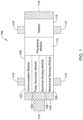
- FIG. 1depicts an illustrative leadless cardiac pacemaker (LCP) that may be implanted into a patient and may operate to prevent, control, or terminate cardiac arrhythmias in patients by, for example, appropriately employing one or more therapies (e.g. anti-tachycardia pacing (ATP) therapy, cardiac resynchronization therapy (CRT), bradycardia therapy, defibrillation pulses, or the like).
- the LCP 100may be a compact device with all components housed within the LCP 100 or directly on the housing 120.
- the LCP 100may include a communication module 102, a pulse generator module 104, an electrical sensing module 106, a mechanical sensing module 108, a processing module 110, a battery 112, and electrodes 114.
- the LCP 100may include more or less modules, depending on the application.
- the pulse generator module 104may be electrically connected to the electrodes 114.
- the LCP 100may include one or more additional electrodes 114'.
- the pulse generator 104may also be electrically connected to the additional electrodes 114'.
- the pulse generator module 104may be configured to generate electrical stimulation signals.
- the pulse generator module 104may generate electrical stimulation signals by using energy stored in a battery 112 within the LCP 100 and deliver the generated electrical stimulation signals via the electrodes 114 and/or 114'.
- the pulse generator 104may include one or more capacitors, and the pulse generator 104 may charge the one or more capacitors by drawing energy from the battery 112.
- the pulse generator 104may then use the energy of the one or more capacitors to deliver the generated electrical stimulation signals via the electrodes 114 and/or 114'.
- the pulse generator 104 of the LCP 100may include switching circuitry to selectively connect one or more of the electrodes 114 and/or 114' to the pulse generator 104 in order to select which of the electrodes 114/114' (and/or other electrodes) the pulse generator 104 delivers the electrical stimulation therapy.
- the pulse generator module 104may generate electrical stimulation signals with particular features or in particular sequences in order to provide one or multiple of a number of different stimulation therapies.
- the LCP 100may not include a pulse generator 104 or may turn off the pulse generator 104. When so provided, the LCP 100 may be a diagnostic only device. In such examples, the LCP 100 may not deliver electrical stimulation therapy to a patient. Rather, the LCP 100 may collect data about cardiac electrical activity and/or physiological parameters of the patient and communicate such data and/or determinations to one or more other medical devices via the communication module 102.
- the LCP 100may include an electrical sensing module 106, and in some cases, a mechanical sensing module 108.
- the electrical sensing module 106may be configured to sense the cardiac electrical activity of the heart.
- the electrical sensing module 106may be connected to the electrodes 114/114', and the electrical sensing module 106 may be configured to receive cardiac electrical signals conducted through the electrodes 114/114'.
- the cardiac electrical signalsmay represent local information from the chamber in which the LCP 100 is implanted. For instance, if the LCP 100 is implanted within a ventricle of the heart, cardiac electrical signals sensed by the LCP 100 through the electrodes 114/114' may represent ventricular cardiac electrical signals.
- the electrodes 114/114'can be secured relative to the housing 120 but exposed to the tissue and/or blood surrounding the LCP 100.
- the electrodes 114may be generally disposed on either end of the LCP 100 and may be in electrical communication with one or more of the modules 102, 104, 106, 108, and 110.
- the electrodes 114/114'may be supported by the housing 120, although in some examples, the electrodes 114/114' may be connected to the housing 120 through short connecting wires such that the electrodes 114/114' are not directly secured relative to the housing 120.
- the processing module 110can be configured to control the operation of the LCP 100.
- the processing module 110may be configured to receive electrical signals from the electrical sensing module 106 and/or the mechanical sensing module 108. Based on the received signals, the processing module 110 may determine, for example, occurrences and, in some cases, types of arrhythmias. Based on any determined arrhythmias, the processing module 110 may control the pulse generator module 104 to generate electrical stimulation in accordance with one or more therapies to treat the determined arrhythmia(s).
- the processing module 110may further receive information from the communication module 102. In some examples, the processing module 110 may use such received information to help determine whether an arrhythmia is occurring, determine a type of arrhythmia, and/or to take particular action in response to the information.
- the processing module 110may additionally control the communication module 102 to send/receive information to/from other devices.
- the processing module 110may include a pre-programmed chip, such as a very-large-scale integration (VLSI) chip and/or an application specific integrated circuit (ASIC).
- the chipmay be pre-programmed with control logic in order to control the operation of the LCP 100.
- the processing module 110may use less power than other programmable circuits (e.g. general purpose programmable microprocessors) while still being able to maintain basic functionality, thereby potentially increasing the battery life of the LCP 100.
- the processing module 110may include a programmable microprocessor.
- Such a programmable microprocessormay allow a user to modify the control logic of the LCP 100 even after implantation, thereby allowing for greater flexibility of the LCP 100 than when using a pre-programmed ASIC.
- the processing module 110may further include a memory, and the processing module 110 may store information on and read information from the memory.
- the LCP 100may include a separate memory (not shown) that is in communication with the processing module 110, such that the processing module 110 may read and write information to and from the separate memory.
- the battery 112may provide power to the LCP 100 for its operations.
- the battery 112may be a non-rechargeable lithium-based battery.
- a non-rechargeable batterymay be made from other suitable materials, as desired.
- the LCP 100is an implantable device, access to the LCP 100 may be limited after implantation. Accordingly, it is desirable to have sufficient battery capacity to deliver therapy over a period of treatment such as days, weeks, months, years or even decades.
- the battery 112may a rechargeable battery, which may help increase the useable lifespan of the LCP 100.
- the battery 112may be some other type of power source, as desired.
- the LCP 100may include one or more anchors 116.
- the anchor 116may include any one of a number of fixation or anchoring mechanisms.
- the anchor 116may include one or more pins, staples, threads, screws, helix, tines, and/or the like.
- the anchor 116may include threads on its external surface that may run along at least a partial length of the anchor 116. The threads may provide friction between the cardiac tissue and the anchor to help fix the anchor 116 within the cardiac tissue.
- the anchor 116may include other structures such as barbs, spikes, or the like to facilitate engagement with the surrounding cardiac tissue.
- Figure 2depicts an example of another medical device (MD) 200, which may be used in conjunction with an LCP 100 ( Figure 1 ) in order to detect and/or treat cardiac arrhythmias and other heart conditions.
- the MD 200may include a communication module 202, a pulse generator module 204, an electrical sensing module 206, a mechanical sensing module 208, a processing module 210, and a battery 218. Each of these modules may be similar to the modules 102, 104, 106, 108, and 110 of the LCP 100. Additionally, the battery 218 may be similar to the battery 112 of the LCP 100.
- the MD 200may have a larger volume within the housing 220 than LCP 100. In such examples, the MD 200 may include a larger battery and/or a larger processing module 210 capable of handling more complex operations than the processing module 110 of the LCP 100.
- the MD 200may be another leadless device such as shown in Figure 1
- the MD 200may include leads such as leads 212.
- the leads 212may include electrical wires that conduct electrical signals between the electrodes 214 and one or more modules located within the housing 220. In some cases, the leads 212 may be connected to and extend away from the housing 220 of the MD 200. In some examples, the leads 212 are implanted on, within, or adjacent to a heart of a patient.
- the leads 212may contain one or more electrodes 214 positioned at various locations on the leads 212, and in some cases at various distances from the housing 220. Some of the leads 212 may only include a single electrode 214, while other leads 212 may include multiple electrodes 214.
- the electrodes 214are positioned on the leads 212 such that when the leads 212 are implanted within the patient, one or more of the electrodes 214 are positioned to perform a desired function.
- the one or more of the electrodes 214may be in contact with the patient's cardiac tissue.
- the one or more of the electrodes 214may be positioned substernally or subcutaneously but adjacent the patient's heart.
- the electrodes 214may conduct intrinsically generated electrical signals to the leads 212, e.g. signals representative of intrinsic cardiac electrical activity.
- the leads 212may, in turn, conduct the received electrical signals to one or more of the modules 202, 204, 206, and 208 of the MD 200.
- the MD 200may generate electrical stimulation signals, and the leads 212 may conduct the generated electrical stimulation signals to the electrodes 214.
- the electrodes 214may then conduct the electrical signals and delivery the signals to the patient's heart (either directly or indirectly).
- the MD 200may be an implantable medical device.
- the housing 220 of the MD 200may be implanted in, for example, a transthoracic region of the patient.
- the housing 220may generally include any of a number of known materials that are safe for implantation in a human body and may, when implanted, hermetically seal the various components of the MD 200 from fluids and tissues of the patient's body.
- the MD 200may be an implantable cardiac pacemaker (ICP).
- the MD 200may have one or more leads, for example leads 212, which are implanted on or within the patient's heart.
- the one or more leads 212may include one or more electrodes 214 that are in contact with cardiac tissue and/or blood of the patient's heart.
- the MD 200may be configured to sense intrinsically generated cardiac electrical signals and determine, for example, one or more cardiac arrhythmias based on analysis of the sensed signals.
- the MD 200may be configured to deliver CRT, ATP therapy, bradycardia therapy, and/or other therapy types via the leads 212 implanted within the heart or in concert with the LCP by commanding the LCP to pace.
- the MD 200may additionally be configured provide defibrillation therapy.
- the MD 200may be an implantable cardioverter-defibrillator (ICD).
- the MD 200may include one or more leads implanted within a patient's heart.
- the MD 200may also be configured to sense cardiac electrical signals, determine occurrences of tachyarrhythmias based on the sensed signals, and may be configured to deliver defibrillation therapy in response to determining an occurrence of a tachyarrhythmia.
- the MD 200may be a subcutaneous implantable cardioverter-defibrillator (S-ICD).
- S-ICDsubcutaneous implantable cardioverter-defibrillator
- one of the leads 212may be a subcutaneously implanted lead.
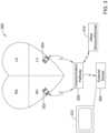
- Figure 3shows an example medical device system with a communication pathway through which multiple medical devices 302, 304, 306, and/or 310 may communicate.
- the medical device system 300may include LCPs 302 and 304, an external medical device 306, and other sensors/devices 310.
- the external device 306may be any of the devices described previously with respect to MD 200.
- the external device 306may be provided with or be in communication with a display 312.
- the display 312may be a personal computer, tablet computer, smart phone, laptop computer, or other display as desired.
- the display 312may include input means for receiving an input from a user.
- the display 312may also include a keyboard, mouse, actuatable (e.g.
- the other sensors/devices 310may be any of the devices described previously with respect to the MD 200.
- the other sensors/devices 310may include a sensor, such as an accelerometer or blood pressure sensor, or the like.
- the other sensors/devices 310may include an external programmer device that may be used to program one or more devices of the system 300.
- Various devices of the system 300may communicate via a communication pathway 308.
- the LCPs 302 and/or 304may sense intrinsic cardiac electrical signals and may communicate such signals to one or more other devices 302/304, 306, and 310 of the system 300 via the communication pathway 308.
- one or more of the devices 302/304may receive such signals and, based on the received signals, determine an occurrence of an arrhythmia.
- the device or devices 302/304may communicate such determinations to one or more other devices 306 and 310 of the system 300.
- one or more of the devices 302/304, 306, and 310 of the system 300may take action based on the communicated determination of an arrhythmia, such as by delivering a suitable electrical stimulation to the heart of the patient.
- the LCPs 302 and/or 304may sense indications of blood pressure (e.g. via one or more pressure sensors) and indications of volume (e.g. via an impedance between the electrodes of an LCP or between LCPs via an ultrasound transducer placed within the LCP, or via strain sensors placed on the heart in communication with the LCP).
- one or more of the devices 302/304may receive such signals and, based on the received signals, determine a pressure-volume loop, and in some cases may communicate such information to one or more other devices 302/304, 306, and 310 of the system 300 via the communication pathway 308.
- the LCPs 302/304may communicate with the external device 306 only through the other sensors/devices 310, where the LCPs 302/304 send signals to the other sensors/devices 310, and the other sensors/devices 310 relay the received signals to the external device 306.
- the communication pathway 308may include conducted communication.
- devices of the system 300may have components that allow for such conducted communication.
- the devices of the system 300may be configured to transmit conducted communication signals (e.g. current and/or voltage pulses) into the patient's body via one or more electrodes of a transmitting device, and may receive the conducted communication signals (e.g. pulses) via one or more electrodes of a receiving device.
- the patient's bodymay "conduct" the conducted communication signals (e.g. pulses) from the one or more electrodes of the transmitting device to the electrodes of the receiving device in the system 300.
- the delivered conducted communication signals(e.g. pulses) may differ from pacing or other therapy signals.
- the devices of the system 300may deliver electrical communication pulses at an amplitude/pulse width that is sub-threshold to the heart.
- the amplitude/pulse width of the delivered electrical communication pulsesmay be above the capture threshold of the heart, but may be delivered during a refractory period of the heart and/or may be incorporated in or modulated onto a pacing pulse, if desired.
- the communication pathway 308may include inductive communication, and when so provided, the devices of the system 300 may be configured to transmit/receive inductive communication signals.
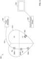
- FIGs 4 and 5show illustrative medical device systems that may be configured to operate according to techniques disclosed herein.
- an LCP 402is shown fixed to the interior of the left ventricle of the heart 410, and a pulse generator 406 is shown coupled to a lead 412 having one or more electrodes 408a, 408b, 408c.
- the pulse generator 406may be part of a subcutaneous implantable cardioverter-defibrillator (S-ICD), and the one or more electrodes 408a, 408b, 408c may be positioned subcutaneously adjacent the heart.
- S-ICDsubcutaneous implantable cardioverter-defibrillator
- the S-ICD leadmay extend subcutaneously from the S-ICD can, around the sternum and one or more electrodes 408a, 408b, 408c may be positioned adjacent the interior surface of the sternum.
- the LCP 402may communicate with the subcutaneous implantable cardioverter-defibrillator (S-ICD).
- the LCP 402may be in the right ventricle, right atrium or left atrium of the heart, as desired. In some cases, more than one LCP 402 may be implanted. For example, one LCP may be implanted in the right ventricle and another may be implanted in the right atrium. In another example, one LCP may be implanted in the right ventricle and another may be implanted in the left ventricle. In yet another example, one LCP may be implanted in each of the chambers of the heart.
- an LCP 502is shown fixed to the interior of the left ventricle of the heart 510, and a pulse generator 506 is shown coupled to a lead 512 having one or more electrodes 504a, 504b, 504c.
- the pulse generator 506may be part of an implantable cardiac pacemaker (ICP) and/or an implantable cardioverter-defibrillator (ICD), and the one or more electrodes 504a, 504b, 504c may be positioned in the heart 510.
- the LCP 502may communicate with the implantable cardiac pacemaker (ICP) and/or an implantable cardioverter-defibrillator (ICD).
- the medical device systems 400 and 500may also include an external support device, such as external support devices 420 and 520.
- the external support devices 420 and 520can be used to perform functions such as device identification, device programming and/or transfer of real-time and/or stored data between devices using one or more of the communication techniques described herein.
- communication between the external support device 420 and the pulse generator 406is performed via a wireless mode
- communication between the pulse generator 406 and the LCP 402is performed via a conducted mode.
- communication between the LCP 402 and the external support device 420is accomplished by sending communication information through the pulse generator 406.
- communication between the LCP 402 and the external support device 420may be via a communication module.
- the external support devices 420, 520may be provided with or be in communication with a display 422, 522.
- the display 422, 522may be a personal computer, tablet computer, smart phone, laptop computer, or other display as desired.
- the display 422, 522may include input means for receiving an input from a user.
- the display 422, 522may also include a keyboard, mouse, actuatable buttons, or be a touchscreen display. These are just examples.
- Figures 4-5illustrate two examples of medical device systems that may be configured to operate according to techniques disclosed herein.
- Other example medical device systemsmay include additional or different medical devices and/or configurations.
- other medical device systems that are suitable to operate according to techniques disclosed hereinmay include additional LCPs implanted within the heart.
- Another example medical device systemmay include a plurality of LCPs without other devices such as the pulse generator 406 or 506, with at least one LCP capable of delivering defibrillation therapy.
- the configuration or placement of the medical devices, leads, and/or electrodesmay be different from those depicted in Figures 4 and 5 .
- FIG 6is a side view of an illustrative implantable leadless cardiac pacemaker (LCP) 610.
- the LCP 610may be similar in form and function to the LCP 100 described above.
- the LCP 610may include any of the modules and/or structural features described herein.
- the LCP 610may include a shell or housing 612 having a proximal end 614 and a distal end 616.
- the illustrative LCP 610includes a first electrode 620 secured relative to the housing 612 and positioned adjacent to the distal end 616 of the housing 612 and a second electrode 622 secured relative to the housing 612 and positioned adjacent to the proximal end 614 of the housing 612.
- the housing 612may include a conductive material and may be insulated along a portion of its length. A section along the proximal end 614 may be free of insulation so as to define the second electrode 622.
- the electrodes 620, 622may be sensing and/or pacing electrodes to provide electro-therapy and/or sensing capabilities.
- the first electrode 620may be capable of being positioned against or may otherwise contact the cardiac tissue of the heart while the second electrode 622 may be spaced away from the first electrode 620.
- the first and/or second electrodes 620, 622may be exposed to the environment outside the housing 612 (e.g. to blood and/or tissue).
- the housing 612may take a variety of different shapes.
- the housing 612may have a generally cylindrical shape.
- the housing 612may have a half-dome shape.
- the housing 612may be a rectangular prism. It is contemplated that the housing may take any cross sectional shape desired, including but not limited to annular, polygonal, oblong, square, etc.
- the LCP 610may include a pulse generator (e.g., electrical circuitry) and a power source (e.g., a battery) within the housing 612 to provide electrical signals to the electrodes 620, 622 to control the pacing/sensing electrodes 620, 622. While not explicitly shown, the LCP 610 may also include a communications module, an electrical sensing module, a mechanical sensing module, and/or a processing module, and the associated circuitry, similar in form and function to the modules 102, 106, 108, 110 described above. The various modules and electrical circuitry may be disposed within the housing 612. Electrical communication between the pulse generator and the electrodes 620, 622 may provide electrical stimulation to heart tissue and/or sense a physiological condition.
- a pulse generatore.g., electrical circuitry
- a power sourcee.g., a battery
- the LCP 610includes a fixation mechanism 624 proximate the distal end 616 of the housing 612.
- the fixation mechanism 624is configured to attach the LCP 610 to a wall of the heart H, or otherwise anchor the LCP 610 to the anatomy of the patient.
- the fixation mechanism 624may include one or more, or a plurality of hooks or tines 626 anchored into the cardiac tissue of the heart H to attach the LCP 610 to a tissue wall.
- the fixation mechanism 624may include one or more, or a plurality of passive tines, configured to entangle with trabeculae within the chamber of the heart H and/or a helical fixation anchor configured to be screwed into a tissue wall to anchor the LCP 610 to the heart H.
- the LCP 610may further include a docking member 630 proximate the proximal end 614 of the housing 612.
- the docking member 630may be configured to facilitate delivery and/or retrieval of the LCP 610.
- the docking member 630may extend from the proximal end 614 of the housing 612 along a longitudinal axis of the housing 612.
- the docking member 630may include a head portion 632 and a neck portion 634 extending between the housing 612 and the head portion 632.
- the head portion 632may be an enlarged portion relative to the neck portion 634.
- the head portion 632may have a radial dimension from the longitudinal axis of the LCP 610 that is greater than a radial dimension of the neck portion 634 from the longitudinal axis of the LCP 610.
- the docking member 630may further include a tether retention structure (not explicitly shown) extending from or recessed within the head portion 632.
- the tether retention structuremay define an opening configured to receive a tether or other anchoring mechanism therethrough.
- the retention structuremay take any shape that provides an enclosed perimeter surrounding the opening such that a tether may be securably and releasably passed (e.g. looped) through the opening.
- the retention structuremay extend though the head portion 632, along the neck portion 634, and to or into the proximal end 614 of the housing 612.
- the docking member 630may be configured to facilitate delivery of the LCP 610 to the intracardiac site and/or retrieval of the LCP 610 from the intracardiac site. While this describes one example docking member 630, it is contemplated that the docking member 630, when provided, can have any suitable configuration.
- the pressure sensor(s) 640may measure/sense pressure in the chamber in which the LCP 610 is implanted. For example, an LCP 610 implanted in the left ventricle (LV) could sense LV pressure.
- the pressure sensor(s) 640may be configured (either alone or in combination with other circuitry in the LCP 610) to derive change in pressure over time and used to adjust atrium to ventricle pacing delay to optimize cardiac resynchronization therapy (CRT). In some cases, the pressure sensor(s) 640 may be configured to detect a-waves and change the pacing timing of the LCP 610 for CRT optimization.
- sensing pressurecould be used during the implant procedure to optimize the placement of the LCP 610 in the chamber (e.g., LV by sampling at different implant locations and using the best location. Frequent pressure monitoring may be beneficial for management of heart failure patients. Frequent pressure monitoring may also be useful for patients with chronic heart disease, hypertension, regurgitation, valve issues, atrial contraction detection, and to aid in addressing other problems. It is further contemplated that the pressure sensor(s) 640 may be used for monitoring respiration and associated diseases (e.g., chronic obstructive pulmonary disease (COPD), etc.). These are just examples.
- COPDchronic obstructive pulmonary disease
- pressure readingsmay be taken in combination with a cardiac chamber volume measurement such an impedance measurement (e.g. the impedance between electrodes 620 and 622) to generate a pressure-impedance loop for one or more cardiac cycles.
- the impedancemay be a surrogate for chamber volume, and thus the pressure-impedance loop may be representative of a pressure-volume loop for the heart H.
- Figure 7Ais a plan view of the example leadless cardiac pacing device 610 implanted within a left ventricle LV of the heart H during ventricular filling.
- the right ventricle RV, right atrium RA, left atrium LA, and aorta Aare also illustrated.
- Figure 7Bis a plan view of the leadless cardiac pacing device 610 implanted within a left ventricle of the heart H during ventricular contraction. These figures illustrate how the volume of the left ventricle may change over a cardiac cycle. As can be seen in Figures 7A and 7B , the volume of the left ventricle during ventricular filling is larger than the volume of the left ventricle of the heart during ventricular contraction.
- the processing module and/or other control circuitrymay capture, at a time point within each of one or more cardiac cycles, a pressure within the heart (e.g. left ventricle), resulting in one or more pressure data points. These one or more data points may be used, in combination with other pressure data points taken at different times during the one or more cardiac cycles, to generate a pressure curve. In some cases, one or more parameters may be extracted or derived from the pressure curve. The pressure curve may be used to facilitate cardiac resynchronization therapy (CRT), patient health status monitoring, and/or the management of a non-CRT cardiac therapy.
- CRTcardiac resynchronization therapy
- Figure 8is a graph 800 showing example pressures and volumes within a heart over time. More specifically, Figure 8 depicts the aortic pressure, left ventricular pressure, left atrial pressure, left ventricular volume, an electrocardiogram (ECG or egram), and heart sounds of the heart H.
- a cardiac cyclemay begin with diastole, and the mitral valve opens. The ventricular pressure falls below the atrial pressure, resulting in the ventricular filling with blood. During ventricular filling, the aortic pressure slowly decreases as shown. During systole, the ventricle contracts. When ventricular pressure exceeds the atrial pressure, the mitral valve closes, generating the S1 heart sound.
- an isovolumetric contraction phaseoccurs where the ventricle pressure rapidly increases but the ventricular volume does not significantly change.
- the aortic valveopens and the ejection phase begins where blood is ejected from the left ventricle into the aorta.
- the ejection phasecontinues until the ventricular pressure falls below the aortic pressure, at which point the aortic valve closes, generating the S2 heart sound.
- the isovolumetric relaxation phasebegins and ventricular pressure falls rapidly until it is exceeded by the atrial pressure, at which point the mitral valve opens and the cycle repeats.
- Cardiac pressure curves for the pulmonary artery, the right atrium, and the right ventricle, and the cardiac volume curve for the right ventricle, similar to those illustrated in Figure 8 for the left part of the heart,may be likewise generated.
- the cardiac pressure in the right ventricleis lower than the cardiac pressure in the left ventricle.
- the heart sound signalscan be recorded using acoustic sensors, (for example, a microphone), which capture the acoustic waves resulted from heart sounds.
- the heart sound signalscan be recorded using accelerometers or pressure sensors that capture the accelerations or pressure waves caused by heart sounds.
- the heart sound signalscan be recorded within or outside the heart. These are just examples.
- FIG. 9is a cross-section of another illustrative implantable leadless cardiac pacemaker (LCP) 900.
- the LCP 900may be similar in form and function to the LCPs 100, 610 described above.
- the LCP 900may include any of the modules and/or structural features described above with respect to the LCPs 100, 610.
- the LCP 900may include a shell or housing 902 having a proximal end 904 and a distal end 906.
- the LCP 900does not include a docking member.
- a docking membermay be provided, such as a cage extending proximally from adjacent the side walls of the housing 902.
- the illustrative LCP 900includes a first electrode 908 secured relative to the housing 902 and positioned adjacent to the distal end 906 of the housing 902, and a second electrode (not explicitly shown) secured relative to the housing 902 and positioned adjacent to the proximal end 904 of the housing 902.
- the first electrode 908may be positioned on a distal end surface facing distally.
- the housing 902may include a conductive material and may be insulated along a portion of its length. A section along the proximal end 904 may be free of insulation so as to define the second electrode.
- the electrodes 908may be sensing and/or pacing electrodes to aid in providing electro-therapy and/or sensing capabilities.
- the first electrode 908may be capable of being positioned against or may otherwise contact the cardiac tissue of the heart while the second electrode may be spaced away from the first electrode 908.
- the first and/or second electrodes 908may be exposed to the environment outside the housing 902 (e.g. to blood and/or tissue).
- the LCP 900may include a pulse generator (e.g., electrical circuitry) 910 and a power source (e.g., a battery) 912 within the housing 902 to provide and/or receive electrical signals via the first and second electrodes. While not explicitly shown, the LCP 900 may also include a communications module, an electrical sensing module, a mechanical sensing module, and/or a processing module, and associated circuitry, similar in form and function to the modules 102, 106, 108, 110 described above. The various modules and electrical circuitry may be disposed within the housing 902. Electrical communication between the pulse generator and the electrodes may provide electrical stimulation to heart tissue and/or sense a physiological condition.
- a pulse generatore.g., electrical circuitry
- a power sourcee.g., a battery
- the LCP 900may also include a communications module, an electrical sensing module, a mechanical sensing module, and/or a processing module, and associated circuitry, similar in form and function to the modules 102, 106,
- the LCP 900further includes a fixation mechanism 914 proximate the distal end 906 of the housing 902.
- the fixation mechanism 914is configured to attach the LCP 900 to a wall of the heart H, or otherwise anchor the LCP 900 to the anatomy of the patient.
- the fixation mechanism 914may include one or more, or a plurality of hooks or tines 916 anchored into the cardiac tissue of the heart H to attach the LCP 900 to a tissue wall.
- the housing 902may include a proximal end surface 918 facing proximally (e.g., in a generally opposite direction from the distal end surface.
- the proximal end surface 918 of the housing 902may form a diaphragm 920.
- the diaphragm 920may be formed from the housing material itself. When so provided, the wall thickness of the housing in the region of the diaphragm 920 may be thinned to increase the flexibility of the diaphragm 920.
- the diaphragm 920may be formed from another material, such as but not limited to silicone, polyimides, etc. to form a deformable or movable diaphragm 920 that is responsive to a pressure applied to the diaphragm 920.
- the diaphragm 920may be fabricated to flex or deform as the pressure (external to the housing 902) in the heart (e.g., left ventricle) changes, as will be described in more detail herein. While the entire proximal end surface 918 may form the diaphragm 920, it is contemplated that only a portion of the end surface 918 may form the diaphragm 920.
- the diaphragm 920may be 1 millimeter in diameter or less. In other cases, the diaphragm 920 may be greater than 1 millimeter in diameter. In some cases, the diaphragm 920 may have a round shape. In other cases, the diaphragm 920 may have a square, rectangular or any other suitable shape. In the example shown, the diaphragm 920 may be configured to transfer an endocardial pressure external to the housing 902 to a pressure sensor 922 positioned within the housing 902.
- the diaphragm 920need not be placed on the proximal end surface 918 of the housing 902. It is contemplated that the diaphragm 920 may be formed in any surface of the housing 902 (or docking member, if so provided) desired. In some cases, locating the diaphragm 920 on or adjacent to the proximal end 904 of the housing 902 may orientate the diaphragm towards the heart valves (when the LCP 900 is positioned in the apex of the heart) and in-line with maximum pressure changes, which may achieve higher signal levels.
- the diaphragm 920may also locate the diaphragm 920 away from the heart tissue, may reduce the likelihood that diaphragm 920 will become fibrossed-over.
- the diaphragm 920may be coated with an anti-thrombogenic coating to help prevent tissue growth.
- a pressure sensor 922is positioned adjacent to, but not necessarily in direct contact with, the diaphragm 920.
- a fluid filled cavity 926 filled with a fluid 928may be positioned between the diaphragm 920 of the housing and the pressure sensor 922.
- the pressure sensor 922may include a diaphragm 934, as best shown in Figure 11 , which is exposed to the fluid filled cavity 926.
- the fluid filled cavity 926may communicate a measure related to the pressure applied by the environment (e.g. endocardial pressures) to the diaphragm 920 of the housing 902 to the pressure sensor diaphragm 934 of the pressure sensor 922.
- the fluid filled cavity 926may be confined to a portion of the volume of the housing, such as between the flexible diaphragm 920 of the housing and the diaphragm 934 of the pressure sensor 922.
- An O-ring 923 or other sealmay be used to confine the fluid 928.
- the fluid filled cavity 926may encompass the entire volume of the housing 902 (e.g., the volume not filled by other components).
- the fluid filled cavity 926may be filled with an incompressible fluid 928.
- the fluid 928may also be dielectric or non-conductive.
- Some illustrative fluids 928may include, but are not limited to, mineral oil, fluorocarbons perfluorohexane, perfluoro (2-butyl-tetrahydrofurane), perfluorotripentylamine, and/or Fluorinert TM (manufactured by the 3M Company, St. Paul, MN).
- the fluid 928may be highly soluble to gases that are likely to arise inside of the housing, particularly at body temperature (e.g. 37°C).
- the fluid 928may be highly soluble to hydrogen, helium, nitrogen, argon, water, and/or other gases or liquids that might arise inside of the housing as a result of, for example, outgassing of internal components of the LCP 900.
- a pressure or external force 930is applied to the outer surface of the diaphragm 920.
- the diaphragm 920may flex inwards and the fluid 928 may transfer the force to the pressure sensor 922, as shown at arrow 932.
- the pressure sensor 922may provide a pressure sensor signal that is representative of the pressure or external force 930.
- the fluid 928(and/or the diaphragm 920) may be selected to match the acoustic impedance of blood. This may facilitate the use of the pressure sensor 922 as an acoustic pressure sensor.
- the pressure sensor 922may be used to detect various sounds such as heart sounds, valve regurgitation, respiration, blood flow, blood turbulence and/or other suitable sounds. In some cases, sounds having a frequency of up to 200 Hz or more may be detected.
- the pressure sensor 922may be a Micro-Electro-Mechanical System (MEMS) pressure sensor, such as shown in Figure 11.
- Figure 11illustrates a cross-sectional view of an illustrated MEMS pressure sensor.
- MEMS pressure sensorsare often formed by anisotropically etching a recess into a back side of a silicon substrate, leaving a thin flexible diaphragm 934.
- a sealed cavity 946is created behind the diaphragm 934.
- the sealed cavity 946may be evacuated to a very low pressure, near zero.
- the front side of the diaphragm 934is exposed to an input pressure, such as from the fluid 928, and may flex or deform by an amount that is related to the difference between the input pressure and the vacuum pressure in the sealed cavity 946.
- the diaphragm 934 of the pressure sensor 922may include one or more sense elements 936, which may detect the flexing of the diaphragm 934.
- the sensor elementsmay include piezoresistors, the change resistance with increased stress in the diaphragm 934.
- the piezoresistorsmay be connected to a circuit, such as a Wheatstone bridge circuit, that outputs a signal that is related to the amount of stress sensed in the diaphragm 934, which is ultimately related to the amount of pressure applied to the outer surface of the diaphragm 920 of the housing.
- the stressmay be one or more of compression or stretching of the diaphragm 920.
- the diaphragm 934 of the pressure sensor 922 and/or the diaphragm 920 of the housingmay be made thinner and/or may include one or more support bosses to help increase the sensitivity and/or linearity of the flexure of the diaphragm.
- circuitry 938may be fabricated in to the first substrate 940, and may be connected to the sensor elements 936.
- the circuitry 938may be configured to provide some level of signal processing before providing an output signal to bond pads 948 of the pressure sensor 922.
- the signal processing circuitrymay filter, amplify, linearize, calibrate and/or otherwise process the raw sensor signal produced by the sensor elements (e.g. piezoresistors 936). While the sense elements 936 have been described as piezoresistors, it is contemplated that the sensor elements 936 may be configured to provide a capacitive output value.
- the back side of the diaphragm 934may support a first plate of a capacitor sensor, and the top side of the second substrate may support a second plate. As the diaphragm 934 flexes toward the second substrate, the distance between the first plate and the second plate changes. This changes the capacitance between the first plate and the second plate. This change in capacitance can be sensed by circuitry 938.
- the bond pads 948may be electrically coupled to the circuitry 910 in the housing 902 of the LCP 900 through one or more electrical conductors 924 to relay one or more output signals of the pressure sensor 922 to the circuitry 910.
- the circuitry 910may be configured to determine a pressure exterior to the housing 902 based on the pressure sensor 922 output signal(s).
- pressure sensor 922has been described as a MEMS pressure sensor, it is contemplated that pressure sensor 922 may take any suitable form.
- the pressure sensormay be formed in such a way that radio waves can be used to detect changes in pressure without sensor elements incorporated into the device.
- a pressure sensormay include a flexible base substrate, a bottom inductive coil positioned on the base substrate, a layer of pressure sensitive rubber pyramids positioned over the bottom inductive coil, a top inductive coil positioned on top of the rubber pyramids, and a top substrate positioned over the top inductive coil. As a pressure is exerted on the sensor, the inductive coils move closer together.
- Radio waves (from an applied source) reflected by the inductive coilshave a lower resonance frequency when the coils are positioned closer together.
- the frequency of the radio wavescan indicate the distance between the coils, which may then be correlated to the pressure exerted on the device.
- the pressure sensor 922may be configured to measure absolute pressure, rather than gauge pressure.
- a communication linkmay be used to determine atmospheric pressure such that the pressure readings provided to the physician are in terms of gauge pressure. Atmospheric pressure may be measured outside of the patient's body using an external device. The external device may be in communication with the LCP 900 through any of the wireless means described herein.
- An absolute pressure sensor 922may provide higher accuracy with lower drift. In some cases, the absolute pressure readings may be transmitted to an external device and converted to gauge pressure at the external device where it can be viewed by a physician and/or transmitted to another external device viewable by the physician.
- the diaphragm 920 of the housing 902may have a first surface area and the pressure sensor diaphragm 934 may have a second surface area.
- the ratio of the first surface area to the second surface areamay be at least 5 to 1, greater than 10 to 1, greater than 20 to one, or more.
- the pressure sensor 922may be configured to obtain pressure measurements in the range of 0 to 240 mmHg (gauge) with an accuracy of 1 mmHg and a resolution of less than 1 mmHg. It is contemplated that in some instances, the pressure sensor 922 may be configured to obtain pressure measurements greater than 240 mmHg (for example, when the patient is under extreme exertion).
- the pressure sensor 922may be configured to obtain pressure measurements at a sample rate of greater than 100 Hertz (Hz). This may allow for pressure measurements to be used to determine characteristics of the cardiac cycle including, but not limited to, dP/dT, dicrotic notch, etc.
- one or more sensor elementsmay be placed directly on the inner surface of the diaphragm 920 of the housing 902 and/or on the housing 902 itself. The sensor elements may then detect the stress in the diaphragm 920 of the housing 902 and/or the housing 902. The sensor elements may be operatively coupled to circuitry (e.g. control electronics 910) through one or more electrical conductors 924. This embodiment may eliminate the need for the fluid filled cavity 926, the fluid 928, the diaphragm 934 of the pressure sensor 922, etc.
- circuitrye.g. control electronics 910
- the battery 912is shown adjacent the pressure sensor 922.
- the processing module (e.g., circuitry or control electronics) 910may be positioned in a distal portion 906 of the housing 902 adjacent to the distal electrode 908.
- the one or more electrical conductors 924may be formed of a polyimide or similar interconnect having a cross-sectional dimension in the range of less than 250 microns.
- the inside surface of the housing 902may be electrically insulated and the electrical conductors 924 (e.g., trace) may be positioned on the inside surface of the housing 902 or along the outer surface of the battery 912, as desired.
- the electrical conductors 924e.g., trace
- wires or a ribbon cablemay be used. These are just examples.
- the pressure sensor 922may be configured to obtain pressure measurements at predetermined intervals over one or more cardiac cycles. In other instances, the pressure sensor may be configured to obtain a pressure measurement in response to a specific cardiac event or at a specific time in a cardiac cycle.
- the circuitry 910may be configured to use one or more cardiac signals sensed by the first electrode 908 and/or second electrode to determine when the patient's heart is in a first phase of a cardiac cycle. The circuitry 910 may be configured to determine a pressure exterior to the housing 902 based at least in part on the pressure sensor output signal from the pressure sensor 922 taken during the first phase of the cardiac cycle. In some cases, the first phase may be systole and in other cases the first phase may be diastole.
- the circuitry 910may be configured to determine a pressure exterior to the housing 902 based at least in part on the pressure sensor output signal from the pressure sensor 922 taken during the first phase of the cardiac cycle. It is contemplated that the circuitry 910 may be further configured to detect heart sounds of the patient's heart based at least in part on the pressure sensor output signal.
- the first heart soundmay be a timing fiducial for a sudden increase in pressure while the second heart sound may be a timing fiducial for a sudden decrease in pressure.
- the circuitry 910 and/or pressure sensor 922 of the LCP 900may be configured to obtain a plurality of pressure readings over one or more cardiac cycles.
- the pressure readingsmay be plotted (either by the circuitry 910 or an external device) to form a graph similar to the one shown in Figure 8 .
- Various parameters related to the function of the heartcan be extrapolated from the graph including but not limited to peak to peak measurements, dP/dT, time averaged values, inotropic response of the ventricle, etc.
- the pressure measurementsmay be compared to calibration values (e.g., measurements taken at the time of implantation of the LCP 900).
- a diaphragm 920 having a different materialmay not be provided.
- the diaphragm 920may be formed of the same material and of the same thickness as the remaining portion of the housing 902.
- the housing 902may flex or deform to transfer a pressure external to the housing 902 to the pressure sensor 922 located within the housing 612.
- the housing 902may have a compliance such that the relative movement of the housing 902 in response to the external pressure may be coupled to the internal pressure sensor 922.
- the internal pressure sensor 922may be calibrated relative to external pressures prior to implantation of the LCP 902 in a patient.
- the calibration datamay be stored in the memory and/or electrical circuitry of the LCP 900.
- a measure related to the pressure applied by the environmente.g. endocardial pressures
- a measure related to the pressure applied by the environmente.g. endocardial pressures
- a pressure sensing diaphragm 934 of the pressure sensor 922may be communicated to a pressure sensing diaphragm 934 of the pressure sensor 922.
- there may be some pressure losse.g., in the range of 1-20%) between the pressure exerted on the housing 902 and the pressure reading obtained at the pressure sensor 922.
- This pressure lossmay be compensated for (e.g., nullified) by adjusting the pressure sensor signal from the pressure sensor 922 using the calibration data stored in the LCP 900.
- an incompressible fluidmay couple the housing 902 and the pressure sensing diaphragm 934 of the pressure sensor 922 in a manner similar to that described herein.
- the entire housing 902 or a portion of the housing 902may be coupled to the pressure sensor 922 by the incompressible fluid.
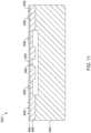
- Figure 12illustrates a proximal end portion 954 of another illustrative LCP 950 having a diaphragm 960 and a pressure sensor 962.
- the LCP 950may be similar in form and function to the LCPs 100, 610, 900 described above.
- the LCP 950may include any of the modules and/or structural features described above with respect to the LCPs 100, 610, 900.
- the diaphragm 960, pressure sensor 962 and internal circuitrymay interact in a similar manner to the diaphragm 920, pressure sensor 922 and circuitry 910 described above.
- the LCP 950may include a shell or housing 952 having a proximal end portion 954 and a distal end (not explicitly shown).
- the housing 952may include a proximal end surface 956 facing proximally (e.g., in a generally opposite direction from the distal end surface.
- the proximal end surface 956 of the housing 952may include a region of localized thinning 958.
- the housing 952may have a first wall thickness T1 and the region of localized thinning 958 may have a second wall thickness T2.
- the second wall thickness T2may be less than the first wall thickness T1.
- the region of localized thinning 958may have a thickness T2 in the range of 30 microns.
- the region of localized thinning 958may have a thickness such that the region 958 may be deformable or movable to create a diaphragm 960 that is responsive to a pressure applied to the proximal end surface 956. This may allow the diaphragm 960 to flex or deform as the pressure (external to the housing 952) in the heart (e.g., left ventricle) changes, as will be described in more detail herein.
- the region of localized thinning 958may be created by removing material from the housing 952 from an interior of the housing 952, which may reduce nucleation points for thrombus formation.
- the region of localized thinning 958may transition from the first wall thickness T1 to the second wall thickness T2 in a tapered, sloped, or curved (e.g., exponential) manner.
- the region of localized thinning 158may not have a uniform thickness across its width.
- a sloped transition between the first wall thickness T1 and the second wall thickness T2may help reduce stress concentration and/or non-linearity in the proximal end surface 956.
- the region of localized thinning 958may transition from the first wall thickness T1 to the second wall thickness T2 in an abrupt or step-wise manner. In other words, the region of localized thinning 158 may have a uniform thickness across its width (not explicitly shown).
- the region of localized thinning 958may function as a diaphragm 960 formed by the housing 952. In some cases, the diaphragm 960 may be as small as approximately 1 millimeter in diameter. The diaphragm 960 diameter and thickness may be configured so that the diaphragm 960 is able to suitable transfer a pressure external to the housing 952 (e.g.
- the fluid filled cavity 970may encompass the entire volume of the housing 952 (e.g., the volume not filled by other components) distal of the diaphragm 960.
- Figure 13illustrates a cross-sectional view of a proximal end portion 1004 of another illustrative LCP 1000 having a diaphragm 1006 and a force sensor 1010.
- the LCP 1000may be similar in form and function to the LCPs 100, 610, 900 described above.
- the LCP 1000may include any of the modules and/or structural features described above with respect to the LCPs 100, 610, 900.
- the diaphragm 1006, a force sensor 1010 and internal circuitrymay interact in a similar manner to the diaphragm 920, pressure sensor 922 and circuitry 910 described above.
- the LCP 1000may include a shell or housing 1002 having a proximal end portion 1004 and a distal end (not explicitly shown).
- the housing 1002may include a proximal end surface 1006 facing proximally (e.g., in a generally opposite direction from the distal end surface.
- the proximal end surface 1006may include a pair of generally opposing sidewalls 1014a, 1014b (collectively, 1014) extending distally therefrom.
- the sidewalls 1014may include a crumple-zone 1008a, 1008b (collectively, 1008) formed therein.
- the crumple-zones 1008may have an accordion or bellow-like structure including a plurality of peaks 1022a, 1022b (collectively, 1022) and valleys 1024a, 1024b (collectively, 1024) which allows the crumple-zones 1008 to compress in the distal direction 1016 or elongate in the proximal direction 1018. This may allow the internal volume of the housing 1002 to change as an exteriorly applied pressure 1 020 is applied to the housing 1002. While the peaks 1022 and valleys 1024 are illustrated as having sharp or abrupt edges, the peaks 1022 and valleys 1024 may have gentle slopes or curves as desired.
- a strut 1021may extend from the proximal end surface 1006 to the force sensor 1010.
- the force sensor 1010may sense the force that is applied by the strut 1021.
- the strut 1021may transfer the force that is applied to the proximal end surface 1006 of the housing by an external pressure (e.g. endocardial pressure).
- the force applied to the proximal end surface 1006 of the housing by an external pressureis amplified by the ratio of the surface area of the proximal end surface 1006 to the surface area of the strut that abuts the force sensor 1010.
- Figure 14illustrates a cross-sectional view of a proximal end portion 1054 of another illustrative LCP 1050 having a diaphragm 1058 and a pressure sensor 1060.
- the LCP 1050may be similar in form and function to the LCPs 100, 610, 900 described above.
- the LCP 1050may include any of the modules and/or structural features described above with respect to the LCPs 100, 610, 900.
- the diaphragm 1058, pressure sensor 1060 and internal circuitrymay interact in a similar manner to the diaphragm 920, pressure sensor 922 and circuitry 910 described above.
- An access port 1068may extend through the head portion 1062 and the neck portion 1064 to fluidly couple the diaphragm 1058 with the blood in the heart.
- the diaphragm 1058may be constructed using any of the materials and/or configurations described herein. Alternatively, the diaphragm 1058 may be positioned at the proximal opening 1070 of the access port 1068.
- a pressure sensor 1060may be positioned adjacent to, but not necessarily in direct contact with the diaphragm 1058.
- the pressure sensor 1060may be operatively coupled to circuitry or control electronics (not explicitly shown) of the LCP 1050 through one or more electrical connections 1072.
- Figure 14illustrates the battery 1078 adjacent to the pressure sensor 1060.
- the one or more electrical connections 1072may be formed of a polyimide or similar interconnect having a cross-sectional dimension in the range of less than 250 microns.
- the inside surface of the housing 1052may be electrically insulated and the electrical connection 1072 (e.g., trace) positioned on the inside surface of the housing 1052 or along the outer surface of the battery 1078, as desired.
- the electrical connection 1072e.g., trace
- wires or a ribbon cablemay be used. These are just examples.
- the pressure sensor 1060may be positioned in or adjacent to a cavity 1074 filled with a fluid 1076.
- the fluid filled cavity 1074is in fluid communication with the diaphragm 1058 and the pressure sensor 1060, such that the fluid filled cavity 1074 may communicate a measure related to the pressure applied by the environment to the diaphragm 1058 to a pressure sensor diaphragm of the pressure sensor 1060.
- the fluid filled cavity 1074may be confined to a portion of the volume of the housing 1052, such as between the flexible diaphragm 1058 and a sensor diaphragm (not shown) of the pressure sensor 1060.
- An O-ring 1073 or other sealmay be used to confine the fluid 1076.
- the fluid filled cavity 1074may encompass the entire volume of the housing 1052 (e.g., the volume not filled by other components) distal of the diaphragm 1058.
- the diaphragm 1058is located distal of the docking member 1056.
- An access port 1068is provided through the docking member 1056 so allow endocardial pressure 1080 to engage the diaphragm 1058.
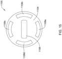
- a plurality of access ports 1108a-1108dmay be provided to the diaphragm 1058, such as shown in Figure 15.
- Figure 15illustrates a proximal end view of another illustrative LCP 1100 having a diaphragm and an internally positioned pressure sensor (not explicitly shown).
- the LCP 1100may be similar in form and function to the LCP 1050 described above.
- the LCP 1100may include any of the modules and/or structural features described above with respect to the LCPs 100, 610, 900, 1050.
- a diaphragm, pressure sensor and internal circuitrymay interact in a similar manner to the diaphragm 1058, pressure sensor 1060 and circuitry of Figure 14 .
- the LCP 1100may include a shell or housing having a proximal end region 1104 and a distal end (not explicitly shown).
- the housing 1102may include a docking member 1106 extending proximally from the proximal end region 1104.
- the docking member 1106may be configured to facilitate delivery and/or retrieval of the LCP 1100.
- the docking member 1106may extend from the proximal end region 1104 of the housing 1102 along a longitudinal axis of the housing 1102.
- One or more access ports 1108a, 1108b, 1108c, 1108dmay be formed through the docking member 1106 and/or through the proximal end region 1104 of the housing 1102. It is contemplated that the access ports 1108 may allow endocardial pressure 1080 to engage the diaphragm inside of the housing, similar to that shown and described with respect to Figure 14 .
- FIG 16is a side view of another illustrative implantable leadless cardiac pacemaker (LCP) 1150.
- the LCP 1150may be similar in form and function to the LCPs 100, 610, 900 described above.
- the LCP 1150may include any of the modules and/or structural features described above with respect to the LCPs 100, 610, 900.
- the LCP 1150may include a shell or housing 1152 having a proximal end 1154 and a distal end 1156. In the example shown, the LCP 1150 does not include a docking member. However, in some cases, a docking member may be provided at the proximal end 1154 of the LCP 1150.
- the illustrative LCP 1150includes a first electrode 1158 secured relative to the housing 1152 and positioned adjacent to the distal end 1156 of the housing 1152, and a second electrode 1160 secured relative to the housing 1152 and positioned adjacent to the proximal end 11 54 of the housing 1152.
- the first electrode 1158may be positioned on a distal end surface facing distally.
- the housing 1152may include a conductive material and may be insulated along a portion of its length. A section along the proximal end 1154 may be free of insulation so as to define the second electrode.
- the electrodes 1158, 1160may be sensing and/or pacing electrodes to provide electro-therapy and/or sensing capabilities.
- the first electrode 1158may be capable of being positioned against or may otherwise contact the cardiac tissue of the heart while the second electrode may be spaced away from the first electrode 1158.
- the first and/or second electrodes 1158, 1160may be exposed to the environment outside the housing 1152 (e.g. to blood and/or tissue).
- the LCP 1150may include a pulse generator (e.g., electrical circuitry) and a power source (e.g., a battery) within the housing 1152 to provide electrical signals to the electrodes 1158, 1160 to control the pacing/sensing electrodes 1158, 1160. While not explicitly shown, the LCP 1150 may also include a communications module, an electrical sensing module, a mechanical sensing module, and/or a processing module, and the associated circuitry, similar in form and function to the modules 102, 106, 108, 110 described above. The various modules and electrical circuitry may be disposed within the housing 1152.
- a pulse generatore.g., electrical circuitry
- a power sourcee.g., a battery
- the LCP 1150may also include a communications module, an electrical sensing module, a mechanical sensing module, and/or a processing module, and the associated circuitry, similar in form and function to the modules 102, 106, 108, 110 described above.
- the LCP 1150includes a fixation mechanism 1162 proximate the distal end 1156 of the housing 1152.
- the fixation mechanism 1162is configured to attach the LCP 1150 to a wall of the heart, or otherwise anchor the LCP 1150 to the anatomy of the patient.
- the fixation mechanism 1162may include one or more, or a plurality of hooks or tines 1164 anchored into the cardiac tissue of the heart to attach the LCP 1150 to a tissue wall.
- the fixation mechanism 1162may include one or more, or a plurality of passive tines, configured to entangle with trabeculae within the chamber of the heart and/or a helical fixation anchor configured to be screwed into a tissue wall to anchor the LCP 1150 to the heart.
- the housing 1152may include a plurality of pressure sensitive regions or diaphragms 1166a, 1166b (collectively, 1166). While the example shown in Figure 16 illustrates two diaphragms 1166, the LCP 1150 may include any number of diaphragms 1166 desired such as, but not limited to, one, two, three, four, or more. It is further contemplated that the diaphragms 1166 may be uniformly or eccentrically positioned about the circumference of the housing 1152. In some cases, the diaphragms 1166 may be spaced equally about the entire circumference of the housing 1152, while in other cases, the diaphragms 1166 may be positioned about a portion of the circumference of the housing 1152.
- the diaphragms 1166may be formed from a flexible or compliant material, such as, but not limited to silicone, polyimides, etc. to form a deformable or movable diaphragm 1166 that is responsive to a pressure applied to the diaphragm 1166.
- the diaphragms 1166may be formed from a thinned wall of the housing itself. In either case, this may allow the diaphragms 1166 to flex or deform as the pressure (external to the housing 1152) in the heart (e.g., left ventricle) changes, as will be described in more detail herein.
- the diaphragms 1166may be a combination of flexible materials and/or regions of localized thinning, and/or any other suitable configuration. While the diaphragms 1166 are illustrated as positioned adjacent to the proximal end 1154, it is contemplated that the diaphragms 1166 may be positioned anywhere along the length of the LCP 1150 as desired.
- locating the diaphragms 1166 on or adjacent to the proximal end 11511 of the housing 1152may orientate the diaphragm towards the heart valves (when the LCP 1150 is positioned in the apex of the heart), which may achieve higher levels of sensitivity. Locating the diaphragm 1166 further away from the heart tissue may also reduce the likelihood of the diaphragm becoming fibrossed-over. However, the diaphragm 1166 may be coated with an anti-thrombogenic coating to help reduce such tissue growth.
- One or more pressure sensorsmay be positioned adjacent to, but not necessarily in direct contact with, the diaphragms 1166.
- piezoresistorsmay be placed directly on the inner surface of the diaphragms 1166.
- the pressure sensormay be operatively coupled to the circuitry or control electronics of the LCP 1050 through one or more electrical connections.
- the one or more electrical connectionsmay be formed of a polyimide or similar interconnect having a cross-sectional dimension in the range of less than 250 microns. It is contemplated that the inside surface of the housing 1152 may be electrically insulated and the electrical connection (e.g., trace) positioned on the inside surface of the housing 1152 or along the outer surface of the battery, as desired. Alternatively, wires or a ribbon cable may be used. These are just examples.
- the one or more pressure sensorsmay be positioned in or adjacent to one or more cavities filled with a fluid.
- the one or more fluid filled cavitiesmay be in fluid communication with the diaphragms 1166 and the one or more pressure sensors such that the one or more fluid filled cavities may communicate a measure related to the pressure applied by the environment to the diaphragms 1166 of the housing 1152 to a pressure sensor diaphragm of a corresponding pressure sensor.
- a fluid filled cavitymay encompass the entire volume of the housing 1152 (e.g., the volume not filled with other components).
- the one or more fluid filled cavitiesmay be a portion of the volume of the housing between the flexible diaphragms 1166 and the pressure sensor.
- each of the diaphragms 1166has a corresponding pressure sensor, such that a separate pressure signal can be derived for each of the diaphragms 1166.
- pressures at different locations of the housingmay be detected.
- these different pressurescan be used to detect a variety of different conditions including, for example, blood flow around the housing, pressure waves as they pass over the housing, relative direction of a detected heart sound using the relative locations of the diaphragms 1166 and the delay between detection times. These are just examples.
- FIG 17Ais a partial cross-sectional view of another illustrative implantable leadless cardiac pacemaker (LCP) 1200.
- the LCP 1200may be similar in form and function to the LCPs 100, 610, 900 described above.
- the LCP 1200may include any of the modules and/or structural features described above with respect to the LCPs 100, 610, 900.
- the LCP 1200may include a shell or housing 1202 having a proximal end region 1204 and a distal end 1206.
- the housing 1202may include a docking member 1210 extending proximally from the proximal end region 1204.
- the docking member 1210may be configured to facilitate delivery and/or retrieval of the LCP 1200.
- the docking member 1210may extend from the proximal end region 1204 of the housing 1202 along a longitudinal axis of the housing 1202.
- the illustrative LCP 1200includes a first electrode 1208 secured relative to the housing 1202 and positioned adjacent to the distal end 1206 of the housing 1202, and a second electrode (not explicitly shown) secured relative to the housing 1202 and positioned adjacent to the proximal end region 1204 of the housing 1202.
- the first electrode 1208may be positioned on a distal end surface facing distally.
- the housing 1202may include a conductive material and may be insulated along a portion of its length. A section along the proximal end region 1204 may be free of insulation so as to define the second electrode.
- the electrodes 1208may be sensing and/or pacing electrodes to provide electro-therapy and/or sensing capabilities.
- the first electrode 1208may be capable of being positioned against or may otherwise contact the cardiac tissue of the heart while the second electrode may be spaced away from the first electrode 1208.
- the first and/or second electrodes 1208may be exposed to the environment outside the housing 1202 (e.g. to blood and/or tissue).
- the LCP 1200may include a pulse generator 1218 (e.g., electrical circuitry) and a power source 1220 (e.g., a battery) within the housing 1202 to provide electrical signals to the electrodes 1208 to control the pacing/sensing electrodes 1208.
- the LCP 1200may also include a communications module 1222, an electrical sensing module 1224, a mechanical sensing module 1226, and/or a processing module 1228, and the associated circuitry, similar in form and function to the modules 102, 106, 108, 110 described above.
- the various modules and electrical circuitrymay be disposed within the housing 1202.
- the modules 1218, 1222, 1224, 1226, 1228may be positioned on a flexible board (e.g., a flexible polyimide) 1232, which allows for electrical communication between the various modules.
- a flexible boarde.g., a flexible polyimide
- the flexible board 1232may be folded over to allow for different size components and/or more components to be present.
- the battery 1220may have a generally "D" shaped cross-section. This is better illustrated in Figure 17B which illustrates a cross-section of the LCP 1200 taken at line B-B of Figure 17A .
- the LCP 1200includes a fixation mechanism 1212 proximate the distal end 1206 of the housing 1202.
- the fixation mechanism 1212is configured to attach the LCP 1200 to a wall of the heart H, or otherwise anchor the LCP 1200 to the anatomy of the patient.
- the fixation mechanism 1212may include one or more, or a plurality of hooks or tines 1214 anchored into the cardiac tissue of the heart to attach the LCP 1200 to a tissue wall.
- the fixation mechanism 1212may include one or more, or a plurality of passive tines, configured to entangle with trabeculae within the chamber of the heart and/or a helical fixation anchor configured to be screwed into a tissue wall to anchor the LCP 1200 to the heart.
- the housing 1202may include one or more pressure sensitive regions or diaphragms (not explicitly shown).
- the diaphragmmay be positioned in the proximal end surface 1234 of the housing 1202, in the docking member 1210, and/or in the side wall of the housing 1202 as desired. In some cases, all or a majority of the housing may function as a diaphragm. When so provided, the housing may have a wall thickness that will flex under endocardial pressures. In some cases, the entire housing may be filled with an incompressible and non-conductive fluid.
- a pressure sensor 1230may be positioned adjacent to, but not necessarily in direct contact with, the diaphragm(s). In some embodiments, a piezoresistors may be placed directly on the inner surface of the diaphragm(s).
- the pressure sensor 1230may be operatively coupled to the circuitry or control electronics through one or more electrical connections (e.g., flexible board 1232).
- the pressure sensor 1230may be positioned in or adjacent to a cavity 1236 filled with a fluid 1238.
- the fluid filled cavity 1236is in fluid communication with the diaphragm(s) and the pressure sensor 1230 such that the fluid filled cavity 1236 may communicate a measure related to the pressure applied by the environment to the diaphragm(s) of the housing 1202 to a pressure sensor diaphragm of the pressure sensor 1230.
- the fluid filled cavity 1236may encompass the entire volume of the housing 1202 (e.g., the volume not filled with other components).
- the fluid filled cavity 1236may be a portion of the volume of the housing, and may extend between the flexible diaphragm and the pressure sensor 1230.
- the fluid filled cavity 1236may be filled with an incompressible fluid 1238.
- the fluid filled cavity 1236may be filled with a non-conductive fluid 1238.
- the fluid 1238may be highly soluble to gases that are likely to arise inside of the housing, particularly at body temperature (e.g. 37°C).
- the fluid 1238may be highly soluble to hydrogen, helium, nitrogen, argon, water, and/or other gases or liquids that might arise inside of the housing as a result of, for example, outgassing of internal components of the LCP 1200.
- the fluid 1238(and/or the diaphragm material) may be selected to match the acoustic impedance of blood. This may facilitate the use of the pressure sensor 1230 as an acoustic pressure sensor.
- the pressure sensor 1230may be used to detect various sounds such as heart sounds, valve regurgitation, respiration, blood flow, blood turbulence and/or other suitable sounds. In some cases, sounds having a frequency of up to 200 Hz or more may be detected.
- a pressure exterior to the housing 1202may be communicated to the pressure sensor diaphragm of the pressure sensor 1230 through the fluid 1238.
- the incompressible fluid 1238may transfer or communicate the pressure exterior to the housing 1202 to the pressure sensor diaphragm of the pressure sensor 1230.
- the pressure sensor 1230may use the deflection of the pressure sensor diaphragm to determine an output signal related to the pressure exterior to the housing 1202.
- the pressure sensor output signalmay be communicated to the circuitry 1218, 1222, 1224, 1226, and/or 1228 in the housing 1202 through one or more electrical connections.
- the circuitryis configured to determine a pressure exterior to the housing 1202 based on the pressure sensor output signal.
- FIG 18is a partial cross-sectional a side view of another illustrative implantable leadless cardiac pacemaker (LCP) 1250.
- the LCP 1250may be similar in form and function to the LCPs 100, 610, 900 described above.
- the LCP 1250may include any of the modules and/or structural features described above with respect to the LCPs 100, 610, 900.
- the LCP 1250may include a shell or housing 1252 having a proximal end region 1254 and a distal end 1256.
- the housing 1252may include a docking member 1260 extending proximally from the proximal end region 1254.
- the docking member 1260may be configured to facilitate delivery and/or retrieval of the LCP 1250.
- the docking member 1260may extend from the proximal end region 1254 of the housing 1252 along a longitudinal axis of the housing 1252.
- the illustrative LCP 1250includes a first electrode 1258 secured relative to the housing 1252 and positioned adjacent to the distal end 1256 of the housing 1252 and a second electrode (not explicitly shown) secured relative to the housing 1252 and positioned adjacent to the proximal end region 1254 of the housing 1252.
- the first electrode 1258may be positioned on a distal end surface facing distally.
- the housing 1252may include a conductive material and may be insulated along a portion of its length. A section along the proximal end region 1254 may be free of insulation so as to define the second electrode.
- the electrodes 1258may be sensing and/or pacing electrodes to provide electro-therapy and/or sensing capabilities.
- the first electrode 1258may be capable of being positioned against or may otherwise contact the cardiac tissue of the heart while the second electrode may be spaced away from the first electrode 1258.
- the first and/or second electrodes 1258may be exposed to the environment outside the housing 1252 (e.g. to blood and/or tissue).
- the LCP 1250includes a fixation mechanism 1262 proximate the distal end 1256 of the housing 1252.
- the fixation mechanism 1262is configured to attach the LCP 1250 to a wall of the heart H, or otherwise anchor the LCP 1250 to the anatomy of the patient.
- the fixation mechanism 1262may include one or more, or a plurality of hooks or tines 1264 anchored into the cardiac tissue of the heart to attach the LCP 1250 to a tissue wall.
- the fixation mechanism 1262may include one or more, or a plurality of passive tines, configured to entangle with trabeculae within the chamber of the heart and/or a helical fixation anchor configured to be screwed into a tissue wall to anchor the LCP 1250 to the heart.
- the LCP 1250may include a pulse generator 1268 (e.g., electrical circuitry) and a power source 1270 (e.g., a battery) within the housing 1252 to provide electrical signals to the electrodes 1258 to control the pacing/sensing electrodes 1258.
- the LCP 1250may also include other modules 1272 including but not limited to a communications module, an electrical sensing module, a mechanical sensing module, and/or a processing module, and the associated circuitry, similar in form and function to the modules 102, 106, 108, 110 described above.
- the various modules and electrical circuitrymay be disposed within the housing 1252.
- the modules 1268, 1272may be positioned on a flexible board (e.g., a flexible polyimide) 1274 which allows for electrical communication between the various modules.
- a flexible boarde.g., a flexible polyimide
- the flexible board 1274may be folded over to allow for different size components and/or more components to be present.
- the modules 1268, 1272may be positioned adjacent to the distal end 1256 of the LCP 1250.
- the housing 1252may include one or more pressure sensitive regions or diaphragms (not explicitly shown).
- the diaphragmmay be positioned in the proximal end surface of the housing 1252, in the docking member 1260, and/or in the side wall of the housing 1252 as desired.
- the diaphragmmay be formed of any of the various materials and/or configurations described herein.
- a pressure sensor 1276may be positioned adjacent to, but not necessarily in direct contact with, the diaphragms.
- the pressure sensor 1276may be operatively coupled to the circuitry or control electronics through one or more electrical connections (e.g., flexible board 1274).
- the pressure sensor 1276may be positioned in the distal end 1256 of the LCP 1250 in or adjacent to a cavity 1278 filled with a fluid 1280.
- the fluid filled cavity 1278is in fluid communication with the diaphragm and the pressure sensor 1276 such that the fluid filled cavity 1278 may communicate a measure related to the pressure applied by the environment to the diaphragm of the housing 1252 to a pressure sensor diaphragm of the pressure sensor 1276.
- the battery 1270may include a port or lumen 1282 extending therethrough. This may allow the pressure sensor 1276 to be positioned in the distal end 1256 of the LCP 1250 while allowing the diaphragm(s) to be positioned adjacent to the proximal end region 1254.
- a fluid passage 1282provides a fluid pathway to allow the diaphragm of the housing 1252 to be in fluid communication with the pressure sensor diaphragm.
- the port 1282may extend through the center of the battery 1270 as shown. Rather than providing the port 1282, it is contemplated that the fluid filled cavity 1278 may encompass the entire volume of the housing 1252 (e.g., the volume not filled with other components).
- a pressure exterior to the housing 1252may be communicated to the pressure sensor diaphragm through the fluid 1280.
- an incompressible fluid 1280may transfer or communicate the pressure exterior to the housing 1252 to the pressure sensor diaphragm, sometimes via fluid in the port 1282.
- the pressure sensor 1276may use the deflection of the pressure sensor diaphragm to determine an output signal related to the pressure exterior to the housing 1252.
- the pressure sensor output signalmay be communicated to the circuitry 1268, 1272, in the housing 1252 through one or more electrical connections.
- the circuitryis configured to determine a pressure exterior to the housing 1252 based on the pressure sensor output signal.
Landscapes
- Health & Medical Sciences (AREA)
- Life Sciences & Earth Sciences (AREA)
- Engineering & Computer Science (AREA)
- Public Health (AREA)
- General Health & Medical Sciences (AREA)
- Biomedical Technology (AREA)
- Veterinary Medicine (AREA)
- Animal Behavior & Ethology (AREA)
- Heart & Thoracic Surgery (AREA)
- Molecular Biology (AREA)
- Surgery (AREA)
- Physics & Mathematics (AREA)
- Medical Informatics (AREA)
- Biophysics (AREA)
- Cardiology (AREA)
- Pathology (AREA)
- Nuclear Medicine, Radiotherapy & Molecular Imaging (AREA)
- Radiology & Medical Imaging (AREA)
- Acoustics & Sound (AREA)
- Physiology (AREA)
- Vascular Medicine (AREA)
- Computer Networks & Wireless Communication (AREA)
- Electrotherapy Devices (AREA)
Description
- The present disclosure generally relates to implantable medical devices and more particularly to implantable medical devices with pressure sensors
- Implantable medical devices are commonly used to perform a variety of functions, such as to monitor one or more conditions and/or delivery therapy to a patient. In some cases, an implantable medical device may deliver neurostimulation therapy to a patient. In some cases, an implantable medical device may simply monitor one or more conditions, such as pressure, acceleration, cardiac events, and may communicate the detected conditions or events to another device, such as another implantable medical device or an external programmer.
- In some cases, an implantable medical device may be configured to deliver pacing and/or defibrillation therapy to a patient. Such implantable medical devices may treat patients suffering from various heart conditions that may result in a reduced ability of the heart to deliver sufficient amounts of blood to a patient's body. In some cases, heart conditions may lead to rapid, irregular, and/or inefficient heart contractions. To help alleviate some of these conditions, various devices (e.g., pacemakers, defibrillators, etc.) may be implanted into a patient's body. When so provided, such devices can monitor and provide therapy, such as electrical stimulation therapy, to the patient's heart to help the heart operate in a more normal, efficient and/or safe manner. In some cases, a patient may have multiple implanted devices that cooperate to monitor and/or provide therapy to the patient's heart. Document
WO 2013/003754 A1 relates to an implantable sensor enclosure with thin sidewalls. DocumentUS 2010/0317978 A1 relates to an implantable medical device housing modified for piezoelectric energy harvesting. DocumentWO 2014/178035 A1 relates to a leadless pacemaker comprising pressure sensor and fixation member. - The present disclosure generally relates to implantable medical devices and more particularly to implantable medical devices with pressure sensors.
- The invention is defined by the appended claims. Further embodiments and examples disclosed herein are for exemplary purpose only and do not form part of the claimed invention.
- In a first example, a leadless cardiac pacemaker (LCP) may be configured to sense cardiac activity and to pace a patient's heart. The LCP may comprise a housing having a proximal end and a distal end, a first electrode secured relative to the housing and exposed to the environment outside of the housing, and a second electrode secured relative to the housing and exposed to the environment outside of the housing. The housing may have a diaphragm that is exposed to the environment outside of the housing. The diaphragm may be responsive to a pressure applied to the diaphragm by the environment outside of the housing. A pressure sensor may be within the housing may have a pressure sensor diaphragm that is responsive to a pressure applied to the pressure sensor diaphragm and provides a pressure sensor output signal that is representative of the pressure applied to the pressure sensor diaphragm. A fluid filled cavity may be in fluid communication with both the diaphragm of the housing and the pressure sensor diaphragm of the pressure sensor. The fluid filled cavity may be configured to communicate a measure related to the pressure applied by the environment to the diaphragm of the housing to the pressure sensor diaphragm of the pressure sensor. Circuitry in the housing may be in operative communication with the pressure sensor. The circuitry may be configured to determine a pressure exterior to the housing based on the pressure sensor output signal.
- Alternatively or additionally to any of the examples above, in another example, the circuitry may be further operatively coupled to the first electrode and the second electrode, and may be further configured to use one or more cardiac signals sensed by the first electrode and the second electrode to determine when the patient's heart is in a first phase of a cardiac cycle and determine a pressure exterior to the housing based at least in part on the pressure sensor output signal taken during the first phase of a cardiac cycle. Alternatively or additionally to any of the examples above, in another example, the first phase of a cardiac cycle may be systole.
- Alternatively or additionally to any of the examples above, in another example, the first phase of a cardiac cycle may be diastole.
- Alternatively or additionally to any of the examples above, in another example, the circuitry may be configured to detect heart sounds of the patient's heart based at least in part on the pressure sensor output signal.
- Alternatively or additionally to any of the examples above, in another example, the diaphragm of the housing may comprise a localized thinning of a housing wall of the housing.
- Alternatively or additionally to any of the examples above, in another example, the diaphragm of the housing may comprise a region comprising a compliant material.
- Alternatively or additionally to any of the examples above, in another example, the diaphragm of the housing may comprise one or more bellows.
- Alternatively or additionally to any of the examples above, in another example, the LCP may further comprise a fixation member at the distal end of the housing for fixing the distal end of the housing to the patient's heart, and wherein the diaphragm of the housing may be adjacent the proximal end of the housing.
- Alternatively or additionally to any of the examples above, in another example, the housing may include an elongated body with a distal end surface facing distally and a proximal end surface facing proximally, wherein the diaphragm of the housing may be situated on the proximal end surface of the housing.
- Alternatively or additionally to any of the examples above, in another example, the housing may have a plurality of diaphragms that are exposed to the environment outside of the housing, each of the plurality of diaphragms are responsive to the pressure applied to the corresponding diaphragm by the environment outside of the housing.
- Alternatively or additionally to any of the examples above, in another example, the fluid filled cavity may be filled with an incompressible fluid.
- Alternatively or additionally to any of the examples above, in another example, the incompressible fluid may be a dielectric fluid.
- Alternatively or additionally to any of the examples above, in another example, the LCP may further comprise an anti-thrombogenic coating disposed over the diaphragm of the housing.
- Alternatively or additionally to any of the examples above, in another example, the diaphragm of the housing may have a first surface area and the pressure sensor diaphragm of the pressure sensor may have a second surface area, wherein a ratio of the first surface area to the second surface area is at least 5 to 1.
- In another example, a leadless cardiac pacemaker (LCP) may be configured to sense cardiac activity and to pace a patient's heart. The LCP may comprise a housing having a proximal end and a distal end, a first electrode secured relative to the housing and exposed to the environment outside of the housing, and a second electrode secured relative to the housing and exposed to the environment outside of the housing. The housing may have a diaphragm that is exposed to the environment outside of the housing. The diaphragm may be responsive to a pressure applied to the diaphragm by the environment outside of the housing. One or more sensors may be coupled to the diaphragm of the housing for detecting a stress in the diaphragm of the housing, wherein the stress in the diaphragm is representative of the pressure applied to the diaphragm by the environment outside of the housing. Circuitry in the housing may be in operative communication with the one or more sensors for determining a pressure exterior to the housing based at least in part on the detected stress in the diaphragm of the housing.
- Alternatively or additionally to any of the examples above, in another example, the diaphragm of the housing may comprise a localized thinning of a housing wall of the housing.
- Alternatively or additionally to any of the examples above, in another example, the localized thinning of the housing wall may comprise a transition from a first thicker wall thickness to a second thinner wall thickness.
- Alternatively or additionally to any of the examples above, in another example, the one or more sensors may comprise a piezo resistor, and wherein the stress in the diaphragm comprises one or more of compression and stretching.
- In another example, an implantable medical device (IMD) may comprise a housing having a proximal end and a distal end, a first electrode secured relative to the housing and exposed to the environment outside of the housing, and a second electrode secured relative to the housing and exposed to the environment outside of the housing. The housing may have a diaphragm that is exposed to the environment outside of the housing. The diaphragm may be responsive to a pressure applied to the diaphragm by the environment outside of the housing. A pressure sensor may be positioned within the housing and may have a pressure sensor diaphragm that is responsive to a pressure applied to the pressure sensor diaphragm and provides a pressure sensor output signal that is representative of the pressure applied to the pressure sensor diaphragm. A fluid filled cavity may be in fluid communication with both the diaphragm of the housing and the pressure sensor diaphragm of the pressure sensor. The fluid filled cavity may be configured to communicate a measure related to the pressure applied by the environment to the diaphragm of the housing to the pressure sensor diaphragm of the pressure sensor. Circuitry in the housing may be in operative communication with the pressure sensor. The circuitry may be configured to determine a pressure exterior to the housing based on the pressure sensor output signal, and further configured to communicate with another device via the first and second electrodes.
- The above summary is not intended to describe each embodiment or every implementation of the present disclosure. Advantages and attainments, together with a more complete understanding of the disclosure, will become apparent and appreciated by referring to the following description and claims taken in conjunction with the accompanying drawings.
- The disclosure may be more completely understood in consideration of the following description of various illustrative embodiments in connection with the accompanying drawings, in which:
Figure 1 is a schematic block diagram of an illustrative leadless cardiac pacemaker (LCP) according to one example of the present disclosure;Figure 2 is a schematic block diagram of another medical device (MD), which may be used in conjunction with an LCP 100 (Figure 1 ) in order to detect and/or treat cardiac arrhythmias and other heart conditions;Figure 3 is a schematic diagram of an exemplary medical system that includes multiple LCPs and/or other devices in communication with one another;Figure 4 is a schematic diagram of an exemplary medical system that includes an LCP and another medical device, in accordance with yet another example of the present disclosure;Figure 5 is a schematic diagram of an exemplary medical system that includes an LCP and another medical device, in accordance with yet another example of the present disclosure;Figure 6 is a side view of an illustrative implantable leadless cardiac pacing device;Figure 7A is a plan view of an example leadless cardiac pacing device implanted within a heart during ventricular filling;Figure 7B is a plan view of an example leadless cardiac pacing device implanted within a heart during ventricular contraction,Figure 8 is a graph showing example pressures and volumes within the heart over time;Figure 9 is a schematic cross-sectional view of a an illustrative leadless cardiac pacing device;Figure 10 is a schematic cross-sectional view of the proximal end of the illustrative leadless cardiac pacing device ofFigure 9 ;Figure 11 is a schematic cross-sectional view of an illustrative pressure sensor for use with a leadless cardiac pacing device;Figure 12 is a schematic cross-sectional view of a proximal end portion of another illustrative leadless cardiac pacing device;Figure 13 is a schematic cross-sectional view of a proximal end portion of another illustrative leadless cardiac pacing device;Figure 14 is a schematic cross-sectional view of a proximal end portion of another illustrative leadless cardiac pacing device;Figure 15 is an end view of the proximal end of another illustrative leadless cardiac pacing device;Figure 16 is a schematic perspective view of another illustrative leadless cardiac pacing device;Figure 17A is a schematic partial cross-sectional view of another illustrative leadless cardiac pacing device;Figure 17B is a cross sectional view of the illustrative leadless cardiac pacing device ofFigure 17A , taken alongline 17B-17B; andFigure 18 is a schematic perspective view of another illustrative leadless cardiac pacing device.- While the disclosure is amenable to various modifications and alternative forms, specifics thereof have been shown by way of example in the drawings and will be described in detail. It should be understood, however, that the intention is not to limit aspects of the disclosure to the particular illustrative embodiments described. On the contrary, the intention is to cover all modifications, equivalents, and alternatives falling within the spirit and scope of the disclosure.
- The following description should be read with reference to the drawings in which similar elements in different drawings are numbered the same. The description and the drawings, which are not necessarily to scale, depict illustrative embodiments and are not intended to limit the scope of the disclosure. While the present disclosure is applicable to any suitable implantable medical device (IMD), the description below uses pacemakers and more particularly leadless cardiac pacemakers (LCP) as particular examples.
- A normal, healthy heart induces contraction by conducting intrinsically generated electrical signals throughout the heart. These intrinsic signals cause the muscle cells or tissue of the heart to contract. This contraction forces blood out of and into the heart, providing circulation of the blood throughout the rest of the body. However, many patients suffer from cardiac conditions that affect this contractility of their hearts. For example, some hearts may develop diseased tissues that no longer generate or conduct intrinsic electrical signals. In some examples, diseased cardiac tissues conduct electrical signals at differing rates, thereby causing an unsynchronized and inefficient contraction of the heart. In other examples, a heart may initiate intrinsic signals at such a low rate that the heart rate becomes dangerously low. In still other examples, a heart may generate electrical signals at an unusually high rate. In some cases such an abnormality can develop into a fibrillation state, where the contraction of the patient's heart chambers are almost completely desynchronized and the heart pumps very little to no blood. Implantable medical devices, which may be configured to determine occurrences of such cardiac abnormalities or arrhythmias and deliver one or more types of electrical stimulation therapy to patient's hearts, may help to terminate or alleviate these and other cardiac conditions.
Figure 1 depicts an illustrative leadless cardiac pacemaker (LCP) that may be implanted into a patient and may operate to prevent, control, or terminate cardiac arrhythmias in patients by, for example, appropriately employing one or more therapies (e.g. anti-tachycardia pacing (ATP) therapy, cardiac resynchronization therapy (CRT), bradycardia therapy, defibrillation pulses, or the like). As can be seen inFigure 1 , theLCP 100 may be a compact device with all components housed within theLCP 100 or directly on thehousing 120. In the example shown inFigure 1 , theLCP 100 may include acommunication module 102, apulse generator module 104, anelectrical sensing module 106, amechanical sensing module 108, aprocessing module 110, abattery 112, andelectrodes 114. TheLCP 100 may include more or less modules, depending on the application.- The
communication module 102 may be configured to communicate with devices such as sensors, other medical devices, and/or the like, that are located externally to theLCP 100. Such devices may be located either external or internal to the patient's body. Irrespective of the location, remote devices (i.e. external to theLCP 100 but not necessarily external to the patient's body) can communicate with theLCP 100 via thecommunication module 102 to accomplish one or more desired functions. For example, theLCP 100 may communicate information, such as sensed electrical signals, data, instructions, messages, etc., to an external medical device through thecommunication module 102. The external medical device may use the communicated signals, data, instructions and/or messages to perform various functions, such as determining occurrences of arrhythmias, delivering electrical stimulation therapy, storing received data, analyzing received data, and/or performing any other suitable function. TheLCP 100 may additionally receive information such as signals, data, instructions and/or messages from the external medical device through thecommunication module 102, and theLCP 100 may use the received signals, data, instructions and/or messages to perform various functions, such as determining occurrences of arrhythmias, delivering electrical stimulation therapy, storing received data, analyzing received data, and/or performing any other suitable function. Thecommunication module 102 may be configured to use one or more methods for communicating with remote devices. For example, thecommunication module 102 may communicate via radiofrequency (RF) signals, inductive coupling, optical signals, acoustic signals, conducted communication signals, and/or any other signals suitable for communication. - In the example shown in
Figure 1 , thepulse generator module 104 may be electrically connected to theelectrodes 114. In some examples, theLCP 100 may include one or more additional electrodes 114'. In such examples, thepulse generator 104 may also be electrically connected to the additional electrodes 114'. Thepulse generator module 104 may be configured to generate electrical stimulation signals. For example, thepulse generator module 104 may generate electrical stimulation signals by using energy stored in abattery 112 within theLCP 100 and deliver the generated electrical stimulation signals via theelectrodes 114 and/or 114'. Alternatively, or additionally, thepulse generator 104 may include one or more capacitors, and thepulse generator 104 may charge the one or more capacitors by drawing energy from thebattery 112. Thepulse generator 104 may then use the energy of the one or more capacitors to deliver the generated electrical stimulation signals via theelectrodes 114 and/or 114'. In at least some examples, thepulse generator 104 of theLCP 100 may include switching circuitry to selectively connect one or more of theelectrodes 114 and/or 114' to thepulse generator 104 in order to select which of theelectrodes 114/114' (and/or other electrodes) thepulse generator 104 delivers the electrical stimulation therapy. Thepulse generator module 104 may generate electrical stimulation signals with particular features or in particular sequences in order to provide one or multiple of a number of different stimulation therapies. For example, thepulse generator module 104 may be configured to generate electrical stimulation signals to provide electrical stimulation therapy to combat bradycardia, tachycardia, cardiac dyssynchrony, bradycardia arrhythmias, tachycardia arrhythmias, fibrillation arrhythmias, cardiac synchronization arrhythmias and/or to produce any other suitable electrical stimulation therapy. Some more common electrical stimulation therapies include bradycardia therapy, anti-tachycardia pacing (ATP) therapy, cardiac resynchronization therapy (CRT), and cardioversion/defibrillation therapy. - In some examples, the
LCP 100 may not include apulse generator 104 or may turn off thepulse generator 104. When so provided, theLCP 100 may be a diagnostic only device. In such examples, theLCP 100 may not deliver electrical stimulation therapy to a patient. Rather, theLCP 100 may collect data about cardiac electrical activity and/or physiological parameters of the patient and communicate such data and/or determinations to one or more other medical devices via thecommunication module 102. - In some examples, the
LCP 100 may include anelectrical sensing module 106, and in some cases, amechanical sensing module 108. Theelectrical sensing module 106 may be configured to sense the cardiac electrical activity of the heart. For example, theelectrical sensing module 106 may be connected to theelectrodes 114/114', and theelectrical sensing module 106 may be configured to receive cardiac electrical signals conducted through theelectrodes 114/114'. The cardiac electrical signals may represent local information from the chamber in which theLCP 100 is implanted. For instance, if theLCP 100 is implanted within a ventricle of the heart, cardiac electrical signals sensed by theLCP 100 through theelectrodes 114/114' may represent ventricular cardiac electrical signals. Themechanical sensing module 108 may include one or more sensors, such as an accelerometer, a blood pressure sensor, a heart sound sensor, a blood-oxygen sensor, a temperature sensor, a flow sensor and/or any other suitable sensors that are configured to measure one or more mechanical and/or chemical parameters of the patient. Both theelectrical sensing module 106 and themechanical sensing module 108 may be connected to aprocessing module 110, which may provide signals representative of the sensed mechanical parameters. Although described with respect toFigure 1 as separate sensing modules, in some cases, theelectrical sensing module 106 and themechanical sensing module 108 may be combined into a single sensing module, as desired. - The
electrodes 114/114' can be secured relative to thehousing 120 but exposed to the tissue and/or blood surrounding theLCP 100. In some cases, theelectrodes 114 may be generally disposed on either end of theLCP 100 and may be in electrical communication with one or more of themodules electrodes 114/114' may be supported by thehousing 120, although in some examples, theelectrodes 114/114' may be connected to thehousing 120 through short connecting wires such that theelectrodes 114/114' are not directly secured relative to thehousing 120. In examples where theLCP 100 includes one or more electrodes 114', the electrodes 114' may in some cases be disposed on the sides of theLCP 100, which may increase the number of electrodes by which theLCP 100 may sense cardiac electrical activity, deliver electrical stimulation and/or communicate with an external medical device. Theelectrodes 114/114' can be made up of one or more biocompatible conductive materials such as various metals or alloys that are known to be safe for implantation within a human body. In some instances, theelectrodes 114/114' connected toLCP 100 may have an insulative portion that electrically isolates theelectrodes 114/114' from adjacent electrodes, thehousing 120, and/or other parts of theLCP 100. - The
processing module 110 can be configured to control the operation of theLCP 100. For example, theprocessing module 110 may be configured to receive electrical signals from theelectrical sensing module 106 and/or themechanical sensing module 108. Based on the received signals, theprocessing module 110 may determine, for example, occurrences and, in some cases, types of arrhythmias. Based on any determined arrhythmias, theprocessing module 110 may control thepulse generator module 104 to generate electrical stimulation in accordance with one or more therapies to treat the determined arrhythmia(s). Theprocessing module 110 may further receive information from thecommunication module 102. In some examples, theprocessing module 110 may use such received information to help determine whether an arrhythmia is occurring, determine a type of arrhythmia, and/or to take particular action in response to the information. Theprocessing module 110 may additionally control thecommunication module 102 to send/receive information to/from other devices. - In some examples, the
processing module 110 may include a pre-programmed chip, such as a very-large-scale integration (VLSI) chip and/or an application specific integrated circuit (ASIC). In such embodiments, the chip may be pre-programmed with control logic in order to control the operation of theLCP 100. By using a pre-programmed chip, theprocessing module 110 may use less power than other programmable circuits (e.g. general purpose programmable microprocessors) while still being able to maintain basic functionality, thereby potentially increasing the battery life of theLCP 100. In other examples, theprocessing module 110 may include a programmable microprocessor. Such a programmable microprocessor may allow a user to modify the control logic of theLCP 100 even after implantation, thereby allowing for greater flexibility of theLCP 100 than when using a pre-programmed ASIC. In some examples, theprocessing module 110 may further include a memory, and theprocessing module 110 may store information on and read information from the memory. In other examples, theLCP 100 may include a separate memory (not shown) that is in communication with theprocessing module 110, such that theprocessing module 110 may read and write information to and from the separate memory. - The
battery 112 may provide power to theLCP 100 for its operations. In some examples, thebattery 112 may be a non-rechargeable lithium-based battery. In other examples, a non-rechargeable battery may be made from other suitable materials, as desired. Because theLCP 100 is an implantable device, access to theLCP 100 may be limited after implantation. Accordingly, it is desirable to have sufficient battery capacity to deliver therapy over a period of treatment such as days, weeks, months, years or even decades. In some instances, thebattery 112 may a rechargeable battery, which may help increase the useable lifespan of theLCP 100. In still other examples, thebattery 112 may be some other type of power source, as desired. - To implant the
LCP 100 inside a patient's body, an operator (e.g., a physician, clinician, etc.), may fix theLCP 100 to the cardiac tissue of the patient's heart. To facilitate fixation, theLCP 100 may include one or more anchors 116. Theanchor 116 may include any one of a number of fixation or anchoring mechanisms. For example, theanchor 116 may include one or more pins, staples, threads, screws, helix, tines, and/or the like. In some examples, although not shown, theanchor 116 may include threads on its external surface that may run along at least a partial length of theanchor 116. The threads may provide friction between the cardiac tissue and the anchor to help fix theanchor 116 within the cardiac tissue. In other examples, theanchor 116 may include other structures such as barbs, spikes, or the like to facilitate engagement with the surrounding cardiac tissue. Figure 2 depicts an example of another medical device (MD) 200, which may be used in conjunction with an LCP 100 (Figure 1 ) in order to detect and/or treat cardiac arrhythmias and other heart conditions. In the example shown, theMD 200 may include acommunication module 202, apulse generator module 204, anelectrical sensing module 206, amechanical sensing module 208, aprocessing module 210, and abattery 218. Each of these modules may be similar to themodules LCP 100. Additionally, thebattery 218 may be similar to thebattery 112 of theLCP 100. In some examples, theMD 200 may have a larger volume within thehousing 220 thanLCP 100. In such examples, theMD 200 may include a larger battery and/or alarger processing module 210 capable of handling more complex operations than theprocessing module 110 of theLCP 100.- While it is contemplated that the
MD 200 may be another leadless device such as shown inFigure 1 , in some instances theMD 200 may include leads such as leads 212. The leads 212 may include electrical wires that conduct electrical signals between theelectrodes 214 and one or more modules located within thehousing 220. In some cases, theleads 212 may be connected to and extend away from thehousing 220 of theMD 200. In some examples, theleads 212 are implanted on, within, or adjacent to a heart of a patient. The leads 212 may contain one ormore electrodes 214 positioned at various locations on theleads 212, and in some cases at various distances from thehousing 220. Some of theleads 212 may only include asingle electrode 214, while other leads 212 may includemultiple electrodes 214. Generally, theelectrodes 214 are positioned on theleads 212 such that when theleads 212 are implanted within the patient, one or more of theelectrodes 214 are positioned to perform a desired function. In some cases, the one or more of theelectrodes 214 may be in contact with the patient's cardiac tissue. In some cases, the one or more of theelectrodes 214 may be positioned substernally or subcutaneously but adjacent the patient's heart. In some cases, theelectrodes 214 may conduct intrinsically generated electrical signals to theleads 212, e.g. signals representative of intrinsic cardiac electrical activity. The leads 212 may, in turn, conduct the received electrical signals to one or more of themodules MD 200. In some cases, theMD 200 may generate electrical stimulation signals, and theleads 212 may conduct the generated electrical stimulation signals to theelectrodes 214. Theelectrodes 214 may then conduct the electrical signals and delivery the signals to the patient's heart (either directly or indirectly). - The
mechanical sensing module 208, as with themechanical sensing module 108, may contain or be electrically connected to one or more sensors, such as accelerometers, blood pressure sensors, heart sound sensors, blood-oxygen sensors, acoustic sensors, ultrasonic sensors and/or other sensors which are configured to measure one or more mechanical/chemical parameters of the heart and/or patient. In some examples, one or more of the sensors may be located on theleads 212, but this is not required. In some examples, one or more of the sensors may be located in thehousing 220. - While not required, in some examples, the
MD 200 may be an implantable medical device. In such examples, thehousing 220 of theMD 200 may be implanted in, for example, a transthoracic region of the patient. Thehousing 220 may generally include any of a number of known materials that are safe for implantation in a human body and may, when implanted, hermetically seal the various components of theMD 200 from fluids and tissues of the patient's body. - In some cases, the
MD 200 may be an implantable cardiac pacemaker (ICP). In this example, theMD 200 may have one or more leads, for example leads 212, which are implanted on or within the patient's heart. The one or more leads 212 may include one ormore electrodes 214 that are in contact with cardiac tissue and/or blood of the patient's heart. TheMD 200 may be configured to sense intrinsically generated cardiac electrical signals and determine, for example, one or more cardiac arrhythmias based on analysis of the sensed signals. TheMD 200 may be configured to deliver CRT, ATP therapy, bradycardia therapy, and/or other therapy types via theleads 212 implanted within the heart or in concert with the LCP by commanding the LCP to pace. In some examples, theMD 200 may additionally be configured provide defibrillation therapy. - In some instances, the
MD 200 may be an implantable cardioverter-defibrillator (ICD). In such examples, theMD 200 may include one or more leads implanted within a patient's heart. TheMD 200 may also be configured to sense cardiac electrical signals, determine occurrences of tachyarrhythmias based on the sensed signals, and may be configured to deliver defibrillation therapy in response to determining an occurrence of a tachyarrhythmia. In some instances, theMD 200 may be a subcutaneous implantable cardioverter-defibrillator (S-ICD). In examples where theMD 200 is an S-ICD, one of theleads 212 may be a subcutaneously implanted lead. In at least some examples where theMD 200 is an S-ICD, theMD 200 may include only a single lead which is implanted subcutaneously, but this is not required. In some cases, the S-ICD lead may extend subcutaneously from the S-ICD can, around the sternum and may terminate adjacent the interior surface of the sternum. - In some examples, the
MD 200 may not be an implantable medical device. Rather, theMD 200 may be a device external to the patient's body, and may include skin-electrodes that are placed on a patient's body. In such examples, theMD 200 may be able to sense surface electrical signals (e.g. cardiac electrical signals that are generated by the heart or electrical signals generated by a device implanted within a patient's body and conducted through the body to the skin). In such examples, theMD 200 may be configured to deliver various types of electrical stimulation therapy, including, for example, defibrillation therapy. TheMD 200 may be further configured to deliver electrical stimulation via the LCP by commanding the LCP to deliver the therapy. Figure 3 shows an example medical device system with a communication pathway through which multiplemedical devices medical device system 300 may includeLCPs medical device 306, and other sensors/devices 310. Theexternal device 306 may be any of the devices described previously with respect toMD 200. In some embodiments, theexternal device 306 may be provided with or be in communication with adisplay 312. Thedisplay 312 may be a personal computer, tablet computer, smart phone, laptop computer, or other display as desired. In some instances, thedisplay 312 may include input means for receiving an input from a user. For example, thedisplay 312 may also include a keyboard, mouse, actuatable (e.g. pushable) buttons, or a touchscreen display. These are just examples. The other sensors/devices 310 may be any of the devices described previously with respect to theMD 200. In some instances, the other sensors/devices 310 may include a sensor, such as an accelerometer or blood pressure sensor, or the like. In some cases, the other sensors/devices 310 may include an external programmer device that may be used to program one or more devices of thesystem 300.- Various devices of the
system 300 may communicate via acommunication pathway 308. For example, theLCPs 302 and/or 304 may sense intrinsic cardiac electrical signals and may communicate such signals to one or moreother devices 302/304, 306, and 310 of thesystem 300 via thecommunication pathway 308. In one example, one or more of thedevices 302/304 may receive such signals and, based on the received signals, determine an occurrence of an arrhythmia. In some cases, the device ordevices 302/304 may communicate such determinations to one or moreother devices system 300. In some cases, one or more of thedevices 302/304, 306, and 310 of thesystem 300 may take action based on the communicated determination of an arrhythmia, such as by delivering a suitable electrical stimulation to the heart of the patient. In another example, theLCPs 302 and/or 304 may sense indications of blood pressure (e.g. via one or more pressure sensors) and indications of volume (e.g. via an impedance between the electrodes of an LCP or between LCPs via an ultrasound transducer placed within the LCP, or via strain sensors placed on the heart in communication with the LCP). In one example, one or more of thedevices 302/304 may receive such signals and, based on the received signals, determine a pressure-volume loop, and in some cases may communicate such information to one or moreother devices 302/304, 306, and 310 of thesystem 300 via thecommunication pathway 308. - It is contemplated that the
communication pathway 308 may communicate using RF signals, inductive coupling, conductive coupling optical signals, acoustic signals, or any other signals suitable for communication. Additionally, in at least some examples, thedevice communication pathway 308 may comprise multiple signal types. For instance, the other sensors/device 310 may communicate with theexternal device 306 using a first signal type (e.g. RF communication) but communicate with theLCPs 302/304 using a second signal type (e.g. conducted communication, inductive communication). Further, in some examples, communication between devices may be limited. For instance, as described above, in some examples, theLCPs 302/304 may communicate with theexternal device 306 only through the other sensors/devices 310, where theLCPs 302/304 send signals to the other sensors/devices 310, and the other sensors/devices 310 relay the received signals to theexternal device 306. - In some cases, the
communication pathway 308 may include conducted communication. Accordingly, devices of thesystem 300 may have components that allow for such conducted communication. For instance, the devices of thesystem 300 may be configured to transmit conducted communication signals (e.g. current and/or voltage pulses) into the patient's body via one or more electrodes of a transmitting device, and may receive the conducted communication signals (e.g. pulses) via one or more electrodes of a receiving device. The patient's body may "conduct" the conducted communication signals (e.g. pulses) from the one or more electrodes of the transmitting device to the electrodes of the receiving device in thesystem 300. In such examples, the delivered conducted communication signals (e.g. pulses) may differ from pacing or other therapy signals. For example, the devices of thesystem 300 may deliver electrical communication pulses at an amplitude/pulse width that is sub-threshold to the heart. Although, in some cases, the amplitude/pulse width of the delivered electrical communication pulses may be above the capture threshold of the heart, but may be delivered during a refractory period of the heart and/or may be incorporated in or modulated onto a pacing pulse, if desired. - Delivered electrical communication pulses may be modulated in any suitable manner to encode communicated information. In some cases, the communication pulses may be pulse width modulated or amplitude modulated. Alternatively, or in addition, the time between pulses may be modulated to encode desired information. In some cases, conducted communication pulses may be voltage pulses, current pulses, biphasic voltage pulses, biphasic current pulses, or any other suitable electrical pulse as desired.
- In some cases, the
communication pathway 308 may include inductive communication, and when so provided, the devices of thesystem 300 may be configured to transmit/receive inductive communication signals. Figures 4 and5 show illustrative medical device systems that may be configured to operate according to techniques disclosed herein. InFigure 4 , anLCP 402 is shown fixed to the interior of the left ventricle of theheart 410, and apulse generator 406 is shown coupled to a lead 412 having one ormore electrodes pulse generator 406 may be part of a subcutaneous implantable cardioverter-defibrillator (S-ICD), and the one ormore electrodes more electrodes LCP 402 may communicate with the subcutaneous implantable cardioverter-defibrillator (S-ICD).- In some cases, the
LCP 402 may be in the right ventricle, right atrium or left atrium of the heart, as desired. In some cases, more than oneLCP 402 may be implanted. For example, one LCP may be implanted in the right ventricle and another may be implanted in the right atrium. In another example, one LCP may be implanted in the right ventricle and another may be implanted in the left ventricle. In yet another example, one LCP may be implanted in each of the chambers of the heart. - In
Figure 5 , anLCP 502 is shown fixed to the interior of the left ventricle of the heart 510, and apulse generator 506 is shown coupled to a lead 512 having one ormore electrodes pulse generator 506 may be part of an implantable cardiac pacemaker (ICP) and/or an implantable cardioverter-defibrillator (ICD), and the one ormore electrodes LCP 502 may communicate with the implantable cardiac pacemaker (ICP) and/or an implantable cardioverter-defibrillator (ICD). - The
medical device systems external support devices external support devices external support device 420 and thepulse generator 406 is performed via a wireless mode, and communication between thepulse generator 406 and theLCP 402 is performed via a conducted mode. In some examples, communication between theLCP 402 and theexternal support device 420 is accomplished by sending communication information through thepulse generator 406. However, in other examples, communication between theLCP 402 and theexternal support device 420 may be via a communication module. In some embodiments, theexternal support devices display display display display Figures 4-5 illustrate two examples of medical device systems that may be configured to operate according to techniques disclosed herein. Other example medical device systems may include additional or different medical devices and/or configurations. For instance, other medical device systems that are suitable to operate according to techniques disclosed herein may include additional LCPs implanted within the heart. Another example medical device system may include a plurality of LCPs without other devices such as thepulse generator Figures 4 and5 . Accordingly, it should be recognized that numerous other medical device systems, different from those depicted inFigures 4 and5 , may be operated in accordance with techniques disclosed herein. As such, the examples shown inFigures 4 and5 should not be viewed as limiting in any way.Figure 6 is a side view of an illustrative implantable leadless cardiac pacemaker (LCP) 610. TheLCP 610 may be similar in form and function to theLCP 100 described above. TheLCP 610 may include any of the modules and/or structural features described herein. TheLCP 610 may include a shell orhousing 612 having aproximal end 614 and adistal end 616. Theillustrative LCP 610 includes afirst electrode 620 secured relative to thehousing 612 and positioned adjacent to thedistal end 616 of thehousing 612 and asecond electrode 622 secured relative to thehousing 612 and positioned adjacent to theproximal end 614 of thehousing 612. In some cases, thehousing 612 may include a conductive material and may be insulated along a portion of its length. A section along theproximal end 614 may be free of insulation so as to define thesecond electrode 622. Theelectrodes first electrode 620 may be capable of being positioned against or may otherwise contact the cardiac tissue of the heart while thesecond electrode 622 may be spaced away from thefirst electrode 620. The first and/orsecond electrodes - It is contemplated that the
housing 612 may take a variety of different shapes. For example, in some cases, thehousing 612 may have a generally cylindrical shape. In other cases, thehousing 612 may have a half-dome shape. In yet other embodiments, thehousing 612 may be a rectangular prism. It is contemplated that the housing may take any cross sectional shape desired, including but not limited to annular, polygonal, oblong, square, etc. - In some cases, the
LCP 610 may include a pulse generator (e.g., electrical circuitry) and a power source (e.g., a battery) within thehousing 612 to provide electrical signals to theelectrodes sensing electrodes LCP 610 may also include a communications module, an electrical sensing module, a mechanical sensing module, and/or a processing module, and the associated circuitry, similar in form and function to themodules housing 612. Electrical communication between the pulse generator and theelectrodes - In the example shown, the
LCP 610 includes a fixation mechanism 624 proximate thedistal end 616 of thehousing 612. The fixation mechanism 624 is configured to attach theLCP 610 to a wall of the heart H, or otherwise anchor theLCP 610 to the anatomy of the patient. As shown inFigure 6 , in some instances, the fixation mechanism 624 may include one or more, or a plurality of hooks ortines 626 anchored into the cardiac tissue of the heart H to attach theLCP 610 to a tissue wall. In other instances, the fixation mechanism 624 may include one or more, or a plurality of passive tines, configured to entangle with trabeculae within the chamber of the heart H and/or a helical fixation anchor configured to be screwed into a tissue wall to anchor theLCP 610 to the heart H. These are just examples. - The
LCP 610 may further include adocking member 630 proximate theproximal end 614 of thehousing 612. Thedocking member 630 may be configured to facilitate delivery and/or retrieval of theLCP 610. For example, thedocking member 630 may extend from theproximal end 614 of thehousing 612 along a longitudinal axis of thehousing 612. Thedocking member 630 may include ahead portion 632 and a neck portion 634 extending between thehousing 612 and thehead portion 632. Thehead portion 632 may be an enlarged portion relative to the neck portion 634. For example, thehead portion 632 may have a radial dimension from the longitudinal axis of theLCP 610 that is greater than a radial dimension of the neck portion 634 from the longitudinal axis of theLCP 610. In some cases, thedocking member 630 may further include a tether retention structure (not explicitly shown) extending from or recessed within thehead portion 632. The tether retention structure may define an opening configured to receive a tether or other anchoring mechanism therethrough. The retention structure may take any shape that provides an enclosed perimeter surrounding the opening such that a tether may be securably and releasably passed (e.g. looped) through the opening. In some cases, the retention structure may extend though thehead portion 632, along the neck portion 634, and to or into theproximal end 614 of thehousing 612. Thedocking member 630 may be configured to facilitate delivery of theLCP 610 to the intracardiac site and/or retrieval of theLCP 610 from the intracardiac site. While this describes oneexample docking member 630, it is contemplated that thedocking member 630, when provided, can have any suitable configuration. - It is contemplated that the
LCP 610 may include one ormore pressure sensors 640 coupled to or formed within thehousing 612 such that the pressure sensor(s) is exposed to and/or otherwise operationally coupled with the environment outside thehousing 612 to measure blood pressures within the heart. In some cases, the one ormore pressure sensors 640 may be coupled to an exterior surface of thehousing 612. In other cases, the one ormore pressures sensors 640 may be positioned within thehousing 612 with a pressure acting on the housing and/or a port on thehousing 612 to affect thepressure sensor 640. For example, if theLCP 610 is placed in the left ventricle, the pressure sensor(s) 640 may measure the pressure within the left ventricle. If theLCP 610 is placed in another portion of the heart (such as one of the atriums or the right ventricle), the pressures sensor(s) may measure the pressure within that portion of the heart. Some illustrative pressure sensor configurations will be described in more detail herein. - The pressure sensor(s) 640 may include a MEMS device, such as a MEMS device with a pressure diaphragm and piezoresistors on the diaphragm, a piezoelectric sensor, a capacitor-Micro-machined Ultrasonic Transducer (cMUT), a condenser, a micromanometer, a surface acoustic wave (SAW) device, or any other suitable sensor adapted for measuring cardiac pressure. The pressures sensor(s) 640 may be part of a mechanical sensing module described herein. It is contemplated that the pressure measurements obtained from the pressures sensor(s) 640 may be used to generate a pressure curve over cardiac cycles. The pressure sensor(s) 640 may measure/sense pressure in the chamber in which the
LCP 610 is implanted. For example, anLCP 610 implanted in the left ventricle (LV) could sense LV pressure. The pressure sensor(s) 640 may be configured (either alone or in combination with other circuitry in the LCP 610) to derive change in pressure over time and used to adjust atrium to ventricle pacing delay to optimize cardiac resynchronization therapy (CRT). In some cases, the pressure sensor(s) 640 may be configured to detect a-waves and change the pacing timing of theLCP 610 for CRT optimization. It is further contemplated that sensing pressure could be used during the implant procedure to optimize the placement of theLCP 610 in the chamber (e.g., LV by sampling at different implant locations and using the best location. Frequent pressure monitoring may be beneficial for management of heart failure patients. Frequent pressure monitoring may also be useful for patients with chronic heart disease, hypertension, regurgitation, valve issues, atrial contraction detection, and to aid in addressing other problems. It is further contemplated that the pressure sensor(s) 640 may be used for monitoring respiration and associated diseases (e.g., chronic obstructive pulmonary disease (COPD), etc.). These are just examples. - In some cases, pressure readings may be taken in combination with a cardiac chamber volume measurement such an impedance measurement (e.g. the impedance between
electrodes 620 and 622) to generate a pressure-impedance loop for one or more cardiac cycles. The impedance may be a surrogate for chamber volume, and thus the pressure-impedance loop may be representative of a pressure-volume loop for the heart H. Figure 7A is a plan view of the example leadlesscardiac pacing device 610 implanted within a left ventricle LV of the heart H during ventricular filling. The right ventricle RV, right atrium RA, left atrium LA, and aorta A are also illustrated.Figure 7B is a plan view of the leadlesscardiac pacing device 610 implanted within a left ventricle of the heart H during ventricular contraction. These figures illustrate how the volume of the left ventricle may change over a cardiac cycle. As can be seen inFigures 7A and7B , the volume of the left ventricle during ventricular filling is larger than the volume of the left ventricle of the heart during ventricular contraction.- In some cases, the processing module and/or other control circuitry may capture, at a time point within each of one or more cardiac cycles, a pressure within the heart (e.g. left ventricle), resulting in one or more pressure data points. These one or more data points may be used, in combination with other pressure data points taken at different times during the one or more cardiac cycles, to generate a pressure curve. In some cases, one or more parameters may be extracted or derived from the pressure curve. The pressure curve may be used to facilitate cardiac resynchronization therapy (CRT), patient health status monitoring, and/or the management of a non-CRT cardiac therapy.
Figure 8 is agraph 800 showing example pressures and volumes within a heart over time. More specifically,Figure 8 depicts the aortic pressure, left ventricular pressure, left atrial pressure, left ventricular volume, an electrocardiogram (ECG or egram), and heart sounds of the heart H. A cardiac cycle may begin with diastole, and the mitral valve opens. The ventricular pressure falls below the atrial pressure, resulting in the ventricular filling with blood. During ventricular filling, the aortic pressure slowly decreases as shown. During systole, the ventricle contracts. When ventricular pressure exceeds the atrial pressure, the mitral valve closes, generating the S1 heart sound. Before the aortic valve opens, an isovolumetric contraction phase occurs where the ventricle pressure rapidly increases but the ventricular volume does not significantly change. Once the ventricular pressure equals the aortic pressure, the aortic valve opens and the ejection phase begins where blood is ejected from the left ventricle into the aorta. The ejection phase continues until the ventricular pressure falls below the aortic pressure, at which point the aortic valve closes, generating the S2 heart sound. At this point, the isovolumetric relaxation phase begins and ventricular pressure falls rapidly until it is exceeded by the atrial pressure, at which point the mitral valve opens and the cycle repeats. Cardiac pressure curves for the pulmonary artery, the right atrium, and the right ventricle, and the cardiac volume curve for the right ventricle, similar to those illustrated inFigure 8 for the left part of the heart, may be likewise generated. Typically, the cardiac pressure in the right ventricle is lower than the cardiac pressure in the left ventricle.- In one example, the heart sound signals can be recorded using acoustic sensors, (for example, a microphone), which capture the acoustic waves resulted from heart sounds. In another example, the heart sound signals can be recorded using accelerometers or pressure sensors that capture the accelerations or pressure waves caused by heart sounds. The heart sound signals can be recorded within or outside the heart. These are just examples.
Figure 9 is a cross-section of another illustrative implantable leadless cardiac pacemaker (LCP) 900. TheLCP 900 may be similar in form and function to theLCPs LCP 900 may include any of the modules and/or structural features described above with respect to theLCPs LCP 900 may include a shell orhousing 902 having aproximal end 904 and adistal end 906. In the example shown, theLCP 900 does not include a docking member. However, in some cases, a docking member may be provided, such as a cage extending proximally from adjacent the side walls of thehousing 902. Theillustrative LCP 900 includes afirst electrode 908 secured relative to thehousing 902 and positioned adjacent to thedistal end 906 of thehousing 902, and a second electrode (not explicitly shown) secured relative to thehousing 902 and positioned adjacent to theproximal end 904 of thehousing 902. In some instances, thefirst electrode 908 may be positioned on a distal end surface facing distally. In some cases, thehousing 902 may include a conductive material and may be insulated along a portion of its length. A section along theproximal end 904 may be free of insulation so as to define the second electrode. Theelectrodes 908 may be sensing and/or pacing electrodes to aid in providing electro-therapy and/or sensing capabilities. Thefirst electrode 908 may be capable of being positioned against or may otherwise contact the cardiac tissue of the heart while the second electrode may be spaced away from thefirst electrode 908. The first and/orsecond electrodes 908 may be exposed to the environment outside the housing 902 (e.g. to blood and/or tissue).- In some cases, the
LCP 900 may include a pulse generator (e.g., electrical circuitry) 910 and a power source (e.g., a battery) 912 within thehousing 902 to provide and/or receive electrical signals via the first and second electrodes. While not explicitly shown, theLCP 900 may also include a communications module, an electrical sensing module, a mechanical sensing module, and/or a processing module, and associated circuitry, similar in form and function to themodules housing 902. Electrical communication between the pulse generator and the electrodes may provide electrical stimulation to heart tissue and/or sense a physiological condition. - In the example shown, the
LCP 900 further includes afixation mechanism 914 proximate thedistal end 906 of thehousing 902. Thefixation mechanism 914 is configured to attach theLCP 900 to a wall of the heart H, or otherwise anchor theLCP 900 to the anatomy of the patient. As shown inFigure 9 , in some instances, thefixation mechanism 914 may include one or more, or a plurality of hooks ortines 916 anchored into the cardiac tissue of the heart H to attach theLCP 900 to a tissue wall. In other instances, thefixation mechanism 914 may include one or more, or a plurality of passive tines, configured to entangle with trabeculae within the chamber of the heart H and/or a helical fixation anchor configured to be screwed into a tissue wall to anchor theLCP 900 to the heart H. These are just examples. - Referring now to
Figure 10 , which illustrates an enlarged cross-sectional view of theproximal end 904 of theLCP 900. Thehousing 902 may include aproximal end surface 918 facing proximally (e.g., in a generally opposite direction from the distal end surface. In some instances, theproximal end surface 918 of thehousing 902 may form adiaphragm 920. In some cases, thediaphragm 920 may be formed from the housing material itself. When so provided, the wall thickness of the housing in the region of thediaphragm 920 may be thinned to increase the flexibility of thediaphragm 920. In other cases, thediaphragm 920 may be formed from another material, such as but not limited to silicone, polyimides, etc. to form a deformable ormovable diaphragm 920 that is responsive to a pressure applied to thediaphragm 920. In any event, thediaphragm 920 may be fabricated to flex or deform as the pressure (external to the housing 902) in the heart (e.g., left ventricle) changes, as will be described in more detail herein. While the entireproximal end surface 918 may form thediaphragm 920, it is contemplated that only a portion of theend surface 918 may form thediaphragm 920. In some cases, thediaphragm 920 may be 1 millimeter in diameter or less. In other cases, thediaphragm 920 may be greater than 1 millimeter in diameter. In some cases, thediaphragm 920 may have a round shape. In other cases, thediaphragm 920 may have a square, rectangular or any other suitable shape. In the example shown, thediaphragm 920 may be configured to transfer an endocardial pressure external to thehousing 902 to apressure sensor 922 positioned within thehousing 902. - As will be described in more detail herein, the
diaphragm 920 need not be placed on theproximal end surface 918 of thehousing 902. It is contemplated that thediaphragm 920 may be formed in any surface of the housing 902 (or docking member, if so provided) desired. In some cases, locating thediaphragm 920 on or adjacent to theproximal end 904 of thehousing 902 may orientate the diaphragm towards the heart valves (when theLCP 900 is positioned in the apex of the heart) and in-line with maximum pressure changes, which may achieve higher signal levels. It may also locate thediaphragm 920 away from the heart tissue, may reduce the likelihood that diaphragm 920 will become fibrossed-over. In some cases, thediaphragm 920 may be coated with an anti-thrombogenic coating to help prevent tissue growth. - In
Figure 10 , apressure sensor 922 is positioned adjacent to, but not necessarily in direct contact with, thediaphragm 920. When so provided, a fluid filledcavity 926 filled with a fluid 928 may be positioned between thediaphragm 920 of the housing and thepressure sensor 922. In some cases, thepressure sensor 922 may include adiaphragm 934, as best shown inFigure 11 , which is exposed to the fluid filledcavity 926. The fluid filledcavity 926 may communicate a measure related to the pressure applied by the environment (e.g. endocardial pressures) to thediaphragm 920 of thehousing 902 to thepressure sensor diaphragm 934 of thepressure sensor 922. In some cases, the fluid filledcavity 926 may be confined to a portion of the volume of the housing, such as between theflexible diaphragm 920 of the housing and thediaphragm 934 of thepressure sensor 922. An O-ring 923 or other seal may be used to confine thefluid 928. In other instances, the fluid filledcavity 926 may encompass the entire volume of the housing 902 (e.g., the volume not filled by other components). - It is contemplated that the fluid filled
cavity 926 may be filled with anincompressible fluid 928. In some cases, the fluid 928 may also be dielectric or non-conductive. Someillustrative fluids 928 may include, but are not limited to, mineral oil, fluorocarbons perfluorohexane, perfluoro (2-butyl-tetrahydrofurane), perfluorotripentylamine, and/or Fluorinert™ (manufactured by the 3M Company, St. Paul, MN). In some cases, the fluid 928 may be highly soluble to gases that are likely to arise inside of the housing, particularly at body temperature (e.g. 37°C). For example, the fluid 928 may be highly soluble to hydrogen, helium, nitrogen, argon, water, and/or other gases or liquids that might arise inside of the housing as a result of, for example, outgassing of internal components of theLCP 900. As a pressure orexternal force 930 is applied to the outer surface of thediaphragm 920. In response, thediaphragm 920 may flex inwards and the fluid 928 may transfer the force to thepressure sensor 922, as shown atarrow 932. Thepressure sensor 922 may provide a pressure sensor signal that is representative of the pressure orexternal force 930. - In some cases, the fluid 928 (and/or the diaphragm 920) may be selected to match the acoustic impedance of blood. This may facilitate the use of the
pressure sensor 922 as an acoustic pressure sensor. In some cases, thepressure sensor 922 may be used to detect various sounds such as heart sounds, valve regurgitation, respiration, blood flow, blood turbulence and/or other suitable sounds. In some cases, sounds having a frequency of up to 200 Hz or more may be detected. - In some cases, the
pressure sensor 922 may be a Micro-Electro-Mechanical System (MEMS) pressure sensor, such as shown inFigure 11. Figure 11 illustrates a cross-sectional view of an illustrated MEMS pressure sensor. MEMS pressure sensors are often formed by anisotropically etching a recess into a back side of a silicon substrate, leaving a thinflexible diaphragm 934. For an absolute pressure sensor, a sealedcavity 946 is created behind thediaphragm 934. The sealedcavity 946 may be evacuated to a very low pressure, near zero. In operation, the front side of thediaphragm 934 is exposed to an input pressure, such as from the fluid 928, and may flex or deform by an amount that is related to the difference between the input pressure and the vacuum pressure in the sealedcavity 946. - The
diaphragm 934 of thepressure sensor 922 may include one ormore sense elements 936, which may detect the flexing of thediaphragm 934. In some cases, the sensor elements may include piezoresistors, the change resistance with increased stress in thediaphragm 934. The piezoresistors may be connected to a circuit, such as a Wheatstone bridge circuit, that outputs a signal that is related to the amount of stress sensed in thediaphragm 934, which is ultimately related to the amount of pressure applied to the outer surface of thediaphragm 920 of the housing. The stress may be one or more of compression or stretching of thediaphragm 920. In some cases, thediaphragm 934 of thepressure sensor 922 and/or thediaphragm 920 of the housing may be made thinner and/or may include one or more support bosses to help increase the sensitivity and/or linearity of the flexure of the diaphragm. - In some cases,
circuitry 938 may be fabricated in to thefirst substrate 940, and may be connected to thesensor elements 936. Thecircuitry 938 may be configured to provide some level of signal processing before providing an output signal tobond pads 948 of thepressure sensor 922. The signal processing circuitry may filter, amplify, linearize, calibrate and/or otherwise process the raw sensor signal produced by the sensor elements (e.g. piezoresistors 936). While thesense elements 936 have been described as piezoresistors, it is contemplated that thesensor elements 936 may be configured to provide a capacitive output value. For example, the back side of thediaphragm 934 may support a first plate of a capacitor sensor, and the top side of the second substrate may support a second plate. As thediaphragm 934 flexes toward the second substrate, the distance between the first plate and the second plate changes. This changes the capacitance between the first plate and the second plate. This change in capacitance can be sensed bycircuitry 938. - The
bond pads 948 may be electrically coupled to thecircuitry 910 in thehousing 902 of theLCP 900 through one or moreelectrical conductors 924 to relay one or more output signals of thepressure sensor 922 to thecircuitry 910. Thecircuitry 910 may be configured to determine a pressure exterior to thehousing 902 based on thepressure sensor 922 output signal(s). - While the
pressure sensor 922 has been described as a MEMS pressure sensor, it is contemplated thatpressure sensor 922 may take any suitable form. In one alternative example, the pressure sensor may be formed in such a way that radio waves can be used to detect changes in pressure without sensor elements incorporated into the device. Such a pressure sensor may include a flexible base substrate, a bottom inductive coil positioned on the base substrate, a layer of pressure sensitive rubber pyramids positioned over the bottom inductive coil, a top inductive coil positioned on top of the rubber pyramids, and a top substrate positioned over the top inductive coil. As a pressure is exerted on the sensor, the inductive coils move closer together. Radio waves (from an applied source) reflected by the inductive coils have a lower resonance frequency when the coils are positioned closer together. Thus, the frequency of the radio waves can indicate the distance between the coils, which may then be correlated to the pressure exerted on the device. - As indicate above, the
pressure sensor 922 may be configured to measure absolute pressure, rather than gauge pressure. A communication link may be used to determine atmospheric pressure such that the pressure readings provided to the physician are in terms of gauge pressure. Atmospheric pressure may be measured outside of the patient's body using an external device. The external device may be in communication with theLCP 900 through any of the wireless means described herein. Anabsolute pressure sensor 922 may provide higher accuracy with lower drift. In some cases, the absolute pressure readings may be transmitted to an external device and converted to gauge pressure at the external device where it can be viewed by a physician and/or transmitted to another external device viewable by the physician. - In some cases, the
diaphragm 920 of thehousing 902 may have a first surface area and thepressure sensor diaphragm 934 may have a second surface area. The ratio of the first surface area to the second surface area may be at least 5 to 1, greater than 10 to 1, greater than 20 to one, or more. In some instances, thepressure sensor 922 may be configured to obtain pressure measurements in the range of 0 to 240 mmHg (gauge) with an accuracy of 1 mmHg and a resolution of less than 1 mmHg. It is contemplated that in some instances, thepressure sensor 922 may be configured to obtain pressure measurements greater than 240 mmHg (for example, when the patient is under extreme exertion). Thepressure sensor 922 may be configured to obtain pressure measurements at a sample rate of greater than 100 Hertz (Hz). This may allow for pressure measurements to be used to determine characteristics of the cardiac cycle including, but not limited to, dP/dT, dicrotic notch, etc. - In some embodiments, one or more sensor elements (e.g. piezoresistors) may be placed directly on the inner surface of the
diaphragm 920 of thehousing 902 and/or on thehousing 902 itself. The sensor elements may then detect the stress in thediaphragm 920 of thehousing 902 and/or thehousing 902. The sensor elements may be operatively coupled to circuitry (e.g. control electronics 910) through one or moreelectrical conductors 924. This embodiment may eliminate the need for the fluid filledcavity 926, the fluid 928, thediaphragm 934 of thepressure sensor 922, etc. - In the example of
Figure 9 , thebattery 912 is shown adjacent thepressure sensor 922. However, many different configurations of the internal components of theLCP 900 are contemplated. In the example shown, the processing module (e.g., circuitry or control electronics) 910 may be positioned in adistal portion 906 of thehousing 902 adjacent to thedistal electrode 908. The one or moreelectrical conductors 924 may be formed of a polyimide or similar interconnect having a cross-sectional dimension in the range of less than 250 microns. It is contemplated that the inside surface of thehousing 902 may be electrically insulated and the electrical conductors 924 (e.g., trace) may be positioned on the inside surface of thehousing 902 or along the outer surface of thebattery 912, as desired. Alternatively, wires or a ribbon cable may be used. These are just examples. - In some cases, the
pressure sensor 922 may be configured to obtain pressure measurements at predetermined intervals over one or more cardiac cycles. In other instances, the pressure sensor may be configured to obtain a pressure measurement in response to a specific cardiac event or at a specific time in a cardiac cycle. For example, thecircuitry 910 may be configured to use one or more cardiac signals sensed by thefirst electrode 908 and/or second electrode to determine when the patient's heart is in a first phase of a cardiac cycle. Thecircuitry 910 may be configured to determine a pressure exterior to thehousing 902 based at least in part on the pressure sensor output signal from thepressure sensor 922 taken during the first phase of the cardiac cycle. In some cases, the first phase may be systole and in other cases the first phase may be diastole. Thecircuitry 910 may be configured to determine a pressure exterior to thehousing 902 based at least in part on the pressure sensor output signal from thepressure sensor 922 taken during the first phase of the cardiac cycle. It is contemplated that thecircuitry 910 may be further configured to detect heart sounds of the patient's heart based at least in part on the pressure sensor output signal. For example, the first heart sound may be a timing fiducial for a sudden increase in pressure while the second heart sound may be a timing fiducial for a sudden decrease in pressure. - In some cases, the
circuitry 910 and/orpressure sensor 922 of theLCP 900 may be configured to obtain a plurality of pressure readings over one or more cardiac cycles. The pressure readings may be plotted (either by thecircuitry 910 or an external device) to form a graph similar to the one shown inFigure 8 . Various parameters related to the function of the heart can be extrapolated from the graph including but not limited to peak to peak measurements, dP/dT, time averaged values, inotropic response of the ventricle, etc. In some instances, the pressure measurements may be compared to calibration values (e.g., measurements taken at the time of implantation of the LCP 900). - In some cases, a
diaphragm 920 having a different material may not be provided. In other words, thediaphragm 920 may be formed of the same material and of the same thickness as the remaining portion of thehousing 902. For example, thehousing 902 may flex or deform to transfer a pressure external to thehousing 902 to thepressure sensor 922 located within thehousing 612. For example, thehousing 902 may have a compliance such that the relative movement of thehousing 902 in response to the external pressure may be coupled to theinternal pressure sensor 922. Theinternal pressure sensor 922 may be calibrated relative to external pressures prior to implantation of theLCP 902 in a patient. The calibration data may be stored in the memory and/or electrical circuitry of theLCP 900. For example, once theLCP 900 is implanted, a measure related to the pressure applied by the environment (e.g. endocardial pressures) to thehousing 902 may be communicated to apressure sensing diaphragm 934 of thepressure sensor 922. It is contemplated that there may be some pressure loss (e.g., in the range of 1-20%) between the pressure exerted on thehousing 902 and the pressure reading obtained at thepressure sensor 922. This pressure loss may be compensated for (e.g., nullified) by adjusting the pressure sensor signal from thepressure sensor 922 using the calibration data stored in theLCP 900. It is contemplated that an incompressible fluid may couple thehousing 902 and thepressure sensing diaphragm 934 of thepressure sensor 922 in a manner similar to that described herein. For example, theentire housing 902 or a portion of thehousing 902 may be coupled to thepressure sensor 922 by the incompressible fluid. Figure 12 illustrates aproximal end portion 954 of anotherillustrative LCP 950 having adiaphragm 960 and apressure sensor 962. TheLCP 950 may be similar in form and function to theLCPs LCP 950 may include any of the modules and/or structural features described above with respect to theLCPs diaphragm 960,pressure sensor 962 and internal circuitry (not explicitly shown) may interact in a similar manner to thediaphragm 920,pressure sensor 922 andcircuitry 910 described above.- The
LCP 950 may include a shell orhousing 952 having aproximal end portion 954 and a distal end (not explicitly shown). Thehousing 952 may include aproximal end surface 956 facing proximally (e.g., in a generally opposite direction from the distal end surface. In some instances, theproximal end surface 956 of thehousing 952 may include a region oflocalized thinning 958. For example, thehousing 952 may have a first wall thickness T1 and the region of localized thinning 958 may have a second wall thickness T2. The second wall thickness T2 may be less than the first wall thickness T1. In some embodiments, the region of localized thinning 958 may have a thickness T2 in the range of 30 microns. This is just an example. The region of localized thinning 958 may have a thickness such that theregion 958 may be deformable or movable to create adiaphragm 960 that is responsive to a pressure applied to theproximal end surface 956. This may allow thediaphragm 960 to flex or deform as the pressure (external to the housing 952) in the heart (e.g., left ventricle) changes, as will be described in more detail herein. - In some cases, the region of localized thinning 958 may be created by removing material from the
housing 952 from an interior of thehousing 952, which may reduce nucleation points for thrombus formation. The region of localized thinning 958 may transition from the first wall thickness T1 to the second wall thickness T2 in a tapered, sloped, or curved (e.g., exponential) manner. In other words, the region of localized thinning 158 may not have a uniform thickness across its width. A sloped transition between the first wall thickness T1 and the second wall thickness T2 may help reduce stress concentration and/or non-linearity in theproximal end surface 956. However, in some cases, the region of localized thinning 958 may transition from the first wall thickness T1 to the second wall thickness T2 in an abrupt or step-wise manner. In other words, the region of localized thinning 158 may have a uniform thickness across its width (not explicitly shown). The region of localized thinning 958 may function as adiaphragm 960 formed by thehousing 952. In some cases, thediaphragm 960 may be as small as approximately 1 millimeter in diameter. Thediaphragm 960 diameter and thickness may be configured so that thediaphragm 960 is able to suitable transfer a pressure external to the housing 952 (e.g. an endocardial pressure) to apressure sensor 962 positioned within thehousing 952, via acavity 968 filled with afluid 970. An O-ring 963 or other seal may be used to confine thefluid 970. In other instances, the fluid filledcavity 970 may encompass the entire volume of the housing 952 (e.g., the volume not filled by other components) distal of thediaphragm 960. Figure 13 illustrates a cross-sectional view of aproximal end portion 1004 of anotherillustrative LCP 1000 having adiaphragm 1006 and aforce sensor 1010. TheLCP 1000 may be similar in form and function to theLCPs LCP 1000 may include any of the modules and/or structural features described above with respect to theLCPs diaphragm 1006, aforce sensor 1010 and internal circuitry (not explicitly shown) may interact in a similar manner to thediaphragm 920,pressure sensor 922 andcircuitry 910 described above.- The
LCP 1000 may include a shell orhousing 1002 having aproximal end portion 1004 and a distal end (not explicitly shown). Thehousing 1002 may include aproximal end surface 1006 facing proximally (e.g., in a generally opposite direction from the distal end surface. Theproximal end surface 1006 may include a pair of generally opposing sidewalls 1014a, 1014b (collectively, 1014) extending distally therefrom. In this example, the sidewalls 1014 may include a crumple-zone peaks valleys distal direction 1016 or elongate in theproximal direction 1018. This may allow the internal volume of thehousing 1002 to change as an exteriorly applied pressure 1 020 is applied to thehousing 1002. While the peaks 1022 and valleys 1024 are illustrated as having sharp or abrupt edges, the peaks 1022 and valleys 1024 may have gentle slopes or curves as desired. - A
strut 1021 may extend from theproximal end surface 1006 to theforce sensor 1010. Theforce sensor 1010 may sense the force that is applied by thestrut 1021. Thestrut 1021 may transfer the force that is applied to theproximal end surface 1006 of the housing by an external pressure (e.g. endocardial pressure). The force applied to theproximal end surface 1006 of the housing by an external pressure (e.g. endocardial pressure) is amplified by the ratio of the surface area of theproximal end surface 1006 to the surface area of the strut that abuts theforce sensor 1010. - The
force sensor 1010 may be operatively coupled to circuitry or control electronics (not explicitly shown) of theLCP 1000 through one or moreelectrical connections 1026.Figure 13 illustrates the battery 1028 adjacent to theforce sensor 1010. However, many different configurations of the internal components are contemplated. The one or moreelectrical connections 1026 may be formed of a polyimide or similar interconnect having a cross-sectional dimension in the range of less than 250 microns. It is contemplated that the inside surface of thehousing 1002 may be electrically insulated and the electrical connection 1026 (e.g., trace) positioned on the inside surface of thehousing 1002 or along the outer surface of the battery 1028, as desired. Alternatively, wires or a ribbon cable may be used. These are just examples. Figure 14 illustrates a cross-sectional view of aproximal end portion 1054 of anotherillustrative LCP 1050 having adiaphragm 1058 and apressure sensor 1060. TheLCP 1050 may be similar in form and function to theLCPs LCP 1050 may include any of the modules and/or structural features described above with respect to theLCPs diaphragm 1058,pressure sensor 1060 and internal circuitry (not explicitly shown) may interact in a similar manner to thediaphragm 920,pressure sensor 922 andcircuitry 910 described above.- The
LCP 1050 may include a shell orhousing 1052 having aproximal end portion 1054 and a distal end (not explicitly shown). Thehousing 1052 may include adocking member 1056 extending proximally from theproximal end portion 1054. Thedocking member 1056 may be configured to facilitate delivery and/or retrieval of theLCP 1050. For example, thedocking member 1056 may extend from theproximal end portion 1054 of thehousing 1052 along a longitudinal axis of thehousing 1052. Thedocking member 1056 may include ahead portion 1062 and aneck portion 1064 extending between thehousing 1052 and thehead portion 1062. Thehead portion 1062 may be an enlarged portion relative to theneck portion 1064. Anaccess port 1068 may extend through thehead portion 1062 and theneck portion 1064 to fluidly couple thediaphragm 1058 with the blood in the heart. Thediaphragm 1058 may be constructed using any of the materials and/or configurations described herein. Alternatively, thediaphragm 1058 may be positioned at theproximal opening 1070 of theaccess port 1068. - A
pressure sensor 1060 may be positioned adjacent to, but not necessarily in direct contact with thediaphragm 1058. Thepressure sensor 1060 may be operatively coupled to circuitry or control electronics (not explicitly shown) of theLCP 1050 through one or moreelectrical connections 1072.Figure 14 illustrates thebattery 1078 adjacent to thepressure sensor 1060. However, many different configurations of the internal components of theLCP 1050 are contemplated. The one or moreelectrical connections 1072 may be formed of a polyimide or similar interconnect having a cross-sectional dimension in the range of less than 250 microns. It is contemplated that the inside surface of thehousing 1052 may be electrically insulated and the electrical connection 1072 (e.g., trace) positioned on the inside surface of thehousing 1052 or along the outer surface of thebattery 1078, as desired. Alternatively, wires or a ribbon cable may be used. These are just examples. - The
pressure sensor 1060 may be positioned in or adjacent to acavity 1074 filled with afluid 1076. The fluid filledcavity 1074 is in fluid communication with thediaphragm 1058 and thepressure sensor 1060, such that the fluid filledcavity 1074 may communicate a measure related to the pressure applied by the environment to thediaphragm 1058 to a pressure sensor diaphragm of thepressure sensor 1060. In some cases, the fluid filledcavity 1074 may be confined to a portion of the volume of thehousing 1052, such as between theflexible diaphragm 1058 and a sensor diaphragm (not shown) of thepressure sensor 1060. An O-ring 1073 or other seal may be used to confine thefluid 1076. In other instances, the fluid filledcavity 1074 may encompass the entire volume of the housing 1052 (e.g., the volume not filled by other components) distal of thediaphragm 1058. In the example shown inFigure 14 , thediaphragm 1058 is located distal of thedocking member 1056. Anaccess port 1068 is provided through thedocking member 1056 so allowendocardial pressure 1080 to engage thediaphragm 1058. - In some cases, a plurality of
access ports 1108a-1108d may be provided to thediaphragm 1058, such as shown inFigure 15. Figure 15 illustrates a proximal end view of anotherillustrative LCP 1100 having a diaphragm and an internally positioned pressure sensor (not explicitly shown). TheLCP 1100 may be similar in form and function to theLCP 1050 described above. TheLCP 1100 may include any of the modules and/or structural features described above with respect to theLCPs Figure 11 ) may interact in a similar manner to thediaphragm 1058,pressure sensor 1060 and circuitry ofFigure 14 . - The
LCP 1100 may include a shell or housing having a proximal end region 1104 and a distal end (not explicitly shown). The housing 1102 may include adocking member 1106 extending proximally from the proximal end region 1104. Thedocking member 1106 may be configured to facilitate delivery and/or retrieval of theLCP 1100. For example, thedocking member 1106 may extend from the proximal end region 1104 of the housing 1102 along a longitudinal axis of the housing 1102. One ormore access ports docking member 1106 and/or through the proximal end region 1104 of the housing 1102. It is contemplated that the access ports 1108 may allowendocardial pressure 1080 to engage the diaphragm inside of the housing, similar to that shown and described with respect toFigure 14 . Figure 16 is a side view of another illustrative implantable leadless cardiac pacemaker (LCP) 1150. TheLCP 1150 may be similar in form and function to theLCPs LCP 1150 may include any of the modules and/or structural features described above with respect to theLCPs LCP 1150 may include a shell orhousing 1152 having aproximal end 1154 and adistal end 1156. In the example shown, theLCP 1150 does not include a docking member. However, in some cases, a docking member may be provided at theproximal end 1154 of theLCP 1150. Theillustrative LCP 1150 includes afirst electrode 1158 secured relative to thehousing 1152 and positioned adjacent to thedistal end 1156 of thehousing 1152, and asecond electrode 1160 secured relative to thehousing 1152 and positioned adjacent to the proximal end 11 54 of thehousing 1152. In some instances, thefirst electrode 1158 may be positioned on a distal end surface facing distally. In some cases, thehousing 1152 may include a conductive material and may be insulated along a portion of its length. A section along theproximal end 1154 may be free of insulation so as to define the second electrode. Theelectrodes first electrode 1158 may be capable of being positioned against or may otherwise contact the cardiac tissue of the heart while the second electrode may be spaced away from thefirst electrode 1158. The first and/orsecond electrodes - In some cases, the
LCP 1150 may include a pulse generator (e.g., electrical circuitry) and a power source (e.g., a battery) within thehousing 1152 to provide electrical signals to theelectrodes sensing electrodes LCP 1150 may also include a communications module, an electrical sensing module, a mechanical sensing module, and/or a processing module, and the associated circuitry, similar in form and function to themodules housing 1152. - In the example shown, the
LCP 1150 includes a fixation mechanism 1162 proximate thedistal end 1156 of thehousing 1152. The fixation mechanism 1162 is configured to attach theLCP 1150 to a wall of the heart, or otherwise anchor theLCP 1150 to the anatomy of the patient. As shown inFigure 16 , in some instances, the fixation mechanism 1162 may include one or more, or a plurality of hooks ortines 1164 anchored into the cardiac tissue of the heart to attach theLCP 1150 to a tissue wall. In other instances, the fixation mechanism 1162 may include one or more, or a plurality of passive tines, configured to entangle with trabeculae within the chamber of the heart and/or a helical fixation anchor configured to be screwed into a tissue wall to anchor theLCP 1150 to the heart. These are just examples. - The
housing 1152 may include a plurality of pressure sensitive regions ordiaphragms Figure 16 illustrates two diaphragms 1166, theLCP 1150 may include any number of diaphragms 1166 desired such as, but not limited to, one, two, three, four, or more. It is further contemplated that the diaphragms 1166 may be uniformly or eccentrically positioned about the circumference of thehousing 1152. In some cases, the diaphragms 1166 may be spaced equally about the entire circumference of thehousing 1152, while in other cases, the diaphragms 1166 may be positioned about a portion of the circumference of thehousing 1152. In some embodiments, the diaphragms 1166 may be formed from a flexible or compliant material, such as, but not limited to silicone, polyimides, etc. to form a deformable or movable diaphragm 1166 that is responsive to a pressure applied to the diaphragm 1166. In other cases, the diaphragms 1166 may be formed from a thinned wall of the housing itself. In either case, this may allow the diaphragms 1166 to flex or deform as the pressure (external to the housing 1152) in the heart (e.g., left ventricle) changes, as will be described in more detail herein. Alternatively, the diaphragms 1166 may be a combination of flexible materials and/or regions of localized thinning, and/or any other suitable configuration. While the diaphragms 1166 are illustrated as positioned adjacent to theproximal end 1154, it is contemplated that the diaphragms 1166 may be positioned anywhere along the length of theLCP 1150 as desired. - In some cases, locating the diaphragms 1166 on or adjacent to the proximal end 11511 of the
housing 1152 may orientate the diaphragm towards the heart valves (when theLCP 1150 is positioned in the apex of the heart), which may achieve higher levels of sensitivity. Locating the diaphragm 1166 further away from the heart tissue may also reduce the likelihood of the diaphragm becoming fibrossed-over. However, the diaphragm 1166 may be coated with an anti-thrombogenic coating to help reduce such tissue growth. - One or more pressure sensors may be positioned adjacent to, but not necessarily in direct contact with, the diaphragms 1166. In some embodiments, piezoresistors may be placed directly on the inner surface of the diaphragms 1166. The pressure sensor may be operatively coupled to the circuitry or control electronics of the
LCP 1050 through one or more electrical connections. The one or more electrical connections may be formed of a polyimide or similar interconnect having a cross-sectional dimension in the range of less than 250 microns. It is contemplated that the inside surface of thehousing 1152 may be electrically insulated and the electrical connection (e.g., trace) positioned on the inside surface of thehousing 1152 or along the outer surface of the battery, as desired. Alternatively, wires or a ribbon cable may be used. These are just examples. - The one or more pressure sensors may be positioned in or adjacent to one or more cavities filled with a fluid. The one or more fluid filled cavities may be in fluid communication with the diaphragms 1166 and the one or more pressure sensors such that the one or more fluid filled cavities may communicate a measure related to the pressure applied by the environment to the diaphragms 1166 of the
housing 1152 to a pressure sensor diaphragm of a corresponding pressure sensor. In some instances, a fluid filled cavity may encompass the entire volume of the housing 1152 (e.g., the volume not filled with other components). In other embodiments, the one or more fluid filled cavities may be a portion of the volume of the housing between the flexible diaphragms 1166 and the pressure sensor. In some cases, each of the diaphragms 1166 has a corresponding pressure sensor, such that a separate pressure signal can be derived for each of the diaphragms 1166. When so provided, pressures at different locations of the housing may be detected. In some cases, these different pressures can be used to detect a variety of different conditions including, for example, blood flow around the housing, pressure waves as they pass over the housing, relative direction of a detected heart sound using the relative locations of the diaphragms 1166 and the delay between detection times. These are just examples. Figure 17A is a partial cross-sectional view of another illustrative implantable leadless cardiac pacemaker (LCP) 1200. TheLCP 1200 may be similar in form and function to theLCPs LCP 1200 may include any of the modules and/or structural features described above with respect to theLCPs LCP 1200 may include a shell orhousing 1202 having aproximal end region 1204 and adistal end 1206. Thehousing 1202 may include adocking member 1210 extending proximally from theproximal end region 1204. Thedocking member 1210 may be configured to facilitate delivery and/or retrieval of theLCP 1200. For example, thedocking member 1210 may extend from theproximal end region 1204 of thehousing 1202 along a longitudinal axis of thehousing 1202.- The
illustrative LCP 1200 includes afirst electrode 1208 secured relative to thehousing 1202 and positioned adjacent to thedistal end 1206 of thehousing 1202, and a second electrode (not explicitly shown) secured relative to thehousing 1202 and positioned adjacent to theproximal end region 1204 of thehousing 1202. In some instances, thefirst electrode 1208 may be positioned on a distal end surface facing distally. In some cases, thehousing 1202 may include a conductive material and may be insulated along a portion of its length. A section along theproximal end region 1204 may be free of insulation so as to define the second electrode. Theelectrodes 1208 may be sensing and/or pacing electrodes to provide electro-therapy and/or sensing capabilities. Thefirst electrode 1208 may be capable of being positioned against or may otherwise contact the cardiac tissue of the heart while the second electrode may be spaced away from thefirst electrode 1208. The first and/orsecond electrodes 1208 may be exposed to the environment outside the housing 1202 (e.g. to blood and/or tissue). - In some cases, the
LCP 1200 may include a pulse generator 1218 (e.g., electrical circuitry) and a power source 1220 (e.g., a battery) within thehousing 1202 to provide electrical signals to theelectrodes 1208 to control the pacing/sensing electrodes 1208. TheLCP 1200 may also include acommunications module 1222, anelectrical sensing module 1224, amechanical sensing module 1226, and/or a processing module 1228, and the associated circuitry, similar in form and function to themodules housing 1202. Themodules flexible board 1232 may be folded over to allow for different size components and/or more components to be present. In order to accommodate theflexible board 1232, thebattery 1220 may have a generally "D" shaped cross-section. This is better illustrated inFigure 17B which illustrates a cross-section of theLCP 1200 taken at line B-B ofFigure 17A . - In the example shown, the
LCP 1200 includes afixation mechanism 1212 proximate thedistal end 1206 of thehousing 1202. Thefixation mechanism 1212 is configured to attach theLCP 1200 to a wall of the heart H, or otherwise anchor theLCP 1200 to the anatomy of the patient. As shown inFigure 16 , in some instances, thefixation mechanism 1212 may include one or more, or a plurality of hooks ortines 1214 anchored into the cardiac tissue of the heart to attach theLCP 1200 to a tissue wall. In other instances, thefixation mechanism 1212 may include one or more, or a plurality of passive tines, configured to entangle with trabeculae within the chamber of the heart and/or a helical fixation anchor configured to be screwed into a tissue wall to anchor theLCP 1200 to the heart. These are just examples. - The
housing 1202 may include one or more pressure sensitive regions or diaphragms (not explicitly shown). The diaphragm may be positioned in theproximal end surface 1234 of thehousing 1202, in thedocking member 1210, and/or in the side wall of thehousing 1202 as desired. In some cases, all or a majority of the housing may function as a diaphragm. When so provided, the housing may have a wall thickness that will flex under endocardial pressures. In some cases, the entire housing may be filled with an incompressible and non-conductive fluid. - A pressure sensor 1230 may be positioned adjacent to, but not necessarily in direct contact with, the diaphragm(s). In some embodiments, a piezoresistors may be placed directly on the inner surface of the diaphragm(s). The pressure sensor 1230 may be operatively coupled to the circuitry or control electronics through one or more electrical connections (e.g., flexible board 1232). The pressure sensor 1230 may be positioned in or adjacent to a
cavity 1236 filled with afluid 1238. The fluid filledcavity 1236 is in fluid communication with the diaphragm(s) and the pressure sensor 1230 such that the fluid filledcavity 1236 may communicate a measure related to the pressure applied by the environment to the diaphragm(s) of thehousing 1202 to a pressure sensor diaphragm of the pressure sensor 1230. As noted above, and in some instances, the fluid filledcavity 1236 may encompass the entire volume of the housing 1202 (e.g., the volume not filled with other components). In other embodiments, the fluid filledcavity 1236 may be a portion of the volume of the housing, and may extend between the flexible diaphragm and the pressure sensor 1230. The fluid filledcavity 1236 may be filled with anincompressible fluid 1238. In some cases, the fluid filledcavity 1236 may be filled with anon-conductive fluid 1238. In some cases, the fluid 1238 may be highly soluble to gases that are likely to arise inside of the housing, particularly at body temperature (e.g. 37°C). For example, the fluid 1238 may be highly soluble to hydrogen, helium, nitrogen, argon, water, and/or other gases or liquids that might arise inside of the housing as a result of, for example, outgassing of internal components of theLCP 1200. - In some cases, the fluid 1238 (and/or the diaphragm material) may be selected to match the acoustic impedance of blood. This may facilitate the use of the pressure sensor 1230 as an acoustic pressure sensor. In some cases, the pressure sensor 1230 may be used to detect various sounds such as heart sounds, valve regurgitation, respiration, blood flow, blood turbulence and/or other suitable sounds. In some cases, sounds having a frequency of up to 200 Hz or more may be detected.
- A pressure exterior to the
housing 1202 may be communicated to the pressure sensor diaphragm of the pressure sensor 1230 through thefluid 1238. For example, as the diaphragm of thehousing 1202 deflects inward, theincompressible fluid 1238 may transfer or communicate the pressure exterior to thehousing 1202 to the pressure sensor diaphragm of the pressure sensor 1230. The pressure sensor 1230 may use the deflection of the pressure sensor diaphragm to determine an output signal related to the pressure exterior to thehousing 1202. The pressure sensor output signal may be communicated to thecircuitry housing 1202 through one or more electrical connections. The circuitry is configured to determine a pressure exterior to thehousing 1202 based on the pressure sensor output signal. Figure 18 is a partial cross-sectional a side view of another illustrative implantable leadless cardiac pacemaker (LCP) 1250. TheLCP 1250 may be similar in form and function to theLCPs LCP 1250 may include any of the modules and/or structural features described above with respect to theLCPs LCP 1250 may include a shell orhousing 1252 having aproximal end region 1254 and adistal end 1256. Thehousing 1252 may include adocking member 1260 extending proximally from theproximal end region 1254. Thedocking member 1260 may be configured to facilitate delivery and/or retrieval of theLCP 1250. For example, thedocking member 1260 may extend from theproximal end region 1254 of thehousing 1252 along a longitudinal axis of thehousing 1252.- The
illustrative LCP 1250 includes afirst electrode 1258 secured relative to thehousing 1252 and positioned adjacent to thedistal end 1256 of thehousing 1252 and a second electrode (not explicitly shown) secured relative to thehousing 1252 and positioned adjacent to theproximal end region 1254 of thehousing 1252. In some instances, thefirst electrode 1258 may be positioned on a distal end surface facing distally. In some cases, thehousing 1252 may include a conductive material and may be insulated along a portion of its length. A section along theproximal end region 1254 may be free of insulation so as to define the second electrode. Theelectrodes 1258 may be sensing and/or pacing electrodes to provide electro-therapy and/or sensing capabilities. Thefirst electrode 1258 may be capable of being positioned against or may otherwise contact the cardiac tissue of the heart while the second electrode may be spaced away from thefirst electrode 1258. The first and/orsecond electrodes 1258 may be exposed to the environment outside the housing 1252 (e.g. to blood and/or tissue). - In the example shown, the
LCP 1250 includes afixation mechanism 1262 proximate thedistal end 1256 of thehousing 1252. Thefixation mechanism 1262 is configured to attach theLCP 1250 to a wall of the heart H, or otherwise anchor theLCP 1250 to the anatomy of the patient. As shown inFigure 18 , in some instances, thefixation mechanism 1262 may include one or more, or a plurality of hooks ortines 1264 anchored into the cardiac tissue of the heart to attach theLCP 1250 to a tissue wall. In other instances, thefixation mechanism 1262 may include one or more, or a plurality of passive tines, configured to entangle with trabeculae within the chamber of the heart and/or a helical fixation anchor configured to be screwed into a tissue wall to anchor theLCP 1250 to the heart. These are just examples. - In some cases, the
LCP 1250 may include a pulse generator 1268 (e.g., electrical circuitry) and a power source 1270 (e.g., a battery) within thehousing 1252 to provide electrical signals to theelectrodes 1258 to control the pacing/sensing electrodes 1258. TheLCP 1250 may also includeother modules 1272 including but not limited to a communications module, an electrical sensing module, a mechanical sensing module, and/or a processing module, and the associated circuitry, similar in form and function to themodules housing 1252. Themodules flexible board 1274 may be folded over to allow for different size components and/or more components to be present. In order to minimize the feed thru and wiring requirements, themodules distal end 1256 of theLCP 1250. - The
housing 1252 may include one or more pressure sensitive regions or diaphragms (not explicitly shown). The diaphragm may be positioned in the proximal end surface of thehousing 1252, in thedocking member 1260, and/or in the side wall of thehousing 1252 as desired. The diaphragm may be formed of any of the various materials and/or configurations described herein. - A
pressure sensor 1276 may be positioned adjacent to, but not necessarily in direct contact with, the diaphragms. Thepressure sensor 1276 may be operatively coupled to the circuitry or control electronics through one or more electrical connections (e.g., flexible board 1274). In some cases, thepressure sensor 1276 may be positioned in thedistal end 1256 of theLCP 1250 in or adjacent to acavity 1278 filled with afluid 1280. The fluid filledcavity 1278 is in fluid communication with the diaphragm and thepressure sensor 1276 such that the fluid filledcavity 1278 may communicate a measure related to the pressure applied by the environment to the diaphragm of thehousing 1252 to a pressure sensor diaphragm of thepressure sensor 1276. In some embodiments, thebattery 1270 may include a port orlumen 1282 extending therethrough. This may allow thepressure sensor 1276 to be positioned in thedistal end 1256 of theLCP 1250 while allowing the diaphragm(s) to be positioned adjacent to theproximal end region 1254. Afluid passage 1282 provides a fluid pathway to allow the diaphragm of thehousing 1252 to be in fluid communication with the pressure sensor diaphragm. Theport 1282 may extend through the center of thebattery 1270 as shown. Rather than providing theport 1282, it is contemplated that the fluid filledcavity 1278 may encompass the entire volume of the housing 1252 (e.g., the volume not filled with other components). - A pressure exterior to the
housing 1252 may be communicated to the pressure sensor diaphragm through thefluid 1280. For example, as the diaphragm of thehousing 1252 deflects inward, anincompressible fluid 1280 may transfer or communicate the pressure exterior to thehousing 1252 to the pressure sensor diaphragm, sometimes via fluid in theport 1282. Thepressure sensor 1276 may use the deflection of the pressure sensor diaphragm to determine an output signal related to the pressure exterior to thehousing 1252. The pressure sensor output signal may be communicated to thecircuitry housing 1252 through one or more electrical connections. The circuitry is configured to determine a pressure exterior to thehousing 1252 based on the pressure sensor output signal. - Those skilled in the art will recognize that the present disclosure may be manifested in a variety of forms other than the specific examples described and contemplated herein. For instance, as described herein, various examples include one or more modules described as performing various functions. However, other examples may include additional modules that split the described functions up over more modules than that described herein. Additionally, other examples may consolidate the described functions into fewer modules.
Claims (14)
- A leadless cardiac pacemaker (LCP) (900) configured to sense cardiac activity and to pace a patient's heart, the LCP (900) comprising:a housing (902) having a proximal end and a distal end;a power source (912) provided within the housing (902);a first electrode (908) secured relative to the housing (902) and exposed to the environment outside of the housing (902);a second electrode (908) secured relative to the housing (902) and exposed to the environment outside of the housing (902);the housing (902) having a diaphragm (920) that is exposed to the environment outside of the housing (902), the diaphragm (920) is responsive to a pressure applied to the diaphragm (920) by the environment outside of the housing (902);a pressure sensor (922) within the housing (902), the pressure sensor (922) having a pressure sensor diaphragm (934) that is responsive to a pressure applied to the pressure sensor diaphragm (934) and provides a pressure sensor output signal that is representative of the pressure applied to the pressure sensor diaphragm (934);a fluid filled cavity in fluid communication with both the diaphragm (920) of the housing (902) and the pressure sensor diaphragm (934) of the pressure sensor (922), the fluid filled cavity configured to communicate a measure related to the pressure applied by the environment to the diaphragm (920) of the housing (902) to the pressure sensor diaphragm (934) of the pressure sensor (922);circuitry (910) in the housing (902) in operative communication with the pressure sensor (922), the circuitry configured to determine a pressure exterior to the housing (902) based on the pressure sensor output signal,wherein the circuitry (910) is further operatively coupled to the first electrode (908) and the second electrode (908), and is further configured to provide pacing pulses via the first and second electrodes (908) based on the pressure sensor output signal; anda fixation member at the distal end of the housing (902) for fixing the distal end of the housing (902) to the patient's heart, and wherein the diaphragm (920) of the housing (902) is adjacent the proximal end of the housing (902).
- The LCP (900) of claim 1, wherein the circuitry (910) is further configured to:use one or more cardiac signals sensed by the first electrode (908) and the second electrode (908) to determine when the patient's heart is in a first phase of a cardiac cycle; anddetermine a pressure exterior to the housing (902) based at least in part on the pressure sensor output signal taken during the first phase of a cardiac cycle.
- The LCP (900) of claim 2, wherein the first phase of a cardiac cycle is systole.
- The LCP (900) of claim 2, wherein the first phase of a cardiac cycle is diastole.
- The LCP (900) of any one of claims 1-4, wherein the circuitry (910) is configured to detect heart sounds of the patient's heart based at least in part on the pressure sensor output signal.
- The LCP (900) of any one of claims 1-5, wherein the diaphragm of the housing (902) comprises a localized thinning of a housing wall of the housing (902).
- The LCP (900) of any one of claims 1-5, wherein the diaphragm of the housing (902) comprises a region comprising a compliant material.
- The LCP (900) of any one of claims 1-5, wherein the diaphragm (920) of the housing (902) comprises one or more bellows.
- The LCP (900) of any one of claims 1-8, wherein the housing (902) includes an elongated body with a distal end surface facing distally and a proximal end surface facing proximally, wherein the diaphragm (920) of the housing (902) is situated on the proximal end surface of the housing (902).
- The LCP (900) of any one of claims 1-9, wherein the housing (902) has a plurality of diaphragms that are exposed to the environment outside of the housing (902), each of the plurality of diaphragms are responsive to the pressure applied to the corresponding diaphragm by the environment outside of the housing (902).
- The LCP (900) of any one of claims 1-10, wherein the fluid filled cavity is filled with an incompressible fluid.
- The LCP (900) of claim 11, wherein the incompressible fluid is a dielectric fluid.
- The LCP (900) of any one of claims 1-12, further comprising an anti-thrombogenic coating disposed over the diaphragm (920) of the housing (902).
- The LCP (900) of any one of claims 1-13, wherein the diaphragm (920) of the housing (902) has a first surface area and the pressure sensor diaphragm (934) of the pressure sensor (922) has a second surface area, wherein a ratio of the first surface area to the second surface area is at least 5 to 1.
Applications Claiming Priority (2)
| Application Number | Priority Date | Filing Date | Title |
|---|---|---|---|
| US201662413766P | 2016-10-27 | 2016-10-27 | |
| PCT/US2017/057929WO2018081017A1 (en) | 2016-10-27 | 2017-10-23 | Implantable medical device with pressure sensor |
Publications (2)
| Publication Number | Publication Date |
|---|---|
| EP3532161A1 EP3532161A1 (en) | 2019-09-04 |
| EP3532161B1true EP3532161B1 (en) | 2023-08-30 |
Family
ID=60263098
Family Applications (1)
| Application Number | Title | Priority Date | Filing Date |
|---|---|---|---|
| EP17794574.8AActiveEP3532161B1 (en) | 2016-10-27 | 2017-10-23 | Implantable medical device with pressure sensor |
Country Status (6)
| Country | Link |
|---|---|
| US (1) | US10765871B2 (en) |
| EP (1) | EP3532161B1 (en) |
| JP (1) | JP7038115B2 (en) |
| CN (1) | CN109890458B (en) |
| AU (1) | AU2017350759B2 (en) |
| WO (1) | WO2018081017A1 (en) |
Families Citing this family (19)
| Publication number | Priority date | Publication date | Assignee | Title |
|---|---|---|---|---|
| CN111032148B (en)* | 2017-08-18 | 2024-04-02 | 心脏起搏器股份公司 | Implantable medical device with pressure sensor |
| US10292675B2 (en)* | 2017-10-10 | 2019-05-21 | Ingen1, L.L.C. | Stethoscope |
| CN112334867A (en) | 2018-05-24 | 2021-02-05 | 纽约州立大学研究基金会 | Capacitive sensor |
| US20210298617A1 (en)* | 2018-08-09 | 2021-09-30 | Koninklijke Philips N.V. | Intraluminal device with capacitive pressure sensor |
| US11247059B2 (en) | 2018-11-20 | 2022-02-15 | Pacesetter, Inc. | Biostimulator having flexible circuit assembly |
| US12357792B2 (en) | 2019-01-04 | 2025-07-15 | Shifamed Holdings, Llc | Internal recharging systems and methods of use |
| US20220192600A1 (en)* | 2019-05-29 | 2022-06-23 | Oracle Health, Inc. | Implantable cardiac monitor |
| JP7648607B2 (en) | 2019-09-09 | 2025-03-18 | シファメド・ホールディングス・エルエルシー | ADJUSTABLE SHUNTS AND ASSOCIATED SYSTEMS AND METHODS - Patent application |
| WO2021159001A1 (en)* | 2020-02-05 | 2021-08-12 | Shifamed Holdings, Llc | Intracardiac pressure sensor with clip structure |
| GB2593153B (en)* | 2020-03-09 | 2024-02-14 | Imperial College Innovations Ltd | Pressure sensor |
| JP2023540220A (en) | 2020-08-25 | 2023-09-22 | シファメド・ホールディングス・エルエルシー | Adjustable interatrial flow diverter and related systems and methods |
| US20230176158A1 (en)* | 2020-10-07 | 2023-06-08 | The United States Of America, As Represented By The Secretary Of The Navy | Micro-electromechanical Systems (MEMS) Directional Acoustic Sensors for Underwater Operation |
| WO2022076651A1 (en)* | 2020-10-08 | 2022-04-14 | University Of Pittsburgh - Of The Commonwealth System Of Higher Education | Device for measurement of core body temperature and temperature monitoring methods |
| CN112294279B (en)* | 2020-10-29 | 2024-06-25 | 江西理工大学 | Integrated invasive blood pressure sensor |
| EP4243915A4 (en) | 2020-11-12 | 2024-08-07 | Shifamed Holdings, LLC | ADJUSTABLE IMPLANTABLE DEVICES AND RELATED METHODS |
| CN112657060B (en)* | 2020-12-25 | 2022-06-07 | 吉林大学 | Cardiology nursing cardiac pacing monitoring device |
| US12090290B2 (en) | 2021-03-09 | 2024-09-17 | Shifamed Holdings, Llc | Shape memory actuators for adjustable shunting systems, and associated systems and methods |
| WO2024030883A2 (en)* | 2022-08-01 | 2024-02-08 | Qura, Inc. | Implantable cardiovascular pressure sensing system and methods of use |
| CN117339108B (en)* | 2023-12-04 | 2024-02-13 | 山东瑞安泰医疗技术有限公司 | Leadless cardiac pacemaker system capable of reducing pacing threshold |
Family Cites Families (997)
| Publication number | Priority date | Publication date | Assignee | Title |
|---|---|---|---|---|
| US3943936A (en) | 1970-09-21 | 1976-03-16 | Rasor Associates, Inc. | Self powered pacers and stimulators |
| USRE30366E (en) | 1970-09-21 | 1980-08-12 | Rasor Associates, Inc. | Organ stimulator |
| US3835864A (en) | 1970-09-21 | 1974-09-17 | Rasor Ass Inc | Intra-cardiac stimulator |
| US4151513A (en) | 1975-03-06 | 1979-04-24 | Medtronic, Inc. | Apparatus for sensing and transmitting a pacemaker's stimulating pulse |
| US4256115A (en) | 1976-12-20 | 1981-03-17 | American Technology, Inc. | Leadless cardiac pacer |
| US4157720A (en) | 1977-09-16 | 1979-06-12 | Greatbatch W | Cardiac pacemaker |
| DE2805681C2 (en) | 1978-02-10 | 1979-11-22 | Siemens Ag, 1000 Berlin Und 8000 Muenchen | Circuit arrangement for suppressing interference signals in a useful signal |
| US4142530A (en) | 1978-03-06 | 1979-03-06 | Vitatron Medical B. V. | Epicardial lead |
| US4250884A (en) | 1978-11-06 | 1981-02-17 | Medtronic, Inc. | Apparatus for and method of programming the minimum energy threshold for pacing pulses to be applied to a patient's heart |
| US4476868A (en) | 1978-11-06 | 1984-10-16 | Medtronic, Inc. | Body stimulator output circuit |
| US4263919A (en) | 1979-10-12 | 1981-04-28 | Levin Kenneth M | Heartbeat detection and artifact discrimination method and apparatus |
| US4440173A (en) | 1979-11-08 | 1984-04-03 | Medtronic | Programmable body stimulation system |
| US4310000A (en) | 1980-01-23 | 1982-01-12 | Medtronic, Inc. | Implantable pulse generator having separate passive sensing reference electrode |
| US4312354A (en) | 1980-02-04 | 1982-01-26 | Arco Medical Products Company | Pacemaker with circuit for pulse width modulating stimulus pulses in accordance with programmed parameter control states |
| US4365639A (en) | 1980-02-07 | 1982-12-28 | Applied Cardiac Electrophysiology | Catheter, cardiac pacemaker and method of pacing |
| US4357946A (en) | 1980-03-24 | 1982-11-09 | Medtronic, Inc. | Epicardial pacing lead with stylet controlled helical fixation screw |
| US4323081A (en) | 1980-06-30 | 1982-04-06 | Medtronic, Inc. | Pacing lead |
| US4556063A (en) | 1980-10-07 | 1985-12-03 | Medtronic, Inc. | Telemetry system for a medical device |
| US4630611A (en) | 1981-02-02 | 1986-12-23 | Medtronic, Inc. | Orthogonally-sensing lead |
| US4522208A (en) | 1981-04-16 | 1985-06-11 | Cardiofrance Compagnie Francaise D'electrocardiologie | Method for determining parameter values of an implanted programmable pacemaker |
| US4754753A (en) | 1981-05-12 | 1988-07-05 | Medtronic, Inc. | System for sensing electrical depolarization wave signals and their direction |
| US4793353A (en) | 1981-06-30 | 1988-12-27 | Borkan William N | Non-invasive multiprogrammable tissue stimulator and method |
| PL133646B1 (en) | 1981-10-22 | 1985-06-29 | Os Bad Rozwojowy Tech Medyc | Non-invasive method of measuring activation of hearth stimuli conducting system between successive stimulations |
| US4562841A (en) | 1982-08-05 | 1986-01-07 | Cardiac Pacemakers, Inc. | Programmable multi-mode cardiac pacemaker |
| US4593955A (en) | 1983-06-14 | 1986-06-10 | Robert Bosch Gmbh | Yaw-compensated vehicle anti-skid system |
| US4537200A (en) | 1983-07-07 | 1985-08-27 | The Board Of Trustees Of The Leland Stanford Junior University | ECG enhancement by adaptive cancellation of electrosurgical interference |
| US4635639A (en) | 1985-01-08 | 1987-01-13 | Physio-Control Corporation | Modular physiological instrument |
| US4712554A (en) | 1985-04-08 | 1987-12-15 | Baylor College Of Medicine | Electronic system to distinguish between sinus and nonsinus atrial depolarizations which do not stimulate ventricular depolarizations in response to nonsinus atrial depolarizations |
| US4729376A (en) | 1985-05-28 | 1988-03-08 | Cordis Corporation | Cardiac pacer and method providing means for periodically determining capture threshold and adjusting pulse output level accordingly |
| US4674508A (en) | 1985-05-28 | 1987-06-23 | Cordis Corporation | Low-power consumption cardiac pacer based on automatic verification of evoked contractions |
| EP0236562B2 (en) | 1985-12-11 | 2006-06-07 | Telectronics N.V. | Apparatus for cardiac pacing with detection of cardiac evoked potentials |
| US4759366A (en) | 1986-03-19 | 1988-07-26 | Telectronics N.V. | Rate responsive pacing using the ventricular gradient |
| US4776338A (en) | 1986-06-16 | 1988-10-11 | Siemens Aktiengesellschaft | Cardiac pacer for pacing a human heart and pacing method |
| IT1214738B (en) | 1986-11-11 | 1990-01-18 | Sbm Soc Brevetti Medicina | IMPROVEMENT IN CARDIAC STIMULATION SYSTEMS VIA PACEMAKER |
| US4887609A (en) | 1987-05-13 | 1989-12-19 | The Methodist Hospital System | Apparatus and method for filtering electrocardiograph signals |
| US4787389A (en) | 1987-07-16 | 1988-11-29 | Tnc Medical Devices Pte. Ltd. | Using an implantable antitachycardia defibrillator circuit |
| US4819662A (en) | 1987-10-26 | 1989-04-11 | Cardiac Pacemakers, Inc. | Cardiac electrode with drug delivery capabilities |
| US4886064A (en) | 1987-11-25 | 1989-12-12 | Siemens Aktiengesellschaft | Body activity controlled heart pacer |
| US5078134A (en) | 1988-04-25 | 1992-01-07 | Lifecor, Inc. | Portable device for sensing cardiac function and automatically delivering electrical therapy |
| DE3831809A1 (en) | 1988-09-19 | 1990-03-22 | Funke Hermann | DEVICE DETERMINED AT LEAST PARTLY IN THE LIVING BODY |
| US4928688A (en) | 1989-01-23 | 1990-05-29 | Mieczyslaw Mirowski | Method and apparatus for treating hemodynamic disfunction |
| US5040534A (en) | 1989-01-25 | 1991-08-20 | Siemens-Pacesetter, Inc. | Microprocessor controlled rate-responsive pacemaker having automatic rate response threshold adjustment |
| US4989602A (en) | 1989-04-12 | 1991-02-05 | Siemens-Pacesetter, Inc. | Programmable automatic implantable cardioverter/defibrillator and pacemaker system |
| US4987897A (en) | 1989-09-18 | 1991-01-29 | Medtronic, Inc. | Body bus medical device communication system |
| US4967746A (en) | 1989-10-23 | 1990-11-06 | Intermedics, Inc. | Dual chamber pacemaker with adjustable blanking and V-A extension |
| JPH0659319B2 (en) | 1989-11-17 | 1994-08-10 | 三洋電機株式会社 | Wireless low frequency therapy device |
| US5111812A (en) | 1990-01-23 | 1992-05-12 | Cardiac Pacemakers, Inc. | Defilbrillation electrode having smooth current distribution |
| US5058581A (en) | 1990-02-20 | 1991-10-22 | Siemens-Pacesetter, Inc. | Telemetry apparatus and method for implantable tissue stimulator |
| US5284136A (en) | 1990-04-04 | 1994-02-08 | Cardiac Pacemakers, Inc. | Dual indifferent electrode pacemaker |
| US5036849A (en) | 1990-04-04 | 1991-08-06 | Cardiac Pacemakers, Inc. | Variable rate cardiac pacer |
| US5133353A (en) | 1990-04-25 | 1992-07-28 | Cardiac Pacemakers, Inc. | Implantable intravenous cardiac stimulation system with pulse generator housing serving as optional additional electrode |
| US5203348A (en) | 1990-06-06 | 1993-04-20 | Cardiac Pacemakers, Inc. | Subcutaneous defibrillation electrodes |
| US5241961A (en) | 1990-07-13 | 1993-09-07 | Cook Pacemaker Corporation | Synchronous telemetry receiver and receiving method for an implantable medical device |
| US5113869A (en) | 1990-08-21 | 1992-05-19 | Telectronics Pacing Systems, Inc. | Implantable ambulatory electrocardiogram monitor |
| US5144950A (en) | 1990-08-30 | 1992-09-08 | Vitatron Medical B.V. | Rate controlled pacemaker system using ar interval for rate control |
| US5127401A (en) | 1990-11-09 | 1992-07-07 | Medtronic, Inc. | Method of and apparatus for multi-vector pacing artifact detection |
| US5117824A (en) | 1990-11-14 | 1992-06-02 | Medtronic, Inc. | Apparatus for monitoring electrical physiologic signals |
| US5170784A (en) | 1990-11-27 | 1992-12-15 | Ceon Ramon | Leadless magnetic cardiac pacemaker |
| US5179945A (en) | 1991-01-17 | 1993-01-19 | Cardiac Pacemakers, Inc. | Defibrillation/cardioversion system with multiple evaluation of heart condition prior to shock delivery |
| JPH05172154A (en) | 1991-03-15 | 1993-07-09 | Yoshinori Miyake | Shaft material connecting mechanism having excellent workability and flexibility |
| WO1992017240A1 (en) | 1991-04-05 | 1992-10-15 | Medtronic, Inc. | Subcutaneous multi-electrode sensing system |
| US5383915A (en) | 1991-04-10 | 1995-01-24 | Angeion Corporation | Wireless programmer/repeater system for an implanted medical device |
| US6044300A (en) | 1991-05-17 | 2000-03-28 | Gray; Noel Desmond | Heart pacemaker |
| WO1994008657A1 (en) | 1992-10-20 | 1994-04-28 | Noel Desmond Gray | A heart pacemaker |
| US5954757A (en) | 1991-05-17 | 1999-09-21 | Gray; Noel Desmond | Heart pacemaker |
| US6144879A (en) | 1991-05-17 | 2000-11-07 | Gray; Noel Desmond | Heart pacemaker |
| US5243977A (en) | 1991-06-26 | 1993-09-14 | Trabucco Hector O | Pacemaker |
| US5259387A (en) | 1991-09-09 | 1993-11-09 | Quinton Instrument Company | ECG muscle artifact filter system |
| US5269326A (en) | 1991-10-24 | 1993-12-14 | Georgetown University | Method for transvenously accessing the pericardial space via the right auricle for medical procedures |
| US5312439A (en) | 1991-12-12 | 1994-05-17 | Loeb Gerald E | Implantable device having an electrolytic storage electrode |
| US5193540A (en) | 1991-12-18 | 1993-03-16 | Alfred E. Mann Foundation For Scientific Research | Structure and method of manufacture of an implantable microstimulator |
| US5193539A (en) | 1991-12-18 | 1993-03-16 | Alfred E. Mann Foundation For Scientific Research | Implantable microstimulator |
| US5313953A (en) | 1992-01-14 | 1994-05-24 | Incontrol, Inc. | Implantable cardiac patient monitor |
| EP0553864B1 (en) | 1992-01-30 | 1999-10-27 | Cardiac Pacemakers, Inc. | Defibrillator waveform generator for generating waveform of long duration |
| US5411525A (en) | 1992-01-30 | 1995-05-02 | Cardiac Pacemakers, Inc. | Dual capacitor biphasic defibrillator waveform generator employing selective connection of capacitors for each phase |
| US5301677A (en) | 1992-02-06 | 1994-04-12 | Cardiac Pacemakers, Inc. | Arrhythmia detector using delta modulated turning point morphology of the ECG wave |
| US5305760A (en) | 1992-02-07 | 1994-04-26 | Interflo Medical Inc. | Method for rejecting electrical interference from physiological measurements |
| JPH05245215A (en) | 1992-03-03 | 1993-09-24 | Terumo Corp | Heart pace maker |
| US5370667A (en) | 1992-04-03 | 1994-12-06 | Intermedics, Inc. | Device and method for automatically adjusting tachycardia recognition criteria based on detected parameter |
| US5342404A (en) | 1992-04-03 | 1994-08-30 | Intermedics, Inc. | Implantable medical interventional device |
| US5320643A (en) | 1992-10-06 | 1994-06-14 | Medtronic, Inc. | Automatic cardiac capture restoration and threshold-seeking method and apparatus |
| US5300107A (en) | 1992-10-22 | 1994-04-05 | Medtronic, Inc. | Universal tined myocardial pacing lead |
| US5334222A (en) | 1992-11-03 | 1994-08-02 | Cardiac Pacemakers, Inc. | Cardiac stimulating apparatus and method for heart failure therapy |
| US5342408A (en) | 1993-01-07 | 1994-08-30 | Incontrol, Inc. | Telemetry system for an implantable cardiac device |
| US5318597A (en) | 1993-03-15 | 1994-06-07 | Cardiac Pacemakers, Inc. | Rate adaptive cardiac rhythm management device control algorithm using trans-thoracic ventilation |
| US5404877A (en) | 1993-06-04 | 1995-04-11 | Telectronics Pacing Systems, Inc. | Leadless implantable sensor assembly and a cardiac emergency warning alarm |
| US5350411A (en) | 1993-06-28 | 1994-09-27 | Medtronic, Inc. | Pacemaker telemetry system |
| US5468254A (en) | 1993-07-26 | 1995-11-21 | Cardiac Pacemakers, Inc. | Method and apparatus for defibrillation using a multiphasic truncated exponential waveform |
| US5372606A (en) | 1993-10-07 | 1994-12-13 | Cardiac Pacemakers, Inc. | Method and apparatus for generating adaptive n-phasic defibrillation waveforms |
| US5376106A (en) | 1993-10-18 | 1994-12-27 | Cardiac Pacemakers, Inc. | Multi-sensor blending in a rate responsive cardiac pacemaker |
| US5456691A (en) | 1993-11-12 | 1995-10-10 | Pacesetter, Inc. | Programming system having multiple program modules |
| US5411031A (en) | 1993-11-24 | 1995-05-02 | Incontrol, Inc. | Implantable cardiac patient monitor |
| US6077236A (en) | 1994-06-07 | 2000-06-20 | Cunningham; David | Apparatus for monitoring cardiac contractility |
| US5466246A (en) | 1994-07-29 | 1995-11-14 | Pacesetter, Inc. | Telemetry receiver for implantable device, incorporating digital signal processing |
| US5522866A (en) | 1994-11-01 | 1996-06-04 | Intermedics, Inc. | Method and apparatus for improving the resolution of pulse position modulated communications between an implantable medical device and an external medical device |
| US5540727A (en) | 1994-11-15 | 1996-07-30 | Cardiac Pacemakers, Inc. | Method and apparatus to automatically optimize the pacing mode and pacing cycle parameters of a dual chamber pacemaker |
| US5545186A (en) | 1995-03-30 | 1996-08-13 | Medtronic, Inc. | Prioritized rule based method and apparatus for diagnosis and treatment of arrhythmias |
| EP0824799B1 (en) | 1995-05-08 | 2002-08-21 | Massachusetts Institute Of Technology | System for non-contact sensing and signalling using human body as signal transmission medium |
| US5827216A (en) | 1995-06-07 | 1998-10-27 | Cormedics Corp. | Method and apparatus for accessing the pericardial space |
| US6083248A (en) | 1995-06-23 | 2000-07-04 | Medtronic, Inc. | World wide patient location and data telemetry system for implantable medical devices |
| US5752976A (en) | 1995-06-23 | 1998-05-19 | Medtronic, Inc. | World wide patient location and data telemetry system for implantable medical devices |
| US5842977A (en) | 1995-07-24 | 1998-12-01 | The Johns Hopkins University | Multi-channel pill with integrated optical interface |
| US5759199A (en) | 1995-08-02 | 1998-06-02 | Pacesetter, Inc. | System and method for ambulatory monitoring and programming of an implantable medical device |
| US5662688A (en) | 1995-08-14 | 1997-09-02 | Cardiac Pacemakers, Inc. | Slow gain control |
| US5620466A (en) | 1995-08-14 | 1997-04-15 | Cardiac Pacemakers, Inc. | Digital AGC using separate gain control and threshold templating |
| US5706823A (en) | 1995-08-18 | 1998-01-13 | Quinton Instrument Company | Electrophysiology filtering system |
| US5709215A (en) | 1995-09-06 | 1998-01-20 | Angeion Corporation | R-wave detection method for implantable cardioverter defibrillators |
| US5720770A (en) | 1995-10-06 | 1998-02-24 | Pacesetter, Inc. | Cardiac stimulation system with enhanced communication and control capability |
| AU708422B2 (en) | 1995-10-19 | 1999-08-05 | Cochlear Pty. Limited | Embedded data link and protocol |
| US6076016A (en) | 1995-10-19 | 2000-06-13 | Feierbach; Gary F. | Galvanic transdermal conduction communication system and method |
| US5774501A (en) | 1995-10-24 | 1998-06-30 | Halpern, Deceased; Peter H. | High speed multilevel symbol telemetry system for cardiac pacemakers |
| US5571146A (en) | 1995-10-31 | 1996-11-05 | Pacesetter, Inc. | Technique for welding dissimilar metals |
| US5649968A (en) | 1995-11-14 | 1997-07-22 | Intermedics, Inc. | Accelerometer-based rate-adaptive cardiac pacing with second generation signal processing |
| US5836987A (en) | 1995-11-15 | 1998-11-17 | Cardiac Pacemakers, Inc. | Apparatus and method for optimizing cardiac performance by determining the optimal timing interval from an accelerometer signal |
| US5591214A (en) | 1995-11-20 | 1997-01-07 | Telectronics Pacing Systems, Inc. | Pacemaker with automatic blanking period function |
| US6915149B2 (en) | 1996-01-08 | 2005-07-05 | Biosense, Inc. | Method of pacing a heart using implantable device |
| AU710236B2 (en) | 1996-01-08 | 1999-09-16 | Biosense, Inc. | Cardiac electro-mechanics |
| US5683432A (en) | 1996-01-11 | 1997-11-04 | Medtronic, Inc. | Adaptive, performance-optimizing communication system for communicating with an implanted medical device |
| US5935078A (en) | 1996-01-30 | 1999-08-10 | Telecom Medical, Inc. | Transdermal communication system and method |
| US5728154A (en) | 1996-02-29 | 1998-03-17 | Minnesota Mining And Manfacturing Company | Communication method for implantable medical device |
| FR2746565B1 (en) | 1996-03-22 | 1998-05-22 | Ela Medical Sa | DEVICE FOR RECEIVING SIGNALS FROM AN IMPLANTED ACTIVE MEDICAL APPARATUS |
| US5702427A (en) | 1996-03-28 | 1997-12-30 | Medtronic, Inc. | Verification of capture using pressure waves transmitted through a pacing lead |
| US6016445A (en) | 1996-04-16 | 2000-01-18 | Cardiotronics | Method and apparatus for electrode and transthoracic impedance estimation |
| DE69718523T2 (en) | 1996-05-14 | 2003-11-20 | Medtronic, Inc. | Priority device for cardiac arrhythmia diagnosis and treatment |
| US5899928A (en) | 1996-05-14 | 1999-05-04 | Pacesetter, Inc. | Descriptive transtelephonic pacing intervals for use by an emplantable pacemaker |
| FR2749175B1 (en) | 1996-06-04 | 1998-08-14 | Ela Medical Sa | DEVICE FOR FILTERING SIGNALS TRANSMITTED BY A MEDICAL DEVICE, IN PARTICULAR AN IMPLANTED ACTIVE MEDICAL DEVICE |
| US5683426A (en) | 1996-08-29 | 1997-11-04 | Pacesetter, Inc. | Apparatus and method for detecting the progression of AV nodal block and atrial capture |
| US5792205A (en) | 1996-10-21 | 1998-08-11 | Intermedics, Inc. | Cardiac pacemaker with bidirectional communication |
| DE19646746C2 (en) | 1996-11-01 | 2003-09-18 | Nanotron Technologies Gmbh | Transmission method for wireless communication with an implanted medical device |
| US5792202A (en) | 1996-12-05 | 1998-08-11 | Medtronic, Inc. | System and method for rate encoding of pacing intervals for external transmission of data |
| US5792195A (en) | 1996-12-16 | 1998-08-11 | Cardiac Pacemakers, Inc. | Acceleration sensed safe upper rate envelope for calculating the hemodynamic upper rate limit for a rate adaptive cardiac rhythm management device |
| US8183998B2 (en) | 1996-12-16 | 2012-05-22 | Ip Holdings, Inc. | System for seamless and secure networking of implantable medical devices, electronic patch devices and wearable devices |
| US5814089A (en) | 1996-12-18 | 1998-09-29 | Medtronic, Inc. | Leadless multisite implantable stimulus and diagnostic system |
| US5999857A (en) | 1996-12-18 | 1999-12-07 | Medtronic, Inc. | Implantable device telemetry system and method |
| US6164284A (en) | 1997-02-26 | 2000-12-26 | Schulman; Joseph H. | System of implantable devices for monitoring and/or affecting body parameters |
| US6208894B1 (en) | 1997-02-26 | 2001-03-27 | Alfred E. Mann Foundation For Scientific Research And Advanced Bionics | System of implantable devices for monitoring and/or affecting body parameters |
| EP1702648B1 (en) | 1997-03-27 | 2015-03-18 | The Alfred E Mann Foundation for Scientific Research | System of implantable devices for monitoring and/or affecting body parameters |
| US6029085A (en) | 1997-04-09 | 2000-02-22 | Survivalink Corporation | Charging and safety control for automated external defibrillator and method |
| US5752977A (en) | 1997-04-15 | 1998-05-19 | Medtronic, Inc. | Efficient high data rate telemetry format for implanted medical device |
| US5983127A (en) | 1997-05-21 | 1999-11-09 | Quinton Instruments Company | ECG noise detection system |
| US5897586A (en) | 1997-08-15 | 1999-04-27 | Regents Of The University Of Minnesota | Implantable defibrillator lead |
| US5792203A (en) | 1997-08-18 | 1998-08-11 | Sulzer Intermedics Inc. | Universal programmable cardiac stimulation device |
| US5899876A (en) | 1997-08-27 | 1999-05-04 | Becton, Dickinson And Company | Multiple site drug delivery system |
| US5999848A (en) | 1997-09-12 | 1999-12-07 | Alfred E. Mann Foundation | Daisy chainable sensors and stimulators for implantation in living tissue |
| US5836985A (en) | 1997-09-18 | 1998-11-17 | The Regents Of The University Of Michigan | Method for treating abnormal arial or ventricular activity |
| US5991660A (en) | 1997-09-18 | 1999-11-23 | The Regents Of The University Of Michigan | Cardiac pacing methods |
| US6409674B1 (en) | 1998-09-24 | 2002-06-25 | Data Sciences International, Inc. | Implantable sensor with wireless communication |
| US20060064135A1 (en) | 1997-10-14 | 2006-03-23 | Transoma Medical, Inc. | Implantable pressure sensor with pacing capability |
| US5941906A (en) | 1997-10-15 | 1999-08-24 | Medtronic, Inc. | Implantable, modular tissue stimulator |
| US5991661A (en) | 1997-10-17 | 1999-11-23 | Pacesetter, Inc. | System and method for measuring cardiac activity |
| DE19747172C2 (en) | 1997-10-24 | 2000-04-13 | Pulsion Verwaltungs Gmbh & Co | Device for determining a pericardial effusion |
| US6211799B1 (en) | 1997-11-06 | 2001-04-03 | Massachusetts Institute Of Technology | Method and apparatus for transbody transmission of power and information |
| US5919214A (en) | 1997-11-12 | 1999-07-06 | Pacesetter, Inc. | Two-sided telemetry in implantable cardiac therapy devices |
| SE9800126D0 (en) | 1998-01-20 | 1998-01-20 | Pacesetter Ab | Implantable medical device |
| SE9800040D0 (en) | 1998-01-09 | 1998-01-09 | Pacesetter Ab | A heart stimulator |
| US5944744A (en) | 1998-02-06 | 1999-08-31 | Sulzer Intermedics Inc. | Implantable cardiac stimulator with automatic electrogram profiling |
| US5978713A (en) | 1998-02-06 | 1999-11-02 | Intermedics Inc. | Implantable device with digital waveform telemetry |
| US5873894A (en) | 1998-02-17 | 1999-02-23 | Sulzer Intermedics Inc. | Diagnostic test protocol in an implantable medical device |
| US6141592A (en) | 1998-03-06 | 2000-10-31 | Intermedics Inc. | Data transmission using a varying electric field |
| US6144880A (en) | 1998-05-08 | 2000-11-07 | Cardiac Pacemakers, Inc. | Cardiac pacing using adjustable atrio-ventricular delays |
| US6307751B1 (en) | 1998-06-01 | 2001-10-23 | Wearlogic, Inc. | Flexible circuit assembly |
| US6026320A (en) | 1998-06-08 | 2000-02-15 | Cardiac Pacemakers, Inc. | Heart rate variability as an indicator of exercise capacity |
| US6704602B2 (en) | 1998-07-02 | 2004-03-09 | Medtronic, Inc. | Implanted medical device/external medical instrument communication utilizing surface electrodes |
| US6141588A (en) | 1998-07-24 | 2000-10-31 | Intermedics Inc. | Cardiac simulation system having multiple stimulators for anti-arrhythmia therapy |
| US6055454A (en) | 1998-07-27 | 2000-04-25 | Cardiac Pacemakers, Inc. | Cardiac pacemaker with automatic response optimization of a physiologic sensor based on a second sensor |
| US6434428B1 (en) | 1998-07-29 | 2002-08-13 | Pacesetter, Inc. | System and method for optimizing far-field R-wave sensing by switching electrode polarity during atrial capture verification |
| US7548787B2 (en) | 2005-08-03 | 2009-06-16 | Kamilo Feher | Medical diagnostic and communication system |
| US6256534B1 (en) | 1998-08-11 | 2001-07-03 | Angeion Corporation | Implantable defibrillator with countershock synchronized to P-wave |
| US6240316B1 (en) | 1998-08-14 | 2001-05-29 | Advanced Bionics Corporation | Implantable microstimulation system for treatment of sleep apnea |
| US6141584A (en) | 1998-09-30 | 2000-10-31 | Agilent Technologies, Inc. | Defibrillator with wireless communications |
| US6044298A (en) | 1998-10-13 | 2000-03-28 | Cardiac Pacemakers, Inc. | Optimization of pacing parameters based on measurement of integrated acoustic noise |
| US6073050A (en) | 1998-11-10 | 2000-06-06 | Advanced Bionics Corporation | Efficient integrated RF telemetry transmitter for use with implantable device |
| US6361780B1 (en) | 1998-11-12 | 2002-03-26 | Cardiac Pacemakers, Inc. | Microporous drug delivery system |
| US6266558B1 (en) | 1998-12-01 | 2001-07-24 | Neurometrix, Inc. | Apparatus and method for nerve conduction measurements with automatic setting of stimulus intensity |
| US6507755B1 (en) | 1998-12-01 | 2003-01-14 | Neurometrix, Inc. | Apparatus and method for stimulating human tissue |
| US6201993B1 (en) | 1998-12-09 | 2001-03-13 | Medtronic, Inc. | Medical device telemetry receiver having improved noise discrimination |
| US6115636A (en) | 1998-12-22 | 2000-09-05 | Medtronic, Inc. | Telemetry for implantable devices using the body as an antenna |
| US6266554B1 (en) | 1999-02-12 | 2001-07-24 | Cardiac Pacemakers, Inc. | System and method for classifying cardiac complexes |
| US6297943B1 (en) | 1999-03-19 | 2001-10-02 | Pacesetter, Inc. | Capacitor with thermosealed polymeric case for implantable medical device |
| US6128526A (en) | 1999-03-29 | 2000-10-03 | Medtronic, Inc. | Method for ischemia detection and apparatus for using same |
| US6167310A (en) | 1999-03-31 | 2000-12-26 | Medtronic, Inc. | Downlink telemetry system and method for implantable medical device |
| US6295473B1 (en) | 1999-04-16 | 2001-09-25 | Medtronic, Inc. | Digital delay line receiver for use with an implantable medical device |
| US6240317B1 (en) | 1999-04-30 | 2001-05-29 | Medtronic, Inc. | Telemetry system for implantable medical devices |
| US6351669B1 (en) | 1999-05-21 | 2002-02-26 | Cardiac Pacemakers, Inc. | Cardiac rhythm management system promoting atrial pacing |
| US6285907B1 (en) | 1999-05-21 | 2001-09-04 | Cardiac Pacemakers, Inc. | System providing ventricular pacing and biventricular coordination |
| US6266567B1 (en) | 1999-06-01 | 2001-07-24 | Ball Semiconductor, Inc. | Implantable epicardial electrode |
| US6312378B1 (en) | 1999-06-03 | 2001-11-06 | Cardiac Intelligence Corporation | System and method for automated collection and analysis of patient information retrieved from an implantable medical device for remote patient care |
| US6270457B1 (en) | 1999-06-03 | 2001-08-07 | Cardiac Intelligence Corp. | System and method for automated collection and analysis of regularly retrieved patient information for remote patient care |
| DE19930241A1 (en) | 1999-06-25 | 2000-12-28 | Biotronik Mess & Therapieg | Procedure for data transmission in implant monitoring |
| DE19930256A1 (en) | 1999-06-25 | 2000-12-28 | Biotronik Mess & Therapieg | Near and far field telemetry implant |
| DE19930262A1 (en) | 1999-06-25 | 2000-12-28 | Biotronik Mess & Therapieg | Electromedical implant, especially pacemaker, has telemetry device transmitter containing oscillator with first transistor and resonator, buffer stage, antenna driver with second transistor |
| US7181505B2 (en) | 1999-07-07 | 2007-02-20 | Medtronic, Inc. | System and method for remote programming of an implantable medical device |
| US6804558B2 (en) | 1999-07-07 | 2004-10-12 | Medtronic, Inc. | System and method of communicating between an implantable medical device and a remote computer system or health care provider |
| US6298271B1 (en) | 1999-07-19 | 2001-10-02 | Medtronic, Inc. | Medical system having improved telemetry |
| US6221011B1 (en) | 1999-07-26 | 2001-04-24 | Cardiac Intelligence Corporation | System and method for determining a reference baseline of individual patient status for use in an automated collection and analysis patient care system |
| US20030187460A1 (en) | 1999-08-10 | 2003-10-02 | Chin Albert K. | Methods and apparatus for endoscopic cardiac surgery |
| US7526342B2 (en) | 1999-08-10 | 2009-04-28 | Maquet Cardiovascular Llc | Apparatus for endoscopic cardiac mapping and lead placement |
| US20030187461A1 (en) | 1999-08-10 | 2003-10-02 | Chin Albert K. | Releasable guide and method for endoscopic cardiac lead placement |
| US7288096B2 (en) | 2003-01-17 | 2007-10-30 | Origin Medsystems, Inc. | Apparatus for placement of cardiac defibrillator and pacer |
| NO311746B1 (en) | 1999-08-27 | 2002-01-21 | Laerdal Medical As | System for reducing signal interference in ECG caused by cardiac lung rescue |
| US6272377B1 (en) | 1999-10-01 | 2001-08-07 | Cardiac Pacemakers, Inc. | Cardiac rhythm management system with arrhythmia prediction and prevention |
| US6273856B1 (en) | 1999-10-19 | 2001-08-14 | Cardiac Pacemakers, Inc. | Apparatus and methods for METS measurement by accelerometer and minute ventilation sensors |
| US6628985B2 (en) | 2000-12-18 | 2003-09-30 | Cardiac Pacemakers, Inc. | Data logging system for implantable medical device |
| US6993385B1 (en) | 1999-10-25 | 2006-01-31 | Impulse Dynamics N.V. | Cardiac contractility modulation device having anti-arrhythmic capabilities and a method of operating thereof |
| US6442433B1 (en) | 1999-10-26 | 2002-08-27 | Medtronic, Inc. | Apparatus and method for remote troubleshooting, maintenance and upgrade of implantable device systems |
| US6408208B1 (en) | 1999-10-28 | 2002-06-18 | Cardiac Pacemakers, Inc. | Fully automatic and physiologic rate-adaptive pacing |
| US7758521B2 (en) | 1999-10-29 | 2010-07-20 | Medtronic, Inc. | Methods and systems for accessing the pericardial space |
| US6613062B1 (en) | 1999-10-29 | 2003-09-02 | Medtronic, Inc. | Method and apparatus for providing intra-pericardial access |
| US6459929B1 (en) | 1999-11-04 | 2002-10-01 | Cardiac Pacemakers, Inc. | Implantable cardiac rhythm management device for assessing status of CHF patients |
| US6368284B1 (en) | 1999-11-16 | 2002-04-09 | Cardiac Intelligence Corporation | Automated collection and analysis patient care system and method for diagnosing and monitoring myocardial ischemia and outcomes thereof |
| US6440066B1 (en) | 1999-11-16 | 2002-08-27 | Cardiac Intelligence Corporation | Automated collection and analysis patient care system and method for ordering and prioritizing multiple health disorders to identify an index disorder |
| US6398728B1 (en) | 1999-11-16 | 2002-06-04 | Cardiac Intelligence Corporation | Automated collection and analysis patient care system and method for diagnosing and monitoring respiratory insufficiency and outcomes thereof |
| US6336903B1 (en) | 1999-11-16 | 2002-01-08 | Cardiac Intelligence Corp. | Automated collection and analysis patient care system and method for diagnosing and monitoring congestive heart failure and outcomes thereof |
| US6442426B1 (en) | 1999-12-01 | 2002-08-27 | Pacesetter, Inc. | Implantable ventricular cadioverter-defibrillator employing atrial pacing for preventing a trial fibrillation form ventricular cardioversion and defibrillation shocks |
| US6497655B1 (en) | 1999-12-17 | 2002-12-24 | Medtronic, Inc. | Virtual remote monitor, alert, diagnostics and programming for implantable medical device systems |
| US7060031B2 (en) | 1999-12-17 | 2006-06-13 | Medtronic, Inc. | Method and apparatus for remotely programming implantable medical devices |
| FR2802433B1 (en) | 1999-12-17 | 2002-05-17 | Ela Medical Sa | MEDICAL DEVICE, ACTIVE IMPLANTABLE, IN PARTICULAR CARDIAC STIMULATOR, DEFIBRILLATOR AND / OR CARDIOVECTOR OF THE MULTISITE TYPE COMPRISING MEANS OF RESYNCHRONIZATION OF VENTRICLES |
| CA2401777A1 (en) | 1999-12-21 | 2001-06-28 | Bozidar Ferek-Petric | System for dynamic remote networking with implantable medical devices |
| US6442432B2 (en) | 1999-12-21 | 2002-08-27 | Medtronic, Inc. | Instrumentation and software for remote monitoring and programming of implantable medical devices (IMDs) |
| US6480745B2 (en) | 1999-12-24 | 2002-11-12 | Medtronic, Inc. | Information network interrogation of an implanted device |
| US8002700B2 (en) | 1999-12-30 | 2011-08-23 | Medtronic, Inc. | Communications system for an implantable medical device and a delivery device |
| US6471645B1 (en) | 1999-12-30 | 2002-10-29 | Medtronic, Inc. | Communications system for an implantable device and a drug dispenser |
| US7483743B2 (en) | 2000-01-11 | 2009-01-27 | Cedars-Sinai Medical Center | System for detecting, diagnosing, and treating cardiovascular disease |
| FR2803759B1 (en) | 2000-01-14 | 2002-02-22 | Ela Medical Sa | ACTIVE IMPLANTABLE MEDICAL DEVICE, IN PARTICULAR A CARDIAC STIMULATOR, DEFIBRILLATOR AND / OR MULTI-SITE DEVICE PROVIDED WITH MEANS OF MEASUREMENT OF TRANSVALVULAR IMPEDANCE |
| US6577899B2 (en) | 2000-01-21 | 2003-06-10 | Medtronic Minimed, Inc. | Microprocessor controlled ambulatory medical apparatus with hand held communication device |
| US6400990B1 (en) | 2000-02-18 | 2002-06-04 | Pacesetter, Inc. | Patient activated telemetry control unit using bidirectional asymmetric dual-mode telemetry link to communicate with an implanted device |
| FR2805998B1 (en) | 2000-03-07 | 2002-10-18 | Ela Medical Sa | ACTIVE IMPLANTABLE MEDICAL DEVICE, IN PARTICULAR A CARDIAC STIMULATOR, A DEFIBRILLATOR AND / OR A MULTI-SITE CARDIOVERVER PROVIDED WITH MEANS OF MEASUREMENT OF INTRACARDIAC IMPEDANCE |
| FR2806311B1 (en) | 2000-03-14 | 2002-10-18 | Ela Medical Sa | ACTIVE IMPLANTABLE MEDICAL DEVICE, IN PARTICULAR A CARDIAC STIMULATOR, DEFIBRILLATOR AND / OR CARDIOVERVER AND / OR MULTI-SITE DEVICE COMPRISING MEANS OF MEASUREMENT OF TRANSSEPTAL BIOIMPEDANCE |
| US6922592B2 (en) | 2000-04-04 | 2005-07-26 | Medtronic, Inc. | Implantable medical device controlled by a non-invasive physiological data measurement device |
| US6371922B1 (en) | 2000-04-07 | 2002-04-16 | Cardiac Pacemakers, Inc. | Method for measuring baroreflex sensitivity and therapy optimization in heart failure patients |
| US6400986B1 (en) | 2000-04-10 | 2002-06-04 | Cardiac Pacemakers, Inc. | Adaptive anti-tachycardia therapy apparatus and method |
| US6441747B1 (en) | 2000-04-18 | 2002-08-27 | Motorola, Inc. | Wireless system protocol for telemetry monitoring |
| US6561975B1 (en) | 2000-04-19 | 2003-05-13 | Medtronic, Inc. | Method and apparatus for communicating with medical device systems |
| US20050102003A1 (en) | 2000-05-03 | 2005-05-12 | Grabek James R. | Perficardial pacing lead placement device and method |
| US7206423B1 (en) | 2000-05-10 | 2007-04-17 | Board Of Trustees Of University Of Illinois | Intrabody communication for a hearing aid |
| US20010049543A1 (en) | 2000-05-15 | 2001-12-06 | Kroll Mark W. | Method and apparatus for biventricular stimulation and capture monitoring |
| US20080243217A1 (en) | 2000-05-30 | 2008-10-02 | Michael Peter Wildon | Cardiac stimulation apparatus |
| US7289852B2 (en) | 2000-06-16 | 2007-10-30 | Medtronic. Inc. | Implantable medical device configured for diagnostic emulation through serial communication |
| US6738670B1 (en) | 2000-06-19 | 2004-05-18 | Medtronic, Inc. | Implantable medical device telemetry processor |
| US6424865B1 (en) | 2000-07-13 | 2002-07-23 | Cardiac Pacemakers, Inc. | Ventricular conduction delay trending system and method |
| US20040167558A1 (en) | 2000-07-26 | 2004-08-26 | Igo Stephen R. | Method and apparatus for accessing the pericardial space |
| US6526311B2 (en) | 2000-08-11 | 2003-02-25 | Medtronic, Inc. | System and method for sensing and detecting far-field R-wave |
| US6519495B1 (en) | 2000-08-15 | 2003-02-11 | Cardiac Pacemakers, Inc. | Rate-adaptive therapy with sensor cross-checking |
| US6539253B2 (en) | 2000-08-26 | 2003-03-25 | Medtronic, Inc. | Implantable medical device incorporating integrated circuit notch filters |
| US6690959B2 (en) | 2000-09-01 | 2004-02-10 | Medtronic, Inc. | Skin-mounted electrodes with nano spikes |
| US6823214B1 (en) | 2000-09-08 | 2004-11-23 | Cardiac Pacemakers, Inc. | Self-calibrating rate-adaptive pacemaker |
| US20020035377A1 (en) | 2000-09-18 | 2002-03-21 | Cameron Health, Inc. | Subcutaneous electrode for transthoracic conduction with insertion tool |
| US7090682B2 (en) | 2000-09-18 | 2006-08-15 | Cameron Health, Inc. | Method and apparatus for extraction of a subcutaneous electrode |
| US20020035379A1 (en) | 2000-09-18 | 2002-03-21 | Bardy Gust H. | Subcutaneous electrode for transthoracic conduction with improved installation characteristics |
| US6988003B2 (en) | 2000-09-18 | 2006-01-17 | Cameron Health, Inc. | Implantable cardioverter-defibrillator having two spaced apart shocking electrodes on housing |
| US6866044B2 (en) | 2000-09-18 | 2005-03-15 | Cameron Health, Inc. | Method of insertion and implantation of implantable cardioverter-defibrillator canisters |
| US7039465B2 (en) | 2000-09-18 | 2006-05-02 | Cameron Health, Inc. | Ceramics and/or other material insulated shell for active and non-active S-ICD can |
| US7065407B2 (en) | 2000-09-18 | 2006-06-20 | Cameron Health, Inc. | Duckbill-shaped implantable cardioverter-defibrillator canister and method of use |
| US6856835B2 (en) | 2000-09-18 | 2005-02-15 | Cameron Health, Inc. | Biphasic waveform for anti-tachycardia pacing for a subcutaneous implantable cardioverter-defibrillator |
| US7120495B2 (en) | 2000-09-18 | 2006-10-10 | Cameron Health, Inc. | Flexible subcutaneous implantable cardioverter-defibrillator |
| US6721597B1 (en) | 2000-09-18 | 2004-04-13 | Cameron Health, Inc. | Subcutaneous only implantable cardioverter defibrillator and optional pacer |
| US7069080B2 (en) | 2000-09-18 | 2006-06-27 | Cameron Health, Inc. | Active housing and subcutaneous electrode cardioversion/defibrillating system |
| US20020095184A1 (en) | 2000-09-18 | 2002-07-18 | Bardy Gust H. | Monophasic waveform for anti-tachycardia pacing for a subcutaneous implantable cardioverter-defibrillator |
| US6647292B1 (en) | 2000-09-18 | 2003-11-11 | Cameron Health | Unitary subcutaneous only implantable cardioverter-defibrillator and optional pacer |
| US7043299B2 (en) | 2000-09-18 | 2006-05-09 | Cameron Health, Inc. | Subcutaneous implantable cardioverter-defibrillator employing a telescoping lead |
| US6788974B2 (en) | 2000-09-18 | 2004-09-07 | Cameron Health, Inc. | Radian curve shaped implantable cardioverter-defibrillator canister |
| US20020035378A1 (en) | 2000-09-18 | 2002-03-21 | Cameron Health, Inc. | Subcutaneous electrode for transthoracic conduction with highly maneuverable insertion tool |
| US7076296B2 (en) | 2000-09-18 | 2006-07-11 | Cameron Health, Inc. | Method of supplying energy to subcutaneous cardioverter-defibrillator and pacer |
| US6950705B2 (en) | 2000-09-18 | 2005-09-27 | Cameron Health, Inc. | Canister designs for implantable cardioverter-defibrillators |
| US7149575B2 (en) | 2000-09-18 | 2006-12-12 | Cameron Health, Inc. | Subcutaneous cardiac stimulator device having an anteriorly positioned electrode |
| US6778860B2 (en) | 2001-11-05 | 2004-08-17 | Cameron Health, Inc. | Switched capacitor defibrillation circuit |
| US6952610B2 (en) | 2000-09-18 | 2005-10-04 | Cameron Health, Inc. | Current waveforms for anti-tachycardia pacing for a subcutaneous implantable cardioverter- defibrillator |
| US6754528B2 (en) | 2001-11-21 | 2004-06-22 | Cameraon Health, Inc. | Apparatus and method of arrhythmia detection in a subcutaneous implantable cardioverter/defibrillator |
| US6937907B2 (en) | 2000-09-18 | 2005-08-30 | Cameron Health, Inc. | Subcutaneous electrode for transthoracic conduction with low-profile installation appendage and method of doing same |
| US7194309B2 (en) | 2000-09-18 | 2007-03-20 | Cameron Health, Inc. | Packaging technology for non-transvenous cardioverter/defibrillator devices |
| US20020035381A1 (en) | 2000-09-18 | 2002-03-21 | Cameron Health, Inc. | Subcutaneous electrode with improved contact shape for transthoracic conduction |
| US6443891B1 (en) | 2000-09-20 | 2002-09-03 | Medtronic, Inc. | Telemetry modulation protocol system for medical devices |
| US6398738B1 (en)* | 2000-09-25 | 2002-06-04 | Millar Instruments, Inc. | Method and apparatus for reconstructing a high fidelity pressure waveform with a balloon catheter |
| US6498951B1 (en) | 2000-10-13 | 2002-12-24 | Medtronic, Inc. | Implantable medical device employing integral housing for a formable flat battery |
| US7024248B2 (en) | 2000-10-16 | 2006-04-04 | Remon Medical Technologies Ltd | Systems and methods for communicating with implantable devices |
| US20030004549A1 (en) | 2000-10-26 | 2003-01-02 | Medtronic, Inc. | Method and apparatus to minimize the effects of a cardiac insult |
| US6522915B1 (en) | 2000-10-26 | 2003-02-18 | Medtronic, Inc. | Surround shroud connector and electrode housings for a subcutaneous electrode array and leadless ECGS |
| US6512940B1 (en) | 2000-10-31 | 2003-01-28 | Medtronic, Inc. | Subcutaneous spiral electrode for sensing electrical signals of the heart |
| US6904315B2 (en) | 2000-12-14 | 2005-06-07 | Medtronic, Inc. | Atrial aware VVI: a method for atrial synchronous ventricular (VDD/R) pacing using the subcutaneous electrode array and a standard pacing lead |
| US6689117B2 (en) | 2000-12-18 | 2004-02-10 | Cardiac Pacemakers, Inc. | Drug delivery system for implantable medical device |
| US6438421B1 (en) | 2000-12-26 | 2002-08-20 | Cardiac Pacemakers, Inc. | Mode transition timing for synchronized pacing |
| US6553258B2 (en) | 2000-12-26 | 2003-04-22 | Cardiac Pacemakers, Inc. | System and method for managing refractory periods in a cardiac rhythm management device with biventricular sensing |
| US6574506B2 (en) | 2000-12-26 | 2003-06-03 | Cardiac Pacemakers, Inc. | System and method for timing synchronized pacing |
| US6512952B2 (en) | 2000-12-26 | 2003-01-28 | Cardiac Pacemakers, Inc. | Method and apparatus for maintaining synchronized pacing |
| US6584352B2 (en) | 2000-12-27 | 2003-06-24 | Medtronic, Inc. | Leadless fully automatic pacemaker follow-up |
| US6556871B2 (en) | 2001-01-04 | 2003-04-29 | Cardiac Pacemakers, Inc. | System and method for receiving telemetry data from an implantable medical device |
| US6786898B2 (en) | 2003-01-15 | 2004-09-07 | Medtronic, Inc. | Methods and tools for accessing an anatomic space |
| US7146225B2 (en) | 2002-10-30 | 2006-12-05 | Medtronic, Inc. | Methods and apparatus for accessing and stabilizing an area of the heart |
| US6445953B1 (en) | 2001-01-16 | 2002-09-03 | Kenergy, Inc. | Wireless cardiac pacing system with vascular electrode-stents |
| US6749566B2 (en) | 2001-02-14 | 2004-06-15 | Draeger Medical Systems, Inc. | Patient monitoring area network |
| EP1381408A4 (en) | 2001-02-22 | 2007-06-13 | Insulet Corp | Modular infusion device and method |
| US6990375B2 (en) | 2001-03-02 | 2006-01-24 | Cardiac Pacemakers, Inc. | Adjustment of the breakpoint of the rate response curve based on minute ventilation values |
| US6694189B2 (en) | 2001-03-07 | 2004-02-17 | Medtronic, Inc. | Rate adaptive pacemaker system with dual sensing component and method of using same |
| US6597951B2 (en) | 2001-03-16 | 2003-07-22 | Cardiac Pacemakers, Inc. | Automatic selection from multiple cardiac optimization protocols |
| US6584350B2 (en) | 2001-04-06 | 2003-06-24 | Cardiac Pacemakers, Inc. | Apparatus and method for R-wave detection with dual dynamic sensitivities |
| US6622046B2 (en) | 2001-05-07 | 2003-09-16 | Medtronic, Inc. | Subcutaneous sensing feedthrough/electrode assembly |
| US7305266B1 (en) | 2001-05-14 | 2007-12-04 | Pacesetter, Inc. | Cardiac stimulation devices and methods for measuring impedances associated with the heart |
| KR100606307B1 (en) | 2001-05-23 | 2006-07-28 | 안태영 | Contactless power train for human implant |
| CA2449468A1 (en) | 2001-06-04 | 2002-12-12 | Albert Einstein Healthcare Network | Cardiac stimulating apparatus having a blood clot filter and atrial pacer |
| US20030009204A1 (en) | 2001-07-06 | 2003-01-09 | Amundson Mark D. | Adapative telemetry system and method for an implantable medical device |
| AU2002354933A1 (en) | 2001-07-16 | 2003-03-03 | Alto Development Corporation | Clip and method for epicardial placement of temporary heart pacing electrodes |
| US6648823B2 (en) | 2001-07-31 | 2003-11-18 | Medtronic, Inc. | Method and system of follow-up support for a medical device |
| US6746797B2 (en) | 2001-07-31 | 2004-06-08 | Delphi Technologies, Inc. | Battery pack having flexible circuit connector |
| US6721602B2 (en) | 2001-08-21 | 2004-04-13 | Medtronic, Inc. | Implantable medical device assembly and manufacturing method |
| US6937899B2 (en) | 2001-08-30 | 2005-08-30 | Medtronic, Inc. | Ischemia detection |
| US6718212B2 (en) | 2001-10-12 | 2004-04-06 | Medtronic, Inc. | Implantable medical electrical lead with light-activated adhesive fixation |
| US7260436B2 (en) | 2001-10-16 | 2007-08-21 | Case Western Reserve University | Implantable networked neural system |
| US7113823B2 (en) | 2001-10-26 | 2006-09-26 | Cardiac Pacemakers, Inc. | Morphology-based optimization of cardiac resynchronization therapy |
| US6763269B2 (en) | 2001-11-02 | 2004-07-13 | Pacesetter, Inc. | Frequency agile telemetry system for implantable medical device |
| US20040230283A1 (en) | 2001-11-29 | 2004-11-18 | Medtronic, Inc. | Trans-septal pacing method and apparatus |
| US6810287B2 (en) | 2001-12-03 | 2004-10-26 | Cardiac Pacemakers, Inc. | Implantable cardiac disease management device with trigger-stored polysomnogram and phonocardiogram |
| US6978176B2 (en) | 2001-12-08 | 2005-12-20 | Lattouf Omar M | Treatment for patient with congestive heart failure |
| DE10162508A1 (en) | 2001-12-19 | 2003-07-03 | Biotronik Mess & Therapieg | Epicardial lead, insertion catheter for such and electrode implantation set |
| US6993393B2 (en) | 2001-12-19 | 2006-01-31 | Cardiac Pacemakers, Inc. | Telemetry duty cycle management system for an implantable medical device |
| SE0104337D0 (en) | 2001-12-19 | 2001-12-19 | St Jude Medical | An implantable heart stimulating device, a system including such a device and a lesser use of the system |
| US6909916B2 (en) | 2001-12-20 | 2005-06-21 | Cardiac Pacemakers, Inc. | Cardiac rhythm management system with arrhythmia classification and electrode selection |
| US6963778B2 (en) | 2002-01-17 | 2005-11-08 | Cardiac Pacemakers, Inc. | Maximum pacing rate limiter implemented using the evoked response-T-wave interval |
| US7211884B1 (en) | 2002-01-28 | 2007-05-01 | Pacesetter, Inc. | Implantable medical device construction using a flexible substrate |
| US8364278B2 (en) | 2002-01-29 | 2013-01-29 | Boston Scientific Neuromodulation Corporation | Lead assembly for implantable microstimulator |
| US6968226B2 (en) | 2002-01-30 | 2005-11-22 | Medtronic, Inc. | Method and system for terminating an atrial arrhythmia |
| US6985773B2 (en) | 2002-02-07 | 2006-01-10 | Cardiac Pacemakers, Inc. | Methods and apparatuses for implantable medical device telemetry power management |
| US8321036B2 (en) | 2002-02-15 | 2012-11-27 | Data Sciences International, Inc. | Cardiac rhythm management device |
| US20090088813A1 (en)* | 2004-03-12 | 2009-04-02 | Brockway Brian P | Cardiac Rhythm Management Device |
| US7236821B2 (en) | 2002-02-19 | 2007-06-26 | Cardiac Pacemakers, Inc. | Chronically-implanted device for sensing and therapy |
| US6957107B2 (en) | 2002-03-13 | 2005-10-18 | Cardionet, Inc. | Method and apparatus for monitoring and communicating with an implanted medical device |
| US7270669B1 (en) | 2002-03-14 | 2007-09-18 | Medtronic, Inc. | Epicardial lead placement for bi-ventricular pacing using thoracoscopic approach |
| US7191015B2 (en) | 2002-04-11 | 2007-03-13 | Medtronic Vascular, Inc. | Devices and methods for transluminal or transthoracic interstitial electrode placement |
| US6777623B2 (en) | 2002-04-17 | 2004-08-17 | M. Daniel Ballard | System and method of tracking surgical sponges |
| US7228174B2 (en) | 2002-04-29 | 2007-06-05 | Medtronics, Inc. | Algorithm for the automatic determination of optimal AV an VV intervals |
| US6892094B2 (en) | 2002-04-30 | 2005-05-10 | Medtronic, Inc. | Combined anti-tachycardia pacing (ATP) and high voltage therapy for treating ventricular arrhythmias |
| US7610104B2 (en) | 2002-05-10 | 2009-10-27 | Cerebral Vascular Applications, Inc. | Methods and apparatus for lead placement on a surface of the heart |
| US6931282B2 (en) | 2002-05-23 | 2005-08-16 | Cardiac Pacemakers, Inc. | Method to create pacemaker timing cycles |
| US6847844B2 (en) | 2002-06-06 | 2005-01-25 | University Of Pittsburgh Of The Commonwealth System Of Higher Education | Method of data communication with implanted device and associated apparatus |
| US7292890B2 (en) | 2002-06-20 | 2007-11-06 | Advanced Bionics Corporation | Vagus nerve stimulation via unidirectional propagation of action potentials |
| US6934585B1 (en) | 2002-06-21 | 2005-08-23 | Pacesetter, Inc. | System and method for far-field R-wave detection |
| US20040147973A1 (en) | 2002-06-27 | 2004-07-29 | Hauser Robert G. | Intra cardiac pacer and method |
| US7142912B2 (en) | 2002-07-12 | 2006-11-28 | Cardiac Pacemakers, Inc. | Method and apparatus for assessing and treating atrial fibrillation risk |
| TWI231109B (en) | 2002-07-18 | 2005-04-11 | Ntt Docomo Inc | Electric field communication system, electric field communication device and electrode allocation method |
| WO2004011081A1 (en) | 2002-07-25 | 2004-02-05 | Oscor Inc. | Epicardial screw-in lead |
| AU2002323811A1 (en) | 2002-08-05 | 2004-02-23 | Japan As Represented By President Of National Cardiovascular Center | Subminiature integrated heart pace maker and dispersed heart pacing system |
| US7801596B2 (en) | 2002-09-20 | 2010-09-21 | Angel Medical Systems, Inc. | Physician's programmer for implantable devices having cardiac diagnostic and patient alerting capabilities |
| US7013178B2 (en) | 2002-09-25 | 2006-03-14 | Medtronic, Inc. | Implantable medical device communication system |
| US7139613B2 (en) | 2002-09-25 | 2006-11-21 | Medtronic, Inc. | Implantable medical device communication system with pulsed power biasing |
| US7209790B2 (en) | 2002-09-30 | 2007-04-24 | Medtronic, Inc. | Multi-mode programmer for medical device communication |
| US8249710B2 (en) | 2002-10-07 | 2012-08-21 | Medtronic, Inc. | Complex connector in component footprint of implantable medical device |
| US7027871B2 (en) | 2002-10-31 | 2006-04-11 | Medtronic, Inc. | Aggregation of data from external data sources within an implantable medical device |
| US20040102830A1 (en) | 2002-11-22 | 2004-05-27 | Williams Terrell M. | System for coupling an implanatable medical device to an epicardial site |
| US7333853B2 (en) | 2002-11-26 | 2008-02-19 | Cardiac Pacemakers, Inc. | Implantable medical device having a controlled diagnostic function |
| US7189204B2 (en) | 2002-12-04 | 2007-03-13 | Cardiac Pacemakers, Inc. | Sleep detection using an adjustable threshold |
| EP1426078A1 (en) | 2002-12-04 | 2004-06-09 | Terumo Kabushiki Kaisha | Heart treatment equipment for preventing fatal arrhythmia |
| US7242982B2 (en) | 2002-12-09 | 2007-07-10 | Medtronic, Inc. | Overmold for a modular implantable medical device |
| US20040133242A1 (en) | 2003-01-02 | 2004-07-08 | Chapman Fred W. | Medical device communication |
| US7512448B2 (en) | 2003-01-10 | 2009-03-31 | Phonak Ag | Electrode placement for wireless intrabody communication between components of a hearing system |
| US7200439B2 (en)* | 2003-01-24 | 2007-04-03 | Proteus Biomedical, Inc. | Method and apparatus for enhancing cardiac pacing |
| KR100873683B1 (en) | 2003-01-25 | 2008-12-12 | 한국과학기술연구원 | Human Body Communication Method, Human Body Communication System and Capsule Endoscope |
| US7149581B2 (en) | 2003-01-31 | 2006-12-12 | Medtronic, Inc. | Patient monitoring device with multi-antenna receiver |
| US7162307B2 (en) | 2003-02-11 | 2007-01-09 | Medtronic, Inc. | Channel occupancy in multi-channel medical device communication |
| US7269460B2 (en) | 2003-02-28 | 2007-09-11 | Medtronic, Inc. | Method and apparatus for evaluating and optimizing ventricular synchronization |
| US6885889B2 (en) | 2003-02-28 | 2005-04-26 | Medtronic, Inc. | Method and apparatus for optimizing cardiac resynchronization therapy based on left ventricular acceleration |
| US7610088B2 (en) | 2003-02-28 | 2009-10-27 | Medtronic, Inc. | Method and apparatus for assessing left ventricular function and optimizing cardiac pacing intervals based on left ventricular wall motion |
| US20040176830A1 (en) | 2003-03-06 | 2004-09-09 | Fang H. Kenith | Epicardial electrode |
| US6871088B2 (en) | 2003-03-20 | 2005-03-22 | Medtronic, Inc. | Method and apparatus for optimizing cardiac resynchronization therapy |
| US20040220626A1 (en) | 2003-04-11 | 2004-11-04 | Wagner Darrell Orvin | Distributed subcutaneous defibrillation system |
| US7302294B2 (en) | 2003-04-11 | 2007-11-27 | Cardiac Pacemakers, Inc. | Subcutaneous cardiac sensing and stimulation system employing blood sensor |
| US7130684B2 (en) | 2003-04-30 | 2006-10-31 | Medtronic, Inc. | Method and apparatus for improving ventricular status using the force interval relationship |
| US7536224B2 (en) | 2003-04-30 | 2009-05-19 | Medtronic, Inc. | Method for elimination of ventricular pro-arrhythmic effect caused by atrial therapy |
| CA2777958C (en) | 2003-05-06 | 2015-01-20 | Enpath Medical, Inc. | Rotatable lead introducer |
| US7130681B2 (en) | 2003-05-09 | 2006-10-31 | Medtronic, Inc. | Use of accelerometer signal to augment ventricular arrhythmia detection |
| DE10323016A1 (en) | 2003-05-15 | 2004-12-02 | Biotronik Meß- und Therapiegeräte GmbH & Co. Ingenieurbüro Berlin | Epicardium electrode |
| US7082336B2 (en) | 2003-06-04 | 2006-07-25 | Synecor, Llc | Implantable intravascular device for defibrillation and/or pacing |
| CA2527909A1 (en) | 2003-06-04 | 2005-01-06 | Synecor Llc | Intravascular electrophysiological system and methods |
| US7617007B2 (en) | 2003-06-04 | 2009-11-10 | Synecor Llc | Method and apparatus for retaining medical implants within body vessels |
| US8239045B2 (en) | 2003-06-04 | 2012-08-07 | Synecor Llc | Device and method for retaining a medical device within a vessel |
| US8214043B2 (en) | 2006-08-29 | 2012-07-03 | Matos Jeffrey A | Control of a defibrillator and/or pacemaker |
| US8565882B2 (en) | 2006-08-29 | 2013-10-22 | Jeffrey A. Matos | Control of a defibrillator and/or pacemaker |
| US7006864B2 (en) | 2003-06-17 | 2006-02-28 | Ebr Systems, Inc. | Methods and systems for vibrational treatment of cardiac arrhythmias |
| EP1488735B1 (en) | 2003-06-17 | 2007-06-13 | Raymond Moser | Instrumented retrievable implantable device |
| US7133718B2 (en) | 2003-06-19 | 2006-11-07 | Medtronic, Inc. | Method and apparatus for temporarily varying a parameter in an implantable medical device |
| US7200440B2 (en) | 2003-07-02 | 2007-04-03 | Cardiac Pacemakers, Inc. | Cardiac cycle synchronized sampling of impedance signal |
| US20050038481A1 (en) | 2003-08-11 | 2005-02-17 | Edward Chinchoy | Evaluating ventricular synchrony based on phase angle between sensor signals |
| US7591265B2 (en) | 2003-09-18 | 2009-09-22 | Cardiac Pacemakers, Inc. | Coordinated use of respiratory and cardiac therapies for sleep disordered breathing |
| US7184830B2 (en) | 2003-08-18 | 2007-02-27 | Ebr Systems, Inc. | Methods and systems for treating arrhythmias using a combination of vibrational and electrical energy |
| US7010347B2 (en) | 2004-02-14 | 2006-03-07 | Pacesetter, Inc. | Optimization of impedance signals for closed loop programming of cardiac resynchronization therapy devices |
| US8162839B2 (en)* | 2003-08-27 | 2012-04-24 | Microtech Medical Technologies Ltd. | Protected passive resonating sensors |
| US7289853B1 (en) | 2003-08-28 | 2007-10-30 | David Campbell | High frequency wireless pacemaker |
| US20050070962A1 (en) | 2003-09-30 | 2005-03-31 | Ebr Systems, Inc. | Methods and systems for treating heart failure with vibrational energy |
| US7280872B1 (en) | 2003-10-16 | 2007-10-09 | Transoma Medical, Inc. | Wireless communication with implantable medical device |
| US7765003B2 (en) | 2003-10-31 | 2010-07-27 | Sunshine Heart Pty Ltd | Synchronization control system |
| US7003350B2 (en) | 2003-11-03 | 2006-02-21 | Kenergy, Inc. | Intravenous cardiac pacing system with wireless power supply |
| US7050849B2 (en) | 2003-11-06 | 2006-05-23 | Ebr Systems, Inc. | Vibrational therapy device used for resynchronization pacing in a treatment for heart failure |
| US7155295B2 (en) | 2003-11-07 | 2006-12-26 | Paracor Medical, Inc. | Cardiac harness for treating congestive heart failure and for defibrillating and/or pacing/sensing |
| US7158839B2 (en) | 2003-11-07 | 2007-01-02 | Paracor Medical, Inc. | Cardiac harness for treating heart disease |
| US20060247693A1 (en) | 2005-04-28 | 2006-11-02 | Yanting Dong | Non-captured intrinsic discrimination in cardiac pacing response classification |
| EP1701766A2 (en) | 2003-12-12 | 2006-09-20 | Synecor, LLC | Implantable medical device having pre-implant exoskeleton |
| EP1711222A4 (en) | 2003-12-19 | 2011-02-09 | Savacor Inc | Digital electrode for cardiac rhythm management |
| US20050149138A1 (en) | 2003-12-24 | 2005-07-07 | Xiaoyi Min | System and method for determining optimal pacing sites based on myocardial activation times |
| US7212871B1 (en) | 2003-12-24 | 2007-05-01 | Pacesetter, Inc. | Epicardial and myocardial leads for implanting in the heart by thoracotomy or port access surgeries with detachable electrode tip |
| US7336994B2 (en) | 2004-01-16 | 2008-02-26 | Medtronic, Inc. | Control of atrial defibrillation therapy based on hemodynamic sensor feedback |
| WO2005070494A1 (en) | 2004-01-22 | 2005-08-04 | Rehabtronics Inc. | Method of routing electrical current to bodily tissues via implanted passive conductors |
| US7186214B2 (en) | 2004-02-12 | 2007-03-06 | Medtronic, Inc. | Instruments and methods for accessing an anatomic space |
| US20050203410A1 (en) | 2004-02-27 | 2005-09-15 | Ep Medsystems, Inc. | Methods and systems for ultrasound imaging of the heart from the pericardium |
| JP2005245215A (en) | 2004-03-01 | 2005-09-15 | Fu Sheng Industrial Co Ltd | Method for producing reel seat for fishing rod |
| US7406105B2 (en) | 2004-03-03 | 2008-07-29 | Alfred E. Mann Foundation For Scientific Research | System and method for sharing a common communication channel between multiple systems of implantable medical devices |
| US7738963B2 (en) | 2004-03-04 | 2010-06-15 | Advanced Neuromodulation Systems, Inc. | System and method for programming an implantable pulse generator |
| US7881798B2 (en) | 2004-03-16 | 2011-02-01 | Medtronic Inc. | Controlling therapy based on sleep quality |
| US7366572B2 (en) | 2004-03-16 | 2008-04-29 | Medtronic, Inc. | Controlling therapy based on sleep quality |
| US7286875B1 (en) | 2004-05-03 | 2007-10-23 | Pacesetter, Inc. | Monitoring ventricular contractions using an implantable stimulation device |
| US7212861B1 (en) | 2004-05-03 | 2007-05-01 | Pacesetter, Inc. | Monitoring ventricular contractions using an implantable stimulation device |
| EP1744809A4 (en) | 2004-05-04 | 2008-05-07 | Univ Rochester | WIRELESS IMPLANTABLE INTRAVASCULAR ELECTROPHYSIOLOGICAL DEVICE FOR DETECTION AND NEUROLOGIC / CARDIOVASCULAR STIMULATION |
| WO2005107863A2 (en) | 2004-05-04 | 2005-11-17 | University Of Rochester | Implantable bio-electro-physiologic interface matrix |
| EP1753506A4 (en) | 2004-05-04 | 2008-06-11 | Univ Rochester | LINE-FREE IMPLANTABLE CARDIOVERED DEFRIBRILLATOR |
| DE102004023190B3 (en) | 2004-05-11 | 2005-10-20 | Ppa Technologies Ag | Device for epicardial support and / or transfer of cardiac activity |
| US20060106442A1 (en) | 2004-05-19 | 2006-05-18 | The Board Of Trustees Of The Leland Stanford Junior University | Devices and methods for treating cardiac pathologies |
| US9082268B2 (en) | 2004-05-28 | 2015-07-14 | Therasolve Nv | Communication unit for a person's skin |
| US7289855B2 (en) | 2004-06-09 | 2007-10-30 | Medtronic, Inc. | Implantable medical device package antenna |
| US7765001B2 (en) | 2005-08-31 | 2010-07-27 | Ebr Systems, Inc. | Methods and systems for heart failure prevention and treatments using ultrasound and leadless implantable devices |
| US7610092B2 (en) | 2004-12-21 | 2009-10-27 | Ebr Systems, Inc. | Leadless tissue stimulation systems and methods |
| US7457669B2 (en) | 2004-06-17 | 2008-11-25 | Cardiac Pacemakers, Inc. | On-demand retransmission of data with an implantable medical device |
| US7519430B2 (en) | 2004-06-17 | 2009-04-14 | Cardiac Pacemakers, Inc. | Dynamic telemetry encoding for an implantable medical device |
| US7630767B1 (en) | 2004-07-14 | 2009-12-08 | Pacesetter, Inc. | System and method for communicating information using encoded pacing pulses within an implantable medical system |
| US7743151B2 (en) | 2004-08-05 | 2010-06-22 | Cardiac Pacemakers, Inc. | System and method for providing digital data communications over a wireless intra-body network |
| US7406349B2 (en) | 2004-08-09 | 2008-07-29 | Cardiac Pacemakers, Inc. | Dynamic telemetry link selection for an implantable device |
| US7539541B2 (en) | 2004-08-09 | 2009-05-26 | Cardiac Pacemakers, Inc. | Automatic power control for a radio frequency transceiver of an implantable device |
| US7335161B2 (en) | 2004-08-20 | 2008-02-26 | Cardiac Pacemakers, Inc. | Techniques for blood pressure measurement by implantable device |
| US20060042830A1 (en) | 2004-08-25 | 2006-03-02 | The Regents Of The University Of California | Flexible multi-level cable |
| US7596412B1 (en) | 2004-08-26 | 2009-09-29 | Pacesetter, Inc. | Opto-electrical coherence detection of hemodynamically compromising arrhythmia |
| US7236829B1 (en) | 2004-08-30 | 2007-06-26 | Pacesetter, Inc. | Implantable leadless cardiac device with flexible flaps for sensing |
| US7515969B2 (en) | 2004-08-31 | 2009-04-07 | Cardiac Pacemakers, Inc. | Sensor guided epicardial lead |
| WO2006029090A2 (en) | 2004-09-02 | 2006-03-16 | Proteus Biomedical, Inc. | Methods and apparatus for tissue activation and monitoring |
| US7277755B1 (en) | 2004-09-08 | 2007-10-02 | Pacesetter, Inc. | Subcutaneous cardiac stimulation device providing anti-tachycardia pacing therapy and method |
| US7386342B1 (en) | 2004-09-08 | 2008-06-10 | Pacesetter, Inc. | Subcutaneous cardiac stimulation device providing anti-tachycardia pacing therapy and method |
| US7493174B2 (en) | 2004-09-23 | 2009-02-17 | Medtronic, Inc. | Implantable medical lead |
| US7200437B1 (en) | 2004-10-13 | 2007-04-03 | Pacesetter, Inc. | Tissue contact for satellite cardiac pacemaker |
| US7650186B2 (en) | 2004-10-20 | 2010-01-19 | Boston Scientific Scimed, Inc. | Leadless cardiac stimulation systems |
| US7532933B2 (en) | 2004-10-20 | 2009-05-12 | Boston Scientific Scimed, Inc. | Leadless cardiac stimulation systems |
| EP1812104B1 (en) | 2004-10-20 | 2012-11-21 | Boston Scientific Limited | Leadless cardiac stimulation systems |
| US8489189B2 (en) | 2004-10-29 | 2013-07-16 | Medtronic, Inc. | Expandable fixation mechanism |
| US8262578B1 (en) | 2004-11-24 | 2012-09-11 | Pacesetter, Inc. | System and method for detecting physiologic states based on intracardiac electrogram signals while distinguishing cardiac rhythm types |
| US7376458B2 (en) | 2004-11-29 | 2008-05-20 | Cameron Health, Inc. | Method for defining signal templates in implantable cardiac devices |
| US7477935B2 (en) | 2004-11-29 | 2009-01-13 | Cameron Health, Inc. | Method and apparatus for beat alignment and comparison |
| US7433739B1 (en) | 2004-11-30 | 2008-10-07 | Pacesetter, Inc. | Passive fixation mechanism for epicardial sensing and stimulation lead placed through pericardial access |
| US7655014B2 (en) | 2004-12-06 | 2010-02-02 | Cameron Health, Inc. | Apparatus and method for subcutaneous electrode insertion |
| US7410497B2 (en) | 2004-12-14 | 2008-08-12 | Boston Scientific Scimed, Inc. | Stimulation of cell growth at implant surfaces |
| US8818504B2 (en) | 2004-12-16 | 2014-08-26 | Cardiac Pacemakers Inc | Leadless cardiac stimulation device employing distributed logic |
| US7384403B2 (en) | 2004-12-17 | 2008-06-10 | Depuy Products, Inc. | Wireless communication system for transmitting information from a medical device |
| US8112148B2 (en) | 2004-12-17 | 2012-02-07 | Medtronic, Inc. | System and method for monitoring cardiac signal activity in patients with nervous system disorders |
| JP5153343B2 (en) | 2004-12-21 | 2013-02-27 | イービーアール システムズ, インコーポレイテッド | Implantable transducer device |
| US7558631B2 (en) | 2004-12-21 | 2009-07-07 | Ebr Systems, Inc. | Leadless tissue stimulation systems and methods |
| US8195308B2 (en) | 2004-12-22 | 2012-06-05 | Proteus Biomedical, Inc. | Implantable hermetically sealed structures |
| US8001975B2 (en) | 2004-12-29 | 2011-08-23 | Depuy Products, Inc. | Medical device communications network |
| US7496410B2 (en) | 2005-01-10 | 2009-02-24 | Cardiac Pacemakers, Inc. | Spring fixation mechanism for epicardial leads |
| US7289847B1 (en) | 2005-01-18 | 2007-10-30 | Pacesetter, Inc. | Implantable cardiac device and method of treating atrial fibrillation |
| US7226440B2 (en) | 2005-01-31 | 2007-06-05 | G & L Consulting, Llc | Method and device for accessing a pericardial space |
| US20060178586A1 (en) | 2005-02-07 | 2006-08-10 | Dobak John D Iii | Devices and methods for accelerometer-based characterization of cardiac function and identification of LV target pacing zones |
| US7340288B1 (en)* | 2005-02-07 | 2008-03-04 | Pacesetter, Inc. | Trans-septal intra-cardiac lead system |
| US20060206151A1 (en) | 2005-02-16 | 2006-09-14 | Fei Lu | Heart rhythm management system |
| US7310556B2 (en) | 2005-03-24 | 2007-12-18 | Kenergy, Inc. | Implantable medical stimulation apparatus with intra-conductor capacitive energy storage |
| US7321798B2 (en) | 2005-03-31 | 2008-01-22 | Medtronic, Inc. | Trans-septal/trans-myocardial ventricular pacing lead |
| EP1871470A4 (en) | 2005-03-31 | 2011-06-01 | Proteus Biomedical Inc | Automated optimization of multi-electrode pacing for cardiac resynchronization |
| US7555340B2 (en) | 2005-04-01 | 2009-06-30 | Cardiac Pacemakers, Inc. | Electrogram morphology-based CRT optimization |
| US7634313B1 (en) | 2005-04-11 | 2009-12-15 | Pacesetter, Inc. | Failsafe satellite pacemaker system |
| US7565195B1 (en) | 2005-04-11 | 2009-07-21 | Pacesetter, Inc. | Failsafe satellite pacemaker system |
| US20060235289A1 (en) | 2005-04-19 | 2006-10-19 | Willem Wesselink | Pacemaker lead with motion sensor |
| US7630763B2 (en) | 2005-04-20 | 2009-12-08 | Cardiac Pacemakers, Inc. | Thoracic or intracardiac impedance detection with automatic vector selection |
| DE102005020071A1 (en) | 2005-04-22 | 2006-10-26 | Biotronik Crm Patent Ag | Pacemaker |
| US7640057B2 (en) | 2005-04-25 | 2009-12-29 | Cardiac Pacemakers, Inc. | Methods of providing neural markers for sensed autonomic nervous system activity |
| US7991467B2 (en) | 2005-04-26 | 2011-08-02 | Medtronic, Inc. | Remotely enabled pacemaker and implantable subcutaneous cardioverter/defibrillator system |
| US7664553B2 (en) | 2005-04-27 | 2010-02-16 | Cardiac Pacemakers, Inc. | System and method for enabling communications with implantable medical devices |
| US20060247672A1 (en) | 2005-04-27 | 2006-11-02 | Vidlund Robert M | Devices and methods for pericardial access |
| US7499751B2 (en) | 2005-04-28 | 2009-03-03 | Cardiac Pacemakers, Inc. | Cardiac signal template generation using waveform clustering |
| US8730031B2 (en) | 2005-04-28 | 2014-05-20 | Proteus Digital Health, Inc. | Communication system using an implantable device |
| US7881786B2 (en) | 2005-04-29 | 2011-02-01 | Medtronic, Inc. | Suppression of high rate pacing for reducing myocardial ischemic irritability |
| US20060259088A1 (en) | 2005-05-13 | 2006-11-16 | Pastore Joseph M | Method and apparatus for delivering pacing pulses using a coronary stent |
| US8391990B2 (en) | 2005-05-18 | 2013-03-05 | Cardiac Pacemakers, Inc. | Modular antitachyarrhythmia therapy system |
| US7272448B1 (en) | 2005-05-24 | 2007-09-18 | Pacesetter, Inc. | Medical lead for placement in the pericardial sac |
| US20060271121A1 (en) | 2005-05-25 | 2006-11-30 | Cardiac Pacemakers, Inc. | Closed loop impedance-based cardiac resynchronization therapy systems, devices, and methods |
| US8095123B2 (en) | 2005-06-13 | 2012-01-10 | Roche Diagnostics International Ag | Wireless communication system |
| US20090299447A1 (en) | 2005-07-01 | 2009-12-03 | Marc Jensen | Deployable epicardial electrode and sensor array |
| KR100738074B1 (en) | 2005-07-16 | 2007-07-10 | 삼성전자주식회사 | Health care device and method |
| US8634908B2 (en) | 2005-08-01 | 2014-01-21 | Ebr Systems, Inc. | Efficiently delivering acoustic stimulation energy to tissue |
| US8116867B2 (en) | 2005-08-04 | 2012-02-14 | Cameron Health, Inc. | Methods and devices for tachyarrhythmia sensing and high-pass filter bypass |
| US7844348B2 (en) | 2005-08-09 | 2010-11-30 | Greatbatch Ltd. | Fiber optic assisted medical lead |
| US8027727B2 (en) | 2005-08-29 | 2011-09-27 | Cardiac Pacemakers, Inc. | Pacemaker RF telemetry repeater and method |
| US7801620B2 (en) | 2005-08-29 | 2010-09-21 | Cardiac Pacemakers, Inc. | RF telemetry link quality assessment system and method |
| US8547248B2 (en) | 2005-09-01 | 2013-10-01 | Proteus Digital Health, Inc. | Implantable zero-wire communications system |
| DE102005042923A1 (en) | 2005-09-08 | 2007-03-22 | Biotronik Crm Patent Ag | Device for determining cardiac function parameters |
| US7890181B2 (en) | 2005-09-12 | 2011-02-15 | Medtronic, Inc. | System and method for unscheduled wireless communication with a medical device |
| US7702392B2 (en) | 2005-09-12 | 2010-04-20 | Ebr Systems, Inc. | Methods and apparatus for determining cardiac stimulation sites using hemodynamic data |
| US8065018B2 (en) | 2005-09-12 | 2011-11-22 | Medtronic, Inc. | System and method for unscheduled wireless communication with a medical device |
| US8380320B2 (en) | 2005-09-12 | 2013-02-19 | Medtronic, Inc. | Implantable medical device communication system with macro and micro sampling intervals |
| EP1948296B2 (en) | 2005-10-14 | 2017-10-11 | Pacesetter, Inc. | Leadless cardiac pacemaker and system |
| US9168383B2 (en) | 2005-10-14 | 2015-10-27 | Pacesetter, Inc. | Leadless cardiac pacemaker with conducted communication |
| KR100723307B1 (en) | 2005-10-25 | 2007-05-30 | 한국전자통신연구원 | Communication device |
| US8160704B2 (en) | 2005-11-02 | 2012-04-17 | Cardiac Pacemakers, Inc. | System and method for enabling relayed communications by implantable medical devices |
| US8233985B2 (en) | 2005-11-04 | 2012-07-31 | Kenergy, Inc. | MRI compatible implanted electronic medical device with power and data communication capability |
| US7761164B2 (en) | 2005-11-30 | 2010-07-20 | Medtronic, Inc. | Communication system for medical devices |
| US7580746B2 (en) | 2005-12-07 | 2009-08-25 | Cardiac Pacemakers, Inc. | Implantable medical device for generating cardiac pressure-volume loop and optimizing therapy |
| EP1957147B1 (en) | 2005-12-09 | 2010-12-29 | Boston Scientific Scimed, Inc. | Cardiac stimulation system |
| EP1968698B1 (en) | 2005-12-12 | 2016-11-23 | Peters, Tor | Intra cardiac device |
| US7844331B2 (en) | 2005-12-20 | 2010-11-30 | Cardiac Pacemakers, Inc. | Method and apparatus for controlling anti-tachyarrhythmia pacing using hemodynamic sensor |
| JP2009521276A (en) | 2005-12-22 | 2009-06-04 | プロテウス バイオメディカル インコーポレイテッド | Implantable integrated circuit |
| WO2007073435A1 (en) | 2005-12-22 | 2007-06-28 | Mayo Foundation For Medical Education And Research | Helical electrodes for intramyocardial pacing and sensing |
| US7826897B2 (en) | 2005-12-22 | 2010-11-02 | Cardiac Pacemakers, Inc. | Cardiac pacemaker with pacing rate monitoring |
| US20080004663A1 (en) | 2005-12-22 | 2008-01-03 | Medtronic Emergency Response Systems, Inc. | Defibrillator with implantable medical device detection |
| US8050774B2 (en) | 2005-12-22 | 2011-11-01 | Boston Scientific Scimed, Inc. | Electrode apparatus, systems and methods |
| EP1800709A1 (en) | 2005-12-23 | 2007-06-27 | BIOTRONIK CRM Patent AG | Cardiac Pacemaker |
| US8102789B2 (en) | 2005-12-29 | 2012-01-24 | Medtronic, Inc. | System and method for synchronous wireless communication with a medical device |
| US20070156190A1 (en) | 2005-12-30 | 2007-07-05 | Can Cinbis | Subcutaneous ICD with motion artifact noise suppression |
| US7848807B2 (en)* | 2005-12-30 | 2010-12-07 | Medtronic, Inc. | Closed loop optimization of A-V and V-V timing |
| US8301254B2 (en) | 2006-01-09 | 2012-10-30 | Greatbatch Ltd. | Cross-band communications in an implantable device |
| US8078278B2 (en) | 2006-01-10 | 2011-12-13 | Remon Medical Technologies Ltd. | Body attachable unit in wireless communication with implantable devices |
| EP1971399A1 (en) | 2006-01-13 | 2008-09-24 | Universität Duisburg-Essen | Stimulation system, in particular a cardiac pacemaker |
| US8050759B2 (en) | 2006-01-31 | 2011-11-01 | Medtronic, Inc. | Subcutaneous ICD with separate cardiac rhythm sensor |
| US8478399B2 (en) | 2006-01-31 | 2013-07-02 | Paul J. Degroot | Method and apparatus for controlling arrhythmia detection and treatment based on patient posture |
| US7509167B2 (en) | 2006-02-16 | 2009-03-24 | Cardiac Pacemakers, Inc. | MRI detector for implantable medical device |
| US7418868B1 (en) | 2006-02-21 | 2008-09-02 | Pacesetter, Inc. | Pressure sensor and method of fabricating such a module |
| US8630710B2 (en) | 2006-03-01 | 2014-01-14 | The Board Of Trustees Of The Leland Stanford Junior University | Implanted cardiac device for defibrillation |
| CN101454963A (en) | 2006-03-17 | 2009-06-10 | 耐力节奏股份有限公司 | Energy generating systems for implanted medical devices |
| US7496409B2 (en) | 2006-03-29 | 2009-02-24 | Medtronic, Inc. | Implantable medical device system and method with signal quality monitoring and response |
| US7991471B2 (en) | 2006-03-29 | 2011-08-02 | Medtronic, Inc. | Method and apparatus for detecting arrhythmias in a subcutaneous medical device |
| US7894894B2 (en) | 2006-03-29 | 2011-02-22 | Medtronic, Inc. | Method and apparatus for detecting arrhythmias in a subcutaneous medical device |
| US7941214B2 (en) | 2006-03-29 | 2011-05-10 | Medtronic, Inc. | Method and apparatus for detecting arrhythmias in a subcutaneous medical device |
| EP1839566A1 (en) | 2006-03-29 | 2007-10-03 | F. Hoffmann-La Roche AG | Method and assembly for the observation of a medical instrument. |
| US7742812B2 (en) | 2006-03-29 | 2010-06-22 | Medtronic, Inc. | Method and apparatus for detecting arrhythmias in a medical device |
| US7937161B2 (en) | 2006-03-31 | 2011-05-03 | Boston Scientific Scimed, Inc. | Cardiac stimulation electrodes, delivery devices, and implantation configurations |
| US7742816B2 (en) | 2006-03-31 | 2010-06-22 | Medtronic, Inc. | Multichannel communication for implantable medical device applications |
| US8095205B2 (en) | 2006-03-31 | 2012-01-10 | Medtronic, Inc. | Method and apparatus for verifying a determined cardiac event in a medical device based on detected variation in hemodynamic status |
| US7899555B2 (en) | 2006-04-11 | 2011-03-01 | Pacesetter, Inc. | Intrapericardial lead |
| DE102006018851A1 (en) | 2006-04-22 | 2007-10-25 | Biotronik Crm Patent Ag | Active medical device implant with at least two diagnostic and / or therapeutic functions |
| US8244379B2 (en) | 2006-04-26 | 2012-08-14 | Medtronic, Inc. | Pericardium fixation concepts of epicardium pacing leads and tools |
| US7729783B2 (en) | 2006-04-26 | 2010-06-01 | Medtronic, Inc. | Apparatus and methods for vacuum- and mechanically-assisted fixation of medical electrical leads |
| US7809441B2 (en) | 2006-05-17 | 2010-10-05 | Cardiac Pacemakers, Inc. | Implantable medical device with chemical sensor and related methods |
| FR2901146A1 (en) | 2006-05-18 | 2007-11-23 | Ela Medical Soc Par Actions Si | ACTIVE IMPLANTABLE MEDICAL DEVICE FOR CARDIAC STIMULATION, RESYNCHRONIZATION, CARDIOVERSION AND / OR DEFIBRILLATION, COMPRISING MEANS FOR DETECTING VENTRICULAR NOISE ARTEFACTS |
| US20070276444A1 (en) | 2006-05-24 | 2007-11-29 | Daniel Gelbart | Self-powered leadless pacemaker |
| US7783340B2 (en) | 2007-01-16 | 2010-08-24 | Cameron Health, Inc. | Systems and methods for sensing vector selection in an implantable medical device using a polynomial approach |
| US8200341B2 (en) | 2007-02-07 | 2012-06-12 | Cameron Health, Inc. | Sensing vector selection in a cardiac stimulus device with postural assessment |
| US7801608B2 (en) | 2006-06-05 | 2010-09-21 | Cardiac Pacemakers, Inc. | Method and apparatus for closed-loop control of anti-tachyarrhythmia pacing using hemodynamic sensor |
| WO2007142562A1 (en) | 2006-06-09 | 2007-12-13 | St Jude Medical Ab | Methods in a medical telemetry system |
| US7565196B2 (en) | 2006-06-15 | 2009-07-21 | Medtronic, Inc. | System and method for promoting intrinsic conduction through atrial timing |
| US7894904B2 (en) | 2006-06-20 | 2011-02-22 | Ebr Systems, Inc. | Systems and methods for implantable leadless brain stimulation |
| US7899542B2 (en) | 2006-06-20 | 2011-03-01 | Ebr Systems, Inc. | Systems and methods for implantable leadless spine stimulation |
| US7899541B2 (en) | 2006-06-20 | 2011-03-01 | Ebr Systems, Inc. | Systems and methods for implantable leadless gastrointestinal tissue stimulation |
| US7751881B2 (en) | 2006-06-20 | 2010-07-06 | Ebr Systems, Inc. | Acoustically-powered wireless defibrillator |
| US7894907B2 (en) | 2006-06-20 | 2011-02-22 | Ebr Systems, Inc. | Systems and methods for implantable leadless nerve stimulation |
| US20070293904A1 (en) | 2006-06-20 | 2007-12-20 | Daniel Gelbart | Self-powered resonant leadless pacemaker |
| US7894910B2 (en) | 2006-06-20 | 2011-02-22 | Ebr Systems, Inc. | Systems and methods for implantable leadless cochlear stimulation |
| US8078283B2 (en) | 2006-06-20 | 2011-12-13 | Ebr Systems, Inc. | Systems and methods for implantable leadless bone stimulation |
| US20100217367A1 (en) | 2006-06-23 | 2010-08-26 | Amir Belson | Transesophageal implantation of cardiac electrodes and delivery of cardiac therapies |
| US7949404B2 (en) | 2006-06-26 | 2011-05-24 | Medtronic, Inc. | Communications network for distributed sensing and therapy in biomedical applications |
| US8682411B2 (en) | 2007-01-22 | 2014-03-25 | Cvdevices, Llc | Devices, systems and methods for epicardial cardiac monitoring system |
| US7877142B2 (en) | 2006-07-05 | 2011-01-25 | Micardia Corporation | Methods and systems for cardiac remodeling via resynchronization |
| US7840281B2 (en) | 2006-07-21 | 2010-11-23 | Boston Scientific Scimed, Inc. | Delivery of cardiac stimulation devices |
| US8290600B2 (en) | 2006-07-21 | 2012-10-16 | Boston Scientific Scimed, Inc. | Electrical stimulation of body tissue using interconnected electrode assemblies |
| US8315708B2 (en) | 2006-08-31 | 2012-11-20 | Biotronik Crm Patent Ag | Patient device for bidirectional data communication with an implant |
| US8036757B2 (en) | 2006-09-10 | 2011-10-11 | Seth Worley | Pacing lead and method for pacing in the pericardial space |
| US8644934B2 (en) | 2006-09-13 | 2014-02-04 | Boston Scientific Scimed Inc. | Cardiac stimulation using leadless electrode assemblies |
| US8209013B2 (en) | 2006-09-14 | 2012-06-26 | Cardiac Pacemakers, Inc. | Therapeutic electrical stimulation that avoids undesirable activation |
| US7925343B1 (en) | 2006-10-06 | 2011-04-12 | Pacesetter, Inc. | Subcutaneous implantable cardiac device system with low defibrillation thresholds and improved sensing |
| FR2906996B1 (en) | 2006-10-13 | 2009-03-20 | Didier Chatel | DEVICE FOR THE IMPLANTATION OF A THERAPY OR DIAGNOSTIC APPARATUS IN OR ON A MAMMALIAN INTERNAL ORGAN |
| US20080294229A1 (en) | 2006-10-17 | 2008-11-27 | Friedman Paul A | Helical Electrodes for Intramyocardial Pacing and Sensing |
| US7894915B1 (en) | 2006-10-27 | 2011-02-22 | Pacesetter, Inc. | Implantable medical device |
| US7899537B1 (en) | 2006-10-27 | 2011-03-01 | Pacesetter, Inc. | Pericardial cardioverter defibrillator |
| WO2008058265A2 (en) | 2006-11-08 | 2008-05-15 | Emerge Medsystems Llc | Transmuscular left ventricular cardiac stimulation leads and related systems and methods |
| US7797059B1 (en) | 2006-11-15 | 2010-09-14 | Pacesetter, Inc. | System and method for lead implantation in a pericardial space |
| EP2083914A4 (en) | 2006-11-16 | 2014-10-08 | St Jude Medical | METHOD AND MEDICAL SYSTEM FOR DETERMINING A BINDING QUALITY OF A COMMUNICATION LINK IN SUCH A MEDICAL SYSTEM |
| US8290590B2 (en) | 2006-11-17 | 2012-10-16 | Cardiac Pacemakers, Inc. | Dynamic morphology based atrial automatic threshold |
| US7835277B2 (en) | 2006-12-05 | 2010-11-16 | Samsung Electronics Co., Ltd. | Method and apparatus for managing a buffer in a communication system |
| US8406879B2 (en) | 2006-12-20 | 2013-03-26 | Cardiac Pacemakers, Inc. | Rate adaptive cardiac pacing systems and methods |
| US7613512B2 (en) | 2006-12-22 | 2009-11-03 | Medtronic, Inc. | Gradually synchronized simultaneous atrial and ventricular pacing for cardiac rhythm discrimination |
| US20100113945A1 (en) | 2006-12-29 | 2010-05-06 | Ryan Timothy J | Hemodynamic monitors and systems and methods for using them |
| US20080195167A1 (en) | 2006-12-29 | 2008-08-14 | Ryan Timothy J | Cardiac pacemakers and systems and methods for using them |
| US7792588B2 (en) | 2007-01-26 | 2010-09-07 | Medtronic, Inc. | Radio frequency transponder based implantable medical system |
| US7920928B1 (en) | 2007-01-31 | 2011-04-05 | Pacesetter, Inc. | Passive fixation for epicardial lead |
| WO2008094080A1 (en) | 2007-01-31 | 2008-08-07 | St Jude Medical Ab | Method for segmentation in a medical telemetry system |
| US8523771B2 (en) | 2007-02-12 | 2013-09-03 | Cardiac Pacemakers, Inc. | Cardiovascular pressure annotations and logbook |
| US7946997B2 (en) | 2007-02-16 | 2011-05-24 | Radi Medical Systems Ab | Measurement system to measure a physiological condition in a body |
| WO2008101409A1 (en) | 2007-02-16 | 2008-08-28 | Sun Medical-Scientific (Shanghai) Co., Ltd. | Non-electrode-lead ultra-thin micro multifunctional heart rate adjusting device |
| US8046079B2 (en) | 2007-03-13 | 2011-10-25 | Cardiac Pacemakers, Inc. | Implantable medical device telemetry with hop-on-error frequency hopping |
| US8150521B2 (en) | 2007-03-15 | 2012-04-03 | Cvrx, Inc. | Methods and devices for controlling battery life in an implantable pulse generator |
| US9381366B2 (en) | 2007-03-16 | 2016-07-05 | Medtronic, Inc. | Methods and apparatus for improved IPG rate response using subcutaneous electrodes directly coupled to an implantable medical device (IMD) |
| US8738131B2 (en) | 2007-03-20 | 2014-05-27 | Medtronic, Inc. | Mechanical ventricular pacing capture detection for a post extrasystolic potentiation (PESP) pacing therapy using at least one lead-based accelerometer |
| US7853327B2 (en) | 2007-04-17 | 2010-12-14 | Cardiac Pacemakers, Inc. | Heart sound tracking system and method |
| US8060212B1 (en) | 2007-04-17 | 2011-11-15 | Pacesetter, Inc. | External medical device configurations for communicating with implantable medical devices |
| US7742822B2 (en) | 2007-04-24 | 2010-06-22 | Medtronic, Inc. | Channel selection and mapping for medical device communication |
| JP5174891B2 (en) | 2007-04-27 | 2013-04-03 | シーヴィ デヴァイシズ,エルエルシー | Devices, systems, and methods for accessing the epicardial surface of the heart |
| US8000788B2 (en) | 2007-04-27 | 2011-08-16 | Medtronic, Inc. | Implantable medical device for treating neurological conditions including ECG sensing |
| US8267863B2 (en)* | 2007-04-30 | 2012-09-18 | Integrated Sensing Systems, Inc. | Procedure and system for monitoring a physiological parameter within an internal organ of a living body |
| US7787942B2 (en) | 2007-04-30 | 2010-08-31 | Medtronic, Inc. | Mechanical ventricular pacing non-capture detection for a refractory period stimulation (RPS) pacing therapy using at least one lead-based accelerometer |
| US7930027B2 (en) | 2007-04-30 | 2011-04-19 | Medtronic, Inc. | Method and apparatus to deliver mechanically fused pacing therapy |
| US7774049B2 (en) | 2007-05-01 | 2010-08-10 | Medtronic, Inc. | Method and apparatus for determining oversensing in a medical device |
| US7937135B2 (en) | 2007-05-01 | 2011-05-03 | Medtronic, Inc. | Method and apparatus for adjusting a sensing parameter |
| US8095206B2 (en) | 2007-05-01 | 2012-01-10 | Medtronic, Inc. | Method and apparatus for detecting arrhythmias in a medical device |
| US7894885B2 (en) | 2007-05-02 | 2011-02-22 | Biosense Webster, Inc. | Coherent signal rejection in ECG |
| US7930022B2 (en) | 2007-05-07 | 2011-04-19 | Cardiac Pacemakers, Inc. | System and method to determine hemodynamic tolerability |
| US8103359B2 (en) | 2007-05-17 | 2012-01-24 | Cardiac Pacemakers, Inc. | Systems and methods for fixating transvenously implanted medical devices |
| US7901360B1 (en) | 2007-05-17 | 2011-03-08 | Pacesetter, Inc. | Implantable sensor for measuring physiologic information |
| US8718773B2 (en) | 2007-05-23 | 2014-05-06 | Ebr Systems, Inc. | Optimizing energy transmission in a leadless tissue stimulation system |
| US7881810B1 (en) | 2007-05-24 | 2011-02-01 | Pacesetter, Inc. | Cardiac access methods and apparatus |
| US8934984B2 (en) | 2007-05-31 | 2015-01-13 | Cochlear Limited | Behind-the-ear (BTE) prosthetic device with antenna |
| WO2008156981A2 (en) | 2007-06-14 | 2008-12-24 | Cardiac Pacemakers, Inc. | Multi-element acoustic recharging system |
| WO2009006531A1 (en) | 2007-07-03 | 2009-01-08 | Ebr Systems, Inc. | Minimization of tissue stimulation energy using a microstimulator |
| DE102007033993A1 (en) | 2007-07-19 | 2009-01-22 | Biotronik Crm Patent Ag | Arrangement and method for the remote programming of a programmable personal device |
| US8340750B2 (en) | 2007-07-19 | 2012-12-25 | Medtronic, Inc. | Mechanical function marker channel for cardiac monitoring and therapy control |
| US20090025459A1 (en) | 2007-07-23 | 2009-01-29 | Cardiac Pacemakers, Inc. | Implantable viscosity monitoring device and method therefor |
| US7682316B2 (en) | 2007-07-23 | 2010-03-23 | Medtronic, Inc. | Implantable heart sound sensor with noise cancellation |
| US7676266B1 (en) | 2007-07-30 | 2010-03-09 | Pacesetter, Inc. | Monitoring ventricular synchrony |
| US8041424B2 (en) | 2007-07-31 | 2011-10-18 | Medtronic, Inc. | Cardiac resynchronization therapy for patients with right bundle branch block |
| DE102007037948A1 (en) | 2007-08-11 | 2009-02-12 | Biotronik Crm Patent Ag | Method for the safe reprogramming of clinically relevant parameters in the context of the remote programming of an electronic implant |
| US7957802B2 (en) | 2007-08-20 | 2011-06-07 | Cardiac Pacemakers, Inc. | Method, apparatus, and system to optimize cardiac preload based on measured pulmonary artery pressure |
| JP5308443B2 (en) | 2007-08-23 | 2013-10-09 | キャメロン ヘルス、 インコーポレイテッド | Screening kit and patient screening device for embedded cardiac stimulation system |
| US7894914B2 (en) | 2007-08-28 | 2011-02-22 | Cardiac Pacemakers, Inc. | Medical device electrodes including nanostructures |
| US8055345B2 (en) | 2007-08-31 | 2011-11-08 | Proteus Biomedical, Inc. | Self-referencing communication in implantable devices |
| DE102007043090A1 (en) | 2007-09-10 | 2009-03-12 | Biotronik Crm Patent Ag | Remote programmable personal device and arrangement and method for remote programming of a personal device |
| JP2010540037A (en) | 2007-09-20 | 2010-12-24 | ナノスティム インコーポレイテッド | Leadless cardiac pacemaker with secondary fixation capability |
| US8019419B1 (en) | 2007-09-25 | 2011-09-13 | Dorin Panescu | Methods and apparatus for leadless, battery-less, wireless stimulation of tissue |
| US20090082827A1 (en) | 2007-09-26 | 2009-03-26 | Cardiac Pacemakers, Inc. | Hinged anchors for wireless pacing electrodes |
| US7877136B1 (en) | 2007-09-28 | 2011-01-25 | Boston Scientific Neuromodulation Corporation | Enhancement of neural signal transmission through damaged neural tissue via hyperpolarizing electrical stimulation current |
| US8352038B2 (en) | 2007-10-01 | 2013-01-08 | Medtronic, Inc. | Medical device function configuration post-manufacturing |
| DE102007051756A1 (en) | 2007-10-30 | 2009-05-07 | Biotronik Crm Patent Ag | Device for determining a follow-up appointment for the supply of an implantable medical device |
| US8352032B2 (en) | 2007-11-01 | 2013-01-08 | Cardiac Pacemakers, Inc. | Monitoring right ventricular hemodynamic function during pacing optimization |
| US20100241185A1 (en) | 2007-11-09 | 2010-09-23 | University Of Virginia Patent Foundation | Steerable epicardial pacing catheter system placed via the subxiphoid process |
| US8229556B2 (en) | 2007-11-21 | 2012-07-24 | Cardiac Pacemakers, Inc. | Tachycardia hemodynamics detection based on cardiac mechanical sensor signal regularity |
| KR101586193B1 (en) | 2007-11-27 | 2016-01-18 | 프로테우스 디지털 헬스, 인코포레이티드 | Transbody communication systems employing communication channels |
| US7979136B2 (en) | 2007-12-07 | 2011-07-12 | Roche Diagnostics Operation, Inc | Method and system for multi-device communication |
| US8509910B2 (en) | 2007-12-14 | 2013-08-13 | Cardiac Pacemakers, Inc. | Telemetry during safety mode operation |
| US7953493B2 (en) | 2007-12-27 | 2011-05-31 | Ebr Systems, Inc. | Optimizing size of implantable medical devices by isolating the power source |
| US20090171414A1 (en) | 2007-12-30 | 2009-07-02 | Cardiac Pacemakers, Inc. | Interrogation of stored data in implantable devices |
| US7974702B1 (en) | 2008-01-10 | 2011-07-05 | Pacesetter, Inc. | Communication device, communication system and communication method for an implantable medical device |
| US8165694B2 (en) | 2008-01-29 | 2012-04-24 | Boston Scientific Neuromodulation Corporation | Thermal management of implantable medical devices |
| JP5153892B2 (en) | 2008-02-07 | 2013-02-27 | カーディアック ペースメイカーズ, インコーポレイテッド | Wireless tissue electrical stimulation |
| WO2009102613A2 (en) | 2008-02-11 | 2009-08-20 | Cardiac Pacemakers, Inc. | Methods of monitoring hemodynamic status for ryhthm discrimination within the heart |
| US8649866B2 (en) | 2008-02-14 | 2014-02-11 | Cardiac Pacemakers, Inc. | Method and apparatus for phrenic stimulation detection |
| WO2009108705A1 (en) | 2008-02-25 | 2009-09-03 | Autonomic Technologies, Inc. | Devices, methods, and systems for harvesting energy in the body |
| ES2605653T3 (en) | 2008-03-07 | 2017-03-15 | Cameron Health, Inc. | Devices to accurately classify cardiac activity |
| CA2717442C (en) | 2008-03-07 | 2017-11-07 | Cameron Health, Inc. | Accurate cardiac event detection in an implantable cardiac stimulus device |
| WO2009113069A1 (en) | 2008-03-12 | 2009-09-17 | Navotek Medical Ltd. | Combination mri and radiotherapy systems and methods of use |
| CN101530649B (en) | 2008-03-13 | 2014-04-16 | 深圳迈瑞生物医疗电子股份有限公司 | Defibrillator and defibrillation electrode with unified electrode interfaces |
| US7941218B2 (en) | 2008-03-13 | 2011-05-10 | Medtronic, Inc. | Apparatus and methods of optimizing atrioventricular pacing delay intervals |
| TWI368188B (en) | 2008-03-18 | 2012-07-11 | Univ Nat Taiwan | Intra-body biomedical communication system (ibc) and the method use of |
| EP2452721B1 (en) | 2008-03-25 | 2013-11-13 | EBR Systems, Inc. | Method of manufacturing implantable wireless acoustic stimulators with high energy conversion efficiency |
| US8364276B2 (en) | 2008-03-25 | 2013-01-29 | Ebr Systems, Inc. | Operation and estimation of output voltage of wireless stimulators |
| US8588926B2 (en) | 2008-03-25 | 2013-11-19 | Ebr Systems, Inc. | Implantable wireless accoustic stimulators with high energy conversion efficiencies |
| US7941217B1 (en) | 2008-03-25 | 2011-05-10 | Pacesetter, Inc. | Techniques for promoting biventricular synchrony and stimulation device efficiency using intentional fusion |
| WO2009120636A1 (en) | 2008-03-25 | 2009-10-01 | Ebr Systems, Inc. | Temporary electrode connection for wireless pacing systems |
| US8478400B2 (en) | 2008-04-24 | 2013-07-02 | Medtronic, Inc. | Pressure and impedance based discrimination of hemodynamic stability |
| US8831721B2 (en) | 2008-04-24 | 2014-09-09 | Medtronic, Inc. | Pressure and impedance based discrimination of hemodynamic stability |
| US8473056B2 (en) | 2008-04-25 | 2013-06-25 | Medtronic, Inc. | Assembly method for implantable medical device |
| US20090275998A1 (en) | 2008-04-30 | 2009-11-05 | Medtronic, Inc. | Extra-cardiac implantable device with fusion pacing capability |
| US8211028B2 (en) | 2008-04-30 | 2012-07-03 | Medtronic, Inc. | System and method of determining arterial blood pressure and ventricular fill parameters from ventricular blood pressure waveform data |
| US20090275999A1 (en) | 2008-04-30 | 2009-11-05 | Burnes John E | Extra-cardiac implantable device with fusion pacing capability |
| EP2291222B1 (en) | 2008-05-07 | 2015-11-25 | Cardiac Pacemakers, Inc. | Apparatus to ensure consistent left ventricular pacing |
| US8103346B2 (en) | 2008-05-22 | 2012-01-24 | Cardiac Pacemakers, Inc. | Regulatory compliant transmission of medical data employing a patient implantable medical device and a generic network access device |
| US20100043462A1 (en) | 2008-06-10 | 2010-02-25 | Oxicool, Inc. | Air Conditioning System |
| US20100016911A1 (en) | 2008-07-16 | 2010-01-21 | Ebr Systems, Inc. | Local Lead To Improve Energy Efficiency In Implantable Wireless Acoustic Stimulators |
| DE102008040502A1 (en) | 2008-07-17 | 2010-01-21 | Biotronik Crm Patent Ag | Medical implant with at least two data communication channels |
| US8554333B2 (en) | 2008-07-24 | 2013-10-08 | Pacesetter, Inc. | Adaptable communication sensitivity for an implantable medical device |
| JP2010029564A (en) | 2008-07-30 | 2010-02-12 | Olympus Corp | Defibrillation electrode, defibrillator and endoscope |
| US20100030061A1 (en) | 2008-07-31 | 2010-02-04 | Canfield Monte R | Navigation system for cardiac therapies using gating |
| US9089254B2 (en) | 2008-08-28 | 2015-07-28 | Biosense Webster, Inc. | Synchronization of medical devices via digital interface |
| RU2478338C2 (en)* | 2008-09-11 | 2013-04-10 | Эсист Медикал Системз, Инк. | Device and method of physiological sensor delivery |
| US9717914B2 (en) | 2008-09-16 | 2017-08-01 | Pacesetter, Inc. | Use of cardiohemic vibration for pacing therapies |
| US8718769B2 (en) | 2008-10-27 | 2014-05-06 | Medtronic, Inc. | Monitoring ventricular capture of applied stimulation using sensed ventricular pressures |
| US8532777B2 (en) | 2008-10-31 | 2013-09-10 | Medtronic, Inc. | Implantable cardioverter defibrillator capacitor assembly with flex circuit |
| US20100114209A1 (en) | 2008-10-31 | 2010-05-06 | Medtronic, Inc. | Communication between implantable medical devices |
| US8287459B2 (en) | 2008-11-06 | 2012-10-16 | Pacesetter, Inc. | Interpolating left ventricular pressures |
| US20100125281A1 (en) | 2008-11-17 | 2010-05-20 | Northwestern University | Cardiac pacing lead and delivery sheath |
| WO2010065465A2 (en) | 2008-12-02 | 2010-06-10 | Proteus Biomedical, Inc. | Analyzer compatible communication protocol |
| WO2010068933A1 (en) | 2008-12-12 | 2010-06-17 | Cameron Health, Inc. | Electrode spacing in a subcutaneous implantable cardiac stimulus device |
| US8285387B2 (en) | 2008-12-12 | 2012-10-09 | Microchips, Inc. | Wireless communication with a medical implant |
| TWI503101B (en) | 2008-12-15 | 2015-10-11 | Proteus Digital Health Inc | Body-associated receiver and method |
| US8626310B2 (en) | 2008-12-31 | 2014-01-07 | Medtronic, Inc. | External RF telemetry module for implantable medical devices |
| US8457761B2 (en) | 2009-01-14 | 2013-06-04 | Cardiac Pacemakers, Inc. | System and method for promoting diuresis and natriuresis by the application of electric fields to the kidney |
| US8494641B2 (en) | 2009-04-22 | 2013-07-23 | Autonomic Technologies, Inc. | Implantable neurostimulator with integral hermetic electronic enclosure, circuit substrate, monolithic feed-through, lead assembly and anchoring mechanism |
| US8527068B2 (en) | 2009-02-02 | 2013-09-03 | Nanostim, Inc. | Leadless cardiac pacemaker with secondary fixation capability |
| US8571678B2 (en) | 2009-02-03 | 2013-10-29 | Medtronic, Inc. | Adaptation of modulation parameters for communications between an implantable medical device and an external instrument |
| US8290598B2 (en) | 2009-02-11 | 2012-10-16 | Cardiac Pacemakers, Inc. | Method and apparatus for intra-body ultrasound communication |
| US20100234906A1 (en) | 2009-03-16 | 2010-09-16 | Pacesetter, Inc. | System and method for controlling rate-adaptive pacing based on a cardiac force-frequency relation detected by an implantable medical device |
| US8805528B2 (en) | 2009-03-31 | 2014-08-12 | Medtronic, Inc. | Channel assessment and selection for wireless communication between medical devices |
| DE102009002397A1 (en) | 2009-04-15 | 2010-10-21 | Biotronik Crm Patent Ag | heart monitor |
| US8706230B2 (en) | 2009-04-23 | 2014-04-22 | Impulse Dynamics Nv | Implantable lead connector |
| US8494619B2 (en) | 2009-05-27 | 2013-07-23 | Cardiac Pacemakers, Inc. | Systems and methods for the generation and display of fusion statistics |
| US8541131B2 (en) | 2009-05-29 | 2013-09-24 | Medtronic, Inc. | Elongate battery for implantable medical device |
| US8359098B2 (en) | 2009-05-29 | 2013-01-22 | Medtronic, Inc. | Implantable medical device with exposed generator |
| EP2437655A1 (en)* | 2009-06-03 | 2012-04-11 | Cardiac Pacemakers, Inc. | System and method for monitoring cardiovascular pressure |
| WO2010144578A2 (en) | 2009-06-09 | 2010-12-16 | Setpoint Medical Corporation | Nerve cuff with pocket for leadless stimulator |
| US20100317978A1 (en)* | 2009-06-10 | 2010-12-16 | Maile Keith R | Implantable medical device housing modified for piezoelectric energy harvesting |
| WO2011017049A1 (en) | 2009-07-27 | 2011-02-10 | Cardiac Pacemakers, Inc. | Medical device for treating heart failure through blood volume redistribution |
| US9072890B2 (en) | 2009-09-03 | 2015-07-07 | Mayo Foundation For Medical Education And Research | Pacing, sensing or defibrillator leads for implantation into the myocardium |
| US20110077708A1 (en) | 2009-09-28 | 2011-03-31 | Alan Ostroff | MRI Compatible Leadless Cardiac Pacemaker |
| US8417340B2 (en) | 2009-10-13 | 2013-04-09 | Empire Technology Development Llc | Implant with antenna array |
| US8744555B2 (en) | 2009-10-27 | 2014-06-03 | Cameron Health, Inc. | Adaptive waveform appraisal in an implantable cardiac system |
| WO2011053196A1 (en) | 2009-10-27 | 2011-05-05 | St. Jude Medical Ab | Implantable medical device power saving communication |
| US20110125208A1 (en) | 2009-11-20 | 2011-05-26 | Edward Karst | Methods and systems to monitor cardiac contractility |
| US8700153B2 (en) | 2009-12-08 | 2014-04-15 | St. Jude Medical Ab | Cardiac stimulating device |
| JP5519804B2 (en) | 2009-12-17 | 2014-06-11 | カーディアック ペースメイカーズ, インコーポレイテッド | Pacemaker with automatic adaptation of pacing heart rate based on inputs from activity sensor and minute ventilation sensor |
| EP2515996B1 (en) | 2009-12-23 | 2019-09-18 | Setpoint Medical Corporation | Neural stimulation devices and systems for treatment of chronic inflammation |
| US20110152970A1 (en) | 2009-12-23 | 2011-06-23 | Medtronic Minimed, Inc. | Location-based ranking and switching of wireless channels in a body area network of medical devices |
| US8945090B2 (en) | 2009-12-29 | 2015-02-03 | Cardiac Pacemakers, Inc. | Implantable radiopaque marking |
| US8983619B2 (en) | 2009-12-30 | 2015-03-17 | Medtronic, Inc. | Testing communication during implantation |
| US20110160787A1 (en) | 2009-12-30 | 2011-06-30 | Medtronic, Inc. | Optimization of av delay using ventricular pressure signal |
| US8391992B2 (en) | 2009-12-30 | 2013-03-05 | Cardiac Pacemakers, Inc. | Implantable medical device switching power supply including multiple modes |
| US20110160565A1 (en) | 2009-12-31 | 2011-06-30 | Stubbs Scott R | Detecting proximity to mri scanner |
| EP2527917A4 (en) | 2010-01-19 | 2014-05-21 | Univ Kyushu Nat Univ Corp | BISTABLE ELEMENT |
| US9186519B2 (en) | 2010-01-28 | 2015-11-17 | Medtronic, Inc. | Wireless communication with an implantable medical device |
| US8433409B2 (en) | 2010-01-29 | 2013-04-30 | Medtronic, Inc. | Implantable medical device battery |
| US8352028B2 (en) | 2010-03-26 | 2013-01-08 | Medtronic, Inc. | Intravascular medical device |
| US8565879B2 (en) | 2010-03-30 | 2013-10-22 | Cardiac Pacemakers, Inc. | Method and apparatus for pacing safety margin |
| CN106570307B (en) | 2010-04-09 | 2020-01-07 | 卓尔医学产品公司 | System and method for streaming patient information from a defibrillator |
| US8532790B2 (en) | 2010-04-13 | 2013-09-10 | Medtronic, Inc. | Slidable fixation device for securing a medical implant |
| US8478431B2 (en) | 2010-04-13 | 2013-07-02 | Medtronic, Inc. | Slidable fixation device for securing a medical implant |
| EP2564417B1 (en) | 2010-04-28 | 2022-04-27 | Medtronic, Inc. | Hermetic wafer-to-wafer bonding with electrical interconnection |
| US20110270340A1 (en) | 2010-04-30 | 2011-11-03 | Medtronic Vascular,Inc. | Two-Stage Delivery Systems and Methods for Fixing a Leadless Implant to Tissue |
| US20110270339A1 (en) | 2010-04-30 | 2011-11-03 | Medtronic Vascular, Inc. | Two-Stage Delivery Systems and Methods for Fixing a Leadless Implant to Tissue |
| US20110276102A1 (en) | 2010-05-05 | 2011-11-10 | Cohen Todd J | Redundant pacing system with leaded and leadless pacing |
| US8525340B2 (en) | 2010-06-11 | 2013-09-03 | Premitec, Inc. | Flexible electronic devices and related methods |
| EP2394695B1 (en) | 2010-06-14 | 2012-09-26 | Sorin CRM SAS | Standalone intracardiac capsule and implantation accessory |
| US9974944B2 (en) | 2010-07-29 | 2018-05-22 | Cameron Health, Inc. | Subcutaneous leads and methods of implant and explant |
| US9610450B2 (en) | 2010-07-30 | 2017-04-04 | Medtronics, Inc. | Antenna for an implantable medical device |
| US9669226B2 (en) | 2010-09-07 | 2017-06-06 | Empi, Inc. | Methods and systems for reducing interference in stimulation treatment |
| US8903473B2 (en) | 2010-09-15 | 2014-12-02 | Medtronic, Inc. | Radiopaque markers for implantable medical devices |
| US20120065500A1 (en) | 2010-09-15 | 2012-03-15 | Medtronic, Inc. | Radiopaque embedded into desiccant for implantable medical device |
| EP2433675B1 (en) | 2010-09-24 | 2013-01-09 | Sorin CRM SAS | Active implantable medical device including a means for wireless communication via electric pulses conducted by the interstitial tissue of the body |
| US9060692B2 (en) | 2010-10-12 | 2015-06-23 | Pacesetter, Inc. | Temperature sensor for a leadless cardiac pacemaker |
| US8543205B2 (en) | 2010-10-12 | 2013-09-24 | Nanostim, Inc. | Temperature sensor for a leadless cardiac pacemaker |
| EP2627406A1 (en) | 2010-10-13 | 2013-08-21 | Nanostim, Inc. | Leadless cardiac pacemaker with anti-unscrewing feature |
| US20120095539A1 (en) | 2010-10-13 | 2012-04-19 | Alexander Khairkhahan | Delivery Catheter Systems and Methods |
| EP2441491B1 (en) | 2010-10-18 | 2013-01-09 | Sorin CRM SAS | Standalone active medical implant, with a circuit for awakening the input on receiving pulses transmitted via the interstitial tissue of the body |
| US20120095521A1 (en) | 2010-10-19 | 2012-04-19 | Medtronic, Inc. | Detection of heart rhythm using an accelerometer |
| US8666505B2 (en) | 2010-10-26 | 2014-03-04 | Medtronic, Inc. | Wafer-scale package including power source |
| US8825170B2 (en) | 2010-10-29 | 2014-09-02 | Medtronic, Inc. | Low-power system clock calibration based on a high-accuracy reference clock |
| US8676319B2 (en) | 2010-10-29 | 2014-03-18 | Medtronic, Inc. | Implantable medical device with compressible fixation member |
| US10713936B2 (en) | 2010-10-29 | 2020-07-14 | Cochlear Limited | Pairing or associating electronic devices |
| US20120109148A1 (en) | 2010-10-29 | 2012-05-03 | Medtronic, Inc. | System and method for retrieval of an implantable medical device |
| US9504820B2 (en) | 2010-10-29 | 2016-11-29 | Medtronic, Inc. | System and method for implantation of an implantable medical device |
| AU2011335129B2 (en) | 2010-11-29 | 2016-04-28 | Stryker European Operations Limited | An external defibrillator |
| US20120136406A1 (en) | 2010-11-30 | 2012-05-31 | Pacesetter, Inc. | Systems and Methods for Determining Optimal Atrioventricular Pacing Delays Based on Cardiomechanical Delays |
| US20120303082A1 (en) | 2010-12-02 | 2012-11-29 | Yanting Dong | Adjusting Cardiac Pacing Response Sensing Intervals |
| US8615310B2 (en) | 2010-12-13 | 2013-12-24 | Pacesetter, Inc. | Delivery catheter systems and methods |
| EP2651502B1 (en) | 2010-12-13 | 2016-11-09 | Pacesetter, Inc. | Pacemaker retrieval systems |
| US10052488B2 (en) | 2010-12-20 | 2018-08-21 | Cardiac Pacemakers, Inc. | Refractory and blanking intervals in the context of multi-site left ventricular pacing |
| WO2012088118A1 (en) | 2010-12-20 | 2012-06-28 | Nanostim, Inc. | Leadless pacemaker with radial fixation mechanism |
| EP2468357B1 (en) | 2010-12-22 | 2015-10-28 | St. Jude Medical AB | Implantable medical device |
| US20160228715A9 (en) | 2010-12-29 | 2016-08-11 | Medtronic, Inc. | Implantable medical device fixation |
| US9775982B2 (en) | 2010-12-29 | 2017-10-03 | Medtronic, Inc. | Implantable medical device fixation |
| US10112045B2 (en) | 2010-12-29 | 2018-10-30 | Medtronic, Inc. | Implantable medical device fixation |
| US20120172891A1 (en) | 2010-12-29 | 2012-07-05 | Medtronic, Inc. | Implantable medical device fixation testing |
| US8452396B2 (en) | 2010-12-30 | 2013-05-28 | Medtronic, Inc. | Synchronization of electrical stimulation therapy to treat cardiac arrhythmias |
| US8386051B2 (en) | 2010-12-30 | 2013-02-26 | Medtronic, Inc. | Disabling an implantable medical device |
| US8515559B2 (en) | 2011-01-28 | 2013-08-20 | Medtronic, Inc. | Communication dipole for implantable medical device |
| US8639335B2 (en) | 2011-01-28 | 2014-01-28 | Medtronic, Inc. | Disabling an implanted medical device with another medical device |
| US8412352B2 (en) | 2011-01-28 | 2013-04-02 | Medtronic, Inc. | Communication dipole for implantable medical device |
| EP2670480A4 (en) | 2011-02-01 | 2015-09-02 | Brigham & Womens Hospital | SYSTEM AND METHOD FOR THE PRODUCTION OF CARDIAC RESYNCHRONIZATION THERAPY CONTROL PARAMETERS USING VENTRICULAR ACTIVATION SIMULATION AND SURFACE ECG RECORDING |
| EP2486953B1 (en) | 2011-02-09 | 2016-06-01 | Sorin CRM SAS | Method for quantifying the desynchronisation between the clocks of two active HBC implants |
| US8983615B2 (en) | 2011-02-21 | 2015-03-17 | Boston Scientific Neuromodulation Corporation | System for communication with implantable medical devices using a bridge device |
| US9314205B2 (en) | 2011-04-28 | 2016-04-19 | Medtronic, Inc. | Measurement of cardiac cycle length and pressure metrics from pulmonary arterial pressure |
| US10010716B2 (en) | 2011-04-28 | 2018-07-03 | Medtronic, Inc. | Implantable medical device with automatic sensing threshold adjustment in noisy environment |
| US8827913B2 (en) | 2011-05-03 | 2014-09-09 | Medtronic, Inc. | Verification of pressure metrics |
| EP2520333B1 (en) | 2011-05-04 | 2014-09-03 | Sorin CRM SAS | Energy recovery device for autonomous intracorporeal capsule |
| US9339657B2 (en) | 2011-05-05 | 2016-05-17 | Medtronic, Inc. | Selectively enabling a passive recharge cycle for an implantable cardiac stimulation device |
| WO2012154599A2 (en) | 2011-05-06 | 2012-11-15 | Ndsu Research Foundation | Intelligent self-organizing electrode stimulation delivery system |
| US20120290021A1 (en) | 2011-05-10 | 2012-11-15 | Medtronic, Inc. | Battery feedthrough for an implantable medical device |
| US9592398B2 (en) | 2011-05-12 | 2017-03-14 | Medtronic, Inc. | Leadless implantable medical device with osmotic pump |
| US20120289815A1 (en) | 2011-05-13 | 2012-11-15 | Broncus Technologies, Inc. | Methods and devices for diagnosing, monitoring, or treating medical conditions through an opening through an airway wall |
| US8709034B2 (en) | 2011-05-13 | 2014-04-29 | Broncus Medical Inc. | Methods and devices for diagnosing, monitoring, or treating medical conditions through an opening through an airway wall |
| EP2529787B9 (en) | 2011-05-31 | 2014-04-16 | St. Jude Medical AB | System for stimulating a heart of a patient |
| US9849291B2 (en) | 2011-06-09 | 2017-12-26 | Cameron Health, Inc. | Antitachycardia pacing pulse from a subcutaneous defibrillator |
| EP2537555B1 (en) | 2011-06-24 | 2013-05-01 | Sorin CRM SAS | Leadless autonomous intracardiac implant with disengageable attachment element |
| WO2013003754A1 (en)* | 2011-06-30 | 2013-01-03 | Endotronix, Inc. | Implantable sensor enclosure with thin sidewalls |
| US20130012151A1 (en) | 2011-07-05 | 2013-01-10 | Hankins Mark S | Defibrillator with integrated telecommunications |
| US10029103B2 (en) | 2011-07-14 | 2018-07-24 | The Brigham And Women's Hospital | System and method for automated adjustment of cardiac resynchronization therapy control parameters |
| US8989873B2 (en) | 2011-07-20 | 2015-03-24 | Medtronic, Inc. | Intravascular medical device with advancable electrode |
| US8478407B2 (en) | 2011-07-28 | 2013-07-02 | Medtronic, Inc. | Methods for promoting intrinsic activation in single chamber implantable cardiac pacing systems |
| US8626294B2 (en) | 2011-07-29 | 2014-01-07 | Medtronic, Inc. | Methods for setting cardiac pacing parameters in relatively high efficiency pacing systems |
| US9643014B2 (en) | 2011-07-29 | 2017-05-09 | Medtronic, Inc. | System and method for pacing parameter optimization using heart sounds |
| US8758365B2 (en) | 2011-08-03 | 2014-06-24 | Medtronic, Inc. | Implant system including guiding accessory and methods of use |
| US8504156B2 (en) | 2011-08-26 | 2013-08-06 | Medtronic, Inc. | Holding members for implantable cardiac stimulation devices |
| EP2564897A1 (en) | 2011-08-31 | 2013-03-06 | St. Jude Medical AB | System for determining pacing settings |
| US8954160B2 (en) | 2011-09-02 | 2015-02-10 | Medtronic, Inc. | Detection of extracardiac stimulation by a cardiac rhythm management device |
| US9248300B2 (en) | 2011-09-09 | 2016-02-02 | Medtronic, Inc. | Controlling wireless communication in an implanted cardiac device |
| US8945145B2 (en) | 2011-09-22 | 2015-02-03 | Medtronic, Inc. | Delivery system assemblies for implantable medical devices |
| US8843198B2 (en) | 2011-09-23 | 2014-09-23 | Biotronik Se & Co. Kg | Apparatus and method to optimize pacing parameters |
| US9101281B2 (en) | 2011-09-27 | 2015-08-11 | Medtronic, Inc. | IMD stability monitor |
| US9668668B2 (en) | 2011-09-30 | 2017-06-06 | Medtronic, Inc. | Electrogram summary |
| US8939905B2 (en) | 2011-09-30 | 2015-01-27 | Medtronic, Inc. | Antenna structures for implantable medical devices |
| US20130085550A1 (en) | 2011-09-30 | 2013-04-04 | Greatbatch, Ltd. | Medical implant range extension bridge apparatus and method |
| US8945146B2 (en) | 2011-10-24 | 2015-02-03 | Medtronic, Inc. | Delivery system assemblies and associated methods for implantable medical devices |
| US20130110008A1 (en) | 2011-10-28 | 2013-05-02 | Medtronic, Inc. | Communication between external devices and implantable medical devices |
| US9017341B2 (en) | 2011-10-31 | 2015-04-28 | Pacesetter, Inc. | Multi-piece dual-chamber leadless intra-cardiac medical device and method of implanting same |
| US8634912B2 (en) | 2011-11-04 | 2014-01-21 | Pacesetter, Inc. | Dual-chamber leadless intra-cardiac medical device with intra-cardiac extension |
| US8781605B2 (en) | 2011-10-31 | 2014-07-15 | Pacesetter, Inc. | Unitary dual-chamber leadless intra-cardiac medical device and method of implanting same |
| US8700181B2 (en) | 2011-11-03 | 2014-04-15 | Pacesetter, Inc. | Single-chamber leadless intra-cardiac medical device with dual-chamber functionality and shaped stabilization intra-cardiac extension |
| US20130123872A1 (en) | 2011-11-03 | 2013-05-16 | Pacesetter, Inc. | Leadless implantable medical device with dual chamber sensing functionality |
| US8798740B2 (en) | 2011-11-03 | 2014-08-05 | Pacesetter, Inc. | Single chamber leadless intra-cardiac medical device with dual-chamber functionality |
| US9265436B2 (en) | 2011-11-04 | 2016-02-23 | Pacesetter, Inc. | Leadless intra-cardiac medical device with built-in telemetry system |
| US9511236B2 (en) | 2011-11-04 | 2016-12-06 | Pacesetter, Inc. | Leadless cardiac pacemaker with integral battery and redundant welds |
| US20130138006A1 (en) | 2011-11-04 | 2013-05-30 | Pacesetter, Inc. | Single chamber leadless intra-cardiac medical device having dual chamber sensing with signal discrimination |
| US8996109B2 (en) | 2012-01-17 | 2015-03-31 | Pacesetter, Inc. | Leadless intra-cardiac medical device with dual chamber sensing through electrical and/or mechanical sensing |
| DE102011055284A1 (en)* | 2011-11-11 | 2013-05-16 | Aesculap Ag | Implantable pressure measuring device |
| US8721587B2 (en) | 2011-11-17 | 2014-05-13 | Medtronic, Inc. | Delivery system assemblies and associated methods for implantable medical devices |
| US9216293B2 (en) | 2011-11-17 | 2015-12-22 | Medtronic, Inc. | Delivery system assemblies for implantable medical devices |
| WO2013078235A1 (en) | 2011-11-23 | 2013-05-30 | Broncus Medical Inc | Methods and devices for diagnosing, monitoring, or treating medical conditions through an opening through an airway wall |
| WO2013080038A2 (en) | 2011-11-28 | 2013-06-06 | Sirius Implantable Systems Ltd. | Implantable medical device communications |
| EP2599523B1 (en) | 2011-11-30 | 2016-02-10 | St. Jude Medical AB | Activity-responsive pacing |
| EP2602001A1 (en) | 2011-12-08 | 2013-06-12 | BIOTRONIK SE & Co. KG | Medical implant and medical arrangement |
| WO2013090118A2 (en) | 2011-12-12 | 2013-06-20 | Cardiac Pacemakers, Inc. | Heart rate variability and heart rate variation |
| WO2013098644A2 (en) | 2011-12-30 | 2013-07-04 | Sirius Implantable Systems Ltd. | Implantable medical device housing and anchoring |
| US10173069B2 (en) | 2012-01-26 | 2019-01-08 | Medtronic, Inc. | Medical device fixation |
| US20130196703A1 (en) | 2012-02-01 | 2013-08-01 | Medtronic, Inc. | System and communication hub for a plurality of medical devices and method therefore |
| FR2987747A1 (en) | 2012-03-12 | 2013-09-13 | Sorin Crm Sas | INTRACORPORAL INDEPENDENT CAPSULE WITH DOUBLE RECOVERY OF ENERGY |
| EP2639845B1 (en)* | 2012-03-12 | 2014-11-19 | Sorin CRM SAS | Autonomous intracorporeal capsule with piezoelectric energy recovery |
| US9833625B2 (en) | 2012-03-26 | 2017-12-05 | Medtronic, Inc. | Implantable medical device delivery with inner and outer sheaths |
| US10485435B2 (en) | 2012-03-26 | 2019-11-26 | Medtronic, Inc. | Pass-through implantable medical device delivery catheter with removeable distal tip |
| US9339197B2 (en) | 2012-03-26 | 2016-05-17 | Medtronic, Inc. | Intravascular implantable medical device introduction |
| US9717421B2 (en) | 2012-03-26 | 2017-08-01 | Medtronic, Inc. | Implantable medical device delivery catheter with tether |
| US9854982B2 (en) | 2012-03-26 | 2018-01-02 | Medtronic, Inc. | Implantable medical device deployment within a vessel |
| US9220906B2 (en) | 2012-03-26 | 2015-12-29 | Medtronic, Inc. | Tethered implantable medical device deployment |
| US20130253342A1 (en) | 2012-03-26 | 2013-09-26 | Medtronic, Inc. | Pass-through implantable medical device delivery catheter |
| US9084545B2 (en) | 2012-05-03 | 2015-07-21 | Physio-Control, Inc. | Filter mechanism for removing ECG artifact from mechanical chest compressions |
| EP2662113B1 (en) | 2012-05-08 | 2016-08-31 | BIOTRONIK SE & Co. KG | Leadless heart stimulation and/or monitoring device |
| WO2013184787A1 (en) | 2012-06-05 | 2013-12-12 | Nanostim, Inc. | Leadless pacemaker with multiple electrodes |
| US9008777B2 (en) | 2012-06-21 | 2015-04-14 | Pacesetter, Inc. | Leadless intra-cardiac medical device with reduced number of feed-thrus |
| WO2014022661A1 (en) | 2012-08-01 | 2014-02-06 | Nanostim, Inc. | Biostimulator circuit with flying cell |
| WO2014031752A1 (en) | 2012-08-21 | 2014-02-27 | Nanostim, Inc. | X-ray identification for active implantable medical device |
| US9351648B2 (en) | 2012-08-24 | 2016-05-31 | Medtronic, Inc. | Implantable medical device electrode assembly |
| WO2014052985A1 (en) | 2012-09-28 | 2014-04-03 | Pare Mike | Systems. devices, and methods for selectively locating implantable devices |
| US20140100627A1 (en) | 2012-10-08 | 2014-04-10 | Pacesetter, Inc. | Leadless intra-cardiac medical device with integrated l-c resonant circuit pressure sensor |
| US9675806B2 (en) | 2012-10-09 | 2017-06-13 | Medtronic, Inc. | Cardiac pacing during medical procedures |
| US20140107723A1 (en) | 2012-10-16 | 2014-04-17 | Pacesetter, Inc. | Single-chamber leadless intra-cardiac medical device with dual-chamber functionality |
| US8923963B2 (en) | 2012-10-31 | 2014-12-30 | Medtronic, Inc. | Leadless pacemaker system |
| US9808633B2 (en) | 2012-10-31 | 2017-11-07 | Medtronic, Inc. | Leadless pacemaker system |
| US9308365B2 (en) | 2012-11-27 | 2016-04-12 | Biotronik Se & Co. Kg | Detachable electrode and anchor |
| US9238145B2 (en) | 2012-11-27 | 2016-01-19 | Biotronik Se & Co. Kg | Leadless implantable device delivery apparatus |
| CN202933393U (en) | 2012-11-30 | 2013-05-15 | 苏州景昱医疗器械有限公司 | Implantable medical equipment and system with wireless communication antenna |
| US8670842B1 (en) | 2012-12-14 | 2014-03-11 | Pacesetter, Inc. | Intra-cardiac implantable medical device |
| US20140169162A1 (en) | 2012-12-17 | 2014-06-19 | St. Jude Medical Ab | Method and system to manage real-time and non-real-time data transmission over a shared link with an imd |
| US8634919B1 (en) | 2012-12-20 | 2014-01-21 | Pacesetter, Inc. | Intracardiac implantable medical device for biatrial and/or left heart pacing and method of implanting same |
| US9050013B2 (en) | 2013-01-22 | 2015-06-09 | Biotronik Se & Co. Kg | Device and method for fusion beat detection |
| US8805505B1 (en) | 2013-01-25 | 2014-08-12 | Medtronic, Inc. | Using telemetry downlink for real time clock calibration |
| US8744572B1 (en) | 2013-01-31 | 2014-06-03 | Medronic, Inc. | Systems and methods for leadless pacing and shock therapy |
| US10098551B2 (en) | 2013-01-31 | 2018-10-16 | Pacesetter, Inc. | Wireless MEMS left atrial pressure sensor |
| US9370663B2 (en) | 2013-02-07 | 2016-06-21 | Biotronik SE & Co., KG | Implantable medical device, medical system and method for data communication |
| US9381365B2 (en) | 2013-02-07 | 2016-07-05 | Biotronik Se & Co. Kg | Implantable medical device, medical system and method for data communication |
| US8929984B2 (en) | 2013-02-21 | 2015-01-06 | Medtronic, Inc. | Criteria for optimal electrical resynchronization during fusion pacing |
| EP2769750B1 (en) | 2013-02-25 | 2020-01-22 | Sorin CRM SAS | System for leadless pacing of the heart |
| US9168372B2 (en) | 2013-03-07 | 2015-10-27 | Pacesetter, Inc. | Temporary leadless implantable medical device with indwelling retrieval mechanism |
| JP2016513496A (en) | 2013-03-07 | 2016-05-16 | ゾール メディカル コーポレイションZOLL Medical Corporation | Reduced defibrillation pad contact detection |
| US20140255298A1 (en) | 2013-03-08 | 2014-09-11 | Medtronic, Inc. | Radiopaque markers for implantable medical leads |
| US20140257444A1 (en) | 2013-03-08 | 2014-09-11 | Medtronic, Inc. | Radiopaque markers for implantable medical leads |
| US9694172B2 (en) | 2013-03-12 | 2017-07-04 | Cardiac Pacemakers, Inc. | Implantable medical devices with separate fixation mechanism |
| US9717915B2 (en) | 2013-03-13 | 2017-08-01 | Cardiac Pacemakers, Inc. | System and method for changing device parameters to control cardiac hemodynamics in a patient |
| JP2016519293A (en)* | 2013-03-15 | 2016-06-30 | エンドトロニクス インコーポレイテッド | Pressure sensing implant |
| US9358387B2 (en) | 2013-04-09 | 2016-06-07 | Biotronik Se & Co Kg | Leadless pacemaker |
| WO2014178035A1 (en) | 2013-05-02 | 2014-11-06 | Sorin Crm Sas | Leadless pacemaker capsule cardiac resynchronization therapy system optimization |
| US9592399B2 (en) | 2013-06-20 | 2017-03-14 | Cardiac Pacemakers, Inc. | Deployable multi-electrode leadless electrostimulator |
| US9687659B2 (en) | 2013-06-25 | 2017-06-27 | Biotronik Se & Co. Kg | Conductive intra-body communication for implantable medical devices |
| US9333342B2 (en) | 2013-07-22 | 2016-05-10 | Cardiac Pacemakers, Inc. | System and methods for chronic fixation of medical devices |
| US9265954B2 (en) | 2013-07-26 | 2016-02-23 | Medtronic, Inc. | Method and system for improved estimation of time of left ventricular pacing with respect to intrinsic right ventricular activation in cardiac resynchronization therapy |
| US9265955B2 (en) | 2013-07-26 | 2016-02-23 | Medtronic, Inc. | Method and system for improved estimation of time of left ventricular pacing with respect to intrinsic right ventricular activation in cardiac resynchronization therapy |
| US9155882B2 (en) | 2013-07-31 | 2015-10-13 | Medtronic, Inc. | Implantable medical devices including tine fixation component having hook segment |
| US9480850B2 (en) | 2013-08-16 | 2016-11-01 | Cardiac Pacemakers, Inc. | Leadless cardiac pacemaker and retrieval device |
| US20150051614A1 (en) | 2013-08-16 | 2015-02-19 | Cardiac Pacemakers, Inc. | Leadless cardiac pacing devices |
| JP6151452B2 (en) | 2013-08-16 | 2017-06-21 | カーディアック ペースメイカーズ, インコーポレイテッド | Delivery device and method for a leadless heart device |
| US10842993B2 (en) | 2013-08-16 | 2020-11-24 | Cardiac Pacemakers, Inc. | Leadless cardiac pacing devices |
| JP6182675B2 (en) | 2013-08-16 | 2017-08-16 | カーディアック ペースメイカーズ, インコーポレイテッド | Leadless cardiac pacemaker and collection device |
| US9492674B2 (en) | 2013-08-16 | 2016-11-15 | Cardiac Pacemakers, Inc. | Leadless cardiac pacemaker with delivery and/or retrieval features |
| US9393427B2 (en) | 2013-08-16 | 2016-07-19 | Cardiac Pacemakers, Inc. | Leadless cardiac pacemaker with delivery and/or retrieval features |
| BR112016003148B1 (en) | 2013-08-16 | 2021-01-12 | Cardiac Pacemakers, Inc. | non-shunt cardiac pacing devices |
| US10722723B2 (en) | 2013-08-16 | 2020-07-28 | Cardiac Pacemakers, Inc. | Delivery devices and methods for leadless cardiac devices |
| WO2015026495A1 (en) | 2013-08-20 | 2015-02-26 | Cardiac Pacemakers, Inc. | Fixation mechanism assembly and method for implantable devices |
| US9433368B2 (en) | 2013-08-23 | 2016-09-06 | Cardiac Pacemakers, Inc. | Leadless pacemaker with tripolar electrode |
| CN105492069B (en) | 2013-08-23 | 2018-01-26 | 心脏起搏器股份公司 | With improved conductive electrical communication without lead pacemaker |
| US20150088155A1 (en) | 2013-09-23 | 2015-03-26 | Cardiac Pacemakers, Inc. | Mechanical configurations for a multi-site leadless pacemaker |
| US9526522B2 (en) | 2013-09-27 | 2016-12-27 | Medtronic, Inc. | Interventional medical systems, tools, and assemblies |
| EP2857065B1 (en) | 2013-10-01 | 2016-05-04 | Sorin CRM SAS | Autonomous intracorporeal capsule having energy recovery with frequency conversion |
| EP2674194A3 (en) | 2013-10-08 | 2014-01-08 | BIOTRONIK SE & Co. KG | Implantable cardioverter-defibrillator with means for delivering a pulse train or a shock |
| US8831747B1 (en) | 2013-11-19 | 2014-09-09 | Pacesetter, Inc. | Leadless neurostimulation device and method including the same |
| US9789319B2 (en) | 2013-11-21 | 2017-10-17 | Medtronic, Inc. | Systems and methods for leadless cardiac resynchronization therapy |
| US9616238B2 (en) | 2013-12-05 | 2017-04-11 | Medtronic, Inc. | Method and apparatus for determining longevity |
| US9713717B2 (en) | 2013-12-09 | 2017-07-25 | Boston Scientific Neuromodulation Corporation | Implantable stimulator device having components embedded in a circuit board |
| US9782594B2 (en) | 2013-12-20 | 2017-10-10 | Cardiac Pacemakers, Inc. | Leadless pacemaker with end-of-life protection |
| US10512424B2 (en) | 2013-12-23 | 2019-12-24 | Medtronic, Inc. | Method and apparatus for selecting activity response vector |
| US9254392B2 (en) | 2013-12-31 | 2016-02-09 | Medtronic, Inc. | Anodal capture detection |
| WO2015106015A1 (en) | 2014-01-10 | 2015-07-16 | Cardiac Pacemakers, Inc. | Systems and methods for detecting cardiac arrhythmias |
| WO2015106011A2 (en) | 2014-01-10 | 2015-07-16 | Cardiac Pacemakers, Inc. | Communication of therapy activity of a first implantable medical device to another implantable medical device |
| US10449361B2 (en) | 2014-01-10 | 2019-10-22 | Cardiac Pacemakers, Inc. | Systems and methods for treating cardiac arrhythmias |
| AU2015204693B2 (en) | 2014-01-10 | 2017-03-23 | Cardiac Pacemakers, Inc. | Methods and systems for improved communication between medical devices |
| US20150297902A1 (en) | 2014-01-10 | 2015-10-22 | Cardiac Pacemakers, Inc. | Systems and methods for treating cardiac arrhythmias |
| US9199086B2 (en) | 2014-01-17 | 2015-12-01 | Medtronic, Inc. | Cardiac resynchronization therapy optimization based on intracardiac impedance |
| US9387330B2 (en) | 2014-01-17 | 2016-07-12 | Medtronic, Inc. | Cardiac resynchronization therapy optimization based on intracardiac impedance and heart sounds |
| US9814887B2 (en) | 2014-02-06 | 2017-11-14 | Medtronic, Inc. | Selection of optimal accelerometer sensing axis for rate response in leadless pacemaker |
| US9381369B2 (en) | 2014-02-06 | 2016-07-05 | Cardiac Pacemakers, Inc. | Battery for use with medical devices |
| JP6363216B2 (en) | 2014-02-10 | 2018-07-25 | カーディアック ペースメイカーズ, インコーポレイテッド | Multi-chamber leadless maker system for inter-device communication |
| WO2015120464A1 (en) | 2014-02-10 | 2015-08-13 | Cardiac Pacemakers, Inc. | Multi-chamber leadless pacemaker system with inter-device communication |
| AU2015218223B2 (en) | 2014-02-17 | 2019-05-16 | Children's National Medical Center | Delivery tool and method for devices in the pericardial space |
| US9452292B2 (en) | 2014-02-24 | 2016-09-27 | Medtronic, Inc. | Method and apparatus for detecting loss of capture |
| US9308376B2 (en) | 2014-02-24 | 2016-04-12 | Medtronic, Inc. | Method and apparatus for detecting loss of capture |
| US20150265841A1 (en) | 2014-03-20 | 2015-09-24 | Pacesetter, Inc. | Leadless spinal cord stimulation system and method including same |
| US9283382B2 (en) | 2014-04-01 | 2016-03-15 | Medtronic, Inc. | Interventional medical systems, tools, and associated methods |
| US9861815B2 (en) | 2014-04-01 | 2018-01-09 | Medtronic, Inc. | Interventional medical systems, tools, and subassemblies |
| EP2929910B1 (en) | 2014-04-08 | 2016-11-16 | Sorin CRM SAS | Intracardiac capsule and accessory for explanting same |
| US9808640B2 (en) | 2014-04-10 | 2017-11-07 | Medtronic, Inc. | Method and apparatus for discriminating tachycardia events in a medical device using two sensing vectors |
| US9782601B2 (en) | 2014-04-15 | 2017-10-10 | Cardiac Pacemakers, Inc. | Pacing device with autonomous anti-tachycardia pacing |
| US9352165B2 (en) | 2014-04-17 | 2016-05-31 | Medtronic, Inc. | Method and apparatus for verifying discriminating of tachycardia events in a medical device having dual sensing vectors |
| US10625087B2 (en) | 2014-04-24 | 2020-04-21 | Medtronic, Inc. | Therapy delivery methods and circuits for an implantable medical device |
| US9956422B2 (en) | 2014-04-24 | 2018-05-01 | Medtronic, Inc. | Therapy delivery methods and circuits for an implantable medical device |
| US10252067B2 (en) | 2014-04-24 | 2019-04-09 | Medtronic, Inc. | Method and apparatus for adjusting a blanking period during transitioning between operating states in a medical device |
| US10278601B2 (en) | 2014-04-24 | 2019-05-07 | Medtronic, Inc. | Method and apparatus for selecting a sensing vector configuration in a medical device |
| US9795312B2 (en) | 2014-04-24 | 2017-10-24 | Medtronic, Inc. | Method and apparatus for adjusting a blanking period for selecting a sensing vector configuration in a medical device |
| US10244957B2 (en) | 2014-04-24 | 2019-04-02 | Medtronic, Inc. | Method and apparatus for selecting a sensing vector configuration in a medical device |
| US10154794B2 (en) | 2014-04-25 | 2018-12-18 | Medtronic, Inc. | Implantable cardioverter-defibrillator (ICD) tachyarrhythmia detection modifications responsive to detected pacing |
| US10226197B2 (en) | 2014-04-25 | 2019-03-12 | Medtronic, Inc. | Pace pulse detector for an implantable medical device |
| US10448855B2 (en) | 2014-04-25 | 2019-10-22 | Medtronic, Inc. | Implantable medical device (IMD) sensing modifications responsive to detected pacing pulses |
| US20150306375A1 (en) | 2014-04-25 | 2015-10-29 | Medtronic, Inc. | Implantable extravascular electrical stimulation lead having improved sensing and pacing capability |
| US9981121B2 (en) | 2014-04-28 | 2018-05-29 | Medtronic, Inc. | Implantable medical devices, systems and components thereof |
| US10080887B2 (en) | 2014-04-29 | 2018-09-25 | Cardiac Pacemakers, Inc. | Leadless cardiac pacing devices including tissue engagement verification |
| US9492671B2 (en) | 2014-05-06 | 2016-11-15 | Medtronic, Inc. | Acoustically triggered therapy delivery |
| US9833624B2 (en) | 2014-05-15 | 2017-12-05 | Pacesetter, Inc. | System and method for rate modulated cardiac therapy utilizing a temperature senor |
| US9962550B2 (en) | 2014-06-12 | 2018-05-08 | Cardiac Pacemakers, Inc. | Systems and methods for rate responsive pacing with a leadless cardiac pacemaker |
| EP2957321B1 (en) | 2014-06-19 | 2018-10-10 | BIOTRONIK SE & Co. KG | Apparatus to optimize pacing parameters |
| FR3022790A1 (en) | 2014-06-25 | 2016-01-01 | Sorin Crm Sas | IMPLANTABLE FASTENING CAPSULE, IN PARTICULAR AN AUTONOMOUS CARDIAC STIMULATION CAPSULE |
| US9656091B2 (en) | 2014-07-11 | 2017-05-23 | Cardiac Pacemakers, Inc. | Power saving communication for medical devices |
| US10390720B2 (en) | 2014-07-17 | 2019-08-27 | Medtronic, Inc. | Leadless pacing system including sensing extension |
| US9168380B1 (en) | 2014-07-24 | 2015-10-27 | Medtronic, Inc. | System and method for triggered pacing |
| US9399140B2 (en) | 2014-07-25 | 2016-07-26 | Medtronic, Inc. | Atrial contraction detection by a ventricular leadless pacing device for atrio-synchronous ventricular pacing |
| US9808631B2 (en) | 2014-08-06 | 2017-11-07 | Cardiac Pacemakers, Inc. | Communication between a plurality of medical devices using time delays between communication pulses to distinguish between symbols |
| US9572991B2 (en) | 2014-08-07 | 2017-02-21 | Cardiac Pacemakers, Inc. | Medical device systems and methods with multiple communication modes |
| US9451893B2 (en) | 2014-08-18 | 2016-09-27 | Cameron Health, Inc. | Calculation of self-correlation in an implantable cardiac device |
| US9457182B2 (en) | 2014-08-26 | 2016-10-04 | Cardiac Pacemakers, Inc. | Leadless cardiac pacemaker with MRI pacing mode |
| WO2016033087A1 (en) | 2014-08-28 | 2016-03-03 | Cardiac Pacemakers, Inc. | Display of temporally aligned heart information from separate implantable medical devices on an extracorporeal display |
| CN107073275B (en) | 2014-08-28 | 2020-09-01 | 心脏起搏器股份公司 | Medical device with triggered blanking period |
| AU2015306670B2 (en) | 2014-08-28 | 2017-12-14 | Cardiac Pacemakers, Inc. | Energy adaptive communication for medical devices |
| US9393424B2 (en) | 2014-09-08 | 2016-07-19 | Medtronic, Inc. | System and method for dual-chamber pacing |
| US9694186B2 (en) | 2014-09-08 | 2017-07-04 | Medtronic, Inc. | Dual chamber timing for leadless pacemakers using infrequent atrial signals and ventricular contractions |
| US9566012B2 (en) | 2014-10-27 | 2017-02-14 | Medtronic, Inc. | Method and apparatus for selection and use of virtual sensing vectors |
| US9457193B2 (en) | 2014-11-03 | 2016-10-04 | Paceseter, Inc. | Dual chamber leadless pacemaker programmer and method |
| US9522280B2 (en) | 2014-11-03 | 2016-12-20 | Pacesetter, Inc. | Leadless dual-chamber pacing system and method |
| US9561382B2 (en) | 2014-11-03 | 2017-02-07 | Pacesetter, Inc. | System and method for low power communication between implantable devices |
| US9492669B2 (en) | 2014-11-11 | 2016-11-15 | Medtronic, Inc. | Mode switching by a ventricular leadless pacing device |
| US9623234B2 (en) | 2014-11-11 | 2017-04-18 | Medtronic, Inc. | Leadless pacing device implantation |
| US9492668B2 (en) | 2014-11-11 | 2016-11-15 | Medtronic, Inc. | Mode switching by a ventricular leadless pacing device |
| US10350417B2 (en) | 2014-11-26 | 2019-07-16 | Medtronic, Inc. | Atrial synchronized ventricular pacing system using intracardiac pacemaker and extracardiac atrial sensing |
| US10434300B2 (en) | 2014-12-01 | 2019-10-08 | Cardiac Pacemaker, Inc. | Implantable medical device with stacked circuit components |
| US9289612B1 (en) | 2014-12-11 | 2016-03-22 | Medtronic Inc. | Coordination of ventricular pacing in a leadless pacing system |
| US9216285B1 (en) | 2014-12-18 | 2015-12-22 | Pacesetter, Inc. | Leadless implantable medical device having removable and fixed components |
| US20160175601A1 (en) | 2014-12-18 | 2016-06-23 | Pacesetter, Inc. | Systems and methods for managing tiered tachycardia therapy |
| US9775974B2 (en) | 2015-01-22 | 2017-10-03 | Medtronic Xomed, Inc. | Corrosion-resistant magnetic article |
| US9522276B2 (en) | 2015-01-22 | 2016-12-20 | Medtronic, Inc. | Accelerometer integrity alert |
| EP3056157B1 (en) | 2015-01-23 | 2018-03-14 | BIOTRONIK SE & Co. KG | A medical implant with a proximal rigid fastener for interaction with a coupling element of a catheter |
| US9636511B2 (en) | 2015-01-23 | 2017-05-02 | Medtronic, Inc. | Tissue conduction communication (TCC) transmission |
| US9808632B2 (en) | 2015-01-23 | 2017-11-07 | Medtronic, Inc. | Implantable medical device with dual-use communication module |
| US9278229B1 (en) | 2015-01-23 | 2016-03-08 | Medtronic, Inc. | Anti-tachyarrhythmia shock detection |
| US9468392B2 (en) | 2015-02-06 | 2016-10-18 | Medtronic, Inc. | Determining paced cardiac depolarization waveform morphological templates |
| US9789317B2 (en) | 2015-02-26 | 2017-10-17 | Medtronic, Inc. | Pacing crosstalk detection |
| US9533163B2 (en) | 2015-02-27 | 2017-01-03 | Pacesetter, Inc. | Systems and methods for implantable medical device communication |
| US10050700B2 (en) | 2015-03-18 | 2018-08-14 | Cardiac Pacemakers, Inc. | Communications in a medical device system with temporal optimization |
| EP3270768B1 (en) | 2015-03-18 | 2023-12-13 | Cardiac Pacemakers, Inc. | Communications in a medical device system with link quality assessment |
| US9993171B2 (en) | 2015-04-08 | 2018-06-12 | Cameron Health, Inc. | Automated screening methods and apparatuses for implantable medical devices |
| US9855435B2 (en) | 2015-04-08 | 2018-01-02 | Pacesetter, Inc. | Systems and methods for leadless pacemaker electronics assemblies |
| US9687654B2 (en) | 2015-04-23 | 2017-06-27 | Medtronic, Inc. | System and method for dual-chamber pacing |
| US10130821B2 (en) | 2015-04-24 | 2018-11-20 | Medtronic, Inc. | Interventional medical systems and associated tethering assemblies and methods |
| US9526891B2 (en) | 2015-04-24 | 2016-12-27 | Medtronic, Inc. | Intracardiac medical device |
| US9427594B1 (en) | 2015-05-26 | 2016-08-30 | Pacesetter, Inc. | Method and system for tracking events of interest between leadless and subcutaneous implantable cardioverter devices |
| US10004906B2 (en) | 2015-07-16 | 2018-06-26 | Medtronic, Inc. | Confirming sensed atrial events for pacing during resynchronization therapy in a cardiac medical device and medical device system |
| US11123547B2 (en) | 2015-07-22 | 2021-09-21 | Cameron Health, Inc. | Substernal placement of a pacing and/or defibrillating electrode |
| US9808637B2 (en) | 2015-08-11 | 2017-11-07 | Medtronic, Inc. | Ventricular tachycardia detection algorithm using only cardiac event intervals |
| US9968787B2 (en) | 2015-08-27 | 2018-05-15 | Cardiac Pacemakers, Inc. | Spatial configuration of a motion sensor in an implantable medical device |
| US9956414B2 (en) | 2015-08-27 | 2018-05-01 | Cardiac Pacemakers, Inc. | Temporal configuration of a motion sensor in an implantable medical device |
| US10137305B2 (en) | 2015-08-28 | 2018-11-27 | Cardiac Pacemakers, Inc. | Systems and methods for behaviorally responsive signal detection and therapy delivery |
| US20170112390A1 (en) | 2015-10-22 | 2017-04-27 | Medtronic, Inc. | Atrial arrythmia detection using a pressure signal in an implantable medical device and medical system |
| US10362948B2 (en) | 2015-10-23 | 2019-07-30 | Cardiac Pacemakers, Inc. | Multi-vector sensing in cardiac devices with detection combinations |
| US9855430B2 (en) | 2015-10-29 | 2018-01-02 | Medtronic, Inc. | Far-field P-wave sensing in near real-time for timing delivery of pacng therapy in a cardiac medical device and medical device system |
| US10080888B2 (en) | 2015-11-16 | 2018-09-25 | Medtronic, Inc. | Interventional medical systems and associated methods |
| US10149627B2 (en) | 2015-12-02 | 2018-12-11 | Cardiac Pacemakers, Inc. | Automatic determination and selection of filtering in a cardiac rhythm management device |
| US10080900B2 (en) | 2016-03-22 | 2018-09-25 | Medtronic, Inc. | Atrial tracking in an intracardiac ventricular pacemaker |
| JP6692920B2 (en) | 2016-03-31 | 2020-05-13 | カーディアック ペースメイカーズ, インコーポレイテッド | Implantable medical device configured for deployment within a patient's heart chamber and implantable medical device configured for deployment within a patient's body |
| US10960216B2 (en) | 2016-03-31 | 2021-03-30 | Cardiac Pacemakers, Inc. | Extraction devices configued to extract chronically implanted medical devices |
| EP3436142B1 (en) | 2016-03-31 | 2025-04-30 | Cardiac Pacemakers, Inc. | Implantable medical device with rechargeable battery |
| US10286221B2 (en) | 2016-04-29 | 2019-05-14 | Medtronic, Inc. | Operation of an extracardiovascular implantable cardioverter defibrillator (ICD) during implantation of another medical device |
| EP3474945B1 (en) | 2016-06-27 | 2022-12-28 | Cardiac Pacemakers, Inc. | Cardiac therapy system using subcutaneously sensed p-waves for resynchronization pacing management |
| US11207527B2 (en) | 2016-07-06 | 2021-12-28 | Cardiac Pacemakers, Inc. | Method and system for determining an atrial contraction timing fiducial in a leadless cardiac pacemaker system |
| WO2018009392A1 (en) | 2016-07-07 | 2018-01-11 | Cardiac Pacemakers, Inc. | Leadless pacemaker using pressure measurements for pacing capture verification |
| US10874860B2 (en) | 2016-07-20 | 2020-12-29 | Cardiac Pacemakers, Inc. | Method and system for determining a cardiac cycle pace time in accordance with metabolic demand in a leadless cardiac pacemaker system |
| US10478629B2 (en) | 2016-07-20 | 2019-11-19 | Cardiac Pacemakers, Inc. | Leadless cardiac pacemaker for generating cardiac pressure volume loop |
| US11147965B2 (en) | 2016-07-20 | 2021-10-19 | Cardiac Pacemakers, Inc. | Method and system for determining pace timing in a leadless cardiac pacemaker system |
| EP3487579B1 (en) | 2016-07-20 | 2020-11-25 | Cardiac Pacemakers, Inc. | System for utilizing an atrial contraction timing fiducial in a leadless cardiac pacemaker system |
| EP3493877B1 (en) | 2016-08-05 | 2020-05-13 | Cardiac Pacemakers, Inc. | Active medical device using the internal thoracic vasculature |
| EP3503799B1 (en) | 2016-08-24 | 2021-06-30 | Cardiac Pacemakers, Inc. | Integrated multi-device cardiac resynchronization therapy using p-wave to pace timing |
| EP3503970B1 (en) | 2016-08-24 | 2023-01-04 | Cardiac Pacemakers, Inc. | Cardiac resynchronization using fusion promotion for timing management |
| US20180078773A1 (en) | 2016-09-21 | 2018-03-22 | Cardiac Pacemakers, Inc. | Multi-device cardiac resynchronization therapy with mode switching timing reference |
| WO2018081275A1 (en) | 2016-10-27 | 2018-05-03 | Cardiac Pacemakers, Inc. | Multi-device cardiac resynchronization therapy with timing enhancements |
| CN110418661B (en) | 2017-03-10 | 2024-01-02 | 心脏起搏器股份公司 | Fixing piece for leadless cardiac device |
| JP6888112B2 (en) | 2017-03-20 | 2021-06-16 | カーディアック ペースメイカーズ, インコーポレイテッド | Leadless pacing device for treating cardiac arrhythmias |
| US10806932B2 (en) | 2017-03-20 | 2020-10-20 | Cardiac Pacemakers, Inc. | Implantable medical device |
| US11000690B2 (en) | 2017-03-20 | 2021-05-11 | Cardiac Pacemakers, Inc. | Systems and methods for treating cardiac arrhythmias |
| US11160989B2 (en) | 2017-03-20 | 2021-11-02 | Cardiac Pacemakers, Inc. | Systems and methods for treating cardiac arrhythmias |
| US10994148B2 (en) | 2017-03-20 | 2021-05-04 | Cardiac Pacemakers, Inc. | Systems and methods for treating cardiac arrhythmias |
| US10722724B2 (en) | 2017-05-25 | 2020-07-28 | Pacesetter, Inc. | Always on receiver with offset correction for implant to implant communication in an implantable medical system |
- 2017
- 2017-10-23EPEP17794574.8Apatent/EP3532161B1/enactiveActive
- 2017-10-23WOPCT/US2017/057929patent/WO2018081017A1/ennot_activeCeased
- 2017-10-23CNCN201780066989.8Apatent/CN109890458B/enactiveActive
- 2017-10-23USUS15/791,311patent/US10765871B2/enactiveActive
- 2017-10-23AUAU2017350759Apatent/AU2017350759B2/ennot_activeCeased
- 2017-10-23JPJP2019522545Apatent/JP7038115B2/enactiveActive
Also Published As
| Publication number | Publication date |
|---|---|
| US10765871B2 (en) | 2020-09-08 |
| AU2017350759A1 (en) | 2019-05-02 |
| EP3532161A1 (en) | 2019-09-04 |
| WO2018081017A1 (en) | 2018-05-03 |
| CN109890458B (en) | 2023-08-11 |
| US20180117341A1 (en) | 2018-05-03 |
| AU2017350759B2 (en) | 2019-10-17 |
| JP7038115B2 (en) | 2022-03-17 |
| JP2019532755A (en) | 2019-11-14 |
| CN109890458A (en) | 2019-06-14 |
Similar Documents
| Publication | Publication Date | Title |
|---|---|---|
| EP3532161B1 (en) | Implantable medical device with pressure sensor | |
| US12151116B2 (en) | Implantable medical device with pressure sensor | |
| EP3487579B1 (en) | System for utilizing an atrial contraction timing fiducial in a leadless cardiac pacemaker system | |
| US11147965B2 (en) | Method and system for determining pace timing in a leadless cardiac pacemaker system | |
| US10478629B2 (en) | Leadless cardiac pacemaker for generating cardiac pressure volume loop | |
| US10918858B2 (en) | Cardiac volume sensing via an implantable medical device in support of cardiac resynchronization therapy | |
| US9265949B2 (en) | Method and apparatus for controlling cardiac therapy based on electromechanical timing | |
| US6937899B2 (en) | Ischemia detection | |
| US20180021582A1 (en) | Method and system for determining a cardiac cycle pace time in accordance with metabolic demand in a leadless cardiac pacemaker system | |
| WO2014085806A1 (en) | Smart tip lvad inlet cannula | |
| US20110313302A1 (en) | Blood pressure measurement with implantable medical device | |
| US20180021585A1 (en) | Leadless medical system for quantifying ventricle to ventricle dyssynchrony | |
| US11305125B2 (en) | Implantable medical device with gyroscope | |
| EP2362747A1 (en) | Method and apparatus for organ specific inflammation monitoring | |
| EP4537741A1 (en) | Intravascular implant |
Legal Events
| Date | Code | Title | Description |
|---|---|---|---|
| STAA | Information on the status of an ep patent application or granted ep patent | Free format text:STATUS: UNKNOWN | |
| STAA | Information on the status of an ep patent application or granted ep patent | Free format text:STATUS: THE INTERNATIONAL PUBLICATION HAS BEEN MADE | |
| PUAI | Public reference made under article 153(3) epc to a published international application that has entered the european phase | Free format text:ORIGINAL CODE: 0009012 | |
| STAA | Information on the status of an ep patent application or granted ep patent | Free format text:STATUS: REQUEST FOR EXAMINATION WAS MADE | |
| 17P | Request for examination filed | Effective date:20190517 | |
| AK | Designated contracting states | Kind code of ref document:A1 Designated state(s):AL AT BE BG CH CY CZ DE DK EE ES FI FR GB GR HR HU IE IS IT LI LT LU LV MC MK MT NL NO PL PT RO RS SE SI SK SM TR | |
| AX | Request for extension of the european patent | Extension state:BA ME | |
| DAV | Request for validation of the european patent (deleted) | ||
| DAX | Request for extension of the european patent (deleted) | ||
| STAA | Information on the status of an ep patent application or granted ep patent | Free format text:STATUS: EXAMINATION IS IN PROGRESS | |
| 17Q | First examination report despatched | Effective date:20220705 | |
| GRAP | Despatch of communication of intention to grant a patent | Free format text:ORIGINAL CODE: EPIDOSNIGR1 | |
| STAA | Information on the status of an ep patent application or granted ep patent | Free format text:STATUS: GRANT OF PATENT IS INTENDED | |
| RIC1 | Information provided on ipc code assigned before grant | Ipc:A61B 5/349 20210101ALI20230213BHEP Ipc:A61B 7/04 20060101ALI20230213BHEP Ipc:A61B 7/00 20060101ALI20230213BHEP Ipc:A61B 5/00 20060101ALI20230213BHEP Ipc:A61B 5/287 20210101ALI20230213BHEP Ipc:A61N 1/365 20060101ALI20230213BHEP Ipc:A61B 5/0215 20060101ALI20230213BHEP Ipc:A61N 1/375 20060101AFI20230213BHEP | |
| INTG | Intention to grant announced | Effective date:20230315 | |
| GRAS | Grant fee paid | Free format text:ORIGINAL CODE: EPIDOSNIGR3 | |
| GRAA | (expected) grant | Free format text:ORIGINAL CODE: 0009210 | |
| STAA | Information on the status of an ep patent application or granted ep patent | Free format text:STATUS: THE PATENT HAS BEEN GRANTED | |
| AK | Designated contracting states | Kind code of ref document:B1 Designated state(s):AL AT BE BG CH CY CZ DE DK EE ES FI FR GB GR HR HU IE IS IT LI LT LU LV MC MK MT NL NO PL PT RO RS SE SI SK SM TR | |
| REG | Reference to a national code | Ref country code:GB Ref legal event code:FG4D | |
| REG | Reference to a national code | Ref country code:CH Ref legal event code:EP | |
| REG | Reference to a national code | Ref country code:DE Ref legal event code:R096 Ref document number:602017073474 Country of ref document:DE | |
| REG | Reference to a national code | Ref country code:IE Ref legal event code:FG4D | |
| REG | Reference to a national code | Ref country code:LT Ref legal event code:MG9D | |
| REG | Reference to a national code | Ref country code:NL Ref legal event code:MP Effective date:20230830 | |
| REG | Reference to a national code | Ref country code:AT Ref legal event code:MK05 Ref document number:1604642 Country of ref document:AT Kind code of ref document:T Effective date:20230830 | |
| PG25 | Lapsed in a contracting state [announced via postgrant information from national office to epo] | Ref country code:GR Free format text:LAPSE BECAUSE OF FAILURE TO SUBMIT A TRANSLATION OF THE DESCRIPTION OR TO PAY THE FEE WITHIN THE PRESCRIBED TIME-LIMIT Effective date:20231201 | |
| PG25 | Lapsed in a contracting state [announced via postgrant information from national office to epo] | Ref country code:IS Free format text:LAPSE BECAUSE OF FAILURE TO SUBMIT A TRANSLATION OF THE DESCRIPTION OR TO PAY THE FEE WITHIN THE PRESCRIBED TIME-LIMIT Effective date:20231230 | |
| PG25 | Lapsed in a contracting state [announced via postgrant information from national office to epo] | Ref country code:SE Free format text:LAPSE BECAUSE OF FAILURE TO SUBMIT A TRANSLATION OF THE DESCRIPTION OR TO PAY THE FEE WITHIN THE PRESCRIBED TIME-LIMIT Effective date:20230830 Ref country code:RS Free format text:LAPSE BECAUSE OF FAILURE TO SUBMIT A TRANSLATION OF THE DESCRIPTION OR TO PAY THE FEE WITHIN THE PRESCRIBED TIME-LIMIT Effective date:20230830 Ref country code:NO Free format text:LAPSE BECAUSE OF FAILURE TO SUBMIT A TRANSLATION OF THE DESCRIPTION OR TO PAY THE FEE WITHIN THE PRESCRIBED TIME-LIMIT Effective date:20231130 Ref country code:LV Free format text:LAPSE BECAUSE OF FAILURE TO SUBMIT A TRANSLATION OF THE DESCRIPTION OR TO PAY THE FEE WITHIN THE PRESCRIBED TIME-LIMIT Effective date:20230830 Ref country code:LT Free format text:LAPSE BECAUSE OF FAILURE TO SUBMIT A TRANSLATION OF THE DESCRIPTION OR TO PAY THE FEE WITHIN THE PRESCRIBED TIME-LIMIT Effective date:20230830 Ref country code:IS Free format text:LAPSE BECAUSE OF FAILURE TO SUBMIT A TRANSLATION OF THE DESCRIPTION OR TO PAY THE FEE WITHIN THE PRESCRIBED TIME-LIMIT Effective date:20231230 Ref country code:HR Free format text:LAPSE BECAUSE OF FAILURE TO SUBMIT A TRANSLATION OF THE DESCRIPTION OR TO PAY THE FEE WITHIN THE PRESCRIBED TIME-LIMIT Effective date:20230830 Ref country code:GR Free format text:LAPSE BECAUSE OF FAILURE TO SUBMIT A TRANSLATION OF THE DESCRIPTION OR TO PAY THE FEE WITHIN THE PRESCRIBED TIME-LIMIT Effective date:20231201 Ref country code:FI Free format text:LAPSE BECAUSE OF FAILURE TO SUBMIT A TRANSLATION OF THE DESCRIPTION OR TO PAY THE FEE WITHIN THE PRESCRIBED TIME-LIMIT Effective date:20230830 Ref country code:AT Free format text:LAPSE BECAUSE OF FAILURE TO SUBMIT A TRANSLATION OF THE DESCRIPTION OR TO PAY THE FEE WITHIN THE PRESCRIBED TIME-LIMIT Effective date:20230830 | |
| PG25 | Lapsed in a contracting state [announced via postgrant information from national office to epo] | Ref country code:PL Free format text:LAPSE BECAUSE OF FAILURE TO SUBMIT A TRANSLATION OF THE DESCRIPTION OR TO PAY THE FEE WITHIN THE PRESCRIBED TIME-LIMIT Effective date:20230830 Ref country code:NL Free format text:LAPSE BECAUSE OF FAILURE TO SUBMIT A TRANSLATION OF THE DESCRIPTION OR TO PAY THE FEE WITHIN THE PRESCRIBED TIME-LIMIT Effective date:20230830 | |
| PG25 | Lapsed in a contracting state [announced via postgrant information from national office to epo] | Ref country code:ES Free format text:LAPSE BECAUSE OF FAILURE TO SUBMIT A TRANSLATION OF THE DESCRIPTION OR TO PAY THE FEE WITHIN THE PRESCRIBED TIME-LIMIT Effective date:20230830 | |
| PG25 | Lapsed in a contracting state [announced via postgrant information from national office to epo] | Ref country code:SM Free format text:LAPSE BECAUSE OF FAILURE TO SUBMIT A TRANSLATION OF THE DESCRIPTION OR TO PAY THE FEE WITHIN THE PRESCRIBED TIME-LIMIT Effective date:20230830 Ref country code:RO Free format text:LAPSE BECAUSE OF FAILURE TO SUBMIT A TRANSLATION OF THE DESCRIPTION OR TO PAY THE FEE WITHIN THE PRESCRIBED TIME-LIMIT Effective date:20230830 Ref country code:ES Free format text:LAPSE BECAUSE OF FAILURE TO SUBMIT A TRANSLATION OF THE DESCRIPTION OR TO PAY THE FEE WITHIN THE PRESCRIBED TIME-LIMIT Effective date:20230830 Ref country code:EE Free format text:LAPSE BECAUSE OF FAILURE TO SUBMIT A TRANSLATION OF THE DESCRIPTION OR TO PAY THE FEE WITHIN THE PRESCRIBED TIME-LIMIT Effective date:20230830 Ref country code:DK Free format text:LAPSE BECAUSE OF FAILURE TO SUBMIT A TRANSLATION OF THE DESCRIPTION OR TO PAY THE FEE WITHIN THE PRESCRIBED TIME-LIMIT Effective date:20230830 Ref country code:CZ Free format text:LAPSE BECAUSE OF FAILURE TO SUBMIT A TRANSLATION OF THE DESCRIPTION OR TO PAY THE FEE WITHIN THE PRESCRIBED TIME-LIMIT Effective date:20230830 Ref country code:SK Free format text:LAPSE BECAUSE OF FAILURE TO SUBMIT A TRANSLATION OF THE DESCRIPTION OR TO PAY THE FEE WITHIN THE PRESCRIBED TIME-LIMIT Effective date:20230830 Ref country code:PT Free format text:LAPSE BECAUSE OF FAILURE TO SUBMIT A TRANSLATION OF THE DESCRIPTION OR TO PAY THE FEE WITHIN THE PRESCRIBED TIME-LIMIT Effective date:20240102 | |
| PG25 | Lapsed in a contracting state [announced via postgrant information from national office to epo] | Ref country code:IT Free format text:LAPSE BECAUSE OF FAILURE TO SUBMIT A TRANSLATION OF THE DESCRIPTION OR TO PAY THE FEE WITHIN THE PRESCRIBED TIME-LIMIT Effective date:20230830 Ref country code:MC Free format text:LAPSE BECAUSE OF FAILURE TO SUBMIT A TRANSLATION OF THE DESCRIPTION OR TO PAY THE FEE WITHIN THE PRESCRIBED TIME-LIMIT Effective date:20230830 | |
| REG | Reference to a national code | Ref country code:CH Ref legal event code:PL | |
| REG | Reference to a national code | Ref country code:DE Ref legal event code:R097 Ref document number:602017073474 Country of ref document:DE | |
| REG | Reference to a national code | Ref country code:BE Ref legal event code:MM Effective date:20231031 | |
| PG25 | Lapsed in a contracting state [announced via postgrant information from national office to epo] | Ref country code:LU Free format text:LAPSE BECAUSE OF NON-PAYMENT OF DUE FEES Effective date:20231023 | |
| PG25 | Lapsed in a contracting state [announced via postgrant information from national office to epo] | Ref country code:LU Free format text:LAPSE BECAUSE OF NON-PAYMENT OF DUE FEES Effective date:20231023 | |
| PLBE | No opposition filed within time limit | Free format text:ORIGINAL CODE: 0009261 | |
| STAA | Information on the status of an ep patent application or granted ep patent | Free format text:STATUS: NO OPPOSITION FILED WITHIN TIME LIMIT | |
| PG25 | Lapsed in a contracting state [announced via postgrant information from national office to epo] | Ref country code:CH Free format text:LAPSE BECAUSE OF NON-PAYMENT OF DUE FEES Effective date:20231031 | |
| PG25 | Lapsed in a contracting state [announced via postgrant information from national office to epo] | Ref country code:CH Free format text:LAPSE BECAUSE OF NON-PAYMENT OF DUE FEES Effective date:20231031 Ref country code:SI Free format text:LAPSE BECAUSE OF FAILURE TO SUBMIT A TRANSLATION OF THE DESCRIPTION OR TO PAY THE FEE WITHIN THE PRESCRIBED TIME-LIMIT Effective date:20230830 | |
| 26N | No opposition filed | Effective date:20240603 | |
| PG25 | Lapsed in a contracting state [announced via postgrant information from national office to epo] | Ref country code:BE Free format text:LAPSE BECAUSE OF NON-PAYMENT OF DUE FEES Effective date:20231031 | |
| PG25 | Lapsed in a contracting state [announced via postgrant information from national office to epo] | Ref country code:IE Free format text:LAPSE BECAUSE OF NON-PAYMENT OF DUE FEES Effective date:20231023 | |
| PGFP | Annual fee paid to national office [announced via postgrant information from national office to epo] | Ref country code:GB Payment date:20240919 Year of fee payment:8 | |
| PGFP | Annual fee paid to national office [announced via postgrant information from national office to epo] | Ref country code:FR Payment date:20240919 Year of fee payment:8 | |
| PG25 | Lapsed in a contracting state [announced via postgrant information from national office to epo] | Ref country code:IE Free format text:LAPSE BECAUSE OF NON-PAYMENT OF DUE FEES Effective date:20231023 | |
| PG25 | Lapsed in a contracting state [announced via postgrant information from national office to epo] | Ref country code:BG Free format text:LAPSE BECAUSE OF FAILURE TO SUBMIT A TRANSLATION OF THE DESCRIPTION OR TO PAY THE FEE WITHIN THE PRESCRIBED TIME-LIMIT Effective date:20230830 | |
| PG25 | Lapsed in a contracting state [announced via postgrant information from national office to epo] | Ref country code:BG Free format text:LAPSE BECAUSE OF FAILURE TO SUBMIT A TRANSLATION OF THE DESCRIPTION OR TO PAY THE FEE WITHIN THE PRESCRIBED TIME-LIMIT Effective date:20230830 | |
| PGFP | Annual fee paid to national office [announced via postgrant information from national office to epo] | Ref country code:DE Payment date:20240919 Year of fee payment:8 | |
| PG25 | Lapsed in a contracting state [announced via postgrant information from national office to epo] | Ref country code:CY Free format text:LAPSE BECAUSE OF FAILURE TO SUBMIT A TRANSLATION OF THE DESCRIPTION OR TO PAY THE FEE WITHIN THE PRESCRIBED TIME-LIMIT; INVALID AB INITIO Effective date:20171023 | |
| PG25 | Lapsed in a contracting state [announced via postgrant information from national office to epo] | Ref country code:HU Free format text:LAPSE BECAUSE OF FAILURE TO SUBMIT A TRANSLATION OF THE DESCRIPTION OR TO PAY THE FEE WITHIN THE PRESCRIBED TIME-LIMIT; INVALID AB INITIO Effective date:20171023 |