EP3530240B1 - Apparatus of a liner interface with neural receptors - Google Patents
Apparatus of a liner interface with neural receptorsDownload PDFInfo
- Publication number
- EP3530240B1 EP3530240B1EP19165968.9AEP19165968AEP3530240B1EP 3530240 B1EP3530240 B1EP 3530240B1EP 19165968 AEP19165968 AEP 19165968AEP 3530240 B1EP3530240 B1EP 3530240B1
- Authority
- EP
- European Patent Office
- Prior art keywords
- electrically conductive
- fabric layer
- liner interface
- liner
- interface
- Prior art date
- Legal status (The legal status is an assumption and is not a legal conclusion. Google has not performed a legal analysis and makes no representation as to the accuracy of the status listed.)
- Active
Links
Images


Classifications
- A—HUMAN NECESSITIES
- A61—MEDICAL OR VETERINARY SCIENCE; HYGIENE
- A61F—FILTERS IMPLANTABLE INTO BLOOD VESSELS; PROSTHESES; DEVICES PROVIDING PATENCY TO, OR PREVENTING COLLAPSING OF, TUBULAR STRUCTURES OF THE BODY, e.g. STENTS; ORTHOPAEDIC, NURSING OR CONTRACEPTIVE DEVICES; FOMENTATION; TREATMENT OR PROTECTION OF EYES OR EARS; BANDAGES, DRESSINGS OR ABSORBENT PADS; FIRST-AID KITS
- A61F2/00—Filters implantable into blood vessels; Prostheses, i.e. artificial substitutes or replacements for parts of the body; Appliances for connecting them with the body; Devices providing patency to, or preventing collapsing of, tubular structures of the body, e.g. stents
- A61F2/50—Prostheses not implantable in the body
- A61F2/78—Means for protecting prostheses or for attaching them to the body, e.g. bandages, harnesses, straps, or stockings for the limb stump
- A61F2/7812—Interface cushioning members placed between the limb stump and the socket, e.g. bandages or stockings for the limb stump
- A—HUMAN NECESSITIES
- A61—MEDICAL OR VETERINARY SCIENCE; HYGIENE
- A61B—DIAGNOSIS; SURGERY; IDENTIFICATION
- A61B5/00—Measuring for diagnostic purposes; Identification of persons
- A61B5/24—Detecting, measuring or recording bioelectric or biomagnetic signals of the body or parts thereof
- A—HUMAN NECESSITIES
- A61—MEDICAL OR VETERINARY SCIENCE; HYGIENE
- A61F—FILTERS IMPLANTABLE INTO BLOOD VESSELS; PROSTHESES; DEVICES PROVIDING PATENCY TO, OR PREVENTING COLLAPSING OF, TUBULAR STRUCTURES OF THE BODY, e.g. STENTS; ORTHOPAEDIC, NURSING OR CONTRACEPTIVE DEVICES; FOMENTATION; TREATMENT OR PROTECTION OF EYES OR EARS; BANDAGES, DRESSINGS OR ABSORBENT PADS; FIRST-AID KITS
- A61F2/00—Filters implantable into blood vessels; Prostheses, i.e. artificial substitutes or replacements for parts of the body; Appliances for connecting them with the body; Devices providing patency to, or preventing collapsing of, tubular structures of the body, e.g. stents
- A61F2/50—Prostheses not implantable in the body
- A61F2/68—Operating or control means
- A61F2/70—Operating or control means electrical
- A61F2/72—Bioelectric control, e.g. myoelectric
- H—ELECTRICITY
- H01—ELECTRIC ELEMENTS
- H01R—ELECTRICALLY-CONDUCTIVE CONNECTIONS; STRUCTURAL ASSOCIATIONS OF A PLURALITY OF MUTUALLY-INSULATED ELECTRICAL CONNECTING ELEMENTS; COUPLING DEVICES; CURRENT COLLECTORS
- H01R43/00—Apparatus or processes specially adapted for manufacturing, assembling, maintaining, or repairing of line connectors or current collectors or for joining electric conductors
- A—HUMAN NECESSITIES
- A61—MEDICAL OR VETERINARY SCIENCE; HYGIENE
- A61F—FILTERS IMPLANTABLE INTO BLOOD VESSELS; PROSTHESES; DEVICES PROVIDING PATENCY TO, OR PREVENTING COLLAPSING OF, TUBULAR STRUCTURES OF THE BODY, e.g. STENTS; ORTHOPAEDIC, NURSING OR CONTRACEPTIVE DEVICES; FOMENTATION; TREATMENT OR PROTECTION OF EYES OR EARS; BANDAGES, DRESSINGS OR ABSORBENT PADS; FIRST-AID KITS
- A61F2210/00—Particular material properties of prostheses classified in groups A61F2/00 - A61F2/26 or A61F2/82 or A61F9/00 or A61F11/00 or subgroups thereof
- A61F2210/0076—Particular material properties of prostheses classified in groups A61F2/00 - A61F2/26 or A61F2/82 or A61F9/00 or A61F11/00 or subgroups thereof multilayered, e.g. laminated structures
- Y—GENERAL TAGGING OF NEW TECHNOLOGICAL DEVELOPMENTS; GENERAL TAGGING OF CROSS-SECTIONAL TECHNOLOGIES SPANNING OVER SEVERAL SECTIONS OF THE IPC; TECHNICAL SUBJECTS COVERED BY FORMER USPC CROSS-REFERENCE ART COLLECTIONS [XRACs] AND DIGESTS
- Y10—TECHNICAL SUBJECTS COVERED BY FORMER USPC
- Y10T—TECHNICAL SUBJECTS COVERED BY FORMER US CLASSIFICATION
- Y10T29/00—Metal working
- Y10T29/49—Method of mechanical manufacture
- Y10T29/49002—Electrical device making
- Y10T29/49117—Conductor or circuit manufacturing
Definitions
- the present inventionrelates generally to a gel cushioned interface and a method of making a gel cushioned interface made of polymer material with heat resistant and electrically conductive neural receptors housed strategically within and potentially raised slightly above the inner surface of the polymer material to be worn over a limb or body surface for the purpose of conducting and/or receiving impulses through the interface.
- myoelectrics in the orthotics and prosthetics fieldstarted with the basic use of a conductive metal dome placed on a user's particular muscle group to pickup neural signals from nerve endings through the skin.
- the domewould pick up the signal and send it to the powered prosthesis telling it to create flexion in the prosthetic elbow.
- Many metal domeswould be affixed to the skin of the end user externally and hard-wired (sometimes long distances) into the powered prosthetic device so that the user could fire off certain muscle groups to control functionality of the prosthesis.
- US 2010/0114238discloses a prosthetic liner, as best illustrated in Figure 1 and 2 , having stimulation electrodes made of conductive hydrogel 105 integrated into the liner material during the molding process that are designed to be flush with the skin 106 on the inside of the liner and connected to a CPU by silver fabric conductors 103.
- US 2010/0318195discloses an orthopedic interface having electrically conductive coatings 23 on the inner fabric surface of the liner.
- DE 102007035409which is considered to represent the closest prior art, discloses an orthopaedic interface having spaced apart upper and under sides connected to one another by supporting threads.
- the inventionis made up of a gel cushioned liner with soft (10-40 durometer on type "A" scale) heat resistant silicone patches made of electrically conductive deformable silicone material or electrically non-conductive deformable material covered in any number of conductive metals or materials (copper, silver, carbon, conductive fabric, etc.) molded into the interface liner during the manufacturing molding process.
- the terminology "axial deformation” hereinis used to describe the reduction or expansion in thickness of the silicone patches.
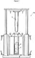
- the manufacturing process for a preferred embodiment of the inventionis carried out by a conventional molding machine as, for example, illustrated in Fig. 1 . During a molding process by the molding machine (10), the male core part (6) will be spaced from the female part (8) by a predetermined distance defining a predetermined annular space.
- a gel liner that serves as an ideal liner interface for housing the electrically conducive silicone components, while at the same time being as comfortable and minimally invasive as possible to the end useris the ALPS Gel Liner.
- these patchesare pressed against the skin of the end user to a degree that allows them to more reliably pick up neural impulses fired by nerve endings of particular muscles to aid in controlling a powered prosthesis.
- the patcheshave an initial predetermined thickness greater than the annular space between the male and female parts of the molding machine.
- the patchesare attached, for example by adhesive, at selected points on an interior surface of a tubular fabric layer designed as an outer fabric layer of a finished liner interface.
- a preferred embodiment of the present inventionalthough not limited thereto, includes a tubular fabric layer (2) illustrated to have a closed distal end and an open proximal end for a below-the-knee (BK) or above-the-knee (AK) liner.
- BKbelow-the-knee
- AKabove-the-knee
- the fabric layer (2)is placed in the female part of the molding machine.
- the male core partis then mated with the female part wherein the patches are axially deformed and the annular space is closed.
- a molten gel material(silicone, other TPE elastomers, copolymer Styrenic gels, polyurethane gel, etc.) is injected into the annular space to completely fill the annular space thereby adhering to the tubular fabric layer and around the patches, while leaving their surface area against the male part free of any molten material.
- the patchesWhen the liner is cured and removed from the molding machine, the patches are free to axially deform by expanding slightly from 0-6.35 mm (0.0" to 0.25") beyond the inner surface of the cured gel layer and thereby toward the skin of the end user when in use so that the patches can have direct contact with the subcutaneous tissue superficial to the nerve that is strong enough to ensure a solid and consistent signal at all times, while still being soft enough to promote end user comfort.
- the neural impulsescan then be linked back through the conductive patches and into a CPU of the prosthetic via a network made up of any number of flexible materials exhibiting very low levels of resistivity (carbon filament, copper filament, silver thread, carbon fabric, copper fabric, silver fabric, traditional light gauge wire, etc.) that are also integrated into the inner gel portion of the liner interface as discussed hereinafter.
- a networkmade up of any number of flexible materials exhibiting very low levels of resistivity (carbon filament, copper filament, silver thread, carbon fabric, copper fabric, silver fabric, traditional light gauge wire, etc.) that are also integrated into the inner gel portion of the liner interface as discussed hereinafter.
- the present inventionas illustrated in Fig. 2 , includes a sewn fabric tubular layer (2) having longitudinal stretch characteristics of 5% to 180%, transverse stretch characteristics of 10% to 250%, and fabric thickness of .30mm to 1.5mm.
- a distal attachmentmay be attached to the distal end of the fabric tubular layer (2).
- a first distal attachmentincludes grommets (11) and an umbrella (12) assembly crimped to the closed end that is then encapsulated during the molding process.
- the umbrella assemblyincludes an outwardly extending threaded bore for receiving a threaded pin as part of a locking assembly.
- Fig. 1The umbrella assembly includes an outwardly extending threaded bore for receiving a threaded pin as part of a locking assembly.
- a distal attachmentis attached to the outer surface of the distal end of the fabric layer subsequent to the molding process and encapsulated thereto using a Liquid Silicone Rubber of approximately 60 durometer silicone to complete the distal attachment (3).
- the liner illustratedincludes the various distal attachments (3), exemplified in more detail in Figs. 2a and 2b , it is important to note that the liner could alternatively be of the cushioned variety as in Fig. 2c , i. e., an interface without a distal attachment but reinforced with a distal cushioning element.
- the preferred receptor patches (1A-1D)are made of deformable Heat Resistant Silicone such as CLS 60-10 or any other low durometer silicone that is heat resistant and of a silicone that is either electrically conductive silicone, or non-electrically conductive silicone but individually wrapped with an electrically conductive medium (4A-4D) using any number of common adhesives such as traditional glue, bonding fabrics, fusible fabrics, or silicone based adhesives.
- Such electric conductive mediummay preferably consist of Silver Fabric (or any other fabric or otherwise unobtrusive medium with low resistivity, including copper or carbon fabrics and/or light gauge wire), that covers each patch completely and includes strips (5A-5D) extending from each patch to encompass the length of the liner as a whole.
- the ends of these strips (5A-5D)can then be passed through the distal end of the liner to be connected to a CPU.
- the conductive stripscan also be fed out the proximal end of the liner, both the distal and proximal ends of the liner, or any other advantageous point throughout the liner to be affixed to a CPU for processing.
- the silicone patches and length of conductive stripsare then strategically attached (glued, sewn, silicone based adhesive, etc.) to the inner surface of the fabric tubular layer prior to the placement of the fabric tubular layer into the female part of the molding machine.
- the silicone patches and stripsare placed in specific pre-determined areas targeting specific nerve endings.
- the preferred shape of the silicone patchesis disc-shaped so that they can be tapered flush with the gel with the dome area extending slightly above to improve contact on the nerve endings.
- other shapescan equally be employed, such as square-shaped, rectangle-shaped, diamond-shaped, oval-shaped or any other configuration necessary to accommodate the particular area to be sensed.
- the four patches illustrated in the figuresis not intended to limit the number of patches that can be provided on any single liner which would depend of the type of prosthetic, orthotic or diagnostic equipment to be controlled.
- the silicone discsare used for their properties highlighted above, but other heat resistant and deformable space fillers could potentially be wrapped in silver fabric (or substitute) and adhered to the fabric in a similar fashion such as heat resistant rubbers, etc.
- the male mold (6)is then lowered down into the center of the opened fabric tubular layer (2).
- the silicone discs (1A-1D)are now axially deformed a predetermined amount (preferably approximately 0.25-6.35 mm (.01" - .25”)) by the male mold as denoted by the phantom lines in Fig. 3 and Fig. 3a .
- the discs (1A-1D)could be flush with the surface of the male mold (6) as demonstrated in Fig. 3b . Any combination of these options exist for any number of receptors.
- the amount of initial axial deformation (reduction in thickness) of the silicone discswould be predetermined by the amount of axial deformation (axial expansion) desired of the discs during the post molding process. It is noted that the molding procedure itself with the exception of the discs and strips is identical to the molding process of a traditional ALPS Locking Liner.
- the Lineris then injection molded with the hot 149-204°C (300 - 400 degrees Fahrenheit) molten gel elastomer (7) exhibiting stretch characteristics of 600% - 2,000% and a Modulus of 0.34-3.45 MPa (50-500 psi) when cured.
- gel elastomersinclude silicone, thermoplastic elastomers [triblock], copolymer Styrenic gels, and polyurethane gels, etc.
- the preferred gel elastomer (7)is the ALPS elastomer but any of the above elastomers could be used in their molten stage to fill the annular space in the molding machine and completely engulf the silicone discs with the exception of the interface between the discs and male core part, and the strips thereby adhering to the inner surface of the tubular fabric layer, the discs and strips. Thus, the discs and the conductive strips are locked in place to ensure durability and an exact location.
- the axially deformed silicone discs (1A-1D)will be free to axially expand. Due to the adhesion of the injected gel to the sides of the discs, the discs will not expand back to their initial thickness, but will expand back to an extent past the inner surface of the cured liner depending on the initial axial deformation of the discs during the molding process to thereby improve pressurized contact on the nerve endings while still being completely integrated into the inner liner material.
- the amount of axial expansion of the discs subsequent to the curing stepswill depend on the amount of axial deformation exerted on the initial thickness of the discs during the molding process.
- the cured gel around the discswill thereby stabilize the receptor to the nerve ending when in use.
Landscapes
- Health & Medical Sciences (AREA)
- Life Sciences & Earth Sciences (AREA)
- Engineering & Computer Science (AREA)
- General Health & Medical Sciences (AREA)
- Animal Behavior & Ethology (AREA)
- Biomedical Technology (AREA)
- Heart & Thoracic Surgery (AREA)
- Veterinary Medicine (AREA)
- Public Health (AREA)
- Oral & Maxillofacial Surgery (AREA)
- Cardiology (AREA)
- Transplantation (AREA)
- Vascular Medicine (AREA)
- Physics & Mathematics (AREA)
- Biophysics (AREA)
- Pathology (AREA)
- Medical Informatics (AREA)
- Molecular Biology (AREA)
- Surgery (AREA)
- Manufacturing & Machinery (AREA)
- Prostheses (AREA)
- Neurology (AREA)
Description
- The present invention relates generally to a gel cushioned interface and a method of making a gel cushioned interface made of polymer material with heat resistant and electrically conductive neural receptors housed strategically within and potentially raised slightly above the inner surface of the polymer material to be worn over a limb or body surface for the purpose of conducting and/or receiving impulses through the interface.
- The use of myoelectrics in the orthotics and prosthetics field started with the basic use of a conductive metal dome placed on a user's particular muscle group to pickup neural signals from nerve endings through the skin. With such a system, when the user would fire the bicep muscle, for example, the dome would pick up the signal and send it to the powered prosthesis telling it to create flexion in the prosthetic elbow. Many metal domes would be affixed to the skin of the end user externally and hard-wired (sometimes long distances) into the powered prosthetic device so that the user could fire off certain muscle groups to control functionality of the prosthesis.
- More recent improvements to myoelectrics in the field involve using a series of metal domes that are punctured through and embedded in an otherwise traditional liner interface after the molding process, that are then connected to a CPU using external wires that control the powered prosthesis. Concurrently, other developments are taking place where metal electrodes are actually implanted into the user's pectoral muscle and hardwired to a CPU for cognitive control over the prosthesis.
- The process of surgically inserting metal domes into a user is obviously a very invasive procedure that many potential users are unwilling to undergo. The post-molding process of puncturing holes into a liner to insert metal domes is also a difficult process that is time consuming and jeopardizes the original liner's structural integrity and durability. Thus, the need in the market exists for an interface liner that contains electrically conductive receptors that can make the appropriate amount of skin contact necessary to reliably pick up electrical impulses from very specific points on the user while also containing a means of transferring these impulses to a central processing unit.
- One attempt that has been made to satisfy this need is disclosed in
US 2009/0216339 A1 to Hanson, et al. As best illustrated inFigure 1 (10) orFigure 2 (20), Hanson suggests affixing "domes" made of conductive silicone onto existing prosthetic liners after the molding process has taken place. Hanson focuses on the silicone dome's ability to create total contact on the skin surface, while also being properly affixed to the liner with an appropriate adhesive such as RTV silicone for silicone liners or moisture-activated urethane for urethane liners to form a more secure "butt j oint" to hold the domes securely in place once they are added to the liner.US 2010/0114238 discloses a prosthetic liner, as best illustrated inFigure 1 and2 , having stimulation electrodes made of conductive hydrogel 105 integrated into the liner material during the molding process that are designed to be flush with the skin 106 on the inside of the liner and connected to a CPU by silver fabric conductors 103.US 2010/0318195 discloses an orthopedic interface having electrically conductive coatings 23 on the inner fabric surface of the liner. DE 102007035409 , which is considered to represent the closest prior art, discloses an orthopaedic interface having spaced apart upper and under sides connected to one another by supporting threads.- While these ideas seek to address the need for improving end user comfort while not jeopardizing functionality, they fail to address the need for a single off the shelf product that combines the manufacturability of having the electrodes molded into the inner material during a "one shot" manufacturing process while still allowing those same domes to provide an adequate amount of compression on the localized skin necessary to get a consistent myoelectric signal.
- The invention is made up of a gel cushioned liner with soft (10-40 durometer on type "A" scale) heat resistant silicone patches made of electrically conductive deformable silicone material or electrically non-conductive deformable material covered in any number of conductive metals or materials (copper, silver, carbon, conductive fabric, etc.) molded into the interface liner during the manufacturing molding process. The terminology "axial deformation" herein is used to describe the reduction or expansion in thickness of the silicone patches. The manufacturing process for a preferred embodiment of the invention is carried out by a conventional molding machine as, for example, illustrated in
Fig. 1 . During a molding process by the molding machine (10), the male core part (6) will be spaced from the female part (8) by a predetermined distance defining a predetermined annular space. A gel liner that serves as an ideal liner interface for housing the electrically conducive silicone components, while at the same time being as comfortable and minimally invasive as possible to the end user is the ALPS Gel Liner. During use of the liner, these patches are pressed against the skin of the end user to a degree that allows them to more reliably pick up neural impulses fired by nerve endings of particular muscles to aid in controlling a powered prosthesis. - The patches have an initial predetermined thickness greater than the annular space between the male and female parts of the molding machine. The patches are attached, for example by adhesive, at selected points on an interior surface of a tubular fabric layer designed as an outer fabric layer of a finished liner interface. As illustrated in
Figs. 2-4 , a preferred embodiment of the present invention, although not limited thereto, includes a tubular fabric layer (2) illustrated to have a closed distal end and an open proximal end for a below-the-knee (BK) or above-the-knee (AK) liner. However, as stated above, the drawings are exemplary of a preferred use for the invention. Other uses could include arm prosthetics or other liners used on other body locations where it is desirable to monitor neural impulses for powering prosthetic and/or orthotic devices or simply monitoring for diagnostic purposes. After attaching the patches, the fabric layer (2) is placed in the female part of the molding machine. The male core part is then mated with the female part wherein the patches are axially deformed and the annular space is closed. Next, a molten gel material (silicone, other TPE elastomers, copolymer Styrenic gels, polyurethane gel, etc.) is injected into the annular space to completely fill the annular space thereby adhering to the tubular fabric layer and around the patches, while leaving their surface area against the male part free of any molten material. When the liner is cured and removed from the molding machine, the patches are free to axially deform by expanding slightly from 0-6.35 mm (0.0" to 0.25") beyond the inner surface of the cured gel layer and thereby toward the skin of the end user when in use so that the patches can have direct contact with the subcutaneous tissue superficial to the nerve that is strong enough to ensure a solid and consistent signal at all times, while still being soft enough to promote end user comfort. - The neural impulses can then be linked back through the conductive patches and into a CPU of the prosthetic via a network made up of any number of flexible materials exhibiting very low levels of resistivity (carbon filament, copper filament, silver thread, carbon fabric, copper fabric, silver fabric, traditional light gauge wire, etc.) that are also integrated into the inner gel portion of the liner interface as discussed hereinafter.
Fig. 1 shows a conventional molding machine of the same design that can be used to manufacture a prosthetic liner interface, which is a preferred embodiment of the present invention.Fig. 2 is a sectional view of the liner interface of a preferred embodiment of the present invention with the silicone patches adhered to the inside surface of the outer tubular fabric layer of the liner interface before the injection molding process.- [0017]
Fig. 2a and Fig. 2b are enlarged sectional views of alternative distal encapsulations (3) circled inFig. 2 that could be attached to the distal end of a preferred embodiment of the present invention. Fig. 2c is an enlarged sectional view of an alternative distal end of the cushioned interface ofFig. 2 that could be used as an alternative to the distal encapsulations inFigs. 2a and 2b .Fig. 3 is a sectional view of the liner interface of a preferred embodiment of the present invention once the tubular fabric layer has been placed inside the female portion of the molding machine and the male core portion of the molding machine has been inserted into the inside of the tubular fabric layer with the receptor patches compressed inside the mold as the core portion fills out the inside of the cavity.- [0020]
Fig. 3a is an enlarged sectional view of one of the receptors inFig. 3 being compressed to some degree (shown in dashed lines) by the core prior to the molding process. Fig. 3b is an enlarged view of another receptor inFig. 3 that could alternatively be compressed very little or none at all to remain "flush" with the core during molding.Fig. 4 is a sectional view of the liner interface of a preferred embodiment of the present invention that shows the once compressed patches returning to their full uncompressed shape after the injection molding process is completed.- The present invention as illustrated in
Fig. 2 , includes a sewn fabric tubular layer (2) having longitudinal stretch characteristics of 5% to 180%, transverse stretch characteristics of 10% to 250%, and fabric thickness of .30mm to 1.5mm. As indicated by circle (3), a distal attachment may be attached to the distal end of the fabric tubular layer (2). As shown inFig. 2a , a first distal attachment includes grommets (11) and an umbrella (12) assembly crimped to the closed end that is then encapsulated during the molding process. The umbrella assembly includes an outwardly extending threaded bore for receiving a threaded pin as part of a locking assembly. As shown inFig. 2b , a distal attachment is attached to the outer surface of the distal end of the fabric layer subsequent to the molding process and encapsulated thereto using a Liquid Silicone Rubber of approximately 60 durometer silicone to complete the distal attachment (3). While the liner illustrated includes the various distal attachments (3), exemplified in more detail inFigs. 2a and 2b , it is important to note that the liner could alternatively be of the cushioned variety as inFig. 2c , i. e., an interface without a distal attachment but reinforced with a distal cushioning element. - Referring to
Fig. 2 , the preferred receptor patches (1A-1D) are made of deformable Heat Resistant Silicone such as CLS 60-10 or any other low durometer silicone that is heat resistant and of a silicone that is either electrically conductive silicone, or non-electrically conductive silicone but individually wrapped with an electrically conductive medium (4A-4D) using any number of common adhesives such as traditional glue, bonding fabrics, fusible fabrics, or silicone based adhesives. Such electric conductive medium may preferably consist of Silver Fabric (or any other fabric or otherwise unobtrusive medium with low resistivity, including copper or carbon fabrics and/or light gauge wire), that covers each patch completely and includes strips (5A-5D) extending from each patch to encompass the length of the liner as a whole. The ends of these strips (5A-5D) can then be passed through the distal end of the liner to be connected to a CPU. Conversely, the conductive strips can also be fed out the proximal end of the liner, both the distal and proximal ends of the liner, or any other advantageous point throughout the liner to be affixed to a CPU for processing. The silicone patches and length of conductive strips are then strategically attached (glued, sewn, silicone based adhesive, etc.) to the inner surface of the fabric tubular layer prior to the placement of the fabric tubular layer into the female part of the molding machine. The silicone patches and strips are placed in specific pre-determined areas targeting specific nerve endings. - The preferred shape of the silicone patches is disc-shaped so that they can be tapered flush with the gel with the dome area extending slightly above to improve contact on the nerve endings. However, other shapes can equally be employed, such as square-shaped, rectangle-shaped, diamond-shaped, oval-shaped or any other configuration necessary to accommodate the particular area to be sensed. Furthermore, the four patches illustrated in the figures is not intended to limit the number of patches that can be provided on any single liner which would depend of the type of prosthetic, orthotic or diagnostic equipment to be controlled. Also, the silicone discs are used for their properties highlighted above, but other heat resistant and deformable space fillers could potentially be wrapped in silver fabric (or substitute) and adhered to the fabric in a similar fashion such as heat resistant rubbers, etc.
- As illustrated in
Fig. 3 , the male mold (6) is then lowered down into the center of the opened fabric tubular layer (2). The silicone discs (1A-1D) are now axially deformed a predetermined amount (preferably approximately 0.25-6.35 mm (.01" - .25")) by the male mold as denoted by the phantom lines inFig. 3 and Fig. 3a . Alternatively, the discs (1A-1D) could be flush with the surface of the male mold (6) as demonstrated inFig. 3b . Any combination of these options exist for any number of receptors. The amount of initial axial deformation (reduction in thickness) of the silicone discs would be predetermined by the amount of axial deformation (axial expansion) desired of the discs during the post molding process. It is noted that the molding procedure itself with the exception of the discs and strips is identical to the molding process of a traditional ALPS Locking Liner. - The Liner is then injection molded with the hot 149-204°C (300 - 400 degrees Fahrenheit) molten gel elastomer (7) exhibiting stretch characteristics of 600% - 2,000% and a Modulus of 0.34-3.45 MPa (50-500 psi) when cured. Such gel elastomers include silicone, thermoplastic elastomers [triblock], copolymer Styrenic gels, and polyurethane gels, etc. The preferred gel elastomer (7) is the ALPS elastomer but any of the above elastomers could be used in their molten stage to fill the annular space in the molding machine and completely engulf the silicone discs with the exception of the interface between the discs and male core part, and the strips thereby adhering to the inner surface of the tubular fabric layer, the discs and strips. Thus, the discs and the conductive strips are locked in place to ensure durability and an exact location.
- As illustrated in
Fig. 4 , once the molding process is completed and the male portion of the mold is removed, the axially deformed silicone discs (1A-1D) will be free to axially expand. Due to the adhesion of the injected gel to the sides of the discs, the discs will not expand back to their initial thickness, but will expand back to an extent past the inner surface of the cured liner depending on the initial axial deformation of the discs during the molding process to thereby improve pressurized contact on the nerve endings while still being completely integrated into the inner liner material. The amount of axial expansion of the discs subsequent to the curing steps will depend on the amount of axial deformation exerted on the initial thickness of the discs during the molding process. The cured gel around the discs will thereby stabilize the receptor to the nerve ending when in use. - The foregoing merely illustrates the principles of the invention. Various modifications and alterations to the described embodiments will be apparent to those skilled in the art in view of the teachings herein.
Claims (13)
- A liner interface with neural receptors comprising:a fabric layer (2) having an inner surface and an outer surface;an electrically conductive receptor; andan electrically conductive element (5A-5D) extending from said electrically conductive receptor for conducting electric signals therefrom caused by neural impulses from nerve endings when said interface is in use,characterised in that:said electrically conductive receptor comprises a silicone patch (1A-1D) having an outer surface, an inner surface, side surfaces, and a selective predetermined thickness, said patch adapted to be electrically conductive;said receptor and said electrically conductive element are adhered to said inner surface of said fabric layer at a selective location based on the area of the user to be sensed;said inner surface of said fabric, said side surfaces of said receptor, and said electrically conductive element have a predetermined thickness of gel material coated thereon; andsaid electrically conductive element comprises a conductive strip attached to the inner surface of the fabric layer and extending from the silicone patch between the fabric layer and the gel material coating (7).
- The liner interface of claim 1, wherein the fabric layer (2) has an open proximal end and a closed distal end, the conductive strip (5A-5D) has an end coupled with the silicone patch (1A-1D), and the conductive strip further has an opposite end extending outward through the closed distal end of the fabric layer.
- The liner interface of claim 1, wherein the silicone patch (1A-1D) is wrapped with an electrically conductive medium (4A-4D).
- The liner interface of claim 3, wherein the conductive strip (5A-5D) is formed as an extension of the electrically conductive medium (4A-4D).
- The liner interface of claim 3, wherein the electrically conductive medium (4A-4D) is adhered onto the silicone patch (1A-1D).
- The liner interface of claim 1, wherein the silicone patch (1A-1D) is disc-shaped, square-shaped, rectangular-shaped, oval-shaped or diamond-shaped.
- The liner interface of claim 1, wherein the gel material coating (7) comprises silicone, thermoplastic triblock elastomers, copolymer Styrenic gel, or polyurethane gel.
- The liner interface of claim 7, wherein the gel material coating (7) exhibits stretch characteristics of 600% - 2000% when cured.
- The liner interface of claim 1, wherein the fabric layer (2) has an open proximal end and a closed distal end, the conductive strip (5A-5D) has an end coupled with the silicone patch (1A-1D), and the conductive strip further has an opposite end extending outward through the open proximal end of the fabric layer.
- The liner interface of claim 1, wherein the electrically conductive element (5A-5D) is sewn to the fabric layer (2).
- The liner interface of claim 1, wherein the electrically conductive element (5A-5D) comprises a filament or thread.
- The liner interface of claim 1, wherein the electrically conductive element (5A-5D) is adhered to the inner surface of the fabric layer (2).
- The liner interface of claim 1, wherein the electrically conductive element (5A-5D) comprises a fabric.
Applications Claiming Priority (2)
| Application Number | Priority Date | Filing Date | Title |
|---|---|---|---|
| US13/687,229US8979944B2 (en) | 2012-11-28 | 2012-11-28 | Method apparatus of a liner interface with neural receptors |
| EP13194821.8AEP2737878B1 (en) | 2012-11-28 | 2013-11-28 | Method and apparatus of a liner interface with neural receptors |
Related Parent Applications (1)
| Application Number | Title | Priority Date | Filing Date |
|---|---|---|---|
| EP13194821.8ADivisionEP2737878B1 (en) | 2012-11-28 | 2013-11-28 | Method and apparatus of a liner interface with neural receptors |
Publications (2)
| Publication Number | Publication Date |
|---|---|
| EP3530240A1 EP3530240A1 (en) | 2019-08-28 |
| EP3530240B1true EP3530240B1 (en) | 2023-05-03 |
Family
ID=49759005
Family Applications (2)
| Application Number | Title | Priority Date | Filing Date |
|---|---|---|---|
| EP19165968.9AActiveEP3530240B1 (en) | 2012-11-28 | 2013-11-28 | Apparatus of a liner interface with neural receptors |
| EP13194821.8AActiveEP2737878B1 (en) | 2012-11-28 | 2013-11-28 | Method and apparatus of a liner interface with neural receptors |
Family Applications After (1)
| Application Number | Title | Priority Date | Filing Date |
|---|---|---|---|
| EP13194821.8AActiveEP2737878B1 (en) | 2012-11-28 | 2013-11-28 | Method and apparatus of a liner interface with neural receptors |
Country Status (2)
| Country | Link |
|---|---|
| US (2) | US8979944B2 (en) |
| EP (2) | EP3530240B1 (en) |
Families Citing this family (11)
| Publication number | Priority date | Publication date | Assignee | Title |
|---|---|---|---|---|
| US9155634B2 (en) | 2011-08-16 | 2015-10-13 | Rehabilitation Institute Of Chicago | Systems and methods of myoelectric prosthesis control |
| US8979944B2 (en) | 2012-11-28 | 2015-03-17 | Alps South, LLC | Method apparatus of a liner interface with neural receptors |
| WO2019032118A1 (en) | 2017-08-11 | 2019-02-14 | The Ohio Willow Wood Company | Conductive human interfaces |
| EP3484419B1 (en)* | 2016-08-11 | 2023-05-03 | WillowWood Global LLC | Conductive human interfaces |
| US11464438B2 (en) | 2016-08-11 | 2022-10-11 | Willowwood Global Llc | Conductive human interfaces |
| US11213409B2 (en) | 2016-08-11 | 2022-01-04 | Willowwood Global Llc | Conductive human interfaces |
| WO2018067932A1 (en) | 2016-10-06 | 2018-04-12 | The Ohio Willow Wood Company | Electrically conductive gel and conductive human interfaces and electrodes formed using electrically conductive gel |
| DE102017126465B4 (en) | 2017-11-10 | 2022-01-13 | Ottobock Se & Co. Kgaa | Orthopedic technical equipment and manager for such as well as manufacturing process |
| US12337177B1 (en) | 2024-08-20 | 2025-06-24 | JSG IP Ventures, LLC | Method for residual limbs of amputees |
| US12329969B1 (en) | 2024-08-20 | 2025-06-17 | JSG IP Ventures, LLC | System and methods for residual limbs of amputees |
| US12324754B1 (en) | 2024-08-20 | 2025-06-10 | JSG IP Ventures, LLC | System for residual limbs of amputees |
Citations (1)
| Publication number | Priority date | Publication date | Assignee | Title |
|---|---|---|---|---|
| DE102007035409B4 (en)* | 2007-07-26 | 2010-06-02 | Otto Bock Healthcare Gmbh | Orthopedic interface |
Family Cites Families (23)
| Publication number | Priority date | Publication date | Assignee | Title |
|---|---|---|---|---|
| US5213715A (en) | 1989-04-17 | 1993-05-25 | Western Digital Corporation | Directionally conductive polymer |
| US5258037A (en) | 1990-07-13 | 1993-11-02 | Caspers Carl A | Prosthetic liner and method of making the liner with a prosthesis socket |
| US5450845A (en)* | 1993-01-11 | 1995-09-19 | Axelgaard; Jens | Medical electrode system |
| US5507834A (en)* | 1994-05-17 | 1996-04-16 | Laghi; Aldo A. | Transparent silicone suction socket |
| US5443525A (en) | 1994-06-27 | 1995-08-22 | Laghi; Aldo A. | Conductive patch for control of prosthetic limbs |
| US5676132A (en) | 1995-12-05 | 1997-10-14 | Pulmonary Interface, Inc. | Pulmonary interface system |
| CA2260801A1 (en) | 1996-07-31 | 1998-02-05 | Ohio Willow Wood Company | Gel and cushioning devices |
| US6852269B2 (en) | 2002-03-19 | 2005-02-08 | Silipos, Inc. | Process for applying a cushion material to an article |
| EP1539028A2 (en)* | 2002-07-08 | 2005-06-15 | Ossur Engineering Inc. | Socket liner incorporating sensors to monitor amputee progress |
| FI120181B (en) | 2003-10-08 | 2009-07-31 | Mega Elektroniikka Oy | Sensor device for measuring signals from the skin surface and manufacturing method for the sensor device |
| US20050101693A1 (en)* | 2003-11-06 | 2005-05-12 | Ohio Willow Wood Company | Gel and cushioning devices |
| US8329202B2 (en)* | 2004-11-12 | 2012-12-11 | Depuy Products, Inc. | System and method for attaching soft tissue to an implant |
| US20070021841A1 (en)* | 2005-03-24 | 2007-01-25 | Bloorview Kids Rehab, A Corporation Registered Under The Ontario Corporations Act | Joint for prosthesis |
| US20090216339A1 (en)* | 2008-01-02 | 2009-08-27 | Hanson William J | Through-Liner Electrode System for Prosthetics and the Like |
| US8349021B2 (en)* | 2008-05-14 | 2013-01-08 | Alps Intellectual Property Management, Llc | Prosthetic locking liner with improved knee flexion |
| EP2140806B1 (en) | 2008-07-04 | 2012-03-07 | Dayton Technologies Limited | A Sensor |
| US20100114238A1 (en) | 2008-10-30 | 2010-05-06 | Philip Edward Muccio | Integration of functional electrical stimulation in prosthetic sockets, liners, and garments for improved amputee care and performance |
| CN102481110B (en) | 2009-08-17 | 2015-05-20 | 加利福尼亚大学董事会 | Distributed external and internal wireless sensor systems for characterizing surface and subsurface biomedical structures and conditions |
| DE102010005462A1 (en)* | 2010-01-20 | 2011-07-21 | Otto Bock HealthCare GmbH, 37115 | liner |
| US8591599B1 (en)* | 2011-01-07 | 2013-11-26 | Infinite Biomedical Technologies, Llc | Electrode assemblies for detecting muscle signals in a prosthetic liner |
| US20120253475A1 (en) | 2011-04-01 | 2012-10-04 | The Ohio Willow Wood Company | Fabric-covered polymeric prosthetic liner |
| US8852291B2 (en)* | 2012-06-12 | 2014-10-07 | Alps South, LLC | Method and apparatus of an integrated raised gel sealing liner |
| US8979944B2 (en) | 2012-11-28 | 2015-03-17 | Alps South, LLC | Method apparatus of a liner interface with neural receptors |
- 2012
- 2012-11-28USUS13/687,229patent/US8979944B2/enactiveActive
- 2013
- 2013-11-28EPEP19165968.9Apatent/EP3530240B1/enactiveActive
- 2013-11-28EPEP13194821.8Apatent/EP2737878B1/enactiveActive
- 2015
- 2015-01-20USUS14/600,197patent/US9937065B2/enactiveActive
Patent Citations (1)
| Publication number | Priority date | Publication date | Assignee | Title |
|---|---|---|---|---|
| DE102007035409B4 (en)* | 2007-07-26 | 2010-06-02 | Otto Bock Healthcare Gmbh | Orthopedic interface |
Also Published As
| Publication number | Publication date |
|---|---|
| US20140148916A1 (en) | 2014-05-29 |
| EP3530240A1 (en) | 2019-08-28 |
| US20160158034A1 (en) | 2016-06-09 |
| US8979944B2 (en) | 2015-03-17 |
| EP2737878A1 (en) | 2014-06-04 |
| US9937065B2 (en) | 2018-04-10 |
| EP2737878B1 (en) | 2019-04-03 |
Similar Documents
| Publication | Publication Date | Title |
|---|---|---|
| EP3530240B1 (en) | Apparatus of a liner interface with neural receptors | |
| CN111491690B (en) | System for nerve electrical stimulation | |
| US9155634B2 (en) | Systems and methods of myoelectric prosthesis control | |
| US9681964B2 (en) | Socket system including a vacuum liner for prosthetic or orthotic devices and associated methods | |
| US9943420B2 (en) | Liner having an integrated electrode | |
| US20100114238A1 (en) | Integration of functional electrical stimulation in prosthetic sockets, liners, and garments for improved amputee care and performance | |
| US20100185300A1 (en) | Expulsion liner for prosthetic or orthotic devices and associated methods | |
| EP3002034A1 (en) | Electrode array and method of manufacturing same | |
| EP3522779B1 (en) | Conductive human interfaces comprising electrodes formed using electrically conductive gel | |
| EP2019709A2 (en) | Methods of making implantable medical leads with a non-linear shape | |
| US7996090B2 (en) | Methods of making implantable medical leads with a non-linear shape | |
| US11931272B2 (en) | Orthopedic device and conductor for such a device | |
| US9066820B2 (en) | Flexion enhancement member for prosthetic or orthotic liner or sleeve and associated methods | |
| US20150297369A1 (en) | Prosthetic liner | |
| CN108451676B (en) | A kind of 3D printing flexibility receptive cavity with adaptivity | |
| US7955397B2 (en) | Socket and sleeve for attachment to a residual limb | |
| US7479162B2 (en) | Liner | |
| WO2013093879A1 (en) | An adjustable elastic antagonist muscle replacement mechanism | |
| US20230018244A1 (en) | Conductive human interfaces | |
| RU2765089C1 (en) | Hand prosthesis for interaction with a capacitive touch screen of an electronic apparatus | |
| WO2024058687A1 (en) | Prosthetic socket (embodiments) | |
| EP3484419B1 (en) | Conductive human interfaces | |
| HK40032200A (en) | System for electrical stimulation of nerves | |
| WO2016020819A1 (en) | Lower extremity prosthesis with implanted shell |
Legal Events
| Date | Code | Title | Description |
|---|---|---|---|
| PUAI | Public reference made under article 153(3) epc to a published international application that has entered the european phase | Free format text:ORIGINAL CODE: 0009012 | |
| STAA | Information on the status of an ep patent application or granted ep patent | Free format text:STATUS: THE APPLICATION HAS BEEN PUBLISHED | |
| AC | Divisional application: reference to earlier application | Ref document number:2737878 Country of ref document:EP Kind code of ref document:P | |
| AK | Designated contracting states | Kind code of ref document:A1 Designated state(s):AL AT BE BG CH CY CZ DE DK EE ES FI FR GB GR HR HU IE IS IT LI LT LU LV MC MK MT NL NO PL PT RO RS SE SI SK SM TR | |
| STAA | Information on the status of an ep patent application or granted ep patent | Free format text:STATUS: REQUEST FOR EXAMINATION WAS MADE | |
| 17P | Request for examination filed | Effective date:20200225 | |
| RBV | Designated contracting states (corrected) | Designated state(s):AL AT BE BG CH CY CZ DE DK EE ES FI FR GB GR HR HU IE IS IT LI LT LU LV MC MK MT NL NO PL PT RO RS SE SI SK SM TR | |
| RAP1 | Party data changed (applicant data changed or rights of an application transferred) | Owner name:WILLOWWOOD GLOBAL LLC | |
| GRAP | Despatch of communication of intention to grant a patent | Free format text:ORIGINAL CODE: EPIDOSNIGR1 | |
| STAA | Information on the status of an ep patent application or granted ep patent | Free format text:STATUS: GRANT OF PATENT IS INTENDED | |
| RIC1 | Information provided on ipc code assigned before grant | Ipc:A61B 5/24 20210101ALN20221129BHEP Ipc:A61F 2/72 20060101ALI20221129BHEP Ipc:A61F 2/78 20060101AFI20221129BHEP | |
| INTG | Intention to grant announced | Effective date:20221219 | |
| RIN1 | Information on inventor provided before grant (corrected) | Inventor name:MCLOONE, KEVIN Inventor name:LAGHI, ALDO A. | |
| GRAS | Grant fee paid | Free format text:ORIGINAL CODE: EPIDOSNIGR3 | |
| GRAA | (expected) grant | Free format text:ORIGINAL CODE: 0009210 | |
| STAA | Information on the status of an ep patent application or granted ep patent | Free format text:STATUS: THE PATENT HAS BEEN GRANTED | |
| AC | Divisional application: reference to earlier application | Ref document number:2737878 Country of ref document:EP Kind code of ref document:P | |
| AK | Designated contracting states | Kind code of ref document:B1 Designated state(s):AL AT BE BG CH CY CZ DE DK EE ES FI FR GB GR HR HU IE IS IT LI LT LU LV MC MK MT NL NO PL PT RO RS SE SI SK SM TR | |
| REG | Reference to a national code | Ref country code:GB Ref legal event code:FG4D | |
| REG | Reference to a national code | Ref country code:DE Ref legal event code:R096 Ref document number:602013083741 Country of ref document:DE | |
| REG | Reference to a national code | Ref country code:AT Ref legal event code:REF Ref document number:1563960 Country of ref document:AT Kind code of ref document:T Effective date:20230515 Ref country code:CH Ref legal event code:EP | |
| REG | Reference to a national code | Ref country code:IE Ref legal event code:FG4D | |
| P01 | Opt-out of the competence of the unified patent court (upc) registered | Effective date:20230530 | |
| REG | Reference to a national code | Ref country code:LT Ref legal event code:MG9D | |
| REG | Reference to a national code | Ref country code:NL Ref legal event code:MP Effective date:20230503 | |
| REG | Reference to a national code | Ref country code:AT Ref legal event code:MK05 Ref document number:1563960 Country of ref document:AT Kind code of ref document:T Effective date:20230503 | |
| PG25 | Lapsed in a contracting state [announced via postgrant information from national office to epo] | Ref country code:SE Free format text:LAPSE BECAUSE OF FAILURE TO SUBMIT A TRANSLATION OF THE DESCRIPTION OR TO PAY THE FEE WITHIN THE PRESCRIBED TIME-LIMIT Effective date:20230503 Ref country code:PT Free format text:LAPSE BECAUSE OF FAILURE TO SUBMIT A TRANSLATION OF THE DESCRIPTION OR TO PAY THE FEE WITHIN THE PRESCRIBED TIME-LIMIT Effective date:20230904 Ref country code:NO Free format text:LAPSE BECAUSE OF FAILURE TO SUBMIT A TRANSLATION OF THE DESCRIPTION OR TO PAY THE FEE WITHIN THE PRESCRIBED TIME-LIMIT Effective date:20230803 Ref country code:NL Free format text:LAPSE BECAUSE OF FAILURE TO SUBMIT A TRANSLATION OF THE DESCRIPTION OR TO PAY THE FEE WITHIN THE PRESCRIBED TIME-LIMIT Effective date:20230503 Ref country code:ES Free format text:LAPSE BECAUSE OF FAILURE TO SUBMIT A TRANSLATION OF THE DESCRIPTION OR TO PAY THE FEE WITHIN THE PRESCRIBED TIME-LIMIT Effective date:20230503 Ref country code:AT Free format text:LAPSE BECAUSE OF FAILURE TO SUBMIT A TRANSLATION OF THE DESCRIPTION OR TO PAY THE FEE WITHIN THE PRESCRIBED TIME-LIMIT Effective date:20230503 | |
| PG25 | Lapsed in a contracting state [announced via postgrant information from national office to epo] | Ref country code:RS Free format text:LAPSE BECAUSE OF FAILURE TO SUBMIT A TRANSLATION OF THE DESCRIPTION OR TO PAY THE FEE WITHIN THE PRESCRIBED TIME-LIMIT Effective date:20230503 Ref country code:PL Free format text:LAPSE BECAUSE OF FAILURE TO SUBMIT A TRANSLATION OF THE DESCRIPTION OR TO PAY THE FEE WITHIN THE PRESCRIBED TIME-LIMIT Effective date:20230503 Ref country code:LV Free format text:LAPSE BECAUSE OF FAILURE TO SUBMIT A TRANSLATION OF THE DESCRIPTION OR TO PAY THE FEE WITHIN THE PRESCRIBED TIME-LIMIT Effective date:20230503 Ref country code:LT Free format text:LAPSE BECAUSE OF FAILURE TO SUBMIT A TRANSLATION OF THE DESCRIPTION OR TO PAY THE FEE WITHIN THE PRESCRIBED TIME-LIMIT Effective date:20230503 Ref country code:HR Free format text:LAPSE BECAUSE OF FAILURE TO SUBMIT A TRANSLATION OF THE DESCRIPTION OR TO PAY THE FEE WITHIN THE PRESCRIBED TIME-LIMIT Effective date:20230503 Ref country code:GR Free format text:LAPSE BECAUSE OF FAILURE TO SUBMIT A TRANSLATION OF THE DESCRIPTION OR TO PAY THE FEE WITHIN THE PRESCRIBED TIME-LIMIT Effective date:20230804 | |
| PG25 | Lapsed in a contracting state [announced via postgrant information from national office to epo] | Ref country code:FI Free format text:LAPSE BECAUSE OF FAILURE TO SUBMIT A TRANSLATION OF THE DESCRIPTION OR TO PAY THE FEE WITHIN THE PRESCRIBED TIME-LIMIT Effective date:20230503 | |
| PG25 | Lapsed in a contracting state [announced via postgrant information from national office to epo] | Ref country code:SK Free format text:LAPSE BECAUSE OF FAILURE TO SUBMIT A TRANSLATION OF THE DESCRIPTION OR TO PAY THE FEE WITHIN THE PRESCRIBED TIME-LIMIT Effective date:20230503 | |
| PG25 | Lapsed in a contracting state [announced via postgrant information from national office to epo] | Ref country code:SM Free format text:LAPSE BECAUSE OF FAILURE TO SUBMIT A TRANSLATION OF THE DESCRIPTION OR TO PAY THE FEE WITHIN THE PRESCRIBED TIME-LIMIT Effective date:20230503 Ref country code:SK Free format text:LAPSE BECAUSE OF FAILURE TO SUBMIT A TRANSLATION OF THE DESCRIPTION OR TO PAY THE FEE WITHIN THE PRESCRIBED TIME-LIMIT Effective date:20230503 Ref country code:RO Free format text:LAPSE BECAUSE OF FAILURE TO SUBMIT A TRANSLATION OF THE DESCRIPTION OR TO PAY THE FEE WITHIN THE PRESCRIBED TIME-LIMIT Effective date:20230503 Ref country code:EE Free format text:LAPSE BECAUSE OF FAILURE TO SUBMIT A TRANSLATION OF THE DESCRIPTION OR TO PAY THE FEE WITHIN THE PRESCRIBED TIME-LIMIT Effective date:20230503 Ref country code:DK Free format text:LAPSE BECAUSE OF FAILURE TO SUBMIT A TRANSLATION OF THE DESCRIPTION OR TO PAY THE FEE WITHIN THE PRESCRIBED TIME-LIMIT Effective date:20230503 Ref country code:CZ Free format text:LAPSE BECAUSE OF FAILURE TO SUBMIT A TRANSLATION OF THE DESCRIPTION OR TO PAY THE FEE WITHIN THE PRESCRIBED TIME-LIMIT Effective date:20230503 | |
| REG | Reference to a national code | Ref country code:DE Ref legal event code:R097 Ref document number:602013083741 Country of ref document:DE | |
| PLBE | No opposition filed within time limit | Free format text:ORIGINAL CODE: 0009261 | |
| STAA | Information on the status of an ep patent application or granted ep patent | Free format text:STATUS: NO OPPOSITION FILED WITHIN TIME LIMIT | |
| 26N | No opposition filed | Effective date:20240206 | |
| PG25 | Lapsed in a contracting state [announced via postgrant information from national office to epo] | Ref country code:SI Free format text:LAPSE BECAUSE OF FAILURE TO SUBMIT A TRANSLATION OF THE DESCRIPTION OR TO PAY THE FEE WITHIN THE PRESCRIBED TIME-LIMIT Effective date:20230503 | |
| PG25 | Lapsed in a contracting state [announced via postgrant information from national office to epo] | Ref country code:SI Free format text:LAPSE BECAUSE OF FAILURE TO SUBMIT A TRANSLATION OF THE DESCRIPTION OR TO PAY THE FEE WITHIN THE PRESCRIBED TIME-LIMIT Effective date:20230503 Ref country code:IT Free format text:LAPSE BECAUSE OF FAILURE TO SUBMIT A TRANSLATION OF THE DESCRIPTION OR TO PAY THE FEE WITHIN THE PRESCRIBED TIME-LIMIT Effective date:20230503 | |
| REG | Reference to a national code | Ref country code:CH Ref legal event code:PL | |
| PG25 | Lapsed in a contracting state [announced via postgrant information from national office to epo] | Ref country code:MC Free format text:LAPSE BECAUSE OF FAILURE TO SUBMIT A TRANSLATION OF THE DESCRIPTION OR TO PAY THE FEE WITHIN THE PRESCRIBED TIME-LIMIT Effective date:20230503 | |
| PG25 | Lapsed in a contracting state [announced via postgrant information from national office to epo] | Ref country code:LU Free format text:LAPSE BECAUSE OF NON-PAYMENT OF DUE FEES Effective date:20231128 | |
| PG25 | Lapsed in a contracting state [announced via postgrant information from national office to epo] | Ref country code:CH Free format text:LAPSE BECAUSE OF NON-PAYMENT OF DUE FEES Effective date:20231130 | |
| PG25 | Lapsed in a contracting state [announced via postgrant information from national office to epo] | Ref country code:MC Free format text:LAPSE BECAUSE OF FAILURE TO SUBMIT A TRANSLATION OF THE DESCRIPTION OR TO PAY THE FEE WITHIN THE PRESCRIBED TIME-LIMIT Effective date:20230503 Ref country code:LU Free format text:LAPSE BECAUSE OF NON-PAYMENT OF DUE FEES Effective date:20231128 Ref country code:CH Free format text:LAPSE BECAUSE OF NON-PAYMENT OF DUE FEES Effective date:20231130 | |
| REG | Reference to a national code | Ref country code:BE Ref legal event code:MM Effective date:20231130 | |
| REG | Reference to a national code | Ref country code:IE Ref legal event code:MM4A | |
| PG25 | Lapsed in a contracting state [announced via postgrant information from national office to epo] | Ref country code:IE Free format text:LAPSE BECAUSE OF NON-PAYMENT OF DUE FEES Effective date:20231128 | |
| PG25 | Lapsed in a contracting state [announced via postgrant information from national office to epo] | Ref country code:BE Free format text:LAPSE BECAUSE OF NON-PAYMENT OF DUE FEES Effective date:20231130 | |
| PG25 | Lapsed in a contracting state [announced via postgrant information from national office to epo] | Ref country code:IE Free format text:LAPSE BECAUSE OF NON-PAYMENT OF DUE FEES Effective date:20231128 Ref country code:BE Free format text:LAPSE BECAUSE OF NON-PAYMENT OF DUE FEES Effective date:20231130 | |
| PG25 | Lapsed in a contracting state [announced via postgrant information from national office to epo] | Ref country code:BG Free format text:LAPSE BECAUSE OF FAILURE TO SUBMIT A TRANSLATION OF THE DESCRIPTION OR TO PAY THE FEE WITHIN THE PRESCRIBED TIME-LIMIT Effective date:20230503 | |
| PG25 | Lapsed in a contracting state [announced via postgrant information from national office to epo] | Ref country code:BG Free format text:LAPSE BECAUSE OF FAILURE TO SUBMIT A TRANSLATION OF THE DESCRIPTION OR TO PAY THE FEE WITHIN THE PRESCRIBED TIME-LIMIT Effective date:20230503 | |
| PGFP | Annual fee paid to national office [announced via postgrant information from national office to epo] | Ref country code:DE Payment date:20241001 Year of fee payment:12 | |
| PGFP | Annual fee paid to national office [announced via postgrant information from national office to epo] | Ref country code:GB Payment date:20241001 Year of fee payment:12 | |
| PGFP | Annual fee paid to national office [announced via postgrant information from national office to epo] | Ref country code:IS Payment date:20241008 Year of fee payment:12 Ref country code:FR Payment date:20241001 Year of fee payment:12 | |
| PG25 | Lapsed in a contracting state [announced via postgrant information from national office to epo] | Ref country code:CY Free format text:LAPSE BECAUSE OF FAILURE TO SUBMIT A TRANSLATION OF THE DESCRIPTION OR TO PAY THE FEE WITHIN THE PRESCRIBED TIME-LIMIT; INVALID AB INITIO Effective date:20131128 | |
| PG25 | Lapsed in a contracting state [announced via postgrant information from national office to epo] | Ref country code:HU Free format text:LAPSE BECAUSE OF FAILURE TO SUBMIT A TRANSLATION OF THE DESCRIPTION OR TO PAY THE FEE WITHIN THE PRESCRIBED TIME-LIMIT; INVALID AB INITIO Effective date:20131128 |