EP3526379B1 - Braiding machine and methods of use - Google Patents
Braiding machine and methods of useDownload PDFInfo
- Publication number
- EP3526379B1 EP3526379B1EP17860912.9AEP17860912AEP3526379B1EP 3526379 B1EP3526379 B1EP 3526379B1EP 17860912 AEP17860912 AEP 17860912AEP 3526379 B1EP3526379 B1EP 3526379B1
- Authority
- EP
- European Patent Office
- Prior art keywords
- tubes
- drive unit
- drive
- assembly
- end portions
- Prior art date
- Legal status (The legal status is an assumption and is not a legal conclusion. Google has not performed a legal analysis and makes no representation as to the accuracy of the status listed.)
- Active
Links
- 238000009954braidingMethods0.000titleclaimsdescription38
- 238000000034methodMethods0.000titleclaimsdescription22
- 230000007246mechanismEffects0.000claimsdescription30
- 230000000712assemblyEffects0.000claimsdescription8
- 238000000429assemblyMethods0.000claimsdescription8
- 238000005516engineering processMethods0.000description26
- 230000033001locomotionEffects0.000description19
- 230000008569processEffects0.000description9
- 230000000737periodic effectEffects0.000description7
- 230000008878couplingEffects0.000description5
- 238000010168coupling processMethods0.000description5
- 238000005859coupling reactionMethods0.000description5
- 239000011148porous materialSubstances0.000description3
- 230000001360synchronised effectEffects0.000description3
- 230000015572biosynthetic processEffects0.000description2
- 210000001124body fluidAnatomy0.000description2
- 230000004048modificationEffects0.000description2
- 238000012986modificationMethods0.000description2
- 238000003466weldingMethods0.000description2
- 229910000831SteelInorganic materials0.000description1
- 208000007536ThrombosisDiseases0.000description1
- 230000009471actionEffects0.000description1
- 229910052782aluminiumInorganic materials0.000description1
- XAGFODPZIPBFFR-UHFFFAOYSA-NaluminiumChemical compound[Al]XAGFODPZIPBFFR-UHFFFAOYSA-N0.000description1
- 230000006872improvementEffects0.000description1
- 230000002401inhibitory effectEffects0.000description1
- 238000004519manufacturing processMethods0.000description1
- 229910052751metalInorganic materials0.000description1
- 239000002184metalSubstances0.000description1
- 238000012978minimally invasive surgical procedureMethods0.000description1
- 239000002245particleSubstances0.000description1
- 239000010959steelSubstances0.000description1
Images


Classifications
- D—TEXTILES; PAPER
- D04—BRAIDING; LACE-MAKING; KNITTING; TRIMMINGS; NON-WOVEN FABRICS
- D04C—BRAIDING OR MANUFACTURE OF LACE, INCLUDING BOBBIN-NET OR CARBONISED LACE; BRAIDING MACHINES; BRAID; LACE
- D04C1/00—Braid or lace, e.g. pillow-lace; Processes for the manufacture thereof
- D04C1/06—Braid or lace serving particular purposes
- D04C1/12—Cords, lines, or tows
- D—TEXTILES; PAPER
- D04—BRAIDING; LACE-MAKING; KNITTING; TRIMMINGS; NON-WOVEN FABRICS
- D04C—BRAIDING OR MANUFACTURE OF LACE, INCLUDING BOBBIN-NET OR CARBONISED LACE; BRAIDING MACHINES; BRAID; LACE
- D04C1/00—Braid or lace, e.g. pillow-lace; Processes for the manufacture thereof
- D04C1/06—Braid or lace serving particular purposes
- D—TEXTILES; PAPER
- D04—BRAIDING; LACE-MAKING; KNITTING; TRIMMINGS; NON-WOVEN FABRICS
- D04C—BRAIDING OR MANUFACTURE OF LACE, INCLUDING BOBBIN-NET OR CARBONISED LACE; BRAIDING MACHINES; BRAID; LACE
- D04C3/00—Braiding or lacing machines
- D04C3/40—Braiding or lacing machines for making tubular braids by circulating strand supplies around braiding centre at equal distances
- D04C3/44—Braiding or lacing machines for making tubular braids by circulating strand supplies around braiding centre at equal distances with means for forming sheds by subsequently diverting various threads using the same guiding means
- D—TEXTILES; PAPER
- D04—BRAIDING; LACE-MAKING; KNITTING; TRIMMINGS; NON-WOVEN FABRICS
- D04C—BRAIDING OR MANUFACTURE OF LACE, INCLUDING BOBBIN-NET OR CARBONISED LACE; BRAIDING MACHINES; BRAID; LACE
- D04C3/00—Braiding or lacing machines
- D04C3/48—Auxiliary devices
- D—TEXTILES; PAPER
- D10—INDEXING SCHEME ASSOCIATED WITH SUBLASSES OF SECTION D, RELATING TO TEXTILES
- D10B—INDEXING SCHEME ASSOCIATED WITH SUBLASSES OF SECTION D, RELATING TO TEXTILES
- D10B2509/00—Medical; Hygiene
- D10B2509/06—Vascular grafts; stents
Definitions
- the present technologyrelates generally to systems and methods for forming a tubular braid of filaments.
- some embodiments of the present technologyrelate to systems for forming a braid through the movement of vertical tubes, each housing a filament, in a series of discrete radial and arcuate paths around a longitudinal axis of a mandrel.
- Braidsgenerally comprise many filaments interwoven together to form a cylindrical or otherwise tubular structure.
- Such braidshave a wide array of medical applications.
- braidscan be designed to collapse into small catheters for deployment in minimally invasive surgical procedures. Once deployed from a catheter, some braids can expand within the vessel or other bodily lumen in which they are deployed to, for example, occlude or slow the flow of bodily fluids, to trap or filter particles within a bodily fluid, or to retrieve blood clots or other foreign objects in the body.
- Some known machines for forming braidsoperate by moving spools of wire such that the wires paid out from individual spools cross over/under one another.
- these braiding machinesare not suitable for most medical applications that require braids constructed of very fine wires that have a low tensile strength.
- the wiresare paid out from the spools they can be subject to large impulse forces that may break the wires.
- Other known braiding machinessecure a weight to each wire to tension the wires without subjecting them to large impulse forces during the braiding process. These machines then manipulate the wires using hooks other means for gripping the wires to braid the wires over/under each other.
- One drawback with such braiding machinesis that they tend to be very slow.
- braidshave many applications, the specifications of their design, such as their length, diameter, pore size, etc., can vary greatly. Accordingly, it would be desirable to provide a braiding machine capable of forming braids with varying dimensions, using very thin filaments, and at higher speeds that hook-type over/under braiders.
- US 2013/092013 A1discloses devices and methods for forming a tubular braid comprising a plurality of filaments.
- US 2013/060323 A1discloses a braided helical wire stent.
- a braiding systemincludes an upper drive unit, a lower drive unit coaxially aligned with the upper drive unit along a central axis, and a plurality of tubes extending between the upper and lower drive units and constrained within the upper and lower drive units. Each tube is configured to receive the end of an individual filament attached to a weight. The filaments extend from the tubes to a mandrel aligned with the central axis.
- the upper and lower drive unitsact in synchronization to move a subset of the tubes (i) radially inward toward the central axis, (ii) radially outward from the central axis, (iii) and rotationally about the central axis. Accordingly, the upper and lower drive units can operate to move the subset of tubes-and the filaments held therein-past another subset of tubes to form, for example, an "over/under" braided structure on the mandrel. Because the wires are contained within the tubes and the upper and lower drive units act in synchronization upon both the upper and lower portion of the tubes, the tubes can be rapidly moved past each other to form the braid.
- the terms “vertical,” “lateral,” “upper,” and “lower”can refer to relative directions or positions of features in the braiding systems in view of the orientation shown in the Figures.
- “upper” or “uppermost”can refer to a feature positioned closer to the top of a page than another feature.
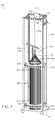
- Figure 1is an isometric of a braiding system 100 (“system 100") configured in accordance with the present technology.
- the system 100includes a frame 110, an upper drive unit 120 coupled to the frame 110, a lower drive unit 130 coupled to the frame 110, a plurality of tubes 140 (e.g., elongate housings) extending between the upper and lower drive units 120, 130 (collectively "drive units 120, 130"), and a mandrel 102.
- the drive units 120, 130 and the mandrel 102are coaxially aligned along a central axis L (e.g., a longitudinal axis).
- the tubes 140are arranged symmetrically with respect to the central axis L with their longitudinal axes parallel to the central axis L. As shown, the tubes 140 are arranged in a circular array about the central axis L. That is, the tubes 140 can each be spaced equally radially from the central axis L, and can collectively form a cylindrical shape. In other embodiments, the longitudinal axes of the tubes 140 may not be vertically aligned with (e.g., parallel to) the central axis L. For example, the tubes 140 can be arranged in a conical shape such that the longitudinal axes of the tubes 140 are angled with respect to and intersect the central axis L.
- the tubes 140can be arranged in a "twisted" shape in which the longitudinal axes of the tubes 140 are angled with respect to the central axis L, but do not intersect the central axis L (e.g., the top ends of the tubes can be angularly offset from the bottom ends of the tubes with respect the central axis L).
- the frame 110can generally comprise a metal (e.g., steel, aluminum, etc.) structure for supporting and housing the components of the system 100. More particularly, for example, the frame 110 can include an upper support structure 116 that supports the upper drive unit 120, a lower support structure 118 that supports the lower drive unit 130, a base 112, and a top 114. In some embodiments, the drive units 120, 130 are directly attached (e.g., via bolts, screws, etc.) to the upper and lower support structures 116, 118, respectively. In some embodiments, the base 112 can be configured to support all or a portion of the tubes 140. In the embodiment illustrated in Figure 1 , the system 100 includes wheels 111 coupled to the base 112 of the frame 110 and can, accordingly, be a portable system. In other embodiments, the base 112 can be permanently attached to a surface (e.g., a floor) such that the system 100 is not portable.
- a surfacee.g., a floor
- the system 100operates to braid filaments 104 loaded to extend radially from the mandrel 102 to the tubes 140.
- each tube 140can receive a single filament 104 therein.
- only a subset of the tubes 140receive a filament.
- the total number of filaments 104is one half the total number of tubes 140 that house the filament 104s. That is, the same filament 104 can have two ends, and two different tubes 140 can receive the different ends of the same filament 104 (e.g., after the filament 104 has been wrapped around or otherwise secured to the mandrel 102).
- the total number of filaments 104is the same as the number of tubes 140 that house a filament 104.
- each filament 104is tensioned by a weight secured to a lower portion of the filament 104.
- Figure 2is an enlarged cross-sectional view of an individual tube 140.
- the filament 104includes an end portion 207 coupled to (e.g., tied to, wrapped around, etc.) a weight 241 positioned within the tube 140.
- the weight 241can have a cylindrical or other shape and is configured to slide smoothly within the tube 140 as the filament 104 is paid out during the braiding process.
- the tubes 140can further include an upper edge portion (e.g., rim) 245 that is rounded or otherwise configured to permit the filament 104 to smoothly pay out from the tube 140.
- the tubes 140have a circular cross-sectional shape, and completely enclose the weights 241 and the filaments 104 disposed therein.
- the tubes 140may have other cross-sectional shapes, such as square, rectangular, oval, polygonal, etc., and may not completely enclose or surround the weights 241 and/or the filaments 104.
- the tubes 140may include slots, openings, and/or other features while still providing the necessary housing and restraint of the filaments 104.
- the tubes 140constrain lateral or "swinging" movement of the weights 241 and filaments 104 to inhibit significant swaying and tangling of these components along the full length of the filaments 104.
- Thisenables the system 100 to operate at higher speeds compared to systems in which filaments and/or tensioning means are non-constrained along their full lengths.
- filaments that are not constrainedmay sway and get tangled with each other if a pause or dwell time is not incorporated into the process so that the filaments can settle.
- the filaments 104are very fine wires that would otherwise require significant pauses for settling without the full-length constraint and synchronization of the present technology.
- the filaments 104are all coupled to identical weights to provide for uniform tensions within the system 100. However, in other embodiments, some or all of the filaments 104 can be coupled to different weights to provide different tensions. Notably, the weights 241 may be made very small to apply a low tension on the filaments 104 and thus allow for the braiding of fine (e.g., small diameter) and fragile filaments.
- the drive units 120, 130control the movement and location of the tubes 140.
- the drive units 120, 130are configured to drive the tubes 140 in a series of discrete radial and arcuate paths relative to the central axis L that move the filaments 104 in a manner that forms a braided structure 105 (e.g., a tubular braid; "braid 105") on the mandrel 102.
- the tubes 140each have an upper end portion 142 proximate the upper drive unit 120 and a lower end portion 144 proximate the lower drive unit 130.
- the drive units 120, 130work in synchronization to simultaneously drive the upper end portion 142 and the lower end portion 144 (collectively "end portions 142, 144") of each individual tube 140 along the same path or at least a substantially similar spatial path.
- end portions 142, 144By driving both end portions 142, 144 of the individual tubes 140 in synchronization, the amount of sway or other undesirable movement of the tubes 140 is highly limited.
- the system 100reduces or even eliminates pauses during the braiding process to allow the tubes to settle, which enables the system 100 to be operated at higher speeds than conventional systems.
- the drive units 120, 130can be arranged differently with respect to the tubes 130.
- the drive units 120, 130can be positioned at two locations that are not adjacent to the end portions 142, 144 of the tubes 140.
- the drive unitsPreferably, the drive units have a vertical spacing (e.g., arranged close enough to the end portions 142, 144 of the tubes 140) that provides stability to the tubes 140 and inhibit swaying or other unwanted movement of the tubes 140.
- the drive units 120, 130are substantially identical and include one or more mechanical connections so that they move identically (e.g., in synchronization).
- one of the drive units 120, 130can be an active unit while the other of the drive units 120, 130 can be a slave unit driven by the active unit.
- an electronic control system coupled to the drive units 120, 130is configured to move the tubes 140 in an identical sequence, spatially and temporally.
- the drive units 120, 130can have the same components but with varying diameters.
- the mandrel 102is attached to a pull mechanism 106 configured to move (e.g., raise) the mandrel 102 along the central axis L relative to the tubes 140.
- the pull mechanism 106can include a shaft 108 (e.g., a cable, string, rigid structure, etc.) that couples the mandrel 102 to an actuator or motor (not pictured) for moving the mandrel 102.
- the pull mechanism 106can further include one or more guides 109 (e.g., wheels, pulleys, rollers, etc.) coupled to the frame 110 for guiding the shaft 108 and directing the force from the actuator or motor to the mandrel 102.
- the mandrel 102can be raised away from the tubes 140 to extend the surface for creating the braid 105 on the mandrel 102.
- the rate at which the mandrel 102 is raisedcan be varied in order to vary the characteristics of the braid 105 (e.g., to increase or decrease the braid angle (pitch) of the filaments 104 and thus the pore size of the braid 105).
- the ultimate length of the finished braiddepends on the available length of the filaments 104 in the tubes 140, the pitch of the braid, and the available length of the mandrel 102.
- the mandrel 102can have lengthwise grooves along its length to, for example, grip the filaments 104.
- the mandrel 102can further include components for inhibiting rotation of the mandrel 102 relative to the central axis L during the braiding process.
- the mandrel 102can include a longitudinal keyway (e.g., channel) and a stationary locking pin slidably received in the keyway that maintains the orientation of the mandrel 102 as it is raised.
- the diameter of the mandrel 102is limited on the large end only by the dimensions of the drive units 120, 130, and on the small end by the quantities and diameters of the filaments 104 being braided.
- the system 100can further include one or weights coupled to the mandrel 102.
- the weightscan put the mandrel 102 under significant tension and prevent the filaments 104 from deforming the mandrel 102 longitudinally during the braiding process.
- the weightscan be configured to further inhibit rotation of the mandrel 102 and/or replace the use of a keyway and locking pin to inhibit rotation.
- the system 100can further include a bushing (e.g., ring) 117 coupled to the frame 110 via an arm 115.
- the mandrel 102extends through the bushing 117 and the filaments 104 each extend through an annular opening between the mandrel 102 and the bushing 117.
- the bushing 117has an inner diameter that is only slightly larger than an outer diameter of the mandrel 102. Therefore, during operation, the bushing 117 forces the filaments 104 against the mandrel 102 such that the braid 105 pulls tightly against the mandrel 102.
- the bushing 117can have an adjustable inner diameter to accommodate filaments of different diameters. Similarly, in certain embodiments, the vertical position of the bushing 117 can be varied to adjust the point at which the filaments 104 converge to form the braid 105.
- FIG 3is an isometric view of the upper drive unit 120 shown in Figure 1 configured in accordance with embodiments of the present technology.
- the upper drive unit 120includes an outer assembly 350 and an inner assembly 370 (collectively "assemblies 350, 370") arranged concentrically about the central axis L ( Figure 1 ).
- the outer assembly 350includes (i) outer slots (e.g., grooves) 354, (ii) outer drive members (e.g., plungers) 356 aligned with and/or positioned within corresponding outer slots 354, and (iii) an outer drive mechanism configured to move the outer drive members 356 radially inward through the outer slots 354.
- the number of outer slots 354can be equal to the number of tubes 140 in the system 100, and the outer slots 354 are configured to receive the tubes 140 therein.
- the outer assembly 350includes 48 outer slots 354. In other embodiments, the outer assembly 350 can have a different number of outer slots 354 such as 12 slots, 24 slots, 96 slots, or any other preferably even number of slots.
- the outer assembly 350further includes an upper plate 351a and a lower plate 351b opposite the upper plate 351a.
- the upper plate 351aat least partially defines an upper surface of the outer assembly 350.
- the lower plate 351bcan be attached to the upper support structure 116 of the frame 110.
- the outer drive mechanism of the outer assembly 350includes a first outer cam ring 352a and a second outer cam ring 352b (collectively “outer cam rings 352") positioned between the upper and lower plates 351a, 351b.
- a first outer cam ring motor 358acan be an electric motor configured to drive the first outer cam ring 352a to move a first set of the outer drive members 356 radially inward to thereby move a first set of the tubes 140 radially inward.
- a second outer cam ring motor 358bis configured to rotate the second outer cam ring 352b to move a second set of the outer drive members 356 radially inward to thereby move a second set of the tubes 140 radially inward.
- the first outer cam ring motor 358acan be coupled to one or more pinions 357a configured to engage a corresponding first track 359a on the first outer cam ring 352a
- the second outer cam ring motor 358bcan be coupled to one or more pinions 357b configured to engage a corresponding second track 359b on the second outer cam ring 352b.
- the first and second tracks 359a, 359bextend only partially around the perimeter of the first and second outer cam rings 352a, 352b respectively. Accordingly, in such embodiments, the outer cam rings 352 are not configured to fully rotate about the central axis L. Rather, the outer cam rings 352 move through only a relatively small arc length (e.g., about 1°-5°, or about 5°-10°) about the central axis L. In operation, the outer cam rings 352 can be rotated in a first direction and a second direction (e.g., by reversing the motor) through the relatively small angle. In other embodiments, the tracks 359 extend around a larger portion of the perimeter, such as the entire perimeter, of the outer cam rings 352, and the outer cam rings 352 can be rotated more fully (e.g., entirely) about the central axis L.
- the tracks 359extend around a larger portion of the perimeter, such as the entire perimeter, of the outer cam rings 352, and the outer cam rings 352 can be rotated more
- the inner assembly 370includes (i) inner slots (e.g., grooves) 374, (ii) inner drive members (e.g., plungers) 376 aligned with and/or positioned within corresponding ones of the inner slots 374, and (iii) an inner drive mechanism configured to move the inner drive members 376 radially outward through the inner slots 374.
- the number of inner slots 374can be equal to one half the number of outer slots 354 (e.g., 24 inner slots 374) such that the inner slots 374 are configured to receive a subset (e.g., half) of the tubes 140 therein.
- the ratio of outer slots 354 to inner slots 374can be different in other embodiments, such as one-to-one.
- the inner slots 374are aligned with alternating ones of the tubes 140 and the outer slots 354 and, as described in further detail below, one of the outer cam rings 352 can be rotated to move the aligned tubes 140 into the inner slots 374.
- the inner assembly 370can further include a lower plate 371b that is rotatably coupled to an inner support member 373.
- the rotatable couplingcomprises a plurality of bearings disposed in a circular groove formed between the inner support member 373 and the lower plate 371b.
- the inner assembly 370can further include an upper plate 371a opposite the lower plate 371b and at least partially defining an upper surface of the inner assembly 370.
- the inner drive mechanismcomprises an inner cam ring 372 positioned between the upper and lower plates 371a, 371b.
- An inner cam ring motor 378is configured to drive (e.g., rotate) the inner cam ring 372 to move all of the inner drive members 376 radially outward to thereby move tubes 140 positioned in the inner slots 374 radially outward.
- the inner cam ring motor 378can be generally similar to the first and second outer cam ring motors 358a, 358b (collectively "outer cam ring motors 358").
- the inner cam ring motor 378can be coupled to one or more pinions configured to engage (e.g., mate with) a corresponding track on the inner cam ring 372 (obscured in Figure 3 ; best illustrated in Figure 6 ).
- the trackextends around only a portion of an inner perimeter of the inner cam ring 372, and the inner cam ring motor 378 is rotatable in a first direction and a second opposite direction to drive the inner cam ring 372 through only a relatively small arc length (e.g., about 1°-5°, about 5°-10°, or about 10°-20°) about the central axis L.
- the inner assembly 370further includes an inner assembly motor 375 configured to rotate the inner assembly 370 relative to the outer assembly 350. This rotation allows for the inner slots 374 to be rotated into alignment with different outer slots 354.
- the operation of the inner assembly motor 375can be generally similar to that of the outer cam ring motors 358 and the inner cam ring motor 378.
- the inner assembly motor 375can rotate one or more pinions coupled to a track mounted on the lower plate 371b and/or the upper plate 371a.
- the upper drive unit 120is configured to drive the tubes 140 in three distinct movements: (i) radially inward (e.g., from the outer slots 354 to the inner slots 374) via rotation of the outer cam rings 352 of the outer assembly 350; (ii) radially outward (e.g., from the inner slots 374 to the outer slots 354) via rotation of the inner cam ring 372 of the inner assembly 370; and (iii) circumferentially via rotation of the inner assembly 370.
- these movementscan be mechanically independent and a system controller (not pictured; e.g., a digital computer) can receive input from a user via a user interface indicating one or more operating parameters for these movements as well as the movement of the mandrel 102 ( Figure 1 ).
- the system controllercan drive each of the four motors in the drive units 120, 130 (e.g., the outer cam ring motors 358, the inner cam ring motor 378, and the inner assembly motor 375) with closed loop shaft rotation feedback.
- the system controllercan relay the parameters to the various motors (e.g., via a processor), thereby allowing manual and/or automatic control of the movements of the tubes 140 and the mandrel 102 to control formation of the braid 105.
- the system 100can be parametric and many different forms of braid can be made without modification of the system 100.
- the various motions of the drive units 120, 130are mechanically sequenced such that turning a single shaft indexes the drive units 120, 130 through an entire cycle.
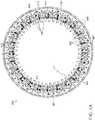
- Figure 4Ais a top view
- Figure 4Bis an enlarged top view, of an embodiment of the outer assembly 350 of the upper drive unit 120.
- the upper plate 351a and the first outer cam ring 352aare not pictured to more clearly illustrate the operation of the outer assembly 350.
- the lower plate 351bhas an inner edge 463 that defines a central opening 464.
- a plurality of wall portions 462are arranged circumferentially around the lower plate 351b and extend radially inward beyond the inner edge 463 of the lower plate 351b.
- Each pair of adjacent wall portions 462defines one of the outer slots 354 in the central opening 464.
- the wall portions 462can be fastened to the lower plate 351b (e.g., using bolts, screws, welding, etc.) or integrally formed with the lower plate 351b. In other embodiments, all or a portion of the wall portions 462 can be on the upper plate 351a rather than the lower plate 351b of the outer assembly 350.
- the second outer cam ring 352bincludes an inner surface 465 having a periodic (e.g., oscillating) shape including a plurality of peaks 467 and troughs 469.
- the inner surface 465has a smooth sinusoidal shape, while in other embodiments, the inner surface 465 can have other periodic shapes such as a saw-tooth shape.
- the second outer cam ring 352bis rotatably coupled to the lower plate 351b such that the second outer cam ring 352b and the lower plate 351b can rotate with respect to each other.
- the rotatable couplingcomprises a plurality of bearings disposed in a first circular channel (obscured in Figures 4A in 4B) formed between the lower plate 351b and the second outer cam ring 352b.
- the second outer cam ring 352bincludes a second circular channel 461 for rotatably coupling the second outer cam ring 352b to the first outer cam ring 352a via a plurality of bearings.
- the first circular channelcan be substantially identical to the second circular channel 461.
- the first outer cam ring 352acan be substantially identical to the second outer cam ring 352b.
- the outer drive members 356are positioned in between adjacent wall portions 462.
- Each of the outer drive members 356is identical, although alternating ones of the outer drive members 356 are oriented differently within the outer assembly 350.
- adjacent ones of the outer drive members 356can be flipped vertically relative to a plane defined by the lower plate 351b.
- the outer drive members 356each comprise a body portion 492 coupled to a push portion 494.
- the push portions 494are configured to engage (e.g., contact and push) tubes positioned within the outer slots 354.
- the body portions 492further comprise a stepped portion 491 that does not engage the outer cam rings 352, and an extension portion 493 that engages only one of the outer cam rings 352.
- a first set of outer drive members 456ahave an extension portion 493 that continuously contacts the inner surface 465 of the second outer cam ring 352b, but does not contact an inner surface of the first outer cam ring 352a.
- the extension portions 493 of the first set of outer drive members 456ado not contact the inner surface of the first outer cam ring 352a as they extend below the first outer cam ring 352a.
- a second set of outer drive members 456bhave extension portions 493 that continuously contact the inner surface of the first outer cam ring 352a, but do not contact the second outer cam ring 352b.
- the extension portions 493 of the second set of outer drive members 456bdo not contact the inner surface 465 of the second outer cam ring 352b as they extend above the second outer cam ring 352b.
- each of the outer cam rings 352is configured to drive only one set (e.g., half) of the outer drive members 356.
- the outer drive members 356can further include bearings 495 or other suitable mechanisms for providing a smooth coupling between the outer drive members 356 and the outer cam rings 352.
- the first set of outer drive members 456acan be coupled to the lower plate 351b in between alternating, adjacent pairs of the wall portions 462.
- the second set of outer drive member 456bcan be coupled to the upper plate 351a and positioned in between alternating, adjacent pairs of the wall portions 462 when the outer assembly 350 is assembled (e.g., when the upper plate 351a is coupled to the lower plate 351b).
- the outer drive members 356can be slidably coupled to a frame 496 that is attached to one of the upper or lower plates 351a, 351b by a plurality of screws 497. In other embodiments, all of the outer drive members 356 can be attached (e.g., via the frame 496 and screws 497) to the lower plate 351b or the upper plate 351a.
- a biasing member 498e.g., a spring extends between each outer drive member 356 and the corresponding frame 496, and exerts a radially outward biasing force against the outer drive members 356.
- each of the outer drive members 356is in a radially retracted position.
- the troughs 469 of the inner surface 465 of the second outer cam ring 352bare aligned with the first set of outer drive members 456a.
- the extension portions 493 of the outer drive members 356are at or nearer to the troughs 469 than the peaks 467 of the inner surface 465.
- the radially outward biasing force of the biasing members 498retracts the first set of outer drive members 456a into the space provided by the troughs 469.
- the operation of the second set of outer drive members 456b and the first outer cam ring 352acan be carried out in a substantially similar or identical manner.
- Figure 5is a top view of the inner assembly 370 of the upper drive unit 120.
- the upper plate 371ais not pictured to more clearly illustrate the operation of the inner assembly 370.
- the lower plate 371bhas an outer edge 583
- the inner assembly 370includes a plurality of wall portions 582 arranged circumferentially about the lower plate 371b and extending radially outward beyond the outer edge 583.
- Each pair of adjacent wall portions 582defines one of the inner slots 374.
- the wall portions 582can be fastened to the lower plate 371b (e.g., using bolts, screws, welding, etc.) or integrally formed with the lower plate 371b. In other embodiments, at least some of the wall portions 582 are on the upper plate 371a rather than the lower plate 371b of the inner assembly 370.
- the inner cam ring 372includes an outer surface 585 having a periodic (e.g., oscillating) shape including a plurality of peaks 587 and troughs 589.
- the outer surface 585has a saw-tooth shape, while in other embodiments, the outer surface 585 can have other periodic shapes such as a smooth sinusoidal shape.
- the inner cam ring 372is rotatably coupled to the lower plate 371b by, for example, a plurality of ball bearings disposed in a first circular channel (obscured in the top view of Figure 5 ) formed between the lower plate 371b and the inner cam ring 372.
- the inner cam ring 372includes a second circular channel 581 for rotatably coupling the inner cam ring 372 to the upper plate 371a via, for example, a plurality of ball bearings.
- the first circular channelcan be substantially identical to the second circular channel 581.
- the inner cam ring 372can accordingly rotate with respect to the upper and lower plates 371a and 371b.
- each of the inner drive members 376is identical, and the inner drive members 376 can be identical to the outer drive members 356 ( Figures 4A and 4B ).
- each of the inner drive members 376can have a body 492 including a stepped portion 491 and an extension portion 493, and the inner drive members 376 can each be slidably coupled to a frame 496 mounted to the lower plate 371b.
- biasing members 498extending between each inner drive member 376 and their corresponding frame 496 exert a radially inward biasing force against the inner drive members 376.
- the extension portions 493 of the inner drive members 376continuously contact the outer surface 585 of the inner cam ring 372.
- rotation of the outer periodic surface 585drives the inner drive members 376 radially outward, while the biasing members 498 retract the inner drive members 376 radially inward.
- the inner drive members 376are in a radially retracted position.
- the troughs 589 of the outer surface 585 of the inner cam ring 372are radially aligned with the inner drive members 376 such that the extension portions 593 of the inner drive members 376 are at or nearer to the troughs 589 than the peaks 587 of the outer surface 585.
- the inner cam ring 372rotates to move the peaks 587 of the outer surface 585 into radial alignment with the inner drive members 376. Since the biasing members 498 urge the extension portions 493 into continuous contact with the outer surface 585, the inner drive members 376 are continuously forced radially inward as the outer surface 585 rotates from trough 589 to peak 587. To subsequently return the inner drive members 576 to the radially retracted position, the inner cam ring 372 is rotated to move the troughs 589 into radial alignment with the inner drive members 576. As this rotation occurs, the radially inward biasing force provided by the biasing members 598 inwardly retracts the inner drive members 376 into the space provided by the troughs 589.
- each of the drive members in the system 100is actuated by the rotation of a cam ring that provides a consistent and synchronized actuation force to all of the drive members.
- a cam ringthat provides a consistent and synchronized actuation force to all of the drive members.
- filamentsare actuated individually or in small sets by separately controlled actuators, if one actuator is out of synchronization with another, there is a possibility of tangling of filaments.
- FIG 6is an enlarged isometric view of a portion of the upper drive unit 120 shown in Figure 3 that illustrates the synchronous (e.g., reciprocal) action of the assemblies 350, 370.
- the upper plate 351a of the outer assembly 350 and the upper plate 371a of the inner assembly 370are not shown in Figure 6 to more clearly illustrate the operation of these components.
- all of the tubes 140are positioned in the outer slots 354 of the outer assembly 350. Accordingly, each of the outer drive members 356 is in a retracted position so that there is space for the tubes 140 in the outer slots 354.
- the troughs 469(partially obscured; illustrated in Figures 4A and 4B ) of the inner surface 465 of the second outer cam ring 352b are radially aligned with the first set of outer drive members 456a
- troughs 669 of a periodic inner surface 665 of first outer cam ring 352aare radially aligned with the second set of outer drive members 456b
- the biasing members 498 coupled to the outer drive members 356have a minimum length (e.g., a fully compressed position).
- the inner drive members 376are in a fully extended position in which the inner drive members 376 are in contact with the outer surface 585 of the inner cam ring 372 at or nearer to the peaks 587 of the outer surface 585 than the troughs 589.
- the biasing members 498 coupled to the inner drive members 376have a maximum length (e.g., a fully expanded position).
- the first set of outer drive members 456aare radially aligned with the inner slots 374.
- the first set of outer drive members 456acan move the tubes 140 in the outer slots 354 corresponding to the first set of outer drive members 456a to the inner slots 374.
- the second outer cam ring motor 358b( Figure 3 ) can be actuated to rotate (e.g., either clockwise or counterclockwise) the second outer cam ring 352b and thereby align the peaks 467 of the inner surface 465 with the first set of outer drive members 456a.
- the inner surface 465accordingly drives the first set of outer drive members 456a radially inward.
- the inner cam ring motor 378can be actuated to rotate the inner cam ring 372 (e.g., in the counterclockwise direction) to align the troughs 589 of the outer surface 585 of the inner cam ring 372 with the inner drive members 376.
- This movement of the inner cam ring 372causes the inner drive members 376 to retract radially inward.
- the assemblies 350, 370can be configured retain the tubes 140 in a well-controlled space. More specifically, at the same time that the outer drive members 356 move radially inward, the inner drive members 376 retract a corresponding amount to maintain the space for the tubes 140, and vice versa. This keeps the tubes 140 moving in a discrete, predictable pattern determined by a control system of the system 100.
- FIG 7is an isometric view of the lower drive unit 130 shown in Figure 1 configured in accordance with embodiments of the present technology.
- the lower drive unit 130has components and functions that are substantially the same as or identical to the upper drive unit 120 described in detail above with reference to Figures 3-6 .
- the lower drive unit 130includes an outer assembly 750 and an inner assembly 770.
- the outer assembly 750can include (i) outer slots, (ii) outer drive members aligned with and/or positioned within corresponding outer slots, and (iii) an outer drive mechanism configured to move the outer drive members radially inward through the outer slots, etc.
- the inner assembly 770can include (i) inner slots, (ii) inner drive members aligned with and/or positioned within corresponding inner slots, and an inner drive mechanism configured to move the inner drive members radially outward through the inner slots, etc.
- the inner drive mechanisms (e.g., inner cam rings) of the drive units 120, 130move in a substantially identical sequence both spatially and temporally to drive the upper portion and lower portion of each individual tube 140 along the same or a substantially similar spatial path.
- the outer drive mechanisms (outer cam rings) of the drive units 120, 130move in a substantially identical sequence both spatially and temporally.
- the drive units 120, 130are synchronized using a mechanical connection.
- jackshafts 713can mechanically couple corresponding components of the inner and outer drive mechanisms of the drive units 120, 130.
- the jackshafts 713mechanically couple the first outer cam ring 352a of the upper drive unit 120 to a matching first outer ring cam in the lower drive unit 130, and the second outer cam ring 352b of the upper drive unit 120 to a matching second outer ring cam in the lower drive unit 130.
- Jackshafts 713can similarly couple the inner cam ring 372 and the inner assembly 370 (e.g., for rotating the inner assembly 370) to corresponding components in the lower drive unit 130.
- Including separate motors on both drive units 120, 130avoids torsional whip in the jackshafts while assuring motion synchronization between the drive units 120, 130.
- the motors in one of the drive 120, 130are closed loop controlled, while the motors in the other of the drive units 120, 130 act as slaves.
- the drive units 120, 130move one of two sets of tubes 140 (and the filaments positioned within those tubes) at a time. Each set consists of alternating ones of the tubes 140 and therefore one half of the total number of tubes 140.
- the drive units 120, 130 move a setthe set is moved (i) radially inward, (ii) rotated past the other set, and then (iii) moved radially outward.
- the sequenceis then applied to the other set, with rotation happening in the opposite direction. That is, one set moves around the central axis L ( Figure 1 ) in a clockwise direction, while the other set moves around the central axis L in a counterclockwise direction. All of the tubes 140 of each set move simultaneously and, when one set is in motion, the other set is stationary. This general cycle is repeated to form the braid 105 on the mandrel 102 ( Figure 1 ).
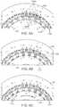
- Figures 8A-8Hare schematic views more particularly showing the movement of six tubes within the upper drive unit 120 at various stages in a method of forming a braided structure (e.g., the braid 105) in accordance with embodiments of the present technology. While reference is made to the movement of the tubes within the upper drive unit 120, the illustrated movement of the tubes is substantially the same or even identical in the lower drive unit 130. Moreover, while only six tubes are shown in Figures 8A-8H for ease of explanation and understanding, one skilled in the art will readily understand that the movement of the six tubes is representative of any number of tubes (e.g., 24 tubes, 48 tubes, 96 tubes, or other numbers of tubes).
- the six tubesare individually labeled 1-6 and are all initially positioned in separate outer slots 354 of the outer assembly 350, labeled A-F, respectively.
- a first set of tubes 840a(including tubes 1, 3, and 5) positioned in the outer slots 354 labeled A, C, E are radially aligned with corresponding inner slots 374 labeled X-Z of the inner assembly 370.
- a second set of tubes 840b(including tubes 2, 4, and 6) positioned in the outer slots 354 labeled B, D, and F are not radially aligned with any of the inner slots 374 of the inner assembly 370.
- the reference numerals A-F for the outer slots 354, X-Z for the inner slots 374, and 1-6 for the tubesare reproduced in each of Figures 8A-8H in order to illustrate the relative movement of these components.
- the first set of tubes 840ais moved radially inward from the outer slots 354 of the outer assembly 350 to the inner slots 374 of the inner assembly 370.
- the outer drive members 356 aligned with the first set of tubes 840amove radially inward and drive the first set of tubes 840a radially inward into the inner slots 374.
- the inner drive members 376can be retracted radially inward through the inner slots 374 to provide space for the first set of tubes 840a to be moved into the inner slots 374. In this manner, the outer assembly 350 and inner assembly 370 move in concert with each other to manipulate the space provided for the first set of tubes 840a.
- the inner assembly 370rotates in a first direction (e.g., in the clockwise direction indicated by the arrow CW) to align the inner slots 374 with a different set of the outer slots 354.
- the inner slots 374are aligned with a different set of outer slots 354 that are two slots away.
- this steppasses the filaments in the first set of tubes 840a under the filaments in the second set of tubes 840b.
- the first set of tubes 840ais moved radially outward from the inner slots 374 of the inner assembly 370 to the outer slots 354 of the outer assembly 350.
- the inner drive members 376move radially outward through the inner slots 374 and drive the first set of tubes 840a radially outward into the outer slots 354 aligned with the inner slots 374.
- the outer drive members 356are retracted radially outward through the aligned outer slots 354 to provide space for the first set of tubes 840a to be moved into the outer slots 354.
- the second set of tubes 840bis stationary during each step in which the first set of tubes 840a is moved.
- the inner assembly 370is rotated in a second direction (e.g., in the counterclockwise direction indicated by the arrow CCW) to align the inner slots 374 with different outer slots 354-i.e., those holding the second set of tubes 840b.
- the inner assembly 370can be rotated in the first direction to align the inner slots 374 with different outer slots 354.
- the inner assembly 370is rotated to align each inner slot 374 with a different outer slot 354 that is one slot away (e.g., an adjacent outer slot 354).
- the outer drive members 356 aligned with the second set of tubes 840bmove radially inward through the outer slots 354 and drive the second set of tubes 840b radially inward into the inner slots 374 while, at the same time, the inner drive members 376 retract radially inward through the inner slots 374 to provide space for the second set of tubes 840b to be moved into the inner slots 374.
- the inner assembly 370is rotated in the second direction (e.g., in the clockwise direction indicated by the arrow CCW) to align the inner slots 374 with a different set of the outer slots 354.
- the inner assembly 370is rotated to align each inner slot 374 with a different outer slot 354 that is two slots away.
- the inner slot 374 labeled Ywas previously aligned with the outer slot 354 labeled D ( Figure 8E )
- this steppasses the filaments in the second set of tubes 840b under the filaments in the first set of tubes 840a.
- the second set of tubes 840bis moved radially outward from the inner slots 374 of the inner assembly 370 to the outer slots 354 of the outer assembly 350.
- the inner drive members 376move radially outward through the inner slots 374 and drive the first set of tubes 840a radially outward into the outer slots 354 aligned with the inner slots 374.
- the outer drive members 356can be retracted radially outward through the outer slots 354 in order to provide space for the first set of tubes 840a to be moved into the outer slots 354.
- the first set of tubes 840ais stationary during each step in which the second set of tubes 840b is moved.
- the inner assembly 370rotates in the first direction (e.g., in the clockwise direction indicated by the arrow CCW) to align the inner slots 374 with different ones of the outer slots 354-i.e., those holding the first set of tubes 840a.
- the inner assembly 370rotates in the second direction to align the inner slots 374 with different ones of the outer slots 354.
- rotation of the inner assembly 370aligns the inner slots 374 with a different set of outer slots 354 that are one slot away (e.g., an adjacent outer slot 354).
- each tube in the first set of tubes 840ahas been rotated in the first direction (e.g., rotated two outer slots 354 in the clockwise direction) relative to the initial position shown in Figure 8A
- each tube in the second set of tubes 840bhas been rotated in the second direction (e.g., rotated two outer slots 354 in the counterclockwise direction) relative to the initial position of Figure 8A .
- Figure 9is a screenshot of a user interface 900 that can be used to control the system 100 ( Figure 1 ) and the characteristics of the resulting braid 105 formed on the mandrel 102.
- a plurality of clickable, pushable, or otherwise engageable buttons, indicators, toggles, and/or user elementsis shown within the user interface 900.
- the user interface 900can include a plurality of elements each indicating a desired and/or expected characteristic for the resulting braid 105.
- characteristicscan be selected for one or more zones (e.g., the 7 illustrated zones) each corresponding to a different vertical portion of the braid 105 formed on the mandrel 102.
- elements 910can indicate a length for the zone along the length of the mandrel or braid (e.g., in cm)
- elements 920can indicate a number of picks (a number of crosses) per cm
- elements 930can indicate a pick count (e.g., a total pick count)
- elements 940can indicate a speed for the process (e.g., in picks formed per minute)
- elements 950can indicate a braiding wire count.
- the userif the user inputs a specific characteristic for a zone, some or all of the other characteristics may be constrained or automatically selected.
- a user input of a certain number of "picks per cm” and zone “length”may constrain or determine the possible number of "picks per cm.”
- the user interfacecan further include selectable elements 960 for pausing of the system 100 after the braid 105 has been formed in a certain zone, and selectable elements 970 for keeping the mandrel stationary during the formation of a particular zone (e.g., to permit manual jogging of the mandrel 102 rather than automatic).
- the user interfacecan include elements 980a and 980b for jogging the table, elements 985a and 985b for jogging (e.g., raising or lowering) the mandrel 102 up or down, respectively, elements 990a and 990b for loading a profile (e.g., a set of saved braid characteristics) and running a selected profile, respectively, and an indicator 995 for indicating that a run (e.g., all or a portion of a braiding process) is complete.
- a profilee.g., a set of saved braid characteristics
- an indicator 995for indicating that a run (e.g., all or a portion of a braiding process) is complete.
- FIG. 10is an enlarged view of the mandrel 102 and the braid 105 formed thereon.
- the braid 105 or mandrel 102can include a first zone Z1, a second zone Z2, and a third zone Z3 each having different characteristics.
- the first zone Z1can have a higher pick count than the second and third zones Z2 and Z3, and the second zone Z2 can have a higher pick count than third zone Z3.
- the braid 105can therefore have a varying flexibility-as well as pore size-in each zone.
Landscapes
- Engineering & Computer Science (AREA)
- Textile Engineering (AREA)
- Manufacturing & Machinery (AREA)
- Braiding, Manufacturing Of Bobbin-Net Or Lace, And Manufacturing Of Nets By Knotting (AREA)
Description
- The present application claims priority to
U.S. Provisional Application No. 62/408,604, filed October 14, 2016 U.S. Provisional Application No. 62/508,938, filed May 19, 2017 - The present technology relates generally to systems and methods for forming a tubular braid of filaments. In particular, some embodiments of the present technology relate to systems for forming a braid through the movement of vertical tubes, each housing a filament, in a series of discrete radial and arcuate paths around a longitudinal axis of a mandrel.
- Braids generally comprise many filaments interwoven together to form a cylindrical or otherwise tubular structure. Such braids have a wide array of medical applications. For example, braids can be designed to collapse into small catheters for deployment in minimally invasive surgical procedures. Once deployed from a catheter, some braids can expand within the vessel or other bodily lumen in which they are deployed to, for example, occlude or slow the flow of bodily fluids, to trap or filter particles within a bodily fluid, or to retrieve blood clots or other foreign objects in the body.
- Some known machines for forming braids operate by moving spools of wire such that the wires paid out from individual spools cross over/under one another. However, these braiding machines are not suitable for most medical applications that require braids constructed of very fine wires that have a low tensile strength. In particular, as the wires are paid out from the spools they can be subject to large impulse forces that may break the wires. Other known braiding machines secure a weight to each wire to tension the wires without subjecting them to large impulse forces during the braiding process. These machines then manipulate the wires using hooks other means for gripping the wires to braid the wires over/under each other. One drawback with such braiding machines is that they tend to be very slow. Moreover, since braids have many applications, the specifications of their design, such as their length, diameter, pore size, etc., can vary greatly. Accordingly, it would be desirable to provide a braiding machine capable of forming braids with varying dimensions, using very thin filaments, and at higher speeds that hook-type over/under braiders.
US 2013/092013 A1 discloses devices and methods for forming a tubular braid comprising a plurality of filaments.US 2013/060323 A1 discloses a braided helical wire stent.DE 20 2008 001829 U1 discloses a device for the production of a braid.- Many aspects of the present disclosure can be better understood with reference to the following drawings. The components in the drawings are not necessarily to scale. Instead, emphasis is placed on illustrating clearly the principles of the present disclosure.
Figure 1 is an isometric view of a braiding system configured in accordance with embodiments of the present technology.Figure 2 is an enlarged cross-sectional view of a tube of the braiding system shown inFigure 1 configured in accordance with embodiments of the present technology.Figure 3 is an isometric view of an upper drive unit of the braiding system shown inFigure 1 configured in accordance with embodiments of the present technology.Figure 4A is a top view, andFigure 4B is an enlarged top view, of an outer assembly of the upper drive unit shown inFigure 3 configured in accordance with embodiments of the present technology.Figure 5 is a top view of an inner assembly of the upper drive unit shown inFigure 3 configured in accordance with embodiments of the present technology.Figure 6 is an enlarged isometric view of a portion of the upper drive unit shown inFigure 3 configured in accordance with embodiments of the present technology.Figure 7 is an isometric view of a lower drive unit of the braiding system shown inFigure 1 configured in accordance with embodiments of the present technology.Figures 8A-8H are enlarged, schematic views of the upper drive unit shown inFigure 3 at various stages in a method of forming a braided structure in accordance with embodiments of the present technology.Figure 9 is a display of user interface for a braiding system controller configured in accordance with embodiments of the present technology.Figure 10 is an isometric of a portion of a mandrel of the braiding system shown inFigure 1 configured in accordance with embodiments of the present technology.- The present invention is directed to systems and methods for forming a braided structure from a plurality of filaments as specified in
claims 1 and 12. A braiding system according to the invention includes an upper drive unit, a lower drive unit coaxially aligned with the upper drive unit along a central axis, and a plurality of tubes extending between the upper and lower drive units and constrained within the upper and lower drive units. Each tube is configured to receive the end of an individual filament attached to a weight. The filaments extend from the tubes to a mandrel aligned with the central axis. The upper and lower drive units act in synchronization to move a subset of the tubes (i) radially inward toward the central axis, (ii) radially outward from the central axis, (iii) and rotationally about the central axis. Accordingly, the upper and lower drive units can operate to move the subset of tubes-and the filaments held therein-past another subset of tubes to form, for example, an "over/under" braided structure on the mandrel. Because the wires are contained within the tubes and the upper and lower drive units act in synchronization upon both the upper and lower portion of the tubes, the tubes can be rapidly moved past each other to form the braid. This is a significant improvement over systems that do not move both the upper and lower portions of the tubes in synchronization. Moreover, the present systems permit for very fine filaments to be used to form the braid since tension is provided using a plurality of weights. The filaments are therefore not subject to large impulse forces during the braiding process that may break them. - As used herein, the terms "vertical," "lateral," "upper," and "lower" can refer to relative directions or positions of features in the braiding systems in view of the orientation shown in the Figures. For example, "upper" or "uppermost" can refer to a feature positioned closer to the top of a page than another feature.
Figure 1 is an isometric of a braiding system 100 ("system 100") configured in accordance with the present technology. Thesystem 100 includes aframe 110, anupper drive unit 120 coupled to theframe 110, alower drive unit 130 coupled to theframe 110, a plurality of tubes 140 (e.g., elongate housings) extending between the upper andlower drive units 120, 130 (collectively "drive units mandrel 102. In some embodiments, thedrive units mandrel 102 are coaxially aligned along a central axis L (e.g., a longitudinal axis). In the embodiment illustrated inFigure 1 , thetubes 140 are arranged symmetrically with respect to the central axis L with their longitudinal axes parallel to the central axis L. As shown, thetubes 140 are arranged in a circular array about the central axis L. That is, thetubes 140 can each be spaced equally radially from the central axis L, and can collectively form a cylindrical shape. In other embodiments, the longitudinal axes of thetubes 140 may not be vertically aligned with (e.g., parallel to) the central axis L. For example, thetubes 140 can be arranged in a conical shape such that the longitudinal axes of thetubes 140 are angled with respect to and intersect the central axis L. In yet other embodiments, thetubes 140 can be arranged in a "twisted" shape in which the longitudinal axes of thetubes 140 are angled with respect to the central axis L, but do not intersect the central axis L (e.g., the top ends of the tubes can be angularly offset from the bottom ends of the tubes with respect the central axis L).- The
frame 110 can generally comprise a metal (e.g., steel, aluminum, etc.) structure for supporting and housing the components of thesystem 100. More particularly, for example, theframe 110 can include anupper support structure 116 that supports theupper drive unit 120, alower support structure 118 that supports thelower drive unit 130, abase 112, and atop 114. In some embodiments, thedrive units lower support structures base 112 can be configured to support all or a portion of thetubes 140. In the embodiment illustrated inFigure 1 , thesystem 100 includeswheels 111 coupled to thebase 112 of theframe 110 and can, accordingly, be a portable system. In other embodiments, thebase 112 can be permanently attached to a surface (e.g., a floor) such that thesystem 100 is not portable. - The
system 100 operates tobraid filaments 104 loaded to extend radially from themandrel 102 to thetubes 140. As shown, eachtube 140 can receive asingle filament 104 therein. In other embodiments, only a subset of thetubes 140 receive a filament. In some embodiments, the total number offilaments 104 is one half the total number oftubes 140 that house the filament 104s. That is, thesame filament 104 can have two ends, and twodifferent tubes 140 can receive the different ends of the same filament 104 (e.g., after thefilament 104 has been wrapped around or otherwise secured to the mandrel 102). In other embodiments, the total number offilaments 104 is the same as the number oftubes 140 that house afilament 104. - Each
filament 104 is tensioned by a weight secured to a lower portion of thefilament 104. For example,Figure 2 is an enlarged cross-sectional view of anindividual tube 140. In the embodiment illustrated inFigure 2 , thefilament 104 includes anend portion 207 coupled to (e.g., tied to, wrapped around, etc.) aweight 241 positioned within thetube 140. Theweight 241 can have a cylindrical or other shape and is configured to slide smoothly within thetube 140 as thefilament 104 is paid out during the braiding process. Thetubes 140 can further include an upper edge portion (e.g., rim) 245 that is rounded or otherwise configured to permit thefilament 104 to smoothly pay out from thetube 140. As shown, thetubes 140 have a circular cross-sectional shape, and completely enclose theweights 241 and thefilaments 104 disposed therein. In other embodiments, thetubes 140 may have other cross-sectional shapes, such as square, rectangular, oval, polygonal, etc., and may not completely enclose or surround theweights 241 and/or thefilaments 104. For example, thetubes 140 may include slots, openings, and/or other features while still providing the necessary housing and restraint of thefilaments 104. - The
tubes 140 constrain lateral or "swinging" movement of theweights 241 andfilaments 104 to inhibit significant swaying and tangling of these components along the full length of thefilaments 104. This enables thesystem 100 to operate at higher speeds compared to systems in which filaments and/or tensioning means are non-constrained along their full lengths. Specifically, filaments that are not constrained may sway and get tangled with each other if a pause or dwell time is not incorporated into the process so that the filaments can settle. In many applications, thefilaments 104 are very fine wires that would otherwise require significant pauses for settling without the full-length constraint and synchronization of the present technology. In some embodiments, thefilaments 104 are all coupled to identical weights to provide for uniform tensions within thesystem 100. However, in other embodiments, some or all of thefilaments 104 can be coupled to different weights to provide different tensions. Notably, theweights 241 may be made very small to apply a low tension on thefilaments 104 and thus allow for the braiding of fine (e.g., small diameter) and fragile filaments. - Referring again to
Figure 1 , and as described in further detail below with reference toFigures 3-8H , thedrive units tubes 140. Thedrive units tubes 140 in a series of discrete radial and arcuate paths relative to the central axis L that move thefilaments 104 in a manner that forms a braided structure 105 (e.g., a tubular braid; "braid 105") on themandrel 102. In particular, thetubes 140 each have anupper end portion 142 proximate theupper drive unit 120 and alower end portion 144 proximate thelower drive unit 130. Thedrive units upper end portion 142 and the lower end portion 144 (collectively "endportions individual tube 140 along the same path or at least a substantially similar spatial path. By driving bothend portions individual tubes 140 in synchronization, the amount of sway or other undesirable movement of thetubes 140 is highly limited. As a result, thesystem 100 reduces or even eliminates pauses during the braiding process to allow the tubes to settle, which enables thesystem 100 to be operated at higher speeds than conventional systems. In other embodiments, thedrive units tubes 130. For example, thedrive units end portions tubes 140. Preferably, the drive units have a vertical spacing (e.g., arranged close enough to theend portions tubes 140 and inhibit swaying or other unwanted movement of thetubes 140. - In some embodiments, the
drive units drive units drive units drive units tubes 140 in an identical sequence, spatially and temporally. In certain embodiments, where thetubes 140 are arranged conically with respect to the central axis L, thedrive units - In the embodiment illustrated in
Figure 1 , themandrel 102 is attached to apull mechanism 106 configured to move (e.g., raise) themandrel 102 along the central axis L relative to thetubes 140. Thepull mechanism 106 can include a shaft 108 (e.g., a cable, string, rigid structure, etc.) that couples themandrel 102 to an actuator or motor (not pictured) for moving themandrel 102. As shown, thepull mechanism 106 can further include one or more guides 109 (e.g., wheels, pulleys, rollers, etc.) coupled to theframe 110 for guiding theshaft 108 and directing the force from the actuator or motor to themandrel 102. During operation, themandrel 102 can be raised away from thetubes 140 to extend the surface for creating thebraid 105 on themandrel 102. In some embodiments, the rate at which themandrel 102 is raised can be varied in order to vary the characteristics of the braid 105 (e.g., to increase or decrease the braid angle (pitch) of thefilaments 104 and thus the pore size of the braid 105). The ultimate length of the finished braid depends on the available length of thefilaments 104 in thetubes 140, the pitch of the braid, and the available length of themandrel 102. - In some embodiments, the
mandrel 102 can have lengthwise grooves along its length to, for example, grip thefilaments 104. Themandrel 102 can further include components for inhibiting rotation of themandrel 102 relative to the central axis L during the braiding process. For example, themandrel 102 can include a longitudinal keyway (e.g., channel) and a stationary locking pin slidably received in the keyway that maintains the orientation of themandrel 102 as it is raised. The diameter of themandrel 102 is limited on the large end only by the dimensions of thedrive units filaments 104 being braided. In some embodiments, where the diameter of themandrel 102 is small (e.g., less than about 4 mm), thesystem 100 can further include one or weights coupled to themandrel 102. The weights can put themandrel 102 under significant tension and prevent thefilaments 104 from deforming themandrel 102 longitudinally during the braiding process. In some embodiments, the weights can be configured to further inhibit rotation of themandrel 102 and/or replace the use of a keyway and locking pin to inhibit rotation. - The
system 100 can further include a bushing (e.g., ring) 117 coupled to theframe 110 via anarm 115. Themandrel 102 extends through thebushing 117 and thefilaments 104 each extend through an annular opening between themandrel 102 and thebushing 117. In some embodiments, thebushing 117 has an inner diameter that is only slightly larger than an outer diameter of themandrel 102. Therefore, during operation, thebushing 117 forces thefilaments 104 against themandrel 102 such that thebraid 105 pulls tightly against themandrel 102. In some embodiments, thebushing 117 can have an adjustable inner diameter to accommodate filaments of different diameters. Similarly, in certain embodiments, the vertical position of thebushing 117 can be varied to adjust the point at which thefilaments 104 converge to form thebraid 105. Figure 3 is an isometric view of theupper drive unit 120 shown inFigure 1 configured in accordance with embodiments of the present technology. Theupper drive unit 120 includes anouter assembly 350 and an inner assembly 370 (collectively "assemblies Figure 1 ). Theouter assembly 350 includes (i) outer slots (e.g., grooves) 354, (ii) outer drive members (e.g., plungers) 356 aligned with and/or positioned within correspondingouter slots 354, and (iii) an outer drive mechanism configured to move theouter drive members 356 radially inward through theouter slots 354. The number ofouter slots 354 can be equal to the number oftubes 140 in thesystem 100, and theouter slots 354 are configured to receive thetubes 140 therein. In certain embodiments, theouter assembly 350 includes 48outer slots 354. In other embodiments, theouter assembly 350 can have a different number ofouter slots 354 such as 12 slots, 24 slots, 96 slots, or any other preferably even number of slots. Theouter assembly 350 further includes anupper plate 351a and alower plate 351b opposite theupper plate 351a. Theupper plate 351a at least partially defines an upper surface of theouter assembly 350. In some embodiments, thelower plate 351b can be attached to theupper support structure 116 of theframe 110.- In the embodiment illustrated in
Figure 3 , the outer drive mechanism of theouter assembly 350 includes a firstouter cam ring 352a and a secondouter cam ring 352b (collectively "outer cam rings 352") positioned between the upper andlower plates cam ring motor 358a can be an electric motor configured to drive the firstouter cam ring 352a to move a first set of theouter drive members 356 radially inward to thereby move a first set of thetubes 140 radially inward. Likewise, a second outercam ring motor 358b is configured to rotate the secondouter cam ring 352b to move a second set of theouter drive members 356 radially inward to thereby move a second set of thetubes 140 radially inward. More particularly, the first outercam ring motor 358a can be coupled to one ormore pinions 357a configured to engage a correspondingfirst track 359a on the firstouter cam ring 352a, and the second outercam ring motor 358b can be coupled to one ormore pinions 357b configured to engage a correspondingsecond track 359b on the secondouter cam ring 352b. In some embodiments, as shown inFigure 3 , the first andsecond tracks - The
inner assembly 370 includes (i) inner slots (e.g., grooves) 374, (ii) inner drive members (e.g., plungers) 376 aligned with and/or positioned within corresponding ones of theinner slots 374, and (iii) an inner drive mechanism configured to move theinner drive members 376 radially outward through theinner slots 374. As shown, the number ofinner slots 374 can be equal to one half the number of outer slots 354 (e.g., 24 inner slots 374) such that theinner slots 374 are configured to receive a subset (e.g., half) of thetubes 140 therein. The ratio ofouter slots 354 toinner slots 374 can be different in other embodiments, such as one-to-one. In particular, in the embodiment illustrated inFigure 3 , theinner slots 374 are aligned with alternating ones of thetubes 140 and theouter slots 354 and, as described in further detail below, one of the outer cam rings 352 can be rotated to move the alignedtubes 140 into theinner slots 374. Theinner assembly 370 can further include alower plate 371b that is rotatably coupled to aninner support member 373. For example, in some embodiments, the rotatable coupling comprises a plurality of bearings disposed in a circular groove formed between theinner support member 373 and thelower plate 371b. Theinner assembly 370 can further include anupper plate 371a opposite thelower plate 371b and at least partially defining an upper surface of theinner assembly 370. - In the embodiment illustrated in
Figure 3 , the inner drive mechanism comprises aninner cam ring 372 positioned between the upper andlower plates cam ring motor 378 is configured to drive (e.g., rotate) theinner cam ring 372 to move all of theinner drive members 376 radially outward to thereby movetubes 140 positioned in theinner slots 374 radially outward. The innercam ring motor 378 can be generally similar to the first and second outercam ring motors cam ring motor 378 can be coupled to one or more pinions configured to engage (e.g., mate with) a corresponding track on the inner cam ring 372 (obscured inFigure 3 ; best illustrated inFigure 6 ). In some embodiments, the track extends around only a portion of an inner perimeter of theinner cam ring 372, and the innercam ring motor 378 is rotatable in a first direction and a second opposite direction to drive theinner cam ring 372 through only a relatively small arc length (e.g., about 1°-5°, about 5°-10°, or about 10°-20°) about the central axis L. - The
inner assembly 370 further includes aninner assembly motor 375 configured to rotate theinner assembly 370 relative to theouter assembly 350. This rotation allows for theinner slots 374 to be rotated into alignment with differentouter slots 354. The operation of theinner assembly motor 375 can be generally similar to that of the outer cam ring motors 358 and the innercam ring motor 378. For example, theinner assembly motor 375 can rotate one or more pinions coupled to a track mounted on thelower plate 371b and/or theupper plate 371a. - In general, the
upper drive unit 120 is configured to drive thetubes 140 in three distinct movements: (i) radially inward (e.g., from theouter slots 354 to the inner slots 374) via rotation of the outer cam rings 352 of theouter assembly 350; (ii) radially outward (e.g., from theinner slots 374 to the outer slots 354) via rotation of theinner cam ring 372 of theinner assembly 370; and (iii) circumferentially via rotation of theinner assembly 370. Moreover, as explained in more detail below with reference toFigure 9 , in some embodiments these movements can be mechanically independent and a system controller (not pictured; e.g., a digital computer) can receive input from a user via a user interface indicating one or more operating parameters for these movements as well as the movement of the mandrel 102 (Figure 1 ). For example, the system controller can drive each of the four motors in thedrive units 120, 130 (e.g., the outer cam ring motors 358, the innercam ring motor 378, and the inner assembly motor 375) with closed loop shaft rotation feedback. The system controller can relay the parameters to the various motors (e.g., via a processor), thereby allowing manual and/or automatic control of the movements of thetubes 140 and themandrel 102 to control formation of thebraid 105. In this way thesystem 100 can be parametric and many different forms of braid can be made without modification of thesystem 100. In other embodiments, the various motions of thedrive units drive units - Further details of the drive mechanisms of the
assemblies Figures 4A-6 . In particular,Figure 4A is a top view, andFigure 4B is an enlarged top view, of an embodiment of theouter assembly 350 of theupper drive unit 120. Theupper plate 351a and the firstouter cam ring 352a are not pictured to more clearly illustrate the operation of theouter assembly 350. Referring to bothFigures 4A and4B together, thelower plate 351b has aninner edge 463 that defines acentral opening 464. A plurality ofwall portions 462 are arranged circumferentially around thelower plate 351b and extend radially inward beyond theinner edge 463 of thelower plate 351b. Each pair ofadjacent wall portions 462 defines one of theouter slots 354 in thecentral opening 464. Thewall portions 462 can be fastened to thelower plate 351b (e.g., using bolts, screws, welding, etc.) or integrally formed with thelower plate 351b. In other embodiments, all or a portion of thewall portions 462 can be on theupper plate 351a rather than thelower plate 351b of theouter assembly 350. - The second
outer cam ring 352b includes aninner surface 465 having a periodic (e.g., oscillating) shape including a plurality ofpeaks 467 andtroughs 469. In the illustrated embodiment, theinner surface 465 has a smooth sinusoidal shape, while in other embodiments, theinner surface 465 can have other periodic shapes such as a saw-tooth shape. The secondouter cam ring 352b is rotatably coupled to thelower plate 351b such that the secondouter cam ring 352b and thelower plate 351b can rotate with respect to each other. For example, in some embodiments, the rotatable coupling comprises a plurality of bearings disposed in a first circular channel (obscured inFigures 4A in 4B) formed between thelower plate 351b and the secondouter cam ring 352b. In the illustrated embodiment, the secondouter cam ring 352b includes a secondcircular channel 461 for rotatably coupling the secondouter cam ring 352b to the firstouter cam ring 352a via a plurality of bearings. In some embodiments, the first circular channel can be substantially identical to the secondcircular channel 461. Although not pictured inFigures 4A and4B , as shown inFigure 6 , the firstouter cam ring 352a can be substantially identical to the secondouter cam ring 352b. - As further shown in
Figures 4A and4B , theouter drive members 356 are positioned in betweenadjacent wall portions 462. Each of theouter drive members 356 is identical, although alternating ones of theouter drive members 356 are oriented differently within theouter assembly 350. For example, adjacent ones of theouter drive members 356 can be flipped vertically relative to a plane defined by thelower plate 351b. More particularly, with reference toFigure 4B , theouter drive members 356 each comprise abody portion 492 coupled to apush portion 494. Thepush portions 494 are configured to engage (e.g., contact and push) tubes positioned within theouter slots 354. - Referring to
Figure 4B , thebody portions 492 further comprise a stepped portion 491 that does not engage the outer cam rings 352, and anextension portion 493 that engages only one of the outer cam rings 352. For example, a first set ofouter drive members 456a have anextension portion 493 that continuously contacts theinner surface 465 of the secondouter cam ring 352b, but does not contact an inner surface of the firstouter cam ring 352a. In particular, theextension portions 493 of the first set ofouter drive members 456a do not contact the inner surface of the firstouter cam ring 352a as they extend below the firstouter cam ring 352a. Likewise, as best seen inFigure 6 , a second set ofouter drive members 456b haveextension portions 493 that continuously contact the inner surface of the firstouter cam ring 352a, but do not contact the secondouter cam ring 352b. In particular, theextension portions 493 of the second set ofouter drive members 456b do not contact theinner surface 465 of the secondouter cam ring 352b as they extend above the secondouter cam ring 352b. In this manner, each of the outer cam rings 352 is configured to drive only one set (e.g., half) of theouter drive members 356. Moreover, as shown inFigure 4B , theouter drive members 356 can further includebearings 495 or other suitable mechanisms for providing a smooth coupling between theouter drive members 356 and the outer cam rings 352. - The first set of
outer drive members 456a can be coupled to thelower plate 351b in between alternating, adjacent pairs of thewall portions 462. Similarly, in some embodiments, the second set ofouter drive member 456b can be coupled to theupper plate 351a and positioned in between alternating, adjacent pairs of thewall portions 462 when theouter assembly 350 is assembled (e.g., when theupper plate 351a is coupled to thelower plate 351b). By mounting the second set ofouter drive members 456b to theupper plate 351a, the same mounting system can be used for each of theouter drive members 356. For example, theouter drive members 356 can be slidably coupled to aframe 496 that is attached to one of the upper orlower plates outer drive members 356 can be attached (e.g., via theframe 496 and screws 497) to thelower plate 351b or theupper plate 351a. As further shown inFigures 4A and4B , a biasing member 498 (e.g., a spring) extends between eachouter drive member 356 and thecorresponding frame 496, and exerts a radially outward biasing force against theouter drive members 356. - In operation, the
outer drive members 356 are driven radially inward by rotation of the periodic inner surfaces of the outer cam rings 352, and returned radially outward by the biasingmembers 498. For example, inFigures 4A and4B , each of theouter drive members 356 is in a radially retracted position. In the radially retracted position, thetroughs 469 of theinner surface 465 of the secondouter cam ring 352b are aligned with the first set ofouter drive members 456a. In this position, theextension portions 493 of theouter drive members 356 are at or nearer to thetroughs 469 than thepeaks 467 of theinner surface 465. To move the first set ofouter drive members 456a radially inward, rotation of the secondouter cam ring 352b moves thepeaks 467 of theinner surface 465 into radial alignment with the first set ofouter drive members 456a. Since the outward force of the biasingmembers 498 urges theextension portions 493 into continuous contact with theinner surface 465, theextension portions 493 move radially inward as theinner surface 465 rotates fromtrough 469 to peak 467. To subsequently return the first set ofouter drive members 456a to a retracted position, the secondouter cam ring 352b rotates to move thetroughs 469 into radial alignment with the first set ofouter drive members 456a. As this rotation occurs, the radially outward biasing force of the biasingmembers 498 retracts the first set ofouter drive members 456a into the space provided by thetroughs 469. The operation of the second set ofouter drive members 456b and the firstouter cam ring 352a can be carried out in a substantially similar or identical manner. Figure 5 is a top view of theinner assembly 370 of theupper drive unit 120. Theupper plate 371a is not pictured to more clearly illustrate the operation of theinner assembly 370. As shown, thelower plate 371b has anouter edge 583, and theinner assembly 370 includes a plurality ofwall portions 582 arranged circumferentially about thelower plate 371b and extending radially outward beyond theouter edge 583. Each pair ofadjacent wall portions 582 defines one of theinner slots 374. Thewall portions 582 can be fastened to thelower plate 371b (e.g., using bolts, screws, welding, etc.) or integrally formed with thelower plate 371b. In other embodiments, at least some of thewall portions 582 are on theupper plate 371a rather than thelower plate 371b of theinner assembly 370.- The
inner cam ring 372 includes anouter surface 585 having a periodic (e.g., oscillating) shape including a plurality ofpeaks 587 andtroughs 589. In the illustrated embodiment, theouter surface 585 has a saw-tooth shape, while in other embodiments, theouter surface 585 can have other periodic shapes such as a smooth sinusoidal shape. Theinner cam ring 372 is rotatably coupled to thelower plate 371b by, for example, a plurality of ball bearings disposed in a first circular channel (obscured in the top view ofFigure 5 ) formed between thelower plate 371b and theinner cam ring 372. In the illustrated embodiment, theinner cam ring 372 includes a secondcircular channel 581 for rotatably coupling theinner cam ring 372 to theupper plate 371a via, for example, a plurality of ball bearings. In some embodiments, the first circular channel can be substantially identical to the secondcircular channel 581. Theinner cam ring 372 can accordingly rotate with respect to the upper andlower plates - As further shown in
Figure 5 , theinner drive members 376 are coupled to thelower plate 371b betweenadjacent wall portions 582. Each of theinner drive members 376 is identical, and theinner drive members 376 can be identical to the outer drive members 356 (Figures 4A and4B ). For example, as described above, each of theinner drive members 376 can have abody 492 including a stepped portion 491 and anextension portion 493, and theinner drive members 376 can each be slidably coupled to aframe 496 mounted to thelower plate 371b. Likewise, biasingmembers 498 extending between eachinner drive member 376 and theircorresponding frame 496 exert a radially inward biasing force against theinner drive members 376. As a result, theextension portions 493 of theinner drive members 376 continuously contact theouter surface 585 of theinner cam ring 372. - In operation, rotation of the outer
periodic surface 585 drives theinner drive members 376 radially outward, while the biasingmembers 498 retract theinner drive members 376 radially inward. For example, as shown inFigure 5 , theinner drive members 376 are in a radially retracted position. In the radially retracted position, thetroughs 589 of theouter surface 585 of theinner cam ring 372 are radially aligned with theinner drive members 376 such that the extension portions 593 of theinner drive members 376 are at or nearer to thetroughs 589 than thepeaks 587 of theouter surface 585. To move theinner drive members 376 radially outward, theinner cam ring 372 rotates to move thepeaks 587 of theouter surface 585 into radial alignment with theinner drive members 376. Since the biasingmembers 498 urge theextension portions 493 into continuous contact with theouter surface 585, theinner drive members 376 are continuously forced radially inward as theouter surface 585 rotates fromtrough 589 to peak 587. To subsequently return the inner drive members 576 to the radially retracted position, theinner cam ring 372 is rotated to move thetroughs 589 into radial alignment with the inner drive members 576. As this rotation occurs, the radially inward biasing force provided by the biasing members 598 inwardly retracts theinner drive members 376 into the space provided by thetroughs 589. - Notably, each of the drive members in the
system 100 is actuated by the rotation of a cam ring that provides a consistent and synchronized actuation force to all of the drive members. In contrast, in conventional systems where filaments are actuated individually or in small sets by separately controlled actuators, if one actuator is out of synchronization with another, there is a possibility of tangling of filaments. Figure 6 is an enlarged isometric view of a portion of theupper drive unit 120 shown inFigure 3 that illustrates the synchronous (e.g., reciprocal) action of theassemblies upper plate 351a of theouter assembly 350 and theupper plate 371a of theinner assembly 370 are not shown inFigure 6 to more clearly illustrate the operation of these components. In the illustrated embodiment, all of thetubes 140 are positioned in theouter slots 354 of theouter assembly 350. Accordingly, each of theouter drive members 356 is in a retracted position so that there is space for thetubes 140 in theouter slots 354. More specifically, as shown, (i) the troughs 469 (partially obscured; illustrated inFigures 4A and4B ) of theinner surface 465 of the secondouter cam ring 352b are radially aligned with the first set ofouter drive members 456a, (ii)troughs 669 of a periodicinner surface 665 of firstouter cam ring 352a are radially aligned with the second set ofouter drive members 456b, and (iii) the biasingmembers 498 coupled to theouter drive members 356 have a minimum length (e.g., a fully compressed position). In contrast, in the illustrated embodiment, theinner drive members 376 are in a fully extended position in which theinner drive members 376 are in contact with theouter surface 585 of theinner cam ring 372 at or nearer to thepeaks 587 of theouter surface 585 than thetroughs 589. In this position, the biasingmembers 498 coupled to theinner drive members 376 have a maximum length (e.g., a fully expanded position).- As further illustrated in
Figure 6 , the first set ofouter drive members 456a are radially aligned with theinner slots 374. In this position the first set ofouter drive members 456a can move thetubes 140 in theouter slots 354 corresponding to the first set ofouter drive members 456a to theinner slots 374. To do so, the second outercam ring motor 358b (Figure 3 ) can be actuated to rotate (e.g., either clockwise or counterclockwise) the secondouter cam ring 352b and thereby align thepeaks 467 of theinner surface 465 with the first set ofouter drive members 456a. Theinner surface 465 accordingly drives the first set ofouter drive members 456a radially inward. At the same time, the innercam ring motor 378 can be actuated to rotate the inner cam ring 372 (e.g., in the counterclockwise direction) to align thetroughs 589 of theouter surface 585 of theinner cam ring 372 with theinner drive members 376. This movement of theinner cam ring 372 causes theinner drive members 376 to retract radially inward. In this manner, theassemblies tubes 140 in a well-controlled space. More specifically, at the same time that theouter drive members 356 move radially inward, theinner drive members 376 retract a corresponding amount to maintain the space for thetubes 140, and vice versa. This keeps thetubes 140 moving in a discrete, predictable pattern determined by a control system of thesystem 100. Figure 7 is an isometric view of thelower drive unit 130 shown inFigure 1 configured in accordance with embodiments of the present technology. Thelower drive unit 130 has components and functions that are substantially the same as or identical to theupper drive unit 120 described in detail above with reference toFigures 3-6 . For example, thelower drive unit 130 includes anouter assembly 750 and aninner assembly 770. Theouter assembly 750 can include (i) outer slots, (ii) outer drive members aligned with and/or positioned within corresponding outer slots, and (iii) an outer drive mechanism configured to move the outer drive members radially inward through the outer slots, etc. Likewise, theinner assembly 770 can include (i) inner slots, (ii) inner drive members aligned with and/or positioned within corresponding inner slots, and an inner drive mechanism configured to move the inner drive members radially outward through the inner slots, etc.- The inner drive mechanisms (e.g., inner cam rings) of the
drive units individual tube 140 along the same or a substantially similar spatial path. Likewise, the outer drive mechanisms (outer cam rings) of thedrive units drive units Figure 7 ,jackshafts 713 can mechanically couple corresponding components of the inner and outer drive mechanisms of thedrive units jackshafts 713 mechanically couple the firstouter cam ring 352a of theupper drive unit 120 to a matching first outer ring cam in thelower drive unit 130, and the secondouter cam ring 352b of theupper drive unit 120 to a matching second outer ring cam in thelower drive unit 130. Jackshafts 713 (not pictured inFigure 7 ) can similarly couple theinner cam ring 372 and the inner assembly 370 (e.g., for rotating the inner assembly 370) to corresponding components in thelower drive unit 130. Including separate motors on both driveunits drive units drive drive units - In general, the
drive units tubes 140 and therefore one half of the total number oftubes 140. When thedrive units Figure 1 ) in a clockwise direction, while the other set moves around the central axis L in a counterclockwise direction. All of thetubes 140 of each set move simultaneously and, when one set is in motion, the other set is stationary. This general cycle is repeated to form thebraid 105 on the mandrel 102 (Figure 1 ). Figures 8A-8H are schematic views more particularly showing the movement of six tubes within theupper drive unit 120 at various stages in a method of forming a braided structure (e.g., the braid 105) in accordance with embodiments of the present technology. While reference is made to the movement of the tubes within theupper drive unit 120, the illustrated movement of the tubes is substantially the same or even identical in thelower drive unit 130. Moreover, while only six tubes are shown inFigures 8A-8H for ease of explanation and understanding, one skilled in the art will readily understand that the movement of the six tubes is representative of any number of tubes (e.g., 24 tubes, 48 tubes, 96 tubes, or other numbers of tubes).- Referring first to
Figure 8A , the six tubes (e.g., the tubes 140) are individually labeled 1-6 and are all initially positioned in separateouter slots 354 of theouter assembly 350, labeled A-F, respectively. A first set oftubes 840a (includingtubes outer slots 354 labeled A, C, E are radially aligned with correspondinginner slots 374 labeled X-Z of theinner assembly 370. In contrast, a second set oftubes 840b (includingtubes outer slots 354 labeled B, D, and F are not radially aligned with any of theinner slots 374 of theinner assembly 370. The reference numerals A-F for theouter slots 354, X-Z for theinner slots 374, and 1-6 for the tubes are reproduced in each ofFigures 8A-8H in order to illustrate the relative movement of these components. - Referring next to
Figure 8B , the first set oftubes 840a is moved radially inward from theouter slots 354 of theouter assembly 350 to theinner slots 374 of theinner assembly 370. In particular, theouter drive members 356 aligned with the first set oftubes 840a move radially inward and drive the first set oftubes 840a radially inward into theinner slots 374. In some embodiments, at the same time, theinner drive members 376 can be retracted radially inward through theinner slots 374 to provide space for the first set oftubes 840a to be moved into theinner slots 374. In this manner, theouter assembly 350 andinner assembly 370 move in concert with each other to manipulate the space provided for the first set oftubes 840a. - Next, as shown in
Figure 8C , theinner assembly 370 rotates in a first direction (e.g., in the clockwise direction indicated by the arrow CW) to align theinner slots 374 with a different set of theouter slots 354. In the embodiment illustrated inFigure 8C , theinner slots 374 are aligned with a different set ofouter slots 354 that are two slots away. For example, while theinner slot 374 labeled Y was initially aligned with theouter slot 374 labeled C (Figure 8A ), after rotation theinner slot 374 labeled Y is aligned with theouter slot 354 labeled E. Accordingly, this step passes the filaments in the first set oftubes 840a under the filaments in the second set oftubes 840b. - Referring next to
Figure 8D , the first set oftubes 840a is moved radially outward from theinner slots 374 of theinner assembly 370 to theouter slots 354 of theouter assembly 350. In particular, theinner drive members 376 move radially outward through theinner slots 374 and drive the first set oftubes 840a radially outward into theouter slots 354 aligned with theinner slots 374. In some embodiments, at the same time, theouter drive members 356 are retracted radially outward through the alignedouter slots 354 to provide space for the first set oftubes 840a to be moved into theouter slots 354. Notably, as illustrated inFigures 8B-8D , the second set oftubes 840b is stationary during each step in which the first set oftubes 840a is moved. - Next, as shown in
Figure 8E , theinner assembly 370 is rotated in a second direction (e.g., in the counterclockwise direction indicated by the arrow CCW) to align theinner slots 374 with different outer slots 354-i.e., those holding the second set oftubes 840b. In other embodiments theinner assembly 370 can be rotated in the first direction to align theinner slots 374 with differentouter slots 354. In the embodiment illustrated inFigure 8E , theinner assembly 370 is rotated to align eachinner slot 374 with a differentouter slot 354 that is one slot away (e.g., an adjacent outer slot 354). For example, while theinner slot 374 labeled X was previously aligned with theouter slot 354 labeled C (Figure 8D ), after rotation theinner slot 374 labeled X is aligned with theouter slot 354 labeled B. Subsequent to rotating theinner assembly 370, the second set oftubes 840b moves radially inward from theouter slots 354 of theouter assembly 350 to theinner slots 374 of theinner assembly 370. In particular, theouter drive members 356 aligned with the second set oftubes 840b move radially inward through theouter slots 354 and drive the second set oftubes 840b radially inward into theinner slots 374 while, at the same time, theinner drive members 376 retract radially inward through theinner slots 374 to provide space for the second set oftubes 840b to be moved into theinner slots 374. - Referring next to
Figure 8F , theinner assembly 370 is rotated in the second direction (e.g., in the clockwise direction indicated by the arrow CCW) to align theinner slots 374 with a different set of theouter slots 354. In the embodiment illustrated inFigure 8F , theinner assembly 370 is rotated to align eachinner slot 374 with a differentouter slot 354 that is two slots away. For example, while theinner slot 374 labeled Y was previously aligned with theouter slot 354 labeled D (Figure 8E ), after rotation theinner slot 374 labeled Y is aligned with theouter slot 354 labeled B. Accordingly, this step passes the filaments in the second set oftubes 840b under the filaments in the first set oftubes 840a. - Next, as shown in
Figure 8G the second set oftubes 840b is moved radially outward from theinner slots 374 of theinner assembly 370 to theouter slots 354 of theouter assembly 350. In particular, theinner drive members 376 move radially outward through theinner slots 374 and drive the first set oftubes 840a radially outward into theouter slots 354 aligned with theinner slots 374. In some embodiments, at the same time, theouter drive members 356 can be retracted radially outward through theouter slots 354 in order to provide space for the first set oftubes 840a to be moved into theouter slots 354. Notably, as illustrated inFigures 8E-8G , the first set oftubes 840a is stationary during each step in which the second set oftubes 840b is moved. - Finally, as shown in
Figure 8H , theinner assembly 370 rotates in the first direction (e.g., in the clockwise direction indicated by the arrow CCW) to align theinner slots 374 with different ones of the outer slots 354-i.e., those holding the first set oftubes 840a. In other embodiments theinner assembly 370 rotates in the second direction to align theinner slots 374 with different ones of theouter slots 354. In the embodiment illustrated inFigure 8H , rotation of theinner assembly 370 aligns theinner slots 374 with a different set ofouter slots 354 that are one slot away (e.g., an adjacent outer slot 354). For example, while the inner slot labeled Y was previously aligned with theouter slot 354 labeled C (Figure 8G ), after rotation theinner slot 374 labeled Y is aligned with theouter slot 354 labeled B. Thus, theinner assembly 370 andouter assembly 350 can be returned to the initial position illustrated inFigure 8A . In contrast, each tube in the first set oftubes 840a has been rotated in the first direction (e.g., rotated twoouter slots 354 in the clockwise direction) relative to the initial position shown inFigure 8A , and each tube in the second set oftubes 840b has been rotated in the second direction (e.g., rotated twoouter slots 354 in the counterclockwise direction) relative to the initial position ofFigure 8A . - The steps illustrated in
Figures 8A-8H can subsequently be repeated to form a cylindrical braid on the mandrel as the first and second sets oftubes Figure 9 is a screenshot of auser interface 900 that can be used to control the system 100 (Figure 1 ) and the characteristics of the resultingbraid 105 formed on themandrel 102. A plurality of clickable, pushable, or otherwise engageable buttons, indicators, toggles, and/or user elements is shown within theuser interface 900. For example, theuser interface 900 can include a plurality of elements each indicating a desired and/or expected characteristic for the resultingbraid 105. In some embodiments, characteristics can be selected for one or more zones (e.g., the 7 illustrated zones) each corresponding to a different vertical portion of thebraid 105 formed on themandrel 102. More particularly,elements 910 can indicate a length for the zone along the length of the mandrel or braid (e.g., in cm),elements 920 can indicate a number of picks (a number of crosses) per cm,elements 930 can indicate a pick count (e.g., a total pick count),elements 940 can indicate a speed for the process (e.g., in picks formed per minute), andelements 950 can indicate a braiding wire count. In some embodiments, if the user inputs a specific characteristic for a zone, some or all of the other characteristics may be constrained or automatically selected. For example, a user input of a certain number of "picks per cm" and zone "length" may constrain or determine the possible number of "picks per cm." The user interface can further includeselectable elements 960 for pausing of thesystem 100 after thebraid 105 has been formed in a certain zone, andselectable elements 970 for keeping the mandrel stationary during the formation of a particular zone (e.g., to permit manual jogging of themandrel 102 rather than automatic). In addition, the user interface can includeelements elements mandrel 102 up or down, respectively,elements indicator 995 for indicating that a run (e.g., all or a portion of a braiding process) is complete.- In some embodiments, for example, lower pick counts improve flexibility, while higher pick counts increases longitudinal stiffness of the
braid 105. Thus, thesystem 100 advantageously permits for the pick count (and other characteristics of the braid 105) to be varied within a specific length of thebraid 105 to provide variable flexibility and/or longitudinal stiffness. For example,Figure 10 is an enlarged view of themandrel 102 and thebraid 105 formed thereon. Thebraid 105 ormandrel 102 can include a first zone Z1, a second zone Z2, and a third zone Z3 each having different characteristics. As shown, for example, the first zone Z1 can have a higher pick count than the second and third zones Z2 and Z3, and the second zone Z2 can have a higher pick count than third zone Z3. Thebraid 105 can therefore have a varying flexibility-as well as pore size-in each zone. - The above detailed descriptions of embodiments of the technology are not intended to be exhaustive or to limit the technology to the precise form disclosed above. Although specific embodiments of, and examples for, the technology are described above for illustrative purposes, various modifications are possible within the scope of the technology as those skilled in the relevant art will recognize. For example, although steps are presented in a given order, alternative embodiments may perform steps in a different order. The various embodiments described herein may also be combined to provide further embodiments.
- From the foregoing, it will be appreciated that specific embodiments of the technology have been described herein for purposes of illustration, but well-known structures and functions have not been shown or described in detail to avoid unnecessarily obscuring the description of the embodiments of the technology. Where the context permits, singular or plural terms may also include the plural or singular term, respectively.
- Moreover, unless the word "or" is expressly limited to mean only a single item exclusive from the other items in reference to a list of two or more items, then the use of "or" in such a list is to be interpreted as including (a) any single item in the list, (b) all of the items in the list, or (c) any combination of the items in the list. Additionally, the term "comprising" is used throughout to mean including at least the recited feature(s) such that any greater number of the same feature and/or additional types of other features are not precluded. Further, while advantages associated with some embodiments of the technology have been described in the context of those embodiments, other embodiments may also exhibit such advantages, and not all embodiments need necessarily exhibit such advantages to fall within the scope of the technology.
Claims (15)
- A braiding system (100), comprising:a plurality of tubes (140) arranged around a longitudinal axis (L), each having an upper portion (142) and a lower portion (144), wherein individual tubes (140) are configured to receive individual filaments (104) therein;a lower drive unit (130) configured to act against the lower portions (144) of the tubes (140); the braiding system beingcharacterized by further comprising:an upper drive unit (120) configured to act against the upper portions (142) of the tubes (140); anda mandrel (102) coaxial with the upper and lower drive units (120, 130);wherein the upper drive unit (120) and the lower drive unit (130) are configured to act against the upper portions (142) and the lower portions (144) of the tubes (140) in synchronization.
- The braiding system (100) of claim 1 wherein the tubes (140) are constrained within the upper and lower drive units (120, 130), and wherein the upper and lower drive units (120, 130) are configured to act against the upper and lower portions (142, 144) of the tubes (140) to (i) drive the tubes (140) radially inward, (ii) drive the tubes (140) radially outward, and (iii) drive the tubes (140) along an arcuate path with respect to the longitudinal axis (L) coaxial with the upper and lower drive units (120, 130).
- The braiding system (100) of claim 1 wherein the tubes (140) include a first set of tubes (840a) and a second set of tubes (840b), and wherein the upper and lower drive units (120, 130) act against the upper and lower portions (142, 144) of the tubes (140) to drive the first set of tubes (840a) along an arcuate path relative to the second set of tubes (840b).
- The braiding system (100) of claim 1 wherein the upper and lower drive units (120, 130) are substantially identical.
- The braiding system (100) of claim 1 wherein
the upper drive unit (120) comprises (a) an outer assembly (350) including (i) outer slots (354), (ii) outer drive members (356), and (iii) an outer drive mechanism configured to move the outer drive members (356), and (b) an inner assembly (370) including (i) inner slots (374), (ii) inner drive members (376), and (iii) an inner drive mechanism configured to move the inner drive members (376);
the lower drive unit (130) comprises (a) an outer assembly (750) including (i) outer slots, (ii) outer drive members, and (iii) an outer drive mechanism configured to move the outer drive members, and (b) an inner assembly (770) including (i) inner slots, (ii) inner drive members, and (iii) an inner drive mechanism configured to move the inner drive members; and
individual tubes (140) are constrained within individual ones of the inner and/or outer slots (374, 354). - The braiding system (100) of claim 5 wherein
the outer slots (354) of the upper drive unit (120) are radially aligned with the outer drive members (356) of the upper drive unit (120) and the outer drive mechanism of the upper drive unit (120) is configured to move the outer drive members (356) radially inward through the outer slots (354);
the inner slots (374) of the upper drive unit (120) are radially aligned with the inner drive members (376) of the upper drive unit (120) and the inner drive mechanism of the upper drive unit (120) is configured to move the inner drive members radially outward through the inner slots (374);
the outer slots of the lower drive unit (130) are radially aligned with the outer drive members of the lower drive unit and the outer drive mechanism of the lower drive unit is configured to move the outer drive members radially inward through the outer slots; and
the inner slots of the lower drive unit (130) are radially aligned with the inner drive members of the lower drive unit and the inner drive mechanism of the lower drive unit is configured to move the inner drive members radially outward through the inner slots. - The braiding system (100) of claim 5 wherein the number of outer slots (354) of the upper and lower drive units (120, 130) is twice as great as the number of inner slots (374) of the upper and lower drive units (120, 130).
- The braiding system (100) of claim 5 wherein
the outer assembly (350) of the upper drive unit (120) further comprises outer biasing members (498) coupled to corresponding one of the outer drive members (356) and configured to apply a radially outward force to the outer drive members (356);
the inner assembly (370) of the upper drive unit (120) further comprises inner biasing members (498) coupled to corresponding one of the inner drive members (376) and configured to apply a radially inward force to the inner drive members (376);
the outer assembly (750) of the lower drive unit (130) further comprises outer biasing members coupled to corresponding one of the outer drive members and configured to apply a radially outward force to the outer drive members; and
the inner assembly (770) of the lower drive unit (130) further comprises inner biasing members coupled to corresponding one of the inner drive members and configured to apply a radially inward force to the inner drive members. - The braiding system (100) of claim 5 wherein
the inner assembly (370) of the upper drive unit (120) is rotatable relative to the outer assembly (350) of the upper drive unit (120);
the inner assembly (770) of the lower drive unit (130) is rotatable relative to the outer assembly (750) of the lower drive unit (130); and
the inner assemblies (370, 770) of the lower and upper drive unit (120, 130) are configured to rotate in synchronization. - The braiding system (100) of claim 5 wherein
the outer drive mechanism of the upper drive unit (120) comprises (i) a first upper outer cam ring (352a) configured to move a first set of the outer drive members (356) of the upper drive unit (120) radially inward and (ii) a second upper outer cam ring (352b) configured to move a second set of the outer drive members of the upper drive unit (120) radially inward;
the inner drive mechanism of the upper drive unit (120) comprises an upper inner cam ring (372) configured to move the inner drive members (376) of the upper drive unit (120) radially outward;
the outer drive mechanism of the lower drive unit (130) comprises (i) a first lower outer cam ring configured to move a first set of the outer drive members of the lower drive unit radially inward and (ii) a second lower outer cam ring configured to move a second set of the outer drive members of the lower drive unit radially inward; and
the inner drive mechanism of the lower drive unit (130) comprises a lower inner cam ring configured to move the inner drive members of the lower drive unit radially outward. - The braiding system (100) of claim 5 wherein
the outer drive mechanism of the upper drive unit (120) comprises an upper outer cam ring configured to move the outer drive members (356) of the upper drive unit (120) radially inward;
the inner drive mechanism of the upper drive unit (120) comprises an upper inner cam ring configured to move the inner drive members (376) of the upper drive unit (120) radially outward;
the outer drive mechanism of the lower drive unit (130) comprises a lower outer cam ring configured to move the outer drive members of the lower drive unit radially inward; and
the inner drive mechanism of the lower drive unit (130) comprises a lower inner cam ring configured to move the inner drive members of the lower drive unit radially outward. - A method of forming a tubular braid (105) with a braiding system (100) comprising:
a plurality of tubes (140) arranged around a longitudinal axis (L), each having an upper end portion (142) and a lower end portion (144), wherein individual tubes (140) are configured to receive individual filaments (104) therein; and a mandrel extending along the longitudinal axis (L); the method comprising:engaging and driving the upper end portions (142) of a first set of tubes (840a) of the plurality of tubes (140) radially inward, while synchronously engaging and driving the lower end portions (144) of the first set of tubes (840a) radially inward;rotating the first set of tubes (840a) in a first direction; andengaging and driving the upper end portions (142) of the first set of tubes (140) radially outward, while synchronously engaging and driving the lower end portions (144) of the first set of tubes (140) radially outward. - The method of claim 12 wherein
driving the upper end portions (142) of the first set of tubes (840a) radially inward includes driving the upper end portions (142) of the first set of tubes (840a) radially inward from an outer assembly (350) to an inner assembly (370) of an upper drive unit (120);
driving the lower end portions (144) of the first set of tubes (840a) radially inward includes driving the lower end portions (144) of the first set of tubes (840a) radially inward from an outer assembly (750) to an inner assembly (770) of a lower drive unit (130);
rotating the first set of tubes (840a) includes synchronously rotating the inner assemblies (370, 770) of the upper and lower drive units (120, 130) to rotate the first set of tubes (370, 770) in the first direction;
driving the upper end portions (142) of the first set of tubes (840a) radially outward includes driving the upper end portions (142) of the first set of tubes (840a) radially outward from the inner assembly (370) to the outer assembly (350) of the upper drive unit (120); and
driving the lower end portions (144) of the first set of tubes (840a) radially outward includes driving the lower end portions (144) of the first set of tubes (840a) radially outward from the inner assembly (770) to the outer assembly (750) of the lower drive unit (130). - The method of claim 12, further comprising:engaging and driving the upper end portions (142) of a second set of tubes (840b) of the plurality of tubes radially inward, while synchronously engaging and driving the lower end portions (144) of the second set of tubes (840b) radially inward;rotating the second set of tubes (840b) in a second direction opposite the first direction; andengaging and driving the upper end portions (142) of the second set of tubes (840b) radially outward, while synchronously engaging and driving the lower end portions (144) of the second set of tubes (840b) radially outward.
- The method of claim 14 wherein
driving the upper end portions (142) of the first set of tubes (840a) radially inward includes driving the upper end portions (142) of the first set of tubes (840a) radially inward from an outer assembly (350) to an inner assembly (370) of an upper drive unit (120);
driving the lower end portions (144) of the first set of tubes (840a) radially inward includes driving the lower end portions (144) of the first set of tubes (840a) radially inward from an outer assembly (750) to an inner assembly (770) of a lower drive unit (130);
rotating the first set of tubes (840a) includes synchronously rotating the inner assemblies (370, 770) of the upper and lower drive units (120, 130) to rotate the first set of tubes (840a) in the first direction;
driving the upper end portions (142) of the first set of tubes (840a) radially outward includes driving the upper end portions (142) of the first set of tubes (840a) radially outward from the inner assembly (370) to the outer assembly (350) of the upper drive unit (120);
driving the lower end portions (144) of the first set of tubes (840a) radially outward includes driving the lower end portions (144) of the first set of tubes (840a) radially outward from the inner assembly (770) to the outer assembly (750) of the lower drive unit (130);
driving the upper end portions (142) of the second set of tubes (840b) radially inward includes driving the upper end portions (142) of the seconds set of tubes (840b) radially inward from the outer assembly (350) to the inner assembly (370) of the upper drive unit (120);
driving the lower end portions (144) of the second set of tubes (840b) radially inward includes driving the lower end portions (144) of the second set of tubes (840b) radially inward from the outer assembly (750) to the inner assembly (770) of the lower drive unit (130);
rotating the second set of tubes (840b) includes synchronously rotating the inner assemblies (370, 770) of the upper and lower drive units (120, 130) to rotate the second set of tubes (840b) in the second direction;
driving the upper end portions (142) of the second set of tubes (840b) radially outward includes driving the upper end portions (142) of the second set of tubes (840b) radially outward from the inner assembly (370) to the outer assembly (350) of the upper drive unit (120); and
driving the lower end portions (144) of the second set of tubes (840b) radially outward includes driving the lower end portions (144) of the second set of tubes (840b) radially outward from the inner assembly (770) to the outer assembly (750) of the lower drive unit (130).
Priority Applications (1)
| Application Number | Priority Date | Filing Date | Title |
|---|---|---|---|
| EP21182590.6AEP3913124A1 (en) | 2016-10-14 | 2017-10-14 | Braiding machine and methods of use |
Applications Claiming Priority (3)
| Application Number | Priority Date | Filing Date | Title |
|---|---|---|---|
| US201662408604P | 2016-10-14 | 2016-10-14 | |
| US201762508938P | 2017-05-19 | 2017-05-19 | |
| PCT/US2017/056692WO2018071880A1 (en) | 2016-10-14 | 2017-10-14 | Braiding machine and methods of use |
Related Child Applications (2)
| Application Number | Title | Priority Date | Filing Date |
|---|---|---|---|
| EP21182590.6ADivision-IntoEP3913124A1 (en) | 2016-10-14 | 2017-10-14 | Braiding machine and methods of use |
| EP21182590.6ADivisionEP3913124A1 (en) | 2016-10-14 | 2017-10-14 | Braiding machine and methods of use |
Publications (3)
| Publication Number | Publication Date |
|---|---|
| EP3526379A1 EP3526379A1 (en) | 2019-08-21 |
| EP3526379A4 EP3526379A4 (en) | 2020-06-17 |
| EP3526379B1true EP3526379B1 (en) | 2021-08-11 |
Family
ID=61902660
Family Applications (2)
| Application Number | Title | Priority Date | Filing Date |
|---|---|---|---|
| EP17860912.9AActiveEP3526379B1 (en) | 2016-10-14 | 2017-10-14 | Braiding machine and methods of use |
| EP21182590.6APendingEP3913124A1 (en) | 2016-10-14 | 2017-10-14 | Braiding machine and methods of use |
Family Applications After (1)
| Application Number | Title | Priority Date | Filing Date |
|---|---|---|---|
| EP21182590.6APendingEP3913124A1 (en) | 2016-10-14 | 2017-10-14 | Braiding machine and methods of use |
Country Status (5)
| Country | Link |
|---|---|
| US (6) | US9994980B2 (en) |
| EP (2) | EP3526379B1 (en) |
| JP (2) | JP7062303B2 (en) |
| CN (2) | CN110100052B (en) |
| WO (1) | WO2018071880A1 (en) |
Families Citing this family (21)
| Publication number | Priority date | Publication date | Assignee | Title |
|---|---|---|---|---|
| US7686825B2 (en) | 2004-03-25 | 2010-03-30 | Hauser David L | Vascular filter device |
| WO2014047650A1 (en) | 2012-09-24 | 2014-03-27 | Inceptus Medical LLC | Device and method for treating vascular occlusion |
| US8784434B2 (en) | 2012-11-20 | 2014-07-22 | Inceptus Medical, Inc. | Methods and apparatus for treating embolism |
| US10238406B2 (en) | 2013-10-21 | 2019-03-26 | Inari Medical, Inc. | Methods and apparatus for treating embolism |
| CN106470728A (en) | 2014-06-09 | 2017-03-01 | 因赛普特斯医学有限责任公司 | Retraction and suction device and related systems and methods for treating embolism |
| DE102015210581A1 (en)* | 2015-06-10 | 2016-12-15 | Bayerische Motoren Werke Aktiengesellschaft | braiding |
| US9700332B2 (en) | 2015-10-23 | 2017-07-11 | Inari Medical, Inc. | Intravascular treatment of vascular occlusion and associated devices, systems, and methods |
| CN113796927B (en) | 2015-10-23 | 2025-03-04 | 伊纳里医疗公司 | Intravascular treatment of vascular occlusion and related devices, systems and methods |
| US10342571B2 (en) | 2015-10-23 | 2019-07-09 | Inari Medical, Inc. | Intravascular treatment of vascular occlusion and associated devices, systems, and methods |
| CN115300748A (en) | 2015-12-18 | 2022-11-08 | 伊纳里医疗有限公司 | Catheter shaft and related devices, systems and methods |
| EP3526379B1 (en) | 2016-10-14 | 2021-08-11 | Inceptus Medical, LLC | Braiding machine and methods of use |
| FI3528717T3 (en) | 2016-10-24 | 2024-08-09 | Inari Medical Inc | Devices for treating vascular occlusion |
| EP3554391A4 (en) | 2017-02-24 | 2020-09-16 | Inceptus Medical LLC | VESSEL LOCKING DEVICES AND METHODS |
| WO2019050765A1 (en) | 2017-09-06 | 2019-03-14 | Inari Medical, Inc. | Hemostasis valves and methods of use |
| US11885051B2 (en) | 2017-10-14 | 2024-01-30 | Inceptus Medical, Llc | Braiding machine and methods of use |
| US11154314B2 (en) | 2018-01-26 | 2021-10-26 | Inari Medical, Inc. | Single insertion delivery system for treating embolism and associated systems and methods |
| CA3114285A1 (en) | 2018-08-13 | 2020-02-20 | Inari Medical, Inc. | System for treating embolism and associated devices and methods |
| JP7638273B2 (en) | 2019-10-16 | 2025-03-03 | イナリ メディカル, インコーポレイテッド | Systems, devices and methods for treating vascular obstructions |
| US11885052B2 (en)* | 2020-10-02 | 2024-01-30 | Polyvalor, Limited Partnership | Braiding machines and carriers for braiding machines |
| CN113373589B (en)* | 2021-05-26 | 2021-12-14 | 南京航空航天大学 | A three-dimensional braided preform radial yarn implantation mechanism |
| EP4463083A1 (en) | 2022-01-11 | 2024-11-20 | Inari Medical, Inc. | Devices for removing clot material from intravascularly implanted devices, and associated systems and methods |
Family Cites Families (205)
| Publication number | Priority date | Publication date | Assignee | Title |
|---|---|---|---|---|
| US290624A (en) | 1883-12-18 | Chester | ||
| US681998A (en) | 1900-07-14 | 1901-09-03 | John P Swift | Braiding-machine. |
| US787383A (en) | 1902-08-02 | 1905-04-18 | Castle Braid Company | Braid-machine. |
| GB231065A (en) | 1924-07-22 | 1925-03-26 | John Boyden Chace | Improvements in or relating to braiding machines |
| US3088363A (en) | 1962-07-17 | 1963-05-07 | Sparks William | Braiding apparatus |
| US3892161A (en) | 1974-06-06 | 1975-07-01 | Vincent Sokol | Braiding machine wire control |
| GB1565509A (en) | 1975-12-10 | 1980-04-23 | Nat Res Dev | Drive mechanism |
| US4034642A (en) | 1976-09-27 | 1977-07-12 | Rockwell International Corporation | Braiding machine |
| US4312261A (en)* | 1980-05-27 | 1982-01-26 | Florentine Robert A | Apparatus for weaving a three-dimensional article |
| JPS57101674A (en) | 1980-12-17 | 1982-06-24 | Hitachi Ltd | Attachment of sacrificial electrode |
| US4535675A (en)* | 1984-11-20 | 1985-08-20 | James F. Karg | Apparatus for rotating a set of carriers for a strand supply bobbin relative to moving strands from a set of contra-rotating carriers for a strand supply bobbin |
| US4535674A (en) | 1984-11-20 | 1985-08-20 | James F. Karg | Apparatus for control of moving strands from rotating strand supply bobbins |
| US4719837A (en)* | 1986-04-17 | 1988-01-19 | E. I. Dupont De Nemours And Company | Complex shaped braided structures |
| US4916997A (en)* | 1988-05-09 | 1990-04-17 | Airfoil Textron Inc. | Method for making 3D fiber reinforced metal/glass matrix composite article |
| US4881444A (en)* | 1988-06-24 | 1989-11-21 | Krauland Konrad L | Method and apparatus for braiding three-dimensional fabrics |
| US4885973A (en)* | 1988-12-14 | 1989-12-12 | Airfoil Textron Inc. | Method of making composite articles |
| JP2788748B2 (en)* | 1989-03-10 | 1998-08-20 | 株式会社山田念珠堂 | Braid making device |
| JPH0519219A (en) | 1991-07-12 | 1993-01-29 | Furukawa Electric Co Ltd:The | External optical modulator using waveguide type optical switch |
| US5301596A (en)* | 1992-04-03 | 1994-04-12 | Clemson University | Shuttle plate braiding machine |
| US5974938A (en) | 1992-06-02 | 1999-11-02 | Lloyd; Carter Francis | Braiding machine |
| ES2123019T3 (en) | 1993-06-24 | 1999-01-01 | Schneider Europ Gmbh | ASPIRATION CATHETER. |
| ES2340142T3 (en) | 1994-07-08 | 2010-05-31 | Ev3 Inc. | SYSTEM TO CARRY OUT AN INTRAVASCULAR PROCEDURE. |
| US5725552A (en) | 1994-07-08 | 1998-03-10 | Aga Medical Corporation | Percutaneous catheter directed intravascular occlusion devices |
| US5702421A (en) | 1995-01-11 | 1997-12-30 | Schneidt; Bernhard | Closure device for closing a vascular opening, such as patent ductus arteriosus |
| US5741332A (en) | 1995-01-23 | 1998-04-21 | Meadox Medicals, Inc. | Three-dimensional braided soft tissue prosthesis |
| US5827304A (en) | 1995-11-16 | 1998-10-27 | Applied Medical Resources Corporation | Intraluminal extraction catheter |
| US5733294A (en) | 1996-02-28 | 1998-03-31 | B. Braun Medical, Inc. | Self expanding cardiovascular occlusion device, method of using and method of making the same |
| US6254571B1 (en) | 1996-04-18 | 2001-07-03 | Applied Medical Resources Corporation | Remote clot management |
| FR2753993B1 (en) | 1996-10-01 | 1998-11-27 | Aerospatiale | BRAIDED TUBULAR STRUCTURE FOR COMPOSITE PIECE, ITS REALIZATION AND ITS APPLICATIONS |
| US5861003A (en) | 1996-10-23 | 1999-01-19 | The Cleveland Clinic Foundation | Apparatus and method for occluding a defect or aperture within body surface |
| US6662061B1 (en) | 1997-02-07 | 2003-12-09 | Peter G. Brown | System and method for simulation and modeling of batch process manufacturing facilities using process time lines |
| US8323305B2 (en) | 1997-02-11 | 2012-12-04 | Cardiva Medical, Inc. | Expansile device for use in blood vessels and tracts in the body and method |
| US5800525A (en) | 1997-06-04 | 1998-09-01 | Vascular Science, Inc. | Blood filter |
| US6245103B1 (en) | 1997-08-01 | 2001-06-12 | Schneider (Usa) Inc | Bioabsorbable self-expanding stent |
| US6371935B1 (en) | 1999-01-22 | 2002-04-16 | Cardeon Corporation | Aortic catheter with flow divider and methods for preventing cerebral embolization |
| US6361545B1 (en) | 1997-09-26 | 2002-03-26 | Cardeon Corporation | Perfusion filter catheter |
| US5976174A (en) | 1997-12-15 | 1999-11-02 | Ruiz; Carlos E. | Medical hole closure device and methods of use |
| US5944738A (en) | 1998-02-06 | 1999-08-31 | Aga Medical Corporation | Percutaneous catheter directed constricting occlusion device |
| JP2003522550A (en) | 1998-02-10 | 2003-07-29 | アーテミス・メディカル・インコーポレイテッド | Occlusion, fixation, tensioning, and diverting devices and methods of use |
| US6511492B1 (en) | 1998-05-01 | 2003-01-28 | Microvention, Inc. | Embolectomy catheters and methods for treating stroke and other small vessel thromboembolic disorders |
| US7128073B1 (en) | 1998-11-06 | 2006-10-31 | Ev3 Endovascular, Inc. | Method and device for left atrial appendage occlusion |
| US6152144A (en) | 1998-11-06 | 2000-11-28 | Appriva Medical, Inc. | Method and device for left atrial appendage occlusion |
| US7018401B1 (en) | 1999-02-01 | 2006-03-28 | Board Of Regents, The University Of Texas System | Woven intravascular devices and methods for making the same and apparatus for delivery of the same |
| US6375676B1 (en) | 1999-05-17 | 2002-04-23 | Advanced Cardiovascular Systems, Inc. | Self-expanding stent with enhanced delivery precision and stent delivery system |
| US6375668B1 (en) | 1999-06-02 | 2002-04-23 | Hanson S. Gifford | Devices and methods for treating vascular malformations |
| US6458139B1 (en) | 1999-06-21 | 2002-10-01 | Endovascular Technologies, Inc. | Filter/emboli extractor for use in variable sized blood vessels |
| US6689150B1 (en) | 1999-10-27 | 2004-02-10 | Atritech, Inc. | Filter apparatus for ostium of left atrial appendage |
| US6994092B2 (en) | 1999-11-08 | 2006-02-07 | Ev3 Sunnyvale, Inc. | Device for containing embolic material in the LAA having a plurality of tissue retention structures |
| US6331184B1 (en) | 1999-12-10 | 2001-12-18 | Scimed Life Systems, Inc. | Detachable covering for an implantable medical device |
| US6821297B2 (en) | 2000-02-02 | 2004-11-23 | Robert V. Snyders | Artificial heart valve, implantation instrument and method therefor |
| US6346117B1 (en) | 2000-03-02 | 2002-02-12 | Prodesco, Inc. | Bag for use in the intravascular treatment of saccular aneurysms |
| US6468303B1 (en) | 2000-03-27 | 2002-10-22 | Aga Medical Corporation | Retrievable self expanding shunt |
| US6360644B1 (en) | 2000-03-31 | 2002-03-26 | American Metric Corporation | Braiding machine |
| US20040073243A1 (en) | 2000-06-29 | 2004-04-15 | Concentric Medical, Inc., A Delaware Corporation | Systems, methods and devices for removing obstructions from a blood vessel |
| TW479085B (en)* | 2000-08-09 | 2002-03-11 | Murata Machinery Ltd | Three dimensional structure, and device and method for manufacturing a three dimensional structure |
| US6554849B1 (en) | 2000-09-11 | 2003-04-29 | Cordis Corporation | Intravascular embolization device |
| US20020107531A1 (en) | 2001-02-06 | 2002-08-08 | Schreck Stefan G. | Method and system for tissue repair using dual catheters |
| US6855153B2 (en) | 2001-05-01 | 2005-02-15 | Vahid Saadat | Embolic balloon |
| US7097659B2 (en) | 2001-09-07 | 2006-08-29 | Medtronic, Inc. | Fixation band for affixing a prosthetic heart valve to tissue |
| WO2003068306A1 (en) | 2001-10-30 | 2003-08-21 | Applied Medical Resources Corporation | Vascular exclusion catheter |
| WO2003047648A2 (en) | 2001-12-05 | 2003-06-12 | Sagax Inc. | Endovascular device for entrapment of particulate matter and method for use |
| US20030139802A1 (en) | 2001-12-06 | 2003-07-24 | Wulfman Edward I. | Medical device |
| US6932830B2 (en) | 2002-01-10 | 2005-08-23 | Scimed Life Systems, Inc. | Disc shaped filter |
| US20030181942A1 (en) | 2002-01-25 | 2003-09-25 | Sutton Gregg S. | Atrial appendage blood filtration systems |
| US7695488B2 (en) | 2002-03-27 | 2010-04-13 | Boston Scientific Scimed, Inc. | Expandable body cavity liner device |
| US20030195553A1 (en) | 2002-04-12 | 2003-10-16 | Scimed Life Systems, Inc. | System and method for retaining vaso-occlusive devices within an aneurysm |
| US20030204249A1 (en) | 2002-04-25 | 2003-10-30 | Michel Letort | Endovascular stent graft and fixation cuff |
| AU2003262938A1 (en) | 2002-08-27 | 2004-03-19 | Amir Belson | Embolic protection device |
| CN101374436A (en) | 2003-01-17 | 2009-02-25 | 伊莱丝美容产品有限公司 | Hair braider |
| US7597704B2 (en) | 2003-04-28 | 2009-10-06 | Atritech, Inc. | Left atrial appendage occlusion device with active expansion |
| US20050038503A1 (en) | 2003-05-29 | 2005-02-17 | Secor Medical, Llc | Filament based prosthesis |
| US7093527B2 (en)* | 2003-06-10 | 2006-08-22 | Surpass Medical Ltd. | Method and apparatus for making intraluminal implants and construction particularly useful in such method and apparatus |
| JP4106308B2 (en)* | 2003-06-10 | 2008-06-25 | 株式会社市川鉄工 | Torsion racing machine |
| US9861346B2 (en) | 2003-07-14 | 2018-01-09 | W. L. Gore & Associates, Inc. | Patent foramen ovale (PFO) closure device with linearly elongating petals |
| US8388630B2 (en) | 2003-09-18 | 2013-03-05 | Boston Scientific Scimed, Inc. | Medical retrieval devices and methods |
| US7604650B2 (en) | 2003-10-06 | 2009-10-20 | 3F Therapeutics, Inc. | Method and assembly for distal embolic protection |
| US7566336B2 (en) | 2003-11-25 | 2009-07-28 | Cardia, Inc. | Left atrial appendage closure device |
| US9526609B2 (en) | 2003-12-23 | 2016-12-27 | Boston Scientific Scimed, Inc. | Methods and apparatus for endovascularly replacing a patient's heart valve |
| US7069835B2 (en) | 2004-01-12 | 2006-07-04 | Surpass Medical Ltd. | Striped braided element |
| AU2005208583A1 (en) | 2004-01-20 | 2005-08-11 | Massachusetts General Hospital | Permanent thrombus filtering stent |
| US20070118165A1 (en) | 2004-03-08 | 2007-05-24 | Demello Jonathan R | System and method for removal of material from a blood vessel using a small diameter catheter |
| US8777974B2 (en) | 2004-03-19 | 2014-07-15 | Aga Medical Corporation | Multi-layer braided structures for occluding vascular defects |
| US8313505B2 (en) | 2004-03-19 | 2012-11-20 | Aga Medical Corporation | Device for occluding vascular defects |
| US9039724B2 (en) | 2004-03-19 | 2015-05-26 | Aga Medical Corporation | Device for occluding vascular defects |
| US8398670B2 (en) | 2004-03-19 | 2013-03-19 | Aga Medical Corporation | Multi-layer braided structures for occluding vascular defects and for occluding fluid flow through portions of the vasculature of the body |
| US20050228434A1 (en) | 2004-03-19 | 2005-10-13 | Aga Medical Corporation | Multi-layer braided structures for occluding vascular defects |
| JP4395519B2 (en) | 2004-04-08 | 2010-01-13 | エイジーエイ メディカル コーポレイション | Flange closure device and method |
| US7794490B2 (en) | 2004-06-22 | 2010-09-14 | Boston Scientific Scimed, Inc. | Implantable medical devices with antimicrobial and biodegradable matrices |
| ES2444590T3 (en) | 2004-09-27 | 2014-02-25 | Rex Medical, L.P. | Venous filter |
| US9545300B2 (en) | 2004-12-22 | 2017-01-17 | W. L. Gore & Associates, Inc. | Filament-wound implantable devices |
| US20060155323A1 (en) | 2005-01-07 | 2006-07-13 | Porter Stephen C | Intra-aneurysm devices |
| CN101991478B (en) | 2005-05-27 | 2013-04-24 | 心叶科技公司 | Stentless support structure |
| US20070005103A1 (en) | 2005-06-30 | 2007-01-04 | Cook Incorporated | Emboli capturing device having a netted outer surface |
| US20090112309A1 (en) | 2005-07-21 | 2009-04-30 | The Florida International University Board Of Trustees | Collapsible Heart Valve with Polymer Leaflets |
| US8790396B2 (en) | 2005-07-27 | 2014-07-29 | Medtronic 3F Therapeutics, Inc. | Methods and systems for cardiac valve delivery |
| DE102005052628B4 (en) | 2005-11-04 | 2014-06-05 | Jenavalve Technology Inc. | Self-expanding, flexible wire mesh with integrated valvular prosthesis for the transvascular heart valve replacement and a system with such a device and a delivery catheter |
| WO2007054015A1 (en) | 2005-11-09 | 2007-05-18 | Ning Wen | An artificial heart valve stent and weaving method thereof |
| US20070129791A1 (en) | 2005-12-05 | 2007-06-07 | Balaji Malur R | Stent with integral filter |
| US20070161963A1 (en) | 2006-01-09 | 2007-07-12 | Smalling Medical Ventures, Llc | Aspiration thrombectomy catheter system, and associated methods |
| EP1986568B1 (en) | 2006-02-03 | 2017-04-05 | Covidien LP | Methods and devices for restoring blood flow within blocked vasculature |
| CN101049266B (en) | 2006-04-03 | 2010-11-17 | 孟坚 | Medical occlusion device and manufacturing method thereof |
| US8597341B2 (en) | 2006-03-06 | 2013-12-03 | David Elmaleh | Intravascular device with netting system |
| EP1849440A1 (en) | 2006-04-28 | 2007-10-31 | Younes Boudjemline | Vascular stents with varying diameter |
| DE102006050385A1 (en) | 2006-10-05 | 2008-04-10 | pfm Produkte für die Medizin AG | Implantable mechanism for use in human and/or animal body for e.g. closing atrium septum defect, has partial piece that is folded back on another partial piece from primary form into secondary form of carrying structure |
| US7500345B2 (en)* | 2006-11-07 | 2009-03-10 | The Goodyear Tire & Rubber Company | Mandrel for a tubular strander |
| WO2008057554A1 (en) | 2006-11-08 | 2008-05-15 | Cook Incorporated | Thrombus removal device |
| US9107734B2 (en) | 2006-11-29 | 2015-08-18 | Emboline, Inc. | Embolic protection device |
| WO2008073964A2 (en) | 2006-12-12 | 2008-06-19 | Spence Paul A | Implant, systems and methods for physically diverting material in blood flow away form the head |
| US9322063B2 (en)* | 2007-01-26 | 2016-04-26 | Illumina, Inc. | Efficient biomolecule recycling method and system |
| US7833218B2 (en)* | 2007-04-17 | 2010-11-16 | Medtronic Vascular, Inc. | Catheter with reinforcing layer having variable strand construction |
| WO2008150346A1 (en) | 2007-05-31 | 2008-12-11 | Rex Medical, L.P. | Closure device for left atrial appendage |
| US8034061B2 (en) | 2007-07-12 | 2011-10-11 | Aga Medical Corporation | Percutaneous catheter directed intravascular occlusion devices |
| US8361138B2 (en) | 2007-07-25 | 2013-01-29 | Aga Medical Corporation | Braided occlusion device having repeating expanded volume segments separated by articulation segments |
| US20090112251A1 (en) | 2007-07-25 | 2009-04-30 | Aga Medical Corporation | Braided occlusion device having repeating expanded volume segments separated by articulation segments |
| US20090082803A1 (en) | 2007-09-26 | 2009-03-26 | Aga Medical Corporation | Braided vascular devices having no end clamps |
| US9414842B2 (en) | 2007-10-12 | 2016-08-16 | St. Jude Medical, Cardiology Division, Inc. | Multi-component vascular device |
| US8066757B2 (en) | 2007-10-17 | 2011-11-29 | Mindframe, Inc. | Blood flow restoration and thrombus management methods |
| DE102007056946A1 (en) | 2007-11-27 | 2009-05-28 | Gunnar Pah | Device for filtering blood |
| US20090171386A1 (en) | 2007-12-28 | 2009-07-02 | Aga Medical Corporation | Percutaneous catheter directed intravascular occlusion devices |
| US9743918B2 (en) | 2008-01-18 | 2017-08-29 | St. Jude Medical, Cardiology Division, Inc. | Percutaneous catheter directed intravascular occlusion device |
| DE202008001829U1 (en)* | 2008-02-08 | 2008-07-03 | Bossert & Kast Gmbh & Co. Kg | Device for producing a braid |
| US9259225B2 (en) | 2008-02-19 | 2016-02-16 | St. Jude Medical, Cardiology Division, Inc. | Medical devices for treating a target site and associated method |
| AU2009232400B2 (en) | 2008-04-03 | 2013-09-12 | Cook Medical Technologies Llc | Self cleaning devices, systems and methods of use |
| EP2633823B1 (en) | 2008-04-21 | 2016-06-01 | Covidien LP | Braid-ball embolic devices and delivery systems |
| US20160206321A1 (en) | 2008-05-01 | 2016-07-21 | Aneuclose Llc | Aneurysm Occlusion Device with Sequence of Shape-Changing Embolic Members |
| AU2009242528B2 (en) | 2008-05-02 | 2015-12-10 | Microvention, Inc. | Filamentary devices for treatment of vascular defects |
| US20110178539A1 (en) | 2008-07-11 | 2011-07-21 | Holmes Jr David R | Left atrial appendage occlusion devices |
| US9351715B2 (en) | 2008-07-24 | 2016-05-31 | St. Jude Medical, Cardiology Division, Inc. | Multi-layered medical device for treating a target site and associated method |
| JP4624453B2 (en)* | 2008-09-03 | 2011-02-02 | トヨタ自動車株式会社 | Yarn layer forming apparatus, yarn layer forming method, and fiber reinforced member manufacturing method |
| US8852225B2 (en) | 2008-09-25 | 2014-10-07 | Medtronic, Inc. | Emboli guarding device |
| US20100114152A1 (en) | 2008-11-06 | 2010-05-06 | Himanshu Shukla | Minimally-Invasive Method and Device for Permanently Compressing Tissues within the Body |
| US8534176B2 (en)* | 2008-11-19 | 2013-09-17 | Philadelphia Health & Education Corporation | Method and apparatus for braiding micro strands |
| US8388644B2 (en) | 2008-12-29 | 2013-03-05 | Cook Medical Technologies Llc | Embolic protection device and method of use |
| US8151682B2 (en) | 2009-01-26 | 2012-04-10 | Boston Scientific Scimed, Inc. | Atraumatic stent and method and apparatus for making the same |
| US10702275B2 (en) | 2009-02-18 | 2020-07-07 | St. Jude Medical Cardiology Division, Inc. | Medical device with stiffener wire for occluding vascular defects |
| US20100256723A1 (en) | 2009-04-03 | 2010-10-07 | Medtronic Vascular, Inc. | Prosthetic Valve With Device for Restricting Expansion |
| CA2765682C (en) | 2009-06-17 | 2018-07-24 | Coherex Medical, Inc. | Medical device for modification of left atrial appendage and related systems and methods |
| US9381006B2 (en) | 2009-06-22 | 2016-07-05 | W. L. Gore & Associates, Inc. | Sealing device and delivery system |
| US20110054515A1 (en) | 2009-08-25 | 2011-03-03 | John Bridgeman | Device and method for occluding the left atrial appendage |
| GB0915552D0 (en) | 2009-09-07 | 2009-10-07 | Icore Internat Ltd | Cable-routing |
| CN102665612B (en) | 2009-11-05 | 2015-04-08 | 宾夕法尼亚大学理事会 | Valve prosthesis |
| BR112012010758A2 (en) | 2009-11-05 | 2019-09-24 | Sequent Medical Inc | multilayer filament devices for treatment of vascular defects |
| US20110146361A1 (en) | 2009-12-22 | 2011-06-23 | Edwards Lifesciences Corporation | Method of Peening Metal Heart Valve Stents |
| US9211123B2 (en) | 2009-12-31 | 2015-12-15 | Cook Medical Technologies Llc | Intraluminal occlusion devices and methods of blocking the entry of fluid into bodily passages |
| CA2804254C (en) | 2010-02-23 | 2016-11-01 | Medina Medical, Inc. | Devices and methods for vascular recanalization |
| US20130226223A1 (en) | 2010-03-23 | 2013-08-29 | Gardia Medical Ltd. | Embolic protection devices, vascular delivery catheters, and methods of deploying same |
| AU2011250971B2 (en) | 2010-05-10 | 2015-05-07 | Hlt, Inc. | Stentless support structure |
| US20110301630A1 (en) | 2010-06-02 | 2011-12-08 | Cook Incorporated | Occlusion device |
| DE102010026470B4 (en)* | 2010-07-07 | 2021-02-25 | Wolfgang Emmerich | Circular slide guide for a braiding machine |
| US9132009B2 (en) | 2010-07-21 | 2015-09-15 | Mitraltech Ltd. | Guide wires with commissural anchors to advance a prosthetic valve |
| CA2812012C (en) | 2010-09-10 | 2018-01-02 | Medina Medical, Inc. | Devices and methods for the treatment of vascular defects |
| DE202011001366U1 (en) | 2011-01-12 | 2011-03-24 | Osypka, Peter, Dr.-Ing. | Closure of unwanted openings in the heart |
| EP4566553A3 (en) | 2011-03-09 | 2025-08-06 | Neuravi Limited | A clot retrieval device for removing occlusive clot from a blood vessel |
| US8821529B2 (en) | 2011-03-25 | 2014-09-02 | Aga Medical Corporation | Device and method for occluding a septal defect |
| US20120283768A1 (en) | 2011-05-05 | 2012-11-08 | Sequent Medical Inc. | Method and apparatus for the treatment of large and giant vascular defects |
| US8641777B2 (en) | 2011-06-03 | 2014-02-04 | Reverse Medical Corporation | Embolic implant and method of use |
| US8764787B2 (en) | 2011-06-17 | 2014-07-01 | Aga Medical Corporation | Occlusion device and associated deployment method |
| US20140303719A1 (en) | 2011-06-24 | 2014-10-09 | Inceptus Medical, Llc | Percutaneously implantable artificial heart valve system and associated methods and devices |
| US9770232B2 (en) | 2011-08-12 | 2017-09-26 | W. L. Gore & Associates, Inc. | Heart occlusion devices |
| US20140343602A1 (en) | 2011-08-19 | 2014-11-20 | Brian J. Cox | Expandable occlusion device and methods |
| EP2751323B1 (en)* | 2011-09-01 | 2020-03-25 | Cook Medical Technologies LLC | Method of forming a braided helical wire stent |
| US8261648B1 (en) | 2011-10-17 | 2012-09-11 | Sequent Medical Inc. | Braiding mechanism and methods of use |
| US20130096606A1 (en) | 2011-10-17 | 2013-04-18 | William C. Bruchman | Embolic protection devices and related systems and methods |
| CN106192198B (en)* | 2011-10-17 | 2020-06-05 | 后续医疗股份有限公司 | Knitting mechanism |
| US8968354B2 (en) | 2011-10-26 | 2015-03-03 | Boston Scientific Scimed, Inc. | Extended protection embolic filter |
| US8758389B2 (en) | 2011-11-18 | 2014-06-24 | Aga Medical Corporation | Devices and methods for occluding abnormal openings in a patient's vasculature |
| EP2785261A4 (en) | 2011-12-02 | 2015-10-07 | Inceptus Medical LLC | EMBOLIC PROTECTION DEVICE AND METHOD OF USE |
| BR112014016789A8 (en) | 2012-01-06 | 2017-07-04 | Inceptus Medical LLC | expandable occlusion devices and methods of use |
| FR2985659B1 (en) | 2012-01-13 | 2015-03-06 | Assist Publ Hopitaux De Paris | DEVICE FOR ANCHORING A PROTHETIC CARDIAC VALVE. |
| JP2015513432A (en) | 2012-03-09 | 2015-05-14 | キーストーン ハート リミテッド | Device and method for deflecting emboli in the aorta |
| EP2833825B1 (en) | 2012-04-06 | 2019-02-20 | Pi-R-Squared Ltd. | Device for treatment of the aortic valve |
| WO2013159065A1 (en) | 2012-04-20 | 2013-10-24 | Paul Lubock | Expandable occlusion devices and methods of use |
| JP2015520637A (en) | 2012-05-08 | 2015-07-23 | ザ・キュレイターズ・オブ・ザ・ユニバーシティー・オブ・ミズーリThe Curators Of The University Of Missouri | Embolic protection system |
| US9211132B2 (en) | 2012-06-27 | 2015-12-15 | MicoVention, Inc. | Obstruction removal system |
| US20140052170A1 (en) | 2012-08-17 | 2014-02-20 | Richard R. Heuser | Embolism protection device |
| US20140107694A1 (en) | 2012-10-11 | 2014-04-17 | Daniel Sheng Wang | Inferior vena cava filter |
| US10327781B2 (en) | 2012-11-13 | 2019-06-25 | Covidien Lp | Occlusive devices |
| US8784434B2 (en) | 2012-11-20 | 2014-07-22 | Inceptus Medical, Inc. | Methods and apparatus for treating embolism |
| CN105228688B (en)* | 2013-03-15 | 2019-02-19 | 伊瑟拉医疗公司 | Vascular treatment devices and methods |
| US8715314B1 (en) | 2013-03-15 | 2014-05-06 | Insera Therapeutics, Inc. | Vascular treatment measurement methods |
| US8690907B1 (en) | 2013-03-15 | 2014-04-08 | Insera Therapeutics, Inc. | Vascular treatment methods |
| US8679150B1 (en) | 2013-03-15 | 2014-03-25 | Insera Therapeutics, Inc. | Shape-set textile structure based mechanical thrombectomy methods |
| US20140330299A1 (en) | 2013-05-06 | 2014-11-06 | Sequent Medical, Inc. | Embolic occlusion device and method |
| US9968434B2 (en) | 2013-06-10 | 2018-05-15 | Subbarao V. Myla | Methods and devices for embolic protection |
| US9259237B2 (en) | 2013-07-12 | 2016-02-16 | Inceptus Medical, Llc | Methods and apparatus for treating pulmonary embolism |
| US20160151141A1 (en) | 2013-07-17 | 2016-06-02 | Lake Region Manufacturing, Inc. | High Flow Embolic Protection Device |
| EP3027124B1 (en) | 2013-07-31 | 2022-01-12 | Embolic Acceleration, LLC | Devices for endovascular embolization |
| US9078658B2 (en) | 2013-08-16 | 2015-07-14 | Sequent Medical, Inc. | Filamentary devices for treatment of vascular defects |
| GB2522034B (en) | 2014-01-10 | 2015-12-02 | Cook Medical Technologies Llc | Implantable medical device with flexible connection |
| US20150374391A1 (en) | 2014-03-07 | 2015-12-31 | Inceptus Medical, Llc | Methods and apparatus for treating small vessel thromboembolisms |
| US9668742B2 (en) | 2014-03-12 | 2017-06-06 | Cook Medical Technologies Llc | Occlusion device |
| JP6309797B2 (en)* | 2014-03-20 | 2018-04-11 | 村田機械株式会社 | Braider and cylinder |
| US20170014115A1 (en) | 2014-03-27 | 2017-01-19 | Transmural Systems Llc | Devices and methods for closure of transvascular or transcameral access ports |
| CN103911744B (en)* | 2014-03-28 | 2016-01-27 | 吴世林 | A kind of 3 D stereo braiding apparatus |
| US9713475B2 (en) | 2014-04-18 | 2017-07-25 | Covidien Lp | Embolic medical devices |
| WO2016014687A1 (en) | 2014-07-22 | 2016-01-28 | Boston Scientific Scimed, Inc. | Expandable vaso-occlusive devices having shape memory and methods of using the same |
| DE102014014149A1 (en) | 2014-09-22 | 2016-03-24 | Maschinenfabrik Niehoff Gmbh & Co. Kg | Coil carrier for a braiding, winding or spiraling machine |
| US9987117B2 (en) | 2014-11-06 | 2018-06-05 | Furqan Tejani | Thromboembolic protection device |
| US20170007260A1 (en) | 2015-07-10 | 2017-01-12 | Boston Scientific Scimed, Inc. | Vascular occlusion devices |
| US9920462B2 (en) | 2015-08-07 | 2018-03-20 | Nike, Inc. | Braiding machine with multiple rings of spools |
| AU2016204483A1 (en) | 2016-01-27 | 2017-08-10 | Karg Corporation | Rotary braiding machine |
| AU2017218115B2 (en) | 2016-02-10 | 2020-03-05 | Microvention, Inc. | Devices for vascular occlusion |
| EP3526379B1 (en) | 2016-10-14 | 2021-08-11 | Inceptus Medical, LLC | Braiding machine and methods of use |
| EP3554391A4 (en) | 2017-02-24 | 2020-09-16 | Inceptus Medical LLC | VESSEL LOCKING DEVICES AND METHODS |
| US11885051B2 (en) | 2017-10-14 | 2024-01-30 | Inceptus Medical, Llc | Braiding machine and methods of use |
- 2017
- 2017-10-14EPEP17860912.9Apatent/EP3526379B1/enactiveActive
- 2017-10-14CNCN201780077601.4Apatent/CN110100052B/enactiveActive
- 2017-10-14JPJP2019520089Apatent/JP7062303B2/enactiveActive
- 2017-10-14CNCN202110416040.4Apatent/CN113215721B/enactiveActive
- 2017-10-14WOPCT/US2017/056692patent/WO2018071880A1/ennot_activeCeased
- 2017-10-14EPEP21182590.6Apatent/EP3913124A1/enactivePending
- 2017-10-14USUS15/784,122patent/US9994980B2/enactiveActive
- 2018
- 2018-05-25USUS15/990,499patent/US10577733B2/enactiveActive
- 2020
- 2020-01-24USUS16/752,452patent/US11346027B2/enactiveActive
- 2022
- 2022-04-13JPJP2022066230Apatent/JP7475075B2/enactiveActive
- 2022-04-28USUS17/732,305patent/US11898282B2/enactiveActive
- 2024
- 2024-01-02USUS18/401,954patent/US12258691B2/enactiveActive
- 2025
- 2025-02-18USUS19/056,416patent/US20250297412A1/enactivePending
Also Published As
| Publication number | Publication date |
|---|---|
| US11346027B2 (en) | 2022-05-31 |
| JP2019533770A (en) | 2019-11-21 |
| WO2018071880A1 (en) | 2018-04-19 |
| CN110100052A (en) | 2019-08-06 |
| JP7062303B2 (en) | 2022-05-06 |
| CN113215721A (en) | 2021-08-06 |
| JP7475075B2 (en) | 2024-04-26 |
| US20240344252A1 (en) | 2024-10-17 |
| CN110100052B (en) | 2021-04-30 |
| US20250297412A1 (en) | 2025-09-25 |
| EP3526379A4 (en) | 2020-06-17 |
| US20200270784A1 (en) | 2020-08-27 |
| US20220251744A1 (en) | 2022-08-11 |
| EP3913124A1 (en) | 2021-11-24 |
| US12258691B2 (en) | 2025-03-25 |
| EP3526379A1 (en) | 2019-08-21 |
| JP2022087246A (en) | 2022-06-09 |
| US11898282B2 (en) | 2024-02-13 |
| CN113215721B (en) | 2023-02-17 |
| US20180274141A1 (en) | 2018-09-27 |
| US9994980B2 (en) | 2018-06-12 |
| US20180105963A1 (en) | 2018-04-19 |
| US10577733B2 (en) | 2020-03-03 |
Similar Documents
| Publication | Publication Date | Title |
|---|---|---|
| EP3526379B1 (en) | Braiding machine and methods of use | |
| US20240344251A1 (en) | Braiding machine and methods of use | |
| US10260183B2 (en) | Braiding mechanism and methods of use | |
| US11885053B2 (en) | Braiding mechanism and methods of use |
Legal Events
| Date | Code | Title | Description |
|---|---|---|---|
| STAA | Information on the status of an ep patent application or granted ep patent | Free format text:STATUS: THE INTERNATIONAL PUBLICATION HAS BEEN MADE | |
| PUAI | Public reference made under article 153(3) epc to a published international application that has entered the european phase | Free format text:ORIGINAL CODE: 0009012 | |
| STAA | Information on the status of an ep patent application or granted ep patent | Free format text:STATUS: REQUEST FOR EXAMINATION WAS MADE | |
| 17P | Request for examination filed | Effective date:20190429 | |
| AK | Designated contracting states | Kind code of ref document:A1 Designated state(s):AL AT BE BG CH CY CZ DE DK EE ES FI FR GB GR HR HU IE IS IT LI LT LU LV MC MK MT NL NO PL PT RO RS SE SI SK SM TR | |
| AX | Request for extension of the european patent | Extension state:BA ME | |
| DAV | Request for validation of the european patent (deleted) | ||
| DAX | Request for extension of the european patent (deleted) | ||
| A4 | Supplementary search report drawn up and despatched | Effective date:20200515 | |
| RIC1 | Information provided on ipc code assigned before grant | Ipc:D04C 1/06 20060101ALI20200511BHEP Ipc:D04C 1/12 20060101ALI20200511BHEP Ipc:D04C 3/48 20060101AFI20200511BHEP | |
| GRAP | Despatch of communication of intention to grant a patent | Free format text:ORIGINAL CODE: EPIDOSNIGR1 | |
| STAA | Information on the status of an ep patent application or granted ep patent | Free format text:STATUS: GRANT OF PATENT IS INTENDED | |
| INTG | Intention to grant announced | Effective date:20210222 | |
| GRAS | Grant fee paid | Free format text:ORIGINAL CODE: EPIDOSNIGR3 | |
| GRAA | (expected) grant | Free format text:ORIGINAL CODE: 0009210 | |
| STAA | Information on the status of an ep patent application or granted ep patent | Free format text:STATUS: THE PATENT HAS BEEN GRANTED | |
| AK | Designated contracting states | Kind code of ref document:B1 Designated state(s):AL AT BE BG CH CY CZ DE DK EE ES FI FR GB GR HR HU IE IS IT LI LT LU LV MC MK MT NL NO PL PT RO RS SE SI SK SM TR | |
| REG | Reference to a national code | Ref country code:CH Ref legal event code:EP | |
| REG | Reference to a national code | Ref country code:DE Ref legal event code:R096 Ref document number:602017044022 Country of ref document:DE | |
| REG | Reference to a national code | Ref country code:IE Ref legal event code:FG4D Ref country code:AT Ref legal event code:REF Ref document number:1419482 Country of ref document:AT Kind code of ref document:T Effective date:20210915 | |
| REG | Reference to a national code | Ref country code:LT Ref legal event code:MG9D | |
| REG | Reference to a national code | Ref country code:NL Ref legal event code:FP | |
| REG | Reference to a national code | Ref country code:AT Ref legal event code:MK05 Ref document number:1419482 Country of ref document:AT Kind code of ref document:T Effective date:20210811 | |
| PG25 | Lapsed in a contracting state [announced via postgrant information from national office to epo] | Ref country code:FI Free format text:LAPSE BECAUSE OF FAILURE TO SUBMIT A TRANSLATION OF THE DESCRIPTION OR TO PAY THE FEE WITHIN THE PRESCRIBED TIME-LIMIT Effective date:20210811 Ref country code:ES Free format text:LAPSE BECAUSE OF FAILURE TO SUBMIT A TRANSLATION OF THE DESCRIPTION OR TO PAY THE FEE WITHIN THE PRESCRIBED TIME-LIMIT Effective date:20210811 Ref country code:HR Free format text:LAPSE BECAUSE OF FAILURE TO SUBMIT A TRANSLATION OF THE DESCRIPTION OR TO PAY THE FEE WITHIN THE PRESCRIBED TIME-LIMIT Effective date:20210811 Ref country code:RS Free format text:LAPSE BECAUSE OF FAILURE TO SUBMIT A TRANSLATION OF THE DESCRIPTION OR TO PAY THE FEE WITHIN THE PRESCRIBED TIME-LIMIT Effective date:20210811 Ref country code:SE Free format text:LAPSE BECAUSE OF FAILURE TO SUBMIT A TRANSLATION OF THE DESCRIPTION OR TO PAY THE FEE WITHIN THE PRESCRIBED TIME-LIMIT Effective date:20210811 Ref country code:PT Free format text:LAPSE BECAUSE OF FAILURE TO SUBMIT A TRANSLATION OF THE DESCRIPTION OR TO PAY THE FEE WITHIN THE PRESCRIBED TIME-LIMIT Effective date:20211213 Ref country code:NO Free format text:LAPSE BECAUSE OF FAILURE TO SUBMIT A TRANSLATION OF THE DESCRIPTION OR TO PAY THE FEE WITHIN THE PRESCRIBED TIME-LIMIT Effective date:20211111 Ref country code:BG Free format text:LAPSE BECAUSE OF FAILURE TO SUBMIT A TRANSLATION OF THE DESCRIPTION OR TO PAY THE FEE WITHIN THE PRESCRIBED TIME-LIMIT Effective date:20211111 Ref country code:AT Free format text:LAPSE BECAUSE OF FAILURE TO SUBMIT A TRANSLATION OF THE DESCRIPTION OR TO PAY THE FEE WITHIN THE PRESCRIBED TIME-LIMIT Effective date:20210811 Ref country code:LT Free format text:LAPSE BECAUSE OF FAILURE TO SUBMIT A TRANSLATION OF THE DESCRIPTION OR TO PAY THE FEE WITHIN THE PRESCRIBED TIME-LIMIT Effective date:20210811 | |
| PG25 | Lapsed in a contracting state [announced via postgrant information from national office to epo] | Ref country code:PL Free format text:LAPSE BECAUSE OF FAILURE TO SUBMIT A TRANSLATION OF THE DESCRIPTION OR TO PAY THE FEE WITHIN THE PRESCRIBED TIME-LIMIT Effective date:20210811 Ref country code:LV Free format text:LAPSE BECAUSE OF FAILURE TO SUBMIT A TRANSLATION OF THE DESCRIPTION OR TO PAY THE FEE WITHIN THE PRESCRIBED TIME-LIMIT Effective date:20210811 Ref country code:GR Free format text:LAPSE BECAUSE OF FAILURE TO SUBMIT A TRANSLATION OF THE DESCRIPTION OR TO PAY THE FEE WITHIN THE PRESCRIBED TIME-LIMIT Effective date:20211112 | |
| PG25 | Lapsed in a contracting state [announced via postgrant information from national office to epo] | Ref country code:DK Free format text:LAPSE BECAUSE OF FAILURE TO SUBMIT A TRANSLATION OF THE DESCRIPTION OR TO PAY THE FEE WITHIN THE PRESCRIBED TIME-LIMIT Effective date:20210811 | |
| REG | Reference to a national code | Ref country code:DE Ref legal event code:R097 Ref document number:602017044022 Country of ref document:DE | |
| PG25 | Lapsed in a contracting state [announced via postgrant information from national office to epo] | Ref country code:SM Free format text:LAPSE BECAUSE OF FAILURE TO SUBMIT A TRANSLATION OF THE DESCRIPTION OR TO PAY THE FEE WITHIN THE PRESCRIBED TIME-LIMIT Effective date:20210811 Ref country code:SK Free format text:LAPSE BECAUSE OF FAILURE TO SUBMIT A TRANSLATION OF THE DESCRIPTION OR TO PAY THE FEE WITHIN THE PRESCRIBED TIME-LIMIT Effective date:20210811 Ref country code:RO Free format text:LAPSE BECAUSE OF FAILURE TO SUBMIT A TRANSLATION OF THE DESCRIPTION OR TO PAY THE FEE WITHIN THE PRESCRIBED TIME-LIMIT Effective date:20210811 Ref country code:EE Free format text:LAPSE BECAUSE OF FAILURE TO SUBMIT A TRANSLATION OF THE DESCRIPTION OR TO PAY THE FEE WITHIN THE PRESCRIBED TIME-LIMIT Effective date:20210811 Ref country code:CZ Free format text:LAPSE BECAUSE OF FAILURE TO SUBMIT A TRANSLATION OF THE DESCRIPTION OR TO PAY THE FEE WITHIN THE PRESCRIBED TIME-LIMIT Effective date:20210811 Ref country code:AL Free format text:LAPSE BECAUSE OF FAILURE TO SUBMIT A TRANSLATION OF THE DESCRIPTION OR TO PAY THE FEE WITHIN THE PRESCRIBED TIME-LIMIT Effective date:20210811 | |
| REG | Reference to a national code | Ref country code:CH Ref legal event code:PL | |
| PLBE | No opposition filed within time limit | Free format text:ORIGINAL CODE: 0009261 | |
| STAA | Information on the status of an ep patent application or granted ep patent | Free format text:STATUS: NO OPPOSITION FILED WITHIN TIME LIMIT | |
| PG25 | Lapsed in a contracting state [announced via postgrant information from national office to epo] | Ref country code:MC Free format text:LAPSE BECAUSE OF FAILURE TO SUBMIT A TRANSLATION OF THE DESCRIPTION OR TO PAY THE FEE WITHIN THE PRESCRIBED TIME-LIMIT Effective date:20210811 | |
| 26N | No opposition filed | Effective date:20220512 | |
| PG25 | Lapsed in a contracting state [announced via postgrant information from national office to epo] | Ref country code:LU Free format text:LAPSE BECAUSE OF NON-PAYMENT OF DUE FEES Effective date:20211014 Ref country code:IT Free format text:LAPSE BECAUSE OF FAILURE TO SUBMIT A TRANSLATION OF THE DESCRIPTION OR TO PAY THE FEE WITHIN THE PRESCRIBED TIME-LIMIT Effective date:20210811 | |
| PG25 | Lapsed in a contracting state [announced via postgrant information from national office to epo] | Ref country code:SI Free format text:LAPSE BECAUSE OF FAILURE TO SUBMIT A TRANSLATION OF THE DESCRIPTION OR TO PAY THE FEE WITHIN THE PRESCRIBED TIME-LIMIT Effective date:20210811 Ref country code:LI Free format text:LAPSE BECAUSE OF NON-PAYMENT OF DUE FEES Effective date:20211031 Ref country code:CH Free format text:LAPSE BECAUSE OF NON-PAYMENT OF DUE FEES Effective date:20211031 | |
| PG25 | Lapsed in a contracting state [announced via postgrant information from national office to epo] | Ref country code:CY Free format text:LAPSE BECAUSE OF FAILURE TO SUBMIT A TRANSLATION OF THE DESCRIPTION OR TO PAY THE FEE WITHIN THE PRESCRIBED TIME-LIMIT Effective date:20210811 | |
| P01 | Opt-out of the competence of the unified patent court (upc) registered | Effective date:20230526 | |
| PG25 | Lapsed in a contracting state [announced via postgrant information from national office to epo] | Ref country code:HU Free format text:LAPSE BECAUSE OF FAILURE TO SUBMIT A TRANSLATION OF THE DESCRIPTION OR TO PAY THE FEE WITHIN THE PRESCRIBED TIME-LIMIT; INVALID AB INITIO Effective date:20171014 | |
| PG25 | Lapsed in a contracting state [announced via postgrant information from national office to epo] | Ref country code:MK Free format text:LAPSE BECAUSE OF FAILURE TO SUBMIT A TRANSLATION OF THE DESCRIPTION OR TO PAY THE FEE WITHIN THE PRESCRIBED TIME-LIMIT Effective date:20210811 | |
| PG25 | Lapsed in a contracting state [announced via postgrant information from national office to epo] | Ref country code:TR Free format text:LAPSE BECAUSE OF FAILURE TO SUBMIT A TRANSLATION OF THE DESCRIPTION OR TO PAY THE FEE WITHIN THE PRESCRIBED TIME-LIMIT Effective date:20210811 | |
| PG25 | Lapsed in a contracting state [announced via postgrant information from national office to epo] | Ref country code:MT Free format text:LAPSE BECAUSE OF FAILURE TO SUBMIT A TRANSLATION OF THE DESCRIPTION OR TO PAY THE FEE WITHIN THE PRESCRIBED TIME-LIMIT Effective date:20210811 | |
| PGFP | Annual fee paid to national office [announced via postgrant information from national office to epo] | Ref country code:IE Payment date:20240910 Year of fee payment:8 | |
| PGFP | Annual fee paid to national office [announced via postgrant information from national office to epo] | Ref country code:GB Payment date:20240829 Year of fee payment:8 | |
| PGFP | Annual fee paid to national office [announced via postgrant information from national office to epo] | Ref country code:BE Payment date:20240917 Year of fee payment:8 | |
| PGFP | Annual fee paid to national office [announced via postgrant information from national office to epo] | Ref country code:FR Payment date:20240909 Year of fee payment:8 | |
| PGFP | Annual fee paid to national office [announced via postgrant information from national office to epo] | Ref country code:NL Payment date:20240917 Year of fee payment:8 | |
| PGFP | Annual fee paid to national office [announced via postgrant information from national office to epo] | Ref country code:DE Payment date:20240904 Year of fee payment:8 |