EP3524189A1 - Ultrasonic surgical instrument having clamp with electrodes - Google Patents
Ultrasonic surgical instrument having clamp with electrodesDownload PDFInfo
- Publication number
- EP3524189A1 EP3524189A1EP19162299.2AEP19162299AEP3524189A1EP 3524189 A1EP3524189 A1EP 3524189A1EP 19162299 AEP19162299 AEP 19162299AEP 3524189 A1EP3524189 A1EP 3524189A1
- Authority
- EP
- European Patent Office
- Prior art keywords
- tissue
- ultrasonic
- surgical instrument
- electrode
- waveguide
- Prior art date
- Legal status (The legal status is an assumption and is not a legal conclusion. Google has not performed a legal analysis and makes no representation as to the accuracy of the status listed.)
- Granted
Links
Images


Classifications
- A—HUMAN NECESSITIES
- A61—MEDICAL OR VETERINARY SCIENCE; HYGIENE
- A61B—DIAGNOSIS; SURGERY; IDENTIFICATION
- A61B17/00—Surgical instruments, devices or methods
- A61B17/32—Surgical cutting instruments
- A61B17/320068—Surgical cutting instruments using mechanical vibrations, e.g. ultrasonic
- A61B17/320092—Surgical cutting instruments using mechanical vibrations, e.g. ultrasonic with additional movable means for clamping or cutting tissue, e.g. with a pivoting jaw
- A—HUMAN NECESSITIES
- A61—MEDICAL OR VETERINARY SCIENCE; HYGIENE
- A61B—DIAGNOSIS; SURGERY; IDENTIFICATION
- A61B18/00—Surgical instruments, devices or methods for transferring non-mechanical forms of energy to or from the body
- A61B18/04—Surgical instruments, devices or methods for transferring non-mechanical forms of energy to or from the body by heating
- A61B18/12—Surgical instruments, devices or methods for transferring non-mechanical forms of energy to or from the body by heating by passing a current through the tissue to be heated, e.g. high-frequency current
- A61B18/1206—Generators therefor
- A—HUMAN NECESSITIES
- A61—MEDICAL OR VETERINARY SCIENCE; HYGIENE
- A61B—DIAGNOSIS; SURGERY; IDENTIFICATION
- A61B18/00—Surgical instruments, devices or methods for transferring non-mechanical forms of energy to or from the body
- A61B18/04—Surgical instruments, devices or methods for transferring non-mechanical forms of energy to or from the body by heating
- A61B18/12—Surgical instruments, devices or methods for transferring non-mechanical forms of energy to or from the body by heating by passing a current through the tissue to be heated, e.g. high-frequency current
- A61B18/14—Probes or electrodes therefor
- A61B18/1442—Probes having pivoting end effectors, e.g. forceps
- A61B18/1445—Probes having pivoting end effectors, e.g. forceps at the distal end of a shaft, e.g. forceps or scissors at the end of a rigid rod
- A—HUMAN NECESSITIES
- A61—MEDICAL OR VETERINARY SCIENCE; HYGIENE
- A61B—DIAGNOSIS; SURGERY; IDENTIFICATION
- A61B17/00—Surgical instruments, devices or methods
- A61B2017/00017—Electrical control of surgical instruments
- A61B2017/00022—Sensing or detecting at the treatment site
- A61B2017/00026—Conductivity or impedance, e.g. of tissue
- A—HUMAN NECESSITIES
- A61—MEDICAL OR VETERINARY SCIENCE; HYGIENE
- A61B—DIAGNOSIS; SURGERY; IDENTIFICATION
- A61B17/00—Surgical instruments, devices or methods
- A61B17/28—Surgical forceps
- A61B17/2812—Surgical forceps with a single pivotal connection
- A61B17/282—Jaws
- A61B2017/2825—Inserts of different material in jaws
- A—HUMAN NECESSITIES
- A61—MEDICAL OR VETERINARY SCIENCE; HYGIENE
- A61B—DIAGNOSIS; SURGERY; IDENTIFICATION
- A61B17/00—Surgical instruments, devices or methods
- A61B17/32—Surgical cutting instruments
- A61B17/320068—Surgical cutting instruments using mechanical vibrations, e.g. ultrasonic
- A61B17/320092—Surgical cutting instruments using mechanical vibrations, e.g. ultrasonic with additional movable means for clamping or cutting tissue, e.g. with a pivoting jaw
- A61B2017/320094—Surgical cutting instruments using mechanical vibrations, e.g. ultrasonic with additional movable means for clamping or cutting tissue, e.g. with a pivoting jaw additional movable means performing clamping operation
- A—HUMAN NECESSITIES
- A61—MEDICAL OR VETERINARY SCIENCE; HYGIENE
- A61B—DIAGNOSIS; SURGERY; IDENTIFICATION
- A61B18/00—Surgical instruments, devices or methods for transferring non-mechanical forms of energy to or from the body
- A61B2018/00636—Sensing and controlling the application of energy
- A61B2018/00773—Sensed parameters
- A61B2018/00827—Current
- A—HUMAN NECESSITIES
- A61—MEDICAL OR VETERINARY SCIENCE; HYGIENE
- A61B—DIAGNOSIS; SURGERY; IDENTIFICATION
- A61B18/00—Surgical instruments, devices or methods for transferring non-mechanical forms of energy to or from the body
- A61B2018/00636—Sensing and controlling the application of energy
- A61B2018/00773—Sensed parameters
- A61B2018/00892—Voltage
- A—HUMAN NECESSITIES
- A61—MEDICAL OR VETERINARY SCIENCE; HYGIENE
- A61B—DIAGNOSIS; SURGERY; IDENTIFICATION
- A61B18/00—Surgical instruments, devices or methods for transferring non-mechanical forms of energy to or from the body
- A61B2018/00994—Surgical instruments, devices or methods for transferring non-mechanical forms of energy to or from the body combining two or more different kinds of non-mechanical energy or combining one or more non-mechanical energies with ultrasound
Definitions
- the present disclosuregenerally relates to ultrasonic surgical systems and, more particularly, to ultrasonic systems that allow surgeons to perform cutting and coagulation.
- Ultrasonic surgical instrumentsare finding increasingly widespread applications in surgical procedures by virtue of the unique performance characteristics of such instruments.
- ultrasonic surgical instrumentscan provide substantially simultaneous cutting of tissue and homeostasis by coagulation, desirably minimizing patient trauma.
- the cutting actionis typically realized by an-end effector, or blade tip, at the distal end of the instrument, which transmits ultrasonic energy to tissue brought into contact with the end effector.
- Ultrasonic instruments of this naturecan be configured for open surgical use, laparoscopic, or endoscopic surgical procedures including robotic-assisted procedures.
- Ultrasonic energycuts and coagulates by using lower temperatures than those used by electrosurgery. Vibrating at high frequencies (e.g., 55,500 times per second), the ultrasonic blade denatures protein in the tissue to form a sticky coagulum. Pressure exerted on tissue with the blade surface collapses blood vessels and allows the coagulum to form a hemostatic seal.
- the precision of cutting and coagulationis controlled by the surgeon's technique and adjusting the power level, blade edge, tissue traction, and blade pressure.
- a primary challenge of ultrasonic technology for medical devicescontinues to be sealing of blood vessels.
- Work done by the applicant and othershas shown that optimum vessel sealing occurs when the inner muscle layer of a vessel is separated and moved away from the adventitia layer prior to the application of standard ultrasonic energy.
- Current efforts to achieve this separationhave involved increasing the clamp force applied to the vessel.
- the userdoes not always have visual feedback of the tissue being cut. Accordingly, it would be desirable to provide some form of feedback to indicate to the user that the cut is complete when visual feedback is unavailable. Moreover, without some form of feedback indicator to indicate that the cut is complete, the user may continue to activate the harmonic instrument even though the cut is complete, which cause possible damage to the harmonic instrument and surrounding tissue by the heat that is generated exponentially when activating a harmonic instrument with nothing between the jaws.
- various embodimentsare directed to an ultrasonic surgical 0instrument that comprises a transducer configured to produce vibrations along a longitudinal axis at a predetermined frequency.
- an ultrasonic bladeextends along the longitudinal axis and is coupled to the transducer.
- the ultrasonic bladeincludes a body having a proximal end and a distal end, wherein the distal end is movable relative to the longitudinal axis by the vibrations produced by the transducer.
- various embodimentsare directed to a surgical instrument that can supply mechanical energy and electrical energy to an end effector of the surgical instrument.
- the surgical instrumentmay be operated in a first operating mode in which a transducer of the surgical instrument produces mechanical energy, or vibrations, that are transmitted to the end effector and a second operating mode in which electrical energy, or current, can flow through the end effector to perform electrosurgery.
- the surgical instrumentmay comprise a clamp, or jaw, which can be moved into a closed position to hold tissue against a waveguide, or blade, of the end effector.
- currentcan flow from a power source, through the waveguide, and return to the power source through a path comprising the jaw.
- an ultrasonic surgical instrument apparatusis configured for use in open surgical procedures, but has applications in other types of surgery, such as laparoscopic, endoscopic, and robotic-assisted procedures. Versatile use is facilitated by selective use of ultrasonic energy.
- proximal and distalare used herein with reference to a clinician gripping a handpiece assembly.
- an end effectoris distal with respect to the more proximal handpiece assembly.
- spatial termssuch as “top” and “bottom” also are used herein with respect to the clinician gripping the handpiece assembly.
- surgical instrumentsare used in many orientations and positions, and these terms are not intended to be limiting and absolute.
- any one of the described embodimentsis useful in combination with a multitude of ultrasonic instruments including those described in, for example, U.S. Patent Nos. 5,322,055 ; 5,449,370 ; 5,630,420 ; 5,935,144 ; 5,938,633 ; 5,944,737 ; 5,954,736 ; 6,278,218 ; 6,283,981 ; 6,309,400 ; 6,325,811 ; and 6,436,115 , wherein the disclosure of each of the patents is herein incorporated by reference.
- embodiments of the surgical instrument described hereinmay be used in association with an oscillator module of a surgical system, whereby ultrasonic energy from the oscillator module provides the desired ultrasonic actuation for the present surgical instrument. It is also contemplated that embodiments of the surgical instrument described herein may be used in association with a signal generator module of a surgical system, whereby electrical energy in the form of radio frequencies (RF), for example, is used to provide feedback to the user regarding the surgical instrument.
- RFradio frequencies
- the ultrasonic oscillator and/or the signal generator modulesmay be non-detachably integrated with the surgical instrument or may be provided as separate components, which can be electrically attachable to the surgical instrument.
- One embodiment of the present surgical apparatusis particularly configured for disposable use by virtue of its straightforward construction. However, it is also contemplated that other embodiments of the present surgical instrument can be configured for non-disposable or multiple uses.
- Detachable connection of the present surgical instrument with an associated oscillator and signal generator unitis presently disclosed for single-patient use for illustrative purposes only.
- non-detachable integrated connection of the present surgical instrument with an associated oscillator and/or signal generator unitis also contemplated.
- various embodiments of the presently described surgical instrumentsmay be configured for single use and/or multiple uses and with either detachable and/or non-detachable integral oscillator and/or signal generator modules, without limitation. All combinations of such configurations are contemplated to be within the scope of the present disclosure.
- FIG. 1illustrates one embodiment of a surgical system 100.
- the surgical system 100includes a generator 112 and an ultrasonic surgical instrument 110.
- the generator 112is connected to an ultrasonic transducer 114 portion of the ultrasonic surgical instrument 110 via a suitable transmission medium such as a cable 142.
- the generator 112is coupled to an ultrasonic generator module 180 and a signal generator module 102.
- the ultrasonic generator module 180 and/or the signal generator module 102each may be formed integrally with the generator 112 or may be provided as a separate circuit modules electrically coupled to the generator 112 (shown in phantom to illustrate this option).
- the signal generator module 102may be formed integrally with the ultrasonic generator module 180.
- the generator 112is shown separate from the surgical instrument 110, in one embodiment, the generator 112 may be formed integrally with the surgical instrument 110 to form a unitary surgical system 100.
- the generator 112comprises an input device 406 located on a front panel of the generator 112 console.
- the input device 406may comprise any suitable device that generates signals suitable for programming the operation of the generator 112 as subsequently described with reference to FIG. 18 .
- the cable 142may comprise multiple electrical conductors 139, 141 for the application of electrical energy to positive (+) and negative (-) electrodes of the ultrasonic transducer 114.
- the ultrasonic transducer 114may be referred to as a "handle assembly" because the surgical instrument 110 of the surgical system 100 may be configured such that a surgeon may grasp and manipulate the ultrasonic transducer 114 during various procedures and operations.
- the generator 112may be implemented as an electrosurgery unit (ESU) capable of supplying power sufficient to perform bipolar electrosurgery using radio frequency (RF) energy.
- ESUelectrosurgery unit
- RFradio frequency
- the ESUcan be a bipolar ERBE ICC 350 sold by ERBE USA, Inc. of Marietta, Georgia.
- a surgical instrument having an active electrode and a return electrodecan be utilized, wherein the active electrode and the return electrode can be positioned against, or adjacent to, the tissue to be treated such that current can flow from the active electrode to the return electrode through the tissue.
- the generator 112may be configured for therapeutic purposes by applying electrical energy to the tissue T sufficient for treating the tissue (e.g., cauterization).
- the signal generator module 102may be configured to deliver a subtherapeutic RF signal to implement a tissue impedance measurement module.
- the signal generator module 102comprises a bipolar radio frequency generator as described in more detail below.
- signal generator module 102may be configured to monitor the electrical impedance Zt of tissue T ( FIG. 5 ) and to control the characteristics of time and power level based on the tissue impedance Zt. The tissue impedance Zt may be determined by applying the subtherapeutic RF signal to the tissue T and measuring the current through the tissue T ( FIGS. 5 , 10 , 16, 17 ) by way of a return electrode on provided on a clamp member 151, as discussed in more detail below.
- the signal generator module 102may be configured for subtherapeutic purposes for measuring the impedance or other electrical characteristics of the tissue T. Techniques and circuit configurations for measuring the impedance or other electrical characteristics of the tissue T are discussed in more detail below with reference to FIGS. 18-20 below.
- a suitable ultrasonic generator module 180may be configured to functionally operate in a manner similar to the GEN 300 sold by Ethicon Endo-Surgery, Inc. of Cincinnati, Ohio as is disclosed in one or more of the following U.S. Patents, all of which are incorporated by reference herein: U.S. Patent No. 6,480,796 (Method for Improving the Start Up of an Ultrasonic System Under Zero Load Conditions); U.S. Patent No. 6,537,291 (Method for Detecting a Loose Blade in a Handle Connected to an Ultrasonic Surgical System); U.S. Patent No.
- the ultrasonic generator module 180produces electrical signals of a particular voltage, current, and frequency, e.g. 55,500 cycles per second (Hz).
- the generatoris 112 connected by the cable 142 to the ultrasonic generator module 180 in the handpiece assembly 160, which contains piezoceramic elements forming the ultrasonic transducer 114.
- the generator signalis applied to the transducer 114, which causes a longitudinal vibration of its elements.
- a structureconnects the transducer 114 to a surgical blade 146, which is thus vibrated at ultrasonic frequencies when the generator signal is applied to the transducer 114.
- the structureis designed to resonate at the selected frequency, thus amplifying the motion initiated by the transducer 114.
- the generator 112is configured to produce a particular voltage, current, and/or frequency output signal that can be stepped with high resolution, accuracy, and repeatability.
- the handpiece assembly 160 of the surgical instrument system 110may include a handpiece housing 116 that operably supports the end effector 150.
- the handpiece housing 116rotatably supports an acoustic assembly 124 therein.
- the acoustic assembly 124includes the ultrasonic transducer 114 that generally includes a transduction portion 118, a first resonator or end-bell 120, a second resonator or fore-bell 122, and ancillary components as shown in FIG. 2 .
- the ultrasonic energy produced by the transducer 114can be transmitted through the acoustic assembly 124 to the end effector 150 via the ultrasonic transmission waveguide 147 as shown in FIGS.
- the components of the acoustic assembly 124are acoustically coupled to the blade 146.
- the distal end of the ultrasonic transducer 114may be acoustically coupled to the proximal end 170 of the waveguide 146 by a coupling assembly that enables the acoustic assembly 124 to freely rotate relative to the waveguide 147 while transmitting ultrasonic energy thereto.
- the proximal end 170 of the waveguide 146may be provided with an aperture 172 therein that is sized to receive a stem (not shown) that protrudes distally from the fore-bell 122.
- piezoelectric elements 132for example, can be compressed between the end-bell 120 and the fore-bell 122 to form a stack of piezoelectric elements when the end-bell 120 and the fore-bell 122 are assembled together as illustrated in FIGS. 2-4 .
- the piezoelectric elements 132may be fabricated from any suitable material, such as, for example, lead zirconate-titanate, lead meta-niobate, lead titanate, and/or any suitable piezoelectric crystal material, for example.
- the transducer 114may comprise electrodes, such as at least one positive electrode 134 and at least one negative electrode 136, for example, which can be configured to create a voltage potential across the one or more piezoelectric elements 132. As shown in FIG.
- the positive electrode 134 and the negative electrode 136, and the piezoelectric elements 132can each be configured with a bore (not shown) that cooperates to form a passageway that can receive a threaded portion of the end-bell 120.
- the positive electrode 134is provided in the form of an annular ring that has a first circumference "PC” and the negative electrode 136 is also provided in the form of an annular ring that has a second circumference "NC.”
- the stack of piezoelectric elements 132may have an outer circumference "OC" that is less than the first and second circumferences "PC" and "NC.”
- the handpiece housing 116may support the ultrasonic generator module 180 and/or the signal generator module 102.
- the ultrasonic generator module 180may be electrically coupled to an electrical contact assembly 190 that may comprise a positive slip ring contact 191 that is mounted within handpiece housing 116 for rotatable contact with the positive electrode 134.
- the positive slip ring contact 191is electrically coupled to the ultrasonic generator module 180 by a positive ultrasonic supply cable/conductor 192.
- the electrical contact assembly 190may further comprise a negative slip ring contact 194 that is mounted within handpiece housing 116 for rotatable contact with the negative electrode 136.
- the negative slip ring contact 194is electrically coupled to the ultrasonic generator module 180 by a negative ultrasonic supply cable 195. It will be appreciated that such arrangement enables the acoustic assembly 124 to freely rotate relative to the ultrasonic generator module 180 while remaining in full electrical contact therewith.
- the ultrasonic transmission waveguide 147may comprise a plurality of stabilizing silicone rings or compliant supports (not shown) positioned at, or at least near, a plurality of nodes.
- the silicone ringscan dampen undesirable vibration and isolate the ultrasonic energy from the sheath 158 that at least partially surrounds the waveguide 147, thereby assuring the flow of ultrasonic energy in a longitudinal direction to the distal end 152 of the end effector 150 with maximum efficiency.
- the sheath 158can be coupled to a rotation wheel 159 that is rotatably attached to the distal end of the handpiece assembly 160.
- the rotation wheel 159facilitates selective rotation of the sheath 158 and the waveguide 147 relative to the handpiece assembly 160.
- the sheath 158may have an adapter portion 162 that may be threaded or snapped onto the rotation wheel 159.
- the rotation wheel 159may include a flanged portion (not shown) that is snapped into an annular groove in the handpiece assembly 160 to facilitate rotation of the sheath 158 and waveguide 146 relative to the handpiece assembly 160 about axis A-A.
- the sheath 158also includes a hollow tubular portion 164 through which the waveguide 146 extends in the manner described in further detail above.
- the adapter 162 of the sheath 158may be constructed from ULTEM®, for example, and the tubular portion 164 may be fabricated from stainless steel, for example.
- the ultrasonic transmission waveguide 147may have polymeric material, for example, surrounding it in order to isolate it from outside contact.
- the ultrasonic generator module 180is electrically coupled to the electronic signal/radio frequency generator 112 by the cables 139, 141 which may be housed in a sheath to form the cable 142. Because the acoustic assembly 124 can freely rotate relative to the ultrasonic generator module 180, the waveguide 147 and the end effector 150 may be freely rotated about axis A-A relative to the handpiece assembly 160 without causing the cable 142 to undesirably twist and tangle.
- the handpiece assembly 160may have a pistol grip configuration and operably support a movable trigger assembly 145 that is pivotally supported within the handpiece assembly 160.
- the handpiece assembly 160may comprise two housing segments 162 that are coupled together by threaded fasteners, snap features, adhesive.
- the movable trigger assembly 145includes a trigger portion 153 that has a pair of spaced attachment arms 154 that each has a hole 155 therethrough. Holes 155 are each sized to receive a corresponding pivot pin (not shown) that protrudes from each of the housing segments 162. Such arrangement permits the trigger portion 153 to pivot relative to the handpiece assembly 160 about an axis that is substantially transverse to axis A-A.
- the trigger assembly 145may comprise an actuation arm 156 that is attached to the trigger portion 153 via an intermediate link 157.
- the actuation arm 156is pivotally coupled (pinned) to the trigger yoke 185.
- the arm 156has a mounting pin 186 extending transversely therethrough that is sized to be slidably received in corresponding elongated cavities 187 formed in the housing segments 162. See FIGS. 2 and 3 .
- Such arrangementfacilitates the axial movement of the actuation arm 156 within the handpiece assembly 160 in response to pivoting the trigger portion 153.
- the end effector 150 portion of the surgical system 100comprises a clamp arm assembly 149 connected at a distal end of the surgical instrument 110.
- the blade 146forms a first (e.g., energizing) electrode and the clamp arm assembly 149 comprises an electrically conductive portion that forms a second (e.g., return) electrode.
- the signal generator module 102is coupled to the blade 146 and the clamp arm assembly 149 through a suitable transmission medium such as a cable 137.
- the cable 137comprises multiple electrical conductors for applying a voltage to the tissue and providing a return path for current flowing through the tissue back to the signal generator module 102.
- the signal generator module 102may be formed integrally with the generator 112 or may be provided as a separate circuit coupled to the generator 112 and, in one embodiment, may be formed integrally with the ultrasonic generator module 180 (shown in phantom to illustrate these options).
- the surgical system 100 illustrated in FIG. 1may comprise components for selectively energizing an end effector 150 and transmitting mechanical energy thereto and, in addition, selectively energizing the end effector 150 with therapeutic and/or subtherapeutic electrical energy.
- the surgical instrument 110may be switchable between a first operating mode in which mechanical energy, or vibrations at ultrasonic frequencies (e.g., 55.5 kHz), are transmitted to the end effector 150 and a second operating mode in which electrical energy (e.g., therapeutic and/or subtherapeutic), or current, is permitted to flow through the end effector 150.
- a first operating modein which mechanical energy, or vibrations at ultrasonic frequencies (e.g., 55.5 kHz)
- electrical energye.g., therapeutic and/or subtherapeutic
- the transducer 114converts electrical energy supplied thereto by the ultrasonic generator module 180 (e.g., an ultrasonic oscillator) of the generator 112 into mechanical vibrations and transmit the vibrations into a waveguide 147 to the blade 146 portion of the end effector 150, for example.
- the ultrasonic generator module 180e.g., an ultrasonic oscillator
- Such mechanical vibrationscan be generated at ultrasonic frequencies, although any suitable frequency, or frequencies, can be used.
- an electrical currentmay be supplied by the generator 112 that can flow through the transducer 114, the waveguide 147, and the end effector 150.
- the current flowing through the waveguide 147 and end effector 150can be an alternating current (AC current), wherein, in various embodiments, the wave form of the AC current can be sinusoidal and/or may comprise a series of step intervals, for example.
- AC currentalternating current
- the current supplied by the signal generator module 102is an RF current.
- the surgical instrument 110may comprise a supply path and a return path, wherein the tissue T ( FIG. 5 ) being treated completes, or closes, an electrical circuit, or loop, comprising a supply path through the transducer 114, the waveguide 147, and the blade 146 and a return path through conductor cable 137.
- the patientcan be positioned on a conductive pad wherein the current can flow from a supply path of the surgical instrument, through the patient, and into the conductive pad in order to complete the electrical circuit.
- the surgical instrument system 110may be energized by the generator 112 by way of the foot switch 144 in order to energize the end effector 150.
- the foot switch 144triggers the generator 112 to deliver electrical energy to the handpiece assembly 160, for example.
- the foot switch 144may be suitable in many circumstances, other suitable switches can be used.
- the surgical instrument system 110may comprise at least one supply conductor 139 and at least one return conductor 141, wherein current can be supplied to handpiece assembly 160 via the supply conductor 139 and wherein the current can flow back to the generator 112 via return conductor 141.
- the supply conductor 139 and the return conductor 141may comprise insulated wires and/or any other suitable type of conductor.
- the supply conductor 139 and the return conductor 141may be contained within and/or may comprise a cable extending between, or at least partially between, the generator 112 and the transducer 114 portion of the handpiece assembly 160.
- the generator 112can be configured to apply a sufficient voltage differential between the supply conductor 139 and the return conductor 141 such that sufficient current can be supplied to the transducer 114.
- the supply conductor 139 and the return conductor 141may be operably connected to a transducer drive unit 135, wherein the drive unit 135 can be configured to receive current from the generator 112 via the supply conductor 139.
- the handpiece assembly 160may comprise a switch, such as a toggle switch 143, for example, which can be manipulated to place the surgical instrument 110 in one of a first operating mode and a second operating mode.
- the toggle switch 143may comprise a first toggle button 143a which can be depressed to place the surgical instrument 110 in the first operating mode and, in addition, a second toggle button 143b which can be depressed to place the surgical instrument in the second operating mode.
- the transducer drive unit 135can operate a transducer, such as the transducer 114, for example, such that the transducer 114 produces vibrations.
- the transducer 114may comprise one or more piezoelectric elements 132, wherein the drive unit 135 can be configured to apply a voltage differential, and/or a series of voltage differentials, across the piezoelectric elements 132 such that they mechanically vibrate in a desired manner.
- the transducer 114may comprise one or more electrodes, such as a positive electrode 134 and a negative electrode 136, for example, positioned intermediate and/or adjacent to the piezoelectric elements 132.
- the surgical instrument 110may comprise a positive polarizing conductor 192 operably connected to the drive unit 135 and a positive electrode 134 and, in addition, a negative polarizing conductor 195 operably connected to the drive unit 135 and the negative electrode 136, wherein the drive unit 135 can be configured to polarize the electrodes 134, 136 via the polarizing conductors 192, 195, respectively.
- the transducer 114may comprise a fore-bell 122 and a velocity transformer 128 which can be configured to conduct the vibrations produced by the piezoelectric elements 132 into the transmission waveguide 147.
- the transmission waveguide 147may comprise an elongate shaft portion surrounded, or at least partially surrounded, by a sheath 158, for example, wherein the waveguide 147 may comprise a distal end 152.
- the distal end 152 of the waveguide 147may comprise part of the end effector 150, wherein the end effector 150 may comprise the clamp member 151 having a rotatable clamp arm, or jaw, which can be pivoted between an open position in which tissue can be positioned intermediate the blade 146 and the clamp member 151 and a closed position in which clamp member 151 can position and/or compress the tissue T ( FIG. 5 ) against the blade 146.
- a surgical instrumentmay comprise a lever or actuator, such as a jaw closure trigger 145, for example, which can be actuated by a surgeon in order to pivot the clamp member 151 between its open and closed positions.
- the jaw closure trigger 145can be operably engaged with a push/pull rod operably engaged with the clamp member 151 wherein, when the jaw closure trigger 145 is closed or moved toward the handpiece assembly 160, the closure trigger 145 can push the push/pull rod distally and pivot the clamp member 151 toward the blade 146 into its closed position.
- the jaw closure trigger 145can be pivoted into its open position in order to pull the rod proximally and pivot the clamp member 151 away from the blade 146 into its open position.
- Various surgical instrumentscomprising clamp arms and mechanisms for operating these clamp arms are disclosed in U.S. Patent [Please point to an Ethicon patent or patent application], the entire disclosure(s) of which are incorporated by reference herein.
- the transducer 114can be operated by the drive unit 135 in order to transmit mechanical energy, or vibrations, into the targeted tissue T.
- the actuation of the foot switch 144may be sufficient to actuate the transducer 114.
- the actuation of a different switchmay be required in addition to or in lieu of the actuation of the foot switch 144.
- the actuation of the foot switch 144can supply power to the drive unit 135, although the actuation of the jaw closure trigger 145, and the trigger closure switch 147, may be required before the drive unit 135 can drive the transducer 114.
- the jaw closure trigger 145can be moved between a first, or open, position in which the trigger closure switch 147 is in an open state, or condition, and a second, or closed, position in which the trigger closure switch 147 is in a closed state, or condition.
- a circuit within the drive unit 135, for example,can be closed such that the drive unit 135 can drive the transducer 114.
- a surgeonmay desire to treat tissue using mechanical energy, or vibrations, transmitted through the blade 146, for example.
- the surgeonmay desire to treat the tissue using therapeutic electrical energy transmitted through the blade 146.
- the surgeonmay desire to obtain feedback in regards to a state of the tissue T ( FIG. 5 ) by measuring the electrical properties of the tissue T (e.g., impedance) using subtherapeutic electrical energy transmitted through the blade 146.
- the toggle switch 143can be manipulated to place the surgical instrument 110 in the second operating mode.
- the second toggle button 143b of the toggle switch 143can be depressed in order to switch the surgical instrument 110 from the first operating mode into the second operating mode.
- the depression of the second toggle button 143bcan configure the handpiece assembly 160 such that the drive unit 135 does not drive the transducer 114 but rather, the power supplied to the handpiece assembly 160 from generator 112 can flow into the blade 146 without being converted into mechanical energy, or vibrations.
- the distal end 152 of the blade 146can be positioned against the targeted tissue "T" and, in addition, the distal end 153 of the clamp member 151 can also be positioned against the tissue T such that current can flow from the supply conductor 139 into the blade 136, through the tissue T, and return back to the generator 112 via the clamp member 151, the return conductors 137, 141.
- the clamp member 151can be configured such that it is not in contact with the blade 146 when the clamp member 151 is in the closed position.
- the return conductor 137may comprise an insulated wire having a first end operably coupled with the clamp member 151 and a second end operably coupled with the return conductor 141, wherein current can flow through the return conductor 137 when the toggle switch 143 is in the second configuration and the trigger closure switch 147 has been closed by the trigger 145.
- currentwill not flow through the return conductor 137 when the trigger closure switch 147 is in an open condition and/or when the toggle switch 143 is in the first configuration, i.e., when the first toggle button 143a is depressed, as described above.
- the current flowing through the tissue TFIG.
- the currentmay be subtherapeutic for measuring the electrical state of the tissue T ( FIG. 5 ).
- the distal end 152 of the blade 146may comprise a supply electrode while the distal end 153 of the clamp member 151 may comprise a return electrode.
- currentcan be supplied to the conductor 137 such that the distal end 153 of the clamp member 151 may comprise the supply electrode and the distal end 152 of the blade 146 may comprise the return electrode.
- the currentcan return to the generator 112 via the blade 146, the waveguide 147, and the conductor 139.
- at least a portion of the return conductor 137can extend along the outside of the sheath 158, wherein at least another portion of the return conductor 137 can extend through the handpiece assembly 160.
- at least a portion of the return conductor 137can be positioned within the sheath 158 and can extend alongside the blade 146.
- the surgical instrument 110may comprise an inner sheath 257 and an outer sheath 258, wherein the inner sheath 257 can define a first, or inner, passageway 259, and wherein the inner sheath 257 and the outer sheath 258 can define a second, or outer, passageway 261 therebetween.
- the blade 146can extend through the inner passageway 259 and the return conductor 137, and/or any other suitable conductor, can extend through the outer passageway 261.
- a conductorcan be embedded in at least a portion of the inner sheath 257 or the outer sheath 258.
- a sheathmay comprise a non-electrically conductive or insulative material 358, such as plastic and/or rubber, for example, overmolded onto a conductive insert 357, which can be comprised of copper, for example, wherein the conductive insert 357 can allow current flowing through the blade 146 to return to the generator 112 after it has passed through the targeted tissue T ( FIG. 5 ) as described above.
- the insulative material 358can entirely, or at least substantially, surround the conductive insert 357 such that current flowing through the conductive insert 357 does not unintentionally short to non-targeted tissue, for example.
- the insulative material 358can cover the inside surface and the outside surface of the conductive insert 357. In certain embodiments, although not illustrated, an insulative material of a sheath may cover only the outer surface of a conductive insert, for example.
- a first end of the return conductor 137can be operably coupled to the clamp member 151 such that current can flow therethrough.
- the first end of the return conductor 137can be soldered and/or welded to the clamp member 151.
- the clamp member 151may comprise an aperture configured to receive the first end of the return conductor 137 wherein a fastener can be inserted into the aperture in order to secure the first end therein.
- the sidewalls of the aperturecan be at least partially threaded and the fastener can be threadably received in the threaded aperture.
- a clamp arm assembly 451may comprise a conductive jacket 472 mounted to a base 449.
- the first end of the return conductor 137may be mounted to the conductive jacket 472 such that current can flow from the blade 146, through tissue positioned intermediate the jacket 472 and the blade 146, and then into the jacket 472 and to the return conductor 137.
- the conductive jacket 472may comprise a center portion 473 and at least one downwardly-extending sidewall 474 which can extend below bottom the surface 475 of the base 449.
- the conductive jacket 472has two sidewalls 474 extending downwardly on opposite sides of the base 449.
- the center portion 473may comprise at least one aperture 476 which can be configured to receive a projection 477 extending from the base 449.
- the projections 477can be press-fit within the apertures 476 in order to secure the conductive jacket 472 to the base 449 although, in some embodiments, the projections 477 can be deformed after they have been inserted into the apertures 476.
- fastenerscan be used to secure the conductive jacket 472 to the base 449.
- the clamp arm assembly 451may comprise a non-electrically conductive or insulative material, such as plastic and/or rubber, for example, positioned intermediate the conductive jacket 472 and the base 449.
- the insulative materialcan prevent current from flowing, or shorting, between the conductive jacket 472 and the base 449.
- the base 449may comprise at least one aperture 478, for example, which can be configured to receive a pivot pin (not illustrated), wherein the pivot pin can be configured to pivotably mount the base 449 to the sheath 158, for example, such that the clamp arm assembly 451 can be rotated between open and closed positions relative to the sheath 158.
- a pivot pinnot illustrated
- the base 449includes two apertures 478 positioned on opposite sides of the base 449.
- the pivot pincan be comprised of a non-electrically conductive or insulative material, such as plastic and/or rubber, for example, which can be configured to prevent current from flowing into the sheath 158 even if the base 449 is in electrical contact with the conductive jacket 472, for example.
- the surgical instrument system 110can be configured such that current can flow from the distal tip of the blade 146, through the tissue T ( FIG. 5 ), and then to the distal tip of the clamp member 151.
- the clamp member 151may comprise a tissue engaging pad or clamp pad 155, for example, mounted thereto, wherein the pad 155 can be configured to contact tissue positioned intermediate the clamp member 151 and the waveguide 146.
- the pad 155may be formed of a non-electrically conductive or insulative material, such as polytetrafluoroethylene (PTFE), such as for example TEFLON® a trademark name of E. I.
- PTFEpolytetrafluoroethylene
- the non-electrically conductive or insulative materialcan also server to prevent current from flowing between the clamp member 151 and the blade 146 without first passing through the distal end 152 of the blade 146, the targeted tissue T, and the distal end 153 of the clamp member 151.
- the pad 155can be attached to the clamp member 151 utilizing an adhesive, for example.
- the clamp pad 155mounts on the clamp member 151 for cooperation with the blade 146, with pivotal movement of the clamp member 151 positioning the clamp pad 155 in substantially parallel relationship to, and in contact with, the blade 146, thereby defining a tissue treatment region.
- the clamp pad 155may be provided with a non-smooth surface, such as a saw tooth-like configuration to enhance the gripping of tissue in cooperation with the blade 146.
- the saw tooth-like configuration, or teethprovide traction against the movement of the blade 146.
- the teethalso provide counter traction to the blade 146 and clamping movement.
- the saw tooth-like configurationis just one example of many tissue engaging surfaces to prevent movement of the tissue relative to the movement of the blade 146.
- Other illustrative examplesinclude bumps, criss-cross patterns, tread patterns, a bead, or sand blasted surface.
- a clamp arm assembly 551may comprise an electrically-conductive member 572 and a pad 555 attached thereto, wherein the electrically-conductive member 572 may comprise at least one sidewall 574 extending downwardly therefrom.
- currentcan flow between the blade 146, for example, through tissue positioned between the blade 146 and the sidewalls 574 of the clamp arm assembly 551, and into the sidewalls 574.
- gapscan be defined between each sidewall 574 and the blade 146 and, in addition, a gap can be defined between the tissue-contacting surface 575 of the pad 555 and the blade 146.
- the gaps between each sidewall 574 and the waveguide 146can be defined by a distance "D1," wherein the distance D1 can be selected such that, when the clamp arm assembly 551 is positioned in a closed position, the tissue positioned intermediate each of the sidewalls 574 and the blade 146 can be compressed.
- D1can be selected such that, when the clamp arm assembly 551 is positioned in a closed position, the tissue positioned intermediate each of the sidewalls 574 and the blade 146 can be compressed.
- a gap between the tissue-contacting surface 575 and the blade 146can be defined by a distance "D2,” wherein the distance D2 also may be selected such that, when the clamp arm assembly 551 is positioned in a closed position, the tissue-contacting surface 575 can be contact and/or compress the tissue against blade 146.
- a clamp arm assemblymay comprise an electrically-conductive pad mounted thereto.
- a padcan be configured to contact and/or compress tissue positioned intermediate the clamp arm assembly and a waveguide, such as the blade 146, for example, such that current can flow from the blade 146 into the pad.
- the electrically conductive padcan be comprised of a typically conductive material, such as copper, for example.
- the padcan be comprised of a typically non-conductive material, such as PTFE, for example, which can be impregnated with electrically conductive particles, such as [medical grade stainless steel (?) need additional materials if any], for example, such that the pad is sufficiently conductive to permit current to flow between the blade 146 and the clamp arm.
- a typically non-conductive materialsuch as PTFE, for example, which can be impregnated with electrically conductive particles, such as [medical grade stainless steel (?) need additional materials if any], for example, such that the pad is sufficiently conductive to permit current to flow between the blade 146 and the clamp arm.
- the surgical instrument 110comprises the blade 146, for example, which may comprise a first electrode and, in addition, a clamp arm, such as the clamp member 151, for example, which may comprise a second electrode.
- the blade 146may comprise a supply electrode whereas the clamp member 151 may comprise a return electrode.
- the clamp member 151may comprise the supply electrode while the blade 146 may comprise the return electrode.
- a clamp armmay comprise both the supply electrode and the return electrode.
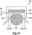
- a clamp armmay comprise a pad 655 and two or more electrodes, such as a first electrode 682 and a second electrode 683, for example.
- the pad 655can be comprised of a non-electrically conductive or insulative material, such as PTFE, for example, as previously discussed with reference to the clamp pad 155 ( FIG. 5 ), whereas the electrodes 682, 683 can be comprised of an electrically conductive material, such as copper and/or a PTFE material having electrically conductive particles mixed therein, for example.
- the first electrode 682 and/or the second electrode 683can be embedded within the pad 655.
- the pad 655can be molded onto the electrodes 682, 683 whereas, in certain embodiments, the electrodes 682, 683 can be inserted and/or press-fit into openings formed in the pad 655.
- the first electrode 682can be positioned adjacent to a first side 674a of the pad 655 while the second electrode 683 can be positioned adjacent to a second side 674b of the pad 655.
- the first electrode 682may comprise a supply electrode and the second electrode 683 may comprise a return electrode, wherein current can flow from the supply electrode 682, through tissue clamped or positioned between the pad 655 and the blade 146, for example, and into the return electrode 683.
- a supply wirecan be operably coupled with the first electrode 682 and a return wire can be operably coupled with the second electrode 683 such that current can be supplied thereto from a power source, such as the generator 112, for example.
- a power sourcesuch as the generator 112
- the electrodes 682, 683can be positioned within the pad 655 such that the electrodes 682, 683 do not contact the blade 146 when the clamp member 151 ( FIG. 5 ) is in a closed position and short to the blade 146.
- the illustrated embodimentcomprises one supply electrode and one return electrode positioned within a pad, embodiments are envisioned in which a pad includes more than one supply electrode and/or more than one return electrode.
- first and second electrodescan be mounted to the sides of a clamp arm pad.
- a clamp armmay comprise a pad 755, for example, which can be configured to hold tissue against the blade 146, for example, wherein a first electrode 782 can be mounted to a first side 774a of the pad 755 and wherein a second electrode 783 can be mounted to a second side 774b of the pad 755.
- the electrodes 782, 783can be positioned within cut-outs in the sides of the pad 755 wherein, in certain embodiments, the electrodes 782, 783 can be adhered and/or fastened, for example, to the pad 755.
- the first electrode 782may comprise a supply electrode and the second electrode 783 may comprise a return electrode, wherein current can flow from the supply electrode 782, through tissue clamped or positioned between the pad 755 and the blade 146, for example, and into the return electrode 783.
- a supply wirecan be operably coupled with the first electrode 782 and a return wire can be operably coupled with the second electrode 783 such that current can be supplied thereto from a power source, such as the generator 112, for example.
- the electrodes 782, 783can be mounted to the pad 755 such that the electrodes 782, 783 do not contact the blade 146 and create an electrical short thereto.
- the illustrated embodimentcomprises one supply electrode and one return electrode mounted to a pad, embodiments are envisioned in which a pad includes more than one supply electrode and/or more than one return electrode.
- various electrodescan be configured such that they extend in a longitudinal direction which is parallel, or at least substantially parallel, to the longitudinal axis of the blade 146, for example.
- the electrodescan extend along an end effector such that the entire length of the tissue positioned within the end effector can be treated.
- a clamp armmay comprise a pad 885 having two point electrodes. More particularly, in one embodiment, the pad 855 may comprise a first point electrode 882 and a second point electrode 883 positioned therein, wherein current can flow through tissue positioned intermediate the first point electrode 882 and the second point electrode 883.
- the pad 855can be comprised of a non-electrically conductive material
- the first point electrode 882may comprise a supply electrode
- the second point electrode 883may comprise a return electrode.
- the electrodes 882, 883can be embedded within the pad 885 and, in one embodiment the pad 885 can be molded around the electrodes 882, 883.
- the electrodes 882, 883can be inserted into apertures within the pad 855.
- a supply wirecan be operably coupled with the first electrode 882 and a return wire can be operably coupled with the second electrode 883 such that current can be supplied thereto from a power source, such as the generator 112, for example.
- the electrodes 882, 883can be positioned within the pad 855 such that the electrodes 882, 883 do not contact the blade 146 and create an electrical short thereto.
- the clamp arm supporting pad 885, and/or a sheath rotatably supporting the clamp armmay further comprise a stop which can be configured to prevent the pad 855 from rotating into a position in which the electrodes 882, 883 contact the blade 146.
- the illustrated embodimentcomprises one supply point electrode and one return point electrode positioned within a pad, other embodiments are envisioned in which a pad includes more than one supply point electrode and/or more than one return point electrode. Various embodiments are envisioned in which a pad includes an array of supply point electrodes and/or an array of return point electrodes.
- a surgical instrumentmay comprise a clamp arm including both a supply electrode and a return electrode.
- the surgical instrumentmay comprise a waveguide which does not comprise an electrode.
- a supply electrode and a return electrodecan be configured such that current can flow therebetween along a predetermined path.
- such a pathcan be one-dimensional.
- Embodiments having two point electrodes, for example,can permit such a path.
- such a pathcan be two-dimensional.
- Embodiments having an array of point electrodesfor example, can permit such a path.
- a two-dimensional pathcan be referred to as a field.
- a pathcan be three-dimensional.
- a clamp arm assemblycan have a supply electrode and a return electrode while the waveguide may comprise one of a supply electrode or a return electrode.
- the waveguidecomprises a return electrode
- currentcan flow from the supply electrode of the clamp arm assembly to the return electrode of the clamp arm assembly and the return electrode of the waveguide.
- the return electrodesmay comprise a common ground.
- the waveguidecomprises a supply electrode
- currentcan flow from the waveguide and the supply electrode of the clamp arm assembly to the return electrode of the clamp arm assembly. Such arrangements can permit the current to flow in a three-dimensional path, or field.
- the surgical instrument 110may comprise a sheath encompassing, or at least partially encompassing, a portion of the blade 146 wherein a sheath may comprise both at least one supply conductor and at least one return conductor.
- a sheathmay comprise a plurality of conductive inserts, such as a first conductive insert 957a and a second conductive inserts 957b, for example, wherein the first conductive insert 957a may comprise a supply conductor and wherein the second conductive insert 957b may comprise a return conductor.
- a non-electrically conductive or insulative material 958such as plastic and/or rubber, for example, can be overmolded onto the first and second conductive inserts 957a, 957b in order to comprise the sheath.
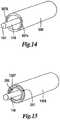
- the surgical instrument 110may comprise, referring now to FIG. 15 , a sheath assembly encompassing, or at least partially encompassing, a portion of a waveguide wherein the sheath assembly may comprise an inner sheath, such as an inner sheath 1057, for example, and an outer sheath, such as an outer sheath 1058, for example.
- the inner sheath 1057may comprise a supply conductor operably coupled with a supply electrode in a clamp arm assembly, wherein the outer sheath 1058 may comprise a return conductor operably coupled with a return electrode in the clamp arm assembly.
- the inner sheath 1057 and/or the outer sheath 1058may be comprised of an electrically conductive material, such as [medical grade stainless steel (?) Inventors - please identify one or more materials], for example, wherein, in one embodiment, one or more surfaces of the inner sheath 1057 and/or the outer sheath 1058 can be coated, or at least partially coated, in a non-conductive material, such as a material comprising poly(p-xylylene) polymers, for example. Materials comprised of poly(p-xylylene) polymers are often sold under the tradename of ParyleneTM.
- a clamp armcan be moved between open and closed positions in order position and/or compress tissue T against a blade.
- a clamp arm 1151may comprise a base 1149 and a pad 1155 mounted to the base 1149, wherein the pad 1155 can be configured to contact and compress tissue T against the blade 146, for example.
- the pad 1155may comprise a tissue-contacting surface 1175 which, although it may include various serrations, ridges, and/or surface texturing, is planar, or at least substantially planar.
- the tissue Tmay contact the blade 146 at a contact point P.
- the clamp arm 1251may comprise downwardly-extending sidewalls 1274 which extend below a tissue-contacting surface 1275 of the pad 1255, for example, although a clamp arm may comprise a tissue-contacting surface with or without a pad. In one embodiment, referring to FIG.
- the sidewalls 1274can be configured to contact the tissue T positioned laterally with respect to the blade 146 and push the tissue T downwardly. As illustrated in FIG. 17 , the sidewalls 1274 can push the tissue T downwardly such that the tissue T positioned intermediate the sidewalls 1274 contacts a larger surface area, or perimeter, on the blade 146 as compared to the embodiment illustrated in FIG. 16 . Owing to the larger contact area, the blade 146 may be more efficient in cutting, coagulating, and/or otherwise treating the tissue.
- the perimeter contact distancei.e., the distance in which the tissue is in contact with the perimeter of the blade 146
- the perimeter contact distancemay comprise an arclength (s) which can equal the product of the radius of curvature of the arc R and the sweep angle ⁇ defined between the two contact points P.
- the contact points Pcan represent the endpoints of the perimeter in which the tissue T contacts the blade 146.
- the tissue-contacting surface 1275 of the clamp arm 1251can define a plane 1298 which can represent the portions of the pad 1255 which contact the tissue T positioned within the end effector when the clamp arm 1251 is rotated between its open and closed positions. As illustrated in FIG.
- the sidewalls 1274 of the clamp arm 1251can extend through the plane 1298, wherein, when the clamp arm 1251 is rotated from an open position into a closed position, the sidewalls 1274 can be positioned laterally along the opposite sides of the blade 146 and, in addition, the tissue-contacting surface 1275 can be positioned against, or adjacent to, the top surface of the blade 146 such that the plane 1298 is aligned with, or respect to, a plane 1299 extending through the top surface of the blade 146.
- the plane 1299can be defined as a tangential plane which is tangential to the perimeter of the blade 146.
- the plane 1299can be tangential to the top tissue-contacting surface of the blade 146, for example, wherein the top tissue-contacting surface of the 146 may comprise the surface closest to the clamp tissue-contacting surface 1275 when the clamp arm 1271 is in its closed position.
- the planes 1298, 1299can be parallel, or at least substantially parallel, to one another when the tissue-contacting surface 1275 is positioned adjacent to the blade 146, while the planes 1298, 1299 can be co-planar, or at least substantially co-planar, with one another when the tissue-contacting surface 1275 is in contact with the blade 146.
- the sidewalls 1274can be sized and configured such that they extend through the blade plane 1299 when the clamp arm 1271 is in the closed position. In various embodiments, the sidewalls 1274 may not extend through the plane 1299 when the clamp arm 1251 is in the open position. In one embodiment, the sidewalls 1274 may "break" the plane 1299 as the clamp arm 1251 is being closed, but before it is completely closed. In one embodiment, the sidewalls 1274 may break the plane 1299 just before the clamp arm 1251 reaches its completely closed position.
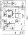
- FIG. 18illustrates one embodiment of a drive system 32 of the ultrasonic generator module 180 shown in FIG. 1 , which creates an ultrasonic electrical signal for driving an ultrasonic transducer.
- the drive system 32is flexible and can create an ultrasonic electrical drive signal 416 at a desired frequency and power level setting for driving the ultrasonic transducer 114.
- the generator 112may comprise several separate functional elements, such as modules and/or blocks. Although certain modules and/or blocks may be described by way of example, it can be appreciated that a greater or lesser number of modules and/or blocks may be used and still fall within the scope of the embodiments.
- modules and/or blocksmay be implemented by one or more hardware components, e.g., processors, Digital Signal Processors (DSPs), Programmable Logic Devices (PLDs), Application Specific Integrated Circuits (ASICs), circuits, registers and/or software components, e.g., programs, subroutines, logic and/or combinations of hardware and software components.
- DSPsDigital Signal Processors
- PLDsProgrammable Logic Devices
- ASICsApplication Specific Integrated Circuits
- registers and/or software componentse.g., programs, subroutines, logic and/or combinations of hardware and software components.
- the ultrasonic generator module 180 drive system 32may comprise one or more embedded applications implemented as firmware, software, hardware, or any combination thereof.
- the ultrasonic generator module 180 drive system 32may comprise various executable modules such as software, programs, data, drivers, application program interfaces (APIs), and so forth.
- the firmwaremay be stored in nonvolatile memory (NVM), such as in bit-masked read-only memory (ROM) or flash memory. In various implementations, storing the firmware in ROM may preserve flash memory.
- the NVMmay comprise other types of memory including, for example, programmable ROM (PROM), erasable programmable ROM (EPROM), electrically erasable programmable ROM (EEPROM), or battery backed random-access memory (RAM) such as dynamic RAM (DRAM), Double-Data-Rate DRAM (DDRAM), and/or synchronous DRAM (SDRAM).
- PROMprogrammable ROM
- EPROMerasable programmable ROM
- EEPROMelectrically erasable programmable ROM
- RAMbattery backed random-access memory
- DRAMdynamic RAM
- DDRAMDouble-Data-Rate DRAM
- SDRAMsynchronous DRAM
- the ultrasonic generator module 180 drive system 32comprises a hardware component implemented as a processor 400 for executing program instructions for monitoring various measurable characteristics of the ultrasonic surgical instrument 110 and generating a corresponding output control signal for operating the surgical instrument 110.
- the output control signalis for driving the ultrasonic transducer 114 in cutting and/or coagulation operating modes, measuring electrical characteristics of the surgical instrument 110 and/or the tissue T, and providing feedback to use.
- the ultrasonic generator module 180 and the drive system 32may comprise additional or fewer components and only a simplified version of the ultrasonic generator module 180 and the drive system 32 are described herein for conciseness and clarity.
- the hardware componentmay be implemented as a DSP, PLD, ASIC, circuits, and/or registers.
- the processor 400may be configured to store and execute computer software program instructions to generate the step function output signals for driving various components of the ultrasonic surgical instrument 110, such as the transducer 114, the end effector 150, and/or the blade 146.
- the processor 400executes the methods in accordance with the described embodiments to perform a variety of functions, such as, for example, generating a step function formed by a stepwise waveform of drive signals comprising current (I), voltage (V), and/or frequency (f) for various time intervals or periods (T), driving the ultrasonic transducer 114, driving the end effector 150 using therapeutic and/or subtherapeutic electrical signals (e.g., RF signal), measuring the impedance (Z) of the transducer 114, measuring the impedance (Z t ) of the tissue T, and/or providing feedback to the user.
- a step functionformed by a stepwise waveform of drive signals comprising current (I), voltage (V), and/or frequency (f) for various time intervals or periods (T)
- driving the ultrasonic transducer 114driving the end effector 150 using therapeutic and/or subtherapeutic electrical signals (e.g., RF signal)
- measuring the impedance (Z) of the transducer 114measuring the imped
- stepwise waveforms of the drive signalsmay be generated by forming a piecewise linear combination of constant functions over a plurality of time intervals created by stepping the ultrasonic generator module 180 drive signals, e.g., output drive current (I), voltage (V), and/or frequency (f).
- the time intervals or periods (T)may be predetermined (e.g., fixed and/or programmed by the user) or may be variable.
- Variable time intervalsmay be defined by setting the drive signal to a first value and maintaining the drive signal at that value until a change is detected in a monitored characteristic. Examples of monitored characteristics may comprise, for example, transducer impedance, tissue impedance, tissue heating, tissue transection, tissue coagulation, and the like.
- the ultrasonic drive signals generated by the ultrasonic generator module 180include, without limitation, ultrasonic drive signals that excite various vibratory modes of the ultrasonic transducer 114 such as the primary longitudinal mode and harmonics thereof as well flexural and torsional vibratory modes.
- the executable modulescomprise one or more algorithm(s) 402 stored in memory that when executed causes the processor 400 to perform a variety of functions, such as, for example, generating a step function formed by a stepwise waveform of drive signals comprising current (I), voltage (V), and/or frequency (f) for various time intervals or periods (T), driving the ultrasonic transducer 114, driving the end effector 150 using a therapeutic and/or subtherapeutic electrical signal (e.g., RF signal), measuring the impedance (Z) of the transducer 114, measuring the impedance (Z t ) of the tissue T, and/or providing feedback in accordance with a state of the tissue T.
- a therapeutic and/or subtherapeutic electrical signale.g., RF signal
- an algorithm 402is executed by the processor 400 to generate a step function formed by a stepwise waveform of drive signals comprising current (I), voltage (V), and/or frequency (f) for various time intervals or periods (T).
- the stepwise waveforms of the drive signalsmay be generated by forming a piecewise linear combination of constant functions over two or more time intervals created by stepping the generator's 30 output drive current (I), voltage (V), and/or frequency (f).
- the drive signalsmay be generated either for predetermined fixed time intervals or periods (T) of time or variable time intervals or periods of time in accordance with the one or more stepped output algorithm(s) 402.
- the ultrasonic generator module 180steps (e.g., increment or decrement) the current (I), voltage (V), and/or frequency (f) up or down at a particular resolution for a predetermined period (T) or until a predetermined condition is detected, such as a change in a monitored characteristic (e.g., transducer impedance, tissue impedance).
- a predetermined conditionsuch as a change in a monitored characteristic (e.g., transducer impedance, tissue impedance).
- the stepscan change in programmed increments or decrements. If other steps are desired, the ultrasonic generator module 180 can increase or decrease the step adaptively based on measured system characteristics.
- algorithms 402may be executed by the processor 400 to drive the ultrasonic transducer 114, drive the end effector 150 using a therapeutic and/or subtherapeutic electrical signal (e.g., RF signal), measure the impedance (Z) of the transducer 114, measure the impedance (Z t ) of the tissue T, and/or to provide feedback in accordance with a state of the tissue T.
- a therapeutic and/or subtherapeutic electrical signale.g., RF signal
- the usercan program the operation of the ultrasonic generator module 180 using the input device 406 located on the front panel of the ultrasonic generator module 180 console.
- the input device 406may comprise any suitable device that generates signals 408 that can be applied to the processor 400 to control the operation of the ultrasonic generator module 180.
- the input device 406includes buttons, switches, thumbwheels, keyboard, keypad, touch screen monitor, pointing device, remote connection to a general purpose or dedicated computer.
- the input device 406may comprise a suitable user interface. Accordingly, by way of the input device 406, the user can set or program the current (I), voltage (V), frequency (f), and/or period (T) for programming the step function output of the ultrasonic generator module 180.
- the processor 400displays the selected power level by sending a signal on line 410 to an output indicator 412.
- the output indicator 412may provide visual, audible, and/or tactile feedback to the surgeon to indicate the status of a surgical procedure, such as, for example, when tissue cutting and coagulating is complete based on a measured characteristic of the ultrasonic surgical instrument 110, e.g., transducer impedance, tissue impedance, or other measurements as subsequently described.
- visual feedbackcomprises any type of visual indication device including incandescent lamps or light emitting diodes (LEDs), graphical user interface, display, analog indicator, digital indicator, bar graph display, digital alphanumeric display.
- audible feedbackcomprises any type of buzzer, computer generated tone, computerized speech, voice user interface (VUI) to interact with computers through a voice/speech platform.
- tactile feedbackcomprises any type of vibratory feedback provided through the instrument handpiece assembly 160 or simply housing handle assembly.
- the processor 400may be configured or programmed to generate a digital current signal 414 and a digital frequency signal 418. These signals 414, 418 are applied to a direct digital synthesizer (DDS) circuit 420 to adjust the amplitude and the frequency (f) of the current output signal 416 to the transducer 114.
- DDSdirect digital synthesizer
- the output of the DDS circuit 420is applied to an amplifier 422 whose output is applied to a transformer 424.
- the output of the transformer 424is the signal 416 applied to the ultrasonic transducer 114, which is coupled to the blade 146 by way of the waveguide 147.
- the ultrasonic generator module 180comprises one or more measurement modules or components that may be configured to monitor measurable characteristics of the ultrasonic instrument 110.
- the processor 400may be employed to monitor and calculate system characteristics. As shown, the processor 400 measures the impedance Z of the transducer 114 by monitoring the current supplied to the transducer 114 and the voltage applied to the transducer 114.
- a current sense circuit 426is employed to sense the current flowing through the transducer 114 and a voltage sense circuit 428 is employed to sense the output voltage applied to the transducer 114. These signals may be applied to the analog-to-digital converter 432 (ADC) via an analog multiplexer 430 circuit or switching circuit arrangement.
- ADCanalog-to-digital converter
- the analog multiplexer 430routes the appropriate analog signal to the ADC 432 for conversion. In other embodiments, multiple ADCs 432 may be employed for each measured characteristic instead of the multiplexer 430 circuit.
- the processor 400receives the digital output 433 of the ADC 432 and calculates the transducer impedance Z based on the measured values of current and voltage. In response to the transducer impedance (Z), the processor 400 controls the operation of the surgical instrument 110. For example, the processor 400 can adjust the power delivered to the transducer 114, can shut off the power to the transducer 114, and/or provide feedback to the user. In one embodiment, the processor 400 adjusts the output drive signal 416 such that it can generate a desired power versus load curve. In one embodiment, in accordance with a programmed step function algorithms 402, the processor 400 can step the drive signal 416, e.g., the current or frequency, in any suitable increment or decrement in response to the transducer impedance Z.
- the useractivates the foot switch 144 or the switch 143 on the handpiece assembly 160, as discussed above.
- This activationoutputs the drive signal 416 to the transducer 114 based on programmed values of current (I), frequency (f), and corresponding time periods (T).
- the processor 400changes the output current step or frequency step in accordance with the programmed values.
- the output indicator 412communicates the particular state of the process to the user.
- the operation of the ultrasonic generator module 180may be programmed to provide a variety of output drive signals to measure electrical properties of current, voltage, power, impedance, and frequency associated with the transducer 114 in an unloaded state, a lightly loaded state, and a heavily loaded state, for example.
- the ultrasonic generator module 180 outputmay be stepped in a first sequence, for example.
- the ultrasonic generator module 180is initially activated at about time 0 resulting in a drive current rising to a first set point I 1 of about 100mA. The current is maintained at the first set point I 1 , for a first period T 1 .
- the current set pointis changed, e.g., stepped, by the ultrasonic generator module 180 in accordance with the software, e.g., the step function algorithm(s) 402, to a second set point I 2 of about 175mA for a second period T 2 , e.g., about 2 seconds.
- the ultrasonic generator module 180 softwarechanges the current to a third set point I 3 of about 350mA.
- the voltage, current, power, and frequencyrespond only slightly because there is no load on the system.
- the ultrasonic generator module 180When the ultrasonic transducer 114 is in a lightly loaded state, the ultrasonic generator module 180 is activated at about time 0 resulting in the current rising to the first current set point I 1 of about 100mA. At about 1 second the current set point is changed within the ultrasonic generator module 180 by the software to I 2 of about 175mA, and then again at about 3 seconds the ultrasonic generator module 180 changes the current 300 set point to I 3 of about 350mA. The voltage, current, power, and frequency respond to the light load.
- the ultrasonic generator module 180When the ultrasonic transducer 114 is in a heavily loaded state, the ultrasonic generator module 180 is activated at about time 0 resulting in the current rising to the first set point I 1 of about 100mA. At about 1 second the current set point is changed within the ultrasonic generator module 180 by the software to I 2 of about 175mA, and then again at about 3 seconds the ultrasonic generator module 180 changes the current 300 set point to I 3 of about 350mA. The voltage, current, power, and frequency respond to the heavy load.
- the current step function set pointse.g., I 1 , I 2 , I 3
- the time intervals or periodse.g., T 1 , T 2
- the periodsmay be predetermined by programming or may be variable based on measurable system characteristics. The embodiments are not limited in this context.
- one technique for sealing a vesselincludes separating and moving the inner muscle layer of the vessel away from the adventitia layer prior to the application of standard ultrasonic energy to transect and seal the vessel.
- conventional methodshave achieved this separation by increasing the force applied to the clamp member 151
- disclosedis an alternative apparatus and method for cutting and coagulating tissue without relying on clamp force alone.
- the ultrasonic generator module 180may be programmed to apply a frequency step function to the ultrasonic transducer 114 to mechanically displace the blade 146 in multiple modes in accordance with the step function.
- the frequency step functionmay be programmed by way of the user interface 406, wherein the user can select a stepped-frequency program, the frequency (f) for each step, and the corresponding time period (T) of duration for each step for which the ultrasonic transducer 114 will be excited.
- the usermay program a complete operational cycle by setting multiple frequencies for multiple periods to perform various surgical procedures.
- a first ultrasonic frequencymay be set initially to mechanically separate the muscle tissue layer of a vessel prior to applying a second ultrasonic frequency to cut and seal the vessel.
- the ultrasonic generator module 180is programmed to output a first drive frequency f 1 for a first period T 1 of time (for example less than approximately 1 second), wherein the first frequency f 1 is significantly off resonance, for example, f o /2, 2f o or other structural resonant frequencies, where f o is the resonant frequency (e.g., 55.5 kHz).
- the first frequency f 1provides a low level of mechanical vibration action to the blade 146 that, in conjunction with the clamp force, mechanically separates the muscle tissue layer (subtherapeutic) of the vessel without causing significant heating that generally occurs at resonance.
- the ultrasonic generator module 180is programmed to automatically switch the drive frequency to the resonant frequency f o for a second period T 2 to transect and seal the vessel.
- the duration of the second period T 2may be programmed or may be determined by the length of time it actually takes to cut and seal the vessel as determined by the user or may be based on measured system characteristics such as the transducer impedance Z as described in more detail below.
- the tissue/vessel transection processmay be automated by sensing the impedance Z characteristics of the transducer 114 to detect when the transection of the tissue/vessel occurs.
- the impedance Zcan be correlated to the transection of the muscle layer and to the transection/sealing of the vessel to provide a trigger for the processor 400 to generate the frequency and/or current step function output.
- the impedance Z of the transducer 114may be calculated by the processor 400 based on the current flowing through transducer 114 and the voltage applied to the transducer 114 while the blade 146 is under various loads. Because the impedance Z of the transducer 114 is proportional to the load applied to the blade 146, as the load on the blade 146 increases the impedance Z of the transducer 114 increases and as the load on the blade 146 decreases the impedance Z of the transducer 114 decreases. Accordingly, the impedance Z of the transducer 114 can be monitored to detect the transection of the inner muscle tissue layer of the vessel from the adventitia layer and can also be monitored to detect when the vessel has been transected and sealed.
- the ultrasonic surgical instrument 110may be operated in accordance with a programmed step function algorithm responsive to the transducer impedance Z.
- a frequency step function outputmay be initiated based on a comparison of the transducer impedance Z and one or more predetermined thresholds that have been correlated with tissue loads against the blade 146.
- the processor 400applies a digital frequency signal 418 to the DDS circuit 420 to change the frequency of the drive signal 416 by a predetermined step in accordance with the step function algorithm(s) 402 responsive to the transducer impedance Z.
- the blade 146is first located at the tissue treatment site.
- the processor 400applies a first digital frequency signal 418 to set a first drive frequency f 1 that is off resonance (e.g., f o /2, 2f o or other structural resonant frequencies, where f o is the resonant frequency).
- the drive signal 416is applied to the transducer 114 in response to activation of the switch 312a on the handpiece assembly 160 or the foot switch 434. During this period the ultrasonic transducer 114 mechanically activates the blade 146 at the first drive frequency f 1 . A force or load may be applied to the clamp member 151 and the blade 146 to facilitate this process.
- the processor 400monitors the transducer impedance Z until the load on the blade 146 changes and the transducer impedance Z crosses a predetermined threshold to indicate that the tissue layer has been transected.
- the processor 400then applies a second digital frequency signal 418 to set a second drive frequency f 2 , e.g., the resonant frequency f o or other suitable frequency for transecting, coagulating, and sealing tissue.
- a second drive frequency f 2e.g., the resonant frequency f o or other suitable frequency for transecting, coagulating, and sealing tissue.
- Another portion of the tissuee.g., the vessel
- the transducer 114is now energized by the drive signal 416 at the second drive frequency f 2 by actuating either the foot switch 434 or the switch 312a on the handpiece assembly 160.
- the drive current (I) outputalso may be stepped as described with reference to FIGS. 6-8 based on the transducer impedance Z.
- the processor 400initially sets a first drive frequency f 1 that is significantly off resonance to separate the inner muscle layer of the vessel from the adventitia layer. During this period of operation the processor 400 monitors the transducer impedance Z to determine when the inner muscle layer is transected or separated from the adventitia layer. Because the transducer impedance Z is correlated to the load applied to the blade 146, for example, cutting more tissue decrease the load on the blade 146 and the transducer impedance Z. The transection of the inner muscle layer is detected when the transducer impedance Z drops below a predetermined threshold.
- the processor 400sets the drive frequency to the resonant frequency f o .
- the vesselis then grasped between the blade 146 and the clamp member 151 and the transducer 114 is activated by actuating either the foot switch or the switch on the handpiece assembly 160 to transect and seal the vessel.
- the impedance Z changemay range between about 1.5 to about 4 times a base impedance measurements from an initial point of contact with the tissue to a point just before the muscle layer is transected and sealed.
- the surgical system 100comprises the signal generator module 102.
- the signal generator module 102may be implemented as a tissue impedance module 502.
- the signal generator module 102is shown separate from the surgical instrument 110, in one embodiment, the signal generator module 102 may be formed integrally with the surgical instrument 110, as shown in phantom in FIG. 1 , such that the surgical instrument 110 forms a unitary surgical system.
- surgical instrument the signal generator module 102may be configured to monitor the electrical impedance Z t of the tissue T ( FIGS.
- an end effector portion of the surgical system 100comprises the clamp arm assembly 451 ( FIG. 8 ) connected to the distal end of the outer sheath 158.
- the blade 146forms a first (e.g., energizing) electrode and the clamp arm assembly 451 comprises an electrically conductive portion that forms a second (e.g., return) electrode.
- the tissue impedance module 502is coupled to the blade 146 and the clamp arm assembly 451 through a suitable transmission medium such as a cable 137.
- the cable 137comprises multiple electrical conductors for applying a voltage to the tissue T and providing a return path for current flowing through the tissue T back to the impedance module 502.
- the tissue impedance module 502may be formed integrally with the generator 112 or may be provided as a separate circuit coupled to the generator 112 (shown in phantom to illustrate this option).
- FIGS. 1 , 8 , and 19illustrates one embodiment of an integrated generator module 320 comprising the ultrasonic generator module 180 and the signal generator module 102.
- the signal generator module 102is configured as a tissue impedance module 502.
- the integrated generator module 320generates the ultrasonic electrical drive signal 416 to drive the ultrasonic transducer 114.
- the tissue impedance module 502may be configured to measure the impedance Z t of the tissue T ( FIGS. 5 , 10 , 16, 17 ) grasped between the blade 146 and the clamp arm assembly 451.
- the tissue impedance module 502comprises an RF oscillator 506, a voltage sensing circuit 508, and a current sensing circuit 510.
- the voltage and current sensing circuits 508, 510respond to the RF voltage v rf applied to the blade 146 electrode and the RF current i rf flowing through the blade 146 electrode, the tissue, and the conductive portion of the clamp arm assembly 451.
- the sensed voltage v rf and current i rfare converted to digital form by the ADC 432 via the analog multiplexer 430.
- the processor 400receives the digitized output 433 of the ADC 432 and determines the tissue impedance Z t by calculating the ratio of the RF voltage v rf to current i rf measured by the voltage sense circuit 508 and the current sense circuit 510.
- the transection of the inner muscle layer and the tissuemay be detected by sensing the tissue impedance Z t . Accordingly, detection of the tissue impedance Z t may be integrated with an automated process for separating the inner muscle layer from the outer adventitia layer prior to transecting the tissue without causing a significant amount of heating, which normally occurs at resonance. Additional clamp arm and sheath assemblies comprising an electrode as shown in FIGS. 9-17 may be employed without limitation.
- FIG. 20is a schematic diagram of the signal generator module 102 configured as the tissue impedance module 502 coupled to the blade 146 and the clamp arm assembly 415 with tissue T located therebetween.
- the generator 112comprises the signal generator module 102 configured as the tissue impedance module 502 configured for monitoring the impedance Z t of the tissue T located between the blade 146 and the clamp arm assembly 451 during the tissue transection process.
- the tissue impedance module 502may is coupled to the ultrasonic surgical instrument 110 by way of the cables 137, 139.
- the cableincludes a first "energizing" conductor 139 connected to the blade 146 (e.g., positive [+] electrode) and a second "return” conductor 137 connected to the conductive jacket 472 (e.g., negative [-] electrode) of the clamp arm assembly 451.
- RF voltage v rfis applied to the blade 146 to cause RF current i rf to flow through the tissue T.
- the second conductor 137provides the return path for the current i rf back to the tissue impedance module 502.
- the distal end of the return conductor 137is connected to the conductive jacket 472 such that the current i rf can flow from the blade 146, through the tissue T positioned intermediate the conductive jacket 472 and the blade 146, and the conductive jacket 472 to the return conductor 137.
- the impedance module 502connects in circuit, by way of the first and second conductors 137, 139.
- the RF energymay be applied to the blade 146 through the ultrasonic transducer 114 and the waveguide 147. It is worthwhile noting that the RF energy applied to the tissue T for purposes of measuring the tissue impedance Z t is a low level subtherapeutic signal that does not contribute in a significant manner, or at all, to the treatment of the tissue T.
- FIGS. 1 , 8 , and 18-20operations for the above surgical system 100 may be further described with reference to FIGS. 1 , 8 , and 18-20 in terms of a process for cutting and coagulating a blood vessel employing a surgical instrument comprising the input device 406 and the tissue impedance module 502.
- a particular processis described in connection with the operational details, it can be appreciated that the process merely provides an example of how the general functionality described herein can be implemented by the surgical system 100. Further, the given process does not necessarily have to be executed in the order presented herein unless otherwise indicated.
- the input device 406may be employed to program the step function output (e.g., current, voltage, frequency) to the ultrasonic transducer 114/blade 146 assembly.
- the step function outpute.g., current, voltage, frequency
- the ultrasonic surgical instrument 110may be operated in accordance with a programmed step function algorithm 402 responsive to the tissue impedance Z t .
- a frequency step function outputmay be initiated based on a comparison of the tissue impedance Z t and predetermined thresholds that have been correlated with various tissue states (e.g., desiccation, transection, sealing).
- tissue impedance Z ttransitions above or below (e.g., crosses) a threshold
- the processor 400applies a digital frequency signal 418 to the DDS circuit 420 to change the frequency of an ultrasonic oscillator by a predetermined step in accordance with the step function algorithm 402 responsive to the tissue impedance Z t .
- the blade 146is located at the tissue treatment site.
- the tissue Tis grasped between the blade 146 and the clamp arm assembly 451 such that the blade 146 and the conductive jacket 472 make electrical contact with the tissue T.
- the processor 400applies a first digital frequency signal 418 to set a first drive frequency f 1 that is off resonance (e.g., f o /2, 2f o or other structural resonant frequencies, where f o is the resonant frequency).
- the blade 146is electrically energized by the low level subtherapeutic RF voltage v rf supplied by the tissue impedance module 502.
- the drive signal 416is applied to the transducer 114/blade 146 in response to actuation of the switch 143 on the handpiece assembly 160 or the foot switch 144434 until the tissue impedance Z t of the tissue T changes by a predetermined amount. A force or load is then applied to the clamp arm assembly 451 and the blade 146. During this period the ultrasonic transducer 114 mechanically activates the blade 146 at the first drive frequency f 1 and as a result, the tissue T begins to desiccate from the ultrasonic action applied between the blade 146 and the one or more clamp pads 155 of the clamp arm assembly 451 causing the impedance Z t of the tissue T to increase.
- the impedance Z t of the tissue Tbecomes very high or infinite. It will be appreciated by those skilled in the art that the drive current (I) output also may be stepped as described above based on measured impedance Z t of the tissue T.
- the impedance Z t of tissue Tmay be monitored by the impedance module 502 in accordance with the following process.
- a measurable RF current i 1is conveyed through the first energizing conductor 139 to the blade 146, through the tissue T, and back to the impedance module 502 through the conductive jacket 472 and the second conductor 137.
- the impedance of the tissue 514increases and thus the current i 1 in the return path, i.e., the second conductor 137, decreases.
- the impedance module 502measures the tissue impedance Z t and conveys a representative signal to the ADC 432 whose digital output 433 is provided to the processor 400.
- the processor 400calculates the tissue impedance Z t based on these measured values of v rf and i rf .
- the processor 400controls the operation of the surgical instrument 110. For example, the processor 400 can adjust the power delivered to the transducer 114, can shut off the power to the transducer 114, and/or provide feedback to the user.
- the processor 400steps the frequency by any suitable increment or decrement in response to changes in the impedance Z t of the tissue T.
- the processor 400controls the drive signals 416 and can make any necessary adjustments in amplitude and frequency in response to the tissue impedance Z t . In one embodiment, the processor 400 can cut off the drive signal 416 when the tissue impedance Z t reaches a predetermined threshold value.
- the ultrasonic surgical instrument 110may be operated in accordance with a programmed stepped output algorithm to separate the inner muscle layer of a vessel from the adventitia layer prior to transecting and sealing the vessel.
- the processor 400initially sets a first drive frequency f 1 that is significantly off resonance.
- the transducer 114is activated to separate the inner muscle layer of the vessel from the adventitia layer and the tissue impedance module 502 applies a subtherapeutic RF voltage v rf signal to the blade 146.
- T 1 of operationthe processor 400 monitors the tissue impedance Z t to determine when the inner muscle layer is transected or separated from the adventitia layer.
- the tissue impedance Z tis correlated to the load applied to the blade 146, for example, when the tissue becomes desiccated or when the tissue is transected the tissue impedance Z t becomes extremely high or infinite.
- the change in tissue impedance Z tindicates that the vessel has been separated or transected from the inner muscle layer and the generator 112 is deactivated for a second period of time T 2 .
- the processor 400then sets the drive frequency to the resonant frequency f o .
- the vesselis then grasped between the blade 146 and the clamp arm assembly 451 and the transducer 114 is reactivated to transect and seal the vessel. Continuous monitoring of the tissue impedance Z t provides an indication of when the vessel is transected and sealed.
- the tissue impedance Z tmay be monitored to provide an indication of the completeness of the tissue cutting and/or coagulating process or to stop the activation of the generator 112 and/or the ultrasonic generator module 180 when the impedance Z t of the tissue T reaches a predetermined threshold value.
- the threshold for the tissue impedance Z tmay be selected, for example, to indicate that the vessel has been transected.
- the tissue impedance Z tmay range between about 10 Ohms to about 1000 Ohms from an initial point to a point just before the muscle layer is transected and sealed.
- the surgical instrument 110may be programmed for detecting a change of state of tissue being manipulated by an ultrasonic surgical instrument and providing feedback to the user to indicate that the tissue has undergone such change of state or that there is a high likelihood that the tissue has undergone such change of state.
- the tissuemay undergo a change of state when the tissue is separated from other layers of tissue or bone, when the tissue is cut or transected, when the tissue is coagulated, and so forth while being manipulated with an end effector of an ultrasonic surgical instrument, such as, for example, the end effector 150 of the ultrasonic surgical instrument 110.
- a change in tissue statemay be determined based on the likelihood of an occurrence of a tissue separation event.
- the impedance Z and the tissue Z tmay be used to provide feedback by the output indicator 412 shown in FIGS. 18 and 19 .
- the output indicator 412is particularly useful in applications where the tissue being manipulated by the end effector 151 is out of the user's field of view and the user cannot see when a change of state occurs in the tissue T.
- the output indicator 412communicates to the user that a change in tissue state has occurred as determined in accordance with the operations described with respect to various logic flows.
- the output indicator 412may be configured to provide various types of feedback to the user including, without limitation, visual, audible, and/or tactile feedback to indicate to the user (e.g., surgeon, clinician) that the tissue has undergone a change of state of the tissue.
- visual feedbackcomprises any type of visual indication device including incandescent lamps or LEDs, graphical user interface, display, analog indicator, digital indicator, bar graph display, digital alphanumeric display.
- audible feedbackcomprises any type of buzzer, computer generated tone, computerized speech, VUI to interact with computers through a voice/speech platform.
- tactile feedbackcomprises any type of vibratory feedback provided through the instrument housing handpiece assembly 160.
- the processor 400to determines a change in tissue state in accordance with the operations described above and provides feedback to the user by way of the output indicator 412.
- the processor 400monitors and evaluates the voltage, current, and/or frequency signal samples available from the generator 32, 320 and according to the evaluation of such signal samples determines whether a change in tissue state has occurred.
- a change in tissue statemay be determined based on the type of ultrasonic instrument and the power level that the instrument is energized at.
- the operational mode of the ultrasonic surgical instrument 110may be controlled by the user or may be automatically or semi-automatically controlled.
- the processor 400 portion of the drive system 32, 320samples the voltage (v), current (i), and frequency (f) signals of the ultrasonic generator module 180 and/or the signal generator module 102.
- the output indicator 412may provide visual, audible, and/or tactile feedback to alert the user of the ultrasonic surgical instrument 110 that a change in tissue state has occurred.
- the operational modes of the generator 112, the ultrasonic generator module 180, the signal generator module 102, and/or the ultrasonic instrument 110may be controlled manually, automatically, or semi-automatically.
- the operational modesinclude, without limitation, disconnecting or shutting down the output power, reducing the output power, cycling the output power, pulsing the output power, and/or outputting momentary surge of high-power.
- the operational modesinclude, operating the surgical instrument 110 in a first operating mode in which the transducer 14 produces mechanical energy, or vibrations, that are transmitted to the end effector 151 and a second operating mode in which electrical energy, or current, can flow through the end effector 151 to perform electrosurgery.
- the operational modes of the ultrasonic instrument 110 in response to the change in tissue statecan be selected, for example, to minimize heating effects of the end effector 151, e.g., of the clamp pad 155, to prevent or minimize possible damage to the surgical instrument 110, and/or surrounding tissue. This is advantageous because heat is generated exponentially when the transducer 114 is activated with nothing between the jaws of the end effector 151 as is the case when a change in tissue state occurs.
- the change of state of the tissuemay be determined based on transducer and tissue impedance measurements as previously described, or based on voltage, current, and frequency measurements in accordance with the operations described in the disclosure of the following commonly-owned, contemporaneously-filed U.S. Patent Application, which is incorporated herein by reference in its entirety: U.S. Patent Application Ser. No._, entitled “ULTRASONIC DEVICE FOR CUTTING AND COAGULATING WITH STEPPED OUTPUT," Attorney Docket No. END6427USNP/080591.
- the devices disclosed hereincan be designed to be disposed of after a single use, or they can be designed to be used multiple times. In either case, however, the device can be reconditioned for reuse after at least one use. Reconditioning can include any combination of the steps of disassembly of the device, followed by cleaning or replacement of particular pieces, and subsequent reassembly. In particular, the device can be disassembled, and any number of the particular pieces or parts of the device can be selectively replaced or removed in any combination. Upon cleaning and/or replacement of particular parts, the device can be reassembled for subsequent use either at a reconditioning facility, or by a surgical team immediately prior to a surgical procedure.
- reconditioning of a devicecan utilize a variety of techniques for disassembly, cleaning/replacement, and reassembly. Use of such techniques, and the resulting reconditioned device, are all within the scope of the present application.
- the various embodiments described hereinwill be processed before surgery.
- a new or used instrumentis obtained and if necessary cleaned.
- the instrumentcan then be sterilized.
- the instrumentis placed in a closed and sealed container, such as a plastic or TYVEK bag.
- the container and instrumentare then placed in a field of radiation that can penetrate the container, such as gamma radiation, x-rays, or high-energy electrons.
- the radiationkills bacteria on the instrument and in the container.
- the sterilized instrumentcan then be stored in the sterile container.
- the sealed containerkeeps the instrument sterile until it is opened in the medical facility. Sterilization can also be done by any number of ways known to those skilled in the art including beta or gamma radiation, ethylene oxide, and/or steam.
- an ultrasonic surgical instrumentcan be supplied to a surgeon with a waveguide and/or end effector already operably coupled with a transducer of the surgical instrument.
- the surgeon, or other cliniciancan remove the ultrasonic surgical instrument from a sterilized package, plug the ultrasonic instrument into a generator, as outlined above, and use the ultrasonic instrument during a surgical procedure.
- Such a systemcan obviate the need for a surgeon, or other clinician, to assemble a waveguide and/or end effector to the ultrasonic surgical instrument.
- the surgeon, or other cliniciancan place the ultrasonic instrument into a sealable package, wherein the package can be transported to a sterilization facility.
- the ultrasonic instrumentcan be disinfected, wherein any expended parts can be discarded and replaced while any reusable parts can be sterilized and used once again. Thereafter, the ultrasonic instrument can be reassembled, tested, placed into a sterile package, and/or sterilized after being placed into a package. Once sterilized, the reprocessed ultrasonic surgical instrument can be used once again.
Landscapes
- Health & Medical Sciences (AREA)
- Surgery (AREA)
- Engineering & Computer Science (AREA)
- Life Sciences & Earth Sciences (AREA)
- Heart & Thoracic Surgery (AREA)
- Veterinary Medicine (AREA)
- Nuclear Medicine, Radiotherapy & Molecular Imaging (AREA)
- Biomedical Technology (AREA)
- Public Health (AREA)
- Medical Informatics (AREA)
- Molecular Biology (AREA)
- Animal Behavior & Ethology (AREA)
- General Health & Medical Sciences (AREA)
- Dentistry (AREA)
- Mechanical Engineering (AREA)
- Physics & Mathematics (AREA)
- Plasma & Fusion (AREA)
- Otolaryngology (AREA)
- Surgical Instruments (AREA)
Abstract
Description
- The present disclosure generally relates to ultrasonic surgical systems and, more particularly, to ultrasonic systems that allow surgeons to perform cutting and coagulation.
- Ultrasonic surgical instruments are finding increasingly widespread applications in surgical procedures by virtue of the unique performance characteristics of such instruments. Depending upon specific instrument configurations and operational parameters, ultrasonic surgical instruments can provide substantially simultaneous cutting of tissue and homeostasis by coagulation, desirably minimizing patient trauma. The cutting action is typically realized by an-end effector, or blade tip, at the distal end of the instrument, which transmits ultrasonic energy to tissue brought into contact with the end effector. Ultrasonic instruments of this nature can be configured for open surgical use, laparoscopic, or endoscopic surgical procedures including robotic-assisted procedures.
- Some surgical instruments utilize ultrasonic energy for both precise cutting and controlled coagulation. Ultrasonic energy cuts and coagulates by using lower temperatures than those used by electrosurgery. Vibrating at high frequencies (e.g., 55,500 times per second), the ultrasonic blade denatures protein in the tissue to form a sticky coagulum. Pressure exerted on tissue with the blade surface collapses blood vessels and allows the coagulum to form a hemostatic seal. The precision of cutting and coagulation is controlled by the surgeon's technique and adjusting the power level, blade edge, tissue traction, and blade pressure.
- A primary challenge of ultrasonic technology for medical devices, however, continues to be sealing of blood vessels. Work done by the applicant and others has shown that optimum vessel sealing occurs when the inner muscle layer of a vessel is separated and moved away from the adventitia layer prior to the application of standard ultrasonic energy. Current efforts to achieve this separation have involved increasing the clamp force applied to the vessel.
- Furthermore, the user does not always have visual feedback of the tissue being cut. Accordingly, it would be desirable to provide some form of feedback to indicate to the user that the cut is complete when visual feedback is unavailable. Moreover, without some form of feedback indicator to indicate that the cut is complete, the user may continue to activate the harmonic instrument even though the cut is complete, which cause possible damage to the harmonic instrument and surrounding tissue by the heat that is generated exponentially when activating a harmonic instrument with nothing between the jaws.
- It would be desirable to provide an ultrasonic surgical instrument that overcomes some of the deficiencies of current instruments. The ultrasonic surgical instrument described herein overcomes those deficiencies.
- In one general aspect, various embodiments are directed to an ultrasonic surgical 0instrument that comprises a transducer configured to produce vibrations along a longitudinal axis at a predetermined frequency. In various embodiments, an ultrasonic blade extends along the longitudinal axis and is coupled to the transducer. In various embodiments, the ultrasonic blade includes a body having a proximal end and a distal end, wherein the distal end is movable relative to the longitudinal axis by the vibrations produced by the transducer.
- In one general aspect, various embodiments are directed to a surgical instrument that can supply mechanical energy and electrical energy to an end effector of the surgical instrument. The surgical instrument may be operated in a first operating mode in which a transducer of the surgical instrument produces mechanical energy, or vibrations, that are transmitted to the end effector and a second operating mode in which electrical energy, or current, can flow through the end effector to perform electrosurgery. In another general aspect, the surgical instrument may comprise a clamp, or jaw, which can be moved into a closed position to hold tissue against a waveguide, or blade, of the end effector. In the second operating mode of the surgical instrument, current can flow from a power source, through the waveguide, and return to the power source through a path comprising the jaw.
- The features of various embodiments are set forth with particularity in the appended claims. The various embodiments, however, both as to organization and methods of operation, together with further objects and advantages thereof, may best be understood by reference to the following description, taken in conjunction with the accompanying drawings as follows.
FIG. 1 illustrates a surgical instrument comprising an ultrasonic surgical instrument system and an electrosurgery surgical instrument system.FIG. 2 illustrates a portion of a handpiece assembly of the surgical instrument ofFIG. 1 with a portion of the handpiece housing removed and an acoustic assembly operably engaged with a waveguide of the surgical instrument.FIG. 3 illustrates the handpiece assembly ofFIG. 2 with the acoustic assembly removed to illustrate positive and negative electrode contacts configured to supply the acoustic assembly with power.FIG. 4 is a detail view of a portion of the acoustic assembly ofFIG. 2 .FIG. 5 is a detail view of the end effector of the ultrasonic surgical instrument ofFIG. 1 .FIG. 6 is a perspective view of an embodiment of a sheath assembly comprising an inner sheath and an outer sheath which can define a first passageway for a waveguide of an ultrasonic instrument and a second passageway for a return conductor.FIG. 7 is a perspective view of an embodiment of a sheath configured to surround at least a portion of a waveguide of an ultrasonic surgical instrument, wherein a conductor can be embedded in at least a portion of a sheath.FIG. 8 is a perspective view of an embodiment of a clamp arm assembly configured to hold tissue against a waveguide of an ultrasonic surgical instrument.FIG. 9 is a perspective view of another embodiment of a clamp arm assembly having downwardly-extending walls which extend below a tissue-contacting surface.FIG. 10 is a cross-sectional end view of the clamp arm assembly ofFIG. 9 positioned in a closed position relative to a waveguide of an ultrasonic surgical instrument.FIG. 11 is a perspective view of a tissue-contacting pad of a clamp arm assembly, wherein the pad includes first and second electrodes embedded therein and positioned relative to a waveguide of an ultrasonic surgical instrument.FIG. 12 is a perspective view of another embodiment of a tissue-contacting pad of a clamp arm assembly, wherein the pad includes first and second electrodes mounted thereto and positioned relative to a waveguide of an ultrasonic surgical instrument.FIG. 13 is a perspective view of another embodiment of a tissue-contacting pad of a clamp arm assembly, wherein the pad includes first and second point electrodes embedded therein.FIG. 14 is a perspective view of an embodiment of a sheath configured to surround at least a portion of a waveguide of an ultrasonic surgical instrument, wherein first and second conductors can be embedded in at least a portion of a sheath.FIG. 15 is a perspective view of an embodiment of a sheath assembly comprising an inner sheath and an outer sheath, wherein the inner sheath and the outer sheath may comprise first and second conductors.FIG. 16 is an end view of a clamp arm assembly holding tissue against a waveguide.FIG. 17 is an end view of an alternative embodiment of a clamp arm assembly holding tissue against a waveguide.FIG. 18 illustrates one embodiment of a drive system of an ultrasonic generator module, which creates the ultrasonic electrical signal for driving an ultrasonic transducer.FIG. 19 illustrates one embodiment of a drive system of a generator comprising a tissue impedance module.FIG. 20 is a schematic diagram of a tissue impedance module coupled to a blade and a clamp arm assembly with tissue located therebetween.- Before explaining various embodiments of ultrasonic surgical instruments in detail, it should be noted that the illustrative embodiments are not limited in application or use to the details of construction and arrangement of parts illustrated in the accompanying drawings and description. The illustrative embodiments may be implemented or incorporated in other embodiments, variations and modifications, and may be practiced or carried out in various ways. Further, unless otherwise indicated, the terms and expressions employed herein have been chosen for the purpose of describing the illustrative embodiments for the convenience of the reader and are not for the purpose of limitation thereof.
- Further, it is understood that any one or more of the following-described embodiments, expressions of embodiments, examples, can be combined with any one or more of the other following-described embodiments, expressions of embodiments, and examples.
- Various embodiments are directed to improved ultrasonic surgical instruments configured for effecting tissue dissecting, cutting, and/or coagulation during surgical procedures. In one embodiment, an ultrasonic surgical instrument apparatus is configured for use in open surgical procedures, but has applications in other types of surgery, such as laparoscopic, endoscopic, and robotic-assisted procedures. Versatile use is facilitated by selective use of ultrasonic energy.
- It will be appreciated that the terms "proximal" and "distal" are used herein with reference to a clinician gripping a handpiece assembly. Thus, an end effector is distal with respect to the more proximal handpiece assembly. It will be further appreciated that, for convenience and clarity, spatial terms such as "top" and "bottom" also are used herein with respect to the clinician gripping the handpiece assembly. However, surgical instruments are used in many orientations and positions, and these terms are not intended to be limiting and absolute.
- The various embodiments will be described in combination with an ultrasonic instrument as described herein. Such description is provided by way of example, and not limitation, and is not intended to limit the scope and applications thereof. For example, any one of the described embodiments is useful in combination with a multitude of ultrasonic instruments including those described in, for example,
U.S. Patent Nos. 5,322,055 ;5,449,370 ;5,630,420 ;5,935,144 ;5,938,633 ;5,944,737 ;5,954,736 ;6,278,218 ;6,283,981 ;6,309,400 ;6,325,811 ; and6,436,115 , wherein the disclosure of each of the patents is herein incorporated by reference. Also incorporated by reference in its entirety is commonly-owned, co-pendingU.S. Patent Application Serial No. 11/726,625 - (1) U.S. Patent Application Serial No. , entitled "ULTRASONIC SURGICAL INSTRUMENTS," Attorney Docket No. END6493USNP1/080593; and
- (2) U.S. Patent Application Serial No._, entitled "ULTRASONIC SURGICAL INSTRUMENTS," Attorney Docket No. END6495USNP2/080594.
- (3) U.S. Patent Application Serial No._, entitled "ULTRASONIC DEVICE FOR CUTTING AND COAGULATING WITH STEPPED OUTPUT," Attorney Docket No. END6427USNP/080591.
- As will become apparent from the following description, it is contemplated that embodiments of the surgical instrument described herein may be used in association with an oscillator module of a surgical system, whereby ultrasonic energy from the oscillator module provides the desired ultrasonic actuation for the present surgical instrument. It is also contemplated that embodiments of the surgical instrument described herein may be used in association with a signal generator module of a surgical system, whereby electrical energy in the form of radio frequencies (RF), for example, is used to provide feedback to the user regarding the surgical instrument. The ultrasonic oscillator and/or the signal generator modules may be non-detachably integrated with the surgical instrument or may be provided as separate components, which can be electrically attachable to the surgical instrument.
- One embodiment of the present surgical apparatus is particularly configured for disposable use by virtue of its straightforward construction. However, it is also contemplated that other embodiments of the present surgical instrument can be configured for non-disposable or multiple uses. Detachable connection of the present surgical instrument with an associated oscillator and signal generator unit is presently disclosed for single-patient use for illustrative purposes only. However, non-detachable integrated connection of the present surgical instrument with an associated oscillator and/or signal generator unit is also contemplated. Accordingly, various embodiments of the presently described surgical instruments may be configured for single use and/or multiple uses and with either detachable and/or non-detachable integral oscillator and/or signal generator modules, without limitation. All combinations of such configurations are contemplated to be within the scope of the present disclosure.
FIG. 1 illustrates one embodiment of asurgical system 100. Thesurgical system 100 includes agenerator 112 and an ultrasonicsurgical instrument 110. Thegenerator 112 is connected to anultrasonic transducer 114 portion of the ultrasonicsurgical instrument 110 via a suitable transmission medium such as acable 142. In one embodiment, thegenerator 112 is coupled to anultrasonic generator module 180 and asignal generator module 102. In various embodiments, theultrasonic generator module 180 and/or thesignal generator module 102 each may be formed integrally with thegenerator 112 or may be provided as a separate circuit modules electrically coupled to the generator 112 (shown in phantom to illustrate this option). In one embodiment, thesignal generator module 102 may be formed integrally with theultrasonic generator module 180. Although in the presently disclosed embodiment, thegenerator 112 is shown separate from thesurgical instrument 110, in one embodiment, thegenerator 112 may be formed integrally with thesurgical instrument 110 to form a unitarysurgical system 100. Thegenerator 112 comprises aninput device 406 located on a front panel of thegenerator 112 console. Theinput device 406 may comprise any suitable device that generates signals suitable for programming the operation of thegenerator 112 as subsequently described with reference toFIG. 18 . Still with reference toFIG. 1 , thecable 142 may comprise multipleelectrical conductors ultrasonic transducer 114. It will be noted that, in some applications, theultrasonic transducer 114 may be referred to as a "handle assembly" because thesurgical instrument 110 of thesurgical system 100 may be configured such that a surgeon may grasp and manipulate theultrasonic transducer 114 during various procedures and operations.- In one embodiment, the
generator 112 may be implemented as an electrosurgery unit (ESU) capable of supplying power sufficient to perform bipolar electrosurgery using radio frequency (RF) energy. In one embodiment, the ESU can be a bipolar ERBE ICC 350 sold by ERBE USA, Inc. of Marietta, Georgia. In bipolar electrosurgery applications, as previously discussed, a surgical instrument having an active electrode and a return electrode can be utilized, wherein the active electrode and the return electrode can be positioned against, or adjacent to, the tissue to be treated such that current can flow from the active electrode to the return electrode through the tissue. Accordingly, thegenerator 112 may be configured for therapeutic purposes by applying electrical energy to the tissue T sufficient for treating the tissue (e.g., cauterization). - In one embodiment, the
signal generator module 102 may be configured to deliver a subtherapeutic RF signal to implement a tissue impedance measurement module. In one embodiment, thesignal generator module 102 comprises a bipolar radio frequency generator as described in more detail below. In one embodiment,signal generator module 102 may be configured to monitor the electrical impedance Zt of tissue T (FIG. 5 ) and to control the characteristics of time and power level based on the tissue impedance Zt. The tissue impedance Zt may be determined by applying the subtherapeutic RF signal to the tissue T and measuring the current through the tissue T (FIGS. 5 ,10 ,16, 17 ) by way of a return electrode on provided on aclamp member 151, as discussed in more detail below. Accordingly, thesignal generator module 102 may be configured for subtherapeutic purposes for measuring the impedance or other electrical characteristics of the tissue T. Techniques and circuit configurations for measuring the impedance or other electrical characteristics of the tissue T are discussed in more detail below with reference toFIGS. 18-20 below. - A suitable
ultrasonic generator module 180 may be configured to functionally operate in a manner similar to the GEN 300 sold by Ethicon Endo-Surgery, Inc. of Cincinnati, Ohio as is disclosed in one or more of the following U.S. Patents, all of which are incorporated by reference herein:U.S. Patent No. 6,480,796 (Method for Improving the Start Up of an Ultrasonic System Under Zero Load Conditions);U.S. Patent No. 6,537,291 (Method for Detecting a Loose Blade in a Handle Connected to an Ultrasonic Surgical System);U.S. Patent No. 6,626,926 (Method for Driving an Ultrasonic System to Improve Acquisition of Blade Resonance Frequency at Startup);U.S. Patent No. 6,633,234 (Method for Detecting Blade Breakage Using Rate and/or Impedance Information);U.S. Patent No. 6,662,127 (Method for Detecting Presence of a Blade in an Ultrasonic System);U.S. Patent No. 6,678,621 (Output Displacement Control Using Phase Margin in an Ultrasonic Surgical Handle);U.S. Patent No. 6,679,899 (Method for Detecting Transverse Vibrations in an Ultrasonic Handle);U.S. Patent No. 6,908,472 (Apparatus and Method for Altering Generator Functions in an Ultrasonic Surgical System);U.S. Patent No. 6,977,495 (Detection Circuitry for Surgical Handpiece System);U.S. Patent No. 7,077,853 (Method for Calculating Transducer Capacitance to Determine Transducer Temperature);U.S. Patent No. 7,179,271 (Method for Driving an Ultrasonic System to Improve Acquisition of Blade Resonance Frequency at Startup); andU.S. Patent No. 7,273,483 (Apparatus and Method for Alerting Generator Function in an Ultrasonic Surgical System). - In accordance with the described embodiments, the
ultrasonic generator module 180 produces electrical signals of a particular voltage, current, and frequency, e.g. 55,500 cycles per second (Hz). The generator is 112 connected by thecable 142 to theultrasonic generator module 180 in thehandpiece assembly 160, which contains piezoceramic elements forming theultrasonic transducer 114. In response to aswitch 143 on thehandpiece assembly 160 or a foot switch 144 connected to thegenerator 112 by anothercable 105 the generator signal is applied to thetransducer 114, which causes a longitudinal vibration of its elements. A structure connects thetransducer 114 to asurgical blade 146, which is thus vibrated at ultrasonic frequencies when the generator signal is applied to thetransducer 114. The structure is designed to resonate at the selected frequency, thus amplifying the motion initiated by thetransducer 114. In one embodiment, thegenerator 112 is configured to produce a particular voltage, current, and/or frequency output signal that can be stepped with high resolution, accuracy, and repeatability. - Referring now to
FIGS. 1-4 , thehandpiece assembly 160 of thesurgical instrument system 110 may include ahandpiece housing 116 that operably supports theend effector 150. Thehandpiece housing 116 rotatably supports anacoustic assembly 124 therein. Theacoustic assembly 124 includes theultrasonic transducer 114 that generally includes atransduction portion 118, a first resonator or end-bell 120, a second resonator or fore-bell 122, and ancillary components as shown inFIG. 2 . In various embodiments, the ultrasonic energy produced by thetransducer 114 can be transmitted through theacoustic assembly 124 to theend effector 150 via theultrasonic transmission waveguide 147 as shown inFIGS. 1 and3 . In order for theacoustic assembly 124 to deliver energy to thewaveguide 147, and ultimately to theend effector 150, the components of theacoustic assembly 124 are acoustically coupled to theblade 146. For example, the distal end of theultrasonic transducer 114 may be acoustically coupled to theproximal end 170 of thewaveguide 146 by a coupling assembly that enables theacoustic assembly 124 to freely rotate relative to thewaveguide 147 while transmitting ultrasonic energy thereto. - As shown in
FIG. 3 , theproximal end 170 of thewaveguide 146 may be provided with anaperture 172 therein that is sized to receive a stem (not shown) that protrudes distally from the fore-bell 122. In various embodiments,piezoelectric elements 132, for example, can be compressed between the end-bell 120 and the fore-bell 122 to form a stack of piezoelectric elements when the end-bell 120 and the fore-bell 122 are assembled together as illustrated inFIGS. 2-4 . Thepiezoelectric elements 132 may be fabricated from any suitable material, such as, for example, lead zirconate-titanate, lead meta-niobate, lead titanate, and/or any suitable piezoelectric crystal material, for example. As shown inFIGS. 2 and4 , thetransducer 114 may comprise electrodes, such as at least onepositive electrode 134 and at least onenegative electrode 136, for example, which can be configured to create a voltage potential across the one or morepiezoelectric elements 132. As shown inFIG. 2 , thepositive electrode 134 and thenegative electrode 136, and thepiezoelectric elements 132 can each be configured with a bore (not shown) that cooperates to form a passageway that can receive a threaded portion of the end-bell 120. In one embodiment, thepositive electrode 134 is provided in the form of an annular ring that has a first circumference "PC" and thenegative electrode 136 is also provided in the form of an annular ring that has a second circumference "NC." As shown inFIG. 2 , in various embodiments, the stack ofpiezoelectric elements 132 may have an outer circumference "OC" that is less than the first and second circumferences "PC" and "NC." - In various embodiments, the
handpiece housing 116 may support theultrasonic generator module 180 and/or thesignal generator module 102. In one embodiment, theultrasonic generator module 180 may be electrically coupled to anelectrical contact assembly 190 that may comprise a positiveslip ring contact 191 that is mounted withinhandpiece housing 116 for rotatable contact with thepositive electrode 134. The positiveslip ring contact 191 is electrically coupled to theultrasonic generator module 180 by a positive ultrasonic supply cable/conductor 192. Theelectrical contact assembly 190 may further comprise a negativeslip ring contact 194 that is mounted withinhandpiece housing 116 for rotatable contact with thenegative electrode 136. The negativeslip ring contact 194 is electrically coupled to theultrasonic generator module 180 by a negativeultrasonic supply cable 195. It will be appreciated that such arrangement enables theacoustic assembly 124 to freely rotate relative to theultrasonic generator module 180 while remaining in full electrical contact therewith. - In various embodiments, the
ultrasonic transmission waveguide 147 may comprise a plurality of stabilizing silicone rings or compliant supports (not shown) positioned at, or at least near, a plurality of nodes. As was discussed above, the silicone rings can dampen undesirable vibration and isolate the ultrasonic energy from thesheath 158 that at least partially surrounds thewaveguide 147, thereby assuring the flow of ultrasonic energy in a longitudinal direction to thedistal end 152 of theend effector 150 with maximum efficiency. - As shown in
FIGS. 2 and3 , thesheath 158 can be coupled to arotation wheel 159 that is rotatably attached to the distal end of thehandpiece assembly 160. Therotation wheel 159 facilitates selective rotation of thesheath 158 and thewaveguide 147 relative to thehandpiece assembly 160. Thesheath 158 may have anadapter portion 162 that may be threaded or snapped onto therotation wheel 159. Therotation wheel 159 may include a flanged portion (not shown) that is snapped into an annular groove in thehandpiece assembly 160 to facilitate rotation of thesheath 158 andwaveguide 146 relative to thehandpiece assembly 160 about axis A-A. In one embodiment, thesheath 158 also includes a hollow tubular portion 164 through which thewaveguide 146 extends in the manner described in further detail above. In various embodiments, theadapter 162 of thesheath 158 may be constructed from ULTEM®, for example, and the tubular portion 164 may be fabricated from stainless steel, for example. In at least one embodiment, theultrasonic transmission waveguide 147 may have polymeric material, for example, surrounding it in order to isolate it from outside contact. - In the embodiment, as shown in
FIG. 1 , theultrasonic generator module 180 is electrically coupled to the electronic signal/radio frequency generator 112 by thecables cable 142. Because theacoustic assembly 124 can freely rotate relative to theultrasonic generator module 180, thewaveguide 147 and theend effector 150 may be freely rotated about axis A-A relative to thehandpiece assembly 160 without causing thecable 142 to undesirably twist and tangle. - As illustrated in
FIGS. 2 and3 , thehandpiece assembly 160 may have a pistol grip configuration and operably support amovable trigger assembly 145 that is pivotally supported within thehandpiece assembly 160. To facilitate easy assembly, thehandpiece assembly 160 may comprise twohousing segments 162 that are coupled together by threaded fasteners, snap features, adhesive. Themovable trigger assembly 145 includes atrigger portion 153 that has a pair of spacedattachment arms 154 that each has ahole 155 therethrough.Holes 155 are each sized to receive a corresponding pivot pin (not shown) that protrudes from each of thehousing segments 162. Such arrangement permits thetrigger portion 153 to pivot relative to thehandpiece assembly 160 about an axis that is substantially transverse to axis A-A. - As shown in
FIGS. 2 and3 , thetrigger assembly 145 may comprise anactuation arm 156 that is attached to thetrigger portion 153 via anintermediate link 157. Theactuation arm 156 is pivotally coupled (pinned) to thetrigger yoke 185. Thearm 156 has a mountingpin 186 extending transversely therethrough that is sized to be slidably received in correspondingelongated cavities 187 formed in thehousing segments 162. SeeFIGS. 2 and3 . Such arrangement facilitates the axial movement of theactuation arm 156 within thehandpiece assembly 160 in response to pivoting thetrigger portion 153. - In the embodiment illustrated in
FIG. 1 , theend effector 150 portion of thesurgical system 100 comprises aclamp arm assembly 149 connected at a distal end of thesurgical instrument 110. Theblade 146 forms a first (e.g., energizing) electrode and theclamp arm assembly 149 comprises an electrically conductive portion that forms a second (e.g., return) electrode. Thesignal generator module 102 is coupled to theblade 146 and theclamp arm assembly 149 through a suitable transmission medium such as acable 137. Thecable 137 comprises multiple electrical conductors for applying a voltage to the tissue and providing a return path for current flowing through the tissue back to thesignal generator module 102. In various embodiments, thesignal generator module 102 may be formed integrally with thegenerator 112 or may be provided as a separate circuit coupled to thegenerator 112 and, in one embodiment, may be formed integrally with the ultrasonic generator module 180 (shown in phantom to illustrate these options). - In one embodiment, the
surgical system 100 illustrated inFIG. 1 may comprise components for selectively energizing anend effector 150 and transmitting mechanical energy thereto and, in addition, selectively energizing theend effector 150 with therapeutic and/or subtherapeutic electrical energy. Thesurgical instrument 110 may be switchable between a first operating mode in which mechanical energy, or vibrations at ultrasonic frequencies (e.g., 55.5 kHz), are transmitted to theend effector 150 and a second operating mode in which electrical energy (e.g., therapeutic and/or subtherapeutic), or current, is permitted to flow through theend effector 150. In certain embodiments, referring toFIG. 1 , in a first operating mode of thesurgical instrument 110, for example, thetransducer 114 converts electrical energy supplied thereto by the ultrasonic generator module 180 (e.g., an ultrasonic oscillator) of thegenerator 112 into mechanical vibrations and transmit the vibrations into awaveguide 147 to theblade 146 portion of theend effector 150, for example. Such mechanical vibrations can be generated at ultrasonic frequencies, although any suitable frequency, or frequencies, can be used. In the second operating mode of thesurgical instrument 110, an electrical current may be supplied by thegenerator 112 that can flow through thetransducer 114, thewaveguide 147, and theend effector 150. The current flowing through thewaveguide 147 andend effector 150 can be an alternating current (AC current), wherein, in various embodiments, the wave form of the AC current can be sinusoidal and/or may comprise a series of step intervals, for example. - In one embodiment, the current supplied by the
signal generator module 102 is an RF current. In any event, thesurgical instrument 110 may comprise a supply path and a return path, wherein the tissue T (FIG. 5 ) being treated completes, or closes, an electrical circuit, or loop, comprising a supply path through thetransducer 114, thewaveguide 147, and theblade 146 and a return path throughconductor cable 137. In one embodiment, the patient can be positioned on a conductive pad wherein the current can flow from a supply path of the surgical instrument, through the patient, and into the conductive pad in order to complete the electrical circuit. - Still referring to
FIG. 1 , as previously discussed, in one embodiment thesurgical instrument system 110 may be energized by thegenerator 112 by way of the foot switch 144 in order to energize theend effector 150. When actuated, the foot switch 144 triggers thegenerator 112 to deliver electrical energy to thehandpiece assembly 160, for example. Although the foot switch 144 may be suitable in many circumstances, other suitable switches can be used. In various embodiments, thesurgical instrument system 110 may comprise at least onesupply conductor 139 and at least onereturn conductor 141, wherein current can be supplied tohandpiece assembly 160 via thesupply conductor 139 and wherein the current can flow back to thegenerator 112 viareturn conductor 141. In various embodiments, thesupply conductor 139 and thereturn conductor 141 may comprise insulated wires and/or any other suitable type of conductor. In certain embodiments, as described below, thesupply conductor 139 and thereturn conductor 141 may be contained within and/or may comprise a cable extending between, or at least partially between, thegenerator 112 and thetransducer 114 portion of thehandpiece assembly 160. In any event, thegenerator 112 can be configured to apply a sufficient voltage differential between thesupply conductor 139 and thereturn conductor 141 such that sufficient current can be supplied to thetransducer 114. - In various embodiments, still referring to
FIG. 1 , thesupply conductor 139 and thereturn conductor 141 may be operably connected to atransducer drive unit 135, wherein thedrive unit 135 can be configured to receive current from thegenerator 112 via thesupply conductor 139. In certain embodiments, thehandpiece assembly 160 may comprise a switch, such as atoggle switch 143, for example, which can be manipulated to place thesurgical instrument 110 in one of a first operating mode and a second operating mode. In one embodiment, as described below, thetoggle switch 143 may comprise afirst toggle button 143a which can be depressed to place thesurgical instrument 110 in the first operating mode and, in addition, asecond toggle button 143b which can be depressed to place the surgical instrument in the second operating mode. Although a toggle switch is illustrated and described herein, any suitable switch, or switches, can be used. When thefirst toggle button 143a is depressed, thetransducer drive unit 135 can operate a transducer, such as thetransducer 114, for example, such that thetransducer 114 produces vibrations. Thetransducer 114 may comprise one or morepiezoelectric elements 132, wherein thedrive unit 135 can be configured to apply a voltage differential, and/or a series of voltage differentials, across thepiezoelectric elements 132 such that they mechanically vibrate in a desired manner. Also, thetransducer 114 may comprise one or more electrodes, such as apositive electrode 134 and anegative electrode 136, for example, positioned intermediate and/or adjacent to thepiezoelectric elements 132. In one embodiment, thesurgical instrument 110 may comprise a positivepolarizing conductor 192 operably connected to thedrive unit 135 and apositive electrode 134 and, in addition, a negativepolarizing conductor 195 operably connected to thedrive unit 135 and thenegative electrode 136, wherein thedrive unit 135 can be configured to polarize theelectrodes conductors - In various embodiments, the
transducer 114 may comprise a fore-bell 122 and avelocity transformer 128 which can be configured to conduct the vibrations produced by thepiezoelectric elements 132 into thetransmission waveguide 147. In certain embodiments, referring still toFIG. 1 , thetransmission waveguide 147 may comprise an elongate shaft portion surrounded, or at least partially surrounded, by asheath 158, for example, wherein thewaveguide 147 may comprise adistal end 152. Thedistal end 152 of thewaveguide 147 may comprise part of theend effector 150, wherein theend effector 150 may comprise theclamp member 151 having a rotatable clamp arm, or jaw, which can be pivoted between an open position in which tissue can be positioned intermediate theblade 146 and theclamp member 151 and a closed position in which clampmember 151 can position and/or compress the tissue T (FIG. 5 ) against theblade 146. In various embodiments, a surgical instrument may comprise a lever or actuator, such as ajaw closure trigger 145, for example, which can be actuated by a surgeon in order to pivot theclamp member 151 between its open and closed positions. In at least one embodiment, thejaw closure trigger 145 can be operably engaged with a push/pull rod operably engaged with theclamp member 151 wherein, when thejaw closure trigger 145 is closed or moved toward thehandpiece assembly 160, theclosure trigger 145 can push the push/pull rod distally and pivot theclamp member 151 toward theblade 146 into its closed position. Correspondingly, thejaw closure trigger 145 can be pivoted into its open position in order to pull the rod proximally and pivot theclamp member 151 away from theblade 146 into its open position. Various surgical instruments comprising clamp arms and mechanisms for operating these clamp arms are disclosed in U.S. Patent [Please point to an Ethicon patent or patent application], the entire disclosure(s) of which are incorporated by reference herein. - In any event, once the tissue T (
FIG. 5 ) has been suitably positioned within the jaws of theend effector 150, thetransducer 114 can be operated by thedrive unit 135 in order to transmit mechanical energy, or vibrations, into the targeted tissue T. In some embodiments, the actuation of the foot switch 144 may be sufficient to actuate thetransducer 114. In certain other embodiments, the actuation of a different switch may be required in addition to or in lieu of the actuation of the foot switch 144. In one embodiment, the actuation of the foot switch 144 can supply power to thedrive unit 135, although the actuation of thejaw closure trigger 145, and thetrigger closure switch 147, may be required before thedrive unit 135 can drive thetransducer 114. In various embodiments, thejaw closure trigger 145 can be moved between a first, or open, position in which thetrigger closure switch 147 is in an open state, or condition, and a second, or closed, position in which thetrigger closure switch 147 is in a closed state, or condition. When thetrigger closure switch 147 is in its closed condition, in various embodiments, a circuit within thedrive unit 135, for example, can be closed such that thedrive unit 135 can drive thetransducer 114. - Referring still to
FIG. 1 , In various applications, a surgeon may desire to treat tissue using mechanical energy, or vibrations, transmitted through theblade 146, for example. In various other applications, the surgeon may desire to treat the tissue using therapeutic electrical energy transmitted through theblade 146. In various other applications, the surgeon may desire to obtain feedback in regards to a state of the tissue T (FIG. 5 ) by measuring the electrical properties of the tissue T (e.g., impedance) using subtherapeutic electrical energy transmitted through theblade 146. In various embodiments, thetoggle switch 143 can be manipulated to place thesurgical instrument 110 in the second operating mode. In at least one such embodiment, thesecond toggle button 143b of thetoggle switch 143 can be depressed in order to switch thesurgical instrument 110 from the first operating mode into the second operating mode. As described below, the depression of thesecond toggle button 143b can configure thehandpiece assembly 160 such that thedrive unit 135 does not drive thetransducer 114 but rather, the power supplied to thehandpiece assembly 160 fromgenerator 112 can flow into theblade 146 without being converted into mechanical energy, or vibrations. In one embodiment, referring now toFIG. 5 , thedistal end 152 of theblade 146 can be positioned against the targeted tissue "T" and, in addition, thedistal end 153 of theclamp member 151 can also be positioned against the tissue T such that current can flow from thesupply conductor 139 into theblade 136, through the tissue T, and return back to thegenerator 112 via theclamp member 151, thereturn conductors FIG. 5 , theclamp member 151 can be configured such that it is not in contact with theblade 146 when theclamp member 151 is in the closed position. - With reference now back to
FIG. 1 , in various embodiments, thereturn conductor 137 may comprise an insulated wire having a first end operably coupled with theclamp member 151 and a second end operably coupled with thereturn conductor 141, wherein current can flow through thereturn conductor 137 when thetoggle switch 143 is in the second configuration and thetrigger closure switch 147 has been closed by thetrigger 145. In one embodiment, current will not flow through thereturn conductor 137 when thetrigger closure switch 147 is in an open condition and/or when thetoggle switch 143 is in the first configuration, i.e., when thefirst toggle button 143a is depressed, as described above. In any event, in various circumstances, the current flowing through the tissue T (FIG. 5 ) from thedistal end 152 of theblade 146 to thedistal end 153 of theclamp member 151 can treat the tissue positioned intermediate, and/or surrounding, the distal ends 152, 153. In another embodiment, the current may be subtherapeutic for measuring the electrical state of the tissue T (FIG. 5 ). - The
distal end 152 of theblade 146 may comprise a supply electrode while thedistal end 153 of theclamp member 151 may comprise a return electrode. In various other embodiments, current can be supplied to theconductor 137 such that thedistal end 153 of theclamp member 151 may comprise the supply electrode and thedistal end 152 of theblade 146 may comprise the return electrode. In one embodiment, the current can return to thegenerator 112 via theblade 146, thewaveguide 147, and theconductor 139. In either event, referring again toFIG. 1 , at least a portion of thereturn conductor 137 can extend along the outside of thesheath 158, wherein at least another portion of thereturn conductor 137 can extend through thehandpiece assembly 160. In certain embodiments, although not illustrated, at least a portion of thereturn conductor 137 can be positioned within thesheath 158 and can extend alongside theblade 146. - A s shown in
FIG. 6 , in some embodiments, thesurgical instrument 110 may comprise aninner sheath 257 and anouter sheath 258, wherein theinner sheath 257 can define a first, or inner,passageway 259, and wherein theinner sheath 257 and theouter sheath 258 can define a second, or outer,passageway 261 therebetween. In one embodiment, theblade 146 can extend through theinner passageway 259 and thereturn conductor 137, and/or any other suitable conductor, can extend through theouter passageway 261. In various other embodiments, a conductor can be embedded in at least a portion of theinner sheath 257 or theouter sheath 258. - As shown in
FIG. 7 , in one embodiment, a sheath may comprise a non-electrically conductive orinsulative material 358, such as plastic and/or rubber, for example, overmolded onto aconductive insert 357, which can be comprised of copper, for example, wherein theconductive insert 357 can allow current flowing through theblade 146 to return to thegenerator 112 after it has passed through the targeted tissue T (FIG. 5 ) as described above. In various embodiments, theinsulative material 358 can entirely, or at least substantially, surround theconductive insert 357 such that current flowing through theconductive insert 357 does not unintentionally short to non-targeted tissue, for example. In at least one embodiment, theinsulative material 358 can cover the inside surface and the outside surface of theconductive insert 357. In certain embodiments, although not illustrated, an insulative material of a sheath may cover only the outer surface of a conductive insert, for example. - In various embodiments, as described above, a first end of the
return conductor 137 can be operably coupled to theclamp member 151 such that current can flow therethrough. In certain embodiments, the first end of thereturn conductor 137 can be soldered and/or welded to theclamp member 151. In one embodiment, although not illustrated, theclamp member 151 may comprise an aperture configured to receive the first end of thereturn conductor 137 wherein a fastener can be inserted into the aperture in order to secure the first end therein. In at least one such embodiment, the sidewalls of the aperture can be at least partially threaded and the fastener can be threadably received in the threaded aperture. - As shown in
FIG. 8 , in one embodiment, aclamp arm assembly 451 may comprise aconductive jacket 472 mounted to abase 449. In one embodiment, the first end of thereturn conductor 137 may be mounted to theconductive jacket 472 such that current can flow from theblade 146, through tissue positioned intermediate thejacket 472 and theblade 146, and then into thejacket 472 and to thereturn conductor 137. In various embodiments, theconductive jacket 472 may comprise acenter portion 473 and at least one downwardly-extendingsidewall 474 which can extend below bottom thesurface 475 of thebase 449. In the illustrated embodiment, theconductive jacket 472 has twosidewalls 474 extending downwardly on opposite sides of thebase 449. In certain embodiments, thecenter portion 473 may comprise at least oneaperture 476 which can be configured to receive aprojection 477 extending from thebase 449. In one embodiment, theprojections 477 can be press-fit within theapertures 476 in order to secure theconductive jacket 472 to the base 449 although, in some embodiments, theprojections 477 can be deformed after they have been inserted into theapertures 476. In various embodiments, fasteners can be used to secure theconductive jacket 472 to thebase 449. - In various embodiments, the
clamp arm assembly 451 may comprise a non-electrically conductive or insulative material, such as plastic and/or rubber, for example, positioned intermediate theconductive jacket 472 and thebase 449. The insulative material can prevent current from flowing, or shorting, between theconductive jacket 472 and thebase 449. In various embodiments, referring again toFIG. 8 , thebase 449 may comprise at least oneaperture 478, for example, which can be configured to receive a pivot pin (not illustrated), wherein the pivot pin can be configured to pivotably mount the base 449 to thesheath 158, for example, such that theclamp arm assembly 451 can be rotated between open and closed positions relative to thesheath 158. In the embodiment illustrated inFIG. 8 , thebase 449 includes twoapertures 478 positioned on opposite sides of thebase 449. In one embodiment, the pivot pin can be comprised of a non-electrically conductive or insulative material, such as plastic and/or rubber, for example, which can be configured to prevent current from flowing into thesheath 158 even if thebase 449 is in electrical contact with theconductive jacket 472, for example. - In various embodiments, as described above, the
surgical instrument system 110 can be configured such that current can flow from the distal tip of theblade 146, through the tissue T (FIG. 5 ), and then to the distal tip of theclamp member 151. In one embodiment, as shown in toFIG. 5 , theclamp member 151 may comprise a tissue engaging pad orclamp pad 155, for example, mounted thereto, wherein thepad 155 can be configured to contact tissue positioned intermediate theclamp member 151 and thewaveguide 146. In one expression of the embodiment, thepad 155 may be formed of a non-electrically conductive or insulative material, such as polytetrafluoroethylene (PTFE), such as for example TEFLON® a trademark name of E. I. Du Pont de Nemours and Company, a low coefficient of friction polymer material, or any other suitable low-friction material. The non-electrically conductive or insulative material can also server to prevent current from flowing between theclamp member 151 and theblade 146 without first passing through thedistal end 152 of theblade 146, the targeted tissue T, and thedistal end 153 of theclamp member 151. In various embodiments, thepad 155 can be attached to theclamp member 151 utilizing an adhesive, for example. Theclamp pad 155 mounts on theclamp member 151 for cooperation with theblade 146, with pivotal movement of theclamp member 151 positioning theclamp pad 155 in substantially parallel relationship to, and in contact with, theblade 146, thereby defining a tissue treatment region. By this construction, tissue is grasped between theclamp pad 155 and theblade 146. Theclamp pad 155 may be provided with a non-smooth surface, such as a saw tooth-like configuration to enhance the gripping of tissue in cooperation with theblade 146. The saw tooth-like configuration, or teeth, provide traction against the movement of theblade 146. The teeth also provide counter traction to theblade 146 and clamping movement. It will be appreciated that the saw tooth-like configuration is just one example of many tissue engaging surfaces to prevent movement of the tissue relative to the movement of theblade 146. Other illustrative examples include bumps, criss-cross patterns, tread patterns, a bead, or sand blasted surface. - In various other embodiments, the
surgical instrument 110 can be configured such that current can flow through tissue clamped between theblade 146, for example, and theclamp member 151 without having to first pass through the distal ends thereof. In at least one embodiment, referring now toFIG. 9 , aclamp arm assembly 551 may comprise an electrically-conductive member 572 and apad 555 attached thereto, wherein the electrically-conductive member 572 may comprise at least onesidewall 574 extending downwardly therefrom. In one embodiment, current can flow between theblade 146, for example, through tissue positioned between theblade 146 and thesidewalls 574 of theclamp arm assembly 551, and into thesidewalls 574. In various embodiments, gaps can be defined between eachsidewall 574 and theblade 146 and, in addition, a gap can be defined between the tissue-contactingsurface 575 of thepad 555 and theblade 146. - In one embodiment, referring now to
FIG. 10 , the gaps between eachsidewall 574 and thewaveguide 146 can be defined by a distance "D1," wherein the distance D1 can be selected such that, when theclamp arm assembly 551 is positioned in a closed position, the tissue positioned intermediate each of thesidewalls 574 and theblade 146 can be compressed. Although these gaps are illustrated as having the same distance D1, other embodiments are envisioned in which the gaps have different distances. A gap between the tissue-contactingsurface 575 and theblade 146 can be defined by a distance "D2," wherein the distance D2 also may be selected such that, when theclamp arm assembly 551 is positioned in a closed position, the tissue-contactingsurface 575 can be contact and/or compress the tissue againstblade 146. - In various embodiments, a clamp arm assembly may comprise an electrically-conductive pad mounted thereto. In at least one such embodiment, such a pad can be configured to contact and/or compress tissue positioned intermediate the clamp arm assembly and a waveguide, such as the
blade 146, for example, such that current can flow from theblade 146 into the pad. In certain embodiments, the electrically conductive pad can be comprised of a typically conductive material, such as copper, for example. In at least one embodiment, the pad can be comprised of a typically non-conductive material, such as PTFE, for example, which can be impregnated with electrically conductive particles, such as [medical grade stainless steel (?) need additional materials if any], for example, such that the pad is sufficiently conductive to permit current to flow between theblade 146 and the clamp arm. - In one embodiment, as previously discussed, the
surgical instrument 110 comprises theblade 146, for example, which may comprise a first electrode and, in addition, a clamp arm, such as theclamp member 151, for example, which may comprise a second electrode. In various embodiments, as also discussed above, theblade 146 may comprise a supply electrode whereas theclamp member 151 may comprise a return electrode. Alternatively, theclamp member 151 may comprise the supply electrode while theblade 146 may comprise the return electrode. In various other embodiments, a clamp arm may comprise both the supply electrode and the return electrode. In certain embodiments, referring now toFIG. 11 , a clamp arm may comprise apad 655 and two or more electrodes, such as afirst electrode 682 and asecond electrode 683, for example. In one embodiment, thepad 655 can be comprised of a non-electrically conductive or insulative material, such as PTFE, for example, as previously discussed with reference to the clamp pad 155 (FIG. 5 ), whereas theelectrodes first electrode 682 and/or thesecond electrode 683 can be embedded within thepad 655. In at least one such embodiment, thepad 655 can be molded onto theelectrodes electrodes pad 655. - In various embodiments, the
first electrode 682 can be positioned adjacent to afirst side 674a of thepad 655 while thesecond electrode 683 can be positioned adjacent to asecond side 674b of thepad 655. In use, thefirst electrode 682 may comprise a supply electrode and thesecond electrode 683 may comprise a return electrode, wherein current can flow from thesupply electrode 682, through tissue clamped or positioned between thepad 655 and theblade 146, for example, and into thereturn electrode 683. In one embodiment, a supply wire can be operably coupled with thefirst electrode 682 and a return wire can be operably coupled with thesecond electrode 683 such that current can be supplied thereto from a power source, such as thegenerator 112, for example. In various embodiments, referring still toFIG. 11 , theelectrodes pad 655 such that theelectrodes blade 146 when the clamp member 151 (FIG. 5 ) is in a closed position and short to theblade 146. Although the illustrated embodiment comprises one supply electrode and one return electrode positioned within a pad, embodiments are envisioned in which a pad includes more than one supply electrode and/or more than one return electrode. - As discussed above, electrodes can be embedded within the pad of a clamp arm assembly. In various embodiments, first and second electrodes can be mounted to the sides of a clamp arm pad. Referring now to
FIG. 12 , a clamp arm may comprise apad 755, for example, which can be configured to hold tissue against theblade 146, for example, wherein afirst electrode 782 can be mounted to afirst side 774a of thepad 755 and wherein asecond electrode 783 can be mounted to asecond side 774b of thepad 755. In various embodiments, theelectrodes pad 755 wherein, in certain embodiments, theelectrodes pad 755. Thefirst electrode 782 may comprise a supply electrode and thesecond electrode 783 may comprise a return electrode, wherein current can flow from thesupply electrode 782, through tissue clamped or positioned between thepad 755 and theblade 146, for example, and into thereturn electrode 783. In one embodiment, a supply wire can be operably coupled with thefirst electrode 782 and a return wire can be operably coupled with thesecond electrode 783 such that current can be supplied thereto from a power source, such as thegenerator 112, for example. Furthermore, theelectrodes pad 755 such that theelectrodes blade 146 and create an electrical short thereto. Although the illustrated embodiment comprises one supply electrode and one return electrode mounted to a pad, embodiments are envisioned in which a pad includes more than one supply electrode and/or more than one return electrode. - Still referring to
FIG. 12 , various electrodes can be configured such that they extend in a longitudinal direction which is parallel, or at least substantially parallel, to the longitudinal axis of theblade 146, for example. In various embodiments, the electrodes can extend along an end effector such that the entire length of the tissue positioned within the end effector can be treated. In various embodiments, referring now toFIG. 13 , a clamp arm may comprise a pad 885 having two point electrodes. More particularly, in one embodiment, thepad 855 may comprise afirst point electrode 882 and asecond point electrode 883 positioned therein, wherein current can flow through tissue positioned intermediate thefirst point electrode 882 and thesecond point electrode 883. In at least one such embodiment, thepad 855 can be comprised of a non-electrically conductive material, thefirst point electrode 882 may comprise a supply electrode, and thesecond point electrode 883 may comprise a return electrode. In various embodiments, theelectrodes electrodes electrodes pad 855. A supply wire can be operably coupled with thefirst electrode 882 and a return wire can be operably coupled with thesecond electrode 883 such that current can be supplied thereto from a power source, such as thegenerator 112, for example. Furthermore, theelectrodes pad 855 such that theelectrodes blade 146 and create an electrical short thereto. In one embodiment, the clamp arm supporting pad 885, and/or a sheath rotatably supporting the clamp arm, may further comprise a stop which can be configured to prevent thepad 855 from rotating into a position in which theelectrodes blade 146. Although the illustrated embodiment comprises one supply point electrode and one return point electrode positioned within a pad, other embodiments are envisioned in which a pad includes more than one supply point electrode and/or more than one return point electrode. Various embodiments are envisioned in which a pad includes an array of supply point electrodes and/or an array of return point electrodes. - In various embodiments, as described above, a surgical instrument may comprise a clamp arm including both a supply electrode and a return electrode. In one embodiment, the surgical instrument may comprise a waveguide which does not comprise an electrode. In certain embodiments, a supply electrode and a return electrode can be configured such that current can flow therebetween along a predetermined path. In various embodiments, such a path can be one-dimensional. Embodiments having two point electrodes, for example, can permit such a path. In other embodiments, such a path can be two-dimensional. Embodiments having an array of point electrodes, for example, can permit such a path. A two-dimensional path can be referred to as a field. In certain embodiments, a path can be three-dimensional. In at least one such embodiment, a clamp arm assembly can have a supply electrode and a return electrode while the waveguide may comprise one of a supply electrode or a return electrode. In embodiments where the waveguide comprises a return electrode, current can flow from the supply electrode of the clamp arm assembly to the return electrode of the clamp arm assembly and the return electrode of the waveguide. In one such embodiment, the return electrodes may comprise a common ground. In embodiments where the waveguide comprises a supply electrode, current can flow from the waveguide and the supply electrode of the clamp arm assembly to the return electrode of the clamp arm assembly. Such arrangements can permit the current to flow in a three-dimensional path, or field.
- In various embodiments, referring now to
FIG. 14 , thesurgical instrument 110 may comprise a sheath encompassing, or at least partially encompassing, a portion of theblade 146 wherein a sheath may comprise both at least one supply conductor and at least one return conductor. In one embodiment, a sheath may comprise a plurality of conductive inserts, such as a firstconductive insert 957a and a secondconductive inserts 957b, for example, wherein the firstconductive insert 957a may comprise a supply conductor and wherein the secondconductive insert 957b may comprise a return conductor. In various embodiments, a non-electrically conductive orinsulative material 958, such as plastic and/or rubber, for example, can be overmolded onto the first and secondconductive inserts surgical instrument 110 may comprise, referring now toFIG. 15 , a sheath assembly encompassing, or at least partially encompassing, a portion of a waveguide wherein the sheath assembly may comprise an inner sheath, such as aninner sheath 1057, for example, and an outer sheath, such as anouter sheath 1058, for example. In one embodiment, theinner sheath 1057 may comprise a supply conductor operably coupled with a supply electrode in a clamp arm assembly, wherein theouter sheath 1058 may comprise a return conductor operably coupled with a return electrode in the clamp arm assembly. In certain embodiments, theinner sheath 1057 and/or theouter sheath 1058 may be comprised of an electrically conductive material, such as [medical grade stainless steel (?) Inventors - please identify one or more materials], for example, wherein, in one embodiment, one or more surfaces of theinner sheath 1057 and/or theouter sheath 1058 can be coated, or at least partially coated, in a non-conductive material, such as a material comprising poly(p-xylylene) polymers, for example. Materials comprised of poly(p-xylylene) polymers are often sold under the tradename of Parylene™. - In various embodiments, a clamp arm can be moved between open and closed positions in order position and/or compress tissue T against a blade. In one embodiment, referring to
FIG. 16 , aclamp arm 1151 may comprise abase 1149 and apad 1155 mounted to thebase 1149, wherein thepad 1155 can be configured to contact and compress tissue T against theblade 146, for example. As illustrated inFIG. 16 , thepad 1155 may comprise a tissue-contactingsurface 1175 which, although it may include various serrations, ridges, and/or surface texturing, is planar, or at least substantially planar. In such embodiments, especially when theblade 146 has a round or arcuate cross-section, only a small portion of the tissue T positioned intermediate theblade 146 and thepad 1155 may contact the surface area, or perimeter, of theblade 146. As illustrated inFIG. 16 , the tissue T may contact theblade 146 at a contact point P. Various alternative embodiments are envisioned in which theclamp arm 1251, for example, may comprise downwardly-extendingsidewalls 1274 which extend below a tissue-contactingsurface 1275 of thepad 1255, for example, although a clamp arm may comprise a tissue-contacting surface with or without a pad. In one embodiment, referring toFIG. 17 , thesidewalls 1274 can be configured to contact the tissue T positioned laterally with respect to theblade 146 and push the tissue T downwardly. As illustrated inFIG. 17 , thesidewalls 1274 can push the tissue T downwardly such that the tissue T positioned intermediate thesidewalls 1274 contacts a larger surface area, or perimeter, on theblade 146 as compared to the embodiment illustrated inFIG. 16 . Owing to the larger contact area, theblade 146 may be more efficient in cutting, coagulating, and/or otherwise treating the tissue. In embodiments where theblade 146 may comprise a circular or arcuate cross-section, the perimeter contact distance, i.e., the distance in which the tissue is in contact with the perimeter of theblade 146, may comprise an arclength (s) which can equal the product of the radius of curvature of the arc R and the sweep angle θ defined between the two contact points P. As illustrated inFIG. 17 , the contact points P can represent the endpoints of the perimeter in which the tissue T contacts theblade 146. Although the illustratedblade 146 is depicted as having a curved or arcuate cross-section, any other suitable cross-section may be used. - In various embodiments, the tissue-contacting
surface 1275 of theclamp arm 1251 can define aplane 1298 which can represent the portions of thepad 1255 which contact the tissue T positioned within the end effector when theclamp arm 1251 is rotated between its open and closed positions. As illustrated inFIG. 17 , thesidewalls 1274 of theclamp arm 1251 can extend through theplane 1298, wherein, when theclamp arm 1251 is rotated from an open position into a closed position, thesidewalls 1274 can be positioned laterally along the opposite sides of theblade 146 and, in addition, the tissue-contactingsurface 1275 can be positioned against, or adjacent to, the top surface of theblade 146 such that theplane 1298 is aligned with, or respect to, aplane 1299 extending through the top surface of theblade 146. In one embodiment, theplane 1299 can be defined as a tangential plane which is tangential to the perimeter of theblade 146. In one embodiment, theplane 1299 can be tangential to the top tissue-contacting surface of theblade 146, for example, wherein the top tissue-contacting surface of the 146 may comprise the surface closest to the clamp tissue-contactingsurface 1275 when the clamp arm 1271 is in its closed position. In the illustrated embodiment, still referring toFIG. 17 , theplanes surface 1275 is positioned adjacent to theblade 146, while theplanes surface 1275 is in contact with theblade 146. Thesidewalls 1274 can be sized and configured such that they extend through theblade plane 1299 when the clamp arm 1271 is in the closed position. In various embodiments, thesidewalls 1274 may not extend through theplane 1299 when theclamp arm 1251 is in the open position. In one embodiment, thesidewalls 1274 may "break" theplane 1299 as theclamp arm 1251 is being closed, but before it is completely closed. In one embodiment, thesidewalls 1274 may break theplane 1299 just before theclamp arm 1251 reaches its completely closed position. FIG. 18 illustrates one embodiment of adrive system 32 of theultrasonic generator module 180 shown inFIG. 1 , which creates an ultrasonic electrical signal for driving an ultrasonic transducer. With reference now toFIGS. 1 and18 , thedrive system 32 is flexible and can create an ultrasonicelectrical drive signal 416 at a desired frequency and power level setting for driving theultrasonic transducer 114. In various embodiments, thegenerator 112 may comprise several separate functional elements, such as modules and/or blocks. Although certain modules and/or blocks may be described by way of example, it can be appreciated that a greater or lesser number of modules and/or blocks may be used and still fall within the scope of the embodiments. Further, although various embodiments may be described in terms of modules and/or blocks to facilitate description, such modules and/or blocks may be implemented by one or more hardware components, e.g., processors, Digital Signal Processors (DSPs), Programmable Logic Devices (PLDs), Application Specific Integrated Circuits (ASICs), circuits, registers and/or software components, e.g., programs, subroutines, logic and/or combinations of hardware and software components.- In one embodiment, the
ultrasonic generator module 180drive system 32 may comprise one or more embedded applications implemented as firmware, software, hardware, or any combination thereof. Theultrasonic generator module 180drive system 32 may comprise various executable modules such as software, programs, data, drivers, application program interfaces (APIs), and so forth. The firmware may be stored in nonvolatile memory (NVM), such as in bit-masked read-only memory (ROM) or flash memory. In various implementations, storing the firmware in ROM may preserve flash memory. The NVM may comprise other types of memory including, for example, programmable ROM (PROM), erasable programmable ROM (EPROM), electrically erasable programmable ROM (EEPROM), or battery backed random-access memory (RAM) such as dynamic RAM (DRAM), Double-Data-Rate DRAM (DDRAM), and/or synchronous DRAM (SDRAM). - In one embodiment, the
ultrasonic generator module 180drive system 32 comprises a hardware component implemented as aprocessor 400 for executing program instructions for monitoring various measurable characteristics of the ultrasonicsurgical instrument 110 and generating a corresponding output control signal for operating thesurgical instrument 110. In various embodiments, the output control signal is for driving theultrasonic transducer 114 in cutting and/or coagulation operating modes, measuring electrical characteristics of thesurgical instrument 110 and/or the tissue T, and providing feedback to use. It will be appreciated by those skilled in the art that theultrasonic generator module 180 and thedrive system 32 may comprise additional or fewer components and only a simplified version of theultrasonic generator module 180 and thedrive system 32 are described herein for conciseness and clarity. In various embodiments, as previously discussed, the hardware component may be implemented as a DSP, PLD, ASIC, circuits, and/or registers. In one embodiment, theprocessor 400 may be configured to store and execute computer software program instructions to generate the step function output signals for driving various components of the ultrasonicsurgical instrument 110, such as thetransducer 114, theend effector 150, and/or theblade 146. - In one embodiment, under control of one or more software program routines, the
processor 400 executes the methods in accordance with the described embodiments to perform a variety of functions, such as, for example, generating a step function formed by a stepwise waveform of drive signals comprising current (I), voltage (V), and/or frequency (f) for various time intervals or periods (T), driving theultrasonic transducer 114, driving theend effector 150 using therapeutic and/or subtherapeutic electrical signals (e.g., RF signal), measuring the impedance (Z) of thetransducer 114, measuring the impedance (Zt) of the tissue T, and/or providing feedback to the user. In one embodiment, stepwise waveforms of the drive signals may be generated by forming a piecewise linear combination of constant functions over a plurality of time intervals created by stepping theultrasonic generator module 180 drive signals, e.g., output drive current (I), voltage (V), and/or frequency (f). The time intervals or periods (T) may be predetermined (e.g., fixed and/or programmed by the user) or may be variable. Variable time intervals may be defined by setting the drive signal to a first value and maintaining the drive signal at that value until a change is detected in a monitored characteristic. Examples of monitored characteristics may comprise, for example, transducer impedance, tissue impedance, tissue heating, tissue transection, tissue coagulation, and the like. The ultrasonic drive signals generated by theultrasonic generator module 180 include, without limitation, ultrasonic drive signals that excite various vibratory modes of theultrasonic transducer 114 such as the primary longitudinal mode and harmonics thereof as well flexural and torsional vibratory modes. - In one embodiment, the executable modules comprise one or more algorithm(s) 402 stored in memory that when executed causes the
processor 400 to perform a variety of functions, such as, for example, generating a step function formed by a stepwise waveform of drive signals comprising current (I), voltage (V), and/or frequency (f) for various time intervals or periods (T), driving theultrasonic transducer 114, driving theend effector 150 using a therapeutic and/or subtherapeutic electrical signal (e.g., RF signal), measuring the impedance (Z) of thetransducer 114, measuring the impedance (Zt) of the tissue T, and/or providing feedback in accordance with a state of the tissue T. In one embodiment, analgorithm 402 is executed by theprocessor 400 to generate a step function formed by a stepwise waveform of drive signals comprising current (I), voltage (V), and/or frequency (f) for various time intervals or periods (T). The stepwise waveforms of the drive signals may be generated by forming a piecewise linear combination of constant functions over two or more time intervals created by stepping the generator's 30 output drive current (I), voltage (V), and/or frequency (f). The drive signals may be generated either for predetermined fixed time intervals or periods (T) of time or variable time intervals or periods of time in accordance with the one or more stepped output algorithm(s) 402. Under control of theprocessor 400, theultrasonic generator module 180 steps (e.g., increment or decrement) the current (I), voltage (V), and/or frequency (f) up or down at a particular resolution for a predetermined period (T) or until a predetermined condition is detected, such as a change in a monitored characteristic (e.g., transducer impedance, tissue impedance). The steps can change in programmed increments or decrements. If other steps are desired, theultrasonic generator module 180 can increase or decrease the step adaptively based on measured system characteristics. In other embodiments,algorithms 402 may be executed by theprocessor 400 to drive theultrasonic transducer 114, drive theend effector 150 using a therapeutic and/or subtherapeutic electrical signal (e.g., RF signal), measure the impedance (Z) of thetransducer 114, measure the impedance (Zt) of the tissue T, and/or to provide feedback in accordance with a state of the tissue T. - In operation, the user can program the operation of the
ultrasonic generator module 180 using theinput device 406 located on the front panel of theultrasonic generator module 180 console. Theinput device 406 may comprise any suitable device that generatessignals 408 that can be applied to theprocessor 400 to control the operation of theultrasonic generator module 180. In various embodiments, theinput device 406 includes buttons, switches, thumbwheels, keyboard, keypad, touch screen monitor, pointing device, remote connection to a general purpose or dedicated computer. In other embodiments, theinput device 406 may comprise a suitable user interface. Accordingly, by way of theinput device 406, the user can set or program the current (I), voltage (V), frequency (f), and/or period (T) for programming the step function output of theultrasonic generator module 180. Theprocessor 400 then displays the selected power level by sending a signal online 410 to anoutput indicator 412. - In various embodiments, the
output indicator 412 may provide visual, audible, and/or tactile feedback to the surgeon to indicate the status of a surgical procedure, such as, for example, when tissue cutting and coagulating is complete based on a measured characteristic of the ultrasonicsurgical instrument 110, e.g., transducer impedance, tissue impedance, or other measurements as subsequently described. By way of example, and not limitation, visual feedback comprises any type of visual indication device including incandescent lamps or light emitting diodes (LEDs), graphical user interface, display, analog indicator, digital indicator, bar graph display, digital alphanumeric display. By way of example, and not limitation, audible feedback comprises any type of buzzer, computer generated tone, computerized speech, voice user interface (VUI) to interact with computers through a voice/speech platform. By way of example, and not limitation, tactile feedback comprises any type of vibratory feedback provided through theinstrument handpiece assembly 160 or simply housing handle assembly. - In one embodiment, the
processor 400 may be configured or programmed to generate a digitalcurrent signal 414 and adigital frequency signal 418. Thesesignals circuit 420 to adjust the amplitude and the frequency (f) of thecurrent output signal 416 to thetransducer 114. The output of theDDS circuit 420 is applied to anamplifier 422 whose output is applied to atransformer 424. The output of thetransformer 424 is thesignal 416 applied to theultrasonic transducer 114, which is coupled to theblade 146 by way of thewaveguide 147. - In one embodiment, the
ultrasonic generator module 180 comprises one or more measurement modules or components that may be configured to monitor measurable characteristics of theultrasonic instrument 110. In embodiment illustrated inFIG. 18 , theprocessor 400 may be employed to monitor and calculate system characteristics. As shown, theprocessor 400 measures the impedance Z of thetransducer 114 by monitoring the current supplied to thetransducer 114 and the voltage applied to thetransducer 114. In one embodiment, acurrent sense circuit 426 is employed to sense the current flowing through thetransducer 114 and avoltage sense circuit 428 is employed to sense the output voltage applied to thetransducer 114. These signals may be applied to the analog-to-digital converter 432 (ADC) via ananalog multiplexer 430 circuit or switching circuit arrangement. Theanalog multiplexer 430 routes the appropriate analog signal to theADC 432 for conversion. In other embodiments,multiple ADCs 432 may be employed for each measured characteristic instead of themultiplexer 430 circuit. Theprocessor 400 receives thedigital output 433 of theADC 432 and calculates the transducer impedance Z based on the measured values of current and voltage. In response to the transducer impedance (Z), theprocessor 400 controls the operation of thesurgical instrument 110. For example, theprocessor 400 can adjust the power delivered to thetransducer 114, can shut off the power to thetransducer 114, and/or provide feedback to the user. In one embodiment, theprocessor 400 adjusts theoutput drive signal 416 such that it can generate a desired power versus load curve. In one embodiment, in accordance with a programmedstep function algorithms 402, theprocessor 400 can step thedrive signal 416, e.g., the current or frequency, in any suitable increment or decrement in response to the transducer impedance Z. - With reference back now to
FIGS. 1 and18 , to actually cause thesurgical blade 146 to vibrate, e.g., actuate theblade 146, the user activates the foot switch 144 or theswitch 143 on thehandpiece assembly 160, as discussed above. This activation outputs thedrive signal 416 to thetransducer 114 based on programmed values of current (I), frequency (f), and corresponding time periods (T). After a predetermined fixed time period (T), or variable time period based on a measurable system characteristic such as changes in the impedance Z of thetransducer 114, theprocessor 400 changes the output current step or frequency step in accordance with the programmed values. Theoutput indicator 412 communicates the particular state of the process to the user. - The operation of the
ultrasonic generator module 180 may be programmed to provide a variety of output drive signals to measure electrical properties of current, voltage, power, impedance, and frequency associated with thetransducer 114 in an unloaded state, a lightly loaded state, and a heavily loaded state, for example. When theultrasonic transducer 114 is in an unloaded state, theultrasonic generator module 180 output may be stepped in a first sequence, for example. In one embodiment, theultrasonic generator module 180 is initially activated at about time 0 resulting in a drive current rising to a first set point I1 of about 100mA. The current is maintained at the first set point I1, for a first period T1. At the end of the first period T1, e.g., about 1 second, the current set point is changed, e.g., stepped, by theultrasonic generator module 180 in accordance with the software, e.g., the step function algorithm(s) 402, to a second set point I2 of about 175mA for a second period T2, e.g., about 2 seconds. At the end of the second period T2, e.g., at about 3 seconds, theultrasonic generator module 180 software changes the current to a third set point I3 of about 350mA. The voltage, current, power, and frequency respond only slightly because there is no load on the system. - When the
ultrasonic transducer 114 is in a lightly loaded state, theultrasonic generator module 180 is activated at about time 0 resulting in the current rising to the first current set point I1 of about 100mA. At about 1 second the current set point is changed within theultrasonic generator module 180 by the software to I2 of about 175mA, and then again at about 3 seconds theultrasonic generator module 180 changes the current 300 set point to I3 of about 350mA. The voltage, current, power, and frequency respond to the light load. - When the
ultrasonic transducer 114 is in a heavily loaded state, theultrasonic generator module 180 is activated at about time 0 resulting in the current rising to the first set point I1 of about 100mA. At about 1 second the current set point is changed within theultrasonic generator module 180 by the software to I2 of about 175mA, and then again at about 3 seconds theultrasonic generator module 180 changes the current 300 set point to I3 of about 350mA. The voltage, current, power, and frequency respond to the heavy load. - It will be appreciated by those skilled in the art that the current step function set points (e.g., I1, I2, I3) and the time intervals or periods (e.g., T1, T2) of duration for each of the step function set points described above are not limited to the values described herein and may be adjusted to any suitable value as may be desired for a given set of surgical procedures. Additional or fewer current set points and periods of duration may be selected as may be desired for a given set of design characteristics or performance constraints. As previously discussed, the periods may be predetermined by programming or may be variable based on measurable system characteristics. The embodiments are not limited in this context.
- Having described operational details of various embodiments of the
surgical system 100, operations for the abovesurgical system 100 may be further described in terms of a process for cutting and coagulating a blood vessel employing a surgical instrument comprising theinput device 406 and the transducer impedance measurement capabilities described with reference toFIG. 18 . Although a particular process is described in connection with the operational details, it can be appreciated that the process merely provides an example of how the general functionality described herein can be implemented by thesurgical system 100. Further, the given process does not necessarily have to be executed in the order presented herein unless otherwise indicated. As previously discussed, theinput device 406 may be employed to program the stepped output (e.g., current, voltage, frequency) to theultrasonic transducer 114/blade 146 assembly. - Accordingly, one technique for sealing a vessel includes separating and moving the inner muscle layer of the vessel away from the adventitia layer prior to the application of standard ultrasonic energy to transect and seal the vessel. Although conventional methods have achieved this separation by increasing the force applied to the
clamp member 151, disclosed is an alternative apparatus and method for cutting and coagulating tissue without relying on clamp force alone. In order to more effectively separate the tissue layers of a vessel, for example, theultrasonic generator module 180 may be programmed to apply a frequency step function to theultrasonic transducer 114 to mechanically displace theblade 146 in multiple modes in accordance with the step function. In one embodiment, the frequency step function may be programmed by way of theuser interface 406, wherein the user can select a stepped-frequency program, the frequency (f) for each step, and the corresponding time period (T) of duration for each step for which theultrasonic transducer 114 will be excited. The user may program a complete operational cycle by setting multiple frequencies for multiple periods to perform various surgical procedures. - In one embodiment, a first ultrasonic frequency may be set initially to mechanically separate the muscle tissue layer of a vessel prior to applying a second ultrasonic frequency to cut and seal the vessel. By way of example, and not limitation, in accordance with one implementation of the program, initially, the
ultrasonic generator module 180 is programmed to output a first drive frequency f1 for a first period T1 of time (for example less than approximately 1 second), wherein the first frequency f1 is significantly off resonance, for example, fo/2, 2fo or other structural resonant frequencies, where fo is the resonant frequency (e.g., 55.5 kHz). The first frequency f1 provides a low level of mechanical vibration action to theblade 146 that, in conjunction with the clamp force, mechanically separates the muscle tissue layer (subtherapeutic) of the vessel without causing significant heating that generally occurs at resonance. After the first period T1, theultrasonic generator module 180 is programmed to automatically switch the drive frequency to the resonant frequency fo for a second period T2 to transect and seal the vessel. The duration of the second period T2 may be programmed or may be determined by the length of time it actually takes to cut and seal the vessel as determined by the user or may be based on measured system characteristics such as the transducer impedance Z as described in more detail below. - In one embodiment, the tissue/vessel transection process (e.g., separating the muscle layer of the vessel from the adventitia layer and transecting/sealing the vessel) may be automated by sensing the impedance Z characteristics of the
transducer 114 to detect when the transection of the tissue/vessel occurs. The impedance Z can be correlated to the transection of the muscle layer and to the transection/sealing of the vessel to provide a trigger for theprocessor 400 to generate the frequency and/or current step function output. As previously discussed with reference toFIG. 18 , the impedance Z of thetransducer 114 may be calculated by theprocessor 400 based on the current flowing throughtransducer 114 and the voltage applied to thetransducer 114 while theblade 146 is under various loads. Because the impedance Z of thetransducer 114 is proportional to the load applied to theblade 146, as the load on theblade 146 increases the impedance Z of thetransducer 114 increases and as the load on theblade 146 decreases the impedance Z of thetransducer 114 decreases. Accordingly, the impedance Z of thetransducer 114 can be monitored to detect the transection of the inner muscle tissue layer of the vessel from the adventitia layer and can also be monitored to detect when the vessel has been transected and sealed. - In one embodiment, the ultrasonic
surgical instrument 110 may be operated in accordance with a programmed step function algorithm responsive to the transducer impedance Z. In one embodiment, a frequency step function output may be initiated based on a comparison of the transducer impedance Z and one or more predetermined thresholds that have been correlated with tissue loads against theblade 146. When the transducer impedance Z transitions above or below (e.g., crosses) a threshold, theprocessor 400 applies adigital frequency signal 418 to theDDS circuit 420 to change the frequency of thedrive signal 416 by a predetermined step in accordance with the step function algorithm(s) 402 responsive to the transducer impedance Z. In operation, theblade 146 is first located at the tissue treatment site. Theprocessor 400 applies a firstdigital frequency signal 418 to set a first drive frequency f1 that is off resonance (e.g., fo/2, 2fo or other structural resonant frequencies, where fo is the resonant frequency). Thedrive signal 416 is applied to thetransducer 114 in response to activation of the switch 312a on thehandpiece assembly 160 or the foot switch 434. During this period theultrasonic transducer 114 mechanically activates theblade 146 at the first drive frequency f1. A force or load may be applied to theclamp member 151 and theblade 146 to facilitate this process. During this period, theprocessor 400 monitors the transducer impedance Z until the load on theblade 146 changes and the transducer impedance Z crosses a predetermined threshold to indicate that the tissue layer has been transected. Theprocessor 400 then applies a seconddigital frequency signal 418 to set a second drive frequency f2, e.g., the resonant frequency fo or other suitable frequency for transecting, coagulating, and sealing tissue. Another portion of the tissue (e.g., the vessel) is then grasped between theclamp member 151 and theblade 146. Thetransducer 114 is now energized by thedrive signal 416 at the second drive frequency f2 by actuating either the foot switch 434 or the switch 312a on thehandpiece assembly 160. It will be appreciated by those skilled in the art that the drive current (I) output also may be stepped as described with reference toFIGS. 6-8 based on the transducer impedance Z. - According to one embodiment of a
step function algorithm 402, theprocessor 400 initially sets a first drive frequency f1 that is significantly off resonance to separate the inner muscle layer of the vessel from the adventitia layer. During this period of operation theprocessor 400 monitors the transducer impedance Z to determine when the inner muscle layer is transected or separated from the adventitia layer. Because the transducer impedance Z is correlated to the load applied to theblade 146, for example, cutting more tissue decrease the load on theblade 146 and the transducer impedance Z. The transection of the inner muscle layer is detected when the transducer impedance Z drops below a predetermined threshold. When the change in transducer impedance Z indicates that the vessel has been separated from the inner muscle layer, theprocessor 400 sets the drive frequency to the resonant frequency fo. The vessel is then grasped between theblade 146 and theclamp member 151 and thetransducer 114 is activated by actuating either the foot switch or the switch on thehandpiece assembly 160 to transect and seal the vessel. In one embodiment, the impedance Z change may range between about 1.5 to about 4 times a base impedance measurements from an initial point of contact with the tissue to a point just before the muscle layer is transected and sealed. - With reference now to
FIGS. 1 ,8 , and19 , as previously discussed, in one embodiment, thesurgical system 100, and the ultrasonicsurgical instrument 110, comprises thesignal generator module 102. In one embodiment, thesignal generator module 102 may be implemented as atissue impedance module 502. Although in the presently disclosed embodiment, thesignal generator module 102 is shown separate from thesurgical instrument 110, in one embodiment, thesignal generator module 102 may be formed integrally with thesurgical instrument 110, as shown in phantom inFIG. 1 , such that thesurgical instrument 110 forms a unitary surgical system. In one embodiment, surgical instrument thesignal generator module 102 may be configured to monitor the electrical impedance Zt of the tissue T (FIGS. 5 ,10 ,16, 17 ) to control the characteristics of time and power level based on the impedance Zt of the tissue T. In one embodiment, the tissue impedance Zt may be determined by applying a subtherapeutic radio frequency (RF) signal to the tissue T and measuring the current through the tissue T by way of a return electrode on theclamp member 151, as previously discussed. In the schematic diagram shown inFIG. 19 , an end effector portion of thesurgical system 100 comprises the clamp arm assembly 451 (FIG. 8 ) connected to the distal end of theouter sheath 158. Theblade 146 forms a first (e.g., energizing) electrode and theclamp arm assembly 451 comprises an electrically conductive portion that forms a second (e.g., return) electrode. Thetissue impedance module 502 is coupled to theblade 146 and theclamp arm assembly 451 through a suitable transmission medium such as acable 137. Thecable 137 comprises multiple electrical conductors for applying a voltage to the tissue T and providing a return path for current flowing through the tissue T back to theimpedance module 502. In various embodiments, thetissue impedance module 502 may be formed integrally with thegenerator 112 or may be provided as a separate circuit coupled to the generator 112 (shown in phantom to illustrate this option). - Still with reference to
FIGS. 1 ,8 , and19 illustrates one embodiment of anintegrated generator module 320 comprising theultrasonic generator module 180 and thesignal generator module 102. As shown, thesignal generator module 102 is configured as atissue impedance module 502. Theintegrated generator module 320 generates the ultrasonicelectrical drive signal 416 to drive theultrasonic transducer 114. In one embodiment, thetissue impedance module 502 may be configured to measure the impedance Zt of the tissue T (FIGS. 5 ,10 ,16, 17 ) grasped between theblade 146 and theclamp arm assembly 451. Thetissue impedance module 502 comprises anRF oscillator 506, avoltage sensing circuit 508, and acurrent sensing circuit 510. The voltage andcurrent sensing circuits blade 146 electrode and the RF current irf flowing through theblade 146 electrode, the tissue, and the conductive portion of theclamp arm assembly 451. The sensed voltage vrf and current irf are converted to digital form by theADC 432 via theanalog multiplexer 430. Theprocessor 400 receives the digitizedoutput 433 of theADC 432 and determines the tissue impedance Zt by calculating the ratio of the RF voltage vrf to current irf measured by thevoltage sense circuit 508 and thecurrent sense circuit 510. In one embodiment, the transection of the inner muscle layer and the tissue may be detected by sensing the tissue impedance Zt. Accordingly, detection of the tissue impedance Zt may be integrated with an automated process for separating the inner muscle layer from the outer adventitia layer prior to transecting the tissue without causing a significant amount of heating, which normally occurs at resonance. Additional clamp arm and sheath assemblies comprising an electrode as shown inFIGS. 9-17 may be employed without limitation. FIG. 20 is a schematic diagram of thesignal generator module 102 configured as thetissue impedance module 502 coupled to theblade 146 and the clamp arm assembly 415 with tissue T located therebetween. With reference now toFIGS. 1 ,8 , and18-20 , thegenerator 112 comprises thesignal generator module 102 configured as thetissue impedance module 502 configured for monitoring the impedance Zt of the tissue T located between theblade 146 and theclamp arm assembly 451 during the tissue transection process. Thetissue impedance module 502 may is coupled to the ultrasonicsurgical instrument 110 by way of thecables conductor 139 connected to the blade 146 (e.g., positive [+] electrode) and a second "return"conductor 137 connected to the conductive jacket 472 (e.g., negative [-] electrode) of theclamp arm assembly 451. In one embodiment, RF voltage vrf is applied to theblade 146 to cause RF current irf to flow through the tissue T. Thesecond conductor 137 provides the return path for the current irf back to thetissue impedance module 502. The distal end of thereturn conductor 137 is connected to theconductive jacket 472 such that the current irf can flow from theblade 146, through the tissue T positioned intermediate theconductive jacket 472 and theblade 146, and theconductive jacket 472 to thereturn conductor 137. Theimpedance module 502 connects in circuit, by way of the first andsecond conductors blade 146 through theultrasonic transducer 114 and thewaveguide 147. It is worthwhile noting that the RF energy applied to the tissue T for purposes of measuring the tissue impedance Zt is a low level subtherapeutic signal that does not contribute in a significant manner, or at all, to the treatment of the tissue T.- Having described operational details of various embodiments of the
surgical system 100, operations for the abovesurgical system 100 may be further described with reference toFIGS. 1 ,8 , and18-20 in terms of a process for cutting and coagulating a blood vessel employing a surgical instrument comprising theinput device 406 and thetissue impedance module 502. Although a particular process is described in connection with the operational details, it can be appreciated that the process merely provides an example of how the general functionality described herein can be implemented by thesurgical system 100. Further, the given process does not necessarily have to be executed in the order presented herein unless otherwise indicated. As previously discussed, theinput device 406 may be employed to program the step function output (e.g., current, voltage, frequency) to theultrasonic transducer 114/blade 146 assembly. - In one embodiment, the ultrasonic
surgical instrument 110 may be operated in accordance with a programmedstep function algorithm 402 responsive to the tissue impedance Zt. In one embodiment, a frequency step function output may be initiated based on a comparison of the tissue impedance Zt and predetermined thresholds that have been correlated with various tissue states (e.g., desiccation, transection, sealing). When the tissue impedance Zt transitions above or below (e.g., crosses) a threshold, theprocessor 400 applies adigital frequency signal 418 to theDDS circuit 420 to change the frequency of an ultrasonic oscillator by a predetermined step in accordance with thestep function algorithm 402 responsive to the tissue impedance Zt. - In operation, the
blade 146 is located at the tissue treatment site. The tissue T is grasped between theblade 146 and theclamp arm assembly 451 such that theblade 146 and theconductive jacket 472 make electrical contact with the tissue T. Theprocessor 400 applies a firstdigital frequency signal 418 to set a first drive frequency f1 that is off resonance (e.g., fo/2, 2fo or other structural resonant frequencies, where fo is the resonant frequency). Theblade 146 is electrically energized by the low level subtherapeutic RF voltage vrf supplied by thetissue impedance module 502. Thedrive signal 416 is applied to thetransducer 114/blade 146 in response to actuation of theswitch 143 on thehandpiece assembly 160 or the foot switch 144434 until the tissue impedance Zt of the tissue T changes by a predetermined amount. A force or load is then applied to theclamp arm assembly 451 and theblade 146. During this period theultrasonic transducer 114 mechanically activates theblade 146 at the first drive frequency f1 and as a result, the tissue T begins to desiccate from the ultrasonic action applied between theblade 146 and the one ormore clamp pads 155 of theclamp arm assembly 451 causing the impedance Zt of the tissue T to increase. Eventually, as the tissue T is transected by the ultrasonic action and applied clamp force, the impedance Zt of the tissue T becomes very high or infinite. It will be appreciated by those skilled in the art that the drive current (I) output also may be stepped as described above based on measured impedance Zt of the tissue T. - In one embodiment, the impedance Zt of tissue T may be monitored by the
impedance module 502 in accordance with the following process. A measurable RF current i1 is conveyed through the first energizingconductor 139 to theblade 146, through the tissue T, and back to theimpedance module 502 through theconductive jacket 472 and thesecond conductor 137. As the tissue T is desiccated and cut by the ultrasonic action of theblade 146 acting against the one ormore clamp pads 155, the impedance of the tissue 514 increases and thus the current i1 in the return path, i.e., thesecond conductor 137, decreases. Theimpedance module 502 measures the tissue impedance Zt and conveys a representative signal to theADC 432 whosedigital output 433 is provided to theprocessor 400. Theprocessor 400 calculates the tissue impedance Zt based on these measured values of vrf and irf. In response to the transducer impedance (Zt), theprocessor 400 controls the operation of thesurgical instrument 110. For example, theprocessor 400 can adjust the power delivered to thetransducer 114, can shut off the power to thetransducer 114, and/or provide feedback to the user. In one embodiment, theprocessor 400 steps the frequency by any suitable increment or decrement in response to changes in the impedance Zt of the tissue T. In other embodiments, theprocessor 400 controls the drive signals 416 and can make any necessary adjustments in amplitude and frequency in response to the tissue impedance Zt. In one embodiment, theprocessor 400 can cut off thedrive signal 416 when the tissue impedance Zt reaches a predetermined threshold value. - Accordingly, by way of example, and not limitation, in one embodiment, the ultrasonic
surgical instrument 110 may be operated in accordance with a programmed stepped output algorithm to separate the inner muscle layer of a vessel from the adventitia layer prior to transecting and sealing the vessel. As previously discussed, according to one step function algorithm, theprocessor 400 initially sets a first drive frequency f1 that is significantly off resonance. Thetransducer 114 is activated to separate the inner muscle layer of the vessel from the adventitia layer and thetissue impedance module 502 applies a subtherapeutic RF voltage vrf signal to theblade 146. During this period T1 of operation theprocessor 400 monitors the tissue impedance Zt to determine when the inner muscle layer is transected or separated from the adventitia layer. The tissue impedance Zt is correlated to the load applied to theblade 146, for example, when the tissue becomes desiccated or when the tissue is transected the tissue impedance Zt becomes extremely high or infinite. The change in tissue impedance Zt indicates that the vessel has been separated or transected from the inner muscle layer and thegenerator 112 is deactivated for a second period of time T2. Theprocessor 400 then sets the drive frequency to the resonant frequency fo. The vessel is then grasped between theblade 146 and theclamp arm assembly 451 and thetransducer 114 is reactivated to transect and seal the vessel. Continuous monitoring of the tissue impedance Zt provides an indication of when the vessel is transected and sealed. Also, the tissue impedance Zt may be monitored to provide an indication of the completeness of the tissue cutting and/or coagulating process or to stop the activation of thegenerator 112 and/or theultrasonic generator module 180 when the impedance Zt of the tissue T reaches a predetermined threshold value. The threshold for the tissue impedance Zt may be selected, for example, to indicate that the vessel has been transected. In one embodiment, the tissue impedance Zt may range between about 10 Ohms to about 1000 Ohms from an initial point to a point just before the muscle layer is transected and sealed. - The applicants have discovered that experiments that run varying current set points (both increasing and decreasing) and dwell times indicate that the described embodiments can be used to separate the inner muscle layer from the outer adventitia layer prior to completing the transection resulting in improved hemostasis and potentially lower total energy (heat) at the transection site. Furthermore, although the
surgical instrument 110 has been described in regards to impedance threshold detection schemes to determine when the muscle layer is separated from the adventitia, other embodiments that do not employ any detection scheme are within the scope of the present disclosure. For example, embodiments of thesurgical instrument 110 may be employed in simplified surgical systems wherein non-resonant power is applied to separate the layers for a predetermined time of approximately 1 second or less, prior to applying a resonant power to cut the tissue. The embodiments are not limited in this context. - In various embodiments, the
surgical instrument 110 may be programmed for detecting a change of state of tissue being manipulated by an ultrasonic surgical instrument and providing feedback to the user to indicate that the tissue has undergone such change of state or that there is a high likelihood that the tissue has undergone such change of state. As used herein, the tissue may undergo a change of state when the tissue is separated from other layers of tissue or bone, when the tissue is cut or transected, when the tissue is coagulated, and so forth while being manipulated with an end effector of an ultrasonic surgical instrument, such as, for example, theend effector 150 of the ultrasonicsurgical instrument 110. A change in tissue state may be determined based on the likelihood of an occurrence of a tissue separation event. - With reference to
FIGS. 1 ,5 , and18-20 , in various embodiments, the impedance Z and the tissue Zt, as well as any other suitable electrical measurements, that can be made with thesurgical system 100, may be used to provide feedback by theoutput indicator 412 shown inFIGS. 18 and19 . Theoutput indicator 412 is particularly useful in applications where the tissue being manipulated by theend effector 151 is out of the user's field of view and the user cannot see when a change of state occurs in the tissue T. Theoutput indicator 412 communicates to the user that a change in tissue state has occurred as determined in accordance with the operations described with respect to various logic flows. As previously discussed, theoutput indicator 412 may be configured to provide various types of feedback to the user including, without limitation, visual, audible, and/or tactile feedback to indicate to the user (e.g., surgeon, clinician) that the tissue has undergone a change of state of the tissue. By way of example, and not limitation, as previously discussed, visual feedback comprises any type of visual indication device including incandescent lamps or LEDs, graphical user interface, display, analog indicator, digital indicator, bar graph display, digital alphanumeric display. By way of example, and not limitation, audible feedback comprises any type of buzzer, computer generated tone, computerized speech, VUI to interact with computers through a voice/speech platform. By way of example, and not limitation, tactile feedback comprises any type of vibratory feedback provided through the instrumenthousing handpiece assembly 160. - The
processor 400 to determines a change in tissue state in accordance with the operations described above and provides feedback to the user by way of theoutput indicator 412. Theprocessor 400 monitors and evaluates the voltage, current, and/or frequency signal samples available from thegenerator surgical instrument 110 may be controlled by the user or may be automatically or semi-automatically controlled. - In one embodiment, the
processor 400 portion of thedrive system ultrasonic generator module 180 and/or thesignal generator module 102. As previously discussed, theoutput indicator 412 may provide visual, audible, and/or tactile feedback to alert the user of the ultrasonicsurgical instrument 110 that a change in tissue state has occurred. In various embodiments, in response to the feedback from theoutput indicator 412, the operational modes of thegenerator 112, theultrasonic generator module 180, thesignal generator module 102, and/or theultrasonic instrument 110 may be controlled manually, automatically, or semi-automatically. The operational modes include, without limitation, disconnecting or shutting down the output power, reducing the output power, cycling the output power, pulsing the output power, and/or outputting momentary surge of high-power. In one embodiment, the operational modes include, operating thesurgical instrument 110 in a first operating mode in which the transducer 14 produces mechanical energy, or vibrations, that are transmitted to theend effector 151 and a second operating mode in which electrical energy, or current, can flow through theend effector 151 to perform electrosurgery. The operational modes of theultrasonic instrument 110 in response to the change in tissue state can be selected, for example, to minimize heating effects of theend effector 151, e.g., of theclamp pad 155, to prevent or minimize possible damage to thesurgical instrument 110, and/or surrounding tissue. This is advantageous because heat is generated exponentially when thetransducer 114 is activated with nothing between the jaws of theend effector 151 as is the case when a change in tissue state occurs. - In various embodiments, the change of state of the tissue may be determined based on transducer and tissue impedance measurements as previously described, or based on voltage, current, and frequency measurements in accordance with the operations described in the disclosure of the following commonly-owned, contemporaneously-filed U.S. Patent Application, which is incorporated herein by reference in its entirety: U.S. Patent Application Ser. No._, entitled "ULTRASONIC DEVICE FOR CUTTING AND COAGULATING WITH STEPPED OUTPUT," Attorney Docket No. END6427USNP/080591.
- The devices disclosed herein can be designed to be disposed of after a single use, or they can be designed to be used multiple times. In either case, however, the device can be reconditioned for reuse after at least one use. Reconditioning can include any combination of the steps of disassembly of the device, followed by cleaning or replacement of particular pieces, and subsequent reassembly. In particular, the device can be disassembled, and any number of the particular pieces or parts of the device can be selectively replaced or removed in any combination. Upon cleaning and/or replacement of particular parts, the device can be reassembled for subsequent use either at a reconditioning facility, or by a surgical team immediately prior to a surgical procedure. Those skilled in the art will appreciate that reconditioning of a device can utilize a variety of techniques for disassembly, cleaning/replacement, and reassembly. Use of such techniques, and the resulting reconditioned device, are all within the scope of the present application.
- Preferably, the various embodiments described herein will be processed before surgery. First, a new or used instrument is obtained and if necessary cleaned. The instrument can then be sterilized. In one sterilization technique, the instrument is placed in a closed and sealed container, such as a plastic or TYVEK bag. The container and instrument are then placed in a field of radiation that can penetrate the container, such as gamma radiation, x-rays, or high-energy electrons. The radiation kills bacteria on the instrument and in the container. The sterilized instrument can then be stored in the sterile container. The sealed container keeps the instrument sterile until it is opened in the medical facility. Sterilization can also be done by any number of ways known to those skilled in the art including beta or gamma radiation, ethylene oxide, and/or steam.
- In various embodiments, an ultrasonic surgical instrument can be supplied to a surgeon with a waveguide and/or end effector already operably coupled with a transducer of the surgical instrument. In at least one such embodiment, the surgeon, or other clinician, can remove the ultrasonic surgical instrument from a sterilized package, plug the ultrasonic instrument into a generator, as outlined above, and use the ultrasonic instrument during a surgical procedure. Such a system can obviate the need for a surgeon, or other clinician, to assemble a waveguide and/or end effector to the ultrasonic surgical instrument. After the ultrasonic surgical instrument has been used, the surgeon, or other clinician, can place the ultrasonic instrument into a sealable package, wherein the package can be transported to a sterilization facility. At the sterilization facility, the ultrasonic instrument can be disinfected, wherein any expended parts can be discarded and replaced while any reusable parts can be sterilized and used once again. Thereafter, the ultrasonic instrument can be reassembled, tested, placed into a sterile package, and/or sterilized after being placed into a package. Once sterilized, the reprocessed ultrasonic surgical instrument can be used once again.
- Although various embodiments have been described herein, many modifications and variations to those embodiments may be implemented. For example, different types of end effectors may be employed. Also, where materials are disclosed for certain components, other materials may be used. The foregoing description and following claims are intended to cover all such modification and variations.
- Any patent, publication, or other disclosure material, in whole or in part, that is said to be incorporated by reference herein is incorporated herein only to the extent that the incorporated materials does not conflict with existing definitions, statements, or other disclosure material set forth in this disclosure. As such, and to the extent necessary, the disclosure as explicitly set forth herein supersedes any conflicting material incorporated herein by reference. Any material, or portion thereof, that is said to be incorporated by reference herein, but which conflicts with existing definitions, statements, or other disclosure material set forth herein will only be incorporated to the extent that no conflict arises between that incorporated material and the existing disclosure material.
- 1. A surgical instrument, comprising:
- a handpiece housing;
- an acoustic assembly supported within said handpiece housing, wherein said acoustic assembly is configured to produce vibrations;
- a waveguide comprising a proximal end and a distal end, wherein said proximal end is mounted to said acoustic assembly such that vibrations produced by said acoustic assembly are transmitted to said waveguide;
- a clamp movable between an open position and a closed position relative to said waveguide;
- a first conductor in electrical communication with said waveguide; and
- a second conductor in electrical communication with said clamp, wherein said first conductor and said second conductor are configured to be placed in electrical communication with a power source such that current can flow between said waveguide and said clamp through tissue in contact with said waveguide and said clamp.
- 2. The surgical instrument of
Aspect 1, wherein said clamp is not in direct contact with said waveguide. - 3. The surgical instrument of
Aspect 1, further comprising a control unit, wherein said control unit is configured to operate said surgical instrument in a first operating mode in which said acoustic assembly produces vibrations and a second operating mode in which current flows through a circuit comprising said first conductor, said waveguide, said clamp, tissue in contact with said waveguide and said clamp, and said second conductor. - 4. The surgical instrument of Aspect 3, further comprising a switch, wherein said switch is configured to switch said surgical instrument between said first operating mode and said second operating mode.
- 5. The surgical instrument of
Aspect 1, wherein said surgical instrument further comprises a sheath at least partially surrounding said waveguide, wherein said clamp comprises a proximal end pivotably mounted to said sheath, wherein said clamp further comprises a distal end, and wherein said distal end of said clamp and said distal end of said waveguide are configured to be placed against tissue such that current can flow between said distal end of said waveguide and said distal end of said clamp through the tissue. - 6. The surgical instrument of
Aspect 1, wherein said surgical instrument further comprises a sheath at least partially surrounding said waveguide, wherein said clamp comprises a proximal end pivotably mounted to said sheath, and wherein said second conductor is at least partially embedded in said sheath. - 7. The surgical instrument of
Aspect 1, further comprising a tissue-contacting pad mounted to said clamp, wherein said tissue-contacting pad is comprised of an electrically-conductive material. - 8. A surgical instrument, comprising:
- a handpiece housing;
- an acoustic assembly supported within said handpiece housing, wherein said acoustic assembly is configured to produce vibrations;
- a waveguide comprising a proximal end and a distal end, wherein said proximal end is mounted to said acoustic assembly such that vibrations produced by said acoustic assembly are transmitted to said waveguide;
- a clamp movable between an open position and a closed position relative to said waveguide, wherein said clamp comprises a first electrode and a second electrode;
- a first conductor in electrical communication with said first electrode;
- a second conductor in electrical communication with said second electrode, wherein said first conductor and said second conductor are configured to be placed in electrical communication with a power source such that current can flow from said first electrode to said second electrode through tissue positioned intermediate said first electrode and said second electrode.
- 9. The surgical instrument of
Aspect 1, further comprising a sheath assembly at least partially surrounding said waveguide, wherein said sheath assembly comprises an inner sheath and an outer sheath, wherein said inner sheath is at least partially positioned within said outer sheath, wherein said first conductor is at least partially embedded in said inner sheath, and wherein said second conductor is at least partially embedded in said outer sheath. - 10. The surgical instrument of Aspect 8, wherein said clamp comprises a tissue-contacting pad, and wherein said first electrode and said second electrode are embedded in said tissue-contacting pad.
- 11. The surgical instrument of Aspect 10, wherein said first electrode comprises a first point electrode, wherein said second electrode comprises a second point electrode, and wherein said first point electrode is positioned closer to said distal end of said waveguide than said second point electrode.
- 12. The surgical instrument of Aspect 8, wherein said clamp comprises a tissue-contacting pad, wherein said tissue-contacting pad comprises a first side and a second side, wherein said first electrode is mounted to said first side, and wherein said second electrode is mounted to said second side.
- 13. A surgical instrument, comprising:
- a handpiece housing;
- an acoustic assembly supported within said handpiece housing, wherein said acoustic assembly is configured to produce vibrations;
- a waveguide comprising a proximal end and a distal end, wherein said proximal end is mounted to said acoustic assembly such that vibrations produced by said acoustic assembly are transmitted to said waveguide, and wherein said waveguide further comprises a tissue-contacting surface;
- a clamp movable between an open position and a closed position relative to said waveguide, wherein said clamp comprises:
- a clamp tissue-contacting surface, wherein said clamp tissue-contacting surface is positioned at least one of against or adjacent to said waveguide tissue-contacting surface when said clamp is in said closed position; and
- a sidewall extending beyond said clamp tissue-contacting surface, wherein said sidewall also extends beyond said waveguide tissue-contacting surface when said clamp is in said closed position.
- 14. The surgical instrument of Aspect 13, wherein said waveguide comprises a first side and a second side, wherein said sidewall comprises a first sidewall, wherein said first sidewall extends laterally with respect to said first side of said waveguide when said clamp is in said closed position, wherein said clamp further comprises a second sidewall extending beyond said clamp tissue-contacting surface, and wherein said second sidewall extends laterally with respect to said second side of said waveguide when said clamp is in said closed position.
- 15. The surgical instrument of Aspect 13, wherein said clamp further comprises a first electrode and a second electrode, and wherein said surgical instrument further comprises:
- a first conductor in electrical communication with said first electrode;
- a second conductor in electrical communication with said second electrode, wherein said first conductor and said second conductor are configured to be placed in electrical communication with a power source such that current can flow from said first electrode to said second electrode through tissue positioned intermediate said first electrode and said second electrode.
- 16. The surgical instrument of Aspect 13, further comprising:
- a first conductor in electrical communication with said waveguide; and
- a second conductor in electrical communication with said clamp, wherein said first conductor and said second conductor are configured to be placed in electrical communication with a power source such that current can flow between said waveguide and said clamp through tissue in contact with said waveguide and said clamp.
- 17. The surgical instrument of Aspect 16, wherein said clamp further comprises a pad mounted thereto, wherein said pad comprises said tissue-contacting surface, and wherein said pad is comprised of an electrically-conductive material.
- 18. The surgical instrument of Aspect 13, wherein said clamp tissue-contacting surface defines a first plane, wherein said waveguide tissue-contacting surface defines a second plane, and wherein said sidewall extends though said first plane and said second plane when said clamp is in said closed position.
- 19. The surgical instrument of Aspect 18, wherein said sidewall extends through said first plane and said second plane when said clamp is in a partially-closed position.
- 20. The surgical instrument of Aspect 19, wherein said sidewall does not extend through said second plane when said clamp is in said open position.
- 21. A surgical instrument comprising:
- a handpiece housing;
- an electrical contact assembly supported within said handpiece housing, said electrical contact assembly in electrical communication with a signal source; and
- an acoustic assembly supported within said handpiece housing in rotatable contact with said electrical contact assembly.
- 22. The surgical instrument of Aspect 21 wherein said acoustic assembly comprises:
a transducer comprising a plurality of piezoelectric electric elements and wherein said acoustic assembly further comprises:- at least one positive electrode coupled to said transducer and supported for continuous rotational contact with said electrical contact assembly; and
- at least one negative electrode coupled to said transducer and supported for continuous rotational contact with said electrical contact assembly.
- 23. The surgical instrument of Aspect 22 wherein said electrical contact assembly comprises:
- a positive slip ring contact mounted within said handpiece housing and in continuous rotational contact with said at least one positive electrode; and
- a negative slip ring contact mounted within said handpiece housing and in continuous rotational contact with said at least one negative electrode.
- 24. The surgical instrument of Aspect 22 wherein said plurality of piezoelectric elements form a stack of piezoelectric elements that has a maximum outer circumference and wherein said at least one positive electrode has an annular shape with a first outer circumference that is greater than said maximum circumference and wherein said at least one negative electrode has a second circumference that is greater than said maximum outer circumference.
- 25. The surgical instrument of Aspect 23 wherein said stack of piezoelectric elements is supported between a first resonator and a fore-bell.
- 26. The surgical instrument of Aspect 25 wherein said fore-bell rotatably interfaces with a waveguide operably attached to an end effector.
- 27. The surgical instrument of Aspect 26 wherein said waveguide it rotatably supported by said handpiece housing to enable said waveguide to be selectively rotated relative to said handpiece housing and said fore-bell.
- 28. The surgical instrument of Aspect 26 wherein said waveguide is supported by a rotation wheel rotatably supported by said handpiece housing.
- 29. The surgical instrument of Aspect 21 wherein said signal source comprises an electronic signal/radio frequency generation unit.
- 30. The surgical instrument of Aspect 21 further comprising an end effector acoustically coupled to said acoustical assembly.
- 31. The surgical instrument of Aspect 30 wherein said end effector has a movable portion thereon and wherein said surgical instrument comprises a trigger portion operably supported on said handpiece assembly and communicating with said movable portion of said end effector for selectively actuating said movable portion.
- 32. The surgical instrument of Aspect 31 wherein said handpiece housing has a pistol grip portion.
- 33. A surgical instrument comprising:
- a handpiece housing;
- acoustic means rotatably supported within said handpiece housing for generating ultrasonic motions upon application of an electrical signal thereto;
- signal means for supplying said electrical signal to said acoustic means; and
- coupling means coupled to said acoustic means and said signal means for transmitting said electrical signal from said signal means to said acoustic means.
- 34. The surgical instrument of Aspect 33 further comprising waveguide means for transmitting said ultrasonic motions from said acoustic means to a surgical end effector operably coupled to said waveguide means.
- 35. A surgical instrument system comprising:
- a handpiece housing;
- an acoustic assembly rotatably supported by said handpiece housing for rotatable travel relative thereto, said acoustic assembly configured to generate ultrasonic motions upon application of an electrical signal thereto;
- a waveguide rotatably supported by said handpiece housing in rotatable contact with said acoustic assembly for rotation relative thereto;
- an end effector operably coupled to said waveguide;
- a signal source for generating at least one of an electrical signal and a radio frequency signal; and
- an electrical contact assembly supported within said handpiece housing and in electrical contact with said signal source and said acoustic assembly.
- 36. A method of controlling a surgical instrument, the method comprising:
- generating a first ultrasonic drive signal by an ultrasonic generator module coupled to an ultrasonic drive system, wherein the ultrasonic drive system comprises an ultrasonic transducer coupled to a waveguide and an end effector coupled to the waveguide, and wherein the ultrasonic drive system is configured to resonate mechanically at a resonant frequency;
- monitoring an electrical characteristic of the ultrasonic drive system; and
- controlling the ultrasonic drive signal in response to the monitored electrical characteristic of the ultrasonic drive system.
- 37. The method of Aspect 36, comprising generating a second ultrasonic drive signal in response to the monitored electrical characteristic, wherein the second ultrasonic drive signal is different from the first ultrasonic drive signal.
- 38. The method of Aspect 36, wherein the electrical characteristic is impedance of the ultrasonic transducer.
- 39. The method of Aspect 36, wherein the electrical characteristic is impedance of a tissue portion contacting the end effector.
- 40. The method of Aspect 36, comprising:
generating a therapeutic electrical signal by an electrosurgical generator coupled to the end effector in response to the monitored electrical characteristic of the ultrasonic drive system. - 41. The method of Aspect 36, comprising:
providing feedback in response to the monitored electrical characteristic of the ultrasonic drive system. - 42. The method of Aspect 36, comprising:
- generating a subtherapeutic electrical signal by a signal generator module coupled to the end effector;
- applying the subtherapeutic electrical signal to a tissue portion contacting the end effector; and
- monitoring an electrical characteristic of the tissue portion.
- 43. The method of Aspect 42, comprising:
controlling the ultrasonic drive signal in response to the monitored electrical characteristic of the tissue portion. - 44. The method of Aspect 43, comprising:
generating a therapeutic electrical signal by an electrosurgical generator coupled to the end effector in response to the monitored electrical characteristic of the tissue portion. - 45. The method of Aspect 42, comprising:
providing feedback in response to the monitored electrical characteristic of the tissue portion. - 46. A surgical instrument, comprising:
- an ultrasonic generator module coupled to an ultrasonic drive system, wherein the ultrasonic drive system comprises an ultrasonic transducer coupled to a waveguide and an end effector coupled to the waveguide, and wherein the ultrasonic drive system is configured to resonate mechanically at a resonant frequency, wherein the ultrasonic generator module is to generate a first ultrasonic drive signal;
- an electronic circuit coupled to the ultrasonic generator module, wherein the electronic circuit is to monitor an electrical characteristic of the ultrasonic drive system; and
- a processor coupled to the electronic circuit, wherein the processor is to control the ultrasonic drive signal in response to the monitored electrical characteristic of the ultrasonic drive system.
- 47. The apparatus of Aspect 46, wherein the electronic circuit comprises:
- a current sense circuit to sense electrical current flowing through the transducer; and
- a voltage sense circuit to sense the output voltage applied to the transducer.
- 48. The apparatus of Aspect 46, comprising:
- an electrosurgical generator coupled to the end effector;
- wherein the electrosurgical generator is to generate a therapeutic electrical signal in response to the monitored electrical characteristic of the ultrasonic drive system.
- 49. The apparatus of Aspect 46, comprising:
an output indicator coupled to the processor to provide feedback in response to the monitored electrical characteristic of the ultrasonic drive system. - 50. The apparatus of Aspect 46, comprising:
- a signal generator module coupled to the end effector to generate a subtherapeutic electrical signal;
- an electrode coupled to the end effector and to the signal generator module, wherein the electrode is to apply the subtherapeutic electrical signal to a tissue portion contacting the end effector;
- a current sense circuit coupled to the signal generator module to sense electrical signal flowing through the tissue portion; and
- a voltage sense circuit coupled to the signal generator to sense the voltage applied to the tissue portion.
- 51. A surgical system, the comprising:
- an ultrasonic generator module coupled to an ultrasonic drive system, wherein the ultrasonic drive system comprises an ultrasonic transducer coupled to a waveguide and an end effector coupled to the waveguide, and wherein the ultrasonic drive system is configured to resonate mechanically at a resonant frequency, wherein the ultrasonic generator module is to generate a first ultrasonic drive signal;
- an electrosurgical generator coupled to the end effector to generate a therapeutic electrical signal;
- a signal generator module coupled to the end effector to generate a subtherapeutic electrical signal; and
- a processor coupled to the ultrasonic generator module and the signal generator module, wherein the processor monitor electrical characteristic of the ultrasonic drive system.
- 52. The system of Aspect 51, comprising:
- an electronic circuit coupled to the ultrasonic generator module, wherein the electronic circuit is to monitor an electrical characteristic of the ultrasonic drive system, wherein the electronic circuit comprises;
- a current sense circuit to sense electrical current flowing through the transducer; and
- a voltage sense circuit to sense the output voltage applied to the transducer.
- 53. The system of Aspect 51, wherein the electrosurgical generator is to generate a therapeutic electrical signal in response to the monitored electrical characteristic of the ultrasonic drive system.
- 54. The system of Aspect 51, comprising:
an output indicator coupled to the processor to provide feedback in response to the monitored electrical characteristic of the ultrasonic drive system. - 55. The system of Aspect 51, comprising:
- an electrode coupled to the end effector and to the signal generator module, wherein the electrode is to apply the subtherapeutic electrical signal to a tissue portion contacting the end effector;
- a current sense circuit coupled to the signal generator module to sense electrical signal flowing through the tissue portion; and
- a voltage sense circuit coupled to the signal generator to sense the voltage applied to the tissue portion.
Claims (5)
- A surgical instrument, comprising:a handpiece housing;an acoustic assembly supported within said handpiece housing, wherein said acoustic assembly is configured to produce vibrations;a waveguide comprising a proximal end and a distal end, wherein said proximal end is mounted to said acoustic assembly such that vibrations produced by said acoustic assembly are transmitted to said waveguide;a clamp movable between an open position and a closed position relative to said waveguide, wherein said clamp comprises a first electrode and a second electrode;a first conductor in electrical communication with said first electrode;a second conductor in electrical communication with said second electrode, wherein said first conductor and said second conductor are configured to be placed in electrical communication with a power source such that current can flow from said first electrode to said second electrode through tissue positioned intermediate said first electrode and said second electrode.
- The surgical instrument of Claim 1, further comprising a sheath assembly at least partially surrounding said waveguide, wherein said sheath assembly comprises an inner sheath and an outer sheath, wherein said inner sheath is at least partially positioned within said outer sheath, wherein said first conductor is at least partially embedded in said inner sheath, and wherein said second conductor is at least partially embedded in said outer sheath.
- The surgical instrument of Claim 1, wherein said clamp comprises a tissue-contacting pad, and wherein said first electrode and said second electrode are embedded in said tissue-contacting pad.
- The surgical instrument of Claim 3, wherein said first electrode comprises a first point electrode, wherein said second electrode comprises a second point electrode, and wherein said first point electrode is positioned closer to said distal end of said waveguide than said second point electrode.
- The surgical instrument of Claim 4, wherein said clamp comprises a tissue-contacting pad, wherein said tissue-contacting pad comprises a first side and a second side, wherein said first electrode is mounted to said first side, and wherein said second electrode is mounted to said second side.
Applications Claiming Priority (6)
| Application Number | Priority Date | Filing Date | Title |
|---|---|---|---|
| US12/503,769US8663220B2 (en) | 2009-07-15 | 2009-07-15 | Ultrasonic surgical instruments |
| US12/503,770US8461744B2 (en) | 2009-07-15 | 2009-07-15 | Rotating transducer mount for ultrasonic surgical instruments |
| US12/503,766US9017326B2 (en) | 2009-07-15 | 2009-07-15 | Impedance monitoring apparatus, system, and method for ultrasonic surgical instruments |
| EP17179625.3AEP3263054B1 (en) | 2009-07-15 | 2010-07-12 | Ultrasonic surgical instruments having clamp |
| PCT/US2010/041663WO2011008672A2 (en) | 2009-07-15 | 2010-07-12 | Electrosurgery generator for ultrasonic surgical instruments |
| EP10736913.4AEP2453813B1 (en) | 2009-07-15 | 2010-07-12 | Electrosurgical ultrasonic instrument |
Related Parent Applications (2)
| Application Number | Title | Priority Date | Filing Date |
|---|---|---|---|
| EP10736913.4ADivisionEP2453813B1 (en) | 2009-07-15 | 2010-07-12 | Electrosurgical ultrasonic instrument |
| EP17179625.3ADivisionEP3263054B1 (en) | 2009-07-15 | 2010-07-12 | Ultrasonic surgical instruments having clamp |
Publications (2)
| Publication Number | Publication Date |
|---|---|
| EP3524189A1true EP3524189A1 (en) | 2019-08-14 |
| EP3524189B1 EP3524189B1 (en) | 2020-12-09 |
Family
ID=42853010
Family Applications (3)
| Application Number | Title | Priority Date | Filing Date |
|---|---|---|---|
| EP10736913.4AActiveEP2453813B1 (en) | 2009-07-15 | 2010-07-12 | Electrosurgical ultrasonic instrument |
| EP17179625.3AActiveEP3263054B1 (en) | 2009-07-15 | 2010-07-12 | Ultrasonic surgical instruments having clamp |
| EP19162299.2AActiveEP3524189B1 (en) | 2009-07-15 | 2010-07-12 | Ultrasonic surgical instrument having clamp with electrodes |
Family Applications Before (2)
| Application Number | Title | Priority Date | Filing Date |
|---|---|---|---|
| EP10736913.4AActiveEP2453813B1 (en) | 2009-07-15 | 2010-07-12 | Electrosurgical ultrasonic instrument |
| EP17179625.3AActiveEP3263054B1 (en) | 2009-07-15 | 2010-07-12 | Ultrasonic surgical instruments having clamp |
Country Status (9)
| Country | Link |
|---|---|
| EP (3) | EP2453813B1 (en) |
| JP (1) | JP5710610B2 (en) |
| CN (1) | CN102497827B (en) |
| AU (1) | AU2010273651B2 (en) |
| CA (1) | CA2768129C (en) |
| ES (1) | ES2723707T3 (en) |
| IN (1) | IN2012DN00339A (en) |
| PL (2) | PL2453813T3 (en) |
| WO (1) | WO2011008672A2 (en) |
Families Citing this family (769)
| Publication number | Priority date | Publication date | Assignee | Title |
|---|---|---|---|---|
| US11229472B2 (en) | 2001-06-12 | 2022-01-25 | Cilag Gmbh International | Modular battery powered handheld surgical instrument with multiple magnetic position sensors |
| US20070084897A1 (en) | 2003-05-20 | 2007-04-19 | Shelton Frederick E Iv | Articulating surgical stapling instrument incorporating a two-piece e-beam firing mechanism |
| US9060770B2 (en) | 2003-05-20 | 2015-06-23 | Ethicon Endo-Surgery, Inc. | Robotically-driven surgical instrument with E-beam driver |
| US8182501B2 (en) | 2004-02-27 | 2012-05-22 | Ethicon Endo-Surgery, Inc. | Ultrasonic surgical shears and method for sealing a blood vessel using same |
| US11998198B2 (en) | 2004-07-28 | 2024-06-04 | Cilag Gmbh International | Surgical stapling instrument incorporating a two-piece E-beam firing mechanism |
| US11890012B2 (en) | 2004-07-28 | 2024-02-06 | Cilag Gmbh International | Staple cartridge comprising cartridge body and attached support |
| US9072535B2 (en) | 2011-05-27 | 2015-07-07 | Ethicon Endo-Surgery, Inc. | Surgical stapling instruments with rotatable staple deployment arrangements |
| US8215531B2 (en) | 2004-07-28 | 2012-07-10 | Ethicon Endo-Surgery, Inc. | Surgical stapling instrument having a medical substance dispenser |
| US20060079879A1 (en) | 2004-10-08 | 2006-04-13 | Faller Craig N | Actuation mechanism for use with an ultrasonic surgical instrument |
| US10159482B2 (en) | 2005-08-31 | 2018-12-25 | Ethicon Llc | Fastener cartridge assembly comprising a fixed anvil and different staple heights |
| US7669746B2 (en) | 2005-08-31 | 2010-03-02 | Ethicon Endo-Surgery, Inc. | Staple cartridges for forming staples having differing formed staple heights |
| US9237891B2 (en) | 2005-08-31 | 2016-01-19 | Ethicon Endo-Surgery, Inc. | Robotically-controlled surgical stapling devices that produce formed staples having different lengths |
| US11484312B2 (en) | 2005-08-31 | 2022-11-01 | Cilag Gmbh International | Staple cartridge comprising a staple driver arrangement |
| US7673781B2 (en) | 2005-08-31 | 2010-03-09 | Ethicon Endo-Surgery, Inc. | Surgical stapling device with staple driver that supports multiple wire diameter staples |
| US11246590B2 (en) | 2005-08-31 | 2022-02-15 | Cilag Gmbh International | Staple cartridge including staple drivers having different unfired heights |
| US7934630B2 (en) | 2005-08-31 | 2011-05-03 | Ethicon Endo-Surgery, Inc. | Staple cartridges for forming staples having differing formed staple heights |
| US20070191713A1 (en) | 2005-10-14 | 2007-08-16 | Eichmann Stephen E | Ultrasonic device for cutting and coagulating |
| US20070106317A1 (en) | 2005-11-09 | 2007-05-10 | Shelton Frederick E Iv | Hydraulically and electrically actuated articulation joints for surgical instruments |
| US7621930B2 (en) | 2006-01-20 | 2009-11-24 | Ethicon Endo-Surgery, Inc. | Ultrasound medical instrument having a medical ultrasonic blade |
| US8820603B2 (en) | 2006-01-31 | 2014-09-02 | Ethicon Endo-Surgery, Inc. | Accessing data stored in a memory of a surgical instrument |
| US11278279B2 (en) | 2006-01-31 | 2022-03-22 | Cilag Gmbh International | Surgical instrument assembly |
| US20110295295A1 (en) | 2006-01-31 | 2011-12-01 | Ethicon Endo-Surgery, Inc. | Robotically-controlled surgical instrument having recording capabilities |
| US7753904B2 (en) | 2006-01-31 | 2010-07-13 | Ethicon Endo-Surgery, Inc. | Endoscopic surgical instrument with a handle that can articulate with respect to the shaft |
| US20120292367A1 (en) | 2006-01-31 | 2012-11-22 | Ethicon Endo-Surgery, Inc. | Robotically-controlled end effector |
| US11224427B2 (en) | 2006-01-31 | 2022-01-18 | Cilag Gmbh International | Surgical stapling system including a console and retraction assembly |
| US11793518B2 (en) | 2006-01-31 | 2023-10-24 | Cilag Gmbh International | Powered surgical instruments with firing system lockout arrangements |
| US8708213B2 (en) | 2006-01-31 | 2014-04-29 | Ethicon Endo-Surgery, Inc. | Surgical instrument having a feedback system |
| US9861359B2 (en) | 2006-01-31 | 2018-01-09 | Ethicon Llc | Powered surgical instruments with firing system lockout arrangements |
| US8186555B2 (en) | 2006-01-31 | 2012-05-29 | Ethicon Endo-Surgery, Inc. | Motor-driven surgical cutting and fastening instrument with mechanical closure system |
| US20110024477A1 (en) | 2009-02-06 | 2011-02-03 | Hall Steven G | Driven Surgical Stapler Improvements |
| US7845537B2 (en) | 2006-01-31 | 2010-12-07 | Ethicon Endo-Surgery, Inc. | Surgical instrument having recording capabilities |
| US8992422B2 (en) | 2006-03-23 | 2015-03-31 | Ethicon Endo-Surgery, Inc. | Robotically-controlled endoscopic accessory channel |
| US8236010B2 (en) | 2006-03-23 | 2012-08-07 | Ethicon Endo-Surgery, Inc. | Surgical fastener and cutter with mimicking end effector |
| US8322455B2 (en) | 2006-06-27 | 2012-12-04 | Ethicon Endo-Surgery, Inc. | Manually driven surgical cutting and fastening instrument |
| US10130359B2 (en) | 2006-09-29 | 2018-11-20 | Ethicon Llc | Method for forming a staple |
| US7506791B2 (en) | 2006-09-29 | 2009-03-24 | Ethicon Endo-Surgery, Inc. | Surgical stapling instrument with mechanical mechanism for limiting maximum tissue compression |
| US10568652B2 (en) | 2006-09-29 | 2020-02-25 | Ethicon Llc | Surgical staples having attached drivers of different heights and stapling instruments for deploying the same |
| US11980366B2 (en) | 2006-10-03 | 2024-05-14 | Cilag Gmbh International | Surgical instrument |
| US11291441B2 (en) | 2007-01-10 | 2022-04-05 | Cilag Gmbh International | Surgical instrument with wireless communication between control unit and remote sensor |
| US8652120B2 (en) | 2007-01-10 | 2014-02-18 | Ethicon Endo-Surgery, Inc. | Surgical instrument with wireless communication between control unit and sensor transponders |
| US8632535B2 (en) | 2007-01-10 | 2014-01-21 | Ethicon Endo-Surgery, Inc. | Interlock and surgical instrument including same |
| US8684253B2 (en) | 2007-01-10 | 2014-04-01 | Ethicon Endo-Surgery, Inc. | Surgical instrument with wireless communication between a control unit of a robotic system and remote sensor |
| US11039836B2 (en) | 2007-01-11 | 2021-06-22 | Cilag Gmbh International | Staple cartridge for use with a surgical stapling instrument |
| US20080169333A1 (en) | 2007-01-11 | 2008-07-17 | Shelton Frederick E | Surgical stapler end effector with tapered distal end |
| US7673782B2 (en) | 2007-03-15 | 2010-03-09 | Ethicon Endo-Surgery, Inc. | Surgical stapling instrument having a releasable buttress material |
| US8142461B2 (en) | 2007-03-22 | 2012-03-27 | Ethicon Endo-Surgery, Inc. | Surgical instruments |
| US8057498B2 (en) | 2007-11-30 | 2011-11-15 | Ethicon Endo-Surgery, Inc. | Ultrasonic surgical instrument blades |
| US8911460B2 (en) | 2007-03-22 | 2014-12-16 | Ethicon Endo-Surgery, Inc. | Ultrasonic surgical instruments |
| US8226675B2 (en) | 2007-03-22 | 2012-07-24 | Ethicon Endo-Surgery, Inc. | Surgical instruments |
| US8893946B2 (en) | 2007-03-28 | 2014-11-25 | Ethicon Endo-Surgery, Inc. | Laparoscopic tissue thickness and clamp load measuring devices |
| US8931682B2 (en) | 2007-06-04 | 2015-01-13 | Ethicon Endo-Surgery, Inc. | Robotically-controlled shaft based rotary drive systems for surgical instruments |
| US11564682B2 (en) | 2007-06-04 | 2023-01-31 | Cilag Gmbh International | Surgical stapler device |
| US7753245B2 (en) | 2007-06-22 | 2010-07-13 | Ethicon Endo-Surgery, Inc. | Surgical stapling instruments |
| US8408439B2 (en) | 2007-06-22 | 2013-04-02 | Ethicon Endo-Surgery, Inc. | Surgical stapling instrument with an articulatable end effector |
| US11849941B2 (en) | 2007-06-29 | 2023-12-26 | Cilag Gmbh International | Staple cartridge having staple cavities extending at a transverse angle relative to a longitudinal cartridge axis |
| US8882791B2 (en) | 2007-07-27 | 2014-11-11 | Ethicon Endo-Surgery, Inc. | Ultrasonic surgical instruments |
| US8523889B2 (en) | 2007-07-27 | 2013-09-03 | Ethicon Endo-Surgery, Inc. | Ultrasonic end effectors with increased active length |
| US8808319B2 (en) | 2007-07-27 | 2014-08-19 | Ethicon Endo-Surgery, Inc. | Surgical instruments |
| US8512365B2 (en) | 2007-07-31 | 2013-08-20 | Ethicon Endo-Surgery, Inc. | Surgical instruments |
| US8430898B2 (en) | 2007-07-31 | 2013-04-30 | Ethicon Endo-Surgery, Inc. | Ultrasonic surgical instruments |
| US9044261B2 (en) | 2007-07-31 | 2015-06-02 | Ethicon Endo-Surgery, Inc. | Temperature controlled ultrasonic surgical instruments |
| EP2217157A2 (en) | 2007-10-05 | 2010-08-18 | Ethicon Endo-Surgery, Inc. | Ergonomic surgical instruments |
| US10010339B2 (en) | 2007-11-30 | 2018-07-03 | Ethicon Llc | Ultrasonic surgical blades |
| US8561870B2 (en) | 2008-02-13 | 2013-10-22 | Ethicon Endo-Surgery, Inc. | Surgical stapling instrument |
| US8636736B2 (en) | 2008-02-14 | 2014-01-28 | Ethicon Endo-Surgery, Inc. | Motorized surgical cutting and fastening instrument |
| US8758391B2 (en) | 2008-02-14 | 2014-06-24 | Ethicon Endo-Surgery, Inc. | Interchangeable tools for surgical instruments |
| JP5410110B2 (en) | 2008-02-14 | 2014-02-05 | エシコン・エンド−サージェリィ・インコーポレイテッド | Surgical cutting / fixing instrument with RF electrode |
| US8573465B2 (en) | 2008-02-14 | 2013-11-05 | Ethicon Endo-Surgery, Inc. | Robotically-controlled surgical end effector system with rotary actuated closure systems |
| US7866527B2 (en) | 2008-02-14 | 2011-01-11 | Ethicon Endo-Surgery, Inc. | Surgical stapling apparatus with interlockable firing system |
| US7819298B2 (en) | 2008-02-14 | 2010-10-26 | Ethicon Endo-Surgery, Inc. | Surgical stapling apparatus with control features operable with one hand |
| US11986183B2 (en) | 2008-02-14 | 2024-05-21 | Cilag Gmbh International | Surgical cutting and fastening instrument comprising a plurality of sensors to measure an electrical parameter |
| US9179912B2 (en) | 2008-02-14 | 2015-11-10 | Ethicon Endo-Surgery, Inc. | Robotically-controlled motorized surgical cutting and fastening instrument |
| US8657174B2 (en) | 2008-02-14 | 2014-02-25 | Ethicon Endo-Surgery, Inc. | Motorized surgical cutting and fastening instrument having handle based power source |
| US9585657B2 (en) | 2008-02-15 | 2017-03-07 | Ethicon Endo-Surgery, Llc | Actuator for releasing a layer of material from a surgical end effector |
| US11272927B2 (en) | 2008-02-15 | 2022-03-15 | Cilag Gmbh International | Layer arrangements for surgical staple cartridges |
| US20090206131A1 (en) | 2008-02-15 | 2009-08-20 | Ethicon Endo-Surgery, Inc. | End effector coupling arrangements for a surgical cutting and stapling instrument |
| US9089360B2 (en) | 2008-08-06 | 2015-07-28 | Ethicon Endo-Surgery, Inc. | Devices and techniques for cutting and coagulating tissue |
| PL3476312T3 (en) | 2008-09-19 | 2024-03-11 | Ethicon Llc | Surgical stapler with apparatus for adjusting staple height |
| US7954686B2 (en) | 2008-09-19 | 2011-06-07 | Ethicon Endo-Surgery, Inc. | Surgical stapler with apparatus for adjusting staple height |
| US8210411B2 (en) | 2008-09-23 | 2012-07-03 | Ethicon Endo-Surgery, Inc. | Motor-driven surgical cutting instrument |
| US9386983B2 (en) | 2008-09-23 | 2016-07-12 | Ethicon Endo-Surgery, Llc | Robotically-controlled motorized surgical instrument |
| US11648005B2 (en) | 2008-09-23 | 2023-05-16 | Cilag Gmbh International | Robotically-controlled motorized surgical instrument with an end effector |
| US9005230B2 (en) | 2008-09-23 | 2015-04-14 | Ethicon Endo-Surgery, Inc. | Motorized surgical instrument |
| US8608045B2 (en) | 2008-10-10 | 2013-12-17 | Ethicon Endo-Sugery, Inc. | Powered surgical cutting and stapling apparatus with manually retractable firing system |
| US8517239B2 (en) | 2009-02-05 | 2013-08-27 | Ethicon Endo-Surgery, Inc. | Surgical stapling instrument comprising a magnetic element driver |
| US8453907B2 (en) | 2009-02-06 | 2013-06-04 | Ethicon Endo-Surgery, Inc. | Motor driven surgical fastener device with cutting member reversing mechanism |
| US8444036B2 (en) | 2009-02-06 | 2013-05-21 | Ethicon Endo-Surgery, Inc. | Motor driven surgical fastener device with mechanisms for adjusting a tissue gap within the end effector |
| RU2525225C2 (en) | 2009-02-06 | 2014-08-10 | Этикон Эндо-Серджери, Инк. | Improvement of drive surgical suturing instrument |
| US9700339B2 (en) | 2009-05-20 | 2017-07-11 | Ethicon Endo-Surgery, Inc. | Coupling arrangements and methods for attaching tools to ultrasonic surgical instruments |
| US8650728B2 (en) | 2009-06-24 | 2014-02-18 | Ethicon Endo-Surgery, Inc. | Method of assembling a transducer for a surgical instrument |
| US8663220B2 (en) | 2009-07-15 | 2014-03-04 | Ethicon Endo-Surgery, Inc. | Ultrasonic surgical instruments |
| US10441345B2 (en) | 2009-10-09 | 2019-10-15 | Ethicon Llc | Surgical generator for ultrasonic and electrosurgical devices |
| USRE47996E1 (en) | 2009-10-09 | 2020-05-19 | Ethicon Llc | Surgical generator for ultrasonic and electrosurgical devices |
| US9168054B2 (en) | 2009-10-09 | 2015-10-27 | Ethicon Endo-Surgery, Inc. | Surgical generator for ultrasonic and electrosurgical devices |
| US9050093B2 (en) | 2009-10-09 | 2015-06-09 | Ethicon Endo-Surgery, Inc. | Surgical generator for ultrasonic and electrosurgical devices |
| US10172669B2 (en) | 2009-10-09 | 2019-01-08 | Ethicon Llc | Surgical instrument comprising an energy trigger lockout |
| US11090104B2 (en) | 2009-10-09 | 2021-08-17 | Cilag Gmbh International | Surgical generator for ultrasonic and electrosurgical devices |
| US8220688B2 (en) | 2009-12-24 | 2012-07-17 | Ethicon Endo-Surgery, Inc. | Motor-driven surgical cutting instrument with electric actuator directional control assembly |
| US8851354B2 (en) | 2009-12-24 | 2014-10-07 | Ethicon Endo-Surgery, Inc. | Surgical cutting instrument that analyzes tissue thickness |
| US8608046B2 (en) | 2010-01-07 | 2013-12-17 | Ethicon Endo-Surgery, Inc. | Test device for a surgical tool |
| US8579928B2 (en) | 2010-02-11 | 2013-11-12 | Ethicon Endo-Surgery, Inc. | Outer sheath and blade arrangements for ultrasonic surgical instruments |
| US8469981B2 (en) | 2010-02-11 | 2013-06-25 | Ethicon Endo-Surgery, Inc. | Rotatable cutting implement arrangements for ultrasonic surgical instruments |
| US8486096B2 (en) | 2010-02-11 | 2013-07-16 | Ethicon Endo-Surgery, Inc. | Dual purpose surgical instrument for cutting and coagulating tissue |
| US8951272B2 (en) | 2010-02-11 | 2015-02-10 | Ethicon Endo-Surgery, Inc. | Seal arrangements for ultrasonically powered surgical instruments |
| US8961547B2 (en) | 2010-02-11 | 2015-02-24 | Ethicon Endo-Surgery, Inc. | Ultrasonic surgical instruments with moving cutting implement |
| US8834518B2 (en) | 2010-04-12 | 2014-09-16 | Ethicon Endo-Surgery, Inc. | Electrosurgical cutting and sealing instruments with cam-actuated jaws |
| GB2480498A (en) | 2010-05-21 | 2011-11-23 | Ethicon Endo Surgery Inc | Medical device comprising RF circuitry |
| US8795327B2 (en) | 2010-07-22 | 2014-08-05 | Ethicon Endo-Surgery, Inc. | Electrosurgical instrument with separate closure and cutting members |
| US9192431B2 (en) | 2010-07-23 | 2015-11-24 | Ethicon Endo-Surgery, Inc. | Electrosurgical cutting and sealing instrument |
| US8783543B2 (en) | 2010-07-30 | 2014-07-22 | Ethicon Endo-Surgery, Inc. | Tissue acquisition arrangements and methods for surgical stapling devices |
| US8360296B2 (en) | 2010-09-09 | 2013-01-29 | Ethicon Endo-Surgery, Inc. | Surgical stapling head assembly with firing lockout for a surgical stapler |
| US8632525B2 (en) | 2010-09-17 | 2014-01-21 | Ethicon Endo-Surgery, Inc. | Power control arrangements for surgical instruments and batteries |
| US9289212B2 (en) | 2010-09-17 | 2016-03-22 | Ethicon Endo-Surgery, Inc. | Surgical instruments and batteries for surgical instruments |
| US8733613B2 (en) | 2010-09-29 | 2014-05-27 | Ethicon Endo-Surgery, Inc. | Staple cartridge |
| US12213666B2 (en) | 2010-09-30 | 2025-02-04 | Cilag Gmbh International | Tissue thickness compensator comprising layers |
| RU2013119928A (en) | 2010-09-30 | 2014-11-10 | Этикон Эндо-Серджери, Инк. | A STAPLING SYSTEM CONTAINING A RETAINING MATRIX AND A LEVELING MATRIX |
| US9307989B2 (en) | 2012-03-28 | 2016-04-12 | Ethicon Endo-Surgery, Llc | Tissue stapler having a thickness compensator incorportating a hydrophobic agent |
| US9055941B2 (en) | 2011-09-23 | 2015-06-16 | Ethicon Endo-Surgery, Inc. | Staple cartridge including collapsible deck |
| US9220501B2 (en) | 2010-09-30 | 2015-12-29 | Ethicon Endo-Surgery, Inc. | Tissue thickness compensators |
| US9301753B2 (en) | 2010-09-30 | 2016-04-05 | Ethicon Endo-Surgery, Llc | Expandable tissue thickness compensator |
| US9629814B2 (en) | 2010-09-30 | 2017-04-25 | Ethicon Endo-Surgery, Llc | Tissue thickness compensator configured to redistribute compressive forces |
| US9386988B2 (en) | 2010-09-30 | 2016-07-12 | Ethicon End-Surgery, LLC | Retainer assembly including a tissue thickness compensator |
| US9788834B2 (en) | 2010-09-30 | 2017-10-17 | Ethicon Llc | Layer comprising deployable attachment members |
| US11925354B2 (en) | 2010-09-30 | 2024-03-12 | Cilag Gmbh International | Staple cartridge comprising staples positioned within a compressible portion thereof |
| US10945731B2 (en) | 2010-09-30 | 2021-03-16 | Ethicon Llc | Tissue thickness compensator comprising controlled release and expansion |
| US9364233B2 (en) | 2010-09-30 | 2016-06-14 | Ethicon Endo-Surgery, Llc | Tissue thickness compensators for circular surgical staplers |
| US9232941B2 (en) | 2010-09-30 | 2016-01-12 | Ethicon Endo-Surgery, Inc. | Tissue thickness compensator comprising a reservoir |
| US9277919B2 (en) | 2010-09-30 | 2016-03-08 | Ethicon Endo-Surgery, Llc | Tissue thickness compensator comprising fibers to produce a resilient load |
| US9016542B2 (en) | 2010-09-30 | 2015-04-28 | Ethicon Endo-Surgery, Inc. | Staple cartridge comprising compressible distortion resistant components |
| US11812965B2 (en) | 2010-09-30 | 2023-11-14 | Cilag Gmbh International | Layer of material for a surgical end effector |
| US9332974B2 (en) | 2010-09-30 | 2016-05-10 | Ethicon Endo-Surgery, Llc | Layered tissue thickness compensator |
| US11298125B2 (en) | 2010-09-30 | 2022-04-12 | Cilag Gmbh International | Tissue stapler having a thickness compensator |
| US9314246B2 (en) | 2010-09-30 | 2016-04-19 | Ethicon Endo-Surgery, Llc | Tissue stapler having a thickness compensator incorporating an anti-inflammatory agent |
| US9301752B2 (en) | 2010-09-30 | 2016-04-05 | Ethicon Endo-Surgery, Llc | Tissue thickness compensator comprising a plurality of capsules |
| US9351730B2 (en) | 2011-04-29 | 2016-05-31 | Ethicon Endo-Surgery, Llc | Tissue thickness compensator comprising channels |
| US8695866B2 (en) | 2010-10-01 | 2014-04-15 | Ethicon Endo-Surgery, Inc. | Surgical instrument having a power control circuit |
| US9211122B2 (en) | 2011-03-14 | 2015-12-15 | Ethicon Endo-Surgery, Inc. | Surgical access devices with anvil introduction and specimen retrieval structures |
| WO2012135715A1 (en)* | 2011-03-30 | 2012-10-04 | Tyco Healthcare Group Lp | Ultrasonic surgical instruments |
| US10729458B2 (en) | 2011-03-30 | 2020-08-04 | Covidien Lp | Ultrasonic surgical instruments |
| AU2012250197B2 (en) | 2011-04-29 | 2017-08-10 | Ethicon Endo-Surgery, Inc. | Staple cartridge comprising staples positioned within a compressible portion thereof |
| US11207064B2 (en) | 2011-05-27 | 2021-12-28 | Cilag Gmbh International | Automated end effector component reloading system for use with a robotic system |
| US9259265B2 (en) | 2011-07-22 | 2016-02-16 | Ethicon Endo-Surgery, Llc | Surgical instruments for tensioning tissue |
| US9044243B2 (en) | 2011-08-30 | 2015-06-02 | Ethcon Endo-Surgery, Inc. | Surgical cutting and fastening device with descendible second trigger arrangement |
| US9050084B2 (en) | 2011-09-23 | 2015-06-09 | Ethicon Endo-Surgery, Inc. | Staple cartridge including collapsible deck arrangement |
| US9629652B2 (en)* | 2011-10-10 | 2017-04-25 | Ethicon Endo-Surgery, Llc | Surgical instrument with clutching slip ring assembly to power ultrasonic transducer |
| US8734476B2 (en)* | 2011-10-13 | 2014-05-27 | Ethicon Endo-Surgery, Inc. | Coupling for slip ring assembly and ultrasonic transducer in surgical instrument |
| US9333025B2 (en) | 2011-10-24 | 2016-05-10 | Ethicon Endo-Surgery, Llc | Battery initialization clip |
| WO2013119545A1 (en) | 2012-02-10 | 2013-08-15 | Ethicon-Endo Surgery, Inc. | Robotically controlled surgical instrument |
| US9044230B2 (en) | 2012-02-13 | 2015-06-02 | Ethicon Endo-Surgery, Inc. | Surgical cutting and fastening instrument with apparatus for determining cartridge and firing motion status |
| AU2013200917A1 (en)* | 2012-03-22 | 2013-10-10 | Ethicon Endo-Surgery, Inc. | Activation feature for surgical instrument with pencil grip |
| US9078653B2 (en) | 2012-03-26 | 2015-07-14 | Ethicon Endo-Surgery, Inc. | Surgical stapling device with lockout system for preventing actuation in the absence of an installed staple cartridge |
| JP6224070B2 (en) | 2012-03-28 | 2017-11-01 | エシコン・エンド−サージェリィ・インコーポレイテッドEthicon Endo−Surgery,Inc. | Retainer assembly including tissue thickness compensator |
| MX358135B (en) | 2012-03-28 | 2018-08-06 | Ethicon Endo Surgery Inc | Tissue thickness compensator comprising a plurality of layers. |
| BR112014024098B1 (en) | 2012-03-28 | 2021-05-25 | Ethicon Endo-Surgery, Inc. | staple cartridge |
| US9198662B2 (en) | 2012-03-28 | 2015-12-01 | Ethicon Endo-Surgery, Inc. | Tissue thickness compensator having improved visibility |
| US20130267874A1 (en)* | 2012-04-09 | 2013-10-10 | Amy L. Marcotte | Surgical instrument with nerve detection feature |
| US9241731B2 (en) | 2012-04-09 | 2016-01-26 | Ethicon Endo-Surgery, Inc. | Rotatable electrical connection for ultrasonic surgical instruments |
| US9724118B2 (en) | 2012-04-09 | 2017-08-08 | Ethicon Endo-Surgery, Llc | Techniques for cutting and coagulating tissue for ultrasonic surgical instruments |
| US9439668B2 (en) | 2012-04-09 | 2016-09-13 | Ethicon Endo-Surgery, Llc | Switch arrangements for ultrasonic surgical instruments |
| US9237921B2 (en)* | 2012-04-09 | 2016-01-19 | Ethicon Endo-Surgery, Inc. | Devices and techniques for cutting and coagulating tissue |
| US9226766B2 (en) | 2012-04-09 | 2016-01-05 | Ethicon Endo-Surgery, Inc. | Serial communication protocol for medical device |
| US11871901B2 (en) | 2012-05-20 | 2024-01-16 | Cilag Gmbh International | Method for situational awareness for surgical network or surgical network connected device capable of adjusting function based on a sensed situation or usage |
| US9101358B2 (en) | 2012-06-15 | 2015-08-11 | Ethicon Endo-Surgery, Inc. | Articulatable surgical instrument comprising a firing drive |
| US20140001231A1 (en) | 2012-06-28 | 2014-01-02 | Ethicon Endo-Surgery, Inc. | Firing system lockout arrangements for surgical instruments |
| US9282974B2 (en) | 2012-06-28 | 2016-03-15 | Ethicon Endo-Surgery, Llc | Empty clip cartridge lockout |
| US9101385B2 (en) | 2012-06-28 | 2015-08-11 | Ethicon Endo-Surgery, Inc. | Electrode connections for rotary driven surgical tools |
| JP6290201B2 (en) | 2012-06-28 | 2018-03-07 | エシコン・エンド−サージェリィ・インコーポレイテッドEthicon Endo−Surgery,Inc. | Lockout for empty clip cartridge |
| US20140005705A1 (en) | 2012-06-29 | 2014-01-02 | Ethicon Endo-Surgery, Inc. | Surgical instruments with articulating shafts |
| US9072536B2 (en) | 2012-06-28 | 2015-07-07 | Ethicon Endo-Surgery, Inc. | Differential locking arrangements for rotary powered surgical instruments |
| US9561038B2 (en) | 2012-06-28 | 2017-02-07 | Ethicon Endo-Surgery, Llc | Interchangeable clip applier |
| US9119657B2 (en) | 2012-06-28 | 2015-09-01 | Ethicon Endo-Surgery, Inc. | Rotary actuatable closure arrangement for surgical end effector |
| US20140005718A1 (en) | 2012-06-28 | 2014-01-02 | Ethicon Endo-Surgery, Inc. | Multi-functional powered surgical device with external dissection features |
| US9028494B2 (en) | 2012-06-28 | 2015-05-12 | Ethicon Endo-Surgery, Inc. | Interchangeable end effector coupling arrangement |
| US9408606B2 (en) | 2012-06-28 | 2016-08-09 | Ethicon Endo-Surgery, Llc | Robotically powered surgical device with manually-actuatable reversing system |
| BR112014032776B1 (en) | 2012-06-28 | 2021-09-08 | Ethicon Endo-Surgery, Inc | SURGICAL INSTRUMENT SYSTEM AND SURGICAL KIT FOR USE WITH A SURGICAL INSTRUMENT SYSTEM |
| US9125662B2 (en) | 2012-06-28 | 2015-09-08 | Ethicon Endo-Surgery, Inc. | Multi-axis articulating and rotating surgical tools |
| US9289256B2 (en) | 2012-06-28 | 2016-03-22 | Ethicon Endo-Surgery, Llc | Surgical end effectors having angled tissue-contacting surfaces |
| US12383267B2 (en) | 2012-06-28 | 2025-08-12 | Cilag Gmbh International | Robotically powered surgical device with manually-actuatable reversing system |
| US11278284B2 (en) | 2012-06-28 | 2022-03-22 | Cilag Gmbh International | Rotary drive arrangements for surgical instruments |
| US9326788B2 (en) | 2012-06-29 | 2016-05-03 | Ethicon Endo-Surgery, Llc | Lockout mechanism for use with robotic electrosurgical device |
| US9351754B2 (en) | 2012-06-29 | 2016-05-31 | Ethicon Endo-Surgery, Llc | Ultrasonic surgical instruments with distally positioned jaw assemblies |
| US9820768B2 (en) | 2012-06-29 | 2017-11-21 | Ethicon Llc | Ultrasonic surgical instruments with control mechanisms |
| US9393037B2 (en) | 2012-06-29 | 2016-07-19 | Ethicon Endo-Surgery, Llc | Surgical instruments with articulating shafts |
| US20140005702A1 (en) | 2012-06-29 | 2014-01-02 | Ethicon Endo-Surgery, Inc. | Ultrasonic surgical instruments with distally positioned transducers |
| US9226767B2 (en) | 2012-06-29 | 2016-01-05 | Ethicon Endo-Surgery, Inc. | Closed feedback control for electrosurgical device |
| US9283045B2 (en) | 2012-06-29 | 2016-03-15 | Ethicon Endo-Surgery, Llc | Surgical instruments with fluid management system |
| US9408622B2 (en) | 2012-06-29 | 2016-08-09 | Ethicon Endo-Surgery, Llc | Surgical instruments with articulating shafts |
| US9198714B2 (en) | 2012-06-29 | 2015-12-01 | Ethicon Endo-Surgery, Inc. | Haptic feedback devices for surgical robot |
| WO2014007168A1 (en)* | 2012-07-05 | 2014-01-09 | オリンパスメディカルシステムズ株式会社 | Treatment device using ultrasonic vibration |
| EP2900158B1 (en) | 2012-09-28 | 2020-04-15 | Ethicon LLC | Multi-function bi-polar forceps |
| US9386985B2 (en) | 2012-10-15 | 2016-07-12 | Ethicon Endo-Surgery, Llc | Surgical cutting instrument |
| US10201365B2 (en) | 2012-10-22 | 2019-02-12 | Ethicon Llc | Surgeon feedback sensing and display methods |
| US9095367B2 (en) | 2012-10-22 | 2015-08-04 | Ethicon Endo-Surgery, Inc. | Flexible harmonic waveguides/blades for surgical instruments |
| US9339284B2 (en)* | 2012-11-06 | 2016-05-17 | Med-Sonics Corporation | Systems and methods for controlling delivery of ultrasonic energy to a bodily tissue |
| US20140135804A1 (en) | 2012-11-15 | 2014-05-15 | Ethicon Endo-Surgery, Inc. | Ultrasonic and electrosurgical devices |
| US9386984B2 (en) | 2013-02-08 | 2016-07-12 | Ethicon Endo-Surgery, Llc | Staple cartridge comprising a releasable cover |
| RU2672520C2 (en) | 2013-03-01 | 2018-11-15 | Этикон Эндо-Серджери, Инк. | Hingedly turnable surgical instruments with conducting ways for signal transfer |
| US9468438B2 (en) | 2013-03-01 | 2016-10-18 | Eticon Endo-Surgery, LLC | Sensor straightened end effector during removal through trocar |
| BR112015021082B1 (en) | 2013-03-01 | 2022-05-10 | Ethicon Endo-Surgery, Inc | surgical instrument |
| US9345481B2 (en) | 2013-03-13 | 2016-05-24 | Ethicon Endo-Surgery, Llc | Staple cartridge tissue thickness sensor system |
| US9808244B2 (en) | 2013-03-14 | 2017-11-07 | Ethicon Llc | Sensor arrangements for absolute positioning system for surgical instruments |
| US10226273B2 (en) | 2013-03-14 | 2019-03-12 | Ethicon Llc | Mechanical fasteners for use with surgical energy devices |
| US9629629B2 (en) | 2013-03-14 | 2017-04-25 | Ethicon Endo-Surgey, LLC | Control systems for surgical instruments |
| US9241728B2 (en) | 2013-03-15 | 2016-01-26 | Ethicon Endo-Surgery, Inc. | Surgical instrument with multiple clamping mechanisms |
| JP5992355B2 (en)* | 2013-03-27 | 2016-09-14 | 日本ゼオン株式会社 | Endoscopic high-frequency treatment instrument |
| US9795384B2 (en) | 2013-03-27 | 2017-10-24 | Ethicon Llc | Fastener cartridge comprising a tissue thickness compensator and a gap setting element |
| US9332984B2 (en) | 2013-03-27 | 2016-05-10 | Ethicon Endo-Surgery, Llc | Fastener cartridge assemblies |
| US9572577B2 (en) | 2013-03-27 | 2017-02-21 | Ethicon Endo-Surgery, Llc | Fastener cartridge comprising a tissue thickness compensator including openings therein |
| US9826976B2 (en) | 2013-04-16 | 2017-11-28 | Ethicon Llc | Motor driven surgical instruments with lockable dual drive shafts |
| BR112015026109B1 (en) | 2013-04-16 | 2022-02-22 | Ethicon Endo-Surgery, Inc | surgical instrument |
| US9574644B2 (en) | 2013-05-30 | 2017-02-21 | Ethicon Endo-Surgery, Llc | Power module for use with a surgical instrument |
| US9872719B2 (en)* | 2013-07-24 | 2018-01-23 | Covidien Lp | Systems and methods for generating electrosurgical energy using a multistage power converter |
| MX369362B (en) | 2013-08-23 | 2019-11-06 | Ethicon Endo Surgery Llc | Firing member retraction devices for powered surgical instruments. |
| US9775609B2 (en) | 2013-08-23 | 2017-10-03 | Ethicon Llc | Tamper proof circuit for surgical instrument battery pack |
| US9814514B2 (en) | 2013-09-13 | 2017-11-14 | Ethicon Llc | Electrosurgical (RF) medical instruments for cutting and coagulating tissue |
| US9265926B2 (en) | 2013-11-08 | 2016-02-23 | Ethicon Endo-Surgery, Llc | Electrosurgical devices |
| US9949785B2 (en)* | 2013-11-21 | 2018-04-24 | Ethicon Llc | Ultrasonic surgical instrument with electrosurgical feature |
| GB2521228A (en)* | 2013-12-16 | 2015-06-17 | Ethicon Endo Surgery Inc | Medical device |
| GB2521229A (en) | 2013-12-16 | 2015-06-17 | Ethicon Endo Surgery Inc | Medical device |
| US9642620B2 (en) | 2013-12-23 | 2017-05-09 | Ethicon Endo-Surgery, Llc | Surgical cutting and stapling instruments with articulatable end effectors |
| US9839428B2 (en) | 2013-12-23 | 2017-12-12 | Ethicon Llc | Surgical cutting and stapling instruments with independent jaw control features |
| US9724092B2 (en) | 2013-12-23 | 2017-08-08 | Ethicon Llc | Modular surgical instruments |
| US20150173756A1 (en) | 2013-12-23 | 2015-06-25 | Ethicon Endo-Surgery, Inc. | Surgical cutting and stapling methods |
| US9681870B2 (en) | 2013-12-23 | 2017-06-20 | Ethicon Llc | Articulatable surgical instruments with separate and distinct closing and firing systems |
| US20150173749A1 (en) | 2013-12-23 | 2015-06-25 | Ethicon Endo-Surgery, Inc. | Surgical staples and staple cartridges |
| US9795436B2 (en) | 2014-01-07 | 2017-10-24 | Ethicon Llc | Harvesting energy from a surgical generator |
| US9962161B2 (en) | 2014-02-12 | 2018-05-08 | Ethicon Llc | Deliverable surgical instrument |
| WO2015122308A1 (en)* | 2014-02-17 | 2015-08-20 | オリンパス株式会社 | Ultrasonic treatment device |
| JP6462004B2 (en) | 2014-02-24 | 2019-01-30 | エシコン エルエルシー | Fastening system with launcher lockout |
| US20140166724A1 (en) | 2014-02-24 | 2014-06-19 | Ethicon Endo-Surgery, Inc. | Staple cartridge including a barbed staple |
| US10349967B2 (en) | 2014-02-28 | 2019-07-16 | Ethicon Llc | Ultrasonic surgical instrument with removable handle assembly |
| US10010340B2 (en)* | 2014-02-28 | 2018-07-03 | Ethicon Llc | Ultrasonic surgical instrument with removable handle assembly |
| US9554854B2 (en) | 2014-03-18 | 2017-01-31 | Ethicon Endo-Surgery, Llc | Detecting short circuits in electrosurgical medical devices |
| US10004497B2 (en) | 2014-03-26 | 2018-06-26 | Ethicon Llc | Interface systems for use with surgical instruments |
| BR112016021943B1 (en) | 2014-03-26 | 2022-06-14 | Ethicon Endo-Surgery, Llc | SURGICAL INSTRUMENT FOR USE BY AN OPERATOR IN A SURGICAL PROCEDURE |
| US10013049B2 (en) | 2014-03-26 | 2018-07-03 | Ethicon Llc | Power management through sleep options of segmented circuit and wake up control |
| US12232723B2 (en) | 2014-03-26 | 2025-02-25 | Cilag Gmbh International | Systems and methods for controlling a segmented circuit |
| US9913642B2 (en) | 2014-03-26 | 2018-03-13 | Ethicon Llc | Surgical instrument comprising a sensor system |
| US20150272580A1 (en) | 2014-03-26 | 2015-10-01 | Ethicon Endo-Surgery, Inc. | Verification of number of battery exchanges/procedure count |
| US10092310B2 (en) | 2014-03-27 | 2018-10-09 | Ethicon Llc | Electrosurgical devices |
| US10463421B2 (en) | 2014-03-27 | 2019-11-05 | Ethicon Llc | Two stage trigger, clamp and cut bipolar vessel sealer |
| US9737355B2 (en) | 2014-03-31 | 2017-08-22 | Ethicon Llc | Controlling impedance rise in electrosurgical medical devices |
| US9913680B2 (en) | 2014-04-15 | 2018-03-13 | Ethicon Llc | Software algorithms for electrosurgical instruments |
| CN106456159B (en) | 2014-04-16 | 2019-03-08 | 伊西康内外科有限责任公司 | Fastener Cartridge Assembly and Nail Retainer Cover Arrangement |
| BR112016023825B1 (en) | 2014-04-16 | 2022-08-02 | Ethicon Endo-Surgery, Llc | STAPLE CARTRIDGE FOR USE WITH A SURGICAL STAPLER AND STAPLE CARTRIDGE FOR USE WITH A SURGICAL INSTRUMENT |
| US10327764B2 (en) | 2014-09-26 | 2019-06-25 | Ethicon Llc | Method for creating a flexible staple line |
| US10470768B2 (en) | 2014-04-16 | 2019-11-12 | Ethicon Llc | Fastener cartridge including a layer attached thereto |
| CN106456176B (en) | 2014-04-16 | 2019-06-28 | 伊西康内外科有限责任公司 | Fastener Cartridge Including Extensions With Different Configurations |
| US20150297225A1 (en) | 2014-04-16 | 2015-10-22 | Ethicon Endo-Surgery, Inc. | Fastener cartridges including extensions having different configurations |
| US9757186B2 (en) | 2014-04-17 | 2017-09-12 | Ethicon Llc | Device status feedback for bipolar tissue spacer |
| US10667835B2 (en)* | 2014-04-22 | 2020-06-02 | Ethicon Llc | Ultrasonic surgical instrument with end effector having restricted articulation |
| US10045781B2 (en) | 2014-06-13 | 2018-08-14 | Ethicon Llc | Closure lockout systems for surgical instruments |
| US10285724B2 (en) | 2014-07-31 | 2019-05-14 | Ethicon Llc | Actuation mechanisms and load adjustment assemblies for surgical instruments |
| CN107106197B (en) | 2014-08-07 | 2019-08-27 | 史赛克公司 | A drive system capable of vibrating an ultrasonic surgical tool in multiple modes and causing nonlinear vibrations in the tool tip |
| US10194976B2 (en) | 2014-08-25 | 2019-02-05 | Ethicon Llc | Lockout disabling mechanism |
| US10194972B2 (en) | 2014-08-26 | 2019-02-05 | Ethicon Llc | Managing tissue treatment |
| US20160058501A1 (en)* | 2014-08-28 | 2016-03-03 | DePuy Synthes Products, LLC | Cavitating ultrasonic surgical aspirator with rf electrodes |
| US11311294B2 (en) | 2014-09-05 | 2022-04-26 | Cilag Gmbh International | Powered medical device including measurement of closure state of jaws |
| BR112017004361B1 (en) | 2014-09-05 | 2023-04-11 | Ethicon Llc | ELECTRONIC SYSTEM FOR A SURGICAL INSTRUMENT |
| US10135242B2 (en) | 2014-09-05 | 2018-11-20 | Ethicon Llc | Smart cartridge wake up operation and data retention |
| US9901360B2 (en)* | 2014-09-17 | 2018-02-27 | Ethicon Llc | Ultrasonic surgical instrument with retractable integral clamp arm |
| US10105142B2 (en) | 2014-09-18 | 2018-10-23 | Ethicon Llc | Surgical stapler with plurality of cutting elements |
| CN107427300B (en) | 2014-09-26 | 2020-12-04 | 伊西康有限责任公司 | Surgical suture buttresses and auxiliary materials |
| US11523821B2 (en) | 2014-09-26 | 2022-12-13 | Cilag Gmbh International | Method for creating a flexible staple line |
| US10076325B2 (en) | 2014-10-13 | 2018-09-18 | Ethicon Llc | Surgical stapling apparatus comprising a tissue stop |
| US9924944B2 (en) | 2014-10-16 | 2018-03-27 | Ethicon Llc | Staple cartridge comprising an adjunct material |
| US10517594B2 (en) | 2014-10-29 | 2019-12-31 | Ethicon Llc | Cartridge assemblies for surgical staplers |
| US11141153B2 (en) | 2014-10-29 | 2021-10-12 | Cilag Gmbh International | Staple cartridges comprising driver arrangements |
| US9844376B2 (en) | 2014-11-06 | 2017-12-19 | Ethicon Llc | Staple cartridge comprising a releasable adjunct material |
| US10639092B2 (en) | 2014-12-08 | 2020-05-05 | Ethicon Llc | Electrode configurations for surgical instruments |
| US10736636B2 (en) | 2014-12-10 | 2020-08-11 | Ethicon Llc | Articulatable surgical instrument system |
| US10117649B2 (en) | 2014-12-18 | 2018-11-06 | Ethicon Llc | Surgical instrument assembly comprising a lockable articulation system |
| US9987000B2 (en) | 2014-12-18 | 2018-06-05 | Ethicon Llc | Surgical instrument assembly comprising a flexible articulation system |
| US9943309B2 (en) | 2014-12-18 | 2018-04-17 | Ethicon Llc | Surgical instruments with articulatable end effectors and movable firing beam support arrangements |
| US10085748B2 (en) | 2014-12-18 | 2018-10-02 | Ethicon Llc | Locking arrangements for detachable shaft assemblies with articulatable surgical end effectors |
| US9844375B2 (en) | 2014-12-18 | 2017-12-19 | Ethicon Llc | Drive arrangements for articulatable surgical instruments |
| US10188385B2 (en) | 2014-12-18 | 2019-01-29 | Ethicon Llc | Surgical instrument system comprising lockable systems |
| US9844374B2 (en) | 2014-12-18 | 2017-12-19 | Ethicon Llc | Surgical instrument systems comprising an articulatable end effector and means for adjusting the firing stroke of a firing member |
| MX389118B (en) | 2014-12-18 | 2025-03-20 | Ethicon Llc | SURGICAL INSTRUMENT WITH AN ANVIL THAT CAN BE SELECTIVELY MOVED ON A DISCRETE, NON-MOBILE AXIS RELATIVE TO A STAPLE CARTRIDGE. |
| US10092348B2 (en) | 2014-12-22 | 2018-10-09 | Ethicon Llc | RF tissue sealer, shear grip, trigger lock mechanism and energy activation |
| US9848937B2 (en) | 2014-12-22 | 2017-12-26 | Ethicon Llc | End effector with detectable configurations |
| US10159524B2 (en) | 2014-12-22 | 2018-12-25 | Ethicon Llc | High power battery powered RF amplifier topology |
| US10111699B2 (en) | 2014-12-22 | 2018-10-30 | Ethicon Llc | RF tissue sealer, shear grip, trigger lock mechanism and energy activation |
| US10245095B2 (en) | 2015-02-06 | 2019-04-02 | Ethicon Llc | Electrosurgical instrument with rotation and articulation mechanisms |
| WO2016127303A1 (en)* | 2015-02-10 | 2016-08-18 | 深圳迈瑞生物医疗电子股份有限公司 | Ultrasonic surgical device |
| US10159483B2 (en) | 2015-02-27 | 2018-12-25 | Ethicon Llc | Surgical apparatus configured to track an end-of-life parameter |
| US11154301B2 (en) | 2015-02-27 | 2021-10-26 | Cilag Gmbh International | Modular stapling assembly |
| US9993258B2 (en) | 2015-02-27 | 2018-06-12 | Ethicon Llc | Adaptable surgical instrument handle |
| US10180463B2 (en) | 2015-02-27 | 2019-01-15 | Ethicon Llc | Surgical apparatus configured to assess whether a performance parameter of the surgical apparatus is within an acceptable performance band |
| US10617412B2 (en) | 2015-03-06 | 2020-04-14 | Ethicon Llc | System for detecting the mis-insertion of a staple cartridge into a surgical stapler |
| JP2020121162A (en) | 2015-03-06 | 2020-08-13 | エシコン エルエルシーEthicon LLC | Time dependent evaluation of sensor data to determine stability element, creep element and viscoelastic element of measurement |
| US10441279B2 (en) | 2015-03-06 | 2019-10-15 | Ethicon Llc | Multiple level thresholds to modify operation of powered surgical instruments |
| US9808246B2 (en) | 2015-03-06 | 2017-11-07 | Ethicon Endo-Surgery, Llc | Method of operating a powered surgical instrument |
| US10548504B2 (en) | 2015-03-06 | 2020-02-04 | Ethicon Llc | Overlaid multi sensor radio frequency (RF) electrode system to measure tissue compression |
| US9993248B2 (en) | 2015-03-06 | 2018-06-12 | Ethicon Endo-Surgery, Llc | Smart sensors with local signal processing |
| US9901342B2 (en) | 2015-03-06 | 2018-02-27 | Ethicon Endo-Surgery, Llc | Signal and power communication system positioned on a rotatable shaft |
| US10687806B2 (en) | 2015-03-06 | 2020-06-23 | Ethicon Llc | Adaptive tissue compression techniques to adjust closure rates for multiple tissue types |
| US10245033B2 (en) | 2015-03-06 | 2019-04-02 | Ethicon Llc | Surgical instrument comprising a lockable battery housing |
| US9895148B2 (en) | 2015-03-06 | 2018-02-20 | Ethicon Endo-Surgery, Llc | Monitoring speed control and precision incrementing of motor for powered surgical instruments |
| US10045776B2 (en) | 2015-03-06 | 2018-08-14 | Ethicon Llc | Control techniques and sub-processor contained within modular shaft with select control processing from handle |
| US9924961B2 (en) | 2015-03-06 | 2018-03-27 | Ethicon Endo-Surgery, Llc | Interactive feedback system for powered surgical instruments |
| US10321950B2 (en) | 2015-03-17 | 2019-06-18 | Ethicon Llc | Managing tissue treatment |
| US10342602B2 (en) | 2015-03-17 | 2019-07-09 | Ethicon Llc | Managing tissue treatment |
| US10595929B2 (en) | 2015-03-24 | 2020-03-24 | Ethicon Llc | Surgical instruments with firing system overload protection mechanisms |
| US10433844B2 (en) | 2015-03-31 | 2019-10-08 | Ethicon Llc | Surgical instrument with selectively disengageable threaded drive systems |
| US10314638B2 (en) | 2015-04-07 | 2019-06-11 | Ethicon Llc | Articulating radio frequency (RF) tissue seal with articulating state sensing |
| US10117702B2 (en) | 2015-04-10 | 2018-11-06 | Ethicon Llc | Surgical generator systems and related methods |
| US10130410B2 (en) | 2015-04-17 | 2018-11-20 | Ethicon Llc | Electrosurgical instrument including a cutting member decouplable from a cutting member trigger |
| US9872725B2 (en) | 2015-04-29 | 2018-01-23 | Ethicon Llc | RF tissue sealer with mode selection |
| WO2016178359A1 (en)* | 2015-05-07 | 2016-11-10 | オリンパス株式会社 | Energy treatment device and energy control device |
| US10034684B2 (en) | 2015-06-15 | 2018-07-31 | Ethicon Llc | Apparatus and method for dissecting and coagulating tissue |
| US11020140B2 (en) | 2015-06-17 | 2021-06-01 | Cilag Gmbh International | Ultrasonic surgical blade for use with ultrasonic surgical instruments |
| US10154841B2 (en) | 2015-06-18 | 2018-12-18 | Ethicon Llc | Surgical stapling instruments with lockout arrangements for preventing firing system actuation when a cartridge is spent or missing |
| US10034704B2 (en) | 2015-06-30 | 2018-07-31 | Ethicon Llc | Surgical instrument with user adaptable algorithms |
| US11141213B2 (en) | 2015-06-30 | 2021-10-12 | Cilag Gmbh International | Surgical instrument with user adaptable techniques |
| US11129669B2 (en) | 2015-06-30 | 2021-09-28 | Cilag Gmbh International | Surgical system with user adaptable techniques based on tissue type |
| US10357303B2 (en) | 2015-06-30 | 2019-07-23 | Ethicon Llc | Translatable outer tube for sealing using shielded lap chole dissector |
| US11051873B2 (en)* | 2015-06-30 | 2021-07-06 | Cilag Gmbh International | Surgical system with user adaptable techniques employing multiple energy modalities based on tissue parameters |
| US10898256B2 (en) | 2015-06-30 | 2021-01-26 | Ethicon Llc | Surgical system with user adaptable techniques based on tissue impedance |
| US10154852B2 (en) | 2015-07-01 | 2018-12-18 | Ethicon Llc | Ultrasonic surgical blade with improved cutting and coagulation features |
| EP4029461A1 (en)* | 2015-07-15 | 2022-07-20 | Stryker Corporation | System and method for controlling an ultrasonic tool |
| AU2016306667B2 (en)* | 2015-08-13 | 2020-12-03 | Covidien Ag | Electrosurgical method and apparatus with varying stiffness capture components |
| US10835249B2 (en) | 2015-08-17 | 2020-11-17 | Ethicon Llc | Implantable layers for a surgical instrument |
| US10980538B2 (en) | 2015-08-26 | 2021-04-20 | Ethicon Llc | Surgical stapling configurations for curved and circular stapling instruments |
| RU2725081C2 (en) | 2015-08-26 | 2020-06-29 | ЭТИКОН ЭлЭлСи | Strips with surgical staples allowing the presence of staples with variable properties and providing simple loading of the cartridge |
| MX2022009705A (en) | 2015-08-26 | 2022-11-07 | Ethicon Llc | Surgical staples comprising hardness variations for improved fastening of tissue. |
| MX2018002392A (en) | 2015-08-26 | 2018-08-01 | Ethicon Llc | Staple cartridge assembly comprising various tissue compression gaps and staple forming gaps. |
| US10413314B2 (en)* | 2015-08-26 | 2019-09-17 | Ethicon Llc | Ultrasonic surgical instrument with activation member pair and slidable cover |
| MX2022006189A (en) | 2015-09-02 | 2022-06-16 | Ethicon Llc | Surgical staple configurations with camming surfaces located between portions supporting surgical staples. |
| US10238390B2 (en) | 2015-09-02 | 2019-03-26 | Ethicon Llc | Surgical staple cartridges with driver arrangements for establishing herringbone staple patterns |
| US10327769B2 (en) | 2015-09-23 | 2019-06-25 | Ethicon Llc | Surgical stapler having motor control based on a drive system component |
| US10105139B2 (en) | 2015-09-23 | 2018-10-23 | Ethicon Llc | Surgical stapler having downstream current-based motor control |
| US10085751B2 (en) | 2015-09-23 | 2018-10-02 | Ethicon Llc | Surgical stapler having temperature-based motor control |
| US10076326B2 (en) | 2015-09-23 | 2018-09-18 | Ethicon Llc | Surgical stapler having current mirror-based motor control |
| US10238386B2 (en) | 2015-09-23 | 2019-03-26 | Ethicon Llc | Surgical stapler having motor control based on an electrical parameter related to a motor current |
| US10363036B2 (en) | 2015-09-23 | 2019-07-30 | Ethicon Llc | Surgical stapler having force-based motor control |
| US10299878B2 (en) | 2015-09-25 | 2019-05-28 | Ethicon Llc | Implantable adjunct systems for determining adjunct skew |
| US10194973B2 (en) | 2015-09-30 | 2019-02-05 | Ethicon Llc | Generator for digitally generating electrical signal waveforms for electrosurgical and ultrasonic surgical instruments |
| US10478188B2 (en) | 2015-09-30 | 2019-11-19 | Ethicon Llc | Implantable layer comprising a constricted configuration |
| US10980539B2 (en) | 2015-09-30 | 2021-04-20 | Ethicon Llc | Implantable adjunct comprising bonded layers |
| US11890015B2 (en) | 2015-09-30 | 2024-02-06 | Cilag Gmbh International | Compressible adjunct with crossing spacer fibers |
| JP7123791B2 (en)* | 2015-09-30 | 2022-08-23 | エシコン エルエルシー | Circuit topology for compound generator |
| US10433846B2 (en) | 2015-09-30 | 2019-10-08 | Ethicon Llc | Compressible adjunct with crossing spacer fibers |
| US10959771B2 (en) | 2015-10-16 | 2021-03-30 | Ethicon Llc | Suction and irrigation sealing grasper |
| US10595930B2 (en) | 2015-10-16 | 2020-03-24 | Ethicon Llc | Electrode wiping surgical device |
| CN105832405B (en)* | 2015-10-28 | 2018-09-07 | 安进医疗科技(北京)有限公司 | Handle and operation control system for surgical operation |
| US10660692B2 (en) | 2015-12-10 | 2020-05-26 | Ethicon Llc | End effector for instrument with ultrasonic blade and bipolar clamp arm |
| US20170164972A1 (en)* | 2015-12-10 | 2017-06-15 | Ethicon Endo-Surgery, Llc | End effector for instrument with ultrasonic and electrosurgical features |
| US20170172614A1 (en)* | 2015-12-17 | 2017-06-22 | Ethicon Endo-Surgery, Llc | Surgical instrument with multi-functioning trigger |
| US10179022B2 (en) | 2015-12-30 | 2019-01-15 | Ethicon Llc | Jaw position impedance limiter for electrosurgical instrument |
| US10292704B2 (en) | 2015-12-30 | 2019-05-21 | Ethicon Llc | Mechanisms for compensating for battery pack failure in powered surgical instruments |
| US10959806B2 (en) | 2015-12-30 | 2021-03-30 | Ethicon Llc | Energized medical device with reusable handle |
| US10368865B2 (en) | 2015-12-30 | 2019-08-06 | Ethicon Llc | Mechanisms for compensating for drivetrain failure in powered surgical instruments |
| US10265068B2 (en) | 2015-12-30 | 2019-04-23 | Ethicon Llc | Surgical instruments with separable motors and motor control circuits |
| US10575892B2 (en) | 2015-12-31 | 2020-03-03 | Ethicon Llc | Adapter for electrical surgical instruments |
| KR101744435B1 (en)* | 2016-01-14 | 2017-06-12 | 성균관대학교산학협력단 | Ultrasonic surgery |
| US12193698B2 (en) | 2016-01-15 | 2025-01-14 | Cilag Gmbh International | Method for self-diagnosing operation of a control switch in a surgical instrument system |
| US11229471B2 (en) | 2016-01-15 | 2022-01-25 | Cilag Gmbh International | Modular battery powered handheld surgical instrument with selective application of energy based on tissue characterization |
| US11051840B2 (en) | 2016-01-15 | 2021-07-06 | Ethicon Llc | Modular battery powered handheld surgical instrument with reusable asymmetric handle housing |
| US11129670B2 (en) | 2016-01-15 | 2021-09-28 | Cilag Gmbh International | Modular battery powered handheld surgical instrument with selective application of energy based on button displacement, intensity, or local tissue characterization |
| US10716615B2 (en) | 2016-01-15 | 2020-07-21 | Ethicon Llc | Modular battery powered handheld surgical instrument with curved end effectors having asymmetric engagement between jaw and blade |
| US11213293B2 (en) | 2016-02-09 | 2022-01-04 | Cilag Gmbh International | Articulatable surgical instruments with single articulation link arrangements |
| BR112018016098B1 (en) | 2016-02-09 | 2023-02-23 | Ethicon Llc | SURGICAL INSTRUMENT |
| US10413291B2 (en) | 2016-02-09 | 2019-09-17 | Ethicon Llc | Surgical instrument articulation mechanism with slotted secondary constraint |
| US10448948B2 (en) | 2016-02-12 | 2019-10-22 | Ethicon Llc | Mechanisms for compensating for drivetrain failure in powered surgical instruments |
| US10258331B2 (en) | 2016-02-12 | 2019-04-16 | Ethicon Llc | Mechanisms for compensating for drivetrain failure in powered surgical instruments |
| US11224426B2 (en) | 2016-02-12 | 2022-01-18 | Cilag Gmbh International | Mechanisms for compensating for drivetrain failure in powered surgical instruments |
| US10555769B2 (en) | 2016-02-22 | 2020-02-11 | Ethicon Llc | Flexible circuits for electrosurgical instrument |
| US10175096B2 (en)* | 2016-04-01 | 2019-01-08 | Ethicon Llc | System and method to enable re-use of surgical instrument |
| US10420552B2 (en) | 2016-04-01 | 2019-09-24 | Ethicon Llc | Surgical stapling system configured to provide selective cutting of tissue |
| JP7010838B2 (en) | 2016-04-01 | 2022-01-26 | エシコン エルエルシー | Surgical staple fasteners |
| US11284890B2 (en) | 2016-04-01 | 2022-03-29 | Cilag Gmbh International | Circular stapling system comprising an incisable tissue support |
| US10531874B2 (en) | 2016-04-01 | 2020-01-14 | Ethicon Llc | Surgical cutting and stapling end effector with anvil concentric drive member |
| US10617413B2 (en) | 2016-04-01 | 2020-04-14 | Ethicon Llc | Closure system arrangements for surgical cutting and stapling devices with separate and distinct firing shafts |
| US10413297B2 (en) | 2016-04-01 | 2019-09-17 | Ethicon Llc | Surgical stapling system configured to apply annular rows of staples having different heights |
| US11607239B2 (en) | 2016-04-15 | 2023-03-21 | Cilag Gmbh International | Systems and methods for controlling a surgical stapling and cutting instrument |
| US10357247B2 (en) | 2016-04-15 | 2019-07-23 | Ethicon Llc | Surgical instrument with multiple program responses during a firing motion |
| US10426467B2 (en) | 2016-04-15 | 2019-10-01 | Ethicon Llc | Surgical instrument with detection sensors |
| US10405859B2 (en) | 2016-04-15 | 2019-09-10 | Ethicon Llc | Surgical instrument with adjustable stop/start control during a firing motion |
| US11179150B2 (en) | 2016-04-15 | 2021-11-23 | Cilag Gmbh International | Systems and methods for controlling a surgical stapling and cutting instrument |
| US10828028B2 (en) | 2016-04-15 | 2020-11-10 | Ethicon Llc | Surgical instrument with multiple program responses during a firing motion |
| US10335145B2 (en) | 2016-04-15 | 2019-07-02 | Ethicon Llc | Modular surgical instrument with configurable operating mode |
| US10456137B2 (en) | 2016-04-15 | 2019-10-29 | Ethicon Llc | Staple formation detection mechanisms |
| US10492783B2 (en) | 2016-04-15 | 2019-12-03 | Ethicon, Llc | Surgical instrument with improved stop/start control during a firing motion |
| US20170296173A1 (en) | 2016-04-18 | 2017-10-19 | Ethicon Endo-Surgery, Llc | Method for operating a surgical instrument |
| US10363037B2 (en) | 2016-04-18 | 2019-07-30 | Ethicon Llc | Surgical instrument system comprising a magnetic lockout |
| US11317917B2 (en) | 2016-04-18 | 2022-05-03 | Cilag Gmbh International | Surgical stapling system comprising a lockable firing assembly |
| US10987156B2 (en) | 2016-04-29 | 2021-04-27 | Ethicon Llc | Electrosurgical instrument with electrically conductive gap setting member and electrically insulative tissue engaging members |
| US10856934B2 (en) | 2016-04-29 | 2020-12-08 | Ethicon Llc | Electrosurgical instrument with electrically conductive gap setting and tissue engaging members |
| US10485607B2 (en) | 2016-04-29 | 2019-11-26 | Ethicon Llc | Jaw structure with distal closure for electrosurgical instruments |
| US10702329B2 (en) | 2016-04-29 | 2020-07-07 | Ethicon Llc | Jaw structure with distal post for electrosurgical instruments |
| US10646269B2 (en) | 2016-04-29 | 2020-05-12 | Ethicon Llc | Non-linear jaw gap for electrosurgical instruments |
| US10456193B2 (en) | 2016-05-03 | 2019-10-29 | Ethicon Llc | Medical device with a bilateral jaw configuration for nerve stimulation |
| JP6980705B2 (en) | 2016-06-24 | 2021-12-15 | エシコン エルエルシーEthicon LLC | Stapling system for use with wire staples and punched staples |
| USD847989S1 (en) | 2016-06-24 | 2019-05-07 | Ethicon Llc | Surgical fastener cartridge |
| JP6957532B2 (en) | 2016-06-24 | 2021-11-02 | エシコン エルエルシーEthicon LLC | Staple cartridges including wire staples and punched staples |
| USD850617S1 (en) | 2016-06-24 | 2019-06-04 | Ethicon Llc | Surgical fastener cartridge |
| US10893863B2 (en) | 2016-06-24 | 2021-01-19 | Ethicon Llc | Staple cartridge comprising offset longitudinal staple rows |
| USD826405S1 (en) | 2016-06-24 | 2018-08-21 | Ethicon Llc | Surgical fastener |
| US10245064B2 (en) | 2016-07-12 | 2019-04-02 | Ethicon Llc | Ultrasonic surgical instrument with piezoelectric central lumen transducer |
| US10893883B2 (en) | 2016-07-13 | 2021-01-19 | Ethicon Llc | Ultrasonic assembly for use with ultrasonic surgical instruments |
| US10842522B2 (en) | 2016-07-15 | 2020-11-24 | Ethicon Llc | Ultrasonic surgical instruments having offset blades |
| US10376305B2 (en) | 2016-08-05 | 2019-08-13 | Ethicon Llc | Methods and systems for advanced harmonic energy |
| US10285723B2 (en) | 2016-08-09 | 2019-05-14 | Ethicon Llc | Ultrasonic surgical blade with improved heel portion |
| US11006997B2 (en) | 2016-08-09 | 2021-05-18 | Covidien Lp | Ultrasonic and radiofrequency energy production and control from a single power converter |
| USD847990S1 (en) | 2016-08-16 | 2019-05-07 | Ethicon Llc | Surgical instrument |
| US10500000B2 (en) | 2016-08-16 | 2019-12-10 | Ethicon Llc | Surgical tool with manual control of end effector jaws |
| US10952759B2 (en) | 2016-08-25 | 2021-03-23 | Ethicon Llc | Tissue loading of a surgical instrument |
| US10736649B2 (en) | 2016-08-25 | 2020-08-11 | Ethicon Llc | Electrical and thermal connections for ultrasonic transducer |
| US10751117B2 (en) | 2016-09-23 | 2020-08-25 | Ethicon Llc | Electrosurgical instrument with fluid diverter |
| US11602364B2 (en) | 2016-11-16 | 2023-03-14 | Cilag Gmbh International | Surgical instrument with removable end effector components |
| US10987124B2 (en) | 2016-11-22 | 2021-04-27 | Covidien Lp | Surgical instruments and jaw members thereof |
| US10603064B2 (en) | 2016-11-28 | 2020-03-31 | Ethicon Llc | Ultrasonic transducer |
| US11266430B2 (en) | 2016-11-29 | 2022-03-08 | Cilag Gmbh International | End effector control and calibration |
| US10568625B2 (en) | 2016-12-21 | 2020-02-25 | Ethicon Llc | Staple cartridges and arrangements of staples and staple cavities therein |
| US10695055B2 (en) | 2016-12-21 | 2020-06-30 | Ethicon Llc | Firing assembly comprising a lockout |
| JP2020501815A (en) | 2016-12-21 | 2020-01-23 | エシコン エルエルシーEthicon LLC | Surgical stapling system |
| MX2019007295A (en) | 2016-12-21 | 2019-10-15 | Ethicon Llc | Surgical instrument system comprising an end effector lockout and a firing assembly lockout. |
| CN110087565A (en) | 2016-12-21 | 2019-08-02 | 爱惜康有限责任公司 | Surgical stapling system |
| US10898186B2 (en) | 2016-12-21 | 2021-01-26 | Ethicon Llc | Staple forming pocket arrangements comprising primary sidewalls and pocket sidewalls |
| JP7010956B2 (en) | 2016-12-21 | 2022-01-26 | エシコン エルエルシー | How to staple tissue |
| US10687810B2 (en) | 2016-12-21 | 2020-06-23 | Ethicon Llc | Stepped staple cartridge with tissue retention and gap setting features |
| US10813638B2 (en) | 2016-12-21 | 2020-10-27 | Ethicon Llc | Surgical end effectors with expandable tissue stop arrangements |
| JP6983893B2 (en) | 2016-12-21 | 2021-12-17 | エシコン エルエルシーEthicon LLC | Lockout configuration for surgical end effectors and replaceable tool assemblies |
| US11134942B2 (en) | 2016-12-21 | 2021-10-05 | Cilag Gmbh International | Surgical stapling instruments and staple-forming anvils |
| US10980536B2 (en) | 2016-12-21 | 2021-04-20 | Ethicon Llc | No-cartridge and spent cartridge lockout arrangements for surgical staplers |
| US20180168615A1 (en) | 2016-12-21 | 2018-06-21 | Ethicon Endo-Surgery, Llc | Method of deforming staples from two different types of staple cartridges with the same surgical stapling instrument |
| US10485543B2 (en) | 2016-12-21 | 2019-11-26 | Ethicon Llc | Anvil having a knife slot width |
| US10582928B2 (en) | 2016-12-21 | 2020-03-10 | Ethicon Llc | Articulation lock arrangements for locking an end effector in an articulated position in response to actuation of a jaw closure system |
| US10973516B2 (en) | 2016-12-21 | 2021-04-13 | Ethicon Llc | Surgical end effectors and adaptable firing members therefor |
| US11684367B2 (en) | 2016-12-21 | 2023-06-27 | Cilag Gmbh International | Stepped assembly having and end-of-life indicator |
| US10426471B2 (en) | 2016-12-21 | 2019-10-01 | Ethicon Llc | Surgical instrument with multiple failure response modes |
| US10542982B2 (en) | 2016-12-21 | 2020-01-28 | Ethicon Llc | Shaft assembly comprising first and second articulation lockouts |
| US20180168648A1 (en) | 2016-12-21 | 2018-06-21 | Ethicon Endo-Surgery, Llc | Durability features for end effectors and firing assemblies of surgical stapling instruments |
| US10993715B2 (en) | 2016-12-21 | 2021-05-04 | Ethicon Llc | Staple cartridge comprising staples with different clamping breadths |
| US11419606B2 (en) | 2016-12-21 | 2022-08-23 | Cilag Gmbh International | Shaft assembly comprising a clutch configured to adapt the output of a rotary firing member to two different systems |
| US10758229B2 (en) | 2016-12-21 | 2020-09-01 | Ethicon Llc | Surgical instrument comprising improved jaw control |
| US20180168625A1 (en) | 2016-12-21 | 2018-06-21 | Ethicon Endo-Surgery, Llc | Surgical stapling instruments with smart staple cartridges |
| JP7010957B2 (en) | 2016-12-21 | 2022-01-26 | エシコン エルエルシー | Shaft assembly with lockout |
| US10945727B2 (en) | 2016-12-21 | 2021-03-16 | Ethicon Llc | Staple cartridge with deformable driver retention features |
| US11090048B2 (en) | 2016-12-21 | 2021-08-17 | Cilag Gmbh International | Method for resetting a fuse of a surgical instrument shaft |
| US11033325B2 (en) | 2017-02-16 | 2021-06-15 | Cilag Gmbh International | Electrosurgical instrument with telescoping suction port and debris cleaner |
| US10799284B2 (en) | 2017-03-15 | 2020-10-13 | Ethicon Llc | Electrosurgical instrument with textured jaws |
| US11497546B2 (en) | 2017-03-31 | 2022-11-15 | Cilag Gmbh International | Area ratios of patterned coatings on RF electrodes to reduce sticking |
| KR20200003089A (en) | 2017-04-28 | 2020-01-08 | 스트리커 코포레이션 | Systems and methods for displaying mapping of console-based surgical systems |
| US11058472B2 (en)* | 2017-05-22 | 2021-07-13 | Cilag Gmbh International | Combination ultrasonic and electrosurgical instrument having clamp arm electrode |
| US11266455B2 (en)* | 2017-05-22 | 2022-03-08 | Cilag Gmbh International | Combination ultrasonic and electrosurgical instrument with a production clamp force based ultrasonic seal process and related methods |
| US10327767B2 (en) | 2017-06-20 | 2019-06-25 | Ethicon Llc | Control of motor velocity of a surgical stapling and cutting instrument based on angle of articulation |
| US10307170B2 (en) | 2017-06-20 | 2019-06-04 | Ethicon Llc | Method for closed loop control of motor velocity of a surgical stapling and cutting instrument |
| US10881396B2 (en) | 2017-06-20 | 2021-01-05 | Ethicon Llc | Surgical instrument with variable duration trigger arrangement |
| USD879809S1 (en) | 2017-06-20 | 2020-03-31 | Ethicon Llc | Display panel with changeable graphical user interface |
| US10779820B2 (en) | 2017-06-20 | 2020-09-22 | Ethicon Llc | Systems and methods for controlling motor speed according to user input for a surgical instrument |
| US11517325B2 (en) | 2017-06-20 | 2022-12-06 | Cilag Gmbh International | Closed loop feedback control of motor velocity of a surgical stapling and cutting instrument based on measured displacement distance traveled over a specified time interval |
| US11071554B2 (en) | 2017-06-20 | 2021-07-27 | Cilag Gmbh International | Closed loop feedback control of motor velocity of a surgical stapling and cutting instrument based on magnitude of velocity error measurements |
| US10646220B2 (en) | 2017-06-20 | 2020-05-12 | Ethicon Llc | Systems and methods for controlling displacement member velocity for a surgical instrument |
| US10980537B2 (en) | 2017-06-20 | 2021-04-20 | Ethicon Llc | Closed loop feedback control of motor velocity of a surgical stapling and cutting instrument based on measured time over a specified number of shaft rotations |
| US10368864B2 (en) | 2017-06-20 | 2019-08-06 | Ethicon Llc | Systems and methods for controlling displaying motor velocity for a surgical instrument |
| US11382638B2 (en) | 2017-06-20 | 2022-07-12 | Cilag Gmbh International | Closed loop feedback control of motor velocity of a surgical stapling and cutting instrument based on measured time over a specified displacement distance |
| US10390841B2 (en) | 2017-06-20 | 2019-08-27 | Ethicon Llc | Control of motor velocity of a surgical stapling and cutting instrument based on angle of articulation |
| US11090046B2 (en) | 2017-06-20 | 2021-08-17 | Cilag Gmbh International | Systems and methods for controlling displacement member motion of a surgical stapling and cutting instrument |
| US10624633B2 (en) | 2017-06-20 | 2020-04-21 | Ethicon Llc | Systems and methods for controlling motor velocity of a surgical stapling and cutting instrument |
| US11653914B2 (en) | 2017-06-20 | 2023-05-23 | Cilag Gmbh International | Systems and methods for controlling motor velocity of a surgical stapling and cutting instrument according to articulation angle of end effector |
| US10881399B2 (en) | 2017-06-20 | 2021-01-05 | Ethicon Llc | Techniques for adaptive control of motor velocity of a surgical stapling and cutting instrument |
| US10813639B2 (en) | 2017-06-20 | 2020-10-27 | Ethicon Llc | Closed loop feedback control of motor velocity of a surgical stapling and cutting instrument based on system conditions |
| US10888321B2 (en) | 2017-06-20 | 2021-01-12 | Ethicon Llc | Systems and methods for controlling velocity of a displacement member of a surgical stapling and cutting instrument |
| USD890784S1 (en) | 2017-06-20 | 2020-07-21 | Ethicon Llc | Display panel with changeable graphical user interface |
| USD879808S1 (en) | 2017-06-20 | 2020-03-31 | Ethicon Llc | Display panel with graphical user interface |
| US11266405B2 (en) | 2017-06-27 | 2022-03-08 | Cilag Gmbh International | Surgical anvil manufacturing methods |
| US10856869B2 (en) | 2017-06-27 | 2020-12-08 | Ethicon Llc | Surgical anvil arrangements |
| US10993716B2 (en) | 2017-06-27 | 2021-05-04 | Ethicon Llc | Surgical anvil arrangements |
| US11090049B2 (en) | 2017-06-27 | 2021-08-17 | Cilag Gmbh International | Staple forming pocket arrangements |
| US11324503B2 (en) | 2017-06-27 | 2022-05-10 | Cilag Gmbh International | Surgical firing member arrangements |
| US10772629B2 (en) | 2017-06-27 | 2020-09-15 | Ethicon Llc | Surgical anvil arrangements |
| US10211586B2 (en) | 2017-06-28 | 2019-02-19 | Ethicon Llc | Surgical shaft assemblies with watertight housings |
| USD854151S1 (en) | 2017-06-28 | 2019-07-16 | Ethicon Llc | Surgical instrument shaft |
| US11564686B2 (en) | 2017-06-28 | 2023-01-31 | Cilag Gmbh International | Surgical shaft assemblies with flexible interfaces |
| US11259805B2 (en) | 2017-06-28 | 2022-03-01 | Cilag Gmbh International | Surgical instrument comprising firing member supports |
| US10603117B2 (en) | 2017-06-28 | 2020-03-31 | Ethicon Llc | Articulation state detection mechanisms |
| US10765427B2 (en) | 2017-06-28 | 2020-09-08 | Ethicon Llc | Method for articulating a surgical instrument |
| USD906355S1 (en) | 2017-06-28 | 2020-12-29 | Ethicon Llc | Display screen or portion thereof with a graphical user interface for a surgical instrument |
| EP3420947B1 (en) | 2017-06-28 | 2022-05-25 | Cilag GmbH International | Surgical instrument comprising selectively actuatable rotatable couplers |
| US10903685B2 (en) | 2017-06-28 | 2021-01-26 | Ethicon Llc | Surgical shaft assemblies with slip ring assemblies forming capacitive channels |
| US11484310B2 (en) | 2017-06-28 | 2022-11-01 | Cilag Gmbh International | Surgical instrument comprising a shaft including a closure tube profile |
| USD851762S1 (en) | 2017-06-28 | 2019-06-18 | Ethicon Llc | Anvil |
| US10716614B2 (en) | 2017-06-28 | 2020-07-21 | Ethicon Llc | Surgical shaft assemblies with slip ring assemblies with increased contact pressure |
| US11246592B2 (en) | 2017-06-28 | 2022-02-15 | Cilag Gmbh International | Surgical instrument comprising an articulation system lockable to a frame |
| US10758232B2 (en) | 2017-06-28 | 2020-09-01 | Ethicon Llc | Surgical instrument with positive jaw opening features |
| US10398434B2 (en) | 2017-06-29 | 2019-09-03 | Ethicon Llc | Closed loop velocity control of closure member for robotic surgical instrument |
| US10898183B2 (en) | 2017-06-29 | 2021-01-26 | Ethicon Llc | Robotic surgical instrument with closed loop feedback techniques for advancement of closure member during firing |
| US11007022B2 (en) | 2017-06-29 | 2021-05-18 | Ethicon Llc | Closed loop velocity control techniques based on sensed tissue parameters for robotic surgical instrument |
| US10258418B2 (en) | 2017-06-29 | 2019-04-16 | Ethicon Llc | System for controlling articulation forces |
| US10932772B2 (en) | 2017-06-29 | 2021-03-02 | Ethicon Llc | Methods for closed loop velocity control for robotic surgical instrument |
| US10820920B2 (en) | 2017-07-05 | 2020-11-03 | Ethicon Llc | Reusable ultrasonic medical devices and methods of their use |
| US11471155B2 (en) | 2017-08-03 | 2022-10-18 | Cilag Gmbh International | Surgical system bailout |
| US11304695B2 (en) | 2017-08-03 | 2022-04-19 | Cilag Gmbh International | Surgical system shaft interconnection |
| US11944300B2 (en) | 2017-08-03 | 2024-04-02 | Cilag Gmbh International | Method for operating a surgical system bailout |
| US11974742B2 (en) | 2017-08-03 | 2024-05-07 | Cilag Gmbh International | Surgical system comprising an articulation bailout |
| US10765429B2 (en) | 2017-09-29 | 2020-09-08 | Ethicon Llc | Systems and methods for providing alerts according to the operational state of a surgical instrument |
| US10729501B2 (en) | 2017-09-29 | 2020-08-04 | Ethicon Llc | Systems and methods for language selection of a surgical instrument |
| US11484358B2 (en) | 2017-09-29 | 2022-11-01 | Cilag Gmbh International | Flexible electrosurgical instrument |
| US11033323B2 (en) | 2017-09-29 | 2021-06-15 | Cilag Gmbh International | Systems and methods for managing fluid and suction in electrosurgical systems |
| USD917500S1 (en) | 2017-09-29 | 2021-04-27 | Ethicon Llc | Display screen or portion thereof with graphical user interface |
| US10743872B2 (en) | 2017-09-29 | 2020-08-18 | Ethicon Llc | System and methods for controlling a display of a surgical instrument |
| US11399829B2 (en) | 2017-09-29 | 2022-08-02 | Cilag Gmbh International | Systems and methods of initiating a power shutdown mode for a surgical instrument |
| USD907648S1 (en) | 2017-09-29 | 2021-01-12 | Ethicon Llc | Display screen or portion thereof with animated graphical user interface |
| US11490951B2 (en) | 2017-09-29 | 2022-11-08 | Cilag Gmbh International | Saline contact with electrodes |
| USD907647S1 (en) | 2017-09-29 | 2021-01-12 | Ethicon Llc | Display screen or portion thereof with animated graphical user interface |
| US10796471B2 (en) | 2017-09-29 | 2020-10-06 | Ethicon Llc | Systems and methods of displaying a knife position for a surgical instrument |
| US11801098B2 (en) | 2017-10-30 | 2023-10-31 | Cilag Gmbh International | Method of hub communication with surgical instrument systems |
| US11564756B2 (en) | 2017-10-30 | 2023-01-31 | Cilag Gmbh International | Method of hub communication with surgical instrument systems |
| US11925373B2 (en) | 2017-10-30 | 2024-03-12 | Cilag Gmbh International | Surgical suturing instrument comprising a non-circular needle |
| US11911045B2 (en) | 2017-10-30 | 2024-02-27 | Cllag GmbH International | Method for operating a powered articulating multi-clip applier |
| US11510741B2 (en) | 2017-10-30 | 2022-11-29 | Cilag Gmbh International | Method for producing a surgical instrument comprising a smart electrical system |
| US11291510B2 (en) | 2017-10-30 | 2022-04-05 | Cilag Gmbh International | Method of hub communication with surgical instrument systems |
| US11090075B2 (en) | 2017-10-30 | 2021-08-17 | Cilag Gmbh International | Articulation features for surgical end effector |
| US11134944B2 (en) | 2017-10-30 | 2021-10-05 | Cilag Gmbh International | Surgical stapler knife motion controls |
| US10779903B2 (en) | 2017-10-31 | 2020-09-22 | Ethicon Llc | Positive shaft rotation lock activated by jaw closure |
| US10842490B2 (en) | 2017-10-31 | 2020-11-24 | Ethicon Llc | Cartridge body design with force reduction based on firing completion |
| US11197670B2 (en) | 2017-12-15 | 2021-12-14 | Cilag Gmbh International | Surgical end effectors with pivotal jaws configured to touch at their respective distal ends when fully closed |
| US10869666B2 (en) | 2017-12-15 | 2020-12-22 | Ethicon Llc | Adapters with control systems for controlling multiple motors of an electromechanical surgical instrument |
| US11006955B2 (en) | 2017-12-15 | 2021-05-18 | Ethicon Llc | End effectors with positive jaw opening features for use with adapters for electromechanical surgical instruments |
| US11071543B2 (en) | 2017-12-15 | 2021-07-27 | Cilag Gmbh International | Surgical end effectors with clamping assemblies configured to increase jaw aperture ranges |
| US10687813B2 (en) | 2017-12-15 | 2020-06-23 | Ethicon Llc | Adapters with firing stroke sensing arrangements for use in connection with electromechanical surgical instruments |
| US10743875B2 (en) | 2017-12-15 | 2020-08-18 | Ethicon Llc | Surgical end effectors with jaw stiffener arrangements configured to permit monitoring of firing member |
| US10779825B2 (en) | 2017-12-15 | 2020-09-22 | Ethicon Llc | Adapters with end effector position sensing and control arrangements for use in connection with electromechanical surgical instruments |
| US10743874B2 (en) | 2017-12-15 | 2020-08-18 | Ethicon Llc | Sealed adapters for use with electromechanical surgical instruments |
| US11033267B2 (en) | 2017-12-15 | 2021-06-15 | Ethicon Llc | Systems and methods of controlling a clamping member firing rate of a surgical instrument |
| US10966718B2 (en) | 2017-12-15 | 2021-04-06 | Ethicon Llc | Dynamic clamping assemblies with improved wear characteristics for use in connection with electromechanical surgical instruments |
| US10779826B2 (en) | 2017-12-15 | 2020-09-22 | Ethicon Llc | Methods of operating surgical end effectors |
| US10828033B2 (en) | 2017-12-15 | 2020-11-10 | Ethicon Llc | Handheld electromechanical surgical instruments with improved motor control arrangements for positioning components of an adapter coupled thereto |
| US11020112B2 (en) | 2017-12-19 | 2021-06-01 | Ethicon Llc | Surgical tools configured for interchangeable use with different controller interfaces |
| US10835330B2 (en) | 2017-12-19 | 2020-11-17 | Ethicon Llc | Method for determining the position of a rotatable jaw of a surgical instrument attachment assembly |
| US11045270B2 (en) | 2017-12-19 | 2021-06-29 | Cilag Gmbh International | Robotic attachment comprising exterior drive actuator |
| US10729509B2 (en) | 2017-12-19 | 2020-08-04 | Ethicon Llc | Surgical instrument comprising closure and firing locking mechanism |
| USD910847S1 (en) | 2017-12-19 | 2021-02-16 | Ethicon Llc | Surgical instrument assembly |
| US10716565B2 (en) | 2017-12-19 | 2020-07-21 | Ethicon Llc | Surgical instruments with dual articulation drivers |
| US12336705B2 (en) | 2017-12-21 | 2025-06-24 | Cilag Gmbh International | Continuous use self-propelled stapling instrument |
| US11311290B2 (en) | 2017-12-21 | 2022-04-26 | Cilag Gmbh International | Surgical instrument comprising an end effector dampener |
| US11129680B2 (en) | 2017-12-21 | 2021-09-28 | Cilag Gmbh International | Surgical instrument comprising a projector |
| US11179151B2 (en) | 2017-12-21 | 2021-11-23 | Cilag Gmbh International | Surgical instrument comprising a display |
| US11076853B2 (en) | 2017-12-21 | 2021-08-03 | Cilag Gmbh International | Systems and methods of displaying a knife position during transection for a surgical instrument |
| US11998193B2 (en) | 2017-12-28 | 2024-06-04 | Cilag Gmbh International | Method for usage of the shroud as an aspect of sensing or controlling a powered surgical device, and a control algorithm to adjust its default operation |
| US20190206569A1 (en) | 2017-12-28 | 2019-07-04 | Ethicon Llc | Method of cloud based data analytics for use with the hub |
| US11969216B2 (en) | 2017-12-28 | 2024-04-30 | Cilag Gmbh International | Surgical network recommendations from real time analysis of procedure variables against a baseline highlighting differences from the optimal solution |
| JP7286654B2 (en)* | 2017-12-28 | 2023-06-05 | エシコン エルエルシー | Controlling the operation of ultrasonic surgical instruments according to the presence of tissue |
| WO2019133144A1 (en) | 2017-12-28 | 2019-07-04 | Ethicon Llc | Detection and escalation of security responses of surgical instruments to increasing severity threats |
| US11559308B2 (en) | 2017-12-28 | 2023-01-24 | Cilag Gmbh International | Method for smart energy device infrastructure |
| US11832899B2 (en) | 2017-12-28 | 2023-12-05 | Cilag Gmbh International | Surgical systems with autonomously adjustable control programs |
| US11389164B2 (en) | 2017-12-28 | 2022-07-19 | Cilag Gmbh International | Method of using reinforced flexible circuits with multiple sensors to optimize performance of radio frequency devices |
| US11818052B2 (en) | 2017-12-28 | 2023-11-14 | Cilag Gmbh International | Surgical network determination of prioritization of communication, interaction, or processing based on system or device needs |
| US11633237B2 (en) | 2017-12-28 | 2023-04-25 | Cilag Gmbh International | Usage and technique analysis of surgeon / staff performance against a baseline to optimize device utilization and performance for both current and future procedures |
| US11446052B2 (en)* | 2017-12-28 | 2022-09-20 | Cilag Gmbh International | Variation of radio frequency and ultrasonic power level in cooperation with varying clamp arm pressure to achieve predefined heat flux or power applied to tissue |
| US11257589B2 (en) | 2017-12-28 | 2022-02-22 | Cilag Gmbh International | Real-time analysis of comprehensive cost of all instrumentation used in surgery utilizing data fluidity to track instruments through stocking and in-house processes |
| US11612444B2 (en) | 2017-12-28 | 2023-03-28 | Cilag Gmbh International | Adjustment of a surgical device function based on situational awareness |
| US11896322B2 (en) | 2017-12-28 | 2024-02-13 | Cilag Gmbh International | Sensing the patient position and contact utilizing the mono-polar return pad electrode to provide situational awareness to the hub |
| US11109866B2 (en) | 2017-12-28 | 2021-09-07 | Cilag Gmbh International | Method for circular stapler control algorithm adjustment based on situational awareness |
| US20190201090A1 (en) | 2017-12-28 | 2019-07-04 | Ethicon Llc | Capacitive coupled return path pad with separable array elements |
| US11969142B2 (en) | 2017-12-28 | 2024-04-30 | Cilag Gmbh International | Method of compressing tissue within a stapling device and simultaneously displaying the location of the tissue within the jaws |
| US11896443B2 (en) | 2017-12-28 | 2024-02-13 | Cilag Gmbh International | Control of a surgical system through a surgical barrier |
| US11864728B2 (en) | 2017-12-28 | 2024-01-09 | Cilag Gmbh International | Characterization of tissue irregularities through the use of mono-chromatic light refractivity |
| US11311306B2 (en) | 2017-12-28 | 2022-04-26 | Cilag Gmbh International | Surgical systems for detecting end effector tissue distribution irregularities |
| CN111526821B (en)* | 2017-12-28 | 2024-03-05 | 爱惜康有限责任公司 | Determining a state of an ultrasonic end effector |
| US12127729B2 (en) | 2017-12-28 | 2024-10-29 | Cilag Gmbh International | Method for smoke evacuation for surgical hub |
| US11696760B2 (en) | 2017-12-28 | 2023-07-11 | Cilag Gmbh International | Safety systems for smart powered surgical stapling |
| US11076921B2 (en) | 2017-12-28 | 2021-08-03 | Cilag Gmbh International | Adaptive control program updates for surgical hubs |
| US12396806B2 (en) | 2017-12-28 | 2025-08-26 | Cilag Gmbh International | Adjustment of a surgical device function based on situational awareness |
| US20190201112A1 (en) | 2017-12-28 | 2019-07-04 | Ethicon Llc | Computer implemented interactive surgical systems |
| US11026751B2 (en) | 2017-12-28 | 2021-06-08 | Cilag Gmbh International | Display of alignment of staple cartridge to prior linear staple line |
| US12062442B2 (en) | 2017-12-28 | 2024-08-13 | Cilag Gmbh International | Method for operating surgical instrument systems |
| US11166772B2 (en) | 2017-12-28 | 2021-11-09 | Cilag Gmbh International | Surgical hub coordination of control and communication of operating room devices |
| US11202570B2 (en) | 2017-12-28 | 2021-12-21 | Cilag Gmbh International | Communication hub and storage device for storing parameters and status of a surgical device to be shared with cloud based analytics systems |
| US11304699B2 (en) | 2017-12-28 | 2022-04-19 | Cilag Gmbh International | Method for adaptive control schemes for surgical network control and interaction |
| US12096916B2 (en) | 2017-12-28 | 2024-09-24 | Cilag Gmbh International | Method of sensing particulate from smoke evacuated from a patient, adjusting the pump speed based on the sensed information, and communicating the functional parameters of the system to the hub |
| US11464559B2 (en) | 2017-12-28 | 2022-10-11 | Cilag Gmbh International | Estimating state of ultrasonic end effector and control system therefor |
| US11324557B2 (en) | 2017-12-28 | 2022-05-10 | Cilag Gmbh International | Surgical instrument with a sensing array |
| US11744604B2 (en) | 2017-12-28 | 2023-09-05 | Cilag Gmbh International | Surgical instrument with a hardware-only control circuit |
| US11179175B2 (en) | 2017-12-28 | 2021-11-23 | Cilag Gmbh International | Controlling an ultrasonic surgical instrument according to tissue location |
| US11376002B2 (en) | 2017-12-28 | 2022-07-05 | Cilag Gmbh International | Surgical instrument cartridge sensor assemblies |
| US11132462B2 (en) | 2017-12-28 | 2021-09-28 | Cilag Gmbh International | Data stripping method to interrogate patient records and create anonymized record |
| US11013563B2 (en) | 2017-12-28 | 2021-05-25 | Ethicon Llc | Drive arrangements for robot-assisted surgical platforms |
| US11857152B2 (en) | 2017-12-28 | 2024-01-02 | Cilag Gmbh International | Surgical hub spatial awareness to determine devices in operating theater |
| US20190201039A1 (en) | 2017-12-28 | 2019-07-04 | Ethicon Llc | Situational awareness of electrosurgical systems |
| US11076910B2 (en) | 2018-01-22 | 2021-08-03 | Covidien Lp | Jaw members for surgical instruments and surgical instruments incorporating the same |
| CN108246592B (en)* | 2018-02-07 | 2024-07-09 | 广州市昊志机电股份有限公司 | Ultrasonic generator |
| US11534196B2 (en) | 2018-03-08 | 2022-12-27 | Cilag Gmbh International | Using spectroscopy to determine device use state in combo instrument |
| US11986233B2 (en) | 2018-03-08 | 2024-05-21 | Cilag Gmbh International | Adjustment of complex impedance to compensate for lost power in an articulating ultrasonic device |
| US11259830B2 (en) | 2018-03-08 | 2022-03-01 | Cilag Gmbh International | Methods for controlling temperature in ultrasonic device |
| CN108294820A (en)* | 2018-03-15 | 2018-07-20 | 广州派若弥医疗器械有限公司 | A kind of Low-temp. electrothermal melting welding knife |
| US11090047B2 (en) | 2018-03-28 | 2021-08-17 | Cilag Gmbh International | Surgical instrument comprising an adaptive control system |
| US11589865B2 (en) | 2018-03-28 | 2023-02-28 | Cilag Gmbh International | Methods for controlling a powered surgical stapler that has separate rotary closure and firing systems |
| US11207065B2 (en) | 2018-08-20 | 2021-12-28 | Cilag Gmbh International | Method for fabricating surgical stapler anvils |
| US11291440B2 (en) | 2018-08-20 | 2022-04-05 | Cilag Gmbh International | Method for operating a powered articulatable surgical instrument |
| US20200054321A1 (en) | 2018-08-20 | 2020-02-20 | Ethicon Llc | Surgical instruments with progressive jaw closure arrangements |
| US11324501B2 (en) | 2018-08-20 | 2022-05-10 | Cilag Gmbh International | Surgical stapling devices with improved closure members |
| US10912559B2 (en) | 2018-08-20 | 2021-02-09 | Ethicon Llc | Reinforced deformable anvil tip for surgical stapler anvil |
| US10779821B2 (en) | 2018-08-20 | 2020-09-22 | Ethicon Llc | Surgical stapler anvils with tissue stop features configured to avoid tissue pinch |
| US10856870B2 (en) | 2018-08-20 | 2020-12-08 | Ethicon Llc | Switching arrangements for motor powered articulatable surgical instruments |
| US11039834B2 (en) | 2018-08-20 | 2021-06-22 | Cilag Gmbh International | Surgical stapler anvils with staple directing protrusions and tissue stability features |
| US11045192B2 (en) | 2018-08-20 | 2021-06-29 | Cilag Gmbh International | Fabricating techniques for surgical stapler anvils |
| USD914878S1 (en) | 2018-08-20 | 2021-03-30 | Ethicon Llc | Surgical instrument anvil |
| US11253256B2 (en) | 2018-08-20 | 2022-02-22 | Cilag Gmbh International | Articulatable motor powered surgical instruments with dedicated articulation motor arrangements |
| US10842492B2 (en) | 2018-08-20 | 2020-11-24 | Ethicon Llc | Powered articulatable surgical instruments with clutching and locking arrangements for linking an articulation drive system to a firing drive system |
| US11083458B2 (en) | 2018-08-20 | 2021-08-10 | Cilag Gmbh International | Powered surgical instruments with clutching arrangements to convert linear drive motions to rotary drive motions |
| WO2020152809A1 (en)* | 2019-01-23 | 2020-07-30 | オリンパス株式会社 | Energy treatment tool and method for producing energy treatment tool |
| CN109646108B (en)* | 2019-02-19 | 2021-01-22 | 深圳市世格赛思医疗科技有限公司 | Ultrasonic knife and cutting hemostasis system |
| US11331100B2 (en) | 2019-02-19 | 2022-05-17 | Cilag Gmbh International | Staple cartridge retainer system with authentication keys |
| CN109646109B (en)* | 2019-02-19 | 2021-04-13 | 深圳市世格赛思医疗科技有限公司 | Self-adaptive cutting hemostasis control method and device for ultrasonic knife tissue |
| US11172929B2 (en) | 2019-03-25 | 2021-11-16 | Cilag Gmbh International | Articulation drive arrangements for surgical systems |
| US11147553B2 (en) | 2019-03-25 | 2021-10-19 | Cilag Gmbh International | Firing drive arrangements for surgical systems |
| US11147551B2 (en) | 2019-03-25 | 2021-10-19 | Cilag Gmbh International | Firing drive arrangements for surgical systems |
| US11696761B2 (en) | 2019-03-25 | 2023-07-11 | Cilag Gmbh International | Firing drive arrangements for surgical systems |
| US20200305924A1 (en)* | 2019-03-29 | 2020-10-01 | Ethicon Llc | Automatic ultrasonic energy activation circuit design for modular surgical systems |
| US11471157B2 (en) | 2019-04-30 | 2022-10-18 | Cilag Gmbh International | Articulation control mapping for a surgical instrument |
| US11903581B2 (en) | 2019-04-30 | 2024-02-20 | Cilag Gmbh International | Methods for stapling tissue using a surgical instrument |
| US11426251B2 (en) | 2019-04-30 | 2022-08-30 | Cilag Gmbh International | Articulation directional lights on a surgical instrument |
| US11253254B2 (en) | 2019-04-30 | 2022-02-22 | Cilag Gmbh International | Shaft rotation actuator on a surgical instrument |
| US11452528B2 (en) | 2019-04-30 | 2022-09-27 | Cilag Gmbh International | Articulation actuators for a surgical instrument |
| US11432816B2 (en) | 2019-04-30 | 2022-09-06 | Cilag Gmbh International | Articulation pin for a surgical instrument |
| US11648009B2 (en) | 2019-04-30 | 2023-05-16 | Cilag Gmbh International | Rotatable jaw tip for a surgical instrument |
| CN118436405A (en)* | 2019-05-01 | 2024-08-06 | 江苏风和医疗器材股份有限公司 | Control device, surgical instrument, and control method thereof |
| US12171930B2 (en) | 2019-05-17 | 2024-12-24 | Johnson & Johnson Surgical Vision, Inc. | Ergonomic phacoemulsification handpiece |
| US11660163B2 (en) | 2019-06-28 | 2023-05-30 | Cilag Gmbh International | Surgical system with RFID tags for updating motor assembly parameters |
| US11638587B2 (en) | 2019-06-28 | 2023-05-02 | Cilag Gmbh International | RFID identification systems for surgical instruments |
| US11298132B2 (en) | 2019-06-28 | 2022-04-12 | Cilag GmbH Inlernational | Staple cartridge including a honeycomb extension |
| US11224497B2 (en) | 2019-06-28 | 2022-01-18 | Cilag Gmbh International | Surgical systems with multiple RFID tags |
| US11627959B2 (en) | 2019-06-28 | 2023-04-18 | Cilag Gmbh International | Surgical instruments including manual and powered system lockouts |
| US11464601B2 (en) | 2019-06-28 | 2022-10-11 | Cilag Gmbh International | Surgical instrument comprising an RFID system for tracking a movable component |
| US11291451B2 (en) | 2019-06-28 | 2022-04-05 | Cilag Gmbh International | Surgical instrument with battery compatibility verification functionality |
| US11376098B2 (en) | 2019-06-28 | 2022-07-05 | Cilag Gmbh International | Surgical instrument system comprising an RFID system |
| US11241235B2 (en) | 2019-06-28 | 2022-02-08 | Cilag Gmbh International | Method of using multiple RFID chips with a surgical assembly |
| US11219455B2 (en) | 2019-06-28 | 2022-01-11 | Cilag Gmbh International | Surgical instrument including a lockout key |
| US11684434B2 (en) | 2019-06-28 | 2023-06-27 | Cilag Gmbh International | Surgical RFID assemblies for instrument operational setting control |
| US11246678B2 (en) | 2019-06-28 | 2022-02-15 | Cilag Gmbh International | Surgical stapling system having a frangible RFID tag |
| US11259803B2 (en) | 2019-06-28 | 2022-03-01 | Cilag Gmbh International | Surgical stapling system having an information encryption protocol |
| US12004740B2 (en) | 2019-06-28 | 2024-06-11 | Cilag Gmbh International | Surgical stapling system having an information decryption protocol |
| US11497492B2 (en) | 2019-06-28 | 2022-11-15 | Cilag Gmbh International | Surgical instrument including an articulation lock |
| US11478241B2 (en) | 2019-06-28 | 2022-10-25 | Cilag Gmbh International | Staple cartridge including projections |
| US11399837B2 (en) | 2019-06-28 | 2022-08-02 | Cilag Gmbh International | Mechanisms for motor control adjustments of a motorized surgical instrument |
| US11426167B2 (en) | 2019-06-28 | 2022-08-30 | Cilag Gmbh International | Mechanisms for proper anvil attachment surgical stapling head assembly |
| US11298127B2 (en) | 2019-06-28 | 2022-04-12 | Cilag GmbH Interational | Surgical stapling system having a lockout mechanism for an incompatible cartridge |
| US11051807B2 (en) | 2019-06-28 | 2021-07-06 | Cilag Gmbh International | Packaging assembly including a particulate trap |
| US11771419B2 (en) | 2019-06-28 | 2023-10-03 | Cilag Gmbh International | Packaging for a replaceable component of a surgical stapling system |
| US11553971B2 (en) | 2019-06-28 | 2023-01-17 | Cilag Gmbh International | Surgical RFID assemblies for display and communication |
| US11523822B2 (en) | 2019-06-28 | 2022-12-13 | Cilag Gmbh International | Battery pack including a circuit interrupter |
| JP7425865B2 (en)* | 2019-09-25 | 2024-01-31 | バード・ペリフェラル・バスキュラー・インコーポレーテッド | Adjustable interface device for connecting components of a medical device |
| GB202006665D0 (en)* | 2020-05-05 | 2020-06-17 | Versono Medical Ltd | Treatment of ischaemia |
| US12035913B2 (en) | 2019-12-19 | 2024-07-16 | Cilag Gmbh International | Staple cartridge comprising a deployable knife |
| US11304696B2 (en) | 2019-12-19 | 2022-04-19 | Cilag Gmbh International | Surgical instrument comprising a powered articulation system |
| US11931033B2 (en) | 2019-12-19 | 2024-03-19 | Cilag Gmbh International | Staple cartridge comprising a latch lockout |
| US11464512B2 (en) | 2019-12-19 | 2022-10-11 | Cilag Gmbh International | Staple cartridge comprising a curved deck surface |
| US11911032B2 (en) | 2019-12-19 | 2024-02-27 | Cilag Gmbh International | Staple cartridge comprising a seating cam |
| US11559304B2 (en) | 2019-12-19 | 2023-01-24 | Cilag Gmbh International | Surgical instrument comprising a rapid closure mechanism |
| US11576672B2 (en) | 2019-12-19 | 2023-02-14 | Cilag Gmbh International | Surgical instrument comprising a closure system including a closure member and an opening member driven by a drive screw |
| US11701111B2 (en) | 2019-12-19 | 2023-07-18 | Cilag Gmbh International | Method for operating a surgical stapling instrument |
| US11529137B2 (en) | 2019-12-19 | 2022-12-20 | Cilag Gmbh International | Staple cartridge comprising driver retention members |
| US11844520B2 (en) | 2019-12-19 | 2023-12-19 | Cilag Gmbh International | Staple cartridge comprising driver retention members |
| US11234698B2 (en) | 2019-12-19 | 2022-02-01 | Cilag Gmbh International | Stapling system comprising a clamp lockout and a firing lockout |
| US11607219B2 (en) | 2019-12-19 | 2023-03-21 | Cilag Gmbh International | Staple cartridge comprising a detachable tissue cutting knife |
| US11504122B2 (en) | 2019-12-19 | 2022-11-22 | Cilag Gmbh International | Surgical instrument comprising a nested firing member |
| US11529139B2 (en) | 2019-12-19 | 2022-12-20 | Cilag Gmbh International | Motor driven surgical instrument |
| US11446029B2 (en) | 2019-12-19 | 2022-09-20 | Cilag Gmbh International | Staple cartridge comprising projections extending from a curved deck surface |
| US11291447B2 (en) | 2019-12-19 | 2022-04-05 | Cilag Gmbh International | Stapling instrument comprising independent jaw closing and staple firing systems |
| US11696776B2 (en) | 2019-12-30 | 2023-07-11 | Cilag Gmbh International | Articulatable surgical instrument |
| US12114912B2 (en) | 2019-12-30 | 2024-10-15 | Cilag Gmbh International | Non-biased deflectable electrode to minimize contact between ultrasonic blade and electrode |
| US12082808B2 (en) | 2019-12-30 | 2024-09-10 | Cilag Gmbh International | Surgical instrument comprising a control system responsive to software configurations |
| US12343063B2 (en) | 2019-12-30 | 2025-07-01 | Cilag Gmbh International | Multi-layer clamp arm pad for enhanced versatility and performance of a surgical device |
| US12076006B2 (en) | 2019-12-30 | 2024-09-03 | Cilag Gmbh International | Surgical instrument comprising an orientation detection system |
| US11812957B2 (en) | 2019-12-30 | 2023-11-14 | Cilag Gmbh International | Surgical instrument comprising a signal interference resolution system |
| US20210196352A1 (en)* | 2019-12-30 | 2021-07-01 | Ethicon Llc | Partially conductive clamp arm pad to enable electrode wear through and minimize short circuiting |
| US20210196362A1 (en) | 2019-12-30 | 2021-07-01 | Ethicon Llc | Electrosurgical end effectors with thermally insulative and thermally conductive portions |
| US11786291B2 (en) | 2019-12-30 | 2023-10-17 | Cilag Gmbh International | Deflectable support of RF energy electrode with respect to opposing ultrasonic blade |
| US12336747B2 (en) | 2019-12-30 | 2025-06-24 | Cilag Gmbh International | Method of operating a combination ultrasonic / bipolar RF surgical device with a combination energy modality end-effector |
| US11786294B2 (en) | 2019-12-30 | 2023-10-17 | Cilag Gmbh International | Control program for modular combination energy device |
| US20210196357A1 (en) | 2019-12-30 | 2021-07-01 | Ethicon Llc | Electrosurgical instrument with asynchronous energizing electrodes |
| US11986201B2 (en) | 2019-12-30 | 2024-05-21 | Cilag Gmbh International | Method for operating a surgical instrument |
| US12023086B2 (en) | 2019-12-30 | 2024-07-02 | Cilag Gmbh International | Electrosurgical instrument for delivering blended energy modalities to tissue |
| US12053224B2 (en) | 2019-12-30 | 2024-08-06 | Cilag Gmbh International | Variation in electrode parameters and deflectable electrode to modify energy density and tissue interaction |
| US11950797B2 (en) | 2019-12-30 | 2024-04-09 | Cilag Gmbh International | Deflectable electrode with higher distal bias relative to proximal bias |
| US11944366B2 (en) | 2019-12-30 | 2024-04-02 | Cilag Gmbh International | Asymmetric segmented ultrasonic support pad for cooperative engagement with a movable RF electrode |
| US11937866B2 (en) | 2019-12-30 | 2024-03-26 | Cilag Gmbh International | Method for an electrosurgical procedure |
| US11660089B2 (en) | 2019-12-30 | 2023-05-30 | Cilag Gmbh International | Surgical instrument comprising a sensing system |
| US11937863B2 (en) | 2019-12-30 | 2024-03-26 | Cilag Gmbh International | Deflectable electrode with variable compression bias along the length of the deflectable electrode |
| US11452525B2 (en) | 2019-12-30 | 2022-09-27 | Cilag Gmbh International | Surgical instrument comprising an adjustment system |
| US11684412B2 (en) | 2019-12-30 | 2023-06-27 | Cilag Gmbh International | Surgical instrument with rotatable and articulatable surgical end effector |
| US11779329B2 (en) | 2019-12-30 | 2023-10-10 | Cilag Gmbh International | Surgical instrument comprising a flex circuit including a sensor system |
| US11779387B2 (en) | 2019-12-30 | 2023-10-10 | Cilag Gmbh International | Clamp arm jaw to minimize tissue sticking and improve tissue control |
| US12064109B2 (en) | 2019-12-30 | 2024-08-20 | Cilag Gmbh International | Surgical instrument comprising a feedback control circuit |
| US12262937B2 (en) | 2019-12-30 | 2025-04-01 | Cilag Gmbh International | User interface for surgical instrument with combination energy modality end-effector |
| US11911063B2 (en) | 2019-12-30 | 2024-02-27 | Cilag Gmbh International | Techniques for detecting ultrasonic blade to electrode contact and reducing power to ultrasonic blade |
| CN111616777B (en)* | 2020-05-28 | 2021-04-13 | 胡均 | Minimally invasive scalpel system |
| USD976401S1 (en) | 2020-06-02 | 2023-01-24 | Cilag Gmbh International | Staple cartridge |
| USD975851S1 (en) | 2020-06-02 | 2023-01-17 | Cilag Gmbh International | Staple cartridge |
| USD975278S1 (en) | 2020-06-02 | 2023-01-10 | Cilag Gmbh International | Staple cartridge |
| USD974560S1 (en) | 2020-06-02 | 2023-01-03 | Cilag Gmbh International | Staple cartridge |
| USD966512S1 (en) | 2020-06-02 | 2022-10-11 | Cilag Gmbh International | Staple cartridge |
| USD967421S1 (en) | 2020-06-02 | 2022-10-18 | Cilag Gmbh International | Staple cartridge |
| USD975850S1 (en) | 2020-06-02 | 2023-01-17 | Cilag Gmbh International | Staple cartridge |
| US11871925B2 (en) | 2020-07-28 | 2024-01-16 | Cilag Gmbh International | Surgical instruments with dual spherical articulation joint arrangements |
| US20220096270A1 (en)* | 2020-09-30 | 2022-03-31 | Johnson & Johnson Surgical Vision, Inc. | Ergonomic phacoemulsification handpiece with rotating needle |
| US11844518B2 (en) | 2020-10-29 | 2023-12-19 | Cilag Gmbh International | Method for operating a surgical instrument |
| USD1013170S1 (en) | 2020-10-29 | 2024-01-30 | Cilag Gmbh International | Surgical instrument assembly |
| US11534259B2 (en) | 2020-10-29 | 2022-12-27 | Cilag Gmbh International | Surgical instrument comprising an articulation indicator |
| US11517390B2 (en) | 2020-10-29 | 2022-12-06 | Cilag Gmbh International | Surgical instrument comprising a limited travel switch |
| US11617577B2 (en) | 2020-10-29 | 2023-04-04 | Cilag Gmbh International | Surgical instrument comprising a sensor configured to sense whether an articulation drive of the surgical instrument is actuatable |
| USD980425S1 (en) | 2020-10-29 | 2023-03-07 | Cilag Gmbh International | Surgical instrument assembly |
| US11452526B2 (en) | 2020-10-29 | 2022-09-27 | Cilag Gmbh International | Surgical instrument comprising a staged voltage regulation start-up system |
| US11896217B2 (en) | 2020-10-29 | 2024-02-13 | Cilag Gmbh International | Surgical instrument comprising an articulation lock |
| US11931025B2 (en) | 2020-10-29 | 2024-03-19 | Cilag Gmbh International | Surgical instrument comprising a releasable closure drive lock |
| US12053175B2 (en) | 2020-10-29 | 2024-08-06 | Cilag Gmbh International | Surgical instrument comprising a stowed closure actuator stop |
| US11779330B2 (en) | 2020-10-29 | 2023-10-10 | Cilag Gmbh International | Surgical instrument comprising a jaw alignment system |
| US11717289B2 (en) | 2020-10-29 | 2023-08-08 | Cilag Gmbh International | Surgical instrument comprising an indicator which indicates that an articulation drive is actuatable |
| US11627960B2 (en) | 2020-12-02 | 2023-04-18 | Cilag Gmbh International | Powered surgical instruments with smart reload with separately attachable exteriorly mounted wiring connections |
| US11653915B2 (en) | 2020-12-02 | 2023-05-23 | Cilag Gmbh International | Surgical instruments with sled location detection and adjustment features |
| US11744581B2 (en) | 2020-12-02 | 2023-09-05 | Cilag Gmbh International | Powered surgical instruments with multi-phase tissue treatment |
| US11944296B2 (en) | 2020-12-02 | 2024-04-02 | Cilag Gmbh International | Powered surgical instruments with external connectors |
| US11653920B2 (en) | 2020-12-02 | 2023-05-23 | Cilag Gmbh International | Powered surgical instruments with communication interfaces through sterile barrier |
| US11890010B2 (en) | 2020-12-02 | 2024-02-06 | Cllag GmbH International | Dual-sided reinforced reload for surgical instruments |
| US11849943B2 (en) | 2020-12-02 | 2023-12-26 | Cilag Gmbh International | Surgical instrument with cartridge release mechanisms |
| US11678882B2 (en) | 2020-12-02 | 2023-06-20 | Cilag Gmbh International | Surgical instruments with interactive features to remedy incidental sled movements |
| US11737751B2 (en) | 2020-12-02 | 2023-08-29 | Cilag Gmbh International | Devices and methods of managing energy dissipated within sterile barriers of surgical instrument housings |
| CN112773466A (en)* | 2021-01-22 | 2021-05-11 | 武汉联影智融医疗科技有限公司 | Ultrasonic knife |
| US11723657B2 (en) | 2021-02-26 | 2023-08-15 | Cilag Gmbh International | Adjustable communication based on available bandwidth and power capacity |
| US11950779B2 (en) | 2021-02-26 | 2024-04-09 | Cilag Gmbh International | Method of powering and communicating with a staple cartridge |
| US11701113B2 (en) | 2021-02-26 | 2023-07-18 | Cilag Gmbh International | Stapling instrument comprising a separate power antenna and a data transfer antenna |
| US11980362B2 (en) | 2021-02-26 | 2024-05-14 | Cilag Gmbh International | Surgical instrument system comprising a power transfer coil |
| US11812964B2 (en) | 2021-02-26 | 2023-11-14 | Cilag Gmbh International | Staple cartridge comprising a power management circuit |
| US11744583B2 (en) | 2021-02-26 | 2023-09-05 | Cilag Gmbh International | Distal communication array to tune frequency of RF systems |
| US12108951B2 (en) | 2021-02-26 | 2024-10-08 | Cilag Gmbh International | Staple cartridge comprising a sensing array and a temperature control system |
| US11793514B2 (en) | 2021-02-26 | 2023-10-24 | Cilag Gmbh International | Staple cartridge comprising sensor array which may be embedded in cartridge body |
| US11925349B2 (en) | 2021-02-26 | 2024-03-12 | Cilag Gmbh International | Adjustment to transfer parameters to improve available power |
| US11751869B2 (en) | 2021-02-26 | 2023-09-12 | Cilag Gmbh International | Monitoring of multiple sensors over time to detect moving characteristics of tissue |
| US11950777B2 (en) | 2021-02-26 | 2024-04-09 | Cilag Gmbh International | Staple cartridge comprising an information access control system |
| US11749877B2 (en) | 2021-02-26 | 2023-09-05 | Cilag Gmbh International | Stapling instrument comprising a signal antenna |
| US11730473B2 (en) | 2021-02-26 | 2023-08-22 | Cilag Gmbh International | Monitoring of manufacturing life-cycle |
| US12324580B2 (en) | 2021-02-26 | 2025-06-10 | Cilag Gmbh International | Method of powering and communicating with a staple cartridge |
| US11696757B2 (en) | 2021-02-26 | 2023-07-11 | Cilag Gmbh International | Monitoring of internal systems to detect and track cartridge motion status |
| US11737749B2 (en) | 2021-03-22 | 2023-08-29 | Cilag Gmbh International | Surgical stapling instrument comprising a retraction system |
| US11806011B2 (en) | 2021-03-22 | 2023-11-07 | Cilag Gmbh International | Stapling instrument comprising tissue compression systems |
| US11717291B2 (en) | 2021-03-22 | 2023-08-08 | Cilag Gmbh International | Staple cartridge comprising staples configured to apply different tissue compression |
| US11759202B2 (en) | 2021-03-22 | 2023-09-19 | Cilag Gmbh International | Staple cartridge comprising an implantable layer |
| US11826042B2 (en) | 2021-03-22 | 2023-11-28 | Cilag Gmbh International | Surgical instrument comprising a firing drive including a selectable leverage mechanism |
| US11826012B2 (en) | 2021-03-22 | 2023-11-28 | Cilag Gmbh International | Stapling instrument comprising a pulsed motor-driven firing rack |
| US11723658B2 (en) | 2021-03-22 | 2023-08-15 | Cilag Gmbh International | Staple cartridge comprising a firing lockout |
| US11849945B2 (en) | 2021-03-24 | 2023-12-26 | Cilag Gmbh International | Rotary-driven surgical stapling assembly comprising eccentrically driven firing member |
| US11744603B2 (en) | 2021-03-24 | 2023-09-05 | Cilag Gmbh International | Multi-axis pivot joints for surgical instruments and methods for manufacturing same |
| US12102323B2 (en) | 2021-03-24 | 2024-10-01 | Cilag Gmbh International | Rotary-driven surgical stapling assembly comprising a floatable component |
| US11793516B2 (en) | 2021-03-24 | 2023-10-24 | Cilag Gmbh International | Surgical staple cartridge comprising longitudinal support beam |
| US11786239B2 (en) | 2021-03-24 | 2023-10-17 | Cilag Gmbh International | Surgical instrument articulation joint arrangements comprising multiple moving linkage features |
| US11849944B2 (en) | 2021-03-24 | 2023-12-26 | Cilag Gmbh International | Drivers for fastener cartridge assemblies having rotary drive screws |
| US11944336B2 (en) | 2021-03-24 | 2024-04-02 | Cilag Gmbh International | Joint arrangements for multi-planar alignment and support of operational drive shafts in articulatable surgical instruments |
| US11832816B2 (en) | 2021-03-24 | 2023-12-05 | Cilag Gmbh International | Surgical stapling assembly comprising nonplanar staples and planar staples |
| US11786243B2 (en) | 2021-03-24 | 2023-10-17 | Cilag Gmbh International | Firing members having flexible portions for adapting to a load during a surgical firing stroke |
| US11896219B2 (en) | 2021-03-24 | 2024-02-13 | Cilag Gmbh International | Mating features between drivers and underside of a cartridge deck |
| US11903582B2 (en) | 2021-03-24 | 2024-02-20 | Cilag Gmbh International | Leveraging surfaces for cartridge installation |
| US11896218B2 (en) | 2021-03-24 | 2024-02-13 | Cilag Gmbh International | Method of using a powered stapling device |
| US11826047B2 (en) | 2021-05-28 | 2023-11-28 | Cilag Gmbh International | Stapling instrument comprising jaw mounts |
| US12279845B2 (en) | 2021-10-18 | 2025-04-22 | Cilag Gmbh International | Cable-driven actuation system for robotic surgical tool attachment |
| US11980363B2 (en) | 2021-10-18 | 2024-05-14 | Cilag Gmbh International | Row-to-row staple array variations |
| US11957337B2 (en) | 2021-10-18 | 2024-04-16 | Cilag Gmbh International | Surgical stapling assembly with offset ramped drive surfaces |
| US12239317B2 (en) | 2021-10-18 | 2025-03-04 | Cilag Gmbh International | Anvil comprising an arrangement of forming pockets proximal to tissue stop |
| US11877745B2 (en) | 2021-10-18 | 2024-01-23 | Cilag Gmbh International | Surgical stapling assembly having longitudinally-repeating staple leg clusters |
| US12251105B2 (en) | 2021-10-20 | 2025-03-18 | Cilag Gmbh International | Lockout arrangements for surgical instruments |
| US11937816B2 (en) | 2021-10-28 | 2024-03-26 | Cilag Gmbh International | Electrical lead arrangements for surgical instruments |
| US12432790B2 (en) | 2021-10-28 | 2025-09-30 | Cilag Gmbh International | Method and device for transmitting UART communications over a security short range wireless communication |
| US12089841B2 (en) | 2021-10-28 | 2024-09-17 | Cilag CmbH International | Staple cartridge identification systems |
| US11957342B2 (en) | 2021-11-01 | 2024-04-16 | Cilag Gmbh International | Devices, systems, and methods for detecting tissue and foreign objects during a surgical operation |
| CN114343846B (en)* | 2021-12-14 | 2024-11-22 | 北京安和加利尔科技有限公司 | Adapter and ultrasonic surgical knife system for surgical robot |
| CN115581506A (en)* | 2022-10-09 | 2023-01-10 | 剑虎医疗科技(苏州)有限公司 | Ultrasonic and high-frequency energy integrated dual-mode system and using method |
| CN116421296A (en)* | 2022-12-29 | 2023-07-14 | 青岛迈博思医疗科技有限公司 | Surgical instrument suitable for super-electric hybrid energy platform |
Citations (28)
| Publication number | Priority date | Publication date | Assignee | Title |
|---|---|---|---|---|
| US5322055A (en) | 1993-01-27 | 1994-06-21 | Ultracision, Inc. | Clamp coagulator/cutting system for ultrasonic surgical instruments |
| US5449370A (en) | 1993-05-12 | 1995-09-12 | Ethicon, Inc. | Blunt tipped ultrasonic trocar |
| US5630420A (en) | 1995-09-29 | 1997-05-20 | Ethicon Endo-Surgery, Inc. | Ultrasonic instrument for surgical applications |
| US5935144A (en) | 1998-04-09 | 1999-08-10 | Ethicon Endo-Surgery, Inc. | Double sealed acoustic isolation members for ultrasonic |
| US5938633A (en) | 1997-07-09 | 1999-08-17 | Ethicon Endo-Surgery, Inc. | Ultrasonic surgical devices |
| US5944737A (en) | 1997-10-10 | 1999-08-31 | Ethicon Endo-Surgery, Inc. | Ultrasonic clamp coagulator apparatus having improved waveguide support member |
| US5954736A (en) | 1997-10-10 | 1999-09-21 | Ethicon Endo-Surgery, Inc. | Coagulator apparatus having indexed rotational positioning |
| US6278218B1 (en) | 1999-04-15 | 2001-08-21 | Ethicon Endo-Surgery, Inc. | Apparatus and method for tuning ultrasonic transducers |
| US6283981B1 (en) | 1998-06-29 | 2001-09-04 | Ethicon Endo-Surgery | Method of balancing asymmetric ultrasonic surgical blades |
| US6309400B2 (en) | 1998-06-29 | 2001-10-30 | Ethicon Endo-Surgery, Inc. | Curved ultrasonic blade having a trapezoidal cross section |
| US6325811B1 (en) | 1999-10-05 | 2001-12-04 | Ethicon Endo-Surgery, Inc. | Blades with functional balance asymmetries for use with ultrasonic surgical instruments |
| US6436115B1 (en) | 1998-06-29 | 2002-08-20 | Jean M. Beaupre | Balanced ultrasonic blade including a plurality of balance asymmetries |
| US6480796B2 (en) | 2000-10-20 | 2002-11-12 | Ethicon Endo-Surgery, Inc. | Method for improving the start up of an ultrasonic system under zero load conditions |
| US6537291B2 (en) | 2000-10-20 | 2003-03-25 | Ethicon Endo-Surgery, Inc. | Method for detecting a loose blade in a hand piece connected to an ultrasonic surgical system |
| US6626926B2 (en) | 2000-10-20 | 2003-09-30 | Ethicon Endo-Surgery, Inc. | Method for driving an ultrasonic system to improve acquisition of blade resonance frequency at startup |
| US6633234B2 (en) | 2000-10-20 | 2003-10-14 | Ethicon Endo-Surgery, Inc. | Method for detecting blade breakage using rate and/or impedance information |
| US6662127B2 (en) | 2000-10-20 | 2003-12-09 | Ethicon Endo-Surgery, Inc. | Method for detecting presence of a blade in an ultrasonic system |
| US6678621B2 (en) | 2000-10-20 | 2004-01-13 | Ethicon Endo-Surgery, Inc. | Output displacement control using phase margin in an ultrasonic surgical hand piece |
| US6679899B2 (en) | 2000-10-20 | 2004-01-20 | Ethicon Endo-Surgery, Inc. | Method for detecting transverse vibrations in an ultrasonic hand piece |
| US20050004589A1 (en)* | 1995-04-06 | 2005-01-06 | Olympus Optical Co., Ld. | Ultrasound treatment system |
| US6908472B2 (en) | 2000-10-20 | 2005-06-21 | Ethicon Endo-Surgery, Inc. | Apparatus and method for altering generator functions in an ultrasonic surgical system |
| US6977495B2 (en) | 2000-10-20 | 2005-12-20 | Ethicon Endo-Surgery, Inc. | Detection circuitry for surgical handpiece system |
| US20060064086A1 (en)* | 2003-03-13 | 2006-03-23 | Darren Odom | Bipolar forceps with multiple electrode array end effector assembly |
| US7077853B2 (en) | 2000-10-20 | 2006-07-18 | Ethicon Endo-Surgery, Inc. | Method for calculating transducer capacitance to determine transducer temperature |
| WO2006129465A1 (en)* | 2005-06-01 | 2006-12-07 | Olympus Medical Systems Corp. | Operating instrument |
| US20070173872A1 (en)* | 2006-01-23 | 2007-07-26 | Ethicon Endo-Surgery, Inc. | Surgical instrument for cutting and coagulating patient tissue |
| US7273483B2 (en) | 2000-10-20 | 2007-09-25 | Ethicon Endo-Surgery, Inc. | Apparatus and method for alerting generator functions in an ultrasonic surgical system |
| EP2074959A1 (en)* | 2007-12-28 | 2009-07-01 | Olympus Medical Systems Corporation | Surgical operating apparatus |
Family Cites Families (8)
| Publication number | Priority date | Publication date | Assignee | Title |
|---|---|---|---|---|
| JPH10127654A (en)* | 1996-11-05 | 1998-05-19 | Olympus Optical Co Ltd | Ultrasonic treatment tool |
| US6193709B1 (en)* | 1998-05-13 | 2001-02-27 | Olympus Optical Co., Ltd. | Ultrasonic treatment apparatus |
| CA2466031C (en)* | 2001-11-07 | 2012-04-10 | Ethicon Endo-Surgery, Inc. | An ultrasonic clamp coagulator apparatus having an improved clamping end-effector |
| JP4402629B2 (en)* | 2005-08-19 | 2010-01-20 | オリンパスメディカルシステムズ株式会社 | Ultrasonic coagulation and incision device |
| US7854735B2 (en)* | 2006-02-16 | 2010-12-21 | Ethicon Endo-Surgery, Inc. | Energy-based medical treatment system and method |
| US9675375B2 (en)* | 2006-03-29 | 2017-06-13 | Ethicon Llc | Ultrasonic surgical system and method |
| JP4157574B2 (en)* | 2006-07-04 | 2008-10-01 | オリンパスメディカルシステムズ株式会社 | Surgical instrument |
| US8529565B2 (en)* | 2007-01-15 | 2013-09-10 | Olympus Medical Systems Corp. | Ultrasonic operating apparatus |
- 2010
- 2010-07-12CNCN201080041134.8Apatent/CN102497827B/enactiveActive
- 2010-07-12EPEP10736913.4Apatent/EP2453813B1/enactiveActive
- 2010-07-12JPJP2012520695Apatent/JP5710610B2/enactiveActive
- 2010-07-12WOPCT/US2010/041663patent/WO2011008672A2/enactiveApplication Filing
- 2010-07-12ININ339DEN2012patent/IN2012DN00339A/enunknown
- 2010-07-12ESES17179625Tpatent/ES2723707T3/enactiveActive
- 2010-07-12PLPL10736913Tpatent/PL2453813T3/enunknown
- 2010-07-12PLPL17179625Tpatent/PL3263054T3/enunknown
- 2010-07-12AUAU2010273651Apatent/AU2010273651B2/ennot_activeCeased
- 2010-07-12CACA2768129Apatent/CA2768129C/ennot_activeExpired - Fee Related
- 2010-07-12EPEP17179625.3Apatent/EP3263054B1/enactiveActive
- 2010-07-12EPEP19162299.2Apatent/EP3524189B1/enactiveActive
Patent Citations (30)
| Publication number | Priority date | Publication date | Assignee | Title |
|---|---|---|---|---|
| US5322055A (en) | 1993-01-27 | 1994-06-21 | Ultracision, Inc. | Clamp coagulator/cutting system for ultrasonic surgical instruments |
| US5322055B1 (en) | 1993-01-27 | 1997-10-14 | Ultracision Inc | Clamp coagulator/cutting system for ultrasonic surgical instruments |
| US5449370A (en) | 1993-05-12 | 1995-09-12 | Ethicon, Inc. | Blunt tipped ultrasonic trocar |
| US20050004589A1 (en)* | 1995-04-06 | 2005-01-06 | Olympus Optical Co., Ld. | Ultrasound treatment system |
| US5630420A (en) | 1995-09-29 | 1997-05-20 | Ethicon Endo-Surgery, Inc. | Ultrasonic instrument for surgical applications |
| US5938633A (en) | 1997-07-09 | 1999-08-17 | Ethicon Endo-Surgery, Inc. | Ultrasonic surgical devices |
| US5944737A (en) | 1997-10-10 | 1999-08-31 | Ethicon Endo-Surgery, Inc. | Ultrasonic clamp coagulator apparatus having improved waveguide support member |
| US5954736A (en) | 1997-10-10 | 1999-09-21 | Ethicon Endo-Surgery, Inc. | Coagulator apparatus having indexed rotational positioning |
| US5935144A (en) | 1998-04-09 | 1999-08-10 | Ethicon Endo-Surgery, Inc. | Double sealed acoustic isolation members for ultrasonic |
| US6283981B1 (en) | 1998-06-29 | 2001-09-04 | Ethicon Endo-Surgery | Method of balancing asymmetric ultrasonic surgical blades |
| US6309400B2 (en) | 1998-06-29 | 2001-10-30 | Ethicon Endo-Surgery, Inc. | Curved ultrasonic blade having a trapezoidal cross section |
| US6436115B1 (en) | 1998-06-29 | 2002-08-20 | Jean M. Beaupre | Balanced ultrasonic blade including a plurality of balance asymmetries |
| US6278218B1 (en) | 1999-04-15 | 2001-08-21 | Ethicon Endo-Surgery, Inc. | Apparatus and method for tuning ultrasonic transducers |
| US6325811B1 (en) | 1999-10-05 | 2001-12-04 | Ethicon Endo-Surgery, Inc. | Blades with functional balance asymmetries for use with ultrasonic surgical instruments |
| US6537291B2 (en) | 2000-10-20 | 2003-03-25 | Ethicon Endo-Surgery, Inc. | Method for detecting a loose blade in a hand piece connected to an ultrasonic surgical system |
| US6908472B2 (en) | 2000-10-20 | 2005-06-21 | Ethicon Endo-Surgery, Inc. | Apparatus and method for altering generator functions in an ultrasonic surgical system |
| US6633234B2 (en) | 2000-10-20 | 2003-10-14 | Ethicon Endo-Surgery, Inc. | Method for detecting blade breakage using rate and/or impedance information |
| US6662127B2 (en) | 2000-10-20 | 2003-12-09 | Ethicon Endo-Surgery, Inc. | Method for detecting presence of a blade in an ultrasonic system |
| US6678621B2 (en) | 2000-10-20 | 2004-01-13 | Ethicon Endo-Surgery, Inc. | Output displacement control using phase margin in an ultrasonic surgical hand piece |
| US6679899B2 (en) | 2000-10-20 | 2004-01-20 | Ethicon Endo-Surgery, Inc. | Method for detecting transverse vibrations in an ultrasonic hand piece |
| US6480796B2 (en) | 2000-10-20 | 2002-11-12 | Ethicon Endo-Surgery, Inc. | Method for improving the start up of an ultrasonic system under zero load conditions |
| US6626926B2 (en) | 2000-10-20 | 2003-09-30 | Ethicon Endo-Surgery, Inc. | Method for driving an ultrasonic system to improve acquisition of blade resonance frequency at startup |
| US6977495B2 (en) | 2000-10-20 | 2005-12-20 | Ethicon Endo-Surgery, Inc. | Detection circuitry for surgical handpiece system |
| US7273483B2 (en) | 2000-10-20 | 2007-09-25 | Ethicon Endo-Surgery, Inc. | Apparatus and method for alerting generator functions in an ultrasonic surgical system |
| US7077853B2 (en) | 2000-10-20 | 2006-07-18 | Ethicon Endo-Surgery, Inc. | Method for calculating transducer capacitance to determine transducer temperature |
| US7179271B2 (en) | 2000-10-20 | 2007-02-20 | Ethicon Endo-Surgery, Inc | Method for driving an ultrasonic system to improve acquisition of blade resonance frequency at startup |
| US20060064086A1 (en)* | 2003-03-13 | 2006-03-23 | Darren Odom | Bipolar forceps with multiple electrode array end effector assembly |
| WO2006129465A1 (en)* | 2005-06-01 | 2006-12-07 | Olympus Medical Systems Corp. | Operating instrument |
| US20070173872A1 (en)* | 2006-01-23 | 2007-07-26 | Ethicon Endo-Surgery, Inc. | Surgical instrument for cutting and coagulating patient tissue |
| EP2074959A1 (en)* | 2007-12-28 | 2009-07-01 | Olympus Medical Systems Corporation | Surgical operating apparatus |
Also Published As
| Publication number | Publication date |
|---|---|
| CN102497827A (en) | 2012-06-13 |
| IN2012DN00339A (en) | 2015-08-21 |
| WO2011008672A3 (en) | 2011-04-07 |
| AU2010273651A1 (en) | 2012-02-02 |
| AU2010273651A8 (en) | 2012-09-06 |
| EP2453813A2 (en) | 2012-05-23 |
| WO2011008672A8 (en) | 2012-02-16 |
| ES2723707T3 (en) | 2019-08-30 |
| EP3263054B1 (en) | 2019-03-13 |
| CA2768129C (en) | 2017-11-28 |
| CA2768129A1 (en) | 2011-01-20 |
| CN102497827B (en) | 2016-06-01 |
| WO2011008672A2 (en) | 2011-01-20 |
| JP5710610B2 (en) | 2015-04-30 |
| EP3524189B1 (en) | 2020-12-09 |
| PL2453813T3 (en) | 2017-11-30 |
| AU2010273651B2 (en) | 2015-12-03 |
| EP2453813B1 (en) | 2017-07-05 |
| JP2012533346A (en) | 2012-12-27 |
| PL3263054T3 (en) | 2019-08-30 |
| EP3263054A1 (en) | 2018-01-03 |
Similar Documents
| Publication | Publication Date | Title |
|---|---|---|
| US20230372743A1 (en) | Ultrasonic surgical instruments | |
| US8773001B2 (en) | Rotating transducer mount for ultrasonic surgical instruments | |
| EP2453813B1 (en) | Electrosurgical ultrasonic instrument | |
| US9017326B2 (en) | Impedance monitoring apparatus, system, and method for ultrasonic surgical instruments | |
| US8058771B2 (en) | Ultrasonic device for cutting and coagulating with stepped output | |
| AU2015227493B2 (en) | Ultrasonic device for cutting and coagulating with stepped output |
Legal Events
| Date | Code | Title | Description |
|---|---|---|---|
| PUAI | Public reference made under article 153(3) epc to a published international application that has entered the european phase | Free format text:ORIGINAL CODE: 0009012 | |
| STAA | Information on the status of an ep patent application or granted ep patent | Free format text:STATUS: THE APPLICATION HAS BEEN PUBLISHED | |
| AC | Divisional application: reference to earlier application | Ref document number:3263054 Country of ref document:EP Kind code of ref document:P Ref document number:2453813 Country of ref document:EP Kind code of ref document:P | |
| AK | Designated contracting states | Kind code of ref document:A1 Designated state(s):AL AT BE BG CH CY CZ DE DK EE ES FI FR GB GR HR HU IE IS IT LI LT LU LV MC MK MT NL NO PL PT RO SE SI SK SM TR | |
| AX | Request for extension of the european patent | Extension state:BA ME RS | |
| STAA | Information on the status of an ep patent application or granted ep patent | Free format text:STATUS: REQUEST FOR EXAMINATION WAS MADE | |
| 17P | Request for examination filed | Effective date:20200214 | |
| RAX | Requested extension states of the european patent have changed | Extension state:ME Payment date:20200214 Extension state:BA Payment date:20200214 Extension state:RS Payment date:20200214 | |
| RBV | Designated contracting states (corrected) | Designated state(s):AL AT BE BG CH CY CZ DE DK EE ES FI FR GB GR HR HU IE IS IT LI LT LU LV MC MK MT NL NO PL PT RO SE SI SK SM TR | |
| GRAP | Despatch of communication of intention to grant a patent | Free format text:ORIGINAL CODE: EPIDOSNIGR1 | |
| STAA | Information on the status of an ep patent application or granted ep patent | Free format text:STATUS: GRANT OF PATENT IS INTENDED | |
| RIC1 | Information provided on ipc code assigned before grant | Ipc:A61B 17/32 20060101AFI20200622BHEP Ipc:A61B 17/28 20060101ALN20200622BHEP Ipc:A61B 18/14 20060101ALN20200622BHEP | |
| RIC1 | Information provided on ipc code assigned before grant | Ipc:A61B 18/14 20060101ALN20200710BHEP Ipc:A61B 17/28 20060101ALN20200710BHEP Ipc:A61B 17/32 20060101AFI20200710BHEP | |
| INTG | Intention to grant announced | Effective date:20200729 | |
| GRAS | Grant fee paid | Free format text:ORIGINAL CODE: EPIDOSNIGR3 | |
| GRAA | (expected) grant | Free format text:ORIGINAL CODE: 0009210 | |
| STAA | Information on the status of an ep patent application or granted ep patent | Free format text:STATUS: THE PATENT HAS BEEN GRANTED | |
| AC | Divisional application: reference to earlier application | Ref document number:3263054 Country of ref document:EP Kind code of ref document:P Ref document number:2453813 Country of ref document:EP Kind code of ref document:P | |
| AK | Designated contracting states | Kind code of ref document:B1 Designated state(s):AL AT BE BG CH CY CZ DE DK EE ES FI FR GB GR HR HU IE IS IT LI LT LU LV MC MK MT NL NO PL PT RO SE SI SK SM TR | |
| AX | Request for extension of the european patent | Extension state:BA ME RS | |
| REG | Reference to a national code | Ref country code:GB Ref legal event code:FG4D | |
| REG | Reference to a national code | Ref country code:AT Ref legal event code:REF Ref document number:1342562 Country of ref document:AT Kind code of ref document:T Effective date:20201215 Ref country code:CH Ref legal event code:EP | |
| REG | Reference to a national code | Ref country code:DE Ref legal event code:R096 Ref document number:602010066145 Country of ref document:DE | |
| REG | Reference to a national code | Ref country code:IE Ref legal event code:FG4D | |
| REG | Reference to a national code | Ref country code:CH Ref legal event code:PK Free format text:BERICHTIGUNGEN | |
| REG | Reference to a national code | Ref country code:DE Ref legal event code:R083 Ref document number:602010066145 Country of ref document:DE | |
| RIN2 | Information on inventor provided after grant (corrected) | Inventor name:ALDRIDGE, JEFFREY L. Inventor name:YATES, DAVID C. Inventor name:WAN, SHAN Inventor name:WIENER, EITAN T. Inventor name:WITT, DAVID A. Inventor name:GIORDANO, JAMES R. Inventor name:PRICE, DANIEL W. Inventor name:MESSERLY, JEFFREY D. Inventor name:NORVELL, DAVID K. Inventor name:DINARDO, BRIAN | |
| PG25 | Lapsed in a contracting state [announced via postgrant information from national office to epo] | Ref country code:GR Free format text:LAPSE BECAUSE OF FAILURE TO SUBMIT A TRANSLATION OF THE DESCRIPTION OR TO PAY THE FEE WITHIN THE PRESCRIBED TIME-LIMIT Effective date:20210310 Ref country code:NO Free format text:LAPSE BECAUSE OF FAILURE TO SUBMIT A TRANSLATION OF THE DESCRIPTION OR TO PAY THE FEE WITHIN THE PRESCRIBED TIME-LIMIT Effective date:20210309 Ref country code:FI Free format text:LAPSE BECAUSE OF FAILURE TO SUBMIT A TRANSLATION OF THE DESCRIPTION OR TO PAY THE FEE WITHIN THE PRESCRIBED TIME-LIMIT Effective date:20201209 | |
| REG | Reference to a national code | Ref country code:AT Ref legal event code:MK05 Ref document number:1342562 Country of ref document:AT Kind code of ref document:T Effective date:20201209 | |
| PG25 | Lapsed in a contracting state [announced via postgrant information from national office to epo] | Ref country code:BG Free format text:LAPSE BECAUSE OF FAILURE TO SUBMIT A TRANSLATION OF THE DESCRIPTION OR TO PAY THE FEE WITHIN THE PRESCRIBED TIME-LIMIT Effective date:20210309 Ref country code:SE Free format text:LAPSE BECAUSE OF FAILURE TO SUBMIT A TRANSLATION OF THE DESCRIPTION OR TO PAY THE FEE WITHIN THE PRESCRIBED TIME-LIMIT Effective date:20201209 Ref country code:LV Free format text:LAPSE BECAUSE OF FAILURE TO SUBMIT A TRANSLATION OF THE DESCRIPTION OR TO PAY THE FEE WITHIN THE PRESCRIBED TIME-LIMIT Effective date:20201209 | |
| REG | Reference to a national code | Ref country code:NL Ref legal event code:MP Effective date:20201209 | |
| PG25 | Lapsed in a contracting state [announced via postgrant information from national office to epo] | Ref country code:NL Free format text:LAPSE BECAUSE OF FAILURE TO SUBMIT A TRANSLATION OF THE DESCRIPTION OR TO PAY THE FEE WITHIN THE PRESCRIBED TIME-LIMIT Effective date:20201209 Ref country code:HR Free format text:LAPSE BECAUSE OF FAILURE TO SUBMIT A TRANSLATION OF THE DESCRIPTION OR TO PAY THE FEE WITHIN THE PRESCRIBED TIME-LIMIT Effective date:20201209 | |
| REG | Reference to a national code | Ref country code:LT Ref legal event code:MG9D | |
| PG25 | Lapsed in a contracting state [announced via postgrant information from national office to epo] | Ref country code:CZ Free format text:LAPSE BECAUSE OF FAILURE TO SUBMIT A TRANSLATION OF THE DESCRIPTION OR TO PAY THE FEE WITHIN THE PRESCRIBED TIME-LIMIT Effective date:20201209 Ref country code:EE Free format text:LAPSE BECAUSE OF FAILURE TO SUBMIT A TRANSLATION OF THE DESCRIPTION OR TO PAY THE FEE WITHIN THE PRESCRIBED TIME-LIMIT Effective date:20201209 Ref country code:SM Free format text:LAPSE BECAUSE OF FAILURE TO SUBMIT A TRANSLATION OF THE DESCRIPTION OR TO PAY THE FEE WITHIN THE PRESCRIBED TIME-LIMIT Effective date:20201209 Ref country code:SK Free format text:LAPSE BECAUSE OF FAILURE TO SUBMIT A TRANSLATION OF THE DESCRIPTION OR TO PAY THE FEE WITHIN THE PRESCRIBED TIME-LIMIT Effective date:20201209 Ref country code:LT Free format text:LAPSE BECAUSE OF FAILURE TO SUBMIT A TRANSLATION OF THE DESCRIPTION OR TO PAY THE FEE WITHIN THE PRESCRIBED TIME-LIMIT Effective date:20201209 Ref country code:PT Free format text:LAPSE BECAUSE OF FAILURE TO SUBMIT A TRANSLATION OF THE DESCRIPTION OR TO PAY THE FEE WITHIN THE PRESCRIBED TIME-LIMIT Effective date:20210409 Ref country code:RO Free format text:LAPSE BECAUSE OF FAILURE TO SUBMIT A TRANSLATION OF THE DESCRIPTION OR TO PAY THE FEE WITHIN THE PRESCRIBED TIME-LIMIT Effective date:20201209 | |
| PG25 | Lapsed in a contracting state [announced via postgrant information from national office to epo] | Ref country code:PL Free format text:LAPSE BECAUSE OF FAILURE TO SUBMIT A TRANSLATION OF THE DESCRIPTION OR TO PAY THE FEE WITHIN THE PRESCRIBED TIME-LIMIT Effective date:20201209 Ref country code:AT Free format text:LAPSE BECAUSE OF FAILURE TO SUBMIT A TRANSLATION OF THE DESCRIPTION OR TO PAY THE FEE WITHIN THE PRESCRIBED TIME-LIMIT Effective date:20201209 | |
| REG | Reference to a national code | Ref country code:DE Ref legal event code:R097 Ref document number:602010066145 Country of ref document:DE | |
| PG25 | Lapsed in a contracting state [announced via postgrant information from national office to epo] | Ref country code:IS Free format text:LAPSE BECAUSE OF FAILURE TO SUBMIT A TRANSLATION OF THE DESCRIPTION OR TO PAY THE FEE WITHIN THE PRESCRIBED TIME-LIMIT Effective date:20210409 | |
| PLBE | No opposition filed within time limit | Free format text:ORIGINAL CODE: 0009261 | |
| STAA | Information on the status of an ep patent application or granted ep patent | Free format text:STATUS: NO OPPOSITION FILED WITHIN TIME LIMIT | |
| PG25 | Lapsed in a contracting state [announced via postgrant information from national office to epo] | Ref country code:AL Free format text:LAPSE BECAUSE OF FAILURE TO SUBMIT A TRANSLATION OF THE DESCRIPTION OR TO PAY THE FEE WITHIN THE PRESCRIBED TIME-LIMIT Effective date:20201209 | |
| 26N | No opposition filed | Effective date:20210910 | |
| PG25 | Lapsed in a contracting state [announced via postgrant information from national office to epo] | Ref country code:DK Free format text:LAPSE BECAUSE OF FAILURE TO SUBMIT A TRANSLATION OF THE DESCRIPTION OR TO PAY THE FEE WITHIN THE PRESCRIBED TIME-LIMIT Effective date:20201209 Ref country code:SI Free format text:LAPSE BECAUSE OF FAILURE TO SUBMIT A TRANSLATION OF THE DESCRIPTION OR TO PAY THE FEE WITHIN THE PRESCRIBED TIME-LIMIT Effective date:20201209 | |
| PG25 | Lapsed in a contracting state [announced via postgrant information from national office to epo] | Ref country code:ES Free format text:LAPSE BECAUSE OF FAILURE TO SUBMIT A TRANSLATION OF THE DESCRIPTION OR TO PAY THE FEE WITHIN THE PRESCRIBED TIME-LIMIT Effective date:20201209 | |
| REG | Reference to a national code | Ref country code:CH Ref legal event code:PL | |
| PG25 | Lapsed in a contracting state [announced via postgrant information from national office to epo] | Ref country code:MC Free format text:LAPSE BECAUSE OF FAILURE TO SUBMIT A TRANSLATION OF THE DESCRIPTION OR TO PAY THE FEE WITHIN THE PRESCRIBED TIME-LIMIT Effective date:20201209 | |
| REG | Reference to a national code | Ref country code:BE Ref legal event code:MM Effective date:20210731 | |
| PG25 | Lapsed in a contracting state [announced via postgrant information from national office to epo] | Ref country code:LI Free format text:LAPSE BECAUSE OF NON-PAYMENT OF DUE FEES Effective date:20210731 Ref country code:CH Free format text:LAPSE BECAUSE OF NON-PAYMENT OF DUE FEES Effective date:20210731 | |
| PG25 | Lapsed in a contracting state [announced via postgrant information from national office to epo] | Ref country code:IS Free format text:LAPSE BECAUSE OF FAILURE TO SUBMIT A TRANSLATION OF THE DESCRIPTION OR TO PAY THE FEE WITHIN THE PRESCRIBED TIME-LIMIT Effective date:20210409 Ref country code:LU Free format text:LAPSE BECAUSE OF NON-PAYMENT OF DUE FEES Effective date:20210712 | |
| PG25 | Lapsed in a contracting state [announced via postgrant information from national office to epo] | Ref country code:IE Free format text:LAPSE BECAUSE OF NON-PAYMENT OF DUE FEES Effective date:20210712 Ref country code:BE Free format text:LAPSE BECAUSE OF NON-PAYMENT OF DUE FEES Effective date:20210731 | |
| PG25 | Lapsed in a contracting state [announced via postgrant information from national office to epo] | Ref country code:CY Free format text:LAPSE BECAUSE OF FAILURE TO SUBMIT A TRANSLATION OF THE DESCRIPTION OR TO PAY THE FEE WITHIN THE PRESCRIBED TIME-LIMIT Effective date:20201209 | |
| PG25 | Lapsed in a contracting state [announced via postgrant information from national office to epo] | Ref country code:HU Free format text:LAPSE BECAUSE OF FAILURE TO SUBMIT A TRANSLATION OF THE DESCRIPTION OR TO PAY THE FEE WITHIN THE PRESCRIBED TIME-LIMIT; INVALID AB INITIO Effective date:20100712 | |
| PG25 | Lapsed in a contracting state [announced via postgrant information from national office to epo] | Ref country code:MK Free format text:LAPSE BECAUSE OF FAILURE TO SUBMIT A TRANSLATION OF THE DESCRIPTION OR TO PAY THE FEE WITHIN THE PRESCRIBED TIME-LIMIT Effective date:20201209 | |
| PG25 | Lapsed in a contracting state [announced via postgrant information from national office to epo] | Ref country code:TR Free format text:LAPSE BECAUSE OF FAILURE TO SUBMIT A TRANSLATION OF THE DESCRIPTION OR TO PAY THE FEE WITHIN THE PRESCRIBED TIME-LIMIT Effective date:20201209 | |
| PG25 | Lapsed in a contracting state [announced via postgrant information from national office to epo] | Ref country code:MT Free format text:LAPSE BECAUSE OF FAILURE TO SUBMIT A TRANSLATION OF THE DESCRIPTION OR TO PAY THE FEE WITHIN THE PRESCRIBED TIME-LIMIT Effective date:20201209 | |
| PGFP | Annual fee paid to national office [announced via postgrant information from national office to epo] | Ref country code:IT Payment date:20240612 Year of fee payment:15 | |
| PGFP | Annual fee paid to national office [announced via postgrant information from national office to epo] | Ref country code:DE Payment date:20240529 Year of fee payment:15 | |
| PGFP | Annual fee paid to national office [announced via postgrant information from national office to epo] | Ref country code:GB Payment date:20250529 Year of fee payment:16 | |
| PGFP | Annual fee paid to national office [announced via postgrant information from national office to epo] | Ref country code:FR Payment date:20250610 Year of fee payment:16 |