EP3524188B1 - Powered tissue resecting device - Google Patents
Powered tissue resecting deviceDownload PDFInfo
- Publication number
- EP3524188B1 EP3524188B1EP19156616.5AEP19156616AEP3524188B1EP 3524188 B1EP3524188 B1EP 3524188B1EP 19156616 AEP19156616 AEP 19156616AEP 3524188 B1EP3524188 B1EP 3524188B1
- Authority
- EP
- European Patent Office
- Prior art keywords
- end effector
- drive
- effector assembly
- drive rotor
- resecting device
- Prior art date
- Legal status (The legal status is an assumption and is not a legal conclusion. Google has not performed a legal analysis and makes no representation as to the accuracy of the status listed.)
- Not-in-force
Links
- 0CC(C(C)C(IC*)=C1[C@]2(CI)CC(CC*)CC([*+])C1)C2(C)IChemical compoundCC(C(C)C(IC*)=C1[C@]2(CI)CC(CC*)CC([*+])C1)C2(C)I0.000description1
Images


Classifications
- A—HUMAN NECESSITIES
- A61—MEDICAL OR VETERINARY SCIENCE; HYGIENE
- A61B—DIAGNOSIS; SURGERY; IDENTIFICATION
- A61B17/00—Surgical instruments, devices or methods
- A61B17/32—Surgical cutting instruments
- A61B17/320016—Endoscopic cutting instruments, e.g. arthroscopes, resectoscopes
- A—HUMAN NECESSITIES
- A61—MEDICAL OR VETERINARY SCIENCE; HYGIENE
- A61B—DIAGNOSIS; SURGERY; IDENTIFICATION
- A61B17/00—Surgical instruments, devices or methods
- A61B17/32—Surgical cutting instruments
- A61B17/320016—Endoscopic cutting instruments, e.g. arthroscopes, resectoscopes
- A61B17/32002—Endoscopic cutting instruments, e.g. arthroscopes, resectoscopes with continuously rotating, oscillating or reciprocating cutting instruments
- A—HUMAN NECESSITIES
- A61—MEDICAL OR VETERINARY SCIENCE; HYGIENE
- A61B—DIAGNOSIS; SURGERY; IDENTIFICATION
- A61B17/00—Surgical instruments, devices or methods
- A61B17/32—Surgical cutting instruments
- A61B17/3205—Excision instruments
- A—HUMAN NECESSITIES
- A61—MEDICAL OR VETERINARY SCIENCE; HYGIENE
- A61B—DIAGNOSIS; SURGERY; IDENTIFICATION
- A61B17/00—Surgical instruments, devices or methods
- A61B17/42—Gynaecological or obstetrical instruments or methods
- A—HUMAN NECESSITIES
- A61—MEDICAL OR VETERINARY SCIENCE; HYGIENE
- A61B—DIAGNOSIS; SURGERY; IDENTIFICATION
- A61B17/00—Surgical instruments, devices or methods
- A61B2017/00017—Electrical control of surgical instruments
- A—HUMAN NECESSITIES
- A61—MEDICAL OR VETERINARY SCIENCE; HYGIENE
- A61B—DIAGNOSIS; SURGERY; IDENTIFICATION
- A61B17/00—Surgical instruments, devices or methods
- A61B2017/00477—Coupling
- A—HUMAN NECESSITIES
- A61—MEDICAL OR VETERINARY SCIENCE; HYGIENE
- A61B—DIAGNOSIS; SURGERY; IDENTIFICATION
- A61B17/00—Surgical instruments, devices or methods
- A61B17/28—Surgical forceps
- A61B17/29—Forceps for use in minimally invasive surgery
- A61B2017/2948—Sealing means, e.g. for sealing the interior from fluid entry
- A—HUMAN NECESSITIES
- A61—MEDICAL OR VETERINARY SCIENCE; HYGIENE
- A61B—DIAGNOSIS; SURGERY; IDENTIFICATION
- A61B17/00—Surgical instruments, devices or methods
- A61B17/32—Surgical cutting instruments
- A61B17/320016—Endoscopic cutting instruments, e.g. arthroscopes, resectoscopes
- A61B17/32002—Endoscopic cutting instruments, e.g. arthroscopes, resectoscopes with continuously rotating, oscillating or reciprocating cutting instruments
- A61B2017/320028—Endoscopic cutting instruments, e.g. arthroscopes, resectoscopes with continuously rotating, oscillating or reciprocating cutting instruments with reciprocating movements
- A—HUMAN NECESSITIES
- A61—MEDICAL OR VETERINARY SCIENCE; HYGIENE
- A61B—DIAGNOSIS; SURGERY; IDENTIFICATION
- A61B17/00—Surgical instruments, devices or methods
- A61B17/32—Surgical cutting instruments
- A61B17/320016—Endoscopic cutting instruments, e.g. arthroscopes, resectoscopes
- A61B17/32002—Endoscopic cutting instruments, e.g. arthroscopes, resectoscopes with continuously rotating, oscillating or reciprocating cutting instruments
- A61B2017/320032—Details of the rotating or oscillating shaft, e.g. using a flexible shaft
- A—HUMAN NECESSITIES
- A61—MEDICAL OR VETERINARY SCIENCE; HYGIENE
- A61B—DIAGNOSIS; SURGERY; IDENTIFICATION
- A61B90/00—Instruments, implements or accessories specially adapted for surgery or diagnosis and not covered by any of the groups A61B1/00 - A61B50/00, e.g. for luxation treatment or for protecting wound edges
- A61B90/08—Accessories or related features not otherwise provided for
- A61B2090/0813—Accessories designed for easy sterilising, i.e. re-usable
- A—HUMAN NECESSITIES
- A61—MEDICAL OR VETERINARY SCIENCE; HYGIENE
- A61B—DIAGNOSIS; SURGERY; IDENTIFICATION
- A61B2217/00—General characteristics of surgical instruments
- A61B2217/002—Auxiliary appliance
- A61B2217/005—Auxiliary appliance with suction drainage system
- A—HUMAN NECESSITIES
- A61—MEDICAL OR VETERINARY SCIENCE; HYGIENE
- A61B—DIAGNOSIS; SURGERY; IDENTIFICATION
- A61B2217/00—General characteristics of surgical instruments
- A61B2217/002—Auxiliary appliance
- A61B2217/007—Auxiliary appliance with irrigation system
Definitions
- the present disclosurerelates generally to the field of tissue resection.
- the present disclosurerelates to a powered tissue resecting device.
- Tissue resectionmay be performed endoscopically within an organ, such as a uterus, by inserting an endoscope (or hysteroscope) into the uterus and passing a tissue resection device through the endoscope (or hysteroscope) and into the uterus.
- a tissue resection devicesuch as a uterus
- tissue resection proceduresit often is desirable to distend the uterus with a fluid, for example, saline, sorbitol, or glycine.
- a fluidfor example, saline, sorbitol, or glycine.
- the inflow and outflow of the fluid during the proceduremaintains the uterus in a distended state and flushes tissue and other debris from within the uterus to maintain a visible working space.
- US 2017/020545discloses a tissue resecting device of the type on which the recharacterizing clause of the independent claim is based.
- distalrefers to the portion that is described which is further from a user
- proximalrefers to the portion that is described which is closer to a user
- tissue resecting deviceas set forth in the independent claim with preferred features set forth in the claims dependent therefrom.
- a tissue resecting device 10provided in accordance with the present disclosure and configured to resect tissue includes an end effector assembly 100 and a handpiece assembly 200.
- Tissue resecting device 10is adapted to connect to a control unit (not shown) to provide power and control functionality to tissue resecting device 10, although tissue resecting device 10 may alternatively or additionally include controls associated with handpiece assembly 200 and/or a power source, e.g., battery, disposed within handpiece assembly 200.
- Tissue resecting device 10is further adapted to connect to a fluid management system (not shown) for removing fluid, tissue, and debris from a surgical site via tissue resecting device 10.
- the control unit and fluid management systemmay be integral with one another, coupled to one another, or separate from one another.
- tissue resecting device 10may be configured as a single-use device that is discarded after use or sent to a manufacturer for reprocessing, a reusable device capable of being cleaned and/or sterilized for repeated use by the end-user, or a partially-single-use, partially-reusable device.
- handpiece assembly 200may be configured as a cleanable/sterilizable, reusable component, while end effector assembly 100 is configured as a single-use, disposable/reprocessable component.
- end effector assembly 100is configured to releasably engage handpiece assembly 200 to facilitate disposal/reprocessing of any single-use components and cleaning and/or sterilization of any reusable components. Further, enabling releasable engagement of end effector assembly 100 with handpiece assembly 200 allows for use of different end effector assemblies, e.g., end effector assembly 100 ( FIGS. 1 and 2A ) or end effector assembly 1100 ( FIG. 2B ), with handpiece assembly 200.
- end effector assembly 100FIGS. 1 and 2A
- end effector assembly 1100FIG. 2B
- end effector assembly 100includes a proximal hub housing 110, an elongated outer shaft 120 fixedly engaged with and extending distally from proximal hub housing 110, an inner cutting shaft 130 movable disposed within elongated outer shaft 120, and an inner drive core 140 operably disposed within proximal hub housing 110 and coupled to inner cutting shaft 130 such that rotational input imparted to inner drive core 140, e.g., via handpiece assembly 200, as detailed below, drives reciprocation and rotation of inner cutting shaft 130 within and relative to elongated outer shaft 120.
- Proximal hub housing 110 of end effector assembly 100includes an outer housing 112 and an inner housing 116 sealingly engaged within outer housing 112.
- Outer housing 112receives and fixedly engages a proximal end portion 122 of elongated outer shaft 120 therein at a distal nose 113 of outer housing 112.
- Outer housing 112further includes an annular protrusion 114 defined at proximal base 115 of outer housing 112 to facilitate grasping and manipulating proximal hub housing 110.
- Inner housing 116includes a threaded distal nose 117, proximal bayonet threading 118 disposed within and facing radially-inwardly into an interior cavity 111 of proximal hub housing 110, and an annular channel 119 disposed about interior cavity 111 and defining a radially-inwardly-facing open distal end 119a, a ring-shaped body 119b, and a proximal exit port 119c.
- Inner housing 116, or at least a portion thereof,is formed from a heat sink material, e.g., a thermally-conductive material such as a metal, to serve as a heat sink for motor 260 of handpiece assembly 200 ( FIG. 4 ), as detailed below.
- Elongated outer shaft 120 of end effector assembly 100includes a proximal end portion 122 fixedly engaged with outer housing 112 of proximal hub housing 110.
- Elongated outer shaft 120further includes a distal end portion 124 defining a closed distal end 126 and a window 128 proximally-spaced from closed distal end 126.
- Window 128provides access to the interior of elongated outer shaft 120 and may be surrounded by a cutting edge 129 about the outer perimeter of window 128 so as to facilitate cutting of tissue passing through window 128 and into elongated outer shaft 120.
- Inner cutting shaft 130defines a proximal end portion 132 and a distal end portion 134 defining an open distal end 136.
- Inner cutting shaft 130defines an annular cutting edge 138 surrounding open distal end 136 so as to facilitate cutting of tissue passing into inner cutting shaft 130 via open distal end 136.
- Inner cutting shaft 130is rotatable and reciprocatable within and relative to elongated outer shaft 120. More specifically, inner cutting shaft 130 is configured to reciprocate and rotate such that annular cutting edge 138 is exposed within window 128 of elongated outer shaft 120 during at least a portion of the reciprocation motion of inner cutting shaft 130 to enable cutting of tissue therewith. As detailed below, suction is provided to facilitate drawing tissue into window 128 and, thus, cutting and removal of tissue through inner cutting shaft 130.
- End effector assembly 1100configured for use with tissue resecting deice 10 ( FIG. 1 ) is shown.
- End effector assembly 1100is similar to and may include any of the features of end effector assembly 100 ( FIG. 2A ), except that, rather than reciprocation and rotation, inner cutting shaft 1130 of end effector assembly 1100 is longitudinally fixed and rotatable relative to elongated outer shaft 1120.
- End effector assembly 1100further differs from end effector assembly 100 ( FIG. 2A ) in that elongated outer shaft 1120 and inner cutting shaft 1130 both define window 1128, 1138 proximally-spaced from the respective distal end 1126, 1136 thereof.
- Window 1128 and/or window 1138may be surrounded by a cutting edge 1129, 1139, respectively, configured to facilitate cutting of tissue passing through windows 1128, 1138 upon relative rotation between windows 1128, 1138, e.g., as a result of rotation of inner cutting shaft 1130 relative to elongated outer shaft 1120.
- Other suitable end effector assembliesincluding various different elongated outer shaft and inner cutting shaft configurations are also contemplated.
- inner drive core 140 of end effector assembly 100includes a threaded ferrule 142 defining threading on an exterior thereof and a receiver 146 engaged to and extending proximally from threaded ferrule 142.
- Threaded ferrule 142is engaged about proximal end portion 132 of inner cutting shaft 130 such that rotation of threaded ferrule 142 effects corresponding rotation of inner cutting shaft 130.
- Threaded ferrule 142is disposed within threaded distal nose 117 of inner housing 116 with the respective threads thereof disposed in meshed engagement with one another.
- rotational input to threaded ferrule 142effects rotation and reciprocation of threaded ferrule 142 through and relative to proximal hub housing 110 which, in turn, rotates and reciprocates inner cutting shaft 130 relative to elongated outer shaft 120.
- Receiver 146 of inner drive core 140is engaged to and extends proximally from threaded ferrule 142.
- Receiver 146is slidably and rotatably disposed within interior cavity 111 of proximal hub housing 110 and defines a slot 148 having a non-circular cross-section.
- Slot 148is configured to receive a drive rotor 250 of handpiece assembly 200 (see FIGS. 4-5B ) in fixed rotational orientation relative thereto such that rotation of drive rotor 250 is imparted to receiver 146 which, in turn, is imparted to threaded ferrule 142 to rotate and reciprocate inner cutting shaft 130 relative to elongated outer shaft 120.
- annular channel 119 defined within inner housing 116has a radially-inwardly-facing open distal end 119a, a ring-shaped body 119b, and a proximal exit port 119c.
- Radially-inwardly-facing open distal end 119ais oriented perpendicularly relative to a longitudinal axis of elongated outer shaft 120 and inner cutting shaft 130 and, thus, perpendicular to the direction of fluid, tissue, and debris flow through inner cutting shaft 130.
- inner housing 116 and receiver 146cooperate to define a valve 150 between radially-inwardly-facing open distal end 119a of annular channel 119 and the open proximal end of inner cutting shaft 130. More specifically, as receiver 146 reciprocates through and relative to inner housing 116, receiver 146 is moved from a proximal position, corresponding to an open position of valve 150 (see FIG. 5B ), enabling fluid communication between the interior of inner cutting shaft 130 and annular channel 119, and a distal position, corresponding to a closed position of valve 150 ( FIG. 5A ), wherein receiver 146 abuts threaded distal nose 117 of inner housing 116 in sealing engagement therewith to inhibit fluid communication between the interior of inner cutting shaft 130 and annular channel 119.
- valve 150is open during a portion of the rotating and reciprocating, and is closed during another portion of the rotating and reciprocating.
- valve 150When valve 150 is open, fluid, tissue and debris suctioned into inner cutting shaft 130 are be evacuated from end effector assembly 100 via annular channel 119, as detailed below.
- handpiece assembly 200generally includes a handle housing 210, a fluid return conduit 220 disposed on handle housing 210, a cable 230 coupled to handle housing 210, a drive casing 240 extending distally from handle housing 210, a drive rotor 250 extending distally from drive casing 240, and a motor 260 disposed within at least a portion of drive casing 240 and/or handle housing 210.
- Handpiece assembly 200may further include one or more controls (not shown) disposed on or operably associated with handle housing 210 to facilitate activation of tissue resecting device 10.
- Handle housing 210defines a pistol-grip configuration, although other configurations are also contemplated, and includes a barrel portion 212 and a fixed handle portion 214.
- Fluid return conduit 220extends alongside barrel portion 212 of handle housing 210 and may be formed with barrel portion 212 or otherwise engaged thereto.
- Fluid return conduit 220defines an open distal end 222 that is configured to abut and operably couple with proximal exit port 119c of end effector assembly 100 ( FIGS. 2A and 3 ) upon engagement of end effector assembly 100 with handpiece assembly 200 so as to define a continuous fluid path from end effector assembly 100, through fluid return conduit 220, to a collection receptacle of the fluid management system (not shown).
- fluid return conduit 220may be coupled at its proximal end to tubing (not shown) or other suitable structure configured to direct fluid from fluid return conduit 220 to the fluid management system.
- Cable 230extends proximally from fixed handle portion 214 of handle housing 210 and is configured to connect to the control unit (not shown) to provide power and control functionality to tissue resecting device 10.
- Cable 230more specifically, houses one or more wires 232 that extend into handle housing 210 and connect to the controls thereof and/or motor 260 to power motor 260 and control operation of tissue resecting device 10 in accordance with controls associated with handpiece assembly 200, the control unit, and/or other remote control devices, e.g., a footswitch (not shown).
- drive casing 240extend distally from handle housing 210.
- Drive casing 240more specifically, surrounds at least a portion of motor 260, is disposed in thermal communication with motor 260, and is formed from a heat sink material, e.g., a thermally-conductive material such as a metal, to serve as a heat sink for motor 260.
- Drive casing 240further defines external bayonet threading 242 therein that is configure to engage proximal bayonet threading 118 of inner housing 116 of end effector assembly 100 to releasably engage end effector assembly 100 with handpiece assembly 200.
- Drive rotor 250extends distally from drive casing 240, as noted above, and defines a non-circular cross-section complementary to that of slot 148 of receiver 146 of end effector assembly 100 such that, upon engagement of end effector assembly 100 with handpiece assembly 200, drive rotor 250 is received within slot 148 of receiver 146 in fixed rotational orientation relative thereto. As such, rotation of drive rotor 250 is imparted to receiver 146 which, in turn, is imparted to threaded ferrule 142 to rotate and reciprocate inner cutting shaft 130 relative to elongated outer shaft 120. An annular gap is defined between drive rotor 250 and drive casing 240 to enable drive rotor 250 to rotate relative to drive casing 240 with minimal friction therebetween.
- a seal ring 270 formed from an elastomeric materialis disposed, in an at-rest position, about drive rotor 250 between a proximally-facing shoulder 272 of drive rotor 250 and a distally-facing surface 274 of drive casing 240 so as to seal the annular gap defined between drive rotor 250 and drive casing 240.
- fluidsare inhibited from entering the annular gap defined between drive rotor 250 and drive casing 240 such as, for example, during sterilization and/or cleaning of handpiece assembly 200 for reuse.
- end effector assembly 100is approximated and rotated relative to handpiece assembly 200 to engage external bayonet threading 242 of drive casing 240 with proximal bayonet threading 118 of inner housing 116 and such that open distal end 222 of fluid return conduit 220 is operably coupled with proximal exit port 119c of annular channel 119 and drive rotor 250 is received within receiver 146 in fixed rotational engagement therewith.
- a ramped surface 276 of inner housing 116urges seal ring 270 proximally such that seal ring 270 is displaced from proximally-facing shoulder 272 of drive rotor 250 and removed from contact with drive rotor 250.
- friction between seal ring 270, drive rotor 250, and drive casing 240 during use, e.g., rotation of drive rotor 250 relative to drive casing 240is substantially reduced if not eliminated.
- seal ring 270is returned under bias to its at-rest position.
- tissue resecting device 10is assembled by engaging end effector assembly 100 with handpiece assembly 200, as detailed above. Further, cable 230 is connected to the control unit and fluid return conduit 220 is connected to the fluid management system. Once this is achieved, tissue resecting device 10 is ready for use. In use, tissue resecting device 10 is positioned within an internal body cavity or organ, e.g., a uterus, such that the distal end portion of end effector assembly 100 is positioned adjacent tissue to be removed. Tissue resecting device 10 may be inserted through an endoscope, e.g., a hysteroscope, or other device, or may be used independently.
- endoscopee.g., a hysteroscope
- tissue resecting device 10is activated. Activation of tissue resecting device 10 powers motor 260 which serves to rotationally drive drive rotor 250. Rotation of drive rotor 250, in turn, provides rotational input to receiver 146 such that threaded ferrule 142 is rotated and reciprocated to thereby rotate and reciprocate inner cutting shaft 130 relative to elongated outer shaft 120. Activation of tissue resecting device 10 also serves to activate suction through fluid return conduit 220, thereby applying suction through inner cutting shaft 130.
- tissueis drawn through window 128 of elongated outer shaft 120 and into inner cutting shaft 130, while cutting edges 129, 138 facilitate cutting of tissue as it passes through window 128 and into inner cutting shaft 130.
- the suctionalso draws fluid and debris into inner cutting shaft 130. Tissue resecting device 10 is utilized until the desired tissue is removed from the internal body cavity or organ.
- valve 150The tissue, fluid, and debris suctioned through inner cutting shaft 130 travel proximally through inner cutting shaft 130, eventually reaching valve 150.
- valve 150With valve 150 in the open position ( FIG. 5B ), the tissue, fluid, and debris are urged radially outwardly, into and through the radially-inwardly-facing open distal end 119a of annular channel 119 and eventually passing through ring-shaped body 119b of annular channel 119, proximal exit port 119c of annular channel 119, and into fluid return conduit 220.
- valve 150When valve 150 is disposed in the closed position ( FIG.
- the fluid (and tissue and debris) passing proximally through annular channel 119also serves to absorb heat conducted away from motor 260 via the heat sink formed from the engagement of inner housing 116 and drive casing 240, thus helping to cool motor 260 during use.
- seal ring 270is maintained decoupled from drive rotor 250 during use, reducing friction and potential wear on seal ring 270 as drive rotor 150 is rotated.
- tissue resecting device 10may be deactivated and removed from the surgical site. Thereafter, end effector assembly 100 may be disengaged from handpiece assembly 200 and discarded (or sent for reprocessing), while handpiece assembly 200 is cleaned and/or sterilized for reuse. As detailed above, upon disengagement of end effector assembly 100 from handpiece assembly 200, seal 270 is returned to its at-rest position, thus inhibiting fluid ingress into handpiece assembly 200 during sterilization and/or cleaning thereof for reuse.
- tissue resecting device 10may alternatively be configured for use with a robotic surgical system wherein handle housing 210 is configured to engage a robotic arm of the robotic surgical system.
- the robotic surgical systemmay employ various robotic elements to assist the surgeon and allow remote operation (or partial remote operation). More specifically, various robotic arms, gears, cams, pulleys, electric and mechanical motors, etc. may be employed for this purpose and may be designed with the robotic surgical system to assist the surgeon during the course of an operation or treatment.
- the robotic surgical systemmay include remotely steerable systems, automatically flexible surgical systems, remotely flexible surgical systems, remotely articulating surgical systems, wireless surgical systems, modular or selectively configurable remotely operated surgical systems, etc.
- the robotic surgical systemmay be employed with one or more consoles that are next to the operating theater or located in a remote location.
- one team of surgeons or nursesmay prep the patient for surgery and configure the robotic surgical system with the surgical device disclosed herein while another surgeon (or group of surgeons) remotely control the surgical device via the robotic surgical system.
- a highly skilled surgeonmay perform multiple operations in multiple locations without leaving his/her remote console which can be both economically advantageous and a benefit to the patient or a series of patients.
- the robotic arms of the robotic surgical systemare typically coupled to a pair of master handles by a controller.
- the handlescan be moved by the surgeon to produce a corresponding movement of the working ends of any type of surgical instrument (e.g., end effectors, graspers, knifes, scissors, cameras, fluid delivery devices, etc.) which may complement the use of the tissue resecting devices described herein.
- the movement of the master handlesmay be scaled so that the working ends have a corresponding movement that is different, smaller or larger, than the movement performed by the operating hands of the surgeon.
- the scale factor or gearing ratiomay be adjustable so that the operator can control the resolution of the working ends of the surgical instrument(s).
Landscapes
- Health & Medical Sciences (AREA)
- Life Sciences & Earth Sciences (AREA)
- Surgery (AREA)
- Heart & Thoracic Surgery (AREA)
- Engineering & Computer Science (AREA)
- Biomedical Technology (AREA)
- Nuclear Medicine, Radiotherapy & Molecular Imaging (AREA)
- Medical Informatics (AREA)
- Molecular Biology (AREA)
- Animal Behavior & Ethology (AREA)
- General Health & Medical Sciences (AREA)
- Public Health (AREA)
- Veterinary Medicine (AREA)
- Orthopedic Medicine & Surgery (AREA)
- Surgical Instruments (AREA)
Description
- The present disclosure relates generally to the field of tissue resection. In particular, the present disclosure relates to a powered tissue resecting device.
- Tissue resection may be performed endoscopically within an organ, such as a uterus, by inserting an endoscope (or hysteroscope) into the uterus and passing a tissue resection device through the endoscope (or hysteroscope) and into the uterus. With respect to such endoscopic tissue resection procedures, it often is desirable to distend the uterus with a fluid, for example, saline, sorbitol, or glycine. The inflow and outflow of the fluid during the procedure maintains the uterus in a distended state and flushes tissue and other debris from within the uterus to maintain a visible working space.
US 2017/020545 discloses a tissue resecting device of the type on which the recharacterizing clause of the independent claim is based.- As used herein, the term "distal" refers to the portion that is described which is further from a user, while the term "proximal" refers to the portion that is described which is closer to a user. Further, to the extent consistent, any or all of the aspects described herein may be used in conjunction with any or all of the other aspects described herein.
- According to the invention there is provided a tissue resecting device as set forth in the independent claim with preferred features set forth in the claims dependent therefrom.
- Various aspects and features of the present disclosure are described hereinbelow with reference to the drawings wherein like numerals designate identical or corresponding elements in each of the several views and:
FIG. 1 is a side view of a tissue resecting device provide in accordance with aspects of the present disclosure;FIG. 2A is a side view of an end effector assembly of the tissue resecting device ofFIG. 1 ;FIG. 2B is a side view of a distal end portion of another end effector assembly configured for use with the tissue resecting device ofFIG. 1 ;FIG. 3 is a longitudinal, cross-sectional view of a proximal portion of the end effector assembly ofFIG. 2A ;FIG. 4 is a side view of a handpiece assembly of the tissue resecting device ofFIG. 1 ;FIG. 5A is a longitudinal, cross-sectional view illustrating the proximal portion of the end effector assembly engaged with a distal portion of the handpiece assembly, wherein internal operating components thereof are in a first position during use; andFIG. 5B is a longitudinal, cross-sectional view illustrating the proximal portion of the end effector assembly engaged with the distal portion of the handpiece assembly, wherein the internal operating components thereof are in a second position during use.- Referring generally to
FIG. 1 , atissue resecting device 10 provided in accordance with the present disclosure and configured to resect tissue includes anend effector assembly 100 and ahandpiece assembly 200.Tissue resecting device 10 is adapted to connect to a control unit (not shown) to provide power and control functionality totissue resecting device 10, althoughtissue resecting device 10 may alternatively or additionally include controls associated withhandpiece assembly 200 and/or a power source, e.g., battery, disposed withinhandpiece assembly 200.Tissue resecting device 10 is further adapted to connect to a fluid management system (not shown) for removing fluid, tissue, and debris from a surgical site viatissue resecting device 10. The control unit and fluid management system may be integral with one another, coupled to one another, or separate from one another. - With continued reference to
FIG. 1 ,tissue resecting device 10 may be configured as a single-use device that is discarded after use or sent to a manufacturer for reprocessing, a reusable device capable of being cleaned and/or sterilized for repeated use by the end-user, or a partially-single-use, partially-reusable device. With respect to partially-single-use, partially-reusable configurations,handpiece assembly 200 may be configured as a cleanable/sterilizable, reusable component, whileend effector assembly 100 is configured as a single-use, disposable/reprocessable component. In either of the above configurations,end effector assembly 100 is configured to releasably engagehandpiece assembly 200 to facilitate disposal/reprocessing of any single-use components and cleaning and/or sterilization of any reusable components. Further, enabling releasable engagement ofend effector assembly 100 withhandpiece assembly 200 allows for use of different end effector assemblies, e.g., end effector assembly 100 (FIGS. 1 and2A ) or end effector assembly 1100 (FIG. 2B ), withhandpiece assembly 200. - Referring to
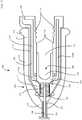
FIGS. 2A and3 ,end effector assembly 100 includes aproximal hub housing 110, an elongatedouter shaft 120 fixedly engaged with and extending distally fromproximal hub housing 110, aninner cutting shaft 130 movable disposed within elongatedouter shaft 120, and aninner drive core 140 operably disposed withinproximal hub housing 110 and coupled toinner cutting shaft 130 such that rotational input imparted toinner drive core 140, e.g., viahandpiece assembly 200, as detailed below, drives reciprocation and rotation ofinner cutting shaft 130 within and relative to elongatedouter shaft 120. - Proximal hub housing 110 of
end effector assembly 100 includes anouter housing 112 and aninner housing 116 sealingly engaged withinouter housing 112.Outer housing 112 receives and fixedly engages aproximal end portion 122 of elongatedouter shaft 120 therein at adistal nose 113 ofouter housing 112.Outer housing 112 further includes anannular protrusion 114 defined atproximal base 115 ofouter housing 112 to facilitate grasping and manipulatingproximal hub housing 110.Inner housing 116 includes a threadeddistal nose 117,proximal bayonet threading 118 disposed within and facing radially-inwardly into aninterior cavity 111 ofproximal hub housing 110, and anannular channel 119 disposed aboutinterior cavity 111 and defining a radially-inwardly-facing opendistal end 119a, a ring-shaped body 119b, and aproximal exit port 119c.Inner housing 116, or at least a portion thereof, is formed from a heat sink material, e.g., a thermally-conductive material such as a metal, to serve as a heat sink formotor 260 of handpiece assembly 200 (FIG. 4 ), as detailed below. - Elongated
outer shaft 120 ofend effector assembly 100, as noted above, includes aproximal end portion 122 fixedly engaged withouter housing 112 ofproximal hub housing 110. Elongatedouter shaft 120 further includes adistal end portion 124 defining a closeddistal end 126 and awindow 128 proximally-spaced from closeddistal end 126.Window 128 provides access to the interior of elongatedouter shaft 120 and may be surrounded by acutting edge 129 about the outer perimeter ofwindow 128 so as to facilitate cutting of tissue passing throughwindow 128 and into elongatedouter shaft 120. Inner cutting shaft 130 defines aproximal end portion 132 and adistal end portion 134 defining an opendistal end 136.Inner cutting shaft 130 defines an annular cutting edge 138 surrounding opendistal end 136 so as to facilitate cutting of tissue passing intoinner cutting shaft 130 via opendistal end 136.Inner cutting shaft 130, as noted above, is rotatable and reciprocatable within and relative to elongatedouter shaft 120. More specifically,inner cutting shaft 130 is configured to reciprocate and rotate such that annular cutting edge 138 is exposed withinwindow 128 of elongatedouter shaft 120 during at least a portion of the reciprocation motion ofinner cutting shaft 130 to enable cutting of tissue therewith. As detailed below, suction is provided to facilitate drawing tissue intowindow 128 and, thus, cutting and removal of tissue throughinner cutting shaft 130.- With momentary reference to
FIG. 2B , another embodiment of anend effector assembly 1100 configured for use with tissue resecting deice 10 (FIG. 1 ) is shown.End effector assembly 1100 is similar to and may include any of the features of end effector assembly 100 (FIG. 2A ), except that, rather than reciprocation and rotation,inner cutting shaft 1130 ofend effector assembly 1100 is longitudinally fixed and rotatable relative to elongatedouter shaft 1120.End effector assembly 1100 further differs from end effector assembly 100 (FIG. 2A ) in that elongatedouter shaft 1120 andinner cutting shaft 1130 both definewindow distal end Window 1128 and/orwindow 1138 may be surrounded by acutting edge windows windows inner cutting shaft 1130 relative to elongatedouter shaft 1120. Other suitable end effector assemblies including various different elongated outer shaft and inner cutting shaft configurations are also contemplated. - Referring again to
FIGS. 2A and3 ,inner drive core 140 ofend effector assembly 100 includes a threadedferrule 142 defining threading on an exterior thereof and areceiver 146 engaged to and extending proximally from threadedferrule 142. Threadedferrule 142 is engaged aboutproximal end portion 132 ofinner cutting shaft 130 such that rotation of threadedferrule 142 effects corresponding rotation ofinner cutting shaft 130. Threadedferrule 142 is disposed within threadeddistal nose 117 ofinner housing 116 with the respective threads thereof disposed in meshed engagement with one another. As a result of this configuration, rotational input to threadedferrule 142 effects rotation and reciprocation of threadedferrule 142 through and relative toproximal hub housing 110 which, in turn, rotates and reciprocatesinner cutting shaft 130 relative to elongatedouter shaft 120. Receiver 146 ofinner drive core 140, as noted above, is engaged to and extends proximally from threadedferrule 142.Receiver 146 is slidably and rotatably disposed withininterior cavity 111 ofproximal hub housing 110 and defines aslot 148 having a non-circular cross-section.Slot 148 is configured to receive adrive rotor 250 of handpiece assembly 200 (seeFIGS. 4-5B ) in fixed rotational orientation relative thereto such that rotation ofdrive rotor 250 is imparted toreceiver 146 which, in turn, is imparted to threadedferrule 142 to rotate and reciprocateinner cutting shaft 130 relative to elongatedouter shaft 120.- With continued reference to
FIGS. 2A and3 , as noted above,annular channel 119 defined withininner housing 116 has a radially-inwardly-facing opendistal end 119a, a ring-shapedbody 119b, and aproximal exit port 119c. Radially-inwardly-facing opendistal end 119a is oriented perpendicularly relative to a longitudinal axis of elongatedouter shaft 120 andinner cutting shaft 130 and, thus, perpendicular to the direction of fluid, tissue, and debris flow throughinner cutting shaft 130. Further,inner housing 116 andreceiver 146 cooperate to define avalve 150 between radially-inwardly-facing opendistal end 119a ofannular channel 119 and the open proximal end ofinner cutting shaft 130. More specifically, asreceiver 146 reciprocates through and relative toinner housing 116,receiver 146 is moved from a proximal position, corresponding to an open position of valve 150 (seeFIG. 5B ), enabling fluid communication between the interior ofinner cutting shaft 130 andannular channel 119, and a distal position, corresponding to a closed position of valve 150 (FIG. 5A ), whereinreceiver 146 abuts threadeddistal nose 117 ofinner housing 116 in sealing engagement therewith to inhibit fluid communication between the interior ofinner cutting shaft 130 andannular channel 119. Thus, during use, whenend effector assembly 100 is activated such thatinner cutting shaft 130 is rotating and reciprocating,valve 150 is open during a portion of the rotating and reciprocating, and is closed during another portion of the rotating and reciprocating. Whenvalve 150 is open, fluid, tissue and debris suctioned intoinner cutting shaft 130 are be evacuated fromend effector assembly 100 viaannular channel 119, as detailed below. - Turning now to
FIGS. 1 and4 ,handpiece assembly 200 generally includes ahandle housing 210, afluid return conduit 220 disposed onhandle housing 210, acable 230 coupled to handlehousing 210, adrive casing 240 extending distally fromhandle housing 210, adrive rotor 250 extending distally fromdrive casing 240, and amotor 260 disposed within at least a portion ofdrive casing 240 and/or handlehousing 210.Handpiece assembly 200 may further include one or more controls (not shown) disposed on or operably associated withhandle housing 210 to facilitate activation oftissue resecting device 10. - Handle
housing 210 defines a pistol-grip configuration, although other configurations are also contemplated, and includes abarrel portion 212 and a fixedhandle portion 214.Fluid return conduit 220 extends alongsidebarrel portion 212 ofhandle housing 210 and may be formed withbarrel portion 212 or otherwise engaged thereto.Fluid return conduit 220 defines an opendistal end 222 that is configured to abut and operably couple withproximal exit port 119c of end effector assembly 100 (FIGS. 2A and3 ) upon engagement ofend effector assembly 100 withhandpiece assembly 200 so as to define a continuous fluid path fromend effector assembly 100, throughfluid return conduit 220, to a collection receptacle of the fluid management system (not shown). To this end,fluid return conduit 220 may be coupled at its proximal end to tubing (not shown) or other suitable structure configured to direct fluid fromfluid return conduit 220 to the fluid management system. Cable 230 extends proximally from fixedhandle portion 214 ofhandle housing 210 and is configured to connect to the control unit (not shown) to provide power and control functionality totissue resecting device 10.Cable 230, more specifically, houses one ormore wires 232 that extend intohandle housing 210 and connect to the controls thereof and/ormotor 260 topower motor 260 and control operation oftissue resecting device 10 in accordance with controls associated withhandpiece assembly 200, the control unit, and/or other remote control devices, e.g., a footswitch (not shown).- With additional reference to
FIG. 3 , drive casing 240, as noted above, extend distally fromhandle housing 210. Drive casing 240, more specifically, surrounds at least a portion ofmotor 260, is disposed in thermal communication withmotor 260, and is formed from a heat sink material, e.g., a thermally-conductive material such as a metal, to serve as a heat sink formotor 260. Drive casing 240 further defines external bayonet threading 242 therein that is configure to engage proximal bayonet threading 118 ofinner housing 116 ofend effector assembly 100 to releasably engageend effector assembly 100 withhandpiece assembly 200. - Drive
rotor 250 extends distally fromdrive casing 240, as noted above, and defines a non-circular cross-section complementary to that ofslot 148 ofreceiver 146 ofend effector assembly 100 such that, upon engagement ofend effector assembly 100 withhandpiece assembly 200,drive rotor 250 is received withinslot 148 ofreceiver 146 in fixed rotational orientation relative thereto. As such, rotation ofdrive rotor 250 is imparted toreceiver 146 which, in turn, is imparted to threadedferrule 142 to rotate and reciprocateinner cutting shaft 130 relative to elongatedouter shaft 120. An annular gap is defined betweendrive rotor 250 and drive casing 240 to enabledrive rotor 250 to rotate relative to drive casing 240 with minimal friction therebetween. - Referring to
FIG. 4 , aseal ring 270 formed from an elastomeric material is disposed, in an at-rest position, aboutdrive rotor 250 between a proximally-facingshoulder 272 ofdrive rotor 250 and a distally-facingsurface 274 ofdrive casing 240 so as to seal the annular gap defined betweendrive rotor 250 and drivecasing 240. Thus, fluids are inhibited from entering the annular gap defined betweendrive rotor 250 and drive casing 240 such as, for example, during sterilization and/or cleaning ofhandpiece assembly 200 for reuse. - Turning to
FIGS. 5A-5B , in conjunction withFIGS. 1 ,3 , and4 , in order to engageend effector assembly 100 withhandpiece assembly 200,end effector assembly 100 is approximated and rotated relative tohandpiece assembly 200 to engage external bayonet threading 242 ofdrive casing 240 with proximal bayonet threading 118 ofinner housing 116 and such that opendistal end 222 offluid return conduit 220 is operably coupled withproximal exit port 119c ofannular channel 119 and driverotor 250 is received withinreceiver 146 in fixed rotational engagement therewith. In this engaged condition, fluid, tissue, and debris are permitted to flow (whenvalve 150 is disposed in the open position) frominner cutting shaft 130 throughannular channel 119 and intofluid return conduit 220 for ultimate collection at the fluid management system. Further, in this engaged condition,inner housing 116 and drive casing 240 are thus disposed in contact with one another to together serve as a heat sink conducting heat away frommotor 260 to fluid passing throughannular channel 119 defined withininner housing 116 during use, thus helping to coolmotor 260. - Additionally, upon engagement of
end effector assembly 100 withhandpiece assembly 200, a rampedsurface 276 ofinner housing 116 urgesseal ring 270 proximally such thatseal ring 270 is displaced from proximally-facingshoulder 272 ofdrive rotor 250 and removed from contact withdrive rotor 250. As such, friction betweenseal ring 270,drive rotor 250, and drive casing 240 during use, e.g., rotation ofdrive rotor 250 relative to drive casing 240, is substantially reduced if not eliminated. Upon disengagement ofend effector assembly 100 fromhandpiece assembly 200,seal ring 270 is returned under bias to its at-rest position. - Referring generally to
FIGS. 1 ,2A , and3-5B , prior to use,tissue resecting device 10 is assembled by engagingend effector assembly 100 withhandpiece assembly 200, as detailed above. Further,cable 230 is connected to the control unit andfluid return conduit 220 is connected to the fluid management system. Once this is achieved,tissue resecting device 10 is ready for use. In use,tissue resecting device 10 is positioned within an internal body cavity or organ, e.g., a uterus, such that the distal end portion ofend effector assembly 100 is positioned adjacent tissue to be removed.Tissue resecting device 10 may be inserted through an endoscope, e.g., a hysteroscope, or other device, or may be used independently. - Once
tissue resecting device 10 is positioned as desired adjacent tissue to be removed,tissue resecting device 10 is activated. Activation oftissue resecting device 10 powers motor 260 which serves to rotationallydrive drive rotor 250. Rotation ofdrive rotor 250, in turn, provides rotational input toreceiver 146 such that threadedferrule 142 is rotated and reciprocated to thereby rotate and reciprocateinner cutting shaft 130 relative to elongatedouter shaft 120. Activation oftissue resecting device 10 also serves to activate suction throughfluid return conduit 220, thereby applying suction throughinner cutting shaft 130. With such suction applied, tissue is drawn throughwindow 128 of elongatedouter shaft 120 and intoinner cutting shaft 130, while cuttingedges 129, 138 facilitate cutting of tissue as it passes throughwindow 128 and intoinner cutting shaft 130. The suction also draws fluid and debris intoinner cutting shaft 130.Tissue resecting device 10 is utilized until the desired tissue is removed from the internal body cavity or organ. - The tissue, fluid, and debris suctioned through
inner cutting shaft 130 travel proximally throughinner cutting shaft 130, eventually reachingvalve 150. Withvalve 150 in the open position (FIG. 5B ), the tissue, fluid, and debris are urged radially outwardly, into and through the radially-inwardly-facing opendistal end 119a ofannular channel 119 and eventually passing through ring-shapedbody 119b ofannular channel 119,proximal exit port 119c ofannular channel 119, and intofluid return conduit 220. Whenvalve 150 is disposed in the closed position (FIG. 5A ), the tissue, fluid, and debris do not pass therethrough; however, upon reopening ofvalve 150, a centrifugal force surge (created due to the rotation ofreceiver 146 relative toinner housing 116 and the perpendicular orientation opendistal end 119a ofannular channel 119 relative to the longitudinal axis of elongated outer shaft 120) above the steady-state suction force urges the tissue, fluid, and debris radially outwardly into opendistal end 119a ofannular channel 119 such that any collected tissue, fluid, and debris is taken therewith under this force surge, thus clearing any collected tissue, fluid, and debris and inhibiting clogging withinproximal hub housing 110 ofend effector assembly 100. Further, as noted above, the fluid (and tissue and debris) passing proximally throughannular channel 119 also serves to absorb heat conducted away frommotor 260 via the heat sink formed from the engagement ofinner housing 116 and drive casing 240, thus helping to coolmotor 260 during use. In addition, as also noted above,seal ring 270 is maintained decoupled fromdrive rotor 250 during use, reducing friction and potential wear onseal ring 270 asdrive rotor 150 is rotated. - Once the desired tissue is removed,
tissue resecting device 10 may be deactivated and removed from the surgical site. Thereafter,end effector assembly 100 may be disengaged fromhandpiece assembly 200 and discarded (or sent for reprocessing), whilehandpiece assembly 200 is cleaned and/or sterilized for reuse. As detailed above, upon disengagement ofend effector assembly 100 fromhandpiece assembly 200,seal 270 is returned to its at-rest position, thus inhibiting fluid ingress intohandpiece assembly 200 during sterilization and/or cleaning thereof for reuse. - As an alternative to
handpiece assembly 200 configured for manual grasping and manipulation during use,tissue resecting device 10 may alternatively be configured for use with a robotic surgical system whereinhandle housing 210 is configured to engage a robotic arm of the robotic surgical system. The robotic surgical system may employ various robotic elements to assist the surgeon and allow remote operation (or partial remote operation). More specifically, various robotic arms, gears, cams, pulleys, electric and mechanical motors, etc. may be employed for this purpose and may be designed with the robotic surgical system to assist the surgeon during the course of an operation or treatment. The robotic surgical system may include remotely steerable systems, automatically flexible surgical systems, remotely flexible surgical systems, remotely articulating surgical systems, wireless surgical systems, modular or selectively configurable remotely operated surgical systems, etc. - The robotic surgical system may be employed with one or more consoles that are next to the operating theater or located in a remote location. In this instance, one team of surgeons or nurses may prep the patient for surgery and configure the robotic surgical system with the surgical device disclosed herein while another surgeon (or group of surgeons) remotely control the surgical device via the robotic surgical system. As can be appreciated, a highly skilled surgeon may perform multiple operations in multiple locations without leaving his/her remote console which can be both economically advantageous and a benefit to the patient or a series of patients.
- The robotic arms of the robotic surgical system are typically coupled to a pair of master handles by a controller. The handles can be moved by the surgeon to produce a corresponding movement of the working ends of any type of surgical instrument (e.g., end effectors, graspers, knifes, scissors, cameras, fluid delivery devices, etc.) which may complement the use of the tissue resecting devices described herein. The movement of the master handles may be scaled so that the working ends have a corresponding movement that is different, smaller or larger, than the movement performed by the operating hands of the surgeon. The scale factor or gearing ratio may be adjustable so that the operator can control the resolution of the working ends of the surgical instrument(s).
- While several embodiments of the disclosure have been shown in the drawings, it is not intended that the disclosure be limited thereto, as it is intended that the disclosure be as broad in scope as the art will allow and that the specification be read likewise. Therefore, the above description should not be construed as limiting, but merely as examples of particular embodiments. Those skilled in the art will envision other modifications within the scope of the claims appended hereto.
- Although the foregoing disclosure has been described in some detail by way of illustration and example, for purposes of clarity or understanding, it will be obvious that certain changes and modifications may be practiced within the scope of the appended claims.
Claims (6)
- A tissue resecting device (10), comprising:an end effector assembly (100; 1100) including a proximal hub housing (110) and a cutting member (126) extending distally from the proximal hub housing; anda handpiece assembly (200), including:a handle housing (210);a drive casing (240) extending distally from the handle housing;a drive rotor (250) extending through and distally from the drive casing (240); anda seal ring (270) disposed about the drive rotor, wherein, in an at-rest position whereby the end effector assembly (100; 1100) is disengaged from the handpiece assembly (200), the seal ring is sealingly engaged between the drive casing and the drive rotor to inhibit fluid ingress into the annular space between the drive rotor (250) and the drive casing (240),wherein the end effector assembly is releasably engageable with the handpiece assembly andcharacterised in that, upon engagement of the end effector assembly with the handpiece assembly, a portion (276) of the proximal hub housing is configured to urge the seal ring (270) from the at-rest position to a displaced position wherein in the displaced position, the seal ring is displaced away from the drive rotor (250) to reduce friction between the drive rotor (250) and the drive casing (240) upon rotation of the drive rotor relative to the drive casing.
- The tissue resecting device according to claim 1, wherein the end effector assembly further includes an inner core (116) disposed within the proximal hub housing (110), the cutting member coupled to the inner core and the inner core (116) configured to couple to the drive rotor (250) upon engagement of the end effector assembly with the handpiece assembly such that rotation of the drive rotor drives the cutting member.
- The tissue resecting device according to claim 2, wherein the inner core (116) is configured such that rotation of the drive rotor drives rotation and reciprocation of the cutting member.
- The tissue resecting device according to claim 1, 2 or 3, wherein the end effector assembly further includes a fixed outer shaft (120) extending distally from the proximal hub housing (110) and disposed about the cutting member.
- The tissue resecting device according to claim 1, 2, 3 or 4, wherein the proximal hub housing (110) defines bayonet threading (118) and wherein the drive casing defines bayonet threading (242) configured to engage the bayonet threading of the proximal hub housing to engage the end effector assembly with the handpiece assembly.
- The tissue resecting device according to any one of claims 1 to 5, wherein the handpiece assembly further includes a motor (260) disposed within the handle housing, the motor configured to drive rotation of the drive rotor.
Applications Claiming Priority (1)
| Application Number | Priority Date | Filing Date | Title |
|---|---|---|---|
| US15/895,407US10869684B2 (en) | 2018-02-13 | 2018-02-13 | Powered tissue resecting device |
Publications (3)
| Publication Number | Publication Date |
|---|---|
| EP3524188A2 EP3524188A2 (en) | 2019-08-14 |
| EP3524188A3 EP3524188A3 (en) | 2019-10-16 |
| EP3524188B1true EP3524188B1 (en) | 2021-01-27 |
Family
ID=65411797
Family Applications (1)
| Application Number | Title | Priority Date | Filing Date |
|---|---|---|---|
| EP19156616.5ANot-in-forceEP3524188B1 (en) | 2018-02-13 | 2019-02-12 | Powered tissue resecting device |
Country Status (5)
| Country | Link |
|---|---|
| US (2) | US10869684B2 (en) |
| EP (1) | EP3524188B1 (en) |
| CN (1) | CN110151259B (en) |
| AU (1) | AU2018278968B2 (en) |
| CA (1) | CA3026926C (en) |
Families Citing this family (9)
| Publication number | Priority date | Publication date | Assignee | Title |
|---|---|---|---|---|
| US10869684B2 (en) | 2018-02-13 | 2020-12-22 | Covidien Lp | Powered tissue resecting device |
| JP7222978B2 (en)* | 2018-03-29 | 2023-02-15 | テルモ株式会社 | medical device |
| US11154318B2 (en)* | 2019-02-22 | 2021-10-26 | Covidien Lp | Tissue resecting instrument including an outflow control seal |
| US11596466B2 (en)* | 2019-09-09 | 2023-03-07 | Covidien Lp | Surgical instrument with evacuation port and method |
| US11777375B2 (en) | 2019-10-04 | 2023-10-03 | Gyrus Acmi, Inc. | Handheld surgical instrument with heat management |
| US11957373B2 (en) | 2020-05-12 | 2024-04-16 | Smith & Nephew, Inc. | Systems and methods of determining orientation of cutting windows of a mechanical resection instrument |
| US11925428B2 (en)* | 2020-08-07 | 2024-03-12 | Covidien Lp | Manual end effector activation for robotic surgical systems |
| JP2024503438A (en) | 2021-01-12 | 2024-01-25 | アースレックス インコーポレイテッド | surgical cutting tools |
| US12336731B2 (en)* | 2021-10-22 | 2025-06-24 | Gyrus Acmi, Inc. | High speed burr with flex shaft cooling and improved suction |
Family Cites Families (261)
| Publication number | Priority date | Publication date | Assignee | Title |
|---|---|---|---|---|
| US1585934A (en) | 1923-12-29 | 1926-05-25 | Radium Emanation Corp | Diagnostic needle |
| US1831786A (en) | 1926-04-20 | 1931-11-10 | California Packing Corp | Fruit peeling apparatus |
| US1666332A (en) | 1927-05-23 | 1928-04-17 | Edwin W Hirsch | Bladder-pressure-testing apparatus |
| US2708437A (en) | 1952-03-31 | 1955-05-17 | Elizabeth Painter Hutchins | Surgical instrument |
| US3297022A (en) | 1963-09-27 | 1967-01-10 | American Cystoscope Makers Inc | Endoscope |
| GB1288091A (en) | 1969-01-03 | 1972-09-06 | ||
| DE7107645U (en) | 1971-03-02 | 1971-05-27 | Storz K | ENDOSCOPE IN PARTICULAR CYSTOSCOPE |
| US3734099A (en) | 1971-04-07 | 1973-05-22 | H Bender | Powered surgical cutter |
| US3812855A (en) | 1971-12-15 | 1974-05-28 | Surgical Design Corp | System for controlling fluid and suction pressure |
| US3945375A (en) | 1972-04-04 | 1976-03-23 | Surgical Design Corporation | Rotatable surgical instrument |
| US3850162A (en) | 1972-07-03 | 1974-11-26 | J Iglesias | Endoscope with continuous irrigation |
| US3835842A (en) | 1972-07-03 | 1974-09-17 | J Iglesias | Endoscope with continuous irrigation |
| US3996921A (en) | 1975-04-17 | 1976-12-14 | Pharmacia Inc. | Method and apparatus for endoscopy |
| US4011869A (en) | 1975-08-01 | 1977-03-15 | David Kopf Instruments | Tubular cutting instrument |
| US3995619A (en) | 1975-10-14 | 1976-12-07 | Glatzer Stephen G | Combination subcutaneous suture remover, biopsy sampler and syringe |
| US3980252A (en) | 1975-10-31 | 1976-09-14 | John T. Hepburn Limited | Wire rope spooling mechanism |
| US4146405A (en) | 1977-01-19 | 1979-03-27 | Henry Timmer | Unitary dishwasher |
| US4108182A (en) | 1977-02-16 | 1978-08-22 | Concept Inc. | Reciprocation vitreous suction cutter head |
| US4198958A (en) | 1977-06-01 | 1980-04-22 | Olympus Optical Co., Ltd. | Flexible cap and instrument seal for a suction control device in an endoscope |
| US4414962A (en) | 1977-06-15 | 1983-11-15 | Carson Robert W | Operating arthroscope |
| US4203444A (en) | 1977-11-07 | 1980-05-20 | Dyonics, Inc. | Surgical instrument suitable for closed surgery such as of the knee |
| FR2415451A1 (en) | 1978-01-26 | 1979-08-24 | Bernard Parent | PANORAMIC VISION DIAGNOSTIC HYSTEROSCOPE |
| US4246902A (en) | 1978-03-10 | 1981-01-27 | Miguel Martinez | Surgical cutting instrument |
| US4210146A (en) | 1978-06-01 | 1980-07-01 | Anton Banko | Surgical instrument with flexible blade |
| US4316465A (en) | 1979-03-30 | 1982-02-23 | Dotson Robert S Jun | Ophthalmic handpiece with pneumatically operated cutter |
| US4294234A (en) | 1979-06-22 | 1981-10-13 | Olympus Optical Co., Ltd. | Endoscope |
| US4247180A (en) | 1979-08-06 | 1981-01-27 | Polaroid Corporation | Card motion picture apparatus with adjustable barrel cam |
| US4261346A (en) | 1979-11-23 | 1981-04-14 | Richard Wolf Medical Instruments Corporation | Endoscopes |
| US4369768A (en) | 1980-07-30 | 1983-01-25 | Marko Vukovic | Arthroscope |
| US4493698A (en) | 1980-11-03 | 1985-01-15 | Cooper Medical Devices | Method of performing opthalmic surgery utilizing a linear intra-ocular suction device |
| US4392485A (en) | 1981-02-17 | 1983-07-12 | Richard Wolf Gmbh | Endoscope |
| US4517977A (en) | 1981-07-24 | 1985-05-21 | Unisearch Limited | Co-axial tube surgical infusion/suction cutter tip |
| US4449538A (en) | 1982-01-25 | 1984-05-22 | John Corbitt | Medical-electronic body fluid accounting system |
| EP0095891B2 (en) | 1982-05-28 | 1988-11-02 | Rhp Group Plc | Devices for converting rotary movement into linear movement |
| IL66047A0 (en) | 1982-06-13 | 1982-09-30 | Univ Ben Gurion | Method and device for measuring intrauterine pressure during labour |
| US5435805A (en) | 1992-08-12 | 1995-07-25 | Vidamed, Inc. | Medical probe device with optical viewing capability |
| US5421819A (en) | 1992-08-12 | 1995-06-06 | Vidamed, Inc. | Medical probe device |
| JPS59200644A (en) | 1983-04-27 | 1984-11-14 | オリンパス光学工業株式会社 | Surgical incision instrument |
| US4606330A (en) | 1983-08-09 | 1986-08-19 | Richard Wolf Gmbh | Device for disintegrating stones in bodily cavities or ducts |
| US4601290A (en) | 1983-10-11 | 1986-07-22 | Cabot Medical Corporation | Surgical instrument for cutting body tissue from a body area having a restricted space |
| DE3569876D1 (en) | 1984-02-20 | 1989-06-08 | Olympus Optical Co | Endoscopic ovum picker instruments |
| JPS60243625A (en) | 1984-05-18 | 1985-12-03 | Fuji Photo Optical Co Ltd | Connecting system of endoscope |
| US4630598A (en) | 1984-05-29 | 1986-12-23 | Richard Wolf Gmbh | Uretero-renoscope |
| DE3443337A1 (en) | 1984-11-28 | 1986-05-28 | Richard Wolf Gmbh, 7134 Knittlingen | INSTRUMENT FOR THE EXAMINATION AND TREATMENT OF BODY CHANNELS |
| US4567880A (en) | 1984-12-26 | 1986-02-04 | Goodman Tobias M | Endoscopic device with three-way valve |
| US4649919A (en) | 1985-01-23 | 1987-03-17 | Precision Surgical Instruments, Inc. | Surgical instrument |
| US4756309A (en) | 1985-02-14 | 1988-07-12 | Sachse Hans Ernst | Endoscope for removal of tissue |
| US4644952A (en) | 1985-02-19 | 1987-02-24 | Palm Beach Medical Engineering, Inc. | Surgical operating instrument |
| JPS61259637A (en) | 1985-05-15 | 1986-11-17 | オリンパス光学工業株式会社 | Endoscope apparatus |
| JPS62105698A (en) | 1985-11-05 | 1987-05-16 | ソニー株式会社 | Printer |
| US4950278A (en) | 1986-08-06 | 1990-08-21 | Sachse Hans E | Endoscope for removal of tissue |
| US4749376A (en) | 1986-10-24 | 1988-06-07 | Intravascular Surgical Instruments, Inc. | Reciprocating working head catheter |
| US5312430A (en) | 1986-12-09 | 1994-05-17 | Rosenbluth Robert F | Balloon dilation catheter |
| US4850354A (en) | 1987-08-13 | 1989-07-25 | Baxter Travenol Laboratories, Inc. | Surgical cutting instrument |
| US4867157A (en) | 1987-08-13 | 1989-09-19 | Baxter Travenol Laboratories, Inc. | Surgical cutting instrument |
| US4819635A (en) | 1987-09-18 | 1989-04-11 | Henry Shapiro | Tubular microsurgery cutting apparatus |
| US4844064A (en) | 1987-09-30 | 1989-07-04 | Baxter Travenol Laboratories, Inc. | Surgical cutting instrument with end and side openings |
| US4986827A (en) | 1987-11-05 | 1991-01-22 | Nestle S.A. | Surgical cutting instrument with reciprocating inner cutter |
| FR2625428A1 (en) | 1988-01-05 | 1989-07-07 | Sinergy Sa | MULTIFUNCTIONAL OPERATIVE COELIOSCOPY DEVICE FOR PERFORMING DIFFERENT OPERATIVE GESTURES WITH INTRODUCTION OF INSTRUMENTS |
| DE3805368C1 (en) | 1988-02-17 | 1989-08-24 | Peter P. Dipl.-Ing. Wiest | |
| US4955882A (en) | 1988-03-30 | 1990-09-11 | Hakky Said I | Laser resectoscope with mechanical and laser cutting means |
| US5027792A (en) | 1989-03-17 | 1991-07-02 | Percutaneous Technologies, Inc. | Endoscopic revision hip surgery device |
| US5116868A (en) | 1989-05-03 | 1992-05-26 | The Johns Hopkins University | Effective ophthalmic irrigation solution |
| JP2787471B2 (en) | 1989-07-04 | 1998-08-20 | 旭光学工業株式会社 | Endoscope sheath device |
| US5226910A (en) | 1989-07-05 | 1993-07-13 | Kabushiki Kaisha Topcon | Surgical cutter |
| US5106364A (en) | 1989-07-07 | 1992-04-21 | Kabushiki Kaisha Topcon | Surgical cutter |
| US4998527A (en) | 1989-07-27 | 1991-03-12 | Percutaneous Technologies Inc. | Endoscopic abdominal, urological, and gynecological tissue removing device |
| US5226909A (en) | 1989-09-12 | 1993-07-13 | Devices For Vascular Intervention, Inc. | Atherectomy device having helical blade and blade guide |
| US5112299A (en) | 1989-10-25 | 1992-05-12 | Hall Surgical Division Of Zimmer, Inc. | Arthroscopic surgical apparatus and method |
| US5163433A (en) | 1989-11-01 | 1992-11-17 | Olympus Optical Co., Ltd. | Ultrasound type treatment apparatus |
| US5409013A (en) | 1989-11-06 | 1995-04-25 | Mectra Labs, Inc. | Tissue removal assembly |
| US5176677A (en) | 1989-11-17 | 1993-01-05 | Sonokinetics Group | Endoscopic ultrasonic rotary electro-cauterizing aspirator |
| US5037386A (en) | 1989-11-17 | 1991-08-06 | Minnesota Mining And Manufacturing Company | Pressure sensing scope cannula |
| US4940061A (en) | 1989-11-27 | 1990-07-10 | Ingress Technologies, Inc. | Biopsy instrument |
| US5152744A (en) | 1990-02-07 | 1992-10-06 | Smith & Nephew Dyonics | Surgical instrument |
| US5169397A (en) | 1990-02-08 | 1992-12-08 | Olympus Optical Co., Ltd. | Medical instrument |
| US5007917A (en) | 1990-03-08 | 1991-04-16 | Stryker Corporation | Single blade cutter for arthroscopic surgery |
| EP0448857A1 (en) | 1990-03-27 | 1991-10-02 | Jong-Khing Huang | An apparatus of a spinning type of resectoscope for prostatectomy |
| US5275609A (en) | 1990-06-22 | 1994-01-04 | Vance Products Incorporated | Surgical cutting instrument |
| US5269785A (en) | 1990-06-28 | 1993-12-14 | Bonutti Peter M | Apparatus and method for tissue removal |
| US5911699A (en) | 1990-07-17 | 1999-06-15 | Aziz Yehia Anis | Removal of tissue |
| US6007513A (en) | 1990-07-17 | 1999-12-28 | Aziz Yehia Anis | Removal of tissue |
| US5158553A (en) | 1990-12-26 | 1992-10-27 | Cardiopulmonics | Rotatably actuated constricting catheter valve |
| US5409453A (en) | 1992-08-12 | 1995-04-25 | Vidamed, Inc. | Steerable medical probe with stylets |
| US5125910A (en) | 1991-02-19 | 1992-06-30 | Dexide, Inc. | Surgical endoscopic suction/irrigation cannula assembly |
| US5490819A (en) | 1991-08-05 | 1996-02-13 | United States Surgical Corporation | Articulating endoscopic surgical apparatus |
| ATE190850T1 (en) | 1991-08-21 | 2000-04-15 | Smith & Nephew Inc | FLUID TREATMENT SYSTEM |
| US5288290A (en) | 1991-09-25 | 1994-02-22 | Alcon Surgical, Inc. | Multi-ported valve assembly |
| US5195541A (en) | 1991-10-18 | 1993-03-23 | Obenchain Theodore G | Method of performing laparoscopic lumbar discectomy |
| US5449356A (en) | 1991-10-18 | 1995-09-12 | Birtcher Medical Systems, Inc. | Multifunctional probe for minimally invasive surgery |
| US5244459A (en) | 1992-01-28 | 1993-09-14 | Hill Raymond R | Suction irrigator endoscope |
| US5242404A (en) | 1992-02-12 | 1993-09-07 | American Cyanamid Company | Aspiration control system |
| US5254117A (en) | 1992-03-17 | 1993-10-19 | Alton Dean Medical | Multi-functional endoscopic probe apparatus |
| US5350390A (en) | 1992-03-25 | 1994-09-27 | Arieh Sher | Device for removal of intraluminal occlusions |
| US5270622A (en) | 1992-04-13 | 1993-12-14 | Smith & Nephew Dyonics, Inc. | Brushless motor control system |
| US5563481A (en) | 1992-04-13 | 1996-10-08 | Smith & Nephew Endoscopy, Inc. | Brushless motor |
| US5602449A (en) | 1992-04-13 | 1997-02-11 | Smith & Nephew Endoscopy, Inc. | Motor controlled surgical system and method having positional control |
| US5672945A (en) | 1992-04-13 | 1997-09-30 | Smith & Nephew Endoscopy, Inc. | Motor controlled surgical system and method having self clearing motor control |
| US5320091A (en) | 1992-04-27 | 1994-06-14 | Circon Corporation | Continuous flow hysteroscope |
| US5556378A (en) | 1992-06-17 | 1996-09-17 | Storz; Karl | Device for irrigation of body cavities |
| US5312399A (en) | 1992-09-29 | 1994-05-17 | Hakky Said I | Laser resectoscope with mechanical cutting means and laser coagulating means |
| US5304118A (en) | 1992-12-16 | 1994-04-19 | Trese Michael T | Method for performing a vitrectomy on an eye |
| US5347992A (en) | 1993-01-22 | 1994-09-20 | Karl Storz Endoscopy America, Inc. | Single axis three way selector valve for endoscopes |
| US5392765A (en) | 1993-02-11 | 1995-02-28 | Circon Corporation | Continuous flow cystoscope |
| US5403276A (en) | 1993-02-16 | 1995-04-04 | Danek Medical, Inc. | Apparatus for minimally invasive tissue removal |
| AU6667494A (en) | 1993-05-07 | 1994-12-12 | Danek Medical, Inc. | Surgical cutting instrument |
| US5364395A (en) | 1993-05-14 | 1994-11-15 | West Jr Hugh S | Arthroscopic surgical instrument with cauterizing capability |
| ATE141481T1 (en) | 1993-06-16 | 1996-09-15 | White Spot Ag | DEVICE FOR INTRODUCING FIBRIN GLUE INTO A STITCH CHANNEL |
| US5395313A (en) | 1993-08-13 | 1995-03-07 | Naves; Neil H. | Reciprocating arthroscopic shaver |
| US5575756A (en) | 1993-08-16 | 1996-11-19 | Olympus Optical Co., Ltd. | Endoscope apparatus |
| US5425376A (en) | 1993-09-08 | 1995-06-20 | Sofamor Danek Properties, Inc. | Method and apparatus for obtaining a biopsy sample |
| US5957832A (en) | 1993-10-08 | 1999-09-28 | Heartport, Inc. | Stereoscopic percutaneous visualization system |
| US5374253A (en) | 1993-10-12 | 1994-12-20 | Burns, Sr.; Charles N. | Medical instrument with automatic shut-off valve |
| US5456689A (en) | 1993-10-13 | 1995-10-10 | Arnold J. Kresch | Method and device for tissue resection |
| US5443476A (en) | 1993-11-12 | 1995-08-22 | Shapiro; Henry | Microsurgical scissor apparatus with rotary cutting blade |
| DE4340056A1 (en) | 1993-11-24 | 1995-06-01 | Delma Elektro Med App | Laparoscopic surgical device |
| US5490860A (en) | 1993-12-08 | 1996-02-13 | Sofamor Danek Properties, Inc. | Portable power cutting tool |
| EP0662572B1 (en) | 1994-01-11 | 1998-04-01 | SAMJOO MACHINERY Co., Ltd. | Rotary motion/constant velocity linear reciprocating motion conversion device and hydraulic system using the same |
| US6359200B1 (en) | 1994-01-13 | 2002-03-19 | Dekalb Genetics Corp. | Inbred corn plant 8M116 |
| US5411513A (en) | 1994-02-24 | 1995-05-02 | Danek Medical, Inc. | Transmission mechanism for a surgical cutting instrument |
| US5483951A (en) | 1994-02-25 | 1996-01-16 | Vision-Sciences, Inc. | Working channels for a disposable sheath for an endoscope |
| US5456673A (en) | 1994-03-23 | 1995-10-10 | Stryker Corporation | Locking cannula for endoscopic surgery |
| US5526822A (en) | 1994-03-24 | 1996-06-18 | Biopsys Medical, Inc. | Method and apparatus for automated biopsy and collection of soft tissue |
| US5649547A (en) | 1994-03-24 | 1997-07-22 | Biopsys Medical, Inc. | Methods and devices for automated biopsy and collection of soft tissue |
| US5709670A (en) | 1994-05-03 | 1998-01-20 | Aquintel, Inc. | Surgical fluid and tissue loss monitor |
| US5492537A (en) | 1994-05-03 | 1996-02-20 | Aquintel, Inc. | Surgical fluid monitor |
| US5702420A (en) | 1994-06-14 | 1997-12-30 | Anthony R. Sterling And Tri-Tech, Inc. | Motorized suction punch forceps |
| US5669921A (en) | 1994-07-19 | 1997-09-23 | Linvatec Corporation | Endoscopic shaver blade window positioning system |
| JP2802244B2 (en) | 1994-08-29 | 1998-09-24 | オリンパス光学工業株式会社 | Endoscope sheath |
| US5498258A (en) | 1994-09-13 | 1996-03-12 | Hakky; Said I. | Laser resectoscope with laser induced mechanical cutting means |
| US5569284A (en) | 1994-09-23 | 1996-10-29 | United States Surgical Corporation | Morcellator |
| US6032673A (en) | 1994-10-13 | 2000-03-07 | Femrx, Inc. | Methods and devices for tissue removal |
| AU701424B2 (en) | 1994-10-24 | 1999-01-28 | Smith & Nephew, Inc. | Hollow surgical cutter with apertured flutes |
| DE4440035C2 (en) | 1994-11-10 | 1998-08-06 | Wolf Gmbh Richard | Morcellating instrument |
| US5603332A (en) | 1995-01-27 | 1997-02-18 | Technological Services, Inc. | Method and apparatus for monitoring the systemic absorption of irrigation fluid during operative hysteroscopy |
| US5601583A (en) | 1995-02-15 | 1997-02-11 | Smith & Nephew Endoscopy Inc. | Surgical instrument |
| US5676497A (en) | 1995-02-27 | 1997-10-14 | Kim; Young S. | Power drill-saw with simultaneous rotation and reciprocation action |
| WO1996026676A1 (en) | 1995-03-02 | 1996-09-06 | Helfgott & Karas, P.C. | Uterine tissue collector |
| DE29503478U1 (en) | 1995-03-02 | 1995-04-20 | Richard Wolf Gmbh, 75438 Knittlingen | endoscope |
| ATE270854T1 (en) | 1995-03-31 | 2004-07-15 | Boston Scient Ltd | BIOPSY SAMPLER |
| US5873886A (en) | 1995-04-04 | 1999-02-23 | United States Surgical Corporation | Surgical cutting apparatus |
| US5569254A (en) | 1995-04-12 | 1996-10-29 | Midas Rex Pneumatic Tools, Inc. | Surgical resection tool having an irrigation, lighting, suction and vision attachment |
| US5685838A (en) | 1995-04-17 | 1997-11-11 | Xomed-Treace, Inc. | Sinus debrider apparatus |
| US5591187A (en) | 1995-07-14 | 1997-01-07 | Dekel; Moshe | Laparoscopic tissue retrieval device and method |
| US5749885A (en) | 1995-10-02 | 1998-05-12 | Smith & Nephew, Inc. | Surgical instrument with embedded coding element |
| US5772634A (en) | 1995-10-06 | 1998-06-30 | Zimmer, Inc. | Device for limiting distention fluid pressure during hysteroscopy |
| US5569178A (en)* | 1995-10-20 | 1996-10-29 | Henley; Julian L. | Power assisted suction lipectomy device |
| PT805652E (en) | 1995-11-27 | 2003-02-28 | C C D Lab | DEVICE FOR THE COLLECTION OF UTERINE MUCOSES |
| US5807282A (en) | 1995-12-28 | 1998-09-15 | Mayo Foundation For Medical Education And Research | Endometrial tissue curette and method |
| US5916229A (en) | 1996-02-07 | 1999-06-29 | Evans; Donald | Rotating needle biopsy device and method |
| US5749889A (en) | 1996-02-13 | 1998-05-12 | Imagyn Medical, Inc. | Method and apparatus for performing biopsy |
| US5709698A (en) | 1996-02-26 | 1998-01-20 | Linvatec Corporation | Irrigating/aspirating shaver blade assembly |
| US5766199A (en) | 1996-04-10 | 1998-06-16 | Linvatec Corporation | Endoscopic shaver blade with resilient cutting edges |
| US5741286A (en) | 1996-06-07 | 1998-04-21 | Symbiosis Corporation | Laparoscopic instrument kit including a plurality of rigid tubes |
| US5833643A (en) | 1996-06-07 | 1998-11-10 | Scieran Technologies, Inc. | Apparatus for performing ophthalmic procedures |
| US6258111B1 (en) | 1997-10-03 | 2001-07-10 | Scieran Technologies, Inc. | Apparatus and method for performing ophthalmic procedures |
| US6113594A (en) | 1996-07-02 | 2000-09-05 | Ethicon, Inc. | Systems, methods and apparatus for performing resection/ablation in a conductive medium |
| US6017354A (en) | 1996-08-15 | 2000-01-25 | Stryker Corporation | Integrated system for powered surgical tools |
| US5857995A (en) | 1996-08-15 | 1999-01-12 | Surgical Dynamics, Inc. | Multiple bladed surgical cutting device removably connected to a rotary drive element |
| US5807240A (en) | 1996-09-24 | 1998-09-15 | Circon Corporation | Continuous flow endoscope with enlarged outflow channel |
| US6090094A (en) | 1996-10-04 | 2000-07-18 | Microgroup, Inc. | Ball valves and uses thereof including endoscopic surgical instruments |
| US5814009A (en) | 1996-10-11 | 1998-09-29 | Cabot Technology Corporation | Fluid management system and replaceable tubing assembly therefor |
| US5730752A (en) | 1996-10-29 | 1998-03-24 | Femrx, Inc. | Tubular surgical cutters having aspiration flow control ports |
| US5741287A (en) | 1996-11-01 | 1998-04-21 | Femrx, Inc. | Surgical tubular cutter having a tapering cutting chamber |
| US5899915A (en) | 1996-12-02 | 1999-05-04 | Angiotrax, Inc. | Apparatus and method for intraoperatively performing surgery |
| US5810770A (en) | 1996-12-13 | 1998-09-22 | Stryker Corporation | Fluid management pump system for surgical procedures |
| US5913867A (en) | 1996-12-23 | 1999-06-22 | Smith & Nephew, Inc. | Surgical instrument |
| US5947990A (en) | 1997-02-24 | 1999-09-07 | Smith & Nephew, Inc. | Endoscopic surgical instrument |
| US6024751A (en) | 1997-04-11 | 2000-02-15 | Coherent Inc. | Method and apparatus for transurethral resection of the prostate |
| US6156049A (en) | 1997-04-11 | 2000-12-05 | Coherent Inc. | Method and apparatus for transurethral resection of the prostate |
| US5925055A (en) | 1997-06-23 | 1999-07-20 | Medelex, Inc | Multimodal rotary abrasion and acoustic ablation catheter |
| US6086542A (en) | 1997-07-01 | 2000-07-11 | Linvatec Corporation | Pressure sensing input/output scope sheath |
| US6149633A (en) | 1997-07-15 | 2000-11-21 | Surgin Surgical Instrumentation, Inc. | Flow control system and method for endoscopic surgeries |
| US6039748A (en) | 1997-08-05 | 2000-03-21 | Femrx, Inc. | Disposable laparoscopic morcellator |
| NL1006944C2 (en) | 1997-09-04 | 1999-03-11 | Mark Hans Emanuel | Surgical endoscopic cutting device. |
| US6004320A (en) | 1997-09-19 | 1999-12-21 | Oratec Interventions, Inc. | Clip on electrocauterizing sheath for orthopedic shave devices |
| US6102895A (en) | 1997-09-30 | 2000-08-15 | Cortella; Julian M. | Digital fluid delivery and aspiration apparatus with mechanical de-amplifier |
| US6171316B1 (en) | 1997-10-10 | 2001-01-09 | Origin Medsystems, Inc. | Endoscopic surgical instrument for rotational manipulation |
| US6159160A (en) | 1998-03-26 | 2000-12-12 | Ethicon, Inc. | System and method for controlled infusion and pressure monitoring |
| US6224603B1 (en) | 1998-06-09 | 2001-05-01 | Nuvasive, Inc. | Transiliac approach to entering a patient's intervertebral space |
| US6132448A (en) | 1998-06-19 | 2000-10-17 | Stryker Corporation | Endoscopic irrigated bur |
| US5911722A (en) | 1998-07-23 | 1999-06-15 | Millenium Devices Llc | Leban/Gordon surgical hand driver |
| US6068641A (en) | 1998-08-25 | 2000-05-30 | Linvatec Corporation | Irrigated burr |
| US6245084B1 (en) | 1998-10-20 | 2001-06-12 | Promex, Inc. | System for controlling a motor driven surgical cutting instrument |
| US6494892B1 (en) | 1998-10-20 | 2002-12-17 | Suros Surgical Systems, Inc. | Disposable hub for a surgical cutting instrument |
| US20010047183A1 (en) | 2000-04-05 | 2001-11-29 | Salvatore Privitera | Surgical device for the collection of soft tissue |
| US6632182B1 (en) | 1998-10-23 | 2003-10-14 | The Trustees Of Columbia University In The City Of New York | Multiple bit, multiple specimen endoscopic biopsy forceps |
| JP3448228B2 (en) | 1998-11-30 | 2003-09-22 | 富士写真光機株式会社 | Endoscope insertion guide tube |
| US6244228B1 (en) | 1998-12-11 | 2001-06-12 | Damon Kuhn | Rotary-to-linear motion converter and use thereof |
| CA2256130A1 (en) | 1998-12-16 | 2000-06-16 | Scott L. Pool | Rotatable dynamic seal and guide for a medical obstruction treatment device sub-assembly attached to a drive motor unit |
| US6119973A (en) | 1999-01-29 | 2000-09-19 | Owens Corning Fiberglas Technology, Inc. | Reciprocating apparatus and cam follower for winding a package |
| WO2000048505A1 (en) | 1999-02-18 | 2000-08-24 | Karl Storz Gmbh & Co. Kg | Endoscope |
| US20020165427A1 (en) | 1999-03-15 | 2002-11-07 | Daniel Yachia | Intravesicular device |
| US6120147A (en) | 1999-03-17 | 2000-09-19 | Dutch Ophthalmic Research Center International Bv | Vitrectomy lens |
| US6159209A (en) | 1999-03-18 | 2000-12-12 | Canox International Ltd. | Automatic resectoscope |
| US6402701B1 (en) | 1999-03-23 | 2002-06-11 | Fna Concepts, Llc | Biopsy needle instrument |
| US6120462A (en) | 1999-03-31 | 2000-09-19 | Ethicon Endo-Surgery, Inc. | Control method for an automated surgical biopsy device |
| US6514268B2 (en) | 1999-08-30 | 2003-02-04 | Alcon Universal Ltd. | Method of operating microsurgical instruments |
| US6358200B1 (en) | 1999-09-01 | 2002-03-19 | Circon Corporation | Continuous flow resectoscope with single tube sheath assembly and rotatable connection |
| US6368324B1 (en) | 1999-09-24 | 2002-04-09 | Medtronic Xomed, Inc. | Powered surgical handpiece assemblies and handpiece adapter assemblies |
| US6716215B1 (en)* | 1999-10-29 | 2004-04-06 | Image-Guided Neurologics | Cranial drill with sterile barrier |
| JP2001149374A (en) | 1999-11-29 | 2001-06-05 | Asahi Optical Co Ltd | Endoscope tissue collection tool |
| US6626827B1 (en) | 2000-09-01 | 2003-09-30 | C. R. Bard, Inc. | Fluid management assembly for use in endoscopic procedures |
| US6338360B2 (en) | 2000-05-10 | 2002-01-15 | Ames True Temper Inc. | Hose reel carrier assembly |
| US6712773B1 (en) | 2000-09-11 | 2004-03-30 | Tyco Healthcare Group Lp | Biopsy system |
| DE10056618B4 (en) | 2000-11-15 | 2015-10-01 | Olympus Winter & Ibe Gmbh | Double endoscope for continuous irrigation |
| US20030050638A1 (en) | 2001-09-12 | 2003-03-13 | Daniel Yachia | Surgical instrument and method of using the same |
| US20030050603A1 (en) | 2001-09-12 | 2003-03-13 | Todd Erik F. | Cannula that provides bi-directional fluid flow that is regulated by a single valve |
| US7226459B2 (en) | 2001-10-26 | 2007-06-05 | Smith & Nephew, Inc. | Reciprocating rotary arthroscopic surgical instrument |
| US7510563B2 (en) | 2001-10-26 | 2009-03-31 | Smith & Nephew, Inc. | Reciprocating rotary arthroscopic surgical instrument |
| US7485125B2 (en) | 2001-12-17 | 2009-02-03 | Smith & Nephew, Inc. | Cutting instrument |
| DE10164384A1 (en) | 2001-12-28 | 2003-07-17 | Wolf Gmbh Richard | Hysteroscope with alternating shaft system |
| DE10310614B4 (en) | 2002-03-25 | 2007-10-11 | Richard Wolf Gmbh | resectoscope |
| US6790173B2 (en) | 2002-06-13 | 2004-09-14 | Usgi Medical, Inc. | Shape lockable apparatus and method for advancing an instrument through unsupported anatomy |
| US6958071B2 (en) | 2002-07-13 | 2005-10-25 | Stryker Corporation | Surgical tool system |
| US7887559B2 (en) | 2002-08-08 | 2011-02-15 | Stryker Corporation | Surgical cutting accessory with encapsulated RFID chip |
| DE10307903A1 (en) | 2003-02-18 | 2004-09-02 | Karl Storz Gmbh & Co. Kg | Method for mounting an endoscope |
| JP4754474B2 (en) | 2003-02-25 | 2011-08-24 | エシコン・エンド−サージェリィ・インコーポレイテッド | Biopsy device with variable speed cutter |
| US7182752B2 (en) | 2003-04-08 | 2007-02-27 | Surgiquest, Incorporated | Continuous gas flow trocar assembly |
| US7150713B2 (en) | 2003-10-16 | 2006-12-19 | Smith & Nephew, Inc. | Endoscopic device |
| ES2260557T3 (en) | 2003-10-17 | 2006-11-01 | Henke-Sass, Wolf Gmbh | ENDOSCOPE |
| US6979332B2 (en)* | 2003-11-04 | 2005-12-27 | Medtronic, Inc. | Surgical micro-resecting instrument with electrocautery and continuous aspiration features |
| US7413542B2 (en) | 2004-01-29 | 2008-08-19 | Cannuflow, Inc. | Atraumatic arthroscopic instrument sheath |
| US8277474B2 (en) | 2004-05-26 | 2012-10-02 | Medtronic, Inc. | Surgical cutting instrument |
| US8062214B2 (en) | 2004-08-27 | 2011-11-22 | Smith & Nephew, Inc. | Tissue resecting system |
| US7458979B2 (en) | 2005-01-18 | 2008-12-02 | The Anspach Effort, Inc. | Internal tip seal for attachment/motor for surgical instruments |
| US9504521B2 (en)* | 2005-03-17 | 2016-11-29 | Stryker Corporation | Surgical tool arrangement |
| US20060241586A1 (en) | 2005-04-22 | 2006-10-26 | Wilk Patent, Llc | Intra-abdominal medical device and associated method |
| US8932208B2 (en) | 2005-05-26 | 2015-01-13 | Maquet Cardiovascular Llc | Apparatus and methods for performing minimally-invasive surgical procedures |
| US7597699B2 (en)* | 2005-07-25 | 2009-10-06 | Rogers William G | Motorized surgical handpiece |
| CA2854625C (en)* | 2006-01-27 | 2017-01-24 | Suturtek Incorporated | Apparatus and method for tissue closure |
| US8678999B2 (en) | 2006-09-11 | 2014-03-25 | Karl Storz Endovision, Inc. | System and method for a hysteroscope with integrated instruments |
| US7763033B2 (en) | 2006-10-18 | 2010-07-27 | Interlace Medical, Inc. | System and methods for preventing intravasation during intrauterine procedures |
| US9392935B2 (en) | 2006-11-07 | 2016-07-19 | Hologic, Inc. | Methods for performing a medical procedure |
| US8025656B2 (en) | 2006-11-07 | 2011-09-27 | Hologic, Inc. | Methods, systems and devices for performing gynecological procedures |
| US20080262308A1 (en) | 2007-02-27 | 2008-10-23 | Percutaneaus Systems, Inc. | Method and system for performing continuous flow endoscopy |
| WO2008124650A1 (en) | 2007-04-06 | 2008-10-16 | Interlace Medical, Inc. | Method, system and device for tissue removal |
| US9095366B2 (en) | 2007-04-06 | 2015-08-04 | Hologic, Inc. | Tissue cutter with differential hardness |
| US8951274B2 (en) | 2007-04-06 | 2015-02-10 | Hologic, Inc. | Methods of high rate, low profile tissue removal |
| US9259233B2 (en) | 2007-04-06 | 2016-02-16 | Hologic, Inc. | Method and device for distending a gynecological cavity |
| US20110166419A1 (en) | 2008-06-27 | 2011-07-07 | Matthias Reif | Endoscope having a shaft tube and optic |
| WO2010036721A2 (en) | 2008-09-24 | 2010-04-01 | Interlace Medical, Inc. | Systems, methods and devices for using a flowable medium for distending a hollow organ |
| US8226677B2 (en)* | 2008-10-22 | 2012-07-24 | Stryker Corporation | Sensing arrangement for control of powered cutting device |
| EP2355720A4 (en) | 2008-11-14 | 2015-11-11 | Cole Isolation Tech Llc | Follicular dissection device and method |
| US9572921B2 (en) | 2008-12-17 | 2017-02-21 | Smith & Nephew, Inc. | Cartridge assembly |
| EP2316356B1 (en)* | 2009-10-28 | 2016-03-23 | Bien-Air Holding SA | Device for coupling between a motor shaft of a surgical instrument and a tool |
| EP2498668A4 (en) | 2009-11-13 | 2013-08-07 | Hologic Inc | Access system with removable outflow channel |
| US9050133B1 (en)* | 2009-12-22 | 2015-06-09 | Envy Medical, Inc. | Skin treatment system with adjustable height wand |
| EP2596738B1 (en) | 2010-09-10 | 2014-09-03 | Olympus Medical Systems Corp. | Endoscope |
| US9155454B2 (en) | 2010-09-28 | 2015-10-13 | Smith & Nephew, Inc. | Hysteroscopic system |
| DE102010050352A1 (en) | 2010-11-05 | 2012-05-10 | Hopp-Elektronik Gmbh & Co. Kg | Surgical instrument |
| US9216062B2 (en) | 2011-02-15 | 2015-12-22 | Intuitive Surgical Operations, Inc. | Seals and sealing methods for a surgical instrument having an articulated end effector actuated by a drive shaft |
| US9668762B2 (en) | 2011-03-30 | 2017-06-06 | Smith & Nephew, Inc. | Medical device |
| US9439677B2 (en) | 2012-01-20 | 2016-09-13 | Iogyn, Inc. | Medical device and methods |
| US10617431B2 (en)* | 2012-06-26 | 2020-04-14 | DePuy Synthes Products, Inc. | Systems and apparatus for providing motor protection in a power tool and method of manufacturing the same |
| KR20160043032A (en) | 2013-08-16 | 2016-04-20 | 스미스 앤드 네퓨, 인크. | Surgical instrument |
| JP2017503630A (en)* | 2014-01-27 | 2017-02-02 | スミス アンド ネフュー インコーポレイテッド | Surgical drive |
| EP3653139B1 (en)* | 2014-10-30 | 2024-07-03 | Stryker Corporation | Surgical tool with an aseptic power module that enters a specific operating state based on the type of handpiece to which the module is attached |
| US10631889B2 (en)* | 2014-12-16 | 2020-04-28 | Covidien Lp | Surgical device with incorporated tissue extraction |
| US20160184046A1 (en)* | 2014-12-23 | 2016-06-30 | Spinal Elements, Inc. | Surgical tool lights |
| US10869684B2 (en) | 2018-02-13 | 2020-12-22 | Covidien Lp | Powered tissue resecting device |
- 2018
- 2018-02-13USUS15/895,407patent/US10869684B2/enactiveActive
- 2018-12-10CACA3026926Apatent/CA3026926C/ennot_activeExpired - Fee Related
- 2018-12-13AUAU2018278968Apatent/AU2018278968B2/ennot_activeCeased
- 2019
- 2019-01-30CNCN201910088354.9Apatent/CN110151259B/enactiveActive
- 2019-02-12EPEP19156616.5Apatent/EP3524188B1/ennot_activeNot-in-force
- 2020
- 2020-12-17USUS17/124,658patent/US11806036B2/enactiveActive
Non-Patent Citations (1)
| Title |
|---|
| None* |
Also Published As
| Publication number | Publication date |
|---|---|
| EP3524188A3 (en) | 2019-10-16 |
| US10869684B2 (en) | 2020-12-22 |
| AU2018278968A1 (en) | 2019-08-29 |
| EP3524188A2 (en) | 2019-08-14 |
| US11806036B2 (en) | 2023-11-07 |
| CN110151259B (en) | 2022-07-29 |
| CN110151259A (en) | 2019-08-23 |
| AU2018278968B2 (en) | 2019-09-26 |
| US20210100577A1 (en) | 2021-04-08 |
| CA3026926C (en) | 2021-01-12 |
| CA3026926A1 (en) | 2019-08-13 |
| US20190247068A1 (en) | 2019-08-15 |
Similar Documents
| Publication | Publication Date | Title |
|---|---|---|
| EP3524188B1 (en) | Powered tissue resecting device | |
| US12285186B2 (en) | Tissue resecting instrument including a rotation lock feature | |
| EP3698736B1 (en) | Tissue resecting instrument including an outflow control seal | |
| US11871950B2 (en) | Tissue resecting device including a motor cooling assembly | |
| US20220079665A1 (en) | Tissue resecting device including a blade lock and release mechanism | |
| US11744606B2 (en) | Tissue resecting instrument including an outflow control seal | |
| US11129672B2 (en) | Tissue resecting device including an articulatable cutting member | |
| US11744605B2 (en) | Tissue resecting device with deflectable tip |
Legal Events
| Date | Code | Title | Description |
|---|---|---|---|
| PUAI | Public reference made under article 153(3) epc to a published international application that has entered the european phase | Free format text:ORIGINAL CODE: 0009012 | |
| STAA | Information on the status of an ep patent application or granted ep patent | Free format text:STATUS: REQUEST FOR EXAMINATION WAS MADE | |
| 17P | Request for examination filed | Effective date:20190212 | |
| AK | Designated contracting states | Kind code of ref document:A2 Designated state(s):AL AT BE BG CH CY CZ DE DK EE ES FI FR GB GR HR HU IE IS IT LI LT LU LV MC MK MT NL NO PL PT RO RS SE SI SK SM TR | |
| AX | Request for extension of the european patent | Extension state:BA ME | |
| PUAL | Search report despatched | Free format text:ORIGINAL CODE: 0009013 | |
| AK | Designated contracting states | Kind code of ref document:A3 Designated state(s):AL AT BE BG CH CY CZ DE DK EE ES FI FR GB GR HR HU IE IS IT LI LT LU LV MC MK MT NL NO PL PT RO RS SE SI SK SM TR | |
| AX | Request for extension of the european patent | Extension state:BA ME | |
| RIC1 | Information provided on ipc code assigned before grant | Ipc:A61B 17/32 20060101AFI20190912BHEP Ipc:A61B 17/42 20060101ALI20190912BHEP | |
| RBV | Designated contracting states (corrected) | Designated state(s):AL AT BE BG CH CY CZ DE DK EE ES FI FR GB GR HR HU IE IS IT LI LT LU LV MC MK MT NL NO PL PT RO RS SE SI SK SM TR | |
| GRAP | Despatch of communication of intention to grant a patent | Free format text:ORIGINAL CODE: EPIDOSNIGR1 | |
| STAA | Information on the status of an ep patent application or granted ep patent | Free format text:STATUS: GRANT OF PATENT IS INTENDED | |
| INTG | Intention to grant announced | Effective date:20200827 | |
| GRAS | Grant fee paid | Free format text:ORIGINAL CODE: EPIDOSNIGR3 | |
| GRAA | (expected) grant | Free format text:ORIGINAL CODE: 0009210 | |
| STAA | Information on the status of an ep patent application or granted ep patent | Free format text:STATUS: THE PATENT HAS BEEN GRANTED | |
| AK | Designated contracting states | Kind code of ref document:B1 Designated state(s):AL AT BE BG CH CY CZ DE DK EE ES FI FR GB GR HR HU IE IS IT LI LT LU LV MC MK MT NL NO PL PT RO RS SE SI SK SM TR | |
| REG | Reference to a national code | Ref country code:GB Ref legal event code:FG4D | |
| REG | Reference to a national code | Ref country code:CH Ref legal event code:EP | |
| REG | Reference to a national code | Ref country code:AT Ref legal event code:REF Ref document number:1357646 Country of ref document:AT Kind code of ref document:T Effective date:20210215 | |
| REG | Reference to a national code | Ref country code:IE Ref legal event code:FG4D | |
| REG | Reference to a national code | Ref country code:DE Ref legal event code:R096 Ref document number:602019002299 Country of ref document:DE | |
| REG | Reference to a national code | Ref country code:DE Ref legal event code:R082 Ref document number:602019002299 Country of ref document:DE Representative=s name:WR SERVICES GMBH, DE | |
| REG | Reference to a national code | Ref country code:NL Ref legal event code:MP Effective date:20210127 | |
| REG | Reference to a national code | Ref country code:LT Ref legal event code:MG9D | |
| REG | Reference to a national code | Ref country code:AT Ref legal event code:MK05 Ref document number:1357646 Country of ref document:AT Kind code of ref document:T Effective date:20210127 | |
| PG25 | Lapsed in a contracting state [announced via postgrant information from national office to epo] | Ref country code:BG Free format text:LAPSE BECAUSE OF FAILURE TO SUBMIT A TRANSLATION OF THE DESCRIPTION OR TO PAY THE FEE WITHIN THE PRESCRIBED TIME-LIMIT Effective date:20210427 Ref country code:GR Free format text:LAPSE BECAUSE OF FAILURE TO SUBMIT A TRANSLATION OF THE DESCRIPTION OR TO PAY THE FEE WITHIN THE PRESCRIBED TIME-LIMIT Effective date:20210428 Ref country code:HR Free format text:LAPSE BECAUSE OF FAILURE TO SUBMIT A TRANSLATION OF THE DESCRIPTION OR TO PAY THE FEE WITHIN THE PRESCRIBED TIME-LIMIT Effective date:20210127 Ref country code:FI Free format text:LAPSE BECAUSE OF FAILURE TO SUBMIT A TRANSLATION OF THE DESCRIPTION OR TO PAY THE FEE WITHIN THE PRESCRIBED TIME-LIMIT Effective date:20210127 Ref country code:LT Free format text:LAPSE BECAUSE OF FAILURE TO SUBMIT A TRANSLATION OF THE DESCRIPTION OR TO PAY THE FEE WITHIN THE PRESCRIBED TIME-LIMIT Effective date:20210127 Ref country code:PT Free format text:LAPSE BECAUSE OF FAILURE TO SUBMIT A TRANSLATION OF THE DESCRIPTION OR TO PAY THE FEE WITHIN THE PRESCRIBED TIME-LIMIT Effective date:20210527 Ref country code:NO Free format text:LAPSE BECAUSE OF FAILURE TO SUBMIT A TRANSLATION OF THE DESCRIPTION OR TO PAY THE FEE WITHIN THE PRESCRIBED TIME-LIMIT Effective date:20210427 | |
| PG25 | Lapsed in a contracting state [announced via postgrant information from national office to epo] | Ref country code:LV Free format text:LAPSE BECAUSE OF FAILURE TO SUBMIT A TRANSLATION OF THE DESCRIPTION OR TO PAY THE FEE WITHIN THE PRESCRIBED TIME-LIMIT Effective date:20210127 Ref country code:RS Free format text:LAPSE BECAUSE OF FAILURE TO SUBMIT A TRANSLATION OF THE DESCRIPTION OR TO PAY THE FEE WITHIN THE PRESCRIBED TIME-LIMIT Effective date:20210127 Ref country code:PL Free format text:LAPSE BECAUSE OF FAILURE TO SUBMIT A TRANSLATION OF THE DESCRIPTION OR TO PAY THE FEE WITHIN THE PRESCRIBED TIME-LIMIT Effective date:20210127 Ref country code:AT Free format text:LAPSE BECAUSE OF FAILURE TO SUBMIT A TRANSLATION OF THE DESCRIPTION OR TO PAY THE FEE WITHIN THE PRESCRIBED TIME-LIMIT Effective date:20210127 Ref country code:SE Free format text:LAPSE BECAUSE OF FAILURE TO SUBMIT A TRANSLATION OF THE DESCRIPTION OR TO PAY THE FEE WITHIN THE PRESCRIBED TIME-LIMIT Effective date:20210127 | |
| PG25 | Lapsed in a contracting state [announced via postgrant information from national office to epo] | Ref country code:IS Free format text:LAPSE BECAUSE OF FAILURE TO SUBMIT A TRANSLATION OF THE DESCRIPTION OR TO PAY THE FEE WITHIN THE PRESCRIBED TIME-LIMIT Effective date:20210527 | |
| REG | Reference to a national code | Ref country code:BE Ref legal event code:MM Effective date:20210228 | |
| REG | Reference to a national code | Ref country code:DE Ref legal event code:R097 Ref document number:602019002299 Country of ref document:DE | |
| PG25 | Lapsed in a contracting state [announced via postgrant information from national office to epo] | Ref country code:EE Free format text:LAPSE BECAUSE OF FAILURE TO SUBMIT A TRANSLATION OF THE DESCRIPTION OR TO PAY THE FEE WITHIN THE PRESCRIBED TIME-LIMIT Effective date:20210127 Ref country code:CZ Free format text:LAPSE BECAUSE OF FAILURE TO SUBMIT A TRANSLATION OF THE DESCRIPTION OR TO PAY THE FEE WITHIN THE PRESCRIBED TIME-LIMIT Effective date:20210127 Ref country code:MC Free format text:LAPSE BECAUSE OF FAILURE TO SUBMIT A TRANSLATION OF THE DESCRIPTION OR TO PAY THE FEE WITHIN THE PRESCRIBED TIME-LIMIT Effective date:20210127 Ref country code:LU Free format text:LAPSE BECAUSE OF NON-PAYMENT OF DUE FEES Effective date:20210212 Ref country code:SM Free format text:LAPSE BECAUSE OF FAILURE TO SUBMIT A TRANSLATION OF THE DESCRIPTION OR TO PAY THE FEE WITHIN THE PRESCRIBED TIME-LIMIT Effective date:20210127 | |
| PG25 | Lapsed in a contracting state [announced via postgrant information from national office to epo] | Ref country code:DK Free format text:LAPSE BECAUSE OF FAILURE TO SUBMIT A TRANSLATION OF THE DESCRIPTION OR TO PAY THE FEE WITHIN THE PRESCRIBED TIME-LIMIT Effective date:20210127 Ref country code:RO Free format text:LAPSE BECAUSE OF FAILURE TO SUBMIT A TRANSLATION OF THE DESCRIPTION OR TO PAY THE FEE WITHIN THE PRESCRIBED TIME-LIMIT Effective date:20210127 Ref country code:SK Free format text:LAPSE BECAUSE OF FAILURE TO SUBMIT A TRANSLATION OF THE DESCRIPTION OR TO PAY THE FEE WITHIN THE PRESCRIBED TIME-LIMIT Effective date:20210127 | |
| PLBE | No opposition filed within time limit | Free format text:ORIGINAL CODE: 0009261 | |
| STAA | Information on the status of an ep patent application or granted ep patent | Free format text:STATUS: NO OPPOSITION FILED WITHIN TIME LIMIT | |
| 26N | No opposition filed | Effective date:20211028 | |
| PG25 | Lapsed in a contracting state [announced via postgrant information from national office to epo] | Ref country code:ES Free format text:LAPSE BECAUSE OF FAILURE TO SUBMIT A TRANSLATION OF THE DESCRIPTION OR TO PAY THE FEE WITHIN THE PRESCRIBED TIME-LIMIT Effective date:20210127 Ref country code:AL Free format text:LAPSE BECAUSE OF FAILURE TO SUBMIT A TRANSLATION OF THE DESCRIPTION OR TO PAY THE FEE WITHIN THE PRESCRIBED TIME-LIMIT Effective date:20210127 Ref country code:IE Free format text:LAPSE BECAUSE OF NON-PAYMENT OF DUE FEES Effective date:20210212 | |
| PG25 | Lapsed in a contracting state [announced via postgrant information from national office to epo] | Ref country code:SI Free format text:LAPSE BECAUSE OF FAILURE TO SUBMIT A TRANSLATION OF THE DESCRIPTION OR TO PAY THE FEE WITHIN THE PRESCRIBED TIME-LIMIT Effective date:20210127 | |
| PG25 | Lapsed in a contracting state [announced via postgrant information from national office to epo] | Ref country code:IT Free format text:LAPSE BECAUSE OF FAILURE TO SUBMIT A TRANSLATION OF THE DESCRIPTION OR TO PAY THE FEE WITHIN THE PRESCRIBED TIME-LIMIT Effective date:20210127 | |
| PG25 | Lapsed in a contracting state [announced via postgrant information from national office to epo] | Ref country code:IS Free format text:LAPSE BECAUSE OF FAILURE TO SUBMIT A TRANSLATION OF THE DESCRIPTION OR TO PAY THE FEE WITHIN THE PRESCRIBED TIME-LIMIT Effective date:20210527 | |
| PGFP | Annual fee paid to national office [announced via postgrant information from national office to epo] | Ref country code:FR Payment date:20220120 Year of fee payment:4 | |
| PG25 | Lapsed in a contracting state [announced via postgrant information from national office to epo] | Ref country code:BE Free format text:LAPSE BECAUSE OF NON-PAYMENT OF DUE FEES Effective date:20210228 | |
| REG | Reference to a national code | Ref country code:CH Ref legal event code:PL | |
| PG25 | Lapsed in a contracting state [announced via postgrant information from national office to epo] | Ref country code:LI Free format text:LAPSE BECAUSE OF NON-PAYMENT OF DUE FEES Effective date:20220228 Ref country code:CH Free format text:LAPSE BECAUSE OF NON-PAYMENT OF DUE FEES Effective date:20220228 | |
| PGFP | Annual fee paid to national office [announced via postgrant information from national office to epo] | Ref country code:DE Payment date:20230119 Year of fee payment:5 | |
| PG25 | Lapsed in a contracting state [announced via postgrant information from national office to epo] | Ref country code:NL Free format text:LAPSE BECAUSE OF NON-PAYMENT OF DUE FEES Effective date:20210127 Ref country code:CY Free format text:LAPSE BECAUSE OF FAILURE TO SUBMIT A TRANSLATION OF THE DESCRIPTION OR TO PAY THE FEE WITHIN THE PRESCRIBED TIME-LIMIT Effective date:20210127 | |
| PG25 | Lapsed in a contracting state [announced via postgrant information from national office to epo] | Ref country code:HU Free format text:LAPSE BECAUSE OF FAILURE TO SUBMIT A TRANSLATION OF THE DESCRIPTION OR TO PAY THE FEE WITHIN THE PRESCRIBED TIME-LIMIT; INVALID AB INITIO Effective date:20190212 | |
| GBPC | Gb: european patent ceased through non-payment of renewal fee | Effective date:20230212 | |
| PG25 | Lapsed in a contracting state [announced via postgrant information from national office to epo] | Ref country code:GB Free format text:LAPSE BECAUSE OF NON-PAYMENT OF DUE FEES Effective date:20230212 | |
| PG25 | Lapsed in a contracting state [announced via postgrant information from national office to epo] | Ref country code:GB Free format text:LAPSE BECAUSE OF NON-PAYMENT OF DUE FEES Effective date:20230212 Ref country code:FR Free format text:LAPSE BECAUSE OF NON-PAYMENT OF DUE FEES Effective date:20230228 | |
| PG25 | Lapsed in a contracting state [announced via postgrant information from national office to epo] | Ref country code:MK Free format text:LAPSE BECAUSE OF FAILURE TO SUBMIT A TRANSLATION OF THE DESCRIPTION OR TO PAY THE FEE WITHIN THE PRESCRIBED TIME-LIMIT Effective date:20210127 | |
| PG25 | Lapsed in a contracting state [announced via postgrant information from national office to epo] | Ref country code:TR Free format text:LAPSE BECAUSE OF FAILURE TO SUBMIT A TRANSLATION OF THE DESCRIPTION OR TO PAY THE FEE WITHIN THE PRESCRIBED TIME-LIMIT Effective date:20210127 | |
| REG | Reference to a national code | Ref country code:DE Ref legal event code:R119 Ref document number:602019002299 Country of ref document:DE | |
| PG25 | Lapsed in a contracting state [announced via postgrant information from national office to epo] | Ref country code:MT Free format text:LAPSE BECAUSE OF FAILURE TO SUBMIT A TRANSLATION OF THE DESCRIPTION OR TO PAY THE FEE WITHIN THE PRESCRIBED TIME-LIMIT Effective date:20210127 | |
| PG25 | Lapsed in a contracting state [announced via postgrant information from national office to epo] | Ref country code:DE Free format text:LAPSE BECAUSE OF NON-PAYMENT OF DUE FEES Effective date:20240903 | |
| PG25 | Lapsed in a contracting state [announced via postgrant information from national office to epo] | Ref country code:DE Free format text:LAPSE BECAUSE OF NON-PAYMENT OF DUE FEES Effective date:20240903 |