EP3523687B1 - Telecommunications system and methods - Google Patents
Telecommunications system and methodsDownload PDFInfo
- Publication number
- EP3523687B1 EP3523687B1EP17784904.9AEP17784904AEP3523687B1EP 3523687 B1EP3523687 B1EP 3523687B1EP 17784904 AEP17784904 AEP 17784904AEP 3523687 B1EP3523687 B1EP 3523687B1
- Authority
- EP
- European Patent Office
- Prior art keywords
- patch panel
- cabinet
- pivotable frame
- fiber optic
- spools
- Prior art date
- Legal status (The legal status is an assumption and is not a legal conclusion. Google has not performed a legal analysis and makes no representation as to the accuracy of the status listed.)
- Active
Links
Images


Classifications
- G—PHYSICS
- G02—OPTICS
- G02B—OPTICAL ELEMENTS, SYSTEMS OR APPARATUS
- G02B6/00—Light guides; Structural details of arrangements comprising light guides and other optical elements, e.g. couplings
- G02B6/44—Mechanical structures for providing tensile strength and external protection for fibres, e.g. optical transmission cables
- G02B6/4439—Auxiliary devices
- G02B6/444—Systems or boxes with surplus lengths
- G02B6/4452—Distribution frames
- G02B6/44524—Distribution frames with frame parts or auxiliary devices mounted on the frame and collectively not covering a whole width of the frame or rack
- G—PHYSICS
- G02—OPTICS
- G02B—OPTICAL ELEMENTS, SYSTEMS OR APPARATUS
- G02B6/00—Light guides; Structural details of arrangements comprising light guides and other optical elements, e.g. couplings
- G02B6/44—Mechanical structures for providing tensile strength and external protection for fibres, e.g. optical transmission cables
- G02B6/4439—Auxiliary devices
- G02B6/444—Systems or boxes with surplus lengths
- G02B6/44528—Patch-cords; Connector arrangements in the system or in the box
Definitions
- This disclosureconcerns optical fibers and organization of optical fibers. More specifically, this disclosure concerns an arrangement to bring splicing and overlength storage into a minimum footprint between equipment, including splitter modules, and incoming fiber optic cables.
- a telecommunications systemaccording to claim 1 is provided.
- the splice areais mounted on a wall covered by the pivotable frame when the pivotable frame is in the storage position.
- the telecommunications equipmentincludes at least one splitter module.
- the telecommunications equipmentcomprises a plurality of splitter modules.
- the plurality of splitter modulesincludes at least two groups of splitter modules, and each group having more than one splitter module.
- the at least two groupsare arranged vertically relative to each other and with a base portion of each group being angled toward the plurality of spools relative to an upper portion of each group.
- the at least two groups of splitter modulesincludes at least four groups of splitter modules.
- each grouphas at least four splitter modules.
- inventive aspectscan relate to individual features and to combinations of features. It is to be understood that both the forgoing general description and the following detailed description are exemplary and explanatory only and are not restrictive of the broad inventive concepts upon which the embodiments disclosed herein are based. These concepts are defined by the appended claims.
- a telecommunications systemthat provides a compact way of bringing splicing and overlength storage into a minimum footprint between equipment and incoming cable.
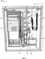
- FIG. 1illustrates a first embodiment of a telecommunications system at 20.
- the systemincludes a cabinet 22.
- the cabinet 22includes a rack or framework 24 for holding or mounting telecommunications equipment.
- the framework 24is generally rectangular defining an interior holding the interior components, to be described further below.
- the system 20includes telecommunications equipment 26.
- the equipment 26can be many different types of equipment that is used in fiber optic systems.
- the equipment 26can include active or passive equipment, including, e.g., an amplifier, etc.
- the telecommunications equipment 26is arranged in a vertical column.
- fiber optic cable 27will be routed from the central office to the system 20 and into the cabinet 22 via plate 25 and then be connected to the equipment 26.
- the system 20further includes a plurality of slack storage members or spools 28.
- the spools 28are mounted within the cabinet 22 to manage overlength slack in the fiber optic cables within the cabinet 22.
- the spools 28organize and take up overlength or slack in cables 29 from the equipment 26.
- the spools 28may be the type that are described in US Patent 6,289,159 .
- the spools 28are arranged in a vertical column adjacent to the column of telecommunications equipment 26.
- the system 20includes a patch panel 30 mounted within the cabinet 22.
- the patch panel 30is provided as is well known in the art and defines a plurality of cable termination locations 32 for receiving at least some of the fiber optic cables 29 in the system 20, as the cables 29 are connected between the equipment 26 and the patch panel 30.
- the patch panel 30is mountable on a pivotable frame 34.
- the pivotable frame 34is movable between a storage position ( FIGS. 1 and 2 ) and an access position ( FIGS. 6 and 11 ).
- the plurality of spools 28is positioned intermediate the telecommunications equipment 26 and the patch panel 30.
- the pivotable frame 34is adjacent the column of spools 28, and the column of spools 28 is between the column of telecommunications equipment 26 and the pivotable frame 34.
- a plurality of cable radius limiters 36can be mounted on the pivotable frame 34 to help manage the cable and protect the fibers in the cable.
- the radius limiters 36are positioned between the patch panel 30 and a splice area 38.
- the system 20further includes splice area 38.
- the splice area 38is mounted within the cabinet 22 and is accessible when the pivotable frame 34 is in the access position ( FIGS. 6 and 11 ).
- the splice area 34receives fiber optic cables from the patch panel 30 and is for splicing to additional cables. In many systems, the cables then exit the cabinet 22 and are directed to customers.
- the splice area 38can be many different embodiments including splice trays, such as those described in US Patent 6,304,707 .
- the cablesmay enter the splice area via troughs.
- the cablesmay include a cable clamping device, and there may be a termination unit associated with the tray.
- the splice area 38is mountable on the pivotable frame 34 on a side of the pivotable frame 34 that is opposite from the side holding the patch panel 30.
- the plurality of cable radius limiters 36are positioned along the edge of the pivotable frame 34 between the side holding the patch panel 30 and the side holding the splice area 38.
- the radius limiters 36are arranged in a column along the edge.
- a storage arrangement or "parking area” 51( FIG. 1 ) for holding one or more unconnected cables that are not connected into the patch panel termination locations 32.
- the parking area 51can include, for example, a housing or arrangement such as described in US Patent 7,218,827 .
- the parking area 51can also include, for example, any type of structure (e.g., a foam block) that uses friction to hold the unconnected cables.
- the pivotable frame 34includes a pivot section 40 and a holding section 42.
- the pivot section 40is pivotally connected to the framework 24.
- the pivot section 40can be connected to the framework 24 by a hinge 44.
- the holding section 42has first and second opposite sides 46, 48.
- the first side 46holds the patch panel 30, and the second side 48 holds the splice area 38.
- the radius limiters 36are positioned along the edge of the holding section 42 between the first side 46 and second side 48.
- the holding section 42is angled at a non-zero angle relative to the pivot section 40.
- the holding section 42is angled at about 80-100 degrees, for example, about 90 degrees, relative to the pivot section 40.
- the pivotable frame 34In use, when it is desired to access the splice area 38, the pivotable frame 34 is pivoted about the hinge 44 to move the frame 34 from the storage position ( FIGS. 2 and 7 ) to the access position ( FIGS. 11 and 6 ). This exposes the splice area 38 and allows access to the splice area 38.
- the frame 34can be pivoted about an angle from the storage position (at 0°) to the access position (90-150°) for servicing or access to the splice area 38.
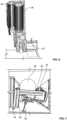
- FIGS. 12-20illustrate another embodiment of system 20. Much of the structure is similar and will use the same reference numerals and rely upon the description above with respect to the embodiment of FIGS. 1-11 .
- the pivotable frame 34is itself the patch panel 30.
- the patch panel 30pivots between the storage position ( FIGS. 12 , 13 , 18 ) and the access position ( FIGS. 15-17 , 19 , 20 ).
- the patch panel 30when the patch panel 30 is pivoted from the storage position to the access position, it exposes the splice area, shown here in FIG. 15 at reference numeral 54.
- the splice area 54is mounted on a wall 56, which in this embodiment, is at the rear of the cabinet 22.
- the patch panel 30When the patch panel 30 is in the storage position, the splice area 54 is covered and protected by the patch panel 30.
- the patch panel 30When the patch panel 30 is in the access position, it exposes and uncovers the splice area 54 on the wall 56.
- the patch panelhas a first side 58 and an opposite second side 60.
- the second side 60will be generally parallel to and in opposition to the splice area 54.
- the patch panel 30is rotated relative to the wall 56 and the splice area 54.
- the anglecan be, for example, between 60° and 150°. See, for example, FIG. 18 in which the storage position shows the patch panel 30 as generally parallel to the splice area 54.
- FIG. 19shows the patch panel 30 at an angle of about 60° relative to the splice area 54.
- the patch panel 30is about 120° relative to the splice area 54.
- FIGS. 16 and 18-20show the wall 56 prior to the splice area 54 being added. It should be understood that when the splice area 54 is added, it may have the appearance of a series of trays as shown in FIG. 15 .
- the system 20is highly flexible.
- the system 20 of both embodiments of FIGS. 1 and 12illustrate a cross-connect system; that is, a system which has cables between the equipment 26 and the patch panel 30 / and between the patch panel 30 and the splice area. If it is desired to have, instead of a cross-connect system, an interconnect system, the patch panel 30 is removed allowing fiber optic cable to connect directly between the equipment 26 and the splice area.
- the system 20can be used in a method of organizing fiber optic cable.
- the methodcan include providing cabinet 22 including framework 24 for mounting telecommunications equipment 26.
- the patch panel 30is mounted on a pivotable frame 34 between a storage position and an access position.
- the patch panel 30includes cable radius limiters 36.
- the spools 28are positioned intermediate the telecommunications equipment 26 and the patch panel 30.
- the step of routing fiber optic cables to the splice area 38includes routing the cables to the splice area 38 mounted on the pivotable frame 34 on an opposite side from the patch panel 30.
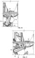
- FIGS. 21-27depict further views of the embodiment of FIG. 12 .
- the system 20is shown in perspective view. Much of the structure is similar and uses the same reference numerals and relies upon the description with respect to the embodiment of FIGS. 1-11 .
- the system 20includes cabinet 22 with a rack or framework 24.
- Telecommunications equipment 26can be shown arranged vertically in a row along one side of the cabinet 22.
- Adjacent to the equipment 26is a plurality of slack storage members or spools 28.
- Next to the spools 28is pivotable patch panel 30.
- the patch panel 30pivots between the storage position ( FIGS. 21 , 22 and 26 ) and the access position ( FIGS. 23 , 24 , 25 , and 27 ).
- the patch panel 30When the patch panel 30 is pivoted from the storage position to the access position, it exposes splice area 54 ( FIGS. 23 and 24 ).
- the splice area 54is mounted on the wall 56 which is at the rear of the cabinet 22.
- the patch panel 30is in the storage position, the splice area 54 is covered and protected by the patch panel 30.
- the patch panel 30When the patch panel 30 is in the access position, it exposes and uncovers the splice area
- FIG. 24illustrates the splice area 54 along the wall 56. It includes a series of splice trays 52.
- FIGS. 21 and 22show the patch panel 30 in the storage position.
- the patch panel 30is pivoted to the access position, which is angled away from the splice area 54 to allow access to the splice area 54.
- FIGS. 26 and 27it can be seen how the patch panel 30 pivots from the storage position, in which the patch panel 30 is generally parallel to the rear wall 56 holding the splice area 54, to the access position in FIG. 27 in which the patch panel 30 is pivoted away from the splice area 54 and extends outside of the enclosure of the cabinet 22.
- the patch panel 30is pivoted to be about 90° relative to the rear wall 56 of the cabinet 22. It should be understood that the patch panel 30 can be pivoted farther than 90°, to at least about 120° relative to the splice area 54.
- the system 20 in the embodiment of FIGS. 21-27may include various structures for managing cables for routing, organizing, and preventing sharp radii.
- cable managers 100are adjacent to the equipment 26, and in FIG. 21 , they are along opposite sides of the equipment 26.
- cable managers 102located between the patch panel 30 and the spools 28.
- Access openings 104are also provided below the patch panel 30 and adjacent to the spools 28.
- a clamping area 106is provided between a cable port area 108 in the cabinet 22 and the splice area 54.
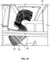
- FIG. 23when the patch panel 30 is in the access position, cable rings 110 are visible and are attached to the second side 60 of the patch panel 30. Also in FIG.
- radius limiters 112adjacent to the splice area 54, can be seen.
- the radius limiters 112are attached to the rear wall 56.
- cable managers 114are visible along side the splice area 54 next to a wall of the cabinet 22.
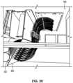
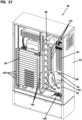
- FIGS. 28-38illustrate another embodiment of a telecommunications system 20.
- the equipment 26includes at least one splitter module 80.
- the splitter module 80is the type of module that is known in the art and may contain either passive optical splitters or wavelength division multiplexors.
- the splitter modules 80can be many types of configurations, and in this embodiment, the splitter modules 80 are 1 X 16 splitters.
- the telecommunications equipment 26includes a plurality of splitter modules 80.
- the splitter modules 80include at least two groups of splitter modules 80 which can include a first group 82, second group 83, third group 84, and fourth group 85. Each group 82-85 has more than one splitter module 80.
- the groups 82-85are arranged vertically relative to each other.
- Each group 82-85has a base portion 86, which is along a bottom, and an upper portion 87, which is along a top.
- Each group 82-85can be arranged so that the base portion 86 is angled toward the spools 28 and patch panel 30 relative to the upper portion 87 of each group 82-85.
- This arrangementprovides advantage in that optical fibers (e.g., pigtails 98, FIG. 38 ) extending from each group 82-85 do not dangle down and interfere with another one of the group 82-85.
- the second group 83, third group 84, and fourth group 85 of splitter modules 80include a radius limiter 90 to help direct the optical fibers (pigtails 98) from the groups 83, 84, 85.
- each group 82-85includes at least four splitter modules 80.
- splitter modules 80are illustrated as being at an angle, they may also be non-angled. However, it has been found to be advantageous when the groups 82-85 of splitter modules 80 are angled, as shown at reference numeral 92 in FIGS. 31 and 32 .
- the angle 92is measured from the base portion 86 to a horizontal, parallel to the ground or the bottom of the cabinet 22. Angle 92 can be 5-40°, for example, 10-30°.
- the patch panel 30pivots or rotates from a storage position ( FIGS. 28 , 31 , 33 , and 35 ) to an access position ( FIGS. 29 , 30 , and 34 ).
- the splice area 54is mounted within the cabinet 22 and is accessible when the pivotable frame 34, holding the patch panel 30, is in the access position.
- the splice area 54is used to receive fiber optic cables from the patch panel 30 for splicing to additional cables.
- the splice area 54can be used with fiber optic cables having a signal coming from the service provider.
- An example of a fiber optic cable with a signal from a service provider, and how it is routed through the cabinet 22is illustrated schematically in FIG. 38 and discussed below.
- the FIG. 28 embodimentmay include various structures for managing cables for routing, organizing, and preventing sharp radii.
- cable managers 120are located between the patch panel 30 and the spools 28.
- Access opening 122is located in a wall 124 between the patch panel 30 and the spools 28.
- a clamping area 126is provided between cable port area 94 in the cabinet 22 and the splice area 54.
- Cable tie-offs 128are provided along a cabinet wall adjacent to the clamping area 126 and splice area 54.
- FIG. 29when the patch panel 30 is in the access position, cable rings 130 are visible and are attached to the second side 60 of the patch panel 30. Also in FIG.
- radius limiters 132adjacent to the splice area 54, can be seen.
- the radius limiters 132are attached to the rear wall 56.
- cable managers 114are visible along side the splice area 54 next to a wall of the cabinet 22.
- a channel cable holder 134is used along the radius limiters 132.
- FIGS. 36 and 37illustrate enlarged views of the cable management structure located between the splice area 54 and the spools 28.
- Multi-piece cable holders 136are adjacent to the slice trays 96 and feed into individual radius limiters 132.
- the channel cable holder 134covers the holders 136 vertically and helps prevent optical fibers from falling out of the holders 136 and limiters 132. Many variations are possible.
- FIG. 38An example of how fiber optic cable is routed through the system 20 is shown schematically in FIG. 38 .
- the optical fiber 88 with the signal from the cable provider (central office) 140enters the cabinet 22 through port 94. From there, the optical fiber 88 is routed to the clamp area 126 wherein it is clamped or held with a clamp 144. From there, it is routed to splice area 54 and is spliced at A at one of the splice trays 96. From there, the spliced fiber 88 is routed to one of the splitter modules 80. In this example it is routed to splitter module 80 in the first group 82 of modules 80. The fiber 88 may also be held by one of the spools 28.
- a plurality of further optical fiberswhich may be in the form of pigtails 98, will extend from the splitter module 80 and then will be routed toward the patch panel 30. Any overlength in the pigtails 98 can be routed onto one or more of the spools 28.
- FIG. 38many of the pigtails 98 are shown broken away after the splitter modules 80 for purposes of illustration. It should be understood that one or more of the pigtails 98c would then be connected to the patch panel 30.
- one or more of the pigtails 98pmay be placed into the parking area 51 ( FIG. 31 ). From the patch panel 30, there can be a connection at one of the splice trays 96, spliced at B, and from the splice tray 96, clamped at 146 and then routed to a user 142.
- FIGS. 28-38has advantages in that the footprint is smaller than many traditional arrangements having similar equipment. Many variations can be made.
Landscapes
- Physics & Mathematics (AREA)
- General Physics & Mathematics (AREA)
- Optics & Photonics (AREA)
- Light Guides In General And Applications Therefor (AREA)
- Insertion, Bundling And Securing Of Wires For Electric Apparatuses (AREA)
Description
- This application claims the benefit of
U.S. Patent Application Serial No. 62/404,523, filed on October 5, 2016 U.S. Patent Application Serial No. 62/432,103, filed on December 9, 2016 - This disclosure concerns optical fibers and organization of optical fibers. More specifically, this disclosure concerns an arrangement to bring splicing and overlength storage into a minimum footprint between equipment, including splitter modules, and incoming fiber optic cables.
- There are systems that take in subscriber or distribution cables, splice them to a pigtail cable, and then connect the cable to equipment. These systems can occupy much space. Examples of such systems can be found in published
U.S. Patent Application 2010/183276 A1 . Improvements in reducing the space occupied to a minimum footprint, without losing functionality, are desirable. - To address the problems of prior systems, a telecommunications system according to
claim 1 is provided. - In some embodiments, the splice area is mounted on a wall covered by the pivotable frame when the pivotable frame is in the storage position.
- In one or more embodiments, there is also a parking area adjacent to the patch panel for holding at least some fiber optic cables that are not connected into the patch panel termination locations.
- In example implementations, the telecommunications equipment includes at least one splitter module.
- In some examples, the telecommunications equipment comprises a plurality of splitter modules.
- In example embodiments, the plurality of splitter modules includes at least two groups of splitter modules, and each group having more than one splitter module. The at least two groups are arranged vertically relative to each other and with a base portion of each group being angled toward the plurality of spools relative to an upper portion of each group.
- In example embodiments, the at least two groups of splitter modules includes at least four groups of splitter modules.
- In one or more embodiments, each group has at least four splitter modules.
- In another aspect, a method of organizing fiber optic cable according to
claim 15 is provided. - A variety of additional inventive aspects will be set forth in the description that follows. The inventive aspects can relate to individual features and to combinations of features. It is to be understood that both the forgoing general description and the following detailed description are exemplary and explanatory only and are not restrictive of the broad inventive concepts upon which the embodiments disclosed herein are based. These concepts are defined by the appended claims.
- The accompanying drawings, which are incorporated herein and constitute a part of the description, illustrate several aspects of the present disclosure. A brief description of the drawings is as follows:
FIG. 1 is a perspective view of a first embodiment of a telecommunications system utilizing a patch panel mounted on a pivotable frame, the pivotable frame being shown in a storage position, constructed in accordance with principles of this disclosure;FIG. 2 is a perspective view of the pivotable frame and patch panel ofFIG. 1 ;FIG. 3 is a perspective view of the pivotable frame and patch panel ofFIG. 2 as it is beginning to be pivoted from the storage position to an access position;FIG. 4 is a perspective view of the patch panel and pivotable frame ofFIG. 3 in a further position as it is being pivoted from the storage position to the access position;FIG. 5 is a perspective view of the pivotable frame ofFIGS. 2-4 and showing the access position, in which the splice area is visible and can be accessed;FIG. 6 is a perspective view of the pivotable frame ofFIGS. 2-5 and in the access position, in which the splice area is visible and accessible;FIGS. 7-11 are top views of the pivotable frame ofFIGS. 2-6 and showing various positions of the pivotable frame as it is rotated from the storage position (FIGS. 2 and7 ) to the access position (FIGS. 6 and11 );FIG. 12 is a perspective view of another embodiment of a telecommunications system utilizing a patch panel mounted on a pivotable frame, the pivotable frame being shown in a storage position, constructed in accordance with principles of this disclosure;FIG. 13 is a perspective view of the patch panel ofFIG. 12 , depicted in the storage position;FIG. 14 is a perspective view of the patch panel as it is being pivoted from the storage position to an access position;FIG. 15 is a perspective view of the patch panel ofFIGS. 13 and 14 pivoted to an access position to expose a splice area mounted on a back wall of the cabinet;FIG. 16 is another perspective view of the patch panel ofFIGS. 13-15 pivoted in the access position, showing the back of the patch panel and showing the area where the splice area would be;FIG. 17 is a perspective view of the patch panel ofFIGS. 13-16 depicting the patch panel in the access position and showing the front of the patch panel;FIGS. 18-20 are top views of the patch panel ofFIGS. 13-17 and showing various positions as it is rotated from the storage position (FIGS. 13 and18 ) to the access position (FIGS. 16 and20 );FIG. 21 is a perspective view of the embodiment of a telecommunications system shown inFIG. 12 ;FIG. 22 is a front view of the system ofFIG. 21 ;FIG. 23 is another perspective view of the system ofFIG. 21 , and showing the patch panel pivoted to an access position;FIG. 24 is a front view of the system ofFIG. 23 ;FIG. 25 is another perspective view of the system ofFIG. 23 and showing the patch panel in the access position;FIG. 26 is a top view of the system ofFIG. 21 ;FIG. 27 is a top view of the system ofFIG. 21 and showing the patch panel in the access position;FIG. 28 is a perspective view of another embodiment of a telecommunications system utilizing a patch panel mounted on a pivotable frame, the pivotable frame being shown in a storage position, constructed in accordance with principles of this disclosure;FIG. 29 is a perspective view of the system ofFIG. 28 and showing the patch panel pivoted to the access position;FIG. 30 is another perspective view of the system ofFIG. 29 with the patch panel in the access position;FIG. 31 is a front view of the system ofFIG. 28 , the patch panel being shown in the storage position;FIG. 32 is a front view of the system ofFIG. 28 , with the patch panel being omitted for purposes of illustration;FIG. 33 is a top view of the system ofFIG. 28 , the patch panel being in the storage position;FIG. 34 is a top view of the system ofFIG. 28 , the patch panel being in the access position;FIG. 35 is a side view of the system ofFIG. 28 , with the outer cabinet wall removed for purposes of illustration;FIG. 36 is a perspective view of a portion of the cable management structure used in the system ofFIG. 28 ;FIG. 37 is a perspective view of a subassembly of the cable management structure ofFIG. 36 ; andFIG. 38 is a schematic illustration showing example cable routing through the system ofFIG. 28 .- To improve the prior art, a telecommunications system is provided that provides a compact way of bringing splicing and overlength storage into a minimum footprint between equipment and incoming cable.
FIG. 1 illustrates a first embodiment of a telecommunications system at 20. The system includes acabinet 22. Thecabinet 22 includes a rack orframework 24 for holding or mounting telecommunications equipment. Many embodiments are possible. In the example illustrated, theframework 24 is generally rectangular defining an interior holding the interior components, to be described further below.- The
system 20 includestelecommunications equipment 26. Theequipment 26 can be many different types of equipment that is used in fiber optic systems. For example, theequipment 26 can include active or passive equipment, including, e.g., an amplifier, etc. - In the example of
FIG. 1 , thetelecommunications equipment 26 is arranged in a vertical column. In general,fiber optic cable 27 will be routed from the central office to thesystem 20 and into thecabinet 22 viaplate 25 and then be connected to theequipment 26. - The
system 20 further includes a plurality of slack storage members or spools 28. Thespools 28 are mounted within thecabinet 22 to manage overlength slack in the fiber optic cables within thecabinet 22. Thespools 28 organize and take up overlength or slack incables 29 from theequipment 26. Thespools 28 may be the type that are described inUS Patent 6,289,159 . - In the example shown in
FIG. 1 , thespools 28 are arranged in a vertical column adjacent to the column oftelecommunications equipment 26. - In accordance with principles of this disclosure, the
system 20 includes apatch panel 30 mounted within thecabinet 22. Thepatch panel 30 is provided as is well known in the art and defines a plurality of cable termination locations 32 for receiving at least some of thefiber optic cables 29 in thesystem 20, as thecables 29 are connected between theequipment 26 and thepatch panel 30. - The
patch panel 30 is mountable on apivotable frame 34. Thepivotable frame 34 is movable between a storage position (FIGS. 1 and2 ) and an access position (FIGS. 6 and11 ). As can be seen inFIG. 1 , the plurality ofspools 28 is positioned intermediate thetelecommunications equipment 26 and thepatch panel 30. As can also be realized from a review ofFIG. 1 , thepivotable frame 34 is adjacent the column ofspools 28, and the column ofspools 28 is between the column oftelecommunications equipment 26 and thepivotable frame 34. - A plurality of
cable radius limiters 36 can be mounted on thepivotable frame 34 to help manage the cable and protect the fibers in the cable. The radius limiters 36 are positioned between thepatch panel 30 and asplice area 38. - The
system 20 further includessplice area 38. Thesplice area 38 is mounted within thecabinet 22 and is accessible when thepivotable frame 34 is in the access position (FIGS. 6 and11 ). Thesplice area 34 receives fiber optic cables from thepatch panel 30 and is for splicing to additional cables. In many systems, the cables then exit thecabinet 22 and are directed to customers. Thesplice area 38 can be many different embodiments including splice trays, such as those described inUS Patent 6,304,707 . The cables may enter the splice area via troughs. Optionally, the cables may include a cable clamping device, and there may be a termination unit associated with the tray. - In the embodiment of
FIGS. 1-11 , thesplice area 38 is mountable on thepivotable frame 34 on a side of thepivotable frame 34 that is opposite from the side holding thepatch panel 30. In the examples shown inFIGS. 3-5 , it can be appreciated that the plurality ofcable radius limiters 36 are positioned along the edge of thepivotable frame 34 between the side holding thepatch panel 30 and the side holding thesplice area 38. In this example, theradius limiters 36 are arranged in a column along the edge. - In some embodiments, there can be a storage arrangement or "parking area" 51 (
FIG. 1 ) for holding one or more unconnected cables that are not connected into the patch panel termination locations 32. Theparking area 51 can include, for example, a housing or arrangement such as described inUS Patent 7,218,827 . Theparking area 51 can also include, for example, any type of structure (e.g., a foam block) that uses friction to hold the unconnected cables. - In reference now to
FIGS. 7-11 , in this example, thepivotable frame 34 includes apivot section 40 and a holdingsection 42. Thepivot section 40 is pivotally connected to theframework 24. For example, thepivot section 40 can be connected to theframework 24 by ahinge 44. - The holding
section 42 has first and secondopposite sides first side 46 holds thepatch panel 30, and thesecond side 48 holds thesplice area 38. The radius limiters 36 are positioned along the edge of the holdingsection 42 between thefirst side 46 andsecond side 48. - The holding
section 42 is angled at a non-zero angle relative to thepivot section 40. In the example shown, the holdingsection 42 is angled at about 80-100 degrees, for example, about 90 degrees, relative to thepivot section 40. - In use, when it is desired to access the
splice area 38, thepivotable frame 34 is pivoted about thehinge 44 to move theframe 34 from the storage position (FIGS. 2 and7 ) to the access position (FIGS. 11 and6 ). This exposes thesplice area 38 and allows access to thesplice area 38. Theframe 34 can be pivoted about an angle from the storage position (at 0°) to the access position (90-150°) for servicing or access to thesplice area 38. FIGS. 12-20 illustrate another embodiment ofsystem 20. Much of the structure is similar and will use the same reference numerals and rely upon the description above with respect to the embodiment ofFIGS. 1-11 . In this embodiment, thepivotable frame 34 is itself thepatch panel 30. Thepatch panel 30 pivots between the storage position (FIGS. 12 ,13 ,18 ) and the access position (FIGS. 15-17 ,19 ,20 ).- In the embodiment of
FIG. 12 , when thepatch panel 30 is pivoted from the storage position to the access position, it exposes the splice area, shown here inFIG. 15 atreference numeral 54. In this embodiment, thesplice area 54 is mounted on awall 56, which in this embodiment, is at the rear of thecabinet 22. When thepatch panel 30 is in the storage position, thesplice area 54 is covered and protected by thepatch panel 30. When thepatch panel 30 is in the access position, it exposes and uncovers thesplice area 54 on thewall 56. - In this embodiment, the patch panel has a
first side 58 and an oppositesecond side 60. In the storage position, thesecond side 60 will be generally parallel to and in opposition to thesplice area 54. In the access position, thepatch panel 30 is rotated relative to thewall 56 and thesplice area 54. The angle can be, for example, between 60° and 150°. See, for example,FIG. 18 in which the storage position shows thepatch panel 30 as generally parallel to thesplice area 54.FIG. 19 shows thepatch panel 30 at an angle of about 60° relative to thesplice area 54. InFIG. 20 , thepatch panel 30 is about 120° relative to thesplice area 54. FIGS. 16 and18-20 show thewall 56 prior to thesplice area 54 being added. It should be understood that when thesplice area 54 is added, it may have the appearance of a series of trays as shown inFIG. 15 .- The
system 20 is highly flexible. Thesystem 20 of both embodiments ofFIGS. 1 and12 illustrate a cross-connect system; that is, a system which has cables between theequipment 26 and thepatch panel 30 / and between thepatch panel 30 and the splice area. If it is desired to have, instead of a cross-connect system, an interconnect system, thepatch panel 30 is removed allowing fiber optic cable to connect directly between theequipment 26 and the splice area. - The
system 20 can be used in a method of organizing fiber optic cable. The method can include providingcabinet 22 includingframework 24 for mountingtelecommunications equipment 26. - Next, there is a step of mounting the
telecommunications equipment 26 to theframework 24. - Next, there is a step of routing overlength slack in fiber optic cables in the cabinet to a plurality of
spools 28 mounted within thecabinet 22. - Next, there is a step of connecting at least some of the fiber optic cables into
patch panel 30 mounted within thecabinet 22. Thepatch panel 30 is mounted on apivotable frame 34 between a storage position and an access position. Thepatch panel 30 includescable radius limiters 36. Thespools 28 are positioned intermediate thetelecommunications equipment 26 and thepatch panel 30. - Next, there can be a step of pivoting the
pivotable frame 34 to the access position and routing the fiber optic cables from thepatch panel 30 to splicearea 38 mounted within thecabinet 22 and accessible when thepivotable frame 34 is in the access position. - In some example methods, the step of routing fiber optic cables to the
splice area 38 includes routing the cables to thesplice area 38 mounted on thepivotable frame 34 on an opposite side from thepatch panel 30. FIGS. 21-27 depict further views of the embodiment ofFIG. 12 . InFIG.21 , thesystem 20 is shown in perspective view. Much of the structure is similar and uses the same reference numerals and relies upon the description with respect to the embodiment ofFIGS. 1-11 .- The
system 20 includescabinet 22 with a rack orframework 24.Telecommunications equipment 26 can be shown arranged vertically in a row along one side of thecabinet 22. Adjacent to theequipment 26 is a plurality of slack storage members or spools 28. Next to thespools 28 ispivotable patch panel 30. Thepatch panel 30 pivots between the storage position (FIGS. 21 ,22 and26 ) and the access position (FIGS. 23 ,24 ,25 , and27 ). When thepatch panel 30 is pivoted from the storage position to the access position, it exposes splice area 54 (FIGS. 23 and24 ). Thesplice area 54 is mounted on thewall 56 which is at the rear of thecabinet 22. When thepatch panel 30 is in the storage position, thesplice area 54 is covered and protected by thepatch panel 30. When thepatch panel 30 is in the access position, it exposes and uncovers thesplice area 54 on thewall 56. FIG. 24 illustrates thesplice area 54 along thewall 56. It includes a series of splice trays 52.FIGS. 21 and22 show thepatch panel 30 in the storage position. InFIGS. 23-25 , thepatch panel 30 is pivoted to the access position, which is angled away from thesplice area 54 to allow access to thesplice area 54.- By comparing
FIGS. 26 and27 , it can be seen how thepatch panel 30 pivots from the storage position, in which thepatch panel 30 is generally parallel to therear wall 56 holding thesplice area 54, to the access position inFIG. 27 in which thepatch panel 30 is pivoted away from thesplice area 54 and extends outside of the enclosure of thecabinet 22. InFIG. 27 , thepatch panel 30 is pivoted to be about 90° relative to therear wall 56 of thecabinet 22. It should be understood that thepatch panel 30 can be pivoted farther than 90°, to at least about 120° relative to thesplice area 54. - The
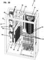
system 20 in the embodiment ofFIGS. 21-27 may include various structures for managing cables for routing, organizing, and preventing sharp radii. For example,cable managers 100 are adjacent to theequipment 26, and inFIG. 21 , they are along opposite sides of theequipment 26. There are alsocable managers 102 located between thepatch panel 30 and thespools 28.Access openings 104 are also provided below thepatch panel 30 and adjacent to thespools 28. A clampingarea 106 is provided between acable port area 108 in thecabinet 22 and thesplice area 54. InFIG. 23 , when thepatch panel 30 is in the access position, cable rings 110 are visible and are attached to thesecond side 60 of thepatch panel 30. Also inFIG. 23 ,radius limiters 112, adjacent to thesplice area 54, can be seen. Theradius limiters 112 are attached to therear wall 56. InFIG. 24 .,cable managers 114 are visible along side thesplice area 54 next to a wall of thecabinet 22. FIGS. 28-38 illustrate another embodiment of atelecommunications system 20. Much of the structure of thesystem 20 ofFIGS. 28-38 is similar and will use the same reference numerals and rely upon the description above with respect to the embodiment ofFIGS. 1-11 and12-20 . In this embodiment, theequipment 26 includes at least onesplitter module 80. Thesplitter module 80 is the type of module that is known in the art and may contain either passive optical splitters or wavelength division multiplexors. Thesplitter modules 80 can be many types of configurations, and in this embodiment, thesplitter modules 80 are 1 X 16 splitters.- In this embodiment, the
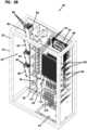
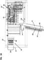
telecommunications equipment 26 includes a plurality ofsplitter modules 80. As can be seen inFIG. 31 , thesplitter modules 80 include at least two groups ofsplitter modules 80 which can include afirst group 82,second group 83,third group 84, andfourth group 85. Each group 82-85 has more than onesplitter module 80. - In the illustrated embodiment, the groups 82-85 are arranged vertically relative to each other. Each group 82-85 has a
base portion 86, which is along a bottom, and anupper portion 87, which is along a top. Each group 82-85 can be arranged so that thebase portion 86 is angled toward thespools 28 andpatch panel 30 relative to theupper portion 87 of each group 82-85. This arrangement provides advantage in that optical fibers (e.g.,pigtails 98,FIG. 38 ) extending from each group 82-85 do not dangle down and interfere with another one of the group 82-85. - In the embodiment of
FIGS. 31 and32 , it can be seen how thesecond group 83,third group 84, andfourth group 85 ofsplitter modules 80 include aradius limiter 90 to help direct the optical fibers (pigtails 98) from thegroups - Many different embodiments are possible. In the one illustrated, each group 82-85 includes at least four
splitter modules 80. - Again in reference to
FIG. 32 , while thesplitter modules 80 are illustrated as being at an angle, they may also be non-angled. However, it has been found to be advantageous when the groups 82-85 ofsplitter modules 80 are angled, as shown atreference numeral 92 inFIGS. 31 and32 . Theangle 92 is measured from thebase portion 86 to a horizontal, parallel to the ground or the bottom of thecabinet 22.Angle 92 can be 5-40°, for example, 10-30°. - As with the embodiment of
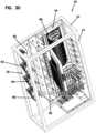
FIGS. 12 and21 , thepatch panel 30 pivots or rotates from a storage position (FIGS. 28 ,31 ,33 , and35 ) to an access position (FIGS. 29 ,30 , and34 ). Thesplice area 54 is mounted within thecabinet 22 and is accessible when thepivotable frame 34, holding thepatch panel 30, is in the access position. Thesplice area 54 is used to receive fiber optic cables from thepatch panel 30 for splicing to additional cables. In addition, thesplice area 54 can be used with fiber optic cables having a signal coming from the service provider. An example of a fiber optic cable with a signal from a service provider, and how it is routed through thecabinet 22 is illustrated schematically inFIG. 38 and discussed below. - As with the embodiment of
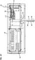
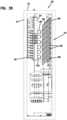
FIGS. 21-27 , theFIG. 28 embodiment may include various structures for managing cables for routing, organizing, and preventing sharp radii. For example,cable managers 120 are located between thepatch panel 30 and thespools 28.Access opening 122 is located in awall 124 between thepatch panel 30 and thespools 28. A clampingarea 126 is provided betweencable port area 94 in thecabinet 22 and thesplice area 54. Cable tie-offs 128 are provided along a cabinet wall adjacent to theclamping area 126 andsplice area 54. InFIG. 29 , when thepatch panel 30 is in the access position, cable rings 130 are visible and are attached to thesecond side 60 of thepatch panel 30. Also inFIG. 29 ,radius limiters 132, adjacent to thesplice area 54, can be seen. Theradius limiters 132 are attached to therear wall 56. InFIG. 24 ,cable managers 114 are visible along side thesplice area 54 next to a wall of thecabinet 22. Achannel cable holder 134 is used along theradius limiters 132. FIGS. 36 and37 illustrate enlarged views of the cable management structure located between thesplice area 54 and thespools 28.Multi-piece cable holders 136 are adjacent to theslice trays 96 and feed intoindividual radius limiters 132. Thechannel cable holder 134 covers theholders 136 vertically and helps prevent optical fibers from falling out of theholders 136 andlimiters 132. Many variations are possible.- An example of how fiber optic cable is routed through the
system 20 is shown schematically inFIG. 38 . Theoptical fiber 88 with the signal from the cable provider (central office) 140 enters thecabinet 22 throughport 94. From there, theoptical fiber 88 is routed to theclamp area 126 wherein it is clamped or held with aclamp 144. From there, it is routed to splicearea 54 and is spliced at A at one of thesplice trays 96. From there, the splicedfiber 88 is routed to one of thesplitter modules 80. In this example it is routed tosplitter module 80 in thefirst group 82 ofmodules 80. Thefiber 88 may also be held by one of thespools 28. From thesplitter module 80, a plurality of further optical fibers, which may be in the form ofpigtails 98, will extend from thesplitter module 80 and then will be routed toward thepatch panel 30. Any overlength in thepigtails 98 can be routed onto one or more of thespools 28. InFIG. 38 , many of thepigtails 98 are shown broken away after thesplitter modules 80 for purposes of illustration. It should be understood that one or more of thepigtails 98c would then be connected to thepatch panel 30. In addition, one or more of thepigtails 98p may be placed into the parking area 51 (FIG. 31 ). From thepatch panel 30, there can be a connection at one of thesplice trays 96, spliced at B, and from thesplice tray 96, clamped at 146 and then routed to auser 142. - The embodiment of
FIGS. 28-38 has advantages in that the footprint is smaller than many traditional arrangements having similar equipment. Many variations can be made. - The above description includes example principles. Many embodiments can be made using these principles.
Claims (15)
- A telecommunications system (20) for organizing fiber optic cables, the telecommunications system comprising:(a) a cabinet (22) including a framework (24) for mounting telecommunications equipment (26);(b) telecommunications equipment (26) mounted to the framework;(c) a patch panel (30) mounted within the cabinet (22) and defining a plurality of cable termination locations (32) for receiving at least some of the fiber optic cables; the patch panel (30) being mounted on a pivotable frame (34) that is adapted to pivot between a storage position and an access position;(d) a plurality of spools (28) mounted within the cabinet (22) for managing overlength slack in the fiber optic cables within the cabinet (22), the plurality of spools (28) positioned intermediate to the telecommunications equipment (26) and the patch panel (30); and(e) a splice area (54) mounted within the cabinet (22) and accessible when the pivotable frame (34) is in the access position; the splice area (54) for receiving the fiber optic cables from the patch panel (30) for splicing to additional cables;characterized in that:the telecommunications equipment (26) is arranged in a vertical column along one side of the cabinet (22);the plurality of spools (28) are arranged in a vertical column adjacent to the column of telecommunications equipment (26),the pivotable frame (34) is arranged adjacent the column of spools (28) with the column of spools (28) being arranged between the column of telecommunications equipment (26) and the pivotable frame (34).
- The system of claim 1 wherein the splice area is mounted on a rear wall (56) covered by the pivotable frame (34) when the pivotable frame (34) is in the storage position.
- The system of any one claims 1-2 further comprising a parking area (51) adjacent to the patch panel for holding at least some of the fiber optic cables that are not connected into the patch panel termination locations.
- The system of any one of claims 2-3 further comprising a plurality of cable radius limiters (112) attached to the rear wall (56).
- The system of any one of claims 1-4 wherein the telecommunications equipment includes at least one splitter module.
- The system of claim 5 wherein the telecommunications equipment comprises a plurality of splitter modules.
- The system of claim 6 wherein the plurality of splitter modules include at least two groups of splitter modules; each group having more than one splitter module; the at least two groups arranged vertically relative to each other and with a base portion of each group being angled toward the plurality of spools relative to an upper portion of each group.
- The system of claim 7 wherein the at least two groups of splitter modules comprise at least four groups of splitter modules.
- The system of any one of claims 7 and 8 wherein each group has at least four splitter modules.
- The system of claim 1, further comprising a parking area (51) for holding one or more unconnected cables that are not connected into patch panel termination locations (32).
- The system of claim 10, wherein the parking area (51) is disposed on the pivotable frame (34).
- The system of claim 1, further comprising a clamping area (106) provided between a cable port area (108) in the cabinet (22) and the splice area (54).
- The system of claim 1, further comprising cable managers (100) along opposite sides of the equipment (26).
- The system of claim 1, further comprising cable managers (102) located between the patch panel (30) and the spools (28).
- A method of organizing fiber optic cables at the telecommunications system (20) as claimed in claim 1; the method comprising:(a) providing the cabinet including the framework for mounting the telecommunications equipment;(b) mounting the telecommunications equipment to the framework;(c) routing the overlength slack in the fiber optic cables in the cabinet to the plurality of spools mounted within the cabinet;(d) connecting at least some of the fiber optic cables into the patch panel mounted within the cabinet; the patch panel being mounted on the pivotable frame between the storage position and the access position; the plurality of spools positioned intermediate to the telecommunications equipment and the patch panel;(e) pivoting the pivotable frame to the access position; and(f) routing the fiber optic cables from the patch panel to the splice area mounted within the cabinet and accessible when the pivotable frame is in the access position,wherein the step of routing the fiber optic cables to the splice area includes routing the fiber optic cables to the splice area mounted on a wall covered by the pivotable frame, when the pivotable frame is in the storage position.
Applications Claiming Priority (3)
| Application Number | Priority Date | Filing Date | Title |
|---|---|---|---|
| US201662404523P | 2016-10-05 | 2016-10-05 | |
| US201662432103P | 2016-12-09 | 2016-12-09 | |
| PCT/EP2017/075090WO2018065423A1 (en) | 2016-10-05 | 2017-10-03 | Telecommunications system and methods |
Publications (2)
| Publication Number | Publication Date |
|---|---|
| EP3523687A1 EP3523687A1 (en) | 2019-08-14 |
| EP3523687B1true EP3523687B1 (en) | 2023-09-27 |
Family
ID=60120016
Family Applications (1)
| Application Number | Title | Priority Date | Filing Date |
|---|---|---|---|
| EP17784904.9AActiveEP3523687B1 (en) | 2016-10-05 | 2017-10-03 | Telecommunications system and methods |
Country Status (4)
| Country | Link |
|---|---|
| US (2) | US10866378B2 (en) |
| EP (1) | EP3523687B1 (en) |
| CL (1) | CL2019000908A1 (en) |
| WO (1) | WO2018065423A1 (en) |
Families Citing this family (7)
| Publication number | Priority date | Publication date | Assignee | Title |
|---|---|---|---|---|
| WO2019072782A1 (en) | 2017-10-09 | 2019-04-18 | CommScope Connectivity Belgium BVBA | Cable fixation devices and methods |
| EP3844971A1 (en)* | 2018-08-31 | 2021-07-07 | CommScope Connectivity Belgium BVBA | Telecommunications equipment cabinet |
| WO2021001416A1 (en)* | 2019-07-01 | 2021-01-07 | CommScope Connectivity Belgium BVBA | Devices, systems, and methods for routing cables inside a telecommunications closure |
| WO2021180796A1 (en)* | 2020-03-10 | 2021-09-16 | CommScope Connectivity Belgium BV | Telecommunications system and methods |
| IT202000009184A1 (en)* | 2020-04-28 | 2021-10-28 | Prysmian Spa | OUTDOOR CABINET FOR TELECOMMUNICATIONS |
| CA3237923A1 (en) | 2021-11-10 | 2023-05-19 | Stefan DONCHEV | Rack mountable panel for optimizing slack storage and management of optical fiber cables |
| NL2031468B1 (en)* | 2022-03-31 | 2023-10-24 | B V Twentsche Kabelfabriek | Parking device, distribution frame and method for parking a patch cord |
Family Cites Families (16)
| Publication number | Priority date | Publication date | Assignee | Title |
|---|---|---|---|---|
| GB9603017D0 (en) | 1996-02-14 | 1996-04-10 | Raychem Sa Nv | Optical fibre distribution system |
| AU722094B2 (en) | 1996-02-29 | 2000-07-20 | N.V. Raychem S.A. | Optical fibre organizer |
| US6061492A (en)* | 1997-04-09 | 2000-05-09 | Siecor Corporation | Apparatus and method for interconnecting fiber cables |
| US7142764B2 (en)* | 2003-03-20 | 2006-11-28 | Tyco Electronics Corporation | Optical fiber interconnect cabinets, termination modules and fiber connectivity management for the same |
| US6983095B2 (en)* | 2003-11-17 | 2006-01-03 | Fiber Optic Network Solutions Corporation | Systems and methods for managing optical fibers and components within an enclosure in an optical communications network |
| US7369741B2 (en)* | 2003-11-17 | 2008-05-06 | Fiber Optics Network Solutions Corp. | Storage adapter with dust cap posts |
| US7218827B2 (en) | 2004-06-18 | 2007-05-15 | Adc Telecommunications, Inc. | Multi-position fiber optic connector holder and method |
| US7720343B2 (en)* | 2006-02-13 | 2010-05-18 | Adc Telecommunications, Inc. | Fiber distribution hub with swing frame and modular termination panels |
| US7760984B2 (en)* | 2006-05-04 | 2010-07-20 | Adc Telecommunications, Inc. | Fiber distribution hub with swing frame and wrap-around doors |
| US7522805B2 (en)* | 2007-03-09 | 2009-04-21 | Adc Telecommunications, Inc. | Wall mount distribution arrangement |
| US7751672B2 (en)* | 2007-10-31 | 2010-07-06 | Adc Telecommunications, Inc. | Low profile fiber distribution hub |
| US8380036B2 (en)* | 2009-01-20 | 2013-02-19 | Adc Telecommunications, Inc. | Splitter module with connectorized pigtail manager |
| WO2010147540A1 (en)* | 2009-06-16 | 2010-12-23 | Telefonaktiebolaget Lm Ericsson (Publ) | Splicing and termination module |
| WO2014011904A2 (en)* | 2012-07-11 | 2014-01-16 | Adc Telecommunications, Inc. | Telecommunications cabinet modularization |
| WO2015116672A1 (en)* | 2014-01-28 | 2015-08-06 | Adc Telecommunications, Inc. | Slidable fiber optic connection module with cable slack management |
| MX2019002984A (en)* | 2016-09-16 | 2019-08-14 | Corning Res And Development Corporation | PARKING DOOR ASSEMBLIES FOR USE WITH FIBER DISTRIBUTION CENTERS AND METHODS TO INSTALL PARKING DOORS. |
- 2017
- 2017-10-03EPEP17784904.9Apatent/EP3523687B1/enactiveActive
- 2017-10-03WOPCT/EP2017/075090patent/WO2018065423A1/ennot_activeCeased
- 2017-10-03USUS16/339,986patent/US10866378B2/ennot_activeExpired - Fee Related
- 2019
- 2019-04-04CLCL2019000908Apatent/CL2019000908A1/enunknown
- 2020
- 2020-12-14USUS17/120,823patent/US20210096316A1/ennot_activeAbandoned
Also Published As
| Publication number | Publication date |
|---|---|
| US10866378B2 (en) | 2020-12-15 |
| EP3523687A1 (en) | 2019-08-14 |
| CL2019000908A1 (en) | 2019-09-27 |
| WO2018065423A1 (en) | 2018-04-12 |
| US20200041743A1 (en) | 2020-02-06 |
| US20210096316A1 (en) | 2021-04-01 |
Similar Documents
| Publication | Publication Date | Title |
|---|---|---|
| EP3523687B1 (en) | Telecommunications system and methods | |
| US10782497B2 (en) | Telecommunications connection cabinet | |
| US7583885B2 (en) | Fiber distribution enclosure | |
| US9810868B2 (en) | Optical fiber distribution frame with outside plant enclosure | |
| US20190094478A1 (en) | Low profile fiber distribution hub | |
| US6061492A (en) | Apparatus and method for interconnecting fiber cables | |
| US8357851B2 (en) | Fiber distribution hub with dual swing frames | |
| US6631237B2 (en) | Termination and splice panel | |
| WO2021180796A1 (en) | Telecommunications system and methods | |
| US20250306323A1 (en) | Fiber distribution hub including sealed splice module | |
| WO2018172378A1 (en) | Telecommunications system and methods |
Legal Events
| Date | Code | Title | Description |
|---|---|---|---|
| STAA | Information on the status of an ep patent application or granted ep patent | Free format text:STATUS: UNKNOWN | |
| STAA | Information on the status of an ep patent application or granted ep patent | Free format text:STATUS: THE INTERNATIONAL PUBLICATION HAS BEEN MADE | |
| PUAI | Public reference made under article 153(3) epc to a published international application that has entered the european phase | Free format text:ORIGINAL CODE: 0009012 | |
| STAA | Information on the status of an ep patent application or granted ep patent | Free format text:STATUS: REQUEST FOR EXAMINATION WAS MADE | |
| 17P | Request for examination filed | Effective date:20190319 | |
| AK | Designated contracting states | Kind code of ref document:A1 Designated state(s):AL AT BE BG CH CY CZ DE DK EE ES FI FR GB GR HR HU IE IS IT LI LT LU LV MC MK MT NL NO PL PT RO RS SE SI SK SM TR | |
| AX | Request for extension of the european patent | Extension state:BA ME | |
| DAV | Request for validation of the european patent (deleted) | ||
| DAX | Request for extension of the european patent (deleted) | ||
| GRAP | Despatch of communication of intention to grant a patent | Free format text:ORIGINAL CODE: EPIDOSNIGR1 | |
| STAA | Information on the status of an ep patent application or granted ep patent | Free format text:STATUS: GRANT OF PATENT IS INTENDED | |
| INTG | Intention to grant announced | Effective date:20220513 | |
| GRAJ | Information related to disapproval of communication of intention to grant by the applicant or resumption of examination proceedings by the epo deleted | Free format text:ORIGINAL CODE: EPIDOSDIGR1 | |
| STAA | Information on the status of an ep patent application or granted ep patent | Free format text:STATUS: REQUEST FOR EXAMINATION WAS MADE | |
| INTC | Intention to grant announced (deleted) | ||
| GRAP | Despatch of communication of intention to grant a patent | Free format text:ORIGINAL CODE: EPIDOSNIGR1 | |
| STAA | Information on the status of an ep patent application or granted ep patent | Free format text:STATUS: GRANT OF PATENT IS INTENDED | |
| INTG | Intention to grant announced | Effective date:20221109 | |
| GRAJ | Information related to disapproval of communication of intention to grant by the applicant or resumption of examination proceedings by the epo deleted | Free format text:ORIGINAL CODE: EPIDOSDIGR1 | |
| STAA | Information on the status of an ep patent application or granted ep patent | Free format text:STATUS: REQUEST FOR EXAMINATION WAS MADE | |
| INTC | Intention to grant announced (deleted) | ||
| GRAP | Despatch of communication of intention to grant a patent | Free format text:ORIGINAL CODE: EPIDOSNIGR1 | |
| STAA | Information on the status of an ep patent application or granted ep patent | Free format text:STATUS: GRANT OF PATENT IS INTENDED | |
| INTG | Intention to grant announced | Effective date:20230421 | |
| GRAS | Grant fee paid | Free format text:ORIGINAL CODE: EPIDOSNIGR3 | |
| GRAA | (expected) grant | Free format text:ORIGINAL CODE: 0009210 | |
| STAA | Information on the status of an ep patent application or granted ep patent | Free format text:STATUS: THE PATENT HAS BEEN GRANTED | |
| AK | Designated contracting states | Kind code of ref document:B1 Designated state(s):AL AT BE BG CH CY CZ DE DK EE ES FI FR GB GR HR HU IE IS IT LI LT LU LV MC MK MT NL NO PL PT RO RS SE SI SK SM TR | |
| REG | Reference to a national code | Ref country code:GB Ref legal event code:FG4D | |
| REG | Reference to a national code | Ref country code:CH Ref legal event code:EP | |
| REG | Reference to a national code | Ref country code:DE Ref legal event code:R096 Ref document number:602017074684 Country of ref document:DE | |
| REG | Reference to a national code | Ref country code:IE Ref legal event code:FG4D | |
| REG | Reference to a national code | Ref country code:LT Ref legal event code:MG9D | |
| PG25 | Lapsed in a contracting state [announced via postgrant information from national office to epo] | Ref country code:GR Free format text:LAPSE BECAUSE OF FAILURE TO SUBMIT A TRANSLATION OF THE DESCRIPTION OR TO PAY THE FEE WITHIN THE PRESCRIBED TIME-LIMIT Effective date:20231228 | |
| PG25 | Lapsed in a contracting state [announced via postgrant information from national office to epo] | Ref country code:SE Free format text:LAPSE BECAUSE OF FAILURE TO SUBMIT A TRANSLATION OF THE DESCRIPTION OR TO PAY THE FEE WITHIN THE PRESCRIBED TIME-LIMIT Effective date:20230927 Ref country code:RS Free format text:LAPSE BECAUSE OF FAILURE TO SUBMIT A TRANSLATION OF THE DESCRIPTION OR TO PAY THE FEE WITHIN THE PRESCRIBED TIME-LIMIT Effective date:20230927 Ref country code:NO Free format text:LAPSE BECAUSE OF FAILURE TO SUBMIT A TRANSLATION OF THE DESCRIPTION OR TO PAY THE FEE WITHIN THE PRESCRIBED TIME-LIMIT Effective date:20231227 Ref country code:LV Free format text:LAPSE BECAUSE OF FAILURE TO SUBMIT A TRANSLATION OF THE DESCRIPTION OR TO PAY THE FEE WITHIN THE PRESCRIBED TIME-LIMIT Effective date:20230927 Ref country code:LT Free format text:LAPSE BECAUSE OF FAILURE TO SUBMIT A TRANSLATION OF THE DESCRIPTION OR TO PAY THE FEE WITHIN THE PRESCRIBED TIME-LIMIT Effective date:20230927 Ref country code:HR Free format text:LAPSE BECAUSE OF FAILURE TO SUBMIT A TRANSLATION OF THE DESCRIPTION OR TO PAY THE FEE WITHIN THE PRESCRIBED TIME-LIMIT Effective date:20230927 Ref country code:GR Free format text:LAPSE BECAUSE OF FAILURE TO SUBMIT A TRANSLATION OF THE DESCRIPTION OR TO PAY THE FEE WITHIN THE PRESCRIBED TIME-LIMIT Effective date:20231228 Ref country code:FI Free format text:LAPSE BECAUSE OF FAILURE TO SUBMIT A TRANSLATION OF THE DESCRIPTION OR TO PAY THE FEE WITHIN THE PRESCRIBED TIME-LIMIT Effective date:20230927 | |
| REG | Reference to a national code | Ref country code:NL Ref legal event code:MP Effective date:20230927 | |
| REG | Reference to a national code | Ref country code:AT Ref legal event code:MK05 Ref document number:1615972 Country of ref document:AT Kind code of ref document:T Effective date:20230927 | |
| PG25 | Lapsed in a contracting state [announced via postgrant information from national office to epo] | Ref country code:NL Free format text:LAPSE BECAUSE OF FAILURE TO SUBMIT A TRANSLATION OF THE DESCRIPTION OR TO PAY THE FEE WITHIN THE PRESCRIBED TIME-LIMIT Effective date:20230927 | |
| PG25 | Lapsed in a contracting state [announced via postgrant information from national office to epo] | Ref country code:IS Free format text:LAPSE BECAUSE OF FAILURE TO SUBMIT A TRANSLATION OF THE DESCRIPTION OR TO PAY THE FEE WITHIN THE PRESCRIBED TIME-LIMIT Effective date:20240127 | |
| PG25 | Lapsed in a contracting state [announced via postgrant information from national office to epo] | Ref country code:AT Free format text:LAPSE BECAUSE OF FAILURE TO SUBMIT A TRANSLATION OF THE DESCRIPTION OR TO PAY THE FEE WITHIN THE PRESCRIBED TIME-LIMIT Effective date:20230927 | |
| PG25 | Lapsed in a contracting state [announced via postgrant information from national office to epo] | Ref country code:ES Free format text:LAPSE BECAUSE OF FAILURE TO SUBMIT A TRANSLATION OF THE DESCRIPTION OR TO PAY THE FEE WITHIN THE PRESCRIBED TIME-LIMIT Effective date:20230927 | |
| PG25 | Lapsed in a contracting state [announced via postgrant information from national office to epo] | Ref country code:SM Free format text:LAPSE BECAUSE OF FAILURE TO SUBMIT A TRANSLATION OF THE DESCRIPTION OR TO PAY THE FEE WITHIN THE PRESCRIBED TIME-LIMIT Effective date:20230927 Ref country code:RO Free format text:LAPSE BECAUSE OF FAILURE TO SUBMIT A TRANSLATION OF THE DESCRIPTION OR TO PAY THE FEE WITHIN THE PRESCRIBED TIME-LIMIT Effective date:20230927 Ref country code:IS Free format text:LAPSE BECAUSE OF FAILURE TO SUBMIT A TRANSLATION OF THE DESCRIPTION OR TO PAY THE FEE WITHIN THE PRESCRIBED TIME-LIMIT Effective date:20240127 Ref country code:ES Free format text:LAPSE BECAUSE OF FAILURE TO SUBMIT A TRANSLATION OF THE DESCRIPTION OR TO PAY THE FEE WITHIN THE PRESCRIBED TIME-LIMIT Effective date:20230927 Ref country code:EE Free format text:LAPSE BECAUSE OF FAILURE TO SUBMIT A TRANSLATION OF THE DESCRIPTION OR TO PAY THE FEE WITHIN THE PRESCRIBED TIME-LIMIT Effective date:20230927 Ref country code:CZ Free format text:LAPSE BECAUSE OF FAILURE TO SUBMIT A TRANSLATION OF THE DESCRIPTION OR TO PAY THE FEE WITHIN THE PRESCRIBED TIME-LIMIT Effective date:20230927 Ref country code:AT Free format text:LAPSE BECAUSE OF FAILURE TO SUBMIT A TRANSLATION OF THE DESCRIPTION OR TO PAY THE FEE WITHIN THE PRESCRIBED TIME-LIMIT Effective date:20230927 Ref country code:PT Free format text:LAPSE BECAUSE OF FAILURE TO SUBMIT A TRANSLATION OF THE DESCRIPTION OR TO PAY THE FEE WITHIN THE PRESCRIBED TIME-LIMIT Effective date:20240129 Ref country code:SK Free format text:LAPSE BECAUSE OF FAILURE TO SUBMIT A TRANSLATION OF THE DESCRIPTION OR TO PAY THE FEE WITHIN THE PRESCRIBED TIME-LIMIT Effective date:20230927 | |
| PG25 | Lapsed in a contracting state [announced via postgrant information from national office to epo] | Ref country code:PL Free format text:LAPSE BECAUSE OF FAILURE TO SUBMIT A TRANSLATION OF THE DESCRIPTION OR TO PAY THE FEE WITHIN THE PRESCRIBED TIME-LIMIT Effective date:20230927 Ref country code:IT Free format text:LAPSE BECAUSE OF FAILURE TO SUBMIT A TRANSLATION OF THE DESCRIPTION OR TO PAY THE FEE WITHIN THE PRESCRIBED TIME-LIMIT Effective date:20230927 | |
| REG | Reference to a national code | Ref country code:CH Ref legal event code:PL | |
| REG | Reference to a national code | Ref country code:BE Ref legal event code:MM Effective date:20231031 | |
| PG25 | Lapsed in a contracting state [announced via postgrant information from national office to epo] | Ref country code:LU Free format text:LAPSE BECAUSE OF NON-PAYMENT OF DUE FEES Effective date:20231003 | |
| PG25 | Lapsed in a contracting state [announced via postgrant information from national office to epo] | Ref country code:LU Free format text:LAPSE BECAUSE OF NON-PAYMENT OF DUE FEES Effective date:20231003 | |
| REG | Reference to a national code | Ref country code:DE Ref legal event code:R097 Ref document number:602017074684 Country of ref document:DE | |
| PG25 | Lapsed in a contracting state [announced via postgrant information from national office to epo] | Ref country code:MC Free format text:LAPSE BECAUSE OF FAILURE TO SUBMIT A TRANSLATION OF THE DESCRIPTION OR TO PAY THE FEE WITHIN THE PRESCRIBED TIME-LIMIT Effective date:20230927 | |
| P01 | Opt-out of the competence of the unified patent court (upc) registered | Effective date:20240525 | |
| PG25 | Lapsed in a contracting state [announced via postgrant information from national office to epo] | Ref country code:DK Free format text:LAPSE BECAUSE OF FAILURE TO SUBMIT A TRANSLATION OF THE DESCRIPTION OR TO PAY THE FEE WITHIN THE PRESCRIBED TIME-LIMIT Effective date:20230927 | |
| PG25 | Lapsed in a contracting state [announced via postgrant information from national office to epo] | Ref country code:CH Free format text:LAPSE BECAUSE OF NON-PAYMENT OF DUE FEES Effective date:20231031 | |
| PG25 | Lapsed in a contracting state [announced via postgrant information from national office to epo] | Ref country code:MC Free format text:LAPSE BECAUSE OF FAILURE TO SUBMIT A TRANSLATION OF THE DESCRIPTION OR TO PAY THE FEE WITHIN THE PRESCRIBED TIME-LIMIT Effective date:20230927 Ref country code:DK Free format text:LAPSE BECAUSE OF FAILURE TO SUBMIT A TRANSLATION OF THE DESCRIPTION OR TO PAY THE FEE WITHIN THE PRESCRIBED TIME-LIMIT Effective date:20230927 Ref country code:CH Free format text:LAPSE BECAUSE OF NON-PAYMENT OF DUE FEES Effective date:20231031 | |
| PLBE | No opposition filed within time limit | Free format text:ORIGINAL CODE: 0009261 | |
| STAA | Information on the status of an ep patent application or granted ep patent | Free format text:STATUS: NO OPPOSITION FILED WITHIN TIME LIMIT | |
| PG25 | Lapsed in a contracting state [announced via postgrant information from national office to epo] | Ref country code:BE Free format text:LAPSE BECAUSE OF NON-PAYMENT OF DUE FEES Effective date:20231031 | |
| 26N | No opposition filed | Effective date:20240628 | |
| PG25 | Lapsed in a contracting state [announced via postgrant information from national office to epo] | Ref country code:IE Free format text:LAPSE BECAUSE OF NON-PAYMENT OF DUE FEES Effective date:20231003 | |
| PG25 | Lapsed in a contracting state [announced via postgrant information from national office to epo] | Ref country code:FR Free format text:LAPSE BECAUSE OF NON-PAYMENT OF DUE FEES Effective date:20231127 | |
| PG25 | Lapsed in a contracting state [announced via postgrant information from national office to epo] | Ref country code:SI Free format text:LAPSE BECAUSE OF FAILURE TO SUBMIT A TRANSLATION OF THE DESCRIPTION OR TO PAY THE FEE WITHIN THE PRESCRIBED TIME-LIMIT Effective date:20230927 | |
| PG25 | Lapsed in a contracting state [announced via postgrant information from national office to epo] | Ref country code:SI Free format text:LAPSE BECAUSE OF FAILURE TO SUBMIT A TRANSLATION OF THE DESCRIPTION OR TO PAY THE FEE WITHIN THE PRESCRIBED TIME-LIMIT Effective date:20230927 Ref country code:IE Free format text:LAPSE BECAUSE OF NON-PAYMENT OF DUE FEES Effective date:20231003 Ref country code:FR Free format text:LAPSE BECAUSE OF NON-PAYMENT OF DUE FEES Effective date:20231127 | |
| PG25 | Lapsed in a contracting state [announced via postgrant information from national office to epo] | Ref country code:BG Free format text:LAPSE BECAUSE OF FAILURE TO SUBMIT A TRANSLATION OF THE DESCRIPTION OR TO PAY THE FEE WITHIN THE PRESCRIBED TIME-LIMIT Effective date:20230927 | |
| PG25 | Lapsed in a contracting state [announced via postgrant information from national office to epo] | Ref country code:BG Free format text:LAPSE BECAUSE OF FAILURE TO SUBMIT A TRANSLATION OF THE DESCRIPTION OR TO PAY THE FEE WITHIN THE PRESCRIBED TIME-LIMIT Effective date:20230927 | |
| PGFP | Annual fee paid to national office [announced via postgrant information from national office to epo] | Ref country code:DE Payment date:20241029 Year of fee payment:8 | |
| PGFP | Annual fee paid to national office [announced via postgrant information from national office to epo] | Ref country code:GB Payment date:20241028 Year of fee payment:8 | |
| PG25 | Lapsed in a contracting state [announced via postgrant information from national office to epo] | Ref country code:CY Free format text:LAPSE BECAUSE OF FAILURE TO SUBMIT A TRANSLATION OF THE DESCRIPTION OR TO PAY THE FEE WITHIN THE PRESCRIBED TIME-LIMIT; INVALID AB INITIO Effective date:20171003 | |
| PG25 | Lapsed in a contracting state [announced via postgrant information from national office to epo] | Ref country code:HU Free format text:LAPSE BECAUSE OF FAILURE TO SUBMIT A TRANSLATION OF THE DESCRIPTION OR TO PAY THE FEE WITHIN THE PRESCRIBED TIME-LIMIT; INVALID AB INITIO Effective date:20171003 |