EP3523211B1 - Device for packaging an object and corresponding method of extraction - Google Patents
Device for packaging an object and corresponding method of extractionDownload PDFInfo
- Publication number
- EP3523211B1 EP3523211B1EP17786980.7AEP17786980AEP3523211B1EP 3523211 B1EP3523211 B1EP 3523211B1EP 17786980 AEP17786980 AEP 17786980AEP 3523211 B1EP3523211 B1EP 3523211B1
- Authority
- EP
- European Patent Office
- Prior art keywords
- strip
- tube
- orifice
- coupling system
- passage
- Prior art date
- Legal status (The legal status is an assumption and is not a legal conclusion. Google has not performed a legal analysis and makes no representation as to the accuracy of the status listed.)
- Active
Links
- 238000004806packaging method and processMethods0.000titleclaimsdescription10
- 238000000605extractionMethods0.000titleclaims3
- 230000008878couplingEffects0.000claimsdescription27
- 238000010168coupling processMethods0.000claimsdescription27
- 238000005859coupling reactionMethods0.000claimsdescription27
- 239000007943implantSubstances0.000claimsdescription26
- 238000000034methodMethods0.000claimsdescription5
- 238000005520cutting processMethods0.000claimsdescription4
- 210000005069earsAnatomy0.000description10
- 210000000988bone and boneAnatomy0.000description4
- 230000003750conditioning effectEffects0.000description3
- 238000003780insertionMethods0.000description3
- 230000037431insertionEffects0.000description3
- 230000006835compressionEffects0.000description2
- 238000007906compressionMethods0.000description2
- 238000006073displacement reactionMethods0.000description2
- 230000005489elastic deformationEffects0.000description2
- 238000003825pressingMethods0.000description2
- 235000001674Agaricus brunnescensNutrition0.000description1
- -1Polyethylene terephthalatePolymers0.000description1
- 239000004793PolystyreneSubstances0.000description1
- 208000037873arthrodesisDiseases0.000description1
- 238000002347injectionMethods0.000description1
- 239000007924injectionSubstances0.000description1
- 238000004519manufacturing processMethods0.000description1
- 239000000463materialSubstances0.000description1
- 229920000139polyethylene terephthalatePolymers0.000description1
- 239000005020polyethylene terephthalateSubstances0.000description1
- 229920002223polystyrenePolymers0.000description1
- 229920001935styrene-ethylene-butadiene-styrenePolymers0.000description1
- 229920002725thermoplastic elastomerPolymers0.000description1
Images


Classifications
- B—PERFORMING OPERATIONS; TRANSPORTING
- B65—CONVEYING; PACKING; STORING; HANDLING THIN OR FILAMENTARY MATERIAL
- B65D—CONTAINERS FOR STORAGE OR TRANSPORT OF ARTICLES OR MATERIALS, e.g. BAGS, BARRELS, BOTTLES, BOXES, CANS, CARTONS, CRATES, DRUMS, JARS, TANKS, HOPPERS, FORWARDING CONTAINERS; ACCESSORIES, CLOSURES, OR FITTINGS THEREFOR; PACKAGING ELEMENTS; PACKAGES
- B65D25/00—Details of other kinds or types of rigid or semi-rigid containers
- B65D25/28—Handles
- B65D25/2802—Handles fixed, i.e. non-swingable, handles
- B65D25/2805—Handles fixed, i.e. non-swingable, handles provided on a local area of the side walls
- B65D25/2814—Handles fixed, i.e. non-swingable, handles provided on a local area of the side walls as a part or combined with a label or wrapping sheet or tube
- B—PERFORMING OPERATIONS; TRANSPORTING
- B65—CONVEYING; PACKING; STORING; HANDLING THIN OR FILAMENTARY MATERIAL
- B65D—CONTAINERS FOR STORAGE OR TRANSPORT OF ARTICLES OR MATERIALS, e.g. BAGS, BARRELS, BOTTLES, BOXES, CANS, CARTONS, CRATES, DRUMS, JARS, TANKS, HOPPERS, FORWARDING CONTAINERS; ACCESSORIES, CLOSURES, OR FITTINGS THEREFOR; PACKAGING ELEMENTS; PACKAGES
- B65D25/00—Details of other kinds or types of rigid or semi-rigid containers
- B65D25/02—Internal fittings
- B65D25/10—Devices to locate articles in containers
- B65D25/102—Straps, bands, strings or other elongate elements
- A—HUMAN NECESSITIES
- A61—MEDICAL OR VETERINARY SCIENCE; HYGIENE
- A61F—FILTERS IMPLANTABLE INTO BLOOD VESSELS; PROSTHESES; DEVICES PROVIDING PATENCY TO, OR PREVENTING COLLAPSING OF, TUBULAR STRUCTURES OF THE BODY, e.g. STENTS; ORTHOPAEDIC, NURSING OR CONTRACEPTIVE DEVICES; FOMENTATION; TREATMENT OR PROTECTION OF EYES OR EARS; BANDAGES, DRESSINGS OR ABSORBENT PADS; FIRST-AID KITS
- A61F2/00—Filters implantable into blood vessels; Prostheses, i.e. artificial substitutes or replacements for parts of the body; Appliances for connecting them with the body; Devices providing patency to, or preventing collapsing of, tubular structures of the body, e.g. stents
- A61F2/0095—Packages or dispensers for prostheses or other implants
- B—PERFORMING OPERATIONS; TRANSPORTING
- B65—CONVEYING; PACKING; STORING; HANDLING THIN OR FILAMENTARY MATERIAL
- B65D—CONTAINERS FOR STORAGE OR TRANSPORT OF ARTICLES OR MATERIALS, e.g. BAGS, BARRELS, BOTTLES, BOXES, CANS, CARTONS, CRATES, DRUMS, JARS, TANKS, HOPPERS, FORWARDING CONTAINERS; ACCESSORIES, CLOSURES, OR FITTINGS THEREFOR; PACKAGING ELEMENTS; PACKAGES
- B65D83/00—Containers or packages with special means for dispensing contents
- B65D83/76—Containers or packages with special means for dispensing contents for dispensing fluent contents by means of a piston
Definitions
- the present inventionrelates generally to the packaging of objects, in particular the packaging of a medical implant.
- attachment systems known from the prior artare expensive to manufacture and / or impractical to handle by the operator.
- these attachment systems known from the prior artcan mask part of the implant, which can be a source of error or complication for the operator who wishes to be able to visually and quickly identify the implant contained. in the tube.
- the object of the present inventionis to propose a new packaging device and method making it possible to overcome all or part of the problems set out above.
- the stripis thus long enough to be able to present a projecting end of the tube in the state removed from the stopper, which facilitates its gripping, but also to come into abutment by its other end against the bottom of the tube, which thus forms a support. for the end of the strip, which prevents the strip from being wedged in the tube at the level of the object with which it is coupled, which could be the case if its length was insufficient to touch the bottom of the tube.
- the tubeis translucent or transparent.
- Combining the use of a strip to which the object is coupled and a transparent or translucent tubeallows the user to easily visualize the object which is maintained at a given height of the tube, for example halfway up the tube. The user can thus quickly and reliably identify the object contained in the tube even before the tube is opened.
- the stripis translucent or transparent.
- the coupling systemcomprises a clip-on element with an orifice formed in the object.
- said coupling systemcomprises an enlarged portion of the strip, preferably located in the middle of the strip, which forms a base, two ears being formed by cutting out said base, said ears being able to be straightened relative to said base, being brought against each other, to be passed through an orifice formed in the object, said ears being able to resume a position separated from one another after the crossing of the orifice of the object, in which the possibility of withdrawal of the object is limited.
- said coupling systemcomprises two parallel spaced apart slots formed through the strip to form an insertion loop for an object, such as a screw.
- the stripis in the form of a strip having a series of notches and the coupling system comprises two slides which can be brought closer to each other along the strip to enclose the object, the notches being configured to prevent a displacement of said slides with respect to each other.
- the shape of the tube and that of the stripare configured to limit or prevent the rotation of the strip relative to the tube.
- said devicecomprises said object, said object being coupled to the strip and contained in the tube.
- a first orifice and a second orificeare formed in the object to allow the passage of an end portion of the strip through the first passage orifice and the passage of a portion opposite end of the strip through the second through hole, such that the coupling system of the strip extends from one side of the object and the end portions extend mainly from the other side.
- the coupling systemcomprises a part of the strip, called a stop part, which is spaced from the ends of the strip, and whose width is greater than the width of the end portions of the strip and greater than the width of the first and second passage openings formed in the object.
- an embodimentmeans that a particular feature, structure, or characteristic described in connection with an embodiment is included in at least one embodiment of the present invention.
- the appearance of the expression “in one embodiment” at various locations throughout the descriptiondoes not necessarily refer to the same embodiment.
- the particular features, structures, or characteristicscan be combined in any suitable manner in one or more embodiments.
- the inventionrelates to an object conditioning device.
- said objectis a medical implant.
- Said devicecomprises a tube 1 which is open at one end.
- a plug 2allows the opening 10 of the tube to be closed.
- the tubecontains an object 5, such as a medical implant.
- the packaging devicealso includes a flexible elongate element, called strip 3.
- Said strip 3comprises a coupling system 4 making it possible to couple said object 5 to said strip 3.
- the objectis decouplable relative to the strip.
- the stripis flexible around an axis parallel to the mean plane of the strip and orthogonal to the longitudinal axis of the strip.
- the strip 3is flexible so that, in the unstressed state, the strip has a given substantially straight shape and, in the compressed state of the strip, the strip is compressed in the manner of a spring blade, while being recalled in its initial form when the constraint it undergoes is removed.
- the strip 3can be compressed while being kept under tension by the plug and can return to its substantially straight initial shape when the plug is removed, that is to say when it does not undergoes more stress.
- the strip 3is configured with the tube 1 to take a first position in which the strip 3 is kept compressed inside the tube 1 by the plug 2. In this first configuration, the strip 3 has a first end 310 in contact with support with the bottom of the tube 1 opposite said opening 10.
- the strip 3is also configured with the tube 1 to take a second position in which, the plug 2 being removed, the strip 3 is no longer constrained by the plug and has a second end 320, opposite to said first end 310, which projects of the opening 10 of the tube 1.
- said strip 3is of length greater than the length of tube 1 so that, in the state removed from the plug and therefore in the unstressed state, said strip has one end which projects from the opening 10 of tube 1.
- the tube 1is translucent or transparent.
- the strip 3is also translucent or transparent.
- the usercan easily and quickly identify the object contained in the tube.
- a first orifice 51 and a second orifice 52are formed in the object 5 to allow the passage of an end portion 31 of the strip 3 through the first passage orifice 51 and the passage of a portion of opposite end 32 of the strip 3 through the second passage orifice 52, so that the coupling system 4 of the strip 3 extends on one side of the object 5, that is to say d on one side of orifices, and the end portions 31, 32 extend mainly on the other side.
- the first, respectively second, end portion 31, 32, called first, respectively second, strandcan be defined as the portion of the strip which extends between the first, respectively second, end 310, 320 of the strip and the coupling system 4 of the object.
- the coupling system 4 of the objectcan be produced in different ways as detailed below.
- the coupling system 4comprises a part 34 of the strip 3, called the stop part, which is spaced from the ends 310, 320 of the strip, and whose width is greater than the width of the end portions 31, 32 of the strip 3.
- the width of the stop partis also greater than the width of the first and second orifices 51, 52 of passage formed in the object 5.
- said stop part 34forms a stop zone of the object 5 along the strip 3.
- the width of the stop part 34is greater than the corresponding width, that is to say taken in the same direction, passage orifices 51, 52 formed in the object, which makes it possible to form a sliding stop stop for the strip 3 along the longitudinal axis of the strip relative to the object 5 in one way and the other.
- the objectis an example of a bone fixation surgical plate (arthrodesis, metatarsophalangeal compression, etc.) which is in the form of an oblong piece in which the two through orifices 51, 52 are formed.
- said through holes 51, 52are oblong and located near the opposite ends of said part.
- the objectis an example of a bone fixation surgical plate which is in the form of a part provided with four ears arranged at the four corners of the part. Said part also has the two through holes 51, 52 located near the opposite ends of said part.
- the coupling system 4comprises an element 343 which can be snapped on with an orifice formed in the object 5.
- said element 343is elastically deformable and configured to be able to deform by retracting the passage of said orifice formed in the object 5 and to be able to resume its shape after crossing the orifice.
- said coupling systemalso comprises an enlarged portion 34B of the strip, preferably located in the middle of the strip, which forms a base on which said snap-in element is located.
- said snap-fit element 343is in the form of a mushroom whose cap is split to allow passage by elastic deformation through the orifice of the object 5.
- said coupling system 4comprises an enlarged portion of the strip, preferably located in the middle of the strip 3, which forms a base 340.
- Two ears 341, 342are formed by cutting out said base 340.
- Said ears 341, 342are capable of being straightened relative to said base 340, by being brought one against the other, to be passed through an orifice 54 formed in the object .
- Said ears 341, 342are capable of assuming a position separated from one another after crossing the orifice 54 of the object, in which the possibility of withdrawal of the object 5 is limited.
- said earshave notches, forming teeth which oppose the withdrawal of the ears 341, 342 through the orifice 54 of the object 5, which prevents a withdrawal of the object 5 relative to the strip 3 in the absence of elastic deformation imposed by the operator.
- said coupling system 4comprises two parallel spaced apart slots formed through the strip 3 to form an insertion loop for an object, such as a screw, according to a insertion direction perpendicular to the slots.
- the shape of the tube 1 and that of the strip 3are configured to limit or prevent the rotation of the strip 3 relative to the tube 1.
- Such a configurationmakes it possible to maintain the object 5 in a given position suspended in the air , without risk of damage to the object by impacts against the wall of the tube.
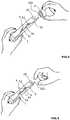
- the Figures 5 to 9illustrate different steps for extracting an object 5 from a packaging device, such as that presented in the figure 1 .
- the operatorremoves the plug 2 to open the tube 1, then grasps the end 320 of the strip which projects from the opening 10 of the tube 2 with a hand ( figure 6 ) to take it out of the tube ( figure 7 ) with the object 5 attached to it.
- the operatorcan then grasp, by his other hand, the object 5 coupled to the strip 3 and decouple it by removing the strip ( figure 8 ).
- the decouplingis carried out by pulling on the enlarged portion 34 to move the enlarged portion of the strip away from the object and cause the ends 310, 320 to come out of the strip through the orifices 51, 52 of the object 5.
- the decouplingis carried out by pressing on the element 340 to bring its two portions towards the slot of said element and pass it through the orifice of the object by pulling on the enlarged portion 34B to spread the enlarged portion of the strip relative to the object and bring the ends 310, 320 out of the strip through the orifices 51, 52 of the object 5.
- the decouplingis carried out by bringing the two ears 341, 342 towards each other to make them pass through the orifice of the object by pulling on the enlarged portion 340 to spread the enlarged portion 340 of the strip 3 relative to the object and bring the ends 310, 320 out of the strip through the orifice 54 of the object 5.
- the figure 10illustrates another embodiment of the invention for which the strip is made in two parts.
- the two partscan be assembled and disassembled relative to one another, preferably by snap-fastening.
- the connection area between the two partsis preferably located halfway along the strip.
- the stripcan be of elliptical section, for example obtained by injection into a thermoplastic elastomer such as SEBS: polystyrene-b-poly (ethylene-butylene) -b-polystyrene.
- the stripcan also be of trapezoidal section ( figure 12 ), for example obtained by cutting a sheet of a material such as PET-G (Polyethylene terephthalate glycol-modified in English). Other forms of section are possible.
- the strip 3is in the form of a strip provided with slides 35.
- the stripis also provided with coupling elements 36 allowing the coupling of the strip with the object 5 when the latter has orifices in which can engage said coupling elements.
- said coupling elements 36are in the form of studs located on the side of one face of the strip, opposite the active parts of the slides 35. Said coupling elements 36 are capable of engaging through orifices in the 'object.
- the sliders 35are movable towards each other along the notches of the slide to enclose the object 5.
- the notchesare configured with the sliders so as to allow their relative displacement only in the direction of approximation one the other.
- the studs 36are carried by the slides 35.
- the sliders 35each have on one side an active part in the form of a cradle to catch the object from the outside and on the other of the pins or stud 36 to hold it by its fixing holes or by its concave areas.
- Such a strip provided with slides as illustrated in Figures 13 and 14makes it possible to propose a method of wedging the object from the outside of said object.
- the object 5 held by the active parts of the slides or by the studscan be easily recovered by buckling (without friction) of the strip as illustrated. to the figure 14 .
Landscapes
- Engineering & Computer Science (AREA)
- Health & Medical Sciences (AREA)
- Mechanical Engineering (AREA)
- General Health & Medical Sciences (AREA)
- Veterinary Medicine (AREA)
- Biomedical Technology (AREA)
- Heart & Thoracic Surgery (AREA)
- Vascular Medicine (AREA)
- Life Sciences & Earth Sciences (AREA)
- Animal Behavior & Ethology (AREA)
- Oral & Maxillofacial Surgery (AREA)
- Public Health (AREA)
- Transplantation (AREA)
- Cardiology (AREA)
- Infusion, Injection, And Reservoir Apparatuses (AREA)
- Prostheses (AREA)
- Package Frames And Binding Bands (AREA)
- Lining Or Joining Of Plastics Or The Like (AREA)
- Sealing Of Jars (AREA)
- Package Closures (AREA)
Description
Translated fromFrenchLa présente invention concerne de manière générale le conditionnement d'objet, en particulier le conditionnement d'un implant médical.The present invention relates generally to the packaging of objects, in particular the packaging of a medical implant.
Il est connu de l'état de la technique, notamment du document
Cependant, on constate que ces systèmes d'accrochage connus de l'état de la technique sont coûteux à fabriquer et/ou peu pratiques à manipuler par l'opérateur. En outre ces systèmes d'accrochage connus de l'état de la technique peuvent masquer une partie de l'implant, ce qui peut être source d'erreur ou de complication pour l'opérateur qui souhaite pouvoir identifier visuellement et rapidement l'implant contenu dans le tube.However, it is found that these attachment systems known from the prior art are expensive to manufacture and / or impractical to handle by the operator. In addition, these attachment systems known from the prior art can mask part of the implant, which can be a source of error or complication for the operator who wishes to be able to visually and quickly identify the implant contained. in the tube.
La présente invention a pour but de proposer un nouveau dispositif et procédé de conditionnement permettant de palier à tout ou partie des problèmes exposés ci-dessus.The object of the present invention is to propose a new packaging device and method making it possible to overcome all or part of the problems set out above.
A cet effet, l'invention a pour objet un dispositif de conditionnement d'objet comprenant :
- un tube qui est ouvert à une extrémité ;
- un bouchon permettant de refermer ladite ouverture du tube,
- un objet, tel qu'un implant médical,
ladite bandelette étant de longueur supérieure à la longueur du tube, ladite bandelette comprenant un système de couplage permettant de coupler ledit objet à ladite bandelette,
la bandelette étant configurée avec le tube pour prendre :
- une première position dans laquelle la bandelette est maintenue comprimée à l'intérieur du tube par le bouchon, ladite bandelette présentant une première extrémité en contact d'appui avec le fond du tube opposé à ladite ouverture,
- une deuxième position dans laquelle, le bouchon étant retiré, la bandelette présente une deuxième extrémité, opposée à ladite première extrémité, qui s'étend en saillie de l'ouverture du tube.
- a tube which is open at one end;
- a plug making it possible to close said opening of the tube,
- an object, such as a medical implant,
said strip being of length greater than the length of the tube, said strip comprising a coupling system making it possible to couple said object to said strip,
the strip being configured with the tube to take:
- a first position in which the strip is kept compressed inside the tube by the plug, said strip having a first end in bearing contact with the bottom of the tube opposite to said opening,
- a second position in which, the plug being removed, the strip has a second end, opposite to said first end, which projects from the opening of the tube.
La bandelette est ainsi suffisamment longue pour pouvoir présenter une extrémité en saillie du tube à l'état retiré du bouchon, ce qui facilite sa saisie, mais aussi pour venir en appui par son autre extrémité contre le fond du tube, qui forme ainsi un appui pour l'extrémité de la bandelette, ce qui évite que la bandelette soit coincée dans le tube au niveau de l'objet avec lequel elle est couplée, ce qui pourrait être le cas si sa longueur était insuffisante pour toucher le fond du tube.The strip is thus long enough to be able to present a projecting end of the tube in the state removed from the stopper, which facilitates its gripping, but also to come into abutment by its other end against the bottom of the tube, which thus forms a support. for the end of the strip, which prevents the strip from being wedged in the tube at the level of the object with which it is coupled, which could be the case if its length was insufficient to touch the bottom of the tube.
L'appui de l'extrémité de la bandelette sur le fond du tube permet de maintenir l'objet qui est couplé à la bandelette à une certaine hauteur par rapport au tube. La compression appliquée par le bouchon sur la bandelette permet de contraindre la bandelette et donc de limiter, voire empêcher, le mouvement de la bandelette et donc de l'objet par rapport au tube, tout en bénéficiant de l'effort de rappel qui tend à ramener la bandelette en position détendue lors de l'ouverture du bouchon et s'oppose à un coincement de l'objet dans le tube. Selon une caractéristique avantageuse de l'invention, le tube est translucide ou transparent.Pressing the end of the strip on the bottom of the tube keeps the object which is coupled to the strip at a certain height relative to the tube. The compression applied by the stopper to the strip makes it possible to constrain the strip and therefore to limit, or even prevent, the movement of the strip and therefore of the object relative to the tube, while benefiting from the restoring effort which tends to return the strip to the relaxed position when the cap is opened and prevent the object from jamming in the tube. According to an advantageous characteristic of the invention, the tube is translucent or transparent.
Le fait de combiner l'utilisation d'une bandelette à laquelle est couplé l'objet et d'un tube transparent ou translucide, permet à l'utilisateur de visualiser aisément l'objet qui est maintenu à une hauteur donnée du tube, par exemple à mi-hauteur du tube. L'utilisateur peut ainsi rapidement et de manière fiable identifier l'objet contenu dans le tube avant même que le tube soit ouvert.Combining the use of a strip to which the object is coupled and a transparent or translucent tube, allows the user to easily visualize the object which is maintained at a given height of the tube, for example halfway up the tube. The user can thus quickly and reliably identify the object contained in the tube even before the tube is opened.
Selon une caractéristique avantageuse de l'invention, la bandelette est translucide ou transparente.According to an advantageous characteristic of the invention, the strip is translucent or transparent.
Selon une caractéristique avantageuse de l'invention, le système de couplage comprend un élément encliquetable avec un orifice ménagé dans l'objet.According to an advantageous characteristic of the invention, the coupling system comprises a clip-on element with an orifice formed in the object.
Selon une caractéristique avantageuse de l'invention, ledit système de couplage comprend une portion élargie de la bandelette, située de préférence au milieu de la bandelette, qui forme une base, deux oreilles étant formées par découpe de ladite base, lesdites oreilles étant aptes à être redressées par rapport à ladite base, en étant ramenées l'une contre l'autre, pour être passées à travers un orifice ménagé dans l'objet, lesdites oreilles étant aptes à reprendre une position écartée l'une de l'autre après la traversée de l'orifice de l'objet, dans laquelle la possibilité de retrait de l'objet est limitée.According to an advantageous characteristic of the invention, said coupling system comprises an enlarged portion of the strip, preferably located in the middle of the strip, which forms a base, two ears being formed by cutting out said base, said ears being able to be straightened relative to said base, being brought against each other, to be passed through an orifice formed in the object, said ears being able to resume a position separated from one another after the crossing of the orifice of the object, in which the possibility of withdrawal of the object is limited.
Selon une caractéristique avantageuse de l'invention, ledit système de couplage comprend deux fentes parallèles écartées ménagées à travers la bandelette pour former un passant d'insertion d'un objet, tel qu'une vis.According to an advantageous characteristic of the invention, said coupling system comprises two parallel spaced apart slots formed through the strip to form an insertion loop for an object, such as a screw.
Selon une caractéristique avantageuse de l'invention, la bandelette se présente sous la forme d'une réglette présentant une série de crans et le système de couplage comprend deux coulisseaux rapprochables l'un de l'autre le long de la réglette pour enserrer l'objet, les crans étant configurés pour empêcher un déplacement à écartement desdits coulisseaux l'un par rapport à l'autre.According to an advantageous characteristic of the invention, the strip is in the form of a strip having a series of notches and the coupling system comprises two slides which can be brought closer to each other along the strip to enclose the object, the notches being configured to prevent a displacement of said slides with respect to each other.
Selon une caractéristique avantageuse de l'invention, la forme du tube et celle de la bandelette sont configurées pour limiter ou empêcher la rotation de la bandelette par rapport au tube.According to an advantageous characteristic of the invention, the shape of the tube and that of the strip are configured to limit or prevent the rotation of the strip relative to the tube.
Selon une caractéristique avantageuse de l'invention, ledit dispositif comprend ledit objet, ledit objet étant couplé à la bandelette et contenu dans le tube.According to an advantageous characteristic of the invention, said device comprises said object, said object being coupled to the strip and contained in the tube.
Selon une caractéristique avantageuse de l'invention, un premier orifice et un deuxième orifice sont ménagés dans l'objet pour permettre le passage d'une portion d'extrémité de la bandelette à travers le premier orifice de passage et le passage d'une portion d'extrémité opposée de la bandelette à travers le deuxième orifice de passage, de telle sorte que le système de couplage de la bandelette s'étend d'un côté de l'objet et les portions d'extrémité s'étendent principalement de l'autre côté.According to an advantageous characteristic of the invention, a first orifice and a second orifice are formed in the object to allow the passage of an end portion of the strip through the first passage orifice and the passage of a portion opposite end of the strip through the second through hole, such that the coupling system of the strip extends from one side of the object and the end portions extend mainly from the other side.
Selon une caractéristique avantageuse de l'invention, le système de couplage comprend une partie de la bandelette, appelée partie d'arrêt, qui est écartée des extrémités de la bandelette, et dont la largeur est supérieure à la largeur des portions extrémités de la bandelette et supérieure à la largeur des premier et deuxième orifices de passage ménagés dans l'objet.According to an advantageous characteristic of the invention, the coupling system comprises a part of the strip, called a stop part, which is spaced from the ends of the strip, and whose width is greater than the width of the end portions of the strip and greater than the width of the first and second passage openings formed in the object.
L'invention concerne également un procédé d'extraction de l'objet d'un dispositif de conditionnement tel que décrit ci-dessus, ledit procédé comprenant les étapes suivantes :
- retrait du bouchon pour ouvrir le tube,
- saisie, par une main de l'opérateur, de la portion d'extrémité de la bandelette qui s'étend en saillie de l'ouverture du tube,
- saisie par une autre main, de l'objet couplé à la bandelette,
- découplage de l'objet par rapport à la bandelette.
- removing the cap to open the tube,
- grip, by an operator's hand, of the end portion of the strip which projects from the opening of the tube,
- grip with another hand of the object coupled to the strip,
- decoupling of the object from the strip.
D'autres caractéristiques et avantages de l'invention ressortiront encore de la description qui suit, laquelle est purement illustrative et non limitative et doit être lue en regard des dessins annexés, sur lesquels :
- la
figure 1 est une vue d'un tube fermé par un bouchon, ledit tube contenant un implant couplé à une bandelette flexible, conformément à un premier mode de réalisation de l'invention ; - la
figure 2 est une vue d'un tube fermé par un bouchon, ledit tube contenant un implant couplé à une bandelette flexible, conformément à un deuxième mode de réalisation de l'invention ; - la
figure 3 est une vue d'un tube fermé par un bouchon, ledit tube contenant un implant couplé à une bandelette flexible, conformément à un troisième mode de réalisation de l'invention ; - la
figure 4 est une vue d'un tube fermé par un bouchon, ledit tube contenant un implant couplé à une bandelette flexible, conformément à un quatrième mode de réalisation de l'invention ; - les
figures 5 à 9 sont des vues montrant différentes étapes effectuées par un opérateur pour saisir la bandelette à laquelle est couplé l'implant, saisir l'implant et le découpler de la bandelette ; - la
figure 10 est une vue d'un tube fermé par un bouchon, ledit tube contenant un implant couplé à une bandelette flexible, conformément à un quatrième mode de réalisation de l'invention. - la
figure 11 est une vue de la section d'une bandelette flexible, conformément à un mode de réalisation de l'invention ; - la
figure 12 est une vue de la section d'une bandelette flexible, conformément à un autre mode de réalisation de l'invention ; - la
figure 13 est une vue en perspective d'une bandelette flexible, conformément à un autre mode de réalisation de l'invention selon lequel la bandelette se présente sous la forme d'une réglette munie de coulisseaux ; - la
figure 14 est une vue en perspective d'une bandelette flexible, conformément au mode de réalisation de lafigure 13 , à l'état fléchi pour récupérer l'objet précédemment tenu par les coulisseaux.
- the
figure 1 is a view of a tube closed by a plug, said tube containing an implant coupled to a flexible strip, in accordance with a first embodiment of the invention; - the
figure 2 is a view of a tube closed by a plug, said tube containing an implant coupled to a flexible strip, in accordance with a second embodiment of the invention; - the
figure 3 is a view of a tube closed by a plug, said tube containing an implant coupled to a flexible strip, in accordance with a third embodiment of the invention; - the
figure 4 is a view of a tube closed by a plug, said tube containing an implant coupled to a flexible strip, in accordance with a fourth embodiment of the invention; - the
Figures 5 to 9 are views showing different steps performed by an operator to grasp the strip to which the implant is coupled, grasp the implant and decouple it from the strip; - the
figure 10 is a view of a tube closed by a plug, said tube containing an implant coupled to a flexible strip, in accordance with a fourth embodiment of the invention. - the
figure 11 is a section view of a flexible strip, according to an embodiment of the invention; - the
figure 12 is a section view of a flexible strip, in accordance with another embodiment of the invention; - the
figure 13 is a perspective view of a flexible strip, in accordance with another embodiment of the invention according to which the strip is in the form of a strip provided with slides; - the
figure 14 is a perspective view of a flexible strip, in accordance with the embodiment of thefigure 13 , in the bent state to recover the object previously held by the slides.
Le concept de l'invention est décrit plus complètement ci-après avec référence aux dessins joints, sur lesquels des modes de réalisation du concept de l'invention sont montrés. Des numéros similaires font référence à des éléments similaires sur tous les dessins. Cependant, ce concept de l'invention peut être mis en œuvre sous de nombreuses formes différentes et ne devrait pas être interprété comme étant limité aux modes de réalisation exposés ici. Au lieu de cela, ces modes de réalisation sont proposés de sorte que cette description soit complète, et communiquent l'étendue du concept de l'invention aux hommes du métier. L'étendue de l'invention est par conséquent définie par les revendications jointes.The concept of the invention is described more fully below with reference to the accompanying drawings, in which embodiments of the concept of the invention are shown. Similar numbers refer to similar elements in all of the drawings. However, this concept of the invention can be implemented in many different forms and should not be interpreted as being limited to the embodiments set out here. Instead, these embodiments are offered so that this description is complete, and communicates the scope of the concept of the invention to those skilled in the art. The scope of the invention is therefore defined by the appended claims.
Une référence dans toute la description à « un mode de réalisation » signifie qu'une fonctionnalité, une structure, ou une caractéristique particulière décrite en relation avec un mode de réalisation est incluse dans au moins un mode de réalisation de la présente invention. Ainsi, l'apparition de l'expression « dans un mode de réalisation » à divers emplacements dans toute la description ne fait pas nécessairement référence au même mode de réalisation. En outre, les fonctionnalités, les structures, ou les caractéristiques particulières peuvent être combinées de n'importe quelle manière appropriée dans un ou plusieurs modes de réalisation.A reference throughout the description to "an embodiment" means that a particular feature, structure, or characteristic described in connection with an embodiment is included in at least one embodiment of the present invention. Thus, the appearance of the expression "in one embodiment" at various locations throughout the description does not necessarily refer to the same embodiment. Additionally, the particular features, structures, or characteristics can be combined in any suitable manner in one or more embodiments.
En référence aux figures et comme rappelé ci-dessus, l'invention concerne un dispositif de conditionnement d'objet. Dans l'exemple illustré aux figures, ledit objet est un implant médical.With reference to the figures and as recalled above, the invention relates to an object conditioning device. In the example illustrated in the figures, said object is a medical implant.
Ledit dispositif comprend un tube 1 qui est ouvert à une extrémité. Un bouchon 2 permet de refermer l'ouverture 10 du tube. Le tube contient un objet 5, tel qu'un implant médical.Said device comprises a
Le dispositif de conditionnement comprend aussi un élément allongé flexible, appelé bandelette 3.The packaging device also includes a flexible elongate element, called
Ladite bandelette 3 comprend un système de couplage 4 permettant de coupler ledit objet 5 à ladite bandelette 3. Comme détaillé ci-après, l'objet est découplable par rapport à la bandelette.Said
La bandelette est flexible autour d'un axe parallèle au plan moyen de la bandelette et orthogonal à l'axe longitudinal de la bandelette.The strip is flexible around an axis parallel to the mean plane of the strip and orthogonal to the longitudinal axis of the strip.
La bandelette 3 est flexible de sorte que, à l'état non contraint, la bandelette présente une forme donnée sensiblement droite et, à l'état comprimé de la bandelette, la bandelette est comprimée à la manière d'une lame ressort, tout en étant rappelée dans sa forme initiale lorsque la contrainte qu'elle subit est supprimée.The
A la manière d'une lame cintrable, la bandelette 3 peut être comprimée en étant maintenue sous tension par le bouchon et peut reprendre sa forme initiale sensiblement droite à l'état retiré du bouchon, c'est-à-dire lorsqu'elle ne subit plus de contrainte.In the manner of a bendable blade, the
La bandelette 3 est configurée avec le tube 1 pour prendre une première position dans laquelle la bandelette 3 est maintenue comprimée à l'intérieur du tube 1 par le bouchon 2. Dans cette première configuration, la bandelette 3 présente une première extrémité 310 en contact d'appui avec le fond du tube 1 opposé à ladite ouverture 10. La bandelette 3 est aussi configurée avec le tube 1 pour prendre une deuxième position dans laquelle, le bouchon 2 étant retiré, la bandelette 3 n'est plus contrainte par le bouchon et présente une deuxième extrémité 320, opposée à ladite première extrémité 310, qui s'étend en saillie de l'ouverture 10 du tube 1.The
En particulier, ladite bandelette 3 est de longueur supérieure à la longueur du tube 1 de sorte que, à l'état retiré du bouchon et donc à l'état non contraint, ladite bandelette présente une extrémité qui s'étend en saillie de l'ouverture 10 du tube 1.In particular, said
Avantageusement, le tube 1 est translucide ou transparent. Préférentiellement, la bandelette 3 est aussi translucide ou transparente. Ainsi, l'utilisateur peut aisément et rapidement identifier l'objet contenu dans le tube.Advantageously, the
Dans chacun des modes de réalisation illustrés aux
La première, respectivement deuxième, portion d'extrémité 31, 32, appelée premier, respectivement deuxième, brin, peut être définie comme la portion de la bandelette qui s'étend entre la première, respectivement deuxième, extrémité 310, 320 de la bandelette et le système de couplage 4 de l'objet. Le système de couplage 4 de l'objet peut être réalisé de différentes manières comme détaillé ci-après.The first, respectively second,
Selon les modes de réalisation illustrés aux
Comme illustré dans les modes de réalisation des
Dans l'exemple illustré à la
Dans l'exemple illustré à la
Selon le mode de réalisation illustré à la
Avantageusement, ledit système de couplage comprend aussi une portion élargie 34B de la bandelette, située de préférence au milieu de la bandelette, qui forme une base sur laquelle est située ledit élément encliquetable. Comme illustré à la
Selon le mode de réalisation illustré à la
Comme illustré à la
Selon un mode de réalisation non illustré aux figures, on peut prévoir que ledit système de couplage 4 comprend deux fentes parallèles écartées ménagées à travers la bandelette 3 pour former un passant d'insertion d'un objet, tel qu'une vis, selon une direction d'introduction perpendiculaire aux fentes.According to an embodiment not illustrated in the figures, it is possible to provide that said
Avantageusement, la forme du tube 1 et celle de la bandelette 3 sont configurées pour limiter ou empêcher la rotation de la bandelette 3 par rapport au tube 1. Une telle configuration permet de maintenir l'objet 5 dans une position donnée suspendue en l'air, sans risque de dégradation de l'objet par des chocs contre la paroi du tube.Advantageously, the shape of the
Les
Comme illustré à la
Dans les exemples illustrés aux
Selon le mode de réalisation illustré à la
De manière similaire, selon le mode de réalisation illustré à la
La
Comme illustré à la
Selon un mode de réalisation particulier illustré à la
Les coulisseaux 35 sont déplaçables l'un vers l'autre le long des crans de la réglette pour enserrer l'objet 5. Les crans sont configurés avec les coulisseaux pour ne permettre leur déplacement relatif que dans le sens d'un rapprochement l'un de l'autre.The
Dans l'exemple illustré aux figures, les plots 36 sont portés par les coulisseaux 35. Ainsi, les coulisseaux 35 ont chacun d'un côté une partie active en forme de berceau pour attraper l'objet par l'extérieur et de l'autre des tétons ou plot 36 pour le maintenir par ses orifices de fixation ou par ses zones concaves.In the example illustrated in the figures, the
Une telle bandelette munie de coulisseaux telle qu'illustrée aux
L'invention n'est pas limitée aux modes de réalisation illustrés dans les dessins. En conséquence, il doit être entendu que, lorsque les caractéristiques mentionnées dans les revendications annexées sont suivies par des signes de référence, ces signes sont inclus uniquement dans le but d'améliorer l'intelligibilité des revendications et ne sont nullement limitatifs de la portée des revendications.The invention is not limited to the embodiments illustrated in the drawings. Consequently, it should be understood that, when the features mentioned in the appended claims are followed by reference signs, these signs are included only for the purpose of improving the intelligibility of the claims and are in no way limitative of the scope of the claims.
De plus, le terme « comprenant » n'exclut pas d'autres éléments ou étapes. En outre, des caractéristiques ou étapes qui ont été décrites en référence à l'un des modes de réalisation exposés ci-dessus peuvent également être utilisées en combinaison avec d'autres caractéristiques ou étapes d'autres modes de réalisation exposés ci-dessus.In addition, the term "comprising" does not exclude other elements or steps. In addition, features or steps which have been described with reference to one of the embodiments set out above can also be used in combination with other features or steps of other embodiments set out above.
Claims (10)
- A device for packaging an object, comprising:- a tube (1) that is open (10) at one end;- a cap (2) making it possible to close said opening (10) of the tube;characterized in that the packaging device comprises a flexible elongated element, called strip (3), said strip (3) having a length greater than the length of the tube (1),
said strip (3) comprising a coupling system (4) making it possible to couple an object (5), such as a medical implant, to said strip (3),
the strip (3) being configured with the tube (1) to assume:- a first position in which the strip (3) is kept compressed inside the tube (1) by the cap (2), said strip (3) having a first end (310) in bearing contact with the bottom of the tube (1) opposite said opening (10),- a second position in which, the cap (2) being removed, the strip (3) has a second end (320), opposite the first end (310), that protrudes from the opening (10) of the tube (1). - The device according to claim 1,characterized in that the tube (1) is translucent or transparent.
- The device according to one of the preceding claims,characterized in that the coupling system (4) comprises an element (343) snapping with an orifice arranged in the object (5).
- The device according to one of the preceding claims,characterized in that said coupling system (4) comprises a wider portion of the strip, preferably located in the middle of the strip (3), which forms a base (340), two lugs (341, 342) being formed by cutting of said base (340), said lugs (341, 342) being able to be straightened relative to said base (340), while being brought one against the other, to be passed through an orifice (54) arranged in the object, said lugs (341, 342) being able to return to a position separated from one another after passing through the orifice (54) of the object, wherein the possibility of extraction of the object (5) is limited.
- The device according to one of the preceding claims,characterized in that the strip (3) assumes the form of a graduated strip having a series of notches and the coupling system (4) comprises two slides (35) able to be brought closer to one another along the graduated strip to grip the object, the notches being configured to prevent a separating movement of said slides relative to one another.
- The device according to one of the preceding claims,characterized in that the shape of the tube (1) and that of the strip (3) are configured to limit or prevent the rotation of the strip (3) relative to the tube (1).
- The device according to one of the preceding claims,characterized in that said device comprises said object (5), said object (5) being coupled to the strip (3) and contained in the tube (1).
- The device according to claim 7,characterized in that a first orifice (51) and a second orifice (52) are arranged in the object (5) to allow the passage of an end portion (31) of the strip (3) through the first passage orifice (51) and the passage of an opposite end portion (32) of the strip (3) through the second passage orifice (52), such that the coupling system (4) of the strip (3) extends on one side of the object (5) and the end portions (31, 32) extend primarily on the other side.
- The device according to claim 8,characterized in that the coupling system (4) comprises a part (34) of the strip (3), called stop part, that is separated from the ends (310, 320) of the strip, and the width of which is greater than the width of the end portions (31, 32) of the strip (3) and greater than the width of the first and second passage orifices (51, 52) arranged in the object (5).
- A method of extraction of the object (5) from a packaging device according to one of claims 7 to 9, said method comprising the following steps:- removing the cap (2) in order to open the tube (1),- grasping, by one hand of the operator, the end portion (32) of the strip that protrudes from the opening (10) of the tube (2),- grasping, by another hand, the object (5) coupled to the strip (3),- uncoupling the object (5) relative to the strip (3).
Applications Claiming Priority (2)
| Application Number | Priority Date | Filing Date | Title |
|---|---|---|---|
| FR1659654AFR3057252B1 (en) | 2016-10-06 | 2016-10-06 | OBJECT PACKING DEVICE AND CORRESPONDING EXTRACTION METHOD |
| PCT/FR2017/052734WO2018065733A1 (en) | 2016-10-06 | 2017-10-05 | Device for packaging an object and corresponding method of extraction |
Publications (2)
| Publication Number | Publication Date |
|---|---|
| EP3523211A1 EP3523211A1 (en) | 2019-08-14 |
| EP3523211B1true EP3523211B1 (en) | 2020-07-01 |
Family
ID=57539472
Family Applications (1)
| Application Number | Title | Priority Date | Filing Date |
|---|---|---|---|
| EP17786980.7AActiveEP3523211B1 (en) | 2016-10-06 | 2017-10-05 | Device for packaging an object and corresponding method of extraction |
Country Status (7)
| Country | Link |
|---|---|
| US (1) | US10752405B2 (en) |
| EP (1) | EP3523211B1 (en) |
| CN (1) | CN110049925B (en) |
| BR (1) | BR112019006659B1 (en) |
| CA (1) | CA3038888A1 (en) |
| FR (1) | FR3057252B1 (en) |
| WO (1) | WO2018065733A1 (en) |
Families Citing this family (5)
| Publication number | Priority date | Publication date | Assignee | Title |
|---|---|---|---|---|
| DE102017215142A1 (en)* | 2017-08-30 | 2019-02-28 | Aesculap Ag | Bohrdrahthülse |
| FR3094703B1 (en) | 2019-04-03 | 2021-03-05 | Selenium Medical | PACKAGING AND CORRESPONDING PACKAGING PROCESS |
| US11518582B2 (en) | 2019-04-03 | 2022-12-06 | Selenium Medical | Packaging and corresponding unpackaging procedure |
| US11406469B2 (en) | 2020-06-10 | 2022-08-09 | GetSet Surgical SA | No touch sterile medical device packaging |
| US11819399B2 (en)* | 2021-07-06 | 2023-11-21 | Wright Medical Technology, Inc. | Systems and methods of plate trial packaging |
Family Cites Families (13)
| Publication number | Priority date | Publication date | Assignee | Title |
|---|---|---|---|---|
| US4856648A (en)* | 1987-12-31 | 1989-08-15 | Steri-Oss, Inc. | Packaging & installing implants |
| DE3804595A1 (en)* | 1988-02-13 | 1989-08-24 | Schott Ruhrglas | Sealable transport container for medical samples |
| US5409377A (en)* | 1994-02-14 | 1995-04-25 | Mays; Ralph C. | Dental post storage and mounting device |
| US5622500A (en)* | 1994-02-24 | 1997-04-22 | Core-Vent Corporation | Insertion tool/healing collar/abutment |
| US5538428A (en)* | 1994-04-05 | 1996-07-23 | Attachments International | Packing delivery system for dental implant and method |
| US5755575A (en)* | 1996-08-16 | 1998-05-26 | Sulzer Calcitek, Inc. | Dental implant delivery system and method |
| US5967305A (en)* | 1997-09-17 | 1999-10-19 | Blonder; Howard | Dental implant component package and holder |
| US6217332B1 (en)* | 1998-07-13 | 2001-04-17 | Nobel Biocare Ab | Combination implant carrier and vial cap |
| CA2421948C (en)* | 2000-09-12 | 2009-12-22 | Anamed, Inc. | System for packaging and handling an implant and method of use |
| DE60327303D1 (en)* | 2002-01-11 | 2009-06-04 | Nobel Biocare Ab | DENTAL IMPLANT TRANSFER SYSTEM |
| US20090057167A1 (en)* | 2007-08-30 | 2009-03-05 | Rathert Brian D | Intraocular Lens Packaging |
| FR2959216B1 (en)* | 2010-04-27 | 2013-10-04 | Selenium Medical | PACKAGING FOR OBJECT |
| FR2974290B1 (en)* | 2011-04-22 | 2014-09-05 | Selenium Medical | MEDICAL ASSEMBLY COMPRISING A MEDICAL OBJECT AND A PACKAGE CONTAINING SAID OBJECT |
- 2016
- 2016-10-06FRFR1659654Apatent/FR3057252B1/ennot_activeExpired - Fee Related
- 2017
- 2017-10-05USUS16/338,921patent/US10752405B2/enactiveActive
- 2017-10-05WOPCT/FR2017/052734patent/WO2018065733A1/ennot_activeCeased
- 2017-10-05EPEP17786980.7Apatent/EP3523211B1/enactiveActive
- 2017-10-05BRBR112019006659-4Apatent/BR112019006659B1/enactiveIP Right Grant
- 2017-10-05CACA3038888Apatent/CA3038888A1/enactivePending
- 2017-10-05CNCN201780075034.9Apatent/CN110049925B/enactiveActive
Non-Patent Citations (1)
| Title |
|---|
| None* |
Also Published As
| Publication number | Publication date |
|---|---|
| BR112019006659B1 (en) | 2023-04-18 |
| FR3057252A1 (en) | 2018-04-13 |
| BR112019006659A2 (en) | 2019-07-02 |
| US10752405B2 (en) | 2020-08-25 |
| WO2018065733A1 (en) | 2018-04-12 |
| CN110049925B (en) | 2021-02-02 |
| US20200010244A1 (en) | 2020-01-09 |
| CA3038888A1 (en) | 2018-04-12 |
| EP3523211A1 (en) | 2019-08-14 |
| FR3057252B1 (en) | 2018-11-30 |
| CN110049925A (en) | 2019-07-23 |
Similar Documents
| Publication | Publication Date | Title |
|---|---|---|
| EP3523211B1 (en) | Device for packaging an object and corresponding method of extraction | |
| FR3034962B1 (en) | DEVICE FOR ASSEMBLING A BATTERY ELEMENT WITH THE USE TIP OF AN ELECTRONIC CIGARETTE TO WHICH IT IS ASSOCIATED | |
| EP2094585B1 (en) | Device for dispensing a fluid product | |
| EP2079646A2 (en) | Fluid product dispensing device | |
| CA3072412A1 (en) | Device for packaging an object, assembly and corresponding extraction method | |
| WO2017005939A1 (en) | Device for dispensing artificial eyelashes comprising an element for holding the eyelashes | |
| EP3470935B1 (en) | Snap-fitting system, for example for attaching a band to a watch | |
| FR2748826A1 (en) | REMOVABLE ELASTIC GLASS HINGE | |
| EP2809524B1 (en) | Writing instrument having a protective element for the retractable tip | |
| EP1998413A1 (en) | Device for protecting the connecting elements of a connector | |
| FR3028577A1 (en) | CLAMPING FIXING DEVICE AND ASSEMBLY COMPRISING SUCH A FIXING DEVICE | |
| EP3659652A1 (en) | Device for removal of needle cap protection | |
| EP2705873B1 (en) | System for removable locking of a catheter | |
| EP2895902B1 (en) | One-piece alignment socket holder with locking means | |
| BE1025776B1 (en) | IMPROVED CLOSURE ASSEMBLY | |
| EP3319764B1 (en) | Manual cutting tool | |
| FR3075992A1 (en) | OPTICAL CABLE HAVING ELEMENTS | |
| EP3490370B1 (en) | Female part of an animal identification device including blocking element for a male part in the female part | |
| EP3220767A1 (en) | Detachable device for removing the need for bows and for blocking laces | |
| EP2868933A1 (en) | Element for locking at least two tubes inserted into one another, and connecting structure with telescopic tubes including same | |
| EP3520185B1 (en) | A clamp for inserting a bendingly elastic strand into a receptacle intended to receive the strand via an opening | |
| CA2424939A1 (en) | Fixing and/or assembling device | |
| EP3626318A1 (en) | Device to assist the towing of at least one glideboard | |
| FR2999543A1 (en) | Packing for packaging of welding rods, has elongated body including internal volume, and cap that is connected to body by junction element that is extensible and deformable and is made of elastic material i.e. standard rubber material | |
| FR3091823A1 (en) | RETAINING DEVICE FOR ICE SPINDLE |
Legal Events
| Date | Code | Title | Description |
|---|---|---|---|
| STAA | Information on the status of an ep patent application or granted ep patent | Free format text:STATUS: UNKNOWN | |
| STAA | Information on the status of an ep patent application or granted ep patent | Free format text:STATUS: THE INTERNATIONAL PUBLICATION HAS BEEN MADE | |
| PUAI | Public reference made under article 153(3) epc to a published international application that has entered the european phase | Free format text:ORIGINAL CODE: 0009012 | |
| STAA | Information on the status of an ep patent application or granted ep patent | Free format text:STATUS: REQUEST FOR EXAMINATION WAS MADE | |
| 17P | Request for examination filed | Effective date:20190328 | |
| AK | Designated contracting states | Kind code of ref document:A1 Designated state(s):AL AT BE BG CH CY CZ DE DK EE ES FI FR GB GR HR HU IE IS IT LI LT LU LV MC MK MT NL NO PL PT RO RS SE SI SK SM TR | |
| AX | Request for extension of the european patent | Extension state:BA ME | |
| GRAP | Despatch of communication of intention to grant a patent | Free format text:ORIGINAL CODE: EPIDOSNIGR1 | |
| STAA | Information on the status of an ep patent application or granted ep patent | Free format text:STATUS: GRANT OF PATENT IS INTENDED | |
| INTG | Intention to grant announced | Effective date:20200221 | |
| GRAS | Grant fee paid | Free format text:ORIGINAL CODE: EPIDOSNIGR3 | |
| GRAA | (expected) grant | Free format text:ORIGINAL CODE: 0009210 | |
| STAA | Information on the status of an ep patent application or granted ep patent | Free format text:STATUS: THE PATENT HAS BEEN GRANTED | |
| AK | Designated contracting states | Kind code of ref document:B1 Designated state(s):AL AT BE BG CH CY CZ DE DK EE ES FI FR GB GR HR HU IE IS IT LI LT LU LV MC MK MT NL NO PL PT RO RS SE SI SK SM TR | |
| AX | Request for extension of the european patent | Extension state:BA ME | |
| REG | Reference to a national code | Ref country code:CH Ref legal event code:EP Ref country code:AT Ref legal event code:REF Ref document number:1285986 Country of ref document:AT Kind code of ref document:T Effective date:20200715 | |
| REG | Reference to a national code | Ref country code:IE Ref legal event code:FG4D Free format text:LANGUAGE OF EP DOCUMENT: FRENCH | |
| REG | Reference to a national code | Ref country code:DE Ref legal event code:R096 Ref document number:602017019136 Country of ref document:DE | |
| REG | Reference to a national code | Ref country code:LT Ref legal event code:MG4D | |
| PG25 | Lapsed in a contracting state [announced via postgrant information from national office to epo] | Ref country code:BG Free format text:LAPSE BECAUSE OF FAILURE TO SUBMIT A TRANSLATION OF THE DESCRIPTION OR TO PAY THE FEE WITHIN THE PRESCRIBED TIME-LIMIT Effective date:20201001 | |
| REG | Reference to a national code | Ref country code:NL Ref legal event code:MP Effective date:20200701 | |
| REG | Reference to a national code | Ref country code:AT Ref legal event code:MK05 Ref document number:1285986 Country of ref document:AT Kind code of ref document:T Effective date:20200701 | |
| PG25 | Lapsed in a contracting state [announced via postgrant information from national office to epo] | Ref country code:CZ Free format text:LAPSE BECAUSE OF FAILURE TO SUBMIT A TRANSLATION OF THE DESCRIPTION OR TO PAY THE FEE WITHIN THE PRESCRIBED TIME-LIMIT Effective date:20200701 Ref country code:ES Free format text:LAPSE BECAUSE OF FAILURE TO SUBMIT A TRANSLATION OF THE DESCRIPTION OR TO PAY THE FEE WITHIN THE PRESCRIBED TIME-LIMIT Effective date:20200701 Ref country code:LT Free format text:LAPSE BECAUSE OF FAILURE TO SUBMIT A TRANSLATION OF THE DESCRIPTION OR TO PAY THE FEE WITHIN THE PRESCRIBED TIME-LIMIT Effective date:20200701 Ref country code:HR Free format text:LAPSE BECAUSE OF FAILURE TO SUBMIT A TRANSLATION OF THE DESCRIPTION OR TO PAY THE FEE WITHIN THE PRESCRIBED TIME-LIMIT Effective date:20200701 Ref country code:PT Free format text:LAPSE BECAUSE OF FAILURE TO SUBMIT A TRANSLATION OF THE DESCRIPTION OR TO PAY THE FEE WITHIN THE PRESCRIBED TIME-LIMIT Effective date:20201102 Ref country code:SE Free format text:LAPSE BECAUSE OF FAILURE TO SUBMIT A TRANSLATION OF THE DESCRIPTION OR TO PAY THE FEE WITHIN THE PRESCRIBED TIME-LIMIT Effective date:20200701 Ref country code:NO Free format text:LAPSE BECAUSE OF FAILURE TO SUBMIT A TRANSLATION OF THE DESCRIPTION OR TO PAY THE FEE WITHIN THE PRESCRIBED TIME-LIMIT Effective date:20201001 Ref country code:FI Free format text:LAPSE BECAUSE OF FAILURE TO SUBMIT A TRANSLATION OF THE DESCRIPTION OR TO PAY THE FEE WITHIN THE PRESCRIBED TIME-LIMIT Effective date:20200701 Ref country code:AT Free format text:LAPSE BECAUSE OF FAILURE TO SUBMIT A TRANSLATION OF THE DESCRIPTION OR TO PAY THE FEE WITHIN THE PRESCRIBED TIME-LIMIT Effective date:20200701 Ref country code:GR Free format text:LAPSE BECAUSE OF FAILURE TO SUBMIT A TRANSLATION OF THE DESCRIPTION OR TO PAY THE FEE WITHIN THE PRESCRIBED TIME-LIMIT Effective date:20201002 | |
| PG25 | Lapsed in a contracting state [announced via postgrant information from national office to epo] | Ref country code:RS Free format text:LAPSE BECAUSE OF FAILURE TO SUBMIT A TRANSLATION OF THE DESCRIPTION OR TO PAY THE FEE WITHIN THE PRESCRIBED TIME-LIMIT Effective date:20200701 Ref country code:LV Free format text:LAPSE BECAUSE OF FAILURE TO SUBMIT A TRANSLATION OF THE DESCRIPTION OR TO PAY THE FEE WITHIN THE PRESCRIBED TIME-LIMIT Effective date:20200701 Ref country code:PL Free format text:LAPSE BECAUSE OF FAILURE TO SUBMIT A TRANSLATION OF THE DESCRIPTION OR TO PAY THE FEE WITHIN THE PRESCRIBED TIME-LIMIT Effective date:20200701 Ref country code:IS Free format text:LAPSE BECAUSE OF FAILURE TO SUBMIT A TRANSLATION OF THE DESCRIPTION OR TO PAY THE FEE WITHIN THE PRESCRIBED TIME-LIMIT Effective date:20201101 | |
| PG25 | Lapsed in a contracting state [announced via postgrant information from national office to epo] | Ref country code:NL Free format text:LAPSE BECAUSE OF FAILURE TO SUBMIT A TRANSLATION OF THE DESCRIPTION OR TO PAY THE FEE WITHIN THE PRESCRIBED TIME-LIMIT Effective date:20200701 | |
| REG | Reference to a national code | Ref country code:DE Ref legal event code:R097 Ref document number:602017019136 Country of ref document:DE | |
| PG25 | Lapsed in a contracting state [announced via postgrant information from national office to epo] | Ref country code:SM Free format text:LAPSE BECAUSE OF FAILURE TO SUBMIT A TRANSLATION OF THE DESCRIPTION OR TO PAY THE FEE WITHIN THE PRESCRIBED TIME-LIMIT Effective date:20200701 Ref country code:DK Free format text:LAPSE BECAUSE OF FAILURE TO SUBMIT A TRANSLATION OF THE DESCRIPTION OR TO PAY THE FEE WITHIN THE PRESCRIBED TIME-LIMIT Effective date:20200701 Ref country code:RO Free format text:LAPSE BECAUSE OF FAILURE TO SUBMIT A TRANSLATION OF THE DESCRIPTION OR TO PAY THE FEE WITHIN THE PRESCRIBED TIME-LIMIT Effective date:20200701 Ref country code:EE Free format text:LAPSE BECAUSE OF FAILURE TO SUBMIT A TRANSLATION OF THE DESCRIPTION OR TO PAY THE FEE WITHIN THE PRESCRIBED TIME-LIMIT Effective date:20200701 | |
| PLBE | No opposition filed within time limit | Free format text:ORIGINAL CODE: 0009261 | |
| STAA | Information on the status of an ep patent application or granted ep patent | Free format text:STATUS: NO OPPOSITION FILED WITHIN TIME LIMIT | |
| PG25 | Lapsed in a contracting state [announced via postgrant information from national office to epo] | Ref country code:AL Free format text:LAPSE BECAUSE OF FAILURE TO SUBMIT A TRANSLATION OF THE DESCRIPTION OR TO PAY THE FEE WITHIN THE PRESCRIBED TIME-LIMIT Effective date:20200701 | |
| VS25 | Lapsed in a validation state [announced via postgrant information from nat. office to epo] | Ref country code:MA Free format text:LAPSE BECAUSE OF FAILURE TO SUBMIT A TRANSLATION OF THE DESCRIPTION OR TO PAY THE FEE WITHIN THE PRESCRIBED TIME-LIMIT Effective date:20200701 Ref country code:MD Free format text:LAPSE BECAUSE OF FAILURE TO SUBMIT A TRANSLATION OF THE DESCRIPTION OR TO PAY THE FEE WITHIN THE PRESCRIBED TIME-LIMIT Effective date:20200701 | |
| 26N | No opposition filed | Effective date:20210406 | |
| PG25 | Lapsed in a contracting state [announced via postgrant information from national office to epo] | Ref country code:SK Free format text:LAPSE BECAUSE OF FAILURE TO SUBMIT A TRANSLATION OF THE DESCRIPTION OR TO PAY THE FEE WITHIN THE PRESCRIBED TIME-LIMIT Effective date:20200701 Ref country code:LU Free format text:LAPSE BECAUSE OF NON-PAYMENT OF DUE FEES Effective date:20201005 Ref country code:MC Free format text:LAPSE BECAUSE OF FAILURE TO SUBMIT A TRANSLATION OF THE DESCRIPTION OR TO PAY THE FEE WITHIN THE PRESCRIBED TIME-LIMIT Effective date:20200701 | |
| REG | Reference to a national code | Ref country code:BE Ref legal event code:MM Effective date:20201031 | |
| PG25 | Lapsed in a contracting state [announced via postgrant information from national office to epo] | Ref country code:BE Free format text:LAPSE BECAUSE OF NON-PAYMENT OF DUE FEES Effective date:20201031 Ref country code:SI Free format text:LAPSE BECAUSE OF FAILURE TO SUBMIT A TRANSLATION OF THE DESCRIPTION OR TO PAY THE FEE WITHIN THE PRESCRIBED TIME-LIMIT Effective date:20200701 | |
| PG25 | Lapsed in a contracting state [announced via postgrant information from national office to epo] | Ref country code:TR Free format text:LAPSE BECAUSE OF FAILURE TO SUBMIT A TRANSLATION OF THE DESCRIPTION OR TO PAY THE FEE WITHIN THE PRESCRIBED TIME-LIMIT Effective date:20200701 Ref country code:MT Free format text:LAPSE BECAUSE OF FAILURE TO SUBMIT A TRANSLATION OF THE DESCRIPTION OR TO PAY THE FEE WITHIN THE PRESCRIBED TIME-LIMIT Effective date:20200701 Ref country code:CY Free format text:LAPSE BECAUSE OF FAILURE TO SUBMIT A TRANSLATION OF THE DESCRIPTION OR TO PAY THE FEE WITHIN THE PRESCRIBED TIME-LIMIT Effective date:20200701 | |
| PG25 | Lapsed in a contracting state [announced via postgrant information from national office to epo] | Ref country code:MK Free format text:LAPSE BECAUSE OF FAILURE TO SUBMIT A TRANSLATION OF THE DESCRIPTION OR TO PAY THE FEE WITHIN THE PRESCRIBED TIME-LIMIT Effective date:20200701 | |
| PGFP | Annual fee paid to national office [announced via postgrant information from national office to epo] | Ref country code:DE Payment date:20241021 Year of fee payment:8 | |
| PGFP | Annual fee paid to national office [announced via postgrant information from national office to epo] | Ref country code:GB Payment date:20241025 Year of fee payment:8 | |
| PGFP | Annual fee paid to national office [announced via postgrant information from national office to epo] | Ref country code:FR Payment date:20241030 Year of fee payment:8 | |
| PGFP | Annual fee paid to national office [announced via postgrant information from national office to epo] | Ref country code:IE Payment date:20241028 Year of fee payment:8 | |
| PGFP | Annual fee paid to national office [announced via postgrant information from national office to epo] | Ref country code:IT Payment date:20241025 Year of fee payment:8 | |
| PGFP | Annual fee paid to national office [announced via postgrant information from national office to epo] | Ref country code:CH Payment date:20241101 Year of fee payment:8 |