EP3522579B1 - Control channel transmission and reception method and system - Google Patents
Control channel transmission and reception method and systemDownload PDFInfo
- Publication number
- EP3522579B1 EP3522579B1EP19165386.4AEP19165386AEP3522579B1EP 3522579 B1EP3522579 B1EP 3522579B1EP 19165386 AEP19165386 AEP 19165386AEP 3522579 B1EP3522579 B1EP 3522579B1
- Authority
- EP
- European Patent Office
- Prior art keywords
- res
- control channel
- muting
- pattern
- crs
- Prior art date
- Legal status (The legal status is an assumption and is not a legal conclusion. Google has not performed a legal analysis and makes no representation as to the accuracy of the status listed.)
- Active
Links
- 238000000034methodMethods0.000titleclaimsdescription36
- 230000005540biological transmissionEffects0.000titledescription81
- 238000000794confocal Raman spectroscopyMethods0.000claimsdescription182
- 238000011500cytoreductive surgeryMethods0.000claimsdescription182
- 230000011664signalingEffects0.000claimsdescription66
- 238000004891communicationMethods0.000claimsdescription8
- 238000012545processingMethods0.000description15
- 238000013468resource allocationMethods0.000description13
- 101000741965Homo sapiens Inactive tyrosine-protein kinase PRAG1Proteins0.000description10
- 102100038659Inactive tyrosine-protein kinase PRAG1Human genes0.000description10
- 230000008569processEffects0.000description8
- 230000004044responseEffects0.000description8
- VJYFKVYYMZPMAB-UHFFFAOYSA-NethoprophosChemical compoundCCCSP(=O)(OCC)SCCCVJYFKVYYMZPMAB-UHFFFAOYSA-N0.000description4
- 238000013507mappingMethods0.000description4
- 238000005259measurementMethods0.000description4
- 230000008901benefitEffects0.000description3
- 230000001413cellular effectEffects0.000description3
- 125000004122cyclic groupChemical group0.000description3
- 230000006870functionEffects0.000description3
- 238000010586diagramMethods0.000description2
- 230000010363phase shiftEffects0.000description2
- 230000001360synchronised effectEffects0.000description2
- 230000003044adaptive effectEffects0.000description1
- 239000000969carrierSubstances0.000description1
- 238000004590computer programMethods0.000description1
- 238000013500data storageMethods0.000description1
- 238000001514detection methodMethods0.000description1
- 230000007774longtermEffects0.000description1
- 238000010295mobile communicationMethods0.000description1
- 238000012986modificationMethods0.000description1
- 230000004048modificationEffects0.000description1
- 230000003287optical effectEffects0.000description1
- 230000002093peripheral effectEffects0.000description1
- 229920001690polydopaminePolymers0.000description1
- 238000004088simulationMethods0.000description1
- 230000003068static effectEffects0.000description1
Images


Classifications
- H—ELECTRICITY
- H04—ELECTRIC COMMUNICATION TECHNIQUE
- H04W—WIRELESS COMMUNICATION NETWORKS
- H04W72/00—Local resource management
- H04W72/04—Wireless resource allocation
- H04W72/044—Wireless resource allocation based on the type of the allocated resource
- H04W72/0446—Resources in time domain, e.g. slots or frames
- H—ELECTRICITY
- H04—ELECTRIC COMMUNICATION TECHNIQUE
- H04L—TRANSMISSION OF DIGITAL INFORMATION, e.g. TELEGRAPHIC COMMUNICATION
- H04L5/00—Arrangements affording multiple use of the transmission path
- H04L5/003—Arrangements for allocating sub-channels of the transmission path
- H04L5/0048—Allocation of pilot signals, i.e. of signals known to the receiver
- H04L5/005—Allocation of pilot signals, i.e. of signals known to the receiver of common pilots, i.e. pilots destined for multiple users or terminals
- H—ELECTRICITY
- H04—ELECTRIC COMMUNICATION TECHNIQUE
- H04L—TRANSMISSION OF DIGITAL INFORMATION, e.g. TELEGRAPHIC COMMUNICATION
- H04L5/00—Arrangements affording multiple use of the transmission path
- H04L5/0001—Arrangements for dividing the transmission path
- H04L5/0003—Two-dimensional division
- H04L5/0005—Time-frequency
- H—ELECTRICITY
- H04—ELECTRIC COMMUNICATION TECHNIQUE
- H04L—TRANSMISSION OF DIGITAL INFORMATION, e.g. TELEGRAPHIC COMMUNICATION
- H04L5/00—Arrangements affording multiple use of the transmission path
- H04L5/003—Arrangements for allocating sub-channels of the transmission path
- H04L5/0053—Allocation of signalling, i.e. of overhead other than pilot signals
- H04L5/0055—Physical resource allocation for ACK/NACK
- H—ELECTRICITY
- H04—ELECTRIC COMMUNICATION TECHNIQUE
- H04L—TRANSMISSION OF DIGITAL INFORMATION, e.g. TELEGRAPHIC COMMUNICATION
- H04L5/00—Arrangements affording multiple use of the transmission path
- H04L5/0091—Signalling for the administration of the divided path, e.g. signalling of configuration information
- H04L5/0096—Indication of changes in allocation
- H04L5/0098—Signalling of the activation or deactivation of component carriers, subcarriers or frequency bands
- H—ELECTRICITY
- H04—ELECTRIC COMMUNICATION TECHNIQUE
- H04W—WIRELESS COMMUNICATION NETWORKS
- H04W72/00—Local resource management
- H04W72/20—Control channels or signalling for resource management
- H04W72/23—Control channels or signalling for resource management in the downlink direction of a wireless link, i.e. towards a terminal
- H—ELECTRICITY
- H04—ELECTRIC COMMUNICATION TECHNIQUE
- H04W—WIRELESS COMMUNICATION NETWORKS
- H04W99/00—Subject matter not provided for in other groups of this subclass
- H—ELECTRICITY
- H04—ELECTRIC COMMUNICATION TECHNIQUE
- H04L—TRANSMISSION OF DIGITAL INFORMATION, e.g. TELEGRAPHIC COMMUNICATION
- H04L5/00—Arrangements affording multiple use of the transmission path
- H04L5/003—Arrangements for allocating sub-channels of the transmission path
- H04L5/0032—Distributed allocation, i.e. involving a plurality of allocating devices, each making partial allocation
- H04L5/0035—Resource allocation in a cooperative multipoint environment
- H—ELECTRICITY
- H04—ELECTRIC COMMUNICATION TECHNIQUE
- H04W—WIRELESS COMMUNICATION NETWORKS
- H04W8/00—Network data management
- H04W8/005—Discovery of network devices, e.g. terminals
Definitions
- the present inventionis directed, in general, to communication systems and, in particular, to an apparatus, method, and system for employing a first and a second type of control channel in a wireless communication system.
- wireless devicessuch as cellular telephones, laptops, PDAs, and the like
- wireless devicesinclude a transceiver and communicate with other transceivers using a variety of communication protocols.
- WiFi networksare popular in homes and businesses and provide a user of a compatible wireless device wireless access to the Internet.
- WiFi networksare based on the IEEE 802.11 standard and provide short range connectivity.
- Many wireless devicesare also compatible with one or more cellular networks to provide broader, longer range coverage. For example, many wireless devices communicate wirelessly to networks utilizing a Global Systems for Mobile Communications (“GSM”) or Code Division Multiple Access (“CDMA”) standard.
- GSMGlobal Systems for Mobile Communications
- CDMACode Division Multiple Access
- LTELong Term Evolution
- 4Gthe Long Term Evolution
- Rel-8, Rel-9 and Rel-10Three previous versions of LTE (Rel-8, Rel-9 and Rel-10 have already been standardized, and the 3GPP is now working on Rcl-11.
- LG ELECTRONICS"Considerations on measurement mismatch Problem", 3GPP DRAFT; R1 - 110545, 3RD GENERATION PARTNERSHIP PROJECT (3GPP), MOBILE COMPETENCE CENTRE ; 650, ROUTE DES LUCIOLES ; F-06921 SOPHIA-ANTIPOLIS CEDEX ; FRANCE, vol. RAN WG1, no. Dublin, Ireland; 20 January 2011 , discusses a measurement mismatch problem and provides some views for solving this problem.
- CMCC(RAPPORTEUR): "Summary of the description of candidate elCIC Solutions", 3GPP DRAFT; R1-105081 SUMMARY OF THE DESCRIPTION OF CANDIDATE ElCIC SOLUTIONS_V5, 3RD PARTNERSHIP PROJECT (3GPP), MOBILE COMPETENCE CENTRE; 650, ROUTE DES LUCIOLES; F-06921 SOPHIA-ANTIPOLIS CEDEX; FRANCE, no. Madrid, Spain;, 27 August 2010 presents a description of related issues of some candidate eICIC solutions.
- a first central controller of the wireless systemselects a common reference signal ("CRS") pattern for muting on a first type of control channel by the first central controller, the first type of control channel formed with resource elements ("REs"), identifies, for a first set of user equipments ("UEs") in a serving area of the first central controller, a set of subframes including the first type of control channel, the set of subframes having REs that overlap the CRS pattern for muting, mutes the overlapping REs in the first type of control channel, frequency-division multiplexes the first type of control channel with data channels, and transmits, to the first set of UEs, the first type of control channel with the muted REs on the identified set of subframes.
- CRScommon reference signal
- the user equipmentis configured to receive, from a first central controller, a first type of control channel formed with resource elements ("REs"), the first central controller having selected a CRS pattern for muting on the first type of control channel, and having identified a set of subframes having the first type of control channel, the set of subframes having REs that overlap the CRS pattern for muting, and the first central controller having muted the overlapping REs in the first type of control channel.
- the user equipmentis further configured to disable reception of the muted REs of the first type of control channel, and receive a data channel frequency-division multiplexed with the first type of control channel.
- a second type of control channelin addition to possibly transmitting a first type of control channel, referred to herein as a PDCCH, in a wireless system, a second type of control channel, referred to herein as an enhanced PDCCH ("ePDCCH"), is transmitted, and the second type of control channel is characterized in that resource elements ("REs") in a CRS pattern employed therein are not used for transmission REs, i.e., data information, of the second type of control channel, while the first type of control channel has no such constraint about CRS patterns.
- REsresource elements
- a reception method of a control channelincluding detecting a first type of control channel in a first subframe and detecting a second type of control channel in a second subframe, wherein REs in a CRS pattern are not used for transmission of the second type of control channel.
- a PDCCHis used to carry control information of PDSCH, such as resource allocation information, modulation, and coding information, etc.
- a PDSCHis used to carry data information.
- a PDCCHis located in the first several symbols in a subframe (one to four). The first several symbols carrying the PDCCH may be referred to as a control domain. Other symbols are used to carry data transmission, and may be referred to as the data domain. Hence, PDCCH is located in the control domain and PDSCH is located in the data domain.
- control channelsthere can be other control channels, such as the physical hybrid indicator channel (“PHICH”), which is used to transmit an acknowledgment/negative acknowledgment (“ACK/NACK”) in response to uplink data transmission, or the physical control format indicator channel (“PCFICH”), indicating the number of symbols of control domain in a subframe.
- PHICHphysical hybrid indicator channel
- ACK/NACKacknowledgment/negative acknowledgment
- PCFICHphysical control format indicator channel
- a new type of control channel (or new control channel) located in the data domain of a subframeis introduced herein for systems operating under LTE-A Release 11 or beyond.
- One or more resource blocks (“RBs")can be allocated to a UE to carry control information of a PDSCH or control information of a physical uplink shared channel (“PUSCH"), such as uplink (“UL") grant information or ACK/NACK information in response to a PUSCH transmission.
- PUSCHphysical uplink shared channel
- This channelmay be referred to as the U-PDCCH for a type of UL grant or downlink (“DL”) grant channel, U-PHICH for a type of PHICH. Note that when the control channel U-PDCCH is present, the control channel PDCCH may or may not be present.
- U-PDCCH/U-PHICHThere are some benefits to having such a U-PDCCH/U-PHICH. For example, different cells may allocate an orthogonal time-frequency resource for the U-PDCCH/U-PHICH; thus, the interference between the U-PDCCH/U-PHICHs of different cells is significantly lowered.
- Another benefitcan be that a dedicated reference signal can be used for the U-PDCCH/U-PHICH.
- a U-PDCCH/U-PHICHhas its own reference signal for channel estimation during demodulation, thereby allowing a more advanced transmission scheme, such as beam forming or precoding.
- the new control channelcan include a new control channel to indicate carrier control information for PDSCH and/or a new PHICH channel to indicate ACK/NACK for PUSCH. Note that this representation is logical and may not actually map to the specific physical resources as shown in Figure 1 but to any resource blocks in the data domain.
- a U-PDCCH/U-PHICHis located in the data domain.
- the PDCCH/PHICHis located in the control domain.
- CRSis a common reference signal, which can be used for PDCCH demodulation and can also be used for channel estimation of PDSCH in the transmission mode of transmission diversity.
- FIG. 2illustrated is a CRS pattern in a resource block with frequency shift 0 in a subframe, in accordance with an embodiment.
- Figure 3illustrated is a CRS pattern in a RB for a subframe with frequency shift 1, in accordance with an embodiment.
- CRSis transmitted in the entire frequency band of the system.
- a subframeconsists (over time) of 14 OFDM symbols for a normal cyclic prefix length.
- a subframeis divided into two slots.
- a slothas seven OFDM symbols, with indices 0, 1, 2, 3, 4, 5, 6.
- a radio frameincludes, without limitation, ten subframes.
- Resourcesare divided into multiple frames in the time domain. In the frequency domain, the resource is divided into multiple resource blocks.
- a resource blockconsists of 12 subcarriers with indices from 0 to 11 from low frequency to high frequency, as illustrated in Figures 2 , 3 , 4 , and 5 .
- a subcarrier in an OFDM symbolis a resource element ("RE").
- REs for antenna port 1are obtained by shifting REs for antenna port 0 in the frequency domain, where the shift offset is three sub carriers.
- CRS REsin the data domain
- CRS in symbol #4 in the first slot of a subframethere are CRS in symbol #4 in the first slot of a subframe, and symbol #0 symbol #4 in the second slot of a subframe for a normal subframe.
- a CRS patternis a one-subcarrier-shifted version compared with the CRS pattern illustrated in Figure 2 .
- subcarriers #0, #3, #6, #9are REs of CRS in Figure 2
- subcarrier #1, #4, #7, #10are REs of CRS in Figure 3 .
- different patternscan reduce interference among CRSs of different cells and hence different patterns can be configured for different cells
- cell 1has the CRS pattern with frequency shift 0 in Figure 2
- cell 2has the CRS pattern with frequency shift 1 in Figure 3 .
- the RE in cell 1 with symbol #4 and subcarrier #1is then interfered by the RE of CRS in cell 2 with symbol #4 and subcarrier #1.
- the new control of a UEmay use one or more RBs, and CRSs are usually transmitted on the entire frequency band.
- a subframecan be configured as a multicast broadcast single frequency network ("MBSFN") subframe by a higher layer to avoid transmission of CRS in the data domain in a neighbor cell since there is no CRS transmitted in the data domain of a MBSFN subframe. In this case, there will be no CRS interference to the new control channel in the data domain from neighboring cells.
- MBSFNmulticast broadcast single frequency network
- transmissionmay not be configured as an MBSFN subframe.
- FDDfrequency division duplex
- subframes 0, 4, 5, and 9may not be configured as MBSFN.
- the channel to carry an ACK/NACK in response to PUSCHcan be transmitted once for every eight subframes to indicate whether a retransmission is needed or not and if a synchronized uplink non-adaptive transmission for PUSCH is configured.
- Non-adaptivemeans a resource allocation and modulation/coding scheme for retransmission in the process of HARQ has been determined by the initial transmission.
- Broadcasting signalingcan have different periodicity with a new PHICH channel. In other words, broadcasting signaling may not be transmitted once for every eight subframes. Hence, there can be broadcasting signaling being transmitted in the same subframe of a neighboring cell as a new PHICH channel in the current cell.
- the simultaneous transmissionmay not always be avoided in a subframe for a new PHICH in the current cell and broadcasting signaling a neighboring cell.
- CRSscan be used for broadcasting signaling transmission
- U-PHICHcan be interfered by CRSs of neighboring cells if the CRSs of neighboring cells have a different frequency shift than the current cell. This is a configuration that is generally useful since the different frequency shift for CRSs improves the signal to interference ratio on the reference sequence. Thus, it is generally not desirable to configure all the neighboring cells to have the same frequency shift. Otherwise, the demodulation performance of the broadcast signaling may not be acceptable.
- a different frequency-shifted CRS for different cellsmay make joint transmission of multiple cells hard to be used.
- a RE in a cellis used to transmit a CRS (for example, symbol #4, subcarrier #0) in Figure 1 , but the RE in the same time-frequency position in another cell is used to transmit the new control channel instead of a CRS as described in Figure 2 (symbol #4, subcarrier #0). In this case, joint transmission cannot be applied on this RE.
- a CRSfor example, symbol #4, subcarrier #0
- the RE in the same time-frequency position in another cellis used to transmit the new control channel instead of a CRS as described in Figure 2 (symbol #4, subcarrier #0).
- joint transmissioncannot be applied on this RE.
- a transmission method of the new control channelmay be characterized by transmitting a control channel in resource elements that do not belong to resource elements of a CRS pattern.
- the systemcan simultaneously support the legacy PDCCH/PHICH channel, although this is not a mandatory requirement.
- the inner-cell UEscan use the legacy PDCCH/PHICH channel in the control domain to have a larger number of control channels.
- the CRS pattern(s) for which REs are not used for U-PDCCH/U-PHICHcan be signaled by higher-layer signaling, for example, radio resource control ("RRC") signaling.
- RRCradio resource control
- REs in CRS pattern(s) not being used for the new control channelcan be predefined or pre-specified in a standard.
- the U-PDCCH/U-PHICHcan be a control channel to carry the control information for PDSCH.
- the U-PDCCH/U-PHICHcan also be a control channel to carry uplink grant information of a PUSCH.
- the control channelcan also be a PHICH channel to carry ACK/NACK feedback information in response to a PUSCH transmission.
- the CRS patterns signaled, predefined, or pre-specifiedcan be, without limitation, 0, 1, 2, or 3 CRS patterns and can be the same across a number of subframes with configured U-PDCCH/U-PHICH or can be different for different sets of subframes with configured U-PDCCH/U-PHICH.
- Signaling "0"means no CRS patterns are excluded for a new control channel transmission.
- Signaling "1”means one CRS pattern is excluded for a new control channel transmission, etc. For example, if a subframe is configured as an MBSFN subframe, all REs in the data domain can be used for a new control channel transmission.
- a CRS pattern for muting REsis signaled, predefined, or pre-specified.
- a CRS pattern for mutingcan be the same as or can be different from a CRS pattern for transmitting CRSs.
- an eNBmay not transmit any signaling to indicate CRS patterns when there are no extra CRS patterns for muting REs.
- a simple bitmap methodcan be used for indication of a CRS pattern(s). For example, three bits, ala2a3, can be used to indicate three CRS patterns.
- Being muted by a CRS pattern for mutingmeans no U-PDCCH/U-PHICH is transmitted in those REs.
- the signalingcan indicate in which subframes there are CRS patterns for muting, for example, the offset and/or period of subframes with CRS patterns for muting.
- a CRS patterns for mutingis signaled to not transmit a new control channel.
- REs in a CRS patternare muted for the new control channel.
- the REs in a CRS patterns for mutingmay or may not be used to transmit a data channel.
- the muting of some REs in a data channelcan be different from the muting of some REs in the new control channel. For a data channel, higher throughput is preferable but for a control channel, better performance is preferable.
- the signaling of a CRS pattern for mutingcan be broadcast signaling or UE-dedicated signaling.
- the signalingcan be higher-layer signaling, such as RRC signaling or physical layer signaling, etc.
- a CRS pattern for mutingcan be the same as or can be different from a CRS pattern for transmitting CRSs.
- CRS mutingcan be different than the channel state information-reference symbol ("CSI-RS") muting technique that was standardized for E-UTRA Rel-10: CSI-RS muting can be configured for the entire bandwidth, whereas CRS muting can be configured on a per-resource-block basis. As a consequence for different RBs, a different set of REs can be muted, in other words, not used to transmit a signal.
- CSI-RS mutingcan be configured for the entire bandwidth, whereas CRS muting can be configured on a per-resource-block basis.
- FIG. 4illustrated is a subframe including a CRS pattern 1 with frequency shift 1, a CRS pattern 2 with frequency shift 2, and resource elements of the new control channel, in accordance with an embodiment.
- the CRS pattern with frequency shift 1(the diagonally-lined REs in Figure 4 ) is for a current CRS transmission and that a neighboring cell with the CRS pattern with frequency shift 2 (the darkened REs in Figure 4 ) is creating severe interference.
- the resource elements of the CRS patterns with frequency shift 1 and frequency shift 2are not allocated to the U-PDCCH/U-PHICH.
- the CRS pattern with shift 1 for CRS of the current cellis known for UEs in the current cell.
- Some signaling to inform the UE(s) that the CRS pattern with frequency shift 2 is used in the neighboring cellcan be used to reduce interference. Assume that the first two symbols (#0, #1) are used for the control domain. Symbols (#2, #3, #4, #5, #6) in the first slot of a subframe then can be used for U-PDCCH/U-PHICH. Another alternative is to use symbols (#0, #1, #2, #3,#4, #5, #6) in the second slot for U-PDCCH/U-PHICH, particularly for U-PHICH, since the timing requirement for PUSCH transmission based on the received ACK/NACK in the U-PHICH is a little looser compared with the DL-grant.
- U-PDCCH of the UL grantcan be in the second slot also based on the similar reason to U-PHICH.
- the resource elements in a resource block not being used by CRS patterns with shift 1 and shift 2are used for U-PDCCH/U-PHICH.
- one or more RBscan be allocated for the U-PDCCH/U-PHICH of a UE.
- Some of the resource elements for the U-PDCCH/U-PHICHcan be used for a dedicated reference signal of the new control channel.
- FIG. 5illustrated is a subframe including a CRS pattern 1 with frequency shift 1, a CRS pattern 2 with frequency shift 2, and REs employed for reference signaling for the new control channel, in accordance with an embodiment.
- some REs in the first slot(the first 7 symbols) are dedicated reference signals for the U-PDCCH/U-PHICH in the first slot of a subframe of a RB.
- Some REs in the second slot(the second 7 symbols) are dedicated reference signals for a control channel in the second slot of a subframe of a RB.
- REs in all of the three CRS patterns with frequency shift 0, 1, and 2are not used for U-PDCCH/U-PHICH transmission. In that case, there are 42 REs in the first slot of a RB and there are 54 REs in the second slot of a subframe of an RB.
- the CSI-RSis the reference signal used for channel status indication measurement, for example, CQI feedback measurement and/or report. In this case, there might be few REs available for transmitting the U-PDCCH/U-PHICH. However, transmission of the U-PDCCH/U-PHICH can be aggregated over several resource blocks. In this case, the rate matching and/or resource mapping for the U-PDCCH/U-PHICH also depends on CSI-RS signaling and/or CSI-RS muting signaling. A UE needs to receive CSI-RS signaling and/or CSI-RS muting signaling before decoding the U-PDCCH/U-PHICH.
- the resource elements of the U-PDCCH/U-PHICHcan be determined based on the signaling. For example, in the above example, signaling can indicate that the CRS pattern with frequency shift 2 is avoided for U-PDCCH/U-PHICH transmission.
- the CRS pattern with frequency shift 1is the CRS of the current cell, thus maintaining orthogonality between the different cells.
- the CRS pattern with a frequency shiftis just for CRS transmission of the current cell and is not used for transmission of any other channels.
- An alternative methodis that the REs in the symbols with CRS pattern(s) for muting are never used for U-PDCCH/U-PHICH transmission. This can be predefined in a system specification or standard. In this case, there is no need of any additional signaling to signal which CRS patterns to avoid.
- the signalingcan be UE-dedicated signaling or broadcast signaling.
- the signalingcan inform which CRS patterns for muting are not being used for the new control channel. For example, one CRS pattern for muting is signaled to a UE for not being used for U-PDCCH/U-PHICH transmission in a set of subframes.
- the CRS pattern for mutingmay be the CRS pattern of the interference cell to this UE. For a different UE, the interference cell may be different.
- the signaled CRS pattern for mutingcan be different for different UE and/or subframes.
- a different CRS pattern for mutingcan be signaled.
- this UE dedicated signalingresource elements of a CRS pattern for muting not being used for the new control channel are only avoided for some UE and/or some subframes.
- UE specific dedicated signalingcan save overhead due to muting the REs of CRS patterns.
- an eNBtransmits a U-PDCCH/U-PHICH in the data domain of a subframe, in accordance with an embodiment.
- the UEreceives and decodes the U-PDCCH/U-PHICH transmission.
- the eNBcan transmit the U-PDCCH/U-PHICH in a candidate resource block for resource allocation from a set of candidates, for example, in some resource blocks with a pre-defined modulation and coding scheme, such as quadrature phase-shift keyed ("QPSK”) modulation and a predefined coding rate.
- QPSKquadrature phase-shift keyed
- the possible candidates of resource allocation and/or possible modulation/encoding schemescan be predefined in a specification or standard or can be signaled to the UE.
- the resource allocation and/or modulation/encoding schemecan depend on the CRS patterns not being used for transmission of the new control channel.
- the UEcan blindly detect the possible U-PDCCH candidates with the corresponding resource allocation and/or modulation/coding schemes to find a U-PDCCH. If the cyclic redundancy check ("CRC”) passes for a candidate U-PDCCH, the UE detects the new control channel correctly.
- CRCcyclic redundancy check
- a signalcan indicate the starting RB and the number of RBs (or generally which RBs) for U-PDCCH candidates.
- the UEcan blindly detect each candidate to determine whether a U-PDCCH has been transmitted for the UE.
- the eNBallocates the REs for a U-PDCCH transmission according to the muting of CRS patterns if any.
- an eNBencodes the control information for a PDSCH with channel coding, in accordance with an embodiment.
- different rate matchingcan be used.
- one to four RBscan be allocated for U-PDCCH/U-PHICH transmission, which correspond to different rate matching and a different coding rate.
- QPSKin block 720, can be used for modulation.
- a CRS patterncan be determined as predefined or by signaling not to transmit the U-PDCCH/U-PHICH on RBs allocated to U-PDCCH/U-PHICH of a UE.
- the modulated signalis mapped in block 730 into resource elements according to a predefined mapping rule.
- REs in the CRS patterns signaled as not being used for the U-PDCCH/U-PHICH transmissionshould not be used for U-PDCCH/U-PHICH transmission.
- IFFTinverse fast Fourier transform
- CRS patternsis used for REs being muted, this does not mean the REs of the CRS pattern cannot be used for transmission in all of the RBs in the current cell, which is different with CSI-RS muting.
- muting REs of a CRS patternis only applicable to a number of RBs to reduce interference from a CRS of a neighboring cell to the U-PDCCH/U-PHICH.
- the muting of a CRS patternis applied. Furthermore, this muting is UE-specific.
- the muting of another CRS patterncan be applied.
- the mutingmay or may not be applied.
- the CRS patterns for mutingmay not be the same as the CRS patterns for muting in other RBs with U-PDCCH/U-PHICH.
- the eNBneeds to determine the CRS patterns for muting for each RB and for multiplex signals of RBs for transmission.
- FIG. 8illustrated is a flowchart in which during reception, in block 810, a fast Fourier transform ("FFT") is used for received signals to transform a time-domain signal into a frequency-domain signal, in accordance with an embodiment.
- FFTfast Fourier transform
- de-mappingis used to get the modulated symbols of the control channel in REs of the new control channel.
- demodulationis used, and in block 840 channel decoding is used to obtain the decoded bits. If a cyclic redundancy check passes for the decoded bits, the U-PDCCH has been received correctly.
- the control channelcan be a U-PDCCH channel or a U-PHICH channel. If the control channel is a U-PHICH channel, one or more bits are modulated by orthogonal codes, such as Walsh code. For example, 1 bit is modulated by an orthogonal code, and the orthogonal code can be (1, 1, 1, 1). Hence, one bit can be modulated in 12 REs with three-time repetition with binary phase shift keyed ("BPSK") or QPSK modulation. (Only an in-phase or quadrature (“I” or "Q”) component is used for 1 bit). Another bit can be modulated by an orthogonal code (1, 1, -1, -1) and repeated three times and then transmitted in the same 12 REs without strong interference to the first "1" bit.
- orthogonal codessuch as Walsh code.
- 1 bitis modulated by an orthogonal code
- the orthogonal codecan be (1, 1, 1, 1).
- QPSKbinary phase shift keyed
- Another bitcan be modulated by an orthogonal code (1,
- the U-PDCCH candidatescan be informed to a UE, and the UE can blindly detect the U-PDCCH control channel based on a CRC check.
- the resource allocation of the U-PHICH and/or modulation/coding schemeshould be signaled to the UE, implicitly or explicitly.
- the resource allocation of the U-PHICHcan be implicitly signaled by the corresponding U-PDCCH.
- a PUSCH transmissionis indicated by a U-PDCCH transmission.
- the time-frequency location of the U-PDCCH being detectedindicates the resource allocation of the U-PHICH in response to the PUSCH indicated by the U-PDCCH.
- FIG. 9illustrated is a flowchart showing UE reception.
- the UEmay need to know which REs in CRS patterns for muting are not used for new control channel transmission, in accordance with an embodiment.
- an eNBsignals the CRS pattern(s) for muting (where the RE on the U-PDCCH/U-PHICH are left blank), and in block 920, the UE receives the signaled pattern(s).
- the UEdecodes the new control channel using received signaling for CRS patterns for muting.
- the CRS pattern(s) for mutingdetermines the resource allocation for the U-PDCCH/U-PHICH, and/or the modulation/coding scheme being used for the U-PDCCH/U-PHICH. Hence, before detecting the U-PDCCH/U-PHICH, the UE first needs to receive the signaling, or according to the predefined resource allocation rule for the new control channel, the UE determines the CRS pattern(s) for muting that are not being used for the new control channel transmission.
- a U-PHICH of multiple usescan be multiplexed with orthogonal codes as described previously hereinabove.
- the REs used by U-PHICHshould be the same for different U-PHICHs. If one U-PHICH has REs different from another U-PHICH, then code orthogonality is lost.
- An eNBcan signal to different UEs the different CRS patterns for muting in which REs are not used for the new type of PHICH transmission.
- U-PHICHeven in a same RB, different U-PHICH can have REs punctured by different CRS patterns; thus, these U-PHICHs in the same RB cannot be code-division orthogonal.
- orthogonality of the code divisionis to be maintained, the U-PHICH of UEs with the same CRS patterns for muting is arranged in the same RB. In an implementation it complicates the allocation of a U-PHICH for UEs. Therefore, U-PHICH may only use REs that are not in CRS symbols. In other words, REs in all CRS patterns for muting are not used for U-PHICH transmission. With this resource allocation for U-PHICH, the code-division orthogonality property is not impacted by the CRS patterns for muting for avoiding control channel transmission and/or data channel transmission.
- signalingcan indicate to a UE which REs in a CRS pattern are being muted, but the U-PHICH always uses the same REs regardless of which CRS pattern(s) are signaled. Those same REs are not affected by an OFDM symbol of CRS.
- a similar schemecan also be used for U-PDCCH.
- REs for U-PDCCHwill not be affected by CRS patterns for muting.
- a signalingcan be used to inform which CRS pattern(s) for muting are avoided for data transmission.
- This signalingcan be carried in U-PDCCH or can be higher-layer signaling, for example, by bitmap signaling. If the current cell to transmit the U-PDCCH has a CRS pattern for muting, then the total number of bits for bitmap signaling can be n-1, where n is the total number of CRS patterns in a system for a specific number of antenna ports.
- the signaling of CRS pattern(s) for muting of PDSCHis carried on a U-PDCCH, then dynamic cell switching or cell selection can be supported for cooperative multiple point ("CoMP") transmission.
- the signaling to indicate muting of REs for a control channel and signaling to indicate muting of REs for a data channelcan be different. Even for a U-PHICH channel, a signaling can be informed to a UE for CRS muting in RBs where a U-PHICH is located. Another signaling can be used to inform a UE for RE muting of another channel, such as a data channel, or another channel, such as data channel depending on another predefined rule for CRS muting.
- the first and second central controllersare each formed with a processor and a memory coupled to the processor.
- the processoris configured to cause the first central controller to identify, by the first central controller, a CRS pattern for muting by the first central controller, and identify, by the first central controller for a first set of UEs in a serving area of the first central controller, a set of subframes including a first type of control channel having overlap REs that overlap the CRS pattern for muting.
- the CRS pattern for mutingcan be signaled or predefined.
- the CRS pattern(s) for mutingis signaled by the first central controller by higher-layer signaling which can be RRC signaling.
- the RRC signalingcan be UE-dedicated signaling.
- the CRS pattern for which REs are not used for the transmission of the at least one of the resource assignment control information and the CRS pattern for which REs are not used for the ACK/NACK responseare independently signaled or predefined.
- a CRS pattern not to be used for transmitting the first type of control channelcan be predefined in a standard or specification, such as a system specification.
- a bitmap patternis used by the first central controller to identify the CRS pattern for muting.
- the first central controllermutes the overlap REs in the first type of control channel that overlap the REs of the CRS pattern for muting.
- the first central controllerfrequency-division multiplexes the first type of control channel with data channels.
- the first central controllertransmits to the first set of UEs, the first type of control channel with the muted overlap REs on the identified set of subframes.
- At least one of the data channelshas data REs that overlap the CRS pattern for muting, and the first central controller transmits data information on the data REs.
- the first central controllertransmits a second type of control channel to a second set of UEs, the second type of control channel being time-division multiplexed with the data channels.
- the second type of control channelcan be transmitted on the muted REs identified by the first central controller for the first set of UEs.
- the first central controllertransmits on the first type of control channel at least one of resource assignment control information and an ACK/NACK response for a PUSCH.
- a second central controllertransmits CRSs in the overlap REs.
- the UEis formed with a processor and a memory coupled to the processor.
- the processoris configured to cause the UE to receive a first type of control channel from a first central controller in the wireless system identifying a set of subframes on which a CRS pattern(s) for muting is configured, signaled, or predefined for the first type of control channel.
- a bitmap patterncan be employed by the first central controller to identify the CRS pattern(s) for muting.
- the CRS patterncan be received by higher-layer signaling which can be RRC signaling.
- the processoris further configured to cause the UE to disable reception of overlap REs of a first type of control channel if the overlap REs of the first type of control channel overlap with REs of the CRS pattern(s) for muting.
- the processoris further configured to cause the UE to receive from the first central controller a data channel frequency-division multiplexed with the first type of control channel.
- the processoris further configured to cause the UE to receive from the first central controller a second type of control channel comprising at least one of resource assignment control information and an ACK/NACK response for a PUSCH transmitted by the UE.
- the processoris further configured to receive data information from the first central controller on data REs that overlap the CRS pattern for muting.
- the UEcan receive the first type of control channel in a first subframe and the second type of control channel in a second subframe.
- a second type of control channelis transmitted in addition to a first type of control channel, and the second type of control channel is characterized in that overlap REs in a CRS pattern(s) for muting are not used for transmission of the second type of control channel, while the first type of control has no such constraint about CRS pattern(s) for muting.
- the control channelcan be a control channel to carry the control information of PDSCH/PUSCH or a control channel to carry ACK/NACK information for PUSCH.
- the CRS pattern(s) for muting not being used for the second type of control transmissioncan be configured by the controller or predefined in the specification or standard.
- the signalingcan be UE-dedicated signaling.
- the signalingcan inform different CRS pattern(s) for muting for different subframes and/or different UEs.
- the REs in signaled CRS pattern(s) for mutingmay not be used for PDSCH transmission either.
- the REs in signaled CRS pattern(s) for mutingcan be used for PDSCH transmission.
- a reception methodis introduced for a control channel, including detecting a first type of control channel in a first subframe and detecting a second type of control channel in a second subframe where REs in a CRS pattern(s) for muting is not used for transmission of a second type of control channel.
- the UEcan receive a signal indicating a CRS pattern(s) for muting in which REs are not used for the transmission of the second type of control channel.
- the UEcan determine a CRS pattern for muting in which REs are not used for the transmission of the second type of control channel based on a signaled rule or a predefined rule specified in a standard.
- the UEcan determine the code rate and/or rate matching of the second control channel according to the CRS pattern(s) not being used for transmission of the second type of control channel.
- An equipment of transmission or receptionhas means for the methods of transmission or reception described hereinabove.
- a reception method of a control channelis provided.
- the methodcan include detecting a first type of control channel in a first subframe and detecting a second type of control channel in a second subframe where REs in a CRS pattern are not used for transmission of a second type of control channel.
- the UEcan receive a signal indicating a CRS pattern in which REs are not used for the transmission of the second type of control channel.
- the UEcan determine a CRS pattern in which REs are not used for the transmission of the second type of control channel based on a predefined rule specified in a standard or specification.
- the UEcan determine the code rate and/or rate matching of the second control channel according to the CRS pattern(s) not being used for transmission of the second type of control channel.
- An equipment of transmission or receptioncan perform and/or have the means for the methods of transmission or reception described hereinabove.
- a method for a primary node to send control information to a remote nodecan include notifying the remote node of a set of resources on a fraction of the resources used for transmission by the primary node and transmitting control channel information to the remote node while keeping the set of resources free of transmission.
- the set of resourcecan be specific to the remote node.
- the processing systemcan be formed with a processing unit 1210 equipped with one or more input/output devices, such as a mouse, a keyboard, printer, or the like, and a display.
- the processing unit 1210can include a central processing unit (“CPU"), memory, a mass storage device, a video adapter, and an I/O interface connected to a bus.
- the buscan be one or more of any type of several bus architectures including a memory bus or memory controller, a peripheral bus, video bus, or the like.
- the CPUcan be formed with any type of electronic data processor.
- the memorycan be formed with any type of system memory such as static random access memory (“SRAM”), dynamic random access memory (“DRAM”), synchronous DRAM (“SDRAM”), read-only memory (“ROM”), non-volatile RAM (“NVRAM”), a combination thereof, or the like.
- the memorycan include ROM for use at boot-up, and DRAM for data storage for use while executing programs.
- the mass storage devicecan be formed with any type of storage device configured to store data, programs, and other information and to make the data, programs, and other information accessible via the bus.
- the mass storage devicecan be formed with, for example, one or more of a hard disk drive, a magnetic disk drive, an optical disk drive, or the like.
- the video adapter and the I/O interfaceprovide interfaces to couple external input and output devices to the processing unit.
- input and output devicesinclude the display coupled to the video adapter and the mouse/keyboard/printer coupled to the I/O interface.
- Other devicescan be coupled to the processing unit, and additional or fewer interface cards can be utilized.
- a serial interface card(not shown) can be used to provide a serial interface for a printer.
- the processing unitcan also include a network interface which can be a wired link, such as an Ethernet cable or the like and/or a wireless link.
- the network interfaceallows the processing unit to communicate with remote units via the network.
- the processing unitis coupled to a local-area network or a wide-area network to provide communications to remote devices, such as other processing units, the Internet, remote storage facilities, or the like.
- the processing systemcan include other components.
- the processing systemcan include power supplies, cables, a motherboard, removable storage media, cases, and the like. These other components, although not shown, are considered part of the processing system.
Landscapes
- Engineering & Computer Science (AREA)
- Signal Processing (AREA)
- Computer Networks & Wireless Communication (AREA)
- Mobile Radio Communication Systems (AREA)
Description
- The present invention is directed, in general, to communication systems and, in particular, to an apparatus, method, and system for employing a first and a second type of control channel in a wireless communication system.
- The use of wireless devices, such as cellular telephones, laptops, PDAs, and the like, has exploded over the last couple decades in both the consumer market as well as the business market. Generally, wireless devices include a transceiver and communicate with other transceivers using a variety of communication protocols. For example, WiFi networks are popular in homes and businesses and provide a user of a compatible wireless device wireless access to the Internet. WiFi networks are based on the IEEE 802.11 standard and provide short range connectivity. Many wireless devices are also compatible with one or more cellular networks to provide broader, longer range coverage. For example, many wireless devices communicate wirelessly to networks utilizing a Global Systems for Mobile Communications ("GSM") or Code Division Multiple Access ("CDMA") standard.
- These communications standards used by wireless devices are constantly evolving to provide greater services, including new features as well as better service. For example, the current standard being developed by the 3rd Generation Partnership Project ("3GPP") is the Long Term Evolution ("LTE") standard. LTE is often marketed in the United States as "4G" and is often the subject of marketing campaigns by service providers. LTE is designed to provide greater throughput and higher speeds for users as well as providing a simpler architecture resulting in lower operating costs for service providers. Three previous versions of LTE (Rel-8, Rel-9 and Rel-10) have already been standardized, and the 3GPP is now working on Rcl-11.
- LG ELECTRONICS: "Considerations on measurement mismatch Problem", 3GPP DRAFT; R1 - 110545, 3RD GENERATION PARTNERSHIP PROJECT (3GPP), MOBILE COMPETENCE CENTRE ; 650, ROUTE DES LUCIOLES ; F-06921 SOPHIA-ANTIPOLIS CEDEX ; FRANCE, vol. RAN WG1, no. Dublin, Ireland; 20 January 2011, discusses a measurement mismatch problem and provides some views for solving this problem.
- QUALCOMM INCORPORATED: "Link performance of DL control Channels and PDSCH in presence of CRS interference", 3GPP DRAFT; R1-106382 LINK PERFORMANCE OF DL CONTROL CHANNELS AND PDSCH IN PRESENCE OF CRS INTERFERENCE, 3RD GENERATION PARTNERSHIP PROJECT (3GPP), MOBILE COMPETENCE CENTRE ; 650, ROUTE DES LUCIOLES ; F-06921 SOPHIA-ANTIPOLIS CEDEX ; FRANCE, vol. RAN WG1, no. Jacksonville; 9 November 2010, evaluates the impacts of CRS interference on DL control channels and PSDCH performance using link simulation methodology.
- CMCC (RAPPORTEUR): "Summary of the description of candidate elCIC Solutions", 3GPP DRAFT; R1-105081 SUMMARY OF THE DESCRIPTION OF CANDIDATE ElCIC SOLUTIONS_V5, 3RD PARTNERSHIP PROJECT (3GPP), MOBILE COMPETENCE CENTRE; 650, ROUTE DES LUCIOLES; F-06921 SOPHIA-ANTIPOLIS CEDEX; FRANCE, no. Madrid, Spain;, 27 August 2010 presents a description of related issues of some candidate eICIC solutions.
- ALCATEL-LUCENT SHANGHAI BELL ET AL: "Considerations on MCCH transmission scheme", 3GPP DRAFT; R2-093094 CONSIDERATION OF MCCH TRANSMISSION SCHEME, 3RD GENERATION PARTNERSHIP PROJECT (3GPP), MOBILE COMPETENCE CENTRE ; 650, ROUTE DES LUCIOLES; F-06921 SOPHIA-ANTIPOLIS CEDEX ; FRANCE, no. San Francisco, USA; 27 April 2009 discusses the possibility to do the MBSFN transmission for MCCH and proposes some options of MCCH MBSFN transmission scheme.
- The invention provides communication methods of
claims claims 5 and a user equipment ofclaim 10. These claims define the scope of protection of the invention. In the following, embodiments not covered by the claims shall be considered as examples helpful for understanding the invention. A first central controller of the wireless system selects a common reference signal ("CRS") pattern for muting on a first type of control channel by the first central controller, the first type of control channel formed with resource elements ("REs"), identifies, for a first set of user equipments ("UEs") in a serving area of the first central controller, a set of subframes including the first type of control channel, the set of subframes having REs that overlap the CRS pattern for muting, mutes the overlapping REs in the first type of control channel, frequency-division multiplexes the first type of control channel with data channels, and transmits, to the first set of UEs, the first type of control channel with the muted REs on the identified set of subframes. - Further aspects of the invention provide a user equipment and a method for its operation. The user equipment is configured to receive, from a first central controller, a first type of control channel formed with resource elements ("REs"), the first central controller having selected a CRS pattern for muting on the first type of control channel, and having identified a set of subframes having the first type of control channel, the set of subframes having REs that overlap the CRS pattern for muting, and the first central controller having muted the overlapping REs in the first type of control channel. The user equipment is further configured to disable reception of the muted REs of the first type of control channel, and receive a data channel frequency-division multiplexed with the first type of control channel.
- For a more complete understanding of the present invention, and the advantages thereof, reference is now made to the following descriptions taken in conjunction with the accompanying drawings, in which:
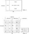
Figure 1 , illustrates a subframe formed with a physical downlink control channel ("PDCCH"), physical downlink shared channel ("PDSCH"), and a new control channel in accordance with an embodiment;Figure 2 illustrates a common reference signal ("CRS") pattern in LTE withfrequency shift 0, in accordance with an embodiment;Figure 3 illustrates a one-sub carrier shifted version of the CRS pattern illustrated inFigure 2 , in accordance with an embodiment;Figure 4 illustrates a subframe including aCRS pattern 1 withfrequency shift 1, aCRS pattern 2 withfrequency shift 2, and resource elements of the new control channel, in accordance with an embodiment;Figure 5 illustrates a subframe including aCRS pattern 1 withfrequency shift 1, aCRS pattern 2 withfrequency shift 2, and REs employed for reference signaling for the new control channel, in accordance with an embodiment;Figure 6 illustrates a flowchart showing transmission and reception, in accordance with an embodiment;Figure 7 illustrates a transmission method, in accordance with an embodiment;Figure 8 illustrates a reception method, in accordance with an embodiment;Figure 9 illustrates reception of CRS signaling, in accordance with an embodiment;Figure 10 illustrates a flowchart showing a sequence of steps in a process performed by first and second central controllers operating in a wireless system, in accordance with an embodiment;Figure 11 illustrates a flowchart showing a sequence of steps in a process performed by a UE operating in a wireless system, in accordance with an embodiment; andFigure 12 illustrates a block diagram of a processing system that can be used to perform one or more of the processes discussed herein in accordance with an embodiment.- The making and using of the presently preferred embodiments are discussed in detail below. It should be appreciated, however, that the present invention provides many applicable inventive concepts that can be embodied in a wide variety of specific contexts. The specific embodiments discussed are merely illustrative of specific ways to make and use the invention and do not limit the scope of the invention.
- Generally, in addition to possibly transmitting a first type of control channel, referred to herein as a PDCCH, in a wireless system, a second type of control channel, referred to herein as an enhanced PDCCH ("ePDCCH"), is transmitted, and the second type of control channel is characterized in that resource elements ("REs") in a CRS pattern employed therein are not used for transmission REs, i.e., data information, of the second type of control channel, while the first type of control channel has no such constraint about CRS patterns.
- A reception method of a control channel is introduced, including detecting a first type of control channel in a first subframe and detecting a second type of control channel in a second subframe, wherein REs in a CRS pattern are not used for transmission of the second type of control channel.
- For LTE Release-10 and earlier cellular systems, both a physical downlink control channel ("PDCCH") and a physical downlink shared channel ("PDSCH") are defined. A PDCCH is used to carry control information of PDSCH, such as resource allocation information, modulation, and coding information, etc. A PDSCH is used to carry data information. A PDCCH is located in the first several symbols in a subframe (one to four). The first several symbols carrying the PDCCH may be referred to as a control domain. Other symbols are used to carry data transmission, and may be referred to as the data domain. Hence, PDCCH is located in the control domain and PDSCH is located in the data domain.
- In the control domain, there can be other control channels, such as the physical hybrid indicator channel ("PHICH"), which is used to transmit an acknowledgment/negative acknowledgment ("ACK/NACK") in response to uplink data transmission, or the physical control format indicator channel ("PCFICH"), indicating the number of symbols of control domain in a subframe.
- A new type of control channel (or new control channel) located in the data domain of a subframe is introduced herein for systems operating under LTE-
A Release 11 or beyond. One or more resource blocks ("RBs") can be allocated to a UE to carry control information of a PDSCH or control information of a physical uplink shared channel ("PUSCH"), such as uplink ("UL") grant information or ACK/NACK information in response to a PUSCH transmission. This channel may be referred to as the U-PDCCH for a type of UL grant or downlink ("DL") grant channel, U-PHICH for a type of PHICH. Note that when the control channel U-PDCCH is present, the control channel PDCCH may or may not be present. - There are some benefits to having such a U-PDCCH/U-PHICH. For example, different cells may allocate an orthogonal time-frequency resource for the U-PDCCH/U-PHICH; thus, the interference between the U-PDCCH/U-PHICHs of different cells is significantly lowered. Another benefit can be that a dedicated reference signal can be used for the U-PDCCH/U-PHICH. In other words, a U-PDCCH/U-PHICH has its own reference signal for channel estimation during demodulation, thereby allowing a more advanced transmission scheme, such as beam forming or precoding.
- Turning now to
Figure 1 , illustrated is a subframe formed with the PDCCH, PDSCH, and the new control channel ("U-PDCCH/U-PHICH"), in accordance with an embodiment. The new control channel can include a new control channel to indicate carrier control information for PDSCH and/or a new PHICH channel to indicate ACK/NACK for PUSCH. Note that this representation is logical and may not actually map to the specific physical resources as shown inFigure 1 but to any resource blocks in the data domain. A U-PDCCH/U-PHICH is located in the data domain. The PDCCH/PHICH is located in the control domain. - There may still be significant interference on the U-PDCCH/U-PHICH from the CRSs transmitted by neighboring evolved NodeBs ("eNBs"). Furthermore, there are some constraints on the U-PDCCH/U-PHICH for coordinated multi-point transmission / reception ("CoMP") transmission due to CRS. CRS is a common reference signal, which can be used for PDCCH demodulation and can also be used for channel estimation of PDSCH in the transmission mode of transmission diversity.
- Turning now to
Figure 2 , illustrated is a CRS pattern in a resource block withfrequency shift 0 in a subframe, in accordance with an embodiment. InFigure 3 , illustrated is a CRS pattern in a RB for a subframe withfrequency shift 1, in accordance with an embodiment. CRS is transmitted in the entire frequency band of the system. - As illustrated in
Figure 2 , a subframe consists (over time) of 14 OFDM symbols for a normal cyclic prefix length. A subframe is divided into two slots. A slot has seven OFDM symbols, withindices Figures 2 ,3 ,4 , and5 . A subcarrier in an OFDM symbol is a resource element ("RE"). REs forantenna port 1 are obtained by shifting REs forantenna port 0 in the frequency domain, where the shift offset is three sub carriers. - There are CRS REs in the data domain, CRS in
symbol # 4 in the first slot of a subframe, andsymbol # 0symbol # 4 in the second slot of a subframe for a normal subframe. - As illustrated in
Figure 3 , a CRS pattern is a one-subcarrier-shifted version compared with the CRS pattern illustrated inFigure 2 . In an OFDM symbol carrying the CRS,subcarriers # 0, #3, #6, #9 are REs of CRS inFigure 2 , butsubcarrier # 1, #4, #7, #10 are REs of CRS inFigure 3 . Usually different patterns (frequency shifts) can reduce interference among CRSs of different cells and hence different patterns can be configured for different cells - Suppose
cell 1 has the CRS pattern withfrequency shift 0 inFigure 2 , andcell 2 has the CRS pattern withfrequency shift 1 inFigure 3 . The RE incell 1 withsymbol # 4 andsubcarrier # 1 is then interfered by the RE of CRS incell 2 withsymbol # 4 andsubcarrier # 1. - Hence, there may be interference from CRS of neighbor cells to the control channel even though a new control channel is located in the data domain of a subframe if neighboring cells have different CRS patterns (different shifts in frequency domain). The new control of a UE may use one or more RBs, and CRSs are usually transmitted on the entire frequency band.
- A subframe can be configured as a multicast broadcast single frequency network ("MBSFN") subframe by a higher layer to avoid transmission of CRS in the data domain in a neighbor cell since there is no CRS transmitted in the data domain of a MBSFN subframe. In this case, there will be no CRS interference to the new control channel in the data domain from neighboring cells. However, in some cases, such as for a subframe with PBCH (primary broadcast channel), transmission may not be configured as an MBSFN subframe. For frequency division duplex ("FDD"),
subframes - Another scenario is that the channel to carry an ACK/NACK in response to PUSCH, such as a U-PHICH/PHICH channel, can be transmitted once for every eight subframes to indicate whether a retransmission is needed or not and if a synchronized uplink non-adaptive transmission for PUSCH is configured. Non-adaptive means a resource allocation and modulation/coding scheme for retransmission in the process of HARQ has been determined by the initial transmission. Broadcasting signaling can have different periodicity with a new PHICH channel. In other words, broadcasting signaling may not be transmitted once for every eight subframes. Hence, there can be broadcasting signaling being transmitted in the same subframe of a neighboring cell as a new PHICH channel in the current cell. The simultaneous transmission may not always be avoided in a subframe for a new PHICH in the current cell and broadcasting signaling a neighboring cell. Since CRSs can be used for broadcasting signaling transmission, U-PHICH can be interfered by CRSs of neighboring cells if the CRSs of neighboring cells have a different frequency shift than the current cell. This is a configuration that is generally useful since the different frequency shift for CRSs improves the signal to interference ratio on the reference sequence. Thus, it is generally not desirable to configure all the neighboring cells to have the same frequency shift. Otherwise, the demodulation performance of the broadcast signaling may not be acceptable. A different frequency-shifted CRS for different cells may make joint transmission of multiple cells hard to be used.
- Since some resource elements are used for CRSs in one cell but are used for U-PDCCH/U-PHICH in another cell, it may be difficult to transmit jointly processed signals from both cells for the new control channel on these REs.
- For example, a RE in a cell is used to transmit a CRS (for example,
symbol # 4, subcarrier #0) inFigure 1 , but the RE in the same time-frequency position in another cell is used to transmit the new control channel instead of a CRS as described inFigure 2 (symbol # 4, subcarrier #0). In this case, joint transmission cannot be applied on this RE. - A transmission method of the new control channel may be characterized by transmitting a control channel in resource elements that do not belong to resource elements of a CRS pattern. The system can simultaneously support the legacy PDCCH/PHICH channel, although this is not a mandatory requirement. The inner-cell UEs can use the legacy PDCCH/PHICH channel in the control domain to have a larger number of control channels.
- The CRS pattern(s) for which REs are not used for U-PDCCH/U-PHICH can be signaled by higher-layer signaling, for example, radio resource control ("RRC") signaling. Alternatively, REs in CRS pattern(s) not being used for the new control channel can be predefined or pre-specified in a standard. Also, it is possible to have fully dynamic signaling, e.g., using the common search space of the PDCCH, although this may be high overhead.
- The U-PDCCH/U-PHICH can be a control channel to carry the control information for PDSCH. The U-PDCCH/U-PHICH can also be a control channel to carry uplink grant information of a PUSCH. The control channel can also be a PHICH channel to carry ACK/NACK feedback information in response to a PUSCH transmission.
- The CRS patterns signaled, predefined, or pre-specified can be, without limitation, 0, 1, 2, or 3 CRS patterns and can be the same across a number of subframes with configured U-PDCCH/U-PHICH or can be different for different sets of subframes with configured U-PDCCH/U-PHICH. Signaling "0" means no CRS patterns are excluded for a new control channel transmission. Signaling "1" means one CRS pattern is excluded for a new control channel transmission, etc. For example, if a subframe is configured as an MBSFN subframe, all REs in the data domain can be used for a new control channel transmission. If a CRS pattern in a neighbor cell severely interferes with a current UE, a CRS pattern can still be signaled for the UE to avoid using REs in the CRS pattern for the new control channel to transmit. Thus, a CRS pattern for muting REs is signaled, predefined, or pre-specified. A CRS pattern for muting can be the same as or can be different from a CRS pattern for transmitting CRSs. By default, when there is no signaling, etc., to indicate a CRS pattern not being used for U-PDCCH/U-PHICH transmission, a UE may assume no extra CRS patterns for muting REs except the configured CRS pattern in the current cell for channel estimation (if so configured). In other words, an eNB may not transmit any signaling to indicate CRS patterns when there are no extra CRS patterns for muting REs. A simple bitmap method can be used for indication of a CRS pattern(s). For example, three bits, ala2a3, can be used to indicate three CRS patterns. The bit value "0" of bit ai indicates REs in pattern i, i = 1, 2, 3, are not muted, and the bit value "1" of bit ai represents REs in pattern i, i = 1, 2, 3, are muted. Being muted by a CRS pattern for muting means no U-PDCCH/U-PHICH is transmitted in those REs. The signaling can indicate in which subframes there are CRS patterns for muting, for example, the offset and/or period of subframes with CRS patterns for muting.
- A CRS patterns for muting is signaled to not transmit a new control channel. Thus, REs in a CRS pattern are muted for the new control channel. The REs in a CRS patterns for muting may or may not be used to transmit a data channel. Thus, the muting of some REs in a data channel can be different from the muting of some REs in the new control channel. For a data channel, higher throughput is preferable but for a control channel, better performance is preferable.
- The signaling of a CRS pattern for muting can be broadcast signaling or UE-dedicated signaling. The signaling can be higher-layer signaling, such as RRC signaling or physical layer signaling, etc. A CRS pattern for muting can be the same as or can be different from a CRS pattern for transmitting CRSs.
- Note that the CRS muting can be different than the channel state information-reference symbol ("CSI-RS") muting technique that was standardized for E-UTRA Rel-10: CSI-RS muting can be configured for the entire bandwidth, whereas CRS muting can be configured on a per-resource-block basis. As a consequence for different RBs, a different set of REs can be muted, in other words, not used to transmit a signal.
- Turning now to
Figure 4 , illustrated is a subframe including aCRS pattern 1 withfrequency shift 1, aCRS pattern 2 withfrequency shift 2, and resource elements of the new control channel, in accordance with an embodiment. Assume that the CRS pattern with frequency shift 1 (the diagonally-lined REs inFigure 4 ) is for a current CRS transmission and that a neighboring cell with the CRS pattern with frequency shift 2 (the darkened REs inFigure 4 ) is creating severe interference. The resource elements of the CRS patterns withfrequency shift 1 andfrequency shift 2 are not allocated to the U-PDCCH/U-PHICH. The CRS pattern withshift 1 for CRS of the current cell is known for UEs in the current cell. Some signaling to inform the UE(s) that the CRS pattern withfrequency shift 2 is used in the neighboring cell can be used to reduce interference. Assume that the first two symbols (#0, #1) are used for the control domain. Symbols (#2, #3, #4, #5, #6) in the first slot of a subframe then can be used for U-PDCCH/U-PHICH. Another alternative is to use symbols (#0, #1, #2, #3,#4, #5, #6) in the second slot for U-PDCCH/U-PHICH, particularly for U-PHICH, since the timing requirement for PUSCH transmission based on the received ACK/NACK in the U-PHICH is a little looser compared with the DL-grant. U-PDCCH of the UL grant can be in the second slot also based on the similar reason to U-PHICH. The resource elements in a resource block not being used by CRS patterns withshift 1 andshift 2 are used for U-PDCCH/U-PHICH. Depending on different coding rate requirements for performance, one or more RBs can be allocated for the U-PDCCH/U-PHICH of a UE. Some of the resource elements for the U-PDCCH/U-PHICH can be used for a dedicated reference signal of the new control channel. - Turning now to
Figure 5 , illustrated is a subframe including aCRS pattern 1 withfrequency shift 1, aCRS pattern 2 withfrequency shift 2, and REs employed for reference signaling for the new control channel, in accordance with an embodiment. As illustrated inFigure 5 , some REs in the first slot (the first 7 symbols) are dedicated reference signals for the U-PDCCH/U-PHICH in the first slot of a subframe of a RB. As illustrated inFigure 5 , there are 46 open REs in the first slot of a RB. Some REs in the second slot (the second 7 symbols) are dedicated reference signals for a control channel in the second slot of a subframe of a RB. There are 58 open REs in the second slot of a subframe of a RB. These counts of open REs depend on a number of factors, such as the number of PDCCH symbols, antenna ports, and the presence or absence of CSI-RS. - In an extreme case, REs in all of the three CRS patterns with
frequency shift - There can also be CSI-RS transmission in some REs. In that case, the number of available REs for the U-PDCCH/U-PHICH is lower. The CSI-RS is the reference signal used for channel status indication measurement, for example, CQI feedback measurement and/or report. In this case, there might be few REs available for transmitting the U-PDCCH/U-PHICH. However, transmission of the U-PDCCH/U-PHICH can be aggregated over several resource blocks. In this case, the rate matching and/or resource mapping for the U-PDCCH/U-PHICH also depends on CSI-RS signaling and/or CSI-RS muting signaling. A UE needs to receive CSI-RS signaling and/or CSI-RS muting signaling before decoding the U-PDCCH/U-PHICH.
- There can be signaling to indicate which CRS patterns for muting are not used for the U-PDCCH/U-PHICH transmission. The resource elements of the U-PDCCH/U-PHICH can be determined based on the signaling. For example, in the above example, signaling can indicate that the CRS pattern with
frequency shift 2 is avoided for U-PDCCH/U-PHICH transmission. The CRS pattern withfrequency shift 1 is the CRS of the current cell, thus maintaining orthogonality between the different cells. The CRS pattern with a frequency shift is just for CRS transmission of the current cell and is not used for transmission of any other channels. - An alternative method is that the REs in the symbols with CRS pattern(s) for muting are never used for U-PDCCH/U-PHICH transmission. This can be predefined in a system specification or standard. In this case, there is no need of any additional signaling to signal which CRS patterns to avoid.
- When signaling is used to indicate which REs in CRS patterns for muting are not used for U-PDCCH/U-PHICH transmission, the signaling can be UE-dedicated signaling or broadcast signaling. The signaling can inform which CRS patterns for muting are not being used for the new control channel. For example, one CRS pattern for muting is signaled to a UE for not being used for U-PDCCH/U-PHICH transmission in a set of subframes. The CRS pattern for muting may be the CRS pattern of the interference cell to this UE. For a different UE, the interference cell may be different. Hence, the signaled CRS pattern for muting can be different for different UE and/or subframes. For example, for other subframes, a different CRS pattern for muting can be signaled. With this UE dedicated signaling, resource elements of a CRS pattern for muting not being used for the new control channel are only avoided for some UE and/or some subframes. Hence, UE specific dedicated signaling can save overhead due to muting the REs of CRS patterns.
- Turning now to
Figure 6 , illustrated is a flowchart in which inblock 610 an eNB transmits a U-PDCCH/U-PHICH in the data domain of a subframe, in accordance with an embodiment. Inblock 620, the UE receives and decodes the U-PDCCH/U-PHICH transmission. The eNB can transmit the U-PDCCH/U-PHICH in a candidate resource block for resource allocation from a set of candidates, for example, in some resource blocks with a pre-defined modulation and coding scheme, such as quadrature phase-shift keyed ("QPSK") modulation and a predefined coding rate. The possible candidates of resource allocation and/or possible modulation/encoding schemes can be predefined in a specification or standard or can be signaled to the UE. The resource allocation and/or modulation/encoding scheme can depend on the CRS patterns not being used for transmission of the new control channel. The UE can blindly detect the possible U-PDCCH candidates with the corresponding resource allocation and/or modulation/coding schemes to find a U-PDCCH. If the cyclic redundancy check ("CRC") passes for a candidate U-PDCCH, the UE detects the new control channel correctly. - There can be signaling or a predefined rule for a UE to determine all the candidates of a U-PDCCH. For example, a signal can indicate the starting RB and the number of RBs (or generally which RBs) for U-PDCCH candidates. The UE can blindly detect each candidate to determine whether a U-PDCCH has been transmitted for the UE. At the eNB side, for a U-PDCCH candidate allocated to a UE, the eNB allocates the REs for a U-PDCCH transmission according to the muting of CRS patterns if any.
- Turning now to
Figure 7 , illustrated is a flowchart in which inblock 710 an eNB encodes the control information for a PDSCH with channel coding, in accordance with an embodiment. Depending on the resource allocation for this control channel, different rate matching can be used. For example, one to four RBs can be allocated for U-PDCCH/U-PHICH transmission, which correspond to different rate matching and a different coding rate. QPSK, inblock 720, can be used for modulation. Furthermore, a CRS pattern can be determined as predefined or by signaling not to transmit the U-PDCCH/U-PHICH on RBs allocated to U-PDCCH/U-PHICH of a UE. Next, the modulated signal is mapped inblock 730 into resource elements according to a predefined mapping rule. During the process of mapping, REs in the CRS patterns signaled as not being used for the U-PDCCH/U-PHICH transmission should not be used for U-PDCCH/U-PHICH transmission. After the modulated signal is mapped, an inverse fast Fourier transform ("IFFT") inblock 740 is applied to transform a signal in the frequency domain to a signal in the time domain. Then, inblock 750, the time domain signal is transmitted. - Even though the term CRS patterns is used for REs being muted, this does not mean the REs of the CRS pattern cannot be used for transmission in all of the RBs in the current cell, which is different with CSI-RS muting. Unlike the PDSCH RE muting for CSI-RS, muting REs of a CRS pattern is only applicable to a number of RBs to reduce interference from a CRS of a neighboring cell to the U-PDCCH/U-PHICH. Hence, only for RBs with a U-PDCCH/U-PHICH, the muting of a CRS pattern is applied. Furthermore, this muting is UE-specific. For RBs with another new control for a different UE, the muting of another CRS pattern can be applied. For RBs without a new control channel, the muting may or may not be applied. For example, for a UE with no U-PDCCH/U-PHICH allocated, data transmission on the allocated RBs may not be muted in REs of CRS patterns. If the muting of the CRS pattern is applied for RBs without U-PDCCH/U-PHICH, the CRS patterns for muting may not be the same as the CRS patterns for muting in other RBs with U-PDCCH/U-PHICH. The eNB needs to determine the CRS patterns for muting for each RB and for multiplex signals of RBs for transmission.
- Turning now to
Figure 8 , illustrated is a flowchart in which during reception, inblock 810, a fast Fourier transform ("FFT") is used for received signals to transform a time-domain signal into a frequency-domain signal, in accordance with an embodiment. Then, inblock 820, de-mapping is used to get the modulated symbols of the control channel in REs of the new control channel. Next, inblock 830 demodulation is used, and inblock 840 channel decoding is used to obtain the decoded bits. If a cyclic redundancy check passes for the decoded bits, the U-PDCCH has been received correctly. - The control channel can be a U-PDCCH channel or a U-PHICH channel. If the control channel is a U-PHICH channel, one or more bits are modulated by orthogonal codes, such as Walsh code. For example, 1 bit is modulated by an orthogonal code, and the orthogonal code can be (1, 1, 1, 1). Hence, one bit can be modulated in 12 REs with three-time repetition with binary phase shift keyed ("BPSK") or QPSK modulation. (Only an in-phase or quadrature ("I" or "Q") component is used for 1 bit). Another bit can be modulated by an orthogonal code (1, 1, -1, -1) and repeated three times and then transmitted in the same 12 REs without strong interference to the first "1" bit.
- The U-PDCCH candidates can be informed to a UE, and the UE can blindly detect the U-PDCCH control channel based on a CRC check. However, for the U-PHICH there may be no CRC in the information bits; thus, the UE cannot decode the U-PHICH based on blind detection. Hence, the resource allocation of the U-PHICH and/or modulation/coding scheme should be signaled to the UE, implicitly or explicitly. For example, the resource allocation of the U-PHICH can be implicitly signaled by the corresponding U-PDCCH. In other words, a PUSCH transmission is indicated by a U-PDCCH transmission. The time-frequency location of the U-PDCCH being detected indicates the resource allocation of the U-PHICH in response to the PUSCH indicated by the U-PDCCH.
- Turning now to
Figure 9 , illustrated is a flowchart showing UE reception. The UE may need to know which REs in CRS patterns for muting are not used for new control channel transmission, in accordance with an embodiment. Inblock 910, an eNB signals the CRS pattern(s) for muting (where the RE on the U-PDCCH/U-PHICH are left blank), and inblock 920, the UE receives the signaled pattern(s). Inblock 930, the UE decodes the new control channel using received signaling for CRS patterns for muting. The CRS pattern(s) for muting determines the resource allocation for the U-PDCCH/U-PHICH, and/or the modulation/coding scheme being used for the U-PDCCH/U-PHICH. Hence, before detecting the U-PDCCH/U-PHICH, the UE first needs to receive the signaling, or according to the predefined resource allocation rule for the new control channel, the UE determines the CRS pattern(s) for muting that are not being used for the new control channel transmission. - For U-PHICH, to save overhead, a U-PHICH of multiple uses can be multiplexed with orthogonal codes as described previously hereinabove. To keep the orthogonal property of different U-PHICH channels in the code domain, the REs used by U-PHICH should be the same for different U-PHICHs. If one U-PHICH has REs different from another U-PHICH, then code orthogonality is lost. An eNB can signal to different UEs the different CRS patterns for muting in which REs are not used for the new type of PHICH transmission. In other words, even in a same RB, different U-PHICH can have REs punctured by different CRS patterns; thus, these U-PHICHs in the same RB cannot be code-division orthogonal. If orthogonality of the code division is to be maintained, the U-PHICH of UEs with the same CRS patterns for muting is arranged in the same RB. In an implementation it complicates the allocation of a U-PHICH for UEs. Therefore, U-PHICH may only use REs that are not in CRS symbols. In other words, REs in all CRS patterns for muting are not used for U-PHICH transmission. With this resource allocation for U-PHICH, the code-division orthogonality property is not impacted by the CRS patterns for muting for avoiding control channel transmission and/or data channel transmission.
- For example, signaling can indicate to a UE which REs in a CRS pattern are being muted, but the U-PHICH always uses the same REs regardless of which CRS pattern(s) are signaled. Those same REs are not affected by an OFDM symbol of CRS.
- A similar scheme can also be used for U-PDCCH. Hence, REs for U-PDCCH will not be affected by CRS patterns for muting. However, for data channel, in order to have a larger throughput, a signaling can be used to inform which CRS pattern(s) for muting are avoided for data transmission. This signaling can be carried in U-PDCCH or can be higher-layer signaling, for example, by bitmap signaling. If the current cell to transmit the U-PDCCH has a CRS pattern for muting, then the total number of bits for bitmap signaling can be n-1, where n is the total number of CRS patterns in a system for a specific number of antenna ports. If the signaling of CRS pattern(s) for muting of PDSCH is carried on a U-PDCCH, then dynamic cell switching or cell selection can be supported for cooperative multiple point ("CoMP") transmission. Generally, the signaling to indicate muting of REs for a control channel and signaling to indicate muting of REs for a data channel can be different. Even for a U-PHICH channel, a signaling can be informed to a UE for CRS muting in RBs where a U-PHICH is located. Another signaling can be used to inform a UE for RE muting of another channel, such as a data channel, or another channel, such as data channel depending on another predefined rule for CRS muting.
- Turning now to
Figure 10 , illustrated is a flowchart showing a sequence of steps in a process performed by first and second central controllers operating in a wireless system, in accordance with an embodiment. The first and second central controllers are each formed with a processor and a memory coupled to the processor. In block orstep 1010, the processor is configured to cause the first central controller to identify, by the first central controller, a CRS pattern for muting by the first central controller, and identify, by the first central controller for a first set of UEs in a serving area of the first central controller, a set of subframes including a first type of control channel having overlap REs that overlap the CRS pattern for muting. The CRS pattern for muting can be signaled or predefined. - In an embodiment, the CRS pattern(s) for muting is signaled by the first central controller by higher-layer signaling which can be RRC signaling. The RRC signaling can be UE-dedicated signaling. In an embodiment, the CRS pattern for which REs are not used for the transmission of the at least one of the resource assignment control information and the CRS pattern for which REs are not used for the ACK/NACK response are independently signaled or predefined. A CRS pattern not to be used for transmitting the first type of control channel can be predefined in a standard or specification, such as a system specification. In an embodiment, a bitmap pattern is used by the first central controller to identify the CRS pattern for muting.
- In block or
step 1020, the first central controller mutes the overlap REs in the first type of control channel that overlap the REs of the CRS pattern for muting. - In block or
step 1030, the first central controller frequency-division multiplexes the first type of control channel with data channels. - In block or
step 1040, the first central controller transmits to the first set of UEs, the first type of control channel with the muted overlap REs on the identified set of subframes. - In block or
step 1050, at least one of the data channels has data REs that overlap the CRS pattern for muting, and the first central controller transmits data information on the data REs. - In block or
step 1060, the first central controller transmits a second type of control channel to a second set of UEs, the second type of control channel being time-division multiplexed with the data channels. The second type of control channel can be transmitted on the muted REs identified by the first central controller for the first set of UEs. - In block or
step 1070, the first central controller transmits on the first type of control channel at least one of resource assignment control information and an ACK/NACK response for a PUSCH. - In block or
step 1080, a second central controller transmits CRSs in the overlap REs. - Turning now to
Figure 11 , illustrated is a flowchart showing a sequence of steps in a process performed by a UE operating in a wireless system, in accordance with an embodiment. The UE is formed with a processor and a memory coupled to the processor. In block orstep 1110, the processor is configured to cause the UE to receive a first type of control channel from a first central controller in the wireless system identifying a set of subframes on which a CRS pattern(s) for muting is configured, signaled, or predefined for the first type of control channel. A bitmap pattern can be employed by the first central controller to identify the CRS pattern(s) for muting. The CRS pattern can be received by higher-layer signaling which can be RRC signaling. In block orstep 1120, the processor is further configured to cause the UE to disable reception of overlap REs of a first type of control channel if the overlap REs of the first type of control channel overlap with REs of the CRS pattern(s) for muting. In block orstep 1130, the processor is further configured to cause the UE to receive from the first central controller a data channel frequency-division multiplexed with the first type of control channel. In block orstep 1140, the processor is further configured to cause the UE to receive from the first central controller a second type of control channel comprising at least one of resource assignment control information and an ACK/NACK response for a PUSCH transmitted by the UE. In block orstep 1150, the processor is further configured to receive data information from the first central controller on data REs that overlap the CRS pattern for muting. - The UE can receive the first type of control channel in a first subframe and the second type of control channel in a second subframe.
- Thus, as introduced herein, a second type of control channel is transmitted in addition to a first type of control channel, and the second type of control channel is characterized in that overlap REs in a CRS pattern(s) for muting are not used for transmission of the second type of control channel, while the first type of control has no such constraint about CRS pattern(s) for muting.
- The control channel can be a control channel to carry the control information of PDSCH/PUSCH or a control channel to carry ACK/NACK information for PUSCH. There can be signaling by an eNB/base station to indicate the CRS pattern(s) for muting not being used for the second type of control channel. The CRS pattern(s) for muting not being used for the second type of control transmission can be configured by the controller or predefined in the specification or standard.
- The signaling can be UE-dedicated signaling. The signaling can inform different CRS pattern(s) for muting for different subframes and/or different UEs. Furthermore, the REs in signaled CRS pattern(s) for muting may not be used for PDSCH transmission either. The REs in signaled CRS pattern(s) for muting can be used for PDSCH transmission.
- A reception method is introduced for a control channel, including detecting a first type of control channel in a first subframe and detecting a second type of control channel in a second subframe where REs in a CRS pattern(s) for muting is not used for transmission of a second type of control channel. The UE can receive a signal indicating a CRS pattern(s) for muting in which REs are not used for the transmission of the second type of control channel. The UE can determine a CRS pattern for muting in which REs are not used for the transmission of the second type of control channel based on a signaled rule or a predefined rule specified in a standard. The UE can determine the code rate and/or rate matching of the second control channel according to the CRS pattern(s) not being used for transmission of the second type of control channel.
- An equipment of transmission or reception has means for the methods of transmission or reception described hereinabove.
- In an embodiment, a reception method of a control channel is provided. The method can include detecting a first type of control channel in a first subframe and detecting a second type of control channel in a second subframe where REs in a CRS pattern are not used for transmission of a second type of control channel.
- The UE can receive a signal indicating a CRS pattern in which REs are not used for the transmission of the second type of control channel. The UE can determine a CRS pattern in which REs are not used for the transmission of the second type of control channel based on a predefined rule specified in a standard or specification. The UE can determine the code rate and/or rate matching of the second control channel according to the CRS pattern(s) not being used for transmission of the second type of control channel.
- An equipment of transmission or reception can perform and/or have the means for the methods of transmission or reception described hereinabove.
- In another embodiment, a method for a primary node to send control information to a remote node is provided. The method can include notifying the remote node of a set of resources on a fraction of the resources used for transmission by the primary node and transmitting control channel information to the remote node while keeping the set of resources free of transmission. The set of resource can be specific to the remote node.
- It is noted that, unless indicated otherwise, all functions described herein can be performed in either hardware or software, or some combination thereof, with or without human intervention. In an embodiment, however, the functions are performed by a processor (e.g., a computer or an electronic data processor), such as that discussed below with reference to
Figure 12 , in accordance with code such as computer program code, software, and/or integrated circuits that are coded to perform such functions, unless indicated otherwise. - Referring now to
Figure 12 , illustrated is a block diagram of a processing system that can be used to perform one or more of the processes discussed above in accordance with an embodiment. The processing system can be formed with aprocessing unit 1210 equipped with one or more input/output devices, such as a mouse, a keyboard, printer, or the like, and a display. Theprocessing unit 1210 can include a central processing unit ("CPU"), memory, a mass storage device, a video adapter, and an I/O interface connected to a bus. - The bus can be one or more of any type of several bus architectures including a memory bus or memory controller, a peripheral bus, video bus, or the like. The CPU can be formed with any type of electronic data processor. The memory can be formed with any type of system memory such as static random access memory ("SRAM"), dynamic random access memory ("DRAM"), synchronous DRAM ("SDRAM"), read-only memory ("ROM"), non-volatile RAM ("NVRAM"), a combination thereof, or the like. In an embodiment, the memory can include ROM for use at boot-up, and DRAM for data storage for use while executing programs.
- The mass storage device can be formed with any type of storage device configured to store data, programs, and other information and to make the data, programs, and other information accessible via the bus. The mass storage device can be formed with, for example, one or more of a hard disk drive, a magnetic disk drive, an optical disk drive, or the like.
- The video adapter and the I/O interface provide interfaces to couple external input and output devices to the processing unit. Examples of input and output devices include the display coupled to the video adapter and the mouse/keyboard/printer coupled to the I/O interface. Other devices can be coupled to the processing unit, and additional or fewer interface cards can be utilized. For example, a serial interface card (not shown) can be used to provide a serial interface for a printer.
- The processing unit can also include a network interface which can be a wired link, such as an Ethernet cable or the like and/or a wireless link. The network interface allows the processing unit to communicate with remote units via the network. In an embodiment, the processing unit is coupled to a local-area network or a wide-area network to provide communications to remote devices, such as other processing units, the Internet, remote storage facilities, or the like.
- It should be noted that the processing system can include other components. For example, the processing system can include power supplies, cables, a motherboard, removable storage media, cases, and the like. These other components, although not shown, are considered part of the processing system.
- While this invention has been described with reference to illustrative embodiments, this description is not intended to be construed in a limiting sense. Various modifications and combinations of the illustrative embodiments, as well as other embodiments of the invention, will be apparent to persons skilled in the art upon reference to the description.
Claims (9)
- A communication method, comprising:identifying, by a first central controller, a pattern for muting resource elements, REs, of a first type of control channel for user equipment, UE, according to a common references signal, CRS, pattern;identifying (1010), by the first central controller, a set of subframes including the first type of control channel, the set of subframes having REs which, according to the pattern for muting REs, should be muted;muting (1020), by the first central controller, the REs which, according to the pattern for muting REs, should be muted in the first type of control channel;frequency-division multiplexing (1030), by the first central controller, the first type of control channel with data channels, wherein at least one of the data channels has data REs which, according to the pattern for muting REs, should be muted;transmitting (1040), by the first central controller, the first type of control channel in the set of subframes with muted REs which, according to the pattern for muting REs, should be muted; andtransmitting (1050), by the first central controller, at least one of the data channels including data information on the data REs which, according to the pattern for muting REs, should be muted.
- The method according to claim 1, wherein the pattern for muting REs is predefined for the first type of control channel.
- The method according to claim 1 or 2, further comprising: using, by the first central controller, a bitmap pattern for identifying the pattern for muting REs.
- The method according to any one of claims 1 to 3, further comprising: transmitting (1080), by a second central controller, CRSs on REs which, according to the pattern for muting REs, should be muted.
- A central controller configured to implement a method in accordance with any one of claims 1 to 3.
- A communication method, comprising:identifying, by user equipment, UE, a pattern for muting resource elements, REs, of a first type of control channel for the UE, according to a common references signal, CRS, pattern, wherein the CRS pattern is received by a higher-layer signaling;identifying (1110), by the UE, a set of subframes including the first type of control channel, the set of subframes having REs which, according to the pattern for muting REs, should be muted;receiving, by the UE from a first central controller, the first type of control channel; andreceiving (1150), by the UE, a data channel on data REs which, according to the pattern for muting REs, should be muted, wherein the data channel is frequency-division multiplexed with the first type of control channel;wherein receiving, by the UE from the first central controller, the first type of control channel comprises:
disabling (1120), by the UE, reception of the first type of control channel in the set of subframes with muted REs which, according to the pattern for muting REs, should be muted. - The method according to claim 6, wherein the pattern for muting REs is predefined for the first type of control channel.
- The method according to claim 6 or 7, further comprising:
using, by the UE, a bitmap pattern to identify the pattern for muting REs. - User equipment configured to implement a method in accordance with any one of claims 6 to 8.
Applications Claiming Priority (3)
| Application Number | Priority Date | Filing Date | Title |
|---|---|---|---|
| US201161442640P | 2011-02-14 | 2011-02-14 | |
| PCT/US2012/025128WO2012112614A1 (en) | 2011-02-14 | 2012-02-14 | Control channel transmission and reception method and system |
| EP12746606.8AEP2661937B1 (en) | 2011-02-14 | 2012-02-14 | Control channel transmission and reception method and system |
Related Parent Applications (2)
| Application Number | Title | Priority Date | Filing Date |
|---|---|---|---|
| EP12746606.8ADivisionEP2661937B1 (en) | 2011-02-14 | 2012-02-14 | Control channel transmission and reception method and system |
| EP12746606.8ADivision-IntoEP2661937B1 (en) | 2011-02-14 | 2012-02-14 | Control channel transmission and reception method and system |
Publications (2)
| Publication Number | Publication Date |
|---|---|
| EP3522579A1 EP3522579A1 (en) | 2019-08-07 |
| EP3522579B1true EP3522579B1 (en) | 2021-02-03 |
Family
ID=46636823
Family Applications (2)
| Application Number | Title | Priority Date | Filing Date |
|---|---|---|---|
| EP19165386.4AActiveEP3522579B1 (en) | 2011-02-14 | 2012-02-14 | Control channel transmission and reception method and system |
| EP12746606.8AActiveEP2661937B1 (en) | 2011-02-14 | 2012-02-14 | Control channel transmission and reception method and system |
Family Applications After (1)
| Application Number | Title | Priority Date | Filing Date |
|---|---|---|---|
| EP12746606.8AActiveEP2661937B1 (en) | 2011-02-14 | 2012-02-14 | Control channel transmission and reception method and system |
Country Status (4)
| Country | Link |
|---|---|
| US (2) | US8811285B2 (en) |
| EP (2) | EP3522579B1 (en) |
| CN (1) | CN103355007B (en) |
| WO (1) | WO2012112614A1 (en) |
Families Citing this family (55)
| Publication number | Priority date | Publication date | Assignee | Title |
|---|---|---|---|---|
| WO2011126025A1 (en)* | 2010-04-05 | 2011-10-13 | 株式会社エヌ・ティ・ティ・ドコモ | Base station device, mobile station device and reference signal transmission method |
| KR101548067B1 (en)* | 2011-03-21 | 2015-08-27 | 엘지전자 주식회사 | Method and device for executing harq in tdd-based wireless communication system |
| US10638464B2 (en)* | 2011-04-01 | 2020-04-28 | Futurewei Technologies, Inc. | System and method for transmission and reception of control channels in a communications system |
| KR20140012152A (en)* | 2011-04-22 | 2014-01-29 | 후지쯔 가부시끼가이샤 | Method for configuring resources, method for sending response signal, base station and user equipment |
| EP2702819B1 (en)* | 2011-04-29 | 2023-01-25 | Samsung Electronics Co., Ltd. | Apparatus and method of resource allocation for data and control channels in a wireless communication system |
| KR101790040B1 (en)* | 2011-05-25 | 2017-11-20 | 삼성전자 주식회사 | Method and apparatus for transmission of dedicated control channel with dedicated reference signal in wireless communication system |
| EP2564611B1 (en) | 2011-07-01 | 2015-02-18 | Ofinno Technologies, LLC | Synchronization signal and control messages in multicarrier OFDM |
| US8369280B2 (en) | 2011-07-01 | 2013-02-05 | Ofinno Techologies, LLC | Control channels in multicarrier OFDM transmission |
| US8582527B2 (en) | 2011-07-01 | 2013-11-12 | Ofinno Technologies, Llc | Hybrid automatic repeat request in multicarrier systems |
| KR101525722B1 (en)* | 2011-07-05 | 2015-06-03 | 엘지전자 주식회사 | Method and apparatus for allocating a downlink control channel in a wireless communication system |
| US9614643B2 (en)* | 2011-07-08 | 2017-04-04 | Lg Electronics Inc. | Method for transmitting a downlink control channel by a base station in a wireless communication system, and apparatus therefor |
| EP2735104A4 (en)* | 2011-07-19 | 2014-07-23 | Renesas Mobile Corp | METHOD AND APPARATUS FOR MEASURING AND DELIVERING CHANNEL STATUS INFORMATION (CSI) FOR A SEGMENT CARRIER |
| US11974295B2 (en) | 2011-07-25 | 2024-04-30 | Nec Corporation | Communication system |
| GB2493154A (en) | 2011-07-25 | 2013-01-30 | Nec Corp | Communicating control channel reference signal patterns in the control region of a sub-frame in a cellular communication system |
| EP2737639A4 (en)* | 2011-07-28 | 2015-04-08 | Samsung Electronics Co Ltd | DEVICE AND METHOD FOR IRONING IN A WIRELESS COMMUNICATION SYSTEM |
| US20130201926A1 (en)* | 2011-08-11 | 2013-08-08 | Samsung Electronics Co., Ltd. | System and method for physical downlink control and hybrid-arq indicator channels in lte-a systems |
| CN107425951B (en)* | 2011-08-16 | 2020-08-21 | Lg 电子株式会社 | Method for multiplexing downlink control channel by base station in wireless communication system and apparatus therefor |
| ES2933488T3 (en)* | 2011-09-30 | 2023-02-09 | Samsung Electronics Co Ltd | Method and apparatus for transmitting and receiving data in a wireless communication system |
| US9113463B2 (en) | 2011-11-04 | 2015-08-18 | Qualcomm Incorporated | Resource management for enhanced PDCCH |
| WO2013068041A1 (en)* | 2011-11-10 | 2013-05-16 | Nokia Siemens Networks Oy | Configuring a communication channel within a cell of a cellular network comprising another cell which uses muting patterns |
| US8842637B2 (en) | 2011-12-04 | 2014-09-23 | Ofinno Technologies, Llc | Carrier information transmission to wireless devices |
| US10791542B2 (en) | 2012-01-27 | 2020-09-29 | Qualcomm Incorporated | Regional and narrow band common reference signal (CRS) for user equipment (UE) relays |
| US9699742B2 (en)* | 2012-02-17 | 2017-07-04 | Lg Electronics Inc. | Method and apparatus for transmitting and receiving signals in wireless communication system |
| US9497756B2 (en) | 2012-03-25 | 2016-11-15 | Comcast Cable Communications, Llc | Base station radio resource management |
| US9949265B2 (en) | 2012-05-04 | 2018-04-17 | Comcast Cable Communications, Llc | Control channel in a wireless communication system |
| KR20130130593A (en) | 2012-05-22 | 2013-12-02 | 삼성전자주식회사 | Method and apparatus for measuring reference signal in wireless communication system comprising a plurality base station using a distributed antenna |
| US9510339B2 (en)* | 2012-06-19 | 2016-11-29 | Lg Electronics Inc. | Method for transceiving signal via interference measurement in wireless communication system with cooperative base stations, and apparatus therefor |
| US9521664B2 (en)* | 2012-11-02 | 2016-12-13 | Qualcomm Incorporated | EPDCCH resource and quasi-co-location management in LTE |
| US9270440B2 (en)* | 2012-11-02 | 2016-02-23 | Qualcomm Incorporated | Processing overlapping EPDCCH resource sets |
| WO2014088185A1 (en)* | 2012-12-04 | 2014-06-12 | Lg Electronics Inc. | Method for changing pattern of reference signals according to coherence time variation in wireless communication system and apparatus therefor |
| CN104956749B (en)* | 2013-01-29 | 2019-08-16 | 太阳专利托管公司 | Base station, terminal and communication method |
| US9521637B2 (en)* | 2013-02-14 | 2016-12-13 | Blackberry Limited | Small cell demodulation reference signal and initial synchronization |
| US9313782B2 (en)* | 2013-05-08 | 2016-04-12 | Qualcomm Incorporated | Enhanced PDSCH operation |
| CN105532054B (en)* | 2013-09-16 | 2019-07-02 | Lg电子株式会社 | The method and apparatus of Network Synchronization |
| US20150098414A1 (en)* | 2013-10-04 | 2015-04-09 | Innovative Sonic Corporation | Method and apparatus for supporting device-to-device (d2d) discovery in a wireless communication system |
| WO2015112071A2 (en)* | 2014-01-22 | 2015-07-30 | Telefonaktiebolaget L M Ericsson (Publ) | Handling of different control channel configurations for one or more wireless devices in a radio network |
| CN106165323B (en)* | 2014-03-04 | 2018-10-12 | Lg电子株式会社 | Receive the method and its device for receiving the control information for finding reference signal |
| US9929839B2 (en)* | 2014-08-08 | 2018-03-27 | Futurewei Technologies, Inc. | Device, network, and method for communications with fast adaptive transmission and reception |
| EP3210424B1 (en)* | 2014-10-21 | 2020-08-19 | Telefonaktiebolaget LM Ericsson (publ) | Handling handover of an ue in case cell specific reference signals interfer with a physical downlink control channel |
| CN105634667B (en)* | 2014-11-06 | 2019-05-21 | 电信科学技术研究院 | A kind of processing method and processing device of physical down channel |
| US10153875B2 (en) | 2014-12-11 | 2018-12-11 | Qualcomm Incorporated | Traffic data allocations in low latency LTE downlink communications |
| KR102286877B1 (en)* | 2015-02-05 | 2021-08-06 | 삼성전자 주식회사 | Filter reusing method for transmitting and receiving multi-carrier based on filter bank system |
| CN111432486B (en)* | 2015-05-08 | 2023-11-21 | 华为技术有限公司 | Device and method for controlling resource allocation in wireless communication network |
| EP3329625A1 (en)* | 2015-07-27 | 2018-06-06 | Intel Corporation | Downlink reference signal patterns |
| EP4080978A1 (en)* | 2016-07-21 | 2022-10-26 | Telefonaktiebolaget LM Ericsson (publ) | Flexible indication for start position of data channel |
| WO2018030327A1 (en)* | 2016-08-10 | 2018-02-15 | 京セラ株式会社 | Wireless terminal |
| CN114466456A (en)* | 2016-09-29 | 2022-05-10 | 华为技术有限公司 | Transmission method of downlink control channel, receiving network element and sending network element |
| KR101971972B1 (en)* | 2017-01-09 | 2019-04-24 | 엘지전자 주식회사 | Method and apparatus for transmitting a reference signal in a wireless communication system |
| CN108400851B (en)* | 2017-02-04 | 2022-08-19 | 中兴通讯股份有限公司 | Configuration information processing method and device, base station and terminal |
| CN115529573B (en)* | 2017-03-24 | 2025-02-18 | 苹果公司 | Method and apparatus for cell-specific reference signal muting |
| US20190230579A1 (en)* | 2017-05-17 | 2019-07-25 | Gilles Charbit | Method And Apparatus For Handling Cell-Specific Reference Signal Muting In Mobile Communications |
| CN111971921B (en)* | 2017-08-11 | 2023-09-12 | 苹果公司 | User equipment for CRS mitigation based on network |
| EP3692676A4 (en)* | 2017-10-02 | 2021-10-06 | Telefonaktiebolaget LM Ericsson (publ) | METHOD OF BAND SCANNING WHEN TRANSMITTING A REFERENCE SIGNAL OVER A REDUCED BANDWIDTH |
| US11672027B2 (en)* | 2018-08-03 | 2023-06-06 | Qualcomm Incorporated | Managing an overlap between downlink reference signals |
| CN114079546B (en)* | 2020-08-12 | 2024-05-28 | 深圳市中兴微电子技术有限公司 | Channel information processing method, device, equipment and storage medium |
Family Cites Families (26)
| Publication number | Priority date | Publication date | Assignee | Title |
|---|---|---|---|---|
| US7843870B2 (en)* | 2006-11-07 | 2010-11-30 | Clear Wireless Llc | Systems and methods of supporting multiple wireless communication technologies |
| US8897269B2 (en) | 2008-01-30 | 2014-11-25 | Qualcomm Incorporated | Method and apparatus for mitigating pilot pollution in a wireless network |
| CA2714421C (en)* | 2008-02-08 | 2017-09-12 | Zte (Usa) Inc. | Dynamic adjustment of downlink/uplink allocation ratio in tdd wireless systems |
| KR100905385B1 (en)* | 2008-03-16 | 2009-06-30 | 엘지전자 주식회사 | Efficient Transmission Method of Control Signal in Wireless Communication System |
| JPWO2009123105A1 (en) | 2008-03-31 | 2011-07-28 | シャープ株式会社 | COMMUNICATION SYSTEM, BASE STATION DEVICE, AND MOBILE STATION DEVICE |
| US8274951B2 (en) | 2009-03-17 | 2012-09-25 | Samsung Electronics Co., Ltd. | System and method for dynamic cell selection and resource mapping for CoMP joint transmission |
| EP2242298A1 (en)* | 2009-04-16 | 2010-10-20 | Vodafone Group PLC | Relays in Telecommunications Networks |
| CN101873609B (en)* | 2009-04-27 | 2013-03-20 | 电信科学技术研究院 | Data transmission method and device for relay system |
| KR101237666B1 (en)* | 2009-07-28 | 2013-02-26 | 엘지전자 주식회사 | Method and apparatus of transmitting reference signal for reducing inter-cell interference in multiple input multiple output communication system |
| WO2011100676A1 (en)* | 2010-02-12 | 2011-08-18 | Research In Motion Limited | Reference signal for a coordinated multi-point network implementation |
| US9407409B2 (en)* | 2010-02-23 | 2016-08-02 | Qualcomm Incorporated | Channel state information reference signals |
| WO2011118993A2 (en) | 2010-03-24 | 2011-09-29 | Lg Electronics Inc. | Method and apparatus for reducing inter-cell interference in radio communication system |
| US8514738B2 (en)* | 2010-04-01 | 2013-08-20 | Texas Instruments Incorporated | Physical downlink shared channel muting on cell-specific reference symbols locations for of non-serving cells |
| WO2011129734A1 (en)* | 2010-04-12 | 2011-10-20 | Telefonaktiebolaget L M Ericsson (Publ) | A method and apparatus for reference signal muting detection in a wireless communication network |
| US9136997B2 (en)* | 2010-05-04 | 2015-09-15 | Qualcomm Incorporated | Methods and apparatuses for using channel state information reference signals |
| KR101863928B1 (en)* | 2010-05-14 | 2018-06-01 | 엘지전자 주식회사 | Method for allocating resources in a wireless communication system and a device for the same |
| CN102263723B (en)* | 2010-05-31 | 2013-09-25 | 中国移动通信集团公司 | Downstream channel measure reference signal sending method, apparatus thereof, downstream channel measure reference signal receiving method, and apparatus thereof |
| KR101671287B1 (en)* | 2010-08-13 | 2016-11-01 | 삼성전자 주식회사 | Method and apparatus for transmission and reception reference signal in wireless communication system |
| EP2606618A4 (en)* | 2010-08-16 | 2014-08-20 | Zte Usa Inc | Methods and systems for csi-rs resource allocation in lte-advance systems |
| WO2012046403A1 (en)* | 2010-10-08 | 2012-04-12 | パナソニック株式会社 | Base station, terminal, transmission method, and reception method |
| US20130215857A1 (en)* | 2010-10-09 | 2013-08-22 | Huaming Wu | Method of Downlink Power Allocation |
| JP4902778B1 (en)* | 2010-11-08 | 2012-03-21 | 株式会社エヌ・ティ・ティ・ドコモ | Mobile terminal apparatus, base station apparatus, and communication control method |
| EP2638726B1 (en)* | 2010-11-11 | 2014-08-27 | Telefonaktiebolaget LM Ericsson (PUBL) | Method and network node for configuring almost blank subframe transmission patterns for reducing intercell interference in an heterogeneous cellular radio communication system |
| US8675558B2 (en)* | 2011-01-07 | 2014-03-18 | Intel Corporation | CQI definition for transmission mode 9 in LTE-advanced |
| WO2012106849A1 (en)* | 2011-02-12 | 2012-08-16 | 富士通株式会社 | Method for measuring channel state information (csi), user equipment (ue) and base station |
| US9125135B2 (en)* | 2011-05-09 | 2015-09-01 | Telefonaktiebolaget L M Ericsson (Publ) | Independent configuration identities in a heterogeneous cellular communication network |
- 2012
- 2012-02-14EPEP19165386.4Apatent/EP3522579B1/enactiveActive
- 2012-02-14CNCN201280008490.9Apatent/CN103355007B/enactiveActive
- 2012-02-14EPEP12746606.8Apatent/EP2661937B1/enactiveActive
- 2012-02-14WOPCT/US2012/025128patent/WO2012112614A1/enactiveApplication Filing
- 2012-02-14USUS13/396,529patent/US8811285B2/enactiveActive
- 2014
- 2014-06-09USUS14/299,916patent/US9014101B2/enactiveActive
Non-Patent Citations (1)
| Title |
|---|
| None* |
Also Published As
| Publication number | Publication date |
|---|---|
| EP2661937A4 (en) | 2013-11-27 |
| EP3522579A1 (en) | 2019-08-07 |
| EP2661937B1 (en) | 2019-05-15 |
| US20140334436A1 (en) | 2014-11-13 |
| WO2012112614A1 (en) | 2012-08-23 |
| EP2661937A1 (en) | 2013-11-13 |
| CN103355007B (en) | 2017-02-08 |
| CN103355007A (en) | 2013-10-16 |
| US20120207126A1 (en) | 2012-08-16 |
| US9014101B2 (en) | 2015-04-21 |
| US8811285B2 (en) | 2014-08-19 |
Similar Documents
| Publication | Publication Date | Title |
|---|---|---|
| EP3522579B1 (en) | Control channel transmission and reception method and system | |
| US10912068B2 (en) | Slot structure of long physical uplink control channel (PUCCH) design for 5th generation (5G) new radio (NR) | |
| CN113162720B (en) | Base station for transmitting signals, terminal for receiving signals and corresponding method | |
| US10397917B2 (en) | Method and arrangement for configuring CSI measurements | |
| EP3410772B1 (en) | Base station, terminal, and communication method | |
| CN107735976B (en) | Method and apparatus for resolving conflicting signals | |
| EP2745445B1 (en) | Method and apparatus for control channel transmission and reception | |
| EP2599356B1 (en) | Signaling methods for ue-specific dynamic downlink scheduler in ofdma systems | |
| US9338730B2 (en) | System and method for transmitting and receiving control channels | |
| EP2803233B1 (en) | Dm-rs based decoding using csi-rs-based timing | |
| US11558831B2 (en) | Method and apparatus for S-SSB transmission | |
| US11329761B2 (en) | Base station apparatus, terminal apparatus, and communication method | |
| US10651982B2 (en) | User terminal, radio base station, and radio communication method | |
| EP4162622B1 (en) | Method and apparatus for uplink transmit beam selection procedures in a wireless communication system | |
| KR20130105820A (en) | Base station, terminal, transmission method, and reception method | |
| CN109964466B (en) | Parameter set dependent downlink control channel mapping | |
| WO2013073899A1 (en) | Method and apparatus for detecting control channel in wireless communication system | |
| CN115699611A (en) | Method and apparatus for event-based uplink transmit beam switching | |
| EP2730044A1 (en) | Transmission and reception of enhanced pdcch | |
| JPWO2018207296A1 (en) | User terminal and wireless communication method | |
| JPWO2018052061A1 (en) | Transmission apparatus and wireless communication method | |
| AU2012309718A1 (en) | Method and device for accessing wireless communication system | |
| WO2013164026A1 (en) | Method for transmission of control channel signals | |
| HK1198851A1 (en) | Flexible transmission of messages in a wireless communication system | |
| HK1198851B (en) | Flexible transmission of messages in a wireless communication system |
Legal Events
| Date | Code | Title | Description |
|---|---|---|---|
| PUAI | Public reference made under article 153(3) epc to a published international application that has entered the european phase | Free format text:ORIGINAL CODE: 0009012 | |
| STAA | Information on the status of an ep patent application or granted ep patent | Free format text:STATUS: THE APPLICATION HAS BEEN PUBLISHED | |
| AC | Divisional application: reference to earlier application | Ref document number:2661937 Country of ref document:EP Kind code of ref document:P | |
| AK | Designated contracting states | Kind code of ref document:A1 Designated state(s):AL AT BE BG CH CY CZ DE DK EE ES FI FR GB GR HR HU IE IS IT LI LT LU LV MC MK MT NL NO PL PT RO RS SE SI SK SM TR | |
| RIN1 | Information on inventor provided before grant (corrected) | Inventor name:QU, BINGYU Inventor name:SARTORI, PHILIPP Inventor name:XIAO, WEIMIN | |
| RIN1 | Information on inventor provided before grant (corrected) | Inventor name:QU, BINGYU Inventor name:SARTORI, PHILIPP Inventor name:XIAO, WEIMIN | |
| STAA | Information on the status of an ep patent application or granted ep patent | Free format text:STATUS: REQUEST FOR EXAMINATION WAS MADE | |
| STAA | Information on the status of an ep patent application or granted ep patent | Free format text:STATUS: EXAMINATION IS IN PROGRESS | |
| 17P | Request for examination filed | Effective date:20191029 | |
| RBV | Designated contracting states (corrected) | Designated state(s):AL AT BE BG CH CY CZ DE DK EE ES FI FR GB GR HR HU IE IS IT LI LT LU LV MC MK MT NL NO PL PT RO RS SE SI SK SM TR | |
| 17Q | First examination report despatched | Effective date:20191202 | |
| GRAP | Despatch of communication of intention to grant a patent | Free format text:ORIGINAL CODE: EPIDOSNIGR1 | |
| STAA | Information on the status of an ep patent application or granted ep patent | Free format text:STATUS: GRANT OF PATENT IS INTENDED | |
| INTG | Intention to grant announced | Effective date:20200925 | |
| RIN1 | Information on inventor provided before grant (corrected) | Inventor name:SARTORI, PHILIPP Inventor name:QU, BINGYU Inventor name:XIAO, WEIMIN | |
| GRAS | Grant fee paid | Free format text:ORIGINAL CODE: EPIDOSNIGR3 | |
| GRAA | (expected) grant | Free format text:ORIGINAL CODE: 0009210 | |
| STAA | Information on the status of an ep patent application or granted ep patent | Free format text:STATUS: THE PATENT HAS BEEN GRANTED | |
| AC | Divisional application: reference to earlier application | Ref document number:2661937 Country of ref document:EP Kind code of ref document:P | |
| AK | Designated contracting states | Kind code of ref document:B1 Designated state(s):AL AT BE BG CH CY CZ DE DK EE ES FI FR GB GR HR HU IE IS IT LI LT LU LV MC MK MT NL NO PL PT RO RS SE SI SK SM TR | |
| REG | Reference to a national code | Ref country code:GB Ref legal event code:FG4D | |
| REG | Reference to a national code | Ref country code:AT Ref legal event code:REF Ref document number:1359980 Country of ref document:AT Kind code of ref document:T Effective date:20210215 Ref country code:CH Ref legal event code:EP | |
| REG | Reference to a national code | Ref country code:DE Ref legal event code:R096 Ref document number:602012074340 Country of ref document:DE | |
| REG | Reference to a national code | Ref country code:IE Ref legal event code:FG4D | |
| REG | Reference to a national code | Ref country code:CH Ref legal event code:PK Free format text:BERICHTIGUNGEN | |
| REG | Reference to a national code | Ref country code:NL Ref legal event code:MP Effective date:20210203 | |
| REG | Reference to a national code | Ref country code:LT Ref legal event code:MG9D | |
| RIN2 | Information on inventor provided after grant (corrected) | Inventor name:SARTORI, PHILIPPE Inventor name:XIAO, WEIMIN Inventor name:QU, BINGYU | |
| REG | Reference to a national code | Ref country code:AT Ref legal event code:MK05 Ref document number:1359980 Country of ref document:AT Kind code of ref document:T Effective date:20210203 | |
| PG25 | Lapsed in a contracting state [announced via postgrant information from national office to epo] | Ref country code:BG Free format text:LAPSE BECAUSE OF FAILURE TO SUBMIT A TRANSLATION OF THE DESCRIPTION OR TO PAY THE FEE WITHIN THE PRESCRIBED TIME-LIMIT Effective date:20210503 Ref country code:GR Free format text:LAPSE BECAUSE OF FAILURE TO SUBMIT A TRANSLATION OF THE DESCRIPTION OR TO PAY THE FEE WITHIN THE PRESCRIBED TIME-LIMIT Effective date:20210504 Ref country code:FI Free format text:LAPSE BECAUSE OF FAILURE TO SUBMIT A TRANSLATION OF THE DESCRIPTION OR TO PAY THE FEE WITHIN THE PRESCRIBED TIME-LIMIT Effective date:20210203 Ref country code:HR Free format text:LAPSE BECAUSE OF FAILURE TO SUBMIT A TRANSLATION OF THE DESCRIPTION OR TO PAY THE FEE WITHIN THE PRESCRIBED TIME-LIMIT Effective date:20210203 Ref country code:LT Free format text:LAPSE BECAUSE OF FAILURE TO SUBMIT A TRANSLATION OF THE DESCRIPTION OR TO PAY THE FEE WITHIN THE PRESCRIBED TIME-LIMIT Effective date:20210203 Ref country code:PT Free format text:LAPSE BECAUSE OF FAILURE TO SUBMIT A TRANSLATION OF THE DESCRIPTION OR TO PAY THE FEE WITHIN THE PRESCRIBED TIME-LIMIT Effective date:20210604 Ref country code:NO Free format text:LAPSE BECAUSE OF FAILURE TO SUBMIT A TRANSLATION OF THE DESCRIPTION OR TO PAY THE FEE WITHIN THE PRESCRIBED TIME-LIMIT Effective date:20210503 | |
| PG25 | Lapsed in a contracting state [announced via postgrant information from national office to epo] | Ref country code:NL Free format text:LAPSE BECAUSE OF FAILURE TO SUBMIT A TRANSLATION OF THE DESCRIPTION OR TO PAY THE FEE WITHIN THE PRESCRIBED TIME-LIMIT Effective date:20210203 Ref country code:PL Free format text:LAPSE BECAUSE OF FAILURE TO SUBMIT A TRANSLATION OF THE DESCRIPTION OR TO PAY THE FEE WITHIN THE PRESCRIBED TIME-LIMIT Effective date:20210203 Ref country code:RS Free format text:LAPSE BECAUSE OF FAILURE TO SUBMIT A TRANSLATION OF THE DESCRIPTION OR TO PAY THE FEE WITHIN THE PRESCRIBED TIME-LIMIT Effective date:20210203 Ref country code:LV Free format text:LAPSE BECAUSE OF FAILURE TO SUBMIT A TRANSLATION OF THE DESCRIPTION OR TO PAY THE FEE WITHIN THE PRESCRIBED TIME-LIMIT Effective date:20210203 Ref country code:AT Free format text:LAPSE BECAUSE OF FAILURE TO SUBMIT A TRANSLATION OF THE DESCRIPTION OR TO PAY THE FEE WITHIN THE PRESCRIBED TIME-LIMIT Effective date:20210203 Ref country code:SE Free format text:LAPSE BECAUSE OF FAILURE TO SUBMIT A TRANSLATION OF THE DESCRIPTION OR TO PAY THE FEE WITHIN THE PRESCRIBED TIME-LIMIT Effective date:20210203 | |
| PG25 | Lapsed in a contracting state [announced via postgrant information from national office to epo] | Ref country code:IS Free format text:LAPSE BECAUSE OF FAILURE TO SUBMIT A TRANSLATION OF THE DESCRIPTION OR TO PAY THE FEE WITHIN THE PRESCRIBED TIME-LIMIT Effective date:20210603 | |
| REG | Reference to a national code | Ref country code:BE Ref legal event code:MM Effective date:20210228 | |
| PG25 | Lapsed in a contracting state [announced via postgrant information from national office to epo] | Ref country code:LU Free format text:LAPSE BECAUSE OF NON-PAYMENT OF DUE FEES Effective date:20210214 Ref country code:LI Free format text:LAPSE BECAUSE OF NON-PAYMENT OF DUE FEES Effective date:20210228 Ref country code:CZ Free format text:LAPSE BECAUSE OF FAILURE TO SUBMIT A TRANSLATION OF THE DESCRIPTION OR TO PAY THE FEE WITHIN THE PRESCRIBED TIME-LIMIT Effective date:20210203 Ref country code:CH Free format text:LAPSE BECAUSE OF NON-PAYMENT OF DUE FEES Effective date:20210228 Ref country code:EE Free format text:LAPSE BECAUSE OF FAILURE TO SUBMIT A TRANSLATION OF THE DESCRIPTION OR TO PAY THE FEE WITHIN THE PRESCRIBED TIME-LIMIT Effective date:20210203 Ref country code:SM Free format text:LAPSE BECAUSE OF FAILURE TO SUBMIT A TRANSLATION OF THE DESCRIPTION OR TO PAY THE FEE WITHIN THE PRESCRIBED TIME-LIMIT Effective date:20210203 | |
| REG | Reference to a national code | Ref country code:DE Ref legal event code:R097 Ref document number:602012074340 Country of ref document:DE | |
| PG25 | Lapsed in a contracting state [announced via postgrant information from national office to epo] | Ref country code:MC Free format text:LAPSE BECAUSE OF FAILURE TO SUBMIT A TRANSLATION OF THE DESCRIPTION OR TO PAY THE FEE WITHIN THE PRESCRIBED TIME-LIMIT Effective date:20210203 Ref country code:DK Free format text:LAPSE BECAUSE OF FAILURE TO SUBMIT A TRANSLATION OF THE DESCRIPTION OR TO PAY THE FEE WITHIN THE PRESCRIBED TIME-LIMIT Effective date:20210203 Ref country code:RO Free format text:LAPSE BECAUSE OF FAILURE TO SUBMIT A TRANSLATION OF THE DESCRIPTION OR TO PAY THE FEE WITHIN THE PRESCRIBED TIME-LIMIT Effective date:20210203 Ref country code:SK Free format text:LAPSE BECAUSE OF FAILURE TO SUBMIT A TRANSLATION OF THE DESCRIPTION OR TO PAY THE FEE WITHIN THE PRESCRIBED TIME-LIMIT Effective date:20210203 | |
| PLBE | No opposition filed within time limit | Free format text:ORIGINAL CODE: 0009261 | |
| STAA | Information on the status of an ep patent application or granted ep patent | Free format text:STATUS: NO OPPOSITION FILED WITHIN TIME LIMIT | |
| 26N | No opposition filed | Effective date:20211104 | |
| PG25 | Lapsed in a contracting state [announced via postgrant information from national office to epo] | Ref country code:ES Free format text:LAPSE BECAUSE OF FAILURE TO SUBMIT A TRANSLATION OF THE DESCRIPTION OR TO PAY THE FEE WITHIN THE PRESCRIBED TIME-LIMIT Effective date:20210203 Ref country code:FR Free format text:LAPSE BECAUSE OF NON-PAYMENT OF DUE FEES Effective date:20210403 Ref country code:AL Free format text:LAPSE BECAUSE OF FAILURE TO SUBMIT A TRANSLATION OF THE DESCRIPTION OR TO PAY THE FEE WITHIN THE PRESCRIBED TIME-LIMIT Effective date:20210203 Ref country code:IE Free format text:LAPSE BECAUSE OF NON-PAYMENT OF DUE FEES Effective date:20210214 | |
| PG25 | Lapsed in a contracting state [announced via postgrant information from national office to epo] | Ref country code:SI Free format text:LAPSE BECAUSE OF FAILURE TO SUBMIT A TRANSLATION OF THE DESCRIPTION OR TO PAY THE FEE WITHIN THE PRESCRIBED TIME-LIMIT Effective date:20210203 | |
| PG25 | Lapsed in a contracting state [announced via postgrant information from national office to epo] | Ref country code:IT Free format text:LAPSE BECAUSE OF FAILURE TO SUBMIT A TRANSLATION OF THE DESCRIPTION OR TO PAY THE FEE WITHIN THE PRESCRIBED TIME-LIMIT Effective date:20210203 | |
| PG25 | Lapsed in a contracting state [announced via postgrant information from national office to epo] | Ref country code:IS Free format text:LAPSE BECAUSE OF FAILURE TO SUBMIT A TRANSLATION OF THE DESCRIPTION OR TO PAY THE FEE WITHIN THE PRESCRIBED TIME-LIMIT Effective date:20210603 | |
| PG25 | Lapsed in a contracting state [announced via postgrant information from national office to epo] | Ref country code:BE Free format text:LAPSE BECAUSE OF NON-PAYMENT OF DUE FEES Effective date:20210228 | |
| PG25 | Lapsed in a contracting state [announced via postgrant information from national office to epo] | Ref country code:CY Free format text:LAPSE BECAUSE OF FAILURE TO SUBMIT A TRANSLATION OF THE DESCRIPTION OR TO PAY THE FEE WITHIN THE PRESCRIBED TIME-LIMIT Effective date:20210203 | |
| P01 | Opt-out of the competence of the unified patent court (upc) registered | Effective date:20230524 | |
| PG25 | Lapsed in a contracting state [announced via postgrant information from national office to epo] | Ref country code:HU Free format text:LAPSE BECAUSE OF FAILURE TO SUBMIT A TRANSLATION OF THE DESCRIPTION OR TO PAY THE FEE WITHIN THE PRESCRIBED TIME-LIMIT; INVALID AB INITIO Effective date:20120214 | |
| PG25 | Lapsed in a contracting state [announced via postgrant information from national office to epo] | Ref country code:MK Free format text:LAPSE BECAUSE OF FAILURE TO SUBMIT A TRANSLATION OF THE DESCRIPTION OR TO PAY THE FEE WITHIN THE PRESCRIBED TIME-LIMIT Effective date:20210203 | |
| PG25 | Lapsed in a contracting state [announced via postgrant information from national office to epo] | Ref country code:TR Free format text:LAPSE BECAUSE OF FAILURE TO SUBMIT A TRANSLATION OF THE DESCRIPTION OR TO PAY THE FEE WITHIN THE PRESCRIBED TIME-LIMIT Effective date:20210203 | |
| PG25 | Lapsed in a contracting state [announced via postgrant information from national office to epo] | Ref country code:MT Free format text:LAPSE BECAUSE OF FAILURE TO SUBMIT A TRANSLATION OF THE DESCRIPTION OR TO PAY THE FEE WITHIN THE PRESCRIBED TIME-LIMIT Effective date:20210203 | |
| PGFP | Annual fee paid to national office [announced via postgrant information from national office to epo] | Ref country code:DE Payment date:20241231 Year of fee payment:14 | |
| PGFP | Annual fee paid to national office [announced via postgrant information from national office to epo] | Ref country code:GB Payment date:20250102 Year of fee payment:14 |