EP3520836B1 - Blood gas exchanger with restriction element or elements to reduce gas exchange - Google Patents
Blood gas exchanger with restriction element or elements to reduce gas exchangeDownload PDFInfo
- Publication number
- EP3520836B1 EP3520836B1EP19161228.2AEP19161228AEP3520836B1EP 3520836 B1EP3520836 B1EP 3520836B1EP 19161228 AEP19161228 AEP 19161228AEP 3520836 B1EP3520836 B1EP 3520836B1
- Authority
- EP
- European Patent Office
- Prior art keywords
- gas
- exchanger
- hollow
- blood
- gas exchanger
- Prior art date
- Legal status (The legal status is an assumption and is not a legal conclusion. Google has not performed a legal analysis and makes no representation as to the accuracy of the status listed.)
- Active
Links
Images


Classifications
- A—HUMAN NECESSITIES
- A61—MEDICAL OR VETERINARY SCIENCE; HYGIENE
- A61M—DEVICES FOR INTRODUCING MEDIA INTO, OR ONTO, THE BODY; DEVICES FOR TRANSDUCING BODY MEDIA OR FOR TAKING MEDIA FROM THE BODY; DEVICES FOR PRODUCING OR ENDING SLEEP OR STUPOR
- A61M1/00—Suction or pumping devices for medical purposes; Devices for carrying-off, for treatment of, or for carrying-over, body-liquids; Drainage systems
- A61M1/14—Dialysis systems; Artificial kidneys; Blood oxygenators ; Reciprocating systems for treatment of body fluids, e.g. single needle systems for hemofiltration or pheresis
- A61M1/16—Dialysis systems; Artificial kidneys; Blood oxygenators ; Reciprocating systems for treatment of body fluids, e.g. single needle systems for hemofiltration or pheresis with membranes
- A61M1/1698—Blood oxygenators with or without heat-exchangers
- A—HUMAN NECESSITIES
- A61—MEDICAL OR VETERINARY SCIENCE; HYGIENE
- A61M—DEVICES FOR INTRODUCING MEDIA INTO, OR ONTO, THE BODY; DEVICES FOR TRANSDUCING BODY MEDIA OR FOR TAKING MEDIA FROM THE BODY; DEVICES FOR PRODUCING OR ENDING SLEEP OR STUPOR
- A61M1/00—Suction or pumping devices for medical purposes; Devices for carrying-off, for treatment of, or for carrying-over, body-liquids; Drainage systems
- A61M1/14—Dialysis systems; Artificial kidneys; Blood oxygenators ; Reciprocating systems for treatment of body fluids, e.g. single needle systems for hemofiltration or pheresis
- A61M1/16—Dialysis systems; Artificial kidneys; Blood oxygenators ; Reciprocating systems for treatment of body fluids, e.g. single needle systems for hemofiltration or pheresis with membranes
- A61M1/26—Dialysis systems; Artificial kidneys; Blood oxygenators ; Reciprocating systems for treatment of body fluids, e.g. single needle systems for hemofiltration or pheresis with membranes and internal elements which are moving
- A—HUMAN NECESSITIES
- A61—MEDICAL OR VETERINARY SCIENCE; HYGIENE
- A61M—DEVICES FOR INTRODUCING MEDIA INTO, OR ONTO, THE BODY; DEVICES FOR TRANSDUCING BODY MEDIA OR FOR TAKING MEDIA FROM THE BODY; DEVICES FOR PRODUCING OR ENDING SLEEP OR STUPOR
- A61M1/00—Suction or pumping devices for medical purposes; Devices for carrying-off, for treatment of, or for carrying-over, body-liquids; Drainage systems
- A61M1/36—Other treatment of blood in a by-pass of the natural circulatory system, e.g. temperature adaptation, irradiation ; Extra-corporeal blood circuits
- A61M1/3621—Extra-corporeal blood circuits
- A61M1/3623—Means for actively controlling temperature of blood
- B—PERFORMING OPERATIONS; TRANSPORTING
- B01—PHYSICAL OR CHEMICAL PROCESSES OR APPARATUS IN GENERAL
- B01D—SEPARATION
- B01D63/00—Apparatus in general for separation processes using semi-permeable membranes
- B01D63/02—Hollow fibre modules
- B01D63/031—Two or more types of hollow fibres within one bundle or within one potting or tube-sheet
- B—PERFORMING OPERATIONS; TRANSPORTING
- B01—PHYSICAL OR CHEMICAL PROCESSES OR APPARATUS IN GENERAL
- B01D—SEPARATION
- B01D63/00—Apparatus in general for separation processes using semi-permeable membranes
- B01D63/02—Hollow fibre modules
- B01D63/034—Lumen open in more than two directions
- B—PERFORMING OPERATIONS; TRANSPORTING
- B01—PHYSICAL OR CHEMICAL PROCESSES OR APPARATUS IN GENERAL
- B01D—SEPARATION
- B01D2313/00—Details relating to membrane modules or apparatus
- B01D2313/08—Flow guidance means within the module or the apparatus
- B—PERFORMING OPERATIONS; TRANSPORTING
- B01—PHYSICAL OR CHEMICAL PROCESSES OR APPARATUS IN GENERAL
- B01D—SEPARATION
- B01D2313/00—Details relating to membrane modules or apparatus
- B01D2313/19—Specific flow restrictors
Definitions
- the present inventionrelates generally to extracorporeal fluid circuits. More specifically, the invention relates to an oxygenator, or gas exchanger, used in such circuits having at least one restriction element that allows for a reduction in gas exchange to avoid hypo-capnia and hyper-oxygenation in small patients.
- oxygenator examplescan be found in DE 10 2007 010 112 A1 , DE 10 2010 027 973 A1 ; US 2003/175149 A1 , and WO 99/58171 A1 .
- the disclosurepertains generally to blood processing units used in blood perfusion systems.
- Blood perfusionentails encouraging blood through the vessels of the body.
- blood perfusion systemstypically entail the use of one or more pumps in an extracorporeal circuit that is interconnected with the vascular system of a patient.
- Cardiopulmonary bypass surgerytypically requires a perfusion system that provides for the temporary cessation of the heart to create a still operating field by replacing the function of the heart and lungs. Such isolation allows for the surgical correction of vascular stenosis, valvular disorders, and congenital heart defects.
- an extracorporeal blood circuitis established that includes at least one pump and an oxygenation device to replace the functions of the heart and lungs.
- oxygen-poor bloodi.e., venous blood
- venous bloodis gravity-drained or vacuum suctioned from a large vein entering the heart or other veins in the body (e.g., femoral) and is transferred through a venous line in the extracorporeal circuit.
- the venous bloodis pumped to an oxygenator that provides for oxygen transfer to the blood.
- Oxygenmay be introduced into the blood by transfer across a membrane or, less frequently, by bubbling oxygen through the blood. Concurrently, carbon dioxide is removed across the membrane.
- the oxygenated bloodis filtered and then returned through an arterial line to the aorta, femoral artery, or other artery.
- an oxygenatoralso commonly referred to as a gas exchanger
- an oxygenatormay be used in an extracorporeal blood circuit.
- An extracorporeal blood circuitsuch as may be used in a bypass procedure, may include several different elements such as a heart-lung machine, a blood reservoir, a heat exchanger, as well as an oxygenator.
- the gas exchanger, or oxygenatorincludes one or more restriction elements that allow for a reduction in gas transfer performance of the oxygenator in order to avoid hypo-capnia and hyper-oxygenation in patients, particularly small or neonatal patients.
- one or more restriction elementsare configured to be activated to allow an oxygen supply to reach only a portion of hollow gas permeable fibers, thereby reducing the amount of gas exchange performed by the oxygenator.
- FIG 1is a schematic illustration of an oxygenator 10 (or "gas exchanger"). While the internal components are not visible in the illustration, the oxygenator 10 will include a fiber bundle inside where gas exchange takes place.
- the oxygenator 10includes a housing 12, a first end cap 14 that is secured to the housing 12 and a second end cap 16 that is secured to the housing 12.
- the housing 12may include other structures that enable attachment of the housing 12 to other devices. While the housing 12 is largely cylindrical in shape, in some embodiments, the housing 12 may have a triangular, rectangular or other parallelogram cross-sectional shape, for example.
- the fiber bundle insidemay have generally the same sectional shape as the housing 12 or may have a different sectional shape.
- a blood inlet 18extends into the housing 12 and a blood outlet 20 exits the housing 12.
- the oxygenator 10includes a fiber bundle inside where gas exchange takes place, and thus includes a gas inlet 22 and a gas outlet 24.
- the oxygenator 10may include one or more purge ports 30 that may be used for purging air bubbles from the interior of the oxygenator 10.
- the positions of the blood and gas inlets and outlets, and the purge port 30 in Figure 1are merely illustrative, as other arrangements and configurations are also contemplated.
- the purge port 30may include a valve or a threaded cap.
- the purge port 30operates to permit gases (e.g., air bubbles) that exit the blood to be vented or aspirated and removed from the oxygenator 10.
- the housing 12is preferably made of a rigid plastic in order for the oxygenator 10 to be sturdy yet lightweight.
- the oxygenatoris also preferably mainly transparent, in order to allow the user to see through the oxygenator. Therefore, a preferred material for the oxygenator is a transparent, amorphous polymer.
- a preferred material for the oxygenatoris a transparent, amorphous polymer.
- One exemplary type of such a materialis a polycarbonate, an ABS (Acrylonitrile Butadiene Styrene), or a co-polyester.
- Other suitable materials for the housingare also contemplated.
- the fiber bundle (not shown in Figure 1 ) inside housing 12may include a number or plurality of microporous hollow fibers through which a gas such as oxygen may flow.
- the bloodmay flow around and past the hollow fibers. Due to concentration gradients, oxygen may diffuse through the microporous, semi-permeable hollow fibers into the blood while carbon dioxide may diffuse into the hollow fibers and out of the blood.
- the hollow fibersare made of semi-permeable membrane including micropores.
- the fiberscomprise polypropylene, polyester, or any other suitable polymer or plastic material.
- the hollow fibersmay have an outer diameter of about 0.25 to about 0.3 millimeters.
- the microporous hollow fibersmay have a diameter of between about 0.2 and 1.0 millimeters, or more specifically, between about 0.25 and 0.5 millimeters.
- the hollow fibersmay be woven into mats that can range from about 50 to about 200 millimeters in width. In some embodiments, the mats are in a criss-cross configuration.
- the fiber bundlemay be formed of hollow fibers in a variety of winding patterns or structures.
- the hollow fibersare embedded, or sealed, at their ends, in rings of polyurethane resin, for example, which is known as "potting."
- the fiber bundle of hollow fibersis preferably in a cylindrical shape, but other shapes are also contemplated.
- the hollow fibers, at first ends,are connected to the first end cap 14 through the potting, with the gas inlet 22 being located in the first end cap 14.
- the hollow fibersare connected to the second end cap 16 through the potting with the gas outlet 24 being located in the second end cap 16.
- the internal lumens of the fibersare part of the gas pathway that is determined by the fist end cap 14, the potting at the first end, the fibers, the second potting and the second end cap 16.
- the oxygenator chamberis thus defined by the housing as an outer wall and an inner wall or core, together with the pottings at each end of the hollow fibers.
- Oxygen, or a mixture of oxygen and air, known as an oxygen supplyenters through gas inlet 22, passes through the microporous hollow fibers within the fiber bundle, and exits the oxygenator 10 through the gas outlet 24.
- the pressure or flow rate of oxygen through the oxygenatormay be varied in order to achieve a desired diffusion rate of, for example, carbon dioxide diffusing out of the blood and oxygen diffusing into the blood.
- the oxygenflows through the hollow fibers while the blood flows around and over the hollow fibers.
- Any suitable gas supply (or oxygen supply) systemmay be used with the oxygenator 10 of the invention, in order to deliver an oxygen supply to the fiber bundle or hollow fibers of oxygenator 10.
- a gas supply systemmay also include, for example, flow regulators, flow meters, a gas blender, an oxygen analyzer, a gas filter, and a moisture trap.
- Other alternative or additional components in the gas supply systemare also contemplated.
- structural featuresmay be included within oxygenator 10, and specifically within the first end cap 14 in the figure, that allow an oxygen supply delivered to the oxygenator 10 to reach only a portion of the hollow fibers in the fiber bundle where gas exchange takes place.
- the restriction elementsare configured to be either in an open/inactivated position or a closed/activated position. Moving the at least one restriction element to a closed or activated position will result in an oxygen supply being delivered to only a portion of the hollow fibers in the fiber bundle, and thereby will reduce gas transfer performance.
- the inventionprovides a way to decrease gas exchange efficiency of the oxygenator 10 in order to avoid excessive carbon dioxide removal and excessive oxygen delivery to small patients, including neonatal patients.
- Figure 1shows two restriction elements, first restriction element 32 and second restriction element 34, extending from or within first end cap 14. Although two restriction elements are shown, it is contemplated that any number of restriction elements may be included in the invention such that the size of the first end cap 14 may accommodate the restriction elements.
- the figurealso shows two levers or arms 36 and 38 that extend from or that are coupled or attached to the restriction elements 32, which are used to move the restriction elements between a restricted or closed configuration and an unrestricted or open configuration. Levers or arms 36, 38 are exemplary structural features used to move the restriction elements 32, 34, but other suitable features are also contemplated by the invention.
- Figure 2is a cross-sectional view of the first end cap 14 shown in the embodiment of the invention in Figure 1 taken at line 2-2.
- Figure 2shows that restriction elements 32 and 34 are circular in shape and are concentrically arranged and surrounding gas inlet 22.
- the circular shapeis one exemplary cross-sectional shape of the restriction elements 32 and 34, but other shapes are also contemplated by the invention.
- the restriction elements 32, 34may be gaskets, for example, although other options are also contemplated.
- gasketsmay be made from a silicone or any soft rubber-like material that is able to provide an airtight seal with the polymeric wall of the end cap 14.
- the silicone or rubber-like material of the restriction elementsmay also be supported by a rigid material in order to provide rigidity to the gasket and allow it to open and close.
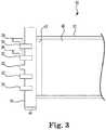
- Figures 3 , 4 and 5are partial cross-sectional perspective views of oxygenator 10.
- Figure 3shows the oxygenator 10 with both restriction elements 32, 34, in an open or inactivated configuration.
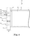
- Figure 4shows the same view as in Figure 3 , but with restriction element 32 being in a closed or activated configuration.
- Figure 5shows the same view again as in Figures 3 and 4 , but with restriction element 34 being in a closed or activated configuration.
- Figures 3 , 4 and 5show cross-sectional views of circular-shaped, restriction elements 32, 34, with rigid levers 36, 38 attached, respectively.
- the levers 36, 38 that are attached to or an extension of restriction elements 32, 34are one example of a feature that may be used to move the restriction elements between an inactivated configuration and an activated configuration or vice versa.
- Other methods or structural features that would allow the restriction elements to be moveable between the two configurationsare also contemplated by the invention.
- a pre-loaded spring(not shown) may be provided in order to move the restriction elements between an open and a closed position.
- a snap(not shown) may be used to fix the restriction elements in an open or a closed position.
- FIGs 8A and 8BAnother alternative restriction element is shown in Figures 8A and 8B , and is described in detail below.
- Fiber bundle 40made up of a plurality of hollow fibers (not shown individually), is shown with a potting 42 on first ends of the hollow fibers.
- a gas inlet compartment 44is formed within first end cap 14 between the gas inlet 22 and potting 42. The gas-holding capacity or size of the gas inlet compartment 44 is determined by whether the restriction elements 32, 34 are activated or not.
- Figure 4shows restriction element 32 in the closed or activated configuration.
- the levers 36, 38may be pushed, which moves the restriction elements 32, 34 inward through the gas inlet compartment 44 and towards potting 42.
- the portion of the gas inlet compartment 44 that is capable of filling with the gas or oxygen supplyis reduced.
- the portion of the hollow fibers in fiber bundle 40 that are able to be reached by the oxygen supplyis reduced.
- Oxygen supply coming in through gas inlet 22is only able to reach the portion of the hollow fibers in fiber bundle 40 with first end openings that are located between gas inlet 22 and the activated restriction element 32 or 34.
- Figure 5shows restriction element 34 in an activated configuration.
- restriction element 32is activated, a greater number of hollow fibers would be able to receive oxygen supply in the fiber bundle in Figure 5 ; however it would still only be only a portion of the hollow fibers in the whole fiber bundle 40. Any number and locations of restriction elements may be included in embodiments of the invention, as can be accommodated by the size of the oxygenator 10.
- Figure 6is a schematic view of a portion of a cross-section of the oxygenator 10 shown in Figure 1 .
- the portion shownincludes core 50 of the housing 12, which is not shown in previous figures.
- restriction element 34is activated and in contact with potting 42. Only hollow fibers making up the fiber bundle 40 that are to the interior of the restriction element 34 are active or effective and able to receive oxygen supply.
- the dotted linesmark the outer perimeter of the active or effective fibers, which are bracketed and marked as 60 in the figure.
- This configurationis possible if a gas inlet connector (not shown) is to the interior of restriction element 34. If, however, the gas inlet connector (not shown) is to the exterior of the restriction element 34, then the hollow fibers of the fiber bundle that are to the exterior of the restriction element 34 would be active or effective and able to receive oxygen supply.
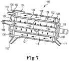
- FIG. 7is a cross-sectional view of another embodiment of an oxygenator 100 of the present invention.
- the oxygenator of the present inventioncan stand alone or, as shown, oxygenator 100 can include an integrated heat exchanger 118.
- blood flow through the heat exchanger portion 118is circumferential, while blood flow though the gas exchanger portion is longitudinal.
- the oxygenator 100includes a housing 102, a first end cap 104, and a second end cap 106.
- the oxygenator 100includes a blood inlet 108 and a blood outlet 110.
- a gas inlet 112permits oxygen to be provided to the gas exchanger portion, while a gas outlet 114 permits gases to exit the oxygenator 100.
- the oxygenator 100includes a heat exchanger core 116, a heat exchanger element 118 disposed about the heat exchanger core 116, a cylindrical shell 120 disposed about the heat exchanger element 118 and a gas exchanger element 122, all disposed inside the outer shell or housing 102.
- the heat exchanger element 118 and the gas exchanger element 122may each include a number of hollow fibers as discussed with respect to oxygenator 10 ( Figures 1-6 ).
- the housing 102includes an annular portion 124 that is in fluid communication with the blood outlet 110.
- bloodenters the blood processing apparatus or oxygenator 100 through the blood inlet 108 and passes into the heat exchanger core 116.
- the bloodfills the heat exchanger core 116 and exits through an elongate core aperture 126 and thus enters the heat exchanger element 118.
- the heat exchanger core 116includes a single elongate core aperture 126, while in other embodiments, the heat exchanger core 116 may include two or more elongate core apertures 126.
- the elongate aperture 126allows or directs blood to flow through the heat exchanger element 118 in a circumferential direction.
- the cylindrical shell 120includes an elongate collector or channel 127.
- the channel 127may be disposed at a location substantially diametrically opposed to the location of the elongate core aperture 126. Locating the channel 127 substantially opposite the location of the core aperture 126 causes blood to flow in a generally circumferential flow pattern within the heat exchanger element 118.
- the channel 127may extend from between about 1 and about 15 degrees about the circumference of the cylindrical shell 120. In one exemplary embodiment, the channel 127 extends about 5 degrees about the circumference.
- the blood flow pathcan be circumferential, as described. Some other alternatives to the blood flow path, however, include radial or longitudinal flow or combinations of circumferential, radial and/or longitudinal flow.
- the shell aperture 128,in various embodiments, extends entirely or substantially around the circumference of the cylindrical shell 120, such that blood exits the inner cylindrical shell 120 around the entire or substantially the entire circumference of the cylindrical shell 120.
- the radially disposed shell aperture 128may be located near an end of the oxygenator 100 that is opposite the blood outlet 110, thereby causing the blood to flow through the heat exchanger element 118 in a longitudinal direction. Blood then collects in the annular portion 124 before exiting the oxygenator 100 through the blood outlet 110.
- At least one restriction element 132would be located radially outward from, and circumferentially surround, the gas inlet 112. Restriction element 132 would include a lever or another activation member 136 that would allow the restriction element 132 to be moved to contact the potting of the fiber bundle in order to reduce the number of hollow fibers in the fiber bundle of the gas exchanger element 122 that receive oxygen supply.
- the embodiment shown in Figure 7is one exemplary integrated oxygenator and heat exchanger.
- the oxygenator of the present inventionmay or may not include a heat exchanger component.
- other embodiments of integrated oxygenators and heat exchangersare contemplated by the invention that may include other configurations and blood flow patterns.
- the embodiment shown in Figure 7is one example.
- Figures 8A and 8Bshow two different cross-sections of another embodiment of the gas exchanger, or oxygenator, of the present invention.
- Figure 8Ais a partial cross-section of the gas exchanger 200 taken longitudinally
- Figure 8Bis a cross-section taken at line B-B from Figure 8A .
- the oxygenator 200has a housing 212 surrounding a plurality of hollow fibers 240 (not shown individually).
- a pottingis shown by 210.
- One end cap 214is shown that includes a gas inlet 222.
- a generally circular-shaped restriction element 250is included in the end cap 214. The restriction element 250 is able to be rotated in two directions as shown by the arrow on Figure 8B .
- Restriction element 250includes a plurality of holes 243 or passages that may be lined up or not lined up with holes or passages 233 in stationary element 232 that may be located either radially inward or outward from restriction element 250.
- the holes 243 and 233may or may not be lined up. If the holes 243 and 233 are lined up then gas will flow through the whole fiber bundle. If the holes 233 and 243 are not lined up, then the gas may only reach the fibers in the portion of the fiber bundle that is located radially outward from the restriction element 250. This is one more exemplary embodiment of the gas exchanger of the present invention.
- the present inventionallows the use of one device for a range of sizes of neonatal patients.
- the deviceallows for ease in setting appropriate gas exchange performances based on specific patient dimensions, thereby avoiding excess carbon dioxide removal, particularly for very small patients (size 5 kg or less, for example).
- Gas exchangemay be set based on the amount of fiber bundle that is active or used, based on whether or not a restriction element is activated or not. With no restriction elements activated, the percentage of the fiber bundle that is active or used is about 100%. If one restriction element is activated, the percentage of the fiber bundle that is active or used is about 50%,for example. If there are two restriction elements included in the device, then the percentage of active fiber bundle could be either about 33% or about 66%, for example, depending on which restriction element is activated. The percentages of fiber bundle that may be active or used may be varied as well as the number and location of the restriction element or elements.
- Another embodiment of the inventionis a method of oxygenation or oxygenating blood.
- the stepsmay comprise providing an oxygenator comprising: an oxygenator housing including an outer wall and a core which defines an inner wall and having a blood inlet for receiving a blood supply and a blood outlet, the oxygenator housing defining an oxygenator volume; a hollow fiber bundle disposed within the housing between the core and the outer wall, the hollow fiber bundle comprising hollow gas permeable fibers, each fiber having first and second ends and a hollow interior; a gas inlet compartment for receiving an oxygen supply and directing the oxygen supply to the first ends of the hollow gas permeable fibers; wherein the gas inlet compartment includes at least one restriction element configured to allow the oxygen supply to reach only a portion of the hollow gas permeable fibers.
- the oxygenatormay alternatively be any embodiment as described, suggested or shown herein, or any other suitable oxygenator.
- the methodmay further comprise: activating at least one restriction element; causing an oxygen supply to flow through the hollow interior of the portion of the hollow gas permeable fibers; delivering blood to the oxygenator through the blood inlet; causing the blood to flow through the oxygenation housing over the exterior of the hollow gas permeable fibers; and discharging the blood through the blood outlet.
- Other methods of oxygenationare also contemplated by the invention.
Landscapes
- Health & Medical Sciences (AREA)
- Heart & Thoracic Surgery (AREA)
- Urology & Nephrology (AREA)
- Vascular Medicine (AREA)
- Emergency Medicine (AREA)
- Hematology (AREA)
- Anesthesiology (AREA)
- Biomedical Technology (AREA)
- Engineering & Computer Science (AREA)
- Life Sciences & Earth Sciences (AREA)
- Animal Behavior & Ethology (AREA)
- General Health & Medical Sciences (AREA)
- Public Health (AREA)
- Veterinary Medicine (AREA)
- Chemical & Material Sciences (AREA)
- Chemical Kinetics & Catalysis (AREA)
- Cardiology (AREA)
- External Artificial Organs (AREA)
Description
- The present invention relates generally to extracorporeal fluid circuits. More specifically, the invention relates to an oxygenator, or gas exchanger, used in such circuits having at least one restriction element that allows for a reduction in gas exchange to avoid hypo-capnia and hyper-oxygenation in small patients. Known oxygenator examples can be found in
DE 10 2007 010 112 A1 ,DE 10 2010 027 973 A1US 2003/175149 A1 , andWO 99/58171 A1 - The disclosure pertains generally to blood processing units used in blood perfusion systems. Blood perfusion entails encouraging blood through the vessels of the body. For such purposes, blood perfusion systems typically entail the use of one or more pumps in an extracorporeal circuit that is interconnected with the vascular system of a patient. Cardiopulmonary bypass surgery typically requires a perfusion system that provides for the temporary cessation of the heart to create a still operating field by replacing the function of the heart and lungs. Such isolation allows for the surgical correction of vascular stenosis, valvular disorders, and congenital heart defects. In perfusion systems used for cardiopulmonary bypass surgery, an extracorporeal blood circuit is established that includes at least one pump and an oxygenation device to replace the functions of the heart and lungs.
- More specifically, in cardiopulmonary bypass procedures oxygen-poor blood, i.e., venous blood, is gravity-drained or vacuum suctioned from a large vein entering the heart or other veins in the body (e.g., femoral) and is transferred through a venous line in the extracorporeal circuit. The venous blood is pumped to an oxygenator that provides for oxygen transfer to the blood. Oxygen may be introduced into the blood by transfer across a membrane or, less frequently, by bubbling oxygen through the blood. Concurrently, carbon dioxide is removed across the membrane. The oxygenated blood is filtered and then returned through an arterial line to the aorta, femoral artery, or other artery.
- In small patients, particularly neonatal patients, with low blood volumes, if a standard sized oxygenator is used during cardiopulmonary bypass, excessive carbon dioxide removal and excessive oxygen delivery can result. Excessive carbon dioxide removal can lead to a deleterious change of pH of the blood out of the physiological levels. Avoiding excessive carbon dioxide removal and excessive oxygen delivery is, therefore, desired.
- The invention is defined by the appended claims.
- While multiple embodiments are disclosed, still other embodiments of the present invention will become apparent to those skilled in the art from the following detailed description, which shows and describes illustrative embodiments of the invention. Accordingly, the drawings and detailed description are to be regarded as illustrative in nature and not restrictive.
Figure 1 is a perspective view of an oxygenator, or gas exchanger, in accordance with an embodiment of the invention.Figure 2 is a cross-sectional view of the oxygenator ofFigure 1 taken at 2-2.Figure 3 is a partial cross-sectional view of an oxygenator in accordance with an embodiment of the invention.Figure 4 is a partial cross-sectional view of an oxygenator in accordance with an embodiment of the invention.Figure 5 is a partial cross-sectional view of an oxygenator in accordance with an embodiment of the invention.Figure 6 is a schematic cross-sectional view of an oxygenator in accordance with an embodiment of the invention.Figure 7 is a cross-sectional view of an embodiment of an oxygenator in accordance with an embodiment of the invention.Figure 8A is a partial cross-sectional view of an oxygenator in accordance with an embodiment of the invention.Figure 8B is a cross-sectional view of the oxygenator ofFigure 8A taken at B-B.- While the invention is amenable to various modifications and alternative forms, specific embodiments have been shown by way of example in the drawings and are described in detail below. The intention, however, is not to limit the invention to the particular embodiments described. On the contrary, the invention is intended to cover all modifications, equivalents, and alternatives falling within the scope of the invention as defined by the appended claims.
- The disclosure pertains to an oxygenator (also commonly referred to as a gas exchanger). In some embodiments, an oxygenator may be used in an extracorporeal blood circuit. An extracorporeal blood circuit, such as may be used in a bypass procedure, may include several different elements such as a heart-lung machine, a blood reservoir, a heat exchanger, as well as an oxygenator. In various embodiments, the gas exchanger, or oxygenator, includes one or more restriction elements that allow for a reduction in gas transfer performance of the oxygenator in order to avoid hypo-capnia and hyper-oxygenation in patients, particularly small or neonatal patients. In various embodiments, one or more restriction elements are configured to be activated to allow an oxygen supply to reach only a portion of hollow gas permeable fibers, thereby reducing the amount of gas exchange performed by the oxygenator.
Figure 1 is a schematic illustration of an oxygenator 10 (or "gas exchanger"). While the internal components are not visible in the illustration, theoxygenator 10 will include a fiber bundle inside where gas exchange takes place. Theoxygenator 10 includes ahousing 12, afirst end cap 14 that is secured to thehousing 12 and asecond end cap 16 that is secured to thehousing 12. In some embodiments, thehousing 12 may include other structures that enable attachment of thehousing 12 to other devices. While thehousing 12 is largely cylindrical in shape, in some embodiments, thehousing 12 may have a triangular, rectangular or other parallelogram cross-sectional shape, for example. The fiber bundle inside may have generally the same sectional shape as thehousing 12 or may have a different sectional shape.- In some embodiments, a
blood inlet 18 extends into thehousing 12 and ablood outlet 20 exits thehousing 12. As noted, theoxygenator 10 includes a fiber bundle inside where gas exchange takes place, and thus includes agas inlet 22 and agas outlet 24. In some embodiments, theoxygenator 10 may include one ormore purge ports 30 that may be used for purging air bubbles from the interior of theoxygenator 10. - The positions of the blood and gas inlets and outlets, and the
purge port 30 inFigure 1 are merely illustrative, as other arrangements and configurations are also contemplated. Thepurge port 30 may include a valve or a threaded cap. Thepurge port 30 operates to permit gases (e.g., air bubbles) that exit the blood to be vented or aspirated and removed from theoxygenator 10. - The
housing 12 is preferably made of a rigid plastic in order for theoxygenator 10 to be sturdy yet lightweight. The oxygenator is also preferably mainly transparent, in order to allow the user to see through the oxygenator. Therefore, a preferred material for the oxygenator is a transparent, amorphous polymer. One exemplary type of such a material is a polycarbonate, an ABS (Acrylonitrile Butadiene Styrene), or a co-polyester. Other suitable materials for the housing are also contemplated. - The fiber bundle (not shown in
Figure 1 ) insidehousing 12 may include a number or plurality of microporous hollow fibers through which a gas such as oxygen may flow. The blood may flow around and past the hollow fibers. Due to concentration gradients, oxygen may diffuse through the microporous, semi-permeable hollow fibers into the blood while carbon dioxide may diffuse into the hollow fibers and out of the blood. - In some embodiments, the hollow fibers are made of semi-permeable membrane including micropores. Preferably, the fibers comprise polypropylene, polyester, or any other suitable polymer or plastic material. According to various embodiments, the hollow fibers may have an outer diameter of about 0.25 to about 0.3 millimeters. According to other embodiments, the microporous hollow fibers may have a diameter of between about 0.2 and 1.0 millimeters, or more specifically, between about 0.25 and 0.5 millimeters. The hollow fibers may be woven into mats that can range from about 50 to about 200 millimeters in width. In some embodiments, the mats are in a criss-cross configuration. The fiber bundle may be formed of hollow fibers in a variety of winding patterns or structures.
- The hollow fibers are embedded, or sealed, at their ends, in rings of polyurethane resin, for example, which is known as "potting." The fiber bundle of hollow fibers is preferably in a cylindrical shape, but other shapes are also contemplated. The hollow fibers, at first ends, are connected to the
first end cap 14 through the potting, with thegas inlet 22 being located in thefirst end cap 14. At second ends, the hollow fibers are connected to thesecond end cap 16 through the potting with thegas outlet 24 being located in thesecond end cap 16. The internal lumens of the fibers are part of the gas pathway that is determined by thefist end cap 14, the potting at the first end, the fibers, the second potting and thesecond end cap 16. The oxygenator chamber is thus defined by the housing as an outer wall and an inner wall or core, together with the pottings at each end of the hollow fibers. - Oxygen, or a mixture of oxygen and air, known as an oxygen supply, enters through
gas inlet 22, passes through the microporous hollow fibers within the fiber bundle, and exits theoxygenator 10 through thegas outlet 24. In some embodiments, the pressure or flow rate of oxygen through the oxygenator may be varied in order to achieve a desired diffusion rate of, for example, carbon dioxide diffusing out of the blood and oxygen diffusing into the blood. In some embodiments, as illustrated, the oxygen flows through the hollow fibers while the blood flows around and over the hollow fibers. - Differences in concentration of gases between the blood and the oxygen supply produce a diffusive flow of oxygen toward the blood and of carbon dioxide from the blood in the opposite direction. The carbon dioxide reaches the
gas outlet 24 and is discharged from theoxygenator 10. - Any suitable gas supply (or oxygen supply) system may be used with the
oxygenator 10 of the invention, in order to deliver an oxygen supply to the fiber bundle or hollow fibers ofoxygenator 10. Such a gas supply system may also include, for example, flow regulators, flow meters, a gas blender, an oxygen analyzer, a gas filter, and a moisture trap. Other alternative or additional components in the gas supply system are also contemplated. - As shown in
Figure 1 , in some embodiments, structural features may be included withinoxygenator 10, and specifically within thefirst end cap 14 in the figure, that allow an oxygen supply delivered to theoxygenator 10 to reach only a portion of the hollow fibers in the fiber bundle where gas exchange takes place. The restriction elements are configured to be either in an open/inactivated position or a closed/activated position. Moving the at least one restriction element to a closed or activated position will result in an oxygen supply being delivered to only a portion of the hollow fibers in the fiber bundle, and thereby will reduce gas transfer performance. The invention provides a way to decrease gas exchange efficiency of theoxygenator 10 in order to avoid excessive carbon dioxide removal and excessive oxygen delivery to small patients, including neonatal patients. Figure 1 shows two restriction elements,first restriction element 32 andsecond restriction element 34, extending from or withinfirst end cap 14. Although two restriction elements are shown, it is contemplated that any number of restriction elements may be included in the invention such that the size of thefirst end cap 14 may accommodate the restriction elements. The figure also shows two levers orarms restriction elements 32, which are used to move the restriction elements between a restricted or closed configuration and an unrestricted or open configuration. Levers orarms restriction elements Figure 2 is a cross-sectional view of thefirst end cap 14 shown in the embodiment of the invention inFigure 1 taken at line 2-2.Figure 2 shows thatrestriction elements gas inlet 22. The circular shape is one exemplary cross-sectional shape of therestriction elements restriction elements end cap 14. The silicone or rubber-like material of the restriction elements may also be supported by a rigid material in order to provide rigidity to the gasket and allow it to open and close.Figures 3 ,4 and5 are partial cross-sectional perspective views ofoxygenator 10.Figure 3 shows theoxygenator 10 with bothrestriction elements Figure 4 shows the same view as inFigure 3 , but withrestriction element 32 being in a closed or activated configuration.Figure 5 shows the same view again as inFigures 3 and4 , but withrestriction element 34 being in a closed or activated configuration.Figures 3 ,4 and5 show cross-sectional views of circular-shaped,restriction elements rigid levers levers restriction elements Figures 8A and 8B , and is described in detail below.Fiber bundle 40, made up of a plurality of hollow fibers (not shown individually), is shown with a potting 42 on first ends of the hollow fibers. Agas inlet compartment 44 is formed withinfirst end cap 14 between thegas inlet 22 andpotting 42. The gas-holding capacity or size of thegas inlet compartment 44 is determined by whether therestriction elements Figure 4 showsrestriction element 32 in the closed or activated configuration. In order to activate therestriction elements levers restriction elements gas inlet compartment 44 and towardspotting 42. Once therestriction elements gas inlet compartment 44 that is capable of filling with the gas or oxygen supply is reduced. Also, the portion of the hollow fibers infiber bundle 40 that are able to be reached by the oxygen supply is reduced. Oxygen supply coming in throughgas inlet 22 is only able to reach the portion of the hollow fibers infiber bundle 40 with first end openings that are located betweengas inlet 22 and the activatedrestriction element Figure 5 showsrestriction element 34 in an activated configuration. Compared toFigure 4 , whererestriction element 32 is activated, a greater number of hollow fibers would be able to receive oxygen supply in the fiber bundle inFigure 5 ; however it would still only be only a portion of the hollow fibers in thewhole fiber bundle 40. Any number and locations of restriction elements may be included in embodiments of the invention, as can be accommodated by the size of theoxygenator 10.Figure 6 is a schematic view of a portion of a cross-section of theoxygenator 10 shown inFigure 1 . The portion shown includescore 50 of thehousing 12, which is not shown in previous figures. InFigure 6 ,restriction element 34 is activated and in contact withpotting 42. Only hollow fibers making up thefiber bundle 40 that are to the interior of therestriction element 34 are active or effective and able to receive oxygen supply. The dotted lines mark the outer perimeter of the active or effective fibers, which are bracketed and marked as 60 in the figure. This configuration is possible if a gas inlet connector (not shown) is to the interior ofrestriction element 34. If, however, the gas inlet connector (not shown) is to the exterior of therestriction element 34, then the hollow fibers of the fiber bundle that are to the exterior of therestriction element 34 would be active or effective and able to receive oxygen supply.Figure 7 is a cross-sectional view of another embodiment of anoxygenator 100 of the present invention. The oxygenator of the present invention can stand alone or, as shown,oxygenator 100 can include anintegrated heat exchanger 118. In the particular embodiment shown, blood flow through theheat exchanger portion 118 is circumferential, while blood flow though the gas exchanger portion is longitudinal. Other arrangements are contemplated, however. As shown inFigure 7 , theoxygenator 100 includes ahousing 102, afirst end cap 104, and asecond end cap 106. Theoxygenator 100 includes ablood inlet 108 and ablood outlet 110. Agas inlet 112 permits oxygen to be provided to the gas exchanger portion, while agas outlet 114 permits gases to exit theoxygenator 100.- The
oxygenator 100 includes aheat exchanger core 116, aheat exchanger element 118 disposed about theheat exchanger core 116, acylindrical shell 120 disposed about theheat exchanger element 118 and agas exchanger element 122, all disposed inside the outer shell orhousing 102. Theheat exchanger element 118 and thegas exchanger element 122 may each include a number of hollow fibers as discussed with respect to oxygenator 10 (Figures 1-6 ). In some embodiments, thehousing 102 includes anannular portion 124 that is in fluid communication with theblood outlet 110. - In use, blood enters the blood processing apparatus or
oxygenator 100 through theblood inlet 108 and passes into theheat exchanger core 116. The blood fills theheat exchanger core 116 and exits through anelongate core aperture 126 and thus enters theheat exchanger element 118. In some embodiments, theheat exchanger core 116 includes a singleelongate core aperture 126, while in other embodiments, theheat exchanger core 116 may include two or moreelongate core apertures 126. In some embodiments, theelongate aperture 126 allows or directs blood to flow through theheat exchanger element 118 in a circumferential direction. - As shown in
Figure 7 , according to some embodiments, thecylindrical shell 120 includes an elongate collector orchannel 127. Thechannel 127 may be disposed at a location substantially diametrically opposed to the location of theelongate core aperture 126. Locating thechannel 127 substantially opposite the location of thecore aperture 126 causes blood to flow in a generally circumferential flow pattern within theheat exchanger element 118. Thechannel 127 may extend from between about 1 and about 15 degrees about the circumference of thecylindrical shell 120. In one exemplary embodiment, thechannel 127 extends about 5 degrees about the circumference. The blood flow path can be circumferential, as described. Some other alternatives to the blood flow path, however, include radial or longitudinal flow or combinations of circumferential, radial and/or longitudinal flow. - After blood passes through the
heat exchanger element 118, it collects in thechannel 127 and flows into anannular shell aperture 128. Theshell aperture 128, in various embodiments, extends entirely or substantially around the circumference of thecylindrical shell 120, such that blood exits the innercylindrical shell 120 around the entire or substantially the entire circumference of thecylindrical shell 120. In some embodiments, the radially disposedshell aperture 128 may be located near an end of theoxygenator 100 that is opposite theblood outlet 110, thereby causing the blood to flow through theheat exchanger element 118 in a longitudinal direction. Blood then collects in theannular portion 124 before exiting theoxygenator 100 through theblood outlet 110. - At least one
restriction element 132, as in the embodiment shown inFigure 7 , would be located radially outward from, and circumferentially surround, thegas inlet 112.Restriction element 132 would include a lever or anotheractivation member 136 that would allow therestriction element 132 to be moved to contact the potting of the fiber bundle in order to reduce the number of hollow fibers in the fiber bundle of thegas exchanger element 122 that receive oxygen supply. - The embodiment shown in
Figure 7 is one exemplary integrated oxygenator and heat exchanger. The oxygenator of the present invention may or may not include a heat exchanger component. Also, other embodiments of integrated oxygenators and heat exchangers are contemplated by the invention that may include other configurations and blood flow patterns. The embodiment shown inFigure 7 is one example. Figures 8A and 8B show two different cross-sections of another embodiment of the gas exchanger, or oxygenator, of the present invention.Figure 8A is a partial cross-section of thegas exchanger 200 taken longitudinally, andFigure 8B is a cross-section taken at line B-B fromFigure 8A . Theoxygenator 200 has ahousing 212 surrounding a plurality of hollow fibers 240 (not shown individually). A potting is shown by 210. Oneend cap 214 is shown that includes agas inlet 222. A generally circular-shapedrestriction element 250 is included in theend cap 214. Therestriction element 250 is able to be rotated in two directions as shown by the arrow onFigure 8B .Restriction element 250 includes a plurality ofholes 243 or passages that may be lined up or not lined up with holes orpassages 233 instationary element 232 that may be located either radially inward or outward fromrestriction element 250. Depending on whether or not the whole fiber bundle or only a portion of the fiber bundle is desired to be used for a particular patient, theholes holes holes restriction element 250. This is one more exemplary embodiment of the gas exchanger of the present invention.- The present invention allows the use of one device for a range of sizes of neonatal patients. The device allows for ease in setting appropriate gas exchange performances based on specific patient dimensions, thereby avoiding excess carbon dioxide removal, particularly for very small patients (size 5 kg or less, for example). Gas exchange may be set based on the amount of fiber bundle that is active or used, based on whether or not a restriction element is activated or not. With no restriction elements activated, the percentage of the fiber bundle that is active or used is about 100%. If one restriction element is activated, the percentage of the fiber bundle that is active or used is about 50%,for example. If there are two restriction elements included in the device, then the percentage of active fiber bundle could be either about 33% or about 66%, for example, depending on which restriction element is activated. The percentages of fiber bundle that may be active or used may be varied as well as the number and location of the restriction element or elements.
- Another embodiment of the invention is a method of oxygenation or oxygenating blood. The steps may comprise providing an oxygenator comprising: an oxygenator housing including an outer wall and a core which defines an inner wall and having a blood inlet for receiving a blood supply and a blood outlet, the oxygenator housing defining an oxygenator volume; a hollow fiber bundle disposed within the housing between the core and the outer wall, the hollow fiber bundle comprising hollow gas permeable fibers, each fiber having first and second ends and a hollow interior; a gas inlet compartment for receiving an oxygen supply and directing the oxygen supply to the first ends of the hollow gas permeable fibers; wherein the gas inlet compartment includes at least one restriction element configured to allow the oxygen supply to reach only a portion of the hollow gas permeable fibers. The oxygenator may alternatively be any embodiment as described, suggested or shown herein, or any other suitable oxygenator. The method may further comprise: activating at least one restriction element; causing an oxygen supply to flow through the hollow interior of the portion of the hollow gas permeable fibers; delivering blood to the oxygenator through the blood inlet; causing the blood to flow through the oxygenation housing over the exterior of the hollow gas permeable fibers; and discharging the blood through the blood outlet. Other methods of oxygenation are also contemplated by the invention.
- Various modifications and additions can be made to the exemplary embodiments discussed without departing from the scope of the present invention. For example, while the embodiments described above refer to particular features, the scope of this invention also includes embodiments having different combinations of features and embodiments that do not include all of the described features. Accordingly, the scope of the present invention is intended to embrace all such alternatives, modifications, and variations as fall within the scope of the claims.
Claims (15)
- A gas exchanger (10; 100) comprising:a gas exchanger housing (12; 102) including an outer wall, at least one lid, and a gas exchanger core which defines an inner wall and having a blood inlet for receiving a blood supply and a blood outlet, the gas exchanger housing (12; 102) defining a gas exchanger volume;a hollow fiber bundle (40) disposed within the housing (12; 102) between the gas exchanger core and the outer wall, the hollow fiber bundle (40) comprising hollow gas permeable fibers, each fiber having first and second ends and a hollow interior, wherein the first ends of the hollow gas permeable fibers are located in a first potting (42) that is located at or near the lid; anda gas inlet compartment (44) including a gas inlet (22; 112) for receiving an oxygen supply and directing the oxygen supply to the first ends of the hollow gas permeable fibers;characterized in that the gas inlet compartment (44) includes at least one restriction element (32, 34; 132) that concentrically surrounds the gas inlet (22; 112), wherein the one or more restriction elements (32, 34; 132) are moveable such that the one or more restriction elements (32, 34; 132) can assume a first position that is open in order to allow the oxygen supply to reach all of the first ends (14) of the hollow gas permeable fibers and a second position that is compressed against the first potting (42) such that the oxygen supply only reaches a portion of the hollow gas permeable fibers (40).
- The gas exchanger (10; 100) of claim 1, further comprising at least one rigid lever (36; 136) that is connected to the at least one restriction element (32, 34; 132) and that is configured to move the at least one restriction element (32, 34; 132) between the first and second positions.
- The gas exchanger (10; 100) of claim 1, wherein the gas inlet compartment (44) is located within the at least one lid.
- The gas exchanger (10) of claim 1, wherein the oxygenator includes at least two restriction elements (32; 34) and the at least two restriction elements are concentrically arranged.
- The gas exchanger (10; 100) of Claim 1, wherein the hollow fibers (40), at first ends, are connected to a first lid (14) through the first potting (42), with the gas inlet (22; 112) being located in the first lid (14), and wherein the hollow fibers (40), at second ends, are connected to a second lid (16) through a second potting.
- The gas exchanger (10) of claim 1 or Claim 5, wherein the at least one restriction element comprises a gasket.
- The gas exchanger (10) of Claim 6, wherein said gasket is made of a silicone or soft rubber-like material that is able to provide an airtight seal with a polymeric wall of the first end cap (14).
- The gas exchanger (10) of Claim 7, wherein the silicone or rubber-like material of the restriction elements (32, 34) is supported by a rigid material in order to provide rigidity to the gasket and allow it to open and close.
- The gas exchanger (100) of Claim 1, further including an integrated heat exchanger (118)
- The gas exchanger (100) of Claim 9, including a heat exchanger core (116), a heat exchanger element (118) disposed about the heat exchanger core (116), a cylindrical shell (120) disposed about the heat exchanger element (118) and the hollow fiber bundle (122), all disposed inside the housing (102).
- The gas exchanger (100) of Claim 10, wherein the heat exchanger element (118) and the hollow fiber bundle (122) each include a number of hollow fibers.
- The gas exchanger (100) of Claim 10 or Claim 11, wherein the housing (102) includes an annular portion (124) that is in fluid communication with the blood outlet (110).
- The gas exchanger of any of Claims 10 to 12, wherein the cylindrical shell (120) includes an elongate core aperture (126) and an elongate channel (127), wherein the elongate channel (127) is disposed at a location diametrically opposed to the location of the elongate core aperture (126).
- The gas exchanger (100) of Claim 13, wherein the elongate channel (127) extends from between about 1 and about 15 degrees about the circumference of the cylindrical shell (120).
- The gas exchanger (10; 100) of claim 1, wherein 50% of the fiber bundle is provided with oxygen supply for a small, neonatal patient when the one or more restriction elements (32, 34; 132) element are in the second position.
Priority Applications (1)
| Application Number | Priority Date | Filing Date | Title |
|---|---|---|---|
| EP19161228.2AEP3520836B1 (en) | 2015-05-12 | 2015-05-12 | Blood gas exchanger with restriction element or elements to reduce gas exchange |
Applications Claiming Priority (3)
| Application Number | Priority Date | Filing Date | Title |
|---|---|---|---|
| EP19161228.2AEP3520836B1 (en) | 2015-05-12 | 2015-05-12 | Blood gas exchanger with restriction element or elements to reduce gas exchange |
| PCT/IB2015/053493WO2016181189A1 (en) | 2015-05-12 | 2015-05-12 | Blood gas exchanger with restriction element or elements to reduce gas exchange |
| EP15728631.1AEP3294368B1 (en) | 2015-05-12 | 2015-05-12 | Blood gas exchanger with restriction element or elements to reduce gas exchange |
Related Parent Applications (2)
| Application Number | Title | Priority Date | Filing Date |
|---|---|---|---|
| EP15728631.1ADivision-IntoEP3294368B1 (en) | 2015-05-12 | 2015-05-12 | Blood gas exchanger with restriction element or elements to reduce gas exchange |
| EP15728631.1ADivisionEP3294368B1 (en) | 2015-05-12 | 2015-05-12 | Blood gas exchanger with restriction element or elements to reduce gas exchange |
Publications (2)
| Publication Number | Publication Date |
|---|---|
| EP3520836A1 EP3520836A1 (en) | 2019-08-07 |
| EP3520836B1true EP3520836B1 (en) | 2021-07-07 |
Family
ID=53385697
Family Applications (2)
| Application Number | Title | Priority Date | Filing Date |
|---|---|---|---|
| EP15728631.1AActiveEP3294368B1 (en) | 2015-05-12 | 2015-05-12 | Blood gas exchanger with restriction element or elements to reduce gas exchange |
| EP19161228.2AActiveEP3520836B1 (en) | 2015-05-12 | 2015-05-12 | Blood gas exchanger with restriction element or elements to reduce gas exchange |
Family Applications Before (1)
| Application Number | Title | Priority Date | Filing Date |
|---|---|---|---|
| EP15728631.1AActiveEP3294368B1 (en) | 2015-05-12 | 2015-05-12 | Blood gas exchanger with restriction element or elements to reduce gas exchange |
Country Status (5)
| Country | Link |
|---|---|
| US (3) | US10661004B2 (en) |
| EP (2) | EP3294368B1 (en) |
| JP (1) | JP6535108B2 (en) |
| CN (1) | CN107635597B (en) |
| WO (1) | WO2016181189A1 (en) |
Families Citing this family (15)
| Publication number | Priority date | Publication date | Assignee | Title |
|---|---|---|---|---|
| EP2612685B1 (en) | 2010-08-19 | 2014-10-08 | Sorin Group Italia S.r.l. | Blood processing unit with modified flow path |
| WO2015128886A1 (en) | 2014-02-28 | 2015-09-03 | Sorin Group Italia S.R.L. | System for providing an integrated arterial filter into an oxygenator, minimizing added priming volume |
| EP3218087A1 (en) | 2014-11-12 | 2017-09-20 | Sorin Group Italia S.r.l. | Elastic protection tube for a hollow fibre blood processing apparatus |
| EP3294368B1 (en)* | 2015-05-12 | 2019-06-26 | Sorin Group Italia S.r.l. | Blood gas exchanger with restriction element or elements to reduce gas exchange |
| HK1256700A1 (en) | 2015-11-06 | 2019-10-04 | 羊膜生命公司 | Premature infant amniotic bath incubator |
| DE102016010398A1 (en)* | 2016-06-10 | 2017-12-14 | Hemovent Gmbh | Gas exchange unit, method for manufacturing a gas exchange unit and set with a gas exchange unit and a humidifying and heating device |
| CN115998976A (en)* | 2017-08-15 | 2023-04-25 | 马里兰大学巴尔的摩 | Dual chamber gas exchanger and method for respiratory support |
| JP6948465B2 (en)* | 2017-10-10 | 2021-10-13 | ソリン・グループ・イタリア・ソシエタ・ア・レスポンサビリタ・リミタータSorin Group Italia S.r.l. | Blood processing unit (BPU) with countercurrent blood / water flow path in heat exchanger (HEX) |
| US10441490B2 (en) | 2018-01-09 | 2019-10-15 | Amnion Life, LLC | Systems, methods, and devices for artificial placentas and amniotic bed incubators |
| JP7288454B2 (en)* | 2018-03-02 | 2023-06-07 | スペクトラム メディカル リミテッド | oxygenation system |
| GB2582239B (en)* | 2018-11-06 | 2022-09-07 | Spectrum Medical Ltd | Oxygenation system |
| EP4252794A1 (en)* | 2019-01-29 | 2023-10-04 | Nipro Corporation | Artificial lung device |
| JP7293671B2 (en)* | 2019-01-29 | 2023-06-20 | ニプロ株式会社 | Oxygenator |
| JP7310286B2 (en)* | 2019-05-14 | 2023-07-19 | ニプロ株式会社 | Oxygenator |
| GB2583532B (en) | 2019-05-03 | 2023-04-05 | Spectrum Medical Ltd | Control system |
Family Cites Families (101)
| Publication number | Priority date | Publication date | Assignee | Title |
|---|---|---|---|---|
| US3339341A (en) | 1965-12-22 | 1967-09-05 | Du Pont | Fluid separation process and apparatus |
| FR2214502B1 (en) | 1973-01-18 | 1976-05-14 | Rhone Poulenc Ind | |
| FR2231421B1 (en) | 1973-05-30 | 1976-05-07 | Rhone Poulenc Ind | |
| SE421999B (en) | 1977-10-17 | 1982-02-15 | Gambro Dialysatoren | DEVICE FOR DIFFUSION AND / OR FILTRATION OF THE SUBSTANCE BETWEEN TWO FLUIDS THROUGH SEMIPERMEABLE MEMBRANE, WHICH DEVICE INCLUDES PARALLEL CONNECTED CIRCUITS INCLUDING SERIAL CONNECTED CHAMBERS |
| IT1091268B (en) | 1977-12-15 | 1985-07-06 | Hospal Dasco Spa | REFINEMENT TO A HEMODIALIZER |
| JPS5935631B2 (en) | 1980-07-24 | 1984-08-29 | テルモ株式会社 | Body fluid “filtration” device |
| JPS5759547A (en)* | 1980-09-26 | 1982-04-09 | Terumo Corp | Hollow fiber type artificial lung |
| US4707268A (en) | 1982-10-18 | 1987-11-17 | Baxter Travenol Laboratories, Inc. | Hollow fiber potted microfilter |
| US4902476A (en) | 1983-01-14 | 1990-02-20 | Baxter International Inc. | Heat exchanger and blood oxygenator apparatus |
| JPS6053156A (en) | 1983-09-01 | 1985-03-26 | 三菱レイヨン株式会社 | blood purifier |
| EP0312125B1 (en) | 1983-11-11 | 1992-03-04 | TERUMO KABUSHIKI KAISHA trading as TERUMO CORPORATION | Device for receiving and treating blood |
| US4639353A (en) | 1984-04-24 | 1987-01-27 | Mitsubishi Rayon Co., Ltd. | Blood oxygenator using a hollow-fiber membrane |
| CA1258436A (en) | 1984-08-01 | 1989-08-15 | Michael A. Smoot | Mat structure for use in filtration devices |
| JPS63139562A (en) | 1986-12-01 | 1988-06-11 | 株式会社 日本メデイカル・サプライ | Hollow yarn type artificial lung |
| US4758341A (en) | 1987-04-20 | 1988-07-19 | The Dow Chemical Company | Membrane separation device |
| JPS6440060A (en) | 1987-08-06 | 1989-02-10 | Ube Industries | Artificial lung provided with built-in heat exchanger |
| JPS6476868A (en) | 1987-09-18 | 1989-03-22 | Nippon Medical Supply | Improved pump-oxygenator |
| US5120501A (en) | 1988-10-20 | 1992-06-09 | Baxter International Inc. | Integrated membrane blood oxygenator/heat exchanger |
| US5316724A (en) | 1989-03-31 | 1994-05-31 | Baxter International Inc. | Multiple blood path membrane oxygenator |
| JPH0347271A (en) | 1989-07-14 | 1991-02-28 | Terumo Corp | Liquid treatment device |
| US5578267A (en) | 1992-05-11 | 1996-11-26 | Minntech Corporation | Cylindrical blood heater/oxygenator |
| US5270004A (en) | 1989-10-01 | 1993-12-14 | Minntech Corporation | Cylindrical blood heater/oxygenator |
| EP0519132A1 (en) | 1989-10-18 | 1992-12-23 | Exxon Research And Engineering Company | Hollow fiber module |
| JPH03169329A (en) | 1989-11-30 | 1991-07-23 | Nok Corp | Production of hollow yarn module |
| JP3228518B2 (en) | 1990-12-14 | 2001-11-12 | 日機装株式会社 | Heart-lung machine |
| JPH05177117A (en) | 1991-10-23 | 1993-07-20 | Hisateru Takano | Substance exchange device |
| JP3284568B2 (en) | 1991-10-31 | 2002-05-20 | 株式会社ジェイ・エム・エス | Inlet header for oxygenator and oxygenator using it |
| US5192439A (en) | 1992-02-03 | 1993-03-09 | Electromedics, Inc. | Blood collection reservoir and filter device |
| WO1994003266A1 (en) | 1992-08-03 | 1994-02-17 | Maloney James V Jr | Improved mass and thermal transfer means for use in heart lung machines, dialyzers, and other applications |
| IT1255820B (en) | 1992-08-10 | 1995-11-16 | Nicola Ghelli | HEAT EXCHANGER IN EXTRACORPOREAL BLOOD CIRCUIT |
| US5489413A (en) | 1992-11-03 | 1996-02-06 | Cobe Laboratories, Inc. | Hollow fiber blood oxygenator |
| US5514095A (en) | 1994-04-04 | 1996-05-07 | Haemonetics Corporation | Apparatus for heating, filtering and eliminating gas from biological fluids |
| IT1271104B (en) | 1994-11-25 | 1997-05-26 | Dideco Spa | BLOOD OXYGENATOR WITH A LAYER OF MICROPOROUS MEMBRANE CAPILLARIES. |
| US5651765A (en) | 1995-04-27 | 1997-07-29 | Avecor Cardiovascular Inc. | Blood filter with concentric pleats and method of use |
| EP0765683B1 (en) | 1995-09-25 | 1998-07-01 | MEDOS Medizintechnik GmbH | Device for treating liquids, in particular blood |
| US5770149A (en) | 1995-10-31 | 1998-06-23 | Baxter International | Extracorporeal blood oxygenation system having integrated blood pump, heat exchanger and membrane oxygenator |
| US5762868A (en) | 1995-11-30 | 1998-06-09 | Minnesota Mining And Manufacturing Company | Blood oxygenator and heat exchanger |
| JPH11508476A (en) | 1996-01-11 | 1999-07-27 | メドトロニック・インコーポレーテッド | Compact membrane oxygenator with concentric heat exchanger and improved manifold |
| SE506613C2 (en) | 1996-05-30 | 1998-01-19 | Votinex Management Sa | Filter and heat exchanger device |
| US5762869A (en) | 1996-07-24 | 1998-06-09 | Gish Biomedical, Inc. | Blood oxygenator |
| WO1998022161A1 (en) | 1996-11-15 | 1998-05-28 | Scitec K.K. | Hollow fiber dialyzer |
| JPH1147268A (en) | 1997-08-06 | 1999-02-23 | Terumo Corp | Hollow fiber membrane type artificial lung |
| US6241945B1 (en) | 1998-03-16 | 2001-06-05 | Life Science Holdings, Inc. | Modular combined pump, filtration, oxygenation and/or debubbler apparatus |
| EP1076572A2 (en)* | 1998-05-08 | 2001-02-21 | Baxter International Inc. | Low prime membrane oxygenator with integrated heat exchanger/reservoir |
| US6113782A (en) | 1998-07-28 | 2000-09-05 | Terumo Cardiovascular Systems Corporation | Potting of tubular bundles in housing |
| JP3992377B2 (en) | 1998-09-18 | 2007-10-17 | テルモ株式会社 | Hollow fiber membrane oxygenator with built-in heat exchange function |
| US6454999B1 (en) | 1998-12-30 | 2002-09-24 | Cardiovention, Inc. | Integrated blood pump and oxygenator system having extended blood flow path |
| JP4041254B2 (en) | 1999-12-15 | 2008-01-30 | テルモ株式会社 | Hollow fiber membrane oxygenator |
| WO2001066237A1 (en) | 2000-03-07 | 2001-09-13 | Mat Adsorption Technologies Gmbh & Co. Kg | Module with membrane elements in a cross-flow and in a dead-end arrangement |
| US6459937B1 (en) | 2000-04-25 | 2002-10-01 | Pacesetter, Inc. | Endocardial pacing lead with detachable tip electrode assembly |
| IT1318742B1 (en) | 2000-08-08 | 2003-09-10 | Dideco Spa | BLOOD OXYGEN DEVICE IN EXTRACORPOREAL CIRCUIT. |
| US6730267B2 (en) | 2001-02-09 | 2004-05-04 | Cardiovention, Inc. | Integrated blood handling system having active gas removal system and methods of use |
| US6755894B2 (en) | 2001-05-02 | 2004-06-29 | Praxair Technology, Inc. | Hollow fiber membrane gas separation cartridge and gas purification assembly |
| US6623638B2 (en) | 2001-06-01 | 2003-09-23 | Baxter International Inc. | Hemodialyzer having improved dialysate perfusion |
| US6682698B2 (en)* | 2001-08-23 | 2004-01-27 | Michigan Critical Care Consultants, Inc. | Apparatus for exchanging gases in a liquid |
| CN100353134C (en) | 2001-09-25 | 2007-12-05 | 本田技研工业株式会社 | Heat accumulation unit and method of manufacturing the unit |
| CN2511309Y (en) | 2001-11-16 | 2002-09-18 | 广东省医疗器械研究所 | Membrane oxygen supplier |
| US20030175149A1 (en)* | 2002-03-18 | 2003-09-18 | Bruce Searles | Renewable, modifiable, membrane gas exchanger |
| ATE458511T1 (en) | 2002-12-26 | 2010-03-15 | Nipro Corp | DIALYZER AND ITS PRODUCTION PROCESS |
| JP4337573B2 (en) | 2004-02-10 | 2009-09-30 | 株式会社ジェイ・エム・エス | Heat exchanger, method for producing the same, and heart-lung machine |
| CN2772515Y (en) | 2004-04-23 | 2006-04-19 | 广东省医疗器械研究所 | Hollow fibrous coat oxygenator |
| JP4366268B2 (en) | 2004-07-23 | 2009-11-18 | テルモ株式会社 | Artificial lung |
| DE102005031582A1 (en) | 2005-07-06 | 2007-01-11 | Maquet Cardiopulmonary Ag | Device for treating blood in an extracorporeal blood circulation |
| DE102005039446B4 (en) | 2005-08-18 | 2009-06-25 | Ilias-Medical Gmbh | Device for accumulating and depleting substances in a liquid |
| US7981121B2 (en) | 2005-08-22 | 2011-07-19 | St. Jude Medical Ab | Tool and a method for attaching a cardiac stimulator lead at a desired position inside a heart |
| US20070107884A1 (en) | 2005-10-27 | 2007-05-17 | Sirkar Kamalesh K | Polymeric hollow fiber heat exchange systems |
| JP4500776B2 (en) | 2006-01-19 | 2010-07-14 | テルモ株式会社 | Artificial lung |
| EP1810704B1 (en) | 2006-01-19 | 2015-04-22 | Terumo Kabushiki Kaisha | Oxygenator |
| ITMI20060490A1 (en) | 2006-03-17 | 2007-09-18 | Eurosets Srl | INTEGRATED DEVICE FOR BLOOD RE-HEALING AND OXYGENATION IN EXTRACORPOREAL CIRCUIT |
| JP4855119B2 (en) | 2006-03-28 | 2012-01-18 | テルモ株式会社 | Filter member and artificial lung |
| JP4714082B2 (en) | 2006-06-07 | 2011-06-29 | 株式会社東芝 | Light emitting device display structure of outdoor equipment |
| DE102007010112A1 (en)* | 2007-02-28 | 2008-09-04 | Rheinisch-Westfälische Technische Hochschule Aachen | Blood oxygenator for material and/or energy exchange has at least one pump element in chamber, by which first medium can be expelled and second one sucked in |
| KR100902674B1 (en) | 2007-10-10 | 2009-06-15 | 엔에이치엔(주) | Method and system for providing document navigation service |
| JP5020111B2 (en) | 2008-02-04 | 2012-09-05 | 株式会社小松製作所 | Hydraulic control device, hydraulic control method, and adjustment method of hydraulic control device |
| US20100272606A1 (en) | 2009-04-23 | 2010-10-28 | Carpenter Walt L | Radial flow oxygenator/heat exchanger |
| JP5828170B2 (en) | 2009-04-23 | 2015-12-02 | メドトロニック,インコーポレイテッド | Radial design oxygenator with heat exchanger |
| US20100269342A1 (en) | 2009-04-23 | 2010-10-28 | Carpenter Walt L | Method of making radial design oxygenator with heat exchanger |
| US20100272607A1 (en) | 2009-04-23 | 2010-10-28 | Carpenter Walt L | Radial design oxygenator with heat exchanger and inlet mandrel |
| EP2295646B1 (en) | 2009-08-28 | 2012-06-27 | BAUER Maschinen GmbH | Drilling equipment and method |
| CN201510571U (en) | 2009-09-29 | 2010-06-23 | 山东威高新生医疗器械有限公司 | Membrane type oxygenator |
| JP5418275B2 (en) | 2010-02-15 | 2014-02-19 | ニプロ株式会社 | Heat exchanger and oxygenator with integrated heat exchanger |
| CN101837151B (en) | 2010-03-19 | 2012-07-04 | 南方医科大学珠江医院 | Two-way filling type bioreactor control system and method |
| DE102010027973A1 (en)* | 2010-04-20 | 2011-10-20 | Ilias-Medical Gmbh | Method and device for producing a membrane mode |
| US8318092B2 (en) | 2010-04-29 | 2012-11-27 | Sorin Group Italia S.R.L. | Oxygenator with integrated arterial filter |
| US8388566B2 (en) | 2010-04-29 | 2013-03-05 | Sorin Group Italia, S.r.l. | Oxygenator with integrated arterial filter including filter frame |
| AU2011258203A1 (en) | 2010-05-26 | 2013-01-10 | The Charles Stark Draper Laboratory, Inc. | Microfabricated artificial lung assist device, and methods of use and manufacture thereof |
| EP2612685B1 (en) | 2010-08-19 | 2014-10-08 | Sorin Group Italia S.r.l. | Blood processing unit with modified flow path |
| EP2524712B1 (en) | 2011-05-17 | 2018-12-12 | Sorin Group Italia S.r.l. | Blood processing unit with cross blood flow |
| WO2012066439A1 (en) | 2010-11-15 | 2012-05-24 | Sorin Group Italia S.R.L. | Blood processing unit with circumferential blood flow |
| US8518259B2 (en) | 2011-01-27 | 2013-08-27 | Medtronic, Inc. | De-airing oxygenator for treating blood in an extracorporeal blood circuit |
| CN201978219U (en) | 2011-02-09 | 2011-09-21 | 朱宗涛 | Flow-controllable blood extracorporeal circulation oxygenator |
| JP5890827B2 (en) | 2011-03-31 | 2016-03-22 | テルモ株式会社 | Artificial lung |
| US8865067B2 (en) | 2011-04-29 | 2014-10-21 | Medtronic, Inc. | Combination oxygenator and arterial filter device for treating blood in an extracorporeal blood circuit |
| US8685319B2 (en) | 2011-04-29 | 2014-04-01 | Medtronic, Inc. | Combination oxygenator and arterial filter device with a fiber bundle of continuously wound hollow fibers for treating blood in an extracorporeal blood circuit |
| US9566376B2 (en)* | 2011-05-31 | 2017-02-14 | Ahmad Ali Kashefi Khorasani | Apparatus for exchanging mass- and/or between two fluids |
| JP5844585B2 (en) | 2011-09-15 | 2016-01-20 | ソリン・グループ・イタリア・ソシエタ・ア・レスポンサビリタ・リミタータ | Blood processing unit having a modified flow path |
| US10098994B2 (en) | 2014-01-09 | 2018-10-16 | Sorin Group Italia S.R.L. | Blood processing unit with heat exchanger core for providing modified flow path |
| EP3096810B1 (en) | 2014-01-20 | 2019-05-01 | Eurosets S.r.l. | Device for the extracorporeal oxygenation of the blood of a patient |
| WO2015128886A1 (en) | 2014-02-28 | 2015-09-03 | Sorin Group Italia S.R.L. | System for providing an integrated arterial filter into an oxygenator, minimizing added priming volume |
| EP3218087A1 (en) | 2014-11-12 | 2017-09-20 | Sorin Group Italia S.r.l. | Elastic protection tube for a hollow fibre blood processing apparatus |
| EP3294368B1 (en)* | 2015-05-12 | 2019-06-26 | Sorin Group Italia S.r.l. | Blood gas exchanger with restriction element or elements to reduce gas exchange |
- 2015
- 2015-05-12EPEP15728631.1Apatent/EP3294368B1/enactiveActive
- 2015-05-12CNCN201580079806.7Apatent/CN107635597B/enactiveActive
- 2015-05-12WOPCT/IB2015/053493patent/WO2016181189A1/ennot_activeCeased
- 2015-05-12EPEP19161228.2Apatent/EP3520836B1/enactiveActive
- 2015-05-12JPJP2017558995Apatent/JP6535108B2/enactiveActive
- 2015-05-12USUS15/571,548patent/US10661004B2/enactiveActive
- 2020
- 2020-05-15USUS16/875,889patent/US12053565B2/enactiveActive
- 2024
- 2024-07-08USUS18/765,697patent/US20240358903A1/enactivePending
Also Published As
| Publication number | Publication date |
|---|---|
| US10661004B2 (en) | 2020-05-26 |
| EP3294368B1 (en) | 2019-06-26 |
| JP6535108B2 (en) | 2019-06-26 |
| US20240358903A1 (en) | 2024-10-31 |
| US12053565B2 (en) | 2024-08-06 |
| US20200276377A1 (en) | 2020-09-03 |
| CN107635597A (en) | 2018-01-26 |
| US20180133388A1 (en) | 2018-05-17 |
| WO2016181189A1 (en) | 2016-11-17 |
| CN107635597B (en) | 2020-11-27 |
| EP3294368A1 (en) | 2018-03-21 |
| JP2018518236A (en) | 2018-07-12 |
| EP3520836A1 (en) | 2019-08-07 |
Similar Documents
| Publication | Publication Date | Title |
|---|---|---|
| US20240358903A1 (en) | Blood gas exchanger with restriction element or elements to reduce gas exchange | |
| US11433168B2 (en) | Dual chamber gas exchanger and method of use for respiratory support | |
| EP2524712B1 (en) | Blood processing unit with cross blood flow | |
| EP2543403B1 (en) | Blood processing unit with circumferential blood flow | |
| US8318092B2 (en) | Oxygenator with integrated arterial filter | |
| EP2421576B1 (en) | Radial design oxygenator with heat exchanger | |
| WO2012066439A1 (en) | Blood processing unit with circumferential blood flow | |
| EP2383001B1 (en) | Oxygenator with integrated arterial filter | |
| US20100272605A1 (en) | Radial design oxygenator with heat exchanger and pump | |
| US11918719B2 (en) | Blood processing unit (BPU) with countercurrent blood/water flow paths in the heat exchanger (HEX) | |
| WO2024159000A2 (en) | Blood gas exchanger for multifunctional respiratory support |
Legal Events
| Date | Code | Title | Description |
|---|---|---|---|
| PUAI | Public reference made under article 153(3) epc to a published international application that has entered the european phase | Free format text:ORIGINAL CODE: 0009012 | |
| STAA | Information on the status of an ep patent application or granted ep patent | Free format text:STATUS: THE APPLICATION HAS BEEN PUBLISHED | |
| AC | Divisional application: reference to earlier application | Ref document number:3294368 Country of ref document:EP Kind code of ref document:P | |
| AK | Designated contracting states | Kind code of ref document:A1 Designated state(s):AL AT BE BG CH CY CZ DE DK EE ES FI FR GB GR HR HU IE IS IT LI LT LU LV MC MK MT NL NO PL PT RO RS SE SI SK SM TR | |
| STAA | Information on the status of an ep patent application or granted ep patent | Free format text:STATUS: REQUEST FOR EXAMINATION WAS MADE | |
| 17P | Request for examination filed | Effective date:20200206 | |
| RBV | Designated contracting states (corrected) | Designated state(s):AL AT BE BG CH CY CZ DE DK EE ES FI FR GB GR HR HU IE IS IT LI LT LU LV MC MK MT NL NO PL PT RO RS SE SI SK SM TR | |
| GRAP | Despatch of communication of intention to grant a patent | Free format text:ORIGINAL CODE: EPIDOSNIGR1 | |
| STAA | Information on the status of an ep patent application or granted ep patent | Free format text:STATUS: GRANT OF PATENT IS INTENDED | |
| INTG | Intention to grant announced | Effective date:20210312 | |
| RIN1 | Information on inventor provided before grant (corrected) | Inventor name:MAZZOLI, ADRIANO Inventor name:REGGIANI, STEFANO | |
| GRAS | Grant fee paid | Free format text:ORIGINAL CODE: EPIDOSNIGR3 | |
| GRAA | (expected) grant | Free format text:ORIGINAL CODE: 0009210 | |
| STAA | Information on the status of an ep patent application or granted ep patent | Free format text:STATUS: THE PATENT HAS BEEN GRANTED | |
| AC | Divisional application: reference to earlier application | Ref document number:3294368 Country of ref document:EP Kind code of ref document:P | |
| AK | Designated contracting states | Kind code of ref document:B1 Designated state(s):AL AT BE BG CH CY CZ DE DK EE ES FI FR GB GR HR HU IE IS IT LI LT LU LV MC MK MT NL NO PL PT RO RS SE SI SK SM TR | |
| REG | Reference to a national code | Ref country code:GB Ref legal event code:FG4D | |
| REG | Reference to a national code | Ref country code:AT Ref legal event code:REF Ref document number:1407934 Country of ref document:AT Kind code of ref document:T Effective date:20210715 | |
| REG | Reference to a national code | Ref country code:DE Ref legal event code:R096 Ref document number:602015071228 Country of ref document:DE | |
| REG | Reference to a national code | Ref country code:IE Ref legal event code:FG4D | |
| REG | Reference to a national code | Ref country code:LT Ref legal event code:MG9D | |
| REG | Reference to a national code | Ref country code:NL Ref legal event code:MP Effective date:20210707 | |
| REG | Reference to a national code | Ref country code:AT Ref legal event code:MK05 Ref document number:1407934 Country of ref document:AT Kind code of ref document:T Effective date:20210707 | |
| PG25 | Lapsed in a contracting state [announced via postgrant information from national office to epo] | Ref country code:RS Free format text:LAPSE BECAUSE OF FAILURE TO SUBMIT A TRANSLATION OF THE DESCRIPTION OR TO PAY THE FEE WITHIN THE PRESCRIBED TIME-LIMIT Effective date:20210707 Ref country code:SE Free format text:LAPSE BECAUSE OF FAILURE TO SUBMIT A TRANSLATION OF THE DESCRIPTION OR TO PAY THE FEE WITHIN THE PRESCRIBED TIME-LIMIT Effective date:20210707 Ref country code:ES Free format text:LAPSE BECAUSE OF FAILURE TO SUBMIT A TRANSLATION OF THE DESCRIPTION OR TO PAY THE FEE WITHIN THE PRESCRIBED TIME-LIMIT Effective date:20210707 Ref country code:FI Free format text:LAPSE BECAUSE OF FAILURE TO SUBMIT A TRANSLATION OF THE DESCRIPTION OR TO PAY THE FEE WITHIN THE PRESCRIBED TIME-LIMIT Effective date:20210707 Ref country code:HR Free format text:LAPSE BECAUSE OF FAILURE TO SUBMIT A TRANSLATION OF THE DESCRIPTION OR TO PAY THE FEE WITHIN THE PRESCRIBED TIME-LIMIT Effective date:20210707 Ref country code:NL Free format text:LAPSE BECAUSE OF FAILURE TO SUBMIT A TRANSLATION OF THE DESCRIPTION OR TO PAY THE FEE WITHIN THE PRESCRIBED TIME-LIMIT Effective date:20210707 Ref country code:PT Free format text:LAPSE BECAUSE OF FAILURE TO SUBMIT A TRANSLATION OF THE DESCRIPTION OR TO PAY THE FEE WITHIN THE PRESCRIBED TIME-LIMIT Effective date:20211108 Ref country code:NO Free format text:LAPSE BECAUSE OF FAILURE TO SUBMIT A TRANSLATION OF THE DESCRIPTION OR TO PAY THE FEE WITHIN THE PRESCRIBED TIME-LIMIT Effective date:20211007 Ref country code:BG Free format text:LAPSE BECAUSE OF FAILURE TO SUBMIT A TRANSLATION OF THE DESCRIPTION OR TO PAY THE FEE WITHIN THE PRESCRIBED TIME-LIMIT Effective date:20211007 Ref country code:AT Free format text:LAPSE BECAUSE OF FAILURE TO SUBMIT A TRANSLATION OF THE DESCRIPTION OR TO PAY THE FEE WITHIN THE PRESCRIBED TIME-LIMIT Effective date:20210707 Ref country code:LT Free format text:LAPSE BECAUSE OF FAILURE TO SUBMIT A TRANSLATION OF THE DESCRIPTION OR TO PAY THE FEE WITHIN THE PRESCRIBED TIME-LIMIT Effective date:20210707 | |
| PG25 | Lapsed in a contracting state [announced via postgrant information from national office to epo] | Ref country code:PL Free format text:LAPSE BECAUSE OF FAILURE TO SUBMIT A TRANSLATION OF THE DESCRIPTION OR TO PAY THE FEE WITHIN THE PRESCRIBED TIME-LIMIT Effective date:20210707 Ref country code:LV Free format text:LAPSE BECAUSE OF FAILURE TO SUBMIT A TRANSLATION OF THE DESCRIPTION OR TO PAY THE FEE WITHIN THE PRESCRIBED TIME-LIMIT Effective date:20210707 Ref country code:GR Free format text:LAPSE BECAUSE OF FAILURE TO SUBMIT A TRANSLATION OF THE DESCRIPTION OR TO PAY THE FEE WITHIN THE PRESCRIBED TIME-LIMIT Effective date:20211008 | |
| REG | Reference to a national code | Ref country code:DE Ref legal event code:R097 Ref document number:602015071228 Country of ref document:DE | |
| PG25 | Lapsed in a contracting state [announced via postgrant information from national office to epo] | Ref country code:DK Free format text:LAPSE BECAUSE OF FAILURE TO SUBMIT A TRANSLATION OF THE DESCRIPTION OR TO PAY THE FEE WITHIN THE PRESCRIBED TIME-LIMIT Effective date:20210707 | |
| PLBE | No opposition filed within time limit | Free format text:ORIGINAL CODE: 0009261 | |
| STAA | Information on the status of an ep patent application or granted ep patent | Free format text:STATUS: NO OPPOSITION FILED WITHIN TIME LIMIT | |
| PG25 | Lapsed in a contracting state [announced via postgrant information from national office to epo] | Ref country code:SM Free format text:LAPSE BECAUSE OF FAILURE TO SUBMIT A TRANSLATION OF THE DESCRIPTION OR TO PAY THE FEE WITHIN THE PRESCRIBED TIME-LIMIT Effective date:20210707 Ref country code:SK Free format text:LAPSE BECAUSE OF FAILURE TO SUBMIT A TRANSLATION OF THE DESCRIPTION OR TO PAY THE FEE WITHIN THE PRESCRIBED TIME-LIMIT Effective date:20210707 Ref country code:RO Free format text:LAPSE BECAUSE OF FAILURE TO SUBMIT A TRANSLATION OF THE DESCRIPTION OR TO PAY THE FEE WITHIN THE PRESCRIBED TIME-LIMIT Effective date:20210707 Ref country code:EE Free format text:LAPSE BECAUSE OF FAILURE TO SUBMIT A TRANSLATION OF THE DESCRIPTION OR TO PAY THE FEE WITHIN THE PRESCRIBED TIME-LIMIT Effective date:20210707 Ref country code:CZ Free format text:LAPSE BECAUSE OF FAILURE TO SUBMIT A TRANSLATION OF THE DESCRIPTION OR TO PAY THE FEE WITHIN THE PRESCRIBED TIME-LIMIT Effective date:20210707 Ref country code:AL Free format text:LAPSE BECAUSE OF FAILURE TO SUBMIT A TRANSLATION OF THE DESCRIPTION OR TO PAY THE FEE WITHIN THE PRESCRIBED TIME-LIMIT Effective date:20210707 | |
| 26N | No opposition filed | Effective date:20220408 | |
| PG25 | Lapsed in a contracting state [announced via postgrant information from national office to epo] | Ref country code:IT Free format text:LAPSE BECAUSE OF FAILURE TO SUBMIT A TRANSLATION OF THE DESCRIPTION OR TO PAY THE FEE WITHIN THE PRESCRIBED TIME-LIMIT Effective date:20210707 | |
| REG | Reference to a national code | Ref country code:CH Ref legal event code:PL | |
| REG | Reference to a national code | Ref country code:BE Ref legal event code:MM Effective date:20220531 | |
| PG25 | Lapsed in a contracting state [announced via postgrant information from national office to epo] | Ref country code:MC Free format text:LAPSE BECAUSE OF FAILURE TO SUBMIT A TRANSLATION OF THE DESCRIPTION OR TO PAY THE FEE WITHIN THE PRESCRIBED TIME-LIMIT Effective date:20210707 Ref country code:LU Free format text:LAPSE BECAUSE OF NON-PAYMENT OF DUE FEES Effective date:20220512 Ref country code:LI Free format text:LAPSE BECAUSE OF NON-PAYMENT OF DUE FEES Effective date:20220531 Ref country code:CH Free format text:LAPSE BECAUSE OF NON-PAYMENT OF DUE FEES Effective date:20220531 | |
| PG25 | Lapsed in a contracting state [announced via postgrant information from national office to epo] | Ref country code:IE Free format text:LAPSE BECAUSE OF NON-PAYMENT OF DUE FEES Effective date:20220512 | |
| PG25 | Lapsed in a contracting state [announced via postgrant information from national office to epo] | Ref country code:BE Free format text:LAPSE BECAUSE OF NON-PAYMENT OF DUE FEES Effective date:20220531 | |
| P01 | Opt-out of the competence of the unified patent court (upc) registered | Effective date:20230516 | |
| PG25 | Lapsed in a contracting state [announced via postgrant information from national office to epo] | Ref country code:HU Free format text:LAPSE BECAUSE OF FAILURE TO SUBMIT A TRANSLATION OF THE DESCRIPTION OR TO PAY THE FEE WITHIN THE PRESCRIBED TIME-LIMIT; INVALID AB INITIO Effective date:20150512 | |
| PG25 | Lapsed in a contracting state [announced via postgrant information from national office to epo] | Ref country code:MK Free format text:LAPSE BECAUSE OF FAILURE TO SUBMIT A TRANSLATION OF THE DESCRIPTION OR TO PAY THE FEE WITHIN THE PRESCRIBED TIME-LIMIT Effective date:20210707 Ref country code:CY Free format text:LAPSE BECAUSE OF FAILURE TO SUBMIT A TRANSLATION OF THE DESCRIPTION OR TO PAY THE FEE WITHIN THE PRESCRIBED TIME-LIMIT Effective date:20210707 | |
| PG25 | Lapsed in a contracting state [announced via postgrant information from national office to epo] | Ref country code:MT Free format text:LAPSE BECAUSE OF FAILURE TO SUBMIT A TRANSLATION OF THE DESCRIPTION OR TO PAY THE FEE WITHIN THE PRESCRIBED TIME-LIMIT Effective date:20210707 | |
| PGFP | Annual fee paid to national office [announced via postgrant information from national office to epo] | Ref country code:FR Payment date:20250310 Year of fee payment:11 | |
| PGFP | Annual fee paid to national office [announced via postgrant information from national office to epo] | Ref country code:GB Payment date:20250320 Year of fee payment:11 | |
| PGFP | Annual fee paid to national office [announced via postgrant information from national office to epo] | Ref country code:DE Payment date:20250319 Year of fee payment:11 |