EP3520024B1 - Detection and validation of objects from sequential images of a camera using homograpies - Google Patents
Detection and validation of objects from sequential images of a camera using homograpiesDownload PDFInfo
- Publication number
- EP3520024B1 EP3520024B1EP17794220.8AEP17794220AEP3520024B1EP 3520024 B1EP3520024 B1EP 3520024B1EP 17794220 AEP17794220 AEP 17794220AEP 3520024 B1EP3520024 B1EP 3520024B1
- Authority
- EP
- European Patent Office
- Prior art keywords
- image
- plane
- planes
- corresponding features
- homography
- Prior art date
- Legal status (The legal status is an assumption and is not a legal conclusion. Google has not performed a legal analysis and makes no representation as to the accuracy of the status listed.)
- Active
Links
Images


Classifications
- G—PHYSICS
- G06—COMPUTING OR CALCULATING; COUNTING
- G06V—IMAGE OR VIDEO RECOGNITION OR UNDERSTANDING
- G06V20/00—Scenes; Scene-specific elements
- G06V20/50—Context or environment of the image
- G06V20/56—Context or environment of the image exterior to a vehicle by using sensors mounted on the vehicle
- G06V20/58—Recognition of moving objects or obstacles, e.g. vehicles or pedestrians; Recognition of traffic objects, e.g. traffic signs, traffic lights or roads
- B—PERFORMING OPERATIONS; TRANSPORTING
- B60—VEHICLES IN GENERAL
- B60W—CONJOINT CONTROL OF VEHICLE SUB-UNITS OF DIFFERENT TYPE OR DIFFERENT FUNCTION; CONTROL SYSTEMS SPECIALLY ADAPTED FOR HYBRID VEHICLES; ROAD VEHICLE DRIVE CONTROL SYSTEMS FOR PURPOSES NOT RELATED TO THE CONTROL OF A PARTICULAR SUB-UNIT
- B60W50/00—Details of control systems for road vehicle drive control not related to the control of a particular sub-unit, e.g. process diagnostic or vehicle driver interfaces
- B60W50/08—Interaction between the driver and the control system
- B60W50/14—Means for informing the driver, warning the driver or prompting a driver intervention
- G—PHYSICS
- G06—COMPUTING OR CALCULATING; COUNTING
- G06V—IMAGE OR VIDEO RECOGNITION OR UNDERSTANDING
- G06V10/00—Arrangements for image or video recognition or understanding
- G06V10/40—Extraction of image or video features
- B—PERFORMING OPERATIONS; TRANSPORTING
- B60—VEHICLES IN GENERAL
- B60W—CONJOINT CONTROL OF VEHICLE SUB-UNITS OF DIFFERENT TYPE OR DIFFERENT FUNCTION; CONTROL SYSTEMS SPECIALLY ADAPTED FOR HYBRID VEHICLES; ROAD VEHICLE DRIVE CONTROL SYSTEMS FOR PURPOSES NOT RELATED TO THE CONTROL OF A PARTICULAR SUB-UNIT
- B60W2420/00—Indexing codes relating to the type of sensors based on the principle of their operation
- B60W2420/40—Photo, light or radio wave sensitive means, e.g. infrared sensors
- B60W2420/403—Image sensing, e.g. optical camera
- G—PHYSICS
- G06—COMPUTING OR CALCULATING; COUNTING
- G06T—IMAGE DATA PROCESSING OR GENERATION, IN GENERAL
- G06T2207/00—Indexing scheme for image analysis or image enhancement
- G06T2207/30—Subject of image; Context of image processing
- G06T2207/30248—Vehicle exterior or interior
- G06T2207/30252—Vehicle exterior; Vicinity of vehicle
- G06T2207/30261—Obstacle
Definitions
- the inventionrelates to a method for recognizing objects from images of a camera and can be used in particular in camera-based driver assistance systems.
- Classification-based systemscan recognize vehicles or vehicle components that they have seen in their training data.
- new vehicle designs and changing structurescan lead to a greatly reduced system performance and require generic approaches to object recognition.
- US 2014/0161323 A1shows a method for generating dense three-dimensional structures in a street environment from images taken with a mono camera.
- EP 2 993 654 A1shows a method for front collision warning (FCW) from camera images.
- FCWfront collision warning
- US 2015/086080 A1shows a driver assistance system with a camera and a detection of a vertical deviation in the road contour while driving.
- First, second and third images of the roadare captured with the camera.
- a first homographyis calculated that converts the first image of the road into the second image.
- a second homographyis calculated that converts the second image of the road into the third image of the road.
- a concatenated homographyis calculated by concatenating the first and second homography. The concatenated homography is used as an initial estimate to calculate a third To calculate homography that converts the first image of the road into the third image of the road.
- MIA Lourakis et al.show in Detecting Planes In An Uncalibrated Image Pair, Proceedings of the 13th British Machine Vision Conference, 2th-5th September 2002, Cambridge University, pages 57.1-57.10, XP055439691, Cambridge, DOI: 10.5244/C. 16.57 ISBN 978-1-901725-19-3 , a method for detecting planes from two images using results from projective geometry.
- the vehicle camerais designed to record the surroundings of a vehicle.
- the surroundingsare in particular the surroundings in front of the vehicle.
- the vehicle cameracan be integrated into a driver assistance device or connected to it, wherein the driver assistance device is designed in particular for object recognition from the image data provided by the vehicle camera device.
- the vehicle camera deviceis a camera to be arranged in the interior of the motor vehicle behind the windshield and directed in the direction of travel. Camera.
- the vehicle camerais preferably a monocular camera.
- individual imagesare taken with the vehicle camera at specific or known points in time, resulting in a sequence of images.
- Correspondenceis the correspondence of a feature in a first image to the same feature in a second image. Corresponding features in two images can also be described as a flow vector that indicates how the feature has moved in the image.
- a featurecan be an image section (or patch), a pixel, an edge or a corner.
- Step d)can be described as follows: Determination of several levels, in each of which a large number of neighboring corresponding features are or will be located.
- Step d)also includes the fact that a plurality of levels in space are specified and an assignment of adjacent corresponding features to each of the specified levels is made (see below).
- plandescribes the following relationships: on the one hand, a criterion for the accumulation of neighboring corresponding features. This means that these are considered to belong together if they lie in a common plane in space and develop over time according to the movement of the plane.
- ground planeSuch accumulated corresponding features are then referred to as the "ground plane" because they all lie in the plane that corresponds to the roadway plane.
- ground planedoes not extend to infinity, but rather means a sub-area of the plane, namely the one in which actually corresponding features are arranged.
- step f)the wording "taking into account" means that the multiple levels determined in step d) are taken into account when detecting objects. This can be done, for example, by deriving a roadway hypothesis from a detected floor level and generating an object hypothesis for a raised object from a rear wall level or a side wall level.
- a free space detectioncan be carried out from a roadway hypothesis and object hypothesis(es) for raised objects, which indicates which free space in the area surrounding the vehicle is currently passable.
- One advantageous application of free space detectionis, for example, determining the edge of the road that is not dependent on the detection of lane markings.
- detection of objectscan, for example, mean the generation of object hypotheses or objects.
- a homographydescribes the correspondence of points on a plane between two camera positions or the correspondence of two points in two consecutive images from the vehicle camera. By calculating homographies for neighboring corresponding features, neighboring corresponding features can be assigned to a plane in space (see step d)).
- the corresponding featurescan be segmented based on the calculated homographies, i.e. assigned to different segments.
- objectscan then be detected taking the segmented features into account.
- a method according to the inventioncomprises the step of assigning adjacent corresponding features to a floor plane, a rear wall plane or a side wall plane.
- a floor plane normal to the y-direction, a rear wall plane normal to the z-direction and a side wall plane normal to the x-directioncan be specified.
- the homographies for the rear wall planecan be calculated according to equation (10) or for the floor plane according to equation (9) or for the side wall plane according to equation (11).
- a, b, care constants
- x 0 , y 0 , x 1 , y 1denote correspondences in the first image (index 0), taken at a time t-0
- t x , t y , t zare the components of the vector t/d.
- tdescribes the translation of the vehicle camera and d the distance to a plane (perpendicular to this plane), i.e. along the normal vector of this plane.
- the components t x , t y and t zare also referred to below as "inverse TTC”.
- TTCcomes from 'time to collision' and is calculated in one spatial direction as the distance divided by the translation speed.
- the planes with identical orientationcan be separated using the associated t x , t y , t z values.
- the planes with identical orientationcan be separated using the associated t x , t y , t z values.
- two rear wall planes that are at different distances from the vehicle camera in the z directionare separated from each other by different t z values.
- an imagecan be divided into similar cells by a grid, and a homography can be calculated for each cell from the corresponding features determined therein. Cells with matching homography can then be clustered.
- a so-called backprojection error of individual corresponding featurescan advantageously be considered to determine a plane boundary.
- Corresponding featurescan be evaluated by the backprojection error.
- the backprojection errorindicates the difference between the measured flow and the flow predicted from the calculated homography.
- the backprojection error of a planedescribes the difference between a point x at time t-0 and the corresponding point mapped according to the homography of this plane at the previous time t-1 (see below: equation 4).
- the level boundary (or segment boundary or cluster boundary) within the first cellcan be refined. In this way, different corresponding features of a cell can be assigned to different levels.
- the assignment of levels to adjacent corresponding featurescan be made essentially in the entire image of the Vehicle camera (e.g. in at least 80% of the image area, preferably at least 90%). Since the method according to the invention can be implemented very quickly, generic object detection or scene interpretation is possible for almost the entire image in real time.
- the camera control unit or the evaluation electronicscan in particular be a microcontroller or processor, a digital signal processor (DSP), an ASIC (Application Specific Integrated Circuit), an FPGA (Field Programmable Gate Array) and the like, as well as software for carrying out the corresponding control or evaluation steps.
- DSPdigital signal processor
- ASICApplication Specific Integrated Circuit
- FPGAField Programmable Gate Array
- the present inventioncan thus be implemented in digital electronic circuits, computer hardware, firmware or software.
- a back planeis shown schematically, which at a first time t-1 occupies the hatched area (20, dotted line).
- the distance between the vehicle camera and the back planehas decreased, which leads to the deformation of the area (21, solid line) of the back plane in the image indicated by the arrows (d1).
- the area (20; 21)scales or enlarges as a result of the relative movement of the vehicle camera to the back plane.
- a ground planeis shown schematically, which at a first time t-1 occupies the hatched area (30, dotted line). This could be a section of a road surface on which the vehicle is driving.
- the area (in the image)changes at a subsequent time t, which leads to the deformation of the area (32) of the ground plane outlined by the arrows (d2).
- the lines marked 32delimit the area of the ground plane.
- the "ground plane”is therefore understood here to mean a delimited area on the road surface.
- the edge arearesults, for example, from signatures (or edge points) on the road surface, which can be tracked in the image sequence.
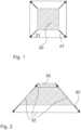
- Fig.3illustrates the difference between a fast ( Fig. 3a : 20, 21; deformation d1) and a slowly moving ( Fig. 3b ) approaching rear wall plane (20, 23; deformation d3), if at time t-1 the rear wall plane (20) is in Fig. 3a the same Distance to the vehicle camera as the rear wall plane (20) in Fig. 3b .
- Fig.3the difference between a close rear wall plane ( Fig. 3a : 20, 21; deformation d1) and a more distant rear wall plane (20, 23; deformation d3), which move with the same (relative) speed, then this would be in Fig. 3b object (20, 21) in real space is larger than the object in Fig. 3a represented object (20, 23).
- the vector x t 0describes the 3D correspondence at time t-0 of the vector x t 1 at time t-1.
- a homographycan be calculated image-based by knowing four point correspondences (cf. Tutorial: Multiple View Geometry, Hartley, R.
- Equation 3shows that for an inverse TTC t / d not equal to zero, planes with different orientations n can be modeled and that planes with identical orientations n can be separated via their inverse TTC.
- HR ⁇ t ⁇ n ′ d
- a homographycan theoretically be decomposed into the normal vector n, the rotation matrix R and the inverse TTC t / d . Unfortunately This decomposition is numerically extremely unstable and sensitive to measurement errors.
- Fig.4shows a schematic of a division into cells (grid, grid/lines).
- the sceneis divided into NxM initial cells and each point correspondence is assigned a unique ID.
- This IDinitially indicates the affiliation to a cell. Later on, the ID can indicate the affiliation to a cluster or an object.
- An object (particularly a backplane) in the foregroundis shown hatched.
- the backgroundis shown in white. If a cell contains only one object (cells B3, D3), a homography will describe this cell very well. However, if a cell contains more than one object (cell C3), the homography will not describe either object well. If the point correspondences (black point or black cross or x) are assigned to the clusters (or segments) of the neighboring cells (B3 or D3) via their backprojection errors, the black point is assigned to the segment of cell B3 and the black cross to the segment of cell D3, since the homography for cell C3 describes neither the foreground nor the background well.
- the segment sizescan be adapted to the scene, for example by generating larger areas in the vicinity of the vehicle or in areas with a positive classification response.
- a dedicated back/ground and side plane homographyis calculated, as shown in equations 5 to 10.
- x 0 c ⁇ a y 0 c ⁇ b ⁇⁇ x 1 0 x 1 x 0 0 ⁇ x 1 x 1 y 0 ⁇ t x t y t z or .
- x 0 c ⁇ a y 0 c ⁇ b ⁇⁇ 1 0 x 0 0 ⁇ 1 y 0 ⁇ t x t y t z .
- neighboring cellscan be combined in a further step by calculating the backprojection errors ⁇ x t 0 i ⁇ H j x t 1 i or ⁇ x t 0 j ⁇ H i x t 1 j over support points (see below point 1. : RANSAC) of the neighboring segments j and i and their homographies. Two neighboring clusters are combined if ⁇ x t 0 i ⁇ H j x t 1 i smaller ⁇ x t 0 i ⁇ H i x t 1 i or, for example, the backprojection error normalized to the predicted flow length is below an adjustable threshold.
- two neighboring clusterscan be combined if ⁇ x t 0 i ⁇ H j x t 1 i smaller ⁇ x t 0 i ⁇ H i x t 1 i and the two back projection errors ⁇ x t 0 i ⁇ H j x t 1 i and ⁇ x t 0 i ⁇ H i x t 1 i fall below a threshold normalized to the flow length.
- backprojection errorscan be used as potentials in a graph and a global solution can be calculated. The compactness of the clusters can be determined using the edge potentials in the graph.
- the homographiesare recalculated and the point correspondences are assigned to the clusters with the lowest backprojection error. If only directly adjacent clusters are considered, very compact objects can be generated. If the minimum error exceeds an adjustable threshold, new (cluster/object) IDs are assigned to the correspondences in order to be able to recognize partially occluded objects or objects with slightly different TTC. By setting the threshold, the resolution of (slightly) different objects can be adjusted.
- the backprojection errorscan be biased to reduce costs for contiguous regions or to increase the costs of an ID change if point correspondences have had the same ID affiliation over a longer period of time.
- Fig.5shows an example of scene segmentation:
- Fig. 5ashows an image taken by a vehicle camera that is located inside the vehicle and records the area ahead through the windshield.
- a three-lane road (51)can be seen, e.g. a motorway. The lanes are separated by corresponding lane markings. Vehicles are driving in all three lanes. The vehicle driving ahead in its own lane (53) may obscure other vehicles driving ahead in its own lane.
- To the left of the three-lane roadthere is a raised structural barrier (52) to the oncoming lane.
- To the right of the three-lane road (51)there is a shoulder or hard shoulder, which is bordered to the right by a guardrail, behind which there is a wooded area.
- this scenecan be segmented.
- Fig. 5b to 5d Cells (56)can be seen.
- Point correspondences (55)are shown in the cells.
- the assignment of a cell (56) to a segmentis shown by the color of the cell frame or the point correspondences (55).
- Fig. 5bshows the red channel of the segmented image
- Fig. 5cthe green channel
- Fig. 5dthe blue channel.
- One segmentwhich is green in the original, extends over the bottom five to six lines (in Fig. 5b and 5d shown in white and without a cell frame). This segment corresponds to the ground level, i.e. the surface of the road (51) on which your car is driving.
- the segmentation result shownwas determined without prior knowledge of the scene in just three iteration steps. This shows the enormous speed and performance of an embodiment of the invention through temporal integration.
- Fig.6shows a determination of the orientation of planes in the already Fig.5 described scene.
- Fig. 6ashows the surrounding situation for orientation according to Fig. 5a .
- All correspondences assigned to a side wall levelshow Fig. 6b .
- the correspondences on the left edgewere assigned to a right side wall level, which is correct because that is where the right side of the structural boundary (52) to the opposite lane is located in the image.
- the correspondences in the right half of the imagewere assigned to left side wall levels, which is also correct because that is where the "left side" of the roadside buildings or plants is located in the image.
- Fig. 6cshows which correspondences are assigned to a ground plane, which is correct since the surface of the roadway (51) can be seen there in the image.
- Fig. 6dshows which correspondences are assigned to a rear wall plane. This is largely correct. From this determination alone, different rear wall planes cannot be sufficiently distinguished, eg those of the delivery truck (53) driving ahead in the same lane from the signs of the sign bridge (54) arranged above it in the image. However, this representation already provides important information about where raised objects occur in the vehicle's surroundings.
- the inverse TTC(t x , t y , t z ) can be used to detect dynamic objects.
- Fig. 7ashows the picture of the vehicle situation (identical to Fig. 6a ).
- the vehicle driving ahead in the same lane (73)is a delivery van.
- Fig. 7bshows correspondences that in turn correspond to the ground plane (violet in the original) and are the only ones with a red component.
- Fig. 7cshows correspondences that are assigned to moving objects. In the original, these are green when they are moving away from your own vehicle (i.e. driving faster) and turquoise when they are driving slower.
- Fig. 7dshows correspondences with a blue component, i.e. those that correspond to the ground plane (cf. Fig. 7b ), moving objects approaching your own vehicle (cf. Fig. 7c ) and those that correspond to static raised objects, these are only in Fig. 7d shown, such as forest areas to the left and right of the motorway and the sign bridges.
- Fig. 7c and 7dtogether, it can be seen that the vehicle in its own lane (73) is approaching. The same applies to the vehicle in front in the right lane (75). In contrast, the other vehicles (71, 72 and 74) are moving away.
- the area that corresponds to the sky in the imagedoes not lead to any correspondences due to the lack of structure in the image (white in Fig. 7b to 7d ) .
- the segmentationis known at time t-1, it can be used both to predict the objects and to generate a dense flow field.
- Signature-based flow methodsgenerate signatures and try to assign them clearly in successive frames.
- the signaturesare usually calculated from a patch (image section or image area) of a defined size. However, if the size and shape of a patch change, a correspondence finding with a fixed template (pattern, pattern, for example an image section of a image of the image sequence that corresponds to an object - for example a vehicle template) is no longer possible. If you approach a back plane, for example, the size of a patch changes. Or if you move over a ground plane or parallel to a side plane, both the size and shape of a patch change, see Fig. 1 and 2 ). If the segmentation is present at time t-1, the homographies can be recalculated over already found flow vectors and used to predict the position and shape of already established correspondences from t-1 to t-0.
- the current frame at time t-0can be transformed to time t-1 to compensate for scale and shape changes.
- Fig.8illustrates such an approach.
- Fig. 8ashows an image of a different driving situation, which was recorded by the vehicle camera at a time t-1. It shows a motorway with three lanes in each direction. To the left of the three-lane road there is a guardrail (81) as a raised boundary to the oncoming lane. To the right of the road there is a noise barrier (82).
- Fig. 8bshows an image that was taken at the following time t and was transformed ("warped") via the homography of the guardrail in such a way that the changes in the image in the area of the guardrail that occur as a result of the movement of the vehicle and thus of the vehicle camera between the two recording times are compensated.
- the forward movement of the own vehicleleads to Fig. 8b that the nearest lane marking is closer to your own vehicle than in Fig. 8a
- the transformationleads to the trapezoidal displacement of the image, which in Fig. 8f is illustrated by a dashed line.
- Fig. 8cnow shows corresponding features (85) which are in the area of the guard rail (81, cf. Fig. 8a ) as white dots.
- Fig. 8dshows where these corresponding features are to be expected in the next image (86), after this as to Fig. 8b has been transformed as described.
- the current imagecan be warped to the previous image for each segment in order to find existing correspondences that have changed in scale or shape or to establish new correspondences using congruent templates.
- the homography from the last framecan be used as an approximation to make the correspondence finding more robust against shape and scale changes.
Landscapes
- Engineering & Computer Science (AREA)
- Automation & Control Theory (AREA)
- General Physics & Mathematics (AREA)
- Theoretical Computer Science (AREA)
- Multimedia (AREA)
- Physics & Mathematics (AREA)
- Transportation (AREA)
- Mechanical Engineering (AREA)
- Human Computer Interaction (AREA)
- Image Analysis (AREA)
- Traffic Control Systems (AREA)
- Image Processing (AREA)
- Closed-Circuit Television Systems (AREA)
Description
Translated fromGermanDie Erfindung betrifft ein Verfahren zur Erkennung von Objekten aus Bildern einer Kamera und kann insbesondere bei kamerabasierten Fahrerassistenzsystemen verwendet werden.The invention relates to a method for recognizing objects from images of a camera and can be used in particular in camera-based driver assistance systems.
Fahrzeugerkennungssysteme nach dem aktuellen Stand der Technik sind meist klassifikationsbasiert. Klassifikationsbasierte Systeme können Fahrzeuge bzw. Fahrzeugkomponenten wiedererkennen, die sie in ihren Trainingsdaten gesehen haben. Neue Fahrzeugdesigns, sowie sich verändernde Aufbauten können jedoch zu einer stark reduzierten System-Performance führen und fordern generische Ansätze zur Objekterkennung.State-of-the-art vehicle recognition systems are mostly classification-based. Classification-based systems can recognize vehicles or vehicle components that they have seen in their training data. However, new vehicle designs and changing structures can lead to a greatly reduced system performance and require generic approaches to object recognition.
Es ist eine Aufgabe der vorliegenden Erfindung, ein Verfahren zur generischen Erkennung von Objekten anzugeben.It is an object of the present invention to provide a method for the generic recognition of objects.
Ein Ausgangspunkt der Erfindung sind die folgenden Überlegungen: Sind die Kamerapositionen zweier Frames (Einzelbilder) bekannt, lassen sich Punkt-Korrespondenzen (korrespondierende Merkmalspunkte) triangulieren, aber es werden keine Objekte generiert, da die Triangulation über kein Modelwissen verfügt, das eine Punktewolke in sinnvolle Objekten clustern könnte. Nachteile monokularer Systeme sind, dass Objekte nahe dem Epipol nur ungenau trianguliert werden können und sich dort kleinste Fehler in der Egomotion (Kamera-Eigenbewegung) bemerkbar machen. Als Epipol bezeichnet man den Bildpunkt in einem ersten Kamerabild, an dem das Zentrum der Kamera zu einem zweiten Zeitpunkt abgebildet wird. Während einer Geradeausfahrt entspricht z.B. der Fluchtpunkt dem Epipol. Dies ist jedoch der relevante Bereich, um Kollisionen mit stehenden bzw. vorrausfahrenden Fahrzeugen zu erkennen. Dynamische Objekte können trianguliert werden, wenn sie sich gemäß der Epipolar-Geometrie bewegen. Sie werden jedoch aufgrund der nicht bekannten Relativgeschwindigkeit zu nah oder zu weit entfernt geschätzt.The invention is based on the following considerations: If the camera positions of two frames (individual images) are known, point correspondences (corresponding feature points) can be triangulated, but no objects are generated because the triangulation does not have any model knowledge that could cluster a point cloud into meaningful objects. Disadvantages of monocular systems are that objects close to the epipole can only be triangulated inaccurately and that the smallest errors in the egomotion (the camera's own movement) become noticeable there. The epipole is the image point in a first camera image at which the center of the camera is shown at a second point in time. When driving straight ahead, for example, the vanishing point corresponds to the epipole. However, this is the relevant area for detecting collisions with stationary vehicles or vehicles driving ahead. Dynamic objects can be triangulated if they move according to the epipolar geometry. However, they are estimated to be too close or too far away due to the unknown relative speed.
Werden anstelle einzelner Korrespondenzen, mehrere benachbarte Korrespondenzen (korrespondierende Merkmale) betrachtet, lassen sich Objekte aufgrund unterschiedlicher Geschwindigkeiten, Skalierungen und Deformation segmentieren.If several neighboring correspondences (corresponding features) are considered instead of individual correspondences, objects can be segmented based on different speeds, scaling and deformation.
Ein erfindungsgemäßes Verfahren zur Detektion von Objekten aus einer Folge von Bildern einer Fahrzeugkamera ist Gegenstand des Anspruchs 1. Das Verfahren umfasst die Schritte:
- a) Aufnahme einer Folge von Bildern mit der Fahrzeugkamera,
- b) Ermittlung von korrespondierenden Merkmalen in zwei aufeinander folgenden Bildern,
- c) Berechnung von Homographien für benachbarte korrespondierende Merkmale zur Bestimmung einer Mehrzahl von Ebenen und zur Zuordnung zu jeweils einer Ebene im Raum,
- d) Bestimmung der Mehrzahl von Ebenen im Raum durch eine Zuordnung von benachbarten korrespondierenden Merkmalen zu jeweils einer Ebene im Raum,
- e) Segmentierung der korrespondierenden Merkmale anhand der berechneten Homographien,
und - f) Detektion von Objekten unter Berücksichtigung der (in Schritt d)) bestimmten Ebenen und der (gemäß Schritt e)) segmentierten Merkmale.
- a) Taking a sequence of images with the vehicle camera,
- b) Determination of corresponding features in two consecutive images,
- c) Calculating homographies for adjacent corresponding features to determine a plurality of levels and to assign each to a level in space,
- d) Determination of the plurality of levels in space by assigning adjacent corresponding features to each level in space,
- e) Segmentation of the corresponding features based on the calculated homographies,
and - f) Detection of objects taking into account the planes determined (in step d)) and the features segmented (according to step e)).
Bevorzugt ist die Fahrzeugkamera zur Aufnahme einer Umgebung eines Fahrzeugs ausgebildet. Bei der Umgebung handelt es sich insbesondere um die vor dem Fahrzeug liegende Umgebung. Vorzugsweise ist die Fahrzeugkamera in eine Fahrerassistenzvorrichtung integrierbar oder mit dieser verbindbar, wobei die Fahrerassistenzvorrichtung insbesondere zur Objekterkennung aus den von der Fahrzeugkameravorrichtung bereitgestellten Bilddaten ausgebildet ist. Bevorzugt ist die Fahrzeugkameravorrichtung eine im Innenraum des Kraftfahrzeugs hinter der Windschutzscheibe anzuordnende und in Fahrtrichtung gerichtete Kamera. Besonders bevorzugt ist die Fahrzeugkamera eine monokulare Kamera.Preferably, the vehicle camera is designed to record the surroundings of a vehicle. The surroundings are in particular the surroundings in front of the vehicle. Preferably, the vehicle camera can be integrated into a driver assistance device or connected to it, wherein the driver assistance device is designed in particular for object recognition from the image data provided by the vehicle camera device. Preferably, the vehicle camera device is a camera to be arranged in the interior of the motor vehicle behind the windshield and directed in the direction of travel. Camera. The vehicle camera is preferably a monocular camera.
Bevorzugt werden mit der Fahrzeugkamera zu bestimmten bzw. bekannten Zeitpunkten Einzelbilder aufgenommen, woraus sich eine Folge von Bildern ergibt.Preferably, individual images are taken with the vehicle camera at specific or known points in time, resulting in a sequence of images.
Als Korrespondenz wird die Entsprechung eines Merkmals in einem ersten Bild zu demselben Merkmal in einem zweiten Bild bezeichnet. Korrespondierende Merkmale in zwei Bildern können auch als Flussvektor beschrieben werden, der angibt wie sich das Merkmal im Bild verschoben hat. Ein Merkmal kann insbesondere ein Bildausschnitt (bzw. Patch), ein Pixel, eine Kante oder eine Ecke sein.Correspondence is the correspondence of a feature in a first image to the same feature in a second image. Corresponding features in two images can also be described as a flow vector that indicates how the feature has moved in the image. A feature can be an image section (or patch), a pixel, an edge or a corner.
Schritt d) kann wie folgt beschrieben werden: Ermittlung von mehreren Ebenen, in denen jeweils eine Vielzahl von benachbarten korrespondierenden Merkmalen liegt bzw. zu liegen kommt.Step d) can be described as follows: Determination of several levels, in each of which a large number of neighboring corresponding features are or will be located.
Unter Schritt d) wird auch subsummiert, dass eine Mehrzahl von Ebenen im Raum vorgegeben wird, und eine Zuordnung von benachbarten korrespondierenden Merkmalen zu jeweils einer der vorgegebenen Eben vorgenommen wird (vgl. unten).Step d) also includes the fact that a plurality of levels in space are specified and an assignment of adjacent corresponding features to each of the specified levels is made (see below).
Der Begriff "Ebene" beschreibt im Kontext der vorliegenden Erfindung folgende Zusammenhänge: einerseits ein Kriterium zur Akkumulation benachbarter korrespondierender Merkmale. D.h. diese werden als zusammengehörig angesehen, wenn sie in einer gemeinsamen Ebene im Raum liegen und sich entsprechend der Bewegung der Ebene zeitlich entwickeln.In the context of the present invention, the term "plane" describes the following relationships: on the one hand, a criterion for the accumulation of neighboring corresponding features. This means that these are considered to belong together if they lie in a common plane in space and develop over time according to the movement of the plane.
Derart akkumulierte korrespondierende Merkmale werden anschließend als "Bodenebene" bezeichnet, da sie alle in der Ebene, die der Fahrbahnebene entspricht liegen. Jedoch erstreckt sich eine solche Bodenebene nicht ins Unendliche, sondern meint einen Teilbereich der Ebene, nämlich den, in dem tatsächlich korrespondierende Merkmale angeordnet sind.Such accumulated corresponding features are then referred to as the "ground plane" because they all lie in the plane that corresponds to the roadway plane. However, such a ground plane does not extend to infinity, but rather means a sub-area of the plane, namely the one in which actually corresponding features are arranged.
In Schritt f) meint die Formulierung "unter Berücksichtigung...", dass die in Schritt d) bestimmten mehreren Ebenen bei der Detektion von Objekten berücksichtigt werden. Dies kann beispielsweise in der Art geschehen, dass aus einer erkannten Bodenebene eine Fahrbahnhypothese abgeleitet wird, und dass aus einer Rückwandebene bzw. einer Seitenwandebene eine Objekthypothese für ein erhabenes Objekt generiert wird. Bereits aus einer Fahrbahnhypothese und Objekthypothese(n) für erhabene Objekte kann eine Freiraumdetektion erfolgen, die angibt, welcher Freiraum in der Umgebung des Fahrzeugs aktuell befahrbar ist. Eine vorteilhafte Anwendung der Freiraumdetektion liegt z.B. in einer Fahrbahnrandermittlung, die nicht von der Erkennung von Fahrspurmarkierungen abhängig ist.In step f), the wording "taking into account..." means that the multiple levels determined in step d) are taken into account when detecting objects. This can be done, for example, by deriving a roadway hypothesis from a detected floor level and generating an object hypothesis for a raised object from a rear wall level or a side wall level. A free space detection can be carried out from a roadway hypothesis and object hypothesis(es) for raised objects, which indicates which free space in the area surrounding the vehicle is currently passable. One advantageous application of free space detection is, for example, determining the edge of the road that is not dependent on the detection of lane markings.
Mit der Formulierung "Detektion von Objekten" kann also beispielsweise eine Generierung von Objekthypothesen bzw. Objekten gemeint sein.The term "detection of objects" can, for example, mean the generation of object hypotheses or objects.
Eine Homographie beschreibt die Korrespondenz von Punkten auf einer Ebene zwischen zwei Kamerapositionen bzw. die Korrespondenz zweier Punkte in zwei aufeinanderfolgenden Bildern der Fahrzeugkamera. Durch die Berechnung von Homographien für benachbarte korrespondierende Merkmale kann so die Zuordnung von benachbarten korrespondierenden Merkmalen zu jeweils einer Ebene im Raum erfolgen (s. Schritt d)).A homography describes the correspondence of points on a plane between two camera positions or the correspondence of two points in two consecutive images from the vehicle camera. By calculating homographies for neighboring corresponding features, neighboring corresponding features can be assigned to a plane in space (see step d)).
Insbesondere anhand der berechneten Homographien können die korrespondierenden Merkmale segmentiert werden, also unterschiedlichen Segmenten zugeordnet werden. In Schritt f) kann dann eine Detektion von Objekten unter Berücksichtigung der segmentierten Merkmale erfolgen.In particular, the corresponding features can be segmented based on the calculated homographies, i.e. assigned to different segments. In step f), objects can then be detected taking the segmented features into account.
Ein erfindungsgemäßes Verfahren umfasst den Schritt: Zuordnung von benachbarten korrespondierenden Merkmalen zu jeweils einer Bodenebene, einer Rückwandebene oder einer Seitenwandebene. Im Falle eines Koordinatensystems, bei dem die x-Richtung horizontal bzw. lateral, die y-Richtung vertikal und die z-Richtung in Fahrzeuglängsrichtung verläuft, kann eine Bodenebene normal zur y-Richtung, eine Rückwandebene normal zur z-Richtung und eine Seitenwandebene normal zur x-Richtung vorgegeben werden. Durch eine Berechnung von Homographien einer Bodenebene, einer Rückwandebene und einer Seitenwandebene kann für benachbarte korrespondierende Merkmale eine Zuordnung zu einer dieser Ebenen erfolgen.A method according to the invention comprises the step of assigning adjacent corresponding features to a floor plane, a rear wall plane or a side wall plane. In the case of a coordinate system in which the x-direction is horizontal or lateral, the y-direction is vertical and the z-direction is in the longitudinal direction of the vehicle, a floor plane normal to the y-direction, a rear wall plane normal to the z-direction and a side wall plane normal to the x-direction can be specified. By calculating homographies of a floor plane, a rear wall plane and a side wall plane, an assignment to one of these planes can be made for adjacent corresponding features.
Bevorzugt können die Homographien für die Rückwandebene nach Gleichung (10) bzw. für die Bodenebene nach Gleichung (9) bzw. für die Seitenwandebene nach Gleichung (11) berechnet werden. Hierbei sind a, b, c Konstanten, x0, y0, x1, y1 bezeichnen Korrespondenzen im ersten Bild (Index 0) , aufgenommen zu einem Zeitpunkt t-0, und zweiten Bild (Index 1) , aufgenommen zu einem früheren Zeitpunkt t-1, und tx, ty, tz sind die Komponenten des Vektors t/d.t beschreibt die Translation der Fahrzeugkamera und d die Entfernung zu einer Ebene (senkrecht zu dieser Ebene), also entlang des Normalenvektors dieser Ebene. Die Komponenten tx, ty bzw. tz werden im Folgenden auch als "inverse TTC" bezeichnet. TTC kommt von ,Time to collision' und ergibt sich in einer Raumrichtung als Abstand geteilt durch Translationsgeschwindigkeit.Preferably, the homographies for the rear wall plane can be calculated according to equation (10) or for the floor plane according to equation (9) or for the side wall plane according to equation (11). Here, a, b, c are constants, x0 , y0 , x1 , y1 denote correspondences in the first image (index 0), taken at a time t-0, and the second image (index 1), taken at an earlier time t-1, and tx , ty , tz are the components of the vector t/d.t describes the translation of the vehicle camera and d the distance to a plane (perpendicular to this plane), i.e. along the normal vector of this plane. The components tx , ty and tz are also referred to below as "inverse TTC". TTC comes from 'time to collision' and is calculated in one spatial direction as the distance divided by the translation speed.
Gemäß einer vorteilhaften Weiterbildung können, falls mehrere Ebenen mit identischer Orientierung auftreten, die Ebenen mit identischer Orientierung anhand der zugehörigen tx, ty, tz -Werte getrennt werden. Beispielsweise können zwei Rückwandebenen, die in z-Richtung unterschiedlich weit von der Fahrzeugkamera entfernt sind, über unterschiedliche tz-Werte voneinander unterschieden werden.According to an advantageous development, if several planes with identical orientation occur, the planes with identical orientation can be separated using the associated tx , ty , tz values. For example, two rear wall planes that are at different distances from the vehicle camera in the z direction are separated from each other by different tz values.
Bevorzugt kann ein Bild durch ein Gitter in gleichartige Zellen unterteilt werden, und für jede Zelle kann aus den darin ermittelten korrespondierenden Merkmalen eine Homographie berechnet werden. Zellen mit übereinstimmender Homographie können anschließend geclustert werden.Preferably, an image can be divided into similar cells by a grid, and a homography can be calculated for each cell from the corresponding features determined therein. Cells with matching homography can then be clustered.
Bevorzugt kann, falls die berechnete Homographie einer ersten Zelle nicht hinreichend mit einer Homographie einer benachbarten Zelle übereinstimmt, zur Ermittlung einer Ebenengrenze vorteilhaft ein sogenannter Rückprojektionsfehler einzelner korrespondierender Merkmale betrachtet werden. Korrespondierende Merkmale können durch den Rückprojektionsfehler bewertet werden. Der Rückprojektionsfehler gibt den Unterschied an zwischen dem gemessenen Fluss und dem aus der berechneten Homographie prädizierten Fluss an. Mit anderen Worten bezeichnet der Rückprojektionsfehler einer Ebene die Differenz zwischen einem Punkt x zum Zeitpunkt t-0 und dem gemäß der Homographie dieser Ebene abgebildeten korrespondierenden Punktes zum vorangegangenen Zeitpunkt t-1 beschrieben wird (siehe unten: Gleichung 4).Preferably, if the calculated homography of a first cell does not sufficiently match a homography of a neighboring cell, a so-called backprojection error of individual corresponding features can advantageously be considered to determine a plane boundary. Corresponding features can be evaluated by the backprojection error. The backprojection error indicates the difference between the measured flow and the flow predicted from the calculated homography. In other words, the backprojection error of a plane describes the difference between a point x at time t-0 and the corresponding point mapped according to the homography of this plane at the previous time t-1 (see below: equation 4).
Wird der Rückprojektionsfehler eines korrespondierenden Merkmals in einer ersten Zelle mit den Rückprojektionsfehlern der Homographien der benachbarten Zellen verglichen und dieses korrespondierende Merkmal der Homographie mit dem geringstem Fehler zugewiesen, kann die Ebenengrenze (bzw. Segmentgrenze bzw. Clustergrenze) innerhalb der ersten Zelle verfeinert werden. Auf diese Weise können verschiedene korrespondierende Merkmale einer Zelle unterschiedlichen Ebenen zugeordnet werden.If the backprojection error of a corresponding feature in a first cell is compared with the backprojection errors of the homographies of the neighboring cells and this corresponding feature is assigned to the homography with the smallest error, the level boundary (or segment boundary or cluster boundary) within the first cell can be refined. In this way, different corresponding features of a cell can be assigned to different levels.
Bevorzugt kann die Zuordnung von Ebenen zu benachbarten korrespondierenden Merkmalen im Wesentlichen im gesamten Bild der Fahrzeugkamera (z.B. in mindestens 80% der Bildfläche, bevorzugt mindestens 90%) ermittelt werden. Da das erfindungsgemäße Verfahren sehr schnell ausgestaltet werden kann, ist eine generische Objektdetektion bzw. Szeneninterpretation für nahezu das gesamte Bild in Echtzeit möglich.Preferably, the assignment of levels to adjacent corresponding features can be made essentially in the entire image of the Vehicle camera (e.g. in at least 80% of the image area, preferably at least 90%). Since the method according to the invention can be implemented very quickly, generic object detection or scene interpretation is possible for almost the entire image in real time.
Gegenstand der Erfindung ist weiterhin eine Vorrichtung zur Detektion von Objekten aus einer Folge von Bildern einer Fahrzeugkamera mit den Merkmalen des Anspruchs 14. Die Vorrichtung umfasst ein Kamerasteuergerät und eine Auswerteelektronik,
wobei das Kamerasteuergerät dazu konfiguriert bzw. ausgebildet ist,
- a) eine Folge von Bildern mit der Fahrzeugkamera aufzunehmen; und wobei die Auswerteelektronik dazu konfiguriert/ausgebildet ist,
- b) korrespondierende Merkmale in zwei aufeinander folgenden Bildern zu ermitteln,
- c) Homographien für benachbarte korrespondierende Merkmale zur Bestimmung einer Mehrzahl von Ebenen und zur Zuordnung zu jeweils einer Ebene im Raum zu berechnen,
- d) die Mehrzahl von Ebenen im Raum durch eine Zuordnung von benachbarten korrespondierenden Merkmalen zu jeweils einer Ebene im Raum zu bestimmen,
- e) korrespondierende Merkmale anhand der berechneten Homographien zu segmentieren,
und - f) ein oder mehrere Objekte zu detektieren (bzw. zu generieren) unter Berücksichtigung der (in Schritt d)) bestimmten Ebenen und segmentierten Merkmale (Schritt e).
wherein the camera control device is configured or designed to
- a) to record a sequence of images with the vehicle camera; and wherein the evaluation electronics are configured/designed to
- b) to identify corresponding features in two consecutive images,
- c) to calculate homographies for neighbouring corresponding features to determine a plurality of levels and to assign each to a level in space,
- d) to determine the plurality of levels in space by assigning adjacent corresponding features to each level in space,
- e) segment corresponding features based on the calculated homographies,
and - f) to detect (or generate) one or more objects taking into account the levels (determined in step d)) and segmented features (step e).
Das Kamerasteuergerät bzw. die Auswertungselektronik können insbesondere einen Mikrocontroller oder -prozessor, einen Digital Signal Processor (DSP), einen ASIC (Application Specific Integrated Circuit), einen FPGA (Field Programmable Gate Array) und dergleichen mehr sowie Software zur Durchführung der entsprechenden Steuerungs- bzw. Auswertungsschritte umfassen. Die vorliegende Erfindung kann somit in digitalen elektronischen Schaltkreisen, Computer-Hardware, Firmware oder Software implementiert sein.The camera control unit or the evaluation electronics can in particular be a microcontroller or processor, a digital signal processor (DSP), an ASIC (Application Specific Integrated Circuit), an FPGA (Field Programmable Gate Array) and the like, as well as software for carrying out the corresponding control or evaluation steps. The present invention can thus be implemented in digital electronic circuits, computer hardware, firmware or software.
Weitere Merkmale, Vorteile und Wirkungen der Erfindung ergeben sich aus der nachfolgenden Beschreibung bevorzugter Ausführungsbeispiele der Erfindung. Dabei zeigen:
- Fig. 1
- schematisch eine typische Deformation einer sich nähernden Rückwandebene;
- Fig. 2
- schematisch eine typische Deformation einer sich nähernden Bodenebene;
- Fig. 3
- schematisch eine typische Deformation a) einer sich schnell und b) einer sich langsam nähernden oder weiter entfernten Rückwandebene;
- Fig. 4
- schematisch eine Unterteilung eines Bildes mit zwei unterschiedlichen Segmenten in Zellen;
- Fig. 5
- Segmentierungsergebnisse nach einem dritten Iterationsschritt;
- Fig. 6
- Ebenen-Orientation zur Target Validierung (Validierung potentieller Kollisionsobekte);
- Fig. 7
- Time to Collision-Betrachtung; und
- Fig. 8
- Projektion (bzw. Warpen) des Leitplankensegments zum Zeitpunkt t-0 (rechts) auf t-1 (links).
- Fig.1
- schematically a typical deformation of an approaching back wall plane;
- Fig.2
- schematically a typical deformation of an approaching ground plane;
- Fig.3
- schematically a typical deformation a) of a rapidly approaching and b) a slowly approaching or further away back wall plane;
- Fig.4
- schematically a division of an image with two different segments into cells;
- Fig.5
- Segmentation results after a third iteration step;
- Fig.6
- Plane orientation for target validation (validation of potential collision objects);
- Fig.7
- Time to Collision consideration; and
- Fig.8
- Projection (or warping) of the guardrail segment at time t-0 (right) to t-1 (left).
Einander entsprechende Teile sind in der Regel in allen Figuren mit denselben Bezugszeichen versehen.As a rule, corresponding parts are provided with the same reference symbols in all figures.
In
In
Alternativ könnte
Werden anstelle einzelner Korrespondenzen, mehrere benachbarte Korrespondenzen betrachtet, lassen sich Objekte aufgrund unterschiedlicher Geschwindigkeiten, Skalierungen und Deformation segmentieren.If several neighboring correspondences are considered instead of individual correspondences, objects can be segmented based on different speeds, scaling and deformation.
Geht man davon aus, dass die Welt aus Ebenen besteht, kann man diese durch Homographien beschreiben und wie im Folgenden gezeigt wird über Ihre Distanz, Geschwindigkeit und Orientierung trennen.If we assume that the world consists of planes, we can describe them using homographies and separate them by their distance, speed and orientation, as shown below.
Eine Homographie beschreibt die Korrespondenz von Punkten auf einer Ebene zwischen zwei Kamerapositionen bzw. die Korrespondenz zweier Punkte in zwei aufeinanderfolgenden Frames:


Alternativ kann bei Kenntnis der Kameratranslation t, der Rotation R und der Entfernung d entlang des Normalen Vektors n der Ebene die Homographie nach Gleichung 3 berechnet werden. Gleichung 3 verdeutlicht, dass sich bei einer inversen TTCt/d ungleich Null, Ebenen mit unterschiedlichen Orientierung n modellieren lassen und dass sich Ebnen mit identischer Orientierung n über ihre inverse TTC trennen lassen.
Eine Homographie lässt sich theoretisch in den Normalenvektor n, die Rotationsmatrix R und die inverse TTCt/d zerlegen. Leider ist diese Zerlegung numerisch äußerst instabil und empfindlich auf Messfehler.A homography can theoretically be decomposed into the normal vector n, the rotation matrix R and the inverse TTCt /d . Unfortunately This decomposition is numerically extremely unstable and sensitive to measurement errors.
Beschreibt man eine Szene durch Ebenen, lässt sie sich wie im Folgenden angegeben segmentieren.If you describe a scene using layers, you can segment it as follows.
Schraffiert ist ein Objekt (insb. eine Rückwandebene) im Vordergrund dargestellt. Der Hintergrund ist weiß dargestellt. Beinhaltet eine Zelle nur ein Objekt (Zellen B3, D3) wird eine Homographie diese Zelle sehr gut beschreiben. Beinhaltet eine Zelle jedoch mehr als ein Objekt (Zelle C3), wird die Homographie keines der beiden Objekte gut beschreiben. Werden die Punkt-Korrespondenzen (schwarzer Punkt bzw. schwarzes Kreuz bzw. x) den Clustern (bzw. Segment) der benachbarten Zellen (B3 bzw. D3) über Ihre Rückprojektionsfehler zugeordnet, wird der schwarze Punkt dem Segment der Zelle B3 und das schwarze Kreuz dem Segment der Zelle D3 zugeordnet, da die Homographie für die Zelle C3 weder den Vordergrund noch den Hintergrund gut beschreibt.An object (particularly a backplane) in the foreground is shown hatched. The background is shown in white. If a cell contains only one object (cells B3, D3), a homography will describe this cell very well. However, if a cell contains more than one object (cell C3), the homography will not describe either object well. If the point correspondences (black point or black cross or x) are assigned to the clusters (or segments) of the neighboring cells (B3 or D3) via their backprojection errors, the black point is assigned to the segment of cell B3 and the black cross to the segment of cell D3, since the homography for cell C3 describes neither the foreground nor the background well.
Ist Vorwissen über eine Szene vorhanden, lassen sich die Segmentgrößen an die Szene anpassen, indem z.B. größere Bereiche im Nahbereich des Fahrzeuges oder in Bereichen mit positiver Klassifikations-Antwort generiert werden. Für jedes Segment wird, wie in den Gleichungen 5 bis 10 gezeigt wird, eine dedizierte Back-/Ground- und Side-Plane-Homographie berechnet.If prior knowledge about a scene is available, the segment sizes can be adapted to the scene, for example by generating larger areas in the vicinity of the vehicle or in areas with a positive classification response. For each segment, a dedicated back/ground and side plane homography is calculated, as shown in equations 5 to 10.
Die Berechnung der Back-/Ground- und Side-Plane-Homographie, erhöht die Trennschärfe, da eine Homographie mit weniger Freiheitsgraden Bereiche, die unterschiedliche Ebenen beinhalten, nur schlecht modellieren kann und somit korrespondierende Punkte einen höheren Rückprojektionsfehler aufweisen werden, siehe
Setzt man die statische Einbaulage der Kamera und Kamera Rotation in zwei unterschiedlichen Ansichten als gegeben voraus (z.B. durch Kenntnis der Kamera Kalibration und durch die Berechnung der Fundamental-Matrix in einem monokularen System oder durch Rotationswerte eines Drehratensensor-Clusters), lässt die inverse TTCt/d mittels der um die statische Kamera-Rotation kompensierten Flussvektoren berechnen, wie im Folgenden exemplarisch für eine Ground Planen' = [010] gezeigt wird. Ist die Rotation nicht bekannt, kann sie näherungsweise durch eine Einheitsmatrix ersetzt werden.If the static installation position of the camera and camera rotation in two different views are assumed to be given (e.g. by knowing the camera calibration and by calculating the fundamental matrix in a monocular system or by rotation values of a yaw rate sensor cluster), the inverse TTCt /d can be calculated using the flow vectors compensated for the static camera rotation, as shown below for a ground planen' = [010] as an example. If the rotation is not known, it can be approximately replaced by a unit matrix.
Ersetzt man den Quotientent/d in Gleichung 3 durch die inverse Time to Collision

Durch Einführung der Konstanten a, b, c, wobei

Durch Normierung der homogenen Koordinaten ergibt sich:

Für mehr als eine Messung ergibt sich ein Gleichungssystem der FormMx =v mit einem zu bestimmenden Vektor x, einer MatrixM und einem Vektor v (siehe Gleichung 9), das sich für mindestens drei Bild-Korrespondenzen als Stützstellen durch z.B. eine Singular Value Decomposition (Singulärwertzerlegung der Matrix) oder ein Least-Square-Verfahren lösen lässt:
Die Herleitung der Back- und Side-Plane-Homographien erfolgt analog und ergibt:

Um größere, aus mehreren Zellen bestehende Objekte zu segmentieren, lassen sich in einem weiteren Schritt benachbarte Zellen zusammenfassen, indem die Rückprojektionsfehler


Wurden die Segmente zusammengefasst, werden die Homographien neu berechnet und die Punkt-Korrespondenzen den Clustern mit geringstem Rückprojektionsfehler zugeordnet. Betrachtet man nur direkt angrenzende Cluster, lassen sich sehr kompakte Objekte generieren. Überschreitet der minimale Fehler eine einstellbare Schwelle, werden den Korrespondenzen neue (Cluster-/Objekt-) IDs zugewiesen, um teilverdeckte Objekte oder Objekte mit leicht unterschiedlicher TTC erkennen zu können. Durch die Einstellung der Schwelle kann die Auflösung (leicht) unterschiedlicher Objekte angepasst werden.If the segments have been combined, the homographies are recalculated and the point correspondences are assigned to the clusters with the lowest backprojection error. If only directly adjacent clusters are considered, very compact objects can be generated. If the minimum error exceeds an adjustable threshold, new (cluster/object) IDs are assigned to the correspondences in order to be able to recognize partially occluded objects or objects with slightly different TTC. By setting the threshold, the resolution of (slightly) different objects can be adjusted.
Die Rückprojektionsfehler lassen sich mit einem Bias versehen, der Kosten für zusammenhängende Bereiche reduziert oder einem Bias, der die Kosten für einen ID-Wechsel erhöht, falls Punkt-Korrespondenzen über eine längere Zeit dieselbe ID-Zugehörigkeit hatten.The backprojection errors can be biased to reduce costs for contiguous regions or to increase the costs of an ID change if point correspondences have had the same ID affiliation over a longer period of time.
Analog dem anhand von
Unterschiedliche Segmente wurden mit unterschiedlichen Farben versehen. Ein Segment, welches im Original grün ist, erstreckt sich über die untersten fünf bis sechs Zeilen (in
Ein weiteres Segment ist in der Mitte des Bildes zu erkennen, im Original ist es pink. Daher weist es in
Das gezeigte Segmentierungsergebnis wurde ohne Vorwissen über die Szene in nur drei Iterationsschritten ermittelt. Das zeigt die enorme Schnelligkeit und Leistungsfähigkeit einer Ausführungsform der Erfindung durch zeitliche Integration.The segmentation result shown was determined without prior knowledge of the scene in just three iteration steps. This shows the enormous speed and performance of an embodiment of the invention through temporal integration.
Wie in
Der Bereich, der im Bild dem Himmel entspricht, führt mangels Struktur im Bild zu keinen Korrespondenzen (weiß in
Wird die Eigenrotation in den Korrespondenzen vor der Berechnung der Homographie berücksichtigt, bzw. wird die Eigenrotation in der Rotationsmatrix R berücksichtigt, lassen sich überholende Fahrzeuge aufgrund Ihrer negativen tz Komponente erkennen bzw. ausscherende oder in einer Kurve fahrende Fahrzeuge durch eine laterale tx Komponente ungleich Null erkennen. Werden die dynamischen Segmente über ihre Homographien prädiziert (siehe unten "Verdichtung des optischen Flusses basierend auf Homographien "), kann über die Zeit eine dynamische Karte aufgebaut werden.If the self-rotation is taken into account in the correspondences before calculating the homography, or if the self-rotation is taken into account in the rotation matrix R, overtaking vehicles can be recognized due to their negative tz component, or vehicles swerving or driving in a curve can be recognized by a lateral tx component that is not equal to zero. If the dynamic segments are predicted via their homographies (see below "Condensation of the optical flow based on homographies "), a dynamic map can be built up over time.
Betrachtet man Gleichung 3, erkennt man, dass Segmente mit einer inversen TTC gleich Null die Rotationsmatrix beschreiben und man kann sie durch Berechnung einer Homographie mit vollen Freiheitsgrad (Gleichung 2) aus Segmenten mitt/d gleich Null bestimmen. Geht man davon aus, dass sich die translatorische Komponenten in der Nähe des Epipols nicht bemerkbar machen, kann man die Pitch- und Gierrate auch bestimmen, indem die Koordinaten des Epipols (x, , ye) durch die Homographie statischer Segmente prädiziert werden und deratan ((xe0 -xe1)/f) bzw.atan ((ye0 -ye1)/f) mit der auf einen Pixel bezogenen Brennweitef berechnet wird.Considering
Wird für jedes Cluster eine Homographie mit allen Freiheitsgraden berechnet, können diese auch zur Rekonstruktion der 3D-Umgebung verwendet werden, indem anstelle der gemessenen Positionxt0, die prädizierte PositionH*xt1 zur Triangulation verwendet wird. Dies reduziert nicht nur den Einfluss von Messfehlern, sondern ermöglicht es auch Objekte nahe des Epipols zu rekonstruieren.If a homography with all degrees of freedom is calculated for each cluster, these can also be used to reconstruct the 3D environment by using the predicted positionH *xt 1 for triangulation instead of the measured positionxt 0 . This not only reduces the influence of measurement errors, but also makes it possible to reconstruct objects close to the epipole.
Im Folgenden wird ein Ausführungsbeispiel zur Verdichtung des optischen Flusses basierend auf Homographien beschrieben.In the following, an embodiment for densifying the optical flow based on homographies is described.
Ist die Segmentierung zum Zeitpunkt t-1 bekannt, kann sie sowohl zur Prädiktion der Objekte als auch zur Generierung eines dichten Flussfeldes verwendet werden. Signaturbasierte Flussverfahren erzeugen Signaturen und versuchen diese in aufeinanderfolgenden Frames eindeutig zuzuordnen. Meist werden die Signaturen aus einem Patch (Bildausschnitt bzw. Bildbereich) definierter Größe berechnet. Verändern sich jedoch Größe und Form eines Patches, ist eine Korrespondenzfindung mit einem festen Template (Vorlage, Muster, gemeint ist z.B. ein Bildausschnitt eines Bildes der Bildfolge, der einem Objekt entspricht - beispielsweise ein Fahrzeug-Template) nicht mehr möglich. Wenn man sich z.B. einer Back-Plane annähert, verändert sich die Größe eines Patches. Oder wenn man sich über einer Ground-Plane oder parallel zu einer Side-Plane bewegt, verändern sich sowohl Größe als auch Form eines Patches, siehe
Alternativ lässt sich der aktuelle Frame zum Zeitpunkt t-0 auf den Zeitpunkt t-1 transformieren, um Skalen- und Formänderungen zu kompensieren.Alternatively, the current frame at time t-0 can be transformed to time t-1 to compensate for scale and shape changes.
In
Zur Generierung eines dichten Flussfeldes kann also für jedes Segment das aktuelle Bild auf das vorherige Bild gewarpt werden, um bereits bestehende Korrespondenzen, die sich in ihrer Skale oder Form veränderte haben, wieder zu finden bzw. um neue Korrespondenzen mittels deckungsgleicher Templates zu etablieren.To generate a dense flow field, the current image can be warped to the previous image for each segment in order to find existing correspondences that have changed in scale or shape or to establish new correspondences using congruent templates.
Sind in einem aktuellen Frame nicht genügend Flussvektoren zur Neuberechnung einer Homographie vorhanden, lassen sich näherungsweise die Homographie aus dem letzten Frame verwenden um die Korrespondenzfindung robuster gegen Form und Skalenänderungen zu gestalten.If there are not enough flow vectors in a current frame to recalculate a homography, the homography from the last frame can be used as an approximation to make the correspondence finding more robust against shape and scale changes.
Folgende Ausgestaltungsformen bzw. -aspekte sind vorteilhaft und können einzeln oder in Kombination vorgesehen werden:
- 1. Das Bild wird in NxM Zellen unterteilt und den Punkt-Korrespondenzen einer Zelle wird eine eindeutige Zellen-ID zugewiesen. Aus den Korrespondenzen mit gleichen IDs werden mittels RANSAC die Back-/Ground- und Side-Plane-Homographien (Gleichung 9, 10 und 10) berechnet und sowohl die Homographie mit dem geringsten Rückprojektionsfehler, als auch die zur Berechnung der Homographie verwendeten Stützstellen gespeichert. Bei RANSAC (RAndom SAmple Consensus) Verfahren wird üblicherweise bei jeder Iteration eine minimale Anzahl an zufällig ausgewählten Korrespondenzen verwendet, um eine Hypothese zu bilden. Für jedes korrespondierende Merkmal wird anschließend ein Wert berechnet, der beschreibt, ob das korrespondierende Merkmal die Hypothese unterstützt. Wenn die Hypothese eine hinreichende Unterstützung durch die korrespondierenden Merkmale erreicht, können die nicht-unterstützenden korrespondierende Merkmale als Ausreißer verworfen werden. Andernfalls wird erneut eine minimale Anzahl an Korrespondenzen zufällig ausgewählt.
- 2. Für benachbarte Zelleni, j werden die Rückprojektionsfehler


- 3. Die Rückprojektionsfehlerxt0 -Hixt1 sämtlicher Punkt-Korrespondenzen werden für die angrenzenden Segmente berechnet und eine Punkt-Korrespondenz wird dem Segment mit geringstem Rückprojektionsfehler zugeordnet. Über schreitet der minimale Fehler eine Schwelle, werden die Korrespondenzen mit einer neuen Objekt ID versehen um auch kleinere bzw. teilverdeckte Objekte erkennen zu können.
- 4. Die Homographien der zum Zeitpunkt t-1 extrahierten Segmente werden zu Beginn eines neuen Frames (t-0) über die bereits gefunden Bild-Korrespondenzen neu berechnet und die bereits bestehenden Segment IDs in den aktuellen Frame prädiziert. Sind im aktuellen Frame nicht genügend Flussvektoren zur Neuberechnung einer Homographie vorhanden, lassen sich näherungsweise die Homographien aus dem letzten Frame verwenden.
- 5. Zur Generierung eines dichten Flussfeldes wird für jedes Segment der aktuelle Frame (t-0) auf den letzten Frame (t-1) gewarpt, um bereits bestehende Korrespondenzen, die sich in ihrer Skale oder Form veränderte haben, wieder zu finden bzw. um neue Korrespondenzen zu etablieren.
- 6. Die Rückprojektionsfehler der Back-/Ground- und Side-Plane können zur Validierung erhabener Ziele verwendet werden, siehe
Fig. 6 . - 7. Ist z.B. bei einer Fahrzeugstereokamera eine Disparitätskarte vorhanden, können die absoluten Geschwindigkeiten aus der inversen TTCt/d berechnet werden, da dann die absoluten Entfernungen d für einzelne Pixel in der Disparitätskarte vorliegen.
- 8. Wird für jedes Segment eine vollständige Homographie mit allen Freiheitsgraden berechnet, kann aus Segmenten mit einer TTC nahe unendlich (bzw. inverse TTCs annähernd Null) die Rotationsmatrix R bestimmt werden.
- 9. Die 3D-Umgebung kann aus der prädizierten Position (Hxt1,xt1) anstelle der gemessenen Position (xt0,xt1) rekonstruiert werden und erlaubt es, auch Objekte am Epipol zu rekonstruieren.


- 1. The image is divided into NxM cells and the point correspondences of a cell are assigned a unique cell ID. From the correspondences with the same IDs, the back/ground and side plane homographies (equations 9, 10 and 10) are calculated using RANSAC and both the homography with the lowest backprojection error and the support points used to calculate the homography are stored. In RANSAC (RAndom SAmple Consensus) methods, a minimum number of randomly selected correspondences are usually used in each iteration to form a hypothesis. For each corresponding feature, a value is then calculated that describes whether the corresponding feature supports the hypothesis. If the hypothesis achieves sufficient support from the corresponding features, the non-supporting corresponding features can be discarded as outliers. Otherwise, a minimum number of correspondences is randomly selected again.
- 2. For neighboring cellsi , j the backprojection errors
- 3. The backprojection errorsxt 0 -Hi xt 1 of all point correspondences are calculated for the adjacent segments and a point correspondence is assigned to the segment with the smallest backprojection error. If the minimum error exceeds a threshold, the correspondences are given a new object ID in order to be able to recognize smaller or partially hidden objects.
- 4. The homographies of the segments extracted at time t-1 are recalculated at the beginning of a new frame (t-0) using the image correspondences already found and the existing segment IDs are predicted into the current frame. If there are not enough flow vectors in the current frame to recalculate a homography, the homographies from the last frame can be used as an approximation.
- 5. To generate a dense flow field, the current frame (t-0) is warped to the last frame (t-1) for each segment in order to find existing correspondences that have changed in their scale or shape or to establish new correspondences.
- 6. The back-/ground- and side-plane projection errors can be used to validate raised targets, see
Fig.6 . - 7. If, for example, a vehicle stereo camera has a disparity map, the absolute velocities can be calculated from the inverse TTCt /d , since the absolute distances d for individual pixels are then available in the disparity map.
- 8. If a complete homography with all degrees of freedom is calculated for each segment, the rotation matrix R can be determined from segments with a TTC close to infinity (or inverse TTCs close to zero).
- 9. The 3D environment can be reconstructed from the predicted position (Hxt 1 ,xt 1 ) instead of the measured position (xt 0 ,xt 1 ) and allows to reconstruct also objects at the epipole.
Claims (12)
- Method for detecting objects from a sequence of images from a vehicle camera, comprising the steps of:a) recording a sequence of images using the vehicle camera,b) ascertaining corresponding features in two consecutive images,c) calculating homographies for neighbouring corresponding features for the determination of a plurality of planes and for assignment to in each case one plane in space,d) determining the plurality of planes in space by assigning neighbouring corresponding features to a plane in space, wherein the possible spatial planes specified are: a rear wall plane extending normally to the vehicle longitudinal direction, a side wall plane extending normally to the lateral direction, and a bottom plane extending normally to the vertical direction,e) segmenting the corresponding features on the basis of the calculated homographies, andf) detecting objects taking into account the planes determined in step d) and the features segmented according to step e).
- Method according to Claim 1, wherein in step a), the image sequencecomprises a first image recorded at a first time and a second image recorded at a later time than the first image, andin step b), each of the corresponding features comprises a correspondence of a first feature in a first image to the same feature in a second image.
- Method according to either of the preceding claims, wherein the at least one rear wall plane is calculated according to

- Method according to any of the preceding claims, wherein the at least one bottom plane is calculated according to

- Method according to any of the preceding claims, wherein the at least one side wall plane is calculated according to

- Method according to any of the preceding claims, wherein, if a plurality of planes with identical orientation occur, the planes with identical orientation are separated on the basis of the associated tx, ty, tz values.
- Method according to any of Claims 1 to 6, wherein an image is divided by a grid into cells of the same type, anda homography is calculated for each cell from the corresponding features ascertained therein, andwherein cells having matching homography are clustered.
- Method according to Claim 7, wherein, if the calculated homography of a first cell does not sufficiently match a homography of a neighbouring cell, a back-projection error of a corresponding feature in the first cell is compared with the back-projection errors of the homographies of the neighbouring cells, and this corresponding feature is assigned to the homography having the lowest error, with the result that a cluster boundary within the first cell can be ascertained.
- Method according to any of the preceding claims, wherein the assignment of planes to neighbouring corresponding features is ascertained substantially in the entire image from the vehicle camera.
- Method according to any of the preceding claims, wherein the vehicle camera is a monocular camera.
- Method according to any of the preceding claims, wherein an object hypothesis for a raised object is generated from a rear wall plane and/or a side wall plane.
- Apparatus for detecting objects from a sequence of images from a vehicle camera, comprising:a camera controller, which is configured fora) recording a sequence of images using the vehicle camera,and an evaluation electronic system, which is configured forb) ascertaining corresponding features in two consecutive images,c) calculating homographies for neighbouring corresponding features for the determination of a plurality of planes and for assignment to in each case one plane in space,d) determining the plurality of planes in space by assigning neighbouring corresponding features to a plane in space, wherein the possible spatial planes specified are: a rear wall plane extending normally to the vehicle longitudinal direction, a side wall plane extending normally to the lateral direction, and a bottom plane extending normally to the vertical direction,e) segmenting corresponding features on the basis of the calculated homographies,
andf) detecting one or more objects taking into account the determined planes and segmented features.


Applications Claiming Priority (2)
| Application Number | Priority Date | Filing Date | Title |
|---|---|---|---|
| DE102016218852.6ADE102016218852A1 (en) | 2016-09-29 | 2016-09-29 | Detection of objects from images of a camera |
| PCT/DE2017/200102WO2018059631A1 (en) | 2016-09-29 | 2017-09-28 | Detection and validation of objects from sequential images from a camera by means of homographs |
Publications (2)
| Publication Number | Publication Date |
|---|---|
| EP3520024A1 EP3520024A1 (en) | 2019-08-07 |
| EP3520024B1true EP3520024B1 (en) | 2024-09-11 |
Family
ID=60262655
Family Applications (1)
| Application Number | Title | Priority Date | Filing Date |
|---|---|---|---|
| EP17794220.8AActiveEP3520024B1 (en) | 2016-09-29 | 2017-09-28 | Detection and validation of objects from sequential images of a camera using homograpies |
Country Status (7)
| Country | Link |
|---|---|
| US (1) | US10984263B2 (en) |
| EP (1) | EP3520024B1 (en) |
| JP (1) | JP7050763B2 (en) |
| KR (1) | KR102491527B1 (en) |
| CN (1) | CN109791607B (en) |
| DE (2) | DE102016218852A1 (en) |
| WO (1) | WO2018059631A1 (en) |
Families Citing this family (9)
| Publication number | Priority date | Publication date | Assignee | Title |
|---|---|---|---|---|
| DE102016218852A1 (en)* | 2016-09-29 | 2018-03-29 | Conti Temic Microelectronic Gmbh | Detection of objects from images of a camera |
| DE102016218849A1 (en) | 2016-09-29 | 2018-03-29 | Conti Temic Microelectronic Gmbh | Detection and tracking of objects from images of a camera |
| DE102016218853A1 (en) | 2016-09-29 | 2018-03-29 | Conti Temic Microelectronic Gmbh | Detection and validation of objects from images of a camera |
| US10706587B1 (en)* | 2018-09-25 | 2020-07-07 | Amazon Technologies, Inc. | Calibration of multiple cameras |
| CN111260719B (en)* | 2020-01-09 | 2022-10-25 | 上海交通大学 | A system and method for calculating collision time based on neural network algorithm |
| CN113284197B (en)* | 2021-07-22 | 2021-11-23 | 浙江华睿科技股份有限公司 | TOF camera external reference calibration method and device for AGV, and electronic equipment |
| FR3155191A1 (en) | 2023-11-13 | 2025-05-16 | Continental Autonomous Mobility Germany GmbH | Segment detection |
| FR3155189A1 (en) | 2023-11-13 | 2025-05-16 | Continental Autonomous Mobility Germany GmbH | Anticipatory tracking of lateral objects |
| CN119705437B (en)* | 2025-01-20 | 2025-10-03 | 重庆长安汽车股份有限公司 | Vehicle forward collision warning method, device, equipment and storage medium |
Citations (1)
| Publication number | Priority date | Publication date | Assignee | Title |
|---|---|---|---|---|
| US20150086080A1 (en)* | 2012-12-04 | 2015-03-26 | Mobileye Vision Technologies Ltd. | Road vertical contour detection |
Family Cites Families (35)
| Publication number | Priority date | Publication date | Assignee | Title |
|---|---|---|---|---|
| JPH11353565A (en) | 1998-06-09 | 1999-12-24 | Yazaki Corp | Vehicle collision warning method and device |
| JP3463858B2 (en) | 1998-08-27 | 2003-11-05 | 矢崎総業株式会社 | Perimeter monitoring device and method |
| US6618672B2 (en) | 1998-10-21 | 2003-09-09 | Yazaki Corporation | Vehicle-applied rear-and-side monitoring system |
| DE19926559A1 (en) | 1999-06-11 | 2000-12-21 | Daimler Chrysler Ag | Method and device for detecting objects in the vicinity of a road vehicle up to a great distance |
| JP4118452B2 (en)* | 1999-06-16 | 2008-07-16 | 本田技研工業株式会社 | Object recognition device |
| JP2002189075A (en)* | 2000-12-20 | 2002-07-05 | Fujitsu Ten Ltd | Method for detecting stationary on-road object |
| JP3895238B2 (en)* | 2002-08-28 | 2007-03-22 | 株式会社東芝 | Obstacle detection apparatus and method |
| JP3987048B2 (en)* | 2003-03-20 | 2007-10-03 | 本田技研工業株式会社 | Vehicle periphery monitoring device |
| DE10317044A1 (en) | 2003-04-11 | 2004-10-21 | Daimlerchrysler Ag | Optical monitoring system for use in maneuvering road vehicles provides virtual guide surfaces to ensure collision free movement |
| DE10351778A1 (en) | 2003-11-06 | 2005-06-09 | Daimlerchrysler Ag | Method for correspondence analysis in image data sets |
| JP4328692B2 (en) | 2004-08-11 | 2009-09-09 | 国立大学法人東京工業大学 | Object detection device |
| DE102004046101B4 (en) | 2004-09-23 | 2007-01-18 | Daimlerchrysler Ag | Method, safety device and use of the safety device for the early detection of motor vehicle collisions |
| US7130745B2 (en) | 2005-02-10 | 2006-10-31 | Toyota Technical Center Usa, Inc. | Vehicle collision warning system |
| JP4203512B2 (en)* | 2006-06-16 | 2009-01-07 | 本田技研工業株式会社 | Vehicle periphery monitoring device |
| JP4166253B2 (en)* | 2006-07-10 | 2008-10-15 | トヨタ自動車株式会社 | Object detection apparatus, object detection method, and object detection program |
| JP4267657B2 (en)* | 2006-10-31 | 2009-05-27 | 本田技研工業株式会社 | Vehicle periphery monitoring device |
| WO2008065717A1 (en)* | 2006-11-29 | 2008-06-05 | Fujitsu Limited | Pedestrian detecting system, and pedestrian detecting method |
| US8098889B2 (en) | 2007-01-18 | 2012-01-17 | Siemens Corporation | System and method for vehicle detection and tracking |
| JP5146446B2 (en)* | 2007-03-22 | 2013-02-20 | 日本電気株式会社 | MOBILE BODY DETECTION DEVICE, MOBILE BODY DETECTING PROGRAM, AND MOBILE BODY DETECTING METHOD |
| EP1988488A1 (en)* | 2007-05-03 | 2008-11-05 | Sony Deutschland Gmbh | Method for detecting moving objects in a blind spot region of a vehicle and blind spot detection device |
| JP2009100342A (en) | 2007-10-18 | 2009-05-07 | Sanyo Electric Co Ltd | Camera calibration device, method and vehicle |
| JP5410730B2 (en) | 2008-10-09 | 2014-02-05 | 日立オートモティブシステムズ株式会社 | Automobile external recognition device |
| DE102009028742A1 (en) | 2009-08-20 | 2011-02-24 | Robert Bosch Gmbh | Method and control device for determining a movement information of an object |
| US8232872B2 (en) | 2009-12-03 | 2012-07-31 | GM Global Technology Operations LLC | Cross traffic collision alert system |
| US9118816B2 (en) | 2011-12-06 | 2015-08-25 | Mobileye Vision Technologies Ltd. | Road vertical contour detection |
| US9959595B2 (en) | 2010-09-21 | 2018-05-01 | Mobileye Vision Technologies Ltd. | Dense structure from motion |
| EP2993654B1 (en) | 2010-12-07 | 2017-05-03 | Mobileye Vision Technologies Ltd. | Method and system for forward collision warning |
| DE102011006564B4 (en)* | 2011-03-31 | 2025-08-28 | Robert Bosch Gmbh | Method for evaluating an image taken by a camera of a vehicle and image processing device |
| EP2546804A1 (en) | 2011-07-10 | 2013-01-16 | Dürr Dental AG | Method and tomography apparatus for reconstruction of a 3D volume |
| JP5944781B2 (en)* | 2012-07-31 | 2016-07-05 | 株式会社デンソーアイティーラボラトリ | Mobile object recognition system, mobile object recognition program, and mobile object recognition method |
| EP3143607A1 (en) | 2014-05-14 | 2017-03-22 | Mobileye Vision Technologies Ltd. | Systems and methods for curb detection and pedestrian hazard assessment |
| DE102015224796A1 (en) | 2015-12-10 | 2017-06-14 | Robert Bosch Gmbh | Method and control unit for detecting a possible collision of an unmanned aerial vehicle with an object |
| DE102016218853A1 (en) | 2016-09-29 | 2018-03-29 | Conti Temic Microelectronic Gmbh | Detection and validation of objects from images of a camera |
| DE102016218849A1 (en) | 2016-09-29 | 2018-03-29 | Conti Temic Microelectronic Gmbh | Detection and tracking of objects from images of a camera |
| DE102016218852A1 (en)* | 2016-09-29 | 2018-03-29 | Conti Temic Microelectronic Gmbh | Detection of objects from images of a camera |
- 2016
- 2016-09-29DEDE102016218852.6Apatent/DE102016218852A1/ennot_activeWithdrawn
- 2017
- 2017-09-28KRKR1020197005955Apatent/KR102491527B1/enactiveActive
- 2017-09-28WOPCT/DE2017/200102patent/WO2018059631A1/ennot_activeCeased
- 2017-09-28EPEP17794220.8Apatent/EP3520024B1/enactiveActive
- 2017-09-28USUS16/323,826patent/US10984263B2/enactiveActive
- 2017-09-28CNCN201780060471.3Apatent/CN109791607B/enactiveActive
- 2017-09-28JPJP2019513924Apatent/JP7050763B2/enactiveActive
- 2017-09-28DEDE112017003466.3Tpatent/DE112017003466A5/ennot_activeWithdrawn
Patent Citations (1)
| Publication number | Priority date | Publication date | Assignee | Title |
|---|---|---|---|---|
| US20150086080A1 (en)* | 2012-12-04 | 2015-03-26 | Mobileye Vision Technologies Ltd. | Road vertical contour detection |
Non-Patent Citations (1)
| Title |
|---|
| M.I.A. LOURAKIS ET AL: "Detecting Planes In An Uncalibrated Image Pair", PROCEEDINGS OF THE 13TH BRITISH MACHINE VISION CONFERENCE : 2ND - 5TH SEPTEMBER 2002, CARDIFF UNIVERSITY, 1 January 2002 (2002-01-01), Cardiff, pages 57.1 - 57.10, XP055439691, ISBN: 978-1-901725-19-3, DOI: 10.5244/C.16.57* |
Also Published As
| Publication number | Publication date |
|---|---|
| CN109791607B (en) | 2024-06-04 |
| DE112017003466A5 (en) | 2019-03-21 |
| WO2018059631A1 (en) | 2018-04-05 |
| JP7050763B2 (en) | 2022-04-08 |
| KR102491527B1 (en) | 2023-01-20 |
| KR20190059894A (en) | 2019-05-31 |
| CN109791607A (en) | 2019-05-21 |
| US20190180121A1 (en) | 2019-06-13 |
| US10984263B2 (en) | 2021-04-20 |
| DE102016218852A1 (en) | 2018-03-29 |
| JP2019530924A (en) | 2019-10-24 |
| EP3520024A1 (en) | 2019-08-07 |
Similar Documents
| Publication | Publication Date | Title |
|---|---|---|
| EP3520024B1 (en) | Detection and validation of objects from sequential images of a camera using homograpies | |
| EP3520025B1 (en) | Detection and validation of objects from sequential images of a camera using homograpies | |
| EP3520023B1 (en) | Detection and validation of objects from sequential images of a camera | |
| DE19636028C1 (en) | Stereo image object detection, esp. for road vehicles | |
| DE102014209137B4 (en) | Method and device for calibrating a camera system of a motor vehicle | |
| DE102009005553B4 (en) | Method and device for detecting the environment of a motor vehicle | |
| DE69624980T2 (en) | Object monitoring method and device with two or more cameras | |
| EP1589484B1 (en) | Method for detecting and/or tracking objects | |
| DE102009009047A1 (en) | Method for object detection | |
| DE102014112820A1 (en) | Vehicle exterior environment recognition device | |
| EP2116958B1 (en) | Method and device for calculating the drive path in the area in front of a vehicle | |
| WO2013029722A2 (en) | Method for representing surroundings | |
| EP2023265A1 (en) | Method for recognising an object | |
| DE112017007347T5 (en) | OBJECT DETECTION DEVICE AND VEHICLE | |
| DE102013113960A1 (en) | Road surface shape determining device | |
| DE102015115012A1 (en) | Method for generating an environment map of an environment of a motor vehicle based on an image of a camera, driver assistance system and motor vehicle | |
| DE102019208216A1 (en) | Detection, 3D reconstruction and tracking of several rigid objects moving relative to one another | |
| DE102013012930A1 (en) | Method for determining a current distance and / or a current speed of a target object from a reference point in a camera image, camera system and motor vehicle | |
| DE102018100909A1 (en) | Method of reconstructing images of a scene taken by a multifocal camera system | |
| DE102012023060A1 (en) | Method for detecting moving object in surrounding region of motor vehicle e.g.passenger car, involves determining vector values within the respective interval values, such movable object is detected based on histogram | |
| DE102012024878A1 (en) | Method for detecting a target object on the basis of a camera image by clustering a plurality of adjacent image cells, camera device and motor vehicle | |
| DE102015211871A1 (en) | Object detection device | |
| DE102019209473A1 (en) | Method and device for the rapid detection of repetitive structures in the image of a street scene | |
| DE102015204529A1 (en) | Method and device for object recognition in a means of transportation | |
| WO2022042903A1 (en) | Method for identifying three-dimensional objects, computer program, machine-readable storage medium, control unit, vehicle and video monitoring system |
Legal Events
| Date | Code | Title | Description |
|---|---|---|---|
| STAA | Information on the status of an ep patent application or granted ep patent | Free format text:STATUS: UNKNOWN | |
| STAA | Information on the status of an ep patent application or granted ep patent | Free format text:STATUS: THE INTERNATIONAL PUBLICATION HAS BEEN MADE | |
| PUAI | Public reference made under article 153(3) epc to a published international application that has entered the european phase | Free format text:ORIGINAL CODE: 0009012 | |
| STAA | Information on the status of an ep patent application or granted ep patent | Free format text:STATUS: REQUEST FOR EXAMINATION WAS MADE | |
| 17P | Request for examination filed | Effective date:20190429 | |
| AK | Designated contracting states | Kind code of ref document:A1 Designated state(s):AL AT BE BG CH CY CZ DE DK EE ES FI FR GB GR HR HU IE IS IT LI LT LU LV MC MK MT NL NO PL PT RO RS SE SI SK SM TR | |
| AX | Request for extension of the european patent | Extension state:BA ME | |
| DAV | Request for validation of the european patent (deleted) | ||
| DAX | Request for extension of the european patent (deleted) | ||
| RAP1 | Party data changed (applicant data changed or rights of an application transferred) | Owner name:CONTI TEMIC MICROELECTRONIC GMBH | |
| STAA | Information on the status of an ep patent application or granted ep patent | Free format text:STATUS: EXAMINATION IS IN PROGRESS | |
| 17Q | First examination report despatched | Effective date:20210309 | |
| RAP1 | Party data changed (applicant data changed or rights of an application transferred) | Owner name:CONTINENTAL AUTONOMOUS MOBILITY GERMANY GMBH | |
| REG | Reference to a national code | Ref country code:DE Ref legal event code:R079 Free format text:PREVIOUS MAIN CLASS: G06K0009000000 Ipc:G06V0020580000 Ref country code:DE Ref legal event code:R079 Ref document number:502017016431 Country of ref document:DE Free format text:PREVIOUS MAIN CLASS: G06K0009000000 Ipc:G06V0020580000 | |
| GRAP | Despatch of communication of intention to grant a patent | Free format text:ORIGINAL CODE: EPIDOSNIGR1 | |
| STAA | Information on the status of an ep patent application or granted ep patent | Free format text:STATUS: GRANT OF PATENT IS INTENDED | |
| RIC1 | Information provided on ipc code assigned before grant | Ipc:G06V 20/58 20220101AFI20240422BHEP | |
| INTG | Intention to grant announced | Effective date:20240513 | |
| GRAS | Grant fee paid | Free format text:ORIGINAL CODE: EPIDOSNIGR3 | |
| GRAA | (expected) grant | Free format text:ORIGINAL CODE: 0009210 | |
| STAA | Information on the status of an ep patent application or granted ep patent | Free format text:STATUS: THE PATENT HAS BEEN GRANTED | |
| AK | Designated contracting states | Kind code of ref document:B1 Designated state(s):AL AT BE BG CH CY CZ DE DK EE ES FI FR GB GR HR HU IE IS IT LI LT LU LV MC MK MT NL NO PL PT RO RS SE SI SK SM TR | |
| REG | Reference to a national code | Ref country code:GB Ref legal event code:FG4D Free format text:NOT ENGLISH | |
| REG | Reference to a national code | Ref country code:CH Ref legal event code:EP | |
| REG | Reference to a national code | Ref country code:DE Ref legal event code:R096 Ref document number:502017016431 Country of ref document:DE | |
| REG | Reference to a national code | Ref country code:IE Ref legal event code:FG4D Free format text:LANGUAGE OF EP DOCUMENT: GERMAN | |
| PGFP | Annual fee paid to national office [announced via postgrant information from national office to epo] | Ref country code:DE Payment date:20240930 Year of fee payment:8 | |
| REG | Reference to a national code | Ref country code:LT Ref legal event code:MG9D | |
| PG25 | Lapsed in a contracting state [announced via postgrant information from national office to epo] | Ref country code:NO Free format text:LAPSE BECAUSE OF FAILURE TO SUBMIT A TRANSLATION OF THE DESCRIPTION OR TO PAY THE FEE WITHIN THE PRESCRIBED TIME-LIMIT Effective date:20241211 | |
| REG | Reference to a national code | Ref country code:NL Ref legal event code:MP Effective date:20240911 | |
| PG25 | Lapsed in a contracting state [announced via postgrant information from national office to epo] | Ref country code:GR Free format text:LAPSE BECAUSE OF FAILURE TO SUBMIT A TRANSLATION OF THE DESCRIPTION OR TO PAY THE FEE WITHIN THE PRESCRIBED TIME-LIMIT Effective date:20241212 Ref country code:FI Free format text:LAPSE BECAUSE OF FAILURE TO SUBMIT A TRANSLATION OF THE DESCRIPTION OR TO PAY THE FEE WITHIN THE PRESCRIBED TIME-LIMIT Effective date:20240911 | |
| PG25 | Lapsed in a contracting state [announced via postgrant information from national office to epo] | Ref country code:BG Free format text:LAPSE BECAUSE OF FAILURE TO SUBMIT A TRANSLATION OF THE DESCRIPTION OR TO PAY THE FEE WITHIN THE PRESCRIBED TIME-LIMIT Effective date:20240911 | |
| PGFP | Annual fee paid to national office [announced via postgrant information from national office to epo] | Ref country code:FR Payment date:20241105 Year of fee payment:8 | |
| PG25 | Lapsed in a contracting state [announced via postgrant information from national office to epo] | Ref country code:LV Free format text:LAPSE BECAUSE OF FAILURE TO SUBMIT A TRANSLATION OF THE DESCRIPTION OR TO PAY THE FEE WITHIN THE PRESCRIBED TIME-LIMIT Effective date:20240911 | |
| PG25 | Lapsed in a contracting state [announced via postgrant information from national office to epo] | Ref country code:HR Free format text:LAPSE BECAUSE OF FAILURE TO SUBMIT A TRANSLATION OF THE DESCRIPTION OR TO PAY THE FEE WITHIN THE PRESCRIBED TIME-LIMIT Effective date:20240911 | |
| PG25 | Lapsed in a contracting state [announced via postgrant information from national office to epo] | Ref country code:ES Free format text:LAPSE BECAUSE OF FAILURE TO SUBMIT A TRANSLATION OF THE DESCRIPTION OR TO PAY THE FEE WITHIN THE PRESCRIBED TIME-LIMIT Effective date:20240911 Ref country code:RS Free format text:LAPSE BECAUSE OF FAILURE TO SUBMIT A TRANSLATION OF THE DESCRIPTION OR TO PAY THE FEE WITHIN THE PRESCRIBED TIME-LIMIT Effective date:20241211 | |
| PG25 | Lapsed in a contracting state [announced via postgrant information from national office to epo] | Ref country code:RS Free format text:LAPSE BECAUSE OF FAILURE TO SUBMIT A TRANSLATION OF THE DESCRIPTION OR TO PAY THE FEE WITHIN THE PRESCRIBED TIME-LIMIT Effective date:20241211 Ref country code:NO Free format text:LAPSE BECAUSE OF FAILURE TO SUBMIT A TRANSLATION OF THE DESCRIPTION OR TO PAY THE FEE WITHIN THE PRESCRIBED TIME-LIMIT Effective date:20241211 Ref country code:LV Free format text:LAPSE BECAUSE OF FAILURE TO SUBMIT A TRANSLATION OF THE DESCRIPTION OR TO PAY THE FEE WITHIN THE PRESCRIBED TIME-LIMIT Effective date:20240911 Ref country code:HR Free format text:LAPSE BECAUSE OF FAILURE TO SUBMIT A TRANSLATION OF THE DESCRIPTION OR TO PAY THE FEE WITHIN THE PRESCRIBED TIME-LIMIT Effective date:20240911 Ref country code:GR Free format text:LAPSE BECAUSE OF FAILURE TO SUBMIT A TRANSLATION OF THE DESCRIPTION OR TO PAY THE FEE WITHIN THE PRESCRIBED TIME-LIMIT Effective date:20241212 Ref country code:FI Free format text:LAPSE BECAUSE OF FAILURE TO SUBMIT A TRANSLATION OF THE DESCRIPTION OR TO PAY THE FEE WITHIN THE PRESCRIBED TIME-LIMIT Effective date:20240911 Ref country code:ES Free format text:LAPSE BECAUSE OF FAILURE TO SUBMIT A TRANSLATION OF THE DESCRIPTION OR TO PAY THE FEE WITHIN THE PRESCRIBED TIME-LIMIT Effective date:20240911 Ref country code:BG Free format text:LAPSE BECAUSE OF FAILURE TO SUBMIT A TRANSLATION OF THE DESCRIPTION OR TO PAY THE FEE WITHIN THE PRESCRIBED TIME-LIMIT Effective date:20240911 | |
| PG25 | Lapsed in a contracting state [announced via postgrant information from national office to epo] | Ref country code:NL Free format text:LAPSE BECAUSE OF FAILURE TO SUBMIT A TRANSLATION OF THE DESCRIPTION OR TO PAY THE FEE WITHIN THE PRESCRIBED TIME-LIMIT Effective date:20240911 | |
| PG25 | Lapsed in a contracting state [announced via postgrant information from national office to epo] | Ref country code:PT Free format text:LAPSE BECAUSE OF FAILURE TO SUBMIT A TRANSLATION OF THE DESCRIPTION OR TO PAY THE FEE WITHIN THE PRESCRIBED TIME-LIMIT Effective date:20250113 Ref country code:IS Free format text:LAPSE BECAUSE OF FAILURE TO SUBMIT A TRANSLATION OF THE DESCRIPTION OR TO PAY THE FEE WITHIN THE PRESCRIBED TIME-LIMIT Effective date:20250111 | |
| PG25 | Lapsed in a contracting state [announced via postgrant information from national office to epo] | Ref country code:RO Free format text:LAPSE BECAUSE OF FAILURE TO SUBMIT A TRANSLATION OF THE DESCRIPTION OR TO PAY THE FEE WITHIN THE PRESCRIBED TIME-LIMIT Effective date:20240911 Ref country code:SM Free format text:LAPSE BECAUSE OF FAILURE TO SUBMIT A TRANSLATION OF THE DESCRIPTION OR TO PAY THE FEE WITHIN THE PRESCRIBED TIME-LIMIT Effective date:20240911 | |
| PG25 | Lapsed in a contracting state [announced via postgrant information from national office to epo] | Ref country code:EE Free format text:LAPSE BECAUSE OF FAILURE TO SUBMIT A TRANSLATION OF THE DESCRIPTION OR TO PAY THE FEE WITHIN THE PRESCRIBED TIME-LIMIT Effective date:20240911 | |
| PG25 | Lapsed in a contracting state [announced via postgrant information from national office to epo] | Ref country code:CZ Free format text:LAPSE BECAUSE OF FAILURE TO SUBMIT A TRANSLATION OF THE DESCRIPTION OR TO PAY THE FEE WITHIN THE PRESCRIBED TIME-LIMIT Effective date:20240911 Ref country code:PL Free format text:LAPSE BECAUSE OF FAILURE TO SUBMIT A TRANSLATION OF THE DESCRIPTION OR TO PAY THE FEE WITHIN THE PRESCRIBED TIME-LIMIT Effective date:20240911 | |
| PG25 | Lapsed in a contracting state [announced via postgrant information from national office to epo] | Ref country code:IT Free format text:LAPSE BECAUSE OF FAILURE TO SUBMIT A TRANSLATION OF THE DESCRIPTION OR TO PAY THE FEE WITHIN THE PRESCRIBED TIME-LIMIT Effective date:20240911 Ref country code:SK Free format text:LAPSE BECAUSE OF FAILURE TO SUBMIT A TRANSLATION OF THE DESCRIPTION OR TO PAY THE FEE WITHIN THE PRESCRIBED TIME-LIMIT Effective date:20240911 | |
| REG | Reference to a national code | Ref country code:CH Ref legal event code:PL | |
| PG25 | Lapsed in a contracting state [announced via postgrant information from national office to epo] | Ref country code:LU Free format text:LAPSE BECAUSE OF NON-PAYMENT OF DUE FEES Effective date:20240928 | |
| REG | Reference to a national code | Ref country code:DE Ref legal event code:R097 Ref document number:502017016431 Country of ref document:DE | |
| PG25 | Lapsed in a contracting state [announced via postgrant information from national office to epo] | Ref country code:MC Free format text:LAPSE BECAUSE OF FAILURE TO SUBMIT A TRANSLATION OF THE DESCRIPTION OR TO PAY THE FEE WITHIN THE PRESCRIBED TIME-LIMIT Effective date:20240911 | |
| PG25 | Lapsed in a contracting state [announced via postgrant information from national office to epo] | Ref country code:DK Free format text:LAPSE BECAUSE OF FAILURE TO SUBMIT A TRANSLATION OF THE DESCRIPTION OR TO PAY THE FEE WITHIN THE PRESCRIBED TIME-LIMIT Effective date:20240911 | |
| REG | Reference to a national code | Ref country code:BE Ref legal event code:MM Effective date:20240930 | |
| REG | Reference to a national code | Ref country code:DE Ref legal event code:R081 Ref document number:502017016431 Country of ref document:DE Owner name:AUMOVIO AUTONOMOUS MOBILITY GERMANY GMBH, DE Free format text:FORMER OWNER: CONTINENTAL AUTONOMOUS MOBILITY GERMANY GMBH, 85057 INGOLSTADT, DE | |
| PG25 | Lapsed in a contracting state [announced via postgrant information from national office to epo] | Ref country code:BE Free format text:LAPSE BECAUSE OF NON-PAYMENT OF DUE FEES Effective date:20240930 | |
| PLBE | No opposition filed within time limit | Free format text:ORIGINAL CODE: 0009261 | |
| STAA | Information on the status of an ep patent application or granted ep patent | Free format text:STATUS: NO OPPOSITION FILED WITHIN TIME LIMIT | |
| PG25 | Lapsed in a contracting state [announced via postgrant information from national office to epo] | Ref country code:CH Free format text:LAPSE BECAUSE OF NON-PAYMENT OF DUE FEES Effective date:20240930 | |
| PG25 | Lapsed in a contracting state [announced via postgrant information from national office to epo] | Ref country code:IE Free format text:LAPSE BECAUSE OF NON-PAYMENT OF DUE FEES Effective date:20240928 | |
| RAP4 | Party data changed (patent owner data changed or rights of a patent transferred) | Owner name:AUMOVIO AUTONOMOUS MOBILITY GERMANY GMBH | |
| 26N | No opposition filed | Effective date:20250612 | |
| GBPC | Gb: european patent ceased through non-payment of renewal fee | Effective date:20241211 | |
| PG25 | Lapsed in a contracting state [announced via postgrant information from national office to epo] | Ref country code:SE Free format text:LAPSE BECAUSE OF FAILURE TO SUBMIT A TRANSLATION OF THE DESCRIPTION OR TO PAY THE FEE WITHIN THE PRESCRIBED TIME-LIMIT Effective date:20240911 |