EP3516624B1 - A method and system for creating a virtual 3d model - Google Patents
A method and system for creating a virtual 3d modelDownload PDFInfo
- Publication number
- EP3516624B1 EP3516624B1EP17777639.0AEP17777639AEP3516624B1EP 3516624 B1EP3516624 B1EP 3516624B1EP 17777639 AEP17777639 AEP 17777639AEP 3516624 B1EP3516624 B1EP 3516624B1
- Authority
- EP
- European Patent Office
- Prior art keywords
- voxel
- image data
- image
- descriptor
- descriptors
- Prior art date
- Legal status (The legal status is an assumption and is not a legal conclusion. Google has not performed a legal analysis and makes no representation as to the accuracy of the status listed.)
- Active
Links
Images


Classifications
- G—PHYSICS
- G06—COMPUTING OR CALCULATING; COUNTING
- G06T—IMAGE DATA PROCESSING OR GENERATION, IN GENERAL
- G06T15/00—3D [Three Dimensional] image rendering
- G06T15/10—Geometric effects
- G06T15/20—Perspective computation
- G—PHYSICS
- G06—COMPUTING OR CALCULATING; COUNTING
- G06T—IMAGE DATA PROCESSING OR GENERATION, IN GENERAL
- G06T7/00—Image analysis
- G06T7/50—Depth or shape recovery
- G06T7/55—Depth or shape recovery from multiple images
- G—PHYSICS
- G06—COMPUTING OR CALCULATING; COUNTING
- G06T—IMAGE DATA PROCESSING OR GENERATION, IN GENERAL
- G06T15/00—3D [Three Dimensional] image rendering
- G06T15/08—Volume rendering
- G—PHYSICS
- G06—COMPUTING OR CALCULATING; COUNTING
- G06T—IMAGE DATA PROCESSING OR GENERATION, IN GENERAL
- G06T7/00—Image analysis
- G06T7/50—Depth or shape recovery
- G06T7/55—Depth or shape recovery from multiple images
- G06T7/579—Depth or shape recovery from multiple images from motion
- G—PHYSICS
- G06—COMPUTING OR CALCULATING; COUNTING
- G06T—IMAGE DATA PROCESSING OR GENERATION, IN GENERAL
- G06T7/00—Image analysis
- G06T7/70—Determining position or orientation of objects or cameras
- G06T7/73—Determining position or orientation of objects or cameras using feature-based methods
- G—PHYSICS
- G06—COMPUTING OR CALCULATING; COUNTING
- G06T—IMAGE DATA PROCESSING OR GENERATION, IN GENERAL
- G06T2207/00—Indexing scheme for image analysis or image enhancement
- G06T2207/10—Image acquisition modality
- G06T2207/10004—Still image; Photographic image
- G—PHYSICS
- G06—COMPUTING OR CALCULATING; COUNTING
- G06T—IMAGE DATA PROCESSING OR GENERATION, IN GENERAL
- G06T2207/00—Indexing scheme for image analysis or image enhancement
- G06T2207/10—Image acquisition modality
- G06T2207/10016—Video; Image sequence
- G—PHYSICS
- G06—COMPUTING OR CALCULATING; COUNTING
- G06T—IMAGE DATA PROCESSING OR GENERATION, IN GENERAL
- G06T2207/00—Indexing scheme for image analysis or image enhancement
- G06T2207/10—Image acquisition modality
- G06T2207/10024—Color image
- G—PHYSICS
- G06—COMPUTING OR CALCULATING; COUNTING
- G06T—IMAGE DATA PROCESSING OR GENERATION, IN GENERAL
- G06T2207/00—Indexing scheme for image analysis or image enhancement
- G06T2207/10—Image acquisition modality
- G06T2207/10028—Range image; Depth image; 3D point clouds
- G—PHYSICS
- G06—COMPUTING OR CALCULATING; COUNTING
- G06T—IMAGE DATA PROCESSING OR GENERATION, IN GENERAL
- G06T2207/00—Indexing scheme for image analysis or image enhancement
- G06T2207/20—Special algorithmic details
- G06T2207/20081—Training; Learning
- G—PHYSICS
- G06—COMPUTING OR CALCULATING; COUNTING
- G06T—IMAGE DATA PROCESSING OR GENERATION, IN GENERAL
- G06T2207/00—Indexing scheme for image analysis or image enhancement
- G06T2207/20—Special algorithmic details
- G06T2207/20084—Artificial neural networks [ANN]
- G—PHYSICS
- G06—COMPUTING OR CALCULATING; COUNTING
- G06T—IMAGE DATA PROCESSING OR GENERATION, IN GENERAL
- G06T2207/00—Indexing scheme for image analysis or image enhancement
- G06T2207/30—Subject of image; Context of image processing
- G06T2207/30244—Camera pose
Definitions
- This disclosurerelates to the field of computer vision, and in particular to a method and system for creating a virtual 3D model of an object.
- the 3D spaceis split into a grid of voxels, and the content of each voxel is calculated via the following rules: if at some point a voxel is observed at a distance closer than the corresponding pixel depth, it is considered a part of a free space. Otherwise, it can be considered to be 'occupied'.
- a second known approachis to use so-called 'deep learning', for instance as discussed in the article by C. B. Choy, D. Xu, J. Gwak, K. Chen, and S. Savarese. "3D-R2N2: A unified approach for single and multi-view 3D object reconstruction" arXiv preprint arXiv:1604.00449, 2016 and the article by D. J. Rezende, S. Eslami, S. Mohamed, P. Battaglia, M. Jaderberg, and N. Heess "Unsupervised learning of 3S structure from images”.arXiv preprint arXiv:1607.00662, 2016 .
- deep generative modelsare conditioned on the input images directly.
- the underlying principle in this approachis that, first, the individual 2D input images are compressed into a 1 D feature vector, which summarises the content of the image. These 1 D feature vectors are later passed as input to a long short-term memory (LSTM) network, the output of which is used to generate a model.
- LSTMlong short-term memory
- This approachis suitable for 'imagining' a missing part of a known object, but tends to lead to generalisation problems when modelling new unknown, observed objects.
- a method for creating a voxel occupancy modelis representative of a region of space which can be described using a three-dimensional voxel array.
- the region of spacecontains at least part of an object.
- the methodcomprises receiving first image data, the first image data being representative of a first view of the at least part of an object and comprising first image location data, and receiving second image data, the second image data being representative of a second view of the at least part of an object and comprising second image location data.
- the methodalso comprises determining a first descriptor, the first descriptor describing a property of a projection of a first voxel of the voxel array in the first image data, and determining a second descriptor, the second descriptor describing a property of a projection of the first voxel in the second image data.
- the methodalso comprises assigning an occupancy value to the first voxel based on the first and second descriptors, the occupancy value being representative of whether the first voxel is occupied by the at least part of an object.
- the methodfurther comprises receiving a set of image data, each respective member of the set of image data being representative of a view of the at least part of an object and comprising image location data.
- the methodmay also comprise determining a descriptor for each member of the set of image data, each descriptor of the resulting plurality of descriptors describing a property of a projection of the first voxel of the voxel array in each corresponding member of the set of image data.
- the methodmay also comprise assigning an occupancy value to the first voxel based on the determined descriptors.
- the methodfurther comprises determining a respective plurality of descriptors for each voxel of the voxel array, and assigning an occupancy value to each voxel based on the determined descriptors.
- the property of the first projectionis the 2D location of the projection of the first voxel in the first image data
- the property of the second projectionis the 2D location of the projection of the first voxel in the second image data.
- both the first image data and the second image datais received from a camera arranged to move with respect to the at least part of an object.
- the first image datais received from a first camera and the second image data is received from a second camera, the first and second cameras being positioned at respective locations with respect to the at least part of an object.
- the first image location datais representative of the pose of the first image
- the second image location datais representative of the pose of the second image
- the methodfurther comprises outputting a voxel occupancy model, the voxel occupancy model comprising the assigned occupancy value for each voxel which has been assigned an occupancy value.
- the methodfurther comprises generating a visual representation of the at least part of an object from the voxel occupancy model.
- the first image datacomprises first encoded image data representative of a first image taken from the first view, wherein the first encoded image data describes a property of each pixel of a plurality of pixels of the first image.
- the second image datacomprises second encoded image data representative of a second image taken from the second view, wherein the second encoded image data describes a property of each of a plurality of pixels of the second image.
- the propertycomprises a brightness value, an intensity value, a pattern, a texture, a colour value, or image features such as image corners or gradient.
- the descriptorsare determined using a neural network.
- the descriptorsare input into a neural network, and the occupancy value is determined based on an output of the neural network.
- a systemcomprising a processor according to claim 14.
- the present inventionseeks to provide an improved method and system for creating a virtual 3D model of an object. Whilst various embodiments of the invention are described below, the invention is not limited to these embodiments, and variations of these embodiments may well fall within the scope of the invention, which as such is to be limited only by the appended claims.
- figure 1shows a schematic diagram of a 3D modelling process.
- An object 105is located in a region of space.
- the object 105is, by way of an example, a model of a cathedral.
- the region of spacecan be described using a voxel array 120, with each voxel V j in the voxel array describing a small element of physical space, "j" being an index that corresponds to a particular voxel, as will be understood by the skilled person.
- a particular voxel V jis said to be 'occupied' if part of the object 105 is located within the voxel.
- a particular voxel V jcan be considered part of free space, and thus not occupied, if no part of the object 105 is located within the voxel.
- Image data 115i associated with each image I iincludes data representative of the image I i and also comprises data T i associated with the pose of each image, i.e. the location and angular orientation of the camera at the position T i .
- the image dataundergoes a 'projective pooling' process, with the pooled output from individual images being merged using a neural network to allow a virtual 3D model / voxel occupancy model 150 of the region of space to be produced.
- the occupancy model 150describes a 3D model 140 of the object 105.
- a camera 101is moveable around the object 105, and thus can be arranged to capture images from various locations T around the object 105.
- Two different camera locations T a and T bare shown in figure 1.
- Figure 1shows an image I a of the object 105 being taken from location T a .
- First image data 115acan be produced.
- First image data 115aalso includes information about the image pose, e.g. the location and angle of the viewpoint of the camera at location T a .
- the first image I ais a projection of the object 105 in the plane of the camera 101 at the first location T a .
- Second image data 115bincludes information about the image pose at camera location T b .
- the second image I bis a projection of the object 105 in the plane of the camera 101 at the second location T b .
- a plurality of such imagesis taken of the object 105 from various viewpoints and locations T i around the object 105.
- the camera 101moves in a circular motion around the object 105, thus capturing 'N' images from all sides of the object 105. This results in a sequence of consecutive images I 1 , I 2 , ... I N taken at positions T 1 , T 2 ...T N .
- Images I ican be encoded, for example each image I i can be converted into a spatially-indexable descriptor D i , as will be described in more detail below.
- Voxel locationscan be labelled V j .
- V j⁇ T i ⁇ q j
- T iimage location data i.e. image pose data.
- the local image patchmay take any size or shape of a region around the position.
- Figure 2depicts a schematic diagram of a 3D modelling apparatus suitable to implement a 3D modelling process in accordance with an embodiment of the invention.
- the present systemcan directly classify voxel occupancy from a sequence of images with associated image location data.
- a neural network architecturemay be used to put this idea into practice in a single coherent network.
- the networkis capable of classifying the occupancy of a volumetric grid of, for example, size MxMxM voxels.
- the processmay comprise four parts, as will be described below.
- the processhas the following inputs: voxel positions q j , image location data T i i.e. image pose data, and the corresponding images I i , and has the output of a virtual 3D model / voxel occupancy model 150.
- the N images I 1, ..., Nform a set of images.
- the processing of image I 1will be primarily considered, and it will be appreciated that each image I i undergoes a substantially similar process.
- Image I 1is encoded by processing device 201 (1).
- the output of the encoding step carried out by processing device 201 (1)is encoded image data.
- the encoded image datadescribes a property of each pixel of image I 1 .
- the propertymay be, for example, a brightness value, a colour value, an intensity value, a pattern, a texture, or image features such as image corners or gradient, although any local property of the pixels may be used in the encoding step as would be appreciated by the skilled person.
- This processconverts the input image I i ⁇ R W ⁇ H ⁇ 3 into a spatially-indexable descriptor D i ⁇ R W ⁇ H ⁇ K which describes the local neighbourhood of each pixel by a descriptor of length K.
- This stepmay be implemented by a simple multi-layer convolutional neural network without pooling to maintain the same resolution as the image I 1 , as would be understood by the skilled person. To support the large receptive fields necessary for detecting optical flow at different resolutions, dilated convolutions can be used.
- a receptive fieldis the portion of the image that affects the value of a particular descriptor.
- a dilated convolutionis a special form of convolution. Convolution is the operation that combines the information within the receptive field to contribute to a particular descriptor.
- the second stepis a 'projective pooling' step carried out by processing device 202(1).
- the inputs into processing device 202(1)are the encoded image data descriptor D1, the corresponding image location data / image pose data T1, and the voxel locations qj. Together, the encoded image data descriptor D1 and image location data T1 comprise first image data. Similarly, encoded image data D2 and image location data T2 comprise second image data, etc.
- the encoded image data descriptor Di for each imageis pooled for each voxel independently by first projecting the voxel Vj into each image using Equation 1.
- the encoded image data descriptor Diis then bilinearly interpolated at the given sub-pixel location. This can be done in parallel resulting into pooled descriptor for each voxel d ⁇ R M ⁇ M ⁇ M ⁇ K .
- a first descriptor d 1 1can be determined.
- the first descriptordescribes a property of the projection of the voxel V1 in image I1. This corresponds to a projection of the voxel V1 in the first image data.
- the first descriptor d 1 1is representative of the projected location of the first voxel in the first image.
- a second descriptor d 2 1can also be determined by processing image I2 with respect to voxel V1 in a similar manner. In this way, it is possible to determine a plurality of descriptors for voxel V1 for each member of the set of image data.
- the resulting plurality of descriptorscan be labelled d i , ... , N 1 .
- This plurality of descriptors d i 1describes a relationship between voxel V1 and each image li.
- the plurality of descriptors d i 1can be said to describe the respective regions in all images li in which voxel V1 is visible.
- a respective plurality of descriptorscan be determined for each voxel Vj of the voxel array 120.
- the next stageis 'volumetric fusion' stage carried out by processing device 203.
- the pooled output from individual imagesis merged using a recurrent neural network 2013.
- a Recurrent Neural Networksuch as a 3D long short-term memory (LSTM) network can be used to perform this task, with the size of hidden state hi ⁇ R MxMxMxL.
- LSTMlong short-term memory
- the output of the recurrent network 202is fed into decoder 203, implemented as a simple multi-layer 3D convolutional network reducing the final hidden state hN into network output O ⁇ R M ⁇ M ⁇ M describing the probability of occupancy of each voxel.
- decoder 203implemented as a simple multi-layer 3D convolutional network reducing the final hidden state hN into network output O ⁇ R M ⁇ M ⁇ M describing the probability of occupancy of each voxel.
- additional mechanismssuch as Conditional Random Fields-as-Recurrent Neural Networks (CRF-as-RNN) can be used to obtain a higher quality result.
- CRF-as-RNNConditional Random Fields-as-Recurrent Neural Networks
- FIG. 3shows a flowchart of an embodiment of the method described herein.
- a set of images Iare taken of the object from a variety of different locations T around the object.
- the images Iare encoded to produce encoded image descriptors D.
- descriptors D and Tcomprise image data.
- the encoded image data D, image locations T and voxel positions qare given as inputs into the 'projective pooling' neural network.
- the encoding stagecan be said to be outputting latent image representations.
- the 'projective pooling' neural networkdetermines a spatial descriptor d i j for each voxel-image pair.
- the projective pooling stagecan be said to be pooling the latent image representations.
- the spatial descriptors d i jare aggregated, as described above, using a recurrent neural network. This stage can be described as the aggregation of the pooled representations.
- the aggregated descriptorsare decoded into a volumetric 3D model, e.g. a voxel occupancy model.
- Some embodimentsmay comprise a further step of generating and/or outputting a visual representation of the object using the voxel occupancy model.
- Figure 4shows a flowchart of an embodiment of the method described herein.
- the method depicted in the flowchartcan be performed by a processor, computer, or neural network implemented on a processing arrangement such as a processor or computer network.
- the methodcan be used to create a voxel occupancy model, the voxel occupancy model being representative of a region of space which can be described using a three-dimensional voxel array, wherein the region of space contains at least part of an object.
- first image datais received.
- the first image data(e.g. D1+T1) is representative of a first view of the at least part of an object, and comprises first image location data.
- second image datais received.
- the second image data(e.g. D2+T2) is representative of a second view of the at least part of an object, and comprises second image location data.
- a first descriptoris determined.
- the first descriptordescribes a property of a projection of a first voxel of the voxel array in the first image data.
- a second descriptoris determined.
- the second descriptordescribes a property of a projection of the first voxel in the second image data.
- an occupancy valueis assigned to the first voxel based on the first and second descriptors.
- the occupancy valueis representative of whether the first voxel is occupied by the at least part of an object.
- this processmay be repeated for image data representative of each available image of the object, in order to build up a more accurate estimate of whether or not the first voxel is occupied or not. It will also be appreciated that this process can be repeated for each voxel. This and/or these processes can be performed in parallel via one or more neural networks. A collection of predictions regarding the occupancy of any particular voxel, of a plurality of voxels, which describes a region of space can be described as a voxel occupancy model.
- a visual representation of the objectis outputted, the visual representation being based on the occupancy value, or voxel occupancy model.
- the occupancy modelmay be passed to a robot, to allow it to navigate or interact with the object in an accurate manner.
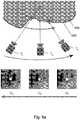
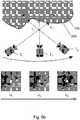
- Figures 5a and 5bdepict a mechanism which the neural network may use during the projective pooling stage 202.
- Figures 5a and 5bshow part of the object 105.
- the part of the object 105has a surface 505, which is imaged by camera 101 from respective locations Tc, Td, and Te.
- the object 105has three points x1, x2 and x3 on its surface 505. Movement of the camera is shown by the dotted arrow.
- the voxel V1 being consideredis 'behind' the surface 505 of the object 105, and thus voxel V1 can be said to be occupied by the object 105.
- the voxel V2 being consideredis in front of the surface 505 of the object 105, and thus voxel V2 can be said to be part of free space, i.e. not occupied by the object 105.
- Optical flowcan be described as the apparent motion of the surface 505 of the object 105 between the images Ic, Id, and le. This apparent motion is caused by the relative movement between the camera 101 and the surface 505 of the object 105.
- the local optical flow in local image patches Uc, Ud and Ueis directly related to the relative position of the voxel V1 and the observed surface 505.
- the direction of optical flowis shown by the solid arrow. It will be appreciated that, if the voxel is behind the surface, as in figure 5a , the direction of the optical flow is opposite to the camera motion.
- the direction of the optical flowis aligned with the camera motion.
- the speed of the flowdepends on the relative distances from the voxel to the surface and camera, and is higher when the voxel is far from the surface, and lower when it is close.
- voxel occupancyObservation and analysis of optical flow allows voxel occupancy to be determined. If a positive optical flow is detected in a sequence of images, i.e. the direction of optical flow is determined to be in broadly the same direction as the camera motion, this is evidence that a given voxel is free. Conversely, if negative optical flow is observed, then the voxel can be considered to be occupied.
- a convolutional neural networkcan be used to analyse the similarity of image patches Uc, Ud and Ue.
- a combination of convolutional and recurrent neural networkcan be used to detect and classify the image patches, as is described in more detail below.
- the method (and system) described hereinis advantageous, as it is less resource-intensive, less time-consuming, and can provide a better model of unknown observed objects than previous methods and systems. Also the method and system described herein is likely to achieve higher quality models and also to generalise better that known systems. That is, it can create models of a greater variety of objects than other methods, given some amount of training data.
- the method and system as described hereinmay be run in real-time on a consumer-grade device such as a mobile phone.
- the method and system as described hereinis also less likely to suffer from erroneous pixel-correspondences between images, which is a disadvantage of known methods.
- the method and system described hereindoes not require a depth sensor, like some other methods do.
- the entire networkcan be trained using standard back-propagation gradient descent. In the future this could also be done in an un-supervised manner if a differential renderer is provided. In this case, the knowledge of ground-truth voxel occupancy is not required and the training is driven by the error in the accuracy of the ray-casted model compared to the training 2D images.
- the structure of the encoding neural network 201 that computes encoded image data descriptors Dican be arbitrary such as, but not limited to, a convolutional networks or a deep residual network.
- the structure of the recurrent neural network 202can be arbitrary such as but not limited to LSTM, GRU or their 3D variants.
- the number of imagescan be constant - in that case it is more accurate to instead call the recurrent neural network a neural network, in which case the encoder network 201 (Eq. (5)) for each image can be different.
- the structure of the decoding network 203 Eq. (8))can be arbitrary such as but not limited to deep generative network or a deconvolution network.
- the training procedurecan be semi-supervised if a differential volumetric renderer is used.
- the recurrent network 202(RNN, Eq. (7)) can be directly connected to the pre-processed input image to incorporate the global image content, and not only local pooled information.
- the pooled descriptors dican also be computed in reverse order: first the position u i j is computed, then explicit image patches U i j at the given locations are extracted from image li. These are then independently passed through encoding network 201 enc (Eq. (5)). In this case explicit pooling does not happen but the resulting information is similar in its content as it describes information about the image at the location u i j .
- the method and system as described hereinmay output the probability that each voxel is occupied.
- the systemmay output an arbitrary scale of occupied-ness or simply a binary scale of in or out (e.g. 1/0).
- the output of the systemcan include colour information of the model. This is achieved similarly - instead or in addition to voxel occupancy the network produces individual voxel colour. Such a network is trained similarly back-propagating the error in prediction.
- the training of the recurrent neural network 202can be improved using decoder module 203 after each step of recurrent neural network 202 and using its output as the additional input of the next step of RNN 202.
- the approaches described hereinmay be performed by a system comprising a processor / computer, and may also be embodied on a computer-readable medium, which may be a non-transitory computer-readable medium.
- the computer-readable mediumcarries computer-readable instructions arranged for execution upon a processor so as to make the processor carry out any or all of the methods described herein.
- Non-volatile mediamay include, for example, optical or magnetic disks.
- Volatile mediamay include dynamic memory.
- Exemplary forms of storage mediuminclude, a floppy disk, a flexible disk, a hard disk, a solid state drive, a magnetic tape, or any other magnetic data storage medium, a CD-ROM, any other optical data storage medium, any physical medium with one or more patterns of holes, a RAM, a PROM, an EPROM, a FLASH-EPROM, NVRAM, and any other memory chip or cartridge.
Landscapes
- Engineering & Computer Science (AREA)
- Physics & Mathematics (AREA)
- Theoretical Computer Science (AREA)
- General Physics & Mathematics (AREA)
- Computer Vision & Pattern Recognition (AREA)
- Computer Graphics (AREA)
- Computing Systems (AREA)
- Geometry (AREA)
- Image Analysis (AREA)
- Image Generation (AREA)
- Image Processing (AREA)
- Processing Or Creating Images (AREA)
Description
- This disclosure relates to the field of computer vision, and in particular to a method and system for creating a virtual 3D model of an object.
- Understanding the 3D structure of the world from a series of 2D image observations, and in particular producing a 3D reconstruction from a sequence of 2D images, is an important undertaking in the field of computer vision. Creating a virtual 3D model from image data has applications in many fields such as but not limited to robotics, self-driving cars and augmented-reality. Augmented reality involves projecting a virtual object onto the physical (real) world around us. Virtual objects may be created from real objects, such that they can be projected into these spaces. Secondarily, for robotics, self-driving cars, and augmented-reality alike, it may be of importance to be able to know the position of a device (phone, drone, car) in the world, and 3D models of the surroundings may be helpful.
- Existing approaches tend to fall into one of two categories: geometric methods and deep learning methods.
- As discussed in the book byR. Hartley and A. Zisserman "Multiple view geometry in computer vision" Cambridge university press, 2003, existing geometric approaches are based on the principles of multi-view geometry. Given two or more images I1,I2,.. . IN taken at positions T1, T2,. .. , TN ∈ SE3 and pixel correspondences between those images, it is possible to triangulate the 3D positions of the image pixels. To determine these correspondences, it is possible to extract an image patch around a pixel and perform an exhaustive search along an epipolar line, finding the position of a similar patch in a different image. If this is done for each pixel, it is possible to produce a 2.5D depth image which contains depth information about each pixel, e.g. the distance of each pixel from the camera in a respective image.
- To compute the complete 3D model, one must concatenate several 2.5D depth images together, or alternatively fuse them into a single volumetric model. In the case of the latter approach, the 3D space is split into a grid of voxels, and the content of each voxel is calculated via the following rules: if at some point a voxel is observed at a distance closer than the corresponding pixel depth, it is considered a part of a free space. Otherwise, it can be considered to be 'occupied'.
- However, this type of system is subject to erroneous pixel correspondences, which results in incorrect depth computations. Also, fusing the depth images into a single volumetric model in the manner described above is time-consuming, and consumes computer resources.
- A second known approach is to use so-called 'deep learning', for instance as discussed in the article byC. B. Choy, D. Xu, J. Gwak, K. Chen, and S. Savarese. "3D-R2N2: A unified approach for single and multi-view 3D object reconstruction" arXiv preprint arXiv:1604.00449, 2016 and the article by D. J. Rezende, S. Eslami, S. Mohamed, P. Battaglia, M. Jaderberg, and N. Heess "Unsupervised learning of 3S structure from images".arXiv preprint arXiv:1607.00662, 2016. In this approach, deep generative models are conditioned on the input images directly. The underlying principle in this approach is that, first, the individual 2D input images are compressed into a 1 D feature vector, which summarises the content of the image. These 1 D feature vectors are later passed as input to a long short-term memory(LSTM) network, the output of which is used to generate a model.
- This approach is suitable for 'imagining' a missing part of a known object, but tends to lead to generalisation problems when modelling new unknown, observed objects.
- An approach for creating models of humans is disclosed in document
US 2015/0178988 A1 . - An approach for three dimensional object reconstruction is disclosed in the paper "3D-R2N2: A Unified Approach for Single and Multi-view 3D Object Reconstruction" dated 17 September 2016 published in Network and Parallel Computing pages 628-644.
- Therefore, an approach which is less resource-intensive, less time-consuming, and which can provide a better model of unknown observed objects is required. The present disclosure describes such an approach.
- A method and system are set out in the independent claims. Optional features are set out in the dependent claims.
- According to an example, there is provided a method for creating a voxel occupancy model. The voxel occupancy model is representative of a region of space which can be described using a three-dimensional voxel array. The region of space contains at least part of an object. The method comprises receiving first image data, the first image data being representative of a first view of the at least part of an object and comprising first image location data, and receiving second image data, the second image data being representative of a second view of the at least part of an object and comprising second image location data. The method also comprises determining a first descriptor, the first descriptor describing a property of a projection of a first voxel of the voxel array in the first image data, and determining a second descriptor, the second descriptor describing a property of a projection of the first voxel in the second image data. The method also comprises assigning an occupancy value to the first voxel based on the first and second descriptors, the occupancy value being representative of whether the first voxel is occupied by the at least part of an object.
- In some examples, the method further comprises receiving a set of image data, each respective member of the set of image data being representative of a view of the at least part of an object and comprising image location data. The method may also comprise determining a descriptor for each member of the set of image data, each descriptor of the resulting plurality of descriptors describing a property of a projection of the first voxel of the voxel array in each corresponding member of the set of image data. The method may also comprise assigning an occupancy value to the first voxel based on the determined descriptors.
- In some examples, the method further comprises determining a respective plurality of descriptors for each voxel of the voxel array, and assigning an occupancy value to each voxel based on the determined descriptors.
- In some examples, the property of the first projection is the 2D location of the projection of the first voxel in the first image data, and the property of the second projection is the 2D location of the projection of the first voxel in the second image data.
- In some examples, both the first image data and the second image data is received from a camera arranged to move with respect to the at least part of an object.
- In some examples, the first image data is received from a first camera and the second image data is received from a second camera, the first and second cameras being positioned at respective locations with respect to the at least part of an object.
- In some examples, the first image location data is representative of the pose of the first image, and the second image location data is representative of the pose of the second image.
- In some examples, the method further comprises outputting a voxel occupancy model, the voxel occupancy model comprising the assigned occupancy value for each voxel which has been assigned an occupancy value.
- In some examples, the method further comprises generating a visual representation of the at least part of an object from the voxel occupancy model.
- In some embodiments, the first image data comprises first encoded image data representative of a first image taken from the first view, wherein the first encoded image data describes a property of each pixel of a plurality of pixels of the first image. In some embodiments, the second image data comprises second encoded image data representative of a second image taken from the second view, wherein the second encoded image data describes a property of each of a plurality of pixels of the second image.
- In some examples, the property comprises a brightness value, an intensity value, a pattern, a texture, a colour value, or image features such as image corners or gradient.
- In some examples, the descriptors are determined using a neural network.
- In some examples, the descriptors are input into a neural network, and the occupancy value is determined based on an output of the neural network.
- According to an aspect, there is provided a system comprising a processor according to claim 14.
- According to an aspect, there is provided a computer-readable medium according to claim 15.
- Specific embodiments are now described with reference to the drawings, in which:
Figure 1 depicts a schematic overview of a 3D modelling process;Figure 2 depicts a schematic diagram of a 3D modelling apparatus;Figure 3 depicts a flow-chart of the 3D modelling process;Figure 4 depicts a flow-chart of the 3D modelling process;Figure 5a depicts the observation of a voxel behind the surface of an observed object;Figure 5b depicts the observation of a voxel in front of the surface of an observed object.- The present invention seeks to provide an improved method and system for creating a virtual 3D model of an object. Whilst various embodiments of the invention are described below, the invention is not limited to these embodiments, and variations of these embodiments may well fall within the scope of the invention, which as such is to be limited only by the appended claims.
- In accordance with an embodiment of the invention,
figure 1 shows a schematic diagram of a 3D modelling process. Anobject 105 is located in a region of space. Infigure 1 , theobject 105 is, by way of an example, a model of a cathedral. The region of space can be described using avoxel array 120, with each voxel Vj in the voxel array describing a small element of physical space, "j" being an index that corresponds to a particular voxel, as will be understood by the skilled person. For the purposes of the modelling process, a particular voxel Vj is said to be 'occupied' if part of theobject 105 is located within the voxel. A particular voxel Vj can be considered part of free space, and thus not occupied, if no part of theobject 105 is located within the voxel. - In overview, the process described herein involves taking a plurality of images Ii of the
object 105 from a plurality of locations T around theobject 105. Image data 115i associated with each image Ii includes data representative of the image Ii and also comprises data Ti associated with the pose of each image, i.e. the location and angular orientation of the camera at the position Ti. The image data undergoes a 'projective pooling' process, with the pooled output from individual images being merged using a neural network to allow a virtual 3D model /voxel occupancy model 150 of the region of space to be produced. Theoccupancy model 150 describes a3D model 140 of theobject 105. - A
camera 101 is moveable around theobject 105, and thus can be arranged to capture images from various locations T around theobject 105. Two different camera locations Ta and Tb are shown infigure 1. Figure 1 shows an image Ia of theobject 105 being taken from location Ta. Accordingly,first image data 115a can be produced.First image data 115a also includes information about the image pose, e.g. the location and angle of the viewpoint of the camera at location Ta. As will be appreciated, the first image Ia is a projection of theobject 105 in the plane of thecamera 101 at the first location Ta. - Similarly, an image Ib of the
object 105 is taken from location Tb. Accordingly, second image data 115b can be produced. Second image data 115b includes information about the image pose at camera location Tb. As will be appreciated, the second image Ib is a projection of theobject 105 in the plane of thecamera 101 at the second location Tb. - A plurality of such images is taken of the
object 105 from various viewpoints and locations Ti around theobject 105. In a preferred embodiment, thecamera 101 moves in a circular motion around theobject 105, thus capturing 'N' images from all sides of theobject 105. This results in a sequence of consecutive images I1, I2, ... IN taken at positions T1, T2...TN. Images Ii can be encoded, for example each image Ii can be converted into a spatially-indexable descriptor Di, as will be described in more detail below. - It is possible to use the plurality of images, and in particular the image data 115i associated with each image Ii, which includes information regarding the pose of each image, to determine whether a
particular voxel 130 of thevoxel array 120 is occupied by the observedobject 105. - Voxel locations can be labelled Vj. To determine the occupancy


- In more detail, a particular voxel's 3D projection w = [wx, wy, wz] into the i-th image Ii is found by:

- The transformed 3D point of the region of space is projected into the image, and the corresponding sub-pixel location


- Note that this is one example of possible choice of camera calibration. There exist many models, for example for fisheye, wide-angle, and macro lenses, or for different sensor types. Theh choice of fx, fy, cx, cy to describe the camera calibration one choice. Other models can be substituted here.
- A local image patch


- As is discussed below, it is possible to determine voxel occupancy by analysing a stream of images at the positions of the projected voxel locations.
Figure 2 depicts a schematic diagram of a 3D modelling apparatus suitable to implement a 3D modelling process in accordance with an embodiment of the invention. The present system can directly classify voxel occupancy from a sequence of images with associated image location data. A neural network architecture may be used to put this idea into practice in a single coherent network. The network is capable of classifying the occupancy of a volumetric grid of, for example, size MxMxM voxels. The process may comprise four parts, as will be described below.- In overview, the process has the following inputs: voxel positions qj, image location data Ti i.e. image pose data, and the corresponding images Ii, and has the output of a virtual 3D model /
voxel occupancy model 150. - The N images I1, ..., N form a set of images. The processing of image I1 will be primarily considered, and it will be appreciated that each image Ii undergoes a substantially similar process. Image I1 is encoded by processing device 201 (1). The output of the encoding step carried out by processing device 201 (1) is encoded image data. The encoded image data describes a property of each pixel of image I1. The property may be, for example, a brightness value, a colour value, an intensity value, a pattern, a texture, or image features such as image corners or gradient, although any local property of the pixels may be used in the encoding step as would be appreciated by the skilled person.
- Each input image li is converted into a spatially-indexable encoded image data descriptor:


- The second step is a 'projective pooling' step carried out by processing device 202(1). The inputs into processing device 202(1) are the encoded image data descriptor D1, the corresponding image location data / image pose data T1, and the voxel locations qj. Together, the encoded image data descriptor D1 and image location data T1 comprise first image data. Similarly, encoded image data D2 and image location data T2 comprise second image data, etc.
- At the projective pooling stage carried out by processing
device 202, a spatial descriptor

- The encoded image data descriptor Di for each image is pooled for each voxel independently by first projecting the voxel Vj into each
image using Equation 1. The encoded image data descriptor Di is then bilinearly interpolated at the given sub-pixel location. This can be done in parallel resulting into pooled descriptor for each voxel d ∈
- In this way, a
first descriptor 
first descriptor 
- A
second descriptor 

descriptors 
descriptors 
voxel array 120. - The next stage is 'volumetric fusion' stage carried out by processing
device 203. This stage involves aggregating the consecutive voxel measurements to a hidden representation h via a recurrent neural network:
- The pooled output from individual images is merged using a recurrent neural network 2013. A Recurrent Neural Network such as a 3D long short-term memory (LSTM) network can be used to perform this task, with the size of hidden state

- Finally,
processing device 204 decodes the final volumetric occupancy model, which can be represented as follows:
- In this stage, the output of the
recurrent network 202 is fed intodecoder 203, implemented as a simple multi-layer 3D convolutional network reducing the final hidden state hN into network output
Figure 3 shows a flowchart of an embodiment of the method described herein.- At 302, a set of images I are taken of the object from a variety of different locations T around the object.
- At 304, the images I are encoded to produce encoded image descriptors D. Together, descriptors D and T comprise image data.
- At 306, the encoded image data D, image locations T and voxel positions q are given as inputs into the 'projective pooling' neural network. The encoding stage can be said to be outputting latent image representations.
- At 308, the 'projective pooling' neural network determines a spatial descriptor

- At 310, the spatial descriptors

- At 312, the aggregated descriptors are decoded into a volumetric 3D model, e.g. a voxel occupancy model. Some embodiments may comprise a further step of generating and/or outputting a visual representation of the object using the voxel occupancy model.
Figure 4 shows a flowchart of an embodiment of the method described herein. The method depicted in the flowchart can be performed by a processor, computer, or neural network implemented on a processing arrangement such as a processor or computer network. The method can be used to create a voxel occupancy model, the voxel occupancy model being representative of a region of space which can be described using a three-dimensional voxel array, wherein the region of space contains at least part of an object.- At 402, first image data is received. The first image data (e.g. D1+T1) is representative of a first view of the at least part of an object, and comprises first image location data.
- At 404, second image data is received. The second image data (e.g. D2+T2) is representative of a second view of the at least part of an object, and comprises second image location data.
- At 406, a first descriptor is determined. The first descriptor describes a property of a projection of a first voxel of the voxel array in the first image data.
- At 408, a second descriptor is determined. The second descriptor describes a property of a projection of the first voxel in the second image data.
- At 410, an occupancy value is assigned to the first voxel based on the first and second descriptors. The occupancy value is representative of whether the first voxel is occupied by the at least part of an object.
- It will be appreciated that, in embodiments of the method described herein, this process may be repeated for image data representative of each available image of the object, in order to build up a more accurate estimate of whether or not the first voxel is occupied or not. It will also be appreciated that this process can be repeated for each voxel. This and/or these processes can be performed in parallel via one or more neural networks. A collection of predictions regarding the occupancy of any particular voxel, of a plurality of voxels, which describes a region of space can be described as a voxel occupancy model.
- In
optional step 412, a visual representation of the object is outputted, the visual representation being based on the occupancy value, or voxel occupancy model. Instead of generating a visual representation, the occupancy model may be passed to a robot, to allow it to navigate or interact with the object in an accurate manner. Figures 5a and5b depict a mechanism which the neural network may use during theprojective pooling stage 202.Figures 5a and5b show part of theobject 105. The part of theobject 105 has asurface 505, which is imaged bycamera 101 from respective locations Tc, Td, and Te. Theobject 105 has three points x1, x2 and x3 on itssurface 505. Movement of the camera is shown by the dotted arrow. Infigure 5a , the voxel V1 being considered is 'behind' thesurface 505 of theobject 105, and thus voxel V1 can be said to be occupied by theobject 105. Infigure 5b , the voxel V2 being considered is in front of thesurface 505 of theobject 105, and thus voxel V2 can be said to be part of free space, i.e. not occupied by theobject 105.- At this stage, the direction of the local optical flow is observed. Optical flow can be described as the apparent motion of the
surface 505 of theobject 105 between the images Ic, Id, and le. This apparent motion is caused by the relative movement between thecamera 101 and thesurface 505 of theobject 105. The local optical flow in local image patches Uc, Ud and Ue is directly related to the relative position of the voxel V1 and the observedsurface 505. The direction of optical flow is shown by the solid arrow. It will be appreciated that, if the voxel is behind the surface, as infigure 5a , the direction of the optical flow is opposite to the camera motion. If the voxel is in front of the surface, as infigure 5b , the direction of the optical flow is aligned with the camera motion. The speed of the flow depends on the relative distances from the voxel to the surface and camera, and is higher when the voxel is far from the surface, and lower when it is close. - Observation and analysis of optical flow allows voxel occupancy to be determined. If a positive optical flow is detected in a sequence of images, i.e. the direction of optical flow is determined to be in broadly the same direction as the camera motion, this is evidence that a given voxel is free. Conversely, if negative optical flow is observed, then the voxel can be considered to be occupied.
- A convolutional neural network can be used to analyse the similarity of image patches Uc, Ud and Ue. A combination of convolutional and recurrent neural network can be used to detect and classify the image patches, as is described in more detail below.
- The method (and system) described herein is advantageous, as it is less resource-intensive, less time-consuming, and can provide a better model of unknown observed objects than previous methods and systems. Also the method and system described herein is likely to achieve higher quality models and also to generalise better that known systems. That is, it can create models of a greater variety of objects than other methods, given some amount of training data. The method and system as described herein may be run in real-time on a consumer-grade device such as a mobile phone. The method and system as described herein is also less likely to suffer from erroneous pixel-correspondences between images, which is a disadvantage of known methods. In addition, the method and system described herein does not require a depth sensor, like some other methods do.
- As all the individual steps are differentiable, the entire network can be trained using standard back-propagation gradient descent. In the future this could also be done in an un-supervised manner if a differential renderer is provided. In this case, the knowledge of ground-truth voxel occupancy is not required and the training is driven by the error in the accuracy of the ray-casted model compared to the training 2D images.
- It will be understood that the above description of specific embodiments is by way of example only and is not intended to limit the scope of the present disclosure. Many modifications of the described embodiments, some of which are now described, are envisaged and intended to be within the scope of the present disclosure.
- It will be appreciated that multiple different types of camera may be used. Whilst an embodiment with a single moving camera has been described, it is equally possible to use multiple cameras positioned at different positions around the object in order to obtain the images li. Similarly, in the case of a fixed camera array or fixed camera ring, or stereo camera set up, the poses of the cameras can be known and always constant, as will be appreciated by the skilled person. Similarly, the camera projection model used has been that of a pin-hole camera, however omnidirectional camera models such as or fisheye can also be incorporated.
- The structure of the encoding
neural network 201 that computes encoded image data descriptors Di can be arbitrary such as, but not limited to, a convolutional networks or a deep residual network. - The structure of the recurrent
neural network 202 can be arbitrary such as but not limited to LSTM, GRU or their 3D variants. - The number of images can be constant - in that case it is more accurate to instead call the recurrent neural network a neural network, in which case the encoder network 201 (Eq. (5)) for each image can be different.
- The structure of the
decoding network 203 Eq. (8)) can be arbitrary such as but not limited to deep generative network or a deconvolution network. - The training procedure can be semi-supervised if a differential volumetric renderer is used.
- In addition to the pooled information, the recurrent network 202 (RNN, Eq. (7)) can be directly connected to the pre-processed input image to incorporate the global image content, and not only local pooled information.
- The pooled descriptors di can also be computed in reverse order: first the position


encoding network 201 enc (Eq. (5)). In this case explicit pooling does not happen but the resulting information is similar in its content as it describes information about the image at the location
- The method and system as described herein may output the probability that each voxel is occupied. However rather than a probability, the system may output an arbitrary scale of occupied-ness or simply a binary scale of in or out (e.g. 1/0). The output of the system can include colour information of the model. This is achieved similarly - instead or in addition to voxel occupancy the network produces individual voxel colour. Such a network is trained similarly back-propagating the error in prediction.
- The training of the recurrent
neural network 202 can be improved usingdecoder module 203 after each step of recurrentneural network 202 and using its output as the additional input of the next step ofRNN 202. - The approaches described herein may be performed by a system comprising a processor / computer, and may also be embodied on a computer-readable medium, which may be a non-transitory computer-readable medium. The computer-readable medium carries computer-readable instructions arranged for execution upon a processor so as to make the processor carry out any or all of the methods described herein.
- The term "computer-readable medium" as used herein refers to any medium that stores data and/or instructions for causing a processor to operate in a specific manner. Such storage medium may comprise non-volatile media and/or volatile media. Non-volatile media may include, for example, optical or magnetic disks. Volatile media may include dynamic memory. Exemplary forms of storage medium include, a floppy disk, a flexible disk, a hard disk, a solid state drive, a magnetic tape, or any other magnetic data storage medium, a CD-ROM, any other optical data storage medium, any physical medium with one or more patterns of holes, a RAM, a PROM, an EPROM, a FLASH-EPROM, NVRAM, and any other memory chip or cartridge.


Claims (15)
- A method for creating a virtual three-dimensional model of an object 140, the method comprising:receiving first image data 402 associated with a first image, the first image data 402 being representative of a first view of the at least part of an object 105 and comprising first image location data and a first spatially-indexable encoded image data descriptor, wherein the first spatially-indexable encoded image data descriptor includes, for each pixel of the first image, a pixel descriptor which describes a local neighbourhood surrounding the pixel;receiving second image data 404 associated with a second image, the second image data 404 being representative of a second view of the at least part of an object 105 and comprising second image location data and a second spatially-indexable encoded image data descriptor, wherein the second spatially-indexable encoded image data descriptor includes, for each pixel of the second image, a pixel descriptor which describes a local neighbourhood surrounding the pixel;determining a first descriptor 406 based on the first spatially-indexable encoded image data descriptor, the first descriptor describing a property of a projection of a first voxel of a voxel array in the first image data 402;determining a second descriptor 408 based on the second spatially-indexable encoded image data descriptor, the second descriptor describing a property of a projection of the first voxel in the second image data 404; andassigning an occupancy value 410 to the first voxel in the virtual three-dimensional model based on the first and second descriptors 406, 408, the occupancy value 410 being representative of whether the first voxel is occupied by the at least part of an object 105.
- The method of claim 1, further comprising:receiving a set of image data, each respective member of the set of image data being representative of a view of the at least part of the object 105 and comprising image location data; anddetermining a descriptor for each member of the set of image data, each descriptor of the resulting plurality of descriptors describing a property of a projection of the first voxel of the voxel array in each corresponding member of the set of image data;wherein assigning the occupancy value 410 to the first voxel in the virtual three-dimensional model based on the first and second descriptors 406, 408 further comprises assigning the occupancy value 410 to the first voxel based on the determined descriptors 406, 408.
- The method of any preceding claim, further comprising:
determining a respective plurality of descriptors 406, 408 for each voxel of a voxel array, and assigning an occupancy value 410 to each voxel in the virtual three-dimensional model based on the determined descriptors 406, 408. - The method of any preceding claim, wherein:the property of the first projection is the 2D location of the projection of the first voxel in the first image data; andthe property of the second projection is the 2D location of the projection of the first voxel in the second image data.
- The method of any preceding claim, wherein both the first image data and the second image data are received from a camera arranged to move with respect to the at least part of the object 105 and/or the first image data is received from a first camera and the second image data is received from a second camera, the first and second cameras being positioned at respective locations with respect to the at least part of the object 105.
- The method of any preceding claim, wherein the first image location data is representative of the pose of the first image, and the second image location data is representative of the pose of the second image.
- The method of any preceding claim, further comprising outputting a virtual three-dimensional model 140, the virtual three-dimensional model 140 comprising the assigned occupancy value 410 for each voxel which has been assigned an occupancy value 410, optionally further comprising generating a visual representation of the at least part of the object 105 from the virtual three-dimensional model 140.
- The method of any preceding claim, wherein the first spatially-indexable encoded image data descriptor describes a property of each pixel of a plurality of pixels of the first image; and
the second spatially-indexable encoded image data descriptor describes a property of each pixel of a plurality of pixels of the second image. - The method of claim 8, wherein the property of each pixel of the plurality of pixels of the first image and the property of each pixel of the plurality of pixels of the second image comprises a brightness value, an intensity value, a pattern, a texture, a colour value, or image features including at least one of: image corners and gradient.
- The method of any preceding claim, wherein the first and second spatially-indexable encoded image data descriptors are determined using a multi-layer neural network.
- The method of any preceding claim, wherein each pixel descriptor of the first and second spatially-indexable encoded image data descriptors has the same length.
- The method of any preceding claim, wherein:the first spatially-indexable encoded image data descriptor includes one or more sections, and each section of the first spatially-indexable encoded image data descriptor corresponds to a particular region of the first image; andthe second spatially-indexable encoded image data descriptor includes one or more sections, and each section of the second spatially-indexable encoded image data descriptor corresponds to a particular region of the second image.
- The method of any preceding claim further comprising:receiving a set of image data 302 associated with a plurality of images;determining a plurality of descriptors 406, 408, wherein each descriptor of the plurality of descriptors is associated with a respective one image of the plurality of images and a respective one voxel of a voxel array; andfor each voxel of the voxel array, pooling descriptors 308 associated with the voxel such that each voxel is associated with a plurality of descriptors describing a relationship between the voxel and each image in the plurality of images;optionally further comprising the step of determining, for each voxel of the voxel array, a probability of occupancy based on the plurality of descriptors 406, 408 and a recurrent neural network.
- A system comprising a processor configured to perform the method of any preceding claim.
- A computer-readable medium comprising computer-executable instructions which, when executed on a computer, perform the method of any of claims 1-13.
Applications Claiming Priority (2)
| Application Number | Priority Date | Filing Date | Title |
|---|---|---|---|
| US15/274,898US10460511B2 (en) | 2016-09-23 | 2016-09-23 | Method and system for creating a virtual 3D model |
| PCT/GB2017/052789WO2018055354A1 (en) | 2016-09-23 | 2017-09-20 | A method and system for creating a virtual 3d model |
Publications (2)
| Publication Number | Publication Date |
|---|---|
| EP3516624A1 EP3516624A1 (en) | 2019-07-31 |
| EP3516624B1true EP3516624B1 (en) | 2021-05-26 |
Family
ID=59997389
Family Applications (1)
| Application Number | Title | Priority Date | Filing Date |
|---|---|---|---|
| EP17777639.0AActiveEP3516624B1 (en) | 2016-09-23 | 2017-09-20 | A method and system for creating a virtual 3d model |
Country Status (7)
| Country | Link |
|---|---|
| US (2) | US10460511B2 (en) |
| EP (1) | EP3516624B1 (en) |
| CN (1) | CN109716393A (en) |
| AU (1) | AU2017331496A1 (en) |
| CA (1) | CA3037805A1 (en) |
| MX (1) | MX2019003279A (en) |
| WO (1) | WO2018055354A1 (en) |
Families Citing this family (27)
| Publication number | Priority date | Publication date | Assignee | Title |
|---|---|---|---|---|
| US9373059B1 (en)* | 2014-05-05 | 2016-06-21 | Atomwise Inc. | Systems and methods for applying a convolutional network to spatial data |
| KR102061408B1 (en)* | 2017-03-24 | 2019-12-31 | (주)제이엘케이인스펙션 | Apparatus and method for analyzing images using semi 3d deep neural network |
| US10534962B2 (en)* | 2017-06-17 | 2020-01-14 | Matterport, Inc. | Automated classification based on photo-realistic image/model mappings |
| US11170246B2 (en)* | 2017-07-12 | 2021-11-09 | Sony Interactive Entertainment Inc. | Recognition processing device, recognition processing method, and program |
| US10915760B1 (en)* | 2017-08-22 | 2021-02-09 | Objectvideo Labs, Llc | Human detection using occupancy grid maps |
| GB2573102A (en)* | 2018-04-20 | 2019-10-30 | Drugai Ltd | Interaction property prediction system and method |
| US11126915B2 (en)* | 2018-10-15 | 2021-09-21 | Sony Corporation | Information processing apparatus and information processing method for volume data visualization |
| US20200137380A1 (en)* | 2018-10-31 | 2020-04-30 | Intel Corporation | Multi-plane display image synthesis mechanism |
| CN111178495B (en)* | 2018-11-10 | 2023-06-30 | 杭州凝眸智能科技有限公司 | Lightweight convolutional neural network for detecting very small objects in an image |
| US11995854B2 (en)* | 2018-12-19 | 2024-05-28 | Nvidia Corporation | Mesh reconstruction using data-driven priors |
| EP3671660B1 (en)* | 2018-12-20 | 2025-06-18 | Dassault Systèmes | Designing a 3d modeled object via user-interaction |
| US11050932B2 (en)* | 2019-03-01 | 2021-06-29 | Texas Instruments Incorporated | Using real time ray tracing for lens remapping |
| CN113892112B (en)* | 2019-07-10 | 2024-08-09 | 赫尔实验室有限公司 | System, method and computer program product for action recognition |
| EP4052223A4 (en)* | 2019-11-01 | 2023-11-01 | Visionary Machines Ptd Ltd | Systems and methods for generating and/or using 3-dimensional information with camera arrays |
| CN111047548B (en)* | 2020-03-12 | 2020-07-03 | 腾讯科技(深圳)有限公司 | Attitude transformation data processing method and device, computer equipment and storage medium |
| US11836965B2 (en) | 2020-08-12 | 2023-12-05 | Niantic, Inc. | Determining visual overlap of images by using box embeddings |
| JP7386888B2 (en)* | 2020-10-08 | 2023-11-27 | グーグル エルエルシー | Two-shot composition of the speaker on the screen |
| US11636685B1 (en)* | 2020-12-18 | 2023-04-25 | Zoox, Inc. | Multi-resolution top-down segmentation |
| US12293535B2 (en)* | 2021-08-03 | 2025-05-06 | Intrinsic Innovation Llc | Systems and methods for training pose estimators in computer vision |
| CN113763539B (en)* | 2021-09-09 | 2023-04-07 | 哈尔滨工业大学(深圳) | Implicit function three-dimensional reconstruction method based on image and three-dimensional input |
| CN113822825B (en)* | 2021-11-25 | 2022-02-11 | 电子科技大学成都学院 | Optical building target three-dimensional reconstruction method based on 3D-R2N2 |
| US12112510B2 (en)* | 2022-03-25 | 2024-10-08 | Tencent America LLC | Convolutional approach to fast and compact packing of 3D mesh into 2D maps |
| US12322068B1 (en)* | 2022-09-08 | 2025-06-03 | Nvidia Corporation | Generating voxel representations using one or more neural networks |
| US20240104829A1 (en)* | 2022-09-26 | 2024-03-28 | Sony Interactive Entertainment Inc. | Using vector graphics to create 3d content |
| US20240193851A1 (en)* | 2022-12-12 | 2024-06-13 | Adobe Inc. | Generation of a 360-degree object view by leveraging available images on an online platform |
| US12293454B2 (en)* | 2023-02-17 | 2025-05-06 | Varjo Technologies Oy | Multiresolution truncated neural radiance fields |
| US12307589B2 (en)* | 2023-03-21 | 2025-05-20 | Qualcomm Incorporated | Generating semantically-labelled three-dimensional models |
Family Cites Families (15)
| Publication number | Priority date | Publication date | Assignee | Title |
|---|---|---|---|---|
| JP3463858B2 (en)* | 1998-08-27 | 2003-11-05 | 矢崎総業株式会社 | Perimeter monitoring device and method |
| US6990228B1 (en)* | 1999-12-17 | 2006-01-24 | Canon Kabushiki Kaisha | Image processing apparatus |
| ATE404950T1 (en)* | 2004-06-11 | 2008-08-15 | Saab Ab | COMPUTER MODELING OF PHYSICAL SCENES |
| EP2209091B1 (en)* | 2009-01-16 | 2012-08-08 | Honda Research Institute Europe GmbH | System and method for object motion detection based on multiple 3D warping and vehicle equipped with such system |
| US8866821B2 (en)* | 2009-01-30 | 2014-10-21 | Microsoft Corporation | Depth map movement tracking via optical flow and velocity prediction |
| CN102396002B (en)* | 2009-04-15 | 2015-07-08 | 丰田自动车株式会社 | Object detection device |
| JP4788798B2 (en)* | 2009-04-23 | 2011-10-05 | トヨタ自動車株式会社 | Object detection device |
| US9171372B2 (en)* | 2010-11-23 | 2015-10-27 | Qualcomm Incorporated | Depth estimation based on global motion |
| US8971612B2 (en)* | 2011-12-15 | 2015-03-03 | Microsoft Corporation | Learning image processing tasks from scene reconstructions |
| WO2013174671A1 (en) | 2012-05-22 | 2013-11-28 | Telefonica, S.A. | A method and a system for generating a realistic 3d reconstruction model for an object or being |
| WO2015017941A1 (en)* | 2013-08-09 | 2015-02-12 | Sweep3D Corporation | Systems and methods for generating data indicative of a three-dimensional representation of a scene |
| US10121259B2 (en)* | 2015-06-04 | 2018-11-06 | New York University Langone Medical | System and method for determining motion and structure from optical flow |
| US10466714B2 (en)* | 2016-09-01 | 2019-11-05 | Ford Global Technologies, Llc | Depth map estimation with stereo images |
| US10878583B2 (en)* | 2016-12-02 | 2020-12-29 | Google Llc | Determining structure and motion in images using neural networks |
| CN109196556A (en)* | 2017-12-29 | 2019-01-11 | 深圳市大疆创新科技有限公司 | Obstacle avoidance method, device and movable platform |
- 2016
- 2016-09-23USUS15/274,898patent/US10460511B2/enactiveActive
- 2017
- 2017-09-20CNCN201780058370.2Apatent/CN109716393A/enactivePending
- 2017-09-20CACA3037805Apatent/CA3037805A1/ennot_activeAbandoned
- 2017-09-20WOPCT/GB2017/052789patent/WO2018055354A1/ennot_activeCeased
- 2017-09-20MXMX2019003279Apatent/MX2019003279A/enunknown
- 2017-09-20AUAU2017331496Apatent/AU2017331496A1/ennot_activeAbandoned
- 2017-09-20EPEP17777639.0Apatent/EP3516624B1/enactiveActive
- 2019
- 2019-10-03USUS16/591,807patent/US11205298B2/enactiveActive
Non-Patent Citations (1)
| Title |
|---|
| None* |
Also Published As
| Publication number | Publication date |
|---|---|
| CA3037805A1 (en) | 2018-03-29 |
| EP3516624A1 (en) | 2019-07-31 |
| WO2018055354A1 (en) | 2018-03-29 |
| US20200126289A1 (en) | 2020-04-23 |
| US20180089888A1 (en) | 2018-03-29 |
| CN109716393A (en) | 2019-05-03 |
| US11205298B2 (en) | 2021-12-21 |
| AU2017331496A1 (en) | 2019-04-11 |
| US10460511B2 (en) | 2019-10-29 |
| MX2019003279A (en) | 2019-10-04 |
Similar Documents
| Publication | Publication Date | Title |
|---|---|---|
| EP3516624B1 (en) | A method and system for creating a virtual 3d model | |
| Liang et al. | Multi-task multi-sensor fusion for 3d object detection | |
| JP7345504B2 (en) | Association of LIDAR data and image data | |
| Jörgensen et al. | Monocular 3d object detection and box fitting trained end-to-end using intersection-over-union loss | |
| AU2017324923B2 (en) | Predicting depth from image data using a statistical model | |
| US12260575B2 (en) | Scale-aware monocular localization and mapping | |
| EP3414641B1 (en) | System and method for achieving fast and reliable time-to-contact estimation using vision and range sensor data for autonomous navigation | |
| US20230121534A1 (en) | Method and electronic device for 3d object detection using neural networks | |
| Bu et al. | Pedestrian planar LiDAR pose (PPLP) network for oriented pedestrian detection based on planar LiDAR and monocular images | |
| dos Santos Rosa et al. | Sparse-to-continuous: Enhancing monocular depth estimation using occupancy maps | |
| Giering et al. | Multi-modal sensor registration for vehicle perception via deep neural networks | |
| Shen | A survey of object classification and detection based on 2D/3D data | |
| CN114766039B (en) | Object detection method, object detection device, terminal device, and medium | |
| US12340520B2 (en) | System and method for motion prediction in autonomous driving | |
| Gählert et al. | Single-shot 3d detection of vehicles from monocular rgb images via geometrically constrained keypoints in real-time | |
| Wetzel et al. | Joint probabilistic people detection in overlapping depth images | |
| Liu et al. | Vehicle-related distance estimation using customized YOLOv7 | |
| Madawy et al. | Rgb and lidar fusion based 3d semantic segmentation for autonomous driving | |
| KR20240012426A (en) | Unconstrained image stabilization | |
| Gählert et al. | Single-shot 3d detection of vehicles from monocular rgb images via geometry constrained keypoints in real-time | |
| Saleh et al. | Perception of 3D scene based on depth estimation and point-cloud generation | |
| HK40006840A (en) | A method and system for creating a virtual 3d model | |
| Ouardirhi et al. | Holistic Approach for Enhanced Object Recognition in Complex Environments | |
| Bhanushali | Multi-Sensor Fusion for 3D Object Detection | |
| Samyuktha et al. | CL-FusionBEV: A Cross-Attention Based Fusion Model for Camera and LiDAR in Bird's Eye View Perception. |
Legal Events
| Date | Code | Title | Description |
|---|---|---|---|
| STAA | Information on the status of an ep patent application or granted ep patent | Free format text:STATUS: UNKNOWN | |
| STAA | Information on the status of an ep patent application or granted ep patent | Free format text:STATUS: THE INTERNATIONAL PUBLICATION HAS BEEN MADE | |
| PUAI | Public reference made under article 153(3) epc to a published international application that has entered the european phase | Free format text:ORIGINAL CODE: 0009012 | |
| STAA | Information on the status of an ep patent application or granted ep patent | Free format text:STATUS: REQUEST FOR EXAMINATION WAS MADE | |
| 17P | Request for examination filed | Effective date:20190417 | |
| AK | Designated contracting states | Kind code of ref document:A1 Designated state(s):AL AT BE BG CH CY CZ DE DK EE ES FI FR GB GR HR HU IE IS IT LI LT LU LV MC MK MT NL NO PL PT RO RS SE SI SK SM TR | |
| AX | Request for extension of the european patent | Extension state:BA ME | |
| DAV | Request for validation of the european patent (deleted) | ||
| DAX | Request for extension of the european patent (deleted) | ||
| GRAP | Despatch of communication of intention to grant a patent | Free format text:ORIGINAL CODE: EPIDOSNIGR1 | |
| STAA | Information on the status of an ep patent application or granted ep patent | Free format text:STATUS: GRANT OF PATENT IS INTENDED | |
| INTG | Intention to grant announced | Effective date:20201208 | |
| RIN1 | Information on inventor provided before grant (corrected) | Inventor name:ONDRUSKA, PETER Inventor name:PLATINSKY, LUKAS | |
| GRAS | Grant fee paid | Free format text:ORIGINAL CODE: EPIDOSNIGR3 | |
| GRAA | (expected) grant | Free format text:ORIGINAL CODE: 0009210 | |
| STAA | Information on the status of an ep patent application or granted ep patent | Free format text:STATUS: THE PATENT HAS BEEN GRANTED | |
| AK | Designated contracting states | Kind code of ref document:B1 Designated state(s):AL AT BE BG CH CY CZ DE DK EE ES FI FR GB GR HR HU IE IS IT LI LT LU LV MC MK MT NL NO PL PT RO RS SE SI SK SM TR | |
| REG | Reference to a national code | Ref country code:GB Ref legal event code:FG4D | |
| REG | Reference to a national code | Ref country code:CH Ref legal event code:EP | |
| REG | Reference to a national code | Ref country code:AT Ref legal event code:REF Ref document number:1396983 Country of ref document:AT Kind code of ref document:T Effective date:20210615 | |
| REG | Reference to a national code | Ref country code:DE Ref legal event code:R096 Ref document number:602017039318 Country of ref document:DE | |
| REG | Reference to a national code | Ref country code:IE Ref legal event code:FG4D | |
| REG | Reference to a national code | Ref country code:LT Ref legal event code:MG9D | |
| REG | Reference to a national code | Ref country code:AT Ref legal event code:MK05 Ref document number:1396983 Country of ref document:AT Kind code of ref document:T Effective date:20210526 | |
| PG25 | Lapsed in a contracting state [announced via postgrant information from national office to epo] | Ref country code:AT Free format text:LAPSE BECAUSE OF FAILURE TO SUBMIT A TRANSLATION OF THE DESCRIPTION OR TO PAY THE FEE WITHIN THE PRESCRIBED TIME-LIMIT Effective date:20210526 Ref country code:BG Free format text:LAPSE BECAUSE OF FAILURE TO SUBMIT A TRANSLATION OF THE DESCRIPTION OR TO PAY THE FEE WITHIN THE PRESCRIBED TIME-LIMIT Effective date:20210826 Ref country code:HR Free format text:LAPSE BECAUSE OF FAILURE TO SUBMIT A TRANSLATION OF THE DESCRIPTION OR TO PAY THE FEE WITHIN THE PRESCRIBED TIME-LIMIT Effective date:20210526 Ref country code:FI Free format text:LAPSE BECAUSE OF FAILURE TO SUBMIT A TRANSLATION OF THE DESCRIPTION OR TO PAY THE FEE WITHIN THE PRESCRIBED TIME-LIMIT Effective date:20210526 Ref country code:LT Free format text:LAPSE BECAUSE OF FAILURE TO SUBMIT A TRANSLATION OF THE DESCRIPTION OR TO PAY THE FEE WITHIN THE PRESCRIBED TIME-LIMIT Effective date:20210526 | |
| REG | Reference to a national code | Ref country code:NL Ref legal event code:MP Effective date:20210526 | |
| PG25 | Lapsed in a contracting state [announced via postgrant information from national office to epo] | Ref country code:IS Free format text:LAPSE BECAUSE OF FAILURE TO SUBMIT A TRANSLATION OF THE DESCRIPTION OR TO PAY THE FEE WITHIN THE PRESCRIBED TIME-LIMIT Effective date:20210926 Ref country code:GR Free format text:LAPSE BECAUSE OF FAILURE TO SUBMIT A TRANSLATION OF THE DESCRIPTION OR TO PAY THE FEE WITHIN THE PRESCRIBED TIME-LIMIT Effective date:20210827 Ref country code:LV Free format text:LAPSE BECAUSE OF FAILURE TO SUBMIT A TRANSLATION OF THE DESCRIPTION OR TO PAY THE FEE WITHIN THE PRESCRIBED TIME-LIMIT Effective date:20210526 Ref country code:PT Free format text:LAPSE BECAUSE OF FAILURE TO SUBMIT A TRANSLATION OF THE DESCRIPTION OR TO PAY THE FEE WITHIN THE PRESCRIBED TIME-LIMIT Effective date:20210927 Ref country code:PL Free format text:LAPSE BECAUSE OF FAILURE TO SUBMIT A TRANSLATION OF THE DESCRIPTION OR TO PAY THE FEE WITHIN THE PRESCRIBED TIME-LIMIT Effective date:20210526 Ref country code:NO Free format text:LAPSE BECAUSE OF FAILURE TO SUBMIT A TRANSLATION OF THE DESCRIPTION OR TO PAY THE FEE WITHIN THE PRESCRIBED TIME-LIMIT Effective date:20210826 Ref country code:RS Free format text:LAPSE BECAUSE OF FAILURE TO SUBMIT A TRANSLATION OF THE DESCRIPTION OR TO PAY THE FEE WITHIN THE PRESCRIBED TIME-LIMIT Effective date:20210526 Ref country code:SE Free format text:LAPSE BECAUSE OF FAILURE TO SUBMIT A TRANSLATION OF THE DESCRIPTION OR TO PAY THE FEE WITHIN THE PRESCRIBED TIME-LIMIT Effective date:20210526 | |
| PG25 | Lapsed in a contracting state [announced via postgrant information from national office to epo] | Ref country code:NL Free format text:LAPSE BECAUSE OF FAILURE TO SUBMIT A TRANSLATION OF THE DESCRIPTION OR TO PAY THE FEE WITHIN THE PRESCRIBED TIME-LIMIT Effective date:20210526 | |
| PG25 | Lapsed in a contracting state [announced via postgrant information from national office to epo] | Ref country code:SK Free format text:LAPSE BECAUSE OF FAILURE TO SUBMIT A TRANSLATION OF THE DESCRIPTION OR TO PAY THE FEE WITHIN THE PRESCRIBED TIME-LIMIT Effective date:20210526 Ref country code:SM Free format text:LAPSE BECAUSE OF FAILURE TO SUBMIT A TRANSLATION OF THE DESCRIPTION OR TO PAY THE FEE WITHIN THE PRESCRIBED TIME-LIMIT Effective date:20210526 Ref country code:DK Free format text:LAPSE BECAUSE OF FAILURE TO SUBMIT A TRANSLATION OF THE DESCRIPTION OR TO PAY THE FEE WITHIN THE PRESCRIBED TIME-LIMIT Effective date:20210526 Ref country code:EE Free format text:LAPSE BECAUSE OF FAILURE TO SUBMIT A TRANSLATION OF THE DESCRIPTION OR TO PAY THE FEE WITHIN THE PRESCRIBED TIME-LIMIT Effective date:20210526 Ref country code:CZ Free format text:LAPSE BECAUSE OF FAILURE TO SUBMIT A TRANSLATION OF THE DESCRIPTION OR TO PAY THE FEE WITHIN THE PRESCRIBED TIME-LIMIT Effective date:20210526 Ref country code:RO Free format text:LAPSE BECAUSE OF FAILURE TO SUBMIT A TRANSLATION OF THE DESCRIPTION OR TO PAY THE FEE WITHIN THE PRESCRIBED TIME-LIMIT Effective date:20210526 Ref country code:ES Free format text:LAPSE BECAUSE OF FAILURE TO SUBMIT A TRANSLATION OF THE DESCRIPTION OR TO PAY THE FEE WITHIN THE PRESCRIBED TIME-LIMIT Effective date:20210526 | |
| REG | Reference to a national code | Ref country code:DE Ref legal event code:R097 Ref document number:602017039318 Country of ref document:DE | |
| REG | Reference to a national code | Ref country code:DE Ref legal event code:R119 Ref document number:602017039318 Country of ref document:DE | |
| PLBE | No opposition filed within time limit | Free format text:ORIGINAL CODE: 0009261 | |
| STAA | Information on the status of an ep patent application or granted ep patent | Free format text:STATUS: NO OPPOSITION FILED WITHIN TIME LIMIT | |
| 26N | No opposition filed | Effective date:20220301 | |
| REG | Reference to a national code | Ref country code:CH Ref legal event code:PL | |
| REG | Reference to a national code | Ref country code:BE Ref legal event code:MM Effective date:20210930 | |
| GBPC | Gb: european patent ceased through non-payment of renewal fee | Effective date:20210920 | |
| PG25 | Lapsed in a contracting state [announced via postgrant information from national office to epo] | Ref country code:IS Free format text:LAPSE BECAUSE OF FAILURE TO SUBMIT A TRANSLATION OF THE DESCRIPTION OR TO PAY THE FEE WITHIN THE PRESCRIBED TIME-LIMIT Effective date:20210926 Ref country code:MC Free format text:LAPSE BECAUSE OF FAILURE TO SUBMIT A TRANSLATION OF THE DESCRIPTION OR TO PAY THE FEE WITHIN THE PRESCRIBED TIME-LIMIT Effective date:20210526 Ref country code:AL Free format text:LAPSE BECAUSE OF FAILURE TO SUBMIT A TRANSLATION OF THE DESCRIPTION OR TO PAY THE FEE WITHIN THE PRESCRIBED TIME-LIMIT Effective date:20210526 | |
| PG25 | Lapsed in a contracting state [announced via postgrant information from national office to epo] | Ref country code:LU Free format text:LAPSE BECAUSE OF NON-PAYMENT OF DUE FEES Effective date:20210920 Ref country code:IT Free format text:LAPSE BECAUSE OF FAILURE TO SUBMIT A TRANSLATION OF THE DESCRIPTION OR TO PAY THE FEE WITHIN THE PRESCRIBED TIME-LIMIT Effective date:20210526 Ref country code:IE Free format text:LAPSE BECAUSE OF NON-PAYMENT OF DUE FEES Effective date:20210920 Ref country code:GB Free format text:LAPSE BECAUSE OF NON-PAYMENT OF DUE FEES Effective date:20210920 Ref country code:FR Free format text:LAPSE BECAUSE OF NON-PAYMENT OF DUE FEES Effective date:20210930 Ref country code:DE Free format text:LAPSE BECAUSE OF NON-PAYMENT OF DUE FEES Effective date:20220401 Ref country code:BE Free format text:LAPSE BECAUSE OF NON-PAYMENT OF DUE FEES Effective date:20210930 | |
| PG25 | Lapsed in a contracting state [announced via postgrant information from national office to epo] | Ref country code:LI Free format text:LAPSE BECAUSE OF NON-PAYMENT OF DUE FEES Effective date:20210930 Ref country code:CH Free format text:LAPSE BECAUSE OF NON-PAYMENT OF DUE FEES Effective date:20210930 | |
| PG25 | Lapsed in a contracting state [announced via postgrant information from national office to epo] | Ref country code:CY Free format text:LAPSE BECAUSE OF FAILURE TO SUBMIT A TRANSLATION OF THE DESCRIPTION OR TO PAY THE FEE WITHIN THE PRESCRIBED TIME-LIMIT Effective date:20210526 | |
| PG25 | Lapsed in a contracting state [announced via postgrant information from national office to epo] | Ref country code:HU Free format text:LAPSE BECAUSE OF FAILURE TO SUBMIT A TRANSLATION OF THE DESCRIPTION OR TO PAY THE FEE WITHIN THE PRESCRIBED TIME-LIMIT; INVALID AB INITIO Effective date:20170920 | |
| PG25 | Lapsed in a contracting state [announced via postgrant information from national office to epo] | Ref country code:MK Free format text:LAPSE BECAUSE OF FAILURE TO SUBMIT A TRANSLATION OF THE DESCRIPTION OR TO PAY THE FEE WITHIN THE PRESCRIBED TIME-LIMIT Effective date:20210526 | |
| PG25 | Lapsed in a contracting state [announced via postgrant information from national office to epo] | Ref country code:TR Free format text:LAPSE BECAUSE OF FAILURE TO SUBMIT A TRANSLATION OF THE DESCRIPTION OR TO PAY THE FEE WITHIN THE PRESCRIBED TIME-LIMIT Effective date:20210526 | |
| PG25 | Lapsed in a contracting state [announced via postgrant information from national office to epo] | Ref country code:MT Free format text:LAPSE BECAUSE OF FAILURE TO SUBMIT A TRANSLATION OF THE DESCRIPTION OR TO PAY THE FEE WITHIN THE PRESCRIBED TIME-LIMIT Effective date:20210526 |