EP3515355B1 - Orthodontic system with tooth movement and position measuring, monitoring, and control - Google Patents
Orthodontic system with tooth movement and position measuring, monitoring, and controlDownload PDFInfo
- Publication number
- EP3515355B1 EP3515355B1EP17783584.0AEP17783584AEP3515355B1EP 3515355 B1EP3515355 B1EP 3515355B1EP 17783584 AEP17783584 AEP 17783584AEP 3515355 B1EP3515355 B1EP 3515355B1
- Authority
- EP
- European Patent Office
- Prior art keywords
- tooth
- sensor
- force
- tooth movement
- orthodontic
- Prior art date
- Legal status (The legal status is an assumption and is not a legal conclusion. Google has not performed a legal analysis and makes no representation as to the accuracy of the status listed.)
- Active
Links
Images


Classifications
- A—HUMAN NECESSITIES
- A61—MEDICAL OR VETERINARY SCIENCE; HYGIENE
- A61C—DENTISTRY; APPARATUS OR METHODS FOR ORAL OR DENTAL HYGIENE
- A61C7/00—Orthodontics, i.e. obtaining or maintaining the desired position of teeth, e.g. by straightening, evening, regulating, separating, or by correcting malocclusions
- A61C7/002—Orthodontic computer assisted systems
- A—HUMAN NECESSITIES
- A61—MEDICAL OR VETERINARY SCIENCE; HYGIENE
- A61B—DIAGNOSIS; SURGERY; IDENTIFICATION
- A61B1/00—Instruments for performing medical examinations of the interior of cavities or tubes of the body by visual or photographical inspection, e.g. endoscopes; Illuminating arrangements therefor
- A61B1/04—Instruments for performing medical examinations of the interior of cavities or tubes of the body by visual or photographical inspection, e.g. endoscopes; Illuminating arrangements therefor combined with photographic or television appliances
- A—HUMAN NECESSITIES
- A61—MEDICAL OR VETERINARY SCIENCE; HYGIENE
- A61B—DIAGNOSIS; SURGERY; IDENTIFICATION
- A61B1/00—Instruments for performing medical examinations of the interior of cavities or tubes of the body by visual or photographical inspection, e.g. endoscopes; Illuminating arrangements therefor
- A61B1/24—Instruments for performing medical examinations of the interior of cavities or tubes of the body by visual or photographical inspection, e.g. endoscopes; Illuminating arrangements therefor for the mouth, i.e. stomatoscopes, e.g. with tongue depressors; Instruments for opening or keeping open the mouth
- A—HUMAN NECESSITIES
- A61—MEDICAL OR VETERINARY SCIENCE; HYGIENE
- A61B—DIAGNOSIS; SURGERY; IDENTIFICATION
- A61B5/00—Measuring for diagnostic purposes; Identification of persons
- A61B5/0002—Remote monitoring of patients using telemetry, e.g. transmission of vital signals via a communication network
- A—HUMAN NECESSITIES
- A61—MEDICAL OR VETERINARY SCIENCE; HYGIENE
- A61B—DIAGNOSIS; SURGERY; IDENTIFICATION
- A61B5/00—Measuring for diagnostic purposes; Identification of persons
- A61B5/0033—Features or image-related aspects of imaging apparatus, e.g. for MRI, optical tomography or impedance tomography apparatus; Arrangements of imaging apparatus in a room
- A61B5/0036—Features or image-related aspects of imaging apparatus, e.g. for MRI, optical tomography or impedance tomography apparatus; Arrangements of imaging apparatus in a room including treatment, e.g., using an implantable medical device, ablating, ventilating
- A—HUMAN NECESSITIES
- A61—MEDICAL OR VETERINARY SCIENCE; HYGIENE
- A61B—DIAGNOSIS; SURGERY; IDENTIFICATION
- A61B5/00—Measuring for diagnostic purposes; Identification of persons
- A61B5/103—Measuring devices for testing the shape, pattern, colour, size or movement of the body or parts thereof, for diagnostic purposes
- A61B5/11—Measuring movement of the entire body or parts thereof, e.g. head or hand tremor or mobility of a limb
- A61B5/1111—Detecting tooth mobility
- A—HUMAN NECESSITIES
- A61—MEDICAL OR VETERINARY SCIENCE; HYGIENE
- A61B—DIAGNOSIS; SURGERY; IDENTIFICATION
- A61B5/00—Measuring for diagnostic purposes; Identification of persons
- A61B5/45—For evaluating or diagnosing the musculoskeletal system or teeth
- A61B5/4538—Evaluating a particular part of the muscoloskeletal system or a particular medical condition
- A61B5/4542—Evaluating the mouth, e.g. the jaw
- A61B5/4547—Evaluating teeth
- A—HUMAN NECESSITIES
- A61—MEDICAL OR VETERINARY SCIENCE; HYGIENE
- A61B—DIAGNOSIS; SURGERY; IDENTIFICATION
- A61B5/00—Measuring for diagnostic purposes; Identification of persons
- A61B5/48—Other medical applications
- A61B5/4836—Diagnosis combined with treatment in closed-loop systems or methods
- A—HUMAN NECESSITIES
- A61—MEDICAL OR VETERINARY SCIENCE; HYGIENE
- A61B—DIAGNOSIS; SURGERY; IDENTIFICATION
- A61B5/00—Measuring for diagnostic purposes; Identification of persons
- A61B5/68—Arrangements of detecting, measuring or recording means, e.g. sensors, in relation to patient
- A61B5/6801—Arrangements of detecting, measuring or recording means, e.g. sensors, in relation to patient specially adapted to be attached to or worn on the body surface
- A61B5/6813—Specially adapted to be attached to a specific body part
- A61B5/6814—Head
- A61B5/682—Mouth, e.g., oral cavity; tongue; Lips; Teeth
- A—HUMAN NECESSITIES
- A61—MEDICAL OR VETERINARY SCIENCE; HYGIENE
- A61B—DIAGNOSIS; SURGERY; IDENTIFICATION
- A61B5/00—Measuring for diagnostic purposes; Identification of persons
- A61B5/68—Arrangements of detecting, measuring or recording means, e.g. sensors, in relation to patient
- A61B5/6801—Arrangements of detecting, measuring or recording means, e.g. sensors, in relation to patient specially adapted to be attached to or worn on the body surface
- A61B5/6843—Monitoring or controlling sensor contact pressure
- A—HUMAN NECESSITIES
- A61—MEDICAL OR VETERINARY SCIENCE; HYGIENE
- A61C—DENTISTRY; APPARATUS OR METHODS FOR ORAL OR DENTAL HYGIENE
- A61C1/00—Dental machines for boring or cutting ; General features of dental machines or apparatus, e.g. hand-piece design
- A61C1/0007—Control devices or systems
- A61C1/0015—Electrical systems
- A—HUMAN NECESSITIES
- A61—MEDICAL OR VETERINARY SCIENCE; HYGIENE
- A61C—DENTISTRY; APPARATUS OR METHODS FOR ORAL OR DENTAL HYGIENE
- A61C1/00—Dental machines for boring or cutting ; General features of dental machines or apparatus, e.g. hand-piece design
- A61C1/0007—Control devices or systems
- A61C1/0038—Pneumatic systems
- A—HUMAN NECESSITIES
- A61—MEDICAL OR VETERINARY SCIENCE; HYGIENE
- A61C—DENTISTRY; APPARATUS OR METHODS FOR ORAL OR DENTAL HYGIENE
- A61C1/00—Dental machines for boring or cutting ; General features of dental machines or apparatus, e.g. hand-piece design
- A61C1/0061—Air and water supply systems; Valves specially adapted therefor
- A—HUMAN NECESSITIES
- A61—MEDICAL OR VETERINARY SCIENCE; HYGIENE
- A61C—DENTISTRY; APPARATUS OR METHODS FOR ORAL OR DENTAL HYGIENE
- A61C19/00—Dental auxiliary appliances
- A61C19/04—Measuring instruments specially adapted for dentistry
- A—HUMAN NECESSITIES
- A61—MEDICAL OR VETERINARY SCIENCE; HYGIENE
- A61C—DENTISTRY; APPARATUS OR METHODS FOR ORAL OR DENTAL HYGIENE
- A61C19/00—Dental auxiliary appliances
- A61C19/04—Measuring instruments specially adapted for dentistry
- A61C19/05—Measuring instruments specially adapted for dentistry for determining occlusion
- A—HUMAN NECESSITIES
- A61—MEDICAL OR VETERINARY SCIENCE; HYGIENE
- A61C—DENTISTRY; APPARATUS OR METHODS FOR ORAL OR DENTAL HYGIENE
- A61C7/00—Orthodontics, i.e. obtaining or maintaining the desired position of teeth, e.g. by straightening, evening, regulating, separating, or by correcting malocclusions
- A61C7/006—Orthodontics, i.e. obtaining or maintaining the desired position of teeth, e.g. by straightening, evening, regulating, separating, or by correcting malocclusions using magnetic force
- A—HUMAN NECESSITIES
- A61—MEDICAL OR VETERINARY SCIENCE; HYGIENE
- A61C—DENTISTRY; APPARATUS OR METHODS FOR ORAL OR DENTAL HYGIENE
- A61C7/00—Orthodontics, i.e. obtaining or maintaining the desired position of teeth, e.g. by straightening, evening, regulating, separating, or by correcting malocclusions
- A61C7/08—Mouthpiece-type retainers or positioners, e.g. for both the lower and upper arch
- A—HUMAN NECESSITIES
- A61—MEDICAL OR VETERINARY SCIENCE; HYGIENE
- A61C—DENTISTRY; APPARATUS OR METHODS FOR ORAL OR DENTAL HYGIENE
- A61C7/00—Orthodontics, i.e. obtaining or maintaining the desired position of teeth, e.g. by straightening, evening, regulating, separating, or by correcting malocclusions
- A61C7/10—Devices having means to apply outwardly directed force, e.g. expanders
- A—HUMAN NECESSITIES
- A61—MEDICAL OR VETERINARY SCIENCE; HYGIENE
- A61B—DIAGNOSIS; SURGERY; IDENTIFICATION
- A61B1/00—Instruments for performing medical examinations of the interior of cavities or tubes of the body by visual or photographical inspection, e.g. endoscopes; Illuminating arrangements therefor
- A61B1/00002—Operational features of endoscopes
- A61B1/00004—Operational features of endoscopes characterised by electronic signal processing
- A61B1/00009—Operational features of endoscopes characterised by electronic signal processing of image signals during a use of endoscope
- A—HUMAN NECESSITIES
- A61—MEDICAL OR VETERINARY SCIENCE; HYGIENE
- A61B—DIAGNOSIS; SURGERY; IDENTIFICATION
- A61B90/00—Instruments, implements or accessories specially adapted for surgery or diagnosis and not covered by any of the groups A61B1/00 - A61B50/00, e.g. for luxation treatment or for protecting wound edges
- A61B90/06—Measuring instruments not otherwise provided for
- A61B2090/064—Measuring instruments not otherwise provided for for measuring force, pressure or mechanical tension
- A61B2090/065—Measuring instruments not otherwise provided for for measuring force, pressure or mechanical tension for measuring contact or contact pressure
- A—HUMAN NECESSITIES
- A61—MEDICAL OR VETERINARY SCIENCE; HYGIENE
- A61B—DIAGNOSIS; SURGERY; IDENTIFICATION
- A61B2562/00—Details of sensors; Constructional details of sensor housings or probes; Accessories for sensors
- A61B2562/16—Details of sensor housings or probes; Details of structural supports for sensors
- A61B2562/164—Details of sensor housings or probes; Details of structural supports for sensors the sensor is mounted in or on a conformable substrate or carrier
- A—HUMAN NECESSITIES
- A61—MEDICAL OR VETERINARY SCIENCE; HYGIENE
- A61B—DIAGNOSIS; SURGERY; IDENTIFICATION
- A61B2562/00—Details of sensors; Constructional details of sensor housings or probes; Accessories for sensors
- A61B2562/16—Details of sensor housings or probes; Details of structural supports for sensors
- A61B2562/168—Fluid filled sensor housings
- A—HUMAN NECESSITIES
- A61—MEDICAL OR VETERINARY SCIENCE; HYGIENE
- A61C—DENTISTRY; APPARATUS OR METHODS FOR ORAL OR DENTAL HYGIENE
- A61C2204/00—Features not otherwise provided for
- A61C2204/005—Features not otherwise provided for using chip tag or any electronic identification mean, e.g. RFID
Definitions
- the present disclosurerelates to orthodontics. More particularly, the present disclosure relates to an orthodontic system with tooth movement and position measuring, monitoring, and control during orthodontic treatment.
- Malocclusionis an abnormal alignment of the teeth and is typically characterized by crooked, crowed, or protruding teeth and upper and lower teeth that do not fit together properly.
- Orthodontic treatmentattempts to remedy malocclusion by properly aligning the teeth.
- One common orthodontic treatmentuses an orthodontic appliance to properly align the teeth.
- Braceswhich are permanently fixed with respect to the teeth until treatment is completed.
- Bracestypically include brackets that are bonded to individual teeth using a suitable adhesive, and wires that are threaded through or wrapped around a portion of each bracket. The wires apply a force against the teeth via the brackets, which gradually move the teeth into alignment.
- removable orthodontic applianceswhich are worn part time or most of the time, day or night. These appliances fit in the intraoral cavity in a manner that allows them to apply a force against the teeth, which gradually move the teeth into alignment, and be easily removed from and refitted in the intraoral cavity by the patient.
- removable orthodontic appliancesare described in U.S. Patent 7819661 and U.S. Patent Application 15/059,140 , the entire disclosures of which are incorporated herein by reference.
- the amount and the duration of the force applied by the orthodontic appliance to the teethmust be controlled over the course of the orthodontic treatment to avoid undesirable effects, such as tooth root resorption and/or pain and discomfort associated with orthodontic appliance.
- an orthodontic systemis needed with tooth movement and position measuring, monitoring, and control during orthodontic treatment.
- US2007/065768relates to an orthodontic appliance and method.
- WO2015/058284relates to intra-oral light-therapy apparatuses and methods for their use.
- JP2014 131774relates to orthodontic systems and methods including parametric attachments.
- US3975825relates to an ortho-activating method and apparatus.
- WO2007/137302relates to nasal and oral appliances and to a method for treating sleep apnea.
- FIG. 1illustrates an embodiment of an orthodontics system 10 with tooth movement and position measuring, monitoring, and control during orthodontic treatment.
- the system 10generally comprises at least one orthodontic appliance or aligner 20, which is configured to receive the teeth 40 of the upper or lower jaw of a patient, and a mobile programmable electronic control console 50.
- the aligner 20 of the system 10moves and aligns each tooth 42 requiring alignment, along a predetermined three-dimensional path under the control of the control console 50.
- the teeth 42 requiring alignmentmay be adjacent to one another, spaced one from another, arranged in groups, or be all the teeth in the same arch of the intraoral cavity.
- the aligner 20can be configured to move one or more of the teeth 42 requiring alignment in a lingual direction L and/or in a buccal/labial direction B.
- the aligner 20may comprise a generally U-shaped mouthpiece 22, one or more inflatable elements (two inflatable elements 32 1 , 32 2 are shown for illustrative purposes only) and a tooth movement monitor 46.
- the mouthpiece 22 of the aligner 20may include a channel 30 formed by a curved labial/buccal (facial) wall 24, a curved lingual wall 26, an incisal/occlusal (base) wall 28 connecting the facial wall 24 and lingual wall 26, and posterior walls 29 connecting posterior ends of the facial wall 24 and lingual wall 26.
- the mouthpiece 22can be made from a transparent, semitransparent or opaque dental-compatible material, which may be rigid or at least sufficiently rigid to ensure that the mouthpiece 22 does not deform under tooth aligning forces. Suitable materials for the mouthpiece 22 include, without limitation, thermoplastic polycarbonate, acrylic resin, and like materials.
- the channel 30 of the mouthpiece 22is configured to receive teeth 40 of a patient's upper or lower jaw.
- the facial wall 24 and the lingual wall 26both extend along the lingual and facial surfaces 40 1 and 40 2 , respectively, of the teeth 40 of the dental arch of the jaw, and the base wall 28 extends along the incising edges 40 3 of the teeth 40 ( FIG. 2 ) when the mouthpiece 22 is inserted into the mouth.
- the posterior walls 29can be omitted so that the ends of the channel 30 are open. Such embodiments may be useful where it is desirable to reduce the length the facial and lingual walls 24 and 26, so that they do not extend past certain teeth 44 not requiring alignment, such as the second and/or third molars or other teeth 44 of the dental arch.
- the inflatable elements 32 1 , 32 2are configured to apply a force to one or more teeth 42 requiring alignment, when inflated with a suitable fluid.
- a suitable fluidmay include, without limitation, a gas such as air, a liquid such as water, or any other suitable fluid.
- the inflatable elements 32 1 , 32 2can comprise inflatable sleeves, balloons, or other devices that can be inflated and expanded with a fluid.
- the inflatable elements 32 1 , 32 2can be attached to or partially embedded in the inner surface of the facial wall 24 and/or the lingual wall 26, and/or base wall 28 of the mouthpiece 22.
- a branch fluid conduit or tube 36 1 , 36 2may extend from each inflatable element 32 1 , 32 2 to allow fluid connection thereof to the programmable electronic control console 50, which is configured to selectively inflate and deflate the inflatable elements 32 1 , 32 2 with the fluid.
- the inflatable elements 32 1 , 32 2when deflated, do not exert a force against the teeth 42 requiring alignment and may or may not make contact therewith.
- the inflatable elements 32 1 , 32 2When inflated, the inflatable elements 32 1 , 32 2 expand and contact the teeth 42 requiring alignment, thereby applying a force which urges the teeth 42 in the desired predetermined three-dimensional path.
- the inflatable elements 32 1 , 32 2are selectively disposed within the mouthpiece 22 so that they apply a force to the one or more teeth 42 requiring alignment in a manner which moves each tooth 42 along a three-dimensional path that has been predetermined to be suitable for that particular tooth 42.
- one of the inflatable elements 32 1can be provided between multiple teeth 42 requiring alignment and the lingual wall 26 of the mouthpiece 22, so that it exerts a force on the lingual surface 42 1 of these teeth 42.
- the other inflatable element 32 2can be located between another tooth 42 requiring alignment and the facial wall 24 of the mouthpiece 22, so that it exerts a force on the facial surface 42 2 of that tooth 42.
- the alignercan be provided with any combination of single and/or multiple tooth inflatable elements, depending upon the orthodontic correction that is needed. All the inflatable elements may be located on the same side (lingual or facial) of the teeth requiring alignment or on opposite sides thereof as in FIG. 1 .
- the tooth movement monitor 46can be disposed on an outer surface of the mouthpiece 22. In other embodiments of the aligner, the tooth movement monitor 46 can be partially embedded in the outer surface of the mouthpiece 22. In still other embodiments, the tooth movement monitor 46 can be fully embedded in the mouth piece 22.
- the tooth movement monitor 46can include a controller 90, a power supply 92 connected to the controller 90, and a memory 94 connected to the controller 90.
- the controller 90receives input from a mass flow sensor 100, which measures the mass of the fluid (e.g., air or water) that has been pumped into the one or more inflatable elements to apply and maintain the force on the one or more teeth 42 requiring alignment, as will be explained further on in more detail.
- the tooth movement monitor 46can further include a communication interface 96 connected to the controller 90, which allows the tooth movement monitor 46 to communicate with the programmable electronic control console 50.
- the controller 90 of the tooth movement monitor 46may comprise without limitation a microcontroller, microprocessor, application specific integrated circuit (ASIC), or field programmable gate array (FPGA).
- FIG. 2illustrates another embodiment the system (the mobile programmable electronic control console not shown) which comprises two of the above-described aligners, i.e., a first aligner 20 a , which receives the teeth 40 of the upper jaw of the patient and a second aligner 20 b , which receives the teeth 40 of the lower jaw of the patient.
- the aligner(s) 20 a , 20 bare configured to move and thereby align one or more teeth 42 a , 42 b of the upper and lower jaws of the patient.
- the aligners 20 a , 20 bcan respectively include one or more inflatable elements 32 a , 32 b and tooth movement monitors 46 a , 46 b .
- just one of the alignersmay be provided with the tooth movement monitor.
- the single tooth movement monitorwould receive mass fluid flow measurements obtained by the mass flow sensors associated with each aligner.
- the programmable electronic control console 50 of the system 10can comprise a fluid micro pump 57, a fluid sensor arrangement 58, a solenoid valve 54, a controller 52 for controlling the operation of the micro pump 57, and a solenoid valve 54, and a communication interface 56.
- the micro pump 57 of the control console 50can be connected to the one or more inflatable elements 32 of the aligner 20 via their branch fluid tubes 36 1 , 36 2 , main fluid tube 36, and multiport solenoid valve or multiple solenoid valves 34, so that it can inflate and expand the inflatable elements 32 1 , 32 2 with the fluid.
- a connector 38can be provided at the free end of the main fluid tube 36 so it can be removably connected to an outlet 66 of the micro pump 57 located externally on the control console 50.
- the solenoid valve 54 of the control console 50can be configured to allow the patient, doctor and/or other end user to adjust the fluid pressure of the micro pump 57 and release the fluid pressure to deflate the one or more inflatable elements 32, prior to disconnecting the fluid tube 36 from the control console 50.
- the micro pump 57 of the control console 50can comprise a piezoelectric micro pump, an electrostatic micro pump, a pneumatic micro pump, a linear pump, a syringe pump, or any other suitable pump that is capable of inflating the one or more inflatable elements 32 with any of the fluids mentioned above (e.g., air, water, etc.) and which is capable of being contained within the mobile control console 50.
- a piezoelectric micro pumpe.g., an electrostatic micro pump, a pneumatic micro pump, a linear pump, a syringe pump, or any other suitable pump that is capable of inflating the one or more inflatable elements 32 with any of the fluids mentioned above (e.g., air, water, etc.) and which is capable of being contained within the mobile control console 50.
- the controller 52 of the control console 50can comprise any suitable microcontroller which is capable of selectively controlling the operation of the micro pump 57 so that the force exerted by the inflatable elements 32 1 , 32 2 on the teeth 42 requiring alignment, may be constant, varied, or a combination thereof.
- the controller 52is configured to be programed locally or remotely by a dentist, dental technician, and/or patient.
- the inflatable elements 32 1 , 32 2can be made to exert a constant force of a desired magnitude on the teeth 42 requiring alignment by programming the controller 52 to energize the micro pump 57 so that it inflates to a pressure which expands the inflatable elements 32 1 , 32 2 and causes them to exert and maintain the desired force, as the teeth 42 requiring alignment move along their predetermined three-dimensional path.
- the controller 52 of the console 50can also be programmed to selectively operate the micro pump 57 and the solenoid valve 54, such that the micro pump 57 inflates and expands the inflatable elements 32 1 , 32 2 and the solenoid valve 54 deflates and contracts the inflatable elements 32 1 , 32 2 in manner that causes them to exert a varied force on the teeth 42 requiring alignment, for example, in the form of periodic pulses, which provide a pulsating force to the teeth requiring alignment 42.
- the controller 52cyclically (at a desired frequency selected by the dentist or dental technician) energizes and de-energizes the micro pump 57 and solenoid valve 54 at the appropriate times, so that the micro pump 57 inflates and expands the inflatable elements 32 1 , 32 2 , thereby causing them to exert the desired force for a certain time period on the teeth 42 requiring alignment, and then de-energizes the micro pump 57 and opens the solenoid valve 54 for a certain time period, to release the fluid pressure and deflate the inflatable elements 32 1 , 32 2 .
- the controller 52 of the console 50can be programmed by the dentist or dental technician to stop the operation of the micro pump 57 and open the solenoid valve 54 to terminate the force exerted by the inflatable elements 32 1 , 32 2 on the teeth 42 requiring alignment, when they arrive at their final positions.
- the controller 52 of the control console 50can store tooth movement and/or position data obtained by tooth movement monitor 46 of each the aligner 20 of the system 10.
- the control console controller 52may comprise but is not limited to a microcontroller, microprocessor with external memories or a field programmable gate array (FPGA).
- the fluid sensor arrangement 58 of the control console 50provides the controller 52 with micro pump performance data, which can be used by the controller 52 to selectively control the operation of the micro pump 57.
- the fluid sensor arrangement 58can comprise a fluid pressure sensor 60, a fluid flow sensor 62, and fluid volume sensor 64.
- the fluid pressure sensor 60detects the fluid pressure of the micro pump 57
- the fluid flow sensor 62measures the fluid flow rate of the micro pump 57
- the fluid volume sensor 64measures the fluid volume of the micro pump 57.
- the fluid pressure, flow, and volume measurementscan be used by the controller 52 of the console 50 to control the energizing and the speed of the pump speed, so that the micro pump 57 maintains desired inflation pressure and corresponding tooth moving forces.
- the console communication interface 56 of the control console 50can be configured to receive tooth movement and/or position data obtained with tooth movement monitor 46, as will be explained further on.
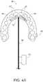
- the mass flow sensor 100 of the aligneras a tooth movement sensor by measuring the mass of fluid used to inflate the inflatable element 32 ( FIG. 4A ) or inflatable elements 32 1-6 ( FIG. 4B ).
- the mass fluid flow measurementscan then be communicated to the tooth movement monitor 46, which uses the measurements to determine tooth movement and/or tooth position in real time and/or the amount of tooth movement and/or the tooth position since a previous tooth movement and/or tooth position calculation.
- the mass flow sensor 100measures the mass of the first volume of fluid used to inflate the inflatable element 32 or elements 32 1-6 to a pressure which causes the inflatable element 32 or inflatable elements 32 1-6 to apply a force which will move the teeth 42, 42 1-6 requiring alignment along the desired path to proper alignment.
- the inflatable element 32 or inflatable elements 32 1-6is/are inflated with additional volumes of fluid to maintain the pressure therein, and thereby maintain the force applied to the teeth 42, 42 1-6 .
- the additional volumes of fluidprovide corresponding increases in the size (volume) of the inflatable element 32, or inflatable elements 32 1-6 .
- the increases in size or volume of the inflatable element 32, or inflatable elements 32 1-6is/are, in turn, used by the tooth movement monitor 46 to determine the position and/or distance the teeth 42, 42 1-6 have moved.
- the mass flow sensor 100can be serially or shunt connected with the main fluid tube 36 to measure the mass of fluid (gas or liquid) pumped into the inflatable element 32 or each of the inflatable elements 32 1-6 .
- the mass flow sensor 100can be configured to transmit the mass fluid flow measurements to the tooth movement monitor 46, which uses the mass fluid flow measurements to calculate tooth position and/or tooth movement.
- Embodiments of the aligner having multiple inflatable elements 32 1-6can include a multiport solenoid valve or multiple solenoid valves 102 and individual fluid tubes 36 1-6 fluidly connecting respective ones of the multiple inflatable elements 32 1-6 with the main fluid tube 36.
- the solenoid valve or valves 102can be operated to allow fluid communication between the main fluid tube 36 and a selected one of the individual fluid tubes 36 1-6 so that the mass flow sensor 100 can measure the mass of fluid pumped into the selected inflatable element 32 1-6 .
- a mass flow sensorcan be connected with each of the individual fluid tubes to measure the mass fluid flow into its respective inflatable element 32 1-6 .
- the main fluid tubecan be omitted and each individual fluid tube can be directly connected to the control console.
- a mass flow sensorcan be connected with each of the individual fluid tubes to measure the mass fluid flow into its respective inflatable element 32 1-6 .
- the tooth movement monitor 46via the controller 90, can be configured to interrogate the mass flow sensor 100, and in response, receive mass fluid flow measurements obtained by the mass flow sensor 100.
- the controller 90 of the tooth movement monitor 46can then use the mass fluid flow measurements to calculate in real time the volume (increase) of the inflatable element 32 or inflatable elements 32 1-6 and therefore, the amount each tooth 42 requiring alignment has moved and/or the current position of the tooth and/or determine the current position of and/or the amount each tooth 42 requiring alignment has moved relative to a previously calculated tooth position stored in the memory by the monitor 46.
- 3D files representing the pretreatment position of the teeth and the Setup (final position of the teeth)are obtained for use in manufacturing the mouthpiece 22 for a patient. Any sub-step between the pretreatment position and the Setup can then be derived, as described above with the tooth movement monitor 46.
- the calculation performed by the controller 90 of the monitor 46can be based on the volume change of the one or more inflatable elements 32.
- the communication interface 96 of the tooth movement monitor 46 ( FIG. 3 ) and the communication interface 56 of the programmable electronic control console 50 ( FIG. 1 ),can be configured to communicate with one another via a wired, wireless, or optical connection. This allows the tooth movement monitor 46 to send tooth movement and position data to the control console 50. In addition, the two-way communication between the tooth movement monitor 46 and the control console 50 allows a dentist or other dental technician to use the control console 50 to obtain real time tooth movement and/or position measurement via the tooth movement monitor 46.
- the wireless communicationcan be implemented using any suitable radio frequency (RF) method including but not limited to Bluetooth ® , wireless fidelity (Wi-Fi), near field communication (NFC), and/or radio frequency identification (RFID).
- Optical communicationcan be implemented using any suitable optical communication method such as, but not limited to infrared (IR).
- the control console communication interface 56may be further configured to communicate with a communication device 70 used by a patient, which may include, without limitation, a hand-held mobile device such as a smartphone, a tablet computer, and/or a personal computer, via the wired, RF and/or optical methods described earlier.
- the communication device 70can be communicatively connected to a cellular network, such as a mobile phone network, and/or a computer network, such as the Internet.
- the computer networkcan be a local server or personal computer or a network of remote servers hosted on the internet (e.g., cloud computing arrangement).
- the console communication interface 56allows the control console 50 to send real time or stored tooth movement and/or position data (stored in the controller 52 of the control console 50 and/or the controller 90 of the tooth movement monitor 46), via the patient's communication device 70, to a communication device 72 used by a remotely located dentist or dental technician.
- the communication device 72 used by the dentist or dental technicianmay include, without limitation, a hand-held mobile device, such as a smartphone, a tablet computer, and/or a personal computer.
- the dentist or dental technicianmay then use the communication device 72 to send a new program to the controller 52 of the control console 50, via the patient's communication device, from the remote location, in response to the tooth movement data received from the control console 50.
- the dentist or dental techniciancan remotely access the control console 50, via communication devices 70 and 72, and initiate a real time measurement of tooth movement and position via the tooth position monitor 46 and control console, or obtain tooth movement and position data stored in the control console 50.
- the mass fluid flow measurements obtained with the mass flow sensorcan be combined with additional tooth movement and/or tooth position measurement methods.
- FIG. 5Aillustrates an embodiment comprising an aligner 120, which is similar to the aligners described earlier and illustrated in any of FIGS. 1 , 2 , 4A , and 4B , however, the aligner 120 further includes one or more additional tooth movement sensors which take the form of contact force sensors 80.
- the contact force sensorsare arranged within the mouthpiece 22 of the aligner 120 so that each force sensor 80 is adjacent to a tooth 42 requiring alignment.
- the tooth movement monitor 46can then selectively use the mass fluid flow measurements, the force measurements, or both the mass fluid flow and force measurements to calculate the amount of tooth movement and/or position of each tooth 42 in real time and/or the amount of tooth movement and/or the position of each tooth 42 since a previous tooth movement and/or tooth position calculation.
- the one or more force sensors 80may each comprise a pressure sensor, such as, but not limited to a piezoresistive force sensor, a strain gauge, a load cell, or any other suitable pressure sensor.
- the one or more contact force sensors 80can be attached to or partially embedded in the interior surface of the facial wall 24 and/or the lingual wall 26 and/or the base wall 28 of the mouthpiece 22, such that each sensor 80 contacts the side of the tooth 42, which is opposite the inflatable element 32.
- FIG. 5Billustrates another embodiment the system comprising an aligner 220 similar to the aligners described earlier and illustrated in any of FIGS. 1 , 2 , 4A , and 4B , however, the aligner 220 further comprises one or more flexible force sensors 84 arranged within the mouthpiece 22 of the aligner 20 adjacent to one or more teeth 42 requiring alignment, which are operative as tooth movement sensors.
- the sensor 84measures an input representing the measured amount of force and the location applied by each tooth 42 on the flexible force sensor 84.
- the tooth movement monitor 46can then selectively use the mass fluid flow measurements, the force measurements, or both the mass fluid flow and force measurements to calculate the amount of tooth movement and/or position of each tooth 42 in real time and/or the amount of tooth movement and/or the position of each tooth 42 since a previous tooth movement and/or tooth position calculation.
- Each of the one or more flexible force sensors 84may comprise a FlexiForce ® force sensor marketed and sold by Tekscan ® , a FSR 400 Force Sensing Resistor ® marketed and sold by Interlink Electronics ® , a K90cN force sensor marketed and sold by Faraday-Sensoren, a S8-1N SingleTact force sensor marketed and sold by Pressure Profile Systems, Inc.
- the one or more flexible force sensors 84can be attached to or embedded in the interior surface of the facial wall 24 and/or the lingual wall 26 and/or the base wall 28 of the mouthpiece 22, such that each sensor 84 contacts the side of the tooth 42, which is opposite the one or more inflatable element 32.
- FIG. 5Cillustrates still another embodiment of the system comprising an aligner 320 similar to the aligners described earlier and illustrated in any of FIGS. 1 , 2 , 4A , and 4B , except that the aligner 320 further comprises one or more optical image sensors 86 arranged within the mouthpiece 22, which capture optical images of the position of at least the one or more teeth 42 requiring alignment, and thus operate as tooth movement sensors.
- Each optical image sensor 86generates a signal (wired, wireless, or optical) representing the captured optical image (video or still), which can be used to calculate the movement and position of each tooth in the image in real time or the amount of movement since a previously calculated tooth position.
- the tooth movement monitor 46can selectively use the mass fluid flow measurements, the captured optical images, or both the mass fluid flow measurements and the captured optical images, to calculate the amount of tooth movement and/or position of the teeth 42 in real time and/or the amount of tooth movement and/or the position of the teeth 42 since a previous tooth movement and/or tooth position calculation.
- Each of the image sensors 86may comprise, without limitation, a micro video camera, a micro still camera, or any other suitable image sensor, which can be unobtrusively integrated within the mouthpiece 22 of the aligner 320 and can convert optical images into signals (wired, wireless, or optical).
- the one or more optical image sensorscan be attached to or embedded in the inner surface of the facial wall 24 and/or the lingual wall 26 and/or the base wall 28 of the mouthpiece 22, such that each sensor can obtain an optical image of at least the one or more teeth 42 requiring alignment.
- FIG. 5Dillustrates yet another embodiment of the system comprising a first aligner 420 a (transparent in this embodiment), which aligns one or more teeth 42 requiring alignment of the upper jaw and a second aligner 420 b (transparent in this embodiment), which aligns one or more teeth 42 requiring alignment of the lower jaw.
- the aligners 420 a , 420 bare also similar to the aligners described earlier and illustrated in any of FIGS.
- the first aligner 420 acan further comprise at least a first optical image sensor 86 a , which is operative as a tooth position sensor and can be attached to or partially embedded in an exterior surface of the base wall 28 of the first aligner's mouthpiece 22 (or fully embedded in the base wall 28).
- the first optical image sensor(s) 86 acan capture an optical image of the position of at least the one or more teeth 42 requiring alignment of the opposite lower jaw, through the transparent second aligner 420 b .
- the second aligner 420 bcan further comprise at least a second optical image sensor 86 b , which is also operative as a tooth movement sensor and can be attached to or partially embedded in an exterior surface of the base wall 28 of the second aligner's mouthpiece 22 (or fully embedded in the base wall 28).
- the second optical image sensor(s) 86 bcan capture an optical image of the position of at least the one or more teeth 42 requiring alignment of the opposite upper jaw, through the transparent first aligner 420 a .
- the optical image sensors 86 a , 86 bgenerate signals (wired, wireless, or optical) representing the captured optical images (video or still), which can be used by the tooth movement monitors 46 a , 46 b to calculate the movement and position of each tooth 42 in real time or the amount of tooth movement since a previously calculated tooth position.
- the tooth movement monitors 46 a , 46 bcan selectively use the mass fluid flow measurements, the captured optical images, or both the mass fluid flow measurement and the captured optical images, to calculate the amount of tooth movement and/or position of each tooth 42 in real time and/or the amount of tooth movement and/or the position of each tooth 42 since a previous tooth movement and/or tooth position calculation.
- Each of the optical image sensors 86 a , 86 bmay comprise, without limitation, a micro video camera, a micro still camera or any other suitable image sensor, which can be unobtrusively integrated within the mouthpiece 22 of the aligner 420 a , 420 b and can convert optical images into signals (wired, wireless, or optical).
- the systemcan include the mass flow sensor and one or more of the one or more contact force sensors 80, one or more flexible force sensors 84, and one or more of the optical image sensors 86, 86 a , 86 b .
- the contact force sensors 80, flexible force sensors 84, and optical image sensors 86, 86 a , 86 bcan be communicatively connected (e.g., wired, wireless, or optically) to or with their associated tooth movement monitors.
- the wireless connectioncan be implemented using any suitable radio frequency (RF) method including but not limited to Bluetooth ® , wireless fidelity (Wi-Fi), and/or radio frequency identification (RFID).
- Optical connectionscan be implemented using any suitable optical communication method such as, but not limited to infrared (IR).
Landscapes
- Health & Medical Sciences (AREA)
- Life Sciences & Earth Sciences (AREA)
- General Health & Medical Sciences (AREA)
- Veterinary Medicine (AREA)
- Public Health (AREA)
- Animal Behavior & Ethology (AREA)
- Engineering & Computer Science (AREA)
- Oral & Maxillofacial Surgery (AREA)
- Dentistry (AREA)
- Surgery (AREA)
- Biophysics (AREA)
- Biomedical Technology (AREA)
- Medical Informatics (AREA)
- Molecular Biology (AREA)
- Physics & Mathematics (AREA)
- Pathology (AREA)
- Heart & Thoracic Surgery (AREA)
- Epidemiology (AREA)
- Nuclear Medicine, Radiotherapy & Molecular Imaging (AREA)
- Radiology & Medical Imaging (AREA)
- Water Supply & Treatment (AREA)
- Optics & Photonics (AREA)
- General Engineering & Computer Science (AREA)
- Physiology (AREA)
- Physical Education & Sports Medicine (AREA)
- Orthopedic Medicine & Surgery (AREA)
- Rheumatology (AREA)
- Computer Networks & Wireless Communication (AREA)
- Signal Processing (AREA)
- Dental Tools And Instruments Or Auxiliary Dental Instruments (AREA)
Description
- The present disclosure relates to orthodontics. More particularly, the present disclosure relates to an orthodontic system with tooth movement and position measuring, monitoring, and control during orthodontic treatment.
- Malocclusion is an abnormal alignment of the teeth and is typically characterized by crooked, crowed, or protruding teeth and upper and lower teeth that do not fit together properly. Orthodontic treatment attempts to remedy malocclusion by properly aligning the teeth. One common orthodontic treatment uses an orthodontic appliance to properly align the teeth.
- There are many known orthodontic appliances for aligning teeth. The most commonly known orthodontic appliance are braces, which are permanently fixed with respect to the teeth until treatment is completed. Braces typically include brackets that are bonded to individual teeth using a suitable adhesive, and wires that are threaded through or wrapped around a portion of each bracket. The wires apply a force against the teeth via the brackets, which gradually move the teeth into alignment.
- In the last couple of decades, removable orthodontic appliances have been developed, which are worn part time or most of the time, day or night. These appliances fit in the intraoral cavity in a manner that allows them to apply a force against the teeth, which gradually move the teeth into alignment, and be easily removed from and refitted in the intraoral cavity by the patient. Such removable orthodontic appliances are described in
U.S. Patent 7819661 andU.S. Patent Application 15/059,140 , the entire disclosures of which are incorporated herein by reference. - The amount and the duration of the force applied by the orthodontic appliance to the teeth must be controlled over the course of the orthodontic treatment to avoid undesirable effects, such as tooth root resorption and/or pain and discomfort associated with orthodontic appliance.
- Accordingly, an orthodontic system is needed with tooth movement and position measuring, monitoring, and control during orthodontic treatment.
US2007/065768 relates to an orthodontic appliance and method.WO2015/058284 relates to intra-oral light-therapy apparatuses and methods for their use.JP2014 131774 US3975825 relates to an ortho-activating method and apparatus.WO2007/137302 relates to nasal and oral appliances and to a method for treating sleep apnea.- Disclosed herein are an orthodontic appliance as claimed in claim 1 of the appended claims, and an orthopedic system as claimed in
claim 10 of the appended claims. Embodiments of the invention are recited in the dependent claims. FIG. 1 is a schematic illustration of an orthodontics system according to an embodiment of the present disclosure.FIG. 2 illustrates an embodiment of the system (the mobile programmable electronic control console not shown) comprising a first or upper aligner for aligning the teeth of the upper jaw of the patient and a second or lower aligner for aligning the teeth of the lower jaw of the patient, where each aligner comprises a mass flow sensor (not shown) which is operative as a tooth movement sensor.FIG. 3 is a block diagram of an embodiment of a tooth movement monitor.FIG. 4A is a schematic illustration of an embodiment of the aligner comprising a mass flow sensor which is operative as tooth movement sensor with an inflatable element.FIG. 4B is a schematic illustration of another embodiment of the aligner comprising a mass flow sensor which is operative as tooth movement sensor with multiple inflatable elements.FIG. 5A is a schematic illustration of another embodiment of the aligner comprising a mass flow sensor and one or more contact force sensors, which can be used together or separately as tooth movement sensors.FIG. 5B is a schematic illustration of another embodiment of the aligner comprising a mass flow sensor and one or more flexible force sensors, which can be used together or separately as tooth movement sensors.FIG. 5C is a schematic illustration of another embodiment of the aligner comprising a mass flow sensor and one or more optical image sensors, which can be used together or separately as tooth movement sensors.FIG. 5D is a schematic illustration of another embodiment of the aligner comprising a mass flow sensor and one or more optical image sensors, which can be used together or separately as tooth movement sensors.FIG. 5D illustrates another embodiment of the system (the mobile programmable electronic control console not shown) which comprises a first aligner for aligning the teeth of the upper jaw of the patient and a second aligner for aligning the teeth of the lower jaw of the patient. Each of the aligners comprises a mass flow sensor and one or more optical image sensors, which can be used together or separately as tooth movement sensors.FIG. 1 illustrates an embodiment of anorthodontics system 10 with tooth movement and position measuring, monitoring, and control during orthodontic treatment. Thesystem 10 generally comprises at least one orthodontic appliance oraligner 20, which is configured to receive theteeth 40 of the upper or lower jaw of a patient, and a mobile programmableelectronic control console 50.- The
aligner 20 of thesystem 10 moves and aligns eachtooth 42 requiring alignment, along a predetermined three-dimensional path under the control of thecontrol console 50. Theteeth 42 requiring alignment may be adjacent to one another, spaced one from another, arranged in groups, or be all the teeth in the same arch of the intraoral cavity. Thealigner 20 can be configured to move one or more of theteeth 42 requiring alignment in a lingual direction L and/or in a buccal/labial direction B. - As illustrated in
FIG. 1 , thealigner 20 may comprise a generallyU-shaped mouthpiece 22, one or more inflatable elements (twoinflatable elements tooth movement monitor 46. Themouthpiece 22 of thealigner 20 may include achannel 30 formed by a curved labial/buccal (facial)wall 24, a curvedlingual wall 26, an incisal/occlusal (base)wall 28 connecting thefacial wall 24 andlingual wall 26, andposterior walls 29 connecting posterior ends of thefacial wall 24 andlingual wall 26. Themouthpiece 22 can be made from a transparent, semitransparent or opaque dental-compatible material, which may be rigid or at least sufficiently rigid to ensure that themouthpiece 22 does not deform under tooth aligning forces. Suitable materials for themouthpiece 22 include, without limitation, thermoplastic polycarbonate, acrylic resin, and like materials. - Referring still to
FIG. 1 , thechannel 30 of themouthpiece 22 is configured to receiveteeth 40 of a patient's upper or lower jaw. Thefacial wall 24 and thelingual wall 26 both extend along the lingual andfacial surfaces teeth 40 of the dental arch of the jaw, and thebase wall 28 extends along theincising edges 403 of the teeth 40 (FIG. 2 ) when themouthpiece 22 is inserted into the mouth. In some embodiments, where thefacial wall 24 andlingual wall 26 are connected to thebase wall 28, theposterior walls 29 can be omitted so that the ends of thechannel 30 are open. Such embodiments may be useful where it is desirable to reduce the length the facial andlingual walls certain teeth 44 not requiring alignment, such as the second and/or third molars orother teeth 44 of the dental arch. - The
inflatable elements more teeth 42 requiring alignment, when inflated with a suitable fluid. Such fluid may include, without limitation, a gas such as air, a liquid such as water, or any other suitable fluid. Theinflatable elements inflatable elements facial wall 24 and/or thelingual wall 26, and/orbase wall 28 of themouthpiece 22. A branch fluid conduit ortube inflatable element electronic control console 50, which is configured to selectively inflate and deflate theinflatable elements inflatable elements teeth 42 requiring alignment and may or may not make contact therewith. When inflated, theinflatable elements teeth 42 requiring alignment, thereby applying a force which urges theteeth 42 in the desired predetermined three-dimensional path. - Referring still to
FIG. 1 , theinflatable elements mouthpiece 22 so that they apply a force to the one ormore teeth 42 requiring alignment in a manner which moves eachtooth 42 along a three-dimensional path that has been predetermined to be suitable for thatparticular tooth 42. As illustrated inFIG. 1 , one of theinflatable elements 321 can be provided betweenmultiple teeth 42 requiring alignment and thelingual wall 26 of themouthpiece 22, so that it exerts a force on thelingual surface 421 of theseteeth 42. The otherinflatable element 322 can be located between anothertooth 42 requiring alignment and thefacial wall 24 of themouthpiece 22, so that it exerts a force on thefacial surface 422 of thattooth 42. The aligner can be provided with any combination of single and/or multiple tooth inflatable elements, depending upon the orthodontic correction that is needed. All the inflatable elements may be located on the same side (lingual or facial) of the teeth requiring alignment or on opposite sides thereof as inFIG. 1 . - As illustrated in
FIG. 1 , the tooth movement monitor 46 can be disposed on an outer surface of themouthpiece 22. In other embodiments of the aligner, the tooth movement monitor 46 can be partially embedded in the outer surface of themouthpiece 22. In still other embodiments, the tooth movement monitor 46 can be fully embedded in themouth piece 22. - Referring now to
FIG. 3 , the tooth movement monitor 46 can include acontroller 90, apower supply 92 connected to thecontroller 90, and amemory 94 connected to thecontroller 90. Thecontroller 90 receives input from amass flow sensor 100, which measures the mass of the fluid (e.g., air or water) that has been pumped into the one or more inflatable elements to apply and maintain the force on the one ormore teeth 42 requiring alignment, as will be explained further on in more detail. The tooth movement monitor 46 can further include acommunication interface 96 connected to thecontroller 90, which allows the tooth movement monitor 46 to communicate with the programmableelectronic control console 50. Thecontroller 90 of the tooth movement monitor 46 may comprise without limitation a microcontroller, microprocessor, application specific integrated circuit (ASIC), or field programmable gate array (FPGA). FIG. 2 illustrates another embodiment the system (the mobile programmable electronic control console not shown) which comprises two of the above-described aligners, i.e., afirst aligner 20a, which receives theteeth 40 of the upper jaw of the patient and asecond aligner 20b, which receives theteeth 40 of the lower jaw of the patient. The aligner(s) 20a, 20b are configured to move and thereby align one ormore teeth aligners inflatable elements - Referring again to
FIG. 1 , the programmableelectronic control console 50 of thesystem 10 can comprise a fluidmicro pump 57, afluid sensor arrangement 58, asolenoid valve 54, acontroller 52 for controlling the operation of themicro pump 57, and asolenoid valve 54, and acommunication interface 56. Themicro pump 57 of thecontrol console 50 can be connected to the one or moreinflatable elements 32 of thealigner 20 via theirbranch fluid tubes fluid tube 36, and multiport solenoid valve ormultiple solenoid valves 34, so that it can inflate and expand theinflatable elements connector 38 can be provided at the free end of the mainfluid tube 36 so it can be removably connected to anoutlet 66 of themicro pump 57 located externally on thecontrol console 50. Thesolenoid valve 54 of thecontrol console 50 can be configured to allow the patient, doctor and/or other end user to adjust the fluid pressure of themicro pump 57 and release the fluid pressure to deflate the one or moreinflatable elements 32, prior to disconnecting thefluid tube 36 from thecontrol console 50. - The
micro pump 57 of thecontrol console 50 can comprise a piezoelectric micro pump, an electrostatic micro pump, a pneumatic micro pump, a linear pump, a syringe pump, or any other suitable pump that is capable of inflating the one or moreinflatable elements 32 with any of the fluids mentioned above (e.g., air, water, etc.) and which is capable of being contained within themobile control console 50. - The
controller 52 of thecontrol console 50 can comprise any suitable microcontroller which is capable of selectively controlling the operation of themicro pump 57 so that the force exerted by theinflatable elements teeth 42 requiring alignment, may be constant, varied, or a combination thereof. Thecontroller 52 is configured to be programed locally or remotely by a dentist, dental technician, and/or patient. Theinflatable elements teeth 42 requiring alignment by programming thecontroller 52 to energize themicro pump 57 so that it inflates to a pressure which expands theinflatable elements teeth 42 requiring alignment move along their predetermined three-dimensional path. - The
controller 52 of theconsole 50 can also be programmed to selectively operate themicro pump 57 and thesolenoid valve 54, such that themicro pump 57 inflates and expands theinflatable elements solenoid valve 54 deflates and contracts theinflatable elements teeth 42 requiring alignment, for example, in the form of periodic pulses, which provide a pulsating force to theteeth requiring alignment 42. When so programmed, thecontroller 52 cyclically (at a desired frequency selected by the dentist or dental technician) energizes and de-energizes themicro pump 57 andsolenoid valve 54 at the appropriate times, so that themicro pump 57 inflates and expands theinflatable elements teeth 42 requiring alignment, and then de-energizes themicro pump 57 and opens thesolenoid valve 54 for a certain time period, to release the fluid pressure and deflate theinflatable elements - The
controller 52 of theconsole 50 can be programmed by the dentist or dental technician to stop the operation of themicro pump 57 and open thesolenoid valve 54 to terminate the force exerted by theinflatable elements teeth 42 requiring alignment, when they arrive at their final positions. Thecontroller 52 of thecontrol console 50 can store tooth movement and/or position data obtained by tooth movement monitor 46 of each thealigner 20 of thesystem 10. Thecontrol console controller 52 may comprise but is not limited to a microcontroller, microprocessor with external memories or a field programmable gate array (FPGA). - Referring still to
FIG. 1 , thefluid sensor arrangement 58 of thecontrol console 50 provides thecontroller 52 with micro pump performance data, which can be used by thecontroller 52 to selectively control the operation of themicro pump 57. Thefluid sensor arrangement 58 can comprise afluid pressure sensor 60, afluid flow sensor 62, andfluid volume sensor 64. Thefluid pressure sensor 60 detects the fluid pressure of themicro pump 57, thefluid flow sensor 62 measures the fluid flow rate of themicro pump 57, and thefluid volume sensor 64 measures the fluid volume of themicro pump 57. The fluid pressure, flow, and volume measurements can be used by thecontroller 52 of theconsole 50 to control the energizing and the speed of the pump speed, so that themicro pump 57 maintains desired inflation pressure and corresponding tooth moving forces. - The
console communication interface 56 of thecontrol console 50 can be configured to receive tooth movement and/or position data obtained with tooth movement monitor 46, as will be explained further on. - Referring now to
FIGS. 4A and4B , themass flow sensor 100 of the aligner as a tooth movement sensor by measuring the mass of fluid used to inflate the inflatable element 32 (FIG. 4A ) or inflatable elements 321-6 (FIG. 4B ). The mass fluid flow measurements can then be communicated to the tooth movement monitor 46, which uses the measurements to determine tooth movement and/or tooth position in real time and/or the amount of tooth movement and/or the tooth position since a previous tooth movement and/or tooth position calculation. Themass flow sensor 100 measures the mass of the first volume of fluid used to inflate theinflatable element 32 orelements 321-6 to a pressure which causes theinflatable element 32 orinflatable elements 321-6 to apply a force which will move theteeth teeth inflatable element 32 orinflatable elements 321-6 is/are inflated with additional volumes of fluid to maintain the pressure therein, and thereby maintain the force applied to theteeth inflatable element 32, orinflatable elements 321-6. The increases in size or volume of theinflatable element 32, orinflatable elements 321-6 is/are, in turn, used by the tooth movement monitor 46 to determine the position and/or distance theteeth - As illustrated in
FIGS. 4A and4B , themass flow sensor 100 can be serially or shunt connected with the mainfluid tube 36 to measure the mass of fluid (gas or liquid) pumped into theinflatable element 32 or each of theinflatable elements 321-6. Themass flow sensor 100 can be configured to transmit the mass fluid flow measurements to the tooth movement monitor 46, which uses the mass fluid flow measurements to calculate tooth position and/or tooth movement. Embodiments of the aligner having multipleinflatable elements 321-6, such as illustrated inFIG. 4B , can include a multiport solenoid valve ormultiple solenoid valves 102 andindividual fluid tubes 361-6 fluidly connecting respective ones of the multipleinflatable elements 321-6 with the mainfluid tube 36. The solenoid valve orvalves 102 can be operated to allow fluid communication between the mainfluid tube 36 and a selected one of theindividual fluid tubes 361-6 so that themass flow sensor 100 can measure the mass of fluid pumped into the selectedinflatable element 321-6. In other embodiments, a mass flow sensor can be connected with each of the individual fluid tubes to measure the mass fluid flow into its respectiveinflatable element 321-6. In still other embodiments, the main fluid tube can be omitted and each individual fluid tube can be directly connected to the control console. In such embodiments, a mass flow sensor can be connected with each of the individual fluid tubes to measure the mass fluid flow into its respectiveinflatable element 321-6. - The tooth movement monitor 46, via the
controller 90, can be configured to interrogate themass flow sensor 100, and in response, receive mass fluid flow measurements obtained by themass flow sensor 100. Thecontroller 90 of the tooth movement monitor 46 can then use the mass fluid flow measurements to calculate in real time the volume (increase) of theinflatable element 32 orinflatable elements 321-6 and therefore, the amount eachtooth 42 requiring alignment has moved and/or the current position of the tooth and/or determine the current position of and/or the amount eachtooth 42 requiring alignment has moved relative to a previously calculated tooth position stored in the memory by themonitor 46. In some embodiments, 3D files representing the pretreatment position of the teeth and the Setup (final position of the teeth) are obtained for use in manufacturing themouthpiece 22 for a patient. Any sub-step between the pretreatment position and the Setup can then be derived, as described above with the tooth movement monitor 46. The calculation performed by thecontroller 90 of themonitor 46 can be based on the volume change of the one or moreinflatable elements 32. - The
communication interface 96 of the tooth movement monitor 46 (FIG. 3 ) and thecommunication interface 56 of the programmable electronic control console 50 (FIG. 1 ), can be configured to communicate with one another via a wired, wireless, or optical connection. This allows the tooth movement monitor 46 to send tooth movement and position data to thecontrol console 50. In addition, the two-way communication between the tooth movement monitor 46 and thecontrol console 50 allows a dentist or other dental technician to use thecontrol console 50 to obtain real time tooth movement and/or position measurement via the tooth movement monitor 46. The wireless communication can be implemented using any suitable radio frequency (RF) method including but not limited to Bluetooth®, wireless fidelity (Wi-Fi), near field communication (NFC), and/or radio frequency identification (RFID). Optical communication can be implemented using any suitable optical communication method such as, but not limited to infrared (IR). - The control
console communication interface 56, in some embodiments, may be further configured to communicate with acommunication device 70 used by a patient, which may include, without limitation, a hand-held mobile device such as a smartphone, a tablet computer, and/or a personal computer, via the wired, RF and/or optical methods described earlier. Thecommunication device 70 can be communicatively connected to a cellular network, such as a mobile phone network, and/or a computer network, such as the Internet. The computer network can be a local server or personal computer or a network of remote servers hosted on the internet (e.g., cloud computing arrangement).So configured, theconsole communication interface 56 allows thecontrol console 50 to send real time or stored tooth movement and/or position data (stored in thecontroller 52 of thecontrol console 50 and/or thecontroller 90 of the tooth movement monitor 46), via the patient'scommunication device 70, to acommunication device 72 used by a remotely located dentist or dental technician. Thecommunication device 72 used by the dentist or dental technician may include, without limitation, a hand-held mobile device, such as a smartphone, a tablet computer, and/or a personal computer. The dentist or dental technician, in turn, may then use thecommunication device 72 to send a new program to thecontroller 52 of thecontrol console 50, via the patient's communication device, from the remote location, in response to the tooth movement data received from thecontrol console 50. In addition, the dentist or dental technician can remotely access thecontrol console 50, viacommunication devices control console 50. - In some embodiments of the system, the mass fluid flow measurements obtained with the mass flow sensor can be combined with additional tooth movement and/or tooth position measurement methods. For example,
FIG. 5A illustrates an embodiment comprising an aligner 120, which is similar to the aligners described earlier and illustrated in any ofFIGS. 1 ,2 ,4A , and4B , however, the aligner 120 further includes one or more additional tooth movement sensors which take the form ofcontact force sensors 80. The contact force sensors are arranged within themouthpiece 22 of the aligner 120 so that eachforce sensor 80 is adjacent to atooth 42 requiring alignment. When theforce sensor 80 is engaged by atooth 42 moved by theinflatable element 32, thesensor 80 measures the amount of force exerted by thetooth 42 and generates a signal (wired, wireless, or optical) representing the measured amount of force. The tooth movement monitor 46 can then selectively use the mass fluid flow measurements, the force measurements, or both the mass fluid flow and force measurements to calculate the amount of tooth movement and/or position of eachtooth 42 in real time and/or the amount of tooth movement and/or the position of eachtooth 42 since a previous tooth movement and/or tooth position calculation. The one ormore force sensors 80 may each comprise a pressure sensor, such as, but not limited to a piezoresistive force sensor, a strain gauge, a load cell, or any other suitable pressure sensor. The one or morecontact force sensors 80 can be attached to or partially embedded in the interior surface of thefacial wall 24 and/or thelingual wall 26 and/or thebase wall 28 of themouthpiece 22, such that eachsensor 80 contacts the side of thetooth 42, which is opposite theinflatable element 32. FIG. 5B illustrates another embodiment the system comprising analigner 220 similar to the aligners described earlier and illustrated in any ofFIGS. 1 ,2 ,4A , and4B , however, thealigner 220 further comprises one or moreflexible force sensors 84 arranged within themouthpiece 22 of thealigner 20 adjacent to one ormore teeth 42 requiring alignment, which are operative as tooth movement sensors. When theflexible force sensor 84 is engaged by one or more of theteeth 42 moved by theinflatable element 32, thesensor 84 measures an input representing the measured amount of force and the location applied by eachtooth 42 on theflexible force sensor 84. The tooth movement monitor 46 can then selectively use the mass fluid flow measurements, the force measurements, or both the mass fluid flow and force measurements to calculate the amount of tooth movement and/or position of eachtooth 42 in real time and/or the amount of tooth movement and/or the position of eachtooth 42 since a previous tooth movement and/or tooth position calculation. Each of the one or moreflexible force sensors 84 may comprise a FlexiForce® force sensor marketed and sold by Tekscan®, a FSR 400 Force Sensing Resistor® marketed and sold by Interlink Electronics®, a K90cN force sensor marketed and sold by Faraday-Sensoren, a S8-1N SingleTact force sensor marketed and sold by Pressure Profile Systems, Inc. or a HSFPAR003A force sensor marketed and sold by ALPS Electric Co., LTD. The one or moreflexible force sensors 84 can be attached to or embedded in the interior surface of thefacial wall 24 and/or thelingual wall 26 and/or thebase wall 28 of themouthpiece 22, such that eachsensor 84 contacts the side of thetooth 42, which is opposite the one or moreinflatable element 32.FIG. 5C illustrates still another embodiment of the system comprising analigner 320 similar to the aligners described earlier and illustrated in any ofFIGS. 1 ,2 ,4A , and4B , except that thealigner 320 further comprises one or moreoptical image sensors 86 arranged within themouthpiece 22, which capture optical images of the position of at least the one ormore teeth 42 requiring alignment, and thus operate as tooth movement sensors. Eachoptical image sensor 86 generates a signal (wired, wireless, or optical) representing the captured optical image (video or still), which can be used to calculate the movement and position of each tooth in the image in real time or the amount of movement since a previously calculated tooth position. The tooth movement monitor 46 can selectively use the mass fluid flow measurements, the captured optical images, or both the mass fluid flow measurements and the captured optical images, to calculate the amount of tooth movement and/or position of theteeth 42 in real time and/or the amount of tooth movement and/or the position of theteeth 42 since a previous tooth movement and/or tooth position calculation. Each of theimage sensors 86 may comprise, without limitation, a micro video camera, a micro still camera, or any other suitable image sensor, which can be unobtrusively integrated within themouthpiece 22 of thealigner 320 and can convert optical images into signals (wired, wireless, or optical). The one or more optical image sensors can be attached to or embedded in the inner surface of thefacial wall 24 and/or thelingual wall 26 and/or thebase wall 28 of themouthpiece 22, such that each sensor can obtain an optical image of at least the one ormore teeth 42 requiring alignment.FIG. 5D illustrates yet another embodiment of the system comprising a first aligner 420a (transparent in this embodiment), which aligns one ormore teeth 42 requiring alignment of the upper jaw and a second aligner 420b (transparent in this embodiment), which aligns one ormore teeth 42 requiring alignment of the lower jaw. The aligners 420a, 420b are also similar to the aligners described earlier and illustrated in any ofFIGS. 1 ,2 ,4A , and4B , however, the first aligner 420a can further comprise at least a firstoptical image sensor 86a, which is operative as a tooth position sensor and can be attached to or partially embedded in an exterior surface of thebase wall 28 of the first aligner's mouthpiece 22 (or fully embedded in the base wall 28). The first optical image sensor(s) 86a can capture an optical image of the position of at least the one ormore teeth 42 requiring alignment of the opposite lower jaw, through the transparent second aligner 420b. The second aligner 420b can further comprise at least a secondoptical image sensor 86b, which is also operative as a tooth movement sensor and can be attached to or partially embedded in an exterior surface of thebase wall 28 of the second aligner's mouthpiece 22 (or fully embedded in the base wall 28). The second optical image sensor(s) 86b can capture an optical image of the position of at least the one ormore teeth 42 requiring alignment of the opposite upper jaw, through the transparent first aligner 420a. Theoptical image sensors tooth 42 in real time or the amount of tooth movement since a previously calculated tooth position. The tooth movement monitors 46a, 46b can selectively use the mass fluid flow measurements, the captured optical images, or both the mass fluid flow measurement and the captured optical images, to calculate the amount of tooth movement and/or position of eachtooth 42 in real time and/or the amount of tooth movement and/or the position of eachtooth 42 since a previous tooth movement and/or tooth position calculation. Each of theoptical image sensors mouthpiece 22 of the aligner 420a, 420b and can convert optical images into signals (wired, wireless, or optical).- In other embodiments, the system can include the mass flow sensor and one or more of the one or more
contact force sensors 80, one or moreflexible force sensors 84, and one or more of theoptical image sensors contact force sensors 80,flexible force sensors 84, andoptical image sensors - Although the orthodontic system, its individual components, and their corresponding methods of operation and use have been described in terms of illustrative embodiments, they are not limited thereto. Rather, the appended claims should be construed broadly to comprise other variants and embodiments of the orthodontic system, its individual components, and their corresponding methods of operation and use, which may be made by those skilled in the art without departing from the scope and range of equivalents of the same.
Claims (13)
- An orthodontic appliance (20, 20a, 20b, 120, 220, 320, 420a, 420b) for aligning at least one tooth (40) of a patient's upper or lower jaw, the orthodontic appliance (20, 20a, 20b, 120, 220, 320, 420a, 420b) comprising:a force exerting member for applying a force to move the at least one tooth (40, 42, 42a, 42b, 421-6), wherein the force exerting member comprises at least one inflatable element (32, 32a, 32b, 321, 322, 321-6), and wherein the at least one inflatable element (32, 32a, 32b, 321, 322, 321-6) is inflated with a fluid which causes the at least one inflatable element (32, 32a, 32b, 321, 322, 321-6) to apply and maintain the force applied to the at least one tooth (40, 42, 42a, 42b, 421-6);a tooth movement sensor (80, 84, 86, 86a, 86b, 100) for obtaining tooth movement data, the tooth movement sensor (80, 84, 86, 86a, 86b, 100) comprising a mass flow sensor (100), wherein the mass flow sensor (100) measures the mass of the fluid used to expand the at least one inflatable element (32, 32a, 32b, 321, 322, 321-6); anda tooth movement monitor (46, 46a, 46b) for calculating at least one of a distance the at least one tooth (40, 42, 42a, 42b, 421-6) has moved and a current position of the at least one tooth (40, 42, 42a, 42b, 421-6) from the tooth movement data.
- The orthodontic appliance (20, 20a, 20b, 120, 220, 320, 420a, 420b) of claim 1, further comprising a mouthpiece (22).
- The orthodontic appliance (20, 20a, 20b, 120, 220, 320, 420a, 420b) of claim 2, wherein the force exerting member is associated with the mouthpiece (22) in a manner that allows physical engagement between the at least one force exerting member and the at least one tooth (40, 42, 42a, 42b, 421-6).
- The orthodontic appliance (20, 20a, 20b, 120, 220, 320, 420a, 420b) of any of claims 1-3, wherein the at least one inflatable element (32, 32a, 32b, 321, 322, 321-6) comprises a plurality of inflatable elements (32a, 32b, 321, 322, 321-6) and further comprising a multiport solenoid valve (54) or multiple solenoid valves (54) connected with the inflatable elements (32a, 32b, 321, 322, 321-6), the multiport solenoid valve (54) or multiple solenoid valves (54) allowing the inflatable elements (32a, 32b, 321, 322, 321-6) to be individually selected to measure the mass of the fluid used to inflate a selected one of the inflatable elements (32a, 32b, 321, 322, 321-6).
- The orthodontic appliance (20, 20a, 20b, 120, 220, 320, 420a, 420b) of any of claims 1-4, further comprising at least a second tooth movement sensor (80, 84, 86, 86a, 86b) associated with the mouthpiece (22) in a manner that allows physical engagement with the at least one tooth (40, 42, 42a, 42b, 421-6) or optical communication with at least one of the at least one tooth (40, 42, 42a, 42b, 421-6).
- The orthodontic appliance (20, 20a, 20b, 120, 220, 320, 420a, 420b) of any of claims 1-4, further comprising at least a second tooth movement sensor (80, 84, 86, 86a, 86b), the second tooth movement sensor (80, 84, 86, 86a, 86b) comprising at least one force sensor (80, 84), at least one optical image sensor (86, 86a, 86b), or any combination thereof.
- The orthodontic appliance (20, 20a, 20b, 120, 220, 320, 420a, 420b) of claim 6, wherein the at least one force sensor (80, 84) comprises at least one contact force sensor (80), at least one flexible force sensor (84), or any combination thereof, and the at least one optical sensor (86, 86a, 86b) comprises at least one micro video camera, at least one micro still camera, or any combination thereof.
- The orthodontic appliance (20, 20a, 20b, 120, 220, 320, 420a, 420b) of claim 6, wherein the at least one force sensor (80, 84) measures at least one of a force applied thereto by the at least one tooth (40, 42, 42a, 42b, 421-6) and a location of the applied force, and the at least one optical image sensor (86, 86a, 86b) obtains at least one optical image of at least one of the at least one tooth (40, 42, 42a, 42b, 421-6).
- The orthodontic appliance (20, 20a, 20b, 120, 220, 320, 420a, 420b) of any of claims 1-8, wherein the tooth movement monitor (46, 46a, 46b) comprises a controller (90) for interrogating the tooth movement sensor (80, 84, 86, 86a, 86b,100), and in response, receiving the tooth movement data from the tooth movement sensor (80, 84, 86, 86a, 86b, 100), the controller (90) calculating the at least one of the distance the at least one tooth (40, 42, 42a, 42b, 421-6) has moved and the current position of the at least one tooth (40, 42, 42a, 42b, 421-6) from the tooth movement data.
- An orthodontic system (10) comprising:a first orthodontic appliance (20, 20a, 20b, 120, 220, 320, 420a, 420b) corresponding to that of any of claims 1-9;
andan electronic control console (50) operatively connected to the force exerting member and in data communication with the tooth movement monitor (46, 46a, 46b), the electronic control console (50) controlling the operation of the force exerting member using the at least one of the distance the at least one tooth (40, 42, 42a, 42b, 421-6) has moved and the current position of the at least one tooth (40, 42, 42a, 42b, 421-6). - The orthodontic system of claim 10, wherein the electronic control console (50) comprises a fluid pump (57) which causes the force exerting member to apply the force on the at least one tooth (40, 42, 42a, 42b, 421-6).
- The orthodontic system (10) of claim 10 or 11, wherein a communication interface (56) of the electronic control console (50) allows receipt of program instructions from a remotely located communication device (72) operated by a dentist or other user, the program instructions programming a controller (52) of the control console (50).
- The orthodontic system of any of claims 10-12, further comprising a second orthodontic appliance (20b, 420b), one of the first and second orthodontic appliances (20a, 20b, 420a, 420b) for aligning at least one tooth (40, 42, 42a, 42b, 421-6) of the patient's upper jaw and the other one of the first and second orthodontic appliances (20a, 20b, 420a, 420b) for aligning at least one tooth (40, 42, 42a, 42b, 421-6) of the patient's lower jaw.
Applications Claiming Priority (2)
| Application Number | Priority Date | Filing Date | Title |
|---|---|---|---|
| US15/269,465US10820965B2 (en) | 2016-09-19 | 2016-09-19 | Orthodontic system with tooth movement and position measuring, monitoring, and control |
| PCT/IB2017/055635WO2018051303A2 (en) | 2016-09-19 | 2017-09-18 | Orthodontic system with tooth movement and position measuring, monitoring, and control |
Publications (2)
| Publication Number | Publication Date |
|---|---|
| EP3515355A2 EP3515355A2 (en) | 2019-07-31 |
| EP3515355B1true EP3515355B1 (en) | 2022-05-18 |
Family
ID=60081109
Family Applications (1)
| Application Number | Title | Priority Date | Filing Date |
|---|---|---|---|
| EP17783584.0AActiveEP3515355B1 (en) | 2016-09-19 | 2017-09-18 | Orthodontic system with tooth movement and position measuring, monitoring, and control |
Country Status (8)
| Country | Link |
|---|---|
| US (2) | US10820965B2 (en) |
| EP (1) | EP3515355B1 (en) |
| JP (1) | JP6880177B2 (en) |
| KR (1) | KR102230739B1 (en) |
| AU (1) | AU2017328249C1 (en) |
| CA (1) | CA3037099A1 (en) |
| IL (1) | IL265377B (en) |
| WO (1) | WO2018051303A2 (en) |
Families Citing this family (24)
| Publication number | Priority date | Publication date | Assignee | Title |
|---|---|---|---|---|
| US10806376B2 (en) | 2016-03-02 | 2020-10-20 | Dror Ortho Design LTD (Aerodentis) | Orthodontic system with tooth movement and position measuring, monitoring, and control |
| KR101831251B1 (en)* | 2016-03-29 | 2018-02-23 | 주식회사 에프이에스 | Apparatus for strengthening lip muscles to prevent malocclusion and mouth breathing |
| US11529213B2 (en) | 2016-05-30 | 2022-12-20 | David Akselrod | Backscatter device-based dental imaging apparatus |
| US11389277B2 (en) | 2016-07-18 | 2022-07-19 | David Akselrod | Material property monitoring using backscatter devices |
| US10383705B2 (en) | 2016-06-17 | 2019-08-20 | Align Technology, Inc. | Orthodontic appliance performance monitor |
| WO2017218947A1 (en) | 2016-06-17 | 2017-12-21 | Align Technology, Inc. | Intraoral appliances with sensing |
| US10820965B2 (en) | 2016-09-19 | 2020-11-03 | Dror Ortho Design Ltd | Orthodontic system with tooth movement and position measuring, monitoring, and control |
| US11419703B2 (en)* | 2017-01-27 | 2022-08-23 | David Akselrod | Orthodontic braces and feet orthotics with backscatter based sensors |
| US12109088B2 (en) | 2017-06-09 | 2024-10-08 | Dental Monitoring | Method of evaluating an orthodontic appliance |
| US10639134B2 (en) | 2017-06-26 | 2020-05-05 | Align Technology, Inc. | Biosensor performance indicator for intraoral appliances |
| US12171575B2 (en)* | 2017-10-04 | 2024-12-24 | Align Technology, Inc. | Intraoral systems and methods for sampling soft-tissue |
| US11219506B2 (en)* | 2017-11-30 | 2022-01-11 | Align Technology, Inc. | Sensors for monitoring oral appliances |
| US11432908B2 (en)* | 2017-12-15 | 2022-09-06 | Align Technology, Inc. | Closed loop adaptive orthodontic treatment methods and apparatuses |
| TWI669142B (en)* | 2018-10-11 | 2019-08-21 | 彰化基督教醫療財團法人彰化基督教醫院 | Oral rehabilitation device and medical treatment system thereof |
| EP3890649A2 (en)* | 2018-11-28 | 2021-10-13 | Biolux Research Holdings, Inc. | Orthodontic appliance compliance monitoring systems, devices, and methods |
| US11602414B2 (en)* | 2019-06-11 | 2023-03-14 | Align Technology, Inc. | Aligner material, cleanliness, and quality detection via aligner case |
| GB2589817B (en)* | 2019-06-20 | 2022-02-09 | Patel Shailen | Cranial restructuring devices |
| US11576757B1 (en)* | 2019-10-29 | 2023-02-14 | Victor Dangond | Dental bridge fitting system |
| WO2021145529A1 (en)* | 2020-01-17 | 2021-07-22 | 나공찬 | Apparatus for oral insertion for controlling shock wave transmission characteristics |
| CN111529113B (en)* | 2020-05-08 | 2021-07-02 | 陈昕 | A device for measuring orthodontic force for orthodontics |
| JPWO2021251421A1 (en)* | 2020-06-09 | 2021-12-16 | ||
| WO2023012358A1 (en)* | 2021-08-05 | 2023-02-09 | Dental Monitoring | Method of evaluating an orthodontic appliance |
| US20230255725A1 (en)* | 2022-02-14 | 2023-08-17 | International Business Machines Corporation | Digital twin based on orthodontic alignment |
| WO2025089849A1 (en)* | 2023-10-25 | 2025-05-01 | (주)에이딘로보틱스 | Orthodontic force measurement apparatus and orthodontic force measurement method |
Citations (1)
| Publication number | Priority date | Publication date | Assignee | Title |
|---|---|---|---|---|
| WO2007137302A2 (en)* | 2006-05-23 | 2007-11-29 | Sleep Improved Center P.C. | Nasal and oral appliances and method for treating sleep apnea |
Family Cites Families (24)
| Publication number | Priority date | Publication date | Assignee | Title |
|---|---|---|---|---|
| US3975825A (en) | 1975-06-11 | 1976-08-24 | Smith C Perry | Ortho-activating method and apparatus |
| DE3710674A1 (en)* | 1987-03-31 | 1988-10-20 | Veit Gmbh & Co | TUNNEL FINISHER |
| US4823788A (en) | 1988-04-18 | 1989-04-25 | Smith Richard F M | Demand oxygen controller and respiratory monitor |
| US20020094509A1 (en)* | 2000-11-30 | 2002-07-18 | Duane Durbin | Method and system for digital occlusal determination |
| KR100583183B1 (en)* | 2004-02-19 | 2006-05-25 | 차경석 | How to provide orthodontic data |
| ATE555741T1 (en) | 2004-03-25 | 2012-05-15 | Dror Ortho Design Ltd | ORTHODONTIC DEVICE |
| US20150173856A1 (en)* | 2007-03-14 | 2015-06-25 | Orthoaccel Technologies Inc. | Intra-oral vibrating othodontic devices |
| US20090017422A1 (en) | 2007-07-13 | 2009-01-15 | Alan Austin Creamer | Method, system, and apparatus for dental appliance with active ingredients for multiple applications |
| US8023676B2 (en) | 2008-03-03 | 2011-09-20 | Sonitus Medical, Inc. | Systems and methods to provide communication and monitoring of user status |
| CA2740808C (en) | 2008-11-20 | 2016-04-05 | Align Technology, Inc. | Orthodontic systems and methods including parametric attachments |
| JP2011045441A (en) | 2009-08-25 | 2011-03-10 | Wildent:Kk | Orthodontic appliance and method of manufacturing the same |
| KR101097638B1 (en)* | 2010-02-24 | 2011-12-22 | 박영석 | Method and recording medium for controlling production of orthodontic appliance components for orthodontic treatment, and orthodontic treatment system |
| NZ603008A (en) | 2010-04-30 | 2014-07-25 | Smilesonica Inc | Ultrasonic methods and devices for dental treatment |
| EP2648651B1 (en) | 2010-12-08 | 2016-11-23 | Biolux Research Limited | Apparatuses useful for regulating bone remodeling or tooth movement using light therapy and a functional appliance |
| EP2814416B1 (en) | 2012-02-15 | 2018-07-11 | Ortho Future Technologies (Pty) Ltd | Orthodontic apparatus |
| FR3010629B1 (en)* | 2013-09-19 | 2018-02-16 | Dental Monitoring | METHOD FOR CONTROLLING THE POSITIONING OF TEETH |
| EP3060159B1 (en) | 2013-10-22 | 2020-04-01 | Biolux Research Holdings, Inc. | Intra-oral light-therapy apparatuses |
| GB2519552A (en)* | 2013-10-24 | 2015-04-29 | Hot Pod Yoga Ltd | Inflatable Exercise Chamber |
| US9622699B2 (en)* | 2014-04-24 | 2017-04-18 | Bruce Willard Hultgren | System for measuring teeth movement and contact pressure |
| US20150314092A1 (en)* | 2014-04-30 | 2015-11-05 | Covidien Lp | Tracheal tube with controlled-pressure cuff |
| US20170028178A1 (en)* | 2015-05-01 | 2017-02-02 | Ahkeo Ventures LLC | Systems and methods for medical diagnostics and medication delivery |
| US11642194B2 (en)* | 2015-07-07 | 2023-05-09 | Align Technology, Inc. | Multi-material aligners |
| US10806376B2 (en) | 2016-03-02 | 2020-10-20 | Dror Ortho Design LTD (Aerodentis) | Orthodontic system with tooth movement and position measuring, monitoring, and control |
| US10820965B2 (en) | 2016-09-19 | 2020-11-03 | Dror Ortho Design Ltd | Orthodontic system with tooth movement and position measuring, monitoring, and control |
- 2016
- 2016-09-19USUS15/269,465patent/US10820965B2/enactiveActive
- 2017
- 2017-09-18EPEP17783584.0Apatent/EP3515355B1/enactiveActive
- 2017-09-18JPJP2019515331Apatent/JP6880177B2/enactiveActive
- 2017-09-18WOPCT/IB2017/055635patent/WO2018051303A2/ennot_activeCeased
- 2017-09-18CACA3037099Apatent/CA3037099A1/enactivePending
- 2017-09-18AUAU2017328249Apatent/AU2017328249C1/enactiveActive
- 2017-09-18KRKR1020197011458Apatent/KR102230739B1/enactiveActive
- 2017-09-18ILIL265377Apatent/IL265377B/enunknown
- 2020
- 2020-11-02USUS17/087,345patent/US11963844B2/enactiveActive
Patent Citations (1)
| Publication number | Priority date | Publication date | Assignee | Title |
|---|---|---|---|---|
| WO2007137302A2 (en)* | 2006-05-23 | 2007-11-29 | Sleep Improved Center P.C. | Nasal and oral appliances and method for treating sleep apnea |
Also Published As
| Publication number | Publication date |
|---|---|
| WO2018051303A3 (en) | 2018-04-26 |
| US20180078334A1 (en) | 2018-03-22 |
| AU2017328249B2 (en) | 2021-09-09 |
| US11963844B2 (en) | 2024-04-23 |
| JP2019528909A (en) | 2019-10-17 |
| KR20190082201A (en) | 2019-07-09 |
| AU2017328249C1 (en) | 2021-12-09 |
| US10820965B2 (en) | 2020-11-03 |
| US20210145544A1 (en) | 2021-05-20 |
| WO2018051303A2 (en) | 2018-03-22 |
| KR102230739B1 (en) | 2021-03-24 |
| EP3515355A2 (en) | 2019-07-31 |
| IL265377A (en) | 2019-05-30 |
| CA3037099A1 (en) | 2018-03-22 |
| AU2017328249A1 (en) | 2019-05-02 |
| JP6880177B2 (en) | 2021-06-02 |
| IL265377B (en) | 2022-08-01 |
Similar Documents
| Publication | Publication Date | Title |
|---|---|---|
| US11963844B2 (en) | Orthodontic system with tooth movement and position measuring, monitoring, and control | |
| US11969242B2 (en) | Orthodontic system with tooth movement and position measuring, monitoring, and control | |
| CN111417357B (en) | Sensors for Monitoring Oral Appliances | |
| US20180008378A1 (en) | Smart orthodontic bracket | |
| CA2864671C (en) | Orthodontic apparatus | |
| JP2019528909A5 (en) | ||
| KR102339604B1 (en) | Sensors and systems for monitoring the wear duration of orthodontic elastic materials | |
| JP7393051B2 (en) | Transparent orthodontic device remote monitoring system | |
| KR102099449B1 (en) | Orthodontic appliance | |
| KR20160109369A (en) | Intra-oral or extra-oral device for dentistry and dental device including the same | |
| KR101663647B1 (en) | Dental root pusher |
Legal Events
| Date | Code | Title | Description |
|---|---|---|---|
| STAA | Information on the status of an ep patent application or granted ep patent | Free format text:STATUS: UNKNOWN | |
| STAA | Information on the status of an ep patent application or granted ep patent | Free format text:STATUS: THE INTERNATIONAL PUBLICATION HAS BEEN MADE | |
| PUAI | Public reference made under article 153(3) epc to a published international application that has entered the european phase | Free format text:ORIGINAL CODE: 0009012 | |
| STAA | Information on the status of an ep patent application or granted ep patent | Free format text:STATUS: REQUEST FOR EXAMINATION WAS MADE | |
| 17P | Request for examination filed | Effective date:20190416 | |
| AK | Designated contracting states | Kind code of ref document:A2 Designated state(s):AL AT BE BG CH CY CZ DE DK EE ES FI FR GB GR HR HU IE IS IT LI LT LU LV MC MK MT NL NO PL PT RO RS SE SI SK SM TR | |
| AX | Request for extension of the european patent | Extension state:BA ME | |
| DAV | Request for validation of the european patent (deleted) | ||
| DAX | Request for extension of the european patent (deleted) | ||
| STAA | Information on the status of an ep patent application or granted ep patent | Free format text:STATUS: EXAMINATION IS IN PROGRESS | |
| 17Q | First examination report despatched | Effective date:20201130 | |
| GRAP | Despatch of communication of intention to grant a patent | Free format text:ORIGINAL CODE: EPIDOSNIGR1 | |
| STAA | Information on the status of an ep patent application or granted ep patent | Free format text:STATUS: GRANT OF PATENT IS INTENDED | |
| INTG | Intention to grant announced | Effective date:20210917 | |
| GRAS | Grant fee paid | Free format text:ORIGINAL CODE: EPIDOSNIGR3 | |
| GRAA | (expected) grant | Free format text:ORIGINAL CODE: 0009210 | |
| STAA | Information on the status of an ep patent application or granted ep patent | Free format text:STATUS: THE PATENT HAS BEEN GRANTED | |
| AK | Designated contracting states | Kind code of ref document:B1 Designated state(s):AL AT BE BG CH CY CZ DE DK EE ES FI FR GB GR HR HU IE IS IT LI LT LU LV MC MK MT NL NO PL PT RO RS SE SI SK SM TR | |
| REG | Reference to a national code | Ref country code:GB Ref legal event code:FG4D | |
| REG | Reference to a national code | Ref country code:CH Ref legal event code:EP | |
| REG | Reference to a national code | Ref country code:IE Ref legal event code:FG4D | |
| REG | Reference to a national code | Ref country code:DE Ref legal event code:R096 Ref document number:602017057663 Country of ref document:DE | |
| REG | Reference to a national code | Ref country code:AT Ref legal event code:REF Ref document number:1492733 Country of ref document:AT Kind code of ref document:T Effective date:20220615 | |
| REG | Reference to a national code | Ref country code:LT Ref legal event code:MG9D | |
| REG | Reference to a national code | Ref country code:NL Ref legal event code:MP Effective date:20220518 | |
| REG | Reference to a national code | Ref country code:AT Ref legal event code:MK05 Ref document number:1492733 Country of ref document:AT Kind code of ref document:T Effective date:20220518 | |
| PG25 | Lapsed in a contracting state [announced via postgrant information from national office to epo] | Ref country code:SE Free format text:LAPSE BECAUSE OF FAILURE TO SUBMIT A TRANSLATION OF THE DESCRIPTION OR TO PAY THE FEE WITHIN THE PRESCRIBED TIME-LIMIT Effective date:20220518 Ref country code:PT Free format text:LAPSE BECAUSE OF FAILURE TO SUBMIT A TRANSLATION OF THE DESCRIPTION OR TO PAY THE FEE WITHIN THE PRESCRIBED TIME-LIMIT Effective date:20220919 Ref country code:NO Free format text:LAPSE BECAUSE OF FAILURE TO SUBMIT A TRANSLATION OF THE DESCRIPTION OR TO PAY THE FEE WITHIN THE PRESCRIBED TIME-LIMIT Effective date:20220818 Ref country code:NL Free format text:LAPSE BECAUSE OF FAILURE TO SUBMIT A TRANSLATION OF THE DESCRIPTION OR TO PAY THE FEE WITHIN THE PRESCRIBED TIME-LIMIT Effective date:20220518 Ref country code:LT Free format text:LAPSE BECAUSE OF FAILURE TO SUBMIT A TRANSLATION OF THE DESCRIPTION OR TO PAY THE FEE WITHIN THE PRESCRIBED TIME-LIMIT Effective date:20220518 Ref country code:HR Free format text:LAPSE BECAUSE OF FAILURE TO SUBMIT A TRANSLATION OF THE DESCRIPTION OR TO PAY THE FEE WITHIN THE PRESCRIBED TIME-LIMIT Effective date:20220518 Ref country code:GR Free format text:LAPSE BECAUSE OF FAILURE TO SUBMIT A TRANSLATION OF THE DESCRIPTION OR TO PAY THE FEE WITHIN THE PRESCRIBED TIME-LIMIT Effective date:20220819 Ref country code:FI Free format text:LAPSE BECAUSE OF FAILURE TO SUBMIT A TRANSLATION OF THE DESCRIPTION OR TO PAY THE FEE WITHIN THE PRESCRIBED TIME-LIMIT Effective date:20220518 Ref country code:ES Free format text:LAPSE BECAUSE OF FAILURE TO SUBMIT A TRANSLATION OF THE DESCRIPTION OR TO PAY THE FEE WITHIN THE PRESCRIBED TIME-LIMIT Effective date:20220518 Ref country code:BG Free format text:LAPSE BECAUSE OF FAILURE TO SUBMIT A TRANSLATION OF THE DESCRIPTION OR TO PAY THE FEE WITHIN THE PRESCRIBED TIME-LIMIT Effective date:20220818 Ref country code:AT Free format text:LAPSE BECAUSE OF FAILURE TO SUBMIT A TRANSLATION OF THE DESCRIPTION OR TO PAY THE FEE WITHIN THE PRESCRIBED TIME-LIMIT Effective date:20220518 | |
| PG25 | Lapsed in a contracting state [announced via postgrant information from national office to epo] | Ref country code:RS Free format text:LAPSE BECAUSE OF FAILURE TO SUBMIT A TRANSLATION OF THE DESCRIPTION OR TO PAY THE FEE WITHIN THE PRESCRIBED TIME-LIMIT Effective date:20220518 Ref country code:PL Free format text:LAPSE BECAUSE OF FAILURE TO SUBMIT A TRANSLATION OF THE DESCRIPTION OR TO PAY THE FEE WITHIN THE PRESCRIBED TIME-LIMIT Effective date:20220518 Ref country code:LV Free format text:LAPSE BECAUSE OF FAILURE TO SUBMIT A TRANSLATION OF THE DESCRIPTION OR TO PAY THE FEE WITHIN THE PRESCRIBED TIME-LIMIT Effective date:20220518 Ref country code:IS Free format text:LAPSE BECAUSE OF FAILURE TO SUBMIT A TRANSLATION OF THE DESCRIPTION OR TO PAY THE FEE WITHIN THE PRESCRIBED TIME-LIMIT Effective date:20220918 | |
| PG25 | Lapsed in a contracting state [announced via postgrant information from national office to epo] | Ref country code:SM Free format text:LAPSE BECAUSE OF FAILURE TO SUBMIT A TRANSLATION OF THE DESCRIPTION OR TO PAY THE FEE WITHIN THE PRESCRIBED TIME-LIMIT Effective date:20220518 Ref country code:SK Free format text:LAPSE BECAUSE OF FAILURE TO SUBMIT A TRANSLATION OF THE DESCRIPTION OR TO PAY THE FEE WITHIN THE PRESCRIBED TIME-LIMIT Effective date:20220518 Ref country code:RO Free format text:LAPSE BECAUSE OF FAILURE TO SUBMIT A TRANSLATION OF THE DESCRIPTION OR TO PAY THE FEE WITHIN THE PRESCRIBED TIME-LIMIT Effective date:20220518 Ref country code:EE Free format text:LAPSE BECAUSE OF FAILURE TO SUBMIT A TRANSLATION OF THE DESCRIPTION OR TO PAY THE FEE WITHIN THE PRESCRIBED TIME-LIMIT Effective date:20220518 Ref country code:DK Free format text:LAPSE BECAUSE OF FAILURE TO SUBMIT A TRANSLATION OF THE DESCRIPTION OR TO PAY THE FEE WITHIN THE PRESCRIBED TIME-LIMIT Effective date:20220518 Ref country code:CZ Free format text:LAPSE BECAUSE OF FAILURE TO SUBMIT A TRANSLATION OF THE DESCRIPTION OR TO PAY THE FEE WITHIN THE PRESCRIBED TIME-LIMIT Effective date:20220518 | |
| REG | Reference to a national code | Ref country code:DE Ref legal event code:R097 Ref document number:602017057663 Country of ref document:DE | |
| PLBE | No opposition filed within time limit | Free format text:ORIGINAL CODE: 0009261 | |
| STAA | Information on the status of an ep patent application or granted ep patent | Free format text:STATUS: NO OPPOSITION FILED WITHIN TIME LIMIT | |
| PG25 | Lapsed in a contracting state [announced via postgrant information from national office to epo] | Ref country code:AL Free format text:LAPSE BECAUSE OF FAILURE TO SUBMIT A TRANSLATION OF THE DESCRIPTION OR TO PAY THE FEE WITHIN THE PRESCRIBED TIME-LIMIT Effective date:20220518 | |
| 26N | No opposition filed | Effective date:20230221 | |
| PG25 | Lapsed in a contracting state [announced via postgrant information from national office to epo] | Ref country code:MC Free format text:LAPSE BECAUSE OF FAILURE TO SUBMIT A TRANSLATION OF THE DESCRIPTION OR TO PAY THE FEE WITHIN THE PRESCRIBED TIME-LIMIT Effective date:20220518 | |
| REG | Reference to a national code | Ref country code:BE Ref legal event code:MM Effective date:20220930 | |
| PG25 | Lapsed in a contracting state [announced via postgrant information from national office to epo] | Ref country code:SI Free format text:LAPSE BECAUSE OF FAILURE TO SUBMIT A TRANSLATION OF THE DESCRIPTION OR TO PAY THE FEE WITHIN THE PRESCRIBED TIME-LIMIT Effective date:20220518 | |
| PG25 | Lapsed in a contracting state [announced via postgrant information from national office to epo] | Ref country code:LU Free format text:LAPSE BECAUSE OF NON-PAYMENT OF DUE FEES Effective date:20220918 | |
| PG25 | Lapsed in a contracting state [announced via postgrant information from national office to epo] | Ref country code:IE Free format text:LAPSE BECAUSE OF NON-PAYMENT OF DUE FEES Effective date:20220918 | |
| PG25 | Lapsed in a contracting state [announced via postgrant information from national office to epo] | Ref country code:BE Free format text:LAPSE BECAUSE OF NON-PAYMENT OF DUE FEES Effective date:20220930 | |
| PG25 | Lapsed in a contracting state [announced via postgrant information from national office to epo] | Ref country code:IT Free format text:LAPSE BECAUSE OF FAILURE TO SUBMIT A TRANSLATION OF THE DESCRIPTION OR TO PAY THE FEE WITHIN THE PRESCRIBED TIME-LIMIT Effective date:20220518 | |
| PG25 | Lapsed in a contracting state [announced via postgrant information from national office to epo] | Ref country code:HU Free format text:LAPSE BECAUSE OF FAILURE TO SUBMIT A TRANSLATION OF THE DESCRIPTION OR TO PAY THE FEE WITHIN THE PRESCRIBED TIME-LIMIT; INVALID AB INITIO Effective date:20170918 | |
| PG25 | Lapsed in a contracting state [announced via postgrant information from national office to epo] | Ref country code:CY Free format text:LAPSE BECAUSE OF FAILURE TO SUBMIT A TRANSLATION OF THE DESCRIPTION OR TO PAY THE FEE WITHIN THE PRESCRIBED TIME-LIMIT Effective date:20220511 | |
| PG25 | Lapsed in a contracting state [announced via postgrant information from national office to epo] | Ref country code:MK Free format text:LAPSE BECAUSE OF FAILURE TO SUBMIT A TRANSLATION OF THE DESCRIPTION OR TO PAY THE FEE WITHIN THE PRESCRIBED TIME-LIMIT Effective date:20220511 | |
| PG25 | Lapsed in a contracting state [announced via postgrant information from national office to epo] | Ref country code:TR Free format text:LAPSE BECAUSE OF FAILURE TO SUBMIT A TRANSLATION OF THE DESCRIPTION OR TO PAY THE FEE WITHIN THE PRESCRIBED TIME-LIMIT Effective date:20220511 | |
| PG25 | Lapsed in a contracting state [announced via postgrant information from national office to epo] | Ref country code:MT Free format text:LAPSE BECAUSE OF FAILURE TO SUBMIT A TRANSLATION OF THE DESCRIPTION OR TO PAY THE FEE WITHIN THE PRESCRIBED TIME-LIMIT Effective date:20220511 | |
| PGFP | Annual fee paid to national office [announced via postgrant information from national office to epo] | Ref country code:DE Payment date:20240919 Year of fee payment:8 | |
| PGFP | Annual fee paid to national office [announced via postgrant information from national office to epo] | Ref country code:GB Payment date:20240918 Year of fee payment:8 | |
| PGFP | Annual fee paid to national office [announced via postgrant information from national office to epo] | Ref country code:FR Payment date:20240916 Year of fee payment:8 | |
| PG25 | Lapsed in a contracting state [announced via postgrant information from national office to epo] | Ref country code:BG Free format text:LAPSE BECAUSE OF FAILURE TO SUBMIT A TRANSLATION OF THE DESCRIPTION OR TO PAY THE FEE WITHIN THE PRESCRIBED TIME-LIMIT Effective date:20220518 | |
| PG25 | Lapsed in a contracting state [announced via postgrant information from national office to epo] | Ref country code:BG Free format text:LAPSE BECAUSE OF FAILURE TO SUBMIT A TRANSLATION OF THE DESCRIPTION OR TO PAY THE FEE WITHIN THE PRESCRIBED TIME-LIMIT Effective date:20220518 | |
| PGFP | Annual fee paid to national office [announced via postgrant information from national office to epo] | Ref country code:CH Payment date:20241001 Year of fee payment:8 |