EP3514106B1 - System comprising a dispenser, a cartridge holder and a cartridge - Google Patents
System comprising a dispenser, a cartridge holder and a cartridgeDownload PDFInfo
- Publication number
- EP3514106B1 EP3514106B1EP19157804.6AEP19157804AEP3514106B1EP 3514106 B1EP3514106 B1EP 3514106B1EP 19157804 AEP19157804 AEP 19157804AEP 3514106 B1EP3514106 B1EP 3514106B1
- Authority
- EP
- European Patent Office
- Prior art keywords
- cartridge
- holder
- piercing means
- membrane
- dispenser
- Prior art date
- Legal status (The legal status is an assumption and is not a legal conclusion. Google has not performed a legal analysis and makes no representation as to the accuracy of the status listed.)
- Active
Links
Images


Classifications
- B—PERFORMING OPERATIONS; TRANSPORTING
- B67—OPENING, CLOSING OR CLEANING BOTTLES, JARS OR SIMILAR CONTAINERS; LIQUID HANDLING
- B67D—DISPENSING, DELIVERING OR TRANSFERRING LIQUIDS, NOT OTHERWISE PROVIDED FOR
- B67D1/00—Apparatus or devices for dispensing beverages on draught
- B67D1/08—Details
- A—HUMAN NECESSITIES
- A23—FOODS OR FOODSTUFFS; TREATMENT THEREOF, NOT COVERED BY OTHER CLASSES
- A23L—FOODS, FOODSTUFFS OR NON-ALCOHOLIC BEVERAGES, NOT OTHERWISE PROVIDED FOR; PREPARATION OR TREATMENT THEREOF
- A23L2/00—Non-alcoholic beverages; Dry compositions or concentrates therefor; Preparation or treatment thereof
- A23L2/385—Concentrates of non-alcoholic beverages
- A23L2/39—Dry compositions
- A—HUMAN NECESSITIES
- A23—FOODS OR FOODSTUFFS; TREATMENT THEREOF, NOT COVERED BY OTHER CLASSES
- A23L—FOODS, FOODSTUFFS OR NON-ALCOHOLIC BEVERAGES, NOT OTHERWISE PROVIDED FOR; PREPARATION OR TREATMENT THEREOF
- A23L2/00—Non-alcoholic beverages; Dry compositions or concentrates therefor; Preparation or treatment thereof
- A23L2/52—Adding ingredients
- A23L2/54—Mixing with gases
- A—HUMAN NECESSITIES
- A47—FURNITURE; DOMESTIC ARTICLES OR APPLIANCES; COFFEE MILLS; SPICE MILLS; SUCTION CLEANERS IN GENERAL
- A47J—KITCHEN EQUIPMENT; COFFEE MILLS; SPICE MILLS; APPARATUS FOR MAKING BEVERAGES
- A47J31/00—Apparatus for making beverages
- A47J31/06—Filters or strainers for coffee or tea makers ; Holders therefor
- A47J31/0657—Filters or strainers for coffee or tea makers ; Holders therefor for brewing coffee under pressure, e.g. for espresso machines
- A47J31/0668—Filters or strainers for coffee or tea makers ; Holders therefor for brewing coffee under pressure, e.g. for espresso machines specially adapted for cartridges
- A47J31/0673—Means to perforate the cartridge for creating the beverage outlet
- A—HUMAN NECESSITIES
- A47—FURNITURE; DOMESTIC ARTICLES OR APPLIANCES; COFFEE MILLS; SPICE MILLS; SUCTION CLEANERS IN GENERAL
- A47J—KITCHEN EQUIPMENT; COFFEE MILLS; SPICE MILLS; APPARATUS FOR MAKING BEVERAGES
- A47J31/00—Apparatus for making beverages
- A47J31/24—Coffee-making apparatus in which hot water is passed through the filter under pressure, i.e. in which the coffee grounds are extracted under pressure
- A47J31/34—Coffee-making apparatus in which hot water is passed through the filter under pressure, i.e. in which the coffee grounds are extracted under pressure with hot water under liquid pressure
- A47J31/36—Coffee-making apparatus in which hot water is passed through the filter under pressure, i.e. in which the coffee grounds are extracted under pressure with hot water under liquid pressure with mechanical pressure-producing means
- A47J31/3604—Coffee-making apparatus in which hot water is passed through the filter under pressure, i.e. in which the coffee grounds are extracted under pressure with hot water under liquid pressure with mechanical pressure-producing means with a mechanism arranged to move the brewing chamber between loading, infusing and ejecting stations
- A47J31/3623—Cartridges being employed
- A47J31/3628—Perforating means therefor
- A—HUMAN NECESSITIES
- A47—FURNITURE; DOMESTIC ARTICLES OR APPLIANCES; COFFEE MILLS; SPICE MILLS; SUCTION CLEANERS IN GENERAL
- A47J—KITCHEN EQUIPMENT; COFFEE MILLS; SPICE MILLS; APPARATUS FOR MAKING BEVERAGES
- A47J31/00—Apparatus for making beverages
- A47J31/40—Beverage-making apparatus with dispensing means for adding a measured quantity of ingredients, e.g. coffee, water, sugar, cocoa, milk, tea
- A47J31/407—Beverage-making apparatus with dispensing means for adding a measured quantity of ingredients, e.g. coffee, water, sugar, cocoa, milk, tea with ingredient-containing cartridges; Cartridge-perforating means
- A—HUMAN NECESSITIES
- A47—FURNITURE; DOMESTIC ARTICLES OR APPLIANCES; COFFEE MILLS; SPICE MILLS; SUCTION CLEANERS IN GENERAL
- A47J—KITCHEN EQUIPMENT; COFFEE MILLS; SPICE MILLS; APPARATUS FOR MAKING BEVERAGES
- A47J31/00—Apparatus for making beverages
- A47J31/44—Parts or details or accessories of beverage-making apparatus
- A47J31/4403—Constructional details
- A47J31/441—Warming devices or supports for beverage containers
- A47J31/4425—Supports for beverage containers when filled or while being filled
- A—HUMAN NECESSITIES
- A47—FURNITURE; DOMESTIC ARTICLES OR APPLIANCES; COFFEE MILLS; SPICE MILLS; SUCTION CLEANERS IN GENERAL
- A47J—KITCHEN EQUIPMENT; COFFEE MILLS; SPICE MILLS; APPARATUS FOR MAKING BEVERAGES
- A47J31/00—Apparatus for making beverages
- A47J31/44—Parts or details or accessories of beverage-making apparatus
- A47J31/4492—Means to read code provided on ingredient pod or cartridge
- B—PERFORMING OPERATIONS; TRANSPORTING
- B65—CONVEYING; PACKING; STORING; HANDLING THIN OR FILAMENTARY MATERIAL
- B65D—CONTAINERS FOR STORAGE OR TRANSPORT OF ARTICLES OR MATERIALS, e.g. BAGS, BARRELS, BOTTLES, BOXES, CANS, CARTONS, CRATES, DRUMS, JARS, TANKS, HOPPERS, FORWARDING CONTAINERS; ACCESSORIES, CLOSURES, OR FITTINGS THEREFOR; PACKAGING ELEMENTS; PACKAGES
- B65D51/00—Closures not otherwise provided for
- B65D51/18—Arrangements of closures with protective outer cap-like covers or of two or more co-operating closures
- B65D51/20—Caps, lids, or covers co-operating with an inner closure arranged to be opened by piercing, cutting, or tearing
- B65D51/22—Caps, lids, or covers co-operating with an inner closure arranged to be opened by piercing, cutting, or tearing having means for piercing, cutting, or tearing the inner closure
- B65D51/221—Caps, lids, or covers co-operating with an inner closure arranged to be opened by piercing, cutting, or tearing having means for piercing, cutting, or tearing the inner closure a major part of the inner closure being left inside the container after the opening
- B65D51/222—Caps, lids, or covers co-operating with an inner closure arranged to be opened by piercing, cutting, or tearing having means for piercing, cutting, or tearing the inner closure a major part of the inner closure being left inside the container after the opening the piercing or cutting means being integral with, or fixedly attached to, the outer closure
- B65D51/223—Caps, lids, or covers co-operating with an inner closure arranged to be opened by piercing, cutting, or tearing having means for piercing, cutting, or tearing the inner closure a major part of the inner closure being left inside the container after the opening the piercing or cutting means being integral with, or fixedly attached to, the outer closure the outer closure having to be removed or inverted for piercing or cutting
- B—PERFORMING OPERATIONS; TRANSPORTING
- B65—CONVEYING; PACKING; STORING; HANDLING THIN OR FILAMENTARY MATERIAL
- B65D—CONTAINERS FOR STORAGE OR TRANSPORT OF ARTICLES OR MATERIALS, e.g. BAGS, BARRELS, BOTTLES, BOXES, CANS, CARTONS, CRATES, DRUMS, JARS, TANKS, HOPPERS, FORWARDING CONTAINERS; ACCESSORIES, CLOSURES, OR FITTINGS THEREFOR; PACKAGING ELEMENTS; PACKAGES
- B65D51/00—Closures not otherwise provided for
- B65D51/18—Arrangements of closures with protective outer cap-like covers or of two or more co-operating closures
- B65D51/20—Caps, lids, or covers co-operating with an inner closure arranged to be opened by piercing, cutting, or tearing
- B65D51/22—Caps, lids, or covers co-operating with an inner closure arranged to be opened by piercing, cutting, or tearing having means for piercing, cutting, or tearing the inner closure
- B65D51/221—Caps, lids, or covers co-operating with an inner closure arranged to be opened by piercing, cutting, or tearing having means for piercing, cutting, or tearing the inner closure a major part of the inner closure being left inside the container after the opening
- B65D51/226—Caps, lids, or covers co-operating with an inner closure arranged to be opened by piercing, cutting, or tearing having means for piercing, cutting, or tearing the inner closure a major part of the inner closure being left inside the container after the opening the piercing or cutting means being non integral with, or not fixedly attached to, the outer closure
- B—PERFORMING OPERATIONS; TRANSPORTING
- B65—CONVEYING; PACKING; STORING; HANDLING THIN OR FILAMENTARY MATERIAL
- B65D—CONTAINERS FOR STORAGE OR TRANSPORT OF ARTICLES OR MATERIALS, e.g. BAGS, BARRELS, BOTTLES, BOXES, CANS, CARTONS, CRATES, DRUMS, JARS, TANKS, HOPPERS, FORWARDING CONTAINERS; ACCESSORIES, CLOSURES, OR FITTINGS THEREFOR; PACKAGING ELEMENTS; PACKAGES
- B65D85/00—Containers, packaging elements or packages, specially adapted for particular articles or materials
- B65D85/70—Containers, packaging elements or packages, specially adapted for particular articles or materials for materials not otherwise provided for
- B65D85/804—Disposable containers or packages with contents which are mixed, infused or dissolved in situ, i.e. without having been previously removed from the package
- B65D85/8043—Packages adapted to allow liquid to pass through the contents
- B65D85/8055—Means for influencing the liquid flow inside the package
- B—PERFORMING OPERATIONS; TRANSPORTING
- B67—OPENING, CLOSING OR CLEANING BOTTLES, JARS OR SIMILAR CONTAINERS; LIQUID HANDLING
- B67D—DISPENSING, DELIVERING OR TRANSFERRING LIQUIDS, NOT OTHERWISE PROVIDED FOR
- B67D1/00—Apparatus or devices for dispensing beverages on draught
- B67D1/0015—Apparatus or devices for dispensing beverages on draught the beverage being prepared by mixing at least two liquid components
- B67D1/0021—Apparatus or devices for dispensing beverages on draught the beverage being prepared by mixing at least two liquid components the components being mixed at the time of dispensing, i.e. post-mix dispensers
- B67D1/0022—Apparatus or devices for dispensing beverages on draught the beverage being prepared by mixing at least two liquid components the components being mixed at the time of dispensing, i.e. post-mix dispensers the apparatus comprising means for automatically controlling the amount to be dispensed
- B—PERFORMING OPERATIONS; TRANSPORTING
- B67—OPENING, CLOSING OR CLEANING BOTTLES, JARS OR SIMILAR CONTAINERS; LIQUID HANDLING
- B67D—DISPENSING, DELIVERING OR TRANSFERRING LIQUIDS, NOT OTHERWISE PROVIDED FOR
- B67D1/00—Apparatus or devices for dispensing beverages on draught
- B67D1/0042—Details of specific parts of the dispensers
- B67D1/0043—Mixing devices for liquids
- B67D1/0044—Mixing devices for liquids for mixing inside the dispensing nozzle
- B67D1/0046—Mixing chambers
- B—PERFORMING OPERATIONS; TRANSPORTING
- B67—OPENING, CLOSING OR CLEANING BOTTLES, JARS OR SIMILAR CONTAINERS; LIQUID HANDLING
- B67D—DISPENSING, DELIVERING OR TRANSFERRING LIQUIDS, NOT OTHERWISE PROVIDED FOR
- B67D1/00—Apparatus or devices for dispensing beverages on draught
- B67D1/0042—Details of specific parts of the dispensers
- B67D1/0078—Ingredient cartridges
- B67D1/0079—Ingredient cartridges having their own dispensing means
- B—PERFORMING OPERATIONS; TRANSPORTING
- B67—OPENING, CLOSING OR CLEANING BOTTLES, JARS OR SIMILAR CONTAINERS; LIQUID HANDLING
- B67D—DISPENSING, DELIVERING OR TRANSFERRING LIQUIDS, NOT OTHERWISE PROVIDED FOR
- B67D1/00—Apparatus or devices for dispensing beverages on draught
- B67D1/04—Apparatus utilising compressed air or other gas acting directly or indirectly on beverages in storage containers
- B67D1/045—Apparatus utilising compressed air or other gas acting directly or indirectly on beverages in storage containers using elastic bags and pistons actuated by air or other gas
- B—PERFORMING OPERATIONS; TRANSPORTING
- B67—OPENING, CLOSING OR CLEANING BOTTLES, JARS OR SIMILAR CONTAINERS; LIQUID HANDLING
- B67D—DISPENSING, DELIVERING OR TRANSFERRING LIQUIDS, NOT OTHERWISE PROVIDED FOR
- B67D1/00—Apparatus or devices for dispensing beverages on draught
- B67D1/08—Details
- B67D1/0857—Cooling arrangements
- B—PERFORMING OPERATIONS; TRANSPORTING
- B67—OPENING, CLOSING OR CLEANING BOTTLES, JARS OR SIMILAR CONTAINERS; LIQUID HANDLING
- B67D—DISPENSING, DELIVERING OR TRANSFERRING LIQUIDS, NOT OTHERWISE PROVIDED FOR
- B67D3/00—Apparatus or devices for controlling flow of liquids under gravity from storage containers for dispensing purposes
- B67D3/0012—Apparatus or devices for controlling flow of liquids under gravity from storage containers for dispensing purposes provided with mixing devices
- B—PERFORMING OPERATIONS; TRANSPORTING
- B67—OPENING, CLOSING OR CLEANING BOTTLES, JARS OR SIMILAR CONTAINERS; LIQUID HANDLING
- B67D—DISPENSING, DELIVERING OR TRANSFERRING LIQUIDS, NOT OTHERWISE PROVIDED FOR
- B67D3/00—Apparatus or devices for controlling flow of liquids under gravity from storage containers for dispensing purposes
- B67D3/0019—Apparatus or devices for controlling flow of liquids under gravity from storage containers for dispensing purposes using ingredient cartridges
- B—PERFORMING OPERATIONS; TRANSPORTING
- B67—OPENING, CLOSING OR CLEANING BOTTLES, JARS OR SIMILAR CONTAINERS; LIQUID HANDLING
- B67D—DISPENSING, DELIVERING OR TRANSFERRING LIQUIDS, NOT OTHERWISE PROVIDED FOR
- B67D7/00—Apparatus or devices for transferring liquids from bulk storage containers or reservoirs into vehicles or into portable containers, e.g. for retail sale purposes
- B67D7/02—Apparatus or devices for transferring liquids from bulk storage containers or reservoirs into vehicles or into portable containers, e.g. for retail sale purposes for transferring liquids other than fuel or lubricants
- B67D7/0227—Apparatus or devices for transferring liquids from bulk storage containers or reservoirs into vehicles or into portable containers, e.g. for retail sale purposes for transferring liquids other than fuel or lubricants by an ejection plunger
- B67D7/0233—Apparatus or devices for transferring liquids from bulk storage containers or reservoirs into vehicles or into portable containers, e.g. for retail sale purposes for transferring liquids other than fuel or lubricants by an ejection plunger the plunger being gas driven
- A—HUMAN NECESSITIES
- A23—FOODS OR FOODSTUFFS; TREATMENT THEREOF, NOT COVERED BY OTHER CLASSES
- A23V—INDEXING SCHEME RELATING TO FOODS, FOODSTUFFS OR NON-ALCOHOLIC BEVERAGES AND LACTIC OR PROPIONIC ACID BACTERIA USED IN FOODSTUFFS OR FOOD PREPARATION
- A23V2002/00—Food compositions, function of food ingredients or processes for food or foodstuffs
- A—HUMAN NECESSITIES
- A47—FURNITURE; DOMESTIC ARTICLES OR APPLIANCES; COFFEE MILLS; SPICE MILLS; SUCTION CLEANERS IN GENERAL
- A47J—KITCHEN EQUIPMENT; COFFEE MILLS; SPICE MILLS; APPARATUS FOR MAKING BEVERAGES
- A47J31/00—Apparatus for making beverages
- A47J31/24—Coffee-making apparatus in which hot water is passed through the filter under pressure, i.e. in which the coffee grounds are extracted under pressure
- A47J31/34—Coffee-making apparatus in which hot water is passed through the filter under pressure, i.e. in which the coffee grounds are extracted under pressure with hot water under liquid pressure
- A47J31/36—Coffee-making apparatus in which hot water is passed through the filter under pressure, i.e. in which the coffee grounds are extracted under pressure with hot water under liquid pressure with mechanical pressure-producing means
- A47J31/3666—Coffee-making apparatus in which hot water is passed through the filter under pressure, i.e. in which the coffee grounds are extracted under pressure with hot water under liquid pressure with mechanical pressure-producing means whereby the loading of the brewing chamber with the brewing material is performed by the user
- A47J31/3676—Cartridges being employed
- A47J31/369—Impermeable cartridges being employed
- A47J31/3695—Cartridge perforating means for creating the hot water inlet
- B—PERFORMING OPERATIONS; TRANSPORTING
- B65—CONVEYING; PACKING; STORING; HANDLING THIN OR FILAMENTARY MATERIAL
- B65D—CONTAINERS FOR STORAGE OR TRANSPORT OF ARTICLES OR MATERIALS, e.g. BAGS, BARRELS, BOTTLES, BOXES, CANS, CARTONS, CRATES, DRUMS, JARS, TANKS, HOPPERS, FORWARDING CONTAINERS; ACCESSORIES, CLOSURES, OR FITTINGS THEREFOR; PACKAGING ELEMENTS; PACKAGES
- B65D51/00—Closures not otherwise provided for
- B65D51/24—Closures not otherwise provided for combined or co-operating with auxiliary devices for non-closing purposes
- B65D51/28—Closures not otherwise provided for combined or co-operating with auxiliary devices for non-closing purposes with auxiliary containers for additional articles or materials
- B65D51/2807—Closures not otherwise provided for combined or co-operating with auxiliary devices for non-closing purposes with auxiliary containers for additional articles or materials the closure presenting means for placing the additional articles or materials in contact with the main contents by acting on a part of the closure without removing the closure, e.g. by pushing down, pulling up, rotating or turning a part of the closure, or upon initial opening of the container
- B65D51/2814—Closures not otherwise provided for combined or co-operating with auxiliary devices for non-closing purposes with auxiliary containers for additional articles or materials the closure presenting means for placing the additional articles or materials in contact with the main contents by acting on a part of the closure without removing the closure, e.g. by pushing down, pulling up, rotating or turning a part of the closure, or upon initial opening of the container the additional article or materials being released by piercing, cutting or tearing an element enclosing it
- B65D51/2828—Closures not otherwise provided for combined or co-operating with auxiliary devices for non-closing purposes with auxiliary containers for additional articles or materials the closure presenting means for placing the additional articles or materials in contact with the main contents by acting on a part of the closure without removing the closure, e.g. by pushing down, pulling up, rotating or turning a part of the closure, or upon initial opening of the container the additional article or materials being released by piercing, cutting or tearing an element enclosing it said element being a film or a foil
- B65D51/2835—Closures not otherwise provided for combined or co-operating with auxiliary devices for non-closing purposes with auxiliary containers for additional articles or materials the closure presenting means for placing the additional articles or materials in contact with the main contents by acting on a part of the closure without removing the closure, e.g. by pushing down, pulling up, rotating or turning a part of the closure, or upon initial opening of the container the additional article or materials being released by piercing, cutting or tearing an element enclosing it said element being a film or a foil ruptured by a sharp element, e.g. a cutter or a piercer
- B—PERFORMING OPERATIONS; TRANSPORTING
- B67—OPENING, CLOSING OR CLEANING BOTTLES, JARS OR SIMILAR CONTAINERS; LIQUID HANDLING
- B67D—DISPENSING, DELIVERING OR TRANSFERRING LIQUIDS, NOT OTHERWISE PROVIDED FOR
- B67D1/00—Apparatus or devices for dispensing beverages on draught
- B67D2001/0091—Component storage means
- B—PERFORMING OPERATIONS; TRANSPORTING
- B67—OPENING, CLOSING OR CLEANING BOTTLES, JARS OR SIMILAR CONTAINERS; LIQUID HANDLING
- B67D—DISPENSING, DELIVERING OR TRANSFERRING LIQUIDS, NOT OTHERWISE PROVIDED FOR
- B67D1/00—Apparatus or devices for dispensing beverages on draught
- B67D1/08—Details
- B67D1/0801—Details of beverage containers, e.g. casks, kegs
- B67D2001/0811—Details of beverage containers, e.g. casks, kegs provided with coded information
- B—PERFORMING OPERATIONS; TRANSPORTING
- B67—OPENING, CLOSING OR CLEANING BOTTLES, JARS OR SIMILAR CONTAINERS; LIQUID HANDLING
- B67D—DISPENSING, DELIVERING OR TRANSFERRING LIQUIDS, NOT OTHERWISE PROVIDED FOR
- B67D1/00—Apparatus or devices for dispensing beverages on draught
- B67D1/08—Details
- B67D1/0801—Details of beverage containers, e.g. casks, kegs
- B67D2001/0812—Bottles, cartridges or similar containers
Definitions
- the inventionrelates to a system comprising a dispenser with a cartridge holder.
- Such systemsare state-of-the-art, for example from EP 2 017 221 A1 and WO 96/36556 A1 , are generally known and are used to produce beverages from pre-portioned cartridges.
- the production of beverages with such systemsis extremely convenient for the user, as they only have to insert a cartridge into the dispenser and initiate a start-up procedure.
- the dispenseralso known as a beverage preparation machine, then takes over the fully automated production of the beverage.
- This means, in particular, that the food or beverage substrateis mixed with a predetermined amount of liquid, in particular cold and carbonated water, and then poured into a drinking vessel. In this way, mixed drinks in particular can be produced much more easily, quickly and with less effort for the user.
- the usercan choose from a variety of different cartridges, so that they can produce different beverages according to their preferences.
- the system mentioned aboveis well-known and is used to produce cold drinks, for example, using cartridges. It is important that the cartridge is securely held in the dispenser, preventing both leakage and recontamination.
- the object of the present inventionwas therefore to provide a system comprising a dispenser that meets these requirements.
- itshould enable leak-free beverage production without recontamination of the dispenser.
- the dispensershould simultaneously offer a high level of user comfort and be cost-effective to implement.
- a further object of the present inventionis to control the foam formation on the beverage or food.
- the present inventionrelates to a dispenser with a cartridge holder that mounts the cartridge on the dispenser and supports and/or guides the cartridge.
- the cartridgehas a cavity containing a beverage and/or food substrate.
- This substrateis preferably liquid, in particular a concentrate, and is mixed with a solvent, in particular water, to produce the beverage or food and then collected in a container, in particular a glass, which preferably stands on a support of the dispenser arranged below the holder.
- the beverage and/or food substratepreferably comprises liquid premix ingredients for soft drinks, such as caffeine-, carbonated, fruit-, and/or sugar-containing lemonades and juices, beer (mixed) drinks, or other alcoholic or non-alcoholic (mixed) drinks.
- a guide and/or anti-twist deviceis provided on the cartridge holder. This ensures that the cartridge, on the one hand, assumes a specific position relative to the dispenser, at least with respect to one spatial direction, and, on the other hand, prevents the cartridge from becoming twisted or being inserted in the wrong orientation before or during beverage production. This also ensures that, if the cartridge is equipped with a product identification code that can be read by an identification detector on the dispenser, the code is always facing the detector, thus enabling reliable and error-free reading.
- the cartridge holderhas a recess that at least partially accommodates the cartridge and/or the cartridge receptacle.
- the recess in the cartridge holder and the cartridge or cartridge receptacleinteract at least partially in a form-fitting manner and thus act as a support and/or anti-twist device.
- the recessextends to the edge, so that the circumference of the recess is open at one point. The bulge in the cartridge receptacle can be placed there.
- the recesshas a bulge for the bulge on the cartridge receptacle.
- the holderhas a guide that interacts with the circumference of the cartridge receptacle and/or the cartridge.
- This guidecan, for example, be a standing collar that preferably extends in the edge region of the recess in the holder.
- the guidepreferably extends at a right angle to the horizontal and prevents the cartridge from tilting relative to the vertical.
- the recess and/or the guidehave an opening for a projection/bulge on the cartridge receptacle, which can act as an anti-twist device or as additional stabilization.
- the holderhas a liquid connection.
- This liquid connectionprovides the solvent for producing the beverage.
- the liquid connection of the holderis preferably connected, in particular in a liquid-tight manner, to the liquid inlet in the cartridge holder. Provision can be made for the liquid connection to be supplied with fluid cooled by a cooling unit, wherein the cooling unit is part of the dispenser or a separate refrigerator operatively connected to the dispenser. This advantageously allows cold beverages to be produced even if the cartridge itself is not cooled and is, for example, at room temperature. Integrating the system into an existing refrigerator has the advantage that the refrigerator's existing cooling unit can be easily and efficiently used for the dispenser.
- the dispenseris a retrofit kit for such a refrigerator.
- the cooling unitpreferably comprises a compressor cooling unit, an absorber cooling unit, or a thermoelectric cooler.
- the liquid connectionis fed with fluid, which is carbonated by a carbonator.
- the carbonatoris part of the dispenser and that the carbonator has a receptacle for a CO2 cartridge and a feed device for adding CO2 from the CO2 cartridge to the fluid.
- the systemcan therefore also be used to produce carbonated (refreshing) drinks.
- the carbonatorto have an external CO2 connection.
- the fluidcomprises, in particular, water, which is supplied from a water pipe or a water tank of the dispenser by means of one or more pumps, preferably diaphragm pumps.
- the wateris conveyed to the
- the liquid connectionis preferably monitored by means of a flow sensor, for example an ultrasonic flow sensor or a magnetic-inductive flow sensor.
- the holderhas a compressed air outlet connected to a compressed air source.
- the compressed air outletfunctions as a cartridge unloading device and serves to introduce compressed air from the outside into the cartridge cavity, thereby forcing the food and/or beverage substrate from the cavity into a mixing chamber of the cartridge receptacle.
- the compressed airis provided in particular by the dispenser.
- the cartridge receptaclepreferably has a gas inlet which, when the cartridge receptacle is inserted into the holder, is directly coupled to the compressed air outlet of the holder.
- the substratecan therefore only move from the cavity in the cartridge in the direction of the mixing chamber.
- a system with a cartridge receptacle and/or a cartridgewherein the cartridge receptacle reversibly or irreversibly, in particular partially, receives the cartridge.
- the cartridgehas a cavity in which the beverage and/or food substance is located and which is hermetically sealed, in particular by the membrane, before beverage and/or food production.
- the cartridgeis then opened, in particular the membrane is pierced, and the substrate runs/flows, in particular assisted by introducing compressed air into the cavity, into a mixing chamber of the cartridge receptacle, which also has an inlet for a diluent (also referred to as solvent), in particular a water inlet, which is mixed with the substrate to produce the finished beverage or food, which flows out of the mixing chamber through an outlet also provided on the cartridge receptacle.
- a diluentalso referred to as solvent
- the volume flow of the solventis generally significantly greater than the volume flow of the substrate.
- the flow cross-sectioni.e., the cross-section available for the flow of the liquid, in particular the solvent stream and/or the mixture of solvent and substrate, can be designed such that, relative to the direction of flow of the solvent, the flow velocity initially slows down and then accelerates again.
- the acceleration achieved by constricting the flow cross-sectionpreferably occurs after the solvent and substrate have been mixed.
- the cartridge receptaclehas a piercing means that perforates the membrane prior to the production of the beverage or food.
- This piercing meansis designed as a spike that protrudes from the bottom of the mixing chamber.
- the cartridge receptaclepreferably has a spike guide in which the piercing means is displaceably mounted. The piercing means is thus displaceable between a retracted position, in which the piercing means is spaced from the membrane, and an extended position, in which the piercing means pierces the membrane and extends into the cavity of the cartridge.
- the piercing meanspreferably has at least one, preferably several indentations and/or protrusions on its outer circumference, which serve as a drain for the substrate.
- the number and size of the indentations and/or protrusionspreferably depends on the viscosity of the substrate.
- the outer wall of the piercing meansis therefore provided with at least one side channel for guiding the substrate towards the mixing chamber when the membrane is pierced. The substrate can then flow past the membrane towards the mixing chamber through the side channel formed laterally on the piercing means.
- a plurality of side channelsare formed on the piercing means.
- the side channelsare each designed in particular in the form of a groove open on one side.
- the cross section of the side channels and/or the number of side channelsis adapted to the viscosity of the substrate, so that the side channels control or limit the flow of the substrate toward the mixing chamber.
- the side channelscontrol or limit the flow of the substrate toward the mixing chamber.
- multiple side channels or side channels with a larger cross-sectionare used, while for lower viscosity, fewer side channels or side channels with a smaller cross-section are provided.
- a compressed air linein particular in the form of an internal channel, is integrated into the piercing means, wherein a compressed air connection of the compressed air line, accessible in particular from outside the cartridge receptacle, is formed on a side of the piercing means facing away from the cartridge and is intended for connection to a compressed air source, and wherein a compressed air outlet of the compressed air line is formed on a side of the piercing means facing the cavity of the cartridge and is intended for blowing the compressed air into the cartridge.
- compressed airis already applied to the compressed air connection when the cartridge system comprising the cartridge and cartridge receptacle is inserted into the holder in order to prevent any recontamination of the dispenser.
- the piercing meansis moved from the retracted position to the extended position by the compressed air applied via the dispenser.
- CO2can also be introduced into the cavity in order to transfer the substrate from the cavity into the mixing chamber.
- the piercing meanshas a channel that ends in or near the tip.
- a gasparticularly air or CO2 can be blown into the cartridge through this channel to accelerate and/or dose the release of the substrate.
- the systemis preferably designed such that the compressed air connection is coupled to the compressed air outlet of the holder when the cartridge receptacle is inserted into the holder and/or the release mechanism for the mounting flange is actuated.
- the compressed air lineis thus pressurized as early as possible, preventing recontamination of the dispenser by the substrate.
- the inlet and outletare provided at opposite ends of the cartridge receptacle.
- the piercing meansis provided in alignment with the inlet and outlet.
- the cartridgeis preferably made of plastic, in particular by a molding and/or blow molding process.
- the cartridgehas a side wall which, for example, has a round, rectangular, square, conical or oval cross-section.
- a baseis usually provided, in particular in one piece.
- the side wall and optionally the base regiondefine a cavity in which a beverage and/or food substrate, in particular in liquid form, is provided.
- a connecting regionis provided with which the cartridge is connected to the cartridge receptacle.
- This cartridge receptaclecan be part of a dispenser or a separate component from the dispenser.
- the connecting regionis provided such that it has at least one flange.
- the flangeprotrudes from the connecting region and preferably protrudes at an angle, particularly preferably at a right angle, from a wall region of the connecting region.
- the flangeis preferably oriented horizontally.
- the flangeis made of solid material, i.e., not hollow.
- the flangeis injection-molded.
- the flangeis preferably provided with a positioning and/or covering means.
- the positioning meansensures that the cartridge can only be arranged in a specific position, in particular at a specific angle of rotation, in particular relative to the longitudinal center axis of the cartridge on the dispenser and/or on the cartridge receptacle.
- the covering meanscovers an area, in particular an area through which the finished beverage or food product flows.
- the positioning means and the covering meansare identical.
- the positioning means and/or covering meansis an indentation and/or protrusion that protrudes from the flange, in particular its periphery.
- the positioning means and/or covering meansis provided integrally with the flange.
- the positioning means and/or covering meansis designed as a nose that is molded onto the periphery of the flange at one point.
- the thickness of the positioning means and/or covering meanscorresponds at least substantially to the thickness of the flange.
- a neckis provided between the wall region and the connecting region.
- This neckcan, for example, have a round cross-section.
- the neckrepresents the wall region of the connecting region.
- the flangepreferably adjoins the neck at a right angle.
- the membranewhich seals the cartridge, in particular hermetically, prior to use, is provided, in particular sealed, on the flange, in particular on its end face.
- the flangein particular on its end face, can have a bead, in particular an annular bead, which interacts with the sealing tool during sealing.
- the outer circumference of the membraneis smaller than the outer circumference of the flange.
- the piercing meanshas a channel.
- a gascan be forced into the cartridge through this channel, forcing the beverage and/or food substrate out of the cartridge, particularly into the mixing chamber of the cartridge receptacle.
- Figures 1shows a cartridge system consisting of a cartridge 1 and a cartridge receptacle 10.
- the cartridge 1is preferably made of a plastic material, for example by injection molding or blow molding.
- the cartridge 1has a wall region 6, in this case square, at one end of which, in this case, the upper end, a base region 7 is connected.
- the wall region 6 and the base region 7define a cavity in which the beverage and/or food substrate, in particular a concentrate, is located, with which a beverage or food can be produced.
- a connecting region 4is provided, which in the present case has a neck 3 and a flange 5.
- the cavity of the cartridge 1is hermetically sealed after it has been filled by a closure, here a membrane 14.
- the membrane 14, in particular a plastic film,is preferably connected to the flange 5 in a materially bonded manner, in particular by sealing.
- the cartridge 1is connected to a cartridge receptacle 10 via the connecting region 4.
- a positioning and/or covering means 8is optionally provided on the flange 5, which in the present case is provided as a bulge, in particular as a nose-shaped bulge.
- the noseis formed integrally onto the flange 5 here.
- the cartridge systemhas a cartridge receptacle 10.
- the cartridge receptacle 10has an inlet 15 for a diluent (also referred to as solvent), which preferably comprises water, as well as a mixing chamber 13 in which the diluent and the beverage and/or food substrate are mixed together.
- the flow direction of the mixtureis indicated by arrow 12.
- the finished beverage/foodleaves the mixing chamber 13 through the outlet 11 and is collected in a container (not shown), for example a drinking glass.
- the cartridge receptacle 10has a piercing means 16, here a mandrel, which pierces the membrane 14, which is sealed to the flange area 5 of the cartridge 1, so that the beverage or food substrate can flow into the mixing chamber 13, in particular along the outer surface of the mandrel, which is preferably provided with side channels 17 on its outside for this purpose.
- a piercing means 16here a mandrel, which pierces the membrane 14, which is sealed to the flange area 5 of the cartridge 1, so that the beverage or food substrate can flow into the mixing chamber 13, in particular along the outer surface of the mandrel, which is preferably provided with side channels 17 on its outside for this purpose.
- the cartridge 1 and/or the cartridge receptacle 10are displaced relative to each other and longitudinally so that the mandrel 16 penetrates the membrane 14.
- the mandrel 16is mounted longitudinally displaceably in a mandrel guide 28 of the cartridge receptacle 10, so that no relative movement between the cartridge receptacle 10 and the cartridge 1 is necessary, but only the mandrel 16 from a retracted position in which it is spaced from the membrane 14 (see Figure 1 ), into an extended position in which it pierces the membrane 14 and extends into the cavity.
- the flow of the substrate into the mixing chamber 13can be accelerated and controlled by gas that is forced through a channel 18 in the piercing mandrel 16 into the cavity of the cartridge 1.
- the pressure in the cartridge 1 and thus the volume flow of the substratecan be adjusted to the volume flow of the solvent. This can be of particular interest if, in order to influence the foam formation of the
- the volume flow of the solventis specifically controlled or regulated.
- the volume flow of the substrateis then preferably adjusted to the volume flow of the solvent.
- the flange 5 of the cartridge 1cooperates sealingly with the cartridge receptacle 10, thereby ensuring that liquid leaves the mixing chamber 13 only through the outlet 5.
- the bulge 8 in the present caseis not only a positioning means, but also, in particular, sealingly covers the outlet 11 in the cartridge receptacle.
- the flange 8 and the bulge 8 provided thereoncan cooperate sealingly with corresponding surfaces of the cartridge receptacle with their end face and/or their circumference.
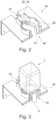
- FIGs 2 to 5the holder 24 of the dispenser and the system according to the first embodiment are shown.
- Figure 2is the holder 24, into which the Figure 1 shown cartridge system and in particular the cartridge receptacle 10 of the cartridge system can be used without the cartridge system.
- Figures 3 and 4The cartridge system is inserted into the holder 24.
- Figure 5the cartridge system and the holder 24 are shown separately.
- the holder 24has a recess 26 which at least partially accommodates the cartridge holder 10.
- Figure 4It can be seen that the part of the cartridge holder 10 that extends into the recess 26 can cooperate with it in a form-fitting manner.
- Figures 2 and 3it is particularly clear that the recess 26 extends to the edge of the holder 24, so that an opening is created there into which the outlet 11 of the mixing chamber 13 projects. This provides an initial anti-twist protection.
- the holder 24can have a guide 25 which interacts positively with the circumference of the cartridge receptacle 10 and supports the cartridge, in particular, against tipping from the vertical. This guide 25 can also have a recess from which the outlet 11 can protrude.
- the outlet 11in interaction with the guide, prevents the cartridge receptacle 10 from rotating relative to the holder 24.
- the holder 24preferably has a line 22 as a liquid connection, which is connected to a solvent reservoir (also referred to as a reservoir for the diluent or fluid source).
- a solvent reservoiralso referred to as a reservoir for the diluent or fluid source.
- the outlet 11 of the cartridge holder 10can be pivotable, in particular to change the angle at which the stream of the finished beverage or food flows into the container. For example, if the stream is directed toward the wall of a container holding the finished beverage or food, foam formation can be reduced. Alternatively or additionally, a support on which the container stands can be tilted, which in turn changes the angle of incidence of the stream of the finished beverage or food relative to the wall. This can also influence foam formation.
- FIG. 6a to 6c 2shows schematic views of the cartridge 1 of the cartridge system of the system according to an exemplary second embodiment.
- the cartridge 2comprises a bottle-shaped object with rounded edges, flattened longitudinal sides, and a cartridge opening on a side opposite the base region 7 along the longitudinal axis of the cartridge 1.
- the cartridge 1has two circumferential retaining flanges 5, onto which the cartridge receptacle 10 is clipped.
- One side of the cartridge 1 of the otherwise round or rounded cartridge 1has a flattened region 29.
- the product identification codeis preferably applied to the flattened region.
- FIGS. 7a, 7b and 7cshow schematic views of a cartridge receptacle 10 of the cartridge system of the system of the exemplary second embodiment of the present invention.
- the cartridge receptacle 10has an at least partially circumferential locking strip 30 on both sides, with which the cartridge receptacle 10 is clipped onto the holding flanges 5 of the cartridge 1.
- the cartridge receptacle 10has the mixing chamber 13, into which the inlet 15 is formed on its rear side in the form of a simple through-opening in the wall of the cartridge receptacle 10.
- the inlet 15is intended to be connected to a line 22, which is in fluid communication with the water reservoir, as soon as the cartridge system is inserted into the holder 24.
- the beverage outlet 11is formed in the floor of the mixing chamber 8 at the front.
- the bottom of the mixing chamber 8forms a continuously deepening depression in the direction of the beverage outlet 11, so that after the beverage production process has ended, no liquid residues remain in the mixing chamber 13.
- Figures 7a to 7calso the mandrel guide 28 can be seen, in which the Figures 8a and 8b illustrated piercing means 16 is slidably mounted.
- the mandrel guide 80comprises a guide part with an internal guide channel in which the piercing mandrel is slidably received.
- the guide channelis essentially cylindrical and protrudes almost vertically from the bottom of the mixing chamber 13 in the direction of the cartridge 1.
- a circumferential stop with a reduced diameteris formed, against which a circumferential shoulder of the piercing mandrel strikes when the piercing mandrel 16 arrives in the extended position. The stop thus limits the movement of the piercing mandrel 16 in the direction of the cavity 6.
- Mixing structuresare optionally arranged on the bottom of the mixing chamber 13, which cause swirling of the inflowing water and thus improve the mixing of the substrate and the water.
- FIGS 8a and 8bDetailed views of the piercing means 16 (also referred to as piercing mandrel) of the cartridge holder 10 of the system according to the second exemplary embodiment of the present invention are shown.
- the piercing mandrel 16is designed to be longitudinally displaceable within the mandrel guide 28. It can thus be moved from a retracted starting position, in which the piercing means 16 is spaced from the membrane 14, into an extended position, in which the piercing means 16 pierces the membrane 14 and extends into the cavity of the cartridge 1.
- the transfer of the piercing means 16 from the retracted position to the extended positionis accomplished by means of a trigger element of the dispenser.
- the compressed air line 31(also referred to as channel 22) running along the piercing mandrel 16 is integrated into the piercing mandrel 16.
- the compressed air line 31runs almost centrally within the piercing mandrel 16 from a first end of the piercing mandrel 16 to a second end of the piercing mandrel 16.
- a compressed air connection 40 of the compressed air line 31is formed, accessible from outside the cartridge receptacle 10, which is provided for connection to a compressed air outlet 32 on the holder 24 that is in fluid communication with a compressed air source of the dispenser.
- a compressed air outlet of the compressed air line 31is formed for injecting compressed air into the cavity of the cartridge 1 when the piercing mandrel 16 is in the extended position, whereby the substrate is then pressed into the mixing chamber 13.
- the systemis designed such that the compressed air connection 40 of the piercing means 16 is coupled to the compressed air outlet 32 of the holder 24 immediately as soon as the cartridge holder 10 is inserted into the holder 24 and/or a release mechanism for the fastening flange is actuated.
- the outer wall of the piercing means 16is formed with several, and in particular exactly five, side channels 17 running almost parallel to one another for guiding the substrate towards the mixing chamber 13 once the membrane 14 has been pierced.
- the substratecan then flow past the membrane 14 towards the mixing chamber 13 through the side channels formed laterally on the piercing means 16.
- the side channels 17are each designed in the form of a groove open on one side. It is conceivable that the cross-section of the side channels and/or the number of side channels is adapted to the viscosity of the substrate, so that the side channels 17 control or limit the flow of the substrate towards the mixing chamber 13.
- the piercing mandrel 16is preferably designed as a plastic part and particularly preferably as a plastic injection-molded part.
- the systemcomprises a cartridge system consisting of the Figures 6a to 6c explained cartridge 1 and the one based on Figures 7a to 8b explained cartridge holder 10.
- Cartridge 1 and cartridge holder 10are connected to each other, in particular clipped.
- the dispenser of the systemcomprises a holder 24 into which the cartridge system is manually inserted by the user.
- the holder 24comprises the compressed air outlet 32, which, after insertion of the cartridge system into the holder 24, establishes a fluid connection with the compressed air connection 40 on the piercing means 16 of the cartridge receptacle 10.
- the compressed air outlet 32 of the dispenseris connected via a flexible line 33 to a compressed air source of the dispenser, for example a compressor inside the housing of the dispenser, so that the compressed air line 31 inside the piercing means 16 is pressurized. It is also conceivable that the compressed air source of the dispenser comprises a replaceable gas cartridge.
- the compressed air outlet 32is designed as a fixed element and thus simultaneously comprises the trigger element, which moves the piercing means 16 from its retracted starting position into the extended position in which it Membrane 14 is pierced and the compressed air outlet is arranged within the cavity of the cartridge 1.
- the holder 24also has the liquid connection 35 (in Figure 2 (also referred to as line 22) through which water from a water reservoir of the dispenser is supplied to the water inlet 15 of the cartridge holder 10.
- the water reservoircomprises, in particular, a removable water tank from which water is withdrawn by means of one or more pumps and supplied to the water inlet 15 under pressure.
- the connection between the fluid supply and the water inlet 15is established directly as soon as the cartridge system is inserted into the holder 24.
- the water from the water tankis optionally carbonated (i.e., carbon dioxide is added) within the dispenser by means of a carbonizer and/or cooled by means of a cooling unit.
- the cooling unitcomprises, in particular, a cooling circuit with a compressor and, like the carbonizer, is also integrated into the housing of the dispenser.
- the holder 24further comprises a fastening flange 34, which positively and/or non-positively engages the cartridge receptacle 10 when inserted into the holder.
- the fastening flange 34comprises at least two claws 37, which radially engage the cartridge receptacle 10.
- the holder 24also has a release mechanism for actuating the fastening flange 34.
- the release mechanismcomprises, for example, a hand lever on the holder 24, which is manually actuated by the user and which, when actuated, can be pivoted about a rotational axis substantially parallel to the longitudinal axis of the cartridge 2.
- the hand leveris coupled to the claws 37 of the fastening flange 34 via a transmission gear such that the pivoting of the hand lever causes the claws 37 to move towards one another and positively receive or clamp the cartridge receptacle 10 between them.
- the transmission geartranslates the rotary movement of the hand lever into a linear translational movement of the fastening flange 34 downwards, so that the entire cartridge system is lowered.
- the cartridge holder 10is thus moved relative to the stationary trigger element 36 in such a way that the piercing means 16 strikes the trigger element 36, causing the piercing means 16 to move from the retracted position to the extended position.
- Thisperforates the membrane 14.
- the fluid connection between the compressed air outlet 32 and the compressed air connection 40is only established by lowering the cartridge holder 10 relative to the trigger element 36.
- the transmission geargenerates the transmission and lowering movement through a screw jack.
- the beverage production processis initiated, and the beverage produced in the mixing chamber 14 can flow through the outlet 11 into a drinking vessel arranged below the outlet 11 on a support of the dispenser.
- the supportis, in particular, pivotable and/or height-adjustable.
- the cartridge 1has the product identification code 38 in its flattened area 28 facing the dispenser housing.
- the product identification code 38comprises a QR code in which information about the substrate present in the cavity is embedded.
- an identification detector 39in the form of an optical camera, in particular a CCD camera, is arranged.
- the QR codeis captured by the optical camera and evaluated by an evaluation unit of the dispenser. In this way, the dispenser recognizes which type of cartridge 1 and/or substrate is involved in the cartridge system inserted into the holder 24. Based on this information, information about the preparation of the beverage using the substrate located in the cartridge 1 can be loaded from an internal memory of the dispenser.
- thisallows for the specification of target values for the temporal and absolute progression of the volume flow, temperature, pressure, and/or carbonation of the supplied water, or for the temporal and absolute progression of the volume flow and/or pressure of the supplied compressed air. It is also conceivable that the ratio between the volume flow of the diluent and the volume flow of the compressed air is controlled depending on the verified product identification code in order to achieve the optimal result in terms of appearance and taste for the produced beverage for the respective cartridge type.
- the usercan pivot the lever back, which raises the cartridge system again.
- the released cartridge systemcan then be removed from the dispenser and disposed of or recycled.
Landscapes
- Engineering & Computer Science (AREA)
- Mechanical Engineering (AREA)
- Food Science & Technology (AREA)
- Health & Medical Sciences (AREA)
- Nutrition Science (AREA)
- Life Sciences & Earth Sciences (AREA)
- Chemical & Material Sciences (AREA)
- Polymers & Plastics (AREA)
- Physics & Mathematics (AREA)
- Thermal Sciences (AREA)
- Devices For Dispensing Beverages (AREA)
- Apparatus For Making Beverages (AREA)
- Packging For Living Organisms, Food Or Medicinal Products That Are Sensitive To Environmental Conditiond (AREA)
- Containers And Packaging Bodies Having A Special Means To Remove Contents (AREA)
- Non-Alcoholic Beverages (AREA)
- Coating Apparatus (AREA)
- Packages (AREA)
- Packaging Of Annular Or Rod-Shaped Articles, Wearing Apparel, Cassettes, Or The Like (AREA)
- Basic Packing Technique (AREA)
- Accessories For Mixers (AREA)
- Processing And Handling Of Plastics And Other Materials For Molding In General (AREA)
- Package Specialized In Special Use (AREA)
- Separation Using Semi-Permeable Membranes (AREA)
Description
Translated fromGermanDie Erfindung betrifft ein System aufweisend einen Dispenser mit einer Kartuschenhalterung.The invention relates to a system comprising a dispenser with a cartridge holder.
Solche Systeme sind aus dem Stand der Technik, beispielsweise aus
Das eingangs genannte System ist also aus dem Stand der Technik bekannt und wird dafür eingesetzt mittels Kartuschen beispielsweise Kaltgetränke herzustellen. Wichtig ist, dass die Kartusche sicher im dem Dispenser gehalten ist, so dass zum einen keinerlei Leckage zum anderen aber auch keine Rückkontamination stattfindet.The system mentioned above is well-known and is used to produce cold drinks, for example, using cartridges. It is important that the cartridge is securely held in the dispenser, preventing both leakage and recontamination.
Es war deshalb die Aufgabe der vorliegenden Erfindung ein System aufweisend einen Dispenser zur Verfügung zu stellen, der diesen Anforderungen gerecht wird. Insbesondere solle eine leckagefreie Getränkeherstellung ohne Rückkontamination des Dispensers ermöglicht werden. Der Dispenser soll gleichzeitig einen hohen Bedienkomfort bieten und kostengünstig realisierbar sein. Eine weitere Aufgabe der vorliegenden Erfindung ist es, die Schaumbildung auf dem Getränk oder Lebensmittel kontrolliert einzustellen.The object of the present invention was therefore to provide a system comprising a dispenser that meets these requirements. In particular, it should enable leak-free beverage production without recontamination of the dispenser. The dispenser should simultaneously offer a high level of user comfort and be cost-effective to implement. A further object of the present invention is to control the foam formation on the beverage or food.
Gelöst wird die Aufgabe mit einem System gemäß Anspruch 1.The problem is solved with a system according to
Die zu diesem Gegenstand der vorliegenden Erfindung gemachten Ausführungen gelten für die anderen Gegenstände der vorliegenden Erfindung gleichermaßen und umgekehrt.The statements made regarding this subject matter of the present invention apply equally to the other subject matters of the present invention and vice versa.
Die vorliegende Erfindung betrifft einen Dispenser mit einer Kartuschenhalterung, die die Kartusche an dem Dispenser lagert und die Kartusche abstützt und/oder führt. Die Kartusche weist einen Hohlraum auf, in dem sich ein Getränke- und/oder Lebensmittelsubstrat befindet. Dieses Substrat ist vorzugsweise flüssig und insbesondere ein Konzentrat und wird mit einem Lösemittel, insbesondere Wasser, zur Herstellung des Getränks oder Lebensmittels gemischt und dann in einem Behälter, insbesondere einem Glas, das vorzugsweise auf einer unterhalb der Halterung angeordneten Auflage des Dispensers steht, aufgefangen. Das Getränke- und/oder Lebensmittelsubstrat umfasst vorzugsweise flüssige Pre-Mix-Bestandteile für Erfrischungsgetränke, wie koffein-, kohlensäure-, frucht- und/oder zuckerhaltige Limonaden und Säfte, Bier(misch)getränke oder sonstige alkoholische oder nicht alkoholische (Misch-)Getränke.The present invention relates to a dispenser with a cartridge holder that mounts the cartridge on the dispenser and supports and/or guides the cartridge. The cartridge has a cavity containing a beverage and/or food substrate. This substrate is preferably liquid, in particular a concentrate, and is mixed with a solvent, in particular water, to produce the beverage or food and then collected in a container, in particular a glass, which preferably stands on a support of the dispenser arranged below the holder. The beverage and/or food substrate preferably comprises liquid premix ingredients for soft drinks, such as caffeine-, carbonated, fruit-, and/or sugar-containing lemonades and juices, beer (mixed) drinks, or other alcoholic or non-alcoholic (mixed) drinks.
Erfindungsgemäß ist nun eine Führung und/oder Verdrehsicherung an der Kartuschenhalterung vorgesehen. Dadurch wird sichergestellt, dass die Kartusche zum einen zumindest bezüglich einer Raumrichtung eine bestimmte Lage relativ zu dem Dispenser einnimmt zum anderen wird verhindert, dass sich die Kartusche vor oder während der Herstellung des Getränks verdreht oder in einer falschen Orientierung eingesetzt wird. Auf diese Weise wird auch sichergestellt, dass falls die Kartusche mit einer Produktidentifikationskennung ausgestattet ist, welche von einem Kennungsdetektor des Dispensers auszulesen ist, die Kennung stets dem Detektor zugewandt ist, so dass ein zuverlässiges und fehlerfreies Auslesen ermöglicht wird.According to the invention, a guide and/or anti-twist device is provided on the cartridge holder. This ensures that the cartridge, on the one hand, assumes a specific position relative to the dispenser, at least with respect to one spatial direction, and, on the other hand, prevents the cartridge from becoming twisted or being inserted in the wrong orientation before or during beverage production. This also ensures that, if the cartridge is equipped with a product identification code that can be read by an identification detector on the dispenser, the code is always facing the detector, thus enabling reliable and error-free reading.
Erfindungsgemäß weist die Kartuschenhalterung eine Ausnehmung auf, die die Kartusche und/oder die Kartuschenaufnahme zumindest teilweise aufnimmt. Vorzugsweise wirken die Ausnehmung in der Kartuschenhalterung und die Kartusche oder Kartuschenaufnahme zumindest teilweise formschlüssig zusammen und wirken so als Auflager und/oder Verdrehsicherung. Vorzugsweise erstreckt sich die Ausnehmung bis zum Rand, so dass der Umfang der Ausnehmung an einer Stelle offen ist. Dort kann die Ausbuchtung in der Kartuschenaufnahme platziert werden. Alternativ weist die Ausnehmung eine Ausbuchtung für die Ausbuchtung an der Kartuschenaufnahme auf.According to the invention, the cartridge holder has a recess that at least partially accommodates the cartridge and/or the cartridge receptacle. Preferably, the recess in the cartridge holder and the cartridge or cartridge receptacle interact at least partially in a form-fitting manner and thus act as a support and/or anti-twist device. Preferably, the recess extends to the edge, so that the circumference of the recess is open at one point. The bulge in the cartridge receptacle can be placed there. Alternatively, the recess has a bulge for the bulge on the cartridge receptacle.
Alternativ oder zusätzlich weist die Halterung eine Führung auf, die mit dem Umfang der Kartuschenaufnahme und/oder die Kartusche zusammenwirkt. Diese Führung kann beispielsweise ein Stehkragen sein, der sich vorzugsweise im Randbereich der Ausnehmung in der Halterung erstreckt. Die Führung erstreckt sich vorzugsweise in einem rechten Winkel zu der Horizontalen und verhindert ein Kippen der Kartusche relativ zu der Vertikalen. Gemäß einer bevorzugten Ausführungsform weisen die Ausnehmung und/oder die Führung eine Öffnung für einen Vorsprung/Ausbuchtung an der Kartuschenaufnahme auf, der als Verdrehsicherung oder als zusätzliche Stabilisierung wirken kann.Alternatively or additionally, the holder has a guide that interacts with the circumference of the cartridge receptacle and/or the cartridge. This guide can, for example, be a standing collar that preferably extends in the edge region of the recess in the holder. The guide preferably extends at a right angle to the horizontal and prevents the cartridge from tilting relative to the vertical. According to a preferred embodiment, the recess and/or the guide have an opening for a projection/bulge on the cartridge receptacle, which can act as an anti-twist device or as additional stabilization.
Die Halterung weist einen Flüssigkeitsanschluss auf. Mit diesem Flüssigkeitsanschluss wird das Lösemittel zur Herstellung des Getränks zur Verfügung gestellt. Der Flüssigkeitsanschluss der Halterung wird vorzugsweise mit dem Flüssigkeitszulauf in der Kartuschenaufnahme, insbesondere flüssigkeitsdicht, in Verbindung gebracht. Es kann vorgesehen sein, dass der Flüssigkeitsanschluss mit Fluid gespeist wird, welches durch ein Kühlaggregat gekühlt wird, wobei das Kühlaggregat Teil des Dispensers oder eines mit dem Dispenser in Wirkverbindung stehenden separaten Kühlschranks ist. In vorteilhafter Weise sind somit Kaltgetränke herstellbar, auch wenn die Kartusche selbst nicht gekühlt ist und beispielweise Zimmertemperatur aufweist. Die Integration des Systems in einen bestehenden Kühlschrank hat den Vorteil, dass das bestehende Kühlaggregat des Kühlschranks für den Dispenser in effizienter Weise einfach mitgenutzt werden kann. Insbesondere bei sogenannten "side-by-side"-Kühlschränken (oft auch als amerikanische Kühlschränke bezeichnet) findet sich in der Front ausreichend Bauraum zur Integration des Dispensers. Denkbar ist, dass es sich bei dem Dispenser um ein Nachrüstset für einen solchen Kühlschrank handelt. Das Kühlaggregat umfasst vorzugsweise eine Kompressorkühleinheit, eine Absorberkühleinheit oder einen thermoelektrischen Kühler. Es kann vorgesehen sein, dass der Flüssigkeitsanschluss mit Fluid gespeist wird, welches durch einen Karbonisierer mit Kohlensäure versetzt wird. Denkbar ist, dass der Karbonisierer Teil des Dispensers ist und wobei der Karbonisierer eine Aufnahme für eine CO2-Patrone und eine Zuführeinrichtung zum Versetzen des Fluides mit CO2 aus der CO2-Patrone aufweist. Vorteilhafterweise lassen sich mit dem System somit auch mit Kohlensäure versetzte (Erfrischungs-) Getränke herstellen. Alternativ wäre auch denkbar, dass der Karbonisierer einen externen CO2-Anschluss aufweist. Das Fluid umfasst insbesondere Wasser, welches aus einer Wasserleitung oder einem Wassertank des Dispensers mittels einer oder mehrerer Pumpen, vorzugsweise Membranpumpen, bereitgestellt wird. Die Förderung des Wassers zum Flüssigkeitsanschluss wird vorzugsweise mittels eines Durchflusssensors, beispielsweise einem Ultraschalldurchflusssensor oder einem magnetisch-induktivem Durchflusssensor, überwacht.The holder has a liquid connection. This liquid connection provides the solvent for producing the beverage. The liquid connection of the holder is preferably connected, in particular in a liquid-tight manner, to the liquid inlet in the cartridge holder. Provision can be made for the liquid connection to be supplied with fluid cooled by a cooling unit, wherein the cooling unit is part of the dispenser or a separate refrigerator operatively connected to the dispenser. This advantageously allows cold beverages to be produced even if the cartridge itself is not cooled and is, for example, at room temperature. Integrating the system into an existing refrigerator has the advantage that the refrigerator's existing cooling unit can be easily and efficiently used for the dispenser. Particularly in so-called "side-by-side" refrigerators (often referred to as American refrigerators), there is sufficient space in the front to integrate the dispenser. It is conceivable that the dispenser is a retrofit kit for such a refrigerator. The cooling unit preferably comprises a compressor cooling unit, an absorber cooling unit, or a thermoelectric cooler. It can be provided that the liquid connection is fed with fluid, which is carbonated by a carbonator. It is conceivable that the carbonator is part of the dispenser and that the carbonator has a receptacle for a CO2 cartridge and a feed device for adding CO2 from the CO2 cartridge to the fluid. Advantageously, the system can therefore also be used to produce carbonated (refreshing) drinks. Alternatively, it would also be conceivable for the carbonator to have an external CO2 connection. The fluid comprises, in particular, water, which is supplied from a water pipe or a water tank of the dispenser by means of one or more pumps, preferably diaphragm pumps. The water is conveyed to the The liquid connection is preferably monitored by means of a flow sensor, for example an ultrasonic flow sensor or a magnetic-inductive flow sensor.
Bevorzugt ist vorgesehen, dass die Halterung einen mit einer Druckluftquelle verbundenen Druckluftauslass aufweist. Der Druckluftauslass fungiert als Kartuschenentladeeinrichtung und dient dazu, Druckluft von außen in den Hohlraum der Kartusche einzuleiten, wodurch das Lebensmittel- und/oder Getränkesubstrat aus dem Hohlraum in eine Mischkammer der Kartuschenaufnahme zu drücken. Die Druckluft wird insbesondere von dem Dispenser bereitgestellt. Die Kartuschenaufnahme weist vorzugsweise einen Gaseinlass auf, welcher beim Einsetzen der Kartuschenaufnahme in die Halterung direkt an den Druckluftauslass der Halterung angekoppelt wird. Dies hat den Vorteil, dass eine Rückkontamination in Richtung des Dispenser wirksam vermieden wird, weil der Druckkanal sofort beim Einsetzen des Kartuschensystems in die Halterung unter Druck steht und somit verhindert wird, dass Lebensmittel- und/oder Getränkesubstrat in Richtung des Dispensers und insbesondere in Richtung der Druckluftquelle wandert. Das Substrat kann sich ausgehend von dem Hohlraum in der Kartusche somit lediglich in Richtung der Mischkammer bewegen.Preferably, the holder has a compressed air outlet connected to a compressed air source. The compressed air outlet functions as a cartridge unloading device and serves to introduce compressed air from the outside into the cartridge cavity, thereby forcing the food and/or beverage substrate from the cavity into a mixing chamber of the cartridge receptacle. The compressed air is provided in particular by the dispenser. The cartridge receptacle preferably has a gas inlet which, when the cartridge receptacle is inserted into the holder, is directly coupled to the compressed air outlet of the holder. This has the advantage that backcontamination in the direction of the dispenser is effectively prevented because the pressure channel is pressurized immediately upon insertion of the cartridge system into the holder, thus preventing food and/or beverage substrate from migrating in the direction of the dispenser and in particular in the direction of the compressed air source. The substrate can therefore only move from the cavity in the cartridge in the direction of the mixing chamber.
Ferner wird beschrieben ein System mit einer Kartuschenaufnahme und/oder einer Kartusche, wobei die Kartuschenaufnahme die Kartusche reversibel oder irreversibel insbesondere teilweise aufnimmt. Die Kartusche hat einen Hohlraum, in dem sich die Getränke- und/oder Lebensmittelsubstanz befindet und die vor der Getränke- und/oder Lebensmittelherstellung, insbesondere durch die Membran, hermetisch verschlossen ist. Zur Herstellung des Getränks und/oder Lebensmittels wird die Kartusche dann geöffnet, insbesondere wird die Membran aufgestochen, und das Substrat läuft/strömt, insbesondere unterstützt durch Einleiten von Druckluft in den Hohlraum, in eine Mischkammer der Kartuschenaufnahme, die auch über einen Zulauf für ein Verdünnungsmittel (auch als Lösungsmittel bezeichnet), insbesondere Wasserzulauf, verfügt, das mit dem Substrat gemischt wird, um das fertige Getränk oder Lebensmittel zu erzeugen, das durch einen ebenfalls an der Kartuschenaufnahme vorgesehenen Ablauf aus der Mischkammer herausläuft. Der Volumenstrom des Lösungsmittels ist dabei in der Regel wesentlich größer als der Volumenstrom des Substrats. Die Kartusche und die mit der Kartusche verbundene Kartuschenaufnahme bilden zusammen ein Kartuschensystem, welches in die Halterung des Dispensers einsetzbar ist.Furthermore, a system with a cartridge receptacle and/or a cartridge is described, wherein the cartridge receptacle reversibly or irreversibly, in particular partially, receives the cartridge. The cartridge has a cavity in which the beverage and/or food substance is located and which is hermetically sealed, in particular by the membrane, before beverage and/or food production. To produce the beverage and/or food, the cartridge is then opened, in particular the membrane is pierced, and the substrate runs/flows, in particular assisted by introducing compressed air into the cavity, into a mixing chamber of the cartridge receptacle, which also has an inlet for a diluent (also referred to as solvent), in particular a water inlet, which is mixed with the substrate to produce the finished beverage or food, which flows out of the mixing chamber through an outlet also provided on the cartridge receptacle. The volume flow of the solvent is generally significantly greater than the volume flow of the substrate. The cartridge and the cartridge holder connected to the cartridge together form a cartridge system that can be inserted into the holder of the dispenser.
Der Strömungsquerschnitt, d.h. der Querschnitt, der für Strömung der Flüssigkeit, insbesondere des Lösungsmittelstroms und/oder des Gemischs aus Lösungsmittel und Substrat zur Verfügung steht, kann so vorgesehen werden, dass sich bezogen auf die Strömungsrichtung des Lösungsmittels die Strömungsgeschwindigkeit zunächst verlangsamt und dann wieder beschleunigt. Die Beschleunigung, die durch eine Strömungsquerschnittsverengung erreicht wird, findet möglichst statt, nachdem das Lösungsmittel und das Substrat vermischt worden sind.The flow cross-section, i.e., the cross-section available for the flow of the liquid, in particular the solvent stream and/or the mixture of solvent and substrate, can be designed such that, relative to the direction of flow of the solvent, the flow velocity initially slows down and then accelerates again. The acceleration achieved by constricting the flow cross-section preferably occurs after the solvent and substrate have been mixed.
Erfindungsgemäss weist die Kartuschenaufnahme ein Aufstechmittel auf, das die Membran vor der Herstellung des Getränks oder Lebensmittels perforiert. Dieses Aufstechmittel ist erfindungsgemäß als Dorn gestaltet, der aus dem Boden der Mischkammer ragt. Die Kartuschenaufnahme weist vorzugsweise eine Dornführung auf, in welcher das Aufstechmittel verschiebbar gelagert ist. Das Aufstechmittel ist auf diese Weise zwischen einer eingefahrenen Position, in welcher das Aufstechmittel von der Membran beabstandet ist, und einer ausgefahrenen Position, in welcher das Aufstechmittel die Membran durchsticht und bis in den Hohlraum der Kartusche ragt, verschiebbar.According to the invention, the cartridge receptacle has a piercing means that perforates the membrane prior to the production of the beverage or food. This piercing means is designed as a spike that protrudes from the bottom of the mixing chamber. The cartridge receptacle preferably has a spike guide in which the piercing means is displaceably mounted. The piercing means is thus displaceable between a retracted position, in which the piercing means is spaced from the membrane, and an extended position, in which the piercing means pierces the membrane and extends into the cavity of the cartridge.
Vorzugsweise weist das Aufstechmittel an seinem äußeren Umfang mindestens eine, vorzugsweise mehrere Ein- und/oder Ausbuchtungen auf, die als Ablauf für das Substrat dienen. Die Menge und die Größe der Ein- und/oder Ausbuchtungen hängt vorzugsweise von der Viskosität des Substrats ab. Die Außenwandung des Aufstechmittels ist also mit wenigstens einem Seitenkanal zum Leiten des Substrats in Richtung der Mischkammer, wenn die Membran durchstochen ist, versehen. Durch den seitlich am Aufstechmittel ausgebildeten Seitenkanal kann das Substrat dann an der Membran vorbei in Richtung Mischkammer fließen. Vorzugsweise sind eine Mehrzahl von Seitenkanälen am Aufstechmittel ausgebildet. Die Seitenkanäle sind insbesondere jeweils in Form einer einseitig offenen Nut ausgebildet. Denkbar ist, dass der Querschnitt der Seitenkanäle und/oder die Anzahl der Seitenkanäle an die Viskosität des Substrats angepasst ist, so dass die Seitenkanäle den Fluss des Substrats in Richtung Mischkammer kontrollieren bzw. begrenzen. Bei einer hohen Viskosität werden mehrere Seitenkanäle oder Seitenkanäle mit größerem Querschnitt verwendet, während bei einer niedrigeren Viskosität weniger Seitenkanäle oder Seitenkanäle mit geringerem Querschnitt vorgesehen sind. Für jede Kartusche existiert somit eine passende Kartuschenaufnahme.The piercing means preferably has at least one, preferably several indentations and/or protrusions on its outer circumference, which serve as a drain for the substrate. The number and size of the indentations and/or protrusions preferably depends on the viscosity of the substrate. The outer wall of the piercing means is therefore provided with at least one side channel for guiding the substrate towards the mixing chamber when the membrane is pierced. The substrate can then flow past the membrane towards the mixing chamber through the side channel formed laterally on the piercing means. Preferably, a plurality of side channels are formed on the piercing means. The side channels are each designed in particular in the form of a groove open on one side. It is conceivable that the cross section of the side channels and/or the number of side channels is adapted to the viscosity of the substrate, so that the side channels control or limit the flow of the substrate toward the mixing chamber. For high viscosity, multiple side channels or side channels with a larger cross-section are used, while for lower viscosity, fewer side channels or side channels with a smaller cross-section are provided. Thus, there is a suitable cartridge receptacle for each cartridge.
Vorzugsweise ist in das Aufstechmittel eine Druckluftleitung, insbesondere in Form eines inneren Kanals, integriert, wobei an einer der Kartusche abgewandten Seite des Aufstechmittels ein, insbesondere von außerhalb der Kartuschenaufnahme zugänglicher Druckluftanschluss der Druckluftleitung zur Verbindung mit einer Druckluftquelle ausgebildet ist und wobei an einer dem Hohlraum der Kartusche zugewandten Seite des Aufstechmittels ein Druckluftausgang der Druckluftleitung zum Einblasen der Druckluft in die Kartusche ausgebildet ist. Vorzugsweise wird bereits beim Einsetzen des Kartuschensystems aus Kartusche und Kartuschenaufnahme in die Halterung bereits Druckluft an den Druckluftanschluss angelegt, um eine etwaige Rückkontamination des Dispensers zu verhindern. Alternativ wird das Aufstechmittel durch die über den Dispenser angelegte Druckluft von der eingefahrenen Position in die ausgefahrene Position verfahren. Anstelle von Druckluft kann auch CO2 in den Hohlraum eingeleitet werden, um das Substrat von dem Hohlraum in die Mischkammer zu überführen.Preferably, a compressed air line, in particular in the form of an internal channel, is integrated into the piercing means, wherein a compressed air connection of the compressed air line, accessible in particular from outside the cartridge receptacle, is formed on a side of the piercing means facing away from the cartridge and is intended for connection to a compressed air source, and wherein a compressed air outlet of the compressed air line is formed on a side of the piercing means facing the cavity of the cartridge and is intended for blowing the compressed air into the cartridge. Preferably, compressed air is already applied to the compressed air connection when the cartridge system comprising the cartridge and cartridge receptacle is inserted into the holder in order to prevent any recontamination of the dispenser. Alternatively, the piercing means is moved from the retracted position to the extended position by the compressed air applied via the dispenser. Instead of compressed air, CO2 can also be introduced into the cavity in order to transfer the substrate from the cavity into the mixing chamber.
Vorzugsweise weist das Aufstechmittel also einen Kanal auf, der in oder im Bereich der Spitze endet. Durch diesen Kanal kann ein Gas, insbesondere Luft oder CO2 in die Kartusche geblasen werden, um die Abgabe des Substrats zu beschleunigen und/oder zu dosieren.Preferably, the piercing means has a channel that ends in or near the tip. A gas, particularly air orCO2, can be blown into the cartridge through this channel to accelerate and/or dose the release of the substrate.
Das System ist vorzugsweise derart ausgebildet, dass eine Kopplung des Druckluftanschlusses mit dem Druckluftauslass der Halterung erfolgt, wenn die Kartuschenaufnahme in die Halterung eingesetzt ist und/oder die Auslösemechanik für den Befestigungsflansch betätigt wird. Die Druckluftleitung wird somit frühestmöglich unter Druck gesetzt, so dass eine Rückkontamination des Dispensers durch das Substrat unterbunden wird.The system is preferably designed such that the compressed air connection is coupled to the compressed air outlet of the holder when the cartridge receptacle is inserted into the holder and/or the release mechanism for the mounting flange is actuated. The compressed air line is thus pressurized as early as possible, preventing recontamination of the dispenser by the substrate.
Vorzugsweise sind der Zulauf und der Ablauf an gegenüberliegenden Enden der Kartuschenaufnahme vorgesehen. Erfindungsgemäß ist das Aufstechmittel in einer Flucht mit dem Zulauf und dem Ablauf vorgesehen.Preferably, the inlet and outlet are provided at opposite ends of the cartridge receptacle. According to the invention, the piercing means is provided in alignment with the inlet and outlet.
Die Kartusche wird vorzugsweise aus Kunststoff, insbesondere durch ein Moulding- und/oder ein Blasverfahren hergestellt. Die Kartusche weist eine Seitenwand auf, die beispielsweise einen runden, rechteckigen, quadratischen, konischen oder ovalen Querschnitt aufweist. An einem Ende der Seitenwand ist in der Regel ein Boden, insbesondere einstückig vorgesehen. Die Seitenwand und gegebenenfalls der Bodenbereich spannen einen Hohlraum auf, in dem ein Getränke- und/oder Lebensmittelsubstrat, insbesondere in flüssiger Form vorgesehen ist. An dem anderen Ende des Wandbereichs ist ein Verbindungsbereich vorgesehen, mit dem die Kartusche mit der Kartuschenaufnahme verbunden wird. Diese Kartuschenaufnahme kann Teil eines Dispensers oder ein vom Dispenser separates Bauteil sein.The cartridge is preferably made of plastic, in particular by a molding and/or blow molding process. The cartridge has a side wall which, for example, has a round, rectangular, square, conical or oval cross-section. At one end of the side wall, a base is usually provided, in particular in one piece. The side wall and optionally the base region define a cavity in which a beverage and/or food substrate, in particular in liquid form, is provided. At the other end of the wall region, a connecting region is provided with which the cartridge is connected to the cartridge receptacle. This cartridge receptacle can be part of a dispenser or a separate component from the dispenser.
Vorzugsweise ist der Verbindungsbereich so vorgesehen, dass er wenigstens einen Flansch aufweist. Der Flansch steht aus dem Verbindungsbereich hervor und steht vorzugsweise in einem Winkel, besonders bevorzugt einem rechten Winkel von einem Wandbereich des Verbindungsbereichs ab. Zur Herstellung des Getränks oder Lebensmittels ist der Flansch vorzugsweise horizontal ausgerichtet. Vorzugsweise ist der Flansch aus Vollmaterial, d.h. nicht hohl gefertigt. Insbesondere ist der Flansch gespritzt.Preferably, the connecting region is provided such that it has at least one flange. The flange protrudes from the connecting region and preferably protrudes at an angle, particularly preferably at a right angle, from a wall region of the connecting region. For the production of the beverage or food, the flange is preferably oriented horizontally. Preferably, the flange is made of solid material, i.e., not hollow. In particular, the flange is injection-molded.
Weiterhin bevorzugt ist der Flansch mit einem Positionier- und oder Abdeckmittel versehen. Das Positioniermittel stellt sicher, dass die Kartusche nur in einer bestimmten Position, insbesondere in einem bestimmten Drehwinkel, insbesondere Bezogen auf die Längsmittelachse der Kartusche an dem Dispenser und/oder an der Kartuschenaufnahme angeordnet werden kann. Das Abdeckmittel deckt einen Bereich, insbesondere einen Bereich, durch den das fertiggestellte Getränk oder Lebensmittel fließt ab. Vorzugsweise sind das Positioniermittel und das Abdeckmittel identisch.Furthermore, the flange is preferably provided with a positioning and/or covering means. The positioning means ensures that the cartridge can only be arranged in a specific position, in particular at a specific angle of rotation, in particular relative to the longitudinal center axis of the cartridge on the dispenser and/or on the cartridge receptacle. The covering means covers an area, in particular an area through which the finished beverage or food product flows. Preferably, the positioning means and the covering means are identical.
Vorzugsweise ist das Positioniermittel und/oder Abdeckmittel eine Ein- und/oder Ausbuchtung, die aus dem Flansch, insbesondere dessen Umfang hervorsteht. Vorzugsweise ist das Positioniermittel und/oder Abdeckmittel einstückig mit dem Flansch vorgesehen. Beispielsweise ist das Positioniermittel und/oder Abdeckmittel als Nase ausgebildet, die an einer Stelle an den Umfang des Flanschs angeformt ist. Die Dicke des Positioniermittels und/oder Abdeckmittels entspricht dabei zumindest im wesentlichen der Dicke des Flanschs.Preferably, the positioning means and/or covering means is an indentation and/or protrusion that protrudes from the flange, in particular its periphery. Preferably, the positioning means and/or covering means is provided integrally with the flange. For example, the positioning means and/or covering means is designed as a nose that is molded onto the periphery of the flange at one point. The thickness of the positioning means and/or covering means corresponds at least substantially to the thickness of the flange.
Gemäß einer bevorzugten Ausführungsform ist zwischen dem Wandbereich und dem Verbindungsbereich ein Hals vorgesehen. Dieser Hals kann beispielsweise einen runden Querschnitt aufweisen. Der Hals stellt den Wandbereich des Verbindungsbereichs dar. Der Flansch schließt sich vorzugsweise rechtwinklig an den Hals an.According to a preferred embodiment, a neck is provided between the wall region and the connecting region. This neck can, for example, have a round cross-section. The neck represents the wall region of the connecting region. The flange preferably adjoins the neck at a right angle.
Vorzugsweise ist die Membran, die die Kartusche vor deren Gebrauch, insbesondere hermetisch verschließt, an dem Flansch, insbesondere dessen Stirnfläche, vorgesehen, insbesondere gesiegelt. Dafür kann der Flansch, insbesondere dessen Stirnfläche eine Wulst, insbesondere eine kreisringförmige Wulst aufweisen, die beim Siegeln mit dem Siegelwerkzeug zusammenwirkt. Vorzugsweise ist der äußere Umfang der Membran geringer als der äußere Umfang des Flansches.Preferably, the membrane, which seals the cartridge, in particular hermetically, prior to use, is provided, in particular sealed, on the flange, in particular on its end face. For this purpose, the flange, in particular on its end face, can have a bead, in particular an annular bead, which interacts with the sealing tool during sealing. Preferably, the outer circumference of the membrane is smaller than the outer circumference of the flange.
Vorzugsweise weist das Aufstechmittel einen Kanal auf. Durch diesen Kanal kann ein Gas in die Kartusche gedrückt werden, das das Getränke- und/oder Lebensmittelsubstrat aus der Kartusche insbesondere in den Mischraum der Kartuschenaufnahme drückt.Preferably, the piercing means has a channel. A gas can be forced into the cartridge through this channel, forcing the beverage and/or food substrate out of the cartridge, particularly into the mixing chamber of the cartridge receptacle.
Im folgendem wird die Erfindung anhand der
Figur 1- zeigt die Kartusche und die Kartuschenaufnahme des Systems gemäß einer ersten Ausgestaltung
- Figuren 2 - 5
- zeigen einen Dispenser und ein System gemäß der ersten Ausführungsform der vorliegenden Erfindung. Ausgestaltung.
- Figuren 6a bis 6c
- zeigen eine Kartusche eines Systems gemäß einer zweiten Ausgestaltung.
- Figuren 7a und 7b
- zeigen eine Kartuschenaufnahme des Systems gemäß der zweiten Ausgestaltung.
- Figuren 8a und 8b
- zeigen ein Aufstechmittel der Kartuschenaufnahme des Systems gemäß der zweiten Ausgestaltung.
- Figuren 9a und 9b
- zeigen ein Dispenser und ein System gemäß einer dritten Ausgestaltung.
- Figure 1
- shows the cartridge and the cartridge holder of the system according to a first embodiment
- Figures 2 - 5
- show a dispenser and a system according to the first embodiment of the present invention.
- Figures 6a to 6c
- show a cartridge of a system according to a second embodiment.
- Figures 7a and 7b
- show a cartridge holder of the system according to the second embodiment.
- Figures 8a and 8b
- show a piercing means of the cartridge holder of the system according to the second embodiment.
- Figures 9a and 9b
- show a dispenser and a system according to a third embodiment.
Der Wandbereich 6 und der Bodenbereich 7 begrenzen einen Hohlraum, in dem sich das Getränke- und/oder Lebensmittelsubstrat, insbesondere ein Konzentrat, befindet, mit dem ein Getränk oder Lebensmittel hergestellt werden kann. An dem dem Bodenbereich 7 gegenüberliegenden Ende, hier unteren Ende, des Wandbereiches 6 ist ein Verbindungsbereich 4 vorgesehen, der in dem vorliegenden Fall einen Hals 3 sowie einen Flansch 5 aufweist. Der Hohlraum der Kartusche 1 wird nach deren Befüllung durch einen Verschluss, hier eine Membran 14, hermetisch abgeschlossen. Die Membran 14, insbesondere eine Kunststofffolie wird vorzugsweise stoffschlüssig, insbesondere durch Siegeln mit dem Flansch 5 verbunden. Mit dem Verbindungsbereich 4 wird die Kartusche 1 mit einer Kartuschenaufnahme 10 verbunden. An dem Flansch 5 ist optional ein Positionier- und/oder Abdeckmittel 8 vorgesehen, das in dem vorliegenden Fall als Ausbuchtung, insbesondere als nasenförmige Ausbuchtung, vorgesehen ist. Die Nase ist hier einstückig an den Flansch 5 angeformt. Des Weiteren weist das Kartuschensystem eine Kartuschenaufnahme 10 auf. Die Kartuschenaufnahme 10 weist einen Zulauf 15 für ein Verdünnungsmittel (auch als Lösemittel bezeichnet), welches vorzugsweise Wasser umfasst, sowie eine Mischkammer 13 auf, in der das Verdünnungsmittel und das Getränke- und/oder Lebensmittelsubstrat miteinander gemischt werden. Die Strömungsrichtung des Gemisches ist durch den Pfeil 12 dargestellt. Das fertiggestellte Getränk/Lebensmittel verlässt die Mischkammer 13 durch den Ablauf 11 und wird in einem Behälter (nicht dargestellt), beispielsweise einem Trinkglas aufgefangen. Weiterhin weist die Kartuschenaufnahme 10 ein Aufstechmittel 16, hier einen Dorn, auf, der die Membran 14, die an den Flanschbereich 5 der Kartusche 1 gesiegelt ist, aufsticht, so dass das Getränke- oder Lebensmittelsubstrat insbesondere entlang der Außenfläche des Dorns, der dafür an seiner Außenseite vorzugsweise mit Seitenkanälen 17 versehen ist, in die Mischkammer 13 fließen kann.The
Um die Membrane 14 zu durchstechen, werden die Kartusche 1 und/oder die Kartuschenaufnahme 10 relativ sowie längs zueinander verschoben, so dass der Dorn 16 die Membrane 14 durchdringt. Alternativ ist der Dorn 16 längsverschiebbar in einer Dornführung 28 der Kartuschenaufnahme 10 gelagert, so dass keine Relativbewegung zwischen der Kartuschenaufnahme 10 und der Kartusche 1 notwendig ist, sondern nur der Dorn 16 von einer eingefahrenen Position, in welcher er von der Membran 14 beabstandet ist (siehe
Der Fluss des Substrates in die Mischkammer 13 kann durch Gas, das durch einen Kanal 18 in dem Aufstechdorn 16 in den Hohlraum der Kartusche 1 gedrückt wird, beschleunigt und gezielt gesteuert werden. Beispielsweise kann der Druck in der Kartusche 1 und damit der Volumenstrom des Substrates dem Volumenstrom des Lösemittels angepasst werden. Dies kann insbesondere dann von Interesse sein, wenn zur Beeinflussung der Schaumbildung der Volumenstrom des Lösungsmittels gezielt gesteuert oder geregelt wird. Der Volumenstrom des Substrats wird dann vorzugsweise an den Volumenstrom des Lösemittels angepasst.The flow of the substrate into the mixing
Vorzugsweise wirkt der Flansch 5 der Kartusche 1 dichtend mit der Kartuschenaufnahme 10 zusammen und stellt dadurch sicher, dass Flüssigkeit die Mischkammer 13 nur durch den Ablauf 5 verlässt. Des Weiteren kann insbesondere diesen Figuren entnommen werden, dass die Ausbuchtung 8 in dem vorliegenden Fall nicht nur ein Positioniermittel ist, sondern auch den Ablauf 11 in der Kartuschenaufnahme insbesondere dichtend abdeckt. Der Flansch 8 und die daran vorgesehene Ausbuchtung 8 können mit ihrer Stirnfläche und/oder mit ihrem Umfang dichtend mit entsprechenden Flächen der Kartuschenaufnahme zusammenwirken.Preferably, the
In
Die Halterung 24 weist eine Ausnehmung 26 auf, die die Kartuschenaufnahme 10 zumindest teilweise aufnimmt. Insbesondere anhand von
Der Ablauf 11 der Kartuschenaufnahme 10 kann schwenkbar vorgesehen sein, insbesondere um den Winkel, mit dem der Strahl des fertiggestellten Getränks oder Lebensmittels in das Gefäß strömt zu verändern. Wird der Strahl beispielsweise in Richtung der Wandung eines Behälters geleitet, der das fertiggestellte Getränk oder Lebensmittel aufnimmt, kann dadurch beispielsweise eine Schaumbildung reduziert werden. Alternativ oder zusätzlich kann eine Auflage, auf der der Behälter steht, gekippt werden, so dass sich wiederum der Auftreffwinkel des Strahls des fertiggestellten Getränks oder Lebensmittels relativ zu Wandung verändert. Auch damit kann die Schaumbildung beeinflusst werden.The
In den
Die
Die Dornführung 80 umfasst hierfür ein Führungsteil mit einem innenliegenden Führungskanal, in welchem der Aufstechdorn verschiebbar aufgenommen ist. Der Führungskanal ist im Wesentlichen zylinderförmig ausgebildet ist und steht nahezu senkrecht vom Boden der Mischkammer 13 in Richtung der Kartusche 1 hervor. An einem der Kartusche 1 zugewandten Ende des Führungsteils ist ein umlaufender Anschlag mit verringertem Durchmesser ausgebildet, an welchem ein umlaufende Absatz des Aufstechdorns anschlägt, wenn der Aufstechdorn 16 in der ausgefahrenen Position ankommt. Der Anschlag begrenzt somit die Bewegung des Aufstechdorns 16 in Richtung des Hohlrausm6. Auf dem Boden der Mischkammer 13 sind optional Mischstrukturen angeordnet, welche eine Verwirbelung des einströmenden Wassers verursachen und somit die Vermischung des Substrats und des Wassers verbessern.For this purpose, the mandrel guide 80 comprises a guide part with an internal guide channel in which the piercing mandrel is slidably received. The guide channel is essentially cylindrical and protrudes almost vertically from the bottom of the mixing
In
Der Aufstechdorn 16 ist dazu ausgebildet, längsverschieblich in der Dornführung 28 angeordnet zu sein. Er ist somit von einer eingefahrenen Ausgangsposition, in welcher das Aufstechmittel 16 von der Membran 14 beabstandet ist, in eine ausgefahrene Position, in welcher das Aufstechmittel 16 die Membran 14 durchsticht und bis in den Hohlraum der Kartusche 1 ragt, überführbar. Die Überführung des Aufstechmittels 16 von der eingefahrenen Position in die ausgefahrene Position erfolgt mittels eines Auslöseelements des Dispensers.The piercing
In den Aufstechdorn 16 ist die entlang des Aufstechdorns 16 verlaufende Druckluftleitung 31 (auch als Kanal 22 bezeichnet) integriert. Die Druckluftleitung 31 verläuft nahezu mittig innerhalb des Aufstechdorns 16 von einem ersten Ende des Aufstechdorns 16 zu einem zweiten Ende des Aufstechdorns 16. Am ersten Ende des Aufstechdorns 16 ist ein von außerhalb der Kartuschenaufnahme 10 zugänglicher Druckluftanschluss 40 der Druckluftleitung 31 ausgebildet, der zur Verbindung mit einem mit einer Druckluftquelle des Dispensers in Fluidverbindung stehenden Druckluftauslass 32 an der Halterung 24 vorgesehen ist. Am zweiten Ende ist ein Druckluftausgang der Druckluftleitung 31 zum Einblasen der Druckluft in den Hohlraum der Kartusche 1 ausgebildet, wenn sich der Aufstechdorn 16 in der ausgefahrenen Position befindet, wodurch dann das Substrat in die Mischkammer 13 gedrückt wird.The compressed air line 31 (also referred to as channel 22) running along the piercing
Das System ist so ausgebildet ist, dass eine Kopplung des Druckluftanschlusses 40 des Aufstechmittels 16 mit dem Druckluftauslass 32 der Halterung 24 sofort erfolgt, sobald die Kartuschenaufnahme 10 in die Halterung 24 eingesetzt ist und/oder eine Auslösemechanik für den Befestigungsflansch betätigt wird.The system is designed such that the
Die Außenwandung des Aufstechmittels 16 ist mit mehreren und insbesondere genau fünf nahezu parallel zueinander verlaufenden Seitenkanälen 17 zum Leiten des Substrats in Richtung der Mischkammer 13 ausgebildet, wenn die Membran 14 durchstochen ist. Durch die seitlich am Aufstechmittel 16 ausgebildeten Seitenkanäle kann das Substrat dann an der Membran 14 vorbei in Richtung Mischkammer 13 fließen. Die Seitenkanäle 17 sind jeweils in Form einer einseitig offenen Nut ausgebildet. Denkbar ist, dass der Querschnitt der Seitenkanäle und/oder die Anzahl der Seitenkanäle an die Viskosität des Substrats angepasst ist, so dass die Seitenkanäle 17 den Fluss des Substrats in Richtung Mischkammer 13 kontrollieren bzw. begrenzen. Der Aufstechdorn 16 ist vorzugsweise als Kunststoffteil und besonders bevorzugt als Kunststoff-Spritzgussteil ausgebildet.The outer wall of the piercing means 16 is formed with several, and in particular exactly five,
In
Das System umfasst ein Kartuschensystem bestehend aus der anhand von
Der Dispenser des Systems umfasst eine Halterung 24, in welche das Kartuschensystem durch den Benutzer manuell eingesetzt wird.The dispenser of the system comprises a
Die Halterung 24 umfasst den Druckluftauslass 32, welcher nach dem Einsetzen des Kartuschensystems in die Halterung 24, eine Fluidverbindung mit dem Druckluftanschluss 40 am Aufstechmittel 16 der Kartuschenaufnahme 10 eingeht. Der Druckluftauslass 32 des Dispensers ist über eine flexible Leitung 33 mit einer Druckluftquelle des Dispensers, beispielsweise einem Kompressor im Inneren des Gehäuses des Dispensers verbunden, so dass die Druckluftleitung 31 im Inneren des Aufstechmittels 16 unter Druck gesetzt wird. Denkbar ist auch, dass die Druckluftquelle des Dispensers eine austauschbare Gaskartusche umfasst. Der Druckluftauslass 32 ist als feststehendes Element ausgebildet und umfasst somit gleichzeitig das Auslöseelement, welches das Aufstechmittel 16 von seiner eingefahrenen Ausgangsposition in die ausgefahrene Position, in welcher es die Membran 14 durchsticht und der Druckluftausgang innerhalb der Hohlraums der Kartusche 1 angeordnet ist, überführt.The
Die Halterung 24 weist ferner den Flüssigkeitsanschluss 35 (in
Die Halterung 24 umfasst ferner einen Befestigungsflansch 34, welcher die Kartuschenaufnahme 10 beim Einsetzen in die Halter formschlüssig und/oder kraftschlüssig umgreift. Der Befestigungsflansch 34 umfasst hierfür wenigstens zwei Klauen 37, welche die Kartuschenaufnahme 10 radial umgreifen. Die Halterung 24 weist zudem eine Auslösemechanik zur Betätigung des Befestigungsflansches 34 auf. Die Auslösemechanik umfasst beispielsweise einen manuell durch den Benutzer zu betätigen Handhebel an der Halterung 24, welcher bei seiner Betätigung um eine zu Längsachse der Kartusche 2 im Wesentlichen parallele Drehachse verschwenkbar ist. Der Handhebel ist über ein Übersetzungsgetriebe mit den Klauen 37 des Befestigungsflansches 34 derart gekoppelt, dass durch die Verschenkung des Handhebels die Klauen 37 aufeinander zu bewegt werden und die Kartuschenaufnahme 10 zwischen sich formschlüssig aufnehmen oder einklemmen.The
Gleichzeitig bewirkt das Übersetzungsgetriebe eine Übersetzung der Drehbewegung des Handhebels in eine lineare Translationsbewegung des Befestigungsflansches 34 nach unten, so dass das gesamte Kartuschensystem abgesenkt wird. Die Kartuschenaufnahme 10 wird somit relativ zu dem feststehenden Auslöseelement 36 derart bewegt, dass das Aufstechmittel 16 an dem Auslöseelement 36 anschlägt, wodurch sich das Aufstechmittel 16 von der eingefahrenen Position in die ausgefahrene Position bewegt. Hierdurch wird die Membran 14 perforiert. Denkbar ist auch, dass durch das Absenken der Kartuschenaufnahme 10 relativ zum Auslöseelement 36 erst die Fluidverbindung zwischen dem Druckluftauslass 32 und dem Druckluftanschluss 40 hergestellt wird. Das Übersetzungsgetriebe erzeugt die Übersetzung und Absenkbewegung durch ein Spindelhubgetriebe.At the same time, the transmission gear translates the rotary movement of the hand lever into a linear translational movement of the
Durch Einleiten der Druckluft in den Hohlraum und des Wassers in die Mischkammer 13 wird nun der Getränkeherstellungsprozess eingeleitet und das in der Mischkammer 14 erzeugte Getränke kann durch den Ablauf 11 in ein unterhalb des Ablaufs 11 auf einer Auflage des Dispensers angeordnetem Trinkgefäß gelangen. Die Auflage ist insbesondere schwenkbar und/oder höhenverstellbar vorgesehen.By introducing compressed air into the cavity and water into the mixing
Die Kartusche 1 weist in ihrem dem Gehäuse des Dispensers zugewandten abgeflachten Bereich 28 die Produktidentifikationskennung 38 auf. Die Produktidentifikationskennung 38 umfasst dabei einen QR-Code, in welchen Informationen über das in dem Hohlraum vorhandene Substrat eingebettet sind. An der gegenüberliegenden Seite ist am Gehäuse des Dispensers ein Kennungsdetektor 39 in Form einer optischen Kamera, insbesondere CCD-Kamera angeordnet. Der QR-Code wird von der optischen Kamera erfasst und mittels einer Auswerteeinheit des Dlspensers ausgewertet. Auf diese Weise wird seitens des Dispensers erkannt, um welche Art von Kartusche 1 und/oder Substrat es sich bei dem in die Halterung 24 eingesetzten Kartuschensystem handelt. Anhand dieser Informationen können aus einem internen Speicher des Dispensers ggf. Informationen über die Zubereitung des Getränks mit Hilfe des in der Kartusche 1 befindlichen Substrats geladen werden. Insbesondere werden hierdurch Sollwerte für den zeitlichen und absoluten Verlauf des Volumenstroms, der Temperatur, des Drucks und/oder der Carbonisierung des eingespeisten Wassers oder des zeitlichen und absoluten Verlaufs des Volumenstroms und/oder des Drucks der eingespeisten Druckluft vorgegeben. Denkbar ist auch, dass das Verhältnis zwischen dem Volumenstrom des Verdünnungsmittels und dem Volumenstrom der Druckluft in Abhängigkeit der verifizierten Produktidentifikationskennung gesteuert wird, um beim hergestellten Getränk für den jeweiligen Kartuschentyp das optimale Ergebnis hinsichtlich Aussehen und Geschmack zu erzielen.The
Nach der Herstellung des Getränks kann der Handhebel von dem Benutzer zurück verschwenkt werden, wodurch sich das Kartuschensystem wieder anhebt. Das somit freigegebene Kartuschensystem kann nun von dem Dispenser entnommen und entsorgt bzw. recycled werden.After the beverage is prepared, the user can pivot the lever back, which raises the cartridge system again. The released cartridge system can then be removed from the dispenser and disposed of or recycled.
- 11
- Kartuschecartridge
- 22
- BewegungsrichtungDirection of movement
- 33
- HalsNeck
- 44
- VerbindungsbereichConnection area
- 55
- Flanschflange
- 66
- WandbereichWall area
- 77
- BodenbereichFloor area
- 88
- Positionier- und/oder Abdeckmittel, Ein- und/oder Ausbuchtung,Positioning and/or covering means, indentation and/or protrusion,
- 99
- Zulauf der Substanz, AufstechmittelInflow of the substance, piercing agent
- 1010
- KartuschenaufnahmeCartridge holder
- 1111
- Ablauf Substanz plus Lösungsmittel/WasserSubstance plus solvent/water
- 1212
- Strömungsrichtung Substanz plus Lösungsmittel/WasserFlow direction substance plus solvent/water
- 1313
- MischkammerMixing chamber
- 1414
- Verschluss, Membranclosure, membrane
- 1515
- Lösemittel-, WasserzulaufSolvent and water supply
- 1616
- Aufstechmittel, Dornpiercing tool, thorn
- 1717
- Ablaufkanäledrainage channels
- 1818
- GaseinlassGas inlet
- 1919
- Dichtung, BunddichtungSeal, flange seal
- 2020
- Befestigungsmittel, BundFasteners, collar
- 2121
- AuflageEdition
- 2222
- Kanalchannel
- 2323
- Ein- und/oder Ausbuchtung der KartuschenaufnahmeIndentation and/or protrusion of the cartridge holder
- 2424
- Halterungbracket
- 2525
- Führung für die KartuschenaufnahmeGuide for the cartridge holder
- 2626
- Ausnehmungrecess
- 2727
- Führungskanteleading edge
- 2828
- DornführungMandrel guide
- 2929
- Abgeflachter BereichFlattened area
- 3030
- Rastleistelocking bar
- 3131
- DruckluftleitungCompressed air line
- 3232
- DruckluftauslassCompressed air outlet
- 3333
- LeitungLine
- 3434
- BefestigungsflanschMounting flange
- 3535
- FlüssigkeitsanschlussLiquid connection
- 3636
- Auslöseelementtrigger element
- 3737
- Klaueclaw
- 3838
- ProduktidentifikationskennungProduct identification code
- 3939
- KennungsdetektorIdentification detector
- 4040
- DruckluftanschlussCompressed air connection
Claims (15)
- System having a dispenser, a cartridge receptacle (10) and a cartridge (1), wherein the dispenser has a cartridge holder (24) which has at least one guide and/or anti-rotation lock (25, 27) for the cartridge (1) and/or for the cartridge receptacle (10), wherein the cartridge holder (24) has a recess (26) which receives at least part of the cartridge (1) and/or the cartridge receptacle (10), wherein the cartridge receptacle (10) has an inflow (15) for a diluting medium, a mixing chamber (13) in which the diluting medium and a drink and/or food substrate are mixed, and an outflow (11), wherein the cartridge (1) is sealed by means of a membrane (14) and the cartridge receptacle (10) has a piercing means (16) for perforating the membrane (14), wherein the piercing means (16) is provided in alignment with the inflow (15) and with the outflow (11),characterized in that the piercing means is configured as a spike (16) which projects from the base of the mixing chamber (13).
- System according to Claim 1, wherein the flow cross-section of the cartridge receptacle (10) is initially widened and then reduced again with respect to the direction of flow of the diluting medium.
- System according to one of Claims 1 or 2,characterized in that the mixing chamber (13) has a bulge.
- System according to Claim 3,characterized in that the outflow (11) is provided in the bulge.
- System according to one of the preceding claims,characterized in that the cartridge receptacle (10) has a spike guide (28) in which the piercing means (16) is mounted displaceably, wherein the piercing means (16) can be displaced between a retracted position in which the piercing means (16) is spaced apart from the membrane (14) and an extended position in which the piercing means (16) punctures the membrane (14) of the cartridge (1) and projects into the cartridge (1).
- System according to Claim 5,characterized in that at least one side channel (71) for conveying the drink and/or food substrate in the direction of the mixing chamber (13) when the membrane (14) is punctured by the piercing means (16) is introduced into the outer wall of the piercing means (16).
- System according to one of the preceding claims,characterized in that a compressed-air line (31) is integrated into the piercing means (16) and wherein, at a side of the piercing means (16) which faces away from the cartridge (1), a compressed-air connector (40), which in particular can be accessed from outside the cartridge receptacle (10), of the compressed-air line (31) is designed for connection to a compressed-air source, and wherein, at a side of the piercing means (16) which faces the cartridge (1), a compressed-air output of the compressed-air line (34) is designed to blow the compressed air into the cartridge (1).
- System according to Claim 7,characterized in that the system is designed in such a way that coupling of the compressed-air connector (40) to the compressed-air outlet of the holder takes place when the cartridge receptacle (10) is inserted into the holder.
- System according to one of the preceding claims,characterized in that the inflow (15) and the outflow (11) are provided at opposite ends of the cartridge receptacle (10).
- System according to one of the preceding claims,characterized in that provided at or in the cartridge receptacle (10) is a cartridge (1) which has a wall region (6), one end of which adjoins a connecting region (4) which is sealed in particular with the membrane (14) and the opposite end of which is provided with a base region (7), wherein the wall region and the base region span a hollow space which contains a drink and/or food substrate.
- System according to Claim 10,characterized in that the connecting region (4) has at least one flange (5) which is provided with a positioning means and/or covering means (8).
- System according to Claim 11,characterized in that the positioning means and/or covering means (8) is an indentation and/or a bulge which protrudes from the flange, in particular the periphery thereof.
- System according to one of Claims 10 to 12,characterized in that a neck (3) is provided between the wall region (6) and the connecting region (4).
- System according to one of the preceding claims,characterized in that the membrane (14) is fastened, in particular sealed, on the flange.
- System according to one of Claims 10 to 13,characterized in that the cartridge receptacle (10) is fastened, in particular detachably, on the connecting region (4) of the cartridge (1).
Applications Claiming Priority (8)
| Application Number | Priority Date | Filing Date | Title |
|---|---|---|---|
| DE102016200254 | 2016-01-12 | ||
| DE102016212012 | 2016-07-01 | ||
| DE102016212013 | 2016-07-01 | ||
| DE102016218509 | 2016-09-27 | ||
| DE102016218507 | 2016-09-27 | ||
| DE102016218884 | 2016-09-29 | ||
| EP17700340.7AEP3402736B1 (en) | 2016-01-12 | 2017-01-12 | Dispenser having a cartridge holder |
| PCT/EP2017/050561WO2017121796A1 (en) | 2016-01-12 | 2017-01-12 | Dispenser having a cartridge holder |
Related Parent Applications (2)
| Application Number | Title | Priority Date | Filing Date |
|---|---|---|---|
| EP17700340.7ADivisionEP3402736B1 (en) | 2016-01-12 | 2017-01-12 | Dispenser having a cartridge holder |
| EP17700340.7ADivision-IntoEP3402736B1 (en) | 2016-01-12 | 2017-01-12 | Dispenser having a cartridge holder |
Publications (4)
| Publication Number | Publication Date |
|---|---|
| EP3514106A2 EP3514106A2 (en) | 2019-07-24 |
| EP3514106A3 EP3514106A3 (en) | 2019-08-21 |
| EP3514106C0 EP3514106C0 (en) | 2025-04-09 |
| EP3514106B1true EP3514106B1 (en) | 2025-04-09 |
Family
ID=57796360
Family Applications (22)
| Application Number | Title | Priority Date | Filing Date |
|---|---|---|---|
| EP19157802.0AActiveEP3517494B1 (en) | 2016-01-12 | 2017-01-12 | System, cartridge, drink preparation unit and method for preparing a beverage |
| EP17700344.9AActiveEP3402738B1 (en) | 2016-01-12 | 2017-01-12 | Cartridge receptacle, cartridge system, beverage preparation machine, and method for producing a beverage |
| EP19157799.8AActiveEP3517488B1 (en) | 2016-01-12 | 2017-01-12 | Dispenser with a cartridge holder |
| EP19157803.8AActiveEP3517489B1 (en) | 2016-01-12 | 2017-01-12 | Dispenser with a cartridge holder |
| EP17700342.3AActiveEP3402742B1 (en) | 2016-01-12 | 2017-01-12 | System, cartridge, beverage preparation unit and method for producing a beverage |
| EP17700340.7AActiveEP3402736B1 (en) | 2016-01-12 | 2017-01-12 | Dispenser having a cartridge holder |
| EP19157792.3AActiveEP3517487B1 (en) | 2016-01-12 | 2017-01-12 | Cartridge holder, cartridge system, beverage preparation machine and method for preparing a beverage |
| EP20157883.8AActiveEP3674255B1 (en) | 2016-01-12 | 2017-01-12 | Dispenser with a cartridge holder |
| EP19157794.9AWithdrawnEP3514107A1 (en) | 2016-01-12 | 2017-01-12 | Cartridge holder, cartridge system, beverage preparation machine and method for preparing a beverage |
| EP17700343.1AActiveEP3402737B1 (en) | 2016-01-12 | 2017-01-12 | Cartridge receiver, cartridge system, drink preparation machine and method for producing a drink |
| EP19157795.6AActiveEP3517485B1 (en) | 2016-01-12 | 2017-01-12 | Cartridge holder, cartridge system, beverage preparation machine and method for preparing a beverage |
| EP17700341.5AActiveEP3402735B1 (en) | 2016-01-12 | 2017-01-12 | Cartridge housing for a beverage or food cartridge |
| EP19157804.6AActiveEP3514106B1 (en) | 2016-01-12 | 2017-01-12 | System comprising a dispenser, a cartridge holder and a cartridge |
| EP17700803.4AActiveEP3402739B1 (en) | 2016-01-12 | 2017-01-12 | Cartridge system, drink preparation machine and method for producing a drink |
| EP20157884.6AActiveEP3674256B1 (en) | 2016-01-12 | 2017-01-12 | Dispenser with a cartridge holder |
| EP20157886.1AActiveEP3674257B1 (en) | 2016-01-12 | 2017-01-12 | Dispensersystem with a cartridge holder |
| EP19157796.4AActiveEP3517491B1 (en) | 2016-01-12 | 2017-01-12 | System, cartridge, drink preparation unit and method for preparing a beverage |
| EP20157882.0AActiveEP3674254B1 (en) | 2016-01-12 | 2017-01-12 | Cartridge for a beverage or food substrate |
| EP17701429.7AActiveEP3402740B1 (en) | 2016-01-12 | 2017-01-12 | Cartridge for a beverage or food substrate |
| EP19157798.0AActiveEP3517493B1 (en) | 2016-01-12 | 2017-01-12 | System, cartridge, drink preparation unit and method for preparing a beverage |
| EP19157800.4AActiveEP3517486B1 (en) | 2016-01-12 | 2017-01-12 | Cartridge holder for a beverage or food cartridge |
| EP19157797.2AActiveEP3517492B1 (en) | 2016-01-12 | 2017-01-12 | System, cartridge, drink preparation unit and method for preparing a beverage |
Family Applications Before (12)
| Application Number | Title | Priority Date | Filing Date |
|---|---|---|---|
| EP19157802.0AActiveEP3517494B1 (en) | 2016-01-12 | 2017-01-12 | System, cartridge, drink preparation unit and method for preparing a beverage |
| EP17700344.9AActiveEP3402738B1 (en) | 2016-01-12 | 2017-01-12 | Cartridge receptacle, cartridge system, beverage preparation machine, and method for producing a beverage |
| EP19157799.8AActiveEP3517488B1 (en) | 2016-01-12 | 2017-01-12 | Dispenser with a cartridge holder |
| EP19157803.8AActiveEP3517489B1 (en) | 2016-01-12 | 2017-01-12 | Dispenser with a cartridge holder |
| EP17700342.3AActiveEP3402742B1 (en) | 2016-01-12 | 2017-01-12 | System, cartridge, beverage preparation unit and method for producing a beverage |
| EP17700340.7AActiveEP3402736B1 (en) | 2016-01-12 | 2017-01-12 | Dispenser having a cartridge holder |
| EP19157792.3AActiveEP3517487B1 (en) | 2016-01-12 | 2017-01-12 | Cartridge holder, cartridge system, beverage preparation machine and method for preparing a beverage |
| EP20157883.8AActiveEP3674255B1 (en) | 2016-01-12 | 2017-01-12 | Dispenser with a cartridge holder |
| EP19157794.9AWithdrawnEP3514107A1 (en) | 2016-01-12 | 2017-01-12 | Cartridge holder, cartridge system, beverage preparation machine and method for preparing a beverage |
| EP17700343.1AActiveEP3402737B1 (en) | 2016-01-12 | 2017-01-12 | Cartridge receiver, cartridge system, drink preparation machine and method for producing a drink |
| EP19157795.6AActiveEP3517485B1 (en) | 2016-01-12 | 2017-01-12 | Cartridge holder, cartridge system, beverage preparation machine and method for preparing a beverage |
| EP17700341.5AActiveEP3402735B1 (en) | 2016-01-12 | 2017-01-12 | Cartridge housing for a beverage or food cartridge |
Family Applications After (9)
| Application Number | Title | Priority Date | Filing Date |
|---|---|---|---|
| EP17700803.4AActiveEP3402739B1 (en) | 2016-01-12 | 2017-01-12 | Cartridge system, drink preparation machine and method for producing a drink |
| EP20157884.6AActiveEP3674256B1 (en) | 2016-01-12 | 2017-01-12 | Dispenser with a cartridge holder |
| EP20157886.1AActiveEP3674257B1 (en) | 2016-01-12 | 2017-01-12 | Dispensersystem with a cartridge holder |
| EP19157796.4AActiveEP3517491B1 (en) | 2016-01-12 | 2017-01-12 | System, cartridge, drink preparation unit and method for preparing a beverage |
| EP20157882.0AActiveEP3674254B1 (en) | 2016-01-12 | 2017-01-12 | Cartridge for a beverage or food substrate |
| EP17701429.7AActiveEP3402740B1 (en) | 2016-01-12 | 2017-01-12 | Cartridge for a beverage or food substrate |
| EP19157798.0AActiveEP3517493B1 (en) | 2016-01-12 | 2017-01-12 | System, cartridge, drink preparation unit and method for preparing a beverage |
| EP19157800.4AActiveEP3517486B1 (en) | 2016-01-12 | 2017-01-12 | Cartridge holder for a beverage or food cartridge |
| EP19157797.2AActiveEP3517492B1 (en) | 2016-01-12 | 2017-01-12 | System, cartridge, drink preparation unit and method for preparing a beverage |
Country Status (22)
| Country | Link |
|---|---|
| US (18) | US11148926B2 (en) |
| EP (22) | EP3517494B1 (en) |
| JP (19) | JP6882333B2 (en) |
| KR (18) | KR20180121499A (en) |
| CN (18) | CN110577180A (en) |
| AU (18) | AU2017207774B2 (en) |
| BR (7) | BR112018014087A2 (en) |
| CA (17) | CA3011183A1 (en) |
| DK (9) | DK3517486T3 (en) |
| ES (16) | ES2939370T3 (en) |
| FI (6) | FI3674257T3 (en) |
| HR (3) | HRP20210168T1 (en) |
| HU (14) | HUE061337T2 (en) |
| IL (16) | IL260524B (en) |
| PH (14) | PH12018501482A1 (en) |
| PL (19) | PL3517493T3 (en) |
| PT (9) | PT3402737T (en) |
| RS (3) | RS61386B1 (en) |
| RU (13) | RU2731493C2 (en) |
| SG (18) | SG10202004045YA (en) |
| WO (7) | WO2017121796A1 (en) |
| ZA (17) | ZA201805339B (en) |
Families Citing this family (56)
| Publication number | Priority date | Publication date | Assignee | Title |
|---|---|---|---|---|
| ES2939370T3 (en) | 2016-01-12 | 2023-04-21 | Freezio Ag | Dispensing system with cartridge holder |
| CH712695A1 (en) | 2016-07-07 | 2018-01-15 | Mühlemann Ip Gmbh | One-serving pack for making a beverage from a beverage concentrate. |
| DE112017005622T5 (en)* | 2016-11-08 | 2019-07-25 | Ngk Insulators, Ltd. | Process for drying a separation membrane and process for producing a separation membrane structure |
| CN113859780B (en)* | 2016-12-01 | 2024-03-01 | 贝德福德系统有限责任公司 | System for beverage production |
| US11643269B2 (en) | 2016-12-01 | 2023-05-09 | Bedford Systems, LLC | Container and opening arrangement for beverage production |
| WO2019002293A1 (en)* | 2017-06-26 | 2019-01-03 | Freezio Ag | DEVICE FOR PRODUCING A DRINK |
| HRP20220532T1 (en) | 2017-11-27 | 2022-06-10 | Freezio Ag | Cartridge receptacle, cartridge system, beverage preparation machine, and method for producing a beverage |
| WO2019183474A1 (en)* | 2018-03-22 | 2019-09-26 | Bedford Systems Llc | Reconstitution of independent beverage flows |
| CN112040820A (en)* | 2018-03-22 | 2020-12-04 | 贝德福德系统有限责任公司 | pod assembly for beverage machine |
| CA3094751A1 (en) | 2018-03-22 | 2019-09-26 | Bedford Systems Llc | Puncture mechanism for beverage machine |
| CN108577560B (en)* | 2018-04-30 | 2020-06-26 | 瑞安市捷达机械制造有限公司 | Movable water drinking device for office |
| SG11202102708UA (en)* | 2018-10-25 | 2021-05-28 | Nestle Sa | Pack for preparing food or beverage products |
| WO2020089404A1 (en)* | 2018-11-01 | 2020-05-07 | Société des Produits Nestlé S.A. | Capsule system with recognition means and adaptable opening and injection mechanism |
| WO2020097558A1 (en) | 2018-11-08 | 2020-05-14 | Bedford Systems Llc | Multi-use beverage system |
| CA3147474A1 (en)* | 2019-07-15 | 2021-01-21 | Freezio Ag | Cartridge receptacle, cartridge system, beverage preparation machine, and method for producing a beverage |
| US20220232859A1 (en)* | 2019-07-22 | 2022-07-28 | Good Design, Inc. | Beverage dispensing apparatus and methods for preparing beverages |
| WO2021018760A1 (en) | 2019-07-26 | 2021-02-04 | Freezio Ag | Cartridge system and method for producing a cartridge system |
| GB201912089D0 (en) | 2019-08-22 | 2019-10-09 | Diageo Ireland | A beverage dispense apparatus and method relating to same |
| US20220287495A1 (en) | 2019-08-22 | 2022-09-15 | Freezio Ag | Cartridge System and Method for Producing a Cartridge System |
| US20220297930A1 (en)* | 2019-09-18 | 2022-09-22 | II Angelo PETRINI | Improved capsule for the infusion of drinks |
| AU2020354429A1 (en)* | 2019-09-23 | 2022-03-10 | Carlsberg Breweries A/S | RFID-equipped pressure chamber for keg |
| AU2020383624B2 (en) | 2019-11-14 | 2024-05-02 | Product Ventures, Ltd. | Automated pet food dispenser |
| KR20220108121A (en)* | 2019-12-04 | 2022-08-02 | 소시에떼 데 프로듀이 네슬레 소시에떼아노님 | Fluid handling device for beverage making machine |
| PH12022551128A1 (en)* | 2019-12-04 | 2023-08-23 | SociaTa Des Produits Nestla S A | Beverage preparation machine |
| US11337438B2 (en)* | 2020-01-15 | 2022-05-24 | Coldsnap, Corp. | Rapidly cooling food and drinks |
| EP4188806A1 (en)* | 2020-07-30 | 2023-06-07 | Société des Produits Nestlé S.A. | Beverage preparation system |
| WO2022084475A1 (en) | 2020-10-22 | 2022-04-28 | Freezio Ag | Cartridge system; beverage preparation machine; and process for manufacturing a cartridge system |
| JP7471208B2 (en)* | 2020-12-02 | 2024-04-19 | 株式会社 ゼンショーホールディングス | Juice supplying device, juice supplying method and program |
| CA3202180A1 (en) | 2021-01-07 | 2022-07-14 | Marc Kruger | Cartridge receptacle, cartridge system, beverage preparation system and method for preparing a beverage |
| JP2024510592A (en)* | 2021-03-11 | 2024-03-08 | フリーツィオ、アクチエンゲゼルシャフト | Beverage preparation machines and beverage preparation systems with locking means and coupling elements |
| CN117083240A (en)* | 2021-03-11 | 2023-11-17 | 弗里奇奥股份公司 | Beverage preparation machine with actuator and beverage preparation system |
| GB202104233D0 (en)* | 2021-03-25 | 2021-05-12 | Edwards Harrison | Brewing cartridge |
| HUE070492T2 (en) | 2021-03-25 | 2025-06-28 | Freezio Ag | Cartridge to be inserted in a beverage preparing apparatus, method for using such a cartridge |
| EP4370466A1 (en) | 2021-07-15 | 2024-05-22 | Freezio AG | Cartridge system comprising a cartridge closed by a valve |
| US11647860B1 (en) | 2022-05-13 | 2023-05-16 | Sharkninja Operating Llc | Flavored beverage carbonation system |
| US12096880B2 (en) | 2022-05-13 | 2024-09-24 | Sharkninja Operating Llc | Flavorant for beverage carbonation system |
| US11751585B1 (en) | 2022-05-13 | 2023-09-12 | Sharkninja Operating Llc | Flavored beverage carbonation system |
| AU2022457789A1 (en) | 2022-05-13 | 2024-11-21 | Sharkninja Operating Llc | Agitator for a carbonation system |
| US12213617B2 (en)* | 2022-05-13 | 2025-02-04 | Sharkninja Operating Llc | Flavored beverage carbonation process |
| DE102022115715A1 (en) | 2022-06-23 | 2023-12-28 | Pressure Wave Systems Gmbh | Compressor device and cooling device with compressor device |
| US12005404B2 (en) | 2022-08-22 | 2024-06-11 | Sharkninja Operating Llc | Beverage carbonation system flow control |
| CN218683765U (en)* | 2022-11-01 | 2023-03-24 | 康富(天津)有限公司 | Beverage machine |
| US11745996B1 (en) | 2022-11-17 | 2023-09-05 | Sharkninja Operating Llc | Ingredient containers for use with beverage dispensers |
| US11634314B1 (en) | 2022-11-17 | 2023-04-25 | Sharkninja Operating Llc | Dosing accuracy |
| US12103840B2 (en) | 2022-11-17 | 2024-10-01 | Sharkninja Operating Llc | Ingredient container with sealing valve |
| US11738988B1 (en) | 2022-11-17 | 2023-08-29 | Sharkninja Operating Llc | Ingredient container valve control |
| US12084334B2 (en) | 2022-11-17 | 2024-09-10 | Sharkninja Operating Llc | Ingredient container |
| USD1092208S1 (en) | 2022-12-23 | 2025-09-09 | Sharkninja Operating Llc | Cap of ingredient container |
| USD1091308S1 (en) | 2022-12-23 | 2025-09-02 | Sharkninja Operating Llc | Ingredient container |
| US11871867B1 (en) | 2023-03-22 | 2024-01-16 | Sharkninja Operating Llc | Additive container with bottom cover |
| US12116257B1 (en) | 2023-03-22 | 2024-10-15 | Sharkninja Operating Llc | Adapter for beverage dispenser |
| US11925287B1 (en) | 2023-03-22 | 2024-03-12 | Sharkninja Operating Llc | Additive container with inlet tube |
| US12005408B1 (en) | 2023-04-14 | 2024-06-11 | Sharkninja Operating Llc | Mixing funnel |
| WO2025018455A1 (en)* | 2023-07-19 | 2025-01-23 | 주식회사 만상코리아 | Cup lid capable of keeping beverage concentration constant |
| WO2025045731A1 (en)* | 2023-08-25 | 2025-03-06 | Société des Produits Nestlé S.A. | Piercing and fluid processing device |
| WO2025099239A1 (en)* | 2023-11-09 | 2025-05-15 | Freezio Ag | Piercing spike, cartridge holder, system for preparing a drink, method for preparing a drink, and use of a piercing spike |
Citations (1)
| Publication number | Priority date | Publication date | Assignee | Title |
|---|---|---|---|---|
| NL1033412A1 (en)* | 2006-02-17 | 2007-08-20 | Meccano Asia Ltd | Packaging and system for preparing a food product, such as a drink. |
Family Cites Families (259)
| Publication number | Priority date | Publication date | Assignee | Title |
|---|---|---|---|---|
| LU57420A1 (en) | 1968-11-02 | 1969-03-04 | ||
| SE378409B (en)* | 1968-12-18 | 1975-09-01 | Kantor Int Sa | |
| US3685694A (en)* | 1969-12-18 | 1972-08-22 | Yan Nell Corp | Liquid dispenser plastic bottle and receptacle with piercing units |
| US3904083A (en) | 1974-04-19 | 1975-09-09 | Gen Electric | Self-sealing viscous material dispenser loading apparatus |
| US4098434A (en) | 1975-06-20 | 1978-07-04 | Owens-Illinois, Inc. | Fluid product dispenser |
| US4012823A (en)* | 1975-12-08 | 1977-03-22 | American Optical Corporation | Method of making artificial intraocular lenses |
| SU1071220A3 (en) | 1978-05-05 | 1984-01-30 | , Луиджи Гольо и Альдо Бас сети (Итали ) | Device for preparing and dispensing drink |
| US4216885A (en) | 1978-10-20 | 1980-08-12 | The Coca-Cola Company | Disposable package for dispensing liquids with a controlled rate of flow |
| JPS56500817A (en)* | 1979-07-02 | 1981-06-18 | ||
| US4306667A (en)* | 1979-10-12 | 1981-12-22 | The Coca-Cola Company | Post-mix beverage dispensing system syrup package, valving system, and carbonator therefor |
| US4376496A (en) | 1979-10-12 | 1983-03-15 | The Coca-Cola Company | Post-mix beverage dispensing system syrup package, valving system, and carbonator therefor |
| US4408701A (en)* | 1980-04-16 | 1983-10-11 | Cadbury Schweppes Plc | Liquid dispensing valve |
| US4363424A (en)* | 1980-10-23 | 1982-12-14 | Cadbury Schweppes Pcl | Quick coupling device for a gas pressurization system |
| DK162369C (en) | 1982-07-19 | 1992-03-23 | Mars G B Ltd | METHOD AND DISPENSES FOR THE PREPARATION OF AN INFUSIONAL BEVERAGE |
| JPS6181991A (en)* | 1984-09-28 | 1986-04-25 | 日世冷機株式会社 | Feeder for drink liquid |
| US4708266A (en) | 1986-03-21 | 1987-11-24 | The Coca-Cola Company | Concentrate dispensing system for a post-mix beverage dispenser |
| CA1280903C (en) | 1987-05-30 | 1991-03-05 | Hirosato Takeuchi | Dispenser |
| JPH0424949Y2 (en)* | 1988-02-29 | 1992-06-12 | ||
| JPH01226387A (en) | 1988-03-07 | 1989-09-11 | Nitto Denko Corp | Thermal recording material and method |
| JP2656935B2 (en)* | 1988-03-08 | 1997-09-24 | キリンビバレッジ株式会社 | Dispenser with bag-in-box |
| GB8806666D0 (en) | 1988-03-21 | 1988-04-20 | Gen Foods Ltd | Method for preparing beverages & beverage preparing machines |
| JPH01254597A (en)* | 1988-04-05 | 1989-10-11 | Sanden Corp | Mixing valve device of post-mix carbonated beverage dispensing device |
| SE462713B (en) | 1988-04-27 | 1990-08-20 | Drinx Productions Ab | DOSAGE AND MIXING DEVICE |
| CN88205971U (en)* | 1988-05-20 | 1988-12-28 | 罗宁 | Bulk beer retail device |
| US4901890A (en)* | 1988-06-24 | 1990-02-20 | Mivelaz Michael B | Watering system automatic additive dispenser kit |
| JPH0279300A (en)* | 1988-09-16 | 1990-03-19 | Sanyo Electric Co Ltd | Sound recording/reproducing device |
| US5025953A (en)* | 1988-10-17 | 1991-06-25 | Doundoulakis George J | Deformable beverage containers for preserving carbonation |
| JPH049360Y2 (en) | 1988-11-30 | 1992-03-09 | ||
| JPH02269696A (en)* | 1989-04-04 | 1990-11-05 | Sanyo Electric Co Ltd | Beverage supply apparatus |
| US4984711A (en)* | 1989-10-23 | 1991-01-15 | Ellis Charles V | Wine dispenser |
| DK533789D0 (en) | 1989-10-26 | 1989-10-26 | Torben Peter Petersen | ICE MACHINE FOR DINING WITH ROTATING MIX ORGAN |
| US6460734B1 (en) | 1990-06-06 | 2002-10-08 | Lancer Partnership | Dispensing apparatus including a pump package system |
| US5842603A (en)* | 1990-06-06 | 1998-12-01 | The Coca-Cola Company | Postmix juice dispenser |
| CN1042415C (en)* | 1990-06-23 | 1999-03-10 | 伊索沃思有限公司 | Apparatus for making or dispensing drinks |
| US5301838A (en) | 1991-01-23 | 1994-04-12 | Continental Pet Technologies, Inc. | Multilayer bottle with separable inner layer and method for forming same |
| US5897899A (en)* | 1991-05-08 | 1999-04-27 | Nestec S.A. | Cartridges containing substances for beverage preparation |
| TW199884B (en) | 1991-05-08 | 1993-02-11 | Sociere Des Produits Nestle S A | |
| JPH05138101A (en)* | 1991-11-21 | 1993-06-01 | Kawasaki Steel Corp | Dropping device for high-viscosity coating material |
| JPH05270592A (en) | 1992-03-25 | 1993-10-19 | Hidefusa Kudo | Cartridge device for liquid |
| JP2591744Y2 (en) | 1993-01-20 | 1999-03-10 | ノードソン株式会社 | Dispenser for liquid discharge with liquid enclosing cartridge storage case |
| US5425404A (en)* | 1993-04-20 | 1995-06-20 | Minnesota Mining And Manufacturing Company | Gravity feed fluid dispensing system |
| US5494194A (en) | 1993-12-10 | 1996-02-27 | White Consolidated Industries, Inc. | Viscous material dispenser |
| JPH07309397A (en)* | 1994-05-12 | 1995-11-28 | Sanyo Electric Co Ltd | Bag-in-box undiluted solution extracting device |
| US5876995A (en) | 1996-02-06 | 1999-03-02 | Bryan; Bruce | Bioluminescent novelty items |
| JPH10245099A (en) | 1997-03-06 | 1998-09-14 | Fuji Electric Co Ltd | Beverage dispenser |
| US5836482A (en)* | 1997-04-04 | 1998-11-17 | Ophardt; Hermann | Automated fluid dispenser |
| US5992685A (en)* | 1998-01-23 | 1999-11-30 | The Coca-Cola Company | Fountain dispensing module |
| GB2335412B (en) | 1998-03-18 | 2003-03-05 | Alan David Somerfield | Improved fluid dispenser |
| DE29825074U1 (en) | 1998-10-08 | 2004-09-09 | Sumitomo Rubber Industries Ltd., Kobe | Sealing equipment, for inflatable object e.g. tyre, has gas source connector, that allows sealant container to be removed |
| US6689108B2 (en) | 1998-11-13 | 2004-02-10 | Elan Pharma International Limited | Device for measuring a volume of drug |
| US6267496B1 (en)* | 1998-12-03 | 2001-07-31 | Bryan Real | Beverage supply apparatus for dispensing machine |
| US6079315A (en) | 1999-01-19 | 2000-06-27 | Keurig, Inc. | Beverage filter cartridge holder |
| AU3666000A (en) | 1999-04-08 | 2000-11-14 | Crossflow International Limited | Method and apparatus for dispensing viscous material |
| US7597922B2 (en) | 1999-05-18 | 2009-10-06 | Nestec S.A. | System for dispensing a liquid beverage concentrate |
| SE515590C2 (en) | 1999-09-24 | 2001-09-03 | Asept Int Ab | Process and apparatus for making beverages on which foam is to be formed |
| DE69910053T2 (en) | 1999-12-01 | 2004-04-15 | The Procter & Gamble Company, Cincinnati | Device for product delivery |
| AUPQ450999A0 (en) | 1999-12-07 | 2000-01-06 | Perna Pty Ltd | Storage and dispensing of carbonated beverages |
| EP1118301A1 (en)* | 2000-01-19 | 2001-07-25 | Cws International Ag | Soap solution dispensing device in a dispenser |
| NL1015368C2 (en)* | 2000-05-31 | 2001-12-12 | Heineken Tech Services | Beverage dispensing assembly as well as container for beverage, in particular carbonated beverage, and beverage dispensing conduit for use in such an assembly. |
| US6896159B2 (en) | 2000-06-08 | 2005-05-24 | Beverage Works, Inc. | Beverage dispensing apparatus having fluid director |
| JP4552969B2 (en)* | 2000-08-24 | 2010-09-29 | 日本軽金属株式会社 | Anaerobic opener for beverage containers |
| US20030036725A1 (en)* | 2000-09-21 | 2003-02-20 | Gilad Lavi | Reconstitution and injection system |
| FR2815328B1 (en) | 2000-10-17 | 2002-12-20 | Biodome | CONNECTION DEVICE BETWEEN A CONTAINER AND A CONTAINER AND READY-TO-USE ASSEMBLY COMPRISING SUCH A DEVICE |
| US6740345B2 (en) | 2000-12-22 | 2004-05-25 | Edward Zhihua Cai | Beverage making cartridge |
| US6554165B2 (en)* | 2001-03-15 | 2003-04-29 | Cactrus Drink Systems Inc. | Beverage dispenser |
| EP1247481B1 (en)* | 2001-04-03 | 2004-11-17 | Societe Des Produits Nestle S.A. | Extraction apparatus with integrated cartridge supply system |
| US6606938B2 (en) | 2001-04-06 | 2003-08-19 | Keurig, Incorporated | Two step puncturing and venting of single serve filter cartridge in a beverage brewer |
| US6655260B2 (en) | 2001-04-11 | 2003-12-02 | Keurig, Incorporated | Beverage filter cartridge holder |
| ITTO20010902A1 (en) | 2001-09-21 | 2003-03-21 | Sgl Italia Srl | COFFEE MACHINE'. |
| NL1019054C2 (en)* | 2001-09-28 | 2003-03-31 | Heineken Tech Services | Beverage dispensing device provided with a double closure. |
| JP2003141625A (en)* | 2001-11-06 | 2003-05-16 | Fuji Electric Co Ltd | Cup-type beverage vending machine |
| CA2421128C (en)* | 2002-03-14 | 2008-05-20 | Robert Hale | Beverage cartridge and filter assembly |
| CA2432814C (en)* | 2003-06-19 | 2012-05-08 | Hygiene-Technik Inc. | Manual or pump assist fluid dispenser |
| CA2484926C (en)* | 2002-05-06 | 2013-07-16 | Bunn-O-Matic Corporation | Spray head |
| CN1313896C (en)* | 2002-06-13 | 2007-05-02 | 荷兰联合利华有限公司 | Beverage dispenser |
| US20040055472A1 (en) | 2002-09-24 | 2004-03-25 | Sto Corporation | One-cup coffee brewer |
| NZ540479A (en) | 2002-11-29 | 2007-03-30 | Interbrew Sa | Beer dispensing system with gas pressure reservoir |
| US7097074B2 (en)* | 2003-01-24 | 2006-08-29 | Kraft Foods R&D, Inc. | Machine for the preparation of beverages |
| US7316178B2 (en) | 2003-01-24 | 2008-01-08 | Kraft Foods R & D, Inc. | Machine for the preparation of beverages |
| CA2513765C (en) | 2003-01-24 | 2012-08-07 | Steven Carter | Cartridge for the preparation of beverages and method of manufacturing a cartridge |
| JP4402687B2 (en) | 2003-01-24 | 2010-01-20 | クラフト・フーヅ・リサーチ・アンド・ディベロップメント・インコーポレイテッド | Machine for preparing beverages |
| MXPA05008160A (en) | 2003-01-31 | 2005-10-06 | Nestec Sa | VISCOSE FOOD AND DRINK DISPENSING SYSTEM. |
| US6959839B2 (en)* | 2003-02-10 | 2005-11-01 | Donna Roth | Flavoring component holding dispenser for use with consumable beverages |
| US6971549B2 (en)* | 2003-04-18 | 2005-12-06 | S.C. Johnson & Son, Inc. | Bottle adapter for dispensing of cleanser from bottle used in an automated cleansing sprayer |
| US20050001095A1 (en)* | 2003-05-05 | 2005-01-06 | Christensen Donald J. | Self-aligning thrust reverser system lock assembly |
| ATE517841T1 (en) | 2003-05-06 | 2011-08-15 | Carlsberg Breweries As | METHOD FOR PRODUCING A BEVERAGE DISPENSER |
| US6955116B2 (en)* | 2003-06-13 | 2005-10-18 | Robert Hale | Beverage dispensing machine including cartridge ejector assembly |
| US8327754B2 (en)* | 2003-07-22 | 2012-12-11 | The Coca-Cola Company | Coffee and tea pod |
| DK1500357T3 (en) | 2003-07-23 | 2006-06-19 | Monodor Sa | Process for preparing a beverage from a capsule and device for initiating the process |
| ATE529027T1 (en)* | 2003-08-25 | 2011-11-15 | Nestec Sa | METHOD AND DEVICE FOR PRODUCING A BEVERAGE FROM A CAPSULE CONTAINING A SUBSTANCE |
| CA2536986C (en) | 2003-08-25 | 2012-11-20 | Henry Macler | Portable water cooler for use with bagged fluids and bagged fluids for use therewith |
| US6983863B2 (en)* | 2003-08-28 | 2006-01-10 | Lancer Partnership, Ltd. | Method and apparatus for beverage dispensing nozzle |
| US7234787B2 (en) | 2004-01-08 | 2007-06-26 | Eastman Kodak Company | Liquid level detection method and apparatus |
| DE102004004314B4 (en) | 2004-01-28 | 2014-05-15 | Tchibo Gmbh | Brewing device for a coffee machine |
| CN1997585B (en) | 2004-02-13 | 2013-11-06 | 美商智高咖啡公司 | Liquid concentrate/extract beverage dispenser with replaceable concentrate/extract cartridge |
| US7651015B2 (en)* | 2004-02-13 | 2010-01-26 | Intelligent Coffee Company, Llc | Liquid concentrate/extract beverage dispenser with replaceable concentrate/extract cartridge |
| GB2413480B (en)* | 2004-02-17 | 2006-08-30 | Kraft Foods R & D Inc | An insert and a system for the preparation of beverages |
| EP1579793B1 (en) | 2004-03-26 | 2007-07-11 | ILLYCAFFE' S.p.A. | Beverage extraction assembly for extracting a beverage from a particulate substance contained in a cartridge |
| JP4727658B2 (en) | 2004-05-05 | 2011-07-20 | コロムブス イー.エーピーエス | Disposable compounding equipment |
| US7347345B2 (en) | 2004-06-02 | 2008-03-25 | Nestec S.A. | Device and method for hygienically delivering a liquid food |
| ES2348020T3 (en)* | 2004-07-09 | 2010-11-26 | Nestec S.A. | SYSTEM AND DEVICE FOR THE PREPARATION AND SUPPLY OF FOOD PRODUCTS FROM A COMPOSITE MIXTURE OF A FOOD LIQUID AND A DILUENT. |
| JP4349985B2 (en) | 2004-07-15 | 2009-10-21 | フジテクノ株式会社 | Beverage server and connection for beverage server |
| GB2416757A (en)* | 2004-08-06 | 2006-02-08 | Imi Vision Ltd | Apparatus for dispensing a flowable foodstuff |
| US20060047250A1 (en) | 2004-08-30 | 2006-03-02 | Hickingbotham Dyson W | Fluid delivery device |
| US7661352B2 (en)* | 2004-08-31 | 2010-02-16 | Nestec S.A. | Method and system for in-cup dispensing, mixing and foaming hot and cold beverages from liquid concentrates |
| NL1029155C2 (en)* | 2004-10-19 | 2006-04-20 | Sara Lee De Nv | System and method for preparing a drink suitable for consumption. |
| CN101080358B (en)* | 2004-10-19 | 2016-02-10 | 皇家戴维艾格伯茨有限公司 | Systems and methods for preparing beverages fit for consumption |
| US20060115570A1 (en)* | 2004-11-30 | 2006-06-01 | Guerrero Arturo F | Beverage dispenser with variable-concentration additive dispensing |
| US7621426B2 (en) | 2004-12-15 | 2009-11-24 | Joseph Kanfer | Electronically keyed dispensing systems and related methods utilizing near field frequency response |
| JP4419854B2 (en)* | 2005-01-21 | 2010-02-24 | 富士電機リテイルシステムズ株式会社 | Drinking water dispenser |
| US20060249536A1 (en) | 2005-05-09 | 2006-11-09 | Hartman Eric E | Device and method for dispensing a food product using a reclosable resilient valve |
| US20060278657A1 (en)* | 2005-06-14 | 2006-12-14 | Roatis Calin V | Concentrate dispensing units and disposable concentrate packages including impeller pumps |
| US7866508B2 (en) | 2005-09-19 | 2011-01-11 | JMF Group LLC | Beverage dispensing system and method |
| US7651010B2 (en)* | 2005-09-23 | 2010-01-26 | Nestec S.A. | Food dispenser with pump for dispensing from a plurality of sources |
| EP1806314A1 (en)* | 2006-01-09 | 2007-07-11 | Nestec S.A. | Device for dispensing a beverage with a controlled air inlet, and method therefor |
| NL1031177C2 (en) | 2006-02-17 | 2007-08-20 | Meccano Asia Ltd | Package for preparation of food product e.g. beverage, includes reservoir and mixing element which are produced monolithically by injection molding |
| US7905373B2 (en)* | 2006-03-06 | 2011-03-15 | Deka Products Limited Partnership | System and method for generating a drive signal |
| NL1031622C2 (en)* | 2006-04-19 | 2007-10-22 | Sara Lee De Nv | System for preparing a drink suitable for consumption, as well as an exchangeable holder for such a system. |
| NL1032081C2 (en) | 2006-04-19 | 2007-10-22 | Sara Lee De Nv | Beverage preparation system, container and device. |
| EP1908706B1 (en) | 2006-06-06 | 2009-12-23 | Nestec S.A. | Capsule with reduced dripping |
| JP5012160B2 (en) | 2006-06-13 | 2012-08-29 | 富士電機リテイルシステムズ株式会社 | Beverage extractor |
| DE502007003099D1 (en) | 2006-08-25 | 2010-04-22 | Delica Ag | MEANS FOR PENETRATING A PORTION PACKAGING CONTAINING EXTRACTION GOODS, DEVICE FOR EXTRACTING THE EXTRACTION GUN CONTAINED IN THE PORTION PACKAGING, AND METHOD FOR PRODUCING THE MEDIUM |
| ITMI20061989A1 (en) | 2006-10-17 | 2008-04-18 | Maddalena Ricotti | INFUSION APPARATUS FOR COFFEE MACHINE AND RELATED DRIVING METHOD |
| NL1032893C2 (en)* | 2006-11-17 | 2008-05-20 | Heineken Supply Chain Bv | Container for dispensing liquor. |
| EP2129618A4 (en) | 2006-12-18 | 2011-04-20 | Avishai Hatuka | System for the preparation and distribution of beverages in a transportation unit |
| ES2661027T3 (en)* | 2007-01-15 | 2018-03-27 | Swiss Caffe Asia Ltd. | Capsule, means of penetration of the bottom of a capsule and device for preparing a beverage |
| PL1967099T3 (en) | 2007-03-06 | 2010-06-30 | Nestec Sa | Device for preparing a food liquid from a capsule |
| ATE431712T1 (en) | 2007-03-06 | 2009-06-15 | Nestec Sa | SYSTEM FOR PRODUCING A BEVERAGE FROM A CAPSULE AND METHOD |
| DE602007008214D1 (en) | 2007-06-05 | 2010-09-16 | Criali Invest Sa | Process for the preparation of a drink and device and capsule for the application of this method |
| CN101742918A (en)* | 2007-06-11 | 2010-06-16 | 艾斯普瑞西股份有限公司 | Portable brewing device and method of making and operating same |
| EP2017220B1 (en)* | 2007-07-19 | 2010-09-15 | Nestec, Ltd. | Device for dispensing a liquid |
| EP2017221A1 (en) | 2007-07-19 | 2009-01-21 | Nestec, Ltd. | Device for dispensing a liquid |
| ES2348931T3 (en) | 2007-07-19 | 2010-12-17 | Nestec, Ltd. | DEVICE FOR DISPENSING A LIQUID. |
| DK2181063T3 (en)* | 2007-08-20 | 2012-04-02 | Carlsberg Breweries As | Modular pressure distribution system for beverages and module therefor |
| MX2010002673A (en)* | 2007-09-06 | 2010-06-01 | Deka Products Lp | Product dispensing system. |
| CN201105986Y (en)* | 2007-10-16 | 2008-08-27 | 犍为一中外国语实验学校 | Edible oil quantitative dispenser |
| PT2080454E (en)* | 2008-01-18 | 2010-08-27 | Nestec Sa | Beverage machine and piercing member for an opening device of a beverage machine |
| EP2082975A1 (en)* | 2008-01-23 | 2009-07-29 | Rychiger AG | Capsule for infusion beverages. |
| EP2265156B1 (en) | 2008-03-14 | 2013-05-15 | Mocoffee AG | Apparatus and capsule for making a drink |
| DE102008021778A1 (en)* | 2008-04-30 | 2009-11-05 | Eugster/Frismag Ag | Process for the preparation and administration of milk froth or a beverage, device for carrying out the process, espresso machine with such a device and preparation vessel for use in such a device or espresso machine |
| DE102008021777A1 (en) | 2008-04-30 | 2009-11-05 | Eugster/Frismag Ag | Process for the preparation of a drink and beverage preparation device for carrying out the method |
| US8522841B2 (en)* | 2008-06-11 | 2013-09-03 | Enpulz, L.L.C. | Soft drink container supporting additive containment and selective release |
| EP2837580B1 (en) | 2008-08-29 | 2018-10-10 | PepsiCo, Inc. | Post-mix beverage system comprising a cartridge having two chambers |
| US9272827B2 (en) | 2008-08-29 | 2016-03-01 | Pepsico, Inc. | Post-mix beverage system |
| IT1391885B1 (en)* | 2008-11-03 | 2012-01-27 | Hausbrandt Trieste 1892 Spa | PERFORATOR DEVICE FOR CAPSULES AND MACHINE FOR THE PREPARATION OF DRINKING DRINKS SUCH A DEVICE. |
| EP2184259A1 (en)* | 2008-11-05 | 2010-05-12 | Carlsberg Breweries A/S | Pressure generating device for beverage dispensing system |
| WO2010080707A1 (en)* | 2009-01-09 | 2010-07-15 | Vitality Foodservice, Inc. | Coupling for pump and container |
| PT2210826E (en)* | 2009-01-22 | 2012-09-21 | Nestec Sa | Capsule with integrated piercing member and system for preparing a beverage |
| PT2236437E (en) | 2009-03-31 | 2012-04-13 | Nestec Sa | Capsule with filter for preparing a liquid nutritional or food composition and related beverage production system |
| CA2757509A1 (en) | 2009-04-15 | 2010-10-21 | Luna Technology Systems Lts Gmbh | Device for discharging an extraction product out of a portion packaging; puncturing device and extraction apparatus |
| GB2469873B (en)* | 2009-05-01 | 2011-09-07 | Kraft Foods R & D Inc | Beverage preparation machines |
| SA110310345B1 (en) | 2009-05-05 | 2013-12-30 | Nestec Sa | Capsule for Preparing a Nutritional Product Including a Water Filter |
| PT2966007T (en) | 2009-06-17 | 2017-12-20 | Douwe Egberts Bv | Capsule, system and method for preparing a predetermined quantity of beverage suitable for consumption |
| AU2010297421A1 (en) | 2009-09-23 | 2012-04-12 | Nestec S.A. | Container holding assembly and receiving assembly adapted for connecting a container to a machine |
| AU2010305408B2 (en) | 2009-10-08 | 2016-06-30 | Société des Produits Nestlé S.A. | Portioned system for preparing a nutritional product |
| IT1396016B1 (en) | 2009-10-15 | 2012-11-09 | Swiss Caffe Asia Ltd | INFUSION DEVICE FOR INFUSION AND SIMILAR CAPSULES, PARTICULARLY FOR ESPRESSO AND SIMILAR COFFEE MACHINES. |
| DE102009049945A1 (en)* | 2009-10-19 | 2011-04-21 | Krüger Gmbh & Co. Kg | Brewing device and method for extracting a portion capsule |
| DE102009052513A1 (en)* | 2009-11-11 | 2011-05-12 | K System Gmbh | Brewing device for extracting portion capsule, particularly preparation of hot drinks, has brewing chamber elements, where brewing chamber elements are at distance from each other between loading position and extraction position |
| BR112012011161A8 (en)* | 2009-11-12 | 2019-02-12 | Formulanow Llc | punching, cartridge and mixing equipment and method for combining mixing and liquid |
| GB2475291B (en) | 2009-11-12 | 2012-03-28 | Kraft Foods R & D Inc | Beverage preparation machines |
| AU2010339892A1 (en) | 2009-12-16 | 2012-07-05 | Intelligent Coffee Company, Llc | Pump and appliances containing a pump |
| CN102843938B (en) | 2010-02-01 | 2016-01-20 | 库里格绿山股份有限公司 | Method and apparatus for cartridge-based carbonation of beverages |
| WO2011091542A1 (en)* | 2010-02-01 | 2011-08-04 | Medmix Systems Ag | Device for removing a fluid from a vial |
| US9936834B2 (en) | 2010-02-01 | 2018-04-10 | Bedford Systems Llc | Method and apparatus for cartridge-based carbonation of beverages |
| CN102970906B (en)* | 2010-02-17 | 2017-03-15 | 皇家戴维艾格伯茨有限公司 | Coffee bean packaging cartridge and the coffee beverage system including it |
| ES2398896T3 (en) | 2010-03-30 | 2013-03-22 | Capitani S.R.L. | Capsule or pod for the production of an infused beverage |
| CN101897544B (en) | 2010-03-31 | 2012-02-15 | 宁波西文电器有限公司 | Coffee machine capable of making coffee package fallen off automatically |
| EP2384996A1 (en) | 2010-05-04 | 2011-11-09 | Luna Technology Systems LTS GmbH | Capsule for coffee, method for its production and device for brewing coffee |
| JP2011235905A (en)* | 2010-05-06 | 2011-11-24 | Sakagami Kogyo Kk | Floating prevention device for synthetic resin bottle in drinking water dispenser |
| TW201200433A (en) | 2010-05-06 | 2012-01-01 | Brita Gmbh | Container and device with such a container |
| DK2571405T3 (en) | 2010-05-19 | 2014-06-23 | Nestec Sa | BEVERAGE MAKING CAPSULES |
| DE102010044945A1 (en) | 2010-05-28 | 2011-12-01 | Eugster/Frismag Ag | Brewing device for extracting a portion capsule, method for operating a brewing device, method for producing a brewing device and use of a brewing device |
| GB2481068B (en)* | 2010-06-11 | 2012-06-20 | Kraft Foods R & D Inc | Cartridge for the preparation of beverages |
| ES2907932T3 (en) | 2010-07-16 | 2022-04-27 | Nestle Sa | Device for the preparation of a drink by centrifugation |
| WO2012019903A1 (en) | 2010-08-13 | 2012-02-16 | Sara Lee/De B.V. | Device, system and method for preparing a beverage suitable for consumption from a capsule |
| US8505777B2 (en) | 2010-08-16 | 2013-08-13 | Lancer Corporation | Method and apparatus for a sanitizable mixing nozzle |
| DE102011012881A1 (en)* | 2010-09-22 | 2012-03-22 | Krüger Gmbh & Co. Kg | Portion capsule and method of making a beverage with a portion capsule |
| JP5909494B2 (en)* | 2010-10-08 | 2016-04-26 | コーニンクレッカ フィリップス エヌ ヴェKoninklijke Philips N.V. | Extraction unit using horizontal motion |
| JP3164948U (en)* | 2010-10-12 | 2010-12-24 | 慎一 矢野 | Needle for water server |
| US8646379B2 (en) | 2010-11-15 | 2014-02-11 | Conair Corporation | Brewed beverage appliance and method |
| EP2651270B1 (en) | 2010-12-16 | 2017-02-15 | Briggo, LLC | Apparatus and method for brewed and espresso drink generation |
| CN202186881U (en)* | 2011-01-13 | 2012-04-11 | 阮志燕 | Oil filling device |
| AU2012213611A1 (en) | 2011-01-31 | 2013-07-25 | Nestec S.A. | Beverage production machine comprising features to facilitate capsule loading and unloading |
| US8596498B2 (en) | 2011-05-02 | 2013-12-03 | Mouse Trap Design, Llc | Mixing and dispensing device |
| US20140130678A1 (en) | 2011-06-01 | 2014-05-15 | Alain Frydman | Capsule for pressurized drink extraction |
| CN102838076A (en)* | 2011-06-23 | 2012-12-26 | 可口可乐公司 | Close over assembly and beverage distributor provided with same |
| JP5514777B2 (en)* | 2011-08-03 | 2014-06-04 | 富士山の銘水株式会社 | Punching device for drinking water packaging bag in water server |
| AU2012290003A1 (en) | 2011-08-03 | 2014-02-27 | Keurig Green Mountain, Inc. | Method and apparatus for cartridge-based carbonation of beverages |
| ITRE20110065A1 (en) | 2011-09-05 | 2013-03-06 | Raimondi Spa | LEVELING SPACER DEVICE FOR INSTALLING LASTRIFORM FACTS FOR SURFACE COATING |
| DE102011053294A1 (en) | 2011-09-06 | 2013-03-07 | Eugster/Frismag Ag | Method and device for producing a coffee preparation |
| EP2782485B1 (en) | 2011-09-09 | 2018-10-24 | Fountain Master, LLC | Beverage maker |
| DE102011086420A1 (en) | 2011-11-15 | 2013-05-16 | BSH Bosch und Siemens Hausgeräte GmbH | Cartridge receptacle for a brewing chamber of a hot beverage vending machine based on dimensionally stable beverage cartridges |
| CN103202653B (en)* | 2012-01-17 | 2015-07-15 | 唐锋机电科技(深圳)有限公司 | Jiuce extractor |
| ITTO20120061A1 (en) | 2012-01-25 | 2013-07-26 | Lavazza Luigi Spa | SYSTEM AND MACHINE FOR THE PREPARATION OF DRINKS WITH THE USE OF CAPSULES |
| BR112014018853A8 (en) | 2012-02-02 | 2017-07-11 | Sodastream Ind Ltd | CAPSULE FOR STORING A FIXED AMOUNT OF SYRUP; SYRUP RELEASE METHOD FROM A CAPSULE INTO A BOTTLE OF SOAR WATER |
| GB2499004A (en) | 2012-02-02 | 2013-08-07 | Kraft Foods R & D Inc | Clamping mechanism for a beverage preparation machine |
| AU2013217593B9 (en) | 2012-02-09 | 2017-02-16 | Keurig Green Mountain, Inc. | Beverage forming device and method with moving beverage cartridge holder |
| CN104254268B (en) | 2012-02-09 | 2018-03-20 | 库里格绿山股份有限公司 | Beverage forming apparatus and method with actuation button |
| MY185241A (en) | 2012-02-09 | 2021-04-30 | Keurig Green Mountain Inc | Beverage forming device and method with cartridge retainer |
| US8622246B2 (en)* | 2012-02-13 | 2014-01-07 | Ecolab Usa Inc. | Fluid reservoir docking station |
| US9365405B2 (en)* | 2012-02-17 | 2016-06-14 | Gus Stratton | Beverage dispensing system |
| US20130224340A1 (en) | 2012-02-27 | 2013-08-29 | Hanan BenDavid | Optimal extraction rate coffee capsule with effective seal for diverse group heads |
| EP2819560B1 (en) | 2012-02-29 | 2015-10-07 | Nestec S.A. | Filtration unit for use in machine for preparing ready-to-drink nutritional liquids |
| US9795245B2 (en) | 2012-03-14 | 2017-10-24 | Hamilton Beach Brands, Inc. | Kitchen appliance for preparing a beverage and method of operating same |
| GB201204999D0 (en) | 2012-03-21 | 2012-05-02 | Bacardi & Company Ltd | Method and system for providing drinks, drinks container and drinks device |
| KR102075814B1 (en) | 2012-06-22 | 2020-02-10 | 터치 커피 & 베버리지스, 엘엘씨. | Beverage brewing system |
| US20140079856A1 (en)* | 2012-06-29 | 2014-03-20 | Darren Hatherell | Beverage Carbonating System and Method for Carbonating a Beverage |
| WO2014008926A1 (en)* | 2012-07-10 | 2014-01-16 | Foster Jody James | System for the preparation of nursing bottles |
| US20140013958A1 (en) | 2012-07-12 | 2014-01-16 | Select Brands, Inc. | Hybrid coffee maker with multiple brewing modes |
| DE102012108653A1 (en) | 2012-08-20 | 2014-02-20 | Eugster/Frismag Ag Elektrohaushaltgeräte | Brewing device and method for operating a brewing device |
| WO2014041539A2 (en)* | 2012-09-13 | 2014-03-20 | Strauss Water Ltd. | Beverage dispensing apparatus with a carbonation system |
| JP2014076814A (en)* | 2012-10-09 | 2014-05-01 | Muramoto Kosakusho:Kk | Water server |
| JP2016502414A (en) | 2012-10-12 | 2016-01-28 | ネステク ソシエテ アノニム | Card for containing food or beverage ingredients |
| NL2009864C2 (en)* | 2012-11-22 | 2014-05-27 | Heineken Supply Chain Bv | Beverage dispensing assembly and container for use in a beverage dispensing assembly. |
| ITTO20121076A1 (en)* | 2012-12-14 | 2014-06-15 | Lavazza Luigi Spa | CAPSULE OR POD AND INFUSION GROUP FOR THE PREPARATION OF A BEVERAGE, IN PARTICULAR COFFEE |
| US9415990B2 (en)* | 2013-02-13 | 2016-08-16 | Cryovac, Inc. | Bag-in-box system for use in dispensing a pumpable product |
| NL2011917C2 (en)* | 2013-02-20 | 2014-12-18 | At Venture B V | SYSTEM FOR PREPARING A DRINK AND METHOD FOR THIS. |
| US20140245893A1 (en) | 2013-03-02 | 2014-09-04 | Robert Bao Vu | Methods, apparatus and products for grinding brewable materials into a filter cartridge |
| US10524609B2 (en)* | 2013-03-14 | 2020-01-07 | Altria Client Services Llc | Disposable beverage pod and apparatus for making a beverage |
| CA2905217C (en) | 2013-04-03 | 2016-11-08 | 2266170 Ontario Inc. | Capsule machine and components |
| CN105473031B (en) | 2013-05-10 | 2018-11-02 | 竹斯柔公司 | Juicing system and method |
| US10154752B2 (en)* | 2013-05-23 | 2018-12-18 | 2266170 Ontario Inc. | Capsule housing |
| JP6240006B2 (en) | 2013-06-05 | 2017-11-29 | シャープ株式会社 | Image forming apparatus |
| CN105283408A (en) | 2013-06-12 | 2016-01-27 | 雀巢产品技术援助有限公司 | Mixing nozzle |
| DE102013110121A1 (en)* | 2013-09-13 | 2015-03-19 | Krones Ag | Disposable emptying system for containers |
| GB201318315D0 (en) | 2013-10-16 | 2013-11-27 | Sab Miller Plc | Dispensing apparatus |
| ZA201409085B (en)* | 2013-12-11 | 2015-11-25 | Bergen Broodryk | Fluid dispensing apparatus and system |
| US9821993B2 (en) | 2013-12-16 | 2017-11-21 | Paul Hertensen | Dispenser platform apparatus and method |
| JP2015134645A (en) | 2013-12-16 | 2015-07-27 | パナソニックIpマネジメント株式会社 | Beverage dispenser |
| JP6150725B2 (en)* | 2013-12-27 | 2017-06-21 | サントリーホールディングス株式会社 | Dilution bottle and beverage delivery device |
| BR112016015443B1 (en) | 2014-01-03 | 2021-09-28 | Koninklijke Douwe Egberts B.V. | SYSTEM FOR PREPARATION OF DRINK CONSUMPTION, DOSING, PARTS KIT, REPLACEABLE REFILLS, AND METHOD FOR POSITIONING AT LEAST ONE REPLACEABLE REFILLS |
| US9474406B2 (en) | 2014-01-17 | 2016-10-25 | Keurig Green Mountain, Inc. | Apparatus with beverage cartridge holder having movable outlet |
| US10136754B2 (en) | 2014-01-17 | 2018-11-27 | Keurig Green Mountain, Inc. | Beverage machine cartridge holder |
| US9462911B2 (en) | 2014-02-03 | 2016-10-11 | Aroma Polti Sa | Coffee machine for preparation of coffee |
| US9788682B2 (en) | 2014-02-25 | 2017-10-17 | Newco Enterprises, Inc. | Beverage brewing device for automatically brewing and dispensing single cup quantities of beverage through a vending machine with minimal manual participation |
| WO2015148710A1 (en) | 2014-03-26 | 2015-10-01 | Secor Water, Llc | Water station with integrated qr code-reading system for user access |
| CA2886358A1 (en)* | 2014-03-28 | 2015-09-28 | C.H. & I. Technologies, Inc. | Aerosol refill cartridge |
| KR101433602B1 (en) | 2014-05-21 | 2014-08-26 | 주식회사 크로버 | Beverage machine with rotatable brew chamber |
| US9521921B2 (en)* | 2014-05-31 | 2016-12-20 | Steven W. Joseph | Integrated hybrid water and beverage dispenser and brewing cups for use therewith |
| GB2527292A (en) | 2014-06-13 | 2015-12-23 | Kraft Foods R&D Inc | Cartridge for the preparation of beverages |
| ES2711854T3 (en) | 2014-09-04 | 2019-05-07 | Nestec Sa | A beverage preparation machine |
| US9327900B2 (en) | 2014-09-09 | 2016-05-03 | Keurig Green Mountain, Inc. | Method and apparatus for cartridge-based carbonation of beverages |
| EP3209952B1 (en) | 2014-10-20 | 2019-12-11 | Bedford Systems LLC | Beverage machine with thermoelectric cooler, heat pipe and heat sink arrangement |
| US10334871B2 (en) | 2014-11-17 | 2019-07-02 | Apiqe Holdings, Llc | System, disposable cartridge, and method for the preparation of a liquid product |
| CN204474309U (en)* | 2015-01-27 | 2015-07-15 | 永骏塑胶制品(深圳)有限公司 | Bidentate list mouth foaming type beer brewing machine |
| BE1022703B1 (en) | 2015-02-10 | 2016-08-17 | CARDIFF GROUP,naamloze vennootschap | Barrel for CO2-containing drinks and their use |
| US9364018B1 (en)* | 2015-02-11 | 2016-06-14 | Keurig Green Mountain, Inc. | Adsorbent particle sizing for gas dissolution in beverages |
| CN107405022B (en) | 2015-03-09 | 2019-11-15 | 雀巢产品有限公司 | Automated fluid injection head for beverage preparation equipment |
| US9346611B1 (en) | 2015-03-20 | 2016-05-24 | Meltz, LLC | Apparatus and processes for creating a consumable liquid food or beverage product from frozen contents |
| US20160338527A1 (en) | 2015-03-20 | 2016-11-24 | Bruce Burrows | Coffee brewing system and method of using the same |
| US9968217B2 (en) | 2015-06-16 | 2018-05-15 | Starbucks Corporation | Beverage preparation systems with brew chamber securing mechanisms |
| EP3322539A1 (en)* | 2015-07-15 | 2018-05-23 | Gary Rayner | Systems and methods for producing a foamable and/or flowable material for consumption |
| CN105110278A (en)* | 2015-08-31 | 2015-12-02 | 成都创想智造科技有限公司 | Intelligent loose-packed white spirit selling machine |
| CN105118175A (en)* | 2015-08-31 | 2015-12-02 | 成都创想智造科技有限公司 | Intelligent self-service bulk liquor vending machine capable of automatically recognizing identity |
| AU2016346005B2 (en) | 2015-10-27 | 2022-05-19 | Koninklijke Douwe Egberts B.V. | Capsule, system and method for preparing a beverage |
| US20170135516A1 (en) | 2015-11-12 | 2017-05-18 | Giancarlo Fantappiè | System for mixing and dispensing a beverage |
| ES2939370T3 (en)* | 2016-01-12 | 2023-04-21 | Freezio Ag | Dispensing system with cartridge holder |
| CN113859780B (en) | 2016-12-01 | 2024-03-01 | 贝德福德系统有限责任公司 | System for beverage production |
| WO2018170054A1 (en) | 2017-03-14 | 2018-09-20 | Saudi Arabian Oil Company | Process for ethylene oligomerization to produce alpha-olefins |
- 2017
- 2017-01-01ESES20157886Tpatent/ES2939370T3/enactiveActive
- 2017-01-12ESES19157804Tpatent/ES3034778T3/enactiveActive
- 2017-01-12CNCN201910730224.0Apatent/CN110577180A/enactivePending
- 2017-01-12JPJP2018554630Apatent/JP6882333B2/ennot_activeExpired - Fee Related
- 2017-01-12HUHUE20157886Apatent/HUE061337T2/enunknown
- 2017-01-12HRHRP20210168TTpatent/HRP20210168T1/enunknown
- 2017-01-12EPEP19157802.0Apatent/EP3517494B1/enactiveActive
- 2017-01-12JPJP2018554628Apatent/JP7190904B2/enactiveActive
- 2017-01-12SGSG10202004045YApatent/SG10202004045YA/enunknown
- 2017-01-12KRKR1020187023016Apatent/KR20180121499A/ennot_activeCeased
- 2017-01-12FIFIEP20157886.1Tpatent/FI3674257T3/enactive
- 2017-01-12EPEP17700344.9Apatent/EP3402738B1/enactiveActive
- 2017-01-12EPEP19157799.8Apatent/EP3517488B1/enactiveActive
- 2017-01-12PTPT177003431Tpatent/PT3402737T/enunknown
- 2017-01-12CNCN201780006595.3Apatent/CN108473298B/enactiveActive
- 2017-01-12CNCN201910280032.4Apatent/CN110127581B/enactiveActive
- 2017-01-12PLPL19157798.0Tpatent/PL3517493T3/enunknown
- 2017-01-12HUHUE19157800Apatent/HUE061789T2/enunknown
- 2017-01-12CNCN201910730225.5Apatent/CN110577181B/enactiveActive
- 2017-01-12FIFIEP19157803.8Tpatent/FI3517489T3/enactive
- 2017-01-12CACA3011183Apatent/CA3011183A1/enactivePending
- 2017-01-12EPEP19157803.8Apatent/EP3517489B1/enactiveActive
- 2017-01-12SGSG10202004416UApatent/SG10202004416UA/enunknown
- 2017-01-12CNCN201910756082.5Apatent/CN110655030B/enactiveActive
- 2017-01-12ESES19157800Tpatent/ES2945420T3/enactiveActive
- 2017-01-12FIFIEP17700803.4Tpatent/FI3402739T3/enactive
- 2017-01-12EPEP17700342.3Apatent/EP3402742B1/enactiveActive
- 2017-01-12RSRS20210122Apatent/RS61386B1/enunknown
- 2017-01-12WOPCT/EP2017/050561patent/WO2017121796A1/ennot_activeCeased
- 2017-01-12KRKR1020197008567Apatent/KR20190034701A/enactivePending
- 2017-01-12KRKR1020197008039Apatent/KR20190033652A/ennot_activeWithdrawn
- 2017-01-12WOPCT/EP2017/050567patent/WO2017121802A1/ennot_activeCeased
- 2017-01-12PLPL17700343Tpatent/PL3402737T3/enunknown
- 2017-01-12ESES19157803Tpatent/ES2939118T3/enactiveActive
- 2017-01-12CACA3038373Apatent/CA3038373A1/ennot_activeAbandoned
- 2017-01-12HUHUE20157882Apatent/HUE065334T2/enunknown
- 2017-01-12RURU2018128360Apatent/RU2731493C2/enactive
- 2017-01-12PLPL17701429.7Tpatent/PL3402740T3/enunknown
- 2017-01-12HUHUE17700341Apatent/HUE051841T2/enunknown
- 2017-01-12CNCN201780007504.8Apatent/CN108495808B/enactiveActive
- 2017-01-12PLPL19157800.4Tpatent/PL3517486T3/enunknown
- 2017-01-12PTPT191578038Tpatent/PT3517489T/enunknown
- 2017-01-12RURU2020116542Apatent/RU2739371C1/enactive
- 2017-01-12ESES19157795Tpatent/ES2966039T3/enactiveActive
- 2017-01-12PLPL17700803.4Tpatent/PL3402739T3/enunknown
- 2017-01-12CACA3038629Apatent/CA3038629C/enactiveActive
- 2017-01-12AUAU2017207774Apatent/AU2017207774B2/ennot_activeCeased
- 2017-01-12CACA3038403Apatent/CA3038403A1/ennot_activeAbandoned
- 2017-01-12ESES20157883Tpatent/ES2939235T3/enactiveActive
- 2017-01-12RURU2018128660Apatent/RU2725774C2/enactive
- 2017-01-12RURU2020116550Apatent/RU2746240C1/enactive
- 2017-01-12CACA3038296Apatent/CA3038296C/enactiveActive
- 2017-01-12EPEP17700340.7Apatent/EP3402736B1/enactiveActive
- 2017-01-12HRHRP20201976TTpatent/HRP20201976T1/enunknown
- 2017-01-12ESES20157884Tpatent/ES2964462T3/enactiveActive
- 2017-01-12HUHUE19157803Apatent/HUE061283T2/enunknown
- 2017-01-12PLPL20157884.6Tpatent/PL3674256T3/enunknown
- 2017-01-12AUAU2017207769Apatent/AU2017207769B2/enactiveActive
- 2017-01-12SGSG10202004046XApatent/SG10202004046XA/enunknown
- 2017-01-12FIFIEP19157799.8Tpatent/FI3517488T3/enactive
- 2017-01-12PLPL19157796.4Tpatent/PL3517491T3/enunknown
- 2017-01-12SGSG11201805979RApatent/SG11201805979RA/enunknown
- 2017-01-12JPJP2018554631Apatent/JP7088845B2/enactiveActive
- 2017-01-12EPEP19157792.3Apatent/EP3517487B1/enactiveActive
- 2017-01-12CNCN201780006520.5Apatent/CN108463426B/ennot_activeExpired - Fee Related
- 2017-01-12EPEP20157883.8Apatent/EP3674255B1/enactiveActive
- 2017-01-12DKDK19157800.4Tpatent/DK3517486T3/enactive
- 2017-01-12DKDK17700340.7Tpatent/DK3402736T3/enactive
- 2017-01-12SGSG10202004417YApatent/SG10202004417YA/enunknown
- 2017-01-12HUHUE19157799Apatent/HUE061284T2/enunknown
- 2017-01-12PTPT177003407Tpatent/PT3402736T/enunknown
- 2017-01-12DKDK19157803.8Tpatent/DK3517489T3/enactive
- 2017-01-12RSRS20230388Apatent/RS64211B1/enunknown
- 2017-01-12EPEP19157794.9Apatent/EP3514107A1/ennot_activeWithdrawn
- 2017-01-12DKDK19157799.8Tpatent/DK3517488T3/enactive
- 2017-01-12USUS16/069,633patent/US11148926B2/enactiveActive
- 2017-01-12CACA3038295Apatent/CA3038295C/enactiveActive
- 2017-01-12AUAU2017207771Apatent/AU2017207771B2/ennot_activeCeased
- 2017-01-12BRBR112018014087-2Apatent/BR112018014087A2/ennot_activeApplication Discontinuation
- 2017-01-12SGSG10202004048TApatent/SG10202004048TA/enunknown
- 2017-01-12WOPCT/EP2017/050565patent/WO2017121800A1/ennot_activeCeased
- 2017-01-12RURU2018128570Apatent/RU2720570C2/enactive
- 2017-01-12ESES17700803Tpatent/ES2937684T3/enactiveActive
- 2017-01-12PLPL17700341Tpatent/PL3402735T3/enunknown
- 2017-01-12EPEP17700343.1Apatent/EP3402737B1/enactiveActive
- 2017-01-12EPEP19157795.6Apatent/EP3517485B1/enactiveActive
- 2017-01-12SGSG11201805982YApatent/SG11201805982YA/enunknown
- 2017-01-12KRKR1020197008235Apatent/KR20190034353A/ennot_activeCeased
- 2017-01-12WOPCT/EP2017/050562patent/WO2017121797A1/ennot_activeCeased
- 2017-01-12CNCN201910279995.2Apatent/CN110028031B/enactiveActive
- 2017-01-12CNCN201910279763.7Apatent/CN110150978A/enactivePending
- 2017-01-12AUAU2017207770Apatent/AU2017207770A1/ennot_activeAbandoned
- 2017-01-12CNCN201910275875.5Apatent/CN110054137B/enactiveActive
- 2017-01-12JPJP2018554634Apatent/JP7015247B2/enactiveActive
- 2017-01-12EPEP17700341.5Apatent/EP3402735B1/enactiveActive
- 2017-01-12USUS16/069,766patent/US10562751B2/enactiveActive
- 2017-01-12EPEP19157804.6Apatent/EP3514106B1/enactiveActive
- 2017-01-12AUAU2017207772Apatent/AU2017207772B2/enactiveActive
- 2017-01-12BRBR122020000674-9Apatent/BR122020000674B1/enactiveIP Right Grant
- 2017-01-12PLPL17700340.7Tpatent/PL3402736T3/enunknown
- 2017-01-12HUHUE20157883Apatent/HUE061196T2/enunknown
- 2017-01-12CACA3038406Apatent/CA3038406C/enactiveActive
- 2017-01-12EPEP17700803.4Apatent/EP3402739B1/enactiveActive
- 2017-01-12ESES17700340Tpatent/ES2936402T3/enactiveActive
- 2017-01-12HUHUE17700340Apatent/HUE060829T2/enunknown
- 2017-01-12SGSG11201805989SApatent/SG11201805989SA/enunknown
- 2017-01-12RURU2018128718Apatent/RU2719693C2/ennot_activeIP Right Cessation
- 2017-01-12CACA3038223Apatent/CA3038223C/enactiveActive
- 2017-01-12CACA3038409Apatent/CA3038409C/enactiveActive
- 2017-01-12WOPCT/EP2017/050564patent/WO2017121799A1/ennot_activeCeased
- 2017-01-12RURU2020116548Apatent/RU2755088C1/enactive
- 2017-01-12HUHUE17700343Apatent/HUE053324T2/enunknown
- 2017-01-12BRBR112018014063-5Apatent/BR112018014063A2/ennot_activeApplication Discontinuation
- 2017-01-12BRBR112018014074-0Apatent/BR112018014074B1/enactiveIP Right Grant
- 2017-01-12FIFIEP20157883.8Tpatent/FI3674255T3/enactive
- 2017-01-12KRKR1020187022818Apatent/KR102522460B1/enactiveActive
- 2017-01-12EPEP20157884.6Apatent/EP3674256B1/enactiveActive
- 2017-01-12KRKR1020197008239Apatent/KR20190034355A/ennot_activeCeased
- 2017-01-12SGSG11201805987XApatent/SG11201805987XA/enunknown
- 2017-01-12HUHUE20157884Apatent/HUE064064T2/enunknown
- 2017-01-12SGSG11201805975YApatent/SG11201805975YA/enunknown
- 2017-01-12CACA3011078Apatent/CA3011078C/enactiveActive
- 2017-01-12ESES19157799Tpatent/ES2939306T3/enactiveActive
- 2017-01-12KRKR1020187022819Apatent/KR102592621B1/enactiveActive
- 2017-01-12PTPT201578861Tpatent/PT3674257T/enunknown
- 2017-01-12RSRS20201495Apatent/RS61240B1/enunknown
- 2017-01-12CNCN201780006605.3Apatent/CN108463429B/enactiveActive
- 2017-01-12CACA3011064Apatent/CA3011064C/enactiveActive
- 2017-01-12ESES17700344Tpatent/ES2969813T3/enactiveActive
- 2017-01-12PLPL19157795.6Tpatent/PL3517485T3/enunknown
- 2017-01-12SGSG10202004042QApatent/SG10202004042QA/enunknown
- 2017-01-12CNCN201780006608.7Apatent/CN108463428B/enactiveActive
- 2017-01-12PLPL19157797.2Tpatent/PL3517492T3/enunknown
- 2017-01-12FIFIEP19157800.4Tpatent/FI3517486T3/enactive
- 2017-01-12PLPL19157799.8Tpatent/PL3517488T3/enunknown
- 2017-01-12KRKR1020197008237Apatent/KR20190034354A/ennot_activeCeased
- 2017-01-12PLPL19157802.0Tpatent/PL3517494T3/enunknown
- 2017-01-12HUHUE17700803Apatent/HUE060969T2/enunknown
- 2017-01-12PLPL19157803.8Tpatent/PL3517489T3/enunknown
- 2017-01-12KRKR1020197008568Apatent/KR102592667B1/enactiveActive
- 2017-01-12RURU2018128620Apatent/RU2742642C2/enactive
- 2017-01-12USUS16/069,752patent/US11518667B2/enactiveActive
- 2017-01-12EPEP20157886.1Apatent/EP3674257B1/enactiveActive
- 2017-01-12RURU2020116554Apatent/RU2751585C1/enactive
- 2017-01-12KRKR1020197008236Apatent/KR20190032663A/ennot_activeCeased
- 2017-01-12CNCN201780006609.1Apatent/CN108463425B/enactiveActive
- 2017-01-12KRKR1020187022817Apatent/KR20180121496A/ennot_activeCeased
- 2017-01-12EPEP19157796.4Apatent/EP3517491B1/enactiveActive
- 2017-01-12PLPL17700344.9Tpatent/PL3402738T3/enunknown
- 2017-01-12CACA3011071Apatent/CA3011071C/enactiveActive
- 2017-01-12SGSG10202006647PApatent/SG10202006647PA/enunknown
- 2017-01-12EPEP20157882.0Apatent/EP3674254B1/enactiveActive
- 2017-01-12KRKR1020197008569Apatent/KR102522464B1/enactiveActive
- 2017-01-12USUS16/069,627patent/US11993505B2/enactiveActive
- 2017-01-12CNCN201910730839.3Apatent/CN110577183A/enactivePending
- 2017-01-12SGSG10202004413SApatent/SG10202004413SA/enunknown
- 2017-01-12KRKR1020197008374Apatent/KR20190034692A/ennot_activeCeased
- 2017-01-12HUHUE19157795Apatent/HUE064622T2/enunknown
- 2017-01-12KRKR1020197008041Apatent/KR102449618B1/enactiveActive
- 2017-01-12RURU2018129054Apatent/RU2744424C2/enactive
- 2017-01-12USUS16/069,771patent/US10968093B2/enactiveActive
- 2017-01-12WOPCT/EP2017/050563patent/WO2017121798A1/ennot_activeCeased
- 2017-01-12PTPT191577998Tpatent/PT3517488T/enunknown
- 2017-01-12JPJP2018554632Apatent/JP6956108B2/enactiveActive
- 2017-01-12AUAU2017207773Apatent/AU2017207773B2/enactiveActive
- 2017-01-12RURU2020117477Apatent/RU2741289C1/enactive
- 2017-01-12SGSG10202004044UApatent/SG10202004044UA/enunknown
- 2017-01-12PTPT177003415Tpatent/PT3402735T/enunknown
- 2017-01-12USUS16/069,817patent/US11021358B2/enactiveActive
- 2017-01-12JPJP2018554633Apatent/JP6823078B2/enactiveActive
- 2017-01-12ESES17701429Tpatent/ES2965724T3/enactiveActive
- 2017-01-12PLPL20157886.1Tpatent/PL3674257T3/enunknown
- 2017-01-12HUHUE17701429Apatent/HUE064626T2/enunknown
- 2017-01-12DKDK17700341.5Tpatent/DK3402735T3/enactive
- 2017-01-12BRBR112018014091-0Apatent/BR112018014091A2/ennot_activeIP Right Cessation
- 2017-01-12SGSG10202004043WApatent/SG10202004043WA/enunknown
- 2017-01-12HUHUE17700344Apatent/HUE065214T2/enunknown
- 2017-01-12CNCN201780006548.9Apatent/CN108463427B/enactiveActive
- 2017-01-12EPEP17701429.7Apatent/EP3402740B1/enactiveActive
- 2017-01-12EPEP19157798.0Apatent/EP3517493B1/enactiveActive
- 2017-01-12BRBR112018014080-5Apatent/BR112018014080B1/enactiveIP Right Grant
- 2017-01-12CNCN201910753977.3Apatent/CN110589747B/enactiveActive
- 2017-01-12PTPT177008034Tpatent/PT3402739T/enunknown
- 2017-01-12BRBR112018014135-6Apatent/BR112018014135B1/enactiveIP Right Grant
- 2017-01-12EPEP19157800.4Apatent/EP3517486B1/enactiveActive
- 2017-01-12RURU2018128700Apatent/RU2741893C2/enactive
- 2017-01-12ESES17700341Tpatent/ES2826329T3/enactiveActive
- 2017-01-12WOPCT/EP2017/050566patent/WO2017121801A1/ennot_activeCeased
- 2017-01-12PLPL20157883.8Tpatent/PL3674255T3/enunknown
- 2017-01-12EPEP19157797.2Apatent/EP3517492B1/enactiveActive
- 2017-01-12ESES20157882Tpatent/ES2969229T3/enactiveActive
- 2017-01-12AUAU2017207768Apatent/AU2017207768B2/enactiveActive
- 2017-01-12PTPT201578838Tpatent/PT3674255T/enunknown
- 2017-01-12CACA3011191Apatent/CA3011191A1/ennot_activeAbandoned
- 2017-01-12ESES17700343Tpatent/ES2846903T3/enactiveActive
- 2017-01-12SGSG11201805976XApatent/SG11201805976XA/enunknown
- 2017-01-12ESES17700342Tpatent/ES2831078T3/enactiveActive
- 2017-01-12DKDK17700343.1Tpatent/DK3402737T3/enactive
- 2017-01-12PTPT191578004Tpatent/PT3517486T/enunknown
- 2017-01-12CNCN201910730818.1Apatent/CN110577182B/ennot_activeExpired - Fee Related
- 2017-01-12KRKR1020187023142Apatent/KR102592645B1/enactiveActive
- 2017-01-12DKDK20157886.1Tpatent/DK3674257T3/enactive
- 2017-01-12HRHRP20230485TTpatent/HRP20230485T1/enunknown
- 2017-01-12KRKR1020187023015Apatent/KR20180121498A/ennot_activeCeased
- 2017-01-12SGSG10202004047VApatent/SG10202004047VA/enunknown
- 2017-01-12USUS16/069,732patent/US10407291B2/enactiveActive
- 2017-01-12CNCN201910753982.4Apatent/CN110615397B/enactiveActive
- 2017-01-12CACA3010898Apatent/CA3010898A1/enactivePending
- 2017-01-12JPJP2018554629Apatent/JP6880066B2/enactiveActive
- 2017-01-12CACA3010892Apatent/CA3010892C/enactiveActive
- 2017-01-12PLPL19157804.6Tpatent/PL3514106T3/enunknown
- 2017-01-12RURU2020117475Apatent/RU2739334C1/enactive
- 2017-01-12PLPL20157882.0Tpatent/PL3674254T3/enunknown
- 2017-01-12CACA3038630Apatent/CA3038630A1/enactivePending
- 2017-01-12SGSG11201805985UApatent/SG11201805985UA/enunknown
- 2017-01-12CACA3038635Apatent/CA3038635C/enactiveActive
- 2017-01-12DKDK20157883.8Tpatent/DK3674255T3/enactive
- 2017-01-12KRKR1020197008038Apatent/KR20190032646A/ennot_activeCeased
- 2017-01-12DKDK17700803.4Tpatent/DK3402739T3/enactive
- 2017-01-12KRKR1020187023145Apatent/KR20180121501A/ennot_activeCeased
- 2018
- 2018-07-10ILIL260524Apatent/IL260524B/enunknown
- 2018-07-10ILIL260533Apatent/IL260533B/enunknown
- 2018-07-10ILIL260520Apatent/IL260520B/enunknown
- 2018-07-10ILIL260527Apatent/IL260527B/enunknown
- 2018-07-11PHPH12018501482Apatent/PH12018501482A1/enunknown
- 2018-07-11PHPH12018501479Apatent/PH12018501479A1/enunknown
- 2018-07-11PHPH12018501478Apatent/PH12018501478A1/enunknown
- 2018-07-11PHPH12018501481Apatent/PH12018501481A1/enunknown
- 2018-07-11PHPH12018501484Apatent/PH12018501484A1/enunknown
- 2018-07-11ILIL260538Apatent/IL260538B2/enunknown
- 2018-07-11PHPH12018501483Apatent/PH12018501483A1/enunknown
- 2018-07-11PHPH12018501480Apatent/PH12018501480A1/enunknown
- 2018-07-11ILIL260535Apatent/IL260535B/enunknown
- 2018-08-10ZAZA201805339Apatent/ZA201805339B/enunknown
- 2018-08-10ZAZA201805343Apatent/ZA201805343B/enunknown
- 2018-08-10ZAZA201805345Apatent/ZA201805345B/enunknown
- 2018-08-10ZAZA201805342Apatent/ZA201805342B/enunknown
- 2018-08-10ZAZA201805341Apatent/ZA201805341B/enunknown
- 2018-08-10ZAZA201805340Apatent/ZA201805340B/enunknown
- 2018-08-10ZAZA201805344Apatent/ZA201805344B/enunknown
- 2019
- 2019-03-07AUAU2019201570Apatent/AU2019201570B2/ennot_activeCeased
- 2019-03-07AUAU2019201571Apatent/AU2019201571B2/ennot_activeCeased
- 2019-03-07AUAU2019201574Apatent/AU2019201574B2/ennot_activeCeased
- 2019-03-07AUAU2019201568Apatent/AU2019201568A1/ennot_activeAbandoned
- 2019-03-07AUAU2019201569Apatent/AU2019201569B2/ennot_activeCeased
- 2019-03-08AUAU2019201605Apatent/AU2019201605B2/enactiveActive
- 2019-03-08AUAU2019201601Apatent/AU2019201601B2/enactiveActive
- 2019-03-08AUAU2019201610Apatent/AU2019201610B2/enactiveActive
- 2019-03-13AUAU2019201727Apatent/AU2019201727B2/ennot_activeCeased
- 2019-03-13AUAU2019201732Apatent/AU2019201732B2/ennot_activeCeased
- 2019-03-13JPJP2019045610Apatent/JP6888040B2/enactiveActive
- 2019-03-13JPJP2019045603Apatent/JP2019116321A/enactivePending
- 2019-03-13AUAU2019201736Apatent/AU2019201736B2/enactiveActive
- 2019-03-13JPJP2019045607Apatent/JP2019116322A/enactivePending
- 2019-03-15JPJP2019047926Apatent/JP7042232B2/enactiveActive
- 2019-03-18JPJP2019050227Apatent/JP2019116324A/ennot_activeWithdrawn
- 2019-03-18JPJP2019050224Apatent/JP6909253B2/ennot_activeExpired - Fee Related
- 2019-03-18JPJP2019050229Apatent/JP6872576B2/enactiveActive
- 2019-03-27USUS16/366,575patent/US10669143B2/enactiveActive
- 2019-03-28JPJP2019062732Apatent/JP6974382B2/ennot_activeExpired - Fee Related
- 2019-03-28JPJP2019062730Apatent/JP7036762B2/enactiveActive
- 2019-03-28JPJP2019062721Apatent/JP6963580B2/ennot_activeExpired - Fee Related
- 2019-03-28JPJP2019062723Apatent/JP7036761B2/enactiveActive
- 2019-03-28USUS16/368,016patent/US11274027B2/enactiveActive
- 2019-03-29USUS16/370,092patent/US11479457B2/enactiveActive
- 2019-03-29USUS16/369,946patent/US11542144B2/enactiveActive
- 2019-04-09USUS16/379,277patent/US20190233274A1/ennot_activeAbandoned
- 2019-04-09USUS16/378,982patent/US11167973B2/enactiveActive
- 2019-04-22USUS16/390,726patent/US20190248640A1/ennot_activeAbandoned
- 2019-04-22USUS16/390,105patent/US11167974B2/enactiveActive
- 2019-04-22USUS16/390,471patent/US11565926B2/enactiveActive
- 2019-04-24USUS16/392,987patent/US11174146B2/enactiveActive
- 2019-04-24USUS16/393,005patent/US11254555B2/enactiveActive
- 2019-08-12ZAZA2019/05299Apatent/ZA201905299B/enunknown
- 2019-08-12ZAZA2019/05301Apatent/ZA201905301B/enunknown
- 2019-08-12ZAZA2019/05304Apatent/ZA201905304B/enunknown
- 2019-08-12ZAZA2019/05298Apatent/ZA201905298B/enunknown
- 2019-08-12ZAZA2019/05300Apatent/ZA201905300B/enunknown
- 2019-08-12ZAZA2019/05295Apatent/ZA201905295B/enunknown
- 2019-08-12ZAZA2019/05294Apatent/ZA201905294B/enunknown
- 2019-08-12ZAZA2019/05303Apatent/ZA201905303B/enunknown
- 2019-08-12ZAZA2019/05296Apatent/ZA201905296B/enunknown
- 2019-08-12ZAZA2019/05302Apatent/ZA201905302B/enunknown
- 2020
- 2020-04-26ILIL274232Apatent/IL274232B/enunknown
- 2020-04-26ILIL274260Apatent/IL274260B/enunknown
- 2020-04-26ILIL274252Apatent/IL274252B/enunknown
- 2020-04-26ILIL274255Apatent/IL274255B/enunknown
- 2020-04-26ILIL274253Apatent/IL274253B/enunknown
- 2020-04-26ILIL274261Apatent/IL274261B/enunknown
- 2020-04-26ILIL274227Apatent/IL274227B/enunknown
- 2020-04-26ILIL274259Apatent/IL274259B2/enunknown
- 2020-04-26ILIL274228Apatent/IL274228B/enunknown
- 2020-04-26ILIL274251Apatent/IL274251B/enunknown
- 2020-04-30PHPH12020550546Apatent/PH12020550546A1/enunknown
- 2020-04-30PHPH12020550545Apatent/PH12020550545A1/enunknown
- 2020-04-30PHPH12020550548Apatent/PH12020550548A1/enunknown
- 2020-05-04PHPH12020550565Apatent/PH12020550565A1/enunknown
- 2020-05-04PHPH12020550559Apatent/PH12020550559A1/enunknown
- 2020-05-04PHPH12020550566Apatent/PH12020550566A1/enunknown
- 2020-05-04PHPH12020550562Apatent/PH12020550562A1/enunknown
- 2023
- 2023-04-28JPJP2023074732Apatent/JP7581414B2/enactiveActive
Patent Citations (1)
| Publication number | Priority date | Publication date | Assignee | Title |
|---|---|---|---|---|
| NL1033412A1 (en)* | 2006-02-17 | 2007-08-20 | Meccano Asia Ltd | Packaging and system for preparing a food product, such as a drink. |
Also Published As
Similar Documents
| Publication | Publication Date | Title |
|---|---|---|
| EP3514106B1 (en) | System comprising a dispenser, a cartridge holder and a cartridge | |
| EP4003899B1 (en) | Method for producing a cartridge system | |
| EP4304976B1 (en) | Beverage preparation machine with a locking means and a coupling element, and beverage preparation system | |
| DE102007001609A1 (en) | Device for preparing a carbonated mixed drink comprises a mixing chamber with a pressure-tight lid arranged between a feed unit and a release unit | |
| EP4232399B1 (en) | Cartridge system, beverage preparation machine, and process for manufacturing a cartridge system | |
| EP4274452B1 (en) | Cartridge receptacle, cartridge system, beverage preparation system, and method for preparing a beverage |
Legal Events
| Date | Code | Title | Description |
|---|---|---|---|
| PUAI | Public reference made under article 153(3) epc to a published international application that has entered the european phase | Free format text:ORIGINAL CODE: 0009012 | |
| STAA | Information on the status of an ep patent application or granted ep patent | Free format text:STATUS: THE APPLICATION HAS BEEN PUBLISHED | |
| PUAL | Search report despatched | Free format text:ORIGINAL CODE: 0009013 | |
| AC | Divisional application: reference to earlier application | Ref document number:3402736 Country of ref document:EP Kind code of ref document:P | |
| AK | Designated contracting states | Kind code of ref document:A2 Designated state(s):AL AT BE BG CH CY CZ DE DK EE ES FI FR GB GR HR HU IE IS IT LI LT LU LV MC MK MT NL NO PL PT RO RS SE SI SK SM TR | |
| AK | Designated contracting states | Kind code of ref document:A3 Designated state(s):AL AT BE BG CH CY CZ DE DK EE ES FI FR GB GR HR HU IE IS IT LI LT LU LV MC MK MT NL NO PL PT RO RS SE SI SK SM TR | |
| RIC1 | Information provided on ipc code assigned before grant | Ipc:B67D 1/08 20060101AFI20190712BHEP | |
| STAA | Information on the status of an ep patent application or granted ep patent | Free format text:STATUS: REQUEST FOR EXAMINATION WAS MADE | |
| 17P | Request for examination filed | Effective date:20200218 | |
| RBV | Designated contracting states (corrected) | Designated state(s):AL AT BE BG CH CY CZ DE DK EE ES FI FR GB GR HR HU IE IS IT LI LT LU LV MC MK MT NL NO PL PT RO RS SE SI SK SM TR | |
| STAA | Information on the status of an ep patent application or granted ep patent | Free format text:STATUS: EXAMINATION IS IN PROGRESS | |
| 17Q | First examination report despatched | Effective date:20221006 | |
| GRAP | Despatch of communication of intention to grant a patent | Free format text:ORIGINAL CODE: EPIDOSNIGR1 | |
| STAA | Information on the status of an ep patent application or granted ep patent | Free format text:STATUS: GRANT OF PATENT IS INTENDED | |
| INTG | Intention to grant announced | Effective date:20241105 | |
| GRAS | Grant fee paid | Free format text:ORIGINAL CODE: EPIDOSNIGR3 | |
| GRAA | (expected) grant | Free format text:ORIGINAL CODE: 0009210 | |
| STAA | Information on the status of an ep patent application or granted ep patent | Free format text:STATUS: THE PATENT HAS BEEN GRANTED | |
| AC | Divisional application: reference to earlier application | Ref document number:3402736 Country of ref document:EP Kind code of ref document:P | |
| AK | Designated contracting states | Kind code of ref document:B1 Designated state(s):AL AT BE BG CH CY CZ DE DK EE ES FI FR GB GR HR HU IE IS IT LI LT LU LV MC MK MT NL NO PL PT RO RS SE SI SK SM TR | |
| REG | Reference to a national code | Ref country code:GB Ref legal event code:FG4D Free format text:NOT ENGLISH | |
| REG | Reference to a national code | Ref country code:CH Ref legal event code:EP | |
| REG | Reference to a national code | Ref country code:DE Ref legal event code:R096 Ref document number:502017016795 Country of ref document:DE | |
| REG | Reference to a national code | Ref country code:IE Ref legal event code:FG4D Free format text:LANGUAGE OF EP DOCUMENT: GERMAN | |
| U01 | Request for unitary effect filed | Effective date:20250507 | |
| U07 | Unitary effect registered | Designated state(s):AT BE BG DE DK EE FI FR IT LT LU LV MT NL PT RO SE SI Effective date:20250513 | |
| REG | Reference to a national code | Ref country code:ES Ref legal event code:FG2A Ref document number:3034778 Country of ref document:ES Kind code of ref document:T3 Effective date:20250822 | |
| REG | Reference to a national code | Ref country code:SK Ref legal event code:T3 Ref document number:E 46660 Country of ref document:SK |