EP3513958B1 - Method of making a laminate - Google Patents
Method of making a laminateDownload PDFInfo
- Publication number
- EP3513958B1 EP3513958B1EP19155120.9AEP19155120AEP3513958B1EP 3513958 B1EP3513958 B1EP 3513958B1EP 19155120 AEP19155120 AEP 19155120AEP 3513958 B1EP3513958 B1EP 3513958B1
- Authority
- EP
- European Patent Office
- Prior art keywords
- shell
- laminate
- resin
- fiber
- layup
- Prior art date
- Legal status (The legal status is an assumption and is not a legal conclusion. Google has not performed a legal analysis and makes no representation as to the accuracy of the status listed.)
- Active
Links
Images


Classifications
- B—PERFORMING OPERATIONS; TRANSPORTING
- B62—LAND VEHICLES FOR TRAVELLING OTHERWISE THAN ON RAILS
- B62D—MOTOR VEHICLES; TRAILERS
- B62D29/00—Superstructures, understructures, or sub-units thereof, characterised by the material thereof
- B62D29/04—Superstructures, understructures, or sub-units thereof, characterised by the material thereof predominantly of synthetic material
- B62D29/043—Superstructures
- B—PERFORMING OPERATIONS; TRANSPORTING
- B29—WORKING OF PLASTICS; WORKING OF SUBSTANCES IN A PLASTIC STATE IN GENERAL
- B29C—SHAPING OR JOINING OF PLASTICS; SHAPING OF MATERIAL IN A PLASTIC STATE, NOT OTHERWISE PROVIDED FOR; AFTER-TREATMENT OF THE SHAPED PRODUCTS, e.g. REPAIRING
- B29C45/00—Injection moulding, i.e. forcing the required volume of moulding material through a nozzle into a closed mould; Apparatus therefor
- B29C45/0005—Injection moulding, i.e. forcing the required volume of moulding material through a nozzle into a closed mould; Apparatus therefor using fibre reinforcements
- B—PERFORMING OPERATIONS; TRANSPORTING
- B29—WORKING OF PLASTICS; WORKING OF SUBSTANCES IN A PLASTIC STATE IN GENERAL
- B29C—SHAPING OR JOINING OF PLASTICS; SHAPING OF MATERIAL IN A PLASTIC STATE, NOT OTHERWISE PROVIDED FOR; AFTER-TREATMENT OF THE SHAPED PRODUCTS, e.g. REPAIRING
- B29C45/00—Injection moulding, i.e. forcing the required volume of moulding material through a nozzle into a closed mould; Apparatus therefor
- B29C45/14—Injection moulding, i.e. forcing the required volume of moulding material through a nozzle into a closed mould; Apparatus therefor incorporating preformed parts or layers, e.g. injection moulding around inserts or for coating articles
- B29C45/14778—Injection moulding, i.e. forcing the required volume of moulding material through a nozzle into a closed mould; Apparatus therefor incorporating preformed parts or layers, e.g. injection moulding around inserts or for coating articles the article consisting of a material with particular properties, e.g. porous, brittle
- B29C45/14786—Fibrous material or fibre containing material, e.g. fibre mats or fibre reinforced material
- B—PERFORMING OPERATIONS; TRANSPORTING
- B29—WORKING OF PLASTICS; WORKING OF SUBSTANCES IN A PLASTIC STATE IN GENERAL
- B29C—SHAPING OR JOINING OF PLASTICS; SHAPING OF MATERIAL IN A PLASTIC STATE, NOT OTHERWISE PROVIDED FOR; AFTER-TREATMENT OF THE SHAPED PRODUCTS, e.g. REPAIRING
- B29C45/00—Injection moulding, i.e. forcing the required volume of moulding material through a nozzle into a closed mould; Apparatus therefor
- B29C45/14—Injection moulding, i.e. forcing the required volume of moulding material through a nozzle into a closed mould; Apparatus therefor incorporating preformed parts or layers, e.g. injection moulding around inserts or for coating articles
- B29C45/14778—Injection moulding, i.e. forcing the required volume of moulding material through a nozzle into a closed mould; Apparatus therefor incorporating preformed parts or layers, e.g. injection moulding around inserts or for coating articles the article consisting of a material with particular properties, e.g. porous, brittle
- B29C45/14811—Multilayered articles
- B—PERFORMING OPERATIONS; TRANSPORTING
- B29—WORKING OF PLASTICS; WORKING OF SUBSTANCES IN A PLASTIC STATE IN GENERAL
- B29C—SHAPING OR JOINING OF PLASTICS; SHAPING OF MATERIAL IN A PLASTIC STATE, NOT OTHERWISE PROVIDED FOR; AFTER-TREATMENT OF THE SHAPED PRODUCTS, e.g. REPAIRING
- B29C70/00—Shaping composites, i.e. plastics material comprising reinforcements, fillers or preformed parts, e.g. inserts
- B29C70/04—Shaping composites, i.e. plastics material comprising reinforcements, fillers or preformed parts, e.g. inserts comprising reinforcements only, e.g. self-reinforcing plastics
- B29C70/28—Shaping operations therefor
- B29C70/40—Shaping or impregnating by compression not applied
- B29C70/42—Shaping or impregnating by compression not applied for producing articles of definite length, i.e. discrete articles
- B29C70/46—Shaping or impregnating by compression not applied for producing articles of definite length, i.e. discrete articles using matched moulds, e.g. for deforming sheet moulding compounds [SMC] or prepregs
- B29C70/465—Shaping or impregnating by compression not applied for producing articles of definite length, i.e. discrete articles using matched moulds, e.g. for deforming sheet moulding compounds [SMC] or prepregs and impregnating by melting a solid material, e.g. sheets, powders of fibres
- B—PERFORMING OPERATIONS; TRANSPORTING
- B29—WORKING OF PLASTICS; WORKING OF SUBSTANCES IN A PLASTIC STATE IN GENERAL
- B29C—SHAPING OR JOINING OF PLASTICS; SHAPING OF MATERIAL IN A PLASTIC STATE, NOT OTHERWISE PROVIDED FOR; AFTER-TREATMENT OF THE SHAPED PRODUCTS, e.g. REPAIRING
- B29C70/00—Shaping composites, i.e. plastics material comprising reinforcements, fillers or preformed parts, e.g. inserts
- B29C70/04—Shaping composites, i.e. plastics material comprising reinforcements, fillers or preformed parts, e.g. inserts comprising reinforcements only, e.g. self-reinforcing plastics
- B29C70/28—Shaping operations therefor
- B29C70/40—Shaping or impregnating by compression not applied
- B29C70/50—Shaping or impregnating by compression not applied for producing articles of indefinite length, e.g. prepregs, sheet moulding compounds [SMC] or cross moulding compounds [XMC]
- B29C70/504—Shaping or impregnating by compression not applied for producing articles of indefinite length, e.g. prepregs, sheet moulding compounds [SMC] or cross moulding compounds [XMC] using rollers or pressure bands
- B29C70/506—Shaping or impregnating by compression not applied for producing articles of indefinite length, e.g. prepregs, sheet moulding compounds [SMC] or cross moulding compounds [XMC] using rollers or pressure bands and impregnating by melting a solid material, e.g. sheet, powder, fibres
- B—PERFORMING OPERATIONS; TRANSPORTING
- B32—LAYERED PRODUCTS
- B32B—LAYERED PRODUCTS, i.e. PRODUCTS BUILT-UP OF STRATA OF FLAT OR NON-FLAT, e.g. CELLULAR OR HONEYCOMB, FORM
- B32B27/00—Layered products comprising a layer of synthetic resin
- B32B27/06—Layered products comprising a layer of synthetic resin as the main or only constituent of a layer, which is next to another layer of the same or of a different material
- B32B27/08—Layered products comprising a layer of synthetic resin as the main or only constituent of a layer, which is next to another layer of the same or of a different material of synthetic resin
- B—PERFORMING OPERATIONS; TRANSPORTING
- B32—LAYERED PRODUCTS
- B32B—LAYERED PRODUCTS, i.e. PRODUCTS BUILT-UP OF STRATA OF FLAT OR NON-FLAT, e.g. CELLULAR OR HONEYCOMB, FORM
- B32B27/00—Layered products comprising a layer of synthetic resin
- B32B27/12—Layered products comprising a layer of synthetic resin next to a fibrous or filamentary layer
- B—PERFORMING OPERATIONS; TRANSPORTING
- B32—LAYERED PRODUCTS
- B32B—LAYERED PRODUCTS, i.e. PRODUCTS BUILT-UP OF STRATA OF FLAT OR NON-FLAT, e.g. CELLULAR OR HONEYCOMB, FORM
- B32B3/00—Layered products comprising a layer with external or internal discontinuities or unevennesses, or a layer of non-planar shape; Layered products comprising a layer having particular features of form
- B32B3/02—Layered products comprising a layer with external or internal discontinuities or unevennesses, or a layer of non-planar shape; Layered products comprising a layer having particular features of form characterised by features of form at particular places, e.g. in edge regions
- B32B3/04—Layered products comprising a layer with external or internal discontinuities or unevennesses, or a layer of non-planar shape; Layered products comprising a layer having particular features of form characterised by features of form at particular places, e.g. in edge regions characterised by at least one layer folded at the edge, e.g. over another layer ; characterised by at least one layer enveloping or enclosing a material
- B—PERFORMING OPERATIONS; TRANSPORTING
- B32—LAYERED PRODUCTS
- B32B—LAYERED PRODUCTS, i.e. PRODUCTS BUILT-UP OF STRATA OF FLAT OR NON-FLAT, e.g. CELLULAR OR HONEYCOMB, FORM
- B32B3/00—Layered products comprising a layer with external or internal discontinuities or unevennesses, or a layer of non-planar shape; Layered products comprising a layer having particular features of form
- B32B3/10—Layered products comprising a layer with external or internal discontinuities or unevennesses, or a layer of non-planar shape; Layered products comprising a layer having particular features of form characterised by a discontinuous layer, i.e. formed of separate pieces of material
- B32B3/12—Layered products comprising a layer with external or internal discontinuities or unevennesses, or a layer of non-planar shape; Layered products comprising a layer having particular features of form characterised by a discontinuous layer, i.e. formed of separate pieces of material characterised by a layer of regularly- arranged cells, e.g. a honeycomb structure
- B—PERFORMING OPERATIONS; TRANSPORTING
- B32—LAYERED PRODUCTS
- B32B—LAYERED PRODUCTS, i.e. PRODUCTS BUILT-UP OF STRATA OF FLAT OR NON-FLAT, e.g. CELLULAR OR HONEYCOMB, FORM
- B32B3/00—Layered products comprising a layer with external or internal discontinuities or unevennesses, or a layer of non-planar shape; Layered products comprising a layer having particular features of form
- B32B3/26—Layered products comprising a layer with external or internal discontinuities or unevennesses, or a layer of non-planar shape; Layered products comprising a layer having particular features of form characterised by a particular shape of the outline of the cross-section of a continuous layer; characterised by a layer with cavities or internal voids ; characterised by an apertured layer
- B32B3/28—Layered products comprising a layer with external or internal discontinuities or unevennesses, or a layer of non-planar shape; Layered products comprising a layer having particular features of form characterised by a particular shape of the outline of the cross-section of a continuous layer; characterised by a layer with cavities or internal voids ; characterised by an apertured layer characterised by a layer comprising a deformed thin sheet, i.e. the layer having its entire thickness deformed out of the plane, e.g. corrugated, crumpled
- B—PERFORMING OPERATIONS; TRANSPORTING
- B32—LAYERED PRODUCTS
- B32B—LAYERED PRODUCTS, i.e. PRODUCTS BUILT-UP OF STRATA OF FLAT OR NON-FLAT, e.g. CELLULAR OR HONEYCOMB, FORM
- B32B37/00—Methods or apparatus for laminating, e.g. by curing or by ultrasonic bonding
- B32B37/04—Methods or apparatus for laminating, e.g. by curing or by ultrasonic bonding characterised by the partial melting of at least one layer
- B—PERFORMING OPERATIONS; TRANSPORTING
- B32—LAYERED PRODUCTS
- B32B—LAYERED PRODUCTS, i.e. PRODUCTS BUILT-UP OF STRATA OF FLAT OR NON-FLAT, e.g. CELLULAR OR HONEYCOMB, FORM
- B32B37/00—Methods or apparatus for laminating, e.g. by curing or by ultrasonic bonding
- B32B37/06—Methods or apparatus for laminating, e.g. by curing or by ultrasonic bonding characterised by the heating method
- B—PERFORMING OPERATIONS; TRANSPORTING
- B32—LAYERED PRODUCTS
- B32B—LAYERED PRODUCTS, i.e. PRODUCTS BUILT-UP OF STRATA OF FLAT OR NON-FLAT, e.g. CELLULAR OR HONEYCOMB, FORM
- B32B37/00—Methods or apparatus for laminating, e.g. by curing or by ultrasonic bonding
- B32B37/10—Methods or apparatus for laminating, e.g. by curing or by ultrasonic bonding characterised by the pressing technique, e.g. using action of vacuum or fluid pressure
- B32B37/1009—Methods or apparatus for laminating, e.g. by curing or by ultrasonic bonding characterised by the pressing technique, e.g. using action of vacuum or fluid pressure using vacuum and fluid pressure
- B—PERFORMING OPERATIONS; TRANSPORTING
- B32—LAYERED PRODUCTS
- B32B—LAYERED PRODUCTS, i.e. PRODUCTS BUILT-UP OF STRATA OF FLAT OR NON-FLAT, e.g. CELLULAR OR HONEYCOMB, FORM
- B32B38/00—Ancillary operations in connection with laminating processes
- B32B38/0036—Heat treatment
- B32B38/004—Heat treatment by physically contacting the layers, e.g. by the use of heated platens or rollers
- B—PERFORMING OPERATIONS; TRANSPORTING
- B32—LAYERED PRODUCTS
- B32B—LAYERED PRODUCTS, i.e. PRODUCTS BUILT-UP OF STRATA OF FLAT OR NON-FLAT, e.g. CELLULAR OR HONEYCOMB, FORM
- B32B38/00—Ancillary operations in connection with laminating processes
- B32B38/16—Drying; Softening; Cleaning
- B32B38/164—Drying
- B—PERFORMING OPERATIONS; TRANSPORTING
- B32—LAYERED PRODUCTS
- B32B—LAYERED PRODUCTS, i.e. PRODUCTS BUILT-UP OF STRATA OF FLAT OR NON-FLAT, e.g. CELLULAR OR HONEYCOMB, FORM
- B32B38/00—Ancillary operations in connection with laminating processes
- B32B38/18—Handling of layers or the laminate
- B—PERFORMING OPERATIONS; TRANSPORTING
- B32—LAYERED PRODUCTS
- B32B—LAYERED PRODUCTS, i.e. PRODUCTS BUILT-UP OF STRATA OF FLAT OR NON-FLAT, e.g. CELLULAR OR HONEYCOMB, FORM
- B32B38/00—Ancillary operations in connection with laminating processes
- B32B38/18—Handling of layers or the laminate
- B32B38/1808—Handling of layers or the laminate characterised by the laying up of the layers
- B—PERFORMING OPERATIONS; TRANSPORTING
- B32—LAYERED PRODUCTS
- B32B—LAYERED PRODUCTS, i.e. PRODUCTS BUILT-UP OF STRATA OF FLAT OR NON-FLAT, e.g. CELLULAR OR HONEYCOMB, FORM
- B32B38/00—Ancillary operations in connection with laminating processes
- B32B38/18—Handling of layers or the laminate
- B32B38/1858—Handling of layers or the laminate using vacuum
- B—PERFORMING OPERATIONS; TRANSPORTING
- B32—LAYERED PRODUCTS
- B32B—LAYERED PRODUCTS, i.e. PRODUCTS BUILT-UP OF STRATA OF FLAT OR NON-FLAT, e.g. CELLULAR OR HONEYCOMB, FORM
- B32B5/00—Layered products characterised by the non- homogeneity or physical structure, i.e. comprising a fibrous, filamentary, particulate or foam layer; Layered products characterised by having a layer differing constitutionally or physically in different parts
- B32B5/02—Layered products characterised by the non- homogeneity or physical structure, i.e. comprising a fibrous, filamentary, particulate or foam layer; Layered products characterised by having a layer differing constitutionally or physically in different parts characterised by structural features of a fibrous or filamentary layer
- B—PERFORMING OPERATIONS; TRANSPORTING
- B60—VEHICLES IN GENERAL
- B60R—VEHICLES, VEHICLE FITTINGS, OR VEHICLE PARTS, NOT OTHERWISE PROVIDED FOR
- B60R21/00—Arrangements or fittings on vehicles for protecting or preventing injuries to occupants or pedestrians in case of accidents or other traffic risks
- B60R21/02—Occupant safety arrangements or fittings, e.g. crash pads
- B60R21/04—Padded linings for the vehicle interior ; Energy absorbing structures associated with padded or non-padded linings
- B—PERFORMING OPERATIONS; TRANSPORTING
- B60—VEHICLES IN GENERAL
- B60R—VEHICLES, VEHICLE FITTINGS, OR VEHICLE PARTS, NOT OTHERWISE PROVIDED FOR
- B60R21/00—Arrangements or fittings on vehicles for protecting or preventing injuries to occupants or pedestrians in case of accidents or other traffic risks
- B60R21/02—Occupant safety arrangements or fittings, e.g. crash pads
- B60R21/055—Padded or energy-absorbing fittings, e.g. seat belt anchors
- B—PERFORMING OPERATIONS; TRANSPORTING
- B62—LAND VEHICLES FOR TRAVELLING OTHERWISE THAN ON RAILS
- B62D—MOTOR VEHICLES; TRAILERS
- B62D63/00—Motor vehicles or trailers not otherwise provided for
- B62D63/02—Motor vehicles
- B62D63/04—Component parts or accessories
- B—PERFORMING OPERATIONS; TRANSPORTING
- B29—WORKING OF PLASTICS; WORKING OF SUBSTANCES IN A PLASTIC STATE IN GENERAL
- B29C—SHAPING OR JOINING OF PLASTICS; SHAPING OF MATERIAL IN A PLASTIC STATE, NOT OTHERWISE PROVIDED FOR; AFTER-TREATMENT OF THE SHAPED PRODUCTS, e.g. REPAIRING
- B29C51/00—Shaping by thermoforming, i.e. shaping sheets or sheet like preforms after heating, e.g. shaping sheets in matched moulds or by deep-drawing; Apparatus therefor
- B29C51/02—Combined thermoforming and manufacture of the preform
- B—PERFORMING OPERATIONS; TRANSPORTING
- B29—WORKING OF PLASTICS; WORKING OF SUBSTANCES IN A PLASTIC STATE IN GENERAL
- B29C—SHAPING OR JOINING OF PLASTICS; SHAPING OF MATERIAL IN A PLASTIC STATE, NOT OTHERWISE PROVIDED FOR; AFTER-TREATMENT OF THE SHAPED PRODUCTS, e.g. REPAIRING
- B29C70/00—Shaping composites, i.e. plastics material comprising reinforcements, fillers or preformed parts, e.g. inserts
- B29C70/04—Shaping composites, i.e. plastics material comprising reinforcements, fillers or preformed parts, e.g. inserts comprising reinforcements only, e.g. self-reinforcing plastics
- B29C70/28—Shaping operations therefor
- B29C70/30—Shaping by lay-up, i.e. applying fibres, tape or broadsheet on a mould, former or core; Shaping by spray-up, i.e. spraying of fibres on a mould, former or core
- B29C70/34—Shaping by lay-up, i.e. applying fibres, tape or broadsheet on a mould, former or core; Shaping by spray-up, i.e. spraying of fibres on a mould, former or core and shaping or impregnating by compression, i.e. combined with compressing after the lay-up operation
- B29C70/345—Shaping by lay-up, i.e. applying fibres, tape or broadsheet on a mould, former or core; Shaping by spray-up, i.e. spraying of fibres on a mould, former or core and shaping or impregnating by compression, i.e. combined with compressing after the lay-up operation using matched moulds
- B—PERFORMING OPERATIONS; TRANSPORTING
- B32—LAYERED PRODUCTS
- B32B—LAYERED PRODUCTS, i.e. PRODUCTS BUILT-UP OF STRATA OF FLAT OR NON-FLAT, e.g. CELLULAR OR HONEYCOMB, FORM
- B32B2250/00—Layers arrangement
- B32B2250/24—All layers being polymeric
- B—PERFORMING OPERATIONS; TRANSPORTING
- B32—LAYERED PRODUCTS
- B32B—LAYERED PRODUCTS, i.e. PRODUCTS BUILT-UP OF STRATA OF FLAT OR NON-FLAT, e.g. CELLULAR OR HONEYCOMB, FORM
- B32B2260/00—Layered product comprising an impregnated, embedded, or bonded layer wherein the layer comprises an impregnation, embedding, or binder material
- B32B2260/02—Composition of the impregnated, bonded or embedded layer
- B32B2260/021—Fibrous or filamentary layer
- B—PERFORMING OPERATIONS; TRANSPORTING
- B32—LAYERED PRODUCTS
- B32B—LAYERED PRODUCTS, i.e. PRODUCTS BUILT-UP OF STRATA OF FLAT OR NON-FLAT, e.g. CELLULAR OR HONEYCOMB, FORM
- B32B2260/00—Layered product comprising an impregnated, embedded, or bonded layer wherein the layer comprises an impregnation, embedding, or binder material
- B32B2260/04—Impregnation, embedding, or binder material
- B32B2260/046—Synthetic resin
- B—PERFORMING OPERATIONS; TRANSPORTING
- B32—LAYERED PRODUCTS
- B32B—LAYERED PRODUCTS, i.e. PRODUCTS BUILT-UP OF STRATA OF FLAT OR NON-FLAT, e.g. CELLULAR OR HONEYCOMB, FORM
- B32B2305/00—Condition, form or state of the layers or laminate
- B32B2305/07—Parts immersed or impregnated in a matrix
- B32B2305/076—Prepregs
- B—PERFORMING OPERATIONS; TRANSPORTING
- B32—LAYERED PRODUCTS
- B32B—LAYERED PRODUCTS, i.e. PRODUCTS BUILT-UP OF STRATA OF FLAT OR NON-FLAT, e.g. CELLULAR OR HONEYCOMB, FORM
- B32B2305/00—Condition, form or state of the layers or laminate
- B32B2305/10—Fibres of continuous length
- B—PERFORMING OPERATIONS; TRANSPORTING
- B32—LAYERED PRODUCTS
- B32B—LAYERED PRODUCTS, i.e. PRODUCTS BUILT-UP OF STRATA OF FLAT OR NON-FLAT, e.g. CELLULAR OR HONEYCOMB, FORM
- B32B2307/00—Properties of the layers or laminate
- B32B2307/50—Properties of the layers or laminate having particular mechanical properties
- B32B2307/56—Damping, energy absorption
- B—PERFORMING OPERATIONS; TRANSPORTING
- B32—LAYERED PRODUCTS
- B32B—LAYERED PRODUCTS, i.e. PRODUCTS BUILT-UP OF STRATA OF FLAT OR NON-FLAT, e.g. CELLULAR OR HONEYCOMB, FORM
- B32B2605/00—Vehicles
- B32B2605/08—Cars
- B—PERFORMING OPERATIONS; TRANSPORTING
- B32—LAYERED PRODUCTS
- B32B—LAYERED PRODUCTS, i.e. PRODUCTS BUILT-UP OF STRATA OF FLAT OR NON-FLAT, e.g. CELLULAR OR HONEYCOMB, FORM
- B32B5/00—Layered products characterised by the non- homogeneity or physical structure, i.e. comprising a fibrous, filamentary, particulate or foam layer; Layered products characterised by having a layer differing constitutionally or physically in different parts
- B32B5/02—Layered products characterised by the non- homogeneity or physical structure, i.e. comprising a fibrous, filamentary, particulate or foam layer; Layered products characterised by having a layer differing constitutionally or physically in different parts characterised by structural features of a fibrous or filamentary layer
- B32B5/12—Layered products characterised by the non- homogeneity or physical structure, i.e. comprising a fibrous, filamentary, particulate or foam layer; Layered products characterised by having a layer differing constitutionally or physically in different parts characterised by structural features of a fibrous or filamentary layer characterised by the relative arrangement of fibres or filaments of different layers, e.g. the fibres or filaments being parallel or perpendicular to each other
- B—PERFORMING OPERATIONS; TRANSPORTING
- B60—VEHICLES IN GENERAL
- B60R—VEHICLES, VEHICLE FITTINGS, OR VEHICLE PARTS, NOT OTHERWISE PROVIDED FOR
- B60R21/00—Arrangements or fittings on vehicles for protecting or preventing injuries to occupants or pedestrians in case of accidents or other traffic risks
- B60R2021/0002—Type of accident
- B60R2021/0018—Roll-over
- B—PERFORMING OPERATIONS; TRANSPORTING
- B60—VEHICLES IN GENERAL
- B60R—VEHICLES, VEHICLE FITTINGS, OR VEHICLE PARTS, NOT OTHERWISE PROVIDED FOR
- B60R21/00—Arrangements or fittings on vehicles for protecting or preventing injuries to occupants or pedestrians in case of accidents or other traffic risks
- B60R21/02—Occupant safety arrangements or fittings, e.g. crash pads
- B60R21/04—Padded linings for the vehicle interior ; Energy absorbing structures associated with padded or non-padded linings
- B60R2021/0414—Padded linings for the vehicle interior ; Energy absorbing structures associated with padded or non-padded linings using energy absorbing ribs
- B—PERFORMING OPERATIONS; TRANSPORTING
- B60—VEHICLES IN GENERAL
- B60R—VEHICLES, VEHICLE FITTINGS, OR VEHICLE PARTS, NOT OTHERWISE PROVIDED FOR
- B60R21/00—Arrangements or fittings on vehicles for protecting or preventing injuries to occupants or pedestrians in case of accidents or other traffic risks
- B60R21/02—Occupant safety arrangements or fittings, e.g. crash pads
- B60R21/04—Padded linings for the vehicle interior ; Energy absorbing structures associated with padded or non-padded linings
- B60R2021/0421—Padded linings for the vehicle interior ; Energy absorbing structures associated with padded or non-padded linings using honeycomb structures
Definitions
- the present disclosurerelates to the structural body of a vehicle and to weight reduction thereof, particularly while meeting high-speed front side and rollover vehicle crash countermeasures.
- Body-in-whiterefers to the welded sheet metal components which form the vehicle's structure to which the other components will be married, i.e., the engine, the chassis, the exterior and interior trim, the seats, etc. Reducing body weight, however, involves a trade-off with body stiffness, a key characteristic which influences vehicle dynamics, durability, and crash worthiness.
- Disclosed, in various embodimentsare methods of making laminates, shells, and energy absorbing devices.
- EP447642A1discloses preparation of laminates via a double-belt press.
- An energy-absorbing devicecan comprise: a polymer reinforcement structure, wherein the polymer reinforcement structure comprises a polymer matrix and chopped fibers; and a shell comprising 2 walls extending from a back and forming a shell channel, wherein the shell comprises continuous fibers and a resin matrix; wherein the polymer reinforcement structure is located in the shell channel.
- a structural body of a vehiclecan comprise: a hollow vehicle component comprising walls that define a cavity, wherein the vehicle component has a component length; and the energy-absorbing device; wherein the energy-absorbing device is located in the cavity.
- a vehiclecan comprise: the structural vehicle component; and the energy-absorbing device located in the structural vehicle component; an engine; and a drive mechanism.
- a vehiclecan comprise: the structural vehicle component, wherein the structural vehicle component is the energy-absorbing device, an engine; and a drive mechanism.
- BIW componentfor automotive vehicles, which are lighter and could be able to absorb a major portion of impact energy during high-speed crashes.
- Use of high strength steel in BIW componentshas been increasing rapidly.
- Lighter metal like aluminum and magnesiumhave also been explored.
- the wall thickness of these various BIW componentsis sufficient to impart the desired structural integrity to that element to meet its desired function and various regulatory requirements.
- foam filled componentsWith foam filled components, a hollow part is filled with foam to its full volume, and the expanded foam material provides the connection to the wall and thus the absorption of force and distribution of load.
- the reinforcement characteristicsare based on the material properties of the foam.
- foam reinforcement systemsrequire a chemical reaction that must be adapted to the production process of the vehicle, particularly in terms of the incident temperatures. The reinforcement function thus depends on accurate and constant adherence to the process parameters.
- Another disadvantageis that the structural parts can no longer be disconnected from one another easily, making recycling more difficult.
- completely filling the space with foambrings about a more or less homogeneous reinforcement effect, without the ability to take three-dimensional varying design requirements into account.
- Some crush countermeasure systemsinclude steel stampings that are fixed to the sheet metal via thermoset adhesive.
- the adhesivewill activate and expand as the body goes through the ovens that bake the paint. This system is not optimal.
- the stampingsare heavy and excessive adhesive is applied to assure a solid bond from the countermeasure to the body.
- Another systemincludes steel stampings that are fixed to the sheet metal via over mold injection mold design. The steel structures were provided with draft and material overflow provision. Once part is cooled and there forms a physical/mechanical bonding between the steel and polymers.
- the crush countermeasurese.g., energy absorbing devices, can improve structural integrity, for example, by reducing excessive deformation and improving crashworthiness during a vehicle crash scenario. It would also be beneficial to provide a crush countermeasure that may be easily manufactured and used in a motor vehicle without the use of additional processing steps.
- reducing the weight while retaining the structural integrity of other vehicle componentsis also desired.
- vehicle components that can benefit from the energy-absorbing device disclosed hereininclude an instrument panel, cross-car member, door support bar, seat structure (e.g., frame), suspension controller (e.g., control arms), engine block, oil pump cover, as well as other components that can benefit from a reduced weight high structural integrity element.
- these vehicle componentscan either be replaced by the energy-absorbing device, or the energy-absorbing device can be located in a hollow portion of the component.
- hollow metal structural elementse.g., beams (e.g., bumper beam), rails (e.g., roof rail), pillars (e.g., "A" pillar, "B” pillar, “C” pillar, “D” pillar), rockers (e.g., floor rocker), bars (e.g., floor cross-bars, and cross bars in chassis ladder), and so forth).
- beamse.g., bumper beam
- railse.g., roof rail
- pillarse.g., "A" pillar, "B” pillar, "C” pillar, “D” pillar
- rockerse.g., floor rocker
- barse.g., floor cross-bars, and cross bars in chassis ladder
- energy-absorbing devicese.g., reinforcement for BIW components.
- locations 70which further illustrates a drive mechanism 76 and engine 74.
- energy-absorbing devicesare lighter than metal-plastic hybrid reinforcements and provide better crash resistance than all plastic reinforcement, metal-plastic hybrid reinforcement, or foam reinforcement.
- the energy-absorbing devicee.g., BIW component
- BIW componentis a hybrid of continuous fiber reinforced-polymer composite and short/long chopped fiber reinforced composite material solution that can be positioned in hollow channels of the BIW components.
- This hybrid structurecomprises a shell of continuous fiber, reinforced polymer over-molded with structure of chopped fiber (e.g., chopped short fiber (e.g., fibers having a length of less than 1 millimeters (mm)) and/or chopped long (e.g., fibers having a length of 1 to 10 mm, specifically, 3 to 5 mm) fiber) reinforced thermoplastic.
- the structure formed from the chopped fiber reinforced materialcan have various geometries that enable the desired energy absorption characteristics, e.g., rib pattern (for example a cross-rib pattern, honeycomb geometry, and so forth).
- the energy-absorbing devicecan be formed, for example, by making shell structure of continuous fiber reinforced-polymer through various methods.
- the continuous fiber reinforced-polymercan comprise fiber fabrics and/or unidirectional (UD) tapes, collectively referred to as fiber structure.
- UD tapescan have greater than or equal to 90%, specifically, greater than or equal to 99% of the fibers oriented in the same direction.
- Fabricshave fibers in a single plane and oriented in at least two directions (e.g., a weave).
- the fiber structuree.g., fabrics and tapes
- the fiber structurecan be formed into laminate(s) (also referred to as a sheet), wherein the laminate can be formed into intermediate(s), preform(s)), and the like.
- Individual layerscomprise a ratio of resin matrix to fibers of 60/40 to 40/60 ratio by weight, specifically, 55/45 to 45/55, 60/40 to 40/60 ratio by weight, for example, 50/50 ratio by weight.
- This ratiocan be attained by forming the layer using a volume ratio of resin to fibers of 70/30 to 30/70, preferably 65/35 to 35/65, for example, 60/40.
- a resin matrix/fiber ratio by density of 40/60can yield a 50/50 ratio by weight with a 3,000 tow or 3,000 twill weave.
- the specific ratiocan be dependent on the materials used and the volume density of the fibers (e.g., the fabric). The specific amounts can readily be determined from the information herein.
- each subsequent layercan be oriented such that the fibers extend in the same direction as in the first layer (i.e., oriented at 0 degrees with respect to the first layer), or at a different angle than the fibers of the prior layer, e.g., at 45 degrees or 90 degrees with respect to the prior layer. Therefore, the layup (and/or the lamina) can be arranged in various orientations with respect to one another to attain a desired structural integrity, e.g. 0 degrees and 90 degrees (also referred to as "0/90"), (0/90/0), (0/45/- 45), 0/60/-60), (0/45/90/0), and so forth, with an alternating 0 and 90 degree being desirable.
- 0 degrees and 90 degreesalso referred to as "0/90"
- the layupis a "balanced" layup comprising multiple layers with alternating fiber direction from one layer (i.e., fabric structure) to the next layer until the center of the layup then the alternation stops and reverses itself (e.g., (0/90/0/90/90/0/90/0), (0/90/45/0/0/45/90/0), (0/90/0/0/90/0) or (0/60/90/90/90/60/0)).
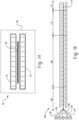
- FIG. 6illustrates laminate/layup fiber orientations, wherein the first layer is considered to be oriented at 0 (i.e., zero degrees). Each subsequent fiber structure is oriented such that the fiber direction is at an angle with respect to the fiber direction of the first fiber structure. The desired combination of fiber angles is dependent upon the desired stiffness of the shell.
- the number of layers employedis based upon the desired thickness and structural integrity of the shell.
- the shellcan have a total thickness of 0.2 to 10 mm, specifically, 0.3 to 3 mm, more specifically, 0.5 mm to 2 mm, and still more specifically, 0.5 mm to 1.5 mm.
- Each layercan have a thickness of 0.1 to 0.4, for example, 0.1 to 0.2 mm.
- all of the fiber structures of the layupcan have the same type of fibers (e.g., composition and/or diameter), or some fiber structure(s) can have a different type of fiber (e.g., composition and/or diameter).
- the lay-upcan be formed to produce a shell.
- the shellcan then be overmolded with chopped fiber reinforced polymer material to form reinforcing elements (e.g., ribbed or honeycomb structure), in the shell.
- reinforcing elementse.g., ribbed or honeycomb structure
- the energy-absorbing devicecan then be used in a BIW component to provide structural integrity (e.g., in the B-pillar).
- front portion of the vehicle chassise.g., bumper beam, energy absorber, and rails
- front portion of the vehicle chassise.g., bumper beam, energy absorber, and rails
- B-pillar, floor rocker, and floor crossbarsplay key role in energy absorption.
- A-pillar, B-pillar, and roof railsplay key role in impact energy absorption.
- the energy-absorbing devicecan replace the element, or can be inserted into the hollow cavity of the element.
- the disclosed crush countermeasureprovides impact resistance and/or reinforcement characteristics in a lighter weight structure as compared to prior systems composed entirely of metal.
- the crush countermeasureprovides a lightweight crush system having comparable protection to current all metal systems. As such, the overall weight of a vehicle is reduced without any compromise on the safety considerations to passengers.
- Disclosed are energy-absorbing devicescomprising a shell comprising continuous fibers in a polymeric matrix, and a polymer reinforcement structure inseparable from the shell, wherein the device can be located in a structural vehicle component (e.g., a BIW component).
- a structural vehicle componente.g., a BIW component
- inseparablerefers to an inability to separate the components without damage to one or both of the components.
- the devicecan be located throughout the structural vehicle component, in strategic locations within the structural vehicle component (“localized”), or can replace the structural vehicle component.
- BIW components that can be reinforcedinclude the beam(s), rail(s), pillar(s), chassis, floor rocker, and cross-bar(s), as well as combinations comprising at least one of the foregoing, e.g., the junction of the A-pillar and the floor rocker.
- the devicecan be employed to reinforce other structural vehicle components besides the BIW components, such as an instrument panel, cross-car member, door support bar, seat structure (e.g., frame), suspension controller (e.g., control arms), engine block, oil pump cover, as well as other components, as well as combinations comprising at least one of the foregoing.
- the shellcan form a channel defined by greater than or equal to 1 wall for example 3 sided U channel.
- the channelcan have, for example 3 sides, or 4 sides, with a channel therethrough, such that the channel is open on each end.
- side wallcan include opening though the wall such that, when the reinforcement is formed, molten polymer can pass from within the cavity, through the opening, and solidify to further secure the polymer reinforcement structure within the shell.
- openingse.g., small openings
- around the free edges of channelsuch that the molten plastic can flow over edges and solidify to further secure channel and reinforcement.
- the number of holescan be greater than or equal to one, specifically greater than or equal to two, e.g., 2 to 4 holes, for ease of polymer flow inside out.
- the hole diameter (along a major axis)can be up to 20 mm (e.g., 0.5 mm to 20 mm), specifically, 1 mm to 10 mm, and more specifically, 2 mm to 7 mm (e.g., 5 mm).
- the polymer reinforcement structurecan have a honeycomb structure, e.g., an array of columns and channels.
- the combs of the structurecan be a shape having greater than or equal to 5 sides, such as pentagonal, hexagonal, heptagonal, and octagonal, and so forth, geometries, as well as combinations comprising at least one of the foregoing geometries, and specifically a hexagonal geometry.
- the channels of the honeycomb structureextend from one end of the structure to the other end of the structure, so that the structure is open on both ends, and wherein one end (e.g., the second end of the channel) can optionally be disposed in physical contact with a side of the shell, thereby effectively blocking the second end.
- Polymer honeycombscan be made by bonding extruded polymer tubes together, injection molding the polymer honeycombs, extruding the honeycomb structure, or otherwise formed.
- the elementcan be a co-extruded component having combs of the same or different material, e.g., adjacent combs can comprise a different material composition.
- some or all of the combshave foam therein.
- the combscan, individually, be hollow or filled, such that the structural integrity can be modified by filling particular combs, by using different polymer for particular combs, or a combination comprising at least one of the foregoing.
- One possible fill materialis foam.
- the honeycomb structureis formed by overmolding the shell using an injection molding process.
- the polymer reinforcement structurecan further or alternatively comprise a rib structure.
- ribscan extend across the channel of the shell, between sidewalls and/or a back wall.
- Various rib designsare possible, including triangular, wave, diagonal, crossed, and the like.
- the ribscan form a triangular, rectangular, "X", or other structure.
- the shell and the polymer reinforcement structurecan, independently, comprise various polymeric materials, e.g., thermoplastic, thermoset and combinations comprising at least one of the foregoing.
- the particular materialcan be chosen based upon its properties, the desired location in the vehicle, and the characteristics of that location.
- the materialcan have moderate stiffness (e.g., Young's modulus of 0.8 gigaPascals (GPa) to 30 GPa, specifically, 3 GPa to 15GPa, for example 7.0 GPa), good elongation (e.g., greater than 1% elongation), chemical resistance and/or heat resistance under vehicle manufacturing conditions (e.g., welding, painting, etc., for example, at temperatures 204 0 C (400°F) for 30 minutes, which enables the polymer reinforcement structure to maintain integrity as the part travels with the auto body through paint bake).
- moderate stiffnesse.g., Young's modulus of 0.8 gigaPascals (GPa) to 30 GPa, specifically, 3 GPa to 15GPa, for example 7.0 GPa
- good elongatione.g., greater than 1% elongation
- chemical resistance and/or heat resistance under vehicle manufacturing conditionse.g., welding, painting, etc., for example, at temperatures 204 0 C (
- thermoplastic materialsinclude polycarbonate; polybutylene terephthalate (PBT); acrylonitrile-butadiene-styrene (ABS); polycarbonate; polycarbonate/PBT blends; polycarbonate/ABS blends; copolycarbonate-polyesters; acrylic-styrene-acrylonitrile (ASA); acrylonitrile-(ethylene-polypropylene diamine modified)-styrene (AES); phenylene ether resins; blends of polyphenylene ether/polyamide; polyamides; phenylene sulfide resins; polyvinyl chloride (PVC); high impact polystyrene (HIPS); polyethylene (e.g., low/high density polyethylene (L/HDPE)); polypropylene (PP) (e.g., expanded polypropylene (EPP)); polyetherimide; and thermoplastic olefins (TPO); as well as combinations comprising at least one of the foregoing.
- the polymer reinforcement structurecan comprise Noryl TM GTX resin, LEXAN TM resin, ULTEM TM resin, VALOX TM resin, CYCOLAC TM resin, and/or STAMAX TM resin, which are commercially available from SABIC.
- the polymer reinforcement structurecomprises polypropylene, and/or blends of polyphenylene ether/polyamide.
- the polymer reinforcement structurecan optionally be reinforced, e.g., with fibers, particles, flakes, as well as combinations comprising at least one of the foregoing. These fibers may include glass, carbon, bamboo, aramid, kevelar etc., as well as combinations comprising at least one of the foregoing.
- the polymer reinforcement structurecan be formed from STAMAX TM materials, a long glass fiber reinforced polypropylene commercially available from SABIC.
- the polymer reinforcement structure and/or shellcan also be made from combinations comprising at least one of any of the above-described materials and/or reinforcements, e.g., a combination with a thermoset material.
- the shellcomprises continuous fibers (e.g., glass, carbon, aramid, kevelar, as well as combinations comprising at least one of the foregoing in a polymeric matrix of polyetherimide, polyamide (nylon), polyphenylene oxide, polycarbonate, polypropylene, as well as combinations comprising at least one of the foregoing.
- the shellcan be made of continuous carbon fiber reinforced composite with base resin of nylon
- the polymer of the polymer reinforcement structurecan also include nylon resin or any other resin blended with nylon like SABIC's Noryl TM GTX.
- the outer shellis made of continues glass fiber reinforced composite material with polypropylene as resin matrix
- polymer reinforcement structurecan comprise a polypropylene based material or short/long fiber reinforced polypropylene composite like SABIC's STAMAX TM resin.
- the honeycombs' orientation with respect to the channel in the supportcan also be chosen to attain the energy absorption characteristics of the reinforced component (e.g., BIW component).
- the honeycombcan form channels that can be oriented 0 degrees (e.g., parallel) to 90 degrees (perpendicular), to the major axis of the shell.
- the major axisis the axis extending down the channel (e.g., see FIG. 3 axis Ax).
- the honeycombscan have a common main axis with the channel and extend parallel thereto.
- the honeycombscan extend perpendicular to the main axis of the channel.
- the honeycombscan have a common main axis with the opening through the structural component, while in other embodiments, the honeycombs can extend perpendicular to the opening through the structural component.
- the overall size of the energy-absorbing devicewill depend upon its location within the BIW and the size of the associated opening in the structural component. Furthermore, the characteristics of the reinforcement will depend upon the energy absorption characteristics desired in the particular area, e.g., the number of combs or ribs per unit area, the thickness of the comb walls or ribs, and the specific material of the plastic reinforcement.
- the density of combs(number of combs per unit area) is dependent upon the desired stiffness, crush characteristics, and materials employed. In some embodiments, the density can be 1 to 20 combs per 100 mm 2 , specifically, 1 to 10 combs per 100 mm 2 , and more specifically 1 to 5 combs per 100 mm 2 .
- the thickness of the walls of the plastic reinforcementcan be 0.5 mm to 10 mm, specifically, 2 mm to 5 mm, and more specifically 2.5 mm to 4 mm.
- a reinforcementwill comprise greater than or equal to 10 combs, specifically, greater than or equal to 20 combs, and more specifically, greater than or equal to 30 combs.
- the length of the shellis dependent upon the particular area of the BIW, while the length of the polymer reinforcement structure is dependent upon the amount and location of enhanced structural integrity in the shell.
- the polymer reinforcement structurecan have a length commensurate with the length of the shell or less than the length of the shell (e.g., can be localized; i.e., disposed only in a specific location to attain enhanced structural integrity of that location). Desirably, to maximize the weight reduction, the polymer reinforcement structure is localized so as to add the minimum amount of weight needed to attain a desired structural integrity (e.g., a structural integrity that this greater than or equal to the standard metal component without the thinner walls).
- a desired structural integritye.g., a structural integrity that this greater than or equal to the standard metal component without the thinner walls.
- the energy-absorbing devicecan have a length of less than or equal to 1,000 mm, specifically, less than or equal to 800 mm, and more specifically, less than or equal to 300 mm.
- the length of the reinforcementcan be less than or equal to 80% of the length of the structural component, specifically, less than or equal to 60%, more specifically, less than or equal to 50%, and yet more specifically, 10% to 35% of the length of the structural component (i.e., the structural component that is reinforced by the energy-absorbing device).
- the energy-absorbing devicecan have a length of 150 mm to 350 mm, specifically, 200 mm to 250 mm, such as for use in a pillar or rail.
- the energy-absorbing devicehas a length of 500 mm to 800 mm, specifically, 600 mm to 700 mm, such as for use in a floor rocker.
- the structural componentis a hollow metal element.
- the reinforcementis disposed in the hollow space. When the reinforcement is not located throughout the hollow space in the structural element, it can be attached to the structural element to inhibit the reinforcement from being dislodged during use of the vehicle or during an impact.
- Some possible structural component material(s)include polymers (e.g., thermoplastic and/or thermoset), composite, metals, and combinations comprising at least one of the foregoing.
- Some metalsinclude aluminum, titanium, chrome, magnesium, zinc, and steel, as well as combinations comprising at least one of the foregoing materials.
- the thickness of the walls of the structural componentcan all be the same or can be different to enhance stiffness in a desired direction. For example, one set of opposing walls can have a greater/lesser thickness than the other set of opposing walls.
- the structural componentshave a wall thickness of less than or equal to 1.6 mm, specifically, 1.0 mm to 1.5 mm, and more specifically 1.3 mm to 1.4 mm.
- metal wallse.g., floor rocker, rails, pillars, bumper beam, and so forth
- wall thicknessof the structural component
- the use of the energy-absorbing deviceenables a reduction in wall thickness (of the structural component) of greater than or equal to 10%, specifically, greater than or equal to 20%, and even greater than or equal to 25%.
- the reinforcementcan be located in various areas of the vehicle, such as in the bumper beam(s) and/or the BIW component (such as rail(s), pillar(s), chassis, floor rocker, and cross-bar(s)), as well as combinations comprising at least one of the foregoing.
- the desired specific location of the reinforcement in the structural componentcan be determined using crash results.
- the fixing measures to attach the energy-absorbing device in the structural componentcan be mechanical and/or chemical.
- mechanical fixing measuresinclude snaps, hooks, screws, bolts (e.g., threaded bolt(s), rivets, welds, crimp(s) (e.g., the crimped metal wall).
- a friction fitcan also be used to maintain the reinforcement in place.
- Chemical fixing measurescan include bonding agents such as glues, adhesives, and so forth.
- FIGS.are merely schematic representations based on convenience and the ease of demonstrating the present disclosure, and are, therefore, not intended to indicate relative size and dimensions of the devices or components thereof and/or to define or limit the scope of the exemplary embodiments.
- FIGS.also referred to herein as "FIG."
- FIGS.are merely schematic representations based on convenience and the ease of demonstrating the present disclosure, and are, therefore, not intended to indicate relative size and dimensions of the devices or components thereof and/or to define or limit the scope of the exemplary embodiments.
- FIGS.also referred to herein as "FIG.”
- FIGS.are merely schematic representations based on convenience and the ease of demonstrating the present disclosure, and are, therefore, not intended to indicate relative size and dimensions of the devices or components thereof and/or to define or limit the scope of the exemplary embodiments.
- specific termsare used in the following description for the sake of clarity, these terms are intended to refer only to the particular structure of the embodiments selected for illustration in the drawings, and are not intended
- FIG. 1is a pictorial representation of possible reinforcement locations in a vehicle.
- the energy-absorbing devicecan be located in one or any combination of the identified locations.
- A-Pillar 50e.g., near the center of the length of A-Pillar
- B-Pillar 52e.g., near the center of the length of B-Pillar
- C-Pillar 54e.g., near the center of the length of C-Pillar
- D-Pillar 56e.g., near the center of D-Pillar
- roof rail 58e.g., in multiple, separate locations along the length of the roof rail; such as centered over the window(s)
- floor rocker 60e.g., in the area where the B-Pillar meets the floor rocker
- inserts that occupy about 10% to 30% of the length of the metal componentcan be located in A-Pillar 50, B-Pillar 52, the roof rail 58, and the floor rocker 60.
- the correct location of these reinforcementsdepends on crash worthiness performance for different high-speed impact requirements.
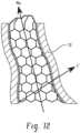
- the honeycombsform channels 18.
- the channelscan be oriented parallel to the main axis of the hollow opening formed in the body in white component, orienting the channels perpendicular to the main axis (Mx in FIG. 12 ) of the hollow opening formed in the body in white component provides further structural integrity.
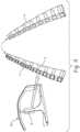
- FIG. 5is a pictorial representation of a concept; in which localized reinforcements are proposed at identified locations of A-Pillar, B-Pillar, roof rail, and floor rocker and so forth.
- the details shown in FIG. 5illustrate the formed structural component (e.g., from two metal structures welded together) formed from a hollow component ( FIG. 4 ) with a reinforcement ( FIG. 3 ) placed in the hollow component.
- the specific location of these reinforcementsdepends on crashworthiness performance for different high-speed impact requirements.
- FIGS. 3-5illustrate the elements of the reinforcement.
- FIG. 5illustrates the polymer reinforcement structure 4 to be located within the channel 20 of the shell 6.
- the shell 6can comprise openings 14, such that the plastic of the polymer reinforcement structure 4 can pass through the opening 14 thereby forming a mechanical bond and locking the shell 6 and polymer reinforcement structure 4 together.
- the openings 14can be preformed such that the continuous fibers are oriented around the openings. Alternatively, the opening 14 can be formed into the shell, by cutting through the side, and the fibers.
- the energy-absorbing device 1can have a shape that is complimentary to the shape of the opening through the structural component 72.
- the depth of the combe.g., length of the honeycomb channels 18
- the depth of the combcan be constant throughout the polymer reinforcement structure, or can vary along the length of the reinforcement, e.g., to follow the shape of the structural component 72 of the vehicle.
- the depth of the combs of the polymer reinforcement structure 4can decrease from one end of the polymer reinforcement structure to an opposite end of the polymer reinforcement structure.
- localized reinforcemente.g., energy-absorbing device having hollow channels therethrough, located in the structural component
- FIGs 6 and 7illustrate some examples of making the energy-absorbing device 1.
- FIG. 7illustrates making the energy-absorbing device 1 by laying up unidirectional (UD) tapes 22 of continuous fiber reinforced plastic material in the injection molding tool.
- the tape layupcan be automated or manual.
- the injection molding toolcan be preheated so that the polymer matrix of UD tapes reaches its glass transition temperature. Then the heated layup can be compressed for consolidation followed by solidification of the compressed lay up to form the shell 6.
- overmolding 26 of the polymer reinforcement structure 4 in the shell 6is accomplished by injection of fiber reinforced polymer into the injection molding tool. Different orientation and number of layers of the can be designed to achieve different geometry and thickness of shell and customized properties of the shell.
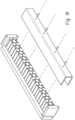
- FIG. 8illustrates a process for forming an energy absorbing device.
- a preform laminate 28comprising continuous fiber reinforced polymer, can be placed into a forming tool 30.
- the tool 30is heated to make this laminate 28 formable, later it is compressed in the tool cavity to take required shape of shell 6.
- the formed shell 6can then be placed into the injection molding tool wherein fiber reinforced plastic material can be injected to overmold the desired polymer reinforcement structure 4.
- the shell 6is made by laying-up UD layers or by using a laminate having a specific lay-up (e.g., with layers of continuous carbon fibers and/or glass fibers in a thermoplastic matrix).
- the shellcan then be formed into a "U" shaped channel from the layup/laminate, e.g., using a special forming tool.
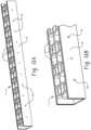
- the hinged platen 86comprises three sections 86A, 86B, and 86C. Movable sections 86A and 86B can move on about hinges 88A and 88B respectively, toward intermediate section 86C, to change a U shaped cavity having a size that is complementary to the size of the core 80.
- the two outside platen sections (86A,86B)can be rotated (e.g., 90 degrees) from a flat to a forming orientation (e.g., vertical orientation) adjacent the core 80, to form a U shaped cavity for forming the shell.
- the movable sections 86A and 86Bcan be moved from the rest position to the forming position using various methods such as manually, using hydraulic, using cylinders 90 (e.g., two gas (e.g., air) operated cylinders) to form the U shaped shell.
- the processcan comprise UD layers laid up in a desired layer orientation and consolidated to form a laminate.
- the consolidated laminate 92can be located on the hinged platen 86 such that the area of the laminate intended to be the sides will be located over the hinged section 86A or 86B.
- the consolidated laminate 92is heated to the glass transition temperature of the resin matrix.
- the shell 6is then formed by lowering the core 80 into the forming position and rotating the movable sections 86A and 86B, e.g., actuating the hinged platen sections by the air cylinders 90, to rotate (e.g., 90 degrees) to a forming position, thereby bending the heated, consolidated laminate into a U shape.
- the degree of rotation of the movable sections 86A and 86Bis dependent on the desired angles of the sides of the shell 6 (e.g., parallel sides, or sides oriented at a different angle).
- the layers used in the laminatecan be formed by forming a film of the resin matrix (e.g., having a thickness or less than or equal to 300 micrometers ( ⁇ m)).
- the pre-consolidated laminatecan be heated above the Tg (glass transition temperature) of the resin matrix, allowing the resin to flow between the fibers in their bundle to form a resin-fiber structure.
- Noryl TM GTX resin filme.g., having a thickness of 76.2 micrometers (0.003 inch) and 127 micrometers (0.005 inch) is heated into a fiber or fabric to form the layer.
- the film thicknessis dictated by the desired laminate ratio by volume.
- the layers for the laminatecan be formed using a powder method.
- a powdere.g., ground powder
- the powdered fabricis heated to semimelt the powder into the fabric, thereby impregnating (e.g., semi-impregnating) the powder into the fiber tape or fabric to form the layer.
- the powderis distributed (e.g., evenly distributed) across the fabric and then by means of ultrasonics, air impingement is forced between the fiber bundles then heated above the Tg so the resin can coat the fiber bundles after which the fiber structure is rolled and the fibers are pre-coated or semi impregnated to form the resin-fiber structure.
- Possible powderscan be formed from any of the above mention thermoplastic materials, such as Noryl TM GTX resin, LEXAN TM resin, ULTEM TM resin, VALOX TM resin, CYCOLAC TM resin, STAMAX TM resin, and combinations comprising at least one of the foregoing, such as an alloy some of these resins.
- the laminatecan be formed.
- the layers (i.e., resin-fiber structure)can be laid-up and the lay-up can then be placed in a laminator.
- the layupis then dried, e.g., allowing residual moisture to surface and be removed.
- the layupis heated (e.g., to a resin melt temperature) under vacuum to enable the fiber to wet out. Pressure is then applied to the layup.
- the temperatureis then reduced (e.g., rapidly to room temperature), the pressure is thereafter released and the laminate is then removed.
- a layup 38is placed between a first platen 32 and a laminate platen 34.
- the temperature in the laminator 40is increased to a temperature sufficient to remove residual moisture (e.g., depending upon the resin matrix, 100°C to 200°C, specifically, 125°C to 165°C, e.g., 150°C).
- This temperaturecan be held for enough time for residual moisture to surface on the layup (e.g., a hold time of up to 30 minutes, specifically, 2 to 20 minute, more specifically, 5-10 minutes). The actual time will depend upon the moisture content of the resin and the thickness of the layup. After drying hold time is complete, a vacuum is pulled in the vacuum chamber 36.
- the vacuumcan be pulled (e.g., to a pressure of less than 102 kPa (30 inches of mercury (Hg)), specifically, less than 98 kPa (28.8 Hg), and more specifically 34 kPa (10 Hg), and the process temperature can be increased.
- the temperaturecan be increased to greater than or equal to a melt temperature of resin in the layup (e.g. to greater than or equal 205°C, specifically, 218°C, and more specifically, 232 to 400°C, wherein the specific temperature is dependent upon the particular resin).
- a melt temperature of resin in the layupe.g. to greater than or equal 205°C, specifically, 218°C, and more specifically, 232 to 400°C, wherein the specific temperature is dependent upon the particular resin.
- the pressurecan be greater than or equal to 1 megaPascal (MPa), specifically, greater than or equal to 1.5 MPa, and more specifically, 1.75 MPa to 2.5 MPa, e.g., 2 MPa (e.g., about 300 pounds per square inch (psi)).
- MPamegaPascal
- 1.5 MPaspecifically, greater than or equal to 1.5 MPa
- 1.75 MPa to 2.5 MPae.g., 2 MPa (e.g., about 300 pounds per square inch (psi)).
- the pressureis adjusted based upon the layup, wherein too much pressure will inhibit resin wet out of fibers, e.g., due to pressing fiber bundles tightly together restricting resin flow into the bundle, while too little pressure will inhibits the laminates attaining a desired thickness.
- the temperatureis reduced so that the laminate solidifies and can be removed from the laminator.
- the temperaturecan be reduced to less than or equal to 38°C, specifically, less than or equal to 33°C, and more specifically, less than or equal to 27°C.
- the temperature reductioncan be by rapid cooling (e.g., reducing the temperature by greater than or equal to 14 °C (25°F per minute). Once cooled, the vacuum and pressure can be released and the laminate can be removed.
- a laminatecan be formed in a dynamic laminating process, e.g., using a heated twin belt laminator.
- alternating feeds of film and fabric (or tape)is fed into the laminator, with the number of films and fabrics dependent upon the desired thickness of the laminate.
- pressureis applied to allow moisture release.
- melt zonethe temperature and pressure are increased to cause the resin to flow into the fabric.
- cooling zonethe layup is cooled under pressure to completely solidify the laminate.
- films 102 and fabrics 104are fed into the twin belt laminator 100.
- Pressuree.g., a pressure of greater than or equal to 131 kPa (10 pounds per square inch (psi), for example 131 kPa to 172 kPa (10 psi to 25 psi)
- 131 kPapounds per square inch
- 172 kPa1.3 kPa
- the temperaturewhich is dependent on the particular resin, can be within the melt process temperature of such resin.
- the pressurewhich is also dependent upon the particular resin and particularly the melt viscosity thereof, can be greater than or equal to 345 kPa (50 psi), for example, the pressure can vary from 345 kPa to 3447 kPa (50 psi to 500 psi).
- the layupFrom the melt zone 108, the layup enters the cooling zone 110 where it is solidified under pressure to form the laminate 114.
- the laminate 114can then optionally be cut to the desired length.
- the continuous laminating processcan yield sheet products four feet wide and cut to any length after which smaller pieces can be cut for a desired application.
- a sequential gate opening system in the injection molding toolcan be incorporated to get favorable alignment of fibers (short and/or long fibers) and minimize weld lines in the polymer reinforcement structure 4 (e.g., honeycomb or ribbed geometry).
- the injection molding cavitycan fill from one end to the other, enhancing the quality of the final product.
- the designis lighter compared to all metallic components, yet the same structural requirements are still met, (ii) the plastic reinforcements have a high stiffness by weight ratio compared to other reinforcements (e.g., compared to foam, expandable epoxy, and steel reinforcements), (iii) there is better thermal performance during paint cycle compared to foam or epoxy reinforcement solutions, and/or (iv) no changes are required in existing assembly line; e.g., the crush countermeasure can be manufactured and used in a motor vehicle without the use of additional processing steps.
- the laminate as used in the present inventionis formed by a method comprising: feeding fiber structure and resin film to a heated belt to form layup; optionally applying a drying pressure to allow moisture release to form a dried layup; increasing a temperature and the pressure to flow the resin into the fiber structure to form the laminate; and cooling the laminate to solidify the laminate.
- the laminatemay be cooled under pressure.
- the laminatemay be cooled under the pressure of greater than or equal to 206.84 kPa (30 psi), or a pressure of greater than or equal to 344.74 kPa (50 psi), or a pressure of 344.74 kPa (50 psi) to 3447.4 kPa (500 psi).
- the drying pressuremay be greater than or equal to 68.95 kPa (10 psi).
- Increasing the temperature and the pressure to flow the resinmay comprise increasing the temperature to greater than or equal to a melt temperature of the resin, and the pressure to greater than or equal to 344.74 kPa (50 psi).
- the layupmay comprise alternating layers of fiber structure and resin.
- the layupmay comprise greater than or equal to 4 fiber structures.
- the layupmay comprise greater than or equal to 6 fiber structures.
- Laying up the fiber structuresmay be done such that the layup has a fiber orientation of alternating 0 degrees and 90 degrees, (0/45/-45), (0/60/-60), (0/45/90/0), (0/90/0/90/90/0/90/0), (0/90/0/0/90/0), (0/90/45/0/0/45/90/0), or (0/60/90/90/90/60/0).
- the methodmay comprise laying up the fiber structures such that the layup has a fiber orientation forming a balanced layup.
- the inventionrelates to a method of forming a laminate shell, comprising: placing the laminate onto a hinged platen in a forming tool; heating the laminate; moving a first movable section and second movable section toward a core, and decreasing a distance between the core and an intermediate section, such that the laminate bends to form the shell; cooling the shell; and removing the shell from the forming tool.
- the shellmay have a total thickness of 0.2 to 10 mm, or 0.3 to 3 mm, or 0.5 mm to 2 mm, or 0.5 mm to 1.5 mm.
- the inventionrelates to a method of forming an energy-absorbing device, comprising: overmolding the shell with a polymer reinforcement structure to form the energy absorbing device.
- the polymer reinforcement structuremay comprise honeycombs and/or ribs.
- the polymer reinforcement structuremay have channels that extend parallel to the sides of the shell and perpendicular to an intermediate section of the shell.
- the energy-absorbing devicemay comprise: a polymer reinforcement structure, wherein the polymer reinforcement structure comprises a polymer matrix and chopped fibers; and a shell comprising 2 walls extending from a back and forming a shell channel, wherein the shell comprises continuous fibers and a resin matrix, and wherein the resin matrix is a polymeric resin matrix; wherein the polymer reinforcement structure is located in the shell channel; wherein the shell comprises a laminate formed from a layup of fiber structures such that the layup has a fiber orientation of angles comprising at least two different angles.
- the anglesmay be selected from 0 degrees and 90 degrees, (0/45/-45), (0/60/- 60), (0/45/90/0), (0/90/0/90/90/0/90/0), (0/90/0/0/90/0), (0/90/45/0/0/45/90/0), or (0/60/90/90/90/60/0).
- the anglemay comprise a fiber orientation forming a balanced layup.
- the polymer reinforcement structuremay comprise honeycombs and/or ribs.
- the polymer reinforcement structuremay comprise honeycombs that extend in the same direction as the walls toward the back.
- the shell channelmay have a major axis
- the honeycomb structuremay comprise honeycomb channels, and the honeycomb channels may be oriented perpendicular to the major axis.
- the polymer reinforcement structuremay be inseparably attached to the shell.
- the plastic elementmay have a hollow honeycomb structure with a hexagonal comb geometry.
- the shellmay comprise a plurality of holes through the walls.
- the polymeric resin matrix and the polymer matrixmay be independently selected from polycarbonate; polybutylene terephthalate; acrylonitrile-butadiene-styrene; polycarbonate; acrylic-styrene-acrylonitrile; acrylonitrile-(ethylene-polypropylene diamine modified)-styrene; phenylene ether resins; polyamides; phenylene sulfide resins; polyvinyl chloride; polystyrene; polyethylene; polypropylene; polyetherimide; and combinations comprising at least one of the foregoing.
- the polymeric resin matrix and the polymer matrixmay be independently selected from polycarbonate blends; polycarbonate/PBT blends; polycarbonate/ABS blends; copolycarbonate-polyesters; blends of polyphenylene ether/polyamide; polyamides; and comprising at least one of the foregoing.
- the polymeric resin matrix and the polymer matrixmay be independently selected from Noryl TM GTX resin, LEXAN TM resin, ULTEM TM resin, VALOX TM resin, CYCOLAC TM resin, and/or STAMAX TM resin.
- the continuous fibersmay be selected from glass fibers, carbon fibers, bamboo fibers, aramid fibers, kevelar fibers, and combinations comprising at least one of the foregoing.
- the chopped fibersmay be selected from glass fibers, carbon fibers, bamboo fibers, aramid fibers, kevelar fibers, and combinations comprising at least one of the foregoing.
- the continuous fibers and the chopped fibersmay be independently selected from glass fibers, carbon fibers, and combinations comprising at least one of the foregoing.
- the devicemay be metal free.
- the continuous fibersmay be unidirectional.
Landscapes
- Engineering & Computer Science (AREA)
- Mechanical Engineering (AREA)
- Chemical & Material Sciences (AREA)
- Manufacturing & Machinery (AREA)
- Physics & Mathematics (AREA)
- Composite Materials (AREA)
- Fluid Mechanics (AREA)
- Combustion & Propulsion (AREA)
- Transportation (AREA)
- Thermal Sciences (AREA)
- Architecture (AREA)
- Structural Engineering (AREA)
- Laminated Bodies (AREA)
- Body Structure For Vehicles (AREA)
- Moulding By Coating Moulds (AREA)
Description
- The present disclosure relates to the structural body of a vehicle and to weight reduction thereof, particularly while meeting high-speed front side and rollover vehicle crash countermeasures.
- Automotive manufacturers are continuing to reduce the weight of passenger cars to meet the increasing government regulations on fuel efficiency and reducing emissions. The structural body of a vehicle (the structure forming what is commonly known as the body-in-white (BIW)), is a vehicle's largest structure, and therefore ideal for weight reduction considerations. Body-in-white refers to the welded sheet metal components which form the vehicle's structure to which the other components will be married, i.e., the engine, the chassis, the exterior and interior trim, the seats, etc. Reducing body weight, however, involves a trade-off with body stiffness, a key characteristic which influences vehicle dynamics, durability, and crash worthiness.
- This generates the need to design a BIW having reduced weight, without sacrificing durability and crash worthiness.
- Disclosed, in various embodiments are methods of making laminates, shells, and energy absorbing devices.
EP447642A1 - An energy-absorbing device can comprise: a polymer reinforcement structure, wherein the polymer reinforcement structure comprises a polymer matrix and chopped fibers; and a shell comprising 2 walls extending from a back and forming a shell channel, wherein the shell comprises continuous fibers and a resin matrix; wherein the polymer reinforcement structure is located in the shell channel.
- A structural body of a vehicle can comprise: a hollow vehicle component comprising walls that define a cavity, wherein the vehicle component has a component length; and the energy-absorbing device; wherein the energy-absorbing device is located in the cavity.
- A vehicle can comprise: the structural vehicle component; and the energy-absorbing device located in the structural vehicle component; an engine; and a drive mechanism.
- A vehicle can comprise: the structural vehicle component, wherein the structural vehicle component is the energy-absorbing device, an engine; and a drive mechanism.
- These and other non-limiting characteristics are more particularly described below.
- The following is a brief description of the drawings wherein like elements are numbered alike and which are presented for the purposes of illustrating the exemplary embodiments disclosed herein and not for the purposes of limiting the same.
FIG. 1 is a partial perspective view of exemplary areas of the BIW that can be reinforced.FIG. 2 is a pictorial representation of exemplary locations for the reinforcement.FIG. 3 is a perspective view of an embodiment of a polymer reinforcement structure.FIG. 4 is a perspective view of an embodiment of a shell.FIG. 5 is a perspective view of an embodiment of the polymer reinforcement structure ofFIG. 3 located in the shell ofFIG. 4 .FIG. 6 is an illustration of possible fiber orientation angles for the UD materials and laminates.FIG. 7 is an illustration of one embodiment of making the energy-absorbing device.FIG. 8 is an illustration of another embodiment of making the energy-absorbing device.FIG. 9 is an illustration of another embodiment of a device and method for making the energy-absorbing device in, and in particular making the shell.FIG. 10 is an illustration of an embodiment of an injection molding scheme showing the gate and hence reinforced polymer flow scheme.FIG. 11 is an illustration of an example of energy-absorbing device having an irregular, varied shape that is complimentary to the shape of the structural vehicle component where it will be located.FIG. 12 is a partial, cut-away, cross-section of an example of a structural vehicle component with the energy-absorbing device located in the hollow channel and wherein the channels of the honeycomb structures are oriented across (e.g., perpendicular) to the main axis.FIG. 13 is an illustration of an example of the energy absorbing device disclosed herein comprising openings that enable mechanical attachment between the shell and the polymer reinforcement structure.FIG. 14 is a schematic drawing of an embodiment of a laminator.FIG. 15 is a schematic view of a dynamic lamination process with a twin belt laminator.- Many attempts have been made to provide BIW component for automotive vehicles, which are lighter and could be able to absorb a major portion of impact energy during high-speed crashes. Use of high strength steel in BIW components has been increasing rapidly. Lighter metal like aluminum and magnesium have also been explored. The wall thickness of these various BIW components is sufficient to impart the desired structural integrity to that element to meet its desired function and various regulatory requirements.
- With foam filled components, a hollow part is filled with foam to its full volume, and the expanded foam material provides the connection to the wall and thus the absorption of force and distribution of load. The reinforcement characteristics are based on the material properties of the foam. However, foam reinforcement systems require a chemical reaction that must be adapted to the production process of the vehicle, particularly in terms of the incident temperatures. The reinforcement function thus depends on accurate and constant adherence to the process parameters. Another disadvantage is that the structural parts can no longer be disconnected from one another easily, making recycling more difficult. In addition, completely filling the space with foam brings about a more or less homogeneous reinforcement effect, without the ability to take three-dimensional varying design requirements into account.
- In crush countermeasure systems that include steel stampings fixed to sheet metal via thermoset adhesive, the adhesive will activate and expand as the body goes through the ovens that bake the paint. Therefore, this system is not optimal. The stampings are heavy and excessive adhesive would generally need to be applied to assure a solid bond from the countermeasure to the body.
- Some crush countermeasure systems include steel stampings that are fixed to the sheet metal via thermoset adhesive. The adhesive will activate and expand as the body goes through the ovens that bake the paint. This system is not optimal. The stampings are heavy and excessive adhesive is applied to assure a solid bond from the countermeasure to the body. Another system includes steel stampings that are fixed to the sheet metal via over mold injection mold design. The steel structures were provided with draft and material overflow provision. Once part is cooled and there forms a physical/mechanical bonding between the steel and polymers.
- It would be beneficial to provide lightweight BIW components comprising crush countermeasures that is lighter than aforementioned solutions and provide ability to absorb more impact energy and/or protecting motor vehicle occupants. The crush countermeasures, e.g., energy absorbing devices, can improve structural integrity, for example, by reducing excessive deformation and improving crashworthiness during a vehicle crash scenario. It would also be beneficial to provide a crush countermeasure that may be easily manufactured and used in a motor vehicle without the use of additional processing steps.
- In addition to the BIW components, reducing the weight while retaining the structural integrity of other vehicle components is also desired. Some other vehicle components that can benefit from the energy-absorbing device disclosed herein include an instrument panel, cross-car member, door support bar, seat structure (e.g., frame), suspension controller (e.g., control arms), engine block, oil pump cover, as well as other components that can benefit from a reduced weight high structural integrity element. As with the BIW components, these vehicle components can either be replaced by the energy-absorbing device, or the energy-absorbing device can be located in a hollow portion of the component.
- As mentioned above, it is desirable to reduce the weight of a vehicle without compromising structural integrity and durability. Therefore, it is desirable to reduce the amount of metal employed in the vehicle while not sacrificing strength. Employed throughout the vehicle are hollow metal structural elements (e.g., beams (e.g., bumper beam), rails (e.g., roof rail), pillars (e.g., "A" pillar, "B" pillar, "C" pillar, "D" pillar), rockers (e.g., floor rocker), bars (e.g., floor cross-bars, and cross bars in chassis ladder), and so forth). For example, refer to
FIG. 1 , which illustrates the locations of theroof rail 58, "A"pillar 50, "B"pillar 52, "C"pillar 54, "D"pillar 56, andfloor rocker 60. Disclosed herein are energy-absorbing devices, e.g., reinforcement for BIW components. Some examples of possible locations for the energy-absorbing device are illustrated inFIG. 2 ,locations 70, which further illustrates adrive mechanism 76 andengine 74. Desirably, energy-absorbing devices are lighter than metal-plastic hybrid reinforcements and provide better crash resistance than all plastic reinforcement, metal-plastic hybrid reinforcement, or foam reinforcement. - The energy-absorbing device, e.g., BIW component, is a hybrid of continuous fiber reinforced-polymer composite and short/long chopped fiber reinforced composite material solution that can be positioned in hollow channels of the BIW components. This hybrid structure comprises a shell of continuous fiber, reinforced polymer over-molded with structure of chopped fiber (e.g., chopped short fiber (e.g., fibers having a length of less than 1 millimeters (mm)) and/or chopped long (e.g., fibers having a length of 1 to 10 mm, specifically, 3 to 5 mm) fiber) reinforced thermoplastic. The structure formed from the chopped fiber reinforced material can have various geometries that enable the desired energy absorption characteristics, e.g., rib pattern (for example a cross-rib pattern, honeycomb geometry, and so forth).
- The energy-absorbing device can be formed, for example, by making shell structure of continuous fiber reinforced-polymer through various methods. The continuous fiber reinforced-polymer can comprise fiber fabrics and/or unidirectional (UD) tapes, collectively referred to as fiber structure. UD tapes can have greater than or equal to 90%, specifically, greater than or equal to 99% of the fibers oriented in the same direction. Fabrics have fibers in a single plane and oriented in at least two directions (e.g., a weave). The fiber structure (e.g., fabrics and tapes) can be formed into laminate(s) (also referred to as a sheet), wherein the laminate can be formed into intermediate(s), preform(s)), and the like. Individual layers comprise a ratio of resin matrix to fibers of 60/40 to 40/60 ratio by weight, specifically, 55/45 to 45/55, 60/40 to 40/60 ratio by weight, for example, 50/50 ratio by weight. This ratio can be attained by forming the layer using a volume ratio of resin to fibers of 70/30 to 30/70, preferably 65/35 to 35/65, for example, 60/40. For example, a resin matrix/fiber ratio by density of 40/60 can yield a 50/50 ratio by weight with a 3,000 tow or 3,000 twill weave. The specific ratio can be dependent on the materials used and the volume density of the fibers (e.g., the fabric). The specific amounts can readily be determined from the information herein.
- When laying up the fiber structures, each subsequent layer can be oriented such that the fibers extend in the same direction as in the first layer (i.e., oriented at 0 degrees with respect to the first layer), or at a different angle than the fibers of the prior layer, e.g., at 45 degrees or 90 degrees with respect to the prior layer. Therefore, the layup (and/or the lamina) can be arranged in various orientations with respect to one another to attain a desired structural integrity, e.g. 0 degrees and 90 degrees (also referred to as "0/90"), (0/90/0), (0/45/- 45), 0/60/-60), (0/45/90/0), and so forth, with an alternating 0 and 90 degree being desirable. Also desirable, the layup is a "balanced" layup comprising multiple layers with alternating fiber direction from one layer (i.e., fabric structure) to the next layer until the center of the layup then the alternation stops and reverses itself (e.g., (0/90/0/90/90/0/90/0), (0/90/45/0/0/45/90/0), (0/90/0/0/90/0) or (0/60/90/90/90/60/0)).
FIG. 6 illustrates laminate/layup fiber orientations, wherein the first layer is considered to be oriented at 0 (i.e., zero degrees). Each subsequent fiber structure is oriented such that the fiber direction is at an angle with respect to the fiber direction of the first fiber structure. The desired combination of fiber angles is dependent upon the desired stiffness of the shell. - The number of layers employed is based upon the desired thickness and structural integrity of the shell. The shell can have a total thickness of 0.2 to 10 mm, specifically, 0.3 to 3 mm, more specifically, 0.5 mm to 2 mm, and still more specifically, 0.5 mm to 1.5 mm. Each layer can have a thickness of 0.1 to 0.4, for example, 0.1 to 0.2 mm.
- Optionally, all of the fiber structures of the layup can have the same type of fibers (e.g., composition and/or diameter), or some fiber structure(s) can have a different type of fiber (e.g., composition and/or diameter).
- The lay-up can be formed to produce a shell. The shell can then be overmolded with chopped fiber reinforced polymer material to form reinforcing elements (e.g., ribbed or honeycomb structure), in the shell.
- The energy-absorbing device can then be used in a BIW component to provide structural integrity (e.g., in the B-pillar).
- For high-speed front crash (e.g., a speed of greater than or equal to 29 kilometers per hour (kmph)), front portion of the vehicle chassis (e.g., bumper beam, energy absorber, and rails), absorbs maximum amount of impact energy. For high-speed side crashes B-pillar, floor rocker, and floor crossbars play key role in energy absorption. For rollover or roof-crush the A-pillar, B-pillar, and roof rails play key role in impact energy absorption. Generally above-mentioned components are hollow metal sections. Depending upon the necessary structural integrity of the particular element, the energy-absorbing device can replace the element, or can be inserted into the hollow cavity of the element. If the energy-absorbing device is located in the element, the thickness of the element can be reduced, thereby reducing vehicle weight. The disclosed crush countermeasure provides impact resistance and/or reinforcement characteristics in a lighter weight structure as compared to prior systems composed entirely of metal. The crush countermeasure provides a lightweight crush system having comparable protection to current all metal systems. As such, the overall weight of a vehicle is reduced without any compromise on the safety considerations to passengers.
- Disclosed are energy-absorbing devices comprising a shell comprising continuous fibers in a polymeric matrix, and a polymer reinforcement structure inseparable from the shell, wherein the device can be located in a structural vehicle component (e.g., a BIW component). As used herein, "inseparable" refers to an inability to separate the components without damage to one or both of the components. The device can be located throughout the structural vehicle component, in strategic locations within the structural vehicle component ("localized"), or can replace the structural vehicle component. BIW components that can be reinforced include the beam(s), rail(s), pillar(s), chassis, floor rocker, and cross-bar(s), as well as combinations comprising at least one of the foregoing, e.g., the junction of the A-pillar and the floor rocker. Optionally, the device can be employed to reinforce other structural vehicle components besides the BIW components, such as an instrument panel, cross-car member, door support bar, seat structure (e.g., frame), suspension controller (e.g., control arms), engine block, oil pump cover, as well as other components, as well as combinations comprising at least one of the foregoing.
- The shell can form a channel defined by greater than or equal to 1 wall for example 3 sided U channel. The channel can have, for example 3 sides, or 4 sides, with a channel therethrough, such that the channel is open on each end. Optionally, side wall can include opening though the wall such that, when the reinforcement is formed, molten polymer can pass from within the cavity, through the opening, and solidify to further secure the polymer reinforcement structure within the shell. Optionally, openings (e.g., small openings) around the free edges of channel, such that the molten plastic can flow over edges and solidify to further secure channel and reinforcement.
- The number of holes can be greater than or equal to one, specifically greater than or equal to two, e.g., 2 to 4 holes, for ease of polymer flow inside out. The hole diameter (along a major axis) can be up to 20 mm (e.g., 0.5 mm to 20 mm), specifically, 1 mm to 10 mm, and more specifically, 2 mm to 7 mm (e.g., 5 mm).
- The polymer reinforcement structure can have a honeycomb structure, e.g., an array of columns and channels. The combs of the structure can be a shape having greater than or equal to 5 sides, such as pentagonal, hexagonal, heptagonal, and octagonal, and so forth, geometries, as well as combinations comprising at least one of the foregoing geometries, and specifically a hexagonal geometry. Optionally, the channels of the honeycomb structure extend from one end of the structure to the other end of the structure, so that the structure is open on both ends, and wherein one end (e.g., the second end of the channel) can optionally be disposed in physical contact with a side of the shell, thereby effectively blocking the second end. Polymer honeycombs can be made by bonding extruded polymer tubes together, injection molding the polymer honeycombs, extruding the honeycomb structure, or otherwise formed. For example, the element can be a co-extruded component having combs of the same or different material, e.g., adjacent combs can comprise a different material composition. Optionally, some or all of the combs have foam therein. In other words, the combs can, individually, be hollow or filled, such that the structural integrity can be modified by filling particular combs, by using different polymer for particular combs, or a combination comprising at least one of the foregoing. One possible fill material is foam. Desirably, the honeycomb structure is formed by overmolding the shell using an injection molding process.
- The polymer reinforcement structure can further or alternatively comprise a rib structure. For examples, ribs can extend across the channel of the shell, between sidewalls and/or a back wall. Various rib designs are possible, including triangular, wave, diagonal, crossed, and the like. For example, the ribs can form a triangular, rectangular, "X", or other structure.
- The shell and the polymer reinforcement structure can, independently, comprise various polymeric materials, e.g., thermoplastic, thermoset and combinations comprising at least one of the foregoing. The particular material can be chosen based upon its properties, the desired location in the vehicle, and the characteristics of that location. For example, in some embodiments, the material can have moderate stiffness (e.g., Young's modulus of 0.8 gigaPascals (GPa) to 30 GPa, specifically, 3 GPa to 15GPa, for example 7.0 GPa), good elongation (e.g., greater than 1% elongation), chemical resistance and/or heat resistance under vehicle manufacturing conditions (e.g., welding, painting, etc., for example, at temperatures 2040C (400°F) for 30 minutes, which enables the polymer reinforcement structure to maintain integrity as the part travels with the auto body through paint bake). Examples of polymers include thermoplastic materials as well as combinations comprising thermoplastic materials. Possible thermoplastic materials include polycarbonate; polybutylene terephthalate (PBT); acrylonitrile-butadiene-styrene (ABS); polycarbonate; polycarbonate/PBT blends; polycarbonate/ABS blends; copolycarbonate-polyesters; acrylic-styrene-acrylonitrile (ASA); acrylonitrile-(ethylene-polypropylene diamine modified)-styrene (AES); phenylene ether resins; blends of polyphenylene ether/polyamide; polyamides; phenylene sulfide resins; polyvinyl chloride (PVC); high impact polystyrene (HIPS); polyethylene (e.g., low/high density polyethylene (L/HDPE)); polypropylene (PP) (e.g., expanded polypropylene (EPP)); polyetherimide; and thermoplastic olefins (TPO); as well as combinations comprising at least one of the foregoing. For example, the polymer reinforcement structure can comprise Noryl™ GTX resin, LEXAN™ resin, ULTEM™ resin, VALOX™ resin, CYCOLAC™ resin, and/or STAMAX™ resin, which are commercially available from SABIC. Desirably, the polymer reinforcement structure comprises polypropylene, and/or blends of polyphenylene ether/polyamide. The polymer reinforcement structure can optionally be reinforced, e.g., with fibers, particles, flakes, as well as combinations comprising at least one of the foregoing. These fibers may include glass, carbon, bamboo, aramid, kevelar etc., as well as combinations comprising at least one of the foregoing. For example, the polymer reinforcement structure can be formed from STAMAX™ materials, a long glass fiber reinforced polypropylene commercially available from SABIC. The polymer reinforcement structure and/or shell can also be made from combinations comprising at least one of any of the above-described materials and/or reinforcements, e.g., a combination with a thermoset material. Desirably, the shell comprises continuous fibers (e.g., glass, carbon, aramid, kevelar, as well as combinations comprising at least one of the foregoing in a polymeric matrix of polyetherimide, polyamide (nylon), polyphenylene oxide, polycarbonate, polypropylene, as well as combinations comprising at least one of the foregoing.
- Good adhesion between the shell and polymer reinforcement structure, can be attained with compatibility between the polymer matrix of the shell and the polymer of the polymer reinforcement structure. For example the shell can be made of continuous carbon fiber reinforced composite with base resin of nylon, and the polymer of the polymer reinforcement structure can also include nylon resin or any other resin blended with nylon like SABIC's Noryl™ GTX. Another example, the outer shell is made of continues glass fiber reinforced composite material with polypropylene as resin matrix, and polymer reinforcement structure can comprise a polypropylene based material or short/long fiber reinforced polypropylene composite like SABIC's STAMAX™ resin.
- The honeycombs' orientation with respect to the channel in the support (and also with respect to the opening through the structural element) can also be chosen to attain the energy absorption characteristics of the reinforced component (e.g., BIW component). For example, the honeycomb can form channels that can be oriented 0 degrees (e.g., parallel) to 90 degrees (perpendicular), to the major axis of the shell. The major axis is the axis extending down the channel (e.g., see
FIG. 3 axis Ax). In other words, in some embodiments, the honeycombs can have a common main axis with the channel and extend parallel thereto. In other embodiments, the honeycombs can extend perpendicular to the main axis of the channel. Consequently, when the reinforcement is disposed in the structural component (also referred to herein as structural vehicle component and vehicle component), in some embodiments, the honeycombs can have a common main axis with the opening through the structural component, while in other embodiments, the honeycombs can extend perpendicular to the opening through the structural component. - The overall size of the energy-absorbing device will depend upon its location within the BIW and the size of the associated opening in the structural component. Furthermore, the characteristics of the reinforcement will depend upon the energy absorption characteristics desired in the particular area, e.g., the number of combs or ribs per unit area, the thickness of the comb walls or ribs, and the specific material of the plastic reinforcement. The density of combs (number of combs per unit area) is dependent upon the desired stiffness, crush characteristics, and materials employed. In some embodiments, the density can be 1 to 20 combs per 100 mm2, specifically, 1 to 10 combs per 100 mm2, and more specifically 1 to 5 combs per 100 mm2. In various embodiments, the thickness of the walls of the plastic reinforcement can be 0.5 mm to 10 mm, specifically, 2 mm to 5 mm, and more specifically 2.5 mm to 4 mm. Generally, a reinforcement will comprise greater than or equal to 10 combs, specifically, greater than or equal to 20 combs, and more specifically, greater than or equal to 30 combs.
- The length of the shell is dependent upon the particular area of the BIW, while the length of the polymer reinforcement structure is dependent upon the amount and location of enhanced structural integrity in the shell. The polymer reinforcement structure can have a length commensurate with the length of the shell or less than the length of the shell (e.g., can be localized; i.e., disposed only in a specific location to attain enhanced structural integrity of that location). Desirably, to maximize the weight reduction, the polymer reinforcement structure is localized so as to add the minimum amount of weight needed to attain a desired structural integrity (e.g., a structural integrity that this greater than or equal to the standard metal component without the thinner walls). The energy-absorbing device can have a length of less than or equal to 1,000 mm, specifically, less than or equal to 800 mm, and more specifically, less than or equal to 300 mm. The length of the reinforcement can be less than or equal to 80% of the length of the structural component, specifically, less than or equal to 60%, more specifically, less than or equal to 50%, and yet more specifically, 10% to 35% of the length of the structural component (i.e., the structural component that is reinforced by the energy-absorbing device). For example, the energy-absorbing device can have a length of 150 mm to 350 mm, specifically, 200 mm to 250 mm, such as for use in a pillar or rail. In other embodiments, the energy-absorbing device has a length of 500 mm to 800 mm, specifically, 600 mm to 700 mm, such as for use in a floor rocker. The structural component is a hollow metal element. The reinforcement is disposed in the hollow space. When the reinforcement is not located throughout the hollow space in the structural element, it can be attached to the structural element to inhibit the reinforcement from being dislodged during use of the vehicle or during an impact.
- Some possible structural component material(s) include polymers (e.g., thermoplastic and/or thermoset), composite, metals, and combinations comprising at least one of the foregoing. Some metals include aluminum, titanium, chrome, magnesium, zinc, and steel, as well as combinations comprising at least one of the foregoing materials. The thickness of the walls of the structural component can all be the same or can be different to enhance stiffness in a desired direction. For example, one set of opposing walls can have a greater/lesser thickness than the other set of opposing walls. In some embodiments, the structural components have a wall thickness of less than or equal to 1.6 mm, specifically, 1.0 mm to 1.5 mm, and more specifically 1.3 mm to 1.4 mm. Generally, metal walls (e.g., floor rocker, rails, pillars, bumper beam, and so forth), have a wall thickness of greater than 1.8 mm. Therefore, the use of the energy-absorbing device enables a reduction in wall thickness (of the structural component) of greater than or equal to 10%, specifically, greater than or equal to 20%, and even greater than or equal to 25%.
- As noted above, the reinforcement can be located in various areas of the vehicle, such as in the bumper beam(s) and/or the BIW component (such as rail(s), pillar(s), chassis, floor rocker, and cross-bar(s)), as well as combinations comprising at least one of the foregoing. The desired specific location of the reinforcement in the structural component can be determined using crash results.
- The fixing measures to attach the energy-absorbing device in the structural component can be mechanical and/or chemical. Examples of mechanical fixing measures include snaps, hooks, screws, bolts (e.g., threaded bolt(s), rivets, welds, crimp(s) (e.g., the crimped metal wall). A friction fit can also be used to maintain the reinforcement in place. Chemical fixing measures can include bonding agents such as glues, adhesives, and so forth.
- A more complete understanding of the components, processes, and apparatuses disclosed herein can be obtained by reference to the accompanying drawings. These FIGS. (also referred to herein as "FIG.") are merely schematic representations based on convenience and the ease of demonstrating the present disclosure, and are, therefore, not intended to indicate relative size and dimensions of the devices or components thereof and/or to define or limit the scope of the exemplary embodiments. Although specific terms are used in the following description for the sake of clarity, these terms are intended to refer only to the particular structure of the embodiments selected for illustration in the drawings, and are not intended to define or limit the scope of the disclosure. In the drawings and the following description below, it is to be understood that like numeric designations refer to components of like function.
FIG. 1 is a pictorial representation of possible reinforcement locations in a vehicle. Here, the energy-absorbing device can be located in one or any combination of the identified locations. For example, A-Pillar 50 (e.g., near the center of the length of A-Pillar), B-Pillar 52 (e.g., near the center of the length of B-Pillar), C-Pillar 54 (e.g., near the center of the length of C-Pillar), D-Pillar 56 (e.g., near the center of D-Pillar), roof rail 58 (e.g., in multiple, separate locations along the length of the roof rail; such as centered over the window(s)), and/or floor rocker 60 (e.g., in the area where the B-Pillar meets the floor rocker), and junction of A pillar and floor rocker. For example, inserts that occupy about 10% to 30% of the length of the metal component can be located inA-Pillar 50, B-Pillar 52, theroof rail 58, and thefloor rocker 60. The correct location of these reinforcements depends on crash worthiness performance for different high-speed impact requirements. As is clear from the illustrations (e.g.,FIGS. 4 - 5 ), the honeycombs formchannels 18. The channels can be oriented parallel to the main axis of the hollow opening formed in the body in white component, orienting the channels perpendicular to the main axis (Mx inFIG. 12 ) of the hollow opening formed in the body in white component provides further structural integrity.FIG. 5 is a pictorial representation of a concept; in which localized reinforcements are proposed at identified locations of A-Pillar, B-Pillar, roof rail, and floor rocker and so forth. The details shown inFIG. 5 illustrate the formed structural component (e.g., from two metal structures welded together) formed from a hollow component (FIG. 4 ) with a reinforcement (FIG. 3 ) placed in the hollow component. The specific location of these reinforcements depends on crashworthiness performance for different high-speed impact requirements.FIGS. 3-5 illustrate the elements of the reinforcement.FIG. 5 illustrates thepolymer reinforcement structure 4 to be located within thechannel 20 of theshell 6. As can be seen inFIG. 13 , theshell 6 can compriseopenings 14, such that the plastic of thepolymer reinforcement structure 4 can pass through theopening 14 thereby forming a mechanical bond and locking theshell 6 andpolymer reinforcement structure 4 together. Theopenings 14 can be preformed such that the continuous fibers are oriented around the openings. Alternatively, theopening 14 can be formed into the shell, by cutting through the side, and the fibers.- As is illustrated in
FIG. 11 , the energy-absorbingdevice 1 can have a shape that is complimentary to the shape of the opening through thestructural component 72. The depth of the comb (e.g., length of the honeycomb channels 18) can be constant throughout the polymer reinforcement structure, or can vary along the length of the reinforcement, e.g., to follow the shape of thestructural component 72 of the vehicle. For example, the depth of the combs of thepolymer reinforcement structure 4 can decrease from one end of the polymer reinforcement structure to an opposite end of the polymer reinforcement structure. - The use of localized reinforcement (e.g., energy-absorbing device having hollow channels therethrough, located in the structural component) may enable the reduction in wall thickness of the structural component (e.g., BIW component) by greater than or equal to 15%, while retaining the structural integrity.
FIGs 6 and 7 illustrate some examples of making the energy-absorbingdevice 1.FIG. 7 illustrates making the energy-absorbingdevice 1 by laying up unidirectional (UD) tapes 22 of continuous fiber reinforced plastic material in the injection molding tool. The tape layup can be automated or manual. The injection molding tool can be preheated so that the polymer matrix of UD tapes reaches its glass transition temperature. Then the heated layup can be compressed for consolidation followed by solidification of the compressed lay up to form theshell 6. Then overmolding 26 of thepolymer reinforcement structure 4 in theshell 6 is accomplished by injection of fiber reinforced polymer into the injection molding tool. Different orientation and number of layers of the can be designed to achieve different geometry and thickness of shell and customized properties of the shell.FIG. 8 illustrates a process for forming an energy absorbing device. Apreform laminate 28 comprising continuous fiber reinforced polymer, can be placed into a formingtool 30. Thetool 30 is heated to make this laminate 28 formable, later it is compressed in the tool cavity to take required shape ofshell 6. The formedshell 6 can then be placed into the injection molding tool wherein fiber reinforced plastic material can be injected to overmold the desiredpolymer reinforcement structure 4.- Now referring to
FIG. 9 , theshell 6 is made by laying-up UD layers or by using a laminate having a specific lay-up (e.g., with layers of continuous carbon fibers and/or glass fibers in a thermoplastic matrix). The shell can then be formed into a "U" shaped channel from the layup/laminate, e.g., using a special forming tool. The forming tool illustrated inFIG. 9 , has acore 80 andcavity 82, wherein the cavity is located between afirst platen 84 and a hingedplaten 86, and thecore 80 extends from the first platen 84 (e.g., is fixedly attached to the first platen 84), into thecavity 82, with a space remaining between the core 80 and the hingedplaten 86. The hingedplaten 86 comprises threesections Movable sections hinges intermediate section 86C, to change a U shaped cavity having a size that is complementary to the size of thecore 80. In other words, the two outside platen sections (86A,86B) can be rotated (e.g., 90 degrees) from a flat to a forming orientation (e.g., vertical orientation) adjacent thecore 80, to form a U shaped cavity for forming the shell. Themovable sections - The process can comprise UD layers laid up in a desired layer orientation and consolidated to form a laminate. The
consolidated laminate 92 can be located on the hingedplaten 86 such that the area of the laminate intended to be the sides will be located over the hingedsection consolidated laminate 92 is heated to the glass transition temperature of the resin matrix. Theshell 6 is then formed by lowering the core 80 into the forming position and rotating themovable sections air cylinders 90, to rotate (e.g., 90 degrees) to a forming position, thereby bending the heated, consolidated laminate into a U shape. The degree of rotation of themovable sections core 80 andmovable sections shell 6. - For example, the layers used in the laminate can be formed by forming a film of the resin matrix (e.g., having a thickness or less than or equal to 300 micrometers (µm)). The pre-consolidated laminate can be heated above the Tg (glass transition temperature) of the resin matrix, allowing the resin to flow between the fibers in their bundle to form a resin-fiber structure. For example,Noryl™ GTX resin film (e.g., having a thickness of 76.2 micrometers (0.003 inch) and 127 micrometers (0.005 inch)) is heated into a fiber or fabric to form the layer. The film thickness is dictated by the desired laminate ratio by volume. A 60/40 ratio by volume, for example, will usually yield a 50/50 ratio by weight with a 3K toe weave or 3K twill weave. This is also dependent on the volume density of the fabric. The use of the GTX resin in the consolidated laminate will help promote better adhesion between the formed laminate shell and the plastic overmolded structure. Optionally, the layers for the laminate can be formed using a powder method. In this method, a powder (e.g., ground powder) is applied to the fiber structure, to form a powdered fiber. The powdered fabric is heated to semimelt the powder into the fabric, thereby impregnating (e.g., semi-impregnating) the powder into the fiber tape or fabric to form the layer. For example, the powder is distributed (e.g., evenly distributed) across the fabric and then by means of ultrasonics, air impingement is forced between the fiber bundles then heated above the Tg so the resin can coat the fiber bundles after which the fiber structure is rolled and the fibers are pre-coated or semi impregnated to form the resin-fiber structure. Possible powders can be formed from any of the above mention thermoplastic materials, such as Noryl™ GTX resin, LEXAN™ resin, ULTEM™ resin, VALOX™ resin, CYCOLAC™ resin, STAMAX™ resin, and combinations comprising at least one of the foregoing, such as an alloy some of these resins.
- Once the layers (i.e., the resin-fiber structure) are prepared, the laminate can be formed. The layers (i.e., resin-fiber structure) can be laid-up and the lay-up can then be placed in a laminator. The layup is then dried, e.g., allowing residual moisture to surface and be removed. After drying, the layup is heated (e.g., to a resin melt temperature) under vacuum to enable the fiber to wet out. Pressure is then applied to the layup. The temperature is then reduced (e.g., rapidly to room temperature), the pressure is thereafter released and the laminate is then removed. For example, referring to
FIG. 14 , alayup 38 is placed between afirst platen 32 and alaminate platen 34. The temperature in thelaminator 40 is increased to a temperature sufficient to remove residual moisture (e.g., depending upon the resin matrix, 100°C to 200°C, specifically, 125°C to 165°C, e.g., 150°C). This temperature can be held for enough time for residual moisture to surface on the layup (e.g., a hold time of up to 30 minutes, specifically, 2 to 20 minute, more specifically, 5-10 minutes). The actual time will depend upon the moisture content of the resin and the thickness of the layup. After drying hold time is complete, a vacuum is pulled in thevacuum chamber 36. The vacuum can be pulled (e.g., to a pressure of less than 102 kPa (30 inches of mercury (Hg)), specifically, less than 98 kPa (28.8 Hg), and more specifically 34 kPa (10 Hg), and the process temperature can be increased. The temperature can be increased to greater than or equal to a melt temperature of resin in the layup (e.g. to greater than or equal 205°C, specifically, 218°C, and more specifically, 232 to 400°C, wherein the specific temperature is dependent upon the particular resin). Once the process temperature is reached, pressure is applied to thelayup 38 by creating relative motion between thefirst platen 32 and thelaminate platen 34. The pressure can be greater than or equal to 1 megaPascal (MPa), specifically, greater than or equal to 1.5 MPa, and more specifically, 1.75 MPa to 2.5 MPa, e.g., 2 MPa (e.g., about 300 pounds per square inch (psi)). - It is noted that the pressure is adjusted based upon the layup, wherein too much pressure will inhibit resin wet out of fibers, e.g., due to pressing fiber bundles tightly together restricting resin flow into the bundle, while too little pressure will inhibits the laminates attaining a desired thickness.
- After the pressure is applied the temperature is reduced so that the laminate solidifies and can be removed from the laminator. For example the temperature can be reduced to less than or equal to 38°C, specifically, less than or equal to 33°C, and more specifically, less than or equal to 27°C. The temperature reduction can be by rapid cooling (e.g., reducing the temperature by greater than or equal to 14 °C (25°F per minute). Once cooled, the vacuum and pressure can be released and the laminate can be removed.
- Alternatively, a laminate can be formed in a dynamic laminating process, e.g., using a heated twin belt laminator. In this process, alternating feeds of film and fabric (or tape) is fed into the laminator, with the number of films and fabrics dependent upon the desired thickness of the laminate. In the first stage, the drying stage, pressure is applied to allow moisture release. In the next stage, the melt zone, the temperature and pressure are increased to cause the resin to flow into the fabric. In the cooling zone, the layup is cooled under pressure to completely solidify the laminate. For example, referring to
FIG. 15 ,films 102 andfabrics 104 are fed into thetwin belt laminator 100. Pressure (e.g., a pressure of greater than or equal to 131 kPa (10 pounds per square inch (psi), for example 131 kPa to 172 kPa (10 psi to 25 psi)) is applied in thedrying zone 106, e.g., during the first stage, allowing moisture to escape. In the next stage, themelt zone 108, the pressure and temperature are increased to allow the resin flow into the fabric. The temperature, which is dependent on the particular resin, can be within the melt process temperature of such resin. The pressure, which is also dependent upon the particular resin and particularly the melt viscosity thereof, can be greater than or equal to 345 kPa (50 psi), for example, the pressure can vary from 345 kPa to 3447 kPa (50 psi to 500 psi). From themelt zone 108, the layup enters thecooling zone 110 where it is solidified under pressure to form thelaminate 114. The laminate 114 can then optionally be cut to the desired length. The continuous laminating process can yield sheet products four feet wide and cut to any length after which smaller pieces can be cut for a desired application. - As illustrated in
FIG. 10 , a sequential gate opening system in the injection molding tool can be incorporated to get favorable alignment of fibers (short and/or long fibers) and minimize weld lines in the polymer reinforcement structure 4 (e.g., honeycomb or ribbed geometry). As a result, the injection molding cavity can fill from one end to the other, enhancing the quality of the final product. - By uniting the structural component (e.g., any hollow, metal, load bearing component in the vehicle) and hybrid reinforcements as described herein, several advantages are realized: (i) the design is lighter compared to all metallic components, yet the same structural requirements are still met, (ii) the plastic reinforcements have a high stiffness by weight ratio compared to other reinforcements (e.g., compared to foam, expandable epoxy, and steel reinforcements), (iii) there is better thermal performance during paint cycle compared to foam or epoxy reinforcement solutions, and/or (iv) no changes are required in existing assembly line; e.g., the crush countermeasure can be manufactured and used in a motor vehicle without the use of additional processing steps. In addition, since the same structural integrity can be attained at a reduced weight, or better structural integrity can be attained at the same weight of standard, all steel structural components (e.g., BIW), this design is better suited to meet the carbon dioxide emission requirements due to be in effect by 2016, as well as meeting the safety requirements of the National Highway Traffic Safety Administration (NHTSA).
- The laminate as used in the present invention is formed by a method comprising: feeding fiber structure and resin film to a heated belt to form layup; optionally applying a drying pressure to allow moisture release to form a dried layup; increasing a temperature and the pressure to flow the resin into the fiber structure to form the laminate; and cooling the laminate to solidify the laminate.
- The laminate may be cooled under pressure.
- The laminate may be cooled under the pressure of greater than or equal to 206.84 kPa (30 psi), or a pressure of greater than or equal to 344.74 kPa (50 psi), or a pressure of 344.74 kPa (50 psi) to 3447.4 kPa (500 psi).
- The drying pressure may be greater than or equal to 68.95 kPa (10 psi).
- Increasing the temperature and the pressure to flow the resin may comprise increasing the temperature to greater than or equal to a melt temperature of the resin, and the pressure to greater than or equal to 344.74 kPa (50 psi).
- The layup may comprise alternating layers of fiber structure and resin.
- The layup may comprise greater than or equal to 4 fiber structures.
- The layup may comprise greater than or equal to 6 fiber structures.
- Laying up the fiber structures may be done such that the layup has a fiber orientation of alternating 0 degrees and 90 degrees, (0/45/-45), (0/60/-60), (0/45/90/0), (0/90/0/90/90/0/90/0), (0/90/0/0/90/0), (0/90/45/0/0/45/90/0), or (0/60/90/90/90/60/0).
- The method may comprise laying up the fiber structures such that the layup has a fiber orientation forming a balanced layup.
- The invention relates to a method of forming a laminate shell, comprising: placing the laminate onto a hinged platen in a forming tool; heating the laminate; moving a first movable section and second movable section toward a core, and decreasing a distance between the core and an intermediate section, such that the laminate bends to form the shell; cooling the shell; and removing the shell from the forming tool.
- The shell may have a total thickness of 0.2 to 10 mm, or 0.3 to 3 mm, or 0.5 mm to 2 mm, or 0.5 mm to 1.5 mm.
- The invention relates to a method of forming an energy-absorbing device, comprising: overmolding the shell with a polymer reinforcement structure to form the energy absorbing device.
- The polymer reinforcement structure may comprise honeycombs and/or ribs.
- The polymer reinforcement structure may have channels that extend parallel to the sides of the shell and perpendicular to an intermediate section of the shell.
- The energy-absorbing device may comprise: a polymer reinforcement structure, wherein the polymer reinforcement structure comprises a polymer matrix and chopped fibers; and a shell comprising 2 walls extending from a back and forming a shell channel, wherein the shell comprises continuous fibers and a resin matrix, and wherein the resin matrix is a polymeric resin matrix; wherein the polymer reinforcement structure is located in the shell channel; wherein the shell comprises a laminate formed from a layup of fiber structures such that the layup has a fiber orientation of angles comprising at least two different angles.
- The angles may be selected from 0 degrees and 90 degrees, (0/45/-45), (0/60/- 60), (0/45/90/0), (0/90/0/90/90/0/90/0), (0/90/0/0/90/0), (0/90/45/0/0/45/90/0), or (0/60/90/90/90/60/0).
- The angle may comprise a fiber orientation forming a balanced layup.
- The polymer reinforcement structure may comprise honeycombs and/or ribs.
- The polymer reinforcement structure may comprise honeycombs that extend in the same direction as the walls toward the back.
- The shell channel may have a major axis, and the honeycomb structure may comprise honeycomb channels, and the honeycomb channels may be oriented perpendicular to the major axis.
- The polymer reinforcement structure may be inseparably attached to the shell.
- The plastic element may have a hollow honeycomb structure with a hexagonal comb geometry.
- The shell may comprise a plurality of holes through the walls.
- wherein The polymeric resin matrix and the polymer matrix may be independently selected from polycarbonate; polybutylene terephthalate; acrylonitrile-butadiene-styrene; polycarbonate; acrylic-styrene-acrylonitrile; acrylonitrile-(ethylene-polypropylene diamine modified)-styrene; phenylene ether resins; polyamides; phenylene sulfide resins; polyvinyl chloride; polystyrene; polyethylene; polypropylene; polyetherimide; and combinations comprising at least one of the foregoing.
- The polymeric resin matrix and the polymer matrix may be independently selected from polycarbonate blends; polycarbonate/PBT blends; polycarbonate/ABS blends; copolycarbonate-polyesters; blends of polyphenylene ether/polyamide; polyamides; and comprising at least one of the foregoing.
- The polymeric resin matrix and the polymer matrix may be independently selected from Noryl™ GTX resin, LEXAN™ resin, ULTEM™ resin, VALOX™ resin, CYCOLAC™ resin, and/or STAMAX™ resin.
- The continuous fibers may be selected from glass fibers, carbon fibers, bamboo fibers, aramid fibers, kevelar fibers, and combinations comprising at least one of the foregoing.
- The chopped fibers may be selected from glass fibers, carbon fibers, bamboo fibers, aramid fibers, kevelar fibers, and combinations comprising at least one of the foregoing.
- The continuous fibers and the chopped fibers may be independently selected from glass fibers, carbon fibers, and combinations comprising at least one of the foregoing.
- The device may be metal free.
- The continuous fibers may be unidirectional.
Claims (13)
- A method of forming a laminate shell (6), comprising:• placing a laminate (92) onto a hinged platen (86) in a forming tool;• heating the laminate;• moving a first movable section (86A) and second movable section (86B) of the hinged platen toward a core (80) of the forming tool, and decreasing a distance between the core and an intermediate section (86C) of the hinged platen, such that the laminate bends to form the shell;• cooling the shell; and• removing the shell from the forming toolwherein the laminate is formed by a method comprising:• feeding fiber structure and resin film to a heated belt to form layup;• increasing a temperature and the pressure to flow the resin into the fiber structure to form the laminate; and• cooling the laminate.
- The method of claim 1 wherein the laminate is cooled under pressure.
- The method of claim 2 wherein the laminate cooled under the pressure of greater than or equal to 206.84 kPa (30 psi).
- The method of any of claims 1-3, wherein increasing the temperature and the pressure to flow the resin comprises increasing the temperature to greater than or equal to a melt temperature of the resin, and the pressure to greater than or equal to 344.74 kPa (50 psi).
- The method of any of claims 1-4, wherein the layup comprises alternative layers of fiber structure and resin.
- The method of any of claims 1-5, wherein the layup comprises greater than or equal to 4 fiber structures.
- The method of any of claim 1-6, wherein the layup comprises greater than or equal to 6 fiber structures.
- The method of any of claims 1-7, comprising laying up the fiber structures such that the layup has a fiber orientation of alternating 0 degrees and 90 degrees, 0/45/-45, 0/60/- 60, 0/45/90/0, 0/90/0/90/90/0/90/0, 0/90/0/0/90/0, 0/90/45/0/0/45/90/0, or 0/60/90/90/90/60/0.
- The method of any of claims 1-8, comprising laying up the fiber structures such that the layup has a fiber orientation forming a balanced layup.
- The method of any of claims 1-9, wherein the shell has a total thickness of 0.2 to 10 mm.
- A method of forming an energy-absorbing device (1) comprising overmolding the shell of the method of any of claims 1-10 with a polymer reinforcement structure (4) to form the energy-absorbing device.
- The method of claim 11, wherein the polymer reinforcement structure comprises honeycombs (18) and/or ribs.
- The method of any of claims 11-12, wherein the polymer reinforcement structure has channels that extend parallel to the sides of the shell and perpendicular to an intermediate section of the shell.
Applications Claiming Priority (5)
| Application Number | Priority Date | Filing Date | Title |
|---|---|---|---|
| US201462012515P | 2014-06-16 | 2014-06-16 | |
| US201462012522P | 2014-06-16 | 2014-06-16 | |
| IN1618DE2014 | 2014-06-16 | ||
| EP15735738.5AEP3154828B1 (en) | 2014-06-16 | 2015-06-15 | Method of making a laminate, an energy absorbing device, an energy absorbing device composition, and a forming tool |
| PCT/IB2015/054518WO2015193795A1 (en) | 2014-06-16 | 2015-06-15 | Method of making a laminate, an energy absorbing device, an energy absorbing device composition, and a forming tool |
Related Parent Applications (2)
| Application Number | Title | Priority Date | Filing Date |
|---|---|---|---|
| EP15735738.5ADivisionEP3154828B1 (en) | 2014-06-16 | 2015-06-15 | Method of making a laminate, an energy absorbing device, an energy absorbing device composition, and a forming tool |
| EP15735738.5ADivision-IntoEP3154828B1 (en) | 2014-06-16 | 2015-06-15 | Method of making a laminate, an energy absorbing device, an energy absorbing device composition, and a forming tool |
Publications (3)
| Publication Number | Publication Date |
|---|---|
| EP3513958A2 EP3513958A2 (en) | 2019-07-24 |
| EP3513958A3 EP3513958A3 (en) | 2019-10-23 |
| EP3513958B1true EP3513958B1 (en) | 2024-09-25 |
Family
ID=54934928
Family Applications (2)
| Application Number | Title | Priority Date | Filing Date |
|---|---|---|---|
| EP19155120.9AActiveEP3513958B1 (en) | 2014-06-16 | 2015-06-15 | Method of making a laminate |
| EP15735738.5AActiveEP3154828B1 (en) | 2014-06-16 | 2015-06-15 | Method of making a laminate, an energy absorbing device, an energy absorbing device composition, and a forming tool |
Family Applications After (1)
| Application Number | Title | Priority Date | Filing Date |
|---|---|---|---|
| EP15735738.5AActiveEP3154828B1 (en) | 2014-06-16 | 2015-06-15 | Method of making a laminate, an energy absorbing device, an energy absorbing device composition, and a forming tool |
Country Status (5)
| Country | Link |
|---|---|
| US (2) | US11603142B2 (en) |
| EP (2) | EP3513958B1 (en) |
| KR (2) | KR102452591B1 (en) |
| CN (2) | CN106458131A (en) |
| WO (1) | WO2015193795A1 (en) |
Families Citing this family (26)
| Publication number | Priority date | Publication date | Assignee | Title |
|---|---|---|---|---|
| CN106573586B (en) | 2014-07-25 | 2020-07-10 | 沙特基础工业全球技术有限公司 | Crushable polymer stringer extensions, systems and methods of making and using the same |
| US11913182B2 (en)* | 2015-12-09 | 2024-02-27 | Ohio University | Guardrail terminal barrier |
| US10513236B2 (en)* | 2015-12-24 | 2019-12-24 | Uacj Corporation | Energy absorbing member |
| US9975578B2 (en)* | 2016-06-06 | 2018-05-22 | Ford Global Technologies, Llc | Light weight hybrid B-pillar |
| WO2018093520A2 (en)* | 2016-10-18 | 2018-05-24 | Sabic Global Technologies B.V. | Selective perforation, construction, and sequencing of plies for composite laminates and hybrids |
| JP2020504691A (en) | 2016-12-30 | 2020-02-13 | サビック グローバル テクノロジーズ ベスローテン フェンノートシャップ | Hybrid structure and manufacturing method thereof |
| EP3616873B1 (en)* | 2017-04-28 | 2023-05-31 | Subaru Corporation | Composite-material molding tool, composite-material molding method and composite material |
| CN108100274A (en)* | 2017-07-14 | 2018-06-01 | 哈尔滨飞机工业集团有限责任公司 | A kind of destruction endergonic structure of helicopter tail part protection ducted tail rotor |
| US11142254B2 (en)* | 2017-08-07 | 2021-10-12 | Sika Technology Ag | System of a sealed and reinforced structural element |
| CN108357566A (en)* | 2018-01-31 | 2018-08-03 | 浙江众泰汽车制造有限公司 | A kind of carbon fiber front longitudinal beam extension board reinforcing plate and its moulding process |
| WO2020170242A1 (en)* | 2019-02-21 | 2020-08-27 | Plasan Sasa Ltd. | Impact absorbing structures and methods of manufacturing |
| CN109732952B (en)* | 2019-03-13 | 2021-04-20 | 武汉理工大学 | Light high-strength composite material structure and preparation method thereof |
| BR112021020492A2 (en)* | 2019-04-16 | 2021-12-14 | Zephyros Inc | Reinforcement structure |
| EP3747736A1 (en)* | 2019-06-07 | 2020-12-09 | SABIC Global Technologies B.V. | Energy absorbing devices and methods of making and using the same |
| EP3747739A1 (en)* | 2019-06-07 | 2020-12-09 | Zephyros Inc. | Universal high expandable filling member |
| EP3983217A4 (en)* | 2019-06-11 | 2023-06-21 | Teijin Automotive Technologies, Inc. | Composite material vehicle component construct |
| JP7376295B2 (en)* | 2019-09-25 | 2023-11-08 | 株式会社Subaru | Fiber-reinforced resin composite material and method for producing fiber-reinforced resin composite material |
| US11167797B2 (en)* | 2019-10-21 | 2021-11-09 | Ford Global Technologies, Llc | Multi-cell energy absorbing structures |
| DE102020206028A1 (en)* | 2020-05-13 | 2021-11-18 | Ford Global Technologies, Llc | Method of making a carrier and carrier |
| EP4172027A1 (en) | 2020-06-25 | 2023-05-03 | SABIC Global Technologies B.V. | Hybrid rocker reinforcement for small overlap impact |
| CN111994021A (en)* | 2020-08-27 | 2020-11-27 | 江苏宏宇车业有限公司 | High-strength high-temperature-resistant automotive exterior plastic part |
| WO2022090906A1 (en) | 2020-10-29 | 2022-05-05 | George Tfe Scp | Rollcage protection |
| DE102021108564A1 (en) | 2021-04-07 | 2022-10-13 | Dr. Ing. H.C. F. Porsche Aktiengesellschaft | component of a motor vehicle |
| CN215451619U (en)* | 2021-06-25 | 2022-01-07 | 比亚迪股份有限公司 | Box, battery package and vehicle |
| DE102021210405A1 (en)* | 2021-08-06 | 2023-02-09 | Bos Gmbh & Co. Kg | Energy supply connection for arrangement in the area of an outer contour of an electric motor vehicle and electric motor vehicle |
| CN114734707B (en)* | 2022-04-25 | 2022-11-11 | 叶金蕊 | Heat-conducting ultrahigh voltage-resistant insulating composite material and preparation method thereof |
Family Cites Families (210)
| Publication number | Priority date | Publication date | Assignee | Title |
|---|---|---|---|---|
| US2882564A (en) | 1956-10-16 | 1959-04-21 | Couse Mfg Inc | Detachable hinge construction |
| US3162745A (en) | 1963-02-12 | 1964-12-22 | Rohr Corp | Method and apparatus for fabricating honeycomb core |
| US3633934A (en) | 1968-03-14 | 1972-01-11 | Daimler Benz Ag | Safety frame for automotive vehicles |
| JPS4915877A (en) | 1972-06-09 | 1974-02-12 | ||
| DE2262293C3 (en) | 1972-12-20 | 1980-12-04 | Dr.Ing.H.C. F. Porsche Ag, 7000 Stuttgart | Impact energy absorbing deformation element for motor vehicles, in particular passenger cars |
| US4227593A (en) | 1976-10-04 | 1980-10-14 | H. H. Robertson Company | Kinetic energy absorbing pad |
| JPS55102745A (en)* | 1979-01-29 | 1980-08-06 | Nissan Motor Co Ltd | Mounting structure of car bumper |
| JPS61261012A (en)* | 1985-05-15 | 1986-11-19 | Matsushita Electric Works Ltd | Manufacture of laminated sheet and device thereof |
| JPH0454336Y2 (en) | 1985-08-26 | 1992-12-21 | ||
| US4890877A (en) | 1988-07-12 | 1990-01-02 | General Motors Corporation | Energy absorption system for vehicle door and method of making |
| US5139843A (en)* | 1988-11-24 | 1992-08-18 | Tonen Kabushiki Kaisha | Elongated lightweight fiber reinforced composite resin pultrusion-formed piece |
| US5190803A (en) | 1988-11-25 | 1993-03-02 | Bayer Aktiengesellschaft | Structural shell with reinforcing ribs connected via perforations |
| CN2044543U (en)* | 1988-11-30 | 1989-09-20 | 陈更五 | Forming die for curving plastic board |
| US5518802A (en)* | 1989-05-31 | 1996-05-21 | Colvin; David P. | Cushioning structure |
| DE4009182A1 (en)* | 1990-03-22 | 1991-09-26 | Bayer Ag | LAMINATED AREA |
| JPH04135743A (en)* | 1990-09-27 | 1992-05-11 | Sekisui Chem Co Ltd | Production of fiber composite sheet |
| US5150935A (en) | 1990-11-06 | 1992-09-29 | Concept Analysis Corp. | Elastomeric energy absorbing mechanism for vehicle bumpers |
| JPH04201412A (en) | 1990-11-30 | 1992-07-22 | Nippon G Ii Plast Kk | Woven fabric reinforced resin composite material |
| US5353502A (en) | 1991-01-14 | 1994-10-11 | Sumitomo Light Metal Industries, Ltd | Method of producing a honeycomb panel insert for fixing a member in an opening |
| DE4115831A1 (en) | 1991-05-15 | 1992-11-19 | Bayer Ag | Prodn. of composite laminates - by laying together stack of reinforcing fibrous, materials and thermoplastics, enclosing in film tubing, exhausting tubing and hot pressing |
| US5354604A (en) | 1991-07-17 | 1994-10-11 | Medical Materials Corporation | Thermoplastic thermoformable composite material and method of forming such material |
| US5139297A (en) | 1991-09-12 | 1992-08-18 | Ford Motor Company | Internal stroking bumper beam |
| US5306066A (en) | 1992-10-15 | 1994-04-26 | Ford Motor Company | Energy absorbing vehicle doors |
| FR2702432B1 (en) | 1993-03-09 | 1995-06-09 | Profil | SHOCK ABSORBING BEAM, PARTICULARLY FOR MOTOR VEHICLES. |
| JP2671781B2 (en)* | 1993-11-11 | 1997-10-29 | ヤマハ株式会社 | Method for manufacturing FRTP preform |
| FR2714713B1 (en) | 1994-01-03 | 1996-02-02 | Gec Alsthom Transport Sa | Rigid structure and shelf incorporating such a structure. |
| US5529826A (en) | 1994-02-15 | 1996-06-25 | Tailor; Dilip K. | Fabric-faced thermoplastic composite panel |
| US6168226B1 (en)* | 1994-05-19 | 2001-01-02 | Henkel Corporation | Composite laminate automotive structures |
| JPH09500592A (en) | 1994-05-20 | 1997-01-21 | デイビドソン テクストロン インコーポレイテッド | Compound car bumper beam |
| WO1996005984A1 (en)* | 1994-08-25 | 1996-02-29 | Mitsubishi Jidosha Kogyo Kabushiki Kaisha | Impact energy absorption structure for interior of vehicle |
| US20080238140A1 (en)* | 1995-01-17 | 2008-10-02 | Kejha Joseph B | Long range and ultralight vehicle body construction |
| US5630605A (en) | 1995-06-05 | 1997-05-20 | Smallwood; Leonard F. | Combination articulated vehicle damping system |
| JPH0920267A (en) | 1995-07-07 | 1997-01-21 | Hino Motors Ltd | Pillar structure of automobile |
| AU685706B2 (en)* | 1995-07-31 | 1998-01-22 | Toyota Jidosha Kabushiki Kaisha | Collision energy absorbing structure of vehicle body upper portion of automobile |
| KR970023007A (en) | 1995-10-16 | 1997-05-30 | 김종진 | Surface treatment method of magnetic metal powder using oleic acid |
| US5836547A (en)* | 1996-04-08 | 1998-11-17 | Aircraft Modular Products, Inc. | Attenuated seat back assembly for an aircraft passenger seat |
| US5618074A (en) | 1996-04-10 | 1997-04-08 | Weast; John B. | Bracket support |
| US5682667A (en) | 1996-04-10 | 1997-11-04 | The Budd Company | Method for preventing damage to an overslam bumper pocket |
| US5819408A (en) | 1996-07-10 | 1998-10-13 | Xcorp, Inc. | Recyclable, low cost, collision-resistant automobile chassis and body |
| KR100229132B1 (en)* | 1996-08-16 | 1999-12-01 | 윤종용 | Trauma iron plate bending device and bending method of refrigerator |
| US5746419A (en) | 1996-10-16 | 1998-05-05 | General Motors Corporation | Energy absorbing device |
| JP5042404B2 (en) | 1997-12-19 | 2012-10-03 | コーニング インコーポレイテッド | Cellular honeycomb body and manufacturing method thereof |
| US6752450B2 (en) | 1998-02-04 | 2004-06-22 | Oakwood Energy Management, Inc. | Formed energy absorber |
| US6682128B2 (en) | 1998-02-04 | 2004-01-27 | Oakwood Energy Management, Inc. | Composite energy absorber |
| DE19828435A1 (en) | 1998-06-25 | 1999-12-30 | Delphi Automotive Systems Gmbh | Structural element |
| DE19848516A1 (en) | 1998-10-21 | 2000-04-27 | Bayer Ag | Hollow chamber lightweight component |
| US6158771A (en)* | 1998-10-23 | 2000-12-12 | Hexcel Corporation | Honeycomb crash pad |
| DE19904185A1 (en) | 1999-02-02 | 2000-08-03 | Sika Ag, Vormals Kaspar Winkler & Co | Process for the production of a flat tape |
| EP1026071A1 (en) | 1999-02-05 | 2000-08-09 | Alusuisse Technology & Management AG | Structural beam |
| US6846548B2 (en)* | 1999-02-19 | 2005-01-25 | Honeywell International Inc. | Flexible fabric from fibrous web and discontinuous domain matrix |
| US6336249B1 (en) | 1999-06-28 | 2002-01-08 | Roger Plumley | Plastic elongated hinge |
| DE60009985T2 (en) | 1999-06-28 | 2004-09-02 | Mazda Motor Corp. | Motor vehicle front end body |
| DE19934141A1 (en) | 1999-07-26 | 2001-02-01 | Dynamit Nobel Kunststoff Gmbh | Bumper support for improved pedestrian protection in motor vehicles |
| JP4491955B2 (en) | 1999-11-02 | 2010-06-30 | 東レ株式会社 | Impact energy absorbing member made of fiber reinforced plastic |
| DE19956607A1 (en) | 1999-11-25 | 2001-05-31 | Bayer Ag | Plastic compound building element comprises at least two parts consisting of different materials, and incorporates a joint zone consisting of a thermoplastic material |
| CA2392672A1 (en) | 1999-11-29 | 2001-05-31 | Conix Corporation | Energy-absorbing elements for automobile bumpers and methods of making same |
| US6312028B1 (en) | 1999-12-04 | 2001-11-06 | Ford Global Technologies, Inc. | Motor vehicle energy absorbing member |
| US20030008105A1 (en) | 2000-01-21 | 2003-01-09 | Ulrich Haack | Metal-plastic composite made from long-fiber-reinforced thermoplastics |
| JP3681945B2 (en) | 2000-02-15 | 2005-08-10 | ジー・ピー・ダイキョー株式会社 | Bumper reinforcement with shock absorbing mechanism |
| JP4605849B2 (en) | 2000-03-30 | 2011-01-05 | 富士重工業株式会社 | Body front structure |
| IT1320526B1 (en) | 2000-07-07 | 2003-12-10 | Fiat Ricerche | INTERCONNECTION JOINT OF STRUCTURAL ELEMENTS. |
| FR2814425B1 (en) | 2000-09-22 | 2003-02-21 | Peguform France | ENGINE FAIRING FOR IMPROVED RESISTANCE VEHICLE |
| IT1319048B1 (en)* | 2000-10-18 | 2003-09-23 | Adlev Srl | IMPACT ENERGY ABSORPTION SYSTEM FOR VEHICLES |
| US6394512B1 (en) | 2000-12-15 | 2002-05-28 | Ford Global Technologies, Inc. | Vehicle bumper system |
| US20020121723A1 (en)* | 2001-03-01 | 2002-09-05 | Preisler Darius J. | Method of manufacturing a honeycomb structure that is to be affixed to an automobile interior component at a desired location to allow impact standards to be met |
| US20020121718A1 (en)* | 2001-03-01 | 2002-09-05 | Winget Larry J. | Automobile interior components that satisfy impact standards and a method for manufacturing the same |
| US6758507B2 (en)* | 2001-03-01 | 2004-07-06 | Venture Industries | Energy absorbing external component for vehicle |
| US20020121714A1 (en)* | 2001-03-01 | 2002-09-05 | Preisler Darius J. | Automobile interior components that satisfy impact standards and a method for manufacturing the same |
| JP2002264741A (en) | 2001-03-08 | 2002-09-18 | Fuji Heavy Ind Ltd | Bumper structure |
| JP2002274430A (en) | 2001-03-15 | 2002-09-25 | Fuji Heavy Ind Ltd | Body front structure |
| GB2375328A (en) | 2001-05-08 | 2002-11-13 | L & L Products | Reinforcing element for hollow structural member |
| ITMI20011170A1 (en) | 2001-06-01 | 2002-12-01 | Adlev Srl | PROTECTION STRUCTURE FOR VEHICLES, SUITABLE FOR USE, IN PARTICULAR, IN THE EVENT OF IMPACTS WITH PEDESTRIANS |
| GB0119357D0 (en) | 2001-08-08 | 2001-10-03 | Dow Chemical Co | Energy absorption unit |
| US6938936B2 (en) | 2001-09-12 | 2005-09-06 | General Electric Company | Energy absorber with crash cans |
| US6668513B2 (en) | 2001-09-12 | 2003-12-30 | Visteon Global Technologies, Inc. | Structural composite member formed of a metal and reinforced by a blow-molded member |
| DE10146494C5 (en) | 2001-09-21 | 2013-03-21 | Dr. Ing. H.C. F. Porsche Aktiengesellschaft | Knee support for motor vehicles |
| EP1300293B1 (en) | 2001-09-28 | 2004-12-01 | Ford Global Technologies, LLC | Motor vehicle with bumper assembly for pedestrian protection |
| GB0124108D0 (en) | 2001-10-06 | 2001-11-28 | Ford Global Tech Inc | A bumper assembly |
| US8158539B2 (en)* | 2001-11-07 | 2012-04-17 | Flexform Technologies, Llc | Heat deflection/high strength panel compositions |
| GB0201221D0 (en) | 2002-01-19 | 2002-03-06 | Ford Global Tech Inc | A bumper assembly for a motor vehicle |
| CA2472727C (en) | 2002-01-22 | 2010-10-26 | Dow Global Technologies Inc. | Reinforced structural body and manufacturing method thereof |
| US6513843B1 (en) | 2002-02-21 | 2003-02-04 | Ford Global Technologies, Inc. | Pedestrian protection leg spoiler |
| GB2386937B (en) | 2002-03-28 | 2005-03-02 | Visteon Global Tech Inc | A collapsible support |
| FR2840574B1 (en) | 2002-06-06 | 2005-01-21 | Faurecia Ind | BUMPER BEAM AND CORRESPONDING MOTOR VEHICLE |
| JP2004009726A (en) | 2002-06-07 | 2004-01-15 | Junsei:Kk | Method for manufacturing moisture absorbing and acoustic sandwich panel |
| DE10229400B4 (en) | 2002-06-29 | 2006-05-24 | Dr.Ing.H.C. F. Porsche Ag | Body structure for a vehicle, in particular a passenger car |
| DE20310156U1 (en) | 2002-07-05 | 2003-09-25 | Decoma (Germany) GmbH, 66280 Sulzbach | Metal profile part |
| US7004502B2 (en) | 2002-07-25 | 2006-02-28 | General Motors Corporation | Frontal impact energy dissipation zone |
| US6685243B1 (en) | 2002-07-30 | 2004-02-03 | Shape Corporation | Bumper for reducing pedestrian injury |
| JP2004161250A (en) | 2002-09-17 | 2004-06-10 | Hanai Seisakusho:Kk | Bumper shock absorber |
| FR2847214B1 (en) | 2002-11-15 | 2005-03-18 | Plastic Omnium Cie | LOW PRESS FOR SHOCK PIECE OF MOTOR VEHICLE AND BUMPER OF MOTOR VEHICLE PROVIDED WITH SUCH LOW SUPPORT |
| JP3729410B2 (en)* | 2002-12-11 | 2005-12-21 | 島根県 | Manufacturing method of skew-type veneer laminate |
| US6886872B2 (en) | 2002-12-25 | 2005-05-03 | Mazda Motor Corporation | Automobile bumper structure |
| CN100355604C (en) | 2003-02-04 | 2007-12-19 | 沙普公司 | Bumper beam with press-fit energy absorber and method of manufacture |
| US6746061B1 (en) | 2003-02-04 | 2004-06-08 | Shape Corporation | Bumper beam with interference-fit energy absorber |
| US20040174025A1 (en) | 2003-03-07 | 2004-09-09 | General Electric Company | Blow molded energy absorber for a vehicle front end |
| US6942910B2 (en) | 2003-04-02 | 2005-09-13 | Visteon Global Technologies, Inc. | Structural hybrid beam utilizing an extruded profile |
| DE10317218A1 (en) | 2003-04-15 | 2004-11-04 | Bayer Ag | Method for producing a plastic-metal composite component |
| FR2854362B1 (en) | 2003-04-29 | 2005-08-05 | Faurecia Ind | MOTOR VEHICLE BUMPER WITH SHOCK ABSORPTION ELEMENTS, AND MOTOR VEHICLE EQUIPPED WITH SUCH BUMPER. |
| FR2859970B1 (en) | 2003-09-23 | 2006-03-03 | Plastic Omnium Cie | CONVERGENT CASSABLE OF MOTOR VEHICLE |
| DE502004010555D1 (en) | 2003-10-08 | 2010-02-04 | Behr Gmbh & Co Kg | COMPONENT AND USE OF SUCH A COMPONENT AND METHOD FOR PRODUCING A COMPONENT |
| US20050095415A1 (en) | 2003-10-30 | 2005-05-05 | Raghavendran Venkat K. | Glass mat thermoplastic composite |
| FR2864811B1 (en) | 2004-01-07 | 2008-08-22 | Renault Sas | IMPACT PROTECTION DEVICE FOR A MOTOR VEHICLE |
| JP4280648B2 (en) | 2004-01-16 | 2009-06-17 | 株式会社ホンダロック | Vehicle visibility assist device |
| JP2007529360A (en) | 2004-03-16 | 2007-10-25 | コンパニ・プラステイツク・オムニウム | An assembly comprising at least two lower supports for a vehicle bumper and an assembly comprising two front blocks |
| DE102004013370B4 (en) | 2004-03-17 | 2007-11-22 | Kautex Textron Gmbh & Co. Kg | Energy absorbing component |
| ES2260998B2 (en) | 2004-03-26 | 2007-06-01 | Universidad Politecnica De Madrid | MOLDING METHOD BY COMPRESSION OF REINFORCED THERMOPLASTICS. |
| FR2869276B1 (en) | 2004-04-23 | 2006-07-28 | Plastic Omnium Cie | OVERMOLD INSERT BEAM |
| US20070202314A1 (en) | 2004-04-30 | 2007-08-30 | Sambark Co., Ltd | Thermoplastic Compound Plate-Shaped Material, Method For Manufacturing And Articles Manufactured Using The Same |
| EP1593872A1 (en) | 2004-05-06 | 2005-11-09 | Grupo Antolin-Ingenieria, S.A. | Shock absorber and manufacturing procedure thereof |
| US7222896B2 (en) | 2004-06-22 | 2007-05-29 | Netshape Energy Management Llc | Bumper having separate energy absorber and fascia support |
| DE102004035434A1 (en) | 2004-07-21 | 2006-03-16 | Adam Opel Ag | Reinforcing element for a lower portion of a front bumper, as well as thus equipped front bumper for a motor vehicle |
| US7086690B2 (en) | 2004-08-24 | 2006-08-08 | General Electric Company | Bumper assembly including twin energy absorbers |
| FR2876332B1 (en) | 2004-10-08 | 2007-01-26 | Faurecia Bloc Avant | PERFECTED BUMPER FAIRING PART |
| US7086674B2 (en) | 2004-12-08 | 2006-08-08 | Goertz Alan R | Underride protection bumper for a trailer |
| US7163243B2 (en) | 2004-12-13 | 2007-01-16 | Netshape International, Llc | Bumper for pedestrian impact having thermoformed energy absorber |
| GB2421478A (en) | 2004-12-21 | 2006-06-28 | L & L Products Inc | Vehicle structure reinforcement member |
| US20060287480A1 (en)* | 2005-06-17 | 2006-12-21 | Crawford Emmett D | Outdoor shelters comprising polyester compositions formed from 2,2,4,4-tetramethyl-1,3-cyclobutanediol and 1,4-cyclohexanedimethanol |
| JP4630094B2 (en) | 2005-03-14 | 2011-02-09 | 能美防災株式会社 | Automatic degassing nozzle in fire extinguishing equipment |
| GB0506404D0 (en) | 2005-03-30 | 2005-05-04 | L & L Products Inc | Improvements in or relating to components |
| US7552955B2 (en) | 2005-05-02 | 2009-06-30 | Netshape Energy Management, Llc | Hybrid bumper with trim |
| US7503620B2 (en) | 2005-05-12 | 2009-03-17 | Zephyros, Inc. | Structural reinforcement member and method of use therefor |
| FR2887508B1 (en) | 2005-06-22 | 2007-09-28 | Peugeot Citroen Automobiles Sa | ENERGY ABSORPTION BEAM, IN PARTICULAR FOR MOTOR VEHICLE, AND MOTOR VEHICLE EQUIPPED WITH SUCH BEAM |
| FR2887739B1 (en) | 2005-06-22 | 2007-08-31 | Roctool Soc Par Actions Simpli | INDUCTION HEATING DEVICE AND METHOD FOR MANUFACTURING PARTS USING SUCH A DEVICE |
| FR2890361B1 (en) | 2005-09-06 | 2009-04-03 | Peugeot Citroen Automobiles Sa | INSERT FOR AUTOMOTIVE VEHICLE BODY |
| FR2890359B1 (en) | 2005-09-06 | 2007-11-30 | Peugeot Citroen Automobiles Sa | INSERT FOR AUTOMOTIVE VEHICLE BODY |
| JP4171739B2 (en) | 2005-10-19 | 2008-10-29 | 小島プレス工業株式会社 | Pedestrian protection device for vehicle and method for tuning load characteristics in such device |
| US20070138815A1 (en) | 2005-12-21 | 2007-06-21 | Kojima Press Industry Co., Ltd. | Pedestrian protection apparatus for vehicle |
| CN101346259A (en) | 2005-12-27 | 2009-01-14 | 沙普公司 | Vehicle bumper beam constructed of metal and plastic |
| US20070257497A1 (en) | 2005-12-27 | 2007-11-08 | Heatherington David W | Vehicle bumper beam constructed of metal and plastic |
| US7517006B2 (en) | 2006-01-31 | 2009-04-14 | Mazda Motor Corporation | Front structure of automotive vehicle |
| US7807005B2 (en) | 2006-02-02 | 2010-10-05 | The Boeing Company | Fabrication process for thermoplastic composite parts |
| WO2007097184A1 (en) | 2006-02-27 | 2007-08-30 | Asahi Kasei Chemicals Corporation | Glass-fiber-reinforced thermoplastic resin composition and molded article |
| JP4797726B2 (en) | 2006-03-20 | 2011-10-19 | マツダ株式会社 | Automotive front structure |
| GB0606045D0 (en)* | 2006-03-25 | 2006-05-03 | Hexcel Composites Ltd | A thermoplastic toughening material |
| DE102006027546A1 (en) | 2006-06-14 | 2007-12-20 | Volkswagen Ag | Impact protection reinforcing part |
| US7441828B2 (en) | 2006-06-14 | 2008-10-28 | Kojima Press Industry Co., Ltd. | Pedestrian protection apparatus for vehicle |
| KR20070122301A (en)* | 2006-06-26 | 2007-12-31 | 현대모비스 주식회사 | Bumper of car |
| DE102006032867A1 (en) | 2006-07-14 | 2008-01-17 | Rehau Ag + Co. | Hollow chamber assembly and method for producing such a hollow chamber assembly |
| WO2008016653A2 (en) | 2006-08-02 | 2008-02-07 | Meridian Automotive Systems, Inc. | Thermoplastic composite bumper system |
| EP2057034A1 (en)* | 2006-08-14 | 2009-05-13 | Basf Se | Composite component |
| US20080098601A1 (en) | 2006-10-30 | 2008-05-01 | Shape Corporation | Tubular tapered crushable structures and manufacturing methods |
| CN101529118A (en) | 2006-10-30 | 2009-09-09 | 沙普公司 | Tubular tapered crushable structures and manufacturing methods |
| US20080138586A1 (en) | 2006-12-11 | 2008-06-12 | Frank Robert Mooijman | Hybrid structure and method |
| DE102006058602B4 (en) | 2006-12-11 | 2016-06-30 | Benteler Automobiltechnik Gmbh | Method for producing a B-pillar arrangement of a motor vehicle |
| US20080286522A1 (en) | 2006-12-15 | 2008-11-20 | Subhotosh Khan | Honeycomb having a low coefficient of thermal expansion and articles made from same |
| KR101449232B1 (en)* | 2007-03-20 | 2014-10-08 | 도레이 카부시키가이샤 | Prepreg, fiber-reinforced composite material, and process for production of fiber-reinforced molding base material |
| US7845688B2 (en) | 2007-04-04 | 2010-12-07 | Savant Measurement Corporation | Multiple material piping component |
| US9725905B2 (en) | 2007-06-22 | 2017-08-08 | Sabic Global Technologies Ip B.V. | Closed hybrid structure and method |
| DE102007038087A1 (en) | 2007-08-11 | 2009-02-12 | GM Global Technology Operations, Inc., Detroit | Side panel for motor vehicle body, has outer plate, inner plate and reinforcement arranged between them, which is made of fiber reinforced plastic or fiber reinforced thermoplastic |
| US8042847B2 (en) | 2007-12-19 | 2011-10-25 | Sabic Innovative Plastics Ip B.V. | Tray energy absorber and bumper system |
| US7748773B2 (en) | 2007-12-31 | 2010-07-06 | Sika Technology Ag | Structural member reinforcement |
| CN101939558B (en) | 2008-02-04 | 2013-02-13 | 丰田合成株式会社 | Shock absorbing apparatus |
| US8047603B2 (en) | 2008-06-13 | 2011-11-01 | Sabic Innovative Plastics Ip B.V. | Plastic crush countermeasure for vehicles |
| KR101234494B1 (en) | 2008-10-22 | 2013-02-18 | (주)엘지하우시스 | Method For Manufacturing Hybrid-composite With Thermoplastics And Continuous Fiber |
| US7806448B2 (en) | 2008-11-04 | 2010-10-05 | Sabic Innovative Plastics Ip B.V. | Vehicle bumper system with energy absorber |
| JP2010120167A (en)* | 2008-11-17 | 2010-06-03 | Toray Ind Inc | Method of manufacturing preform and fiber reinforced plastic |
| DE102008058225A1 (en) | 2008-11-19 | 2010-07-08 | Lanxess Deutschland Gmbh | Lightweight component in hybrid construction |
| DE102009005763A1 (en) | 2009-01-23 | 2010-07-29 | Lanxess Deutschland Gmbh | Frame side part of a motor vehicle body |
| IT1395087B1 (en) | 2009-03-12 | 2012-09-05 | Red Stamp Sas | SHOCK ABSORPTION ELEMENT |
| US20100239856A1 (en) | 2009-03-20 | 2010-09-23 | Paul Douglas Olson | Continuous Fiber Reinforced Thermoplastic Parts With In-Situ Molded Features |
| IT1398269B1 (en) | 2009-03-26 | 2013-02-22 | Red Stamp Sas | BUMPER STRUCTURE |
| FR2943595B1 (en) | 2009-03-26 | 2011-06-03 | Faurecia Bloc Avant | FRONT VEHICLE ASSEMBLY COMPRISING A FRONT BUMPER SHIELD |
| DE102009030349B4 (en) | 2009-06-25 | 2020-01-02 | GM Global Technology Operations LLC (n. d. Ges. d. Staates Delaware) | Side structure of a vehicle |
| US8262155B2 (en) | 2009-12-06 | 2012-09-11 | Honda Motor Co., Ltd. | Overmolded joint for beam assembly |
| DE102010013131A1 (en) | 2009-12-21 | 2011-06-22 | REHAU AG + Co., 95111 | Process for producing continuous fiber-reinforced molded parts made of thermoplastic material and motor vehicle molding |
| DE202010002099U1 (en) | 2010-02-09 | 2011-06-09 | Voestalpine Automotive Gmbh | Composite component for a vehicle |
| CN101797822A (en)* | 2010-03-29 | 2010-08-11 | 王韬 | Novel fiber reinforced cellular board and preparation method thereof |
| FR2959199B1 (en) | 2010-04-26 | 2012-07-13 | Faurecia Bloc Avant | FRONT STRUCTURAL ASSEMBLY FOR MOTOR VEHICLE AND RELATED CRADLE EXTENSIONS |
| CN102947079A (en) | 2010-06-11 | 2013-02-27 | 提克纳有限责任公司 | Structural member formed from a solid lineal profile |
| IT1401678B1 (en) | 2010-07-29 | 2013-08-02 | Tres Srl | POLYMERIC IMPACT ABSORPTION ELEMENT FOR A VEHICLE. |
| IT1401982B1 (en) | 2010-09-28 | 2013-08-28 | Tres Srl | POLYMERIC IMPACT ABSORPTION ELEMENT FOR A VEHICLE AND BUMPER STRUCTURE. |
| US8336933B2 (en) | 2010-11-04 | 2012-12-25 | Sabic Innovative Plastics Ip B.V. | Energy absorbing device and methods of making and using the same |
| US8322780B2 (en) | 2010-12-20 | 2012-12-04 | Sabic Innovative Plastics Ip B.V. | Reinforced body in white and method of making and using the same |
| DE102010063751A1 (en) | 2010-12-21 | 2012-06-21 | Kraussmaffei Technologies Gmbh | Process for the production of surface-processed lightweight components with high natural fiber content and integrated fasteners |
| DE102011009892A1 (en) | 2011-01-31 | 2012-08-02 | Benteler Sgl Gmbh & Co. Kg | Motor vehicle component and method for producing the motor vehicle component |
| JP5741041B2 (en) | 2011-02-14 | 2015-07-01 | マツダ株式会社 | Crush can made of die-cast aluminum alloy |
| JP5287927B2 (en) | 2011-05-13 | 2013-09-11 | トヨタ自動車株式会社 | Body structure |
| DE102011050701A1 (en) | 2011-05-30 | 2012-12-06 | Benteler Automobiltechnik Gmbh | Method for producing a hybrid component and cover for use in the manufacture |
| DE102011104368A1 (en)* | 2011-06-16 | 2012-03-15 | Daimler Ag | Method for fabricating composite hollow profile, involves injecting plastic reinforcement structure to metallic open profile, where open profile is closed with plastic cover part |
| DE102011107698A1 (en) | 2011-07-13 | 2013-01-17 | F.W. Brökelmann Aluminiumwerk GmbH & Co. KG | Crashbox for absorption of impact energy |
| DE102011109514B4 (en)* | 2011-08-02 | 2014-11-20 | Faurecia Innenraum Systeme Gmbh | composite part |
| DE102011111744B4 (en) | 2011-08-24 | 2013-09-05 | Daimler Ag | Control box module and manufacturing process |
| US10072690B2 (en) | 2011-09-05 | 2018-09-11 | Johnson Controls Technology Company | Hybrid component and method for producing a hybrid component |
| KR101734575B1 (en) | 2011-09-22 | 2017-05-11 | 현대자동차주식회사 | Seat cross member for vehicle |
| CN102561230A (en) | 2011-12-30 | 2012-07-11 | 南京工业大学 | Buffering energy-absorbing type web reinforced composite material anti-collision device |
| AT512441B1 (en) | 2012-01-18 | 2014-08-15 | Engel Austria Gmbh | METHOD FOR PRODUCING A FIBER COMPOSITE OR HYBRID COMPONENT |
| DE102012006034A1 (en)* | 2012-03-27 | 2013-10-02 | Mbb Fertigungstechnik Gmbh | Method for producing a substantially cup-shaped, fiber-reinforced plastic part |
| DE102013203337A1 (en) | 2012-03-30 | 2013-10-02 | Fuji Jukogyo K.K. | vehicle |
| US20130309442A1 (en) | 2012-05-17 | 2013-11-21 | Ticona Llc | Structural Member with Locally Reinforced Portion and Method for Forming Structural Member |
| KR101396822B1 (en) | 2012-06-04 | 2014-05-21 | 한화엘앤씨 주식회사 | Method for manufacturing thermoplastic composite using continuous fiber reinforced thermoplastic prepreg sheet and thermoplastic compositemanufactured by that method |
| CN102785438B (en) | 2012-07-19 | 2015-04-08 | 佛山市顺德区北航先进技术产业基地有限公司 | Hybrid fiber composite material bumper and preparation method thereof |
| KR101484371B1 (en) | 2012-08-17 | 2015-01-20 | (주)엘지하우시스 | Laminate including thermoplastic resin impregnated continuous carbon fiber and method of preparing the same |
| JP6148915B2 (en) | 2012-09-26 | 2017-06-14 | 株式会社Subaru | vehicle |
| DE102012218686A1 (en) | 2012-10-15 | 2014-04-17 | Zf Friedrichshafen Ag | Component for a chassis of a vehicle |
| US9248613B2 (en)* | 2012-10-30 | 2016-02-02 | The Boeing Company | Method for forming thick thermoplastic composite structures |
| WO2014078499A1 (en) | 2012-11-16 | 2014-05-22 | Bayer Materialscience Llc | Thermoplastic composite and its manufacturing |
| US9498915B2 (en)* | 2013-01-02 | 2016-11-22 | The Boeing Company | Fabrication of reinforced thermoplastic composite parts |
| US8864216B2 (en) | 2013-01-18 | 2014-10-21 | Sabic Global Technologies B.V. | Reinforced body in white and method of making and using the same |
| US9067550B2 (en) | 2013-01-18 | 2015-06-30 | Sabic Global Technologies B.V. | Polymer, energy absorber rail extension, methods of making and vehicles using the same |
| US9370904B2 (en)* | 2013-12-19 | 2016-06-21 | Carbitex, LLC | Flexible fiber-reinforced composite material |
| JP5850037B2 (en) | 2013-12-24 | 2016-02-03 | トヨタ自動車株式会社 | Body shock absorption structure |
| DE102014205231A1 (en) | 2014-03-20 | 2015-09-24 | Bayerische Motoren Werke Aktiengesellschaft | Structural molding, motor vehicle equipment element and method for producing a structural molding |
| TWM481825U (en)* | 2014-03-26 | 2014-07-11 | Tyko Tech Co Ltd | Structural improvement of prepreg substrate |
| CN106573586B (en) | 2014-07-25 | 2020-07-10 | 沙特基础工业全球技术有限公司 | Crushable polymer stringer extensions, systems and methods of making and using the same |
| FR3030356B1 (en) | 2014-12-23 | 2019-04-05 | Renault S.A.S | METHOD FOR MANUFACTURING A HYBRID STRUCTURE PIECE OF A MOTOR VEHICLE AND CORRESPONDING HYBRID STRUCTURE PART |
| US10053046B2 (en)* | 2015-09-04 | 2018-08-21 | Ford Global Technologies, Llc | Side pillar air curtain guide |
| JP6528674B2 (en) | 2015-12-24 | 2019-06-12 | トヨタ自動車株式会社 | Vehicle rear structure |
| DE102016110439A1 (en)* | 2016-06-06 | 2017-12-07 | Dr. Ing. H.C. F. Porsche Aktiengesellschaft | Rollover protection body for a rollover protection device of a motor vehicle |
| DE102016117903A1 (en) | 2016-09-22 | 2018-03-22 | Dr. Ing. H.C. F. Porsche Aktiengesellschaft | Body part assembly for a motor vehicle and method of making such a body part assembly |
- 2015
- 2015-06-15EPEP19155120.9Apatent/EP3513958B1/enactiveActive
- 2015-06-15CNCN201580025480.XApatent/CN106458131A/enactivePending
- 2015-06-15CNCN201810988593.5Apatent/CN109131190B/enactiveActive
- 2015-06-15KRKR1020207035425Apatent/KR102452591B1/enactiveActive
- 2015-06-15WOPCT/IB2015/054518patent/WO2015193795A1/enactiveApplication Filing
- 2015-06-15EPEP15735738.5Apatent/EP3154828B1/enactiveActive
- 2015-06-15KRKR1020177000997Apatent/KR102191809B1/enactiveActive
- 2015-06-15USUS15/319,571patent/US11603142B2/enactiveActive
- 2023
- 2023-02-01USUS18/163,032patent/US12384469B2/enactiveActive
Also Published As
| Publication number | Publication date |
|---|---|
| EP3154828A1 (en) | 2017-04-19 |
| KR102191809B1 (en) | 2020-12-17 |
| CN106458131A (en) | 2017-02-22 |
| KR20200141097A (en) | 2020-12-17 |
| KR102452591B1 (en) | 2022-10-07 |
| US11603142B2 (en) | 2023-03-14 |
| US20230192197A1 (en) | 2023-06-22 |
| WO2015193795A1 (en) | 2015-12-23 |
| CN109131190B (en) | 2022-08-12 |
| US12384469B2 (en) | 2025-08-12 |
| EP3513958A3 (en) | 2019-10-23 |
| CN109131190A (en) | 2019-01-04 |
| EP3154828B1 (en) | 2020-01-15 |
| US20170158252A1 (en) | 2017-06-08 |
| EP3513958A2 (en) | 2019-07-24 |
| KR20170018917A (en) | 2017-02-20 |
Similar Documents
| Publication | Publication Date | Title |
|---|---|---|
| US20230192197A1 (en) | Method of making a laminate, an energy absorbing device, an energy absorbing device composition, and a forming tool | |
| US12350896B2 (en) | Structural reinforcements | |
| US8322780B2 (en) | Reinforced body in white and method of making and using the same | |
| EP2911901B1 (en) | Vehicle side door structure and method of making and using the same | |
| US9771109B2 (en) | Reinforced body in white and reinforcement therefor | |
| US6758507B2 (en) | Energy absorbing external component for vehicle | |
| EP3562732B1 (en) | Hybrid structures and methods of making the same | |
| GB2552852A (en) | A monocoque structure | |
| EP3668778B1 (en) | Closed structural component and a process for preparing the same | |
| WO2019034761A1 (en) | Closed structural component and a process for preparing the same |
Legal Events
| Date | Code | Title | Description |
|---|---|---|---|
| PUAI | Public reference made under article 153(3) epc to a published international application that has entered the european phase | Free format text:ORIGINAL CODE: 0009012 | |
| STAA | Information on the status of an ep patent application or granted ep patent | Free format text:STATUS: THE APPLICATION HAS BEEN PUBLISHED | |
| AC | Divisional application: reference to earlier application | Ref document number:3154828 Country of ref document:EP Kind code of ref document:P | |
| AK | Designated contracting states | Kind code of ref document:A2 Designated state(s):AL AT BE BG CH CY CZ DE DK EE ES FI FR GB GR HR HU IE IS IT LI LT LU LV MC MK MT NL NO PL PT RO RS SE SI SK SM TR | |
| PUAL | Search report despatched | Free format text:ORIGINAL CODE: 0009013 | |
| AK | Designated contracting states | Kind code of ref document:A3 Designated state(s):AL AT BE BG CH CY CZ DE DK EE ES FI FR GB GR HR HU IE IS IT LI LT LU LV MC MK MT NL NO PL PT RO RS SE SI SK SM TR | |
| RIC1 | Information provided on ipc code assigned before grant | Ipc:B32B 3/12 20060101ALI20190916BHEP Ipc:B32B 37/10 20060101ALI20190916BHEP Ipc:B29C 70/46 20060101ALI20190916BHEP Ipc:B29C 70/50 20060101AFI20190916BHEP Ipc:B29C 33/26 20060101ALI20190916BHEP Ipc:B32B 5/02 20060101ALI20190916BHEP | |
| STAA | Information on the status of an ep patent application or granted ep patent | Free format text:STATUS: REQUEST FOR EXAMINATION WAS MADE | |
| 17P | Request for examination filed | Effective date:20200422 | |
| RBV | Designated contracting states (corrected) | Designated state(s):AL AT BE BG CH CY CZ DE DK EE ES FI FR GB GR HR HU IE IS IT LI LT LU LV MC MK MT NL NO PL PT RO RS SE SI SK SM TR | |
| STAA | Information on the status of an ep patent application or granted ep patent | Free format text:STATUS: EXAMINATION IS IN PROGRESS | |
| 17Q | First examination report despatched | Effective date:20210525 | |
| GRAP | Despatch of communication of intention to grant a patent | Free format text:ORIGINAL CODE: EPIDOSNIGR1 | |
| STAA | Information on the status of an ep patent application or granted ep patent | Free format text:STATUS: GRANT OF PATENT IS INTENDED | |
| GRAS | Grant fee paid | Free format text:ORIGINAL CODE: EPIDOSNIGR3 | |
| INTG | Intention to grant announced | Effective date:20240725 | |
| GRAA | (expected) grant | Free format text:ORIGINAL CODE: 0009210 | |
| STAA | Information on the status of an ep patent application or granted ep patent | Free format text:STATUS: THE PATENT HAS BEEN GRANTED | |
| AC | Divisional application: reference to earlier application | Ref document number:3154828 Country of ref document:EP Kind code of ref document:P | |
| AK | Designated contracting states | Kind code of ref document:B1 Designated state(s):AL AT BE BG CH CY CZ DE DK EE ES FI FR GB GR HR HU IE IS IT LI LT LU LV MC MK MT NL NO PL PT RO RS SE SI SK SM TR | |
| REG | Reference to a national code | Ref country code:GB Ref legal event code:FG4D | |
| REG | Reference to a national code | Ref country code:CH Ref legal event code:EP | |
| REG | Reference to a national code | Ref country code:DE Ref legal event code:R096 Ref document number:602015090008 Country of ref document:DE | |
| REG | Reference to a national code | Ref country code:IE Ref legal event code:FG4D | |
| P01 | Opt-out of the competence of the unified patent court (upc) registered | Free format text:CASE NUMBER: APP_61675/2024 Effective date:20241118 | |
| REG | Reference to a national code | Ref country code:LT Ref legal event code:MG9D | |
| PG25 | Lapsed in a contracting state [announced via postgrant information from national office to epo] | Ref country code:NO Free format text:LAPSE BECAUSE OF FAILURE TO SUBMIT A TRANSLATION OF THE DESCRIPTION OR TO PAY THE FEE WITHIN THE PRESCRIBED TIME-LIMIT Effective date:20241225 | |
| PG25 | Lapsed in a contracting state [announced via postgrant information from national office to epo] | Ref country code:GR Free format text:LAPSE BECAUSE OF FAILURE TO SUBMIT A TRANSLATION OF THE DESCRIPTION OR TO PAY THE FEE WITHIN THE PRESCRIBED TIME-LIMIT Effective date:20241226 Ref country code:FI Free format text:LAPSE BECAUSE OF FAILURE TO SUBMIT A TRANSLATION OF THE DESCRIPTION OR TO PAY THE FEE WITHIN THE PRESCRIBED TIME-LIMIT Effective date:20240925 | |
| PG25 | Lapsed in a contracting state [announced via postgrant information from national office to epo] | Ref country code:BG Free format text:LAPSE BECAUSE OF FAILURE TO SUBMIT A TRANSLATION OF THE DESCRIPTION OR TO PAY THE FEE WITHIN THE PRESCRIBED TIME-LIMIT Effective date:20240925 | |
| PG25 | Lapsed in a contracting state [announced via postgrant information from national office to epo] | Ref country code:LV Free format text:LAPSE BECAUSE OF FAILURE TO SUBMIT A TRANSLATION OF THE DESCRIPTION OR TO PAY THE FEE WITHIN THE PRESCRIBED TIME-LIMIT Effective date:20240925 | |
| PG25 | Lapsed in a contracting state [announced via postgrant information from national office to epo] | Ref country code:RS Free format text:LAPSE BECAUSE OF FAILURE TO SUBMIT A TRANSLATION OF THE DESCRIPTION OR TO PAY THE FEE WITHIN THE PRESCRIBED TIME-LIMIT Effective date:20241225 | |
| REG | Reference to a national code | Ref country code:NL Ref legal event code:MP Effective date:20240925 | |
| PG25 | Lapsed in a contracting state [announced via postgrant information from national office to epo] | Ref country code:RS Free format text:LAPSE BECAUSE OF FAILURE TO SUBMIT A TRANSLATION OF THE DESCRIPTION OR TO PAY THE FEE WITHIN THE PRESCRIBED TIME-LIMIT Effective date:20241225 Ref country code:NO Free format text:LAPSE BECAUSE OF FAILURE TO SUBMIT A TRANSLATION OF THE DESCRIPTION OR TO PAY THE FEE WITHIN THE PRESCRIBED TIME-LIMIT Effective date:20241225 Ref country code:LV Free format text:LAPSE BECAUSE OF FAILURE TO SUBMIT A TRANSLATION OF THE DESCRIPTION OR TO PAY THE FEE WITHIN THE PRESCRIBED TIME-LIMIT Effective date:20240925 Ref country code:GR Free format text:LAPSE BECAUSE OF FAILURE TO SUBMIT A TRANSLATION OF THE DESCRIPTION OR TO PAY THE FEE WITHIN THE PRESCRIBED TIME-LIMIT Effective date:20241226 Ref country code:FI Free format text:LAPSE BECAUSE OF FAILURE TO SUBMIT A TRANSLATION OF THE DESCRIPTION OR TO PAY THE FEE WITHIN THE PRESCRIBED TIME-LIMIT Effective date:20240925 Ref country code:BG Free format text:LAPSE BECAUSE OF FAILURE TO SUBMIT A TRANSLATION OF THE DESCRIPTION OR TO PAY THE FEE WITHIN THE PRESCRIBED TIME-LIMIT Effective date:20240925 | |
| REG | Reference to a national code | Ref country code:AT Ref legal event code:MK05 Ref document number:1726324 Country of ref document:AT Kind code of ref document:T Effective date:20240925 | |
| PG25 | Lapsed in a contracting state [announced via postgrant information from national office to epo] | Ref country code:NL Free format text:LAPSE BECAUSE OF FAILURE TO SUBMIT A TRANSLATION OF THE DESCRIPTION OR TO PAY THE FEE WITHIN THE PRESCRIBED TIME-LIMIT Effective date:20240925 | |
| PG25 | Lapsed in a contracting state [announced via postgrant information from national office to epo] | Ref country code:PT Free format text:LAPSE BECAUSE OF FAILURE TO SUBMIT A TRANSLATION OF THE DESCRIPTION OR TO PAY THE FEE WITHIN THE PRESCRIBED TIME-LIMIT Effective date:20250127 Ref country code:IS Free format text:LAPSE BECAUSE OF FAILURE TO SUBMIT A TRANSLATION OF THE DESCRIPTION OR TO PAY THE FEE WITHIN THE PRESCRIBED TIME-LIMIT Effective date:20250125 | |
| PG25 | Lapsed in a contracting state [announced via postgrant information from national office to epo] | Ref country code:SM Free format text:LAPSE BECAUSE OF FAILURE TO SUBMIT A TRANSLATION OF THE DESCRIPTION OR TO PAY THE FEE WITHIN THE PRESCRIBED TIME-LIMIT Effective date:20240925 Ref country code:RO Free format text:LAPSE BECAUSE OF FAILURE TO SUBMIT A TRANSLATION OF THE DESCRIPTION OR TO PAY THE FEE WITHIN THE PRESCRIBED TIME-LIMIT Effective date:20240925 | |
| PG25 | Lapsed in a contracting state [announced via postgrant information from national office to epo] | Ref country code:ES Free format text:LAPSE BECAUSE OF FAILURE TO SUBMIT A TRANSLATION OF THE DESCRIPTION OR TO PAY THE FEE WITHIN THE PRESCRIBED TIME-LIMIT Effective date:20240925 | |
| PG25 | Lapsed in a contracting state [announced via postgrant information from national office to epo] | Ref country code:EE Free format text:LAPSE BECAUSE OF FAILURE TO SUBMIT A TRANSLATION OF THE DESCRIPTION OR TO PAY THE FEE WITHIN THE PRESCRIBED TIME-LIMIT Effective date:20240925 Ref country code:AT Free format text:LAPSE BECAUSE OF FAILURE TO SUBMIT A TRANSLATION OF THE DESCRIPTION OR TO PAY THE FEE WITHIN THE PRESCRIBED TIME-LIMIT Effective date:20240925 | |
| PG25 | Lapsed in a contracting state [announced via postgrant information from national office to epo] | Ref country code:CZ Free format text:LAPSE BECAUSE OF FAILURE TO SUBMIT A TRANSLATION OF THE DESCRIPTION OR TO PAY THE FEE WITHIN THE PRESCRIBED TIME-LIMIT Effective date:20240925 Ref country code:PL Free format text:LAPSE BECAUSE OF FAILURE TO SUBMIT A TRANSLATION OF THE DESCRIPTION OR TO PAY THE FEE WITHIN THE PRESCRIBED TIME-LIMIT Effective date:20240925 | |
| PG25 | Lapsed in a contracting state [announced via postgrant information from national office to epo] | Ref country code:SK Free format text:LAPSE BECAUSE OF FAILURE TO SUBMIT A TRANSLATION OF THE DESCRIPTION OR TO PAY THE FEE WITHIN THE PRESCRIBED TIME-LIMIT Effective date:20240925 Ref country code:IT Free format text:LAPSE BECAUSE OF FAILURE TO SUBMIT A TRANSLATION OF THE DESCRIPTION OR TO PAY THE FEE WITHIN THE PRESCRIBED TIME-LIMIT Effective date:20240925 | |
| REG | Reference to a national code | Ref country code:DE Ref legal event code:R097 Ref document number:602015090008 Country of ref document:DE | |
| PGFP | Annual fee paid to national office [announced via postgrant information from national office to epo] | Ref country code:DE Payment date:20250627 Year of fee payment:11 | |
| PG25 | Lapsed in a contracting state [announced via postgrant information from national office to epo] | Ref country code:DK Free format text:LAPSE BECAUSE OF FAILURE TO SUBMIT A TRANSLATION OF THE DESCRIPTION OR TO PAY THE FEE WITHIN THE PRESCRIBED TIME-LIMIT Effective date:20240925 | |
| PGFP | Annual fee paid to national office [announced via postgrant information from national office to epo] | Ref country code:GB Payment date:20250627 Year of fee payment:11 | |
| PGFP | Annual fee paid to national office [announced via postgrant information from national office to epo] | Ref country code:FR Payment date:20250625 Year of fee payment:11 | |
| PLBE | No opposition filed within time limit | Free format text:ORIGINAL CODE: 0009261 | |
| STAA | Information on the status of an ep patent application or granted ep patent | Free format text:STATUS: NO OPPOSITION FILED WITHIN TIME LIMIT | |
| 26N | No opposition filed | Effective date:20250626 | |
| PG25 | Lapsed in a contracting state [announced via postgrant information from national office to epo] | Ref country code:SE Free format text:LAPSE BECAUSE OF FAILURE TO SUBMIT A TRANSLATION OF THE DESCRIPTION OR TO PAY THE FEE WITHIN THE PRESCRIBED TIME-LIMIT Effective date:20240925 |