EP3513742B1 - Surgical stapling instrument with improved firing trigger arrangement - Google Patents
Surgical stapling instrument with improved firing trigger arrangementDownload PDFInfo
- Publication number
- EP3513742B1 EP3513742B1EP19162275.2AEP19162275AEP3513742B1EP 3513742 B1EP3513742 B1EP 3513742B1EP 19162275 AEP19162275 AEP 19162275AEP 3513742 B1EP3513742 B1EP 3513742B1
- Authority
- EP
- European Patent Office
- Prior art keywords
- staple
- cases
- actuator
- staple cartridge
- anvil
- Prior art date
- Legal status (The legal status is an assumption and is not a legal conclusion. Google has not performed a legal analysis and makes no representation as to the accuracy of the status listed.)
- Active
Links
- 0CCCC(C)C(C)(*)N=OChemical compoundCCCC(C)C(C)(*)N=O0.000description1
Images


Classifications
- A—HUMAN NECESSITIES
- A61—MEDICAL OR VETERINARY SCIENCE; HYGIENE
- A61B—DIAGNOSIS; SURGERY; IDENTIFICATION
- A61B17/00—Surgical instruments, devices or methods
- A61B17/068—Surgical staplers, e.g. containing multiple staples or clamps
- A61B17/072—Surgical staplers, e.g. containing multiple staples or clamps for applying a row of staples in a single action, e.g. the staples being applied simultaneously
- A61B17/07207—Surgical staplers, e.g. containing multiple staples or clamps for applying a row of staples in a single action, e.g. the staples being applied simultaneously the staples being applied sequentially
- A—HUMAN NECESSITIES
- A61—MEDICAL OR VETERINARY SCIENCE; HYGIENE
- A61B—DIAGNOSIS; SURGERY; IDENTIFICATION
- A61B17/00—Surgical instruments, devices or methods
- A61B17/064—Surgical staples, i.e. penetrating the tissue
- A61B17/0644—Surgical staples, i.e. penetrating the tissue penetrating the tissue, deformable to closed position
- A—HUMAN NECESSITIES
- A61—MEDICAL OR VETERINARY SCIENCE; HYGIENE
- A61B—DIAGNOSIS; SURGERY; IDENTIFICATION
- A61B17/00—Surgical instruments, devices or methods
- A61B17/28—Surgical forceps
- A61B17/29—Forceps for use in minimally invasive surgery
- A61B17/2909—Handles
- A—HUMAN NECESSITIES
- A61—MEDICAL OR VETERINARY SCIENCE; HYGIENE
- A61B—DIAGNOSIS; SURGERY; IDENTIFICATION
- A61B17/00—Surgical instruments, devices or methods
- A61B17/32—Surgical cutting instruments
- A—HUMAN NECESSITIES
- A61—MEDICAL OR VETERINARY SCIENCE; HYGIENE
- A61B—DIAGNOSIS; SURGERY; IDENTIFICATION
- A61B17/00—Surgical instruments, devices or methods
- A61B2017/00367—Details of actuation of instruments, e.g. relations between pushing buttons, or the like, and activation of the tool, working tip, or the like
- A—HUMAN NECESSITIES
- A61—MEDICAL OR VETERINARY SCIENCE; HYGIENE
- A61B—DIAGNOSIS; SURGERY; IDENTIFICATION
- A61B17/00—Surgical instruments, devices or methods
- A61B2017/0042—Surgical instruments, devices or methods with special provisions for gripping
- A—HUMAN NECESSITIES
- A61—MEDICAL OR VETERINARY SCIENCE; HYGIENE
- A61B—DIAGNOSIS; SURGERY; IDENTIFICATION
- A61B17/00—Surgical instruments, devices or methods
- A61B2017/0042—Surgical instruments, devices or methods with special provisions for gripping
- A61B2017/00429—Surgical instruments, devices or methods with special provisions for gripping with a roughened portion
- A—HUMAN NECESSITIES
- A61—MEDICAL OR VETERINARY SCIENCE; HYGIENE
- A61B—DIAGNOSIS; SURGERY; IDENTIFICATION
- A61B17/00—Surgical instruments, devices or methods
- A61B2017/0042—Surgical instruments, devices or methods with special provisions for gripping
- A61B2017/00455—Orientation indicators, e.g. recess on the handle
- A—HUMAN NECESSITIES
- A61—MEDICAL OR VETERINARY SCIENCE; HYGIENE
- A61B—DIAGNOSIS; SURGERY; IDENTIFICATION
- A61B17/00—Surgical instruments, devices or methods
- A61B2017/00477—Coupling
- A—HUMAN NECESSITIES
- A61—MEDICAL OR VETERINARY SCIENCE; HYGIENE
- A61B—DIAGNOSIS; SURGERY; IDENTIFICATION
- A61B17/00—Surgical instruments, devices or methods
- A61B2017/00831—Material properties
- A61B2017/00853—Material properties low friction, hydrophobic and corrosion-resistant fluorocarbon resin coating (ptf, ptfe, polytetrafluoroethylene)
- A—HUMAN NECESSITIES
- A61—MEDICAL OR VETERINARY SCIENCE; HYGIENE
- A61B—DIAGNOSIS; SURGERY; IDENTIFICATION
- A61B17/00—Surgical instruments, devices or methods
- A61B17/068—Surgical staplers, e.g. containing multiple staples or clamps
- A61B17/072—Surgical staplers, e.g. containing multiple staples or clamps for applying a row of staples in a single action, e.g. the staples being applied simultaneously
- A61B2017/07214—Stapler heads
- A61B2017/0725—Stapler heads with settable gap between anvil and cartridge, e.g. for different staple heights at different shots
- A—HUMAN NECESSITIES
- A61—MEDICAL OR VETERINARY SCIENCE; HYGIENE
- A61B—DIAGNOSIS; SURGERY; IDENTIFICATION
- A61B17/00—Surgical instruments, devices or methods
- A61B17/068—Surgical staplers, e.g. containing multiple staples or clamps
- A61B17/072—Surgical staplers, e.g. containing multiple staples or clamps for applying a row of staples in a single action, e.g. the staples being applied simultaneously
- A61B2017/07214—Stapler heads
- A61B2017/07257—Stapler heads characterised by its anvil
- A61B2017/07264—Stapler heads characterised by its anvil characterised by its staple forming cavities, e.g. geometry or material
- A—HUMAN NECESSITIES
- A61—MEDICAL OR VETERINARY SCIENCE; HYGIENE
- A61B—DIAGNOSIS; SURGERY; IDENTIFICATION
- A61B17/00—Surgical instruments, devices or methods
- A61B17/068—Surgical staplers, e.g. containing multiple staples or clamps
- A61B17/072—Surgical staplers, e.g. containing multiple staples or clamps for applying a row of staples in a single action, e.g. the staples being applied simultaneously
- A61B2017/07214—Stapler heads
- A61B2017/07285—Stapler heads characterised by its cutter
- A—HUMAN NECESSITIES
- A61—MEDICAL OR VETERINARY SCIENCE; HYGIENE
- A61B—DIAGNOSIS; SURGERY; IDENTIFICATION
- A61B17/00—Surgical instruments, devices or methods
- A61B17/32—Surgical cutting instruments
- A61B2017/320052—Guides for cutting instruments
- A—HUMAN NECESSITIES
- A61—MEDICAL OR VETERINARY SCIENCE; HYGIENE
- A61B—DIAGNOSIS; SURGERY; IDENTIFICATION
- A61B90/00—Instruments, implements or accessories specially adapted for surgery or diagnosis and not covered by any of the groups A61B1/00 - A61B50/00, e.g. for luxation treatment or for protecting wound edges
- A61B90/08—Accessories or related features not otherwise provided for
- A61B2090/0801—Prevention of accidental cutting or pricking
- A61B2090/08021—Prevention of accidental cutting or pricking of the patient or his organs
- A—HUMAN NECESSITIES
- A61—MEDICAL OR VETERINARY SCIENCE; HYGIENE
- A61B—DIAGNOSIS; SURGERY; IDENTIFICATION
- A61B90/00—Instruments, implements or accessories specially adapted for surgery or diagnosis and not covered by any of the groups A61B1/00 - A61B50/00, e.g. for luxation treatment or for protecting wound edges
- A61B90/08—Accessories or related features not otherwise provided for
- A61B2090/0813—Accessories designed for easy sterilising, i.e. re-usable
- A—HUMAN NECESSITIES
- A61—MEDICAL OR VETERINARY SCIENCE; HYGIENE
- A61B—DIAGNOSIS; SURGERY; IDENTIFICATION
- A61B90/00—Instruments, implements or accessories specially adapted for surgery or diagnosis and not covered by any of the groups A61B1/00 - A61B50/00, e.g. for luxation treatment or for protecting wound edges
- A61B90/08—Accessories or related features not otherwise provided for
- A61B2090/0814—Preventing re-use
Definitions
- the present inventionrelates to surgical stapling instruments.
- US 2010/072256describes and illustrates in figures 1 - 7 , 13 and 14 , a surgical stapling instrument comprising a first handle portion and a second handle portion.
- the first handle portion and second handle portionare configured to be grasped by a surgeon.
- the distal ends of the handle portionsform an end-effector including a staple cartridge channel having a pair of opposed, elongated side walls connected by a bottom wall.
- a pair of spaced, upstanding side flangescan extend upwardly from opposed side walls.
- the width of the staple cartridge channel between side flangesis greater than the width of the upper jaw member, or anvil, extending from second handle portion.
- each side flangeincludes a notch, or recess, which receives one or more latch projections extending from the anvil.
- the staple cartridge channel and a staple cartridgeinclude co-operating projections and/or recesses, which removably retain the staple cartridge within the staple cartridge channel.
- the first handle portionincludes one or more pins extending therefrom which are slidably received within one or more slots in the second handle portion.
- the open ends of the slotsare aligned with the pins such that the second handle portion can be translated relative to the first handle portion and the pins can be slid within the slots.
- the instrumentfurther includes an actuator that can be moved between a first position on a first side of the instrument, a second position on a second side and an intermediate position located at the proximal ends and of the first and second handle portions. Once the actuator has been rotated into position on one of the first and second sides, it can be advanced distally to fire the instrument.
- the surgeoncan select whether to move the actuator along the first side or the second side.
- the surgical instrumentincludes a first slot extending along the first side and a second slot extending along the second side, wherein the first and second slots are configured to slidably receive a portion of the actuator.
- the sidewalls of the first and second slotscan confine, or at least assist in confining, the movement of actuator such that it can be moved along a predetermined path.
- the first and second slotscan be defined between the first handle portion and the second handle portion such that, when the actuator is moved distally along one or other side, an arm of actuator, which pivotally connects to a pusher bar of the instrument, can be slid between the first and second handle portions.
- the surgical instrumentcan further include an intermediate slot which allows the arm to slide therein to move between the first and second slots.
- the present inventionprovides a surgical stapling instrument according to claim 1.
- the instrumentcomprises a first side, a second side, a longitudinal axis, and first and second housing members.
- the first housing membercomprises a staple cartridge attachment portion configured to operably support a staple cartridge and a first lock rail extending from the first housing portion and along the longitudinal axis.
- the second housing membercomprises a jaw member configured to operably support an anvil configured to deform staples deployed from the staple cartridge and a second lock rail extending from the second housing portion and along the longitudinal axis.
- Each of the first and second lock railsincludes an inner surface facing the other lock rail and an outer surface facing away from the other lock rail.
- the instrumentalso includes a pusher bar configured to move a staple driver relative to the staple cartridge attachment portion and the jaw member.
- An actuatoris configured to receive a force thereto, configured to be moved between a first position and a second position, wherein the actuator is configured to be moved along the first side when the actuator is in the first position, and configured to be moved along the second side when the actuator is in the second position.
- the actuatorfurther comprises a channel configured to receive the first lock rail and the second lock rail.
- the channelcomprises first and second bearing surfaces facing one another and on opposite sides of the channel, wherein the first bearing surface is positioned adjacent to the outer surface of the first lock rail and the second bearing surface is positioned adjacent to the outer surface of the second lock rail, whereby the first bearing surface and the second bearing surface are configured to limit relative movement between the first lock rail and the second lock rail.
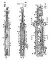
- a linear anastomotic stapling instrumentcan comprise an upper elongated anvil carrying jaw member 22 and a lower elongated staple cartridge carrying jaw member 24.
- Upper anvil carrying jaw member 22can be supported by a handle 26 with a front portion of the jaw member extending forwardly therefrom.
- Lower staple cartridge carrying jaw member 24can be supported by a handle 28 with a front portion of the jaw member extending forwardly therefrom.
- upper handle 26 and lower handle 28can be suitably shaped to form a hand grip to facilitate the handling and operation of the stapling instrument by a surgeon.
- An enlarged front protrusion 27 and a small rear protrusion 29can be provided on each handle for this purpose.
- handles 26 and 28can be made of plastic of other lightweight materials, for example, while jaw members 22 and 24 can be made of stainless steel or other similar materials, for example.
- upper jaw member 22can comprise a one-piece elongated channel-shaped frame including a pair of opposed, elongated side walls 30 connected by a top wall 31.
- Upper handle 26can include a pair of depending ears 32 located inside the upper handle adjacent to its front end.
- Upper jaw member 22can include a slot 34 ( FIG. 4 ) formed at an intermediate position along its top wall 31 through which depending ears 32 can project downwardly.
- a latch pin 36can extend through circular holes formed in side walls 30 of upper jaw member 22 and through circular holes formed in depending ears 32 to pivotally connect the upper jaw member to upper handle 26.
- the front portion of upper jaw member 22can be provided with a pair of elongated inwardly extending flanges 38 which can define an anvil 40 of the stapling instrument.
- Flanges 38can be separated by a central longitudinal slot 42 which extends along the entire length of anvil 40.
- the flanges 38can be provided with inwardly sloped guide surfaces 41.
- Each flange 38can also provided with two longitudinal rows of uniformly spaced staple-forming pockets 44.
- a tapered anvil tip 46can be mounted at the front of anvil carrying jaw member 22 to facilitate the insertion of the jaw member into hollow, tubular body organs, for example.
- Anvil tip 46can include an elongated body 48 ( FIG. 4 ) which can be inserted through the longitudinal passageway above anvil 40 defined by side walls 30 and flanges 38 of the upper jaw member.
- This elongated body 48can extend between depending ears 32 above latch pin 36 and can include an enlarged rear portion 50 located behind ears 32 to hold anvil tip 46 in place on upper jaw member 22.
- lower cartridge carrying jaw member 24can comprise a one-piece elongated channel-shaped frame including a pair of opposed, elongated side walls 52 connected by a bottom wall 53.
- a pair of spaced, elongated upstanding side flanges 54( FIG. 2 ) can extend upward from its opposed side walls 52.
- the width of lower jaw member 24 between its side flanges 54can be greater than the width of upper jaw member 22 between its side walls 30 to permit the rear portion of the upper jaw member to be received between side flanges 54 of the lower jaw member when the stapling instrument is assembled for operation.
- each side flange 54 of lower jaw member 24can include a vertical notch 56 located in alignment with latch pin 36 on upper jaw member 22. When upper jaw member 22 and lower jaw member 24 are assembled, the opposite ends of latch pin 36 can be received in notches 56.
- lower jaw member 24can support a staple cartridge 60 which is adapted to receive a plurality of surgical staples 61 ( FIG. 17 ) arranged in at least two laterally spaced longitudinal rows.
- Staple cartridge 60can be mounted at the front portion of lower jaw member 24 between its side walls 52.
- Staple cartridge 60can be divided longitudinally by a central, elongated slot 62 ( FIG. 6 ) which extends from the proximal end of the cartridge toward its distal end.
- a plurality of staple openings 64 formed in staple cartridge 60can be arranged in two pairs of laterally spaced rows, with each pair of rows disposed on opposite sides of central longitudinal slot 62.
- a plurality of surgical staples 61FIG.
- staple cartridge 60can include a pair of longitudinal slots 66 located on opposite sides of elongated central slot 62 and disposed between the staggered rows of openings 64 on each side of the central slot. Each longitudinal slot 66 can extend from the proximal end of cartridge 60 towards its distal end.
- a plurality of staple drivers 65can be slidably mounted in staple openings 64 for actuating the staples 61 which are loaded into staple cartridge 60.
- each staple driver 65can be designed to simultaneously actuate two staples 61 located in the adjacent rows provided in staple cartridge 60.
- a first set of staple drivers 65can be provided for actuating the staples 61 in the staggered rows located on one side of central longitudinal slot 62
- a second set of staple drivers 65can be provided for actuating the staples 61 in the pair of adjacent rows located on the other side of central longitudinal slot 62.
- the front or distal end of staple cartridge 60can include a tapered tip 68 to facilitate the insertion of lower jaw member 24 into a hollow, tubular body organ, for example.
- staple cartridge 60can be provided with a pair of rearwardly extending protrusions 70 (one shown in FIG. 14 ) which can be received in corresponding notches provided in side walls 52 of lower jaw member 24.
- a pair of depending arms 72can extend downwardly from the cartridge. Each arm 72 can be notched to provide a side opening 74.
- cartridge 60When cartridge 60 is assembled on lower jaw member 24, its protrusions 70 can be received in corresponding notches provided at the front ends of side walls 52 and its depending arms 72 extend downwardly through an opening 76 ( FIG. 4 ) formed in bottom wall 53 of jaw member 24.
- Lower jaw member 24can include a pair of depending ears 78 ( FIG. 18 ) extending downwardly from its side walls 52 on opposite sides of opening 76.
- a pivot pin 80can extend through holes formed in depending ears 78 of lower jaw member 24 and through side openings 74 of depending arms 72 on staple cartridge 60 to fasten the staple cartridge to the lower jaw member.
- the stapling instrument 20can include a latching mechanism, generally 90, for latching upper jaw member 22 and lower jaw member 24 together at an intermediate position along the jaw members.
- jaw members 22 and 24can be latched together at a position adjacent to the proximal ends of anvil 40 and staple cartridge 60.
- latching mechanism 90can comprise a latch arm 92 ( FIG. 2 ) pivotally connected to lower jaw member 24 via pivot pin 80 ( FIG. 4 ).
- Latch arm 92can be channel-shaped in configuration and can include a pair of opposed, elongated side walls 94 ( FIG. 6 ) which are spaced apart by a distance sufficient to span side walls 52 of lower jaw member 24.
- Each side wall 94 of latch arm 92can include an upwardly and forwardly extending hook member 96 provided with a forwardly facing slot 98 for receiving latch pin 36.
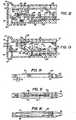
- a shroud 100can be mounted on the lower surface of latch arm 92. When latch arm 92 is closed, as shown in FIG. 3 , shroud 100 can be aligned with the bottom of lower handle 28 to facilitate the handling and operation of stapling instrument 20 by the surgeon. In some cases, shroud 100 can be made of plastic or other lightweight materials, for example, while latch arm 92 can be made of stainless steel, for example. As shown in FIG.
- shroud 100can include elongated flanges 102 and 104 extending outwardly from its opposite sides which can serve as fingergrips to enable latch arm 92 to be pivoted downwardly from its latched to its unlatched position.
- latch arm 92When latch arm 92 is moved to its closed or latched position, the surfaces of slots 98 of hook members 96 can cooperate with latch pin 36 which can act as an over-center latch to maintain latch arm 92 in its latched position.
- the preferred stapling instrument 20can include an improved pusher bar and knife blade assembly, generally 110, which can be slidably mounted for longitudinal movement relative to upper and lower jaw members 22 and 24, respectively, for driving staples 61 from staple cartridge 60 into tissue gripped between the jaw members, forming staples 61 against anvil 40, and cutting the tissue along a line between the rows of staples formed in the tissue.
- Pusher bar and knife blade assembly 110can include a pusher block 112 ( FIG. 6 ) which can be slidably received within the lower channel-shaped jaw member 24 between its upstanding side flanges 54. As shown in FIG.
- pusher block 112can be attached to an actuator knob 114 by a flange 116 which includes a laterally projecting finger 118 provided with a longitudinally extending notch 119 on its top surface. Finger 118 can be snap-fitted into a lateral slot 120 formed in pusher block 112 to locate notch 119 underneath a longitudinal locking bar 121 to secure pusher block 112 and actuator knob 114 together.
- Flange 116 of actuator knob 114can extend through and rids along an elongated slot 122 ( FIG. 2 ) formed in one side flange 54 of lower jaw member 24.
- the pusher bar and knife blade assembly 110can include a pair of staple pusher bars 124 ( FIG. 10 ) projecting forwardly from pusher block 112 and slidably received in elongated slots 66 ( FIG. 16 ) of staple cartridge 60.
- Pusher block 112can be provided with a pair of vertical slots 126 ( FIG. 11 ) in which pusher bars 124 are secured.
- the front end of each staple pusher bar 124can be provided with a wedge-shaped tip 128 which defines an inclined cam surface 130 for engaging staple drivers 65 as pusher bars 124 are advanced into staple cartridge 60.
- each staple driver 65can be provided with a sloped surface 132 oriented at the same angle as cam surface 130 of each staple pusher bar 124 to provide a flat, sliding contact between the surfaces.
- the pusher bar and knife blade assembly 110can include a knife block 134 which is slidably mounted for longitudinal movement along lower jaw member 24 between its upstanding side flanges 54.
- Knife block 134can include a knife support bar 136 which extends forwardly into central longitudinal slot 62 of staple cartridge 60.
- An inclined knife blade 138 provided with a beveled cutting edge 140can be located at the front end of knife support bar 136.
- the beveled cutting edge of knife blade 138can be oriented at an angle relative to elongate jaw members 22 and 24 and can be slidably received in central longitudinal slot 62 of staple cartridge 60.
- Knife block 134can include a pair of longitudinal slots 135 ( FIG. 19 ) extending therethrough which slidably receive staple pusher bars 124 to permit pusher block 112 to slide relative to the knife block. Accordingly, when pusher block 112 is advanced toward staple cartridge 60 by actuator knob 114, staple pusher bars 124 can slide through knife block 134 which remains stationary until the pusher block moves into engagement with the knife block. After knife block 134 is engaged by pusher block 112, the knife block and pusher block can advance simultaneously toward staple cartridge 60. As shown in FIG. 17 , knife blade 138 can be advanced through staple cartridge 60 along with staple pusher bars 124, forming staples 61 in the tissue gripped between the jaw members and cutting the tissue between the staple rows.
- pusher block 112can initially slide staple pusher bars 124 backward through knife block 134 which can remain stationary.
- Each staple pusher bar 124can include an offset portion 142 which can move into engagement with knife block 134 after staple pusher bars 124 are withdrawn by a predetermined distance. With offset portions 142 of staple pusher bars 124 engaging knife block 134, pusher block 112 and knife block 134 can be simultaneously retracted by actuator knob 114 to return pusher bars 124 and knife blade 138 to the start position.
- Stapling instrument 20can be provided with jaw clamping means for applying clamping forces to the jaw members to urge staple cartridge 60 and anvil 40 together during the formation of staples 61.
- the jaw clamping meanscan include means for urging the jaw members apart at a position remote from the latching mechanism to resist the forces exerted on staple cartridge 60 and anvil 40 when staples 61 are formed.
- a cam meanscan be mounted on one of the jaw members and can be engageable with the other jaw member for moving said jaw members apart at the remote position to urge staple cartridge 60 and anvil 40 together.
- a cam membercan be pivotally mounted on one of the jaw members at a position remote from the latching mechanism.
- the cam membercan be pivotable from a first inoperative position to a second operative position to move the remote ends of the jaw members apart.
- the cam membercan be operable by pusher block 112 of pusher bar and knife blade assembly 110 to move to its operative position when the pusher block is advanced and to return to its inoperative position when the pusher block is retracted.
- a cam mechanism, generally 150can be located adjacent to the rear end of lower jaw member 24, as shown in FIG. 4 .
- Cam mechanism 150can include a cam member 152 pivotally mounted on a transverse pivot pin 154 extending between upstanding side flanges 54 of lower jaw member 24.
- Cam member 152can include a first lower cam surface 156 for engaging top wall 31 of upper jaw member 22 with cam 152 in its first inoperative position ( FIG. 12 ) and a second higher cam surface 158 for engaging the top wall 31 of upper jaw member 22 with cam 152 disposed in its second operative position ( FIG. 13 ).
- First cam surface 156can be arranged to maintain upper and lower jaw members substantially parallel with cam 152 in its inoperative position.
- Second cam surface 158can be arranged to raise the rear end of upper jaw member 22 by approximately 0.125 inch (3.2 mm), for example, when cam 152 pivots from its inoperative position to its operative position.
- upper jaw member 22can be sufficiently flexible to permit the rear portion of upper jaw member 22 to bend upward away from lower jaw member 24 when cam member 152 is moved from its inoperative position to its operative position.
- cam member 152can include a radially extending notch 160 which divides the cam into a large front finger 162 and a small rear finger 164.
- Front cam finger 162can include a flat, rearwardly facing surface 165
- rear cam finger 164can include a sloped, forwardly facing surface 166. With cam 152 in its inoperative position, front cam finger 162 and rear cam finger 164 can extend downwardly through an elongated slot 168 formed in bottom wall 53 of lower jaw member 24.
- Cam member 152can be operable by pusher block 112 to move from its inoperative position to its operative position when the pusher block is advanced.
- pusher block 112can include a pair of rearwardly extending arms 170 which are spaced apart to define a gap 172 therebetween. The rear ends of arms 170 can be connected by a cam actuator pin 174 which extends across gap 172.
- cam actuator pin 174can be received in notch 160 between front finger 162 and rear finger 164 of the cam member.
- top wall 31 of upper jaw member 22can rest on first cam surface 156 of the cam member. With cam member 152 in its inoperative position, top wall 31 of upper jaw member 22 can be substantially parallel to bottom wall 53 of lower jaw member 24.
- pusher block 112can be located in its start position spaced rearwardly from knife block 134. When pusher block 112 is advanced, as indicated by arrow 182 ( FIG.
- cam actuator pin 174can engage rear surface 165 of front cam finger 162 to rotate cam member 152 in a counter-clockwise direction, as indicated by arrow 184, to pivot the cam member to its second operative position and move its second cam surface 158 into engagement with top wall 31 of upper jaw member 22.
- cam member 152 pivoted to its operative positionthe top wall 31 of upper jaw member 22 can be bent upwardly, as indicated by arrow 186, away from bottom wall 53 of lower jaw member 24.
- the cam membercan apply forces to upper jaw member 22 and lower jaw member 24 which bend the rear portions of the jaw members apart.
- anvil 40 and staple cartridge 60can be urged together to resist the forces exerted on the anvil and staple cartridge when pusher bar and knife blade assembly 110 is advanced to form staples 61 and cut the tissue.
- cam actuator pin 174can engage sloped surface 166 of rear cam finger 164 to pivot cam member 152 in a clockwise direction.
- cam member 152can pivot in a clockwise direction and return to its first inoperative position ( FIG. 12 ) with its first cam surface 156 in engagement with top wall 31 of upper jaw member 22.
- first inoperative positionFIG. 12
- cam member 152can pivot in a clockwise direction and return to its first inoperative position ( FIG. 12 ) with its first cam surface 156 in engagement with top wall 31 of upper jaw member 22.
- the forces exerted on the rear portions of upper jaw member 22 and lower jaw member 24 by cam 152can be released and top wall 31 of upper jaw member 22 can return to a substantially parallel relationship with bottom wall 53 of lower jaw member 24.
- the clamping forces applied to the front portions of jaw members 22 and 24can be released to unclamp anvil 40 and staple cartridge 60.
- Stapling instrument 20can include spacer means mounted on one of the jaw members for maintaining a predetermined gap between staple cartridge 60 and anvil 40 of the stapling instrument.
- this spacer meanscan be embodied as a spacer pin 190 mounted adjacent to the distal end of staple cartridge 60.
- Spacer pin 190can extend vertically upward from bottom wall 53 of lower jaw member 24 through staple cartridge 60 and project upwardly from the top of the staple cartridge by a predetermined distance.
- one flange 38 of anvil 40can include a flange section 192 adjacent to its distal end for engaging spacer pin 190. With the stapling instrument assembled for operation ( FIG. 4 ), spacer pin 190 can engage flange section 192 to maintain a predetermined gap between anvil 40 and staple cartridge 60.
- the tissue to be stapled and cutcan be initially placed between jaw members 22 and 24 and clamped by the jaw members.
- handles 26 and 28can be unlatched by pivotal movement of latch arm 92 downward to its unlatched position ( FIG. 2 ).
- latch pin 36can be disengaged from slots 98 formed in hook members 96 of latching arm 92.
- upper and lower jaw members 22 and 24can be separated by disengaging latch pin 36 from slots 56 formed in side flanges 54 of the lower jaw member.
- the tissue to be stapled and cutcan be placed on jaw members 22 and 24.
- a piece of tubular, intestinal tissuemay be slipped onto the front portion of each jaw member.
- stapling instrument 20can be reassembled. The reassembly can be accomplished by aligning latch pin 36 with vertical slots 56 formed in upstanding side flanges 54 of lower jaw member 24. Thereafter, side flanges 54 of lower jaw member 24 can be positioned inside upper handle 26, spanning side walls 30 of upper jaw member 22, while the opposite ends of latch pin 36 can be inserted into vertical slots 56. Finally, latch arm 92 can be pivoted upward to its latched position ( FIG.
- hook members 92can be pivoted over latch pin 36 and slots 98 can receive the opposite ends of the latch pin.
- upper jaw member 22 and lower jaw member 24can be latched together at an intermediate position therealong adjacent to anvil 40 and staple cartridge 60.
- spacer pin 190can engage flange section 192 of anvil 40 through the body tissue to maintain a predetermined gap between anvil 40 and staple cartridge 60.
- stapling instrument 20can be fired by advancing actuator knob 114 to actuate the pusher bar and knife blade assembly 110.
- actuator knob 114actuate the pusher bar and knife blade assembly 110.
- pusher block 112 and pusher bars 124FIG. 4
- knife block 134can remain stationary. Since only pusher block 112 and its pusher bars 124 are advanced to actuate cam member 152, the initial force required to operate stapling instrument 20 can be minimized.
- pusher bars 124can slide through knife block 134 and the wedge-shaped tips 128 of the pusher bars can begin to advance through slots 66 of staple cartridge 60.
- its cam actuator pin 174can engage rear surface 165 of front cam finger 162 to pivot cam 152 counter-clockwise, as indicated by arrow 184 of FIG. 13 , to move the second cam surface 158 of the cam member into engagement with top wall 31 of upper jaw member 22.
- Cam member 152can apply forces to upper jaw member 22 and lower jaw member 24 which bend the rear portions of the jaw members apart.
- the rear end of top wall 31 of upper jaw member 22can be bent upward by approximately 0.125 inch (3.2 mm), for example, relative to the rear end of bottom wall 53 of lower jaw member 24.
- the bending of the rear ends of jaw members 22 and 24 apartcan result in additional clamping forces on the front portions of the jaw members to clamp anvil 40 and staple cartridge 60 against the tissue gripped between the jaw members.
- These additional clamping forcestend to resist the forces exerted on anvil 40 and staple cartridge 60, while the tissue is cut and staples 61 are formed against anvil 40, to maintain the desired spacing between anvil 40 and staple cartridge 60 to produce formed staples 61 which are substantially uniform in height.
- pusher block 112can subsequently engage knife block 134 to begin the longitudinal movement of knife block 134 toward staple cartridge 60.
- the initial spacing between pusher block 112 and knife block 134can be arranged such that pusher block 112 engages knife block 134 slightly before cam member 152 arrives at its operative position.
- the initial spacing between pusher block 112 and knife block 134can be arranged such that pusher block 112 initially engages knife block 134 after the movement of cam member 152 to its operative position is completed.
- staple pusher bars 124can be moved longitudinally along slots 66 provided in staple cartridge 60.
- the two wedge-like cam surfaces 130 of staple pusher bars 124can move through slots 66 into engagement with the sloped surfaces of staple drivers 65 to sequentially drive staples 61 from cartridge 60 and to form staples 61 into B-shaped configuration against anvil flanges 38.
- the cam surfaces 130can be located at the same distance from pusher block 112 to simultaneously actuate staple drivers 65 located on opposite sides of central longitudinal slot 62.
- knife block 134can be advanced to move knife blade 138 through central longitudinal slot 42 of anvil 40 and through central longitudinal slot 62 of staple cartridge 60 to cut the tissue gripped between the jaw members.
- the additional clamping forces applied to the front portions of upper jaw member 22 and lower jaw member 24 via cam mechanism 150can tend to resist the forces exerted on anvil 40 and staple cartridge 60 when staples 61 are formed.
- pusher block 112After pusher block 112 is fully advanced to form all of the staples in cartridge 60, the pusher block can be retracted toward its start position by retraction of actuator knob 114. Initially, only pusher block 112 can move backward from staple cartridge 60 because staple pusher bars 124 slide through knife block 134 which remains stationary. When offset portions 142 of staple pusher bars 124 engage the front of knife block 134, the knife block can be moved backward from staple cartridge 60 along with pusher block 112. As a result, staple pusher bars 124 and knife blade 138 can be simultaneously retracted from staple cartridge 60 and anvil 40.
- cam actuator pin 174can engage sloped surface 166 of rear cam finger 164 to pivot cam member 152 in a clockwise direction toward its inoperative position. Cam actuator pin 174 can move along sloped surface 166 into slot 160 between cam fingers 162 and 164 to return cam member 152 to its inoperative position. As a result, second cam surface 158 of cam member 152 can be disengaged from the top wall of upper jaw member 22 and rear end of top wall 31 of upper jaw member 22 and move downwardly into engagement with first cam surface 156.
- front cam finger 162can pivot downwardly into gap 172 between fingers 170 on pusher block 112, and both cam fingers 162 and 164 can pivot downwardly into slot 168 formed in bottom wall 53 of lower jaw member 24.
- latching arm 92can be pivoted downward, as shown in FIG. 2 , to permit upper jaw member 22 and lower jaw member 24 to be disassembled. At this point, the cut and stapled tissue can be removed from the jaw members.
- a surgical stapling instrumentcan include an actuator knob, such as actuator knob 114 ( FIG. 1 ), for example, which can be configured to advance a pusher bar assembly, such as pusher bar assembly 110 ( FIG. 10 ), within a staple cartridge of the surgical stapling instrument.
- actuator knob 114can be configured to be grasped by a surgeon such that the surgeon can apply a force thereto.
- actuator knob 114can come into contact with or abut tissue surrounding the surgical site when it is advanced distally.
- the surgeonmay have to reposition the stapling instrument such that actuator knob 114 can pass by the tissue.
- the surgeonmay have to force actuator knob 114 by the tissue. In either event, such circumstances may be unsuitable and, as a result, there exists a need for a stapling instrument having an actuator knob which can be manipulated to reduce the possibility that the actuator knob may impinge on the surrounding tissue.
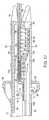
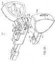
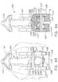
- stapling instrument 220can include anvil carrying jaw member 222 extending from upper handle 226, staple cartridge carrying jaw member 224 extending from lower handle 228, and actuator knobs 214a and 214b which can be operably engaged with a pusher bar assembly, such as pusher bar assembly 210 as illustrated in FIG. 24 , for example.
- a staple cartridgecan be removably attached to staple cartridge carrying jaw member 224, for example, such that, after the staple cartridge has been expended, it can be replaced with another staple cartridge.
- pusher bar assembly 210can include a staple driver integrally-formed with or operably mounted thereto which can be moved through the staple cartridge as outlined above.
- the staple cartridgecan include a staple driver contained therein which can be engaged with and pushed distally by the pusher bar assembly.
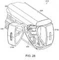
- first actuator knob 214afor example, can be rotated between a first position ( FIG. 21 ) in which it is operably disengaged from pusher bar assembly 210 and a second position ( FIG. 22 ) in which it is operably engaged with pusher bar assembly 210.
- second actuator knob 214bcan be configured to be rotated between first and second positions in which it is operably disengaged and engaged, respectively, with pusher bar assembly 210.
- the actuator knobs of a stapling instrumentcan be selectively engaged with a pusher bar assembly such that, in the event that an actuator knob may come into contact with or abut tissue surrounding the surgical site when it is advanced, that actuator knob can remain in its retracted position while another actuator knob can be extended to advance the pusher bar assembly distally.
- first actuator knob 214acan be rotated into its second position such that it can be operably engaged with pusher bar assembly 210 while second actuator knob 214b can remain in its retracted position.
- first actuator knob 214acan be advanced distally relative to upper handle 226 and lower handle 228 along first side 201 of surgical stapler 210 in order to motivate pusher assembly 210.
- first actuator knob 214acan be slid within first slot 227 defined between, or within, upper handle 226 and lower handle 228.
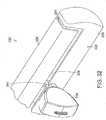
- first actuator knob 214acan remain in its retracted position while second actuator knob 214b can be rotated into its extended position.
- second actuator knob 214bcan be advanced distally along second side 203 of stapling instrument 210 to advance pusher bar assembly 210 within second slot 229, for example.
- both actuator knobs 214can be extended to advance pusher bar assembly 210 distally.
- a stapling instrumentcan include more than two actuator knobs which can be selectively utilized to motivate a pusher bar and/or knife blade assembly. In effect, as a result of the above, the actuator knobs of a surgical instrument can be engaged with a pusher bar assembly independently of each other.
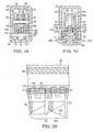
- stapling instrument 201can further include guide member 209 which can be configured to guide actuator knobs 214 as they are rotated between their first and second positions.
- guide member 209can include guide rails 211 which can be slidably received within grooves 213 of actuator knobs 214 such that, when actuator knobs 214 are rotated, guide member 209 can dictate the path along which the actuator knobs 214 are moved.
- guide rails 211 and grooves 213can comprise interlocking features which can cooperatively prevent actuator knobs 214 from being unintentionally displaced proximally and/or distally, for example.
- guide member 209can prevent one or more of actuator knobs 214 from being translated along with pusher bar assembly 210 when pusher bar assembly 210 is advanced distally as described above.
- a slight friction or interference fitcan be present between guide rails 211 and grooves 213 such that the possibility that actuator knobs 214 may be unintentionally rotated into their extended positions can be reduced.
- the actuator knobscan include guide rails extending therefrom which can be slidably received in grooves within the guide member, for example.
- guide member 209can include one or more retention members 215 which can be configured to retain guide member 209 in position intermediate upper handle 226 and lower handle 228. Furthermore, referring to FIGS. 24 and 25 , guide member 209 can include aperture 217 which can be configured to receive retention pin 219 extending therethrough wherein retention pin 219 can be configured to be engaged with upper handle 226 and/or lower handle 228 to retain guide member 209 in position.
- pusher bar assembly 210can include a first clutch feature, such as slots or grooves 205, for example, and actuator knobs 214 can each include a second clutch feature, such as projections 207, for example, wherein the first and second clutch features can be operatively engaged with each other in order to operatively engage one or more of actuator knobs 214 with pusher bar assembly 210.
- projections 207can be closely received within slots 205 such that, when a force is applied to one or more of actuator knobs 214, the force can be transmitted to pusher bar assembly 210 through projections 207 and the sidewalls of slots 205.
- a slight friction or interference fitcan be present between projections 207 and slots 205 to hold actuators 214 in their extended position.
- the first clutch featurecan include projections extending from the pusher bar assembly which can be configured to be received within recesses or slots within the actuator knobs. In addition to or in lieu of the above, referring to FIG.
- pusher bar assembly 210can further include second guide rails 221 which can be configured to be slidably received within slots or grooves 223 within actuator knobs 214, wherein rails 221 and grooves 223 can be configured to guide actuator knobs 214 into their second position and/or transmit forces from actuator knobs 214 to pusher bar assembly 210 once they are in their second position. Similar to guide rails 211, guide rails 221 can be configured to create a slight friction or interference fit with grooves 223 to hold actuator knobs 214 in position. Further to the above, in some cases, actuator bar 210 can include post 225 about which actuator knobs 214 can be rotated.
- actuator knobs 214can include recesses 227 which can be contoured such that the sidewalls of recesses 227 can closely receive and slide around post 225 and, as a result, post 225 can guide actuator knobs 214 as they are rotated between their first and second positions, for example.
- a stapling instrumentcan include an actuator knob which can be configured to be selectively advanced along a first side of the stapling instrument and a second side of the stapling instrument.
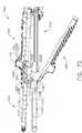
- stapling instrument 320can include an upper handle 326, a lower handle 328, and an actuator knob 314, wherein actuator knob 314 can, similar to the above, be configured to advance a pusher bar assembly within a staple cartridge.
- upper handle 326 and lower handle 328can define first slot 327 and second slot 329 therebetween, wherein slots 327 and 329 can both be configured to permit actuator knob 314 to slide therethrough.
- actuator knob 314can be configured such that it can be selectively slid through first slot 327 along first side 301 or, alternatively, through second slot 329 along second side 303.
- stapling instrument 320can further include third slot 331 which can be configured to allow actuator knob 314 to be moved from one side of the stapling instrument to the other.
- a surgeoncan selectively position actuator knob 314 such that, if it appears that actuator knob 314 may impinge on tissue if it is advanced distally on one side of the stapling instrument, actuator knob 314 can rotated over to the other side of the stapling instrument before it is advanced.
- first and second sides as illustratedare located on opposite sides of surgical instrument 320, alternatives are envisioned where the first and second slots, for example, are located on adjacent sides and/or sides which are not directly opposite to each other. Furthermore, alternatives are envisioned in which the sides of a stapling instrument are not readily discernable, such as instruments having round and/or arcuate portions.
- first slot 327can be configured such that it defines a path for actuator knob 314 which is parallel to, or at least substantially parallel to, a path defined by second slot 329.
- third slot 331can be configured to connect first slot 327 and second slot 329 such that it can define a path for actuator knob 314 which is perpendicular to, or at least substantially perpendicular to, the paths defined by slots 327 and 329.
- actuator knob 314can be rotated over the top of the surgical instrument to move actuator knob 314 from first side 301 to second side 303.
- a third slotcan define a path for actuator knob 314 which is parallel to, or at least substantially parallel to, and/or co-planar with, or at least substantially co-planar with, the paths defined by slots 327 and 329.
- a third slotcan define a path which is skew with respect to the paths defined by slots 327 and 329.
- a third slotcan be configured connect first and second slots such that an actuator knob can be slid therewithin.
- stapling instrument 320can include a pusher bar assembly which can be operably engaged with actuator knob 314, for example, such that actuator knob 314 can be configured to advance the pusher bar assembly distally.
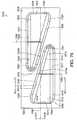
- stapling instrument 320can include pusher bar assembly 310 which can include a first portion 333 operably engaged with a knife assembly, for example, and, in addition, a second portion 335 which can be rotatably mounted to first portion 333.
- first portion 333can define an axis 337 about which second portion 335 can be rotated.
- second portion 335can include aperture 339 defined therein which can be configured to closely receive first portion 333.
- pusher bar assembly 310can further include one or more retaining members, such as set screws, for example, configured to extend into a groove in first portion 333, for example, for retaining second portion 335 to first portion 333.
- second portion 335can include mount 341 extending therefrom which can be configured to retain actuator knob 314 to second portion 335.
- actuator knob 314 and second portion 335can be rotated relative to first portion 333 such that actuator knob 314 can be selectively positioned within first slot 327 and second slot 329.
- a stapling instrumentcan have more than two slots for receiving an actuator knob when it is advanced within a staple cartridge.
- first portion 333 and second portion 335can be fixedly mounted together such that they are rotated together about axis 337.
- first portion 333can be configured to rotate relative to a substantially non-rotatable portion of pusher bar assembly 310.
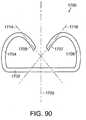
- a surgical stapling instrumentcan comprise a first handle portion 1102 and a second handle portion 1104.
- first handle portion 1102 and second handle portion 1104can be configured to be grasped by a surgeon, for example, and can comprise hand grip portion 1106.
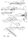
- first handle portion 1102, referring to Figs. 35 and 36can include a first cover 1108 attached to a first frame 1110 and, similarly, second handle portion 1104 can include a second cover 1112 attached to a second frame 1114.
- Covers 1108 and 1112can be ergonomically contoured, or otherwise suitably contoured, to assist a surgeon in manipulating stapling instrument 1100 within a surgical site.
- handle covers 1108 and 1112can include enlarged protrusions 1109 and 1113, respectively, which can facilitate the insertion of stapling instrument 1100 into a surgical site.
- handle covers 1108 and 1112can be made of plastic, lightweight materials, and/or any other suitable material, for example, while handle frames 1110 and 1114 can be made of stainless steel, titanium, and/or any other suitable material, for example.
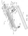
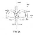
- the distal ends of handle portions 1102 and 1104can comprise an end-effector 1120 which can be configured to treat tissue within a surgical site, for example.
- end-effector 1120can include a staple cartridge channel 1122 configured to receive and/or retain a staple cartridge as described in greater detail further below.
- staple cartridge channel 1122can comprise a one-piece elongated channel-shaped frame extending from first handle portion frame 1110.
- staple cartridge channel 1122can include a pair of opposed, elongated side walls 1124 connected by a bottom wall 1126.
- a pair of spaced, upstanding side flanges 1128can extend upwardly from opposed side walls 1124.
- the width of staple cartridge channel 1122 between side flanges 1128can be greater than the width of the upper jaw member, or anvil, 1130 extending from second handle portion 1104.
- the distance between flanges 1128can be configured to permit at least a portion of anvil 1130 to be received between side flanges 1128 when the stapling instrument is assembled for operation. As shown in FIG.
- each side flange 1128 ofcan include a notch, or recess, 1127, for example, which can be configured to receive one or more latch projections 1131, for example, extending from anvil 1130, and/or any other suitable portion of second handle portion 1104, as described in greater detail further below.
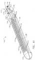
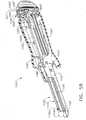
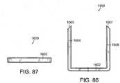
- staple cartridge channel 1122can be configured to support and/or retain a staple cartridge, such as staple cartridge 1150, for example, within end-effector 1120, wherein the staple cartridge can include one or more staples (not illustrated) removably stored therein.
- staple cartridge 1150can include one or more staple cavities 1151 which can be configured to store staples in any suitable arrangement, such as in at least two laterally-spaced longitudinal rows, for example. In some cases, referring to Figs.
- staple cartridge 1150can include staple cartridge body 1152 and pan, or retainer, 1154, wherein staple cartridge body 1152 and/or pan 1154 can be configured to define a channel, or path, for slidably receiving a staple sled and/or cutting member therein.
- pan 1154can include flexible arms 1155, for example, which can be configured to engage staple cartridge body 1152 in a snap-fit and/or press-fit arrangement.
- staple cartridge 1150can further include staple sled assembly 1160 which can include staple sled portion 1162 and, in addition, cutting member 1164.
- cutting member 1164can include cutting edge 1165 and lock arm 1166, for example, wherein lock arm 1166 can be configured to be press-fit and/or snap-fit into aperture 1163 in staple sled 1162 when cutting member 1164 is assembled to staple sled portion 1162. Staple sled portion 1162 can be integrally molded to cutting member 1164.
- staple cartridge body 1152can include a slot, such as slot 1156, for example, which can be configured to receive at least a portion of cutting member 1164 therein, and/or any other portion of staple sled assembly 1160 and pusher bar assembly 1200 (discussed below), wherein slot 1156 can be configured to permit cutting member 1164 to be moved between first and second positions within staple cartridge 1150.
- slot 1156can be configured to permit cutting member 1164 to be moved between a proximal position ( FIG. 43 ) and a distal position in order to incise tissue positioned intermediate staple cartridge 1150 and anvil 1130, for example.
- staple sled portion 1162can include cam, ramp, or actuator, surfaces 1167 which can be configured to engage staple drivers positioned within staple cartridge 1150.
- staple cartridge 1150can include staple drivers 1168 which can be lifted, or slid, upwardly within staple cavities 1151 by sled portion 1162 such that the upward movement of staple drivers 1168 can eject, or deploy, staples at least partially positioned within staple cavities 1151.
- staple drives 1168can be, in fact, lifted vertically upwardly, the term upward, and the like, can mean that staple drivers 1168, for example, are moved toward the top surface, or deck, 1158 of the staple cartridge and/or toward anvil 1130, for example. In certain cases, as illustrated in FIG.
- each staple driver 1168can include one or more sloped surfaces 1169 oriented at the same angle as a cam surface 1167, and/or any other suitable angle, which can provide a relatively flat, or at least substantially flat, sliding contact surface between staple sled 1162 and staple drivers 1168.
- a staple drivercan be configured to deploy only one staple, while, in certain cases, a staple driver can be configured to simultaneously deploy two or more staples located in adjacent rows, for example.
- Other devicesare disclosed in U.S. Patent Application Publication No. 2009/0200355 , entitled SURGICAL STAPLING INSTRUMENT WITH IMPROVED FIRING TRIGGER ARRANGEMENT, which was filed on February 13, 2008.
- a surgical stapling instrumentcan include a cutting member/staple sled assembly configured to incise tissue and deploy staples from a staple cartridge.
- a surgical stapling instrumentmay not require, or include, a cutting member.
- a staple cartridgecan include a staple sled positioned therein and/or a surgical instrument can be configured to move a staple sled into a staple cartridge in order to staple tissue, for example, without otherwise dissecting it.
- a staple cartridgecan include a staple sled positioned therein where a surgical instrument can include a cutting member movable into, or relative to, the staple cartridge.
- the cutting membercan be advanced into contact with the staple sled such that the cutting member and staple sled can be advanced together. Thereafter, the cutting member can be sufficiently retracted to allow the staple cartridge to be detached from the surgical instrument and replaced with a new staple cartridge having a new staple sled. This may be useful when a staple sled may become worn or deformed during use.
- a staple cartridgecan include a cutting member positioned therein where a surgical instrument can include a staple sled movable into, or relative to, the staple cartridge. In such a case, similar to the above, the staple sled can be advanced into contact with the cutting member such that the cutting member and staple sled can be advanced together.
- the staple sledcan be sufficiently retracted to allow the staple cartridge to be detached from the surgical instrument and replaced with a new staple cartridge having a new cutting member. This may be useful when a cutting member may become worn or deformed during use.
- the staple cartridgecan include a protective housing or cover configured to prevent, or at least reduce the possibility of, a surgeon or other clinician from touching the cutting member positioned within the staple cartridge while handling the staple cartridge, for example.
- staple cartridge channel 1122 and/or staple cartridge 1150can include one or more co-operating projections and/or recesses, for example, which can be configured to removably retain staple cartridge 1150 within staple cartridge channel 1122.
- first handle portion 1102 and second handle portion 1104can include proximal ends 1103 and 1105, respectively, which can be assembled together such that the first and second handle portions can be rotatably or pivotably coupled to one another.
- first handle portion 1102can include one or more pins, or projections, 1111 extending therefrom which can be configured to be slidably received within one or more grooves, channels, or slots 1115 in second handle portion 1104.
- slots 1115can be defined in second handle frame 1114 and projections 1111 can extend from a proximal end post 1107 extending from first handle frame 1110, for example.
- first handle portion 1102 and second handle portion 1104In order to assemble first handle portion 1102 and second handle portion 1104, referring to FIG. 37 , the open ends of slots 1115 can be aligned with projections 1111 such that second handle portion 1104, for example, can be translated relative to first handle portion 1102 and projections 1111 can be slid within slots 1115.
- the open ends of slots 1115can be located proximally with respect to their closed ends.
- proximal end 1105 of second handle portion 1104can be positioned distally with respect to proximal end 1103 of first handle portion 1102 such that second handle portion 1104 can be moved proximally in order to position projections 1111 within slots 1115.
- first handle portion 1102can be positioned proximally with respect to second handle portion 1104 and slid distally in order to position projections 1111 within slots 1115.
- second handle portion 1104can be rotated toward first handle portion 1102 such that anvil 1130 can be moved into position relative to staple cartridge 1150 and/or staple cartridge channel 1122.
- first handle portion 1102can be rotated toward second handle portion 1104 and/or the first and second handle portions can be rotated toward each other.
- projections 1111 and slots 1115when engaged with one another, can comprise a pivot about which one or both of the first and second handle portions can be moved relative to each other.
- second handle portion 1104can be moved relative to first handle portion 1102 such that anvil 1130 is moved into close opposition to staple cartridge 1150.
- first handle portion 1102can further include latching mechanism 1180 rotatably mounted thereto which can be utilized to engage latch projections 1131 extending from second handle portion 1104 and secure the first and second handle portions together.
- latching mechanism 1180can be mounted to first frame 1110 by one or more pivot pins 1182 which can be configured to define an axis about which latch 1180 can be rotated.
- latching mechanism 1180can include latch frame 1184 and, in addition, latch cover 1186 assembled to latch frame 1184.
- the latch cover and the latch framecan comprise an integral unit or, in certain cases, the latching mechanism may not even include a cover.
- latch frame 1184can be channel-shaped and can include a pair of opposed, elongated side walls 1185 which are spaced apart by a distance sufficient to span first frame portion 1110.
- latch cover 1186can be made of plastic, lightweight materials, and/or any other suitable materials, for example, while latch frame 1184 can be made of stainless steel and/or any other suitable material, for example.
- latch cover 1186can be aligned with first handle cover 1108.
- Latch cover 1186can include contoured portion 1187 which can be configured to assist a surgeon in manipulating surgical instrument 1100 wherein, in some cases, contoured portion 1187 can be aligned with, or at least substantially aligned with, protrusion 1109 extending from first handle cover 1108.
- Latching mechanism 1180can further include one or more latch arms 1188 extending therefrom which can be configured to engage one or more latch projections 1131 extending from second handle portion 104 and pull and/or secure projections 1131 within recesses 1127 as illustrated in FIG. 40 .
- At least one of latch arms 1188can be integrally-formed with latch frame 1184.
- at least one of latch arms 1188can include a distal hook 1189 which can be configured to wrap around at least a portion of projections 1131 so as to encompass or surround, or at least partially encompass or surround, projections 1131.
- latch arms 1188can act as an over-center latch to maintain latching mechanism 1180 in its latched, or closed, position.
- one of the first handle portion 1102 and the second handle portion 1104can be positioned on a first side of tissue within a surgical site and the other handle portion can be rotated into position on the opposite side of the tissue.
- staple cartridge 1150can be positioned on one side of the tissue and anvil 1130 can be positioned on the other side of the tissue.
- latching mechanism 1180can be actuated such that it can be moved between an open position and a closed position in order to latch second handle portion 1104 to first handle portion 1102 and apply a clamping force to the tissue positioned between staple cartridge 1150 and anvil 1130.
- latching mechanism 1180can be moved between an open position ( FIG.
- latching mechanism 1180can be moved between an open position in which latch arms 1188 are not engaged with projections 1131 and a partially-closed position in which latch arms 1188 are engaged with projections 1131 such that, although anvil 1130 has been at least partially brought into opposition to staple cartridge 1150, a sufficient gap can remain between anvil 1130 and staple cartridge 1150 which can allow end-effector 1120 to be repositioned relative to the tissue, for example.
- latching mechanism 1180can be moved between its partially-closed position and a closed position, as illustrated in FIG. 40 .
- a surgical stapling instrumentcan further include a biasing member which can be configured to bias the first handle portion of a stapling instrument away from a second handle portion.
- a springand/or any suitably resilient material, can be positioned intermediate the first and second handle portions such that the anvil and staple cartridge of the stapling instrument can be biased away from each other.
- the springcan be configured to at least partially separate the first and second handle portions such that a gap exists between the anvil and the staple cartridge, wherein the gap can be sufficient to allow tissue to be positioned therebetween. In use, a surgeon can position such a surgical stapling instrument without having to separate and hold the first and second handle portions apart from each other.
- Such an instrumentmay be especially useful when the stapling instrument is in a partially-closed configuration and the surgeon is manipulating the instrument within a surgical site. After the surgeon is satisfied with the positioning of the stapling instrument, the surgeon can compress and/or disengage the spring and place the stapling instrument in a closed configuration.
- first handle portion 1102can be moved relative to the distal end of second handle portion 1104, especially when latching mechanism 1180 is not engaged with, or only partially engaged with, projections 1131 of second handle portion 1104.
- projections 1111 and slots 1115 at the proximal ends of the first and second handle portionscan be configured to retain at least the proximal ends of the first and second handle portions together when the distal ends of the first and second handle portions are being moved relative to each other, for example. Stated another way, projections 1111 and slots 1115 can cooperate to prevent, or at least inhibit, first handle portion 1102 from becoming completely detached from second handle portion 1104.
- a first handle portioncan include a first lock portion and a second handle portion can include a second lock portion, wherein the first and second lock portions can be configured to be engaged with one another and prevent the first handle portion from becoming completely detached from the second handle portion.
- projections 1111can comprise the first lock portion and slots 1115 can comprise the second lock portion.
- Previous stapling instrumentslacked such lock portions and instead relied on a sole latching mechanism to keep the first and second handle portions together. In circumstances where the latching mechanisms of these previous stapling instruments were not fully engaged with both of the first and second handle portions, the first and second handle portions could become completely detached from one another, thereby requiring a surgeon, for example, to reposition and reassemble the handle portions. In certain circumstances, a complete detachment of the first and second handle portions of these previous staples could expose at least a portion of a cutting member.
- latching mechanism 1180can be configured to be moved between an open position, a partially-closed position, and a closed position.
- latching mechanism 1180When latching mechanism 1180 is in its open position, as also outlined above, projections 1111 can be inserted into and/or removed from slots 1115.
- latch arms 1188When latching mechanism 1180 is in its partially-closed position, referring to FIG. 39 , latch arms 1188 can be configured to engage latch projections 1131 such that projections 1111 cannot be removed from slots 1115.
- latch arms 1188 and latch projections 1131can be configured to prevent, or at least inhibit, second handle portion 1104 from being moved distally with respect to first handle portion 1102 and, as a result, prevent, or at least inhibit, projections 1111 from being disengaged from slots 1115.
- latch arms 1188 and latch projections 1131can be configured to prevent first handle portion 1102 from being moved proximally with respect to second handle portion 1104. Similar to the above, in some cases, latch arms 1188 and latch projections 1131 can also be configured to prevent, or at least inhibit, projections 1111 from being removed from slots 1115 when latching mechanism 1180 is in its closed position ( FIG. 40 ).
- latch projections 1131can extend from second handle portion 1104 at a location which is intermediate its proximal and distal ends.
- projections 1111 and slots 1115can be configured to hold the first and second handle portions together at their proximal ends while latching mechanism 1180 can be utilized to hold the first and second handle portions together at an intermediate location.
- the first and second handle portionscannot be disengaged from one another unless latching mechanism 1180 is moved into its fully open position.
- projections 1111 and slots 1115cannot be disengaged from one another when latching mechanism 1180 is in a closed and/or partially-closed position.
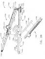
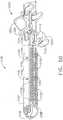
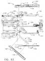
- surgical stapling instrument 1100can further include pusher bar assembly 1200 which can be configured to advance and/or retract staple sled assembly 1160 within staple cartridge 1150, for example.
- pusher bar assembly 1200can include pusher bar 1202 and firing actuator 1204, wherein firing actuator 1204 can be configured to move pusher bar 1202 and staple sled assembly 1160 distally to deploy staples from staple cartridge 1150 and deform the staples against anvil 1130 as described above.
- firing actuator 1204can be configured to move pusher bar 1202 and staple sled assembly 1160 distally to deploy staples from staple cartridge 1150 and deform the staples against anvil 1130 as described above.
- staple sled 1162can include a groove, channel, or slot 1161 which can be configured to receive, and can be operably connected to, a distal end 1201 ( FIG. 36 ) of pusher bar 1202.
- staple sled assembly 1160can be operably engaged with pusher bar 1202 when staple cartridge 1150 is inserted into staple cartridge channel 1122.
- distal end 1201 and slot 1161can include cooperating features which can allow distal end 1201 and slot 1161 to be assembled in a transverse direction but prevent, or at least inhibit, distal end 1201 and slot 1161 from being disassembled from one another in a proximal direction and/or distal direction.
- pusher bar 1202can be advanced distally before contacting and engaging staple sled assembly 1160. In such a case, the staple sled assembly 1160 can remain stationary until contacted by pusher bar 1202.
- actuator 1204can be operably connected to pusher bar 1202 such that a pushing and/or pulling force can be applied to actuator 1204 and transmitted to pusher bar 1202.
- actuator 1204can be pivotably connected to a proximal end 1203 of pusher bar 1202 such that actuator 1204 can be selectively rotated between at least first and second positions.
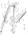
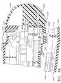
- actuator 1204can be movable between a first position on a first side 1116 of surgical stapling instrument 1100 ( FIG. 46 ), a second position on a second side 1117 ( FIG. 47 ), and an intermediate position ( FIG. 34 ) located at the proximal ends 1103 and 1105 of the first and second handle portions 1102 and 1104. Once actuator 1204 has been rotated into position on one of the first and second sides 1116, 1117, actuator 1204 can be advanced distally. In various circumstances, as a result, a surgeon may select whether to move actuator 1204 distally along first side 1116 or second side 1117.
- actuator 1204can include arm 1206 extending therefrom where arm 1206 can be pivotably mounted to proximal end 1203 of pusher bar 1202.
- surgical instrument 1100can include a first slot (not illustrated) extending along first side 1116 and a second slot 1118 extending along second side 1117, wherein the first and second slots can be configured to slidably receive at least a portion of actuator 1204.
- the sidewalls of the first and second slotscan confine, or at least assist in confining, the movement of actuator 1204 such that it can be moved along a predetermined path.
- second slot 1118can be defined between first handle portion 1102 and second handle portion 1104 such that, when actuator 1204 is moved distally along second side 1117, arm 1206 of actuator 1204 can be slid intermediate the first and second handle portions.
- the first slotcan also be defined intermediate the first and second handle portions.
- surgical instrument 1100can further include intermediate slot 1119 which can also be configured to allow arm 1206, and/or any other suitable portion of actuator 1204, to slide therein.
- intermediate slot 1119can connect the first and second slots such that, when actuator 1204 is positioned in its intermediate position, actuator 1204 can be moved into either one of its first and second positions.
- the first slot, second slot 1117, and intermediate slot 1119can be parallel, or at least substantially parallel, to one another and/or lie in the same plane, although alternatives are envisioned in which one or more of the slots is not parallel to the others and/or lies in a different plane.
- the first and second sides as illustratedare located on opposite sides of surgical instrument 1100, alternatives are envisioned where the first and second slots, for example, are located on adjacent sides and/or sides which are not directly opposite to each other.
- alternativesare envisioned in which the sides of a stapling instrument are not readily discernable, such as instruments having round and/or arcuate portions.
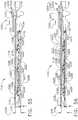
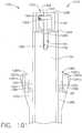
- surgical stapling instrument 1100can further include a locking mechanism which can prevent, or at least inhibit, actuator 1204 and, correspondingly, staple sled assembly 1160, from being advanced prematurely.
- the locking mechanismcan be configured to prevent, or at least inhibit, actuator 1204 from being advanced distally prior to latching mechanism 1180 being moved into a closed, or an at least partially-closed, position.
- surgical stapling instrument 1100can further including locking mechanism 1220 which can be engaged with actuator 1204 and can remain engaged with actuator 1204 while latching mechanism 1180 is in a fully open position ( FIG. 38 ) and/or an at least substantially-open position.
- locking mechanism 1220can include lock 1222 which can be biased into engagement with actuator 1204 by a biasing force applied thereto by lock spring 1224, for example.
- actuator 1204can include one or more grooves, channels, or slots (not illustrated) which can be configured to receive at least a portion of lock 1222.
- locking mechanism 1220can hold actuator 1204 in position until latching mechanism 1180 is moved into its fully closed position ( FIG. 40 ) and/or an at least substantially closed position.
- latching mechanism 1180can be configured to engage locking mechanism 1220 and disengage lock 1222 from actuator 1204. In such a case, referring to Figs.
- latching mechanism 1180can further include cam 1183 which can be configured to engage cam surface 1223 on lock 1222 when latching mechanism 1180 is moved into its closed position and, as a result, slide, and/or otherwise move, lock 1222 away from actuator 1204.
- cam 1183can comprise a wall, rib, and/or ridge extending from latch cover 1186 and/or latch frame 1184.
- actuator 1204can be moved from its intermediate position, illustrated in FIG. 34 , into one of its first and second positions, as illustrated in Figs. 46 and 47 .
- locking mechanism 1220can be configured to prevent, or at least inhibit, drive bar 1202 from being advanced distally prior to latching mechanism 1180 being moved into a predetermined position, such as, for example, a closed position and/or partially-closed position.
- locking mechanism 1220may also prevent, or at least inhibit, staple sled assembly 1160 from being advanced prior to the first handle portion 1102 and the second handle portion 1104 being assembled together.
- locking mechanism 1220can prevent tissue positioned intermediate anvil 1130 and staple cartridge 1150 from being cut and/or stapled prior to anvil 1130 and staple cartridge 1150 being properly positioned relative to the tissue.
- locking mechanism 1220can prevent staples from being deployed into the tissue prior to an appropriate clamping force being applied to the tissue.
- locking mechanism 1220'can include a lock 1222' comprising a cam surface 1223' and, in addition, a stop 1226' which can limit the relative movement of lock 1222'.
- cam 1183for example, can be configured to contact cam surface 1223' and, owing to the contoured, beveled, and/or angled surface of cam surface 1223', cam 1183 can be configured to drive lock 1222' distally as illustrated in FIG. 49 .
- Lock 1222'can be driven distally such that pin 1228', which extends from lock 1222', can be moved between a first position ( FIG. 48 ) in which it is positioned within aperture 1229' in actuator 1204' and a second position ( FIG. 49 ) in which pin 1228' has been sufficiently removed from aperture 1229'.
- stop 1226'can be configured such that, as lock 1222' is driven distally, stop 1226' can come into contact with cam 1183 once lock 1222' has been sufficiently displaced. In such cases, stop 1226' can be configured to control the second, or displaced, position of lock 1222'. Similar to the above, as actuator 1180 is moved out of its closed position and cam 1183 is disengaged from locking mechanism 1220', lock spring 1224' can move lock 1222' into engagement with actuator 1204' once again.
- a firing actuatorcan be utilized to move a pusher bar, staple sled, and/or cutting member between first and second positions.
- pusher bar assembly 1200can be utilized to move a staple sled assembly, such as staple sled assembly 1160, for example, between a proximal position ( FIG. 43 ) and a distal position.
- a staple cartridgesuch as staple cartridge 1150, for example, can include a staple sled assembly 1160 contained therein, wherein staple sled assembly 1160 can be positioned in a proximal position, as illustrated in FIG. 43 , when the staple cartridge is assembled to or inserted into staple cartridge channel 1122. In such a case, referring to Figs.
- staple cartridge 1150can include further housing 1170 which can be configured to cover at least a portion of cutting member 1164 when staple sled assembly 1160 is in its proximal position, for example.
- housing 1170can be configured to protect a surgeon, for example, when handling the staple cartridge, when inserting the staple cartridge into the surgical stapler, and/or assembling two or more portions of the surgical stapler together, for example.
- at least an upper portion of cutting edge 1165can extend above deck, or top surface, 1158 of staple cartridge 1150 and, absent a protective housing, such as housing 1170, for example, the upper portion of cutting edge 1165 may be exposed.
- housing 1170can include a first wall, or portion, 1172 extending from a first portion 1157 of staple cartridge body 1152, a second wall, or portion, 1174 extending from a second portion 1159 of staple cartridge body 1152, and a top wall, or portion, 1176 extending between first wall 1172 and second wall 1174.
- a housingmay comprise only one support wall, or support portion, extending from a staple cartridge body and, in addition, a top wall, or top portion, extending therefrom.
- a housingmay comprise one or more side walls, or portions, and no top wall.
- the side walls of the housingcan be configured such that they extend above the top of the cutting member, or at least extend above a cutting edge of the cutting member, for example.
- at least a portion of cutting member 1164can be positioned underneath top wall 1176 and/or between side walls 1172 and 1174 when staple sled assembly 1160 is in its proximal position.
- cutting member 1164can be entirely positioned underneath top wall 1176, and/or entirely positioned within housing 1170. In some cases, cutting member 1164 can be positioned underneath top wall 1176 such that cutting surface 1165 does not extend beyond the distal edge 1175 and/or the proximal edge 1177 of top wall 1176. In some cases, housing 1170 can include a rear wall 1178 which can be configured to limit the proximal movement of cutting member 1164 and/or any other portion of staple sled assembly 1160. In some cases, at least a portion of housing 1170, for example, can be integrally-formed with staple cartridge body 1152.
- first wall 1172, second wall 1174, top wall 1176, and/or rear wall 1178can be formed when staple cartridge body 1152 is injection molded, for example.
- at least a portion of housing 1170can be assembled to staple cartridge body 1152 via a snap-fit arrangement, press-fit arrangement, and/or any other suitable manner.
- cutting member 1164can be defined by a planar, or an at least substantially planar, body having a knife edge extending along at least one side of the cutting member body.
- first wall 1172 and/or second wall 1174can be configured and arranged such that they can include planar, or at least substantially planar, interior surfaces 1173 which are parallel, or at least substantially parallel, to the side surfaces of cutting member 1164.
- cutting member 1164can be closely received between the interior surfaces 1173 of walls 1172 and 1174. In such a case, the distance between walls 1172 and 1174 may be the same as, or at least substantially the same as, the width of slot 1156.
- a housingcan be configured such that at least a portion of the housing extends over at least a portion of slot 1156, for example.
- housing 1170can completely enclose or surround a cutting member 1164 and/or cutting surface 1165.
- a housingcan include a break-away and/or incisable portion which can be at least partially detached, separated, and/or otherwise deformed in order to permit a cutting member to exit the housing.
- the tissue cutting surfacecan be configured to contact the housing to break and/or incise a housing wall, for example.
- the housing wallcan include a thin portion, a reduced-thickness portion, score mark, and/or any other configuration to facilitate the deformation and/or incision of the housing wall.
- a cutting membercan include one or more additional cutting surfaces and/or anvils, for example, which can be configured to deform and/or incise the housing.
- the housingcan include a movable and/or flexible portion, such as a hinged member and/or flexible flap, for example, which can be configured to sufficiently move and/or flex to allow the cutting member to pass thereby.
- the cutting membercan have any suitable configuration for incising tissue and the protective housing can have any suitable configuration for at least partially enclosing or surrounding the cutting member.
- a cutting membercan comprise a sharpened edge as described above, other suitable cutting members are envisioned, such as those supplied with an electrical current sufficient to dissect tissue, for example.
- housing 1170can be configured to at least partially cover, enclose, and/or surround a cutting member when it is in its proximal position.
- the cutting membercan be advanced distally to incise tissue, for example, and then retracted proximally in order to position the cutting member within housing 1170 once again.
- the cutting membercan be at least partially covered by housing 1170 when the staple cartridge is assembled to and removed from a surgical stapling instrument.
- a new, or unspent, staple cartridgecan be inserted into the staple cartridge channel to replace the at least partially spent staple cartridge.
- the new staple cartridgecan include a new cutting member and/or staple sled assembly positioned therein, although it is envisioned that the previously-used cutting member and/or staple sled assembly can be sufficiently withdrawn from the spent staple cartridge and advanced into the new staple cartridge in order to be reused once again.
- a new cutting member and/or staple sled assemblyis provided with each new staple cartridge, a sharp cutting edge, for example, can be utilized with each staple cartridge.
- a staple cartridgecan include two or more housings configured to at least partially cover a cutting member when it is in two or more positions.
- a staple cartridgecan include a proximal housing configured to at least partially cover the cutting member when it is in a proximal position, for example, and, in addition, a distal housing configured to at least partially cover the cutting member when it is in a distal position, for example.
- the cutting membercan be positioned within the proximal housing when the staple cartridge is assembled to a surgical stapling instrument and, in certain cases, the cutting member can be advanced into the distal housing after it has transected tissue positioned within the end-effector, for example.
- the cutting membercan be at least partially positioned within the distal housing when the staple cartridge is removed from the surgical stapler. This may be particularly useful when a vessel, for example, is positioned intermediate the proximal housing and the distal housing of the staple cartridge. In some cases, although not illustrated, a cutting member can be moved proximally from a distal position to a proximal position, and/or any other suitable position.
- staple cartridge 1150can be inserted into staple cartridge channel 1122.
- a proximal end 1213 of staple cartridge 1150can be positioned within a proximal end 1123 of staple cartridge channel 1122 while a distal end 1211 of staple cartridge 1150 can be positioned within a distal end 1121 of staple cartridge channel 1122.
- the distal end 1121 of staple cartridge channel 1122can comprise one or more projections and/or one or more recesses which can be correspondingly aligned with one or more projections and/or one or more recesses in the distal end 1211 of staple cartridge 1150, for example.
- each sidewall 1124 of staple cartridge channel 1122can comprise a projection, or tab, 1279 and a recess, or slot, 1278, wherein each side of staple cartridge 1150 can comprise, referring to Fig. 95 , a projection 1274 configured to be positioned within a recess 1278 and, in addition, a recess 1270 configured to receive a projection 1279.
- each recess 1270 of staple cartridge 1150can comprise opposing sidewalls 1272 and 1273 and a distal surface 1271, wherein the distal surface 1271 can be positioned against the projection 1279 positioned therein when the staple cartridge 1150 is positioned in staple cartridge channel 1122.
- the distal surfaces 1271 of recesses 1270can serve as a datum surface from which certain features of the staple cartridge 1150 can be predetermined.
- the distal end 1211 of staple cartridge 1150can be aligned with and/or inserted into the distal end 1121 of staple cartridge channel 1122 before the proximal end 1213 of staple cartridge 1150 is inserted into the proximal end 1123 of staple cartridge channel 1122.
- the distal end 1211 of staple cartridge channel 1150can be aligned with the staple cartridge channel 1122 such that projections 1279 are positioned within recesses 1270 wherein, thereafter, the staple cartridge 1150 can be rocked, or rotated, toward staple cartridge channel 1122 such that proximal end 1213 of staple cartridge 1150 is inserted into the proximal end 1123 of staple cartridge channel 1122.
- the projections 1274 of staple cartridge 1150can be inserted into the recesses 1279 of staple cartridge channel 1122 by hooking the projections 1274 underneath the projections 1278 of staple cartridge channel 1122.
- the co-operation of projections 1274 and 1278 and recesses 1270 and 1279can attach the distal end 1211 of staple cartridge 1150 to the distal end of staple cartridge 1122 and, in addition, align the staple cartridge 1150 with the staple cartridge channel 1122 such that the staple cartridge 1150 can be inserted between the sidewalls 1124 of staple cartridge channel 1122.
- the staple cartridge 1150can be pivoted toward the staple cartridge channel 1122 such that alignment slots 1280 in staple cartridge channel 1150 become aligned with side flanges 1128.
- the staple cartridge 1150can comprise alignment slots 1280 on opposite sides thereof which can each be configured to receive a side flange 1128.
- each alignment slot 1280can comprise lateral sidewalls 1283 and 1284 and a basewall 1281 extending between the sidewalls 1283 and 1284.
- a predetermined distance 1289can be measured between the distal datum surfaces 1271 of recesses 1270 to the distal basewalls 1281 of alignment slots 1280.
- the predetermined distance 1288 between the distal end of the projections 1279 and the distal end of the side flanges 1128can be such that it is shorter than the distance 1289 between the distal surfaces 1271 of recesses 1270 and the basewalls 1281 of alignment slots 1280. Owing to the distance 1288 being shorter than the distance 1289, the staple cartridge 1150 can be rotated into position as described above such that side flanges 1128 can enter into alignment slots 1280.
- alignment slots 1280can be sized and configured such that the side flanges 1128 are closely received between the sidewalls 1283 and 1284 such that there is little, if any, relative movement between the side flanges 1128 and the sidewalls of the alignment slots 1280, for example.
- the proximal end 1213 of the staple cartridge 1150can be inserted into the distal end 1121 of staple cartridge channel 1122 and slid proximally between sidewalls 1124 such that the proximal end 1213 of staple cartridge channel 1150 enters into the proximal end 1123 of staple cartridge channel 1122.
- the side flanges 1128can enter into alignment slots 1280 and, in addition, the projections 1279 can enter into the recesses 1270.
- the staple cartridge 1150can be both slid and rotated into the staple cartridge channel 1122.
- the staple cartridge 1150 and the staple cartridge channel 1122can be configured such that the staple cartridge 1150 can be removably secured within the staple cartridge channel 1122.
- the staple cartridge 1150can comprise one or more retention features which can be configured to releasably engage one or more retention features in the staple cartridge channel 1122. More particularly, in such a case, the staple cartridge 1150 can comprise one or more retention slots 1190 which can be configured to engage one or more retention keys 1195 in the staple cartridge channel 1122.
- the staple cartridge 1150can comprise one or more retention slots 1190 which can be configured to engage one or more retention keys 1195 in the staple cartridge channel 1122.
- each retention slot 1190can comprise a first, or entrance, portion 1191 which can be configured to receive a retention key 1195 therein and, in addition, a second portion 1192 which can be configured to receive the retention key 1195 after it has passed through the entrance portion 1191.
- the entrance portion 1191in certain cases, can define a first width between a proximal side 1193 and a distal side 1194 of retention slot 1190 and, in addition, the second portion 1192 can define a second width between the proximal side 1193 and the distal side 1194 which is wider than the first width of entrance portion 1191.
- the first width of entrance portion 1191can be narrower than the width of the retention key 1195 and the second width of second portion 1192 can be wider than the width of the retention key 1195.
- a retention slot 1190can be configured to engage a retention key 1195 in at least one of a pres-fit and/or a snap-fit manner.
- at least one of the proximal side 1193 and/or the distal side 1194can be configured to flex or splay outwardly as the retention key 1195 is inserted into retention slot 1190.
- the proximal sides 1193can be displaced proximally.
- the proximal side 1193 of retention slot 1190can be positioned on a proximal side 1196 of retention key 1195 and the distal side 1194 of retention slot 1190 can be positioned on a distal side 1197 of retention key 1195.
- the staple cartridge 1150can be assembled into the staple cartridge channel 1122 by coupling the distal end 1211 of staple cartridge 1150 to the distal end 1121 of staple cartridge channel 1122 and then rotating the proximal end 1213 of staple cartridge 1150 into the proximal end 1123 of staple cartridge channel 1122.
- the retention slots 1190can be configured to engage the retention keys 1195 as the staple cartridge 1195 is rotated into its seated position within staple cartridge channel 1122.
- a predetermined distance 1199 between the distal datum surfaces 1271 of recesses 1270 and the retention slots 1190can be sized and configured such that the retention slots 1190 are aligned with the retention keys 1195 as the staple cartridge 1150 is rotated into position as described above.
- a distance between the distal ends of projections 1279 and retention keys 1195can be such that it equals, or at least substantially equals, the distance 1199.
- the above-mentioned distancescan be measured to the center of the features comprising retention slots 1190 and retention keys 1195.
- the distance 1199can be measured to a position in the center of slot 1190 intermediate the proximal and distal sidewalls thereof, for example.
- the retention slot 1190can further comprise lead-in, beveled, and/or radiused surfaces, which can be configured to guide, or direct, the retention keys 1195 into the retention slots 1190.
- lead-in surfacescan be wider than the first portions 1191.
- the staple cartridge 1150can include a cutting member 1160 which can be operably coupled with pusher bar 1202 such that, after the staple cartridge 1150 has been seated within the staple cartridge channel 1122, the pusher bar 1202 and cutting member 1160 can be advanced together as described above.
- the cutting member 1160can comprise a slot 1161 which can be configured to receive a distal drive projection 1294 ( Fig. 93 ) at the distal end of pusher bar 1202. More particularly, referring now to Fig.
- the slot 1161 of cutting member 1160can be aligned with an access slot 1290 in the bottom of the staple cartridge 1150 such that, as the proximal end 1213 of staple cartridge 1150 is seated in the proximal end 1123 of staple cartridge channel 1122, the drive projection 1294 of pusher bar 1200 can extend through the access slot 1290 into the slot 1161 of cutting member 1160.
- the slot 1161 and the drive projection 1294can be sized and configured such that there is little, if any, relative movement therebetween. More particularly, referring again to Figs.
- the slot 1161can comprise a distal sidewall 1291 and a proximal sidewall 1292 wherein the drive projection 1294 can be securely received between the sidewalls 1291 and 1292.
- the pusher bar 1202can further comprise a recess, or slot, 1295 positioned proximally with respect to the drive projection 1294 wherein the slot 1295 can be configured to receive a proximal projection 1293 ( Fig. 97 ) extending from the cutting member 1160.
- the slot 1295can be defined by sidewalls which can be configured to closely receive the proximal projection 1293 such that there is little, if any, relative movement therebetween.
- the slot 1161 of cutting member 1160can be positioned within the staple cartridge 1150 such that it is aligned with the drive projection 1294 of pusher bar 1202 when the staple cartridge 1150 is seated within the staple cartridge channel 1122.
- a predetermined distance 1299can be defined between the distal surfaces 1271 of recesses 1270 and the slot 1161, wherein the distance 1299 can be equal to, or at least substantially equal to, a predetermined distance 1297 between the distal end of the projections 1279 and the drive projection 1294.
- the cutting member 1160can be moved through a range of positions between a proximal-most position, in which it is positioned in housing 1170, and a distal-most position after it has been advanced through the cutting slot 1156.
- the distance 1299can be measured with respect to the cutting member 1160 when it is in its proximal-most position. Similar to the above, the distances 1297 and 1299 can be measured to the center or midpoint of the drive projection 1297 and slot 1161, respectively.
- the surgical instrument 1100can further comprise a locking mechanism which can be configured to hold the pusher bar 1202 in position while the cutting member 1160 is engaged with the drive projection 1294.
- a distance 1298can be defined between the distal end of projections 1279 and the recess 1295 of pusher bar 1202 wherein the distance 1298 can be equal to, or at least substantially equal to, the distance between the distal surface 1271 of recesses 1270 and the projection 1293 of cutting member 1160.
- the staple cartridge 1150can comprise a clearance region defined between the proximal end 1295 of the staple cartridge body 1152 and the proximal end 1294 of the staple cartridge pan 1154, wherein such a clearance region can be configured to receive the pusher bar 1202 and/or a portion of the staple cartridge channel 1122 therein, for example.
- the pusher bar 1202can be advanced distally once it has been engaged with cutting member 1160, wherein such movement is depicted in Fig. 100 which illustrates the distal end 1201 of pusher bar 1202 in a proximal position (illustrated with solid lines) and a second, distal position (illustrated with phantom lines), for example.
- the distal end 1211 of staple cartridge 1150can be engaged with the distal end 1121 of the staple cartridge channel 1122 and then pivoted into staple cartridge channel 1122 such that the proximal end 1213 of staple cartridge 1150 can be seated in the proximal end 1123 of staple cartridge channel 1122.
- Such a processcan comprise engaging the projections 1274 of staple cartridge 1150 underneath the projections 1276 of staple cartridge channel 1122 and then, as described above, rotating the staple cartridge 1150 until alignment slots 1280 are positioned adjacent to flanges 1182.
- the cutting member 1160may not be engaged with the pusher bar 1202 and, in addition, the retention slots 1190 may not be engaged with the retention keys 1195.
- the surgeon, or cliniciancan adjust the position of the staple cartridge 1150 within the staple cartridge channel 1122 before the staple cartridge 1150 is locked into position.
- the proximal end 1213can be further rotated toward the staple cartridge channel 1122.
- the cutting member 1160can come into operable engagement with the pusher bar 1202 and, in addition, the retention slots 1190 can engage the retention keys 1195.
- the cutting member 1160can operably engage the pusher bar 1202 at the same time, or at least substantially the same time, as the retention slots engage retention keys 1195.
- the drive projection 1294 of pusher bar 1202can enter slot 1161 of cutting member 1160 at the same time that the retention keys 1195 enter into, or snap into, the second portions 1192 of slots 1190.
- the cutting member 1160may not be advanceable by the pusher bar 1202 until the staple cartridge 1150 is snapped into, or seated in, place.
- the cutting member 1160can be operably engaged with the pusher bar 1202 before the retention keys 1195 are fully seated within the retention slots 1190 when the proximal end 1213 of the staple cartridge 1150 is seated in the proximal end 1123 of the staple cartridge channel 1122.
- the retention slots 1190can be aligned with each other such that they engage the retention keys 1195 at the same time, or at least substantially the same time. In such a case, the retention slots can be configured such that the retention keys 1195 enter into the second portions 1192 of the retention slots 1190 simultaneously.
- the retention slots 1190can be positioned along an axis which is transverse to or perpendicular to a longitudinal axis defined by the cutting slot 1156. In some cases, the retention slots 1190, and the axis defined therebetween, can be positioned proximally with respect to the cutting member 1160 regardless of the position of the cutting member 1160 including when the cutting member 1160 is in its proximal-most position, for example.
- the cutting slot 1156can define a first body portion 1152a on a first side thereof and a second body portion 1152b on a second, or opposite, side thereof.
- the first body portion 1152acan comprise a first plurality of staple cavities 1151 and, in addition, the second body portion 1152b can comprise a second plurality of staple cavities 1151.
- the first body portion 1152acan comprise a proximal-most staple cavity 1151a which can be positioned proximally relative to the other staple cavities 1151 in first body portion 1152a.
- the entirety of staple cavity 1151acan be positioned proximally relative to base wall 1281 of the alignment slot 1280 in first body portion 1152a, while, in other cases, at least a portion of staple cavity 1151a can be positioned proximally relative to the base wall 1281.
- the alignment slot 1280 in the first body portion 1152ais positioned laterally with respect to the proximal-most staple cavity 1151a and, in addition, laterally with respect to the cutting slot 1156.
- the first body portion 1152acan comprise a second proximal-most staple cavity 1151c which can be positioned proximally relative to the other staple cavities 1151 in first body portion 1152a except for proximal-most staple cavity 1151a.
- the entirety of staple cavity 1151ccan be positioned proximally relative to base wall 1281 of the alignment slot 1280 in first body portion 1152a, while, in other cases, at least a portion of staple cavity 1151c can be positioned proximally relative to the base wall 1281.
- the alignment slot 1280is the first body portion 1152a is at least partially positioned laterally with respect to the second proximal-most staple cavity 1151c.
- the first body portion 1152acan comprise a retention slot 1190 therein which can be positioned proximally with respect to the staple cavities 1151 therein, including the staple cavities 151a and 1151c, for example.
- the second body portion 1152bcan comprise a proximal-most staple cavity 1151b which can be positioned proximally relative to the other staple cavities 1151 in second body portion 1152b.
- the entirety of staple cavity 1151bcan be positioned proximally relative to base wall 1281 of the alignment slot 1280 in second body portion 1152b, while, in other cases, at least a portion of staple cavity 1151b can be positioned proximally relative to the base wall 1281.
- the alignment slot 1280 in the second body portion 1152bis positioned laterally with respect to the proximal-most staple cavity 1151b and the cutting slot 1156.
- the second body portion 1152bcan comprise a second proximal-most staple cavity 1151d which can be positioned proximally relative to the other staple cavities 1151 in second body portion 1152b except for proximal-most staple cavity 1151b.
- the entirety of staple cavity 1151dcan be positioned proximally relative to base wall 1281 of the alignment slot 1280 in second body portion 1152b, while, in other cases, at least a portion of staple cavity 1151d can be positioned proximally relative to the base wall 1281.
- the alignment slot 1280 in the second body portion 1152bis at least partially positioned laterally with respect to the second proximal-most staple cavity 1151d.
- the second body portion 1152bcan comprise a retention slot 1190 therein which can be positioned proximally with respect to the staple cavities 1151 therein, including the staple cavities 1151b and 1151d, for example.
- the staple cartridge body 1152can be comprised of plastic and can be formed utilizing an injection molding process. Thereafter, in some cases, the staple drivers 1168 ( Fig. 42 ) can be assembled into staple cavities 1151 and the cutting member 1160 can be positioned within the cartridge body 1152 such that the cutting member 1164 is located within housing 1170, as described above. The staple cartridge pan 1154 can then be assembled to the staple cartridge body 1152. In some cases, referring now to Fig. 96 , the distal end 1277 of staple cartridge pan 1154 can be aligned with the proximal end 1295 of the staple cartridge body 1152 such that the staple cartridge body can be slid within the staple cartridge pan 1154 between opposing walls 1154a and 1154b, for example.
- the staple cartridge body 1152 and pan 1154can be slid relative to one another until pan projections 1276 are positioned within recesses 1270 and projections 1274 are positioned within pan recesses 1275.
- the lock projections 1288 extending from staple cartridge body 1152can be received within the lock apertures 1287 in staple cartridge pan 1154 such that pan 1154 can be locked to staple cartridge body 1152.
- the sidewalls 1154a and 1154b of pan 1154can flex or splay outwardly as they pass over lock projections 1288 and then elastically return inwardly when lock apertures 1287 are aligned with lock projections 1288.
- the staple cartridge 1150can further comprise a retention member, such as retention member 1300, for example, which can be configured to selectively obstruct slot 1301 in staple cartridge body 1152, for example.
- the retention member 1300can comprise a pivotable arm 1303 which can be rotated between a first position in which it extends across slot 1301 (illustrated in solid lines) and a second position in which it is positioned adjacent to slot 1301 (illustrated in phantom lines).
- an integral pivot pin 1302( Fig.
- the arm 1303can include a lock member 1304 extending therefrom which can be configured to be releasably engaged with a lock cavity 1305 in staple cartridge body 1152 in order to hold the arm 1303 in at least one of its first and second positions, for example.
- the positioning of arm 1303 across slot 1301can prevent, or at least inhibit, the cutting member 1160, for example, from sliding out of the staple cartridge 1150.
- the staple cartridge 1150can comprise gripping portions positioned on opposite sides thereof, for example.
- the staple cartridge body 1152can comprise lateral portions 1285 positioned adjacent to alignment slots 1280 wherein the lateral portions 1285 can be gripped and/or pushed on by a clinician in order to seat the proximal end 1213 of staple cartridge 1150 in the proximal end of staple cartridge channel 1122, for example.
- Such a forcecan be applied to top, or tissue-contacting, surfaces of the lateral portions 1285 as the proximal end 1213 of staple cartridge 1150 is rotated into position as described above.
- each lateral portion 1285can comprise one or more steps, ridges, and/or elevations, such as elevations 1287a, 1287b, and/or 1287c, for example, which can be configured to improve the clinician's grip on the lateral portions 1285.
- the elevations 1287a, 1287b, and/or 1287ccan be positioned at different heights relative to one another.
- the staple cartridge 1150can be removed from channel 1122 by lifting the proximal end 1213 of staple cartridge 1150 out of channel 1122 and then unhooking, or disengaging, the distal end 1211 of staple cartridge 1150 from the distal end 1121 of channel 1122, for example.
- the slot 1161 within cutting member 1160can be moved away and disengaged from the drive projection 1294 of pusher bar 1202, for example.
- the pusher bar 1202 and cutting member 1160can be returned to their proximal positions before the staple cartridge 1150 is removed from the staple cartridge channel 1122.
- the cutting edge 1165can be positioned within the housing 1170.
- an alternative staple cartridge 1150'is depicted without a housing 1170.
- the cutting edge 1165can at least partially extend above the deck surface 1158 of the staple cartridge body 1152 in its proximal position and/or any other distally-advanced positions, for example.
- anvil 1130can include one or more apertures, slots, or recesses 1179 ( FIG. 50 ) which can be configured to receive at least a portion of housing 1170 when anvil 1130 is brought into close opposition to staple cartridge 1150, for example. In some cases, sufficient clearance can be present between housing 1170 and recess 1179 such that anvil 1130 and staple cartridge 1150 can be moved relative to each other without interference, or at least substantial interference, therebetween.
- an opposing anvilcan have more than one corresponding aperture for receiving the housings.
- an anvilcan include a movable cutting member and at least one housing for at least partially covering, enclosing, and/or surrounding the cutting member.
- both anvil and a staple cartridgecan comprise at least one movable cutting member and/or at least one housing configured to at least partially cover, surround, or enclose the cutting members when they are in a proximal position, for example.
- pusher bar assembly 1200can be advanced distally in order to move staple sled assembly 1160 within staple cartridge assembly 1150.
- the wedge-like cam surfaces 1167 of staple sled 1162can be moved into engagement with the sloped surfaces 1169 on staple drivers 1168 to sequentially, and/or simultaneously, drive staples from staple cartridge 1150 against anvil 1130 and form the staples into any suitable configuration, such as B-shaped configurations, for example.
- anvil 1130can include one or more staple forming surfaces, such as staple pockets 1132, for example, which can be configured to deform the staples.
- anvil 1130can further include a slot, channel, or groove 1133 which can be configured to slidably receive at least a portion of staple sled 1162, cutting member 1164, and/or pusher bar 1202, for example.
- an anvilcan include an anvil plate which can be securely and/or immovably positioned within an anvil channel defined within the anvil.
- anvil 1130can include an anvil plate 1134 movably positioned within anvil channel 1136.
- anvil channel 1136can include opposite side walls 1137 and, in addition, a base 1138 extending between side walls 1137.
- anvil 1130can further include a distal nose portion 1139, for example, assembled thereto wherein nose portion 1139 can be configured to be press-fit and/or snap-fit into anvil channel 1136, for example, such that nose portion 1139 can be securely retained therein.
- nose portion 1139can be comprised of a soft and/or pliable material, such as rubber, for example, and can comprise any suitable shape which can facilitate the insertion of anvil 1130 into a surgical site, for example.
- a nose portion, such as nose portion 1139'can be retained to an anvil by one or more fasteners 1139a'.
- a staple cartridge channel and/or staple cartridge, such as staple cartridge 1150for example, can include a nose portion, such as nose portion 1153, for example, which can facilitate the insertion of staple cartridge 1150 into a surgical site, for example
- staplescan be deployed from a staple cartridge and deformed against an anvil.
- the distance between the staple forming surfaces on anvil 1130 and staple sled 1162can determine the amount in which the staples are deformed. For example, if the distance between anvil pockets 1132 on anvil 1130 and top surfaces 1135 on staple sled 1162 ( Figs. 43-45 ) is relatively large, the staples will be deformed a lesser amount as compared to when the distance between anvil pockets 1132 and sled surfaces 1135 is relatively small.
- the stapleswill be deformed a greater amount as compared to when the distance between anvil pockets 1132 and sled surfaces 1135 is relatively large.
- the distance between anvil pockets 1132 and sled surfaces 1135is referred to as the forming height of the staples.
- the forming height of the staplescan be measured between the top surface, or deck, of the staple cartridge and the staple forming surfaces on the anvil.
- any reference to a staple forming height, or the likecan include one or both manners of measurement, where appropriate, and/or any other suitable manner of measurement.
- a surgical stapling instrumentsuch as stapling instrument 1100, for example, can include means for adjusting the staple forming height.
- an anvilcan include one or more forming surfaces which can be moved toward and/or away from a staple cartridge in order to set the forming height of the staples.
- anvil 1130can include anvil plate 1134 which can be movably and/or slidably positioned within anvil channel 1136.
- anvil 1130can further include one or more retention, or guide, pins 1140, wherein anvil plate 1134 can include one or more retention, or guide, slots 1141 configured to slidably receive at least a portion of pins 1140.
- pins 1140 and/or slots 1141can be configured to define a predetermined path along which anvil plate 1134 can be moved.
- pins 1140 and slots 1141can be structured and arranged such that anvil plate 1134 can be moved along a linear, or at least substantially linear, path, wherein the linear path can be at least partially defined by axes 1142 and 1143, for example.
- an anvil platecan be moved along a non-linear path, such as a curved and/or curvi-linear path, for example.
- at least a portion of pins 1140can be retained within apertures 1144 in side walls 1137 wherein, in some cases, pins 1140 can be press-fit within apertures 1144.
- pins 1140can guide anvil plate 1134 as it is moved toward and/or away from staple cartridge 1150, for example.
- a surgical stapling instrumentsuch as stapling instrument 1100, can include one or more adjustment members configured to position a portion of an anvil, such as anvil plate 1134, for example, relative to other portions of an anvil assembly and/or an opposing staple cartridge.
- stapling instrument 1100can include anvil plate adjustment member 1230 which can be configured to limit the range of motion of anvil plate 1134. In such a case, referring to Figs.
- adjusting member 1230can be positioned intermediate anvil plate 1134 in a first position in which first surface, or step, 1231 of adjusting member 1230 is positioned intermediate base 1138 of anvil channel 1136 and first positioning surface 1145 on anvil plate 1134.
- first step 1231can define the amount of relative movement possible, or permitted, between anvil plate 1134 and anvil channel 1136.
- anvil plate 1134can contact the tissue and slide upwardly toward base 1138 until first positioning surface 1145 contacts first step 1231.
- adjusting member 1230can prevent, or at least inhibit, anvil plate 1134 from moving further toward base 1138.
- adjusting member 1230can act as a stop such that the distance between base 1138 and tissue-contacting surface 1148 on anvil plate 1134 can be defined by a first distance 1234.
- base 1138is used as a reference datum in the present example, other portions of anvil 1130 and/or an opposing staple cartridge, for example, could be used as reference datums.
- second surface, or step, 1232 of adjusting member 1230can be positioned intermediate base 1138 and second positioning surface 1146 on anvil plate 1134, and, in addition, third surface, or step, 1233 can be positioned intermediate base 1138 and third positioning surface 1147. Referring to FIG.
- adjustment member 1230can include two or more sets of steps, 1231, 1232, and/or 1233 and anvil plate 1134 can include two or more sets of positioning surfaces 1145, 1146, and/or 1147. While first step 1231 and first positioning surface 1145 are described above as being configured to control the position of anvil plate 1134, the second and third steps (1232, 1233) of adjustment member 1230 and the second and third positioning surfaces (1146, 1147) of anvil plate 1134, respectively, can also be configured to control the position of anvil plate 1134.
- step 1231the first surface which controls the position of anvil plate 1134
- steps 1232 and 1233can control the position of anvil plate 1134 as well.
- the first position of adjustment member 1230can provide for a relatively small, or short, staple forming height. In other cases, although not illustrated, the first position of an adjustment member can provide for an intermediate, a relatively large, and/or any other suitable staple forming height. In the event that the forming height associated with the first position of the adjustment member is suitable, a surgeon can proceed to use the surgical stapling instrument to staple and/or incise tissue as described above. In the event, however, that the staple forming height is unsuitable, a surgeon, or other clinician, can move adjustment member 1230 such that adjustment member 1230 can permit anvil plate 1134 to slide upwardly a different distance when anvil plate 1134 contacts tissue positioned intermediate anvil 1130 and staple cartridge 1150.
- the distance in which anvil plate 1134 is permitted to slide upwardlycan be larger, thereby providing a larger forming height for the staples.
- the adjustment membercan be moved such that anvil plate 1134 can slide upwardly a shorter distance when anvil plate 1134 contacts the tissue, for example, thereby providing a shorter staple forming height.
- upwardcan mean vertically upward, the term is not so limited; rather, “upward” can mean any direction which is toward the base of the anvil and/or away from a staple cartridge, for example.
- adjustment member 1230can be moved between its first position, illustrated in FIG. 54 , and a second position, illustrated in FIG.
- adjustment member 1230can be slid proximally in order to move adjustment member 1230 between its first and second positions, although it is envisioned that an adjustment member can be slid distally and/or any other suitable direction in order to adjust adjustment member 1230.
- first surface, or step, 1231can be positioned intermediate base 1138 and second positioning surface 1146 of anvil plate 1134. In such a second position, first step 1231 can once again define the amount of relative movement permitted between anvil plate 1134 and anvil channel 1136.
- adjusting member 1230can act as a stop such that the distance between base 1138 and tissue-contacting surface 1148 on anvil plate 1134 can be defined by a second distance 1235.
- adjustment member 1230can be moved between its second position, illustrated in FIG. 55 , and a third position, illustrated in FIG. 56 , in order to once again increase the staple forming height. As indicated by arrow "P" in FIG. 56 , adjustment member 1230 can be slid proximally in order to move adjustment member 1230 between its second and third positions. Once adjustment member 1230 has been moved into its third position, referring to FIG. 56 , first surface, or step, 1231 can be positioned intermediate base 1138 and third positioning surface 1147. In such a third position, first step 1231 can once again define the amount of relative movement between anvil plate 1134 and anvil channel 1136.
- adjusting member 1230can act as a stop such that the distance between base 1138 and tissue-contacting surface 1148 on anvil plate 1134 can be defined by a third distance 1236. While adjustment member 1230 can be selectively moved between three positions as described above to provide three different staple forming heights, alternatives are envisioned which comprise an adjustment member which can be moved between more than three positions to provide more than three different staple forming heights. For example, an adjustment member can be movable between four positions in order to provide four staple forming heights. Further examples are envisioned which comprise an adjustment member which can be moved between two positions to provide two staple forming heights.
- adjustment member 1230can be slid along an axis, alternatives are envisioned where an adjustment member can be moved along any suitable path such as curved and/or curvi-linear paths, for example.
- adjustment member 1230can comprise three surfaces, or steps, 1231, 1232, and 1233 while anvil plate 1134 can comprise three corresponding adjustment surfaces 1145, 1146, and 1147.
- first surface 1231can be positioned such that it abuts or is adjacent to first adjustment surface 1145
- second surface 1232can be positioned such that it abuts or is adjacent to second adjustment surface 1146
- third surface 1233can be positioned such that it abuts or is adjacent to third adjustment surface 1147.
- adjustment member 1230is slid relative to anvil plate 1134, as described above and referring to Figs.
- surfaces 1231, 1232, and 1233 of adjustment member 1230can be sequentially indexed relative to surfaces 1145, 1146, and 1147 of anvil plate 1134.
- an adjustment membercan have the same number of steps as the number of positioning surfaces on an anvil plate.
- an adjustment memberhas more steps than positioning surfaces on the anvil plate.
- an anvil platecan include one positioning surface wherein the steps of an adjustment member can be selectively utilized to limit the upward movement of the anvil plate, for example.
- an anvil platemay include one positioning surface, such as positioning surface 1145, for example, where steps 1231, 1232, and 1233 of adjustment member 1230, for example, can be selectively positioned intermediate base 1138 and positioning surface 1145.
- first step 1231can have a first thickness or height which can stop, or limit, the upward movement of anvil plate 1134 so as to define a first staple forming height
- second step 1232can have a second thickness or height which can stop, or limit, the upward movement of anvil plate 1134 so as to define a second staple forming height
- third step 1233can have a third thickness or height which can stop, or limit, the upward movement of anvil plate 1134 so as to define a third staple forming height.
- the thickness or height of steps 1231, 1232, and/or 1233can be measured between a back surface 1237 of adjustment member 1230 and a surface on the steps (1231, 1232, 1233) which will contact anvil plate 1134.
- the difference in height, or thickness, between first step 1231 and second step 1232can be the same, or at least substantially the same, as the difference in height, or thickness, between second step 1232 and third step 1233.
- the step heightscan increase at a linear rate, or an at least substantially linear rate.
- the difference in height, or thickness, between the first and second stepscan be different than the difference in height, or thickness, between the second and the third steps.
- the first, second, and third stepsmay not increase or decrease in height, or thickness, at a linear rate; rather, although not illustrated, the steps may increase or decrease in height, or thickness, in a non-linear and/or geometric rate.
- an adjustment membersuch as adjustment member 1230
- a surgical stapling instrumentcan include an actuator configured to move the adjustment member.
- surgical stapling instrument 1100can include actuator 1250 which can be operably attached to adjustment member 1230 such that a force can be applied to actuator 1250 and transmitted to adjustment member 1230.
- actuator 1250can include grasping portions, or handles, 1252 which can be configured to be grasped by a surgeon, for example, in order to advance or retract adjustment member 1230 within anvil 1130 as described above.
- grasping portions 1252can extend from actuator body 1251, wherein actuator body 1251 can include one or more apertures, slots, or cavities 1253 which can be configured to receive at least a portion of adjustment member 1230.
- adjustment member 1230can include lock 1254 extending therefrom, wherein at least a portion of lock 1254 can be received within aperture 1253 so as to retain actuator body 1251 to adjustment member 1230.
- lock 1254can include one or more resilient, or flexible, legs 1255 which can be deflected when they are inserted into aperture 1253 but resiliently return, or at least partially return, to their unflexed position after feet 1256 of legs 1255 are sufficiently pushed through aperture 1253. In such a case, feet 1256 can prevent, or at least inhibit, actuator body 1251 from being detached from adjustment member 1230.
- surgical stapling instrument 1100can further include a detent mechanism which can be configured to hold, or releasably hold, actuator 1250 and/or adjustment member 1230 in position.
- detent member 1260can be attached to actuator 1250 wherein, in some cases, actuator body 1251 can include one or more channels, grooves, or recesses 1257 which can be configured to receive and/or retain a detent body 1261 of detent member 1260 therein.
- detent body 1261can include one or more apertures 1263, and/or any other suitable channels, slots, or grooves, which can be configured to receive one or more fasteners for securing detent body 1261 to actuator 1251, for example.
- Detent member 1260can further include detent legs 1262 which can be configured to engage one or more recesses, apertures, or grooves 1101 ( Figs. 35-40 ) in first frame portion 1110, for example. More particularly, referring to Figs. 34 and 35 , each side flange 1128 can include one or more recesses 1101 (1101a, 1101b, and 1101c) defined therein wherein detent legs 1262 can be biased into engagement with the top surfaces of side flanges 1128 such that detent legs 1262 can be slid into, and slid out of, recesses 1101.
- each side flangecan include three recesses 1101 which can be configured to removably hold actuator 1250 in a first, distal position, a second, intermediate position, and a third, proximal position, wherein the first, second, and third positions of actuator 1250 can respectively correspond with the first, second, and third positions of adjustment member 1230 described above.
- detent legs 1262 of detent member 1260can be positioned within recess 1101a so as to removably retain actuator 1250 and adjustment member 1230 in their first positions.
- actuator 1250Upon the application of a sufficient force, actuator 1250 can be moved proximally into its second position such that detent legs 1162 are positioned within recess 1101b and actuator 1250 and adjustment member 1230 are retained in their second positions. Similarly, upon the application of a sufficient force, actuator 1250 can be moved proximally into its third position such that detent legs 1162 are positioned within recess 1101c and actuator 1250 and adjustment member 1230 are retained in their third positions. In some cases, detent legs 1162 can be configured such that actuator 1250 can be returned to its first and/or second positions.
- adjustment member 1230can be moved along a predetermined path between two or more positions by actuator 1250.
- surgical stapling instrument 1100can include one or more guides for controlling or limiting the movement of adjustment member 1230 and/or actuator 1250.
- adjustment member 1230can be closely received between side walls 1137 of anvil 1130 such that side walls 1137 can guide adjustment member 1230. In such a case, side walls 1137 can be configured to control or limit the lateral or side-to-side movement of adjustment member 1230.
- detent legs 1162 of detent member 1160can comprise resilient members which can be configured to apply an upward biasing or pulling force on adjustment member 1230 so as to position adjustment member 1230 against, or at least adjacent to, base 1138 and intermediate side walls 1137.
- base 138 of anvil 1130can further include guide slot 1149 which can be configured to receive at least a portion of adjustment member 1230 and/or actuator 1250 therein such that guide slot 1149 can limit the movement of adjustment member 1230 and actuator 1250.
- lock 1254 of adjustment member 1230can be configured to extend through guide slot 1149 such that, when lock 1254 is inserted into aperture 1253 of actuator 1250 as described above, base 1138 of anvil 1130 can be captured intermediate adjustment member 1230 and actuator 1250.
- guide slot 1149can be configured to limit the movement of lock 1254 such that adjustment member 1230 can be prevented, or at least inhibited, from being moved distally when adjustment member 1230 is in its first, or distal-most, position and/or, similarly, prevented, or at least inhibited, from being moved proximally when adjustment member 1230 is in its third, or proximal-most, position.
- a detent membersimilar to detent member 1260, for example, can be utilized to bias first handle portion 1102 and second handle portion 1104 away from one another.
- surgical stapling instrument 1100'can include a detent member 1260' configured to position first handle portion 1102 and second handle portion 1104 such that a gap exists between anvil 1130 and staple cartridge 1150.
- a detent member 1260'configured to position first handle portion 1102 and second handle portion 1104 such that a gap exists between anvil 1130 and staple cartridge 1150.
- detent member 1260'can be sufficiently mounted to second handle portion 1104 such that detent legs 1262' extending from detent member 1260' can contact flanges 1128 and, when compressed, apply a biasing force to the first and second handle portions. As seen in FIG. 70 , legs 1262' can contact surfaces 1101d on flanges 1128. In order to compress detent legs 1262', latch mechanism 1180 can be moved into a partially-closed position such that latch arms 1188 can engage, and at least partially surround, latch projections 1131. In this configuration, a surgeon can manipulate the instrument and, when satisfied with its position, move latch mechanism 1180 into a closed position and further compress detent legs 1262'.
- detent member 1260'can be affixed, or otherwise operably engaged with, actuator 1250 such that, when actuator 1250 is moved between its first, second, and third positions as described above, legs 1262' can engage recesses 1101a, 1101b, and 1101c, respectively.
- actuator 1250can have a pre-staged position in which actuator 1250 is positioned distally with respect to its first position and, in addition, surfaces 1101d can comprise pre-stage surfaces against which legs 1262' can be positioned when actuator 1250 is in its pre-staged position.
- an adjustment membercan be slid, or translated, between first and second positions so as to adjust the forming height of staples deployed by a surgical stapling instrument.
- an adjustment membercan be configured to positively displace an anvil plate toward and/or away from an opposing staple cartridge, for example.
- a surgical stapling instrumentcan include one or more biasing members, such as springs, for example, configured to position the anvil plate against the adjustment member such that, when the adjustment member is moved between its first and second positions, the adjustment member can displace the anvil plate between first and second positions in order to set first and second staple forming heights.
- an adjustment membercan be configured to cam a portion of an anvil into position.
- an adjustment membercan be slid along an axis in order to positively displace an anvil plate.
- a rotatable adjustment membercan be configured to positively displace an anvil plate toward and/or away from a staple cartridge, for example.
- surgical instrument 1100'can include, similar to the above, a first handle portion 1102', a second handle portion 1104', and a latching mechanism 1180' which can be utilized to clamp tissue intermediate anvil 1130' and staple cartridge 1150'.
- latching mechanism 1180'can be pivotably coupled to first portion 1102' by one or more pivot pins 1182', wherein latching mechanism 1180' can include one or more latch arms 1188' which can be configured to engage second portion 1104' and latch the first and second handle portions together.
- surgical instrument 1100'can further include pusher bar assembly 1200' which can be configured to advance a cutting member and/or staple sled within end-effector 1120'.
- pusher bar assembly 1200'can include a proximal end 1203' and an actuator 1204', wherein actuator 1204' can be rotatably mounted to proximal end 1203' and selectively positioned on first and second sides of stapling instrument 1100'.
- surgical stapling instrument 1100'can comprise the same, or similar, features to those described in connection with surgical stapling instrument 1100 and can be operated in the same manner, or a similar manner, as instrument 1100 and, as a result, such details are not repeated herein.
- surgical instrument 1100'can include a rotatable adjustment member 1230' which can be selectively positioned in at least first and second positions so as to provide different staple forming heights.
- surgical instrument 1100'can include an actuator 1250' which can be operably connected to adjustment member 1230' such that actuator 1250' can move adjustment member 1230' between at least its first and second positions.
- actuator 1250'can include actuator body 1251' and grasping portion, or handle, 1252'.
- Actuator body 1251'can include an aperture 1258' which can be configured to receive a proximal end 1238' of adjustment member 1230' such that rotational motion, torque, and/or forces can be transmitted between actuator 1250' and adjustment member 1230'.
- aperture 1258'can comprise a non-circular profile and/or a profile which includes one or more flat drive surfaces configured to transmit rotational motion between actuator body 1251' and actuator 1230'.
- aperture 1258'can be sized and configured to closely receive proximal end 1238' of actuator 1230'.
- aperture 1258'can be configured to receive proximal end 1238' in a press-fit and/or snap-fit arrangement.
- handle portion 1104'can include one or more slots 1259' which can be configured to permit at least a portion of actuator body 1251' to extend therethrough such that grasping portion 1252' can be assembled to actuator body 1251' with at least a portion of handle portion 1104' positioned therebetween.
- second handle portion 1104'can further include recess 1253' which can be configured such that at least a portion, if not all, of grasping portion 1252' is positioned within recess 1253'.
- recess 1253'can be configured such that grasping portion 1252' does not extend above the top surface of second handle portion 1104' although, in other cases, an upper portion of grasping portion 1252' can extend above second handle portion 1104, as illustrated in FIG. 63 , such that grasping portion 1252' can be easily accessed by a surgeon.
- an adjustment membercan be rotatable between at least first and second positions in order to adjust the forming height of staples deployed by a surgical stapler.
- a surgical stapling instrumentcan include an adjustment member rotatably positioned within an anvil wherein the adjustment member can be configured to limit the relative movement of a movable anvil portion.
- surgical stapling instrument 1100'can include an anvil plate 1134' which can be slidably retained within anvil channel 1136' by retention, or guide, pins 1140', wherein guide pins 1140'can be configured to allow anvil plate 1134' to slide upwardly when anvil plate 1134' comes into contact with tissue as described above.
- adjustment member 1230'can be positionable in a first position, or orientation, such that it can limit the upward movement of anvil plate 1134' within anvil channel 1136' and dictate the staple forming height of the staples. In such a case, referring to Figs. 60 , 63, and 64 , adjustment member 1230' can be positionable in a first position, or orientation, such that it can limit the upward movement of anvil plate 1134' within anvil channel 1136' and dictate the staple forming height of the staples. In such a case, referring to Figs.
- adjustment member 1230'can include opposing first surfaces 1231' which can be positioned intermediate base 1138' of anvil channel 1136' and positioning surface 1145' of anvil plate 1134' such that, when positioning surface 1145' contacts one of first surfaces 1231', tissue-contacting surface 1148' of anvil plate 1134' can be positioned a first distance 1234' away from a datum surface 1129' on anvil 1130', for example.
- forming surfaces 1132'can be positioned a first distance away from a staple cartridge such that, when staples are deployed from the staple cartridge, the staples can be deformed to a first staple height.
- a first diameter 1241'can be defined between first surfaces 1231' wherein the first diameter 1241' can define the maximum upward position of anvil plate 1134' within anvil channel 1136'.
- adjustment member 1230'can be rotated in order to adjust the forming height of the staples.
- adjustment member 1230'can be rotated between its first position, or orientation, ( Figs. 63 and 64 ) and a second position, or orientation ( Figs 65 and 66 ).
- handle 1252'can be rotated in a direction indicated by arrow "A" in order to move adjustment member 1230' between its first and second positions.
- actuator 1230'when actuator 1230' is in its second position, or orientation, actuator 1230' can limit the upward movement of anvil plate 1134' within anvil channel 1136' and dictate the staple forming height of the staples.
- adjustment member 1230'can include opposing second surfaces 1232' which can be positioned intermediate base 1138' and positioning surface 1145' such that, when positioning surface 1145' contacts one of second surfaces 1232', tissue-contacting surface 1148' of anvil plate 1134' can be positioned a second distance 1235' away from datum surface 1129', for example.
- forming surfaces 1132'can be positioned a second distance away from a staple cartridge such that, when staples are deployed from the staple cartridge, the staples can be deformed to a second staple height.
- a second diameter 1242'can be defined between second surfaces 1232', wherein second diameter 1242' can define the maximum upward position of anvil plate 1134' within anvil channel 1136'.
- first surfaces 1231' and second surfaces 1232'can be defined by flat, or at least substantially flat, surfaces, alternatives are envisioned in which the first and second surfaces 1231' and 1232' can include at least partially arcuate, or curved, contours.
- adjustment member 1230'may include one or more clearance slots 1240' which can be configured to provide clearance between actuator 1230' and retention pins 1140'. Clearance slots 1240' can be configured to provide clearance between actuator 1230' and retention pins 1140' when actuator 1230' is in its first position, second position, and/or any other suitable position.
- adjustment member 1230'can be rotated between its first position, or orientation, ( Figs. 63 and 64 ) and a third position, or orientation ( Figs 67 and 68 ).
- handle 1252'can be rotated in a direction indicated by arrow "B" in order to move adjustment member 1230' between its first and third positions.
- actuator 1230'when actuator 1230' is in its third position, or orientation, actuator 1230' can limit the upward movement of anvil plate 1134' within anvil channel 1136' and dictate the staple forming height of the staples. In such a case, referring to Figs.
- adjustment member 1230'can include opposing third surfaces 1233' which can be positioned intermediate base 1138' and positioning surface 1145' such that, when positioning surface 1145' contacts one of third surfaces 1233', tissue-contacting surface 1148' of anvil plate 1134' can be positioned a third distance 1236' away from datum surface 1129', for example.
- forming surfaces 1132'can be positioned a third distance away from a staple cartridge such that, when staples are deployed from the staple cartridge, the staples can be deformed to a third staple height.
- a third diameter 1243'can be defined between third surfaces 1233', wherein third diameter 1243' can define the maximum upward position of anvil plate 1134' within anvil channel 1136'.
- third surfaces 1233'can be defined by an at least partially arcuate contour, although alternatives are envisioned in which third surfaces 1233' can include flat, or at least substantially flat, contours.
- adjustment member 1230'can be configured such that the largest distance, or diameter, between the arcuate third surfaces 1233' can be utilized to define the third staple height.
- adjustment member 1230'can be positioned in a first position, or orientation, to set a first forming height for the staples deployed by surgical stapling instrument 1100'.
- actuator 1250'can be utilized to move adjustment member 1230' into its second position, or orientation, to set a second forming height for the staples. To do this, in some cases, a force can be applied to handle 1252' which can cause handle 1252', and adjustment member 1230' attached thereto, to rotate in a direction indicated by arrow "A".
- adjustment member 1230' and/or actuator 1250'can be sufficiently retained such that, when adjustment member 1230' is rotated, adjustment member 1230' can be rotated about an axis, such as axis 1245' ( FIG. 60 ), for example.
- the proximal end 1203' of pusher bar assembly 1200'can include one or more grooves, channels, or recesses 1205' which can be configured to receive and/or retain at least a portion of adjustment member 1230' and/or actuator 1250' therein. In any event, as illustrated in Figs.
- the second position, or orientation, of adjustment member 1230'can allow anvil plate 1134' to slide a larger distance within anvil channel 1136' as compared to when adjustment member 1230' is in its first position.
- the second staple forming heightcan be larger than the first staple forming height.
- actuator 1250'can be utilized to move adjustment member 1230' into its third position, or orientation, to set a third forming height for the staples. To do this, in some cases, a force can be applied to handle 1252' which can cause handle 1252', and adjustment member 1230' attached thereto, to rotate in a direction indicated by arrow "B".
- the third position, or orientation, of adjustment member 1230'can allow anvil plate 1134' to slide a smaller distance within anvil channel 1136' as compared to when adjustment member 1230' is in its first position.
- the first and second staple forming heightscan be larger than the third staple forming height.
- the first position of adjustment member 1230', and actuator 1250'can represent an intermediate position, wherein adjustment member 1230' can be selectively moved into its second and third positions directly from its first position.
- surgical stapling instrument 1100'can include one or more indicia thereon which can be configured to convey the staple forming heights, or at least relative forming heights, that can be selected.
- second handle portion 1104'can include a first indicium 1245' which can indicate an intermediate, or first, staple height, a second indicium 1246' which can indicate a taller, or second, staple height, and, in addition, a third indicium 1247' which can indicate a shorter, or third, staple height.
- first surfaces 1231', second surfaces 1232', and third surfaces 1233'can comprise or define, or at least partially comprise or define, a perimeter, or circumference, of adjustment member 1230'.
- the perimeter, or circumference, of adjustment member 1230'may be non-circular. In certain cases, though, the perimeter, or circumference of adjustment member 1230', may be symmetrical, substantially symmetrical, and/or non-symmetrical.
- an adjustment membercan comprise a cam rotatably positioned intermediate base 1138' of anvil 1130' and adjustment surface 1145' of anvil plate 1134', for example.
- one or more of first surfaces 1231', second surfaces 1232', and third surfaces 1233'can comprise or define a cam profile which, similar to the above, can be configured to either positively position anvil plate 1134' and/or provide a stop against which anvil plate 1134' can be positioned.
- an adjustment membercan be slid and rotated in order to set two or more staple forming heights for staples deployed by a surgical stapling instrument.
- an adjustment membercan comprise a cam profile which can be defined along the length of the adjustment member wherein longitudinal and/or rotational movement can be utilized to move the cam profile between at least first and second positions.
- surgical instrument 1100'can further include a detent mechanism configured to hold, or at least releasably hold, actuator 1250' in position.
- surgical instrument 1100'can further include detent member 1260' comprising detent body 1261' and one or more detent legs 1262'.
- detent body 1261'can include one or more grooves, recesses, or channels 1263' which can be configured to receive at least a portion of proximal end 1105' of second handle portion 1104' therein such that detent member 1260' can be retained in position.
- proximal end 1105'can further include one or more grooves, channels, or recesses 1265' which can be configured to closely receive detent member 1260'.
- detent body 1261'such as channel 1263', for example, can be press-fit, snap-fit, and/or otherwise suitably retained in recess 1265'.
- each detent leg 1262' of detent member 1260'can include one or more projections 1264' extending therefrom which can be configured to engage actuator body 1251' and releasably hold actuator 1250' in position.
- actuator body 1251'can include one or more recesses, or holes, 1269' which can be configured to receive a projection 1264'.
- the projectioncan be configured to hold actuator 1250' in its first position, for example, until a sufficient force is applied to actuator 1250' so as to cause the projection 1264' to be displaced out of recess 1269'. More particularly, the force applied to actuator 1250' can be transmitted to the projection 1264' and, owing to cooperating surfaces between the projection 1264' and recess 1269', the detent leg 1262' associated with the projection 1264' can be flexed or moved proximally to allow actuator body 1251' to be moved relative thereto.
- recess 1265'can include elongate portions 1266' which can each be configured to receive at least a portion of legs 1262' such that legs 1262' can move relative to handle portion 1104'.
- actuator body 1251'can contact a projection 1264' extending from another leg 1262' and deflect the leg 1262' proximally such that, once actuator 1250' is in its second or third positions, the leg 1262' can spring forward, or distally, such that the projection 1264' can be secured within recess 1269'.
- the interaction between projections 1264' and the sidewalls of recess 1269'can be such that actuator 1250'can be securely held in one of its first, second, and third positions, for example, yet permit actuator 1250' to be moved upon a sufficient application of force.
- the detent member 1260'can prevent, or at least inhibit, actuator 1250' and, correspondingly, adjustment member 1230' from being unintentionally displaced.
- each side flange 1128 of first handle portion 1102can include a notch, or recess, 1127, for example, which can be configured to receive one or more latch projections 1131, for example, extending from anvil 1130, and/or any other suitable portion of second handle portion 1104.
- first handle portion 1102can further include latching mechanism 1180 rotatably mounted thereto which can be utilized to engage latch projections 1131 extending from second handle portion 1104 and secure the first and second handle portions 1102, 1104 together.
- Latching mechanism 1180can include one or more latch arms 1188 extending therefrom which can be configured to engage latch projections 1131 and pull and/or secure projections 1131 within recesses 1127 as illustrated in FIG. 40 .
- at least one of latch arms 1188can include a distal hook 1189 which can be configured to wrap around at least a portion of projections 1131 so as to encompass or surround, or at least partially encompass or surround, projections 1131.
- latch arms 1188can act as an overcenter latch to maintain latching mechanism 1180 in its latched, or closed, position.
- each projection 1131can comprise a slot, or groove, 1190 positioned intermediate sidewall 1191 and an enlarged end, or head, 1192 of projection 1131, wherein the slot 1190 can be configured to receive at least a portion of latch arm 1188. More particularly, in some cases, the slot 1190 can have a width which is greater than the width of the latch arm 1188 such that, when the latch arm 1188 is engaged with the projection 1131, the latch arm 1188 can enter into slot 1190. In some circumstances, the width of each slot 1190 may be slightly larger than the width of a latch arm 1188 such that the latch arm is closely received within the slot 1190.
- the slot 1190, the sidewall 1191, and the head 1192 of projection 1131can be sized and configured so as to prevent, or at least limit, relative lateral movement, i.e., movement away from or to the sides of anvil 1130, between latch arm 1188 and projection 1131.
- the latch arms 1188can slide longitudinally within the grooves 1190 as the latch arms 1188 move the projections 1131 into the recesses 1127 in first portion 1102. Owing to such relative sliding movement between latch arms 1188 and projections 1131, frictional forces can be generated therebetween which can resist the movement of latch arms 1188.
- a surgical instrumentcan comprise one or more latch projections having a rotatable bearing which can reduce the magnitude of the friction forces between the latch arms of a latching mechanism and the latch projections.
- an anvil 1330which can be substantially similar to anvil 1130 in many respects, can comprise a latch projection 1331 extending from each side thereof, wherein each latch projection 1331 can comprise a rotatable bearing 1393.
- the latch arms 1188 of latching mechanism 1180for example, can contact the rotatable bearings 1393 in order to position the latch projections 1331 in recesses 1127.
- the latch arms 1188can slide across the surface, or outer diameter, of bearings 1393; however, as bearings 1393 can rotate relative to the latch arms 1188, the magnitude of the frictional forces between the latch arms 1188 and projections 1331 can be lower than the magnitude of the frictional forces between latch arms 1188 and projections 1131. Owing to such lower frictional forces, a lower closing, or clamping, force may be required to actuate clamping mechanism 1180, for example.
- each rotatable bearing 1393can comprise a circular, or round, outer diameter 1394 and, in addition, a circular, or round, bearing aperture 1395 extending therethrough.
- each projection 1331can further comprise a shaft portion 1396 extending from sidewall 1391 and an enlarged end, or head, 1392 extending from shaft portion 1396, wherein, as illustrated in FIG. 64 , the shaft portion 1396 can extend through the bearing aperture 1395 of rotatable bearing 1393.
- the shaft portion 1396can comprise a circular, or round, outer diameter which can be closely received within bearing aperture 1395 such that there is little, if any, relative radial movement therebetween.
- the diameter of the bearing aperture 1395may be sufficiently larger than the outer diameter of shaft portion 1396 such that bearing 1393 can rotate relative to shaft portion 1396 about an axis 1399.
- the rotatable bearing 1393can be retained on shaft portion 1396 by the enlarged head 1392. More particularly, in some cases, the enlarged head 1392 may be larger than, or define a larger diameter than, the diameter of bearing aperture 1395 such that rotatable bearing 1393 cannot slide off the end of shaft portion 1396.
- the sidewall 1391 and the head 1392can define a gap distance therebetween and, in addition, the bearing 1393 can comprise a width, wherein the gap distance can be larger than the width of bearing 1393. In some cases, the gap distance may be slightly larger than the width of bearing 1393 such that bearing 1393 does not tilt, or at least substantially tilt, relative to axis 1399, for example.
- a surgical instrumentcan comprise a latching mechanism 1380 which can comprise first and second latch arms 1388 extending therefrom on opposite sides of anvil 1331 and staple cartridge channel 1324.
- the latch arms 1388can contact bearings 1393 in order to move bearings 1393 into recesses 1327 in staple cartridge channel 1324 and move anvil 1331 toward staple cartridge channel 1324. Such movement is illustrated with phantom lines in FIG. 74 .
- each latch arm 1388can at least partially define a groove, or slot, 1397 therein, wherein each slot 1397 can be configured to receive a bearing 1393.
- a slot 1397can comprise a first drive surface, or sidewall, 1398a which can be positioned against bearing 1393 and, as a closing force is applied to latching mechanism 1380, the latch arm 1388 can apply a closing force to the bearing 1393. In such circumstances, the bearing 1393 can move further into slot 1397 as latching mechanism 1380 is rotated into its closed position.
- the slot 1397can further comprise a second drive surface, or sidewall, 1398b which can be positioned against another and/or opposite side of bearing 1393 such that an opening force can be applied to the bearing 1393 via latch arm 1388.
- the bearing 1393can move out of slot 1397.
- the first drive surface 1398a and the second drive surface 1398bcan define a slot width therebetween which can be larger than the outside diameter of bearing 1393 such that bearing 1393 can move within slot 1397.
- the slot widthmay be slightly larger than the outside diameter of bearing 1393.
- At least portions of the first drive surface 1398a and the second drive surface 1398bcan be parallel, or at least substantially parallel, to one another. In such a case, at least portions of the first drive surface 1398a can be positioned opposite the second drive surface 1398b.
- a surgical stapling instrumentcan be configured to deform one or more surgical staples between a first, undeployed, configuration and a second, deployed, configuration.
- a surgical staplesuch as staple 1400, for example, can comprise a base 1402, a first leg, or deformable member, 1404 extending from base 1402, and, in addition, a second leg, or deformable member, 1406 extending from base 1402.
- the base 1402, the first leg 1404, and the second leg 1406can be comprised of a continuous wire, wherein, in some cases, the first leg 1404 and the second leg 1406 can each be bent in a direction which is perpendicular to the base 1402 prior to staple 1400 being inserted into and deformed by a surgical stapler. More particularly, the staple 1400 can be manufactured such that base 1402 is oriented along a baseline 1401 and such that the legs 1404 and 1406 are oriented along lines 1409 and 1411, respectively, which are perpendicular, or at least substantially perpendicular, to the baseline 1401.
- first leg 1404can be positioned at a first end of base 1402 and the second end 1406 can be positioned at a second end of base 1402, wherein, in some cases, a mid-line 1403 can be defined which extends through a midpoint of base 1402 and which extends in a direction which is perpendicular to baseline 1401.
- the staple 1400can be configured such that the base 1402, first leg 1404, and second leg 1406 lie, or at least substantially lie, in the same, or common, plane when the staple 1400 is in its first, or undeployed, configuration.
- the baseline 1401, along which the base 1402 is oriented, and the perpendicular lines 1409 and 1411, along which the legs 1404 and 1406 are orientedcan lie in the same plane.
- the continuous wire comprising the base 1402, the first leg 1404, and the second leg 1406can be comprised of titanium and/or stainless steel, for example.
- the first leg 1404can comprise a first end 1405 and the second leg 1406 can comprise a second end 1407, wherein the ends 1405 and 1407 can each comprise a sharp, or chisel, tip which can be configured to puncture bone and/or tissue.
- the staple 1400can be deformed by a surgical stapler in order to capture tissue, for example, within the staple 1400.
- the staple 1400can be deployed from a staple cartridge such that the ends 1405 and 1407 of staple legs 1404 and 1406, respectively, contact an anvil positioned opposite the staple 1400.
- a first compressive force F1can be applied to the first leg 1404 and a second compressive force F2 can be applied to the second leg 1406 while the base 1402 is supported by at least a portion of the staple cartridge.
- the anvilcan comprise a staple pocket which can apply the first compressive force F1 to the first leg 1404 such that the end 1405 of staple leg 1404 is moved toward the base 1402.
- the staple pocketcan apply the second compressive force F2 to the second staple leg 1406 such that the end 1407 of staple leg 1404 is also moved toward base 402.
- the staple pocketcan bend the first staple leg 1404 to a first side of base 1402 and the second staple leg 1406 to a second, or opposite, side of base 1402.
- the first leg 1404 of staple 1400can be bent such that the end 1405 of the first leg 1404 is moved toward the base 402 and toward the second leg 1406 when the first leg 1404 is deformed by the first compressive force F1.
- the end 1405can be moved from a first side 1410 of midline 1403, as illustrated in FIG. 82 , to a second side 1412 of midline 1403, as illustrated in FIG. 83 .
- the second leg 1406 of staple 1400can be bent such that the end 1407 of the second leg 1406 is moved toward the base 1402 and toward the first leg 1404 when the second leg 1406 is deformed by the second compressive force F2.
- the end 1407can be moved from a second side 1412 of midline 1403, as illustrated in FIG. 82 , to a first side 1410 of midline 1403, as illustrated in FIG. 83 .
- the ends 1405 and 1407 of staple legs 1404 and 1406can extend across the midline 1403 in such a way that they form an angle therebetween.
- the end 1405 of the first leg 1404when it is in its deformed configuration, can extend along or with respect to a first axis 1414 and, similarly, the end 1407 of the second leg 1406, when it is in its deformed configuration, can extend along or with respect to a second axis 1416 such that the first axis 1414 and the second axis 1416 define an angle 1417 therebetween.
- the angle 1417may be approximately 90 degrees, for example.
- the angle 1417may be in a range between approximately 0.1 degrees and approximately 89 degrees, for example.
- the angle 1417may be greater than 90 degrees, while, in some cases, the angle 1417 may be greater than approximately 90 degrees but less than 180 degrees, for example.
- first axis 1414 and the second axis 1416can, in some cases, be oriented, or crossed, at a transverse angle with respect to each other, i.e., at least when the staple 1400 is viewed from the side or elevational view of FIG. 83 . More particularly, upon reviewing FIG. 85 , it becomes evident that, although axes 1414 and 1416 extend in transverse directions when viewed from the side ( FIG. 83 ), the axes 1414 and 1416 may not, in some cases, actually intersect one another. In such cases, when viewing the staple 1400 from the top or bottom ( FIG. 85 ), for example, the axes 1414 and 1416 may extend in parallel, or at least substantially parallel, directions.
- first axis 1414 and the second axis 1416are not perpendicular with baseline 1401. Stated another way, the end 1405 of first staple leg 1404 and the end 1407 of second staple leg 1406 are not pointing directly downwardly toward base 1402 and baseline 1401. In such a case, the first axis 1414 and the second axis 1416 can each extend at an acute angle with respect to baseline 1401, for example.
- a surgical instrumentcan be configured to deform the staple 1400 of FIG. 82 , for example, between an undeformed shape ( FIG. 82 ) and a deformed shape ( FIG. 83 ).
- the surgical instrumentcan comprise an anvil having a staple pocket configured to receive and deform at least a portion of the staple.
- an anvilcan comprise a tissue-contacting surface 1501 and a plurality of staple pockets 1500 formed therein, wherein each staple pocket 1500 can be configured to deform a staple 1400.
- each staple pocket 1500can comprise a longitudinal axis 1599 ( FIG.
- the first forming cup 1502can be configured to receive the first staple leg 1404 of staple 1400 and the second forming cup 1504 can be configured to receive the second staple leg 1406.
- the staple pocket 1500can be positioned relative to the staple 1400 such that, as the staple 1400 is ejected from a staple cartridge, for example, the end 1405 of first leg 1404 can enter the first forming cup 1502 and the end 1407 of second leg 1406 can enter the second forming cup 1504.
- first staple leg 1404can contact the base 1506 of first forming cup 1502 such that the first compressive force F1 can be applied to the first leg 1404 and, similarly, the end 1407 of second staple leg 1406 can contact the base 1508 of second forming cup 1504 such that the second compressive force F2 can be applied to the second leg 1406.
- the first forming cup 1502can comprise an inside portion 1510 and an outside portion 1512, wherein, when the end 1405 of first staple leg 1404 enters into the first forming cup 1502, the end 1405 can enter into the outside portion 1512. Upon entering into the outside portion 1512 of forming cup 1502, the end 1405 can contact base 1506 and, owing to a concave curve of base 1506, the end 1405 can be directed inwardly toward the inside portion 1510. More particularly, referring now to Figs.
- the base 1506can be curved toward tissue-contacting surface 1501 such that, as the staple leg 1404 contacts the base 1506, the end 1405 can be directed downwardly, i.e., away from tissue-contacting surface 1501, and inwardly along the curved concave surface toward an inflection point 1595.
- the inflection point 1595can represent the point in which the concave surface of base 1506 will begin to deflect the end 1405 of first leg 1404 upwardly toward the tissue-contacting surface 1501.
- the radius of curvature, r, of the concave surfacecan be constant, or at least substantially constant, in the longitudinal direction along the length thereof as illustrated in Figs. 80 and 81 .
- the radius of curvature r of the concave surface of base 1506can be consistent across the width of base 1506 between a first interior sidewall 1516 and a first exterior sidewall 1517.
- the end 1405 of first leg 1404can come into contact with a radius transition 1514 positioned intermediate the base 1506 and the first interior sidewall 1516.
- the radius transition 1514can be configured to direct the end 1405 against the first interior sidewall 1516.
- the first interior sidewall 1516can be oriented at an angle with respect to staple pocket longitudinal axis 1599. In certain cases, the first interior sidewall 1516 can be oriented at an acute angle, such as 10 degrees, for example, with respect to longitudinal axis 1599. In some cases, the first interior sidewall 1516 and the longitudinal axis 1599 may be neither perpendicular nor parallel to one another. In any event, the first interior sidewall 1516 can extend through the axis 1599 such that a first portion of the first interior sidewall 1516 is positioned on a first side 1515 of axis 1599 and a second portion of the first interior sidewall 1516 is positioned on a second side 1517 of axis 1599.
- the first interior sidewall 1516can extend between the first outside portion 1512 and the first inside portion 1510.
- the end 1405 of first leg 1404contacts the first interior sidewall 1516, as described above, the end 1405 can be directed along the first interior sidewall 1516 and away from longitudinal axis 1599 such that the staple leg 1404 is bent away from the common plane of staple 1400 toward the first side 1515 of axis 1599.
- the staple leg 1404can also be directed, or bent, by base 1506.
- first sidewall 1516 and the first base 1506can co-operate to deform the first staple leg 1404 such that end 1405 is re-directed toward the base 1402 and, at the same time, to a first side of the base 1402 as described above.
- the end 1405 of first staple leg 1404can emerge from the first inside portion 1510 of first forming cup 1502 and, as the staple leg 1404 is further deformed by the staple pocket 1500, the end 1405 can be directed along the first axis 1414 ( FIG. 83 ) as described above.
- the first interior sidewall 1516can extend along an interior side of the first base 1506, wherein, in some cases, the first forming cup 1502 can further comprise a first exterior sidewall 1517 extending along an opposite side of the first base 1506. In certain cases, similar to the above, the first forming cup 1502 can further comprise a transition radius 1519 positioned intermediate the base 1506 and the exterior sidewall 1517. In some cases, referring now to FIG. 76 , the exterior sidewall 1517 can extend in a direction which is parallel, or at least substantially parallel, to the staple pocket longitudinal axis 1599. As also illustrated in FIG. 76 , the first interior sidewall 1516 and the first exterior sidewall 1517 can extend in directions which are transverse to one another.
- the interior sidewall 1516can extend at an acute angle, such as approximately 15 degrees, for example, with respect to the exterior sidewall 1517.
- the outside portion 1512 of first forming cup 1502can be wider than the inside portion 1510.
- the width of the outside portion 1512 and the inside portion 1510can taper between a first width and a second width.
- the outside portion 1512 of first forming cup 1502can comprise a first outside wall 1513 which can extend in a direction which is perpendicular to the first exterior wall 1517 and/or the longitudinal axis 1599 and can define the outermost portion of forming cup 1502.
- the width of the first outside wall 1513can be such that the outside portion 1512 can capture the end 1405 of first leg 1404 and guide it into the inside portion 1510 of cup 1502 as described above.
- the first outside wall 1513can be at least as twice as wide as the diameter of the first leg 1404.
- the first forming cup 1502can further comprise a channeling surface 1528 surrounding the first inner portion 1510 and the first outer portion 1512 which can be configured to guide the staple leg 1404 into and/or out of the forming cup 1502.
- the inside portion 1510can further comprise an inside wall 1511 which can define the innermost portion of forming cup 1502. Similar to the above, the inside wall 1511 can also define the narrowest portion of forming cup 1502.
- the width of the inside wall 1511may be the same, or at least substantially the same, as the diameter of first leg 1404 such that the inside wall 1511 can control the location in which the end 1405 emerges from staple forming cup 1502.
- the second forming cup 1504can comprise an inside portion 1520 and an outside portion 1522, wherein, when the end 1407 of second staple leg 1406 enters into the second forming cup 1504, the end 1407 can enter into the outside portion 1522.
- the end 1407Upon entering into the outside portion 1522 of forming cup 1504, the end 1407 can contact base 1508 and, owing to a concave curve of base 1508, the end 1407 can be directed inwardly toward the inside portion 1520.
- the base 1508can be curved toward tissue-contacting surface 1501 such that, as the staple leg 1406 contacts the base 1508, the end 1407 can be directed downwardly, i.e., away from tissue-contacting surface 1501, and inwardly along the curved concave surface toward an inflection point 1596.
- the inflection point 1596can represent the point in which the concave surface of base 1508 will begin to deflect the end 1407 of second leg 1406 upwardly toward the tissue-contacting surface 1501.
- the radius of curvature, r, of the concave surfacecan be constant, or at least substantially constant, in the longitudinal direction along the length thereof, similar to the base 1506 of first forming cup 1502 illustrated in Figs.
- the end 1407 of second leg 1406can come into contact with a radius transition 1524 positioned intermediate the base 1508 and a second interior sidewall 1526.
- the radius transition 1524can be configured to direct the end 1407 against the second interior sidewall 1526.
- the second interior sidewall 1526can be oriented at an angle with respect to staple pocket longitudinal axis 1599.
- the second interior sidewall 1526can be oriented at an acute angle, such as 10 degrees, for example, with respect to longitudinal axis 1599.
- the second interior sidewall 1526 and the longitudinal axis 1599may be neither perpendicular nor parallel to one another.
- the second interior sidewall 1526can extend through the axis 1599 such that a first portion of the second interior sidewall 1526 is positioned on a first side 1515 of axis 1599 and a second portion of the second interior sidewall 1526 is positioned on a second side 1517 of axis 1599.
- the second interior sidewall 1526can extend between the second outside portion 1522 and the second inside portion 1520.
- the end 1407 of second leg 1406contacts the interior sidewall 1526, as described above, the end 1407 can be directed along the interior sidewall 1526 such that the staple leg 1406 is bent away from the common plane of staple 1400 toward the second side 1517 of axis 1599.
- the staple leg 1406can also be directed, and bent, by base 1508.
- the second interior sidewall 1526 and the second base 1508can co-operate to deform the second staple leg 1406 such that end 1407 is re-directed toward the base 1402 and, at the same time, toward a second, or opposite, side of the base 1402 as described above.
- the end 1407 of second staple leg 1406can emerge from the second inside portion 1520 of second forming cup 1504 and, as the staple leg 1406 is further deformed by the staple pocket 1500, the end 1407 can be directed along the second axis 1416 ( FIG. 83 ) as described above.
- the second interior sidewall 1526can extend along an interior side of the second base 1508, wherein, in some cases, the second forming cup 1504 can further comprise a second exterior sidewall 1527 extending along an opposite side of the second base 1508. In certain cases, similar to the above, the second forming cup 1504 can further comprise a transition radius 1529 positioned intermediate the base 1508 and the exterior sidewall 1527. In some cases, referring now to FIG. 76 , the exterior sidewall 1527 can extend in a direction which is parallel, or at least substantially parallel, to the staple pocket longitudinal axis 1599. As also illustrated in FIG. 76 , the second interior sidewall 1526 and the second exterior sidewall 1527 can extend in directions which are transverse to one another.
- the interior sidewall 1526can extend at an acute angle, such as approximately 15 degrees, for example, with respect to the exterior sidewall 1527.
- the outside portion 1522 of second forming cup 1504can be wider than the inside portion 1520.
- the width of the outside portion 1522 and the inside portion 1520can taper between a first width and a second width.
- the outside portion 1522 of second forming cup 1504can comprise a second outside wall 1523 which can extend in a direction which is perpendicular to the second exterior wall 1527 and/or the longitudinal axis 1599 and can define the outermost portion of forming cup 1504.
- the width of the second outside wall 1523can be such that the outside portion 1522 can capture the end 1407 of second leg 1406 and guide it into the inside portion 1520 of cup 1504 as described above.
- the second outside wall 1523can be at least as twice as wide as the diameter of the second leg 1406.
- the second forming cup 1504can further comprise a channeling surface 1529 surrounding the second inner portion 1520 and the second outer portion 1522 which can be configured to guide the staple leg 1406 into and/or out of the forming cup 1504.
- the inside portion 1520can further comprise an inside wall 1521 which can define the innermost portion of forming cup 1504. Similar to the above, the inside wall 1521 can also define the narrowest portion of forming cup 1504. In some cases, the width of the inside wall 1521 may be the same, or at least substantially the same, as the diameter of second leg 1406 such that the inside wall 1521 can control the location in which the end 1407 emerges from staple forming cup 1504.
- the first forming cup 1502can comprise a first interior sidewall 1516 and the second forming cup 1504 can comprise a second interior sidewall 1526.
- the first inside portion 1510 of forming cup 1502can be positioned in close proximity to, or close relation to, the second inside portion 1520 of forming cup 1504 such that the first interior sidewall 1516 can be positioned adjacent to the second interior sidewall 1526.
- the first interior portion 1510can be offset from the staple pocket longitudinal axis 1599 in the first direction 1515 while the second interior portion 1520, or at least a substantial portion thereof, can be offset from the longitudinal axis 1599 in the second direction 1517.
- the staple pocket 1500can comprise a wall 1530 positioned intermediate the first inside portion 1510 and the second inside portion 1520, wherein a first side of wall 1530 can comprise the first interior sidewall 1516 and wherein a second side of wall 1530 can comprise the second interior sidewall 1526.
- the first interior sidewall 1516can be parallel, or at least substantially parallel to, the second interior sidewall 1526.
- the first interior sidewall 1516can define a first plane and the second interior sidewall 1526 can define a second plane, wherein the first plane and the second plane can be parallel, or at least substantially parallel, to one another.
- the first interior sidewall 1516can be perpendicular, or at least substantially perpendicular, to the tissue-contacting surface 1501 and, similarly, the second interior sidewall 1526 can be perpendicular, or at least substantially perpendicular, to the tissue-contacting surface 1501.
- the first interior sidewall 1516can comprise a first vertical portion 1516a which is perpendicular, or at least substantially perpendicular, to the tissue-contacting surface 1501.
- the first vertical portion 1516acan extend through, or transect, the longitudinal axis 1599.
- the first vertical portion 1516acan extend along the entirety of, or only a portion of, the first interior sidewall 1516.
- the second interior sidewall 1526can comprise a second vertical portion 1526a which is perpendicular, or at least substantially perpendicular, to the tissue-contacting surface 1501. In some cases, such a second vertical portion 1526a can extend through, or transect, the longitudinal axis 1599.
- the second vertical portion 1526acan extend along the entirety of, or only a portion of, the second interior sidewall 1526.
- the end 1405 of first leg 1404can be in contact with the first vertical portion 1516a of first interior sidewall 1516 at the same time the end 1407 of second leg 1406 is in contact with the second vertical portion 1526a of second interior sidewall 1526.
- the first vertical portion 1516a and the second vertical portion 1526acan comprise a vertical trap.
- the vertical portions 1516a and 1526acan co-operate to control, deflect, and bend the staple legs 1404 and 1406 in opposite directions, i.e., in directions to the sides of a common plane, as described above, when the legs 1404 and 1406 come into contact with the interior sidewalls 1516 and 1526 of forming cups 1502 and 1504, respectively.
- the first vertical portion 1516acan be configured to deflect and bend the staple leg 1404 to a first side of base 1402 and the second vertical portion 1526a can be configured to deflect and bend the staple leg 1406 to a second, or opposite, side of base 1402.
- the vertical trap comprising vertical portions 1516a and 1526acan extend along the entire length of the first and second interior sidewalls 1516 and 1526, while, in other cases, the vertical trap may extend along only a portion of the sidewalls 1516 and 1526.
- the vertical trapcan be approximately 0.05 inches (1.27 mm) long, i.e., the overlap of the first vertical surface 1516a and the second vertical surface 1526a can be approximately 0.05 inches (1.27 mm), for example, along the lengths of interior surfaces 1516 and 1526.
- the length of the vertical trapcan be between approximately 0.03 inches (0.762 mm) and approximately 0.10 inches (2.54 mm), for example.
- the length of the vertical trapcan be approximately twice the radius of curvature (r) of the curved concave surface of base 1506, for example. In some cases, the length of the vertical trap can be approximately equal to the radius of curvature (r) of base 1506, for example. In some cases, the length of the vertical trap can be between approximately 0.5 ⁇ r and approximately 2 ⁇ r, for example. In some cases, further to the above, the vertical trap can extend through the longitudinal axis 1599 of staple pocket 1500 such that, in some cases, at least a portion of the vertical trap can be positioned on a first side and/or a second side of axis 1599. In certain cases, the vertical trap can extend through the central portions of the first and second forming cups 1502 and 1504.
- the first interior sidewall 1516can further comprise a first angled portion which, in some cases, can be oriented at an acute angle with respect to the tissue-contacting surface 1501. In such a case, the first angled portion can be positioned outwardly with respect to the first vertical portion 1516a. In certain cases, the first interior sidewall 1516 can comprise an angled portion positioned toward the outside portion 1512 which can become progressively more perpendicular toward the inside portion 1510 of the first forming cup 1502 until the angled portion transitions into the first vertical portion 1516a. In some cases, the second interior sidewall 1526 can further comprise a second angled portion which, in some cases, can be oriented at an acute angle with respect to the tissue-contacting surface 1501.
- the second angled portioncan be positioned outwardly with respect to the second vertical portion 1526a.
- the second interior sidewall 1526can comprise an angled portion positioned toward the outside portion 1522 which can become progressively more perpendicular toward the inside portion 1520 of the second forming cup 1504 until the angled portion transitions into the second vertical portion 1526a.
- the staple pocket 1500can be configured to deform the first staple leg 1404 such that the first end 1405 is deflected a first distance X1 from baseline 1401.
- the second staple leg 1406can be deformed such that the second end 1407 is deflected a second distance X2 from baseline 1401.
- the distance X1 and the distance X2can be the same, or at least substantially the same. In other cases, the distances X1 and X2 can be different. In such a case, the first leg 1404 can be deformed such that the first end 1405 is positioned closer to base 1402 than the second end 1407, for example.
- first axis 1414 of deformed staple leg 1404 and the second axis 1416 of deformed staple leg 1406may be non-parallel. More particularly, in some cases, the first axis 1414 can extend at a first angle with respect to baseline 1401 and the second axis 1416 can extend at a second angle with respect to baseline 1401 wherein the second angle is different than the first angle. In some cases, the first leg 1404 and the second leg 1406 can extend across midline 1403 at different angles. In other cases, the first leg 1404 and the second leg 1406 can be extend at different angles with respect to baseline 1401 although one or both of the legs 1404 and 1406 may not extend across the midline 1403.
- a surgical staplercan comprise a staple pocket which can be configured to deform one staple leg of staple 1400 such that it lies within, or substantially within, a common plane with base 1402 and, in addition, deform the other staple leg of staple 1400 to a side of base 1402 as described above.
- the first leg 1404can be deformed such that it extends through midline 1403 in a direction which is co-planar, or at least substantially co-planar, with base 1402 and, in addition, the second leg 1406 can be deformed such that it extends through midline 1403 in a direction which is transverse to the plane.
- axis 1414 and baseline 1401 of staple 1400can be coplanar, or at least nearly co-planar, with one another while second axis 1416 can extend in a direction which extends through such a plane.
- at least one of the first leg 1404 and the second leg 1406may not extend through the midline 1403.
- the staple pocket 1500can be configured to deform the staple legs 1404 and 1406 of staple 1400 simultaneously, or at least substantially simultaneously.
- the base 1506 of first forming cup 1502can contact end 1405 of first staple leg 1404 at the same time, or at least substantially the same time, that the base 1508 of second forming cup 1504 contacts end 1407 of second staple leg 1406.
- a staple pocketcan be configured to deform the staple legs 1404 and 1406 sequentially.
- a first forming cupcan be brought into contact with the first staple leg 1404 before a second forming cup is brought into contact with the second staple leg 1406, for example.
- a surgical staplecan comprise more than two staple legs, such as three staple legs or four staple legs, for example, and a staple pocket can comprise a corresponding quantity of staple forming cups for deforming the staple legs.
- the wire comprising the surgical staple 1400can comprise a circular, or at least substantially circular, cross-section.
- a surgical staplesuch as staple 1600, for example, can comprise a non-circular cross-section.
- the staple 1600can comprise a base 1602, a first leg 1604, and a second leg 1606, wherein the base 1602 and legs 1604 and 1606 can be comprised of a continuous wire.
- the continuous wirecan comprise a rectangular cross-section, for example.
- the rectangular cross-sectioncan comprise a base (b) and a height (h), wherein the base (b) can be defined relative to a central lateral axis (x), and wherein the height (h) can be defined relative to a central longitudinal axis (y).
- the rectangular cross-sectioncan be defined as having two moments of inertia, i.e., a first moment of inertia (Ix) defined with respect to axis (x) and a second moment of inertia (Iy) defined with respect to axis (y).
- the first moment of inertia (Ix)can be calculated as (b ⁇ h ⁇ 3)/12 while the second moment of inertia (Iy) can be calculated as (h ⁇ b ⁇ 3)/12.
- staple 1600comprises a rectangular, or at least substantially rectangular cross-section, any other suitable non-circular cross-section can be utilized, such as oblate, elliptical, and/or trapezoidal cross-sections, for example.
- the base (b) of surgical staple 1600is larger than the height (h) and, in view of the above, the moment of inertia (Iy) of the rectangular cross-section is larger than the moment of inertia (Ix).
- the moment of inertia ratio, i.e., Iy/Ix, of the rectangular cross-sectioncan be greater than 1.0.
- the moment of inertia ratiocan be between approximately 2.0 and approximately 2.7, for example. In other cases, the moment of inertia ratio can be between approximately 1.1 and approximately 3.0, for example.
- the leg 1604is more likely to bend about axis (x) than about axis (y) when a force, such as compressive load F1, for example, is applied to the leg 1604.
- a forcesuch as compressive load F1
- the leg 1604in such cases, is more likely to bend within a common plane defined by the staple 1600 when it is in its undeformed state than bend to a side of staple base 1602.
- a surgical staplercomprising an anvil and staple pocket as described herein, such as staple pocket 1500, for example, can be utilized to cause the legs 1604 and 1606 of staple 1600 to bend out of their common plane when they are deformed.
- first leg 1604 of staple 1600can be deformed such that it is bent relative to both axis (x) and axis (y) of its cross-section and, as a result, the first staple leg 1604 can be twisted or deformed such that the end 1605 of first staple leg 1604 is positioned on a first side of base 1602.
- the second leg 1606can be deformed such that it is bent relative to both axis (x) and axis (y) of its cross-section and, as a result, the second staple leg 1606 can be twisted or deformed such that the end 1607 of second staple leg 1606 is positioned on a second side of base 1602.
- a surgical staplesuch as surgical staple 1700, for example, can comprise a base 1702 and, in addition, a first leg 1704 and a second leg 1706 extending from base 1702.
- the base 1702, the first leg 1704, and the second leg 1706can lie, or at least substantially lie, in a common plane when the staple 1700 is an undeformed, or undeployed, configuration, i.e., a configuration prior to being deformed by an anvil of a surgical stapler, for example.
- the first leg 1704can be deformed such that end 1705 points toward base 1702 and second leg 1706.
- the end 1705can lie along, or with respect to, a first axis 1714 which is oriented at angle with respect to midline 1703.
- the second leg 1706can be deformed such that end 1707 points toward base 1702 and first leg 1704.
- the end 1707can lie along, or with respect to, a second axis 1716 which is oriented at angle with respect to midline 1703.
- the ends 1705 and 1707 of legs 1704 and 1706may not cross mid-line 1703.
- first leg 1704may be deformed such that it extends to a first side of base 1702 and the end 1707 of second leg 1706 may be deformed such that it extends to a second, or opposite, side of base 1702 such that legs 1704 and 1706 are not entirely positioned in-plane with base 1702 in their deformed configuration, for example.
- a surgical staplesuch as staple 1800 ( FIG. 91 ), for example, can comprise a base 1802, a first leg 1804, and a second leg 1806, wherein the staple 1800 can comprise a substantially U-shaped configuration in its undeformed, or undeployed, configuration.
- legs 1804 and 1806can extend in a perpendicular, or at least substantially perpendicular, direction with respect to base 1802.
- the staple 1800can be deformed into a B-shaped configuration as illustrated in FIG. 91 .
- the first leg 1804can be bent downwardly toward base 1802 such that axis 1814 extending through end 1805 is perpendicular, or at least substantially perpendicular, to baseline 1801.
- the second leg 1806can be bent downwardly toward base 1802 such that axis 1816 extending through end 1807 is perpendicular, or at least substantially perpendicular, to baseline 1801.
- the legs 1804 and 1806can be bent such that axes 1814 and 1816 are parallel, or at least substantially parallel, to one another.
- the staple legs 1804 and 1806can be deformed such that they do not cross centerline 1803.
- the staple legs 1804 and 1806can be deformed such that they remain in-plane, or at least substantially in-plane, with base 1802.
- the surgical staplecan comprise a base defining a baseline, a first leg and a second leg which extend from the base, and a midline midway between the first leg and the second leg.
- a surgical staplecan be deformed such that: First Leg Second Leg Crosses the midline ( FIG. 83 ) Crosses the midline ( FIG. 83 ) Extends in-plane, or substantially in-plane, with the base ( FIG. 91 ) Extends out of plane with the base ( FIG. 85 ) The end extends in a non-perpendicular direction with the baseline ( FIG. 83 ) The end extends in a non-perpendicular direction with the baseline ( FIG. 83 )
- a surgical staplecan be deformed such that: First Leg Second Leg Crosses the midline ( FIG. 83 ) Crosses the midline ( FIG. 83 ) Extends out of plane with the base ( FIG. 85 ) to the same side of the base as the second leg, the distance X1 being different than X2 ( FIG. 85A ) Extends out of plane with the base ( FIG. 85 ) to the same side of the base as the first leg, the distance X1 being different than X2 ( FIG. 85A )
- the endextends in a non-perpendicular direction with the baseline ( FIG. 83 )
- the endextends in a non-perpendicular direction with the baseline ( FIG. 83 )
- a surgical staplecan be deformed such that: First Leg Second Leg Does not cross the midline ( FIG. 90 ) Does not cross the midline ( FIG. 90 ) Extends out of plane with the base ( FIG. 85 ) to a first side of the base, the distance X1 being different than X2 ( FIG. 85A ) Extends out of plane with the base ( FIG. 85 ) to a second side of the base, the distance X1 being different than X2 ( FIG. 85A )
- the endextends in a non-perpendicular direction with the baseline ( FIG. 83 )
- the endextends in a non-perpendicular direction with the baseline ( FIG. 83 )
- a surgical staplecan be deformed such that: First Leg Second Leg Does not cross the midline ( FIG. 90 ) Does not cross the midline ( FIG. 90 ) Extends out of plane with the base ( FIG. 85 ) to the same side of the base as the second leg, the distance X1 being different than X2 ( FIG. 85A ) Extends out of plane with the base ( FIG. 85 ) to the same side of the base as the second leg, the distance X1 being different than X2 ( FIG. 85A )
- the endextends in a non-perpendicular direction with the baseline ( FIG. 83 )
- the endextends in a non-perpendicular direction with the baseline ( FIG. 83 )
- a surgical staplecan be deformed such that: First Leg Second Leg Does not cross the midline ( FIG. 90 ) Does not cross the midline ( FIG. 90 ) Extends in-plane, or substantially in-plane, with the base ( FIG. 91 ) Extends out of plane with the base ( FIG. 85 ) The end extends in a perpendicular direction with the baseline ( FIG. 91 ) The end extends in a non-perpendicular direction with the baseline ( FIG. 83 )
- a surgical staplecan be deformed such that: First Leg Second Leg Crosses the midline ( FIG. 83 ) Does not cross the midline ( FIG. 90 ) Extends out of plane with the base ( FIG. 85 ) to a first side of the base, the distance X1 being different than X2 ( FIG. 85A ) Extends out of plane with the base ( FIG. 85 ) to a second side of the base, the distance X1 being different than X2 ( FIG. 52A )
- the endextends in a non-perpendicular direction with the baseline ( FIG. 83 )
- the endextends in a non-perpendicular direction with the baseline ( FIG. 83 )
- a surgical staplecan be deformed such that: First Leg Second Leg Crosses the midline ( FIG. 83 ) Does not cross the midline ( FIG. 90 ) Extends out of plane with the base ( FIG. 85 ) to the same side of the base as the second leg, the distance X1 being different than X2 ( FIG. 85A ) Extends out of plane with the base ( FIG. 85 ) to the same side of the base as the second leg, the distance X1 being different than X2 ( FIG. 85A )
- the endextends in a non-perpendicular direction with the baseline ( FIG. 83 )
- the endextends in a non-perpendicular direction with the baseline ( FIG. 83 )
- a surgical staplecan be deformed such that: First Leg Second Leg Crosses the midline ( FIG. 83 ) Does not cross the midline ( FIG. 90 ) Extends out of plane with the base ( FIG. 85 ) Extends in-plane, or substantially in-plane, with the base ( FIG. 91 ) The end extends in a non-perpendicular direction with the baseline ( FIG. 83 ) The end extends in a perpendicular direction to the baseline ( FIG. 91 )
- a surgical staplecan be deformed such that: First Leg Second Leg Crosses the midline ( FIG. 83 ) Does not cross the midline ( FIG. 90 ) Extends in-plane, or substantially in-plane, with the base ( FIG. 91 ) Extends out of plane with the base ( FIG. 85 ) The end extends in a non-perpendicular direction with the baseline ( FIG. 83 ) The end extends in a non-perpendicular direction with the baseline ( FIG. 83 )
- the deformed staples described abovecomprise one or more staple legs which cross the mid-line of the staple base.
- the deformed staple legsmay at least partially overlap with one another.
- the deformed staple legswhen viewed from the side, may co-operate to traverse the staple base from one end to the other leaving no gap therebetween. This can be particularly useful, especially when used to staple vascular tissue.
- the overlapping staple legscan compress blood vessels within the tissue regardless of where the blood vessels extend through the staple. Staples having gaps between the legs, or legs which do not extend along the entire length of the staple base when deformed, may not be able to properly compress every blood vessel in the tissue and, as a result, one or more blood vessels may leak.
- a surgical instrumentcan be configured to deploy a plurality of staples 1400 in the manner described above and illustrated in Figs. 83-85 .
- the surgical staplercan deploy the staples 1400 in a sequential manner along a staple path and/or in a simultaneous manner, for example.
- a surgical instrumentcan be configured to deploy a plurality of staples 1600 in the manner described above and illustrated in FIG. 88 .
- the surgical staplercan deploy the staples 1600 in a sequential manner along a staple path and/or in a simultaneous manner, for example.
- a surgical instrumentcan be configured to deploy a plurality of staples 1700 in the manner described above and illustrated in FIG. 90 .
- the surgical staplercan deploy the staples 1700 in a sequential manner along a staple path and/or in a simultaneous manner, for example.
- a surgical stapling instrument 2100can comprise, similar to the above, a first housing portion 2102 and a second housing portion 2104 which can be operably connected to one another by a latch 2180.
- Latch 2180can comprise a frame 2184 which can be pivotably mounted to a frame 2110 of first housing portion 2102.
- the latch 2180can be configured to engage a frame 2114 of second housing portion 2104 and draw the second housing portion 2104 toward the first housing portion 2102 and move the anvil support portion 2130 of second housing portion 2104 toward the staple cartridge support portion 2124 of first housing portion 2102.
- first housing portion 2102, the second housing portion 2104, and the latch 2180can each comprise one or more contoured outer housings or gripping portions, for example.
- first housing portion 2102can comprise an outer housing 2108
- second housing portion 2104can comprise an outer housing 2112
- the latch 2180can comprise an outer housing 2186.
- the surgical stapling instrument 2100can further comprise a firing actuator 2204 which can, similar to the above, be selectively positioned on opposite sides of the surgical stapling instrument.
- the actuator 2204can be selectively positioned on a first side of the housing portions 2102, 2104 such that the actuator 2204 can be moved distally along the first side or selectively positioned on a second side of the housing portions 2102, 2104 such that the actuator 2204 can be moved distally along the second side.
- the first housing portion 2102 and the second housing portion 2104can define one or more slots 2118 therebetween which can permit the actuator 2204 to be moved along the first and second sides.
- the slots 2118can be connected by an intermediate slot 2331 which can extend around and/or through the proximal end of the surgical stapling instrument 2100.
- the firing actuator 2204can be rotatably mounted to a drive bar 2220, wherein, in some cases, the actuator 2204 can be rotatably mounted to the drive bar 2220 via a connecting link 2206.
- the actuator 2204can be rotated between an intermediate, or neutral, position ( FIG. 109 ) in which the drive bar 2220 is locked in position and cannot be advanced distally and an unlocked position ( FIG. 110 ) in which the drive bar 2220 and the actuator 2204 are ready to be fired distally.
- the actuator 2204can also be moved into an unlocked position on the opposite, or second, side of the surgical stapling instrument housing.
- the following examplealthough discussed in connection with the actuator 2204 being moved along the first side of the housing, is also applicable in connection with the actuator 2204 being moved along the second side of the housing.
- the actuator 2204 and the first housing portion 2102can comprise various interlocking features which can prevent, or at least limit, relative movement between the drive bar 2220 and the first housing portion 2102.
- the first housing portion 2102can comprise one or more slots and/or one or more projections which can be configured to co-operate with one or more slots and/or one or more projections of actuator 2204 such that the drive bar 2220 cannot be advanced distally until the actuator 2204 has been sufficiently rotated out of its neutral position and into an unlocked position.
- the proximal end of the first housing portion 2102can comprise an end post 2107 which can include a retention slot 2213 configured to receive at least a portion of actuator link 2206, such as retention projection 2214, therein. When the actuator 2204 is in its neutral position, the retention projection 2214 is positioned in the retention slot 2213 and neither the actuator 2204 nor the driver bar 2220 can be advanced distally.
- the retention projection 2214can move out of the retention slot 2213 in end post 2107 and into a receiving slot 2215 in driver bar 2220 as illustrated in FIG. 110 .
- the driver bar 2220 and actuator 2204can remain in a locked condition until the retention projection 2214 has completely exited the retention slot 2213. Thereafter, the actuator 2204 can be advanced distally.
- the end post 2107can further comprise a retention wall 2211 which can, similar to the above, impede the distal movement of actuator 2204 and drive bar 2220.
- the actuator link 2206can further comprise a retention projection 2216 which can be positioned behind, or distally with respect to, the retention wall 2211 when the actuator 2204 is in its neutral position and, owing to such alignment, the retention wall 2211 can provide a bearing surface preventing the distal movement of retention projection 2216.
- the retention projection 2216can be moved to a position in channel 2217 which is out of longitudinal alignment with the retention wall 2211 thereby permitting relative longitudinal movement therebetween.
- the actuator 2204can be advanced distally into a fired position ( FIG. 111 ).
- a forcecan be applied to the actuator 2204 in order to advance drive bar 2220 distally and incise tissue and/or deploy staples from a staple cartridge as described above.
- the forcecan rotate and seat the actuator 2204 in a fully-deployed, or an at least nearly fully-deployed, position.
- the drive bar 2220can comprise one or more stops, such as stops 2221 ( FIG. 111 ), for example, which can limit the rotation of the actuator 2204 in the distal direction.
- the drive bar 2220can comprise a first stop 2221 configured to limit the rotation of the actuator 2204 toward the first side of the instrument and a second stop 2221 configured to limit the rotation of the actuator toward the second side of the instrument.
- the stops 2221can be configured such that the actuator 2204 is positioned along an axis which is perpendicular, or at least substantially perpendicular, to a longitudinal axis 2299 of the surgical stapling instrument 2100. Such a position of actuator 2204 is also illustrated in FIG. 104 .
- a forcecan be applied to the actuator 2204 in order to retract the actuator 2204 proximally.
- the forcecan cause the actuator 2204 to rotate proximally until it comes into contact with the first housing portion 2102 and/or the second housing portion 2104.
- Such a position of actuator 2204is also illustrated in FIG. 105 wherein the actuator 2204 can be positioned against lock rail 2131 and/or lock rail 2132, for example, in order to prevent any further rotation of the actuator 2204.
- the latch 2180can be utilized to lock the first housing portion 2102 and the second housing portion 2104 together.
- the actuator 2204can be utilized to limit the relative movement between the housing portions 2102, 2104 and/or move the housing portions 2102, 2104 toward one another.
- the actuator 2204can comprise a recess, or channel, 2130 which can be configured to receive the lock rails 2131 and 2132 when the actuator 2204 is moved along the first side of the surgical stapling instrument 2100 or, alternatively, receive the lock rails 2133 and 2134 when the actuator 2204 is moved along the second side of the surgical stapling instrument 2100.
- the recess 2130can be configured to capture an opposing set of rails, such as rails 2131 and 2132, for example, and prevent, or at least limit, relative movement therebetween. More particularly, in some cases, the recess 2130 can comprise a first bearing surface 2135 positioned opposite the first lock rail 2131 and a second bearing surface 2136 positioned opposite the second lock rail 2132 such that the bearing surfaces 2135, 2136 can prevent, or at least limit, the movement of the first housing portion 2102 and the second housing portion 2104 away from one another.
- gapsmay exist between the bearing surfaces 2135, 2136 and the lock rails 2131, 2132, respectively, when the bearing surfaces 2135, 2136 are adjacent to the lock rails 2131, 2132 while, in other circumstances, the bearing surface 2135 may contact the lock rail 2131 and/or the bearing surface 2136 may contact the lock rail 1232, for example.
- the actuator 2204can be moved from its neutral position ( FIG. 109 ) into an unlocked position ( FIG. 110 ) wherein, in such a position, the recess 2130 can be aligned with either a set of rails 2131, 2132 or a set of rails 2133, 2134 depending on whether the actuator 2204 has been rotated to the first or second side.
- the actuator 2204When the actuator 2204 is advanced distally, in some circumstances, the actuator 2204 may contact the rails and cam, or drive, the rails toward each other. In such circumstances, the first housing portion 2102 and the second housing portion 2104 can be cammed, or driven, toward one another.
- the actuator 2204can receive, capture, and/or engage a lock rail extending from each of the first housing portion 2102 and the second housing portion 2104.
- the actuator 2204can be configured to receive, capture, and/or engage two or more lock rails extending from the first housing portion 2102 and/or the second housing portion 2104.
- the first housing portion 2102 and/or the second housing portion 2104can comprise one or more lock channels which can be configured to receive at least a portion of the actuator.
- the housing portions and the actuator of the surgical stapling instrumentcan comprise any suitable lock portions which can be configured to receive, align, retain, capture, lock, move, cam, and/or limit the movement of the surgical instrument housing portions. In some cases, referring primarily to FIGS.
- the lock rails 2131, 2132, 2133, and/or 2134can extend longitudinally along the stapling instrument 2100 such that, in some cases, they extend in a longitudinal direction from the proximal end of the surgical stapling instrument 2100 toward the distal end of the instrument which is parallel, or at least substantially parallel, to longitudinal axis 2299. Furthermore, in some cases, the lock rails 2131, 2132, 2133, and/or 2134 can extend in directions which are parallel, or at least substantially parallel, to one another.
- a surgical staplecan be comprised of titanium, such as titanium wire, for example.
- a surgical staplecan be comprised of an alloy comprising titanium, aluminum, and/or vanadium, for example.
- the surgical staplecan be comprised of surgical stainless steel and/or an alloy comprised of cobalt and chromium, for example.
- the surgical staplecan be comprised of metal, such as titanium, and a metal oxide outer surface, such as titanium oxide, for example. In some cases, the metal oxide outer surface can be coated with a material.
- the coating materialcan be comprised of polytetrafluoroethylene (PTFE), such as Teflon®, and/or a tetrafluoroehtylene (TFE) such as ethylene-tetrafluoroehtylene (ETFE), perfluroralkoxyethylenetetrafluoroehtylene (PFA), and/or Fluorinated Ethylene Propylene (FEP), for example.
- Certain coatingscan comprise silicon.
- such coating materialscan prevent, or at least inhibit, further oxidation of the metal.
- the coating materialscan provide one or more lubricious surfaces against which the anvil, or staple pockets, can contact the staples in order to reduce the friction force therebetween. In various circumstances, lower friction forces between the staples and the staple pockets can reduce the force required to deform the staples.
- the devices disclosed hereincan be designed to be disposed of after a single use, or they can be designed to be used multiple times. In either case, however, the device can be reconditioned for reuse after at least one use.
- Reconditioningcan include any combination of the steps of disassembly of the device, followed by cleaning or replacement of particular pieces, and subsequent reassembly.
- the devicecan be disassembled, and any number of the particular pieces or parts of the device can be selectively replaced or removed in any combination.
- the devicecan be reassembled for subsequent use either at a reconditioning facility, or by a surgical team immediately prior to a surgical procedure.
- reconditioning of a devicecan utilize a variety of techniques for disassembly, cleaning/replacement, and reassembly.
- the invention described hereinwill be processed before surgery.
- a new or used instrumentis obtained and if necessary cleaned.
- the instrumentcan then be sterilized.
- the instrumentis placed in a closed and sealed container, such as a plastic or TYVEK bag.
- the container and instrumentare then placed in a field of radiation that can penetrate the container, such as gamma radiation, x-rays, or high-energy electrons.
- the radiationkills bacteria on the instrument and in the container.
- the sterilized instrumentcan then be stored in the sterile container.
- the sealed containerkeeps the instrument sterile until it is opened in the medical facility.
Landscapes
- Health & Medical Sciences (AREA)
- Life Sciences & Earth Sciences (AREA)
- Surgery (AREA)
- Heart & Thoracic Surgery (AREA)
- Engineering & Computer Science (AREA)
- Biomedical Technology (AREA)
- Nuclear Medicine, Radiotherapy & Molecular Imaging (AREA)
- Medical Informatics (AREA)
- Molecular Biology (AREA)
- Animal Behavior & Ethology (AREA)
- General Health & Medical Sciences (AREA)
- Public Health (AREA)
- Veterinary Medicine (AREA)
- Surgical Instruments (AREA)
Description
- The present invention relates to surgical stapling instruments.
- In recent years, there has been an increasing tendency for surgeons to use stapling instruments to suture body tissues such as a lung, an esophagus, a stomach, a duodenum and/or other organs in the intestinal tract. The use of an appropriate stapling instrument in many instances may perform a better job in less time and simplify previously difficult surgical procedures such as gastrointestinal anastomoses. Previous linear two and four row cutting staplers comprised cartridge-less instruments into which staples were individually hand-loaded. Other previous devices have included a presterilized disposable staple loading unit and a cutting member which could be utilized for dividing the tissue and forming the rows of staples simultaneously. An example of such a surgical stapler is disclosed in
U.S. Patent No. 3,499,591 , entitled INSTRUMENT FOR PLACING LATERAL GASTROINTESTINAL ANASTOMOSES, which issued on March 10, 1970. US 2010/072256 describes and illustrates infigures 1 - 7 ,13 and 14 , a surgical stapling instrument comprising a first handle portion and a second handle portion. The first handle portion and second handle portion are configured to be grasped by a surgeon. The distal ends of the handle portions form an end-effector including a staple cartridge channel having a pair of opposed, elongated side walls connected by a bottom wall. Along the rearward, or proximal, portion of the staple cartridge channel, a pair of spaced, upstanding side flanges can extend upwardly from opposed side walls. The width of the staple cartridge channel between side flanges is greater than the width of the upper jaw member, or anvil, extending from second handle portion. Thus, the anvil can be received between the side flanges when the stapling instrument is assembled for operation. Each side flange includes a notch, or recess, which receives one or more latch projections extending from the anvil. The staple cartridge channel and a staple cartridge include co-operating projections and/or recesses, which removably retain the staple cartridge within the staple cartridge channel. Once the staple cartridge has been inserted into the staple cartridge channel, the first handle portion is assembled to the second handle portion. The first handle portion and second handle portion include proximal ends which can be assembled together such that the first and second handle portions are rotatably or pivotally coupled to one another. In particular, the first handle portion includes one or more pins extending therefrom which are slidably received within one or more slots in the second handle portion. To enable assembly of the first handle portion and the second handle portion, the open ends of the slots are aligned with the pins such that the second handle portion can be translated relative to the first handle portion and the pins can be slid within the slots. The instrument further includes an actuator that can be moved between a first position on a first side of the instrument, a second position on a second side and an intermediate position located at the proximal ends and of the first and second handle portions. Once the actuator has been rotated into position on one of the first and second sides, it can be advanced distally to fire the instrument. The surgeon can select whether to move the actuator along the first side or the second side. The surgical instrument includes a first slot extending along the first side and a second slot extending along the second side, wherein the first and second slots are configured to slidably receive a portion of the actuator. In at least one embodiment, the sidewalls of the first and second slots can confine, or at least assist in confining, the movement of actuator such that it can be moved along a predetermined path. The first and second slots can be defined between the first handle portion and the second handle portion such that, when the actuator is moved distally along one or other side, an arm of actuator, which pivotally connects to a pusher bar of the instrument, can be slid between the first and second handle portions. The surgical instrument can further include an intermediate slot which allows the arm to slide therein to move between the first and second slots.- The present invention provides a surgical stapling instrument according to
claim 1. The instrument comprises a first side, a second side, a longitudinal axis, and first and second housing members. The first housing member comprises a staple cartridge attachment portion configured to operably support a staple cartridge and a first lock rail extending from the first housing portion and along the longitudinal axis. The second housing member comprises a jaw member configured to operably support an anvil configured to deform staples deployed from the staple cartridge and a second lock rail extending from the second housing portion and along the longitudinal axis. Each of the first and second lock rails includes an inner surface facing the other lock rail and an outer surface facing away from the other lock rail. The instrument also includes a pusher bar configured to move a staple driver relative to the staple cartridge attachment portion and the jaw member. An actuator is configured to receive a force thereto, configured to be moved between a first position and a second position, wherein the actuator is configured to be moved along the first side when the actuator is in the first position, and configured to be moved along the second side when the actuator is in the second position. The actuator further comprises a channel configured to receive the first lock rail and the second lock rail. The channel comprises first and second bearing surfaces facing one another and on opposite sides of the channel, wherein the first bearing surface is positioned adjacent to the outer surface of the first lock rail and the second bearing surface is positioned adjacent to the outer surface of the second lock rail, whereby the first bearing surface and the second bearing surface are configured to limit relative movement between the first lock rail and the second lock rail. Further embodiments of the invention are defined by the dependent claims. - The above-mentioned and other features and advantages of this invention, and the manner of attaining them, will become more apparent and the invention itself will be better understood by reference to the following description taken in conjunction with the accompanying drawings, wherein the invention as claimed is illustrated in
FIGs. 103 - 111 . The remaining drawings are included for background and context as follows: FIG. 1 is a perspective view of a linear anastomotic stapling instrument;FIG. 2 is a side elevational view showing the anastomotic stapling instrument ofFIG. 1 partially disassembled with its upper anvil carrying jaw member detached from its lower staple cartridge carrying jaw member;FIG. 3 is a side elevational view showing the anastomotic stapling instrument ofFIG. 1 in its assembled configuration;FIG. 4 is a cross-sectional view of the anastomotic stapling instrument ofFIG. 1 showing a cam mechanism for urging the rear portions of the upper and lower jaw members apart;FIG. 5 is a bottom view of the anvil carrying jaw member of the anastomotic stapling instrument ofFIG. 1 ;FIG. 6 is a top view of the staple cartridge carrying jaw member of the anastomotic stapling instrument ofFIG. 1 ;FIG. 7 is a bottom view of the anastomotic stapling instrument ofFIG. 1 ;FIG. 8 is a front end view of the anastomotic stapling instrument ofFIG. 1 ;FIG. 9 is a rear end view of the anastomotic stapling instrument ofFIG. 1 ;FIG. 10 is a perspective view of a pusher bar and knife blade assembly of the anastomotic stapling instrument ofFIG. 1 ;FIG. 11 is a perspective view of a pusher block and an actuator knob which are components of the pusher bar and knife blade assembly ofFIG. 10 ;FIG. 12 is a partial cross-sectional view of the rear portion of the anastomotic stapling instrument ofFIG. 1 illustrating the cam mechanism in its inoperative position;FIG. 13 is a partial cross-sectional view of the rear portion of the anastomotic stapling instrument ofFIG. 1 illustrating the cam mechanism in its operative position;FIG. 14 is a side view of the staple cartridge of the anastomotic stapling instrument ofFIG. 1 ;FIG. 15 is a top view of the staple cartridge of the anastomotic stapling instrument ofFIG. 1 ;FIG. 16 is a bottom view of the staple cartridge of the anastomotic stapling instrument ofFIG. 1 ;FIG. 17 is a partial cross-sectional view of the anvil and staple cartridge carrying jaw members ofFIGS. 5 and 6 illustrating the operation of the pusher bar and knife blade assembly ofFIG. 10 ;FIG. 18 is a cross-sectional view of the anastomotic stapling instrument ofFIG. 1 taken along line 18-18 inFIG. 4 ;FIG. 19 is a cross-sectional view of the anastomotic stapling instrument ofFIG. 1 taken along line 19-19 inFIG. 4 ;FIG. 20 is a detail view of a portion of the anvil and staple cartridge shown inFIG. 18 ;FIG. 21 is a perspective view of a stapling instrument;FIG. 22 is a perspective view of the stapling instrument ofFIG. 21 illustrating a first actuator knob in an extended position;FIG. 23 is a perspective view of the stapling instrument ofFIG. 21 illustrating the extended actuator knob ofFIG. 22 after it has been advanced distally;FIG. 24 is an exploded view of a clutch mechanism for operably engaging one or more actuator knobs with a pusher bar of the stapling instrument ofFIG. 21 ;FIG. 25 is a perspective view of a guide member of the clutch mechanism ofFIG. 24 ;FIG. 26 is a perspective view of an actuator knob of the stapling instrument ofFIG. 21 ;FIG. 27 is another perspective view of the clutch mechanism ofFIG. 24 ;FIG. 28 is a perspective view of the stapling instrument ofFIG. 21 illustrating the first actuator knob in a retracted position and a second actuator knob in an extended position;FIG. 29 is a partial exploded view of a stapling instrument;FIG. 30 is a partial perspective view of the stapling instrument ofFIG. 29 illustrating an actuator knob after it has been advanced distally along a first side of the stapling instrument;FIG. 31 is a partial perspective view of the stapling instrument ofFIG. 29 illustrating the actuator knob ofFIG. 30 being rotated between a first position and a second position;FIG. 32 is a partial perspective view of the stapling instrument ofFIG. 29 illustrating the actuator knob ofFIG. 30 after it has been advanced distally along a second side of the stapling instrument;FIG. 33 is an exploded view of a pusher bar assembly of the stapling instrument ofFIG. 29 configured to allow the actuator knob ofFIG. 30 to be rotated between its first and second positions;FIG. 34 is a perspective view of a surgical stapling instrument;FIG. 35 is an exploded perspective view of the surgical stapling instrument ofFIG. 34 ;FIG. 36 is an exploded elevational view of the surgical stapling instrument ofFIG. 34 ;FIG. 37 is a partial cross-sectional view of the surgical stapling instrument ofFIG. 34 illustrating first and second portions being assembled together;FIG. 38 is a partial cross-sectional view of the surgical stapling instrument ofFIG. 34 illustrating the proximal end of the first portion ofFIG. 37 being locked to the proximal end of the second portion ofFIG. 37 and illustrating the second portion being rotated toward the first portion;FIG. 39 is a partial cross-sectional view of the surgical stapling instrument ofFIG. 34 illustrating a latch rotatably mounted to the first portion, wherein the latch is engaged with the second portion and wherein the latch has been rotated into a partially-closed position;FIG. 40 is a partial cross-sectional view of the surgical stapling instrument ofFIG. 34 illustrating the latch ofFIG. 39 in a closed position;FIG. 41 is a perspective view of a staple cartridge assembly of the surgical stapling instrument ofFIG. 34 ;FIG. 42 is an exploded view of the staple cartridge assembly ofFIG. 41 ;FIG. 43 is a cross-sectional view of the staple cartridge assembly ofFIG. 41 taken along line 43-43 inFIG. 42 ;FIG. 44 is an exploded view of a staple sled and cutting member assembly of the staple cartridge assembly ofFIG. 41 ;FIG. 45 is a perspective view of the staple sled and cutting member assembly ofFIG. 44 ;FIG. 46 is a perspective view of the surgical stapling instrument ofFIG. 34 illustrating a firing actuator moved distally along a first side of the surgical stapling instrument;FIG. 47 is a perspective view of the surgical stapling instrument ofFIG. 34 illustrating the firing actuator ofFIG. 46 moved distally along a second side of the surgical stapling instrument;FIG. 48 is a cross-sectional view of an alternative surgical stapling instrument illustrating a latch in a partially-closed position and a locking mechanism engaged with a firing actuator;FIG. 49 is a cross-sectional view of the surgical stapling instrument ofFIG. 48 wherein the latch has been moved into a closed position and has disengaged the locking mechanism from the firing actuator;FIG. 50 is a perspective view of an anvil assembly of the surgical stapling instrument ofFIG. 34 ;FIG. 51 is an exploded perspective view of the anvil assembly ofFIG. 50 ;FIG. 52 is another exploded perspective view of the anvil assembly ofFIG. 50 ;FIG. 53 is an exploded cross-sectional elevational view of the anvil assembly ofFIG. 50 ;FIG. 54 is a cross-sectional assembly view of the anvil assembly ofFIG. 50 illustrating an anvil adjustment member in a first position;FIG. 55 is a cross-sectional assembly view of the anvil assembly ofFIG. 50 illustrating the anvil adjustment member ofFIG. 54 in a second position;FIG. 56 is a cross-sectional assembly view of the anvil assembly ofFIG. 50 illustrating the anvil adjustment member ofFIG. 54 in a third position;FIG. 57 is a perspective view of an alternative surgical stapling instrument;FIG. 58 is a cross-sectional view of the surgical stapling instrument ofFIG. 57 taken along line 58-58 inFIG. 57 ;FIG. 59 is a partial exploded view of the proximal end of the surgical stapling instrument ofFIG. 57 including a detent mechanism for releasably holding a rotatable anvil adjustment member in position;FIG. 60 is a perspective view of the surgical stapling instrument ofFIG. 57 with some components removed and others shown in cross-section;FIG. 61 is an exploded view of portions of the surgical stapling instrument ofFIG. 57 illustrating a rotatable anvil adjustment member in a first orientation;FIG. 62 is a perspective view of the rotatable anvil adjustment member ofFIG. 61 ;FIG. 63 is an end view of the surgical stapling instrument ofFIG. 57 with some components removed and others shown in dashed lines illustrating the rotatable anvil adjustment member in the first orientation ofFIG. 61 ;FIG. 64 is a cross-sectional end view of the surgical stapling instrument ofFIG. 57 taken along line 64-64 inFIG. 57 ;FIG. 65 is an end view of the surgical stapling instrument ofFIG. 57 illustrating the rotatable anvil adjustment member ofFIG. 61 rotated in a first direction into a second orientation;FIG. 66 is a cross-sectional end view of the surgical stapling instrument ofFIG. 57 illustrating the anvil adjustment member in the second orientation ofFIG. 65 ;FIG. 67 is an end view of the surgical stapling instrument ofFIG. 57 illustrating the rotatable anvil adjustment member ofFIG. 61 rotated in a second direction into a third orientation;FIG. 68 is a cross-sectional end view of the surgical stapling instrument ofFIG. 57 illustrating the anvil adjustment member in the third orientation ofFIG. 67 ;FIG. 69 is a perspective view of an actuator for rotating the anvil adjustment member ofFIG. 61 ;FIG. 70 is a partial cross-sectional view of a surgical stapling instrument including a spring configured to bias the distal end of a first handle portion away from the distal end of a second handle portion when the stapling instrument is in a partially-closed configuration;FIG. 71 is a similar perspective view of the surgical stapling instrument ofFIG. 34 to that ofFIG. 50 ;FIG. 72 is a detail view of a latch projection extending from an anvil of an alternative surgical stapling instrument;FIG. 73 is a diagram illustrating the latch projection ofFIG. 72 and a latch configured to engage the latch projection and move the latch projection into a latch recess;FIG. 74 is an elevational view of the latch projection ofFIG. 72 ;FIG. 75 is a perspective view of a staple pocket;FIG. 76 is a top view of the staple pocket ofFIG. 75 ;FIG. 77 is a cross-sectional view of the staple pocket ofFIG. 75 taken along line 77-77 inFIG. 76 ;FIG. 78 is a cross-sectional view of the staple pocket ofFIG. 75 taken along line 78-78 inFIG. 76 ;FIG. 79 is another top view of the staple pocket ofFIG. 75 ;FIG. 80 is a cross-sectional view of the staple pocket ofFIG. 75 taken along line 80-80 inFIG. 79 ;FIG. 81 is a cross-sectional view of the staple pocket ofFIG. 75 taken along line 81-81 inFIG. 79 ;FIG. 82 is an elevational view of a surgical staple in an undeformed shape;FIG. 83 is an elevational view of the surgical staple ofFIG. 82 in a deformed shape;FIG. 84 is a side view of the surgical staple ofFIG. 82 in the deformed shape ofFIG. 83 ;FIG. 85 is a plan view of the surgical staple ofFIG. 82 in the deformed shape ofFIG. 83 ;FIG. 85A is another plan view of the surgical staple ofFIG. 82 in the deformed shape ofFIG. 83 ;FIG. 86 is an elevational view of a surgical staple in an undeformed shape;FIG. 87 is a bottom view of the surgical staple ofFIG. 86 in an undeformed shape;FIG. 88 is a bottom view of the surgical staple ofFIG. 86 in a deformed shape;FIG. 89 is a partial cross-sectional view of the surgical staple ofFIG. 86 ;FIG. 90 is an elevational view of a surgical staple in a deformed shape;FIG. 91 is an elevational view of a surgical staple in a deformed shape;FIG. 92 is an exploded perspective view of the surgical stapling instrument ofFIG. 34 ;FIG. 93 is an exploded elevational view of the surgical stapling instrument ofFIG. 34 ;FIG. 94 is a partial cross-sectional view of the surgical stapling instrument ofFIG. 34 illustrating a latch rotatably mounted to the first portion, wherein the latch is engaged with the second portion and wherein the latch has been rotated into a partially-closed position;FIG. 95 is a perspective view of a staple cartridge assembly of the surgical stapling instrument ofFIG. 34 ;FIG. 96 is an exploded view of the staple cartridge assembly ofFIG. 95 ;FIG. 97 is a cross-sectional view of the staple cartridge assembly ofFIG. 95 ;FIG. 98 is an exploded view of a staple sled and cutting member assembly of the staple cartridge assembly ofFIG. 95 ;FIG. 99 is a perspective view of the staple sled and cutting member assembly ofFIG. 98 ;FIG. 100 is a detail view of a distal end of a drive bar configured to be operably connected to the staple sled and cutting assembly ofFIG. 98 , wherein the drive bar distal end is illustrated in a proximal position in solid lines a second, or distal, position in phantom lines;FIG. 101 is a partial bottom view of the staple cartridge assembly ofFIG. 95 ;FIG. 102 is a cross-sectional view of an alternative staple cartridge assembly;FIG. 103 is a perspective view of a surgical stapling instrument according to the present invention comprising a firing actuator in a partially-advanced position;FIG. 104 is a cross-sectional view of the surgical stapling instrument ofFIG. 103 illustrating the firing actuator in the partially-advanced position;FIG. 105 is a cross-sectional view of the surgical stapling instrument ofFIG. 103 illustrating the firing actuator being returned toward an unfired position;FIG. 106 is a top view of the surgical stapling instrument ofFIG. 103 illustrating the firing actuator being moved distally;FIG. 107 is a top view of the surgical stapling instrument ofFIG. 107 illustrating the firing actuator being moved proximally;FIG. 108 is another perspective view of the surgical stapling instrument ofFIG. 103 ;FIG. 109 is a cross-sectional view of the proximal end of the surgical stapling instrument ofFIG. 103 illustrating the firing actuator in an unfired position;FIG. 110 is a cross-sectional view of the proximal end of the surgical stapling instrument ofFIG. 103 illustrating the firing actuator rotated to a first side of the surgical stapling instrument housing; andFIG. 111 is a cross-sectional view of the proximal end of the surgical stapling instrument ofFIG. 103 illustrating the firing actuator in a partially-fired position.- Corresponding reference characters indicate corresponding parts throughout the several views.
- Those of ordinary skill in the art will understand that the devices specifically described herein and illustrated in the accompanying drawings are non-limiting and exemplary and that the scope of the present invention is defined solely by the claims.
- Referring to
FIGS. 1 and2 , a linear anastomotic stapling instrument, generally 20, can comprise an upper elongated anvil carryingjaw member 22 and a lower elongated staple cartridge carryingjaw member 24. Upper anvil carryingjaw member 22 can be supported by ahandle 26 with a front portion of the jaw member extending forwardly therefrom. Lower staple cartridge carryingjaw member 24 can be supported by ahandle 28 with a front portion of the jaw member extending forwardly therefrom. As shown inFIG. 3 ,upper handle 26 andlower handle 28 can be suitably shaped to form a hand grip to facilitate the handling and operation of the stapling instrument by a surgeon. Anenlarged front protrusion 27 and a smallrear protrusion 29 can be provided on each handle for this purpose. In some cases, handles 26 and 28 can be made of plastic of other lightweight materials, for example, whilejaw members - As shown in
FIG. 5 ,upper jaw member 22 can comprise a one-piece elongated channel-shaped frame including a pair of opposed,elongated side walls 30 connected by atop wall 31.Upper handle 26 can include a pair of dependingears 32 located inside the upper handle adjacent to its front end.Upper jaw member 22 can include a slot 34 (FIG. 4 ) formed at an intermediate position along itstop wall 31 through which dependingears 32 can project downwardly. Alatch pin 36 can extend through circular holes formed inside walls 30 ofupper jaw member 22 and through circular holes formed in dependingears 32 to pivotally connect the upper jaw member toupper handle 26. - Referring to
FIG. 5 , the front portion ofupper jaw member 22 can be provided with a pair of elongated inwardly extendingflanges 38 which can define an anvil 40 of the stapling instrument.Flanges 38 can be separated by a central longitudinal slot 42 which extends along the entire length of anvil 40. At the proximal end of central slot 42, theflanges 38 can be provided with inwardly sloped guide surfaces 41. Eachflange 38 can also provided with two longitudinal rows of uniformly spaced staple-formingpockets 44. Referring toFIGS. 4 and 5 , atapered anvil tip 46 can be mounted at the front of anvil carryingjaw member 22 to facilitate the insertion of the jaw member into hollow, tubular body organs, for example.Anvil tip 46 can include an elongated body 48 (FIG. 4 ) which can be inserted through the longitudinal passageway above anvil 40 defined byside walls 30 andflanges 38 of the upper jaw member. Thiselongated body 48 can extend between dependingears 32 abovelatch pin 36 and can include an enlargedrear portion 50 located behindears 32 to holdanvil tip 46 in place onupper jaw member 22. - Referring to
FIGS. 2 and6 , lower cartridge carryingjaw member 24 can comprise a one-piece elongated channel-shaped frame including a pair of opposed, elongated side walls 52 connected by abottom wall 53. Along the rearward portion oflower jaw member 24, a pair of spaced, elongated upstanding side flanges 54 (FIG. 2 ) can extend upward from its opposed side walls 52. As shown inFIGS. 5 and 6 , the width oflower jaw member 24 between itsside flanges 54 can be greater than the width ofupper jaw member 22 between itsside walls 30 to permit the rear portion of the upper jaw member to be received betweenside flanges 54 of the lower jaw member when the stapling instrument is assembled for operation. As shown inFIG. 2 , eachside flange 54 oflower jaw member 24 can include a vertical notch 56 located in alignment withlatch pin 36 onupper jaw member 22. Whenupper jaw member 22 andlower jaw member 24 are assembled, the opposite ends oflatch pin 36 can be received in notches 56. - As shown in
FIGS. 2 and6 ,lower jaw member 24 can support astaple cartridge 60 which is adapted to receive a plurality of surgical staples 61 (FIG. 17 ) arranged in at least two laterally spaced longitudinal rows.Staple cartridge 60 can be mounted at the front portion oflower jaw member 24 between its side walls 52.Staple cartridge 60 can be divided longitudinally by a central, elongated slot 62 (FIG. 6 ) which extends from the proximal end of the cartridge toward its distal end. In some cases, a plurality ofstaple openings 64 formed instaple cartridge 60 can be arranged in two pairs of laterally spaced rows, with each pair of rows disposed on opposite sides of centrallongitudinal slot 62. A plurality of surgical staples 61 (FIG. 17 ) can be mounted withinopenings 64 ofcartridge 60. As shown inFIG. 6 , thestaple openings 64 in adjacent rows can be staggered to provide more effective stapling of the tissue when the instrument is operated. Referring toFIGS. 15 and 16 ,staple cartridge 60 can include a pair oflongitudinal slots 66 located on opposite sides of elongatedcentral slot 62 and disposed between the staggered rows ofopenings 64 on each side of the central slot. Eachlongitudinal slot 66 can extend from the proximal end ofcartridge 60 towards its distal end. - As shown in
FIG. 17 , a plurality ofstaple drivers 65 can be slidably mounted instaple openings 64 for actuating thestaples 61 which are loaded intostaple cartridge 60. Referring toFIG. 6 , eachstaple driver 65 can be designed to simultaneously actuate twostaples 61 located in the adjacent rows provided instaple cartridge 60. Thus, in some cases, a first set ofstaple drivers 65 can be provided for actuating thestaples 61 in the staggered rows located on one side of centrallongitudinal slot 62, and a second set ofstaple drivers 65 can be provided for actuating thestaples 61 in the pair of adjacent rows located on the other side of centrallongitudinal slot 62. - As shown in
FIGS. 2 and 3 , similar to the above, the front or distal end ofstaple cartridge 60 can include a taperedtip 68 to facilitate the insertion oflower jaw member 24 into a hollow, tubular body organ, for example. Immediately behind its taperedtip 68,staple cartridge 60 can be provided with a pair of rearwardly extending protrusions 70 (one shown inFIG. 14 ) which can be received in corresponding notches provided in side walls 52 oflower jaw member 24. At the rear ofstaple cartridge 60, a pair of dependingarms 72 can extend downwardly from the cartridge. Eacharm 72 can be notched to provide a side opening 74. Whencartridge 60 is assembled onlower jaw member 24, itsprotrusions 70 can be received in corresponding notches provided at the front ends of side walls 52 and its dependingarms 72 extend downwardly through an opening 76 (FIG. 4 ) formed inbottom wall 53 ofjaw member 24.Lower jaw member 24 can include a pair of depending ears 78 (FIG. 18 ) extending downwardly from its side walls 52 on opposite sides ofopening 76. Apivot pin 80 can extend through holes formed in dependingears 78 oflower jaw member 24 and through side openings 74 of dependingarms 72 onstaple cartridge 60 to fasten the staple cartridge to the lower jaw member. - Referring to
FIG. 2 , the staplinginstrument 20 can include a latching mechanism, generally 90, for latchingupper jaw member 22 andlower jaw member 24 together at an intermediate position along the jaw members. In some cases,jaw members staple cartridge 60. In some cases, latching mechanism 90 can comprise a latch arm 92 (FIG. 2 ) pivotally connected tolower jaw member 24 via pivot pin 80 (FIG. 4 ). Latch arm 92 can be channel-shaped in configuration and can include a pair of opposed, elongated side walls 94 (FIG. 6 ) which are spaced apart by a distance sufficient to span side walls 52 oflower jaw member 24. Eachside wall 94 of latch arm 92 can include an upwardly and forwardly extendinghook member 96 provided with a forwardly facingslot 98 for receivinglatch pin 36. Ashroud 100 can be mounted on the lower surface of latch arm 92. When latch arm 92 is closed, as shown inFIG. 3 ,shroud 100 can be aligned with the bottom oflower handle 28 to facilitate the handling and operation of staplinginstrument 20 by the surgeon. In some cases,shroud 100 can be made of plastic or other lightweight materials, for example, while latch arm 92 can be made of stainless steel, for example. As shown inFIG. 7 ,shroud 100 can includeelongated flanges slots 98 ofhook members 96 can cooperate withlatch pin 36 which can act as an over-center latch to maintain latch arm 92 in its latched position. - Referring to
FIGS. 6 and10 , thepreferred stapling instrument 20 can include an improved pusher bar and knife blade assembly, generally 110, which can be slidably mounted for longitudinal movement relative to upper andlower jaw members staples 61 fromstaple cartridge 60 into tissue gripped between the jaw members, formingstaples 61 against anvil 40, and cutting the tissue along a line between the rows of staples formed in the tissue. Pusher bar andknife blade assembly 110 can include a pusher block 112 (FIG. 6 ) which can be slidably received within the lower channel-shapedjaw member 24 between itsupstanding side flanges 54. As shown inFIG. 11 , pusher block 112 can be attached to anactuator knob 114 by aflange 116 which includes a laterally projecting finger 118 provided with a longitudinally extending notch 119 on its top surface. Finger 118 can be snap-fitted into alateral slot 120 formed inpusher block 112 to locate notch 119 underneath a longitudinal locking bar 121 to securepusher block 112 andactuator knob 114 together.Flange 116 ofactuator knob 114 can extend through and rids along an elongated slot 122 (FIG. 2 ) formed in oneside flange 54 oflower jaw member 24. - The pusher bar and
knife blade assembly 110 can include a pair of staple pusher bars 124 (FIG. 10 ) projecting forwardly frompusher block 112 and slidably received in elongated slots 66 (FIG. 16 ) ofstaple cartridge 60.Pusher block 112 can be provided with a pair of vertical slots 126 (FIG. 11 ) in which pusher bars 124 are secured. As shown inFIG. 10 , the front end of eachstaple pusher bar 124 can be provided with a wedge-shapedtip 128 which defines aninclined cam surface 130 for engagingstaple drivers 65 as pusher bars 124 are advanced intostaple cartridge 60. As shown inFIG. 21 , eachstaple driver 65 can be provided with asloped surface 132 oriented at the same angle ascam surface 130 of eachstaple pusher bar 124 to provide a flat, sliding contact between the surfaces. - Referring to
FIGS. 6 and10 , the pusher bar andknife blade assembly 110 can include aknife block 134 which is slidably mounted for longitudinal movement alonglower jaw member 24 between itsupstanding side flanges 54.Knife block 134 can include aknife support bar 136 which extends forwardly into centrallongitudinal slot 62 ofstaple cartridge 60. Aninclined knife blade 138 provided with a beveled cutting edge 140 can be located at the front end ofknife support bar 136. The beveled cutting edge ofknife blade 138 can be oriented at an angle relative to elongatejaw members longitudinal slot 62 ofstaple cartridge 60. Knife block 134 can include a pair of longitudinal slots 135 (FIG. 19 ) extending therethrough which slidably receive staple pusher bars 124 to permit pusher block 112 to slide relative to the knife block. Accordingly, when pusher block 112 is advanced towardstaple cartridge 60 byactuator knob 114, staple pusher bars 124 can slide throughknife block 134 which remains stationary until the pusher block moves into engagement with the knife block. Afterknife block 134 is engaged bypusher block 112, the knife block and pusher block can advance simultaneously towardstaple cartridge 60. As shown inFIG. 17 ,knife blade 138 can be advanced throughstaple cartridge 60 along with staple pusher bars 124, formingstaples 61 in the tissue gripped between the jaw members and cutting the tissue between the staple rows. Thereafter, whenactuator knob 114 is retracted, pusher block 112 can initially slide staple pusher bars 124 backward throughknife block 134 which can remain stationary. Eachstaple pusher bar 124 can include an offset portion 142 which can move into engagement withknife block 134 after staple pusher bars 124 are withdrawn by a predetermined distance. With offset portions 142 of staple pusher bars 124 engagingknife block 134, pusher block 112 andknife block 134 can be simultaneously retracted byactuator knob 114 to return pusher bars 124 andknife blade 138 to the start position.- Stapling
instrument 20 can be provided with jaw clamping means for applying clamping forces to the jaw members to urgestaple cartridge 60 and anvil 40 together during the formation ofstaples 61. The jaw clamping means can include means for urging the jaw members apart at a position remote from the latching mechanism to resist the forces exerted onstaple cartridge 60 and anvil 40 whenstaples 61 are formed. In some cases, a cam means can be mounted on one of the jaw members and can be engageable with the other jaw member for moving said jaw members apart at the remote position to urgestaple cartridge 60 and anvil 40 together. In some cases, a cam member can be pivotally mounted on one of the jaw members at a position remote from the latching mechanism. The cam member can be pivotable from a first inoperative position to a second operative position to move the remote ends of the jaw members apart. The cam member can be operable bypusher block 112 of pusher bar andknife blade assembly 110 to move to its operative position when the pusher block is advanced and to return to its inoperative position when the pusher block is retracted. - A cam mechanism, generally 150, can be located adjacent to the rear end of
lower jaw member 24, as shown inFIG. 4 .Cam mechanism 150 can include acam member 152 pivotally mounted on atransverse pivot pin 154 extending betweenupstanding side flanges 54 oflower jaw member 24.Cam member 152 can include a firstlower cam surface 156 for engagingtop wall 31 ofupper jaw member 22 withcam 152 in its first inoperative position (FIG. 12 ) and a secondhigher cam surface 158 for engaging thetop wall 31 ofupper jaw member 22 withcam 152 disposed in its second operative position (FIG. 13 ).First cam surface 156 can be arranged to maintain upper and lower jaw members substantially parallel withcam 152 in its inoperative position.Second cam surface 158 can be arranged to raise the rear end ofupper jaw member 22 by approximately 0.125 inch (3.2 mm), for example, whencam 152 pivots from its inoperative position to its operative position. In addition,upper jaw member 22 can be sufficiently flexible to permit the rear portion ofupper jaw member 22 to bend upward away fromlower jaw member 24 whencam member 152 is moved from its inoperative position to its operative position. - As shown in
FIG. 4 ,cam member 152 can include a radially extending notch 160 which divides the cam into a largefront finger 162 and a small rear finger 164.Front cam finger 162 can include a flat, rearwardly facing surface 165, and rear cam finger 164 can include a sloped, forwardly facing surface 166. Withcam 152 in its inoperative position,front cam finger 162 and rear cam finger 164 can extend downwardly through an elongated slot 168 formed inbottom wall 53 oflower jaw member 24. Cam member 152 can be operable bypusher block 112 to move from its inoperative position to its operative position when the pusher block is advanced. As shown inFIG. 11 , pusher block 112 can include a pair of rearwardly extendingarms 170 which are spaced apart to define agap 172 therebetween. The rear ends ofarms 170 can be connected by a cam actuator pin 174 which extends acrossgap 172. Referring toFIGS. 4 and11 , withcam member 152 disposed in its inoperative position,front cam finger 162 can extend throughgap 172 betweenarms 170 ofpusher block 112, while cam actuator pin 174 can be received in notch 160 betweenfront finger 162 and rear finger 164 of the cam member.- As shown in
FIG. 12 , withcam member 152 disposed in its first inoperative position,top wall 31 ofupper jaw member 22 can rest onfirst cam surface 156 of the cam member. Withcam member 152 in its inoperative position,top wall 31 ofupper jaw member 22 can be substantially parallel tobottom wall 53 oflower jaw member 24. In addition, pusher block 112 can be located in its start position spaced rearwardly fromknife block 134. When pusher block 112 is advanced, as indicated by arrow 182 (FIG. 13 ), cam actuator pin 174 can engage rear surface 165 offront cam finger 162 to rotatecam member 152 in a counter-clockwise direction, as indicated byarrow 184, to pivot the cam member to its second operative position and move itssecond cam surface 158 into engagement withtop wall 31 ofupper jaw member 22. Withcam member 152 pivoted to its operative position, thetop wall 31 ofupper jaw member 22 can be bent upwardly, as indicated byarrow 186, away frombottom wall 53 oflower jaw member 24. The cam member can apply forces toupper jaw member 22 andlower jaw member 24 which bend the rear portions of the jaw members apart. As a result of the bending the rear portions ofupper jaw member 22 andlower jaw member 24 apart, additional clamping forces can be applied to the front portions ofupper jaw member 22 andlower jaw member 24 to clamp anvil 40 andstaple cartridge 60 against the tissue gripped between the jaw members. Thus, anvil 40 andstaple cartridge 60 can be urged together to resist the forces exerted on the anvil and staple cartridge when pusher bar andknife blade assembly 110 is advanced to formstaples 61 and cut the tissue. - Referring to
FIG. 13 , when pusher block 112 is retracted afterstaples 61 are formed, cam actuator pin 174 can engage sloped surface 166 of rear cam finger 164 to pivotcam member 152 in a clockwise direction. As cam actuator pin 174 moves along sloped surface 166 into notch 160,cam member 152 can pivot in a clockwise direction and return to its first inoperative position (FIG. 12 ) with itsfirst cam surface 156 in engagement withtop wall 31 ofupper jaw member 22. As a result, the forces exerted on the rear portions ofupper jaw member 22 andlower jaw member 24 bycam 152 can be released andtop wall 31 ofupper jaw member 22 can return to a substantially parallel relationship withbottom wall 53 oflower jaw member 24. Similarly, the clamping forces applied to the front portions ofjaw members staple cartridge 60. - Stapling
instrument 20 can include spacer means mounted on one of the jaw members for maintaining a predetermined gap betweenstaple cartridge 60 and anvil 40 of the stapling instrument. Referring toFIGS. 4 and 6 , this spacer means can be embodied as aspacer pin 190 mounted adjacent to the distal end ofstaple cartridge 60.Spacer pin 190 can extend vertically upward frombottom wall 53 oflower jaw member 24 throughstaple cartridge 60 and project upwardly from the top of the staple cartridge by a predetermined distance. As shown inFIG. 5 , oneflange 38 of anvil 40 can include a flange section 192 adjacent to its distal end for engagingspacer pin 190. With the stapling instrument assembled for operation (FIG. 4 ),spacer pin 190 can engage flange section 192 to maintain a predetermined gap between anvil 40 andstaple cartridge 60. - In the operation of stapling
instrument 20, the tissue to be stapled and cut can be initially placed betweenjaw members FIG. 2 ). As a result, the opposite ends oflatch pin 36 can be disengaged fromslots 98 formed inhook members 96 of latching arm 92. Thereafter, upper andlower jaw members latch pin 36 from slots 56 formed inside flanges 54 of the lower jaw member. - Next, the tissue to be stapled and cut can be placed on
jaw members FIG. 17 , a piece of tubular, intestinal tissue may be slipped onto the front portion of each jaw member. After the tissue is placed on the jaw member, staplinginstrument 20 can be reassembled. The reassembly can be accomplished by aligninglatch pin 36 with vertical slots 56 formed inupstanding side flanges 54 oflower jaw member 24. Thereafter,side flanges 54 oflower jaw member 24 can be positioned insideupper handle 26, spanningside walls 30 ofupper jaw member 22, while the opposite ends oflatch pin 36 can be inserted into vertical slots 56. Finally, latch arm 92 can be pivoted upward to its latched position (FIG. 3 ) with itscover 100 flush with the bottom oflower handle 28. As a result, hook members 92 can be pivoted overlatch pin 36 andslots 98 can receive the opposite ends of the latch pin. Thus,upper jaw member 22 andlower jaw member 24 can be latched together at an intermediate position therealong adjacent to anvil 40 andstaple cartridge 60. In addition,spacer pin 190 can engage flange section 192 of anvil 40 through the body tissue to maintain a predetermined gap between anvil 40 andstaple cartridge 60. - After the tissue is clamped between the jaw members, stapling
instrument 20 can be fired by advancingactuator knob 114 to actuate the pusher bar andknife blade assembly 110. Initially, in the actuation ofcam mechanism 150, pusher block 112 and pusher bars 124 (FIG. 4 ) can be advanced, whileknife block 134 can remain stationary. Since only pusher block 112 and its pusher bars 124 are advanced to actuatecam member 152, the initial force required to operate staplinginstrument 20 can be minimized. - Referring to
FIG. 12 , during the initial advance ofpusher block 112, pusher bars 124 can slide throughknife block 134 and the wedge-shapedtips 128 of the pusher bars can begin to advance throughslots 66 ofstaple cartridge 60. Aspusher block 112 advances towardknife block 134, its cam actuator pin 174 can engage rear surface 165 offront cam finger 162 to pivotcam 152 counter-clockwise, as indicated byarrow 184 ofFIG. 13 , to move thesecond cam surface 158 of the cam member into engagement withtop wall 31 ofupper jaw member 22.Cam member 152 can apply forces toupper jaw member 22 andlower jaw member 24 which bend the rear portions of the jaw members apart. As a result, the rear end oftop wall 31 ofupper jaw member 22 can be bent upward by approximately 0.125 inch (3.2 mm), for example, relative to the rear end ofbottom wall 53 oflower jaw member 24. The bending of the rear ends ofjaw members staple cartridge 60 against the tissue gripped between the jaw members. These additional clamping forces tend to resist the forces exerted on anvil 40 andstaple cartridge 60, while the tissue is cut andstaples 61 are formed against anvil 40, to maintain the desired spacing between anvil 40 andstaple cartridge 60 to produce formedstaples 61 which are substantially uniform in height. - Referring to
FIG. 13 , aftercam mechanism 150 is actuated, pusher block 112 can subsequently engageknife block 134 to begin the longitudinal movement ofknife block 134 towardstaple cartridge 60. In some cases, the initial spacing betweenpusher block 112 andknife block 134 can be arranged such thatpusher block 112 engagesknife block 134 slightly beforecam member 152 arrives at its operative position. Alternatively, the initial spacing betweenpusher block 112 andknife block 134 can be arranged such thatpusher block 112 initially engagesknife block 134 after the movement ofcam member 152 to its operative position is completed. When pusher block 112 engagesknife block 134, the advance ofknife blade 138 along centrallongitudinal slots 42 and 62 of anvil 40 andstaple cartridge 60, respectively, can be initiated. Thereafter, staple pusher bars 124 andknife blade 138 can be advanced simultaneously to staple and cut the tissue gripped between anvil 40 andstaple cartridge 60. - As
pusher block 112 is advanced, staple pusher bars 124 can be moved longitudinally alongslots 66 provided instaple cartridge 60. The two wedge-like cam surfaces 130 of staple pusher bars 124 can move throughslots 66 into engagement with the sloped surfaces ofstaple drivers 65 to sequentiallydrive staples 61 fromcartridge 60 and to formstaples 61 into B-shaped configuration againstanvil flanges 38. The cam surfaces 130 can be located at the same distance frompusher block 112 to simultaneously actuatestaple drivers 65 located on opposite sides of centrallongitudinal slot 62. At the same time,knife block 134 can be advanced to moveknife blade 138 through central longitudinal slot 42 of anvil 40 and through centrallongitudinal slot 62 ofstaple cartridge 60 to cut the tissue gripped between the jaw members. The additional clamping forces applied to the front portions ofupper jaw member 22 andlower jaw member 24 viacam mechanism 150 can tend to resist the forces exerted on anvil 40 andstaple cartridge 60 whenstaples 61 are formed. - After
pusher block 112 is fully advanced to form all of the staples incartridge 60, the pusher block can be retracted toward its start position by retraction ofactuator knob 114. Initially, only pusher block 112 can move backward fromstaple cartridge 60 because staple pusher bars 124 slide throughknife block 134 which remains stationary. When offset portions 142 of staple pusher bars 124 engage the front ofknife block 134, the knife block can be moved backward fromstaple cartridge 60 along withpusher block 112. As a result, staple pusher bars 124 andknife blade 138 can be simultaneously retracted fromstaple cartridge 60 and anvil 40. - As
pusher block 112 returns toward its start position, cam actuator pin 174 can engage sloped surface 166 of rear cam finger 164 to pivotcam member 152 in a clockwise direction toward its inoperative position. Cam actuator pin 174 can move along sloped surface 166 into slot 160 betweencam fingers 162 and 164 to returncam member 152 to its inoperative position. As a result,second cam surface 158 ofcam member 152 can be disengaged from the top wall ofupper jaw member 22 and rear end oftop wall 31 ofupper jaw member 22 and move downwardly into engagement withfirst cam surface 156. At the same time,front cam finger 162 can pivot downwardly intogap 172 betweenfingers 170 onpusher block 112, and bothcam fingers 162 and 164 can pivot downwardly into slot 168 formed inbottom wall 53 oflower jaw member 24. Thereafter, withcam member 152 in its inoperative position, latching arm 92 can be pivoted downward, as shown inFIG. 2 , to permitupper jaw member 22 andlower jaw member 24 to be disassembled. At this point, the cut and stapled tissue can be removed from the jaw members. - As outlined above, a surgical stapling instrument can include an actuator knob, such as actuator knob 114 (
FIG. 1 ), for example, which can be configured to advance a pusher bar assembly, such as pusher bar assembly 110 (FIG. 10 ), within a staple cartridge of the surgical stapling instrument. In some cases,actuator knob 114 can be configured to be grasped by a surgeon such that the surgeon can apply a force thereto. In various circumstances,actuator knob 114 can come into contact with or abut tissue surrounding the surgical site when it is advanced distally. In at least one circumstance, as a result, the surgeon may have to reposition the stapling instrument such thatactuator knob 114 can pass by the tissue. In other circumstances, the surgeon may have to forceactuator knob 114 by the tissue. In either event, such circumstances may be unsuitable and, as a result, there exists a need for a stapling instrument having an actuator knob which can be manipulated to reduce the possibility that the actuator knob may impinge on the surrounding tissue. - In some cases of the present invention, referring to
FIG. 21 , staplinginstrument 220 can include anvil carryingjaw member 222 extending fromupper handle 226, staple cartridge carryingjaw member 224 extending fromlower handle 228, andactuator knobs pusher bar assembly 210 as illustrated inFIG. 24 , for example. In some cases, a staple cartridge can be removably attached to staple cartridge carryingjaw member 224, for example, such that, after the staple cartridge has been expended, it can be replaced with another staple cartridge. In some cases,pusher bar assembly 210 can include a staple driver integrally-formed with or operably mounted thereto which can be moved through the staple cartridge as outlined above. In other cases, the staple cartridge can include a staple driver contained therein which can be engaged with and pushed distally by the pusher bar assembly. In any event,first actuator knob 214a, for example, can be rotated between a first position (FIG. 21 ) in which it is operably disengaged frompusher bar assembly 210 and a second position (FIG. 22 ) in which it is operably engaged withpusher bar assembly 210. Similarly,second actuator knob 214b can be configured to be rotated between first and second positions in which it is operably disengaged and engaged, respectively, withpusher bar assembly 210. - As a result of the above, the actuator knobs of a stapling instrument can be selectively engaged with a pusher bar assembly such that, in the event that an actuator knob may come into contact with or abut tissue surrounding the surgical site when it is advanced, that actuator knob can remain in its retracted position while another actuator knob can be extended to advance the pusher bar assembly distally. In such a case, referring to
FIG. 22 ,first actuator knob 214a can be rotated into its second position such that it can be operably engaged withpusher bar assembly 210 whilesecond actuator knob 214b can remain in its retracted position. Thereafter, referring toFIG. 23 ,first actuator knob 214a can be advanced distally relative toupper handle 226 andlower handle 228 alongfirst side 201 ofsurgical stapler 210 in order to motivatepusher assembly 210. In some cases,first actuator knob 214a can be slid withinfirst slot 227 defined between, or within,upper handle 226 andlower handle 228. In various other circumstances, referring toFIG. 28 ,first actuator knob 214a can remain in its retracted position whilesecond actuator knob 214b can be rotated into its extended position. Similar to the above,second actuator knob 214b can be advanced distally alongsecond side 203 of staplinginstrument 210 to advancepusher bar assembly 210 withinsecond slot 229, for example. In some cases, both actuator knobs 214 can be extended to advancepusher bar assembly 210 distally. Alternatively, although not illustrated, a stapling instrument can include more than two actuator knobs which can be selectively utilized to motivate a pusher bar and/or knife blade assembly. In effect, as a result of the above, the actuator knobs of a surgical instrument can be engaged with a pusher bar assembly independently of each other. - Further to the above, the actuator knobs of a stapling instrument can be situated in a first position in which they can be held in position and held out of operative engagement with a pusher bar assembly. In some cases, referring to
FIG. 24 , staplinginstrument 201 can further includeguide member 209 which can be configured to guide actuator knobs 214 as they are rotated between their first and second positions. In some cases, referring toFIGS. 24-26 ,guide member 209 can includeguide rails 211 which can be slidably received withingrooves 213 of actuator knobs 214 such that, when actuator knobs 214 are rotated,guide member 209 can dictate the path along which the actuator knobs 214 are moved. Furthermore,guide rails 211 andgrooves 213 can comprise interlocking features which can cooperatively prevent actuator knobs 214 from being unintentionally displaced proximally and/or distally, for example. In such a case,guide member 209 can prevent one or more of actuator knobs 214 from being translated along withpusher bar assembly 210 whenpusher bar assembly 210 is advanced distally as described above. In some cases, a slight friction or interference fit can be present betweenguide rails 211 andgrooves 213 such that the possibility that actuator knobs 214 may be unintentionally rotated into their extended positions can be reduced. Although not illustrated, the actuator knobs can include guide rails extending therefrom which can be slidably received in grooves within the guide member, for example. In any event, referring toFIG. 25 ,guide member 209 can include one ormore retention members 215 which can be configured to retainguide member 209 in position intermediateupper handle 226 andlower handle 228. Furthermore, referring toFIGS. 24 and25 ,guide member 209 can includeaperture 217 which can be configured to receiveretention pin 219 extending therethrough whereinretention pin 219 can be configured to be engaged withupper handle 226 and/orlower handle 228 to retainguide member 209 in position. - As actuator knobs 214 are rotated between their first and second positions as described above,
grooves 213 can be rotated out of engagement withguide rails 211 and actuator knobs 214 can be operatively engaged withpusher bar assembly 210. In some cases, referring primarily toFIG. 24 ,pusher bar assembly 210 can include a first clutch feature, such as slots orgrooves 205, for example, and actuator knobs 214 can each include a second clutch feature, such asprojections 207, for example, wherein the first and second clutch features can be operatively engaged with each other in order to operatively engage one or more of actuator knobs 214 withpusher bar assembly 210. In such a case,projections 207 can be closely received withinslots 205 such that, when a force is applied to one or more of actuator knobs 214, the force can be transmitted topusher bar assembly 210 throughprojections 207 and the sidewalls ofslots 205. In some cases, similar to the above, a slight friction or interference fit can be present betweenprojections 207 andslots 205 to hold actuators 214 in their extended position. In any event, although not illustrated, the first clutch feature can include projections extending from the pusher bar assembly which can be configured to be received within recesses or slots within the actuator knobs. In addition to or in lieu of the above, referring toFIG. 24 ,pusher bar assembly 210 can further includesecond guide rails 221 which can be configured to be slidably received within slots orgrooves 223 within actuator knobs 214, whereinrails 221 andgrooves 223 can be configured to guide actuator knobs 214 into their second position and/or transmit forces from actuator knobs 214 topusher bar assembly 210 once they are in their second position. Similar to guiderails 211,guide rails 221 can be configured to create a slight friction or interference fit withgrooves 223 to hold actuator knobs 214 in position. Further to the above, in some cases,actuator bar 210 can include post 225 about which actuator knobs 214 can be rotated. In some cases, actuator knobs 214 can includerecesses 227 which can be contoured such that the sidewalls ofrecesses 227 can closely receive and slide aroundpost 225 and, as a result, post 225 can guide actuator knobs 214 as they are rotated between their first and second positions, for example. - In some cases of the present invention, a stapling instrument can include an actuator knob which can be configured to be selectively advanced along a first side of the stapling instrument and a second side of the stapling instrument. In some cases, referring to
FIGS. 29 and30 , staplinginstrument 320 can include anupper handle 326, alower handle 328, and anactuator knob 314, whereinactuator knob 314 can, similar to the above, be configured to advance a pusher bar assembly within a staple cartridge. In some cases,upper handle 326 andlower handle 328 can definefirst slot 327 andsecond slot 329 therebetween, whereinslots actuator knob 314 to slide therethrough. More particularly, in some cases,actuator knob 314 can be configured such that it can be selectively slid throughfirst slot 327 alongfirst side 301 or, alternatively, throughsecond slot 329 alongsecond side 303. In some cases, referring toFIG. 31 , staplinginstrument 320 can further includethird slot 331 which can be configured to allowactuator knob 314 to be moved from one side of the stapling instrument to the other. In such a case, as a result, a surgeon can selectively positionactuator knob 314 such that, if it appears thatactuator knob 314 may impinge on tissue if it is advanced distally on one side of the stapling instrument,actuator knob 314 can rotated over to the other side of the stapling instrument before it is advanced. Although the first and second sides as illustrated are located on opposite sides ofsurgical instrument 320, alternatives are envisioned where the first and second slots, for example, are located on adjacent sides and/or sides which are not directly opposite to each other. Furthermore, alternatives are envisioned in which the sides of a stapling instrument are not readily discernable, such as instruments having round and/or arcuate portions. - Referring primarily to
FIG. 29 ,first slot 327 can be configured such that it defines a path foractuator knob 314 which is parallel to, or at least substantially parallel to, a path defined bysecond slot 329. In some cases,third slot 331 can be configured to connectfirst slot 327 andsecond slot 329 such that it can define a path foractuator knob 314 which is perpendicular to, or at least substantially perpendicular to, the paths defined byslots actuator knob 314 can be rotated over the top of the surgical instrument to moveactuator knob 314 fromfirst side 301 tosecond side 303. In the event that a surgeon decides to reposition actuator knob onfirst side 301, the surgeon can moveactuator knob 314 back through slot 311 until it is positioned withinfirst slot 327 once again. Alternatively, although not illustrated, a third slot can define a path foractuator knob 314 which is parallel to, or at least substantially parallel to, and/or co-planar with, or at least substantially co-planar with, the paths defined byslots slots - As outlined above, stapling
instrument 320 can include a pusher bar assembly which can be operably engaged withactuator knob 314, for example, such thatactuator knob 314 can be configured to advance the pusher bar assembly distally. In some cases, referring toFIG. 33 , staplinginstrument 320 can includepusher bar assembly 310 which can include afirst portion 333 operably engaged with a knife assembly, for example, and, in addition, asecond portion 335 which can be rotatably mounted tofirst portion 333. In some cases,first portion 333 can define anaxis 337 about whichsecond portion 335 can be rotated. In such a case,second portion 335 can includeaperture 339 defined therein which can be configured to closely receivefirst portion 333. In some cases, although not illustrated,pusher bar assembly 310 can further include one or more retaining members, such as set screws, for example, configured to extend into a groove infirst portion 333, for example, for retainingsecond portion 335 tofirst portion 333. In some cases,second portion 335 can include mount 341 extending therefrom which can be configured to retainactuator knob 314 tosecond portion 335. In order to move actuator knob from a first side of staplinginstrument 320 to the another side, as described above,actuator knob 314 andsecond portion 335 can be rotated relative tofirst portion 333 such thatactuator knob 314 can be selectively positioned withinfirst slot 327 andsecond slot 329. In some cases, although not illustrated, a stapling instrument can have more than two slots for receiving an actuator knob when it is advanced within a staple cartridge. In any event, alternatively,first portion 333 andsecond portion 335 can be fixedly mounted together such that they are rotated together aboutaxis 337. In such a case,first portion 333 can be configured to rotate relative to a substantially non-rotatable portion ofpusher bar assembly 310. - Referring to
FIG. 34 , a surgical stapling instrument, generally 1100, can comprise afirst handle portion 1102 and asecond handle portion 1104. In some cases,first handle portion 1102 andsecond handle portion 1104 can be configured to be grasped by a surgeon, for example, and can comprisehand grip portion 1106. In some cases,first handle portion 1102, referring toFigs. 35 and36 , can include afirst cover 1108 attached to afirst frame 1110 and, similarly,second handle portion 1104 can include asecond cover 1112 attached to asecond frame 1114.Covers stapling instrument 1100 within a surgical site. In some cases, handle covers 1108 and 1112, for example, can includeenlarged protrusions stapling instrument 1100 into a surgical site. In some cases, handle covers 1108 and 1112 can be made of plastic, lightweight materials, and/or any other suitable material, for example, while handle frames 1110 and 1114 can be made of stainless steel, titanium, and/or any other suitable material, for example. - Referring again to
Figs. 34-37 , the distal ends ofhandle portions effector 1120 which can be configured to treat tissue within a surgical site, for example. In such a case, end-effector 1120 can include astaple cartridge channel 1122 configured to receive and/or retain a staple cartridge as described in greater detail further below. In certain cases,staple cartridge channel 1122 can comprise a one-piece elongated channel-shaped frame extending from firsthandle portion frame 1110. In some cases,staple cartridge channel 1122 can include a pair of opposed,elongated side walls 1124 connected by abottom wall 1126. Along the rearward, or proximal, portion ofstaple cartridge channel 1122, a pair of spaced,upstanding side flanges 1128 can extend upwardly fromopposed side walls 1124. In some cases, the width ofstaple cartridge channel 1122 betweenside flanges 1128 can be greater than the width of the upper jaw member, or anvil, 1130 extending fromsecond handle portion 1104. In some cases, the distance betweenflanges 1128 can be configured to permit at least a portion ofanvil 1130 to be received betweenside flanges 1128 when the stapling instrument is assembled for operation. As shown inFIG. 35 , eachside flange 1128 of can include a notch, or recess, 1127, for example, which can be configured to receive one ormore latch projections 1131, for example, extending fromanvil 1130, and/or any other suitable portion ofsecond handle portion 1104, as described in greater detail further below. - As indicated above, referring once again to
Figs. 34-37 ,staple cartridge channel 1122 can be configured to support and/or retain a staple cartridge, such asstaple cartridge 1150, for example, within end-effector 1120, wherein the staple cartridge can include one or more staples (not illustrated) removably stored therein. In some cases, referring toFigs. 41-43 ,staple cartridge 1150 can include one or morestaple cavities 1151 which can be configured to store staples in any suitable arrangement, such as in at least two laterally-spaced longitudinal rows, for example. In some cases, referring toFigs. 42 and43 ,staple cartridge 1150 can includestaple cartridge body 1152 and pan, or retainer, 1154, whereinstaple cartridge body 1152 and/orpan 1154 can be configured to define a channel, or path, for slidably receiving a staple sled and/or cutting member therein. In some cases,pan 1154 can includeflexible arms 1155, for example, which can be configured to engagestaple cartridge body 1152 in a snap-fit and/or press-fit arrangement. Referring toFigs. 43-45 ,staple cartridge 1150 can further includestaple sled assembly 1160 which can includestaple sled portion 1162 and, in addition, cuttingmember 1164. In some cases, cuttingmember 1164 can includecutting edge 1165 andlock arm 1166, for example, whereinlock arm 1166 can be configured to be press-fit and/or snap-fit intoaperture 1163 instaple sled 1162 when cuttingmember 1164 is assembled tostaple sled portion 1162.Staple sled portion 1162 can be integrally molded to cuttingmember 1164. - Further to the above, referring to
Figs. 41-43 ,staple cartridge body 1152 can include a slot, such asslot 1156, for example, which can be configured to receive at least a portion of cuttingmember 1164 therein, and/or any other portion ofstaple sled assembly 1160 and pusher bar assembly 1200 (discussed below), whereinslot 1156 can be configured to permit cuttingmember 1164 to be moved between first and second positions withinstaple cartridge 1150. In some cases,slot 1156 can be configured to permit cuttingmember 1164 to be moved between a proximal position (FIG. 43 ) and a distal position in order to incise tissue positionedintermediate staple cartridge 1150 andanvil 1130, for example. Referring again toFigs. 43-45 ,staple sled portion 1162 can include cam, ramp, or actuator, surfaces 1167 which can be configured to engage staple drivers positioned withinstaple cartridge 1150. In some cases, referring toFIG. 42 ,staple cartridge 1150 can includestaple drivers 1168 which can be lifted, or slid, upwardly withinstaple cavities 1151 bysled portion 1162 such that the upward movement ofstaple drivers 1168 can eject, or deploy, staples at least partially positioned withinstaple cavities 1151. While staple drives 1168 can be, in fact, lifted vertically upwardly, the term upward, and the like, can mean thatstaple drivers 1168, for example, are moved toward the top surface, or deck, 1158 of the staple cartridge and/or towardanvil 1130, for example. In certain cases, as illustrated inFIG. 42 , eachstaple driver 1168 can include one or moresloped surfaces 1169 oriented at the same angle as acam surface 1167, and/or any other suitable angle, which can provide a relatively flat, or at least substantially flat, sliding contact surface betweenstaple sled 1162 andstaple drivers 1168. In some cases, a staple driver can be configured to deploy only one staple, while, in certain cases, a staple driver can be configured to simultaneously deploy two or more staples located in adjacent rows, for example. Other devices are disclosed inU.S. Patent Application Publication No. 2009/0200355 , entitled SURGICAL STAPLING INSTRUMENT WITH IMPROVED FIRING TRIGGER ARRANGEMENT, which was filed on February 13, 2008. - As described above, a surgical stapling instrument can include a cutting member/staple sled assembly configured to incise tissue and deploy staples from a staple cartridge. In certain cases, though, a surgical stapling instrument may not require, or include, a cutting member. In such a case, a staple cartridge can include a staple sled positioned therein and/or a surgical instrument can be configured to move a staple sled into a staple cartridge in order to staple tissue, for example, without otherwise dissecting it. In other cases, a staple cartridge can include a staple sled positioned therein where a surgical instrument can include a cutting member movable into, or relative to, the staple cartridge. In such a case, the cutting member can be advanced into contact with the staple sled such that the cutting member and staple sled can be advanced together. Thereafter, the cutting member can be sufficiently retracted to allow the staple cartridge to be detached from the surgical instrument and replaced with a new staple cartridge having a new staple sled. This may be useful when a staple sled may become worn or deformed during use. Alternatives are envisioned where a staple cartridge can include a cutting member positioned therein where a surgical instrument can include a staple sled movable into, or relative to, the staple cartridge. In such a case, similar to the above, the staple sled can be advanced into contact with the cutting member such that the cutting member and staple sled can be advanced together. Thereafter, the staple sled can be sufficiently retracted to allow the staple cartridge to be detached from the surgical instrument and replaced with a new staple cartridge having a new cutting member. This may be useful when a cutting member may become worn or deformed during use. In some cases, as described in greater detail below, the staple cartridge can include a protective housing or cover configured to prevent, or at least reduce the possibility of, a surgeon or other clinician from touching the cutting member positioned within the staple cartridge while handling the staple cartridge, for example.
- Further to the above,
staple cartridge channel 1122 and/orstaple cartridge 1150, for example, can include one or more co-operating projections and/or recesses, for example, which can be configured to removably retainstaple cartridge 1150 withinstaple cartridge channel 1122. Oncestaple cartridge 1150 has been inserted intostaple cartridge channel 1122, in some cases, thefirst handle portion 1102 can be assembled to thesecond handle portion 1104. In other cases, the staple cartridge may be inserted into the staple cartridge channel after the first and second handle portions have been assembled together. In either event, referring toFigs. 34-41 ,first handle portion 1102 andsecond handle portion 1104 can includeproximal ends Figs. 35 and36 ,first handle portion 1102 can include one or more pins, or projections, 1111 extending therefrom which can be configured to be slidably received within one or more grooves, channels, orslots 1115 insecond handle portion 1104. In certain cases,slots 1115 can be defined insecond handle frame 1114 andprojections 1111 can extend from aproximal end post 1107 extending fromfirst handle frame 1110, for example. In order to assemblefirst handle portion 1102 andsecond handle portion 1104, referring toFIG. 37 , the open ends ofslots 1115 can be aligned withprojections 1111 such thatsecond handle portion 1104, for example, can be translated relative tofirst handle portion 1102 andprojections 1111 can be slid withinslots 1115. In some cases, as illustrated inFigs. 35 and36 , the open ends ofslots 1115 can be located proximally with respect to their closed ends. In such a case,proximal end 1105 ofsecond handle portion 1104 can be positioned distally with respect toproximal end 1103 offirst handle portion 1102 such thatsecond handle portion 1104 can be moved proximally in order to positionprojections 1111 withinslots 1115. In various other circumstances,first handle portion 1102 can be positioned proximally with respect tosecond handle portion 1104 and slid distally in order to positionprojections 1111 withinslots 1115. - Referring to
FIG. 38 ,second handle portion 1104 can be rotated towardfirst handle portion 1102 such thatanvil 1130 can be moved into position relative tostaple cartridge 1150 and/orstaple cartridge channel 1122. In certain cases,first handle portion 1102 can be rotated towardsecond handle portion 1104 and/or the first and second handle portions can be rotated toward each other. In any event,projections 1111 andslots 1115, when engaged with one another, can comprise a pivot about which one or both of the first and second handle portions can be moved relative to each other. In some cases,second handle portion 1104 can be moved relative tofirst handle portion 1102 such thatanvil 1130 is moved into close opposition tostaple cartridge 1150. In certain cases, referring toFIG. 39 ,second handle portion 1104 can be moved relative tofirst handle portion 1102 such thatlatch projections 1131 extending fromsecond handle portion 1104 can be aligned with and/or inserted intorecesses 1127 withinfirst handle portion 1102. In some cases, referring primarily toFigs. 35 and36 ,first handle portion 1102 can further includelatching mechanism 1180 rotatably mounted thereto which can be utilized to engagelatch projections 1131 extending fromsecond handle portion 1104 and secure the first and second handle portions together. Although not illustrated, alternatives are envisioned in which a latching mechanism is rotatably mounted to the second handle portion and latch projections can extend from the first handle portion. In any event, in some cases,latching mechanism 1180 can be mounted tofirst frame 1110 by one ormore pivot pins 1182 which can be configured to define an axis about which latch 1180 can be rotated. - In certain cases, referring now to
Figs. 37 and38 ,latching mechanism 1180 can includelatch frame 1184 and, in addition,latch cover 1186 assembled to latchframe 1184. In other cases, the latch cover and the latch frame can comprise an integral unit or, in certain cases, the latching mechanism may not even include a cover. In certain cases,latch frame 1184 can be channel-shaped and can include a pair of opposed,elongated side walls 1185 which are spaced apart by a distance sufficient to spanfirst frame portion 1110. In some cases,latch cover 1186 can be made of plastic, lightweight materials, and/or any other suitable materials, for example, whilelatch frame 1184 can be made of stainless steel and/or any other suitable material, for example. In certain cases, when latchingmechanism 1180 is closed, as illustrated inFIG. 40 ,latch cover 1186 can be aligned withfirst handle cover 1108.Latch cover 1186 can include contouredportion 1187 which can be configured to assist a surgeon in manipulatingsurgical instrument 1100 wherein, in some cases, contouredportion 1187 can be aligned with, or at least substantially aligned with,protrusion 1109 extending fromfirst handle cover 1108.Latching mechanism 1180 can further include one ormore latch arms 1188 extending therefrom which can be configured to engage one ormore latch projections 1131 extending fromsecond handle portion 104 and pull and/orsecure projections 1131 withinrecesses 1127 as illustrated inFIG. 40 . In some cases, at least one oflatch arms 1188 can be integrally-formed withlatch frame 1184. In certain cases, referring toFIG. 39 , at least one oflatch arms 1188 can include adistal hook 1189 which can be configured to wrap around at least a portion ofprojections 1131 so as to encompass or surround, or at least partially encompass or surround,projections 1131. In some cases, latcharms 1188 can act as an over-center latch to maintainlatching mechanism 1180 in its latched, or closed, position. - In use, in various circumstances, one of the
first handle portion 1102 and thesecond handle portion 1104 can be positioned on a first side of tissue within a surgical site and the other handle portion can be rotated into position on the opposite side of the tissue. In such cases,staple cartridge 1150 can be positioned on one side of the tissue andanvil 1130 can be positioned on the other side of the tissue. Thereafter, as also outlined above,latching mechanism 1180 can be actuated such that it can be moved between an open position and a closed position in order to latchsecond handle portion 1104 tofirst handle portion 1102 and apply a clamping force to the tissue positioned betweenstaple cartridge 1150 andanvil 1130. In certain circumstances,latching mechanism 1180 can be moved between an open position (FIG. 38 ), a partially-closed, or intermediate, position (FIG. 39 ), and a closed position (FIG. 40 ). In such a case, referring toFigs. 38 and39 ,latching mechanism 1180 can be moved between an open position in which latcharms 1188 are not engaged withprojections 1131 and a partially-closed position in which latcharms 1188 are engaged withprojections 1131 such that, althoughanvil 1130 has been at least partially brought into opposition tostaple cartridge 1150, a sufficient gap can remain betweenanvil 1130 andstaple cartridge 1150 which can allow end-effector 1120 to be repositioned relative to the tissue, for example. Once theanvil 1130 andstaple cartridge 1150 have been sufficiently positioned relative to the tissue,latching mechanism 1180 can be moved between its partially-closed position and a closed position, as illustrated inFIG. 40 . - Further to the above, a surgical stapling instrument can further include a biasing member which can be configured to bias the first handle portion of a stapling instrument away from a second handle portion. In some cases, as described in greater detail further below, a spring, and/or any suitably resilient material, can be positioned intermediate the first and second handle portions such that the anvil and staple cartridge of the stapling instrument can be biased away from each other. In certain cases, the spring can be configured to at least partially separate the first and second handle portions such that a gap exists between the anvil and the staple cartridge, wherein the gap can be sufficient to allow tissue to be positioned therebetween. In use, a surgeon can position such a surgical stapling instrument without having to separate and hold the first and second handle portions apart from each other. Such an instrument may be especially useful when the stapling instrument is in a partially-closed configuration and the surgeon is manipulating the instrument within a surgical site. After the surgeon is satisfied with the positioning of the stapling instrument, the surgeon can compress and/or disengage the spring and place the stapling instrument in a closed configuration.
- In various circumstances, as outlined above, the distal end of
first handle portion 1102 can be moved relative to the distal end ofsecond handle portion 1104, especially when latchingmechanism 1180 is not engaged with, or only partially engaged with,projections 1131 ofsecond handle portion 1104. In such circumstances,projections 1111 andslots 1115 at the proximal ends of the first and second handle portions can be configured to retain at least the proximal ends of the first and second handle portions together when the distal ends of the first and second handle portions are being moved relative to each other, for example. Stated another way,projections 1111 andslots 1115 can cooperate to prevent, or at least inhibit,first handle portion 1102 from becoming completely detached fromsecond handle portion 1104. In certain cases, a first handle portion can include a first lock portion and a second handle portion can include a second lock portion, wherein the first and second lock portions can be configured to be engaged with one another and prevent the first handle portion from becoming completely detached from the second handle portion. In some cases,projections 1111 can comprise the first lock portion andslots 1115 can comprise the second lock portion. Previous stapling instruments lacked such lock portions and instead relied on a sole latching mechanism to keep the first and second handle portions together. In circumstances where the latching mechanisms of these previous stapling instruments were not fully engaged with both of the first and second handle portions, the first and second handle portions could become completely detached from one another, thereby requiring a surgeon, for example, to reposition and reassemble the handle portions. In certain circumstances, a complete detachment of the first and second handle portions of these previous staples could expose at least a portion of a cutting member. - As outlined above,
latching mechanism 1180 can be configured to be moved between an open position, a partially-closed position, and a closed position. When latchingmechanism 1180 is in its open position, as also outlined above,projections 1111 can be inserted into and/or removed fromslots 1115. When latchingmechanism 1180 is in its partially-closed position, referring toFIG. 39 , latcharms 1188 can be configured to engagelatch projections 1131 such thatprojections 1111 cannot be removed fromslots 1115. In such a case, latcharms 1188 andlatch projections 1131 can be configured to prevent, or at least inhibit,second handle portion 1104 from being moved distally with respect tofirst handle portion 1102 and, as a result, prevent, or at least inhibit,projections 1111 from being disengaged fromslots 1115. Correspondingly, latcharms 1188 andlatch projections 1131 can be configured to preventfirst handle portion 1102 from being moved proximally with respect tosecond handle portion 1104. Similar to the above, in some cases, latcharms 1188 andlatch projections 1131 can also be configured to prevent, or at least inhibit,projections 1111 from being removed fromslots 1115 when latchingmechanism 1180 is in its closed position (FIG. 40 ). In certain cases, further to the above,latch projections 1131 can extend fromsecond handle portion 1104 at a location which is intermediate its proximal and distal ends. In such a case,projections 1111 andslots 1115 can be configured to hold the first and second handle portions together at their proximal ends while latchingmechanism 1180 can be utilized to hold the first and second handle portions together at an intermediate location. In any event, in certain cases, the first and second handle portions cannot be disengaged from one another unless latchingmechanism 1180 is moved into its fully open position. In such a case,projections 1111 andslots 1115 cannot be disengaged from one another when latchingmechanism 1180 is in a closed and/or partially-closed position. - Once
anvil 1130 andstaple cartridge 1150 have been sufficiently positioned, the tissue positionedintermediate anvil 1130 andstaple cartridge 1150 can be stapled and/or incised. In some cases, referring toFIG. 36 ,surgical stapling instrument 1100 can further includepusher bar assembly 1200 which can be configured to advance and/or retractstaple sled assembly 1160 withinstaple cartridge 1150, for example. In some cases,pusher bar assembly 1200 can includepusher bar 1202 and firingactuator 1204, wherein firingactuator 1204 can be configured to movepusher bar 1202 andstaple sled assembly 1160 distally to deploy staples fromstaple cartridge 1150 and deform the staples againstanvil 1130 as described above. In some cases, referring toFigs. 44 and 45 ,staple sled 1162 can include a groove, channel, orslot 1161 which can be configured to receive, and can be operably connected to, a distal end 1201 (FIG. 36 ) ofpusher bar 1202. In certain cases,staple sled assembly 1160 can be operably engaged withpusher bar 1202 whenstaple cartridge 1150 is inserted intostaple cartridge channel 1122. In some cases,distal end 1201 andslot 1161 can include cooperating features which can allowdistal end 1201 andslot 1161 to be assembled in a transverse direction but prevent, or at least inhibit,distal end 1201 andslot 1161 from being disassembled from one another in a proximal direction and/or distal direction. In other cases,pusher bar 1202 can be advanced distally before contacting and engagingstaple sled assembly 1160. In such a case, thestaple sled assembly 1160 can remain stationary until contacted bypusher bar 1202. In any event, as outlined above,actuator 1204 can be operably connected topusher bar 1202 such that a pushing and/or pulling force can be applied toactuator 1204 and transmitted topusher bar 1202. In certain cases, as described in greater detail below,actuator 1204 can be pivotably connected to aproximal end 1203 ofpusher bar 1202 such thatactuator 1204 can be selectively rotated between at least first and second positions. - Further to the above, referring to
Figs. 34 ,46 , and47 ,actuator 1204 can be movable between a first position on afirst side 1116 of surgical stapling instrument 1100 (FIG. 46 ), a second position on a second side 1117 (FIG. 47 ), and an intermediate position (FIG. 34 ) located at the proximal ends 1103 and 1105 of the first andsecond handle portions actuator 1204 has been rotated into position on one of the first andsecond sides actuator 1204 can be advanced distally. In various circumstances, as a result, a surgeon may select whether to moveactuator 1204 distally alongfirst side 1116 orsecond side 1117. Such circumstances may arise when it is more likely thatactuator 1204 may impinge on tissue surrounding the surgical site, for example, whenactuator 1204 is moved distally along one side of the surgical instrument as compared to the other. In some cases, referring toFigs. 35 and36 ,actuator 1204 can includearm 1206 extending therefrom wherearm 1206 can be pivotably mounted toproximal end 1203 ofpusher bar 1202. In certain cases, referring once again toFigs. 34 ,46 , and47 ,surgical instrument 1100 can include a first slot (not illustrated) extending alongfirst side 1116 and asecond slot 1118 extending alongsecond side 1117, wherein the first and second slots can be configured to slidably receive at least a portion ofactuator 1204. In some cases, the sidewalls of the first and second slots can confine, or at least assist in confining, the movement ofactuator 1204 such that it can be moved along a predetermined path. Referring toFIG. 47 ,second slot 1118, for example, can be defined betweenfirst handle portion 1102 andsecond handle portion 1104 such that, whenactuator 1204 is moved distally alongsecond side 1117,arm 1206 ofactuator 1204 can be slid intermediate the first and second handle portions. Similar to the above, the first slot can also be defined intermediate the first and second handle portions. In some cases, referring again toFigs. 46 and47 ,surgical instrument 1100 can further includeintermediate slot 1119 which can also be configured to allowarm 1206, and/or any other suitable portion ofactuator 1204, to slide therein. In such a case,intermediate slot 1119 can connect the first and second slots such that, whenactuator 1204 is positioned in its intermediate position,actuator 1204 can be moved into either one of its first and second positions. In certain cases, the first slot,second slot 1117, andintermediate slot 1119 can be parallel, or at least substantially parallel, to one another and/or lie in the same plane, although alternatives are envisioned in which one or more of the slots is not parallel to the others and/or lies in a different plane. Furthermore, although the first and second sides as illustrated are located on opposite sides ofsurgical instrument 1100, alternatives are envisioned where the first and second slots, for example, are located on adjacent sides and/or sides which are not directly opposite to each other. Furthermore, alternatives are envisioned in which the sides of a stapling instrument are not readily discernable, such as instruments having round and/or arcuate portions. - Further to the above,
surgical stapling instrument 1100 can further include a locking mechanism which can prevent, or at least inhibit,actuator 1204 and, correspondingly,staple sled assembly 1160, from being advanced prematurely. In some cases, the locking mechanism can be configured to prevent, or at least inhibit,actuator 1204 from being advanced distally prior tolatching mechanism 1180 being moved into a closed, or an at least partially-closed, position. In certain cases, generally referring toFIG. 38 ,surgical stapling instrument 1100 can further includinglocking mechanism 1220 which can be engaged withactuator 1204 and can remain engaged withactuator 1204 while latchingmechanism 1180 is in a fully open position (FIG. 38 ) and/or an at least substantially-open position. In some cases,locking mechanism 1220 can includelock 1222 which can be biased into engagement withactuator 1204 by a biasing force applied thereto bylock spring 1224, for example. In such a case,actuator 1204 can include one or more grooves, channels, or slots (not illustrated) which can be configured to receive at least a portion oflock 1222. In use,locking mechanism 1220 can holdactuator 1204 in position until latchingmechanism 1180 is moved into its fully closed position (FIG. 40 ) and/or an at least substantially closed position. In such circumstances, in some cases,latching mechanism 1180 can be configured to engagelocking mechanism 1220 and disengagelock 1222 fromactuator 1204. In such a case, referring toFigs. 38-40 ,latching mechanism 1180 can further includecam 1183 which can be configured to engagecam surface 1223 onlock 1222 when latchingmechanism 1180 is moved into its closed position and, as a result, slide, and/or otherwise move,lock 1222 away fromactuator 1204. In some cases,cam 1183 can comprise a wall, rib, and/or ridge extending fromlatch cover 1186 and/orlatch frame 1184. In any event, oncelock 1222 has been sufficiently disengaged fromactuator 1204, in some cases,actuator 1204 can be moved from its intermediate position, illustrated inFIG. 34 , into one of its first and second positions, as illustrated inFigs. 46 and47 . - As described above,
locking mechanism 1220 can be configured to prevent, or at least inhibit, drivebar 1202 from being advanced distally prior tolatching mechanism 1180 being moved into a predetermined position, such as, for example, a closed position and/or partially-closed position. Advantageously,locking mechanism 1220 may also prevent, or at least inhibit,staple sled assembly 1160 from being advanced prior to thefirst handle portion 1102 and thesecond handle portion 1104 being assembled together. In effect,locking mechanism 1220 can prevent tissue positionedintermediate anvil 1130 andstaple cartridge 1150 from being cut and/or stapled prior toanvil 1130 andstaple cartridge 1150 being properly positioned relative to the tissue. Also, in effect,locking mechanism 1220 can prevent staples from being deployed into the tissue prior to an appropriate clamping force being applied to the tissue. In any event, when latchingmechanism 1180 is returned to its fully open position, and/or a partially-open position,cam 1183 can be moved away fromlock 1222 such thatlock spring 1124 can biaslock 1222 into engagement withactuator 1204 once again. In other cases, referring toFigs. 38 and39 , locking mechanism 1220' can include a lock 1222' comprising a cam surface 1223' and, in addition, a stop 1226' which can limit the relative movement of lock 1222'. In some cases,cam 1183, for example, can be configured to contact cam surface 1223' and, owing to the contoured, beveled, and/or angled surface of cam surface 1223',cam 1183 can be configured to drive lock 1222' distally as illustrated inFIG. 49 . Lock 1222' can be driven distally such that pin 1228', which extends from lock 1222', can be moved between a first position (FIG. 48 ) in which it is positioned within aperture 1229' in actuator 1204' and a second position (FIG. 49 ) in which pin 1228' has been sufficiently removed from aperture 1229'. In some cases, stop 1226' can be configured such that, as lock 1222' is driven distally, stop 1226' can come into contact withcam 1183 once lock 1222' has been sufficiently displaced. In such cases, stop 1226' can be configured to control the second, or displaced, position of lock 1222'. Similar to the above, asactuator 1180 is moved out of its closed position andcam 1183 is disengaged from locking mechanism 1220', lock spring 1224' can move lock 1222' into engagement with actuator 1204' once again. - As described above, a firing actuator can be utilized to move a pusher bar, staple sled, and/or cutting member between first and second positions. As also described above,
pusher bar assembly 1200, for example, can be utilized to move a staple sled assembly, such asstaple sled assembly 1160, for example, between a proximal position (FIG. 43 ) and a distal position. In certain cases, a staple cartridge, such asstaple cartridge 1150, for example, can include astaple sled assembly 1160 contained therein, whereinstaple sled assembly 1160 can be positioned in a proximal position, as illustrated inFIG. 43 , when the staple cartridge is assembled to or inserted intostaple cartridge channel 1122. In such a case, referring toFigs. 41-43 ,staple cartridge 1150 can includefurther housing 1170 which can be configured to cover at least a portion of cuttingmember 1164 whenstaple sled assembly 1160 is in its proximal position, for example. In some cases,housing 1170 can be configured to protect a surgeon, for example, when handling the staple cartridge, when inserting the staple cartridge into the surgical stapler, and/or assembling two or more portions of the surgical stapler together, for example. In such a case, at least an upper portion ofcutting edge 1165 can extend above deck, or top surface, 1158 ofstaple cartridge 1150 and, absent a protective housing, such ashousing 1170, for example, the upper portion ofcutting edge 1165 may be exposed. - As described above, cutting
member 1165 can be at least partially positioned within slot, or channel, 1156 and, as illustrated inFIG. 43 , at least the upper, or top, portion of cuttingmember 1164 can extend abovedeck 1158. In some cases, referring toFigs. 41-43 ,housing 1170 can include a first wall, or portion, 1172 extending from afirst portion 1157 ofstaple cartridge body 1152, a second wall, or portion, 1174 extending from asecond portion 1159 ofstaple cartridge body 1152, and a top wall, or portion, 1176 extending betweenfirst wall 1172 andsecond wall 1174. In certain cases, a housing may comprise only one support wall, or support portion, extending from a staple cartridge body and, in addition, a top wall, or top portion, extending therefrom. In other cases, a housing may comprise one or more side walls, or portions, and no top wall. In such a case, the side walls of the housing can be configured such that they extend above the top of the cutting member, or at least extend above a cutting edge of the cutting member, for example. In any event, as illustrated inFIG. 43 , at least a portion of cuttingmember 1164 can be positioned underneathtop wall 1176 and/or betweenside walls staple sled assembly 1160 is in its proximal position. In certain cases, cuttingmember 1164 can be entirely positioned underneathtop wall 1176, and/or entirely positioned withinhousing 1170. In some cases, cuttingmember 1164 can be positioned underneathtop wall 1176 such that cuttingsurface 1165 does not extend beyond thedistal edge 1175 and/or theproximal edge 1177 oftop wall 1176. In some cases,housing 1170 can include arear wall 1178 which can be configured to limit the proximal movement of cuttingmember 1164 and/or any other portion ofstaple sled assembly 1160. In some cases, at least a portion ofhousing 1170, for example, can be integrally-formed withstaple cartridge body 1152. In such a case,first wall 1172,second wall 1174,top wall 1176, and/orrear wall 1178 can be formed whenstaple cartridge body 1152 is injection molded, for example. In certain cases, at least a portion ofhousing 1170 can be assembled tostaple cartridge body 1152 via a snap-fit arrangement, press-fit arrangement, and/or any other suitable manner. - Further to the above, cutting
member 1164 can be defined by a planar, or an at least substantially planar, body having a knife edge extending along at least one side of the cutting member body. In such a case,first wall 1172 and/orsecond wall 1174 can be configured and arranged such that they can include planar, or at least substantially planar,interior surfaces 1173 which are parallel, or at least substantially parallel, to the side surfaces of cuttingmember 1164. In certain cases, cuttingmember 1164 can be closely received between theinterior surfaces 1173 ofwalls walls slot 1156. In any event, a housing can be configured such that at least a portion of the housing extends over at least a portion ofslot 1156, for example. In certain cases,housing 1170 can completely enclose or surround a cuttingmember 1164 and/or cuttingsurface 1165. In some cases, although not illustrated, a housing can include a break-away and/or incisable portion which can be at least partially detached, separated, and/or otherwise deformed in order to permit a cutting member to exit the housing. In such a case, the tissue cutting surface can be configured to contact the housing to break and/or incise a housing wall, for example. In some cases, the housing wall can include a thin portion, a reduced-thickness portion, score mark, and/or any other configuration to facilitate the deformation and/or incision of the housing wall. In certain cases, a cutting member can include one or more additional cutting surfaces and/or anvils, for example, which can be configured to deform and/or incise the housing. In some cases, the housing can include a movable and/or flexible portion, such as a hinged member and/or flexible flap, for example, which can be configured to sufficiently move and/or flex to allow the cutting member to pass thereby. In any event, it is envisioned that the cutting member can have any suitable configuration for incising tissue and the protective housing can have any suitable configuration for at least partially enclosing or surrounding the cutting member. Furthermore, although a cutting member can comprise a sharpened edge as described above, other suitable cutting members are envisioned, such as those supplied with an electrical current sufficient to dissect tissue, for example. - As described above,
housing 1170 can be configured to at least partially cover, enclose, and/or surround a cutting member when it is in its proximal position. In some cases, the cutting member can be advanced distally to incise tissue, for example, and then retracted proximally in order to position the cutting member withinhousing 1170 once again. In such cases, the cutting member can be at least partially covered byhousing 1170 when the staple cartridge is assembled to and removed from a surgical stapling instrument. In certain cases, a new, or unspent, staple cartridge can be inserted into the staple cartridge channel to replace the at least partially spent staple cartridge. In such a case, the new staple cartridge can include a new cutting member and/or staple sled assembly positioned therein, although it is envisioned that the previously-used cutting member and/or staple sled assembly can be sufficiently withdrawn from the spent staple cartridge and advanced into the new staple cartridge in order to be reused once again. Where a new cutting member and/or staple sled assembly is provided with each new staple cartridge, a sharp cutting edge, for example, can be utilized with each staple cartridge. - Although not illustrated, a staple cartridge can include two or more housings configured to at least partially cover a cutting member when it is in two or more positions. In some cases, a staple cartridge can include a proximal housing configured to at least partially cover the cutting member when it is in a proximal position, for example, and, in addition, a distal housing configured to at least partially cover the cutting member when it is in a distal position, for example. In such a case, the cutting member can be positioned within the proximal housing when the staple cartridge is assembled to a surgical stapling instrument and, in certain cases, the cutting member can be advanced into the distal housing after it has transected tissue positioned within the end-effector, for example. In such cases, as a result, the cutting member can be at least partially positioned within the distal housing when the staple cartridge is removed from the surgical stapler. This may be particularly useful when a vessel, for example, is positioned intermediate the proximal housing and the distal housing of the staple cartridge. In some cases, although not illustrated, a cutting member can be moved proximally from a distal position to a proximal position, and/or any other suitable position.
- As discussed above,
staple cartridge 1150 can be inserted intostaple cartridge channel 1122. Referring now toFig. 92 , aproximal end 1213 ofstaple cartridge 1150 can be positioned within aproximal end 1123 ofstaple cartridge channel 1122 while adistal end 1211 ofstaple cartridge 1150 can be positioned within adistal end 1121 ofstaple cartridge channel 1122. In some cases, thedistal end 1121 ofstaple cartridge channel 1122 can comprise one or more projections and/or one or more recesses which can be correspondingly aligned with one or more projections and/or one or more recesses in thedistal end 1211 ofstaple cartridge 1150, for example. In such a case, eachsidewall 1124 ofstaple cartridge channel 1122 can comprise a projection, or tab, 1279 and a recess, or slot, 1278, wherein each side ofstaple cartridge 1150 can comprise, referring toFig. 95 , aprojection 1274 configured to be positioned within arecess 1278 and, in addition, arecess 1270 configured to receive aprojection 1279. In some cases, eachrecess 1270 ofstaple cartridge 1150 can comprise opposing sidewalls 1272 and 1273 and adistal surface 1271, wherein thedistal surface 1271 can be positioned against theprojection 1279 positioned therein when thestaple cartridge 1150 is positioned instaple cartridge channel 1122. In various circumstances, as discussed in greater detail below, thedistal surfaces 1271 ofrecesses 1270 can serve as a datum surface from which certain features of thestaple cartridge 1150 can be predetermined. In some circumstances, thedistal end 1211 ofstaple cartridge 1150 can be aligned with and/or inserted into thedistal end 1121 ofstaple cartridge channel 1122 before theproximal end 1213 ofstaple cartridge 1150 is inserted into theproximal end 1123 ofstaple cartridge channel 1122. For example, thedistal end 1211 ofstaple cartridge channel 1150 can be aligned with thestaple cartridge channel 1122 such thatprojections 1279 are positioned withinrecesses 1270 wherein, thereafter, thestaple cartridge 1150 can be rocked, or rotated, towardstaple cartridge channel 1122 such thatproximal end 1213 ofstaple cartridge 1150 is inserted into theproximal end 1123 ofstaple cartridge channel 1122. - When
distal end 1211 ofstaple cartridge 1150 is engaged with thedistal end 1121 ofstaple cartridge channel 1122, as described above, theprojections 1274 ofstaple cartridge 1150 can be inserted into therecesses 1279 ofstaple cartridge channel 1122 by hooking theprojections 1274 underneath theprojections 1278 ofstaple cartridge channel 1122. In such circumstances, the co-operation ofprojections recesses distal end 1211 ofstaple cartridge 1150 to the distal end ofstaple cartridge 1122 and, in addition, align thestaple cartridge 1150 with thestaple cartridge channel 1122 such that thestaple cartridge 1150 can be inserted between thesidewalls 1124 ofstaple cartridge channel 1122. Once thedistal end 1211 ofstaple cartridge 1150 has been hooked tostaple cartridge channel 1122, at least one of thestaple cartridge 1150 and thestaple cartridge channel 1122 can be rotated toward the other. In various circumstances, referring again toFigs. 92 and95 , thestaple cartridge 1150 can be pivoted toward thestaple cartridge channel 1122 such thatalignment slots 1280 instaple cartridge channel 1150 become aligned withside flanges 1128. In some cases, thestaple cartridge 1150 can comprisealignment slots 1280 on opposite sides thereof which can each be configured to receive aside flange 1128. In some cases, eachalignment slot 1280 can compriselateral sidewalls basewall 1281 extending between thesidewalls predetermined distance 1289 can be measured between thedistal datum surfaces 1271 ofrecesses 1270 to thedistal basewalls 1281 ofalignment slots 1280. Referring now toFigs. 93 and95 , thepredetermined distance 1288 between the distal end of theprojections 1279 and the distal end of theside flanges 1128 can be such that it is shorter than thedistance 1289 between thedistal surfaces 1271 ofrecesses 1270 and thebasewalls 1281 ofalignment slots 1280. Owing to thedistance 1288 being shorter than thedistance 1289, thestaple cartridge 1150 can be rotated into position as described above such thatside flanges 1128 can enter intoalignment slots 1280. In some cases,alignment slots 1280 can be sized and configured such that theside flanges 1128 are closely received between thesidewalls side flanges 1128 and the sidewalls of thealignment slots 1280, for example. - Alternatively, further to the above, the
proximal end 1213 of thestaple cartridge 1150 can be inserted into thedistal end 1121 ofstaple cartridge channel 1122 and slid proximally between sidewalls 1124 such that theproximal end 1213 ofstaple cartridge channel 1150 enters into theproximal end 1123 ofstaple cartridge channel 1122. During such sliding movement, theside flanges 1128 can enter intoalignment slots 1280 and, in addition, theprojections 1279 can enter into therecesses 1270. In certain cases, thestaple cartridge 1150 can be both slid and rotated into thestaple cartridge channel 1122. In any event, in some cases, thestaple cartridge 1150 and thestaple cartridge channel 1122 can be configured such that thestaple cartridge 1150 can be removably secured within thestaple cartridge channel 1122. In some cases, referring primarily now toFigs. 95 and100 , thestaple cartridge 1150 can comprise one or more retention features which can be configured to releasably engage one or more retention features in thestaple cartridge channel 1122. More particularly, in such a case, thestaple cartridge 1150 can comprise one ormore retention slots 1190 which can be configured to engage one ormore retention keys 1195 in thestaple cartridge channel 1122. In some cases, referring again toFig. 95 , eachretention slot 1190 can comprise a first, or entrance,portion 1191 which can be configured to receive aretention key 1195 therein and, in addition, asecond portion 1192 which can be configured to receive theretention key 1195 after it has passed through theentrance portion 1191. Theentrance portion 1191, in certain cases, can define a first width between aproximal side 1193 and adistal side 1194 ofretention slot 1190 and, in addition, thesecond portion 1192 can define a second width between theproximal side 1193 and thedistal side 1194 which is wider than the first width ofentrance portion 1191. In some cases, the first width ofentrance portion 1191 can be narrower than the width of theretention key 1195 and the second width ofsecond portion 1192 can be wider than the width of theretention key 1195. In such a case, aretention slot 1190 can be configured to engage aretention key 1195 in at least one of a pres-fit and/or a snap-fit manner. In certain cases, at least one of theproximal side 1193 and/or thedistal side 1194 can be configured to flex or splay outwardly as theretention key 1195 is inserted intoretention slot 1190. In such a case, theproximal sides 1193 can be displaced proximally. In any event, referring toFig. 100 , once theretention slot 1190 has received theretention key 1195, theproximal side 1193 ofretention slot 1190 can be positioned on aproximal side 1196 ofretention key 1195 and thedistal side 1194 ofretention slot 1190 can be positioned on adistal side 1197 ofretention key 1195. - As outlined above, the
staple cartridge 1150 can be assembled into thestaple cartridge channel 1122 by coupling thedistal end 1211 ofstaple cartridge 1150 to thedistal end 1121 ofstaple cartridge channel 1122 and then rotating theproximal end 1213 ofstaple cartridge 1150 into theproximal end 1123 ofstaple cartridge channel 1122. In such a case, theretention slots 1190 can be configured to engage theretention keys 1195 as thestaple cartridge 1195 is rotated into its seated position withinstaple cartridge channel 1122. Referring now toFig. 93 , apredetermined distance 1199 between thedistal datum surfaces 1271 ofrecesses 1270 and theretention slots 1190 can be sized and configured such that theretention slots 1190 are aligned with theretention keys 1195 as thestaple cartridge 1150 is rotated into position as described above. Correspondingly, in some cases, a distance between the distal ends ofprojections 1279 andretention keys 1195 can be such that it equals, or at least substantially equals, thedistance 1199. In various circumstances, the above-mentioned distances can be measured to the center of the features comprisingretention slots 1190 andretention keys 1195. For example, thedistance 1199 can be measured to a position in the center ofslot 1190 intermediate the proximal and distal sidewalls thereof, for example. In some cases, theretention slot 1190 can further comprise lead-in, beveled, and/or radiused surfaces, which can be configured to guide, or direct, theretention keys 1195 into theretention slots 1190. In such a case, these lead-in surfaces can be wider than thefirst portions 1191. - As
staple cartridge 1150 is rotated intostaple cartridge 1122, a cutting member and/or staple deploying sled positioned within thestaple cartridge 1150 can be operably engaged with thepusher bar 1202. More particularly, referring now toFigs. 97-99 , thestaple cartridge 1150 can include a cuttingmember 1160 which can be operably coupled withpusher bar 1202 such that, after thestaple cartridge 1150 has been seated within thestaple cartridge channel 1122, thepusher bar 1202 and cuttingmember 1160 can be advanced together as described above. In some cases, the cuttingmember 1160 can comprise aslot 1161 which can be configured to receive a distal drive projection 1294 (Fig. 93 ) at the distal end ofpusher bar 1202. More particularly, referring now toFig. 101 , theslot 1161 of cuttingmember 1160 can be aligned with anaccess slot 1290 in the bottom of thestaple cartridge 1150 such that, as theproximal end 1213 ofstaple cartridge 1150 is seated in theproximal end 1123 ofstaple cartridge channel 1122, thedrive projection 1294 ofpusher bar 1200 can extend through theaccess slot 1290 into theslot 1161 of cuttingmember 1160. In some cases, theslot 1161 and thedrive projection 1294 can be sized and configured such that there is little, if any, relative movement therebetween. More particularly, referring again toFigs. 98 and 99 , theslot 1161 can comprise adistal sidewall 1291 and aproximal sidewall 1292 wherein thedrive projection 1294 can be securely received between thesidewalls Figs. 93 and101 , thepusher bar 1202 can further comprise a recess, or slot, 1295 positioned proximally with respect to thedrive projection 1294 wherein theslot 1295 can be configured to receive a proximal projection 1293 (Fig. 97 ) extending from the cuttingmember 1160. Similar to the above, theslot 1295 can be defined by sidewalls which can be configured to closely receive theproximal projection 1293 such that there is little, if any, relative movement therebetween. - As described above, the
slot 1161 of cuttingmember 1160 can be positioned within thestaple cartridge 1150 such that it is aligned with thedrive projection 1294 ofpusher bar 1202 when thestaple cartridge 1150 is seated within thestaple cartridge channel 1122. Referring now toFig. 96 , apredetermined distance 1299 can be defined between thedistal surfaces 1271 ofrecesses 1270 and theslot 1161, wherein thedistance 1299 can be equal to, or at least substantially equal to, apredetermined distance 1297 between the distal end of theprojections 1279 and thedrive projection 1294. In various circumstances, the cuttingmember 1160 can be moved through a range of positions between a proximal-most position, in which it is positioned inhousing 1170, and a distal-most position after it has been advanced through thecutting slot 1156. In some cases, thedistance 1299 can be measured with respect to the cuttingmember 1160 when it is in its proximal-most position. Similar to the above, thedistances drive projection 1297 andslot 1161, respectively. In some cases, thesurgical instrument 1100 can further comprise a locking mechanism which can be configured to hold thepusher bar 1202 in position while the cuttingmember 1160 is engaged with thedrive projection 1294. Similar to the above, in certain cases, adistance 1298 can be defined between the distal end ofprojections 1279 and therecess 1295 ofpusher bar 1202 wherein thedistance 1298 can be equal to, or at least substantially equal to, the distance between thedistal surface 1271 ofrecesses 1270 and theprojection 1293 of cuttingmember 1160. In some cases, referring primarily now toFigs. 97 and100 , thestaple cartridge 1150 can comprise a clearance region defined between theproximal end 1295 of thestaple cartridge body 1152 and theproximal end 1294 of thestaple cartridge pan 1154, wherein such a clearance region can be configured to receive thepusher bar 1202 and/or a portion of thestaple cartridge channel 1122 therein, for example. In any event, thepusher bar 1202 can be advanced distally once it has been engaged with cuttingmember 1160, wherein such movement is depicted inFig. 100 which illustrates thedistal end 1201 ofpusher bar 1202 in a proximal position (illustrated with solid lines) and a second, distal position (illustrated with phantom lines), for example. - As described above, the
distal end 1211 ofstaple cartridge 1150 can be engaged with thedistal end 1121 of thestaple cartridge channel 1122 and then pivoted intostaple cartridge channel 1122 such that theproximal end 1213 ofstaple cartridge 1150 can be seated in theproximal end 1123 ofstaple cartridge channel 1122. Such a process can comprise engaging theprojections 1274 ofstaple cartridge 1150 underneath theprojections 1276 ofstaple cartridge channel 1122 and then, as described above, rotating thestaple cartridge 1150 untilalignment slots 1280 are positioned adjacent toflanges 1182. At such point, in some cases, the cuttingmember 1160 may not be engaged with thepusher bar 1202 and, in addition, theretention slots 1190 may not be engaged with theretention keys 1195. As a result, the surgeon, or clinician, can adjust the position of thestaple cartridge 1150 within thestaple cartridge channel 1122 before thestaple cartridge 1150 is locked into position. Once theside flanges 1182 have been at least partially positioned inalignment slots 1280, theproximal end 1213 can be further rotated toward thestaple cartridge channel 1122. At such point, the cuttingmember 1160 can come into operable engagement with thepusher bar 1202 and, in addition, theretention slots 1190 can engage theretention keys 1195. In some cases, the cuttingmember 1160 can operably engage thepusher bar 1202 at the same time, or at least substantially the same time, as the retention slots engageretention keys 1195. More particularly, in some cases, thedrive projection 1294 ofpusher bar 1202 can enterslot 1161 of cuttingmember 1160 at the same time that theretention keys 1195 enter into, or snap into, thesecond portions 1192 ofslots 1190. In such a case, the cuttingmember 1160 may not be advanceable by thepusher bar 1202 until thestaple cartridge 1150 is snapped into, or seated in, place. Alternatively, the cuttingmember 1160 can be operably engaged with thepusher bar 1202 before theretention keys 1195 are fully seated within theretention slots 1190 when theproximal end 1213 of thestaple cartridge 1150 is seated in theproximal end 1123 of thestaple cartridge channel 1122. In some cases, theretention slots 1190 can be aligned with each other such that they engage theretention keys 1195 at the same time, or at least substantially the same time. In such a case, the retention slots can be configured such that theretention keys 1195 enter into thesecond portions 1192 of theretention slots 1190 simultaneously. In some cases, theretention slots 1190 can be positioned along an axis which is transverse to or perpendicular to a longitudinal axis defined by thecutting slot 1156. In some cases, theretention slots 1190, and the axis defined therebetween, can be positioned proximally with respect to the cuttingmember 1160 regardless of the position of the cuttingmember 1160 including when the cuttingmember 1160 is in its proximal-most position, for example. - The
cutting slot 1156 can define afirst body portion 1152a on a first side thereof and asecond body portion 1152b on a second, or opposite, side thereof. Referring toFigs. 95 and98 , thefirst body portion 1152a can comprise a first plurality ofstaple cavities 1151 and, in addition, thesecond body portion 1152b can comprise a second plurality ofstaple cavities 1151. In some cases, thefirst body portion 1152a can comprise a proximal-moststaple cavity 1151a which can be positioned proximally relative to theother staple cavities 1151 infirst body portion 1152a. In some cases, the entirety ofstaple cavity 1151a can be positioned proximally relative tobase wall 1281 of thealignment slot 1280 infirst body portion 1152a, while, in other cases, at least a portion ofstaple cavity 1151a can be positioned proximally relative to thebase wall 1281. As illustrated inFig. 97 , thealignment slot 1280 in thefirst body portion 1152a is positioned laterally with respect to theproximal-most staple cavity 1151a and, in addition, laterally with respect to thecutting slot 1156. Further to the above, thefirst body portion 1152a can comprise a secondproximal-most staple cavity 1151c which can be positioned proximally relative to theother staple cavities 1151 infirst body portion 1152a except for proximal-moststaple cavity 1151a. In some cases, the entirety ofstaple cavity 1151c can be positioned proximally relative tobase wall 1281 of thealignment slot 1280 infirst body portion 1152a, while, in other cases, at least a portion ofstaple cavity 1151c can be positioned proximally relative to thebase wall 1281. As illustrated inFig. 97 , thealignment slot 1280 is thefirst body portion 1152a is at least partially positioned laterally with respect to the secondproximal-most staple cavity 1151c. Still referring toFig. 97 , thefirst body portion 1152a can comprise aretention slot 1190 therein which can be positioned proximally with respect to thestaple cavities 1151 therein, including thestaple cavities 151a and 1151c, for example. - Referring to
Fig. 95 , further to the above, thesecond body portion 1152b can comprise a proximal-moststaple cavity 1151b which can be positioned proximally relative to theother staple cavities 1151 insecond body portion 1152b. In some cases, the entirety ofstaple cavity 1151b can be positioned proximally relative tobase wall 1281 of thealignment slot 1280 insecond body portion 1152b, while, in other cases, at least a portion ofstaple cavity 1151b can be positioned proximally relative to thebase wall 1281. As illustrated inFig. 95 , thealignment slot 1280 in thesecond body portion 1152b is positioned laterally with respect to the proximal-moststaple cavity 1151b and thecutting slot 1156. Further to the above, thesecond body portion 1152b can comprise a secondproximal-most staple cavity 1151d which can be positioned proximally relative to theother staple cavities 1151 insecond body portion 1152b except for proximal-moststaple cavity 1151b. In some cases, the entirety ofstaple cavity 1151d can be positioned proximally relative tobase wall 1281 of thealignment slot 1280 insecond body portion 1152b, while, in other cases, at least a portion ofstaple cavity 1151d can be positioned proximally relative to thebase wall 1281. As illustrated inFig. 95 , thealignment slot 1280 in thesecond body portion 1152b is at least partially positioned laterally with respect to the secondproximal-most staple cavity 1151d. Still referring toFig. 95 , thesecond body portion 1152b can comprise aretention slot 1190 therein which can be positioned proximally with respect to thestaple cavities 1151 therein, including thestaple cavities - Further to the above, the
staple cartridge body 1152 can be comprised of plastic and can be formed utilizing an injection molding process. Thereafter, in some cases, the staple drivers 1168 (Fig. 42 ) can be assembled intostaple cavities 1151 and the cuttingmember 1160 can be positioned within thecartridge body 1152 such that the cuttingmember 1164 is located withinhousing 1170, as described above. Thestaple cartridge pan 1154 can then be assembled to thestaple cartridge body 1152. In some cases, referring now toFig. 96 , thedistal end 1277 ofstaple cartridge pan 1154 can be aligned with theproximal end 1295 of thestaple cartridge body 1152 such that the staple cartridge body can be slid within thestaple cartridge pan 1154 between opposingwalls staple cartridge body 1152 andpan 1154 can be slid relative to one another untilpan projections 1276 are positioned withinrecesses 1270 andprojections 1274 are positioned within pan recesses 1275. At the same time, thelock projections 1288 extending fromstaple cartridge body 1152 can be received within thelock apertures 1287 instaple cartridge pan 1154 such thatpan 1154 can be locked tostaple cartridge body 1152. In some cases, the sidewalls 1154a and 1154b ofpan 1154 can flex or splay outwardly as they pass overlock projections 1288 and then elastically return inwardly whenlock apertures 1287 are aligned withlock projections 1288. At such point, thearms 1155 extending frompan 1154 can be aligned with and positioned within theretention slots 1287 instaple cartridge body 1152. In certain cases, referring now toFig. 101 , thestaple cartridge 1150 can further comprise a retention member, such asretention member 1300, for example, which can be configured to selectively obstructslot 1301 instaple cartridge body 1152, for example. In some cases, theretention member 1300 can comprise apivotable arm 1303 which can be rotated between a first position in which it extends across slot 1301 (illustrated in solid lines) and a second position in which it is positioned adjacent to slot 1301 (illustrated in phantom lines). In such a case, an integral pivot pin 1302 (Fig. 95 ) can extend fromarm 1303 into an aperture instaple cartridge body 1152 which can define an axis about which thearm 1303 can be rotated. In certain cases, thearm 1303 can include alock member 1304 extending therefrom which can be configured to be releasably engaged with alock cavity 1305 instaple cartridge body 1152 in order to hold thearm 1303 in at least one of its first and second positions, for example. In certain cases, the positioning ofarm 1303 acrossslot 1301 can prevent, or at least inhibit, the cuttingmember 1160, for example, from sliding out of thestaple cartridge 1150. - In order to facilitate the insertion and removal of the
staple cartridge 1150 fromstaple cartridge channel 1122, in some cases, thestaple cartridge 1150 can comprise gripping portions positioned on opposite sides thereof, for example. In some cases, referring now toFigs. 97 and101 , thestaple cartridge body 1152 can compriselateral portions 1285 positioned adjacent toalignment slots 1280 wherein thelateral portions 1285 can be gripped and/or pushed on by a clinician in order to seat theproximal end 1213 ofstaple cartridge 1150 in the proximal end ofstaple cartridge channel 1122, for example. Such a force can be applied to top, or tissue-contacting, surfaces of thelateral portions 1285 as theproximal end 1213 ofstaple cartridge 1150 is rotated into position as described above. In some cases, a lifting force can be applied tolateral portions 1285 in order to lift theproximal end 1213 ofstaple cartridge 1150 out of thestaple cartridge channel 1122. In such a case, referring primarily toFig. 101 , eachlateral portion 1285 can comprise one or more steps, ridges, and/or elevations, such aselevations lateral portions 1285. In some cases, theelevations staple cartridge 1150 can be removed fromchannel 1122 by lifting theproximal end 1213 ofstaple cartridge 1150 out ofchannel 1122 and then unhooking, or disengaging, thedistal end 1211 ofstaple cartridge 1150 from thedistal end 1121 ofchannel 1122, for example. Asstaple cartridge 1150 is removed from thechannel 1122, theslot 1161 within cuttingmember 1160 can be moved away and disengaged from thedrive projection 1294 ofpusher bar 1202, for example. - In various circumstances, further to the above, the
pusher bar 1202 and cuttingmember 1160 can be returned to their proximal positions before thestaple cartridge 1150 is removed from thestaple cartridge channel 1122. In such a position, as described above, thecutting edge 1165 can be positioned within thehousing 1170. In some cases, referring now toFig. 102 , an alternative staple cartridge 1150' is depicted without ahousing 1170. In such a case, thecutting edge 1165 can at least partially extend above thedeck surface 1158 of thestaple cartridge body 1152 in its proximal position and/or any other distally-advanced positions, for example. - Further to the above,
anvil 1130 can include one or more apertures, slots, or recesses 1179 (FIG. 50 ) which can be configured to receive at least a portion ofhousing 1170 whenanvil 1130 is brought into close opposition tostaple cartridge 1150, for example. In some cases, sufficient clearance can be present betweenhousing 1170 andrecess 1179 such thatanvil 1130 andstaple cartridge 1150 can be moved relative to each other without interference, or at least substantial interference, therebetween. In examples having more than one cutting member housing as outlined above, an opposing anvil can have more than one corresponding aperture for receiving the housings. In some cases, an anvil can include a movable cutting member and at least one housing for at least partially covering, enclosing, and/or surrounding the cutting member. In certain cases, although not illustrated, both an anvil and a staple cartridge can comprise at least one movable cutting member and/or at least one housing configured to at least partially cover, surround, or enclose the cutting members when they are in a proximal position, for example. - As outlined above,
pusher bar assembly 1200 can be advanced distally in order to movestaple sled assembly 1160 withinstaple cartridge assembly 1150. In some cases, as also outlined above, the wedge-like cam surfaces 1167 ofstaple sled 1162 can be moved into engagement with thesloped surfaces 1169 onstaple drivers 1168 to sequentially, and/or simultaneously, drive staples fromstaple cartridge 1150 againstanvil 1130 and form the staples into any suitable configuration, such as B-shaped configurations, for example. In such a case, referring toFIG. 50 ,anvil 1130 can include one or more staple forming surfaces, such asstaple pockets 1132, for example, which can be configured to deform the staples. In certain cases,anvil 1130 can further include a slot, channel, orgroove 1133 which can be configured to slidably receive at least a portion ofstaple sled 1162, cuttingmember 1164, and/orpusher bar 1202, for example. In some cases, although not illustrated, an anvil can include an anvil plate which can be securely and/or immovably positioned within an anvil channel defined within the anvil. In other cases, as illustrated inFigs. 51 and52 and described in greater detail below,anvil 1130 can include ananvil plate 1134 movably positioned withinanvil channel 1136. In certain cases,anvil channel 1136 can includeopposite side walls 1137 and, in addition, abase 1138 extending betweenside walls 1137. In some cases,anvil 1130 can further include adistal nose portion 1139, for example, assembled thereto whereinnose portion 1139 can be configured to be press-fit and/or snap-fit intoanvil channel 1136, for example, such thatnose portion 1139 can be securely retained therein. In certain cases,nose portion 1139 can be comprised of a soft and/or pliable material, such as rubber, for example, and can comprise any suitable shape which can facilitate the insertion ofanvil 1130 into a surgical site, for example. In some cases, referring toFIG. 51 , a nose portion, such as nose portion 1139' can be retained to an anvil by one ormore fasteners 1139a'. Similarly, referring toFIG. 34 , a staple cartridge channel and/or staple cartridge, such asstaple cartridge 1150, for example, can include a nose portion, such asnose portion 1153, for example, which can facilitate the insertion ofstaple cartridge 1150 into a surgical site, for example - As indicated above, staples can be deployed from a staple cartridge and deformed against an anvil. In various circumstances, the distance between the staple forming surfaces on
anvil 1130 andstaple sled 1162 can determine the amount in which the staples are deformed. For example, if the distance betweenanvil pockets 1132 onanvil 1130 andtop surfaces 1135 on staple sled 1162 (Figs. 43-45 ) is relatively large, the staples will be deformed a lesser amount as compared to when the distance betweenanvil pockets 1132 andsled surfaces 1135 is relatively small. Correspondingly, if the distance betweenanvil pockets 1132 andsled surfaces 1135 is relatively small, the staples will be deformed a greater amount as compared to when the distance betweenanvil pockets 1132 andsled surfaces 1135 is relatively large. Often, the distance betweenanvil pockets 1132 andsled surfaces 1135 is referred to as the forming height of the staples. Sometimes the forming height of the staples can be measured between the top surface, or deck, of the staple cartridge and the staple forming surfaces on the anvil. For the purpose of this application, however, any reference to a staple forming height, or the like, can include one or both manners of measurement, where appropriate, and/or any other suitable manner of measurement. In any event, as described in greater detail below, a surgical stapling instrument, such asstapling instrument 1100, for example, can include means for adjusting the staple forming height. - Further to the above, an anvil can include one or more forming surfaces which can be moved toward and/or away from a staple cartridge in order to set the forming height of the staples. In some cases, referring to
Figs. 50-56 ,anvil 1130 can includeanvil plate 1134 which can be movably and/or slidably positioned withinanvil channel 1136. In certain cases,anvil 1130 can further include one or more retention, or guide, pins 1140, whereinanvil plate 1134 can include one or more retention, or guide,slots 1141 configured to slidably receive at least a portion ofpins 1140. In such a case, pins 1140 and/orslots 1141 can be configured to define a predetermined path along whichanvil plate 1134 can be moved. Referring toFIG. 51 ,pins 1140 andslots 1141 can be structured and arranged such thatanvil plate 1134 can be moved along a linear, or at least substantially linear, path, wherein the linear path can be at least partially defined byaxes pins 1140 can be retained withinapertures 1144 inside walls 1137 wherein, in some cases,pins 1140 can be press-fit withinapertures 1144. In any event, as described herein, pins 1140 can guideanvil plate 1134 as it is moved toward and/or away fromstaple cartridge 1150, for example. - Further to the above, a surgical stapling instrument, such as
stapling instrument 1100, for example, can include one or more adjustment members configured to position a portion of an anvil, such asanvil plate 1134, for example, relative to other portions of an anvil assembly and/or an opposing staple cartridge. In certain cases, referring toFigs. 51 and52 , staplinginstrument 1100 can include anvilplate adjustment member 1230 which can be configured to limit the range of motion ofanvil plate 1134. In such a case, referring to Figs. 120 and 121, adjustingmember 1230 can be positionedintermediate anvil plate 1134 in a first position in which first surface, or step, 1231 of adjustingmember 1230 is positionedintermediate base 1138 ofanvil channel 1136 andfirst positioning surface 1145 onanvil plate 1134. In such a first position,first step 1231 can define the amount of relative movement possible, or permitted, betweenanvil plate 1134 andanvil channel 1136. For example, whenanvil 1130 is clamped against tissue as described above,anvil plate 1134 can contact the tissue and slide upwardly toward base 1138 untilfirst positioning surface 1145 contactsfirst step 1231. Oncesurface 1145 andstep 1231 are in contact, adjustingmember 1230 can prevent, or at least inhibit,anvil plate 1134 from moving further towardbase 1138. In such a case, as a result, adjustingmember 1230 can act as a stop such that the distance betweenbase 1138 and tissue-contactingsurface 1148 onanvil plate 1134 can be defined by afirst distance 1234. Whilebase 1138 is used as a reference datum in the present example, other portions ofanvil 1130 and/or an opposing staple cartridge, for example, could be used as reference datums. When adjustingmember 1230 is in its first position, as described above, second surface, or step, 1232 of adjustingmember 1230 can be positionedintermediate base 1138 andsecond positioning surface 1146 onanvil plate 1134, and, in addition, third surface, or step, 1233 can be positionedintermediate base 1138 andthird positioning surface 1147. Referring toFIG. 53 ,adjustment member 1230 can include two or more sets of steps, 1231, 1232, and/or 1233 andanvil plate 1134 can include two or more sets ofpositioning surfaces first step 1231 andfirst positioning surface 1145 are described above as being configured to control the position ofanvil plate 1134, the second and third steps (1232, 1233) ofadjustment member 1230 and the second and third positioning surfaces (1146, 1147) ofanvil plate 1134, respectively, can also be configured to control the position ofanvil plate 1134. For the sake of brevity, though, the present example will be described in reference to the first surface, orstep 1231, as being the surface which controls the position ofanvil plate 1134, although the reader will understand that thesteps anvil plate 1134 as well. - In certain cases, the first position of
adjustment member 1230 can provide for a relatively small, or short, staple forming height. In other cases, although not illustrated, the first position of an adjustment member can provide for an intermediate, a relatively large, and/or any other suitable staple forming height. In the event that the forming height associated with the first position of the adjustment member is suitable, a surgeon can proceed to use the surgical stapling instrument to staple and/or incise tissue as described above. In the event, however, that the staple forming height is unsuitable, a surgeon, or other clinician, can moveadjustment member 1230 such thatadjustment member 1230 can permitanvil plate 1134 to slide upwardly a different distance whenanvil plate 1134 contacts tissue positionedintermediate anvil 1130 andstaple cartridge 1150. In at least one such circumstance, the distance in whichanvil plate 1134 is permitted to slide upwardly can be larger, thereby providing a larger forming height for the staples. Correspondingly, in other circumstances, the adjustment member can be moved such thatanvil plate 1134 can slide upwardly a shorter distance whenanvil plate 1134 contacts the tissue, for example, thereby providing a shorter staple forming height. While the term "upward", and the like, can mean vertically upward, the term is not so limited; rather, "upward" can mean any direction which is toward the base of the anvil and/or away from a staple cartridge, for example. In any event,adjustment member 1230 can be moved between its first position, illustrated inFIG. 54 , and a second position, illustrated inFIG. 55 , in order to increase the staple forming height. As indicated by arrow "P" inFIG. 55 ,adjustment member 1230 can be slid proximally in order to moveadjustment member 1230 between its first and second positions, although it is envisioned that an adjustment member can be slid distally and/or any other suitable direction in order to adjustadjustment member 1230. Onceadjustment member 1230 has been moved into its second position, referring toFIG. 55 , first surface, or step, 1231 can be positionedintermediate base 1138 andsecond positioning surface 1146 ofanvil plate 1134. In such a second position,first step 1231 can once again define the amount of relative movement permitted betweenanvil plate 1134 andanvil channel 1136. In some cases, similar to the above, adjustingmember 1230 can act as a stop such that the distance betweenbase 1138 and tissue-contactingsurface 1148 onanvil plate 1134 can be defined by asecond distance 1235. - Further to the above,
adjustment member 1230 can be moved between its second position, illustrated inFIG. 55 , and a third position, illustrated inFIG. 56 , in order to once again increase the staple forming height. As indicated by arrow "P" inFIG. 56 ,adjustment member 1230 can be slid proximally in order to moveadjustment member 1230 between its second and third positions. Onceadjustment member 1230 has been moved into its third position, referring toFIG. 56 , first surface, or step, 1231 can be positionedintermediate base 1138 andthird positioning surface 1147. In such a third position,first step 1231 can once again define the amount of relative movement betweenanvil plate 1134 andanvil channel 1136. In some cases, similar to the above, adjustingmember 1230 can act as a stop such that the distance betweenbase 1138 and tissue-contactingsurface 1148 onanvil plate 1134 can be defined by athird distance 1236. Whileadjustment member 1230 can be selectively moved between three positions as described above to provide three different staple forming heights, alternatives are envisioned which comprise an adjustment member which can be moved between more than three positions to provide more than three different staple forming heights. For example, an adjustment member can be movable between four positions in order to provide four staple forming heights. Further examples are envisioned which comprise an adjustment member which can be moved between two positions to provide two staple forming heights. Furthermore, while surfaces, or steps, 1231, 1232, and 1233 ofadjustment member 1230 are arranged in a descending order, other arrangements are envisioned in which the surfaces, or steps, are arranged in an ascending order. Other arrangements are envisioned in which the surfaces, or steps, are not necessarily arranged in either an ascending or a descending order. Similarly,positioning surfaces anvil plate 1134 can be arranged in an ascending order, a descending order (FIG. 53 ), and/or any other suitable order. Furthermore, whileadjustment member 1230 can be slid along an axis, alternatives are envisioned where an adjustment member can be moved along any suitable path such as curved and/or curvi-linear paths, for example. - As described above, referring to
FIG. 54 ,adjustment member 1230 can comprise three surfaces, or steps, 1231, 1232, and 1233 whileanvil plate 1134 can comprise threecorresponding adjustment surfaces adjustment member 1230 is in its first position, for example,first surface 1231 can be positioned such that it abuts or is adjacent tofirst adjustment surface 1145,second surface 1232 can be positioned such that it abuts or is adjacent tosecond adjustment surface 1146, andthird surface 1233 can be positioned such that it abuts or is adjacent tothird adjustment surface 1147. Asadjustment member 1230 is slid relative toanvil plate 1134, as described above and referring toFigs. 55 and 56 ,surfaces adjustment member 1230 can be sequentially indexed relative tosurfaces anvil plate 1134. In such a case, an adjustment member can have the same number of steps as the number of positioning surfaces on an anvil plate. Alternatives are envisioned where an adjustment member has more steps than positioning surfaces on the anvil plate. In such a case, an anvil plate can include one positioning surface wherein the steps of an adjustment member can be selectively utilized to limit the upward movement of the anvil plate, for example. In some cases, referring generally toadjustment member 1230 andanvil plate 1134, an anvil plate may include one positioning surface, such aspositioning surface 1145, for example, wheresteps adjustment member 1230, for example, can be selectively positionedintermediate base 1138 andpositioning surface 1145. In such cases,first step 1231 can have a first thickness or height which can stop, or limit, the upward movement ofanvil plate 1134 so as to define a first staple forming height,second step 1232 can have a second thickness or height which can stop, or limit, the upward movement ofanvil plate 1134 so as to define a second staple forming height, and, in addition,third step 1233 can have a third thickness or height which can stop, or limit, the upward movement ofanvil plate 1134 so as to define a third staple forming height. In some cases, the thickness or height ofsteps back surface 1237 ofadjustment member 1230 and a surface on the steps (1231, 1232, 1233) which will contactanvil plate 1134. In some cases, the difference in height, or thickness, betweenfirst step 1231 andsecond step 1232 can be the same, or at least substantially the same, as the difference in height, or thickness, betweensecond step 1232 andthird step 1233. In such a case, as a result, the step heights can increase at a linear rate, or an at least substantially linear rate. Alternatively, the difference in height, or thickness, between the first and second steps can be different than the difference in height, or thickness, between the second and the third steps. In such a case, the first, second, and third steps may not increase or decrease in height, or thickness, at a linear rate; rather, although not illustrated, the steps may increase or decrease in height, or thickness, in a non-linear and/or geometric rate. - As described above, an adjustment member, such as
adjustment member 1230, for example, can be movable between two or more positions. In some cases, a surgical stapling instrument can include an actuator configured to move the adjustment member. In some cases, referring toFigs. 50-53 ,surgical stapling instrument 1100 can include actuator 1250 which can be operably attached toadjustment member 1230 such that a force can be applied toactuator 1250 and transmitted toadjustment member 1230. In certain cases,actuator 1250 can include grasping portions, or handles, 1252 which can be configured to be grasped by a surgeon, for example, in order to advance or retractadjustment member 1230 withinanvil 1130 as described above. In certain cases, graspingportions 1252 can extend fromactuator body 1251, whereinactuator body 1251 can include one or more apertures, slots, orcavities 1253 which can be configured to receive at least a portion ofadjustment member 1230. In such a case, referring toFIG. 52 ,adjustment member 1230 can includelock 1254 extending therefrom, wherein at least a portion oflock 1254 can be received withinaperture 1253 so as to retainactuator body 1251 toadjustment member 1230. In some cases,lock 1254 can include one or more resilient, or flexible,legs 1255 which can be deflected when they are inserted intoaperture 1253 but resiliently return, or at least partially return, to their unflexed position afterfeet 1256 oflegs 1255 are sufficiently pushed throughaperture 1253. In such a case,feet 1256 can prevent, or at least inhibit,actuator body 1251 from being detached fromadjustment member 1230. - Further to the above,
surgical stapling instrument 1100 can further include a detent mechanism which can be configured to hold, or releasably hold,actuator 1250 and/oradjustment member 1230 in position. In some cases, referring toFIG. 52 ,detent member 1260 can be attached toactuator 1250 wherein, in some cases,actuator body 1251 can include one or more channels, grooves, orrecesses 1257 which can be configured to receive and/or retain adetent body 1261 ofdetent member 1260 therein. In some cases,detent body 1261 can include one ormore apertures 1263, and/or any other suitable channels, slots, or grooves, which can be configured to receive one or more fasteners for securingdetent body 1261 toactuator 1251, for example.Detent member 1260 can further includedetent legs 1262 which can be configured to engage one or more recesses, apertures, or grooves 1101 (Figs. 35-40 ) infirst frame portion 1110, for example. More particularly, referring toFigs. 34 and35 , eachside flange 1128 can include one or more recesses 1101 (1101a, 1101b, and 1101c) defined therein whereindetent legs 1262 can be biased into engagement with the top surfaces ofside flanges 1128 such thatdetent legs 1262 can be slid into, and slid out of, recesses 1101. As illustrated, each side flange can include threerecesses 1101 which can be configured to removablyhold actuator 1250 in a first, distal position, a second, intermediate position, and a third, proximal position, wherein the first, second, and third positions ofactuator 1250 can respectively correspond with the first, second, and third positions ofadjustment member 1230 described above. For example, whenactuator 1250 is in its first, distal position,detent legs 1262 ofdetent member 1260 can be positioned withinrecess 1101a so as to removably retainactuator 1250 andadjustment member 1230 in their first positions. Upon the application of a sufficient force,actuator 1250 can be moved proximally into its second position such thatdetent legs 1162 are positioned withinrecess 1101b andactuator 1250 andadjustment member 1230 are retained in their second positions. Similarly, upon the application of a sufficient force,actuator 1250 can be moved proximally into its third position such thatdetent legs 1162 are positioned withinrecess 1101c andactuator 1250 andadjustment member 1230 are retained in their third positions. In some cases,detent legs 1162 can be configured such thatactuator 1250 can be returned to its first and/or second positions. - As described above,
adjustment member 1230 can be moved along a predetermined path between two or more positions byactuator 1250. In some cases,surgical stapling instrument 1100, for example, can include one or more guides for controlling or limiting the movement ofadjustment member 1230 and/oractuator 1250. In some cases,adjustment member 1230 can be closely received betweenside walls 1137 ofanvil 1130 such thatside walls 1137 can guideadjustment member 1230. In such a case,side walls 1137 can be configured to control or limit the lateral or side-to-side movement ofadjustment member 1230. In some cases,detent legs 1162 ofdetent member 1160 can comprise resilient members which can be configured to apply an upward biasing or pulling force onadjustment member 1230 so as to positionadjustment member 1230 against, or at least adjacent to,base 1138 andintermediate side walls 1137. In certain cases, referring toFIG. 52 ,base 138 ofanvil 1130 can further includeguide slot 1149 which can be configured to receive at least a portion ofadjustment member 1230 and/oractuator 1250 therein such thatguide slot 1149 can limit the movement ofadjustment member 1230 andactuator 1250. In such a case,lock 1254 ofadjustment member 1230 can be configured to extend throughguide slot 1149 such that, whenlock 1254 is inserted intoaperture 1253 ofactuator 1250 as described above,base 1138 ofanvil 1130 can be capturedintermediate adjustment member 1230 andactuator 1250. In certain cases,guide slot 1149 can be configured to limit the movement oflock 1254 such thatadjustment member 1230 can be prevented, or at least inhibited, from being moved distally whenadjustment member 1230 is in its first, or distal-most, position and/or, similarly, prevented, or at least inhibited, from being moved proximally whenadjustment member 1230 is in its third, or proximal-most, position. - Further to the above, a detent member, similar to
detent member 1260, for example, can be utilized to biasfirst handle portion 1102 andsecond handle portion 1104 away from one another. In some cases, referring toFIG. 70 , surgical stapling instrument 1100' can include a detent member 1260' configured to positionfirst handle portion 1102 andsecond handle portion 1104 such that a gap exists betweenanvil 1130 andstaple cartridge 1150. Such a feature, as outlined above, can allow a surgeon to easily manipulate the surgical instrument without having to hold the first and second handle portions apart from one another. In certain cases, detent member 1260' can be sufficiently mounted tosecond handle portion 1104 such that detent legs 1262' extending from detent member 1260' can contactflanges 1128 and, when compressed, apply a biasing force to the first and second handle portions. As seen inFIG. 70 , legs 1262' can contactsurfaces 1101d onflanges 1128. In order to compress detent legs 1262',latch mechanism 1180 can be moved into a partially-closed position such thatlatch arms 1188 can engage, and at least partially surround,latch projections 1131. In this configuration, a surgeon can manipulate the instrument and, when satisfied with its position, movelatch mechanism 1180 into a closed position and further compress detent legs 1262'. Similar to the above, detent member 1260' can be affixed, or otherwise operably engaged with,actuator 1250 such that, whenactuator 1250 is moved between its first, second, and third positions as described above, legs 1262' can engagerecesses actuator 1250 can have a pre-staged position in which actuator 1250 is positioned distally with respect to its first position and, in addition, surfaces 1101d can comprise pre-stage surfaces against which legs 1262' can be positioned whenactuator 1250 is in its pre-staged position. - As outlined above, an adjustment member can be slid, or translated, between first and second positions so as to adjust the forming height of staples deployed by a surgical stapling instrument. In some cases, although not illustrated, an adjustment member can be configured to positively displace an anvil plate toward and/or away from an opposing staple cartridge, for example. In such a case, a surgical stapling instrument can include one or more biasing members, such as springs, for example, configured to position the anvil plate against the adjustment member such that, when the adjustment member is moved between its first and second positions, the adjustment member can displace the anvil plate between first and second positions in order to set first and second staple forming heights. In some cases, as a result of the above, an adjustment member can be configured to cam a portion of an anvil into position. In such a case, an adjustment member can be slid along an axis in order to positively displace an anvil plate. In other cases, a rotatable adjustment member can be configured to positively displace an anvil plate toward and/or away from a staple cartridge, for example.
- Further to the above, as described in greater detail below, an adjustment member can be rotated to adjust the staple forming height. Referring to
Figs. 57-69 , surgical instrument 1100' can include, similar to the above, a first handle portion 1102', a second handle portion 1104', and a latching mechanism 1180' which can be utilized to clamp tissue intermediate anvil 1130' and staple cartridge 1150'. Referring toFIG. 58 , also similar to the above, latching mechanism 1180' can be pivotably coupled to first portion 1102' by one or more pivot pins 1182', wherein latching mechanism 1180' can include one or more latch arms 1188' which can be configured to engage second portion 1104' and latch the first and second handle portions together. Also similar to the above, referring toFigs. 58 and60 , surgical instrument 1100' can further include pusher bar assembly 1200' which can be configured to advance a cutting member and/or staple sled within end-effector 1120'. In such a case, pusher bar assembly 1200' can include a proximal end 1203' and an actuator 1204', wherein actuator 1204' can be rotatably mounted to proximal end 1203' and selectively positioned on first and second sides of stapling instrument 1100'. In some cases, surgical stapling instrument 1100' can comprise the same, or similar, features to those described in connection withsurgical stapling instrument 1100 and can be operated in the same manner, or a similar manner, asinstrument 1100 and, as a result, such details are not repeated herein. - Referring to
FIG. 60 , surgical instrument 1100' can include a rotatable adjustment member 1230' which can be selectively positioned in at least first and second positions so as to provide different staple forming heights. In certain cases, surgical instrument 1100' can include an actuator 1250' which can be operably connected to adjustment member 1230' such that actuator 1250' can move adjustment member 1230' between at least its first and second positions. In some cases, referring toFIG. 61 , actuator 1250' can include actuator body 1251' and grasping portion, or handle, 1252'. Actuator body 1251' can include an aperture 1258' which can be configured to receive a proximal end 1238' of adjustment member 1230' such that rotational motion, torque, and/or forces can be transmitted between actuator 1250' and adjustment member 1230'. In such a case, referring toFIG. 69 , aperture 1258' can comprise a non-circular profile and/or a profile which includes one or more flat drive surfaces configured to transmit rotational motion between actuator body 1251' and actuator 1230'. In certain cases, aperture 1258' can be sized and configured to closely receive proximal end 1238' of actuator 1230'. In some cases, aperture 1258' can be configured to receive proximal end 1238' in a press-fit and/or snap-fit arrangement. In some cases, referring again toFIG. 61 , handle portion 1104' can include one or more slots 1259' which can be configured to permit at least a portion of actuator body 1251' to extend therethrough such that grasping portion 1252' can be assembled to actuator body 1251' with at least a portion of handle portion 1104' positioned therebetween. In such a case, second handle portion 1104' can further include recess 1253' which can be configured such that at least a portion, if not all, of grasping portion 1252' is positioned within recess 1253'. In certain cases, recess 1253' can be configured such that grasping portion 1252' does not extend above the top surface of second handle portion 1104' although, in other cases, an upper portion of grasping portion 1252' can extend abovesecond handle portion 1104, as illustrated inFIG. 63 , such that grasping portion 1252' can be easily accessed by a surgeon. - As outlined above, an adjustment member can be rotatable between at least first and second positions in order to adjust the forming height of staples deployed by a surgical stapler. In certain cases, referring to
FIG. 61 , a surgical stapling instrument can include an adjustment member rotatably positioned within an anvil wherein the adjustment member can be configured to limit the relative movement of a movable anvil portion. In such a case, surgical stapling instrument 1100' can include ananvil plate 1134' which can be slidably retained within anvil channel 1136' by retention, or guide, pins 1140', wherein guide pins 1140'can be configured to allowanvil plate 1134' to slide upwardly whenanvil plate 1134' comes into contact with tissue as described above. Referring toFigs. 60 ,63, and 64 , adjustment member 1230' can be positionable in a first position, or orientation, such that it can limit the upward movement ofanvil plate 1134' within anvil channel 1136' and dictate the staple forming height of the staples. In such a case, referring toFigs. 63 and 64 , adjustment member 1230' can include opposingfirst surfaces 1231' which can be positionedintermediate base 1138' of anvil channel 1136' andpositioning surface 1145' ofanvil plate 1134' such that, when positioningsurface 1145' contacts one offirst surfaces 1231', tissue-contacting surface 1148' ofanvil plate 1134' can be positioned a first distance 1234' away from a datum surface 1129' on anvil 1130', for example. Correspondingly, formingsurfaces 1132' can be positioned a first distance away from a staple cartridge such that, when staples are deployed from the staple cartridge, the staples can be deformed to a first staple height. Further to the above, a first diameter 1241' can be defined betweenfirst surfaces 1231' wherein the first diameter 1241' can define the maximum upward position ofanvil plate 1134' within anvil channel 1136'. - As indicated above, adjustment member 1230' can be rotated in order to adjust the forming height of the staples. In some cases, adjustment member 1230' can be rotated between its first position, or orientation, (
Figs. 63 and 64 ) and a second position, or orientation (Figs 65 and 66 ). In some cases, referring toFigs. 65 and 66 , handle 1252' can be rotated in a direction indicated by arrow "A" in order to move adjustment member 1230' between its first and second positions. Similar to the above, when actuator 1230' is in its second position, or orientation, actuator 1230' can limit the upward movement ofanvil plate 1134' within anvil channel 1136' and dictate the staple forming height of the staples. In such a case, referring toFigs. 65 and 66 , adjustment member 1230' can include opposingsecond surfaces 1232' which can be positionedintermediate base 1138' andpositioning surface 1145' such that, when positioningsurface 1145' contacts one ofsecond surfaces 1232', tissue-contacting surface 1148' ofanvil plate 1134' can be positioned a second distance 1235' away from datum surface 1129', for example. Correspondingly, formingsurfaces 1132' can be positioned a second distance away from a staple cartridge such that, when staples are deployed from the staple cartridge, the staples can be deformed to a second staple height. In some cases, similar to the above, a second diameter 1242' can be defined betweensecond surfaces 1232', wherein second diameter 1242' can define the maximum upward position ofanvil plate 1134' within anvil channel 1136'. Althoughfirst surfaces 1231' andsecond surfaces 1232' can be defined by flat, or at least substantially flat, surfaces, alternatives are envisioned in which the first andsecond surfaces FIG. 60 , adjustment member 1230' may include one or more clearance slots 1240' which can be configured to provide clearance between actuator 1230' and retention pins 1140'. Clearance slots 1240' can be configured to provide clearance between actuator 1230' and retention pins 1140' when actuator 1230' is in its first position, second position, and/or any other suitable position. - Further to the above, adjustment member 1230' can be rotated between its first position, or orientation, (
Figs. 63 and 64 ) and a third position, or orientation (Figs 67 and 68 ). In some cases, referring toFigs. 67 and 68 , handle 1252' can be rotated in a direction indicated by arrow "B" in order to move adjustment member 1230' between its first and third positions. Similar to the above, when actuator 1230' is in its third position, or orientation, actuator 1230' can limit the upward movement ofanvil plate 1134' within anvil channel 1136' and dictate the staple forming height of the staples. In such a case, referring toFigs. 67 and 68 , adjustment member 1230' can include opposingthird surfaces 1233' which can be positionedintermediate base 1138' andpositioning surface 1145' such that, when positioningsurface 1145' contacts one ofthird surfaces 1233', tissue-contacting surface 1148' ofanvil plate 1134' can be positioned a third distance 1236' away from datum surface 1129', for example. Correspondingly, formingsurfaces 1132' can be positioned a third distance away from a staple cartridge such that, when staples are deployed from the staple cartridge, the staples can be deformed to a third staple height. In some cases, similar to the above, a third diameter 1243' can be defined betweenthird surfaces 1233', wherein third diameter 1243' can define the maximum upward position ofanvil plate 1134' within anvil channel 1136'. Referring once again toFigs. 67 and 68 ,third surfaces 1233' can be defined by an at least partially arcuate contour, although alternatives are envisioned in whichthird surfaces 1233' can include flat, or at least substantially flat, contours. In some cases, adjustment member 1230' can be configured such that the largest distance, or diameter, between the arcuatethird surfaces 1233' can be utilized to define the third staple height. - As described above, referring to
Figs. 63 and 64 , adjustment member 1230' can be positioned in a first position, or orientation, to set a first forming height for the staples deployed by surgical stapling instrument 1100'. As also described above, referring toFigs. 65 and 66 , actuator 1250' can be utilized to move adjustment member 1230' into its second position, or orientation, to set a second forming height for the staples. To do this, in some cases, a force can be applied to handle 1252' which can cause handle 1252', and adjustment member 1230' attached thereto, to rotate in a direction indicated by arrow "A". In some cases, adjustment member 1230' and/or actuator 1250' can be sufficiently retained such that, when adjustment member 1230' is rotated, adjustment member 1230' can be rotated about an axis, such as axis 1245' (FIG. 60 ), for example. In some cases, referring toFIG. 58 , the proximal end 1203' of pusher bar assembly 1200' can include one or more grooves, channels, or recesses 1205' which can be configured to receive and/or retain at least a portion of adjustment member 1230' and/or actuator 1250' therein. In any event, as illustrated inFigs. 63-66 , the second position, or orientation, of adjustment member 1230' can allowanvil plate 1134' to slide a larger distance within anvil channel 1136' as compared to when adjustment member 1230' is in its first position. In some cases, as a result, the second staple forming height can be larger than the first staple forming height. As also described above, referring toFigs. 67 and 68 , actuator 1250' can be utilized to move adjustment member 1230' into its third position, or orientation, to set a third forming height for the staples. To do this, in some cases, a force can be applied to handle 1252' which can cause handle 1252', and adjustment member 1230' attached thereto, to rotate in a direction indicated by arrow "B". As illustrated inFigs. 63, 64 ,67, and 68 , the third position, or orientation, of adjustment member 1230' can allowanvil plate 1134' to slide a smaller distance within anvil channel 1136' as compared to when adjustment member 1230' is in its first position. In some cases, as a result, the first and second staple forming heights can be larger than the third staple forming height. In such a case, the first position of adjustment member 1230', and actuator 1250', can represent an intermediate position, wherein adjustment member 1230' can be selectively moved into its second and third positions directly from its first position. In effect, the first position of adjustment member 1230' can represent an intermediate staple height, wherein the second and third staple positions of adjustment member 1230' can represent taller and shorter staple heights, respectively. In certain cases, referring toFIG. 57 , surgical stapling instrument 1100' can include one or more indicia thereon which can be configured to convey the staple forming heights, or at least relative forming heights, that can be selected. For example, second handle portion 1104' can include a first indicium 1245' which can indicate an intermediate, or first, staple height, a second indicium 1246' which can indicate a taller, or second, staple height, and, in addition, a third indicium 1247' which can indicate a shorter, or third, staple height. - Further to the above, one or more of
first surfaces 1231',second surfaces 1232', andthird surfaces 1233' can comprise or define, or at least partially comprise or define, a perimeter, or circumference, of adjustment member 1230'. As discussed above, owing to the first, second, and third diameters (1241', 1242', and 1243') defined by the first, second, and third surfaces (1231', 1232', and 1233'), respectively, the perimeter, or circumference, of adjustment member 1230' may be non-circular. In certain cases, though, the perimeter, or circumference of adjustment member 1230', may be symmetrical, substantially symmetrical, and/or non-symmetrical. In some cases, further to the above, an adjustment member can comprise a cam rotatably positionedintermediate base 1138' of anvil 1130' andadjustment surface 1145' ofanvil plate 1134', for example. In such a case, one or more offirst surfaces 1231',second surfaces 1232', andthird surfaces 1233', for example, can comprise or define a cam profile which, similar to the above, can be configured to either positively positionanvil plate 1134' and/or provide a stop against whichanvil plate 1134' can be positioned. In any event, although not illustrated, it is envisioned that an adjustment member can be slid and rotated in order to set two or more staple forming heights for staples deployed by a surgical stapling instrument. In such a case, an adjustment member can comprise a cam profile which can be defined along the length of the adjustment member wherein longitudinal and/or rotational movement can be utilized to move the cam profile between at least first and second positions. - Similar to the above, surgical instrument 1100' can further include a detent mechanism configured to hold, or at least releasably hold, actuator 1250' in position. In some cases, referring to
Figs. 58 and59 , surgical instrument 1100' can further include detent member 1260' comprising detent body 1261' and one or more detent legs 1262'. Referring toFIG. 59 , detent body 1261' can include one or more grooves, recesses, or channels 1263' which can be configured to receive at least a portion of proximal end 1105' of second handle portion 1104' therein such that detent member 1260' can be retained in position. In such a case, proximal end 1105' can further include one or more grooves, channels, or recesses 1265' which can be configured to closely receive detent member 1260'. In certain cases, at least a portion of detent body 1261', such as channel 1263', for example, can be press-fit, snap-fit, and/or otherwise suitably retained in recess 1265'. As also illustrated inFIG. 59 , each detent leg 1262' of detent member 1260' can include one or more projections 1264' extending therefrom which can be configured to engage actuator body 1251' and releasably hold actuator 1250' in position. In some cases, referring toFIG. 69 , actuator body 1251' can include one or more recesses, or holes, 1269' which can be configured to receive a projection 1264'. When a projection 1264' is positioned within recess 1269', the projection can be configured to hold actuator 1250' in its first position, for example, until a sufficient force is applied to actuator 1250' so as to cause the projection 1264' to be displaced out of recess 1269'. More particularly, the force applied to actuator 1250' can be transmitted to the projection 1264' and, owing to cooperating surfaces between the projection 1264' and recess 1269', the detent leg 1262' associated with the projection 1264' can be flexed or moved proximally to allow actuator body 1251' to be moved relative thereto. In order to accommodate such proximal movement, referring toFIG. 58 , recess 1265' can include elongate portions 1266' which can each be configured to receive at least a portion of legs 1262' such that legs 1262' can move relative to handle portion 1104'. As actuator 1250' is moved into either its second or third position, actuator body 1251' can contact a projection 1264' extending from another leg 1262' and deflect the leg 1262' proximally such that, once actuator 1250' is in its second or third positions, the leg 1262' can spring forward, or distally, such that the projection 1264' can be secured within recess 1269'. In some cases, further to the above, the interaction between projections 1264' and the sidewalls of recess 1269' can be such that actuator 1250'can be securely held in one of its first, second, and third positions, for example, yet permit actuator 1250' to be moved upon a sufficient application of force. In such cases, the detent member 1260' can prevent, or at least inhibit, actuator 1250' and, correspondingly, adjustment member 1230' from being unintentionally displaced. - As discussed above and as shown in
FIG. 35 , eachside flange 1128 offirst handle portion 1102 can include a notch, or recess, 1127, for example, which can be configured to receive one ormore latch projections 1131, for example, extending fromanvil 1130, and/or any other suitable portion ofsecond handle portion 1104. As also discussed above, referring primarily toFigs. 35 and36 ,first handle portion 1102 can further includelatching mechanism 1180 rotatably mounted thereto which can be utilized to engagelatch projections 1131 extending fromsecond handle portion 1104 and secure the first andsecond handle portions Latching mechanism 1180 can include one ormore latch arms 1188 extending therefrom which can be configured to engagelatch projections 1131 and pull and/orsecure projections 1131 withinrecesses 1127 as illustrated inFIG. 40 . Referring toFIG. 39 , at least one oflatch arms 1188 can include adistal hook 1189 which can be configured to wrap around at least a portion ofprojections 1131 so as to encompass or surround, or at least partially encompass or surround,projections 1131. In some cases, latcharms 1188 can act as an overcenter latch to maintainlatching mechanism 1180 in its latched, or closed, position. - Referring now to
FIG. 71 , eachprojection 1131 can comprise a slot, or groove, 1190 positionedintermediate sidewall 1191 and an enlarged end, or head, 1192 ofprojection 1131, wherein theslot 1190 can be configured to receive at least a portion oflatch arm 1188. More particularly, in some cases, theslot 1190 can have a width which is greater than the width of thelatch arm 1188 such that, when thelatch arm 1188 is engaged with theprojection 1131, thelatch arm 1188 can enter intoslot 1190. In some circumstances, the width of eachslot 1190 may be slightly larger than the width of alatch arm 1188 such that the latch arm is closely received within theslot 1190. In various circumstances, theslot 1190, thesidewall 1191, and thehead 1192 ofprojection 1131 can be sized and configured so as to prevent, or at least limit, relative lateral movement, i.e., movement away from or to the sides ofanvil 1130, betweenlatch arm 1188 andprojection 1131. Further to the above, however, thelatch arms 1188 can slide longitudinally within thegrooves 1190 as thelatch arms 1188 move theprojections 1131 into therecesses 1127 infirst portion 1102. Owing to such relative sliding movement betweenlatch arms 1188 andprojections 1131, frictional forces can be generated therebetween which can resist the movement oflatch arms 1188. In various circumstances, the magnitude of such frictional forces can be significant when the normal, or perpendicular, contact forces between thelatch arms 1188 and the sidewalls ofgroove 1190 are large. In many circumstances, as a result, the operator of the surgical instrument has to overcome these frictional forces when actuatingclamping mechanism 1180. - Alternatively, referring now to
FIGS. 72 and73 , a surgical instrument can comprise one or more latch projections having a rotatable bearing which can reduce the magnitude of the friction forces between the latch arms of a latching mechanism and the latch projections. In some cases, ananvil 1330, which can be substantially similar toanvil 1130 in many respects, can comprise alatch projection 1331 extending from each side thereof, wherein eachlatch projection 1331 can comprise arotatable bearing 1393. In use, thelatch arms 1188 oflatching mechanism 1180, for example, can contact therotatable bearings 1393 in order to position thelatch projections 1331 inrecesses 1127. In various circumstances, thelatch arms 1188 can slide across the surface, or outer diameter, ofbearings 1393; however, asbearings 1393 can rotate relative to thelatch arms 1188, the magnitude of the frictional forces between thelatch arms 1188 andprojections 1331 can be lower than the magnitude of the frictional forces betweenlatch arms 1188 andprojections 1131. Owing to such lower frictional forces, a lower closing, or clamping, force may be required to actuateclamping mechanism 1180, for example. - Referring primarily to
FIG. 74 , eachrotatable bearing 1393 can comprise a circular, or round,outer diameter 1394 and, in addition, a circular, or round,bearing aperture 1395 extending therethrough. In certain cases, eachprojection 1331 can further comprise ashaft portion 1396 extending fromsidewall 1391 and an enlarged end, or head, 1392 extending fromshaft portion 1396, wherein, as illustrated inFIG. 64 , theshaft portion 1396 can extend through thebearing aperture 1395 ofrotatable bearing 1393. In some cases, theshaft portion 1396 can comprise a circular, or round, outer diameter which can be closely received withinbearing aperture 1395 such that there is little, if any, relative radial movement therebetween. The diameter of thebearing aperture 1395, however, may be sufficiently larger than the outer diameter ofshaft portion 1396 such thatbearing 1393 can rotate relative toshaft portion 1396 about anaxis 1399. In some cases, therotatable bearing 1393 can be retained onshaft portion 1396 by theenlarged head 1392. More particularly, in some cases, theenlarged head 1392 may be larger than, or define a larger diameter than, the diameter of bearingaperture 1395 such thatrotatable bearing 1393 cannot slide off the end ofshaft portion 1396. In certain cases, thesidewall 1391 and thehead 1392 can define a gap distance therebetween and, in addition, thebearing 1393 can comprise a width, wherein the gap distance can be larger than the width ofbearing 1393. In some cases, the gap distance may be slightly larger than the width of bearing 1393 such thatbearing 1393 does not tilt, or at least substantially tilt, relative toaxis 1399, for example. - As discussed above, the
latch arms 1188 oflatching mechanism 1180 can be configured to engagebearings 1393 andposition bearings 1393 withinrecesses 1127. Alternatively, referring primarily toFIG. 73 , a surgical instrument can comprise alatching mechanism 1380 which can comprise first andsecond latch arms 1388 extending therefrom on opposite sides ofanvil 1331 andstaple cartridge channel 1324. In use, similar to the above, thelatch arms 1388 can contactbearings 1393 in order to movebearings 1393 intorecesses 1327 instaple cartridge channel 1324 and moveanvil 1331 towardstaple cartridge channel 1324. Such movement is illustrated with phantom lines inFIG. 74 . In some cases, eachlatch arm 1388 can at least partially define a groove, or slot, 1397 therein, wherein eachslot 1397 can be configured to receive abearing 1393. In some cases, aslot 1397 can comprise a first drive surface, or sidewall, 1398a which can be positioned againstbearing 1393 and, as a closing force is applied tolatching mechanism 1380, thelatch arm 1388 can apply a closing force to thebearing 1393. In such circumstances, thebearing 1393 can move further intoslot 1397 as latchingmechanism 1380 is rotated into its closed position. In various circumstances, theslot 1397 can further comprise a second drive surface, or sidewall, 1398b which can be positioned against another and/or opposite side of bearing 1393 such that an opening force can be applied to thebearing 1393 vialatch arm 1388. As thelatching mechanism 1380 is moved into its open position, thebearing 1393 can move out ofslot 1397. In any event, thefirst drive surface 1398a and thesecond drive surface 1398b can define a slot width therebetween which can be larger than the outside diameter of bearing 1393 such thatbearing 1393 can move withinslot 1397. In some cases, the slot width may be slightly larger than the outside diameter ofbearing 1393. In some cases, at least portions of thefirst drive surface 1398a and thesecond drive surface 1398b can be parallel, or at least substantially parallel, to one another. In such a case, at least portions of thefirst drive surface 1398a can be positioned opposite thesecond drive surface 1398b. - As described above, a surgical stapling instrument can be configured to deform one or more surgical staples between a first, undeployed, configuration and a second, deployed, configuration. In some cases, referring now to
FIG. 72 , a surgical staple, such asstaple 1400, for example, can comprise abase 1402, a first leg, or deformable member, 1404 extending frombase 1402, and, in addition, a second leg, or deformable member, 1406 extending frombase 1402. In certain cases, thebase 1402, thefirst leg 1404, and thesecond leg 1406 can be comprised of a continuous wire, wherein, in some cases, thefirst leg 1404 and thesecond leg 1406 can each be bent in a direction which is perpendicular to thebase 1402 prior to staple 1400 being inserted into and deformed by a surgical stapler. More particularly, thestaple 1400 can be manufactured such thatbase 1402 is oriented along abaseline 1401 and such that thelegs lines baseline 1401. In some cases, thefirst leg 1404 can be positioned at a first end ofbase 1402 and thesecond end 1406 can be positioned at a second end ofbase 1402, wherein, in some cases, amid-line 1403 can be defined which extends through a midpoint ofbase 1402 and which extends in a direction which is perpendicular tobaseline 1401. The staple 1400 can be configured such that thebase 1402,first leg 1404, andsecond leg 1406 lie, or at least substantially lie, in the same, or common, plane when thestaple 1400 is in its first, or undeployed, configuration. In such cases, thebaseline 1401, along which thebase 1402 is oriented, and theperpendicular lines legs - Further to the above, the continuous wire comprising the
base 1402, thefirst leg 1404, and thesecond leg 1406 can be comprised of titanium and/or stainless steel, for example. In some cases, thefirst leg 1404 can comprise afirst end 1405 and thesecond leg 1406 can comprise asecond end 1407, wherein theends staple 1400 can be deformed by a surgical stapler in order to capture tissue, for example, within thestaple 1400. In some cases, thestaple 1400 can be deployed from a staple cartridge such that theends staple legs staple 1400. In such circumstances, a first compressive force F1 can be applied to thefirst leg 1404 and a second compressive force F2 can be applied to thesecond leg 1406 while thebase 1402 is supported by at least a portion of the staple cartridge. As described in greater detail below, the anvil can comprise a staple pocket which can apply the first compressive force F1 to thefirst leg 1404 such that theend 1405 ofstaple leg 1404 is moved toward thebase 1402. Similarly, the staple pocket can apply the second compressive force F2 to the secondstaple leg 1406 such that theend 1407 ofstaple leg 1404 is also moved toward base 402. In addition to the above, as also discussed in greater detail below, referring now toFigs. 83-85 , the staple pocket can bend the firststaple leg 1404 to a first side ofbase 1402 and the secondstaple leg 1406 to a second, or opposite, side ofbase 1402. - Referring to
Figs. 82 and83 , thefirst leg 1404 of staple 1400 can be bent such that theend 1405 of thefirst leg 1404 is moved toward the base 402 and toward thesecond leg 1406 when thefirst leg 1404 is deformed by the first compressive force F1. In some cases, theend 1405 can be moved from afirst side 1410 ofmidline 1403, as illustrated inFIG. 82 , to asecond side 1412 ofmidline 1403, as illustrated inFIG. 83 . Similarly, thesecond leg 1406 of staple 1400 can be bent such that theend 1407 of thesecond leg 1406 is moved toward thebase 1402 and toward thefirst leg 1404 when thesecond leg 1406 is deformed by the second compressive force F2. In some cases, theend 1407 can be moved from asecond side 1412 ofmidline 1403, as illustrated inFIG. 82 , to afirst side 1410 ofmidline 1403, as illustrated inFIG. 83 . In the deployed, or deformed, configuration of staple 1400, as illustrated inFIG. 83 , theends staple legs midline 1403 in such a way that they form an angle therebetween. More particularly, theend 1405 of thefirst leg 1404, when it is in its deformed configuration, can extend along or with respect to afirst axis 1414 and, similarly, theend 1407 of thesecond leg 1406, when it is in its deformed configuration, can extend along or with respect to asecond axis 1416 such that thefirst axis 1414 and thesecond axis 1416 define anangle 1417 therebetween. In some cases, theangle 1417 may be approximately 90 degrees, for example. In certain cases, theangle 1417 may be in a range between approximately 0.1 degrees and approximately 89 degrees, for example. In some cases, theangle 1417 may be greater than 90 degrees, while, in some cases, theangle 1417 may be greater than approximately 90 degrees but less than 180 degrees, for example. - Further to the above, the
first axis 1414 and thesecond axis 1416 can, in some cases, be oriented, or crossed, at a transverse angle with respect to each other, i.e., at least when thestaple 1400 is viewed from the side or elevational view ofFIG. 83 . More particularly, upon reviewingFIG. 85 , it becomes evident that, althoughaxes FIG. 83 ), theaxes FIG. 85 ), for example, theaxes first axis 1414 and thesecond axis 1416 are not perpendicular withbaseline 1401. Stated another way, theend 1405 of firststaple leg 1404 and theend 1407 of secondstaple leg 1406 are not pointing directly downwardly towardbase 1402 andbaseline 1401. In such a case, thefirst axis 1414 and thesecond axis 1416 can each extend at an acute angle with respect tobaseline 1401, for example. - As described above, a surgical instrument can be configured to deform the
staple 1400 ofFIG. 82 , for example, between an undeformed shape (FIG. 82 ) and a deformed shape (FIG. 83 ). In some cases, as also described above, the surgical instrument can comprise an anvil having a staple pocket configured to receive and deform at least a portion of the staple. In certain cases, referring now toFIG. 75 , an anvil can comprise a tissue-contactingsurface 1501 and a plurality ofstaple pockets 1500 formed therein, wherein eachstaple pocket 1500 can be configured to deform astaple 1400. In some cases, eachstaple pocket 1500 can comprise a longitudinal axis 1599 (FIG. 76 ) and, in addition, a first formingcup 1502 and a second formingcup 1504 positioned relative to thelongitudinal axis 1599. In use, the first formingcup 1502 can be configured to receive the firststaple leg 1404 ofstaple 1400 and the second formingcup 1504 can be configured to receive the secondstaple leg 1406. More particularly, in some cases, thestaple pocket 1500 can be positioned relative to thestaple 1400 such that, as thestaple 1400 is ejected from a staple cartridge, for example, theend 1405 offirst leg 1404 can enter the first formingcup 1502 and theend 1407 ofsecond leg 1406 can enter the second formingcup 1504. Further to the above, theend 1405 of firststaple leg 1404 can contact thebase 1506 of first formingcup 1502 such that the first compressive force F1 can be applied to thefirst leg 1404 and, similarly, theend 1407 of secondstaple leg 1406 can contact thebase 1508 of second formingcup 1504 such that the second compressive force F2 can be applied to thesecond leg 1406. - Further to the above, the first forming
cup 1502 can comprise aninside portion 1510 and anoutside portion 1512, wherein, when theend 1405 of firststaple leg 1404 enters into the first formingcup 1502, theend 1405 can enter into theoutside portion 1512. Upon entering into theoutside portion 1512 of formingcup 1502, theend 1405 can contactbase 1506 and, owing to a concave curve ofbase 1506, theend 1405 can be directed inwardly toward theinside portion 1510. More particularly, referring now toFigs. 77-81 , thebase 1506 can be curved toward tissue-contactingsurface 1501 such that, as thestaple leg 1404 contacts thebase 1506, theend 1405 can be directed downwardly, i.e., away from tissue-contactingsurface 1501, and inwardly along the curved concave surface toward aninflection point 1595. In some cases, theinflection point 1595 can represent the point in which the concave surface ofbase 1506 will begin to deflect theend 1405 offirst leg 1404 upwardly toward the tissue-contactingsurface 1501. In some cases, the radius of curvature, r, of the concave surface can be constant, or at least substantially constant, in the longitudinal direction along the length thereof as illustrated inFigs. 80 and81 . In certain cases, the radius of curvature r of the concave surface of base 1506 can be consistent across the width ofbase 1506 between a firstinterior sidewall 1516 and afirst exterior sidewall 1517. In any event, as theend 1405 offirst leg 1404 is advanced into theinside portion 1510 of formingcup 1502, theend 1405 can come into contact with aradius transition 1514 positioned intermediate thebase 1506 and the firstinterior sidewall 1516. In such cases, theradius transition 1514 can be configured to direct theend 1405 against the firstinterior sidewall 1516. - As illustrated in
FIG. 76 , further to the above, the firstinterior sidewall 1516 can be oriented at an angle with respect to staple pocketlongitudinal axis 1599. In certain cases, the firstinterior sidewall 1516 can be oriented at an acute angle, such as 10 degrees, for example, with respect tolongitudinal axis 1599. In some cases, the firstinterior sidewall 1516 and thelongitudinal axis 1599 may be neither perpendicular nor parallel to one another. In any event, the firstinterior sidewall 1516 can extend through theaxis 1599 such that a first portion of the firstinterior sidewall 1516 is positioned on afirst side 1515 ofaxis 1599 and a second portion of the firstinterior sidewall 1516 is positioned on asecond side 1517 ofaxis 1599. In some cases, as a result, the firstinterior sidewall 1516 can extend between the firstoutside portion 1512 and the firstinside portion 1510. When theend 1405 offirst leg 1404 contacts the firstinterior sidewall 1516, as described above, theend 1405 can be directed along the firstinterior sidewall 1516 and away fromlongitudinal axis 1599 such that thestaple leg 1404 is bent away from the common plane of staple 1400 toward thefirst side 1515 ofaxis 1599. As theend 1405 offirst leg 1404 is directed along, or bent by, the firstinterior sidewall 1516, as described above, thestaple leg 1404 can also be directed, or bent, bybase 1506. Stated another way, thefirst sidewall 1516 and thefirst base 1506 can co-operate to deform the firststaple leg 1404 such thatend 1405 is re-directed toward thebase 1402 and, at the same time, to a first side of the base 1402 as described above. At some point during the insertion of firststaple leg 1404 into first formingcup 1502, theend 1405 of firststaple leg 1404 can emerge from the firstinside portion 1510 of first formingcup 1502 and, as thestaple leg 1404 is further deformed by thestaple pocket 1500, theend 1405 can be directed along the first axis 1414 (FIG. 83 ) as described above. - Further to the above, the first
interior sidewall 1516 can extend along an interior side of thefirst base 1506, wherein, in some cases, the first formingcup 1502 can further comprise afirst exterior sidewall 1517 extending along an opposite side of thefirst base 1506. In certain cases, similar to the above, the first formingcup 1502 can further comprise atransition radius 1519 positioned intermediate thebase 1506 and theexterior sidewall 1517. In some cases, referring now toFIG. 76 , theexterior sidewall 1517 can extend in a direction which is parallel, or at least substantially parallel, to the staple pocketlongitudinal axis 1599. As also illustrated inFIG. 76 , the firstinterior sidewall 1516 and thefirst exterior sidewall 1517 can extend in directions which are transverse to one another. In some cases, theinterior sidewall 1516 can extend at an acute angle, such as approximately 15 degrees, for example, with respect to theexterior sidewall 1517. In some cases, as a result, theoutside portion 1512 of first formingcup 1502 can be wider than theinside portion 1510. In such a case, the width of theoutside portion 1512 and theinside portion 1510 can taper between a first width and a second width. - Referring once again to
FIG. 76 , theoutside portion 1512 of first formingcup 1502 can comprise a firstoutside wall 1513 which can extend in a direction which is perpendicular to thefirst exterior wall 1517 and/or thelongitudinal axis 1599 and can define the outermost portion of formingcup 1502. In some cases, further to the above, the width of the firstoutside wall 1513 can be such that theoutside portion 1512 can capture theend 1405 offirst leg 1404 and guide it into theinside portion 1510 ofcup 1502 as described above. In such a case, the firstoutside wall 1513 can be at least as twice as wide as the diameter of thefirst leg 1404. In certain cases, the first formingcup 1502 can further comprise a channelingsurface 1528 surrounding the firstinner portion 1510 and the firstouter portion 1512 which can be configured to guide thestaple leg 1404 into and/or out of the formingcup 1502. In some cases, theinside portion 1510 can further comprise aninside wall 1511 which can define the innermost portion of formingcup 1502. Similar to the above, theinside wall 1511 can also define the narrowest portion of formingcup 1502. In some cases, the width of theinside wall 1511 may be the same, or at least substantially the same, as the diameter offirst leg 1404 such that theinside wall 1511 can control the location in which theend 1405 emerges fromstaple forming cup 1502. - Further to the above, the second forming
cup 1504 can comprise aninside portion 1520 and anoutside portion 1522, wherein, when theend 1407 of secondstaple leg 1406 enters into the second formingcup 1504, theend 1407 can enter into theoutside portion 1522. Upon entering into theoutside portion 1522 of formingcup 1504, theend 1407 can contactbase 1508 and, owing to a concave curve ofbase 1508, theend 1407 can be directed inwardly toward theinside portion 1520. More particularly, similar to the above, thebase 1508 can be curved toward tissue-contactingsurface 1501 such that, as thestaple leg 1406 contacts thebase 1508, theend 1407 can be directed downwardly, i.e., away from tissue-contactingsurface 1501, and inwardly along the curved concave surface toward aninflection point 1596. In some cases, theinflection point 1596 can represent the point in which the concave surface ofbase 1508 will begin to deflect theend 1407 ofsecond leg 1406 upwardly toward the tissue-contactingsurface 1501. In some cases, the radius of curvature, r, of the concave surface can be constant, or at least substantially constant, in the longitudinal direction along the length thereof, similar to thebase 1506 of first formingcup 1502 illustrated inFigs. 80 and81 . In any event, as theend 1407 ofsecond leg 1406 is advanced into theinside portion 1520 of formingcup 1504, theend 1407 can come into contact with aradius transition 1524 positioned intermediate thebase 1508 and a secondinterior sidewall 1526. In such cases, theradius transition 1524 can be configured to direct theend 1407 against the secondinterior sidewall 1526. - As illustrated in
FIG. 76 , further to the above, the secondinterior sidewall 1526 can be oriented at an angle with respect to staple pocketlongitudinal axis 1599. In certain cases, the secondinterior sidewall 1526 can be oriented at an acute angle, such as 10 degrees, for example, with respect tolongitudinal axis 1599. In some cases, the secondinterior sidewall 1526 and thelongitudinal axis 1599 may be neither perpendicular nor parallel to one another. In any event, the secondinterior sidewall 1526 can extend through theaxis 1599 such that a first portion of the secondinterior sidewall 1526 is positioned on afirst side 1515 ofaxis 1599 and a second portion of the secondinterior sidewall 1526 is positioned on asecond side 1517 ofaxis 1599. In some cases, as a result, the secondinterior sidewall 1526 can extend between the secondoutside portion 1522 and the secondinside portion 1520. When theend 1407 ofsecond leg 1406 contacts theinterior sidewall 1526, as described above, theend 1407 can be directed along theinterior sidewall 1526 such that thestaple leg 1406 is bent away from the common plane of staple 1400 toward thesecond side 1517 ofaxis 1599. As theend 1407 ofsecond leg 1406 is directed along, and bent by, theinterior sidewall 1526, as described above, thestaple leg 1406 can also be directed, and bent, bybase 1508. Stated another way, the secondinterior sidewall 1526 and thesecond base 1508 can co-operate to deform the secondstaple leg 1406 such thatend 1407 is re-directed toward thebase 1402 and, at the same time, toward a second, or opposite, side of the base 1402 as described above. At some point during the insertion of secondstaple leg 1406 into second formingcup 1504, theend 1407 of secondstaple leg 1406 can emerge from the secondinside portion 1520 of second formingcup 1504 and, as thestaple leg 1406 is further deformed by thestaple pocket 1500, theend 1407 can be directed along the second axis 1416 (FIG. 83 ) as described above. - Further to the above, the second
interior sidewall 1526 can extend along an interior side of thesecond base 1508, wherein, in some cases, the second formingcup 1504 can further comprise asecond exterior sidewall 1527 extending along an opposite side of thesecond base 1508. In certain cases, similar to the above, the second formingcup 1504 can further comprise atransition radius 1529 positioned intermediate thebase 1508 and theexterior sidewall 1527. In some cases, referring now toFIG. 76 , theexterior sidewall 1527 can extend in a direction which is parallel, or at least substantially parallel, to the staple pocketlongitudinal axis 1599. As also illustrated inFIG. 76 , the secondinterior sidewall 1526 and thesecond exterior sidewall 1527 can extend in directions which are transverse to one another. In some cases, theinterior sidewall 1526 can extend at an acute angle, such as approximately 15 degrees, for example, with respect to theexterior sidewall 1527. In some cases, as a result, theoutside portion 1522 of second formingcup 1504 can be wider than theinside portion 1520. In such a case, the width of theoutside portion 1522 and theinside portion 1520 can taper between a first width and a second width. - Referring once again to
FIG. 76 , theoutside portion 1522 of second formingcup 1504 can comprise a secondoutside wall 1523 which can extend in a direction which is perpendicular to thesecond exterior wall 1527 and/or thelongitudinal axis 1599 and can define the outermost portion of formingcup 1504. In some cases, further to the above, the width of the secondoutside wall 1523 can be such that theoutside portion 1522 can capture theend 1407 ofsecond leg 1406 and guide it into theinside portion 1520 ofcup 1504 as described above. In such a case, the secondoutside wall 1523 can be at least as twice as wide as the diameter of thesecond leg 1406. In certain cases, the second formingcup 1504 can further comprise a channelingsurface 1529 surrounding the secondinner portion 1520 and the secondouter portion 1522 which can be configured to guide thestaple leg 1406 into and/or out of the formingcup 1504. In some cases, theinside portion 1520 can further comprise aninside wall 1521 which can define the innermost portion of formingcup 1504. Similar to the above, theinside wall 1521 can also define the narrowest portion of formingcup 1504. In some cases, the width of theinside wall 1521 may be the same, or at least substantially the same, as the diameter ofsecond leg 1406 such that theinside wall 1521 can control the location in which theend 1407 emerges fromstaple forming cup 1504. - As discussed above, referring again to
Figs. 76-78 , the first formingcup 1502 can comprise a firstinterior sidewall 1516 and the second formingcup 1504 can comprise a secondinterior sidewall 1526. As illustrated inFIG. 76 , the firstinside portion 1510 of formingcup 1502 can be positioned in close proximity to, or close relation to, the secondinside portion 1520 of formingcup 1504 such that the firstinterior sidewall 1516 can be positioned adjacent to the secondinterior sidewall 1526. In some cases, the firstinterior portion 1510, or at least a substantial portion thereof, can be offset from the staple pocketlongitudinal axis 1599 in thefirst direction 1515 while the secondinterior portion 1520, or at least a substantial portion thereof, can be offset from thelongitudinal axis 1599 in thesecond direction 1517. In some cases, thestaple pocket 1500 can comprise awall 1530 positioned intermediate the firstinside portion 1510 and the secondinside portion 1520, wherein a first side ofwall 1530 can comprise the firstinterior sidewall 1516 and wherein a second side ofwall 1530 can comprise the secondinterior sidewall 1526. In such a case, the firstinterior sidewall 1516 can be parallel, or at least substantially parallel to, the secondinterior sidewall 1526. More particularly, in some cases, the firstinterior sidewall 1516 can define a first plane and the secondinterior sidewall 1526 can define a second plane, wherein the first plane and the second plane can be parallel, or at least substantially parallel, to one another. In some cases, referring again toFigs. 77 and78 , the firstinterior sidewall 1516 can be perpendicular, or at least substantially perpendicular, to the tissue-contactingsurface 1501 and, similarly, the secondinterior sidewall 1526 can be perpendicular, or at least substantially perpendicular, to the tissue-contactingsurface 1501. - Further to the above, the first
interior sidewall 1516 can comprise a firstvertical portion 1516a which is perpendicular, or at least substantially perpendicular, to the tissue-contactingsurface 1501. In some cases, the firstvertical portion 1516a can extend through, or transect, thelongitudinal axis 1599. In some cases, the firstvertical portion 1516a can extend along the entirety of, or only a portion of, the firstinterior sidewall 1516. Similarly, the secondinterior sidewall 1526 can comprise a secondvertical portion 1526a which is perpendicular, or at least substantially perpendicular, to the tissue-contactingsurface 1501. In some cases, such a secondvertical portion 1526a can extend through, or transect, thelongitudinal axis 1599. In some cases, the secondvertical portion 1526a can extend along the entirety of, or only a portion of, the secondinterior sidewall 1526. During the deployment ofstaple 1400, further to the above, theend 1405 offirst leg 1404 can be in contact with the firstvertical portion 1516a of firstinterior sidewall 1516 at the same time theend 1407 ofsecond leg 1406 is in contact with the secondvertical portion 1526a of secondinterior sidewall 1526. In such circumstances, the firstvertical portion 1516a and the secondvertical portion 1526a can comprise a vertical trap. More particularly, thevertical portions staple legs legs interior sidewalls cups FIG. 75 , the firstvertical portion 1516a can be configured to deflect and bend thestaple leg 1404 to a first side ofbase 1402 and the secondvertical portion 1526a can be configured to deflect and bend thestaple leg 1406 to a second, or opposite, side ofbase 1402. - Further to the above, the vertical trap comprising
vertical portions interior sidewalls sidewalls vertical surface 1516a and the secondvertical surface 1526a can be approximately 0.05 inches (1.27 mm), for example, along the lengths ofinterior surfaces base 1506, for example. In some cases, the length of the vertical trap can be approximately equal to the radius of curvature (r) ofbase 1506, for example. In some cases, the length of the vertical trap can be between approximately 0.5∗ r and approximately 2∗ r, for example. In some cases, further to the above, the vertical trap can extend through thelongitudinal axis 1599 ofstaple pocket 1500 such that, in some cases, at least a portion of the vertical trap can be positioned on a first side and/or a second side ofaxis 1599. In certain cases, the vertical trap can extend through the central portions of the first and second formingcups - The first
interior sidewall 1516 can further comprise a first angled portion which, in some cases, can be oriented at an acute angle with respect to the tissue-contactingsurface 1501. In such a case, the first angled portion can be positioned outwardly with respect to the firstvertical portion 1516a. In certain cases, the firstinterior sidewall 1516 can comprise an angled portion positioned toward theoutside portion 1512 which can become progressively more perpendicular toward theinside portion 1510 of the first formingcup 1502 until the angled portion transitions into the firstvertical portion 1516a. In some cases, the secondinterior sidewall 1526 can further comprise a second angled portion which, in some cases, can be oriented at an acute angle with respect to the tissue-contactingsurface 1501. In such a case, the second angled portion can be positioned outwardly with respect to the secondvertical portion 1526a. In certain cases, the secondinterior sidewall 1526 can comprise an angled portion positioned toward theoutside portion 1522 which can become progressively more perpendicular toward theinside portion 1520 of the second formingcup 1504 until the angled portion transitions into the secondvertical portion 1526a. - Referring now to
FIG. 85A , thestaple pocket 1500 can be configured to deform the firststaple leg 1404 such that thefirst end 1405 is deflected a first distance X1 frombaseline 1401. Similarly, the secondstaple leg 1406 can be deformed such that thesecond end 1407 is deflected a second distance X2 frombaseline 1401. In certain cases, the distance X1 and the distance X2 can be the same, or at least substantially the same. In other cases, the distances X1 and X2 can be different. In such a case, thefirst leg 1404 can be deformed such that thefirst end 1405 is positioned closer to base 1402 than thesecond end 1407, for example. In such cases, thefirst axis 1414 of deformedstaple leg 1404 and thesecond axis 1416 of deformedstaple leg 1406 may be non-parallel. More particularly, in some cases, thefirst axis 1414 can extend at a first angle with respect tobaseline 1401 and thesecond axis 1416 can extend at a second angle with respect tobaseline 1401 wherein the second angle is different than the first angle. In some cases, thefirst leg 1404 and thesecond leg 1406 can extend acrossmidline 1403 at different angles. In other cases, thefirst leg 1404 and thesecond leg 1406 can be extend at different angles with respect tobaseline 1401 although one or both of thelegs midline 1403. - Further to the above, a surgical stapler can comprise a staple pocket which can be configured to deform one staple leg of staple 1400 such that it lies within, or substantially within, a common plane with
base 1402 and, in addition, deform the other staple leg of staple 1400 to a side of base 1402 as described above. In some cases, thefirst leg 1404 can be deformed such that it extends throughmidline 1403 in a direction which is co-planar, or at least substantially co-planar, withbase 1402 and, in addition, thesecond leg 1406 can be deformed such that it extends throughmidline 1403 in a direction which is transverse to the plane. Stated another way, in some cases,axis 1414 andbaseline 1401 of staple 1400 can be coplanar, or at least nearly co-planar, with one another whilesecond axis 1416 can extend in a direction which extends through such a plane. In certain cases, at least one of thefirst leg 1404 and thesecond leg 1406 may not extend through themidline 1403. - Further to the above, the
staple pocket 1500 can be configured to deform thestaple legs base 1506 of first formingcup 1502 can contact end 1405 of firststaple leg 1404 at the same time, or at least substantially the same time, that thebase 1508 of second formingcup 1504 contacts end 1407 of secondstaple leg 1406. In other cases, a staple pocket can be configured to deform thestaple legs staple leg 1404 before a second forming cup is brought into contact with the secondstaple leg 1406, for example. Alternatively, although not illustrated, a surgical staple can comprise more than two staple legs, such as three staple legs or four staple legs, for example, and a staple pocket can comprise a corresponding quantity of staple forming cups for deforming the staple legs. - Further to the above, the wire comprising the
surgical staple 1400 can comprise a circular, or at least substantially circular, cross-section. In other cases, referring now toFigs. 86-89 , a surgical staple, such asstaple 1600, for example, can comprise a non-circular cross-section. In some cases, thestaple 1600 can comprise abase 1602, afirst leg 1604, and asecond leg 1606, wherein thebase 1602 andlegs FIG. 89 , the rectangular cross-section can comprise a base (b) and a height (h), wherein the base (b) can be defined relative to a central lateral axis (x), and wherein the height (h) can be defined relative to a central longitudinal axis (y). In various circumstances, the rectangular cross-section can be defined as having two moments of inertia, i.e., a first moment of inertia (Ix) defined with respect to axis (x) and a second moment of inertia (Iy) defined with respect to axis (y). In at least one circumstance, the first moment of inertia (Ix) can be calculated as (b∗h^3)/12 while the second moment of inertia (Iy) can be calculated as (h∗b^3)/12. Although staple 1600 comprises a rectangular, or at least substantially rectangular cross-section, any other suitable non-circular cross-section can be utilized, such as oblate, elliptical, and/or trapezoidal cross-sections, for example. - As illustrated in
FIG. 89 , the base (b) ofsurgical staple 1600 is larger than the height (h) and, in view of the above, the moment of inertia (Iy) of the rectangular cross-section is larger than the moment of inertia (Ix). In some cases, as a result, the moment of inertia ratio, i.e., Iy/Ix, of the rectangular cross-section can be greater than 1.0. In certain cases, the moment of inertia ratio can be between approximately 2.0 and approximately 2.7, for example. In other cases, the moment of inertia ratio can be between approximately 1.1 and approximately 3.0, for example. As a result of the above, theleg 1604 is more likely to bend about axis (x) than about axis (y) when a force, such as compressive load F1, for example, is applied to theleg 1604. In any event, absent all other considerations, theleg 1604, in such cases, is more likely to bend within a common plane defined by thestaple 1600 when it is in its undeformed state than bend to a side ofstaple base 1602. In some cases, however, a surgical stapler comprising an anvil and staple pocket as described herein, such asstaple pocket 1500, for example, can be utilized to cause thelegs FIG. 88 , thefirst leg 1604 of staple 1600 can be deformed such that it is bent relative to both axis (x) and axis (y) of its cross-section and, as a result, the firststaple leg 1604 can be twisted or deformed such that theend 1605 of firststaple leg 1604 is positioned on a first side ofbase 1602. Similarly, thesecond leg 1606 can be deformed such that it is bent relative to both axis (x) and axis (y) of its cross-section and, as a result, the secondstaple leg 1606 can be twisted or deformed such that theend 1607 of secondstaple leg 1606 is positioned on a second side ofbase 1602. - Referring now to
FIG. 90 , a surgical staple, such assurgical staple 1700, for example, can comprise abase 1702 and, in addition, afirst leg 1704 and asecond leg 1706 extending frombase 1702. In certain cases, similar to the above, thebase 1702, thefirst leg 1704, and thesecond leg 1706 can lie, or at least substantially lie, in a common plane when thestaple 1700 is an undeformed, or undeployed, configuration, i.e., a configuration prior to being deformed by an anvil of a surgical stapler, for example. In the deformed or deployed configuration of staple 1700, as illustrated inFIG. 90 , thefirst leg 1704 can be deformed such thatend 1705 points towardbase 1702 andsecond leg 1706. More particularly, in some cases, theend 1705 can lie along, or with respect to, afirst axis 1714 which is oriented at angle with respect tomidline 1703. Similarly, thesecond leg 1706 can be deformed such thatend 1707 points towardbase 1702 andfirst leg 1704. More particularly, in some cases, theend 1707 can lie along, or with respect to, asecond axis 1716 which is oriented at angle with respect tomidline 1703. In some cases, theends legs end 1705 offirst leg 1704 may be deformed such that it extends to a first side ofbase 1702 and theend 1707 ofsecond leg 1706 may be deformed such that it extends to a second, or opposite, side of base 1702 such thatlegs - A surgical staple, such as staple 1800 (
FIG. 91 ), for example, can comprise abase 1802, afirst leg 1804, and asecond leg 1806, wherein thestaple 1800 can comprise a substantially U-shaped configuration in its undeformed, or undeployed, configuration. In such a case,legs base 1802. In various circumstances, thestaple 1800 can be deformed into a B-shaped configuration as illustrated inFIG. 91 . In such a case, thefirst leg 1804 can be bent downwardly toward base 1802 such thataxis 1814 extending throughend 1805 is perpendicular, or at least substantially perpendicular, tobaseline 1801. Similarly, thesecond leg 1806 can be bent downwardly toward base 1802 such thataxis 1816 extending throughend 1807 is perpendicular, or at least substantially perpendicular, tobaseline 1801. In at least one such circumstance, thelegs axes FIG. 91 , thestaple legs centerline 1803. Thestaple legs base 1802. - Various examples are described below. In each of the examples described below, the surgical staple can comprise a base defining a baseline, a first leg and a second leg which extend from the base, and a midline midway between the first leg and the second leg.
- A surgical staple can be deformed such that:
First Leg SecondLeg Crosses the midline ( FIG. 83 )Crosses the midline ( FIG. 83 )Extends in-plane, or substantially in-plane, with the base ( FIG. 91 )Extends out of plane with the base ( FIG. 85 )The end extends in a non-perpendicular direction with the baseline ( FIG. 83 )The end extends in a non-perpendicular direction with the baseline ( FIG. 83 ) - A surgical staple can be deformed such that:
First Leg SecondLeg Crosses the midline ( FIG. 83 )Crosses the midline ( FIG. 83 )Extends out of plane with the base ( FIG. 85 ) to the same side of the base as the second leg, the distance X1 being different than X2 (FIG. 85A )Extends out of plane with the base ( FIG. 85 ) to the same side of the base as the first leg, the distance X1 being different than X2 (FIG. 85A )The end extends in a non-perpendicular direction with the baseline ( FIG. 83 )The end extends in a non-perpendicular direction with the baseline ( FIG. 83 ) - A surgical staple can be deformed such that:
First Leg SecondLeg Does not cross the midline ( FIG. 90 )Does not cross the midline ( FIG. 90 )Extends out of plane with the base ( FIG. 85 ) to a first side of the base, the distance X1 being different than X2 (FIG. 85A )Extends out of plane with the base ( FIG. 85 ) to a second side of the base, the distance X1 being different than X2 (FIG. 85A )The end extends in a non-perpendicular direction with the baseline ( FIG. 83 )The end extends in a non-perpendicular direction with the baseline ( FIG. 83 ) - A surgical staple can be deformed such that:
First Leg SecondLeg Does not cross the midline ( FIG. 90 )Does not cross the midline ( FIG. 90 )Extends out of plane with the base ( FIG. 85 ) to the same side of the base as the second leg, the distance X1 being different than X2 (FIG. 85A )Extends out of plane with the base ( FIG. 85 ) to the same side of the base as the second leg, the distance X1 being different than X2 (FIG. 85A )The end extends in a non-perpendicular direction with the baseline ( FIG. 83 )The end extends in a non-perpendicular direction with the baseline ( FIG. 83 ) - A surgical staple can be deformed such that:
First Leg SecondLeg Does not cross the midline ( FIG. 90 )Does not cross the midline ( FIG. 90 )Extends in-plane, or substantially in-plane, with the base ( FIG. 91 )Extends out of plane with the base ( FIG. 85 )The end extends in a perpendicular direction with the baseline ( FIG. 91 )The end extends in a non-perpendicular direction with the baseline ( FIG. 83 ) - A surgical staple can be deformed such that:
First Leg SecondLeg Crosses the midline ( FIG. 83 )Does not cross the midline ( FIG. 90 )Extends out of plane with the base ( FIG. 85 ) to a first side of the base, the distance X1 being different than X2 (FIG. 85A )Extends out of plane with the base ( FIG. 85 ) to a second side of the base, the distance X1 being different than X2 (FIG. 52A )The end extends in a non-perpendicular direction with the baseline ( FIG. 83 )The end extends in a non-perpendicular direction with the baseline ( FIG. 83 ) - A surgical staple can be deformed such that:
First Leg SecondLeg Crosses the midline ( FIG. 83 )Does not cross the midline ( FIG. 90 )Extends out of plane with the base ( FIG. 85 ) to the same side of the base as the second leg, the distance X1 being different than X2 (FIG. 85A )Extends out of plane with the base ( FIG. 85 ) to the same side of the base as the second leg, the distance X1 being different than X2 (FIG. 85A )The end extends in a non-perpendicular direction with the baseline ( FIG. 83 )The end extends in a non-perpendicular direction with the baseline ( FIG. 83 ) - A surgical staple can be deformed such that:
First Leg SecondLeg Crosses the midline ( FIG. 83 )Does not cross the midline ( FIG. 90 )Extends out of plane with the base ( FIG. 85 )Extends in-plane, or substantially in-plane, with the base ( FIG. 91 )The end extends in a non-perpendicular direction with the baseline ( FIG. 83 )The end extends in a perpendicular direction to the baseline ( FIG. 91 ) - A surgical staple can be deformed such that:
First Leg SecondLeg Crosses the midline ( FIG. 83 )Does not cross the midline ( FIG. 90 )Extends in-plane, or substantially in-plane, with the base ( FIG. 91 )Extends out of plane with the base ( FIG. 85 )The end extends in a non-perpendicular direction with the baseline ( FIG. 83 )The end extends in a non-perpendicular direction with the baseline ( FIG. 83 ) - Several of the deformed staples described above comprise one or more staple legs which cross the mid-line of the staple base. In some cases, as a result, the deformed staple legs may at least partially overlap with one another. More particularly, the deformed staple legs, when viewed from the side, may co-operate to traverse the staple base from one end to the other leaving no gap therebetween. This can be particularly useful, especially when used to staple vascular tissue. More specifically, the overlapping staple legs can compress blood vessels within the tissue regardless of where the blood vessels extend through the staple. Staples having gaps between the legs, or legs which do not extend along the entire length of the staple base when deformed, may not be able to properly compress every blood vessel in the tissue and, as a result, one or more blood vessels may leak.
- Further to the above, a surgical instrument can be configured to deploy a plurality of
staples 1400 in the manner described above and illustrated inFigs. 83-85 . In such a case, the surgical stapler can deploy thestaples 1400 in a sequential manner along a staple path and/or in a simultaneous manner, for example. In certain cases, a surgical instrument can be configured to deploy a plurality ofstaples 1600 in the manner described above and illustrated inFIG. 88 . In such a case, similar to the above, the surgical stapler can deploy thestaples 1600 in a sequential manner along a staple path and/or in a simultaneous manner, for example. In some cases, further to the above, a surgical instrument can be configured to deploy a plurality ofstaples 1700 in the manner described above and illustrated inFIG. 90 . In such a case, the surgical stapler can deploy thestaples 1700 in a sequential manner along a staple path and/or in a simultaneous manner, for example. - Referring now to
FIGS. 103-108 , asurgical stapling instrument 2100 can comprise, similar to the above, afirst housing portion 2102 and asecond housing portion 2104 which can be operably connected to one another by alatch 2180.Latch 2180 can comprise aframe 2184 which can be pivotably mounted to aframe 2110 offirst housing portion 2102. In use, thelatch 2180 can be configured to engage aframe 2114 ofsecond housing portion 2104 and draw thesecond housing portion 2104 toward thefirst housing portion 2102 and move theanvil support portion 2130 ofsecond housing portion 2104 toward the staplecartridge support portion 2124 offirst housing portion 2102. In some cases, thefirst housing portion 2102, thesecond housing portion 2104, and thelatch 2180 can each comprise one or more contoured outer housings or gripping portions, for example. In such a case, thefirst housing portion 2102 can comprise anouter housing 2108, thesecond housing portion 2104 can comprise anouter housing 2112, and thelatch 2180 can comprise anouter housing 2186. Thesurgical stapling instrument 2100 can further comprise afiring actuator 2204 which can, similar to the above, be selectively positioned on opposite sides of the surgical stapling instrument. More particularly, further to the above, theactuator 2204 can be selectively positioned on a first side of thehousing portions actuator 2204 can be moved distally along the first side or selectively positioned on a second side of thehousing portions actuator 2204 can be moved distally along the second side. In some cases, thefirst housing portion 2102 and thesecond housing portion 2104 can define one ormore slots 2118 therebetween which can permit theactuator 2204 to be moved along the first and second sides. In such a case, theslots 2118 can be connected by anintermediate slot 2331 which can extend around and/or through the proximal end of thesurgical stapling instrument 2100. - Further to the above, referring to
FIGS. 103-111 , thefiring actuator 2204 can be rotatably mounted to adrive bar 2220, wherein, in some cases, theactuator 2204 can be rotatably mounted to thedrive bar 2220 via a connectinglink 2206. Referring primarily toFIGS. 109-111 , theactuator 2204 can be rotated between an intermediate, or neutral, position (FIG. 109 ) in which thedrive bar 2220 is locked in position and cannot be advanced distally and an unlocked position (FIG. 110 ) in which thedrive bar 2220 and theactuator 2204 are ready to be fired distally. AlthoughFIG. 110 illustrates theactuator 2204 in an unlocked position on the first side of the surgical stapling instrument housing, theactuator 2204 can also be moved into an unlocked position on the opposite, or second, side of the surgical stapling instrument housing. The following example, although discussed in connection with theactuator 2204 being moved along the first side of the housing, is also applicable in connection with theactuator 2204 being moved along the second side of the housing. In any event, theactuator 2204 and thefirst housing portion 2102, for example, can comprise various interlocking features which can prevent, or at least limit, relative movement between thedrive bar 2220 and thefirst housing portion 2102. More particularly, in some cases, thefirst housing portion 2102 can comprise one or more slots and/or one or more projections which can be configured to co-operate with one or more slots and/or one or more projections ofactuator 2204 such that thedrive bar 2220 cannot be advanced distally until theactuator 2204 has been sufficiently rotated out of its neutral position and into an unlocked position. In some cases, the proximal end of thefirst housing portion 2102 can comprise anend post 2107 which can include aretention slot 2213 configured to receive at least a portion ofactuator link 2206, such asretention projection 2214, therein. When theactuator 2204 is in its neutral position, theretention projection 2214 is positioned in theretention slot 2213 and neither theactuator 2204 nor thedriver bar 2220 can be advanced distally. As theactuator 2204 is rotated toward an unlocked position, theretention projection 2214 can move out of theretention slot 2213 inend post 2107 and into areceiving slot 2215 indriver bar 2220 as illustrated inFIG. 110 . In some cases, thedriver bar 2220 andactuator 2204 can remain in a locked condition until theretention projection 2214 has completely exited theretention slot 2213. Thereafter, theactuator 2204 can be advanced distally. In addition to or lieu of the above, theend post 2107 can further comprise aretention wall 2211 which can, similar to the above, impede the distal movement ofactuator 2204 and drivebar 2220. More particularly, theactuator link 2206 can further comprise aretention projection 2216 which can be positioned behind, or distally with respect to, theretention wall 2211 when theactuator 2204 is in its neutral position and, owing to such alignment, theretention wall 2211 can provide a bearing surface preventing the distal movement ofretention projection 2216. Onceactuator 2204 has been sufficiently rotated out of its neutral position toward an unlocked position, theretention projection 2216 can be moved to a position inchannel 2217 which is out of longitudinal alignment with theretention wall 2211 thereby permitting relative longitudinal movement therebetween. - As described above, once the
actuator 2204 has been moved into an unlocked position (FIG. 110 ), theactuator 2204 can be advanced distally into a fired position (FIG. 111 ). In such circumstances, referring now toFIG. 106 , a force can be applied to theactuator 2204 in order to advancedrive bar 2220 distally and incise tissue and/or deploy staples from a staple cartridge as described above. In such circumstances, the force can rotate and seat theactuator 2204 in a fully-deployed, or an at least nearly fully-deployed, position. In some cases, thedrive bar 2220 can comprise one or more stops, such as stops 2221 (FIG. 111 ), for example, which can limit the rotation of theactuator 2204 in the distal direction. In such a case, thedrive bar 2220 can comprise afirst stop 2221 configured to limit the rotation of theactuator 2204 toward the first side of the instrument and asecond stop 2221 configured to limit the rotation of the actuator toward the second side of the instrument. In certain cases, referring toFIG. 106 , thestops 2221 can be configured such that theactuator 2204 is positioned along an axis which is perpendicular, or at least substantially perpendicular, to alongitudinal axis 2299 of thesurgical stapling instrument 2100. Such a position ofactuator 2204 is also illustrated inFIG. 104 . Referring now toFIG. 107 , a force can be applied to theactuator 2204 in order to retract theactuator 2204 proximally. In such circumstances, the force can cause theactuator 2204 to rotate proximally until it comes into contact with thefirst housing portion 2102 and/or thesecond housing portion 2104. Such a position ofactuator 2204 is also illustrated inFIG. 105 wherein theactuator 2204 can be positioned againstlock rail 2131 and/orlock rail 2132, for example, in order to prevent any further rotation of theactuator 2204. - As described above, the
latch 2180 can be utilized to lock thefirst housing portion 2102 and thesecond housing portion 2104 together. In certain cases, theactuator 2204 can be utilized to limit the relative movement between thehousing portions housing portions FIGS. 103 ,104 , and108 , theactuator 2204 can comprise a recess, or channel, 2130 which can be configured to receive the lock rails 2131 and 2132 when theactuator 2204 is moved along the first side of thesurgical stapling instrument 2100 or, alternatively, receive the lock rails 2133 and 2134 when theactuator 2204 is moved along the second side of thesurgical stapling instrument 2100. In either event, therecess 2130 can be configured to capture an opposing set of rails, such asrails recess 2130 can comprise afirst bearing surface 2135 positioned opposite thefirst lock rail 2131 and asecond bearing surface 2136 positioned opposite thesecond lock rail 2132 such that the bearingsurfaces first housing portion 2102 and thesecond housing portion 2104 away from one another. In some circumstances, gaps may exist between the bearingsurfaces surfaces bearing surface 2135 may contact thelock rail 2131 and/or thebearing surface 2136 may contact thelock rail 1232, for example. In use, in various circumstances, theactuator 2204 can be moved from its neutral position (FIG. 109 ) into an unlocked position (FIG. 110 ) wherein, in such a position, therecess 2130 can be aligned with either a set ofrails rails actuator 2204 has been rotated to the first or second side. When theactuator 2204 is advanced distally, in some circumstances, theactuator 2204 may contact the rails and cam, or drive, the rails toward each other. In such circumstances, thefirst housing portion 2102 and thesecond housing portion 2104 can be cammed, or driven, toward one another. - As described above, the
actuator 2204 can receive, capture, and/or engage a lock rail extending from each of thefirst housing portion 2102 and thesecond housing portion 2104. Alternatively, theactuator 2204 can be configured to receive, capture, and/or engage two or more lock rails extending from thefirst housing portion 2102 and/or thesecond housing portion 2104. In certain cases, thefirst housing portion 2102 and/or thesecond housing portion 2104 can comprise one or more lock channels which can be configured to receive at least a portion of the actuator. In some cases, the housing portions and the actuator of the surgical stapling instrument can comprise any suitable lock portions which can be configured to receive, align, retain, capture, lock, move, cam, and/or limit the movement of the surgical instrument housing portions. In some cases, referring primarily toFIGS. 106 and107 , the lock rails 2131, 2132, 2133, and/or 2134 can extend longitudinally along thestapling instrument 2100 such that, in some cases, they extend in a longitudinal direction from the proximal end of thesurgical stapling instrument 2100 toward the distal end of the instrument which is parallel, or at least substantially parallel, tolongitudinal axis 2299. Furthermore, in some cases, the lock rails 2131, 2132, 2133, and/or 2134 can extend in directions which are parallel, or at least substantially parallel, to one another. - Further to the above, a surgical staple can be comprised of titanium, such as titanium wire, for example. In certain cases, a surgical staple can be comprised of an alloy comprising titanium, aluminum, and/or vanadium, for example. In some cases, the surgical staple can be comprised of surgical stainless steel and/or an alloy comprised of cobalt and chromium, for example. In any event, the surgical staple can be comprised of metal, such as titanium, and a metal oxide outer surface, such as titanium oxide, for example. In some cases, the metal oxide outer surface can be coated with a material. In certain cases, the coating material can be comprised of polytetrafluoroethylene (PTFE), such as Teflon®, and/or a tetrafluoroehtylene (TFE) such as ethylene-tetrafluoroehtylene (ETFE), perfluroralkoxyethylenetetrafluoroehtylene (PFA), and/or Fluorinated Ethylene Propylene (FEP), for example. Certain coatings can comprise silicon. In some cases, such coating materials can prevent, or at least inhibit, further oxidation of the metal. In certain cases, the coating materials can provide one or more lubricious surfaces against which the anvil, or staple pockets, can contact the staples in order to reduce the friction force therebetween. In various circumstances, lower friction forces between the staples and the staple pockets can reduce the force required to deform the staples.
- The devices disclosed herein can be designed to be disposed of after a single use, or they can be designed to be used multiple times. In either case, however, the device can be reconditioned for reuse after at least one use. Reconditioning can include any combination of the steps of disassembly of the device, followed by cleaning or replacement of particular pieces, and subsequent reassembly. In particular, the device can be disassembled, and any number of the particular pieces or parts of the device can be selectively replaced or removed in any combination. Upon cleaning and/or replacement of particular parts, the device can be reassembled for subsequent use either at a reconditioning facility, or by a surgical team immediately prior to a surgical procedure. Those skilled in the art will appreciate that reconditioning of a device can utilize a variety of techniques for disassembly, cleaning/replacement, and reassembly.
- Preferably, the invention described herein will be processed before surgery. First, a new or used instrument is obtained and if necessary cleaned. The instrument can then be sterilized. In one sterilization technique, the instrument is placed in a closed and sealed container, such as a plastic or TYVEK bag. The container and instrument are then placed in a field of radiation that can penetrate the container, such as gamma radiation, x-rays, or high-energy electrons. The radiation kills bacteria on the instrument and in the container. The sterilized instrument can then be stored in the sterile container. The sealed container keeps the instrument sterile until it is opened in the medical facility.
- The invention is defined by the following claims.
Claims (5)
- A surgical stapling instrument (2100), comprising:a first side;a second side;a longitudinal axis;a first housing portion (2102), comprising:a staple cartridge attachment portion (2124) configured to operably support a staple cartridge; anda first lock rail (2131) extending from the first housing portion (2102) and along said longitudinal axis;a second housing portion (2104), comprising:a jaw member (2130) configured to operably support an anvil configured to deform staples deployed from the staple cartridge; anda second lock rail (2132) extending from the second housing portion (2104) and along said longitudinal axis, wherein each of the first and second lock rails (2131, 2132) includes an inner surface facing the other lock rail and an outer surface facing away from the other lock rail;a pusher bar (2220) configured to move a staple driver relative to said staple cartridge attachment portion (2124) and said jaw member (2130); andan actuator (2204) configured to receive a force thereto, wherein said actuator (2204) is configured to be moved between a first position and a second position, wherein said actuator (2204) is configured to be moved along said first side when said actuator (2204) is in said first position, wherein said actuator (2204) is configured to be moved along said second side when said actuator (2204) is in said second position, and wherein said actuator (2204) further comprises a channel (2130) configured to receive said first lock rail (2131) and said second lock rail (2132);wherein said channel (2130) comprises first and second bearing surfaces (2135, 2136) facing one another and on opposite sides of the channel (2130), wherein the first bearing surface (2135) is positioned adjacent to the outer surface of said first lock rail (2131) and the second bearing surface (2136) is positioned adjacent to the outer surface of said second lock rail (2132), whereby said first bearing surface (2135) and said second bearing surface (2136) are configured to limit relative movement between said first lock rail (2131) and said second lock rail (2132).
- The surgical stapling instrument (2100) of Claim 1, wherein said first bearing surface (2135) is configured to engage the outer surface of said first lock rail (2131) and said second bearing surface (2136) is configured to engage the outer surface of said second lock rail (2132), and wherein said first bearing surface (2135) and said second bearing surface (2136) are configured to move said first housing portion (2102) and said second housing portion (2104) toward each other.
- The surgical stapling instrument (2100) of Claim 1 or Claim 2, wherein said first lock rail (2131) and said second lock rail (2132) extend from said first side, wherein said channel (2130) is configured to receive said first lock rail (2131) and said second lock rail (2132) when said actuator (2204) is in said first position, wherein said first housing portion (2102) further comprises a third lock rail (2133) extending from said second side and along said longitudinal axis, wherein said second housing (2104) portion further comprises a fourth lock rail (2134) extending from said second side and along said longitudinal axis, and wherein said channel (2130) is configured to receive said third lock rail (2133) and said fourth lock rail (2134) when said actuator (2204) is in said second position, wherein each of the third and fourth lock rails (2133, 2134) includes an inner surface facing the other of said third and fourth lock rails (2133, 2134) and an outer surface facing away from the other of the third and fourth lock rails (2133, 2134), and wherein the first bearing surface (2135) is positioned adjacent to the outer surface of said third lock rail (2133) and the second bearing surface (2136) is positioned adjacent to the outer surface of said fourth lock rail (2134) when said actuator (2204) is in said second position, whereby said first bearing surface (2135) and said second bearing surface (2136) are configured to limit relative movement between said third lock rail (2133) and said fourth lock rail (2134).
- The surgical stapling instrument (2100) of any preceding Claim, further comprising said staple cartridge.
- The surgical stapling instrument (2100) of any preceding Claim, further comprising said anvil.
Applications Claiming Priority (3)
| Application Number | Priority Date | Filing Date | Title |
|---|---|---|---|
| US12/855,351US8453908B2 (en) | 2008-02-13 | 2010-08-12 | Surgical stapling instrument with improved firing trigger arrangement |
| EP11746112.9AEP2603149B1 (en) | 2010-08-12 | 2011-08-11 | Surgical stapling instrument with improved firing trigger arrangement |
| PCT/US2011/047353WO2012021671A1 (en) | 2010-08-12 | 2011-08-11 | Surgical stapling instrument with improved firing trigger arrangement |
Related Parent Applications (1)
| Application Number | Title | Priority Date | Filing Date |
|---|---|---|---|
| EP11746112.9ADivisionEP2603149B1 (en) | 2010-08-12 | 2011-08-11 | Surgical stapling instrument with improved firing trigger arrangement |
Publications (2)
| Publication Number | Publication Date |
|---|---|
| EP3513742A1 EP3513742A1 (en) | 2019-07-24 |
| EP3513742B1true EP3513742B1 (en) | 2021-07-28 |
Family
ID=44509703
Family Applications (3)
| Application Number | Title | Priority Date | Filing Date |
|---|---|---|---|
| EP11746112.9AActiveEP2603149B1 (en) | 2010-08-12 | 2011-08-11 | Surgical stapling instrument with improved firing trigger arrangement |
| EP19162282.8AActiveEP3513743B1 (en) | 2010-08-12 | 2011-08-11 | Surgical stapling instrument with improved firing trigger arrangement |
| EP19162275.2AActiveEP3513742B1 (en) | 2010-08-12 | 2011-08-11 | Surgical stapling instrument with improved firing trigger arrangement |
Family Applications Before (2)
| Application Number | Title | Priority Date | Filing Date |
|---|---|---|---|
| EP11746112.9AActiveEP2603149B1 (en) | 2010-08-12 | 2011-08-11 | Surgical stapling instrument with improved firing trigger arrangement |
| EP19162282.8AActiveEP3513743B1 (en) | 2010-08-12 | 2011-08-11 | Surgical stapling instrument with improved firing trigger arrangement |
Country Status (9)
| Country | Link |
|---|---|
| US (1) | US8453908B2 (en) |
| EP (3) | EP2603149B1 (en) |
| JP (1) | JP5872556B2 (en) |
| CN (1) | CN103153210B (en) |
| AU (1) | AU2011289352B2 (en) |
| BR (1) | BR112013003402B1 (en) |
| CA (1) | CA2808084C (en) |
| RU (1) | RU2591785C2 (en) |
| WO (1) | WO2012021671A1 (en) |
Families Citing this family (760)
| Publication number | Priority date | Publication date | Assignee | Title |
|---|---|---|---|---|
| US5865361A (en) | 1997-09-23 | 1999-02-02 | United States Surgical Corporation | Surgical stapling apparatus |
| US20070084897A1 (en) | 2003-05-20 | 2007-04-19 | Shelton Frederick E Iv | Articulating surgical stapling instrument incorporating a two-piece e-beam firing mechanism |
| US9060770B2 (en) | 2003-05-20 | 2015-06-23 | Ethicon Endo-Surgery, Inc. | Robotically-driven surgical instrument with E-beam driver |
| US8905977B2 (en) | 2004-07-28 | 2014-12-09 | Ethicon Endo-Surgery, Inc. | Surgical stapling instrument having an electroactive polymer actuated medical substance dispenser |
| US11890012B2 (en) | 2004-07-28 | 2024-02-06 | Cilag Gmbh International | Staple cartridge comprising cartridge body and attached support |
| US9072535B2 (en) | 2011-05-27 | 2015-07-07 | Ethicon Endo-Surgery, Inc. | Surgical stapling instruments with rotatable staple deployment arrangements |
| US8215531B2 (en) | 2004-07-28 | 2012-07-10 | Ethicon Endo-Surgery, Inc. | Surgical stapling instrument having a medical substance dispenser |
| US11998198B2 (en) | 2004-07-28 | 2024-06-04 | Cilag Gmbh International | Surgical stapling instrument incorporating a two-piece E-beam firing mechanism |
| US11246590B2 (en) | 2005-08-31 | 2022-02-15 | Cilag Gmbh International | Staple cartridge including staple drivers having different unfired heights |
| US11484312B2 (en) | 2005-08-31 | 2022-11-01 | Cilag Gmbh International | Staple cartridge comprising a staple driver arrangement |
| US7934630B2 (en) | 2005-08-31 | 2011-05-03 | Ethicon Endo-Surgery, Inc. | Staple cartridges for forming staples having differing formed staple heights |
| US8800838B2 (en) | 2005-08-31 | 2014-08-12 | Ethicon Endo-Surgery, Inc. | Robotically-controlled cable-based surgical end effectors |
| US7673781B2 (en) | 2005-08-31 | 2010-03-09 | Ethicon Endo-Surgery, Inc. | Surgical stapling device with staple driver that supports multiple wire diameter staples |
| US9237891B2 (en) | 2005-08-31 | 2016-01-19 | Ethicon Endo-Surgery, Inc. | Robotically-controlled surgical stapling devices that produce formed staples having different lengths |
| US10159482B2 (en) | 2005-08-31 | 2018-12-25 | Ethicon Llc | Fastener cartridge assembly comprising a fixed anvil and different staple heights |
| US7669746B2 (en) | 2005-08-31 | 2010-03-02 | Ethicon Endo-Surgery, Inc. | Staple cartridges for forming staples having differing formed staple heights |
| US20070106317A1 (en) | 2005-11-09 | 2007-05-10 | Shelton Frederick E Iv | Hydraulically and electrically actuated articulation joints for surgical instruments |
| US11793518B2 (en) | 2006-01-31 | 2023-10-24 | Cilag Gmbh International | Powered surgical instruments with firing system lockout arrangements |
| US11224427B2 (en) | 2006-01-31 | 2022-01-18 | Cilag Gmbh International | Surgical stapling system including a console and retraction assembly |
| US20110024477A1 (en) | 2009-02-06 | 2011-02-03 | Hall Steven G | Driven Surgical Stapler Improvements |
| US8186555B2 (en) | 2006-01-31 | 2012-05-29 | Ethicon Endo-Surgery, Inc. | Motor-driven surgical cutting and fastening instrument with mechanical closure system |
| US8820603B2 (en) | 2006-01-31 | 2014-09-02 | Ethicon Endo-Surgery, Inc. | Accessing data stored in a memory of a surgical instrument |
| US7753904B2 (en) | 2006-01-31 | 2010-07-13 | Ethicon Endo-Surgery, Inc. | Endoscopic surgical instrument with a handle that can articulate with respect to the shaft |
| US9861359B2 (en) | 2006-01-31 | 2018-01-09 | Ethicon Llc | Powered surgical instruments with firing system lockout arrangements |
| US11278279B2 (en) | 2006-01-31 | 2022-03-22 | Cilag Gmbh International | Surgical instrument assembly |
| US8708213B2 (en) | 2006-01-31 | 2014-04-29 | Ethicon Endo-Surgery, Inc. | Surgical instrument having a feedback system |
| US8161977B2 (en) | 2006-01-31 | 2012-04-24 | Ethicon Endo-Surgery, Inc. | Accessing data stored in a memory of a surgical instrument |
| US7845537B2 (en) | 2006-01-31 | 2010-12-07 | Ethicon Endo-Surgery, Inc. | Surgical instrument having recording capabilities |
| US20110295295A1 (en) | 2006-01-31 | 2011-12-01 | Ethicon Endo-Surgery, Inc. | Robotically-controlled surgical instrument having recording capabilities |
| US20120292367A1 (en) | 2006-01-31 | 2012-11-22 | Ethicon Endo-Surgery, Inc. | Robotically-controlled end effector |
| US8763879B2 (en) | 2006-01-31 | 2014-07-01 | Ethicon Endo-Surgery, Inc. | Accessing data stored in a memory of surgical instrument |
| US8236010B2 (en) | 2006-03-23 | 2012-08-07 | Ethicon Endo-Surgery, Inc. | Surgical fastener and cutter with mimicking end effector |
| US8992422B2 (en) | 2006-03-23 | 2015-03-31 | Ethicon Endo-Surgery, Inc. | Robotically-controlled endoscopic accessory channel |
| US8322455B2 (en) | 2006-06-27 | 2012-12-04 | Ethicon Endo-Surgery, Inc. | Manually driven surgical cutting and fastening instrument |
| US7740159B2 (en)* | 2006-08-02 | 2010-06-22 | Ethicon Endo-Surgery, Inc. | Pneumatically powered surgical cutting and fastening instrument with a variable control of the actuating rate of firing with mechanical power assist |
| US20110087276A1 (en) | 2009-10-09 | 2011-04-14 | Ethicon Endo-Surgery, Inc. | Method for forming a staple |
| US10130359B2 (en) | 2006-09-29 | 2018-11-20 | Ethicon Llc | Method for forming a staple |
| US7506791B2 (en) | 2006-09-29 | 2009-03-24 | Ethicon Endo-Surgery, Inc. | Surgical stapling instrument with mechanical mechanism for limiting maximum tissue compression |
| US10568652B2 (en) | 2006-09-29 | 2020-02-25 | Ethicon Llc | Surgical staples having attached drivers of different heights and stapling instruments for deploying the same |
| US11980366B2 (en) | 2006-10-03 | 2024-05-14 | Cilag Gmbh International | Surgical instrument |
| US8584921B2 (en) | 2006-10-06 | 2013-11-19 | Covidien Lp | Surgical instrument with articulating tool assembly |
| US8684253B2 (en) | 2007-01-10 | 2014-04-01 | Ethicon Endo-Surgery, Inc. | Surgical instrument with wireless communication between a control unit of a robotic system and remote sensor |
| US8632535B2 (en) | 2007-01-10 | 2014-01-21 | Ethicon Endo-Surgery, Inc. | Interlock and surgical instrument including same |
| US8652120B2 (en) | 2007-01-10 | 2014-02-18 | Ethicon Endo-Surgery, Inc. | Surgical instrument with wireless communication between control unit and sensor transponders |
| US11291441B2 (en) | 2007-01-10 | 2022-04-05 | Cilag Gmbh International | Surgical instrument with wireless communication between control unit and remote sensor |
| US8459520B2 (en) | 2007-01-10 | 2013-06-11 | Ethicon Endo-Surgery, Inc. | Surgical instrument with wireless communication between control unit and remote sensor |
| US20080169333A1 (en) | 2007-01-11 | 2008-07-17 | Shelton Frederick E | Surgical stapler end effector with tapered distal end |
| US11039836B2 (en) | 2007-01-11 | 2021-06-22 | Cilag Gmbh International | Staple cartridge for use with a surgical stapling instrument |
| US7673782B2 (en)* | 2007-03-15 | 2010-03-09 | Ethicon Endo-Surgery, Inc. | Surgical stapling instrument having a releasable buttress material |
| US8893946B2 (en) | 2007-03-28 | 2014-11-25 | Ethicon Endo-Surgery, Inc. | Laparoscopic tissue thickness and clamp load measuring devices |
| US8157145B2 (en) | 2007-05-31 | 2012-04-17 | Ethicon Endo-Surgery, Inc. | Pneumatically powered surgical cutting and fastening instrument with electrical feedback |
| US7832408B2 (en) | 2007-06-04 | 2010-11-16 | Ethicon Endo-Surgery, Inc. | Surgical instrument having a directional switching mechanism |
| US7905380B2 (en) | 2007-06-04 | 2011-03-15 | Ethicon Endo-Surgery, Inc. | Surgical instrument having a multiple rate directional switching mechanism |
| US8534528B2 (en) | 2007-06-04 | 2013-09-17 | Ethicon Endo-Surgery, Inc. | Surgical instrument having a multiple rate directional switching mechanism |
| US11564682B2 (en) | 2007-06-04 | 2023-01-31 | Cilag Gmbh International | Surgical stapler device |
| US8931682B2 (en) | 2007-06-04 | 2015-01-13 | Ethicon Endo-Surgery, Inc. | Robotically-controlled shaft based rotary drive systems for surgical instruments |
| US7753245B2 (en) | 2007-06-22 | 2010-07-13 | Ethicon Endo-Surgery, Inc. | Surgical stapling instruments |
| US8408439B2 (en) | 2007-06-22 | 2013-04-02 | Ethicon Endo-Surgery, Inc. | Surgical stapling instrument with an articulatable end effector |
| US11849941B2 (en) | 2007-06-29 | 2023-12-26 | Cilag Gmbh International | Staple cartridge having staple cavities extending at a transverse angle relative to a longitudinal cartridge axis |
| US8061576B2 (en) | 2007-08-31 | 2011-11-22 | Tyco Healthcare Group Lp | Surgical instrument |
| US8540133B2 (en) | 2008-09-19 | 2013-09-24 | Ethicon Endo-Surgery, Inc. | Staple cartridge |
| US8561870B2 (en)* | 2008-02-13 | 2013-10-22 | Ethicon Endo-Surgery, Inc. | Surgical stapling instrument |
| US7766209B2 (en)* | 2008-02-13 | 2010-08-03 | Ethicon Endo-Surgery, Inc. | Surgical stapling instrument with improved firing trigger arrangement |
| US8453908B2 (en) | 2008-02-13 | 2013-06-04 | Ethicon Endo-Surgery, Inc. | Surgical stapling instrument with improved firing trigger arrangement |
| US8758391B2 (en) | 2008-02-14 | 2014-06-24 | Ethicon Endo-Surgery, Inc. | Interchangeable tools for surgical instruments |
| US8459525B2 (en) | 2008-02-14 | 2013-06-11 | Ethicon Endo-Sugery, Inc. | Motorized surgical cutting and fastening instrument having a magnetic drive train torque limiting device |
| US9179912B2 (en) | 2008-02-14 | 2015-11-10 | Ethicon Endo-Surgery, Inc. | Robotically-controlled motorized surgical cutting and fastening instrument |
| US7793812B2 (en) | 2008-02-14 | 2010-09-14 | Ethicon Endo-Surgery, Inc. | Disposable motor-driven loading unit for use with a surgical cutting and stapling apparatus |
| US8584919B2 (en) | 2008-02-14 | 2013-11-19 | Ethicon Endo-Sugery, Inc. | Surgical stapling apparatus with load-sensitive firing mechanism |
| US8622274B2 (en) | 2008-02-14 | 2014-01-07 | Ethicon Endo-Surgery, Inc. | Motorized cutting and fastening instrument having control circuit for optimizing battery usage |
| US7819298B2 (en) | 2008-02-14 | 2010-10-26 | Ethicon Endo-Surgery, Inc. | Surgical stapling apparatus with control features operable with one hand |
| JP5410110B2 (en) | 2008-02-14 | 2014-02-05 | エシコン・エンド−サージェリィ・インコーポレイテッド | Surgical cutting / fixing instrument with RF electrode |
| US8573465B2 (en) | 2008-02-14 | 2013-11-05 | Ethicon Endo-Surgery, Inc. | Robotically-controlled surgical end effector system with rotary actuated closure systems |
| US8752749B2 (en) | 2008-02-14 | 2014-06-17 | Ethicon Endo-Surgery, Inc. | Robotically-controlled disposable motor-driven loading unit |
| US8636736B2 (en) | 2008-02-14 | 2014-01-28 | Ethicon Endo-Surgery, Inc. | Motorized surgical cutting and fastening instrument |
| US11986183B2 (en) | 2008-02-14 | 2024-05-21 | Cilag Gmbh International | Surgical cutting and fastening instrument comprising a plurality of sensors to measure an electrical parameter |
| US8657174B2 (en) | 2008-02-14 | 2014-02-25 | Ethicon Endo-Surgery, Inc. | Motorized surgical cutting and fastening instrument having handle based power source |
| US7866527B2 (en) | 2008-02-14 | 2011-01-11 | Ethicon Endo-Surgery, Inc. | Surgical stapling apparatus with interlockable firing system |
| US9585657B2 (en) | 2008-02-15 | 2017-03-07 | Ethicon Endo-Surgery, Llc | Actuator for releasing a layer of material from a surgical end effector |
| US11272927B2 (en) | 2008-02-15 | 2022-03-15 | Cilag Gmbh International | Layer arrangements for surgical staple cartridges |
| US20090206131A1 (en) | 2008-02-15 | 2009-08-20 | Ethicon Endo-Surgery, Inc. | End effector coupling arrangements for a surgical cutting and stapling instrument |
| US20090206141A1 (en)* | 2008-02-15 | 2009-08-20 | Ethicon Endo-Surgery, Inc. | Buttress material having an activatable adhesive |
| US8608044B2 (en) | 2008-02-15 | 2013-12-17 | Ethicon Endo-Surgery, Inc. | Feedback and lockout mechanism for surgical instrument |
| US20100069942A1 (en)* | 2008-09-18 | 2010-03-18 | Ethicon Endo-Surgery, Inc. | Surgical instrument with apparatus for measuring elapsed time between actions |
| US8083120B2 (en)* | 2008-09-18 | 2011-12-27 | Ethicon Endo-Surgery, Inc. | End effector for use with a surgical cutting and stapling instrument |
| PL3476312T3 (en) | 2008-09-19 | 2024-03-11 | Ethicon Llc | Surgical stapler with apparatus for adjusting staple height |
| US7954686B2 (en) | 2008-09-19 | 2011-06-07 | Ethicon Endo-Surgery, Inc. | Surgical stapler with apparatus for adjusting staple height |
| US7988028B2 (en) | 2008-09-23 | 2011-08-02 | Tyco Healthcare Group Lp | Surgical instrument having an asymmetric dynamic clamping member |
| US8210411B2 (en) | 2008-09-23 | 2012-07-03 | Ethicon Endo-Surgery, Inc. | Motor-driven surgical cutting instrument |
| US9386983B2 (en) | 2008-09-23 | 2016-07-12 | Ethicon Endo-Surgery, Llc | Robotically-controlled motorized surgical instrument |
| US9050083B2 (en)* | 2008-09-23 | 2015-06-09 | Ethicon Endo-Surgery, Inc. | Motorized surgical instrument |
| US7896214B2 (en) | 2008-09-23 | 2011-03-01 | Tyco Healthcare Group Lp | Tissue stop for surgical instrument |
| US11648005B2 (en) | 2008-09-23 | 2023-05-16 | Cilag Gmbh International | Robotically-controlled motorized surgical instrument with an end effector |
| US8628544B2 (en) | 2008-09-23 | 2014-01-14 | Covidien Lp | Knife bar for surgical instrument |
| US9005230B2 (en) | 2008-09-23 | 2015-04-14 | Ethicon Endo-Surgery, Inc. | Motorized surgical instrument |
| US8608045B2 (en) | 2008-10-10 | 2013-12-17 | Ethicon Endo-Sugery, Inc. | Powered surgical cutting and stapling apparatus with manually retractable firing system |
| US8485413B2 (en) | 2009-02-05 | 2013-07-16 | Ethicon Endo-Surgery, Inc. | Surgical stapling instrument comprising an articulation joint |
| US8397971B2 (en) | 2009-02-05 | 2013-03-19 | Ethicon Endo-Surgery, Inc. | Sterilizable surgical instrument |
| US8414577B2 (en) | 2009-02-05 | 2013-04-09 | Ethicon Endo-Surgery, Inc. | Surgical instruments and components for use in sterile environments |
| US8517239B2 (en) | 2009-02-05 | 2013-08-27 | Ethicon Endo-Surgery, Inc. | Surgical stapling instrument comprising a magnetic element driver |
| US8453907B2 (en) | 2009-02-06 | 2013-06-04 | Ethicon Endo-Surgery, Inc. | Motor driven surgical fastener device with cutting member reversing mechanism |
| RU2525225C2 (en) | 2009-02-06 | 2014-08-10 | Этикон Эндо-Серджери, Инк. | Improvement of drive surgical suturing instrument |
| US8444036B2 (en) | 2009-02-06 | 2013-05-21 | Ethicon Endo-Surgery, Inc. | Motor driven surgical fastener device with mechanisms for adjusting a tissue gap within the end effector |
| US8066167B2 (en)* | 2009-03-23 | 2011-11-29 | Ethicon Endo-Surgery, Inc. | Circular surgical stapling instrument with anvil locking system |
| US8292154B2 (en) | 2009-04-16 | 2012-10-23 | Tyco Healthcare Group Lp | Surgical apparatus for applying tissue fasteners |
| US20110114697A1 (en) | 2009-11-19 | 2011-05-19 | Ethicon Endo-Surgery, Inc. | Circular stapler introducer with multi-lumen sheath |
| US8136712B2 (en) | 2009-12-10 | 2012-03-20 | Ethicon Endo-Surgery, Inc. | Surgical stapler with discrete staple height adjustment and tactile feedback |
| US8851354B2 (en) | 2009-12-24 | 2014-10-07 | Ethicon Endo-Surgery, Inc. | Surgical cutting instrument that analyzes tissue thickness |
| US8220688B2 (en) | 2009-12-24 | 2012-07-17 | Ethicon Endo-Surgery, Inc. | Motor-driven surgical cutting instrument with electric actuator directional control assembly |
| US8267300B2 (en) | 2009-12-30 | 2012-09-18 | Ethicon Endo-Surgery, Inc. | Dampening device for endoscopic surgical stapler |
| US8608046B2 (en) | 2010-01-07 | 2013-12-17 | Ethicon Endo-Surgery, Inc. | Test device for a surgical tool |
| US8801734B2 (en) | 2010-07-30 | 2014-08-12 | Ethicon Endo-Surgery, Inc. | Circular stapling instruments with secondary cutting arrangements and methods of using same |
| US8783543B2 (en) | 2010-07-30 | 2014-07-22 | Ethicon Endo-Surgery, Inc. | Tissue acquisition arrangements and methods for surgical stapling devices |
| US8789740B2 (en) | 2010-07-30 | 2014-07-29 | Ethicon Endo-Surgery, Inc. | Linear cutting and stapling device with selectively disengageable cutting member |
| US8360296B2 (en) | 2010-09-09 | 2013-01-29 | Ethicon Endo-Surgery, Inc. | Surgical stapling head assembly with firing lockout for a surgical stapler |
| US9289212B2 (en) | 2010-09-17 | 2016-03-22 | Ethicon Endo-Surgery, Inc. | Surgical instruments and batteries for surgical instruments |
| US8632525B2 (en) | 2010-09-17 | 2014-01-21 | Ethicon Endo-Surgery, Inc. | Power control arrangements for surgical instruments and batteries |
| US20120078244A1 (en) | 2010-09-24 | 2012-03-29 | Worrell Barry C | Control features for articulating surgical device |
| US8733613B2 (en) | 2010-09-29 | 2014-05-27 | Ethicon Endo-Surgery, Inc. | Staple cartridge |
| US9314246B2 (en) | 2010-09-30 | 2016-04-19 | Ethicon Endo-Surgery, Llc | Tissue stapler having a thickness compensator incorporating an anti-inflammatory agent |
| US9307989B2 (en) | 2012-03-28 | 2016-04-12 | Ethicon Endo-Surgery, Llc | Tissue stapler having a thickness compensator incorportating a hydrophobic agent |
| US9055941B2 (en) | 2011-09-23 | 2015-06-16 | Ethicon Endo-Surgery, Inc. | Staple cartridge including collapsible deck |
| RU2013119928A (en) | 2010-09-30 | 2014-11-10 | Этикон Эндо-Серджери, Инк. | A STAPLING SYSTEM CONTAINING A RETAINING MATRIX AND A LEVELING MATRIX |
| US9332974B2 (en) | 2010-09-30 | 2016-05-10 | Ethicon Endo-Surgery, Llc | Layered tissue thickness compensator |
| US11925354B2 (en) | 2010-09-30 | 2024-03-12 | Cilag Gmbh International | Staple cartridge comprising staples positioned within a compressible portion thereof |
| US9788834B2 (en) | 2010-09-30 | 2017-10-17 | Ethicon Llc | Layer comprising deployable attachment members |
| US9277919B2 (en) | 2010-09-30 | 2016-03-08 | Ethicon Endo-Surgery, Llc | Tissue thickness compensator comprising fibers to produce a resilient load |
| US9629814B2 (en) | 2010-09-30 | 2017-04-25 | Ethicon Endo-Surgery, Llc | Tissue thickness compensator configured to redistribute compressive forces |
| US9016542B2 (en) | 2010-09-30 | 2015-04-28 | Ethicon Endo-Surgery, Inc. | Staple cartridge comprising compressible distortion resistant components |
| US9364233B2 (en) | 2010-09-30 | 2016-06-14 | Ethicon Endo-Surgery, Llc | Tissue thickness compensators for circular surgical staplers |
| US12213666B2 (en) | 2010-09-30 | 2025-02-04 | Cilag Gmbh International | Tissue thickness compensator comprising layers |
| US11298125B2 (en) | 2010-09-30 | 2022-04-12 | Cilag Gmbh International | Tissue stapler having a thickness compensator |
| US8893949B2 (en) | 2010-09-30 | 2014-11-25 | Ethicon Endo-Surgery, Inc. | Surgical stapler with floating anvil |
| US10945731B2 (en) | 2010-09-30 | 2021-03-16 | Ethicon Llc | Tissue thickness compensator comprising controlled release and expansion |
| US9351730B2 (en) | 2011-04-29 | 2016-05-31 | Ethicon Endo-Surgery, Llc | Tissue thickness compensator comprising channels |
| US11812965B2 (en) | 2010-09-30 | 2023-11-14 | Cilag Gmbh International | Layer of material for a surgical end effector |
| US9386988B2 (en) | 2010-09-30 | 2016-07-12 | Ethicon End-Surgery, LLC | Retainer assembly including a tissue thickness compensator |
| US9113862B2 (en) | 2010-09-30 | 2015-08-25 | Ethicon Endo-Surgery, Inc. | Surgical stapling instrument with a variable staple forming system |
| US9220501B2 (en) | 2010-09-30 | 2015-12-29 | Ethicon Endo-Surgery, Inc. | Tissue thickness compensators |
| US9301752B2 (en) | 2010-09-30 | 2016-04-05 | Ethicon Endo-Surgery, Llc | Tissue thickness compensator comprising a plurality of capsules |
| US9301753B2 (en) | 2010-09-30 | 2016-04-05 | Ethicon Endo-Surgery, Llc | Expandable tissue thickness compensator |
| US9232941B2 (en) | 2010-09-30 | 2016-01-12 | Ethicon Endo-Surgery, Inc. | Tissue thickness compensator comprising a reservoir |
| US8695866B2 (en) | 2010-10-01 | 2014-04-15 | Ethicon Endo-Surgery, Inc. | Surgical instrument having a power control circuit |
| US8899461B2 (en) | 2010-10-01 | 2014-12-02 | Covidien Lp | Tissue stop for surgical instrument |
| USD650074S1 (en) | 2010-10-01 | 2011-12-06 | Ethicon Endo-Surgery, Inc. | Surgical instrument |
| US9211122B2 (en) | 2011-03-14 | 2015-12-15 | Ethicon Endo-Surgery, Inc. | Surgical access devices with anvil introduction and specimen retrieval structures |
| US8540131B2 (en) | 2011-03-15 | 2013-09-24 | Ethicon Endo-Surgery, Inc. | Surgical staple cartridges with tissue tethers for manipulating divided tissue and methods of using same |
| US8857693B2 (en) | 2011-03-15 | 2014-10-14 | Ethicon Endo-Surgery, Inc. | Surgical instruments with lockable articulating end effector |
| US9044229B2 (en) | 2011-03-15 | 2015-06-02 | Ethicon Endo-Surgery, Inc. | Surgical fastener instruments |
| US8800841B2 (en) | 2011-03-15 | 2014-08-12 | Ethicon Endo-Surgery, Inc. | Surgical staple cartridges |
| US8926598B2 (en) | 2011-03-15 | 2015-01-06 | Ethicon Endo-Surgery, Inc. | Surgical instruments with articulatable and rotatable end effector |
| AU2012250197B2 (en) | 2011-04-29 | 2017-08-10 | Ethicon Endo-Surgery, Inc. | Staple cartridge comprising staples positioned within a compressible portion thereof |
| US11207064B2 (en) | 2011-05-27 | 2021-12-28 | Cilag Gmbh International | Automated end effector component reloading system for use with a robotic system |
| US9289209B2 (en) | 2011-06-09 | 2016-03-22 | Covidien Lp | Surgical fastener applying apparatus |
| US9451959B2 (en) | 2011-06-09 | 2016-09-27 | Covidien Lp | Surgical fastener applying apparatus |
| US9271728B2 (en) | 2011-06-09 | 2016-03-01 | Covidien Lp | Surgical fastener applying apparatus |
| US8763876B2 (en) | 2011-06-30 | 2014-07-01 | Covidien Lp | Surgical instrument and cartridge for use therewith |
| US20130012958A1 (en) | 2011-07-08 | 2013-01-10 | Stanislaw Marczyk | Surgical Device with Articulation and Wrist Rotation |
| US9724095B2 (en) | 2011-08-08 | 2017-08-08 | Covidien Lp | Surgical fastener applying apparatus |
| US9539007B2 (en) | 2011-08-08 | 2017-01-10 | Covidien Lp | Surgical fastener applying aparatus |
| US9155537B2 (en) | 2011-08-08 | 2015-10-13 | Covidien Lp | Surgical fastener applying apparatus |
| US8833632B2 (en) | 2011-09-06 | 2014-09-16 | Ethicon Endo-Surgery, Inc. | Firing member displacement system for a stapling instrument |
| US9050084B2 (en) | 2011-09-23 | 2015-06-09 | Ethicon Endo-Surgery, Inc. | Staple cartridge including collapsible deck arrangement |
| US9016539B2 (en) | 2011-10-25 | 2015-04-28 | Covidien Lp | Multi-use loading unit |
| US8740036B2 (en) | 2011-12-01 | 2014-06-03 | Covidien Lp | Surgical instrument with actuator spring arm |
| US9220502B2 (en)* | 2011-12-28 | 2015-12-29 | Covidien Lp | Staple formation recognition for a surgical device |
| CN103181804B (en)* | 2011-12-30 | 2015-11-25 | 苏州天臣国际医疗科技有限公司 | Medical linear suturing and cutting instrument |
| US10299815B2 (en) | 2012-01-19 | 2019-05-28 | Covidien Lp | Surgical instrument with clam releases mechanism |
| US8864010B2 (en) | 2012-01-20 | 2014-10-21 | Covidien Lp | Curved guide member for articulating instruments |
| US9044230B2 (en) | 2012-02-13 | 2015-06-02 | Ethicon Endo-Surgery, Inc. | Surgical cutting and fastening instrument with apparatus for determining cartridge and firing motion status |
| US8979827B2 (en) | 2012-03-14 | 2015-03-17 | Covidien Lp | Surgical instrument with articulation mechanism |
| US9078653B2 (en) | 2012-03-26 | 2015-07-14 | Ethicon Endo-Surgery, Inc. | Surgical stapling device with lockout system for preventing actuation in the absence of an installed staple cartridge |
| BR112014024098B1 (en) | 2012-03-28 | 2021-05-25 | Ethicon Endo-Surgery, Inc. | staple cartridge |
| MX358135B (en) | 2012-03-28 | 2018-08-06 | Ethicon Endo Surgery Inc | Tissue thickness compensator comprising a plurality of layers. |
| US9198662B2 (en) | 2012-03-28 | 2015-12-01 | Ethicon Endo-Surgery, Inc. | Tissue thickness compensator having improved visibility |
| JP6224070B2 (en) | 2012-03-28 | 2017-11-01 | エシコン・エンド−サージェリィ・インコーポレイテッドEthicon Endo−Surgery,Inc. | Retainer assembly including tissue thickness compensator |
| US9526497B2 (en) | 2012-05-07 | 2016-12-27 | Covidien Lp | Surgical instrument with articulation mechanism |
| US9101358B2 (en) | 2012-06-15 | 2015-08-11 | Ethicon Endo-Surgery, Inc. | Articulatable surgical instrument comprising a firing drive |
| US9282974B2 (en) | 2012-06-28 | 2016-03-15 | Ethicon Endo-Surgery, Llc | Empty clip cartridge lockout |
| US11278284B2 (en) | 2012-06-28 | 2022-03-22 | Cilag Gmbh International | Rotary drive arrangements for surgical instruments |
| US8747238B2 (en) | 2012-06-28 | 2014-06-10 | Ethicon Endo-Surgery, Inc. | Rotary drive shaft assemblies for surgical instruments with articulatable end effectors |
| US9561038B2 (en) | 2012-06-28 | 2017-02-07 | Ethicon Endo-Surgery, Llc | Interchangeable clip applier |
| US9125662B2 (en) | 2012-06-28 | 2015-09-08 | Ethicon Endo-Surgery, Inc. | Multi-axis articulating and rotating surgical tools |
| US20140005718A1 (en) | 2012-06-28 | 2014-01-02 | Ethicon Endo-Surgery, Inc. | Multi-functional powered surgical device with external dissection features |
| US9028494B2 (en) | 2012-06-28 | 2015-05-12 | Ethicon Endo-Surgery, Inc. | Interchangeable end effector coupling arrangement |
| US20140001231A1 (en) | 2012-06-28 | 2014-01-02 | Ethicon Endo-Surgery, Inc. | Firing system lockout arrangements for surgical instruments |
| US9289256B2 (en) | 2012-06-28 | 2016-03-22 | Ethicon Endo-Surgery, Llc | Surgical end effectors having angled tissue-contacting surfaces |
| US9072536B2 (en) | 2012-06-28 | 2015-07-07 | Ethicon Endo-Surgery, Inc. | Differential locking arrangements for rotary powered surgical instruments |
| US9119657B2 (en) | 2012-06-28 | 2015-09-01 | Ethicon Endo-Surgery, Inc. | Rotary actuatable closure arrangement for surgical end effector |
| JP6290201B2 (en) | 2012-06-28 | 2018-03-07 | エシコン・エンド−サージェリィ・インコーポレイテッドEthicon Endo−Surgery,Inc. | Lockout for empty clip cartridge |
| US12383267B2 (en) | 2012-06-28 | 2025-08-12 | Cilag Gmbh International | Robotically powered surgical device with manually-actuatable reversing system |
| BR112014032776B1 (en) | 2012-06-28 | 2021-09-08 | Ethicon Endo-Surgery, Inc | SURGICAL INSTRUMENT SYSTEM AND SURGICAL KIT FOR USE WITH A SURGICAL INSTRUMENT SYSTEM |
| US9408606B2 (en) | 2012-06-28 | 2016-08-09 | Ethicon Endo-Surgery, Llc | Robotically powered surgical device with manually-actuatable reversing system |
| US9101385B2 (en) | 2012-06-28 | 2015-08-11 | Ethicon Endo-Surgery, Inc. | Electrode connections for rotary driven surgical tools |
| US9232944B2 (en) | 2012-06-29 | 2016-01-12 | Covidien Lp | Surgical instrument and bushing |
| US9386985B2 (en) | 2012-10-15 | 2016-07-12 | Ethicon Endo-Surgery, Llc | Surgical cutting instrument |
| US9364217B2 (en) | 2012-10-16 | 2016-06-14 | Covidien Lp | In-situ loaded stapler |
| US9289207B2 (en) | 2012-11-29 | 2016-03-22 | Ethicon Endo-Surgery, Llc | Surgical staple with integral pledget for tip deflection |
| US9345480B2 (en) | 2013-01-18 | 2016-05-24 | Covidien Lp | Surgical instrument and cartridge members for use therewith |
| US9386984B2 (en) | 2013-02-08 | 2016-07-12 | Ethicon Endo-Surgery, Llc | Staple cartridge comprising a releasable cover |
| US10092292B2 (en) | 2013-02-28 | 2018-10-09 | Ethicon Llc | Staple forming features for surgical stapling instrument |
| US9468438B2 (en) | 2013-03-01 | 2016-10-18 | Eticon Endo-Surgery, LLC | Sensor straightened end effector during removal through trocar |
| RU2672520C2 (en) | 2013-03-01 | 2018-11-15 | Этикон Эндо-Серджери, Инк. | Hingedly turnable surgical instruments with conducting ways for signal transfer |
| BR112015021082B1 (en) | 2013-03-01 | 2022-05-10 | Ethicon Endo-Surgery, Inc | surgical instrument |
| US10561432B2 (en) | 2013-03-05 | 2020-02-18 | Covidien Lp | Pivoting screw for use with a pair of jaw members of a surgical instrument |
| US9814463B2 (en) | 2013-03-13 | 2017-11-14 | Covidien Lp | Surgical stapling apparatus |
| US9717498B2 (en) | 2013-03-13 | 2017-08-01 | Covidien Lp | Surgical stapling apparatus |
| US12161322B2 (en) | 2013-03-13 | 2024-12-10 | Covidien Lp | Surgical stapling apparatus |
| US9345481B2 (en) | 2013-03-13 | 2016-05-24 | Ethicon Endo-Surgery, Llc | Staple cartridge tissue thickness sensor system |
| US9668729B2 (en) | 2013-03-13 | 2017-06-06 | Covidien Lp | Surgical stapling apparatus |
| US9629628B2 (en) | 2013-03-13 | 2017-04-25 | Covidien Lp | Surgical stapling apparatus |
| US9808244B2 (en) | 2013-03-14 | 2017-11-07 | Ethicon Llc | Sensor arrangements for absolute positioning system for surgical instruments |
| US9629629B2 (en) | 2013-03-14 | 2017-04-25 | Ethicon Endo-Surgey, LLC | Control systems for surgical instruments |
| US9510827B2 (en) | 2013-03-25 | 2016-12-06 | Covidien Lp | Micro surgical instrument and loading unit for use therewith |
| US9795384B2 (en) | 2013-03-27 | 2017-10-24 | Ethicon Llc | Fastener cartridge comprising a tissue thickness compensator and a gap setting element |
| US9572577B2 (en) | 2013-03-27 | 2017-02-21 | Ethicon Endo-Surgery, Llc | Fastener cartridge comprising a tissue thickness compensator including openings therein |
| US9332984B2 (en) | 2013-03-27 | 2016-05-10 | Ethicon Endo-Surgery, Llc | Fastener cartridge assemblies |
| BR112015026109B1 (en) | 2013-04-16 | 2022-02-22 | Ethicon Endo-Surgery, Inc | surgical instrument |
| US9826976B2 (en) | 2013-04-16 | 2017-11-28 | Ethicon Llc | Motor driven surgical instruments with lockable dual drive shafts |
| US9574644B2 (en) | 2013-05-30 | 2017-02-21 | Ethicon Endo-Surgery, Llc | Power module for use with a surgical instrument |
| US9445810B2 (en) | 2013-06-12 | 2016-09-20 | Covidien Lp | Stapling device with grasping jaw mechanism |
| MX369362B (en) | 2013-08-23 | 2019-11-06 | Ethicon Endo Surgery Llc | Firing member retraction devices for powered surgical instruments. |
| US9775609B2 (en) | 2013-08-23 | 2017-10-03 | Ethicon Llc | Tamper proof circuit for surgical instrument battery pack |
| US9662108B2 (en) | 2013-08-30 | 2017-05-30 | Covidien Lp | Surgical stapling apparatus |
| US20140171986A1 (en) | 2013-09-13 | 2014-06-19 | Ethicon Endo-Surgery, Inc. | Surgical Clip Having Comliant Portion |
| CN105682568B (en) | 2013-11-04 | 2018-10-23 | 柯惠Lp公司 | Surgical fasteners bringing device |
| CN105682567B (en) | 2013-11-04 | 2021-09-10 | 柯惠Lp公司 | Surgical fastener applying apparatus |
| JP6366708B2 (en) | 2013-11-04 | 2018-08-01 | コヴィディエン リミテッド パートナーシップ | Surgical fastener application device |
| US9867613B2 (en) | 2013-12-19 | 2018-01-16 | Covidien Lp | Surgical staples and end effectors for deploying the same |
| AU2014365821B2 (en) | 2013-12-20 | 2019-10-03 | Crossroads Extremity Systems, Llc | Polyaxial locking hole |
| US20150173756A1 (en) | 2013-12-23 | 2015-06-25 | Ethicon Endo-Surgery, Inc. | Surgical cutting and stapling methods |
| US9642620B2 (en) | 2013-12-23 | 2017-05-09 | Ethicon Endo-Surgery, Llc | Surgical cutting and stapling instruments with articulatable end effectors |
| US9839428B2 (en) | 2013-12-23 | 2017-12-12 | Ethicon Llc | Surgical cutting and stapling instruments with independent jaw control features |
| US20150173749A1 (en) | 2013-12-23 | 2015-06-25 | Ethicon Endo-Surgery, Inc. | Surgical staples and staple cartridges |
| US9681870B2 (en) | 2013-12-23 | 2017-06-20 | Ethicon Llc | Articulatable surgical instruments with separate and distinct closing and firing systems |
| US9724092B2 (en) | 2013-12-23 | 2017-08-08 | Ethicon Llc | Modular surgical instruments |
| ES2824426T3 (en)* | 2013-12-31 | 2021-05-12 | Touchstone International Medical Science Co Ltd | Linear cutting stapler |
| US9962161B2 (en) | 2014-02-12 | 2018-05-08 | Ethicon Llc | Deliverable surgical instrument |
| US9848874B2 (en) | 2014-02-14 | 2017-12-26 | Covidien Lp | Small diameter endoscopic stapler |
| US20140166724A1 (en) | 2014-02-24 | 2014-06-19 | Ethicon Endo-Surgery, Inc. | Staple cartridge including a barbed staple |
| JP6462004B2 (en) | 2014-02-24 | 2019-01-30 | エシコン エルエルシー | Fastening system with launcher lockout |
| US10013049B2 (en) | 2014-03-26 | 2018-07-03 | Ethicon Llc | Power management through sleep options of segmented circuit and wake up control |
| US10004497B2 (en) | 2014-03-26 | 2018-06-26 | Ethicon Llc | Interface systems for use with surgical instruments |
| US12232723B2 (en) | 2014-03-26 | 2025-02-25 | Cilag Gmbh International | Systems and methods for controlling a segmented circuit |
| US9913642B2 (en) | 2014-03-26 | 2018-03-13 | Ethicon Llc | Surgical instrument comprising a sensor system |
| BR112016021943B1 (en) | 2014-03-26 | 2022-06-14 | Ethicon Endo-Surgery, Llc | SURGICAL INSTRUMENT FOR USE BY AN OPERATOR IN A SURGICAL PROCEDURE |
| US20150272580A1 (en) | 2014-03-26 | 2015-10-01 | Ethicon Endo-Surgery, Inc. | Verification of number of battery exchanges/procedure count |
| US9757126B2 (en) | 2014-03-31 | 2017-09-12 | Covidien Lp | Surgical stapling apparatus with firing lockout mechanism |
| US20150297225A1 (en) | 2014-04-16 | 2015-10-22 | Ethicon Endo-Surgery, Inc. | Fastener cartridges including extensions having different configurations |
| US10327764B2 (en) | 2014-09-26 | 2019-06-25 | Ethicon Llc | Method for creating a flexible staple line |
| CN106456159B (en) | 2014-04-16 | 2019-03-08 | 伊西康内外科有限责任公司 | Fastener Cartridge Assembly and Nail Retainer Cover Arrangement |
| US10470768B2 (en) | 2014-04-16 | 2019-11-12 | Ethicon Llc | Fastener cartridge including a layer attached thereto |
| BR112016023825B1 (en) | 2014-04-16 | 2022-08-02 | Ethicon Endo-Surgery, Llc | STAPLE CARTRIDGE FOR USE WITH A SURGICAL STAPLER AND STAPLE CARTRIDGE FOR USE WITH A SURGICAL INSTRUMENT |
| CN106456176B (en) | 2014-04-16 | 2019-06-28 | 伊西康内外科有限责任公司 | Fastener Cartridge Including Extensions With Different Configurations |
| US9668733B2 (en) | 2014-04-21 | 2017-06-06 | Covidien Lp | Stapling device with features to prevent inadvertent firing of staples |
| US9861366B2 (en) | 2014-05-06 | 2018-01-09 | Covidien Lp | Ejecting assembly for a surgical stapler |
| EP3142569B1 (en)* | 2014-05-15 | 2023-12-27 | Covidien LP | Surgical fastener applying apparatus |
| US10045781B2 (en) | 2014-06-13 | 2018-08-14 | Ethicon Llc | Closure lockout systems for surgical instruments |
| JP2017529886A (en) | 2014-07-10 | 2017-10-12 | クロスローズ エクストリミティ システムズ リミテッド ライアビリティ カンパニー | Bone implant and means of insertion |
| US11202626B2 (en) | 2014-07-10 | 2021-12-21 | Crossroads Extremity Systems, Llc | Bone implant with means for multi directional force and means of insertion |
| BR112017004361B1 (en) | 2014-09-05 | 2023-04-11 | Ethicon Llc | ELECTRONIC SYSTEM FOR A SURGICAL INSTRUMENT |
| US11311294B2 (en) | 2014-09-05 | 2022-04-26 | Cilag Gmbh International | Powered medical device including measurement of closure state of jaws |
| US10135242B2 (en) | 2014-09-05 | 2018-11-20 | Ethicon Llc | Smart cartridge wake up operation and data retention |
| US10105142B2 (en) | 2014-09-18 | 2018-10-23 | Ethicon Llc | Surgical stapler with plurality of cutting elements |
| US11523821B2 (en) | 2014-09-26 | 2022-12-13 | Cilag Gmbh International | Method for creating a flexible staple line |
| CN107427300B (en) | 2014-09-26 | 2020-12-04 | 伊西康有限责任公司 | Surgical suture buttresses and auxiliary materials |
| US10076325B2 (en) | 2014-10-13 | 2018-09-18 | Ethicon Llc | Surgical stapling apparatus comprising a tissue stop |
| US9924944B2 (en) | 2014-10-16 | 2018-03-27 | Ethicon Llc | Staple cartridge comprising an adjunct material |
| US10517594B2 (en) | 2014-10-29 | 2019-12-31 | Ethicon Llc | Cartridge assemblies for surgical staplers |
| US11141153B2 (en) | 2014-10-29 | 2021-10-12 | Cilag Gmbh International | Staple cartridges comprising driver arrangements |
| US9844376B2 (en) | 2014-11-06 | 2017-12-19 | Ethicon Llc | Staple cartridge comprising a releasable adjunct material |
| US10736636B2 (en) | 2014-12-10 | 2020-08-11 | Ethicon Llc | Articulatable surgical instrument system |
| MX389118B (en) | 2014-12-18 | 2025-03-20 | Ethicon Llc | SURGICAL INSTRUMENT WITH AN ANVIL THAT CAN BE SELECTIVELY MOVED ON A DISCRETE, NON-MOBILE AXIS RELATIVE TO A STAPLE CARTRIDGE. |
| US10085748B2 (en) | 2014-12-18 | 2018-10-02 | Ethicon Llc | Locking arrangements for detachable shaft assemblies with articulatable surgical end effectors |
| US9844375B2 (en) | 2014-12-18 | 2017-12-19 | Ethicon Llc | Drive arrangements for articulatable surgical instruments |
| US10117649B2 (en) | 2014-12-18 | 2018-11-06 | Ethicon Llc | Surgical instrument assembly comprising a lockable articulation system |
| US9844374B2 (en) | 2014-12-18 | 2017-12-19 | Ethicon Llc | Surgical instrument systems comprising an articulatable end effector and means for adjusting the firing stroke of a firing member |
| US10188385B2 (en) | 2014-12-18 | 2019-01-29 | Ethicon Llc | Surgical instrument system comprising lockable systems |
| US9943309B2 (en) | 2014-12-18 | 2018-04-17 | Ethicon Llc | Surgical instruments with articulatable end effectors and movable firing beam support arrangements |
| US9987000B2 (en) | 2014-12-18 | 2018-06-05 | Ethicon Llc | Surgical instrument assembly comprising a flexible articulation system |
| US10039545B2 (en) | 2015-02-23 | 2018-08-07 | Covidien Lp | Double fire stapling |
| US10085749B2 (en) | 2015-02-26 | 2018-10-02 | Covidien Lp | Surgical apparatus with conductor strain relief |
| US10285698B2 (en) | 2015-02-26 | 2019-05-14 | Covidien Lp | Surgical apparatus |
| US10180463B2 (en) | 2015-02-27 | 2019-01-15 | Ethicon Llc | Surgical apparatus configured to assess whether a performance parameter of the surgical apparatus is within an acceptable performance band |
| US9993258B2 (en) | 2015-02-27 | 2018-06-12 | Ethicon Llc | Adaptable surgical instrument handle |
| US10159483B2 (en) | 2015-02-27 | 2018-12-25 | Ethicon Llc | Surgical apparatus configured to track an end-of-life parameter |
| US11154301B2 (en) | 2015-02-27 | 2021-10-26 | Cilag Gmbh International | Modular stapling assembly |
| US9808246B2 (en) | 2015-03-06 | 2017-11-07 | Ethicon Endo-Surgery, Llc | Method of operating a powered surgical instrument |
| US10245033B2 (en) | 2015-03-06 | 2019-04-02 | Ethicon Llc | Surgical instrument comprising a lockable battery housing |
| JP2020121162A (en) | 2015-03-06 | 2020-08-13 | エシコン エルエルシーEthicon LLC | Time dependent evaluation of sensor data to determine stability element, creep element and viscoelastic element of measurement |
| US10045776B2 (en) | 2015-03-06 | 2018-08-14 | Ethicon Llc | Control techniques and sub-processor contained within modular shaft with select control processing from handle |
| US10617412B2 (en) | 2015-03-06 | 2020-04-14 | Ethicon Llc | System for detecting the mis-insertion of a staple cartridge into a surgical stapler |
| US9924961B2 (en) | 2015-03-06 | 2018-03-27 | Ethicon Endo-Surgery, Llc | Interactive feedback system for powered surgical instruments |
| US9901342B2 (en) | 2015-03-06 | 2018-02-27 | Ethicon Endo-Surgery, Llc | Signal and power communication system positioned on a rotatable shaft |
| US9993248B2 (en) | 2015-03-06 | 2018-06-12 | Ethicon Endo-Surgery, Llc | Smart sensors with local signal processing |
| US10687806B2 (en) | 2015-03-06 | 2020-06-23 | Ethicon Llc | Adaptive tissue compression techniques to adjust closure rates for multiple tissue types |
| US10548504B2 (en) | 2015-03-06 | 2020-02-04 | Ethicon Llc | Overlaid multi sensor radio frequency (RF) electrode system to measure tissue compression |
| US10441279B2 (en) | 2015-03-06 | 2019-10-15 | Ethicon Llc | Multiple level thresholds to modify operation of powered surgical instruments |
| US9895148B2 (en) | 2015-03-06 | 2018-02-20 | Ethicon Endo-Surgery, Llc | Monitoring speed control and precision incrementing of motor for powered surgical instruments |
| US9918717B2 (en) | 2015-03-18 | 2018-03-20 | Covidien Lp | Pivot mechanism for surgical device |
| US10433844B2 (en) | 2015-03-31 | 2019-10-08 | Ethicon Llc | Surgical instrument with selectively disengageable threaded drive systems |
| US10463368B2 (en) | 2015-04-10 | 2019-11-05 | Covidien Lp | Endoscopic stapler |
| US10117650B2 (en) | 2015-05-05 | 2018-11-06 | Covidien Lp | Adapter assembly and loading units for surgical stapling devices |
| US10299789B2 (en) | 2015-05-05 | 2019-05-28 | Covidie LP | Adapter assembly for surgical stapling devices |
| US10039532B2 (en) | 2015-05-06 | 2018-08-07 | Covidien Lp | Surgical instrument with articulation assembly |
| EP4245227A3 (en) | 2015-05-08 | 2024-01-17 | Bolder Surgical, LLC | Surgical stapler |
| CN107635481B (en) | 2015-05-25 | 2021-01-05 | 柯惠有限合伙公司 | Minor diameter surgical suturing device |
| US10349941B2 (en) | 2015-05-27 | 2019-07-16 | Covidien Lp | Multi-fire lead screw stapling device |
| US10172615B2 (en) | 2015-05-27 | 2019-01-08 | Covidien Lp | Multi-fire push rod stapling device |
| US10154841B2 (en) | 2015-06-18 | 2018-12-18 | Ethicon Llc | Surgical stapling instruments with lockout arrangements for preventing firing system actuation when a cartridge is spent or missing |
| WO2017011589A1 (en) | 2015-07-13 | 2017-01-19 | Crossroads Extremity Systems, Llc | Bone plates with dynamic elements |
| US10548599B2 (en) | 2015-07-20 | 2020-02-04 | Covidien Lp | Endoscopic stapler and staple |
| US9987012B2 (en) | 2015-07-21 | 2018-06-05 | Covidien Lp | Small diameter cartridge design for a surgical stapling instrument |
| US10064622B2 (en) | 2015-07-29 | 2018-09-04 | Covidien Lp | Surgical stapling loading unit with stroke counter and lockout |
| US10045782B2 (en) | 2015-07-30 | 2018-08-14 | Covidien Lp | Surgical stapling loading unit with stroke counter and lockout |
| JP6858746B2 (en)* | 2015-07-30 | 2021-04-14 | エシコン エルエルシーEthicon LLC | Surgical instrument with a system for bypassing the operating process of the surgical instrument |
| US10835249B2 (en) | 2015-08-17 | 2020-11-17 | Ethicon Llc | Implantable layers for a surgical instrument |
| MX2018002392A (en) | 2015-08-26 | 2018-08-01 | Ethicon Llc | Staple cartridge assembly comprising various tissue compression gaps and staple forming gaps. |
| MX2022009705A (en) | 2015-08-26 | 2022-11-07 | Ethicon Llc | Surgical staples comprising hardness variations for improved fastening of tissue. |
| US10980538B2 (en) | 2015-08-26 | 2021-04-20 | Ethicon Llc | Surgical stapling configurations for curved and circular stapling instruments |
| RU2725081C2 (en) | 2015-08-26 | 2020-06-29 | ЭТИКОН ЭлЭлСи | Strips with surgical staples allowing the presence of staples with variable properties and providing simple loading of the cartridge |
| US10238390B2 (en) | 2015-09-02 | 2019-03-26 | Ethicon Llc | Surgical staple cartridges with driver arrangements for establishing herringbone staple patterns |
| MX2022006189A (en) | 2015-09-02 | 2022-06-16 | Ethicon Llc | Surgical staple configurations with camming surfaces located between portions supporting surgical staples. |
| US10105139B2 (en) | 2015-09-23 | 2018-10-23 | Ethicon Llc | Surgical stapler having downstream current-based motor control |
| US10085751B2 (en) | 2015-09-23 | 2018-10-02 | Ethicon Llc | Surgical stapler having temperature-based motor control |
| US10076326B2 (en) | 2015-09-23 | 2018-09-18 | Ethicon Llc | Surgical stapler having current mirror-based motor control |
| US10238386B2 (en) | 2015-09-23 | 2019-03-26 | Ethicon Llc | Surgical stapler having motor control based on an electrical parameter related to a motor current |
| US10327769B2 (en) | 2015-09-23 | 2019-06-25 | Ethicon Llc | Surgical stapler having motor control based on a drive system component |
| US10363036B2 (en) | 2015-09-23 | 2019-07-30 | Ethicon Llc | Surgical stapler having force-based motor control |
| US10299878B2 (en) | 2015-09-25 | 2019-05-28 | Ethicon Llc | Implantable adjunct systems for determining adjunct skew |
| US11890015B2 (en) | 2015-09-30 | 2024-02-06 | Cilag Gmbh International | Compressible adjunct with crossing spacer fibers |
| US10980539B2 (en) | 2015-09-30 | 2021-04-20 | Ethicon Llc | Implantable adjunct comprising bonded layers |
| US10433846B2 (en) | 2015-09-30 | 2019-10-08 | Ethicon Llc | Compressible adjunct with crossing spacer fibers |
| US10478188B2 (en) | 2015-09-30 | 2019-11-19 | Ethicon Llc | Implantable layer comprising a constricted configuration |
| US10213204B2 (en) | 2015-10-02 | 2019-02-26 | Covidien Lp | Micro surgical instrument and loading unit for use therewith |
| US10772632B2 (en) | 2015-10-28 | 2020-09-15 | Covidien Lp | Surgical stapling device with triple leg staples |
| US10595864B2 (en) | 2015-11-24 | 2020-03-24 | Covidien Lp | Adapter assembly for interconnecting electromechanical surgical devices and surgical loading units, and surgical systems thereof |
| US10111660B2 (en) | 2015-12-03 | 2018-10-30 | Covidien Lp | Surgical stapler flexible distal tip |
| US10265068B2 (en) | 2015-12-30 | 2019-04-23 | Ethicon Llc | Surgical instruments with separable motors and motor control circuits |
| US10292704B2 (en) | 2015-12-30 | 2019-05-21 | Ethicon Llc | Mechanisms for compensating for battery pack failure in powered surgical instruments |
| US10368865B2 (en) | 2015-12-30 | 2019-08-06 | Ethicon Llc | Mechanisms for compensating for drivetrain failure in powered surgical instruments |
| US10966717B2 (en) | 2016-01-07 | 2021-04-06 | Covidien Lp | Surgical fastener apparatus |
| US10660623B2 (en) | 2016-01-15 | 2020-05-26 | Covidien Lp | Centering mechanism for articulation joint |
| BR112018016098B1 (en) | 2016-02-09 | 2023-02-23 | Ethicon Llc | SURGICAL INSTRUMENT |
| US10413291B2 (en) | 2016-02-09 | 2019-09-17 | Ethicon Llc | Surgical instrument articulation mechanism with slotted secondary constraint |
| US11213293B2 (en) | 2016-02-09 | 2022-01-04 | Cilag Gmbh International | Articulatable surgical instruments with single articulation link arrangements |
| US10349937B2 (en) | 2016-02-10 | 2019-07-16 | Covidien Lp | Surgical stapler with articulation locking mechanism |
| US10420559B2 (en) | 2016-02-11 | 2019-09-24 | Covidien Lp | Surgical stapler with small diameter endoscopic portion |
| US10258331B2 (en) | 2016-02-12 | 2019-04-16 | Ethicon Llc | Mechanisms for compensating for drivetrain failure in powered surgical instruments |
| US10448948B2 (en) | 2016-02-12 | 2019-10-22 | Ethicon Llc | Mechanisms for compensating for drivetrain failure in powered surgical instruments |
| US11224426B2 (en) | 2016-02-12 | 2022-01-18 | Cilag Gmbh International | Mechanisms for compensating for drivetrain failure in powered surgical instruments |
| US11284890B2 (en) | 2016-04-01 | 2022-03-29 | Cilag Gmbh International | Circular stapling system comprising an incisable tissue support |
| US10420552B2 (en) | 2016-04-01 | 2019-09-24 | Ethicon Llc | Surgical stapling system configured to provide selective cutting of tissue |
| CN109219405B (en)* | 2016-04-01 | 2022-05-24 | 伊西康有限责任公司 | Surgical Suture System |
| JP7010838B2 (en) | 2016-04-01 | 2022-01-26 | エシコン エルエルシー | Surgical staple fasteners |
| US10617413B2 (en) | 2016-04-01 | 2020-04-14 | Ethicon Llc | Closure system arrangements for surgical cutting and stapling devices with separate and distinct firing shafts |
| US10413297B2 (en) | 2016-04-01 | 2019-09-17 | Ethicon Llc | Surgical stapling system configured to apply annular rows of staples having different heights |
| US10531874B2 (en) | 2016-04-01 | 2020-01-14 | Ethicon Llc | Surgical cutting and stapling end effector with anvil concentric drive member |
| US10405859B2 (en) | 2016-04-15 | 2019-09-10 | Ethicon Llc | Surgical instrument with adjustable stop/start control during a firing motion |
| US10828028B2 (en) | 2016-04-15 | 2020-11-10 | Ethicon Llc | Surgical instrument with multiple program responses during a firing motion |
| US10357247B2 (en) | 2016-04-15 | 2019-07-23 | Ethicon Llc | Surgical instrument with multiple program responses during a firing motion |
| US10492783B2 (en) | 2016-04-15 | 2019-12-03 | Ethicon, Llc | Surgical instrument with improved stop/start control during a firing motion |
| US11179150B2 (en) | 2016-04-15 | 2021-11-23 | Cilag Gmbh International | Systems and methods for controlling a surgical stapling and cutting instrument |
| US10456137B2 (en) | 2016-04-15 | 2019-10-29 | Ethicon Llc | Staple formation detection mechanisms |
| US10335145B2 (en) | 2016-04-15 | 2019-07-02 | Ethicon Llc | Modular surgical instrument with configurable operating mode |
| US11607239B2 (en) | 2016-04-15 | 2023-03-21 | Cilag Gmbh International | Systems and methods for controlling a surgical stapling and cutting instrument |
| US10426467B2 (en) | 2016-04-15 | 2019-10-01 | Ethicon Llc | Surgical instrument with detection sensors |
| US20170296173A1 (en) | 2016-04-18 | 2017-10-19 | Ethicon Endo-Surgery, Llc | Method for operating a surgical instrument |
| US10363037B2 (en) | 2016-04-18 | 2019-07-30 | Ethicon Llc | Surgical instrument system comprising a magnetic lockout |
| US11317917B2 (en) | 2016-04-18 | 2022-05-03 | Cilag Gmbh International | Surgical stapling system comprising a lockable firing assembly |
| US10561419B2 (en) | 2016-05-04 | 2020-02-18 | Covidien Lp | Powered end effector assembly with pivotable channel |
| US11065022B2 (en) | 2016-05-17 | 2021-07-20 | Covidien Lp | Cutting member for a surgical instrument |
| JP6957532B2 (en) | 2016-06-24 | 2021-11-02 | エシコン エルエルシーEthicon LLC | Staple cartridges including wire staples and punched staples |
| US10893863B2 (en) | 2016-06-24 | 2021-01-19 | Ethicon Llc | Staple cartridge comprising offset longitudinal staple rows |
| USD826405S1 (en) | 2016-06-24 | 2018-08-21 | Ethicon Llc | Surgical fastener |
| JP6980705B2 (en) | 2016-06-24 | 2021-12-15 | エシコン エルエルシーEthicon LLC | Stapling system for use with wire staples and punched staples |
| USD850617S1 (en) | 2016-06-24 | 2019-06-04 | Ethicon Llc | Surgical fastener cartridge |
| USD822206S1 (en) | 2016-06-24 | 2018-07-03 | Ethicon Llc | Surgical fastener |
| USD847989S1 (en) | 2016-06-24 | 2019-05-07 | Ethicon Llc | Surgical fastener cartridge |
| CN106108965B (en)* | 2016-07-28 | 2019-05-10 | 上海逸思医疗科技有限公司 | A staple-forming staple height adjustment mechanism of a stapler and a stapler comprising the adjustment mechanism |
| US10500000B2 (en) | 2016-08-16 | 2019-12-10 | Ethicon Llc | Surgical tool with manual control of end effector jaws |
| US10631857B2 (en) | 2016-11-04 | 2020-04-28 | Covidien Lp | Loading unit for surgical instruments with low profile pushers |
| US11642126B2 (en) | 2016-11-04 | 2023-05-09 | Covidien Lp | Surgical stapling apparatus with tissue pockets |
| US10492784B2 (en) | 2016-11-08 | 2019-12-03 | Covidien Lp | Surgical tool assembly with compact firing assembly |
| JP6803395B2 (en) | 2016-11-18 | 2020-12-23 | オリンパス株式会社 | Medical stapler system |
| US10463371B2 (en) | 2016-11-29 | 2019-11-05 | Covidien Lp | Reload assembly with spent reload indicator |
| US11134942B2 (en) | 2016-12-21 | 2021-10-05 | Cilag Gmbh International | Surgical stapling instruments and staple-forming anvils |
| US20180168648A1 (en) | 2016-12-21 | 2018-06-21 | Ethicon Endo-Surgery, Llc | Durability features for end effectors and firing assemblies of surgical stapling instruments |
| US10758229B2 (en) | 2016-12-21 | 2020-09-01 | Ethicon Llc | Surgical instrument comprising improved jaw control |
| US10485543B2 (en) | 2016-12-21 | 2019-11-26 | Ethicon Llc | Anvil having a knife slot width |
| JP7010956B2 (en) | 2016-12-21 | 2022-01-26 | エシコン エルエルシー | How to staple tissue |
| US10687810B2 (en) | 2016-12-21 | 2020-06-23 | Ethicon Llc | Stepped staple cartridge with tissue retention and gap setting features |
| US10542982B2 (en) | 2016-12-21 | 2020-01-28 | Ethicon Llc | Shaft assembly comprising first and second articulation lockouts |
| US10993715B2 (en) | 2016-12-21 | 2021-05-04 | Ethicon Llc | Staple cartridge comprising staples with different clamping breadths |
| MX2019007295A (en) | 2016-12-21 | 2019-10-15 | Ethicon Llc | Surgical instrument system comprising an end effector lockout and a firing assembly lockout. |
| US10568625B2 (en) | 2016-12-21 | 2020-02-25 | Ethicon Llc | Staple cartridges and arrangements of staples and staple cavities therein |
| US11419606B2 (en) | 2016-12-21 | 2022-08-23 | Cilag Gmbh International | Shaft assembly comprising a clutch configured to adapt the output of a rotary firing member to two different systems |
| US10898186B2 (en) | 2016-12-21 | 2021-01-26 | Ethicon Llc | Staple forming pocket arrangements comprising primary sidewalls and pocket sidewalls |
| US10582928B2 (en) | 2016-12-21 | 2020-03-10 | Ethicon Llc | Articulation lock arrangements for locking an end effector in an articulated position in response to actuation of a jaw closure system |
| US10973516B2 (en) | 2016-12-21 | 2021-04-13 | Ethicon Llc | Surgical end effectors and adaptable firing members therefor |
| JP7010957B2 (en) | 2016-12-21 | 2022-01-26 | エシコン エルエルシー | Shaft assembly with lockout |
| US10813638B2 (en) | 2016-12-21 | 2020-10-27 | Ethicon Llc | Surgical end effectors with expandable tissue stop arrangements |
| CN110087565A (en) | 2016-12-21 | 2019-08-02 | 爱惜康有限责任公司 | Surgical stapling system |
| US20180168615A1 (en) | 2016-12-21 | 2018-06-21 | Ethicon Endo-Surgery, Llc | Method of deforming staples from two different types of staple cartridges with the same surgical stapling instrument |
| US10426471B2 (en) | 2016-12-21 | 2019-10-01 | Ethicon Llc | Surgical instrument with multiple failure response modes |
| US10945727B2 (en) | 2016-12-21 | 2021-03-16 | Ethicon Llc | Staple cartridge with deformable driver retention features |
| US10695055B2 (en) | 2016-12-21 | 2020-06-30 | Ethicon Llc | Firing assembly comprising a lockout |
| US11090048B2 (en) | 2016-12-21 | 2021-08-17 | Cilag Gmbh International | Method for resetting a fuse of a surgical instrument shaft |
| US10980536B2 (en) | 2016-12-21 | 2021-04-20 | Ethicon Llc | No-cartridge and spent cartridge lockout arrangements for surgical staplers |
| JP2020501815A (en) | 2016-12-21 | 2020-01-23 | エシコン エルエルシーEthicon LLC | Surgical stapling system |
| JP6983893B2 (en) | 2016-12-21 | 2021-12-17 | エシコン エルエルシーEthicon LLC | Lockout configuration for surgical end effectors and replaceable tool assemblies |
| US20180168625A1 (en) | 2016-12-21 | 2018-06-21 | Ethicon Endo-Surgery, Llc | Surgical stapling instruments with smart staple cartridges |
| US11684367B2 (en) | 2016-12-21 | 2023-06-27 | Cilag Gmbh International | Stepped assembly having and end-of-life indicator |
| US10709901B2 (en) | 2017-01-05 | 2020-07-14 | Covidien Lp | Implantable fasteners, applicators, and methods for brachytherapy |
| CN106725681A (en)* | 2017-01-12 | 2017-05-31 | 常州健瑞宝医疗器械有限公司 | Linear cutting anastomat in chamber |
| US10952767B2 (en) | 2017-02-06 | 2021-03-23 | Covidien Lp | Connector clip for securing an introducer to a surgical fastener applying apparatus |
| US11864753B2 (en) | 2017-02-06 | 2024-01-09 | Crossroads Extremity Systems, Llc | Implant inserter |
| EP3579762B1 (en) | 2017-02-07 | 2024-06-26 | Crossroads Extremity Systems, LLC | Counter-torque implant |
| US20180235618A1 (en) | 2017-02-22 | 2018-08-23 | Covidien Lp | Loading unit for surgical instruments with low profile pushers |
| US11350915B2 (en) | 2017-02-23 | 2022-06-07 | Covidien Lp | Surgical stapler with small diameter endoscopic portion |
| US10849621B2 (en) | 2017-02-23 | 2020-12-01 | Covidien Lp | Surgical stapler with small diameter endoscopic portion |
| US10299790B2 (en) | 2017-03-03 | 2019-05-28 | Covidien Lp | Adapter with centering mechanism for articulation joint |
| US10660641B2 (en) | 2017-03-16 | 2020-05-26 | Covidien Lp | Adapter with centering mechanism for articulation joint |
| US10603035B2 (en) | 2017-05-02 | 2020-03-31 | Covidien Lp | Surgical loading unit including an articulating end effector |
| US11324502B2 (en) | 2017-05-02 | 2022-05-10 | Covidien Lp | Surgical loading unit including an articulating end effector |
| US10524784B2 (en) | 2017-05-05 | 2020-01-07 | Covidien Lp | Surgical staples with expandable backspan |
| US10390826B2 (en) | 2017-05-08 | 2019-08-27 | Covidien Lp | Surgical stapling device with elongated tool assembly and methods of use |
| US10420551B2 (en) | 2017-05-30 | 2019-09-24 | Covidien Lp | Authentication and information system for reusable surgical instruments |
| US10478185B2 (en) | 2017-06-02 | 2019-11-19 | Covidien Lp | Tool assembly with minimal dead space |
| US10307170B2 (en) | 2017-06-20 | 2019-06-04 | Ethicon Llc | Method for closed loop control of motor velocity of a surgical stapling and cutting instrument |
| USD879809S1 (en) | 2017-06-20 | 2020-03-31 | Ethicon Llc | Display panel with changeable graphical user interface |
| US10646220B2 (en) | 2017-06-20 | 2020-05-12 | Ethicon Llc | Systems and methods for controlling displacement member velocity for a surgical instrument |
| US10813639B2 (en) | 2017-06-20 | 2020-10-27 | Ethicon Llc | Closed loop feedback control of motor velocity of a surgical stapling and cutting instrument based on system conditions |
| US10624633B2 (en) | 2017-06-20 | 2020-04-21 | Ethicon Llc | Systems and methods for controlling motor velocity of a surgical stapling and cutting instrument |
| US10779820B2 (en) | 2017-06-20 | 2020-09-22 | Ethicon Llc | Systems and methods for controlling motor speed according to user input for a surgical instrument |
| US10390841B2 (en) | 2017-06-20 | 2019-08-27 | Ethicon Llc | Control of motor velocity of a surgical stapling and cutting instrument based on angle of articulation |
| US10881396B2 (en) | 2017-06-20 | 2021-01-05 | Ethicon Llc | Surgical instrument with variable duration trigger arrangement |
| US10327767B2 (en) | 2017-06-20 | 2019-06-25 | Ethicon Llc | Control of motor velocity of a surgical stapling and cutting instrument based on angle of articulation |
| US10368864B2 (en) | 2017-06-20 | 2019-08-06 | Ethicon Llc | Systems and methods for controlling displaying motor velocity for a surgical instrument |
| US10888321B2 (en) | 2017-06-20 | 2021-01-12 | Ethicon Llc | Systems and methods for controlling velocity of a displacement member of a surgical stapling and cutting instrument |
| US11090046B2 (en) | 2017-06-20 | 2021-08-17 | Cilag Gmbh International | Systems and methods for controlling displacement member motion of a surgical stapling and cutting instrument |
| US11653914B2 (en) | 2017-06-20 | 2023-05-23 | Cilag Gmbh International | Systems and methods for controlling motor velocity of a surgical stapling and cutting instrument according to articulation angle of end effector |
| US11071554B2 (en) | 2017-06-20 | 2021-07-27 | Cilag Gmbh International | Closed loop feedback control of motor velocity of a surgical stapling and cutting instrument based on magnitude of velocity error measurements |
| US10881399B2 (en) | 2017-06-20 | 2021-01-05 | Ethicon Llc | Techniques for adaptive control of motor velocity of a surgical stapling and cutting instrument |
| US10980537B2 (en) | 2017-06-20 | 2021-04-20 | Ethicon Llc | Closed loop feedback control of motor velocity of a surgical stapling and cutting instrument based on measured time over a specified number of shaft rotations |
| USD879808S1 (en) | 2017-06-20 | 2020-03-31 | Ethicon Llc | Display panel with graphical user interface |
| USD890784S1 (en) | 2017-06-20 | 2020-07-21 | Ethicon Llc | Display panel with changeable graphical user interface |
| US11382638B2 (en) | 2017-06-20 | 2022-07-12 | Cilag Gmbh International | Closed loop feedback control of motor velocity of a surgical stapling and cutting instrument based on measured time over a specified displacement distance |
| US11517325B2 (en) | 2017-06-20 | 2022-12-06 | Cilag Gmbh International | Closed loop feedback control of motor velocity of a surgical stapling and cutting instrument based on measured displacement distance traveled over a specified time interval |
| US11324503B2 (en) | 2017-06-27 | 2022-05-10 | Cilag Gmbh International | Surgical firing member arrangements |
| US10993716B2 (en) | 2017-06-27 | 2021-05-04 | Ethicon Llc | Surgical anvil arrangements |
| US11090049B2 (en) | 2017-06-27 | 2021-08-17 | Cilag Gmbh International | Staple forming pocket arrangements |
| US10772629B2 (en) | 2017-06-27 | 2020-09-15 | Ethicon Llc | Surgical anvil arrangements |
| US10856869B2 (en) | 2017-06-27 | 2020-12-08 | Ethicon Llc | Surgical anvil arrangements |
| US11266405B2 (en) | 2017-06-27 | 2022-03-08 | Cilag Gmbh International | Surgical anvil manufacturing methods |
| US11564686B2 (en) | 2017-06-28 | 2023-01-31 | Cilag Gmbh International | Surgical shaft assemblies with flexible interfaces |
| EP3420947B1 (en) | 2017-06-28 | 2022-05-25 | Cilag GmbH International | Surgical instrument comprising selectively actuatable rotatable couplers |
| USD854151S1 (en) | 2017-06-28 | 2019-07-16 | Ethicon Llc | Surgical instrument shaft |
| US10716614B2 (en) | 2017-06-28 | 2020-07-21 | Ethicon Llc | Surgical shaft assemblies with slip ring assemblies with increased contact pressure |
| USD851762S1 (en) | 2017-06-28 | 2019-06-18 | Ethicon Llc | Anvil |
| USD869655S1 (en) | 2017-06-28 | 2019-12-10 | Ethicon Llc | Surgical fastener cartridge |
| US10903685B2 (en) | 2017-06-28 | 2021-01-26 | Ethicon Llc | Surgical shaft assemblies with slip ring assemblies forming capacitive channels |
| US10211586B2 (en) | 2017-06-28 | 2019-02-19 | Ethicon Llc | Surgical shaft assemblies with watertight housings |
| US11259805B2 (en) | 2017-06-28 | 2022-03-01 | Cilag Gmbh International | Surgical instrument comprising firing member supports |
| US10765427B2 (en) | 2017-06-28 | 2020-09-08 | Ethicon Llc | Method for articulating a surgical instrument |
| US10758232B2 (en) | 2017-06-28 | 2020-09-01 | Ethicon Llc | Surgical instrument with positive jaw opening features |
| US11246592B2 (en) | 2017-06-28 | 2022-02-15 | Cilag Gmbh International | Surgical instrument comprising an articulation system lockable to a frame |
| US11484310B2 (en) | 2017-06-28 | 2022-11-01 | Cilag Gmbh International | Surgical instrument comprising a shaft including a closure tube profile |
| USD906355S1 (en) | 2017-06-28 | 2020-12-29 | Ethicon Llc | Display screen or portion thereof with a graphical user interface for a surgical instrument |
| US10258418B2 (en) | 2017-06-29 | 2019-04-16 | Ethicon Llc | System for controlling articulation forces |
| US10398434B2 (en) | 2017-06-29 | 2019-09-03 | Ethicon Llc | Closed loop velocity control of closure member for robotic surgical instrument |
| US11007022B2 (en) | 2017-06-29 | 2021-05-18 | Ethicon Llc | Closed loop velocity control techniques based on sensed tissue parameters for robotic surgical instrument |
| US10932772B2 (en) | 2017-06-29 | 2021-03-02 | Ethicon Llc | Methods for closed loop velocity control for robotic surgical instrument |
| US10898183B2 (en) | 2017-06-29 | 2021-01-26 | Ethicon Llc | Robotic surgical instrument with closed loop feedback techniques for advancement of closure member during firing |
| US11471155B2 (en) | 2017-08-03 | 2022-10-18 | Cilag Gmbh International | Surgical system bailout |
| US11304695B2 (en) | 2017-08-03 | 2022-04-19 | Cilag Gmbh International | Surgical system shaft interconnection |
| US11974742B2 (en) | 2017-08-03 | 2024-05-07 | Cilag Gmbh International | Surgical system comprising an articulation bailout |
| US11944300B2 (en) | 2017-08-03 | 2024-04-02 | Cilag Gmbh International | Method for operating a surgical system bailout |
| US10624636B2 (en) | 2017-08-23 | 2020-04-21 | Covidien Lp | Surgical stapling device with floating staple cartridge |
| US10806452B2 (en) | 2017-08-24 | 2020-10-20 | Covidien Lp | Loading unit for a surgical stapling instrument |
| US10729501B2 (en) | 2017-09-29 | 2020-08-04 | Ethicon Llc | Systems and methods for language selection of a surgical instrument |
| US10743872B2 (en) | 2017-09-29 | 2020-08-18 | Ethicon Llc | System and methods for controlling a display of a surgical instrument |
| US10765429B2 (en) | 2017-09-29 | 2020-09-08 | Ethicon Llc | Systems and methods for providing alerts according to the operational state of a surgical instrument |
| USD907648S1 (en) | 2017-09-29 | 2021-01-12 | Ethicon Llc | Display screen or portion thereof with animated graphical user interface |
| USD917500S1 (en) | 2017-09-29 | 2021-04-27 | Ethicon Llc | Display screen or portion thereof with graphical user interface |
| USD907647S1 (en) | 2017-09-29 | 2021-01-12 | Ethicon Llc | Display screen or portion thereof with animated graphical user interface |
| US10796471B2 (en) | 2017-09-29 | 2020-10-06 | Ethicon Llc | Systems and methods of displaying a knife position for a surgical instrument |
| US11399829B2 (en) | 2017-09-29 | 2022-08-02 | Cilag Gmbh International | Systems and methods of initiating a power shutdown mode for a surgical instrument |
| US11090075B2 (en) | 2017-10-30 | 2021-08-17 | Cilag Gmbh International | Articulation features for surgical end effector |
| US11134944B2 (en) | 2017-10-30 | 2021-10-05 | Cilag Gmbh International | Surgical stapler knife motion controls |
| US10842490B2 (en) | 2017-10-31 | 2020-11-24 | Ethicon Llc | Cartridge body design with force reduction based on firing completion |
| US10779903B2 (en) | 2017-10-31 | 2020-09-22 | Ethicon Llc | Positive shaft rotation lock activated by jaw closure |
| US10925603B2 (en) | 2017-11-14 | 2021-02-23 | Covidien Lp | Reload with articulation stabilization system |
| US10863987B2 (en) | 2017-11-16 | 2020-12-15 | Covidien Lp | Surgical instrument with imaging device |
| US10966718B2 (en) | 2017-12-15 | 2021-04-06 | Ethicon Llc | Dynamic clamping assemblies with improved wear characteristics for use in connection with electromechanical surgical instruments |
| US10687813B2 (en) | 2017-12-15 | 2020-06-23 | Ethicon Llc | Adapters with firing stroke sensing arrangements for use in connection with electromechanical surgical instruments |
| US10743874B2 (en) | 2017-12-15 | 2020-08-18 | Ethicon Llc | Sealed adapters for use with electromechanical surgical instruments |
| US11006955B2 (en) | 2017-12-15 | 2021-05-18 | Ethicon Llc | End effectors with positive jaw opening features for use with adapters for electromechanical surgical instruments |
| US10779826B2 (en) | 2017-12-15 | 2020-09-22 | Ethicon Llc | Methods of operating surgical end effectors |
| US10779825B2 (en) | 2017-12-15 | 2020-09-22 | Ethicon Llc | Adapters with end effector position sensing and control arrangements for use in connection with electromechanical surgical instruments |
| US10869666B2 (en) | 2017-12-15 | 2020-12-22 | Ethicon Llc | Adapters with control systems for controlling multiple motors of an electromechanical surgical instrument |
| US11033267B2 (en) | 2017-12-15 | 2021-06-15 | Ethicon Llc | Systems and methods of controlling a clamping member firing rate of a surgical instrument |
| US10828033B2 (en) | 2017-12-15 | 2020-11-10 | Ethicon Llc | Handheld electromechanical surgical instruments with improved motor control arrangements for positioning components of an adapter coupled thereto |
| US11197670B2 (en) | 2017-12-15 | 2021-12-14 | Cilag Gmbh International | Surgical end effectors with pivotal jaws configured to touch at their respective distal ends when fully closed |
| US10743875B2 (en) | 2017-12-15 | 2020-08-18 | Ethicon Llc | Surgical end effectors with jaw stiffener arrangements configured to permit monitoring of firing member |
| US11071543B2 (en) | 2017-12-15 | 2021-07-27 | Cilag Gmbh International | Surgical end effectors with clamping assemblies configured to increase jaw aperture ranges |
| US10716565B2 (en) | 2017-12-19 | 2020-07-21 | Ethicon Llc | Surgical instruments with dual articulation drivers |
| US10729509B2 (en) | 2017-12-19 | 2020-08-04 | Ethicon Llc | Surgical instrument comprising closure and firing locking mechanism |
| US11020112B2 (en) | 2017-12-19 | 2021-06-01 | Ethicon Llc | Surgical tools configured for interchangeable use with different controller interfaces |
| US10835330B2 (en) | 2017-12-19 | 2020-11-17 | Ethicon Llc | Method for determining the position of a rotatable jaw of a surgical instrument attachment assembly |
| USD910847S1 (en) | 2017-12-19 | 2021-02-16 | Ethicon Llc | Surgical instrument assembly |
| US11045270B2 (en) | 2017-12-19 | 2021-06-29 | Cilag Gmbh International | Robotic attachment comprising exterior drive actuator |
| US12336705B2 (en) | 2017-12-21 | 2025-06-24 | Cilag Gmbh International | Continuous use self-propelled stapling instrument |
| US11076853B2 (en) | 2017-12-21 | 2021-08-03 | Cilag Gmbh International | Systems and methods of displaying a knife position during transection for a surgical instrument |
| US11311290B2 (en) | 2017-12-21 | 2022-04-26 | Cilag Gmbh International | Surgical instrument comprising an end effector dampener |
| US11179151B2 (en) | 2017-12-21 | 2021-11-23 | Cilag Gmbh International | Surgical instrument comprising a display |
| US11129680B2 (en) | 2017-12-21 | 2021-09-28 | Cilag Gmbh International | Surgical instrument comprising a projector |
| US10945732B2 (en) | 2018-01-17 | 2021-03-16 | Covidien Lp | Surgical stapler with self-returning assembly |
| US10631866B2 (en) | 2018-02-06 | 2020-04-28 | Ethicon Llc | Release mechanism for linear surgical stapler |
| US10687819B2 (en)* | 2018-02-06 | 2020-06-23 | Ethicon Llc | Clamping mechanism for linear surgical stapler |
| CA3090020A1 (en) | 2018-03-02 | 2019-09-06 | Covidien Lp | Surgical stapling instrument |
| CN108378886A (en)* | 2018-05-08 | 2018-08-10 | 常州苏川医疗科技有限公司 | Disposable circumcision stitching unstrument |
| US10849622B2 (en) | 2018-06-21 | 2020-12-01 | Covidien Lp | Articulated stapling with fire lock |
| US10736631B2 (en) | 2018-08-07 | 2020-08-11 | Covidien Lp | End effector with staple cartridge ejector |
| US10898187B2 (en)* | 2018-08-13 | 2021-01-26 | Ethicon Llc | Firing system for linear surgical stapler |
| USD913495S1 (en)* | 2018-08-13 | 2021-03-16 | Ethicon Llc | Linear surgical stapler |
| US20200054321A1 (en) | 2018-08-20 | 2020-02-20 | Ethicon Llc | Surgical instruments with progressive jaw closure arrangements |
| US10779821B2 (en) | 2018-08-20 | 2020-09-22 | Ethicon Llc | Surgical stapler anvils with tissue stop features configured to avoid tissue pinch |
| US11324501B2 (en) | 2018-08-20 | 2022-05-10 | Cilag Gmbh International | Surgical stapling devices with improved closure members |
| US11083458B2 (en) | 2018-08-20 | 2021-08-10 | Cilag Gmbh International | Powered surgical instruments with clutching arrangements to convert linear drive motions to rotary drive motions |
| US11253256B2 (en) | 2018-08-20 | 2022-02-22 | Cilag Gmbh International | Articulatable motor powered surgical instruments with dedicated articulation motor arrangements |
| US11045192B2 (en) | 2018-08-20 | 2021-06-29 | Cilag Gmbh International | Fabricating techniques for surgical stapler anvils |
| US11039834B2 (en) | 2018-08-20 | 2021-06-22 | Cilag Gmbh International | Surgical stapler anvils with staple directing protrusions and tissue stability features |
| US10912559B2 (en) | 2018-08-20 | 2021-02-09 | Ethicon Llc | Reinforced deformable anvil tip for surgical stapler anvil |
| US11207065B2 (en) | 2018-08-20 | 2021-12-28 | Cilag Gmbh International | Method for fabricating surgical stapler anvils |
| US11291440B2 (en) | 2018-08-20 | 2022-04-05 | Cilag Gmbh International | Method for operating a powered articulatable surgical instrument |
| US10856870B2 (en) | 2018-08-20 | 2020-12-08 | Ethicon Llc | Switching arrangements for motor powered articulatable surgical instruments |
| USD914878S1 (en) | 2018-08-20 | 2021-03-30 | Ethicon Llc | Surgical instrument anvil |
| US10842492B2 (en) | 2018-08-20 | 2020-11-24 | Ethicon Llc | Powered articulatable surgical instruments with clutching and locking arrangements for linking an articulation drive system to a firing drive system |
| US10849620B2 (en) | 2018-09-14 | 2020-12-01 | Covidien Lp | Connector mechanisms for surgical stapling instruments |
| US11510669B2 (en) | 2020-09-29 | 2022-11-29 | Covidien Lp | Hand-held surgical instruments |
| US11090051B2 (en) | 2018-10-23 | 2021-08-17 | Covidien Lp | Surgical stapling device with floating staple cartridge |
| US11197673B2 (en) | 2018-10-30 | 2021-12-14 | Covidien Lp | Surgical stapling instruments and end effector assemblies thereof |
| US10912563B2 (en) | 2019-01-02 | 2021-02-09 | Covidien Lp | Stapling device including tool assembly stabilizing member |
| US11344297B2 (en) | 2019-02-28 | 2022-05-31 | Covidien Lp | Surgical stapling device with independently movable jaws |
| US11259808B2 (en) | 2019-03-13 | 2022-03-01 | Covidien Lp | Tool assemblies with a gap locking member |
| US11172929B2 (en) | 2019-03-25 | 2021-11-16 | Cilag Gmbh International | Articulation drive arrangements for surgical systems |
| US11147553B2 (en) | 2019-03-25 | 2021-10-19 | Cilag Gmbh International | Firing drive arrangements for surgical systems |
| US11147551B2 (en) | 2019-03-25 | 2021-10-19 | Cilag Gmbh International | Firing drive arrangements for surgical systems |
| US11696761B2 (en) | 2019-03-25 | 2023-07-11 | Cilag Gmbh International | Firing drive arrangements for surgical systems |
| US11284893B2 (en) | 2019-04-02 | 2022-03-29 | Covidien Lp | Stapling device with articulating tool assembly |
| US11284892B2 (en) | 2019-04-02 | 2022-03-29 | Covidien Lp | Loading unit and adapter with modified coupling assembly |
| US11241228B2 (en) | 2019-04-05 | 2022-02-08 | Covidien Lp | Surgical instrument including an adapter assembly and an articulating surgical loading unit |
| US11903581B2 (en) | 2019-04-30 | 2024-02-20 | Cilag Gmbh International | Methods for stapling tissue using a surgical instrument |
| US11452528B2 (en) | 2019-04-30 | 2022-09-27 | Cilag Gmbh International | Articulation actuators for a surgical instrument |
| US11426251B2 (en) | 2019-04-30 | 2022-08-30 | Cilag Gmbh International | Articulation directional lights on a surgical instrument |
| US11471157B2 (en) | 2019-04-30 | 2022-10-18 | Cilag Gmbh International | Articulation control mapping for a surgical instrument |
| US11432816B2 (en) | 2019-04-30 | 2022-09-06 | Cilag Gmbh International | Articulation pin for a surgical instrument |
| US11648009B2 (en) | 2019-04-30 | 2023-05-16 | Cilag Gmbh International | Rotatable jaw tip for a surgical instrument |
| US11253254B2 (en) | 2019-04-30 | 2022-02-22 | Cilag Gmbh International | Shaft rotation actuator on a surgical instrument |
| US11464508B2 (en)* | 2019-05-13 | 2022-10-11 | Cilag Gmbh International | Actuator retainer for surgical stapler |
| US11166715B2 (en)* | 2019-05-13 | 2021-11-09 | Cilag Gmbh International | Actuator support structure for surgical stapler |
| US11298127B2 (en) | 2019-06-28 | 2022-04-12 | Cilag GmbH Interational | Surgical stapling system having a lockout mechanism for an incompatible cartridge |
| US11051807B2 (en) | 2019-06-28 | 2021-07-06 | Cilag Gmbh International | Packaging assembly including a particulate trap |
| US11246678B2 (en) | 2019-06-28 | 2022-02-15 | Cilag Gmbh International | Surgical stapling system having a frangible RFID tag |
| US11426167B2 (en) | 2019-06-28 | 2022-08-30 | Cilag Gmbh International | Mechanisms for proper anvil attachment surgical stapling head assembly |
| US11553971B2 (en) | 2019-06-28 | 2023-01-17 | Cilag Gmbh International | Surgical RFID assemblies for display and communication |
| US11298132B2 (en) | 2019-06-28 | 2022-04-12 | Cilag GmbH Inlernational | Staple cartridge including a honeycomb extension |
| US11376098B2 (en) | 2019-06-28 | 2022-07-05 | Cilag Gmbh International | Surgical instrument system comprising an RFID system |
| US11259803B2 (en) | 2019-06-28 | 2022-03-01 | Cilag Gmbh International | Surgical stapling system having an information encryption protocol |
| US11660163B2 (en) | 2019-06-28 | 2023-05-30 | Cilag Gmbh International | Surgical system with RFID tags for updating motor assembly parameters |
| US11684434B2 (en) | 2019-06-28 | 2023-06-27 | Cilag Gmbh International | Surgical RFID assemblies for instrument operational setting control |
| US11497492B2 (en) | 2019-06-28 | 2022-11-15 | Cilag Gmbh International | Surgical instrument including an articulation lock |
| US11219455B2 (en) | 2019-06-28 | 2022-01-11 | Cilag Gmbh International | Surgical instrument including a lockout key |
| US11523822B2 (en) | 2019-06-28 | 2022-12-13 | Cilag Gmbh International | Battery pack including a circuit interrupter |
| US11291451B2 (en) | 2019-06-28 | 2022-04-05 | Cilag Gmbh International | Surgical instrument with battery compatibility verification functionality |
| US11464601B2 (en) | 2019-06-28 | 2022-10-11 | Cilag Gmbh International | Surgical instrument comprising an RFID system for tracking a movable component |
| US11224497B2 (en) | 2019-06-28 | 2022-01-18 | Cilag Gmbh International | Surgical systems with multiple RFID tags |
| US11399837B2 (en) | 2019-06-28 | 2022-08-02 | Cilag Gmbh International | Mechanisms for motor control adjustments of a motorized surgical instrument |
| US11771419B2 (en) | 2019-06-28 | 2023-10-03 | Cilag Gmbh International | Packaging for a replaceable component of a surgical stapling system |
| US11627959B2 (en) | 2019-06-28 | 2023-04-18 | Cilag Gmbh International | Surgical instruments including manual and powered system lockouts |
| US11241235B2 (en) | 2019-06-28 | 2022-02-08 | Cilag Gmbh International | Method of using multiple RFID chips with a surgical assembly |
| US11638587B2 (en) | 2019-06-28 | 2023-05-02 | Cilag Gmbh International | RFID identification systems for surgical instruments |
| US11478241B2 (en) | 2019-06-28 | 2022-10-25 | Cilag Gmbh International | Staple cartridge including projections |
| US12004740B2 (en) | 2019-06-28 | 2024-06-11 | Cilag Gmbh International | Surgical stapling system having an information decryption protocol |
| US11224424B2 (en) | 2019-08-02 | 2022-01-18 | Covidien Lp | Linear stapling device with vertically movable knife |
| US11406385B2 (en) | 2019-10-11 | 2022-08-09 | Covidien Lp | Stapling device with a gap locking member |
| US11123068B2 (en) | 2019-11-08 | 2021-09-21 | Covidien Lp | Surgical staple cartridge |
| US11534163B2 (en) | 2019-11-21 | 2022-12-27 | Covidien Lp | Surgical stapling instruments |
| US11974743B2 (en) | 2019-12-02 | 2024-05-07 | Covidien Lp | Linear stapling device with a gap locking member |
| US11707274B2 (en) | 2019-12-06 | 2023-07-25 | Covidien Lp | Articulating mechanism for surgical instrument |
| US11109862B2 (en) | 2019-12-12 | 2021-09-07 | Covidien Lp | Surgical stapling device with flexible shaft |
| US12383260B2 (en) | 2019-12-13 | 2025-08-12 | Covidien Lp | Surgical stapler with universal tip reload |
| US11737747B2 (en) | 2019-12-17 | 2023-08-29 | Covidien Lp | Hand-held surgical instruments |
| US11701111B2 (en) | 2019-12-19 | 2023-07-18 | Cilag Gmbh International | Method for operating a surgical stapling instrument |
| US11576672B2 (en) | 2019-12-19 | 2023-02-14 | Cilag Gmbh International | Surgical instrument comprising a closure system including a closure member and an opening member driven by a drive screw |
| US11559304B2 (en) | 2019-12-19 | 2023-01-24 | Cilag Gmbh International | Surgical instrument comprising a rapid closure mechanism |
| US11607219B2 (en) | 2019-12-19 | 2023-03-21 | Cilag Gmbh International | Staple cartridge comprising a detachable tissue cutting knife |
| US11529137B2 (en) | 2019-12-19 | 2022-12-20 | Cilag Gmbh International | Staple cartridge comprising driver retention members |
| US11464512B2 (en) | 2019-12-19 | 2022-10-11 | Cilag Gmbh International | Staple cartridge comprising a curved deck surface |
| US12035913B2 (en) | 2019-12-19 | 2024-07-16 | Cilag Gmbh International | Staple cartridge comprising a deployable knife |
| US11234698B2 (en) | 2019-12-19 | 2022-02-01 | Cilag Gmbh International | Stapling system comprising a clamp lockout and a firing lockout |
| US11529139B2 (en) | 2019-12-19 | 2022-12-20 | Cilag Gmbh International | Motor driven surgical instrument |
| US11911032B2 (en) | 2019-12-19 | 2024-02-27 | Cilag Gmbh International | Staple cartridge comprising a seating cam |
| US11844520B2 (en) | 2019-12-19 | 2023-12-19 | Cilag Gmbh International | Staple cartridge comprising driver retention members |
| US11291447B2 (en) | 2019-12-19 | 2022-04-05 | Cilag Gmbh International | Stapling instrument comprising independent jaw closing and staple firing systems |
| US11931033B2 (en) | 2019-12-19 | 2024-03-19 | Cilag Gmbh International | Staple cartridge comprising a latch lockout |
| US11504122B2 (en) | 2019-12-19 | 2022-11-22 | Cilag Gmbh International | Surgical instrument comprising a nested firing member |
| US11446029B2 (en) | 2019-12-19 | 2022-09-20 | Cilag Gmbh International | Staple cartridge comprising projections extending from a curved deck surface |
| US11304696B2 (en) | 2019-12-19 | 2022-04-19 | Cilag Gmbh International | Surgical instrument comprising a powered articulation system |
| US11278282B2 (en) | 2020-01-31 | 2022-03-22 | Covidien Lp | Stapling device with selective cutting |
| US11452524B2 (en) | 2020-01-31 | 2022-09-27 | Covidien Lp | Surgical stapling device with lockout |
| US12156651B2 (en) | 2020-02-03 | 2024-12-03 | Covidien Lp | Surgical stapling device |
| JP2023523507A (en) | 2020-02-14 | 2023-06-06 | コヴィディエン リミテッド パートナーシップ | A cartridge holder for surgical staples and having ridges on the peripheral wall for gripping tissue |
| CN115103642A (en) | 2020-02-14 | 2022-09-23 | 柯惠有限合伙公司 | surgical stapler |
| US11344301B2 (en) | 2020-03-02 | 2022-05-31 | Covidien Lp | Surgical stapling device with replaceable reload assembly |
| US11344302B2 (en) | 2020-03-05 | 2022-05-31 | Covidien Lp | Articulation mechanism for surgical stapling device |
| US11707278B2 (en) | 2020-03-06 | 2023-07-25 | Covidien Lp | Surgical stapler tool assembly to minimize bleeding |
| US11246593B2 (en) | 2020-03-06 | 2022-02-15 | Covidien Lp | Staple cartridge |
| US11317911B2 (en) | 2020-03-10 | 2022-05-03 | Covidien Lp | Tool assembly with replaceable cartridge assembly |
| US11357505B2 (en) | 2020-03-10 | 2022-06-14 | Covidien Lp | Surgical stapling apparatus with firing lockout mechanism |
| US11406383B2 (en) | 2020-03-17 | 2022-08-09 | Covidien Lp | Fire assisted powered EGIA handle |
| US12108953B2 (en) | 2020-03-24 | 2024-10-08 | Covidien Lp | Surgical stapling device with replaceable staple cartridge |
| US11426159B2 (en) | 2020-04-01 | 2022-08-30 | Covidien Lp | Sled detection device |
| US11331098B2 (en) | 2020-04-01 | 2022-05-17 | Covidien Lp | Sled detection device |
| US11504117B2 (en) | 2020-04-02 | 2022-11-22 | Covidien Lp | Hand-held surgical instruments |
| US11937794B2 (en) | 2020-05-11 | 2024-03-26 | Covidien Lp | Powered handle assembly for surgical devices |
| US11191537B1 (en) | 2020-05-12 | 2021-12-07 | Covidien Lp | Stapling device with continuously parallel jaws |
| US11406387B2 (en) | 2020-05-12 | 2022-08-09 | Covidien Lp | Surgical stapling device with replaceable staple cartridge |
| US11534167B2 (en) | 2020-05-28 | 2022-12-27 | Covidien Lp | Electrotaxis-conducive stapling |
| USD975851S1 (en) | 2020-06-02 | 2023-01-17 | Cilag Gmbh International | Staple cartridge |
| USD976401S1 (en) | 2020-06-02 | 2023-01-24 | Cilag Gmbh International | Staple cartridge |
| USD975278S1 (en) | 2020-06-02 | 2023-01-10 | Cilag Gmbh International | Staple cartridge |
| USD975850S1 (en) | 2020-06-02 | 2023-01-17 | Cilag Gmbh International | Staple cartridge |
| USD966512S1 (en) | 2020-06-02 | 2022-10-11 | Cilag Gmbh International | Staple cartridge |
| USD974560S1 (en) | 2020-06-02 | 2023-01-03 | Cilag Gmbh International | Staple cartridge |
| USD967421S1 (en) | 2020-06-02 | 2022-10-18 | Cilag Gmbh International | Staple cartridge |
| US11191538B1 (en) | 2020-06-08 | 2021-12-07 | Covidien Lp | Surgical stapling device with parallel jaw closure |
| US11844517B2 (en) | 2020-06-25 | 2023-12-19 | Covidien Lp | Linear stapling device with continuously parallel jaws |
| US11324500B2 (en) | 2020-06-30 | 2022-05-10 | Covidien Lp | Surgical stapling device |
| US12023027B2 (en) | 2020-07-02 | 2024-07-02 | Covidien Lp | Surgical stapling device with compressible staple cartridge |
| US11446028B2 (en) | 2020-07-09 | 2022-09-20 | Covidien Lp | Tool assembly with pivotable clamping beam |
| US12349902B2 (en) | 2020-07-09 | 2025-07-08 | Covidien Lp | Powered handle assembly for surgical devices |
| US11517305B2 (en) | 2020-07-09 | 2022-12-06 | Covidien Lp | Contoured staple pusher |
| EP4185215A4 (en) | 2020-07-21 | 2024-04-03 | Covidien LP | Shipping cover for staple cartridge |
| US11871925B2 (en) | 2020-07-28 | 2024-01-16 | Cilag Gmbh International | Surgical instruments with dual spherical articulation joint arrangements |
| US11266402B2 (en) | 2020-07-30 | 2022-03-08 | Covidien Lp | Sensing curved tip for surgical stapling instruments |
| US12059183B2 (en) | 2020-07-31 | 2024-08-13 | Crossroads Extremity Systems, Llc | Bone plates with dynamic elements and screws |
| US11439392B2 (en) | 2020-08-03 | 2022-09-13 | Covidien Lp | Surgical stapling device and fastener for pathological exam |
| US11395654B2 (en) | 2020-08-07 | 2022-07-26 | Covidien Lp | Surgical stapling device with articulation braking assembly |
| US11602342B2 (en) | 2020-08-27 | 2023-03-14 | Covidien Lp | Surgical stapling device with laser probe |
| US11678878B2 (en) | 2020-09-16 | 2023-06-20 | Covidien Lp | Articulation mechanism for surgical stapling device |
| US11660092B2 (en) | 2020-09-29 | 2023-05-30 | Covidien Lp | Adapter for securing loading units to handle assemblies of surgical stapling instruments |
| US11406384B2 (en) | 2020-10-05 | 2022-08-09 | Covidien Lp | Stapling device with drive assembly stop member |
| US11576674B2 (en) | 2020-10-06 | 2023-02-14 | Covidien Lp | Surgical stapling device with articulation lock assembly |
| US11517390B2 (en) | 2020-10-29 | 2022-12-06 | Cilag Gmbh International | Surgical instrument comprising a limited travel switch |
| US12053175B2 (en) | 2020-10-29 | 2024-08-06 | Cilag Gmbh International | Surgical instrument comprising a stowed closure actuator stop |
| USD980425S1 (en) | 2020-10-29 | 2023-03-07 | Cilag Gmbh International | Surgical instrument assembly |
| USD1013170S1 (en) | 2020-10-29 | 2024-01-30 | Cilag Gmbh International | Surgical instrument assembly |
| US11717289B2 (en) | 2020-10-29 | 2023-08-08 | Cilag Gmbh International | Surgical instrument comprising an indicator which indicates that an articulation drive is actuatable |
| US11534259B2 (en) | 2020-10-29 | 2022-12-27 | Cilag Gmbh International | Surgical instrument comprising an articulation indicator |
| US11452526B2 (en) | 2020-10-29 | 2022-09-27 | Cilag Gmbh International | Surgical instrument comprising a staged voltage regulation start-up system |
| US11617577B2 (en) | 2020-10-29 | 2023-04-04 | Cilag Gmbh International | Surgical instrument comprising a sensor configured to sense whether an articulation drive of the surgical instrument is actuatable |
| US11844518B2 (en) | 2020-10-29 | 2023-12-19 | Cilag Gmbh International | Method for operating a surgical instrument |
| US11779330B2 (en) | 2020-10-29 | 2023-10-10 | Cilag Gmbh International | Surgical instrument comprising a jaw alignment system |
| US11931025B2 (en) | 2020-10-29 | 2024-03-19 | Cilag Gmbh International | Surgical instrument comprising a releasable closure drive lock |
| US11896217B2 (en) | 2020-10-29 | 2024-02-13 | Cilag Gmbh International | Surgical instrument comprising an articulation lock |
| US11890007B2 (en) | 2020-11-18 | 2024-02-06 | Covidien Lp | Stapling device with flex cable and tensioning mechanism |
| USD961081S1 (en) | 2020-11-18 | 2022-08-16 | Crossroads Extremity Systems, Llc | Orthopedic implant |
| US11627960B2 (en) | 2020-12-02 | 2023-04-18 | Cilag Gmbh International | Powered surgical instruments with smart reload with separately attachable exteriorly mounted wiring connections |
| US11890010B2 (en) | 2020-12-02 | 2024-02-06 | Cllag GmbH International | Dual-sided reinforced reload for surgical instruments |
| US11849943B2 (en) | 2020-12-02 | 2023-12-26 | Cilag Gmbh International | Surgical instrument with cartridge release mechanisms |
| US11653915B2 (en) | 2020-12-02 | 2023-05-23 | Cilag Gmbh International | Surgical instruments with sled location detection and adjustment features |
| US11744581B2 (en) | 2020-12-02 | 2023-09-05 | Cilag Gmbh International | Powered surgical instruments with multi-phase tissue treatment |
| US11737751B2 (en) | 2020-12-02 | 2023-08-29 | Cilag Gmbh International | Devices and methods of managing energy dissipated within sterile barriers of surgical instrument housings |
| US11944296B2 (en) | 2020-12-02 | 2024-04-02 | Cilag Gmbh International | Powered surgical instruments with external connectors |
| US11653920B2 (en) | 2020-12-02 | 2023-05-23 | Cilag Gmbh International | Powered surgical instruments with communication interfaces through sterile barrier |
| US11678882B2 (en) | 2020-12-02 | 2023-06-20 | Cilag Gmbh International | Surgical instruments with interactive features to remedy incidental sled movements |
| US11737774B2 (en) | 2020-12-04 | 2023-08-29 | Covidien Lp | Surgical instrument with articulation assembly |
| US11819200B2 (en) | 2020-12-15 | 2023-11-21 | Covidien Lp | Surgical instrument with articulation assembly |
| US11553914B2 (en) | 2020-12-22 | 2023-01-17 | Covidien Lp | Surgical stapling device with parallel jaw closure |
| WO2022140080A1 (en) | 2020-12-23 | 2022-06-30 | Covidien Lp | Surgical instrument including a decoupling mechanism |
| US11759206B2 (en) | 2021-01-05 | 2023-09-19 | Covidien Lp | Surgical stapling device with firing lockout mechanism |
| US11744582B2 (en) | 2021-01-05 | 2023-09-05 | Covidien Lp | Surgical stapling device with firing lockout mechanism |
| US11759207B2 (en) | 2021-01-27 | 2023-09-19 | Covidien Lp | Surgical stapling apparatus with adjustable height clamping member |
| US11517313B2 (en) | 2021-01-27 | 2022-12-06 | Covidien Lp | Surgical stapling device with laminated drive member |
| US11730473B2 (en) | 2021-02-26 | 2023-08-22 | Cilag Gmbh International | Monitoring of manufacturing life-cycle |
| US11749877B2 (en) | 2021-02-26 | 2023-09-05 | Cilag Gmbh International | Stapling instrument comprising a signal antenna |
| US11751869B2 (en) | 2021-02-26 | 2023-09-12 | Cilag Gmbh International | Monitoring of multiple sensors over time to detect moving characteristics of tissue |
| US11925349B2 (en) | 2021-02-26 | 2024-03-12 | Cilag Gmbh International | Adjustment to transfer parameters to improve available power |
| US11696757B2 (en) | 2021-02-26 | 2023-07-11 | Cilag Gmbh International | Monitoring of internal systems to detect and track cartridge motion status |
| US11980362B2 (en) | 2021-02-26 | 2024-05-14 | Cilag Gmbh International | Surgical instrument system comprising a power transfer coil |
| US11723657B2 (en) | 2021-02-26 | 2023-08-15 | Cilag Gmbh International | Adjustable communication based on available bandwidth and power capacity |
| US12324580B2 (en) | 2021-02-26 | 2025-06-10 | Cilag Gmbh International | Method of powering and communicating with a staple cartridge |
| US11950779B2 (en) | 2021-02-26 | 2024-04-09 | Cilag Gmbh International | Method of powering and communicating with a staple cartridge |
| US11950777B2 (en) | 2021-02-26 | 2024-04-09 | Cilag Gmbh International | Staple cartridge comprising an information access control system |
| US11744583B2 (en) | 2021-02-26 | 2023-09-05 | Cilag Gmbh International | Distal communication array to tune frequency of RF systems |
| US12108951B2 (en) | 2021-02-26 | 2024-10-08 | Cilag Gmbh International | Staple cartridge comprising a sensing array and a temperature control system |
| US11793514B2 (en) | 2021-02-26 | 2023-10-24 | Cilag Gmbh International | Staple cartridge comprising sensor array which may be embedded in cartridge body |
| US11701113B2 (en) | 2021-02-26 | 2023-07-18 | Cilag Gmbh International | Stapling instrument comprising a separate power antenna and a data transfer antenna |
| US11812964B2 (en) | 2021-02-26 | 2023-11-14 | Cilag Gmbh International | Staple cartridge comprising a power management circuit |
| US11717300B2 (en) | 2021-03-11 | 2023-08-08 | Covidien Lp | Surgical stapling apparatus with integrated visualization |
| US11723658B2 (en) | 2021-03-22 | 2023-08-15 | Cilag Gmbh International | Staple cartridge comprising a firing lockout |
| US11717291B2 (en) | 2021-03-22 | 2023-08-08 | Cilag Gmbh International | Staple cartridge comprising staples configured to apply different tissue compression |
| US11826012B2 (en) | 2021-03-22 | 2023-11-28 | Cilag Gmbh International | Stapling instrument comprising a pulsed motor-driven firing rack |
| US11759202B2 (en) | 2021-03-22 | 2023-09-19 | Cilag Gmbh International | Staple cartridge comprising an implantable layer |
| US11737749B2 (en) | 2021-03-22 | 2023-08-29 | Cilag Gmbh International | Surgical stapling instrument comprising a retraction system |
| US11806011B2 (en) | 2021-03-22 | 2023-11-07 | Cilag Gmbh International | Stapling instrument comprising tissue compression systems |
| US11826042B2 (en) | 2021-03-22 | 2023-11-28 | Cilag Gmbh International | Surgical instrument comprising a firing drive including a selectable leverage mechanism |
| US11793516B2 (en) | 2021-03-24 | 2023-10-24 | Cilag Gmbh International | Surgical staple cartridge comprising longitudinal support beam |
| US12102323B2 (en) | 2021-03-24 | 2024-10-01 | Cilag Gmbh International | Rotary-driven surgical stapling assembly comprising a floatable component |
| US11944336B2 (en) | 2021-03-24 | 2024-04-02 | Cilag Gmbh International | Joint arrangements for multi-planar alignment and support of operational drive shafts in articulatable surgical instruments |
| US11857183B2 (en) | 2021-03-24 | 2024-01-02 | Cilag Gmbh International | Stapling assembly components having metal substrates and plastic bodies |
| US11849945B2 (en) | 2021-03-24 | 2023-12-26 | Cilag Gmbh International | Rotary-driven surgical stapling assembly comprising eccentrically driven firing member |
| US11896219B2 (en) | 2021-03-24 | 2024-02-13 | Cilag Gmbh International | Mating features between drivers and underside of a cartridge deck |
| US11903582B2 (en) | 2021-03-24 | 2024-02-20 | Cilag Gmbh International | Leveraging surfaces for cartridge installation |
| US11744603B2 (en) | 2021-03-24 | 2023-09-05 | Cilag Gmbh International | Multi-axis pivot joints for surgical instruments and methods for manufacturing same |
| US11786239B2 (en) | 2021-03-24 | 2023-10-17 | Cilag Gmbh International | Surgical instrument articulation joint arrangements comprising multiple moving linkage features |
| US11849944B2 (en) | 2021-03-24 | 2023-12-26 | Cilag Gmbh International | Drivers for fastener cartridge assemblies having rotary drive screws |
| US11832816B2 (en) | 2021-03-24 | 2023-12-05 | Cilag Gmbh International | Surgical stapling assembly comprising nonplanar staples and planar staples |
| US11896218B2 (en) | 2021-03-24 | 2024-02-13 | Cilag Gmbh International | Method of using a powered stapling device |
| US11786243B2 (en) | 2021-03-24 | 2023-10-17 | Cilag Gmbh International | Firing members having flexible portions for adapting to a load during a surgical firing stroke |
| US11974750B2 (en) | 2021-03-26 | 2024-05-07 | Covidien Lp | Surgical staple cartridge |
| US11497495B2 (en) | 2021-03-31 | 2022-11-15 | Covidien Lp | Continuous stapler strip for use with a surgical stapling device |
| US11666330B2 (en) | 2021-04-05 | 2023-06-06 | Covidien Lp | Surgical stapling device with lockout mechanism |
| US11576670B2 (en) | 2021-05-06 | 2023-02-14 | Covidien Lp | Surgical stapling device with optimized drive assembly |
| US11812956B2 (en) | 2021-05-18 | 2023-11-14 | Covidien Lp | Dual firing radial stapling device |
| US11696755B2 (en) | 2021-05-19 | 2023-07-11 | Covidien Lp | Surgical stapling device with reload assembly removal lockout |
| CN117337154A (en) | 2021-05-21 | 2024-01-02 | 柯惠有限合伙公司 | Articulated assemblies for surgical devices |
| US11771423B2 (en) | 2021-05-25 | 2023-10-03 | Covidien Lp | Powered stapling device with manual retraction |
| US11510673B1 (en) | 2021-05-25 | 2022-11-29 | Covidien Lp | Powered stapling device with manual retraction |
| US11701119B2 (en) | 2021-05-26 | 2023-07-18 | Covidien Lp | Powered stapling device with rack release |
| US11826047B2 (en) | 2021-05-28 | 2023-11-28 | Cilag Gmbh International | Stapling instrument comprising jaw mounts |
| US11576675B2 (en) | 2021-06-07 | 2023-02-14 | Covidien Lp | Staple cartridge with knife |
| US11707275B2 (en) | 2021-06-29 | 2023-07-25 | Covidien Lp | Asymmetrical surgical stapling device |
| US11617579B2 (en) | 2021-06-29 | 2023-04-04 | Covidien Lp | Ultra low profile surgical stapling instrument for tissue resections |
| US11602344B2 (en) | 2021-06-30 | 2023-03-14 | Covidien Lp | Surgical stapling apparatus with firing lockout assembly |
| US11540831B1 (en) | 2021-08-12 | 2023-01-03 | Covidien Lp | Staple cartridge with actuation sled detection |
| US11779334B2 (en) | 2021-08-19 | 2023-10-10 | Covidien Lp | Surgical stapling device including a manual retraction assembly |
| US11707277B2 (en) | 2021-08-20 | 2023-07-25 | Covidien Lp | Articulating surgical stapling apparatus with pivotable knife bar guide assembly |
| US11576671B1 (en) | 2021-08-20 | 2023-02-14 | Covidien Lp | Small diameter linear surgical stapling apparatus |
| US12023028B2 (en) | 2021-08-20 | 2024-07-02 | Covidien Lp | Articulating surgical stapling apparatus with pivotable knife bar guide assembly |
| US11864761B2 (en) | 2021-09-14 | 2024-01-09 | Covidien Lp | Surgical instrument with illumination mechanism |
| US11660094B2 (en) | 2021-09-29 | 2023-05-30 | Covidien Lp | Surgical fastening instrument with two-part surgical fasteners |
| US11653922B2 (en) | 2021-09-29 | 2023-05-23 | Covidien Lp | Surgical stapling device with firing lockout mechanism |
| US11849949B2 (en) | 2021-09-30 | 2023-12-26 | Covidien Lp | Surgical stapling device with firing lockout member |
| US12035909B2 (en) | 2021-10-13 | 2024-07-16 | Covidien Lp | Surgical stapling device with firing lockout mechanism |
| US12279845B2 (en) | 2021-10-18 | 2025-04-22 | Cilag Gmbh International | Cable-driven actuation system for robotic surgical tool attachment |
| US11957337B2 (en) | 2021-10-18 | 2024-04-16 | Cilag Gmbh International | Surgical stapling assembly with offset ramped drive surfaces |
| US12239317B2 (en) | 2021-10-18 | 2025-03-04 | Cilag Gmbh International | Anvil comprising an arrangement of forming pockets proximal to tissue stop |
| US11980363B2 (en) | 2021-10-18 | 2024-05-14 | Cilag Gmbh International | Row-to-row staple array variations |
| US11877745B2 (en) | 2021-10-18 | 2024-01-23 | Cilag Gmbh International | Surgical stapling assembly having longitudinally-repeating staple leg clusters |
| US12251105B2 (en) | 2021-10-20 | 2025-03-18 | Cilag Gmbh International | Lockout arrangements for surgical instruments |
| US11937816B2 (en) | 2021-10-28 | 2024-03-26 | Cilag Gmbh International | Electrical lead arrangements for surgical instruments |
| US12432790B2 (en) | 2021-10-28 | 2025-09-30 | Cilag Gmbh International | Method and device for transmitting UART communications over a security short range wireless communication |
| US12089841B2 (en) | 2021-10-28 | 2024-09-17 | Cilag CmbH International | Staple cartridge identification systems |
| US12268389B2 (en) | 2021-11-12 | 2025-04-08 | Covidien Lp | Surgical stapling device with firing lockout |
| US12137905B2 (en) | 2022-05-16 | 2024-11-12 | Covidien Lp | Gas-powered continuous feed surgical fastening device |
| US12193666B2 (en) | 2022-05-27 | 2025-01-14 | Covidien Lp | Replaceable staple cartridge with retractable knife |
| WO2024105694A1 (en)* | 2022-11-16 | 2024-05-23 | Ashwingiri Gosai Gaurangkumar | A surgical device and method of operating the same |
Family Cites Families (928)
| Publication number | Priority date | Publication date | Assignee | Title |
|---|---|---|---|---|
| DE273689C (en) | 1913-08-07 | 1914-05-08 | ||
| FR999646A (en) | 1949-11-16 | 1952-02-04 | Cable clamp device | |
| FR1112936A (en) | 1954-10-20 | 1956-03-20 | Electric motor and three-speed control enclosed in a sheath | |
| US3042408A (en) | 1957-07-05 | 1962-07-03 | Kenneth G Johnson | Game |
| DE1775926U (en) | 1958-06-11 | 1958-10-16 | Rudolf W Dipl Ing Ihmig | BALLPOINT REFILL. |
| GB939929A (en) | 1959-10-30 | 1963-10-16 | Vasilii Fedotovich Goodov | Instrument for stitching blood vessels, intestines, bronchi and other soft tissues |
| US3490675A (en) | 1966-10-10 | 1970-01-20 | United States Surgical Corp | Instrument for placing lateral gastrointestinal anastomoses |
| GB1210522A (en) | 1966-10-10 | 1970-10-28 | United States Surgical Corp | Instrument for placing lateral gastro-intestinal anastomoses |
| US3499591A (en) | 1967-06-23 | 1970-03-10 | United States Surgical Corp | Instrument for placing lateral gastro-intestinal anastomoses |
| GB1217159A (en) | 1967-12-05 | 1970-12-31 | Coventry Gauge & Tool Co Ltd | Torque limiting device |
| US3551987A (en) | 1968-09-12 | 1971-01-05 | Jack E Wilkinson | Stapling clamp for gastrointestinal surgery |
| US3643851A (en) | 1969-08-25 | 1972-02-22 | United States Surgical Corp | Skin stapler |
| US3662939A (en) | 1970-02-26 | 1972-05-16 | United States Surgical Corp | Surgical stapler for skin and fascia |
| US3643651A (en)* | 1970-08-04 | 1972-02-22 | Lorton Lab Ltd | Finger scale for gynecologic and other measurement of body orifice |
| US3717294A (en) | 1970-12-14 | 1973-02-20 | Surgical Corp | Cartridge and powering instrument for stapling skin and fascia |
| GB1339394A (en) | 1972-04-06 | 1973-12-05 | Vnii Khirurgicheskoi Apparatur | Dies for surgical stapling instruments |
| USRE28932E (en) | 1972-09-29 | 1976-08-17 | United States Surgical Corporation | Surgical stapling instrument |
| US3819100A (en) | 1972-09-29 | 1974-06-25 | United States Surgical Corp | Surgical stapling instrument |
| US4304236A (en) | 1977-05-26 | 1981-12-08 | United States Surgical Corporation | Stapling instrument having an anvil-carrying part of particular geometric shape |
| SU886900A1 (en) | 1979-03-26 | 1981-12-07 | Всесоюзный научно-исследовательский и испытательный институт медицинской техники | Surgical apparatus for applying line sutures |
| US4429695A (en) | 1980-02-05 | 1984-02-07 | United States Surgical Corporation | Surgical instruments |
| AU534210B2 (en) | 1980-02-05 | 1984-01-12 | United States Surgical Corporation | Surgical staples |
| US4396139A (en) | 1980-02-15 | 1983-08-02 | Technalytics, Inc. | Surgical stapling system, apparatus and staple |
| US4296881A (en) | 1980-04-03 | 1981-10-27 | Sukoo Lee | Surgical stapler using cartridge |
| US4331277A (en) | 1980-05-23 | 1982-05-25 | United States Surgical Corporation | Self-contained gas powered surgical stapler |
| DE3036217C2 (en) | 1980-09-25 | 1986-12-18 | Siemens AG, 1000 Berlin und 8000 München | Remote-controlled medical device |
| AU542936B2 (en) | 1980-10-17 | 1985-03-28 | United States Surgical Corporation | Self centering staple |
| US4500024A (en) | 1980-11-19 | 1985-02-19 | Ethicon, Inc. | Multiple clip applier |
| US4379457A (en) | 1981-02-17 | 1983-04-12 | United States Surgical Corporation | Indicator for surgical stapler |
| SU1009439A1 (en) | 1981-03-24 | 1983-04-07 | Предприятие П/Я Р-6094 | Surgical suturing device for application of anastomosis on digestive tract |
| US4383634A (en) | 1981-05-26 | 1983-05-17 | United States Surgical Corporation | Surgical stapler apparatus with pivotally mounted actuator assemblies |
| FR2509490B1 (en) | 1981-07-09 | 1985-02-22 | Tractel Sa | RELEASE MECHANISM FOR TRACTION EQUIPMENT ACTING ON A CABLE THROUGH IT |
| US4475679A (en) | 1981-08-07 | 1984-10-09 | Fleury Jr George J | Multi-staple cartridge for surgical staplers |
| US4632290A (en) | 1981-08-17 | 1986-12-30 | United States Surgical Corporation | Surgical stapler apparatus |
| JPS5844033A (en) | 1981-09-11 | 1983-03-14 | 富士写真光機株式会社 | Adaptor type treating tool introducing apparatus for endoscope |
| US4402445A (en) | 1981-10-09 | 1983-09-06 | United States Surgical Corporation | Surgical fastener and means for applying same |
| US4809695A (en) | 1981-10-21 | 1989-03-07 | Owen M. Gwathmey | Suturing assembly and method |
| US4415112A (en) | 1981-10-27 | 1983-11-15 | United States Surgical Corporation | Surgical stapling assembly having resiliently mounted anvil |
| DE3204532C2 (en) | 1982-02-10 | 1983-12-08 | B. Braun Melsungen Ag, 3508 Melsungen | Surgical skin staple |
| DE3210466A1 (en) | 1982-03-22 | 1983-09-29 | Peter Dipl.-Kfm. Dr. 6230 Frankfurt Gschaider | Method and device for carrying out handling processes |
| US4664305A (en) | 1982-05-04 | 1987-05-12 | Blake Joseph W Iii | Surgical stapler |
| JPS59168848A (en) | 1983-03-11 | 1984-09-22 | エチコン・インコ−ポレ−テツド | Antiseptic surgical apparatus made of nonmetal having affinity to organism |
| US4506671A (en) | 1983-03-30 | 1985-03-26 | United States Surgical Corporation | Apparatus for applying two-part surgical fasteners |
| US4522327A (en) | 1983-05-18 | 1985-06-11 | United States Surgical Corporation | Surgical fastener applying apparatus |
| US4527724A (en) | 1983-06-10 | 1985-07-09 | Senmed, Inc. | Disposable linear surgical stapling instrument |
| GR81919B (en) | 1983-06-20 | 1984-12-12 | Ethicon Inc | |
| SU1175891A1 (en) | 1983-08-16 | 1985-08-30 | Предприятие П/Я А-7840 | Device for moulding articles |
| US4944443A (en) | 1988-04-22 | 1990-07-31 | Innovative Surgical Devices, Inc. | Surgical suturing instrument and method |
| US4530453A (en) | 1983-10-04 | 1985-07-23 | United States Surgical Corporation | Surgical fastener applying apparatus |
| US4505414A (en) | 1983-10-12 | 1985-03-19 | Filipi Charles J | Expandable anvil surgical stapler |
| US4610383A (en) | 1983-10-14 | 1986-09-09 | Senmed, Inc. | Disposable linear surgical stapler |
| US4612933A (en) | 1984-03-30 | 1986-09-23 | Senmed, Inc. | Multiple-load cartridge assembly for a linear surgical stapling instrument |
| US5002553A (en) | 1984-05-14 | 1991-03-26 | Surgical Systems & Instruments, Inc. | Atherectomy system with a clutch |
| US4655222A (en) | 1984-07-30 | 1987-04-07 | Ethicon, Inc. | Coated surgical staple |
| US4671445A (en) | 1984-08-09 | 1987-06-09 | Baxter Travenol Laboratories, Inc. | Flexible surgical stapler assembly |
| US4754909A (en) | 1984-08-09 | 1988-07-05 | Barker John M | Flexible stapler |
| US4605001A (en) | 1984-10-19 | 1986-08-12 | Senmed, Inc. | Surgical stapling instrument with dual staple height mechanism |
| US4580712A (en) | 1984-10-19 | 1986-04-08 | United States Surgical Corporation | Surgical fastener applying apparatus with progressive application of fastener |
| US4633874A (en) | 1984-10-19 | 1987-01-06 | Senmed, Inc. | Surgical stapling instrument with jaw latching mechanism and disposable staple cartridge |
| US4566620A (en) | 1984-10-19 | 1986-01-28 | United States Surgical Corporation | Articulated surgical fastener applying apparatus |
| US4608981A (en) | 1984-10-19 | 1986-09-02 | Senmed, Inc. | Surgical stapling instrument with staple height adjusting mechanism |
| US4767044A (en) | 1984-10-19 | 1988-08-30 | United States Surgical Corporation | Surgical fastener applying apparatus |
| US4573622A (en) | 1984-10-19 | 1986-03-04 | United States Surgical Corporation | Surgical fastener applying apparatus with variable fastener arrays |
| US4750902A (en) | 1985-08-28 | 1988-06-14 | Sonomed Technology, Inc. | Endoscopic ultrasonic aspirators |
| US4728020A (en) | 1985-08-30 | 1988-03-01 | United States Surgical Corporation | Articulated surgical fastener applying apparatus |
| SU1377053A1 (en) | 1985-10-02 | 1988-02-28 | В. Г. Сахаутдинов, Р. А. Талипов, Р. М. Халиков и 3. X. Гарифуллин | Surgical suturing apparatus |
| US4715520A (en) | 1985-10-10 | 1987-12-29 | United States Surgical Corporation | Surgical fastener applying apparatus with tissue edge control |
| SU1333319A2 (en) | 1985-12-10 | 1987-08-30 | Петрозаводский государственный университет им.О.В.Куусинена | Suture appliance for hollow organs |
| US4634419A (en) | 1985-12-13 | 1987-01-06 | Cooper Lasersonics, Inc. | Angulated ultrasonic surgical handpieces and method for their production |
| US4827911A (en) | 1986-04-02 | 1989-05-09 | Cooper Lasersonics, Inc. | Method and apparatus for ultrasonic surgical fragmentation and removal of tissue |
| US4747820A (en) | 1986-04-09 | 1988-05-31 | Cooper Lasersonics, Inc. | Irrigation/aspiration manifold and fittings for ultrasonic surgical aspiration system |
| US4817847A (en) | 1986-04-21 | 1989-04-04 | Finanzaktiengesellschaft Globe Control | Instrument and a procedure for performing an anastomosis |
| SU1561964A1 (en) | 1986-04-24 | 1990-05-07 | Благовещенский государственный медицинский институт | Surgical suturing apparatus |
| FR2598905B1 (en) | 1986-05-22 | 1993-08-13 | Chevalier Jean Michel | DEVICE FOR INTERRUPTING THE CIRCULATION OF A FLUID IN A FLEXIBLE WALL CONDUIT, IN PARTICULAR A HOLLOW VISCERE AND CLIP ASSEMBLY COMPRISING THIS DEVICE |
| US4752024A (en) | 1986-10-17 | 1988-06-21 | Green David T | Surgical fastener and surgical stapling apparatus |
| US4865030A (en) | 1987-01-21 | 1989-09-12 | American Medical Systems, Inc. | Apparatus for removal of objects from body passages |
| CA1322314C (en) | 1987-02-10 | 1993-09-21 | Paul Mulhauser | Venous cuff applicator |
| US4941623A (en) | 1987-05-12 | 1990-07-17 | United States Surgical Corporation | Stapling process and device for use on the mesentery of the abdomen |
| US4844068A (en) | 1987-06-05 | 1989-07-04 | Ethicon, Inc. | Bariatric surgical instrument |
| US5027834A (en) | 1987-06-11 | 1991-07-02 | United States Surgical Corporation | Stapling process for use on the mesenteries of the abdomen |
| US5158567A (en) | 1987-09-02 | 1992-10-27 | United States Surgical Corporation | One-piece surgical staple |
| US4821939A (en) | 1987-09-02 | 1989-04-18 | United States Surgical Corporation | Staple cartridge and an anvilless surgical stapler |
| US5015227A (en) | 1987-09-30 | 1991-05-14 | Valleylab Inc. | Apparatus for providing enhanced tissue fragmentation and/or hemostasis |
| US4819853A (en) | 1987-12-31 | 1989-04-11 | United States Surgical Corporation | Surgical fastener cartridge |
| GB8800909D0 (en) | 1988-01-15 | 1988-02-17 | Ethicon Inc | Gas powered surgical stapler |
| US4805823A (en) | 1988-03-18 | 1989-02-21 | Ethicon, Inc. | Pocket configuration for internal organ staplers |
| US4869415A (en) | 1988-09-26 | 1989-09-26 | Ethicon, Inc. | Energy storage means for a surgical stapler |
| CA1308782C (en) | 1988-10-13 | 1992-10-13 | Gyrus Medical Limited | Screening and monitoring instrument |
| US4892244A (en) | 1988-11-07 | 1990-01-09 | Ethicon, Inc. | Surgical stapler cartridge lockout device |
| DE68924692T2 (en) | 1988-11-11 | 1996-04-25 | United States Surgical Corp | Surgical instrument. |
| US4986808A (en) | 1988-12-20 | 1991-01-22 | Valleylab, Inc. | Magnetostrictive transducer |
| US4978333A (en) | 1988-12-20 | 1990-12-18 | Valleylab, Inc. | Resonator for surgical handpiece |
| US5104397A (en) | 1989-04-14 | 1992-04-14 | Codman & Shurtleff, Inc. | Multi-position latching mechanism for forceps |
| US4978049A (en) | 1989-05-26 | 1990-12-18 | United States Surgical Corporation | Three staple drive member |
| US4955959A (en) | 1989-05-26 | 1990-09-11 | United States Surgical Corporation | Locking mechanism for a surgical fastening apparatus |
| US5505363A (en) | 1989-05-26 | 1996-04-09 | United States Surgical Corporation | Surgical staples with plated anvils |
| US5040715B1 (en) | 1989-05-26 | 1994-04-05 | United States Surgical Corp | Apparatus and method for placing staples in laparoscopic or endoscopic procedures |
| CH677728A5 (en) | 1989-10-17 | 1991-06-28 | Bieffe Medital Sa | |
| US5088997A (en) | 1990-03-15 | 1992-02-18 | Valleylab, Inc. | Gas coagulation device |
| SU1722476A1 (en) | 1990-04-02 | 1992-03-30 | Свердловский Филиал Научно-Производственного Объединения "Фтизиопульмонология" | Appliance for temporary occlusion of tubular organs |
| US5074454A (en) | 1990-06-04 | 1991-12-24 | Peters Ronald L | Surgical stapler |
| US5342395A (en) | 1990-07-06 | 1994-08-30 | American Cyanamid Co. | Absorbable surgical repair devices |
| SU1752361A1 (en) | 1990-07-10 | 1992-08-07 | Производственное Объединение "Челябинский Тракторный Завод Им.В.И.Ленина" | Surgical sutural material |
| RU2008830C1 (en) | 1990-07-13 | 1994-03-15 | Константин Алексеевич Додонов | Electrosurgical apparatus |
| US5156614A (en) | 1990-09-17 | 1992-10-20 | United States Surgical Corporation | Apparatus for applying two-part surgical fasteners |
| US5653373A (en) | 1990-09-17 | 1997-08-05 | United States Surgical Corporation | Arcuate apparatus for applying two-part surgical fasteners |
| US5156315A (en) | 1990-09-17 | 1992-10-20 | United States Surgical Corporation | Arcuate apparatus for applying two-part surgical fasteners |
| EP0484677B2 (en) | 1990-10-05 | 2000-07-05 | United States Surgical Corporation | Apparatus for placing staples in laparoscopic or endoscopic procedures |
| US5129570A (en) | 1990-11-30 | 1992-07-14 | Ethicon, Inc. | Surgical stapler |
| US5141144A (en) | 1990-12-18 | 1992-08-25 | Minnesota Mining And Manufacturing Company | Stapler and firing device |
| US5083695A (en) | 1990-12-18 | 1992-01-28 | Minnesota Mining And Manufacturing Company | Stapler and firing device |
| BR9107241A (en) | 1990-12-18 | 1994-02-16 | Minnesota Mining & Mfg | CLAMP CARTRIDGE SET ADAPTED FOR USE IN A SURGICAL STAPLER |
| US5219111A (en) | 1991-03-11 | 1993-06-15 | Ethicon, Inc. | Pneumatically actuated linear stapling device |
| CA2061885A1 (en) | 1991-03-14 | 1992-09-15 | David T. Green | Approximating apparatus for surgical jaw structure |
| US5065929A (en) | 1991-04-01 | 1991-11-19 | Ethicon, Inc. | Surgical stapler with locking means |
| US5257713A (en) | 1991-05-07 | 1993-11-02 | United States Surgical Corporation | Surgical fastening device |
| US5137198A (en) | 1991-05-16 | 1992-08-11 | Ethicon, Inc. | Fast closure device for linear surgical stapling instrument |
| FI93607C (en) | 1991-05-24 | 1995-05-10 | John Koivukangas | Cutting Remedy |
| US5190517A (en) | 1991-06-06 | 1993-03-02 | Valleylab Inc. | Electrosurgical and ultrasonic surgical system |
| US5221036A (en) | 1991-06-11 | 1993-06-22 | Haruo Takase | Surgical stapler |
| US5173133A (en) | 1991-07-23 | 1992-12-22 | United States Surgical Corporation | Method for annealing stapler anvils |
| US5282829A (en) | 1991-08-15 | 1994-02-01 | United States Surgical Corporation | Hollow body implants |
| GR920100358A (en) | 1991-08-23 | 1993-06-07 | Ethicon Inc | Surgical anastomosis stapling instrument. |
| US5350104A (en) | 1991-08-23 | 1994-09-27 | Ethicon, Inc. | Sealing means for endoscopic surgical anastomosis stapling instrument |
| CA2075141C (en) | 1991-10-17 | 1998-06-30 | Donald A. Morin | Anvil for surgical staplers |
| US5579978A (en) | 1991-10-18 | 1996-12-03 | United States Surgical Corporation | Apparatus for applying surgical fasteners |
| CA2079756A1 (en) | 1991-10-18 | 1993-04-19 | David T. Green | Apparatus for applying surgical fasteners |
| US5497933A (en) | 1991-10-18 | 1996-03-12 | United States Surgical Corporation | Apparatus and method for applying surgical staples to attach an object to body tissue |
| AU660712B2 (en) | 1991-10-18 | 1995-07-06 | United States Surgical Corporation | Apparatus for applying surgical fasteners |
| US5443198A (en) | 1991-10-18 | 1995-08-22 | United States Surgical Corporation | Surgical fastener applying apparatus |
| US5307976A (en) | 1991-10-18 | 1994-05-03 | Ethicon, Inc. | Linear stapling mechanism with cutting means |
| AU657364B2 (en) | 1991-10-18 | 1995-03-09 | United States Surgical Corporation | Self contained gas powered surgical apparatus |
| US5364001A (en) | 1991-10-18 | 1994-11-15 | United States Surgical Corporation | Self contained gas powered surgical apparatus |
| US5289963A (en) | 1991-10-18 | 1994-03-01 | United States Surgical Corporation | Apparatus and method for applying surgical staples to attach an object to body tissue |
| US5397046A (en) | 1991-10-18 | 1995-03-14 | United States Surgical Corporation | Lockout mechanism for surgical apparatus |
| US6250532B1 (en) | 1991-10-18 | 2001-06-26 | United States Surgical Corporation | Surgical stapling apparatus |
| US5312023A (en) | 1991-10-18 | 1994-05-17 | United States Surgical Corporation | Self contained gas powered surgical apparatus |
| US5478003A (en) | 1991-10-18 | 1995-12-26 | United States Surgical Corporation | Surgical apparatus |
| CA2075227C (en) | 1991-10-18 | 2004-02-10 | Robert J. Geiste | Surgical fastening apparatus with shipping interlock |
| CA2078794C (en) | 1991-10-18 | 1998-10-06 | Frank J. Viola | Locking device for an apparatus for applying surgical fasteners |
| US5711472A (en) | 1991-10-18 | 1998-01-27 | United States Surgical Corporation | Self contained gas powered surgical apparatus |
| US5326013A (en) | 1991-10-18 | 1994-07-05 | United States Surgical Corporation | Self contained gas powered surgical apparatus |
| US5350400A (en) | 1991-10-30 | 1994-09-27 | American Cyanamid Company | Malleable, bioabsorbable, plastic staple; and method and apparatus for deforming such staple |
| US5395034A (en) | 1991-11-07 | 1995-03-07 | American Cyanamid Co. | Linear surgical stapling instrument |
| CA2106410C (en) | 1991-11-08 | 2004-07-06 | Stuart D. Edwards | Ablation electrode with insulated temperature sensing elements |
| US5383880A (en) | 1992-01-17 | 1995-01-24 | Ethicon, Inc. | Endoscopic surgical system with sensing means |
| US5433721A (en) | 1992-01-17 | 1995-07-18 | Ethicon, Inc. | Endoscopic instrument having a torsionally stiff drive shaft for applying fasteners to tissue |
| DE9290164U1 (en) | 1992-01-21 | 1994-09-15 | Valleylab, Inc., Boulder, Col. | Electrosurgical control for a trocar |
| US5284128A (en) | 1992-01-24 | 1994-02-08 | Applied Medical Resources Corporation | Surgical manipulator |
| WO1993015648A1 (en) | 1992-02-07 | 1993-08-19 | Wilk Peter J | Endoscope with disposable insertion member |
| US5271543A (en) | 1992-02-07 | 1993-12-21 | Ethicon, Inc. | Surgical anastomosis stapling instrument with flexible support shaft and anvil adjusting mechanism |
| DE9290173U1 (en) | 1992-02-07 | 1994-10-27 | Valleylab, Inc., Boulder, Col. | Ultrasonic surgical device |
| US5282806A (en) | 1992-08-21 | 1994-02-01 | Habley Medical Technology Corporation | Endoscopic surgical instrument having a removable, rotatable, end effector assembly |
| US5281216A (en) | 1992-03-31 | 1994-01-25 | Valleylab, Inc. | Electrosurgical bipolar treating apparatus |
| US5484095A (en) | 1992-03-31 | 1996-01-16 | United States Surgical Corporation | Apparatus for endoscopically applying staples individually to body tissue |
| US5236440A (en) | 1992-04-14 | 1993-08-17 | American Cyanamid Company | Surgical fastener |
| US5484451A (en) | 1992-05-08 | 1996-01-16 | Ethicon, Inc. | Endoscopic surgical instrument and staples for applying purse string sutures |
| US5344059A (en) | 1992-05-19 | 1994-09-06 | United States Surgical Corporation | Surgical apparatus and anvil delivery system therefor |
| US5658300A (en) | 1992-06-04 | 1997-08-19 | Olympus Optical Co., Ltd. | Tissue fixing surgical instrument, tissue-fixing device, and method of fixing tissues |
| US5263629A (en) | 1992-06-29 | 1993-11-23 | Ethicon, Inc. | Method and apparatus for achieving hemostasis along a staple line |
| US5221281A (en) | 1992-06-30 | 1993-06-22 | Valleylab Inc. | Electrosurgical tubular trocar |
| US5258009A (en) | 1992-06-30 | 1993-11-02 | American Cyanamid Company | Malleable, bioabsorbable,plastic staple having a knotted configuration; and method and apparatus for deforming such staple |
| US5258012A (en) | 1992-06-30 | 1993-11-02 | Ethicon, Inc. | Surgical fasteners |
| US5222975A (en) | 1992-07-13 | 1993-06-29 | Lawrence Crainich | Surgical staples |
| US5511564A (en) | 1992-07-29 | 1996-04-30 | Valleylab Inc. | Laparoscopic stretching instrument and associated method |
| US5762458A (en) | 1996-02-20 | 1998-06-09 | Computer Motion, Inc. | Method and apparatus for performing minimally invasive cardiac procedures |
| US5368215A (en) | 1992-09-08 | 1994-11-29 | United States Surgical Corporation | Surgical apparatus and detachable anvil rod therefor |
| US5485952A (en) | 1992-09-23 | 1996-01-23 | United States Surgical Corporation | Apparatus for applying surgical fasteners |
| US5423471A (en) | 1992-10-02 | 1995-06-13 | United States Surgical Corporation | Apparatus for applying two-part surgical fasteners in laparoscopic or endoscopic procedures |
| US5431323A (en) | 1992-10-09 | 1995-07-11 | Ethicon, Inc. | Endoscopic surgical instrument with pivotable and rotatable staple cartridge |
| US5601224A (en) | 1992-10-09 | 1997-02-11 | Ethicon, Inc. | Surgical instrument |
| US5381943A (en) | 1992-10-09 | 1995-01-17 | Ethicon, Inc. | Endoscopic surgical stapling instrument with pivotable and rotatable staple cartridge |
| CA2108605A1 (en) | 1992-10-21 | 1994-04-22 | Nagabhushanam Totakura | Bioabsorbable foam pledget |
| US5309927A (en) | 1992-10-22 | 1994-05-10 | Ethicon, Inc. | Circular stapler tissue retention spring method |
| GB2272159A (en) | 1992-11-10 | 1994-05-11 | Andreas G Constantinides | Surgical/diagnostic aid |
| IL103737A (en) | 1992-11-13 | 1997-02-18 | Technion Res & Dev Foundation | Stapler device particularly useful in medical suturing |
| US5441483A (en) | 1992-11-16 | 1995-08-15 | Avitall; Boaz | Catheter deflection control |
| US5346504A (en) | 1992-11-19 | 1994-09-13 | Ethicon, Inc. | Intraluminal manipulator with a head having articulating links |
| AU672227B2 (en) | 1992-11-30 | 1996-09-26 | Sherwood Services Ag | An ultrasonic surgical handpiece and an energy initiator to maintain the vibration and linear dynamics |
| US5807393A (en) | 1992-12-22 | 1998-09-15 | Ethicon Endo-Surgery, Inc. | Surgical tissue treating device with locking mechanism |
| FR2699806B1 (en) | 1992-12-30 | 1995-03-24 | Duthoit Francois | Instrument, intended in particular to allow the extraction of pathological venous sections such as varicose veins. |
| US5304204A (en) | 1993-02-09 | 1994-04-19 | Ethicon, Inc. | Receiverless surgical fasteners |
| JPH08502438A (en) | 1993-02-22 | 1996-03-19 | ヴァリーラブ・インコーポレーテッド | Laparoscopic distraction tension retractor device and method |
| US5342396A (en) | 1993-03-02 | 1994-08-30 | Cook Melvin S | Staples |
| US5397324A (en) | 1993-03-10 | 1995-03-14 | Carroll; Brendan J. | Surgical stapler instrument and method for vascular hemostasis |
| US5312329A (en) | 1993-04-07 | 1994-05-17 | Valleylab Inc. | Piezo ultrasonic and electrosurgical handpiece |
| US5370645A (en) | 1993-04-19 | 1994-12-06 | Valleylab Inc. | Electrosurgical processor and method of use |
| DE69406845T2 (en) | 1993-04-20 | 1998-04-09 | United States Surgical Corp | Surgical stapling instrument |
| US5540375A (en) | 1993-04-20 | 1996-07-30 | United States Surgical Corporation | Endoscopic stapler |
| US5447265A (en) | 1993-04-30 | 1995-09-05 | Minnesota Mining And Manufacturing Company | Laparoscopic surgical instrument with a mechanism for preventing its entry into the abdominal cavity once it is depleted and removed from the abdominal cavity |
| US6716232B1 (en) | 1993-04-30 | 2004-04-06 | United States Surgical Corporation | Surgical instrument having an articulated jaw structure and a detachable knife |
| GB9309142D0 (en) | 1993-05-04 | 1993-06-16 | Gyrus Medical Ltd | Laparoscopic instrument |
| US5415334A (en) | 1993-05-05 | 1995-05-16 | Ethicon Endo-Surgery | Surgical stapler and staple cartridge |
| US5364003A (en) | 1993-05-05 | 1994-11-15 | Ethicon Endo-Surgery | Staple cartridge for a surgical stapler |
| CA2124109A1 (en) | 1993-05-24 | 1994-11-25 | Mark T. Byrne | Endoscopic surgical instrument with electromagnetic sensor |
| GB9314391D0 (en) | 1993-07-12 | 1993-08-25 | Gyrus Medical Ltd | A radio frequency oscillator and an electrosurgical generator incorporating such an oscillator |
| US5478354A (en) | 1993-07-14 | 1995-12-26 | United States Surgical Corporation | Wound closing apparatus and method |
| US5372596A (en) | 1993-07-27 | 1994-12-13 | Valleylab Inc. | Apparatus for leakage control and method for its use |
| US5503320A (en) | 1993-08-19 | 1996-04-02 | United States Surgical Corporation | Surgical apparatus with indicator |
| US5447417A (en) | 1993-08-31 | 1995-09-05 | Valleylab Inc. | Self-adjusting pump head and safety manifold cartridge for a peristaltic pump |
| US5405344A (en) | 1993-09-30 | 1995-04-11 | Ethicon, Inc. | Articulable socket joint assembly for an endoscopic instrument for surgical fastner track therefor |
| CA2133159A1 (en) | 1993-09-30 | 1995-03-31 | Eric J. Butterfield | Surgical instrument having improved manipulating means |
| US5542594A (en) | 1993-10-06 | 1996-08-06 | United States Surgical Corporation | Surgical stapling apparatus with biocompatible surgical fabric |
| CA2132917C (en) | 1993-10-07 | 2004-12-14 | John Charles Robertson | Circular anastomosis device |
| US5496312A (en) | 1993-10-07 | 1996-03-05 | Valleylab Inc. | Impedance and temperature generator control |
| US6210403B1 (en) | 1993-10-07 | 2001-04-03 | Sherwood Services Ag | Automatic control for energy from an electrosurgical generator |
| US5487499A (en) | 1993-10-08 | 1996-01-30 | United States Surgical Corporation | Surgical apparatus for applying surgical fasteners including a counter |
| US5560532A (en) | 1993-10-08 | 1996-10-01 | United States Surgical Corporation | Apparatus and method for applying surgical staples to body tissue |
| US5725554A (en) | 1993-10-08 | 1998-03-10 | Richard-Allan Medical Industries, Inc. | Surgical staple and stapler |
| US5562682A (en) | 1993-10-08 | 1996-10-08 | Richard-Allan Medical Industries, Inc. | Surgical Instrument with adjustable arms |
| GB9322464D0 (en) | 1993-11-01 | 1993-12-22 | Gyrus Medical Ltd | Electrosurgical apparatus |
| US5449355A (en) | 1993-11-24 | 1995-09-12 | Valleylab Inc. | Retrograde tissue splitter and method |
| DE4340707C2 (en) | 1993-11-30 | 1997-03-27 | Wolf Gmbh Richard | manipulator |
| US5465894A (en) | 1993-12-06 | 1995-11-14 | Ethicon, Inc. | Surgical stapling instrument with articulated stapling head assembly on rotatable and flexible support shaft |
| US5743456A (en) | 1993-12-16 | 1998-04-28 | Stryker Corporation | Hand actuable surgical handpiece |
| US5422567A (en) | 1993-12-27 | 1995-06-06 | Valleylab Inc. | High frequency power measurement |
| WO1995017855A1 (en) | 1993-12-30 | 1995-07-06 | Valleylab, Inc. | Bipolar ultrasonic surgery |
| US5782397A (en) | 1994-01-04 | 1998-07-21 | Alpha Surgical Technologies, Inc. | Stapling device |
| US5382247A (en) | 1994-01-21 | 1995-01-17 | Valleylab Inc. | Technique for electrosurgical tips and method of manufacture and use |
| US5452837A (en) | 1994-01-21 | 1995-09-26 | Ethicon Endo-Surgery, Inc. | Surgical stapler with tissue gripping ridge |
| JP2925036B2 (en) | 1994-01-31 | 1999-07-26 | ヴァリーラブ・インコーポレーテッド | Telescopic telescopic bipolar electrode for non-invasive therapy |
| US5597107A (en) | 1994-02-03 | 1997-01-28 | Ethicon Endo-Surgery, Inc. | Surgical stapler instrument |
| US5487500A (en) | 1994-02-03 | 1996-01-30 | Ethicon Endo-Surgery, Inc. | Surgical stapler instrument |
| US5465895A (en) | 1994-02-03 | 1995-11-14 | Ethicon Endo-Surgery, Inc. | Surgical stapler instrument |
| US5503638A (en) | 1994-02-10 | 1996-04-02 | Bio-Vascular, Inc. | Soft tissue stapling buttress |
| JPH0833642A (en) | 1994-02-25 | 1996-02-06 | Ethicon Endo Surgery Inc | Improved anvil receiving port for surgical stapler |
| WO1995023557A1 (en) | 1994-03-01 | 1995-09-08 | United States Surgical Corporation | Surgical stapler with anvil sensor and lockout |
| US5484398A (en) | 1994-03-17 | 1996-01-16 | Valleylab Inc. | Methods of making and using ultrasonic handpiece |
| US5472442A (en) | 1994-03-23 | 1995-12-05 | Valleylab Inc. | Moveable switchable electrosurgical handpiece |
| US5541376A (en) | 1994-03-28 | 1996-07-30 | Valleylab Inc | Switch and connector |
| CA2145723A1 (en) | 1994-03-30 | 1995-10-01 | Steven W. Hamblin | Surgical stapling instrument with remotely articulated stapling head assembly on rotatable support shaft |
| US5695524A (en) | 1994-04-05 | 1997-12-09 | Tracor Aerospace, Inc. | Constant width, adjustable grip, staple apparatus and method |
| US5715987A (en) | 1994-04-05 | 1998-02-10 | Tracor Incorporated | Constant width, adjustable grip, staple apparatus and method |
| CA2144818C (en) | 1994-04-07 | 2006-07-11 | Henry Bolanos | Graduated anvil for surgical stapling instruments |
| US5529235A (en) | 1994-04-28 | 1996-06-25 | Ethicon Endo-Surgery, Inc. | Identification device for surgical instrument |
| US5489058A (en) | 1994-05-02 | 1996-02-06 | Minnesota Mining And Manufacturing Company | Surgical stapler with mechanisms for reducing the firing force |
| US5470007A (en) | 1994-05-02 | 1995-11-28 | Minnesota Mining And Manufacturing Company | Laparoscopic stapler with overload sensor and interlock |
| US5628446A (en) | 1994-05-05 | 1997-05-13 | United States Surgical Corporation | Self-contained powered surgical apparatus |
| US5474566A (en) | 1994-05-05 | 1995-12-12 | United States Surgical Corporation | Self-contained powered surgical apparatus |
| CA2148667A1 (en) | 1994-05-05 | 1995-11-06 | Carlo A. Mililli | Self-contained powered surgical apparatus |
| US5843021A (en) | 1994-05-09 | 1998-12-01 | Somnus Medical Technologies, Inc. | Cell necrosis apparatus |
| US5732872A (en) | 1994-06-17 | 1998-03-31 | Heartport, Inc. | Surgical stapling instrument |
| US5558665A (en) | 1994-06-24 | 1996-09-24 | Archimedes Surgical, Inc. | Surgical instrument and method for intraluminal retraction of an anatomic structure |
| GB9413070D0 (en) | 1994-06-29 | 1994-08-17 | Gyrus Medical Ltd | Electrosurgical apparatus |
| US5551622A (en) | 1994-07-13 | 1996-09-03 | Yoon; Inbae | Surgical stapler |
| US5833695A (en) | 1994-07-13 | 1998-11-10 | Yoon; Inbae | Surgical stapling system and method of applying staples from multiple staple cartridges |
| DE9412228U1 (en) | 1994-07-28 | 1994-09-22 | Loctite Europa E.E.I.G. (E.W.I.V.), 85748 Garching | Peristaltic pump for precise dosing of small amounts of liquid |
| EP0699418A1 (en) | 1994-08-05 | 1996-03-06 | United States Surgical Corporation | Self-contained powered surgical apparatus |
| US5507426A (en) | 1994-08-05 | 1996-04-16 | United States Surgical Corporation | Apparatus for applying surgical fasteners |
| US5779130A (en) | 1994-08-05 | 1998-07-14 | United States Surgical Corporation | Self-contained powered surgical apparatus |
| US5509916A (en) | 1994-08-12 | 1996-04-23 | Valleylab Inc. | Laser-assisted electrosurgery system |
| US5480089A (en) | 1994-08-19 | 1996-01-02 | United States Surgical Corporation | Surgical stapler apparatus with improved staple pockets |
| CA2146508C (en) | 1994-08-25 | 2006-11-14 | Robert H. Schnut | Anvil for circular stapler |
| US5609601A (en) | 1994-09-23 | 1997-03-11 | United States Surgical Corporation | Endoscopic surgical apparatus with rotation lock |
| US5571116A (en) | 1994-10-02 | 1996-11-05 | United States Surgical Corporation | Non-invasive treatment of gastroesophageal reflux disease |
| US5685474A (en) | 1994-10-04 | 1997-11-11 | United States Surgical Corporation | Tactile indicator for surgical instrument |
| US5797538A (en) | 1994-10-05 | 1998-08-25 | United States Surgical Corporation | Articulating apparatus for applying surgical fasteners to body tissue |
| US5901895A (en) | 1994-10-05 | 1999-05-11 | United States Surgical Corporation | Articulating apparatus for applying surgical fasteners to body tissue |
| EP0705571A1 (en) | 1994-10-07 | 1996-04-10 | United States Surgical Corporation | Self-contained powered surgical apparatus |
| US5868760A (en) | 1994-12-07 | 1999-02-09 | Mcguckin, Jr.; James F. | Method and apparatus for endolumenally resectioning tissue |
| US5988479A (en) | 1994-12-13 | 1999-11-23 | United States Surgical Corporation | Apparatus for applying surgical fasteners |
| US5636779A (en) | 1994-12-13 | 1997-06-10 | United States Surgical Corporation | Apparatus for applying surgical fasteners |
| US5632432A (en) | 1994-12-19 | 1997-05-27 | Ethicon Endo-Surgery, Inc. | Surgical instrument |
| US5704534A (en) | 1994-12-19 | 1998-01-06 | Ethicon Endo-Surgery, Inc. | Articulation assembly for surgical instruments |
| US5713505A (en) | 1996-05-13 | 1998-02-03 | Ethicon Endo-Surgery, Inc. | Articulation transmission mechanism for surgical instruments |
| US5628743A (en) | 1994-12-21 | 1997-05-13 | Valleylab Inc. | Dual mode ultrasonic surgical apparatus |
| GB9425781D0 (en) | 1994-12-21 | 1995-02-22 | Gyrus Medical Ltd | Electrosurgical instrument |
| US5613966A (en) | 1994-12-21 | 1997-03-25 | Valleylab Inc | System and method for accessory rate control |
| AU701320B2 (en) | 1994-12-22 | 1999-01-28 | Ethicon Endo-Surgery, Inc. | Impedance feedback monitor with query electrode for electrosurgical instrument |
| US5695494A (en) | 1994-12-22 | 1997-12-09 | Valleylab Inc | Rem output stage topology |
| US5466020A (en) | 1994-12-30 | 1995-11-14 | Valleylab Inc. | Bayonet connector for surgical handpiece |
| US5713895A (en) | 1994-12-30 | 1998-02-03 | Valleylab Inc | Partially coated electrodes |
| CA2210517A1 (en) | 1995-02-03 | 1996-08-08 | Valleylab, Inc. | Electrosurgical aspirator combined with a pencil |
| US5669907A (en) | 1995-02-10 | 1997-09-23 | Valleylab Inc. | Plasma enhanced bipolar electrosurgical system |
| US6213999B1 (en) | 1995-03-07 | 2001-04-10 | Sherwood Services Ag | Surgical gas plasma ignition apparatus and method |
| US5735445A (en) | 1995-03-07 | 1998-04-07 | United States Surgical Corporation | Surgical stapler |
| US5669904A (en) | 1995-03-07 | 1997-09-23 | Valleylab Inc. | Surgical gas plasma ignition apparatus and method |
| DE19509116C2 (en) | 1995-03-16 | 2000-01-05 | Deutsch Zentr Luft & Raumfahrt | Flexible structure |
| DE19509115C2 (en) | 1995-03-16 | 1997-11-27 | Deutsche Forsch Luft Raumfahrt | Surgical device for preparing an anastomosis using minimally invasive surgical techniques |
| US5575799A (en) | 1995-03-30 | 1996-11-19 | United States Surgical Corporation | Articulating surgical apparatus |
| US5619992A (en) | 1995-04-06 | 1997-04-15 | Guthrie; Robert B. | Methods and apparatus for inhibiting contamination of reusable pulse oximetry sensors |
| US5624452A (en) | 1995-04-07 | 1997-04-29 | Ethicon Endo-Surgery, Inc. | Hemostatic surgical cutting or stapling instrument |
| US5553765A (en) | 1995-04-28 | 1996-09-10 | Ethicon Endo-Surgery, Inc. | Surgical stapler with improved operating lever mounting arrangement |
| AU5741296A (en) | 1995-05-12 | 1996-11-29 | Rodney C. Perkins | Translumenal circumferential injector |
| US5630540A (en) | 1995-05-24 | 1997-05-20 | United States Surgical Corporation | Surgical staple and staple drive member |
| US5678748A (en) | 1995-05-24 | 1997-10-21 | Vir Engineering | Surgical stapler with improved safety mechanism |
| US5599344A (en) | 1995-06-06 | 1997-02-04 | Valleylab Inc. | Control apparatus for electrosurgical generator power output |
| US5628745A (en) | 1995-06-06 | 1997-05-13 | Bek; Robin B. | Exit spark control for an electrosurgical generator |
| US5720744A (en) | 1995-06-06 | 1998-02-24 | Valleylab Inc | Control system for neurosurgery |
| JPH10506564A (en) | 1995-06-06 | 1998-06-30 | ヴァリーラブ・インコーポレーテッド | Digital waveform generation for electrosurgical generators |
| WO1996039086A1 (en) | 1995-06-06 | 1996-12-12 | Valleylab Inc. | Power control for an electrosurgical generator |
| EP1025807B1 (en) | 1995-06-23 | 2004-12-08 | Gyrus Medical Limited | An electrosurgical instrument |
| GB9604770D0 (en) | 1995-06-23 | 1996-05-08 | Gyrus Medical Ltd | An electrosurgical generator and system |
| GB9600377D0 (en) | 1996-01-09 | 1996-03-13 | Gyrus Medical Ltd | Electrosurgical instrument |
| US6015406A (en) | 1996-01-09 | 2000-01-18 | Gyrus Medical Limited | Electrosurgical instrument |
| US6293942B1 (en) | 1995-06-23 | 2001-09-25 | Gyrus Medical Limited | Electrosurgical generator method |
| KR19990028365A (en) | 1995-06-23 | 1999-04-15 | 니겔 마크 고블 | Electrosurgical surgical instruments |
| US5752644A (en) | 1995-07-11 | 1998-05-19 | United States Surgical Corporation | Disposable loading unit for surgical stapler |
| USRE38708E1 (en) | 1995-07-11 | 2005-03-01 | United States Surgical Corporation | Disposable loading unit for surgical stapler |
| US5706998A (en) | 1995-07-17 | 1998-01-13 | United States Surgical Corporation | Surgical stapler with alignment pin locking mechanism |
| US5611709A (en) | 1995-08-10 | 1997-03-18 | Valleylab Inc | Method and assembly of member and terminal |
| US5715988A (en) | 1995-08-14 | 1998-02-10 | United States Surgical Corporation | Surgical stapler with lockout mechanism |
| US5718359A (en) | 1995-08-14 | 1998-02-17 | United States Of America Surgical Corporation | Surgical stapler with lockout mechanism |
| US5839639A (en) | 1995-08-17 | 1998-11-24 | Lasersurge, Inc. | Collapsible anvil assembly and applicator instrument |
| US6032849A (en) | 1995-08-28 | 2000-03-07 | United States Surgical | Surgical stapler |
| US5782396A (en) | 1995-08-28 | 1998-07-21 | United States Surgical Corporation | Surgical stapler |
| US5762256A (en) | 1995-08-28 | 1998-06-09 | United States Surgical Corporation | Surgical stapler |
| DE19534112A1 (en) | 1995-09-14 | 1997-03-20 | Wolf Gmbh Richard | Endoscopic instrument with steerable distal end |
| US5814055A (en) | 1995-09-19 | 1998-09-29 | Ethicon Endo-Surgery, Inc. | Surgical clamping mechanism |
| US5776130A (en) | 1995-09-19 | 1998-07-07 | Valleylab, Inc. | Vascular tissue sealing pressure control |
| US5827271A (en) | 1995-09-19 | 1998-10-27 | Valleylab | Energy delivery system for vessel sealing |
| US5772659A (en) | 1995-09-26 | 1998-06-30 | Valleylab Inc. | Electrosurgical generator power control circuit and method |
| US5702387A (en) | 1995-09-27 | 1997-12-30 | Valleylab Inc | Coated electrosurgical electrode |
| US5697542A (en) | 1995-10-19 | 1997-12-16 | Ethicon Endo-Surgery, Inc. | Endoscopic surgical stapler with compact profile |
| GB9521772D0 (en) | 1995-10-24 | 1996-01-03 | Gyrus Medical Ltd | An electrosurgical instrument |
| US5941442A (en) | 1995-10-27 | 1999-08-24 | United States Surgical | Surgical stapler |
| US5651491A (en) | 1995-10-27 | 1997-07-29 | United States Surgical Corporation | Surgical stapler having interchangeable loading units |
| CA2188738A1 (en) | 1995-10-27 | 1997-04-28 | Lisa W. Heaton | Surgical stapler having interchangeable loading units |
| BR9612395A (en) | 1995-12-29 | 1999-07-13 | Gyrus Medical Ltd | Electrosurgical instrument and an electrosurgical electrode set |
| GB9600354D0 (en) | 1996-01-09 | 1996-03-13 | Gyrus Medical Ltd | Electrosurgical instrument |
| US6013076A (en) | 1996-01-09 | 2000-01-11 | Gyrus Medical Limited | Electrosurgical instrument |
| WO1997029680A1 (en) | 1996-02-13 | 1997-08-21 | Imagyn Medical, Inc. | Surgical access device and method of constructing same |
| US5820009A (en) | 1996-02-20 | 1998-10-13 | Richard-Allan Medical Industries, Inc. | Articulated surgical instrument with improved jaw closure mechanism |
| US5762255A (en) | 1996-02-20 | 1998-06-09 | Richard-Allan Medical Industries, Inc. | Surgical instrument with improvement safety lockout mechanisms |
| US5855583A (en) | 1996-02-20 | 1999-01-05 | Computer Motion, Inc. | Method and apparatus for performing minimally invasive cardiac procedures |
| US6010054A (en) | 1996-02-20 | 2000-01-04 | Imagyn Medical Technologies | Linear stapling instrument with improved staple cartridge |
| US6436107B1 (en) | 1996-02-20 | 2002-08-20 | Computer Motion, Inc. | Method and apparatus for performing minimally invasive surgical procedures |
| US5797537A (en) | 1996-02-20 | 1998-08-25 | Richard-Allan Medical Industries, Inc. | Articulated surgical instrument with improved firing mechanism |
| US5725536A (en) | 1996-02-20 | 1998-03-10 | Richard-Allen Medical Industries, Inc. | Articulated surgical instrument with improved articulation control mechanism |
| US5800379A (en) | 1996-02-23 | 1998-09-01 | Sommus Medical Technologies, Inc. | Method for ablating interior sections of the tongue |
| US5673842A (en) | 1996-03-05 | 1997-10-07 | Ethicon Endo-Surgery | Surgical stapler with locking mechanism |
| US5605272A (en) | 1996-03-12 | 1997-02-25 | Ethicon Endo-Surgery, Inc. | Trigger mechanism for surgical instruments |
| US5697543A (en) | 1996-03-12 | 1997-12-16 | Ethicon Endo-Surgery, Inc. | Linear stapler with improved firing stroke |
| IL117607A0 (en) | 1996-03-21 | 1996-07-23 | Dev Of Advanced Medical Produc | Surgical stapler and method of surgical fastening |
| US5785232A (en) | 1996-04-17 | 1998-07-28 | Vir Engineering | Surgical stapler |
| US5836503A (en) | 1996-04-22 | 1998-11-17 | United States Surgical Corporation | Insertion device for surgical apparatus |
| US6149660A (en) | 1996-04-22 | 2000-11-21 | Vnus Medical Technologies, Inc. | Method and apparatus for delivery of an appliance in a vessel |
| US6050472A (en) | 1996-04-26 | 2000-04-18 | Olympus Optical Co., Ltd. | Surgical anastomosis stapler |
| US6119913A (en) | 1996-06-14 | 2000-09-19 | Boston Scientific Corporation | Endoscopic stapler |
| GB2314274A (en) | 1996-06-20 | 1997-12-24 | Gyrus Medical Ltd | Electrode construction for an electrosurgical instrument |
| US5735874A (en) | 1996-06-21 | 1998-04-07 | Ethicon Endo-Surgery, Inc. | Variable position handle locking mechanism |
| US5702408A (en) | 1996-07-17 | 1997-12-30 | Ethicon Endo-Surgery, Inc. | Articulating surgical instrument |
| US5730758A (en) | 1996-09-12 | 1998-03-24 | Allgeyer; Dean O. | Staple and staple applicator for use in skin fixation of catheters |
| US6109500A (en) | 1996-10-04 | 2000-08-29 | United States Surgical Corporation | Lockout mechanism for a surgical stapler |
| US5752965A (en) | 1996-10-21 | 1998-05-19 | Bio-Vascular, Inc. | Apparatus and method for producing a reinforced surgical fastener suture line |
| GB9626512D0 (en) | 1996-12-20 | 1997-02-05 | Gyrus Medical Ltd | An improved electrosurgical generator and system |
| US6074401A (en) | 1997-01-09 | 2000-06-13 | Coalescent Surgical, Inc. | Pinned retainer surgical fasteners, instruments and methods for minimally invasive vascular and endoscopic surgery |
| US5908402A (en) | 1997-02-03 | 1999-06-01 | Valleylab | Method and apparatus for detecting tube occlusion in argon electrosurgery system |
| CA2283392C (en) | 1997-03-05 | 2009-06-30 | The Trustees Of Columbia University In The City Of New York | Electrothermal device for sealing and joining or cutting tissue |
| US6033399A (en) | 1997-04-09 | 2000-03-07 | Valleylab, Inc. | Electrosurgical generator with adaptive power control |
| US5919198A (en) | 1997-04-17 | 1999-07-06 | Ethicon Endo-Surgery, Inc. | Disposable cartridge with drivers |
| GB9708268D0 (en) | 1997-04-24 | 1997-06-18 | Gyrus Medical Ltd | An electrosurgical instrument |
| USH2037H1 (en) | 1997-05-14 | 2002-07-02 | David C. Yates | Electrosurgical hemostatic device including an anvil |
| DE19721076A1 (en) | 1997-05-20 | 1998-11-26 | Trw Repa Gmbh | Method for producing a rope section with a fastening element for a vehicle occupant restraint system, and rope section produced with this method |
| US5951552A (en) | 1997-06-30 | 1999-09-14 | Ethicon Endo-Surgery, Inc. | Capacitively coupled cordless electrosurgical instrument |
| FR2765794B1 (en) | 1997-07-11 | 1999-09-03 | Joel Bardeau | DRAINAGE DEVICE, PARTICULARLY FOR COVERING |
| US6338737B1 (en) | 1997-07-17 | 2002-01-15 | Haviv Toledano | Flexible annular stapler for closed surgery of hollow organs |
| WO1999003409A1 (en) | 1997-07-18 | 1999-01-28 | Gyrus Medical Limited | An electrosurgical instrument |
| WO1999003408A1 (en) | 1997-07-18 | 1999-01-28 | Gyrus Medical Limited | An electrosurgical instrument |
| US5937951A (en) | 1997-07-18 | 1999-08-17 | Ethicon Endo-Surgery, Inc. | Skin stapler with rack and pinion staple feed mechanism |
| AU731398B2 (en) | 1997-07-18 | 2001-03-29 | Gyrus Medical Limited | An electrosurgical instrument |
| GB9900964D0 (en) | 1999-01-15 | 1999-03-10 | Gyrus Medical Ltd | An electrosurgical system |
| US5878938A (en) | 1997-08-11 | 1999-03-09 | Ethicon Endo-Surgery, Inc. | Surgical stapler with improved locking mechanism |
| US6267761B1 (en) | 1997-09-09 | 2001-07-31 | Sherwood Services Ag | Apparatus and method for sealing and cutting tissue |
| WO1999012488A1 (en) | 1997-09-10 | 1999-03-18 | Sherwood Services Ag | Bipolar instrument for vessel fusion |
| AU9478498A (en) | 1997-09-11 | 1999-03-29 | Genzyme Corporation | Articulating endoscopic implant rotator surgical apparatus and method for using same |
| US5865361A (en) | 1997-09-23 | 1999-02-02 | United States Surgical Corporation | Surgical stapling apparatus |
| US5947984A (en) | 1997-10-10 | 1999-09-07 | Ethicon Endo-Surger, Inc. | Ultrasonic clamp coagulator apparatus having force limiting clamping mechanism |
| US6086600A (en) | 1997-11-03 | 2000-07-11 | Symbiosis Corporation | Flexible endoscopic surgical instrument for invagination and fundoplication |
| US6187003B1 (en) | 1997-11-12 | 2001-02-13 | Sherwood Services Ag | Bipolar electrosurgical instrument for sealing vessels |
| US6050996A (en) | 1997-11-12 | 2000-04-18 | Sherwood Services Ag | Bipolar electrosurgical instrument with replaceable electrodes |
| US6228083B1 (en) | 1997-11-14 | 2001-05-08 | Sherwood Services Ag | Laparoscopic bipolar electrosurgical instrument |
| US6068627A (en) | 1997-12-10 | 2000-05-30 | Valleylab, Inc. | Smart recognition apparatus and method |
| US6171330B1 (en) | 1997-12-15 | 2001-01-09 | Sofradim Production | Pneumatic surgical instrument for the distribution and placement of connecting or fastening means |
| EP0923907A1 (en) | 1997-12-19 | 1999-06-23 | Gyrus Medical Limited | An electrosurgical instrument |
| US6156056A (en) | 1998-01-09 | 2000-12-05 | Ethicon, Inc. | Suture buttress |
| GB2336214A (en) | 1998-01-16 | 1999-10-13 | David William Taylor | Preventionof multiple use of limited use devices |
| RU2141279C1 (en) | 1998-03-11 | 1999-11-20 | Кондратюк Георгий Константинович | Multipurpose attachment |
| US6099551A (en) | 1998-03-12 | 2000-08-08 | Shelhigh, Inc. | Pericardial strip and stapler assembly for dividing and sealing visceral tissues and method of use thereof |
| AU3157599A (en) | 1998-03-26 | 1999-10-18 | Gyrus Medical Limited | An electrosurgical instrument |
| GB9807303D0 (en) | 1998-04-03 | 1998-06-03 | Gyrus Medical Ltd | An electrode assembly for an electrosurgical instrument |
| GB2335858A (en) | 1998-04-03 | 1999-10-06 | Gyrus Medical Ltd | Resectoscope having pivoting electrode assembly |
| US6003517A (en) | 1998-04-30 | 1999-12-21 | Ethicon Endo-Surgery, Inc. | Method for using an electrosurgical device on lung tissue |
| US6517566B1 (en) | 1998-05-11 | 2003-02-11 | Surgical Connections, Inc. | Devices and methods for treating e.g. urinary stress incontinence |
| US6629630B2 (en) | 1998-06-19 | 2003-10-07 | Scimed Life Systems, Inc. | Non-circular resection device and endoscope |
| US6601749B2 (en) | 1998-06-19 | 2003-08-05 | Scimed Life Systems, Inc. | Multi fire full thickness resectioning device |
| US6126058A (en) | 1998-06-19 | 2000-10-03 | Scimed Life Systems, Inc. | Method and device for full thickness resectioning of an organ |
| US6585144B2 (en) | 1998-06-19 | 2003-07-01 | Acimed Life Systems, Inc. | Integrated surgical staple retainer for a full thickness resectioning device |
| US6228098B1 (en) | 1998-07-10 | 2001-05-08 | General Surgical Innovations, Inc. | Apparatus and method for surgical fastening |
| JP3806518B2 (en) | 1998-07-17 | 2006-08-09 | オリンパス株式会社 | Endoscopic treatment device |
| WO2000024322A1 (en) | 1998-10-23 | 2000-05-04 | Applied Medical Resources Corporation | Surgical grasper with inserts and method of using same |
| AU756626B2 (en) | 1998-10-23 | 2003-01-16 | Covidien Ag | Open vessel sealing forceps with disposable electrodes |
| DE19851291A1 (en) | 1998-11-06 | 2000-01-05 | Siemens Ag | Data input unit suitable for use in operating theatre |
| US6102271A (en) | 1998-11-23 | 2000-08-15 | Ethicon Endo-Surgery, Inc. | Circular stapler for hemorrhoidal surgery |
| JP2000171730A (en) | 1998-12-08 | 2000-06-23 | Olympus Optical Co Ltd | Battery type portable endoscopic device |
| US6387113B1 (en) | 1999-02-02 | 2002-05-14 | Biomet, Inc. | Method and apparatus for repairing a torn meniscus |
| DE19906191A1 (en) | 1999-02-15 | 2000-08-17 | Ingo F Herrmann | Mouldable endoscope for transmitting light and images with supplementary device has non-round cross section along longitudinal section for inserting in human or animal body opening |
| US6083242A (en) | 1999-02-17 | 2000-07-04 | Holobeam, Inc. | Surgical staples with deformation zones of non-uniform cross section |
| GB9905211D0 (en) | 1999-03-05 | 1999-04-28 | Gyrus Medical Ltd | Electrosurgery system and instrument |
| GB9905210D0 (en) | 1999-03-05 | 1999-04-28 | Gyrus Medical Ltd | Electrosurgical system |
| GB9905209D0 (en) | 1999-03-05 | 1999-04-28 | Gyrus Medical Ltd | Electrosurgery system |
| US6179776B1 (en) | 1999-03-12 | 2001-01-30 | Scimed Life Systems, Inc. | Controllable endoscopic sheath apparatus and related method of use |
| AU4187800A (en) | 1999-03-31 | 2000-10-16 | Peter L. Rosenblatt | Systems and methods for soft tissue reconstruction |
| JP2000287987A (en) | 1999-04-01 | 2000-10-17 | Olympus Optical Co Ltd | Chargeable battery type medical treatment apparatus |
| US6325805B1 (en) | 1999-04-23 | 2001-12-04 | Sdgi Holdings, Inc. | Shape memory alloy staple |
| JP4503725B2 (en) | 1999-05-17 | 2010-07-14 | オリンパス株式会社 | Endoscopic treatment device |
| GB9911956D0 (en) | 1999-05-21 | 1999-07-21 | Gyrus Medical Ltd | Electrosurgery system and method |
| GB9911954D0 (en) | 1999-05-21 | 1999-07-21 | Gyrus Medical Ltd | Electrosurgery system and instrument |
| DE19924311A1 (en) | 1999-05-27 | 2000-11-30 | Walter A Rau | Clip cutting device to cut body tissue and place staple on at least one side of cut line; has clamp head with staples and pressure plate part, with collagen and fibrin fleece underlay covering staples |
| GB9912625D0 (en) | 1999-05-28 | 1999-07-28 | Gyrus Medical Ltd | An electrosurgical generator and system |
| GB9912627D0 (en) | 1999-05-28 | 1999-07-28 | Gyrus Medical Ltd | An electrosurgical instrument |
| US6264087B1 (en) | 1999-07-12 | 2001-07-24 | Powermed, Inc. | Expanding parallel jaw device for use with an electromechanical driver device |
| US6793652B1 (en) | 1999-06-02 | 2004-09-21 | Power Medical Interventions, Inc. | Electro-mechanical surgical device |
| US6716233B1 (en) | 1999-06-02 | 2004-04-06 | Power Medical Interventions, Inc. | Electromechanical driver and remote surgical instrument attachment having computer assisted control capabilities |
| US8025199B2 (en) | 2004-02-23 | 2011-09-27 | Tyco Healthcare Group Lp | Surgical cutting and stapling device |
| US6491201B1 (en) | 2000-02-22 | 2002-12-10 | Power Medical Interventions, Inc. | Fluid delivery mechanism for use with anastomosing, stapling, and resecting instruments |
| US6443973B1 (en) | 1999-06-02 | 2002-09-03 | Power Medical Interventions, Inc. | Electromechanical driver device for use with anastomosing, stapling, and resecting instruments |
| US6517565B1 (en) | 1999-06-02 | 2003-02-11 | Power Medical Interventions, Inc. | Carriage assembly for controlling a steering wire steering mechanism within a flexible shaft |
| US7951071B2 (en) | 1999-06-02 | 2011-05-31 | Tyco Healthcare Group Lp | Moisture-detecting shaft for use with an electro-mechanical surgical device |
| US8241322B2 (en) | 2005-07-27 | 2012-08-14 | Tyco Healthcare Group Lp | Surgical device |
| US7032798B2 (en) | 1999-06-02 | 2006-04-25 | Power Medical Interventions, Inc. | Electro-mechanical surgical device |
| US7695485B2 (en) | 2001-11-30 | 2010-04-13 | Power Medical Interventions, Llc | Surgical device |
| US6315184B1 (en) | 1999-06-02 | 2001-11-13 | Powermed, Inc. | Stapling device for use with an electromechanical driver device for use with anastomosing, stapling, and resecting instruments |
| GB9913652D0 (en) | 1999-06-11 | 1999-08-11 | Gyrus Medical Ltd | An electrosurgical generator |
| US6488196B1 (en) | 1999-06-30 | 2002-12-03 | Axya Medical, Inc. | Surgical stapler and method of applying plastic staples to body tissue |
| US6325810B1 (en) | 1999-06-30 | 2001-12-04 | Ethicon, Inc. | Foam buttress for stapling apparatus |
| JP2001035827A (en) | 1999-07-16 | 2001-02-09 | Memc Kk | High concentration ozone water, preparation method thereof and cleaning method using the same |
| AU6519100A (en) | 1999-08-05 | 2001-03-05 | Biocardia, Inc. | A system and method for delivering thermally sensitive and reverse-thermal gelation matrials |
| US7662161B2 (en) | 1999-09-13 | 2010-02-16 | Rex Medical, L.P | Vascular hole closure device |
| US6358224B1 (en) | 1999-09-24 | 2002-03-19 | Tyco Healthcare Group Lp | Irrigation system for endoscopic surgery |
| CA2322061A1 (en) | 1999-10-05 | 2001-04-05 | Anil K. Nalagatla | Stapling instrument having two staple forming surfaces |
| US6749560B1 (en) | 1999-10-26 | 2004-06-15 | Circon Corporation | Endoscope shaft with slotted tube |
| EP1095627A1 (en) | 1999-10-27 | 2001-05-02 | Everest Medical Corporation | Electrosurgical probe for surface treatment |
| GB9927338D0 (en) | 1999-11-18 | 2000-01-12 | Gyrus Medical Ltd | Electrosurgical system |
| US6193129B1 (en) | 2000-01-24 | 2001-02-27 | Ethicon Endo-Surgery, Inc. | Cutting blade for a surgical anastomosis stapling instrument |
| HU225908B1 (en) | 2000-01-24 | 2007-12-28 | Ethicon Endo Surgery Europe | Surgical circular stapling head |
| GB0002849D0 (en) | 2000-02-08 | 2000-03-29 | Gyrus Medical Ltd | An electrosurgical instrument and an electosurgery system including such an instrument |
| GB0223348D0 (en) | 2002-10-08 | 2002-11-13 | Gyrus Medical Ltd | A surgical instrument |
| US8016855B2 (en) | 2002-01-08 | 2011-09-13 | Tyco Healthcare Group Lp | Surgical device |
| US7770773B2 (en) | 2005-07-27 | 2010-08-10 | Power Medical Interventions, Llc | Surgical device |
| JP4447196B2 (en) | 2000-02-22 | 2010-04-07 | パワー メディカル インターベンションズ, エルエルシー | Telesurgical instrument attachment with electromechanical driver and computer control capability |
| GB0004179D0 (en) | 2000-02-22 | 2000-04-12 | Gyrus Medical Ltd | Tissue resurfacing |
| US6533157B1 (en) | 2000-02-22 | 2003-03-18 | Power Medical Interventions, Inc. | Tissue stapling attachment for use with an electromechanical driver device |
| US6488197B1 (en) | 2000-02-22 | 2002-12-03 | Power Medical Interventions, Inc. | Fluid delivery device for use with anastomosing resecting and stapling instruments |
| US6273897B1 (en) | 2000-02-29 | 2001-08-14 | Ethicon, Inc. | Surgical bettress and surgical stapling apparatus |
| US6510854B2 (en) | 2000-03-16 | 2003-01-28 | Gyrus Medical Limited | Method of treatment of prostatic adenoma |
| JP4477280B2 (en) | 2000-03-16 | 2010-06-09 | メディガス リミテッド | Gastric fistula wall forming device |
| US6858005B2 (en) | 2000-04-03 | 2005-02-22 | Neo Guide Systems, Inc. | Tendon-driven endoscope and methods of insertion |
| US6517528B1 (en) | 2000-04-13 | 2003-02-11 | Scimed Life Systems, Inc. | Magnetic catheter drive shaft clutch |
| RU2187249C2 (en) | 2000-04-27 | 2002-08-20 | Общество с ограниченной ответственностью "ЭНДОМЕДИУМ+" | Surgical instrument |
| US6805273B2 (en) | 2002-11-04 | 2004-10-19 | Federico Bilotti | Surgical stapling instrument |
| DE10026683C2 (en) | 2000-05-30 | 2003-07-10 | Ethicon Endo Surgery Europe | Surgical stapling device |
| EP2005914B1 (en) | 2000-07-20 | 2012-04-04 | CareFusion 2200, Inc. | Hand-actuated articulating surgical tool |
| EP1303222A1 (en) | 2000-07-21 | 2003-04-23 | Atropos Limited | A cannula |
| AU2001288462A1 (en) | 2000-08-30 | 2002-03-13 | Cerebral Vascular Applications Inc. | Medical instrument |
| US20040093024A1 (en) | 2000-09-01 | 2004-05-13 | James Lousararian | Advanced wound site management systems and methods |
| GB0021799D0 (en) | 2000-09-05 | 2000-10-18 | Gyrus Medical Ltd | Electrosurgery system |
| DE60144328D1 (en) | 2000-09-08 | 2011-05-12 | Abbott Vascular Inc | Surgical clamp |
| US6817508B1 (en) | 2000-10-13 | 2004-11-16 | Tyco Healthcare Group, Lp | Surgical stapling device |
| US7334717B2 (en) | 2001-10-05 | 2008-02-26 | Tyco Healthcare Group Lp | Surgical fastener applying apparatus |
| WO2003079909A2 (en) | 2002-03-19 | 2003-10-02 | Tyco Healthcare Group, Lp | Surgical fastener applying apparatus |
| US7055730B2 (en) | 2000-10-13 | 2006-06-06 | Tyco Healthcare Group Lp | Surgical fastener applying apparatus |
| US6773438B1 (en) | 2000-10-19 | 2004-08-10 | Ethicon Endo-Surgery | Surgical instrument having a rotary lockout mechanism |
| US20040267310A1 (en) | 2000-10-20 | 2004-12-30 | Racenet David C | Directionally biased staple and anvil assembly for forming the staple |
| US6793661B2 (en) | 2000-10-30 | 2004-09-21 | Vision Sciences, Inc. | Endoscopic sheath assemblies having longitudinal expansion inhibiting mechanisms |
| GB0026586D0 (en) | 2000-10-31 | 2000-12-13 | Gyrus Medical Ltd | An electrosurgical system |
| JP2002143078A (en) | 2000-11-08 | 2002-05-21 | Olympus Optical Co Ltd | Outside tube for endoscope |
| US8286845B2 (en) | 2000-11-27 | 2012-10-16 | Boston Scientific Scimed, Inc. | Full thickness resection device control handle |
| US6439446B1 (en) | 2000-12-01 | 2002-08-27 | Stephen J. Perry | Safety lockout for actuator shaft |
| US6569085B2 (en) | 2001-08-16 | 2003-05-27 | Syntheon, Llc | Methods and apparatus for delivering a medical instrument over an endoscope while the endoscope is in a body lumen |
| EP1357844B1 (en) | 2001-01-24 | 2008-06-25 | Tyco Healthcare Group Lp | Anastomosis instrument and method for performing same |
| US6835199B2 (en) | 2001-01-31 | 2004-12-28 | Rex Medical, L.P. | Apparatus and method for resectioning gastro-esophageal tissue |
| US8313496B2 (en) | 2001-02-02 | 2012-11-20 | Lsi Solutions, Inc. | System for endoscopic suturing |
| US6997931B2 (en) | 2001-02-02 | 2006-02-14 | Lsi Solutions, Inc. | System for endoscopic suturing |
| DE60224990T2 (en) | 2001-02-27 | 2009-02-05 | Tyco Healthcare Group Lp, Norwalk | EXTERNAL MIXING ARRANGEMENT |
| US7097644B2 (en) | 2001-03-30 | 2006-08-29 | Ethicon Endo-Surgery, Inc. | Medical device with improved wall construction |
| US20030181900A1 (en) | 2002-03-25 | 2003-09-25 | Long Gary L. | Endoscopic ablation system with a plurality of electrodes |
| US6769590B2 (en) | 2001-04-02 | 2004-08-03 | Susan E. Vresh | Luminal anastomotic device and method |
| EP2397080B1 (en) | 2001-04-03 | 2018-08-01 | Covidien LP | Surgical stapling device |
| US6656193B2 (en) | 2001-05-07 | 2003-12-02 | Ethicon Endo-Surgery, Inc. | Device for attachment of buttress material to a surgical fastening device |
| IES20010547A2 (en) | 2001-06-07 | 2002-12-11 | Christy Cummins | Surgical Staple |
| DE20121753U1 (en) | 2001-06-15 | 2003-04-17 | BEMA GmbH + Co. KG Endochirurgische Instrumente, 78576 Emmingen-Liptingen | Handle for a surgical instrument comprises a locking device having a sliding element attached to one handle part and axially moving in a clamping housing attached to the other handle part |
| AU2002315397A1 (en) | 2001-06-20 | 2003-01-08 | Power Medical Interventions, Inc. | A method and system for integrated medical tracking |
| DE20112837U1 (en) | 2001-08-02 | 2001-10-04 | Aesculap AG & Co. KG, 78532 Tuttlingen | Forceps or tweezers shaped surgical instrument |
| DE60216676T2 (en) | 2001-08-07 | 2007-10-04 | Universitair Medisch Centrum Utrecht | Device for connecting a surgical device with a stable base |
| IES20010748A2 (en) | 2001-08-09 | 2003-02-19 | Christy Cummins | Surgical Stapling Device and Method |
| DE10139153A1 (en) | 2001-08-09 | 2003-02-27 | Ingo F Herrmann | Disposable endoscope sheath |
| EP1287788B1 (en) | 2001-08-27 | 2011-04-20 | Gyrus Medical Limited | Electrosurgical system |
| US7282048B2 (en) | 2001-08-27 | 2007-10-16 | Gyrus Medical Limited | Electrosurgical generator and system |
| WO2004078051A2 (en) | 2001-08-27 | 2004-09-16 | Gyrus Medial Limited | Electrosurgical system |
| GB0425051D0 (en) | 2004-11-12 | 2004-12-15 | Gyrus Medical Ltd | Electrosurgical generator and system |
| US6629988B2 (en) | 2001-08-28 | 2003-10-07 | Ethicon, Inc. | Composite staple for completing an anastomosis |
| US6755338B2 (en) | 2001-08-29 | 2004-06-29 | Cerebral Vascular Applications, Inc. | Medical instrument |
| NL1018874C2 (en) | 2001-09-03 | 2003-03-05 | Michel Petronella Hub Vleugels | Surgical instrument. |
| GB2379878B (en) | 2001-09-21 | 2004-11-10 | Gyrus Medical Ltd | Electrosurgical system and method |
| US6578751B2 (en) | 2001-09-26 | 2003-06-17 | Scimed Life Systems, Inc. | Method of sequentially firing staples using springs and a rotary or linear shutter |
| JP4245480B2 (en) | 2001-10-05 | 2009-03-25 | タイコ ヘルスケア グループ エルピー | Surgical stapling apparatus and method |
| EP1432358B1 (en) | 2001-10-05 | 2015-08-12 | Covidien LP | Surgical stapling device |
| US7464847B2 (en) | 2005-06-03 | 2008-12-16 | Tyco Healthcare Group Lp | Surgical stapler with timer and feedback display |
| FR2831417B1 (en) | 2001-10-30 | 2004-08-06 | Eurosurgical | SURGICAL INSTRUMENT |
| DE10158246C1 (en) | 2001-11-28 | 2003-08-21 | Ethicon Endo Surgery Europe | Surgical stapling instrument |
| US6939358B2 (en) | 2001-12-20 | 2005-09-06 | Gore Enterprise Holdings, Inc. | Apparatus and method for applying reinforcement material to a surgical stapler |
| RU2225170C2 (en) | 2001-12-25 | 2004-03-10 | Дубровский Аркадий Вениаминович | Instrument having rotation device |
| JP4313205B2 (en) | 2001-12-27 | 2009-08-12 | ジラス メディカル リミティド | Surgical instruments |
| US6602252B2 (en) | 2002-01-03 | 2003-08-05 | Starion Instruments Corporation | Combined dissecting, cauterizing, and stapling device |
| DE60335080D1 (en) | 2002-01-16 | 2011-01-05 | Toyota Motor Co Ltd | TESTING PROCEDURE, STORAGE MEDIUM, PROGRAM, DRIVE |
| EP1478263B1 (en) | 2002-01-30 | 2011-03-09 | Tyco Healthcare Group LP | Surgical imaging device |
| US7427607B2 (en) | 2002-02-20 | 2008-09-23 | Next21 K.K. | Drug administration method |
| US7049625B2 (en)* | 2002-03-18 | 2006-05-23 | Max-Planck-Gesellschaft Zur Fonderung Der Wissenschaften E.V. | Field effect transistor memory cell, memory device and method for manufacturing a field effect transistor memory cell |
| US7247161B2 (en) | 2002-03-22 | 2007-07-24 | Gyrus Ent L.L.C. | Powered surgical apparatus, method of manufacturing powered surgical apparatus, and method of using powered surgical apparatus |
| US7137981B2 (en) | 2002-03-25 | 2006-11-21 | Ethicon Endo-Surgery, Inc. | Endoscopic ablation system with a distally mounted image sensor |
| US7128748B2 (en) | 2002-03-26 | 2006-10-31 | Synovis Life Technologies, Inc. | Circular stapler buttress combination |
| US7070083B2 (en) | 2002-04-11 | 2006-07-04 | Tyco Healthcare Group Lp | Surgical stapling apparatus including an anvil and cartridge each having cooperating mating surfaces |
| EP2298187B1 (en) | 2002-04-16 | 2017-06-07 | Covidien LP | Surgical stapler and method |
| WO2003090630A2 (en) | 2002-04-25 | 2003-11-06 | Tyco Healthcare Group, Lp | Surgical instruments including micro-electromechanical systems (mems) |
| AU2003230359B2 (en) | 2002-05-10 | 2008-11-13 | Covidien Lp | Electrosurgical stapling apparatus |
| EP2292151B1 (en) | 2002-05-10 | 2014-08-27 | Covidien LP | Surgical stapling apparatus having a wound closure material applicator assembly |
| JP4316491B2 (en) | 2002-05-10 | 2009-08-19 | タイコ ヘルスケア グループ エルピー | Wound closure material applicator and stapler |
| AU2003234551A1 (en) | 2002-05-13 | 2003-11-11 | Tyco Healthcare Group, Lp | Surgical stapler and disposable loading unit having different size staples |
| US7967839B2 (en) | 2002-05-20 | 2011-06-28 | Rocky Mountain Biosystems, Inc. | Electromagnetic treatment of tissues and cells |
| US6769594B2 (en) | 2002-05-31 | 2004-08-03 | Tyco Healthcare Group, Lp | End-to-end anastomosis instrument and method for performing same |
| US6543456B1 (en) | 2002-05-31 | 2003-04-08 | Ethicon Endo-Surgery, Inc. | Method for minimally invasive surgery in the digestive system |
| US7056330B2 (en) | 2002-05-31 | 2006-06-06 | Ethicon Endo-Surgery, Inc. | Method for applying tissue fastener |
| CA2489727C (en) | 2002-06-14 | 2011-04-26 | Power Medical Interventions, Inc. | Surgical device |
| EP1515645B1 (en) | 2002-06-17 | 2006-08-16 | Tyco Healthcare Group Lp | Annular support structures |
| US7699856B2 (en) | 2002-06-27 | 2010-04-20 | Van Wyk Robert A | Method, apparatus, and kit for thermal suture cutting |
| GB2390024B (en) | 2002-06-27 | 2005-09-21 | Gyrus Medical Ltd | Electrosurgical system |
| US20060089535A1 (en) | 2002-07-11 | 2006-04-27 | Dan Raz | Piston-actuated endoscopic steering system |
| WO2004011037A2 (en) | 2002-07-31 | 2004-02-05 | Tyco Heathcare Group, Lp | Tool member cover and cover deployment device |
| US7223230B2 (en) | 2002-09-06 | 2007-05-29 | C. R. Bard, Inc. | External endoscopic accessory control system |
| WO2004028585A2 (en) | 2002-09-30 | 2004-04-08 | Sightline Technologies Ltd. | Piston-actuated endoscopic tool |
| US7326203B2 (en) | 2002-09-30 | 2008-02-05 | Depuy Acromed, Inc. | Device for advancing a functional element through tissue |
| ES2730694T3 (en) | 2002-10-04 | 2019-11-12 | Covidien Lp | Surgical stapler with universal joint and prior tissue support |
| CA2500785C (en) | 2002-10-04 | 2011-04-26 | Philip C. Roy | Pneumatic powered surgical stapling device |
| AU2003279854B2 (en) | 2002-10-04 | 2008-12-18 | Covidien Lp | Tool assembly for a surgical stapling device |
| ES2289334T3 (en) | 2002-10-04 | 2008-02-01 | Tyco Healthcare Group Lp | TOOL ASSEMBLY FOR SURGICAL STAPLING DEVICE. |
| JP4422027B2 (en) | 2002-10-04 | 2010-02-24 | タイコ ヘルスケア グループ エルピー | Surgical stapling device |
| US6958035B2 (en) | 2002-10-15 | 2005-10-25 | Dusa Pharmaceuticals, Inc | Medical device sheath apparatus and method of making and using same |
| US20090149871A9 (en) | 2002-11-01 | 2009-06-11 | Jonathan Kagan | Devices and methods for treating morbid obesity |
| CN1486667A (en) | 2002-11-22 | 2004-04-07 | Endoscope system with disposable sheath | |
| DE10257760A1 (en) | 2002-11-26 | 2004-06-17 | Stefan Koscher | Surgical instrument |
| US20040102783A1 (en) | 2002-11-27 | 2004-05-27 | Sutterlin Chester E. | Powered Kerrison-like Rongeur system |
| US20040147909A1 (en) | 2002-12-20 | 2004-07-29 | Gyrus Ent L.L.C. | Surgical instrument |
| US7343920B2 (en) | 2002-12-20 | 2008-03-18 | Toby E Bruce | Connective tissue repair system |
| GB0230055D0 (en) | 2002-12-23 | 2003-01-29 | Gyrus Medical Ltd | Electrosurgical method and apparatus |
| US7131445B2 (en) | 2002-12-23 | 2006-11-07 | Gyrus Medical Limited | Electrosurgical method and apparatus |
| GB0426648D0 (en) | 2004-12-03 | 2005-01-05 | Gyrus Medical Ltd | An electrosurgical generator |
| CN1323649C (en) | 2003-01-09 | 2007-07-04 | 盖拉斯医疗有限公司 | electrosurgical generator |
| US20040225186A1 (en) | 2003-01-29 | 2004-11-11 | Horne Guy E. | Composite flexible endoscope insertion shaft with tubular substructure |
| DE602004015729D1 (en) | 2003-02-11 | 2008-09-25 | Olympus Corp | ABOUT TUBE |
| US20040167572A1 (en) | 2003-02-20 | 2004-08-26 | Roth Noah M. | Coated medical devices |
| AU2004216886B9 (en) | 2003-03-05 | 2010-02-25 | Gyrus Medical Limited | Electrosurgical generator and system |
| US7559449B2 (en) | 2003-03-26 | 2009-07-14 | Tyco Healthcare Group Lp | Energy stored in spring with controlled release |
| DE10314072B4 (en) | 2003-03-28 | 2009-01-15 | Aesculap Ag | Surgical instrument |
| DE10324844A1 (en) | 2003-04-01 | 2004-12-23 | Tuebingen Scientific Surgical Products Gmbh | Surgical instrument with instrument handle and zero point adjustment |
| CA2523270A1 (en) | 2003-04-25 | 2004-11-11 | Applied Medical Resources Corporation | Steerable kink-resistant sheath |
| US8714429B2 (en) | 2003-04-29 | 2014-05-06 | Covidien Lp | Dissecting tip for surgical stapler |
| US20040243151A1 (en) | 2003-04-29 | 2004-12-02 | Demmy Todd L. | Surgical stapling device with dissecting tip |
| AU2003243219B2 (en) | 2003-05-09 | 2009-10-29 | Covidien Lp | Anastomotic staple with fluid dispensing capillary |
| US9060770B2 (en) | 2003-05-20 | 2015-06-23 | Ethicon Endo-Surgery, Inc. | Robotically-driven surgical instrument with E-beam driver |
| US7380695B2 (en) | 2003-05-20 | 2008-06-03 | Ethicon Endo-Surgery, Inc. | Surgical stapling instrument having a single lockout mechanism for prevention of firing |
| US20070084897A1 (en) | 2003-05-20 | 2007-04-19 | Shelton Frederick E Iv | Articulating surgical stapling instrument incorporating a two-piece e-beam firing mechanism |
| US6988649B2 (en) | 2003-05-20 | 2006-01-24 | Ethicon Endo-Surgery, Inc. | Surgical stapling instrument having a spent cartridge lockout |
| US7140528B2 (en) | 2003-05-20 | 2006-11-28 | Ethicon Endo-Surgery, Inc. | Surgical stapling instrument having an electroactive polymer actuated single lockout mechanism for prevention of firing |
| US6978921B2 (en) | 2003-05-20 | 2005-12-27 | Ethicon Endo-Surgery, Inc. | Surgical stapling instrument incorporating an E-beam firing mechanism |
| US7044352B2 (en) | 2003-05-20 | 2006-05-16 | Ethicon Endo-Surgery, Inc. | Surgical stapling instrument having a single lockout mechanism for prevention of firing |
| US7143923B2 (en) | 2003-05-20 | 2006-12-05 | Ethicon Endo-Surgery, Inc. | Surgical stapling instrument having a firing lockout for an unclosed anvil |
| US7380696B2 (en) | 2003-05-20 | 2008-06-03 | Ethicon Endo-Surgery, Inc. | Articulating surgical stapling instrument incorporating a two-piece E-beam firing mechanism |
| JP3521910B1 (en) | 2003-05-29 | 2004-04-26 | 清輝 司馬 | External forceps channel device for endoscope |
| US20060052825A1 (en) | 2003-06-16 | 2006-03-09 | Ransick Mark H | Surgical implant alloy |
| US7905902B2 (en) | 2003-06-16 | 2011-03-15 | Ethicon Endo-Surgery, Inc. | Surgical implant with preferential corrosion zone |
| US7494039B2 (en) | 2003-06-17 | 2009-02-24 | Tyco Healthcare Group Lp | Surgical stapling device |
| EP2474272B1 (en) | 2003-06-17 | 2020-11-04 | Covidien LP | Surgical stapling device |
| WO2004112652A2 (en) | 2003-06-20 | 2004-12-29 | Medtronic Vascular, Inc. | Device, system, and method for contracting tissue in a mammalian body |
| EP1635712B1 (en) | 2003-06-20 | 2015-09-30 | Covidien LP | Surgical stapling device |
| US7055731B2 (en) | 2003-07-09 | 2006-06-06 | Ethicon Endo-Surgery Inc. | Surgical stapling instrument incorporating a tapered firing bar for increased flexibility around the articulation joint |
| US7111769B2 (en) | 2003-07-09 | 2006-09-26 | Ethicon Endo-Surgery, Inc. | Surgical instrument incorporating an articulation mechanism having rotation about the longitudinal axis |
| US7213736B2 (en) | 2003-07-09 | 2007-05-08 | Ethicon Endo-Surgery, Inc. | Surgical stapling instrument incorporating an electroactive polymer actuated firing bar track through an articulation joint |
| US6981628B2 (en) | 2003-07-09 | 2006-01-03 | Ethicon Endo-Surgery, Inc. | Surgical instrument with a lateral-moving articulation control |
| US6786382B1 (en) | 2003-07-09 | 2004-09-07 | Ethicon Endo-Surgery, Inc. | Surgical stapling instrument incorporating an articulation joint for a firing bar track |
| US6964363B2 (en) | 2003-07-09 | 2005-11-15 | Ethicon Endo-Surgery, Inc. | Surgical stapling instrument having articulation joint support plates for supporting a firing bar |
| CA2531909C (en) | 2003-07-16 | 2011-02-15 | Tyco Healthcare Group Lp | Surgical stapling device with tissue tensioner |
| US20050059997A1 (en) | 2003-09-17 | 2005-03-17 | Bauman Ann M. | Circular stapler buttress |
| US7547312B2 (en) | 2003-09-17 | 2009-06-16 | Gore Enterprise Holdings, Inc. | Circular stapler buttress |
| US6905057B2 (en) | 2003-09-29 | 2005-06-14 | Ethicon Endo-Surgery, Inc. | Surgical stapling instrument incorporating a firing mechanism having a linked rack transmission |
| US7364061B2 (en) | 2003-09-29 | 2008-04-29 | Ethicon Endo-Surgery, Inc. | Surgical stapling instrument incorporating a multistroke firing position indicator and retraction mechanism |
| US7434715B2 (en) | 2003-09-29 | 2008-10-14 | Ethicon Endo-Surgery, Inc. | Surgical stapling instrument having multistroke firing with opening lockout |
| US7083075B2 (en) | 2003-09-29 | 2006-08-01 | Ethicon Endo-Surgery, Inc. | Multi-stroke mechanism with automatic end of stroke retraction |
| US7000819B2 (en) | 2003-09-29 | 2006-02-21 | Ethicon Endo-Surgery, Inc. | Surgical stapling instrument having multistroke firing incorporating a traction-biased ratcheting mechanism |
| US6959852B2 (en) | 2003-09-29 | 2005-11-01 | Ethicon Endo-Surgery, Inc. | Surgical stapling instrument with multistroke firing incorporating an anti-backup mechanism |
| US7303108B2 (en) | 2003-09-29 | 2007-12-04 | Ethicon Endo-Surgery, Inc. | Surgical stapling instrument incorporating a multi-stroke firing mechanism with a flexible rack |
| US20050070929A1 (en) | 2003-09-30 | 2005-03-31 | Dalessandro David A. | Apparatus and method for attaching a surgical buttress to a stapling apparatus |
| US9113880B2 (en) | 2007-10-05 | 2015-08-25 | Covidien Lp | Internal backbone structural chassis for a surgical device |
| US8770459B2 (en) | 2003-10-17 | 2014-07-08 | Covidien Lp | Surgical stapling device with independent tip rotation |
| US7296722B2 (en) | 2003-10-17 | 2007-11-20 | Tyco Healthcare Group Lp | Surgical fastener applying apparatus with controlled beam deflection |
| US20090090763A1 (en) | 2007-10-05 | 2009-04-09 | Tyco Healthcare Group Lp | Powered surgical stapling device |
| EP1680028B1 (en) | 2003-10-17 | 2012-01-25 | Tyco Healthcare Group LP | Surgical stapling device |
| US7842028B2 (en) | 2005-04-14 | 2010-11-30 | Cambridge Endoscopic Devices, Inc. | Surgical instrument guide device |
| US7147650B2 (en) | 2003-10-30 | 2006-12-12 | Woojin Lee | Surgical instrument |
| JP2005131163A (en) | 2003-10-31 | 2005-05-26 | Olympus Corp | External channel for endoscope |
| JP2005131211A (en) | 2003-10-31 | 2005-05-26 | Olympus Corp | Externally mounted channel for endoscope |
| JP2005131173A (en) | 2003-10-31 | 2005-05-26 | Olympus Corp | Externally mounted channel for endoscope |
| JP2005131164A (en) | 2003-10-31 | 2005-05-26 | Olympus Corp | External channel for endoscope |
| JP2005131212A (en) | 2003-10-31 | 2005-05-26 | Olympus Corp | External channel for endoscope and endoscope device |
| JP2005137423A (en) | 2003-11-04 | 2005-06-02 | Olympus Corp | External channel for endoscope and branch member for external channel |
| JP4594612B2 (en) | 2003-11-27 | 2010-12-08 | オリンパス株式会社 | Insertion aid |
| GB2408936B (en) | 2003-12-09 | 2007-07-18 | Gyrus Group Plc | A surgical instrument |
| US8590764B2 (en) | 2003-12-24 | 2013-11-26 | Boston Scientific Scimed, Inc. | Circumferential full thickness resectioning device |
| CN1634601A (en) | 2003-12-26 | 2005-07-06 | 吉林省中立实业有限公司 | Method for sterilizing medical appliance |
| US7147139B2 (en) | 2003-12-30 | 2006-12-12 | Ethicon Endo-Surgery, Inc | Closure plate lockout for a curved cutter stapler |
| US6988650B2 (en) | 2003-12-30 | 2006-01-24 | Ethicon Endo-Surgery, Inc. | Retaining pin lever advancement mechanism for a curved cutter stapler |
| US20050143759A1 (en) | 2003-12-30 | 2005-06-30 | Kelly William D. | Curved cutter stapler shaped for male pelvis |
| US7207472B2 (en) | 2003-12-30 | 2007-04-24 | Ethicon Endo-Surgery, Inc. | Cartridge with locking knife for a curved cutter stapler |
| US7549563B2 (en) | 2003-12-30 | 2009-06-23 | Ethicon Endo-Surgery, Inc. | Rotating curved cutter stapler |
| US20050139636A1 (en) | 2003-12-30 | 2005-06-30 | Schwemberger Richard F. | Replaceable cartridge module for a surgical stapling and cutting instrument |
| US7204835B2 (en) | 2004-02-02 | 2007-04-17 | Gyrus Medical, Inc. | Surgical instrument |
| GB0403020D0 (en) | 2004-02-11 | 2004-03-17 | Pa Consulting Services | Portable charging device |
| ES2285587T3 (en) | 2004-02-17 | 2007-11-16 | Tyco Healthcare Group Lp | SURGICAL ENGRAVING DEVICE WITH LOCKING MECHANISM. |
| ES2285586T3 (en) | 2004-02-17 | 2007-11-16 | Tyco Healthcare Group Lp | SURGICAL ENGRAVING DEVICE WITH LOCKING MECHANISM. |
| GB2429651C (en) | 2004-02-17 | 2009-03-25 | Cook Biotech Inc | Medical devices and methods useful for applying bolster material |
| DE602005001328T2 (en) | 2004-02-17 | 2008-02-14 | Tyco Healthcare Group Lp, Norwalk | Surgical stapler |
| US7097089B2 (en) | 2004-02-17 | 2006-08-29 | Tyco Healthcare Group Lp | Surgical stapling apparatus with locking mechanism |
| US6953138B1 (en) | 2004-02-18 | 2005-10-11 | Frank W. Dworak | Surgical stapler anvil with nested staple forming pockets |
| US8046049B2 (en) | 2004-02-23 | 2011-10-25 | Biosense Webster, Inc. | Robotically guided catheter |
| JP2005279253A (en) | 2004-03-02 | 2005-10-13 | Olympus Corp | Endoscope |
| US7066944B2 (en) | 2004-03-11 | 2006-06-27 | Laufer Michael D | Surgical fastening system |
| ES2400050T3 (en) | 2004-03-19 | 2013-04-05 | Covidien Lp | Anvil set with improved cutting ring |
| US7758612B2 (en) | 2004-04-27 | 2010-07-20 | Tyco Healthcare Group Lp | Surgery delivery device and mesh anchor |
| US8333764B2 (en) | 2004-05-12 | 2012-12-18 | Medtronic, Inc. | Device and method for determining tissue thickness and creating cardiac ablation lesions |
| GB2414185A (en) | 2004-05-20 | 2005-11-23 | Gyrus Medical Ltd | Morcellating device using cutting electrodes on end-face of tube |
| IES20040368A2 (en) | 2004-05-25 | 2005-11-30 | James E Coleman | Surgical stapler |
| US7161403B2 (en)* | 2004-06-18 | 2007-01-09 | Nantero, Inc. | Storage elements using nanotube switching elements |
| GB2415140A (en) | 2004-06-18 | 2005-12-21 | Gyrus Medical Ltd | A surgical instrument |
| US7059508B2 (en) | 2004-06-30 | 2006-06-13 | Ethicon Endo-Surgery, Inc. | Surgical stapling instrument incorporating an uneven multistroke firing mechanism having a rotary transmission |
| CA2512948C (en) | 2004-07-28 | 2013-10-01 | Ethicon Endo-Surgery, Inc. | Surgical stapling instrument having an electroactive polymer actuated medical substance dispenser |
| US7410086B2 (en) | 2004-07-28 | 2008-08-12 | Ethicon Endo-Surgery, Inc. | Electroactive polymer-based actuation mechanism for circular stapler |
| US9072535B2 (en) | 2011-05-27 | 2015-07-07 | Ethicon Endo-Surgery, Inc. | Surgical stapling instruments with rotatable staple deployment arrangements |
| US8215531B2 (en) | 2004-07-28 | 2012-07-10 | Ethicon Endo-Surgery, Inc. | Surgical stapling instrument having a medical substance dispenser |
| US7407077B2 (en) | 2004-07-28 | 2008-08-05 | Ethicon Endo-Surgery, Inc. | Electroactive polymer-based actuation mechanism for linear surgical stapler |
| US7506790B2 (en) | 2004-07-28 | 2009-03-24 | Ethicon Endo-Surgery, Inc. | Surgical instrument incorporating an electrically actuated articulation mechanism |
| US7143925B2 (en) | 2004-07-28 | 2006-12-05 | Ethicon Endo-Surgery, Inc. | Surgical instrument incorporating EAP blocking lockout mechanism |
| US7354447B2 (en) | 2005-11-10 | 2008-04-08 | Ethicon Endo-Surgery, Inc. | Disposable loading unit and surgical instruments including same |
| US8905977B2 (en) | 2004-07-28 | 2014-12-09 | Ethicon Endo-Surgery, Inc. | Surgical stapling instrument having an electroactive polymer actuated medical substance dispenser |
| US7147138B2 (en) | 2004-07-28 | 2006-12-12 | Ethicon Endo-Surgery, Inc. | Surgical stapling instrument having an electroactive polymer actuated buttress deployment mechanism |
| US7513408B2 (en) | 2004-07-28 | 2009-04-07 | Ethicon Endo-Surgery, Inc. | Multiple firing stroke surgical instrument incorporating electroactive polymer anti-backup mechanism |
| US7210609B2 (en) | 2004-07-30 | 2007-05-01 | Tools For Surgery, Llc | Stapling apparatus having a curved anvil and driver |
| AU2005277448B2 (en) | 2004-08-17 | 2011-04-21 | Covidien Lp | Stapling support structures |
| US7182239B1 (en) | 2004-08-27 | 2007-02-27 | Myers Stephan R | Segmented introducer device for a circular surgical stapler |
| US7128254B2 (en) | 2004-09-07 | 2006-10-31 | Ethicon Endo-Surgery, Inc. | Surgical stapling instrument incorporating a multistroke firing mechanism having a rotary slip-clutch transmission |
| CA2579606C (en) | 2004-09-10 | 2012-04-17 | Ethicon Endo-Surgery, Inc. | Surgical stapling instrument |
| WO2006044581A2 (en) | 2004-10-13 | 2006-04-27 | Medtronic, Inc. | Single-use transurethral needle ablation device |
| ES2748926T3 (en) | 2004-10-18 | 2020-03-18 | Covidien Lp | Surgical fixings coated with wound treatment materials |
| US7823592B2 (en) | 2004-10-18 | 2010-11-02 | Tyco Healthcare Group Lp | Annular adhesive structure |
| US7922743B2 (en) | 2004-10-18 | 2011-04-12 | Tyco Healthcare Group Lp | Structure for applying sprayable wound treatment material |
| US7717313B2 (en) | 2004-10-18 | 2010-05-18 | Tyco Healthcare Group Lp | Surgical apparatus and structure for applying sprayable wound treatment material |
| US7455682B2 (en) | 2004-10-18 | 2008-11-25 | Tyco Healthcare Group Lp | Structure containing wound treatment material |
| US7938307B2 (en) | 2004-10-18 | 2011-05-10 | Tyco Healthcare Group Lp | Support structures and methods of using the same |
| US7328829B2 (en) | 2004-12-13 | 2008-02-12 | Niti Medical Technologies Ltd. | Palm size surgical stapler for single hand operation |
| US7121446B2 (en) | 2004-12-13 | 2006-10-17 | Niti Medical Technologies Ltd. | Palm-size surgical stapler for single hand operation |
| US20060173470A1 (en) | 2005-01-31 | 2006-08-03 | Oray B N | Surgical fastener buttress material |
| US7780054B2 (en) | 2005-02-18 | 2010-08-24 | Ethicon Endo-Surgery, Inc. | Surgical instrument with laterally moved shaft actuator coupled to pivoting articulation joint |
| US7559452B2 (en) | 2005-02-18 | 2009-07-14 | Ethicon Endo-Surgery, Inc. | Surgical instrument having fluid actuated opposing jaws |
| US7784662B2 (en) | 2005-02-18 | 2010-08-31 | Ethicon Endo-Surgery, Inc. | Surgical instrument with articulating shaft with single pivot closure and double pivot frame ground |
| US7559450B2 (en) | 2005-02-18 | 2009-07-14 | Ethicon Endo-Surgery, Inc. | Surgical instrument incorporating a fluid transfer controlled articulation mechanism |
| US7654431B2 (en) | 2005-02-18 | 2010-02-02 | Ethicon Endo-Surgery, Inc. | Surgical instrument with guided laterally moving articulation member |
| US20060289602A1 (en) | 2005-06-23 | 2006-12-28 | Ethicon Endo-Surgery, Inc. | Surgical instrument with articulating shaft with double pivot closure and single pivot frame ground |
| US7699846B2 (en) | 2005-03-04 | 2010-04-20 | Gyrus Ent L.L.C. | Surgical instrument and method |
| US7674263B2 (en) | 2005-03-04 | 2010-03-09 | Gyrus Ent, L.L.C. | Surgical instrument and method |
| US7942890B2 (en) | 2005-03-15 | 2011-05-17 | Tyco Healthcare Group Lp | Anastomosis composite gasket |
| US7784663B2 (en) | 2005-03-17 | 2010-08-31 | Ethicon Endo-Surgery, Inc. | Surgical stapling instrument having load sensing control circuitry |
| JP4857585B2 (en) | 2005-04-04 | 2012-01-18 | 日立工機株式会社 | Cordless power tool |
| US7780055B2 (en) | 2005-04-06 | 2010-08-24 | Tyco Healthcare Group Lp | Loading unit having drive assembly locking mechanism |
| US7837694B2 (en) | 2005-04-28 | 2010-11-23 | Warsaw Orthopedic, Inc. | Method and apparatus for surgical instrument identification |
| DE102005020377B4 (en) | 2005-05-02 | 2021-08-12 | Robert Bosch Gmbh | Method for operating an electric machine tool |
| US7781862B2 (en)* | 2005-05-09 | 2010-08-24 | Nantero, Inc. | Two-terminal nanotube devices and systems and methods of making same |
| EP1883358B1 (en) | 2005-05-25 | 2009-12-02 | Gyrus Medical, Inc. | A surgical instrument |
| CA2549209C (en) | 2005-06-02 | 2014-03-25 | Tyco Healthcare Group Lp | Multiple coil staple and staple applier |
| US20060291981A1 (en) | 2005-06-02 | 2006-12-28 | Viola Frank J | Expandable backspan staple |
| US7717312B2 (en) | 2005-06-03 | 2010-05-18 | Tyco Healthcare Group Lp | Surgical instruments employing sensors |
| CA2609970C (en) | 2005-06-03 | 2014-08-12 | Tyco Healthcare Group Lp | Battery powered surgical instrument |
| AU2006344427B2 (en) | 2005-06-03 | 2012-03-01 | Covidien Lp | Surgical stapler with timer and feedback display |
| EP2241270B1 (en) | 2005-06-28 | 2012-10-10 | Stryker Corporation | Control assembly for a motorized surgical tool that contains a sensor that monitors the state of the motor rotor |
| US8627993B2 (en) | 2007-02-12 | 2014-01-14 | Ethicon Endo-Surgery, Inc. | Active braking electrical surgical instrument and method for braking such an instrument |
| US8679154B2 (en) | 2007-01-12 | 2014-03-25 | Ethicon Endo-Surgery, Inc. | Adjustable compression staple and method for stapling with adjustable compression |
| US8573462B2 (en) | 2006-05-19 | 2013-11-05 | Ethicon Endo-Surgery, Inc. | Electrical surgical instrument with optimized power supply and drive |
| US7959050B2 (en) | 2005-07-26 | 2011-06-14 | Ethicon Endo-Surgery, Inc | Electrically self-powered surgical instrument with manual release |
| US8627995B2 (en) | 2006-05-19 | 2014-01-14 | Ethicon Endo-Sugery, Inc. | Electrically self-powered surgical instrument with cryptographic identification of interchangeable part |
| US8579176B2 (en) | 2005-07-26 | 2013-11-12 | Ethicon Endo-Surgery, Inc. | Surgical stapling and cutting device and method for using the device |
| US7641092B2 (en) | 2005-08-05 | 2010-01-05 | Ethicon Endo - Surgery, Inc. | Swing gate for device lockout in a curved cutter stapler |
| US7407075B2 (en) | 2005-08-15 | 2008-08-05 | Tyco Healthcare Group Lp | Staple cartridge having multiple staple sizes for a surgical stapling instrument |
| US7401721B2 (en) | 2005-08-15 | 2008-07-22 | Tyco Healthcare Group Lp | Surgical stapling instruments including a cartridge having multiple staple sizes |
| US7398908B2 (en) | 2005-08-15 | 2008-07-15 | Tyco Healthcare Group Lp | Surgical stapling instruments including a cartridge having multiple staple sizes |
| US7500979B2 (en) | 2005-08-31 | 2009-03-10 | Ethicon Endo-Surgery, Inc. | Surgical stapling device with multiple stacked actuator wedge cams for driving staple drivers |
| US7673781B2 (en) | 2005-08-31 | 2010-03-09 | Ethicon Endo-Surgery, Inc. | Surgical stapling device with staple driver that supports multiple wire diameter staples |
| US8800838B2 (en) | 2005-08-31 | 2014-08-12 | Ethicon Endo-Surgery, Inc. | Robotically-controlled cable-based surgical end effectors |
| US7669746B2 (en) | 2005-08-31 | 2010-03-02 | Ethicon Endo-Surgery, Inc. | Staple cartridges for forming staples having differing formed staple heights |
| US7934630B2 (en) | 2005-08-31 | 2011-05-03 | Ethicon Endo-Surgery, Inc. | Staple cartridges for forming staples having differing formed staple heights |
| US9237891B2 (en) | 2005-08-31 | 2016-01-19 | Ethicon Endo-Surgery, Inc. | Robotically-controlled surgical stapling devices that produce formed staples having different lengths |
| US20070051375A1 (en) | 2005-09-06 | 2007-03-08 | Milliman Keith L | Instrument introducer |
| US7467740B2 (en) | 2005-09-21 | 2008-12-23 | Ethicon Endo-Surgery, Inc. | Surgical stapling instruments having flexible channel and anvil features for adjustable staple heights |
| US7407078B2 (en) | 2005-09-21 | 2008-08-05 | Ehthicon Endo-Surgery, Inc. | Surgical stapling instrument having force controlled spacing end effector |
| EP1767163A1 (en) | 2005-09-22 | 2007-03-28 | Sherwood Services AG | Bipolar forceps with multiple electrode array end effector assembly |
| US7357287B2 (en) | 2005-09-29 | 2008-04-15 | Ethicon Endo-Surgery, Inc. | Surgical stapling instrument having preloaded firing assistance mechanism |
| AU2006222753B2 (en) | 2005-09-30 | 2012-09-27 | Ethicon Endo-Surgery, Inc. | Electroactive polymer-based actuation mechanism for linear surgical stapler |
| US20070102472A1 (en) | 2005-11-04 | 2007-05-10 | Ethicon Endo-Surgery, Inc. | Electrosurgical stapling instrument with disposable severing / stapling unit |
| US7673783B2 (en) | 2005-11-04 | 2010-03-09 | Ethicon Endo-Surgery, Inc. | Surgical stapling instruments structured for delivery of medical agents |
| US7328828B2 (en) | 2005-11-04 | 2008-02-12 | Ethicon Endo-Surgery, Inc, | Lockout mechanisms and surgical instruments including same |
| US7607557B2 (en) | 2005-11-04 | 2009-10-27 | Ethicon Endo-Surgery, Inc. | Surgical stapling instruments structured for pump-assisted delivery of medical agents |
| US7799039B2 (en) | 2005-11-09 | 2010-09-21 | Ethicon Endo-Surgery, Inc. | Surgical instrument having a hydraulically actuated end effector |
| US7673780B2 (en) | 2005-11-09 | 2010-03-09 | Ethicon Endo-Surgery, Inc. | Articulation joint with improved moment arm extension for articulating an end effector of a surgical instrument |
| US20070106317A1 (en) | 2005-11-09 | 2007-05-10 | Shelton Frederick E Iv | Hydraulically and electrically actuated articulation joints for surgical instruments |
| US7651017B2 (en) | 2005-11-23 | 2010-01-26 | Ethicon Endo-Surgery, Inc. | Surgical stapler with a bendable end effector |
| US7246734B2 (en) | 2005-12-05 | 2007-07-24 | Ethicon Endo-Surgery, Inc. | Rotary hydraulic pump actuated multi-stroke surgical instrument |
| US7670334B2 (en) | 2006-01-10 | 2010-03-02 | Ethicon Endo-Surgery, Inc. | Surgical instrument having an articulating end effector |
| US7753904B2 (en) | 2006-01-31 | 2010-07-13 | Ethicon Endo-Surgery, Inc. | Endoscopic surgical instrument with a handle that can articulate with respect to the shaft |
| US7422139B2 (en) | 2006-01-31 | 2008-09-09 | Ethicon Endo-Surgery, Inc. | Motor-driven surgical cutting fastening instrument with tactile position feedback |
| US8708213B2 (en) | 2006-01-31 | 2014-04-29 | Ethicon Endo-Surgery, Inc. | Surgical instrument having a feedback system |
| US7845537B2 (en) | 2006-01-31 | 2010-12-07 | Ethicon Endo-Surgery, Inc. | Surgical instrument having recording capabilities |
| US20070175950A1 (en) | 2006-01-31 | 2007-08-02 | Shelton Frederick E Iv | Disposable staple cartridge having an anvil with tissue locator for use with a surgical cutting and fastening instrument and modular end effector system therefor |
| US20110024477A1 (en) | 2009-02-06 | 2011-02-03 | Hall Steven G | Driven Surgical Stapler Improvements |
| US7464846B2 (en) | 2006-01-31 | 2008-12-16 | Ethicon Endo-Surgery, Inc. | Surgical instrument having a removable battery |
| US20070175955A1 (en) | 2006-01-31 | 2007-08-02 | Shelton Frederick E Iv | Surgical cutting and fastening instrument with closure trigger locking mechanism |
| US7416101B2 (en) | 2006-01-31 | 2008-08-26 | Ethicon Endo-Surgery, Inc. | Motor-driven surgical cutting and fastening instrument with loading force feedback |
| US20110295295A1 (en) | 2006-01-31 | 2011-12-01 | Ethicon Endo-Surgery, Inc. | Robotically-controlled surgical instrument having recording capabilities |
| US7575144B2 (en) | 2006-01-31 | 2009-08-18 | Ethicon Endo-Surgery, Inc. | Surgical fastener and cutter with single cable actuator |
| US7770775B2 (en) | 2006-01-31 | 2010-08-10 | Ethicon Endo-Surgery, Inc. | Motor-driven surgical cutting and fastening instrument with adaptive user feedback |
| US20070175951A1 (en) | 2006-01-31 | 2007-08-02 | Shelton Frederick E Iv | Gearing selector for a powered surgical cutting and fastening instrument |
| US7464849B2 (en) | 2006-01-31 | 2008-12-16 | Ethicon Endo-Surgery, Inc. | Electro-mechanical surgical instrument with closure system and anvil alignment components |
| US7766210B2 (en) | 2006-01-31 | 2010-08-03 | Ethicon Endo-Surgery, Inc. | Motor-driven surgical cutting and fastening instrument with user feedback system |
| US8161977B2 (en) | 2006-01-31 | 2012-04-24 | Ethicon Endo-Surgery, Inc. | Accessing data stored in a memory of a surgical instrument |
| US7568603B2 (en) | 2006-01-31 | 2009-08-04 | Ethicon Endo-Surgery, Inc. | Motor-driven surgical cutting and fastening instrument with articulatable end effector |
| US7644848B2 (en) | 2006-01-31 | 2010-01-12 | Ethicon Endo-Surgery, Inc. | Electronic lockouts and surgical instrument including same |
| US20120292367A1 (en) | 2006-01-31 | 2012-11-22 | Ethicon Endo-Surgery, Inc. | Robotically-controlled end effector |
| US8186555B2 (en) | 2006-01-31 | 2012-05-29 | Ethicon Endo-Surgery, Inc. | Motor-driven surgical cutting and fastening instrument with mechanical closure system |
| US9629626B2 (en) | 2006-02-02 | 2017-04-25 | Covidien Lp | Mechanically tuned buttress material to assist with proper formation of surgical element in diseased tissue |
| CN201263101Y (en) | 2006-02-20 | 2009-06-24 | 布莱克和戴克公司 | DC motor with double commutator strip set and selectable series/parallel connection adjacent coil |
| US8721630B2 (en) | 2006-03-23 | 2014-05-13 | Ethicon Endo-Surgery, Inc. | Methods and devices for controlling articulation |
| US8236010B2 (en) | 2006-03-23 | 2012-08-07 | Ethicon Endo-Surgery, Inc. | Surgical fastener and cutter with mimicking end effector |
| US8992422B2 (en) | 2006-03-23 | 2015-03-31 | Ethicon Endo-Surgery, Inc. | Robotically-controlled endoscopic accessory channel |
| US9675375B2 (en) | 2006-03-29 | 2017-06-13 | Ethicon Llc | Ultrasonic surgical system and method |
| US20070246505A1 (en) | 2006-04-24 | 2007-10-25 | Medical Ventures Inc. | Surgical buttress assemblies and methods of uses thereof |
| US7278563B1 (en) | 2006-04-25 | 2007-10-09 | Green David T | Surgical instrument for progressively stapling and incising tissue |
| EP2015681B1 (en) | 2006-05-03 | 2018-03-28 | Datascope Corp. | Tissue closure device |
| EP2018248B1 (en) | 2006-05-19 | 2015-11-04 | Applied Medical Resources Corporation | Surgical stapler |
| EP2486862B1 (en) | 2006-05-19 | 2019-03-27 | Ethicon Endo-Surgery, Inc. | Electrical surgical instrument |
| US8105350B2 (en) | 2006-05-23 | 2012-01-31 | Cambridge Endoscopic Devices, Inc. | Surgical instrument |
| DE202007003114U1 (en) | 2006-06-13 | 2007-06-21 | Olympus Winter & Ibe Gmbh | Medical forceps has a removable tool that fits into a retaining sleeve that has a snap action element that prevents rotation |
| DE502006006482C5 (en) | 2006-06-21 | 2017-08-17 | Steffpa Gmbh | DEVICE FOR INTRODUCING AND POSITIONING SURGICAL INSTRUMENTS |
| US8322455B2 (en) | 2006-06-27 | 2012-12-04 | Ethicon Endo-Surgery, Inc. | Manually driven surgical cutting and fastening instrument |
| DE602006010845D1 (en) | 2006-07-07 | 2010-01-14 | Ethicon Endo Surgery Inc | Surgical stapling device |
| US7431189B2 (en) | 2006-08-02 | 2008-10-07 | Ethicon Endo-Surgery, Inc. | Pneumatically powered surgical cutting and fastening instrument with mechanical linkage coupling end effector and trigger motion |
| US20080029574A1 (en) | 2006-08-02 | 2008-02-07 | Shelton Frederick E | Pneumatically powered surgical cutting and fastening instrument with actuator at distal end |
| US7740159B2 (en) | 2006-08-02 | 2010-06-22 | Ethicon Endo-Surgery, Inc. | Pneumatically powered surgical cutting and fastening instrument with a variable control of the actuating rate of firing with mechanical power assist |
| WO2008021969A2 (en) | 2006-08-09 | 2008-02-21 | Coherex Medical, Inc. | Methods, systems and devices for reducing the size of an internal tissue opening |
| US8794496B2 (en) | 2006-09-11 | 2014-08-05 | Covidien Lp | Rotating knob locking mechanism for surgical stapling device |
| US7506791B2 (en) | 2006-09-29 | 2009-03-24 | Ethicon Endo-Surgery, Inc. | Surgical stapling instrument with mechanical mechanism for limiting maximum tissue compression |
| US20110087276A1 (en) | 2009-10-09 | 2011-04-14 | Ethicon Endo-Surgery, Inc. | Method for forming a staple |
| US20100133317A1 (en) | 2006-09-29 | 2010-06-03 | Shelton Iv Frederick E | Motor-Driven Surgical Cutting And Fastening Instrument with Tactile Position Feedback |
| US8708210B2 (en) | 2006-10-05 | 2014-04-29 | Covidien Lp | Method and force-limiting handle mechanism for a surgical instrument |
| US8584921B2 (en) | 2006-10-06 | 2013-11-19 | Covidien Lp | Surgical instrument with articulating tool assembly |
| RU2009119425A (en)* | 2006-10-24 | 2010-11-27 | Конинклейке Филипс Электроникс Н.В. (Nl) | SYSTEM FOR OBJECT IMAGE FORMATION |
| US8028883B2 (en) | 2006-10-26 | 2011-10-04 | Tyco Healthcare Group Lp | Methods of using shape memory alloys for buttress attachment |
| US7845533B2 (en) | 2007-06-22 | 2010-12-07 | Tyco Healthcare Group Lp | Detachable buttress material retention systems for use with a surgical stapling device |
| US7708180B2 (en) | 2006-11-09 | 2010-05-04 | Ethicon Endo-Surgery, Inc. | Surgical fastening device with initiator impregnation of a matrix or buttress to improve adhesive application |
| US7721930B2 (en) | 2006-11-10 | 2010-05-25 | Thicon Endo-Surgery, Inc. | Disposable cartridge with adhesive for use with a stapling device |
| US8114100B2 (en) | 2006-12-06 | 2012-02-14 | Ethicon Endo-Surgery, Inc. | Safety fastener for tissue apposition |
| US20110174861A1 (en) | 2007-01-10 | 2011-07-21 | Shelton Iv Frederick E | Surgical Instrument With Wireless Communication Between Control Unit and Remote Sensor |
| US8652120B2 (en) | 2007-01-10 | 2014-02-18 | Ethicon Endo-Surgery, Inc. | Surgical instrument with wireless communication between control unit and sensor transponders |
| US7954682B2 (en) | 2007-01-10 | 2011-06-07 | Ethicon Endo-Surgery, Inc. | Surgical instrument with elements to communicate between control unit and end effector |
| US7900805B2 (en) | 2007-01-10 | 2011-03-08 | Ethicon Endo-Surgery, Inc. | Surgical instrument with enhanced battery performance |
| US7738971B2 (en) | 2007-01-10 | 2010-06-15 | Ethicon Endo-Surgery, Inc. | Post-sterilization programming of surgical instruments |
| US8632535B2 (en) | 2007-01-10 | 2014-01-21 | Ethicon Endo-Surgery, Inc. | Interlock and surgical instrument including same |
| US8459520B2 (en) | 2007-01-10 | 2013-06-11 | Ethicon Endo-Surgery, Inc. | Surgical instrument with wireless communication between control unit and remote sensor |
| US8684253B2 (en) | 2007-01-10 | 2014-04-01 | Ethicon Endo-Surgery, Inc. | Surgical instrument with wireless communication between a control unit of a robotic system and remote sensor |
| US7721936B2 (en) | 2007-01-10 | 2010-05-25 | Ethicon Endo-Surgery, Inc. | Interlock and surgical instrument including same |
| US7721931B2 (en) | 2007-01-10 | 2010-05-25 | Ethicon Endo-Surgery, Inc. | Prevention of cartridge reuse in a surgical instrument |
| US20080169333A1 (en) | 2007-01-11 | 2008-07-17 | Shelton Frederick E | Surgical stapler end effector with tapered distal end |
| US20080169328A1 (en) | 2007-01-11 | 2008-07-17 | Shelton Frederick E | Buttress material for use with a surgical stapler |
| WO2008089404A2 (en) | 2007-01-19 | 2008-07-24 | Synovis Life Technologies, Inc. | Circular stapler anvil introducer |
| US8011555B2 (en) | 2007-03-06 | 2011-09-06 | Tyco Healthcare Group Lp | Surgical stapling apparatus |
| EP3087929B1 (en) | 2007-03-06 | 2020-04-29 | Covidien LP | Surgical stapling apparatus |
| US8011550B2 (en) | 2009-03-31 | 2011-09-06 | Tyco Healthcare Group Lp | Surgical stapling apparatus |
| US7422136B1 (en) | 2007-03-15 | 2008-09-09 | Tyco Healthcare Group Lp | Powered surgical stapling device |
| US7673782B2 (en) | 2007-03-15 | 2010-03-09 | Ethicon Endo-Surgery, Inc. | Surgical stapling instrument having a releasable buttress material |
| US7431188B1 (en) | 2007-03-15 | 2008-10-07 | Tyco Healthcare Group Lp | Surgical stapling apparatus with powered articulation |
| US7490749B2 (en) | 2007-03-28 | 2009-02-17 | Ethicon Endo-Surgery, Inc. | Surgical stapling and cutting instrument with manually retractable firing member |
| US8893946B2 (en) | 2007-03-28 | 2014-11-25 | Ethicon Endo-Surgery, Inc. | Laparoscopic tissue thickness and clamp load measuring devices |
| US8056787B2 (en) | 2007-03-28 | 2011-11-15 | Ethicon Endo-Surgery, Inc. | Surgical stapling and cutting instrument with travel-indicating retraction member |
| US7950560B2 (en) | 2007-04-13 | 2011-05-31 | Tyco Healthcare Group Lp | Powered surgical instrument |
| US7931660B2 (en) | 2007-05-10 | 2011-04-26 | Tyco Healthcare Group Lp | Powered tacker instrument |
| US7810691B2 (en) | 2007-05-16 | 2010-10-12 | The Invention Science Fund I, Llc | Gentle touch surgical stapler |
| US7823761B2 (en) | 2007-05-16 | 2010-11-02 | The Invention Science Fund I, Llc | Maneuverable surgical stapler |
| US7832611B2 (en) | 2007-05-16 | 2010-11-16 | The Invention Science Fund I, Llc | Steerable surgical stapler |
| US8038045B2 (en) | 2007-05-25 | 2011-10-18 | Tyco Healthcare Group Lp | Staple buttress retention system |
| US7810693B2 (en) | 2007-05-30 | 2010-10-12 | Ethicon Endo-Surgery, Inc. | Surgical stapling and cutting instrument with articulatable end effector |
| US7798386B2 (en) | 2007-05-30 | 2010-09-21 | Ethicon Endo-Surgery, Inc. | Surgical instrument articulation joint cover |
| US7549564B2 (en) | 2007-06-22 | 2009-06-23 | Ethicon Endo-Surgery, Inc. | Surgical stapling instrument with an articulating end effector |
| US8157145B2 (en) | 2007-05-31 | 2012-04-17 | Ethicon Endo-Surgery, Inc. | Pneumatically powered surgical cutting and fastening instrument with electrical feedback |
| US20080296346A1 (en) | 2007-05-31 | 2008-12-04 | Shelton Iv Frederick E | Pneumatically powered surgical cutting and fastening instrument with electrical control and recording mechanisms |
| US7819299B2 (en) | 2007-06-04 | 2010-10-26 | Ethicon Endo-Surgery, Inc. | Surgical instrument having a common trigger for actuating an end effector closing system and a staple firing system |
| US8931682B2 (en) | 2007-06-04 | 2015-01-13 | Ethicon Endo-Surgery, Inc. | Robotically-controlled shaft based rotary drive systems for surgical instruments |
| US7832408B2 (en) | 2007-06-04 | 2010-11-16 | Ethicon Endo-Surgery, Inc. | Surgical instrument having a directional switching mechanism |
| US7905380B2 (en) | 2007-06-04 | 2011-03-15 | Ethicon Endo-Surgery, Inc. | Surgical instrument having a multiple rate directional switching mechanism |
| US7665646B2 (en) | 2007-06-18 | 2010-02-23 | Tyco Healthcare Group Lp | Interlocking buttress material retention system |
| US7731072B2 (en) | 2007-06-18 | 2010-06-08 | Ethicon Endo-Surgery, Inc. | Surgical stapling and cutting instrument with improved anvil opening features |
| US7950561B2 (en) | 2007-06-18 | 2011-05-31 | Tyco Healthcare Group Lp | Structure for attachment of buttress material to anvils and cartridges of surgical staplers |
| US7597229B2 (en) | 2007-06-22 | 2009-10-06 | Ethicon Endo-Surgery, Inc. | End effector closure system for a surgical stapling instrument |
| US7753245B2 (en) | 2007-06-22 | 2010-07-13 | Ethicon Endo-Surgery, Inc. | Surgical stapling instruments |
| US8408439B2 (en) | 2007-06-22 | 2013-04-02 | Ethicon Endo-Surgery, Inc. | Surgical stapling instrument with an articulatable end effector |
| US7604150B2 (en) | 2007-06-22 | 2009-10-20 | Ethicon Endo-Surgery, Inc. | Surgical stapling instrument with an anti-back up mechanism |
| US7441685B1 (en) | 2007-06-22 | 2008-10-28 | Ethicon Endo-Surgery, Inc. | Surgical stapling instrument with a return mechanism |
| US7658311B2 (en) | 2007-06-22 | 2010-02-09 | Ethicon Endo-Surgery, Inc. | Surgical stapling instrument with a geared return mechanism |
| US8062330B2 (en) | 2007-06-27 | 2011-11-22 | Tyco Healthcare Group Lp | Buttress and surgical stapling apparatus |
| US7600663B2 (en) | 2007-07-05 | 2009-10-13 | Green David T | Apparatus for stapling and incising tissue |
| US7556185B2 (en) | 2007-08-15 | 2009-07-07 | Tyco Healthcare Group Lp | Surgical instrument with flexible drive mechanism |
| US7967181B2 (en) | 2007-08-29 | 2011-06-28 | Tyco Healthcare Group Lp | Rotary knife cutting systems |
| US7624902B2 (en) | 2007-08-31 | 2009-12-01 | Tyco Healthcare Group Lp | Surgical stapling apparatus |
| US9597080B2 (en) | 2007-09-24 | 2017-03-21 | Covidien Lp | Insertion shroud for surgical instrument |
| US7922063B2 (en) | 2007-10-31 | 2011-04-12 | Tyco Healthcare Group, Lp | Powered surgical instrument |
| US7954687B2 (en) | 2007-11-06 | 2011-06-07 | Tyco Healthcare Group Lp | Coated surgical staples and an illuminated staple cartridge for a surgical stapling instrument |
| US8453908B2 (en) | 2008-02-13 | 2013-06-04 | Ethicon Endo-Surgery, Inc. | Surgical stapling instrument with improved firing trigger arrangement |
| US8540133B2 (en) | 2008-09-19 | 2013-09-24 | Ethicon Endo-Surgery, Inc. | Staple cartridge |
| US7766209B2 (en) | 2008-02-13 | 2010-08-03 | Ethicon Endo-Surgery, Inc. | Surgical stapling instrument with improved firing trigger arrangement |
| US8561870B2 (en) | 2008-02-13 | 2013-10-22 | Ethicon Endo-Surgery, Inc. | Surgical stapling instrument |
| US7913891B2 (en) | 2008-02-14 | 2011-03-29 | Ethicon Endo-Surgery, Inc. | Disposable loading unit with user feedback features and surgical instrument for use therewith |
| US8758391B2 (en) | 2008-02-14 | 2014-06-24 | Ethicon Endo-Surgery, Inc. | Interchangeable tools for surgical instruments |
| US7857185B2 (en) | 2008-02-14 | 2010-12-28 | Ethicon Endo-Surgery, Inc. | Disposable loading unit for surgical stapling apparatus |
| US7819297B2 (en) | 2008-02-14 | 2010-10-26 | Ethicon Endo-Surgery, Inc. | Surgical stapling apparatus with reprocessible handle assembly |
| US7866527B2 (en) | 2008-02-14 | 2011-01-11 | Ethicon Endo-Surgery, Inc. | Surgical stapling apparatus with interlockable firing system |
| US7819298B2 (en) | 2008-02-14 | 2010-10-26 | Ethicon Endo-Surgery, Inc. | Surgical stapling apparatus with control features operable with one hand |
| US8573465B2 (en) | 2008-02-14 | 2013-11-05 | Ethicon Endo-Surgery, Inc. | Robotically-controlled surgical end effector system with rotary actuated closure systems |
| US7793812B2 (en) | 2008-02-14 | 2010-09-14 | Ethicon Endo-Surgery, Inc. | Disposable motor-driven loading unit for use with a surgical cutting and stapling apparatus |
| US7810692B2 (en) | 2008-02-14 | 2010-10-12 | Ethicon Endo-Surgery, Inc. | Disposable loading unit with firing indicator |
| US8752749B2 (en) | 2008-02-14 | 2014-06-17 | Ethicon Endo-Surgery, Inc. | Robotically-controlled disposable motor-driven loading unit |
| US8584919B2 (en) | 2008-02-14 | 2013-11-19 | Ethicon Endo-Sugery, Inc. | Surgical stapling apparatus with load-sensitive firing mechanism |
| US8636736B2 (en) | 2008-02-14 | 2014-01-28 | Ethicon Endo-Surgery, Inc. | Motorized surgical cutting and fastening instrument |
| US7819296B2 (en) | 2008-02-14 | 2010-10-26 | Ethicon Endo-Surgery, Inc. | Surgical stapling apparatus with retractable firing systems |
| US9179912B2 (en) | 2008-02-14 | 2015-11-10 | Ethicon Endo-Surgery, Inc. | Robotically-controlled motorized surgical cutting and fastening instrument |
| US8657174B2 (en) | 2008-02-14 | 2014-02-25 | Ethicon Endo-Surgery, Inc. | Motorized surgical cutting and fastening instrument having handle based power source |
| US20090206133A1 (en) | 2008-02-14 | 2009-08-20 | Ethicon Endo-Surgery, Inc. | Articulatable loading units for surgical stapling and cutting instruments |
| US7861906B2 (en) | 2008-02-14 | 2011-01-04 | Ethicon Endo-Surgery, Inc. | Surgical stapling apparatus with articulatable components |
| US20090206137A1 (en) | 2008-02-15 | 2009-08-20 | Ethicon Endo-Surgery, Inc. | Disposable loading units for a surgical cutting and stapling instrument |
| US20090206141A1 (en) | 2008-02-15 | 2009-08-20 | Ethicon Endo-Surgery, Inc. | Buttress material having an activatable adhesive |
| US7959051B2 (en) | 2008-02-15 | 2011-06-14 | Ethicon Endo-Surgery, Inc. | Closure systems for a surgical cutting and stapling instrument |
| US20090206131A1 (en) | 2008-02-15 | 2009-08-20 | Ethicon Endo-Surgery, Inc. | End effector coupling arrangements for a surgical cutting and stapling instrument |
| US7980443B2 (en) | 2008-02-15 | 2011-07-19 | Ethicon Endo-Surgery, Inc. | End effectors for a surgical cutting and stapling instrument |
| US8608044B2 (en) | 2008-02-15 | 2013-12-17 | Ethicon Endo-Surgery, Inc. | Feedback and lockout mechanism for surgical instrument |
| US20090242610A1 (en) | 2008-03-26 | 2009-10-01 | Shelton Iv Frederick E | Disposable loading unit and surgical instruments including same |
| US7926691B2 (en) | 2008-04-14 | 2011-04-19 | Tyco Healthcare Group, L.P. | Variable compression surgical fastener cartridge |
| US20090255974A1 (en) | 2008-04-14 | 2009-10-15 | Tyco Healthcare Group Lp | Single loop surgical fastener apparatus for applying variable compression |
| US8100310B2 (en) | 2008-04-14 | 2012-01-24 | Tyco Healthcare Group Lp | Variable compression surgical fastener apparatus |
| US8231041B2 (en) | 2008-04-14 | 2012-07-31 | Tyco Healthcare Group Lp | Variable compression surgical fastener cartridge |
| US8231040B2 (en) | 2008-04-14 | 2012-07-31 | Tyco Healthcare Group Lp | Variable compression surgical fastener cartridge |
| US8091756B2 (en) | 2008-05-09 | 2012-01-10 | Tyco Healthcare Group Lp | Varying tissue compression using take-up component |
| DE112009001239T5 (en) | 2008-05-21 | 2011-04-07 | Cook Biotech, Inc., West Lafayette | Apparatus and methods for attaching reinforcing materials to surgical fasteners |
| US7922061B2 (en) | 2008-05-21 | 2011-04-12 | Ethicon Endo-Surgery, Inc. | Surgical instrument with automatically reconfigurable articulating end effector |
| US7942303B2 (en) | 2008-06-06 | 2011-05-17 | Tyco Healthcare Group Lp | Knife lockout mechanisms for surgical instrument |
| US8007513B2 (en) | 2008-06-12 | 2011-08-30 | Ethicon Endo-Surgery, Inc. | Partially reusable surgical stapler |
| US8011551B2 (en) | 2008-07-01 | 2011-09-06 | Tyco Healthcare Group Lp | Retraction mechanism with clutch-less drive for use with a surgical apparatus |
| US20100023024A1 (en) | 2008-07-25 | 2010-01-28 | Zeiner Mark S | Reloadable laparoscopic fastener deploying device with disposable cartridge for use in a gastric volume reduction procedure |
| US20100069942A1 (en) | 2008-09-18 | 2010-03-18 | Ethicon Endo-Surgery, Inc. | Surgical instrument with apparatus for measuring elapsed time between actions |
| US8083120B2 (en) | 2008-09-18 | 2011-12-27 | Ethicon Endo-Surgery, Inc. | End effector for use with a surgical cutting and stapling instrument |
| US7837080B2 (en) | 2008-09-18 | 2010-11-23 | Ethicon Endo-Surgery, Inc. | Surgical stapling instrument with device for indicating when the instrument has cut through tissue |
| BRPI0903919B8 (en)* | 2008-09-19 | 2021-06-22 | Ethicon Endo Surgery Inc | staple cartridge and surgical stapler |
| US7954686B2 (en) | 2008-09-19 | 2011-06-07 | Ethicon Endo-Surgery, Inc. | Surgical stapler with apparatus for adjusting staple height |
| US9386983B2 (en) | 2008-09-23 | 2016-07-12 | Ethicon Endo-Surgery, Llc | Robotically-controlled motorized surgical instrument |
| US9050083B2 (en) | 2008-09-23 | 2015-06-09 | Ethicon Endo-Surgery, Inc. | Motorized surgical instrument |
| US8210411B2 (en) | 2008-09-23 | 2012-07-03 | Ethicon Endo-Surgery, Inc. | Motor-driven surgical cutting instrument |
| US8608045B2 (en) | 2008-10-10 | 2013-12-17 | Ethicon Endo-Sugery, Inc. | Powered surgical cutting and stapling apparatus with manually retractable firing system |
| US8020743B2 (en) | 2008-10-15 | 2011-09-20 | Ethicon Endo-Surgery, Inc. | Powered articulatable surgical cutting and fastening instrument with flexible drive member |
| US7918377B2 (en) | 2008-10-16 | 2011-04-05 | Ethicon Endo-Surgery, Inc. | Surgical stapling instrument with apparatus for providing anvil position feedback |
| US8231042B2 (en) | 2008-11-06 | 2012-07-31 | Tyco Healthcare Group Lp | Surgical stapler |
| GB0822110D0 (en) | 2008-12-03 | 2009-01-07 | Angiomed Ag | Catheter sheath for implant delivery |
| US8770460B2 (en) | 2008-12-23 | 2014-07-08 | George E. Belzer | Shield for surgical stapler and method of use |
| US8517239B2 (en) | 2009-02-05 | 2013-08-27 | Ethicon Endo-Surgery, Inc. | Surgical stapling instrument comprising a magnetic element driver |
| US8397971B2 (en) | 2009-02-05 | 2013-03-19 | Ethicon Endo-Surgery, Inc. | Sterilizable surgical instrument |
| US8414577B2 (en) | 2009-02-05 | 2013-04-09 | Ethicon Endo-Surgery, Inc. | Surgical instruments and components for use in sterile environments |
| US8485413B2 (en) | 2009-02-05 | 2013-07-16 | Ethicon Endo-Surgery, Inc. | Surgical stapling instrument comprising an articulation joint |
| US20100193566A1 (en) | 2009-02-05 | 2010-08-05 | Ethicon Endo-Surgery, Inc. | Surgical stapling instrument |
| US20110024478A1 (en) | 2009-02-06 | 2011-02-03 | Shelton Iv Frederick E | Driven Surgical Stapler Improvements |
| US8453907B2 (en) | 2009-02-06 | 2013-06-04 | Ethicon Endo-Surgery, Inc. | Motor driven surgical fastener device with cutting member reversing mechanism |
| US8444036B2 (en) | 2009-02-06 | 2013-05-21 | Ethicon Endo-Surgery, Inc. | Motor driven surgical fastener device with mechanisms for adjusting a tissue gap within the end effector |
| US8245899B2 (en) | 2009-02-06 | 2012-08-21 | Ethicon Endo-Surgery, Inc. | Driven surgical stapler improvements |
| US8066167B2 (en) | 2009-03-23 | 2011-11-29 | Ethicon Endo-Surgery, Inc. | Circular surgical stapling instrument with anvil locking system |
| US8016178B2 (en) | 2009-03-31 | 2011-09-13 | Tyco Healthcare Group Lp | Surgical stapling apparatus |
| US8360299B2 (en) | 2009-08-11 | 2013-01-29 | Covidien Lp | Surgical stapling apparatus |
| US8152041B2 (en) | 2009-10-14 | 2012-04-10 | Tyco Healthcare Group Lp | Varying tissue compression aided by elastic members |
| US8413872B2 (en) | 2009-10-28 | 2013-04-09 | Covidien Lp | Surgical fastening apparatus |
| US20110114697A1 (en) | 2009-11-19 | 2011-05-19 | Ethicon Endo-Surgery, Inc. | Circular stapler introducer with multi-lumen sheath |
| US8136712B2 (en) | 2009-12-10 | 2012-03-20 | Ethicon Endo-Surgery, Inc. | Surgical stapler with discrete staple height adjustment and tactile feedback |
| US8851354B2 (en) | 2009-12-24 | 2014-10-07 | Ethicon Endo-Surgery, Inc. | Surgical cutting instrument that analyzes tissue thickness |
| US8220688B2 (en) | 2009-12-24 | 2012-07-17 | Ethicon Endo-Surgery, Inc. | Motor-driven surgical cutting instrument with electric actuator directional control assembly |
| US8267300B2 (en) | 2009-12-30 | 2012-09-18 | Ethicon Endo-Surgery, Inc. | Dampening device for endoscopic surgical stapler |
| US8608046B2 (en) | 2010-01-07 | 2013-12-17 | Ethicon Endo-Surgery, Inc. | Test device for a surgical tool |
| US20110275901A1 (en) | 2010-05-07 | 2011-11-10 | Ethicon Endo-Surgery, Inc. | Laparoscopic devices with articulating end effectors |
| US20110276083A1 (en) | 2010-05-07 | 2011-11-10 | Ethicon Endo-Surgery, Inc. | Bendable shaft for handle positioning |
| US8783543B2 (en) | 2010-07-30 | 2014-07-22 | Ethicon Endo-Surgery, Inc. | Tissue acquisition arrangements and methods for surgical stapling devices |
| US8789740B2 (en) | 2010-07-30 | 2014-07-29 | Ethicon Endo-Surgery, Inc. | Linear cutting and stapling device with selectively disengageable cutting member |
| US8801734B2 (en) | 2010-07-30 | 2014-08-12 | Ethicon Endo-Surgery, Inc. | Circular stapling instruments with secondary cutting arrangements and methods of using same |
| US8360296B2 (en) | 2010-09-09 | 2013-01-29 | Ethicon Endo-Surgery, Inc. | Surgical stapling head assembly with firing lockout for a surgical stapler |
| US9289212B2 (en) | 2010-09-17 | 2016-03-22 | Ethicon Endo-Surgery, Inc. | Surgical instruments and batteries for surgical instruments |
| US8632525B2 (en) | 2010-09-17 | 2014-01-21 | Ethicon Endo-Surgery, Inc. | Power control arrangements for surgical instruments and batteries |
| US20120078244A1 (en) | 2010-09-24 | 2012-03-29 | Worrell Barry C | Control features for articulating surgical device |
| US8733613B2 (en) | 2010-09-29 | 2014-05-27 | Ethicon Endo-Surgery, Inc. | Staple cartridge |
| US9220501B2 (en) | 2010-09-30 | 2015-12-29 | Ethicon Endo-Surgery, Inc. | Tissue thickness compensators |
| US9364233B2 (en) | 2010-09-30 | 2016-06-14 | Ethicon Endo-Surgery, Llc | Tissue thickness compensators for circular surgical staplers |
| US9332974B2 (en) | 2010-09-30 | 2016-05-10 | Ethicon Endo-Surgery, Llc | Layered tissue thickness compensator |
| US20120248169A1 (en) | 2010-09-30 | 2012-10-04 | Ethicon Endo-Surgery, Inc. | Methods for forming tissue thickness compensator arrangements for surgical staplers |
| US9351730B2 (en) | 2011-04-29 | 2016-05-31 | Ethicon Endo-Surgery, Llc | Tissue thickness compensator comprising channels |
| US9113862B2 (en) | 2010-09-30 | 2015-08-25 | Ethicon Endo-Surgery, Inc. | Surgical stapling instrument with a variable staple forming system |
| US9277919B2 (en) | 2010-09-30 | 2016-03-08 | Ethicon Endo-Surgery, Llc | Tissue thickness compensator comprising fibers to produce a resilient load |
| US9301753B2 (en) | 2010-09-30 | 2016-04-05 | Ethicon Endo-Surgery, Llc | Expandable tissue thickness compensator |
| US9386988B2 (en) | 2010-09-30 | 2016-07-12 | Ethicon End-Surgery, LLC | Retainer assembly including a tissue thickness compensator |
| US9055941B2 (en) | 2011-09-23 | 2015-06-16 | Ethicon Endo-Surgery, Inc. | Staple cartridge including collapsible deck |
| US9301752B2 (en) | 2010-09-30 | 2016-04-05 | Ethicon Endo-Surgery, Llc | Tissue thickness compensator comprising a plurality of capsules |
| US8893949B2 (en) | 2010-09-30 | 2014-11-25 | Ethicon Endo-Surgery, Inc. | Surgical stapler with floating anvil |
| US9232941B2 (en) | 2010-09-30 | 2016-01-12 | Ethicon Endo-Surgery, Inc. | Tissue thickness compensator comprising a reservoir |
| US9016542B2 (en) | 2010-09-30 | 2015-04-28 | Ethicon Endo-Surgery, Inc. | Staple cartridge comprising compressible distortion resistant components |
| US8695866B2 (en) | 2010-10-01 | 2014-04-15 | Ethicon Endo-Surgery, Inc. | Surgical instrument having a power control circuit |
| USD650074S1 (en) | 2010-10-01 | 2011-12-06 | Ethicon Endo-Surgery, Inc. | Surgical instrument |
| US9084602B2 (en) | 2011-01-26 | 2015-07-21 | Covidien Lp | Buttress film with hemostatic action for surgical stapling apparatus |
| US9211122B2 (en) | 2011-03-14 | 2015-12-15 | Ethicon Endo-Surgery, Inc. | Surgical access devices with anvil introduction and specimen retrieval structures |
| US20120234895A1 (en) | 2011-03-15 | 2012-09-20 | Ethicon Endo-Surgery, Inc. | Surgical staple cartridges and end effectors with vessel measurement arrangements |
| US8800841B2 (en) | 2011-03-15 | 2014-08-12 | Ethicon Endo-Surgery, Inc. | Surgical staple cartridges |
| US8857693B2 (en) | 2011-03-15 | 2014-10-14 | Ethicon Endo-Surgery, Inc. | Surgical instruments with lockable articulating end effector |
| US9044229B2 (en) | 2011-03-15 | 2015-06-02 | Ethicon Endo-Surgery, Inc. | Surgical fastener instruments |
| US8926598B2 (en) | 2011-03-15 | 2015-01-06 | Ethicon Endo-Surgery, Inc. | Surgical instruments with articulatable and rotatable end effector |
| US8540131B2 (en) | 2011-03-15 | 2013-09-24 | Ethicon Endo-Surgery, Inc. | Surgical staple cartridges with tissue tethers for manipulating divided tissue and methods of using same |
- 2010
- 2010-08-12USUS12/855,351patent/US8453908B2/enactiveActive
- 2011
- 2011-08-11CNCN201180048986.4Apatent/CN103153210B/enactiveActive
- 2011-08-11EPEP11746112.9Apatent/EP2603149B1/enactiveActive
- 2011-08-11CACA2808084Apatent/CA2808084C/ennot_activeExpired - Fee Related
- 2011-08-11RURU2013110516/14Apatent/RU2591785C2/ennot_activeIP Right Cessation
- 2011-08-11EPEP19162282.8Apatent/EP3513743B1/enactiveActive
- 2011-08-11JPJP2013524220Apatent/JP5872556B2/enactiveActive
- 2011-08-11WOPCT/US2011/047353patent/WO2012021671A1/enactiveApplication Filing
- 2011-08-11EPEP19162275.2Apatent/EP3513742B1/enactiveActive
- 2011-08-11AUAU2011289352Apatent/AU2011289352B2/ennot_activeCeased
- 2011-08-11BRBR112013003402-5Apatent/BR112013003402B1/enactiveIP Right Grant
Non-Patent Citations (1)
| Title |
|---|
| None* |
Also Published As
| Publication number | Publication date |
|---|---|
| WO2012021671A1 (en) | 2012-02-16 |
| JP2013534159A (en) | 2013-09-02 |
| RU2013110516A (en) | 2014-09-20 |
| EP2603149B1 (en) | 2019-03-13 |
| EP3513743A1 (en) | 2019-07-24 |
| RU2591785C2 (en) | 2016-07-20 |
| BR112013003402B1 (en) | 2021-02-17 |
| EP3513743B1 (en) | 2021-07-28 |
| EP2603149A1 (en) | 2013-06-19 |
| CN103153210A (en) | 2013-06-12 |
| US8453908B2 (en) | 2013-06-04 |
| CN103153210B (en) | 2015-12-16 |
| AU2011289352A1 (en) | 2013-02-14 |
| AU2011289352B2 (en) | 2013-12-19 |
| CA2808084C (en) | 2019-01-08 |
| CA2808084A1 (en) | 2012-02-16 |
| BR112013003402A2 (en) | 2017-06-20 |
| JP5872556B2 (en) | 2016-03-01 |
| US20110068145A1 (en) | 2011-03-24 |
| EP3513742A1 (en) | 2019-07-24 |
Similar Documents
| Publication | Publication Date | Title |
|---|---|---|
| EP3513742B1 (en) | Surgical stapling instrument with improved firing trigger arrangement | |
| US10765424B2 (en) | Surgical stapling instrument | |
| EP2485655B1 (en) | Surgical stapler having a closer mechanism |
Legal Events
| Date | Code | Title | Description |
|---|---|---|---|
| PUAI | Public reference made under article 153(3) epc to a published international application that has entered the european phase | Free format text:ORIGINAL CODE: 0009012 | |
| STAA | Information on the status of an ep patent application or granted ep patent | Free format text:STATUS: THE APPLICATION HAS BEEN PUBLISHED | |
| AC | Divisional application: reference to earlier application | Ref document number:2603149 Country of ref document:EP Kind code of ref document:P | |
| AK | Designated contracting states | Kind code of ref document:A1 Designated state(s):AL AT BE BG CH CY CZ DE DK EE ES FI FR GB GR HR HU IE IS IT LI LT LU LV MC MK MT NL NO PL PT RO RS SE SI SK SM TR | |
| STAA | Information on the status of an ep patent application or granted ep patent | Free format text:STATUS: REQUEST FOR EXAMINATION WAS MADE | |
| 17P | Request for examination filed | Effective date:20200122 | |
| RBV | Designated contracting states (corrected) | Designated state(s):AL AT BE BG CH CY CZ DE DK EE ES FI FR GB GR HR HU IE IS IT LI LT LU LV MC MK MT NL NO PL PT RO RS SE SI SK SM TR | |
| STAA | Information on the status of an ep patent application or granted ep patent | Free format text:STATUS: EXAMINATION IS IN PROGRESS | |
| 17Q | First examination report despatched | Effective date:20200602 | |
| GRAP | Despatch of communication of intention to grant a patent | Free format text:ORIGINAL CODE: EPIDOSNIGR1 | |
| STAA | Information on the status of an ep patent application or granted ep patent | Free format text:STATUS: GRANT OF PATENT IS INTENDED | |
| RIC1 | Information provided on ipc code assigned before grant | Ipc:A61B 17/072 20060101AFI20210111BHEP Ipc:A61B 17/064 20060101ALI20210111BHEP Ipc:A61B 17/29 20060101ALI20210111BHEP | |
| INTG | Intention to grant announced | Effective date:20210210 | |
| GRAS | Grant fee paid | Free format text:ORIGINAL CODE: EPIDOSNIGR3 | |
| GRAA | (expected) grant | Free format text:ORIGINAL CODE: 0009210 | |
| STAA | Information on the status of an ep patent application or granted ep patent | Free format text:STATUS: THE PATENT HAS BEEN GRANTED | |
| RAP1 | Party data changed (applicant data changed or rights of an application transferred) | Owner name:CILAG GMBH INTERNATIONAL | |
| AC | Divisional application: reference to earlier application | Ref document number:2603149 Country of ref document:EP Kind code of ref document:P | |
| AK | Designated contracting states | Kind code of ref document:B1 Designated state(s):AL AT BE BG CH CY CZ DE DK EE ES FI FR GB GR HR HU IE IS IT LI LT LU LV MC MK MT NL NO PL PT RO RS SE SI SK SM TR | |
| REG | Reference to a national code | Ref country code:GB Ref legal event code:FG4D | |
| REG | Reference to a national code | Ref country code:CH Ref legal event code:EP | |
| REG | Reference to a national code | Ref country code:AT Ref legal event code:REF Ref document number:1413987 Country of ref document:AT Kind code of ref document:T Effective date:20210815 | |
| REG | Reference to a national code | Ref country code:IE Ref legal event code:FG4D | |
| REG | Reference to a national code | Ref country code:DE Ref legal event code:R096 Ref document number:602011071473 Country of ref document:DE | |
| REG | Reference to a national code | Ref country code:LT Ref legal event code:MG9D | |
| REG | Reference to a national code | Ref country code:NL Ref legal event code:MP Effective date:20210728 | |
| REG | Reference to a national code | Ref country code:AT Ref legal event code:MK05 Ref document number:1413987 Country of ref document:AT Kind code of ref document:T Effective date:20210728 | |
| PG25 | Lapsed in a contracting state [announced via postgrant information from national office to epo] | Ref country code:SE Free format text:LAPSE BECAUSE OF FAILURE TO SUBMIT A TRANSLATION OF THE DESCRIPTION OR TO PAY THE FEE WITHIN THE PRESCRIBED TIME-LIMIT Effective date:20210728 Ref country code:RS Free format text:LAPSE BECAUSE OF FAILURE TO SUBMIT A TRANSLATION OF THE DESCRIPTION OR TO PAY THE FEE WITHIN THE PRESCRIBED TIME-LIMIT Effective date:20210728 Ref country code:FI Free format text:LAPSE BECAUSE OF FAILURE TO SUBMIT A TRANSLATION OF THE DESCRIPTION OR TO PAY THE FEE WITHIN THE PRESCRIBED TIME-LIMIT Effective date:20210728 Ref country code:ES Free format text:LAPSE BECAUSE OF FAILURE TO SUBMIT A TRANSLATION OF THE DESCRIPTION OR TO PAY THE FEE WITHIN THE PRESCRIBED TIME-LIMIT Effective date:20210728 Ref country code:PT Free format text:LAPSE BECAUSE OF FAILURE TO SUBMIT A TRANSLATION OF THE DESCRIPTION OR TO PAY THE FEE WITHIN THE PRESCRIBED TIME-LIMIT Effective date:20211129 Ref country code:NO Free format text:LAPSE BECAUSE OF FAILURE TO SUBMIT A TRANSLATION OF THE DESCRIPTION OR TO PAY THE FEE WITHIN THE PRESCRIBED TIME-LIMIT Effective date:20211028 Ref country code:NL Free format text:LAPSE BECAUSE OF FAILURE TO SUBMIT A TRANSLATION OF THE DESCRIPTION OR TO PAY THE FEE WITHIN THE PRESCRIBED TIME-LIMIT Effective date:20210728 Ref country code:HR Free format text:LAPSE BECAUSE OF FAILURE TO SUBMIT A TRANSLATION OF THE DESCRIPTION OR TO PAY THE FEE WITHIN THE PRESCRIBED TIME-LIMIT Effective date:20210728 Ref country code:LT Free format text:LAPSE BECAUSE OF FAILURE TO SUBMIT A TRANSLATION OF THE DESCRIPTION OR TO PAY THE FEE WITHIN THE PRESCRIBED TIME-LIMIT Effective date:20210728 Ref country code:AT Free format text:LAPSE BECAUSE OF FAILURE TO SUBMIT A TRANSLATION OF THE DESCRIPTION OR TO PAY THE FEE WITHIN THE PRESCRIBED TIME-LIMIT Effective date:20210728 Ref country code:BG Free format text:LAPSE BECAUSE OF FAILURE TO SUBMIT A TRANSLATION OF THE DESCRIPTION OR TO PAY THE FEE WITHIN THE PRESCRIBED TIME-LIMIT Effective date:20211028 | |
| PG25 | Lapsed in a contracting state [announced via postgrant information from national office to epo] | Ref country code:PL Free format text:LAPSE BECAUSE OF FAILURE TO SUBMIT A TRANSLATION OF THE DESCRIPTION OR TO PAY THE FEE WITHIN THE PRESCRIBED TIME-LIMIT Effective date:20210728 Ref country code:LV Free format text:LAPSE BECAUSE OF FAILURE TO SUBMIT A TRANSLATION OF THE DESCRIPTION OR TO PAY THE FEE WITHIN THE PRESCRIBED TIME-LIMIT Effective date:20210728 Ref country code:GR Free format text:LAPSE BECAUSE OF FAILURE TO SUBMIT A TRANSLATION OF THE DESCRIPTION OR TO PAY THE FEE WITHIN THE PRESCRIBED TIME-LIMIT Effective date:20211029 | |
| REG | Reference to a national code | Ref country code:CH Ref legal event code:PL | |
| REG | Reference to a national code | Ref country code:BE Ref legal event code:MM Effective date:20210831 | |
| PG25 | Lapsed in a contracting state [announced via postgrant information from national office to epo] | Ref country code:LI Free format text:LAPSE BECAUSE OF NON-PAYMENT OF DUE FEES Effective date:20210831 Ref country code:DK Free format text:LAPSE BECAUSE OF FAILURE TO SUBMIT A TRANSLATION OF THE DESCRIPTION OR TO PAY THE FEE WITHIN THE PRESCRIBED TIME-LIMIT Effective date:20210728 Ref country code:CH Free format text:LAPSE BECAUSE OF NON-PAYMENT OF DUE FEES Effective date:20210831 | |
| REG | Reference to a national code | Ref country code:DE Ref legal event code:R097 Ref document number:602011071473 Country of ref document:DE | |
| PG25 | Lapsed in a contracting state [announced via postgrant information from national office to epo] | Ref country code:SM Free format text:LAPSE BECAUSE OF FAILURE TO SUBMIT A TRANSLATION OF THE DESCRIPTION OR TO PAY THE FEE WITHIN THE PRESCRIBED TIME-LIMIT Effective date:20210728 Ref country code:SK Free format text:LAPSE BECAUSE OF FAILURE TO SUBMIT A TRANSLATION OF THE DESCRIPTION OR TO PAY THE FEE WITHIN THE PRESCRIBED TIME-LIMIT Effective date:20210728 Ref country code:RO Free format text:LAPSE BECAUSE OF FAILURE TO SUBMIT A TRANSLATION OF THE DESCRIPTION OR TO PAY THE FEE WITHIN THE PRESCRIBED TIME-LIMIT Effective date:20210728 Ref country code:MC Free format text:LAPSE BECAUSE OF FAILURE TO SUBMIT A TRANSLATION OF THE DESCRIPTION OR TO PAY THE FEE WITHIN THE PRESCRIBED TIME-LIMIT Effective date:20210728 Ref country code:LU Free format text:LAPSE BECAUSE OF NON-PAYMENT OF DUE FEES Effective date:20210811 Ref country code:EE Free format text:LAPSE BECAUSE OF FAILURE TO SUBMIT A TRANSLATION OF THE DESCRIPTION OR TO PAY THE FEE WITHIN THE PRESCRIBED TIME-LIMIT Effective date:20210728 Ref country code:CZ Free format text:LAPSE BECAUSE OF FAILURE TO SUBMIT A TRANSLATION OF THE DESCRIPTION OR TO PAY THE FEE WITHIN THE PRESCRIBED TIME-LIMIT Effective date:20210728 Ref country code:AL Free format text:LAPSE BECAUSE OF FAILURE TO SUBMIT A TRANSLATION OF THE DESCRIPTION OR TO PAY THE FEE WITHIN THE PRESCRIBED TIME-LIMIT Effective date:20210728 | |
| PLBE | No opposition filed within time limit | Free format text:ORIGINAL CODE: 0009261 | |
| STAA | Information on the status of an ep patent application or granted ep patent | Free format text:STATUS: NO OPPOSITION FILED WITHIN TIME LIMIT | |
| 26N | No opposition filed | Effective date:20220429 | |
| PG25 | Lapsed in a contracting state [announced via postgrant information from national office to epo] | Ref country code:IE Free format text:LAPSE BECAUSE OF NON-PAYMENT OF DUE FEES Effective date:20210811 Ref country code:BE Free format text:LAPSE BECAUSE OF NON-PAYMENT OF DUE FEES Effective date:20210831 | |
| PG25 | Lapsed in a contracting state [announced via postgrant information from national office to epo] | Ref country code:CY Free format text:LAPSE BECAUSE OF FAILURE TO SUBMIT A TRANSLATION OF THE DESCRIPTION OR TO PAY THE FEE WITHIN THE PRESCRIBED TIME-LIMIT Effective date:20210728 | |
| PG25 | Lapsed in a contracting state [announced via postgrant information from national office to epo] | Ref country code:HU Free format text:LAPSE BECAUSE OF FAILURE TO SUBMIT A TRANSLATION OF THE DESCRIPTION OR TO PAY THE FEE WITHIN THE PRESCRIBED TIME-LIMIT; INVALID AB INITIO Effective date:20110811 | |
| PG25 | Lapsed in a contracting state [announced via postgrant information from national office to epo] | Ref country code:MK Free format text:LAPSE BECAUSE OF FAILURE TO SUBMIT A TRANSLATION OF THE DESCRIPTION OR TO PAY THE FEE WITHIN THE PRESCRIBED TIME-LIMIT Effective date:20210728 | |
| PG25 | Lapsed in a contracting state [announced via postgrant information from national office to epo] | Ref country code:MT Free format text:LAPSE BECAUSE OF FAILURE TO SUBMIT A TRANSLATION OF THE DESCRIPTION OR TO PAY THE FEE WITHIN THE PRESCRIBED TIME-LIMIT Effective date:20210728 | |
| PGFP | Annual fee paid to national office [announced via postgrant information from national office to epo] | Ref country code:DE Payment date:20240702 Year of fee payment:14 | |
| PGFP | Annual fee paid to national office [announced via postgrant information from national office to epo] | Ref country code:GB Payment date:20240701 Year of fee payment:14 | |
| PGFP | Annual fee paid to national office [announced via postgrant information from national office to epo] | Ref country code:FR Payment date:20240702 Year of fee payment:14 | |
| PGFP | Annual fee paid to national office [announced via postgrant information from national office to epo] | Ref country code:IT Payment date:20240710 Year of fee payment:14 |