EP3511243B1 - Airplane wing - Google Patents
Airplane wingDownload PDFInfo
- Publication number
- EP3511243B1 EP3511243B1EP18020023.0AEP18020023AEP3511243B1EP 3511243 B1EP3511243 B1EP 3511243B1EP 18020023 AEP18020023 AEP 18020023AEP 3511243 B1EP3511243 B1EP 3511243B1
- Authority
- EP
- European Patent Office
- Prior art keywords
- winglet
- wing
- winglets
- length
- interval
- Prior art date
- Legal status (The legal status is an assumption and is not a legal conclusion. Google has not performed a legal analysis and makes no representation as to the accuracy of the status listed.)
- Active
Links
- 238000011144upstream manufacturingMethods0.000claimsdescription16
- 238000004088simulationMethods0.000description21
- 230000006872improvementEffects0.000description19
- 230000007704transitionEffects0.000description12
- 230000009467reductionEffects0.000description10
- 238000005452bendingMethods0.000description9
- 230000008901benefitEffects0.000description8
- 238000005457optimizationMethods0.000description8
- 238000009826distributionMethods0.000description7
- 230000006870functionEffects0.000description7
- 230000007423decreaseEffects0.000description6
- 230000000694effectsEffects0.000description6
- UJCHIZDEQZMODR-BYPYZUCNSA-N(2r)-2-acetamido-3-sulfanylpropanamideChemical compoundCC(=O)N[C@@H](CS)C(N)=OUJCHIZDEQZMODR-BYPYZUCNSA-N0.000description4
- 241001669680Dormitator maculatusSpecies0.000description4
- 238000004364calculation methodMethods0.000description4
- 238000010276constructionMethods0.000description4
- 238000000926separation methodMethods0.000description4
- 238000005094computer simulationMethods0.000description3
- 230000001627detrimental effectEffects0.000description3
- 238000010586diagramMethods0.000description3
- 239000012530fluidSubstances0.000description3
- 238000013507mappingMethods0.000description3
- 230000003068static effectEffects0.000description3
- 210000001015abdomenAnatomy0.000description2
- 230000008859changeEffects0.000description2
- 230000006866deteriorationEffects0.000description2
- 230000005489elastic deformationEffects0.000description2
- 230000002349favourable effectEffects0.000description2
- 238000004519manufacturing processMethods0.000description2
- 239000003381stabilizerSubstances0.000description2
- 230000002195synergetic effectEffects0.000description2
- 230000009466transformationEffects0.000description2
- JNUZADQZHYFJGW-JOCHJYFZSA-N(2R)-N-[3-[5-fluoro-2-(2-fluoro-3-methylsulfonylanilino)pyrimidin-4-yl]-1H-indol-7-yl]-3-methoxy-2-(4-methylpiperazin-1-yl)propanamideChemical compoundFC=1C(=NC(=NC=1)NC1=C(C(=CC=C1)S(=O)(=O)C)F)C1=CNC2=C(C=CC=C12)NC([C@@H](COC)N1CCN(CC1)C)=OJNUZADQZHYFJGW-JOCHJYFZSA-N0.000description1
- BWSQKOKULIALEW-UHFFFAOYSA-N2-[2-[4-fluoro-3-(trifluoromethyl)phenyl]-3-[2-(piperidin-3-ylamino)pyrimidin-4-yl]imidazol-4-yl]acetonitrileChemical compoundFC1=C(C=C(C=C1)C=1N(C(=CN=1)CC#N)C1=NC(=NC=C1)NC1CNCCC1)C(F)(F)FBWSQKOKULIALEW-UHFFFAOYSA-N0.000description1
- 241001264313Semioptera wallaciiSpecies0.000description1
- 238000004590computer programMethods0.000description1
- 230000003750conditioning effectEffects0.000description1
- 238000005520cutting processMethods0.000description1
- 230000003247decreasing effectEffects0.000description1
- 108700041286deltaProteins0.000description1
- 238000013213extrapolationMethods0.000description1
- 230000005484gravityEffects0.000description1
- 230000002401inhibitory effectEffects0.000description1
- 238000000034methodMethods0.000description1
- 238000012986modificationMethods0.000description1
- 230000004048modificationEffects0.000description1
- VZUGBLTVBZJZOE-KRWDZBQOSA-Nn-[3-[(4s)-2-amino-1,4-dimethyl-6-oxo-5h-pyrimidin-4-yl]phenyl]-5-chloropyrimidine-2-carboxamideChemical compoundN1=C(N)N(C)C(=O)C[C@@]1(C)C1=CC=CC(NC(=O)C=2N=CC(Cl)=CN=2)=C1VZUGBLTVBZJZOE-KRWDZBQOSA-N0.000description1
- 230000002829reductive effectEffects0.000description1
- 239000007787solidSubstances0.000description1
- 230000001052transient effectEffects0.000description1
Images


Classifications
- B—PERFORMING OPERATIONS; TRANSPORTING
- B64—AIRCRAFT; AVIATION; COSMONAUTICS
- B64C—AEROPLANES; HELICOPTERS
- B64C23/00—Influencing air flow over aircraft surfaces, not otherwise provided for
- B64C23/06—Influencing air flow over aircraft surfaces, not otherwise provided for by generating vortices
- B64C23/065—Influencing air flow over aircraft surfaces, not otherwise provided for by generating vortices at the wing tips
- B64C23/069—Influencing air flow over aircraft surfaces, not otherwise provided for by generating vortices at the wing tips using one or more wing tip airfoil devices, e.g. winglets, splines, wing tip fences or raked wingtips
- Y—GENERAL TAGGING OF NEW TECHNOLOGICAL DEVELOPMENTS; GENERAL TAGGING OF CROSS-SECTIONAL TECHNOLOGIES SPANNING OVER SEVERAL SECTIONS OF THE IPC; TECHNICAL SUBJECTS COVERED BY FORMER USPC CROSS-REFERENCE ART COLLECTIONS [XRACs] AND DIGESTS
- Y02—TECHNOLOGIES OR APPLICATIONS FOR MITIGATION OR ADAPTATION AGAINST CLIMATE CHANGE
- Y02T—CLIMATE CHANGE MITIGATION TECHNOLOGIES RELATED TO TRANSPORTATION
- Y02T50/00—Aeronautics or air transport
- Y02T50/10—Drag reduction
Definitions
- the present inventionrelates to an airplane and a wing for an airplane.
- Airplanesare one of the most important transportation apparatus both for persons and for goods as well as for military applications, and they are almost without alternative for most long-distance travels.
- the present inventionis related to airplanes in a sense that does not include helicopters, and it relates to a wing for an airplane in a sense that does not include rotor blades for helicopters.
- the inventionrelates to airplanes having fixed wings and to such fixed wings themselves.
- the basic function of a motorized airplane and its wingsis to produce a certain velocity by means of a propulsion engine and to produce a required lift by means of wings of the airplane in the airflow resulting from the velocity.
- This functionis the subject of the aerodynamic design of the wings of the airplane, for example with regard to their size, profile etc..
- wing tip devices or wingletsat the outer ends of the main wings of airplanes, i.e. of those wings mainly or exclusively responsible for the lift.
- These wingletsare meant to reduce so-called wing tip vortices which result from a pressure difference between a region above and a region below the wing, said pressure difference being the cause of the intended lift. Since there is some end of the wing, the airflow tends to compensate the pressure difference which results in a vortex.
- This wing tip vortexreduces the lifting effect of the wing, increases the noise produced, increases energy loss due to dissipation in the airflow, and can be detrimental for other aircrafts closely following the airplane.
- the winglets mentionedare so to speak a baffle against the wing tip vortex.
- US 6,345,790 B1proposes four respective winglets on the outer ends of the main wings of an airplane, each winglet being articulated to be rotatable around an axis parallel to the flight direction.
- the documentmentions relative pivot angles (dihedral angles) between the winglets adding up to 20° to 40° for all four winglets.
- the respective wingletsare spread-out or fanned-out relatively widely apart from each other, e.g. spanning an angular range of 90° to 100°.
- US 9,469,391 B1discloses an airplane, the main wings of which have one winglet at their respective tip. In a specific embodiment and figure, three winglets at the main wing tip are shown. The winglets are articulated, again, to be rotatable around an axis parallel to the flight direction.
- EP 2 998 218 A1discloses an airplane having main wings with two respective winglets at their outer ends. These winglets have quite specific curved shapes and overlap each other at their respective roots.
- the problem of the present inventionis to provide an improved wing having a winglet and an improved respective airplane.
- the inventionis directed to a wing for an airplane according to claim 1,
- the inventionrelates to a wing having at least three winglets wherein these winglets are fixed to an outer wing end of the wing.
- the "wing”can be the main wing of the airplane which is (mainly) responsible for the required lift; it can, however, also be the horizontal stabilizer wing which is normally approximately horizontal as well.
- the term "wing”shall relate to the wing as such as originating at the airplane's base body and extending therefrom outwardly.
- the at least three wingletsare fixed and extend further, but not in the same direction.
- a wingletcan be inclined relative to the wing and/or bent.
- the wingletsdo not extend inwardly from the outer wing end, however.
- the inventorshave found that a mutual inclination of the first two winglets as seen against the flight direction, leads to advantageous results in a quantitative assessment by computer fluid dynamics calculations.
- the difference in inclination, the difference in the so called dihedral angle (relative dihedral angle)should be substantial, namely not less than 37°.
- a certain maximum relative dihedral angleshould be observed and the dihedral angle should thus not be larger than 80°.
- More preferred lower limits of the relative dihedral angle intervalare (in the following order) 38°, 39°, 40°, 42°, 44°, 46°, and 48°, wherein more preferred upper limits are 78°, 76°, 74°, 72°, 70°, 68°, 66°, 64°, and 62°.
- the relative dihedral angleis defined herein in an average sense, namely by means of an isosceles triangle between vertices.
- One vertexshall be on the root and one respective vertex on each winglet.
- the triangleis defined in a projection against the flight direction and the vertex on the root shall be, as regards the horizontal dimension, at a splitting point of both winglets, i. e. where both winglets are separated in the horizontal dimension as seen vertically.
- the root vertexshall be in the middle of the positions of the leading edges (the most upstream edges) of both winglets at the just mentioned horizontal location or, if they coincide there, at that position.
- the leading edgeSince this region is subject to smooth transition shapes in order to avoid aerodynamic disturbance, the leading edge so to say loses its identity in this transition region (the so called fairing between the winglets and the main wing end). Therefore, the leading edges shall be extrapolated in the following manner: an inner portion of 10 % of the spanwise length of the winglet (defined in more detail in the following) is disregarded and an outer portion between 90 % and 100 % is disregarded as well for other reasons (namely possible roundings as explained in the embodiment). The remaining 10 % - 90 % represent a proper leading edge which can be extrapolated. Should the leading edge not be straight, an average line can be used for extrapolation.
- the triangle definitionincludes a variable length of the equal sides within the limits imposed by the shorter one of both winglets.
- the defined relative dihedral angle intervalsshall be valid for at least 70 % of the side length, more preferably for at least 75 %, 80 %, 85 %, or even 90 % of the side length. In other words: If a minor portion of the winglets does not obey to the relative dihedral angle interval, this is not too detrimental for the invention, whereas, of course, 100 % within the interval are the best case.
- variable side length concepttakes into account that the winglets need not be straight (in the perspective against the flight direction) but can also be completely or partially bent, e. g. along a circular portion as shown for the first winglet in the embodiment.
- the wingletscould also be polygonal (with limited angles) or shaped otherwise so that the relative dihedral angle varies along their spanwise length. Further, even with straight winglets (as seen against the flight direction), their leading edge lines need not necessarily meet at the root vertex as defined above which could lead to slight variations of the relative dihedral angle along their length. However, with straight winglets, the relative dihedral angle as defined by the triangle concept is at least approximately just the angle visible against the flight direction.
- a reference to the jig shape in this descriptionwould thus not make much sense because the aerodynamic performance is the relevant category.
- the mechanical structure of a wing and a winglet according to the inventionmay vary from case to case so that any assumptions about how the jig shape transforms into the in-flight shape would be speculative.
- horizontal and verticalrelate to a mounted state of the wing at an airplane, wherein “vertical” is the direction of gravity and “horizontal” is perpendicular thereto.
- a relative dihedral angle of zero or a very small quantityleads to that a downstream winglet, here the second winglet, is subject to an airstream not only influenced by the upstream (here first) winglet, but also to a turbulent or even diffuse airflow in the wake of the upstream winglet, inhibiting a proper and pronounced aerodynamic performance such as the production of a lift and/or thrust contribution as discussed below.
- a downstream wingletmight produce too much drag compared to what it is actually intended for, this being lift, thrust, vortex cancellation or whatever.
- the inventionpreferably aims at conditioning the airflow by the upstream winglet for the downstream winglet.
- one aspect of the inventionis to use the inclined airflow in the region of the tip vortex of the wing in a positive sense.
- a further thoughtis to produce an aerodynamic "lift” in this inclined airflow having a positive thrust component, i.e. a forwardly directed component parallel to the flight direction of the airplane.
- the "lift”relates to the aerodynamic wing function of the winglet. It is, however, not necessarily important to maximize or even create a lifting force in an upwardly directed sense, here, but the forward thrust component is in the centre of interest.
- the inventorsfound it advantageous to "broaden” the inclined airflow in order to make an improved use thereof.
- three wingletsone upstream winglet being intended for "broadening" the region of inclined airflow and a downstream winglet being intended for producing a thrust component therefrom, according to a preferred aspect.
- the upstream wingletis thus intended for "splitting" the wingtip vortex of the wing by “shifting" a part thereof to the winglet tip, i.e. outwardly. Consequently, a superposition of the winglet-induced tip vortex (winglet tip vortex) and the vortex of the "rest of” the wing (said wing being deeper in the direction of flight than the winglet) results.
- the winglets as represented by their respective chord lineshall also be inclined in a certain manner as regards a rotation around a horizontal axis perpendicular (instead of parallel) to the flight direction.
- the rotation angleis named angle of incidence and shall be positive in case of a clockwise rotation of the winglet as seen from the airplane's left side and vice versa from its right side.
- an angle of incidence interval for the first wingletfrom -15° to -5° is preferred, more preferably in combination with an angle of incidence interval for the second winglet from -10° to 0°.
- intervalsrelate to the root of the winglets and the angle of incidence interval is defined in a variable sense in linear dependence of the position along the spanwise length of the winglet. It shall be shifted from the root to the tip of the respective winglet by +2° which leads to an interval from -13° to -3° for the first winglet and from -8° to +2° for the second winglet at their respective tip.
- An actual implementationcan also be within the intervals defined without any twisting.
- a moderate dependence of the interval definition in this senseis appropriate (in other words: the centre of the interval and the borders thereof are "twisted").
- the angle of incidenceis defined as above between the respective winglet's chord line and a chord line of the wing as such (the main wing).
- This latter chord lineis referred to near to that position (in horizontal direction perpendicular to the flight direction) where the wing is split into the winglets, in other words where the winglets separate when going more outwardly.
- the chord lineshall be referred to a little bit more inward, namely 10 % of the main wing spanwise length more inward. The same applies vice versa to the winglet so that the chord line is referred to 10 % more outward of the splitting position.
- More preferred lower limits of the incidence angle interval for the first winglet at its rootare -14°, -13°, -12°, and -11 °, and at its tip +2° additional to these values, whereas more preferred upper limits at the root of the first winglet are -6°, -7°, -8°, -9° and, again, +2° more at the tip.
- more preferred lower limits for the second winglet at the rootare -9°, -8°, -7°, -6°, and more preferred upper limits are -1°, -2°, -3°, -4°, and again +2° more at the tip, respectively.
- angle intervals definedshall be valid for at least 70 %, more preferably at least 75 %, 80 %, 85 %, and even 90 %, of the spanwise length of the respective winglet. In other words: minor portions of the winglets not obeying to these criteria are not of essence.
- the interval defined in order to minimize the drag thereof and to produce not too much downwash of the airstream downstream of the first wingletit is favourable to use the interval defined in order to minimize the drag thereof and to produce not too much downwash of the airstream downstream of the first winglet.
- the first wingletshall broaden the vortex and the function of the second winglet is based on the inclination of the airflow due to the already described and broadened vortex.
- the interval given for the second winglethas proven to be advantageous in terms of an optimized thrust contribution.
- the actual angle of incidence of the first wingletwill be smaller than that of the second winglet as can also be seen from the intervals given, because the airstream downstream of the first winglet has already been changed thereby.
- the actual angle of incidence of the first winglet and the second winglet within the intervals givencan be optimized to a much finer degree for an individual situation thus maximizing the effects of the invention.
- the intervals defined and, in most cases, a somewhat smaller angle of incidence of the first winglet compared to the second wingletare general results of the computer fluid dynamics simulations performed.
- the inventionalso comprises a third winglet downstream of the second winglet, and preferably, the invention is limited to these three winglets (per wing).
- the third wingletobeys to a relative dihedral angle interval relative to the second winglet as well, namely from 37° to 80° with the same more preferred lower and upper limits as for the relative dihedral angle between the first and the second winglet (but disclosed independently thereof).
- This dihedral angle differenceis to be understood in the second winglet being inclined relative to the third winglet.
- the definition of the relative dihedral angleis analogous to what has been explained above but, naturally, relates to a second and a third winglet, here.
- the third wingletwill again be in the position to produce a synergetic effect downstream of the first and the second winglets, and in particular, as preferred in this invention, to produce a thrust contribution once more.
- the third wingletalso is subject to a limitation of the angle of incidence in an analogous manner as explained above for the first and for the second winglet including the explanations as regards a definition of the chord line.
- the intervalsshall be from -7° to +3° at the root and, again, +2° more at the tip and the linear interpolation therebetween of the interval. More preferred lower limits for the interval of the incidence angle for the third winglet are -6°, -5°, - 4°, -3°, and more preferred upper limits are +2°, +1°, 0°, -1°, at the root and +2° more at the tip.
- intervals for the relative dihedral angle and the angle of incidenceshall be valid for preferably at least 70 % of the shorter one of the second and third winglet and for the spanwise length of the third winglet, respectively. Again, more preferred limits are at least 75 %, 80 %, 85 %, 90 %.
- the function of the above choice of the angle of incidence of the third wingletis similar to that one of the second winglet, namely that the third winglet is intended to produce a thrust contribution in the airstream already changed somewhat by the upstream two winglets together with a minimized drag of the complete system.
- a so called sweepback angle of the three wingletsis in an interval from -5° to 35°, respectively, relative to the sweepback angle of the main wing (a positive value meaning "backwards").
- the wingletscan be inclined in an arrow-like manner backwardly, as airplane wings usually are, preferably at least as much as the main wing or even stronger.
- the sweepback angleneed not be the same for all three winglets. More preferred lower limits are -4°, -3°, -2°, -1°, whereas more preferred upper limits are 30°, 25°, 20°, 15°.
- the sweepback angleis related to the inclination of the leading edge of the respective winglet compared to a horizontal line perpendicular to the flight direction. This can be defined in a fictious horizontal position of a winglet (the dihedral angle and the angle of incidence being zero and in an unrolled condition of any bending). Alternatively, the sweepback angle can be defined by replacing the actual extension of the winglet in the horizontal direction perpendicular to the flight direction (as seen vertically) by the spanwise length b thereof defined somewhere else in this application.
- the sweepback anglerelates to an average line with regard to the non-linear leading edge in the range from 20 % to 80 % of the respective span of the winglets.
- This limited span rangetakes into account that the leading edge might be deformed by rounded corners (such as in the embodiment) at the outward end and by transitions at the so called fairing at their inner end. Since the sweepback angle is very sensitive to such effects, 20 % instead of 10 % are "cut off" at the borders.
- the leading edge of the main wingthe range from 50 % to 90 % of its span and an average line in this range shall be taken into account.
- the spanwise position of 0 %relates, as usual, to the middle of the base body and thus is not in the main wing itself, and there is a so called belly fairing at the transition from the base body to the main wing which is not only configured to be a proper airfoil but is more a transition to the airfoil.
- an adaption of a sweepback angle of the winglets to the outer portion of the main wingsis appropriate anyway.
- the relative dihedral angle between the first and the second winglet and also that between the second and the third wingletis more important than the absolute values of the respective dihedral angles of the winglets, they are also preferred choices for the latter.
- the respective dihedral angle intervalis from 0° to -90° (a negative value meaning upward inclination), more preferred lower limits being -85°, -80°, -75°, -70°, and -65°, whereas more preferred upper limits are -5°, -10°, -15°, -20°, -25° and -30°.
- the preferred intervalis from -40° to +30°. More preferred lower limits are -35°, -30°, -25°, and -20°, whereas more preferred upper limits are 25°, 20°, and 15°. Again, these angle intervals shall be valid for at least 70 %, preferably at least 75 %, 80 %, 85 %, or even 90 % of the respective spanwise length of the winglet.
- the absolute dihedral angleis defined in a similar manner as the relative dihedral angle, the difference being that one of the equal sides of the isosceles triangle is horizontal instead of on the leading edge of one of the winglets.
- certain proportions to the spanwise length of the (main) wingare preferred, namely from 2.5 % to 10 % for the first winglet, from 4 % to 14 % for the second winglet and from 3 % to 11 % for the third winglet.
- Respective preferred lower limits for the first wingletare 2.5 %, 3.0 %, 3.5 %, 4.0 %, 4.5 %, 5.0 %.
- Preferred upper limits for the first wingletare 9.5 %, 9.0 %, 8.5 %, 8.0 %, 7.5 %, 7.0 %.
- the more preferred lower limitsare 5.0 %, 6.0 %, 6.5 %, 7.0 %, 7.5 %, 8.0 %, and more preferred upper limits for the second winglet are 13 %, 12 %, 11.5 %, 11.0 %, 10.5 %, 10.0 %.
- the more preferred lower limits for the third wingletare 3.5 %, 4.0 %, 4.5 %, 5.0 %, 5.5 %, 6.0 %, and more preferred upper limits are 10.5 %, 10.0 %, 9.5 %, 9.0 %, 8.5 %, and 8.0 %.
- the spanwise lengthis herein defined as the distance from the root of the winglets, namely at the separation of the winglet from the neighbouring winglets (in case of the second winglet between the first and the third winglet, the innermost separation) to their outward end in a direction perpendicular to the flight direction and under the assumption of an angle of incidence and a dihedral angle of zero, i. e. with the winglet in a horizontal position.
- the spanwise lengthrelates to a fictious straight shape (an "unrolled" condition) since such a bending is an alternative to a dihedral inclination.
- the main wingrelates to a projection plane perpendicular to the flight direction and, therein, to the length of the wing in terms of a middle line between the upper and the lower limitation line of the projected winglet.
- the main wingthe same definition holds but starting in the middle of the base body (in the sense of a half span).
- the length of the main wingis measured up to the separation into the winglets; it is not the length of the complete wing including the winglets.
- the second winglethas a length from 105% to 180% of the first winglet.
- the third winglet lengthis from 60% to 100% of the second winglet.
- more preferred lower limits for the first intervalare 110 %, 115%, 120 %, 125 %, 130 %, 135 %, and 140%, whereas more preferred upper limits are 175 %, 170 %, 165 %, and 160 %.
- More preferred lower limits for the second intervalare 65 %, 70 %, 75 %, whereas more preferred upper limits are 95 % and 90 %.
- the second wingletis at least as long (spanwise) as the third winglet, preferably longer, and the third (and thus also second) winglet is longer than the first winglet.
- Thisis basically due to the fact that the second winglet should take full advantage of the broadened inclined airstream region as broadened by the first winglet in order to produce a maximum effect, and the third winglet shall, again, produce an analogous or similar effect, but will not be able to do so since energy has already been taken out of the airstream. Thus, it should be limited in size in order not to produce too much drag.
- the aspect ratio of the wingletsis preferably in the interval from 4 to 9 wherein preferred lower limits are 4.5 and 5.0 and more preferred upper limits are 8.5, 8.0, and 7.5. This relates, again, to each winglet individually.
- the aspect ratiois defined as the double spanwise length of a wing (i. e. the full span of the airplane in case of a main wing), and likewise the double spanwise length of a winglet, divided by the chord line length, namely as an average value.
- the definition in this application to cut-off the outer 10% of the spanwise length when assessing the chord line lengthis valid also here to exclude an influence of a fairing structure and/or roundings of a winglet.
- Preferred implementations of the inventioncan have certain root chord lengths for the winglets.
- a preferred intervalis from 15 % to 35 % of the chord length of the main wing next to the splitting, and from 25 % to 45 % for the second winglet, and from 15 % to 35 % for the third winglet.
- More preferred lower limits for the first wingletare 17 %, 19 %, 21 %, for the second winglet 27 %, 29 %, 31 %, and for the third winglet 17 %, 19 %, 21 %.
- More preferred upper limits for the first wingletare 33 %, 31 %, 29 %, for the second winglet 43 %, 41 %, 39 %, and for the third winglet 33 %, 31 %, 29 %.
- the respective tip chord length of the wingletsis preferably in an interval from 40 % to 100 % of the respective root chord length, wherein more preferred lower limits are 45 %, 50 %, 55 %, 60 %, and the more preferred upper limits are 95 %, 90 %, 85 %, 80 %.
- these chord lengthstake into account the available overall length, the advantageous size distribution between the winglets and the desired aspect ratio thereof.
- chord length at the end of the main wingis referred to at a distance 10 % inward from the splitting into the winglets (relative to the length in terms of the half span of the main wing) to be clearly out of this transition.
- root chord length of the wingletsis referred to at a position 10 % outward of the separation into the winglets to be well within the proper airfoil shape of the winglets. The same applies to the position of the chord line in relation to for example the angle of attack.
- the outer front corneris "rounded" as in the embodiment to be explained hereunder. This rounding can be done by a substantial reduction of the chord length in the outermost portion of the winglet but is not regarded to be a part of the above-mentioned feature of the relative chord length at a winglet tip in relation to a winglet root. Therefore, the chord length of the winglet at 10 % of the winglet's length inward of its tip is referred to, here.
- the inventionis preferably used for two wings of the same airplane mutually opposed.
- the respective two wings and the winglets according to the invention on both sidescan be antisymmetrical with regard to a vertical centre plane in the base body of the airplane.
- the inventionalso relates to the complete airplane.
- a preferred category of airplanesare so called transport category airplanes which have a certain size and are meant for transportation of substantial numbers of persons or even goods over substantial distances.
- transport category airplaneswhich have a certain size and are meant for transportation of substantial numbers of persons or even goods over substantial distances.
- the economic advantages of the inventionare most desirable.
- Thisrelates to subsonic airplanes but also to transonic airplanes where supersonic conditions occur locally, in particular above the main wings and possibly also above the winglets. It also relates to supersonic airplanes having a long distance travel velocity in the supersonic region.
- the inventionis also contemplated in view of upgrade parts for upgrading existing airplanes.
- an upgrade partincluding at least three winglets at a conventional wing (or two opposed wings) rather than to change complete wings or winglets.
- the main advantage of the inventioncannot be to increase the lift force of the wings which could exceed limitations of the existing mechanical structure.
- the inventionpreferably aims at a substantial thrust contribution to improve efficiency and/or speed. Consequently, the invention 2. as defined in claim 13, also relates to a use of such an upgrade part for upgrading an airplane or a wing in terms of the invention.
- Airbus model A320a first simulated choice for the airplane has been the Airbus model A320.
- an outward part of the conventional wingsa so called fence, can be demounted and replaced by a structure according to the invention having three winglets.
- Figure 1is a plan view of an airplane 1 having two main wings 2 and 3 and two horizontal stabilizers 4 and 5 as well as a vertical tail 6 and a fuselage or base body 7.
- Figure 1shall represent an Airbus model A320 having four propulsion engines, not shown here.
- the main wings 2 and 3each have three winglets 8, 9, 10, respectively.
- Two respective winglets sharing a reference numeralare mirror symmetrical to each other in an analogous manner as both main wings 2 and 3 and the base body 7 are mirror symmetric with regard to a vertical plane (perpendicular to the plane of drawing) through the longitudinal axis of the base body.
- an x-axis opposite to the flight direction and thus identical with the main airflow direction and a horizontal y-axis perpendicular theretoare shown.
- the z-axisis perpendicular and directed upwardly.
- Figure 2is a schematic side view of an airfoil or profile (in figure 2 a symmetric standard wing airfoil, in case of the A320 an asymmetric airfoil) of a main wing 2 and an airfoil (for example NACA 2412, a standard asymmetric wing airfoil or RAE 5214, an asymmetric wing airfoil for transonic flight conditions) of an exemplary winglet W which is just for explanation purposes.
- an airfoil or profilein figure 2 a symmetric standard wing airfoil, in case of the A320 an asymmetric airfoil
- an airfoilfor example NACA 2412, a standard asymmetric wing airfoil or RAE 5214, an asymmetric wing airfoil for transonic flight conditions
- a solid horizontal lineis the x-axis already mentioned.
- a chain-dotted line 13corresponds to the chord line of the main wing 2 (connecting the front-most point and the end point of the profile), the angle alpha there between being the angle of attack of the main wing.
- a bottom line 14 of the profile of winglet W(which represents schematically one of winglets 8, 9, 10) is shown and the angle between this bottom line 14 and the bottom line of the main wing profile is gamma, the so-called angle of incidence.
- the location of the definition of the chord lines along the respective span of the wing and the wingletsreference is made to what has been explained before.
- Figures 3a and billustrate a tip vortex as present at any wing tip during flight.
- the fields of arrows at the right sidessymbolize the component of the airflow velocity in the plane of drawing as regards direction and magnitude (arrow length).
- figures 3a and billustrate that the wing tip vortex principally adds some upward component to the airflow velocity together with some outward component in the lower region and some inward component in the upper region.
- figure 2shows a local flow direction having an angle beta to the flight direction x. This local flow direction (components perpendicular to the plane of drawing of figure 2 being ignored) attacks the symbolic winglet W and causes a lift L n thereof as shown by an arrow. This lift is perpendicular to the flow direction by definition. It can be seen as a superposition of a vertically upward component and a positive thrust component F xn,L .
- Figure 4shows the main wing 2 and exemplary two winglets of figure 2 , namely 8 and 9, and represents an example not forming part of the claimed invention, but which may be useful for understanding aspects thereof.
- Wing 2is somewhat inclined relative to the y-axis by a so called sweepback angle and has a chord line length decreasing with the distance from the base body 7 from a root chord line length cr to a tip chord line length ct.
- winglets 8 and 9are mounted, compare also figure 5 .
- wing 2 and winglets 8 and 9are shown straight and horizontal, only. However, an inclination relative to wing 2 around an axis parallel to the x-axis would not lead to qualitative changes.
- Figure 6shows a diagram including two graphs.
- the vertical axisrelates to beta (compare figure 2 ), namely the angle of inclination of the local airflow direction in a projection on a x-z-plane.
- the horizontal lineshows "eta”, namely the distance from outer wing end 15 divided by b, the length of main wing 2.
- a first graph with crossesrelates to the condition without winglets 8 and 9 and thus corresponds to figures 3a and b , qualitatively.
- the second graph showing circlesrelates to an airflow distribution downstream of first winglet 8 and thus upstream of second winglet 9 (the first graph relating to the same x-position).
- the graphsresult from a computer simulation of the airflow distribution (such as figures 3a and b ).
- the length b1 of the upstream first winglet 8 for the A320has been chosen to be 2/3, namely 1 m in order to enable the downstream second winglet 9 to take advantage of the main part of the broadened vortex region, compare again the setup of figures 4 and 5 and the results in figure 6 .
- chord lengthresults from the length of the fingers and from the fixed aspect ratio. As usual for airplane wings, there is a diminution of the chord line length in an outward direction. For the first upstream winglet 8, the chord line length at the root is 400 mm and at the top is 300 mm, whereas for the downstream second winglet 9 the root chord length is 600 mm and the tip chord length 400 mm. These values have been chosen intuitively and arbitrarily.
- a transonic airfoil RAE 5214has been chosen which is a standard transonic airfoil and is well adapted to the aerodynamic conditions of the A320 at its typical travel velocity and altitude, compare below.
- the Airbus A320is a well-documented and economically important model airplane for the present invention.
- the most influential parametersare the angles of incidence gamma and the dihedral angle delta (namely the inclination with respect to a rotation around an axis parallel to the travel direction).
- the mapping stepswere 3° to 5° for gamma and 10° for delta.
- a first and a second but no third winglethave been included in the simulations in order to have a basis for a study of the third winglet.
- Figure 7illustrates the angle gamma, namely gamma 1 of winglet 8, the first winglet, and gamma 2 of winglet 9, the second winglet, both shown as airfoils (compare figure 2 ) and with their chord lines in relation to the main wing airfoil and its chord line.
- Figure 8illustrates the angle delta in a perspective as in figure 5 , but not in a quantitative (or to scale) sense. Again, delta 1 is related to the first winglet 8 and delta 2 to the second winglet 9.
- the structures in the left part of figure 8are transient structures as used for the CFD simulations. These structures do not correspond to the actual A320 main wing to which the winglets, the slim structures in the middle and the right, have to be mounted but they define a pragmatic model to enable the simulation.
- Figure 9shows a plan view onto a main wing of the A320, the wing tip is oriented downward and the base body is not shown but would be on top.
- Figure 9shows a main wing 20 of the A320 which actually has a so called fence structure, namely a vertical plate, at the end of the wing which has been omitted here, because it is to be substituted by the winglets according to the invention.
- Figure 10shows the main wing 20 of figure 9 in a front view
- figure 11shows the main wing 20 in a side view (perspective perpendicular to the travel direction - X).
- the somewhat inclined V geometry of the main wings of the A320can be seen in figures 10 and 11 .
- figure 12explains the definition of the relative dihedral angle along the claim language.
- the first and the second wingletare shown together with two radii r1 and r2 of different size.
- the meeting point of a vertical and the horizontal lineis the root R (at the splitting point horizontally and the meeting of the leading edges vertically) and one vertex of an isosceles triangle shown, the other two vertices of which are on the leading edges of the two winglets and referred as V1 and V2.
- the angle between the line R-V1 and the line R-V2is the relative dihedral angle if taken as an average over all radii ri possible within the shorter one of the two winglets, namely the first one.
- FIG. 13illustrates the above mentioned bending of the first winglet which is so to say a distribution of a part of the dihedral angle along a certain portion of the spanwise length.
- a leading edge Lis schematically shown to start from a root R and to be bent along a circular arch shape B extending over one third (330 mm) of its length with a radius of 750 mm and an arch angle of -15°.
- the leading edge of the first winglethas a dihedral angle of for example -20°.
- the dihedral angle for the second and third of the length of the first wingletis actually for example - 35°.
- an average dihedral angle of about for example -30°results, - 15° of which have been "distributed" along the arch as described.
- winglet shapesthat are not straight along the spanwise direction such as shown in figure 13 . They could even be arch shaped along the complete length as pointed out before. What is relevant in the view of the inventors, is the relative dihedral angle in an average sense. If for example, a first and a second winglet would both be arch shaped in a similar manner so that the isosceles triangle construction explained earlier with a fixed vertex at the root would be inclined more and more with increasing length of the equal sides thereof due to the curvature of the winglet leading edges, the relative dihedral angle according to this construction might even remain almost constant along the leading edges.
- the proximate portion along the spanwise length of the first wingletwould be positioned relative to the second winglet in a manner that is well described by the relative dihedral angle (remember the somewhat rotationally symmetrical shape of the vortex at the wing end) and is well described by the triangle construction.
- figure 14showing a side view and sections through the three winglets 8, 9, 10, and the main wing 2.
- the sectional planesare different, naturally, namely 10 % outward of the spanwise length of the winglets from the respective splitting positions, and 10 % inward in case of the main wing 2, as explained earlier, to provide for undisturbed chord lines.
- the chord lines and the respective angles gamma 1, 2, 3are shown in figure 14 .
- Figure 14also shows the respective rotating points on the chord line of main wing 2 as well as on the chord line of the respective winglet 8, 9, 10.
- the rotating pointsare approximately at a third thereof.
- the rotating point of the first wingletis at 16.7 % (0 % being the front most point on the chord line)
- the rotating point of the second wingletis at 54.8 %
- the rotating point of the third wingletis at 88.1 %.
- Figure 15illustrates the sweepback angle epsilon of a representative winglet 9, namely the angle between the leading edge thereof and a direction (y in figure 15 ) being horizontal and perpendicular to the flight direction.
- winglet 9is thought to be horizontal (delta and gamma being zero in a fictious manner).
- the spanwise length of winglet 9could be used instead of its actual extension in the y-direction when being projected onto a horizontal plane.
- the arch shape of winglet 8 as explained along figure 15would be regarded to be unrolled.
- the spanwise lengthincludes the length of the arch.
- the sweepback angle of the main wing 2is 27.5° and this value has also been chosen for all winglets.
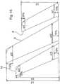
- Figure 16is a fictious top view onto the three winglets 8, 9, 10, to explain their shape. It is fictious because the dihedral angles and the angles of incidence are zero in figure 16 and the arch shape of the first winglet 8 is unrolled. Figure 16 , thus, shows the respective spanwise length b1, 2, 3. It further shows the chord line lengths cr1, 2, 3, at 10 % of the spanwise length outward of the splitting points (these being at the bottom of figure 16 ) as well as the tip chord line lengths ct1, 2, 3, at 10 % inward of the wing lets' tips.
- the actual valuesare (in the order first, second, third winglet): a root chord length cr of 0.4 m, 0.6 m, 0.4 m; a tip chord length ct of 0.3 m, 0.4 m, 0.25 m; a spanwise length b of 1 m, 1.5 m, 1.2 m.
- Thiscorresponds to a root chord length cr of approximately 25 % of the main wing chord length at its end (as defined), approximately 37 % and approximately 25 %; a tip chord length relative to the root chord length of 75 %, 67 % and 63 %; and a spanwise length relative to the spanwise main wing length (16.4 m) of 6.1 %, 9.2 %, 7.3 %, respectively.
- figure 16shows a rounding of the respective outer forward corner of the winglets' shape.
- This roundingrelates to the region between 90 % and 100 % of the spanwise length wherein the chord line length is continuously reduced from 90 % to 100 % spanwise length by 50 % of the chord line length such that in the top view of figure 23 an arch shape is generated. It is common practice to use roundings at the outer forward corners of wings to avoid turbulences at sharp corner shapes. By the just explained reduction of the chord line length in the outer 10 % of the spanwise length, the qualitative nature of the airfoil can be preserved.
- the airfoil used hereis adapted to the transonic conditions at the main wing of the A320 at its typical travel velocity and travel altitude and is named RAE 5214. As just explained this airfoil is still valid in the outer 10 % of the spanwise length of the winglets.
- this trailing edge (opposite to the leading edge) of the wingletscan be made blunt for manufacturing and stability reasons by cutting it at 98 % of the respective chord line length for all winglets.
- the transformation of the shapes shown in figure 16 to the actual 3D geometryis as follows: first, the sweepback angle is introduced which are already shown in figure 16 . Second, the bending of the first winglet along for example the inner third of its spanwise length is introduced, if any. Then, the winglets are inclined by a rotation by the angle of incidence gamma. Then, the dihedral angles are adjusted, namely by inclining the first winglet by for example 50° upwardly (minus an angle considering the bending, if any), the second winglet by 10° downwardly and the third winglet by 30° upwardly.
- the jig shapecan vary although the in-flight shape might not change. It is, naturally, the in-flight shape that is responsible for the aerodynamic performance and the economic advantages of the invention.
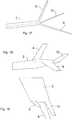
- figure 17 to 19show the 3D shape of the three winglets, namely a front view of the main wing end and the winglets in figure 17 (x-direction), a side view (in y-direction) in figure 18 , and finally a top view (against z-direction) in figure 19 .
- a typical travel velocity of 0.78 mach and a typical travel altitude of 35,000 feethas been chosen which means an air density of 0.380 kg/m 3 (comparison: 1.125 kg/m 3 on ground), a static pressure of 23.842 Pa, a static temperature of 218.8 K and a true air speed (TAS) of 450 kts which is 231.5 m/s.
- the velocity chosen hereis reason to a compressible simulation model in contrast to the more simple incompressible simulation models appropriate for lower velocities and thus in particular for smaller passenger airplanes.
- Table Ilists such various CFD simulations, represented by the symbols V0281, V0419 etc. (first column).
- the already-mentioned values of a root chord length and a tip chord length of the wingletsare fixed as well as a respective sweep-back angle epsilon of 27,5°.
- the overall airplane massis 70 t.
- the first linerepresents V0281 with gamma values of -10° for the first winglet, -5° for the second winglet and -3° for the third winglet.
- the dihedral anglesare much more different from each other, namely -60° for the first winglet, 20° for the second winglet and -20° for the third winglet.
- the relative dihedral angle between the first and the second wingletis 80° and between the second and the third winglet it is 40°.
- the tablelists, right of the winglet parameters, the simulation results, namely the X directed force of an outward section of the main wing (drag) in Newton (N) as all other forces.
- the following Z directed forceis the respective lift of this outward section.
- the outward sectionis defined starting from a borderline approximately 4.3 m inward of the main wing tip and used in these simulations because this outward section shows a clear influence of the winglets whereas the inward section and the base body of the airplane do not.
- the following six columnsshow the drag and the lift (X directed and Z directed force) of the three winglets (wing tip 1, 2, 3), from the most upstream to the most downstream one. Thereafter, the lift/drag ratio of the wing including the outward and the inward section as well as the winglets is shown and, still further, the thrust contribution (delta of drag) of all three winglets together, the respective relative improvement, namely relative to the complete airplane A320 without the invention but including the so-called fence, an already-explained outermost part of the conventional A320 main wing. Finally, the relative improvement under additional consideration of a lift contribution of the winglets is shown. Here, since the weight and thus the necessary lift of the complete airplane is fixed, the inclination of the airplane can be adapted due to the lift contribution so that a further reduction of drag can be achieved which somewhat increases the relative improvement compared to the second from right column in the table.
- table Icomprises various modifications of the first basic simulation V0281.
- the angles gamma and delta of the three wingletshave been varied stepwise starting with a reduction of gamma of the upstream first winglet by -2° and an increase by +2°, a decrease of delta of the first winglet by -10° and then an increase of +10° and then the same for the second and the third winglet.
- V0281 to V0419 and V0420shows a variation of gamma of the first winglet by +/- 2° leading to a substantial decrease of the improvement to 1.51 % and a small further improvement to 1.85 % (for a gamma of -8°).
- variations of gamma of the second and third wingletdo not lead to further improvements, though (compare V0423, V0424, V0427, and V0428).
- the individual optimization of gammais depending on the individual aerodynamic shape of the main wing and cannot be generalized. Within the borders defined in the claims, it is, however, not a too difficult task and even non-optimized gamma-values provide for substantial improvements as can be seen in table I.
- V0421 and V0422relate to a variation of delta of the first winglet, a decrease thereof leading to a moderate deterioration of the improvement, and an increase (to -50°) to a moderate further improvement. This indicates, that for very large relative dihedral angles of for example 90° between the first and the second winglet for V0421, a smaller improvement can be expected. On the other hand, still quite substantial relative dihedral angles of 80° (V0281) or 70° (V0422) lead to better results.
- a reduction of the relative dihedral angle between the first and the second winglet by a reduction of the absolute dihedral angle of the second winglet with V0425gives a remarkably good result of 1.94 % and, to the contrary, a further increase thereof leads to a substantial reduction of the improvement to 1.43 %.
- a reduction of the absolute dihedral angle delta of the third winglet compared to V0281 stepwise by 10, 20 and 30° in V0429 - V0431does lead to some deterioration from 1.78 % to 1.76%, 1.67 %, and 1.68 %, but still remains within comparatively good values.
- the relative dihedral angle between the second and the third wingletis smaller than 80° in each case.
- V0435an example with a relative dihedral angle of 60° between the first and the second winglet and of 50° between the second and the third winglet is shown, which again is comparatively very good (1.95 %).
- V0446which can be compared to V0420 (third line) with regard to a variation of delta of the first winglet and shows a further improvement compared to an already good example (from 1.85 % to 1.95 %). It can also be compared to V0422 (fifth line) with regard to a variation of gamma and thereby shows that, starting therefrom, a similar optimization is due to a variation of gamma.
- the next step to V0447increases delta of the second winglet and thus increases the relative dihedral angle to both, the first and the third winglet which leads to a moderate loss of the achieved improvement (from 1.95 % to 1.86 %). This can be compensated by a substantial increase of the absolute dihedral angle of the third winglet as shown by V0448.
- the relative dihedral anglescan be comparatively large still achieving very good results but should not be outside of the claimed region to avoid unnecessary losses of improvement. Further, compared to an earlier and not prepublished application of the same applicant concentrating on relative dihedral angles between 5° and 35°, the improvements achieved by the present invention are smaller but still substantial.
Landscapes
- Engineering & Computer Science (AREA)
- Aviation & Aerospace Engineering (AREA)
- Structures Of Non-Positive Displacement Pumps (AREA)
- Toys (AREA)
Description
- The present invention relates to an airplane and a wing for an airplane.
- Airplanes are one of the most important transportation apparatus both for persons and for goods as well as for military applications, and they are almost without alternative for most long-distance travels. The present invention is related to airplanes in a sense that does not include helicopters, and it relates to a wing for an airplane in a sense that does not include rotor blades for helicopters. In particular, the invention relates to airplanes having fixed wings and to such fixed wings themselves.
- The basic function of a motorized airplane and its wings is to produce a certain velocity by means of a propulsion engine and to produce a required lift by means of wings of the airplane in the airflow resulting from the velocity. This function is the subject of the aerodynamic design of the wings of the airplane, for example with regard to their size, profile etc..
- It is generally known to use so-called wing tip devices or winglets at the outer ends of the main wings of airplanes, i.e. of those wings mainly or exclusively responsible for the lift. These winglets are meant to reduce so-called wing tip vortices which result from a pressure difference between a region above and a region below the wing, said pressure difference being the cause of the intended lift. Since there is some end of the wing, the airflow tends to compensate the pressure difference which results in a vortex. This wing tip vortex reduces the lifting effect of the wing, increases the noise produced, increases energy loss due to dissipation in the airflow, and can be detrimental for other aircrafts closely following the airplane. The winglets mentioned are so to speak a baffle against the wing tip vortex.
- As regards prior art, reference is made to
US 2009/0039204 A1 disclosing an airplane having main wings with two respective winglets at their outer ends, each. So called cant angles (dihedral angles) of these winglets relative to a horizontal plane are said to have less than 45° and preferably less than about 20°, each, wherein one of the respective two winglets is inclined to be below this horizontal plane and the other one is inclined to be above. - Further,
US 6,345,790 B1 proposes four respective winglets on the outer ends of the main wings of an airplane, each winglet being articulated to be rotatable around an axis parallel to the flight direction. For a cruise flight shape of the winglets, the document mentions relative pivot angles (dihedral angles) between the winglets adding up to 20° to 40° for all four winglets. For take-off and landing of the aircraft, the respective winglets are spread-out or fanned-out relatively widely apart from each other, e.g. spanning an angular range of 90° to 100°. US 9,469,391 B1 EP 2 998 218 A1 discloses an airplane having main wings with two respective winglets at their outer ends. These winglets have quite specific curved shapes and overlap each other at their respective roots.- The problem of the present invention is to provide an improved wing having a winglet and an improved respective airplane.
- In order to solve this problem, the invention is directed to a wing for an airplane according to
claim 1, - and to an airplane having two such wings mutually opposed , according to claim as well as to a use of
- an upgrade part comprising three winglets, according to
claim 13, for mounting to a wing in order to produce such a wing or airplane. - The invention relates to a wing having at least three winglets wherein these winglets are fixed to an outer wing end of the wing. To avoid misunderstandings, the "wing" can be the main wing of the airplane which is (mainly) responsible for the required lift; it can, however, also be the horizontal stabilizer wing which is normally approximately horizontal as well. Further, the term "wing" shall relate to the wing as such as originating at the airplane's base body and extending therefrom outwardly. At an outer wing end of this wing, the at least three winglets are fixed and extend further, but not in the same direction. As principally already known in the prior art, a winglet can be inclined relative to the wing and/or bent. Preferably, the winglets do not extend inwardly from the outer wing end, however. The inventors have found that a mutual inclination of the first two winglets as seen against the flight direction, leads to advantageous results in a quantitative assessment by computer fluid dynamics calculations. In particular, it has proven to be advantageous to substantially incline the upstream first winglet relative to the second winglet. Therein, the difference in inclination, the difference in the so called dihedral angle (relative dihedral angle) should be substantial, namely not less than 37°. On the other hand, a certain maximum relative dihedral angle should be observed and the dihedral angle should thus not be larger than 80°. More preferred lower limits of the relative dihedral angle interval are (in the following order) 38°, 39°, 40°, 42°, 44°, 46°, and 48°, wherein more preferred upper limits are 78°, 76°, 74°, 72°, 70°, 68°, 66°, 64°, and 62°.
- The results of the inventors show that this relative dihedral angle is more important than the absolute dihedral angels of both winglets which might be due to the fact that the air flow geometry has a certain degree of rotational symmetry about an axis parallel to the flight direction at the end of the main wing and thus at the root of the winglets. This is, naturally, only an approximative statement but nevertheless, the relative dihedral angle is regarded to be more important than the absolute one.
- The relative dihedral angle is defined herein in an average sense, namely by means of an isosceles triangle between vertices. One vertex shall be on the root and one respective vertex on each winglet. More precisely, the triangle is defined in a projection against the flight direction and the vertex on the root shall be, as regards the horizontal dimension, at a splitting point of both winglets, i. e. where both winglets are separated in the horizontal dimension as seen vertically. As regards the vertical dimension, the root vertex shall be in the middle of the positions of the leading edges (the most upstream edges) of both winglets at the just mentioned horizontal location or, if they coincide there, at that position. Since this region is subject to smooth transition shapes in order to avoid aerodynamic disturbance, the leading edge so to say loses its identity in this transition region (the so called fairing between the winglets and the main wing end). Therefore, the leading edges shall be extrapolated in the following manner: an inner portion of 10 % of the spanwise length of the winglet (defined in more detail in the following) is disregarded and an outer portion between 90 % and 100 % is disregarded as well for other reasons (namely possible roundings as explained in the embodiment). The remaining 10 % - 90 % represent a proper leading edge which can be extrapolated. Should the leading edge not be straight, an average line can be used for extrapolation.
- The vertices on the winglets themselves shall be on their leading edges, respectively. Consequently, the opening angle of this triangle, namely the angle between the two equal sides, is the relative dihedral angle.
- The triangle definition includes a variable length of the equal sides within the limits imposed by the shorter one of both winglets. In terms of this variable side length concept, the defined relative dihedral angle intervals shall be valid for at least 70 % of the side length, more preferably for at least 75 %, 80 %, 85 %, or even 90 % of the side length. In other words: If a minor portion of the winglets does not obey to the relative dihedral angle interval, this is not too detrimental for the invention, whereas, of course, 100 % within the interval are the best case.
- The variable side length concept takes into account that the winglets need not be straight (in the perspective against the flight direction) but can also be completely or partially bent, e. g. along a circular portion as shown for the first winglet in the embodiment. The winglets could also be polygonal (with limited angles) or shaped otherwise so that the relative dihedral angle varies along their spanwise length. Further, even with straight winglets (as seen against the flight direction), their leading edge lines need not necessarily meet at the root vertex as defined above which could lead to slight variations of the relative dihedral angle along their length. However, with straight winglets, the relative dihedral angle as defined by the triangle concept is at least approximately just the angle visible against the flight direction.
- The above and all following descriptions of the geometric shape of the wing and the winglets relate to what the expert understands as an "in-flight" shape. In other words, these explanations and definitions relate to the flight conditions in which the aerodynamic performance is actually meant to be and is relevant, which basically is the typical travel velocity (on distance) at the typical travel altitude. The expert is familiar with that there is another "jig shape" which is meant to be the shape of the wing and the winglets in a non-flying condition, i. e. without any aerodynamic forces acting thereon. Any difference between the jig shape and the in-flight shape is due to the elastic deformation of the wing and the winglets under the aerodynamic forces acting thereupon. The precise nature of these elastic deformations depends on the static mechanical properties of the wing's and winglets' construction which can be different from case to case. This is also a familiar concept to the mechanical engineer and it is straightforward to calculate and predict such deformations for example by finite element calculations with standard computer simulation programs.
- A reference to the jig shape in this description would thus not make much sense because the aerodynamic performance is the relevant category. Further, the mechanical structure of a wing and a winglet according to the invention may vary from case to case so that any assumptions about how the jig shape transforms into the in-flight shape would be speculative.
- Further, the terms "horizontal" and "vertical" relate to a mounted state of the wing at an airplane, wherein "vertical" is the direction of gravity and "horizontal" is perpendicular thereto.
- The inclinations of the winglets relative to each other as explained above have proven to be advantageous in terms of a trade-off between two aspects. On the one hand, a relative dihedral angle of zero or a very small quantity leads to that a downstream winglet, here the second winglet, is subject to an airstream not only influenced by the upstream (here first) winglet, but also to a turbulent or even diffuse airflow in the wake of the upstream winglet, inhibiting a proper and pronounced aerodynamic performance such as the production of a lift and/or thrust contribution as discussed below. In contrast, a downstream winglet might produce too much drag compared to what it is actually intended for, this being lift, thrust, vortex cancellation or whatever.
- On the other hand, substantial relative dihedral angles "decouple" the winglets from each other only in a limited sense and the invention intends to use a synergetic effect of the at least two winglets in that moderately coupled sense. In particular, the invention preferably aims at conditioning the airflow by the upstream winglet for the downstream winglet. In particular, one aspect of the invention is to use the inclined airflow in the region of the tip vortex of the wing in a positive sense. A further thought is to produce an aerodynamic "lift" in this inclined airflow having a positive thrust component, i.e. a forwardly directed component parallel to the flight direction of the airplane. Herein, it should be clear that the "lift" relates to the aerodynamic wing function of the winglet. It is, however, not necessarily important to maximize or even create a lifting force in an upwardly directed sense, here, but the forward thrust component is in the centre of interest.
- In this respect, the inventors found it advantageous to "broaden" the inclined airflow in order to make an improved use thereof. This makes sense because a wingtip vortex is quite concentrated so that substantial angles of inclination of the airflow direction (relative to the flight direction) can be found only quite near to the wingtip. Therefore, the invention provides for at least 2. three winglets, one upstream winglet being intended for "broadening" the region of inclined airflow and a downstream winglet being intended for producing a thrust component therefrom, according to a preferred aspect.
- The upstream winglet is thus intended for "splitting" the wingtip vortex of the wing by "shifting" a part thereof to the winglet tip, i.e. outwardly. Consequently, a superposition of the winglet-induced tip vortex (winglet tip vortex) and the vortex of the "rest of" the wing (said wing being deeper in the direction of flight than the winglet) results.
- In this sense, the above relative dihedral angle interval is advantageous.
- Preferably, the winglets as represented by their respective chord line (the line between the leading edge and the most downstream point of the airfoil) shall also be inclined in a certain manner as regards a rotation around a horizontal axis perpendicular (instead of parallel) to the flight direction. The rotation angle is named angle of incidence and shall be positive in case of a clockwise rotation of the winglet as seen from the airplane's left side and vice versa from its right side. In this sense, an angle of incidence interval for the first winglet from -15° to -5° is preferred, more preferably in combination with an angle of incidence interval for the second winglet from -10° to 0°. These intervals relate to the root of the winglets and the angle of incidence interval is defined in a variable sense in linear dependence of the position along the spanwise length of the winglet. It shall be shifted from the root to the tip of the respective winglet by +2° which leads to an interval from -13° to -3° for the first winglet and from -8° to +2° for the second winglet at their respective tip. This does not necessarily imply that the actual angle of incidence of a certain implementation must be "twisted" which means show a varying angle of incidence in this sense. An actual implementation can also be within the intervals defined without any twisting. However, since the inventors take into regard the variation of the airflow in dependence of the distance from the root of the winglets, a moderate dependence of the interval definition in this sense is appropriate (in other words: the centre of the interval and the borders thereof are "twisted").
- The angle of incidence is defined as above between the respective winglet's chord line and a chord line of the wing as such (the main wing). This latter chord line is referred to near to that position (in horizontal direction perpendicular to the flight direction) where the wing is split into the winglets, in other words where the winglets separate when going more outwardly. Since at the splitting position, also the main wing can already be deformed somewhat (in terms of a fairing) in order to provide for a smooth transition to the winglets, the chord line shall be referred to a little bit more inward, namely 10 % of the main wing spanwise length more inward. The same applies vice versa to the winglet so that the chord line is referred to 10 % more outward of the splitting position.
- More preferred lower limits of the incidence angle interval for the first winglet at its root are -14°, -13°, -12°, and -11 °, and at its tip +2° additional to these values, whereas more preferred upper limits at the root of the first winglet are -6°, -7°, -8°, -9° and, again, +2° more at the tip. Analogously, more preferred lower limits for the second winglet at the root are -9°, -8°, -7°, -6°, and more preferred upper limits are -1°, -2°, -3°, -4°, and again +2° more at the tip, respectively.
- Again, the angle intervals defined shall be valid for at least 70 %, more preferably at least 75 %, 80 %, 85 %, and even 90 %, of the spanwise length of the respective winglet. In other words: minor portions of the winglets not obeying to these criteria are not of essence.
- As regards the angle of incidence of the first winglet, it is favourable to use the interval defined in order to minimize the drag thereof and to produce not too much downwash of the airstream downstream of the first winglet. The first winglet shall broaden the vortex and the function of the second winglet is based on the inclination of the airflow due to the already described and broadened vortex. The interval given for the second winglet has proven to be advantageous in terms of an optimized thrust contribution. In many cases, the actual angle of incidence of the first winglet will be smaller than that of the second winglet as can also be seen from the intervals given, because the airstream downstream of the first winglet has already been changed thereby. In many cases, the actual angle of incidence of the first winglet and the second winglet within the intervals given can be optimized to a much finer degree for an individual situation thus maximizing the effects of the invention. In any case, the intervals defined and, in most cases, a somewhat smaller angle of incidence of the first winglet compared to the second winglet are general results of the computer fluid dynamics simulations performed.
- Moreover, the invention also comprises a third winglet downstream of the second winglet, and preferably, the invention is limited to these three winglets (per wing).
- More preferably, the third winglet obeys to a relative dihedral angle interval relative to the second winglet as well, namely from 37° to 80° with the same more preferred lower and upper limits as for the relative dihedral angle between the first and the second winglet (but disclosed independently thereof). This dihedral angle difference is to be understood in the second winglet being inclined relative to the third winglet. The definition of the relative dihedral angle is analogous to what has been explained above but, naturally, relates to a second and a third winglet, here.
- As already explained with regard to the relation between the first and the second winglets and their relative dihedral angle, also here, in the retrospective relation between the second and the third winglets, it is unfavourable to position the third winglet directly "behind" the upstream second winglet, but it is more favourable to decouple them in an aerodynamic sense to a certain extent. Thus, by means of a relative dihedral angle in the interval given, the third winglet will again be in the position to produce a synergetic effect downstream of the first and the second winglets, and in particular, as preferred in this invention, to produce a thrust contribution once more.
- Preferably, the third winglet also is subject to a limitation of the angle of incidence in an analogous manner as explained above for the first and for the second winglet including the explanations as regards a definition of the chord line. Here, for the third winglet, the intervals shall be from -7° to +3° at the root and, again, +2° more at the tip and the linear interpolation therebetween of the interval. More preferred lower limits for the interval of the incidence angle for the third winglet are -6°, -5°, - 4°, -3°, and more preferred upper limits are +2°, +1°, 0°, -1°, at the root and +2° more at the tip. Again, the intervals for the relative dihedral angle and the angle of incidence shall be valid for preferably at least 70 % of the shorter one of the second and third winglet and for the spanwise length of the third winglet, respectively. Again, more preferred limits are at least 75 %, 80 %, 85 %, 90 %.
- The function of the above choice of the angle of incidence of the third winglet is similar to that one of the second winglet, namely that the third winglet is intended to produce a thrust contribution in the airstream already changed somewhat by the upstream two winglets together with a minimized drag of the complete system.
- In a further preferred implementation, a so called sweepback angle of the three winglets is in an interval from -5° to 35°, respectively, relative to the sweepback angle of the main wing (a positive value meaning "backwards"). In other words, the winglets can be inclined in an arrow-like manner backwardly, as airplane wings usually are, preferably at least as much as the main wing or even stronger. Therein, the sweepback angle need not be the same for all three winglets. More preferred lower limits are -4°, -3°, -2°, -1°, whereas more preferred upper limits are 30°, 25°, 20°, 15°. As just noted, the sweepback angle is related to the inclination of the leading edge of the respective winglet compared to a horizontal line perpendicular to the flight direction. This can be defined in a fictious horizontal position of a winglet (the dihedral angle and the angle of incidence being zero and in an unrolled condition of any bending). Alternatively, the sweepback angle can be defined by replacing the actual extension of the winglet in the horizontal direction perpendicular to the flight direction (as seen vertically) by the spanwise length b thereof defined somewhere else in this application.
- Should the leading edge not be linear, the sweepback angle relates to an average line with regard to the non-linear leading edge in the range from 20 % to 80 % of the respective span of the winglets. This limited span range takes into account that the leading edge might be deformed by rounded corners (such as in the embodiment) at the outward end and by transitions at the so called fairing at their inner end. Since the sweepback angle is very sensitive to such effects, 20 % instead of 10 % are "cut off" at the borders.
- As regards the reference, the leading edge of the main wing, the range from 50 % to 90 % of its span and an average line in this range shall be taken into account. This is because the spanwise position of 0 % relates, as usual, to the middle of the base body and thus is not in the main wing itself, and there is a so called belly fairing at the transition from the base body to the main wing which is not only configured to be a proper airfoil but is more a transition to the airfoil. Still further, an adaption of a sweepback angle of the winglets to the outer portion of the main wings is appropriate anyway.
- The simulations done have shown that the results can be optimized by a somewhat enhanced sweepback angle of the winglets but that this angle should not be exaggerated. Since the sweepback angle has a connection to the usual speed range of the aircraft, it is a pragmatic and technically meaningful reference to start from the sweepback angle of the main wing.
- The above explanations with regard to the relative dihedral angle are intentionally open with regard to their "polarity", in other words to whether a downstream winglet is inclined upwardly or downwardly with regard to an upstream winglet. In fact, the inventors have found that the aerodynamic performance is rather insensitive in this respect. However, it is preferred that none of the winglets is inclined too much downwardly in view of ground clearance. Since the relative dihedral angles are substantial in this invention, it is thus preferred that either the first and the third winglet are inclined more downwardly than the second one or vice versa so that the relative dihedral angle between the first and the second winglet and that one between the second and the third winglet preferably have opposite polarities.
- Although it has been explained above that the relative dihedral angle between the first and the second winglet and also that between the second and the third winglet is more important than the absolute values of the respective dihedral angles of the winglets, they are also preferred choices for the latter. For the more upwardly inclined winglet(s) (compare above), the respective dihedral angle interval is from 0° to -90° (a negative value meaning upward inclination), more preferred lower limits being -85°, -80°, -75°, -70°, and -65°, whereas more preferred upper limits are -5°, -10°, -15°, -20°, -25° and -30°.
- For the more downwardly inclined winglet(s), the preferred interval is from -40° to +30°. More preferred lower limits are -35°, -30°, -25°, and -20°, whereas more preferred upper limits are 25°, 20°, and 15°. Again, these angle intervals shall be valid for at least 70 %, preferably at least 75 %, 80 %, 85 %, or even 90 % of the respective spanwise length of the winglet.
- For the sake of clarity: The limitations of the relative dihedral angle explained above apply in this context and are dominant, thus. Further, the absolute dihedral angle is defined in a similar manner as the relative dihedral angle, the difference being that one of the equal sides of the isosceles triangle is horizontal instead of on the leading edge of one of the winglets.
- It has already been mentioned that too low absolute values of the dihedral angle such as below -90°, and thus winglets oriented somewhat inwardly can be disadvantageous. First, it is more difficult to provide for a proper and smooth transition (fairing) between the main wing's outer end and the winglet. Further, the numerical simulations have not shown any advantage for such very low dihedral angles. On the other hand, very large values, i. e. winglets directed strongly downwardly can have the detrimental effect of reducing the ground clearance.
- As regards the respective length and spanwise direction of the winglets, certain proportions to the spanwise length of the (main) wing are preferred, namely from 2.5 % to 10 % for the first winglet, from 4 % to 14 % for the second winglet and from 3 % to 11 % for the third winglet. Respective preferred lower limits for the first winglet are 2.5 %, 3.0 %, 3.5 %, 4.0 %, 4.5 %, 5.0 %. Preferred upper limits for the first winglet are 9.5 %, 9.0 %, 8.5 %, 8.0 %, 7.5 %, 7.0 %. For the second winglet, the more preferred lower limits are 5.0 %, 6.0 %, 6.5 %, 7.0 %, 7.5 %, 8.0 %, and more preferred upper limits for the second winglet are 13 %, 12 %, 11.5 %, 11.0 %, 10.5 %, 10.0 %. Finally, the more preferred lower limits for the third winglet are 3.5 %, 4.0 %, 4.5 %, 5.0 %, 5.5 %, 6.0 %, and more preferred upper limits are 10.5 %, 10.0 %, 9.5 %, 9.0 %, 8.5 %, and 8.0 %.
- The spanwise length is herein defined as the distance from the root of the winglets, namely at the separation of the winglet from the neighbouring winglets (in case of the second winglet between the first and the third winglet, the innermost separation) to their outward end in a direction perpendicular to the flight direction and under the assumption of an angle of incidence and a dihedral angle of zero, i. e. with the winglet in a horizontal position. In case of an non-linear shape of the winglet, such as a curved part as with the first winglet in the embodiment, the spanwise length relates to a fictious straight shape (an "unrolled" condition) since such a bending is an alternative to a dihedral inclination. More precisely, it relates to a projection plane perpendicular to the flight direction and, therein, to the length of the wing in terms of a middle line between the upper and the lower limitation line of the projected winglet. For the main wing, the same definition holds but starting in the middle of the base body (in the sense of a half span). The length of the main wing is measured up to the separation into the winglets; it is not the length of the complete wing including the winglets.
- As regards the above relative length intervals for the winglets, these sizes have proven to be practical and effective in terms of the typical dimensions of the tip vortex of the main wing which is of essence for the function of the winglets. Too small (too short) winglets do not take advantage of the full opportunities whereas too large winglets reach into regions with their respective winglet tips where the main wing's tip vortex is already too weak so that the inclined airflow cannot be taken advantage from for the full length of the winglets (in particular the second and third) and the broadening effect discussed above, as a particularly preferred concept of the invention, will possibly more produce two separated than two superposed vortex fields.
- Further, according to the invention, the second winglet has a length from 105% to 180% of the first winglet. Likewise, the third winglet length is from 60% to 100% of the second winglet. Therein, more preferred lower limits for the first interval are 110 %, 115%, 120 %, 125 %, 130 %, 135 %, and 140%, whereas more preferred upper limits are 175 %, 170 %, 165 %, and 160 %. More preferred lower limits for the second interval are 65 %, 70 %, 75 %, whereas more preferred upper limits are 95 % and 90 %.
- In a more general sense, the second winglet is at least as long (spanwise) as the third winglet, preferably longer, and the third (and thus also second) winglet is longer than the first winglet. This is basically due to the fact that the second winglet should take full advantage of the broadened inclined airstream region as broadened by the first winglet in order to produce a maximum effect, and the third winglet shall, again, produce an analogous or similar effect, but will not be able to do so since energy has already been taken out of the airstream. Thus, it should be limited in size in order not to produce too much drag.
- Still further, the aspect ratio of the winglets is preferably in the interval from 4 to 9 wherein preferred lower limits are 4.5 and 5.0 and more preferred upper limits are 8.5, 8.0, and 7.5. This relates, again, to each winglet individually.
- Although higher aspect ratios are more efficient in an aerodynamic sense, they have a smaller area and thus, produce smaller forces (and thus a small thrust). In other words, within the already-described length limitation, a substantial winglet area is preferred. On the other hand, a too low aspect ratio increases the drag and decreases the efficiency in an amount that finally reduces the effective thrust by means of an increased drag. All in all, the CFD simulations repeatedly showed optimum values around 5.
- The aspect ratio is defined as the double spanwise length of a wing (i. e. the full span of the airplane in case of a main wing), and likewise the double spanwise length of a winglet, divided by the chord line length, namely as an average value. To be precise, the definition in this application to cut-off the outer 10% of the spanwise length when assessing the chord line length, is valid also here to exclude an influence of a fairing structure and/or roundings of a winglet.
- Preferred implementations of the invention can have certain root chord lengths for the winglets. In the preferred case of exactly three winglets, a preferred interval is from 15 % to 35 % of the chord length of the main wing next to the splitting, and from 25 % to 45 % for the second winglet, and from 15 % to 35 % for the third winglet. More preferred lower limits for the first winglet are 17 %, 19 %, 21 %, for the
second winglet 27 %, 29 %, 31 %, and for thethird winglet 17 %, 19 %, 21 %. More preferred upper limits for the first winglet are 33 %, 31 %, 29 %, for the second winglet 43 %, 41 %, 39 %, and for the third winglet 33 %, 31 %, 29 %. The respective tip chord length of the winglets is preferably in an interval from 40 % to 100 % of the respective root chord length, wherein more preferred lower limits are 45 %, 50 %, 55 %, 60 %, and the more preferred upper limits are 95 %, 90 %, 85 %, 80 %. Generally, these chord lengths take into account the available overall length, the advantageous size distribution between the winglets and the desired aspect ratio thereof. - Still further, it is clear to the expert that some fairing (as the so called belly fairing at the transition between the base body and the main wing) is used in the transition region between the main wing's end and the winglets' roots. Therefore, also the chord length at the end of the main wing is referred to at a
distance 10 % inward from the splitting into the winglets (relative to the length in terms of the half span of the main wing) to be clearly out of this transition. In the same manner, the root chord length of the winglets is referred to at aposition 10 % outward of the separation into the winglets to be well within the proper airfoil shape of the winglets. The same applies to the position of the chord line in relation to for example the angle of attack. - Still further, in some wings and winglets, the outer front corner is "rounded" as in the embodiment to be explained hereunder. This rounding can be done by a substantial reduction of the chord length in the outermost portion of the winglet but is not regarded to be a part of the above-mentioned feature of the relative chord length at a winglet tip in relation to a winglet root. Therefore, the chord length of the winglet at 10 % of the winglet's length inward of its tip is referred to, here.
- As already mentioned, the invention is preferably used for two wings of the same airplane mutually opposed. In particular, the respective two wings and the winglets according to the invention on both sides can be antisymmetrical with regard to a vertical centre plane in the base body of the airplane. In this sense, the invention also relates to the complete airplane.
- A preferred category of airplanes are so called transport category airplanes which have a certain size and are meant for transportation of substantial numbers of persons or even goods over substantial distances. Here, the economic advantages of the invention are most desirable. This relates to subsonic airplanes but also to transonic airplanes where supersonic conditions occur locally, in particular above the main wings and possibly also above the winglets. It also relates to supersonic airplanes having a long distance travel velocity in the supersonic region.
- Further, the invention is also contemplated in view of upgrade parts for upgrading existing airplanes. For economic reasons, it can be preferred to add such an upgrade part including at least three winglets at a conventional wing (or two opposed wings) rather than to change complete wings or winglets. This is particularly reasonable because the main advantage of the invention cannot be to increase the lift force of the wings which could exceed limitations of the existing mechanical structure. Rather, the invention preferably aims at a substantial thrust contribution to improve efficiency and/or speed. Consequently, the
invention 2. as defined inclaim 13, also relates to a use of such an upgrade part for upgrading an airplane or a wing in terms of the invention. - In both cases, with regard to the complete airplane and with regard to the upgrade of existing airplanes, a first simulated choice for the airplane has been the Airbus model A320. Therein, an outward part of the conventional wings, a so called fence, can be demounted and replaced by a structure according to the invention having three winglets.
- The invention will hereunder be explained in further details referring to exemplary embodiments below which are not intended to limit the scope of the claims but meant for illustrative purposes only.
- Figure 1
- shows a plan view of an airplane according to the invention including six winglets schematically drawn;
- Figure 2
- is a schematic diagram for explaining the creation of a thrust by a winglet;
- Figure 3a, b
- are schematic illustrations of the air velocity distribution in a tip vortex;
- Figure 4
- is a schematic perspective view of a wing not forming part of the claimed invention, but which may be useful for understanding aspects thereof;
- Figure 5
- is a schematic front view of a wing tip and two winglets;
- Figure 6
- is a diagram showing two graphs of an inclination angle dependency on distance relating to
figure 5 ; - Figure 7
- is a schematic side view to explain the gamma angles of winglets;
- Figure 8
- is a front view of the same winglets to explain the delta angles;
- Figure 9
- is a plan view of an Airbus A320 main wing;
- Figure 10
- is a front view of said wing;
- Figure 11
- is a side view of said wing;
- Figure 12
- is another front view of two winglets for explaining a relative dihedral angle;
- Figure 13
- is a schematic drawing for explaining a bending of a first winglet;
- Figure 14
- is a side view of sections of a main wing and three winglets for explaining angles of inclination;
- Figure 15
- combines a front view and a top view for explaining a sweepback angle of a winglet;
- Figure 16
- is a top view onto three winglets in a plane for explaining the shape;
- Figure 17
- is a front view thereof;
- Figure 18
- is a side view of the three winglets of
figure 17 ; and - Figure 19
- is a top view onto three winglets at a main wing tip of said airplane.
Figure 1 is a plan view of anairplane 1 having twomain wings horizontal stabilizers vertical tail 6 and a fuselage orbase body 7.Figure 1 shall represent an Airbus model A320 having four propulsion engines, not shown here. However, infigure 1 , themain wings winglets main wings base body 7 are mirror symmetric with regard to a vertical plane (perpendicular to the plane of drawing) through the longitudinal axis of the base body.- Further, an x-axis opposite to the flight direction and thus identical with the main airflow direction and a horizontal y-axis perpendicular thereto are shown. The z-axis is perpendicular and directed upwardly.
Figure 2 is a schematic side view of an airfoil or profile (infigure 2 a symmetric standard wing airfoil, in case of the A320 an asymmetric airfoil) of amain wing 2 and an airfoil (for example NACA 2412, a standard asymmetric wing airfoil or RAE 5214, an asymmetric wing airfoil for transonic flight conditions) of an exemplary winglet W which is just for explanation purposes.- A solid horizontal line is the x-axis already mentioned. A chain-dotted
line 13 corresponds to the chord line of the main wing 2 (connecting the front-most point and the end point of the profile), the angle alpha there between being the angle of attack of the main wing. - Further, a
bottom line 14 of the profile of winglet W (which represents schematically one ofwinglets bottom line 14 and the bottom line of the main wing profile is gamma, the so-called angle of incidence. As regards the location of the definition of the chord lines along the respective span of the wing and the winglets reference is made to what has been explained before. Figures 3a andb illustrate a tip vortex as present at any wing tip during flight. The fields of arrows at the right sides symbolize the component of the airflow velocity in the plane of drawing as regards direction and magnitude (arrow length).Figure 3a shows a point of x = 2.5 m (x = 0 corresponding to the front end of the wing tip) andfigure 3b relating to a downstream location of x = 3.4 m. It can be seen that the tip vortex "develops with increasing x" and that the vortex is quite concentrated around the wing tip and quickly vanishes with increasing distance therefrom. This statement relates to almost any direction when starting from the wing tip with no qualitative but also small quantitative differences.- Further,
figures 3a andb illustrate that the wing tip vortex principally adds some upward component to the airflow velocity together with some outward component in the lower region and some inward component in the upper region. With this in mind, it can be understood thatfigure 2 shows a local flow direction having an angle beta to the flight direction x. This local flow direction (components perpendicular to the plane of drawing offigure 2 being ignored) attacks the symbolic winglet W and causes a lift Ln thereof as shown by an arrow. This lift is perpendicular to the flow direction by definition. It can be seen as a superposition of a vertically upward component and a positive thrust component Fxn,L. - Principally the same applies for the drag Dn of the winglet W. There is a negative thrust component of the drag, namely Fxn,D. The thrust contribution of the winglet W as referred to earlier in this description is thus the difference thereof, namely Fxn = Fxn,L - Fxn,D and is positive here. This is intended by the invention, namely a positive effective thrust contribution of a winglet.
Figure 4 shows themain wing 2 and exemplary two winglets offigure 2 , namely 8 and 9, and represents an example not forming part of the claimed invention, but which may be useful for understanding aspects thereof.Wing 2 is somewhat inclined relative to the y-axis by a so called sweepback angle and has a chord line length decreasing with the distance from thebase body 7 from a root chord line length cr to a tip chord line length ct. At a wingouter end 15,winglets figure 5 .Figure 5 shows thewing 2 and thewinglets base body 7 at y = 0 along the span ofmain wing 2 as explained before) and respective lengths b1 and b2 ofwinglets wing 2 andwinglets wing 2 around an axis parallel to the x-axis would not lead to qualitative changes.Figure 6 shows a diagram including two graphs. The vertical axis relates to beta (comparefigure 2 ), namely the angle of inclination of the local airflow direction in a projection on a x-z-plane.- The horizontal line shows "eta", namely the distance from
outer wing end 15 divided by b, the length ofmain wing 2. - A first graph with crosses relates to the condition without
winglets figures 3a andb , qualitatively. The second graph showing circles relates to an airflow distribution downstream offirst winglet 8 and thus upstream of second winglet 9 (the first graph relating to the same x-position). The graphs result from a computer simulation of the airflow distribution (such asfigures 3a andb ). - It can easily be seen that the first graph shows a maximum 16 closely to
outer wing end 15 whereas the second graph has a maximum 17 there, an intermediate minimum at around eta = 1.025 and a further maximum 18 at around eta = 1.055, and decreases outwardly therefrom. Further, the second graph drops to a value of more than 50 % of its smaller (left) maximum and more than 40 % of its larger (right) maximum whereas it drops to a value of still more than 25 % of its larger maximum at about eta = 1.1, e.g. at a distance of about 10 % of b fromouter wing end 15. This angle distribution is a good basis for the already described function ofwinglet 9, comparefigure 2 . - Simulations on the basis of the airplane type Airbus A320 have been made. They will be explained hereunder. So far, the inventors achieve around 2 % reduction of the overall drag of the airplane with three winglets as shown in
figure1 by means of the thrust contribution of the winglets and a small increase of the overall lifting force. The lift increase enables the airplane to fly with a somewhat lower inclination (compare alpha infigure 2 ) which leads to a further reduction of the overall drag. These simulations have been made by the computer programme CFD (computational fluid dynamics) of ANSYS. - As a general basic study, computer simulations for optimization of the thrust contribution of a two winglet set (first and second winglet) with a standard NACA 0012 main wing airfoil and a NACA 2412 winglet airfoil and without any inclination of the winglet relative to the main wing (thus with a setup along
figures 4 and5 ) have shown that anaspect ratio 5 is a good choice. Although higher aspect ratios are more efficient in an aerodynamic sense, they have a smaller area and thus, produce smaller forces (and thus a small thrust). In other words, within the limitation of a length b2 (span) of 1.5 m (for the A320), a substantial winglet area is preferred. On the other hand, a too low aspect ratio increases the drag and decreases the efficiency in an amount that finally reduces the effective thrust by means of an increased drag. All in all, the CFD simulations repeatedly showed optimum values around 5. - On this basis, the length b1 of the upstream
first winglet 8 for the A320 has been chosen to be 2/3, namely 1 m in order to enable the downstreamsecond winglet 9 to take advantage of the main part of the broadened vortex region, compare again the setup offigures 4 and5 and the results infigure 6 . - The mean chord length results from the length of the fingers and from the fixed aspect ratio. As usual for airplane wings, there is a diminution of the chord line length in an outward direction. For the first
upstream winglet 8, the chord line length at the root is 400 mm and at the top is 300 mm, whereas for the downstreamsecond winglet 9 the root chord length is 600 mm and the tip chord length 400 mm. These values have been chosen intuitively and arbitrarily. - For the winglets, instead of the above mentioned (readily available) NACA 2412 of the preliminary simulations, a transonic airfoil RAE 5214 has been chosen which is a standard transonic airfoil and is well adapted to the aerodynamic conditions of the A320 at its typical travel velocity and altitude, compare below. The Airbus A320 is a well-documented and economically important model airplane for the present invention.
- The most influential parameters are the angles of incidence gamma and the dihedral angle delta (namely the inclination with respect to a rotation around an axis parallel to the travel direction). In a first coarse mapping study, the mapping steps were 3° to 5° for gamma and 10° for delta. In this coarse mapping, a first and a second but no third winglet have been included in the simulations in order to have a basis for a study of the third winglet.
Figure 7 illustrates the angle gamma, namelygamma 1 ofwinglet 8, the first winglet, andgamma 2 ofwinglet 9, the second winglet, both shown as airfoils (comparefigure 2 ) and with their chord lines in relation to the main wing airfoil and its chord line.Figure 8 illustrates the angle delta in a perspective as infigure 5 , but not in a quantitative (or to scale) sense. Again,delta 1 is related to thefirst winglet 8 anddelta 2 to thesecond winglet 9. The structures in the left part offigure 8 are transient structures as used for the CFD simulations. These structures do not correspond to the actual A320 main wing to which the winglets, the slim structures in the middle and the right, have to be mounted but they define a pragmatic model to enable the simulation.Figure 9 shows a plan view onto a main wing of the A320, the wing tip is oriented downward and the base body is not shown but would be on top.Figure 9 shows amain wing 20 of the A320 which actually has a so called fence structure, namely a vertical plate, at the end of the wing which has been omitted here, because it is to be substituted by the winglets according to the invention.Figure 10 shows themain wing 20 offigure 9 in a front view, andfigure 11 shows themain wing 20 in a side view (perspective perpendicular to the travel direction - X). The somewhat inclined V geometry of the main wings of the A320 can be seen infigures 10 and 11 .- Taking this opportunity,
figure 12 explains the definition of the relative dihedral angle along the claim language. In the perspective against the flight direction, the first and the second winglet are shown together with two radii r1 and r2 of different size. The meeting point of a vertical and the horizontal line is the root R (at the splitting point horizontally and the meeting of the leading edges vertically) and one vertex of an isosceles triangle shown, the other two vertices of which are on the leading edges of the two winglets and referred as V1 and V2. The angle between the line R-V1 and the line R-V2 is the relative dihedral angle if taken as an average over all radii ri possible within the shorter one of the two winglets, namely the first one. - The visible difference between the line R-V1 from the leading edge of the first winglet is connected to the bending of the first winglet to be explained hereunder.
Figure 13 illustrates the above mentioned bending of the first winglet which is so to say a distribution of a part of the dihedral angle along a certain portion of the spanwise length. Actually, infigure 13 , a leading edge L is schematically shown to start from a root R and to be bent along a circular arch shape B extending over one third (330 mm) of its length with a radius of 750 mm and an arch angle of -15°. Already at the start of R the leading edge of the first winglet has a dihedral angle of for example -20°. This means that outwards of the bending, the dihedral angle for the second and third of the length of the first winglet is actually for example - 35°. In an average along the complete spanwise length of the first winglet from R to its outward end, an average dihedral angle of about for example -30° results, - 15° of which have been "distributed" along the arch as described. - The reason is that in this particular embodiment, a straight leading edge of the first winglet with a dihedral angle of -30° has made it somewhat difficult to provide for a smooth transition of a leading edge to that one of the main wing end (in the so-called fairing region) whereas with -20° dihedral angle, the smooth transition has not caused any problems. Therefore, in order to enable an average value of -30°, the solution of figure 20 has been chosen. For more negative values such as down to -80° dihedral angle, this distribution of the dihedral angle can be even more advantageous.
- In general, it is within the teaching of this invention to use winglet shapes that are not straight along the spanwise direction such as shown in
figure 13 . They could even be arch shaped along the complete length as pointed out before. What is relevant in the view of the inventors, is the relative dihedral angle in an average sense. If for example, a first and a second winglet would both be arch shaped in a similar manner so that the isosceles triangle construction explained earlier with a fixed vertex at the root would be inclined more and more with increasing length of the equal sides thereof due to the curvature of the winglet leading edges, the relative dihedral angle according to this construction might even remain almost constant along the leading edges. Still, at a certain portion along the spanwise length of for example the second winglet, the proximate portion along the spanwise length of the first winglet would be positioned relative to the second winglet in a manner that is well described by the relative dihedral angle (remember the somewhat rotationally symmetrical shape of the vortex at the wing end) and is well described by the triangle construction. - As regards the angles of incidence, reference is made to
figure 14 showing a side view and sections through the threewinglets main wing 2. The sectional planes are different, naturally, namely 10 % outward of the spanwise length of the winglets from the respective splitting positions, and 10 % inward in case of themain wing 2, as explained earlier, to provide for undisturbed chord lines. The chord lines and therespective angles gamma figure 14 . The angles aregamma 1 = -10° for the first winglet,gamma 2 = -5° for the second winglet andgamma 3 = -3° for the third winglet, all being defined relative to the main wing chord line at the described outward position and in the in-flight shape of the winglets and of the main wing (all parameters explained for this embodiment relating to the in-flight shape). Figure 14 also shows the respective rotating points on the chord line ofmain wing 2 as well as on the chord line of therespective winglet main wing 2, the rotating point of the first winglet is at 16.7 % (0 % being the front most point on the chord line), the rotating point of the second winglet is at 54.8 %, and the rotating point of the third winglet is at 88.1 %.Figure 15 illustrates the sweepback angle epsilon of arepresentative winglet 9, namely the angle between the leading edge thereof and a direction (y infigure 15 ) being horizontal and perpendicular to the flight direction. Herein,winglet 9 is thought to be horizontal (delta and gamma being zero in a fictious manner). Alternatively, the spanwise length ofwinglet 9 could be used instead of its actual extension in the y-direction when being projected onto a horizontal plane. Please note that also the arch shape ofwinglet 8 as explained alongfigure 15 would be regarded to be unrolled. In other words, the spanwise length includes the length of the arch. In the present embodiment, the sweepback angle of themain wing 2 is 27.5° and this value has also been chosen for all winglets.Figure 16 is a fictious top view onto the threewinglets figure 16 and the arch shape of thefirst winglet 8 is unrolled.Figure 16 , thus, shows the respective spanwise length b1, 2, 3. It further shows the chord line lengths cr1, 2, 3, at 10 % of the spanwise length outward of the splitting points (these being at the bottom offigure 16 ) as well as the tip chord line lengths ct1, 2, 3, at 10 % inward of the wing lets' tips.- The actual values are (in the order first, second, third winglet): a root chord length cr of 0.4 m, 0.6 m, 0.4 m; a tip chord length ct of 0.3 m, 0.4 m, 0.25 m; a spanwise length b of 1 m, 1.5 m, 1.2 m. This corresponds to a root chord length cr of approximately 25 % of the main wing chord length at its end (as defined), approximately 37 % and approximately 25 %; a tip chord length relative to the root chord length of 75 %, 67 % and 63 %; and a spanwise length relative to the spanwise main wing length (16.4 m) of 6.1 %, 9.2 %, 7.3 %, respectively.
- Please note that the angle of sweepback as shown in
figure 16 is no rotating operation result. This can be seen in that the chord line lengths cr and ct remain unchanged and remain in the x-z-plane, in other words horizontal infigure 16 . This is necessary in order not to disturb the airfoil by the introduction of the sweepback angle. - Still further,
figure 16 shows a rounding of the respective outer forward corner of the winglets' shape. This rounding relates to the region between 90 % and 100 % of the spanwise length wherein the chord line length is continuously reduced from 90 % to 100 % spanwise length by 50 % of the chord line length such that in the top view of figure 23 an arch shape is generated. It is common practice to use roundings at the outer forward corners of wings to avoid turbulences at sharp corner shapes. By the just explained reduction of the chord line length in the outer 10 % of the spanwise length, the qualitative nature of the airfoil can be preserved. - The airfoil used here is adapted to the transonic conditions at the main wing of the A320 at its typical travel velocity and travel altitude and is named RAE 5214. As just explained this airfoil is still valid in the outer 10 % of the spanwise length of the winglets.
- Still further, this trailing edge (opposite to the leading edge) of the winglets can be made blunt for manufacturing and stability reasons by cutting it at 98 % of the respective chord line length for all winglets.
- The transformation of the shapes shown in
figure 16 to the actual 3D geometry is as follows: first, the sweepback angle is introduced which are already shown infigure 16 . Second, the bending of the first winglet along for example the inner third of its spanwise length is introduced, if any. Then, the winglets are inclined by a rotation by the angle of incidence gamma. Then, the dihedral angles are adjusted, namely by inclining the first winglet by for example 50° upwardly (minus an angle considering the bending, if any), the second winglet by 10° downwardly and the third winglet by 30° upwardly. - Please note that the above transformation procedure does not relate to the jig shape and to the geometry as manufactured which is slightly different and depends on the elastic properties of the main wing and the winglets. These elastic properties are subject of the mechanical structure of the wing and the winglets which is not part of the present invention and can be very different from case to case. It is, however, common practice for the mechanical engineer to predict mechanical deformations under aerodynamic loads by for example finite elements calculations. One example for a practical computer program is NASTRAN.
- Thus, depending on the actual implementation, the jig shape can vary although the in-flight shape might not change. It is, naturally, the in-flight shape that is responsible for the aerodynamic performance and the economic advantages of the invention.
- For illustration,
figure 17 to 19 show the 3D shape of the three winglets, namely a front view of the main wing end and the winglets infigure 17 (x-direction), a side view (in y-direction) infigure 18 , and finally a top view (against z-direction) infigure 19 . - On the above basis, further CFD simulations with three winglets and for a A320 have been made. A typical travel velocity of 0.78 mach and a typical travel altitude of 35,000 feet has been chosen which means an air density of 0.380 kg/m3 (comparison: 1.125 kg/m3 on ground), a static pressure of 23.842 Pa, a static temperature of 218.8 K and a true air speed (TAS) of 450 kts which is 231.5 m/s. The velocity chosen here is reason to a compressible simulation model in contrast to the more simple incompressible simulation models appropriate for lower velocities and thus in particular for smaller passenger airplanes. This means that pressure and temperature are variables in the airflow and that local areas with air velocities above 1 Mach appear which is called a transsonic flow. The total weight of the aircraft is about 70 tons. A typical angle of attack alpha is 1.7° for the main wing end in in-flight shape. This value is illustrated in
figure 2 and relates to the angle between the chord line of the main wing at its tip end to the actual flight direction. It has been determined by variation of this angle and calculation of the resultant overall lifting force of the two main wings. When they equal the required 70 to, the mentioned value is approximately correct. - Further, data relating to the drag of the complete airplane for different inclinations thereof were available, so that the impact of an improvement of the overall lift (by a lift contribution of the winglets as well as by an increase of the lift of the main wing due to a limitation of the vortex-induced losses) on the overall drag due to a variation of the inclination of the airplane could be assessed.
- Table I lists such various CFD simulations, represented by the symbols V0281, V0419 etc. (first column). The already-mentioned values of a root chord length and a tip chord length of the winglets are fixed as well as a respective sweep-back angle epsilon of 27,5°. The overall airplane mass is 70 t.
- As a basis for the variations, the first line represents V0281 with gamma values of -10° for the first winglet, -5° for the second winglet and -3° for the third winglet. The dihedral angles are much more different from each other, namely -60° for the first winglet, 20° for the second winglet and -20° for the third winglet. Thus, the relative dihedral angle between the first and the second winglet is 80° and between the second and the third winglet it is 40°. With these parameters, the performance values given in the right part of table I have been calculated.
- In particular, the table lists, right of the winglet parameters, the simulation results, namely the X directed force of an outward section of the main wing (drag) in Newton (N) as all other forces. The following Z directed force is the respective lift of this outward section. The outward section is defined starting from a borderline approximately 4.3 m inward of the main wing tip and used in these simulations because this outward section shows a clear influence of the winglets whereas the inward section and the base body of the airplane do not.
- The following six columns show the drag and the lift (X directed and Z directed force) of the three winglets (
wing tip - Linewise, table I comprises various modifications of the first basic simulation V0281. The angles gamma and delta of the three winglets have been varied stepwise starting with a reduction of gamma of the upstream first winglet by -2° and an increase by +2°, a decrease of delta of the first winglet by -10° and then an increase of +10° and then the same for the second and the third winglet.
- It can be seen that basically all simulations lead to relative improvements both including and excluding the lift contribution between about 1.3 % minimum and up to almost 2 % maximum (lift contribution included), as compared to the same airplane with fence only. This applies to a lower or higher extent depending on the individual choice of gamma and delta.
- The comparison of V0281 to V0419 and V0420 shows a variation of gamma of the first winglet by +/- 2° leading to a substantial decrease of the improvement to 1.51 % and a small further improvement to 1.85 % (for a gamma of -8°). This confirms that an optimization of gamma is effective in achieving maximum results. In the present embodiment, variations of gamma of the second and third winglet do not lead to further improvements, though (compare V0423, V0424, V0427, and V0428). The individual optimization of gamma, however, is depending on the individual aerodynamic shape of the main wing and cannot be generalized. Within the borders defined in the claims, it is, however, not a too difficult task and even non-optimized gamma-values provide for substantial improvements as can be seen in table I.
- V0421 and V0422 relate to a variation of delta of the first winglet, a decrease thereof leading to a moderate deterioration of the improvement, and an increase (to -50°) to a moderate further improvement. This indicates, that for very large relative dihedral angles of for example 90° between the first and the second winglet for V0421, a smaller improvement can be expected. On the other hand, still quite substantial relative dihedral angles of 80° (V0281) or 70° (V0422) lead to better results.
- Analogously, a reduction of the relative dihedral angle between the first and the second winglet by a reduction of the absolute dihedral angle of the second winglet with V0425 gives a remarkably good result of 1.94 % and, to the contrary, a further increase thereof leads to a substantial reduction of the improvement to 1.43 %. Further, a reduction of the absolute dihedral angle delta of the third winglet compared to V0281 stepwise by 10, 20 and 30° in V0429 - V0431 does lead to some deterioration from 1.78 % to 1.76%, 1.67 %, and 1.68 %, but still remains within comparatively good values. Notably, here, the relative dihedral angle between the second and the third winglet is smaller than 80° in each case.
- With V0435, an example with a relative dihedral angle of 60° between the first and the second winglet and of 50° between the second and the third winglet is shown, which again is comparatively very good (1.95 %).
- A further example is V0446 which can be compared to V0420 (third line) with regard to a variation of delta of the first winglet and shows a further improvement compared to an already good example (from 1.85 % to 1.95 %). It can also be compared to V0422 (fifth line) with regard to a variation of gamma and thereby shows that, starting therefrom, a similar optimization is due to a variation of gamma.
- The next step to V0447 increases delta of the second winglet and thus increases the relative dihedral angle to both, the first and the third winglet which leads to a moderate loss of the achieved improvement (from 1.95 % to 1.86 %). This can be compensated by a substantial increase of the absolute dihedral angle of the third winglet as shown by V0448.
- In general, the relative dihedral angles can be comparatively large still achieving very good results but should not be outside of the claimed region to avoid unnecessary losses of improvement. Further, compared to an earlier and not prepublished application of the same applicant concentrating on relative dihedral angles between 5° and 35°, the improvements achieved by the present invention are smaller but still substantial.
- In this comparison, it should be added that the data in table I could be further optimized with some steps not yet included in V0281 and the other listed simulations. This includes an optimization of the sweep-back angle of each winglet in a fine step width, an optimization of the fairing structures possibly together with the above explained bending of the inner part of the first winglet or also other winglets, and some optimizations in the winglet tips (roundings in the outer forward corners to avoid turbulences have not been considered here) and blunt edges of the winglets have not yet been considered neither.
- A consideration of the in-flight shape twisting of the main wing would shift the gamma values of the winglets by about +1°, as can be estimated based on other simulations relating to winglet structures not claimed here. This has been observed in defining the ranges in the claims.
- Thus, the values in table I could be improved somewhat by further optimization steps. However, already in this early stage, substantial improvements in particular of the lift/drag ratio in the last column have been achieved between approximately 1.3 % and almost 2 % (last column), namely 1.96 % for V0448.
Table I winglet 1 winglet 2 winglet 3 Run CFDC γ δ γ δ γ δ wing outboard X-Force [N] wing outboard Z-Force [N] winglet1 X-Force [N] winglet 1 Z-Force [N] winglet 2 X-Force [N] winglet 2 Z-Force [N] winglet 3 X-Force [N] winglet 3 Z-Force [N] delta W1,W2, W3 [N] improvement % imp lift include % V0281 -10 -60 -5 20 -3 -20 773 68826 -99 795 -294 4256 -61 2526 -242 -1.38 -1.78 V0419 V0420 -12 -8 -60 -5 20 -3 -20 763 68448 -58 477 -308 4428 -65 2620 -228 -1.30 -1.51 -3 -20 782 69156 -97 1100 -281 4113 -56 2418 -213 -1.22 -1.85 V0421 -10 -70 -5 20 -3 -20 779 68803 -90 498 -302 4369 -63 2564 -236 -1.35 -1.67 V0422 -10 -50 -5 20 -3 -20 760 68728 -102 1076 -290 4184 -58 2490 -251 -1.44 -1.85 V0423 -10 -60 -7 20 -3 -20 770 68252 -103 777 -293 3038 -78 2809 -265 -1.52 -1.33 V0424 -10 -60 -3 20 -3 -20 776 69287 -99 820 -191 5323 -45 2214 -120 -0.69 -1.58 V0425 -10 -60 -5 10 -3 -20 787 69020 -104 833 -310 4756 -44 2292 -232 -1.33 -1.94 V0426 -10 -60 -5 30 -3 -20 760 68553 -98 765 -276 3602 -74 2674 -248 -1.42 -1.43 V0427 -10 -60 -5 20 -5 -20 759 68607 -98 789 -289 4274 -91 1887 -281 -1.60 -1.69 V0428 -10 -60 -5 20 -1 -20 786 69063 -100 804 -303 4242 23 3149 -156 -0.89 -1.70 V0429 -10 -60 -5 20 -3 -30 787 68865 -100 796 -289 4208 -79 2435 -242 -1.38 -1.76 V0430 -10 -60 -5 20 -3 -40 800 68850 -101 795 -282 4171 -98 2181 -241 -1.38 -1.67 V0431 -10 -60 -5 20 -3 50 800 68860 -101 797 -284 4177 -98 2178 -243 -1.39 -1.68 V0435 -10 -60 -5 0 -3 -50 828 69201 -112 866 -314 4949 -66 1875 -225 -1.29 -1.95 V0446 -8 -50 -5 0 -3 -50 819 69329 -109 1565 -289 4577 -49 1661 -189 -1.08 -1.95 V0447 -8 -50 -5 10 -3 -50 805 69209 -103 1526 -276 4317 -67 1811 -202 -1.15 -1.86 V0448 -8 - 50 -5 10 -3 -30 796 69236 -103 1527 -283 4363 -52 2045 -203 -1.16 -1.96
Claims (13)
- A wing (2,3) for an airplane (1), said wing (2,3) comprising:an outer wing end (15) on an opposed side of said wing (2,3) with regard to an inner side of the wing (2,3) for mounting to the airplane (1),at least three winglets (8-10) on said outer wing end (15) connected to said wing (2,3),an upstream first one (8) of said winglets preceding a more downstream second one (9) of said winglets, and said second winglet (9) preceding an even more downstream third one (10) of said winglets in a flight direction of said wing (2,3),said first winglet (8) and said second winglet (9) being mutually inclined, as seen against the flight direction, by a relative dihedral angle (δ1,2) in an interval from 37° to 80°,wherein said relative dihedral angle (δ1,2) is defined as the opening angle at said winglets' root of an isosceles triangle having one vertex on the root,namely at a splitting point of both winglets in horizontal direction and in the middle of the positions of leading edges of said winglets (8-10) in vertical direction, one vertex on the leading edge of said first winglet (8) and one vertex on the leading edge of said second winglet (9), as seen in a projection against said flight direction, said triangle having a variable length of the two equal triangle sides,said relative dihedral angle interval being valid for at least 70 % of the equal side length along a shorter one of said first winglet (8) and said second winglet (9),and wherein said second winglet (9) has a spanwise length (b2) of between 105 % and 180 % of a spanwise length (b1) of said first winglet (8) and said third winglet (10) has a spanwise length (b3) of between 60 % and 100 % of the spanwise length (b2) of said second winglet (9).
- The wing of claim 1 wherein said third winglet (10) and said second winglet (9) are mutually inclined, as seen against said flight direction, by a relative dihedral angle (δ2,3) in an interval from 37° to 80°,wherein said relative dihedral angle (δ2,3) is defined as the opening angle at said winglets' root of an isosceles triangle having one vertex on the root, namely at a splitting point of both winglets in horizontal direction and in the middle of the positions of leading edges of said winglets in vertical direction, one vertex on said leading edge of said second winglet (9) and one vertex on a leading edge of said third winglet (10), as seen in a projection against said flight direction, said triangle having a variable length of the two equal triangle sidesand said relative dihedral angle interval being valid for at least 70 % of said equal side length along a shorter one of said second winglet (9) and said third winglet (10).
- The wing of claim 1 or 2 wherein said first, second, and third winglets (8-10) are inclined as regards their respective winglet chord line relative to a main wing chord line of said wing (2,3), at a position 10 % of a main wing length of said wing (2,3) inwards of a splitting into said winglets (8-10) of said wing (2,3), around a horizontal axis which is perpendicular to said flight direction by an angle of incidence (γ1) in an interval from -15° to -5° for said first winglet (8) and (γ2) in an interval from -10° to 0° for said second winglet (9) and (γ3) in an interval from -7° to +3° for said third winglet (10) at their respective root, namely at a position 10% of the respective winglet's length outward of a splitting into said winglets of said wing, andin an interval from -13° to -3° for said first winglet (8) andin an interval from -8° to +2° for said second winglet (9)in an interval from -5° to + 5° for said third winglet (10)at their respective tip,the angle of incidence interval being linearly interpolated between the respective winglet's root and tip,wherein a positive angle of incidence means a clockwise rotation of the winglet as seen from said airplane's left side.
- The wing (2,3) of one of the preceding claims, wherein a sweepback angle (ε) of all of the winglets (8-10), respectively, is in an interval from -5° to 35° compared to a sweepback angle of a leading edge of said wing (2,3), namely in reference to an average line with regard to the leading edge of each winglet (8-10) in the range from 20 % to 80 % of the respective winglet's span.
- The wing of one of the preceding claims, wherein said first winglet (8) is upwardly inclined relative to said second winglet (9) and said second winglet (9) is downwardly inclined relative to said third winglet (10).
- The wing of one of claims 1 to 4, wherein said first winglet (8) is downwardly inclined relative to said second winglet (9) and said second winglet (9) is upwardly inclined relative to said third winglet (10).
- The wing of one of the preceding claims wherein the inclination of an upwardly inclined winglet relative to a horizontal line and as seen against said flight direction by a dihedral angle (δ1) is in an interval from 0° to -90°, a negative value of the dihedral angle meaning an upward inclination, and the respective dihedral angle (δ2) of a more downwardly inclined winglet is in an interval from -40° to +30° wherein said dihedral angle is defined as the opening angle at said winglet's root of an isosceles triangle having one vertex (R) on the root, namely at the innermost splitting point of said winglets (8-10) in horizontal direction and on the position of the leading edge of said respective winglet in vertical direction, one vertex (V1,V2) on the leading edge of the respective winglet and one vertex on a horizontal line including said vertex (R) on said root, as seen in a projection against said flight direction, said triangle having a variable length of the two equal triangle sides,
and said dihedral angle intervals being valid for at least 70 % of the equal side length along the respective winglet. - The wing (2,3) of one of the preceding claims wherein said first winglet (8) has a spanwise length (b1) in an interval from 2.5 % to 10 % of a main wing spanwise length of said wing (2,3) , said second winglet (9) has a spanwise length (b2) in an interval from 4 % to 14 % of said main wing spanwise length of said wing (2,3), and said third winglet (10) has a spanwise length (b3) in an interval from 3 % to 11 % of said main wing spanwise length of said wing (2,3).
- The wing (2,3) of one of the preceding claims wherein said first, second, and third winglets (8-10) have respective aspect ratios in an interval from 4 to 9.
- The wing of one of the preceding claims whereina root chord length (cr1) of said first winglet (8) is in an interval from 15 % to 35 % of a main wing chord length at a splitting into said winglets of said wing (2,3),a root chord length (cr2) of said second winglet (9) is in an interval from 25 % to 45 % of said main wing chord length at said splitting into said winglets of said wing (2,3),and a root chord length (cr3) of said third winglet (10) is in an interval from 15% to 35% of said main wing chord length at said splitting into said winglets of said wing (2,3),said root chord lengths (cr1/2/3) of said winglets (8-10) relating to a position 10% of said winglet's spanwise length (b1/2/3) outward of said splitting and said main wing chord length relating to a position 10 % of said main wing spanwise length inward of said splitting, respectively.
- The wing (2,3) of one of the preceding claims wherein a tip chord length (ct1) of said first winglet (8) and a tip chord length (ct2) of said second winglet (9) and a tip chord length (ct3) of said third winglet (10) at a respective tip of said respective winglet, are in an interval from 40 % to 100 % of said respective winglet's root chord length (cr1/2/3), said root chord lengths of said winglets (8-10) relating to a position 10% of said respective winglet's spanwise length (b1/2/3) outward of said splitting of said main wing (2,3) into said winglets (8-10), and said tip chord lengths of said winglets (8-10) relating to a position 10% of said respective winglet's spanwise length (b1/2/3) inwards of said respective winglet's tip.
- An airplane, in particular a transport category airplane, having two mutually opposed wings according to one of the preceding claims.
- A use of an upgrade part comprising at least three winglets (8-10) for mounting to a wing in order to produce a wing according to one of claims 1 to 11 or an airplane according to claim 12.
Priority Applications (5)
| Application Number | Priority Date | Filing Date | Title |
|---|---|---|---|
| EP18020023.0AEP3511243B1 (en) | 2018-01-15 | 2018-01-15 | Airplane wing |
| ES18020023TES2905192T3 (en) | 2018-01-15 | 2018-01-15 | airplane wing |
| CN201980008618.3ACN111629961B (en) | 2018-01-15 | 2019-01-14 | Aircraft wing |
| US16/961,556US11427307B2 (en) | 2018-01-15 | 2019-01-14 | Airplane wing |
| PCT/EP2019/050774WO2019138100A1 (en) | 2018-01-15 | 2019-01-14 | Airplane wing |
Applications Claiming Priority (1)
| Application Number | Priority Date | Filing Date | Title |
|---|---|---|---|
| EP18020023.0AEP3511243B1 (en) | 2018-01-15 | 2018-01-15 | Airplane wing |
Publications (2)
| Publication Number | Publication Date |
|---|---|
| EP3511243A1 EP3511243A1 (en) | 2019-07-17 |
| EP3511243B1true EP3511243B1 (en) | 2021-12-29 |
Family
ID=60997283
Family Applications (1)
| Application Number | Title | Priority Date | Filing Date |
|---|---|---|---|
| EP18020023.0AActiveEP3511243B1 (en) | 2018-01-15 | 2018-01-15 | Airplane wing |
Country Status (5)
| Country | Link |
|---|---|
| US (1) | US11427307B2 (en) |
| EP (1) | EP3511243B1 (en) |
| CN (1) | CN111629961B (en) |
| ES (1) | ES2905192T3 (en) |
| WO (1) | WO2019138100A1 (en) |
Families Citing this family (13)
| Publication number | Priority date | Publication date | Assignee | Title |
|---|---|---|---|---|
| GB201011843D0 (en)* | 2010-07-14 | 2010-09-01 | Airbus Operations Ltd | Wing tip device |
| EP3269635A1 (en)* | 2016-07-12 | 2018-01-17 | The Aircraft Performance Company UG | Airplane wing |
| RU2019144407A (en)* | 2017-07-12 | 2021-06-28 | Зе Эркрафт Перфоманс Компани Гмбх | AIRCRAFT WING CONSOLE WITH AT LESS THAN TWO WINGLETS |
| EP3511243B1 (en)* | 2018-01-15 | 2021-12-29 | The Aircraft Performance Company GmbH | Airplane wing |
| US11034436B2 (en)* | 2018-07-12 | 2021-06-15 | General Electric Company | Aerodynamic tip feature |
| GB2576929A (en)* | 2018-09-07 | 2020-03-11 | Airbus Operations Ltd | A wing tip device |
| RU2748824C1 (en)* | 2020-11-18 | 2021-05-31 | Сергей Николаевич Низов | Tip |
| GB2616252A (en)* | 2022-01-31 | 2023-09-06 | Airbus Operations Ltd | Aircraft with movable wing tip device |
| GB2615311A (en)* | 2022-01-31 | 2023-08-09 | Airbus Operations Ltd | Aircraft wing with movable wing tip device |
| GB2628523B (en)* | 2022-11-16 | 2025-07-09 | Airbus Operations Ltd | Aircraft wing |
| GB2630990A (en)* | 2023-06-16 | 2024-12-18 | Airbus Operations Ltd | An aircraft wing with a moveable wing tip |
| US12428138B2 (en)* | 2023-09-08 | 2025-09-30 | Textron Innovations Inc. | Blended falx winglet |
| USD1073579S1 (en) | 2023-09-08 | 2025-05-06 | Textron Innovations, Inc. | Blended falx winglet |
Family Cites Families (248)
| Publication number | Priority date | Publication date | Assignee | Title |
|---|---|---|---|---|
| US994968A (en)* | 1910-06-04 | 1911-06-13 | Georges Barbaudy | Supporting device for aviation. |
| US1050222A (en)* | 1911-03-16 | 1913-01-14 | Arthur Marshall Mcintosh | Aeroplane. |
| US1888418A (en)* | 1921-04-14 | 1932-11-22 | Adams Herbert Luther | Flying machine |
| US1466551A (en)* | 1921-12-06 | 1923-08-28 | Bristol Aeroplane Co Ltd | Aircraft, submarine, torpedo, and other totally immersed craft or structure |
| US1692081A (en)* | 1925-11-24 | 1928-11-20 | Cierva Juan De La | Aircraft with rotative wings |
| US1710673A (en)* | 1925-12-14 | 1929-04-23 | Bonney Flora Macdonald | Aeroplane wing or aerofoil structure |
| US1841921A (en)* | 1929-12-04 | 1932-01-19 | Spiegel Jacob | Airplane construction |
| US2164721A (en)* | 1934-12-08 | 1939-07-04 | Albert O Price | Sustaining and propulsive means for aircraft |
| US2123096A (en)* | 1935-03-22 | 1938-07-05 | Jean Frederic Georges Ma Charp | Aeroplane |
| US2576981A (en)* | 1949-02-08 | 1951-12-04 | Vogt Richard | Twisted wing tip fin for airplanes |
| US2743888A (en)* | 1951-10-20 | 1956-05-01 | Collins Radio Co | Variable wing |
| US2775419A (en)* | 1952-01-26 | 1956-12-25 | Josef S J Hlobil | Fractional aspect ratio aircraft |
| US2805830A (en)* | 1952-07-01 | 1957-09-10 | Helmut P G A R Von Zborowski | Annular lift-producing wing |
| US3029018A (en)* | 1955-02-21 | 1962-04-10 | Dresser Ind | Two dimensional analog of a three dimensional phenomenon |
| US2846165A (en)* | 1956-06-25 | 1958-08-05 | John A Axelson | Aircraft control system |
| US3128371A (en)* | 1957-10-28 | 1964-04-07 | Gen Motors Corp | Method of predicting current distribution in an electroplating tank |
| US3027118A (en)* | 1959-01-28 | 1962-03-27 | English Electric Co Ltd | Ram jet propelled aircraft |
| US3270988A (en)* | 1962-12-26 | 1966-09-06 | Jr Clarence D Cone | Minimum induced drag airfoil body |
| US3684217A (en)* | 1970-09-30 | 1972-08-15 | Aereon Corp | Aircraft |
| US3712564A (en)* | 1970-11-13 | 1973-01-23 | S Rethorst | Slotted diffuser system for reducing aircraft induced drag |
| DE2149956C3 (en) | 1971-10-07 | 1974-03-28 | Messerschmitt-Boelkow-Blohm Gmbh, 8000 Muenchen | High lift wing |
| US3840199A (en)* | 1972-05-09 | 1974-10-08 | R Tibbs | Aircraft |
| US3778926A (en)* | 1972-08-11 | 1973-12-18 | Gentle Toy Co Inc | Slow-flying aircraft |
| US4053125A (en)* | 1973-08-30 | 1977-10-11 | Alexander Ratony | Staggered channel wing-type aircraft |
| US4046336A (en)* | 1975-05-13 | 1977-09-06 | Textron, Inc. | Vortex diffusion and dissipation |
| US4017041A (en)* | 1976-01-12 | 1977-04-12 | Nelson Wilbur C | Airfoil tip vortex control |
| US4172574A (en)* | 1976-06-16 | 1979-10-30 | National Research Development Corporation | Fluid stream deflecting members for aircraft bodies or the like |
| US4093160A (en)* | 1976-10-15 | 1978-06-06 | Reighart Ii Ray R | Free vortex aircraft |
| US4190219A (en)* | 1977-05-17 | 1980-02-26 | Lockheed Corporation | Vortex diffuser |
| US4108403A (en)* | 1977-08-05 | 1978-08-22 | Reginald Vernon Finch | Vortex reducing wing tip |
| DE2756107C2 (en)* | 1977-12-16 | 1980-02-28 | Messerschmitt-Boelkow-Blohm Gmbh, 8000 Muenchen | Highly effective vertical stabilizer with variable wing geometry |
| US4205810A (en)* | 1977-12-19 | 1980-06-03 | The Boeing Company | Minimum drag wing configuration for aircraft operating at transonic speeds |
| US4245804B1 (en)* | 1977-12-19 | 1993-12-14 | K. Ishimitsu Kichio | Minimum drag wing configuration for aircraft operating at transonic speeds |
| USD259554S (en)* | 1978-07-05 | 1981-06-16 | Carl Parise | Aircraft |
| US4247063A (en)* | 1978-08-07 | 1981-01-27 | Lockheed Corporation | Flight control mechanism for airplanes |
| US4240597A (en)* | 1978-08-28 | 1980-12-23 | Gates Learjet Corporation | Wing with improved leading edge for aircraft |
| US4449680A (en)* | 1979-01-03 | 1984-05-22 | The Boeing Company | Aerodynamically contoured, low drag wing engine and engine nacelle combination |
| US4449683A (en)* | 1979-01-03 | 1984-05-22 | The Boeing Company | Aerodynamically contoured, low drag wing engine and engine nacelle combination |
| US4449681A (en)* | 1979-01-03 | 1984-05-22 | The Boeing Company | Aerodynamically contoured, low drag wing, engine and engine nacelle combination |
| US4449682A (en)* | 1979-01-03 | 1984-05-22 | The Boeing Company | Aerodynamically contoured, low drag wing, engine and engine nacelle combination |
| US4598885A (en)* | 1979-03-05 | 1986-07-08 | Waitzman Simon V | Airplane airframe |
| US4365773A (en)* | 1979-04-11 | 1982-12-28 | Julian Wolkovitch | Joined wing aircraft |
| US4382569A (en)* | 1979-12-26 | 1983-05-10 | Grumman Aerospace Corporation | Wing tip flow control |
| US4444365A (en)* | 1981-11-25 | 1984-04-24 | Omac, Inc. | Double cam mounting assembly for mounting an aircraft wing to a fuselage to provide an adjustable angle of attack |
| US4700911A (en)* | 1982-02-09 | 1987-10-20 | Dornier Gmbh | Transverse driving bodies, particularly airplane wings |
| FR2521520A1 (en)* | 1982-02-15 | 1983-08-19 | Daude Martine | MARGINAL FINS WITH VARIABLE ANGLES OF ATTACK |
| FR2523072A1 (en)* | 1982-03-09 | 1983-09-16 | Cabrol Lucien | AIRCRAFT PROVIDED WITH A MULTIPLE OVERLAPPING SUSPENSION STRUCTURE |
| FR2531676A1 (en)* | 1982-08-11 | 1984-02-17 | Onera (Off Nat Aerospatiale) | PROCESS AND INSTALLATION FOR REDUCING THE SHOCKING OF THE AIRCRAFT VANE BY MEANS OF ACTIVE GOVERNORS |
| US4455004A (en)* | 1982-09-07 | 1984-06-19 | Lockheed Corporation | Flight control device for airplanes |
| US4575030A (en)* | 1982-09-13 | 1986-03-11 | The Boeing Company | Laminar flow control airfoil |
| US4813631A (en)* | 1982-09-13 | 1989-03-21 | The Boeing Company | Laminar flow control airfoil |
| US4429844A (en)* | 1982-09-29 | 1984-02-07 | The Boeing Company | Variable camber aircraft wing tip |
| DE3242584A1 (en)* | 1982-11-18 | 1984-05-24 | Messerschmitt-Bölkow-Blohm GmbH, 8000 München | ARRANGEMENT OF ADDITIONAL SURFACES AT THE TIPS OF AN WING |
| GB8310224D0 (en)* | 1983-04-15 | 1983-05-18 | British Aerospace | Wing tip arrangement |
| US4595160A (en)* | 1983-05-18 | 1986-06-17 | Jonathan Santos | Wing tip airfoils |
| US4545552A (en)* | 1983-06-20 | 1985-10-08 | Welles Stanley W | Airframe design |
| US4674709A (en)* | 1983-06-20 | 1987-06-23 | Welles Stanley W | Airframe design |
| US4605183A (en)* | 1984-03-22 | 1986-08-12 | Gabriel Albert L | Swing wing glider |
| US4671473A (en)* | 1984-11-08 | 1987-06-09 | Goodson Kenneth W | Airfoil |
| US4667906A (en)* | 1985-04-02 | 1987-05-26 | Grumman Aerospace Corporation | Replaceable tip for aircraft leading edge |
| GB8522270D0 (en)* | 1985-09-09 | 1985-10-16 | Wajnikonis K J | Velocity hydrofoils |
| US4776542A (en)* | 1987-05-27 | 1988-10-11 | Vigyan Research Associates, Inc. | Aircraft stall-spin entry deterrent system |
| US5039032A (en)* | 1988-11-07 | 1991-08-13 | The Boeing Company | High taper wing tip extension |
| US5096382A (en)* | 1989-05-17 | 1992-03-17 | Gratzer Louis B | Ring-shrouded propeller |
| US5082204A (en)* | 1990-06-29 | 1992-01-21 | Croston Leon J | All wing aircraft |
| US5190441A (en)* | 1990-08-13 | 1993-03-02 | General Electric Company | Noise reduction in aircraft propellers |
| GB9022281D0 (en)* | 1990-10-13 | 1991-02-20 | Westland Helicopters | Helicopter rotor blades |
| US5102068A (en)* | 1991-02-25 | 1992-04-07 | Gratzer Louis B | Spiroid-tipped wing |
| IL101069A (en)* | 1991-02-25 | 1996-09-12 | Valsan Partners Purchase N Y | System for increasing airplane fuel mileage and airplane wing modification kit |
| US5156358A (en)* | 1991-04-11 | 1992-10-20 | Northrop Corporation | Aircraft outboard control |
| US5275358A (en)* | 1991-08-02 | 1994-01-04 | The Boeing Company | Wing/winglet configurations and methods for aircraft |
| US5381986A (en)* | 1992-01-30 | 1995-01-17 | The Boeing Company | Folding wing-tip system |
| US5348253A (en)* | 1993-02-01 | 1994-09-20 | Gratzer Louis B | Blended winglet |
| US5823480A (en)* | 1993-04-05 | 1998-10-20 | La Roche; Ulrich | Wing with a wing grid as the end section |
| US5634613A (en)* | 1994-07-18 | 1997-06-03 | Mccarthy; Peter T. | Tip vortex generation technology for creating a lift enhancing and drag reducing upwash effect |
| US5778191A (en)* | 1995-10-26 | 1998-07-07 | Motorola, Inc. | Method and device for error control of a macroblock-based video compression technique |
| GB9600123D0 (en)* | 1996-01-04 | 1996-03-06 | Westland Helicopters | Aerofoil |
| US6161797A (en)* | 1996-11-25 | 2000-12-19 | Dugan Air Technologies, Inc. | Method and apparatus for reducing airplane noise |
| DE19706668A1 (en) | 1997-02-20 | 1998-09-10 | Winfried Dipl Ing Bessler | Winglets for tips of propeller blades or aircraft wings |
| JP3170470B2 (en)* | 1997-03-24 | 2001-05-28 | 株式会社コミュータヘリコプタ先進技術研究所 | Rotor blades for rotary wing aircraft |
| JP3916723B2 (en) | 1997-05-15 | 2007-05-23 | 富士重工業株式会社 | Rotor blade of rotorcraft |
| AU7968698A (en)* | 1997-06-13 | 1998-12-30 | Boeing Company, The | Blunt-leading-edge raked wingtips |
| US5909858A (en)* | 1997-06-19 | 1999-06-08 | Mcdonnell Douglas Corporation | Spanwise transition section for blended wing-body aircraft |
| US5961068A (en)* | 1997-10-23 | 1999-10-05 | Northrop Grumman Corporation | Aerodynamic control effector |
| US5988563A (en)* | 1997-12-30 | 1999-11-23 | Mcdonnell Douglas Corporation | Articulating winglets |
| US6015115A (en)* | 1998-03-25 | 2000-01-18 | Lockheed Martin Corporation | Inflatable structures to control aircraft |
| DE19819341C2 (en)* | 1998-04-30 | 2000-06-15 | Daimler Chrysler Aerospace | Method for reducing gust loads on an aircraft below the cruising altitude |
| US5975464A (en)* | 1998-09-22 | 1999-11-02 | Scaled Composites, Inc. | Aircraft with removable structural payload module |
| US6474604B1 (en)* | 1999-04-12 | 2002-11-05 | Jerry E. Carlow | Mobius-like joining structure for fluid dynamic foils |
| US6227487B1 (en)* | 1999-05-05 | 2001-05-08 | Northrop Grumman Corporation | Augmented wing tip drag flap |
| DE19926832B4 (en)* | 1999-06-12 | 2005-09-15 | Airbus Deutschland Gmbh | Subsonic aircraft preferably with swept-up wings |
| JP4535550B2 (en) | 2000-02-23 | 2010-09-01 | 富士重工業株式会社 | Rotor blade of rotorcraft |
| US6260809B1 (en)* | 2000-04-05 | 2001-07-17 | United Technologies Corporation | Ovate loop for rotary-wing blades |
| DE10020177A1 (en)* | 2000-04-25 | 2001-11-08 | Daimler Chrysler Ag | Device for reducing noise on aircraft wings |
| ATE293565T1 (en)* | 2000-11-10 | 2005-05-15 | Roche Ulrich La | WINGS WITH WING GRILLS AS END SECTIONS |
| US6375126B1 (en)* | 2000-11-16 | 2002-04-23 | The Boeing Company | Variable camber leading edge for an airfoil |
| US6394397B1 (en)* | 2000-12-06 | 2002-05-28 | The Boeing Company | Lifting surface with active variable tip member and method for influencing lifting surface behavior therewith |
| US6484968B2 (en)* | 2000-12-11 | 2002-11-26 | Fort F. Felker | Aircraft with elliptical winglets |
| US6743504B1 (en)* | 2001-03-01 | 2004-06-01 | Rohr, Inc. | Co-cured composite structures and method of making them |
| DE10117721B4 (en)* | 2001-04-09 | 2007-09-27 | Gerd Heller | Wingtip extension for a wing |
| GB0115130D0 (en)* | 2001-06-21 | 2001-08-15 | Bae Systems Plc | A winglet |
| DE10160315A1 (en)* | 2001-12-07 | 2003-11-13 | Airbus Gmbh | Device for the approach control of an aircraft |
| US6578798B1 (en)* | 2002-04-08 | 2003-06-17 | Faruk Dizdarevic | Airlifting surface division |
| US6547181B1 (en)* | 2002-05-29 | 2003-04-15 | The Boeing Company | Ground effect wing having a variable sweep winglet |
| US6726149B2 (en)* | 2002-05-31 | 2004-04-27 | The Boeing Company | Derivative aircraft and methods for their manufacture |
| FR2841211B1 (en)* | 2002-06-21 | 2004-12-17 | Airbus France | METHOD AND DEVICE FOR REDUCING THE VIBRATORY MOVEMENTS OF THE FUSELAGE OF AN AIRCRAFT |
| FR2841532B1 (en)* | 2002-06-27 | 2004-12-17 | Airbus France | AIRCRAFT WITH ACTIVE WINGER TURN CONTROL |
| US6622974B1 (en)* | 2002-08-14 | 2003-09-23 | The Boeing Company | Geometric morphing wing with expandable spars |
| US6796534B2 (en)* | 2002-09-10 | 2004-09-28 | The Boeing Company | Method and apparatus for controlling airflow with a leading edge device having a flexible flow surface |
| US6926345B2 (en)* | 2002-09-20 | 2005-08-09 | The Regents Of The University Of California | Apparatus and method for reducing drag of a bluff body in ground effect using counter-rotating vortex pairs |
| US7048228B2 (en)* | 2002-10-09 | 2006-05-23 | The Boeing Company | Slotted aircraft wing |
| US6910661B2 (en)* | 2002-10-10 | 2005-06-28 | The Boeing Company | Geometric morphing wing |
| ES2440218T3 (en)* | 2003-01-02 | 2014-01-28 | Wobben Properties Gmbh | Wind turbine rotor blade with reduced noise emission |
| DE10302514B4 (en)* | 2003-01-23 | 2008-12-18 | Eads Deutschland Gmbh | Fluid-mechanically effective surface of a moving in a fluid device, in particular an aircraft, in particular wing of an aircraft |
| US6886778B2 (en)* | 2003-06-30 | 2005-05-03 | The Boeing Company | Efficient wing tip devices and methods for incorporating such devices into existing wing designs |
| US6976829B2 (en)* | 2003-07-16 | 2005-12-20 | Sikorsky Aircraft Corporation | Rotor blade tip section |
| US7028948B2 (en)* | 2003-08-28 | 2006-04-18 | The Boeing Company | Apparatus for increase of aircraft lift and maneuverability |
| IL158215A0 (en)* | 2003-10-02 | 2004-09-27 | Israel Aircraft Ind Ltd | Aircraft arrangement for micro and mini unmanned aircraft vehicle |
| GB0326228D0 (en)* | 2003-11-10 | 2003-12-17 | Airbus Uk Ltd | Wing tip device |
| EP1531126B1 (en) | 2003-11-11 | 2007-02-07 | Airbus UK Limited | Wing tip device |
| US7475848B2 (en)* | 2003-11-11 | 2009-01-13 | Morgenstern John M | Wing employing leading edge flaps and winglets to achieve improved aerodynamic performance |
| US7100867B2 (en)* | 2004-02-09 | 2006-09-05 | Houck Ii Ronald G | Lifting foil |
| US7100875B2 (en)* | 2004-02-20 | 2006-09-05 | The Boeing Company | Apparatus and method for the control of trailing wake flows |
| DE102004019576A1 (en) | 2004-04-20 | 2005-11-10 | Roland Mahler | Vortex quenching process used on ends of supporting surfaces of airplanes comprises comparing pressure differences on bodies moving in liquids and gases, and degrading the pressure differences in the form of vortexes or equalization flows |
| US7264200B2 (en)* | 2004-07-23 | 2007-09-04 | The Boeing Company | System and method for improved rotor tip performance |
| GB0420601D0 (en)* | 2004-09-16 | 2004-10-20 | Qinetiq Ltd | Wing tip devices |
| US20060144992A1 (en)* | 2004-12-07 | 2006-07-06 | Jha Akhllesh K | Transformable fluid foil with pivoting spars |
| US20060118675A1 (en)* | 2004-12-07 | 2006-06-08 | Tidwell John Z | Transformable fluid foil with pivoting spars and ribs |
| EP1690788A1 (en)* | 2005-02-15 | 2006-08-16 | C.R.F. Società Consortile per Azioni | An aircraft of compact dimensions |
| DE102005017825A1 (en)* | 2005-04-18 | 2006-10-26 | Airbus Deutschland Gmbh | Aircraft`s wake reducing system, has component provided fixed unit and two aerofoil units, which are periodically swivelable between end positions for interference of rolling procedure of air in area of outer aerofoil in flight direction |
| DE102005028688A1 (en)* | 2005-05-19 | 2006-11-30 | Airbus Deutschland Gmbh | Wing unit`s aerodynamic characteristics adapting device for e.g. aircraft, has winglet rotatable in relation to wing unit, such that angle between rotary axis and main direction of extension of unit differs from specified degree |
| US7561545B2 (en)* | 2005-06-08 | 2009-07-14 | Research In Motion Limited | Scanning groups of profiles of wireless local area networks |
| US8544800B2 (en)* | 2005-07-21 | 2013-10-01 | The Boeing Company | Integrated wingtip extensions for jet transport aircraft and other types of aircraft |
| GB0518755D0 (en)* | 2005-09-14 | 2005-10-19 | Airbus Uk Ltd | Wing tip device |
| US20070114327A1 (en)* | 2005-11-18 | 2007-05-24 | The Boeing Company | Wing load alleviation apparatus and method |
| FR2894558A1 (en)* | 2005-12-12 | 2007-06-15 | Dassault Avions | Wing for aircraft, has airfoil and winglet defining airfoil zone, winglet zone and connecting zone of winglet and airfoil, where flattened portion in part of connecting zone is central portion of upper surface of profile |
| DE102006008434A1 (en) | 2006-02-23 | 2007-09-06 | Airbus Deutschland Gmbh | Device for reducing the aerodynamically induced noise at the side edge of a footprint, in particular a high lift surface of an aircraft |
| US20070262205A1 (en)* | 2006-05-09 | 2007-11-15 | Grant Roger H | Retractable multiple winglet |
| US7644892B1 (en)* | 2006-07-06 | 2010-01-12 | Alford Jr Lionel D | Blended winglet |
| US20090302167A1 (en)* | 2006-08-23 | 2009-12-10 | Desroche Robert J | Apparatus and method for use on aircraft with spanwise flow inhibitors |
| WO2008022428A1 (en)* | 2006-08-25 | 2008-02-28 | A Partnership Of Jim Langley And Courtney Hunter | Aircraft wing modification and related methods |
| CN101535125B (en)* | 2006-09-15 | 2013-06-19 | 空中客车德国运营有限责任公司 | Aerodynamic body and carrier wing comprising an aerodynamic body, actuating drive control module, computer, computer program, and method for influencing post-turbulences |
| DE102006055090A1 (en)* | 2006-11-21 | 2008-05-29 | Airbus Deutschland Gmbh | Wing i.e. airfoil wing, end form for wing of commercial aircraft, has transition area arranged between wing and winglet, where local V-form changes continuously from wing to winglet in transition area |
| FR2909359B1 (en)* | 2006-11-30 | 2009-09-25 | Airbus France Sas | AIRPLANE WITH REACTORS ARRANGED AT THE BACK |
| US7748958B2 (en)* | 2006-12-13 | 2010-07-06 | The Boeing Company | Vortex generators on rotor blades to delay an onset of large oscillatory pitching moments and increase maximum lift |
| US7798443B2 (en)* | 2006-12-18 | 2010-09-21 | The Boeing Company | Composite material for geometric morphing wing |
| US20090014596A1 (en)* | 2007-03-28 | 2009-01-15 | Jerome Pearson | Long endurance aircraft having morphing wing configured to change shape |
| US7744038B2 (en)* | 2007-06-15 | 2010-06-29 | The Boeing Company | Controllable winglets |
| GB0711942D0 (en)* | 2007-06-21 | 2007-08-01 | Airbus Uk Ltd | Winglet |
| US7789343B2 (en)* | 2007-07-24 | 2010-09-07 | The Boeing Company | Morphing aircraft with telescopic lifting and control surfaces |
| US7900876B2 (en)* | 2007-08-09 | 2011-03-08 | The Boeing Company | Wingtip feathers, including forward swept feathers, and associated aircraft systems and methods |
| US20090084904A1 (en)* | 2007-10-02 | 2009-04-02 | The Boeing Company | Wingtip Feathers, Including Paired, Fixed Feathers, and Associated Systems and Methods |
| US8083185B2 (en)* | 2007-11-07 | 2011-12-27 | The Boeing Company | Aircraft wing tip having a variable incidence angle |
| US7750491B2 (en)* | 2007-11-21 | 2010-07-06 | Ric Enterprises | Fluid-dynamic renewable energy harvesting system |
| US8152109B2 (en)* | 2007-11-29 | 2012-04-10 | Silich Bert A | Method and system for controlling fluid flow in relation to a foil and harnessing energy therefrom |
| US7762785B2 (en)* | 2007-12-10 | 2010-07-27 | Sikorsky Aircraft Corporation | Main rotor blade with integral tip section |
| US8136766B2 (en)* | 2008-02-01 | 2012-03-20 | Insitu, Inc. | Frangible fasteners for aircraft components and associated systems and methods |
| PL216244B1 (en)* | 2008-02-08 | 2014-03-31 | Anew Inst Społka Z Ograniczoną Odpowiedzialnością | Wind turbine rotor with vertical axis of rotation |
| US8418967B2 (en)* | 2008-02-21 | 2013-04-16 | Cornerstone Research Group, Inc. | Passive adaptive structures |
| US8678324B2 (en)* | 2008-02-21 | 2014-03-25 | Cornerstone Research Group, Inc. | Passive adaptive structures |
| US20090224107A1 (en)* | 2008-03-04 | 2009-09-10 | The Boeing Company | Reduced Span Wings with Wing Tip Devices, and Associated Systems and Methods |
| US7997538B2 (en)* | 2008-03-13 | 2011-08-16 | The Boeing Company | Aerodynamic fan control effector |
| USD595211S1 (en)* | 2008-04-09 | 2009-06-30 | Airbus France Sas | Aircraft tail |
| US8128035B2 (en)* | 2008-04-15 | 2012-03-06 | The Boeing Company | Winglets with recessed surfaces, and associated systems and methods |
| US8651427B1 (en)* | 2008-04-15 | 2014-02-18 | The Boeing Company | Wing tip device with recess in surface |
| US8353673B2 (en)* | 2008-04-26 | 2013-01-15 | Sikorsky Aircraft Corporation | Main rotor blade with integral cuff |
| US7975965B2 (en)* | 2008-05-13 | 2011-07-12 | The Boeing Company | Wing tip joint in airfoils |
| WO2010036419A2 (en)* | 2008-06-06 | 2010-04-01 | Frontline Aerospace, Inc. | Vtol aerial vehicle |
| DE102008027618A1 (en)* | 2008-06-10 | 2009-12-31 | Airbus Deutschland Gmbh | Device for forming aerodynamic vertebrae, as well as valve and wing with a device for forming aerodynamic vertebrae |
| US9302766B2 (en)* | 2008-06-20 | 2016-04-05 | Aviation Partners, Inc. | Split blended winglet |
| US9381999B2 (en)* | 2008-06-20 | 2016-07-05 | C. R. Bard, Inc. | Wing tip with optimum loading |
| US20100012773A1 (en)* | 2008-07-16 | 2010-01-21 | Im Sunstar | Aircrft Structure |
| US8336830B2 (en)* | 2008-10-03 | 2012-12-25 | The Boeing Company | Retractable aircraft wing tip |
| US20100123047A1 (en)* | 2008-11-14 | 2010-05-20 | Williams Aerospace, Inc. | Blended Wing Body Unmanned Aerial Vehicle |
| US8256719B2 (en)* | 2008-12-01 | 2012-09-04 | The Boeing Company | Shape changing airfoil system |
| US7793884B2 (en)* | 2008-12-31 | 2010-09-14 | Faruk Dizdarevic | Deltoid main wing aerodynamic configurations |
| DE102009019542A1 (en)* | 2009-04-30 | 2010-11-11 | Airbus Deutschland Gmbh | Non-planar wing tail for airplanes of aircraft and wings with such wing tail |
| WO2010129722A1 (en)* | 2009-05-05 | 2010-11-11 | Aerostar Aircraft Corporation | Aircraft winglet design having a compound curve profile |
| US20170137116A1 (en)* | 2009-07-10 | 2017-05-18 | Peter Ireland | Efficiency improvements for flow control body and system shocks |
| US8870124B2 (en)* | 2009-07-10 | 2014-10-28 | Peter Ireland | Application of elastomeric vortex generators |
| US8366057B2 (en)* | 2009-07-28 | 2013-02-05 | University Of Kansas | Method and apparatus for pressure adaptive morphing structure |
| FR2948628B1 (en)* | 2009-08-03 | 2012-02-03 | Airbus Operations Sas | AIRPLANE WITH LACET CONTROL BY DIFFERENTIAL TRAINING |
| GB0913602D0 (en)* | 2009-08-05 | 2009-09-16 | Qinetiq Ltd | Aircraft |
| US20110042508A1 (en)* | 2009-08-24 | 2011-02-24 | Bevirt Joeben | Controlled take-off and flight system using thrust differentials |
| DE102009050747A1 (en)* | 2009-10-27 | 2011-04-28 | Airbus Operations Gmbh | Aircraft with at least two vertical stabilizers in a non-central arrangement |
| US9162755B2 (en)* | 2009-12-01 | 2015-10-20 | Tamarack Aerospace Group, Inc. | Multiple controllable airflow modification devices |
| US20110127383A1 (en)* | 2009-12-01 | 2011-06-02 | Guida Associates Consulting, Inc. | Active winglet |
| BR112012013602A2 (en)* | 2009-12-10 | 2017-03-01 | Univ Johannesburg Witwatersrand | aircraft wing set. |
| EP2354801A1 (en)* | 2010-02-03 | 2011-08-10 | Rohde & Schwarz GmbH & Co. KG | Holding device and system for positioning a device for a wireless communication in a measurement environment |
| US8333348B1 (en)* | 2010-02-15 | 2012-12-18 | The Boeing Company | Wing tip load alleviation device and method |
| US8444389B1 (en)* | 2010-03-30 | 2013-05-21 | Florida Turbine Technologies, Inc. | Multiple piece turbine rotor blade |
| GB2468978B (en)* | 2010-04-27 | 2012-04-04 | Aerodynamic Res Innovation Holdings Ltd | Fluid flow control device for an aerofoil |
| US8342447B2 (en)* | 2010-06-15 | 2013-01-01 | The Boeing Company | Morphing control surface transition |
| GB201011843D0 (en)* | 2010-07-14 | 2010-09-01 | Airbus Operations Ltd | Wing tip device |
| EP2416005A1 (en)* | 2010-08-02 | 2012-02-08 | Siemens Aktiengesellschaft | Lightning protection of a wind turbine blade |
| US8382041B1 (en)* | 2010-08-04 | 2013-02-26 | The United States Of America As Represented By The Secretary Of The Air Force | Rakelet |
| US8439313B2 (en)* | 2010-10-15 | 2013-05-14 | The Boeing Company | Forward swept winglet |
| GB201018185D0 (en)* | 2010-10-28 | 2010-12-08 | Airbus Operations Ltd | Wing tip device attachment apparatus and method |
| US20120104181A1 (en)* | 2010-11-02 | 2012-05-03 | Matthew Boyd Rix | Cross-Sectionally Morphing Airfoil |
| US7997875B2 (en)* | 2010-11-16 | 2011-08-16 | General Electric Company | Winglet for wind turbine rotor blade |
| US9963223B2 (en)* | 2011-01-14 | 2018-05-08 | Lockheed Martin Corporation | Aerodynamic force sensing apparatus |
| EP2718182B1 (en)* | 2011-06-09 | 2018-04-18 | Aviation Partners, Inc. | The split blended winglet |
| DE102011107251A1 (en)* | 2011-07-14 | 2013-01-17 | Airbus Operations Gmbh | Wing tail of a wing and a wing with such wing tail |
| US9499252B2 (en)* | 2011-10-01 | 2016-11-22 | The Boeing Company | Wing fold controller |
| US9290260B2 (en)* | 2011-10-01 | 2016-03-22 | The Boeing Company | Wing fold controller |
| US8925870B1 (en)* | 2012-03-09 | 2015-01-06 | The Boeing Company | Morphing wing leading edge |
| US8936219B2 (en)* | 2012-03-30 | 2015-01-20 | The Boeing Company | Performance-enhancing winglet system and method |
| EP2855275B1 (en)* | 2012-05-31 | 2020-07-29 | Bombardier Inc. | Lighting array for an aircraft |
| WO2014015127A1 (en)* | 2012-07-18 | 2014-01-23 | P-Wave Holdings Llc | Broadband aircraft wingtip antenna system |
| CA2822665C (en)* | 2012-07-31 | 2018-07-17 | Gabor Devenyi | Aircraft wing having continuously rotating wing tips |
| US9145203B2 (en)* | 2012-10-31 | 2015-09-29 | The Boeing Company | Natural laminar flow wingtip |
| TWD160160S (en)* | 2012-12-06 | 2014-04-21 | Bmw股份有限公司 | Headlight for motor vehicles (halogen) |
| EP2953849B1 (en)* | 2013-02-05 | 2019-08-28 | Tamarack Aerospace Group, Inc. | Controllable airflow modification device periodic load control |
| GB201307066D0 (en)* | 2013-04-18 | 2013-05-29 | Airbus Operations Ltd | Winglet and braided composite spar |
| US9452825B2 (en)* | 2013-04-19 | 2016-09-27 | The Boeing Company | Winglet attach fitting for attaching a split winglet to a wing |
| US9469391B1 (en)* | 2013-04-26 | 2016-10-18 | The Boeing Company | Adaptive wing for an aircraft |
| US9845162B2 (en)* | 2013-05-03 | 2017-12-19 | The Boeing Company | Protective finish for wing tip devices |
| US9527581B2 (en)* | 2013-07-25 | 2016-12-27 | Joby Aviation, Inc. | Aerodynamically efficient lightweight vertical take-off and landing aircraft with multi-configuration wing tip mounted rotors |
| US9296472B2 (en)* | 2013-10-17 | 2016-03-29 | The Boeing Company | Wingtip control system |
| US9738375B2 (en)* | 2013-12-05 | 2017-08-22 | The Boeing Company | One-piece composite bifurcated winglet |
| US9511850B2 (en) | 2014-04-12 | 2016-12-06 | The Boeing Company | Wing tip device for an aircraft wing |
| US10807728B2 (en)* | 2014-05-20 | 2020-10-20 | The Boeing Company | Solar powered airplane |
| EP2955102B1 (en) | 2014-06-12 | 2019-03-27 | Airbus Operations GmbH | Morphing trailing edge device for an airfoil |
| JP6440293B2 (en) | 2014-06-13 | 2018-12-19 | 国立研究開発法人宇宙航空研究開発機構 | Morphing wings |
| US9499266B1 (en)* | 2014-06-24 | 2016-11-22 | Elytron Aircraft LLC | Five-wing aircraft to permit smooth transitions between vertical and horizontal flight |
| JP6098897B2 (en)* | 2014-08-08 | 2017-03-22 | 株式会社デンソー | Vehicle collision detection device |
| DE202014104042U1 (en) | 2014-08-28 | 2015-09-01 | Centerline Design Gmbh | Winglet for inflated surfaces |
| EP2998218A1 (en)* | 2014-09-16 | 2016-03-23 | Airbus Operations GmbH | A wing for an aircraft, and an aircraft comprising such a wing |
| WO2016048211A1 (en)* | 2014-09-25 | 2016-03-31 | Hernadi Andras | Methods for improvements of the box wing aircraft concept and corresponding aircraft configuration |
| GB2530578A (en)* | 2014-09-29 | 2016-03-30 | Airbus Operations Ltd | Interface for control of a foldable wing on an aircraft |
| GB2532238A (en)* | 2014-11-12 | 2016-05-18 | Airbus Operations Ltd | An aircraft with a wing tip comprising a fuel pod |
| GB2533413A (en) | 2014-12-19 | 2016-06-22 | Airbus Operations Ltd | Lifting Surfaces |
| GB2535580A (en)* | 2015-02-17 | 2016-08-24 | Airbus Operations Ltd | Actuation assembly for moving a wing tip device on an aircraft wing |
| FR3043651B1 (en) | 2015-11-12 | 2018-10-12 | Airbus Group Sas | AIRCRAFT COMPRISING A WING FORMED FROM A PLURALITY OF DISTRIBUTED CARRIER SURFACES |
| US11148788B2 (en)* | 2016-02-12 | 2021-10-19 | Textron Innovation, Inc. | Curved wingtip for aircraft |
| US20170253322A1 (en)* | 2016-03-02 | 2017-09-07 | Google Inc. | Split Winglet Lateral Control |
| EP3426915B1 (en)* | 2016-03-11 | 2021-05-12 | Louis B. Gratzer | Wind-powered cyclo-turbine |
| US9505484B1 (en)* | 2016-04-11 | 2016-11-29 | Nasser M. Al-Sabah | Modular aircraft system |
| GB2547957A (en)* | 2016-05-24 | 2017-09-06 | Airbus Operations Ltd | Winglet |
| EP3269635A1 (en) | 2016-07-12 | 2018-01-17 | The Aircraft Performance Company UG | Airplane wing |
| US10710702B2 (en)* | 2016-08-12 | 2020-07-14 | Aviation Partners, Inc. | Shape adaptive airfoil |
| EP3284667B1 (en)* | 2016-08-16 | 2019-03-06 | Airbus Operations GmbH | Wing-tip arrangement having vortilons attached to a lower surface, an aircraft having such a wing-tip arrangement and the use of vortilons on a wing-tip arrangement |
| CN206050054U (en) | 2016-08-18 | 2017-03-29 | 中国商用飞机有限责任公司 | Wingtip device of airplane wing |
| CN106184710B (en)* | 2016-08-18 | 2018-11-06 | 中国商用飞机有限责任公司 | Wingtip device of airplane wing |
| GB2559968A (en)* | 2017-02-22 | 2018-08-29 | Airbus Operations Ltd | A winglet and method of designing a winglet |
| RU2019144407A (en)* | 2017-07-12 | 2021-06-28 | Зе Эркрафт Перфоманс Компани Гмбх | AIRCRAFT WING CONSOLE WITH AT LESS THAN TWO WINGLETS |
| ES2711660B2 (en)* | 2017-11-02 | 2020-06-17 | Ottonello Carlos Cesar Manterola | Set of three compound wings for air, water, land or space vehicles |
| EP3511243B1 (en)* | 2018-01-15 | 2021-12-29 | The Aircraft Performance Company GmbH | Airplane wing |
- 2018
- 2018-01-15EPEP18020023.0Apatent/EP3511243B1/enactiveActive
- 2018-01-15ESES18020023Tpatent/ES2905192T3/enactiveActive
- 2019
- 2019-01-14USUS16/961,556patent/US11427307B2/enactiveActive
- 2019-01-14WOPCT/EP2019/050774patent/WO2019138100A1/ennot_activeCeased
- 2019-01-14CNCN201980008618.3Apatent/CN111629961B/enactiveActive
Also Published As
| Publication number | Publication date |
|---|---|
| US11427307B2 (en) | 2022-08-30 |
| CN111629961B (en) | 2024-10-25 |
| US20200339249A1 (en) | 2020-10-29 |
| WO2019138100A1 (en) | 2019-07-18 |
| EP3511243A1 (en) | 2019-07-17 |
| ES2905192T3 (en) | 2022-04-07 |
| CN111629961A (en) | 2020-09-04 |
Similar Documents
| Publication | Publication Date | Title |
|---|---|---|
| EP3511243B1 (en) | Airplane wing | |
| EP3652068B1 (en) | Airplane wing with at least two winglets | |
| US11279469B2 (en) | Airplane wing | |
| JP6196795B2 (en) | Performance-enhanced winglet system and method | |
| CN114026022B (en) | Fixed-wing aircraft with rear rotor and T-tail | |
| US10625847B2 (en) | Split winglet | |
| US11396368B2 (en) | Airplane wing | |
| EP1942053A2 (en) | Low-drag swept wings | |
| US7357358B2 (en) | Aircraft leading edge device systems and corresponding sizing methods | |
| EP2490934B1 (en) | Aircraft horizontal stabiliser fitted with leading-edge strake | |
| HK40006237B (en) | Airplane wing | |
| HK40006237A (en) | Airplane wing | |
| TW201908201A (en) | Airplane wing | |
| Garcia et al. | Downwash at the tail of swept-wing transports with high-lift devices |
Legal Events
| Date | Code | Title | Description |
|---|---|---|---|
| PUAI | Public reference made under article 153(3) epc to a published international application that has entered the european phase | Free format text:ORIGINAL CODE: 0009012 | |
| STAA | Information on the status of an ep patent application or granted ep patent | Free format text:STATUS: THE APPLICATION HAS BEEN PUBLISHED | |
| AK | Designated contracting states | Kind code of ref document:A1 Designated state(s):AL AT BE BG CH CY CZ DE DK EE ES FI FR GB GR HR HU IE IS IT LI LT LU LV MC MK MT NL NO PL PT RO RS SE SI SK SM TR | |
| AX | Request for extension of the european patent | Extension state:BA ME | |
| STAA | Information on the status of an ep patent application or granted ep patent | Free format text:STATUS: REQUEST FOR EXAMINATION WAS MADE | |
| 17P | Request for examination filed | Effective date:20200116 | |
| RBV | Designated contracting states (corrected) | Designated state(s):AL AT BE BG CH CY CZ DE DK EE ES FI FR GB GR HR HU IE IS IT LI LT LU LV MC MK MT NL NO PL PT RO RS SE SI SK SM TR | |
| RAP1 | Party data changed (applicant data changed or rights of an application transferred) | Owner name:THE AIRCRAFT PERFORMANCE COMPANY GMBH | |
| GRAP | Despatch of communication of intention to grant a patent | Free format text:ORIGINAL CODE: EPIDOSNIGR1 | |
| STAA | Information on the status of an ep patent application or granted ep patent | Free format text:STATUS: GRANT OF PATENT IS INTENDED | |
| GRAJ | Information related to disapproval of communication of intention to grant by the applicant or resumption of examination proceedings by the epo deleted | Free format text:ORIGINAL CODE: EPIDOSDIGR1 | |
| STAA | Information on the status of an ep patent application or granted ep patent | Free format text:STATUS: REQUEST FOR EXAMINATION WAS MADE | |
| INTG | Intention to grant announced | Effective date:20210419 | |
| GRAP | Despatch of communication of intention to grant a patent | Free format text:ORIGINAL CODE: EPIDOSNIGR1 | |
| STAA | Information on the status of an ep patent application or granted ep patent | Free format text:STATUS: GRANT OF PATENT IS INTENDED | |
| INTC | Intention to grant announced (deleted) | ||
| INTG | Intention to grant announced | Effective date:20210604 | |
| GRAJ | Information related to disapproval of communication of intention to grant by the applicant or resumption of examination proceedings by the epo deleted | Free format text:ORIGINAL CODE: EPIDOSDIGR1 | |
| STAA | Information on the status of an ep patent application or granted ep patent | Free format text:STATUS: REQUEST FOR EXAMINATION WAS MADE | |
| GRAP | Despatch of communication of intention to grant a patent | Free format text:ORIGINAL CODE: EPIDOSNIGR1 | |
| STAA | Information on the status of an ep patent application or granted ep patent | Free format text:STATUS: GRANT OF PATENT IS INTENDED | |
| INTC | Intention to grant announced (deleted) | ||
| INTG | Intention to grant announced | Effective date:20210915 | |
| GRAS | Grant fee paid | Free format text:ORIGINAL CODE: EPIDOSNIGR3 | |
| GRAA | (expected) grant | Free format text:ORIGINAL CODE: 0009210 | |
| STAA | Information on the status of an ep patent application or granted ep patent | Free format text:STATUS: THE PATENT HAS BEEN GRANTED | |
| AK | Designated contracting states | Kind code of ref document:B1 Designated state(s):AL AT BE BG CH CY CZ DE DK EE ES FI FR GB GR HR HU IE IS IT LI LT LU LV MC MK MT NL NO PL PT RO RS SE SI SK SM TR | |
| REG | Reference to a national code | Ref country code:GB Ref legal event code:FG4D | |
| REG | Reference to a national code | Ref country code:CH Ref legal event code:EP | |
| REG | Reference to a national code | Ref country code:AT Ref legal event code:REF Ref document number:1458509 Country of ref document:AT Kind code of ref document:T Effective date:20220115 | |
| REG | Reference to a national code | Ref country code:IE Ref legal event code:FG4D | |
| REG | Reference to a national code | Ref country code:DE Ref legal event code:R096 Ref document number:602018028677 Country of ref document:DE | |
| REG | Reference to a national code | Ref country code:ES Ref legal event code:FG2A Ref document number:2905192 Country of ref document:ES Kind code of ref document:T3 Effective date:20220407 | |
| REG | Reference to a national code | Ref country code:LT Ref legal event code:MG9D | |
| PG25 | Lapsed in a contracting state [announced via postgrant information from national office to epo] | Ref country code:RS Free format text:LAPSE BECAUSE OF FAILURE TO SUBMIT A TRANSLATION OF THE DESCRIPTION OR TO PAY THE FEE WITHIN THE PRESCRIBED TIME-LIMIT Effective date:20211229 Ref country code:LT Free format text:LAPSE BECAUSE OF FAILURE TO SUBMIT A TRANSLATION OF THE DESCRIPTION OR TO PAY THE FEE WITHIN THE PRESCRIBED TIME-LIMIT Effective date:20211229 Ref country code:FI Free format text:LAPSE BECAUSE OF FAILURE TO SUBMIT A TRANSLATION OF THE DESCRIPTION OR TO PAY THE FEE WITHIN THE PRESCRIBED TIME-LIMIT Effective date:20211229 Ref country code:BG Free format text:LAPSE BECAUSE OF FAILURE TO SUBMIT A TRANSLATION OF THE DESCRIPTION OR TO PAY THE FEE WITHIN THE PRESCRIBED TIME-LIMIT Effective date:20220329 | |
| REG | Reference to a national code | Ref country code:NL Ref legal event code:MP Effective date:20211229 | |
| REG | Reference to a national code | Ref country code:AT Ref legal event code:MK05 Ref document number:1458509 Country of ref document:AT Kind code of ref document:T Effective date:20211229 | |
| PG25 | Lapsed in a contracting state [announced via postgrant information from national office to epo] | Ref country code:SE Free format text:LAPSE BECAUSE OF FAILURE TO SUBMIT A TRANSLATION OF THE DESCRIPTION OR TO PAY THE FEE WITHIN THE PRESCRIBED TIME-LIMIT Effective date:20211229 Ref country code:NO Free format text:LAPSE BECAUSE OF FAILURE TO SUBMIT A TRANSLATION OF THE DESCRIPTION OR TO PAY THE FEE WITHIN THE PRESCRIBED TIME-LIMIT Effective date:20220329 Ref country code:LV Free format text:LAPSE BECAUSE OF FAILURE TO SUBMIT A TRANSLATION OF THE DESCRIPTION OR TO PAY THE FEE WITHIN THE PRESCRIBED TIME-LIMIT Effective date:20211229 Ref country code:HR Free format text:LAPSE BECAUSE OF FAILURE TO SUBMIT A TRANSLATION OF THE DESCRIPTION OR TO PAY THE FEE WITHIN THE PRESCRIBED TIME-LIMIT Effective date:20211229 Ref country code:GR Free format text:LAPSE BECAUSE OF FAILURE TO SUBMIT A TRANSLATION OF THE DESCRIPTION OR TO PAY THE FEE WITHIN THE PRESCRIBED TIME-LIMIT Effective date:20220330 | |
| PG25 | Lapsed in a contracting state [announced via postgrant information from national office to epo] | Ref country code:NL Free format text:LAPSE BECAUSE OF FAILURE TO SUBMIT A TRANSLATION OF THE DESCRIPTION OR TO PAY THE FEE WITHIN THE PRESCRIBED TIME-LIMIT Effective date:20211229 | |
| PG25 | Lapsed in a contracting state [announced via postgrant information from national office to epo] | Ref country code:SM Free format text:LAPSE BECAUSE OF FAILURE TO SUBMIT A TRANSLATION OF THE DESCRIPTION OR TO PAY THE FEE WITHIN THE PRESCRIBED TIME-LIMIT Effective date:20211229 Ref country code:SK Free format text:LAPSE BECAUSE OF FAILURE TO SUBMIT A TRANSLATION OF THE DESCRIPTION OR TO PAY THE FEE WITHIN THE PRESCRIBED TIME-LIMIT Effective date:20211229 Ref country code:RO Free format text:LAPSE BECAUSE OF FAILURE TO SUBMIT A TRANSLATION OF THE DESCRIPTION OR TO PAY THE FEE WITHIN THE PRESCRIBED TIME-LIMIT Effective date:20211229 Ref country code:PT Free format text:LAPSE BECAUSE OF FAILURE TO SUBMIT A TRANSLATION OF THE DESCRIPTION OR TO PAY THE FEE WITHIN THE PRESCRIBED TIME-LIMIT Effective date:20220429 Ref country code:EE Free format text:LAPSE BECAUSE OF FAILURE TO SUBMIT A TRANSLATION OF THE DESCRIPTION OR TO PAY THE FEE WITHIN THE PRESCRIBED TIME-LIMIT Effective date:20211229 Ref country code:CZ Free format text:LAPSE BECAUSE OF FAILURE TO SUBMIT A TRANSLATION OF THE DESCRIPTION OR TO PAY THE FEE WITHIN THE PRESCRIBED TIME-LIMIT Effective date:20211229 | |
| PG25 | Lapsed in a contracting state [announced via postgrant information from national office to epo] | Ref country code:PL Free format text:LAPSE BECAUSE OF FAILURE TO SUBMIT A TRANSLATION OF THE DESCRIPTION OR TO PAY THE FEE WITHIN THE PRESCRIBED TIME-LIMIT Effective date:20211229 Ref country code:AT Free format text:LAPSE BECAUSE OF FAILURE TO SUBMIT A TRANSLATION OF THE DESCRIPTION OR TO PAY THE FEE WITHIN THE PRESCRIBED TIME-LIMIT Effective date:20211229 | |
| REG | Reference to a national code | Ref country code:CH Ref legal event code:PL | |
| PG25 | Lapsed in a contracting state [announced via postgrant information from national office to epo] | Ref country code:MC Free format text:LAPSE BECAUSE OF FAILURE TO SUBMIT A TRANSLATION OF THE DESCRIPTION OR TO PAY THE FEE WITHIN THE PRESCRIBED TIME-LIMIT Effective date:20211229 Ref country code:IS Free format text:LAPSE BECAUSE OF FAILURE TO SUBMIT A TRANSLATION OF THE DESCRIPTION OR TO PAY THE FEE WITHIN THE PRESCRIBED TIME-LIMIT Effective date:20220429 | |
| REG | Reference to a national code | Ref country code:DE Ref legal event code:R097 Ref document number:602018028677 Country of ref document:DE | |
| REG | Reference to a national code | Ref country code:BE Ref legal event code:MM Effective date:20220131 | |
| PG25 | Lapsed in a contracting state [announced via postgrant information from national office to epo] | Ref country code:LU Free format text:LAPSE BECAUSE OF NON-PAYMENT OF DUE FEES Effective date:20220115 Ref country code:DK Free format text:LAPSE BECAUSE OF FAILURE TO SUBMIT A TRANSLATION OF THE DESCRIPTION OR TO PAY THE FEE WITHIN THE PRESCRIBED TIME-LIMIT Effective date:20211229 Ref country code:AL Free format text:LAPSE BECAUSE OF FAILURE TO SUBMIT A TRANSLATION OF THE DESCRIPTION OR TO PAY THE FEE WITHIN THE PRESCRIBED TIME-LIMIT Effective date:20211229 | |
| PLBE | No opposition filed within time limit | Free format text:ORIGINAL CODE: 0009261 | |
| STAA | Information on the status of an ep patent application or granted ep patent | Free format text:STATUS: NO OPPOSITION FILED WITHIN TIME LIMIT | |
| PG25 | Lapsed in a contracting state [announced via postgrant information from national office to epo] | Ref country code:BE Free format text:LAPSE BECAUSE OF NON-PAYMENT OF DUE FEES Effective date:20220131 | |
| 26N | No opposition filed | Effective date:20220930 | |
| PG25 | Lapsed in a contracting state [announced via postgrant information from national office to epo] | Ref country code:LI Free format text:LAPSE BECAUSE OF NON-PAYMENT OF DUE FEES Effective date:20220131 Ref country code:CH Free format text:LAPSE BECAUSE OF NON-PAYMENT OF DUE FEES Effective date:20220131 | |
| PG25 | Lapsed in a contracting state [announced via postgrant information from national office to epo] | Ref country code:IE Free format text:LAPSE BECAUSE OF NON-PAYMENT OF DUE FEES Effective date:20220115 | |
| PG25 | Lapsed in a contracting state [announced via postgrant information from national office to epo] | Ref country code:SI Free format text:LAPSE BECAUSE OF FAILURE TO SUBMIT A TRANSLATION OF THE DESCRIPTION OR TO PAY THE FEE WITHIN THE PRESCRIBED TIME-LIMIT Effective date:20211229 | |
| PG25 | Lapsed in a contracting state [announced via postgrant information from national office to epo] | Ref country code:IT Free format text:LAPSE BECAUSE OF FAILURE TO SUBMIT A TRANSLATION OF THE DESCRIPTION OR TO PAY THE FEE WITHIN THE PRESCRIBED TIME-LIMIT Effective date:20211229 | |
| P01 | Opt-out of the competence of the unified patent court (upc) registered | Effective date:20230530 | |
| PG25 | Lapsed in a contracting state [announced via postgrant information from national office to epo] | Ref country code:MK Free format text:LAPSE BECAUSE OF FAILURE TO SUBMIT A TRANSLATION OF THE DESCRIPTION OR TO PAY THE FEE WITHIN THE PRESCRIBED TIME-LIMIT Effective date:20211229 Ref country code:CY Free format text:LAPSE BECAUSE OF FAILURE TO SUBMIT A TRANSLATION OF THE DESCRIPTION OR TO PAY THE FEE WITHIN THE PRESCRIBED TIME-LIMIT Effective date:20211229 | |
| PG25 | Lapsed in a contracting state [announced via postgrant information from national office to epo] | Ref country code:HU Free format text:LAPSE BECAUSE OF FAILURE TO SUBMIT A TRANSLATION OF THE DESCRIPTION OR TO PAY THE FEE WITHIN THE PRESCRIBED TIME-LIMIT; INVALID AB INITIO Effective date:20180115 | |
| PG25 | Lapsed in a contracting state [announced via postgrant information from national office to epo] | Ref country code:MT Free format text:LAPSE BECAUSE OF FAILURE TO SUBMIT A TRANSLATION OF THE DESCRIPTION OR TO PAY THE FEE WITHIN THE PRESCRIBED TIME-LIMIT Effective date:20211229 | |
| REG | Reference to a national code | Ref country code:DE Ref legal event code:R082 Ref document number:602018028677 Country of ref document:DE Representative=s name:SZYNKA SMORODIN PATENTANWAELTE PARTNERSCHAFT M, DE | |
| PGFP | Annual fee paid to national office [announced via postgrant information from national office to epo] | Ref country code:DE Payment date:20250218 Year of fee payment:8 | |
| PGFP | Annual fee paid to national office [announced via postgrant information from national office to epo] | Ref country code:ES Payment date:20250214 Year of fee payment:8 | |
| PGFP | Annual fee paid to national office [announced via postgrant information from national office to epo] | Ref country code:FR Payment date:20250130 Year of fee payment:8 | |
| PGFP | Annual fee paid to national office [announced via postgrant information from national office to epo] | Ref country code:GB Payment date:20250220 Year of fee payment:8 |