EP3508374B1 - Headrest with loudspeakers - Google Patents
Headrest with loudspeakersDownload PDFInfo
- Publication number
- EP3508374B1 EP3508374B1EP18208443.4AEP18208443AEP3508374B1EP 3508374 B1EP3508374 B1EP 3508374B1EP 18208443 AEP18208443 AEP 18208443AEP 3508374 B1EP3508374 B1EP 3508374B1
- Authority
- EP
- European Patent Office
- Prior art keywords
- headrest
- speaker
- megaphone
- shaped tube
- speaker box
- Prior art date
- Legal status (The legal status is an assumption and is not a legal conclusion. Google has not performed a legal analysis and makes no representation as to the accuracy of the status listed.)
- Active
Links
Images


Classifications
- B—PERFORMING OPERATIONS; TRANSPORTING
- B60—VEHICLES IN GENERAL
- B60N—SEATS SPECIALLY ADAPTED FOR VEHICLES; VEHICLE PASSENGER ACCOMMODATION NOT OTHERWISE PROVIDED FOR
- B60N2/00—Seats specially adapted for vehicles; Arrangement or mounting of seats in vehicles
- B60N2/80—Head-rests
- B60N2/879—Head-rests with additional features not related to head-rest positioning, e.g. heating or cooling devices or loudspeakers
- B—PERFORMING OPERATIONS; TRANSPORTING
- B29—WORKING OF PLASTICS; WORKING OF SUBSTANCES IN A PLASTIC STATE IN GENERAL
- B29C—SHAPING OR JOINING OF PLASTICS; SHAPING OF MATERIAL IN A PLASTIC STATE, NOT OTHERWISE PROVIDED FOR; AFTER-TREATMENT OF THE SHAPED PRODUCTS, e.g. REPAIRING
- B29C44/00—Shaping by internal pressure generated in the material, e.g. swelling or foaming ; Producing porous or cellular expanded plastics articles
- B29C44/02—Shaping by internal pressure generated in the material, e.g. swelling or foaming ; Producing porous or cellular expanded plastics articles for articles of definite length, i.e. discrete articles
- B29C44/12—Incorporating or moulding on preformed parts, e.g. inserts or reinforcements
- B—PERFORMING OPERATIONS; TRANSPORTING
- B29—WORKING OF PLASTICS; WORKING OF SUBSTANCES IN A PLASTIC STATE IN GENERAL
- B29C—SHAPING OR JOINING OF PLASTICS; SHAPING OF MATERIAL IN A PLASTIC STATE, NOT OTHERWISE PROVIDED FOR; AFTER-TREATMENT OF THE SHAPED PRODUCTS, e.g. REPAIRING
- B29C44/00—Shaping by internal pressure generated in the material, e.g. swelling or foaming ; Producing porous or cellular expanded plastics articles
- B29C44/34—Auxiliary operations
- B29C44/36—Feeding the material to be shaped
- B29C44/38—Feeding the material to be shaped into a closed space, i.e. to make articles of definite length
- B29C44/42—Feeding the material to be shaped into a closed space, i.e. to make articles of definite length using pressure difference, e.g. by injection or by vacuum
- B—PERFORMING OPERATIONS; TRANSPORTING
- B60—VEHICLES IN GENERAL
- B60N—SEATS SPECIALLY ADAPTED FOR VEHICLES; VEHICLE PASSENGER ACCOMMODATION NOT OTHERWISE PROVIDED FOR
- B60N2/00—Seats specially adapted for vehicles; Arrangement or mounting of seats in vehicles
- B60N2/58—Seat coverings
- B60N2/60—Removable protective coverings
- B60N2/6018—Removable protective coverings attachments thereof
- B60N2/6045—Removable protective coverings attachments thereof by clamping means
- B—PERFORMING OPERATIONS; TRANSPORTING
- B60—VEHICLES IN GENERAL
- B60N—SEATS SPECIALLY ADAPTED FOR VEHICLES; VEHICLE PASSENGER ACCOMMODATION NOT OTHERWISE PROVIDED FOR
- B60N2/00—Seats specially adapted for vehicles; Arrangement or mounting of seats in vehicles
- B60N2/80—Head-rests
- B60N2/897—Head-rests with sleeves located in the back-rest for guiding the rods of the head-rest
- B—PERFORMING OPERATIONS; TRANSPORTING
- B60—VEHICLES IN GENERAL
- B60R—VEHICLES, VEHICLE FITTINGS, OR VEHICLE PARTS, NOT OTHERWISE PROVIDED FOR
- B60R11/00—Arrangements for holding or mounting articles, not otherwise provided for
- B60R11/02—Arrangements for holding or mounting articles, not otherwise provided for for radio sets, television sets, telephones, or the like; Arrangement of controls thereof
- B60R11/0217—Arrangements for holding or mounting articles, not otherwise provided for for radio sets, television sets, telephones, or the like; Arrangement of controls thereof for loud-speakers
- H—ELECTRICITY
- H04—ELECTRIC COMMUNICATION TECHNIQUE
- H04R—LOUDSPEAKERS, MICROPHONES, GRAMOPHONE PICK-UPS OR LIKE ACOUSTIC ELECTROMECHANICAL TRANSDUCERS; DEAF-AID SETS; PUBLIC ADDRESS SYSTEMS
- H04R5/00—Stereophonic arrangements
- H04R5/02—Spatial or constructional arrangements of loudspeakers
- H04R5/023—Spatial or constructional arrangements of loudspeakers in a chair, pillow
- B—PERFORMING OPERATIONS; TRANSPORTING
- B29—WORKING OF PLASTICS; WORKING OF SUBSTANCES IN A PLASTIC STATE IN GENERAL
- B29L—INDEXING SCHEME ASSOCIATED WITH SUBCLASS B29C, RELATING TO PARTICULAR ARTICLES
- B29L2031/00—Other particular articles
- B29L2031/30—Vehicles, e.g. ships or aircraft, or body parts thereof
- B29L2031/3005—Body finishings
- B29L2031/3023—Head-rests
- B—PERFORMING OPERATIONS; TRANSPORTING
- B60—VEHICLES IN GENERAL
- B60R—VEHICLES, VEHICLE FITTINGS, OR VEHICLE PARTS, NOT OTHERWISE PROVIDED FOR
- B60R11/00—Arrangements for holding or mounting articles, not otherwise provided for
- B60R2011/0001—Arrangements for holding or mounting articles, not otherwise provided for characterised by position
- B60R2011/0003—Arrangements for holding or mounting articles, not otherwise provided for characterised by position inside the vehicle
- B60R2011/0012—Seats or parts thereof
- B60R2011/0017—Head-rests
- H—ELECTRICITY
- H04—ELECTRIC COMMUNICATION TECHNIQUE
- H04R—LOUDSPEAKERS, MICROPHONES, GRAMOPHONE PICK-UPS OR LIKE ACOUSTIC ELECTROMECHANICAL TRANSDUCERS; DEAF-AID SETS; PUBLIC ADDRESS SYSTEMS
- H04R1/00—Details of transducers, loudspeakers or microphones
- H04R1/20—Arrangements for obtaining desired frequency or directional characteristics
- H04R1/32—Arrangements for obtaining desired frequency or directional characteristics for obtaining desired directional characteristic only
- H04R1/34—Arrangements for obtaining desired frequency or directional characteristics for obtaining desired directional characteristic only by using a single transducer with sound reflecting, diffracting, directing or guiding means
- H04R1/345—Arrangements for obtaining desired frequency or directional characteristics for obtaining desired directional characteristic only by using a single transducer with sound reflecting, diffracting, directing or guiding means for loudspeakers
- H—ELECTRICITY
- H04—ELECTRIC COMMUNICATION TECHNIQUE
- H04R—LOUDSPEAKERS, MICROPHONES, GRAMOPHONE PICK-UPS OR LIKE ACOUSTIC ELECTROMECHANICAL TRANSDUCERS; DEAF-AID SETS; PUBLIC ADDRESS SYSTEMS
- H04R2499/00—Aspects covered by H04R or H04S not otherwise provided for in their subgroups
- H04R2499/10—General applications
- H04R2499/13—Acoustic transducers and sound field adaptation in vehicles
Definitions
- the present disclosurerelates to headrests and is applicable to a headrest with a speaker, for example.
- the skin integral foam moldingrefers to a manufacturing technique using a single step as a combination of two steps, foaming and covering. At this single step, a sewed trim cover (skin material) and a frame component are set in a mold and a foaming material such as a material of urethane is injected directly into the mold and foamed to implement molding (Refer to US 2015/0298371 (Patent Document 1), for example).
- WO 2016/129663Patent Document 2
- WO 2017/160572 A1discloses a seat headrest comprising an interior chamber that accommodates an acoustic transducer, and an acoustic channel is disposed between the interior chamber and an external opening in the seat headrest.
- a soft outer layerdisposed around at least a portion of a periphery of the external opening; and a grill mount disposed in or attached to the outer layer, wherein the grill mount extending, at least in part, around a periphery of the acoustic channel, and configured to engage with a portion of a speaker grill-assembly in a mating configuration.
- Patent Document 2involves a problem. Though a skin material is provided with an opening portion to give off a sound from the speaker, an end portion of the opening portion in the skin material is not secured. Consequently, there is a possibility that a foaming material leaks out into a hole in a side support member during skin integral foam molding.
- a headrest having the features of independent claim 1 and a manufacturing method for said headrest having the features of independent claim 7are provided. Preferred embodiments are described in the dependent claims.
- a headrestincludes; (a) headrest frame; (b) a speaker unit supported on the headrest frame and having a speaker box, a speaker attached to the speaker box, and a megaphone-shaped tube attached to the speaker box; (c) a cushion material; (d) a skin material sewed into a pouch shape having an opening and covering the headrest frame, the speaker unit, and the cushion material; and/or (e) a ring-shaped member securing the entire opening-side end portion of the skin material by sandwiching the end portion between the ring-shaped member and the megaphone-shaped tube.
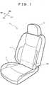
- FIG. 1is a perspective view of a vehicular seat in accordance with an embodiment.
- FIG. 2is a schematic partial front view of a seat back provided with the headrest in FIG. 1 , illustrating how to mount the headrest.
- a perpendicular directionis defined as upward and downward directions on the basis of a vehicle mounted with the vehicular seat 1 placed on a horizontal plane.
- Front and rearward directions(FR, RR) are defined as directions consistent with the frontward and rearward directions of the vehicle; and leftward and rightward directions (width direction) are defined as directions consistent with the width direction of the vehicle.
- FRdenotes the frontward direction of the vehicle and RR denotes the rearward direction of the vehicle.
- the right side (RH) and the left side (LH) of the vehicular seat 1are designated as viewed in the traveling direction of the vehicle.
- the vehicular seat 1includes: a seat cushion 2 on which a person seats him/herself; a seat back 3 erected at the rear end of the seat cushion 2; and a headrest 4 provided at the upper end of the seat back 3.
- the seat cushion 2is installed on the floor of the vehicle but can be provided with a mechanism for making a frontward/rearward position or a height adjustable.
- the seat back 3constitutes a backrest and is coupled with the seat cushion 2 such that the seat back is rotatable about a rotation axis (rotation center line, rotation axial center) 3A provided at the lower end of the seat back. That is, the vehicular seat is provided with a reclining function for tiling the seat back 3 rearward and a frontward tilting function for inclining the seat back 3 frontward and the seat back 3 is configured such that the seat back is rotatable relative to the seat cushion 2.
- the rotation axis 3A covered with a cushion material and a trim coveris indicated by alternate long and short dashed lines.
- the headrest 4is attached to the seat back 3 such that the height position of the headrest is adjustable.
- the seat cushion 2, the seat back 3, and the headrest 4are provided therein with a frame to be a skeleton member and a cushion material formed of resin foam and the like and the surface of the cushion material is covered with a trim cover (skin material).
- the headrest 4includes a headrest stay 41 having a pair of right and left portions (longitudinal frame portions 41a, 41b described later) extending downward.
- the headrestis attached to the seat back 3 by inserting the headrest stay 41 into headrest holders 32 at the upper part of the seat back 3.
- FIG. 3is a perspective view illustrating an appearance of the headrest in FIG. 1 .
- FIG. 4is a sectional view illustrating an internal structure of the headrest in FIG. 3 .
- the headrest 4includes: the headrest frame 40; a speaker unit 50 attached to the headrest frame 40; the cushion material 60; a pouch-like skin material 70; and speaker grill units 80R, 80L.
- the cushion material 60is provided by subjecting a foaming body formed of urethane or the like to skin integral foam molding.
- Speaker wirings 53are connected with wirings coming from the vehicle body side, routed inside the seat back 3.
- FIG. 5is a perspective view illustrating the headrest frame in FIG. 2 .
- FIG. 6is an exploded perspective view illustrating the headrest frame in FIG. 5 .
- the headrest frame 40includes: the headrest stay 41; a headrest support wire 42; a headrest bracket 43 as a first bracket; and a headrest bracket 44 as a second bracket.
- the headrest stay 41is formed by bending a metal pipe and includes: a pair of right and left longitudinal frame portions 41a, 41b extending substantially in the perpendicular direction; a pair of right and left horizontal frame portions 41c, 41d respectively extending from the longitudinal frame portions 41a, 41b substantially in the horizonal direction; and a pair of right and left longitudinal frame portions 41g, 41h extending from the horizontal frame portions 41c, 41d substantially in the perpendicular direction with their respective upper parts connected with each other.
- the longitudinal frame portions 41a, 41bare respectively inserted into a pair of the headrest holders 32 supported by a back frame of the seat back 3 at a predetermined distance from each other in the horizontal direction.
- the horizontal frame portion 41chas a hole 41e for inserting a speaker wiring 53L.
- the horizontal frame portion 41dalso has a hole (not shown) for inserting a speaker wiring 53R.
- the headrest support wire 42is formed by bending a metal wire and includes: a pair of right and left inner longitudinal wire portions 42a, 42b extending substantially in the perpendicular direction; and a pair of right and left outer longitudinal wire portions 42c, 42d whose respective lower parts are connected with the respective lower parts of the longitudinal wire portions 42a, 42b.
- the outer longitudinal wire portionsare extended substantially in the perpendicular direction and their respective upper parts are connected with each other.
- the inner longitudinal wire portions 42a, 42bare secured on the longitudinal frame portions 41g, 41h of the headrest stay 41; and the outer longitudinal wire portions 42c, 42d are engaged with protruded portions 54Re, 54Le of megaphone-shaped tubes 54R, 54L described later.
- the headrest bracket 43which is for fixing the front face of the speaker unit 50 (speaker box 51), has holes 43a, 43b for letting through screws 45a, 45b as fastening materials and is secured on the longitudinal frame portions 41g, 41h.
- the headrest bracket 44which is for fixing the bottom face of the speaker unit 50 (speaker box 51), has holes 44a, 44b for letting through screws 46a, 46b and is secured on the horizontal frame portions 41c, 41d.
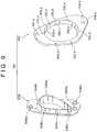
- FIG. 7is a perspective view illustrating the speaker unit in FIG. 4 .
- FIG. 8is an exploded perspective view illustrating the speaker unit in the FIG. 7 .
- FIG. 9is a perspective view illustrating the cover portions in FIG. 4 .
- the speaker unit 50includes: the speaker box 51; speakers 52R, 52L; the speaker wirings 53R, 53L; and megaphone-shaped tubes 54R, 54L.
- cover portions 55R, 55L as ring-shaped members as shown in FIG. 9are attached to the speaker unit 50.
- the speaker box (enclosure) 51includes: a right speaker box 51R in which the speaker 52R is placed; a left speaker box 51L in which the speaker 52L is placed; and a plate-like member 51M inserted into between the speaker box 51R and the speaker box 51L.
- the speaker boxis partitioned (separated) into the right and left speaker boxes 51R, 51L by the 51M. Because of this configuration, right and left separated spaces are formed behind the speakers 52R, 52L in the speaker box 51. These spaces function as acoustic chambers important for sound effect and this enables enhancement of the sound quality of the headrest with the built-in speakers.
- the speaker box 51Lis made of synthetic resin such as polypropylene and includes: a screw hole 51Lc for securing on the bracket 43 with the screw 45a; a screw hole 51Ld for securing on the bracket 44 with the screw 46a; screw holes 51La, 51Lb for securing the speaker 52L and the megaphone-shaped tube 54L with screws 56La, 56Lb; and a substantially round opening portion 51Le in which the speaker 52L is placed.
- the speaker box 51Ris symmetrical with the speaker box 51L except a screw hole 51Rc.
- the speaker 52Lincludes: mounting portions 52La, 52Lb having holes for inserting the screws 56La, 56Lb into the speaker box 51L; and a flange portion 52Lc positioned outside the opening portion 51Le.
- the megaphone-shaped tube 54L made of synthetic resin such as polypropyleneis for radiating a sound from the speaker 52L to a lateral side of the headrest 4 and includes a tubular portion 54La and a flange portion 54Lb.
- the tubular portion 54Lahas, in its outer wall, mounting portions 54Lc, 54Ld having holes for inserting the screw 56La, 56Lb into the speaker box 51L and a protruded portion 54Le to be engaged with the headrest support wire 42; and in its inner wall a recess 54Lf for installing the cover portion 55L.
- the base portion of the tubular portion 54Lais so sized that the base portion can be abutted against the flange portion 52Lc of the speaker 52L.
- the flange portion 54Lbincludes a protruded portion 54Lg.
- the tubular portion 55La of the cover portion 55Lis inserted into an area between the tip portion and the protruded portion 54Le; however, the area close to the tip portion is offset outward (the inside diameter of the tubular portion 54La is increased) by an amount equivalent to the thickness of the tubular portion 55La.
- the cover portion 55L-side opening of the megaphone-shaped tube 54Lis larger than the speaker 52L-side opening.
- the speaker 52L-side opening of the megaphone-shaped tube 54Lis equal to the opening of the speaker box 51L is size.
- the cover portion 55Lis made of synthetic resin such as polypropylene and includes: the tubular portion 55La inserted into the opening of the megaphone-shaped tube 54L; and a flange portion 55Lb for fixing the skin material 70.
- the tubular portion 55Laincludes six lugs 55Lc to be inserted into the recesses 54Lf of the megaphone-shaped tube 54L to fit the cover portion 55L.
- the flange portion 55Lbincludes: six holes 55Ld into which the protruded portion 54Lg of the flange portion 54Lb of the megaphone-shaped tube 54L is inserted; and three holes 55Le for fixing a speaker grill unit 80.
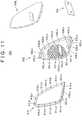
- FIG. 10is a perspective view illustrating a speaker grill unit in FIG. 3 .
- FIG. 11is an exploded perspective view of the left speaker grill unit in FIG. 10 .
- the left speaker grill unit 80a description will be given to the left speaker grill unit 80; however, the right speaker grill unit is structurally in plane symmetry with the left speaker grill unit and a description of the right speaker grill unit is identical with that of the left speaker grill unit.
- the speaker grill unit 80Lis formed by providing a speaker grill trim 81L with a speaker grill 82L, grill scrim 83L, and a logo plate 84L.
- the speaker grill trim 81Lis made of synthetic resin such as polypropylene and includes: eight protrusions 81La for installing the speaker grill 82L and the grill scrim 83L; and eight holes 81Lb for installing the speaker grill 82L.
- the speaker grill 82Lis made of synthetic resin such as polypropylene and includes a honeycomb-like opening adapted to the opening of the cover portion 55L.
- the speaker grill 82Lincludes: eight holes 82La into which the protrusions 81La of the speaker grill trim 81L are inserted; eight protrusions (not shown) positioned behind eight locations 82Lb and inserted into the holes 81Lb in the speaker grill trim 81L; three protrusions (not shown) positioned behind three locations 82Lc and inserted and fitted into the holes 55Le in the cover portion 55L; a logo plate attaching portion 82Ld for attaching a logo plate 84L.
- the grill scrim 83Lis a sheet of black, coarse, and thin cloth (fabric). A portion of the grill scrim 83L where the logo plate 8L is to be positioned is removed.
- the protrusions 81La of the speaker grill trim 81Lare inserted into the holes 82La in the speaker grill 82L from the back side and the protrusions on the back side of the speaker grill 82L are inserted into the holes 81Lb in the speaker grill trim 81L.
- the speaker grill 82Lis attached from outside (front side of) the speaker grill trim 81L.
- the protrusions 81La of the speaker grill trim 81Lare inserted into the holes 83La in the grill scrim 83L from the back side and secured by ultrasonic welding or the like.
- the grill scrim 83Lis installed on the front side of the speaker grill 82L and the logo plate 84L is attached to the speaker grill 82L through the opening in the grill scrim 83L.
- the speaker grill unit 80Lis assembled.
- FIG. 12is a perspective view illustrating a manufacturing method for the headrest in FIG. 3 .
- the skin material 70is formed of cloth, synthetic leather, genuine leather, or the like and has openings 71R, 71L in positions where the cover portions 55R, 55L are to be attached and is sewed into a pouch shape.
- the skin material 70has at its lower end an opening 70a for inserting the speaker unit 50 and the like; and the opening is closed by folding the skin material forward and rearward and leftward and rightward, except holes through which the longitudinal frame portions 41a, 41b of the headrest stay 41 are to be passed.
- a more specific descriptionwill be given.
- the skin material 70has six extended portions which close the opening portion 70a of the skin material after the speaker unit 50 and the like are inserted.
- the six extended portionsare bifurcated right extended portions 70b, bifurcated left extended portions 70c, a front extended portion 70d, and a rear extended portion 70e; and a hook and loop fastener 70f, 70g, 70h, 70i is attached to the vicinities of the opening 70a-side end and the opposite-side end of each extended portion.
- the hook and loop fasteners 70gare positioned on the back side of the left extended portions 70c in the drawing and the hook and loop fastener 70i is positioned on the back side of the rear extended portion 70e in the drawings.
- the left extended portions 70b and the right extended portions 70ccan be fastened together by these hook and loop fasteners 70f, 70g and can also be fastened together with the front extended portion 70d and the rear extended portion by the hook and loop fasteners 70h, 70i.
- FIG. 13is a flowchart illustrating a manufacturing method for the headrest in FIG. 3 .
- the headrest support wire 42, the headrest bracket 43, and the headrest bracket 44are bonded to the headrest stay 41 by welding or the like to prepare the headrest frame 40 (Step S1).
- the skin material 70 sewed into a pouch shape, having the openings 71R, 71L in positions where the cover portions 55R, 55L are to be attachedis prepared (Step S2).
- Step S3Preparation of the speaker unit 50 (Step S3) will be described below:
- the member 51Mis inserted into between and bonded to the speaker box 51R and the speaker box 51L to assemble the speaker box 51.
- the speaker wiring 53Lis installed on the speaker 52L and the speaker 52L is inserted into the opening portion 51Le in the speaker box 51L and the speaker wiring 53L is taken out.
- a hole in the mounting portion 52La of the speaker 52L and a hole in the mounting portion 54Lc of the megaphone-shaped tube 54Lare aligned with the screw hole 51La of the speaker box 51L and the screw 56La is inserted into the holes to fasten these portions and the speaker box together.
- a hole in the mounting portion 52Lb of the speaker 52L and a hole in the mounting portion 54Ld of the megaphone-shaped tube 54Lare aligned with the screw hole 51Lb in the speaker box 51L and the screw 56Lb is inserted into the holes to fasten these portions and the speaker box together. Consequently, the megaphone-shaped tube 54L and the speaker 52L are jointly fastened to the speaker box 51L.
- the flange portion 52Lc of the speaker 52Lis sandwiched and secured between the speaker box 51L and the base portion of the megaphone-shaped tube 54L.
- the speaker 52R and the megaphone-shaped tube 54Rare also similarly installed.
- Step S4A step (Step S4) of securing the speaker unit 50 prepared at Step S3 on the headrest frame prepared at Step S1 will be described below:
- the hole 43a in the bracket 43 of the headrest frame 41 and the screw hole 51Lc in the speaker box 51Lare aligned with each other and the screw 45a is inserted into these holes to fasten the bracket and the speaker box together;
- the hole 43b in the bracket 43 of the headrest frame 41 and the screw hole 51Rc in the speaker box 51Rare aligned with each other and the screw 45b is inserted into these holes to fasten the bracket and the speaker box together.
- the hole 44a in the bracket 44 of the headrest frame 41 and the screw hole 51Ld in the speaker box 51Lare aligned with each other and the screw 46a is inserted into these holes to fasten the bracket and the speaker box together; and the hole 44b in the bracket 44 of the headrest frame 41 and the screw hole 51Rd in the speaker box 51R are aligned with each other and the screw 46b is inserted into these holes to fasten the bracket and the speaker box together.
- the protruded portion 54Le of the megaphone-shaped tube 54Lis engaged with the outer longitudinal wire portion 42c of the headrest support wire 42; and the protruded portion 54Re of the megaphone-shaped tube 54R is engaged with the outer longitudinal wire portion 42d of the headrest support wire 42.
- the headrest frame 40 with the speaker unit 50 attached to the headrest frameis inserted from the opening 70a provided on the bottom face side of the skin material 70 sewed into a pouch shape (Step S5). With the headrest frame 40 inserted at this time, the longitudinal frame portions 41a, 41b of the headrest stay 41 are protruded from the skin material 70.
- the opening 70ais covered with the right extended portions 70b and the left extended portions and both the extended portions are secured together with the hook and loop fasteners 70f, 70g.
- the longitudinal frame portions 41a, 41bare respectively positioned between the two right extended portions 70b, 70b and left extended portions 70c, 70c.
- the opening 70ais covered with the front extended portion 70d and the rear extended portion 70e and both the extended portions are secured together with the hook and loop fasteners 70h, 70i.
- the front extended portion 70d and the rear extended portion 70eare positioned between the longitudinal frame portions 41a, 41b.
- the entire opening 71L-side end portion of the skin material 70is sandwiched between the flange portion 54Lb of the megaphone-shaped tube 54L and the flange portion 55Lb of the cover portion 55L.
- the protrusion 54Le of the flange portion 54Lb of the megaphone-shaped tube 54Lis inserted into the hole 55Ld in the flange portion 55Lb of the cover portion 55L to secure the skin material 70 (Step S6) .
- the speaker 52L and the megaphone-shaped tube 54Lare jointly fastened to the speaker box 51L and brought into tight contact with each other; and similarly, the speaker 52R and the megaphone-shaped tube 54R are jointly fastened to the speaker box 51R and brought into tight contact with each other.
- the skin material 70is sandwiched between the megaphone-shaped tube 54L and the cover portion 55L and brought into tight contact with the megaphone-shaped tube 54L and the cover portion 55L.
- the skin material 70is sandwiched between the megaphone-shaped tube 54R and the cover portion 55R and brought into tight contact with the megaphone-shaped tube 54R and the cover portion 55R.
- the pouch-shaped skin materialhaving the same sealability as headrests without built-in speakers is formed.
- Step S7skin integral foam molding
- the pouch-shaped skin material 70 including the headrest frame 40 (except part of the headrest stay 41) and the speaker unit 50 (speakers 52R, 52L, speaker box 51, megaphone-shaped tubes 54R, 54L)is set in a mold (not shown).
- the bottom face side (the longitudinal frame portions 41a, 41b of the headrest stay 41 protruded from the skin material 70) of the skin material 70is set upward.
- An injection nozzle (not shown)is inserted into a hole (not shown) formed in the front extended portion 70d and the rear extended portion 70e of the skin material 70 from above.
- a foaming materialsuch as a urethane material is injected from an injecting machine (not shown) and foamed to form the cushion material 60. That is, a headrest form is formed by skin integral foam molding.
- the three protrusions on the back side of the speaker grill unit 80Lare inserted and fit into the three holes 55Le in the cover portion 55L to install the speaker grill unit 80L (Step S8).
- the speaker grill unit 80Ris similarly installed on the cover portion 55R to manufacture the headrest 4.
- the headrest 4is covered with the skin material 70 on the front side and the rear side and is covered with the skin material 70 and the speaker grill units 80R, 80L on the left side and the right side. That is, the speaker grill units 80R, 80L form part of the side portions of the headrest 4.
- the headrest 4is recessed at the front part and projected at the rear part and the side parts as sectionally viewed.
- the back of the head of a seating personis abutted against the skin material 70 in the recessed position at the front part of the headrest 4.
- Some parts of the cushion material 60 and the skin material 70are positioned ahead of the megaphone-shaped tubes 54R, 54L.
- the speakers 52R, 52Lare installed such that the speakers are respectively oriented outward of the center of the headrest 4, rather than frontward.
- the speakers 52R, 52Lare disposed such that the speakers are respectively oriented outward from the frontward direction by approximately 45 degrees.
- the megaphone-shaped tubes 54R, 54Lare disposed such that the tubes are oriented more outward than the speakers 52R, 52L are.
- the megaphone-shaped tubes 54R, 54Lare respectively longer on the front side than on the rear side. Some parts of the speakers 52R, 52L are protruded more outward than the speaker boxes 51R, 51L are.
- the cushion material 60is positioned ahead of a part of the speaker box 51 positioned most frontward and further the skin material 70 is positioned there.
- the distance between the front side of the speaker box 51 and the skin material 70 on the front side of the headrest 4is larger than the distance between the rear side of the speaker box 51 and the skin material 70 on the rear side of the headrest 4.
- the cushion material 70 on the front side of the speaker box 51is thicker than the cushion material 70 on the rear side.
- Skin integral form moldingsare basically made by injecting a urethane material into a pouch-shaped skin material and foaming the material; therefore, this molding technique requires sealability (hermeticity).
- the skin materialis sandwiched between and brought into tight contact with the megaphone-shaped tubular portions for preventing a sound from the speakers from being blocked off and the cover portions. Since the speakers and the megaphone-shaped tubes are jointly fastened to the speaker box and the megaphone-shaped tubes are thus secured on the speaker box, the speakers are tightly fixed in the speaker box. As a result, a gap is not produced between the speaker box and the speakers and the hermeticity of the speaker box (enclosure) can be maintained during integral foam molding.
- the megaphone-shaped tubescontribute to both the effects of hermeticity of the skin to the exterior and hermeticity of the speaker box to the interior.
- the pouch-shaped skin materialis formed and sealability can be ensured and skin integral foam molding can be implemented. Necessity for installation of the skin material at any different step is obviated and thus a simple structure can be obtained in terms of appearance.
- a case where the flange portion 54Lb of the megaphone-shaped tube 54L has the protruded portion 54Lg and the flange portion 55Lb of the cover portion 55L has the hole 55Ldis taken as an example.
- the present inventionis not limited to this.
- the protruded portion 54Lg and the hole 55Ld constituting engaging portionsmay be omitted; and a hole may be provided instead of the protruded portion 54Lg and a protruded portion may be provided instead of the hole 55Ld.
- the speaker unit 50is disposed behind the headrest frame 40.
- the speaker unit 50may be disposed ahead of the headrest frame 40.
Landscapes
- Engineering & Computer Science (AREA)
- Mechanical Engineering (AREA)
- Aviation & Aerospace Engineering (AREA)
- Transportation (AREA)
- Physics & Mathematics (AREA)
- Acoustics & Sound (AREA)
- Signal Processing (AREA)
- Seats For Vehicles (AREA)
- Chair Legs, Seat Parts, And Backrests (AREA)
- Fittings On The Vehicle Exterior For Carrying Loads, And Devices For Holding Or Mounting Articles (AREA)
Description
- The present disclosure relates to headrests and is applicable to a headrest with a speaker, for example.
- Headrests, armrests, and the like of vehicular seats are manufactured by skin integral foam molding. The skin integral foam molding refers to a manufacturing technique using a single step as a combination of two steps, foaming and covering. At this single step, a sewed trim cover (skin material) and a frame component are set in a mold and a foaming material such as a material of urethane is injected directly into the mold and foamed to implement molding (Refer to
US 2015/0298371 (Patent Document 1), for example). - An example of a headrest with a speaker manufactured by skin integral foam molding is disclosed in
WO 2016/129663 (Patent Document 2), for example. Furthermore,WO 2017/160572 A1 discloses a seat headrest comprising an interior chamber that accommodates an acoustic transducer, and an acoustic channel is disposed between the interior chamber and an external opening in the seat headrest. Moreover, a soft outer layer disposed around at least a portion of a periphery of the external opening; and a grill mount disposed in or attached to the outer layer, wherein the grill mount extending, at least in part, around a periphery of the acoustic channel, and configured to engage with a portion of a speaker grill-assembly in a mating configuration. - However, the technology in
Patent Document 2 involves a problem. Though a skin material is provided with an opening portion to give off a sound from the speaker, an end portion of the opening portion in the skin material is
not secured. Consequently, there is a possibility that a foaming material leaks out into a hole in a side support member during skin integral foam molding. - In order to solve the above-mentioned problems, a headrest having the features of
independent claim 1 and a manufacturing method for said headrest having the features of independent claim 7 are provided. Preferred embodiments are described in the dependent claims. - Other objects and novel features will be apparent from the description of the present disclosure and the accompanying drawings.
- Following is a brief description of an overview of representative elements of the present disclosure:
A headrest includes; (a) headrest frame; (b) a speaker unit supported on the headrest frame and having a speaker box, a speaker attached to the speaker box, and a megaphone-shaped tube attached to the speaker box; (c) a cushion material; (d) a skin material sewed into a pouch shape having an opening and covering the headrest frame, the speaker unit, and the cushion material; and/or (e) a ring-shaped member securing the entire opening-side end portion of the skin material by sandwiching the end portion
between the ring-shaped member and the megaphone-shaped tube. FIG. 1 is a perspective view of a vehicular seat in accordance with an embodiment;FIG. 2 a schematic partial front view illustrating a way the headrest inFIG. 1 is mounted;FIG. 3 a perspective view illustrating an appearance of the headrest inFIG. 1 ;FIG. 4 is a sectional view illustrating an internal structure of the headrest inFIG. 3 ;FIG. 5 is a perspective view illustrating the headrest frame inFIG. 4 ;FIG. 6 is an exploded perspective view illustrating the headrest frame inFIG. 5 ;FIG. 7 is a perspective view illustrating the speaker unit inFIG. 4 ;FIG. 8 is an exploded perspective view illustrating the speaker unit inFIG. 7 ;FIG. 9 is a perspective view illustrating the cover portions inFIG. 4 ;FIG. 10 is a perspective view illustrating a speaker grill inFIG. 3 ;FIG. 11 is an exploded perspective view illustrating the speaker grill inFIG. 10 ;FIG. 12 is a perspective view illustrating a manufacturing method for the headrest inFIG. 3 ; andFIG. 13 is a flowchart illustrating a manufacturing method for the headrest inFIG. 3 .- Hereafter, a description will be given to an embodiment of the present disclosure with reference to the drawings. In the following description, identical components will be marked with identical reference numerals and a repetitive description of such components may be omitted. In the drawings, the width, thickness, shape, and the like of each part may be schematically depicted as compared with actual appearance for the purpose of making the description clearer. Such depictions are just an example and are not intended to limit the interpretation of the present invention.
FIG. 1 is a perspective view of a vehicular seat in accordance with an embodiment.FIG. 2 is a schematic partial front view of a seat back provided with the headrest inFIG. 1 , illustrating how to mount the headrest. In the following description, a perpendicular direction is defined as upward and downward directions on the basis of a vehicle mounted with thevehicular seat 1 placed on a horizontal plane. Front and rearward directions (FR, RR) are defined as directions consistent with the frontward and rearward directions of the vehicle; and leftward and rightward directions (width direction) are defined as directions consistent with the width direction of the vehicle. FR denotes the frontward direction of the vehicle and RR denotes the rearward direction of the vehicle. In the following description, the right side (RH) and the left side (LH) of thevehicular seat 1 are designated as viewed in the traveling direction of the vehicle.- As illustrated in
FIG. 1 , thevehicular seat 1 includes: aseat cushion 2 on which a person seats him/herself; aseat back 3 erected at the rear end of theseat cushion 2; and aheadrest 4 provided at the upper end of theseat back 3. - The
seat cushion 2 is installed on the floor of the vehicle but can be provided with a mechanism for making a frontward/rearward position or a height adjustable. - The
seat back 3 constitutes a backrest and is coupled with theseat cushion 2 such that the seat back is rotatable about a rotation axis (rotation center line, rotation axial center) 3A provided at the lower end of the seat back. That is, the vehicular seat is provided with a reclining function for tiling the seat back 3 rearward and a frontward tilting function for inclining the seat back 3 frontward and theseat back 3 is configured such that the seat back is rotatable relative to theseat cushion 2. InFIG. 1 , therotation axis 3A covered with a cushion material and a trim cover is indicated by alternate long and short dashed lines. - The
headrest 4 is attached to theseat back 3 such that the height position of the headrest is adjustable. - The
seat cushion 2, theseat back 3, and theheadrest 4 are provided therein with a frame to be a skeleton member and a cushion material formed of resin foam and the like and the surface of the cushion material is covered with a trim cover (skin material). - As illustrated in
FIG. 2 , theheadrest 4 includes a headrest stay 41 having a pair of right and left portions (longitudinal frame portions seat back 3 by inserting the headrest stay 41 intoheadrest holders 32 at the upper part of the seat back 3. - A detailed description will be given to a structure of the
headrest 4 with reference toFIGS. 3 and4 .FIG. 3 is a perspective view illustrating an appearance of the headrest inFIG. 1 .FIG. 4 is a sectional view illustrating an internal structure of the headrest inFIG. 3 . - The
headrest 4 includes: theheadrest frame 40; aspeaker unit 50 attached to theheadrest frame 40; thecushion material 60; a pouch-like skin material 70; andspeaker grill units cushion material 60 is provided by subjecting a foaming body formed of urethane or the like to skin integral foam molding. Speaker wirings 53 (speaker wirings - A description will be given to a structure of the
headrest frame 40 with reference toFIGS. 5 and6 .FIG. 5 is a perspective view illustrating the headrest frame inFIG. 2 .FIG. 6 is an exploded perspective view illustrating the headrest frame inFIG. 5 . - The
headrest frame 40 includes: the headrest stay 41; aheadrest support wire 42; aheadrest bracket 43 as a first bracket; and aheadrest bracket 44 as a second bracket. - The
headrest stay 41 is formed by bending a metal pipe and includes: a pair of right and leftlongitudinal frame portions horizontal frame portions longitudinal frame portions longitudinal frame portions horizontal frame portions longitudinal frame portions headrest holders 32 supported by a back frame of theseat back 3 at a predetermined distance from each other in the horizontal direction. Thehorizontal frame portion 41c has ahole 41e for inserting aspeaker wiring 53L. Thehorizontal frame portion 41d also has a hole (not shown) for inserting aspeaker wiring 53R. - The
headrest support wire 42 is formed by bending a metal wire and includes: a pair of right and left innerlongitudinal wire portions longitudinal wire portions longitudinal wire portions longitudinal wire portions longitudinal frame portions headrest stay 41; and the outerlongitudinal wire portions tubes - The
headrest bracket 43, which is for fixing the front face of the speaker unit 50 (speaker box 51), hasholes screws longitudinal frame portions - The
headrest bracket 44, which is for fixing the bottom face of the speaker unit 50 (speaker box 51), hasholes horizontal frame portions - A description will be given to a structure of the
speaker unit 50 with reference toFIGS. 3 and7 to 9 .FIG. 7 is a perspective view illustrating the speaker unit inFIG. 4 .FIG. 8 is an exploded perspective view illustrating the speaker unit in theFIG. 7 .FIG. 9 is a perspective view illustrating the cover portions inFIG. 4 . - As illustrated in
FIGS. 7 and8 , thespeaker unit 50 includes: thespeaker box 51;speakers speaker wirings tubes Such cover portions FIG. 9 are attached to thespeaker unit 50. - The speaker box (enclosure) 51 includes: a
right speaker box 51R in which thespeaker 52R is placed; aleft speaker box 51L in which thespeaker 52L is placed; and a plate-like member 51M inserted into between thespeaker box 51R and thespeaker box 51L. The speaker box is partitioned (separated) into the right and leftspeaker boxes speakers speaker box 51. These spaces function as acoustic chambers important for sound effect and this enables enhancement of the sound quality of the headrest with the built-in speakers. - Hereafter, a description will be given to the left side of the
speaker unit 50 but the right side is substantially symmetrical with the left side and a description of the right side is identical with that of the left side. The reference numerals of elements on the left side are suffixed with L and the reference numerals of corresponding elements on the right side are suffixed with R. - The
speaker box 51L is made of synthetic resin such as polypropylene and includes: a screw hole 51Lc for securing on thebracket 43 with thescrew 45a; a screw hole 51Ld for securing on thebracket 44 with the screw 46a; screw holes 51La, 51Lb for securing thespeaker 52L and the megaphone-shapedtube 54L with screws 56La, 56Lb; and a substantially round opening portion 51Le in which thespeaker 52L is placed. Thespeaker box 51R is symmetrical with thespeaker box 51L except a screw hole 51Rc. - The
speaker 52L includes: mounting portions 52La, 52Lb having holes for inserting the screws 56La, 56Lb into thespeaker box 51L; and a flange portion 52Lc positioned outside the opening portion 51Le. - The megaphone-shaped
tube 54L made of synthetic resin such as polypropylene is for radiating a sound from thespeaker 52L to a lateral side of theheadrest 4 and includes a tubular portion 54La and a flange portion 54Lb. The tubular portion 54La has, in its outer wall, mounting portions 54Lc, 54Ld having holes for inserting the screw 56La, 56Lb into thespeaker box 51L and a protruded portion 54Le to be engaged with theheadrest support wire 42; and in its inner wall a recess 54Lf for installing thecover portion 55L. The base portion of the tubular portion 54La is so sized that the base portion can be abutted against the flange portion 52Lc of thespeaker 52L. The flange portion 54Lb includes a protruded portion 54Lg. The tubular portion 55La of thecover portion 55L is inserted into an area between the tip portion and the protruded portion 54Le; however, the area close to the tip portion is offset outward (the inside diameter of the tubular portion 54La is increased) by an amount equivalent to the thickness of the tubular portion 55La. Thecover portion 55L-side opening of the megaphone-shapedtube 54L is larger than thespeaker 52L-side opening. Thespeaker 52L-side opening of the megaphone-shapedtube 54L is equal to the opening of thespeaker box 51L is size. - As illustrated in
FIG. 9 , thecover portion 55L is made of synthetic resin such as polypropylene and includes: the tubular portion 55La inserted into the opening of the megaphone-shapedtube 54L; and a flange portion 55Lb for fixing theskin material 70. The tubular portion 55La includes six lugs 55Lc to be inserted into the recesses 54Lf of the megaphone-shapedtube 54L to fit thecover portion 55L. The flange portion 55Lb includes: six holes 55Ld into which the protruded portion 54Lg of the flange portion 54Lb of the megaphone-shapedtube 54L is inserted; and three holes 55Le for fixing a speaker grill unit 80. - A description will be given to a structure of each speaker grill unit with reference to
FIGS. 10 and11 .FIG. 10 is a perspective view illustrating a speaker grill unit inFIG. 3 .FIG. 11 is an exploded perspective view of the left speaker grill unit inFIG. 10 . Hereafter, a description will be given to the left speaker grill unit 80; however, the right speaker grill unit is structurally in plane symmetry with the left speaker grill unit and a description of the right speaker grill unit is identical with that of the left speaker grill unit. - The
speaker grill unit 80L is formed by providing a speaker grill trim 81L with aspeaker grill 82L,grill scrim 83L, and alogo plate 84L. - The speaker grill trim 81L is made of synthetic resin such as polypropylene and includes: eight protrusions 81La for installing the
speaker grill 82L and thegrill scrim 83L; and eight holes 81Lb for installing thespeaker grill 82L. Thespeaker grill 82L is made of synthetic resin such as polypropylene and includes a honeycomb-like opening adapted to the opening of thecover portion 55L. Thespeaker grill 82L includes: eight holes 82La into which the protrusions 81La of the speaker grill trim 81L are inserted; eight protrusions (not shown) positioned behind eight locations 82Lb and inserted into the holes 81Lb in the speaker grill trim 81L; three protrusions (not shown) positioned behind three locations 82Lc and inserted and fitted into the holes 55Le in thecover portion 55L; a logo plate attaching portion 82Ld for attaching alogo plate 84L. Thegrill scrim 83L is a sheet of black, coarse, and thin cloth (fabric). A portion of thegrill scrim 83L where the logo plate 8L is to be positioned is removed. - The protrusions 81La of the speaker grill trim 81L are inserted into the holes 82La in the
speaker grill 82L from the back side and the protrusions on the back side of thespeaker grill 82L are inserted into the holes 81Lb in the speaker grill trim 81L. Thus, thespeaker grill 82L is attached from outside (front side of) the speaker grill trim 81L. In addition, the protrusions 81La of the speaker grill trim 81L are inserted into the holes 83La in thegrill scrim 83L from the back side and secured by ultrasonic welding or the like. Thegrill scrim 83L is installed on the front side of thespeaker grill 82L and thelogo plate 84L is attached to thespeaker grill 82L through the opening in thegrill scrim 83L. Thus, thespeaker grill unit 80L is assembled. - A description will be given to the skin material with reference to
FIG. 12. FIG. 12 is a perspective view illustrating a manufacturing method for the headrest inFIG. 3 . Theskin material 70 is formed of cloth, synthetic leather, genuine leather, or the like and hasopenings cover portions skin material 70 has at its lower end anopening 70a for inserting thespeaker unit 50 and the like; and the opening is closed by folding the skin material forward and rearward and leftward and rightward, except holes through which thelongitudinal frame portions skin material 70 has six extended portions which close theopening portion 70a of the skin material after thespeaker unit 50 and the like are inserted. The six extended portions are bifurcated rightextended portions 70b, bifurcated leftextended portions 70c, a frontextended portion 70d, and a rearextended portion 70e; and a hook andloop fastener opening 70a-side end and the opposite-side end of each extended portion. The hook andloop fasteners 70g are positioned on the back side of the leftextended portions 70c in the drawing and the hook and loop fastener 70i is positioned on the back side of the rearextended portion 70e in the drawings. The left extendedportions 70b and the rightextended portions 70c can be fastened together by these hook andloop fasteners extended portion 70d and the rear extended portion by the hook andloop fasteners 70h, 70i. - A description will be given to a manufacturing method for the
headrest 4 with reference toFIGS. 3 to 13 .FIG. 13 is a flowchart illustrating a manufacturing method for the headrest inFIG. 3 . - The
headrest support wire 42, theheadrest bracket 43, and theheadrest bracket 44 are bonded to the headrest stay 41 by welding or the like to prepare the headrest frame 40 (Step S1). - The
skin material 70 sewed into a pouch shape, having theopenings cover portions - Preparation of the speaker unit 50 (Step S3) will be described below:
Themember 51M is inserted into between and bonded to thespeaker box 51R and thespeaker box 51L to assemble thespeaker box 51. - The
speaker wiring 53L is installed on thespeaker 52L and thespeaker 52L is inserted into the opening portion 51Le in thespeaker box 51L and thespeaker wiring 53L is taken out. - A hole in the mounting portion 52La of the
speaker 52L and a hole in the mounting portion 54Lc of the megaphone-shapedtube 54L are aligned with the screw hole 51La of thespeaker box 51L and the screw 56La is inserted into the holes to fasten these portions and the speaker box together. A hole in the mounting portion 52Lb of thespeaker 52L and a hole in the mounting portion 54Ld of the megaphone-shapedtube 54L are aligned with the screw hole 51Lb in thespeaker box 51L and the screw 56Lb is inserted into the holes to fasten these portions and the speaker box together. Consequently, the megaphone-shapedtube 54L and thespeaker 52L are jointly fastened to thespeaker box 51L. At this time, the flange portion 52Lc of thespeaker 52L is sandwiched and secured between thespeaker box 51L and the base portion of the megaphone-shapedtube 54L. Thespeaker 52R and the megaphone-shapedtube 54R are also similarly installed. - A step (Step S4) of securing the
speaker unit 50 prepared at Step S3 on the headrest frame prepared at Step S1 will be described below:
Thehole 43a in thebracket 43 of theheadrest frame 41 and the screw hole 51Lc in thespeaker box 51L are aligned with each other and thescrew 45a is inserted into these holes to fasten the bracket and the speaker box together; and thehole 43b in thebracket 43 of theheadrest frame 41 and the screw hole 51Rc in thespeaker box 51R are aligned with each other and thescrew 45b is inserted into these holes to fasten the bracket and the speaker box together. Further, thehole 44a in thebracket 44 of theheadrest frame 41 and the screw hole 51Ld in thespeaker box 51L are aligned with each other and the screw 46a is inserted into these holes to fasten the bracket and the speaker box together; and thehole 44b in thebracket 44 of theheadrest frame 41 and the screw hole 51Rd in thespeaker box 51R are aligned with each other and the screw 46b is inserted into these holes to fasten the bracket and the speaker box together. In addition, the protruded portion 54Le of the megaphone-shapedtube 54L is engaged with the outerlongitudinal wire portion 42c of theheadrest support wire 42; and the protruded portion 54Re of the megaphone-shapedtube 54R is engaged with the outerlongitudinal wire portion 42d of theheadrest support wire 42. Thus, thespeaker unit 50 is secured and installed on theheadrest frame 41. - The
headrest frame 40 with thespeaker unit 50 attached to the headrest frame is inserted from theopening 70a provided on the bottom face side of theskin material 70 sewed into a pouch shape (Step S5). With theheadrest frame 40 inserted at this time, thelongitudinal frame portions skin material 70. - To close the hole formed by the
opening 70a, theopening 70a is covered with the rightextended portions 70b and the left extended portions and both the extended portions are secured together with the hook andloop fasteners longitudinal frame portions extended portions extended portions opening 70a is covered with the frontextended portion 70d and the rearextended portion 70e and both the extended portions are secured together with the hook andloop fasteners 70h, 70i. The frontextended portion 70d and the rearextended portion 70e are positioned between thelongitudinal frame portions opening 70a being closed with the six extended portions, theskin material 70 is brought into a complete pouch shape. - The
entire opening 71L-side end portion of theskin material 70 is sandwiched between the flange portion 54Lb of the megaphone-shapedtube 54L and the flange portion 55Lb of thecover portion 55L. The protrusion 54Le of the flange portion 54Lb of the megaphone-shapedtube 54L is inserted into the hole 55Ld in the flange portion 55Lb of thecover portion 55L to secure the skin material 70 (Step S6) . - As mentioned above, the
speaker 52L and the megaphone-shapedtube 54L are jointly fastened to thespeaker box 51L and brought into tight contact with each other; and similarly, thespeaker 52R and the megaphone-shapedtube 54R are jointly fastened to thespeaker box 51R and brought into tight contact with each other. Theskin material 70 is sandwiched between the megaphone-shapedtube 54L and thecover portion 55L and brought into tight contact with the megaphone-shapedtube 54L and thecover portion 55L. Similarly, theskin material 70 is sandwiched between the megaphone-shapedtube 54R and thecover portion 55R and brought into tight contact with the megaphone-shapedtube 54R and thecover portion 55R. Thus, the pouch-shaped skin material having the same sealability as headrests without built-in speakers is formed. - Hereafter, a description will be given to skin integral foam molding (Step S7).
- The pouch-shaped
skin material 70 including the headrest frame 40 (except part of the headrest stay 41) and the speaker unit 50 (speakers speaker box 51, megaphone-shapedtubes longitudinal frame portions skin material 70 is set upward. An injection nozzle (not shown) is inserted into a hole (not shown) formed in the frontextended portion 70d and the rearextended portion 70e of theskin material 70 from above. A foaming material such as a urethane material is injected from an injecting machine (not shown) and foamed to form thecushion material 60. That is, a headrest form is formed by skin integral foam molding. - Thereafter, the three protrusions on the back side of the
speaker grill unit 80L are inserted and fit into the three holes 55Le in thecover portion 55L to install thespeaker grill unit 80L (Step S8). Thespeaker grill unit 80R is similarly installed on thecover portion 55R to manufacture theheadrest 4. - As illustrated in
FIG. 3 , theheadrest 4 is covered with theskin material 70 on the front side and the rear side and is covered with theskin material 70 and thespeaker grill units speaker grill units headrest 4. Theheadrest 4 is recessed at the front part and projected at the rear part and the side parts as sectionally viewed. The back of the head of a seating person is abutted against theskin material 70 in the recessed position at the front part of theheadrest 4. Some parts of thecushion material 60 and theskin material 70 are positioned ahead of the megaphone-shapedtubes - The
speakers headrest 4, rather than frontward. In this embodiment, thespeakers tubes speakers tubes speakers speaker boxes cushion material 60 is positioned ahead of a part of thespeaker box 51 positioned most frontward and further theskin material 70 is positioned there. The distance between the front side of thespeaker box 51 and theskin material 70 on the front side of theheadrest 4 is larger than the distance between the rear side of thespeaker box 51 and theskin material 70 on the rear side of theheadrest 4. In other words, thecushion material 70 on the front side of thespeaker box 51 is thicker than thecushion material 70 on the rear side. - Skin integral form moldings are basically made by injecting a urethane material into a pouch-shaped skin material and foaming the material; therefore, this molding technique requires sealability (hermeticity). In this embodiment, the skin material is sandwiched between and brought into tight contact with the megaphone-shaped tubular portions for preventing a sound from the speakers from being blocked off and the cover portions. Since the speakers and the megaphone-shaped tubes are jointly fastened to the speaker box and the megaphone-shaped tubes are thus secured on the speaker box, the speakers are tightly fixed in the speaker box. As a result, a gap is not produced between the speaker box and the speakers and the hermeticity of the speaker box (enclosure) can be maintained during integral foam molding. As mentioned above, the megaphone-shaped tubes contribute to both the effects of hermeticity of the skin to the exterior and hermeticity of the speaker box to the interior.
- As a result, the pouch-shaped skin material is formed and sealability can be ensured and skin integral foam molding can be implemented. Necessity for installation of the skin material at any different step is obviated and thus a simple structure can be obtained in terms of appearance.
- Up to this point, the invention made by the present inventors has been specifically described based on an embodiment. However, the present invention is not limited to the above-mentioned embodiment and can be variously modified, needless to add.
- Some examples will be taken. In the description of the above embodiment, a case where three round holes are formed in each cover portion for installing a speaker grill is taken as an example. The present invention is not limited to this and two rectangular holes may be provided instead. In this case, two protrusions to be fit into the rectangular holes are provided on the back side of each speaker grill.
- In the above description of this embodiment, a case where the flange portion 54Lb of the megaphone-shaped
tube 54L has the protruded portion 54Lg and the flange portion 55Lb of thecover portion 55L has the hole 55Ld is taken as an example. The present invention is not limited to this. The protruded portion 54Lg and the hole 55Ld constituting engaging portions may be omitted; and a hole may be provided instead of the protruded portion 54Lg and a protruded portion may be provided instead of the hole 55Ld. - In this embodiment, the
speaker unit 50 is disposed behind theheadrest frame 40. When the entire headrest is differently shaped, thespeaker unit 50 may be disposed ahead of theheadrest frame 40.
Claims (16)
- A headrest (4) comprising:- a headrest frame (40);- a speaker unit (50) supported by the headrest frame (40) and including a speaker box (51), a speaker (52L,R) attached to the speaker box (51), and a megaphone-shaped tube (54L,R) attached to the speaker box (51);- a cushion material (60);- a skin material (70) having an opening (70a), sewed into a pouch shape, and covering the headrest frame (40), the speaker unit (50), and the cushion material (60); and- a ring-shaped member (55L,R) securing the entire opening-side end portion of the skin (70) material sandwiched between the ring-shaped member (55L,R) and the megaphone-shaped tube (54L,R), wherein the megaphone-shaped tube (54L,R) has a flange portion at an end portion on the side opposite the speaker (52L,R), and wherein the ring-shaped member (55R,L) has a tubular portion (54La) inserted into and abutted against the megaphone-shaped tube (54L,R) and a flange portion abutted against the flange portion of the megaphone-shaped tube (54L,R),
characterized in that:
the end portion of the skin material (70) is sandwiched and secured between the flange portion of the megaphone-shaped tube (54L,R) and the flange portion of the ring-shaped member (55L,R). - The headrest (4) according to Claim 1, wherein the speaker (52L,R) and the megaphone-shaped tube (54L,R) are jointly fastened to the speaker box (51).
- The headrest (4) according to at least one of Claims 1 to 2, wherein an opening at an end of the megaphone-shaped tube (54L,R) is larger than an opening in the speaker box (51).
- The headrest (4) according to at least one of Claims 1 to 3, further comprising:- a speaker grill (82L) attached to the ring-shaped member (55R,L) and covering an opening portion of the speaker unit (50).
- The headrest (4) according to Claim 1, wherein the headrest frame (40) includes:- a headrest stay (41) inserted into a mounting portion of a seat back (3),- a first bracket securing a front face of the speaker box (51), a second bracket securing a bottom face of the speaker box (51), and- an auxiliary wire anchoring the speaker box (51), and wherein the headrest stay (41) includes:- a longitudinal frame portion (41a,b) securing the first bracket and the auxiliary wire, and- a horizontal frame portion (41c,d) securing the second bracket.
- The headrest (4) according to Claim 1, wherein the flange portion of the megaphone-shaped tube (54L,R) has an engaging portion, and
wherein the flange portion of the ring-shaped member (55L,R) has an engaging portion engaged with the engaging portion of the flange portion of the megaphone-shaped tube (54L,R). - A manufacturing method for a headrest (4) comprising the steps of:(a) preparing a headrest frame (40), a skin material (70) having an opening (70a) and sewed into a pouch shape, and a speaker unit (50) including a speaker box (51), a speaker (52L,R) attached to the speaker box (51), and a megaphone-shaped tube (54L,R) attached to the speaker box (51);(b) securing the speaker unit (50) on the headrest frame (40);(c) inserting the speaker unit (50) secured on the headrest frame (40) into the skin material pouch;(d) sandwiching and securing the entire opening-side end portion of the skin material (70) between the megaphone-shaped tube (54L,R) and ring-shaped member (55L,R); and(e) injecting a foaming material into the skin material pouch to form a cushion material (60)), wherein the megaphone-shaped tube (54L,R) has a flange portion at an end portion on the side opposite the speaker (52L,R), and wherein the ring-shaped member (55R,L) has a tubular portion (54La) inserted into and abutted against the megaphone-shaped tube (54L,R) and a flange portion abutted against the flange portion of the megaphone-shaped tube (54L,R),
characterized in that:
the end portion of the skin material (70) is sandwiched and secured between the flange portion of the megaphone-shaped tube (54L,R) and the flange portion of the ring-shaped member (55L,R). - The manufacturing method for a headrest (4) according to Claim 7, wherein the step (a) includes a step of jointly fastening the speaker and the megaphone-shaped tube (54L,R) to the speaker box (51).
- The manufacturing method for a headrest (4) according to Claim 7 or 8, further comprising the step of:- (f) after the step (e), attaching a speaker grill (82L) to the ring-shaped member (55L,R).
- A vehicular seat comprising:
a headrest (4) according to at least one of the claims 1 to 6; and the vehicular seat further comprising:
a seat back (3) having a headrest holder (32) supporting the headrest (4); and a seat cushion (2) coupled to the seat back (3), - The vehicular seat according to Claim 10, wherein the skin material (70) has an opening (70a) and is sewed into a pouch shape, and
wherein the entire opening-side end portion of the skin material (70) is sandwiched and secured between the megaphone-shaped tube (54L,R) and the ring-shaped member (55L,R). - The vehicular seat according to at least one of Claims 10 to 11, wherein the speaker (52L,R) and the megaphone-shaped tube (54L,R) are jointly fastened to the speaker box (51).
- The vehicular seat according to at least one of Claims 10 to 12, wherein an opening at an end of the megaphone-shaped tube (54L.R) is larger than an opening in the speaker box (51).
- The vehicular seat according to at least one of Claims 10 to 13, further comprising:- a speaker grill (82L) attached to the ring-shaped member (55L,R) and covering an opening portion of the speaker unit (50).
- The vehicular seat according to at least one of Claims 10 to 14, wherein the headrest frame (40) includes: a headrest stay (41) inserted into the headrest holder (32), a first bracket securing a front face of the speaker box (51), a second bracket securing a bottom face of the speaker box (51), and an auxiliary wire anchoring the speaker box (51), and
wherein the headrest stay (41) includes: a longitudinal frame portion (41a,b) securing the first bracket and the auxiliary wire, and a horizontal frame portion (41c,d) securing the second bracket. - The vehicular seat according to at least one of Claims 10 to 15, wherein the flange portion of the megaphone-shaped tube (54L,R) has an engaging portion, and
wherein the flange portion of the ring-shaped member (55L,R) has an engaging portion engaged with the engaging portion of the flange portion of the megaphone-shaped tube (54L,R).
Applications Claiming Priority (1)
| Application Number | Priority Date | Filing Date | Title |
|---|---|---|---|
| US15/847,133US10596941B2 (en) | 2017-12-19 | 2017-12-19 | Headrest |
Publications (2)
| Publication Number | Publication Date |
|---|---|
| EP3508374A1 EP3508374A1 (en) | 2019-07-10 |
| EP3508374B1true EP3508374B1 (en) | 2021-05-19 |
Family
ID=64500186
Family Applications (1)
| Application Number | Title | Priority Date | Filing Date |
|---|---|---|---|
| EP18208443.4AActiveEP3508374B1 (en) | 2017-12-19 | 2018-11-27 | Headrest with loudspeakers |
Country Status (4)
| Country | Link |
|---|---|
| US (1) | US10596941B2 (en) |
| EP (1) | EP3508374B1 (en) |
| JP (1) | JP6663472B2 (en) |
| CN (1) | CN109927600B (en) |
Families Citing this family (15)
| Publication number | Priority date | Publication date | Assignee | Title |
|---|---|---|---|---|
| EP3532344B1 (en) | 2016-10-28 | 2022-03-02 | Bose Corporation | Backrest speakers with acoustic channels |
| EP3802210B1 (en)* | 2018-06-08 | 2022-08-03 | Bose Corporation | Headrests |
| DE102019206715A1 (en)* | 2019-05-09 | 2020-11-12 | Audi Ag | headrest |
| CN114556967A (en)* | 2019-10-10 | 2022-05-27 | 哈曼国际工业有限公司 | Side-firing headrest speaker with omnidirectional lens |
| USD983582S1 (en)* | 2020-03-27 | 2023-04-18 | Sony Corporation | Combined head rest and seat speaker |
| JP7439649B2 (en)* | 2020-06-01 | 2024-02-28 | トヨタ紡織株式会社 | vehicle headrest |
| US11590869B2 (en) | 2021-05-28 | 2023-02-28 | Bose Corporation | Seatback speakers |
| EP4158907A1 (en) | 2020-06-01 | 2023-04-05 | Bose Corporation | Backrest speakers |
| US12337742B2 (en) | 2020-08-31 | 2025-06-24 | Ts Tech Co., Ltd. | Headrest for a passenger seat of a vehicle |
| US11813970B2 (en)* | 2020-09-02 | 2023-11-14 | Continental Engineering Services Gmbh | Seating means with actuators for sound emission |
| JP7489915B2 (en) | 2020-12-28 | 2024-05-24 | 株式会社タチエス | Vehicle seat |
| CN113442810B (en)* | 2021-07-31 | 2022-10-11 | 重庆长安汽车股份有限公司 | Seat stereo headrest structure |
| DE102022121712A1 (en) | 2022-08-26 | 2024-02-29 | Grammer Aktiengesellschaft | Method for producing a headrest |
| KR102657556B1 (en)* | 2023-06-12 | 2024-04-15 | 주식회사 현대공업 | Manufacturing method of vibrant headrest for automotive seat |
| WO2025065620A1 (en)* | 2023-09-28 | 2025-04-03 | 深圳引望智能技术有限公司 | Seat, headrest and vehicle |
Family Cites Families (28)
| Publication number | Priority date | Publication date | Assignee | Title |
|---|---|---|---|---|
| US3385393A (en)* | 1967-09-15 | 1968-05-28 | Pacific Internat Plastics | Headrest and speaker apparatus |
| DE7508842U (en)* | 1974-12-20 | 1976-01-02 | Blaupunkt-Werke Gmbh, 3200 Hildesheim | HEADREST WITH SPEAKER |
| US5133017A (en)* | 1990-04-09 | 1992-07-21 | Active Noise And Vibration Technologies, Inc. | Noise suppression system |
| FR2829980B1 (en)* | 2001-09-26 | 2004-01-30 | Security Vision Concept | METHOD OF MOUNTING A CASE ON A CUSHION PROVIDED WITH A COVER COVER, COVER COVER EQUIPPED WITH A CASE AND THE CUSHION COATED WITH THIS COVER |
| JP3676716B2 (en)* | 2001-10-05 | 2005-07-27 | 株式会社ホンダアクセス | Speaker mounting structure for vehicle headrest |
| CN2552277Y (en)* | 2002-04-30 | 2003-05-21 | 邱金国 | Loadspeaker box structure for chair headrest |
| JP2006197267A (en)* | 2005-01-13 | 2006-07-27 | Toshiba Corp | Bone conduction speaker built-in pillow |
| JP2008188099A (en) | 2007-02-01 | 2008-08-21 | Toyota Boshoku Corp | Headrest structure |
| JP5118892B2 (en)* | 2007-05-29 | 2013-01-16 | 株式会社イノアックコーポレーション | Manufacturing method of headrest |
| JP5913767B2 (en)* | 2012-05-25 | 2016-04-27 | 株式会社タチエス | Headrest interference prevention structure |
| WO2014007082A1 (en)* | 2012-07-06 | 2014-01-09 | テイ・エス テック株式会社 | Seat device for vehicle |
| JP5992812B2 (en) | 2012-12-03 | 2016-09-14 | 株式会社タチエス | Manufacturing method of skin integral foam molding |
| US9327628B2 (en)* | 2013-05-31 | 2016-05-03 | Bose Corporation | Automobile headrest |
| US9699537B2 (en) | 2014-01-14 | 2017-07-04 | Bose Corporation | Vehicle headrest with speakers |
| WO2015198745A1 (en) | 2014-06-27 | 2015-12-30 | クラリオン株式会社 | Acoustic device |
| JP6396698B2 (en) | 2014-06-27 | 2018-09-26 | クラリオン株式会社 | Headrest device |
| US9428090B2 (en) | 2014-08-07 | 2016-08-30 | Bose Corporation | Headrest with speakers and method for manufacturing headrest cushion member |
| US20160100250A1 (en)* | 2014-10-02 | 2016-04-07 | AISIN Technical Center of America, Inc. | Noise-cancelation apparatus for a vehicle headrest |
| US9403454B2 (en) | 2014-11-17 | 2016-08-02 | Bose Corporation | External attachments for speakers in seats |
| WO2016117687A1 (en) | 2015-01-23 | 2016-07-28 | 株式会社デルタツーリング | Method for manufacturing headrest, and headrest |
| WO2016129663A1 (en) | 2015-02-14 | 2016-08-18 | 株式会社デルタツーリング | Headrest having speaker |
| WO2016151022A1 (en) | 2015-03-23 | 2016-09-29 | Johnson Controls Gmbh | Method for manufacturing a headrest comprising an integrated functional module |
| FR3042158B1 (en)* | 2015-10-09 | 2017-12-08 | Cera Tsc | HEADREST FOR THE SEAT OF A MOTOR VEHICLE |
| CN205220442U (en)* | 2015-12-17 | 2016-05-11 | 昆山乔扬汽车配件有限公司 | A rest head on assembly after for car |
| US9756408B2 (en)* | 2016-01-25 | 2017-09-05 | Ford Global Technologies, Llc | Integrated sound system |
| US9682641B1 (en)* | 2016-03-16 | 2017-06-20 | Bose Corporation | Speaker grill assembly for vehicle seats |
| WO2017204125A1 (en)* | 2016-05-25 | 2017-11-30 | 株式会社タチエス | Headrest and vehicle seat |
| US10730423B2 (en)* | 2017-10-16 | 2020-08-04 | Bose Corporation | Vehicle headrest |
- 2017
- 2017-12-19USUS15/847,133patent/US10596941B2/enactiveActive
- 2018
- 2018-11-14JPJP2018213419Apatent/JP6663472B2/enactiveActive
- 2018-11-27EPEP18208443.4Apatent/EP3508374B1/enactiveActive
- 2018-11-30CNCN201811448152.2Apatent/CN109927600B/enactiveActive
Non-Patent Citations (1)
| Title |
|---|
| None* |
Also Published As
| Publication number | Publication date |
|---|---|
| CN109927600A (en) | 2019-06-25 |
| US20190184881A1 (en) | 2019-06-20 |
| JP6663472B2 (en) | 2020-03-11 |
| CN109927600B (en) | 2022-02-22 |
| EP3508374A1 (en) | 2019-07-10 |
| US10596941B2 (en) | 2020-03-24 |
| JP2019108118A (en) | 2019-07-04 |
Similar Documents
| Publication | Publication Date | Title |
|---|---|---|
| EP3508374B1 (en) | Headrest with loudspeakers | |
| EP3094517B1 (en) | Vehicle headrest | |
| EP3228093B1 (en) | Lightweight acoustic enclosures | |
| CN112334359B (en) | Head pillow | |
| JP6650477B2 (en) | Vehicle seat | |
| US7703855B1 (en) | Vehicle seat assembly | |
| JP5722172B2 (en) | Soft shell pad concealed cover | |
| JP2009262877A (en) | Instrument panel and shield member | |
| CN219904142U (en) | Motor vehicle seat assembly for motor vehicles | |
| US11285853B1 (en) | Modular seating assembly | |
| US7040707B2 (en) | Seat back of automotive seat | |
| JP4435019B2 (en) | Loudspeaker speaker system | |
| JP2003237488A (en) | Fixing device for speaker covered by speaker shield body in facing member of vehicle | |
| JP6930456B2 (en) | Vehicle seat | |
| JP7707222B2 (en) | Vehicle seats | |
| JP3750773B2 (en) | Terminal structure for interior parts | |
| JP3982191B2 (en) | Seat back mounting method | |
| JP2023112270A (en) | Sheet and manufacturing method thereof | |
| JP2018034802A5 (en) | ||
| JP2024150463A (en) | Automotive trim devices | |
| JP6352466B2 (en) | Vehicle structure | |
| JP2023112271A (en) | seat | |
| WO2023228961A1 (en) | Vehicle seat | |
| JP2022165145A (en) | Seat structure for vehicle, pad material molding method, and vehicle seat manufacturing method | |
| JP2023112269A (en) | seat |
Legal Events
| Date | Code | Title | Description |
|---|---|---|---|
| PUAI | Public reference made under article 153(3) epc to a published international application that has entered the european phase | Free format text:ORIGINAL CODE: 0009012 | |
| STAA | Information on the status of an ep patent application or granted ep patent | Free format text:STATUS: REQUEST FOR EXAMINATION WAS MADE | |
| 17P | Request for examination filed | Effective date:20190311 | |
| AK | Designated contracting states | Kind code of ref document:A1 Designated state(s):AL AT BE BG CH CY CZ DE DK EE ES FI FR GB GR HR HU IE IS IT LI LT LU LV MC MK MT NL NO PL PT RO RS SE SI SK SM TR | |
| AX | Request for extension of the european patent | Extension state:BA ME | |
| REG | Reference to a national code | Ref country code:DE Ref legal event code:R079 Ref document number:602018017235 Country of ref document:DE Free format text:PREVIOUS MAIN CLASS: B60N0002879000 Ipc:B60R0011000000 | |
| GRAP | Despatch of communication of intention to grant a patent | Free format text:ORIGINAL CODE: EPIDOSNIGR1 | |
| STAA | Information on the status of an ep patent application or granted ep patent | Free format text:STATUS: GRANT OF PATENT IS INTENDED | |
| RIC1 | Information provided on ipc code assigned before grant | Ipc:B60N 2/897 20180101ALI20200626BHEP Ipc:B60R 11/02 20060101ALI20200626BHEP Ipc:B60N 2/879 20180101ALI20200626BHEP Ipc:B60R 11/00 20060101AFI20200626BHEP Ipc:H04R 1/34 20060101ALI20200626BHEP Ipc:H04R 5/02 20060101ALI20200626BHEP Ipc:B60N 2/60 20060101ALI20200626BHEP | |
| INTG | Intention to grant announced | Effective date:20200803 | |
| GRAS | Grant fee paid | Free format text:ORIGINAL CODE: EPIDOSNIGR3 | |
| GRAA | (expected) grant | Free format text:ORIGINAL CODE: 0009210 | |
| STAA | Information on the status of an ep patent application or granted ep patent | Free format text:STATUS: THE PATENT HAS BEEN GRANTED | |
| AK | Designated contracting states | Kind code of ref document:B1 Designated state(s):AL AT BE BG CH CY CZ DE DK EE ES FI FR GB GR HR HU IE IS IT LI LT LU LV MC MK MT NL NO PL PT RO RS SE SI SK SM TR | |
| RAP3 | Party data changed (applicant data changed or rights of an application transferred) | Owner name:BOSE CORPORATION Owner name:TACHI-S ENGINEERING U.S.A., INCORPORATED | |
| REG | Reference to a national code | Ref country code:GB Ref legal event code:FG4D | |
| REG | Reference to a national code | Ref country code:CH Ref legal event code:EP | |
| REG | Reference to a national code | Ref country code:DE Ref legal event code:R096 Ref document number:602018017235 Country of ref document:DE | |
| REG | Reference to a national code | Ref country code:AT Ref legal event code:REF Ref document number:1393678 Country of ref document:AT Kind code of ref document:T Effective date:20210615 | |
| REG | Reference to a national code | Ref country code:IE Ref legal event code:FG4D | |
| REG | Reference to a national code | Ref country code:LT Ref legal event code:MG9D | |
| REG | Reference to a national code | Ref country code:SE Ref legal event code:TRGR | |
| RAP4 | Party data changed (patent owner data changed or rights of a patent transferred) | Owner name:BOSE CORPORATION Owner name:TACHI-S ENGINEERING U.S.A., INCORPORATED | |
| REG | Reference to a national code | Ref country code:AT Ref legal event code:MK05 Ref document number:1393678 Country of ref document:AT Kind code of ref document:T Effective date:20210519 | |
| REG | Reference to a national code | Ref country code:NL Ref legal event code:MP Effective date:20210519 | |
| PG25 | Lapsed in a contracting state [announced via postgrant information from national office to epo] | Ref country code:AT Free format text:LAPSE BECAUSE OF FAILURE TO SUBMIT A TRANSLATION OF THE DESCRIPTION OR TO PAY THE FEE WITHIN THE PRESCRIBED TIME-LIMIT Effective date:20210519 Ref country code:BG Free format text:LAPSE BECAUSE OF FAILURE TO SUBMIT A TRANSLATION OF THE DESCRIPTION OR TO PAY THE FEE WITHIN THE PRESCRIBED TIME-LIMIT Effective date:20210819 Ref country code:FI Free format text:LAPSE BECAUSE OF FAILURE TO SUBMIT A TRANSLATION OF THE DESCRIPTION OR TO PAY THE FEE WITHIN THE PRESCRIBED TIME-LIMIT Effective date:20210519 Ref country code:LT Free format text:LAPSE BECAUSE OF FAILURE TO SUBMIT A TRANSLATION OF THE DESCRIPTION OR TO PAY THE FEE WITHIN THE PRESCRIBED TIME-LIMIT Effective date:20210519 Ref country code:HR Free format text:LAPSE BECAUSE OF FAILURE TO SUBMIT A TRANSLATION OF THE DESCRIPTION OR TO PAY THE FEE WITHIN THE PRESCRIBED TIME-LIMIT Effective date:20210519 | |
| PG25 | Lapsed in a contracting state [announced via postgrant information from national office to epo] | Ref country code:IS Free format text:LAPSE BECAUSE OF FAILURE TO SUBMIT A TRANSLATION OF THE DESCRIPTION OR TO PAY THE FEE WITHIN THE PRESCRIBED TIME-LIMIT Effective date:20210919 Ref country code:GR Free format text:LAPSE BECAUSE OF FAILURE TO SUBMIT A TRANSLATION OF THE DESCRIPTION OR TO PAY THE FEE WITHIN THE PRESCRIBED TIME-LIMIT Effective date:20210820 Ref country code:RS Free format text:LAPSE BECAUSE OF FAILURE TO SUBMIT A TRANSLATION OF THE DESCRIPTION OR TO PAY THE FEE WITHIN THE PRESCRIBED TIME-LIMIT Effective date:20210519 Ref country code:NO Free format text:LAPSE BECAUSE OF FAILURE TO SUBMIT A TRANSLATION OF THE DESCRIPTION OR TO PAY THE FEE WITHIN THE PRESCRIBED TIME-LIMIT Effective date:20210819 Ref country code:LV Free format text:LAPSE BECAUSE OF FAILURE TO SUBMIT A TRANSLATION OF THE DESCRIPTION OR TO PAY THE FEE WITHIN THE PRESCRIBED TIME-LIMIT Effective date:20210519 Ref country code:PT Free format text:LAPSE BECAUSE OF FAILURE TO SUBMIT A TRANSLATION OF THE DESCRIPTION OR TO PAY THE FEE WITHIN THE PRESCRIBED TIME-LIMIT Effective date:20210920 Ref country code:PL Free format text:LAPSE BECAUSE OF FAILURE TO SUBMIT A TRANSLATION OF THE DESCRIPTION OR TO PAY THE FEE WITHIN THE PRESCRIBED TIME-LIMIT Effective date:20210519 | |
| PG25 | Lapsed in a contracting state [announced via postgrant information from national office to epo] | Ref country code:NL Free format text:LAPSE BECAUSE OF FAILURE TO SUBMIT A TRANSLATION OF THE DESCRIPTION OR TO PAY THE FEE WITHIN THE PRESCRIBED TIME-LIMIT Effective date:20210519 | |
| PG25 | Lapsed in a contracting state [announced via postgrant information from national office to epo] | Ref country code:SM Free format text:LAPSE BECAUSE OF FAILURE TO SUBMIT A TRANSLATION OF THE DESCRIPTION OR TO PAY THE FEE WITHIN THE PRESCRIBED TIME-LIMIT Effective date:20210519 Ref country code:SK Free format text:LAPSE BECAUSE OF FAILURE TO SUBMIT A TRANSLATION OF THE DESCRIPTION OR TO PAY THE FEE WITHIN THE PRESCRIBED TIME-LIMIT Effective date:20210519 Ref country code:ES Free format text:LAPSE BECAUSE OF FAILURE TO SUBMIT A TRANSLATION OF THE DESCRIPTION OR TO PAY THE FEE WITHIN THE PRESCRIBED TIME-LIMIT Effective date:20210519 Ref country code:EE Free format text:LAPSE BECAUSE OF FAILURE TO SUBMIT A TRANSLATION OF THE DESCRIPTION OR TO PAY THE FEE WITHIN THE PRESCRIBED TIME-LIMIT Effective date:20210519 Ref country code:CZ Free format text:LAPSE BECAUSE OF FAILURE TO SUBMIT A TRANSLATION OF THE DESCRIPTION OR TO PAY THE FEE WITHIN THE PRESCRIBED TIME-LIMIT Effective date:20210519 Ref country code:DK Free format text:LAPSE BECAUSE OF FAILURE TO SUBMIT A TRANSLATION OF THE DESCRIPTION OR TO PAY THE FEE WITHIN THE PRESCRIBED TIME-LIMIT Effective date:20210519 Ref country code:RO Free format text:LAPSE BECAUSE OF FAILURE TO SUBMIT A TRANSLATION OF THE DESCRIPTION OR TO PAY THE FEE WITHIN THE PRESCRIBED TIME-LIMIT Effective date:20210519 | |
| REG | Reference to a national code | Ref country code:DE Ref legal event code:R097 Ref document number:602018017235 Country of ref document:DE | |
| PLBE | No opposition filed within time limit | Free format text:ORIGINAL CODE: 0009261 | |
| STAA | Information on the status of an ep patent application or granted ep patent | Free format text:STATUS: NO OPPOSITION FILED WITHIN TIME LIMIT | |
| 26N | No opposition filed | Effective date:20220222 | |
| PG25 | Lapsed in a contracting state [announced via postgrant information from national office to epo] | Ref country code:IS Free format text:LAPSE BECAUSE OF FAILURE TO SUBMIT A TRANSLATION OF THE DESCRIPTION OR TO PAY THE FEE WITHIN THE PRESCRIBED TIME-LIMIT Effective date:20210919 Ref country code:AL Free format text:LAPSE BECAUSE OF FAILURE TO SUBMIT A TRANSLATION OF THE DESCRIPTION OR TO PAY THE FEE WITHIN THE PRESCRIBED TIME-LIMIT Effective date:20210519 | |
| PG25 | Lapsed in a contracting state [announced via postgrant information from national office to epo] | Ref country code:MC Free format text:LAPSE BECAUSE OF FAILURE TO SUBMIT A TRANSLATION OF THE DESCRIPTION OR TO PAY THE FEE WITHIN THE PRESCRIBED TIME-LIMIT Effective date:20210519 | |
| REG | Reference to a national code | Ref country code:CH Ref legal event code:PL | |
| PG25 | Lapsed in a contracting state [announced via postgrant information from national office to epo] | Ref country code:LU Free format text:LAPSE BECAUSE OF NON-PAYMENT OF DUE FEES Effective date:20211127 Ref country code:IT Free format text:LAPSE BECAUSE OF FAILURE TO SUBMIT A TRANSLATION OF THE DESCRIPTION OR TO PAY THE FEE WITHIN THE PRESCRIBED TIME-LIMIT Effective date:20210519 Ref country code:BE Free format text:LAPSE BECAUSE OF NON-PAYMENT OF DUE FEES Effective date:20211130 | |
| REG | Reference to a national code | Ref country code:BE Ref legal event code:MM Effective date:20211130 | |
| PG25 | Lapsed in a contracting state [announced via postgrant information from national office to epo] | Ref country code:LI Free format text:LAPSE BECAUSE OF NON-PAYMENT OF DUE FEES Effective date:20211130 Ref country code:CH Free format text:LAPSE BECAUSE OF NON-PAYMENT OF DUE FEES Effective date:20211130 | |
| PG25 | Lapsed in a contracting state [announced via postgrant information from national office to epo] | Ref country code:IE Free format text:LAPSE BECAUSE OF NON-PAYMENT OF DUE FEES Effective date:20211127 | |
| PG25 | Lapsed in a contracting state [announced via postgrant information from national office to epo] | Ref country code:CY Free format text:LAPSE BECAUSE OF FAILURE TO SUBMIT A TRANSLATION OF THE DESCRIPTION OR TO PAY THE FEE WITHIN THE PRESCRIBED TIME-LIMIT Effective date:20210519 | |
| PG25 | Lapsed in a contracting state [announced via postgrant information from national office to epo] | Ref country code:HU Free format text:LAPSE BECAUSE OF FAILURE TO SUBMIT A TRANSLATION OF THE DESCRIPTION OR TO PAY THE FEE WITHIN THE PRESCRIBED TIME-LIMIT; INVALID AB INITIO Effective date:20181127 | |
| PG25 | Lapsed in a contracting state [announced via postgrant information from national office to epo] | Ref country code:MK Free format text:LAPSE BECAUSE OF FAILURE TO SUBMIT A TRANSLATION OF THE DESCRIPTION OR TO PAY THE FEE WITHIN THE PRESCRIBED TIME-LIMIT Effective date:20210519 | |
| PG25 | Lapsed in a contracting state [announced via postgrant information from national office to epo] | Ref country code:MT Free format text:LAPSE BECAUSE OF FAILURE TO SUBMIT A TRANSLATION OF THE DESCRIPTION OR TO PAY THE FEE WITHIN THE PRESCRIBED TIME-LIMIT Effective date:20210519 | |
| PGFP | Annual fee paid to national office [announced via postgrant information from national office to epo] | Ref country code:DE Payment date:20241130 Year of fee payment:7 | |
| PGFP | Annual fee paid to national office [announced via postgrant information from national office to epo] | Ref country code:GB Payment date:20241121 Year of fee payment:7 | |
| PGFP | Annual fee paid to national office [announced via postgrant information from national office to epo] | Ref country code:FR Payment date:20241122 Year of fee payment:7 | |
| PGFP | Annual fee paid to national office [announced via postgrant information from national office to epo] | Ref country code:SE Payment date:20241120 Year of fee payment:7 |