EP3507782B1 - Emitter programmer and verification system - Google Patents
Emitter programmer and verification systemDownload PDFInfo
- Publication number
- EP3507782B1 EP3507782B1EP17768283.8AEP17768283AEP3507782B1EP 3507782 B1EP3507782 B1EP 3507782B1EP 17768283 AEP17768283 AEP 17768283AEP 3507782 B1EP3507782 B1EP 3507782B1
- Authority
- EP
- European Patent Office
- Prior art keywords
- emitter
- portable computing
- computing device
- programming device
- support structure
- Prior art date
- Legal status (The legal status is an assumption and is not a legal conclusion. Google has not performed a legal analysis and makes no representation as to the accuracy of the status listed.)
- Active
Links
- 238000012795verificationMethods0.000titleclaimsdescription12
- 238000004891communicationMethods0.000claimsdescription21
- 238000000034methodMethods0.000claimsdescription12
- 230000005540biological transmissionEffects0.000claimsdescription5
- 230000004044responseEffects0.000claimsdescription3
- 230000011664signalingEffects0.000description5
- 238000012360testing methodMethods0.000description4
- 238000013459approachMethods0.000description2
- 230000010267cellular communicationEffects0.000description2
- 230000008569processEffects0.000description2
- 238000012552reviewMethods0.000description2
- 241000269400SirenidaeSpecies0.000description1
- 238000004378air conditioningMethods0.000description1
- 239000000969carrierSubstances0.000description1
- 230000001413cellular effectEffects0.000description1
- 230000008859changeEffects0.000description1
- 238000010586diagramMethods0.000description1
- 238000005516engineering processMethods0.000description1
- 230000006870functionEffects0.000description1
- 208000016354hearing loss diseaseDiseases0.000description1
- 230000000977initiatory effectEffects0.000description1
- 230000003287optical effectEffects0.000description1
- 238000012545processingMethods0.000description1
- 230000035945sensitivityEffects0.000description1
- 238000001228spectrumMethods0.000description1
Images


Classifications
- G—PHYSICS
- G08—SIGNALLING
- G08G—TRAFFIC CONTROL SYSTEMS
- G08G1/00—Traffic control systems for road vehicles
- G08G1/07—Controlling traffic signals
- G08G1/087—Override of traffic control, e.g. by signal transmitted by an emergency vehicle
- G—PHYSICS
- G08—SIGNALLING
- G08C—TRANSMISSION SYSTEMS FOR MEASURED VALUES, CONTROL OR SIMILAR SIGNALS
- G08C23/00—Non-electrical signal transmission systems, e.g. optical systems
- G08C23/04—Non-electrical signal transmission systems, e.g. optical systems using light waves, e.g. infrared
- G—PHYSICS
- G08—SIGNALLING
- G08C—TRANSMISSION SYSTEMS FOR MEASURED VALUES, CONTROL OR SIMILAR SIGNALS
- G08C2201/00—Transmission systems of control signals via wireless link
- G08C2201/20—Binding and programming of remote control devices
Definitions
- the disclosureis generally directed to configuring infrared emitters for traffic control preemption systems.
- Traffic signalshave long been used to regulate the flow of traffic at intersections. Generally, traffic signals have relied on timers or vehicle sensors to determine when to change traffic signal lights, thereby signaling alternating directions of traffic to stop, and others to proceed.
- Emergency vehiclessuch as police cars, fire trucks and ambulances generally have the right to cross an intersection against a traffic signal.
- Emergency vehicleshave in the past typically depended on horns, sirens and flashing lights to alert other drivers approaching the intersection that an emergency vehicle intends to cross the intersection.
- due to hearing impairment, air conditioning, audio systems and other distractionsoften the driver of a vehicle approaching an intersection will not be aware of a warning being emitted by an approaching emergency vehicle.
- Traffic control preemption systemsassist authorized vehicles (police, fire and other public safety or transit vehicles) through signalized intersections by making preemption requests to the intersection controllers that control the traffic lights at the intersections.
- the intersection controllermay respond to the preemption request from the vehicle by changing the intersection lights to green in the direction of travel of the approaching vehicle.
- This systemimproves the response time of public safety personnel, while reducing dangerous situations at intersections when an emergency vehicle is trying to cross on a red light.
- speed and schedule efficiencycan be improved for transit vehicles.
- a traffic control preemption systemthat have equipment installed at certain traffic signals and on authorized vehicles.
- One such system in use todayis the OPTICOM® system.
- This systemutilizes a high power strobe tube (emitter), located in or on the emergency vehicle, that generates light pulses at a predetermined rate, typically 10 Hz or 14 Hz.
- a receiverwhich includes a photodetector and associated electronics, is typically mounted on the mast arm located at the intersection and produces a series of voltage pulses, the number of which are proportional to the intensity of light pulses received from the emitter.
- the emittergenerates sufficient radiant power to be detected from over 2500 feet away.
- the conventional strobe tube emittergenerates broad spectrum light.
- an optical filteris used on the detector to restrict its sensitivity to light only in the near infrared (IR) spectrum. This minimizes interference from other sources of light.
- Intensity levelsare associated with each intersection approach to determine when a detected vehicle is within range of the intersection. Vehicles with valid security codes and a sufficient intensity level are reviewed with other detected vehicles to determine the highest priority vehicle. Vehicles of equivalent priority are selected in a first come, first served manner. A preemption request is issued to the controller for the approach direction with the highest priority vehicle.
- the emitter on a vehiclemay be configurable so that it is associated with a vehicle class, vehicle identifier, and a government agency, for example.
- the emittermay encode this information in the light pulses for processing by the intersection equipment.
- the intersection equipmentmay use this information in prioritizing preemption requests and logging preemption data.
- the OpticomTM 794H LED emitter from Global Traffic Technologies, LLCis an example of an emitter that generates pulses of infrared light that encode preemption requests.
- the 794H LED emitteris also configurable via an infrared interface and a handheld infrared remote coding unit.
- Document US 2014/0200760 A1discloses a method for transmitting vehicle diagnostic data from the vehicle implemented vehicle diagnostics system to a mobile user communication terminal.
- a device for configuring an infrared (IR) emitterincludes a support structure and a microprocessor attached to the support structure.
- An interface circuitis also attached to the support structure and is configured to provide communications between the microprocessor and a portable computing device.
- a memorywhich is attached to the support structure, is coupled to the microprocessor and is configured with instructions. Execution of the instructions by the microprocessor cause the microprocessor to communicate with an application executing on the portable computing device and initiate transmission of configuration data to the IR emitter.
- a transmitteris attached to the support structure and is coupled to the microprocessor. The transmitter is configured to transmit the configuration data to the IR emitter.
- a method of configuring an IR emitterincludes establishing communication between a programming device and an application executing on a portable computing device, receiving by the programming device, configuration data from the application, and transmitting the configuration data from the programming device to the IR emitter.
- Configuring emittershas been found to present a number of challenges. For some emitters, physical access to the emitters is required for cable connections, and accessing the emitters may be cumbersome. For example, an emitter may be disposed on the roof of a fire engine and enclosed within a structure containing other emergency lighting apparatus. A ladder, tools, and cables may be required to access the emitter in the aforementioned scenario.
- the infrared (IR) configuration interface and handheld unit for some emittersalleviates some challenges of configuring emitters. However, a good line of sight is needed between the handheld unit and the emitter, and bright sunlight may interfere with the IR communications.
- This disclosuredescribes devices and methods for configuring an IR emitter.
- the ease with which IR emitters may be configured, tested, or updated with new firmwareis important to the user experience with the emitter. Many users may be inconvenienced in having to procure and place a ladder, and climb the ladder with a notebook computer or other equipment to configure or test an IR emitter. These and other inconveniences associated with configuring or testing an IR emitter are eliminated with the disclosed devices and methods.
- a device for configuring an IR emitterincludes a support structure and a microprocessor attached to the support structure.
- An interface circuitis attached to the support structure, and the interface circuit is configured to provide communications between the microprocessor and a portable computing device, such as a smart phone, tablet computer, notebook computer or other similar devices.
- a memoryis also attached to the support structure and is coupled to the microprocessor. The memory is configured with instructions, and execution of the instructions by the microprocessor causes the microprocessor to communicate with an application executing on the portable computing device, and to initiate transmission of configuration data received from the application to the IR emitter.
- a transmitteris attached to the support structure, coupled to the microprocessor, and configured to transmit the configuration data to the IR emitter.
- the support structuremay include a circuit board on which the circuit components are mounted and a case to which the circuit board is attached and in which the circuit board is enclosed.
- the support structuremay be structured similar to a dongle, for example.
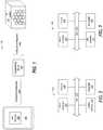
- FIG. 1shows a system 100 in which an IR emitter 102 is configured by a programming device 104 that is controlled by a portable computing device 106.
- the portable computing deviceexecutes an application program that provides a user interface 108 through which a user may enter and view data for configuring or testing operation of the IR emitter 102.
- Configuration dataas may be specified via user interface 108, is communicated from the portable computing device to the programming device, and from the programming device to the IR emitter.
- the configuration datamay include the class of vehicle with which the IR emitter is associated, a vehicle identifier of the vehicle to which the IR emitter is assigned and installed, an agency identifier of the entity to which the vehicle belongs, and the model and/or serial number of the IR emitter.
- Diagnostic datawhich is generated by the IR emitter in response to a command entered at the portable computing device, is transmitted from the IR emitter and received by the programming device, and then communicated from the programming device to the portable computing device for display via the user interface. Diagnostic data may include logged error data, a count of the number of times the number of on-off cycles of the LEDs of the IR emitter (flash count), an a number of hours of operations.
- the programming device 104may communicate with the portable computing device 106 via a wireless or a wired connection.
- Wireless communicationsmay be by Bluetooth or a wireless network connection, for example.
- a wired connectionmay include a cable that connects to a USB or micro-USB port (not shown) of the portable computing device.
- the IR emitter 102includes a wireless interface (not shown) for wirelessly communicating with the programming device 104 and for interfacing with control circuitry (not shown) of the IR emitter.
- the wireless communication between the programming device 104 and the IR emittermay be by Bluetooth, wireless network, cellular communications, IR signaling or other wireless medium.
- the portable computing device 106may be a multi-purpose computing device such as a smart phone, tablet computer, or notebook computer, for example.
- the portable computing deviceexecutes an application program that provides the user interface 108 and establishes communications with the programming device 104 and provides configuration data and/or diagnostic commands to the programming device.
- FIG. 2shows an implementation of a programming device 200 having a wireless interface 202 for communicating with an application on a portable computing device.
- the programming devicefurther includes a micro-processor 204, a memory arrangement 206, and a transmitter 208, all inter-coupled via bus 210.
- the wireless interfacemay be a network interface controller that includes a radio signal transceiver and antenna for connecting to a radio signal-based network such as one based on the IEEE 802.11 standard or Bluetooth standard, for example.
- the transmitter 208is configured to wirelessly transmit data and/or commands to the IR emitter.
- the transmittermay be a network interface controller that connects to a radio signal-based network such as one based on the IEEE 802.11 standard or Bluetooth standard, or may provide IR light signaling, for example.
- the transmittermay be part of a transceiver (not shown) for connecting and communicating with the IR emitter via an IEEE 802.11 network or a cellular communications network, thereby providing long-range transmission of configuration data and receipt of diagnostic data.
- Microprocessor 204may be any type of processor capable of executing program instructions and suitable for implementation requirements.
- the memory arrangement 206may include a hierarchy of memory components ranging from cache memory to retentive storage.
- the retentive storagemay be flash memory for storing executable program code.
- the memory arrangement 206may be configured with instructions that are executable by the microprocessor 204 for transmitting configuration data to the IR emitter.
- the configuration datamay be provided to the programming device via the portable computing device 106 ( FIG. 1 ).
- the memory arrangementmay be further configured with program code that is executable by the portable computing device for providing the user interface 108 and interacting with the programming device. Further still, the memory arrangement may be configured with program code that is executable by the portable computing device for receiving diagnostic data from the IR emitter and forwarding the diagnostic data to the application on the portable computing device.
- the bus 210may include multiple buses for communicating data, address and control signals between the connected components.
- FIG. 3shows an implementation of a programming device 300 having a wire interface 302 for connecting the programming device to a portable computing device.
- the wire interface 302may implement a micro-USB or USB connection, for example.
- FIG. 4shows an implementation of a programming device 400 having an IR receiver 402 for receiving an IR light signal from the emitter and providing data from the signal to the microprocessor for verification.
- the IR receiverincludes circuitry for detecting an IR light signal, decoding the IR light signal into electrical signals, and communicating data represented in the electrical signals to the microprocessor.
- the IR receiver 402may be used in supporting diagnostic operations on the IR emitter.
- the memory arrangement 206may be configured with instructions that are executable by the microprocessor for initiating transmission of a request or command to the IR emitter for diagnostic data.
- the request or commandmay have been first received by the programming device 400 from the portable computing device 106 ( FIG. 1 ) via the computing device interface.
- the microprocessorinputs the diagnostic data, as decoded by the IR receiver 402, and communicates the diagnostic data to the application executing on the portable computing device.
- FIG. 5shows a programming device 500 in which the components are attached to a support structure 502, and the programming device has a wireless interface for connecting to a portable computing device.
- the support structure 502may include a circuit board on which the wireless interface 202, microprocessor 204, memory 206, transmitter 208, and IR receiver 402 are mounted and communicatively interconnected.
- the circuit boardmay be attached to a housing or case that encloses the circuit board and attached components.
- Other implementationsmay have multiple ones of the components constructed as a system on a chip (SOC).
- SOCsystem on a chip
- FIG. 6shows a programming device 600 in which the components are attached to a support structure 602, and the programming device has a wire interface 302 for connecting to a portable computing device.
- the support structure 602may include a circuit board on which the wire interface 302, microprocessor 204, memory 206, transmitter 208, and IR receiver 402 are mounted and communicatively interconnected.
- the circuit boardmay be attached to a housing or case that encloses the circuit board and attached components.
- Other implementationsmay have multiple ones of the components constructed as a system on a chip (SOC).
- SOCsystem on a chip
- the wire interface 302is coupled to the cable 604 and connector 606, and the cable may be either permanently attached or detachable from the support structure.
- the connectoris configured to mechanically and electrically connect to a data port on the portable computing device.
- the connector and cablemay be micro-USB compatible, or compatible with another similar interface.
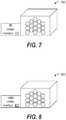
- FIG. 7shows an IR emitter 700 having an IR communications interface 702 through which the emitter can be configured via IR signaling.
- the IR communications interfaceincludes an IR light detector and circuitry for converting the IR signal into an electrical signal for input to control circuity of the IR emitter.
- FIG. 8shows an alternative IR emitter 800 having a radio communications interface 802 through which the emitter can be configured via radio signaling specified in the IEEE 802.11 standard or the Bluetooth standard, or in a cellular network, for example.
- the radio communications interfaceincludes an antenna and circuitry for converting the radio signal into an electrical signal for input to control circuity of the IR emitter.
- FIG. 9is a flowchart of a process for configuring and verifying the configuration of an IR emitter.
- the programming deviceis connected to the portable computing device. It will be appreciated that for a programming device having a wireless interface to the portable computing device, no physical connection need be made.
- communicationis established between the programming device and the portable computing device according to the protocol of the interface.
- the programming devicestores program code that is executable by the portable computing device. The program code may be loaded by the portable computing device and executed to provide an application program and user interface for configuring and/or testing the IR emitter. In an alternative implementation, the program code may be stored as an available application on the portable computing device.
- configuration datais received from the portable computing device by the programming device.
- the configuration datamay be entered, specified, or referenced via the user interface of the application executing on the portable computing device.
- the configuration datamay include commands and data.
- the commandsmay direct the IR emitter to perform configuration of its local registers or memory or direct the IR emitter to perform diagnostic functions.
- the configuration datais transmitted from the programming device to the IR emitter. Depending on the implementation, the configuration data may be transmitted via radio signal or an IR light signal.
- the programming devicereceives a verification command from the application on the portable computing device.
- the verification commandis for obtaining diagnostic and configuration information from the IR emitter.
- the diagnostic informationmay include logged error data, a count of the number of times the number of on-off cycles of the LEDs of the IR emitter (flash count), and a number of hours of operation.
- the configuration information read-back from the IR emittermay include the class of vehicle with which the IR emitter is associated, a vehicle identifier of the vehicle to which the IR emitter is assigned and installed, an agency identifier of the entity to which the vehicle belongs, and the model and/or serial number of the IR emitter.
- the verification commandis transmitted from the programming device to the IR emitter.
- the commandmay be encoded in a radio signal or an IR light signal and transmitted accordingly, depending on the implementation.
- output from the IR emitteris captured and converted by the programming device into electrical signals that represent the diagnostic data.
- the outputmay be an IR light signal and/or a radio signal, depending on the implementation of the IR emitter and programming device.
- the diagnostic datais communicated from the programming device to the application on the portable computing device at block 916.
- the applicationmay then display the diagnostic data on the portable computing device for review by a user.
Landscapes
- Physics & Mathematics (AREA)
- General Physics & Mathematics (AREA)
- Business, Economics & Management (AREA)
- Emergency Management (AREA)
- Selective Calling Equipment (AREA)
- Optical Communication System (AREA)
- Telephone Function (AREA)
Description
- The disclosure is generally directed to configuring infrared emitters for traffic control preemption systems.
- Traffic signals have long been used to regulate the flow of traffic at intersections. Generally, traffic signals have relied on timers or vehicle sensors to determine when to change traffic signal lights, thereby signaling alternating directions of traffic to stop, and others to proceed.
- Emergency vehicles, such as police cars, fire trucks and ambulances generally have the right to cross an intersection against a traffic signal. Emergency vehicles have in the past typically depended on horns, sirens and flashing lights to alert other drivers approaching the intersection that an emergency vehicle intends to cross the intersection. However, due to hearing impairment, air conditioning, audio systems and other distractions, often the driver of a vehicle approaching an intersection will not be aware of a warning being emitted by an approaching emergency vehicle.
- Traffic control preemption systems assist authorized vehicles (police, fire and other public safety or transit vehicles) through signalized intersections by making preemption requests to the intersection controllers that control the traffic lights at the intersections. The intersection controller may respond to the preemption request from the vehicle by changing the intersection lights to green in the direction of travel of the approaching vehicle. This system improves the response time of public safety personnel, while reducing dangerous situations at intersections when an emergency vehicle is trying to cross on a red light. In addition, speed and schedule efficiency can be improved for transit vehicles.
- There are presently a number of known traffic control preemption systems that have equipment installed at certain traffic signals and on authorized vehicles. One such system in use today is the OPTICOM® system. This system utilizes a high power strobe tube (emitter), located in or on the emergency vehicle, that generates light pulses at a predetermined rate, typically 10 Hz or 14 Hz. A receiver, which includes a photodetector and associated electronics, is typically mounted on the mast arm located at the intersection and produces a series of voltage pulses, the number of which are proportional to the intensity of light pulses received from the emitter. The emitter generates sufficient radiant power to be detected from over 2500 feet away. The conventional strobe tube emitter generates broad spectrum light. However, an optical filter is used on the detector to restrict its sensitivity to light only in the near infrared (IR) spectrum. This minimizes interference from other sources of light.
- Intensity levels are associated with each intersection approach to determine when a detected vehicle is within range of the intersection. Vehicles with valid security codes and a sufficient intensity level are reviewed with other detected vehicles to determine the highest priority vehicle. Vehicles of equivalent priority are selected in a first come, first served manner. A preemption request is issued to the controller for the approach direction with the highest priority vehicle.
- The emitter on a vehicle may be configurable so that it is associated with a vehicle class, vehicle identifier, and a government agency, for example. The emitter may encode this information in the light pulses for processing by the intersection equipment. The intersection equipment may use this information in prioritizing preemption requests and logging preemption data.
- The Opticom™ 794H LED emitter from Global Traffic Technologies, LLC, is an example of an emitter that generates pulses of infrared light that encode preemption requests. The 794H LED emitter is also configurable via an infrared interface and a handheld infrared remote coding unit.
- Document
US 2014/0200760 A1 discloses a method for transmitting vehicle diagnostic data from the vehicle implemented vehicle diagnostics system to a mobile user communication terminal. - In one implementation, a device for configuring an infrared (IR) emitter is provided. The device includes a support structure and a microprocessor attached to the support structure. An interface circuit is also attached to the support structure and is configured to provide communications between the microprocessor and a portable computing device. A memory, which is attached to the support structure, is coupled to the microprocessor and is configured with instructions. Execution of the instructions by the microprocessor cause the microprocessor to communicate with an application executing on the portable computing device and initiate transmission of configuration data to the IR emitter. A transmitter is attached to the support structure and is coupled to the microprocessor. The transmitter is configured to transmit the configuration data to the IR emitter.
- In another implementation, a method of configuring an IR emitter is provided. The method includes establishing communication between a programming device and an application executing on a portable computing device, receiving by the programming device, configuration data from the application, and transmitting the configuration data from the programming device to the IR emitter.
- The above summary of the present invention is not intended to describe each disclosed embodiment of the present invention. The figures and detailed description that follow provide additional example embodiments and aspects of the present invention.
- Other aspects and advantages of the invention will become apparent upon review of the Detailed Description and upon reference to the drawings in which:
FIG. 1 shows a system in which an IR emitter is configured by a programming device that is controlled by a portable computing device;FIG. 2 shows an implementation of a programming device having a wireless interface for communicating with an application on a portable computing device;FIG. 3 shows an implementation of a programming device having a wire interface for connecting the programming device to a portable computing device;FIG. 4 shows an implementation of a programming device having an IR receiver for receiving an IR light signal from the emitter and providing data from the signal to the microprocessor for verification;FIG. 5 shows a programming device in which the components are attached to a support structure, and the programming device has a wireless interface for connecting to a portable computing device;FIG. 6 shows a programming device in which the components are attached to a support structure, and the programming device has a wire interface for connecting to a portable computing device;FIG. 7 shows an IR emitter having an IR communications interface;FIG. 8 shows an alternative IR emitter having a radio communications interface; andFIG. 9 is a flowchart of a process for configuring and verifying the configuration of an IR emitter.- In the following description, numerous specific details are set forth to describe specific examples presented herein. It should be apparent, however, to one skilled in the art, that one or more other examples and/or variations of these examples may be practiced without all the specific details given below. In other instances, well known features have not been described in detail so as not to obscure the description of the examples herein. For ease of illustration, the same reference numerals may be used in different diagrams to refer to the same element or additional instances of the same element.
- Configuring emitters has been found to present a number of challenges. For some emitters, physical access to the emitters is required for cable connections, and accessing the emitters may be cumbersome. For example, an emitter may be disposed on the roof of a fire engine and enclosed within a structure containing other emergency lighting apparatus. A ladder, tools, and cables may be required to access the emitter in the aforementioned scenario. The infrared (IR) configuration interface and handheld unit for some emitters alleviates some challenges of configuring emitters. However, a good line of sight is needed between the handheld unit and the emitter, and bright sunlight may interfere with the IR communications.
- This disclosure describes devices and methods for configuring an IR emitter. The ease with which IR emitters may be configured, tested, or updated with new firmware is important to the user experience with the emitter. Many users may be inconvenienced in having to procure and place a ladder, and climb the ladder with a notebook computer or other equipment to configure or test an IR emitter. These and other inconveniences associated with configuring or testing an IR emitter are eliminated with the disclosed devices and methods.
- A device for configuring an IR emitter includes a support structure and a microprocessor attached to the support structure. An interface circuit is attached to the support structure, and the interface circuit is configured to provide communications between the microprocessor and a portable computing device, such as a smart phone, tablet computer, notebook computer or other similar devices. A memory is also attached to the support structure and is coupled to the microprocessor. The memory is configured with instructions, and execution of the instructions by the microprocessor causes the microprocessor to communicate with an application executing on the portable computing device, and to initiate transmission of configuration data received from the application to the IR emitter. A transmitter is attached to the support structure, coupled to the microprocessor, and configured to transmit the configuration data to the IR emitter. The support structure may include a circuit board on which the circuit components are mounted and a case to which the circuit board is attached and in which the circuit board is enclosed. The support structure may be structured similar to a dongle, for example.
FIG. 1 shows asystem 100 in which anIR emitter 102 is configured by aprogramming device 104 that is controlled by aportable computing device 106. The portable computing device executes an application program that provides a user interface 108 through which a user may enter and view data for configuring or testing operation of theIR emitter 102. Configuration data, as may be specified via user interface 108, is communicated from the portable computing device to the programming device, and from the programming device to the IR emitter. The configuration data may include the class of vehicle with which the IR emitter is associated, a vehicle identifier of the vehicle to which the IR emitter is assigned and installed, an agency identifier of the entity to which the vehicle belongs, and the model and/or serial number of the IR emitter. Diagnostic data, which is generated by the IR emitter in response to a command entered at the portable computing device, is transmitted from the IR emitter and received by the programming device, and then communicated from the programming device to the portable computing device for display via the user interface. Diagnostic data may include logged error data, a count of the number of times the number of on-off cycles of the LEDs of the IR emitter (flash count), an a number of hours of operations.- The
programming device 104 may communicate with theportable computing device 106 via a wireless or a wired connection. Wireless communications may be by Bluetooth or a wireless network connection, for example. A wired connection may include a cable that connects to a USB or micro-USB port (not shown) of the portable computing device. - The
IR emitter 102 includes a wireless interface (not shown) for wirelessly communicating with theprogramming device 104 and for interfacing with control circuitry (not shown) of the IR emitter. The wireless communication between theprogramming device 104 and the IR emitter may be by Bluetooth, wireless network, cellular communications, IR signaling or other wireless medium. - The
portable computing device 106 may be a multi-purpose computing device such as a smart phone, tablet computer, or notebook computer, for example. The portable computing device executes an application program that provides the user interface 108 and establishes communications with theprogramming device 104 and provides configuration data and/or diagnostic commands to the programming device. FIG. 2 shows an implementation of aprogramming device 200 having awireless interface 202 for communicating with an application on a portable computing device. The programming device further includes a micro-processor 204, amemory arrangement 206, and atransmitter 208, all inter-coupled via bus 210. The wireless interface may be a network interface controller that includes a radio signal transceiver and antenna for connecting to a radio signal-based network such as one based on the IEEE 802.11 standard or Bluetooth standard, for example.- The
transmitter 208 is configured to wirelessly transmit data and/or commands to the IR emitter. The transmitter may be a network interface controller that connects to a radio signal-based network such as one based on the IEEE 802.11 standard or Bluetooth standard, or may provide IR light signaling, for example. In another implementation, the transmitter may be part of a transceiver (not shown) for connecting and communicating with the IR emitter via an IEEE 802.11 network or a cellular communications network, thereby providing long-range transmission of configuration data and receipt of diagnostic data. Microprocessor 204 may be any type of processor capable of executing program instructions and suitable for implementation requirements. Thememory arrangement 206 may include a hierarchy of memory components ranging from cache memory to retentive storage. The retentive storage may be flash memory for storing executable program code.- The
memory arrangement 206 may be configured with instructions that are executable by themicroprocessor 204 for transmitting configuration data to the IR emitter. The configuration data may be provided to the programming device via the portable computing device 106 (FIG. 1 ). The memory arrangement may be further configured with program code that is executable by the portable computing device for providing the user interface 108 and interacting with the programming device. Further still, the memory arrangement may be configured with program code that is executable by the portable computing device for receiving diagnostic data from the IR emitter and forwarding the diagnostic data to the application on the portable computing device. The bus 210 may include multiple buses for communicating data, address and control signals between the connected components. FIG. 3 shows an implementation of aprogramming device 300 having awire interface 302 for connecting the programming device to a portable computing device. Thewire interface 302 may implement a micro-USB or USB connection, for example.FIG. 4 shows an implementation of aprogramming device 400 having anIR receiver 402 for receiving an IR light signal from the emitter and providing data from the signal to the microprocessor for verification. The IR receiver includes circuitry for detecting an IR light signal, decoding the IR light signal into electrical signals, and communicating data represented in the electrical signals to the microprocessor.- The
IR receiver 402 may be used in supporting diagnostic operations on the IR emitter. For example, thememory arrangement 206 may be configured with instructions that are executable by the microprocessor for initiating transmission of a request or command to the IR emitter for diagnostic data. The request or command may have been first received by theprogramming device 400 from the portable computing device 106 (FIG. 1 ) via the computing device interface. The microprocessor inputs the diagnostic data, as decoded by theIR receiver 402, and communicates the diagnostic data to the application executing on the portable computing device. FIG. 5 shows aprogramming device 500 in which the components are attached to asupport structure 502, and the programming device has a wireless interface for connecting to a portable computing device. Thesupport structure 502 may include a circuit board on which thewireless interface 202,microprocessor 204,memory 206,transmitter 208, andIR receiver 402 are mounted and communicatively interconnected. The circuit board may be attached to a housing or case that encloses the circuit board and attached components. Other implementations may have multiple ones of the components constructed as a system on a chip (SOC).FIG. 6 shows aprogramming device 600 in which the components are attached to asupport structure 602, and the programming device has awire interface 302 for connecting to a portable computing device. Thesupport structure 602 may include a circuit board on which thewire interface 302,microprocessor 204,memory 206,transmitter 208, andIR receiver 402 are mounted and communicatively interconnected. The circuit board may be attached to a housing or case that encloses the circuit board and attached components. Other implementations may have multiple ones of the components constructed as a system on a chip (SOC).- The
wire interface 302 is coupled to thecable 604 andconnector 606, and the cable may be either permanently attached or detachable from the support structure. The connector is configured to mechanically and electrically connect to a data port on the portable computing device. The connector and cable may be micro-USB compatible, or compatible with another similar interface. FIG. 7 shows anIR emitter 700 having an IR communications interface 702 through which the emitter can be configured via IR signaling. The IR communications interface includes an IR light detector and circuitry for converting the IR signal into an electrical signal for input to control circuity of the IR emitter.FIG. 8 shows analternative IR emitter 800 having aradio communications interface 802 through which the emitter can be configured via radio signaling specified in the IEEE 802.11 standard or the Bluetooth standard, or in a cellular network, for example. The radio communications interface includes an antenna and circuitry for converting the radio signal into an electrical signal for input to control circuity of the IR emitter.FIG. 9 is a flowchart of a process for configuring and verifying the configuration of an IR emitter. Atblock 902, the programming device is connected to the portable computing device. It will be appreciated that for a programming device having a wireless interface to the portable computing device, no physical connection need be made. Atblock 904, communication is established between the programming device and the portable computing device according to the protocol of the interface. In one implementation, the programming device stores program code that is executable by the portable computing device. The program code may be loaded by the portable computing device and executed to provide an application program and user interface for configuring and/or testing the IR emitter. In an alternative implementation, the program code may be stored as an available application on the portable computing device.- At block 906, configuration data is received from the portable computing device by the programming device. The configuration data may be entered, specified, or referenced via the user interface of the application executing on the portable computing device. Note that the configuration data may include commands and data. The commands may direct the IR emitter to perform configuration of its local registers or memory or direct the IR emitter to perform diagnostic functions. At block 908, the configuration data is transmitted from the programming device to the IR emitter. Depending on the implementation, the configuration data may be transmitted via radio signal or an IR light signal.
- At
block 910, the programming device receives a verification command from the application on the portable computing device. The verification command is for obtaining diagnostic and configuration information from the IR emitter. For example, the diagnostic information may include logged error data, a count of the number of times the number of on-off cycles of the LEDs of the IR emitter (flash count), and a number of hours of operation. The configuration information read-back from the IR emitter may include the class of vehicle with which the IR emitter is associated, a vehicle identifier of the vehicle to which the IR emitter is assigned and installed, an agency identifier of the entity to which the vehicle belongs, and the model and/or serial number of the IR emitter. - At
block 912, the verification command is transmitted from the programming device to the IR emitter. The command may be encoded in a radio signal or an IR light signal and transmitted accordingly, depending on the implementation. Atblock 914, output from the IR emitter is captured and converted by the programming device into electrical signals that represent the diagnostic data. The output may be an IR light signal and/or a radio signal, depending on the implementation of the IR emitter and programming device. The diagnostic data is communicated from the programming device to the application on the portable computing device atblock 916. The application may then display the diagnostic data on the portable computing device for review by a user. - Though aspects and features may in some carriers be described in individual figures, it will be appreciated that features from one figure can be combined with features of another figure even though the combination is not explicitly shown or explicitly described as a combination.
- The present invention is thought to be applicable to a variety of systems for controlling the flow of traffic. Other aspects and embodiments of the present invention will be apparent to those skilled in the art from consideration of the specification and practice of the invention disclosed herein. It is intended that the specification and illustrated embodiments be considered as examples only, with a true scope of the invention being indicated by the following claims.
Claims (15)
- A device (104, 200, 300, 400, 500, 600) for configuring an infrared (IR) emitter-based traffic control preemption system (102), comprising:a support structure (502, 602);a microprocessor (204) attached to the support structure; an IR receiver (402) attached to the support structure and coupled to the microprocessor;an interface circuit (202, 302) attached to the support structure and configured to provide communications between the microprocessor and a portable computing device (106);a memory (206) attached to the support structure and coupled to the microprocessor, wherein the memory is configured with instructions and execution of the instructions by the microprocessor cause the microprocessor to:communicate with an application executing on the portable computing device;receive a verification command from the application;initiate transmission of configuration data and the verification command to the IR emitter-based traffic control preemption system (102);capture an IR light signal via the IR receiver (402);convert the IR light signal into diagnostic data; andcommunicate the diagnostic data to the application executing on the portable computing device; anda transmitter (208) attached to the support structure (502, 602) and coupled to the microprocessor (204), the transmitter configured to transmit the configuration data and the verification command to the IR emitter-based traffic control preemption system (102).
- The device of claim 1, wherein the transmitter includes:a radio signal transmitter, and/oran IR emitter.
- The device of claim 1, further comprising:
a connector electrically coupled to the interface circuit, attached to the support structure and configured to mechanically and electrically engage with and disengage from a data port on a portable computing device. - The device of claim 1, wherein the interface circuit includes a radio signal transceiver for wirelessly communicating with the portable computing device.
- A method of configuring an infrared (IR) emitter-based traffic control preemption system, comprising:establishing (904) communication between a programming device and an application executing on a portable computing device;receiving (906) by the programming device, configuration data from the application;transmitting (908) the configuration data from the programming device to the IR emitter-based traffic control preemption system;receiving (910) by the programming device, a verification command from the application;transmitting (912) the verification command from the programming device to the IR emitter-based traffic control preemption system;capturing (914) by the programming device, an IR light signal generated by the IR emitter-based traffic control preemption system in response to the verification command;converting (916) the IR light signal into diagnostic data; andcommunicating (916) the diagnostic data from the programming device to the application on the portable computing device.
- The method of claim 5, wherein the transmitting the configuration data from the programming device to the IR emitter-based traffic control preemption system includes generating a radio signal that encodes the configuration data.
- The method of claim 5, wherein the transmitting the configuration data from the programming device to the IR emitter-based traffic control preemption system includes generating an IR light signal that encodes the configuration data.
- The method of claim 5, wherein the establishing communication between the programming device and the application executing on the portable computing device includes establishing communication via a wired connection between the programming device and the application executing on the portable computing device.
- The method of claim 5, wherein the establishing communication between the programming device and the application executing on the portable computing device includes establishing communication via a wireless connection between the programming device and the application executing on the portable computing device.
- A system (100) for configuring an infrared (IR) emitter-based traffic control preemption system (102), comprising:
a portable computing device (106); and
a device (104, 200, 300, 400, 500, 600) according to claim 1. - The system of claim 10, wherein the transmitter includes a radio signal transmitter.
- The system of claim 10, wherein the transmitter includes an IR emitter.
- The system of claim 10, further comprising an IR receiver attached to the support structure and coupled to the microprocessor.
- The system of claim 10, further comprising:
a connector electrically coupled to the interface circuit, attached to the support structure and configured to mechanically and electrically engage with and disengage from a data port on a portable computing device. - The system of claim 10, wherein the interface circuit includes a radio signal transceiver for wirelessly communicating with the portable computing device.
Applications Claiming Priority (2)
| Application Number | Priority Date | Filing Date | Title |
|---|---|---|---|
| US15/254,683US10198947B2 (en) | 2016-09-01 | 2016-09-01 | Emitter programmer and verification system |
| PCT/US2017/048881WO2018044784A1 (en) | 2016-09-01 | 2017-08-28 | Emitter programmer and verification system |
Publications (2)
| Publication Number | Publication Date |
|---|---|
| EP3507782A1 EP3507782A1 (en) | 2019-07-10 |
| EP3507782B1true EP3507782B1 (en) | 2020-07-22 |
Family
ID=59887369
Family Applications (1)
| Application Number | Title | Priority Date | Filing Date |
|---|---|---|---|
| EP17768283.8AActiveEP3507782B1 (en) | 2016-09-01 | 2017-08-28 | Emitter programmer and verification system |
Country Status (6)
| Country | Link |
|---|---|
| US (1) | US10198947B2 (en) |
| EP (1) | EP3507782B1 (en) |
| AU (1) | AU2017321292B2 (en) |
| CA (1) | CA3035521C (en) |
| ES (1) | ES2817428T3 (en) |
| WO (1) | WO2018044784A1 (en) |
Families Citing this family (1)
| Publication number | Priority date | Publication date | Assignee | Title |
|---|---|---|---|---|
| US11055991B1 (en) | 2018-02-09 | 2021-07-06 | Applied Information, Inc. | Systems, methods, and devices for communication between traffic controller systems and mobile transmitters and receivers |
Family Cites Families (23)
| Publication number | Priority date | Publication date | Assignee | Title |
|---|---|---|---|---|
| US5014052A (en) | 1983-04-21 | 1991-05-07 | Bourse Trading Company, Ltd. | Traffic signal control for emergency vehicles |
| US5027260A (en) | 1989-09-06 | 1991-06-25 | Whelen Technologies, Inc. | Vehicular lightbar assembly |
| US5237663A (en)* | 1991-03-26 | 1993-08-17 | Hewlett-Packard Company | Low cost diagnostic/configuration interface |
| US5187476A (en) | 1991-06-25 | 1993-02-16 | Minnesota Mining And Manufacturing Company | Optical traffic preemption detector circuitry |
| US5172113A (en) | 1991-10-24 | 1992-12-15 | Minnesota Mining And Manufacturing Company | System and method for transmitting data in an optical traffic preemption system |
| WO1996019093A1 (en) | 1994-12-14 | 1996-06-20 | Luminescent Systems, Inc. | Led light strip with brightness/current draw control circuitry |
| US5826965A (en) | 1996-08-21 | 1998-10-27 | Whelen Engineering Company, Inc. | Modular light bar |
| US5988839A (en) | 1998-08-17 | 1999-11-23 | Whelen Engineering Company, Inc. | Rear facing light bar |
| US6064319A (en) | 1998-10-22 | 2000-05-16 | Matta; David M. | Method and system for regulating switching of a traffic light |
| DE19909399C1 (en) | 1999-03-04 | 2001-01-04 | Osram Opto Semiconductors Gmbh | Flexible LED multiple module, especially for a light housing of a motor vehicle |
| US6326903B1 (en) | 2000-01-26 | 2001-12-04 | Dave Gross | Emergency vehicle traffic signal pre-emption and collision avoidance system |
| US6682210B1 (en) | 2002-01-11 | 2004-01-27 | Whelen Engineering Company, Inc. | Tip-up light bar assembly |
| US6863424B2 (en) | 2002-08-07 | 2005-03-08 | Whelen Engineering Company, Inc. | Light bar with integrated warning illumination and lens support structure |
| JP4037289B2 (en) | 2003-03-06 | 2008-01-23 | 株式会社小糸製作所 | Vehicle headlamp |
| US7411174B2 (en) | 2004-10-12 | 2008-08-12 | Eash Brandon A | Sensor-controlled LED array apparatus and method |
| US7573399B2 (en) | 2005-06-01 | 2009-08-11 | Global Traffic Technologies, Llc | Multimode traffic priority/preemption vehicle arrangement |
| US7429917B2 (en) | 2006-02-27 | 2008-09-30 | Whelen Engineering Company, Inc. | LED aviation warning light with fault detection |
| US20080001773A1 (en)* | 2006-06-29 | 2008-01-03 | X10 Ltd. | Programmable remote control and methods of using same |
| US7808401B1 (en) | 2008-01-11 | 2010-10-05 | Global Traffic Technologies, Llc | Light emitters for optical traffic control systems |
| US20110298581A1 (en)* | 2010-06-08 | 2011-12-08 | Wei Hsu | Universal remote controller |
| US9881432B2 (en)* | 2010-10-18 | 2018-01-30 | Zonar Systems, Inc. | Method and apparatus for an automated fuel authorization program for fuel terminals using a camera as part of the authorization process |
| US8884783B2 (en) | 2011-02-24 | 2014-11-11 | Global Traffic Technologies, Llc | Systems and method for controlling preemption of a traffic signal |
| DE102011076638A1 (en) | 2011-05-27 | 2012-11-29 | Stephan Kaufmann | A method of vehicle communication via a vehicle-implemented vehicle diagnostic system, interface module and vehicle diagnostic interface and diagnostic and control network for a plurality of vehicles |
- 2016
- 2016-09-01USUS15/254,683patent/US10198947B2/enactiveActive
- 2017
- 2017-08-28EPEP17768283.8Apatent/EP3507782B1/enactiveActive
- 2017-08-28CACA3035521Apatent/CA3035521C/enactiveActive
- 2017-08-28AUAU2017321292Apatent/AU2017321292B2/enactiveActive
- 2017-08-28ESES17768283Tpatent/ES2817428T3/enactiveActive
- 2017-08-28WOPCT/US2017/048881patent/WO2018044784A1/ennot_activeCeased
Non-Patent Citations (1)
| Title |
|---|
| None* |
Also Published As
| Publication number | Publication date |
|---|---|
| US10198947B2 (en) | 2019-02-05 |
| CA3035521A1 (en) | 2018-03-08 |
| AU2017321292A1 (en) | 2019-04-18 |
| ES2817428T3 (en) | 2021-04-07 |
| CA3035521C (en) | 2019-09-24 |
| WO2018044784A1 (en) | 2018-03-08 |
| US20180061229A1 (en) | 2018-03-01 |
| EP3507782A1 (en) | 2019-07-10 |
| AU2017321292B2 (en) | 2019-10-31 |
Similar Documents
| Publication | Publication Date | Title |
|---|---|---|
| US9478131B2 (en) | Prioritization of traffic signal preemption requests received from multiple sources over different communication mediums | |
| CN102081807B (en) | Parking management system for parking lot and parking guiding method | |
| US8054202B1 (en) | Traffic preemption system and related methods | |
| EP2964485B1 (en) | System and method for the access to information contained in motor vehicles | |
| US20210049904A1 (en) | Traffic management system | |
| AU2021329202A1 (en) | Incident-based traffic signal preemption and priority | |
| US20220050475A1 (en) | Autonomous vehicle signaling system | |
| CN106920411A (en) | It is a kind of automatic with the method and device during car by intersection | |
| CN109598883A (en) | Lamp leads fire evacuation system and its control method | |
| EP3507782B1 (en) | Emitter programmer and verification system | |
| KR102420342B1 (en) | Traffic flow control apparatus for controling mixed traffic flow with automated vehicles and method using the same | |
| CN104383697A (en) | Electronic building block and electronic building block group | |
| CN202389340U (en) | Wireless alarming lamp | |
| KR102417041B1 (en) | Apparatus and method for controlling vichile using a traffic signal informtion | |
| US12365493B2 (en) | Lighting device and lighting system | |
| KR102106450B1 (en) | A method for Traffic Signal Notification System Using Traffic Lights Capable of Wireless Communications | |
| CN115013045A (en) | A rescue method and system applied to tunnel construction | |
| JP6132194B2 (en) | Tunnel warning system and tunnel warning transmission system | |
| CN109835295A (en) | It is a kind of interior to forget life body detecting method, device and medium | |
| US6603387B1 (en) | Programming of RF transmitter identification data by monitoring power | |
| CN109476286B (en) | Method and system for controlling vehicle functions | |
| JP3772827B2 (en) | In-vehicle communication device and road-to-vehicle optical communication device | |
| AU2023248110A1 (en) | DSRC Cap Lamp | |
| JP2017092879A (en) | Optical beacon | |
| CN118248003A (en) | Early warning system and early warning method for high-speed lane |
Legal Events
| Date | Code | Title | Description |
|---|---|---|---|
| STAA | Information on the status of an ep patent application or granted ep patent | Free format text:STATUS: UNKNOWN | |
| STAA | Information on the status of an ep patent application or granted ep patent | Free format text:STATUS: THE INTERNATIONAL PUBLICATION HAS BEEN MADE | |
| PUAI | Public reference made under article 153(3) epc to a published international application that has entered the european phase | Free format text:ORIGINAL CODE: 0009012 | |
| STAA | Information on the status of an ep patent application or granted ep patent | Free format text:STATUS: REQUEST FOR EXAMINATION WAS MADE | |
| 17P | Request for examination filed | Effective date:20190322 | |
| AK | Designated contracting states | Kind code of ref document:A1 Designated state(s):AL AT BE BG CH CY CZ DE DK EE ES FI FR GB GR HR HU IE IS IT LI LT LU LV MC MK MT NL NO PL PT RO RS SE SI SK SM TR | |
| AX | Request for extension of the european patent | Extension state:BA ME | |
| DAV | Request for validation of the european patent (deleted) | ||
| DAX | Request for extension of the european patent (deleted) | ||
| GRAP | Despatch of communication of intention to grant a patent | Free format text:ORIGINAL CODE: EPIDOSNIGR1 | |
| STAA | Information on the status of an ep patent application or granted ep patent | Free format text:STATUS: GRANT OF PATENT IS INTENDED | |
| INTG | Intention to grant announced | Effective date:20200225 | |
| GRAS | Grant fee paid | Free format text:ORIGINAL CODE: EPIDOSNIGR3 | |
| GRAA | (expected) grant | Free format text:ORIGINAL CODE: 0009210 | |
| STAA | Information on the status of an ep patent application or granted ep patent | Free format text:STATUS: THE PATENT HAS BEEN GRANTED | |
| AK | Designated contracting states | Kind code of ref document:B1 Designated state(s):AL AT BE BG CH CY CZ DE DK EE ES FI FR GB GR HR HU IE IS IT LI LT LU LV MC MK MT NL NO PL PT RO RS SE SI SK SM TR | |
| REG | Reference to a national code | Ref country code:GB Ref legal event code:FG4D | |
| REG | Reference to a national code | Ref country code:CH Ref legal event code:EP | |
| REG | Reference to a national code | Ref country code:DE Ref legal event code:R096 Ref document number:602017020258 Country of ref document:DE | |
| REG | Reference to a national code | Ref country code:AT Ref legal event code:REF Ref document number:1294149 Country of ref document:AT Kind code of ref document:T Effective date:20200815 | |
| REG | Reference to a national code | Ref country code:IE Ref legal event code:FG4D | |
| REG | Reference to a national code | Ref country code:NL Ref legal event code:FP | |
| REG | Reference to a national code | Ref country code:LT Ref legal event code:MG4D | |
| PG25 | Lapsed in a contracting state [announced via postgrant information from national office to epo] | Ref country code:HR Free format text:LAPSE BECAUSE OF FAILURE TO SUBMIT A TRANSLATION OF THE DESCRIPTION OR TO PAY THE FEE WITHIN THE PRESCRIBED TIME-LIMIT Effective date:20200722 Ref country code:BG Free format text:LAPSE BECAUSE OF FAILURE TO SUBMIT A TRANSLATION OF THE DESCRIPTION OR TO PAY THE FEE WITHIN THE PRESCRIBED TIME-LIMIT Effective date:20201022 Ref country code:PT Free format text:LAPSE BECAUSE OF FAILURE TO SUBMIT A TRANSLATION OF THE DESCRIPTION OR TO PAY THE FEE WITHIN THE PRESCRIBED TIME-LIMIT Effective date:20201123 Ref country code:LT Free format text:LAPSE BECAUSE OF FAILURE TO SUBMIT A TRANSLATION OF THE DESCRIPTION OR TO PAY THE FEE WITHIN THE PRESCRIBED TIME-LIMIT Effective date:20200722 Ref country code:GR Free format text:LAPSE BECAUSE OF FAILURE TO SUBMIT A TRANSLATION OF THE DESCRIPTION OR TO PAY THE FEE WITHIN THE PRESCRIBED TIME-LIMIT Effective date:20201023 Ref country code:SE Free format text:LAPSE BECAUSE OF FAILURE TO SUBMIT A TRANSLATION OF THE DESCRIPTION OR TO PAY THE FEE WITHIN THE PRESCRIBED TIME-LIMIT Effective date:20200722 Ref country code:NO Free format text:LAPSE BECAUSE OF FAILURE TO SUBMIT A TRANSLATION OF THE DESCRIPTION OR TO PAY THE FEE WITHIN THE PRESCRIBED TIME-LIMIT Effective date:20201022 Ref country code:FI Free format text:LAPSE BECAUSE OF FAILURE TO SUBMIT A TRANSLATION OF THE DESCRIPTION OR TO PAY THE FEE WITHIN THE PRESCRIBED TIME-LIMIT Effective date:20200722 | |
| PG25 | Lapsed in a contracting state [announced via postgrant information from national office to epo] | Ref country code:PL Free format text:LAPSE BECAUSE OF FAILURE TO SUBMIT A TRANSLATION OF THE DESCRIPTION OR TO PAY THE FEE WITHIN THE PRESCRIBED TIME-LIMIT Effective date:20200722 Ref country code:RS Free format text:LAPSE BECAUSE OF FAILURE TO SUBMIT A TRANSLATION OF THE DESCRIPTION OR TO PAY THE FEE WITHIN THE PRESCRIBED TIME-LIMIT Effective date:20200722 Ref country code:LV Free format text:LAPSE BECAUSE OF FAILURE TO SUBMIT A TRANSLATION OF THE DESCRIPTION OR TO PAY THE FEE WITHIN THE PRESCRIBED TIME-LIMIT Effective date:20200722 Ref country code:IS Free format text:LAPSE BECAUSE OF FAILURE TO SUBMIT A TRANSLATION OF THE DESCRIPTION OR TO PAY THE FEE WITHIN THE PRESCRIBED TIME-LIMIT Effective date:20201122 | |
| REG | Reference to a national code | Ref country code:DE Ref legal event code:R119 Ref document number:602017020258 Country of ref document:DE | |
| REG | Reference to a national code | Ref country code:CH Ref legal event code:PL | |
| REG | Reference to a national code | Ref country code:ES Ref legal event code:FG2A Ref document number:2817428 Country of ref document:ES Kind code of ref document:T3 Effective date:20210407 Ref country code:NL Ref legal event code:MM Effective date:20200901 | |
| PG25 | Lapsed in a contracting state [announced via postgrant information from national office to epo] | Ref country code:IT Free format text:LAPSE BECAUSE OF FAILURE TO SUBMIT A TRANSLATION OF THE DESCRIPTION OR TO PAY THE FEE WITHIN THE PRESCRIBED TIME-LIMIT Effective date:20200722 Ref country code:EE Free format text:LAPSE BECAUSE OF FAILURE TO SUBMIT A TRANSLATION OF THE DESCRIPTION OR TO PAY THE FEE WITHIN THE PRESCRIBED TIME-LIMIT Effective date:20200722 Ref country code:SM Free format text:LAPSE BECAUSE OF FAILURE TO SUBMIT A TRANSLATION OF THE DESCRIPTION OR TO PAY THE FEE WITHIN THE PRESCRIBED TIME-LIMIT Effective date:20200722 Ref country code:RO Free format text:LAPSE BECAUSE OF FAILURE TO SUBMIT A TRANSLATION OF THE DESCRIPTION OR TO PAY THE FEE WITHIN THE PRESCRIBED TIME-LIMIT Effective date:20200722 Ref country code:DK Free format text:LAPSE BECAUSE OF FAILURE TO SUBMIT A TRANSLATION OF THE DESCRIPTION OR TO PAY THE FEE WITHIN THE PRESCRIBED TIME-LIMIT Effective date:20200722 Ref country code:CH Free format text:LAPSE BECAUSE OF NON-PAYMENT OF DUE FEES Effective date:20200831 Ref country code:CZ Free format text:LAPSE BECAUSE OF FAILURE TO SUBMIT A TRANSLATION OF THE DESCRIPTION OR TO PAY THE FEE WITHIN THE PRESCRIBED TIME-LIMIT Effective date:20200722 Ref country code:LI Free format text:LAPSE BECAUSE OF NON-PAYMENT OF DUE FEES Effective date:20200831 Ref country code:LU Free format text:LAPSE BECAUSE OF NON-PAYMENT OF DUE FEES Effective date:20200828 | |
| REG | Reference to a national code | Ref country code:BE Ref legal event code:MM Effective date:20200831 | |
| PLBE | No opposition filed within time limit | Free format text:ORIGINAL CODE: 0009261 | |
| STAA | Information on the status of an ep patent application or granted ep patent | Free format text:STATUS: NO OPPOSITION FILED WITHIN TIME LIMIT | |
| PG25 | Lapsed in a contracting state [announced via postgrant information from national office to epo] | Ref country code:AL Free format text:LAPSE BECAUSE OF FAILURE TO SUBMIT A TRANSLATION OF THE DESCRIPTION OR TO PAY THE FEE WITHIN THE PRESCRIBED TIME-LIMIT Effective date:20200722 | |
| 26N | No opposition filed | Effective date:20210423 | |
| PG25 | Lapsed in a contracting state [announced via postgrant information from national office to epo] | Ref country code:SK Free format text:LAPSE BECAUSE OF FAILURE TO SUBMIT A TRANSLATION OF THE DESCRIPTION OR TO PAY THE FEE WITHIN THE PRESCRIBED TIME-LIMIT Effective date:20200722 | |
| PG25 | Lapsed in a contracting state [announced via postgrant information from national office to epo] | Ref country code:FR Free format text:LAPSE BECAUSE OF NON-PAYMENT OF DUE FEES Effective date:20200922 Ref country code:DE Free format text:LAPSE BECAUSE OF NON-PAYMENT OF DUE FEES Effective date:20210302 | |
| PG25 | Lapsed in a contracting state [announced via postgrant information from national office to epo] | Ref country code:SI Free format text:LAPSE BECAUSE OF FAILURE TO SUBMIT A TRANSLATION OF THE DESCRIPTION OR TO PAY THE FEE WITHIN THE PRESCRIBED TIME-LIMIT Effective date:20200722 Ref country code:IE Free format text:LAPSE BECAUSE OF NON-PAYMENT OF DUE FEES Effective date:20200828 Ref country code:BE Free format text:LAPSE BECAUSE OF NON-PAYMENT OF DUE FEES Effective date:20200831 | |
| PG25 | Lapsed in a contracting state [announced via postgrant information from national office to epo] | Ref country code:NL Free format text:LAPSE BECAUSE OF NON-PAYMENT OF DUE FEES Effective date:20200901 | |
| REG | Reference to a national code | Ref country code:ES Ref legal event code:FD2A Effective date:20211228 | |
| PG25 | Lapsed in a contracting state [announced via postgrant information from national office to epo] | Ref country code:ES Free format text:LAPSE BECAUSE OF NON-PAYMENT OF DUE FEES Effective date:20200829 | |
| REG | Reference to a national code | Ref country code:AT Ref legal event code:UEP Ref document number:1294149 Country of ref document:AT Kind code of ref document:T Effective date:20200722 | |
| GBPC | Gb: european patent ceased through non-payment of renewal fee | Effective date:20210828 | |
| PG25 | Lapsed in a contracting state [announced via postgrant information from national office to epo] | Ref country code:TR Free format text:LAPSE BECAUSE OF FAILURE TO SUBMIT A TRANSLATION OF THE DESCRIPTION OR TO PAY THE FEE WITHIN THE PRESCRIBED TIME-LIMIT Effective date:20200722 Ref country code:MT Free format text:LAPSE BECAUSE OF FAILURE TO SUBMIT A TRANSLATION OF THE DESCRIPTION OR TO PAY THE FEE WITHIN THE PRESCRIBED TIME-LIMIT Effective date:20200722 Ref country code:CY Free format text:LAPSE BECAUSE OF FAILURE TO SUBMIT A TRANSLATION OF THE DESCRIPTION OR TO PAY THE FEE WITHIN THE PRESCRIBED TIME-LIMIT Effective date:20200722 | |
| PG25 | Lapsed in a contracting state [announced via postgrant information from national office to epo] | Ref country code:MK Free format text:LAPSE BECAUSE OF FAILURE TO SUBMIT A TRANSLATION OF THE DESCRIPTION OR TO PAY THE FEE WITHIN THE PRESCRIBED TIME-LIMIT Effective date:20200722 Ref country code:MC Free format text:LAPSE BECAUSE OF FAILURE TO SUBMIT A TRANSLATION OF THE DESCRIPTION OR TO PAY THE FEE WITHIN THE PRESCRIBED TIME-LIMIT Effective date:20200722 | |
| PG25 | Lapsed in a contracting state [announced via postgrant information from national office to epo] | Ref country code:GB Free format text:LAPSE BECAUSE OF NON-PAYMENT OF DUE FEES Effective date:20210828 | |
| REG | Reference to a national code | Ref country code:AT Ref legal event code:MM01 Ref document number:1294149 Country of ref document:AT Kind code of ref document:T Effective date:20220828 | |
| PG25 | Lapsed in a contracting state [announced via postgrant information from national office to epo] | Ref country code:AT Free format text:LAPSE BECAUSE OF NON-PAYMENT OF DUE FEES Effective date:20220828 |