EP3507140B1 - Cooling device for rearview assembly - Google Patents
Cooling device for rearview assemblyDownload PDFInfo
- Publication number
- EP3507140B1 EP3507140B1EP17847633.9AEP17847633AEP3507140B1EP 3507140 B1EP3507140 B1EP 3507140B1EP 17847633 AEP17847633 AEP 17847633AEP 3507140 B1EP3507140 B1EP 3507140B1
- Authority
- EP
- European Patent Office
- Prior art keywords
- moving device
- air moving
- rearview assembly
- rearview
- air
- Prior art date
- Legal status (The legal status is an assumption and is not a legal conclusion. Google has not performed a legal analysis and makes no representation as to the accuracy of the status listed.)
- Active
Links
- 238000001816coolingMethods0.000titleclaimsdescription19
- 239000012530fluidSubstances0.000claimsdescription7
- 230000008859changeEffects0.000claimsdescription5
- 239000007788liquidSubstances0.000claimsdescription4
- 238000010438heat treatmentMethods0.000claimsdescription2
- 238000009423ventilationMethods0.000claimsdescription2
- 238000000034methodMethods0.000description18
- 230000008569processEffects0.000description11
- 239000000463materialSubstances0.000description4
- 230000008901benefitEffects0.000description3
- 238000004891communicationMethods0.000description3
- 238000012986modificationMethods0.000description3
- 230000004048modificationEffects0.000description3
- 230000000712assemblyEffects0.000description2
- 238000000429assemblyMethods0.000description2
- 239000011248coating agentSubstances0.000description2
- 238000000576coating methodMethods0.000description2
- 239000003086colorantSubstances0.000description2
- 238000010276constructionMethods0.000description2
- 239000011521glassSubstances0.000description2
- 230000010365information processingEffects0.000description2
- 230000000670limiting effectEffects0.000description2
- 238000005259measurementMethods0.000description2
- 230000037361pathwayEffects0.000description2
- 230000002829reductive effectEffects0.000description2
- 238000012546transferMethods0.000description2
- 230000015572biosynthetic processEffects0.000description1
- 238000007664blowingMethods0.000description1
- 230000008878couplingEffects0.000description1
- 238000010168coupling processMethods0.000description1
- 238000005859coupling reactionMethods0.000description1
- 230000003247decreasing effectEffects0.000description1
- 230000000694effectsEffects0.000description1
- 230000006870functionEffects0.000description1
- 230000004313glareEffects0.000description1
- 230000003287optical effectEffects0.000description1
- 238000013021overheatingMethods0.000description1
- 230000036961partial effectEffects0.000description1
- 238000012545processingMethods0.000description1
- 230000009467reductionEffects0.000description1
- 230000002441reversible effectEffects0.000description1
- 238000012552reviewMethods0.000description1
- 239000007787solidSubstances0.000description1
Images


Classifications
- B—PERFORMING OPERATIONS; TRANSPORTING
- B60—VEHICLES IN GENERAL
- B60R—VEHICLES, VEHICLE FITTINGS, OR VEHICLE PARTS, NOT OTHERWISE PROVIDED FOR
- B60R1/00—Optical viewing arrangements; Real-time viewing arrangements for drivers or passengers using optical image capturing systems, e.g. cameras or video systems specially adapted for use in or on vehicles
- B60R1/02—Rear-view mirror arrangements
- B60R1/04—Rear-view mirror arrangements mounted inside vehicle
- B—PERFORMING OPERATIONS; TRANSPORTING
- B60—VEHICLES IN GENERAL
- B60R—VEHICLES, VEHICLE FITTINGS, OR VEHICLE PARTS, NOT OTHERWISE PROVIDED FOR
- B60R1/00—Optical viewing arrangements; Real-time viewing arrangements for drivers or passengers using optical image capturing systems, e.g. cameras or video systems specially adapted for use in or on vehicles
- B60R1/12—Mirror assemblies combined with other articles, e.g. clocks
- F—MECHANICAL ENGINEERING; LIGHTING; HEATING; WEAPONS; BLASTING
- F21—LIGHTING
- F21V—FUNCTIONAL FEATURES OR DETAILS OF LIGHTING DEVICES OR SYSTEMS THEREOF; STRUCTURAL COMBINATIONS OF LIGHTING DEVICES WITH OTHER ARTICLES, NOT OTHERWISE PROVIDED FOR
- F21V29/00—Protecting lighting devices from thermal damage; Cooling or heating arrangements specially adapted for lighting devices or systems
- F21V29/50—Cooling arrangements
- F21V29/502—Cooling arrangements characterised by the adaptation for cooling of specific components
- F21V29/508—Cooling arrangements characterised by the adaptation for cooling of specific components of electrical circuits
- F—MECHANICAL ENGINEERING; LIGHTING; HEATING; WEAPONS; BLASTING
- F21—LIGHTING
- F21V—FUNCTIONAL FEATURES OR DETAILS OF LIGHTING DEVICES OR SYSTEMS THEREOF; STRUCTURAL COMBINATIONS OF LIGHTING DEVICES WITH OTHER ARTICLES, NOT OTHERWISE PROVIDED FOR
- F21V29/00—Protecting lighting devices from thermal damage; Cooling or heating arrangements specially adapted for lighting devices or systems
- F21V29/50—Cooling arrangements
- F21V29/60—Cooling arrangements characterised by the use of a forced flow of gas, e.g. air
- F21V29/61—Cooling arrangements characterised by the use of a forced flow of gas, e.g. air characterised by control arrangements
- F—MECHANICAL ENGINEERING; LIGHTING; HEATING; WEAPONS; BLASTING
- F21—LIGHTING
- F21V—FUNCTIONAL FEATURES OR DETAILS OF LIGHTING DEVICES OR SYSTEMS THEREOF; STRUCTURAL COMBINATIONS OF LIGHTING DEVICES WITH OTHER ARTICLES, NOT OTHERWISE PROVIDED FOR
- F21V29/00—Protecting lighting devices from thermal damage; Cooling or heating arrangements specially adapted for lighting devices or systems
- F21V29/50—Cooling arrangements
- F21V29/60—Cooling arrangements characterised by the use of a forced flow of gas, e.g. air
- F21V29/63—Cooling arrangements characterised by the use of a forced flow of gas, e.g. air using electrically-powered vibrating means; using ionic wind
- F—MECHANICAL ENGINEERING; LIGHTING; HEATING; WEAPONS; BLASTING
- F21—LIGHTING
- F21V—FUNCTIONAL FEATURES OR DETAILS OF LIGHTING DEVICES OR SYSTEMS THEREOF; STRUCTURAL COMBINATIONS OF LIGHTING DEVICES WITH OTHER ARTICLES, NOT OTHERWISE PROVIDED FOR
- F21V29/00—Protecting lighting devices from thermal damage; Cooling or heating arrangements specially adapted for lighting devices or systems
- F21V29/50—Cooling arrangements
- F21V29/60—Cooling arrangements characterised by the use of a forced flow of gas, e.g. air
- F21V29/67—Cooling arrangements characterised by the use of a forced flow of gas, e.g. air characterised by the arrangement of fans
- F21V29/673—Cooling arrangements characterised by the use of a forced flow of gas, e.g. air characterised by the arrangement of fans the fans being used for intake
- G—PHYSICS
- G02—OPTICS
- G02B—OPTICAL ELEMENTS, SYSTEMS OR APPARATUS
- G02B7/00—Mountings, adjusting means, or light-tight connections, for optical elements
- G02B7/18—Mountings, adjusting means, or light-tight connections, for optical elements for prisms; for mirrors
- G02B7/181—Mountings, adjusting means, or light-tight connections, for optical elements for prisms; for mirrors with means for compensating for changes in temperature or for controlling the temperature; thermal stabilisation
- G02B7/1815—Mountings, adjusting means, or light-tight connections, for optical elements for prisms; for mirrors with means for compensating for changes in temperature or for controlling the temperature; thermal stabilisation with cooling or heating systems
- B—PERFORMING OPERATIONS; TRANSPORTING
- B60—VEHICLES IN GENERAL
- B60R—VEHICLES, VEHICLE FITTINGS, OR VEHICLE PARTS, NOT OTHERWISE PROVIDED FOR
- B60R1/00—Optical viewing arrangements; Real-time viewing arrangements for drivers or passengers using optical image capturing systems, e.g. cameras or video systems specially adapted for use in or on vehicles
- B60R1/12—Mirror assemblies combined with other articles, e.g. clocks
- B60R2001/1215—Mirror assemblies combined with other articles, e.g. clocks with information displays
- B—PERFORMING OPERATIONS; TRANSPORTING
- B60—VEHICLES IN GENERAL
- B60R—VEHICLES, VEHICLE FITTINGS, OR VEHICLE PARTS, NOT OTHERWISE PROVIDED FOR
- B60R1/00—Optical viewing arrangements; Real-time viewing arrangements for drivers or passengers using optical image capturing systems, e.g. cameras or video systems specially adapted for use in or on vehicles
- B60R1/12—Mirror assemblies combined with other articles, e.g. clocks
- B60R2001/1253—Mirror assemblies combined with other articles, e.g. clocks with cameras, video cameras or video screens
- B—PERFORMING OPERATIONS; TRANSPORTING
- B60—VEHICLES IN GENERAL
- B60Y—INDEXING SCHEME RELATING TO ASPECTS CROSS-CUTTING VEHICLE TECHNOLOGY
- B60Y2306/00—Other features of vehicle sub-units
- B60Y2306/09—Reducing noise
- B—PERFORMING OPERATIONS; TRANSPORTING
- B60—VEHICLES IN GENERAL
- B60Y—INDEXING SCHEME RELATING TO ASPECTS CROSS-CUTTING VEHICLE TECHNOLOGY
- B60Y2400/00—Special features of vehicle units
- B60Y2400/87—Auxiliary drives
- B60Y2400/89—Cooling systems, e.g. fan drives
- B—PERFORMING OPERATIONS; TRANSPORTING
- B60—VEHICLES IN GENERAL
- B60Y—INDEXING SCHEME RELATING TO ASPECTS CROSS-CUTTING VEHICLE TECHNOLOGY
- B60Y2410/00—Constructional features of vehicle sub-units
- B60Y2410/10—Housings
- F—MECHANICAL ENGINEERING; LIGHTING; HEATING; WEAPONS; BLASTING
- F21—LIGHTING
- F21Y—INDEXING SCHEME ASSOCIATED WITH SUBCLASSES F21K, F21L, F21S and F21V, RELATING TO THE FORM OR THE KIND OF THE LIGHT SOURCES OR OF THE COLOUR OF THE LIGHT EMITTED
- F21Y2115/00—Light-generating elements of semiconductor light sources
- F21Y2115/10—Light-emitting diodes [LED]
Definitions
- the present disclosuregenerally relates to a display mirror, and more particularly to a method of cooling a full display mirror.
- Document CN 205 044 633 Udescribes a rear-view mirror system with heat sinking function, comprising a body of backsight mirror, and this body of backsight mirror comprises an upper cover, a lower cover and a support which are connected successively. Described upper cover offers an eyeglass mounting hole. In this eyeglass mounting hole, back-mirror glass is installed, wherein the back-mirror glass offers a read-out mounting hole. In this read-out mounting hole, read-out is installed.
- the body of the backsight mirroris provided with a pcb board electrically connected with the read-out. Also provided is a fan for dispelling heat in the body of the backsight mirror, and apartly spaced multiple louvres are provided.
- Document US 2009/201137 A1describes a rearview assembly for a vehicle which includes a mirror element having a partially reflective, partially transmissive coating and a video display positioned behind the mirror element such that a display image is viewable through the partially reflective, partially transmissive coating.
- the video displaymay generate a viewable display image that has an intensity of at least 250 cd/m 2 .
- the video displaymay generate a display image that extends along and abuts at least a portion of curved edges of a housing.
- the assemblymay include a forward facing light sensor for sensing a first light level forward of the vehicle, a rearward facing light sensor sensing a second light level to the rear of the vehicle, and a control circuit for comparing the first and second light levels and generating a warning signal when the second light level exceeds the first light level by at least threshold amount.
- Document EP 1 122 990 A2describes an information processing apparatus of an on-vehicle type provided with a fan and a detecting device for detecting an operation status of a vehicle.
- the information processing apparatusis also provided with a controlling device for controlling a rotation speed of the fan in accordance with the detected operation status.
- a rearview assembly for a vehicleincludes a rearview device and a processor.
- a housingsupports the rearview device and the processor.
- the housingdefines a recess therein.
- An air moving deviceis operably coupled with the housing and is configured to draw air from an area exterior to the housing into the recess, thereby cooling at least one of the rearview device and the processor.
- a rearview assemblyincludes a rearview device, a processor, and a light-emitting diode (LED) board.
- a housingsupports the rearview device, the processor, and the LED board.
- An air moving deviceis operably coupled with the housing and is configured to draw air from an area exterior to the housing to a radiator configured to cool the processor and LED board.
- a rearview assemblyincludes a rearview device.
- a housingsupports the rearview device.
- the housingdefines a recess therein.
- a bloweris disposed within the housing and is operable to draw air from an area exterior to the housing into the recess proximate the rearview device.
- the terms “upper,” “lower,” “right,” “left,” “rear,” “front,” “vertical,” “horizontal,” and derivatives thereof,shall relate to the disclosure as oriented in FIG. 1 .
- the term “front”shall refer to the surface of the device closer to an intended viewer of the device, and the term “rear” shall refer to the surface of the device further from the intended viewer of the device.
- the disclosuremay assume various alternative orientations, except where expressly specified to the contrary.
- the specific devices and processes illustrated in the attached drawings, and described in the following specificationare simply exemplary embodiments of the inventive concepts defined in the appended claims. Hence, specific dimensions and other physical characteristics relating to the embodiments disclosed herein are not to be considered as limiting, unless the claims expressly state otherwise.
- reference numeral 10generally designates a rearview assembly for a vehicle.
- the rearview assembly 10includes a rearview device 12 and a processor 14.
- a housing 16supports the rearview device 12 and the processor 14.
- the housing 16defines a recess 18 therein.
- An air moving device 20is operably coupled with the housing 16 and is configured to draw air from an area exterior to the housing 16 into the recess 18, thereby cooling at least one of the rearview device 12 and the processor 14.
- An LED boardmay be cooled by the air moving device 20.
- the rearview assembly 10is generally configured for use inside a vehicle.
- the rearview assembly 10may be operably coupled with an inside surface of a windshield, a headliner of the vehicle, operably coupled with a dash of the vehicle, or directly coupled with a support structure or frame of the vehicle.
- the housing 16includes a central rearwardly-extending protrusion 30 ( FIG. 2 ) configured to engage a mount that couples the rearview assembly 10 with the vehicle.
- Each side 32, 34 of the rearview assembly 10includes a slimmer profile configured for grasping by a passenger.
- the rearview assembly 10includes a bezel 36 forward of the housing 16 configured to provide an interface between the housing 16 and a display 38 of the rearview assembly 10, electro-optic device, or mirror device of the rearview assembly 10.
- the illustrated rearview assembly 10includes the processor 14, which is in electrical communication with electrical components of the rearview assembly 10 and supported on a carrier plate 39.
- the processor 14can generate excessive heat that can impact the overall performance of the rearview assembly 10 and negatively effect longevity of the rearview assembly 10 as a whole. Accordingly, heat management proximate the processor 14 can increase the lifespan of the rearview assembly 10 and increase performance of the rearview assembly 10.
- the recess 18generally defines an air pathway through the housing 16 that is in fluid communication with the interior recess 18 of the housing 16. The air pathway allows for heat that is generated within the housing 16 to escape to the environment.
- the processor 14may be positioned at a first end of the recess 18, and the air moving device 20 may be positioned at a second end of the recess 18.
- the air moving device 20may be directly adjacent to the processor 14 ( FIG. 3 ).
- the air moving device 20is generally configured to move air by the processor 14, thereby cooling the processor 14 during operation. It is generally contemplated that the air moving device 20 can blow air by the processor 14 or draw air by the air moving device 20. In either instance, cooling of the processor 14 is achieved.
- FIG. 2illustrates one embodiment of the rearview assembly 10 utilizing the air moving device 20, which causes movement of air through the recess 18 of the housing 16 (illustrated by air flow lines 41).
- the air moving device 20draws air through a first port 40 and blows the cool air past the processor 14, and cools the processor 14 by pushing warmed air proximate to the processor 14 out a second port 42.
- the processcould also work in reverse.
- the air moving device 20could draw warm air from the processor 14 inside the housing 16, and blow the warmed air out an exhaust port.
- defined portsmay not be present at all.
- the air moving device 20could draw cool air from the surrounding environment and blow the air past the processor 14, thus cooling the processor 14. The heat would exit through joints in the rearview assembly 10 as the rearview assembly 10 is not airtight.
- the illustrated embodimentincludes an air moving device 20 that is proximate the processor 14 of the rearview assembly 10.
- the air moving device 20draws air or blows air from the processor 14 out a duct 44, thereby removing heat from the area proximate the processor 14.
- airis not blown through the recess 18 of the housing 16. Rather, the air moving device 20 simply removes heat from the processor 14 directly outward to the environment.
- the rearview assembly 10includes a heat pipe 50, a radiator 52, and a cooling plate 54.
- the radiator 52is operably coupled with the air moving device 20.
- the processor 14is thermally coupled to the radiator 52 so that heat can be removed by the air moving device 20.
- the air moving device 20removes heat from the radiator 52 by blowing air past the radiator 52, which radiates the heat externally to the environment.
- the air moving device 20is proximate both the radiator 52 and the heat pipe 50.
- the heat pipe 50acts as a heat transfer device, utilizing thermal conductivity to efficiently manage the transfer of heat away from a light-emitting diode (LED) board 55.
- the heat pipe 50includes a working fluid disposed therein. The working fluid is configured to move between liquid and gaseous states within the heat pipe 50. Heat from the LED board 55 is transferred into the cooling plate 54 and then into the heat pipe 50. The heat works to vaporize the working fluid, which travels to a cool end 56 of the heat pipe 50 proximate the radiator 52. At the same time, heat from the processor 14 is transferred to the radiator 52.
- Cool air that is drawn in from the environment by the air moving device 20is then forced across the radiator 52, which cools the processor 14 and the working fluid vapor in the heat pipe 50.
- the vapor in the heat pipe 50cools back into a liquid, the liquid is wicked back to the hot areas of the heat pipe 50 adjacent to the LED board 55 and the process begins again.
- the working fluidis continually moving heat from the LED board 55 to the cooling plate 54 and then to the radiator 52, thus lessening the thermal load.
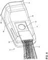
- FIG. 5generally illustrates the direction of air flow lines 60 of the embodiment of FIG. 3 after heated air has been blown away (or drawn away) from the processor 14 past the radiator 52 by the air moving device 20.
- the heated airis illustrated as moving through the duct 44 in a longitudinal direction relative to the longitudinal extent of the rearview assembly 10, it is also contemplated that the heated air may be blown upward or downward relative to the rearview assembly 10.
- the cooling system as set forth hereinis configured to prevent overheating of a rearview assembly having a full display mirror or other electronic features, thereby increasing performance and longevity of the rearview assembly.
- external surfaces of the rearview assemblyare maintained at a comfortable temperature such that a passenger can easily grasp the external surfaces and adjust the rearview assembly.
- the air moving device 20, as set forth hereinmay be a fan, a blower, a piezoelectric blower, a solid state ionic air mover, etc., that provides cooling and maintains ideal temperature thresholds.
- air moving deviceone or more fans, one or more blowers, etc.
- heat pipesto provide external and internal device temperatures that meet customer desirabilities and working limits of the electronics of the rearview assembly.
- speed of the air moving devicecan be activated and deactivated, and also variably modulated based on the desired cooling load.
- an air moving device having a speed modulating controlis utilized to reduce the relative noise level of the rearview assembly.
- This featureis implemented because the rearview assembly is located adjacent to and between the driver and passenger.
- the speed, and therefore the volumetric flow rate and noise output, of the air moving devicecan be reduced temporarily as the ambient noise level in the vehicle cabin is lowered.
- a noise output associated with a particular measure of revolutions per minutecan be adjusted based on the operation of a heating, ventilation, and cooling (HVAC) system within the vehicle, an audio system within the vehicle, or whether the windows are open or to what degree the windows are open.
- HVACheating, ventilation, and cooling
- the processor 14 within the rearview assembly 10determines whether a predetermined noise output associated with the windows down (as an example) satisfies a threshold noise output requirement. If so, the air moving device 20 is activated to cool the rearview assembly 10. If not, the air moving device 20 may be deactivated or activated at a reduced RPM.
- the speed modulating controlmay be operable to change an RPM of the air moving device 20, thereby changing the noise output of the air moving device 20 based on a vehicle speed, as defined in the invention. It is contemplated that the speed modulating control may be operable to reduce an overall volumetric flow rate or reduce the RPM of the air moving device 20, thereby reducing the noise output when the vehicle is moving below a threshold speed.
- the speed modulating controlmay be operable to increase an overall volumetric flow rate or increase the RPM of the air moving device 20, thereby increasing the noise output when the vehicle is moving above a threshold speed.
- the speed modulating controlmay also operable to change an RPM of the air moving device 20, thereby changing the noise output of the air moving device 20 based on various different inputs.
- the speed modulating controlmay be operable to change the RPM of the air moving device 20 based on at least one of an HVAC blower RPM and a radio volume level.
- the systemcan be set to monitor motor RPM, vehicle speed, etc., and when below a predetermined threshold, the LED board 55 could dim the LEDs, thereby lessening thermal output of the LED board 55.
- the LED board 55could be configured to dim when the fan cannot control or maintain a desired operating temperature. It will be understood that the LED board 55 could include a direct LED backlight of the display 38 and/or an edge lit LED backlight, as illustrated in FIG. 4 .
- the air moving device 20can also be controlled or modulated with direct ambient noise measurements from within the cabin via a microphone and processor.
- noise measurementscan be predicted by detecting varying light levels from ambient and glare sensors that suggest vehicle movement, or via image processing from the vehicle cameras to detect movement (optical flow) and for speed and relative cabin noise.
- the speed of the air moving device 20can be modulated based on the speed of the vehicle itself, motor RPM, or other signals transmitted over the vehicle bus communications, or by discrete signal. The air moving device 20 can be slowed down when the vehicle is not moving, or moving at relatively slow speeds that do not meet a threshold requirement.
- the RPMs of the air moving device 20may be adjusted linearly over a given range, or may be increased or decreased in a step-like controlled manner between a "fast speed” and a "low speed.” When the speed exceeds those threshold requirements, the air moving device 20 can increase in speed as a result of an increase in ambient noise with the vehicle moving faster in speed.
- the term "coupled”in all of its forms, couple, coupling, coupled, etc. generally means the joining of two components (electrical or mechanical) directly or indirectly to one another. Such joining may be stationary in nature or movable in nature. Such joining may be achieved with the two components (electrical or mechanical) and any additional intermediate members being integrally formed as a single unitary body with one another or with the two components. Such joining may be permanent in nature or may be removable or releasable in nature unless otherwise stated.
- elements shown as integrally formedmay be constructed of multiple parts, or elements shown as multiple parts may be integrally formed, the operation of the interfaces may be reversed or otherwise varied, the length or width of the structures and/or members or connector or other elements of the system may be varied, the nature or number of adjustment positions provided between the elements may be varied.
- the elements and/or assemblies of the systemmay be constructed from any of a wide variety of materials that provide sufficient strength or durability, in any of a wide variety of colors, textures, and combinations. Accordingly, all such modifications are intended to be included within the scope of the present innovations.
Landscapes
- Engineering & Computer Science (AREA)
- General Engineering & Computer Science (AREA)
- Physics & Mathematics (AREA)
- Multimedia (AREA)
- Mechanical Engineering (AREA)
- General Physics & Mathematics (AREA)
- Optics & Photonics (AREA)
- Fittings On The Vehicle Exterior For Carrying Loads, And Devices For Holding Or Mounting Articles (AREA)
- Rear-View Mirror Devices That Are Mounted On The Exterior Of The Vehicle (AREA)
Description
- The present disclosure generally relates to a display mirror, and more particularly to a method of cooling a full display mirror.
- Document
CN 205 044 633 U describes a rear-view mirror system with heat sinking function, comprising a body of backsight mirror, and this body of backsight mirror comprises an upper cover, a lower cover and a support which are connected successively. Described upper cover offers an eyeglass mounting hole. In this eyeglass mounting hole, back-mirror glass is installed, wherein the back-mirror glass offers a read-out mounting hole. In this read-out mounting hole, read-out is installed. The body of the backsight mirror is provided with a pcb board electrically connected with the read-out. Also provided is a fan for dispelling heat in the body of the backsight mirror, and apartly spaced multiple louvres are provided. - Document
US 2009/201137 A1 describes a rearview assembly for a vehicle which includes a mirror element having a partially reflective, partially transmissive coating and a video display positioned behind the mirror element such that a display image is viewable through the partially reflective, partially transmissive coating. The video display may generate a viewable display image that has an intensity of at least 250 cd/m2. The video display may generate a display image that extends along and abuts at least a portion of curved edges of a housing. The assembly may include a forward facing light sensor for sensing a first light level forward of the vehicle, a rearward facing light sensor sensing a second light level to the rear of the vehicle, and a control circuit for comparing the first and second light levels and generating a warning signal when the second light level exceeds the first light level by at least threshold amount. - Document
US 2004/253130 A1 describes piezoelectric fan assemblies which are provided to provide a conduction path and forced convection for space-limited electronic devices. The fan blade of a piezoelectric fan is thermally coupled to the heat source, such as, but not limited to, the fins of a heat sink, the condenser of the heat pipe, and to the thermal mass of a heat spreader or block. The high amplitude resonant vibration of the fan blade causes formation of a high velocity unidirectional flow stream. Maximum airflow occurs on axes of the piezoelectric fan's centerline, relative to both width and height dimensions. Air intake is above and below the swept out plane of the fan blade. The air flow provides forced convection for the fan blade and, secondarily, for the heat source. Document EP 1 122 990 A2 describes an information processing apparatus of an on-vehicle type provided with a fan and a detecting device for detecting an operation status of a vehicle. The information processing apparatus is also provided with a controlling device for controlling a rotation speed of the fan in accordance with the detected operation status.- The aforementioned objectives are achieved by means of a rearview assembly according to
claim 1. - According to one aspect of the present disclosure, a rearview assembly for a vehicle includes a rearview device and a processor. A housing supports the rearview device and the processor. The housing defines a recess therein. An air moving device is operably coupled with the housing and is configured to draw air from an area exterior to the housing into the recess, thereby cooling at least one of the rearview device and the processor.
- According to another aspect of the present disclosure, a rearview assembly includes a rearview device, a processor, and a light-emitting diode (LED) board. A housing supports the rearview device, the processor, and the LED board. An air moving device is operably coupled with the housing and is configured to draw air from an area exterior to the housing to a radiator configured to cool the processor and LED board.
- According to yet another aspect of the present disclosure, a rearview assembly includes a rearview device. A housing supports the rearview device. The housing defines a recess therein. A blower is disposed within the housing and is operable to draw air from an area exterior to the housing into the recess proximate the rearview device.
- These and other features, advantages, and objects of the present disclosure will be further understood and appreciated by those skilled in the art by reference to the following specification, claims, and appended drawings.
- In the drawings:
FIG. 1 is a rear perspective view of a rearview assembly of the present disclosure;FIG. 2 is a rear perspective view of a rearview assembly of the present disclosure with the housing shown in phantom and also showing air flow lines through the rearview assembly;FIG. 3 is a rear perspective view of another rearview assembly of the present disclosure;FIG. 4 is a top perspective view of a cooling system of the present disclosure; andFIG. 5 is an enlarged partial rear perspective view of an air moving device with air flow lines in a rearview assembly of the present disclosure.- The present illustrated embodiments reside primarily in combinations of method steps and apparatus components related to a display mirror. Accordingly, the apparatus components and method steps have been represented, where appropriate, by conventional symbols in the drawings, showing only those specific details that are pertinent to understanding the embodiments of the present disclosure so as not to obscure the disclosure with details that will be readily apparent to those of ordinary skill in the art having the benefit of the description herein. Further, like numerals in the description and drawings represent like elements.
- For purposes of description herein, the terms "upper," "lower," "right," "left," "rear," "front," "vertical," "horizontal," and derivatives thereof, shall relate to the disclosure as oriented in
FIG. 1 . Unless stated otherwise, the term "front" shall refer to the surface of the device closer to an intended viewer of the device, and the term "rear" shall refer to the surface of the device further from the intended viewer of the device. However, it is to be understood that the disclosure may assume various alternative orientations, except where expressly specified to the contrary. It is also to be understood that the specific devices and processes illustrated in the attached drawings, and described in the following specification are simply exemplary embodiments of the inventive concepts defined in the appended claims. Hence, specific dimensions and other physical characteristics relating to the embodiments disclosed herein are not to be considered as limiting, unless the claims expressly state otherwise. - The terms "including," "comprises," "comprising," or any other variation thereof, are intended to cover a non-exclusive inclusion, such that a process, method, article, or apparatus that comprises a list of elements does not include only those elements but may include other elements not expressly listed or inherent to such process, method, article, or apparatus. An element preceded by "comprises a ..." does not, without more constraints, preclude the existence of additional identical elements in the process, method, article, or apparatus that comprises the element.
- Referring to
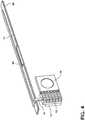
FIGS. 1-5 ,reference numeral 10 generally designates a rearview assembly for a vehicle. Therearview assembly 10 includes arearview device 12 and aprocessor 14. Ahousing 16 supports therearview device 12 and theprocessor 14. Thehousing 16 defines arecess 18 therein. Anair moving device 20 is operably coupled with thehousing 16 and is configured to draw air from an area exterior to thehousing 16 into therecess 18, thereby cooling at least one of therearview device 12 and theprocessor 14. An LED board may be cooled by theair moving device 20. - With reference again to
FIG. 1 , therearview assembly 10 is generally configured for use inside a vehicle. Therearview assembly 10 may be operably coupled with an inside surface of a windshield, a headliner of the vehicle, operably coupled with a dash of the vehicle, or directly coupled with a support structure or frame of the vehicle. Thehousing 16 includes a central rearwardly-extending protrusion 30 (FIG. 2 ) configured to engage a mount that couples therearview assembly 10 with the vehicle. Eachside rearview assembly 10 includes a slimmer profile configured for grasping by a passenger. In the illustrated embodiment, therearview assembly 10 includes abezel 36 forward of thehousing 16 configured to provide an interface between thehousing 16 and adisplay 38 of therearview assembly 10, electro-optic device, or mirror device of therearview assembly 10. - With reference again to
FIG. 1 , the illustratedrearview assembly 10 includes theprocessor 14, which is in electrical communication with electrical components of therearview assembly 10 and supported on acarrier plate 39. Theprocessor 14 can generate excessive heat that can impact the overall performance of therearview assembly 10 and negatively effect longevity of therearview assembly 10 as a whole. Accordingly, heat management proximate theprocessor 14 can increase the lifespan of therearview assembly 10 and increase performance of therearview assembly 10. In the illustrated embodiment, therecess 18 generally defines an air pathway through thehousing 16 that is in fluid communication with theinterior recess 18 of thehousing 16. The air pathway allows for heat that is generated within thehousing 16 to escape to the environment. In an effort to maximize thermal cooling of theprocessor 14, theprocessor 14 may be positioned at a first end of therecess 18, and theair moving device 20 may be positioned at a second end of therecess 18. Alternatively, theair moving device 20 may be directly adjacent to the processor 14 (FIG. 3 ). Theair moving device 20 is generally configured to move air by theprocessor 14, thereby cooling theprocessor 14 during operation. It is generally contemplated that theair moving device 20 can blow air by theprocessor 14 or draw air by theair moving device 20. In either instance, cooling of theprocessor 14 is achieved.FIG. 2 illustrates one embodiment of therearview assembly 10 utilizing theair moving device 20, which causes movement of air through therecess 18 of the housing 16 (illustrated by air flow lines 41). As shown, theair moving device 20 draws air through afirst port 40 and blows the cool air past theprocessor 14, and cools theprocessor 14 by pushing warmed air proximate to theprocessor 14 out asecond port 42. The process could also work in reverse. Theair moving device 20 could draw warm air from theprocessor 14 inside thehousing 16, and blow the warmed air out an exhaust port. Alternatively, defined ports may not be present at all. In this instance, theair moving device 20 could draw cool air from the surrounding environment and blow the air past theprocessor 14, thus cooling theprocessor 14. The heat would exit through joints in therearview assembly 10 as therearview assembly 10 is not airtight. - With reference now to
FIG. 3 , the illustrated embodiment includes anair moving device 20 that is proximate theprocessor 14 of therearview assembly 10. Theair moving device 20 draws air or blows air from theprocessor 14 out aduct 44, thereby removing heat from the area proximate theprocessor 14. Notably, in this instance, air is not blown through therecess 18 of thehousing 16. Rather, theair moving device 20 simply removes heat from theprocessor 14 directly outward to the environment. - With reference now to
FIG. 4 , in the illustrated embodiment, therearview assembly 10 includes aheat pipe 50, aradiator 52, and acooling plate 54. Theradiator 52 is operably coupled with theair moving device 20. Theprocessor 14 is thermally coupled to theradiator 52 so that heat can be removed by theair moving device 20. Theair moving device 20 removes heat from theradiator 52 by blowing air past theradiator 52, which radiates the heat externally to the environment. - With reference again to
FIG. 4 , theair moving device 20 is proximate both theradiator 52 and theheat pipe 50. Theheat pipe 50 acts as a heat transfer device, utilizing thermal conductivity to efficiently manage the transfer of heat away from a light-emitting diode (LED)board 55. Theheat pipe 50 includes a working fluid disposed therein. The working fluid is configured to move between liquid and gaseous states within theheat pipe 50. Heat from theLED board 55 is transferred into the coolingplate 54 and then into theheat pipe 50. The heat works to vaporize the working fluid, which travels to acool end 56 of theheat pipe 50 proximate theradiator 52. At the same time, heat from theprocessor 14 is transferred to theradiator 52. Cool air that is drawn in from the environment by theair moving device 20 is then forced across theradiator 52, which cools theprocessor 14 and the working fluid vapor in theheat pipe 50. As the vapor in theheat pipe 50 cools back into a liquid, the liquid is wicked back to the hot areas of theheat pipe 50 adjacent to theLED board 55 and the process begins again. As a result, the working fluid is continually moving heat from theLED board 55 to thecooling plate 54 and then to theradiator 52, thus lessening the thermal load. FIG. 5 generally illustrates the direction ofair flow lines 60 of the embodiment ofFIG. 3 after heated air has been blown away (or drawn away) from theprocessor 14 past theradiator 52 by theair moving device 20. Although the heated air is illustrated as moving through theduct 44 in a longitudinal direction relative to the longitudinal extent of therearview assembly 10, it is also contemplated that the heated air may be blown upward or downward relative to therearview assembly 10.- The cooling system as set forth herein is configured to prevent overheating of a rearview assembly having a full display mirror or other electronic features, thereby increasing performance and longevity of the rearview assembly. In addition, external surfaces of the rearview assembly are maintained at a comfortable temperature such that a passenger can easily grasp the external surfaces and adjust the rearview assembly. The
air moving device 20, as set forth herein, may be a fan, a blower, a piezoelectric blower, a solid state ionic air mover, etc., that provides cooling and maintains ideal temperature thresholds. It will be understood that more than an air moving device (one or more fans, one or more blowers, etc.) may be utilized in conjunction with one or more heat pipes to provide external and internal device temperatures that meet customer desirabilities and working limits of the electronics of the rearview assembly. It will also be understood that the speed of the air moving device can be activated and deactivated, and also variably modulated based on the desired cooling load. - In addition, an air moving device having a speed modulating control is utilized to reduce the relative noise level of the rearview assembly. This feature is implemented because the rearview assembly is located adjacent to and between the driver and passenger. The speed, and therefore the volumetric flow rate and noise output, of the air moving device can be reduced temporarily as the ambient noise level in the vehicle cabin is lowered. These are typically instances when the vehicle is traveling below a threshold speed, for example, entering or leaving a parking ramp, coming to a stop, slowing down, etc. However, other scenarios are also possible. For example, a noise output associated with a particular measure of revolutions per minute (RPM) can be adjusted based on the operation of a heating, ventilation, and cooling (HVAC) system within the vehicle, an audio system within the vehicle, or whether the windows are open or to what degree the windows are open. The
processor 14 within therearview assembly 10 determines whether a predetermined noise output associated with the windows down (as an example) satisfies a threshold noise output requirement. If so, theair moving device 20 is activated to cool therearview assembly 10. If not, theair moving device 20 may be deactivated or activated at a reduced RPM. The same process can be initiated when the audio system is activated, the HVAC system is activated, or ambient noise levels are detected that allow for theair moving device 20 to work at a higher RPM. The overall thermal mass of the system is generally sufficient to allow temporary reductions in the cooling performance. Once the vehicle begins traveling at a higher rate of speed, the speed modulating control may be operable to change an RPM of theair moving device 20, thereby changing the noise output of theair moving device 20 based on a vehicle speed, as defined in the invention. It is contemplated that the speed modulating control may be operable to reduce an overall volumetric flow rate or reduce the RPM of theair moving device 20, thereby reducing the noise output when the vehicle is moving below a threshold speed. Alternatively, it is contemplated that the speed modulating control may be operable to increase an overall volumetric flow rate or increase the RPM of theair moving device 20, thereby increasing the noise output when the vehicle is moving above a threshold speed. The speed modulating control may also operable to change an RPM of theair moving device 20, thereby changing the noise output of theair moving device 20 based on various different inputs. For example, the speed modulating control may be operable to change the RPM of theair moving device 20 based on at least one of an HVAC blower RPM and a radio volume level. Alternatively, the system can be set to monitor motor RPM, vehicle speed, etc., and when below a predetermined threshold, theLED board 55 could dim the LEDs, thereby lessening thermal output of theLED board 55. It is generally contemplated that theLED board 55 could be configured to dim when the fan cannot control or maintain a desired operating temperature. It will be understood that theLED board 55 could include a direct LED backlight of thedisplay 38 and/or an edge lit LED backlight, as illustrated inFIG. 4 . - Moreover, the
air moving device 20 can also be controlled or modulated with direct ambient noise measurements from within the cabin via a microphone and processor. Alternatively, noise measurements can be predicted by detecting varying light levels from ambient and glare sensors that suggest vehicle movement, or via image processing from the vehicle cameras to detect movement (optical flow) and for speed and relative cabin noise. Additionally, the speed of theair moving device 20 can be modulated based on the speed of the vehicle itself, motor RPM, or other signals transmitted over the vehicle bus communications, or by discrete signal. Theair moving device 20 can be slowed down when the vehicle is not moving, or moving at relatively slow speeds that do not meet a threshold requirement. The RPMs of theair moving device 20 may be adjusted linearly over a given range, or may be increased or decreased in a step-like controlled manner between a "fast speed" and a "low speed." When the speed exceeds those threshold requirements, theair moving device 20 can increase in speed as a result of an increase in ambient noise with the vehicle moving faster in speed. - It will be understood by one having ordinary skill in the art that construction of the described disclosure and other components is not limited to any specific material. Other exemplary embodiments of the disclosure disclosed herein may be formed from a wide variety of materials, unless described otherwise herein.
- For purposes of this disclosure, the term "coupled" (in all of its forms, couple, coupling, coupled, etc.) generally means the joining of two components (electrical or mechanical) directly or indirectly to one another. Such joining may be stationary in nature or movable in nature. Such joining may be achieved with the two components (electrical or mechanical) and any additional intermediate members being integrally formed as a single unitary body with one another or with the two components. Such joining may be permanent in nature or may be removable or releasable in nature unless otherwise stated.
- It is also important to note that the construction and arrangement of the elements of the disclosure, as shown in the exemplary embodiments, is illustrative only. Although only a few embodiments of the present innovations have been described in detail in this disclosure, those skilled in the art who review this disclosure will readily appreciate that many modifications are possible (e.g., variations in sizes, dimensions, structures, shapes and proportions of the various elements, values of parameters, mounting arrangements, use of materials, colors, orientations, etc.) without materially departing from the novel teachings and advantages of the subject matter recited. For example, elements shown as integrally formed may be constructed of multiple parts, or elements shown as multiple parts may be integrally formed, the operation of the interfaces may be reversed or otherwise varied, the length or width of the structures and/or members or connector or other elements of the system may be varied, the nature or number of adjustment positions provided between the elements may be varied. It should be noted that the elements and/or assemblies of the system may be constructed from any of a wide variety of materials that provide sufficient strength or durability, in any of a wide variety of colors, textures, and combinations. Accordingly, all such modifications are intended to be included within the scope of the present innovations.
- It will be understood that any described processes or steps within described processes may be combined with other disclosed processes or steps to form structures within the scope of the present disclosure. The exemplary structures and processes disclosed herein are for illustrative purposes and are not to be construed as limiting.
- It is also to be understood that variations and modifications can be made on the aforementioned structures and methods without departing from the concepts of the present disclosure, and further it is to be understood that such concepts are intended to be covered by the following claims unless these claims by their language expressly state otherwise.
Claims (8)
- A rearview assembly (10) for a vehicle, the rearview assembly (10) comprising:a rearview device (12);a processor (14);a housing (16) supporting the rearview device (12) and processor, the housing (16) defining a recess (18) therein;an air moving device (20) operably coupled with the housing (16) and configured to draw air from an area exterior to the housing (16) into the recess (18), thereby cooling at least one of the rearview device (12) and the processor (14); anda speed modulating control, wherein the speed modulating control is operable to change revolutions per minute (RPM) of the air moving device (20), thereby changing a noise output of the air moving device (20) based on a vehicle speed.
- The rearview assembly (10) of claim 1, further comprising:
a light-emitting diode (LED) board (55) that is cooled by the air moving device (20). - The rearview assembly (10) of either of claims 1 or 2, wherein the air moving device (20) includes multiple fans.
- The rearview assembly (10) of either of claims 1 or 2, wherein the air moving device (20) includes at least one piezoelectric blower.
- The rearview assembly (10) of any of claims 1-4, further comprising:
a heat pipe (50) disposed proximate the air moving device (20). - The rearview assembly (10) of claim 5,
wherein the heat pipe (50) includes a working fluid configured to move between liquid and gaseous states within the heat pipe (50). - The rearview assembly (10) of any one of claims 1 to 6, wherein the speed modulating control is operable to reduce the volumetric flow rate of the air moving device (20), thereby reducing the speed modulating control noise output when a motor of the vehicle is operating below a threshold revolutions per minute (RPM).
- The rearview assembly (10) of any one of claims 1 to 7, wherein the speed modulating control is operable to change revolutions per minute (RPM) of the air moving device (20), thereby changing the noise output of the air moving device (20) based on at least one of:a heating, ventilation, and cooling (HVAC) blower RPM; anda radio volume level.
Applications Claiming Priority (2)
| Application Number | Priority Date | Filing Date | Title |
|---|---|---|---|
| US201662383066P | 2016-09-02 | 2016-09-02 | |
| PCT/US2017/049892WO2018045306A1 (en) | 2016-09-02 | 2017-09-01 | Method of cooling full display mirror |
Publications (3)
| Publication Number | Publication Date |
|---|---|
| EP3507140A1 EP3507140A1 (en) | 2019-07-10 |
| EP3507140A4 EP3507140A4 (en) | 2019-07-31 |
| EP3507140B1true EP3507140B1 (en) | 2020-10-28 |
Family
ID=61280491
Family Applications (1)
| Application Number | Title | Priority Date | Filing Date |
|---|---|---|---|
| EP17847633.9AActiveEP3507140B1 (en) | 2016-09-02 | 2017-09-01 | Cooling device for rearview assembly |
Country Status (6)
| Country | Link |
|---|---|
| US (1) | US10627597B2 (en) |
| EP (1) | EP3507140B1 (en) |
| JP (1) | JP6796191B2 (en) |
| KR (1) | KR102397389B1 (en) |
| CN (1) | CN109641556B (en) |
| WO (1) | WO2018045306A1 (en) |
Families Citing this family (7)
| Publication number | Priority date | Publication date | Assignee | Title |
|---|---|---|---|---|
| USD845851S1 (en)* | 2016-03-31 | 2019-04-16 | Gentex Corporation | Rearview device |
| CN111918792B (en)* | 2018-03-27 | 2023-09-26 | 金泰克斯公司 | Full display mirror with integrated cooling system |
| CN110397611B (en)* | 2018-04-25 | 2021-07-06 | 硕天科技股份有限公司 | Volume Control for Uninterruptible Power Systems |
| JP7101074B2 (en)* | 2018-08-03 | 2022-07-14 | 東京コスモス電機株式会社 | Anti-fog device |
| FR3091506B1 (en)* | 2018-10-31 | 2023-10-20 | Valeo Comfort & Driving Assistance | SMART MIRROR FOR MOTOR VEHICLES |
| US11287859B2 (en)* | 2019-03-15 | 2022-03-29 | Gentex Corporation | Rearview assembly with enhanced cooling |
| JP7624693B2 (en)* | 2020-03-31 | 2025-01-31 | 株式会社ユピテル | In-vehicle equipment, electronic devices and mounting parts, etc. |
Family Cites Families (19)
| Publication number | Priority date | Publication date | Assignee | Title |
|---|---|---|---|---|
| US5398041A (en)* | 1970-12-28 | 1995-03-14 | Hyatt; Gilbert P. | Colored liquid crystal display having cooling |
| DE2904825C3 (en)* | 1979-02-08 | 1981-07-23 | Schuwerk, Fritz, 8000 München | Rearview mirrors for automobiles |
| US5178448A (en)* | 1991-09-13 | 1993-01-12 | Donnelly Corporation | Rearview mirror with lighting assembly |
| ES2088318T3 (en)* | 1993-02-15 | 1996-08-01 | Fischer Artur Werke Gmbh | INTERIOR MIRROR MIRROR WITH BUILT-IN GLOVEBOARD FOR AN AUTOMOBILE VEHICLE. |
| JPH09188195A (en)* | 1996-01-09 | 1997-07-22 | Tokai Rika Co Ltd | Inner mirror |
| US5638895A (en)* | 1996-03-25 | 1997-06-17 | Dodson; Douglas A. | Twin fan cooling device |
| US6201471B1 (en)* | 1998-07-24 | 2001-03-13 | General Motors Corporation | Modular center stack console |
| JP2001213243A (en) | 2000-01-31 | 2001-08-07 | Pioneer Electronic Corp | On-vehicle information processor |
| US20060061008A1 (en) | 2004-09-14 | 2006-03-23 | Lee Karner | Mounting assembly for vehicle interior mirror |
| US7031155B2 (en)* | 2003-01-06 | 2006-04-18 | Intel Corporation | Electronic thermal management |
| US7397461B1 (en)* | 2005-03-17 | 2008-07-08 | Graham Jonathan W | Mirrored decorative video display concealment and cooling apparatus and method |
| EP1949666B1 (en)* | 2005-11-01 | 2013-07-17 | Magna Mirrors of America, Inc. | Interior rearview mirror with display |
| JP4878388B2 (en)* | 2006-10-04 | 2012-02-15 | シーメンス アクチエンゲゼルシヤフト | Switching power supply |
| JP2009081270A (en) | 2007-09-26 | 2009-04-16 | Furukawa Electric Co Ltd:The | Cooling device with piezoelectric fan |
| US20100080399A1 (en)* | 2008-09-30 | 2010-04-01 | Visteon Global Technologies, Inc. | Method For Reducing Vehicle Noise |
| US9435348B2 (en)* | 2012-07-10 | 2016-09-06 | Asia Vital Components Co., Ltd. | Fan structure |
| US9458979B2 (en)* | 2012-12-14 | 2016-10-04 | Sl Corporation | Signal lamp for vehicle having a light guide and mirror housing and lamp housing with reflection unit and support unit |
| CN205044633U (en) | 2015-09-06 | 2016-02-24 | 深圳市歌美迪电子技术发展有限公司 | Rearview mirror system of area heat dissipation function |
| US10442360B2 (en)* | 2017-03-02 | 2019-10-15 | Magna Mirrors Of America, Inc. | Interior rearview mirror assembly with display and tilt mechanism |
- 2017
- 2017-09-01EPEP17847633.9Apatent/EP3507140B1/enactiveActive
- 2017-09-01WOPCT/US2017/049892patent/WO2018045306A1/ennot_activeCeased
- 2017-09-01CNCN201780051059.5Apatent/CN109641556B/enactiveActive
- 2017-09-01USUS15/693,988patent/US10627597B2/enactiveActive
- 2017-09-01KRKR1020197005261Apatent/KR102397389B1/enactiveActive
- 2017-09-01JPJP2019512223Apatent/JP6796191B2/enactiveActive
Non-Patent Citations (1)
| Title |
|---|
| None* |
Also Published As
| Publication number | Publication date |
|---|---|
| EP3507140A4 (en) | 2019-07-31 |
| JP6796191B2 (en) | 2020-12-02 |
| CN109641556B (en) | 2022-03-18 |
| CN109641556A (en) | 2019-04-16 |
| KR20190040213A (en) | 2019-04-17 |
| WO2018045306A1 (en) | 2018-03-08 |
| US10627597B2 (en) | 2020-04-21 |
| US20180067279A1 (en) | 2018-03-08 |
| KR102397389B1 (en) | 2022-05-12 |
| EP3507140A1 (en) | 2019-07-10 |
| JP2019529208A (en) | 2019-10-17 |
Similar Documents
| Publication | Publication Date | Title |
|---|---|---|
| EP3507140B1 (en) | Cooling device for rearview assembly | |
| JP5735057B2 (en) | External camera device for a vehicle and a vehicle comprising such an external camera device | |
| US6181070B1 (en) | Method for cooling a lamp backlighting module of a liquid crystal display | |
| US20200386860A1 (en) | Mounting base for mounting sensors | |
| JP6642706B2 (en) | Air blowing device | |
| JP4718373B2 (en) | LIGHTING DEVICE OR SIGNAL DEVICE FOR AUTOMOBILE HAVING LED | |
| KR20160111341A (en) | Thermal dissipation system of an electric vehicle | |
| EP3336414B1 (en) | Automotive headlight defogging/defrosting | |
| US10787204B2 (en) | Thermal transmission structure for creating heat generated graphics on external vehicle panels | |
| WO2016121269A1 (en) | Head-up display device for vehicle | |
| JP6300012B2 (en) | Head-up display device, cooling system for head-up display device | |
| JPWO2016158100A1 (en) | Head-up display device | |
| US20190182994A1 (en) | Head up display cooling | |
| US11713871B2 (en) | Display device | |
| JP2003029648A (en) | Plasma display | |
| CN105774466A (en) | Display unit for displaying image data on display, and method for operating the dispaly unit | |
| US20180251012A1 (en) | Vehicular defroster duct structure | |
| US20020029912A1 (en) | Bi-directional automotive cooling fan | |
| WO2025077890A1 (en) | Optical element support assembly for windshield, windshield assembly, and vehicle | |
| JP2015020624A (en) | Instrument panel structure | |
| EP3584498B1 (en) | Vehicular lamp | |
| CN114360362A (en) | Vehicle-mounted display module and vehicle | |
| CN222329415U (en) | Thermal management system for vehicle and vehicle | |
| JP2018079830A (en) | Grille shutter attachment structure | |
| KR101976821B1 (en) | Apparatus for cooling lamp module of an automobile |
Legal Events
| Date | Code | Title | Description |
|---|---|---|---|
| STAA | Information on the status of an ep patent application or granted ep patent | Free format text:STATUS: THE INTERNATIONAL PUBLICATION HAS BEEN MADE | |
| PUAI | Public reference made under article 153(3) epc to a published international application that has entered the european phase | Free format text:ORIGINAL CODE: 0009012 | |
| STAA | Information on the status of an ep patent application or granted ep patent | Free format text:STATUS: REQUEST FOR EXAMINATION WAS MADE | |
| 17P | Request for examination filed | Effective date:20190321 | |
| AK | Designated contracting states | Kind code of ref document:A1 Designated state(s):AL AT BE BG CH CY CZ DE DK EE ES FI FR GB GR HR HU IE IS IT LI LT LU LV MC MK MT NL NO PL PT RO RS SE SI SK SM TR | |
| AX | Request for extension of the european patent | Extension state:BA ME | |
| A4 | Supplementary search report drawn up and despatched | Effective date:20190627 | |
| RIC1 | Information provided on ipc code assigned before grant | Ipc:B60R 1/04 20060101AFI20190621BHEP Ipc:B60R 1/12 20060101ALI20190621BHEP | |
| DAV | Request for validation of the european patent (deleted) | ||
| DAX | Request for extension of the european patent (deleted) | ||
| GRAP | Despatch of communication of intention to grant a patent | Free format text:ORIGINAL CODE: EPIDOSNIGR1 | |
| STAA | Information on the status of an ep patent application or granted ep patent | Free format text:STATUS: GRANT OF PATENT IS INTENDED | |
| INTG | Intention to grant announced | Effective date:20200508 | |
| GRAS | Grant fee paid | Free format text:ORIGINAL CODE: EPIDOSNIGR3 | |
| GRAA | (expected) grant | Free format text:ORIGINAL CODE: 0009210 | |
| STAA | Information on the status of an ep patent application or granted ep patent | Free format text:STATUS: THE PATENT HAS BEEN GRANTED | |
| AK | Designated contracting states | Kind code of ref document:B1 Designated state(s):AL AT BE BG CH CY CZ DE DK EE ES FI FR GB GR HR HU IE IS IT LI LT LU LV MC MK MT NL NO PL PT RO RS SE SI SK SM TR | |
| REG | Reference to a national code | Ref country code:GB Ref legal event code:FG4D | |
| REG | Reference to a national code | Ref country code:CH Ref legal event code:EP | |
| REG | Reference to a national code | Ref country code:DE Ref legal event code:R096 Ref document number:602017026565 Country of ref document:DE | |
| REG | Reference to a national code | Ref country code:AT Ref legal event code:REF Ref document number:1327899 Country of ref document:AT Kind code of ref document:T Effective date:20201115 | |
| REG | Reference to a national code | Ref country code:IE Ref legal event code:FG4D | |
| REG | Reference to a national code | Ref country code:AT Ref legal event code:MK05 Ref document number:1327899 Country of ref document:AT Kind code of ref document:T Effective date:20201028 | |
| REG | Reference to a national code | Ref country code:NL Ref legal event code:MP Effective date:20201028 | |
| PG25 | Lapsed in a contracting state [announced via postgrant information from national office to epo] | Ref country code:NO Free format text:LAPSE BECAUSE OF FAILURE TO SUBMIT A TRANSLATION OF THE DESCRIPTION OR TO PAY THE FEE WITHIN THE PRESCRIBED TIME-LIMIT Effective date:20210128 Ref country code:GR Free format text:LAPSE BECAUSE OF FAILURE TO SUBMIT A TRANSLATION OF THE DESCRIPTION OR TO PAY THE FEE WITHIN THE PRESCRIBED TIME-LIMIT Effective date:20210129 Ref country code:RS Free format text:LAPSE BECAUSE OF FAILURE TO SUBMIT A TRANSLATION OF THE DESCRIPTION OR TO PAY THE FEE WITHIN THE PRESCRIBED TIME-LIMIT Effective date:20201028 Ref country code:PT Free format text:LAPSE BECAUSE OF FAILURE TO SUBMIT A TRANSLATION OF THE DESCRIPTION OR TO PAY THE FEE WITHIN THE PRESCRIBED TIME-LIMIT Effective date:20210301 Ref country code:FI Free format text:LAPSE BECAUSE OF FAILURE TO SUBMIT A TRANSLATION OF THE DESCRIPTION OR TO PAY THE FEE WITHIN THE PRESCRIBED TIME-LIMIT Effective date:20201028 | |
| REG | Reference to a national code | Ref country code:LT Ref legal event code:MG4D | |
| PG25 | Lapsed in a contracting state [announced via postgrant information from national office to epo] | Ref country code:IS Free format text:LAPSE BECAUSE OF FAILURE TO SUBMIT A TRANSLATION OF THE DESCRIPTION OR TO PAY THE FEE WITHIN THE PRESCRIBED TIME-LIMIT Effective date:20210228 Ref country code:PL Free format text:LAPSE BECAUSE OF FAILURE TO SUBMIT A TRANSLATION OF THE DESCRIPTION OR TO PAY THE FEE WITHIN THE PRESCRIBED TIME-LIMIT Effective date:20201028 Ref country code:LV Free format text:LAPSE BECAUSE OF FAILURE TO SUBMIT A TRANSLATION OF THE DESCRIPTION OR TO PAY THE FEE WITHIN THE PRESCRIBED TIME-LIMIT Effective date:20201028 Ref country code:SE Free format text:LAPSE BECAUSE OF FAILURE TO SUBMIT A TRANSLATION OF THE DESCRIPTION OR TO PAY THE FEE WITHIN THE PRESCRIBED TIME-LIMIT Effective date:20201028 Ref country code:BG Free format text:LAPSE BECAUSE OF FAILURE TO SUBMIT A TRANSLATION OF THE DESCRIPTION OR TO PAY THE FEE WITHIN THE PRESCRIBED TIME-LIMIT Effective date:20210128 Ref country code:AT Free format text:LAPSE BECAUSE OF FAILURE TO SUBMIT A TRANSLATION OF THE DESCRIPTION OR TO PAY THE FEE WITHIN THE PRESCRIBED TIME-LIMIT Effective date:20201028 Ref country code:ES Free format text:LAPSE BECAUSE OF FAILURE TO SUBMIT A TRANSLATION OF THE DESCRIPTION OR TO PAY THE FEE WITHIN THE PRESCRIBED TIME-LIMIT Effective date:20201028 | |
| PG25 | Lapsed in a contracting state [announced via postgrant information from national office to epo] | Ref country code:NL Free format text:LAPSE BECAUSE OF FAILURE TO SUBMIT A TRANSLATION OF THE DESCRIPTION OR TO PAY THE FEE WITHIN THE PRESCRIBED TIME-LIMIT Effective date:20201028 Ref country code:HR Free format text:LAPSE BECAUSE OF FAILURE TO SUBMIT A TRANSLATION OF THE DESCRIPTION OR TO PAY THE FEE WITHIN THE PRESCRIBED TIME-LIMIT Effective date:20201028 | |
| REG | Reference to a national code | Ref country code:DE Ref legal event code:R097 Ref document number:602017026565 Country of ref document:DE | |
| PG25 | Lapsed in a contracting state [announced via postgrant information from national office to epo] | Ref country code:SK Free format text:LAPSE BECAUSE OF FAILURE TO SUBMIT A TRANSLATION OF THE DESCRIPTION OR TO PAY THE FEE WITHIN THE PRESCRIBED TIME-LIMIT Effective date:20201028 Ref country code:RO Free format text:LAPSE BECAUSE OF FAILURE TO SUBMIT A TRANSLATION OF THE DESCRIPTION OR TO PAY THE FEE WITHIN THE PRESCRIBED TIME-LIMIT Effective date:20201028 Ref country code:EE Free format text:LAPSE BECAUSE OF FAILURE TO SUBMIT A TRANSLATION OF THE DESCRIPTION OR TO PAY THE FEE WITHIN THE PRESCRIBED TIME-LIMIT Effective date:20201028 Ref country code:CZ Free format text:LAPSE BECAUSE OF FAILURE TO SUBMIT A TRANSLATION OF THE DESCRIPTION OR TO PAY THE FEE WITHIN THE PRESCRIBED TIME-LIMIT Effective date:20201028 Ref country code:LT Free format text:LAPSE BECAUSE OF FAILURE TO SUBMIT A TRANSLATION OF THE DESCRIPTION OR TO PAY THE FEE WITHIN THE PRESCRIBED TIME-LIMIT Effective date:20201028 Ref country code:SM Free format text:LAPSE BECAUSE OF FAILURE TO SUBMIT A TRANSLATION OF THE DESCRIPTION OR TO PAY THE FEE WITHIN THE PRESCRIBED TIME-LIMIT Effective date:20201028 | |
| PG25 | Lapsed in a contracting state [announced via postgrant information from national office to epo] | Ref country code:DK Free format text:LAPSE BECAUSE OF FAILURE TO SUBMIT A TRANSLATION OF THE DESCRIPTION OR TO PAY THE FEE WITHIN THE PRESCRIBED TIME-LIMIT Effective date:20201028 | |
| PLBE | No opposition filed within time limit | Free format text:ORIGINAL CODE: 0009261 | |
| STAA | Information on the status of an ep patent application or granted ep patent | Free format text:STATUS: NO OPPOSITION FILED WITHIN TIME LIMIT | |
| 26N | No opposition filed | Effective date:20210729 | |
| PG25 | Lapsed in a contracting state [announced via postgrant information from national office to epo] | Ref country code:AL Free format text:LAPSE BECAUSE OF FAILURE TO SUBMIT A TRANSLATION OF THE DESCRIPTION OR TO PAY THE FEE WITHIN THE PRESCRIBED TIME-LIMIT Effective date:20201028 Ref country code:IT Free format text:LAPSE BECAUSE OF FAILURE TO SUBMIT A TRANSLATION OF THE DESCRIPTION OR TO PAY THE FEE WITHIN THE PRESCRIBED TIME-LIMIT Effective date:20201028 | |
| PG25 | Lapsed in a contracting state [announced via postgrant information from national office to epo] | Ref country code:SI Free format text:LAPSE BECAUSE OF FAILURE TO SUBMIT A TRANSLATION OF THE DESCRIPTION OR TO PAY THE FEE WITHIN THE PRESCRIBED TIME-LIMIT Effective date:20201028 | |
| REG | Reference to a national code | Ref country code:CH Ref legal event code:PL | |
| REG | Reference to a national code | Ref country code:BE Ref legal event code:MM Effective date:20210930 | |
| PG25 | Lapsed in a contracting state [announced via postgrant information from national office to epo] | Ref country code:IS Free format text:LAPSE BECAUSE OF FAILURE TO SUBMIT A TRANSLATION OF THE DESCRIPTION OR TO PAY THE FEE WITHIN THE PRESCRIBED TIME-LIMIT Effective date:20210228 Ref country code:MC Free format text:LAPSE BECAUSE OF FAILURE TO SUBMIT A TRANSLATION OF THE DESCRIPTION OR TO PAY THE FEE WITHIN THE PRESCRIBED TIME-LIMIT Effective date:20201028 | |
| PG25 | Lapsed in a contracting state [announced via postgrant information from national office to epo] | Ref country code:LU Free format text:LAPSE BECAUSE OF NON-PAYMENT OF DUE FEES Effective date:20210901 Ref country code:IE Free format text:LAPSE BECAUSE OF NON-PAYMENT OF DUE FEES Effective date:20210901 Ref country code:BE Free format text:LAPSE BECAUSE OF NON-PAYMENT OF DUE FEES Effective date:20210930 | |
| PG25 | Lapsed in a contracting state [announced via postgrant information from national office to epo] | Ref country code:CH Free format text:LAPSE BECAUSE OF NON-PAYMENT OF DUE FEES Effective date:20210930 Ref country code:LI Free format text:LAPSE BECAUSE OF NON-PAYMENT OF DUE FEES Effective date:20210930 | |
| P01 | Opt-out of the competence of the unified patent court (upc) registered | Effective date:20230503 | |
| PG25 | Lapsed in a contracting state [announced via postgrant information from national office to epo] | Ref country code:CY Free format text:LAPSE BECAUSE OF FAILURE TO SUBMIT A TRANSLATION OF THE DESCRIPTION OR TO PAY THE FEE WITHIN THE PRESCRIBED TIME-LIMIT Effective date:20201028 | |
| PG25 | Lapsed in a contracting state [announced via postgrant information from national office to epo] | Ref country code:HU Free format text:LAPSE BECAUSE OF FAILURE TO SUBMIT A TRANSLATION OF THE DESCRIPTION OR TO PAY THE FEE WITHIN THE PRESCRIBED TIME-LIMIT; INVALID AB INITIO Effective date:20170901 | |
| PG25 | Lapsed in a contracting state [announced via postgrant information from national office to epo] | Ref country code:MK Free format text:LAPSE BECAUSE OF FAILURE TO SUBMIT A TRANSLATION OF THE DESCRIPTION OR TO PAY THE FEE WITHIN THE PRESCRIBED TIME-LIMIT Effective date:20201028 | |
| PG25 | Lapsed in a contracting state [announced via postgrant information from national office to epo] | Ref country code:MT Free format text:LAPSE BECAUSE OF FAILURE TO SUBMIT A TRANSLATION OF THE DESCRIPTION OR TO PAY THE FEE WITHIN THE PRESCRIBED TIME-LIMIT Effective date:20201028 | |
| PGFP | Annual fee paid to national office [announced via postgrant information from national office to epo] | Ref country code:DE Payment date:20240820 Year of fee payment:8 | |
| PGFP | Annual fee paid to national office [announced via postgrant information from national office to epo] | Ref country code:GB Payment date:20240820 Year of fee payment:8 | |
| PGFP | Annual fee paid to national office [announced via postgrant information from national office to epo] | Ref country code:FR Payment date:20240820 Year of fee payment:8 |