EP3507065B1 - Robotic device with compact joint design and an additional degree of freedom - Google Patents
Robotic device with compact joint design and an additional degree of freedomDownload PDFInfo
- Publication number
- EP3507065B1 EP3507065B1EP17847471.4AEP17847471AEP3507065B1EP 3507065 B1EP3507065 B1EP 3507065B1EP 17847471 AEP17847471 AEP 17847471AEP 3507065 B1EP3507065 B1EP 3507065B1
- Authority
- EP
- European Patent Office
- Prior art keywords
- driveshaft
- bevel gear
- gear
- coupled
- rotation
- Prior art date
- Legal status (The legal status is an assumption and is not a legal conclusion. Google has not performed a legal analysis and makes no representation as to the accuracy of the status listed.)
- Active
Links
Images


Classifications
- B—PERFORMING OPERATIONS; TRANSPORTING
- B25—HAND TOOLS; PORTABLE POWER-DRIVEN TOOLS; MANIPULATORS
- B25J—MANIPULATORS; CHAMBERS PROVIDED WITH MANIPULATION DEVICES
- B25J17/00—Joints
- B25J17/02—Wrist joints
- A—HUMAN NECESSITIES
- A61—MEDICAL OR VETERINARY SCIENCE; HYGIENE
- A61B—DIAGNOSIS; SURGERY; IDENTIFICATION
- A61B34/00—Computer-aided surgery; Manipulators or robots specially adapted for use in surgery
- A61B34/30—Surgical robots
- A—HUMAN NECESSITIES
- A61—MEDICAL OR VETERINARY SCIENCE; HYGIENE
- A61B—DIAGNOSIS; SURGERY; IDENTIFICATION
- A61B34/00—Computer-aided surgery; Manipulators or robots specially adapted for use in surgery
- A61B34/30—Surgical robots
- A61B34/37—Leader-follower robots
- B—PERFORMING OPERATIONS; TRANSPORTING
- B25—HAND TOOLS; PORTABLE POWER-DRIVEN TOOLS; MANIPULATORS
- B25J—MANIPULATORS; CHAMBERS PROVIDED WITH MANIPULATION DEVICES
- B25J18/00—Arms
- B—PERFORMING OPERATIONS; TRANSPORTING
- B25—HAND TOOLS; PORTABLE POWER-DRIVEN TOOLS; MANIPULATORS
- B25J—MANIPULATORS; CHAMBERS PROVIDED WITH MANIPULATION DEVICES
- B25J9/00—Programme-controlled manipulators
- B25J9/0009—Constructional details, e.g. manipulator supports, bases
- B25J9/0024—Wrist motors at rear part of the upper arm
- B—PERFORMING OPERATIONS; TRANSPORTING
- B25—HAND TOOLS; PORTABLE POWER-DRIVEN TOOLS; MANIPULATORS
- B25J—MANIPULATORS; CHAMBERS PROVIDED WITH MANIPULATION DEVICES
- B25J9/00—Programme-controlled manipulators
- B25J9/10—Programme-controlled manipulators characterised by positioning means for manipulator elements
- B25J9/102—Gears specially adapted therefor, e.g. reduction gears
- A—HUMAN NECESSITIES
- A61—MEDICAL OR VETERINARY SCIENCE; HYGIENE
- A61B—DIAGNOSIS; SURGERY; IDENTIFICATION
- A61B34/00—Computer-aided surgery; Manipulators or robots specially adapted for use in surgery
- A61B34/30—Surgical robots
- A61B2034/305—Details of wrist mechanisms at distal ends of robotic arms
Definitions
- the disclosures hereinrelate to various medical devices and related components, including robotic and/or in vivo medical devices and related components, such as arms and end effectors, having a compact joint design. More specifically, certain disclosures include various robotic medical devices, including robotic devices that are disposed within a body cavity and/or disposed through an orifice or opening in the body cavity with such a compact joint design that results in three degrees of freedom. Additional disclosure relate to various robotic device arms and/or medical device operational components, often referred to as "end effectors.” Certain arm and/or end effector disclosure disclosed herein relate to forearms having grasper and/or cautery end effectors. Further disclosures relate to methods of operating the above devices and operational components.
- Invasive surgical proceduresare essential for addressing various medical conditions. When possible, minimally invasive procedures such as laparoscopy are preferred.
- WO 2015/088655describes an end effector for use and connection to a robot arm of a robotic surgical system, wherein the end effector is controlled and/or articulated by at least one cable extending from a respective motor of a control device of the robot surgical system.
- US 4,684,313describes an industrial robot in which a concentric triple shaft is constituted by a first drive shaft, a cylindrical, second drive shaft, which concentrically encloses the first drive shaft, and a cylindrical, third drive shaft, which concentrically encloses the second drive shaft.
- US 2003/159535relates to a robot drive assembly for moving a working tool in x, y, z and theta directions comprising three independent, coaxially nested tubes, each tube being driven around a common central axis by drive belts attached to separate drive motors located in a mounting flange associated with the outermost tube.
- EP 0105656describes an industrial robot of articulated arm type, having a movable main body, an upper arm, a forearm, and a wrist assembly.
- the forearmis provided with a rear extension extending rearward of the axis of articulation between the upper arm and forearm.
- a robotic devicecomprises an elongate device body, a first shoulder joint, and a first arm operably coupled to the first shoulder joint.
- the elongate device bodycomprises a first driveshaft rotatably disposed within the device body (the first driveshaft having a first lumen defined along a length of the first driveshaft), a second driveshaft rotatably disposed within the first lumen (the second driveshaft having a second lumen defined along a length of the second driveshaft), and a third driveshaft rotatably disposed within the second lumen.
- the first shoulder jointcomprises a conversion body operably coupled to at least one of the first, second, or third driveshafts, and a rotation body rotatable in relation to the conversion body.
- Example 2relates to the robotic device according to Example 1, wherein the conversion body is a yoke body comprises a yoke shaft extending from the yoke body, wherein a longitudinal axis of the yoke shaft is transverse to a longitudinal axis of the first driveshaft, and a yoke opening defined in the yoke shaft.
- the conversion bodyis a yoke body comprises a yoke shaft extending from the yoke body, wherein a longitudinal axis of the yoke shaft is transverse to a longitudinal axis of the first driveshaft, and a yoke opening defined in the yoke shaft.
- Example 3relates to the robotic device according to Example 2, wherein the first driveshaft is operably coupled to the first drive gear and wherein the third driveshaft is rotatably disposed through the yoke opening, the third driveshaft being operably coupled to the third drive gear.
- Example 4relates to the robotic device according to Example 3, wherein the first and third drive gears are rotatably coupled to the rotation body.
- Example 5relates to the robotic device according to Example 1, wherein the second driveshaft is operably coupled to the second drive gear, wherein the second drive gear is rotatably coupled to a first shoulder gear, wherein the first shoulder gear is operably coupled to a second shoulder gear through a first opening in the rotation body, wherein the second shoulder gear is rotatably coupled to a third shoulder gear, wherein the third shoulder gear is operably coupled to a fourth shoulder gear through a second opening in the rotation body, wherein the fourth shoulder gear is rotatably coupled to an output gear.
- Example 6relates to the robotic device according to Example 1, wherein the conversion body is a shoulder housing comprising a top opening defined in the shoulder housing, the top opening comprising at least one coupling feature, and a side opening defined in the shoulder housing.
- the conversion bodyis a shoulder housing comprising a top opening defined in the shoulder housing, the top opening comprising at least one coupling feature, and a side opening defined in the shoulder housing.
- Example 7relates to the robotic device according to Example 6, wherein the first driveshaft is operably coupled to the at least one coupling feature on the shoulder housing, whereby rotation of the first driveshaft causes rotation of the shoulder housing.
- Example 8relates to the robotic device according to Example 7, wherein the second driveshaft is disposed through the top opening in the shoulder housing and operably coupled to a second drive gear, wherein the second drive gear is disposed within a cavity in the shoulder housing.
- Example 9relates to the robotic device according to Example 8, wherein the second drive gear is rotatably coupled to a first shoulder gear, wherein the first shoulder gear is operably coupled to the rotation body.
- Example 10relates to the robotic device according to Example 6, wherein the third driveshaft is disposed through the top opening in the shoulder housing and operably coupled to a third drive gear, wherein the third drive gear is disposed within a cavity in the shoulder housing.
- Example 11relates to the robotic device according to Example 10, wherein the third drive gear is rotatably coupled to a second shoulder gear, wherein the second shoulder gear is operably coupled to a third shoulder gear through a first opening in the rotation body, wherein the third shoulder gear is rotatably coupled to a fourth shoulder gear, wherein the fourth shoulder gear is operably coupled to a fifth shoulder gear through a second opening in the rotation body, wherein the fifth shoulder gear is rotatably coupled to an output gear.
- a robotic devicecomprises an elongate device body sized and constructed to be disposable through a port or an incision into a cavity of a patient, a first shoulder joint, and a first arm operably coupled to the output gear.
- the elongate device bodycomprises a first driveshaft rotatably disposed within the device body, the first driveshaft comprising a first lumen extending along a length of the first driveshaft, a second driveshaft rotatably disposed within the first lumen such that the second driveshaft is disposed within and coaxial with the first driveshaft, the second driveshaft comprising a second lumen extending along a length of the second driveshaft, and a third driveshaft rotatably disposed within the second lumen such that the third driveshaft is disposed within and coaxial with the second driveshaft.
- the first shoulder jointcomprises a conversion body operably coupled to at least one of the first, second, or third driveshafts, a rotation body rotatable in relation to the conversion body, and an output gear operably coupled with the rotation body, wherein the output gear is rotatable around an axis parallel to a longitudinal axis of the first driveshaft.
- Example 13relates to the robotic device according to Example 12, wherein the first driveshaft is operably coupled to a first drive gear and wherein the third driveshaft is rotatably disposed through an opening in the conversion body, the third driveshaft being operably coupled to a third drive gear.
- Example 14relates to the robotic device according to Example 13, wherein the first and third drive gears are rotatably coupled to the rotation body.
- Example 15relates to the robotic device according to Example 12, wherein the second driveshaft is operably coupled to the second drive gear, wherein the second drive gear is operably coupled to an output gear via at least one shoulder gear.
- Example 16relates to the robotic device according to Example 12, wherein the first driveshaft is operably coupled to the conversion body, whereby rotation of the first driveshaft causes rotation of the conversion body.
- Example 17relates to the robotic device according to Example 12, wherein the second driveshaft is operably coupled to a second drive gear, wherein the second drive gear is rotatably coupled to a first shoulder gear, wherein the first shoulder gear is operably coupled to the rotation body.
- Example 18relates to the robotic device according to Example 12, wherein the third driveshaft is operably coupled to a third drive gear, wherein the third drive gear is operably coupled to an output gear via at least one shoulder gear.
- a robotic devicecomprises an elongate device body sized and constructed to be disposable through a port or an incision into a cavity of a patient, a first shoulder joint, and a first arm operably coupled to the first shoulder joint.
- the elongate device bodycomprises a first drivetrain, a second drivetrain, and a third drivetrain.
- the first drivetraincomprises a first motor, and a first driveshaft operably coupled to the first motor, the first driveshaft rotatably disposed within the device body, the first driveshaft comprising a first lumen extending along a length of the first driveshaft.
- the second drivetraincomprises a second motor, and a second driveshaft operably coupled to the second motor, the second driveshaft rotatably disposed within the first lumen such that the second driveshaft is disposed within and coaxial with the first driveshaft, the second driveshaft comprising a second lumen extending along a length of the second driveshaft.
- the third drivetraincomprises a third motor, and a third driveshaft operably coupled to the third motor, the third driveshaft rotatably disposed within the second lumen such that the third driveshaft is disposed within and coaxial with the second driveshaft.
- the first shoulder jointcomprises a conversion body operably coupled to at least one of the first, second, or third driveshafts, and a rotation body rotatable in relation to the conversion body.
- the various disclosures contemplated hereinrelate to surgical robotic devices, systems, and methods. More specifically, various embodiments relate to various medical devices, including robotic devices and related methods anitd systems. Certain implementations relate to such devices for use in laparo-endoscopic single-site (LESS) surgical procedures. Further embodiments relate to certain robotic arms and/or end effectors that can used with the robotic devices, including grasper and/or cautery end effectors.
- LESSlaparo-endoscopic single-site
- the robotic devices in these various implementationshave a compact joint design as set forth herein, and, in certain embodiments, the arm or other component extending from the joint has at least three degrees of freedom. More specifically, these embodiments have compact shoulder joints with each joint having three nested bevel gear sets that provide three intersecting degrees of freedom, as will be described in additional detail herein. The compact nature of the device results from the three concentric driveshafts that are coupled to and drive the three bevel gear sets at each shoulder.
- Patent 9,579,088(issued on February 28, 2017 and entitled “Methods, Systems, and Devices for Surgical Visualization and Device Manipulation")
- U.S. Patent 8,343,171(issued on January 1, 2013 and entitled “Methods and Systems of Actuation in Robotic Devices")
- U.S. Patent 8,828,024(issued on September 9, 2014 and entitled “Methods and Systems of Actuation in Robotic Devices”)
- U.S. Patent Application 14/454,035(filed August 7, 2014 and entitled “Methods and Systems of Actuation in Robotic Devices” and published under US2014/0350574 )
- Patent Application 12/192,663(filed August 15, 2008 and entitled Medical Inflation, Attachment, and Delivery Devices and Related Methods” and published under US2009/0076536 ), U.S. Patent Application 15/018,530 (filed February 8, 2016 and entitled “Medical Inflation, Attachment, and Delivery Devices and Related Methods” and published under US2016/0157709 ), U.S. Patent 8,974,440 (issued on March 10, 2015 and entitled “Modular and Cooperative Medical Devices and Related Systems and Methods"), U.S. Patent 8,679,096 (issued on March 25, 2014 and entitled “Multifunctional Operational Component for Robotic Devices”), U.S.
- Patent 9,179,981(issued on November 10, 2015 and entitled “Multifunctional Operational Component for Robotic Devices")
- U.S. Patent Application 14/936,234(filed on November 9, 2015 and entitled “Multifunctional Operational Component for Robotic Devices” and published under US2016/0058515 )
- U.S. Patent 8,894,633(issued on November 25, 2014 and entitled “Modular and Cooperative Medical Devices and Related Systems and Methods")
- U.S. Patent 8,968,267(issued on March 3, 2015 and entitled “Methods and Systems for Handling or Delivering Materials for Natural Orifice Surgery”)
- Patent 9,060,781issued on June 23, 2015 and entitled “Methods, Systems, and Devices Relating to Surgical End Effectors”
- U.S. Patent Application 14/745,487filed on June 22, 2015 and entitled “Methods, Systems, and Devices Relating to Surgical End Effectors” and published under US2016/0291915
- U.S. Patent 9,089,353issued on July 28, 2015 and entitled “Robotic Surgical Devices, Systems, and Related Methods”
- U.S. Patent Application 14/800,423filed on July 15, 2015 and entitled “Robotic Surgical Devices, Systems, and Related Methods” and published under US2016/0015461
- Patent Application 13/573,849(filed October 9, 2012 and entitled “Robotic Surgical Devices, Systems, and Related Methods” and published under US2014/0100587 ), U.S. Patent Application 13/738,706 (filed January 10, 2013 and entitled “Methods, Systems, and Devices for Surgical Access and Insertion” and published under US2014/0058205 ), U.S. Patent Application 13/833,605 (filed March 15, 2013 and entitled “Robotic Surgical Devices, Systems, and Related Methods” and published under US2014/0046340 ), U.S.
- Patent Application 14/661,465(filed March 18, 2015 and entitled “Methods, Systems, and Devices for Surgical Access and Insertion” and published under US2015/0190170 ), U.S. Patent 9,498,292 (issued on November 22, 2016 and entitled “Single Site Robotic Devices and Related Systems and Methods"), U.S. Patent Application 15/357,663 (filed November 21, 2016 and entitled “Single Site Robotic Devices and Related Systems and Methods” and published under US2017/0119482 ), U.S. Patent 9,010,214 (issued on April 21, 2015 and entitled “Local Control Robotic Surgical Devices and Related Methods”), U.S.
- Patent Application 14/656,109(filed on March 12, 2015 and entitled “Local Control Robotic Surgical Devices and Related Methods” and published under US2016/0256227 ), U.S. Patent Application 14/208,515 (filed March 13, 2014 and entitled “Methods, Systems, and Devices Relating to Robotic Surgical Devices, End Effectors, and Controllers" and published under US2014/0276944 ), U.S. Patent Application 14/210,934 (filed March 14, 2014 and entitled “Methods, Systems, and Devices Relating to Force Control Surgical Systems and published under US2014/031762 ), U.S.
- Patent Application 14/212,686(filed March 14, 2014 and entitled “Robotic Surgical Devices, Systems, and Related Methods” and published under US2014/0303434 ), U.S. Patent Application 14/334,383 (filed July 17, 2014 and entitled “Robotic Surgical Devices, Systems, and Related Methods” and published under US2014/0051446 ), U.S. Patent Application 14/853,477 (filed September 14, 2015 and entitled “Quick-Release End Effectors and Related Systems and Methods" and published US2016/0074120 ), U.S. Patent Application 14/938,667 (filed November 11, 2015 and entitled “Robotic Device with Compact Joint Design and Related Systems and Methods” and published under US2016/0135898 ), U.S.
- Patent Application 15/227,813(filed August 3, 2016 and entitled “Robotic Surgical Devices, Systems, and Related Methods” and published under US2017/0035526 ), U.S. Patent Application 15/599,231 (filed May 18, 2017 and entitled “Robotic Surgical Devices, Systems, and Related Methods"), U.S. Patent Application 15/687,113 (filed August 25, 2017 and entitled “Quick-Release End Effector Tool Interface” and published under US2017/0254470 ), U.S. Patent Application 62/425,149 (filed November 22, 2016 and entitled “Improved Gross Positioning Device and Related Systems and Methods”), U.S.
- Patent Application 62/427,357(filed November 29, 2016 and entitled “Controller with User Presence Detection and Related Systems and Methods")
- U.S. Patent Application 62/433,837(filed December 14, 2016 and entitled “Releasable Attachment Device for Coupling to Medical Devices and Related Systems and Methods”
- U.S. Patents 7,492,116(filed on October 31, 2007 and entitled “Robot for Surgical Applications")
- 7,772,796filed on April 3, 2007 and entitled “Robot for Surgical Applications”
- 8,179,073(issued May 15, 2011 , and entitled “Robotic Devices with Agent Delivery Components and Related Methods”).
- an "in vivo device” as used hereinmeans any device that can be positioned, operated, or controlled at least in part by a user while being positioned within a body cavity of a patient, including any device that is coupled to a support component such as a rod or other such component that is disposed through an opening or orifice of the body cavity, also including any device positioned substantially against or adjacent to a wall of a body cavity of a patient, further including any such device that is internally actuated (having no external source of motive force), and additionally including any device that may be used laparoscopically or endoscopically during a surgical procedure.
- the terms "robot,” and “robotic device”shall refer to any device that can perform a task either automatically or in response to a command.
- Certain disclosuresprovide for insertion of the device and system into the cavity while maintaining sufficient insufflation of the cavity. Further disclosures minimize the physical contact of the surgeon or surgical users during the insertion process. Other implementations enhance the safety of the insertion process for the patient. For example, some disclosures provide visualization of the device as it is being inserted into the patient's cavity to ensure that no damaging contact occurs between the system/device and the patient. In addition, certain disclosures allow for minimization of the incision size/length. Further implementations reduce the complexity of the access/insertion procedure and/or the steps required for the procedure. Other disclosures relate to devices that have minimal profiles, minimal size, or are generally minimal in function and appearance to enhance ease of handling and use.
- both “combination device” and “modular device”shall mean any medical device having modular or interchangeable components that can be arranged in a variety of different configurations.
- the modular components and combination devices disclosed hereinalso include segmented triangular or quadrangular-shaped combination devices. These devices, which are made up of modular components (also referred to herein as “segments") that are connected to create the triangular or quadrangular configuration, can provide leverage and/or stability during use while also providing for substantial payload space within the device that can be used for larger components or more operational components.
- these triangular or quadrangular devicescan be positioned inside the body cavity of a patient in the same fashion as those devices discussed and disclosed above.
- FIGS. 1A and 1BAn exemplary disclosure of a robotic device 10 is depicted in FIGS. 1A and 1B .
- the device 10has an elongate device body 12, a right shoulder joint 14, and a left shoulder joint 16. While no arms are depicted in FIG. 1A , it is understood that a robotic arm or other component can be coupled to each of the right and left shoulder joints 14, 16.
- the main body 12has a motor section 12A and a shaft section 12B, wherein the motors (discussed below) are disposed in the motor section 12A and the elongate driveshafts (discussed below) are disposed in the shaft section 12B.
- control electronics 18are disposed on an outer surface of the motor section 12A as best shown in both FIG. 1A and FIG. 1B . It is understood that, according to some implementations, a cover (not shown) will be positioned over the top of the control electronics 18.
- each of the nested or compact shoulder joints 14, 16provides three intersecting degrees of freedom.
- the left shoulder joint 16has three intersecting degrees of freedom as shown in FIG. 1A .
- the first degree of freedomis depicted at arrow A, which represents rotation around the axis 20 parallel to the longitudinal axis of the device body 12, which causes any arm (not shown) coupled to the shoulder 16 to rotate about that axis 20, thereby moving left and right in relation to the device body 12 ("yaw").
- the second degree of freedomis depicted at arrow B, which represents rotation around the axis 22 perpendicular to the longitudinal axis of the device body 12, which causes any arm (not shown) coupled to the shoulder 16 to rotate about that axis 22, thereby moving "up and down” in relation to the device body 12 ("pitch"). More specifically, if the device body 12 were laid on a flat plane along its longitudical axis, the arm (not shown) would move into and out of the flat plane.
- the third degree of freedomis depicted at arrow C, which represents rotation around the axis 24 that causes any arm (not shown) coupled to the shoulder 16 to rotate around it's own longitudinal axis (or "roll").
- the third degree of freedomis not limited to actuating an arm to rotate on its own longitudinal axis.
- the form of actuationis determined based on the configuration of the arm that is coupled to the shoulder.
- the arm coupled to the shoulderis configured such that the rotation around the axis 24 causes the arm to roll (rotate on its own axis).
- the arm coupled to the shoulderis configured such that the rotation around the axis 24 actuates the elbow of the arm to rotate.
- the type of actuation that occurs as a result of the rotation around the axis 24is limited only by the configuration of the arm coupled thereto.
- FIG. 2depicts a cross-sectional front view of the body 12 in which certain internal components of the body 12 are visible, according to one exemplary disclosure.
- the body 12has a right set of nested driveshafts 40 and a left set of nested driveshafts 41, wherein both sets are rotatably disposed within the body 12.
- the word "nested”is intended to describe components that are concentric such that at least one of the components is positioned inside another of those components and each of the components have a common axis of rotation. In the remainder of this description of the body 12 and its components, the description will focus on the right side of the body 12, the right set of nested driveshafts 40, and components coupled thereto. It is understood that the components of the left side of the body 12, the left set of nested driveshafts 41, the components coupled thereto, the relationship of those components to each other, and their functionality is substantially similar to those components of the right side of the body 12.
- the right set of nested driveshafts 40is made up of a first or outer driveshaft 40A, a second or middle driveshaft 40B, and a third or inner driveshaft 40C.
- the right set of nested driveshafts 40extend from the motor section 12A into and through the shaft section 12B as shown.
- the inner driveshaft 40Cis rotatably disposed within the middle driveshaft 40B as shown, and has a driven gear 42C fixedly or integrally attached at its proximal end. At its distal end, the inner driveshaft 40C is coupled to a third or lower drive bevel gear 44C.
- the middle driveshaft 40Bis rotatably disposed within the outer driveshaft 40A as shown, and has a driven gear 42B fixedly or integrally attached at its proximal end. At its distal end, the middle driveshaft 40B is coupled to a second or middle drive bevel gear 44B.
- the outer driveshaft 40Ais rotatably disposed on the right side of the body 12 and has a driven gear 42A fixedly or integrally attached at its proximal end. At its distal end, the outer driveshaft 40A is coupled to a first or upper drive bevel gear 44A.
- the right set of nested driveshafts 40is supported at its proximal end by first set bearing 46 and at its distal end by second set bearing 48.
- the shaft section 12Bis coupled to the motor section 12A via two or more screws 60A, 60B or other known attachment components or devices.
- five screws like screws 60A, 60Bare used to couple the shaft 12B and motor 12A sections.
- FIGS. 3A-3EExpanded views of various internal components at the proximal end of the body 12, including the proximal end of the driveshafts 40A, 40B, 40C and related gears and motors that drive those driveshafts 40A, 40B, 40C, are depicted in FIGS. 3A-3E , according to one disclosure.
- the proximal end of the inner driveshaft 40C, including the driven gear 42Cis rotatably supported in the body 12 via a first shaft bearing 62 and a second shaft bearing 64.
- the proximal end of the middle driveshaft 40B, including driven gear 42Bis rotatably supported in the body 12 via the second shaft bearing 64 and a third shaft bearing 66.
- the proximal end of the outer driveshaft 40A, including driven gear 42Ais rotatably supported in the body 12 via the third shaft bearing 66 and the first set bearing 46.
- each of the sets of nested driveshafts 40, 41have three motors operably coupled thereto. More specifically, as best shown in the side view of FIG. 3B , motor 80A has a motor drive gear 82A that is coupled to the driven gear 42A (which is coupled to the outer driveshaft 40A). Further, motor 80B has a motor drive gear 82B that is coupled to the driven gear 42B (which is coupled to the middle driveshaft 40B). In addition, motor 80C has a motor drive gear 82C that is coupled to the driven gear 42C (which is coupled to the inner driveshaft 40C).
- the motor 80Acan be actuated to drive rotation of the outer driveshaft 40A by driving rotation of motor drive gear 82A, which drives rotation of the driven gear 42A.
- the motor 80Bcan be actuated to drive rotation of the middle driveshaft 40B by driving rotation of motor drive gear 82B, which drives rotation of the driven gear 42B.
- the motor 80Ccan be actuated to drive rotation of the inner driveshaft 40C by driving rotation of motor drive gear 82C, which drives rotation of the driven gear 42C.
- FIGS. 3C and 3Dprovide a bottom view of the motors and driveshafts, according to one disclosure. More specifically, FIG. 3C depicts a partial cutaway bottom view of the motor section 12A, in which the outer body of the motor section 12A has been removed on the right half of the section 12A such that the left nested driveshaft shaft set 41 and coupled motors are shown in the cutaway portion of the figure. As can be seen in this figure, the motor section 12A is configured such that the entire section 12A is mirrored across its centerline D as shown in this disclosure. That is, the left side of the motor section 12A and the internal components therein are a mirror image of the right side of the section 12A and its components.
- FIG. 3Ddepicts a bottom view of the right nested driveshaft set 40 and coupled motors, 80A, 80B, 80C, thereby showing the arrangement of the motors 80A, 80B, 80C around the driveshaft set 40.
- the driveshafts 40A, 40B, 40Care coupled to potentiometers 86A, 86B, 86C that provide absolute position feedback relating to each driveshaft 40A, 40B, 40C.
- the driven gear 42A(of the outer driveshaft 40A) is coupled to potentiometer gear 84A, which is coupled to potentiometer 86A
- driven gear 42B(of the middle driveshaft 40B) is coupled to potentiometer gear 84B, which is coupled to potentiometer 86B.
- driven gear 42C(of the inner driveshaft 40C) is coupled to potentiometer gear 84C, which is coupled to potentiometer 86C.
- potentiometer gears 84A, 84B, 84C and potentiometers 86A, 86B, 86Care coupled to a pin 88.
- each of the potentiometers 86A, 86B, 86Care single-turn potentiometers.
- these components 86A, 86B, 86Ccan be any known sensors or meters for detecting or monitoring position information.
- FIGS. 4A and 4Bdepict the right shoulder joint 14 and its various components, according to one implementation. More specifically, FIG. 4A depicts a cross-sectional front view of the internal components of both the right 14 and 16 shoulder joints, while FIG. 4B depicts an exploded view of the internal components of the right shoulder joint 14.
- the outer driveshaft 40Ais coupled (or rotationally constrained) to the upper drive bevel gear 44A
- the middle driveshaft 40Bis coupled to the middle drive bevel gear 44B
- the inner driveshaft 40Cis coupled to the lower drive bevel gear 44C.
- the outer driveshaft 40A and upper drive bevel gear 44Aare supported by the second set bearing 48 and the first shoulder bearing 100, wherein the first shoulder bearing 100 is positioned within the distal end of the bevel gear 44A as best shown in FIG. 4A .
- the middle driveshaft 40B and the middle drive bevel gear 44Bare supported by the first shoulder bearing 100 and the second shoulder bearing 102, wherein the second shoulder bearing 102 is positioned within the distal end of the bevel gear 44B as best shown in FIG. 4A .
- the right shoulder 14also has a differential yoke (also referred to as a "shoulder housing” or “conversion body”) 104 (as does the left shoulder 16).
- the yoke 104has a body 104A and a yoke shaft 104B, wherein the body 104A defines a yoke opening 104C.
- the yoke 104 as shownis configured to be positioned over the inner driveshaft 40C such that the driveshaft 40C is positioned through the yoke opening 104C.
- the driveshaft 40Cis rotatably supported within the yoke opening 104C by the third 106 and fourth 108 shoulder bearings, which are disposed within the opening 104C.
- the inner driveshaft 40Cis coupled to the lower drive bevel gear 44C.
- the bevel gears 44A, 44B, 44C, the driveshafts 40A, 40B, 40C, and the bearings 100, 102, 106, 108are coupled together and "preloaded" by the screw 110 that is coupled to the inner driveshaft 40C.
- any known attachment componentcan be used to couple together and preload these components.
- the yoke shaft 104Bis rotatably coupled to a bevel gear body (also referred to as a "rotatable arm,” “rotatable body,” “rotation arm,” “rotation body,” “pitch arm,” or “pitch body”) 120.
- the bevel gear body 120has two openings 120A, 120B defined therein, with a body bevel gear 120C disposed around one side of the opening 120A such that rotation of the bevel gear 120C causes rotation of the bevel gear body 120.
- the opening 120Ais configured to receive the yoke shaft 104B such that the yoke shaft 104B is positioned through the opening 120A.
- an first inner bevel gear 122is also positioned over the yoke shaft 104B and is supported by a fifth shoulder bearing 124 and a sixth shoulder bearing 126, wherein the fifth shoulder bearing 124 is disposed within the distal end of the bevel gear 122 and the sixth shoulder bearing 126 is disposed within the body bevel gear 120C.
- rotation body 120can be any component that has two openings as described herein and can be coupled to the various components as described.
- the first inner bevel gear 122is operably coupled to a first spur gear 130 such that rotation of the first inner bevel gear 122 causes rotation of the spur gear 130.
- the first spur gear 130is also positioned over the yoke shaft 104B, and the two gears 122, 130 are coupled together through the opening 120A in the bevel gear body 120.
- the first inner bevel gear 122has two projections 128A, 128B that mate with the spur gear 130 to couple the two gears 122, 130 together.
- any coupling component or mechanismcan be used to couple the two gears 122, 130 together.
- the first spur gear 130is supported in part by the sixth bearing 126 discussed above and further in part by a seventh shoulder bearing 132, which is disposed within the distal end of the spur gear 130.
- the bearings 124, 126, 132all help to support the first inner bevel gear 122, the bevel gear body 120, and the first spur gear 130 such that all three (the bevel gear 122, body 120, and spur gear 130) are rotatable around the yoke shaft 104B.
- the bearings 124, 126, 132are preloaded by the countersunk screw 134, which is threaded into a threaded lumen 135 at the end of the yoke shaft 104B.
- the first spur gear 130is rotatably coupled to a second spur gear 136 such that rotation of the first spur gear 130 causes rotation of the second spur gear 136.
- the second spur gear 136is positioned over a horizontal shaft 138A of a gear linkage 138 (also referred to herein as an "L-shaft” 138) and is supported in part by an eighth shoulder bearing 140 and a ninth shoulder bearing 142.
- the eighth shoulder bearing 140is positioned within the distal end of the second spur gear 136.
- the second spur gear 136is operably coupled to a second inner bevel gear 144 such that rotation of the spur gear 136 causes rotation of the bevel gear 144.
- the second inner bevel gear 144is also positioned over the horizontal shaft 138A, and the two gears 136, 144 are coupled together through the opening 120B in the bevel gear body 120.
- the horizontal shaft 138Ais also positioned through the opening 120B in the gear body 120.
- the second inner bevel gear 144has two projections 146A, 146B that mate with the spur gear 136 to couple the two gears 136, 144 together.
- any coupling component or mechanismcan be used to couple the two gears 136, 144 together.
- the second inner bevel gear 144is supported in part by the ninth shoulder bearing 142 discussed above and further in part by a tenth shoulder bearing 148, which is disposed within the distal end of the bevel gear 144.
- the bearings 140, 142, 148all help to support the second inner bevel gear 144, the bevel gear body 120, and the second spur gear 136 such that all three (the bevel gear 144, body 120, and spur gear 136) are rotatable around the horizontal shaft 138A.
- the bearings 140, 142, 148are preloaded by the countersunk screw 150, which is threaded into a threaded lumen 152 at the end of the horizontal shaft 138A.
- the L-shaft 138has both the horizontal shaft 138A, as discussed above, and a vertical shaft 138B.
- the horizontal shaft 138Areceives the second inner bevel gear 144, the bevel gear body 120, and the second spur gear 136, along with the bearings 140, 142, 148, such that all three of the bevel gear 144, gear body 120, and spur gear 136 are disposed on the shaft 183A, with the bevel gear 144 and the spur gear 136 being rotatably disposed on the shaft 138A and the gear body 120 being non-rotatably disposed on the shaft 138A as discussed in further detail below.
- the vertical shaft 138Breceives an output bevel gear 154 that is supported by the eleventh bearing 156 and the twelfth bearing 158 such that the bevel gear 154 is rotatably disposed around the shaft 138B.
- the bearings 156, 158are preloaded by the countersunk screw 160, which is threaded into a threaded lumen (not shown) at the end of the shaft 138B.
- the L-shaft 138is coupled to the gear body 120 via two wings 138C, 138D that couple to slots 120D defined in the gear body 120 such that the L-shaft moves when the gear body 120 moves.
- the L-shaft 138can be coupled to the body 120 by any known component or mechanism.
- the upper drive bevel gear 44Ais rotatably coupled to the bevel gear 120C (on the bevel gear body 120) such that rotation of the upper drive bevel gear 44A causes rotation of the bevel gear 120C.
- the lower drive bevel gear 44Cis also rotatably coupled to the bevel gear 120C on bevel gear body 120 such that rotation of the lower drive bevel gear 44C also causes rotation of the bevel gear 120C.
- the two bevel gears 44A, 44Cwork together to drive the rotation of the yoke 104 about the driveshaft 40C and the rotation of the bevel gear body 120 about the yoke shaft 104B.
- the two bevel gears 44A, 44Care actuated to rotate in opposite directions, that causes the bevel gear body 120 to rotate about the yoke shaft 104B, and if the two bevel gears 44A, 44C are actuated to rotate in the same direction, that causes the yoke 104 to rotate about the driveshaft 40C. Further, the two gears 44A, 44C can be actuated to do both at the same time.
- the middle drive bevel gear 44Bis rotatably coupled to the first inner bevel gear 122 such that rotation of the middle drive bevel gear 44B causes rotation of the first inner bevel gear 122, which causes rotation of the first spur gear 130.
- Rotation of the first spur gear 130causes rotation of the second spur gear 136, which causes rotation of the second inner bevel gear 144.
- the second inner bevel gear 144is rotatably coupled to the output bevel gear 154 such that rotation of the second inner bevel gear 144 causes rotation of the output bevel gear 154.
- the output bevel gear 154can be coupled to a robotic arm (not shown) or other component of a robotic device, such that rotation of the output bevel gear 154 causes rotation of the component.
- the right shoulder 14 as best shown in FIGS. 2 , 4A , and 4B(and the left shoulder 16 as shown in FIG. 1A ) has a compact joint design with three degrees of freedom based on three concentric driveshafts (made up of driveshafts 40A, 40B, 40C, as best shown in FIG. 2 ) and three nested bevel gear sets (made up of bevel gears 44A, 44B, 44C, as best shown in FIGS. 2 and 4A ) coupled to those driveshafts.
- the three degrees of freedomare intersecting degrees of freedom in certain disclosures.
- the nested driveshafts 40A, 40B, 40Callow for the motors coupled thereto (motors 80A, 80B, 80C) to be positioned axially at a proximal position along the length of the device body 12 at a distance from the shoulders 14, 16 (and thus the gear sets associated with gears 44A, 44B, 44C), thereby resulting in smaller overall circumferential or radial size (width and thickness) of the device body 12.
- the configuration according to these disclosuresresults in the motors and driveshafts not having to be positioned axially alongside the bevel gear sets, thereby allowing for a device body 12 having a smaller overall circumferential or radial size (smaller circumference or radius) in relation to any device in which the motors and driveshafts are positioned alongside (at the same length as) the shoulders along the length of the device.
- each shoulder joint 14, 16provides three degrees of freedom.
- two of the degrees of freedom - the pitch and yaw of the arms coupled to the shoulders 14, 16 -are accomplished via the bevel gears 44A and 44C being coupled to the output bevel gear 120C as described above.
- the third degree of freedomis accomplished via the bevel gear 44B driving bevel gear 122, which ultimately drives output bevel gear 154 as described above.
- the actuation resulting from the rotation of output bevel gear 154depends on the configuration of the arm coupled thereto.
- the rotation of the bevel gear 154causes roll: rotation of the arm on its longitudinal axis.
- the rotation of the bevel gear 154is passed through the shoulder and causes the elbow of the arm to rotate.
- the rotation of the output bevel gear 154can actuate the arm in other ways, depending on the arm configuration.
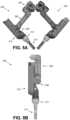
- a robotic arm 200(or, alternatively, two such arms) is provided that can be coupled to a shoulder of the device 10 disclosure discussed above.
- this arm 200can be coupled to any known robotic surgical device.
- the arm 200is a right arm 200.
- FIG. 5Adepicts both the right arm 200 and a left arm 202. In the remainder of this discussion, the description will focus on the right arm 200. It is understood that the components of the left arm 202, the relationship of those components to each other, and their functionality is substantially similar to those components of the right arm 200.
- the right arm 200has a shoulder joint (also referred to herein as a "shoulder” or “first joint”) 204, an upper arm (also referred to as a “first arm link” or “first arm component”) 206, an elbow joint (also referred to herein as an “elbow” or “second joint”) 208, a forearm (also referred to herein as a “second arm link” or “second arm component”) 210, a wrist joint (also referred to herein as a “wrist” or “third joint”) 212, and an end effector 214.
- shoulder jointalso referred to herein as a "shoulder” or “first joint”
- first arm linkalso referred to as a "first arm link” or “first arm component”
- elbow jointalso referred to herein as an "elbow” or “second joint”
- a forearmalso referred to herein as a "second arm link” or “second arm component”
- wrist jointalso referred to herein as a "w
- the arm 200(and arm 202) is configured to couple to a shoulder having 3 degrees of freedom ("DOF"), such as the device 10 described herein above.
- DOFdegrees of freedom
- the arm 200can be coupled with any known robotic device with a shoulder having 3 DOF.
- the arm 200can couple with any known robotic device.
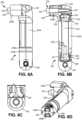
- the upper arm 206is shown in further detail in FIGS. 6A-6D .
- the upper arm 206has a body (also referred to as a "casing,” “outer structure,” or “shell”) 220.
- the body 220is made up of a first body component 220A and a second body component 220B that are coupled together via the countersunk screw 222 that is coupled to a distal end of a coupling shaft (also referred to as a "cylindrical shaft” or “coupling shaft”) 224 (as best shown in FIG. 6B ).
- a coupling shaftalso referred to as a "cylindrical shaft” or “coupling shaft”
- the two body components 220A, 220Bare constrained together via the coupling of the screw 222 and the distal end of the shaft 224 such that tightening the screw 222 into the shaft 224 produces clamping forces between the two body components 220A, 220B.
- the tightening of the coupling between the screw 222 and shaft 224also causes the shaft 224 to be pulled into a corresponding cylindrical lumen 225 defined in the body component 220B as best shown in FIG. 6B .
- the shaft 224is positioned within the cylindrical lumen 225 and is urged distally as the screw 222 is tightened into the shaft 224.
- the body 220is a single, unitary component.
- the body 220can be made up of three or more different components.
- the upper arm 206is coupled to the shoulder 14 by removing/replacing some of the components of shoulder 14 described above. More specifically, in this particular example, the following components as best shown in FIG. 4B are removed and replaced with components of the upper arm 206: the second inner bevel gear 144, the tenth shoulder bearing 148, the L-shaft gear linkage 138, the eleventh bearing 156, the output bevel gear 154, the twelfth bearing 158, and the countersunk screw 160.
- the proximal end 226 of the upper arm 206is configured to couple with the bevel gear body 120 (as best shown in FIG.
- the proximal end 226has projections 226A as best shown in FIG. 6D that geometrically match with the slots 120D defined in the gear body 120 (as best shown in FIG. 4B ) such that the proximal end 226 is coupled to the gear body 120.
- the proximal end 226 and the gear body 120can have any feature or configuration that results in geometric matching and thus coupling of the two components.
- the coupling shaft 224 and thus the entire upper arm 206are attached to the gear body 120 via the countersunk screw 150 (as best shown in FIG.
- the upper arm 206has a first upper arm bevel gear 228 disposed in the proximal end 226 that is rotationally coupled at its proximal end to the second spur gear 136 (as best shown in FIG. 4B ) such that rotation of the spur gear 136 causes the bevel gear 228 to rotate.
- the first gear 228has projections 228A at its proximal end that geometrically match with a feature or component on the spur gear 136, thereby allowing the two gears 228, 136 to couple.
- the gears 228, 136can have any configurations that allow them to couple together.
- the first bevel gear 228can be rotationally coupled to a gear or shaft or other rotational component of any robotic device to which the upper arm 206 is coupled.
- the first upper arm bevel gear 228is constrained and supported by the coupling shaft 224 (which is positioned through the gear 228 such that the gear 228 rotates around the shaft 224) and is mateably coupled to (and further constrained and supported by) a second upper arm bevel gear 230 such that rotation of the first bevel gear 228 causes rotation of the second bevel gear 230.
- the second bevel gear 230is rotationally coupled to a driveshaft 232 such that rotation of the bevel gear 230 causes rotation of the driveshaft 232.
- the gear 230 and driveshaft 232have geometrical features that allow for the two components to mateably couple in a similar fashion to the gear 228 and spur gear 136, as described above.
- first upper arm bearing 234 and second upper arm bearing 236are supported by first upper arm bearing 234 and second upper arm bearing 236.
- These bearings 234, 236, according to one disclosure,also function as alignment features to help with alignment and constraint of the first and second body components 220A, 220B. That is, each of the first and second body components 220A, 220B have bearing receiving openings 235, 237 defined within the components 220A, 220B such that the bearings 234, 236 can be positioned therein when the components 220A, 220B are coupled to each other as shown.
- the driveshaft 232is rotationally coupled to a third upper arm bevel gear 238 such that rotation of the driveshaft 232 causes rotation of the gear 238.
- the driveshaft 232 and gear 238have geometrical features that allow for the two components to mateably couple in a similar fashion to the gear 230 and driveshaft 232 or are coupled in any known fashion such that rotation of one causes rotation of the other, as described above.
- the upper arm 206has a distal opening 244 defined at or near the distal end of the arm 206.
- the distal opening 244is configured to receive a component of any forearm (such as forearm 210, for example) or other component that is coupled to the upper arm 206 such that the forearm or other component can rotate in relation to upper arm 206.
- the opening 244has two bearings 246A, 246B disposed therein that provide support to the component disposed therethrough, as described below.
- the upper arm 206has at least one retaining ring that functions to help hold together the distal end of the upper arm 206. That is, the retaining ring can help to maintain the coupling of the first and second body components 220A, 220B.
- the upper arm 206has two retaining rings 240A, 240B as best shown in FIG. 6A .
- any upper arm disclosure disclosed or contemplated hereincan have one, three, or any number of retaining rings to help hold the distal end of the upper arm together.
- any known mechanism or component for helping to maintain the coupling of the two body components 220A, 220Bcan be used.
- the upper arm 206can also have an end-mounted retaining ring 242, as best shown in FIG. 6C .
- the end-mounted retaining ring 242helps to hold the distal end of the upper arm 206 together.
- the upper arm 206can also have an anchor point 248 disposed on the second body component 220B as best shown in FIG. 6B .
- the anchor point 248is configured to act as an anchor or attachment point for one or more elongate elastic components (also referred to herein as "elastic tendons” or “elastic bands”) (not shown) that extend over the elbow joint 208 and couple to the forearm attached thereto (such as forearm 210) such that the elastic band (not shown) can apply a restraining force to the upper arm 206 and forearm (such as forearm 210) when the forearm is actuated to bend at the elbow joint 208.
- elongate elastic componentsalso referred to herein as "elastic tendons” or “elastic bands”
- the elastic bandis intended to reduce any loose couplings or "sloppiness" of the various components at the joint 208, thereby enhancing the coupling of those components.
- the elastic bandis stretched, thereby resulting in force being applied at the elbow joint 208 that urges the forearm to return to the "straight" position as best shown in FIG. 5B .
- the anchor point 248is a countersunk bolt 248 threadably coupled to the second body component 220B.
- any component or mechanism that can serve as an anchor point 248can be incorporated into the arm 206.
- the third upper arm bevel gear 238is configured to be coupleable to a matching bevel gear fixed to a forearm (such as forearm 210, for example) that is coupled to the upper arm 206.
- the drivetrain in the upper arm 206can be used to cause rotation of the forearm (such as forearm 210) in relation to the upper arm 206.
- the drivetrainis made up of the first upper arm bevel gear 228, the second upper arm bevel gear 230, the driveshaft 232, and the third upper arm bevel gear 238.
- the first upper arm bevel gear 228can be actuated to rotate (by rotation of the spur gear 136, according to some implementations), thereby causing the second upper arm bevel gear 230 to rotate, thereby causing the driveshaft 232 to rotate.
- Rotation of the driveshaft 232causes the third upper arm bevel gear 238 to rotate, thereby causing any forearm component coupled thereto to rotate in relation to the upper 206.
- rotation of the bevel gear 238causes the forearm (such as forearm 210) to move in relation to the upper arm 206 at the elbow joint (such as elbow joint 208).
- each shoulder(such as shoulders 14, 16 discussed above in relation to FIG. 1A ) provides three degrees of freedom in the form of pitch, yaw, and rotation of the elbow.
- the fourth degree of freedomis the rotation of the end effector around an axis parallel to the longitudinal axis of the forearm
- the fifth degree of freedomis the rotation of each of the graspers that cause the graspers to open and close.
- the third degree of freedom - the rotation of the output bevel gear 154 as discussed above -is utilized to actuate the elbow joint 208 instead of causing roll of the upper arm 206.
- the upper arm 206does not rotate around its own longitudinal axis.
- FIGS. 7, 8A, and 8Bdepict the forearm 210 that is coupled with the upper arm 206, according to one disclosure.
- the forearm 210has a forearm body 300 (also referred to as a "casing” or “shell”) that contains and constrains the one or more motors (discussed below).
- the body 300can have, in certain disclosures, a cautery connection (not shown) disposed in the body 300 and a cautery wire opening 303 defined therein.
- the body 300is made up of three components: a main body 300A, a electronics cover 300B, and a distal cover 300C.
- the electronics cover 300Bcontains a controller (not shown) - which can include a printed circuit board (“PCB") - that is coupled to the motors (discussed below) such that the controller can operate to control the motors. Further, the electronics cover 300B can sealably and fluidically protect the controller and any other electronics (not shown) contained within the body 300 from the external environment.
- the distal cover 300Cis positioned at or on a distal end of the body 300 and has a lip 302 defined therein that is configured to receive and help to retain any elastic constraint that is used to couple and fluidically seal a sterile cover (not shown) to the forearm 210 such that the cover can be retained in its appropriate position during use.
- the distal cover 300Ccan have any known component or mechanism for receiving, retaining, or coupling to a sterile cover. Further, the distal cover 300C defines an opening 304 at its distal end that is configured to receive an interchangeable end effector, as discussed in further detail below.
- the forearm 210also has two protrusions 264A, 264B as best shown in FIGS. 8A and 8B that form a portion of the joint 208 at which the upper arm 206 is coupled to the forearm 210.
- the two protrusions 264A, 264B(and thus the elbow joint 208) are positioned at a point along the length of the forearm 210 between the distal end 260 and the proximal end 262 of the forearm 210. That is, the protrusions 264A, 264B are spaced from both the distal end 260 and proximal end 262 of the forearm 210.
- the protrusions 264A, 264Bare positioned at or substantially adjacent to a midpoint along the length of the forearm 210 as shown.
- the protrusions 264A, 264Bare positioned anywhere along the length of the forearm 210 such that the protrusions 264A, 264B are spaced from both the proximal 262 and distal 260 ends.
- rotation of the forearm 210does not occur at the proximal end 262 of the forearm 210 but instead occurs at some other point along the length of the forearm 210 as determined by the position of the protrusions 264A, 264B.
- Each protrusion 264A, 264Bhas an opening 266A, 266B, respectively, defined therein as shown.
- a joint gear 268is disposed within the joint 208 between the two protrusions 264A, 264B such that the shaft 268A of the gear 268 is rotatably disposed within the opening 264A.
- a joint shaft 270is also disposed within the joint 208 between the two protrusions 264A, 264B such that the shaft 270 is rotatably disposed within the opening 264B at one end and disposed within the gear 268 at the other end.
- the distal end of the upper arm 206is disposed between the two protrusions 264A, 264B such that the opening 244 (as best shown above in FIGS. 6A, 6B, and 6D ) is disposed between and axially aligned with the two openings 266A, 266B.
- the distal end of the upper arm 206is coupled to the forearm 210 by the joint shaft 270, which is disposed through opening 264B, opening 244 (and supported by bearings 246A, 246B in opening 244 as discussed above), and into the gear 268 such that the distal end of the upper arm 206 is rotatably retained in the joint 210 between the two protrusions 264A, 266B as shown.
- the joint gear 268is rotationally coupled to the third upper arm bevel gear 238 of the upper arm 206 as shown in FIG. 8B such that rotation of the third upper arm bevel gear 238 causes rotation of the joint gear 268.
- joint 208 in this specific implementationis made up of the two protrusions 264A, 264B, the joint shaft 270, and the joint bevel gear 268, it is understood that any known joint or rotational coupling configuration or mechanism can be incorporated into these various arm disclosures.
- the forearm 210can also have an anchor point 272 as best shown in FIGS. 8A and 8B .
- the anchor point 272is configured to act as the other anchor or attachment point (in combination with the anchor point 248) for any elastic tendons (not shown) as discussed above that extend over the elbow joint 208.
- the anchor point 272is a countersunk bolt 272 threadably coupled to the forearm 210.
- any component or mechanism that can serve as an anchor point 272can be incorporated into the forearm 210.
- FIGS. 9A-9COne exemplary interchangeable end effector 320 that can be coupled to the forearm 210 discussed above is depicted in FIGS. 9A-9C .
- the end effector 320can be coupled with any known robotic arm or robotic surgical device.
- any interchangeable end effectorcan be coupled to the forearm 210 or removed and replaced with any other known interchangeable end effector.
- the end effector 320 in this exemplary disclosureis a graspers end effector 320 with a graspers component 322 having first and second grasper arms 322A, 322B.
- the end effector 320has a twistable knob 324 that can be grasped by a user to couple the end effector 320 to and uncouple the end effector 320 from an arm (such as the forearm 210).
- the knob 324is coupled to the locking collar 326 having locking protrusions 326A that mateably couple to the four notches 382 defined in the cover 300C as described in further detail below.
- a sealing ring(also referred to herein as an "o-ring") 328 is disposed around the end effector 320 at a proximal end or portion of the knob 324 such that the ring 328 can provide for a fluidically sealed coupling of the end effector 320 to the forearm 210 when the end effector 320 is coupled thereto as described above.
- the ring 328can also provide outward pressure or force against both the end effector 320 and the forearm 210 such that counter-rotation of the knob 324 that might cause the end effector 320 to uncouple during use is reduced or eliminated.
- the end effector 320has both a rotational drive system and a grasper arm actuation drive system.
- the rotational drive systemis made up of a rotatable yoke 330 that is coupled to the graspers 322 such that rotation of the yoke 330 causes rotation of the graspers 322. That is, the yoke 330 has two flanges 330A, 330B as best shown in FIG. 9A such that the graspers 322 are disposed between the two flanges 330A, 330B and coupled thereto via the pin 331.
- the yoke 330has mateable coupling components 332 that are configured to couple to the rotational drive component 370 in the distal end of the forearm 210, as described in further detail below. More specifically, in this exemplary disclosure, the mateable coupling components 332 are two protrusions 332 as best shown in FIGS. 9A and 9C .
- the rotatable yoke 330is axially restrained (such that the yoke 330 does not move distally or proximally in relation to the length of the end effector 320) by a groove 334 defined around an outer surface of the yoke 330 such that a pin (not shown) can be inserted through an opening 336 in the knob 324 (as best shown in FIG. 9A ) and positioned in the groove 334, thereby allowing the yoke 330 to rotate but preventing it from moving in an axial direction.
- rotation of the rotational drive component 370 in the forearmcauses rotation of the rotatable yoke 330, which causes rotation of the graspers 322.
- the grasper arm actuation drive systemis made up of an internally-threaded rotatable cylinder 338, an externally threaded drive pin 340 threadably coupled to the cylinder 338, and two linkages (including linkage 342) coupled to the pin 340.
- the rotatable cylinder 338has mateable coupling components 344 at its proximal end that are configured to couple to the actuation drive component 372 in the distal end of the forearm 210, as described in further detail below. More specifically, in this exemplary disclosure, the mateable coupling components 344 are two protrusions 344 as best shown in FIGS. 9A and 9C .
- the rotatable cylinder 338is axially restrained by a groove 346 defined around an outer surface of the cylinder 338 such that a pin (not shown) can be inserted through an opening (not shown) in the knob 324 (similar to opening 336 discussed above) and positioned in the groove 346, thereby allowing the cylinder 338 to rotate but preventing it from moving in an axial direction.
- the rotatable cylinder 338has a lumen 347 with a lumen inner surface 348 that is threaded.
- the drive pin 340has a distal head (also referred to as a "coupling component") 350 and an externally-threaded proximal body 352 that is sized to be disposed within the lumen 347 of the cylinder 338 such that the proximal body 352 is threadably coupled to the lumen inner surface 348.
- the distal head 350has two openings 354A, 354B defined therein that are coupleable to the two linkages. More specifically, the linkage 342 is coupled to the distal head 350 at opening 354A with a pin or similar coupling component (not shown).
- a second linkage(not shown) is coupled to the distal head 350 at opening 354B in the same fashion.
- the linkages (342 and the linkage that is not shown)are coupled to the proximal ends of the grasper arms 322A, 322B.
- rotation of the actuation drive component 372 in the forearm 210causes rotation of the rotatable cylinder 338, which causes axial movement of the drive pin 340 (through the threadable coupling of the cylinder 338 and the pin 34), which causes movement of the linkages (342 and the linkage that is not shown), which causes the grasper arms 322A, 322B to rotate around the axis at pin 331 in the yoke 330 such that the arms 322A, 322B move between an open position and a closed position.
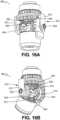
- FIGS. 10A-10Cdepict the distal cover 300C of the body 300, along with the end effector interface 364, according to onedisclosure.
- the distal cover 300C discussed abovecan be coupled to the main body 300A and electronics cover 300B by a fastener 360 positioned through the distal cover 300C and the electronics cover 300B, thereby coupling both the distal cover 300C and electronics cover 300B to the main body 300A.
- the fastener 360is a bolt 360.
- any known fastener or attachment mechanismcan be used.
- a further fastener 362is provided to further couple the distal cover 300C to the main body 300A.
- the fastener 362is a pin 362.
- the fastener 362can be any known fastener or attachment mechanism.
- the distal cover 300Chouses the end effector interface 364.
- the end effector interface 364is configured to couple to the actuation components of an end effector (such as end effector 320 discussed above). More specifically, in those exemplary disclosures in which the end effector interface 364 is coupling to the end effector 320, the interface 364 is configured to couple to both the rotational drive system and the graspers drive system as discussed above.
- the interface 364has first and second sealing rings 366, 368, a rotatable rotational drive component 370, a rotatable graspers actuation drive component 372, and an electrical contact spring 374.
- this interface 364can be coupled with various end effectors. While the description below will specifically reference the end effector 320 and how the components of the interface 364 relate to and couple with that end effector 320, that is not intended to limit the use of this end effector interface 364 to solely the end effector 320. Instead, the interface 364 can be coupled to any end effector having the appropriate components to couple thereto.
- the rotatable rotational drive component 370in this specific implementation, is a rotatable drive cylinder 370 with mateable coupling components 370A, 370B (as best shown in FIG. 10B ) that are configured to mate with the mateable coupling components 332 of the rotatable yoke 330 in the end effector 320, as discussed above. More specifically, the mateable coupling components 370A, 370B in this disclosure are projections 370A, 370B that are mateable or coupleable with the mateable coupling components 332 of the rotatable yoke 330 in the end effector 320.
- the rotatable graspers actuation drive component 372in this specific implementation, is a rotatable drive cylinder 372 with mateable coupling components 372A, 372B (as best shown in FIG. 10B ) that are configured to mate with the mateable coupling components 344 of the rotatable cylinder 338 in the end effector 320, as discussed above.
- the mateable coupling components 372A, 372B in this disclosureare projections 372A, 372B that are mateable or coupleable with the mateable coupling components 344 of the rotatable cylinder 338 in the end effector 320.
- the rotatable graspers actuation drive component 372can transfer electrical energy to the graspers of an end effector (such as the graspers 322 of end effector 320) for cauterization. That is, the rotatable cylinder 372 has a proximal lumen 378 defined in a proximal end of the cylinder 372 that is configured to receive the electrical contact spring 374.
- the spring 374extends proximally into a lumen 380 defined in the body 300 such that the spring 374 is positioned adjacent to the cautery wire opening 303 discussed above such that a cautery wire (or cautery cable) positioned through the opening 303 can be coupled to the spring 374.
- the spring 374can be any electrical contact component. It is understood that, according to certain disclosures, the cautery wire opening 303 is defined on both sides of the body 300 so that the same body 300 configuration can be used in both the left and right arms of the device.
- the rotatable drive cylinder 372is positioned or nested within the rotatable drive cylinder 370 as shown.
- the first sealing ring 366is an o-ring 366 that is disposed between the distal cover 300C and the rotatable drive cylinder 370.
- the second sealing ring 368is an o-ring 368 that is disposed between the rotatable drive cylinder 370 and the rotatable drive cylinder 372.
- the two rotatable drive cylinders 370, 372are supported and rotatably retained in place by a first bearing 376, along with the first sealing ring 366.
- the distal cover 300Chas at least two notches defined in the distal cover opening 304 that can be mateable or coupleable with the locking protrusions 326A on the end effector 320 as discussed above.
- the cover 300Chas four notches 382 that are mateable with the four protrusions 326A discussed above such that the end effector 320 can be coupled to the distal cover 300C with a single rotation or "twist" of the know 324 of the end effector 320.
- any known locking mechanism or featurecan be used.
- FIGS. 11A-11Cdepict the motors within the body 300 that power the rotatable rotational drive component 370 and the rotatable graspers actuation drive component 372 discussed above. More specifically, in accordance with one implementation, the forearm 210 has two motors 400, 402 disposed therein, as best shown in FIG. 11C . In one disclosure, the motors 400, 402 are 6 mm brushless motors. Alternatively, the motors 400, 402 can be any known type of motors for use in robotic arms.
- the motor 400is coupled to a shaft 404, which is coupled to a bushing 406, which in turn is coupled to the drive gear (also referred to as a "spur gear") 408.
- the shaft 404can be coupled directly to the drive gear 408.
- the drive gear 408is rotatably coupled to gear teeth 410 that are attached to or otherwise coupled to the rotatable graspers actuation drive component 372.
- actuation of the motor 400causes rotation of shaft 404, which causes rotation of drive gear 408, which causes rotation of the rotatable graspers actuation drive component 372, which ultimately causes the grasper arms 322A, 322B to move between an open position and a closed position, as described above.
- the motor 402is coupled to a shaft 420, which is coupled to a bushing 422, which in turn is coupled to the drive gear (also referred to as a "spur gear") 424.
- the shaft 420can be coupled directly to the drive gear 424.
- the drive gear 424is rotatably coupled to gear teeth 426 that are attached to or otherwise coupled to the rotatable rotational drive component 370.
- actuation of the motor 402causes rotation of shaft 420, which causes rotation of drive gear 424, which causes rotation of the rotatable rotational drive component 370, which ultimately causes the graspers end effector to rotate, as described above.
- the motors 400, 402are retained or held in place in the forearm 210 by a locking wedge 430.
- the locking wedge 430can be urged toward the distal end of the forearm 210 along the two motors 400, 402 such that the angled or wedge portion 434 is positioned in the wedge-shaped opening 432 defined in the body 300 to help to retain or "lock" the two motors 400, 402 in place.
- This positioning of the wedge portion 434 in the wedge-shaped opening 432urges the wedge portion 434 against the motors 400, 402, thereby creating a friction-based contact between the wedge portion 434 and motors 400, 402, thereby helping to retain the motors 400, 402 in place via the frictional force.
- the locking wedge 430can be positioned manually to lock the motors 400, 402 in position.
- FIGS. 12A and 12Bdepict another disclosure of the right shoulder joint 14 and its various components. More specifically, FIG. 12A depicts an exploded view of the internal components of the right shoulder joint 14, while FIG. 12B depicts a cross-sectional front view of the internal components of the right shoulder joint 14.
- the outer driveshaft 40A(discussed above in relation to FIGS. 2-3E ) is coupled (or rotationally constrained) to the shoulder roll housing (also referred to herein as the "shoulder housing" or “conversion body") 500
- the middle driveshaft 40B(discussed above in relation to FIGS. 2-3E ) is coupled to the upper drive bevel gear 502
- the inner driveshaft 40Cextends through the spacer 512 and is coupled to the lower drive bevel gear 504.
- the outer driveshaft 40A and shoulder housing 500are supported by the first bearing 506, which is disposed on an outer portion of the housing 500.
- the outer driveshaft 40A and shoulder housing 500are further supported by the second bearing 508, which is disposed within the housing 500.
- the middle driveshaft 40B and the upper drive bevel gear 502are supported by the second bearing 508 and the third bearing 510, which is positioned within the distal end of the upper drive bevel gear 502 as best shown in FIG. 12B .
- the bearings 506, 508, 510are preloaded using a single countersunk screw 514 threaded into the distal end of the inner driveshaft 40C. Alternatively, any attachment components can be used to preload the bearings 506, 508, 510.
- the shoulder housing 500is made up of two housing components: the first housing component (or “first housing shell”) 500A and the second housing component (or “second housing shell”) 500B.
- the two shells 500A, 500Bare coupled together with a screw 516 and a retaining ring 518.
- any known attachment components or mechanismscan be used to couple the two shells 500A, 500B together.
- the housing 500is single unitary housing.
- the outer driveshaft 40Ais coupled (or rotationally constrained) to the shoulder roll housing 500. More specifically, projections 501A, 501B extending from a top portion of the housing 500 (more specifically, from each of the two housing shells 500A, 500B, according to this disclosure) are mateable with two notches 503A, 503B in the outer driveshaft 40A. Alternatively, any mechanism(s) or feature(s) for coupling the driveshaft 40A and the housing 500 can be used.
- rotation of the outer driveshaft 40Acauses the shoulder housing 500 to rotate around the longitudinal axis of the driveshaft 40A, thereby causing any arm coupled to the shoulder (at output bevel gear 550 discussed below) to rotate around the same axis, resulting in the arm moving from left to right (“yaw") in relation to the device body (such as body 12 discussed above).
- the upper drive bevel gear 502is mateably coupled to the first driven bevel gear 520 such that rotation of the upper drive bevel gear 502 causes rotation of the first driven bevel gear 520 around the longitudinal axis of the shaft 528A of the second driven bevel gear 528 discussed below.
- the first driven bevel gear 520drives the pitch of the shoulder 14 by causing rotation of the bevel gear body 522 around the same longitudinal axis of the shaft 528A, thereby causing the arm to move "up and down" in relation to the device body.
- the first driven bevel gear 520is coupled to the bevel gear body (also referred to as “rotatable arm,” “rotatable body,” “rotation arm,” “rotation body,” “pitch arm,” or “pitch body”) 522 such that rotation of the first driven bevel gear 520 causes rotation of the bevel gear body 522.
- the bevel gear body 522has two openings 522A, 522B defined therein (as best shown in FIG. 12A ), with a mateable coupling 522C disposed around one side of the opening 522A that is coupled to the first driven bevel gear 520 such that rotation of the bevel gear 520 causes rotation of the bevel gear body 522.
- the first driven bevel gear 520has an opening 520A defined therethrough such that the bevel gear 520 is rotatably disposed over the second driven bevel gear 528, which is discussed in further detail below.
- the first driven bevel gear 520is constrained by fourth bearing 524 and fifth bearing 526.
- rotation body 522can be any component that has two openings as described herein and can be coupled to the various components as described.
- the lower drive bevel gear 504is mateably coupled to the second driven bevel gear 528 such that rotation of the lower drive bevel gear 504 causes rotation of the second driven bevel gear 528.
- the second driven bevel gear 528is rotatably disposed through the opening 520A in the first driven bevel gear 520 such that the second driven bevel gear 528 is at least partially disposed within the first driven bevel gear 520.
- the second driven bevel gear 528is coupled to the first spur gear 530 such that rotation of the second driven bevel gear 528 causes rotation of the first spur gear 530. That is, the shaft 528A of the second driven bevel gear 528 extends through the opening 522A in the bevel gear body 522 and is coupled to the first spur gear 530.
- the second driven bevel gear 528is mateably coupled to the first spur gear 530 via a geometric coupling.
- the second driven bevel gear 528is constrained by the fourth bearing 524 and a sixth bearing 532. It is understood that the bearings 524, 526, 532 are preloaded using a spring 534 and translationally constrained by a retaining ring 536.
- the spring 534is a Belleville spring 534.
- the first spur gear 530 discussed aboveis mateably coupled to the second spur gear 538 such that rotation of the first spur gear 530 causes rotation of the second spur gear 538.
- the second spur gear 538is coupled to the third driven bevel gear 540 such that rotation of the second spur gear 538 causes rotation of the third driven bevel gear 540. That is, the shaft 540A of the third driven bevel gear 540 extends through the opening 522B in the bevel gear body 522 and is coupled to the second spur gear 538.
- the second spur gear 538is mateably coupled to the shaft 540A of the third driven bevel gear 540 via a geometric coupling.
- the third driven bevel gear 540is constrained by a seventh bearing 542 and an eighth bearing 544.
- both bearings 542, 544are disposed within or press fit within the bevel gear body 522. It is understood that the bearings 542, 544 are preloaded using a spring 546 and translationally constrained by a retaining ring 548.
- the spring 546is a Belleville spring 546.
- the third driven bevel gear 540is mateably coupled to a fourth driven bevel gear (also referred to herein as a "yaw output gear” or “output gear") 550 such that rotation of the third driven bevel gear 540 causes rotation of the output gear 550.
- the output gear 550is constrained by a ninth bearing 552 and a tenth bearing 554.
- the bearings 552, 554are retained in place by the bevel gear body 522.
- the gear 550is translationally constrained by a retaining ring 556.
- the pitch, yaw, and roll rotationsare coupled. That is, the actuation of one of the rotations will cause actuation of at least one of the other rotations as a result of their coupled nature such that some counteraction must occur if the secondary actuation is undesirable.
- the bevel gear 502is actuated to rotate, thereby causing gear 520 to rotate as described above.
- the coupled nature of these drive componentsresults in the output gear 550 rotating as well.
- the bevel gear body 522is made up of two components 522C, 522D coupled together as best shown in FIG. 12A .
- the bevel gear body 522can be a single, unitary component 522.
- FIGS. 13-17Drelate to joint implementations that can be incorporated into shoulder joints, elbow joints, wrist joints, or other joints of a robotic arm. These joint disclosures have four degrees of freedom while - in some instances - requiring only three motors.
- the joint disclosures belowcan be incorporated into a wrist joint, thereby resulting in a wrist joint with four degrees of freedom, which is two more degrees of freedom than known robotic grasper drivetrains.
- the wrist joint disclosuresare nimble wrist joints providing more dexterity to the surgeon in comparison to known wrist joints.
- the joint disclosures belowcan be incorporated into a shoulder joint, thereby allowing for four degrees of freedom to pass through the shoulder joint and into the robotic arm coupled thereto.
- larger motorscan be used to actuate the joints of the robotic arm coupled thereto and also allow for the lengths of the arm components to be determined based on factors other than solely motor size.
- these disclosurescan utilize only three motors to control four degrees of freedom. As will be described in detail below, these configurations that have only three motors are possible because all three motors are coupled together in a shared state in which a fourth degree of freedom is realized. As detailed below, the coupling of the three motors can be accomplished in several ways, including by providing a braking force condition on one of the outputs such that only deliberate commands will cause a robotic joint to actuate.
- the first disclosureas depicted in FIGS. 13-14B , utilizes four motors, while the second disclosure, as depicted in FIGS. 15A-17D , requires only three motors.
- FIG. 13depicts a cross-sectional front view of a joint 600 having a set of nested driveshafts 602, 604, 606, 608. More specifically, the set of four nested driveshafts 602, 604, 606, 608 includes a first (also referred to herein as “inner”) driveshaft 602, a second (also referred to as “first middle”) driveshaft 604, a third (also referred to as “second middle”) driveshaft 606, and a fourth (also referred to as “outer”) driveshaft 608. It is understood that the specific length of these driveshafts 602, 604, 606, 608 as shown in FIG. 13 is merely exemplary, and that the length can vary depending on various circumstances, including whether the joint 600 is a shoulder joint, elbow joint, wrist joint, or some other kind of joint.
- the first driveshaft 602is rotatably disposed within the second driveshaft 604 as shown, and has a first driven gear 610 fixedly or integrally attached at its proximal end as shown.
- the first driveshaft 602is supported at its proximal end by first proximal bearing 640 and second proximal bearing 642, with the first bearing 640 being supported by the enclosure (not shown) of the joint 600 and the second bearing 642 being supported by the second driven gear 612.
- the first driveshaft 602is rotationally coupled to a first bevel gear 620, as best shown in FIGS. 13 , 14A, and 14B .
- the driveshaft 602is coupled to the gear 620 via a geometric coupling, and the gear 620 is retained axially in relation to the driveshaft 602 by bolt 660.
- the driveshaft 602 and gear 620are radially constrained in a first distal bearing 650.
- the first bevel gear 620is rotatably coupled to a first intermediate bevel gear 680, as best shown in FIGS. 13 , 14A, and 14B .
- the bevel gear 680is fixedly coupled or integral with a rotatable cylinder 681, which is fixedly coupled to a drive post 662, which extends distally toward a distal end of the joint 600 from the rotatable cylinder 681.
- the drive post 662is retained in position by a first post bolt 664 and a second post bolt 666 and constrained by first post bearing 668 and second post bearing 670.
- Rotation of the first intermediate bevel gear 680causes rotation of the cylinder 681 around the axis of the bevel gear 680, which causes the drive post 662 to rotate around the axis of the bevel gear 680, which is perpendicular to the rotational axis of the driveshafts 602, 604, 606, 608.
- the portion of the joint 600 distal to the rotatable cylinder 681rotates with the drive post 662.
- actuation of the motor (not shown) coupled to the first driven gear 610causes rotation of the first driven gear 610, which causes rotation of the first driveshaft 602.
- Rotation of the first driveshaft 602causes rotation of the first bevel gear 620, which causes rotation of the first intermediate bevel gear 680 around an axis perpendicular to the axis of rotation of the driveshafts 602, 604, 606, 608.
- rotation of the first intermediate bevel gear 680causes rotation of the rotatable cylinder 681, which causes rotation of the drive post 662, which causes rotation of the portion of the joint 600 distal to the first intermediate bevel gear 680 around the same axis of rotation as the first intermediate bevel gear 680.
- the second driveshaft 604is rotatably disposed within the third driveshaft 606 as shown, and has a second driven gear 612 fixedly or integrally attached at its proximal end.
- the second driveshaft 604is supported at its proximal end by second proximal bearing 642 and third proximal bearing 644, with the second bearing 642 being supported by the second driven gear 612 and the third bearing 644 being supported by the third driven gear 614.
- the second driveshaft 604is rotationally coupled to a second bevel gear 622, as best shown in FIGS. 13 , 14A, and 14B .
- the driveshaft 604is coupled to the gear 622 via a geometric coupling, and the driveshaft 604 and gear 622 are constrained by a second distal bearing 652.
- the second bevel gear 622is rotatably coupled to a second intermediate bevel gear 682, as best shown in FIGS. 13 , 14A, and 14B . Further, the bevel gear 682 is rotatably coupled to a first output bevel gear 690, which is rotationally coupled with or integral with the first (or “inner”) rotatable output member 672.
- the second intermediate bevel gear 682is supported by a third distal bearing 654, which is supported by a portion of the first intermediate bevel gear 680.
- Rotation of the second driveshaft 604causes rotation of the second bevel gear 622, which causes rotation of the second intermediate bevel gear 682 around an axis perpendicular to the axis of rotation of the driveshafts 602, 604, 606, 608.
- rotation of the second intermediate bevel gear 682causes rotation of the first output bevel gear 690 around an axis parallel to the axis of rotation of the driveshafts 602, 604, 606, 608, which causes rotation of the first rotatable output member 672 around the same axis of rotation.
- first rotatable output member 672is configured to be coupled to an actuatable component, such as a portion of a robotic arm wrist, an end effector, or a robotic upper arm, depending on the location of the joint 600 on the robotic device.
- an actuatable componentsuch as a portion of a robotic arm wrist, an end effector, or a robotic upper arm, depending on the location of the joint 600 on the robotic device.
- the third driveshaft 606is rotatably disposed within the fourth driveshaft 608 as shown and has a third driven gear 614 fixedly or integrally attached at its proximal end.
- the third driveshaft 606is supported at its proximal end by third proximal bearing 644 and fourth proximal bearing 646, with the third bearing 644 being supported by the third driven gear 614 and the fourth bearing 646 being supported by the fourth driven gear 616.
- the third driveshaft 606is rotationally coupled to a third bevel gear 624, as best shown in FIGS. 13 , 14A, and 14B .
- the driveshaft 606is coupled to the gear 624 via a geometric coupling, and the driveshaft 606 and gear 624 are constrained by a fourth distal bearing 656.
- the third bevel gear 624is rotatably coupled to a third intermediate bevel gear 684, as best shown in FIGS. 13 , 14A, and 14B . Further, the bevel gear 684 is rotatably coupled to a second output bevel gear 692, which is rotatationally coupled with or integral with the second (or “outer") rotatable output member 674.
- the third intermediate bevel gear 684is supported by a fifth distal bearing 657.
- the second output bevel gear 692is supported by a first output bearing 694 and a second output bearing 696 in relation to the first output bevel gear 690.
- actuation of the motor (not shown) coupled to the third driven gear 614causes rotation of the third driven gear 614, which causes rotation of the third driveshaft 606.
- Rotation of the third driveshaft 606causes rotation of the third bevel gear 624, which causes rotation of the third intermediate bevel gear 684 around an axis perpendicular to the axis of rotation of the driveshafts 602, 604, 606, 608.
- rotation of the third intermediate bevel gear 684causes rotation of the second output bevel gear 692 around an axis parallel to the axis of rotation of the driveshafts 602, 604, 606, 608, which causes rotation of the second rotatable output member 674 around the same axis of rotation.
- the second rotatable output member 674is configured to be coupled to an actuatable component, such as a portion of a robotic arm wrist, an end effector, or a robotic upper arm, depending on the location of the joint 600 on the robotic device.
- an actuatable componentsuch as a portion of a robotic arm wrist, an end effector, or a robotic upper arm, depending on the location of the joint 600 on the robotic device.
- the fourth driveshaft 608is rotatably disposed around the third driveshaft 606 (and thus around the first and second driveshafts 602, 604 as well) and has a fourth driven gear 616 fixedly or integrally attached at its proximal end.
- the fourth driveshaft 608is supported at its proximal end by the fourth proximal bearing 646 and a fifth proximal bearing 648 and, with the fourth bearing 646 being supported by the fourth driven gear 616 and the fifth bearing 648 being supported by an enclosure (not shown) of the joint 600.
- the fifth bearing 648is retained in place by a retaining ring 649.
- the fourth driveshaft 608is rotationally coupled to or integral with a first retaining member 700, as best shown in FIGS.
- the first retaining member 700has two arms 700A, 700B, as best shown in FIGS. 13 and 14A , wherein the rotatable cylinder 681 and attached first intermediate bevel gear 680 are disposed between the two arms 700A, 700B.
- two bolts 702, 704are positioned through the arms 700A, 700B, respectively, and threaded into the rotatable cylinder 681.
- the two bolts 702, 704are radially supported by first and second bolt bearings 706, 708, as best shown in FIG. 13 . More specifically, the two bolts have heads 702A, 704A (as best shown in FIG. 13 ) sized to fit within the bearings 706, 708.
- the heads 702A, 704Aare positioned in contact with (or "rest on") washers 710, 712, respectively.
- actuation of the motor (not shown) coupled to the fourth driven gear 616causes rotation of the fourth driven gear 616, which causes rotation of the fourth driveshaft 608.
- Rotation of the fourth driveshaft 608causes rotation of the first retaining member 700 around an axis that is parallel to the axis of rotation of the driveshafts 602, 604, 606, 608.
- the rotation of the retaining member 700causes rotation of the two arms 700A, 700B, which causes rotation of the two bolts 702, 704, which causes rotation of the rotatable cylinder 681 and the entire distal end of the joint 600 (distal to the bearing 648).
- the driven gears 610, 612, 614, 616 at the proximal end of the driveshafts 602, 604, 606, 608, respectively,are configured to be coupled to gears (not shown) that are driven by motors (not shown).
- the motors and associated gearshave been omitted.
- the motors and associated gearscould be configured in a fashion similar to those depicted in FIG. 3B .
- any configuration of motorscan be used.
- the joint 600provides four degrees of freedom.
- one degree of freedomis accomplished via the coupling of the first driveshaft 602 to the rotatable cylinder 681 and drive post 662 that results in rotation of the portion of the joint 600 distal to the first intermediate bevel gear 680 around an axis of rotation perpendicular to that of the driveshafts 602, 604, 606, 608.
- Another degree of freedomis accomplished via the coupling of the second driveshaft 604 to the first (or “inner") rotatable output member 672 that results in rotation of the output member 672 around an axis parallel to the axis of rotation of the driveshafts 602, 604, 606, 608.
- a further degree of freedomis achieved by the coupling of the third driveshaft 606 to the second (or “outer”) rotatable output member 674 that results in rotation of the output member 674 around an axis parallel to the axis of rotation of the driveshafts 602, 604, 606, 608.
- Another degree of freedomis accomplished via the coupling or integration of the fourth driveshaft 608 to the first retaining member 700 that results in rotation of the entire distal end of the joint 600 (distal to the bearing 648) around an axis that is parallel to the axis of rotation of the driveshafts 602, 604, 606, 608.
- the joint 600can also have an optional passive retaining member (also referred to as a "second retaining member") 720.
- the passive retaining member 720is typically incorporated in those disclosures in which the joint 600 is a wrist joint 600, but it can be incorporated into other types of joints as well.
- the passive retaining member 720could be used to couple the joint 600 to the end effector 320 depicted in FIGS. 9A-9C .
- the passive retaining member 720provides a stationary foundation for the first and second rotatable output members 672, 674.
- the retaining member 720has a channel 722 defined on an outer surface of the member 720 that can be used to help with securing any flexible outer protection sleeves (not shown) thereto.
- the retaining member 720is positioned over the bolt heads 702A, 704A such that the bolt heads 702A, 704A help to retain the member 720 in its coupling with the joint 600, with first retaining member bearing 724 and second retaining member bearing 726 serving as the interface between the member 720 and the heads 702A, 704A.
- the joint 600has no passive retaining member, as best shown in FIG. 14A . In certain implementations, this is the configuration that is utilized when the joint 600 is a shoulder joint 600, rather than a wrist joint.
- FIGS. 15A-17DAlternative joint implementations are best shown in FIGS. 15A-17D , in which the joints have four degrees of freedom while requiring only three motors, as mentioned above.
- the joint disclosures belowcan be incorporated into a wrist joint, while in other implementations, the joint disclosures below can be incorporated into a shoulder joint.
- these three motor configurationsare possible because all three motors are coupled together in a shared state in which a fourth degree of freedom is realized. More specifically, the coupling of the three motors can be accomplished in several ways, including by providing a braking force condition on one of the outputs such that only deliberate commands will cause a robotic joint to actuate.
- FIGS. 15A and 15Bdepict a cross-sectional front view of a joint 800 according to one disclosure having a set of nested driveshafts (not shown) that are coupled to separate bevel gears as discussed below in a configuration similar to that described above with respect to FIGS. 13-14B . While the actual nested driveshafts are not depicted in this particular implementation, it is understood that the driveshafts (not shown) are substantially similar to those described above with respect to FIGS. 13-14B .
- the joint 800has a set of three nested driveshafts, including a first (also referred to herein as “inner”) driveshaft (not shown), a second (also referred to as “middle”) driveshaft (not shown), and a third (also referred to as “outer”) driveshaft (not shown).
- the first driveshaft (not shown)is rotationally coupled to a first bevel gear 802, as best shown in FIGS. 15A , 15B , 16A, 16B , and 17A , such that rotation of the driveshaft (not shown) causes rotation of the first bevel gear 802.
- the driveshaft (not shown)is coupled to the gear 802 via a geometric coupling, and the gear 802 is retained axially in relation to the driveshaft (not shown) by bolt 804 which is threaded into the driveshaft (not shown).
- the driveshaft (not shown) and gear 802are constrained in a first bearing 806, which is inset in second bevel gear 830, which is discussed below.
- the first bevel gear 802is rotatably coupled to a first intermediate bevel gear 810, as best shown in FIGS. 15A , 15B , 16A, 16B , and 17A , such that rotation of the first bevel gear 802 causes rotation of the first intermediate bevel gear 810.
- the intermediate bevel gear 810is rotatably coupled to first output bevel gear 812 such that rotation of the first intermediate bevel gear 810 causes rotation of the first output bevel gear 812.
- the first intermediate bevel gear 810is axially constrained by second bearing 814, which is inset in third intermediate bevel gear 854.
- the first output bevel gear 812is constrained by third and fourth bearings 816, 818, which are inset in the second output bevel gear 836.
- first output bevel gear 812is further constrained where the gear 812 interfaces with the crossbar 856, which is discussed in detail below, along with the fifth bearing 820 and the axial bolt 822.
- the fifth bearing 820rotationally separates (provides a rotational interface between) first output bevel gear 812 from the crossbar 856.
- the output bevel gear 812is rotationally coupled to or integral with a first generic output interface 824, which can couple to any component intended to be actuated.
- any type of known coupling component or interfacecan be coupled to or integral with the bevel gear 812.
- actuation of the motor (not shown) coupled to the first driveshaft (not shown)causes rotation of the first driveshaft (not shown).
- Rotation of the first driveshaft (not shown)causes rotation of the first bevel gear 802, which causes rotation of the first intermediate bevel gear 810 around an axis perpendicular to the axis of rotation of the first bevel gear 802.
- rotation of the first intermediate bevel gear 810causes rotation of the first output bevel gear 812, which causes rotation of the first generic output interface 824 around the same axis of rotation as the first bevel gear 802.
- the second driveshaft (not shown)is rotationally coupled to a second bevel gear 830, as best shown in FIGS. 15A , 15B , 16A, 16B , and 17B , such that rotation of the driveshaft (not shown) causes rotation of the second bevel gear 830.
- the driveshaft (not shown)is coupled to the gear 830 via a geometric coupling, and the gear 830 is retained axially in relation to the driveshaft (not shown) in part by the bolt 804 discussed above, which is threaded into the first driveshaft (not shown).
- the bolt 804compresses the first and second bevel gears 802, 830 such that axial movement is minimized or prevented.
- the second driveshaft (not shown) and gear 830are constrained in a sixth bearing 832, which is inset in third bevel gear 850, which is discussed below.
- the second bevel gear 830is rotatably coupled to a second intermediate bevel gear 834, as best shown in FIGS. 15A , 15B , 16A, 16B , and 17B , such that rotation of the second bevel gear 830 causes rotation of the second intermediate bevel gear 834.
- the intermediate bevel gear 834is rotatably coupled to second output bevel gear 836 such that rotation of the second intermediate bevel gear 834 causes rotation of the second output bevel gear 836.
- the second intermediate bevel gear 834is axially constrained by seventh bearing 838, which is disposed on the crossbar 856, along with the threaded coupling of the bolt 840 with the crossbar 856.
- the second output bevel gear 836is constrained by the third and fourth bearings 816, 818, which are discussed above.
- the output bevel gear 836is rotationally coupled to or integral with a second generic output interface 842, which can couple to any component intended to be actuated.
- any type of known coupling component or interfacecan be coupled to or integral with the bevel gear 836.
- actuation of the motor (not shown) coupled to the second driveshaft (not shown)causes rotation of the second driveshaft (not shown).
- Rotation of the second driveshaft (not shown)causes rotation of the second bevel gear 830, which causes rotation of the second intermediate bevel gear 834 around an axis perpendicular to the axis of rotation of the second bevel gear 830.
- rotation of the second intermediate bevel gear 834causes rotation of the second output bevel gear 836, which causes rotation of the second generic output interface 842 around the same axis of rotation as the second bevel gear 830.
- the third driveshaft (not shown)is rotationally coupled to a third bevel gear 850, as best shown in FIGS. 15A , 15B , 16A, 16B , and 17C , such that rotation of the driveshaft (not shown) causes rotation of the third bevel gear 850.
- the driveshaft (not shown)is coupled to the gear 850 via a geometric coupling, and the gear 850 is retained axially in relation to the driveshaft (not shown) in part by the bolt 804 discussed above, which is threaded into the first driveshaft (not shown).
- the third driveshaft (not shown) and gear 850are constrained in an eighth bearing 852, which is inset in the enclosure (not shown) of the joint 800, which is discussed below.
- a retaining ring 858is disposed on the shaft of the third bevel gear 850 such that the third bevel gear 850 cannot be moved axially in relation to the eighth bearing 852.
- the third bevel gear 850is rotatably coupled to a third intermediate bevel gear 854, as best shown in FIGS. 15A , 15B , 16A, 16B , and 17C , such that rotation of the third bevel gear 850 causes rotation of the third intermediate bevel gear 854.
- the intermediate bevel gear 854is rotationally coupled to or integral with a rotatable cylinder (also referred to herein as a "crossbar") 856 such that rotation of the third intermediate bevel gear 854 causes rotation of the rotatable cylinder 856.
- the second intermediate bevel gear 834is axially constrained by the second 814 and seventh 838 bearings, which are both disposed on the crossbar 856, along with the threaded coupling of the bolt 840 with the crossbar 856.
- the crossbar 856is rotationally coupled to the distal portion of the joint 800, which is the portion distal from the crossbar 856, such that rotatable crossbar 856 causes rotation of the distal portion of the joint 800 around an axis perpendicular to the axis of the third bevel gear 850.
- a distal enclosure 860is disposed over the distal portion of the joint 800. In one implementation, the distal enclosure 860 provides a sealing surface for any external sealing bag system such as those systems discussed elsewhere herein.
- actuation of the motor (not shown) coupled to the third driveshaft (not shown)causes rotation of the third driveshaft (not shown).
- Rotation of the third driveshaft (not shown)causes rotation of the third bevel gear 850, which causes rotation of the third intermediate bevel gear 854 around an axis perpendicular to the axis of rotation of the third bevel gear 850.
- rotation of the third intermediate bevel gear 854causes rotation of the crossbar 856, which causes rotation of the distal portion of the joint 800 around an axis of rotation that is perpendicular to the third bevel gear 850.
- a fourth degree of freedomcan be provided by a support member (also referred to herein as a "spacing member") 870 which is positioned over a portion of the joint 800, as best shown in FIGS. 15A , 15B , 16A, 16B , and 17D .
- the support member 870has a first arm 872 and a second arm 874, with both arms having openings 876, 878 configured to receive the heads of the bolts 840, 841 such that the retainer 870 constrains the heads of the bolts 840, 841, thereby maintaining the coupling and the spacing of the bevel sets (the coupling of the first bevel gear 802 and the first intermediate bevel gear 810, the coupling of the second bevel gear 830 and the second intermediate bevel gear 834, and the coupling of the third bevel gear 850 and the third intermediate bevel gear 854).
- the arms 872, 874have interfaces 880, 882 that contact the third bevel gear 850 such that the retainer 870 is rotatable in relation to the third bevel gear 850.
- the support member 870makes it possible for the joint 800 to use only three complex motors (typically very expensive components) instead of four to allow for movement around four degrees of freedom. That is, the three expensive motors are coupled together in a shared state such that a fourth degree of freedom is realized.
- the couplingcan be accomplished by providing a braking system (in the form of a smaller, less complex, and inexpensive motor) on one of the outputs such that only deliberate commands will cause the joint to actuate.
- a braking systemin the form of a smaller, less complex, and inexpensive motor
- the various device embodiments disclosed or contemplated hereinare utilized to perform minimally invasive surgery in a target cavity of a patient, such as, for example, the peritoneal cavity.
- the device body 12is positioned through an incision into the target cavity such that the shoulders 14, 16 and the arms attached thereto are positioned within the target cavity, with the shaft section 12B disposed through the incision and the motor section 12A positioned outside the patient's body.
- the device body 12is attached to some type of support component outside the patient's body to provide stability and ensure that the body 12 remains stationary when desired.
Landscapes
- Engineering & Computer Science (AREA)
- Health & Medical Sciences (AREA)
- Robotics (AREA)
- Life Sciences & Earth Sciences (AREA)
- Surgery (AREA)
- Mechanical Engineering (AREA)
- Heart & Thoracic Surgery (AREA)
- Biomedical Technology (AREA)
- Nuclear Medicine, Radiotherapy & Molecular Imaging (AREA)
- Medical Informatics (AREA)
- Molecular Biology (AREA)
- Animal Behavior & Ethology (AREA)
- General Health & Medical Sciences (AREA)
- Public Health (AREA)
- Veterinary Medicine (AREA)
- Manipulator (AREA)
Description
- The disclosures herein relate to various medical devices and related components, including robotic and/or in vivo medical devices and related components, such as arms and end effectors, having a compact joint design. More specifically, certain disclosures include various robotic medical devices, including robotic devices that are disposed within a body cavity and/or disposed through an orifice or opening in the body cavity with such a compact joint design that results in three degrees of freedom. Additional disclosure relate to various robotic device arms and/or medical device operational components, often referred to as "end effectors." Certain arm and/or end effector disclosure disclosed herein relate to forearms having grasper and/or cautery end effectors. Further disclosures relate to methods of operating the above devices and operational components.
- Invasive surgical procedures are essential for addressing various medical conditions. When possible, minimally invasive procedures such as laparoscopy are preferred.
- However, known minimally invasive technologies such as laparoscopy are limited in scope and complexity due in part to 1) mobility restrictions resulting from using rigid tools inserted through access ports, and 2) limited visual feedback. Known robotic systems such as theda Vinci® Surgical System (available from Intuitive Surgical, Inc., located in Sunnyvale, CA) are also restricted by the access ports, as well as having the additional disadvantages of being very large, very expensive, unavailable in most hospitals, and having limited sensory and mobility capabilities.
- There is a need in the art for improved surgical methods, systems, and devices, including improved robotic arms and end effectors for use with the devices.
WO 2015/088655 describes an end effector for use and connection to a robot arm of a robotic surgical system, wherein the end effector is controlled and/or articulated by at least one cable extending from a respective motor of a control device of the robot surgical system.US 4,684,313 describes an industrial robot in which a concentric triple shaft is constituted by a first drive shaft, a cylindrical, second drive shaft, which concentrically encloses the first drive shaft, and a cylindrical, third drive shaft, which concentrically encloses the second drive shaft.US 2003/159535 relates to a robot drive assembly for moving a working tool in x, y, z and theta directions comprising three independent, coaxially nested tubes, each tube being driven around a common central axis by drive belts attached to separate drive motors located in a mounting flange associated with the outermost tube.EP 0105656 describes an industrial robot of articulated arm type, having a movable main body, an upper arm, a forearm, and a wrist assembly. The forearm is provided with a rear extension extending rearward of the axis of articulation between the upper arm and forearm.- The present invention is defined with reference to the appended claims.
Discussed herein are various robotic devices having a compact joint design that results from the configuration of the internal components and allows for three degrees of freedom in the arm or other component extending from the compact joint. Also discussed herein are various arms and/or end effectors that can be used with the robotic devices disclosed herein or other known robotic devices. - In Example 1, a robotic device comprises an elongate device body, a first shoulder joint, and a first arm operably coupled to the first shoulder joint. The elongate device body comprises a first driveshaft rotatably disposed within the device body (the first driveshaft having a first lumen defined along a length of the first driveshaft), a second driveshaft rotatably disposed within the first lumen (the second driveshaft having a second lumen defined along a length of the second driveshaft), and a third driveshaft rotatably disposed within the second lumen. The first shoulder joint comprises a conversion body operably coupled to at least one of the first, second, or third driveshafts, and a rotation body rotatable in relation to the conversion body.
- Example 2 relates to the robotic device according to Example 1, wherein the conversion body is a yoke body comprises a yoke shaft extending from the yoke body, wherein a longitudinal axis of the yoke shaft is transverse to a longitudinal axis of the first driveshaft, and a yoke opening defined in the yoke shaft.
- Example 3 relates to the robotic device according to Example 2, wherein the first driveshaft is operably coupled to the first drive gear and wherein the third driveshaft is rotatably disposed through the yoke opening, the third driveshaft being operably coupled to the third drive gear.
- Example 4 relates to the robotic device according to Example 3, wherein the first and third drive gears are rotatably coupled to the rotation body.
- Example 5 relates to the robotic device according to Example 1, wherein the second driveshaft is operably coupled to the second drive gear, wherein the second drive gear is rotatably coupled to a first shoulder gear, wherein the first shoulder gear is operably coupled to a second shoulder gear through a first opening in the rotation body, wherein the second shoulder gear is rotatably coupled to a third shoulder gear, wherein the third shoulder gear is operably coupled to a fourth shoulder gear through a second opening in the rotation body, wherein the fourth shoulder gear is rotatably coupled to an output gear.
- Example 6 relates to the robotic device according to Example 1, wherein the conversion body is a shoulder housing comprising a top opening defined in the shoulder housing, the top opening comprising at least one coupling feature, and a side opening defined in the shoulder housing.
- Example 7 relates to the robotic device according to Example 6, wherein the first driveshaft is operably coupled to the at least one coupling feature on the shoulder housing, whereby rotation of the first driveshaft causes rotation of the shoulder housing.
- Example 8 relates to the robotic device according to Example 7, wherein the second driveshaft is disposed through the top opening in the shoulder housing and operably coupled to a second drive gear, wherein the second drive gear is disposed within a cavity in the shoulder housing.
- Example 9 relates to the robotic device according to Example 8, wherein the second drive gear is rotatably coupled to a first shoulder gear, wherein the first shoulder gear is operably coupled to the rotation body.
- Example 10 relates to the robotic device according to Example 6, wherein the third driveshaft is disposed through the top opening in the shoulder housing and operably coupled to a third drive gear, wherein the third drive gear is disposed within a cavity in the shoulder housing.
- Example 11 relates to the robotic device according to Example 10, wherein the third drive gear is rotatably coupled to a second shoulder gear, wherein the second shoulder gear is operably coupled to a third shoulder gear through a first opening in the rotation body, wherein the third shoulder gear is rotatably coupled to a fourth shoulder gear, wherein the fourth shoulder gear is operably coupled to a fifth shoulder gear through a second opening in the rotation body, wherein the fifth shoulder gear is rotatably coupled to an output gear.
- In Example 12, a robotic device comprises an elongate device body sized and constructed to be disposable through a port or an incision into a cavity of a patient, a first shoulder joint, and a first arm operably coupled to the output gear. The elongate device body comprises a first driveshaft rotatably disposed within the device body, the first driveshaft comprising a first lumen extending along a length of the first driveshaft, a second driveshaft rotatably disposed within the first lumen such that the second driveshaft is disposed within and coaxial with the first driveshaft, the second driveshaft comprising a second lumen extending along a length of the second driveshaft, and a third driveshaft rotatably disposed within the second lumen such that the third driveshaft is disposed within and coaxial with the second driveshaft. The first shoulder joint comprises a conversion body operably coupled to at least one of the first, second, or third driveshafts, a rotation body rotatable in relation to the conversion body, and an output gear operably coupled with the rotation body, wherein the output gear is rotatable around an axis parallel to a longitudinal axis of the first driveshaft.
- Example 13 relates to the robotic device according to Example 12, wherein the first driveshaft is operably coupled to a first drive gear and wherein the third driveshaft is rotatably disposed through an opening in the conversion body, the third driveshaft being operably coupled to a third drive gear.
- Example 14 relates to the robotic device according to Example 13, wherein the first and third drive gears are rotatably coupled to the rotation body.
- Example 15 relates to the robotic device according to Example 12, wherein the second driveshaft is operably coupled to the second drive gear, wherein the second drive gear is operably coupled to an output gear via at least one shoulder gear.
- Example 16 relates to the robotic device according to Example 12, wherein the first driveshaft is operably coupled to the conversion body, whereby rotation of the first driveshaft causes rotation of the conversion body.
- Example 17 relates to the robotic device according to Example 12, wherein the second driveshaft is operably coupled to a second drive gear, wherein the second drive gear is rotatably coupled to a first shoulder gear, wherein the first shoulder gear is operably coupled to the rotation body.
- Example 18 relates to the robotic device according to Example 12, wherein the third driveshaft is operably coupled to a third drive gear, wherein the third drive gear is operably coupled to an output gear via at least one shoulder gear.
- In Example 19, a robotic device comprises an elongate device body sized and constructed to be disposable through a port or an incision into a cavity of a patient, a first shoulder joint, and a first arm operably coupled to the first shoulder joint. The elongate device body comprises a first drivetrain, a second drivetrain, and a third drivetrain. The first drivetrain comprises a first motor, and a first driveshaft operably coupled to the first motor, the first driveshaft rotatably disposed within the device body, the first driveshaft comprising a first lumen extending along a length of the first driveshaft. The second drivetrain comprises a second motor, and a second driveshaft operably coupled to the second motor, the second driveshaft rotatably disposed within the first lumen such that the second driveshaft is disposed within and coaxial with the first driveshaft, the second driveshaft comprising a second lumen extending along a length of the second driveshaft. The third drivetrain comprises a third motor, and a third driveshaft operably coupled to the third motor, the third driveshaft rotatably disposed within the second lumen such that the third driveshaft is disposed within and coaxial with the second driveshaft. The first shoulder joint comprises a conversion body operably coupled to at least one of the first, second, or third driveshafts, and a rotation body rotatable in relation to the conversion body.
FIG. 1A is a perspective view of a robotic device, according to one disclosure.FIG. 1B is a perspective view of the motor section of the robotic device ofFIG. 1A , according to one disclosure.FIG. 2 is a cross-sectional front view of the device body of the robotic device ofFIG. 1A , according to one disclosure.FIG. 3A is a cross-sectional front view of a portion of the device body of the robotic device ofFIG. 1 , according to one disclosure.FIG. 3B is a perspective view of certain internal components of the device body of the robotic device ofFIG. 1 , according to one disclosure.FIG. 3C is a cross-sectional bottom view of certain internal components of the device body of the robotic device ofFIG. 1 , according to one disclosure.FIG. 3D is a bottom view of certain internal components of the device body of the robotic device ofFIG. 1 , according to one disclosure.FIG. 3E is a side view of certain internal components of the device body of the robotic device ofFIG. 1 , according to onedisclosure.FIG. 4A is a cross-sectional front view of a portion of the device body of the robotic device ofFIG. 1 , according to one disclosure.FIG. 4B is a perspective view of various components of the right shoulder joint of the robotic device ofFIG. 1 , according to one disclosure.FIG. 5A is a perspective view of an arm of a robotic device, according to one disclosure.FIG. 5B is a side view of one of the arms ofFIG. 5A , according to one disclosure.FIG. 6A is a side view of an upper arm of a robotic device, according to one disclosure.FIG. 6B is a cross-sectional side view of the upper arm ofFIG. 6A , according to one disclosure.FIG. 6C is a cross-sectional side view of a portion of the upper arm ofFIG. 6A , according to one disclousre.FIG. 6D is a perspective view of the upper arm ofFIG. 6A , according to one disclosure.FIG. 7 is a side view of a forearm of a robotic device, according to one disclosure.FIG. 8A is a perspective view of an elbow joint, according to one disclosure.FIG. 8B is a cross-sectional view of the elbow joint ofFIG. 8A , according to one disclosure.FIG. 9A is a perspective view of an end effector, according to one disclosure.FIG. 9B is a side view of the end effector ofFIG. 9A , according to one disclosure.FIG. 9C is a cross-sectional side view of the end effector ofFIG. 9A , according to one disclosure.FIG. 10A is a perspective view of a distal portion of the forearm ofFIG 7 , according to one disclosure.FIG. 10B is a different perspective view of a distal portion of the forearm ofFIG 10A , according to one disclosure.FIG. 10C is a cross-sectional side view of the distal portion of the forearm ofFIG. 10A , according to one disclosure.FIG. 11A is a perspective view of certain internal components of the distal portion of the forearm ofFIG. 10 , including certain motors and gears therein, according to one disclosure.FIG. 11B is a perspective cross-sectional view of certain internal components of the distal portion of the forearm ofFIG. 10 , according to one disclosure.FIG. 11C is a perspective view of certain internal components of the distal portion of the forearm ofFIG. 10 , including certain motors therein, according to one disclosure.FIG. 12A is a perspective view of various components of another embodiment of a right shoulder joint, according to one disclosure.FIG. 12B is a cross-sectional side view of various components of the right shoulder joint ofFIG. 12A , according to one disclosure.FIG. 13 is a cross-sectional side view of a joint for a robotic device, according to a further disclosure.FIG. 14A is a side view of various components of the joint ofFIG. 13 , according to one disclosure.FIG. 14B is a side view of various components of the joint ofFIG. 13 , according to one disclosure.FIG. 15A is a cross-sectional side view of a joint for a robotic device, according to another disclosure.FIG. 15B is a cross-sectional perspective view of the joint ofFIG. 15A , according to another disclosure.FIG. 16A is a perspective view of the joint ofFIG. 15A , according to another disclosure.FIG. 16B is a perspective view of the joint ofFIG. 15A , according to another disclosure.FIG. 17A is a side view of certain components of the joint ofFIG. 15A , according to another disclosure.FIG. 17B is a side view of certain components of the joint ofFIG. 15A , according to another disclosure.FIG. 17C is a side view of certain components of the joint ofFIG. 15A , according to another disclosure.FIG. 17D is a side view of certain components of the joint ofFIG. 15A , according to another disclosure.- The various disclosures contemplated herein relate to surgical robotic devices, systems, and methods. More specifically, various embodiments relate to various medical devices, including robotic devices and related methods anitd systems. Certain implementations relate to such devices for use in laparo-endoscopic single-site (LESS) surgical procedures. Further embodiments relate to certain robotic arms and/or end effectors that can used with the robotic devices, including grasper and/or cautery end effectors.
- The robotic devices in these various implementations have a compact joint design as set forth herein, and, in certain embodiments, the arm or other component extending from the joint has at least three degrees of freedom. More specifically, these embodiments have compact shoulder joints with each joint having three nested bevel gear sets that provide three intersecting degrees of freedom, as will be described in additional detail herein. The compact nature of the device results from the three concentric driveshafts that are coupled to and drive the three bevel gear sets at each shoulder. Nesting the three driveshafts of each shoulder within each other as will be described herein enables the three motors that drive the driveshafts (and thus the three bevel gear sets of each shoulder) to be positioned axially along the length of the device body - away from the three gear sets - thereby resulting in a smaller overall circumferential or radial size (width and thickness) of the device body since the motors and driveshafts do not need to be positioned alongside the coupled bevel gear sets.
- It is understood that the various disclosures of robotic devices and related methods and systems disclosed herein can be incorporated into or used with any other known medical devices, systems, and methods. For example, the various disclosures disclosed herein may be incorporated into or used with any of the medical devices and systems disclosed in
U.S. Patent 8,968,332 (issued on March 3, 2015 and entitled "Magnetically Coupleable Robotic Devices and Related Methods"),U.S. Patent 8,834,488 (issued on September 16, 2014 and entitled "Magnetically Coupleable Surgical Robotic Devices and Related Methods"),U.S. Patent Application 14/617,232 (filed on February 9, 2015 US2015/0223896 ),U.S. Patent 9,579,088 (issued on February 28, 2017 U.S. Patent 8,343,171 (issued on January 1, 2013 and entitled "Methods and Systems of Actuation in Robotic Devices"),U.S. Patent 8,828,024 (issued on September 9, 2014 and entitled "Methods and Systems of Actuation in Robotic Devices"),U.S. Patent Application 14/454,035 (filed August 7, 2014 US2014/0350574 ),U.S. Patent Application 12/192,663 (filed August 15, 2008 US2009/0076536 ),U.S. Patent Application 15/018,530 (filed February 8, 2016 and entitled "Medical Inflation, Attachment, and Delivery Devices and Related Methods" and published underUS2016/0157709 ),U.S. Patent 8,974,440 (issued on March 10, 2015 and entitled "Modular and Cooperative Medical Devices and Related Systems and Methods"),U.S. Patent 8,679,096 (issued on March 25, 2014 and entitled "Multifunctional Operational Component for Robotic Devices"),U.S. Patent 9,179,981 (issued on November 10, 2015 U.S. Patent Application 14/936,234 (filed on November 9, 2015 US2016/0058515 ),U.S. Patent 8,894,633 (issued on November 25, 2014 and entitled "Modular and Cooperative Medical Devices and Related Systems and Methods"),U.S. Patent 8,968,267 (issued on March 3, 2015 and entitled "Methods and Systems for Handling or Delivering Materials for Natural Orifice Surgery"),U.S. Patent 9,060,781 (issued on June 23, 2015 U.S. Patent Application 14/745,487 (filed on June 22, 2015 US2016/0291915 ),U.S. Patent 9,089,353 (issued on July 28, 2015 U.S. Patent Application 14/800,423 (filed on July 15, 2015 US2016/0015461 ),U.S. Patent Application 13/573,849 (filed October 9, 2012 US2014/0100587 ),U.S. Patent Application 13/738,706 (filed January 10, 2013 US2014/0058205 ),U.S. Patent Application 13/833,605 (filed March 15, 2013 US2014/0046340 ),U.S. Patent Application 14/661,465 (filed March 18, 2015 US2015/0190170 ),U.S. Patent 9,498,292 (issued on November 22, 2016 U.S. Patent Application 15/357,663 (filed November 21, 2016 US2017/0119482 ),U.S. Patent 9,010,214 (issued on April 21, 2015 U.S. Patent Application 14/656,109 (filed on March 12, 2015 US2016/0256227 ),U.S. Patent Application 14/208,515 (filed March 13, 2014 US2014/0276944 ),U.S. Patent Application 14/210,934 (filed March 14, 2014 US2014/031762 ),U.S. Patent Application 14/212,686 (filed March 14, 2014 US2014/0303434 ),U.S. Patent Application 14/334,383 (filed July 17, 2014 US2014/0051446 ),U.S. Patent Application 14/853,477 (filed September 14, 2015 US2016/0074120 ),U.S. Patent Application 14/938,667 (filed November 11, 2015 US2016/0135898 ),U.S. Patent Application 15/227,813 (filed August 3, 2016 US2017/0035526 ),U.S. Patent Application 15/599,231 (filed May 18, 2017 U.S. Patent Application 15/687,113 (filed August 25, 2017 US2017/0254470 ),U.S. Patent Application 62/425,149 (filed November 22, 2016 U.S. Patent Application 62/427,357 (filed November 29, 2016 U.S. Patent Application 62/433,837 (filed December 14, 2016 U.S. Patents 7,492,116 (filed on October 31, 2007 and entitled "Robot for Surgical Applications"),7,772,796 (filed on April 3, 2007 8,179,073 (issued May 15, 2011 - Certain device and system implementations disclosed in the applications listed above can be positioned within a body cavity of a patient in combination with the robotic arms and/or end effectors disclosed herein. An "in vivo device" as used herein means any device that can be positioned, operated, or controlled at least in part by a user while being positioned within a body cavity of a patient, including any device that is coupled to a support component such as a rod or other such component that is disposed through an opening or orifice of the body cavity, also including any device positioned substantially against or adjacent to a wall of a body cavity of a patient, further including any such device that is internally actuated (having no external source of motive force), and additionally including any device that may be used laparoscopically or endoscopically during a surgical procedure. As used herein, the terms "robot," and "robotic device" shall refer to any device that can perform a task either automatically or in response to a command.
- Certain disclosures provide for insertion of the device and system into the cavity while maintaining sufficient insufflation of the cavity. Further disclosures minimize the physical contact of the surgeon or surgical users during the insertion process. Other implementations enhance the safety of the insertion process for the patient. For example, some disclosures provide visualization of the device as it is being inserted into the patient's cavity to ensure that no damaging contact occurs between the system/device and the patient. In addition, certain disclosures allow for minimization of the incision size/length. Further implementations reduce the complexity of the access/insertion procedure and/or the steps required for the procedure. Other disclosures relate to devices that have minimal profiles, minimal size, or are generally minimal in function and appearance to enhance ease of handling and use.
- Certain implementations disclosed herein relate to "combination" or "modular" medical devices that can be assembled in a variety of configurations. For purposes of this application, both "combination device" and "modular device" shall mean any medical device having modular or interchangeable components that can be arranged in a variety of different configurations. The modular components and combination devices disclosed herein also include segmented triangular or quadrangular-shaped combination devices. These devices, which are made up of modular components (also referred to herein as "segments") that are connected to create the triangular or quadrangular configuration, can provide leverage and/or stability during use while also providing for substantial payload space within the device that can be used for larger components or more operational components. As with the various combination devices disclosed and discussed above, according to one disclosure these triangular or quadrangular devices can be positioned inside the body cavity of a patient in the same fashion as those devices discussed and disclosed above.
- An exemplary disclosure of a
robotic device 10 is depicted inFIGS. 1A and 1B . As best shown inFIG. 1A , thedevice 10 has anelongate device body 12, aright shoulder joint 14, and aleft shoulder joint 16. While no arms are depicted inFIG. 1A , it is understood that a robotic arm or other component can be coupled to each of the right and leftshoulder joints main body 12 has amotor section 12A and ashaft section 12B, wherein the motors (discussed below) are disposed in themotor section 12A and the elongate driveshafts (discussed below) are disposed in theshaft section 12B. In one disclosure, the control electronics 18 (circuit boards, processors, etc.) are disposed on an outer surface of themotor section 12A as best shown in bothFIG. 1A and FIG. 1B . It is understood that, according to some implementations, a cover (not shown) will be positioned over the top of thecontrol electronics 18. - As will be discussed in additional detail below, each of the nested or
compact shoulder joints FIG. 1A . The first degree of freedom is depicted at arrow A, which represents rotation around theaxis 20 parallel to the longitudinal axis of thedevice body 12, which causes any arm (not shown) coupled to theshoulder 16 to rotate about thataxis 20, thereby moving left and right in relation to the device body 12 ("yaw"). The second degree of freedom is depicted at arrow B, which represents rotation around theaxis 22 perpendicular to the longitudinal axis of thedevice body 12, which causes any arm (not shown) coupled to theshoulder 16 to rotate about thataxis 22, thereby moving "up and down" in relation to the device body 12 ("pitch"). More specifically, if thedevice body 12 were laid on a flat plane along its longitudical axis, the arm (not shown) would move into and out of the flat plane. The third degree of freedom is depicted at arrow C, which represents rotation around theaxis 24 that causes any arm (not shown) coupled to theshoulder 16 to rotate around it's own longitudinal axis (or "roll"). These three degrees of freedom are intersecting because all three axes of rotation intersect at asingle point 26, as shown inFIG. 1A . While this description above relates to the left shoulder joint 16, it is understood that theright shoulder joint 14 also has substantially the same three intersecting degrees of freedom. - It should be noted that the third degree of freedom is not limited to actuating an arm to rotate on its own longitudinal axis. Instead, the form of actuation is determined based on the configuration of the arm that is coupled to the shoulder. In certain disclosures, the arm coupled to the shoulder is configured such that the rotation around the
axis 24 causes the arm to roll (rotate on its own axis). According to other disclosures as will be described in further detail below, the arm coupled to the shoulder is configured such that the rotation around theaxis 24 actuates the elbow of the arm to rotate. In further disclosures, it is understood that the type of actuation that occurs as a result of the rotation around theaxis 24 is limited only by the configuration of the arm coupled thereto. FIG. 2 depicts a cross-sectional front view of thebody 12 in which certain internal components of thebody 12 are visible, according to one exemplary disclosure. Thebody 12 has a right set of nesteddriveshafts 40 and a left set of nesteddriveshafts 41, wherein both sets are rotatably disposed within thebody 12. As set forth herein, the word "nested" is intended to describe components that are concentric such that at least one of the components is positioned inside another of those components and each of the components have a common axis of rotation. In the remainder of this description of thebody 12 and its components, the description will focus on the right side of thebody 12, the right set of nesteddriveshafts 40, and components coupled thereto. It is understood that the components of the left side of thebody 12, the left set of nesteddriveshafts 41, the components coupled thereto, the relationship of those components to each other, and their functionality is substantially similar to those components of the right side of thebody 12.- With respect to
FIG. 2 , the right set of nesteddriveshafts 40 is made up of a first orouter driveshaft 40A, a second ormiddle driveshaft 40B, and a third orinner driveshaft 40C. The right set of nesteddriveshafts 40 extend from themotor section 12A into and through theshaft section 12B as shown. Theinner driveshaft 40C is rotatably disposed within themiddle driveshaft 40B as shown, and has a drivengear 42C fixedly or integrally attached at its proximal end. At its distal end, theinner driveshaft 40C is coupled to a third or lowerdrive bevel gear 44C. Themiddle driveshaft 40B is rotatably disposed within theouter driveshaft 40A as shown, and has a drivengear 42B fixedly or integrally attached at its proximal end. At its distal end, themiddle driveshaft 40B is coupled to a second or middledrive bevel gear 44B. Theouter driveshaft 40A is rotatably disposed on the right side of thebody 12 and has a drivengear 42A fixedly or integrally attached at its proximal end. At its distal end, theouter driveshaft 40A is coupled to a first or upperdrive bevel gear 44A. The right set of nesteddriveshafts 40 is supported at its proximal end by first set bearing 46 and at its distal end by second set bearing 48. - In accordance with one disclosure, the
shaft section 12B is coupled to themotor section 12A via two ormore screws screws shaft 12B andmotor 12A sections. - Expanded views of various internal components at the proximal end of the
body 12, including the proximal end of thedriveshafts driveshafts FIGS. 3A-3E , according to one disclosure. As best shown inFIG. 3A , the proximal end of theinner driveshaft 40C, including the drivengear 42C, is rotatably supported in thebody 12 via a first shaft bearing 62 and a second shaft bearing 64. Further, the proximal end of themiddle driveshaft 40B, including drivengear 42B, is rotatably supported in thebody 12 via the second shaft bearing 64 and a third shaft bearing 66. In addition, the proximal end of theouter driveshaft 40A, including drivengear 42A, is rotatably supported in thebody 12 via the third shaft bearing 66 and the first set bearing 46. - As best shown in
FIGS. 3B-3E , each of the sets of nesteddriveshafts FIG. 3B ,motor 80A has amotor drive gear 82A that is coupled to the drivengear 42A (which is coupled to theouter driveshaft 40A). Further,motor 80B has amotor drive gear 82B that is coupled to the drivengear 42B (which is coupled to themiddle driveshaft 40B). In addition,motor 80C has amotor drive gear 82C that is coupled to the drivengear 42C (which is coupled to theinner driveshaft 40C). Thus, in operation, themotor 80A can be actuated to drive rotation of theouter driveshaft 40A by driving rotation ofmotor drive gear 82A, which drives rotation of the drivengear 42A. Similarly, themotor 80B can be actuated to drive rotation of themiddle driveshaft 40B by driving rotation ofmotor drive gear 82B, which drives rotation of the drivengear 42B. In a similar fashion, themotor 80C can be actuated to drive rotation of theinner driveshaft 40C by driving rotation ofmotor drive gear 82C, which drives rotation of the drivengear 42C. FIGS. 3C and 3D provide a bottom view of the motors and driveshafts, according to one disclosure. More specifically,FIG. 3C depicts a partial cutaway bottom view of themotor section 12A, in which the outer body of themotor section 12A has been removed on the right half of thesection 12A such that the left nested driveshaft shaft set 41 and coupled motors are shown in the cutaway portion of the figure. As can be seen in this figure, themotor section 12A is configured such that theentire section 12A is mirrored across its centerline D as shown in this disclosure. That is, the left side of themotor section 12A and the internal components therein are a mirror image of the right side of thesection 12A and its components.- Further,
FIG. 3D depicts a bottom view of the right nested driveshaft set 40 and coupled motors, 80A, 80B, 80C, thereby showing the arrangement of themotors - In one implementation as shown in
FIG. 3E , thedriveshafts potentiometers driveshaft gear 42A (of theouter driveshaft 40A) is coupled topotentiometer gear 84A, which is coupled topotentiometer 86A, while drivengear 42B (of themiddle driveshaft 40B) is coupled topotentiometer gear 84B, which is coupled topotentiometer 86B. Similarly, drivengear 42C (of theinner driveshaft 40C) is coupled topotentiometer gear 84C, which is coupled topotentiometer 86C. The potentiometer gears 84A, 84B, 84C andpotentiometers pin 88. In one disclosure, each of thepotentiometers components FIGS. 4A and4B depict theright shoulder joint 14 and its various components, according to one implementation. More specifically,FIG. 4A depicts a cross-sectional front view of the internal components of both the right 14 and 16 shoulder joints, whileFIG. 4B depicts an exploded view of the internal components of theright shoulder joint 14. As discussed above, and as shown in bothFIGS. 4A and4B , theouter driveshaft 40A is coupled (or rotationally constrained) to the upperdrive bevel gear 44A, while themiddle driveshaft 40B is coupled to the middledrive bevel gear 44B, and theinner driveshaft 40C is coupled to the lowerdrive bevel gear 44C. Theouter driveshaft 40A and upperdrive bevel gear 44A are supported by the second set bearing 48 and thefirst shoulder bearing 100, wherein thefirst shoulder bearing 100 is positioned within the distal end of thebevel gear 44A as best shown inFIG. 4A . Themiddle driveshaft 40B and the middledrive bevel gear 44B are supported by thefirst shoulder bearing 100 and the second shoulder bearing 102, wherein the second shoulder bearing 102 is positioned within the distal end of thebevel gear 44B as best shown inFIG. 4A .- The
right shoulder 14 also has a differential yoke (also referred to as a "shoulder housing" or "conversion body") 104 (as does the left shoulder 16). As best shown inFIG. 4B , theyoke 104 has abody 104A and ayoke shaft 104B, wherein thebody 104A defines ayoke opening 104C. Theyoke 104 as shown is configured to be positioned over theinner driveshaft 40C such that thedriveshaft 40C is positioned through theyoke opening 104C. Thedriveshaft 40C is rotatably supported within theyoke opening 104C by the third 106 and fourth 108 shoulder bearings, which are disposed within theopening 104C. As mentioned above, theinner driveshaft 40C is coupled to the lowerdrive bevel gear 44C. The bevel gears 44A, 44B, 44C, thedriveshafts bearings screw 110 that is coupled to theinner driveshaft 40C. Alternatively, any known attachment component can be used to couple together and preload these components. - Continuing with
FIGS. 4A and4B , theyoke shaft 104B is rotatably coupled to a bevel gear body (also referred to as a "rotatable arm," "rotatable body," "rotation arm," "rotation body," "pitch arm," or "pitch body") 120. Thebevel gear body 120 has twoopenings body bevel gear 120C disposed around one side of theopening 120A such that rotation of thebevel gear 120C causes rotation of thebevel gear body 120. Theopening 120A is configured to receive theyoke shaft 104B such that theyoke shaft 104B is positioned through theopening 120A. When thebevel gear body 120 is coupled to theyoke shaft 104B, an firstinner bevel gear 122 is also positioned over theyoke shaft 104B and is supported by afifth shoulder bearing 124 and a sixth shoulder bearing 126, wherein the fifth shoulder bearing 124 is disposed within the distal end of thebevel gear 122 and the sixth shoulder bearing 126 is disposed within thebody bevel gear 120C. - It is understood that the
rotation body 120 can be any component that has two openings as described herein and can be coupled to the various components as described. - The first
inner bevel gear 122 is operably coupled to afirst spur gear 130 such that rotation of the firstinner bevel gear 122 causes rotation of thespur gear 130. Thefirst spur gear 130 is also positioned over theyoke shaft 104B, and the twogears opening 120A in thebevel gear body 120. In one disclosure, the firstinner bevel gear 122 has twoprojections spur gear 130 to couple the twogears gears first spur gear 130 is supported in part by thesixth bearing 126 discussed above and further in part by a seventh shoulder bearing 132, which is disposed within the distal end of thespur gear 130. Thebearings inner bevel gear 122, thebevel gear body 120, and thefirst spur gear 130 such that all three (thebevel gear 122,body 120, and spur gear 130) are rotatable around theyoke shaft 104B. Thebearings screw 134, which is threaded into a threadedlumen 135 at the end of theyoke shaft 104B. - The
first spur gear 130 is rotatably coupled to asecond spur gear 136 such that rotation of thefirst spur gear 130 causes rotation of thesecond spur gear 136. Thesecond spur gear 136 is positioned over ahorizontal shaft 138A of a gear linkage 138 (also referred to herein as an "L-shaft" 138) and is supported in part by aneighth shoulder bearing 140 and aninth shoulder bearing 142. Theeighth shoulder bearing 140 is positioned within the distal end of thesecond spur gear 136. Thesecond spur gear 136 is operably coupled to a secondinner bevel gear 144 such that rotation of thespur gear 136 causes rotation of thebevel gear 144. The secondinner bevel gear 144 is also positioned over thehorizontal shaft 138A, and the twogears opening 120B in thebevel gear body 120. As such, thehorizontal shaft 138A is also positioned through theopening 120B in thegear body 120. - In one disclosure, the second
inner bevel gear 144 has twoprojections spur gear 136 to couple the twogears gears inner bevel gear 144 is supported in part by the ninth shoulder bearing 142 discussed above and further in part by a tenth shoulder bearing 148, which is disposed within the distal end of thebevel gear 144. Thebearings inner bevel gear 144, thebevel gear body 120, and thesecond spur gear 136 such that all three (thebevel gear 144,body 120, and spur gear 136) are rotatable around thehorizontal shaft 138A. Thebearings screw 150, which is threaded into a threadedlumen 152 at the end of thehorizontal shaft 138A. - According to one disclosure, the L-
shaft 138 has both thehorizontal shaft 138A, as discussed above, and avertical shaft 138B. As also discussed above, thehorizontal shaft 138A receives the secondinner bevel gear 144, thebevel gear body 120, and thesecond spur gear 136, along with thebearings bevel gear 144,gear body 120, andspur gear 136 are disposed on the shaft 183A, with thebevel gear 144 and thespur gear 136 being rotatably disposed on theshaft 138A and thegear body 120 being non-rotatably disposed on theshaft 138A as discussed in further detail below. Thevertical shaft 138B receives anoutput bevel gear 154 that is supported by theeleventh bearing 156 and thetwelfth bearing 158 such that thebevel gear 154 is rotatably disposed around theshaft 138B. Thebearings screw 160, which is threaded into a threaded lumen (not shown) at the end of theshaft 138B. - The L-
shaft 138 is coupled to thegear body 120 via twowings slots 120D defined in thegear body 120 such that the L-shaft moves when thegear body 120 moves. Alternatively, the L-shaft 138 can be coupled to thebody 120 by any known component or mechanism. - In use, the upper
drive bevel gear 44A is rotatably coupled to thebevel gear 120C (on the bevel gear body 120) such that rotation of the upperdrive bevel gear 44A causes rotation of thebevel gear 120C. Further, the lowerdrive bevel gear 44C is also rotatably coupled to thebevel gear 120C onbevel gear body 120 such that rotation of the lowerdrive bevel gear 44C also causes rotation of thebevel gear 120C. As such, the twobevel gears yoke 104 about thedriveshaft 40C and the rotation of thebevel gear body 120 about theyoke shaft 104B. In other words, if the twobevel gears bevel gear body 120 to rotate about theyoke shaft 104B, and if the twobevel gears yoke 104 to rotate about thedriveshaft 40C. Further, the twogears - In addition, the middle
drive bevel gear 44B is rotatably coupled to the firstinner bevel gear 122 such that rotation of the middledrive bevel gear 44B causes rotation of the firstinner bevel gear 122, which causes rotation of thefirst spur gear 130. Rotation of thefirst spur gear 130 causes rotation of thesecond spur gear 136, which causes rotation of the secondinner bevel gear 144. The secondinner bevel gear 144 is rotatably coupled to theoutput bevel gear 154 such that rotation of the secondinner bevel gear 144 causes rotation of theoutput bevel gear 154. According to certain implementations, theoutput bevel gear 154 can be coupled to a robotic arm (not shown) or other component of a robotic device, such that rotation of theoutput bevel gear 154 causes rotation of the component. - As such, according to certain disclosures, the
right shoulder 14 as best shown inFIGS. 2 ,4A , and4B (and theleft shoulder 16 as shown inFIG. 1A ) has a compact joint design with three degrees of freedom based on three concentric driveshafts (made up ofdriveshafts FIG. 2 ) and three nested bevel gear sets (made up ofbevel gears FIGS. 2 and4A ) coupled to those driveshafts. As discussed above and as best shown inFIG. 1A , the three degrees of freedom are intersecting degrees of freedom in certain disclosures. The nesteddriveshafts motors device body 12 at a distance from theshoulders 14, 16 (and thus the gear sets associated withgears device body 12. More specifically, the configuration according to these disclosures results in the motors and driveshafts not having to be positioned axially alongside the bevel gear sets, thereby allowing for adevice body 12 having a smaller overall circumferential or radial size (smaller circumference or radius) in relation to any device in which the motors and driveshafts are positioned alongside (at the same length as) the shoulders along the length of the device. - As discussed above in the context of
FIG. 1A , eachshoulder joint FIGS. 4A and4B , two of the degrees of freedom - the pitch and yaw of the arms coupled to theshoulders 14, 16 - are accomplished via thebevel gears output bevel gear 120C as described above. Further, the third degree of freedom is accomplished via thebevel gear 44B drivingbevel gear 122, which ultimately drivesoutput bevel gear 154 as described above. As discussed in further detail above in relation toFIG. 1A , the actuation resulting from the rotation ofoutput bevel gear 154 depends on the configuration of the arm coupled thereto. In certain disclosures, the rotation of thebevel gear 154 causes roll: rotation of the arm on its longitudinal axis. In some alternative disclosures, including the disclosure discussed below in relation toFIGS. 5A-8B , the rotation of thebevel gear 154 is passed through the shoulder and causes the elbow of the arm to rotate. In further implementations, the rotation of theoutput bevel gear 154 can actuate the arm in other ways, depending on the arm configuration. - In accordance with one implementation as shown in
FIGS. 5A and 5B , a robotic arm 200 (or, alternatively, two such arms) is provided that can be coupled to a shoulder of thedevice 10 disclosure discussed above. Alternatively, thisarm 200 can be coupled to any known robotic surgical device. In this specific implementation, thearm 200 is aright arm 200. Note thatFIG. 5A depicts both theright arm 200 and aleft arm 202. In the remainder of this discussion, the description will focus on theright arm 200. It is understood that the components of theleft arm 202, the relationship of those components to each other, and their functionality is substantially similar to those components of theright arm 200. - Continuing with reference to
FIGS. 5A and 5B , theright arm 200 has a shoulder joint (also referred to herein as a "shoulder" or "first joint") 204, an upper arm (also referred to as a "first arm link" or "first arm component") 206, an elbow joint (also referred to herein as an "elbow" or "second joint") 208, a forearm (also referred to herein as a "second arm link" or "second arm component") 210, a wrist joint (also referred to herein as a "wrist" or "third joint") 212, and anend effector 214. - In one implementation, the arm 200 (and arm 202) is configured to couple to a shoulder having 3 degrees of freedom ("DOF"), such as the
device 10 described herein above. Alternatively, thearm 200 can be coupled with any known robotic device with a shoulder having 3 DOF. In a further alternative, thearm 200 can couple with any known robotic device. - The
upper arm 206, according to one disclosure, is shown in further detail inFIGS. 6A-6D . Theupper arm 206 has a body (also referred to as a "casing," "outer structure," or "shell") 220. In this particular implementation, thebody 220 is made up of afirst body component 220A and asecond body component 220B that are coupled together via the countersunkscrew 222 that is coupled to a distal end of a coupling shaft (also referred to as a "cylindrical shaft" or "coupling shaft") 224 (as best shown inFIG. 6B ). More specifically, the twobody components screw 222 and the distal end of theshaft 224 such that tightening thescrew 222 into theshaft 224 produces clamping forces between the twobody components screw 222 andshaft 224 also causes theshaft 224 to be pulled into a correspondingcylindrical lumen 225 defined in thebody component 220B as best shown inFIG. 6B . More specifically, theshaft 224 is positioned within thecylindrical lumen 225 and is urged distally as thescrew 222 is tightened into theshaft 224. Alternatively, thebody 220 is a single, unitary component. In further alternatives, thebody 220 can be made up of three or more different components. - In this particular disclosure as depicted in which the
upper arm 206 is coupled to theshoulder 14 described above, theupper arm 206 is coupled to theshoulder 14 by removing/replacing some of the components ofshoulder 14 described above. More specifically, in this particular example, the following components as best shown inFIG. 4B are removed and replaced with components of the upper arm 206: the secondinner bevel gear 144, the tenth shoulder bearing 148, the L-shaft gear linkage 138, theeleventh bearing 156, theoutput bevel gear 154, thetwelfth bearing 158, and thecountersunk screw 160. Thus, theproximal end 226 of theupper arm 206 is configured to couple with the bevel gear body 120 (as best shown inFIG. 4B ) such that the distal end of thecoupling shaft 224 extends through theopening 120B in thegear body 120. More specifically, theproximal end 226 hasprojections 226A as best shown inFIG. 6D that geometrically match with theslots 120D defined in the gear body 120 (as best shown inFIG. 4B ) such that theproximal end 226 is coupled to thegear body 120. Alternatively, theproximal end 226 and thegear body 120 can have any feature or configuration that results in geometric matching and thus coupling of the two components. In one disclosure, thecoupling shaft 224 and thus the entireupper arm 206 are attached to thegear body 120 via the countersunk screw 150 (as best shown inFIG. 4B ), which threadably couples to the distal end of theshaft 224. Further, theupper arm 206 has a first upperarm bevel gear 228 disposed in theproximal end 226 that is rotationally coupled at its proximal end to the second spur gear 136 (as best shown inFIG. 4B ) such that rotation of thespur gear 136 causes thebevel gear 228 to rotate. In one disclosure, as best shown inFIG. 6D , thefirst gear 228 has projections 228A at its proximal end that geometrically match with a feature or component on thespur gear 136, thereby allowing the twogears gears upper arm 206 being coupled to thedevice 10 described above, it is understood that, according to various alternative disclosures, thefirst bevel gear 228 can be rotationally coupled to a gear or shaft or other rotational component of any robotic device to which theupper arm 206 is coupled. - Continuing with
FIGS. 6A and 6B , the first upperarm bevel gear 228 is constrained and supported by the coupling shaft 224 (which is positioned through thegear 228 such that thegear 228 rotates around the shaft 224) and is mateably coupled to (and further constrained and supported by) a second upperarm bevel gear 230 such that rotation of thefirst bevel gear 228 causes rotation of thesecond bevel gear 230. Thesecond bevel gear 230 is rotationally coupled to adriveshaft 232 such that rotation of thebevel gear 230 causes rotation of thedriveshaft 232. In one implementation, thegear 230 anddriveshaft 232 have geometrical features that allow for the two components to mateably couple in a similar fashion to thegear 228 andspur gear 136, as described above. Alternatively, thegear 230 anddriveshaft 232 can be coupled in any known fashion such that rotation of one causes rotation of the other. Thedriveshaft 232 is supported by first upper arm bearing 234 and secondupper arm bearing 236. Thesebearings 234, 236, according to one disclosure, also function as alignment features to help with alignment and constraint of the first andsecond body components second body components bearing receiving openings components bearings 234, 236 can be positioned therein when thecomponents components bearings 234, 236 in thebearing receiving openings driveshaft 232 is rotationally coupled to a third upperarm bevel gear 238 such that rotation of thedriveshaft 232 causes rotation of thegear 238. Thedriveshaft 232 andgear 238 have geometrical features that allow for the two components to mateably couple in a similar fashion to thegear 230 anddriveshaft 232 or are coupled in any known fashion such that rotation of one causes rotation of the other, as described above. - The
upper arm 206 has adistal opening 244 defined at or near the distal end of thearm 206. As described in further detail below, thedistal opening 244 is configured to receive a component of any forearm (such asforearm 210, for example) or other component that is coupled to theupper arm 206 such that the forearm or other component can rotate in relation toupper arm 206. As best shown inFIG. 6D , theopening 244 has twobearings - According to some implementations, the
upper arm 206 has at least one retaining ring that functions to help hold together the distal end of theupper arm 206. That is, the retaining ring can help to maintain the coupling of the first andsecond body components upper arm 206 has two retainingrings FIG. 6A . Alternatively, any upper arm disclosure disclosed or contemplated herein can have one, three, or any number of retaining rings to help hold the distal end of the upper arm together. Further, it is understood that any known mechanism or component for helping to maintain the coupling of the twobody components upper arm 206 can also have an end-mountedretaining ring 242, as best shown inFIG. 6C . As with the retaining rings 240A, 240B, the end-mountedretaining ring 242 helps to hold the distal end of theupper arm 206 together. - In certain disclosures, the
upper arm 206 can also have ananchor point 248 disposed on thesecond body component 220B as best shown inFIG. 6B . Theanchor point 248 is configured to act as an anchor or attachment point for one or more elongate elastic components (also referred to herein as "elastic tendons" or "elastic bands") (not shown) that extend over the elbow joint 208 and couple to the forearm attached thereto (such as forearm 210) such that the elastic band (not shown) can apply a restraining force to theupper arm 206 and forearm (such as forearm 210) when the forearm is actuated to bend at theelbow joint 208. That is, the elastic band is intended to reduce any loose couplings or "sloppiness" of the various components at the joint 208, thereby enhancing the coupling of those components. Thus, as the forearm (such as forearm 210) is actuated to bend at the elbow joint 208, the elastic band is stretched, thereby resulting in force being applied at the elbow joint 208 that urges the forearm to return to the "straight" position as best shown inFIG. 5B . In the disclosure as shown, theanchor point 248 is a countersunkbolt 248 threadably coupled to thesecond body component 220B. Alternatively, instead of thebolt 248, any component or mechanism that can serve as ananchor point 248 can be incorporated into thearm 206. - In one disclosure, the third upper
arm bevel gear 238 is configured to be coupleable to a matching bevel gear fixed to a forearm (such asforearm 210, for example) that is coupled to theupper arm 206. Hence, in one disclosure, the drivetrain in theupper arm 206 can be used to cause rotation of the forearm (such as forearm 210) in relation to theupper arm 206. The drivetrain is made up of the first upperarm bevel gear 228, the second upperarm bevel gear 230, thedriveshaft 232, and the third upperarm bevel gear 238. In use, the first upperarm bevel gear 228 can be actuated to rotate (by rotation of thespur gear 136, according to some implementations), thereby causing the second upperarm bevel gear 230 to rotate, thereby causing thedriveshaft 232 to rotate. Rotation of thedriveshaft 232 causes the third upperarm bevel gear 238 to rotate, thereby causing any forearm component coupled thereto to rotate in relation to the upper 206. As a result, rotation of thebevel gear 238 causes the forearm (such as forearm 210) to move in relation to theupper arm 206 at the elbow joint (such as elbow joint 208). - According to one disclosure, the coupling of the
upper arm 206 to thedevice 10 described above results in an arm with five degrees of freedom. That is, as discussed above with respect toFIGS. 4A and4B , each shoulder (such asshoulders FIG. 1A ) provides three degrees of freedom in the form of pitch, yaw, and rotation of the elbow. In this disclosure, the fourth degree of freedom is the rotation of the end effector around an axis parallel to the longitudinal axis of the forearm, and the fifth degree of freedom is the rotation of each of the graspers that cause the graspers to open and close. In this implementation, the third degree of freedom - the rotation of theoutput bevel gear 154 as discussed above - is utilized to actuate the elbow joint 208 instead of causing roll of theupper arm 206. Thus, in this particular disclosure, theupper arm 206 does not rotate around its own longitudinal axis. FIGS. 7, 8A, and 8B depict theforearm 210 that is coupled with theupper arm 206, according to one disclosure. Theforearm 210 has a forearm body 300 (also referred to as a "casing" or "shell") that contains and constrains the one or more motors (discussed below). Thebody 300 can have, in certain disclosures, a cautery connection (not shown) disposed in thebody 300 and a cautery wire opening 303 defined therein. In one implementation as shown, thebody 300 is made up of three components: amain body 300A, aelectronics cover 300B, and adistal cover 300C. The electronics cover 300B contains a controller (not shown) - which can include a printed circuit board ("PCB") - that is coupled to the motors (discussed below) such that the controller can operate to control the motors. Further, the electronics cover 300B can sealably and fluidically protect the controller and any other electronics (not shown) contained within thebody 300 from the external environment. Thedistal cover 300C is positioned at or on a distal end of thebody 300 and has alip 302 defined therein that is configured to receive and help to retain any elastic constraint that is used to couple and fluidically seal a sterile cover (not shown) to theforearm 210 such that the cover can be retained in its appropriate position during use. Alternatively, thedistal cover 300C can have any known component or mechanism for receiving, retaining, or coupling to a sterile cover. Further, thedistal cover 300C defines anopening 304 at its distal end that is configured to receive an interchangeable end effector, as discussed in further detail below.- The
forearm 210 also has twoprotrusions FIGS. 8A and 8B that form a portion of the joint 208 at which theupper arm 206 is coupled to theforearm 210. In this implementation, the twoprotrusions forearm 210 between thedistal end 260 and theproximal end 262 of theforearm 210. That is, theprotrusions distal end 260 andproximal end 262 of theforearm 210. In this particular disclosure, theprotrusions forearm 210 as shown. Alternatively, theprotrusions forearm 210 such that theprotrusions forearm 210 does not occur at theproximal end 262 of theforearm 210 but instead occurs at some other point along the length of theforearm 210 as determined by the position of theprotrusions - Each
protrusion opening FIG. 8B , ajoint gear 268 is disposed within the joint 208 between the twoprotrusions shaft 268A of thegear 268 is rotatably disposed within theopening 264A. Further, ajoint shaft 270 is also disposed within the joint 208 between the twoprotrusions shaft 270 is rotatably disposed within theopening 264B at one end and disposed within thegear 268 at the other end. - When the
upper arm 206 is coupled to theforearm 210 as shown inFIG. 8B , the distal end of theupper arm 206 is disposed between the twoprotrusions FIGS. 6A, 6B, and 6D ) is disposed between and axially aligned with the twoopenings upper arm 206 is coupled to theforearm 210 by thejoint shaft 270, which is disposed throughopening 264B, opening 244 (and supported bybearings gear 268 such that the distal end of theupper arm 206 is rotatably retained in the joint 210 between the twoprotrusions - The
joint gear 268 is rotationally coupled to the third upperarm bevel gear 238 of theupper arm 206 as shown inFIG. 8B such that rotation of the third upperarm bevel gear 238 causes rotation of thejoint gear 268. - While the joint 208 in this specific implementation is made up of the two
protrusions joint shaft 270, and thejoint bevel gear 268, it is understood that any known joint or rotational coupling configuration or mechanism can be incorporated into these various arm disclosures. - In certain disclosures, the
forearm 210 can also have ananchor point 272 as best shown inFIGS. 8A and 8B . Like theanchor point 248 discussed above, theanchor point 272 is configured to act as the other anchor or attachment point (in combination with the anchor point 248) for any elastic tendons (not shown) as discussed above that extend over theelbow joint 208. In the disclosure as shown, theanchor point 272 is a countersunkbolt 272 threadably coupled to theforearm 210. Alternatively, instead of thebolt 272, any component or mechanism that can serve as ananchor point 272 can be incorporated into theforearm 210. - One exemplary
interchangeable end effector 320 that can be coupled to theforearm 210 discussed above is depicted inFIGS. 9A-9C . Alternatively, it is understood that theend effector 320 can be coupled with any known robotic arm or robotic surgical device. It is further understood that any interchangeable end effector can be coupled to theforearm 210 or removed and replaced with any other known interchangeable end effector. - The
end effector 320 in this exemplary disclosure is agraspers end effector 320 with agraspers component 322 having first andsecond grasper arms end effector 320 has atwistable knob 324 that can be grasped by a user to couple theend effector 320 to and uncouple theend effector 320 from an arm (such as the forearm 210). Theknob 324 is coupled to thelocking collar 326 having lockingprotrusions 326A that mateably couple to the fournotches 382 defined in thecover 300C as described in further detail below. Rotation of theknob 324 causes rotation of thelocking collar 326, thereby allowing for positioning theprotrusions 326A into thenotches 382 and thereby coupling theend effector 320 to theforearm 210. In certain disclosures, a sealing ring (also referred to herein as an "o-ring") 328 is disposed around theend effector 320 at a proximal end or portion of theknob 324 such that thering 328 can provide for a fluidically sealed coupling of theend effector 320 to theforearm 210 when theend effector 320 is coupled thereto as described above. Further, according to some implementations, thering 328 can also provide outward pressure or force against both theend effector 320 and theforearm 210 such that counter-rotation of theknob 324 that might cause theend effector 320 to uncouple during use is reduced or eliminated. - The
end effector 320 has both a rotational drive system and a grasper arm actuation drive system. The rotational drive system is made up of arotatable yoke 330 that is coupled to thegraspers 322 such that rotation of theyoke 330 causes rotation of thegraspers 322. That is, theyoke 330 has twoflanges FIG. 9A such that thegraspers 322 are disposed between the twoflanges pin 331. At its proximal end, theyoke 330 hasmateable coupling components 332 that are configured to couple to therotational drive component 370 in the distal end of theforearm 210, as described in further detail below. More specifically, in this exemplary disclosure, themateable coupling components 332 are twoprotrusions 332 as best shown inFIGS. 9A and 9C . Therotatable yoke 330 is axially restrained (such that theyoke 330 does not move distally or proximally in relation to the length of the end effector 320) by agroove 334 defined around an outer surface of theyoke 330 such that a pin (not shown) can be inserted through anopening 336 in the knob 324 (as best shown inFIG. 9A ) and positioned in thegroove 334, thereby allowing theyoke 330 to rotate but preventing it from moving in an axial direction. Thus, rotation of therotational drive component 370 in the forearm causes rotation of therotatable yoke 330, which causes rotation of thegraspers 322. - The grasper arm actuation drive system is made up of an internally-threaded
rotatable cylinder 338, an externally threadeddrive pin 340 threadably coupled to thecylinder 338, and two linkages (including linkage 342) coupled to thepin 340. Therotatable cylinder 338 hasmateable coupling components 344 at its proximal end that are configured to couple to theactuation drive component 372 in the distal end of theforearm 210, as described in further detail below. More specifically, in this exemplary disclosure, themateable coupling components 344 are twoprotrusions 344 as best shown inFIGS. 9A and 9C . Therotatable cylinder 338 is axially restrained by agroove 346 defined around an outer surface of thecylinder 338 such that a pin (not shown) can be inserted through an opening (not shown) in the knob 324 (similar to opening 336 discussed above) and positioned in thegroove 346, thereby allowing thecylinder 338 to rotate but preventing it from moving in an axial direction. - The
rotatable cylinder 338 has alumen 347 with a lumeninner surface 348 that is threaded. Thedrive pin 340 has a distal head (also referred to as a "coupling component") 350 and an externally-threadedproximal body 352 that is sized to be disposed within thelumen 347 of thecylinder 338 such that theproximal body 352 is threadably coupled to the lumeninner surface 348. Thedistal head 350 has twoopenings linkage 342 is coupled to thedistal head 350 at opening 354A with a pin or similar coupling component (not shown). Further, a second linkage (not shown) is coupled to thedistal head 350 at opening 354B in the same fashion. The linkages (342 and the linkage that is not shown) are coupled to the proximal ends of thegrasper arms actuation drive component 372 in theforearm 210 causes rotation of therotatable cylinder 338, which causes axial movement of the drive pin 340 (through the threadable coupling of thecylinder 338 and the pin 34), which causes movement of the linkages (342 and the linkage that is not shown), which causes thegrasper arms pin 331 in theyoke 330 such that thearms FIGS. 10A-10C depict thedistal cover 300C of thebody 300, along with theend effector interface 364, according to onedisclosure.- As best shown in
FIG. 10A , according to one implementation, thedistal cover 300C discussed above can be coupled to themain body 300A and electronics cover 300B by afastener 360 positioned through thedistal cover 300C and the electronics cover 300B, thereby coupling both thedistal cover 300C and electronics cover 300B to themain body 300A. In one disclosure, thefastener 360 is abolt 360. Alternatively, any known fastener or attachment mechanism can be used. - According to another disclosure, a
further fastener 362 is provided to further couple thedistal cover 300C to themain body 300A. Thefastener 362 is apin 362. Alternatively, thefastener 362 can be any known fastener or attachment mechanism. - As best shown in
FIGS. 10B and 10C , thedistal cover 300C, in accordance with certain implementations, houses theend effector interface 364. Theend effector interface 364 is configured to couple to the actuation components of an end effector (such asend effector 320 discussed above). More specifically, in those exemplary disclosures in which theend effector interface 364 is coupling to theend effector 320, theinterface 364 is configured to couple to both the rotational drive system and the graspers drive system as discussed above. Theinterface 364 has first and second sealing rings 366, 368, a rotatablerotational drive component 370, a rotatable graspersactuation drive component 372, and anelectrical contact spring 374. - It is understood that this
interface 364 can be coupled with various end effectors. While the description below will specifically reference theend effector 320 and how the components of theinterface 364 relate to and couple with thatend effector 320, that is not intended to limit the use of thisend effector interface 364 to solely theend effector 320. Instead, theinterface 364 can be coupled to any end effector having the appropriate components to couple thereto. - The rotatable
rotational drive component 370, in this specific implementation, is arotatable drive cylinder 370 withmateable coupling components FIG. 10B ) that are configured to mate with themateable coupling components 332 of therotatable yoke 330 in theend effector 320, as discussed above. More specifically, themateable coupling components projections mateable coupling components 332 of therotatable yoke 330 in theend effector 320. - The rotatable graspers
actuation drive component 372, in this specific implementation, is arotatable drive cylinder 372 withmateable coupling components FIG. 10B ) that are configured to mate with themateable coupling components 344 of therotatable cylinder 338 in theend effector 320, as discussed above. More specifically, themateable coupling components projections mateable coupling components 344 of therotatable cylinder 338 in theend effector 320. - In one implementation, the rotatable graspers
actuation drive component 372 can transfer electrical energy to the graspers of an end effector (such as thegraspers 322 of end effector 320) for cauterization. That is, therotatable cylinder 372 has aproximal lumen 378 defined in a proximal end of thecylinder 372 that is configured to receive theelectrical contact spring 374. Thespring 374 extends proximally into alumen 380 defined in thebody 300 such that thespring 374 is positioned adjacent to thecautery wire opening 303 discussed above such that a cautery wire (or cautery cable) positioned through theopening 303 can be coupled to thespring 374. Alternatively, thespring 374 can be any electrical contact component. It is understood that, according to certain disclosures, thecautery wire opening 303 is defined on both sides of thebody 300 so that thesame body 300 configuration can be used in both the left and right arms of the device. - The
rotatable drive cylinder 372 is positioned or nested within therotatable drive cylinder 370 as shown. Thefirst sealing ring 366 is an o-ring 366 that is disposed between thedistal cover 300C and therotatable drive cylinder 370. Thesecond sealing ring 368 is an o-ring 368 that is disposed between therotatable drive cylinder 370 and therotatable drive cylinder 372. The tworotatable drive cylinders first bearing 376, along with thefirst sealing ring 366. - As best shown in
FIG. 10B , thedistal cover 300C, according to a further disclosure, has at least two notches defined in the distal cover opening 304 that can be mateable or coupleable with the lockingprotrusions 326A on theend effector 320 as discussed above. In this specific implementation, thecover 300C has fournotches 382 that are mateable with the fourprotrusions 326A discussed above such that theend effector 320 can be coupled to thedistal cover 300C with a single rotation or "twist" of theknow 324 of theend effector 320. Alternatively, any known locking mechanism or feature can be used. - According to one disclosure,
FIGS. 11A-11C depict the motors within thebody 300 that power the rotatablerotational drive component 370 and the rotatable graspersactuation drive component 372 discussed above. More specifically, in accordance with one implementation, theforearm 210 has twomotors FIG. 11C . In one disclosure, themotors motors - As best shown in
FIG. 11A , themotor 400 is coupled to ashaft 404, which is coupled to abushing 406, which in turn is coupled to the drive gear (also referred to as a "spur gear") 408. Alternatively, theshaft 404 can be coupled directly to thedrive gear 408. Thedrive gear 408 is rotatably coupled to gearteeth 410 that are attached to or otherwise coupled to the rotatable graspersactuation drive component 372. Thus, actuation of themotor 400 causes rotation ofshaft 404, which causes rotation ofdrive gear 408, which causes rotation of the rotatable graspersactuation drive component 372, which ultimately causes thegrasper arms - As also shown in
FIG. 11A , themotor 402 is coupled to ashaft 420, which is coupled to abushing 422, which in turn is coupled to the drive gear (also referred to as a "spur gear") 424. Alternatively, theshaft 420 can be coupled directly to thedrive gear 424. Thedrive gear 424 is rotatably coupled to gearteeth 426 that are attached to or otherwise coupled to the rotatablerotational drive component 370. Thus, actuation of themotor 402 causes rotation ofshaft 420, which causes rotation ofdrive gear 424, which causes rotation of the rotatablerotational drive component 370, which ultimately causes the graspers end effector to rotate, as described above. - According to one implementation, the
motors forearm 210 by a lockingwedge 430. In use according to one disclosure, the lockingwedge 430 can be urged toward the distal end of theforearm 210 along the twomotors wedge portion 434 is positioned in the wedge-shapedopening 432 defined in thebody 300 to help to retain or "lock" the twomotors wedge portion 434 in the wedge-shapedopening 432 urges thewedge portion 434 against themotors wedge portion 434 andmotors motors wedge 430 can be positioned manually to lock themotors FIGS. 12A and 12B depict another disclosure of theright shoulder joint 14 and its various components. More specifically,FIG. 12A depicts an exploded view of the internal components of theright shoulder joint 14, whileFIG. 12B depicts a cross-sectional front view of the internal components of theright shoulder joint 14. As shown in bothFIGS. 12A and 12B , and as will be explained in further detail below, theouter driveshaft 40A (discussed above in relation toFIGS. 2-3E ) is coupled (or rotationally constrained) to the shoulder roll housing (also referred to herein as the "shoulder housing" or "conversion body") 500, while themiddle driveshaft 40B (discussed above in relation toFIGS. 2-3E ) is coupled to the upperdrive bevel gear 502, and theinner driveshaft 40C (discussed above in relation toFIGS. 2-3E ) extends through thespacer 512 and is coupled to the lowerdrive bevel gear 504.- While the remainder of this description will focus on the
right shoulder joint 14 and its components, it is understood that the components of the left shoulder joint 16, the components coupled thereto, the relationship of those components to each other, and their functionality can be substantially similar to theright shoulder joint 14. - As best shown in
FIG. 12B , theouter driveshaft 40A andshoulder housing 500 are supported by thefirst bearing 506, which is disposed on an outer portion of thehousing 500. In addition, as best shown in bothFIGS. 12A and 12B , theouter driveshaft 40A andshoulder housing 500 are further supported by thesecond bearing 508, which is disposed within thehousing 500. Themiddle driveshaft 40B and the upperdrive bevel gear 502 are supported by thesecond bearing 508 and thethird bearing 510, which is positioned within the distal end of the upperdrive bevel gear 502 as best shown inFIG. 12B . Thebearings countersunk screw 514 threaded into the distal end of theinner driveshaft 40C. Alternatively, any attachment components can be used to preload thebearings - According to one disclosure, as best shown in
FIG. 12A , theshoulder housing 500 is made up of two housing components: the first housing component (or "first housing shell") 500A and the second housing component (or "second housing shell") 500B. In this implementation, the twoshells screw 516 and a retainingring 518. Alternatively, any known attachment components or mechanisms can be used to couple the twoshells housing 500 is single unitary housing. - As mentioned above, the
outer driveshaft 40A is coupled (or rotationally constrained) to theshoulder roll housing 500. More specifically,projections housing shells notches outer driveshaft 40A. Alternatively, any mechanism(s) or feature(s) for coupling thedriveshaft 40A and thehousing 500 can be used. Thus, rotation of theouter driveshaft 40A causes theshoulder housing 500 to rotate around the longitudinal axis of thedriveshaft 40A, thereby causing any arm coupled to the shoulder (atoutput bevel gear 550 discussed below) to rotate around the same axis, resulting in the arm moving from left to right ("yaw") in relation to the device body (such asbody 12 discussed above). - The upper
drive bevel gear 502 is mateably coupled to the first drivenbevel gear 520 such that rotation of the upperdrive bevel gear 502 causes rotation of the first drivenbevel gear 520 around the longitudinal axis of theshaft 528A of the second drivenbevel gear 528 discussed below. The first drivenbevel gear 520 drives the pitch of theshoulder 14 by causing rotation of thebevel gear body 522 around the same longitudinal axis of theshaft 528A, thereby causing the arm to move "up and down" in relation to the device body. That is, at its distal end, the first drivenbevel gear 520 is coupled to the bevel gear body (also referred to as "rotatable arm," "rotatable body," "rotation arm," "rotation body," "pitch arm," or "pitch body") 522 such that rotation of the first drivenbevel gear 520 causes rotation of thebevel gear body 522. More specifically, thebevel gear body 522 has twoopenings FIG. 12A ), with amateable coupling 522C disposed around one side of theopening 522A that is coupled to the first drivenbevel gear 520 such that rotation of thebevel gear 520 causes rotation of thebevel gear body 522. In this exemplary disclosure, the first drivenbevel gear 520 has anopening 520A defined therethrough such that thebevel gear 520 is rotatably disposed over the second drivenbevel gear 528, which is discussed in further detail below. The first drivenbevel gear 520 is constrained byfourth bearing 524 andfifth bearing 526. - It is understood that the
rotation body 522 can be any component that has two openings as described herein and can be coupled to the various components as described. - The lower
drive bevel gear 504 is mateably coupled to the second drivenbevel gear 528 such that rotation of the lowerdrive bevel gear 504 causes rotation of the second drivenbevel gear 528. As mentioned above, the second drivenbevel gear 528 is rotatably disposed through theopening 520A in the first drivenbevel gear 520 such that the second drivenbevel gear 528 is at least partially disposed within the first drivenbevel gear 520. The second drivenbevel gear 528 is coupled to thefirst spur gear 530 such that rotation of the second drivenbevel gear 528 causes rotation of thefirst spur gear 530. That is, theshaft 528A of the second drivenbevel gear 528 extends through theopening 522A in thebevel gear body 522 and is coupled to thefirst spur gear 530. In one specific disclosure, the second drivenbevel gear 528 is mateably coupled to thefirst spur gear 530 via a geometric coupling. The second drivenbevel gear 528 is constrained by thefourth bearing 524 and asixth bearing 532. It is understood that thebearings spring 534 and translationally constrained by a retainingring 536. In one disclosure, thespring 534 is aBelleville spring 534. - The
first spur gear 530 discussed above is mateably coupled to thesecond spur gear 538 such that rotation of thefirst spur gear 530 causes rotation of thesecond spur gear 538. Thesecond spur gear 538 is coupled to the third drivenbevel gear 540 such that rotation of thesecond spur gear 538 causes rotation of the third drivenbevel gear 540. That is, theshaft 540A of the third drivenbevel gear 540 extends through theopening 522B in thebevel gear body 522 and is coupled to thesecond spur gear 538. In one specificdisclosure, thesecond spur gear 538 is mateably coupled to theshaft 540A of the third drivenbevel gear 540 via a geometric coupling. The third drivenbevel gear 540 is constrained by aseventh bearing 542 and aneighth bearing 544. According to one implementation, bothbearings bevel gear body 522. It is understood that thebearings spring 546 and translationally constrained by a retainingring 548. In one disclosure, thespring 546 is aBelleville spring 546. - The third driven
bevel gear 540 is mateably coupled to a fourth driven bevel gear (also referred to herein as a "yaw output gear" or "output gear") 550 such that rotation of the third drivenbevel gear 540 causes rotation of theoutput gear 550. Theoutput gear 550 is constrained by aninth bearing 552 and atenth bearing 554. In accordance with one disclosure, thebearings bevel gear body 522. Further, thegear 550 is translationally constrained by a retainingring 556. - In this disclosure as shown in
FIGS. 12A and 12B , the pitch, yaw, and roll rotations are coupled. That is, the actuation of one of the rotations will cause actuation of at least one of the other rotations as a result of their coupled nature such that some counteraction must occur if the secondary actuation is undesirable. For example, when it is desirable to cause the device arm coupled to the shoulder to move "up and down" (pitch), thebevel gear 502 is actuated to rotate, thereby causinggear 520 to rotate as described above. However, that is not the only motion that is caused by the actuation ofbevel gear 502. That is, the coupled nature of these drive components results in theoutput gear 550 rotating as well. If that secondary rotation is undesirable, it must be nullified by a counteracting actuation ofbevel gear 504 to prevent the rotation ofoutput gear 550. Similarly, actuation of the drive components to cause yaw (rotation of theshoulder housing 500 around the longitudinal axis of thedriveshaft 40A) can also cause some pitch and roll. Thus, the coupled nature of these three rotations requires a counteracting actuation if the secondary actuations are undesirable. - In accordance with one implementation, the
bevel gear body 522 is made up of twocomponents FIG. 12A . Alternatively, thebevel gear body 522 can be a single,unitary component 522. - Further disclosures as best shown in
FIGS. 13-17D relate to joint implementations that can be incorporated into shoulder joints, elbow joints, wrist joints, or other joints of a robotic arm. These joint disclosures have four degrees of freedom while - in some instances - requiring only three motors. In certain implementations, the joint disclosures below can be incorporated into a wrist joint, thereby resulting in a wrist joint with four degrees of freedom, which is two more degrees of freedom than known robotic grasper drivetrains. Hence, the wrist joint disclosures are nimble wrist joints providing more dexterity to the surgeon in comparison to known wrist joints. In other implementations, the joint disclosures below can be incorporated into a shoulder joint, thereby allowing for four degrees of freedom to pass through the shoulder joint and into the robotic arm coupled thereto. As a result of this disclosure, larger motors can be used to actuate the joints of the robotic arm coupled thereto and also allow for the lengths of the arm components to be determined based on factors other than solely motor size. - As mentioned above, these disclosures can utilize only three motors to control four degrees of freedom. As will be described in detail below, these configurations that have only three motors are possible because all three motors are coupled together in a shared state in which a fourth degree of freedom is realized. As detailed below, the coupling of the three motors can be accomplished in several ways, including by providing a braking force condition on one of the outputs such that only deliberate commands will cause a robotic joint to actuate.
- It is understood that there are at least two disclosures described below having four degrees of freedom. The first disclosure, as depicted in
FIGS. 13-14B , utilizes four motors, while the second disclosure, as depicted inFIGS. 15A-17D , requires only three motors. FIG. 13 depicts a cross-sectional front view of a joint 600 having a set of nesteddriveshafts driveshafts driveshaft 602, a second (also referred to as "first middle")driveshaft 604, a third (also referred to as "second middle")driveshaft 606, and a fourth (also referred to as "outer")driveshaft 608. It is understood that the specific length of thesedriveshafts FIG. 13 is merely exemplary, and that the length can vary depending on various circumstances, including whether the joint 600 is a shoulder joint, elbow joint, wrist joint, or some other kind of joint.- The
first driveshaft 602 is rotatably disposed within thesecond driveshaft 604 as shown, and has a first drivengear 610 fixedly or integrally attached at its proximal end as shown. Thefirst driveshaft 602 is supported at its proximal end by firstproximal bearing 640 and secondproximal bearing 642, with thefirst bearing 640 being supported by the enclosure (not shown) of the joint 600 and thesecond bearing 642 being supported by the second drivengear 612. At its distal end, thefirst driveshaft 602 is rotationally coupled to afirst bevel gear 620, as best shown inFIGS. 13 ,14A, and 14B . According to one disclosure, thedriveshaft 602 is coupled to thegear 620 via a geometric coupling, and thegear 620 is retained axially in relation to thedriveshaft 602 bybolt 660. Thedriveshaft 602 andgear 620 are radially constrained in a firstdistal bearing 650. - The
first bevel gear 620 is rotatably coupled to a firstintermediate bevel gear 680, as best shown inFIGS. 13 ,14A, and 14B . Thebevel gear 680 is fixedly coupled or integral with arotatable cylinder 681, which is fixedly coupled to adrive post 662, which extends distally toward a distal end of the joint 600 from therotatable cylinder 681. Thedrive post 662 is retained in position by afirst post bolt 664 and asecond post bolt 666 and constrained by first post bearing 668 and second post bearing 670. Rotation of the firstintermediate bevel gear 680 causes rotation of thecylinder 681 around the axis of thebevel gear 680, which causes thedrive post 662 to rotate around the axis of thebevel gear 680, which is perpendicular to the rotational axis of thedriveshafts rotatable cylinder 681 rotates with thedrive post 662. Thus, actuation of the motor (not shown) coupled to the first drivengear 610 causes rotation of the first drivengear 610, which causes rotation of thefirst driveshaft 602. Rotation of thefirst driveshaft 602 causes rotation of thefirst bevel gear 620, which causes rotation of the firstintermediate bevel gear 680 around an axis perpendicular to the axis of rotation of thedriveshafts intermediate bevel gear 680 causes rotation of therotatable cylinder 681, which causes rotation of thedrive post 662, which causes rotation of the portion of the joint 600 distal to the firstintermediate bevel gear 680 around the same axis of rotation as the firstintermediate bevel gear 680. - The
second driveshaft 604 is rotatably disposed within thethird driveshaft 606 as shown, and has a second drivengear 612 fixedly or integrally attached at its proximal end. Thesecond driveshaft 604 is supported at its proximal end by secondproximal bearing 642 and thirdproximal bearing 644, with thesecond bearing 642 being supported by the second drivengear 612 and thethird bearing 644 being supported by the third drivengear 614. At its distal end, thesecond driveshaft 604 is rotationally coupled to asecond bevel gear 622, as best shown inFIGS. 13 ,14A, and 14B . According to one disclosure, thedriveshaft 604 is coupled to thegear 622 via a geometric coupling, and thedriveshaft 604 andgear 622 are constrained by a seconddistal bearing 652. - The
second bevel gear 622 is rotatably coupled to a secondintermediate bevel gear 682, as best shown inFIGS. 13 ,14A, and 14B . Further, thebevel gear 682 is rotatably coupled to a firstoutput bevel gear 690, which is rotationally coupled with or integral with the first (or "inner")rotatable output member 672. The secondintermediate bevel gear 682 is supported by a thirddistal bearing 654, which is supported by a portion of the firstintermediate bevel gear 680. Thus, actuation of the motor (not shown) coupled to the second drivengear 612 causes rotation of the second drivengear 612, which causes rotation of thesecond driveshaft 604. Rotation of thesecond driveshaft 604 causes rotation of thesecond bevel gear 622, which causes rotation of the secondintermediate bevel gear 682 around an axis perpendicular to the axis of rotation of thedriveshafts intermediate bevel gear 682 causes rotation of the firstoutput bevel gear 690 around an axis parallel to the axis of rotation of thedriveshafts rotatable output member 672 around the same axis of rotation. It is understood that the firstrotatable output member 672 is configured to be coupled to an actuatable component, such as a portion of a robotic arm wrist, an end effector, or a robotic upper arm, depending on the location of the joint 600 on the robotic device. - The
third driveshaft 606 is rotatably disposed within thefourth driveshaft 608 as shown and has a third drivengear 614 fixedly or integrally attached at its proximal end. Thethird driveshaft 606 is supported at its proximal end by thirdproximal bearing 644 and fourthproximal bearing 646, with thethird bearing 644 being supported by the third drivengear 614 and thefourth bearing 646 being supported by the fourth drivengear 616. At its distal end, thethird driveshaft 606 is rotationally coupled to athird bevel gear 624, as best shown inFIGS. 13 ,14A, and 14B . According to one disclosure, thedriveshaft 606 is coupled to thegear 624 via a geometric coupling, and thedriveshaft 606 andgear 624 are constrained by a fourthdistal bearing 656. - The
third bevel gear 624 is rotatably coupled to a thirdintermediate bevel gear 684, as best shown inFIGS. 13 ,14A, and 14B . Further, thebevel gear 684 is rotatably coupled to a secondoutput bevel gear 692, which is rotatationally coupled with or integral with the second (or "outer")rotatable output member 674. The thirdintermediate bevel gear 684 is supported by a fifthdistal bearing 657. The secondoutput bevel gear 692 is supported by afirst output bearing 694 and a second output bearing 696 in relation to the firstoutput bevel gear 690. Thus, actuation of the motor (not shown) coupled to the third drivengear 614 causes rotation of the third drivengear 614, which causes rotation of thethird driveshaft 606. Rotation of thethird driveshaft 606 causes rotation of thethird bevel gear 624, which causes rotation of the thirdintermediate bevel gear 684 around an axis perpendicular to the axis of rotation of thedriveshafts intermediate bevel gear 684 causes rotation of the secondoutput bevel gear 692 around an axis parallel to the axis of rotation of thedriveshafts rotatable output member 674 around the same axis of rotation. It is understood that the secondrotatable output member 674 is configured to be coupled to an actuatable component, such as a portion of a robotic arm wrist, an end effector, or a robotic upper arm, depending on the location of the joint 600 on the robotic device. - The
fourth driveshaft 608 is rotatably disposed around the third driveshaft 606 (and thus around the first andsecond driveshafts gear 616 fixedly or integrally attached at its proximal end. Thefourth driveshaft 608 is supported at its proximal end by the fourthproximal bearing 646 and a fifthproximal bearing 648 and, with thefourth bearing 646 being supported by the fourth drivengear 616 and thefifth bearing 648 being supported by an enclosure (not shown) of the joint 600. In addition, thefifth bearing 648 is retained in place by a retainingring 649. At its distal end, thefourth driveshaft 608 is rotationally coupled to or integral with a first retainingmember 700, as best shown inFIGS. 13 ,14A, and 14B . Thefirst retaining member 700 has twoarms FIGS. 13 and14A , wherein therotatable cylinder 681 and attached firstintermediate bevel gear 680 are disposed between the twoarms bolts arms rotatable cylinder 681. The twobolts second bolt bearings FIG. 13 . More specifically, the two bolts haveheads FIG. 13 ) sized to fit within thebearings heads - Thus, actuation of the motor (not shown) coupled to the fourth driven
gear 616 causes rotation of the fourth drivengear 616, which causes rotation of thefourth driveshaft 608. Rotation of thefourth driveshaft 608 causes rotation of the first retainingmember 700 around an axis that is parallel to the axis of rotation of thedriveshafts member 700 causes rotation of the twoarms bolts rotatable cylinder 681 and the entire distal end of the joint 600 (distal to the bearing 648). - It is understood that the driven gears 610, 612, 614, 616 at the proximal end of the
driveshafts FIG. 3B . Alternatively, any configuration of motors can be used. - In this implementation, it is understood that the joint 600 provides four degrees of freedom. For example, one degree of freedom is accomplished via the coupling of the
first driveshaft 602 to therotatable cylinder 681 and drivepost 662 that results in rotation of the portion of the joint 600 distal to the firstintermediate bevel gear 680 around an axis of rotation perpendicular to that of thedriveshafts second driveshaft 604 to the first (or "inner")rotatable output member 672 that results in rotation of theoutput member 672 around an axis parallel to the axis of rotation of thedriveshafts third driveshaft 606 to the second (or "outer")rotatable output member 674 that results in rotation of theoutput member 674 around an axis parallel to the axis of rotation of thedriveshafts fourth driveshaft 608 to the first retainingmember 700 that results in rotation of the entire distal end of the joint 600 (distal to the bearing 648) around an axis that is parallel to the axis of rotation of thedriveshafts - In certain alternative disclosures, the joint 600 can also have an optional passive retaining member (also referred to as a "second retaining member") 720. The
passive retaining member 720 is typically incorporated in those disclosures in which the joint 600 is a wrist joint 600, but it can be incorporated into other types of joints as well. In one specific example, thepassive retaining member 720 could be used to couple the joint 600 to theend effector 320 depicted inFIGS. 9A-9C . In accordance with one implementation, thepassive retaining member 720 provides a stationary foundation for the first and secondrotatable output members member 720 has achannel 722 defined on an outer surface of themember 720 that can be used to help with securing any flexible outer protection sleeves (not shown) thereto. The retainingmember 720 is positioned over the bolt heads 702A, 704A such that the bolt heads 702A, 704A help to retain themember 720 in its coupling with the joint 600, with first retaining member bearing 724 and second retaining member bearing 726 serving as the interface between themember 720 and theheads - In other disclosures, the joint 600 has no passive retaining member, as best shown in
FIG. 14A . In certain implementations, this is the configuration that is utilized when the joint 600 is ashoulder joint 600, rather than a wrist joint. - Alternative joint implementations are best shown in
FIGS. 15A-17D , in which the joints have four degrees of freedom while requiring only three motors, as mentioned above. In certain implementations, the joint disclosures below can be incorporated into a wrist joint, while in other implementations, the joint disclosures below can be incorporated into a shoulder joint. As mentioned above, these three motor configurations are possible because all three motors are coupled together in a shared state in which a fourth degree of freedom is realized. More specifically, the coupling of the three motors can be accomplished in several ways, including by providing a braking force condition on one of the outputs such that only deliberate commands will cause a robotic joint to actuate. FIGS. 15A and15B depict a cross-sectional front view of a joint 800 according to one disclosure having a set of nested driveshafts (not shown) that are coupled to separate bevel gears as discussed below in a configuration similar to that described above with respect toFIGS. 13-14B . While the actual nested driveshafts are not depicted in this particular implementation, it is understood that the driveshafts (not shown) are substantially similar to those described above with respect toFIGS. 13-14B . More specifically, in this disclosure, the joint 800 has a set of three nested driveshafts, including a first (also referred to herein as "inner") driveshaft (not shown), a second (also referred to as "middle") driveshaft (not shown), and a third (also referred to as "outer") driveshaft (not shown).- The first driveshaft (not shown) is rotationally coupled to a
first bevel gear 802, as best shown inFIGS. 15A ,15B ,16A, 16B , and17A , such that rotation of the driveshaft (not shown) causes rotation of thefirst bevel gear 802. According to one disclosure, the driveshaft (not shown) is coupled to thegear 802 via a geometric coupling, and thegear 802 is retained axially in relation to the driveshaft (not shown) bybolt 804 which is threaded into the driveshaft (not shown). The driveshaft (not shown) andgear 802 are constrained in afirst bearing 806, which is inset insecond bevel gear 830, which is discussed below. - The
first bevel gear 802 is rotatably coupled to a firstintermediate bevel gear 810, as best shown inFIGS. 15A ,15B ,16A, 16B , and17A , such that rotation of thefirst bevel gear 802 causes rotation of the firstintermediate bevel gear 810. Theintermediate bevel gear 810 is rotatably coupled to firstoutput bevel gear 812 such that rotation of the firstintermediate bevel gear 810 causes rotation of the firstoutput bevel gear 812. The firstintermediate bevel gear 810 is axially constrained bysecond bearing 814, which is inset in thirdintermediate bevel gear 854. The firstoutput bevel gear 812 is constrained by third andfourth bearings output bevel gear 836. In addition, the firstoutput bevel gear 812 is further constrained where thegear 812 interfaces with thecrossbar 856, which is discussed in detail below, along with thefifth bearing 820 and theaxial bolt 822. Thefifth bearing 820 rotationally separates (provides a rotational interface between) firstoutput bevel gear 812 from thecrossbar 856. Theoutput bevel gear 812 is rotationally coupled to or integral with a firstgeneric output interface 824, which can couple to any component intended to be actuated. Alternatively, any type of known coupling component or interface can be coupled to or integral with thebevel gear 812. - Thus, actuation of the motor (not shown) coupled to the first driveshaft (not shown) causes rotation of the first driveshaft (not shown). Rotation of the first driveshaft (not shown) causes rotation of the
first bevel gear 802, which causes rotation of the firstintermediate bevel gear 810 around an axis perpendicular to the axis of rotation of thefirst bevel gear 802. And rotation of the firstintermediate bevel gear 810 causes rotation of the firstoutput bevel gear 812, which causes rotation of the firstgeneric output interface 824 around the same axis of rotation as thefirst bevel gear 802. - The second driveshaft (not shown) is rotationally coupled to a
second bevel gear 830, as best shown inFIGS. 15A ,15B ,16A, 16B , and17B , such that rotation of the driveshaft (not shown) causes rotation of thesecond bevel gear 830. According to one disclosure, the driveshaft (not shown) is coupled to thegear 830 via a geometric coupling, and thegear 830 is retained axially in relation to the driveshaft (not shown) in part by thebolt 804 discussed above, which is threaded into the first driveshaft (not shown). According to one disclosure, thebolt 804 compresses the first andsecond bevel gears gear 830 are constrained in asixth bearing 832, which is inset inthird bevel gear 850, which is discussed below. - The
second bevel gear 830 is rotatably coupled to a secondintermediate bevel gear 834, as best shown inFIGS. 15A ,15B ,16A, 16B , and17B , such that rotation of thesecond bevel gear 830 causes rotation of the secondintermediate bevel gear 834. Theintermediate bevel gear 834 is rotatably coupled to secondoutput bevel gear 836 such that rotation of the secondintermediate bevel gear 834 causes rotation of the secondoutput bevel gear 836. The secondintermediate bevel gear 834 is axially constrained byseventh bearing 838, which is disposed on thecrossbar 856, along with the threaded coupling of thebolt 840 with thecrossbar 856. The secondoutput bevel gear 836 is constrained by the third andfourth bearings output bevel gear 836 is rotationally coupled to or integral with a secondgeneric output interface 842, which can couple to any component intended to be actuated. Alternatively, any type of known coupling component or interface can be coupled to or integral with thebevel gear 836. - Thus, actuation of the motor (not shown) coupled to the second driveshaft (not shown) causes rotation of the second driveshaft (not shown). Rotation of the second driveshaft (not shown) causes rotation of the
second bevel gear 830, which causes rotation of the secondintermediate bevel gear 834 around an axis perpendicular to the axis of rotation of thesecond bevel gear 830. And rotation of the secondintermediate bevel gear 834 causes rotation of the secondoutput bevel gear 836, which causes rotation of the secondgeneric output interface 842 around the same axis of rotation as thesecond bevel gear 830. - The third driveshaft (not shown) is rotationally coupled to a
third bevel gear 850, as best shown inFIGS. 15A ,15B ,16A, 16B , and17C , such that rotation of the driveshaft (not shown) causes rotation of thethird bevel gear 850. According to one disclosure, the driveshaft (not shown) is coupled to thegear 850 via a geometric coupling, and thegear 850 is retained axially in relation to the driveshaft (not shown) in part by thebolt 804 discussed above, which is threaded into the first driveshaft (not shown). The third driveshaft (not shown) andgear 850 are constrained in aneighth bearing 852, which is inset in the enclosure (not shown) of the joint 800, which is discussed below. In one implementation, a retainingring 858 is disposed on the shaft of thethird bevel gear 850 such that thethird bevel gear 850 cannot be moved axially in relation to theeighth bearing 852. - The
third bevel gear 850 is rotatably coupled to a thirdintermediate bevel gear 854, as best shown inFIGS. 15A ,15B ,16A, 16B , and17C , such that rotation of thethird bevel gear 850 causes rotation of the thirdintermediate bevel gear 854. Theintermediate bevel gear 854 is rotationally coupled to or integral with a rotatable cylinder (also referred to herein as a "crossbar") 856 such that rotation of the thirdintermediate bevel gear 854 causes rotation of therotatable cylinder 856. The secondintermediate bevel gear 834 is axially constrained by the second 814 and seventh 838 bearings, which are both disposed on thecrossbar 856, along with the threaded coupling of thebolt 840 with thecrossbar 856. Thecrossbar 856 is rotationally coupled to the distal portion of the joint 800, which is the portion distal from thecrossbar 856, such thatrotatable crossbar 856 causes rotation of the distal portion of the joint 800 around an axis perpendicular to the axis of thethird bevel gear 850. A distal enclosure 860, according to one disclosure, is disposed over the distal portion of the joint 800. In one implementation, the distal enclosure 860 provides a sealing surface for any external sealing bag system such as those systems discussed elsewhere herein. - Thus, actuation of the motor (not shown) coupled to the third driveshaft (not shown) causes rotation of the third driveshaft (not shown). Rotation of the third driveshaft (not shown) causes rotation of the
third bevel gear 850, which causes rotation of the thirdintermediate bevel gear 854 around an axis perpendicular to the axis of rotation of thethird bevel gear 850. And rotation of the thirdintermediate bevel gear 854 causes rotation of thecrossbar 856, which causes rotation of the distal portion of the joint 800 around an axis of rotation that is perpendicular to thethird bevel gear 850. - In addition to the three different degrees of freedom described above with respect to the first and second
output bevel gears rotatable crossbar 856, a fourth degree of freedom can be provided by a support member (also referred to herein as a "spacing member") 870 which is positioned over a portion of the joint 800, as best shown inFIGS. 15A ,15B ,16A, 16B , and17D . More specifically, thesupport member 870 has afirst arm 872 and asecond arm 874, with botharms having openings bolts retainer 870 constrains the heads of thebolts first bevel gear 802 and the firstintermediate bevel gear 810, the coupling of thesecond bevel gear 830 and the secondintermediate bevel gear 834, and the coupling of thethird bevel gear 850 and the third intermediate bevel gear 854). Thearms interfaces third bevel gear 850 such that theretainer 870 is rotatable in relation to thethird bevel gear 850. - In certain implementations, the
support member 870 makes it possible for the joint 800 to use only three complex motors (typically very expensive components) instead of four to allow for movement around four degrees of freedom. That is, the three expensive motors are coupled together in a shared state such that a fourth degree of freedom is realized. For example, the coupling can be accomplished by providing a braking system (in the form of a smaller, less complex, and inexpensive motor) on one of the outputs such that only deliberate commands will cause the joint to actuate. In other words, the use of the simple motor for braking makes it possible to take advantage of the coupled nature of the bevel gear differential system. - In use, the various device embodiments disclosed or contemplated herein are utilized to perform minimally invasive surgery in a target cavity of a patient, such as, for example, the peritoneal cavity. In certain implementations, with reference to
FIG. 1A , thedevice body 12 is positioned through an incision into the target cavity such that theshoulders shaft section 12B disposed through the incision and themotor section 12A positioned outside the patient's body. In those implementations, thedevice body 12 is attached to some type of support component outside the patient's body to provide stability and ensure that thebody 12 remains stationary when desired. - While multiple embodiments are disclosed, still other embodiments of the present invention will become apparent to those skilled in the art from the following detailed description, which shows and describes illustrative embodiments of the invention. As will be realized, the invention is capable of modifications in various obvious aspects, all without departing from the spirit and scope of the present invention. Accordingly, the drawings and detailed description are to be regarded as illustrative in nature and not restrictive.
- Although the present invention has been described with reference to preferred embodiments, persons skilled in the art will recognize that changes may be made in form and detail without departing from the scope of the appended claims.
Claims (10)
- A robotic device (10) comprising:(a) an elongate device body (12) comprising:(i) a first driveshaft (40A) rotatably disposed within the device body (12), the first driveshaft (40A) comprising:(A) a first lumen defined along a length of the first driveshaft (40A);(B) a first drive bevel gear (44A) operably coupled to the first driveshaft (40A);(ii) a second driveshaft (40B) rotatably disposed within the first lumen, the second driveshaft (40B) comprising:(A) a second lumen defined along a length of the second driveshaft; and(B) a second drive bevel gear (44B) operably coupled to the second driveshaft (40B); and(iii) a third driveshaft (40C) rotatably disposed within the second lumen;(b) a first shoulder joint (14) comprising:(i) a conversion body (104) operably coupled to at least one of the first, second, or third driveshafts (40A, 40B, 40C);
characterised in that the first shoulder joint further comprises:(ii) a rotation body (120) rotatable in relation to the conversion body (104), the rotation body (120) comprising first and second coplanar openings (120A, 120B);(iii) a first inner bevel gear (122) rotatably coupled to the second drive gear (44B);(iv) a first spur gear (130) operably coupled to the first inner bevel gear (122) through the first opening (120A);(v) a second spur gear (136) operably coupled to a first spur gear (130);(vi) a second inner bevel gear operably coupled to the second spur gear through the second opening (120B); and(vii) an output gear (550) rotatably coupled to the second inner bevel gear (120B); and(c) a first arm (200) operably coupled to the first shoulder joint (14). - The robotic device of claim 1, wherein the conversion body (104) is a yoke body (104A) comprising:(a) a yoke shaft (104B) extending from the yoke body (104A), wherein a longitudinal axis of the yoke shaft (104B) is transverse to a longitudinal axis of the first driveshaft (40A); and(b) a yoke opening (104C) defined in the yoke shaft (104B).
- The robotic device of claim 2, wherein the third driveshaft (40C) is rotatably disposed through the yoke opening (104C), the third driveshaft (40C) being operably coupled to a third drive gear (44C).
- The robotic device of claim 3, wherein the first and third drive gears (44A, 44C) are rotatably coupled to the rotation body (120).
- The robotic device of claim 1, wherein the conversion body (104) is a shoulder housing (500) comprising:(a) a top opening defined in the shoulder housing (500), the top opening comprising at least one coupling feature (501A, 501B); and(b) a side opening defined in the shoulder housing (500).
- The robotic device of claim 5, wherein the second driveshaft (40B) is disposed through the top opening in the shoulder housing (500), wherein the second drive gear (44B) is disposed within a cavity in the shoulder housing (500).
- The robotic device of claim 6, wherein the second drive bevel gear (44B) is rotatably coupled to a first shoulder gear, wherein the first shoulder gear is operably coupled to the rotation body (120).
- The robotic device of claim 5, wherein the third driveshaft (40C) is disposed through the top opening in the shoulder housing (500) and operably coupled to a third drive gear (44C), wherein the third drive gear (44C) is disposed within a cavity in the shoulder housing (500).
- The robotic device of claim 1, wherein the output gear (550) is rotatable around an axis parallel to a longitudinal axis of the first driveshaft (40A), wherein
the first arm (200) is operably coupled to the output gear (550). - The robotic device of claim 1, wherein the elongate body further comprises:(a) a first drivetrain comprising:(i) a first motor (80A); and(ii) the first driveshaft (40A) operably coupled to the first motor (80A);(b) a second drivetrain comprising:(i) a second motor (80B); and(ii) the second driveshaft (40B) operably coupled to the second motor (80B); and(c) a third drivetrain comprising:(i) a third motor (80C); and(ii) the third driveshaft operably coupled to the third motor (80C).
Priority Applications (1)
| Application Number | Priority Date | Filing Date | Title |
|---|---|---|---|
| EP25155300.4AEP4523648A3 (en) | 2016-08-30 | 2017-08-30 | Robotic device with compact joint design and an additional degree of freedom and related systems and methods |
Applications Claiming Priority (2)
| Application Number | Priority Date | Filing Date | Title |
|---|---|---|---|
| US201662381299P | 2016-08-30 | 2016-08-30 | |
| PCT/US2017/049390WO2018045036A1 (en) | 2016-08-30 | 2017-08-30 | Robotic device with compact joint design and an additional degree of freedom and related systems and methods |
Related Child Applications (1)
| Application Number | Title | Priority Date | Filing Date |
|---|---|---|---|
| EP25155300.4ADivisionEP4523648A3 (en) | 2016-08-30 | 2017-08-30 | Robotic device with compact joint design and an additional degree of freedom and related systems and methods |
Publications (3)
| Publication Number | Publication Date |
|---|---|
| EP3507065A1 EP3507065A1 (en) | 2019-07-10 |
| EP3507065A4 EP3507065A4 (en) | 2020-04-29 |
| EP3507065B1true EP3507065B1 (en) | 2025-02-12 |
Family
ID=61241063
Family Applications (2)
| Application Number | Title | Priority Date | Filing Date |
|---|---|---|---|
| EP25155300.4APendingEP4523648A3 (en) | 2016-08-30 | 2017-08-30 | Robotic device with compact joint design and an additional degree of freedom and related systems and methods |
| EP17847471.4AActiveEP3507065B1 (en) | 2016-08-30 | 2017-08-30 | Robotic device with compact joint design and an additional degree of freedom |
Family Applications Before (1)
| Application Number | Title | Priority Date | Filing Date |
|---|---|---|---|
| EP25155300.4APendingEP4523648A3 (en) | 2016-08-30 | 2017-08-30 | Robotic device with compact joint design and an additional degree of freedom and related systems and methods |
Country Status (6)
| Country | Link |
|---|---|
| US (3) | US10702347B2 (en) |
| EP (2) | EP4523648A3 (en) |
| JP (2) | JP7090615B2 (en) |
| CN (2) | CN114872081B (en) |
| CA (1) | CA3035064A1 (en) |
| WO (1) | WO2018045036A1 (en) |
Cited By (1)
| Publication number | Priority date | Publication date | Assignee | Title |
|---|---|---|---|---|
| EP4461479A2 (en)* | 2018-01-05 | 2024-11-13 | Board of Regents of the University of Nebraska | Single-arm robotic device with compact joint design and related systems |
Families Citing this family (33)
| Publication number | Priority date | Publication date | Assignee | Title |
|---|---|---|---|---|
| JP6174017B2 (en) | 2011-06-10 | 2017-08-02 | ボード オブ リージェンツ オブ ザ ユニバーシティ オブ ネブラスカ | In vivo vascular seal end effector and in vivo robotic device |
| WO2013009887A1 (en) | 2011-07-11 | 2013-01-17 | Board Of Regents Of The University Of Nebraska | Robotic surgical devices, systems and related methods |
| WO2013052137A2 (en) | 2011-10-03 | 2013-04-11 | Board Of Regents Of The University Of Nebraska | Robotic surgical devices, systems and related methods |
| EP2844181B1 (en) | 2012-05-01 | 2021-03-10 | Board of Regents of the University of Nebraska | Single site robotic device and related systems |
| EP2882331A4 (en) | 2012-08-08 | 2016-03-23 | Univ Nebraska | ROBOTIC SURGICAL SYSTEMS AND DEVICES, AND ASSOCIATED METHODS |
| US12295680B2 (en) | 2012-08-08 | 2025-05-13 | Board Of Regents Of The University Of Nebraska | Robotic surgical devices, systems and related methods |
| CA2906672C (en) | 2013-03-14 | 2022-03-15 | Board Of Regents Of The University Of Nebraska | Methods, systems, and devices relating to force control surgical systems |
| US10966700B2 (en) | 2013-07-17 | 2021-04-06 | Virtual Incision Corporation | Robotic surgical devices, systems and related methods |
| US11090123B2 (en) | 2014-04-22 | 2021-08-17 | Bio-Medical Engineering (HK) Limited | Robotic devices and systems for performing single incision procedures and natural orifice translumenal endoscopic surgical procedures, and methods of configuring robotic devices and systems |
| CN105358072B (en) | 2014-04-22 | 2018-11-09 | 香港生物医学工程有限公司 | Single access channel surgical robotic devices and systems and methods of configuring single access channel surgical robotic devices and systems |
| US9895200B2 (en) | 2014-04-22 | 2018-02-20 | Bio-Medical Engineering (HK) Limited | Robotic devices and systems for performing single incision procedures and natural orifice translumenal endoscopic surgical procedures, and methods of configuring robotic devices and systems |
| US11801099B2 (en) | 2014-04-22 | 2023-10-31 | Bio-Medical Engineering (HK) Limited | Robotic devices and systems for performing single incision procedures and natural orifice translumenal endoscopic surgical procedures, and methods of configuring robotic devices and systems |
| US11154368B2 (en) | 2014-04-22 | 2021-10-26 | Bio-Medical Engineering (HK) Limited | Port assembly for use with robotic devices and systems to perform single incision procedures and natural orifice translumenal endoscopic surgical procedures |
| US10500008B2 (en) | 2014-04-22 | 2019-12-10 | Bio-Medical Engineering (HK) Limited | Surgical arm system with internally driven gear assemblies |
| CA2961213A1 (en) | 2014-09-12 | 2016-03-17 | Board Of Regents Of The University Of Nebraska | Quick-release end effectors and related systems and methods |
| EP3217890B1 (en) | 2014-11-11 | 2020-04-08 | Board of Regents of the University of Nebraska | Robotic device with compact joint design |
| GB2541369B (en)* | 2015-07-22 | 2021-03-31 | Cmr Surgical Ltd | Drive mechanisms for robot arms |
| GB2540756B (en)* | 2015-07-22 | 2021-03-31 | Cmr Surgical Ltd | Gear packaging for robot arms |
| CN108260350B (en) | 2015-07-22 | 2021-10-26 | Cmr外科有限公司 | Gear encapsulation for a robotic arm |
| WO2017024081A1 (en) | 2015-08-03 | 2017-02-09 | Board Of Regents Of The University Of Nebraska | Robotic surgical devices systems and related methods |
| CA3024623A1 (en) | 2016-05-18 | 2017-11-23 | Virtual Incision Corporation | Robotic surgical devices, systems and related methods |
| WO2018045036A1 (en) | 2016-08-30 | 2018-03-08 | Board Of Regents Of The University Of Nebraska | Robotic device with compact joint design and an additional degree of freedom and related systems and methods |
| CN115553922A (en) | 2016-11-29 | 2023-01-03 | 虚拟切割有限公司 | User controller with user presence detection and related systems and methods |
| CN117017492A (en) | 2017-09-27 | 2023-11-10 | 虚拟切割有限公司 | Robotic surgical device with tracking camera technology and related systems and methods |
| JP6810102B2 (en)* | 2018-07-04 | 2021-01-06 | ファナック株式会社 | Robot wrist structure |
| SG11202105684PA (en) | 2018-11-30 | 2021-06-29 | Bio Medical Eng Hk Ltd | Robotic arm system with gear-driven end-effector assembly |
| WO2020146348A1 (en) | 2019-01-07 | 2020-07-16 | Virtual Incision Corporation | Robotically assisted surgical system and related devices and methods |
| CN110478043B (en)* | 2019-06-28 | 2020-10-02 | 香港生物医学工程有限公司 | Surgical arm system with internally driven gear assembly |
| WO2020261208A2 (en)* | 2019-06-28 | 2020-12-30 | Auris Health, Inc. | Patient introducer for a robotic system |
| JP7009428B2 (en)* | 2019-09-26 | 2022-01-25 | 株式会社メディカロイド | Surgical instruments |
| EP4144492B1 (en)* | 2020-07-28 | 2025-03-05 | Samsung Electronics Co., Ltd. | Joint device for robot |
| DE102020122352A1 (en)* | 2020-08-26 | 2022-03-03 | Isys Medizintechnik Gmbh | Motorized positioning arm |
| CN112975933B (en)* | 2021-02-08 | 2021-11-05 | 上海睿刀医疗科技有限公司 | Interlocking mechanical arm |
Citations (1)
| Publication number | Priority date | Publication date | Assignee | Title |
|---|---|---|---|---|
| US20160015461A1 (en)* | 2011-07-11 | 2016-01-21 | Board Of Regents Of The University Of Nebraska | Robotic surgical devices, systems, and related methods |
Family Cites Families (552)
| Publication number | Priority date | Publication date | Assignee | Title |
|---|---|---|---|---|
| US2858947A (en) | 1953-11-16 | 1958-11-04 | Garrett Corp | Remote control manipulating apparatus |
| FR2183584B1 (en) | 1972-05-10 | 1974-09-27 | Commissariat Energie Atomique | |
| US3870264A (en) | 1973-03-26 | 1975-03-11 | William I Robinson | Stand |
| US3971266A (en) | 1973-07-17 | 1976-07-27 | Nippondenso Co., Ltd. | Power transmission device |
| DE2339827B2 (en) | 1973-08-06 | 1977-02-24 | A6 In 3-02 | DENTAL EQUIPMENT |
| US3922930A (en) | 1974-12-23 | 1975-12-02 | Nasa | Remotely operable articulated manipulator |
| US4258716A (en) | 1978-02-06 | 1981-03-31 | The University Of Melbourne | Microsurgical instruments |
| JPS5519124A (en) | 1978-07-27 | 1980-02-09 | Olympus Optical Co | Camera system for medical treatment |
| US4246661A (en) | 1979-03-15 | 1981-01-27 | The Boeing Company | Digitally-controlled artificial hand |
| US4353677A (en) | 1980-03-05 | 1982-10-12 | Thermwood Corporation | Wrist construction for industrial robots |
| JPS58132490A (en) | 1982-01-29 | 1983-08-06 | 株式会社日立製作所 | Angle transmission mechanism |
| US4636138A (en) | 1982-02-05 | 1987-01-13 | American Robot Corporation | Industrial robot |
| US4645409A (en) | 1982-02-05 | 1987-02-24 | American Cimflex Corporation | Outer arm assembly for industrial robot |
| JPS5959371A (en) | 1982-09-30 | 1984-04-05 | フアナツク株式会社 | Industrial robot |
| US5307447A (en) | 1982-10-29 | 1994-04-26 | Kabushiki Kaisha Toshiba | Control system of multi-joint arm robot apparatus |
| GB2130889B (en) | 1982-11-26 | 1986-06-18 | Wolf Gmbh Richard | Rectoscope |
| JPS601456A (en)* | 1983-06-17 | 1985-01-07 | Agency Of Ind Science & Technol | One point-centered three-degree of freedom drive mechanism |
| JPS6076986A (en) | 1983-09-30 | 1985-05-01 | 株式会社東芝 | Robot |
| GB2162814B (en)* | 1984-01-13 | 1988-02-24 | Mitsubishi Electric Corp | Wrist apparatus for industrial robot |
| DE3536747A1 (en) | 1984-10-15 | 1986-04-24 | Tokico Ltd., Kawasaki, Kanagawa | Joint mechanism |
| DE3441332A1 (en) | 1984-11-12 | 1986-05-22 | Forschungsinstitut für Steuerungstechnik der Werkzeugmaschinen und Fertigungseinrichtungen in der Institutsgemeinschaft Stuttgart e.V., 7000 Stuttgart | JOINT DRIVE, ESPECIALLY FOR INDUSTRIAL ROBOTS |
| DE3525806A1 (en) | 1985-07-19 | 1987-01-29 | Kuka Schweissanlagen & Roboter | TRANSMISSION HEAD FOR MANIPULATORS |
| JPS6268293A (en) | 1985-09-20 | 1987-03-28 | 株式会社明電舎 | Manipulator shoulder mechanism |
| DE3545068A1 (en) | 1985-12-19 | 1987-06-25 | Kuka Schweissanlagen & Roboter | TRANSMISSION HEAD FOR MANIPULATORS |
| DE3612498A1 (en) | 1986-04-14 | 1987-10-29 | Norske Stats Oljeselskap | SELF-DRIVING VEHICLE FOR PIPELINES |
| US4787270A (en)* | 1987-02-11 | 1988-11-29 | Cincinnati Milacron Inc. | Robotic manipulator |
| US4762455A (en) | 1987-06-01 | 1988-08-09 | Remote Technology Corporation | Remote manipulator |
| IT1211195B (en) | 1987-07-10 | 1989-10-12 | Bruno Bisiach | INDUSTRIAL ROBOT WITH MULTIPLE ARTICULATIONS WITH MULTI-DEGREE FREEDOM OF MOVEMENT |
| JPH01109094A (en)* | 1987-10-20 | 1989-04-26 | Fanuc Ltd | End-section rotary drive mechanism of industrial robot and end-section unit-change structure |
| DE3751227D1 (en) | 1987-11-30 | 1995-05-11 | Mark E Rosheim | WRIST ROBOT. |
| JP2591968B2 (en) | 1987-12-28 | 1997-03-19 | 株式会社日立製作所 | Industrial robot wrist |
| US5187796A (en) | 1988-03-29 | 1993-02-16 | Computer Motion, Inc. | Three-dimensional vector co-processor having I, J, and K register files and I, J, and K execution units |
| US5019968A (en) | 1988-03-29 | 1991-05-28 | Yulan Wang | Three-dimensional vector processor |
| US5108140A (en) | 1988-04-18 | 1992-04-28 | Odetics, Inc. | Reconfigurable end effector |
| JPH0224075A (en) | 1988-07-13 | 1990-01-26 | Mitsubishi Electric Corp | Industrial robot |
| US4896015A (en) | 1988-07-29 | 1990-01-23 | Refractive Laser Research & Development Program, Ltd. | Laser delivery system |
| US4897014A (en) | 1988-09-06 | 1990-01-30 | Harbor Branch Oceanographic Institution, Inc. | Device for interchange of tools |
| US5201325A (en) | 1989-09-01 | 1993-04-13 | Andronic Devices Ltd. | Advanced surgical retractor |
| US5271384A (en) | 1989-09-01 | 1993-12-21 | Mcewen James A | Powered surgical retractor |
| US5562448A (en) | 1990-04-10 | 1996-10-08 | Mushabac; David R. | Method for facilitating dental diagnosis and treatment |
| JP2914388B2 (en) | 1990-04-17 | 1999-06-28 | 株式会社ユアサコーポレーション | Polymer solid electrolyte |
| IT1241621B (en) | 1990-10-04 | 1994-01-25 | Comau Spa | ARTICULATED ROBOT |
| IT1241622B (en) | 1990-10-04 | 1994-01-25 | Comau Spa | ROBOT WRIST |
| JPH04144533A (en) | 1990-10-05 | 1992-05-19 | Olympus Optical Co Ltd | Endoscope |
| US5176649A (en) | 1991-01-28 | 1993-01-05 | Akio Wakabayashi | Insertion device for use with curved, rigid endoscopic instruments and the like |
| US5217003A (en) | 1991-03-18 | 1993-06-08 | Wilk Peter J | Automated surgical system and apparatus |
| US5172639A (en) | 1991-03-26 | 1992-12-22 | Gas Research Institute | Cornering pipe traveler |
| US5632761A (en) | 1991-05-29 | 1997-05-27 | Origin Medsystems, Inc. | Inflatable devices for separating layers of tissue, and methods of using |
| JP3307392B2 (en) | 1991-05-29 | 2002-07-24 | オリジン・メドシステムズ・インク | Endoscope retraction device for surgery |
| US5370134A (en) | 1991-05-29 | 1994-12-06 | Orgin Medsystems, Inc. | Method and apparatus for body structure manipulation and dissection |
| US5417210A (en) | 1992-05-27 | 1995-05-23 | International Business Machines Corporation | System and method for augmentation of endoscopic surgery |
| US5284096A (en) | 1991-08-06 | 1994-02-08 | Osaka Gas Company, Limited | Vehicle for use in pipes |
| US5674030A (en) | 1991-08-27 | 1997-10-07 | Sika Equipment Ag. | Device and method for repairing building branch lines in inacessible sewer mains |
| JP2526537B2 (en) | 1991-08-30 | 1996-08-21 | 日本電装株式会社 | Pipe energy supply system |
| JP3051868B2 (en)* | 1992-03-19 | 2000-06-12 | 株式会社安川電機 | Robot wrist mechanism |
| US5305653A (en) | 1991-09-30 | 1994-04-26 | Tokico Ltd. | Robot wrist mechanism |
| JPH05115425A (en) | 1991-10-25 | 1993-05-14 | Olympus Optical Co Ltd | Endoscope |
| US6963792B1 (en) | 1992-01-21 | 2005-11-08 | Sri International | Surgical method |
| US6731988B1 (en) | 1992-01-21 | 2004-05-04 | Sri International | System and method for remote endoscopic surgery |
| US5631973A (en) | 1994-05-05 | 1997-05-20 | Sri International | Method for telemanipulation with telepresence |
| CA2128606C (en) | 1992-01-21 | 2008-07-22 | Philip S. Green | Teleoperator system and method with telepresence |
| US5624380A (en) | 1992-03-12 | 1997-04-29 | Olympus Optical Co., Ltd. | Multi-degree of freedom manipulator |
| US5263382A (en) | 1992-04-13 | 1993-11-23 | Hughes Aircraft Company | Six Degrees of freedom motion device |
| US5372147A (en) | 1992-06-16 | 1994-12-13 | Origin Medsystems, Inc. | Peritoneal distension robotic arm |
| US5297443A (en) | 1992-07-07 | 1994-03-29 | Wentz John D | Flexible positioning appendage |
| US7074179B2 (en) | 1992-08-10 | 2006-07-11 | Intuitive Surgical Inc | Method and apparatus for performing minimally invasive cardiac procedures |
| US5524180A (en) | 1992-08-10 | 1996-06-04 | Computer Motion, Inc. | Automated endoscope system for optimal positioning |
| US5515478A (en) | 1992-08-10 | 1996-05-07 | Computer Motion, Inc. | Automated endoscope system for optimal positioning |
| US5762458A (en) | 1996-02-20 | 1998-06-09 | Computer Motion, Inc. | Method and apparatus for performing minimally invasive cardiac procedures |
| US5657429A (en) | 1992-08-10 | 1997-08-12 | Computer Motion, Inc. | Automated endoscope system optimal positioning |
| US5754741A (en) | 1992-08-10 | 1998-05-19 | Computer Motion, Inc. | Automated endoscope for optimal positioning |
| US5588442A (en) | 1992-08-12 | 1996-12-31 | Scimed Life Systems, Inc. | Shaft movement control apparatus and method |
| US5458131A (en) | 1992-08-25 | 1995-10-17 | Wilk; Peter J. | Method for use in intra-abdominal surgery |
| US5297536A (en) | 1992-08-25 | 1994-03-29 | Wilk Peter J | Method for use in intra-abdominal surgery |
| US5397323A (en) | 1992-10-30 | 1995-03-14 | International Business Machines Corporation | Remote center-of-motion robot for surgery |
| US5769640A (en) | 1992-12-02 | 1998-06-23 | Cybernet Systems Corporation | Method and system for simulating medical procedures including virtual reality and control method and system for use therein |
| US5353807A (en) | 1992-12-07 | 1994-10-11 | Demarco Thomas J | Magnetically guidable intubation device |
| CA2112271A1 (en) | 1992-12-28 | 1994-06-29 | Kiichi Suyama | Intrapipe work robot apparatus and method of measuring position of intrapipe work robot |
| EP0683684B1 (en) | 1993-01-07 | 2001-08-08 | Medical Innovations Corporation | Gastrostomy catheter system |
| US6346074B1 (en) | 1993-02-22 | 2002-02-12 | Heartport, Inc. | Devices for less invasive intracardiac interventions |
| US6832996B2 (en) | 1995-06-07 | 2004-12-21 | Arthrocare Corporation | Electrosurgical systems and methods for treating tissue |
| US5363935A (en) | 1993-05-14 | 1994-11-15 | Carnegie Mellon University | Reconfigurable mobile vehicle with magnetic tracks |
| US5791231A (en) | 1993-05-17 | 1998-08-11 | Endorobotics Corporation | Surgical robotic system and hydraulic actuator therefor |
| JP3349197B2 (en) | 1993-06-30 | 2002-11-20 | テルモ株式会社 | Trocar tube |
| US5441494A (en) | 1993-07-29 | 1995-08-15 | Ethicon, Inc. | Manipulable hand for laparoscopy |
| CA2103626A1 (en) | 1993-08-09 | 1995-02-10 | Septimiu Edmund Salcudean | Motion scaling tele-operating system with force feedback suitable for microsurgery |
| US5728599A (en) | 1993-10-28 | 1998-03-17 | Lsi Logic Corporation | Printable superconductive leadframes for semiconductor device assembly |
| US5876325A (en) | 1993-11-02 | 1999-03-02 | Olympus Optical Co., Ltd. | Surgical manipulation system |
| JP3476878B2 (en) | 1993-11-15 | 2003-12-10 | オリンパス株式会社 | Surgical manipulator |
| US5458598A (en) | 1993-12-02 | 1995-10-17 | Cabot Technology Corporation | Cutting and coagulating forceps |
| AU7601094A (en) | 1993-12-15 | 1995-07-03 | Computer Motion, Inc. | Automated endoscope system for optimal positioning |
| US5471515A (en) | 1994-01-28 | 1995-11-28 | California Institute Of Technology | Active pixel sensor with intra-pixel charge transfer |
| US5436542A (en) | 1994-01-28 | 1995-07-25 | Surgix, Inc. | Telescopic camera mount with remotely controlled positioning |
| JPH07223180A (en) | 1994-02-10 | 1995-08-22 | Tescon:Kk | Horizontal articulated robot |
| US5456673A (en) | 1994-03-23 | 1995-10-10 | Stryker Corporation | Locking cannula for endoscopic surgery |
| JP3226710B2 (en) | 1994-05-10 | 2001-11-05 | 株式会社東芝 | Inspection image processing device and method |
| US5620417A (en) | 1994-07-07 | 1997-04-15 | Cardiovascular Imaging Systems Incorporated | Rapid exchange delivery catheter |
| US5623582A (en) | 1994-07-14 | 1997-04-22 | Immersion Human Interface Corporation | Computer interface or control input device for laparoscopic surgical instrument and other elongated mechanical objects |
| US5603702A (en) | 1994-08-08 | 1997-02-18 | United States Surgical Corporation | Valve system for cannula assembly |
| US7053752B2 (en) | 1996-08-06 | 2006-05-30 | Intuitive Surgical | General purpose distributed operating room control system |
| US6646541B1 (en) | 1996-06-24 | 2003-11-11 | Computer Motion, Inc. | General purpose distributed operating room control system |
| US6463361B1 (en) | 1994-09-22 | 2002-10-08 | Computer Motion, Inc. | Speech interface for an automated endoscopic system |
| US5797538A (en) | 1994-10-05 | 1998-08-25 | United States Surgical Corporation | Articulating apparatus for applying surgical fasteners to body tissue |
| US5672168A (en) | 1994-10-07 | 1997-09-30 | De La Torre; Roger A. | Laparoscopic access port for surgical instruments or the hand |
| US5653705A (en) | 1994-10-07 | 1997-08-05 | General Surgical Innovations, Inc. | Laparoscopic access port for surgical instruments or the hand |
| US6071274A (en) | 1996-12-19 | 2000-06-06 | Ep Technologies, Inc. | Loop structures for supporting multiple electrode elements |
| US5645520A (en) | 1994-10-12 | 1997-07-08 | Computer Motion, Inc. | Shape memory alloy actuated rod for endoscopic instruments |
| US5814062A (en) | 1994-12-22 | 1998-09-29 | Target Therapeutics, Inc. | Implant delivery assembly with expandable coupling/decoupling mechanism |
| JP3610110B2 (en) | 1995-02-23 | 2005-01-12 | オリンパス株式会社 | Medical manipulator |
| GB2301187B (en) | 1995-05-22 | 1999-04-21 | British Gas Plc | Method of and apparatus for locating an anomaly in a duct |
| US5657584A (en) | 1995-07-24 | 1997-08-19 | Rensselaer Polytechnic Institute | Concentric joint mechanism |
| US5825982A (en) | 1995-09-15 | 1998-10-20 | Wright; James | Head cursor control interface for an automated endoscope system for optimal positioning |
| US6714841B1 (en) | 1995-09-15 | 2004-03-30 | Computer Motion, Inc. | Head cursor control interface for an automated endoscope system for optimal positioning |
| US6283951B1 (en) | 1996-10-11 | 2001-09-04 | Transvascular, Inc. | Systems and methods for delivering drugs to selected locations within the body |
| US5624398A (en) | 1996-02-08 | 1997-04-29 | Symbiosis Corporation | Endoscopic robotic surgical tools and methods |
| US6063095A (en) | 1996-02-20 | 2000-05-16 | Computer Motion, Inc. | Method and apparatus for performing minimally invasive surgical procedures |
| US5855583A (en) | 1996-02-20 | 1999-01-05 | Computer Motion, Inc. | Method and apparatus for performing minimally invasive cardiac procedures |
| US5971976A (en) | 1996-02-20 | 1999-10-26 | Computer Motion, Inc. | Motion minimization and compensation system for use in surgical procedures |
| US6699177B1 (en) | 1996-02-20 | 2004-03-02 | Computer Motion, Inc. | Method and apparatus for performing minimally invasive surgical procedures |
| US6436107B1 (en) | 1996-02-20 | 2002-08-20 | Computer Motion, Inc. | Method and apparatus for performing minimally invasive surgical procedures |
| US5895417A (en) | 1996-03-06 | 1999-04-20 | Cardiac Pathways Corporation | Deflectable loop design for a linear lesion ablation apparatus |
| US6544276B1 (en) | 1996-05-20 | 2003-04-08 | Medtronic Ave. Inc. | Exchange method for emboli containment |
| US5797900A (en) | 1996-05-20 | 1998-08-25 | Intuitive Surgical, Inc. | Wrist mechanism for surgical instrument for performing minimally invasive surgery with enhanced dexterity and sensitivity |
| US6652480B1 (en) | 1997-03-06 | 2003-11-25 | Medtronic Ave., Inc. | Methods for reducing distal embolization |
| US5807377A (en) | 1996-05-20 | 1998-09-15 | Intuitive Surgical, Inc. | Force-reflecting surgical instrument and positioning mechanism for performing minimally invasive surgery with enhanced dexterity and sensitivity |
| US5792135A (en) | 1996-05-20 | 1998-08-11 | Intuitive Surgical, Inc. | Articulated surgical instrument for performing minimally invasive surgery with enhanced dexterity and sensitivity |
| US6911916B1 (en) | 1996-06-24 | 2005-06-28 | The Cleveland Clinic Foundation | Method and apparatus for accessing medical data over a network |
| US6496099B2 (en) | 1996-06-24 | 2002-12-17 | Computer Motion, Inc. | General purpose distributed operating room control system |
| US6642836B1 (en) | 1996-08-06 | 2003-11-04 | Computer Motion, Inc. | General purpose distributed operating room control system |
| US6106521A (en) | 1996-08-16 | 2000-08-22 | United States Surgical Corporation | Apparatus for thermal treatment of tissue |
| US6364888B1 (en) | 1996-09-09 | 2002-04-02 | Intuitive Surgical, Inc. | Alignment of master and slave in a minimally invasive surgical apparatus |
| CA2266016C (en) | 1996-09-13 | 2004-06-01 | Schering Corporation | Tricyclic inhibitors of farnesyl protein transferase |
| US6520951B1 (en) | 1996-09-13 | 2003-02-18 | Scimed Life Systems, Inc. | Rapid exchange catheter with detachable hood |
| IT1285533B1 (en) | 1996-10-22 | 1998-06-08 | Scuola Superiore Di Studi Universitari E Di Perfezionamento Sant Anna | ENDOSCOPIC ROBOT |
| US6286514B1 (en) | 1996-11-05 | 2001-09-11 | Jerome Lemelson | System and method for treating select tissue in a living being |
| US5845646A (en) | 1996-11-05 | 1998-12-08 | Lemelson; Jerome | System and method for treating select tissue in a living being |
| US6293282B1 (en) | 1996-11-05 | 2001-09-25 | Jerome Lemelson | System and method for treating select tissue in living being |
| US6058323A (en) | 1996-11-05 | 2000-05-02 | Lemelson; Jerome | System and method for treating select tissue in a living being |
| US6132441A (en) | 1996-11-22 | 2000-10-17 | Computer Motion, Inc. | Rigidly-linked articulating wrist with decoupled motion transmission |
| US5993467A (en) | 1996-11-27 | 1999-11-30 | Yoon; Inbae | Suturing instrument with rotatably mounted spreadable needle holder |
| US6132368A (en) | 1996-12-12 | 2000-10-17 | Intuitive Surgical, Inc. | Multi-component telepresence system and method |
| US6331181B1 (en) | 1998-12-08 | 2001-12-18 | Intuitive Surgical, Inc. | Surgical robotic tools, data architecture, and use |
| US5910129A (en) | 1996-12-19 | 1999-06-08 | Ep Technologies, Inc. | Catheter distal assembly with pull wires |
| US6332880B1 (en) | 1996-12-19 | 2001-12-25 | Ep Technologies, Inc. | Loop structures for supporting multiple electrode elements |
| US6086529A (en) | 1997-05-13 | 2000-07-11 | Wisconsin Medical, Inc. | Bronchoscopic manifold with compressible diaphragmatic valve for simultaneous airway instrumentation |
| US6066090A (en) | 1997-06-19 | 2000-05-23 | Yoon; Inbae | Branched endoscope system |
| ATE253111T1 (en) | 1997-08-20 | 2003-11-15 | Univ California | NUCLEIC ACID SEQUENCES ENCODING THE CAPSAICIN RECEPTOR AND POLYPEPTIDES SIMILAR TO THE CAPSAICIN RECEPTOR AND USE THEREOF |
| US6714839B2 (en) | 1998-12-08 | 2004-03-30 | Intuitive Surgical, Inc. | Master having redundant degrees of freedom |
| US6139563A (en) | 1997-09-25 | 2000-10-31 | Allegiance Corporation | Surgical device with malleable shaft |
| JP3342021B2 (en) | 1997-10-17 | 2002-11-05 | サーコン コーポレーション | Medical device system that penetrates tissue |
| US6240312B1 (en) | 1997-10-23 | 2001-05-29 | Robert R. Alfano | Remote-controllable, micro-scale device for use in in vivo medical diagnosis and/or treatment |
| FR2771280B1 (en) | 1997-11-26 | 2001-01-26 | Albert P Alby | RESILIENT VERTEBRAL CONNECTION DEVICE |
| US20020128661A1 (en) | 1998-02-24 | 2002-09-12 | Brock David L. | Surgical instrument |
| US20020095175A1 (en) | 1998-02-24 | 2002-07-18 | Brock David L. | Flexible instrument |
| US6810281B2 (en) | 2000-12-21 | 2004-10-26 | Endovia Medical, Inc. | Medical mapping system |
| US6949106B2 (en) | 1998-02-24 | 2005-09-27 | Endovia Medical, Inc. | Surgical instrument |
| US6692485B1 (en) | 1998-02-24 | 2004-02-17 | Endovia Medical, Inc. | Articulated apparatus for telemanipulator system |
| US7789875B2 (en) | 1998-02-24 | 2010-09-07 | Hansen Medical, Inc. | Surgical instruments |
| US7090683B2 (en) | 1998-02-24 | 2006-08-15 | Hansen Medical, Inc. | Flexible instrument |
| US6309403B1 (en) | 1998-06-01 | 2001-10-30 | Board Of Trustees Operating Michigan State University | Dexterous articulated linkage for surgical applications |
| US6030365A (en) | 1998-06-10 | 2000-02-29 | Laufer; Michael D. | Minimally invasive sterile surgical access device and method |
| US6352503B1 (en) | 1998-07-17 | 2002-03-05 | Olympus Optical Co., Ltd. | Endoscopic surgery apparatus |
| WO2000007503A1 (en) | 1998-08-04 | 2000-02-17 | Intuitive Surgical, Inc. | Manipulator positioning linkage for robotic surgery |
| US6852107B2 (en) | 2002-01-16 | 2005-02-08 | Computer Motion, Inc. | Minimally invasive surgical training using robotics and tele-collaboration |
| US6398726B1 (en) | 1998-11-20 | 2002-06-04 | Intuitive Surgical, Inc. | Stabilizer for robotic beating-heart surgery |
| US6554790B1 (en) | 1998-11-20 | 2003-04-29 | Intuitive Surgical, Inc. | Cardiopulmonary bypass device and method |
| US6468265B1 (en) | 1998-11-20 | 2002-10-22 | Intuitive Surgical, Inc. | Performing cardiac surgery without cardioplegia |
| US6951535B2 (en) | 2002-01-16 | 2005-10-04 | Intuitive Surgical, Inc. | Tele-medicine system that transmits an entire state of a subsystem |
| US6659939B2 (en) | 1998-11-20 | 2003-12-09 | Intuitive Surgical, Inc. | Cooperative minimally invasive telesurgical system |
| US6459926B1 (en) | 1998-11-20 | 2002-10-01 | Intuitive Surgical, Inc. | Repositioning and reorientation of master/slave relationship in minimally invasive telesurgery |
| US6162171A (en) | 1998-12-07 | 2000-12-19 | Wan Sing Ng | Robotic endoscope and an autonomous pipe robot for performing endoscopic procedures |
| USD441862S1 (en) | 1998-12-08 | 2001-05-08 | Intuitive Surgical, Inc. | Portion of an interface for a medical instrument |
| US6799065B1 (en) | 1998-12-08 | 2004-09-28 | Intuitive Surgical, Inc. | Image shifting apparatus and method for a telerobotic system |
| US6620173B2 (en) | 1998-12-08 | 2003-09-16 | Intuitive Surgical, Inc. | Method for introducing an end effector to a surgical site in minimally invasive surgery |
| US6309397B1 (en) | 1999-12-02 | 2001-10-30 | Sri International | Accessories for minimally invasive robotic surgery and methods |
| US6770081B1 (en) | 2000-01-07 | 2004-08-03 | Intuitive Surgical, Inc. | In vivo accessories for minimally invasive robotic surgery and methods |
| US6720988B1 (en) | 1998-12-08 | 2004-04-13 | Intuitive Surgical, Inc. | Stereo imaging system and method for use in telerobotic systems |
| USD438617S1 (en) | 1998-12-08 | 2001-03-06 | Intuitive Surgical, Inc. | Portion of an adaptor for a medical instrument |
| USD441076S1 (en) | 1998-12-08 | 2001-04-24 | Intuitive Surgical, Inc. | Adaptor for a medical instrument |
| USD444555S1 (en) | 1998-12-08 | 2001-07-03 | Intuitive Surgical, Inc. | Interface for a medical instrument |
| US6522906B1 (en) | 1998-12-08 | 2003-02-18 | Intuitive Surgical, Inc. | Devices and methods for presenting and regulating auxiliary information on an image display of a telesurgical system to assist an operator in performing a surgical procedure |
| US7125403B2 (en) | 1998-12-08 | 2006-10-24 | Intuitive Surgical | In vivo accessories for minimally invasive robotic surgery |
| US6493608B1 (en) | 1999-04-07 | 2002-12-10 | Intuitive Surgical, Inc. | Aspects of a control system of a minimally invasive surgical apparatus |
| US6451027B1 (en) | 1998-12-16 | 2002-09-17 | Intuitive Surgical, Inc. | Devices and methods for moving an image capture device in telesurgical systems |
| US6394998B1 (en) | 1999-01-22 | 2002-05-28 | Intuitive Surgical, Inc. | Surgical tools for use in minimally invasive telesurgical applications |
| US8636648B2 (en) | 1999-03-01 | 2014-01-28 | West View Research, Llc | Endoscopic smart probe |
| US6159146A (en) | 1999-03-12 | 2000-12-12 | El Gazayerli; Mohamed Mounir | Method and apparatus for minimally-invasive fundoplication |
| JP3596340B2 (en) | 1999-03-18 | 2004-12-02 | 株式会社日立製作所 | Surgical insertion device |
| US6594552B1 (en) | 1999-04-07 | 2003-07-15 | Intuitive Surgical, Inc. | Grip strength with tactile feedback for robotic surgery |
| US6565554B1 (en) | 1999-04-07 | 2003-05-20 | Intuitive Surgical, Inc. | Friction compensation in a minimally invasive surgical apparatus |
| US6424885B1 (en) | 1999-04-07 | 2002-07-23 | Intuitive Surgical, Inc. | Camera referenced control in a minimally invasive surgical apparatus |
| US6820653B1 (en) | 1999-04-12 | 2004-11-23 | Carnegie Mellon University | Pipe inspection and repair system |
| US6292678B1 (en) | 1999-05-13 | 2001-09-18 | Stereotaxis, Inc. | Method of magnetically navigating medical devices with magnetic fields and gradients, and medical devices adapted therefor |
| US7637905B2 (en) | 2003-01-15 | 2009-12-29 | Usgi Medical, Inc. | Endoluminal tool deployment system |
| US6450992B1 (en) | 1999-07-02 | 2002-09-17 | Smith & Nephew, Inc. | Cannula interface |
| US6788018B1 (en) | 1999-08-03 | 2004-09-07 | Intuitive Surgical, Inc. | Ceiling and floor mounted surgical robot set-up arms |
| US6454775B1 (en) | 1999-12-06 | 2002-09-24 | Bacchus Vascular Inc. | Systems and methods for clot disruption and retrieval |
| US6661571B1 (en) | 1999-09-21 | 2003-12-09 | Olympus Optical Co., Ltd. | Surgical microscopic system |
| US6817972B2 (en) | 1999-10-01 | 2004-11-16 | Computer Motion, Inc. | Heart stabilizer |
| US6936001B1 (en) | 1999-10-01 | 2005-08-30 | Computer Motion, Inc. | Heart stabilizer |
| US7217240B2 (en) | 1999-10-01 | 2007-05-15 | Intuitive Surgical, Inc. | Heart stabilizer |
| US6491691B1 (en) | 1999-10-08 | 2002-12-10 | Intuitive Surgical, Inc. | Minimally invasive surgical hook apparatus and method for using same |
| US6206903B1 (en) | 1999-10-08 | 2001-03-27 | Intuitive Surgical, Inc. | Surgical tool with mechanical advantage |
| US6312435B1 (en) | 1999-10-08 | 2001-11-06 | Intuitive Surgical, Inc. | Surgical instrument with extended reach for use in minimally invasive surgery |
| JP3326472B2 (en) | 1999-11-10 | 2002-09-24 | 独立行政法人 航空宇宙技術研究所 | Articulated robot |
| US6702805B1 (en) | 1999-11-12 | 2004-03-09 | Microdexterity Systems, Inc. | Manipulator |
| US6548982B1 (en) | 1999-11-19 | 2003-04-15 | Regents Of The University Of Minnesota | Miniature robotic vehicles and methods of controlling same |
| US6591239B1 (en) | 1999-12-09 | 2003-07-08 | Steris Inc. | Voice controlled surgical suite |
| US6817975B1 (en) | 2000-01-14 | 2004-11-16 | Intuitive Surgical, Inc. | Endoscope |
| AU2001233098A1 (en) | 2000-01-27 | 2001-08-07 | Sterilis, Inc. | Cavity enlarger method and apparatus |
| US7039453B2 (en) | 2000-02-08 | 2006-05-02 | Tarun Mullick | Miniature ingestible capsule |
| US6428539B1 (en) | 2000-03-09 | 2002-08-06 | Origin Medsystems, Inc. | Apparatus and method for minimally invasive surgery using rotational cutting tool |
| WO2001074260A1 (en) | 2000-03-24 | 2001-10-11 | Johns Hopkins University | Peritoneal cavity device and method |
| US6468203B2 (en) | 2000-04-03 | 2002-10-22 | Neoguide Systems, Inc. | Steerable endoscope and improved method of insertion |
| US6984203B2 (en) | 2000-04-03 | 2006-01-10 | Neoguide Systems, Inc. | Endoscope with adjacently positioned guiding apparatus |
| US6974411B2 (en) | 2000-04-03 | 2005-12-13 | Neoguide Systems, Inc. | Endoscope with single step guiding apparatus |
| US6610007B2 (en) | 2000-04-03 | 2003-08-26 | Neoguide Systems, Inc. | Steerable segmented endoscope and method of insertion |
| US6837846B2 (en) | 2000-04-03 | 2005-01-04 | Neo Guide Systems, Inc. | Endoscope having a guide tube |
| US6508413B2 (en) | 2000-04-06 | 2003-01-21 | Siemens Westinghouse Power Corporation | Remote spray coating of nuclear cross-under piping |
| US6450104B1 (en) | 2000-04-28 | 2002-09-17 | North Carolina State University | Modular observation crawler and sensing instrument and method for operating same |
| DE10025285A1 (en) | 2000-05-22 | 2001-12-06 | Siemens Ag | Fully automatic, robot-assisted camera guidance using position sensors for laparoscopic interventions |
| US6645196B1 (en) | 2000-06-16 | 2003-11-11 | Intuitive Surgical, Inc. | Guided tool change |
| JP2002000524A (en) | 2000-06-20 | 2002-01-08 | Hitachi Ltd | Electric vacuum cleaner |
| FR2812067B1 (en) | 2000-07-18 | 2003-05-16 | Commissariat Energie Atomique | MOBILE ROBOT ABLE TO WORK IN PIPES OR OTHER NARROW PASSAGES |
| US6746443B1 (en) | 2000-07-27 | 2004-06-08 | Intuitive Surgical Inc. | Roll-pitch-roll surgical tool |
| US6902560B1 (en) | 2000-07-27 | 2005-06-07 | Intuitive Surgical, Inc. | Roll-pitch-roll surgical tool |
| US6726699B1 (en) | 2000-08-15 | 2004-04-27 | Computer Motion, Inc. | Instrument guide |
| US6860877B1 (en) | 2000-09-29 | 2005-03-01 | Computer Motion, Inc. | Heart stabilizer support arm |
| US6475215B1 (en) | 2000-10-12 | 2002-11-05 | Naim Erturk Tanrisever | Quantum energy surgical device and method |
| US6601468B2 (en)* | 2000-10-24 | 2003-08-05 | Innovative Robotic Solutions | Drive system for multiple axis robot arm |
| DE10055293A1 (en) | 2000-11-03 | 2002-05-29 | Storz Karl Gmbh & Co Kg | Device for holding and positioning an endoscopic instrument |
| EP1339326B1 (en) | 2000-11-27 | 2013-03-06 | Covidien LP | Tissue sampling and removal apparatus |
| WO2002043569A2 (en) | 2000-11-28 | 2002-06-06 | Intuitive Surgical, Inc. | Endoscopic beating-heart stabilizer and vessel occlusion fastener |
| AU2002218518A1 (en) | 2000-12-06 | 2002-06-18 | Honda Giken Kogyo Kabushiki Kaisha | Multi-finger hand device |
| JP4655175B2 (en) | 2000-12-19 | 2011-03-23 | ソニー株式会社 | MANIPULATOR SYSTEM, MASTER MANIPULATOR, SLAVE MANIPULATOR, CONTROL METHOD THEREOF, AND RECORDING MEDIUM |
| US6934589B2 (en) | 2000-12-29 | 2005-08-23 | Medtronic, Inc. | System and method for placing endocardial leads |
| US6840938B1 (en) | 2000-12-29 | 2005-01-11 | Intuitive Surgical, Inc. | Bipolar cauterizing instrument |
| US7519421B2 (en) | 2001-01-16 | 2009-04-14 | Kenergy, Inc. | Vagal nerve stimulation using vascular implanted devices for treatment of atrial fibrillation |
| KR100380181B1 (en) | 2001-02-10 | 2003-04-11 | 한국과학기술연구원 | Micro Robot for Test the Large Intestines |
| US6871563B2 (en) | 2001-02-26 | 2005-03-29 | Howie Choset | Orientation preserving angular swivel joint |
| CA2440344C (en) | 2001-03-07 | 2007-06-26 | Carnegie Mellon University | Gas main robotic inspection system |
| US6870343B2 (en) | 2001-03-30 | 2005-03-22 | The University Of Michigan | Integrated, proportionally controlled, and naturally compliant universal joint actuator with controllable stiffness |
| US6512345B2 (en) | 2001-03-30 | 2003-01-28 | The Regents Of The University Of Michigan | Apparatus for obstacle traversion |
| US6774597B1 (en) | 2001-03-30 | 2004-08-10 | The Regents Of The University Of Michigan | Apparatus for obstacle traversion |
| EP1383416A2 (en) | 2001-04-18 | 2004-01-28 | BBMS Ltd. | Navigating and maneuvering of an in vivo vechicle by extracorporeal devices |
| US6783524B2 (en) | 2001-04-19 | 2004-08-31 | Intuitive Surgical, Inc. | Robotic surgical tool with ultrasound cauterizing and cutting instrument |
| US6994708B2 (en) | 2001-04-19 | 2006-02-07 | Intuitive Surgical | Robotic tool with monopolar electro-surgical scissors |
| US6687571B1 (en) | 2001-04-24 | 2004-02-03 | Sandia Corporation | Cooperating mobile robots |
| KR100413058B1 (en) | 2001-04-24 | 2003-12-31 | 한국과학기술연구원 | Micro Robotic Colonoscope with Motor Locomotion |
| KR100426613B1 (en) | 2001-05-19 | 2004-04-08 | 한국과학기술연구원 | Micro robot driving system |
| KR100402920B1 (en) | 2001-05-19 | 2003-10-22 | 한국과학기술연구원 | Micro robot |
| US7607440B2 (en) | 2001-06-07 | 2009-10-27 | Intuitive Surgical, Inc. | Methods and apparatus for surgical planning |
| US6440085B1 (en) | 2001-06-12 | 2002-08-27 | Jacek Krzyzanowski | Method of assembling a non-metallic biopsy forceps jaw and a non-metallic biopsy forceps jaw |
| US9226699B2 (en) | 2002-04-19 | 2016-01-05 | Sanofi-Aventis Deutschland Gmbh | Body fluid sampling module with a continuous compression tissue interface surface |
| US6817974B2 (en) | 2001-06-29 | 2004-11-16 | Intuitive Surgical, Inc. | Surgical tool having positively positionable tendon-actuated multi-disk wrist joint |
| AU2002322374B2 (en) | 2001-06-29 | 2006-10-26 | Intuitive Surgical, Inc. | Platform link wrist mechanism |
| US20040243147A1 (en) | 2001-07-03 | 2004-12-02 | Lipow Kenneth I. | Surgical robot and robotic controller |
| US20050083460A1 (en) | 2001-07-16 | 2005-04-21 | Nippon Sheet Glass Co., Ltd. | Semi-transmitting mirror-possessing substrate, and semi-transmitting type liquid crystal display apparatus |
| JP4744026B2 (en) | 2001-07-30 | 2011-08-10 | オリンパス株式会社 | Capsule endoscope and capsule endoscope system |
| JP3926119B2 (en) | 2001-08-10 | 2007-06-06 | 株式会社東芝 | Medical manipulator |
| US6676684B1 (en) | 2001-09-04 | 2004-01-13 | Intuitive Surgical, Inc. | Roll-pitch-roll-yaw surgical tool |
| US6728599B2 (en) | 2001-09-07 | 2004-04-27 | Computer Motion, Inc. | Modularity system for computer assisted surgery |
| US6764441B2 (en) | 2001-09-17 | 2004-07-20 | Case Western Reserve University | Peristaltically self-propelled endoscopic device |
| US6587750B2 (en) | 2001-09-25 | 2003-07-01 | Intuitive Surgical, Inc. | Removable infinite roll master grip handle and touch sensor for robotic surgery |
| EP1437977B1 (en) | 2001-10-02 | 2014-05-21 | ArthroCare Corporation | Apparatus for electrosurgical removal and digestion of tissue |
| US6835173B2 (en) | 2001-10-05 | 2004-12-28 | Scimed Life Systems, Inc. | Robotic endoscope |
| US7182025B2 (en) | 2001-10-17 | 2007-02-27 | William Marsh Rice University | Autonomous robotic crawler for in-pipe inspection |
| AU2002356817A1 (en) | 2001-10-17 | 2003-04-28 | William Marsh Rice University | Autonomous robotic crawler for in-pipe inspection |
| US6730021B2 (en) | 2001-11-07 | 2004-05-04 | Computer Motion, Inc. | Tissue spreader with force measurement, force indication or force limitation |
| KR100417163B1 (en) | 2001-11-12 | 2004-02-05 | 한국과학기술연구원 | Micro capsule robot |
| WO2003043683A1 (en) | 2001-11-13 | 2003-05-30 | Applied Medical Resources Corporation | Multi-seal trocar system |
| US7294146B2 (en) | 2001-12-03 | 2007-11-13 | Xtent, Inc. | Apparatus and methods for delivery of variable length stents |
| US6839612B2 (en) | 2001-12-07 | 2005-01-04 | Institute Surgical, Inc. | Microwrist system for surgical procedures |
| US6793653B2 (en) | 2001-12-08 | 2004-09-21 | Computer Motion, Inc. | Multifunctional handle for a medical robotic system |
| US20030114731A1 (en) | 2001-12-14 | 2003-06-19 | Cadeddu Jeffrey A. | Magnetic positioning system for trocarless laparoscopic instruments |
| US6780191B2 (en) | 2001-12-28 | 2004-08-24 | Yacmur Llc | Cannula system |
| US6676660B2 (en) | 2002-01-23 | 2004-01-13 | Ethicon Endo-Surgery, Inc. | Feedback light apparatus and method for use with an electrosurgical instrument |
| US7967816B2 (en) | 2002-01-25 | 2011-06-28 | Medtronic, Inc. | Fluid-assisted electrosurgical instrument with shapeable electrode |
| US7637919B2 (en) | 2002-01-30 | 2009-12-29 | Olympus Corporation | Anastomosis system for performing anastomosis in body |
| WO2003068055A2 (en) | 2002-02-11 | 2003-08-21 | Arthrocare Corporation | Electrosurgical apparatus and methods for laparoscopy |
| DE50304179D1 (en) | 2002-03-05 | 2006-08-24 | Wagner Wilhelm Wiwa | Apparatus and method for internal coating of a pipe |
| US7831292B2 (en) | 2002-03-06 | 2010-11-09 | Mako Surgical Corp. | Guidance system and method for surgical procedures with improved feedback |
| US8010180B2 (en) | 2002-03-06 | 2011-08-30 | Mako Surgical Corp. | Haptic guidance system and method |
| TW200304608A (en) | 2002-03-06 | 2003-10-01 | Z Kat Inc | System and method for using a haptic device in combination with a computer-assisted surgery system |
| US20030179308A1 (en) | 2002-03-19 | 2003-09-25 | Lucia Zamorano | Augmented tracking using video, computed data and/or sensing technologies |
| JP3869291B2 (en) | 2002-03-25 | 2007-01-17 | オリンパス株式会社 | Capsule medical device |
| JP3917885B2 (en) | 2002-04-08 | 2007-05-23 | オリンパス株式会社 | Capsule endoscope system |
| US6860346B2 (en) | 2002-04-19 | 2005-03-01 | Regents Of The University Of Minnesota | Adjustable diameter wheel assembly, and methods and vehicles using same |
| US7674270B2 (en) | 2002-05-02 | 2010-03-09 | Laparocision, Inc | Apparatus for positioning a medical instrument |
| FR2839440B1 (en) | 2002-05-13 | 2005-03-25 | Perception Raisonnement Action | POSITIONING SYSTEM ON A PATIENT OF AN OBSERVATION AND / OR INTERVENTION DEVICE |
| US6678582B2 (en) | 2002-05-30 | 2004-01-13 | Kuka Roboter Gmbh | Method and control device for avoiding collisions between cooperating robots |
| US20030230372A1 (en) | 2002-06-13 | 2003-12-18 | Kurt Schmidt | Method for placing objects on the inner wall of a placed sewer pipe and device for carrying out said method |
| US6801325B2 (en) | 2002-06-25 | 2004-10-05 | Intuitive Surgical, Inc. | Method and devices for inspecting and calibrating of stereoscopic endoscopes |
| BR0313429A (en) | 2002-08-13 | 2007-07-31 | Wyeth Corp | peptides as solubilizing excipients for transforming growth factor beta proteins |
| AU2003257309A1 (en) | 2002-08-13 | 2004-02-25 | Microbotics Corporation | Microsurgical robot system |
| EP1556509A2 (en) | 2002-08-19 | 2005-07-27 | Pharmacia Corporation | Antisense modulation of vegf co-regulated chemokine-1 expression |
| US6776165B2 (en) | 2002-09-12 | 2004-08-17 | The Regents Of The University Of California | Magnetic navigation system for diagnosis, biopsy and drug delivery vehicles |
| JP4133188B2 (en) | 2002-10-07 | 2008-08-13 | 株式会社ハーモニック・ドライブ・システムズ | Robot hand finger unit |
| US7794494B2 (en) | 2002-10-11 | 2010-09-14 | Boston Scientific Scimed, Inc. | Implantable medical devices |
| JP3700848B2 (en) | 2002-10-23 | 2005-09-28 | Necエンジニアリング株式会社 | Micro light source position measuring device |
| US6936003B2 (en) | 2002-10-29 | 2005-08-30 | Given Imaging Ltd | In-vivo extendable element device and system, and method of use |
| JP4148763B2 (en) | 2002-11-29 | 2008-09-10 | 学校法人慈恵大学 | Endoscopic surgery robot |
| JP3686947B2 (en) | 2002-12-09 | 2005-08-24 | 国立大学法人 東京大学 | High-rigid forceps tip structure for active forceps and active forceps including the same |
| DE602004015729D1 (en) | 2003-02-11 | 2008-09-25 | Olympus Corp | ABOUT TUBE |
| US7083615B2 (en) | 2003-02-24 | 2006-08-01 | Intuitive Surgical Inc | Surgical tool having electrocautery energy supply conductor with inhibited current leakage |
| JP4612280B2 (en) | 2003-02-25 | 2011-01-12 | 本田技研工業株式会社 | Automatic working device and automatic working device control program |
| JP2004283940A (en) | 2003-03-20 | 2004-10-14 | Harada Denshi Kogyo Kk | Coordinate driving mechanism, and joint mechanism for robot using it |
| US7105000B2 (en) | 2003-03-25 | 2006-09-12 | Ethicon Endo-Surgery, Inc. | Surgical jaw assembly with increased mechanical advantage |
| JP3752494B2 (en) | 2003-03-31 | 2006-03-08 | 株式会社東芝 | Master-slave manipulator, control device and control method thereof |
| JP4329394B2 (en) | 2003-04-30 | 2009-09-09 | 株式会社島津製作所 | Small photographing device |
| DE10323216B3 (en) | 2003-05-22 | 2004-12-23 | Siemens Ag | Endoscope apparatus has cameras which are provided at respective ends of endoscope capsule, such that one of camera is tilted or rotated to change photography range |
| US7121781B2 (en) | 2003-06-11 | 2006-10-17 | Intuitive Surgical | Surgical instrument with a universal wrist |
| JP4532188B2 (en) | 2003-06-30 | 2010-08-25 | カール−ツアイス−スチフツング | Holding device, in particular for medical optical instruments, with means for compensating the load rotational moment |
| GB0315479D0 (en) | 2003-07-02 | 2003-08-06 | Paz Adrian | Virtual ports devices |
| US7126303B2 (en) | 2003-07-08 | 2006-10-24 | Board Of Regents Of The University Of Nebraska | Robot for surgical applications |
| US7042184B2 (en) | 2003-07-08 | 2006-05-09 | Board Of Regents Of The University Of Nebraska | Microrobot for surgical applications |
| US7960935B2 (en) | 2003-07-08 | 2011-06-14 | The Board Of Regents Of The University Of Nebraska | Robotic devices with agent delivery components and related methods |
| US20080058989A1 (en) | 2006-04-13 | 2008-03-06 | Board Of Regents Of The University Of Nebraska | Surgical camera robot |
| US20100081875A1 (en) | 2003-07-15 | 2010-04-01 | EndoRobotics Inc. | Surgical Device For Minimal Access Surgery |
| WO2009058350A1 (en) | 2007-11-02 | 2009-05-07 | The Trustees Of Columbia University In The City Of New York | Insertable surgical imaging device |
| US7066879B2 (en) | 2003-07-15 | 2006-06-27 | The Trustees Of Columbia University In The City Of New York | Insertable device and system for minimal access procedure |
| US20050021069A1 (en) | 2003-07-24 | 2005-01-27 | Gerald Feuer | Inflatable apparatus for accessing body cavity and methods of making |
| JP2005074031A (en) | 2003-09-01 | 2005-03-24 | Pentax Corp | Capsule endoscope |
| JP4128504B2 (en) | 2003-09-05 | 2008-07-30 | オリンパス株式会社 | Capsule endoscope |
| JP4128505B2 (en) | 2003-09-05 | 2008-07-30 | オリンパス株式会社 | Capsule endoscope |
| US7993384B2 (en) | 2003-09-12 | 2011-08-09 | Abbott Cardiovascular Systems Inc. | Delivery system for medical devices |
| DE10343494B4 (en) | 2003-09-19 | 2006-06-14 | Siemens Ag | Magnetically navigable device for use in the field of medical endoscopy |
| US7594815B2 (en) | 2003-09-24 | 2009-09-29 | Toly Christopher C | Laparoscopic and endoscopic trainer including a digital camera |
| US7789825B2 (en) | 2003-09-29 | 2010-09-07 | Ethicon Endo-Surgery, Inc. | Handle for endoscopic device |
| US20050070850A1 (en) | 2003-09-30 | 2005-03-31 | Albrecht Thomas E. | Low-profile, recessed stop-cock valve for trocar assembly |
| US7785294B2 (en) | 2003-09-30 | 2010-08-31 | Ethicon Endo-Surgery, Inc. | Woven protector for trocar seal assembly |
| US20050096502A1 (en) | 2003-10-29 | 2005-05-05 | Khalili Theodore M. | Robotic surgical device |
| US7147650B2 (en) | 2003-10-30 | 2006-12-12 | Woojin Lee | Surgical instrument |
| WO2005046461A1 (en) | 2003-11-07 | 2005-05-26 | Carnegie Mellon University | Robot for minimally invasive interventions |
| US7429259B2 (en) | 2003-12-02 | 2008-09-30 | Cadeddu Jeffrey A | Surgical anchor and system |
| US7625338B2 (en) | 2003-12-31 | 2009-12-01 | Given Imaging, Ltd. | In-vivo sensing device with alterable fields of view |
| US7344494B2 (en) | 2004-02-09 | 2008-03-18 | Karl Storz Development Corp. | Endoscope with variable direction of view module |
| US20050272977A1 (en) | 2004-04-14 | 2005-12-08 | Usgi Medical Inc. | Methods and apparatus for performing endoluminal procedures |
| US8562516B2 (en) | 2004-04-14 | 2013-10-22 | Usgi Medical Inc. | Methods and apparatus for obtaining endoluminal access |
| US8277373B2 (en) | 2004-04-14 | 2012-10-02 | Usgi Medical, Inc. | Methods and apparaus for off-axis visualization |
| WO2006033671A2 (en) | 2004-04-15 | 2006-03-30 | Wilson-Cook Medical Inc. | Endoscopic surgical access devices and methods of articulating an external accessory channel |
| US7998060B2 (en) | 2004-04-19 | 2011-08-16 | The Invention Science Fund I, Llc | Lumen-traveling delivery device |
| US8000784B2 (en) | 2004-04-19 | 2011-08-16 | The Invention Science Fund I, Llc | Lumen-traveling device |
| US8512219B2 (en) | 2004-04-19 | 2013-08-20 | The Invention Science Fund I, Llc | Bioelectromagnetic interface system |
| US20070244520A1 (en) | 2004-04-19 | 2007-10-18 | Searete Llc | Lumen-traveling biological interface device and method of use |
| US7734375B2 (en) | 2004-06-09 | 2010-06-08 | Boston Dynamics | Robot and robot leg mechanism |
| US7241290B2 (en) | 2004-06-16 | 2007-07-10 | Kinetic Surgical, Llc | Surgical tool kit |
| US8353897B2 (en) | 2004-06-16 | 2013-01-15 | Carefusion 2200, Inc. | Surgical tool kit |
| KR20070039065A (en) | 2004-06-24 | 2007-04-11 | 필립 엘. 길덴버그 | Anti-robot sealing device |
| US7892230B2 (en) | 2004-06-24 | 2011-02-22 | Arthrocare Corporation | Electrosurgical device having planar vertical electrode and related methods |
| US20050288555A1 (en) | 2004-06-28 | 2005-12-29 | Binmoeller Kenneth E | Methods and devices for illuminating, vievwing and monitoring a body cavity |
| WO2006005075A2 (en) | 2004-06-30 | 2006-01-12 | Amir Belson | Apparatus and methods for capsule endoscopy of the esophagus |
| CA2513202C (en) | 2004-07-23 | 2015-03-31 | Mehran Anvari | Multi-purpose robotic operating system and method |
| US20060046226A1 (en) | 2004-08-27 | 2006-03-02 | Bergler Hans J | Dental imaging system and method of use |
| US10646292B2 (en) | 2004-09-30 | 2020-05-12 | Intuitive Surgical Operations, Inc. | Electro-mechanical strap stack in robotic arms |
| JP4541091B2 (en) | 2004-10-04 | 2010-09-08 | 本田技研工業株式会社 | Processing transfer device |
| JP2008518731A (en) | 2004-11-08 | 2008-06-05 | ザ ジョンズ ホプキンス ユニバーシティー | Biopsy forceps |
| US7163525B2 (en) | 2004-12-17 | 2007-01-16 | Ethicon Endo-Surgery, Inc. | Duckbill seal protector |
| US8128680B2 (en) | 2005-01-10 | 2012-03-06 | Taheri Laduca Llc | Apparatus and method for deploying an implantable device within the body |
| US20060152591A1 (en) | 2005-01-13 | 2006-07-13 | Sheng-Feng Lin | Automatic focus mechanism of an image capturing device |
| US7763015B2 (en) | 2005-01-24 | 2010-07-27 | Intuitive Surgical Operations, Inc. | Modular manipulator support for robotic surgery |
| US8463439B2 (en) | 2009-03-31 | 2013-06-11 | Intuitive Surgical Operations, Inc. | Optic fiber connection for a force sensing instrument |
| US20060241570A1 (en) | 2005-04-22 | 2006-10-26 | Wilk Patent, Llc | Intra-abdominal medical method |
| US7785251B2 (en) | 2005-04-22 | 2010-08-31 | Wilk Patent, Llc | Port extraction method for trans-organ surgery |
| US20110020779A1 (en) | 2005-04-25 | 2011-01-27 | University Of Washington | Skill evaluation using spherical motion mechanism |
| US7762960B2 (en) | 2005-05-13 | 2010-07-27 | Boston Scientific Scimed, Inc. | Biopsy forceps assemblies |
| US9789608B2 (en) | 2006-06-29 | 2017-10-17 | Intuitive Surgical Operations, Inc. | Synthetic representation of a surgical robot |
| US10555775B2 (en) | 2005-05-16 | 2020-02-11 | Intuitive Surgical Operations, Inc. | Methods and system for performing 3-D tool tracking by fusion of sensor and/or camera derived data during minimally invasive robotic surgery |
| JP2006321027A (en) | 2005-05-20 | 2006-11-30 | Hitachi Ltd | Master / slave manipulator system and its operation input device |
| US7708687B2 (en) | 2005-05-27 | 2010-05-04 | Bern M Jonathan | Endoscope propulsion system and method |
| WO2007011654A1 (en) | 2005-07-14 | 2007-01-25 | Enhanced Medical System Llc | Robot for minimally invasive interventions |
| JP2009507617A (en) | 2005-09-14 | 2009-02-26 | ネオガイド システムズ, インコーポレイテッド | Method and apparatus for performing transluminal and other operations |
| US9198728B2 (en) | 2005-09-30 | 2015-12-01 | Intouch Technologies, Inc. | Multi-camera mobile teleconferencing platform |
| EP1933733A2 (en) | 2005-10-14 | 2008-06-25 | Applied Medical Resources Corporation | Surgical access port |
| US20070106113A1 (en) | 2005-11-07 | 2007-05-10 | Biagio Ravo | Combination endoscopic operative delivery system |
| US20070106317A1 (en) | 2005-11-09 | 2007-05-10 | Shelton Frederick E Iv | Hydraulically and electrically actuated articulation joints for surgical instruments |
| US7761137B2 (en) | 2005-12-16 | 2010-07-20 | Suros Surgical Systems, Inc. | Biopsy site marker deployment device |
| US7762825B2 (en) | 2005-12-20 | 2010-07-27 | Intuitive Surgical Operations, Inc. | Electro-mechanical interfaces to mount robotic surgical arms |
| US7678043B2 (en) | 2005-12-29 | 2010-03-16 | Given Imaging, Ltd. | Device, system and method for in-vivo sensing of a body lumen |
| US7930065B2 (en) | 2005-12-30 | 2011-04-19 | Intuitive Surgical Operations, Inc. | Robotic surgery system including position sensors using fiber bragg gratings |
| US7785333B2 (en) | 2006-02-21 | 2010-08-31 | Olympus Medical Systems Corp. | Overtube and operative procedure via bodily orifice |
| EP1815950A1 (en) | 2006-02-03 | 2007-08-08 | The European Atomic Energy Community (EURATOM), represented by the European Commission | Robotic surgical system for performing minimally invasive medical procedures |
| EP1815949A1 (en) | 2006-02-03 | 2007-08-08 | The European Atomic Energy Community (EURATOM), represented by the European Commission | Medical robotic system with manipulator arm of the cylindrical coordinate type |
| US20060253109A1 (en) | 2006-02-08 | 2006-11-09 | David Chu | Surgical robotic helping hand system |
| WO2007111571A1 (en) | 2006-03-27 | 2007-10-04 | Nanyang Technological University | Surgical robotic system for flexible endoscopy |
| US7789861B2 (en) | 2006-04-18 | 2010-09-07 | Ethicon Endo-Surgery, Inc. | Pleated trocar seal |
| US8585733B2 (en) | 2006-04-19 | 2013-11-19 | Vibrynt, Inc | Devices, tools and methods for performing minimally invasive abdominal surgical procedures |
| US7862573B2 (en) | 2006-04-21 | 2011-01-04 | Darois Roger E | Method and apparatus for surgical fastening |
| CA2650474A1 (en) | 2006-04-24 | 2007-11-08 | Synecor, Llc | Natural orifice surgical system |
| US7731727B2 (en) | 2006-04-26 | 2010-06-08 | Lsi Solutions, Inc. | Medical instrument to place a pursestring suture, open a hole and pass a guidewire |
| JP2009535161A (en) | 2006-04-29 | 2009-10-01 | ボード・オブ・リージエンツ,ザ・ユニバーシテイ・オブ・テキサス・システム | Device for use in transmural and intraluminal surgery |
| US8377045B2 (en) | 2006-06-13 | 2013-02-19 | Intuitive Surgical Operations, Inc. | Extendable suction surface for bracing medial devices during robotically assisted medical procedures |
| KR101477133B1 (en) | 2006-06-13 | 2014-12-29 | 인튜어티브 서지컬 인코포레이티드 | Minimally invasive surgical system |
| WO2007147232A1 (en) | 2006-06-19 | 2007-12-27 | Robarts Research Institute | Apparatus for guiding a medical tool |
| US8679096B2 (en) | 2007-06-21 | 2014-03-25 | Board Of Regents Of The University Of Nebraska | Multifunctional operational component for robotic devices |
| US9579088B2 (en) | 2007-02-20 | 2017-02-28 | Board Of Regents Of The University Of Nebraska | Methods, systems, and devices for surgical visualization and device manipulation |
| WO2007149559A2 (en) | 2006-06-22 | 2007-12-27 | Board Of Regents Of The University Of Nebraska | Magnetically coupleable robotic devices and related methods |
| US10008017B2 (en) | 2006-06-29 | 2018-06-26 | Intuitive Surgical Operations, Inc. | Rendering tool information as graphic overlays on displayed images of tools |
| US10258425B2 (en) | 2008-06-27 | 2019-04-16 | Intuitive Surgical Operations, Inc. | Medical robotic system providing an auxiliary view of articulatable instruments extending out of a distal end of an entry guide |
| CN101528146B (en) | 2006-07-13 | 2011-06-29 | 博维医药公司 | Surgical sealing and cutting apparatus |
| JP4755047B2 (en)* | 2006-08-08 | 2011-08-24 | テルモ株式会社 | Working mechanism and manipulator |
| US8231610B2 (en) | 2006-09-06 | 2012-07-31 | National Cancer Center | Robotic surgical system for laparoscopic surgery |
| US8551114B2 (en) | 2006-11-06 | 2013-10-08 | Human Robotics S.A. De C.V. | Robotic surgical device |
| EP2549165B1 (en) | 2006-11-13 | 2014-03-12 | Raytheon Company | Serpentine robotic crawler |
| US7935130B2 (en) | 2006-11-16 | 2011-05-03 | Intuitive Surgical Operations, Inc. | Two-piece end-effectors for robotic surgical tools |
| EP2097029A1 (en) | 2006-12-27 | 2009-09-09 | Boston Scientific Limited | Rf ablation probe array advancing device |
| US8632535B2 (en) | 2007-01-10 | 2014-01-21 | Ethicon Endo-Surgery, Inc. | Interlock and surgical instrument including same |
| US7655004B2 (en) | 2007-02-15 | 2010-02-02 | Ethicon Endo-Surgery, Inc. | Electroporation ablation apparatus, system, and method |
| US8700213B2 (en) | 2007-03-01 | 2014-04-15 | Tokyo Institute Of Technology | Maneuvering system having inner force sense presenting function |
| US8591399B2 (en) | 2007-04-25 | 2013-11-26 | Karl Storz Endovision, Inc. | Surgical method utilizing transluminal endoscope and instruments |
| US9596980B2 (en) | 2007-04-25 | 2017-03-21 | Karl Storz Endovision, Inc. | Endoscope system with pivotable arms |
| US9138129B2 (en) | 2007-06-13 | 2015-09-22 | Intuitive Surgical Operations, Inc. | Method and system for moving a plurality of articulated instruments in tandem back towards an entry guide |
| US9089256B2 (en) | 2008-06-27 | 2015-07-28 | Intuitive Surgical Operations, Inc. | Medical robotic system providing an auxiliary view including range of motion limitations for articulatable instruments extending out of a distal end of an entry guide |
| US8444631B2 (en) | 2007-06-14 | 2013-05-21 | Macdonald Dettwiler & Associates Inc | Surgical manipulator |
| JP5483834B2 (en) | 2007-06-28 | 2014-05-07 | キヤノン株式会社 | Image processing apparatus and image processing method |
| WO2009004616A2 (en) | 2007-07-02 | 2009-01-08 | M.S.T. Medical Surgery Technologies Ltd | System for positioning endoscope and surgical instruments |
| DE102007031957A1 (en) | 2007-07-10 | 2009-01-22 | Pierburg Gmbh | Combined non-return and control valve |
| US8343171B2 (en) | 2007-07-12 | 2013-01-01 | Board Of Regents Of The University Of Nebraska | Methods and systems of actuation in robotic devices |
| EP2626030A3 (en) | 2007-08-14 | 2017-03-08 | Koninklijke Philips N.V. | Robotic instrument systems and methods utilizing optical fiber sensors |
| JP2010536435A (en) | 2007-08-15 | 2010-12-02 | ボード オブ リージェンツ オブ ザ ユニバーシティ オブ ネブラスカ | Medical inflation, attachment and delivery devices and associated methods |
| CA2695619C (en) | 2007-08-15 | 2015-11-24 | Board Of Regents Of The University Of Nebraska | Modular and cooperative medical devices and related systems and methods |
| US8920300B2 (en) | 2007-09-19 | 2014-12-30 | Walter A. Roberts | Direct visualization robotic intra-operative radiation therapy device with radiation ablation capsule |
| GB2454017A (en) | 2007-10-26 | 2009-04-29 | Prosurgics Ltd | A control assembly |
| JP5364255B2 (en) | 2007-10-31 | 2013-12-11 | テルモ株式会社 | Medical manipulator |
| US8758342B2 (en) | 2007-11-28 | 2014-06-24 | Covidien Ag | Cordless power-assisted medical cauterization and cutting device |
| US20100262162A1 (en) | 2007-12-28 | 2010-10-14 | Terumo Kabushiki Kaisha | Medical manipulator and medical robot system |
| WO2009114613A2 (en) | 2008-03-11 | 2009-09-17 | Health Research Inc. | System and method for robotic surgery simulation |
| US8020741B2 (en) | 2008-03-18 | 2011-09-20 | Barosense, Inc. | Endoscopic stapling devices and methods |
| US8328802B2 (en) | 2008-03-19 | 2012-12-11 | Covidien Ag | Cordless medical cauterization and cutting device |
| US8641663B2 (en) | 2008-03-27 | 2014-02-04 | St. Jude Medical, Atrial Fibrillation Division, Inc. | Robotic catheter system input device |
| US8727966B2 (en) | 2008-03-31 | 2014-05-20 | Intuitive Surgical Operations, Inc. | Endoscope with rotationally deployed arms |
| US9895813B2 (en) | 2008-03-31 | 2018-02-20 | Intuitive Surgical Operations, Inc. | Force and torque sensing in a surgical robot setup arm |
| US8636686B2 (en) | 2008-04-28 | 2014-01-28 | Ethicon Endo-Surgery, Inc. | Surgical access device |
| US8562513B2 (en) | 2008-05-20 | 2013-10-22 | Olympus Medical Systems Corp. | Endoscope device |
| WO2009144729A1 (en) | 2008-05-28 | 2009-12-03 | Technion Research & Development Foundation Ltd. | Laparoscopic camera array |
| US8771260B2 (en) | 2008-05-30 | 2014-07-08 | Ethicon Endo-Surgery, Inc. | Actuating and articulating surgical device |
| JP5195054B2 (en) | 2008-06-11 | 2013-05-08 | パナソニック株式会社 | Arm joint and robot having the same |
| US9179832B2 (en) | 2008-06-27 | 2015-11-10 | Intuitive Surgical Operations, Inc. | Medical robotic system with image referenced camera control using partitionable orientational and translational modes |
| US8864652B2 (en) | 2008-06-27 | 2014-10-21 | Intuitive Surgical Operations, Inc. | Medical robotic system providing computer generated auxiliary views of a camera instrument for controlling the positioning and orienting of its tip |
| US20100010294A1 (en) | 2008-07-10 | 2010-01-14 | Ethicon Endo-Surgery, Inc. | Temporarily positionable medical devices |
| US8771270B2 (en) | 2008-07-16 | 2014-07-08 | Intuitive Surgical Operations, Inc. | Bipolar cautery instrument |
| WO2010009292A1 (en) | 2008-07-18 | 2010-01-21 | Boston Scientific Scimed, Inc. | Endoscope with guide |
| JP2010041156A (en) | 2008-08-01 | 2010-02-18 | Toshiba Corp | Semiconductor integrated circuit |
| US8500728B2 (en) | 2008-08-18 | 2013-08-06 | Encision, Inc. | Enhanced control systems including flexible shielding and support systems for electrosurgical applications |
| US20100069710A1 (en) | 2008-09-02 | 2010-03-18 | Ken Yamatani | treatment method |
| US8834353B2 (en) | 2008-09-02 | 2014-09-16 | Olympus Medical Systems Corp. | Medical manipulator, treatment system, and treatment method |
| WO2010030850A2 (en) | 2008-09-12 | 2010-03-18 | Ethicon Endo-Surgery, Inc. | Ultrasonic device for fingertip control |
| WO2010042611A1 (en) | 2008-10-07 | 2010-04-15 | The Trustees Of Columbia University In The City Of New York | Systems, devices, and method for providing insertable robotic sensory and manipulation platforms for single port surgery |
| ITFI20080201A1 (en) | 2008-10-20 | 2010-04-21 | Scuola Superiore Di Studi Universit Ari E Di Perfe | ENDOLUMINAL ROBOTIC SYSTEM |
| US8333129B2 (en) | 2008-10-29 | 2012-12-18 | S.A. Robotics | Robotic manipulator arm |
| KR101075363B1 (en) | 2008-10-31 | 2011-10-19 | 정창욱 | Surgical Robot System Having Tool for Minimally Invasive Surgery |
| US9033958B2 (en) | 2008-11-11 | 2015-05-19 | Perception Raisonnement Action En Medecine | Surgical robotic system |
| US20100331856A1 (en) | 2008-12-12 | 2010-12-30 | Hansen Medical Inc. | Multiple flexible and steerable elongate instruments for minimally invasive operations |
| EP2381873A2 (en) | 2009-01-16 | 2011-11-02 | The Board Of Regents Of The University Of Texas System | Medical devices and methods |
| US8858547B2 (en) | 2009-03-05 | 2014-10-14 | Intuitive Surgical Operations, Inc. | Cut and seal instrument |
| US8120301B2 (en) | 2009-03-09 | 2012-02-21 | Intuitive Surgical Operations, Inc. | Ergonomic surgeon control console in robotic surgical systems |
| DE102009017581B4 (en) | 2009-04-18 | 2021-06-24 | Igus Gmbh | Multi-axis joint especially for robotics |
| KR101030427B1 (en) | 2009-04-28 | 2011-04-20 | 국립암센터 | Endoscopic adjustment device for minimally invasive surgery |
| SG176213A1 (en) | 2009-05-29 | 2011-12-29 | Univ Nanyang Tech | Robotic system for flexible endoscopy |
| EP2286756B1 (en) | 2009-08-21 | 2013-04-03 | Novineon Healthcare Technology Partners Gmbh | Surgical manipulator means |
| JP2011045500A (en) | 2009-08-26 | 2011-03-10 | Terumo Corp | Medical manipulator |
| US8545515B2 (en) | 2009-09-23 | 2013-10-01 | Intuitive Surgical Operations, Inc. | Curved cannula surgical system |
| US8465476B2 (en) | 2009-09-23 | 2013-06-18 | Intuitive Surgical Operations, Inc. | Cannula mounting fixture |
| JP2011077339A (en) | 2009-09-30 | 2011-04-14 | Sony Corp | Semiconductor laser |
| US8504134B2 (en) | 2009-10-01 | 2013-08-06 | Intuitive Surgical Operations, Inc. | Laterally fenestrated cannula |
| US8888687B2 (en) | 2009-10-28 | 2014-11-18 | Boston Scientific Scimed, Inc. | Method and apparatus related to a flexible assembly at a distal end portion of a medical device |
| JP5499647B2 (en) | 2009-11-10 | 2014-05-21 | 株式会社安川電機 | Robot and robot system |
| KR102152042B1 (en) | 2009-11-13 | 2020-09-04 | 인튜어티브 서지컬 오퍼레이션즈 인코포레이티드 | Surgical tool with a compact wrist |
| US8870759B2 (en) | 2009-12-04 | 2014-10-28 | Covidien Lp | Suspension system for minimally invasive surgery |
| WO2011075693A1 (en) | 2009-12-17 | 2011-06-23 | Board Of Regents Of The University Of Nebraska | Modular and cooperative medical devices and related systems and methods |
| US9877744B2 (en) | 2010-02-12 | 2018-01-30 | Intuitive Surgical Operations, Inc. | Entry guide for multiple instruments in a single port surgical system |
| WO2011116332A2 (en) | 2010-03-18 | 2011-09-22 | SPI Surgical, Inc. | Surgical cockpit comprising multisensory and multimodal interfaces for robotic surgery and methods related thereto |
| CN102821918A (en) | 2010-03-24 | 2012-12-12 | 株式会社安川电机 | Robot hand and robot device |
| US20110238080A1 (en) | 2010-03-25 | 2011-09-29 | Date Ranjit | Robotic Surgical Instrument System |
| US9498298B2 (en) | 2010-04-23 | 2016-11-22 | Kenneth I. Lipow | Ring form surgical effector |
| IT1399603B1 (en) | 2010-04-26 | 2013-04-26 | Scuola Superiore Di Studi Universitari E Di Perfez | ROBOTIC SYSTEM FOR MINIMUM INVASIVE SURGERY INTERVENTIONS |
| JP5311294B2 (en) | 2010-04-28 | 2013-10-09 | 株式会社安川電機 | Robot contact position detector |
| US9918787B2 (en) | 2010-05-05 | 2018-03-20 | St. Jude Medical, Atrial Fibrillation Division, Inc. | Monitoring, managing and/or protecting system and method for non-targeted tissue |
| JP5653073B2 (en) | 2010-05-19 | 2015-01-14 | キヤノン株式会社 | Robot cell device and production system |
| JP5851499B2 (en) | 2010-06-25 | 2016-02-03 | マツィエイ ジェイ. チェトゥラキス, | Single-port laparoscopic access with laterally spaced virtual insertion points |
| US8437884B2 (en) | 2010-07-28 | 2013-05-07 | GM Global Technology Operations LLC | System and method for detecting vehicle motion |
| EP2600758A1 (en) | 2010-08-06 | 2013-06-12 | Board of Regents of the University of Nebraska | Methods and systems for handling or delivering materials for natural orifice surgery |
| DE102010040405B4 (en) | 2010-09-08 | 2017-07-27 | Siemens Healthcare Gmbh | Instrument system for an endoscopic robot |
| EP2627278B1 (en) | 2010-10-11 | 2015-03-25 | Ecole Polytechnique Fédérale de Lausanne (EPFL) | Mechanical manipulator for surgical instruments |
| IT1404527B1 (en) | 2011-02-24 | 2013-11-22 | Comau Spa | ARTICULATED ROBOT WRIST. |
| JP6174017B2 (en)* | 2011-06-10 | 2017-08-02 | ボード オブ リージェンツ オブ ザ ユニバーシティ オブ ネブラスカ | In vivo vascular seal end effector and in vivo robotic device |
| JP5582313B2 (en) | 2011-06-28 | 2014-09-03 | 株式会社安川電機 | Robot system |
| WO2013052137A2 (en) | 2011-10-03 | 2013-04-11 | Board Of Regents Of The University Of Nebraska | Robotic surgical devices, systems and related methods |
| CN102499759B (en) | 2011-10-31 | 2013-11-20 | 上海交通大学 | Multi-degree-of-freedom single-wound-hole robot flexible hand for celiac minimally invasive surgery |
| CN103121215A (en) | 2011-11-18 | 2013-05-29 | 鸿富锦精密工业(深圳)有限公司 | Robot arm part |
| US9622825B2 (en) | 2011-11-28 | 2017-04-18 | National University Of Singapore | Robotic system for flexible endoscopy |
| WO2013106569A2 (en) | 2012-01-10 | 2013-07-18 | Board Of Regents Of The University Of Nebraska | Methods, systems, and devices for surgical access and insertion |
| EP2844181B1 (en)* | 2012-05-01 | 2021-03-10 | Board of Regents of the University of Nebraska | Single site robotic device and related systems |
| US9120233B2 (en) | 2012-05-31 | 2015-09-01 | Toyota Motor Engineering & Manufacturing North America, Inc. | Non-contact optical distance and tactile sensing system and method |
| EP2854687B1 (en) | 2012-06-01 | 2022-08-24 | Intuitive Surgical Operations, Inc. | Systems for avoiding collisions between manipulator arms using a null-space |
| EP2863827B1 (en) | 2012-06-21 | 2022-11-16 | Globus Medical, Inc. | Surgical robot platform |
| EP3189948B1 (en)* | 2012-06-22 | 2018-10-17 | Board of Regents of the University of Nebraska | Local control robotic surgical devices |
| US20140005718A1 (en) | 2012-06-28 | 2014-01-02 | Ethicon Endo-Surgery, Inc. | Multi-functional powered surgical device with external dissection features |
| US9839480B2 (en) | 2012-07-09 | 2017-12-12 | Covidien Lp | Surgical adapter assemblies for use between surgical handle assembly and surgical end effectors |
| US9770305B2 (en) | 2012-08-08 | 2017-09-26 | Board Of Regents Of The University Of Nebraska | Robotic surgical devices, systems, and related methods |
| EP2882331A4 (en) | 2012-08-08 | 2016-03-23 | Univ Nebraska | ROBOTIC SURGICAL SYSTEMS AND DEVICES, AND ASSOCIATED METHODS |
| JP5549950B2 (en) | 2012-11-19 | 2014-07-16 | 株式会社安川電機 | robot |
| JP5418704B1 (en) | 2013-01-17 | 2014-02-19 | 株式会社安川電機 | robot |
| JP6375309B2 (en) | 2013-02-01 | 2018-08-15 | デカ・プロダクツ・リミテッド・パートナーシップ | Endoscope with camera capable of panning |
| US10616491B2 (en) | 2013-02-01 | 2020-04-07 | Deka Products Limited Partnership | Endoscope with pannable camera and related method |
| US10507066B2 (en) | 2013-02-15 | 2019-12-17 | Intuitive Surgical Operations, Inc. | Providing information of tools by filtering image areas adjacent to or on displayed images of the tools |
| US9468438B2 (en) | 2013-03-01 | 2016-10-18 | Eticon Endo-Surgery, LLC | Sensor straightened end effector during removal through trocar |
| US9234606B2 (en) | 2013-03-11 | 2016-01-12 | Kohler Co. | Transverse handle assembly for a valve |
| CA2906672C (en)* | 2013-03-14 | 2022-03-15 | Board Of Regents Of The University Of Nebraska | Methods, systems, and devices relating to force control surgical systems |
| CA2905948C (en)* | 2013-03-14 | 2022-01-11 | Board Of Regents Of The University Of Nebraska | Methods, systems, and devices relating to robotic surgical devices, end effectors, and controllers |
| EP2969409B1 (en) | 2013-03-15 | 2024-05-01 | Intuitive Surgical Operations, Inc. | Inter-operative switching of tools in a robotic surgical system |
| CA2906772C (en)* | 2013-03-15 | 2021-09-21 | Board Of Regents Of The University Of Nebraska | Robotic surgical devices, systems and related methods |
| ITMI20130666A1 (en) | 2013-04-23 | 2014-10-24 | Valuebiotech S R L | ROBOT STRUCTURE, PARTICULARLY FOR MINI-INVASIVE SURGERY THROUGH SINGLE PARIETAL ENGRAVING OR NATURAL ORIFICE. |
| US9797486B2 (en) | 2013-06-20 | 2017-10-24 | Covidien Lp | Adapter direct drive with manual retraction, lockout and connection mechanisms |
| US10966700B2 (en)* | 2013-07-17 | 2021-04-06 | Virtual Incision Corporation | Robotic surgical devices, systems and related methods |
| WO2015026557A1 (en) | 2013-08-20 | 2015-02-26 | Cook Medical Technologies Llc | Endoscope mountable visualization device and handle |
| WO2015031777A1 (en) | 2013-08-29 | 2015-03-05 | Wayne State University | Camera control system and method |
| US9295522B2 (en) | 2013-11-08 | 2016-03-29 | Covidien Lp | Medical device adapter with wrist mechanism |
| US9918713B2 (en) | 2013-12-09 | 2018-03-20 | Covidien Lp | Adapter assembly for interconnecting electromechanical surgical devices and surgical loading units, and surgical systems thereof |
| CN110448377A (en) | 2013-12-12 | 2019-11-15 | 柯惠Lp公司 | Gear train for robotic surgical system |
| WO2015103089A1 (en)* | 2014-01-05 | 2015-07-09 | Applied Materials, Inc | Robot apparatus, drive assemblies, and methods for transporting substrates in electronic device manufacturing |
| KR101483081B1 (en)* | 2014-01-16 | 2015-01-21 | 주식회사 로보스타 | Parallel robot wrist using differential gear |
| EP3125785B1 (en) | 2014-03-31 | 2020-03-04 | Covidien LP | Wrist and jaw assemblies for robotic surgical systems |
| CN203738813U (en)* | 2014-04-03 | 2014-07-30 | 长春工业大学 | Multi-joint humanoid piano-playing robot arm |
| US10080552B2 (en) | 2014-04-21 | 2018-09-25 | Covidien Lp | Adapter assembly with gimbal for interconnecting electromechanical surgical devices and surgical loading units, and surgical systems thereof |
| CN105358072B (en) | 2014-04-22 | 2018-11-09 | 香港生物医学工程有限公司 | Single access channel surgical robotic devices and systems and methods of configuring single access channel surgical robotic devices and systems |
| US10159533B2 (en) | 2014-07-01 | 2018-12-25 | Auris Health, Inc. | Surgical system with configurable rail-mounted mechanical arms |
| CA2961213A1 (en)* | 2014-09-12 | 2016-03-17 | Board Of Regents Of The University Of Nebraska | Quick-release end effectors and related systems and methods |
| US9849586B2 (en) | 2014-10-27 | 2017-12-26 | Ross-Hime Designs, Incorporated | Robotic manipulator |
| US9814640B1 (en) | 2014-10-31 | 2017-11-14 | Space Technology Research LLC | Robotic arm bed assist |
| EP3217890B1 (en)* | 2014-11-11 | 2020-04-08 | Board of Regents of the University of Nebraska | Robotic device with compact joint design |
| CN204337044U (en) | 2014-12-17 | 2015-05-20 | 上海交通大学 | A kind of operating theater instruments end structure of micro-wound operation robot |
| CN104523309B (en) | 2015-01-23 | 2017-01-18 | 哈尔滨工业大学 | Intraperitoneal traction surgical robot for minimally invasive surgery |
| US9857786B2 (en) | 2015-03-31 | 2018-01-02 | Recognition Robotics, Inc. | System and method for aligning a coordinated movement machine reference frame with a measurement system reference frame |
| EP3288720A4 (en) | 2015-05-01 | 2018-04-25 | Titan Medical Inc. | Instrument collision detection and feedback |
| JP6494404B2 (en) | 2015-05-01 | 2019-04-03 | キヤノン株式会社 | Vibration type driving device, image forming apparatus, positioning stage, and medical system |
| GB2541369B (en)* | 2015-07-22 | 2021-03-31 | Cmr Surgical Ltd | Drive mechanisms for robot arms |
| WO2017024081A1 (en) | 2015-08-03 | 2017-02-09 | Board Of Regents Of The University Of Nebraska | Robotic surgical devices systems and related methods |
| US11202653B2 (en) | 2015-08-28 | 2021-12-21 | Atropos Limited | Access port device |
| ITUB20155057A1 (en) | 2015-10-16 | 2017-04-16 | Medical Microinstruments S R L | Robotic surgery set |
| JP6416746B2 (en) | 2015-12-24 | 2018-10-31 | ファナック株式会社 | Industrial articulated robot with miniaturized joints |
| EP3426176B1 (en)* | 2016-03-07 | 2020-10-07 | Ethicon LLC | Robotic bi-polar instruments |
| CA3024623A1 (en) | 2016-05-18 | 2017-11-23 | Virtual Incision Corporation | Robotic surgical devices, systems and related methods |
| WO2018045036A1 (en) | 2016-08-30 | 2018-03-08 | Board Of Regents Of The University Of Nebraska | Robotic device with compact joint design and an additional degree of freedom and related systems and methods |
| US10917543B2 (en) | 2017-04-24 | 2021-02-09 | Alcon Inc. | Stereoscopic visualization camera and integrated robotics platform |
| WO2019046131A1 (en) | 2017-08-28 | 2019-03-07 | RELIGN Corporation | Arthroscopic devices and methods |
| CN117017492A (en) | 2017-09-27 | 2023-11-10 | 虚拟切割有限公司 | Robotic surgical device with tracking camera technology and related systems and methods |
| US10751883B2 (en) | 2018-08-16 | 2020-08-25 | Mitutoyo Corporation | Robot system with supplementary metrology position coordinates determination system |
| CN111134849B (en) | 2018-11-02 | 2024-05-31 | 威博外科公司 | Surgical robot system |
| WO2020146348A1 (en) | 2019-01-07 | 2020-07-16 | Virtual Incision Corporation | Robotically assisted surgical system and related devices and methods |
| JP7306155B2 (en) | 2019-08-22 | 2023-07-11 | スズキ株式会社 | vehicle power transmission |
| EP4084721B1 (en) | 2019-12-31 | 2025-10-01 | Auris Health, Inc. | Anatomical feature identification and targeting |
- 2017
- 2017-08-30WOPCT/US2017/049390patent/WO2018045036A1/ennot_activeCeased
- 2017-08-30USUS15/691,087patent/US10702347B2/enactiveActive
- 2017-08-30CACA3035064Apatent/CA3035064A1/enactivePending
- 2017-08-30EPEP25155300.4Apatent/EP4523648A3/enactivePending
- 2017-08-30EPEP17847471.4Apatent/EP3507065B1/enactiveActive
- 2017-08-30CNCN202210665558.6Apatent/CN114872081B/enactiveActive
- 2017-08-30CNCN201780066729.0Apatent/CN109890580B/enactiveActive
- 2017-08-30JPJP2019531593Apatent/JP7090615B2/enactiveActive
- 2020
- 2020-07-06USUS16/921,073patent/US12274517B2/enactiveActive
- 2022
- 2022-06-14JPJP2022095608Apatent/JP7427716B2/enactiveActive
- 2024
- 2024-08-16USUS18/807,163patent/US20240398494A1/enactivePending
Patent Citations (1)
| Publication number | Priority date | Publication date | Assignee | Title |
|---|---|---|---|---|
| US20160015461A1 (en)* | 2011-07-11 | 2016-01-21 | Board Of Regents Of The University Of Nebraska | Robotic surgical devices, systems, and related methods |
Cited By (1)
| Publication number | Priority date | Publication date | Assignee | Title |
|---|---|---|---|---|
| EP4461479A2 (en)* | 2018-01-05 | 2024-11-13 | Board of Regents of the University of Nebraska | Single-arm robotic device with compact joint design and related systems |
Also Published As
| Publication number | Publication date |
|---|---|
| CN114872081A (en) | 2022-08-09 |
| EP4523648A2 (en) | 2025-03-19 |
| CN109890580A (en) | 2019-06-14 |
| CA3035064A1 (en) | 2018-03-08 |
| JP2019528152A (en) | 2019-10-10 |
| JP7090615B2 (en) | 2022-06-24 |
| CN109890580B (en) | 2022-06-28 |
| US20200330171A1 (en) | 2020-10-22 |
| US20240398494A1 (en) | 2024-12-05 |
| US10702347B2 (en) | 2020-07-07 |
| EP3507065A1 (en) | 2019-07-10 |
| WO2018045036A1 (en) | 2018-03-08 |
| JP7427716B2 (en) | 2024-02-05 |
| EP4523648A3 (en) | 2025-04-09 |
| US20180055584A1 (en) | 2018-03-01 |
| CN114872081B (en) | 2025-01-17 |
| US12274517B2 (en) | 2025-04-15 |
| EP3507065A4 (en) | 2020-04-29 |
| JP2022121470A (en) | 2022-08-19 |
Similar Documents
| Publication | Publication Date | Title |
|---|---|---|
| EP3507065B1 (en) | Robotic device with compact joint design and an additional degree of freedom | |
| US11909576B2 (en) | Robotic surgical devices, systems, and related methods | |
| US20220378529A1 (en) | Robotic Device with Compact Joint Design and Related Systems and Methods | |
| US20240148454A1 (en) | Robotically Assisted Surgical System and Related Devices and Methods | |
| CN108025445A (en) | Robots arm and robotic surgical system | |
| US20090048612A1 (en) | Modular and cooperative medical devices and related systems and methods | |
| EP3307179B1 (en) | Surgical arrangement for rendering medical devices functionally sterile | |
| JP2021503998A (en) | Robotic surgery system, instrument drive assembly, and drive assembly | |
| WO2025090718A1 (en) | Articulatable mechanisms and related devices and methods | |
| HK1246126B (en) | Surgical arrangement for rendering medical devices functionally sterile |
Legal Events
| Date | Code | Title | Description |
|---|---|---|---|
| STAA | Information on the status of an ep patent application or granted ep patent | Free format text:STATUS: THE INTERNATIONAL PUBLICATION HAS BEEN MADE | |
| PUAI | Public reference made under article 153(3) epc to a published international application that has entered the european phase | Free format text:ORIGINAL CODE: 0009012 | |
| STAA | Information on the status of an ep patent application or granted ep patent | Free format text:STATUS: REQUEST FOR EXAMINATION WAS MADE | |
| 17P | Request for examination filed | Effective date:20190225 | |
| AK | Designated contracting states | Kind code of ref document:A1 Designated state(s):AL AT BE BG CH CY CZ DE DK EE ES FI FR GB GR HR HU IE IS IT LI LT LU LV MC MK MT NL NO PL PT RO RS SE SI SK SM TR | |
| AX | Request for extension of the european patent | Extension state:BA ME | |
| DAV | Request for validation of the european patent (deleted) | ||
| DAX | Request for extension of the european patent (deleted) | ||
| A4 | Supplementary search report drawn up and despatched | Effective date:20200326 | |
| RIC1 | Information provided on ipc code assigned before grant | Ipc:B25J 19/00 20060101ALI20200321BHEP Ipc:A61B 34/30 20160101ALI20200321BHEP Ipc:B25J 7/00 20060101ALI20200321BHEP Ipc:A61B 34/37 20160101ALI20200321BHEP Ipc:B25J 17/02 20060101AFI20200321BHEP | |
| STAA | Information on the status of an ep patent application or granted ep patent | Free format text:STATUS: EXAMINATION IS IN PROGRESS | |
| 17Q | First examination report despatched | Effective date:20240508 | |
| REG | Reference to a national code | Ref country code:DE Ref legal event code:R079 Free format text:PREVIOUS MAIN CLASS: B25J0017020000 Ipc:B25J0009000000 Ref document number:602017087748 Country of ref document:DE | |
| RIC1 | Information provided on ipc code assigned before grant | Ipc:A61B 34/37 20160101ALI20240902BHEP Ipc:A61B 34/30 20160101ALI20240902BHEP Ipc:B25J 9/10 20060101ALI20240902BHEP Ipc:B25J 9/00 20060101AFI20240902BHEP | |
| GRAP | Despatch of communication of intention to grant a patent | Free format text:ORIGINAL CODE: EPIDOSNIGR1 | |
| STAA | Information on the status of an ep patent application or granted ep patent | Free format text:STATUS: GRANT OF PATENT IS INTENDED | |
| INTG | Intention to grant announced | Effective date:20241021 | |
| GRAS | Grant fee paid | Free format text:ORIGINAL CODE: EPIDOSNIGR3 | |
| GRAA | (expected) grant | Free format text:ORIGINAL CODE: 0009210 | |
| STAA | Information on the status of an ep patent application or granted ep patent | Free format text:STATUS: THE PATENT HAS BEEN GRANTED | |
| AK | Designated contracting states | Kind code of ref document:B1 Designated state(s):AL AT BE BG CH CY CZ DE DK EE ES FI FR GB GR HR HU IE IS IT LI LT LU LV MC MK MT NL NO PL PT RO RS SE SI SK SM TR | |
| REG | Reference to a national code | Ref country code:GB Ref legal event code:FG4D | |
| RIN1 | Information on inventor provided before grant (corrected) | Inventor name:CUBRICH, LOU Inventor name:FREDERICK, THOMAS Inventor name:FARRITOR, SHANE | |
| REG | Reference to a national code | Ref country code:CH Ref legal event code:EP | |
| REG | Reference to a national code | Ref country code:DE Ref legal event code:R096 Ref document number:602017087748 Country of ref document:DE | |
| P01 | Opt-out of the competence of the unified patent court (upc) registered | Free format text:CASE NUMBER: APP_5070/2025 Effective date:20250131 | |
| REG | Reference to a national code | Ref country code:IE Ref legal event code:FG4D | |
| REG | Reference to a national code | Ref country code:NL Ref legal event code:MP Effective date:20250212 | |
| PG25 | Lapsed in a contracting state [announced via postgrant information from national office to epo] | Ref country code:RS Free format text:LAPSE BECAUSE OF FAILURE TO SUBMIT A TRANSLATION OF THE DESCRIPTION OR TO PAY THE FEE WITHIN THE PRESCRIBED TIME-LIMIT Effective date:20250512 | |
| PG25 | Lapsed in a contracting state [announced via postgrant information from national office to epo] | Ref country code:FI Free format text:LAPSE BECAUSE OF FAILURE TO SUBMIT A TRANSLATION OF THE DESCRIPTION OR TO PAY THE FEE WITHIN THE PRESCRIBED TIME-LIMIT Effective date:20250212 | |
| PG25 | Lapsed in a contracting state [announced via postgrant information from national office to epo] | Ref country code:PL Free format text:LAPSE BECAUSE OF FAILURE TO SUBMIT A TRANSLATION OF THE DESCRIPTION OR TO PAY THE FEE WITHIN THE PRESCRIBED TIME-LIMIT Effective date:20250212 | |
| PG25 | Lapsed in a contracting state [announced via postgrant information from national office to epo] | Ref country code:ES Free format text:LAPSE BECAUSE OF FAILURE TO SUBMIT A TRANSLATION OF THE DESCRIPTION OR TO PAY THE FEE WITHIN THE PRESCRIBED TIME-LIMIT Effective date:20250212 | |
| REG | Reference to a national code | Ref country code:LT Ref legal event code:MG9D | |
| PG25 | Lapsed in a contracting state [announced via postgrant information from national office to epo] | Ref country code:IS Free format text:LAPSE BECAUSE OF FAILURE TO SUBMIT A TRANSLATION OF THE DESCRIPTION OR TO PAY THE FEE WITHIN THE PRESCRIBED TIME-LIMIT Effective date:20250612 Ref country code:NO Free format text:LAPSE BECAUSE OF FAILURE TO SUBMIT A TRANSLATION OF THE DESCRIPTION OR TO PAY THE FEE WITHIN THE PRESCRIBED TIME-LIMIT Effective date:20250512 | |
| PG25 | Lapsed in a contracting state [announced via postgrant information from national office to epo] | Ref country code:NL Free format text:LAPSE BECAUSE OF FAILURE TO SUBMIT A TRANSLATION OF THE DESCRIPTION OR TO PAY THE FEE WITHIN THE PRESCRIBED TIME-LIMIT Effective date:20250212 | |
| PG25 | Lapsed in a contracting state [announced via postgrant information from national office to epo] | Ref country code:HR Free format text:LAPSE BECAUSE OF FAILURE TO SUBMIT A TRANSLATION OF THE DESCRIPTION OR TO PAY THE FEE WITHIN THE PRESCRIBED TIME-LIMIT Effective date:20250212 | |
| PG25 | Lapsed in a contracting state [announced via postgrant information from national office to epo] | Ref country code:PT Free format text:LAPSE BECAUSE OF FAILURE TO SUBMIT A TRANSLATION OF THE DESCRIPTION OR TO PAY THE FEE WITHIN THE PRESCRIBED TIME-LIMIT Effective date:20250612 Ref country code:LV Free format text:LAPSE BECAUSE OF FAILURE TO SUBMIT A TRANSLATION OF THE DESCRIPTION OR TO PAY THE FEE WITHIN THE PRESCRIBED TIME-LIMIT Effective date:20250212 | |
| PG25 | Lapsed in a contracting state [announced via postgrant information from national office to epo] | Ref country code:GR Free format text:LAPSE BECAUSE OF FAILURE TO SUBMIT A TRANSLATION OF THE DESCRIPTION OR TO PAY THE FEE WITHIN THE PRESCRIBED TIME-LIMIT Effective date:20250513 Ref country code:BG Free format text:LAPSE BECAUSE OF FAILURE TO SUBMIT A TRANSLATION OF THE DESCRIPTION OR TO PAY THE FEE WITHIN THE PRESCRIBED TIME-LIMIT Effective date:20250212 | |
| REG | Reference to a national code | Ref country code:AT Ref legal event code:MK05 Ref document number:1765665 Country of ref document:AT Kind code of ref document:T Effective date:20250212 | |
| PG25 | Lapsed in a contracting state [announced via postgrant information from national office to epo] | Ref country code:SE Free format text:LAPSE BECAUSE OF FAILURE TO SUBMIT A TRANSLATION OF THE DESCRIPTION OR TO PAY THE FEE WITHIN THE PRESCRIBED TIME-LIMIT Effective date:20250212 | |
| PG25 | Lapsed in a contracting state [announced via postgrant information from national office to epo] | Ref country code:SM Free format text:LAPSE BECAUSE OF FAILURE TO SUBMIT A TRANSLATION OF THE DESCRIPTION OR TO PAY THE FEE WITHIN THE PRESCRIBED TIME-LIMIT Effective date:20250212 |