EP3506300A1 - Self describing data packets generated at an issuing instrument - Google Patents
Self describing data packets generated at an issuing instrumentDownload PDFInfo
- Publication number
- EP3506300A1 EP3506300A1EP18193610.5AEP18193610AEP3506300A1EP 3506300 A1EP3506300 A1EP 3506300A1EP 18193610 AEP18193610 AEP 18193610AEP 3506300 A1EP3506300 A1EP 3506300A1
- Authority
- EP
- European Patent Office
- Prior art keywords
- data
- surgical
- self
- hub
- processor
- Prior art date
- Legal status (The legal status is an assumption and is not a legal conclusion. Google has not performed a legal analysis and makes no representation as to the accuracy of the status listed.)
- Withdrawn
Links
Images


Classifications
- G—PHYSICS
- G16—INFORMATION AND COMMUNICATION TECHNOLOGY [ICT] SPECIALLY ADAPTED FOR SPECIFIC APPLICATION FIELDS
- G16H—HEALTHCARE INFORMATICS, i.e. INFORMATION AND COMMUNICATION TECHNOLOGY [ICT] SPECIALLY ADAPTED FOR THE HANDLING OR PROCESSING OF MEDICAL OR HEALTHCARE DATA
- G16H40/00—ICT specially adapted for the management or administration of healthcare resources or facilities; ICT specially adapted for the management or operation of medical equipment or devices
- G16H40/60—ICT specially adapted for the management or administration of healthcare resources or facilities; ICT specially adapted for the management or operation of medical equipment or devices for the operation of medical equipment or devices
- H—ELECTRICITY
- H04—ELECTRIC COMMUNICATION TECHNIQUE
- H04L—TRANSMISSION OF DIGITAL INFORMATION, e.g. TELEGRAPHIC COMMUNICATION
- H04L9/00—Cryptographic mechanisms or cryptographic arrangements for secret or secure communications; Network security protocols
- H04L9/32—Cryptographic mechanisms or cryptographic arrangements for secret or secure communications; Network security protocols including means for verifying the identity or authority of a user of the system or for message authentication, e.g. authorization, entity authentication, data integrity or data verification, non-repudiation, key authentication or verification of credentials
- H04L9/3263—Cryptographic mechanisms or cryptographic arrangements for secret or secure communications; Network security protocols including means for verifying the identity or authority of a user of the system or for message authentication, e.g. authorization, entity authentication, data integrity or data verification, non-repudiation, key authentication or verification of credentials involving certificates, e.g. public key certificate [PKC] or attribute certificate [AC]; Public key infrastructure [PKI] arrangements
- G—PHYSICS
- G16—INFORMATION AND COMMUNICATION TECHNOLOGY [ICT] SPECIALLY ADAPTED FOR SPECIFIC APPLICATION FIELDS
- G16H—HEALTHCARE INFORMATICS, i.e. INFORMATION AND COMMUNICATION TECHNOLOGY [ICT] SPECIALLY ADAPTED FOR THE HANDLING OR PROCESSING OF MEDICAL OR HEALTHCARE DATA
- G16H10/00—ICT specially adapted for the handling or processing of patient-related medical or healthcare data
- G16H10/60—ICT specially adapted for the handling or processing of patient-related medical or healthcare data for patient-specific data, e.g. for electronic patient records
- G—PHYSICS
- G16—INFORMATION AND COMMUNICATION TECHNOLOGY [ICT] SPECIALLY ADAPTED FOR SPECIFIC APPLICATION FIELDS
- G16H—HEALTHCARE INFORMATICS, i.e. INFORMATION AND COMMUNICATION TECHNOLOGY [ICT] SPECIALLY ADAPTED FOR THE HANDLING OR PROCESSING OF MEDICAL OR HEALTHCARE DATA
- G16H20/00—ICT specially adapted for therapies or health-improving plans, e.g. for handling prescriptions, for steering therapy or for monitoring patient compliance
- G16H20/40—ICT specially adapted for therapies or health-improving plans, e.g. for handling prescriptions, for steering therapy or for monitoring patient compliance relating to mechanical, radiation or invasive therapies, e.g. surgery, laser therapy, dialysis or acupuncture
- H—ELECTRICITY
- H04—ELECTRIC COMMUNICATION TECHNIQUE
- H04L—TRANSMISSION OF DIGITAL INFORMATION, e.g. TELEGRAPHIC COMMUNICATION
- H04L69/00—Network arrangements, protocols or services independent of the application payload and not provided for in the other groups of this subclass
- H04L69/22—Parsing or analysis of headers
Definitions
- Surgical proceduresare typically performed in surgical operating theaters or rooms in a healthcare facility such as, for example, a hospital.
- a sterile fieldis typically created around the patient.
- the sterile fieldmay include the scrubbed team members, who are properly attired, and all furniture and fixtures in the area.
- Various surgical devices and systemsare utilized in performance of a surgical procedure.
- a surgical hubcomprises a processor and a memory coupled to the processor.
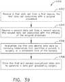
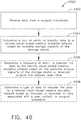
- the memorystores instructions executable by the processor to: receive a first self-describing data packet from a first data source, the first self-describing data packet comprising a first preamble, a first data payload, a source of the first data payload, and a first encryption certificate, wherein the first preamble defines the first data payload and the first encryption certificate verifies the authenticity of the first data packet; parse the received first preamble; and interpret the first data payload based on the first preamble.
- the surgical hubcomprises a control circuit configured to receive a first self-describing data packet from a first data source.
- the first self-describing data packetcomprises a first preamble, a first data payload, a source of the first data payload, and a first encryption certificate.
- the first preambledefines the first data payload and the first encryption certificate verifies the authenticity of the first data packet.
- the control circuitis also configured to parse the received first preamble, and to interpret the first data payload based on the first preamble.
- a computer-readable mediumstores computer-readable instructions which, when executed, cause a machine to receive a first self-describing data packet from a first data source, the first self-describing data packet comprising a first preamble, a first data payload, a source of the first data payload, and a first encryption certificate.
- the first preambledefines the first data payload and the first encryption certificate verifies the authenticity of the first data packet.
- the computer-readable instructions when executedalso parse the received first preamble and interpret the first data payload based on the first preamble.
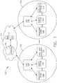
- a computer-implemented interactive surgical system 100includes one or more surgical systems 102 and a cloud-based system (e.g., the cloud 104 that may include a remote server 113 coupled to a storage device 105).
- Each surgical system 102includes at least one surgical hub 106 in communication with the cloud 104 that may include a remote server 113.
- the surgical system 102includes a visualization system 108, a robotic system 110, and a handheld intelligent surgical instrument 112, which are configured to communicate with one another and/or the hub 106.
- the surgical system 102may include an M number of hubs 106, an N number of visualization systems 108, an O number of robotic systems 110, and a P number of handheld intelligent surgical instruments 112, where M, N, O, and P are integers greater than or equal to one.
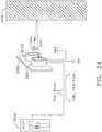
- FIG. 3depicts an example of a surgical system 102 being used to perform a surgical procedure on a patient who is lying down on an operating table 114 in a surgical operating room 116.
- a robotic system 110is used in the surgical procedure as a part of the surgical system 102.
- the robotic system 110includes a surgeon's console 118, a patient side cart 120 (surgical robot), and a surgical robotic hub 122.
- the patient side cart 120manipulates at least one removably coupled surgical tool 117 through a minimally invasive incision in the body of the patient while the surgeon views the surgical site through the surgeon's console 118.
- An image of the surgical siteis obtained by a medical imaging device 124, which is manipulated by the patient side cart 120 to orient the imaging device 124.
- the robotic hub 122is used to process the images of the surgical site for subsequent display to the surgeon through the surgeon's console 118.
- the imaging device 124includes at least one image sensor and one or more optical components.
- Suitable image sensorsinclude, but are not limited to, Charge-Coupled Device (CCD) sensors and Complementary Metal-Oxide Semiconductor (CMOS) sensors.
- CCDCharge-Coupled Device
- CMOSComplementary Metal-Oxide Semiconductor
- the optical components of the imaging device 124include one or more illumination sources and/or one or more lenses.
- the one or more illumination sourcesare directed to illuminate portions of the surgical field.
- the one or more image sensorsreceive light reflected or refracted from the surgical field, including light reflected or refracted from tissue and/or surgical instruments.
- the one or more illumination sourcesare configured to radiate electromagnetic energy in the visible spectrum as well as the invisible spectrum.
- the visible spectrumsometimes referred to as the optical spectrum or luminous spectrum, is that portion of the electromagnetic spectrum that is visible to (i.e., can be detected by) the human eye and may be referred to as visible light or simply light.
- a typical human eyewill respond to wavelengths in air that are from about 380 nm to about 750 nm.
- the invisible spectrumis that portion of the electromagnetic spectrum that lies below and above the visible spectrum (i.e., wavelengths below about 380 nm and above about 750 nm).
- the invisible spectrumis not detectable by the human eye.
- Wavelengths greater than about 750 nmare longer than the red visible spectrum, and they become invisible infrared (IR), microwave, and radio electromagnetic radiation.
- Wavelengths less than about 380 nmare shorter than the violet spectrum, and they become invisible ultraviolet, x-ray, and gamma ray electromagnetic radiation.
- the imaging device 124is configured for use in a minimally invasive procedure.
- imaging devices suitable for use with the present disclosureinclude, but not limited to, an arthroscope, angioscope, bronchoscope, choledochoscope, colonoscope, cytoscope, duodenoscope, enteroscope, esophagogastro-duodenoscope (gastroscope), endoscope, laryngoscope, nasopharyngo-neproscope, sigmoidoscope, thoracoscope, and ureteroscope.
- the imaging deviceemploys multi-spectrum monitoring to discriminate topography and underlying structures.
- a multi-spectral imageis one that captures image data within specific wavelength ranges across the electromagnetic spectrum. The wavelengths are separated by filters or by the use of instruments that are sensitive to particular wavelengths, including light from frequencies beyond the visible light range, e.g., IR and ultraviolet. Spectral imaging can allow extraction of additional information the human eye fails to capture with its receptors for red, green, and blue.
- Multi-spectrum monitoringcan be a useful tool in relocating a surgical field after a surgical task is completed to perform one or more of the previously described tests on the treated tissue.
- the sterile fieldmay be considered a specified area, such as within a tray or on a sterile towel, that is considered free of microorganisms, or the sterile field may be considered an area, immediately around a patient, who has been prepared for a surgical procedure.
- the sterile fieldmay include the scrubbed team members, who are properly attired, and all furniture and fixtures in the area.
- the visualization system 108includes one or more imaging sensors, one or more image processing units, one or more storage arrays, and one or more displays that are strategically arranged with respect to the sterile field, as illustrated in FIG. 2 .
- the visualization system 108includes an interface for HL7, PACS, and EMR.
- Various components of the visualization system 108are described under the heading "Advanced Imaging Acquisition Module” in U.S. Provisional Patent Application Serial No. 62/611,341 , titled INTERACTIVE SURGICAL PLATFORM, filed December 28, 2017.
- a primary display 119is positioned in the sterile field to be visible to an operator at the operating table 114.
- a visualization tower 111is positioned outside the sterile field.
- the visualization tower 111includes a first non-sterile display 107 and a second non-sterile display 109, which face away from each other.
- the visualization system 108guided by the hub 106, is configured to utilize the displays 107, 109, and 119 to coordinate information flow to operators inside and outside the sterile field.
- the hub 106may cause the visualization system 108 to display a snap-shot of a surgical site, as recorded by an imaging device 124, on a non-sterile display 107 or 109, while maintaining a live feed of the surgical site on the primary display 119.
- the snap-shot on the non-sterile display 107 or 109can permit a non-sterile operator to perform a diagnostic step relevant to the surgical procedure, for example.
- the hub 106is also configured to route a diagnostic input or feedback entered by a non-sterile operator at the visualization tower 111 to the primary display 119 within the sterile field, where it can be viewed by a sterile operator at the operating table.
- the inputis in the form of a modification to the snap-shot displayed on the non-sterile display 107 or 109, which can be routed to the primary display 119 by the hub 106.
- a surgical instrument 112is being used in the surgical procedure as part of the surgical system 102.
- the hub 106is also configured to coordinate information flow to a display of the surgical instrument 112.
- a diagnostic input or feedback entered by a non-sterile operator at the visualization tower 111is routed by the hub 106 to the surgical instrument display 115 within the sterile field, where it is viewed by the operator of the surgical instrument 112.
- Example surgical instruments that are suitable for use with the surgical system 102are described under the heading "Surgical Instrument Hardware” and in U.S. Provisional Patent Application Serial No. 62/611,341 , titled INTERACTIVE SURGICAL PLATFORM, filed December 28, 2017.
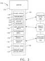
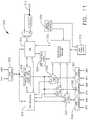
- a hub 106is depicted in communication with a visualization system 108, a robotic system 110, and a handheld intelligent surgical instrument 112.
- the hub 106includes a hub display 135, an imaging module 138, a generator module 140, a communication module 130, a processor module 132, and a storage array 134.
- the hub 106further includes a smoke evacuation module 126 and/or a suction/irrigation module 128.
- the hub modular enclosure 136offers a unified environment for managing the power, data, and fluid lines, which reduces the frequency of entanglement between such lines.
- a surgical hubis used in a surgical procedure that involves energy application to tissue at a surgical site.
- the surgical hubincludes a hub enclosure and a combo generator module slidably receivable in a docking station of the hub enclosure.
- the docking stationincludes data and power contacts.
- the combo generator moduleincludes two or more of an ultrasonic energy generator component, a bipolar RF energy generator component, and a monopolar RF energy generator component that are housed in a single unit.
- the combo generator modulealso includes a smoke evacuation component, at least one energy delivery cable for connecting the combo generator module to a surgical instrument, at least one smoke evacuation component configured to evacuate smoke, fluid, and/or particulates generated by the application of therapeutic energy to the tissue, and a fluid line extending from the remote surgical site to the smoke evacuation component.
- the fluid lineis a first fluid line and a second fluid line extends from the remote surgical site to a suction and irrigation module slidably received in the hub enclosure.
- the hub enclosurecomprises a fluid interface.
- Certain surgical proceduresmay require the application of more than one energy type to the tissue.
- One energy typemay be more beneficial for cutting the tissue, while another different energy type may be more beneficial for sealing the tissue.
- a bipolar generatorcan be used to seal the tissue while an ultrasonic generator can be used to cut the sealed tissue.
- a hub modular enclosure 136is configured to accommodate different generators, and facilitate an interactive communication therebetween.
- One of the advantages of the hub modular enclosure 136is enabling the quick removal and/or replacement of various modules.
- a modular surgical enclosureis used in a surgical procedure that involves energy application to tissue.
- the modular surgical enclosureincludes a first energy-generator module, configured to generate a first energy for application to the tissue, and a first docking station comprising a first docking port that includes first data and power contacts, wherein the first energy-generator module is slidably movable into an electrical engagement with the power and data contacts and wherein the first energy-generator module is slidably movable out of the electrical engagement with the first power and data contacts.
- the modular surgical enclosurealso includes a second energy-generator module configured to generate a second energy, different than the first energy, for application to the tissue, and a second docking station comprising a second docking port that includes second data and power contacts, wherein the second energy-generator module is slidably movable into an electrical engagement with the power and data contacts, and wherein the second energy-generator module is slidably movable out of the electrical engagement with the second power and data contacts.
- a second energy-generator moduleconfigured to generate a second energy, different than the first energy, for application to the tissue
- a second docking stationcomprising a second docking port that includes second data and power contacts
- the modular surgical enclosurealso includes a communication bus between the first docking port and the second docking port, configured to facilitate communication between the first energy-generator module and the second energy-generator module.
- a hub modular enclosure 136that allows the modular integration of a generator module 140, a smoke evacuation module 126, and a suction/irrigation module 128.
- the hub modular enclosure 136further facilitates interactive communication between the modules 140, 126, 128.
- the generator module 140is a generator module with integrated monopolar, bipolar, and ultrasonic components supported in a single housing unit 139 slidably insertable into the hub modular enclosure 136.
- the generator module 140is configured to connect to a monopolar device 146, a bipolar device 147, and an ultrasonic device 148.
- the generator module 140may comprise a series of monopolar, bipolar, and/or ultrasonic generator modules that interact through the hub modular enclosure 136.
- the hub modular enclosure 136is configured to facilitate the insertion of multiple generators and interactive communication between the generators docked into the hub modular enclosure 136 so that the generators would act as a single generator.
- the hub modular enclosure 136comprises a modular power and communication backplane 149 with external and wireless communication headers to enable the removable attachment of the modules 140, 126, 128 and interactive communication therebetween.
- the hub modular enclosure 136includes docking stations, or drawers, 151, herein also referred to as drawers, which are configured to slidably receive the modules 140, 126, 128.
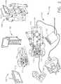
- FIG. 4illustrates a partial perspective view of a surgical hub enclosure 136, and a combo generator module 145 slidably receivable in a docking station 151 of the surgical hub enclosure 136.
- a docking port 152 with power and data contacts on a rear side of the combo generator module 145is configured to engage a corresponding docking port 150 with power and data contacts of a corresponding docking station 151 of the hub modular enclosure 136 as the combo generator module 145 is slid into position within the corresponding docking station 151 of the hub module enclosure 136.
- the combo generator module 145includes a bipolar, ultrasonic, and monopolar module and a smoke evacuation module integrated together into a single housing unit 139, as illustrated in FIG. 5 .
- the smoke evacuation module 126includes a fluid line 154 that conveys captured/collected smoke and/or fluid away from a surgical site and to, for example, the smoke evacuation module 126. Vacuum suction originating from the smoke evacuation module 126 can draw the smoke into an opening of a utility conduit at the surgical site.
- the utility conduitcoupled to the fluid line, is in the form of a flexible tube terminating at the smoke evacuation module 126.
- the utility conduit and the fluid linedefine a fluid path extending toward the smoke evacuation module 126 that is received in the hub enclosure 136.
- the suction/irrigation module 128is coupled to a surgical tool comprising an aspiration fluid line and a suction fluid line.
- the aspiration and suction fluid linesare in the form of flexible tubes extending from the surgical site toward the suction/irrigation module 128.
- One or more drive systemsare configured to cause irrigation and aspiration of fluids to and from the surgical site.
- the surgical toolincludes a shaft having an end effector at a distal end thereof and at least one energy treatment associated with the end effector, an aspiration tube, and an irrigation tube.
- the aspiration tubehas an inlet port at a distal end thereof and the aspiration tube extends through the shaft.
- an irrigation tubeextends through the shaft and has an inlet port in proximity to the energy deliver implement.
- the energy deliver implementis configured to deliver ultrasonic and/or RF energy to the surgical site and is coupled to the generator module 140 by a cable extending initially through the shaft.
- the irrigation tubeis in fluid communication with a fluid source, and the aspiration tube is in fluid communication with a vacuum source.
- the fluid source and/or the vacuum sourceis housed in the suction/irrigation module 128.
- the fluid source and/or the vacuum sourceis housed in the hub enclosure 136 separately from the suction/irrigation module 128.
- a fluid interfaceis configured to connect the suction/irrigation module 128 to the fluid source and/or the vacuum source.
- the modules 140, 126, 128 and/or their corresponding docking stations on the hub modular enclosure 136include alignment features that are configured to align the docking ports of the modules into engagement with their counterparts in the docking stations of the hub modular enclosure 136.
- the combo generator module 145includes side brackets 155 that are configured to slidably engage with corresponding brackets 156 of the corresponding docking station 151 of the hub modular enclosure 136. The brackets cooperate to guide the docking port contacts of the combo generator module 145 into an electrical engagement with the docking port contacts of the hub modular enclosure 136.
- the drawers 151 of the hub modular enclosure 136are the same, or substantially the same size, and the modules are adjusted in size to be received in the drawers 151.
- the side brackets 155 and/or 156are larger or smaller depending on the size of the module.
- the drawers 151are different in size and are each designed to accommodate a particular module.
- the contacts of a particular modulecan be keyed for engagement with the contacts of a particular drawer to avoid inserting a module into a drawer with mismatching contacts.
- the docking port 150 of one drawer 151can be coupled to the docking port 150 of another drawer 151 through a communications link 157 to facilitate an interactive communication between the modules housed in the hub modular enclosure 136.
- the docking ports 150 of the hub modular enclosure 136may alternatively, or additionally, facilitate a wireless interactive communication between the modules housed in the hub modular enclosure 136. Any suitable wireless communication can be employed, such as for example Air Titan-Bluetooth.
- FIG. 6illustrates individual power bus attachments for a plurality of lateral docking ports of a lateral modular housing 160 configured to receive a plurality of modules of a surgical hub 206.
- the lateral modular housing 160is configured to laterally receive and interconnect the modules 161.
- the modules 161are slidably inserted into docking stations 162 of lateral modular housing 160, which includes a backplane for interconnecting the modules 161.
- the modules 161are arranged laterally in the lateral modular housing 160.
- the modules 161may be arranged vertically in a lateral modular housing.
- FIG. 7illustrates a vertical modular housing 164 configured to receive a plurality of modules 165 of the surgical hub 106.
- the modules 165are slidably inserted into docking stations, or drawers, 167 of vertical modular housing 164, which includes a backplane for interconnecting the modules 165.
- the drawers 167 of the vertical modular housing 164are arranged vertically, a vertical modular housing 164 may include drawers that are arranged laterally.
- the modules 165interact with one another through the docking ports of the vertical modular housing 164.
- a display 177is provided for displaying data relevant to the operation of the modules 165.
- the vertical modular housing 164includes a master module 178 housing a plurality of sub-modules that are slidably received in the master module 178.
- the imaging module 138comprises an integrated video processor and a modular light source and is adapted for use with various imaging devices.
- the imaging deviceis comprised of a modular housing that can be assembled with a light source module and a camera module.
- the housingis a disposable housing.
- the disposable housingis removably coupled to a reusable controller, a light source module, and a camera module.
- the light source module and/or the camera moduleare selectively chosen depending on the type of surgical procedure.
- the camera modulecomprises a CCD sensor.
- the camera modulecomprises a CMOS sensor.
- the camera moduleis configured for scanned beam imaging.
- the light source moduleis configured to deliver a white light or a different light, depending on the surgical procedure.
- the module imaging device of the present disclosureis configured to permit the replacement of a light source module or a camera module midstream during a surgical procedure, without having to remove the imaging device from the surgical field.
- the imaging devicecomprises a tubular housing that includes a plurality of channels.
- a first channelis configured to slidably receive the camera module, which can be configured for a snap-fit engagement with the first channel.
- a second channelis configured to slidably receive the light source module, which can be configured for a snap-fit engagement with the second channel.
- the camera module and/or the light source modulecan be rotated into a final position within their respective channels.
- a threaded engagementcan be employed in lieu of the snap-fit engagement.
- the imaging module 138are configured to switch between the imaging devices to provide an optimal view.
- the imaging module 138is configured to integrate the images from the different imaging device.
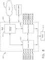
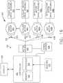
- FIG. 8illustrates a surgical data network 201 comprising a modular communication hub 203 configured to connect modular devices located in one or more operating theaters of a healthcare facility, or any room in a healthcare facility specially equipped for surgical operations, to a cloud-based system (e.g., the cloud 204 that includes a remote server 213 coupled to a storage device 205).
- the modular communication hub 203comprises a network hub 207 and/or a network switch 209 in communication with a network router.
- the modular communication hub 203also is coupled to a local computer system 210 to provide local computer processing and data manipulation.
- the surgical data network 201may be configured as passive, intelligent, or switching.
- a passive surgical data networkserves as a conduit for the data, enabling it to go from one device (or segment) to another and to the cloud computing resources.
- An intelligent surgical data networkincludes additional features to enable the traffic passing through the surgical data network to be monitored and to configure each port in the network hub 207 or network switch 209.
- An intelligent surgical data networkis referred to as a manageable hub or switch.
- a switching hubreads the destination address of each packet and then forwards the packet to the correct port.
- Modular devices 1a-1n located in the operating theaterare coupled to the modular communication hub 203.
- the network hub 207 and/or the network switch 209is/are coupled to a network router 211 to connect the devices 1a-1n to the cloud 204 or the local computer system 210.
- Data associated with the devices 1a-1nis transferred to cloud-based computers via the router for remote data processing and manipulation.
- Data associated with the devices 1a-1nis also be transferred to the local computer system 210 for local data processing and manipulation.
- Modular devices 2a-2m located in the same operating theateralso are coupled to a network switch 209.
- the network switch 209is coupled to the network hub 207 and/or the network router 211 to connect to the devices 2a-2m to the cloud 204.
- Data associated with the devices 2a-2nis transferred to the cloud 204 via the network router 211 for data processing and manipulation.
- Data associated with the devices 2a-2mis also be transferred to the local computer system 210 for local data processing and manipulation.
- the surgical data network 201can be expanded by interconnecting multiple network hubs 207 and/or multiple network switches 209 with multiple network routers 211.
- the modular communication hub 203is contained in a modular control tower configured to receive multiple devices 1a-1n/2a-2m.
- the local computer system 210also is contained in a modular control tower.
- the modular communication hub 203is connected to a display 212 to display images obtained by some of the devices 1a-1n/2a-2m, for example during surgical procedures.
- the devices 1a-1n/2a-2minclude, for example, various modules such as an imaging module 138 coupled to an endoscope, a generator module 140 coupled to an energy-based surgical device, a smoke evacuation module 126, a suction/irrigation module 128, a communication module 130, a processor module 132, a storage array 134, a surgical device coupled to a display, and/or a non-contact sensor module, among other modular devices that are connected to the modular communication hub 203 of the surgical data network 201.
- various modulessuch as an imaging module 138 coupled to an endoscope, a generator module 140 coupled to an energy-based surgical device, a smoke evacuation module 126, a suction/irrigation module 128, a communication module 130, a processor module 132, a storage array 134, a surgical device coupled to a display, and/or a non-contact sensor module, among other modular devices that are connected to the modular communication hub 203 of the surgical data network 201.
- the surgical data network 201comprises a combination of network hub(s), network switch(es), and network router(s) connecting the devices 1a-1n/2a-2m to the cloud. Any one of or all of the devices 1a-1n/2a-2m coupled to the network hub or network switch collects data in real time and transfers the data to cloud computers for data processing and manipulation. It will be appreciated that cloud computing relies on sharing computing resources rather than having local servers or personal devices to handle software applications.
- the word “cloud”is used as a metaphor for "the Internet,” although the term is not limited as such.
- the term “cloud computing”is also used herein to refer to "a type of Internet-based computing," where different services-such as servers, storage, and applications-are delivered to the modular communication hub 203 and/or computer system 210 located in the surgical theater (e.g., a fixed, mobile, temporary, or field operating room or space) and to devices connected to the modular communication hub 203 and/or computer system 210 through the Internet.
- the cloud infrastructuremay be maintained by a cloud service provider.
- the cloud service provideris the entity that coordinates the usage and control of the devices 1a-1n/2a-2m located in one or more operating theaters.
- the cloud computing servicescan perform a large number of calculations based on the data gathered by smart surgical instruments, robots, and other computerized devices located in the operating theater.
- the hub hardwareenables multiple devices or connections to be connected to a computer that communicates with the cloud computing resources and storage.
- the surgical data networkprovides improved surgical outcomes, reduced costs, and improved patient satisfaction.
- At least some of the devices 1a-1n/2a-2mare employed to view tissue states to assess leaks or perfusion of sealed tissue after a tissue sealing and cutting procedure.
- At least some of the devices 1a-1n/2a-2mare employed to identify pathology, such as the effects of diseases, using the cloud-based computing to examine data including images of samples of body tissue for diagnostic purposes. This includes localization and margin confirmation of tissue and phenotypes.
- At least some of the devices 1a-1n/2a-2mare employed to identify anatomical structures of the body using a variety of sensors integrated with imaging devices and techniques such as overlaying images captured by multiple imaging devices.
- the datais analyzed to improve surgical procedure outcomes by determining if further treatment, such as the application of endoscopic intervention, emerging technologies, a targeted radiation, targeted intervention, and precise robotics to tissue-specific sites and conditions, is pursued.
- Such data analysisemploys outcome analytics processing, and using standardized approaches may provide beneficial feedback to either confirm surgical treatments and the behavior of the surgeon or suggest modifications to surgical treatments and the behavior of the surgeon.
- the operating theater devices 1a-1nare connected to the modular communication hub 203 over a wired channel or a wireless channel depending on the configuration of the devices 1a-1n to a network hub.
- the network hub 207is implemented as a local network broadcast device that works on the physical layer of the Open System Interconnection (OSI) model.
- the network hubprovides connectivity to the devices 1a-1n located in the same operating theater network.
- the network hub 207collects data in the form of packets and sends them to the router in half duplex mode.
- the network hub 207does not store any media access control/internet protocol (MAC/IP) to transfer the device data. Only one of the devices 1a-1n can send data at a time through the network hub 207.
- MAC/IPmedia access control/internet protocol
- the network hub 207has no routing tables or intelligence regarding where to send information and broadcasts all network data across each connection and to a remote server 213 ( FIG. 9 ) over the cloud 204.
- the network hub 207can detect basic network errors such as collisions, but having all information broadcast to multiple ports can be a security risk and cause bottlenecks.
- the operating theater devices 2a-2mare connected to a network switch 209 over a wired channel or a wireless channel.
- the network switch 209works in the data link layer of the OSI model.
- the network switch 209is a multicast device for connecting the devices 2a-2m located in the same operating theater to the network.
- the network switch 209sends data in the form of frames to the network router 211 and works in full duplex mode. Multiple devices 2a-2m can send data at the same time through the network switch 209.
- the network switch 209stores and uses MAC addresses of the devices 2a-2m to transfer data.
- the network hub 207 and/or the network switch 209are coupled to the network router 211 for connection to the cloud 204.
- the network router 211works in the network layer of the OSI model.
- the network router 211creates a route for transmitting data packets received from the network hub 207 and/or network switch 211 to cloud-based computer resources for further processing and manipulation of the data collected by any one of or all the devices 1a-1n/2a-2m.
- the network router 211is employed to connect two or more different networks located in different locations, such as, for example, different operating theaters of the same healthcare facility or different networks located in different operating theaters of different healthcare facilities.
- the network router 211sends data in the form of packets to the cloud 204 and works in full duplex mode. Multiple devices can send data at the same time.
- the network router 211uses IP addresses to transfer data.
- the network hub 207is implemented as a USB hub, which allows multiple USB devices to connect to a host computer.
- the USB hubexpands a single USB port into several tiers so that there are more ports available to connect devices to the host system computer.
- the network hub 207includes wired or wireless capabilities to receive information over a wired channel or a wireless channel.
- a wireless USB short-range, high-bandwidth wireless radio communication protocolis employed for communication between the devices 1a-1n and devices 2a-2m located in the operating theater.
- the operating theater devices 1a-1n/2a-2mcommunicate to the modular communication hub 203 via Bluetooth wireless technology standard for exchanging data over short distances (using short-wavelength UHF radio waves in the ISM band from 2.4 to 2.485 GHz) from fixed and mobile devices and building personal area networks (PANs).
- Bluetooth wireless technology standardfor exchanging data over short distances (using short-wavelength UHF radio waves in the ISM band from 2.4 to 2.485 GHz) from fixed and mobile devices and building personal area networks (PANs).
- the operating theater devices 1a-1n/2a-2mcommunicates to the modular communication hub 203 via a number of wireless or wired communication standards or protocols, including but not limited to Wi-Fi (IEEE 802.11 family), WiMAX (IEEE 802.16 family), IEEE 802.20, long-term evolution (LTE), and Ev-DO, HSPA+, HSDPA+, HSUPA+, EDGE, GSM, GPRS, CDMA, TDMA, DECT, and Ethernet derivatives thereof, as well as any other wireless and wired protocols that are designated as 3G, 4G, 5G, and beyond.
- the computing moduleincludes a plurality of communication modules.
- a first communication moduleis dedicated to shorterrange wireless communications such as Wi-Fi and Bluetooth
- a second communication moduleis dedicated to longer-range wireless communications such as GPS, EDGE, GPRS, CDMA, WiMAX, LTE, Ev-DO, and others.
- the modular communication hub 203serves as a central connection for one or all of the operating theater devices 1a-1n/2a-2m and handles a data type known as frames. Frames carry the data generated by the devices 1a-1n/2a-2m. When a frame is received by the modular communication hub 203, it is amplified and transmitted to the network router 211, which transfers the data to the cloud computing resources by using a number of wireless or wired communication standards or protocols, as described herein.
- the modular communication hub 203can be used as a standalone device or be connected to compatible network hubs and network switches to form a larger network.
- the modular communication hub 203is generally easy to install, configure, and maintain, making it a good option for networking the operating theater devices 1a-1n/2a-2m.
- FIG. 9illustrates a computer-implemented interactive surgical system 200.
- the computer-implemented interactive surgical system 200is similar in many respects to the computer-implemented interactive surgical system 100.
- the computer-implemented interactive surgical system 200includes one or more surgical systems 202, which are similar in many respects to the surgical systems 102.
- Each surgical system 202includes at least one surgical hub 206 in communication with a cloud 204 that may include a remote server 213.
- the computer-implemented interactive surgical system 200comprises a modular control tower 236 connected to multiple operating theater devices such as, for example, intelligent surgical instruments, robots, and other computerized devices located in the operating theater. As shown in FIG.
- the modular control tower 236comprises a modular communication hub 203 coupled to a computer system 210.
- the modular control tower 236is coupled to an imaging module 238 that is coupled to an endoscope 239, a generator module 240 that is coupled to an energy device 241, a smoke evacuator module 226, a suction/irrigation module 228, a communication module 230, a processor module 232, a storage array 234, a smart device/instrument 235 optionally coupled to a display 237, and a non-contact sensor module 242.
- the operating theater devicesare coupled to cloud computing resources and data storage via the modular control tower 236.
- a robot hub 222also is connected to the modular control tower 236 and to the cloud computing resources.
- the devices/instruments 235, visualization systems 208, among others,is coupled to the modular control tower 236 via wired or wireless communication standards or protocols, as described herein.
- the modular control tower 236is coupled to a hub display 215 (e.g., monitor, screen) to display and overlay images received from the imaging module, device/instrument display, and/or other visualization systems 208.
- the hub displayalso displays data received from devices connected to the modular control tower in conjunction with images and overlaid images.
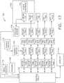
- FIG. 10illustrates a surgical hub 206 comprising a plurality of modules coupled to the modular control tower 236.
- the modular control tower 236comprises a modular communication hub 203, e.g., a network connectivity device, and a computer system 210 to provide local processing, visualization, and imaging, for example.
- the modular communication hub 203is connected in a tiered configuration to expand the number of modules (e.g., devices) that may be connected to the modular communication hub 203 and transfer data associated with the modules to the computer system 210, cloud computing resources, or both.
- each of the network hubs/switches in the modular communication hub 203includes three downstream ports and one upstream port.
- the upstream network hub/switchis connected to a processor to provide a communication connection to the cloud computing resources and a local display 217. Communication to the cloud 204 is made either through a wired or a wireless communication channel.
- the surgical hub 206employs a non-contact sensor module 242 to measure the dimensions of the operating theater and generate a map of the surgical theater using either ultrasonic or laser-type non-contact measurement devices.
- An ultrasound-based non-contact sensor modulescans the operating theater by transmitting a burst of ultrasound and receiving the echo when it bounces off the perimeter walls of an operating theater as described under the heading "Surgical Hub Spatial Awareness Within an Operating Room” in U.S. Provisional Patent Application Serial No. 62/611,341 , titled INTERACTIVE SURGICAL PLATFORM, filed December 28, 2017, in which the sensor module is configured to determine the size of the operating theater and to adjust Bluetooth-pairing distance limits.
- a laser-based non-contact sensor modulescans the operating theater by transmitting laser light pulses, receiving laser light pulses that bounce off the perimeter walls of the operating theater, and comparing the phase of the transmitted pulse to the received pulse to determine the size of the operating theater and to adjust Bluetooth pairing distance limits, for example.
- the computer system 210comprises a processor 244 and a network interface 245.
- the processor 244is coupled to a communication module 247, storage 248, memory 249, non-volatile memory 250, and input/output interface 251 via a system bus.
- the system busis any of several types of bus structure(s) including the memory bus or memory controller, a peripheral bus or external bus, and/or a local bus using any variety of available bus architectures including, but not limited to, 9-bit bus, Industrial Standard Architecture (ISA), Micro-Charmel Architecture (MSA), Extended ISA (EISA), Intelligent Drive Electronics (IDE), VESA Local Bus (VLB), Peripheral Component Interconnect (PCI), USB, Advanced Graphics Port (AGP), Personal Computer Memory Card International Association bus (PCMCIA), Small Computer Systems Interface (SCSI), or any other proprietary bus.
- ISAIndustrial Standard Architecture
- MSAMicro-Charmel Architecture
- EISAExtended ISA
- IDEIntelligent Drive Electronics
- VLBVESA Local Bus
- PCIPerip
- the processor 244is any single-core or multicore processor such as those known under the trade name ARM Cortex by Texas Instruments.
- the processormay be an LM4F230H5QR ARM Cortex-M4F Processor Core, available from Texas Instruments, for example, comprising an on-chip memory of 256 KB single-cycle flash memory, or other non-volatile memory, up to 40 MHz, a prefetch buffer to improve performance above 40 MHz, a 32 KB single-cycle serial random access memory (SRAM), an internal read-only memory (ROM) loaded with StellarisWare® software, a 2 KB electrically erasable programmable read-only memory (EEPROM), and/or one or more pulse width modulation (PWM) modules, one or more quadrature encoder inputs (QEI) analogs, one or more 12-bit analog-to-digital converters (ADCs) with 12 analog input channels, details of which are available for the product datasheet.
- QEIquadrature encoder inputs
- the processor 244comprises a safety controller comprising two controller-based families such as TMS570 and RM4x, known under the trade name Hercules ARM Cortex R4, also by Texas Instruments.
- the safety controlleris configured specifically for IEC 61508 and ISO 26262 safety critical applications, among others, to provide advanced integrated safety features while delivering scalable performance, connectivity, and memory options.
- the system memoryincludes volatile memory and non-volatile memory.
- the basic input/output system (BIOS)containing the basic routines to transfer information between elements within the computer system, such as during start-up, is stored in non-volatile memory.
- the non-volatile memorycan include ROM, programmable ROM (PROM), electrically programmable ROM (EPROM), EEPROM, or flash memory.
- Volatile memoryincludes random-access memory (RAM), which acts as external cache memory.
- RAMis available in many forms such as SRAM, dynamic RAM (DRAM), synchronous DRAM (SDRAM), double data rate SDRAM (DDR SDRAM), enhanced SDRAM (ESDRAM), Synchlink DRAM (SLDRAM), and direct Rambus RAM (DRRAM).
- the computer system 210also includes removable/non-removable, volatile/non-volatile computer storage media, such as for example disk storage.
- the disk storageincludes, but is not limited to, devices like a magnetic disk drive, floppy disk drive, tape drive, Jaz drive, Zip drive, LS-60 drive, flash memory card, or memory stick.
- the disk storagecan include storage media separately or in combination with other storage media including, but not limited to, an optical disc drive such as a compact disc ROM device (CD-ROM), compact disc recordable drive (CD-R Drive), compact disc rewritable drive (CD-RW Drive), or a digital versatile disc ROM drive (DVD-ROM).
- CD-ROMcompact disc ROM
- CD-R Drivecompact disc recordable drive
- CD-RW Drivecompact disc rewritable drive
- DVD-ROMdigital versatile disc ROM drive
- a removable or non-removable interfacemay be employed.
- the computer system 210includes software that acts as an intermediary between users and the basic computer resources described in a suitable operating environment.
- Such softwareincludes an operating system.
- the operating systemwhich can be stored on the disk storage, acts to control and allocate resources of the computer system.
- System applicationstake advantage of the management of resources by the operating system through program modules and program data stored either in the system memory or on the disk storage. It is to be appreciated that various components described herein can be implemented with various operating systems or combinations of operating systems.
- a userenters commands or information into the computer system 210 through input device(s) coupled to the I/O interface 251.
- the input devicesinclude, but are not limited to, a pointing device such as a mouse, trackball, stylus, touch pad, keyboard, microphone, joystick, game pad, satellite dish, scanner, TV tuner card, digital camera, digital video camera, web camera, and the like.
- These and other input devicesconnect to the processor through the system bus via interface port(s).
- the interface port(s)include, for example, a serial port, a parallel port, a game port, and a USB.
- the output device(s)use some of the same types of ports as input device(s).
- a USB portis used to provide input to the computer system and to output information from the computer system to an output device.
- An output adapteris provided to illustrate that there are some output devices like monitors, displays, speakers, and printers, among other output devices that require special adapters.
- the output adaptersinclude, by way of illustration and not limitation, video and sound cards that provide a means of connection between the output device and the system bus. It should be noted that other devices and/or systems of devices, such as remote computer(s), provide both input and output capabilities.
- the computer system 210operates in a networked environment using logical connections to one or more remote computers, such as cloud computer(s), or local computers.
- the remote cloud computer(s)can be a personal computer, server, router, network PC, workstation, microprocessor-based appliance, peer device, or other common network node, and the like, and typically includes many or all of the elements described relative to the computer system. For purposes of brevity, only a memory storage device is illustrated with the remote computer(s).
- the remote computer(s)is logically connected to the computer system through a network interface and then physically connected via a communication connection.
- the network interfaceencompasses communication networks such as local area networks (LANs) and wide area networks (WANs).
- LAN technologiesinclude Fiber Distributed Data Interface (FDDI), Copper Distributed Data Interface (CDDI), Ethernet/IEEE 802.3, Token Ring/IEEE 802.5 and the like.
- WAN technologiesinclude, but are not limited to, point-to-point links, circuit-switching networks like Integrated Services Digital Networks (ISDN) and variations thereon, packet-switching networks, and Digital Subscriber Lines (DSL).
- ISDNIntegrated Services Digital Networks
- DSLDigital Subscriber Lines
- the computer system 210 of FIG. 10 , the imaging module 238 and/or visualization system 208, and/or the processor module 232 of FIGS. 9-10comprises an image processor, image processing engine, media processor, or any specialized digital signal processor (DSP) used for the processing of digital images.
- the image processoremploys parallel computing with single instruction, multiple data (SIMD) or multiple instruction, multiple data (MIMD) technologies to increase speed and efficiency.
- SIMDsingle instruction, multiple data
- MIMDmultiple instruction, multiple data
- the digital image processing enginecan perform a range of tasks.
- the image processormay be a system on a chip with multicore processor architecture.
- the communication connection(s)refers to the hardware/software employed to connect the network interface to the bus. While the communication connection is shown for illustrative clarity inside the computer system, it can also be external to the computer system 210.
- the hardware/software necessary for connection to the network interfaceincludes, for illustrative purposes only, internal and external technologies such as modems, including regular telephone-grade modems, cable modems, and DSL modems, ISDN adapters, and Ethernet cards.
- FIG. 11illustrates a functional block diagram of a USB network hub 300 device.
- the USB network hub device 300employs a TUSB2036 integrated circuit hub by Texas Instruments.
- the USB network hub 300is a CMOS device that provides an upstream USB transceiver port 302 and up to three downstream USB transceiver ports 304, 306, 308 in compliance with the USB 2.0 specification.
- the upstream USB transceiver port 302is a differential root data port comprising a differential data minus (DM0) input paired with a differential data plus (DP0) input.
- the three downstream USB transceiver ports 304, 306, 308are differential data ports where each port includes differential data plus (DP1-DP3) outputs paired with differential data minus (DM1-DM3) outputs.
- the USB network hub 300 deviceis implemented with a digital state machine instead of a microcontroller, and no firmware programming is required. Fully compliant USB transceivers are integrated into the circuit for the upstream USB transceiver port 302 and all downstream USB transceiver ports 304, 306, 308.
- the downstream USB transceiver ports 304, 306, 308support both full-speed and low-speed devices by automatically setting the slew rate according to the speed of the device attached to the ports.
- the USB network hub 300 devicemay be configured either in bus-powered or self-powered mode and includes a hub power logic 312 to manage power.
- the USB network hub 300 deviceincludes a serial interface engine 310 (SIE).
- SIE 310is the front end of the USB network hub 300 hardware and handles most of the protocol described in chapter 8 of the USB specification.
- the SIE 310typically comprehends signaling up to the transaction level.
- the functions that it handlesinclude: packet recognition, transaction sequencing, SOP, EOP, RESET, and RESUME signal detection/generation, clock/data separation, non-return-to-zero invert (NRZI) data encoding/decoding and bit-stuffing, CRC generation and checking (token and data), packet ID (PID) generation and checking/decoding, and/or serial-parallel/parallel-serial conversion.
- NRZInon-return-to-zero invert
- the 310receives a clock input 314 and is coupled to a suspend/resume logic and frame timer 316 circuit and a hub repeater circuit 318 to control communication between the upstream USB transceiver port 302 and the downstream USB transceiver ports 304, 306, 308 through port logic circuits 320, 322, 324.
- the SIE 310is coupled to a command decoder 326 via interface logic to control commands from a serial EEPROM via a serial EEPROM interface 330.
- the USB network hub 300connects 127 functions configured in up to six logical layers (tiers) to a single computer. Further, the USB network hub 300 connects to all peripherals using a standardized four-wire cable that provides both communication and power distribution.
- the power configurationsare bus-powered and self-powered modes.
- the USB network hub 300is configured to support four modes of power management: a bus-powered hub, with either individual-port power management or ganged-port power management, and the self-powered hub, with either individual-port power management or ganged-port power management.
- the upstream USB transceiver port 302is plugged into a USB host controller, and the downstream USB transceiver ports 304, 306, 308 are exposed for connecting USB compatible devices, and so forth.
- FIG. 12illustrates a logic diagram of a control system 470 of a surgical instrument or tool.
- the system 470comprises a control circuit.
- the control circuitincludes a microcontroller 461 comprising a processor 462 and a memory 468.
- One or more of sensors 472, 474, 476for example, provide real-time feedback to the processor 462.
- a motor 482, driven by a motor driver 492,operably couples a longitudinally movable displacement member to drive the I-beam knife element.
- a tracking system 480is configured to determine the position of the longitudinally movable displacement member.
- the position informationis provided to the processor 462, which is programmed or configured to determine the position of the longitudinally movable drive member as well as the position of a firing member, firing bar, and I-beam knife element.
- a display 473displays a variety of operating conditions of the instruments and includes touch screen functionality for data input. Information displayed on the display 473 is overlaid with images acquired via endoscopic imaging modules.
- the microcontroller 461may be any single-core or multicore processor such as those known under the trade name ARM Cortex by Texas Instruments.
- the main microcontroller 461may be an LM4F230H5QR ARM Cortex-M4F Processor Core, available from Texas Instruments, for example, comprising an on-chip memory of 256 KB single-cycle flash memory, or other non-volatile memory, up to 40 MHz, a prefetch buffer to improve performance above 40 MHz, a 32 KB single-cycle SRAM, and internal ROM loaded with StellarisWare® software, a 2 KB EEPROM, one or more PWM modules, one or more QEI analogs, and/or one or more 12-bit ADCs with 12 analog input channels, details of which are available for the product datasheet.
- the microcontroller 461comprises a safety controller comprising two controller-based families such as TMS570 and RM4x, known under the trade name Hercules ARM Cortex R4, also by Texas Instruments.
- the safety controlleris configured specifically for IEC 61508 and ISO 26262 safety critical applications, among others, to provide advanced integrated safety features while delivering scalable performance, connectivity, and memory options.
- the microcontroller 461is programmed to perform various functions such as precise control over the speed and position of the knife and articulation systems.
- the microcontroller 461includes a processor 462 and a memory 468.
- the electric motor 482may be a brushed direct current (DC) motor with a gearbox and mechanical links to an articulation or knife system.
- a motor driver 492is an A3941 available from Allegro Microsystems, Inc. Other motor drivers may be readily substituted for use in the tracking system 480 comprising an absolute positioning system. A detailed description of an absolute positioning system is described in U.S. Patent Application Publication No. 2017/0296213 , titled SYSTEMS AND METHODS FOR CONTROLLING A SURGICAL STAPLING AND CUTTING INSTRUMENT, which published on October 19, 2017.
- the microcontroller 461is programmed to provide precise control over the speed and position of displacement members and articulation systems.
- the microcontroller 461is configured to compute a response in the software of the microcontroller 461.
- the computed responseis compared to a measured response of the actual system to obtain an "observed" response, which is used for actual feedback decisions.
- the observed responseis a favorable, tuned value that balances the smooth, continuous nature of the simulated response with the measured response, which detects outside influences on the system.
- the motor 482is controlled by the motor driver 492 and is employed by the firing system of the surgical instrument or tool.
- the motor 482is a brushed DC driving motor having a maximum rotational speed of approximately 25,000 RPM.
- the motor 482includes a brushless motor, a cordless motor, a synchronous motor, a stepper motor, or any other suitable electric motor.
- the motor driver 492comprises an H-bridge driver comprising field-effect transistors (FETs), for example.
- FETsfield-effect transistors
- the motor 482is powered by a power assembly releasably mounted to the handle assembly or tool housing for supplying control power to the surgical instrument or tool.
- the power assemblycomprises a battery which includes a number of battery cells connected in series that can be used as the power source to power the surgical instrument or tool. In certain circumstances, the battery cells of the power assembly are replaceable and/or rechargeable. In at least one example, the battery cells can be lithium-ion batteries which are couplable to and separable from the power
- the motor driver 492may be an A3941 available from Allegro Microsystems, Inc.
- the A3941 492is a full-bridge controller for use with external N-channel power metal-oxide semiconductor field-effect transistors (MOSFETs) specifically designed for inductive loads, such as brush DC motors.
- the driver 492comprises a unique charge pump regulator that provides full (>10 V) gate drive for battery voltages down to 7 V and allows the A3941 to operate with a reduced gate drive, down to 5.5 V.
- a bootstrap capacitoris employed to provide the above battery supply voltage required for N-channel MOSFETs.
- An internal charge pump for the high-side driveallows DC (100% duty cycle) operation.
- the full bridgeis driven in fast or slow decay modes using diode or synchronous rectification.
- current recirculationcan be through the high-side or the lowside FETs.
- the power FETsare protected from shoot-through by resistor-adjustable dead time.
- Integrated diagnosticsprovide indications of undervoltage, overtemperature, and power bridge faults and are configured to protect the power MOSFETs under most short circuit conditions.
- Other motor driversare readily substituted for use in the tracking system 480 comprising an absolute positioning system.
- the tracking system 480comprises a controlled motor drive circuit arrangement comprising a position sensor 472.
- the position sensor 472 for an absolute positioning systemprovides a unique position signal corresponding to the location of a displacement member.
- the displacement memberrepresents a longitudinally movable drive member comprising a rack of drive teeth for meshing engagement with a corresponding drive gear of a gear reducer assembly.
- the displacement memberrepresents the firing member, which could be adapted and configured to include a rack of drive teeth.
- the displacement memberrepresents a firing bar or the I-beam, each of which can be adapted and configured to include a rack of drive teeth.
- the term displacement memberis used generically to refer to any movable member of the surgical instrument or tool such as the drive member, the firing member, the firing bar, the I-beam, or any element that can be displaced.
- the longitudinally movable drive memberis coupled to the firing member, the firing bar, and the I-beam. Accordingly, the absolute positioning system can, in effect, track the linear displacement of the I-beam by tracking the linear displacement of the longitudinally movable drive member.
- the displacement memberis coupled to any position sensor 472 suitable for measuring linear displacement.
- the longitudinally movable drive member, the firing member, the firing bar, or the I-beam, or combinations thereof,are coupled to any suitable linear displacement sensor.
- Linear displacement sensorsinclude contact or non-contact displacement sensors.
- Linear displacement sensorscomprise linear variable differential transformers (LVDT), differential variable reluctance transducers (DVRT), a slide potentiometer, a magnetic sensing system comprising a movable magnet and a series of linearly arranged Hall effect sensors, a magnetic sensing system comprising a fixed magnet and a series of movable, linearly arranged Hall effect sensors, an optical sensing system comprising a movable light source and a series of linearly arranged photo diodes or photo detectors, an optical sensing system comprising a fixed light source and a series of movable linearly, arranged photo diodes or photo detectors, or any combination thereof.
- LVDTlinear variable differential transformers
- DVRTdifferential variable reluctance transducers
- slide potentiometera magnetic sensing system comprising a movable magnet and a series of linearly arranged Hall effect sensors
- a magnetic sensing systemcomprising a fixed magnet and a series of movable, linearly arranged Hall effect sensors
- the electric motor 482can include a rotatable shaft that operably interfaces with a gear assembly that is mounted in meshing engagement with a set, or rack, of drive teeth on the displacement member.
- a sensor elementis operably coupled to a gear assembly such that a single revolution of the position sensor 472 element corresponds to some linear longitudinal translation of the displacement member.
- An arrangement of gearing and sensorsis connected to the linear actuator, via a rack and pinion arrangement, or a rotary actuator, via a spur gear or other connection.
- a power sourcesupplies power to the absolute positioning system and an output indicator may display the output of the absolute positioning system.
- the displacement memberrepresents the longitudinally movable drive member comprising a rack of drive teeth formed thereon for meshing engagement with a corresponding drive gear of the gear reducer assembly.
- the displacement memberrepresents the longitudinally movable firing member, firing bar, I-beam, or combinations thereof.
- a single revolution of the sensor element associated with the position sensor 472is equivalent to a longitudinal linear displacement d1 of the of the displacement member, where d1 is the longitudinal linear distance that the displacement member moves from point "a" to point "b” after a single revolution of the sensor element coupled to the displacement member.
- the sensor arrangementmay be connected via a gear reduction that results in the position sensor 472 completing one or more revolutions for the full stroke of the displacement member.
- the position sensor 472may complete multiple revolutions for the full stroke of the displacement member.
- a series of switcheswhere n is an integer greater than one, is employed alone or in combination with a gear reduction to provide a unique position signal for more than one revolution of the position sensor 472.
- the state of the switchesare fed back to the microcontroller 461 that applies logic to determine a unique position signal corresponding to the longitudinal linear displacement d1 + d2 + ... dn of the displacement member.
- the output of the position sensor 472is provided to the microcontroller 461.
- the position sensor 472 of the sensor arrangementcomprises a magnetic sensor, an analog rotary sensor like a potentiometer, or an array of analog Hall-effect elements, which output a unique combination of position signals or values.
- the position sensor 472comprise a any number of magnetic sensing elements, such as, for example, magnetic sensors classified according to whether they measure the total magnetic field or the vector components of the magnetic field.
- the techniques used to produce both types of magnetic sensorsencompass many aspects of physics and electronics.
- the technologies used for magnetic field sensinginclude search coil, fluxgate, optically pumped, nuclear precession, SQUID, Hall-effect, anisotropic magnetoresistance, giant magnetoresistance, magnetic tunnel junctions, giant magnetoimpedance, magnetostrictive/piezoelectric composites, magnetodiode, magnetotransistor, fiber-optic, magneto-optic, and microelectromechanical systems-based magnetic sensors, among others.
- the position sensor 472 for the tracking system 480 comprising an absolute positioning systemcomprises a magnetic rotary absolute positioning system.
- the position sensor 472may be implemented as an AS5055EQFT single-chip magnetic rotary position sensor available from Austria Microsystems, AG.
- the position sensor 472is interfaced with the microcontroller 461 to provide an absolute positioning system.
- the position sensor 472is a low-voltage and low-power component and includes four Hall-effect elements in an area of the position sensor 472 that is located above a magnet.
- a high-resolution ADC and a smart power management controllerare also provided on the chip.
- a coordinate rotation digital computer (CORDIC) processoralso known as the digit-by-digit method and Volder's algorithm, is provided to implement a simple and efficient algorithm to calculate hyperbolic and trigonometric functions that require only addition, subtraction, bitshift, and table lookup operations.
- the angle position, alarm bits, and magnetic field informationare transmitted over a standard serial communication interface, such as a serial peripheral interface (SPI) interface, to the microcontroller 461.
- SPIserial peripheral interface
- the position sensor 472provides 12 or 14 bits of resolution.
- the position sensor 472may be an AS5055 chip provided in a small QFN 16-pin 4x4x0.85mm package.
- the tracking system 480comprising an absolute positioning system comprises and/or is programmed to implement a feedback controller, such as a PID, state feedback, and adaptive controller.
- a power sourceconverts the signal from the feedback controller into a physical input to the system: in this case the voltage.
- Other examplesinclude a PWM of the voltage, current, and force.
- Other sensor(s)may be provided to measure physical parameters of the physical system in addition to the position measured by the position sensor 472.
- the other sensor(s)can include sensor arrangements such as those described in U.S. Patent No. 9,345,481 , titled STAPLE CARTRIDGE TISSUE THICKNESS SENSOR SYSTEM, which issued on May 24, 2016; U.S. Patent Application Publication No.
- an absolute positioning systemis coupled to a digital data acquisition system where the output of the absolute positioning system will have a finite resolution and sampling frequency.
- the absolute positioning systemcomprises a compare-and-combine circuit to combine a computed response with a measured response using algorithms, such as a weighted average and a theoretical control loop, that drive the computed response towards the measured response.
- the computed response of the physical systemtakes into account properties like mass, inertial, viscous friction, inductance resistance, etc., to predict what the states and outputs of the physical system will be by knowing the input.
- the absolute positioning systemprovides an absolute position of the displacement member upon power-up of the instrument, without retracting or advancing the displacement member to a reset (zero or home) position as may be required with conventional rotary encoders that merely count the number of steps forwards or backwards that the motor 482 has taken to infer the position of a device actuator, drive bar, knife, or the like.
- a sensor 474such as, for example, a strain gauge or a micro-strain gauge, is configured to measure one or more parameters of the end effector, such as, for example, the amplitude of the strain exerted on the anvil during a clamping operation, which is indicative of the closure forces applied to the anvil.
- the measured strainis converted to a digital signal and provided to the processor 462.
- a sensor 476such as, for example, a load sensor, measures the closure force applied by the closure drive system to the anvil.
- the sensor 476such as, for example, a load sensor, can measure the firing force applied to an I-beam in a firing stroke of the surgical instrument or tool.
- the I-beamis configured to engage a wedge sled, which is configured to upwardly cam staple drivers to force out staples into deforming contact with an anvil.
- the I-beamalso includes a sharpened cutting edge that is used to sever tissue as the I-beam is advanced distally by the firing bar.
- a current sensor 478is employed to measure the current drawn by the motor 482. The force required to advance the firing member corresponds to the current drawn by the motor 482, for example. The measured force is converted to a digital signal and provided to the processor 462.
- the strain gauge sensor 474is used to measure the force applied to the tissue by the end effector.
- a strain gaugeis coupled to the end effector to measure the force on the tissue being treated by the end effector.
- a system for measuring forces applied to the tissue grasped by the end effectorcomprises a strain gauge sensor 474, such as, for example, a micro-strain gauge, that is configured to measure one or more parameters of the end effector, for example.
- the strain gauge sensor 474measures the amplitude or magnitude of the strain exerted on a jaw member of an end effector during a clamping operation, which is indicative of the tissue compression.
- the measured strainis converted to a digital signal and provided to a processor 462 of the microcontroller 461.
- a load sensor 476measures the force used to operate the knife element, for example, to cut the tissue captured between the anvil and the staple cartridge.
- a magnetic field sensoris employed to measure the thickness of the captured tissue. The measurement of the magnetic field sensor also may be converted to a digital signal and provided to the processor 462.
- a memory 468stores a technique, an equation, and/or a lookup table which is employed by the microcontroller 461 in the assessment.
- the control system 470 of the surgical instrument or toolalso comprises wired or wireless communication circuits to communicate with the modular communication hub as shown in FIGS. 8-11 .
- FIG. 13illustrates a control circuit 500 configured to control aspects of the surgical instrument or tool.
- the control circuit 500is configured to implement various processes described herein.
- the control circuit 500comprises a microcontroller comprising one or more processors 502 (e.g., microprocessor, microcontroller) coupled to at least one memory circuit 504.
- the memory circuit 504stores machine-executable instructions that, when executed by the processor 502, cause the processor 502 to execute machine instructions to implement various processes described herein.
- the processor 502is any one of a number of single-core or multicore processors known in the art.
- the memory circuit 504comprises volatile and non-volatile storage media.
- the processor 502includes an instruction processing unit 506 and an arithmetic unit 508.
- the instruction processing unitis configured to receive instructions from the memory circuit 504 of this disclosure.
- FIG. 14illustrates a combinational logic circuit 510 configured to control aspects of the surgical instrument or tool.
- the combinational logic circuit 510can be configured to implement various processes described herein.
- the combinational logic circuit 510comprises a finite state machine comprising a combinational logic 512 configured to receive data associated with the surgical instrument or tool at an input 514, process the data by the combinational logic 512, and provide an output 516.
- FIG. 15illustrates a sequential logic circuit 520 configured to control aspects of the surgical instrument or tool.
- the sequential logic circuit 520 or the combinational logic 522is configured to implement various processes described herein.
- the sequential logic circuit 520comprises a finite state machine.
- the sequential logic circuit 520comprises a combinational logic 522, at least one memory circuit 524, and a clock 529, for example.
- the at least one memory circuit 524stores a current state of the finite state machine.
- the sequential logic circuit 520is synchronous or asynchronous.
- the combinational logic 522is configured to receive data associated with the surgical instrument or tool from an input 526, process the data by the combinational logic 522, and provide an output 528.
- the circuitcomprises a combination of a processor (e.g., processor 502, FIG. 13 ) and a finite state machine to implement various processes herein.
- the finite state machinecomprises a combination of a combinational logic circuit (e.g., combinational logic circuit 510, FIG.
- FIG. 16illustrates a surgical instrument or tool comprising a plurality of motors which are activated to perform various functions.
- a first motoris activated to perform a first function
- a second motoris activated to perform a second function
- a third motoris activated to perform a third function
- a fourth motoris activated to perform a fourth function, and so on.
- the plurality of motors of robotic surgical instrument 600are individually activated to cause firing, closure, and/or articulation motions in the end effector.
- the firing, closure, and/or articulation motionsare transmitted to the end effector through a shaft assembly, for example.
- the surgical instrument system or toolincludes a firing motor 602.
- the firing motor 602is operably coupled to a firing motor drive assembly 604 which is configured to transmit firing motions, generated by the motor 602 to the end effector, in particular to displace the I-beam element.
- the firing motions generated by the motor 602cause the staples to be deployed from the staple cartridge into tissue captured by the end effector and/or the cutting edge of the I-beam element to be advanced to cut the captured tissue, for example.
- the I-beam elementis retracted by reversing the direction of the motor 602.
- the surgical instrument or toolincludes a closure motor 603.
- the closure motor 603is operably coupled to a closure motor drive assembly 605 which is configured to transmit closure motions, generated by the motor 603 to the end effector, in particular to displace a closure tube to close the anvil and compress tissue between the anvil and the staple cartridge.
- the closure motionscause the end effector to transition from an open configuration to an approximated configuration to capture tissue, for example.
- the end effectoris transitioned to an open position by reversing the direction of the motor 603.
- the surgical instrument or toolincludes one or more articulation motors 606a, 606b, for example.
- the motors 606a, 606bare operably coupled to respective articulation motor drive assemblies 608a, 608b, which are configured to transmit articulation motions generated by the motors 606a, 606b to the end effector.
- the articulation motionscauses the end effector to articulate relative to the shaft, for example.
- the surgical instrument or toolincludes a plurality of motors which are configured to perform various independent functions.
- the plurality of motors of the surgical instrument or toolare individually or separately activated to perform one or more functions while the other motors remain inactive.
- the articulation motors 606a, 606bare activated to cause the end effector to be articulated while the firing motor 602 remains inactive.
- the firing motor 602is activated to fire the plurality of staples, and/or to advance the cutting edge, while the articulation motor 606 remains inactive.
- the closure motor 603is activated simultaneously with the firing motor 602 to cause the closure tube and the I-beam element to advance distally as described in more detail hereinbelow.
- the surgical instrument or toolincludes a common control module 610 which is employed with a plurality of motors of the surgical instrument or tool.
- the common control module 610accommodates one of the plurality of motors at a time.
- the common control module 610is couplable to and separable from the plurality of motors of the robotic surgical instrument individually.
- a plurality of the motors of the surgical instrument or toolshares one or more common control modules such as the common control module 610.
- a plurality of motors of the surgical instrument or toolare individually and selectively engaged with the common control module 610.
- the common control module 610is selectively switched from interfacing with one of a plurality of motors of the surgical instrument or tool to interfacing with another one of the plurality of motors of the surgical instrument or tool.
- the common control module 610is selectively switched between operable engagement with the articulation motors 606a, 606b and operable engagement with either the firing motor 602 or the closure motor 603. As illustrated in FIG. 16 , a switch 614 is moved or transitioned between a plurality of positions and/or states.
- the switch 614electrically couples the common control module 610 to the firing motor 602; in a second position 617, the switch 614 electrically couples the common control module 610 to the closure motor 603; in a third position 618a, the switch 614 electrically couples the common control module 610 to the first articulation motor 606a; and in a fourth position 618b, the switch 614 electrically couples the common control module 610 to the second articulation motor 606b, for example.
- separate common control modules 610are electrically coupled to the firing motor 602, the closure motor 603, and the articulations motor 606a, 606b at the same time.
- the switch 614may be a mechanical switch, an electromechanical switch, a solid-state switch, or any suitable switching mechanism.
- Each of the motors 602, 603, 606a, 606bcomprises a torque sensor to measure the output torque on the shaft of the motor.
- the force on an end effectoris sensed in any conventional manner, such as by force sensors on the outer sides of the jaws or by a torque sensor for the motor actuating the jaws.
- the common control module 610comprises a motor driver 626 which comprises one or more H-Bridge FETs.
- the motor driver 626modulates the power transmitted from a power source 628 to a motor coupled to the common control module 610 based on input from a microcontroller 620 (the "controller"), for example.
- the microcontroller 620is employed to determine the current drawn by the motor while the motor is coupled to the common control module 610, as described above.
- the microcontroller 620includes a microprocessor 622 (the "processor") and one or more non-transitory computer-readable mediums or memory units 624 (the “memory”).
- the memory 624stores various program instructions, which when executed cause the processor 622 to perform a plurality of functions and/or calculations described herein.
- One or more of the memory units 624is coupled to the processor 622.
- the power source 628is employed to supply power to the microcontroller 620.
- the power source 628may comprise a battery (or "battery pack” or “power pack”), such as a lithium-ion battery, for example.
- the battery packis configured to be releasably mounted to a handle for supplying power to the surgical instrument 600.
- a number of battery cells connected in seriesis used as the power source 628.
- the power source 628may be replaceable and/or rechargeable.
- the processor 622controls the motor driver 626 to control the position, direction of rotation, and/or velocity of a motor that is coupled to the common control module 610.
- the processor 622signals the motor driver 626 to stop and/or disable a motor that is coupled to the common control module 610.
- processorincludes any suitable microprocessor, microcontroller, or other basic computing device that incorporates the functions of a computer's central processing unit (CPU) on an integrated circuit or, at most, a few integrated circuits.
- the processoris a multipurpose, programmable device that accepts digital data as input, processes it according to instructions stored in its memory, and provides results as output. It is an example of sequential digital logic, as it has internal memory. Processors operate on numbers and symbols represented in the binary numeral system.
- the processor 622may be any single-core or multicore processor such as those known under the trade name ARM Cortex by Texas Instruments.
- the microcontroller 620may be an LM 4F230H5QR, available from Texas Instruments.
- the Texas Instruments LM4F230H5QRis an ARM Cortex-M4F Processor Core comprising an on-chip memory of 256 KB single-cycle flash memory, or other non-volatile memory, up to 40 MHz, a prefetch buffer to improve performance above 40 MHz, a 32 KB single-cycle SRAM, an internal ROM loaded with StellarisWare® software, a 2 KB EEPROM, one or more PWM modules, one or more QEI analogs, one or more 12-bit ADCs with 12 analog input channels, among other features that are readily available for the product datasheet.
- Other microcontrollersmay be readily substituted for use with the module 4410. Accordingly, the present disclosure should not be limited in this context.
- the memory 624includes program instructions for controlling each of the motors of the surgical instrument 600 that are couplable to the common control module 610.
- the memory 624includes program instructions for controlling the firing motor 602, the closure motor 603, and the articulation motors 606a, 606b. Such program instructions cause the processor 622 to control the firing, closure, and articulation functions in accordance with inputs from algorithms or control programs of the surgical instrument or tool.
- One or more mechanisms and/or sensorssuch as sensors 630 are employed to alert the processor 622 to the program instructions that should be used in a particular setting.
- the sensors 630alert the processor 622 to use the program instructions associated with firing, closing, and articulating the end effector.
- the sensors 630comprise position sensors which are be employed to sense the position of the switch 614.
- the processor 622uses the program instructions associated with firing the I-beam of the end effector upon detecting, through the sensors 630, that the switch 614 is in the first position 616; the processor 622 uses the program instructions associated with closing the anvil upon detecting, through the sensors 630, that the switch 614 is in the second position 617; and the processor 622 uses the program instructions associated with articulating the end effector upon detecting, through the sensors 630, that the switch 614 is in the third or fourth position 618a, 618b.
- FIG. 17is a schematic diagram of a robotic surgical instrument 700 configured to operate a surgical tool described herein.
- the robotic surgical instrument 700is programmed or configured to control distal/proximal translation of a displacement member, distal/proximal displacement of a closure tube, shaft rotation, and articulation, either with single or multiple articulation drive links.
- the surgical instrument 700is programmed or configured to individually control a firing member, a closure member, a shaft member, and/or one or more articulation members.
- the surgical instrument 700comprises a control circuit 710 configured to control motor-driven firing members, closure members, shaft members, and/or one or more articulation members.
- the robotic surgical instrument 700comprises a control circuit 710 configured to control an anvil 716 and an I-beam 714 (including a sharp cutting edge) portion of an end effector 702, a removable staple cartridge 718, a shaft 740, and one or more articulation members 742a, 742b via a plurality of motors 704a-704e.
- a position sensor 734is configured to provide position feedback of the I-beam 714 to the control circuit 710.
- Other sensors 738are configured to provide feedback to the control circuit 710.
- a timer/counter 731provides timing and counting information to the control circuit 710.
- An energy source 712is provided to operate the motors 704a-704e, and a current sensor 736 provides motor current feedback to the control circuit 710.
- the motors 704a-704eare operated individually by the control circuit 710 in a open-loop or closed-loop feedback control.
- the control circuit 710comprises one or more microcontrollers, microprocessors, or other suitable processors for executing instructions that cause the processor or processors to perform one or more tasks.
- a timer/counter 731provides an output signal, such as the elapsed time or a digital count, to the control circuit 710 to correlate the position of the I-beam 714 as determined by the position sensor 734 with the output of the timer/counter 731 such that the control circuit 710 can determine the position of the I-beam 714 at a specific time (t) relative to a starting position or the time (t) when the I-beam 714 is at a specific position relative to a starting position.
- the timer/counter 731is configured to measure elapsed time, count external events, or time external events.
- the control circuit 710is programmed to control functions of the end effector 702 based on one or more tissue conditions.
- the control circuit 710is programmed to sense tissue conditions, such as thickness, either directly or indirectly, as described herein.
- the control circuit 710is programmed to select a firing control program or closure control program based on tissue conditions.
- a firing control programdescribes the distal motion of the displacement member. Different firing control programs are selected to better treat different tissue conditions. For example, when thicker tissue is present, the control circuit 710 is programmed to translate the displacement member at a lower velocity and/or with lower power. When thinner tissue is present, the control circuit 710 is programmed to translate the displacement member at a higher velocity and/or with higher power.
- a closure control programcontrols the closure force applied to the tissue by the anvil 716. Other control programs control the rotation of the shaft 740 and the articulation members 742a, 742b.
- the control circuit 710generates motor set point signals.
- the motor set point signalsare provided to various motor controllers 708a-708e.
- the motor controllers 708a-708ecomprise one or more circuits configured to provide motor drive signals to the motors 704a-704e to drive the motors 704a-704e as described herein.
- the motors 704a-704emay be brushed DC electric motors.
- the velocity of the motors 704a-704eare proportional to the respective motor drive signals.
- the motors 704a-704emay be brushless DC electric motors, and the respective motor drive signals may comprise a PWM signal provided to one or more stator windings of the motors 704a-704e.
- the motor controllers 708a-708emay be omitted and the control circuit 710 may generate the motor drive signals directly.
- the control circuit 710initially operates each of the motors 704a-704e in an open-loop configuration for a first open-loop portion of a stroke of the displacement member. Based on the response of the robotic surgical instrument 700 during the open-loop portion of the stroke, the control circuit 710 selects a firing control program in a closed-loop configuration.
- the response of the instrumentincludes a translation distance of the displacement member during the open-loop portion, a time elapsed during the open-loop portion, the energy provided to one of the motors 704a-704e during the open-loop portion, a sum of pulse widths of a motor drive signal, etc.
- the control circuit 710implements the selected firing control program for a second portion of the displacement member stroke.
- control circuit 710modulates one of the motors 704a-704e based on translation data describing a position of the displacement member in a closed-loop manner to translate the displacement member at a constant velocity.
- the motors 704a-704ereceive power from an energy source 712.
- the energy source 712is a DC power supply driven by a main alternating current power source, a battery, a super capacitor, or any other suitable energy source.
- the motors 704a-704eare mechanically coupled to individual movable mechanical elements such as the I-beam 714, anvil 716, shaft 740, articulation 742a, and articulation 742b via respective transmissions 706a-706e.
- the transmissions 706a-706einclude one or more gears or other linkage components to couple the motors 704a-704e to movable mechanical elements.
- a position sensor 734senses a position of the I-beam 714.
- the position sensor 734includes any type of sensor that is capable of generating position data that indicate a position of the I-beam 714.
- the position sensor 734includes an encoder configured to provide a series of pulses to the control circuit 710 as the I-beam 714 translates distally and proximally.
- the control circuit 710tracks the pulses to determine the position of the I-beam 714.
- Other suitable position sensorsmay be used, including, for example, a proximity sensor.
- Other types of position sensorsprovide other signals indicating motion of the I-beam 714.
- the position sensor 734may be omitted.
- the control circuit 710tracks the position of the I-beam 714 by aggregating the number and direction of steps that the motor 704 has been instructed to execute.
- the position sensor 734is located in the end effector 702 or at any other portion of the instrument.
- the outputs of each of the motors 704a-704einclude a torque sensor 744a-744e to sense force and have an encoder to sense rotation of the drive shaft.
- the control circuit 710is configured to drive a firing member such as the I-beam 714 portion of the end effector 702.
- the control circuit 710provides a motor set point to a motor control 708a, which provides a drive signal to the motor 704a.
- the output shaft of the motor 704ais coupled to a torque sensor 744a.
- the torque sensor 744ais coupled to a transmission 706a which is coupled to the I-beam 714.
- the transmission 706acomprises movable mechanical elements such as rotating elements and a firing member to control the movement of the I-beam 714 distally and proximally along a longitudinal axis of the end effector 702.
- the motor 704ais coupled to the knife gear assembly, which includes a knife gear reduction set that includes a first knife drive gear and a second knife drive gear.
- a torque sensor 744aprovides a firing force feedback signal to the control circuit 710.
- the firing force signalrepresents the force required to fire or displace the I-beam 714.
- a position sensor 734is configured to provide the position of the I-beam 714 along the firing stroke or the position of the firing member as a feedback signal to the control circuit 710.
- the end effector 702includes additional sensors 738 configured to provide feedback signals to the control circuit 710. When ready to use, the control circuit 710 provides a firing signal to the motor control 708a.
- the motor 704adrives the firing member distally along the longitudinal axis of the end effector 702 from a proximal stroke start position to a stroke end position distal to the stroke start position.
- an I-beam 714With a cutting element positioned at a distal end, advances distally to cut tissue located between the staple cartridge 718 and the anvil 716.
- the control circuit 710is configured to drive a closure member such as the anvil 716 portion of the end effector 702.
- the control circuit 710provides a motor set point to a motor control 708b, which provides a drive signal to the motor 704b.
- the output shaft of the motor 704bis coupled to a torque sensor 744b.
- the torque sensor 744bis coupled to a transmission 706b which is coupled to the anvil 716.
- the transmission 706bcomprises movable mechanical elements such as rotating elements and a closure member to control the movement of the anvil 716 from the open and closed positions.
- the motor 704bis coupled to a closure gear assembly, which includes a closure reduction gear set that is supported in meshing engagement with the closure spur gear.
- the torque sensor 744bprovides a closure force feedback signal to the control circuit 710.
- the closure force feedback signalrepresents the closure force applied to the anvil 716.
- the position sensor 734is configured to provide the position of the closure member as a feedback signal to the control circuit 710. Additional sensors 738 in the end effector 702 provide the closure force feedback signal to the control circuit 710.
- the pivotable anvil 716is positioned opposite the staple cartridge 718.
- the control circuit 710provides a closure signal to the motor control 708b.
- the motor 704badvances a closure member to grasp tissue between the anvil 716 and the staple cartridge 718.
- the control circuit 710is configured to rotate a shaft member such as the shaft 740 to rotate the end effector 702.
- the control circuit 710provides a motor set point to a motor control 708c, which provides a drive signal to the motor 704c.
- the output shaft of the motor 704cis coupled to a torque sensor 744c.
- the torque sensor 744cis coupled to a transmission 706c which is coupled to the shaft 740.
- the transmission 706ccomprises movable mechanical elements such as rotating elements to control the rotation of the shaft 740 clockwise or counterclockwise up to and over 360°.
- the motor 704cis coupled to the rotational transmission assembly, which includes a tube gear segment that is formed on (or attached to) the proximal end of the proximal closure tube for operable engagement by a rotational gear assembly that is operably supported on the tool mounting plate.
- the torque sensor 744cprovides a rotation force feedback signal to the control circuit 710.
- the rotation force feedback signalrepresents the rotation force applied to the shaft 740.
- the position sensor 734is configured to provide the position of the closure member as a feedback signal to the control circuit 710. Additional sensors 738 such as a shaft encoder may provide the rotational position of the shaft 740 to the control circuit 710.
- the control circuit 710is configured to articulate the end effector 702.
- the control circuit 710provides a motor set point to a motor control 708d, which provides a drive signal to the motor 704d.
- the output shaft of the motor 704dis coupled to a torque sensor 744d.
- the torque sensor 744dis coupled to a transmission 706d which is coupled to an articulation member 742a.
- the transmission 706dcomprises movable mechanical elements such as articulation elements to control the articulation of the end effector 702 ⁇ 65°.
- the motor 704dis coupled to an articulation nut, which is rotatably journaled on the proximal end portion of the distal spine portion and is rotatably driven thereon by an articulation gear assembly.
- the torque sensor 744dprovides an articulation force feedback signal to the control circuit 710.
- the articulation force feedback signalrepresents the articulation force applied to the end effector 702.
- Sensors 738such as an articulation encoder, may provide the articulation position of the end effector 702 to the control circuit 710.
- the articulation function of the robotic surgical system 700comprises two articulation members, or links, 742a, 742b. These articulation members 742a, 742b are driven by separate disks on the robot interface (the rack) which are driven by the two motors 708d, 708e.
- each of articulation links 742a, 742bcan be antagonistically driven with respect to the other link in order to provide a resistive holding motion and a load to the head when it is not moving and to provide an articulation motion as the head is articulated.
- the articulation members 742a, 742battach to the head at a fixed radius as the head is rotated. Accordingly, the mechanical advantage of the push-and-pull link changes as the head is rotated. This change in the mechanical advantage may be more pronounced with other articulation link drive systems.
- the one or more motors 704a-704ecomprises a brushed DC motor with a gearbox and mechanical links to a firing member, closure member, or articulation member.
- Another exampleincludes electric motors 704a-704e that operate the movable mechanical elements such as the displacement member, articulation links, closure tube, and shaft.
- An outside influenceis an unmeasured, unpredictable influence of things like tissue, surrounding bodies, and friction on the physical system. Such outside influence can be referred to as drag, which acts in opposition to one of electric motors 704a-704e.
- the outside influence, such as dragmay cause the operation of the physical system to deviate from a desired operation of the physical system.
- the position sensor 734is implemented as an absolute positioning system.
- the position sensor 734comprises a magnetic rotary absolute positioning system implemented as an AS5055EQFT single-chip magnetic rotary position sensor available from Austria Microsystems, AG.
- the position sensor 734interfaces with the control circuit 710 to provide an absolute positioning system.
- the positionincludes multiple Hall-effect elements located above a magnet and coupled to a CORDIC processor, also known as the digit-by-digit method and Volder's algorithm, that is provided to implement a simple and efficient algorithm to calculate hyperbolic and trigonometric functions that require only addition, subtraction, bitshift, and table lookup operations.
- CORDIC processoralso known as the digit-by-digit method and Volder's algorithm
- the control circuit 710is in communication with one or more sensors 738.
- the sensors 738are positioned on the end effector 702 and adapted to operate with the robotic surgical instrument 700 to measure the various derived parameters such as the gap distance versus time, tissue compression versus time, and anvil strain versus time.
- the sensors 738comprise a magnetic sensor, a magnetic field sensor, a strain gauge, a load cell, a pressure sensor, a force sensor, a torque sensor, an inductive sensor such as an eddy current sensor, a resistive sensor, a capacitive sensor, an optical sensor, and/or any other suitable sensor for measuring one or more parameters of the end effector 702.
- the sensors 738include one or more sensors.
- the sensors 738are be located on the staple cartridge 718 deck to determine tissue location using segmented electrodes.
- the torque sensors 744a-744eare configured to sense force such as firing force, closure force, and/or articulation force, among others. Accordingly, the control circuit 710 can sense (1) the closure load experienced by the distal closure tube and its position, (2) the firing member at the rack and its position, (3) what portion of the staple cartridge 718 has tissue on it, and (4) the load and position on both articulation rods.
- the one or more sensors 738comprise a strain gauge, such as a micro-strain gauge, configured to measure the magnitude of the strain in the anvil 716 during a clamped condition.
- the strain gaugeprovides an electrical signal whose amplitude varies with the magnitude of the strain.
- the sensors 738comprise a pressure sensor configured to detect a pressure generated by the presence of compressed tissue between the anvil 716 and the staple cartridge 718.
- the sensors 738are configured to detect impedance of a tissue section located between the anvil 716 and the staple cartridge 718 that is indicative of the thickness and/or fullness of tissue located therebetween.
- the sensors 738are implemented as one or more limit switches, electromechanical devices, solid-state switches, Hall-effect devices, magneto-resistive (MR) devices, giant magneto-resistive (GMR) devices, magnetometers, among others.
- the sensors 738may be implemented as solid-state switches that operate under the influence of light, such as optical sensors, IR sensors, ultraviolet sensors, among others. Still, the switches may be solid-state devices such as transistors (e.g., FET, junction FET, MOSFET, bipolar, and the like).
- the sensors 738may include electrical conductorless switches, ultrasonic switches, accelerometers, and inertial sensors, among others.
- the sensors 738are configured to measure forces exerted on the anvil 716 by the closure drive system. For example, one or more sensors 738 are at an interaction point between the closure tube and the anvil 716 to detect the closure forces applied by the closure tube to the anvil 716. The forces exerted on the anvil 716 can be representative of the tissue compression experienced by the tissue section captured between the anvil 716 and the staple cartridge 718. The one or more sensors 738 are positioned at various interaction points along the closure drive system to detect the closure forces applied to the anvil 716 by the closure drive system. The one or more sensors 738 are sampled in real time during a clamping operation by the processor of the control circuit 710. The control circuit 710 receives real-time sample measurements to provide and analyze time-based information and assess, in real time, closure forces applied to the anvil 716.
- a current sensor 736is employed to measure the current drawn by each of the motors 704a-704e.
- the force required to advance any of the movable mechanical elements such as the I-beam 714corresponds to the current drawn by one of the motors 704a-704e.
- the forceis converted to a digital signal and provided to the control circuit 710.
- the control circuit 710is configured to simulate the response of the actual system of the instrument in the software of the controller.
- a displacement memberis actuated to move an I-beam 714 in the end effector 702 at or near a target velocity.
- the robotic surgical instrument 700includes a feedback controller, which can be one of any feedback controllers, including, but not limited to a PID, a state feedback, a linear-quadratic (LQR), and/or an adaptive controller, for example.
- the robotic surgical instrument 700includes a power source to convert the signal from the feedback controller into a physical input such as case voltage, PWM voltage, frequency modulated voltage, current, torque, and/or force, for example. Additional details are disclosed in U.S. Patent Application Serial No. 15/636,829 , titled CLOSED LOOP VELOCITY CONTROL TECHNIQUES FOR ROBOTIC SURGICAL INSTRUMENT, filed June 29, 2017.
- FIG. 18illustrates a block diagram of a surgical instrument 750 programmed to control the distal translation of a displacement member.
- the surgical instrument 750is programmed to control the distal translation of a displacement member such as the I-beam 764.
- the surgical instrument 750comprises an end effector 752 that comprises an anvil 766, an I-beam 764 (including a sharp cutting edge), and a removable staple cartridge 768.
- the position, movement, displacement, and/or translation of a linear displacement member, such as the I-beam 764,is measured by an absolute positioning system, sensor arrangement, and position sensor 784. Because the I-beam 764 is coupled to a longitudinally movable drive member, the position of the I-beam 764 is determined by measuring the position of the longitudinally movable drive member employing the position sensor 784. Accordingly, in the following description, the position, displacement, and/or translation of the I-beam 764 is achieved by the position sensor 784 as described herein.
- a control circuit 760is programmed to control the translation of the displacement member, such as the I-beam 764.
- the control circuit 760comprises one or more microcontrollers, microprocessors, or other suitable processors for executing instructions that cause the processor or processors to control the displacement member, e.g., the I-beam 764, in the manner described.
- a timer/counter 781provides an output signal, such as the elapsed time or a digital count, to the control circuit 760 to correlate the position of the I-beam 764 as determined by the position sensor 784 with the output of the timer/counter 781 such that the control circuit 760 can determine the position of the I-beam 764 at a specific time (t) relative to a starting position.
- the timer/counter 781is configured to measure elapsed time, count external events, or time external events.
- the control circuit 760generates a motor set point signal 772.
- the motor set point signal 772is provided to a motor controller 758.
- the motor controller 758comprises one or more circuits configured to provide a motor drive signal 774 to the motor 754 to drive the motor 754 as described herein.
- the motor 754is a brushed DC electric motor.
- the velocity of the motor 754is proportional to the motor drive signal 774.
- the motor 754is a brushless DC electric motor and the motor drive signal 774 comprises a PWM signal provided to one or more stator windings of the motor 754.
- the motor controller 758may be omitted, and the control circuit 760 generates the motor drive signal 774 directly.
- the motor 754receives power from an energy source 762.
- the energy source 762may be or include a battery, a super capacitor, or any other suitable energy source.
- the motor 754is mechanically coupled to the I-beam 764 via a transmission 756.
- the transmission 756includes one or more gears or other linkage components to couple the motor 754 to the I-beam 764.
- a position sensor 784senses a position of the I-beam 764.
- the position sensor 784includes any type of sensor that is capable of generating position data that indicate a position of the I-beam 764.
- the position sensor 784includes an encoder configured to provide a series of pulses to the control circuit 760 as the I-beam 764 translates distally and proximally.
- the control circuit 760may track the pulses to determine the position of the I-beam 764.
- Other suitable position sensorsare used, including, for example, a proximity sensor. Other types of position sensors provide other signals indicating motion of the I-beam 764.
- the position sensor 784may be omitted.
- the control circuit 760tracks the position of the I-beam 764 by aggregating the number and direction of steps that the motor 754 has been instructed to execute.
- the position sensor 784is located in the end effector 752 or at any other portion of the instrument.
- the control circuit 760is in communication with one or more sensors 788.
- the sensors 788are positioned on the end effector 752 and adapted to operate with the surgical instrument 750 to measure the various derived parameters such as gap distance versus time, tissue compression versus time, and anvil strain versus time.
- the sensors 788comprise a magnetic sensor, a magnetic field sensor, a strain gauge, a pressure sensor, a force sensor, an inductive sensor such as an eddy current sensor, a resistive sensor, a capacitive sensor, an optical sensor, and/or any other suitable sensor for measuring one or more parameters of the end effector 752.
- the sensors 788include one or more sensors.
- the one or more sensors 788comprise a strain gauge, such as a micro-strain gauge, configured to measure the magnitude of the strain in the anvil 766 during a clamped condition.
- the strain gaugeprovides an electrical signal whose amplitude varies with the magnitude of the strain.
- the sensors 788comprise a pressure sensor configured to detect a pressure generated by the presence of compressed tissue between the anvil 766 and the staple cartridge 768.
- the sensors 788are configured to detect impedance of a tissue section located between the anvil 766 and the staple cartridge 768 that is indicative of the thickness and/or fullness of tissue located therebetween.
- the sensors 788are configured to measure forces exerted on the anvil 766 by a closure drive system.
- one or more sensors 788can be at an interaction point between a closure tube and the anvil 766 to detect the closure forces applied by a closure tube to the anvil 766.
- the forces exerted on the anvil 766can be representative of the tissue compression experienced by the tissue section captured between the anvil 766 and the staple cartridge 768.
- the one or more sensors 788are positioned at various interaction points along the closure drive system to detect the closure forces applied to the anvil 766 by the closure drive system.
- the one or more sensors 788are sampled in real time during a clamping operation by a processor of the control circuit 760.
- the control circuit 760receives real-time sample measurements to provide and analyze time-based information and assess, in real time, closure forces applied to the anvil 766.
- a current sensor 786is employed to measure the current drawn by the motor 754.
- the force required to advance the I-beam 764corresponds to the current drawn by the motor 754.
- the forceis converted to a digital signal and provided to the control circuit 760.
- the control circuit 760is configured to simulate the response of the actual system of the instrument in the software of the controller.
- a displacement memberis actuated to move an I-beam 764 in the end effector 752 at or near a target velocity.
- the surgical instrument 750includes a feedback controller, which can be one of any feedback controllers, including, but not limited to a PID, a state feedback, LQR, and/or an adaptive controller, for example.
- the surgical instrument 750includes a power source to convert the signal from the feedback controller into a physical input such as case voltage, PWM voltage, frequency modulated voltage, current, torque, and/or force, for example.
- the actual drive system of the surgical instrument 750is configured to drive the displacement member, cutting member, or I-beam 764, by a brushed DC motor with gearbox and mechanical links to an articulation and/or knife system.
- a brushed DC motor with gearbox and mechanical linksto an articulation and/or knife system.
- the electric motor 754that operates the displacement member and the articulation driver, for example, of an interchangeable shaft assembly.
- An outside influenceis an unmeasured, unpredictable influence of things like tissue, surrounding bodies and friction on the physical system. Such outside influence can be referred to as drag which acts in opposition to the electric motor 754.
- the outside influence, such as dragcauses the operation of the physical system to deviate from a desired operation of the physical system.
- a surgical instrument 750comprises an end effector 752 with motor-driven surgical stapling and cutting implements.
- a motor 754drives a displacement member distally and proximally along a longitudinal axis of the end effector 752.
- the end effector 752comprises a pivotable anvil 766 and, when configured for use, a staple cartridge 768 positioned opposite the anvil 766.
- a cliniciangrasps tissue between the anvil 766 and the staple cartridge 768, as described herein. When ready to use the instrument 750, the clinician provides a firing signal, for example by depressing a trigger of the instrument 750.
- the motor 754drives the displacement member distally along the longitudinal axis of the end effector 752 from a proximal stroke begin position to a stroke end position distal of the stroke begin position.
- an I-beam 764 with a cutting element positioned at a distal endcuts the tissue between the staple cartridge 768 and the anvil 766.
- the surgical instrument 750comprises a control circuit 760 programmed to control the distal translation of the displacement member, such as the I-beam 764, for example, based on one or more tissue conditions.
- the control circuit 760is programmed to sense tissue conditions, such as thickness, either directly or indirectly, as described herein.
- the control circuit 760is programmed to select a firing control program based on tissue conditions.
- a firing control programmay describe the distal motion of the displacement member. Different firing control programs are selected to better treat different tissue conditions. For example, when thicker tissue is present, the control circuit 760 is programmed to translate the displacement member at a lower velocity and/or with lower power. When thinner tissue is present, the control circuit 760 is programmed to translate the displacement member at a higher velocity and/or with higher power.
- the control circuit 760initially operates the motor 754 in an open loop configuration for a first open loop portion of a stroke of the displacement member. Based on a response of the instrument 750 during the open loop portion of the stroke, the control circuit 760 selects a firing control program.
- the response of the instrumentincludes, a translation distance of the displacement member during the open loop portion, a time elapsed during the open loop portion, energy provided to the motor 754 during the open loop portion, a sum of pulse widths of a motor drive signal, etc.
- the control circuit 760implements the selected firing control program for a second portion of the displacement member stroke.
- the control circuit 760modulates the motor 754 based on translation data describing a position of the displacement member in a closed loop manner to translate the displacement member at a constant velocity. Additional details are disclosed in U.S. Patent Application Serial No. 15/720,852 , titled SYSTEM AND METHODS FOR CONTROLLING A DISPLAY OF A SURGICAL INSTRUMENT, filed September 29, 2017.
- FIG. 19is a schematic diagram of a surgical instrument 790 configured to control various functions.
- the surgical instrument 790is programmed to control distal translation of a displacement member such as the I-beam 764.
- the surgical instrument 790comprises an end effector 792 that comprises an anvil 766, an I-beam 764, and a removable staple cartridge 768 which may be interchanged with an RF cartridge 796 (shown in dashed line).
- Sensors 788are implemented as a limit switch, electromechanical device, solid-state switches, Hall-effect devices, MR devices, GMR devices, magnetometers, among others.
- the sensors 638are solid-state switches that operate under the influence of light, such as optical sensors, IR sensors, ultraviolet sensors, among others. Still, the switches are solid-state devices such as transistors (e.g., FET, junction FET, MOSFET, bipolar, and the like).
- the sensors 788include electrical conductorless switches, ultrasonic switches, accelerometers, and inertial sensors, among others.
- the position sensor 784is implemented as an absolute positioning system comprising a magnetic rotary absolute positioning system implemented as an AS5055EQFT single-chip magnetic rotary position sensor available from Austria Microsystems, AG.
- the position sensor 784interfaces with the control circuit 760 to provide an absolute positioning system.
- the positionincludes multiple Hall-effect elements located above a magnet and coupled to a CORDIC processor, also known as the digit-by-digit method and Volder's algorithm, that is provided to implement a simple and efficient algorithm to calculate hyperbolic and trigonometric functions that require only addition, subtraction, bitshift, and table lookup operations.
- CORDIC processoralso known as the digit-by-digit method and Volder's algorithm
- the I-beam 764is implemented as a knife member comprising a knife body that operably supports a tissue cutting blade thereon and further includes anvil engagement tabs or features and channel engagement features or a foot.
- the staple cartridge 768is implemented as a standard (mechanical) surgical fastener cartridge.
- the RF cartridge 796is implemented as an RF cartridge.
- the position, movement, displacement, and/or translation of a linear displacement member, such as the I-beam 764,is measured by an absolute positioning system, sensor arrangement, and position sensor represented as position sensor 784. Because the I-beam 764 is coupled to the longitudinally movable drive member, the position of the I-beam 764 is determined by measuring the position of the longitudinally movable drive member employing the position sensor 784. Accordingly, in the following description, the position, displacement, and/or translation of the I-beam 764 is achieved by the position sensor 784 as described herein.
- a control circuit 760is programmed to control the translation of the displacement member, such as the I-beam 764, as described herein.
- the control circuit 760comprises one or more microcontrollers, microprocessors, or other suitable processors for executing instructions that cause the processor or processors to control the displacement member, e.g., the I-beam 764, in the manner described.
- a timer/counter 781provides an output signal, such as the elapsed time or a digital count, to the control circuit 760 to correlate the position of the I-beam 764 as determined by the position sensor 784 with the output of the timer/counter 781 such that the control circuit 760 can determine the position of the I-beam 764 at a specific time (t) relative to a starting position.
- the timer/counter 781is configured to measure elapsed time, count external events, or time external events.
- the control circuit 760generates a motor set point signal 772.
- the motor set point signal 772is provided to a motor controller 758.
- the motor controller 758comprises one or more circuits configured to provide a motor drive signal 774 to the motor 754 to drive the motor 754 as described herein.
- the motor 754is a brushed DC electric motor.
- the velocity of the motor 754is proportional to the motor drive signal 774.
- the motor 754is a brushless DC electric motor and the motor drive signal 774 may comprise a PWM signal provided to one or more stator windings of the motor 754.
- the motor controller 758is omitted, and the control circuit 760 generates the motor drive signal 774 directly.
- the motor 754receives power from an energy source 762.
- the energy source 762may be or include a battery, a super capacitor, or any other suitable energy source.
- the motor 754is mechanically coupled to the I-beam 764 via a transmission 756.
- the transmission 756includes one or more gears or other linkage components to couple the motor 754 to the I-beam 764.
- a position sensor 784senses a position of the I-beam 764.
- the position sensor 784includes any type of sensor that is capable of generating position data that indicate a position of the I-beam 764.
- the position sensor 784includes an encoder configured to provide a series of pulses to the control circuit 760 as the I-beam 764 translates distally and proximally.
- the control circuit 760tracks the pulses to determine the position of the I-beam 764.
- Other suitable position sensorsare used, including, for example, a proximity sensor. Other types of position sensors provide other signals indicating motion of the I-beam 764.
- the position sensor 784is omitted. Where the motor 754 is a stepper motor, the control circuit 760 tracks the position of the I-beam 764 by aggregating the number and direction of steps that the motor has been instructed to execute.
- the position sensor 784is located in the end effector 792 or at any other portion of the instrument.
- the control circuit 760is in communication with one or more sensors 788.
- the sensors 788are positioned on the end effector 792 and adapted to operate with the surgical instrument 790 to measure the various derived parameters such as gap distance versus time, tissue compression versus time, and anvil strain versus time.
- the sensors 788comprise a magnetic sensor, a magnetic field sensor, a strain gauge, a pressure sensor, a force sensor, an inductive sensor such as an eddy current sensor, a resistive sensor, a capacitive sensor, an optical sensor, and/or any other suitable sensor for measuring one or more parameters of the end effector 792.
- the sensors 788include one or more sensors.
- the one or more sensors 788comprise a strain gauge, such as a micro-strain gauge, configured to measure the magnitude of the strain in the anvil 766 during a clamped condition.
- the strain gaugeprovides an electrical signal whose amplitude varies with the magnitude of the strain.
- the sensors 788comprise a pressure sensor configured to detect a pressure generated by the presence of compressed tissue between the anvil 766 and the staple cartridge 768.
- the sensors 788are configured to detect impedance of a tissue section located between the anvil 766 and the staple cartridge 768 that is indicative of the thickness and/or fullness of tissue located therebetween.
- the sensors 788are configured to measure forces exerted on the anvil 766 by the closure drive system. For example, one or more sensors 788 is at an interaction point between a closure tube and the anvil 766 to detect the closure forces applied by a closure tube to the anvil 766. The forces exerted on the anvil 766 are representative of the tissue compression experienced by the tissue section captured between the anvil 766 and the staple cartridge 768. The one or more sensors 788 are positioned at various interaction points along the closure drive system to detect the closure forces applied to the anvil 766 by the closure drive system. The one or more sensors 788 are sampled in real time during a clamping operation by a processor portion of the control circuit 760. The control circuit 760 receives real-time sample measurements to provide and analyze time-based information and assess, in real time, closure forces applied to the anvil 766.
- a current sensor 786is employed to measure the current drawn by the motor 754.
- the force required to advance the I-beam 764corresponds to the current drawn by the motor 754.
- the forceis converted to a digital signal and provided to the control circuit 760.
- An RF energy source 794is coupled to the end effector 792 and is applied to the RF cartridge 796 when the RF cartridge 796 is loaded in the end effector 792 in place of the staple cartridge 768.
- the control circuit 760controls the delivery of the RF energy to the RF cartridge 796.
- FIG. 20is a simplified block diagram of a generator 800 configured to provide inductorless tuning, among other benefits. Additional details of the generator 800 are described in U.S. Patent No. 9,060,775 , titled SURGICAL GENERATOR FOR ULTRASONIC AND ELECTROSURGICAL DEVICES, which issued on June 23, 2015, .
- the generator 800comprises a patient isolated stage 802 in communication with a non-isolated stage 804 via a power transformer 806.
- a secondary winding 808 of the power transformer 806is contained in the isolated stage 802 and comprises a tapped configuration (e.g., a center-tapped or a non-center-tapped configuration) to define drive signal outputs 810a, 810b, 810c for delivering drive signals to different surgical instruments, such as, for example, an ultrasonic surgical instrument, an RF electrosurgical instrument, and a multifunction surgical instrument which includes ultrasonic and RF energy modes that can be delivered alone or simultaneously.
- a tapped configuratione.g., a center-tapped or a non-center-tapped configuration
- drive signal outputs 810a, 810coutput an ultrasonic drive signal (e.g., a 420V root-mean-square (RMS) drive signal) to an ultrasonic surgical instrument
- drive signal outputs 810b, 810coutput an RF electrosurgical drive signal (e.g., a 100V RMS drive signal) to an RF electrosurgical instrument, with the drive signal output 810b corresponding to the center tap of the power transformer 806.
- an ultrasonic drive signale.g., a 420V root-mean-square (RMS) drive signal
- RMSroot-mean-square
- the ultrasonic and electrosurgical drive signalsare provided simultaneously to distinct surgical instruments and/or to a single surgical instrument, such as the multifunction surgical instrument, having the capability to deliver both ultrasonic and electrosurgical energy to tissue.
- the electrosurgical signalprovided either to a dedicated electrosurgical instrument and/or to a combined multifunction ultrasonic/electrosurgical instrument is either a therapeutic or sub-therapeutic level signal where the sub-therapeutic signal is used, for example, to monitor tissue or instrument conditions and provide feedback to the generator.
- the ultrasonic and RF signalsare delivered separately or simultaneously from a generator with a single output port in order to provide the desired output signal to the surgical instrument, as will be discussed in more detail below.
- the generatorcombines the ultrasonic and electrosurgical RF energies and deliver the combined energies to the multifunction ultrasonic/electrosurgical instrument.
- Bipolar electrodesare placed on one or both jaws of the end effector. One jaw may be driven by ultrasonic energy in addition to electrosurgical RF energy, working simultaneously.
- the ultrasonic energyis employed to dissect tissue, while the electrosurgical RF energy is employed for vessel sealing.
- the non-isolated stage 804comprises a power amplifier 812 having an output connected to a primary winding 814 of the power transformer 806.
- the power amplifier 812comprises a push-pull amplifier.
- the non-isolated stage 804further comprises a logic device 816 for supplying a digital output to a digital-to-analog converter (DAC) circuit 818, which in turn supplies a corresponding analog signal to an input of the power amplifier 812.
- the logic device 816comprises a programmable gate array (PGA), a FPGA, programmable logic device (PLD), among other logic circuits, for example.
- the logic device 816by virtue of controlling the input of the power amplifier 812 via the DAC circuit 818, therefore controls any of a number of parameters (e.g., frequency, waveform shape, waveform amplitude) of drive signals appearing at the drive signal outputs 810a, 810b, 810c.
- the logic device 816in conjunction with a processor (e.g., a DSP discussed below), implements a number of DSP-based and/or other control algorithms to control parameters of the drive signals output by the generator 800.
- the switch-mode regulator 820comprises an adjustable buck regulator.
- the non-isolated stage 804further comprises a first processor 822, which in one form comprises a DSP processor such as an Analog Devices ADSP-21469 SHARC DSP, available from Analog Devices, Norwood, MA, for example, although in various forms any suitable processor is employed.
- the DSP processor 822controls the operation of the switch-mode regulator 820 responsive to voltage feedback data received from the power amplifier 812 by the DSP processor 822 via an ADC circuit 824.
- the DSP processor 822receives as input, via the ADC circuit 824, the waveform envelope of a signal (e.g., an RF signal) being amplified by the power amplifier 812.
- the DSP processor 822controls the switch-mode regulator 820 (e.g., via a PWM output) such that the rail voltage supplied to the power amplifier 812 tracks the waveform envelope of the amplified signal.
- the switch-mode regulator 820e.g., via a PWM output
- the logic device 816in conjunction with the DSP processor 822, implements a digital synthesis circuit such as a direct digital synthesizer control scheme to control the waveform shape, frequency, and/or amplitude of drive signals output by the generator 800.
- the logic device 816implements a DDS control algorithm by recalling waveform samples stored in a dynamically updated lookup table (LUT), such as a RAM LUT, which are embedded in an FPGA.
- LUTdynamically updated lookup table
- This control algorithmis particularly useful for ultrasonic applications in which an ultrasonic transducer, such as an ultrasonic transducer, is driven by a clean sinusoidal current at its resonant frequency.
- minimizing or reducing the total distortion of the motional branch currentmay correspondingly minimize or reduce undesirable resonance effects.
- voltage and current feedback data based on the drive signalis input into an algorithm, such as an error control algorithm implemented by the DSP processor 822, which compensates for distortion by suitably pre-distorting or modifying the waveform samples stored in the LUT on a dynamic, ongoing basis (e.g., in real time).
- the amount or degree of pre-distortion applied to the LUT samplesis based on the error between a computed motional branch current and a desired current waveform shape, with the error being determined on a sample-by-sample basis.
- the pre-distorted LUT sampleswhen processed through the drive circuit, results in a motional branch drive signal having the desired waveform shape (e.g., sinusoidal) for optimally driving the ultrasonic transducer.
- the LUT waveform sampleswill therefore not represent the desired waveform shape of the drive signal, but rather the waveform shape that is required to ultimately produce the desired waveform shape of the motional branch drive signal when distortion effects are taken into account.
- the non-isolated stage 804further comprises a first ADC circuit 826 and a second ADC circuit 828 coupled to the output of the power transformer 806 via respective isolation transformers 830, 832 for respectively sampling the voltage and current of drive signals output by the generator 800.
- the ADC circuits 826, 828are configured to sample at high speeds (e.g., 80 mega samples per second (MSPS)) to enable oversampling of the drive signals.
- MSPSmega samples per second
- the sampling speed of the ADC circuits 826, 828enable approximately 200x (depending on frequency) oversampling of the drive signals.
- the sampling operations of the ADC circuit 826, 828are performed by a single ADC circuit receiving input voltage and current signals via a two-way multiplexer.
- the use of highspeed sampling in forms of the generator 800enable, among other things, calculation of the complex current flowing through the motional branch (which is used in certain forms to implement DDS-based waveform shape control described above), accurate digital filtering of the sampled signals, and calculation of real power consumption with a high degree of precision.
- Voltage and current feedback data output by the ADC circuits 826, 828is received and processed (e.g., first-in-first-out (FIFO) buffer, multiplexer) by the logic device 816 and stored in data memory for subsequent retrieval by, for example, the DSP processor 822.
- FIFOfirst-in-first-out
- voltage and current feedback datais used as input to an algorithm for pre-distorting or modifying LUT waveform samples on a dynamic and ongoing basis. This requires each stored voltage and current feedback data pair to be indexed based on, or otherwise associated with, a corresponding LUT sample that was output by the logic device 816 when the voltage and current feedback data pair was acquired. Synchronization of the LUT samples and the voltage and current feedback data in this manner contributes to the correct timing and stability of the pre-distortion algorithm.
- the voltage and current feedback datais used to control the frequency and/or amplitude (e.g., current amplitude) of the drive signals.
- voltage and current feedback datais used to determine impedance phase.
- the frequency of the drive signalmay then be controlled to minimize or reduce the difference between the determined impedance phase and an impedance phase setpoint (e.g., 0°), thereby minimizing or reducing the effects of harmonic distortion and correspondingly enhancing impedance phase measurement accuracy.
- the determination of phase impedance and a frequency control signalis implemented in the DSP processor 822, for example, with the frequency control signal being supplied as input to a DDS control algorithm implemented by the logic device 816.
- the current feedback datais monitored in order to maintain the current amplitude of the drive signal at a current amplitude setpoint.
- the current amplitude setpointis specified directly or determined indirectly based on specified voltage amplitude and power setpoints.
- Control of the current amplitudeis implemented by control algorithm, such as, for example, a proportional-integral-derivative (PID) control algorithm, in the DSP processor 822.
- PIDproportional-integral-derivative
- Variables controlled by the control algorithm to suitably control the current amplitude of the drive signalinclude, for example, the scaling of the LUT waveform samples stored in the logic device 816 and/or the full-scale output voltage of the DAC circuit 818 (which supplies the input to the power amplifier 812) via a DAC circuit 834.
- the non-isolated stage 804further comprises a second processor 836 for providing, among other things user interface (UI) functionality.
- the UI processor 836may comprise an Atmel AT91SAM9263 processor having an ARM 926EJ-S core, available from Atmel Corporation, San Jose, California, for example. Examples of UI functionality supported by the UI processor 836 include audible and visual user feedback, communication with peripheral devices (e.g., via a USB interface), communication with a foot switch, communication with an input device (e.g., a touch screen display) and communication with an output device (e.g., a speaker).
- the UI processor 836communicates with the DSP processor 822 and the logic device 816 (e.g., via SPI buses).
- the UI processor 836may primarily support UI functionality, it also coordinates with the DSP processor 822 to implement hazard mitigation in certain forms.
- the UI processor 836may be programmed to monitor various aspects of user input and/or other inputs (e.g., touch screen inputs, foot switch inputs, temperature sensor inputs) and disables the drive output of the generator 800 when an erroneous condition is detected.
- Both the DSP processor 822 and the UI processor 836determine and monitor the operating state of the generator 800.
- the operating state of the generator 800dictates, for example, which control and/or diagnostic processes are implemented by the DSP processor 822.
- the UI processor 836the operating state of the generator 800 dictates, for example, which elements of a UI (e.g., display screens, sounds) are presented to a user.
- the respective DSP and UI processors 822, 836independently maintain the current operating state of the generator 800 and recognize and evaluate possible transitions out of the current operating state.
- the DSP processor 822functions as the master in this relationship and determine when transitions between operating states are to occur.
- the UI processor 836is aware of valid transitions between operating states and confirms if a particular transition is appropriate. For example, when the DSP processor 822 instructs the UI processor 836 to transition to a specific state, the UI processor 836 verifies that requested transition is valid. In the event that a requested transition between states is determined to be invalid by the UI processor 836, the UI processor 836 causes the generator 800 to enter a failure mode.
- the non-isolated stage 804further comprises a controller 838 for monitoring input devices (e.g., a capacitive touch sensor used for turning the generator 800 on and off, a capacitive touch screen).
- the controller 838comprises at least one processor and/or other controller device in communication with the UI processor 836.
- the controller 838comprises a processor (e.g., a Meg168 8-bit controller available from Atmel) configured to monitor user input provided via one or more capacitive touch sensors.
- the controller 838comprises a touch screen controller (e.g., a QT5480 touch screen controller available from Atmel) to control and manage the acquisition of touch data from a capacitive touch screen.
- the controller 838When the generator 800 is in a "power off” state, the controller 838 continues to receive operating power (e.g., via a line from a power supply of the generator 800, such as the power supply 854 discussed below). In this way, the controller 838 continues to monitor an input device (e.g., a capacitive touch sensor located on a front panel of the generator 800) for turning the generator 800 on and off.
- an input devicee.g., a capacitive touch sensor located on a front panel of the generator 800
- the controller 838wakes the power supply (e.g., enable operation of one or more DC/DC voltage converters 856 of the power supply 854) if activation of the "on/off" input device by a user is detected.
- the controller 838therefore initiates a sequence for transitioning the generator 800 to a "power on” state.
- the controller 838may initiate a sequence for transitioning the generator 800 to the power off state if activation of the "on/off" input device is detected when the generator 800 is in the power on state.
- the controller 838reports activation of the "on/off” input device to the UI processor 836, which in turn implements the necessary process sequence for transitioning the generator 800 to the power off state.
- the controller 838has no independent ability for causing the removal of power from the generator 800 after its power on state has been established.
- the controller 838causes the generator 800 to provide audible or other sensory feedback for alerting the user that a power on or power off sequence has been initiated. Such an alert is provided at the beginning of a power on or power off sequence and prior to the commencement of other processes associated with the sequence.
- the isolated stage 802comprises an instrument interface circuit 840 to, for example, provide a communication interface between a control circuit of a surgical instrument (e.g., a control circuit comprising handpiece switches) and components of the non-isolated stage 804, such as, for example, the logic device 816, the DSP processor 822, and/or the UI processor 836.
- the instrument interface circuit 840exchanges information with components of the non-isolated stage 804 via a communication link that maintains a suitable degree of electrical isolation between the isolated and non-isolated stages 802, 804, such as, for example, an IR-based communication link.
- Poweris supplied to the instrument interface circuit 840 using, for example, a low-dropout voltage regulator powered by an isolation transformer driven from the non-isolated stage 804.
- the instrument interface circuit 840comprises a logic circuit 842 (e.g., logic circuit, programmable logic circuit, PGA, FPGA, PLD) in communication with a signal conditioning circuit 844.
- the signal conditioning circuit 844is configured to receive a periodic signal from the logic circuit 842 (e.g., a 2 kHz square wave) to generate a bipolar interrogation signal having an identical frequency.
- the interrogation signalis generated, for example, using a bipolar current source fed by a differential amplifier.
- the interrogation signalis communicated to a surgical instrument control circuit (e.g., by using a conductive pair in a cable that connects the generator 800 to the surgical instrument) and monitored to determine a state or configuration of the control circuit.
- the control circuitcomprises a number of switches, resistors, and/or diodes to modify one or more characteristics (e.g., amplitude, rectification) of the interrogation signal such that a state or configuration of the control circuit is uniquely discernable based on the one or more characteristics.
- the signal conditioning circuit 844comprises an ADC circuit for generating samples of a voltage signal appearing across inputs of the control circuit resulting from passage of interrogation signal therethrough.
- the logic circuit 842(or a component of the non-isolated stage 804) then determines the state or configuration of the control circuit based on the ADC circuit samples.
- the instrument interface circuit 840comprises a first data circuit interface 846 to enable information exchange between the logic circuit 842 (or other element of the instrument interface circuit 840) and a first data circuit disposed in or otherwise associated with a surgical instrument.
- a first data circuitis disposed in a cable integrally attached to a surgical instrument handpiece or in an adaptor for interfacing a specific surgical instrument type or model with the generator 800.
- the first data circuitis implemented in any suitable manner and communicates with the generator according to any suitable protocol, including, for example, as described herein with respect to the first data circuit.
- the first data circuitcomprise a non-volatile storage device, such as an EEPROM device.
- the first data circuit interface 846is implemented separately from the logic circuit 842 and comprise suitable circuitry (e.g., discrete logic devices, a processor) to enable communication between the logic circuit 842 and the first data circuit.
- suitable circuitrye.g., discrete logic devices, a processor
- the first data circuit interface 846is integral with the logic circuit 842.
- the first data circuitstores information pertaining to the particular surgical instrument with which it is associated. Such information includes, for example, a model number, a serial number, a number of operations in which the surgical instrument has been used, and/or any other type of information. This information is read by the instrument interface circuit 840 (e.g., by the logic circuit 842), transferred to a component of the non-isolated stage 804 (e.g., to logic device 816, DSP processor 822, and/or UI processor 836) for presentation to a user via an output device and/or for controlling a function or operation of the generator 800. Additionally, any type of information is communicated to the first data circuit for storage therein via the first data circuit interface 846 (e.g., using the logic circuit 842). Such information comprises, for example, an updated number of operations in which the surgical instrument has been used and/or dates and/or times of its usage.
- a surgical instrumentis detachable from a handpiece (e.g., the multifunction surgical instrument may be detachable from the handpiece) to promote instrument interchangeability and/or disposability.
- conventional generatorsare limited in their ability to recognize particular instrument configurations being used and to optimize control and diagnostic processes accordingly.
- the addition of readable data circuits to surgical instruments to address this issueis problematic from a compatibility standpoint, however. For example, designing a surgical instrument to remain backwardly compatible with generators that lack the requisite data reading functionality may be impractical due to, for example, differing signal schemes, design complexity, and cost.
- Forms of instruments discussed hereinaddress these concerns by using data circuits that are implemented in existing surgical instruments economically and with minimal design changes to preserve compatibility of the surgical instruments with current generator platforms.
- forms of the generator 800enable communication with instrument-based data circuits.
- the generator 800is configured to communicate with a second data circuit contained in an instrument (e.g., the multifunction surgical instrument).
- the second data circuitis implemented in a many similar to that of the first data circuit described herein.
- the instrument interface circuit 840comprises a second data circuit interface 848 to enable this communication.
- the second data circuit interface 848comprises a tri-state digital interface, although other interfaces may also be used.
- the second data circuitis generally any circuit for transmitting and/or receiving data.
- the second data circuitstores information pertaining to the particular surgical instrument with which it is associated. Such information includes, for example, a model number, a serial number, a number of operations in which the surgical instrument has been used, and/or any other type of information.
- the second data circuitstores information about the electrical and/or ultrasonic properties of an associated ultrasonic transducer, end effector, or ultrasonic drive system.
- the first data circuitindicates a burn-in frequency slope, as described herein.
- any type of informationis communicated to second data circuit for storage therein via the second data circuit interface 848 (e.g., using the logic circuit 842).
- Such informationcomprises, for example, an updated number of operations in which the instrument has been used and/or dates and/or times of its usage.
- the second data circuitmay transmit data acquired by one or more sensors (e.g., an instrument-based temperature sensor).
- the second data circuitreceives data from the generator 800 and provide an indication to a user (e.g., a light emitting diode indication or other visible indication) based on the received data.
- the second data circuit and the second data circuit interface 848is configured such that communication between the logic circuit 842 and the second data circuit can be effected without the need to provide additional conductors for this purpose (e.g., dedicated conductors of a cable connecting a handpiece to the generator 800).
- Informationis communicated to and from the second data circuit using a one-wire bus communication scheme implemented on existing cabling, such as one of the conductors used transmit interrogation signals from the signal conditioning circuit 844 to a control circuit in a handpiece. In this way, design changes or modifications to the surgical instrument that might otherwise be necessary are minimized or reduced.
- the presence of a second data circuitis "invisible" to generators that do not have the requisite data reading functionality, thus enabling backward compatibility of the surgical instrument.
- the isolated stage 802comprises at least one blocking capacitor 850-1 connected to the drive signal output 810b to prevent passage of DC current to a patient.
- a single blocking capacitoris required to comply with medical regulations or standards, for example. While failure in single-capacitor designs is relatively uncommon, such failure nonetheless has negative consequences.
- a second blocking capacitor 850-2is provided in series with the blocking capacitor 850-1, with current leakage from a point between the blocking capacitors 850-1, 850-2 being monitored by an ADC circuit 852 for sampling a voltage induced by leakage current. The samples are received by the logic circuit 842, for example. Based changes in the leakage current (as indicated by the voltage samples), the generator 800 determines when at least one of the blocking capacitors 850-1, 850-2 has failed, thus providing a benefit over single-capacitor designs having a single point of failure.
- the non-isolated stage 804comprises a power supply 854 for delivering DC power at a suitable voltage and current.
- the power supplycomprises, for example, a 400 W power supply for delivering a 48 VDC system voltage.
- the power supply 854further comprises one or more DC/DC voltage converters 856 for receiving the output of the power supply to generate DC outputs at the voltages and currents required by the various components of the generator 800.
- one or more of the DC/DC voltage converters 856may receive an input from the controller 838 when activation of the "on/off' input device by a user is detected by the controller 838 to enable operation of, or wake, the DC/DC voltage converters 856.
- FIG. 21illustrates an example of a generator 900, which is one form of the generator 800 ( FIG. 20 ).
- the generator 900is configured to deliver multiple energy modalities to a surgical instrument.
- the generator 900provides RF and ultrasonic signals for delivering energy to a surgical instrument either independently or simultaneously.
- the RF and ultrasonic signalsare provided alone or in combination and are provided simultaneously.
- at least one generator outputcan deliver multiple energy modalities (e.g., ultrasonic, bipolar or monopolar RF, irreversible and/or reversible electroporation, and/or microwave energy, among others) through a single port, and these signals can be delivered separately or simultaneously to the end effector to treat tissue.
- the generator 900comprises a processor 902 coupled to a waveform generator 904.
- the processor 902 and waveform generator 904are configured to generate a variety of signal waveforms based on information stored in a memory coupled to the processor 902, not shown for clarity of disclosure.
- the digital information associated with a waveformis provided to the waveform generator 904 which includes one or more DAC circuits to convert the digital input into an analog output.
- the analog outputis fed to an amplifier 1106 for signal conditioning and amplification.
- the conditioned and amplified output of the amplifier 906is coupled to a power transformer 908.
- the signalsare coupled across the power transformer 908 to the secondary side, which is in the patient isolation side.
- a first signal of a first energy modalityis provided to the surgical instrument between the terminals labeled ENERGY1 and RETURN.
- a second signal of a second energy modalityis coupled across a capacitor 910 and is provided to the surgical instrument between the terminals labeled ENERGY2 and RETURN.
- nis a positive integer greater than 1.
- up to "n" return paths RETURNnmay be provided without departing from the scope of the present disclosure.
- a first voltage sensing circuit 912is coupled across the terminals labeled ENERGY1 and the RETURN path to measure the output voltage therebetween.
- a second voltage sensing circuit 924is coupled across the terminals labeled ENERGY2 and the RETURN path to measure the output voltage therebetween.
- a current sensing circuit 914is disposed in series with the RETURN leg of the secondary side of the power transformer 908 as shown to measure the output current for either energy modality. If different return paths are provided for each energy modality, then a separate current sensing circuit should be provided in each return leg.
- the outputs of the first and second voltage sensing circuits 912, 924are provided to respective isolation transformers 916, 922 and the output of the current sensing circuit 914 is provided to another isolation transformer 918.
- the outputs of the isolation transformers 916, 928, 922 in the on the primary side of the power transformer 908 (non-patient isolated side)are provided to a one or more ADC circuit 926.
- the digitized output of the ADC circuit 926is provided to the processor 902 for further processing and computation.
- the output voltages and output current feedback informationcan be employed to adjust the output voltage and current provided to the surgical instrument and to compute output impedance, among other parameters.
- Input/output communications between the processor 902 and patient isolated circuitsis provided through an interface circuit 920. Sensors also may be in electrical communication with the processor 902 by way of the interface circuit 920.
- the impedanceis determined by the processor 902 by dividing the output of either the first voltage sensing circuit 912 coupled across the terminals labeled ENERGY1/RETURN or the second voltage sensing circuit 924 coupled across the terminals labeled ENERGY2/RETURN by the output of the current sensing circuit 914 disposed in series with the RETURN leg of the secondary side of the power transformer 908.
- the outputs of the first and second voltage sensing circuits 912, 924are provided to separate isolations transformers 916, 922 and the output of the current sensing circuit 914 is provided to another isolation transformer 916.
- the digitized voltage and current sensing measurements from the ADC circuit 926are provided the processor 902 for computing impedance.
- the first energy modality ENERGY1is ultrasonic energy and the second energy modality ENERGY2 is RF energy.
- other energy modalitiesinclude irreversible and/or reversible electroporation and/or microwave energy, among others.
- FIG. 21shows a single return path RETURN is provided for two or more energy modalities, multiple return paths RETURNn may be provided for each energy modality ENERGYn.
- the ultrasonic transducer impedanceis measured by dividing the output of the first voltage sensing circuit 912 by the current sensing circuit 914 and the tissue impedance is measured by dividing the output of the second voltage sensing circuit 924 by the current sensing circuit 914.
- the generator 900comprising at least one output port can include a power transformer 908 with a single output and with multiple taps to provide power in the form of one or more energy modalities, such as ultrasonic, bipolar or monopolar RF, irreversible and/or reversible electroporation, and/or microwave energy, among others, for example, to the end effector depending on the type of treatment of tissue being performed.
- the generator 900can deliver energy with higher voltage and lower current to drive an ultrasonic transducer, with lower voltage and higher current to drive RF electrodes for sealing tissue, or with a coagulation waveform for spot coagulation using either monopolar or bipolar RF electrosurgical electrodes.
- the output waveform from the generator 900can be steered, switched, or filtered to provide the frequency to the end effector of the surgical instrument.
- the connection of an ultrasonic transducer to the generator 900 outputwould be preferably located between the output labeled ENERGY1 and RETURN as shown in FIG. 21 .
- a connection of RF bipolar electrodes to the generator 900 outputwould be preferably located between the output labeled ENERGY2 and RETURN.
- the preferred connectionswould be active electrode (e.g., pencil or other probe) to the ENERGY2 output and a suitable return pad connected to the RETURN output.
- wirelessand its derivatives is used to describe circuits, devices, systems, methods, techniques, communications channels, etc., that communicate data through the use of modulated electromagnetic radiation through a non-solid medium. The term does not imply that the associated devices do not contain any wires, although in some aspects they might not.
- the communication moduleimplements any of a number of wireless or wired communication standards or protocols, including but not limited to Wi-Fi (IEEE 802.11 family), WiMAX (IEEE 802.16 family), IEEE 802.20, long term evolution (LTE), Ev-DO, HSPA+, HSDPA+, HSUPA+, EDGE, GSM, GPRS, CDMA, TDMA, DECT, Bluetooth, Ethernet derivatives thereof, as well as any other wireless and wired protocols that are designated as 3G, 4G, 5G, and beyond.
- the computing moduleincludes a plurality of communication modules. A first communication module is dedicated to shorter range wireless communications such as Wi-Fi and Bluetooth and a second communication module is dedicated to longer range wireless communications such as GPS, EDGE, GPRS, CDMA, WiMAX, LTE, Ev-DO, and others.
- processor or processing unitis an electronic circuit which performs operations on some external data source, usually memory or some other data stream.
- the termis used herein to refer to the central processor (central processing unit) in a system or computer systems (especially systems on a chip (SoCs)) that combine a number of specialized "processors.”
- SoCsystem on a chip or system on chip
- SOCsystem on chip
- ICintegrated circuit
- a SoCintegrates a microcontroller (or microprocessor) with advanced peripherals like graphics processing unit (GPU), Wi-Fi module, or coprocessor.
- a SoCmay contain built-in memory.
- a microcontroller or controlleris a system that integrates a microprocessor with peripheral circuits and memory.
- a microcontroller(or MCU for microcontroller unit) is implemented as a small computer on a single integrated circuit. It is similar to a SoC; an SoC includes a microcontroller as one of its components.
- a microcontrollercontains one or more core processing units (CPUs) along with memory and programmable input/output peripherals. Program memory in the form of Ferroelectric RAM, NOR flash or OTP ROM is also often included on chip, as well as a small amount of RAM.
- Microcontrollersare employed for embedded applications, in contrast to the microprocessors used in personal computers or other general purpose applications consisting of various discrete chips.
- controller or microcontrolleris a stand-alone IC or chip device that interfaces with a peripheral device. This is a link between two parts of a computer or a controller on an external device that manages the operation of (and connection with) that device.
- processors or microcontrollers described hereinare implemented by any single core or multicore processor such as those known under the trade name ARM Cortex by Texas Instruments.
- the processormay be an LM4F230H5QR ARM Cortex-M4F Processor Core, available from Texas Instruments comprising on-chip memory of 256 KB single-cycle flash memory, or other non-volatile memory, up to 40 MHz, a prefetch buffer to improve performance above 40 MHz, a 32 KB single-cycle serial random access memory (SRAM), internal read-only memory (ROM) loaded with StellarisWare® software, 2 KB electrically erasable programmable read-only memory (EEPROM), one or more pulse width modulation (PWM) modules, one or more quadrature encoder inputs (QEI) analog, one or more 12-bit Analog-to-Digital Converters (ADC) with 12 analog input channels, details of which are available for the product datasheet.
- SRAMserial random access memory
- ROMinternal read-only memory
- the processorcomprises a safety controller comprising two controller-based families such as TMS570 and RM4x known under the trade name Hercules ARM Cortex R4, also by Texas Instruments.
- the safety controlleris configured specifically for IEC 61508 and ISO 26262 safety critical applications, among others, to provide advanced integrated safety features while delivering scalable performance, connectivity, and memory options.
- Modular devicesinclude the modules (as described in connection with FIGS. 3 and 9 , for example) that are receivable within a surgical hub and the surgical devices or instruments that can be connected to the various modules in order to connect or pair with the corresponding surgical hub.
- the modular devicesinclude, for example, intelligent surgical instruments, medical imaging devices, suction/irrigation devices, smoke evacuators, energy generators, ventilators, insufflators, and displays.
- the modular devices described hereinare controlled by control algorithms. The control algorithms can be executed on the modular device itself, on the surgical hub to which the particular modular device is paired, or on both the modular device and the surgical hub (e.g., via a distributed computing architecture).
- the modular devices' control algorithmscontrol the devices based on data sensed by the modular device itself (i.e., by sensors in, on, or connected to the modular device). This data is related to the patient being operated on (e.g., tissue properties or insufflation pressure) or the modular device itself (e.g., the rate at which a knife is being advanced, motor current, or energy levels).
- a control algorithm for a surgical stapling and cutting instrumentcan control the rate at which the instrument's motor drives its knife through tissue according to resistance encountered by the knife as it advances.
- a surgical hubprovides data storage capabilities.
- the data storageincludes creation and use of self-describing data including identification features, management of redundant data sets, and storage of the data in a manner of paired data sets which can be grouped by surgery but not necessarily keyed to actual surgical dates and surgeons to maintain data anonymity.
- the following descriptionincorporates by reference all of the "hub” and “cloud” analytics system hardware and software processing techniques to implement the specific data management and collection techniques described hereinbelow.
- FIGS. 22-41will be described in the context of the interactive surgical system 100 environment including a surgical hub 106, 206 described in connection FIGS. 1-11 and intelligent instruments and generators described in connection with FIGS. 12-21 .
- EMRElectronic Medical Record
- FIG. 22is a diagram 4000 illustrating a technique for interacting with a patient Electronic Medical Record (EMR) database 4002, according to one aspect of the present disclosure.
- EMRElectronic Medical Record
- the present disclosureprovides a method of embedding a key 4004 within the EMR database 4002 located within the hospital or medical facility.
- a data barrier 4006is provided to preserve patient data privacy and allows the reintegration of stripped and isolated data pairs, as described hereinbelow, from the surgical hub 106, 206 or the cloud 104, 204, to be reassembled.
- a schematic diagram of the surgical hub 206is described generally in FIGS. 1-11 and in particular in FIGS. 9-10 . Therefore, in the description of FIG. 22 , the reader is guided to FIG. 1-11 and in particular FIGS.
- the methodallows the users full access to all the data collected during a surgical procedure and patient information stored in the form of electronic medical records 4012.
- the reassembled datacan be displayed on a monitor 4010 coupled to the surgical hub 206 or secondary monitors but is not permanently stored on any surgical hub storage device 248.
- the reassembled datais temporarily stored in a storage device 248 located either in the surgical hub 206 or the cloud 204 and is deleted at the end of its use and overwritten to insure it cannot be recovered.
- the key 4004 in the EMR database 4002is used to reintegrate anonymized hub data back into full integrated patient electronic medical records 4012 data.
- the EMR database 4002is located within the hospital data barrier 4006.
- the EMR database 4002may be configured for storing, retrieving, and managing associative arrays, or other data structures known today as a dictionary or hash. Dictionaries contain a collection of objects, or records, which in turn have many different fields within them, each containing data.
- the patient electronic medical records 4012may be stored and retrieved using a key 4004 that uniquely identifies the patient electronic medical record 4012, and is used to quickly find the data within the EMR database 4002.
- the key-value EMR database 4002 systemtreats the data as a single opaque collection which may have different fields for every record.
- Information from the EMR database 4002may be transmitted to the surgical hub 206 and the patient electronic medical records 4012 data is redacted and stripped before it is sent to an analytics system based either on the hub 206 or the cloud 204.
- An anonymous data file 4016is created by redacting personal patient data and stripping relevant patient data 4018 from the patient electronic medical record 4012.
- the redaction processincludes deleting or removing personal patient information from the patient electronic medical record 4012 to create a redacted record that includes only anonymous patient data.
- a redacted recordis a record from which sensitive patient information has been expunged. Un-redacted data may be deleted 4019.
- the relevant patient data 4018may be referred to herein as stripped/extracted data 4018.
- the relevant patient data 4018is used by the surgical hub 206 or cloud 204 processing engines for analytic purposes and may be stored on the storage device 248 of the surgical hub 206 or may be stored on the cloud 204 based analytics system storage device 205.
- the surgical hub anonymous data file 4016can be rebuilt using a key 4004 stored in the EMR database 4002 to reintegrate the surgical hub anonymous data file 4016 back into a fully integrated patient electronic medical record 4012.
- the relevant patient data 4018 that is used in analytic processesmay include information such as the patient's diagnoses of emphysema, pre-operative treatment (e.g., chemotherapy, radiation, blood thinner, blood pressure medication, etc.), typical blood pressures, or any data that alone cannot be used to ascertain the identity of the patient.
- Data 4020 to be redactedincludes personal information removed from the patient electronic medical record 4012, may include age, employer, body mass index (BMI), or any data that can be used to ascertain the identify of the patient.
- the surgical hub 206creates a unique anonymous procedure ID number (e.g., 380i4z), for example, as described in FIG. 23 .
- the surgical hub 206can reunite the data in the anonymous data file 4016 stored on the surgical hub 206 storage device 248 with the data in the patient electronic medical record 4012 stored on the EMR database 4002 for surgeon review.
- the surgical hub 206displays the combined patient electronic medical record 4012 on a display or monitor 4010 coupled to the surgical hub 206.
- un-redacted datais deleted 4019 from the surgical hub 206 storage 248.
- the present disclosureprovides a surgical hub 206 as described in FIGS. 9 and 10 , for example, where the surgical hub 206 comprises a processor 244; and a memory 249 coupled to the processor 244.
- the memory 249stores instructions executable by the processor 244 to interrogate a surgical instrument 235, retrieve a first data set from the surgical instrument 235, interrogate a medical imaging device 238, retrieve a second data set from the medical imaging device 238, associate the first and second data sets by a key, and transmit the associated first and second data sets to a remote network, e.g., the cloud 204, outside of the surgical hub 206.
- the surgical instrument 235is a first source of patient data and the first data set is associated with a surgical procedure.
- the medical imaging device 238is a second source of patient data and the second data set is associated with an outcome of the surgical procedure.
- the first and second data recordsare uniquely identified by the key.
- the surgical hub 206provides a memory 249 storing instructions executable by the processor 244 to retrieve the first data set using the key, anonymize the first data set, retrieve the second data set using the key, anonymize the second data set, pair the anonymized first and second data sets, and determine success rate of surgical procedures grouped by the surgical procedure based on the anonymized paired first and second data sets.
- the surgical hub 206provides a memory 249 storing instructions executable by the processor 244 to retrieve the anonymized first data set, retrieve the anonymized second data set, and reintegrate the anonymized first and second data sets using the key.
- first and second data setsdefine first and second data payloads in respective first and second data packets.
- the present disclosureprovides a control circuit to associate the first and second data sets by a key as described above.
- the present disclosureprovides a non-transitory computer readable medium storing computer readable instructions which, when executed, causes a machine to associate the first and second data sets by a key as described above.
- the technical challengeis to retrieve the data in a manner that maintains the anonymity of the patient to maintain privacy of the data associated with the patient.
- the datamay be used for conglomeration with other data without individualizing the data.
- One solutionprovides a surgical hub 206 to interrogate an electronic medical records database 4002 for patient electronic medical records 4012 data, strip out desirable or relevant patient data 4018 from the patient electronic medical record 4012, and redact any personal information that could be used to identify the patient.
- the redaction techniqueremoves any information that could be used to correlate the stripped relevant patient data 4018 to a specific patient, surgery, or time.
- the surgical hub 206 and the instruments 235 coupled to the surgical hub 206can then be configured and operated based on the stripped relevant patient data 4018.
- extracting (or stripping) relevant patient data 4018 from a patient electronic medical record 4012 while redacting any information that can be used to correlate the patient with the surgery or a scheduled time of the surgeryenables the relevant patient data 4018 to be anonymized.
- the anonymous data file 4016can then be sent to the cloud 204 for aggregation, processing, and manipulation.
- the anonymous data file 4016can be used to configure the surgical instrument 235, or any of the modules shown in FIGS. 9 and 10 or the surgical hub 206 during the surgery based on the extracted anonymous data file 4016.
- a hospital data barrier 4006is created such that inside the data barrier 4006 data from various surgical hubs 206 can be compared using non-anonymized un-redacted data and outside the data barrier 4006 data from various surgical hubs 206 are stripped to maintain anonymity and protect the privacy of the patient and the surgeon. This aspect is discussed further in connection with FIG. 26 .
- the data from a surgical hub 206can be exchanged between surgical hubs 206 (e.g., hub-to-hub, switch-to-switch, or router-to-router) to provide in-hospital analysis and display of the data.
- FIG. 1shows an example of multiple hubs 106 in communication which each other and with the cloud 104. This aspect also is discussed further in connection with FIG. 26 .
- an artificial time measureis substituted for a real time clock for all information stored internally within an instrument 235, a robot located in a robot hub 222, a surgical hub 206, and/or hospital computer equipment.
- the anonymized datawhich may include anonymized patient and surgeon data, is transmitted to the server 213 in the cloud 204 and it is stored in the cloud storage device 205 coupled to the server 213.
- the substitution of an artificial real time clockenables anonymizing the patient data and surgeon data while maintaining data continuity.
- the instrument 235, robot hub 222, surgical hub 206, and/or the cloud 204are configured to obscure patient identification (ID) while maintaining data continuity. This aspect is discussed further in connection with FIG. 23 .
- a local decipher key 4004allows information retrieved from the surgical hub 206 itself to reinstate the real-time information from the anonymized data set located in the anonymous data file 4016.
- the data stored on the hub 206 or the cloud 204cannot be reinstated to real-time information from the anonymized data set in the anonymous data file 4016.
- the key 4004is held locally in the surgical hub 206 computer/storage device 248 in an encrypted format.
- the surgical hub 206 network processor IDis part of the decryption mechanism such that if the key 4004 and data is removed, the anonymized data set in the anonymous data file 4016 cannot be restored without being on the original surgical hub 206 computer/storage device 248.
- FIG. 23illustrates a process 4030 of anonymizing a surgical procedure by substituting an artificial time measure for a real time clock for all information stored internally within the instrument, robot, surgical hub, and/or hospital computer equipment, according to one aspect of the present disclosure.
- the surgical procedure set-up start time 4032was scheduled to begin at an actual time of 11:31:14 (EST) based on a real time clock.
- the surgical hub 206starts 4034 an artificial randomized real time clock timing scheme at artificial real time at 07:36:00.
- the surgical hub 206then ultrasonically pings 4036 the operating theater (e.g., sends out a burst of ultrasound and listens for the echo when it bounces off the perimeter walls of an operating theater (e.g., a fixed, mobile, temporary, or field the operating room) as described in connection with FIG. 24 to verify the size of the operating theater and to adjust short range wireless, e.g., Bluetooth, pairing distance limits at artificial real time 07:36:01.
- the surgical hub 206strips 4038 the relevant data and applies a time stamp to the stripped data.
- the surgical hub 206wakes up and begins pairing 4040 only devices located within the operating theater as verified using the ultrasonic pinging 4036 process.
- FIG. 24illustrates ultrasonic pinging of an operating room wall to determine a distance between a surgical hub and the operating room wall, in accordance with at least one aspect of the present disclosure.
- the spatial awareness of the surgical hub 206 and its ability to map an operating room for potential components of the surgical systemallows the surgical hub 206 to make autonomous decisions about whether to include or exclude such potential components as part of the surgical system, which relieves the surgical staff from dealing with such tasks.
- the surgical hub 206is configured to make inferences about, for example, the type of surgical procedure to be performed in the operating room based on information gathered prior to, during, and/or after the performance of the surgical procedure. Examples of gathered information include the types of devices that are brought into the operating room, time of introduction of such devices into the operating room, and/or the devices sequence of activation.
- the surgical hub 206employs the operating-room mapping module, such as, for example, the non-contact sensor module 242 to determine the bounds of the surgical theater (e.g., a fixed, mobile, or temporary operating room or space) using either ultrasonic or laser non-contact measurement devices.
- the operating-room mapping modulesuch as, for example, the non-contact sensor module 242 to determine the bounds of the surgical theater (e.g., a fixed, mobile, or temporary operating room or space) using either ultrasonic or laser non-contact measurement devices.
- ultrasound based non-contact sensors 3002can be employed to scan the operating theater by transmitting a burst of ultrasound and receiving the echo when it bounces off a perimeter wall 3006 of an operating theater to determine the size of the operating theater and to adjust short range wireless, e.g., Bluetooth, pairing distance limits.
- the non-contact sensors 3002can be Ping ultrasonic distance sensors, as illustrated in FIG. 24 .
- FIG. 24shows how an ultrasonic sensor 3002 sends a brief chirp with its ultrasonic speaker 3003 and makes it possible for a micro-controller 3004 of the operating-room mapping module to measure how long the echo takes to return to the ultrasonic sensor's ultrasonic microphone 3005.
- the micro-controller 3004has to send the ultrasonic sensor 3002 a pulse to begin the measurement.
- the ultrasonic sensor 3002then waits long enough for the micro-controller program to start a pulse input command. Then, at about the same time the ultrasonic sensor 3002 chirps a 40 kHz tone, it sends a high signal to the micro-controller 3004.
- the micro-controller's pulse input commandmeasures the time between the high and low changes, and stores it measurement in a variable. This value can be used along with the speed of sound in air to calculate the distance between the surgical hub 106 and the operating-room wall 3006.
- a surgical hub 206can be equipped with four ultrasonic sensors 3002, wherein each of the four ultrasonic sensors is configured to assess the distance between the surgical hub 206 and a wall of the operating room 3000.
- a surgical hub 206can be equipped with more or less than four ultrasonic sensors 3002 to determine the bounds of an operating room.
- the operating-room mapping modulecan be equipped with one or more photoelectric sensors that can be employed to assess the bounds of an operating room.
- suitable laser distance sensorscan also be employed to assess the bounds of an operating room.
- Laser based non-contact sensorsmay scan the operating theater by transmitting laser light pulses, receiving laser light pulses that bounce off the perimeter walls of the operating theater, and comparing the phase of the transmitted pulse to the received pulse to determine the size of the operating theater and to adjust short range wireless, e.g., Bluetooth, pairing distance limits.
- the present disclosureprovides a data stripping method which interrogates the electronic patient records provided, extracts the relevant portions to configure and operate the surgical hub and instruments coupled to the surgical hub, while anonymizing the surgery, patient, and all identifying parameters to maintain patient privacy.
- the computer processor 244 of the surgical hub 206begins stripping 4038 data received from the modules coupled to the surgical hub 206.
- the processor 244begins stripping 4083 images received from the imaging module 238 and connected smart instruments 235, for example. Stripping 4038 the data allows conglomeration of the data but not individualization of the data. This enables stripping 4038 the data identifier, linking the data, and monitoring an event while maintaining patient privacy by anonymizing the data.
- a data stripping 4038 methodis provided.
- the surgical hub 206 processor 244interrogates the patient records stored in the surgical hub database 238 and extracts the relevant portions of the patient records to configure and operate the surgical hub 206 and its instruments 235, robots, and other modular devices, e.g., modules.
- the data stripping 4038 methodanonymizes the surgical procedure, patient, and all identifying parameters associated with the surgical procedure. Stripping 4038 the data on the fly ensures that at no time the data is correlated to a specific patient, surgical procedure, surgeon, time or other possible identifier that can be used to correlate the data.
- the datamay be stripped 4038 for compilation of the base information at a remote cloud 204 database storage device 205 coupled to the remote server 213.
- the data stored in the database storage device 248can be used in advanced cloud based analytics, as described in U.S. Provisional Patent Application Serial No. 62/611,340, filed December 28, 2017 , titled CLOUD-BASED MEDICAL ANALYTICS, which is incorporated herein by reference in its entirety.
- a copy of the information with data links intactalso can be stored into the patient EMR database 4002 ( FIG. 22 ).
- the surgical hub 206may import patient tissue irregularities or co-morbidities to add to an existing data set stored in the database 248.
- the datamay be stripped 4038 before the surgery and/or may be stripped 4038 as the data is transmitted to the cloud 204 database storage device 205 coupled to the remote server 213.
- FIG. 25is a diagram 4050 depicting the process of importing patient electronic medical records 4012 containing surgical procedure and relevant patient data 4018 stored in the EMR database 4002, stripping 4038 the relevant patient data 4018 from the imported medical records 4012, and identifying 4060 smart device implications 4062, or inferences, according to one aspect of the present disclosure.
- the patient electronic medical records 4012containing information stored in the patient EMR database 4002, are retrieved from the EMR database 4002, imported into the surgical hub 206, and stored in the surgical hub 206 storage device 248.
- Un-redacted datais removed or deleted 4019 from the patient electronic medical records 4012 before they are stored in the surgical hub 206 storage device 248 as an anonymous data file 4016 ( FIG. 22 ).
- the relevant patient data 4018is then stripped 4038 from the medical records 4012 to remove the desired relevant patient data 4018 and delete 4019 un-redacted data to maintain patient anonymity.
- the stripped data 4058includes emphysema, high blood pressure, small lung cancer, warfarin/blood thinner, and/or radiation pretreatment.
- the stripped data 4058is employed to identify 4060 smart device implications while maintaining patient anonymity as described hereinbelow.
- the surgical procedure data and relevant patient data 4018is described as being imported from patient electronic medical records 4012 stored in the EMR database 4002, in various aspects, the surgical procedure data and relevant patient data 4018 may be retrieved from a modular device coupled to the surgical hub 206 before being stored in the EMR database 4002. For example, the surgical hub 206 may interrogate the module to retrieve the surgical procedure data and relevant patient data 4018 from the module.
- a moduleincludes an imaging module 238 that is coupled to an endoscope 239, a generator module 240 that is coupled to an energy device 241, a smoke evacuator module 226, a suction/irrigation module 228, a communication module 230, a processor module 232, a storage array 234, a smart device/instrument 235 optionally coupled to a display 237, and a non-contact sensor module 242, among other modules as illustrated in FIGS. 3 and 8-10 .
- the anonymized stripped data 4058may be employed to identify 4060 catastrophic failures of instruments, and other smart devices, and may initiate an automatic archive process and submission of data for further implications analysis.
- OEMoriginal equipment manufacturer
- the surgical hub 206may execute situational awareness algorithms as described in connection FIG. 41 .
- the surgical hub 206may initially receive or identify a variety of implications 4062 that are derived from anonymized stripped data 4058.
- the surgical hub 206is configured to control the instruments 235, or other modules, so that they operate correspondingly to the derived implications 4062.
- the surgical hub 206 control logicidentifies that (i) lung tissue may be more fragile than normal (e.g., due to emphysema), (ii) hemostasis issues are more likely (e.g., due to high blood pressure and/or the patient being on a blood thinner, such as warfarin), (iii) cancer may be more aggressive (e.g., due to the target of the procedure being a small cell lung cancer), and (iv) lung tissue may be stiffer and more prone to fracture (e.g., due to the patient having received a radiation pretreatment).
- the control logic or processor 244 of the surgical hub 206interprets how this data impacts the instruments 235, or other modules, so that the instruments 235 are operated consistently with the data and then communicates the corresponding adjustments to each of the instruments 235.
- the control logic or processor 244 of the surgical hub 206may (i) notify the stapler to adjust the compression rate threshold parameter, (ii) adjust the surgical hub 206 visualization threshold value to quantify the bleeding and internal parameters, (iii) notify the combo generator module 240 of the lung tissue and vessel tissue types so that the power and generator module 240 control algorithms are adjusted accordingly, (iv) notify the imaging module 238 of the aggressive cancer tag to adjust the margin ranges accordingly, (v) notify the stapler of the margin parameter adjustment needed (the margin parameter corresponds to the distance or amount of tissue around the cancer that will be excised), and (vi) notify the stapler that the tissue is potentially fragile.
- the anonymized stripped data 4058upon which the implications 40602 are based, is identified by the surgical hub 206 and is fed into the situational awareness algorithm (see FIG. 41 ). Examples include, without limitations, thoracic lung resection, e.g., segmentectomy, among others.
- FIG. 26is a diagram 4070 illustrating the application of cloud based analytics to un-redacted data, stripped relevant patient data 4018, and independent data pairs, according to one aspect of the present disclosure.
- multiple surgical hubs Hub #1 4072, Hub #3 4074, and Hub #4 4076are located within the hospital data barrier 4006 (see also FIG. 22 ).
- the un-redacted patient electronic medical record 4012 including patient data and surgery related datamay be used and exchanged between the surgical hubs: Hub #1 4072, Hub #3 4074, and Hub #4 4076 located within the hospital data barrier 4006.
- the patient electronic medical record 4012 patient dataPrior to transmitting the un-redacted patient electronic medical record 4012 containing patient data and surgery related data outside the hospital data barrier 4006, however, the patient electronic medical record 4012 patient data is redacted and stripped to create an anonymous data file 4016 containing anonymized information for further analysis and processing of the redacted/stripped data by a cloud based analytic processes in the cloud 204.
- FIG. 27is a logic flow diagram 4080 of a process depicting a control program or a logic configuration for associating patient data sets from first and second sources of data, according to one aspect of the present disclosure.
- the present disclosureprovides a surgical hub 206, comprising a processor 244; and a memory 249 coupled to the processor 244.
- the memory 249stores instructions executable by the processor 244 to interrogate 4082 a surgical instrument 235, retrieve 4084 a first data set from the surgical instrument 235, interrogate 4086 a medical imaging device 238, retrieve 4088 a second data set from the medical imaging device 238, associate 4090 the first and second data sets by a key, and transmit the associated first and second data sets to a remote network outside of the surgical hub 206.
- the surgical instrument 235is a first source of patient data and the first data set is associated with a surgical procedure.
- the medical imaging device 238is a second source of patient data and the second data set is associated with an outcome of the surgical procedure.
- the first and second data recordsare uniquely identified by the key.
- the surgical hub 206provides a memory 249 storing instructions executable by the processor 244 to retrieve the first data set using the key, anonymize the first data set, retrieve the second data set using the key, anonymize the second data set, pair the anonymized first and second data sets, and determine success rate of surgical procedures grouped by the surgical procedure based on the anonymized paired first and second data sets.
- the surgical hub 206provides a memory 249 storing instructions executable by the processor 244 to retrieve the anonymized first data set, retrieve the anonymized second data set, and reintegrate the anonymized first and second data sets using the key.
- FIG. 28is a logic flow diagram of a process 4400 depicting a control program or a logic configuration for stripping data to extract relevant portions of the data to configure and operate the surgical hub 206 and modules (e.g., instruments 235) coupled to the surgical hub 206, according to one aspect of the present disclosure.
- modulese.g., instruments 235
- the surgical hub 206may be configured to interrogate a module coupled to surgical hub 206 for data, and strip the data to extract relevant portions of the data to configure and operate the surgical hub 206 and modules (e.g., instruments 235) coupled to the surgical hub 206 and anonymize the surgery, patient, and other parameters that can be used to identify the patient to maintain patient privacy.
- the present disclosureprovides a surgical hub 206 including a processor 244, a modular communication hub 203 coupled to the processor 244, where the modular communication hub 203 is configured to connect modular devices located in one or more operating theaters to the surgical hub 206.
- the processor 244is coupled to a memory 249, where the memory 249 stores instructions executable by the processor 244 to cause the processor to interrogate 4402 a modular device coupled to the processor 244 via the modular communication hub 203.
- the modular deviceis a source of data sets that include patient identity data and surgical procedure data.
- the processor 244receives 4404 a data set from the modular device.
- the processor 244discards 4406 the patient identity data and any portion of the surgical procedure data that identifies the patient from the data set.
- the processor 244extracts 4408 anonymous data from the data set and creates 4410 an anonymized data set.
- the processor 244configures 4412 the operation of the surgical hub 206 or the modular device based on the anonymized data set.
- the memory 249stores instructions executable by the processor 244 to initiate automatic archiving and submission of data for implications analysis based on the catastrophic failure of the modular device. In another aspect, the memory 249 stores instructions executable by the processor 244 to detect counterfeit component information from the anonymized data set. In another aspect, the memory 249 stores instructions executable by the processor 244 to derive implications of the modular device from the anonymized data set and the memory 249 stores instructions executable by the processor 244 to configure the modular device to operate based on the derived implications or to configure the surgical hub based on the derived implications. In another aspect, the memory 249 stores instructions executable by the processor 244 to conglomerate the anonymized data.
- the memory 249stores instructions executable by the processor 244 to extract the anonymized data prior to storing the received data in a storage device coupled to the surgical hub. In another aspect, the memory 249 stores instructions executable by the processor to transmit the anonymized data to a remote network outside of the surgical hub, compile the anonymized data at the remote network, and store a copy of the data set from the modular device in a patient electronic medical records database.
- a surgical hubmakes use of self-describing data packets generated at the issuing instrument and including identifiers for all devices that handled the packet.
- the self-descriptionallows the processor to interpret the data in the self-describing packet without knowing the data type in advance prior to receipt of the self-describing packet.
- the dataapplies to every data point or data string and includes the type of data, the source of the self-describing packet, the device identification that generated the packet, the units, the time of generation of the packet, and an authentication that the data contained in the packet is unaltered.
- the processorin the device or the surgical hub
- the processoralters the collection techniques to be ready for any subsequent packets from that source.
- FIGS. 1-11show interaction with an interactive surgical system 100 environment including a surgical hub 106, 206, during a surgical procedure being performed in a surgical hub 206 environment, the size and quantity of data being generated by surgical devices 235 coupled to the surgical hub 206 can become quite large. Also, data exchanged between the surgical devices 235 and/or the surgical hub 206 can become quite large.
- One solutionprovides a techniques for minimizing the size of the data and handling the data within a surgical hub 206 by generating a self-describing packet.
- the self-describing packetis initially assembled by the instrument 235 that generated it.
- the packetis then ordered and encrypted by generating an encryption certificate which is unique for each data packet.
- the datais then communicated from the instrument 235 via encrypted wired or wireless protocols and stored on the surgical hub 206 for processing and transmission to the cloud 204 analytics engine.
- Each self-describing data packetincludes an identifier to identify the specific instrument that generated it and the time it was generated.
- a surgical hub 206 identifieris added to the packet when the packet is received by the surgical hub 206.
- the present disclosureprovides a surgical hub 206 comprising a processor 244 and a memory 249 coupled to the processor 244.
- the memory 249storing instructions executable by the processor 244 to receive a first data packet from a first source, receive a second data packet from a second source, associate the first and second data packets, and generate a third data packet comprising the first and second data payloads.
- the first data packetcomprises a first preamble, a first data payload, a source of the first data payload, and a first encryption certificate.
- the first preambledefines the first data payload and the first encryption certificate verifies the authenticity of the first data packet.
- the second data packetcomprises a second preamble, a second data payload, a source of the second data payload, and a second encryption certificate.
- the second preambledefines the second data payload and the second encryption certificate verifies the authenticity of the second data packet.
- the memory 249may store instructions executable by the processor 244 to determine that a data payload is from a new source, verify the new source of the data payload, and alter a data collection process at the surgical hub to receive subsequent data packets from the new source.
- the memory 249stores instructions executable by the processor 244 to associate the first and second data packets based on a key. In another aspect, the memory 249 stores instructions executable by the processor 244 to anonymize the data payload of the third data packet. In another aspect, the memory 249 stores instructions executable by the processor 244 to receive an anonymized third data packet and reintegrate the anonymized third data packet into the first and second data packets using the key.
- the present disclosureprovides a control circuit to receive and process data packets as described above.
- the present disclosureprovides a non-transitory computer-readable medium storing computer readable instructions, which when executed, causes a machine to receive and process data packets as described above.
- a surgical instrumentincludes a processor and a memory coupled to the processor, a control circuit, and/or a computer-readable medium configured to generate a data packet comprising a preamble, a data payload, a source of the data payload, and an encryption certificate.
- the preambledefines the data payload and the encryption certificate verifies the authenticity of the data packet.
- the data packetmay be generated by any module coupled to the surgical hub. Self-describing data packets minimize data size and data handing in the surgical hub.
- the present disclosureprovides a self-describing data packet generated at an issuing device (e.g., instrument, tool, robot).
- the self-describing data packetcomprises identifiers for all devices that handle the data packet along a communication path; a self description to enable a processor to interpret that data contained in the data packet without having been told in advance of receipt of the data packet along a path; data for every data point or data string; and type of data, source of data, device IDs that generated the data, units of the data, time of generation, and authentication that the data packet is unaltered.
- the processoralters the data collection technique to prepare for any subsequent data packets from the source.
- the surgical hubincludes identification features.
- the hub and intelligent devicesuse self-describing data packets to minimize data size and data handling.
- the self-describing data packetsminimize data size and data handling, thus saving time and enabling the operating theater to run more efficiently.
- FIG. 29illustrates a self-describing data packet 4100, for use with a surgical hub according to the invention, comprising self-describing data.
- self-describing data packets 4100are generated at an issuing instrument 235, or device or module located in or in communication with the operating theater, and include identifiers for all devices 235 that handle the packet along a communication path.
- the self-descriptionallows a processor 244 to interpret the data payload of the packet 4100 without having advance knowledge of the definition of the data payload prior to receiving the self-describing data packet 4100.
- the processor 244can interpret the data payload by parsing an incoming self-describing packet 4100 as it is received and identifying the data payload without being notified in advance that the self-describing packet 4100 was received.
- the datais for every data point or data string.
- the data payloadincludes type of data, source of data, device IDs that generated the data, data units, time when data was generated, and an authentication that the self-describing data packet 4100 is unaltered.
- the processor 244which may be located either in the device or the surgical hub 206, receives an unexpected self-describing data packet 4100 and verifies the source of the self-describing data packet 4100, the processor 244 alters the data collection means to be ready for any subsequent self-describing data packets 4100 from that source.
- the information contained in a self-describing packet 4100may be recorded during the first firing 4172 in the lung tumor resection surgical procedure described in connection with FIGS. 31-35 .
- the self-describing data packet 4100includes not only the data but a preamble which defines what the data is and where the data came from as well as an encryption certificate verifying the authenticity of each data packet 4100.
- the data packet 4100may comprise a self-describing data header 4102 (e.g., force-to-fire [FTF], force-to-close [FTC], energy amplitude, energy frequency, energy pulse width, speed of firing, and the like), a device ID 4104 (e.g., 002), a shaft ID 4106 (e.g., W30), a cartridge ID 4108 (e.g., ESN736), a unique time stamp 4110 (e.g., 09:35:15), a force-to-fire value 4112 (e.g., 85) when the self-describing data header 4102 includes FTF (force-to-fire), otherwise, this position in the data packet 4100 includes the value of force-to-close, energy amplitude, energy frequency, energy pulse width, speed of firing
- FTFforce
- the data packet 4100further includes tissue thickness value 4114 (e.g., 1.1mm), and an identification certificate of data value 4116 (e.g., 01101010001001) that is unique for each data packet 4100.
- tissue thickness value 4114e.g., 1.1mm
- an identification certificate of data value 4116e.g., 01101010001001
- Each self-describing data packet 4100 comprising self-describing datais initially assembled by the instrument 235, device, or module that generated the self-describing data packet 4100. Subsequently, the self-describing data packet 4100 comprising self-describing data is ordered and encrypted to generate an encryption certificate. The encryption certificate is unique for each self-describing data packet 4100. That data is then communicated via encrypted wired or wireless protocols and stored on the surgical hub 206 for processing and transmission to the cloud 204 analytics engine.
- Each self-describing data packet 4100 comprising self-describing dataincludes a device ID 4104 to identify the specific instrument 235 that generated the self-describing data packet 4100, a time stamp 4110 to indicate the time that the data packet 4100 was generated, and when the self-describing data packet 4100 is received by the surgical hub 206.
- the surgical hub 206 IDalso may be added to the self- describing data packet 4100.
- Each of the self-describing data packets 4100 comprising self-describing datamay include a packet wrapper that defines the beginning of the data packet 4100 and the end of the data packet 4100 including any identifiers necessary to forecast the number and order of the bits in the self-describing data packet.
- the surgical hub 206also manages redundant data sets. As the device 235 functions and interconnects with other surgical hubs 206, multiple sets of the same data may be created and stored on various devices 235. Accordingly, the surgical hub 206 manages multiple images of redundant data as well as anonymization and security of data. The surgical hub 206 also provides temporary visualization and communication, incident management, peer-to-peer processing or distributed processing, and storage backup and protection of data.
- FIG. 30is a logic flow diagram 4120 of a process according to the invention depicting a control program or a logic configuration for using data packets comprising self-describing data.
- the present disclosureprovides a surgical hub 206 comprising a processor 244 and a memory 249 coupled to the processor 244.
- the memory 249storing instructions executable by the processor 244 to receive a first data packet from a first source, receive a second data packet from a second source, associate the first and second data packets, and generate a third data packet comprising the first and second data payloads.
- the first data packetcomprises a first preamble, a first data payload, a source of the first data payload, and a first encryption certificate.
- the first preambledefines the first data payload and the first encryption certificate verifies the authenticity of the first data packet.
- the second data packetcomprises a second preamble, a second data payload, a source of the second data payload, and a second encryption certificate.
- the second preambledefines the second data payload and the second encryption certificate verifies the authenticity of the second data packet.
- the memory 249stores instructions executable by the processor 244 to determine that a data payload is from a new source, verify the new source of the data payload, and alter a data collection process at the surgical hub to receive subsequent data packets from the new source.
- the memory 249stores instructions executable by the processor 244 to associate the first and second data packets based on a key. In another aspect, the memory 249 stores instructions executable by the processor 244 to anonymize the data payload of the third data packet. In another aspect, the memory 244 stores instructions executable by the processor 244 to receive an anonymized third data packet and reintegrate the anonymized third data packet into the first and second data packets using the key.
- FIG. 31is a logic flow diagram 4130 of a process according to the invention depicting a control program or a logic configuration for using data packets comprising self-describing data.
- the present disclosureprovides a surgical hub 206 comprising a processor 244 and a memory 249 coupled to the processor 244.
- the memory 249storing instructions executable by the processor 244 to receive 4132 a first self-describing data packet from a first data source, the first self-describing data packet comprising a first preamble, a first data payload, a source of the first data payload, and a first encryption certificate.
- the first preambledefines the first data payload and the first encryption certificate verifies the authenticity of the first data packet.
- the memory 249storing instructions executable by the processor 244 to parse 4134 the received first preamble and interpret 4136 the first data payload based on the first preamble.
- the memory 249stores instructions executable by the processor 244 to receive a second self-describing data packet from a second data source, the second self-describing data packet comprising a second preamble, a second data payload, a source of the second data payload, and a second encryption certificate.
- the second preambledefines the second data payload and the second encryption certificate verifies the authenticity of the second data packet.
- the memory 249storing instructions executable by the processor 244 to parse the received second preamble, interpret the second data payload based on the second preamble, associate the first and second self-describing data packets, and generate a third self-describing data packet comprising the first and second data payloads.
- the memorystores instructions executable by the processor to anonymize the data payload of the third self-describing data packet.
- the memorystores instructions executable by the processor to determine that a data payload was generated by a new data source, verify the new data source of the data payload, and alter a data collection process at the surgical hub to receive subsequent data packets from the new data source.
- the memorystores instructions executable by the processor to associate the first and second self-describing data packets based on a key.
- the memorystores instructions executable by the processor to receive an anonymized third self-describing data packet and reintegrate the anonymized third self-describing data packet into the first and second self-describing data packets using the key.
- the present disclosureprovides a data pairing method that allows a surgical hub to interconnect a device measured parameter with a surgical outcome.
- the data pairincludes all the relevant surgical data or patient qualifiers without any patient identifier data.
- the data pairis generated at two separate and distinct times.
- the disclosurefurther provides configuring and storing the data in such a manner as to be able to rebuild a chronological series of events or merely a series of coupled but unconstrained data sets.
- the disclosurefurther provides storing data in an encrypted form and having predefined backup and mirroring to the cloud.
- data stored in a surgical instrumentshould be correlated with the outcome of the surgical procedure while simultaneously anonymizing the data to protect the privacy of the patient.
- One solutionis to pair data associated with a surgical procedure, as recorded by the surgical instrument during the surgical procedure, with data assessing the efficacy of the procedure.
- the datais paired without identifiers associated with surgery, patient, or time to preserve anonymity.
- the paired datais generated at two separate and distinct times.
- the present disclosureprovides a surgical hub configured to communicate with a surgical instrument.
- the surgical hubcomprises a processor and a memory coupled to the processor.
- the memorystoring instructions executable by the processor to receive a first data set associated with a surgical procedure, receive a second data set associated with the efficacy of the surgical procedure, anonymize the first and second data sets by removing information that identifies a patient, a surgery, or a scheduled time of the surgery, and store the first and second anonymized data sets to generate a data pair grouped by surgery.
- the first data setis generated at a first time
- the second data setis generated at a second time
- the second timeis separate and distinct from the first time.
- the memorystores instructions executable by the processor to reconstruct a series of chronological events based on the data pair. In another aspect, the memory stores instructions executable by the processor to reconstruct a series of coupled but unconstrained data sets based on the data pair. In another aspect, the memory stores instructions executable by the processor to encrypt the data pair, define a backup format for the data pair, and mirror the data pair to a cloud storage device.
- the present disclosureprovides a control circuit to receive and process data sets as described above.
- the present disclosureprovides a non-transitory computer-readable medium storing computer readable instructions, which when executed, causes a machine to receive and process data sets as described above.
- Storage of paired anonymous dataenables the hospital or surgeon to use the data pairs locally to link to specific surgeries or to store the data pairs to analyze overall trends without extracting specific events in chronological manner.
- the surgical hubprovides user defined storage and configuration of data. Storage of the data may be made in a manner of paired data sets which can be grouped by surgery, but not necessarily keyed to actual surgical dates and surgeons. This technique provides data anonymity with regard to the patient and surgeon.
- the present disclosureprovides a data pairing method.
- the data pairing methodcomprises enabling a surgical hub to interconnect a device measured parameter with an outcome, wherein a data pair includes all the relevant tissue or patient qualifiers without any of the identifiers, wherein the data pair is generated at two distinct and separate times.
- the present disclosureprovides a data configuration that includes whether the data is stored in such a manner as to enable rebuilding a chronological series of events or merely a series of coupled but unconstrained data sets.
- the datamay be stored in an encrypted form.
- the stored datamay comprise a predefined backup and mirroring to the cloud.
- the datamay be encrypted locally to the device.
- the data backupmay be automatic to an integrated load secondary storage device.
- the device and/or the surgical hubmay be configured to maintain the time of storage of the data and compile and transmit the data to another location for storage, e.g., another surgical hub or a cloud storage device.
- the datamay be grouped together and keyed for transmission to the cloud analytics location.
- a cloud based analytics systemis described in commonly owned U.S. Provisional Patent Application Serial No. 62/611,340, filed December 28, 2017 , titled CLOUD-BASED MEDICAL ANALYTICS, which is incorporated herein by reference in its entirety.
- the hubprovides user selectable options for storing the data.
- the hubenables the hospital or the surgeon to select if the data should be stored in such a manner that it could be used locally in a surgical hub to link to specific surgeries.
- the surgical hubenables the data to be stored as data pairs so that overall trends can be analyzed without specific events extracted in a chronological manner.
- FIG. 32is a diagram 4150 of a tumor 4152 embedded in the right superior posterior lobe 4154 of the right lung 4156, according to one aspect of the present disclosure.
- the surgeoncuts around the tumor 4152 along the perimeter generally designated as a margin 4158.
- a fissure 4160separates the upper lobe 4162 and the middle lobe 4164 of the right lung 4156.
- the surgeonIn order to cut out the tumor 4152 about the margin 4158, the surgeon must cut the bronchial vessels 4166 leading to and from the middle lobe 4164 and the upper lobe 4162 of the right lung 4156.
- the bronchial vessels 4166must be sealed and cut using a device such as a surgical stapler, electrosurgical instrument, ultrasonic instrument, a combo electrosurgical/ultrasonic instrument, and/or a combo stapler/electrosurgical device generally represented herein as the instrument/device 235 coupled to the surgical hub 206.
- the device 235is configured to record data as described above, which is formed as a data packet, encrypted, stored, and/or transmitted to a remote data storage device 105 and processed by the server 113 in the cloud 104.
- FIGS. 37 and 38are diagrams that illustrate the right lung 4156 and the bronchial tree 4250 embedded within the parenchyma tissue of the lung.
- the data packetmay be in the form of the self-describing data 4100 described in connection with FIGS. 29-31 .
- the self-describing data packet 4100will contain the information recorded by the device 235 during the procedure. Such information may include, for example, a self-describing data header 4102 (e.g., force-to-fire [FTF], force-to-close [FTC], energy amplitude, energy frequency, energy pulse width, speed of firing, and the like) based on the particular variable.
- the device ID 4104e.g., 002 of the instrument/device 235 used in the procedure including components of the instrument/device 235 such as the shaft ID 4106 (e.g., W30) and the cartridge ID 4108 (e.g., ESN736).
- the self-describing packet 4100also records a unique time stamp 4110 (e.g., 09:35:15) and procedural variables such as a force-to-fire value 4112 (e.g., 85) when the self-describing data header 4102 includes FTF (force-to-fire), otherwise, this position in the data packet 4100 includes the value of force-to-close (FTC), energy amplitude, energy frequency, energy pulse width, speed of firing, and the like, as shown in TABLE 1, for example.
- the data packet 4100further may include tissue thickness value 4114 (e.g., 1.1mm), which in this example refers to the thickness of the bronchial vessel 4166 exposed in the fissure 4160 that were sealed and cut.
- each self-describing packet 4100includes an identification certificate of data value 4116 (e.g., 01101010001001) that uniquely identifies each data packet 4100 transmitted by the device/instrument 235 to the surgical hub 206, further transmitted from the surgical hub 206 to the cloud 204 and stored on the storage device 205 coupled to the server 213, and/or further transmitted to the robot hub 222 and stored.
- an identification certificate of data value 4116e.g., 01101010001001
- the data transmitted by way of a self-describing data packet 4100is sampled by the instrument device 235 at a predetermined sample rate. Each sample is formed into a self-describing data packet 4100 which is transmitted to the surgical hub 206 and eventually is transmitted from the surgical hub 206 to the cloud 204.
- the samplesmay be stored locally in the instrument device 235 prior to packetizing or may be transmitted on the fly.
- the predetermined sampling rate and transmission rateare dictated by communication traffic in the surgical hub 206 and may be adjusted dynamically to accommodate current bandwidth limitations. Accordingly, in one aspect, the instrument device 235 may record all the samples taken during surgery and at the end of the procedure packetize each sample into a self-describing packet 4100 and transmit the self-describing packet 4100 to the surgical hub 206. In another aspect, the sampled data may be packetized as it is recorded and transmitted to the surgical hub 206 on the fly.
- FIG. 33is a diagram 4170 of a lung tumor resection surgical procedure including four separate firings of a surgical stapler device 235 to seal and cut bronchial vessels 4166 exposed in the fissure 4160 leading to and from the upper and lower lobes 4162, 4164 of the right lung 4156 shown in FIG. 32 , according to one aspect of the present disclosure.
- the surgical stapler device 235is identified by a Device ID "002".
- the data from each firing of the surgical stapler device 235is recorded and formed into a data packet 4100 comprising self- describing data as shown in FIG. 30 .
- the self-describing data packet 4100 shown in FIG. 30is representative of the first firing of device "002" having a staple cartridge serial number of ESN736, for example.
- FIGS. 12-19descriptions of various architectures of instruments/devices 235 that include a processor or a control circuit coupled to a memory for recording (e.g., saving or storing) data collected during a surgical procedure.
- the first firing 4172is recorded at anonymous time 09:35:15.
- the first firing 4172seals and severs a first bronchial vessel 4166 leading to and from the middle lobe 4164 and the upper lobe 4162 of the right lung 4156 into a first portion 4166a and a second portion 4166b, where each portion 4166a, 4166b is sealed by respective first and second staple lines 4180a, 4180b.
- Information associated with the first firing 4172for example the information described in connection with FIG. 30 , is recorded in the surgical stapler device 235 memory and is used to build a first self-describing data packet 4100 described in connection with FIGS. 29-31 .
- the first self-describing packet 4100may be transmitted upon completion of the first firing 4172 or may be kept stored in the surgical stapler device 235 memory until the surgical procedure is completed. Once transmitted by the surgical stapler device 235, the first self-describing data packet 4100 is received by the surgical hub 206.
- the first self-describing data packet 4100is anonymized by stripping and time stamping 4038 the data, as discussed, for example, in connection with FIG. 23 . After the lung resection surgical is completed, the integrity of the seals of the first and second staple lines 4182a, 4182b will be evaluated as shown in FIG. 34 , for example, and the results of the evaluation will be paired with information associated with the first firing 4172.
- the second firing 4174seals and severs a second bronchial vessel of the bronchial vessels 4166 leading to and from the middle lobe 4164 and the upper lobe 4162 of the right lung 4156 into a first portion 4166c and a second portion 4166d, where each portion 4166c, 4166d is sealed by first and second staple lines 4180c, 4180d.
- Information associated with the second firing 4174for example the information described in connection with FIGS. 29-31 , is recorded in the surgical stapler device 235 memory and is used to build a second self-describing data packet 4100 described in connection with FIGS. 29-31 .
- the second self-describing data packet 4100may be transmitted upon completion of the second firing 4174 or may be kept stored in the surgical stapler device 235 memory until the surgical procedure is completed. Once transmitted by the surgical stapler device 235, the second self-describing data packet 4100 is received by the surgical hub 206.
- the second self-describing data packet 4100is anonymized by stripping and time stamping 4038 the data as discussed, for example, in connection with FIG. 23 . After the lung resection surgical is completed, the integrity of the seals of the first and second staple lines 4182c, 4182d will be evaluated as shown in FIG. 34 , for example, and the results of the evaluation will be paired with information associated with the second firing 4174.
- the third firing 4176is recorded at anonymous time 09:42:12.
- the third firing 4176seals and severs an outer portion of the upper and middle lobes 4162, 4164 of the right lung 4156.
- First and second staple lines 4182a, 4182bare used to seal the outer portion of the upper and middle lobes 4162, 4162.
- Information associated with the third firing 4176for example the information described in connection with FIGS. 29-31 , is recorded in the surgical stapler device 235 memory and is used to build a third self-describing data packet 4100 described in connection with FIGS. 29-31 .
- the third self-describing packet 4100may be transmitted upon completion of the third firing 4176 or may be kept stored in the surgical stapler device 235 memory until the surgical procedure is completed.
- the third self-describing data packet 4100is received by the surgical hub 206.
- the third self-describing data packet 4100is anonymized by stripping and time stamping 4038 the data, as discussed, for example, in connection with FIG. 23 .
- the integrity of the seals of the first and second staple lines 4180a, 4180bwill be evaluated as shown in FIG. 34 , for example, and the results of the evaluation will be paired with information associated with the third firing 4172.
- the fourth firing 4178seals and severs an inner portion of the upper and middle lobes 4162, 4162 of the right lung 4156.
- First and second staple lines 4182c, 4182dare used to seal the inner portions of the upper and middle lobes 4162, 4164.
- Information associated with the fourth firing 4178for example the information described in connection with FIG. 30 , is recorded in the surgical stapler device 235 memory and is used to build a fourth self-describing data packet 4100 described in connection with FIGS. 29-31 .
- the fourth self-describing packet 4100may be transmitted upon completion of the fourth firing 4178 or may be kept stored in the surgical stapler device 235 memory until the surgical procedure is completed.
- the fourth self-describing data packet 4100is received by the surgical hub 206.
- the fourth self-describing data packet 4100is anonymized by stripping and time stamping 4038 the data, as discussed, for example, in connection with FIG. 23 .
- the integrity of the seals of the first and second staple lines 4182a, 4182bwill be evaluated as shown in FIG. 34 , for example, and the results of the evaluation will be paired with information associated with the fourth firing 4172.
- FIG. 34is a graphical illustration 4190 of a force-to-close (FTC) versus time curve 4192 and a force-to-fire (FTF) versus time curve 4194 characterizing the first firing 4172 of device 002 shown in FIG. 33 , according to one aspect of the present disclosure.
- the surgical stapler device 235is identified as 002 with a 30mm staple cartridge S/N ESN736 with a PVS shaft S/N M3615N (Shaft ID W30). The surgical stapler device 235 was used for the first firing 4172 to complete the lung resection surgical procedure shown in FIG. 33 .
- the peak force-to-fire force of 85 N.is recorded at anonymous time 09:35:15.
- Algorithms in the surgical stapler device 235determine a tissue thickness of about 1.1mm.
- the FTC versus time curve 4192 and the FTF versus time curve 4194 characterizing the first firing 4172 of the surgical device 235 identified by ID 002will be paired with the outcome of the lung resection surgical procedure, transmitted to the surgical hub 206, anonymized, and either stored in the surgical hub 206 or transmitted to the cloud 204 for aggregation, further processing, analysis, etc.
- FIG. 35is a diagram 4200 illustrating a staple line visualization laser Doppler to evaluate the integrity of staple line seals by monitoring bleeding of a vessel after a firing of a surgical stapler, according to one aspect of the present disclosure.
- a laser Doppler techniqueis described in above under the heading "Advanced Imaging Acquisition Module,” in U.S. Provisional Patent Application Serial No. 62/611,341, filed December 28, 2017 , and titled INTERACTIVE SURGICAL PLATFORM, which is hereby incorporated by reference herein in its entirety.
- the laser Dopplerprovides an image 4202 suitable for inspecting seals along the staple lines 4180a, 4180b, 4182a and for visualizing bleeding 4206 of any defective seals.
- Laser Doppler inspection of the first firing 4172 of device 002shows a defective seal at the first staple line 4180a of the first portion 4166a of the bronchial vessel sealed during the first firing 4172.
- the staple line 4180a sealis bleeding 4206 out at a volume of 0.5cc.
- the image 4202is recorded at anonymous time 09:55:15 4204 and is paired with the force-to-close curve 4192 and force-to-fire curve 4194 shown in FIG. 34 .
- the data pair setis grouped by surgery and is stored locally in the surgical hub 206 storage 248 and/or remotely to the cloud 204 storage 205 for aggregation, processing, and analysis, for example.
- the cloud 204 analytics engineassociates the information contained in the first self-describing packet 4100 associated with the first firing 4172 and indicate that a defective seal was produced at the staple line 4166a. Over time, this information can be aggregated, analyzed, and used to improve outcomes of the surgical procedure, such as, resection of a lung tumor, for example.
- FIG. 36illustrates two paired data sets 4210 grouped by surgery, according to one aspect of the present disclosure.
- the upper paired data set 4212is grouped by one surgery and a lower paired data set 4214 grouped by another surgery.
- the upper paired data set 4212for example, is grouped by the lung tumor resection surgery discussed in connection with FIGS. 33-36 . Accordingly, the rest of the description of FIG. 36 will reference information described in FIGS. 32-35 as well as FIGS. 1-21 to show interaction with an interactive surgical system 100 environment including a surgical hub 106, 206.
- the lower paired data set 4214is grouped by a liver tumor resection surgical procedure where the surgeon treated parenchyma tissue.
- the upper paired data setis associated with a failed staple line seal and the bottom paired data set is associated with a successful staple line seal.
- the upper and lower paired data sets 4212, 4214are sampled by the instrument device 235 and each sample formed into a self-describing data packet 4100 which is transmitted to the surgical hub 206 and eventually is transmitted from the surgical hub 206 to the cloud 204.
- the samplesmay be stored locally in the instrument device 235 prior to packetizing or may be transmitted on the fly. Sampling rate and transmission rate are dictated by communication traffic in the surgical hub 206 and may be adjusted dynamically to accommodate current bandwidth limitations.
- the upper paired data set 4212includes a left data set 4216 recorded by the instrument/device 235 during the first firing 4172 linked 4224 to a right data set 4218 recorded at the time the staple line seal 4180a of the first bronchial vessel 4166a was evaluated.
- the left data set 4216indicates a "Vessel" tissue type 4236 having a thickness 4238 of 1.1mm. Also included in the left data set 4216 is the force-to-close curve 4192 and force-to-fire curve 4194 versus time (anonymous real time) recorded during the first firing 4172 of the lung tumor resection surgical procedure.
- the left data set 4216shows that the force-to-fire peaked at 85 Lbs. and recorded at anonymous real time 4240 t 1a (09:35:15).
- the right data set 4218depicts the staple line visualization curve 4228 depicting leakage versus time.
- the right data set 4218indicates that a "Vessel" tissue type 4244 having a thickness 4246 of 1.1mm experienced a staple line 4180a seal failure 4242.
- the staple line visualization curve 4228depicts leakage volume (cc) versus time of the staple line 4180a seal.
- the staple line visualization curve 4228shows that the leakage volume reached 0.5cc, indicating a failed staple line 4180a seal of the bronchial vessel 4166a, recorded at anonymous time 4248 (09:55:15).
- the lower paired data set 4214includes a left data set 4220 recorded by the instrument/device 235 during a firing linked 4226 to a right data set 4222 recorded at the time the staple line seal of the parenchyma tissue was evaluated.
- the left data set 4220indicates a "Parenchyma" tissue type 4236 having a thickness 4238 of 2.1mm.
- Also included in the left data set 4220is the force-to-close curve 4230 and force-to-fire curve 4232 versus time (anonymous real time) recorded during the first firing of the liver tumor resection surgical procedure.
- the left data set 4220shows that the force-to-fire peaked at 100 Lbs. and recorded at anonymous real time 4240 t 1b (09:42:12).
- the right data set 4222depicts the staple line visualization curve 4228 depicting leakage versus time.
- the right data set 4234indicates that a "Parenchyma" tissue type 4244 having a thickness 4246 of 2.2mm experienced a successful staple line seal.
- the staple line visualization curve 4234depicts leakage volume (cc) versus time of the staple line seal.
- the staple line visualization curve 4234shows that the leakage volume was 0.0 cc, indicating a successful staple line seal of the parenchyma tissue, recorded at anonymous time 4248 (10:02:12).
- the paired date sets 4212, 4214 grouped by surgeryare collected for many procedures and the data contained in the paired date sets 4212, 4214 is recorded and stored in the cloud 204 storage 205 anonymously to protect patient privacy, as described in connection with FIGS. 22-29 .
- the paired date sets 4212, 4214 dataare transmitted from the instrument/device 235, or other modules coupled to the surgical hub 206, to the surgical hub 206 and to the cloud 204 in the form of the self-describing packet 4100 as described in connection with FIGS. 31 and 32 and surgical procedure examples described in connection with FIGS. 32-36 .
- the paired date sets 4212, 4214 data stored in the cloud 204 storage 205is analyzed in the cloud 204 to provide feedback to the instrument/device 235, or other modules coupled to the surgical hub 206, notifying a surgical robot coupled to the robot hub 222, or the surgeon, that the conditions identified by the left data set ultimately lead to either a successful or failed seal.
- the upper left data set 4216led to a failed seal and the bottom left data set 4220 led to a successful seal.
- FIG. 37is a diagram of the right lung 4156 and FIG. 38 is a diagram of the bronchial tree 4250 including the trachea 4252 and the bronchi 4254, 4256 of the lungs.
- the right lung 4156is composed of three lobes divided into the upper lobe 4162, the middle lobe 4160, and the lower lobe 4165 separated by the oblique fissure 4167 and horizontal fissure 4160.
- the left lungis composed of only two smaller lobes due to the position of heart.
- the right bronchus 4254 and the left bronchus 4256divide into many smaller airways called bronchioles 4258, greatly increasing surface area.
- Each bronchiole 4258terminates with a cluster of air sacs called alveoli 4260, where gas exchange with the bloodstream occurs.
- FIG. 39is a logic flow diagram 4300 of a process depicting a control program or a logic configuration for storing paired anonymous data sets grouped by surgery, according to one aspect of the present disclosure.
- the present disclosureprovides a surgical hub 206 configured to communicate with a surgical instrument 235.
- the surgical hub 206comprises a processor 244 and a memory 249 coupled to the processor 244.
- the memory 249storing instructions executable by the processor 244 to receive 4302 a first data set from a first source, the first data set associated with a surgical procedure, receive 4304 a second data set from a second source, the second data set associated with the efficacy of the surgical procedure, anonymize 4306 the first and second data sets by removing information that identifies a patient, a surgery, or a scheduled time of the surgery, and store 4308 the first and second anonymized data sets to generate a data pair grouped by surgery.
- the first data setis generated at a first time
- the second data setis generated at a second time
- the second timeis separate and distinct from the first time.
- the memory 249stores instructions executable by the processor 244 to reconstruct a series of chronological events based on the data pair. In another aspect, the memory 249 stores instructions executable by the processor 244 to reconstruct a series of coupled but unconstrained data sets based on the data pair. In another aspect, the memory 249 stores instructions executable by the processor 244 to encrypt the data pair, define a backup format for the data pair, and mirror the data pair to a cloud 204 storage device 205.
- the present disclosureprovides a communication hub and storage device for storing parameters and status of a surgical device what has the ability to determine when, how often, transmission rate, and type of data to be shared with a cloud based analytics system.
- the disclosurefurther provides techniques to determine where the analytics system communicates new operational parameters for the hub and surgical devices.
- One solutionmay include local determination of when and what data is transmitted for to the cloud-based medical analytics system for further processing and manipulation of surgical hub data.
- the timing and rate at which the surgical hub data is exportedcan be determined based on available local data storage capacity.
- User defined inclusion or exclusion of specific users, patients, or proceduresenable data sets to be included for analysis or automatically deleted.
- the time of uploads or communications to the cloud-based medical analytics systemmay be determined based on detected surgical hub network down time or available capacity.
- the present disclosureprovides a surgical hub 206 comprising a storage device 248, a processor 244 coupled to the storage device 248, and a memory 249 coupled to the processor 244.
- the memory 249stores instructions executable by the processor 244 to receive data from a surgical instrument 235, determine a rate at which to transfer the data to a remote cloud-based medical analytics network 204 based on available storage capacity of the storage device 248, determine a frequency at which to transfer the data to the remote cloud-based medical analytics network 204 based on the available storage capacity of the storage device 248 or detected surgical hub network 206 down time, and determine a type of data to transfer the data to a remote cloud-based medical analytics network 204 based on inclusion or exclusion of data associated with a users, patient, or surgical procedure.
- the memory 249stores instructions executable by the processor 244 to receive new operational parameters for the surgical hub 206 or the surgical instrument 235.
- the present disclosureprovides a control circuit to determine, rate, frequency and type of data to transfer the data to the remote cloud-based medical analytics network as described above.
- the present disclosureprovides a non-transitory computer- readable medium storing computer readable instructions which, when executed, causes a machine to determine, rate, frequency and type of data to transfer to the remote cloud-based medical analytics network.
- the surgical hub 206is configured to determine what data to transmit to the cloud based analytics system 204.
- a surgical hub 206 modular device 235 that includes local processing capabilitiesmay determine the rate, frequency, and type of data to be transmitted to the cloud based analytics system 204 for analysis and processing.
- the surgical hub 206comprises a modular communication hub 203 and storage device 248 for storing parameters and status of a device 235 that has the ability to determine when and how often data can be shared with a cloud based analytics system 204, the transmission rate and the type of data that can be shared with the cloud based analytics system 204.
- the cloud analytics system 204communicates new operational parameters for the surgical hub 206 and surgical devices 235 coupled to the surgical hub 206.
- a cloud based analytics system 204is described in commonly owned U.S. Provisional Patent Application Serial No. 62/611,340, filed December 28, 2017 , and titled CLOUD-BASED MEDICAL ANALYTICS, which is incorporated herein by reference in its entirety.
- a device 235 coupled to a local surgical hub 206determines when and what data is transmitted to the cloud analytics system 204 for company analytic improvements.
- the available local data storage capacity remaining in the storage device 248controls the timing and rate at which the data is exported.
- user defined inclusion or exclusion of specific users, patients, or proceduresallows data sets to be included for analysis or automatically deleted.
- detected network down time or available capacitydetermines the time of uploads or communications.
- transmission of data for diagnosis of failure modesis keyed by specific incidents. For example, user defined failure of a device, instrument, or tool within a procedure initiates archiving and transmission of data recorded with respect to that instrument for failure modes analysis. Further, when a failure event is identified, all the data surrounding the event is archived and packaged for sending back for predictive informatics (PI) analytics. Data that is part of a PI failure is flagged for storage and maintenance until either the hospital or the cloud based analytics system releases the hold on the data.
- PIpredictive informatics
- Catastrophic failures of instrumentsmay initiate an automatic archive and submission of data for implications analysis.
- Detection of a counterfeit component or adapter on an original equipment manufacturer (OEM) deviceinitiates documentation of the component and recording of the results and outcome of its use.
- OEMoriginal equipment manufacturer
- FIG. 40is a logic flow diagram 4320 of a process depicting a control program or a logic configuration for determining rate, frequency, and type of data to transfer to a remote cloud-based analytics network, according to one aspect of the present disclosure.
- the present disclosureprovides a surgical hub 206 comprising a storage device 248, a processor 244 coupled to the storage device 248, and a memory 249 coupled to the processor 244.
- the memory 249stores instructions executable by the processor 244 to receive 4322 data from a surgical instrument 235, determine 4324 a rate at which to transfer the data to a remote cloud-based medical analytics network 204 based on available storage capacity of the storage device 248.
- the memory 249stores instructions executable by the processor 244 to determine 4326 a frequency at which to transfer the data to the remote cloud-based medical analytics network 204 based on the available storage capacity of the storage device 248.
- the memory 249stores instructions executable by the processor 244 to detect surgical hub network downtime and to determine 4326 a frequency at which to transfer the data to the remote cloud-based medical analytics network 204 based on the detected surgical hub network 206 down time.
- the memory 249stores instructions executable by the processor 244 to determine 4328 a type of data to transfer the data to a remote cloud-based medical analytics network 204 based on inclusion or exclusion of data associated with a users, patient, or surgical procedure.
- the memory 249stores instructions executable by the processor 244 to receive new operational parameters for the surgical hub 206 or the surgical instrument 235.
- Situational awarenessis the ability of some aspects of a surgical system to determine or infer information related to a surgical procedure from data received from databases and/or instruments.
- the informationcan include the type of procedure being undertaken, the type of tissue being operated on, or the body cavity that is the subject of the procedure.
- the surgical systemcan, for example, improve the manner in which it controls the modular devices (e.g., a robotic arm and/or robotic surgical tool) that are connected to it and provide contextualized information or suggestions to the surgeon during the course of the surgical procedure.
- a timeline 5200 depicting situational awareness of a hubsuch as the surgical hub 106 or 206, for example.
- the timeline 5200is an illustrative surgical procedure and the contextual information that the surgical hub 106, 206 can derive from the data received from the data sources at each step in the surgical procedure.
- the timeline 5200depicts the typical steps that would be taken by the nurses, surgeons, and other medical personnel during the course of a lung segmentectomy procedure, beginning with setting up the operating theater and ending with transferring the patient to a post-operative recovery room.
- the situationally aware surgical hub 106, 206receives data from the data sources throughout the course of the surgical procedure, including data generated each time medical personnel utilize a modular device that is paired with the surgical hub 106, 206.
- the surgical hub 106, 206can receive this data from the paired modular devices and other data sources and continually derive inferences (i.e., contextual information) about the ongoing procedure as new data is received, such as which step of the procedure is being performed at any given time.
- the situational awareness system of the surgical hub 106, 206is able to, for example, record data pertaining to the procedure for generating reports, verify the steps being taken by the medical personnel, provide data or prompts (e.g., via a display screen) that may be pertinent for the particular procedural step, adjust modular devices based on the context (e.g., activate monitors, adjust the field of view (FOV) of the medical imaging device, or change the energy level of an ultrasonic surgical instrument or RF electrosurgical instrument), and take any other such action described above.
- record data pertaining to the procedure for generating reportsverify the steps being taken by the medical personnel, provide data or prompts (e.g., via a display screen) that may be pertinent for the particular procedural step, adjust modular devices based on the context (e.g., activate monitors, adjust the field of view (FOV) of the medical imaging device, or change the energy level of an ultrasonic surgical instrument or RF electrosurgical instrument), and take any other such action described above.
- FOVfield of view
- the hospital staff membersretrieve the patient's EMR from the hospital's EMR database. Based on select patient data in the EMR, the surgical hub 106, 206 determines that the procedure to be performed is a thoracic procedure.
- Second step 5204the staff members scan the incoming medical supplies for the procedure.
- the surgical hub 106, 206cross-references the scanned supplies with a list of supplies that are utilized in various types of procedures and confirms that the mix of supplies corresponds to a thoracic procedure. Further, the surgical hub 106, 206 is also able to determine that the procedure is not a wedge procedure (because the incoming supplies either lack certain supplies that are necessary for a thoracic wedge procedure or do not otherwise correspond to a thoracic wedge procedure).
- Third step 5206the medical personnel scan the patient band via a scanner that is communicably connected to the surgical hub 106, 206.
- the surgical hub 106, 206can then confirm the patient's identity based on the scanned data.
- the medical staffturns on the auxiliary equipment.
- the auxiliary equipment being utilizedcan vary according to the type of surgical procedure and the techniques to be used by the surgeon, but in this illustrative case they include a smoke evacuator, insufflator, and medical imaging device.
- the auxiliary equipment that are modular devicescan automatically pair with the surgical hub 106, 206 that is located within a particular vicinity of the modular devices as part of their initialization process.
- the surgical hub 106, 206can then derive contextual information about the surgical procedure by detecting the types of modular devices that pair with it during this pre-operative or initialization phase. In this particular example, the surgical hub 106, 206 determines that the surgical procedure is a VATS procedure based on this particular combination of paired modular devices.
- the surgical hub 106, 206can generally infer the specific procedure that the surgical team will be performing. Once the surgical hub 106, 206 knows what specific procedure is being performed, the surgical hub 106, 206 can then retrieve the steps of that procedure from a memory or from the cloud and then cross-reference the data it subsequently receives from the connected data sources (e.g., modular devices and patient monitoring devices) to infer what step of the surgical procedure the surgical team is performing.
- the connected data sourcese.g., modular devices and patient monitoring devices
- the staff membersattach the EKG electrodes and other patient monitoring devices to the patient.
- the EKG electrodes and other patient monitoring devicesare able to pair with the surgical hub 106, 206.
- the surgical hub 106, 206begins receiving data from the patient monitoring devices, the surgical hub 106, 206 thus confirms that the patient is in the operating theater.
- the medical personnelinduce anesthesia in the patient.
- the surgical hub 106, 206can infer that the patient is under anesthesia based on data from the modular devices and/or patient monitoring devices, including EKG data, blood pressure data, ventilator data, or combinations thereof, for example.
- the pre-operative portion of the lung segmentectomy procedureis completed and the operative portion begins.
- the patient's lung that is being operated onis collapsed (while ventilation is switched to the contralateral lung).
- the surgical hub 106, 206can infer from the ventilator data that the patient's lung has been collapsed, for example.
- the surgical hub 106, 206can infer that the operative portion of the procedure has commenced as it can compare the detection of the patient's lung collapsing to the expected steps of the procedure (which can be accessed or retrieved previously) and thereby determine that collapsing the lung is the first operative step in this particular procedure.
- the medical imaging devicee.g., a scope
- receives the medical imaging device datai.e., video or image data
- the surgical hub 106, 206can determine that the laparoscopic portion of the surgical procedure has commenced. Further, the surgical hub 106, 206 can determine that the particular procedure being performed is a segmentectomy, as opposed to a lobectomy (note that a wedge procedure has already been discounted by the surgical hub 106, 206 based on data received at the second step 5204 of the procedure).
- the data from the medical imaging device 124FIG.
- the medical imaging device 2can be utilized to determine contextual information regarding the type of procedure being performed in a number of different ways, including by determining the angle at which the medical imaging device is oriented with respect to the visualization of the patient's anatomy, monitoring the number or medical imaging devices being utilized (i.e., that are activated and paired with the surgical hub 106, 206), and monitoring the types of visualization devices utilized.
- one technique for performing a VATS lobectomyplaces the camera in the lower anterior corner of the patient's chest cavity above the diaphragm
- one technique for performing a VATS segmentectomyplaces the camera in an anterior intercostal position relative to the segmental fissure.
- the situational awareness systemcan be trained to recognize the positioning of the medical imaging device according to the visualization of the patient's anatomy.
- one technique for performing a VATS lobectomyutilizes a single medical imaging device, whereas another technique for performing a VATS segmentectomy utilizes multiple cameras.
- one technique for performing a VATS segmentectomyutilizes an infrared light source (which can be communicably coupled to the surgical hub as part of the visualization system) to visualize the segmental fissure, which is not utilized in a VATS lobectomy.
- the surgical hub 106, 206can thereby determine the specific type of surgical procedure being performed and/or the technique being used for a particular type of surgical procedure.
- the surgical teambegins the dissection step of the procedure.
- the surgical hub 106, 206can infer that the surgeon is in the process of dissecting to mobilize the patient's lung because it receives data from the RF or ultrasonic generator indicating that an energy instrument is being fired.
- the surgical hub 106, 206can cross-reference the received data with the retrieved steps of the surgical procedure to determine that an energy instrument being fired at this point in the process (i.e., after the completion of the previously discussed steps of the procedure) corresponds to the dissection step.
- the energy instrumentcan be an energy tool mounted to a robotic arm of a robotic surgical system.
- the surgical teamproceeds to the ligation step of the procedure.
- the surgical hub 106, 206can infer that the surgeon is ligating arteries and veins because it receives data from the surgical stapling and cutting instrument indicating that the instrument is being fired. Similarly to the prior step, the surgical hub 106, 206 can derive this inference by cross-referencing the receipt of data from the surgical stapling and cutting instrument with the retrieved steps in the process.
- the surgical instrumentcan be a surgical tool mounted to a robotic arm of a robotic surgical system.
- the segmentectomy portion of the procedureis performed.
- the surgical hub 106, 206can infer that the surgeon is transecting the parenchyma based on data from the surgical stapling and cutting instrument, including data from its cartridge.
- the cartridge datacan correspond to the size or type of staple being fired by the instrument, for example.
- the cartridge datacan thus indicate the type of tissue being stapled and/or transected.
- the type of staple being firedis utilized for parenchyma (or other similar tissue types), which allows the surgical hub 106, 206 to infer that the segmentectomy portion of the procedure is being performed.
- the node dissection stepis then performed.
- the surgical hub 106, 206can infer that the surgical team is dissecting the node and performing a leak test based on data received from the generator indicating that an RF or ultrasonic instrument is being fired.
- an RF or ultrasonic instrument being utilized after parenchyma was transectedcorresponds to the node dissection step, which allows the surgical hub 106, 206 to make this inference.
- surgeonsregularly switch back and forth between surgical stapling/cutting instruments and surgical energy (i.e., RF or ultrasonic) instruments depending upon the particular step in the procedure because different instruments are better adapted for particular tasks.
- the particular sequence in which the stapling/cutting instruments and surgical energy instruments are usedcan indicate what step of the procedure the surgeon is performing.
- robotic toolscan be utilized for one or more steps in a surgical procedure and/or handheld surgical instruments can be utilized for one or more steps in the surgical procedure.
- the surgeon(s)can alternate between robotic tools and handheld surgical instruments and/or can use the devices concurrently, for example.
- the patient's anesthesiais reversed.
- the surgical hub 106, 206can infer that the patient is emerging from the anesthesia based on the ventilator data (i.e., the patient's breathing rate begins increasing), for example.
- the fourteenth step 5228is that the medical personnel remove the various patient monitoring devices from the patient.
- the surgical hub 106, 206can thus infer that the patient is being transferred to a recovery room when the hub loses EKG, BP, and other data from the patient monitoring devices.
- the surgical hub 106, 206can determine or infer when each step of a given surgical procedure is taking place according to data received from the various data sources that are communicably coupled to the surgical hub 106, 206.
- the present disclosureprovides a surgical hub, comprising: a processor; and a memory coupled to the processor, the memory storing instructions executable by the processor to: interrogate a surgical instrument, wherein the surgical instrument is a first source of patient data; retrieve a first data set from the surgical instrument, wherein the first data set is associated with a patient and a surgical procedure; interrogate a medical imaging device, wherein the medical imaging device is a second source of patient data; retrieve a second data set from the medical imaging device, wherein the second data set is associated with the patient and an outcome of the surgical procedure; associate the first and second data sets by a key; and transmit the associated first and second data sets to remote network outside of the surgical hub.
- the present disclosurefurther provides, a surgical hub wherein the memory stores instructions executable by the processor to: retrieve the first data set using the key; anonymize the first data set by removing its association with the patient; retrieve the second data set using the key; anonymize the second data set by removing its association with the patient; pair the anonymized first and second data sets; and determine success rates of surgical procedures grouped by the surgical procedure based on the anonymized paired first and second data sets.
- the present disclosurefurther provides a surgical hub, wherein the memory stores instructions executable by the processor to: retrieve the anonymized first data set; retrieve the anonymized second data set; and reintegrate the anonymized first and second data sets using the key.
- the present disclosurefurther provides a surgical hub, wherein the first and second data sets define first and second data payloads in respective first and second data packets.
- the present disclosurefurther provides a control circuit to perform any one of the above recited functions and/or a non-transitory computer readable medium storing computer readable instructions which, when executed, causes a machine to perform any one of the above recited functions.
- the present disclosureprovides a surgical hub, comprising: a processor; and a memory coupled to the processor, the memory storing instructions executable by the processor to: receive a first data packet from a first source, the first data packet comprising a first preamble, a first data payload, a source of the first data payload, and a first encryption certificate, wherein the first preamble defines the first data payload and the first encryption certificate verifies the authenticity of the first data packet; receive a second data packet from a second source, the second data packet comprising a second preamble, a second data payload, a source of the second data payload, and a second encryption certificate, wherein the second preamble defines the second data payload and the second encryption certificate verifies the authenticity of the second data packet; associate the first and second data packets; and generate a third data packet comprising the first and second data payloads.
- the present disclosurefurther provides a surgical hub, wherein the memory stores instructions executable by the processor to: determine that a data payload is from a new source; verify the new source of the data payload; and alter a data collection process at the surgical hub to receive subsequent data packets from the new source.
- the present disclosurefurther provides a surgical, wherein the memory stores instructions executable by the processor to associate the first and second data packets based on a key.
- the present disclosurefurther provides a surgical hub, wherein the memory stores instructions executable by the processor to anonymize the data payload of the third data packet.
- the present disclosurefurther provides a surgical hub, wherein the memory stores instructions executable by the processor to receive an anonymized third data packet and reintegrate the anonymized third data packet into the first and second data packets using the key.
- the present disclosurefurther provides a control circuit to perform any one of the above recited functions and/or a non-transitory computer readable medium storing computer readable instructions which, when executed, causes a machine to perform any one of the
- the present disclosureprovides a surgical hub configured to communicate with a surgical instrument, the surgical hub comprising: a processor; and a memory coupled to the processor, the memory storing instructions executable by the processor to: receive a first data set associated with a surgical procedure, wherein the first data set is generated at a first time; receive a second data set associated with the efficacy of the surgical procedure, wherein the second data set is generated at a second time, wherein the second time is separate and distinct from the first time; anonymize the first and second data sets by removing information that identifies a patient, a surgery, or a scheduled time of the surgery; and store the first and second anonymized data sets to generate a data pair grouped by surgery.
- the present disclosurefurther provides a surgical hub, wherein the memory stores instructions executable by the processor to reconstruct a series of chronological events based on the data pair.
- the present disclosurefurther provides a surgical hub, wherein the memory stores instructions executable by the processor to reconstruct a series of coupled but unconstrained data sets based on the data pair.
- the present disclosurefurther provides a surgical hub, wherein the memory stores instructions executable by the processor to: encrypt the data pair; define a backup format for the data pair; and mirror the data pair to a cloud storage device.
- the present disclosurefurther provides a control circuit to perform any one of the above recited functions and/or a non-transitory computer readable medium storing computer readable instructions which, when executed, causes a machine to perform any one of the above recited functions.
- the present disclosureprovides a surgical hub comprising: a storage device; a processor coupled to the storage device; and a memory coupled to the processor, the memory storing instructions executable by the processor to: receive data from a surgical instrument; determine a rate at which to transfer the data to a remote cloud-based medical analytics network based on available storage capacity of the storage device; determine a frequency at which to transfer the data to the remote cloud-based medical analytics network based on the available storage capacity of the storage device or detected surgical hub network down time; and determine a type of data to transfer the data to a remote cloud-based medical analytics network based on inclusion or exclusion of data associated with a users, patient, or surgical procedure.
- the present disclosurefurther provides a surgical hub, wherein the memory stores instructions executable by the processor to receive new operational parameters for the surgical hub or the surgical instrument.
- the present disclosurefurther provides a control circuit to perform any one of the above recited functions and/or a non-transitory computer readable medium storing computer readable instructions which, when executed, causes a machine to perform any one of the above recited functions.
- the present disclosureprovides a surgical hub comprising: a control configured to: receive data from a surgical instrument; determine a rate at which to transfer the data to a remote cloud-based medical analytics network based on available storage capacity of the storage device; determine a frequency at which to transfer the data to the remote cloud-based medical analytics network based on the available storage capacity of the storage device or detected surgical hub network down time; and determine a type of data to transfer the data to a remote cloud-based medical analytics network based on inclusion or exclusion of data associated with a users, patient, or surgical procedure.
- a machine-readable mediummay include any mechanism for storing or transmitting information in a form readable by a machine (e.g., a computer), but is not limited to, floppy diskettes, optical disks, compact disc, read-only memory (CD-ROMs), and magneto-optical disks, read-only memory (ROMs), random access memory (RAM), erasable programmable read-only memory (EPROM), electrically erasable programmable read-only memory (EEPROM), magnetic or optical cards, flash memory, or a tangible, machine-readable storage used in the transmission of information over the Internet via electrical, optical, acoustical or other forms of propagated signals (e.g., carrier waves, infrared signals, digital signals, etc.). Accordingly, the non-
- control circuitmay refer to, for example, hardwired circuitry, programmable circuitry (e.g., a computer processor comprising one or more individual instruction processing cores, processing unit, processor, microcontroller, microcontroller unit, controller, digital signal processor (DSP), programmable logic device (PLD), programmable logic array (PLA), or field programmable gate array (FPGA)), state machine circuitry, firmware that stores instructions executed by programmable circuitry, and any combination thereof.
- programmable circuitrye.g., a computer processor comprising one or more individual instruction processing cores, processing unit, processor, microcontroller, microcontroller unit, controller, digital signal processor (DSP), programmable logic device (PLD), programmable logic array (PLA), or field programmable gate array (FPGA)
- state machine circuitryfirmware that stores instructions executed by programmable circuitry, and any combination thereof.
- the control circuitmay, collectively or individually, be embodied as circuitry that forms part of a larger system, for example, an integrated circuit (IC), an application-specific integrated circuit (ASIC), a system on-chip (SoC), desktop computers, laptop computers, tablet computers, servers, smart phones, etc.
- ICintegrated circuit
- ASICapplication-specific integrated circuit
- SoCsystem on-chip
- control circuitincludes, but is not limited to, electrical circuitry having at least one discrete electrical circuit, electrical circuitry having at least one integrated circuit, electrical circuitry having at least one application specific integrated circuit, electrical circuitry forming a general purpose computing device configured by a computer program (e.g., a general purpose computer configured by a computer program which at least partially carries out processes and/or devices described herein, or a microprocessor configured by a computer program which at least partially carries out processes and/or devices described herein), electrical circuitry forming a memory device (e.g., forms of random access memory), and/or electrical circuitry forming a communications device (e.g., a modem, communications switch, or optical-electrical equipment).
- a computer programe.g., a general purpose computer configured by a computer program which at least partially carries out processes and/or devices described herein, or a microprocessor configured by a computer program which at least partially carries out processes and/or devices described herein
- electrical circuitry forming a memory device
- logicmay refer to an app, software, firmware and/or circuitry configured to perform any of the aforementioned operations.
- Softwaremay be embodied as a software package, code, instructions, instruction sets and/or data recorded on non-transitory computer readable storage medium.
- Firmwaremay be embodied as code, instructions or instruction sets and/or data that are hard-coded (e.g., nonvolatile) in memory devices.
- the terms "component,” “system,” “module” and the likecan refer to a computer-related entity, either hardware, a combination of hardware and software, software, or software in execution.
- an “algorithm”refers to a self-consistent sequence of steps leading to a desired result, where a “step” refers to a manipulation of physical quantities and/or logic states which may, though need not necessarily, take the form of electrical or magnetic signals capable of being stored, transferred, combined, compared, and otherwise manipulated. It is common usage to refer to these signals as bits, values, elements, symbols, characters, terms, numbers, or the like. These and similar terms may be associated with the appropriate physical quantities and are merely convenient labels applied to these quantities and/or states.
- a networkmay include a packet switched network.
- the communication devicesmay be capable of communicating with each other using a selected packet switched network communications protocol.
- One example communications protocolmay include an Ethernet communications protocol which may be capable permitting communication using a Transmission Control Protocol/Internet Protocol (TCP/IP).
- TCP/IPTransmission Control Protocol/Internet Protocol
- the Ethernet protocolmay comply or be compatible with the Ethernet standard published by the Institute of Electrical and Electronics Engineers (IEEE) titled "IEEE 802.3 Standard", published in December, 2008 and/or later versions of this standard.
- the communication devicesmay be capable of communicating with each other using an X.25 communications protocol.
- the X.25 communications protocolmay comply or be compatible with a standard promulgated by the International Telecommunication Union-Telecommunication Standardization Sector (ITU-T).
- the communication devicesmay be capable of communicating with each other using a frame relay communications protocol.
- the frame relay communications protocolmay comply or be compatible with a standard promulgated by Consultative Committee for International Circuit and Telephone (CCITT) and/or the American National Standards Institute (ANSI).
- the transceiversmay be capable of communicating with each other using an Asynchronous Transfer Mode (ATM) communications protocol.
- ATMAsynchronous Transfer Mode
- the ATM communications protocolmay comply or be compatible with an ATM standard published by the ATM Forum titled "ATM-MPLS Network Interworking 2.0" published August 2001, and/or later versions of this standard.
- ATM-MPLS Network Interworking 2.0published August 2001
- One or more componentsmay be referred to herein as “configured to,” “configurable to,” “operable/operative to,” “adapted/adaptable,” “able to,” “conformable/conformed to,” etc.
- “configured to”can generally encompass active-state components and/or inactive-state components and/or standby-state components, unless context requires otherwise.
- proximal and distalare used herein with reference to a clinician manipulating the handle portion of the surgical instrument.
- proximalrefers to the portion closest to the clinician and the term “distal” refers to the portion located away from the clinician.
- distalrefers to the portion located away from the clinician.
- spatial termssuch as “vertical”, “horizontal”, “up”, and “down” may be used herein with respect to the drawings.
- surgical instrumentsare used in many orientations and positions, and these terms are not intended to be limiting and/or absolute.
- any reference to “one aspect,” “an aspect,” “an exemplification,” “one exemplification,” and the likemeans that a particular feature, structure, or characteristic described in connection with the aspect is included in at least one aspect.
- appearances of the phrases “in one aspect,” “in an aspect,” “in an exemplification,” and “in one exemplification” in various places throughout the specificationare not necessarily all referring to the same aspect.
- the particular features, structures or characteristicsmay be combined in any suitable manner in one or more aspects.
Landscapes
- Engineering & Computer Science (AREA)
- Health & Medical Sciences (AREA)
- Public Health (AREA)
- Epidemiology (AREA)
- General Health & Medical Sciences (AREA)
- Medical Informatics (AREA)
- Primary Health Care (AREA)
- Biomedical Technology (AREA)
- Computer Security & Cryptography (AREA)
- Signal Processing (AREA)
- Computer Networks & Wireless Communication (AREA)
- General Business, Economics & Management (AREA)
- Business, Economics & Management (AREA)
- Nuclear Medicine, Radiotherapy & Molecular Imaging (AREA)
- Surgery (AREA)
- Urology & Nephrology (AREA)
- Surgical Instruments (AREA)
- Data Exchanges In Wide-Area Networks (AREA)
- Medical Treatment And Welfare Office Work (AREA)
Abstract
Description
- The present disclosure relates to various surgical systems. Surgical procedures are typically performed in surgical operating theaters or rooms in a healthcare facility such as, for example, a hospital. A sterile field is typically created around the patient. The sterile field may include the scrubbed team members, who are properly attired, and all furniture and fixtures in the area. Various surgical devices and systems are utilized in performance of a surgical procedure.
- In one aspect of the invention, a surgical hub is provided. The surgical hub comprises a processor and a memory coupled to the processor. The memory stores instructions executable by the processor to: receive a first self-describing data packet from a first data source, the first self-describing data packet comprising a first preamble, a first data payload, a source of the first data payload, and a first encryption certificate, wherein the first preamble defines the first data payload and the first encryption certificate verifies the authenticity of the first data packet; parse the received first preamble; and interpret the first data payload based on the first preamble.
- In another aspect of the invention, another surgical hub is provided. The surgical hub comprises a control circuit configured to receive a first self-describing data packet from a first data source. The first self-describing data packet comprises a first preamble, a first data payload, a source of the first data payload, and a first encryption certificate. The first preamble defines the first data payload and the first encryption certificate verifies the authenticity of the first data packet. The control circuit is also configured to parse the received first preamble, and to interpret the first data payload based on the first preamble.
- In yet another aspect of the invention, a computer-readable medium is provided. The non-transitory computer-readable medium stores computer-readable instructions which, when executed, cause a machine to receive a first self-describing data packet from a first data source, the first self-describing data packet comprising a first preamble, a first data payload, a source of the first data payload, and a first encryption certificate. The first preamble defines the first data payload and the first encryption certificate verifies the authenticity of the first data packet. The computer-readable instructions when executed also parse the received first preamble and interpret the first data payload based on the first preamble.
- The features of various aspects are set forth with particularity in the appended claims. The various aspects, however, both as to organization and methods of operation, together with further objects and advantages thereof, may best be understood by reference to the following description, taken in conjunction with the accompanying drawings as follows.
FIG. 1 is a block diagram of a computer-implemented interactive surgical system.FIG. 2 is a surgical system being used to perform a surgical procedure in an operating room.FIG. 3 is a surgical hub paired with a visualization system, a robotic system, and an intelligent instrument.FIG. 4 is a partial perspective view of a surgical hub enclosure, and of a combo generator module slidably receivable in a drawer of the surgical hub enclosure.FIG. 5 is a perspective view of a combo generator module with bipolar, ultrasonic, and monopolar contacts and a smoke evacuation component.FIG. 6 illustrates individual power bus attachments for a plurality of lateral docking ports of a lateral modular housing configured to receive a plurality of modules.FIG. 7 illustrates a vertical modular housing configured to receive a plurality of modules.FIG. 8 illustrates a surgical data network comprising a modular communication hub configured to connect modular devices located in one or more operating theaters of a healthcare facility, or any room in a healthcare facility specially equipped for surgical operations, to the cloud.FIG. 9 illustrates a computer-implemented interactive surgical system.FIG. 10 illustrates a surgical hub comprising a plurality of modules coupled to the modular control tower.FIG. 11 illustrates one aspect of a Universal Serial Bus (USB) network hub device.FIG. 12 illustrates a logic diagram of a control system of a surgical instrument or tool.FIG. 13 illustrates a control circuit configured to control aspects of the surgical instrument or tool.FIG. 14 illustrates a combinational logic circuit configured to control aspects of the surgical instrument or tool.FIG. 15 illustrates a sequential logic circuit configured to control aspects of the surgical instrument or tool.FIG. 16 illustrates a surgical instrument or tool comprising a plurality of motors which can be activated to perform various functions.FIG. 17 is a schematic diagram of a robotic surgical instrument configured to operate a surgical tool described herein.FIG. 18 illustrates a block diagram of a surgical instrument programmed to control the distal translation of a displacement member.FIG. 19 is a schematic diagram of a surgical instrument configured to control various functions.FIG. 20 is a simplified block diagram of a generator configured to provide inductorless tuning, among other benefits.FIG. 21 illustrates an example of a generator, which is one form of the generator ofFIG. 20 .FIG. 22 is a diagram illustrating a technique for interacting with a patient Electronic Medical Record (EMR) database.FIG. 23 illustrates a process of anonymizing a surgical procedure by substituting an artificial time measure for a real time clock for all information stored internally within the instrument, robot, surgical hub, and/or hospital computer equipment.FIG. 24 illustrates ultrasonic pinging of an operating room wall to determine a distance between a surgical hub and the operating room wall.FIG. 25 illustrates a diagram depicting the process of importing patient data stored in an Electronic Medical Record (EMR) database, stripping the patient data, and identifying smart device implications.FIG. 26 illustrates the application of cloud based analytics to redacted and stripped patient data and independent data pairs.FIG. 27 is a logic flow diagram of a process depicting a control program or a logic configuration for associating patient data sets from first and second sources of data.FIG. 28 is a logic flow diagram of a process depicting a control program or a logic configuration for stripping data to extract relevant portions of the data to configure and operate the surgical hub and modules (e.g., instruments) coupled to the surgical hub.FIG. 29 illustrates a self-describing data packet for use in a surgical hub or non-transitory computer-readable medium according to the invention, comprising self-describing data.FIG. 30 is a logic flow diagram of a process according to the invention depicting a control program or a logic configuration for using data packets comprising self-describing data.FIG. 31 is a logic flow diagram of a process according to the invention depicting a control program or a logic configuration for using data packets comprising self-describing data.FIG. 32 is a diagram of a tumor embedded in the right superior posterior lobe of the right lung.FIG. 33 is a diagram of a lung tumor resection surgical procedure including four separate firings of a surgical stapler to seal and cut bronchial vessels exposed in the fissure leading to and from the upper and lower lobes of the right lung shown inFIG. 32 .FIG. 34 is a graphical illustration of a force-to-close (FTC) versus time curve and a force-to-fire (FTF) versus time curve characterizing the first firing ofdevice 002 as shown inFIG. 32 .FIG. 35 is a diagram of a staple line visualization laser Doppler to evaluate the integrity of staple line seals by monitoring bleeding of a vessel after a firing of a surgical stapler.FIG. 36 illustrates a paired data set grouped by surgery.FIG. 37 is a diagram of the right lung.FIG. 38 is a diagram of the bronchial tree including the trachea and bronchi of the lung.FIG. 39 is a logic flow diagram of a process depicting a control program or a logic configuration for storing paired anonymous data sets grouped by surgery.FIG. 40 is a logic flow diagram of a process depicting a control program or a logic configuration for determining rate, frequency, and type of data to transfer to a remote cloud-based analytics network.FIG. 41 is a timeline depicting situational awareness of a surgical hub.- Before explaining various aspects of surgical devices and generators in detail, it should be noted that the illustrative examples are not limited in application or use to the details of construction and arrangement of parts illustrated in the accompanying drawings and description. The illustrative examples may be implemented or incorporated in other aspects, variations and modifications, and may be practiced or carried out in various ways. Further, unless otherwise indicated, the terms and expressions employed herein have been chosen for the purpose of describing the illustrative examples for the convenience of the reader and are not for the purpose of limitation thereof.
- Referring to
FIG. 1 , a computer-implemented interactivesurgical system 100 includes one or moresurgical systems 102 and a cloud-based system (e.g., thecloud 104 that may include aremote server 113 coupled to a storage device 105). Eachsurgical system 102 includes at least onesurgical hub 106 in communication with thecloud 104 that may include aremote server 113. As illustrated inFIG. 1 , thesurgical system 102 includes avisualization system 108, arobotic system 110, and a handheld intelligentsurgical instrument 112, which are configured to communicate with one another and/or thehub 106. Thesurgical system 102 may include an M number ofhubs 106, an N number ofvisualization systems 108, an O number ofrobotic systems 110, and a P number of handheld intelligentsurgical instruments 112, where M, N, O, and P are integers greater than or equal to one. FIG. 3 depicts an example of asurgical system 102 being used to perform a surgical procedure on a patient who is lying down on an operating table 114 in asurgical operating room 116. Arobotic system 110 is used in the surgical procedure as a part of thesurgical system 102. Therobotic system 110 includes a surgeon'sconsole 118, a patient side cart 120 (surgical robot), and a surgicalrobotic hub 122. Thepatient side cart 120 manipulates at least one removably coupledsurgical tool 117 through a minimally invasive incision in the body of the patient while the surgeon views the surgical site through the surgeon'sconsole 118. An image of the surgical site is obtained by amedical imaging device 124, which is manipulated by thepatient side cart 120 to orient theimaging device 124. Therobotic hub 122 is used to process the images of the surgical site for subsequent display to the surgeon through the surgeon'sconsole 118.- Other types of robotic systems can be readily adapted for use with the
surgical system 102. Various examples of robotic systems and surgical tools that are suitable for use with the present disclosure are described inU.S. Provisional Patent Application Serial No. 62/611,339 - Various examples of cloud-based analytics that are performed by the
cloud 104, and are suitable for use with the present disclosure, are described inU.S. Provisional Patent Application Serial No. 62/611,340 - The
imaging device 124 includes at least one image sensor and one or more optical components. Suitable image sensors include, but are not limited to, Charge-Coupled Device (CCD) sensors and Complementary Metal-Oxide Semiconductor (CMOS) sensors. - The optical components of the
imaging device 124 include one or more illumination sources and/or one or more lenses. The one or more illumination sources are directed to illuminate portions of the surgical field. The one or more image sensors receive light reflected or refracted from the surgical field, including light reflected or refracted from tissue and/or surgical instruments. - The one or more illumination sources are configured to radiate electromagnetic energy in the visible spectrum as well as the invisible spectrum. The visible spectrum, sometimes referred to as the optical spectrum or luminous spectrum, is that portion of the electromagnetic spectrum that is visible to (i.e., can be detected by) the human eye and may be referred to as visible light or simply light. A typical human eye will respond to wavelengths in air that are from about 380 nm to about 750 nm.
- The invisible spectrum (i.e., the non-luminous spectrum) is that portion of the electromagnetic spectrum that lies below and above the visible spectrum (i.e., wavelengths below about 380 nm and above about 750 nm). The invisible spectrum is not detectable by the human eye. Wavelengths greater than about 750 nm are longer than the red visible spectrum, and they become invisible infrared (IR), microwave, and radio electromagnetic radiation. Wavelengths less than about 380 nm are shorter than the violet spectrum, and they become invisible ultraviolet, x-ray, and gamma ray electromagnetic radiation.
- The
imaging device 124 is configured for use in a minimally invasive procedure. Examples of imaging devices suitable for use with the present disclosure include, but not limited to, an arthroscope, angioscope, bronchoscope, choledochoscope, colonoscope, cytoscope, duodenoscope, enteroscope, esophagogastro-duodenoscope (gastroscope), endoscope, laryngoscope, nasopharyngo-neproscope, sigmoidoscope, thoracoscope, and ureteroscope. - The imaging device employs multi-spectrum monitoring to discriminate topography and underlying structures. A multi-spectral image is one that captures image data within specific wavelength ranges across the electromagnetic spectrum. The wavelengths are separated by filters or by the use of instruments that are sensitive to particular wavelengths, including light from frequencies beyond the visible light range, e.g., IR and ultraviolet. Spectral imaging can allow extraction of additional information the human eye fails to capture with its receptors for red, green, and blue. The use of multi-spectral imaging is described in greater detail under the heading "Advanced Imaging Acquisition Module" in
U.S. Provisional Patent Application Serial No. 62/611,341 - It is axiomatic that strict sterilization of the operating room and surgical equipment is required during any surgery. The strict hygiene and sterilization conditions required in a "surgical theater," i.e., an operating or treatment room, necessitate the highest possible sterility of all medical devices and equipment. Part of that sterilization process is the need to sterilize anything that comes in contact with the patient or penetrates the sterile field, including the
imaging device 124 and its attachments and components. It will be appreciated that the sterile field may be considered a specified area, such as within a tray or on a sterile towel, that is considered free of microorganisms, or the sterile field may be considered an area, immediately around a patient, who has been prepared for a surgical procedure. The sterile field may include the scrubbed team members, who are properly attired, and all furniture and fixtures in the area. - The
visualization system 108 includes one or more imaging sensors, one or more image processing units, one or more storage arrays, and one or more displays that are strategically arranged with respect to the sterile field, as illustrated inFIG. 2 . Thevisualization system 108 includes an interface for HL7, PACS, and EMR. Various components of thevisualization system 108 are described under the heading "Advanced Imaging Acquisition Module" inU.S. Provisional Patent Application Serial No. 62/611,341 - As illustrated in
FIG. 2 , aprimary display 119 is positioned in the sterile field to be visible to an operator at the operating table 114. In addition, avisualization tower 111 is positioned outside the sterile field. Thevisualization tower 111 includes a firstnon-sterile display 107 and a secondnon-sterile display 109, which face away from each other. Thevisualization system 108, guided by thehub 106, is configured to utilize thedisplays hub 106 may cause thevisualization system 108 to display a snap-shot of a surgical site, as recorded by animaging device 124, on anon-sterile display primary display 119. The snap-shot on thenon-sterile display - The
hub 106 is also configured to route a diagnostic input or feedback entered by a non-sterile operator at thevisualization tower 111 to theprimary display 119 within the sterile field, where it can be viewed by a sterile operator at the operating table. The input is in the form of a modification to the snap-shot displayed on thenon-sterile display primary display 119 by thehub 106. - Referring to
FIG. 2 , asurgical instrument 112 is being used in the surgical procedure as part of thesurgical system 102. Thehub 106 is also configured to coordinate information flow to a display of thesurgical instrument 112. For example, inU.S. Provisional Patent Application Serial No. 62/611,341 visualization tower 111 is routed by thehub 106 to the surgical instrument display 115 within the sterile field, where it is viewed by the operator of thesurgical instrument 112. Example surgical instruments that are suitable for use with thesurgical system 102 are described under the heading "Surgical Instrument Hardware" and inU.S. Provisional Patent Application Serial No. 62/611,341 - Referring now to
FIG. 3 , ahub 106 is depicted in communication with avisualization system 108, arobotic system 110, and a handheld intelligentsurgical instrument 112. Thehub 106 includes ahub display 135, animaging module 138, agenerator module 140, acommunication module 130, aprocessor module 132, and astorage array 134. As illustrated inFIG. 3 , thehub 106 further includes asmoke evacuation module 126 and/or a suction/irrigation module 128. - During a surgical procedure, energy application to tissue, for sealing and/or cutting, is generally associated with smoke evacuation, suction of excess fluid, and/or irrigation of the tissue. Fluid, power, and/or data lines from different sources are often entangled during the surgical procedure. Valuable time can be lost addressing this issue during a surgical procedure. Detangling the lines may necessitate disconnecting the lines from their respective modules, which may require resetting the modules. The hub
modular enclosure 136 offers a unified environment for managing the power, data, and fluid lines, which reduces the frequency of entanglement between such lines. - A surgical hub is used in a surgical procedure that involves energy application to tissue at a surgical site. The surgical hub includes a hub enclosure and a combo generator module slidably receivable in a docking station of the hub enclosure. The docking station includes data and power contacts. The combo generator module includes two or more of an ultrasonic energy generator component, a bipolar RF energy generator component, and a monopolar RF energy generator component that are housed in a single unit. The combo generator module also includes a smoke evacuation component, at least one energy delivery cable for connecting the combo generator module to a surgical instrument, at least one smoke evacuation component configured to evacuate smoke, fluid, and/or particulates generated by the application of therapeutic energy to the tissue, and a fluid line extending from the remote surgical site to the smoke evacuation component.
- The fluid line is a first fluid line and a second fluid line extends from the remote surgical site to a suction and irrigation module slidably received in the hub enclosure. The hub enclosure comprises a fluid interface.
- Certain surgical procedures may require the application of more than one energy type to the tissue. One energy type may be more beneficial for cutting the tissue, while another different energy type may be more beneficial for sealing the tissue. For example, a bipolar generator can be used to seal the tissue while an ultrasonic generator can be used to cut the sealed tissue. A hub
modular enclosure 136 is configured to accommodate different generators, and facilitate an interactive communication therebetween. One of the advantages of the hubmodular enclosure 136 is enabling the quick removal and/or replacement of various modules. - A modular surgical enclosure is used in a surgical procedure that involves energy application to tissue. The modular surgical enclosure includes a first energy-generator module, configured to generate a first energy for application to the tissue, and a first docking station comprising a first docking port that includes first data and power contacts, wherein the first energy-generator module is slidably movable into an electrical engagement with the power and data contacts and wherein the first energy-generator module is slidably movable out of the electrical engagement with the first power and data contacts.
- The modular surgical enclosure also includes a second energy-generator module configured to generate a second energy, different than the first energy, for application to the tissue, and a second docking station comprising a second docking port that includes second data and power contacts, wherein the second energy-generator module is slidably movable into an electrical engagement with the power and data contacts, and wherein the second energy-generator module is slidably movable out of the electrical engagement with the second power and data contacts.
- The modular surgical enclosure also includes a communication bus between the first docking port and the second docking port, configured to facilitate communication between the first energy-generator module and the second energy-generator module.
- Referring to
FIGS. 3-7 , depicted is a hubmodular enclosure 136 that allows the modular integration of agenerator module 140, asmoke evacuation module 126, and a suction/irrigation module 128. The hubmodular enclosure 136 further facilitates interactive communication between themodules FIG. 5 , thegenerator module 140 is a generator module with integrated monopolar, bipolar, and ultrasonic components supported in asingle housing unit 139 slidably insertable into the hubmodular enclosure 136. As illustrated inFIG. 5 , thegenerator module 140 is configured to connect to amonopolar device 146, abipolar device 147, and anultrasonic device 148. Alternatively, thegenerator module 140 may comprise a series of monopolar, bipolar, and/or ultrasonic generator modules that interact through the hubmodular enclosure 136. The hubmodular enclosure 136 is configured to facilitate the insertion of multiple generators and interactive communication between the generators docked into the hubmodular enclosure 136 so that the generators would act as a single generator. - The hub
modular enclosure 136 comprises a modular power andcommunication backplane 149 with external and wireless communication headers to enable the removable attachment of themodules - The hub
modular enclosure 136 includes docking stations, or drawers, 151, herein also referred to as drawers, which are configured to slidably receive themodules FIG. 4 illustrates a partial perspective view of asurgical hub enclosure 136, and acombo generator module 145 slidably receivable in adocking station 151 of thesurgical hub enclosure 136. Adocking port 152 with power and data contacts on a rear side of thecombo generator module 145 is configured to engage acorresponding docking port 150 with power and data contacts of acorresponding docking station 151 of the hubmodular enclosure 136 as thecombo generator module 145 is slid into position within thecorresponding docking station 151 of thehub module enclosure 136. Thecombo generator module 145 includes a bipolar, ultrasonic, and monopolar module and a smoke evacuation module integrated together into asingle housing unit 139, as illustrated inFIG. 5 . - The
smoke evacuation module 126 includes afluid line 154 that conveys captured/collected smoke and/or fluid away from a surgical site and to, for example, thesmoke evacuation module 126. Vacuum suction originating from thesmoke evacuation module 126 can draw the smoke into an opening of a utility conduit at the surgical site. The utility conduit, coupled to the fluid line, is in the form of a flexible tube terminating at thesmoke evacuation module 126. The utility conduit and the fluid line define a fluid path extending toward thesmoke evacuation module 126 that is received in thehub enclosure 136. - The suction/
irrigation module 128 is coupled to a surgical tool comprising an aspiration fluid line and a suction fluid line. The aspiration and suction fluid lines are in the form of flexible tubes extending from the surgical site toward the suction/irrigation module 128. One or more drive systems are configured to cause irrigation and aspiration of fluids to and from the surgical site. - The surgical tool includes a shaft having an end effector at a distal end thereof and at least one energy treatment associated with the end effector, an aspiration tube, and an irrigation tube. The aspiration tube has an inlet port at a distal end thereof and the aspiration tube extends through the shaft. Similarly, an irrigation tube extends through the shaft and has an inlet port in proximity to the energy deliver implement. The energy deliver implement is configured to deliver ultrasonic and/or RF energy to the surgical site and is coupled to the
generator module 140 by a cable extending initially through the shaft. - The irrigation tube is in fluid communication with a fluid source, and the aspiration tube is in fluid communication with a vacuum source. The fluid source and/or the vacuum source is housed in the suction/
irrigation module 128. In one example, the fluid source and/or the vacuum source is housed in thehub enclosure 136 separately from the suction/irrigation module 128. In such example, a fluid interface is configured to connect the suction/irrigation module 128 to the fluid source and/or the vacuum source. - The
modules modular enclosure 136 include alignment features that are configured to align the docking ports of the modules into engagement with their counterparts in the docking stations of the hubmodular enclosure 136. For example, as illustrated inFIG. 4 , thecombo generator module 145 includesside brackets 155 that are configured to slidably engage withcorresponding brackets 156 of thecorresponding docking station 151 of the hubmodular enclosure 136. The brackets cooperate to guide the docking port contacts of thecombo generator module 145 into an electrical engagement with the docking port contacts of the hubmodular enclosure 136. - The
drawers 151 of the hubmodular enclosure 136 are the same, or substantially the same size, and the modules are adjusted in size to be received in thedrawers 151. Theside brackets 155 and/or 156 are larger or smaller depending on the size of the module. Alternatively, thedrawers 151 are different in size and are each designed to accommodate a particular module. - Furthermore, the contacts of a particular module can be keyed for engagement with the contacts of a particular drawer to avoid inserting a module into a drawer with mismatching contacts.
- As illustrated in
FIG. 4 , thedocking port 150 of onedrawer 151 can be coupled to thedocking port 150 of anotherdrawer 151 through a communications link 157 to facilitate an interactive communication between the modules housed in the hubmodular enclosure 136. Thedocking ports 150 of the hubmodular enclosure 136 may alternatively, or additionally, facilitate a wireless interactive communication between the modules housed in the hubmodular enclosure 136. Any suitable wireless communication can be employed, such as for example Air Titan-Bluetooth. FIG. 6 illustrates individual power bus attachments for a plurality of lateral docking ports of a lateralmodular housing 160 configured to receive a plurality of modules of asurgical hub 206. The lateralmodular housing 160 is configured to laterally receive and interconnect themodules 161. Themodules 161 are slidably inserted intodocking stations 162 of lateralmodular housing 160, which includes a backplane for interconnecting themodules 161. As illustrated inFIG. 6 , themodules 161 are arranged laterally in the lateralmodular housing 160. Alternatively, themodules 161 may be arranged vertically in a lateral modular housing.FIG. 7 illustrates a verticalmodular housing 164 configured to receive a plurality ofmodules 165 of thesurgical hub 106. Themodules 165 are slidably inserted into docking stations, or drawers, 167 of verticalmodular housing 164, which includes a backplane for interconnecting themodules 165. Although thedrawers 167 of the verticalmodular housing 164 are arranged vertically, a verticalmodular housing 164 may include drawers that are arranged laterally. Furthermore, themodules 165 interact with one another through the docking ports of the verticalmodular housing 164. In the example ofFIG. 7 , adisplay 177 is provided for displaying data relevant to the operation of themodules 165. In addition, the verticalmodular housing 164 includes amaster module 178 housing a plurality of sub-modules that are slidably received in themaster module 178.- The
imaging module 138 comprises an integrated video processor and a modular light source and is adapted for use with various imaging devices. The imaging device is comprised of a modular housing that can be assembled with a light source module and a camera module. The housing is a disposable housing. The disposable housing is removably coupled to a reusable controller, a light source module, and a camera module. The light source module and/or the camera module are selectively chosen depending on the type of surgical procedure. The camera module comprises a CCD sensor. The camera module comprises a CMOS sensor. The camera module is configured for scanned beam imaging. Likewise, the light source module is configured to deliver a white light or a different light, depending on the surgical procedure. - During a surgical procedure, removing a surgical device from the surgical field and replacing it with another surgical device that includes a different camera or a different light source can be inefficient. Temporarily losing sight of the surgical field may lead to undesirable consequences. The module imaging device of the present disclosure is configured to permit the replacement of a light source module or a camera module midstream during a surgical procedure, without having to remove the imaging device from the surgical field.
- The imaging device comprises a tubular housing that includes a plurality of channels. A first channel is configured to slidably receive the camera module, which can be configured for a snap-fit engagement with the first channel. A second channel is configured to slidably receive the light source module, which can be configured for a snap-fit engagement with the second channel. The camera module and/or the light source module can be rotated into a final position within their respective channels. A threaded engagement can be employed in lieu of the snap-fit engagement.
- Multiple imaging devices are placed at different positions in the surgical field to provide multiple views. The
imaging module 138 are configured to switch between the imaging devices to provide an optimal view. Theimaging module 138 is configured to integrate the images from the different imaging device. - Various image processors and imaging devices suitable for use with the present disclosure are described in
U.S. Patent No. 7,995,045 , titled COMBINED SBI AND CONVENTIONAL IMAGE PROCESSOR, which issued on August 9, 2011. In addition,U.S. Patent No. 7,982,776 , titled SBI MOTION ARTIFACT REMOVAL APPARATUS AND METHOD, which issued on July 19, 2011, describes various systems for removing motion artifacts from image data. Such systems can be integrated with theimaging module 138. Furthermore,U.S. Patent Application Publication No. 2011/0306840 , titled CONTROLLABLE MAGNETIC SOURCE TO FIXTURE INTRACORPOREAL APPARATUS, which published on December 15, 2011, andU.S. Patent Application Publication No. 2014/0243597 , titled SYSTEM FOR PERFORMING A MINIMALLY INVASIVE SURGICAL PROCEDURE, which published on August 28, 2014. FIG. 8 illustrates asurgical data network 201 comprising amodular communication hub 203 configured to connect modular devices located in one or more operating theaters of a healthcare facility, or any room in a healthcare facility specially equipped for surgical operations, to a cloud-based system (e.g., thecloud 204 that includes aremote server 213 coupled to a storage device 205). Themodular communication hub 203 comprises anetwork hub 207 and/or anetwork switch 209 in communication with a network router. Themodular communication hub 203 also is coupled to alocal computer system 210 to provide local computer processing and data manipulation. Thesurgical data network 201 may be configured as passive, intelligent, or switching. A passive surgical data network serves as a conduit for the data, enabling it to go from one device (or segment) to another and to the cloud computing resources. An intelligent surgical data network includes additional features to enable the traffic passing through the surgical data network to be monitored and to configure each port in thenetwork hub 207 ornetwork switch 209. An intelligent surgical data network is referred to as a manageable hub or switch. A switching hub reads the destination address of each packet and then forwards the packet to the correct port.- Modular devices 1a-1n located in the operating theater are coupled to the
modular communication hub 203. Thenetwork hub 207 and/or thenetwork switch 209 is/are coupled to anetwork router 211 to connect the devices 1a-1n to thecloud 204 or thelocal computer system 210. Data associated with the devices 1a-1n is transferred to cloud-based computers via the router for remote data processing and manipulation. Data associated with the devices 1a-1n is also be transferred to thelocal computer system 210 for local data processing and manipulation.Modular devices 2a-2m located in the same operating theater also are coupled to anetwork switch 209. Thenetwork switch 209 is coupled to thenetwork hub 207 and/or thenetwork router 211 to connect to thedevices 2a-2m to thecloud 204. Data associated with thedevices 2a-2n is transferred to thecloud 204 via thenetwork router 211 for data processing and manipulation. Data associated with thedevices 2a-2m is also be transferred to thelocal computer system 210 for local data processing and manipulation. - It will be appreciated that the
surgical data network 201 can be expanded by interconnectingmultiple network hubs 207 and/or multiple network switches 209 withmultiple network routers 211. Themodular communication hub 203 is contained in a modular control tower configured to receive multiple devices 1a-1n/2a-2m. Thelocal computer system 210 also is contained in a modular control tower. Themodular communication hub 203 is connected to a display 212 to display images obtained by some of the devices 1a-1n/2a-2m, for example during surgical procedures. The devices 1a-1n/2a-2m include, for example, various modules such as animaging module 138 coupled to an endoscope, agenerator module 140 coupled to an energy-based surgical device, asmoke evacuation module 126, a suction/irrigation module 128, acommunication module 130, aprocessor module 132, astorage array 134, a surgical device coupled to a display, and/or a non-contact sensor module, among other modular devices that are connected to themodular communication hub 203 of thesurgical data network 201. - The
surgical data network 201 comprises a combination of network hub(s), network switch(es), and network router(s) connecting the devices 1a-1n/2a-2m to the cloud. Any one of or all of the devices 1a-1n/2a-2m coupled to the network hub or network switch collects data in real time and transfers the data to cloud computers for data processing and manipulation. It will be appreciated that cloud computing relies on sharing computing resources rather than having local servers or personal devices to handle software applications. The word "cloud" is used as a metaphor for "the Internet," although the term is not limited as such. Accordingly, the term "cloud computing" is also used herein to refer to "a type of Internet-based computing," where different services-such as servers, storage, and applications-are delivered to themodular communication hub 203 and/orcomputer system 210 located in the surgical theater (e.g., a fixed, mobile, temporary, or field operating room or space) and to devices connected to themodular communication hub 203 and/orcomputer system 210 through the Internet. The cloud infrastructure may be maintained by a cloud service provider. In this context, the cloud service provider is the entity that coordinates the usage and control of the devices 1a-1n/2a-2m located in one or more operating theaters. The cloud computing services can perform a large number of calculations based on the data gathered by smart surgical instruments, robots, and other computerized devices located in the operating theater. The hub hardware enables multiple devices or connections to be connected to a computer that communicates with the cloud computing resources and storage. - Applying cloud computer data processing techniques on the data collected by the devices 1a-1n/2a-2m, the surgical data network provides improved surgical outcomes, reduced costs, and improved patient satisfaction. At least some of the devices 1a-1n/2a-2m are employed to view tissue states to assess leaks or perfusion of sealed tissue after a tissue sealing and cutting procedure. At least some of the devices 1a-1n/2a-2m are employed to identify pathology, such as the effects of diseases, using the cloud-based computing to examine data including images of samples of body tissue for diagnostic purposes. This includes localization and margin confirmation of tissue and phenotypes. At least some of the devices 1a-1n/2a-2m are employed to identify anatomical structures of the body using a variety of sensors integrated with imaging devices and techniques such as overlaying images captured by multiple imaging devices. The data gathered by the devices 1a-1n/2a-2m, including image data, is transferred to the
cloud 204 or thelocal computer system 210 or both for data processing and manipulation including image processing and manipulation. The data is analyzed to improve surgical procedure outcomes by determining if further treatment, such as the application of endoscopic intervention, emerging technologies, a targeted radiation, targeted intervention, and precise robotics to tissue-specific sites and conditions, is pursued. Such data analysis employs outcome analytics processing, and using standardized approaches may provide beneficial feedback to either confirm surgical treatments and the behavior of the surgeon or suggest modifications to surgical treatments and the behavior of the surgeon. - The operating theater devices 1a-1n are connected to the
modular communication hub 203 over a wired channel or a wireless channel depending on the configuration of the devices 1a-1n to a network hub. Thenetwork hub 207 is implemented as a local network broadcast device that works on the physical layer of the Open System Interconnection (OSI) model. The network hub provides connectivity to the devices 1a-1n located in the same operating theater network. Thenetwork hub 207 collects data in the form of packets and sends them to the router in half duplex mode. Thenetwork hub 207 does not store any media access control/internet protocol (MAC/IP) to transfer the device data. Only one of the devices 1a-1n can send data at a time through thenetwork hub 207. Thenetwork hub 207 has no routing tables or intelligence regarding where to send information and broadcasts all network data across each connection and to a remote server 213 (FIG. 9 ) over thecloud 204. Thenetwork hub 207 can detect basic network errors such as collisions, but having all information broadcast to multiple ports can be a security risk and cause bottlenecks. - The
operating theater devices 2a-2m are connected to anetwork switch 209 over a wired channel or a wireless channel. Thenetwork switch 209 works in the data link layer of the OSI model. Thenetwork switch 209 is a multicast device for connecting thedevices 2a-2m located in the same operating theater to the network. Thenetwork switch 209 sends data in the form of frames to thenetwork router 211 and works in full duplex mode.Multiple devices 2a-2m can send data at the same time through thenetwork switch 209. Thenetwork switch 209 stores and uses MAC addresses of thedevices 2a-2m to transfer data. - The
network hub 207 and/or thenetwork switch 209 are coupled to thenetwork router 211 for connection to thecloud 204. Thenetwork router 211 works in the network layer of the OSI model. Thenetwork router 211 creates a route for transmitting data packets received from thenetwork hub 207 and/ornetwork switch 211 to cloud-based computer resources for further processing and manipulation of the data collected by any one of or all the devices 1a-1n/2a-2m. Thenetwork router 211 is employed to connect two or more different networks located in different locations, such as, for example, different operating theaters of the same healthcare facility or different networks located in different operating theaters of different healthcare facilities. Thenetwork router 211 sends data in the form of packets to thecloud 204 and works in full duplex mode. Multiple devices can send data at the same time. Thenetwork router 211 uses IP addresses to transfer data. - The
network hub 207 is implemented as a USB hub, which allows multiple USB devices to connect to a host computer. The USB hub expands a single USB port into several tiers so that there are more ports available to connect devices to the host system computer. Thenetwork hub 207 includes wired or wireless capabilities to receive information over a wired channel or a wireless channel. A wireless USB short-range, high-bandwidth wireless radio communication protocol is employed for communication between the devices 1a-1n anddevices 2a-2m located in the operating theater. - The operating theater devices 1a-1n/2a-2m communicate to the
modular communication hub 203 via Bluetooth wireless technology standard for exchanging data over short distances (using short-wavelength UHF radio waves in the ISM band from 2.4 to 2.485 GHz) from fixed and mobile devices and building personal area networks (PANs). The operating theater devices 1a-1n/2a-2m communicates to themodular communication hub 203 via a number of wireless or wired communication standards or protocols, including but not limited to Wi-Fi (IEEE 802.11 family), WiMAX (IEEE 802.16 family), IEEE 802.20, long-term evolution (LTE), and Ev-DO, HSPA+, HSDPA+, HSUPA+, EDGE, GSM, GPRS, CDMA, TDMA, DECT, and Ethernet derivatives thereof, as well as any other wireless and wired protocols that are designated as 3G, 4G, 5G, and beyond. The computing module includes a plurality of communication modules. For instance, a first communication module is dedicated to shorterrange wireless communications such as Wi-Fi and Bluetooth, and a second communication module is dedicated to longer-range wireless communications such as GPS, EDGE, GPRS, CDMA, WiMAX, LTE, Ev-DO, and others. - The
modular communication hub 203 serves as a central connection for one or all of the operating theater devices 1a-1n/2a-2m and handles a data type known as frames. Frames carry the data generated by the devices 1a-1n/2a-2m. When a frame is received by themodular communication hub 203, it is amplified and transmitted to thenetwork router 211, which transfers the data to the cloud computing resources by using a number of wireless or wired communication standards or protocols, as described herein. - The
modular communication hub 203 can be used as a standalone device or be connected to compatible network hubs and network switches to form a larger network. Themodular communication hub 203 is generally easy to install, configure, and maintain, making it a good option for networking the operating theater devices 1a-1n/2a-2m. FIG. 9 illustrates a computer-implemented interactivesurgical system 200. The computer-implemented interactivesurgical system 200 is similar in many respects to the computer-implemented interactivesurgical system 100. For example, the computer-implemented interactivesurgical system 200 includes one or moresurgical systems 202, which are similar in many respects to thesurgical systems 102. Eachsurgical system 202 includes at least onesurgical hub 206 in communication with acloud 204 that may include aremote server 213. In one aspect, the computer-implemented interactivesurgical system 200 comprises amodular control tower 236 connected to multiple operating theater devices such as, for example, intelligent surgical instruments, robots, and other computerized devices located in the operating theater. As shown inFIG. 10 , themodular control tower 236 comprises amodular communication hub 203 coupled to acomputer system 210. As illustrated in the example ofFIG. 9 , themodular control tower 236 is coupled to animaging module 238 that is coupled to anendoscope 239, agenerator module 240 that is coupled to anenergy device 241, asmoke evacuator module 226, a suction/irrigation module 228, acommunication module 230, aprocessor module 232, astorage array 234, a smart device/instrument 235 optionally coupled to adisplay 237, and anon-contact sensor module 242. The operating theater devices are coupled to cloud computing resources and data storage via themodular control tower 236. Arobot hub 222 also is connected to themodular control tower 236 and to the cloud computing resources. The devices/instruments 235,visualization systems 208, among others, is coupled to themodular control tower 236 via wired or wireless communication standards or protocols, as described herein. Themodular control tower 236 is coupled to a hub display 215 (e.g., monitor, screen) to display and overlay images received from the imaging module, device/instrument display, and/orother visualization systems 208. The hub display also displays data received from devices connected to the modular control tower in conjunction with images and overlaid images.FIG. 10 illustrates asurgical hub 206 comprising a plurality of modules coupled to themodular control tower 236. Themodular control tower 236 comprises amodular communication hub 203, e.g., a network connectivity device, and acomputer system 210 to provide local processing, visualization, and imaging, for example. As shown inFIG. 10 , themodular communication hub 203 is connected in a tiered configuration to expand the number of modules (e.g., devices) that may be connected to themodular communication hub 203 and transfer data associated with the modules to thecomputer system 210, cloud computing resources, or both. As shown inFIG. 10 , each of the network hubs/switches in themodular communication hub 203 includes three downstream ports and one upstream port. The upstream network hub/switch is connected to a processor to provide a communication connection to the cloud computing resources and alocal display 217. Communication to thecloud 204 is made either through a wired or a wireless communication channel.- The
surgical hub 206 employs anon-contact sensor module 242 to measure the dimensions of the operating theater and generate a map of the surgical theater using either ultrasonic or laser-type non-contact measurement devices. An ultrasound-based non-contact sensor module scans the operating theater by transmitting a burst of ultrasound and receiving the echo when it bounces off the perimeter walls of an operating theater as described under the heading "Surgical Hub Spatial Awareness Within an Operating Room" inU.S. Provisional Patent Application Serial No. 62/611,341 - The
computer system 210 comprises aprocessor 244 and anetwork interface 245. Theprocessor 244 is coupled to acommunication module 247,storage 248,memory 249,non-volatile memory 250, and input/output interface 251 via a system bus. The system bus is any of several types of bus structure(s) including the memory bus or memory controller, a peripheral bus or external bus, and/or a local bus using any variety of available bus architectures including, but not limited to, 9-bit bus, Industrial Standard Architecture (ISA), Micro-Charmel Architecture (MSA), Extended ISA (EISA), Intelligent Drive Electronics (IDE), VESA Local Bus (VLB), Peripheral Component Interconnect (PCI), USB, Advanced Graphics Port (AGP), Personal Computer Memory Card International Association bus (PCMCIA), Small Computer Systems Interface (SCSI), or any other proprietary bus. - The
processor 244 is any single-core or multicore processor such as those known under the trade name ARM Cortex by Texas Instruments. In one aspect, the processor may be an LM4F230H5QR ARM Cortex-M4F Processor Core, available from Texas Instruments, for example, comprising an on-chip memory of 256 KB single-cycle flash memory, or other non-volatile memory, up to 40 MHz, a prefetch buffer to improve performance above 40 MHz, a 32 KB single-cycle serial random access memory (SRAM), an internal read-only memory (ROM) loaded with StellarisWare® software, a 2 KB electrically erasable programmable read-only memory (EEPROM), and/or one or more pulse width modulation (PWM) modules, one or more quadrature encoder inputs (QEI) analogs, one or more 12-bit analog-to-digital converters (ADCs) with 12 analog input channels, details of which are available for the product datasheet. - In one aspect, the
processor 244 comprises a safety controller comprising two controller-based families such as TMS570 and RM4x, known under the trade name Hercules ARM Cortex R4, also by Texas Instruments. The safety controller is configured specifically for IEC 61508 and ISO 26262 safety critical applications, among others, to provide advanced integrated safety features while delivering scalable performance, connectivity, and memory options. - The system memory includes volatile memory and non-volatile memory. The basic input/output system (BIOS), containing the basic routines to transfer information between elements within the computer system, such as during start-up, is stored in non-volatile memory. For example, the non-volatile memory can include ROM, programmable ROM (PROM), electrically programmable ROM (EPROM), EEPROM, or flash memory. Volatile memory includes random-access memory (RAM), which acts as external cache memory. Moreover, RAM is available in many forms such as SRAM, dynamic RAM (DRAM), synchronous DRAM (SDRAM), double data rate SDRAM (DDR SDRAM), enhanced SDRAM (ESDRAM), Synchlink DRAM (SLDRAM), and direct Rambus RAM (DRRAM).
- The
computer system 210 also includes removable/non-removable, volatile/non-volatile computer storage media, such as for example disk storage. The disk storage includes, but is not limited to, devices like a magnetic disk drive, floppy disk drive, tape drive, Jaz drive, Zip drive, LS-60 drive, flash memory card, or memory stick. In addition, the disk storage can include storage media separately or in combination with other storage media including, but not limited to, an optical disc drive such as a compact disc ROM device (CD-ROM), compact disc recordable drive (CD-R Drive), compact disc rewritable drive (CD-RW Drive), or a digital versatile disc ROM drive (DVD-ROM). To facilitate the connection of the disk storage devices to the system bus, a removable or non-removable interface may be employed. - It is to be appreciated that the
computer system 210 includes software that acts as an intermediary between users and the basic computer resources described in a suitable operating environment. Such software includes an operating system. The operating system, which can be stored on the disk storage, acts to control and allocate resources of the computer system. System applications take advantage of the management of resources by the operating system through program modules and program data stored either in the system memory or on the disk storage. It is to be appreciated that various components described herein can be implemented with various operating systems or combinations of operating systems. - A user enters commands or information into the
computer system 210 through input device(s) coupled to the I/O interface 251. The input devices include, but are not limited to, a pointing device such as a mouse, trackball, stylus, touch pad, keyboard, microphone, joystick, game pad, satellite dish, scanner, TV tuner card, digital camera, digital video camera, web camera, and the like. These and other input devices connect to the processor through the system bus via interface port(s). The interface port(s) include, for example, a serial port, a parallel port, a game port, and a USB. The output device(s) use some of the same types of ports as input device(s). Thus, for example, a USB port is used to provide input to the computer system and to output information from the computer system to an output device. An output adapter is provided to illustrate that there are some output devices like monitors, displays, speakers, and printers, among other output devices that require special adapters. The output adapters include, by way of illustration and not limitation, video and sound cards that provide a means of connection between the output device and the system bus. It should be noted that other devices and/or systems of devices, such as remote computer(s), provide both input and output capabilities. - The
computer system 210 operates in a networked environment using logical connections to one or more remote computers, such as cloud computer(s), or local computers. The remote cloud computer(s) can be a personal computer, server, router, network PC, workstation, microprocessor-based appliance, peer device, or other common network node, and the like, and typically includes many or all of the elements described relative to the computer system. For purposes of brevity, only a memory storage device is illustrated with the remote computer(s). The remote computer(s) is logically connected to the computer system through a network interface and then physically connected via a communication connection. The network interface encompasses communication networks such as local area networks (LANs) and wide area networks (WANs). LAN technologies include Fiber Distributed Data Interface (FDDI), Copper Distributed Data Interface (CDDI), Ethernet/IEEE 802.3, Token Ring/IEEE 802.5 and the like. WAN technologies include, but are not limited to, point-to-point links, circuit-switching networks like Integrated Services Digital Networks (ISDN) and variations thereon, packet-switching networks, and Digital Subscriber Lines (DSL). - The
computer system 210 ofFIG. 10 , theimaging module 238 and/orvisualization system 208, and/or theprocessor module 232 ofFIGS. 9-10 , comprises an image processor, image processing engine, media processor, or any specialized digital signal processor (DSP) used for the processing of digital images. The image processor employs parallel computing with single instruction, multiple data (SIMD) or multiple instruction, multiple data (MIMD) technologies to increase speed and efficiency. The digital image processing engine can perform a range of tasks. The image processor may be a system on a chip with multicore processor architecture. - The communication connection(s) refers to the hardware/software employed to connect the network interface to the bus. While the communication connection is shown for illustrative clarity inside the computer system, it can also be external to the
computer system 210. The hardware/software necessary for connection to the network interface includes, for illustrative purposes only, internal and external technologies such as modems, including regular telephone-grade modems, cable modems, and DSL modems, ISDN adapters, and Ethernet cards. FIG. 11 illustrates a functional block diagram of aUSB network hub 300 device. The USBnetwork hub device 300 employs a TUSB2036 integrated circuit hub by Texas Instruments. TheUSB network hub 300 is a CMOS device that provides an upstreamUSB transceiver port 302 and up to three downstreamUSB transceiver ports USB transceiver port 302 is a differential root data port comprising a differential data minus (DM0) input paired with a differential data plus (DP0) input. The three downstreamUSB transceiver ports - The
USB network hub 300 device is implemented with a digital state machine instead of a microcontroller, and no firmware programming is required. Fully compliant USB transceivers are integrated into the circuit for the upstreamUSB transceiver port 302 and all downstreamUSB transceiver ports USB transceiver ports USB network hub 300 device may be configured either in bus-powered or self-powered mode and includes ahub power logic 312 to manage power. - The
USB network hub 300 device includes a serial interface engine 310 (SIE). TheSIE 310 is the front end of theUSB network hub 300 hardware and handles most of the protocol described in chapter 8 of the USB specification. TheSIE 310 typically comprehends signaling up to the transaction level. The functions that it handles include: packet recognition, transaction sequencing, SOP, EOP, RESET, and RESUME signal detection/generation, clock/data separation, non-return-to-zero invert (NRZI) data encoding/decoding and bit-stuffing, CRC generation and checking (token and data), packet ID (PID) generation and checking/decoding, and/or serial-parallel/parallel-serial conversion. The 310 receives aclock input 314 and is coupled to a suspend/resume logic andframe timer 316 circuit and ahub repeater circuit 318 to control communication between the upstreamUSB transceiver port 302 and the downstreamUSB transceiver ports port logic circuits SIE 310 is coupled to acommand decoder 326 via interface logic to control commands from a serial EEPROM via aserial EEPROM interface 330. - The
USB network hub 300 connects 127 functions configured in up to six logical layers (tiers) to a single computer. Further, theUSB network hub 300 connects to all peripherals using a standardized four-wire cable that provides both communication and power distribution. The power configurations are bus-powered and self-powered modes. TheUSB network hub 300 is configured to support four modes of power management: a bus-powered hub, with either individual-port power management or ganged-port power management, and the self-powered hub, with either individual-port power management or ganged-port power management. Using a USB cable, theUSB network hub 300, the upstreamUSB transceiver port 302 is plugged into a USB host controller, and the downstreamUSB transceiver ports FIG. 12 illustrates a logic diagram of acontrol system 470 of a surgical instrument or tool. Thesystem 470 comprises a control circuit. The control circuit includes amicrocontroller 461 comprising aprocessor 462 and amemory 468. One or more ofsensors processor 462. Amotor 482, driven by amotor driver 492, operably couples a longitudinally movable displacement member to drive the I-beam knife element. Atracking system 480 is configured to determine the position of the longitudinally movable displacement member. The position information is provided to theprocessor 462, which is programmed or configured to determine the position of the longitudinally movable drive member as well as the position of a firing member, firing bar, and I-beam knife element. Additional motors are provided at the tool driver interface to control I-beam firing, closure tube travel, shaft rotation, and articulation. Adisplay 473 displays a variety of operating conditions of the instruments and includes touch screen functionality for data input. Information displayed on thedisplay 473 is overlaid with images acquired via endoscopic imaging modules.- The
microcontroller 461 may be any single-core or multicore processor such as those known under the trade name ARM Cortex by Texas Instruments. Themain microcontroller 461 may be an LM4F230H5QR ARM Cortex-M4F Processor Core, available from Texas Instruments, for example, comprising an on-chip memory of 256 KB single-cycle flash memory, or other non-volatile memory, up to 40 MHz, a prefetch buffer to improve performance above 40 MHz, a 32 KB single-cycle SRAM, and internal ROM loaded with StellarisWare® software, a 2 KB EEPROM, one or more PWM modules, one or more QEI analogs, and/or one or more 12-bit ADCs with 12 analog input channels, details of which are available for the product datasheet. - The
microcontroller 461 comprises a safety controller comprising two controller-based families such as TMS570 and RM4x, known under the trade name Hercules ARM Cortex R4, also by Texas Instruments. The safety controller is configured specifically for IEC 61508 and ISO 26262 safety critical applications, among others, to provide advanced integrated safety features while delivering scalable performance, connectivity, and memory options. - The
microcontroller 461 is programmed to perform various functions such as precise control over the speed and position of the knife and articulation systems. Themicrocontroller 461 includes aprocessor 462 and amemory 468. Theelectric motor 482 may be a brushed direct current (DC) motor with a gearbox and mechanical links to an articulation or knife system. Amotor driver 492 is an A3941 available from Allegro Microsystems, Inc. Other motor drivers may be readily substituted for use in thetracking system 480 comprising an absolute positioning system. A detailed description of an absolute positioning system is described inU.S. Patent Application Publication No. 2017/0296213 , titled SYSTEMS AND METHODS FOR CONTROLLING A SURGICAL STAPLING AND CUTTING INSTRUMENT, which published on October 19, 2017. - The
microcontroller 461 is programmed to provide precise control over the speed and position of displacement members and articulation systems. Themicrocontroller 461 is configured to compute a response in the software of themicrocontroller 461. The computed response is compared to a measured response of the actual system to obtain an "observed" response, which is used for actual feedback decisions. The observed response is a favorable, tuned value that balances the smooth, continuous nature of the simulated response with the measured response, which detects outside influences on the system. - The
motor 482 is controlled by themotor driver 492 and is employed by the firing system of the surgical instrument or tool. Themotor 482 is a brushed DC driving motor having a maximum rotational speed of approximately 25,000 RPM. Alernatively, themotor 482 includes a brushless motor, a cordless motor, a synchronous motor, a stepper motor, or any other suitable electric motor. Themotor driver 492 comprises an H-bridge driver comprising field-effect transistors (FETs), for example. Themotor 482 is powered by a power assembly releasably mounted to the handle assembly or tool housing for supplying control power to the surgical instrument or tool. The power assembly comprises a battery which includes a number of battery cells connected in series that can be used as the power source to power the surgical instrument or tool. In certain circumstances, the battery cells of the power assembly are replaceable and/or rechargeable. In at least one example, the battery cells can be lithium-ion batteries which are couplable to and separable from the power assembly. - The
motor driver 492 may be an A3941 available from Allegro Microsystems, Inc. TheA3941 492 is a full-bridge controller for use with external N-channel power metal-oxide semiconductor field-effect transistors (MOSFETs) specifically designed for inductive loads, such as brush DC motors. Thedriver 492 comprises a unique charge pump regulator that provides full (>10 V) gate drive for battery voltages down to 7 V and allows the A3941 to operate with a reduced gate drive, down to 5.5 V. A bootstrap capacitor is employed to provide the above battery supply voltage required for N-channel MOSFETs. An internal charge pump for the high-side drive allows DC (100% duty cycle) operation. The full bridge is driven in fast or slow decay modes using diode or synchronous rectification. In the slow decay mode, current recirculation can be through the high-side or the lowside FETs. The power FETs are protected from shoot-through by resistor-adjustable dead time. Integrated diagnostics provide indications of undervoltage, overtemperature, and power bridge faults and are configured to protect the power MOSFETs under most short circuit conditions. Other motor drivers are readily substituted for use in thetracking system 480 comprising an absolute positioning system. - The
tracking system 480 comprises a controlled motor drive circuit arrangement comprising aposition sensor 472. Theposition sensor 472 for an absolute positioning system provides a unique position signal corresponding to the location of a displacement member. The displacement member represents a longitudinally movable drive member comprising a rack of drive teeth for meshing engagement with a corresponding drive gear of a gear reducer assembly. The displacement member represents the firing member, which could be adapted and configured to include a rack of drive teeth. The displacement member represents a firing bar or the I-beam, each of which can be adapted and configured to include a rack of drive teeth. Accordingly, as used herein, the term displacement member is used generically to refer to any movable member of the surgical instrument or tool such as the drive member, the firing member, the firing bar, the I-beam, or any element that can be displaced. The longitudinally movable drive member is coupled to the firing member, the firing bar, and the I-beam. Accordingly, the absolute positioning system can, in effect, track the linear displacement of the I-beam by tracking the linear displacement of the longitudinally movable drive member. The displacement member is coupled to anyposition sensor 472 suitable for measuring linear displacement. Thus, the longitudinally movable drive member, the firing member, the firing bar, or the I-beam, or combinations thereof, are coupled to any suitable linear displacement sensor. Linear displacement sensors include contact or non-contact displacement sensors. Linear displacement sensors comprise linear variable differential transformers (LVDT), differential variable reluctance transducers (DVRT), a slide potentiometer, a magnetic sensing system comprising a movable magnet and a series of linearly arranged Hall effect sensors, a magnetic sensing system comprising a fixed magnet and a series of movable, linearly arranged Hall effect sensors, an optical sensing system comprising a movable light source and a series of linearly arranged photo diodes or photo detectors, an optical sensing system comprising a fixed light source and a series of movable linearly, arranged photo diodes or photo detectors, or any combination thereof. - The
electric motor 482 can include a rotatable shaft that operably interfaces with a gear assembly that is mounted in meshing engagement with a set, or rack, of drive teeth on the displacement member. A sensor element is operably coupled to a gear assembly such that a single revolution of theposition sensor 472 element corresponds to some linear longitudinal translation of the displacement member. An arrangement of gearing and sensors is connected to the linear actuator, via a rack and pinion arrangement, or a rotary actuator, via a spur gear or other connection. A power source supplies power to the absolute positioning system and an output indicator may display the output of the absolute positioning system. The displacement member represents the longitudinally movable drive member comprising a rack of drive teeth formed thereon for meshing engagement with a corresponding drive gear of the gear reducer assembly. The displacement member represents the longitudinally movable firing member, firing bar, I-beam, or combinations thereof. - A single revolution of the sensor element associated with the
position sensor 472 is equivalent to a longitudinal linear displacement d1 of the of the displacement member, where d1 is the longitudinal linear distance that the displacement member moves from point "a" to point "b" after a single revolution of the sensor element coupled to the displacement member. The sensor arrangement may be connected via a gear reduction that results in theposition sensor 472 completing one or more revolutions for the full stroke of the displacement member. Theposition sensor 472 may complete multiple revolutions for the full stroke of the displacement member. - A series of switches, where n is an integer greater than one, is employed alone or in combination with a gear reduction to provide a unique position signal for more than one revolution of the
position sensor 472. The state of the switches are fed back to themicrocontroller 461 that applies logic to determine a unique position signal corresponding to the longitudinal linear displacement d1 + d2 + ... dn of the displacement member. The output of theposition sensor 472 is provided to themicrocontroller 461. Theposition sensor 472 of the sensor arrangement comprises a magnetic sensor, an analog rotary sensor like a potentiometer, or an array of analog Hall-effect elements, which output a unique combination of position signals or values. - The
position sensor 472 comprisea any number of magnetic sensing elements, such as, for example, magnetic sensors classified according to whether they measure the total magnetic field or the vector components of the magnetic field. The techniques used to produce both types of magnetic sensors encompass many aspects of physics and electronics. The technologies used for magnetic field sensing include search coil, fluxgate, optically pumped, nuclear precession, SQUID, Hall-effect, anisotropic magnetoresistance, giant magnetoresistance, magnetic tunnel junctions, giant magnetoimpedance, magnetostrictive/piezoelectric composites, magnetodiode, magnetotransistor, fiber-optic, magneto-optic, and microelectromechanical systems-based magnetic sensors, among others. - The
position sensor 472 for thetracking system 480 comprising an absolute positioning system comprises a magnetic rotary absolute positioning system. Theposition sensor 472 may be implemented as an AS5055EQFT single-chip magnetic rotary position sensor available from Austria Microsystems, AG. Theposition sensor 472 is interfaced with themicrocontroller 461 to provide an absolute positioning system. Theposition sensor 472 is a low-voltage and low-power component and includes four Hall-effect elements in an area of theposition sensor 472 that is located above a magnet. A high-resolution ADC and a smart power management controller are also provided on the chip. A coordinate rotation digital computer (CORDIC) processor, also known as the digit-by-digit method and Volder's algorithm, is provided to implement a simple and efficient algorithm to calculate hyperbolic and trigonometric functions that require only addition, subtraction, bitshift, and table lookup operations. The angle position, alarm bits, and magnetic field information are transmitted over a standard serial communication interface, such as a serial peripheral interface (SPI) interface, to themicrocontroller 461. Theposition sensor 472 provides 12 or 14 bits of resolution. Theposition sensor 472 may be an AS5055 chip provided in a small QFN 16-pin 4x4x0.85mm package. - The
tracking system 480 comprising an absolute positioning system comprises and/or is programmed to implement a feedback controller, such as a PID, state feedback, and adaptive controller. A power source converts the signal from the feedback controller into a physical input to the system: in this case the voltage. Other examples include a PWM of the voltage, current, and force. Other sensor(s) may be provided to measure physical parameters of the physical system in addition to the position measured by theposition sensor 472. The other sensor(s) can include sensor arrangements such as those described inU.S. Patent No. 9,345,481 U.S. Patent Application Publication No. 2014/0263552 , titled STAPLE CARTRIDGE TISSUE THICKNESS SENSOR SYSTEM, which published on September 18, 2014; andU.S. Patent Application Serial No. 15/628,175 - The absolute positioning system provides an absolute position of the displacement member upon power-up of the instrument, without retracting or advancing the displacement member to a reset (zero or home) position as may be required with conventional rotary encoders that merely count the number of steps forwards or backwards that the
motor 482 has taken to infer the position of a device actuator, drive bar, knife, or the like. - A
sensor 474, such as, for example, a strain gauge or a micro-strain gauge, is configured to measure one or more parameters of the end effector, such as, for example, the amplitude of the strain exerted on the anvil during a clamping operation, which is indicative of the closure forces applied to the anvil. The measured strain is converted to a digital signal and provided to theprocessor 462. Alternatively, or in addition to thesensor 474, asensor 476, such as, for example, a load sensor, measures the closure force applied by the closure drive system to the anvil. Thesensor 476, such as, for example, a load sensor, can measure the firing force applied to an I-beam in a firing stroke of the surgical instrument or tool. The I-beam is configured to engage a wedge sled, which is configured to upwardly cam staple drivers to force out staples into deforming contact with an anvil. The I-beam also includes a sharpened cutting edge that is used to sever tissue as the I-beam is advanced distally by the firing bar. Alternatively, acurrent sensor 478 is employed to measure the current drawn by themotor 482. The force required to advance the firing member corresponds to the current drawn by themotor 482, for example. The measured force is converted to a digital signal and provided to theprocessor 462. - The
strain gauge sensor 474 is used to measure the force applied to the tissue by the end effector. A strain gauge is coupled to the end effector to measure the force on the tissue being treated by the end effector. A system for measuring forces applied to the tissue grasped by the end effector comprises astrain gauge sensor 474, such as, for example, a micro-strain gauge, that is configured to measure one or more parameters of the end effector, for example. Thestrain gauge sensor 474 measures the amplitude or magnitude of the strain exerted on a jaw member of an end effector during a clamping operation, which is indicative of the tissue compression. The measured strain is converted to a digital signal and provided to aprocessor 462 of themicrocontroller 461. Aload sensor 476 measures the force used to operate the knife element, for example, to cut the tissue captured between the anvil and the staple cartridge. A magnetic field sensor is employed to measure the thickness of the captured tissue. The measurement of the magnetic field sensor also may be converted to a digital signal and provided to theprocessor 462. - The measurements of the tissue compression, the tissue thickness, and/or the force required to close the end effector on the tissue, as respectively measured by the
sensors microcontroller 461 to characterize the selected position of the firing member and/or the corresponding value of the speed of the firing member. Amemory 468 stores a technique, an equation, and/or a lookup table which is employed by themicrocontroller 461 in the assessment. - The
control system 470 of the surgical instrument or tool also comprises wired or wireless communication circuits to communicate with the modular communication hub as shown inFIGS. 8-11 . FIG. 13 illustrates acontrol circuit 500 configured to control aspects of the surgical instrument or tool. Thecontrol circuit 500 is configured to implement various processes described herein. Thecontrol circuit 500 comprises a microcontroller comprising one or more processors 502 (e.g., microprocessor, microcontroller) coupled to at least onememory circuit 504. Thememory circuit 504 stores machine-executable instructions that, when executed by theprocessor 502, cause theprocessor 502 to execute machine instructions to implement various processes described herein. Theprocessor 502 is any one of a number of single-core or multicore processors known in the art. Thememory circuit 504 comprises volatile and non-volatile storage media. Theprocessor 502 includes aninstruction processing unit 506 and anarithmetic unit 508. The instruction processing unit is configured to receive instructions from thememory circuit 504 of this disclosure.FIG. 14 illustrates acombinational logic circuit 510 configured to control aspects of the surgical instrument or tool. Thecombinational logic circuit 510 can be configured to implement various processes described herein. Thecombinational logic circuit 510 comprises a finite state machine comprising acombinational logic 512 configured to receive data associated with the surgical instrument or tool at aninput 514, process the data by thecombinational logic 512, and provide anoutput 516.FIG. 15 illustrates asequential logic circuit 520 configured to control aspects of the surgical instrument or tool. Thesequential logic circuit 520 or thecombinational logic 522 is configured to implement various processes described herein. Thesequential logic circuit 520 comprises a finite state machine. Thesequential logic circuit 520 comprises acombinational logic 522, at least onememory circuit 524, and aclock 529, for example. The at least onememory circuit 524 stores a current state of the finite state machine. Thesequential logic circuit 520 is synchronous or asynchronous. Thecombinational logic 522 is configured to receive data associated with the surgical instrument or tool from aninput 526, process the data by thecombinational logic 522, and provide anoutput 528. The circuit comprises a combination of a processor (e.g.,processor 502,FIG. 13 ) and a finite state machine to implement various processes herein. The finite state machine comprises a combination of a combinational logic circuit (e.g.,combinational logic circuit 510,FIG. 14 ) and thesequential logic circuit 520.FIG. 16 illustrates a surgical instrument or tool comprising a plurality of motors which are activated to perform various functions. A first motor is activated to perform a first function, a second motor is activated to perform a second function, a third motor is activated to perform a third function, a fourth motor is activated to perform a fourth function, and so on. The plurality of motors of roboticsurgical instrument 600 are individually activated to cause firing, closure, and/or articulation motions in the end effector. The firing, closure, and/or articulation motions are transmitted to the end effector through a shaft assembly, for example.- The surgical instrument system or tool includes a firing
motor 602. The firingmotor 602 is operably coupled to a firingmotor drive assembly 604 which is configured to transmit firing motions, generated by themotor 602 to the end effector, in particular to displace the I-beam element. The firing motions generated by themotor 602 cause the staples to be deployed from the staple cartridge into tissue captured by the end effector and/or the cutting edge of the I-beam element to be advanced to cut the captured tissue, for example. The I-beam element is retracted by reversing the direction of themotor 602. - The surgical instrument or tool includes a
closure motor 603. Theclosure motor 603 is operably coupled to a closuremotor drive assembly 605 which is configured to transmit closure motions, generated by themotor 603 to the end effector, in particular to displace a closure tube to close the anvil and compress tissue between the anvil and the staple cartridge. The closure motions cause the end effector to transition from an open configuration to an approximated configuration to capture tissue, for example. The end effector is transitioned to an open position by reversing the direction of themotor 603. - The surgical instrument or tool includes one or
more articulation motors motors motor drive assemblies motors - As described above, the surgical instrument or tool includes a plurality of motors which are configured to perform various independent functions. The plurality of motors of the surgical instrument or tool are individually or separately activated to perform one or more functions while the other motors remain inactive. For example, the
articulation motors motor 602 remains inactive. Alternatively, the firingmotor 602 is activated to fire the plurality of staples, and/or to advance the cutting edge, while the articulation motor 606 remains inactive. Furthermore theclosure motor 603 is activated simultaneously with the firingmotor 602 to cause the closure tube and the I-beam element to advance distally as described in more detail hereinbelow. - The surgical instrument or tool includes a
common control module 610 which is employed with a plurality of motors of the surgical instrument or tool. Thecommon control module 610 accommodates one of the plurality of motors at a time. For example, thecommon control module 610 is couplable to and separable from the plurality of motors of the robotic surgical instrument individually. A plurality of the motors of the surgical instrument or tool shares one or more common control modules such as thecommon control module 610. A plurality of motors of the surgical instrument or tool are individually and selectively engaged with thecommon control module 610. Thecommon control module 610 is selectively switched from interfacing with one of a plurality of motors of the surgical instrument or tool to interfacing with another one of the plurality of motors of the surgical instrument or tool. - The
common control module 610 is selectively switched between operable engagement with thearticulation motors motor 602 or theclosure motor 603. As illustrated inFIG. 16 , aswitch 614 is moved or transitioned between a plurality of positions and/or states. In afirst position 616, theswitch 614 electrically couples thecommon control module 610 to the firingmotor 602; in asecond position 617, theswitch 614 electrically couples thecommon control module 610 to theclosure motor 603; in athird position 618a, theswitch 614 electrically couples thecommon control module 610 to thefirst articulation motor 606a; and in afourth position 618b, theswitch 614 electrically couples thecommon control module 610 to thesecond articulation motor 606b, for example. In certain instances, separatecommon control modules 610 are electrically coupled to the firingmotor 602, theclosure motor 603, and thearticulations motor switch 614 may be a mechanical switch, an electromechanical switch, a solid-state switch, or any suitable switching mechanism. - Each of the
motors - As illustrated in
FIG. 16 , thecommon control module 610 comprises amotor driver 626 which comprises one or more H-Bridge FETs. Themotor driver 626 modulates the power transmitted from apower source 628 to a motor coupled to thecommon control module 610 based on input from a microcontroller 620 (the "controller"), for example. Themicrocontroller 620 is employed to determine the current drawn by the motor while the motor is coupled to thecommon control module 610, as described above. - The
microcontroller 620 includes a microprocessor 622 (the "processor") and one or more non-transitory computer-readable mediums or memory units 624 (the "memory"). Thememory 624 stores various program instructions, which when executed cause theprocessor 622 to perform a plurality of functions and/or calculations described herein. One or more of thememory units 624 is coupled to theprocessor 622. - The
power source 628 is employed to supply power to themicrocontroller 620. Thepower source 628 may comprise a battery (or "battery pack" or "power pack"), such as a lithium-ion battery, for example. The battery pack is configured to be releasably mounted to a handle for supplying power to thesurgical instrument 600. A number of battery cells connected in series is used as thepower source 628. Thepower source 628 may be replaceable and/or rechargeable. - The
processor 622 controls themotor driver 626 to control the position, direction of rotation, and/or velocity of a motor that is coupled to thecommon control module 610. Theprocessor 622 signals themotor driver 626 to stop and/or disable a motor that is coupled to thecommon control module 610. It should be understood that the term "processor" as used herein includes any suitable microprocessor, microcontroller, or other basic computing device that incorporates the functions of a computer's central processing unit (CPU) on an integrated circuit or, at most, a few integrated circuits. The processor is a multipurpose, programmable device that accepts digital data as input, processes it according to instructions stored in its memory, and provides results as output. It is an example of sequential digital logic, as it has internal memory. Processors operate on numbers and symbols represented in the binary numeral system. - The
processor 622 may be any single-core or multicore processor such as those known under the trade name ARM Cortex by Texas Instruments. Themicrocontroller 620 may be an LM 4F230H5QR, available from Texas Instruments. the Texas Instruments LM4F230H5QR is an ARM Cortex-M4F Processor Core comprising an on-chip memory of 256 KB single-cycle flash memory, or other non-volatile memory, up to 40 MHz, a prefetch buffer to improve performance above 40 MHz, a 32 KB single-cycle SRAM, an internal ROM loaded with StellarisWare® software, a 2 KB EEPROM, one or more PWM modules, one or more QEI analogs, one or more 12-bit ADCs with 12 analog input channels, among other features that are readily available for the product datasheet. Other microcontrollers may be readily substituted for use with themodule 4410. Accordingly, the present disclosure should not be limited in this context. - The
memory 624 includes program instructions for controlling each of the motors of thesurgical instrument 600 that are couplable to thecommon control module 610. Thememory 624 includes program instructions for controlling the firingmotor 602, theclosure motor 603, and thearticulation motors processor 622 to control the firing, closure, and articulation functions in accordance with inputs from algorithms or control programs of the surgical instrument or tool. - One or more mechanisms and/or sensors such as
sensors 630 are employed to alert theprocessor 622 to the program instructions that should be used in a particular setting. Thesensors 630 alert theprocessor 622 to use the program instructions associated with firing, closing, and articulating the end effector. Thesensors 630 comprise position sensors which are be employed to sense the position of theswitch 614. Accordingly, theprocessor 622 uses the program instructions associated with firing the I-beam of the end effector upon detecting, through thesensors 630, that theswitch 614 is in thefirst position 616; theprocessor 622 uses the program instructions associated with closing the anvil upon detecting, through thesensors 630, that theswitch 614 is in thesecond position 617; and theprocessor 622 uses the program instructions associated with articulating the end effector upon detecting, through thesensors 630, that theswitch 614 is in the third orfourth position FIG. 17 is a schematic diagram of a roboticsurgical instrument 700 configured to operate a surgical tool described herein. The roboticsurgical instrument 700 is programmed or configured to control distal/proximal translation of a displacement member, distal/proximal displacement of a closure tube, shaft rotation, and articulation, either with single or multiple articulation drive links. Thesurgical instrument 700 is programmed or configured to individually control a firing member, a closure member, a shaft member, and/or one or more articulation members. Thesurgical instrument 700 comprises acontrol circuit 710 configured to control motor-driven firing members, closure members, shaft members, and/or one or more articulation members.- The robotic
surgical instrument 700 comprises acontrol circuit 710 configured to control ananvil 716 and an I-beam 714 (including a sharp cutting edge) portion of anend effector 702, a removablestaple cartridge 718, ashaft 740, and one ormore articulation members motors 704a-704e. Aposition sensor 734 is configured to provide position feedback of the I-beam 714 to thecontrol circuit 710.Other sensors 738 are configured to provide feedback to thecontrol circuit 710. A timer/counter 731 provides timing and counting information to thecontrol circuit 710. Anenergy source 712 is provided to operate themotors 704a-704e, and acurrent sensor 736 provides motor current feedback to thecontrol circuit 710. Themotors 704a-704e are operated individually by thecontrol circuit 710 in a open-loop or closed-loop feedback control. - The
control circuit 710 comprises one or more microcontrollers, microprocessors, or other suitable processors for executing instructions that cause the processor or processors to perform one or more tasks. A timer/counter 731 provides an output signal, such as the elapsed time or a digital count, to thecontrol circuit 710 to correlate the position of the I-beam 714 as determined by theposition sensor 734 with the output of the timer/counter 731 such that thecontrol circuit 710 can determine the position of the I-beam 714 at a specific time (t) relative to a starting position or the time (t) when the I-beam 714 is at a specific position relative to a starting position. The timer/counter 731 is configured to measure elapsed time, count external events, or time external events. - The
control circuit 710 is programmed to control functions of theend effector 702 based on one or more tissue conditions. Thecontrol circuit 710 is programmed to sense tissue conditions, such as thickness, either directly or indirectly, as described herein. Thecontrol circuit 710 is programmed to select a firing control program or closure control program based on tissue conditions. A firing control program describes the distal motion of the displacement member. Different firing control programs are selected to better treat different tissue conditions. For example, when thicker tissue is present, thecontrol circuit 710 is programmed to translate the displacement member at a lower velocity and/or with lower power. When thinner tissue is present, thecontrol circuit 710 is programmed to translate the displacement member at a higher velocity and/or with higher power. A closure control program controls the closure force applied to the tissue by theanvil 716. Other control programs control the rotation of theshaft 740 and thearticulation members - The
control circuit 710 generates motor set point signals. The motor set point signals are provided tovarious motor controllers 708a-708e. Themotor controllers 708a-708e comprise one or more circuits configured to provide motor drive signals to themotors 704a-704e to drive themotors 704a-704e as described herein. Themotors 704a-704e may be brushed DC electric motors. The velocity of themotors 704a-704e are proportional to the respective motor drive signals. In some examples, themotors 704a-704e may be brushless DC electric motors, and the respective motor drive signals may comprise a PWM signal provided to one or more stator windings of themotors 704a-704e. Also, in some examples, themotor controllers 708a-708e may be omitted and thecontrol circuit 710 may generate the motor drive signals directly. - The
control circuit 710 initially operates each of themotors 704a-704e in an open-loop configuration for a first open-loop portion of a stroke of the displacement member. Based on the response of the roboticsurgical instrument 700 during the open-loop portion of the stroke, thecontrol circuit 710 selects a firing control program in a closed-loop configuration. The response of the instrument includes a translation distance of the displacement member during the open-loop portion, a time elapsed during the open-loop portion, the energy provided to one of themotors 704a-704e during the open-loop portion, a sum of pulse widths of a motor drive signal, etc. After the open-loop portion, thecontrol circuit 710 implements the selected firing control program for a second portion of the displacement member stroke. For example, during a closed-loop portion of the stroke, thecontrol circuit 710 modulates one of themotors 704a-704e based on translation data describing a position of the displacement member in a closed-loop manner to translate the displacement member at a constant velocity. - The
motors 704a-704e receive power from anenergy source 712. Theenergy source 712 is a DC power supply driven by a main alternating current power source, a battery, a super capacitor, or any other suitable energy source. Themotors 704a-704e are mechanically coupled to individual movable mechanical elements such as the I-beam 714,anvil 716,shaft 740,articulation 742a, andarticulation 742b viarespective transmissions 706a-706e. Thetransmissions 706a-706e include one or more gears or other linkage components to couple themotors 704a-704e to movable mechanical elements. Aposition sensor 734 senses a position of the I-beam 714. Theposition sensor 734 includes any type of sensor that is capable of generating position data that indicate a position of the I-beam 714. Theposition sensor 734 includes an encoder configured to provide a series of pulses to thecontrol circuit 710 as the I-beam 714 translates distally and proximally. Thecontrol circuit 710 tracks the pulses to determine the position of the I-beam 714. Other suitable position sensors may be used, including, for example, a proximity sensor. Other types of position sensors provide other signals indicating motion of the I-beam 714. Also, in some examples, theposition sensor 734 may be omitted. Where any of themotors 704a-704e is a stepper motor, thecontrol circuit 710 tracks the position of the I-beam 714 by aggregating the number and direction of steps that the motor 704 has been instructed to execute. Theposition sensor 734 is located in theend effector 702 or at any other portion of the instrument. The outputs of each of themotors 704a-704e include atorque sensor 744a-744e to sense force and have an encoder to sense rotation of the drive shaft. - The
control circuit 710 is configured to drive a firing member such as the I-beam 714 portion of theend effector 702. Thecontrol circuit 710 provides a motor set point to amotor control 708a, which provides a drive signal to themotor 704a. The output shaft of themotor 704a is coupled to atorque sensor 744a. Thetorque sensor 744a is coupled to atransmission 706a which is coupled to the I-beam 714. Thetransmission 706a comprises movable mechanical elements such as rotating elements and a firing member to control the movement of the I-beam 714 distally and proximally along a longitudinal axis of theend effector 702. Themotor 704a is coupled to the knife gear assembly, which includes a knife gear reduction set that includes a first knife drive gear and a second knife drive gear. Atorque sensor 744a provides a firing force feedback signal to thecontrol circuit 710. The firing force signal represents the force required to fire or displace the I-beam 714. Aposition sensor 734 is configured to provide the position of the I-beam 714 along the firing stroke or the position of the firing member as a feedback signal to thecontrol circuit 710. Theend effector 702 includesadditional sensors 738 configured to provide feedback signals to thecontrol circuit 710. When ready to use, thecontrol circuit 710 provides a firing signal to themotor control 708a. In response to the firing signal, themotor 704a drives the firing member distally along the longitudinal axis of theend effector 702 from a proximal stroke start position to a stroke end position distal to the stroke start position. As the firing member translates distally, an I-beam 714, with a cutting element positioned at a distal end, advances distally to cut tissue located between thestaple cartridge 718 and theanvil 716. - The
control circuit 710 is configured to drive a closure member such as theanvil 716 portion of theend effector 702. Thecontrol circuit 710 provides a motor set point to amotor control 708b, which provides a drive signal to themotor 704b. The output shaft of themotor 704b is coupled to atorque sensor 744b. Thetorque sensor 744b is coupled to atransmission 706b which is coupled to theanvil 716. Thetransmission 706b comprises movable mechanical elements such as rotating elements and a closure member to control the movement of theanvil 716 from the open and closed positions. Themotor 704b is coupled to a closure gear assembly, which includes a closure reduction gear set that is supported in meshing engagement with the closure spur gear. Thetorque sensor 744b provides a closure force feedback signal to thecontrol circuit 710. The closure force feedback signal represents the closure force applied to theanvil 716. Theposition sensor 734 is configured to provide the position of the closure member as a feedback signal to thecontrol circuit 710.Additional sensors 738 in theend effector 702 provide the closure force feedback signal to thecontrol circuit 710. Thepivotable anvil 716 is positioned opposite thestaple cartridge 718. When ready to use, thecontrol circuit 710 provides a closure signal to themotor control 708b. In response to the closure signal, themotor 704b advances a closure member to grasp tissue between theanvil 716 and thestaple cartridge 718. - The
control circuit 710 is configured to rotate a shaft member such as theshaft 740 to rotate theend effector 702. Thecontrol circuit 710 provides a motor set point to amotor control 708c, which provides a drive signal to themotor 704c. The output shaft of themotor 704c is coupled to atorque sensor 744c. Thetorque sensor 744c is coupled to atransmission 706c which is coupled to theshaft 740. Thetransmission 706c comprises movable mechanical elements such as rotating elements to control the rotation of theshaft 740 clockwise or counterclockwise up to and over 360°. Themotor 704c is coupled to the rotational transmission assembly, which includes a tube gear segment that is formed on (or attached to) the proximal end of the proximal closure tube for operable engagement by a rotational gear assembly that is operably supported on the tool mounting plate. Thetorque sensor 744c provides a rotation force feedback signal to thecontrol circuit 710. The rotation force feedback signal represents the rotation force applied to theshaft 740. Theposition sensor 734 is configured to provide the position of the closure member as a feedback signal to thecontrol circuit 710.Additional sensors 738 such as a shaft encoder may provide the rotational position of theshaft 740 to thecontrol circuit 710. - The
control circuit 710 is configured to articulate theend effector 702. Thecontrol circuit 710 provides a motor set point to amotor control 708d, which provides a drive signal to themotor 704d. The output shaft of themotor 704d is coupled to atorque sensor 744d. Thetorque sensor 744d is coupled to atransmission 706d which is coupled to anarticulation member 742a. Thetransmission 706d comprises movable mechanical elements such as articulation elements to control the articulation of theend effector 702 ±65°. Themotor 704d is coupled to an articulation nut, which is rotatably journaled on the proximal end portion of the distal spine portion and is rotatably driven thereon by an articulation gear assembly. Thetorque sensor 744d provides an articulation force feedback signal to thecontrol circuit 710. The articulation force feedback signal represents the articulation force applied to theend effector 702.Sensors 738, such as an articulation encoder, may provide the articulation position of theend effector 702 to thecontrol circuit 710. - The articulation function of the robotic
surgical system 700 comprises two articulation members, or links, 742a, 742b. Thesearticulation members motors separate firing motor 704a is provided, each ofarticulation links articulation members - The one or
more motors 704a-704e comprises a brushed DC motor with a gearbox and mechanical links to a firing member, closure member, or articulation member. Another example includeselectric motors 704a-704e that operate the movable mechanical elements such as the displacement member, articulation links, closure tube, and shaft. An outside influence is an unmeasured, unpredictable influence of things like tissue, surrounding bodies, and friction on the physical system. Such outside influence can be referred to as drag, which acts in opposition to one ofelectric motors 704a-704e. The outside influence, such as drag, may cause the operation of the physical system to deviate from a desired operation of the physical system. - The
position sensor 734 is implemented as an absolute positioning system. Theposition sensor 734 comprises a magnetic rotary absolute positioning system implemented as an AS5055EQFT single-chip magnetic rotary position sensor available from Austria Microsystems, AG. Theposition sensor 734 interfaces with thecontrol circuit 710 to provide an absolute positioning system. The position includes multiple Hall-effect elements located above a magnet and coupled to a CORDIC processor, also known as the digit-by-digit method and Volder's algorithm, that is provided to implement a simple and efficient algorithm to calculate hyperbolic and trigonometric functions that require only addition, subtraction, bitshift, and table lookup operations. - The
control circuit 710 is in communication with one ormore sensors 738. Thesensors 738 are positioned on theend effector 702 and adapted to operate with the roboticsurgical instrument 700 to measure the various derived parameters such as the gap distance versus time, tissue compression versus time, and anvil strain versus time. Thesensors 738 comprise a magnetic sensor, a magnetic field sensor, a strain gauge, a load cell, a pressure sensor, a force sensor, a torque sensor, an inductive sensor such as an eddy current sensor, a resistive sensor, a capacitive sensor, an optical sensor, and/or any other suitable sensor for measuring one or more parameters of theend effector 702. Thesensors 738 include one or more sensors. Thesensors 738 are be located on thestaple cartridge 718 deck to determine tissue location using segmented electrodes. Thetorque sensors 744a-744e are configured to sense force such as firing force, closure force, and/or articulation force, among others. Accordingly, thecontrol circuit 710 can sense (1) the closure load experienced by the distal closure tube and its position, (2) the firing member at the rack and its position, (3) what portion of thestaple cartridge 718 has tissue on it, and (4) the load and position on both articulation rods. - The one or
more sensors 738 comprise a strain gauge, such as a micro-strain gauge, configured to measure the magnitude of the strain in theanvil 716 during a clamped condition. The strain gauge provides an electrical signal whose amplitude varies with the magnitude of the strain. Thesensors 738 comprise a pressure sensor configured to detect a pressure generated by the presence of compressed tissue between theanvil 716 and thestaple cartridge 718. Thesensors 738 are configured to detect impedance of a tissue section located between theanvil 716 and thestaple cartridge 718 that is indicative of the thickness and/or fullness of tissue located therebetween. - The
sensors 738 are implemented as one or more limit switches, electromechanical devices, solid-state switches, Hall-effect devices, magneto-resistive (MR) devices, giant magneto-resistive (GMR) devices, magnetometers, among others. Thesensors 738 may be implemented as solid-state switches that operate under the influence of light, such as optical sensors, IR sensors, ultraviolet sensors, among others. Still, the switches may be solid-state devices such as transistors (e.g., FET, junction FET, MOSFET, bipolar, and the like). Thesensors 738 may include electrical conductorless switches, ultrasonic switches, accelerometers, and inertial sensors, among others. - The
sensors 738 are configured to measure forces exerted on theanvil 716 by the closure drive system. For example, one ormore sensors 738 are at an interaction point between the closure tube and theanvil 716 to detect the closure forces applied by the closure tube to theanvil 716. The forces exerted on theanvil 716 can be representative of the tissue compression experienced by the tissue section captured between theanvil 716 and thestaple cartridge 718. The one ormore sensors 738 are positioned at various interaction points along the closure drive system to detect the closure forces applied to theanvil 716 by the closure drive system. The one ormore sensors 738 are sampled in real time during a clamping operation by the processor of thecontrol circuit 710. Thecontrol circuit 710 receives real-time sample measurements to provide and analyze time-based information and assess, in real time, closure forces applied to theanvil 716. - A
current sensor 736 is employed to measure the current drawn by each of themotors 704a-704e. The force required to advance any of the movable mechanical elements such as the I-beam 714 corresponds to the current drawn by one of themotors 704a-704e. The force is converted to a digital signal and provided to thecontrol circuit 710. Thecontrol circuit 710 is configured to simulate the response of the actual system of the instrument in the software of the controller. A displacement member is actuated to move an I-beam 714 in theend effector 702 at or near a target velocity. The roboticsurgical instrument 700 includes a feedback controller, which can be one of any feedback controllers, including, but not limited to a PID, a state feedback, a linear-quadratic (LQR), and/or an adaptive controller, for example. The roboticsurgical instrument 700 includes a power source to convert the signal from the feedback controller into a physical input such as case voltage, PWM voltage, frequency modulated voltage, current, torque, and/or force, for example. Additional details are disclosed inU.S. Patent Application Serial No. 15/636,829 FIG. 18 illustrates a block diagram of asurgical instrument 750 programmed to control the distal translation of a displacement member. Thesurgical instrument 750 is programmed to control the distal translation of a displacement member such as the I-beam 764. Thesurgical instrument 750 comprises anend effector 752 that comprises ananvil 766, an I-beam 764 (including a sharp cutting edge), and a removable staple cartridge 768.- The position, movement, displacement, and/or translation of a linear displacement member, such as the I-
beam 764, is measured by an absolute positioning system, sensor arrangement, andposition sensor 784. Because the I-beam 764 is coupled to a longitudinally movable drive member, the position of the I-beam 764 is determined by measuring the position of the longitudinally movable drive member employing theposition sensor 784. Accordingly, in the following description, the position, displacement, and/or translation of the I-beam 764 is achieved by theposition sensor 784 as described herein. Acontrol circuit 760 is programmed to control the translation of the displacement member, such as the I-beam 764. Thecontrol circuit 760, in some examples, comprises one or more microcontrollers, microprocessors, or other suitable processors for executing instructions that cause the processor or processors to control the displacement member, e.g., the I-beam 764, in the manner described. A timer/counter 781 provides an output signal, such as the elapsed time or a digital count, to thecontrol circuit 760 to correlate the position of the I-beam 764 as determined by theposition sensor 784 with the output of the timer/counter 781 such that thecontrol circuit 760 can determine the position of the I-beam 764 at a specific time (t) relative to a starting position. The timer/counter 781 is configured to measure elapsed time, count external events, or time external events. - The
control circuit 760 generates a motor setpoint signal 772. The motor setpoint signal 772 is provided to amotor controller 758. Themotor controller 758 comprises one or more circuits configured to provide amotor drive signal 774 to themotor 754 to drive themotor 754 as described herein. In some examples, themotor 754 is a brushed DC electric motor. The velocity of themotor 754 is proportional to themotor drive signal 774. Themotor 754 is a brushless DC electric motor and themotor drive signal 774 comprises a PWM signal provided to one or more stator windings of themotor 754. Themotor controller 758 may be omitted, and thecontrol circuit 760 generates themotor drive signal 774 directly. - The
motor 754 receives power from anenergy source 762. Theenergy source 762 may be or include a battery, a super capacitor, or any other suitable energy source. Themotor 754 is mechanically coupled to the I-beam 764 via atransmission 756. Thetransmission 756 includes one or more gears or other linkage components to couple themotor 754 to the I-beam 764. Aposition sensor 784 senses a position of the I-beam 764. Theposition sensor 784 includes any type of sensor that is capable of generating position data that indicate a position of the I-beam 764. Theposition sensor 784 includes an encoder configured to provide a series of pulses to thecontrol circuit 760 as the I-beam 764 translates distally and proximally. Thecontrol circuit 760 may track the pulses to determine the position of the I-beam 764. Other suitable position sensors are used, including, for example, a proximity sensor. Other types of position sensors provide other signals indicating motion of the I-beam 764.Theposition sensor 784 may be omitted. Where themotor 754 is a stepper motor, thecontrol circuit 760 tracks the position of the I-beam 764 by aggregating the number and direction of steps that themotor 754 has been instructed to execute. Theposition sensor 784 is located in theend effector 752 or at any other portion of the instrument. - The
control circuit 760 is in communication with one ormore sensors 788. Thesensors 788 are positioned on theend effector 752 and adapted to operate with thesurgical instrument 750 to measure the various derived parameters such as gap distance versus time, tissue compression versus time, and anvil strain versus time. Thesensors 788 comprise a magnetic sensor, a magnetic field sensor, a strain gauge, a pressure sensor, a force sensor, an inductive sensor such as an eddy current sensor, a resistive sensor, a capacitive sensor, an optical sensor, and/or any other suitable sensor for measuring one or more parameters of theend effector 752. Thesensors 788 include one or more sensors. - The one or
more sensors 788 comprise a strain gauge, such as a micro-strain gauge, configured to measure the magnitude of the strain in theanvil 766 during a clamped condition. The strain gauge provides an electrical signal whose amplitude varies with the magnitude of the strain. Thesensors 788 comprise a pressure sensor configured to detect a pressure generated by the presence of compressed tissue between theanvil 766 and the staple cartridge 768. Thesensors 788 are configured to detect impedance of a tissue section located between theanvil 766 and the staple cartridge 768 that is indicative of the thickness and/or fullness of tissue located therebetween. - The
sensors 788 are configured to measure forces exerted on theanvil 766 by a closure drive system. For example, one ormore sensors 788 can be at an interaction point between a closure tube and theanvil 766 to detect the closure forces applied by a closure tube to theanvil 766. The forces exerted on theanvil 766 can be representative of the tissue compression experienced by the tissue section captured between theanvil 766 and the staple cartridge 768. The one ormore sensors 788 are positioned at various interaction points along the closure drive system to detect the closure forces applied to theanvil 766 by the closure drive system. The one ormore sensors 788 are sampled in real time during a clamping operation by a processor of thecontrol circuit 760. Thecontrol circuit 760 receives real-time sample measurements to provide and analyze time-based information and assess, in real time, closure forces applied to theanvil 766. - A
current sensor 786 is employed to measure the current drawn by themotor 754. The force required to advance the I-beam 764 corresponds to the current drawn by themotor 754. The force is converted to a digital signal and provided to thecontrol circuit 760. - The
control circuit 760 is configured to simulate the response of the actual system of the instrument in the software of the controller. A displacement member is actuated to move an I-beam 764 in theend effector 752 at or near a target velocity. Thesurgical instrument 750 includes a feedback controller, which can be one of any feedback controllers, including, but not limited to a PID, a state feedback, LQR, and/or an adaptive controller, for example. Thesurgical instrument 750 includes a power source to convert the signal from the feedback controller into a physical input such as case voltage, PWM voltage, frequency modulated voltage, current, torque, and/or force, for example. - The actual drive system of the
surgical instrument 750 is configured to drive the displacement member, cutting member, or I-beam 764, by a brushed DC motor with gearbox and mechanical links to an articulation and/or knife system. Another example is theelectric motor 754 that operates the displacement member and the articulation driver, for example, of an interchangeable shaft assembly. An outside influence is an unmeasured, unpredictable influence of things like tissue, surrounding bodies and friction on the physical system. Such outside influence can be referred to as drag which acts in opposition to theelectric motor 754. The outside influence, such as drag, causes the operation of the physical system to deviate from a desired operation of the physical system. - A
surgical instrument 750 comprises anend effector 752 with motor-driven surgical stapling and cutting implements. Amotor 754 drives a displacement member distally and proximally along a longitudinal axis of theend effector 752. Theend effector 752 comprises apivotable anvil 766 and, when configured for use, a staple cartridge 768 positioned opposite theanvil 766. A clinician grasps tissue between theanvil 766 and the staple cartridge 768, as described herein. When ready to use theinstrument 750, the clinician provides a firing signal, for example by depressing a trigger of theinstrument 750. In response to the firing signal, themotor 754 drives the displacement member distally along the longitudinal axis of theend effector 752 from a proximal stroke begin position to a stroke end position distal of the stroke begin position. As the displacement member translates distally, an I-beam 764 with a cutting element positioned at a distal end, cuts the tissue between the staple cartridge 768 and theanvil 766. - The
surgical instrument 750 comprises acontrol circuit 760 programmed to control the distal translation of the displacement member, such as the I-beam 764, for example, based on one or more tissue conditions. Thecontrol circuit 760 is programmed to sense tissue conditions, such as thickness, either directly or indirectly, as described herein. Thecontrol circuit 760 is programmed to select a firing control program based on tissue conditions. A firing control program may describe the distal motion of the displacement member. Different firing control programs are selected to better treat different tissue conditions. For example, when thicker tissue is present, thecontrol circuit 760 is programmed to translate the displacement member at a lower velocity and/or with lower power. When thinner tissue is present, thecontrol circuit 760 is programmed to translate the displacement member at a higher velocity and/or with higher power. - The
control circuit 760 initially operates themotor 754 in an open loop configuration for a first open loop portion of a stroke of the displacement member. Based on a response of theinstrument 750 during the open loop portion of the stroke, thecontrol circuit 760 selects a firing control program. The response of the instrument includes, a translation distance of the displacement member during the open loop portion, a time elapsed during the open loop portion, energy provided to themotor 754 during the open loop portion, a sum of pulse widths of a motor drive signal, etc. After the open loop portion, thecontrol circuit 760 implements the selected firing control program for a second portion of the displacement member stroke. For example, during the closed loop portion of the stroke, thecontrol circuit 760 modulates themotor 754 based on translation data describing a position of the displacement member in a closed loop manner to translate the displacement member at a constant velocity. Additional details are disclosed inU.S. Patent Application Serial No. 15/720,852 FIG. 19 is a schematic diagram of asurgical instrument 790 configured to control various functions. Thesurgical instrument 790 is programmed to control distal translation of a displacement member such as the I-beam 764. Thesurgical instrument 790 comprises anend effector 792 that comprises ananvil 766, an I-beam 764, and a removable staple cartridge 768 which may be interchanged with an RF cartridge 796 (shown in dashed line).Sensors 788 are implemented as a limit switch, electromechanical device, solid-state switches, Hall-effect devices, MR devices, GMR devices, magnetometers, among others. The sensors 638 are solid-state switches that operate under the influence of light, such as optical sensors, IR sensors, ultraviolet sensors, among others. Still, the switches are solid-state devices such as transistors (e.g., FET, junction FET, MOSFET, bipolar, and the like). Thesensors 788 include electrical conductorless switches, ultrasonic switches, accelerometers, and inertial sensors, among others.- The
position sensor 784 is implemented as an absolute positioning system comprising a magnetic rotary absolute positioning system implemented as an AS5055EQFT single-chip magnetic rotary position sensor available from Austria Microsystems, AG. Theposition sensor 784 interfaces with thecontrol circuit 760 to provide an absolute positioning system. The position includes multiple Hall-effect elements located above a magnet and coupled to a CORDIC processor, also known as the digit-by-digit method and Volder's algorithm, that is provided to implement a simple and efficient algorithm to calculate hyperbolic and trigonometric functions that require only addition, subtraction, bitshift, and table lookup operations. - The I-
beam 764 is implemented as a knife member comprising a knife body that operably supports a tissue cutting blade thereon and further includes anvil engagement tabs or features and channel engagement features or a foot. The staple cartridge 768 is implemented as a standard (mechanical) surgical fastener cartridge. TheRF cartridge 796 is implemented as an RF cartridge. These and other sensors arrangements are described in commonly-ownedU.S. Patent Application Serial No. 15/628,175 - The position, movement, displacement, and/or translation of a linear displacement member, such as the I-
beam 764, is measured by an absolute positioning system, sensor arrangement, and position sensor represented asposition sensor 784. Because the I-beam 764 is coupled to the longitudinally movable drive member, the position of the I-beam 764 is determined by measuring the position of the longitudinally movable drive member employing theposition sensor 784. Accordingly, in the following description, the position, displacement, and/or translation of the I-beam 764 is achieved by theposition sensor 784 as described herein. Acontrol circuit 760 is programmed to control the translation of the displacement member, such as the I-beam 764, as described herein. Thecontrol circuit 760, in some examples, comprises one or more microcontrollers, microprocessors, or other suitable processors for executing instructions that cause the processor or processors to control the displacement member, e.g., the I-beam 764, in the manner described. A timer/counter 781 provides an output signal, such as the elapsed time or a digital count, to thecontrol circuit 760 to correlate the position of the I-beam 764 as determined by theposition sensor 784 with the output of the timer/counter 781 such that thecontrol circuit 760 can determine the position of the I-beam 764 at a specific time (t) relative to a starting position. The timer/counter 781 is configured to measure elapsed time, count external events, or time external events. - The
control circuit 760 generates a motor setpoint signal 772. The motor setpoint signal 772 is provided to amotor controller 758. Themotor controller 758 comprises one or more circuits configured to provide amotor drive signal 774 to themotor 754 to drive themotor 754 as described herein. Themotor 754 is a brushed DC electric motor. The velocity of themotor 754 is proportional to themotor drive signal 774. In some examples, themotor 754 is a brushless DC electric motor and themotor drive signal 774 may comprise a PWM signal provided to one or more stator windings of themotor 754. Also, in some examples, themotor controller 758 is omitted, and thecontrol circuit 760 generates themotor drive signal 774 directly. - The
motor 754 receives power from anenergy source 762. Theenergy source 762 may be or include a battery, a super capacitor, or any other suitable energy source. Themotor 754 is mechanically coupled to the I-beam 764 via atransmission 756. Thetransmission 756 includes one or more gears or other linkage components to couple themotor 754 to the I-beam 764. Aposition sensor 784 senses a position of the I-beam 764. Theposition sensor 784 includes any type of sensor that is capable of generating position data that indicate a position of the I-beam 764. Theposition sensor 784 includes an encoder configured to provide a series of pulses to thecontrol circuit 760 as the I-beam 764 translates distally and proximally. Thecontrol circuit 760 tracks the pulses to determine the position of the I-beam 764. Other suitable position sensors are used, including, for example, a proximity sensor. Other types of position sensors provide other signals indicating motion of the I-beam 764. Also, in some examples, theposition sensor 784 is omitted. Where themotor 754 is a stepper motor, thecontrol circuit 760 tracks the position of the I-beam 764 by aggregating the number and direction of steps that the motor has been instructed to execute. Theposition sensor 784 is located in theend effector 792 or at any other portion of the instrument. - The
control circuit 760 is in communication with one ormore sensors 788. Thesensors 788 are positioned on theend effector 792 and adapted to operate with thesurgical instrument 790 to measure the various derived parameters such as gap distance versus time, tissue compression versus time, and anvil strain versus time. Thesensors 788 comprise a magnetic sensor, a magnetic field sensor, a strain gauge, a pressure sensor, a force sensor, an inductive sensor such as an eddy current sensor, a resistive sensor, a capacitive sensor, an optical sensor, and/or any other suitable sensor for measuring one or more parameters of theend effector 792. Thesensors 788 include one or more sensors. - The one or
more sensors 788 comprise a strain gauge, such as a micro-strain gauge, configured to measure the magnitude of the strain in theanvil 766 during a clamped condition. The strain gauge provides an electrical signal whose amplitude varies with the magnitude of the strain. Thesensors 788 comprise a pressure sensor configured to detect a pressure generated by the presence of compressed tissue between theanvil 766 and the staple cartridge 768. Thesensors 788 are configured to detect impedance of a tissue section located between theanvil 766 and the staple cartridge 768 that is indicative of the thickness and/or fullness of tissue located therebetween. - The
sensors 788 are configured to measure forces exerted on theanvil 766 by the closure drive system. For example, one ormore sensors 788 is at an interaction point between a closure tube and theanvil 766 to detect the closure forces applied by a closure tube to theanvil 766. The forces exerted on theanvil 766 are representative of the tissue compression experienced by the tissue section captured between theanvil 766 and the staple cartridge 768. The one ormore sensors 788 are positioned at various interaction points along the closure drive system to detect the closure forces applied to theanvil 766 by the closure drive system. The one ormore sensors 788 are sampled in real time during a clamping operation by a processor portion of thecontrol circuit 760. Thecontrol circuit 760 receives real-time sample measurements to provide and analyze time-based information and assess, in real time, closure forces applied to theanvil 766. - A
current sensor 786 is employed to measure the current drawn by themotor 754. The force required to advance the I-beam 764 corresponds to the current drawn by themotor 754. The force is converted to a digital signal and provided to thecontrol circuit 760. - An
RF energy source 794 is coupled to theend effector 792 and is applied to theRF cartridge 796 when theRF cartridge 796 is loaded in theend effector 792 in place of the staple cartridge 768. Thecontrol circuit 760 controls the delivery of the RF energy to theRF cartridge 796. - Additional details are disclosed in
U.S. Patent Application Serial No. 15/636,096 FIG. 20 is a simplified block diagram of agenerator 800 configured to provide inductorless tuning, among other benefits. Additional details of thegenerator 800 are described inU.S. Patent No. 9,060,775 generator 800 comprises a patientisolated stage 802 in communication with anon-isolated stage 804 via apower transformer 806. A secondary winding 808 of thepower transformer 806 is contained in theisolated stage 802 and comprises a tapped configuration (e.g., a center-tapped or a non-center-tapped configuration) to definedrive signal outputs drive signal outputs signal outputs drive signal output 810b corresponding to the center tap of thepower transformer 806.- The ultrasonic and electrosurgical drive signals are provided simultaneously to distinct surgical instruments and/or to a single surgical instrument, such as the multifunction surgical instrument, having the capability to deliver both ultrasonic and electrosurgical energy to tissue. It will be appreciated that the electrosurgical signal, provided either to a dedicated electrosurgical instrument and/or to a combined multifunction ultrasonic/electrosurgical instrument is either a therapeutic or sub-therapeutic level signal where the sub-therapeutic signal is used, for example, to monitor tissue or instrument conditions and provide feedback to the generator. For example, the ultrasonic and RF signals are delivered separately or simultaneously from a generator with a single output port in order to provide the desired output signal to the surgical instrument, as will be discussed in more detail below. Accordingly, the generator combines the ultrasonic and electrosurgical RF energies and deliver the combined energies to the multifunction ultrasonic/electrosurgical instrument. Bipolar electrodes are placed on one or both jaws of the end effector. One jaw may be driven by ultrasonic energy in addition to electrosurgical RF energy, working simultaneously. The ultrasonic energy is employed to dissect tissue, while the electrosurgical RF energy is employed for vessel sealing.
- The
non-isolated stage 804 comprises apower amplifier 812 having an output connected to a primary winding 814 of thepower transformer 806. Thepower amplifier 812 comprises a push-pull amplifier. Thenon-isolated stage 804 further comprises alogic device 816 for supplying a digital output to a digital-to-analog converter (DAC)circuit 818, which in turn supplies a corresponding analog signal to an input of thepower amplifier 812. In certain forms, thelogic device 816 comprises a programmable gate array (PGA), a FPGA, programmable logic device (PLD), among other logic circuits, for example. Thelogic device 816, by virtue of controlling the input of thepower amplifier 812 via theDAC circuit 818, therefore controls any of a number of parameters (e.g., frequency, waveform shape, waveform amplitude) of drive signals appearing at thedrive signal outputs logic device 816, in conjunction with a processor (e.g., a DSP discussed below), implements a number of DSP-based and/or other control algorithms to control parameters of the drive signals output by thegenerator 800. - Power is supplied to a power rail of the
power amplifier 812 by a switch-mode regulator 820, e.g., a power converter. The switch-mode regulator 820 comprises an adjustable buck regulator. Thenon-isolated stage 804 further comprises afirst processor 822, which in one form comprises a DSP processor such as an Analog Devices ADSP-21469 SHARC DSP, available from Analog Devices, Norwood, MA, for example, although in various forms any suitable processor is employed. TheDSP processor 822 controls the operation of the switch-mode regulator 820 responsive to voltage feedback data received from thepower amplifier 812 by theDSP processor 822 via anADC circuit 824. TheDSP processor 822 receives as input, via theADC circuit 824, the waveform envelope of a signal (e.g., an RF signal) being amplified by thepower amplifier 812. TheDSP processor 822 then controls the switch-mode regulator 820 (e.g., via a PWM output) such that the rail voltage supplied to thepower amplifier 812 tracks the waveform envelope of the amplified signal. By dynamically modulating the rail voltage of thepower amplifier 812 based on the waveform envelope, the efficiency of thepower amplifier 812 is significantly improved relative to a fixed rail voltage amplifier schemes. - The
logic device 816, in conjunction with theDSP processor 822, implements a digital synthesis circuit such as a direct digital synthesizer control scheme to control the waveform shape, frequency, and/or amplitude of drive signals output by thegenerator 800. Thelogic device 816 implements a DDS control algorithm by recalling waveform samples stored in a dynamically updated lookup table (LUT), such as a RAM LUT, which are embedded in an FPGA. This control algorithm is particularly useful for ultrasonic applications in which an ultrasonic transducer, such as an ultrasonic transducer, is driven by a clean sinusoidal current at its resonant frequency. Because other frequencies may excite parasitic resonances, minimizing or reducing the total distortion of the motional branch current may correspondingly minimize or reduce undesirable resonance effects. Because the waveform shape of a drive signal output by thegenerator 800 is impacted by various sources of distortion present in the output drive circuit (e.g., thepower transformer 806, the power amplifier 812), voltage and current feedback data based on the drive signal is input into an algorithm, such as an error control algorithm implemented by theDSP processor 822, which compensates for distortion by suitably pre-distorting or modifying the waveform samples stored in the LUT on a dynamic, ongoing basis (e.g., in real time). In one form, the amount or degree of pre-distortion applied to the LUT samples is based on the error between a computed motional branch current and a desired current waveform shape, with the error being determined on a sample-by-sample basis. In this way, the pre-distorted LUT samples, when processed through the drive circuit, results in a motional branch drive signal having the desired waveform shape (e.g., sinusoidal) for optimally driving the ultrasonic transducer. In such forms, the LUT waveform samples will therefore not represent the desired waveform shape of the drive signal, but rather the waveform shape that is required to ultimately produce the desired waveform shape of the motional branch drive signal when distortion effects are taken into account. - The
non-isolated stage 804 further comprises afirst ADC circuit 826 and asecond ADC circuit 828 coupled to the output of thepower transformer 806 via respective isolation transformers 830, 832 for respectively sampling the voltage and current of drive signals output by thegenerator 800. In certain forms, theADC circuits ADC circuits ADC circuit generator 800 enable, among other things, calculation of the complex current flowing through the motional branch (which is used in certain forms to implement DDS-based waveform shape control described above), accurate digital filtering of the sampled signals, and calculation of real power consumption with a high degree of precision. Voltage and current feedback data output by theADC circuits logic device 816 and stored in data memory for subsequent retrieval by, for example, theDSP processor 822. As noted above, voltage and current feedback data is used as input to an algorithm for pre-distorting or modifying LUT waveform samples on a dynamic and ongoing basis. This requires each stored voltage and current feedback data pair to be indexed based on, or otherwise associated with, a corresponding LUT sample that was output by thelogic device 816 when the voltage and current feedback data pair was acquired. Synchronization of the LUT samples and the voltage and current feedback data in this manner contributes to the correct timing and stability of the pre-distortion algorithm. - The voltage and current feedback data is used to control the frequency and/or amplitude (e.g., current amplitude) of the drive signals. In one form, for example, voltage and current feedback data is used to determine impedance phase. The frequency of the drive signal may then be controlled to minimize or reduce the difference between the determined impedance phase and an impedance phase setpoint (e.g., 0°), thereby minimizing or reducing the effects of harmonic distortion and correspondingly enhancing impedance phase measurement accuracy. The determination of phase impedance and a frequency control signal is implemented in the
DSP processor 822, for example, with the frequency control signal being supplied as input to a DDS control algorithm implemented by thelogic device 816. - The current feedback data is monitored in order to maintain the current amplitude of the drive signal at a current amplitude setpoint. The current amplitude setpoint is specified directly or determined indirectly based on specified voltage amplitude and power setpoints. Control of the current amplitude is implemented by control algorithm, such as, for example, a proportional-integral-derivative (PID) control algorithm, in the
DSP processor 822. Variables controlled by the control algorithm to suitably control the current amplitude of the drive signal include, for example, the scaling of the LUT waveform samples stored in thelogic device 816 and/or the full-scale output voltage of the DAC circuit 818 (which supplies the input to the power amplifier 812) via a DAC circuit 834. - The
non-isolated stage 804 further comprises asecond processor 836 for providing, among other things user interface (UI) functionality. TheUI processor 836 may comprise an Atmel AT91SAM9263 processor having an ARM 926EJ-S core, available from Atmel Corporation, San Jose, California, for example. Examples of UI functionality supported by theUI processor 836 include audible and visual user feedback, communication with peripheral devices (e.g., via a USB interface), communication with a foot switch, communication with an input device (e.g., a touch screen display) and communication with an output device (e.g., a speaker). TheUI processor 836 communicates with theDSP processor 822 and the logic device 816 (e.g., via SPI buses). Although theUI processor 836 may primarily support UI functionality, it also coordinates with theDSP processor 822 to implement hazard mitigation in certain forms. For example, theUI processor 836 may be programmed to monitor various aspects of user input and/or other inputs (e.g., touch screen inputs, foot switch inputs, temperature sensor inputs) and disables the drive output of thegenerator 800 when an erroneous condition is detected. - Both the
DSP processor 822 and the UI processor 836determine and monitor the operating state of thegenerator 800. For theDSP processor 822, the operating state of thegenerator 800 dictates, for example, which control and/or diagnostic processes are implemented by theDSP processor 822. For theUI processor 836, the operating state of thegenerator 800 dictates, for example, which elements of a UI (e.g., display screens, sounds) are presented to a user. The respective DSP andUI processors generator 800 and recognize and evaluate possible transitions out of the current operating state. TheDSP processor 822 functions as the master in this relationship and determine when transitions between operating states are to occur. TheUI processor 836 is aware of valid transitions between operating states and confirms if a particular transition is appropriate. For example, when theDSP processor 822 instructs theUI processor 836 to transition to a specific state, theUI processor 836 verifies that requested transition is valid. In the event that a requested transition between states is determined to be invalid by theUI processor 836, theUI processor 836 causes thegenerator 800 to enter a failure mode. - The
non-isolated stage 804 further comprises acontroller 838 for monitoring input devices (e.g., a capacitive touch sensor used for turning thegenerator 800 on and off, a capacitive touch screen). Thecontroller 838 comprises at least one processor and/or other controller device in communication with theUI processor 836. In one form, for example, thecontroller 838 comprises a processor (e.g., a Meg168 8-bit controller available from Atmel) configured to monitor user input provided via one or more capacitive touch sensors. Thecontroller 838 comprises a touch screen controller (e.g., a QT5480 touch screen controller available from Atmel) to control and manage the acquisition of touch data from a capacitive touch screen. - When the
generator 800 is in a "power off" state, thecontroller 838 continues to receive operating power (e.g., via a line from a power supply of thegenerator 800, such as thepower supply 854 discussed below). In this way, thecontroller 838 continues to monitor an input device (e.g., a capacitive touch sensor located on a front panel of the generator 800) for turning thegenerator 800 on and off. When thegenerator 800 is in the power off state, thecontroller 838 wakes the power supply (e.g., enable operation of one or more DC/DC voltage converters 856 of the power supply 854) if activation of the "on/off" input device by a user is detected. Thecontroller 838 therefore initiates a sequence for transitioning thegenerator 800 to a "power on" state. Conversely, thecontroller 838 may initiate a sequence for transitioning thegenerator 800 to the power off state if activation of the "on/off" input device is detected when thegenerator 800 is in the power on state. Thecontroller 838 reports activation of the "on/off" input device to theUI processor 836, which in turn implements the necessary process sequence for transitioning thegenerator 800 to the power off state. Thecontroller 838 has no independent ability for causing the removal of power from thegenerator 800 after its power on state has been established. - The
controller 838 causes thegenerator 800 to provide audible or other sensory feedback for alerting the user that a power on or power off sequence has been initiated. Such an alert is provided at the beginning of a power on or power off sequence and prior to the commencement of other processes associated with the sequence. - The
isolated stage 802 comprises aninstrument interface circuit 840 to, for example, provide a communication interface between a control circuit of a surgical instrument (e.g., a control circuit comprising handpiece switches) and components of thenon-isolated stage 804, such as, for example, thelogic device 816, theDSP processor 822, and/or theUI processor 836. Theinstrument interface circuit 840 exchanges information with components of thenon-isolated stage 804 via a communication link that maintains a suitable degree of electrical isolation between the isolated andnon-isolated stages instrument interface circuit 840 using, for example, a low-dropout voltage regulator powered by an isolation transformer driven from thenon-isolated stage 804. - The
instrument interface circuit 840 comprises a logic circuit 842 (e.g., logic circuit, programmable logic circuit, PGA, FPGA, PLD) in communication with a signal conditioning circuit 844. The signal conditioning circuit 844 is configured to receive a periodic signal from the logic circuit 842 (e.g., a 2 kHz square wave) to generate a bipolar interrogation signal having an identical frequency. The interrogation signal is generated, for example, using a bipolar current source fed by a differential amplifier. The interrogation signal is communicated to a surgical instrument control circuit (e.g., by using a conductive pair in a cable that connects thegenerator 800 to the surgical instrument) and monitored to determine a state or configuration of the control circuit. The control circuit comprises a number of switches, resistors, and/or diodes to modify one or more characteristics (e.g., amplitude, rectification) of the interrogation signal such that a state or configuration of the control circuit is uniquely discernable based on the one or more characteristics. In one form, for example, the signal conditioning circuit 844 comprises an ADC circuit for generating samples of a voltage signal appearing across inputs of the control circuit resulting from passage of interrogation signal therethrough. The logic circuit 842 (or a component of the non-isolated stage 804) then determines the state or configuration of the control circuit based on the ADC circuit samples. - The
instrument interface circuit 840 comprises a first data circuit interface 846 to enable information exchange between the logic circuit 842 (or other element of the instrument interface circuit 840) and a first data circuit disposed in or otherwise associated with a surgical instrument. A first data circuit is disposed in a cable integrally attached to a surgical instrument handpiece or in an adaptor for interfacing a specific surgical instrument type or model with thegenerator 800. The first data circuit is implemented in any suitable manner and communicates with the generator according to any suitable protocol, including, for example, as described herein with respect to the first data circuit. The first data circuit comprise a non-volatile storage device, such as an EEPROM device. The first data circuit interface 846 is implemented separately from the logic circuit 842 and comprise suitable circuitry (e.g., discrete logic devices, a processor) to enable communication between the logic circuit 842 and the first data circuit. The first data circuit interface 846 is integral with the logic circuit 842. - The first data circuit stores information pertaining to the particular surgical instrument with which it is associated. Such information includes, for example, a model number, a serial number, a number of operations in which the surgical instrument has been used, and/or any other type of information. This information is read by the instrument interface circuit 840 (e.g., by the logic circuit 842), transferred to a component of the non-isolated stage 804 (e.g., to
logic device 816,DSP processor 822, and/or UI processor 836) for presentation to a user via an output device and/or for controlling a function or operation of thegenerator 800. Additionally, any type of information is communicated to the first data circuit for storage therein via the first data circuit interface 846 (e.g., using the logic circuit 842). Such information comprises, for example, an updated number of operations in which the surgical instrument has been used and/or dates and/or times of its usage. - As discussed previously, a surgical instrument is detachable from a handpiece (e.g., the multifunction surgical instrument may be detachable from the handpiece) to promote instrument interchangeability and/or disposability. In such cases, conventional generators are limited in their ability to recognize particular instrument configurations being used and to optimize control and diagnostic processes accordingly. The addition of readable data circuits to surgical instruments to address this issue is problematic from a compatibility standpoint, however. For example, designing a surgical instrument to remain backwardly compatible with generators that lack the requisite data reading functionality may be impractical due to, for example, differing signal schemes, design complexity, and cost. Forms of instruments discussed herein address these concerns by using data circuits that are implemented in existing surgical instruments economically and with minimal design changes to preserve compatibility of the surgical instruments with current generator platforms.
- Additionally, forms of the
generator 800 enable communication with instrument-based data circuits. For example, thegenerator 800 is configured to communicate with a second data circuit contained in an instrument (e.g., the multifunction surgical instrument). In some forms, the second data circuit is implemented in a many similar to that of the first data circuit described herein. Theinstrument interface circuit 840 comprises a seconddata circuit interface 848 to enable this communication. The seconddata circuit interface 848 comprises a tri-state digital interface, although other interfaces may also be used. In certain forms, the second data circuit is generally any circuit for transmitting and/or receiving data. The second data circuit stores information pertaining to the particular surgical instrument with which it is associated. Such information includes, for example, a model number, a serial number, a number of operations in which the surgical instrument has been used, and/or any other type of information. - The second data circuit stores information about the electrical and/or ultrasonic properties of an associated ultrasonic transducer, end effector, or ultrasonic drive system. For example, the first data circuit indicates a burn-in frequency slope, as described herein. Additionally or alternatively, any type of information is communicated to second data circuit for storage therein via the second data circuit interface 848 (e.g., using the logic circuit 842). Such information comprises, for example, an updated number of operations in which the instrument has been used and/or dates and/or times of its usage. In certain forms, the second data circuit may transmit data acquired by one or more sensors (e.g., an instrument-based temperature sensor). In certain forms, the second data circuit receives data from the
generator 800 and provide an indication to a user (e.g., a light emitting diode indication or other visible indication) based on the received data. - The second data circuit and the second
data circuit interface 848 is configured such that communication between the logic circuit 842 and the second data circuit can be effected without the need to provide additional conductors for this purpose (e.g., dedicated conductors of a cable connecting a handpiece to the generator 800). Information is communicated to and from the second data circuit using a one-wire bus communication scheme implemented on existing cabling, such as one of the conductors used transmit interrogation signals from the signal conditioning circuit 844 to a control circuit in a handpiece. In this way, design changes or modifications to the surgical instrument that might otherwise be necessary are minimized or reduced. Moreover, because different types of communications implemented over a common physical channel can be frequency-band separated, the presence of a second data circuit is "invisible" to generators that do not have the requisite data reading functionality, thus enabling backward compatibility of the surgical instrument. - The
isolated stage 802 comprises at least one blocking capacitor 850-1 connected to thedrive signal output 810b to prevent passage of DC current to a patient. A single blocking capacitor is required to comply with medical regulations or standards, for example. While failure in single-capacitor designs is relatively uncommon, such failure nonetheless has negative consequences. A second blocking capacitor 850-2 is provided in series with the blocking capacitor 850-1, with current leakage from a point between the blocking capacitors 850-1, 850-2 being monitored by anADC circuit 852 for sampling a voltage induced by leakage current. The samples are received by the logic circuit 842, for example. Based changes in the leakage current (as indicated by the voltage samples), thegenerator 800 determines when at least one of the blocking capacitors 850-1, 850-2 has failed, thus providing a benefit over single-capacitor designs having a single point of failure. - In certain forms, the
non-isolated stage 804 comprises apower supply 854 for delivering DC power at a suitable voltage and current. The power supply comprises, for example, a 400 W power supply for delivering a 48 VDC system voltage. Thepower supply 854 further comprises one or more DC/DC voltage converters 856 for receiving the output of the power supply to generate DC outputs at the voltages and currents required by the various components of thegenerator 800. As discussed above in connection with thecontroller 838, one or more of the DC/DC voltage converters 856 may receive an input from thecontroller 838 when activation of the "on/off' input device by a user is detected by thecontroller 838 to enable operation of, or wake, the DC/DC voltage converters 856. FIG. 21 illustrates an example of agenerator 900, which is one form of the generator 800 (FIG. 20 ). Thegenerator 900 is configured to deliver multiple energy modalities to a surgical instrument. Thegenerator 900 provides RF and ultrasonic signals for delivering energy to a surgical instrument either independently or simultaneously. The RF and ultrasonic signals are provided alone or in combination and are provided simultaneously. As noted above, at least one generator output can deliver multiple energy modalities (e.g., ultrasonic, bipolar or monopolar RF, irreversible and/or reversible electroporation, and/or microwave energy, among others) through a single port, and these signals can be delivered separately or simultaneously to the end effector to treat tissue.- The
generator 900 comprises aprocessor 902 coupled to awaveform generator 904. Theprocessor 902 andwaveform generator 904 are configured to generate a variety of signal waveforms based on information stored in a memory coupled to theprocessor 902, not shown for clarity of disclosure. The digital information associated with a waveform is provided to thewaveform generator 904 which includes one or more DAC circuits to convert the digital input into an analog output. The analog output is fed to an amplifier 1106 for signal conditioning and amplification. The conditioned and amplified output of theamplifier 906 is coupled to apower transformer 908. The signals are coupled across thepower transformer 908 to the secondary side, which is in the patient isolation side. A first signal of a first energy modality is provided to the surgical instrument between the terminals labeled ENERGY1 and RETURN. A second signal of a second energy modality is coupled across acapacitor 910 and is provided to the surgical instrument between the terminals labeled ENERGY2 and RETURN. It will be appreciated that more than two energy modalities may be output and thus the subscript "n" may be used to designate that up to n ENERGYn terminals may be provided, where n is a positive integer greater than 1. It also will be appreciated that up to "n" return paths RETURNn may be provided without departing from the scope of the present disclosure. - A first
voltage sensing circuit 912 is coupled across the terminals labeled ENERGY1 and the RETURN path to measure the output voltage therebetween. A secondvoltage sensing circuit 924 is coupled across the terminals labeled ENERGY2 and the RETURN path to measure the output voltage therebetween. Acurrent sensing circuit 914 is disposed in series with the RETURN leg of the secondary side of thepower transformer 908 as shown to measure the output current for either energy modality. If different return paths are provided for each energy modality, then a separate current sensing circuit should be provided in each return leg. The outputs of the first and secondvoltage sensing circuits respective isolation transformers current sensing circuit 914 is provided to another isolation transformer 918. The outputs of theisolation transformers more ADC circuit 926. The digitized output of theADC circuit 926 is provided to theprocessor 902 for further processing and computation. The output voltages and output current feedback information can be employed to adjust the output voltage and current provided to the surgical instrument and to compute output impedance, among other parameters. Input/output communications between theprocessor 902 and patient isolated circuits is provided through aninterface circuit 920. Sensors also may be in electrical communication with theprocessor 902 by way of theinterface circuit 920. - The impedance is determined by the
processor 902 by dividing the output of either the firstvoltage sensing circuit 912 coupled across the terminals labeled ENERGY1/RETURN or the secondvoltage sensing circuit 924 coupled across the terminals labeled ENERGY2/RETURN by the output of thecurrent sensing circuit 914 disposed in series with the RETURN leg of the secondary side of thepower transformer 908. The outputs of the first and secondvoltage sensing circuits isolations transformers current sensing circuit 914 is provided to anotherisolation transformer 916. The digitized voltage and current sensing measurements from theADC circuit 926 are provided theprocessor 902 for computing impedance. As an example, the first energy modality ENERGY1 is ultrasonic energy and the second energy modality ENERGY2 is RF energy. Nevertheless, in addition to ultrasonic and bipolar or monopolar RF energy modalities, other energy modalities include irreversible and/or reversible electroporation and/or microwave energy, among others. Also, although the example illustrated inFIG. 21 shows a single return path RETURN is provided for two or more energy modalities, multiple return paths RETURNn may be provided for each energy modality ENERGYn. Thus, as described herein, the ultrasonic transducer impedance is measured by dividing the output of the firstvoltage sensing circuit 912 by thecurrent sensing circuit 914 and the tissue impedance is measured by dividing the output of the secondvoltage sensing circuit 924 by thecurrent sensing circuit 914. - As shown in
FIG. 21 , thegenerator 900 comprising at least one output port can include apower transformer 908 with a single output and with multiple taps to provide power in the form of one or more energy modalities, such as ultrasonic, bipolar or monopolar RF, irreversible and/or reversible electroporation, and/or microwave energy, among others, for example, to the end effector depending on the type of treatment of tissue being performed. For example, thegenerator 900 can deliver energy with higher voltage and lower current to drive an ultrasonic transducer, with lower voltage and higher current to drive RF electrodes for sealing tissue, or with a coagulation waveform for spot coagulation using either monopolar or bipolar RF electrosurgical electrodes. The output waveform from thegenerator 900 can be steered, switched, or filtered to provide the frequency to the end effector of the surgical instrument. The connection of an ultrasonic transducer to thegenerator 900 output would be preferably located between the output labeled ENERGY1 and RETURN as shown inFIG. 21 . In one example, a connection of RF bipolar electrodes to thegenerator 900 output would be preferably located between the output labeled ENERGY2 and RETURN. In the case of monopolar output, the preferred connections would be active electrode (e.g., pencil or other probe) to the ENERGY2 output and a suitable return pad connected to the RETURN output. - Additional details are disclosed in
U.S. Patent Application Publication No. 2017/0086914 , titled TECHNIQUES FOR OPERATING GENERATOR FOR DIGITALLY GENERATING ELECTRICAL SIGNAL WAVEFORMS AND SURGICAL INSTRUMENTS, which published on March 30, 2017. - As used throughout this description, the term "wireless" and its derivatives is used to describe circuits, devices, systems, methods, techniques, communications channels, etc., that communicate data through the use of modulated electromagnetic radiation through a non-solid medium. The term does not imply that the associated devices do not contain any wires, although in some aspects they might not. The communication module implements any of a number of wireless or wired communication standards or protocols, including but not limited to Wi-Fi (IEEE 802.11 family), WiMAX (IEEE 802.16 family), IEEE 802.20, long term evolution (LTE), Ev-DO, HSPA+, HSDPA+, HSUPA+, EDGE, GSM, GPRS, CDMA, TDMA, DECT, Bluetooth, Ethernet derivatives thereof, as well as any other wireless and wired protocols that are designated as 3G, 4G, 5G, and beyond. The computing module includes a plurality of communication modules. A first communication module is dedicated to shorter range wireless communications such as Wi-Fi and Bluetooth and a second communication module is dedicated to longer range wireless communications such as GPS, EDGE, GPRS, CDMA, WiMAX, LTE, Ev-DO, and others.
- As used herein a processor or processing unit is an electronic circuit which performs operations on some external data source, usually memory or some other data stream. The term is used herein to refer to the central processor (central processing unit) in a system or computer systems (especially systems on a chip (SoCs)) that combine a number of specialized "processors."
- As used herein, a system on a chip or system on chip (SoC or SOC) is an integrated circuit (also known as an "IC" or "chip") that integrates all components of a computer or other electronic systems. It contains digital, analog, mixed-signal, and often radio-frequency functions-all on a single substrate. A SoC integrates a microcontroller (or microprocessor) with advanced peripherals like graphics processing unit (GPU), Wi-Fi module, or coprocessor. A SoC may contain built-in memory.
- As used herein, a microcontroller or controller is a system that integrates a microprocessor with peripheral circuits and memory. A microcontroller (or MCU for microcontroller unit) is implemented as a small computer on a single integrated circuit. It is similar to a SoC; an SoC includes a microcontroller as one of its components. A microcontroller contains one or more core processing units (CPUs) along with memory and programmable input/output peripherals. Program memory in the form of Ferroelectric RAM, NOR flash or OTP ROM is also often included on chip, as well as a small amount of RAM. Microcontrollers are employed for embedded applications, in contrast to the microprocessors used in personal computers or other general purpose applications consisting of various discrete chips.
- As used herein, the term controller or microcontroller is a stand-alone IC or chip device that interfaces with a peripheral device. This is a link between two parts of a computer or a controller on an external device that manages the operation of (and connection with) that device.
- Any of the processors or microcontrollers described herein, are implemented by any single core or multicore processor such as those known under the trade name ARM Cortex by Texas Instruments. The processor may be an LM4F230H5QR ARM Cortex-M4F Processor Core, available from Texas Instruments comprising on-chip memory of 256 KB single-cycle flash memory, or other non-volatile memory, up to 40 MHz, a prefetch buffer to improve performance above 40 MHz, a 32 KB single-cycle serial random access memory (SRAM), internal read-only memory (ROM) loaded with StellarisWare® software, 2 KB electrically erasable programmable read-only memory (EEPROM), one or more pulse width modulation (PWM) modules, one or more quadrature encoder inputs (QEI) analog, one or more 12-bit Analog-to-Digital Converters (ADC) with 12 analog input channels, details of which are available for the product datasheet.
- The processor comprises a safety controller comprising two controller-based families such as TMS570 and RM4x known under the trade name Hercules ARM Cortex R4, also by Texas Instruments. The safety controller is configured specifically for IEC 61508 and ISO 26262 safety critical applications, among others, to provide advanced integrated safety features while delivering scalable performance, connectivity, and memory options.
- Modular devices include the modules (as described in connection with
FIGS. 3 and9 , for example) that are receivable within a surgical hub and the surgical devices or instruments that can be connected to the various modules in order to connect or pair with the corresponding surgical hub. The modular devices include, for example, intelligent surgical instruments, medical imaging devices, suction/irrigation devices, smoke evacuators, energy generators, ventilators, insufflators, and displays. The modular devices described herein are controlled by control algorithms. The control algorithms can be executed on the modular device itself, on the surgical hub to which the particular modular device is paired, or on both the modular device and the surgical hub (e.g., via a distributed computing architecture). In some exemplifications, the modular devices' control algorithms control the devices based on data sensed by the modular device itself (i.e., by sensors in, on, or connected to the modular device). This data is related to the patient being operated on (e.g., tissue properties or insufflation pressure) or the modular device itself (e.g., the rate at which a knife is being advanced, motor current, or energy levels). For example, a control algorithm for a surgical stapling and cutting instrument can control the rate at which the instrument's motor drives its knife through tissue according to resistance encountered by the knife as it advances. - A surgical hub according to the invention provides data storage capabilities. The data storage includes creation and use of self-describing data including identification features, management of redundant data sets, and storage of the data in a manner of paired data sets which can be grouped by surgery but not necessarily keyed to actual surgical dates and surgeons to maintain data anonymity. The following description incorporates by reference all of the "hub" and "cloud" analytics system hardware and software processing techniques to implement the specific data management and collection techniques described hereinbelow.
FIGS. 22-41 will be described in the context of the interactivesurgical system 100 environment including asurgical hub FIGS. 1-11 and intelligent instruments and generators described in connection withFIGS. 12-21 . FIG. 22 is a diagram 4000 illustrating a technique for interacting with a patient Electronic Medical Record (EMR)database 4002, according to one aspect of the present disclosure. In one aspect, the present disclosure provides a method of embedding a key 4004 within theEMR database 4002 located within the hospital or medical facility. Adata barrier 4006 is provided to preserve patient data privacy and allows the reintegration of stripped and isolated data pairs, as described hereinbelow, from thesurgical hub cloud surgical hub 206 is described generally inFIGS. 1-11 and in particular inFIGS. 9-10 . Therefore, in the description ofFIG. 22 , the reader is guided toFIG. 1-11 and in particularFIGS. 9-10 for any implementation details of thesurgical hub 206 that may be omitted here for conciseness and clarity of disclosure. Returning toFIG. 22 , the method allows the users full access to all the data collected during a surgical procedure and patient information stored in the form of electronicmedical records 4012. The reassembled data can be displayed on amonitor 4010 coupled to thesurgical hub 206 or secondary monitors but is not permanently stored on any surgicalhub storage device 248. The reassembled data is temporarily stored in astorage device 248 located either in thesurgical hub 206 or thecloud 204 and is deleted at the end of its use and overwritten to insure it cannot be recovered. The key 4004 in theEMR database 4002 is used to reintegrate anonymized hub data back into full integrated patient electronicmedical records 4012 data.- As shown in
FIG. 22 , theEMR database 4002 is located within thehospital data barrier 4006. TheEMR database 4002 may be configured for storing, retrieving, and managing associative arrays, or other data structures known today as a dictionary or hash. Dictionaries contain a collection of objects, or records, which in turn have many different fields within them, each containing data. The patient electronicmedical records 4012 may be stored and retrieved using a key 4004 that uniquely identifies the patient electronicmedical record 4012, and is used to quickly find the data within theEMR database 4002. The key-value EMR database 4002 system treats the data as a single opaque collection which may have different fields for every record. - Information from the
EMR database 4002 may be transmitted to thesurgical hub 206 and the patient electronicmedical records 4012 data is redacted and stripped before it is sent to an analytics system based either on thehub 206 or thecloud 204. An anonymous data file 4016 is created by redacting personal patient data and strippingrelevant patient data 4018 from the patient electronicmedical record 4012. As used herein, the redaction process includes deleting or removing personal patient information from the patient electronicmedical record 4012 to create a redacted record that includes only anonymous patient data. A redacted record is a record from which sensitive patient information has been expunged. Un-redacted data may be deleted 4019. Therelevant patient data 4018 may be referred to herein as stripped/extracteddata 4018. Therelevant patient data 4018 is used by thesurgical hub 206 orcloud 204 processing engines for analytic purposes and may be stored on thestorage device 248 of thesurgical hub 206 or may be stored on thecloud 204 based analyticssystem storage device 205. The surgical hub anonymous data file 4016 can be rebuilt using a key 4004 stored in theEMR database 4002 to reintegrate the surgical hub anonymous data file 4016 back into a fully integrated patient electronicmedical record 4012. Therelevant patient data 4018 that is used in analytic processes may include information such as the patient's diagnoses of emphysema, pre-operative treatment (e.g., chemotherapy, radiation, blood thinner, blood pressure medication, etc.), typical blood pressures, or any data that alone cannot be used to ascertain the identity of the patient.Data 4020 to be redacted includes personal information removed from the patient electronicmedical record 4012, may include age, employer, body mass index (BMI), or any data that can be used to ascertain the identify of the patient. Thesurgical hub 206 creates a unique anonymous procedure ID number (e.g., 380i4z), for example, as described inFIG. 23 . Within theEMR database 4002 located in thehospital data barrier 4006, thesurgical hub 206 can reunite the data in the anonymous data file 4016 stored on thesurgical hub 206storage device 248 with the data in the patient electronicmedical record 4012 stored on theEMR database 4002 for surgeon review. Thesurgical hub 206 displays the combined patient electronicmedical record 4012 on a display or monitor 4010 coupled to thesurgical hub 206. Ultimately, un-redacted data is deleted 4019 from thesurgical hub 206storage 248. - In one aspect, the present disclosure provides a
surgical hub 206 as described inFIGS. 9 and10 , for example, where thesurgical hub 206 comprises aprocessor 244; and amemory 249 coupled to theprocessor 244. Thememory 249 stores instructions executable by theprocessor 244 to interrogate asurgical instrument 235, retrieve a first data set from thesurgical instrument 235, interrogate amedical imaging device 238, retrieve a second data set from themedical imaging device 238, associate the first and second data sets by a key, and transmit the associated first and second data sets to a remote network, e.g., thecloud 204, outside of thesurgical hub 206. Thesurgical instrument 235 is a first source of patient data and the first data set is associated with a surgical procedure. Themedical imaging device 238 is a second source of patient data and the second data set is associated with an outcome of the surgical procedure. The first and second data records are uniquely identified by the key. - In another aspect, the
surgical hub 206 provides amemory 249 storing instructions executable by theprocessor 244 to retrieve the first data set using the key, anonymize the first data set, retrieve the second data set using the key, anonymize the second data set, pair the anonymized first and second data sets, and determine success rate of surgical procedures grouped by the surgical procedure based on the anonymized paired first and second data sets. - In another aspect, the
surgical hub 206 provides amemory 249 storing instructions executable by theprocessor 244 to retrieve the anonymized first data set, retrieve the anonymized second data set, and reintegrate the anonymized first and second data sets using the key. - In another aspect, the first and second data sets define first and second data payloads in respective first and second data packets.
- In various aspects, the present disclosure provides a control circuit to associate the first and second data sets by a key as described above. In various aspects, the present disclosure provides a non-transitory computer readable medium storing computer readable instructions which, when executed, causes a machine to associate the first and second data sets by a key as described above.
- During a surgical procedure it would be desirable to monitor data associated with the surgical procedure to enable configuration and operation of instruments used during the procedure to improve surgical outcomes. The technical challenge is to retrieve the data in a manner that maintains the anonymity of the patient to maintain privacy of the data associated with the patient. The data may be used for conglomeration with other data without individualizing the data.
- One solution provides a
surgical hub 206 to interrogate an electronicmedical records database 4002 for patient electronicmedical records 4012 data, strip out desirable orrelevant patient data 4018 from the patient electronicmedical record 4012, and redact any personal information that could be used to identify the patient. The redaction technique removes any information that could be used to correlate the strippedrelevant patient data 4018 to a specific patient, surgery, or time. Thesurgical hub 206 and theinstruments 235 coupled to thesurgical hub 206 can then be configured and operated based on the strippedrelevant patient data 4018. - As disclosed in connection with
FIG. 22 , extracting (or stripping)relevant patient data 4018 from a patient electronicmedical record 4012 while redacting any information that can be used to correlate the patient with the surgery or a scheduled time of the surgery enables therelevant patient data 4018 to be anonymized. The anonymous data file 4016 can then be sent to thecloud 204 for aggregation, processing, and manipulation. The anonymous data file 4016 can be used to configure thesurgical instrument 235, or any of the modules shown inFIGS. 9 and10 or thesurgical hub 206 during the surgery based on the extracted anonymous data file 4016. - In one aspect, a
hospital data barrier 4006 is created such that inside thedata barrier 4006 data from varioussurgical hubs 206 can be compared using non-anonymized un-redacted data and outside thedata barrier 4006 data from varioussurgical hubs 206 are stripped to maintain anonymity and protect the privacy of the patient and the surgeon. This aspect is discussed further in connection withFIG. 26 . - In one aspect, the data from a
surgical hub 206 can be exchanged between surgical hubs 206 (e.g., hub-to-hub, switch-to-switch, or router-to-router) to provide in-hospital analysis and display of the data.FIG. 1 shows an example ofmultiple hubs 106 in communication which each other and with thecloud 104. This aspect also is discussed further in connection withFIG. 26 . - In another aspect, an artificial time measure is substituted for a real time clock for all information stored internally within an
instrument 235, a robot located in arobot hub 222, asurgical hub 206, and/or hospital computer equipment. The anonymized data, which may include anonymized patient and surgeon data, is transmitted to theserver 213 in thecloud 204 and it is stored in thecloud storage device 205 coupled to theserver 213. The substitution of an artificial real time clock enables anonymizing the patient data and surgeon data while maintaining data continuity. In one aspect, theinstrument 235,robot hub 222,surgical hub 206, and/or thecloud 204 are configured to obscure patient identification (ID) while maintaining data continuity. This aspect is discussed further in connection withFIG. 23 . - Within the
surgical hub 206, a local decipher key 4004 allows information retrieved from thesurgical hub 206 itself to reinstate the real-time information from the anonymized data set located in theanonymous data file 4016. The data stored on thehub 206 or thecloud 204, however, cannot be reinstated to real-time information from the anonymized data set in theanonymous data file 4016. The key 4004 is held locally in thesurgical hub 206 computer/storage device 248 in an encrypted format. Thesurgical hub 206 network processor ID is part of the decryption mechanism such that if the key 4004 and data is removed, the anonymized data set in the anonymous data file 4016 cannot be restored without being on the originalsurgical hub 206 computer/storage device 248. FIG. 23 illustrates aprocess 4030 of anonymizing a surgical procedure by substituting an artificial time measure for a real time clock for all information stored internally within the instrument, robot, surgical hub, and/or hospital computer equipment, according to one aspect of the present disclosure. As shown inFIG. 23 , the surgical procedure set-upstart time 4032 was scheduled to begin at an actual time of 11:31:14 (EST) based on a real time clock. At the stated procedure set-upstart time 4032, thesurgical hub 206 starts 4034 an artificial randomized real time clock timing scheme at artificial real time at 07:36:00. Thesurgical hub 206 then ultrasonically pings 4036 the operating theater (e.g., sends out a burst of ultrasound and listens for the echo when it bounces off the perimeter walls of an operating theater (e.g., a fixed, mobile, temporary, or field the operating room) as described in connection withFIG. 24 to verify the size of the operating theater and to adjust short range wireless, e.g., Bluetooth, pairing distance limits at artificial real time 07:36:01. At artificial real time 07:36:03, thesurgical hub 206strips 4038 the relevant data and applies a time stamp to the stripped data. At artificial real time 07:36:05, thesurgical hub 206 wakes up and begins pairing 4040 only devices located within the operating theater as verified using the ultrasonic pinging 4036 process.FIG. 24 illustrates ultrasonic pinging of an operating room wall to determine a distance between a surgical hub and the operating room wall, in accordance with at least one aspect of the present disclosure. With reference also toFIG. 2 , the spatial awareness of thesurgical hub 206 and its ability to map an operating room for potential components of the surgical system allows thesurgical hub 206 to make autonomous decisions about whether to include or exclude such potential components as part of the surgical system, which relieves the surgical staff from dealing with such tasks. Furthermore, thesurgical hub 206 is configured to make inferences about, for example, the type of surgical procedure to be performed in the operating room based on information gathered prior to, during, and/or after the performance of the surgical procedure. Examples of gathered information include the types of devices that are brought into the operating room, time of introduction of such devices into the operating room, and/or the devices sequence of activation.- In one aspect, the
surgical hub 206 employs the operating-room mapping module, such as, for example, thenon-contact sensor module 242 to determine the bounds of the surgical theater (e.g., a fixed, mobile, or temporary operating room or space) using either ultrasonic or laser non-contact measurement devices. - Referring now to
FIG. 24 , ultrasound basednon-contact sensors 3002 can be employed to scan the operating theater by transmitting a burst of ultrasound and receiving the echo when it bounces off aperimeter wall 3006 of an operating theater to determine the size of the operating theater and to adjust short range wireless, e.g., Bluetooth, pairing distance limits. In one example, thenon-contact sensors 3002 can be Ping ultrasonic distance sensors, as illustrated inFIG. 24 . FIG. 24 shows how anultrasonic sensor 3002 sends a brief chirp with itsultrasonic speaker 3003 and makes it possible for a micro-controller 3004 of the operating-room mapping module to measure how long the echo takes to return to the ultrasonic sensor'sultrasonic microphone 3005. The micro-controller 3004 has to send the ultrasonic sensor 3002 a pulse to begin the measurement. Theultrasonic sensor 3002 then waits long enough for the micro-controller program to start a pulse input command. Then, at about the same time theultrasonic sensor 3002 chirps a 40 kHz tone, it sends a high signal to the micro-controller 3004. When theultrasonic sensor 3002 detects the echo with itsultrasonic microphone 3005, it changes that high signal back to low. The micro-controller's pulse input command measures the time between the high and low changes, and stores it measurement in a variable. This value can be used along with the speed of sound in air to calculate the distance between thesurgical hub 106 and the operating-room wall 3006.- In one example, a
surgical hub 206 can be equipped with fourultrasonic sensors 3002, wherein each of the four ultrasonic sensors is configured to assess the distance between thesurgical hub 206 and a wall of the operating room 3000. Asurgical hub 206 can be equipped with more or less than fourultrasonic sensors 3002 to determine the bounds of an operating room. - Other distance sensors can be employed by the operating-room mapping module to determine the bounds of an operating room. In one example, the operating-room mapping module can be equipped with one or more photoelectric sensors that can be employed to assess the bounds of an operating room. In one example, suitable laser distance sensors can also be employed to assess the bounds of an operating room. Laser based non-contact sensors may scan the operating theater by transmitting laser light pulses, receiving laser light pulses that bounce off the perimeter walls of the operating theater, and comparing the phase of the transmitted pulse to the received pulse to determine the size of the operating theater and to adjust short range wireless, e.g., Bluetooth, pairing distance limits.
- In one aspect, the present disclosure provides a data stripping method which interrogates the electronic patient records provided, extracts the relevant portions to configure and operate the surgical hub and instruments coupled to the surgical hub, while anonymizing the surgery, patient, and all identifying parameters to maintain patient privacy.
- With reference now back to
FIG. 23 and also toFIGS. 1-11 to show interaction with an interactivesurgical system 100 environment including asurgical hub computer processor 244 of thesurgical hub 206 begins stripping 4038 data received from the modules coupled to thesurgical hub 206. In one example, theprocessor 244 begins stripping 4083 images received from theimaging module 238 and connectedsmart instruments 235, for example. Stripping 4038 the data allows conglomeration of the data but not individualization of the data. This enables stripping 4038 the data identifier, linking the data, and monitoring an event while maintaining patient privacy by anonymizing the data. - With reference to
FIGS. 1-24 , in one aspect, a data stripping 4038 method is provided. In accordance with the data stripping 4038 method, thesurgical hub 206processor 244 interrogates the patient records stored in thesurgical hub database 238 and extracts the relevant portions of the patient records to configure and operate thesurgical hub 206 and itsinstruments 235, robots, and other modular devices, e.g., modules. The data stripping 4038 method anonymizes the surgical procedure, patient, and all identifying parameters associated with the surgical procedure. Stripping 4038 the data on the fly ensures that at no time the data is correlated to a specific patient, surgical procedure, surgeon, time or other possible identifier that can be used to correlate the data. - The data may be stripped 4038 for compilation of the base information at a
remote cloud 204database storage device 205 coupled to theremote server 213. The data stored in thedatabase storage device 248 can be used in advanced cloud based analytics, as described inU.S. Provisional Patent Application Serial No. 62/611,340, filed December 28, 2017 FIG. 22 ). For example, thesurgical hub 206 may import patient tissue irregularities or co-morbidities to add to an existing data set stored in thedatabase 248. The data may be stripped 4038 before the surgery and/or may be stripped 4038 as the data is transmitted to thecloud 204database storage device 205 coupled to theremote server 213. - With continued reference to
FIGS. 1-11 and22-24 ,FIG. 25 is a diagram 4050 depicting the process of importing patient electronicmedical records 4012 containing surgical procedure andrelevant patient data 4018 stored in theEMR database 4002, stripping 4038 therelevant patient data 4018 from the importedmedical records 4012, and identifying 4060smart device implications 4062, or inferences, according to one aspect of the present disclosure. As shown inFIG. 25 , the patient electronicmedical records 4012, containing information stored in thepatient EMR database 4002, are retrieved from theEMR database 4002, imported into thesurgical hub 206, and stored in thesurgical hub 206storage device 248. Un-redacted data is removed or deleted 4019 from the patient electronicmedical records 4012 before they are stored in thesurgical hub 206storage device 248 as an anonymous data file 4016 (FIG. 22 ). Therelevant patient data 4018 is then stripped 4038 from themedical records 4012 to remove the desiredrelevant patient data 4018 and delete 4019 un-redacted data to maintain patient anonymity. In the illustrated example, the strippeddata 4058 includes emphysema, high blood pressure, small lung cancer, warfarin/blood thinner, and/or radiation pretreatment. The strippeddata 4058 is employed to identify 4060 smart device implications while maintaining patient anonymity as described hereinbelow. - Although the surgical procedure data and
relevant patient data 4018 is described as being imported from patient electronicmedical records 4012 stored in theEMR database 4002, in various aspects, the surgical procedure data andrelevant patient data 4018 may be retrieved from a modular device coupled to thesurgical hub 206 before being stored in theEMR database 4002. For example, thesurgical hub 206 may interrogate the module to retrieve the surgical procedure data andrelevant patient data 4018 from the module. As described herein, a module includes animaging module 238 that is coupled to anendoscope 239, agenerator module 240 that is coupled to anenergy device 241, asmoke evacuator module 226, a suction/irrigation module 228, acommunication module 230, aprocessor module 232, astorage array 234, a smart device/instrument 235 optionally coupled to adisplay 237, and anon-contact sensor module 242, among other modules as illustrated inFIGS. 3 and8-10 . - For example, the anonymized stripped
data 4058 may be employed to identify 4060 catastrophic failures of instruments, and other smart devices, and may initiate an automatic archive process and submission of data for further implications analysis. For example, the implication of detecting a counterfeit component or adapter on an original equipment manufacturer (OEM) device would be to initiate documentation of the component and recording of the results and outcome of its use. For example, thesurgical hub 206 may execute situational awareness algorithms as described in connectionFIG. 41 . In one aspect, thesurgical hub 206 may initially receive or identify a variety ofimplications 4062 that are derived from anonymized strippeddata 4058. Thesurgical hub 206 is configured to control theinstruments 235, or other modules, so that they operate correspondingly to the derivedimplications 4062. In one example, thesurgical hub 206 control logic identifies that (i) lung tissue may be more fragile than normal (e.g., due to emphysema), (ii) hemostasis issues are more likely (e.g., due to high blood pressure and/or the patient being on a blood thinner, such as warfarin), (iii) cancer may be more aggressive (e.g., due to the target of the procedure being a small cell lung cancer), and (iv) lung tissue may be stiffer and more prone to fracture (e.g., due to the patient having received a radiation pretreatment). The control logic orprocessor 244 of thesurgical hub 206 then interprets how this data impacts theinstruments 235, or other modules, so that theinstruments 235 are operated consistently with the data and then communicates the corresponding adjustments to each of theinstruments 235. - In one example relating to a stapler type of
surgical instrument 235, based on theimplications 4062 identified 4060 from the anonymized strippeddata 4058, the control logic orprocessor 244 of thesurgical hub 206 may (i) notify the stapler to adjust the compression rate threshold parameter, (ii) adjust thesurgical hub 206 visualization threshold value to quantify the bleeding and internal parameters, (iii) notify thecombo generator module 240 of the lung tissue and vessel tissue types so that the power andgenerator module 240 control algorithms are adjusted accordingly, (iv) notify theimaging module 238 of the aggressive cancer tag to adjust the margin ranges accordingly, (v) notify the stapler of the margin parameter adjustment needed (the margin parameter corresponds to the distance or amount of tissue around the cancer that will be excised), and (vi) notify the stapler that the tissue is potentially fragile. Furthermore, the anonymized strippeddata 4058, upon which the implications 40602 are based, is identified by thesurgical hub 206 and is fed into the situational awareness algorithm (seeFIG. 41 ). Examples include, without limitations, thoracic lung resection, e.g., segmentectomy, among others. FIG. 26 is a diagram 4070 illustrating the application of cloud based analytics to un-redacted data, strippedrelevant patient data 4018, and independent data pairs, according to one aspect of the present disclosure. As shown, multiple surgicalhubs Hub # 1 4072,Hub # 3 4074, andHub # 4 4076 are located within the hospital data barrier 4006 (see alsoFIG. 22 ). The un-redacted patient electronicmedical record 4012 including patient data and surgery related data may be used and exchanged between the surgical hubs:Hub # 1 4072,Hub # 3 4074, andHub # 4 4076 located within thehospital data barrier 4006. Prior to transmitting the un-redacted patient electronicmedical record 4012 containing patient data and surgery related data outside thehospital data barrier 4006, however, the patient electronicmedical record 4012 patient data is redacted and stripped to create ananonymous data file 4016 containing anonymized information for further analysis and processing of the redacted/stripped data by a cloud based analytic processes in thecloud 204.FIG. 27 is a logic flow diagram 4080 of a process depicting a control program or a logic configuration for associating patient data sets from first and second sources of data, according to one aspect of the present disclosure. With reference toFIG. 27 and with reference also toFIGS. 1-11 to show interaction with an interactivesurgical system 100 environment including asurgical hub surgical hub 206, comprising aprocessor 244; and amemory 249 coupled to theprocessor 244. Thememory 249 stores instructions executable by theprocessor 244 to interrogate 4082 asurgical instrument 235, retrieve 4084 a first data set from thesurgical instrument 235, interrogate 4086 amedical imaging device 238, retrieve 4088 a second data set from themedical imaging device 238, associate 4090 the first and second data sets by a key, and transmit the associated first and second data sets to a remote network outside of thesurgical hub 206. Thesurgical instrument 235 is a first source of patient data and the first data set is associated with a surgical procedure. Themedical imaging device 238 is a second source of patient data and the second data set is associated with an outcome of the surgical procedure. The first and second data records are uniquely identified by the key.- In another aspect, the
surgical hub 206 provides amemory 249 storing instructions executable by theprocessor 244 to retrieve the first data set using the key, anonymize the first data set, retrieve the second data set using the key, anonymize the second data set, pair the anonymized first and second data sets, and determine success rate of surgical procedures grouped by the surgical procedure based on the anonymized paired first and second data sets. - In another aspect, the
surgical hub 206 provides amemory 249 storing instructions executable by theprocessor 244 to retrieve the anonymized first data set, retrieve the anonymized second data set, and reintegrate the anonymized first and second data sets using the key. FIG. 28 is a logic flow diagram of aprocess 4400 depicting a control program or a logic configuration for stripping data to extract relevant portions of the data to configure and operate thesurgical hub 206 and modules (e.g., instruments 235) coupled to thesurgical hub 206, according to one aspect of the present disclosure. With reference toFIG. 28 and with reference also toFIGS. 1-11 to show interaction with an interactivesurgical system 100 environment including asurgical hub surgical hub 206 may be configured to interrogate a module coupled tosurgical hub 206 for data, and strip the data to extract relevant portions of the data to configure and operate thesurgical hub 206 and modules (e.g., instruments 235) coupled to thesurgical hub 206 and anonymize the surgery, patient, and other parameters that can be used to identify the patient to maintain patient privacy. According to theprocess 4400, in one aspect the present disclosure provides asurgical hub 206 including aprocessor 244, amodular communication hub 203 coupled to theprocessor 244, where themodular communication hub 203 is configured to connect modular devices located in one or more operating theaters to thesurgical hub 206. Theprocessor 244 is coupled to amemory 249, where thememory 249 stores instructions executable by theprocessor 244 to cause the processor to interrogate 4402 a modular device coupled to theprocessor 244 via themodular communication hub 203. The modular device is a source of data sets that include patient identity data and surgical procedure data. Theprocessor 244 receives 4404 a data set from the modular device. Theprocessor 244discards 4406 the patient identity data and any portion of the surgical procedure data that identifies the patient from the data set. Theprocessor 244extracts 4408 anonymous data from the data set and creates 4410 an anonymized data set. Theprocessor 244 configures 4412 the operation of thesurgical hub 206 or the modular device based on the anonymized data set.- In another aspect, where the anonymized data set includes catastrophic failure of a modular device, the
memory 249 stores instructions executable by theprocessor 244 to initiate automatic archiving and submission of data for implications analysis based on the catastrophic failure of the modular device. In another aspect, thememory 249 stores instructions executable by theprocessor 244 to detect counterfeit component information from the anonymized data set. In another aspect, thememory 249 stores instructions executable by theprocessor 244 to derive implications of the modular device from the anonymized data set and thememory 249 stores instructions executable by theprocessor 244 to configure the modular device to operate based on the derived implications or to configure the surgical hub based on the derived implications. In another aspect, thememory 249 stores instructions executable by theprocessor 244 to conglomerate the anonymized data. In another aspect, thememory 249 stores instructions executable by theprocessor 244 to extract the anonymized data prior to storing the received data in a storage device coupled to the surgical hub. In another aspect, thememory 249 stores instructions executable by the processor to transmit the anonymized data to a remote network outside of the surgical hub, compile the anonymized data at the remote network, and store a copy of the data set from the modular device in a patient electronic medical records database. - A surgical hub according to the invention makes use of self-describing data packets generated at the issuing instrument and including identifiers for all devices that handled the packet. The self-description allows the processor to interpret the data in the self-describing packet without knowing the data type in advance prior to receipt of the self-describing packet. The data applies to every data point or data string and includes the type of data, the source of the self-describing packet, the device identification that generated the packet, the units, the time of generation of the packet, and an authentication that the data contained in the packet is unaltered. When the processor (in the device or the surgical hub) receives an unexpected packet and verifies the source of the packet, the processor alters the collection techniques to be ready for any subsequent packets from that source.
- With reference also to
FIGS. 1-11 to show interaction with an interactivesurgical system 100 environment including asurgical hub surgical hub 206 environment, the size and quantity of data being generated bysurgical devices 235 coupled to thesurgical hub 206 can become quite large. Also, data exchanged between thesurgical devices 235 and/or thesurgical hub 206 can become quite large. - One solution provides a techniques for minimizing the size of the data and handling the data within a
surgical hub 206 by generating a self-describing packet. The self-describing packet is initially assembled by theinstrument 235 that generated it. The packet is then ordered and encrypted by generating an encryption certificate which is unique for each data packet. The data is then communicated from theinstrument 235 via encrypted wired or wireless protocols and stored on thesurgical hub 206 for processing and transmission to thecloud 204 analytics engine. Each self-describing data packet includes an identifier to identify the specific instrument that generated it and the time it was generated. Asurgical hub 206 identifier is added to the packet when the packet is received by thesurgical hub 206. - In one aspect, the present disclosure provides a
surgical hub 206 comprising aprocessor 244 and amemory 249 coupled to theprocessor 244. Thememory 249 storing instructions executable by theprocessor 244 to receive a first data packet from a first source, receive a second data packet from a second source, associate the first and second data packets, and generate a third data packet comprising the first and second data payloads. The first data packet comprises a first preamble, a first data payload, a source of the first data payload, and a first encryption certificate. The first preamble defines the first data payload and the first encryption certificate verifies the authenticity of the first data packet. The second data packet comprises a second preamble, a second data payload, a source of the second data payload, and a second encryption certificate. The second preamble defines the second data payload and the second encryption certificate verifies the authenticity of the second data packet. - The
memory 249 may store instructions executable by theprocessor 244 to determine that a data payload is from a new source, verify the new source of the data payload, and alter a data collection process at the surgical hub to receive subsequent data packets from the new source. - In another aspect, the
memory 249 stores instructions executable by theprocessor 244 to associate the first and second data packets based on a key. In another aspect, thememory 249 stores instructions executable by theprocessor 244 to anonymize the data payload of the third data packet. In another aspect, thememory 249 stores instructions executable by theprocessor 244 to receive an anonymized third data packet and reintegrate the anonymized third data packet into the first and second data packets using the key. - In various aspects, the present disclosure provides a control circuit to receive and process data packets as described above. In various aspects, the present disclosure provides a non-transitory computer-readable medium storing computer readable instructions, which when executed, causes a machine to receive and process data packets as described above.
- In other aspects, the present disclosure a method of generating a data packet comprising self- describing data. In one aspect, a surgical instrument includes a processor and a memory coupled to the processor, a control circuit, and/or a computer-readable medium configured to generate a data packet comprising a preamble, a data payload, a source of the data payload, and an encryption certificate. The preamble defines the data payload and the encryption certificate verifies the authenticity of the data packet. In various aspects, the data packet may be generated by any module coupled to the surgical hub. Self-describing data packets minimize data size and data handing in the surgical hub.
- In one aspect, the present disclosure provides a self-describing data packet generated at an issuing device (e.g., instrument, tool, robot). The self-describing data packet comprises identifiers for all devices that handle the data packet along a communication path; a self description to enable a processor to interpret that data contained in the data packet without having been told in advance of receipt of the data packet along a path; data for every data point or data string; and type of data, source of data, device IDs that generated the data, units of the data, time of generation, and authentication that the data packet is unaltered. In another aspect, when a processor receives a data packet from an unexpected source and verifies the source of the data, the processor alters the data collection technique to prepare for any subsequent data packets from the source.
- In the creation and use of a data packet comprising self-describing data, the surgical hub includes identification features. The hub and intelligent devices use self-describing data packets to minimize data size and data handling. In a surgical hub that generates large volumes of data, the self-describing data packets minimize data size and data handling, thus saving time and enabling the operating theater to run more efficiently.
FIG. 29 illustrates a self-describingdata packet 4100, for use with a surgical hub according to the invention, comprising self-describing data. With reference also toFIGS. 1-11 to show interaction with an interactivesurgical system 100 environment including asurgical hub data packets 4100 as shown inFIG. 29 are generated at anissuing instrument 235, or device or module located in or in communication with the operating theater, and include identifiers for alldevices 235 that handle the packet along a communication path. The self-description allows aprocessor 244 to interpret the data payload of thepacket 4100 without having advance knowledge of the definition of the data payload prior to receiving the self-describingdata packet 4100. Theprocessor 244 can interpret the data payload by parsing an incoming self-describingpacket 4100 as it is received and identifying the data payload without being notified in advance that the self-describingpacket 4100 was received. The data is for every data point or data string. The data payload includes type of data, source of data, device IDs that generated the data, data units, time when data was generated, and an authentication that the self-describingdata packet 4100 is unaltered. Once theprocessor 244, which may be located either in the device or thesurgical hub 206, receives an unexpected self-describingdata packet 4100 and verifies the source of the self-describingdata packet 4100, theprocessor 244 alters the data collection means to be ready for any subsequent self-describingdata packets 4100 from that source. In one example, the information contained in a self-describingpacket 4100 may be recorded during thefirst firing 4172 in the lung tumor resection surgical procedure described in connection withFIGS. 31-35 .- The self-describing
data packet 4100 includes not only the data but a preamble which defines what the data is and where the data came from as well as an encryption certificate verifying the authenticity of eachdata packet 4100. As shown inFIG. 29 , thedata packet 4100 may comprise a self-describing data header 4102 (e.g., force-to-fire [FTF], force-to-close [FTC], energy amplitude, energy frequency, energy pulse width, speed of firing, and the like), a device ID 4104 (e.g., 002), a shaft ID 4106 (e.g., W30), a cartridge ID 4108 (e.g., ESN736), a unique time stamp 4110 (e.g., 09:35:15), a force-to-fire value 4112 (e.g., 85) when the self-describing data header 4102 includes FTF (force-to-fire), otherwise, this position in thedata packet 4100 includes the value of force-to-close, energy amplitude, energy frequency, energy pulse width, speed of firing, and the like. Thedata packet 4100, further includes tissue thickness value 4114 (e.g., 1.1mm), and an identification certificate of data value 4116 (e.g., 01101010001001) that is unique for eachdata packet 4100. Once the self-describingdata packet 4100 is received by anotherinstrument 235,surgical hub 206,cloud 204, etc., the receiver parses the self-describing data header 4102 and based on its value knows what data type is contained in the self-describingdata packet 4100. TABLE 1 below lists the value of the self-describing data header 4102 and the corresponding data value.TABLE 1 Self-Describing Data Header (4102) Data Type FTF Force To Fire (N) FTC Force To Close (N) EA Energy Amplitude (J) EF Energy Frequency (Hz) EPW Energy Pulse Width (Sec) SOF Speed Of Firing (mm/sec) - Each self-describing
data packet 4100 comprising self-describing data is initially assembled by theinstrument 235, device, or module that generated the self-describingdata packet 4100. Subsequently, the self-describingdata packet 4100 comprising self-describing data is ordered and encrypted to generate an encryption certificate. The encryption certificate is unique for each self-describingdata packet 4100. That data is then communicated via encrypted wired or wireless protocols and stored on thesurgical hub 206 for processing and transmission to thecloud 204 analytics engine. - Each self-describing
data packet 4100 comprising self-describing data includes a device ID 4104 to identify thespecific instrument 235 that generated the self-describingdata packet 4100, atime stamp 4110 to indicate the time that thedata packet 4100 was generated, and when the self-describingdata packet 4100 is received by thesurgical hub 206. Thesurgical hub 206 ID also may be added to the self- describingdata packet 4100. - Each of the self-describing
data packets 4100 comprising self-describing data may include a packet wrapper that defines the beginning of thedata packet 4100 and the end of thedata packet 4100 including any identifiers necessary to forecast the number and order of the bits in the self-describing data packet. - The
surgical hub 206 also manages redundant data sets. As thedevice 235 functions and interconnects with othersurgical hubs 206, multiple sets of the same data may be created and stored onvarious devices 235. Accordingly, thesurgical hub 206 manages multiple images of redundant data as well as anonymization and security of data. Thesurgical hub 206 also provides temporary visualization and communication, incident management, peer-to-peer processing or distributed processing, and storage backup and protection of data. FIG. 30 is a logic flow diagram 4120 of a process according to the invention depicting a control program or a logic configuration for using data packets comprising self-describing data. With reference toFIGS. 1-29 , the present disclosure provides asurgical hub 206 comprising aprocessor 244 and amemory 249 coupled to theprocessor 244. Thememory 249 storing instructions executable by theprocessor 244 to receive a first data packet from a first source, receive a second data packet from a second source, associate the first and second data packets, and generate a third data packet comprising the first and second data payloads. The first data packet comprises a first preamble, a first data payload, a source of the first data payload, and a first encryption certificate. The first preamble defines the first data payload and the first encryption certificate verifies the authenticity of the first data packet. The second data packet comprises a second preamble, a second data payload, a source of the second data payload, and a second encryption certificate. The second preamble defines the second data payload and the second encryption certificate verifies the authenticity of the second data packet.- In another aspect, the
memory 249 stores instructions executable by theprocessor 244 to determine that a data payload is from a new source, verify the new source of the data payload, and alter a data collection process at the surgical hub to receive subsequent data packets from the new source. - In another aspect, the
memory 249 stores instructions executable by theprocessor 244 to associate the first and second data packets based on a key. In another aspect, thememory 249 stores instructions executable by theprocessor 244 to anonymize the data payload of the third data packet. In another aspect, thememory 244 stores instructions executable by theprocessor 244 to receive an anonymized third data packet and reintegrate the anonymized third data packet into the first and second data packets using the key. FIG. 31 is a logic flow diagram 4130 of a process according to the invention depicting a control program or a logic configuration for using data packets comprising self-describing data. With reference toFIG. 31 and with reference also toFIGS. 1-11 to show interaction with an interactivesurgical system 100 environment including asurgical hub surgical hub 206 comprising aprocessor 244 and amemory 249 coupled to theprocessor 244. Thememory 249 storing instructions executable by theprocessor 244 to receive 4132 a first self-describing data packet from a first data source, the first self-describing data packet comprising a first preamble, a first data payload, a source of the first data payload, and a first encryption certificate. The first preamble defines the first data payload and the first encryption certificate verifies the authenticity of the first data packet. Thememory 249 storing instructions executable by theprocessor 244 to parse 4134 the received first preamble and interpret 4136 the first data payload based on the first preamble.- In various aspects, the
memory 249 stores instructions executable by theprocessor 244 to receive a second self-describing data packet from a second data source, the second self-describing data packet comprising a second preamble, a second data payload, a source of the second data payload, and a second encryption certificate. The second preamble defines the second data payload and the second encryption certificate verifies the authenticity of the second data packet. Thememory 249 storing instructions executable by theprocessor 244 to parse the received second preamble, interpret the second data payload based on the second preamble, associate the first and second self-describing data packets, and generate a third self-describing data packet comprising the first and second data payloads. In one aspect, the memory stores instructions executable by the processor to anonymize the data payload of the third self-describing data packet. - In various aspects, the memory stores instructions executable by the processor to determine that a data payload was generated by a new data source, verify the new data source of the data payload, and alter a data collection process at the surgical hub to receive subsequent data packets from the new data source. In one aspect, the memory stores instructions executable by the processor to associate the first and second self-describing data packets based on a key. In another aspect, the memory stores instructions executable by the processor to receive an anonymized third self-describing data packet and reintegrate the anonymized third self-describing data packet into the first and second self-describing data packets using the key.
- In one aspect, the present disclosure provides a data pairing method that allows a surgical hub to interconnect a device measured parameter with a surgical outcome. The data pair includes all the relevant surgical data or patient qualifiers without any patient identifier data. The data pair is generated at two separate and distinct times. The disclosure further provides configuring and storing the data in such a manner as to be able to rebuild a chronological series of events or merely a series of coupled but unconstrained data sets. The disclosure further provides storing data in an encrypted form and having predefined backup and mirroring to the cloud.
- To determine the success or failure of a surgical procedure, data stored in a surgical instrument should be correlated with the outcome of the surgical procedure while simultaneously anonymizing the data to protect the privacy of the patient. One solution is to pair data associated with a surgical procedure, as recorded by the surgical instrument during the surgical procedure, with data assessing the efficacy of the procedure. The data is paired without identifiers associated with surgery, patient, or time to preserve anonymity. The paired data is generated at two separate and distinct times.
- In one aspect, the present disclosure provides a surgical hub configured to communicate with a surgical instrument. The surgical hub comprises a processor and a memory coupled to the processor. The memory storing instructions executable by the processor to receive a first data set associated with a surgical procedure, receive a second data set associated with the efficacy of the surgical procedure, anonymize the first and second data sets by removing information that identifies a patient, a surgery, or a scheduled time of the surgery, and store the first and second anonymized data sets to generate a data pair grouped by surgery. The first data set is generated at a first time, the second data set is generated at a second time, and the second time is separate and distinct from the first time.
- In another aspect, the memory stores instructions executable by the processor to reconstruct a series of chronological events based on the data pair. In another aspect, the memory stores instructions executable by the processor to reconstruct a series of coupled but unconstrained data sets based on the data pair. In another aspect, the memory stores instructions executable by the processor to encrypt the data pair, define a backup format for the data pair, and mirror the data pair to a cloud storage device.
- In various aspects, the present disclosure provides a control circuit to receive and process data sets as described above. In various aspects, the present disclosure provides a non-transitory computer-readable medium storing computer readable instructions, which when executed, causes a machine to receive and process data sets as described above.
- Storage of paired anonymous data enables the hospital or surgeon to use the data pairs locally to link to specific surgeries or to store the data pairs to analyze overall trends without extracting specific events in chronological manner.
- In one aspect, the surgical hub provides user defined storage and configuration of data. Storage of the data may be made in a manner of paired data sets which can be grouped by surgery, but not necessarily keyed to actual surgical dates and surgeons. This technique provides data anonymity with regard to the patient and surgeon.
- In one aspect, the present disclosure provides a data pairing method. The data pairing method comprises enabling a surgical hub to interconnect a device measured parameter with an outcome, wherein a data pair includes all the relevant tissue or patient qualifiers without any of the identifiers, wherein the data pair is generated at two distinct and separate times. In another aspect, the present disclosure provides a data configuration that includes whether the data is stored in such a manner as to enable rebuilding a chronological series of events or merely a series of coupled but unconstrained data sets. In another aspect, the data may be stored in an encrypted form. The stored data may comprise a predefined backup and mirroring to the cloud.
- The data may be encrypted locally to the device. The data backup may be automatic to an integrated load secondary storage device. The device and/or the surgical hub may be configured to maintain the time of storage of the data and compile and transmit the data to another location for storage, e.g., another surgical hub or a cloud storage device. The data may be grouped together and keyed for transmission to the cloud analytics location. A cloud based analytics system is described in commonly owned
U.S. Provisional Patent Application Serial No. 62/611,340, filed December 28, 2017 - In another aspect, the hub provides user selectable options for storing the data. In one technique, the hub enables the hospital or the surgeon to select if the data should be stored in such a manner that it could be used locally in a surgical hub to link to specific surgeries. In another technique, the surgical hub enables the data to be stored as data pairs so that overall trends can be analyzed without specific events extracted in a chronological manner.
FIG. 32 is a diagram 4150 of atumor 4152 embedded in the rightsuperior posterior lobe 4154 of theright lung 4156, according to one aspect of the present disclosure. To remove thetumor 4152, the surgeon cuts around thetumor 4152 along the perimeter generally designated as amargin 4158. Afissure 4160 separates theupper lobe 4162 and themiddle lobe 4164 of theright lung 4156. In order to cut out thetumor 4152 about themargin 4158, the surgeon must cut thebronchial vessels 4166 leading to and from themiddle lobe 4164 and theupper lobe 4162 of theright lung 4156. Thebronchial vessels 4166 must be sealed and cut using a device such as a surgical stapler, electrosurgical instrument, ultrasonic instrument, a combo electrosurgical/ultrasonic instrument, and/or a combo stapler/electrosurgical device generally represented herein as the instrument/device 235 coupled to thesurgical hub 206. Thedevice 235 is configured to record data as described above, which is formed as a data packet, encrypted, stored, and/or transmitted to a remotedata storage device 105 and processed by theserver 113 in thecloud 104.FIGS. 37 and 38 are diagrams that illustrate theright lung 4156 and thebronchial tree 4250 embedded within the parenchyma tissue of the lung.- In one aspect, the data packet may be in the form of the self-describing
data 4100 described in connection withFIGS. 29-31 . The self-describingdata packet 4100 will contain the information recorded by thedevice 235 during the procedure. Such information may include, for example, a self-describing data header 4102 (e.g., force-to-fire [FTF], force-to-close [FTC], energy amplitude, energy frequency, energy pulse width, speed of firing, and the like) based on the particular variable. The device ID 4104 (e.g., 002) of the instrument/device 235 used in the procedure including components of the instrument/device 235 such as the shaft ID 4106 (e.g., W30) and the cartridge ID 4108 (e.g., ESN736). The self-describingpacket 4100 also records a unique time stamp 4110 (e.g., 09:35:15) and procedural variables such as a force-to-fire value 4112 (e.g., 85) when the self-describing data header 4102 includes FTF (force-to-fire), otherwise, this position in thedata packet 4100 includes the value of force-to-close (FTC), energy amplitude, energy frequency, energy pulse width, speed of firing, and the like, as shown in TABLE 1, for example. Thedata packet 4100, further may include tissue thickness value 4114 (e.g., 1.1mm), which in this example refers to the thickness of thebronchial vessel 4166 exposed in thefissure 4160 that were sealed and cut. Finally, each self-describingpacket 4100 includes an identification certificate of data value 4116 (e.g., 01101010001001) that uniquely identifies eachdata packet 4100 transmitted by the device/instrument 235 to thesurgical hub 206, further transmitted from thesurgical hub 206 to thecloud 204 and stored on thestorage device 205 coupled to theserver 213, and/or further transmitted to therobot hub 222 and stored. - The data transmitted by way of a self-describing
data packet 4100 is sampled by theinstrument device 235 at a predetermined sample rate. Each sample is formed into a self-describingdata packet 4100 which is transmitted to thesurgical hub 206 and eventually is transmitted from thesurgical hub 206 to thecloud 204. The samples may be stored locally in theinstrument device 235 prior to packetizing or may be transmitted on the fly. The predetermined sampling rate and transmission rate are dictated by communication traffic in thesurgical hub 206 and may be adjusted dynamically to accommodate current bandwidth limitations. Accordingly, in one aspect, theinstrument device 235 may record all the samples taken during surgery and at the end of the procedure packetize each sample into a self-describingpacket 4100 and transmit the self-describingpacket 4100 to thesurgical hub 206. In another aspect, the sampled data may be packetized as it is recorded and transmitted to thesurgical hub 206 on the fly. FIG. 33 is a diagram 4170 of a lung tumor resection surgical procedure including four separate firings of asurgical stapler device 235 to seal and cutbronchial vessels 4166 exposed in thefissure 4160 leading to and from the upper andlower lobes right lung 4156 shown inFIG. 32 , according to one aspect of the present disclosure. Thesurgical stapler device 235 is identified by a Device ID "002". The data from each firing of thesurgical stapler device 235 is recorded and formed into adata packet 4100 comprising self- describing data as shown inFIG. 30 . The self-describingdata packet 4100 shown inFIG. 30 is representative of the first firing of device "002" having a staple cartridge serial number of ESN736, for example. In the following description, reference also is made toFIGS. 12-19 for descriptions of various architectures of instruments/devices 235 that include a processor or a control circuit coupled to a memory for recording (e.g., saving or storing) data collected during a surgical procedure.- The
first firing 4172 is recorded at anonymous time 09:35:15. Thefirst firing 4172 seals and severs a firstbronchial vessel 4166 leading to and from themiddle lobe 4164 and theupper lobe 4162 of theright lung 4156 into afirst portion 4166a and asecond portion 4166b, where eachportion second staple lines first firing 4172, for example the information described in connection withFIG. 30 , is recorded in thesurgical stapler device 235 memory and is used to build a first self-describingdata packet 4100 described in connection withFIGS. 29-31 . The first self-describingpacket 4100 may be transmitted upon completion of thefirst firing 4172 or may be kept stored in thesurgical stapler device 235 memory until the surgical procedure is completed. Once transmitted by thesurgical stapler device 235, the first self-describingdata packet 4100 is received by thesurgical hub 206. The first self-describingdata packet 4100 is anonymized by stripping and time stamping 4038 the data, as discussed, for example, in connection withFIG. 23 . After the lung resection surgical is completed, the integrity of the seals of the first andsecond staple lines FIG. 34 , for example, and the results of the evaluation will be paired with information associated with thefirst firing 4172. - The
second firing 4174 seals and severs a second bronchial vessel of thebronchial vessels 4166 leading to and from themiddle lobe 4164 and theupper lobe 4162 of theright lung 4156 into afirst portion 4166c and asecond portion 4166d, where eachportion second staple lines second firing 4174, for example the information described in connection withFIGS. 29-31 , is recorded in thesurgical stapler device 235 memory and is used to build a second self-describingdata packet 4100 described in connection withFIGS. 29-31 . The second self-describingdata packet 4100 may be transmitted upon completion of thesecond firing 4174 or may be kept stored in thesurgical stapler device 235 memory until the surgical procedure is completed. Once transmitted by thesurgical stapler device 235, the second self-describingdata packet 4100 is received by thesurgical hub 206. The second self-describingdata packet 4100 is anonymized by stripping and time stamping 4038 the data as discussed, for example, in connection withFIG. 23 . After the lung resection surgical is completed, the integrity of the seals of the first andsecond staple lines FIG. 34 , for example, and the results of the evaluation will be paired with information associated with thesecond firing 4174. - The
third firing 4176 is recorded at anonymous time 09:42:12. Thethird firing 4176 seals and severs an outer portion of the upper andmiddle lobes right lung 4156. First andsecond staple lines middle lobes third firing 4176, for example the information described in connection withFIGS. 29-31 , is recorded in thesurgical stapler device 235 memory and is used to build a third self-describingdata packet 4100 described in connection withFIGS. 29-31 . The third self-describingpacket 4100 may be transmitted upon completion of thethird firing 4176 or may be kept stored in thesurgical stapler device 235 memory until the surgical procedure is completed. Once transmitted by thesurgical stapler device 235, the third self-describingdata packet 4100 is received by thesurgical hub 206. The third self-describingdata packet 4100 is anonymized by stripping and time stamping 4038 the data, as discussed, for example, in connection withFIG. 23 . After the lung resection surgical is completed, the integrity of the seals of the first andsecond staple lines FIG. 34 , for example, and the results of the evaluation will be paired with information associated with thethird firing 4172. - The
fourth firing 4178 seals and severs an inner portion of the upper andmiddle lobes right lung 4156. First andsecond staple lines middle lobes fourth firing 4178, for example the information described in connection withFIG. 30 , is recorded in thesurgical stapler device 235 memory and is used to build a fourth self-describingdata packet 4100 described in connection withFIGS. 29-31 . The fourth self-describingpacket 4100 may be transmitted upon completion of thefourth firing 4178 or may be kept stored in thesurgical stapler device 235 memory until the surgical procedure is completed. Once transmitted by thesurgical stapler device 235, the fourth self-describingdata packet 4100 is received by thesurgical hub 206. The fourth self-describingdata packet 4100 is anonymized by stripping and time stamping 4038 the data, as discussed, for example, in connection withFIG. 23 . After the lung resection surgical is completed, the integrity of the seals of the first andsecond staple lines FIG. 34 , for example, and the results of the evaluation will be paired with information associated with thefourth firing 4172. FIG. 34 is agraphical illustration 4190 of a force-to-close (FTC) versustime curve 4192 and a force-to-fire (FTF) versustime curve 4194 characterizing thefirst firing 4172 ofdevice 002 shown inFIG. 33 , according to one aspect of the present disclosure. Thesurgical stapler device 235 is identified as 002 with a 30mm staple cartridge S/N ESN736 with a PVS shaft S/N M3615N (Shaft ID W30). Thesurgical stapler device 235 was used for thefirst firing 4172 to complete the lung resection surgical procedure shown inFIG. 33 . As shown inFIG. 34 , the peak force-to-fire force of 85 N. is recorded at anonymous time 09:35:15. Algorithms in thesurgical stapler device 235 determine a tissue thickness of about 1.1mm. As described hereinbelow, the FTC versustime curve 4192 and the FTF versustime curve 4194 characterizing thefirst firing 4172 of thesurgical device 235 identified byID 002 will be paired with the outcome of the lung resection surgical procedure, transmitted to thesurgical hub 206, anonymized, and either stored in thesurgical hub 206 or transmitted to thecloud 204 for aggregation, further processing, analysis, etc.FIG. 35 is a diagram 4200 illustrating a staple line visualization laser Doppler to evaluate the integrity of staple line seals by monitoring bleeding of a vessel after a firing of a surgical stapler, according to one aspect of the present disclosure. A laser Doppler technique is described in above under the heading "Advanced Imaging Acquisition Module," inU.S. Provisional Patent Application Serial No. 62/611,341, filed December 28, 2017 image 4202 suitable for inspecting seals along thestaple lines first firing 4172 ofdevice 002 shows a defective seal at thefirst staple line 4180a of thefirst portion 4166a of the bronchial vessel sealed during thefirst firing 4172. Thestaple line 4180a seal is bleeding 4206 out at a volume of 0.5cc. Theimage 4202 is recorded at anonymous time 09:55:15 4204 and is paired with the force-to-close curve 4192 and force-to-fire curve 4194 shown inFIG. 34 . The data pair set is grouped by surgery and is stored locally in thesurgical hub 206storage 248 and/or remotely to thecloud 204storage 205 for aggregation, processing, and analysis, for example. For example, thecloud 204 analytics engine associates the information contained in the first self-describingpacket 4100 associated with thefirst firing 4172 and indicate that a defective seal was produced at thestaple line 4166a. Over time, this information can be aggregated, analyzed, and used to improve outcomes of the surgical procedure, such as, resection of a lung tumor, for example.FIG. 36 illustrates two paireddata sets 4210 grouped by surgery, according to one aspect of the present disclosure. The upper paireddata set 4212 is grouped by one surgery and a lower paireddata set 4214 grouped by another surgery. The upper paireddata set 4212, for example, is grouped by the lung tumor resection surgery discussed in connection withFIGS. 33-36 . Accordingly, the rest of the description ofFIG. 36 will reference information described inFIGS. 32-35 as well asFIGS. 1-21 to show interaction with an interactivesurgical system 100 environment including asurgical hub data set 4214 is grouped by a liver tumor resection surgical procedure where the surgeon treated parenchyma tissue. The upper paired data set is associated with a failed staple line seal and the bottom paired data set is associated with a successful staple line seal. The upper and lower paireddata sets instrument device 235 and each sample formed into a self-describingdata packet 4100 which is transmitted to thesurgical hub 206 and eventually is transmitted from thesurgical hub 206 to thecloud 204. The samples may be stored locally in theinstrument device 235 prior to packetizing or may be transmitted on the fly. Sampling rate and transmission rate are dictated by communication traffic in thesurgical hub 206 and may be adjusted dynamically to accommodate current bandwidth limitations.- The upper paired
data set 4212 includes aleft data set 4216 recorded by the instrument/device 235 during thefirst firing 4172 linked 4224 to aright data set 4218 recorded at the time thestaple line seal 4180a of the firstbronchial vessel 4166a was evaluated. Theleft data set 4216 indicates a "Vessel"tissue type 4236 having athickness 4238 of 1.1mm. Also included in theleft data set 4216 is the force-to-close curve 4192 and force-to-fire curve 4194 versus time (anonymous real time) recorded during thefirst firing 4172 of the lung tumor resection surgical procedure. Theleft data set 4216 shows that the force-to-fire peaked at 85 Lbs. and recorded at anonymous real time 4240 t1a (09:35:15). Theright data set 4218 depicts the stapleline visualization curve 4228 depicting leakage versus time. Theright data set 4218 indicates that a "Vessel"tissue type 4244 having athickness 4246 of 1.1mm experienced astaple line 4180aseal failure 4242. The stapleline visualization curve 4228 depicts leakage volume (cc) versus time of thestaple line 4180a seal. The stapleline visualization curve 4228 shows that the leakage volume reached 0.5cc, indicating a failedstaple line 4180a seal of thebronchial vessel 4166a, recorded at anonymous time 4248 (09:55:15). - The lower paired
data set 4214 includes aleft data set 4220 recorded by the instrument/device 235 during a firing linked 4226 to a right data set 4222 recorded at the time the staple line seal of the parenchyma tissue was evaluated. Theleft data set 4220 indicates a "Parenchyma"tissue type 4236 having athickness 4238 of 2.1mm. Also included in theleft data set 4220 is the force-to-close curve 4230 and force-to-fire curve 4232 versus time (anonymous real time) recorded during the first firing of the liver tumor resection surgical procedure. Theleft data set 4220 shows that the force-to-fire peaked at 100 Lbs. and recorded at anonymous real time 4240 t1b (09:42:12). The right data set 4222 depicts the stapleline visualization curve 4228 depicting leakage versus time. Theright data set 4234 indicates that a "Parenchyma"tissue type 4244 having athickness 4246 of 2.2mm experienced a successful staple line seal. The stapleline visualization curve 4234 depicts leakage volume (cc) versus time of the staple line seal. The stapleline visualization curve 4234 shows that the leakage volume was 0.0 cc, indicating a successful staple line seal of the parenchyma tissue, recorded at anonymous time 4248 (10:02:12). - The paired date sets 4212, 4214 grouped by surgery are collected for many procedures and the data contained in the paired date sets 4212, 4214 is recorded and stored in the
cloud 204storage 205 anonymously to protect patient privacy, as described in connection withFIGS. 22-29 . In one aspect, the paired date sets 4212, 4214 data are transmitted from the instrument/device 235, or other modules coupled to thesurgical hub 206, to thesurgical hub 206 and to thecloud 204 in the form of the self-describingpacket 4100 as described in connection withFIGS. 31 and32 and surgical procedure examples described in connection withFIGS. 32-36 . The paired date sets 4212, 4214 data stored in thecloud 204storage 205 is analyzed in thecloud 204 to provide feedback to the instrument/device 235, or other modules coupled to thesurgical hub 206, notifying a surgical robot coupled to therobot hub 222, or the surgeon, that the conditions identified by the left data set ultimately lead to either a successful or failed seal. As described in connection withFIG. 36 , the upperleft data set 4216 led to a failed seal and the bottom leftdata set 4220 led to a successful seal. This is advantageous because the information provided in a paired data set grouped by surgery can be used to improve resection, transection, and creation of anastomosis in a variety of tissue types. The information can be used to avoid pitfalls that may lead to a failed seal. FIG. 37 is a diagram of theright lung 4156 andFIG. 38 is a diagram of thebronchial tree 4250 including thetrachea 4252 and thebronchi FIG. 37 , theright lung 4156 is composed of three lobes divided into theupper lobe 4162, themiddle lobe 4160, and thelower lobe 4165 separated by theoblique fissure 4167 andhorizontal fissure 4160. The left lung is composed of only two smaller lobes due to the position of heart. As shown inFIG. 38 , inside each lung, theright bronchus 4254 and theleft bronchus 4256 divide into many smaller airways calledbronchioles 4258, greatly increasing surface area. Eachbronchiole 4258 terminates with a cluster of air sacs calledalveoli 4260, where gas exchange with the bloodstream occurs.FIG. 39 is a logic flow diagram 4300 of a process depicting a control program or a logic configuration for storing paired anonymous data sets grouped by surgery, according to one aspect of the present disclosure. With reference toFIGS. 1-39 , in one aspect, the present disclosure provides asurgical hub 206 configured to communicate with asurgical instrument 235. Thesurgical hub 206 comprises aprocessor 244 and amemory 249 coupled to theprocessor 244. Thememory 249 storing instructions executable by theprocessor 244 to receive 4302 a first data set from a first source, the first data set associated with a surgical procedure, receive 4304 a second data set from a second source, the second data set associated with the efficacy of the surgical procedure, anonymize 4306 the first and second data sets by removing information that identifies a patient, a surgery, or a scheduled time of the surgery, andstore 4308 the first and second anonymized data sets to generate a data pair grouped by surgery. The first data set is generated at a first time, the second data set is generated at a second time, and the second time is separate and distinct from the first time.- In another aspect, the
memory 249 stores instructions executable by theprocessor 244 to reconstruct a series of chronological events based on the data pair. In another aspect, thememory 249 stores instructions executable by theprocessor 244 to reconstruct a series of coupled but unconstrained data sets based on the data pair. In another aspect, thememory 249 stores instructions executable by theprocessor 244 to encrypt the data pair, define a backup format for the data pair, and mirror the data pair to acloud 204storage device 205. - In one aspect, the present disclosure provides a communication hub and storage device for storing parameters and status of a surgical device what has the ability to determine when, how often, transmission rate, and type of data to be shared with a cloud based analytics system. The disclosure further provides techniques to determine where the analytics system communicates new operational parameters for the hub and surgical devices.
- In a surgical hub environment, large amounts of data can be generated rather quickly and may cause storage and communication bottlenecks in the surgical hub network. One solution may include local determination of when and what data is transmitted for to the cloud-based medical analytics system for further processing and manipulation of surgical hub data. The timing and rate at which the surgical hub data is exported can be determined based on available local data storage capacity. User defined inclusion or exclusion of specific users, patients, or procedures enable data sets to be included for analysis or automatically deleted. The time of uploads or communications to the cloud-based medical analytics system may be determined based on detected surgical hub network down time or available capacity.
- With reference to
FIGS. 1-39 , in one aspect, the present disclosure provides asurgical hub 206 comprising astorage device 248, aprocessor 244 coupled to thestorage device 248, and amemory 249 coupled to theprocessor 244. Thememory 249 stores instructions executable by theprocessor 244 to receive data from asurgical instrument 235, determine a rate at which to transfer the data to a remote cloud-basedmedical analytics network 204 based on available storage capacity of thestorage device 248, determine a frequency at which to transfer the data to the remote cloud-basedmedical analytics network 204 based on the available storage capacity of thestorage device 248 or detectedsurgical hub network 206 down time, and determine a type of data to transfer the data to a remote cloud-basedmedical analytics network 204 based on inclusion or exclusion of data associated with a users, patient, or surgical procedure. - In another aspect, the
memory 249 stores instructions executable by theprocessor 244 to receive new operational parameters for thesurgical hub 206 or thesurgical instrument 235. - In various aspects, the present disclosure provides a control circuit to determine, rate, frequency and type of data to transfer the data to the remote cloud-based medical analytics network as described above. In various aspects, the present disclosure provides a non-transitory computer- readable medium storing computer readable instructions which, when executed, causes a machine to determine, rate, frequency and type of data to transfer to the remote cloud-based medical analytics network.
- In one aspect, the
surgical hub 206 is configured to determine what data to transmit to the cloud basedanalytics system 204. For example, asurgical hub 206modular device 235 that includes local processing capabilities may determine the rate, frequency, and type of data to be transmitted to the cloud basedanalytics system 204 for analysis and processing. - In one aspect, the
surgical hub 206 comprises amodular communication hub 203 andstorage device 248 for storing parameters and status of adevice 235 that has the ability to determine when and how often data can be shared with a cloud basedanalytics system 204, the transmission rate and the type of data that can be shared with the cloud basedanalytics system 204. In another aspect, thecloud analytics system 204 communicates new operational parameters for thesurgical hub 206 andsurgical devices 235 coupled to thesurgical hub 206. A cloud basedanalytics system 204 is described in commonly ownedU.S. Provisional Patent Application Serial No. 62/611,340, filed December 28, 2017 - In one aspect, a
device 235 coupled to a localsurgical hub 206 determines when and what data is transmitted to thecloud analytics system 204 for company analytic improvements. In one example, the available local data storage capacity remaining in thestorage device 248 controls the timing and rate at which the data is exported. In another example, user defined inclusion or exclusion of specific users, patients, or procedures allows data sets to be included for analysis or automatically deleted. In yet another example, detected network down time or available capacity determines the time of uploads or communications. - In another aspect, transmission of data for diagnosis of failure modes is keyed by specific incidents. For example, user defined failure of a device, instrument, or tool within a procedure initiates archiving and transmission of data recorded with respect to that instrument for failure modes analysis. Further, when a failure event is identified, all the data surrounding the event is archived and packaged for sending back for predictive informatics (PI) analytics. Data that is part of a PI failure is flagged for storage and maintenance until either the hospital or the cloud based analytics system releases the hold on the data.
- Catastrophic failures of instruments may initiate an automatic archive and submission of data for implications analysis. Detection of a counterfeit component or adapter on an original equipment manufacturer (OEM) device initiates documentation of the component and recording of the results and outcome of its use.
FIG. 40 is a logic flow diagram 4320 of a process depicting a control program or a logic configuration for determining rate, frequency, and type of data to transfer to a remote cloud-based analytics network, according to one aspect of the present disclosure. With reference toFIGS. 1-40 , in one aspect, the present disclosure provides asurgical hub 206 comprising astorage device 248, aprocessor 244 coupled to thestorage device 248, and amemory 249 coupled to theprocessor 244. Thememory 249 stores instructions executable by theprocessor 244 to receive 4322 data from asurgical instrument 235, determine 4324 a rate at which to transfer the data to a remote cloud-basedmedical analytics network 204 based on available storage capacity of thestorage device 248. Optionally, thememory 249 stores instructions executable by theprocessor 244 to determine 4326 a frequency at which to transfer the data to the remote cloud-basedmedical analytics network 204 based on the available storage capacity of thestorage device 248. Optionally, thememory 249 stores instructions executable by theprocessor 244 to detect surgical hub network downtime and to determine 4326 a frequency at which to transfer the data to the remote cloud-basedmedical analytics network 204 based on the detectedsurgical hub network 206 down time. Optionally, thememory 249 stores instructions executable by theprocessor 244 to determine 4328 a type of data to transfer the data to a remote cloud-basedmedical analytics network 204 based on inclusion or exclusion of data associated with a users, patient, or surgical procedure.- In another aspect, the
memory 249 stores instructions executable by theprocessor 244 to receive new operational parameters for thesurgical hub 206 or thesurgical instrument 235. - Situational awareness is the ability of some aspects of a surgical system to determine or infer information related to a surgical procedure from data received from databases and/or instruments. The information can include the type of procedure being undertaken, the type of tissue being operated on, or the body cavity that is the subject of the procedure. With the contextual information related to the surgical procedure, the surgical system can, for example, improve the manner in which it controls the modular devices (e.g., a robotic arm and/or robotic surgical tool) that are connected to it and provide contextualized information or suggestions to the surgeon during the course of the surgical procedure.
- Referring now to
FIG. 41 , atimeline 5200 depicting situational awareness of a hub, such as thesurgical hub timeline 5200 is an illustrative surgical procedure and the contextual information that thesurgical hub timeline 5200 depicts the typical steps that would be taken by the nurses, surgeons, and other medical personnel during the course of a lung segmentectomy procedure, beginning with setting up the operating theater and ending with transferring the patient to a post-operative recovery room. - The situationally aware
surgical hub surgical hub surgical hub surgical hub - As the
first step 5202 in this illustrative procedure, the hospital staff members retrieve the patient's EMR from the hospital's EMR database. Based on select patient data in the EMR, thesurgical hub Second step 5204, the staff members scan the incoming medical supplies for the procedure. Thesurgical hub surgical hub Third step 5206, the medical personnel scan the patient band via a scanner that is communicably connected to thesurgical hub surgical hub Fourth step 5208, the medical staff turns on the auxiliary equipment. The auxiliary equipment being utilized can vary according to the type of surgical procedure and the techniques to be used by the surgeon, but in this illustrative case they include a smoke evacuator, insufflator, and medical imaging device. When activated, the auxiliary equipment that are modular devices can automatically pair with thesurgical hub surgical hub surgical hub surgical hub surgical hub surgical hub - Fifth step 5210, the staff members attach the EKG electrodes and other patient monitoring devices to the patient. The EKG electrodes and other patient monitoring devices are able to pair with the
surgical hub surgical hub surgical hub - Sixth step 5212, the medical personnel induce anesthesia in the patient. The
surgical hub - Seventh step 5214, the patient's lung that is being operated on is collapsed (while ventilation is switched to the contralateral lung). The
surgical hub surgical hub Eighth step 5216, the medical imaging device (e.g., a scope) is inserted and video from the medical imaging device is initiated. Thesurgical hub surgical hub surgical hub surgical hub second step 5204 of the procedure). The data from the medical imaging device 124 (FIG. 2 ) can be utilized to determine contextual information regarding the type of procedure being performed in a number of different ways, including by determining the angle at which the medical imaging device is oriented with respect to the visualization of the patient's anatomy, monitoring the number or medical imaging devices being utilized (i.e., that are activated and paired with thesurgical hub 106, 206), and monitoring the types of visualization devices utilized. For example, one technique for performing a VATS lobectomy places the camera in the lower anterior corner of the patient's chest cavity above the diaphragm, whereas one technique for performing a VATS segmentectomy places the camera in an anterior intercostal position relative to the segmental fissure. Using pattern recognition or machine learning techniques, for example, the situational awareness system can be trained to recognize the positioning of the medical imaging device according to the visualization of the patient's anatomy. As another example, one technique for performing a VATS lobectomy utilizes a single medical imaging device, whereas another technique for performing a VATS segmentectomy utilizes multiple cameras. As yet another example, one technique for performing a VATS segmentectomy utilizes an infrared light source (which can be communicably coupled to the surgical hub as part of the visualization system) to visualize the segmental fissure, which is not utilized in a VATS lobectomy. By tracking any or all of this data from the medical imaging device, thesurgical hub Ninth step 5218, the surgical team begins the dissection step of the procedure. Thesurgical hub surgical hub Tenth step 5220, the surgical team proceeds to the ligation step of the procedure. Thesurgical hub surgical hub Eleventh step 5222, the segmentectomy portion of the procedure is performed. Thesurgical hub surgical hub Twelfth step 5224, the node dissection step is then performed. Thesurgical hub surgical hub twelfth step 5224, the incisions are closed up and the post-operative portion of the procedure begins.Thirteenth step 5226, the patient's anesthesia is reversed. Thesurgical hub - Lastly, the
fourteenth step 5228 is that the medical personnel remove the various patient monitoring devices from the patient. Thesurgical hub surgical hub surgical hub - Situational awareness is further described in
U.S. Provisional Patent Application Serial No. 62/611,341 hub cloud 102. - In one aspect, the present disclosure provides a surgical hub, comprising: a processor; and a memory coupled to the processor, the memory storing instructions executable by the processor to: interrogate a surgical instrument, wherein the surgical instrument is a first source of patient data; retrieve a first data set from the surgical instrument, wherein the first data set is associated with a patient and a surgical procedure; interrogate a medical imaging device, wherein the medical imaging device is a second source of patient data; retrieve a second data set from the medical imaging device, wherein the second data set is associated with the patient and an outcome of the surgical procedure; associate the first and second data sets by a key; and transmit the associated first and second data sets to remote network outside of the surgical hub. The present disclosure further provides, a surgical hub wherein the memory stores instructions executable by the processor to: retrieve the first data set using the key; anonymize the first data set by removing its association with the patient; retrieve the second data set using the key; anonymize the second data set by removing its association with the patient; pair the anonymized first and second data sets; and determine success rates of surgical procedures grouped by the surgical procedure based on the anonymized paired first and second data sets. The present disclosure further provides a surgical hub, wherein the memory stores instructions executable by the processor to: retrieve the anonymized first data set; retrieve the anonymized second data set; and reintegrate the anonymized first and second data sets using the key. The present disclosure further provides a surgical hub, wherein the first and second data sets define first and second data payloads in respective first and second data packets. The present disclosure further provides a control circuit to perform any one of the above recited functions and/or a non-transitory computer readable medium storing computer readable instructions which, when executed, causes a machine to perform any one of the above recited functions.
- In another aspect, the present disclosure provides a surgical hub, comprising: a processor; and a memory coupled to the processor, the memory storing instructions executable by the processor to: receive a first data packet from a first source, the first data packet comprising a first preamble, a first data payload, a source of the first data payload, and a first encryption certificate, wherein the first preamble defines the first data payload and the first encryption certificate verifies the authenticity of the first data packet; receive a second data packet from a second source, the second data packet comprising a second preamble, a second data payload, a source of the second data payload, and a second encryption certificate, wherein the second preamble defines the second data payload and the second encryption certificate verifies the authenticity of the second data packet; associate the first and second data packets; and generate a third data packet comprising the first and second data payloads. The present disclosure further provides a surgical hub, wherein the memory stores instructions executable by the processor to: determine that a data payload is from a new source; verify the new source of the data payload; and alter a data collection process at the surgical hub to receive subsequent data packets from the new source. The present disclosure further provides a surgical, wherein the memory stores instructions executable by the processor to associate the first and second data packets based on a key. The present disclosure further provides a surgical hub, wherein the memory stores instructions executable by the processor to anonymize the data payload of the third data packet. The present disclosure further provides a surgical hub, wherein the memory stores instructions executable by the processor to receive an anonymized third data packet and reintegrate the anonymized third data packet into the first and second data packets using the key. The present disclosure further provides a control circuit to perform any one of the above recited functions and/or a non-transitory computer readable medium storing computer readable instructions which, when executed, causes a machine to perform any one of the above recited functions.
- In another aspect, the present disclosure provides a surgical hub configured to communicate with a surgical instrument, the surgical hub comprising: a processor; and a memory coupled to the processor, the memory storing instructions executable by the processor to: receive a first data set associated with a surgical procedure, wherein the first data set is generated at a first time; receive a second data set associated with the efficacy of the surgical procedure, wherein the second data set is generated at a second time, wherein the second time is separate and distinct from the first time; anonymize the first and second data sets by removing information that identifies a patient, a surgery, or a scheduled time of the surgery; and store the first and second anonymized data sets to generate a data pair grouped by surgery. The present disclosure further provides a surgical hub, wherein the memory stores instructions executable by the processor to reconstruct a series of chronological events based on the data pair. The present disclosure further provides a surgical hub, wherein the memory stores instructions executable by the processor to reconstruct a series of coupled but unconstrained data sets based on the data pair. The present disclosure further provides a surgical hub, wherein the memory stores instructions executable by the processor to: encrypt the data pair; define a backup format for the data pair; and mirror the data pair to a cloud storage device. The present disclosure further provides a control circuit to perform any one of the above recited functions and/or a non-transitory computer readable medium storing computer readable instructions which, when executed, causes a machine to perform any one of the above recited functions.
- In another aspect, the present disclosure provides a surgical hub comprising: a storage device; a processor coupled to the storage device; and a memory coupled to the processor, the memory storing instructions executable by the processor to: receive data from a surgical instrument; determine a rate at which to transfer the data to a remote cloud-based medical analytics network based on available storage capacity of the storage device; determine a frequency at which to transfer the data to the remote cloud-based medical analytics network based on the available storage capacity of the storage device or detected surgical hub network down time; and determine a type of data to transfer the data to a remote cloud-based medical analytics network based on inclusion or exclusion of data associated with a users, patient, or surgical procedure. The present disclosure further provides a surgical hub, wherein the memory stores instructions executable by the processor to receive new operational parameters for the surgical hub or the surgical instrument. The present disclosure further provides a control circuit to perform any one of the above recited functions and/or a non-transitory computer readable medium storing computer readable instructions which, when executed, causes a machine to perform any one of the above recited functions.
- In another aspect, the present disclosure provides a surgical hub comprising: a control configured to: receive data from a surgical instrument; determine a rate at which to transfer the data to a remote cloud-based medical analytics network based on available storage capacity of the storage device; determine a frequency at which to transfer the data to the remote cloud-based medical analytics network based on the available storage capacity of the storage device or detected surgical hub network down time; and determine a type of data to transfer the data to a remote cloud-based medical analytics network based on inclusion or exclusion of data associated with a users, patient, or surgical procedure.
- Various aspects of the subject matter described herein are set out in the following numbered examples.
- Example 1. A surgical hub, comprising: a processor; and a memory coupled to the processor, the memory storing instructions executable by the processor to: receive a first self-describing data packet from a first data source, the first self-describing data packet comprising a first preamble, a first data payload, a source of the first data payload, and a first encryption certificate, wherein the first preamble defines the first data payload and the first encryption certificate verifies the authenticity of the first data packet; parse the received first preamble; and interpret the first data payload based on the first preamble.
- Example 2. The surgical hub of Example 1, wherein the memory stores instructions executable by the processor to: receive a second self-describing data packet from a second data source, the second self-describing data packet comprising a second preamble, a second data payload, a source of the second data payload, and a second encryption certificate, wherein the second preamble defines the second data payload and the second encryption certificate verifies the authenticity of the second data packet; parse the received second preamble; interpret the second data payload based on the second preamble; associate the first and second self-describing data packets; and generate a third self-describing data packet comprising the first and second data payloads.
- Example 3. The surgical hub of any one of Examples 1-2, wherein the memory stores instructions executable by the processor to anonymize the data payload of the third self-describing data packet.
- Example 4. The surgical hub of any one of Examples 1-3, wherein the memory stores instructions executable by the processor to: determine that a data payload was generated by a new data source; verify the new data source of the data payload; and alter a data collection process at the surgical hub to receive subsequent data packets from the new data source.
- Example 5. The surgical hub of any one of Examples 1-4, wherein the memory stores instructions executable by the processor to associate the first and second self-describing data packets based on a key.
- Example 6. The surgical hub of any one of Examples 1-5, wherein the memory stores instructions executable by the processor to: receive an anonymized third self-describing data packet; and reintegrate the anonymized third self-describing data packet into the first and second self-describing data packets using the key.
- Example 7. A surgical hub, comprising: a control circuit configured to: receive a first self-describing data packet from a first data source, the first self-describing data packet comprising a first preamble, a first data payload, a source of the first data payload, and a first encryption certificate, wherein the first preamble defines the first data payload and the first encryption certificate verifies the authenticity of the first data packet; parse the received first preamble; and interpret the first data payload based on the first preamble.
- Example 8. The surgical hub of Example 7, wherein the control circuit is further configured: receive a second self-describing data packet from a second data source, the second self-describing data packet comprising a second preamble, a second data payload, a source of the second data payload, and a second encryption certificate, wherein the second preamble defines the second data payload and the second encryption certificate verifies the authenticity of the second data packet; parse the received second preamble; interpret the second data payload based on the second preamble; associate the first and second self-describing data packets; and generate a third self-describing data packet comprising the first and second data payloads.
- Example 9. The surgical hub of any one of Examples 7-8, wherein the control circuit is further configured to anonymize the data payload of the third self-describing data packet.
- Example 10. The surgical hub of any one of Examples 7-9, wherein the control circuit is further configured to: determine that a data payload was generated by a new data source; verify the new data source of the data payload; and alter a data collection process at the surgical hub to receive subsequent data packets from the new data source.
- Example 11. The surgical hub of any one of Examples 7-10, wherein the control circuit is further configured to associate the first and second self-describing data packets based on a key.
- Example 12. The surgical hub of any one of Examples 7-11, wherein the control circuit is further configured to: receive an anonymized third self-describing data packet; and reintegrate the anonymized third self-describing data packet into the first and second self-describing data packets using the key.
- Example 13. A non-transitory computer readable medium storing computer readable instructions which, when executed, causes a machine to: receive a first self-describing data packet from a first data source, the first self-describing data packet comprising a first preamble, a first data payload, a source of the first data payload, and a first encryption certificate, wherein the first preamble defines the first data payload and the first encryption certificate verifies the authenticity of the first data packet; parse the received first preamble; and interpret the first data payload based on the first preamble.
- Example 14. The non-transitory computer-readable medium of Example 13, storing computer readable instructions which, when executed, causes a machine to: receive a second self-describing data packet from a second data source, the second self-describing data packet comprising a second preamble, a second data payload, a source of the second data payload, and a second encryption certificate, wherein the second preamble defines the second data payload and the second encryption certificate verifies the authenticity of the second data packet; parse the received second preamble; interpret the second data payload based on the second preamble; associate the first and second self-describing data packets; and generate a third self-describing data packet comprising the first and second data payloads.
- Example 15. The non-transitory computer-readable medium of any one of Examples 13-14, storing computer readable instructions to anonymize the data payload of the third self-describing data packet.
- Example 16. The non-transitory computer-readable medium of any one of Examples 13-15, storing computer readable instructions to: determine that a data payload was generated by a new data source; verify the new data source of the data payload; and alter a data collection process at the surgical hub to receive subsequent data packets from the new data source.
- Example 17. The non-transitory computer-readable medium of any one of Examples 13-16, storing computer readable instructions to associate the first and second self-describing data packets based on a key.
- Example 18. The non-transitory computer-readable medium of any one of Examples 13-17, storing computer readable instructions to: receive an anonymized third self-describing data packet; and reintegrate the anonymized third self-describing data packet into the first and second self-describing data packets using the key.
- While several forms have been illustrated and described, it is not the intention of the applicant to restrict or limit the scope of the appended claims to such detail. Numerous modifications, variations, changes, substitutions, combinations, and equivalents to those forms may be implemented and will occur to those skilled in the art without departing from the scope of the present disclosure. Moreover, the structure of each element associated with the described forms can be alternatively described as a means for providing the function performed by the element. Also, where materials are disclosed for certain components, other materials may be used. It is therefore to be understood that the foregoing description and the appended claims are intended to cover all such modifications, combinations, and variations as falling within the scope of the disclosed forms. The appended claims are intended to cover all such modifications, variations, changes, substitutions, modifications, and equivalents.
- The foregoing detailed description has set forth various forms of the devices and/or processes via the use of block diagrams, flowcharts, and/or examples. Insofar as such block diagrams, flowcharts, and/or examples contain one or more functions and/or operations, it will be understood by those within the art that each function and/or operation within such block diagrams, flowcharts, and/or examples can be implemented, individually and/or collectively, by a wide range of hardware, software, firmware, or virtually any combination thereof. Those skilled in the art will recognize that some aspects of the forms disclosed herein, in whole or in part, can be equivalently implemented in integrated circuits, as one or more computer programs running on one or more computers (e.g., as one or more programs running on one or more computer systems), as one or more programs running on one or more processors (e.g., as one or more programs running on one or more microprocessors), as firmware, or as virtually any combination thereof, and that designing the circuitry and/or writing the code for the software and or firmware would be well within the skill of one of skill in the art in light of this disclosure. In addition, those skilled in the art will appreciate that the mechanisms of the subject matter described herein are capable of being distributed as one or more program products in a variety of forms, and that an illustrative form of the subject matter described herein applies regardless of the particular type of signal bearing medium used to actually carry out the distribution.
- Instructions used to program logic to perform various disclosed aspects can be stored within a memory in the system, such as dynamic random access memory (DRAM), cache, flash memory, or other storage. Furthermore, the instructions can be distributed via a network or by way of other computer readable media. Thus a machine-readable medium may include any mechanism for storing or transmitting information in a form readable by a machine (e.g., a computer), but is not limited to, floppy diskettes, optical disks, compact disc, read-only memory (CD-ROMs), and magneto-optical disks, read-only memory (ROMs), random access memory (RAM), erasable programmable read-only memory (EPROM), electrically erasable programmable read-only memory (EEPROM), magnetic or optical cards, flash memory, or a tangible, machine-readable storage used in the transmission of information over the Internet via electrical, optical, acoustical or other forms of propagated signals (e.g., carrier waves, infrared signals, digital signals, etc.). Accordingly, the non-transitory computer-readable medium includes any type of tangible machine-readable medium suitable for storing or transmitting electronic instructions or information in a form readable by a machine (e.g., a computer).
- As used in any aspect herein, the term "control circuit" may refer to, for example, hardwired circuitry, programmable circuitry (e.g., a computer processor comprising one or more individual instruction processing cores, processing unit, processor, microcontroller, microcontroller unit, controller, digital signal processor (DSP), programmable logic device (PLD), programmable logic array (PLA), or field programmable gate array (FPGA)), state machine circuitry, firmware that stores instructions executed by programmable circuitry, and any combination thereof. The control circuit may, collectively or individually, be embodied as circuitry that forms part of a larger system, for example, an integrated circuit (IC), an application-specific integrated circuit (ASIC), a system on-chip (SoC), desktop computers, laptop computers, tablet computers, servers, smart phones, etc. Accordingly, as used herein "control circuit" includes, but is not limited to, electrical circuitry having at least one discrete electrical circuit, electrical circuitry having at least one integrated circuit, electrical circuitry having at least one application specific integrated circuit, electrical circuitry forming a general purpose computing device configured by a computer program (e.g., a general purpose computer configured by a computer program which at least partially carries out processes and/or devices described herein, or a microprocessor configured by a computer program which at least partially carries out processes and/or devices described herein), electrical circuitry forming a memory device (e.g., forms of random access memory), and/or electrical circuitry forming a communications device (e.g., a modem, communications switch, or optical-electrical equipment). Those having skill in the art will recognize that the subject matter described herein may be implemented in an analog or digital fashion or some combination thereof.
- As used in any aspect herein, the term "logic" may refer to an app, software, firmware and/or circuitry configured to perform any of the aforementioned operations. Software may be embodied as a software package, code, instructions, instruction sets and/or data recorded on non-transitory computer readable storage medium. Firmware may be embodied as code, instructions or instruction sets and/or data that are hard-coded (e.g., nonvolatile) in memory devices.
- As used in any aspect herein, the terms "component," "system," "module" and the like can refer to a computer-related entity, either hardware, a combination of hardware and software, software, or software in execution.
- As used in any aspect herein, an "algorithm" refers to a self-consistent sequence of steps leading to a desired result, where a "step" refers to a manipulation of physical quantities and/or logic states which may, though need not necessarily, take the form of electrical or magnetic signals capable of being stored, transferred, combined, compared, and otherwise manipulated. It is common usage to refer to these signals as bits, values, elements, symbols, characters, terms, numbers, or the like. These and similar terms may be associated with the appropriate physical quantities and are merely convenient labels applied to these quantities and/or states.
- A network may include a packet switched network. The communication devices may be capable of communicating with each other using a selected packet switched network communications protocol. One example communications protocol may include an Ethernet communications protocol which may be capable permitting communication using a Transmission Control Protocol/Internet Protocol (TCP/IP). The Ethernet protocol may comply or be compatible with the Ethernet standard published by theInstitute of Electrical and Electronics Engineers (IEEE) titled "IEEE 802.3 Standard", published in December, 2008 and/or later versions of this standard. Alternatively or additionally, the communication devices may be capable of communicating with each other using an X.25 communications protocol. The X.25 communications protocol may comply or be compatible with a standard promulgated by the International Telecommunication Union-Telecommunication Standardization Sector (ITU-T). Alternatively or additionally, the communication devices may be capable of communicating with each other using a frame relay communications protocol. The frame relay communications protocol may comply or be compatible with a standard promulgated by Consultative Committee for International Telegraph and Telephone (CCITT) and/or the American National Standards Institute (ANSI). Alternatively or additionally, the transceivers may be capable of communicating with each other using an Asynchronous Transfer Mode (ATM) communications protocol. The ATM communications protocol may comply or be compatible with an ATM standard published by the ATM Forum titled "ATM-MPLS Network Interworking 2.0" published August 2001, and/or later versions of this standard. Of course, different and/or after-developed connection-oriented network communication protocols are equally contemplated herein.
- Unless specifically stated otherwise as apparent from the foregoing disclosure, it is appreciated that, throughout the foregoing disclosure, discussions using terms such as "processing," "computing," "calculating," "determining," "displaying," or the like, refer to the action and processes of a computer system, or similar electronic computing device, that manipulates and transforms data represented as physical (electronic) quantities within the computer system's registers and memories into other data similarly represented as physical quantities within the computer system memories or registers or other such information storage, transmission or display devices.
- One or more components may be referred to herein as "configured to," "configurable to," "operable/operative to," "adapted/adaptable," "able to," "conformable/conformed to," etc. Those skilled in the art will recognize that "configured to" can generally encompass active-state components and/or inactive-state components and/or standby-state components, unless context requires otherwise.
- The terms "proximal" and "distal" are used herein with reference to a clinician manipulating the handle portion of the surgical instrument. The term "proximal" refers to the portion closest to the clinician and the term "distal" refers to the portion located away from the clinician. It will be further appreciated that, for convenience and clarity, spatial terms such as "vertical", "horizontal", "up", and "down" may be used herein with respect to the drawings. However, surgical instruments are used in many orientations and positions, and these terms are not intended to be limiting and/or absolute.
- Those skilled in the art will recognize that, in general, terms used herein, and especially in the appended claims (e.g., bodies of the appended claims) are generally intended as "open" terms (e.g., the term "including" should be interpreted as "including but not limited to," the term "having" should be interpreted as "having at least," the term "includes" should be interpreted as "includes but is not limited to," etc.). It will be further understood by those within the art that if a specific number of an introduced claim recitation is intended, such an intent will be explicitly recited in the claim, and in the absence of such recitation no such intent is present. For example, as an aid to understanding, the following appended claims may contain usage of the introductory phrases "at least one" and "one or more" to introduce claim recitations. However, the use of such phrases should not be construed to imply that the introduction of a claim recitation by the indefinite articles "a" or "an" limits any particular claim containing such introduced claim recitation to claims containing only one such recitation, even when the same claim includes the introductory phrases "one or more" or "at least one" and indefinite articles such as "a" or "an" (e.g., "a" and/or "an" should typically be interpreted to mean "at least one" or "one or more"); the same holds true for the use of definite articles used to introduce claim recitations.
- In addition, even if a specific number of an introduced claim recitation is explicitly recited, those skilled in the art will recognize that such recitation should typically be interpreted to mean at least the recited number (e.g., the bare recitation of "two recitations," without other modifiers, typically means at least two recitations, or two or more recitations). Furthermore, in those instances where a convention analogous to "at least one of A, B, and C, etc." is used, in general such a construction is intended in the sense one having skill in the art would understand the convention (e.g., "a system having at least one of A, B, and C" would include but not be limited to systems that have A alone, B alone, C alone, A and B together, A and C together, B and C together, and/or A, B, and C together, etc.). In those instances where a convention analogous to "at least one of A, B, or C, etc." is used, in general such a construction is intended in the sense one having skill in the art would understand the convention (e.g., "a system having at least one of A, B, or C" would include but not be limited to systems that have A alone, B alone, C alone, A and B together, A and C together, B and C together, and/or A, B, and C together, etc.). It will be further understood by those within the art that typically a disjunctive word and/or phrase presenting two or more alternative terms, whether in the description, claims, or drawings, should be understood to contemplate the possibilities of including one of the terms, either of the terms, or both terms unless context dictates otherwise. For example, the phrase "A or B" will be typically understood to include the possibilities of "A" or "B" or "A and B."
- With respect to the appended claims, those skilled in the art will appreciate that recited operations therein may generally be performed in any order. Also, although various operational flow diagrams are presented in a sequence(s), it should be understood that the various operations may be performed in other orders than those which are illustrated, or may be performed concurrently. Examples of such alternate orderings may include overlapping, interleaved, interrupted, reordered, incremental, preparatory, supplemental, simultaneous, reverse, or other variant orderings, unless context dictates otherwise. Furthermore, terms like "responsive to," "related to," or other past-tense adjectives are generally not intended to exclude such variants, unless context dictates otherwise.
- It is worthy to note that any reference to "one aspect," "an aspect," "an exemplification," "one exemplification," and the like means that a particular feature, structure, or characteristic described in connection with the aspect is included in at least one aspect. Thus, appearances of the phrases "in one aspect," "in an aspect," "in an exemplification," and "in one exemplification" in various places throughout the specification are not necessarily all referring to the same aspect. Furthermore, the particular features, structures or characteristics may be combined in any suitable manner in one or more aspects.
- Any patent application, patent, non-patent publication, or other disclosure material referred to in this specification and/or listed in any Application Data Sheet is incorporated by reference herein, to the extent that the incorporated materials is not inconsistent herewith. As such, and to the extent necessary, the disclosure as explicitly set forth herein supersedes any conflicting material incorporated herein by reference. Any material, or portion thereof, that is said to be incorporated by reference herein, but which conflicts with existing definitions, statements, or other disclosure material set forth herein will only be incorporated to the extent that no conflict arises between that incorporated material and the existing disclosure material.
- In summary, numerous benefits have been described which result from employing the concepts described herein. The foregoing description of the one or more forms has been presented for purposes of illustration and description. It is not intended to be exhaustive or limiting to the precise form disclosed. Modifications or variations are possible in light of the above teachings. The one or more forms were chosen and described in order to illustrate principles and practical application to thereby enable one of ordinary skill in the art to utilize the various forms and with various modifications as are suited to the particular use contemplated. It is intended that the claims submitted herewith define the overall scope.
Claims (18)
- A surgical hub, comprising:a processor; anda memory coupled to the processor, the memory storing instructions executable by the processor to:receive a first self-describing data packet from a first data source, the first self-describing data packet comprising a first preamble, a first data payload, a source of the first data payload, and a first encryption certificate, wherein the first preamble defines the first data payload and the first encryption certificate verifies the authenticity of the first data packet;parse the received first preamble; andinterpret the first data payload based on the first preamble.
- The surgical hub of claim 1, wherein the memory stores instructions executable by the processor to:receive a second self-describing data packet from a second data source, the second self-describing data packet comprising a second preamble, a second data payload, a source of the second data payload, and a second encryption certificate, wherein the second preamble defines the second data payload and the second encryption certificate verifies the authenticity of the second data packet;parse the received second preamble;interpret the second data payload based on the second preamble;associate the first and second self-describing data packets; andgenerate a third self-describing data packet comprising the first and second data payloads.
- The surgical hub of claim 2, wherein the memory stores instructions executable by the processor to anonymize the data payload of the third self-describing data packet.
- The surgical hub of any preceding claim, wherein the memory stores instructions executable by the processor to:determine that a data payload was generated by a new data source;verify the new data source of the data payload; andalter a data collection process at the surgical hub to receive subsequent data packets from the new data source.
- The surgical hub of any preceding claim, wherein the memory stores instructions executable by the processor to associate the first and second self-describing data packets based on a key.
- The surgical hub of claim 5, wherein the memory stores instructions executable by the processor to:receive an anonymized third self-describing data packet; andreintegrate the anonymized third self-describing data packet into the first and second self-describing data packets using the key.
- A surgical hub, comprising:a control circuit configured to:receive a first self-describing data packet from a first data source, the first self-describing data packet comprising a first preamble, a first data payload, a source of the first data payload, and a first encryption certificate, wherein the first preamble defines the first data payload and the first encryption certificate verifies the authenticity of the first data packet;parse the received first preamble; andinterpret the first data payload based on the first preamble.
- The surgical hub of claim 7, wherein the control circuit is further configured:receive a second self-describing data packet from a second data source, the second self-describing data packet comprising a second preamble, a second data payload, a source of the second data payload, and a second encryption certificate, wherein the second preamble defines the second data payload and the second encryption certificate verifies the authenticity of the second data packet;parse the received second preamble;interpret the second data payload based on the second preamble;associate the first and second self-describing data packets; andgenerate a third self-describing data packet comprising the first and second data payloads.
- The surgical hub of claim 8, wherein the control circuit is further configured to anonymize the data payload of the third self-describing data packet.
- The surgical hub of claim 7 or claim 8, wherein the control circuit is further configured to:determine that a data payload was generated by a new data source;verify the new data source of the data payload; andalter a data collection process at the surgical hub to receive subsequent data packets from the new data source.
- The surgical hub of any one of claims 7 to 10, wherein the control circuit is further configured to associate the first and second self-describing data packets based on a key.
- The surgical hub of claim 11, wherein the control circuit is further configured to:receive an anonymized third self-describing data packet; andreintegrate the anonymized third self-describing data packet into the first and second self-describing data packets using the key.
- A non-transitory computer readable medium storing computer readable instructions which, when executed, causes a machine to:receive a first self-describing data packet from a first data source, the first self-describing data packet comprising a first preamble, a first data payload, a source of the first data payload, and a first encryption certificate, wherein the first preamble defines the first data payload and the first encryption certificate verifies the authenticity of the first data packet;parse the received first preamble; andinterpret the first data payload based on the first preamble.
- The non-transitory computer-readable medium of claim 13, storing computer readable instructions which, when executed, causes a machine to:receive a second self-describing data packet from a second data source, the second self-describing data packet comprising a second preamble, a second data payload, a source of the second data payload, and a second encryption certificate, wherein the second preamble defines the second data payload and the second encryption certificate verifies the authenticity of the second data packet;parse the received second preamble;interpret the second data payload based on the second preamble;associate the first and second self-describing data packets; andgenerate a third self-describing data packet comprising the first and second data payloads.
- The non-transitory computer-readable medium of claim 14, storing computer readable instructions to anonymize the data payload of the third self-describing data packet.
- The non-transitory computer-readable medium of any one of claims 13 to 15, storing computer readable instructions to:determine that a data payload was generated by a new data source;verify the new data source of the data payload; andalter a data collection process at the surgical hub to receive subsequent data packets from the new data source.
- The non-transitory computer-readable medium of any one of claims 13 to 16, storing computer readable instructions to associate the first and second self-describing data packets based on a key.
- The non-transitory computer-readable medium of any one of claims 13 to 17, storing computer readable instructions to:receive an anonymized third self-describing data packet; andreintegrate the anonymized third self-describing data packet into the first and second self-describing data packets using the key.
Applications Claiming Priority (5)
| Application Number | Priority Date | Filing Date | Title |
|---|---|---|---|
| US201762611341P | 2017-12-28 | 2017-12-28 | |
| US201762611340P | 2017-12-28 | 2017-12-28 | |
| US201762611339P | 2017-12-28 | 2017-12-28 | |
| US201862649294P | 2018-03-28 | 2018-03-28 | |
| US15/940,645US10892899B2 (en) | 2017-12-28 | 2018-03-29 | Self describing data packets generated at an issuing instrument |
Publications (1)
| Publication Number | Publication Date |
|---|---|
| EP3506300A1true EP3506300A1 (en) | 2019-07-03 |
Family
ID=63209672
Family Applications (1)
| Application Number | Title | Priority Date | Filing Date |
|---|---|---|---|
| EP18193610.5AWithdrawnEP3506300A1 (en) | 2017-12-28 | 2018-09-11 | Self describing data packets generated at an issuing instrument |
Country Status (6)
| Country | Link |
|---|---|
| US (1) | US10892899B2 (en) |
| EP (1) | EP3506300A1 (en) |
| JP (1) | JP7200252B2 (en) |
| CN (1) | CN111527558B (en) |
| BR (1) | BR112020012896A2 (en) |
| WO (1) | WO2019133064A1 (en) |
Families Citing this family (482)
| Publication number | Priority date | Publication date | Assignee | Title |
|---|---|---|---|---|
| US9060770B2 (en) | 2003-05-20 | 2015-06-23 | Ethicon Endo-Surgery, Inc. | Robotically-driven surgical instrument with E-beam driver |
| US20070084897A1 (en) | 2003-05-20 | 2007-04-19 | Shelton Frederick E Iv | Articulating surgical stapling instrument incorporating a two-piece e-beam firing mechanism |
| US11890012B2 (en) | 2004-07-28 | 2024-02-06 | Cilag Gmbh International | Staple cartridge comprising cartridge body and attached support |
| US8215531B2 (en) | 2004-07-28 | 2012-07-10 | Ethicon Endo-Surgery, Inc. | Surgical stapling instrument having a medical substance dispenser |
| US9072535B2 (en) | 2011-05-27 | 2015-07-07 | Ethicon Endo-Surgery, Inc. | Surgical stapling instruments with rotatable staple deployment arrangements |
| US11998198B2 (en) | 2004-07-28 | 2024-06-04 | Cilag Gmbh International | Surgical stapling instrument incorporating a two-piece E-beam firing mechanism |
| US7934630B2 (en) | 2005-08-31 | 2011-05-03 | Ethicon Endo-Surgery, Inc. | Staple cartridges for forming staples having differing formed staple heights |
| US7669746B2 (en) | 2005-08-31 | 2010-03-02 | Ethicon Endo-Surgery, Inc. | Staple cartridges for forming staples having differing formed staple heights |
| US11484312B2 (en) | 2005-08-31 | 2022-11-01 | Cilag Gmbh International | Staple cartridge comprising a staple driver arrangement |
| US9237891B2 (en) | 2005-08-31 | 2016-01-19 | Ethicon Endo-Surgery, Inc. | Robotically-controlled surgical stapling devices that produce formed staples having different lengths |
| US11246590B2 (en) | 2005-08-31 | 2022-02-15 | Cilag Gmbh International | Staple cartridge including staple drivers having different unfired heights |
| US10159482B2 (en) | 2005-08-31 | 2018-12-25 | Ethicon Llc | Fastener cartridge assembly comprising a fixed anvil and different staple heights |
| US20070106317A1 (en) | 2005-11-09 | 2007-05-10 | Shelton Frederick E Iv | Hydraulically and electrically actuated articulation joints for surgical instruments |
| US7845537B2 (en) | 2006-01-31 | 2010-12-07 | Ethicon Endo-Surgery, Inc. | Surgical instrument having recording capabilities |
| US20110295295A1 (en) | 2006-01-31 | 2011-12-01 | Ethicon Endo-Surgery, Inc. | Robotically-controlled surgical instrument having recording capabilities |
| US11278279B2 (en) | 2006-01-31 | 2022-03-22 | Cilag Gmbh International | Surgical instrument assembly |
| US20120292367A1 (en) | 2006-01-31 | 2012-11-22 | Ethicon Endo-Surgery, Inc. | Robotically-controlled end effector |
| US11224427B2 (en) | 2006-01-31 | 2022-01-18 | Cilag Gmbh International | Surgical stapling system including a console and retraction assembly |
| US8708213B2 (en) | 2006-01-31 | 2014-04-29 | Ethicon Endo-Surgery, Inc. | Surgical instrument having a feedback system |
| US11793518B2 (en) | 2006-01-31 | 2023-10-24 | Cilag Gmbh International | Powered surgical instruments with firing system lockout arrangements |
| US8820603B2 (en) | 2006-01-31 | 2014-09-02 | Ethicon Endo-Surgery, Inc. | Accessing data stored in a memory of a surgical instrument |
| US7753904B2 (en) | 2006-01-31 | 2010-07-13 | Ethicon Endo-Surgery, Inc. | Endoscopic surgical instrument with a handle that can articulate with respect to the shaft |
| US8186555B2 (en) | 2006-01-31 | 2012-05-29 | Ethicon Endo-Surgery, Inc. | Motor-driven surgical cutting and fastening instrument with mechanical closure system |
| US8992422B2 (en) | 2006-03-23 | 2015-03-31 | Ethicon Endo-Surgery, Inc. | Robotically-controlled endoscopic accessory channel |
| US8322455B2 (en) | 2006-06-27 | 2012-12-04 | Ethicon Endo-Surgery, Inc. | Manually driven surgical cutting and fastening instrument |
| US10568652B2 (en) | 2006-09-29 | 2020-02-25 | Ethicon Llc | Surgical staples having attached drivers of different heights and stapling instruments for deploying the same |
| US11980366B2 (en) | 2006-10-03 | 2024-05-14 | Cilag Gmbh International | Surgical instrument |
| US8632535B2 (en) | 2007-01-10 | 2014-01-21 | Ethicon Endo-Surgery, Inc. | Interlock and surgical instrument including same |
| US8684253B2 (en) | 2007-01-10 | 2014-04-01 | Ethicon Endo-Surgery, Inc. | Surgical instrument with wireless communication between a control unit of a robotic system and remote sensor |
| US11291441B2 (en) | 2007-01-10 | 2022-04-05 | Cilag Gmbh International | Surgical instrument with wireless communication between control unit and remote sensor |
| US20080169333A1 (en) | 2007-01-11 | 2008-07-17 | Shelton Frederick E | Surgical stapler end effector with tapered distal end |
| US7673782B2 (en) | 2007-03-15 | 2010-03-09 | Ethicon Endo-Surgery, Inc. | Surgical stapling instrument having a releasable buttress material |
| US11564682B2 (en) | 2007-06-04 | 2023-01-31 | Cilag Gmbh International | Surgical stapler device |
| US8931682B2 (en) | 2007-06-04 | 2015-01-13 | Ethicon Endo-Surgery, Inc. | Robotically-controlled shaft based rotary drive systems for surgical instruments |
| US7753245B2 (en) | 2007-06-22 | 2010-07-13 | Ethicon Endo-Surgery, Inc. | Surgical stapling instruments |
| US11849941B2 (en) | 2007-06-29 | 2023-12-26 | Cilag Gmbh International | Staple cartridge having staple cavities extending at a transverse angle relative to a longitudinal cartridge axis |
| US11986183B2 (en) | 2008-02-14 | 2024-05-21 | Cilag Gmbh International | Surgical cutting and fastening instrument comprising a plurality of sensors to measure an electrical parameter |
| US7866527B2 (en) | 2008-02-14 | 2011-01-11 | Ethicon Endo-Surgery, Inc. | Surgical stapling apparatus with interlockable firing system |
| US8573465B2 (en) | 2008-02-14 | 2013-11-05 | Ethicon Endo-Surgery, Inc. | Robotically-controlled surgical end effector system with rotary actuated closure systems |
| US8636736B2 (en) | 2008-02-14 | 2014-01-28 | Ethicon Endo-Surgery, Inc. | Motorized surgical cutting and fastening instrument |
| JP5410110B2 (en) | 2008-02-14 | 2014-02-05 | エシコン・エンド−サージェリィ・インコーポレイテッド | Surgical cutting / fixing instrument with RF electrode |
| US9179912B2 (en) | 2008-02-14 | 2015-11-10 | Ethicon Endo-Surgery, Inc. | Robotically-controlled motorized surgical cutting and fastening instrument |
| US7819298B2 (en) | 2008-02-14 | 2010-10-26 | Ethicon Endo-Surgery, Inc. | Surgical stapling apparatus with control features operable with one hand |
| US9585657B2 (en) | 2008-02-15 | 2017-03-07 | Ethicon Endo-Surgery, Llc | Actuator for releasing a layer of material from a surgical end effector |
| US11648005B2 (en) | 2008-09-23 | 2023-05-16 | Cilag Gmbh International | Robotically-controlled motorized surgical instrument with an end effector |
| US9005230B2 (en) | 2008-09-23 | 2015-04-14 | Ethicon Endo-Surgery, Inc. | Motorized surgical instrument |
| US9386983B2 (en) | 2008-09-23 | 2016-07-12 | Ethicon Endo-Surgery, Llc | Robotically-controlled motorized surgical instrument |
| US8210411B2 (en) | 2008-09-23 | 2012-07-03 | Ethicon Endo-Surgery, Inc. | Motor-driven surgical cutting instrument |
| US8608045B2 (en) | 2008-10-10 | 2013-12-17 | Ethicon Endo-Sugery, Inc. | Powered surgical cutting and stapling apparatus with manually retractable firing system |
| US8517239B2 (en) | 2009-02-05 | 2013-08-27 | Ethicon Endo-Surgery, Inc. | Surgical stapling instrument comprising a magnetic element driver |
| RU2525225C2 (en) | 2009-02-06 | 2014-08-10 | Этикон Эндо-Серджери, Инк. | Improvement of drive surgical suturing instrument |
| US8851354B2 (en) | 2009-12-24 | 2014-10-07 | Ethicon Endo-Surgery, Inc. | Surgical cutting instrument that analyzes tissue thickness |
| US8220688B2 (en) | 2009-12-24 | 2012-07-17 | Ethicon Endo-Surgery, Inc. | Motor-driven surgical cutting instrument with electric actuator directional control assembly |
| US8783543B2 (en) | 2010-07-30 | 2014-07-22 | Ethicon Endo-Surgery, Inc. | Tissue acquisition arrangements and methods for surgical stapling devices |
| US11812965B2 (en) | 2010-09-30 | 2023-11-14 | Cilag Gmbh International | Layer of material for a surgical end effector |
| US12213666B2 (en) | 2010-09-30 | 2025-02-04 | Cilag Gmbh International | Tissue thickness compensator comprising layers |
| US9351730B2 (en) | 2011-04-29 | 2016-05-31 | Ethicon Endo-Surgery, Llc | Tissue thickness compensator comprising channels |
| US9788834B2 (en) | 2010-09-30 | 2017-10-17 | Ethicon Llc | Layer comprising deployable attachment members |
| US10945731B2 (en) | 2010-09-30 | 2021-03-16 | Ethicon Llc | Tissue thickness compensator comprising controlled release and expansion |
| US11925354B2 (en) | 2010-09-30 | 2024-03-12 | Cilag Gmbh International | Staple cartridge comprising staples positioned within a compressible portion thereof |
| US9629814B2 (en) | 2010-09-30 | 2017-04-25 | Ethicon Endo-Surgery, Llc | Tissue thickness compensator configured to redistribute compressive forces |
| US9386988B2 (en) | 2010-09-30 | 2016-07-12 | Ethicon End-Surgery, LLC | Retainer assembly including a tissue thickness compensator |
| US11298125B2 (en) | 2010-09-30 | 2022-04-12 | Cilag Gmbh International | Tissue stapler having a thickness compensator |
| US9016542B2 (en) | 2010-09-30 | 2015-04-28 | Ethicon Endo-Surgery, Inc. | Staple cartridge comprising compressible distortion resistant components |
| US8695866B2 (en) | 2010-10-01 | 2014-04-15 | Ethicon Endo-Surgery, Inc. | Surgical instrument having a power control circuit |
| AU2012250197B2 (en) | 2011-04-29 | 2017-08-10 | Ethicon Endo-Surgery, Inc. | Staple cartridge comprising staples positioned within a compressible portion thereof |
| US11207064B2 (en) | 2011-05-27 | 2021-12-28 | Cilag Gmbh International | Automated end effector component reloading system for use with a robotic system |
| BR112014024098B1 (en) | 2012-03-28 | 2021-05-25 | Ethicon Endo-Surgery, Inc. | staple cartridge |
| MX358135B (en) | 2012-03-28 | 2018-08-06 | Ethicon Endo Surgery Inc | Tissue thickness compensator comprising a plurality of layers. |
| US12226070B2 (en) | 2012-05-20 | 2025-02-18 | Cilag Gmbh International | System comprising control circuit to determine a property of a fluid at a surgical site |
| US11871901B2 (en) | 2012-05-20 | 2024-01-16 | Cilag Gmbh International | Method for situational awareness for surgical network or surgical network connected device capable of adjusting function based on a sensed situation or usage |
| US9101358B2 (en) | 2012-06-15 | 2015-08-11 | Ethicon Endo-Surgery, Inc. | Articulatable surgical instrument comprising a firing drive |
| US11278284B2 (en) | 2012-06-28 | 2022-03-22 | Cilag Gmbh International | Rotary drive arrangements for surgical instruments |
| US9408606B2 (en) | 2012-06-28 | 2016-08-09 | Ethicon Endo-Surgery, Llc | Robotically powered surgical device with manually-actuatable reversing system |
| JP6290201B2 (en) | 2012-06-28 | 2018-03-07 | エシコン・エンド−サージェリィ・インコーポレイテッドEthicon Endo−Surgery,Inc. | Lockout for empty clip cartridge |
| US9289256B2 (en) | 2012-06-28 | 2016-03-22 | Ethicon Endo-Surgery, Llc | Surgical end effectors having angled tissue-contacting surfaces |
| US20140001231A1 (en) | 2012-06-28 | 2014-01-02 | Ethicon Endo-Surgery, Inc. | Firing system lockout arrangements for surgical instruments |
| BR112014032776B1 (en) | 2012-06-28 | 2021-09-08 | Ethicon Endo-Surgery, Inc | SURGICAL INSTRUMENT SYSTEM AND SURGICAL KIT FOR USE WITH A SURGICAL INSTRUMENT SYSTEM |
| US12383267B2 (en) | 2012-06-28 | 2025-08-12 | Cilag Gmbh International | Robotically powered surgical device with manually-actuatable reversing system |
| US9282974B2 (en) | 2012-06-28 | 2016-03-15 | Ethicon Endo-Surgery, Llc | Empty clip cartridge lockout |
| BR112015021082B1 (en) | 2013-03-01 | 2022-05-10 | Ethicon Endo-Surgery, Inc | surgical instrument |
| RU2672520C2 (en) | 2013-03-01 | 2018-11-15 | Этикон Эндо-Серджери, Инк. | Hingedly turnable surgical instruments with conducting ways for signal transfer |
| US9629629B2 (en) | 2013-03-14 | 2017-04-25 | Ethicon Endo-Surgey, LLC | Control systems for surgical instruments |
| US9826976B2 (en) | 2013-04-16 | 2017-11-28 | Ethicon Llc | Motor driven surgical instruments with lockable dual drive shafts |
| BR112015026109B1 (en) | 2013-04-16 | 2022-02-22 | Ethicon Endo-Surgery, Inc | surgical instrument |
| MX369362B (en) | 2013-08-23 | 2019-11-06 | Ethicon Endo Surgery Llc | Firing member retraction devices for powered surgical instruments. |
| US9775609B2 (en) | 2013-08-23 | 2017-10-03 | Ethicon Llc | Tamper proof circuit for surgical instrument battery pack |
| BR112016021943B1 (en) | 2014-03-26 | 2022-06-14 | Ethicon Endo-Surgery, Llc | SURGICAL INSTRUMENT FOR USE BY AN OPERATOR IN A SURGICAL PROCEDURE |
| US10013049B2 (en) | 2014-03-26 | 2018-07-03 | Ethicon Llc | Power management through sleep options of segmented circuit and wake up control |
| US20150272580A1 (en) | 2014-03-26 | 2015-10-01 | Ethicon Endo-Surgery, Inc. | Verification of number of battery exchanges/procedure count |
| US12232723B2 (en) | 2014-03-26 | 2025-02-25 | Cilag Gmbh International | Systems and methods for controlling a segmented circuit |
| CN106456176B (en) | 2014-04-16 | 2019-06-28 | 伊西康内外科有限责任公司 | Fastener Cartridge Including Extensions With Different Configurations |
| US20150297225A1 (en) | 2014-04-16 | 2015-10-22 | Ethicon Endo-Surgery, Inc. | Fastener cartridges including extensions having different configurations |
| CN106456159B (en) | 2014-04-16 | 2019-03-08 | 伊西康内外科有限责任公司 | Fastener Cartridge Assembly and Nail Retainer Cover Arrangement |
| BR112016023825B1 (en) | 2014-04-16 | 2022-08-02 | Ethicon Endo-Surgery, Llc | STAPLE CARTRIDGE FOR USE WITH A SURGICAL STAPLER AND STAPLE CARTRIDGE FOR USE WITH A SURGICAL INSTRUMENT |
| US10327764B2 (en) | 2014-09-26 | 2019-06-25 | Ethicon Llc | Method for creating a flexible staple line |
| US10135242B2 (en) | 2014-09-05 | 2018-11-20 | Ethicon Llc | Smart cartridge wake up operation and data retention |
| US11311294B2 (en) | 2014-09-05 | 2022-04-26 | Cilag Gmbh International | Powered medical device including measurement of closure state of jaws |
| BR112017004361B1 (en) | 2014-09-05 | 2023-04-11 | Ethicon Llc | ELECTRONIC SYSTEM FOR A SURGICAL INSTRUMENT |
| US10105142B2 (en) | 2014-09-18 | 2018-10-23 | Ethicon Llc | Surgical stapler with plurality of cutting elements |
| CN107427300B (en) | 2014-09-26 | 2020-12-04 | 伊西康有限责任公司 | Surgical suture buttresses and auxiliary materials |
| US11523821B2 (en) | 2014-09-26 | 2022-12-13 | Cilag Gmbh International | Method for creating a flexible staple line |
| US9924944B2 (en) | 2014-10-16 | 2018-03-27 | Ethicon Llc | Staple cartridge comprising an adjunct material |
| US11141153B2 (en) | 2014-10-29 | 2021-10-12 | Cilag Gmbh International | Staple cartridges comprising driver arrangements |
| US10517594B2 (en) | 2014-10-29 | 2019-12-31 | Ethicon Llc | Cartridge assemblies for surgical staplers |
| US11504192B2 (en) | 2014-10-30 | 2022-11-22 | Cilag Gmbh International | Method of hub communication with surgical instrument systems |
| US9844376B2 (en) | 2014-11-06 | 2017-12-19 | Ethicon Llc | Staple cartridge comprising a releasable adjunct material |
| US10736636B2 (en) | 2014-12-10 | 2020-08-11 | Ethicon Llc | Articulatable surgical instrument system |
| US9844375B2 (en) | 2014-12-18 | 2017-12-19 | Ethicon Llc | Drive arrangements for articulatable surgical instruments |
| US9844374B2 (en) | 2014-12-18 | 2017-12-19 | Ethicon Llc | Surgical instrument systems comprising an articulatable end effector and means for adjusting the firing stroke of a firing member |
| US10085748B2 (en) | 2014-12-18 | 2018-10-02 | Ethicon Llc | Locking arrangements for detachable shaft assemblies with articulatable surgical end effectors |
| US9943309B2 (en) | 2014-12-18 | 2018-04-17 | Ethicon Llc | Surgical instruments with articulatable end effectors and movable firing beam support arrangements |
| MX389118B (en) | 2014-12-18 | 2025-03-20 | Ethicon Llc | SURGICAL INSTRUMENT WITH AN ANVIL THAT CAN BE SELECTIVELY MOVED ON A DISCRETE, NON-MOBILE AXIS RELATIVE TO A STAPLE CARTRIDGE. |
| US9987000B2 (en) | 2014-12-18 | 2018-06-05 | Ethicon Llc | Surgical instrument assembly comprising a flexible articulation system |
| US11154301B2 (en) | 2015-02-27 | 2021-10-26 | Cilag Gmbh International | Modular stapling assembly |
| JP2020121162A (en) | 2015-03-06 | 2020-08-13 | エシコン エルエルシーEthicon LLC | Time dependent evaluation of sensor data to determine stability element, creep element and viscoelastic element of measurement |
| US10548504B2 (en) | 2015-03-06 | 2020-02-04 | Ethicon Llc | Overlaid multi sensor radio frequency (RF) electrode system to measure tissue compression |
| US10245033B2 (en) | 2015-03-06 | 2019-04-02 | Ethicon Llc | Surgical instrument comprising a lockable battery housing |
| US10441279B2 (en) | 2015-03-06 | 2019-10-15 | Ethicon Llc | Multiple level thresholds to modify operation of powered surgical instruments |
| US9993248B2 (en) | 2015-03-06 | 2018-06-12 | Ethicon Endo-Surgery, Llc | Smart sensors with local signal processing |
| US10433844B2 (en) | 2015-03-31 | 2019-10-08 | Ethicon Llc | Surgical instrument with selectively disengageable threaded drive systems |
| US10105139B2 (en) | 2015-09-23 | 2018-10-23 | Ethicon Llc | Surgical stapler having downstream current-based motor control |
| US10238386B2 (en) | 2015-09-23 | 2019-03-26 | Ethicon Llc | Surgical stapler having motor control based on an electrical parameter related to a motor current |
| US10299878B2 (en) | 2015-09-25 | 2019-05-28 | Ethicon Llc | Implantable adjunct systems for determining adjunct skew |
| US10433846B2 (en) | 2015-09-30 | 2019-10-08 | Ethicon Llc | Compressible adjunct with crossing spacer fibers |
| US11890015B2 (en) | 2015-09-30 | 2024-02-06 | Cilag Gmbh International | Compressible adjunct with crossing spacer fibers |
| US10478188B2 (en) | 2015-09-30 | 2019-11-19 | Ethicon Llc | Implantable layer comprising a constricted configuration |
| US10265068B2 (en) | 2015-12-30 | 2019-04-23 | Ethicon Llc | Surgical instruments with separable motors and motor control circuits |
| US10292704B2 (en) | 2015-12-30 | 2019-05-21 | Ethicon Llc | Mechanisms for compensating for battery pack failure in powered surgical instruments |
| US10368865B2 (en) | 2015-12-30 | 2019-08-06 | Ethicon Llc | Mechanisms for compensating for drivetrain failure in powered surgical instruments |
| US11213293B2 (en) | 2016-02-09 | 2022-01-04 | Cilag Gmbh International | Articulatable surgical instruments with single articulation link arrangements |
| BR112018016098B1 (en) | 2016-02-09 | 2023-02-23 | Ethicon Llc | SURGICAL INSTRUMENT |
| US10448948B2 (en) | 2016-02-12 | 2019-10-22 | Ethicon Llc | Mechanisms for compensating for drivetrain failure in powered surgical instruments |
| US11224426B2 (en) | 2016-02-12 | 2022-01-18 | Cilag Gmbh International | Mechanisms for compensating for drivetrain failure in powered surgical instruments |
| US10357247B2 (en) | 2016-04-15 | 2019-07-23 | Ethicon Llc | Surgical instrument with multiple program responses during a firing motion |
| US10456137B2 (en) | 2016-04-15 | 2019-10-29 | Ethicon Llc | Staple formation detection mechanisms |
| US10828028B2 (en) | 2016-04-15 | 2020-11-10 | Ethicon Llc | Surgical instrument with multiple program responses during a firing motion |
| US11179150B2 (en) | 2016-04-15 | 2021-11-23 | Cilag Gmbh International | Systems and methods for controlling a surgical stapling and cutting instrument |
| US10426467B2 (en) | 2016-04-15 | 2019-10-01 | Ethicon Llc | Surgical instrument with detection sensors |
| US10335145B2 (en) | 2016-04-15 | 2019-07-02 | Ethicon Llc | Modular surgical instrument with configurable operating mode |
| US11607239B2 (en) | 2016-04-15 | 2023-03-21 | Cilag Gmbh International | Systems and methods for controlling a surgical stapling and cutting instrument |
| US10492783B2 (en) | 2016-04-15 | 2019-12-03 | Ethicon, Llc | Surgical instrument with improved stop/start control during a firing motion |
| US20170296173A1 (en) | 2016-04-18 | 2017-10-19 | Ethicon Endo-Surgery, Llc | Method for operating a surgical instrument |
| US10363037B2 (en) | 2016-04-18 | 2019-07-30 | Ethicon Llc | Surgical instrument system comprising a magnetic lockout |
| US11317917B2 (en) | 2016-04-18 | 2022-05-03 | Cilag Gmbh International | Surgical stapling system comprising a lockable firing assembly |
| US10500000B2 (en) | 2016-08-16 | 2019-12-10 | Ethicon Llc | Surgical tool with manual control of end effector jaws |
| JP7010956B2 (en) | 2016-12-21 | 2022-01-26 | エシコン エルエルシー | How to staple tissue |
| US20180168625A1 (en) | 2016-12-21 | 2018-06-21 | Ethicon Endo-Surgery, Llc | Surgical stapling instruments with smart staple cartridges |
| US10542982B2 (en) | 2016-12-21 | 2020-01-28 | Ethicon Llc | Shaft assembly comprising first and second articulation lockouts |
| US10813638B2 (en) | 2016-12-21 | 2020-10-27 | Ethicon Llc | Surgical end effectors with expandable tissue stop arrangements |
| JP6983893B2 (en) | 2016-12-21 | 2021-12-17 | エシコン エルエルシーEthicon LLC | Lockout configuration for surgical end effectors and replaceable tool assemblies |
| US10973516B2 (en) | 2016-12-21 | 2021-04-13 | Ethicon Llc | Surgical end effectors and adaptable firing members therefor |
| US10582928B2 (en) | 2016-12-21 | 2020-03-10 | Ethicon Llc | Articulation lock arrangements for locking an end effector in an articulated position in response to actuation of a jaw closure system |
| CN110087565A (en) | 2016-12-21 | 2019-08-02 | 爱惜康有限责任公司 | Surgical stapling system |
| US10980536B2 (en) | 2016-12-21 | 2021-04-20 | Ethicon Llc | No-cartridge and spent cartridge lockout arrangements for surgical staplers |
| US11090048B2 (en) | 2016-12-21 | 2021-08-17 | Cilag Gmbh International | Method for resetting a fuse of a surgical instrument shaft |
| JP7010957B2 (en) | 2016-12-21 | 2022-01-26 | エシコン エルエルシー | Shaft assembly with lockout |
| US20180168615A1 (en) | 2016-12-21 | 2018-06-21 | Ethicon Endo-Surgery, Llc | Method of deforming staples from two different types of staple cartridges with the same surgical stapling instrument |
| US11419606B2 (en) | 2016-12-21 | 2022-08-23 | Cilag Gmbh International | Shaft assembly comprising a clutch configured to adapt the output of a rotary firing member to two different systems |
| MX2019007295A (en) | 2016-12-21 | 2019-10-15 | Ethicon Llc | Surgical instrument system comprising an end effector lockout and a firing assembly lockout. |
| JP2020501815A (en) | 2016-12-21 | 2020-01-23 | エシコン エルエルシーEthicon LLC | Surgical stapling system |
| US11382638B2 (en) | 2017-06-20 | 2022-07-12 | Cilag Gmbh International | Closed loop feedback control of motor velocity of a surgical stapling and cutting instrument based on measured time over a specified displacement distance |
| US11517325B2 (en) | 2017-06-20 | 2022-12-06 | Cilag Gmbh International | Closed loop feedback control of motor velocity of a surgical stapling and cutting instrument based on measured displacement distance traveled over a specified time interval |
| US10307170B2 (en) | 2017-06-20 | 2019-06-04 | Ethicon Llc | Method for closed loop control of motor velocity of a surgical stapling and cutting instrument |
| US10779820B2 (en) | 2017-06-20 | 2020-09-22 | Ethicon Llc | Systems and methods for controlling motor speed according to user input for a surgical instrument |
| US10881399B2 (en) | 2017-06-20 | 2021-01-05 | Ethicon Llc | Techniques for adaptive control of motor velocity of a surgical stapling and cutting instrument |
| US11653914B2 (en) | 2017-06-20 | 2023-05-23 | Cilag Gmbh International | Systems and methods for controlling motor velocity of a surgical stapling and cutting instrument according to articulation angle of end effector |
| US11090049B2 (en) | 2017-06-27 | 2021-08-17 | Cilag Gmbh International | Staple forming pocket arrangements |
| US10993716B2 (en) | 2017-06-27 | 2021-05-04 | Ethicon Llc | Surgical anvil arrangements |
| US11266405B2 (en) | 2017-06-27 | 2022-03-08 | Cilag Gmbh International | Surgical anvil manufacturing methods |
| US11324503B2 (en) | 2017-06-27 | 2022-05-10 | Cilag Gmbh International | Surgical firing member arrangements |
| US11259805B2 (en) | 2017-06-28 | 2022-03-01 | Cilag Gmbh International | Surgical instrument comprising firing member supports |
| EP3420947B1 (en) | 2017-06-28 | 2022-05-25 | Cilag GmbH International | Surgical instrument comprising selectively actuatable rotatable couplers |
| US11246592B2 (en) | 2017-06-28 | 2022-02-15 | Cilag Gmbh International | Surgical instrument comprising an articulation system lockable to a frame |
| US11484310B2 (en) | 2017-06-28 | 2022-11-01 | Cilag Gmbh International | Surgical instrument comprising a shaft including a closure tube profile |
| US11564686B2 (en) | 2017-06-28 | 2023-01-31 | Cilag Gmbh International | Surgical shaft assemblies with flexible interfaces |
| US10765427B2 (en) | 2017-06-28 | 2020-09-08 | Ethicon Llc | Method for articulating a surgical instrument |
| US10758232B2 (en) | 2017-06-28 | 2020-09-01 | Ethicon Llc | Surgical instrument with positive jaw opening features |
| USD906355S1 (en) | 2017-06-28 | 2020-12-29 | Ethicon Llc | Display screen or portion thereof with a graphical user interface for a surgical instrument |
| US11298128B2 (en) | 2017-06-28 | 2022-04-12 | Cilag Gmbh International | Surgical system couplable with staple cartridge and radio frequency cartridge, and method of using same |
| US10932772B2 (en) | 2017-06-29 | 2021-03-02 | Ethicon Llc | Methods for closed loop velocity control for robotic surgical instrument |
| US11471155B2 (en) | 2017-08-03 | 2022-10-18 | Cilag Gmbh International | Surgical system bailout |
| US11944300B2 (en) | 2017-08-03 | 2024-04-02 | Cilag Gmbh International | Method for operating a surgical system bailout |
| US11304695B2 (en) | 2017-08-03 | 2022-04-19 | Cilag Gmbh International | Surgical system shaft interconnection |
| US11974742B2 (en) | 2017-08-03 | 2024-05-07 | Cilag Gmbh International | Surgical system comprising an articulation bailout |
| US10743872B2 (en) | 2017-09-29 | 2020-08-18 | Ethicon Llc | System and methods for controlling a display of a surgical instrument |
| US11399829B2 (en) | 2017-09-29 | 2022-08-02 | Cilag Gmbh International | Systems and methods of initiating a power shutdown mode for a surgical instrument |
| US11801098B2 (en) | 2017-10-30 | 2023-10-31 | Cilag Gmbh International | Method of hub communication with surgical instrument systems |
| US11925373B2 (en) | 2017-10-30 | 2024-03-12 | Cilag Gmbh International | Surgical suturing instrument comprising a non-circular needle |
| US11911045B2 (en) | 2017-10-30 | 2024-02-27 | Cllag GmbH International | Method for operating a powered articulating multi-clip applier |
| US11134944B2 (en) | 2017-10-30 | 2021-10-05 | Cilag Gmbh International | Surgical stapler knife motion controls |
| US11564756B2 (en) | 2017-10-30 | 2023-01-31 | Cilag Gmbh International | Method of hub communication with surgical instrument systems |
| US11311342B2 (en) | 2017-10-30 | 2022-04-26 | Cilag Gmbh International | Method for communicating with surgical instrument systems |
| US11317919B2 (en) | 2017-10-30 | 2022-05-03 | Cilag Gmbh International | Clip applier comprising a clip crimping system |
| US11291510B2 (en) | 2017-10-30 | 2022-04-05 | Cilag Gmbh International | Method of hub communication with surgical instrument systems |
| US11026687B2 (en) | 2017-10-30 | 2021-06-08 | Cilag Gmbh International | Clip applier comprising clip advancing systems |
| US11229436B2 (en) | 2017-10-30 | 2022-01-25 | Cilag Gmbh International | Surgical system comprising a surgical tool and a surgical hub |
| US11090075B2 (en) | 2017-10-30 | 2021-08-17 | Cilag Gmbh International | Articulation features for surgical end effector |
| US11510741B2 (en) | 2017-10-30 | 2022-11-29 | Cilag Gmbh International | Method for producing a surgical instrument comprising a smart electrical system |
| US10842490B2 (en) | 2017-10-31 | 2020-11-24 | Ethicon Llc | Cartridge body design with force reduction based on firing completion |
| US11071543B2 (en) | 2017-12-15 | 2021-07-27 | Cilag Gmbh International | Surgical end effectors with clamping assemblies configured to increase jaw aperture ranges |
| US11197670B2 (en) | 2017-12-15 | 2021-12-14 | Cilag Gmbh International | Surgical end effectors with pivotal jaws configured to touch at their respective distal ends when fully closed |
| US10779826B2 (en) | 2017-12-15 | 2020-09-22 | Ethicon Llc | Methods of operating surgical end effectors |
| US10835330B2 (en) | 2017-12-19 | 2020-11-17 | Ethicon Llc | Method for determining the position of a rotatable jaw of a surgical instrument attachment assembly |
| US12336705B2 (en) | 2017-12-21 | 2025-06-24 | Cilag Gmbh International | Continuous use self-propelled stapling instrument |
| US11076853B2 (en) | 2017-12-21 | 2021-08-03 | Cilag Gmbh International | Systems and methods of displaying a knife position during transection for a surgical instrument |
| US11179151B2 (en) | 2017-12-21 | 2021-11-23 | Cilag Gmbh International | Surgical instrument comprising a display |
| US11311290B2 (en) | 2017-12-21 | 2022-04-26 | Cilag Gmbh International | Surgical instrument comprising an end effector dampener |
| US11304720B2 (en) | 2017-12-28 | 2022-04-19 | Cilag Gmbh International | Activation of energy devices |
| US12290231B2 (en) | 2017-12-28 | 2025-05-06 | Cilag Gmbh International | Method of hub communication, processing, storage and display |
| US11602393B2 (en) | 2017-12-28 | 2023-03-14 | Cilag Gmbh International | Surgical evacuation sensing and generator control |
| US11832899B2 (en) | 2017-12-28 | 2023-12-05 | Cilag Gmbh International | Surgical systems with autonomously adjustable control programs |
| US11304763B2 (en) | 2017-12-28 | 2022-04-19 | Cilag Gmbh International | Image capturing of the areas outside the abdomen to improve placement and control of a surgical device in use |
| US11540855B2 (en) | 2017-12-28 | 2023-01-03 | Cilag Gmbh International | Controlling activation of an ultrasonic surgical instrument according to the presence of tissue |
| US11786245B2 (en) | 2017-12-28 | 2023-10-17 | Cilag Gmbh International | Surgical systems with prioritized data transmission capabilities |
| US11529187B2 (en) | 2017-12-28 | 2022-12-20 | Cilag Gmbh International | Surgical evacuation sensor arrangements |
| US20190201142A1 (en) | 2017-12-28 | 2019-07-04 | Ethicon Llc | Automatic tool adjustments for robot-assisted surgical platforms |
| US12127729B2 (en) | 2017-12-28 | 2024-10-29 | Cilag Gmbh International | Method for smoke evacuation for surgical hub |
| US11903601B2 (en) | 2017-12-28 | 2024-02-20 | Cilag Gmbh International | Surgical instrument comprising a plurality of drive systems |
| US20190206569A1 (en) | 2017-12-28 | 2019-07-04 | Ethicon Llc | Method of cloud based data analytics for use with the hub |
| US11464559B2 (en) | 2017-12-28 | 2022-10-11 | Cilag Gmbh International | Estimating state of ultrasonic end effector and control system therefor |
| US11612444B2 (en) | 2017-12-28 | 2023-03-28 | Cilag Gmbh International | Adjustment of a surgical device function based on situational awareness |
| US11051876B2 (en) | 2017-12-28 | 2021-07-06 | Cilag Gmbh International | Surgical evacuation flow paths |
| US10892995B2 (en) | 2017-12-28 | 2021-01-12 | Ethicon Llc | Surgical network determination of prioritization of communication, interaction, or processing based on system or device needs |
| US12396806B2 (en) | 2017-12-28 | 2025-08-26 | Cilag Gmbh International | Adjustment of a surgical device function based on situational awareness |
| US11278281B2 (en) | 2017-12-28 | 2022-03-22 | Cilag Gmbh International | Interactive surgical system |
| US11069012B2 (en) | 2017-12-28 | 2021-07-20 | Cilag Gmbh International | Interactive surgical systems with condition handling of devices and data capabilities |
| US11832840B2 (en) | 2017-12-28 | 2023-12-05 | Cilag Gmbh International | Surgical instrument having a flexible circuit |
| US10849697B2 (en) | 2017-12-28 | 2020-12-01 | Ethicon Llc | Cloud interface for coupled surgical devices |
| US11304745B2 (en) | 2017-12-28 | 2022-04-19 | Cilag Gmbh International | Surgical evacuation sensing and display |
| US10898622B2 (en) | 2017-12-28 | 2021-01-26 | Ethicon Llc | Surgical evacuation system with a communication circuit for communication between a filter and a smoke evacuation device |
| US11284936B2 (en) | 2017-12-28 | 2022-03-29 | Cilag Gmbh International | Surgical instrument having a flexible electrode |
| US11786251B2 (en) | 2017-12-28 | 2023-10-17 | Cilag Gmbh International | Method for adaptive control schemes for surgical network control and interaction |
| US11273001B2 (en) | 2017-12-28 | 2022-03-15 | Cilag Gmbh International | Surgical hub and modular device response adjustment based on situational awareness |
| US11291495B2 (en) | 2017-12-28 | 2022-04-05 | Cilag Gmbh International | Interruption of energy due to inadvertent capacitive coupling |
| US11376002B2 (en) | 2017-12-28 | 2022-07-05 | Cilag Gmbh International | Surgical instrument cartridge sensor assemblies |
| US11666331B2 (en) | 2017-12-28 | 2023-06-06 | Cilag Gmbh International | Systems for detecting proximity of surgical end effector to cancerous tissue |
| US11253315B2 (en) | 2017-12-28 | 2022-02-22 | Cilag Gmbh International | Increasing radio frequency to create pad-less monopolar loop |
| US11308075B2 (en) | 2017-12-28 | 2022-04-19 | Cilag Gmbh International | Surgical network, instrument, and cloud responses based on validation of received dataset and authentication of its source and integrity |
| US11013563B2 (en) | 2017-12-28 | 2021-05-25 | Ethicon Llc | Drive arrangements for robot-assisted surgical platforms |
| US11696760B2 (en) | 2017-12-28 | 2023-07-11 | Cilag Gmbh International | Safety systems for smart powered surgical stapling |
| US12376855B2 (en) | 2017-12-28 | 2025-08-05 | Cilag Gmbh International | Safety systems for smart powered surgical stapling |
| US11304699B2 (en) | 2017-12-28 | 2022-04-19 | Cilag Gmbh International | Method for adaptive control schemes for surgical network control and interaction |
| US11446052B2 (en) | 2017-12-28 | 2022-09-20 | Cilag Gmbh International | Variation of radio frequency and ultrasonic power level in cooperation with varying clamp arm pressure to achieve predefined heat flux or power applied to tissue |
| US11160605B2 (en) | 2017-12-28 | 2021-11-02 | Cilag Gmbh International | Surgical evacuation sensing and motor control |
| US11257589B2 (en) | 2017-12-28 | 2022-02-22 | Cilag Gmbh International | Real-time analysis of comprehensive cost of all instrumentation used in surgery utilizing data fluidity to track instruments through stocking and in-house processes |
| US11896322B2 (en) | 2017-12-28 | 2024-02-13 | Cilag Gmbh International | Sensing the patient position and contact utilizing the mono-polar return pad electrode to provide situational awareness to the hub |
| US11969216B2 (en) | 2017-12-28 | 2024-04-30 | Cilag Gmbh International | Surgical network recommendations from real time analysis of procedure variables against a baseline highlighting differences from the optimal solution |
| US11132462B2 (en) | 2017-12-28 | 2021-09-28 | Cilag Gmbh International | Data stripping method to interrogate patient records and create anonymized record |
| US11026751B2 (en) | 2017-12-28 | 2021-06-08 | Cilag Gmbh International | Display of alignment of staple cartridge to prior linear staple line |
| US12062442B2 (en) | 2017-12-28 | 2024-08-13 | Cilag Gmbh International | Method for operating surgical instrument systems |
| US11324557B2 (en) | 2017-12-28 | 2022-05-10 | Cilag Gmbh International | Surgical instrument with a sensing array |
| US11109866B2 (en) | 2017-12-28 | 2021-09-07 | Cilag Gmbh International | Method for circular stapler control algorithm adjustment based on situational awareness |
| US11969142B2 (en) | 2017-12-28 | 2024-04-30 | Cilag Gmbh International | Method of compressing tissue within a stapling device and simultaneously displaying the location of the tissue within the jaws |
| US11571234B2 (en) | 2017-12-28 | 2023-02-07 | Cilag Gmbh International | Temperature control of ultrasonic end effector and control system therefor |
| US11419630B2 (en) | 2017-12-28 | 2022-08-23 | Cilag Gmbh International | Surgical system distributed processing |
| US11559308B2 (en) | 2017-12-28 | 2023-01-24 | Cilag Gmbh International | Method for smart energy device infrastructure |
| US11432885B2 (en) | 2017-12-28 | 2022-09-06 | Cilag Gmbh International | Sensing arrangements for robot-assisted surgical platforms |
| US11266468B2 (en) | 2017-12-28 | 2022-03-08 | Cilag Gmbh International | Cooperative utilization of data derived from secondary sources by intelligent surgical hubs |
| WO2019133144A1 (en) | 2017-12-28 | 2019-07-04 | Ethicon Llc | Detection and escalation of security responses of surgical instruments to increasing severity threats |
| US11311306B2 (en) | 2017-12-28 | 2022-04-26 | Cilag Gmbh International | Surgical systems for detecting end effector tissue distribution irregularities |
| US11678881B2 (en) | 2017-12-28 | 2023-06-20 | Cilag Gmbh International | Spatial awareness of surgical hubs in operating rooms |
| US11389164B2 (en) | 2017-12-28 | 2022-07-19 | Cilag Gmbh International | Method of using reinforced flexible circuits with multiple sensors to optimize performance of radio frequency devices |
| US10755813B2 (en) | 2017-12-28 | 2020-08-25 | Ethicon Llc | Communication of smoke evacuation system parameters to hub or cloud in smoke evacuation module for interactive surgical platform |
| US11364075B2 (en) | 2017-12-28 | 2022-06-21 | Cilag Gmbh International | Radio frequency energy device for delivering combined electrical signals |
| US10944728B2 (en) | 2017-12-28 | 2021-03-09 | Ethicon Llc | Interactive surgical systems with encrypted communication capabilities |
| US11166772B2 (en) | 2017-12-28 | 2021-11-09 | Cilag Gmbh International | Surgical hub coordination of control and communication of operating room devices |
| US20190201039A1 (en) | 2017-12-28 | 2019-07-04 | Ethicon Llc | Situational awareness of electrosurgical systems |
| US12096916B2 (en) | 2017-12-28 | 2024-09-24 | Cilag Gmbh International | Method of sensing particulate from smoke evacuated from a patient, adjusting the pump speed based on the sensed information, and communicating the functional parameters of the system to the hub |
| US11424027B2 (en) | 2017-12-28 | 2022-08-23 | Cilag Gmbh International | Method for operating surgical instrument systems |
| US10987178B2 (en) | 2017-12-28 | 2021-04-27 | Ethicon Llc | Surgical hub control arrangements |
| US11937769B2 (en) | 2017-12-28 | 2024-03-26 | Cilag Gmbh International | Method of hub communication, processing, storage and display |
| US11317937B2 (en) | 2018-03-08 | 2022-05-03 | Cilag Gmbh International | Determining the state of an ultrasonic end effector |
| US11857152B2 (en) | 2017-12-28 | 2024-01-02 | Cilag Gmbh International | Surgical hub spatial awareness to determine devices in operating theater |
| US11659023B2 (en) | 2017-12-28 | 2023-05-23 | Cilag Gmbh International | Method of hub communication |
| US11179175B2 (en) | 2017-12-28 | 2021-11-23 | Cilag Gmbh International | Controlling an ultrasonic surgical instrument according to tissue location |
| US11589888B2 (en) | 2017-12-28 | 2023-02-28 | Cilag Gmbh International | Method for controlling smart energy devices |
| US11464535B2 (en) | 2017-12-28 | 2022-10-11 | Cilag Gmbh International | Detection of end effector emersion in liquid |
| US11419667B2 (en) | 2017-12-28 | 2022-08-23 | Cilag Gmbh International | Ultrasonic energy device which varies pressure applied by clamp arm to provide threshold control pressure at a cut progression location |
| US11423007B2 (en) | 2017-12-28 | 2022-08-23 | Cilag Gmbh International | Adjustment of device control programs based on stratified contextual data in addition to the data |
| US10966791B2 (en) | 2017-12-28 | 2021-04-06 | Ethicon Llc | Cloud-based medical analytics for medical facility segmented individualization of instrument function |
| US11896443B2 (en) | 2017-12-28 | 2024-02-13 | Cilag Gmbh International | Control of a surgical system through a surgical barrier |
| US11076921B2 (en) | 2017-12-28 | 2021-08-03 | Cilag Gmbh International | Adaptive control program updates for surgical hubs |
| US11100631B2 (en) | 2017-12-28 | 2021-08-24 | Cilag Gmbh International | Use of laser light and red-green-blue coloration to determine properties of back scattered light |
| US11056244B2 (en) | 2017-12-28 | 2021-07-06 | Cilag Gmbh International | Automated data scaling, alignment, and organizing based on predefined parameters within surgical networks |
| US11998193B2 (en) | 2017-12-28 | 2024-06-04 | Cilag Gmbh International | Method for usage of the shroud as an aspect of sensing or controlling a powered surgical device, and a control algorithm to adjust its default operation |
| US11744604B2 (en) | 2017-12-28 | 2023-09-05 | Cilag Gmbh International | Surgical instrument with a hardware-only control circuit |
| US11818052B2 (en) | 2017-12-28 | 2023-11-14 | Cilag Gmbh International | Surgical network determination of prioritization of communication, interaction, or processing based on system or device needs |
| US20190201034A1 (en) | 2017-12-28 | 2019-07-04 | Ethicon Llc | Powered stapling device configured to adjust force, advancement speed, and overall stroke of cutting member based on sensed parameter of firing or clamping |
| US11410259B2 (en) | 2017-12-28 | 2022-08-09 | Cilag Gmbh International | Adaptive control program updates for surgical devices |
| US11179208B2 (en) | 2017-12-28 | 2021-11-23 | Cilag Gmbh International | Cloud-based medical analytics for security and authentication trends and reactive measures |
| US11202570B2 (en) | 2017-12-28 | 2021-12-21 | Cilag Gmbh International | Communication hub and storage device for storing parameters and status of a surgical device to be shared with cloud based analytics systems |
| US11559307B2 (en) | 2017-12-28 | 2023-01-24 | Cilag Gmbh International | Method of robotic hub communication, detection, and control |
| US10695081B2 (en) | 2017-12-28 | 2020-06-30 | Ethicon Llc | Controlling a surgical instrument according to sensed closure parameters |
| US11147607B2 (en) | 2017-12-28 | 2021-10-19 | Cilag Gmbh International | Bipolar combination device that automatically adjusts pressure based on energy modality |
| US20190201090A1 (en) | 2017-12-28 | 2019-07-04 | Ethicon Llc | Capacitive coupled return path pad with separable array elements |
| US10758310B2 (en) | 2017-12-28 | 2020-09-01 | Ethicon Llc | Wireless pairing of a surgical device with another device within a sterile surgical field based on the usage and situational awareness of devices |
| US20190201112A1 (en) | 2017-12-28 | 2019-07-04 | Ethicon Llc | Computer implemented interactive surgical systems |
| US11864728B2 (en) | 2017-12-28 | 2024-01-09 | Cilag Gmbh International | Characterization of tissue irregularities through the use of mono-chromatic light refractivity |
| US11234756B2 (en) | 2017-12-28 | 2022-02-01 | Cilag Gmbh International | Powered surgical tool with predefined adjustable control algorithm for controlling end effector parameter |
| US11096693B2 (en) | 2017-12-28 | 2021-08-24 | Cilag Gmbh International | Adjustment of staple height of at least one row of staples based on the sensed tissue thickness or force in closing |
| US10943454B2 (en) | 2017-12-28 | 2021-03-09 | Ethicon Llc | Detection and escalation of security responses of surgical instruments to increasing severity threats |
| US11633237B2 (en) | 2017-12-28 | 2023-04-25 | Cilag Gmbh International | Usage and technique analysis of surgeon / staff performance against a baseline to optimize device utilization and performance for both current and future procedures |
| US10918310B2 (en) | 2018-01-03 | 2021-02-16 | Biosense Webster (Israel) Ltd. | Fast anatomical mapping (FAM) using volume filling |
| US11576677B2 (en) | 2017-12-28 | 2023-02-14 | Cilag Gmbh International | Method of hub communication, processing, display, and cloud analytics |
| US10932872B2 (en) | 2017-12-28 | 2021-03-02 | Ethicon Llc | Cloud-based medical analytics for linking of local usage trends with the resource acquisition behaviors of larger data set |
| US11986233B2 (en) | 2018-03-08 | 2024-05-21 | Cilag Gmbh International | Adjustment of complex impedance to compensate for lost power in an articulating ultrasonic device |
| US11259830B2 (en) | 2018-03-08 | 2022-03-01 | Cilag Gmbh International | Methods for controlling temperature in ultrasonic device |
| US11534196B2 (en) | 2018-03-08 | 2022-12-27 | Cilag Gmbh International | Using spectroscopy to determine device use state in combo instrument |
| US12303159B2 (en) | 2018-03-08 | 2025-05-20 | Cilag Gmbh International | Methods for estimating and controlling state of ultrasonic end effector |
| US11471156B2 (en) | 2018-03-28 | 2022-10-18 | Cilag Gmbh International | Surgical stapling devices with improved rotary driven closure systems |
| US10973520B2 (en) | 2018-03-28 | 2021-04-13 | Ethicon Llc | Surgical staple cartridge with firing member driven camming assembly that has an onboard tissue cutting feature |
| US11589865B2 (en) | 2018-03-28 | 2023-02-28 | Cilag Gmbh International | Methods for controlling a powered surgical stapler that has separate rotary closure and firing systems |
| US11219453B2 (en) | 2018-03-28 | 2022-01-11 | Cilag Gmbh International | Surgical stapling devices with cartridge compatible closure and firing lockout arrangements |
| US11207067B2 (en) | 2018-03-28 | 2021-12-28 | Cilag Gmbh International | Surgical stapling device with separate rotary driven closure and firing systems and firing member that engages both jaws while firing |
| US11090047B2 (en) | 2018-03-28 | 2021-08-17 | Cilag Gmbh International | Surgical instrument comprising an adaptive control system |
| US11213294B2 (en) | 2018-03-28 | 2022-01-04 | Cilag Gmbh International | Surgical instrument comprising co-operating lockout features |
| US11278280B2 (en) | 2018-03-28 | 2022-03-22 | Cilag Gmbh International | Surgical instrument comprising a jaw closure lockout |
| US11096688B2 (en) | 2018-03-28 | 2021-08-24 | Cilag Gmbh International | Rotary driven firing members with different anvil and channel engagement features |
| US11207065B2 (en) | 2018-08-20 | 2021-12-28 | Cilag Gmbh International | Method for fabricating surgical stapler anvils |
| US11324501B2 (en) | 2018-08-20 | 2022-05-10 | Cilag Gmbh International | Surgical stapling devices with improved closure members |
| US11291440B2 (en) | 2018-08-20 | 2022-04-05 | Cilag Gmbh International | Method for operating a powered articulatable surgical instrument |
| US20200054321A1 (en) | 2018-08-20 | 2020-02-20 | Ethicon Llc | Surgical instruments with progressive jaw closure arrangements |
| US11253256B2 (en) | 2018-08-20 | 2022-02-22 | Cilag Gmbh International | Articulatable motor powered surgical instruments with dedicated articulation motor arrangements |
| US11331100B2 (en) | 2019-02-19 | 2022-05-17 | Cilag Gmbh International | Staple cartridge retainer system with authentication keys |
| US11317915B2 (en) | 2019-02-19 | 2022-05-03 | Cilag Gmbh International | Universal cartridge based key feature that unlocks multiple lockout arrangements in different surgical staplers |
| US11369377B2 (en) | 2019-02-19 | 2022-06-28 | Cilag Gmbh International | Surgical stapling assembly with cartridge based retainer configured to unlock a firing lockout |
| US11357503B2 (en) | 2019-02-19 | 2022-06-14 | Cilag Gmbh International | Staple cartridge retainers with frangible retention features and methods of using same |
| US11464511B2 (en) | 2019-02-19 | 2022-10-11 | Cilag Gmbh International | Surgical staple cartridges with movable authentication key arrangements |
| US11147553B2 (en) | 2019-03-25 | 2021-10-19 | Cilag Gmbh International | Firing drive arrangements for surgical systems |
| US11147551B2 (en) | 2019-03-25 | 2021-10-19 | Cilag Gmbh International | Firing drive arrangements for surgical systems |
| US11696761B2 (en) | 2019-03-25 | 2023-07-11 | Cilag Gmbh International | Firing drive arrangements for surgical systems |
| US11172929B2 (en) | 2019-03-25 | 2021-11-16 | Cilag Gmbh International | Articulation drive arrangements for surgical systems |
| US11648009B2 (en) | 2019-04-30 | 2023-05-16 | Cilag Gmbh International | Rotatable jaw tip for a surgical instrument |
| US11253254B2 (en) | 2019-04-30 | 2022-02-22 | Cilag Gmbh International | Shaft rotation actuator on a surgical instrument |
| US11426251B2 (en) | 2019-04-30 | 2022-08-30 | Cilag Gmbh International | Articulation directional lights on a surgical instrument |
| US11432816B2 (en) | 2019-04-30 | 2022-09-06 | Cilag Gmbh International | Articulation pin for a surgical instrument |
| US11452528B2 (en) | 2019-04-30 | 2022-09-27 | Cilag Gmbh International | Articulation actuators for a surgical instrument |
| US11471157B2 (en) | 2019-04-30 | 2022-10-18 | Cilag Gmbh International | Articulation control mapping for a surgical instrument |
| US11903581B2 (en) | 2019-04-30 | 2024-02-20 | Cilag Gmbh International | Methods for stapling tissue using a surgical instrument |
| USD964564S1 (en) | 2019-06-25 | 2022-09-20 | Cilag Gmbh International | Surgical staple cartridge retainer with a closure system authentication key |
| USD952144S1 (en) | 2019-06-25 | 2022-05-17 | Cilag Gmbh International | Surgical staple cartridge retainer with firing system authentication key |
| USD950728S1 (en) | 2019-06-25 | 2022-05-03 | Cilag Gmbh International | Surgical staple cartridge |
| US11771419B2 (en) | 2019-06-28 | 2023-10-03 | Cilag Gmbh International | Packaging for a replaceable component of a surgical stapling system |
| US11523822B2 (en) | 2019-06-28 | 2022-12-13 | Cilag Gmbh International | Battery pack including a circuit interrupter |
| US11464601B2 (en) | 2019-06-28 | 2022-10-11 | Cilag Gmbh International | Surgical instrument comprising an RFID system for tracking a movable component |
| US11553971B2 (en) | 2019-06-28 | 2023-01-17 | Cilag Gmbh International | Surgical RFID assemblies for display and communication |
| US11298127B2 (en) | 2019-06-28 | 2022-04-12 | Cilag GmbH Interational | Surgical stapling system having a lockout mechanism for an incompatible cartridge |
| US11224497B2 (en) | 2019-06-28 | 2022-01-18 | Cilag Gmbh International | Surgical systems with multiple RFID tags |
| US11259803B2 (en) | 2019-06-28 | 2022-03-01 | Cilag Gmbh International | Surgical stapling system having an information encryption protocol |
| US11246678B2 (en) | 2019-06-28 | 2022-02-15 | Cilag Gmbh International | Surgical stapling system having a frangible RFID tag |
| US11853835B2 (en) | 2019-06-28 | 2023-12-26 | Cilag Gmbh International | RFID identification systems for surgical instruments |
| US11426167B2 (en) | 2019-06-28 | 2022-08-30 | Cilag Gmbh International | Mechanisms for proper anvil attachment surgical stapling head assembly |
| US11298132B2 (en) | 2019-06-28 | 2022-04-12 | Cilag GmbH Inlernational | Staple cartridge including a honeycomb extension |
| US11638587B2 (en) | 2019-06-28 | 2023-05-02 | Cilag Gmbh International | RFID identification systems for surgical instruments |
| US11376098B2 (en) | 2019-06-28 | 2022-07-05 | Cilag Gmbh International | Surgical instrument system comprising an RFID system |
| US11497492B2 (en) | 2019-06-28 | 2022-11-15 | Cilag Gmbh International | Surgical instrument including an articulation lock |
| US11627959B2 (en) | 2019-06-28 | 2023-04-18 | Cilag Gmbh International | Surgical instruments including manual and powered system lockouts |
| US11478241B2 (en) | 2019-06-28 | 2022-10-25 | Cilag Gmbh International | Staple cartridge including projections |
| US11399837B2 (en) | 2019-06-28 | 2022-08-02 | Cilag Gmbh International | Mechanisms for motor control adjustments of a motorized surgical instrument |
| US11241235B2 (en) | 2019-06-28 | 2022-02-08 | Cilag Gmbh International | Method of using multiple RFID chips with a surgical assembly |
| US12004740B2 (en) | 2019-06-28 | 2024-06-11 | Cilag Gmbh International | Surgical stapling system having an information decryption protocol |
| US11684434B2 (en) | 2019-06-28 | 2023-06-27 | Cilag Gmbh International | Surgical RFID assemblies for instrument operational setting control |
| US11361176B2 (en) | 2019-06-28 | 2022-06-14 | Cilag Gmbh International | Surgical RFID assemblies for compatibility detection |
| US11291451B2 (en) | 2019-06-28 | 2022-04-05 | Cilag Gmbh International | Surgical instrument with battery compatibility verification functionality |
| US11660163B2 (en) | 2019-06-28 | 2023-05-30 | Cilag Gmbh International | Surgical system with RFID tags for updating motor assembly parameters |
| US11446029B2 (en) | 2019-12-19 | 2022-09-20 | Cilag Gmbh International | Staple cartridge comprising projections extending from a curved deck surface |
| US11559304B2 (en) | 2019-12-19 | 2023-01-24 | Cilag Gmbh International | Surgical instrument comprising a rapid closure mechanism |
| US11464512B2 (en) | 2019-12-19 | 2022-10-11 | Cilag Gmbh International | Staple cartridge comprising a curved deck surface |
| US11576672B2 (en) | 2019-12-19 | 2023-02-14 | Cilag Gmbh International | Surgical instrument comprising a closure system including a closure member and an opening member driven by a drive screw |
| US11931033B2 (en) | 2019-12-19 | 2024-03-19 | Cilag Gmbh International | Staple cartridge comprising a latch lockout |
| US12035913B2 (en) | 2019-12-19 | 2024-07-16 | Cilag Gmbh International | Staple cartridge comprising a deployable knife |
| US11529137B2 (en) | 2019-12-19 | 2022-12-20 | Cilag Gmbh International | Staple cartridge comprising driver retention members |
| US11844520B2 (en) | 2019-12-19 | 2023-12-19 | Cilag Gmbh International | Staple cartridge comprising driver retention members |
| US11607219B2 (en) | 2019-12-19 | 2023-03-21 | Cilag Gmbh International | Staple cartridge comprising a detachable tissue cutting knife |
| US11504122B2 (en) | 2019-12-19 | 2022-11-22 | Cilag Gmbh International | Surgical instrument comprising a nested firing member |
| US11529139B2 (en) | 2019-12-19 | 2022-12-20 | Cilag Gmbh International | Motor driven surgical instrument |
| US11234698B2 (en) | 2019-12-19 | 2022-02-01 | Cilag Gmbh International | Stapling system comprising a clamp lockout and a firing lockout |
| US11911032B2 (en) | 2019-12-19 | 2024-02-27 | Cilag Gmbh International | Staple cartridge comprising a seating cam |
| US11304696B2 (en) | 2019-12-19 | 2022-04-19 | Cilag Gmbh International | Surgical instrument comprising a powered articulation system |
| US11701111B2 (en) | 2019-12-19 | 2023-07-18 | Cilag Gmbh International | Method for operating a surgical stapling instrument |
| US11291447B2 (en) | 2019-12-19 | 2022-04-05 | Cilag Gmbh International | Stapling instrument comprising independent jaw closing and staple firing systems |
| USD974560S1 (en) | 2020-06-02 | 2023-01-03 | Cilag Gmbh International | Staple cartridge |
| USD975851S1 (en) | 2020-06-02 | 2023-01-17 | Cilag Gmbh International | Staple cartridge |
| USD966512S1 (en) | 2020-06-02 | 2022-10-11 | Cilag Gmbh International | Staple cartridge |
| USD967421S1 (en) | 2020-06-02 | 2022-10-18 | Cilag Gmbh International | Staple cartridge |
| USD975850S1 (en) | 2020-06-02 | 2023-01-17 | Cilag Gmbh International | Staple cartridge |
| USD975278S1 (en) | 2020-06-02 | 2023-01-10 | Cilag Gmbh International | Staple cartridge |
| USD976401S1 (en) | 2020-06-02 | 2023-01-24 | Cilag Gmbh International | Staple cartridge |
| US11871925B2 (en) | 2020-07-28 | 2024-01-16 | Cilag Gmbh International | Surgical instruments with dual spherical articulation joint arrangements |
| US11896217B2 (en) | 2020-10-29 | 2024-02-13 | Cilag Gmbh International | Surgical instrument comprising an articulation lock |
| US11844518B2 (en) | 2020-10-29 | 2023-12-19 | Cilag Gmbh International | Method for operating a surgical instrument |
| US11534259B2 (en) | 2020-10-29 | 2022-12-27 | Cilag Gmbh International | Surgical instrument comprising an articulation indicator |
| US12053175B2 (en) | 2020-10-29 | 2024-08-06 | Cilag Gmbh International | Surgical instrument comprising a stowed closure actuator stop |
| USD1013170S1 (en) | 2020-10-29 | 2024-01-30 | Cilag Gmbh International | Surgical instrument assembly |
| US11931025B2 (en) | 2020-10-29 | 2024-03-19 | Cilag Gmbh International | Surgical instrument comprising a releasable closure drive lock |
| US11779330B2 (en) | 2020-10-29 | 2023-10-10 | Cilag Gmbh International | Surgical instrument comprising a jaw alignment system |
| US11517390B2 (en) | 2020-10-29 | 2022-12-06 | Cilag Gmbh International | Surgical instrument comprising a limited travel switch |
| US11452526B2 (en) | 2020-10-29 | 2022-09-27 | Cilag Gmbh International | Surgical instrument comprising a staged voltage regulation start-up system |
| US11617577B2 (en) | 2020-10-29 | 2023-04-04 | Cilag Gmbh International | Surgical instrument comprising a sensor configured to sense whether an articulation drive of the surgical instrument is actuatable |
| US11717289B2 (en) | 2020-10-29 | 2023-08-08 | Cilag Gmbh International | Surgical instrument comprising an indicator which indicates that an articulation drive is actuatable |
| USD980425S1 (en) | 2020-10-29 | 2023-03-07 | Cilag Gmbh International | Surgical instrument assembly |
| US11744581B2 (en) | 2020-12-02 | 2023-09-05 | Cilag Gmbh International | Powered surgical instruments with multi-phase tissue treatment |
| US11653915B2 (en) | 2020-12-02 | 2023-05-23 | Cilag Gmbh International | Surgical instruments with sled location detection and adjustment features |
| US11849943B2 (en) | 2020-12-02 | 2023-12-26 | Cilag Gmbh International | Surgical instrument with cartridge release mechanisms |
| US11653920B2 (en) | 2020-12-02 | 2023-05-23 | Cilag Gmbh International | Powered surgical instruments with communication interfaces through sterile barrier |
| US11944296B2 (en) | 2020-12-02 | 2024-04-02 | Cilag Gmbh International | Powered surgical instruments with external connectors |
| US11737751B2 (en) | 2020-12-02 | 2023-08-29 | Cilag Gmbh International | Devices and methods of managing energy dissipated within sterile barriers of surgical instrument housings |
| US11890010B2 (en) | 2020-12-02 | 2024-02-06 | Cllag GmbH International | Dual-sided reinforced reload for surgical instruments |
| US11627960B2 (en) | 2020-12-02 | 2023-04-18 | Cilag Gmbh International | Powered surgical instruments with smart reload with separately attachable exteriorly mounted wiring connections |
| US11678882B2 (en) | 2020-12-02 | 2023-06-20 | Cilag Gmbh International | Surgical instruments with interactive features to remedy incidental sled movements |
| US12108951B2 (en) | 2021-02-26 | 2024-10-08 | Cilag Gmbh International | Staple cartridge comprising a sensing array and a temperature control system |
| US11980362B2 (en) | 2021-02-26 | 2024-05-14 | Cilag Gmbh International | Surgical instrument system comprising a power transfer coil |
| US11701113B2 (en) | 2021-02-26 | 2023-07-18 | Cilag Gmbh International | Stapling instrument comprising a separate power antenna and a data transfer antenna |
| US11744583B2 (en) | 2021-02-26 | 2023-09-05 | Cilag Gmbh International | Distal communication array to tune frequency of RF systems |
| US11723657B2 (en) | 2021-02-26 | 2023-08-15 | Cilag Gmbh International | Adjustable communication based on available bandwidth and power capacity |
| US11950779B2 (en) | 2021-02-26 | 2024-04-09 | Cilag Gmbh International | Method of powering and communicating with a staple cartridge |
| US11812964B2 (en) | 2021-02-26 | 2023-11-14 | Cilag Gmbh International | Staple cartridge comprising a power management circuit |
| US11950777B2 (en) | 2021-02-26 | 2024-04-09 | Cilag Gmbh International | Staple cartridge comprising an information access control system |
| US11749877B2 (en) | 2021-02-26 | 2023-09-05 | Cilag Gmbh International | Stapling instrument comprising a signal antenna |
| US11696757B2 (en) | 2021-02-26 | 2023-07-11 | Cilag Gmbh International | Monitoring of internal systems to detect and track cartridge motion status |
| US11925349B2 (en) | 2021-02-26 | 2024-03-12 | Cilag Gmbh International | Adjustment to transfer parameters to improve available power |
| US12324580B2 (en) | 2021-02-26 | 2025-06-10 | Cilag Gmbh International | Method of powering and communicating with a staple cartridge |
| US11730473B2 (en) | 2021-02-26 | 2023-08-22 | Cilag Gmbh International | Monitoring of manufacturing life-cycle |
| US11793514B2 (en) | 2021-02-26 | 2023-10-24 | Cilag Gmbh International | Staple cartridge comprising sensor array which may be embedded in cartridge body |
| US11751869B2 (en) | 2021-02-26 | 2023-09-12 | Cilag Gmbh International | Monitoring of multiple sensors over time to detect moving characteristics of tissue |
| US11966351B2 (en)* | 2021-03-11 | 2024-04-23 | Xilinx, Inc. | Network interface device |
| US11826012B2 (en) | 2021-03-22 | 2023-11-28 | Cilag Gmbh International | Stapling instrument comprising a pulsed motor-driven firing rack |
| US11759202B2 (en) | 2021-03-22 | 2023-09-19 | Cilag Gmbh International | Staple cartridge comprising an implantable layer |
| US11826042B2 (en) | 2021-03-22 | 2023-11-28 | Cilag Gmbh International | Surgical instrument comprising a firing drive including a selectable leverage mechanism |
| US11723658B2 (en) | 2021-03-22 | 2023-08-15 | Cilag Gmbh International | Staple cartridge comprising a firing lockout |
| US11717291B2 (en) | 2021-03-22 | 2023-08-08 | Cilag Gmbh International | Staple cartridge comprising staples configured to apply different tissue compression |
| US11737749B2 (en) | 2021-03-22 | 2023-08-29 | Cilag Gmbh International | Surgical stapling instrument comprising a retraction system |
| US11806011B2 (en) | 2021-03-22 | 2023-11-07 | Cilag Gmbh International | Stapling instrument comprising tissue compression systems |
| US11793516B2 (en) | 2021-03-24 | 2023-10-24 | Cilag Gmbh International | Surgical staple cartridge comprising longitudinal support beam |
| US11896219B2 (en) | 2021-03-24 | 2024-02-13 | Cilag Gmbh International | Mating features between drivers and underside of a cartridge deck |
| US12102323B2 (en) | 2021-03-24 | 2024-10-01 | Cilag Gmbh International | Rotary-driven surgical stapling assembly comprising a floatable component |
| US11857183B2 (en) | 2021-03-24 | 2024-01-02 | Cilag Gmbh International | Stapling assembly components having metal substrates and plastic bodies |
| US11944336B2 (en) | 2021-03-24 | 2024-04-02 | Cilag Gmbh International | Joint arrangements for multi-planar alignment and support of operational drive shafts in articulatable surgical instruments |
| US11849944B2 (en) | 2021-03-24 | 2023-12-26 | Cilag Gmbh International | Drivers for fastener cartridge assemblies having rotary drive screws |
| US11896218B2 (en) | 2021-03-24 | 2024-02-13 | Cilag Gmbh International | Method of using a powered stapling device |
| US11786239B2 (en) | 2021-03-24 | 2023-10-17 | Cilag Gmbh International | Surgical instrument articulation joint arrangements comprising multiple moving linkage features |
| US11786243B2 (en) | 2021-03-24 | 2023-10-17 | Cilag Gmbh International | Firing members having flexible portions for adapting to a load during a surgical firing stroke |
| US11744603B2 (en) | 2021-03-24 | 2023-09-05 | Cilag Gmbh International | Multi-axis pivot joints for surgical instruments and methods for manufacturing same |
| US11903582B2 (en) | 2021-03-24 | 2024-02-20 | Cilag Gmbh International | Leveraging surfaces for cartridge installation |
| US11849945B2 (en) | 2021-03-24 | 2023-12-26 | Cilag Gmbh International | Rotary-driven surgical stapling assembly comprising eccentrically driven firing member |
| US11832816B2 (en) | 2021-03-24 | 2023-12-05 | Cilag Gmbh International | Surgical stapling assembly comprising nonplanar staples and planar staples |
| US11857184B2 (en) | 2021-04-30 | 2024-01-02 | Cilag Gmbh International | Surgical instrument comprising a rotation-driven and translation-driven tissue cutting knife |
| US20220346773A1 (en) | 2021-04-30 | 2022-11-03 | Cilag Gmbh International | Surgical staple for use with combination electrosurgical instruments |
| US20220346784A1 (en) | 2021-04-30 | 2022-11-03 | Cilag Gmbh International | Surgical instrument comprising a closure bar and a firing bar |
| US20220346859A1 (en) | 2021-04-30 | 2022-11-03 | Cilag Gmbh International | Surgical instrument comprising independently activatable segmented electrodes |
| US20220346861A1 (en) | 2021-04-30 | 2022-11-03 | Cilag Gmbh International | Surgical systems configured to cooperatively control end effector function and application of therapeutic energy |
| US11944295B2 (en) | 2021-04-30 | 2024-04-02 | Cilag Gmbh International | Surgical instrument comprising end effector with longitudinal sealing step |
| US20220346786A1 (en) | 2021-04-30 | 2022-11-03 | Cilag Gmbh International | Shaft system for surgical instrument |
| US20220346781A1 (en) | 2021-04-30 | 2022-11-03 | Cilag Gmbh International | Staple cartridge comprising staple drivers and stability supports |
| US20220346787A1 (en) | 2021-04-30 | 2022-11-03 | Cilag Gmbh International | Interchangeable end effector reloads |
| US11918275B2 (en) | 2021-04-30 | 2024-03-05 | Cilag Gmbh International | Electrosurgical adaptation techniques of energy modality for combination electrosurgical instruments based on shorting or tissue impedance irregularity |
| US11931035B2 (en) | 2021-04-30 | 2024-03-19 | Cilag Gmbh International | Articulation system for surgical instrument |
| US20220346785A1 (en) | 2021-04-30 | 2022-11-03 | Cilag Gmbh International | Surgical instrument comprising end effector with energy sensitive resistance elements |
| US20220346860A1 (en) | 2021-04-30 | 2022-11-03 | Cilag Gmbh International | Surgical systems configured to control therapeutic energy application to tissue based on cartridge and tissue parameters |
| US12232796B2 (en) | 2021-04-30 | 2025-02-25 | Cilag Gmbh International | Electrosurgical techniques for sealing, short circuit detection, and system determination of power level |
| US11826043B2 (en) | 2021-04-30 | 2023-11-28 | Cilag Gmbh International | Staple cartridge comprising formation support features |
| US20220354487A1 (en) | 2021-05-10 | 2022-11-10 | Cilag Gmbh International | Method for implementing a staple system |
| EP4188238A1 (en) | 2021-05-10 | 2023-06-07 | Cilag GmbH International | Bioabsorbable staple comprising mechanisms for slowing the absorption of the staple |
| EP4178458A1 (en) | 2021-05-10 | 2023-05-17 | Cilag GmbH International | System of surgical staple cartridges comprising absorbable staples |
| US20220370065A1 (en) | 2021-05-10 | 2022-11-24 | Cilag Gmbh International | Dissimilar staple cartridges with different bioabsorbable components |
| WO2022238841A2 (en) | 2021-05-10 | 2022-11-17 | Cilag Gmbh International | Packaging assemblies for surgical staple cartridges containing bioabsorbable staples |
| BR112023023389A2 (en) | 2021-05-10 | 2024-01-23 | Cilag Gmbh Int | ABSORBABLE SURGICAL CLIP COMPRISING A COATING |
| US11826047B2 (en) | 2021-05-28 | 2023-11-28 | Cilag Gmbh International | Stapling instrument comprising jaw mounts |
| US12046358B2 (en) | 2021-07-22 | 2024-07-23 | Cilag Gmbh International | Configuration of the display settings and displayed information based on the recognition of the user(s) and awareness of procedure, location or usage |
| WO2023002380A1 (en) | 2021-07-22 | 2023-01-26 | Cilag Gmbh International | Surgical data system and control |
| US11877745B2 (en) | 2021-10-18 | 2024-01-23 | Cilag Gmbh International | Surgical stapling assembly having longitudinally-repeating staple leg clusters |
| US11980363B2 (en) | 2021-10-18 | 2024-05-14 | Cilag Gmbh International | Row-to-row staple array variations |
| US12239317B2 (en) | 2021-10-18 | 2025-03-04 | Cilag Gmbh International | Anvil comprising an arrangement of forming pockets proximal to tissue stop |
| US11957337B2 (en) | 2021-10-18 | 2024-04-16 | Cilag Gmbh International | Surgical stapling assembly with offset ramped drive surfaces |
| US12432790B2 (en) | 2021-10-28 | 2025-09-30 | Cilag Gmbh International | Method and device for transmitting UART communications over a security short range wireless communication |
| US11937816B2 (en) | 2021-10-28 | 2024-03-26 | Cilag Gmbh International | Electrical lead arrangements for surgical instruments |
| US12089841B2 (en) | 2021-10-28 | 2024-09-17 | Cilag CmbH International | Staple cartridge identification systems |
| WO2024069562A1 (en) | 2022-09-30 | 2024-04-04 | Cilag Gmbh International | Systems and methods for managing data subject to patient consent |
| US12243629B2 (en) | 2022-09-30 | 2025-03-04 | Cilag Gmbh International | Capacity to adjust patient consent |
| WO2024069570A1 (en) | 2022-09-30 | 2024-04-04 | Cilag Gmbh International | Systems and methods for processing health data |
| US12314413B2 (en) | 2023-01-12 | 2025-05-27 | Bank Of America Corporation | Systems, methods, and apparatuses for self-interrogating data and correcting data storage implementations in an electronic network |
Citations (22)
| Publication number | Priority date | Publication date | Assignee | Title |
|---|---|---|---|---|
| US20010037366A1 (en)* | 1997-03-27 | 2001-11-01 | Medtronic, Inc. | System and method for providing remote expert communications and video capabilities for use during a medical procedure |
| US6341164B1 (en)* | 1998-07-22 | 2002-01-22 | Entrust Technologies Limited | Method and apparatus for correcting improper encryption and/or for reducing memory storage |
| US20030046562A1 (en)* | 2001-09-05 | 2003-03-06 | Olympus Optical Co., Ltd. | Remote medical supporting system |
| US20050063575A1 (en)* | 2003-09-22 | 2005-03-24 | Ge Medical Systems Global Technology, Llc | System and method for enabling a software developer to introduce informational attributes for selective inclusion within image headers for medical imaging apparatus applications |
| US20100235689A1 (en)* | 2009-03-16 | 2010-09-16 | Qualcomm Incorporated | Apparatus and method for employing codes for telecommunications |
| US7982776B2 (en) | 2007-07-13 | 2011-07-19 | Ethicon Endo-Surgery, Inc. | SBI motion artifact removal apparatus and method |
| US7995045B2 (en) | 2007-04-13 | 2011-08-09 | Ethicon Endo-Surgery, Inc. | Combined SBI and conventional image processor |
| US20110306840A1 (en) | 2009-01-30 | 2011-12-15 | The Trustees Of Columbia University In The City Of New York | Controllable magnetic source to fixture intracorporeal apparatus. |
| WO2013086036A1 (en)* | 2011-12-05 | 2013-06-13 | Qualcomm Incorporated | Telehealth wireless communication hub device and service platform system |
| EP2642418A2 (en)* | 2012-03-22 | 2013-09-25 | Ethicon Endo-Surgery, Inc. | Surgical instrument usage data management |
| US20140243597A1 (en) | 2013-02-27 | 2014-08-28 | Ethicon Endo-Surgery, Inc. | System for performing a minimally invasive surgical procedure |
| US20140257330A1 (en)* | 2013-03-06 | 2014-09-11 | Samsung Electronics Co., Ltd. | Surgical robot system and method of controlling the same |
| US20140263552A1 (en) | 2013-03-13 | 2014-09-18 | Ethicon Endo-Surgery, Inc. | Staple cartridge tissue thickness sensor system |
| US9060775B2 (en) | 2009-10-09 | 2015-06-23 | Ethicon Endo-Surgery, Inc. | Surgical generator for ultrasonic and electrosurgical devices |
| EP3054835A1 (en)* | 2013-10-11 | 2016-08-17 | Masimo Corporation | System for displaying medical monitoring data |
| WO2016149794A1 (en)* | 2015-03-26 | 2016-09-29 | Surgical Safety Technologies Inc. | Operating room black-box device, system, method and computer readable medium |
| WO2016201123A1 (en)* | 2015-06-09 | 2016-12-15 | Intuitive Surgical Operations, Inc. | Configuring surgical system with surgical procedures atlas |
| US20170094532A1 (en)* | 2015-09-30 | 2017-03-30 | George Ou | Multicomputer data transferring system with a rotating base station |
| US20170086914A1 (en) | 2015-09-30 | 2017-03-30 | Ethicon Endo-Surgery, Llc | Techniques for operating generator for digitally generating electrical signal waveforms and surgical instruments |
| WO2017075541A1 (en)* | 2015-10-29 | 2017-05-04 | Sharp Fluidics Llc | Systems and methods for data capture in an operating room |
| US20170296213A1 (en) | 2016-04-15 | 2017-10-19 | Ethicon Endo-Surgery, Llc | Systems and methods for controlling a surgical stapling and cutting instrument |
| US20200160063A1 (en)* | 2017-02-28 | 2020-05-21 | Digital Surgery Limited | Surgical tracking and procedural map analysis tool |
Family Cites Families (1138)
| Publication number | Priority date | Publication date | Assignee | Title |
|---|---|---|---|---|
| US3082426A (en) | 1960-06-17 | 1963-03-26 | George Oliver Halsted | Surgical stapling device |
| US3503396A (en) | 1967-09-21 | 1970-03-31 | American Hospital Supply Corp | Atraumatic surgical clamp |
| US3584628A (en) | 1968-10-11 | 1971-06-15 | United States Surgical Corp | Wire suture wrapping instrument |
| US3759017A (en) | 1971-10-22 | 1973-09-18 | American Air Filter Co | Latch for a filter apparatus |
| JPS6056394B2 (en) | 1976-12-10 | 1985-12-10 | ソニー株式会社 | Motor control device |
| CA1124605A (en) | 1977-08-05 | 1982-06-01 | Charles H. Klieman | Surgical stapler |
| DE3204522A1 (en) | 1982-02-10 | 1983-08-25 | B. Braun Melsungen Ag, 3508 Melsungen | SURGICAL SKIN CLIP DEVICE |
| US4448193A (en) | 1982-02-26 | 1984-05-15 | Ethicon, Inc. | Surgical clip applier with circular clip magazine |
| DE3523871C3 (en) | 1985-07-04 | 1994-07-28 | Erbe Elektromedizin | High frequency surgical device |
| US4701193A (en) | 1985-09-11 | 1987-10-20 | Xanar, Inc. | Smoke evacuator system for use in laser surgery |
| US4735603A (en) | 1986-09-10 | 1988-04-05 | James H. Goodson | Laser smoke evacuation system and method |
| US5084057A (en) | 1989-07-18 | 1992-01-28 | United States Surgical Corporation | Apparatus and method for applying surgical clips in laparoscopic or endoscopic procedures |
| DE3824913A1 (en) | 1988-07-22 | 1990-02-01 | Thomas Hill | Device for monitoring high-frequency (radio-frequency) electric leakage currents |
| JPH071130Y2 (en) | 1988-10-25 | 1995-01-18 | オリンパス光学工業株式会社 | Ultrasonic treatment device |
| US4892244A (en) | 1988-11-07 | 1990-01-09 | Ethicon, Inc. | Surgical stapler cartridge lockout device |
| US4955959A (en) | 1989-05-26 | 1990-09-11 | United States Surgical Corporation | Locking mechanism for a surgical fastening apparatus |
| FR2647683B1 (en) | 1989-05-31 | 1993-02-12 | Kyocera Corp | BLOOD WATERPROOFING / COAGULATION DEVICE OUTSIDE BLOOD VESSELS |
| DE4002843C1 (en) | 1990-02-01 | 1991-04-18 | Gesellschaft Fuer Geraetebau Mbh, 4600 Dortmund, De | Protective breathing mask with filter - having gas sensors in-front and behind with difference in their signals providing signal for change of filter |
| US5318516A (en) | 1990-05-23 | 1994-06-07 | Ioan Cosmescu | Radio frequency sensor for automatic smoke evacuator system for a surgical laser and/or electrical apparatus and method therefor |
| US5156315A (en) | 1990-09-17 | 1992-10-20 | United States Surgical Corporation | Arcuate apparatus for applying two-part surgical fasteners |
| US5253793A (en) | 1990-09-17 | 1993-10-19 | United States Surgical Corporation | Apparatus for applying two-part surgical fasteners |
| US5100402A (en) | 1990-10-05 | 1992-03-31 | Megadyne Medical Products, Inc. | Electrosurgical laparoscopic cauterization electrode |
| BR9107241A (en) | 1990-12-18 | 1994-02-16 | Minnesota Mining & Mfg | CLAMP CARTRIDGE SET ADAPTED FOR USE IN A SURGICAL STAPLER |
| USD399561S (en) | 1991-01-24 | 1998-10-13 | Megadyne Medical Products, Inc. | Electrical surgical forceps handle |
| US5396900A (en) | 1991-04-04 | 1995-03-14 | Symbiosis Corporation | Endoscopic end effectors constructed from a combination of conductive and non-conductive materials and useful for selective endoscopic cautery |
| US5413267A (en) | 1991-05-14 | 1995-05-09 | United States Surgical Corporation | Surgical stapler with spent cartridge sensing and lockout means |
| US5197962A (en) | 1991-06-05 | 1993-03-30 | Megadyne Medical Products, Inc. | Composite electrosurgical medical instrument |
| US5417210A (en) | 1992-05-27 | 1995-05-23 | International Business Machines Corporation | System and method for augmentation of endoscopic surgery |
| US6250532B1 (en) | 1991-10-18 | 2001-06-26 | United States Surgical Corporation | Surgical stapling apparatus |
| US5397046A (en) | 1991-10-18 | 1995-03-14 | United States Surgical Corporation | Lockout mechanism for surgical apparatus |
| EP0642376A4 (en) | 1991-11-01 | 1995-04-12 | Sorenson Laboratories, Inc. | Dual mode laser smoke evacuation system with sequential filter monitor and vacuum compensation. |
| US5383880A (en) | 1992-01-17 | 1995-01-24 | Ethicon, Inc. | Endoscopic surgical system with sensing means |
| US5906625A (en) | 1992-06-04 | 1999-05-25 | Olympus Optical Co., Ltd. | Tissue-fixing surgical instrument, tissue-fixing device, and method of fixing tissue |
| US5762458A (en) | 1996-02-20 | 1998-06-09 | Computer Motion, Inc. | Method and apparatus for performing minimally invasive cardiac procedures |
| US5772597A (en) | 1992-09-14 | 1998-06-30 | Sextant Medical Corporation | Surgical tool end effector |
| FR2696089B1 (en) | 1992-09-25 | 1994-11-25 | Gen Electric Cgr | Device for handling a radiology device. |
| US5417699A (en) | 1992-12-10 | 1995-05-23 | Perclose Incorporated | Device and method for the percutaneous suturing of a vascular puncture site |
| US5697926A (en) | 1992-12-17 | 1997-12-16 | Megadyne Medical Products, Inc. | Cautery medical instrument |
| US5403312A (en) | 1993-07-22 | 1995-04-04 | Ethicon, Inc. | Electrosurgical hemostatic device |
| US5403327A (en) | 1992-12-31 | 1995-04-04 | Pilling Weck Incorporated | Surgical clip applier |
| US5322055B1 (en) | 1993-01-27 | 1997-10-14 | Ultracision Inc | Clamp coagulator/cutting system for ultrasonic surgical instruments |
| US5467911A (en) | 1993-04-27 | 1995-11-21 | Olympus Optical Co., Ltd. | Surgical device for stapling and fastening body tissues |
| ES2122282T3 (en) | 1993-04-30 | 1998-12-16 | United States Surgical Corp | SURGICAL INSTRUMENT THAT HAS AN ARTICULATED JAW STRUCTURE. |
| US5439468A (en) | 1993-05-07 | 1995-08-08 | Ethicon Endo-Surgery | Surgical clip applier |
| US5817093A (en) | 1993-07-22 | 1998-10-06 | Ethicon Endo-Surgery, Inc. | Impedance feedback monitor with query electrode for electrosurgical instrument |
| GR940100335A (en) | 1993-07-22 | 1996-05-22 | Ethicon Inc. | Electrosurgical device for placing staples. |
| US5342349A (en) | 1993-08-18 | 1994-08-30 | Sorenson Laboratories, Inc. | Apparatus and system for coordinating a surgical plume evacuator and power generator |
| US5503320A (en) | 1993-08-19 | 1996-04-02 | United States Surgical Corporation | Surgical apparatus with indicator |
| US5465895A (en) | 1994-02-03 | 1995-11-14 | Ethicon Endo-Surgery, Inc. | Surgical stapler instrument |
| US5474566A (en) | 1994-05-05 | 1995-12-12 | United States Surgical Corporation | Self-contained powered surgical apparatus |
| DE69530642T2 (en) | 1994-07-29 | 2004-04-01 | Olympus Optical Co., Ltd. | Medical instrument for use in combination with endoscopes |
| US5496315A (en) | 1994-08-26 | 1996-03-05 | Megadyne Medical Products, Inc. | Medical electrode insulating system |
| US6646541B1 (en) | 1996-06-24 | 2003-11-11 | Computer Motion, Inc. | General purpose distributed operating room control system |
| US7053752B2 (en) | 1996-08-06 | 2006-05-30 | Intuitive Surgical | General purpose distributed operating room control system |
| DE4434864C2 (en) | 1994-09-29 | 1997-06-19 | United States Surgical Corp | Surgical staple applicator with interchangeable staple magazine |
| US5531743A (en) | 1994-11-18 | 1996-07-02 | Megadyne Medical Products, Inc. | Resposable electrode |
| US5846237A (en) | 1994-11-18 | 1998-12-08 | Megadyne Medical Products, Inc. | Insulated implement |
| JPH08164148A (en) | 1994-12-13 | 1996-06-25 | Olympus Optical Co Ltd | Surgical operation device under endoscope |
| US5632432A (en) | 1994-12-19 | 1997-05-27 | Ethicon Endo-Surgery, Inc. | Surgical instrument |
| US5613966A (en) | 1994-12-21 | 1997-03-25 | Valleylab Inc | System and method for accessory rate control |
| DE19503702B4 (en) | 1995-02-04 | 2005-10-27 | Nicolay Verwaltungs-Gmbh | Liquid and gas-tight encapsulated switch, in particular for electrosurgical instruments |
| US5654750A (en) | 1995-02-23 | 1997-08-05 | Videorec Technologies, Inc. | Automatic recording system |
| US5695505A (en) | 1995-03-09 | 1997-12-09 | Yoon; Inbae | Multifunctional spring clips and cartridges and applicators therefor |
| US5942333A (en) | 1995-03-27 | 1999-08-24 | Texas Research Institute | Non-conductive coatings for underwater connector backshells |
| US5624452A (en) | 1995-04-07 | 1997-04-29 | Ethicon Endo-Surgery, Inc. | Hemostatic surgical cutting or stapling instrument |
| US5752644A (en) | 1995-07-11 | 1998-05-19 | United States Surgical Corporation | Disposable loading unit for surgical stapler |
| US5706998A (en) | 1995-07-17 | 1998-01-13 | United States Surgical Corporation | Surgical stapler with alignment pin locking mechanism |
| US5693052A (en) | 1995-09-01 | 1997-12-02 | Megadyne Medical Products, Inc. | Coated bipolar electrocautery |
| US5746209A (en) | 1996-01-26 | 1998-05-05 | The United States Of America As Represented By The Administrator Of The National Aeronautics And Space Administration | Method of and apparatus for histological human tissue characterizationusing ultrasound |
| US6099537A (en) | 1996-02-26 | 2000-08-08 | Olympus Optical Co., Ltd. | Medical treatment instrument |
| US5673842A (en) | 1996-03-05 | 1997-10-07 | Ethicon Endo-Surgery | Surgical stapler with locking mechanism |
| IL117607A0 (en) | 1996-03-21 | 1996-07-23 | Dev Of Advanced Medical Produc | Surgical stapler and method of surgical fastening |
| US6017354A (en) | 1996-08-15 | 2000-01-25 | Stryker Corporation | Integrated system for powered surgical tools |
| US7030146B2 (en) | 1996-09-10 | 2006-04-18 | University Of South Carolina | Methods for treating diabetic neuropathy |
| US5836909A (en) | 1996-09-13 | 1998-11-17 | Cosmescu; Ioan | Automatic fluid control system for use in open and laparoscopic laser surgery and electrosurgery and method therefor |
| US5843080A (en) | 1996-10-16 | 1998-12-01 | Megadyne Medical Products, Inc. | Bipolar instrument with multi-coated electrodes |
| US6582424B2 (en) | 1996-10-30 | 2003-06-24 | Megadyne Medical Products, Inc. | Capacitive reusable electrosurgical return electrode |
| US6053910A (en) | 1996-10-30 | 2000-04-25 | Megadyne Medical Products, Inc. | Capacitive reusable electrosurgical return electrode |
| US9050119B2 (en) | 2005-12-20 | 2015-06-09 | Intuitive Surgical Operations, Inc. | Cable tensioning in a robotic surgical system |
| EP0864348A1 (en) | 1997-03-11 | 1998-09-16 | Philips Electronics N.V. | Gas purifier |
| US7041941B2 (en) | 1997-04-07 | 2006-05-09 | Patented Medical Solutions, Llc | Medical item thermal treatment systems and method of monitoring medical items for compliance with prescribed requirements |
| US5947996A (en) | 1997-06-23 | 1999-09-07 | Medicor Corporation | Yoke for surgical instrument |
| US5865361A (en) | 1997-09-23 | 1999-02-02 | United States Surgical Corporation | Surgical stapling apparatus |
| US6039735A (en) | 1997-10-03 | 2000-03-21 | Megadyne Medical Products, Inc. | Electric field concentrated electrosurgical electrode |
| US5873873A (en) | 1997-10-10 | 1999-02-23 | Ethicon Endo-Surgery, Inc. | Ultrasonic clamp coagulator apparatus having improved clamp mechanism |
| US5980510A (en) | 1997-10-10 | 1999-11-09 | Ethicon Endo-Surgery, Inc. | Ultrasonic clamp coagulator apparatus having improved clamp arm pivot mount |
| US6273887B1 (en) | 1998-01-23 | 2001-08-14 | Olympus Optical Co., Ltd. | High-frequency treatment tool |
| US5968032A (en) | 1998-03-30 | 1999-10-19 | Sleister; Dennis R. | Smoke evacuator for a surgical laser or cautery plume |
| US6059799A (en) | 1998-06-25 | 2000-05-09 | United States Surgical Corporation | Apparatus for applying surgical clips |
| US6090107A (en) | 1998-10-20 | 2000-07-18 | Megadyne Medical Products, Inc. | Resposable electrosurgical instrument |
| WO2000024322A1 (en) | 1998-10-23 | 2000-05-04 | Applied Medical Resources Corporation | Surgical grasper with inserts and method of using same |
| US6659939B2 (en) | 1998-11-20 | 2003-12-09 | Intuitive Surgical, Inc. | Cooperative minimally invasive telesurgical system |
| US6325808B1 (en) | 1998-12-08 | 2001-12-04 | Advanced Realtime Control Systems, Inc. | Robotic system, docking station, and surgical tool for collaborative control in minimally invasive surgery |
| DE19860689C2 (en) | 1998-12-29 | 2001-07-05 | Erbe Elektromedizin | Method for controlling a device for removing smoke and device for carrying out the method |
| CA2358387C (en) | 1998-12-31 | 2007-11-13 | Jeffrey E. Yeung | Tissue fastening devices and delivery means |
| GB2351884B (en) | 1999-04-10 | 2002-07-31 | Peter Strong | Data transmission method |
| US6301495B1 (en) | 1999-04-27 | 2001-10-09 | International Business Machines Corporation | System and method for intra-operative, image-based, interactive verification of a pre-operative surgical plan |
| US6461352B2 (en) | 1999-05-11 | 2002-10-08 | Stryker Corporation | Surgical handpiece with self-sealing switch assembly |
| US6264087B1 (en) | 1999-07-12 | 2001-07-24 | Powermed, Inc. | Expanding parallel jaw device for use with an electromechanical driver device |
| US7032798B2 (en) | 1999-06-02 | 2006-04-25 | Power Medical Interventions, Inc. | Electro-mechanical surgical device |
| US6716233B1 (en) | 1999-06-02 | 2004-04-06 | Power Medical Interventions, Inc. | Electromechanical driver and remote surgical instrument attachment having computer assisted control capabilities |
| US8229549B2 (en) | 2004-07-09 | 2012-07-24 | Tyco Healthcare Group Lp | Surgical imaging device |
| US6443973B1 (en) | 1999-06-02 | 2002-09-03 | Power Medical Interventions, Inc. | Electromechanical driver device for use with anastomosing, stapling, and resecting instruments |
| US6619406B1 (en) | 1999-07-14 | 2003-09-16 | Cyra Technologies, Inc. | Advanced applications for 3-D autoscanning LIDAR system |
| WO2001008578A1 (en) | 1999-07-30 | 2001-02-08 | Vivant Medical, Inc. | Device and method for safe location and marking of a cavity and sentinel lymph nodes |
| AU7880600A (en) | 1999-08-12 | 2001-03-13 | Somnus Medical Technologies, Inc. | Nerve stimulation and tissue ablation apparatus and method |
| WO2001020892A2 (en) | 1999-09-13 | 2001-03-22 | Fernway Limited | A method for transmitting data between respective first and second modems in a telecommunications system, and a telecommunications system |
| US6325811B1 (en) | 1999-10-05 | 2001-12-04 | Ethicon Endo-Surgery, Inc. | Blades with functional balance asymmetries for use with ultrasonic surgical instruments |
| US20040078236A1 (en) | 1999-10-30 | 2004-04-22 | Medtamic Holdings | Storage and access of aggregate patient data for analysis |
| US6569109B2 (en) | 2000-02-04 | 2003-05-27 | Olympus Optical Co., Ltd. | Ultrasonic operation apparatus for performing follow-up control of resonance frequency drive of ultrasonic oscillator by digital PLL system using DDS (direct digital synthesizer) |
| US6911033B2 (en) | 2001-08-21 | 2005-06-28 | Microline Pentax Inc. | Medical clip applying device |
| US7770773B2 (en) | 2005-07-27 | 2010-08-10 | Power Medical Interventions, Llc | Surgical device |
| AUPQ600100A0 (en) | 2000-03-03 | 2000-03-23 | Macropace Products Pty. Ltd. | Animation technology |
| US6391102B1 (en) | 2000-03-21 | 2002-05-21 | Stackhouse, Inc. | Air filtration system with filter efficiency management |
| JP4723156B2 (en) | 2000-03-31 | 2011-07-13 | アンジオ ダイナミクス インコーポレイテッド | Tissue biopsy and treatment equipment |
| US6742895B2 (en) | 2000-07-06 | 2004-06-01 | Alan L. Robin | Internet-based glaucoma diagnostic system |
| JP2004520865A (en) | 2000-07-25 | 2004-07-15 | リタ メディカル システムズ インコーポレイテッド | Apparatus for tumor detection and treatment using localized impedance measurements |
| ATE369800T1 (en) | 2000-09-24 | 2007-09-15 | Medtronic Inc | MOTOR CONTROL SYSTEM FOR A SURGICAL HANDPIECE |
| US7334717B2 (en) | 2001-10-05 | 2008-02-26 | Tyco Healthcare Group Lp | Surgical fastener applying apparatus |
| US20020049551A1 (en) | 2000-10-20 | 2002-04-25 | Ethicon Endo-Surgery, Inc. | Method for differentiating between burdened and cracked ultrasonically tuned blades |
| US6945981B2 (en) | 2000-10-20 | 2005-09-20 | Ethicon-Endo Surgery, Inc. | Finger operated switch for controlling a surgical handpiece |
| US7077853B2 (en) | 2000-10-20 | 2006-07-18 | Ethicon Endo-Surgery, Inc. | Method for calculating transducer capacitance to determine transducer temperature |
| ATE326802T1 (en) | 2000-11-28 | 2006-06-15 | Flash Networks Ltd | SYSTEM AND METHOD FOR TRANSMISSION RATE CONTROL |
| US7232445B2 (en) | 2000-12-06 | 2007-06-19 | Id, Llc | Apparatus for the endoluminal treatment of gastroesophageal reflux disease (GERD) |
| US6618626B2 (en) | 2001-01-16 | 2003-09-09 | Hs West Investments, Llc | Apparatus and methods for protecting the axillary nerve during thermal capsullorhaphy |
| US6551243B2 (en) | 2001-01-24 | 2003-04-22 | Siemens Medical Solutions Health Services Corporation | System and user interface for use in providing medical information and health care delivery support |
| US6783524B2 (en) | 2001-04-19 | 2004-08-31 | Intuitive Surgical, Inc. | Robotic surgical tool with ultrasound cauterizing and cutting instrument |
| JP4617059B2 (en) | 2001-04-20 | 2011-01-19 | パワー メディカル インターベンションズ, エルエルシー | Imaging device |
| US7044911B2 (en) | 2001-06-29 | 2006-05-16 | Philometron, Inc. | Gateway platform for biological monitoring and delivery of therapeutic compounds |
| EP2314233B1 (en) | 2001-08-08 | 2013-06-12 | Stryker Corporation | A surgical tool system with an intermediate attachment located between the handpiece and an accessory or an implant, the attachment able to transmit energy from the handpiece to the accessory or the implant and the transmission of data signals from the accessory or implant to the handpiece |
| CN1561244A (en) | 2001-09-28 | 2005-01-05 | 密根医药公司 | Method and apparatus for securing and/or identifying a link to a percutaneous probe |
| DE10151269B4 (en) | 2001-10-17 | 2005-08-25 | Sartorius Ag | Method for monitoring the integrity of filtration plants |
| US7464847B2 (en) | 2005-06-03 | 2008-12-16 | Tyco Healthcare Group Lp | Surgical stapler with timer and feedback display |
| US7383088B2 (en) | 2001-11-07 | 2008-06-03 | Cardiac Pacemakers, Inc. | Centralized management system for programmable medical devices |
| US7409354B2 (en) | 2001-11-29 | 2008-08-05 | Medison Online Inc. | Method and apparatus for operative event documentation and related data management |
| EP1453432B1 (en) | 2001-12-04 | 2012-08-01 | Tyco Healthcare Group LP | System and method for calibrating a surgical instrument |
| US6783525B2 (en) | 2001-12-12 | 2004-08-31 | Megadyne Medical Products, Inc. | Application and utilization of a water-soluble polymer on a surface |
| US6869435B2 (en) | 2002-01-17 | 2005-03-22 | Blake, Iii John W | Repeating multi-clip applier |
| US6585791B1 (en) | 2002-01-29 | 2003-07-01 | Jon C. Garito | Smoke plume evacuation filtration system |
| US8775196B2 (en) | 2002-01-29 | 2014-07-08 | Baxter International Inc. | System and method for notification and escalation of medical data |
| US6685704B2 (en) | 2002-02-26 | 2004-02-03 | Megadyne Medical Products, Inc. | Utilization of an active catalyst in a surface coating of an electrosurgical instrument |
| US8010180B2 (en) | 2002-03-06 | 2011-08-30 | Mako Surgical Corp. | Haptic guidance system and method |
| WO2003090630A2 (en) | 2002-04-25 | 2003-11-06 | Tyco Healthcare Group, Lp | Surgical instruments including micro-electromechanical systems (mems) |
| EP2292151B1 (en) | 2002-05-10 | 2014-08-27 | Covidien LP | Surgical stapling apparatus having a wound closure material applicator assembly |
| US6951559B1 (en) | 2002-06-21 | 2005-10-04 | Megadyne Medical Products, Inc. | Utilization of a hybrid material in a surface coating of an electrosurgical instrument |
| US7121460B1 (en) | 2002-07-16 | 2006-10-17 | Diebold Self-Service Systems Division Of Diebold, Incorporated | Automated banking machine component authentication system and method |
| US6852219B2 (en) | 2002-07-22 | 2005-02-08 | John M. Hammond | Fluid separation and delivery apparatus and method |
| US20060116908A1 (en) | 2002-07-30 | 2006-06-01 | Dew Douglas K | Web-based data entry system and method for generating medical records |
| US9271753B2 (en) | 2002-08-08 | 2016-03-01 | Atropos Limited | Surgical device |
| ES2730694T3 (en) | 2002-10-04 | 2019-11-12 | Covidien Lp | Surgical stapler with universal joint and prior tissue support |
| EP1561299B1 (en) | 2002-10-28 | 2009-09-16 | Nokia Corporation | Device keys |
| JP3769752B2 (en) | 2002-12-24 | 2006-04-26 | ソニー株式会社 | Information processing apparatus and information processing method, data communication system, and program |
| US7081096B2 (en) | 2003-01-24 | 2006-07-25 | Medtronic Vascular, Inc. | Temperature mapping balloon |
| US7230529B2 (en) | 2003-02-07 | 2007-06-12 | Theradoc, Inc. | System, method, and computer program for interfacing an expert system to a clinical information system |
| US7182775B2 (en) | 2003-02-27 | 2007-02-27 | Microline Pentax, Inc. | Super atraumatic grasper apparatus |
| US20080114212A1 (en) | 2006-10-10 | 2008-05-15 | General Electric Company | Detecting surgical phases and/or interventions |
| US8882657B2 (en) | 2003-03-07 | 2014-11-11 | Intuitive Surgical Operations, Inc. | Instrument having radio frequency identification systems and methods for use |
| WO2004091419A2 (en) | 2003-04-08 | 2004-10-28 | Wasielewski Ray C | Use of micro-and miniature position sensing devices for use in tka and tha |
| US7380695B2 (en) | 2003-05-20 | 2008-06-03 | Ethicon Endo-Surgery, Inc. | Surgical stapling instrument having a single lockout mechanism for prevention of firing |
| US6978921B2 (en) | 2003-05-20 | 2005-12-27 | Ethicon Endo-Surgery, Inc. | Surgical stapling instrument incorporating an E-beam firing mechanism |
| US20070010838A1 (en) | 2003-05-20 | 2007-01-11 | Shelton Frederick E Iv | Surgical stapling instrument having a firing lockout for an unclosed anvil |
| US6988649B2 (en) | 2003-05-20 | 2006-01-24 | Ethicon Endo-Surgery, Inc. | Surgical stapling instrument having a spent cartridge lockout |
| US20070084897A1 (en) | 2003-05-20 | 2007-04-19 | Shelton Frederick E Iv | Articulating surgical stapling instrument incorporating a two-piece e-beam firing mechanism |
| US7143923B2 (en) | 2003-05-20 | 2006-12-05 | Ethicon Endo-Surgery, Inc. | Surgical stapling instrument having a firing lockout for an unclosed anvil |
| US9060770B2 (en) | 2003-05-20 | 2015-06-23 | Ethicon Endo-Surgery, Inc. | Robotically-driven surgical instrument with E-beam driver |
| US7044352B2 (en) | 2003-05-20 | 2006-05-16 | Ethicon Endo-Surgery, Inc. | Surgical stapling instrument having a single lockout mechanism for prevention of firing |
| US20040243435A1 (en) | 2003-05-29 | 2004-12-02 | Med-Sched, Inc. | Medical information management system |
| US9002518B2 (en) | 2003-06-30 | 2015-04-07 | Intuitive Surgical Operations, Inc. | Maximum torque driving of robotic surgical tools in robotic surgical systems |
| US20050065438A1 (en)* | 2003-09-08 | 2005-03-24 | Miller Landon C.G. | System and method of capturing and managing information during a medical diagnostic imaging procedure |
| AU2004273890A1 (en) | 2003-09-15 | 2005-03-31 | Robert O. Dean | Operating room smoke evacuator with integrated vacuum motor and filter |
| EP1517117A1 (en) | 2003-09-22 | 2005-03-23 | Leica Geosystems AG | Method and system for the determination of the actual position of a positioning apparatus |
| US8147486B2 (en) | 2003-09-22 | 2012-04-03 | St. Jude Medical, Atrial Fibrillation Division, Inc. | Medical device with flexible printed circuit |
| JP2005111085A (en) | 2003-10-09 | 2005-04-28 | Olympus Corp | Operation supporting system |
| US10041822B2 (en) | 2007-10-05 | 2018-08-07 | Covidien Lp | Methods to shorten calibration times for powered devices |
| US10105140B2 (en) | 2009-11-20 | 2018-10-23 | Covidien Lp | Surgical console and hand-held surgical device |
| US20090090763A1 (en) | 2007-10-05 | 2009-04-09 | Tyco Healthcare Group Lp | Powered surgical stapling device |
| US10588629B2 (en) | 2009-11-20 | 2020-03-17 | Covidien Lp | Surgical console and hand-held surgical device |
| US7169145B2 (en) | 2003-11-21 | 2007-01-30 | Megadyne Medical Products, Inc. | Tuned return electrode with matching inductor |
| US7118564B2 (en) | 2003-11-26 | 2006-10-10 | Ethicon Endo-Surgery, Inc. | Medical treatment system with energy delivery device for limiting reuse |
| US7317955B2 (en) | 2003-12-12 | 2008-01-08 | Conmed Corporation | Virtual operating room integration |
| US7147139B2 (en) | 2003-12-30 | 2006-12-12 | Ethicon Endo-Surgery, Inc | Closure plate lockout for a curved cutter stapler |
| US20050149356A1 (en) | 2004-01-02 | 2005-07-07 | Cyr Keneth K. | System and method for management of clinical supply operations |
| US7766905B2 (en) | 2004-02-12 | 2010-08-03 | Covidien Ag | Method and system for continuity testing of medical electrodes |
| ES2285586T3 (en) | 2004-02-17 | 2007-11-16 | Tyco Healthcare Group Lp | SURGICAL ENGRAVING DEVICE WITH LOCKING MECHANISM. |
| US20050192610A1 (en) | 2004-02-27 | 2005-09-01 | Houser Kevin L. | Ultrasonic surgical shears and tissue pad for same |
| US20050222631A1 (en) | 2004-04-06 | 2005-10-06 | Nirav Dalal | Hierarchical data storage and analysis system for implantable medical devices |
| US20050277913A1 (en) | 2004-06-09 | 2005-12-15 | Mccary Brian D | Heads-up display for displaying surgical parameters in a surgical microscope |
| KR20070039065A (en) | 2004-06-24 | 2007-04-11 | 필립 엘. 길덴버그 | Anti-robot sealing device |
| US7818041B2 (en) | 2004-07-07 | 2010-10-19 | Young Kim | System and method for efficient diagnostic analysis of ophthalmic examinations |
| CA2513202C (en) | 2004-07-23 | 2015-03-31 | Mehran Anvari | Multi-purpose robotic operating system and method |
| US7879070B2 (en) | 2004-07-28 | 2011-02-01 | Ethicon Endo-Surgery, Inc. | Electroactive polymer-based actuation mechanism for grasper |
| US8905977B2 (en) | 2004-07-28 | 2014-12-09 | Ethicon Endo-Surgery, Inc. | Surgical stapling instrument having an electroactive polymer actuated medical substance dispenser |
| US7407074B2 (en) | 2004-07-28 | 2008-08-05 | Ethicon Endo-Surgery, Inc. | Electroactive polymer-based actuation mechanism for multi-fire surgical fastening instrument |
| US7143925B2 (en) | 2004-07-28 | 2006-12-05 | Ethicon Endo-Surgery, Inc. | Surgical instrument incorporating EAP blocking lockout mechanism |
| US9072535B2 (en) | 2011-05-27 | 2015-07-07 | Ethicon Endo-Surgery, Inc. | Surgical stapling instruments with rotatable staple deployment arrangements |
| US8123764B2 (en) | 2004-09-20 | 2012-02-28 | Endoevolution, Llc | Apparatus and method for minimally invasive suturing |
| US7782789B2 (en) | 2004-09-23 | 2010-08-24 | Harris Corporation | Adaptive bandwidth utilization for telemetered data |
| US20080015664A1 (en) | 2004-10-06 | 2008-01-17 | Podhajsky Ronald J | Systems and methods for thermally profiling radiofrequency electrodes |
| JP2006158525A (en) | 2004-12-03 | 2006-06-22 | Olympus Medical Systems Corp | Ultrasonic surgical apparatus and driving method of ultrasonic treatment instrument |
| US7371227B2 (en) | 2004-12-17 | 2008-05-13 | Ethicon Endo-Surgery, Inc. | Trocar seal assembly |
| US7294116B1 (en) | 2005-01-03 | 2007-11-13 | Ellman Alan G | Surgical smoke plume evacuation system |
| US20070168461A1 (en) | 2005-02-01 | 2007-07-19 | Moore James F | Syndicating surgical data in a healthcare environment |
| US20080040151A1 (en) | 2005-02-01 | 2008-02-14 | Moore James F | Uses of managed health care data |
| EP1848332A4 (en)* | 2005-02-03 | 2011-11-02 | Christopher Sakezles | Models and methods of using same for testing medical devices |
| US20060241399A1 (en) | 2005-02-10 | 2006-10-26 | Fabian Carl E | Multiplex system for the detection of surgical implements within the wound cavity |
| WO2006093807A2 (en) | 2005-02-28 | 2006-09-08 | Michael Rothman | A system and method for improving hospital patient care by providing a continual measurement of health |
| US8206345B2 (en) | 2005-03-07 | 2012-06-26 | Medtronic Cryocath Lp | Fluid control system for a medical device |
| US7784663B2 (en) | 2005-03-17 | 2010-08-31 | Ethicon Endo-Surgery, Inc. | Surgical stapling instrument having load sensing control circuitry |
| US7297149B2 (en) | 2005-04-14 | 2007-11-20 | Ethicon Endo-Surgery, Inc. | Surgical clip applier methods |
| US7699860B2 (en) | 2005-04-14 | 2010-04-20 | Ethicon Endo-Surgery, Inc. | Surgical clip |
| US8038686B2 (en) | 2005-04-14 | 2011-10-18 | Ethicon Endo-Surgery, Inc. | Clip applier configured to prevent clip fallout |
| US9204830B2 (en) | 2005-04-15 | 2015-12-08 | Surgisense Corporation | Surgical instruments with sensors for detecting tissue properties, and system using such instruments |
| US7362228B2 (en) | 2005-04-28 | 2008-04-22 | Warsaw Orthepedic, Inc. | Smart instrument tray RFID reader |
| US7515961B2 (en) | 2005-04-29 | 2009-04-07 | Medtronic, Inc. | Method and apparatus for dynamically monitoring, detecting and diagnosing lead conditions |
| US9526587B2 (en) | 2008-12-31 | 2016-12-27 | Intuitive Surgical Operations, Inc. | Fiducial marker design and detection for locating surgical instrument in images |
| US7717312B2 (en) | 2005-06-03 | 2010-05-18 | Tyco Healthcare Group Lp | Surgical instruments employing sensors |
| US8398541B2 (en) | 2006-06-06 | 2013-03-19 | Intuitive Surgical Operations, Inc. | Interactive user interfaces for robotic minimally invasive surgical systems |
| US20060282097A1 (en) | 2005-06-13 | 2006-12-14 | Ortiz Mark S | Surgical suturing apparatus with a non-visible spectrum sensing member |
| US8468030B2 (en) | 2005-06-27 | 2013-06-18 | Children's Mercy Hospital | System and method for collecting, organizing, and presenting date-oriented medical information |
| US9662116B2 (en) | 2006-05-19 | 2017-05-30 | Ethicon, Llc | Electrically self-powered surgical instrument with cryptographic identification of interchangeable part |
| US8627995B2 (en) | 2006-05-19 | 2014-01-14 | Ethicon Endo-Sugery, Inc. | Electrically self-powered surgical instrument with cryptographic identification of interchangeable part |
| CN101495046B (en) | 2005-07-27 | 2012-12-12 | Tyco医疗健康集团 | e.g. shafts for electromechanical surgical equipment |
| US7621192B2 (en) | 2005-07-29 | 2009-11-24 | Dynatek Laboratories, Inc. | Medical device durability test apparatus having an integrated particle counter and method of use |
| KR20080045165A (en) | 2005-07-29 | 2008-05-22 | 알콘, 인코퍼레이티드 | Method and system for configuring a surgical device and entering data |
| US7641092B2 (en) | 2005-08-05 | 2010-01-05 | Ethicon Endo - Surgery, Inc. | Swing gate for device lockout in a curved cutter stapler |
| US7407075B2 (en) | 2005-08-15 | 2008-08-05 | Tyco Healthcare Group Lp | Staple cartridge having multiple staple sizes for a surgical stapling instrument |
| US7720306B2 (en) | 2005-08-29 | 2010-05-18 | Photomed Technologies, Inc. | Systems and methods for displaying changes in biological responses to therapy |
| US9237891B2 (en) | 2005-08-31 | 2016-01-19 | Ethicon Endo-Surgery, Inc. | Robotically-controlled surgical stapling devices that produce formed staples having different lengths |
| CA2625359A1 (en) | 2005-10-11 | 2007-04-19 | Blake Podaima | Smart medical compliance method and system |
| US8096459B2 (en) | 2005-10-11 | 2012-01-17 | Ethicon Endo-Surgery, Inc. | Surgical stapler with an end effector support |
| US7966269B2 (en) | 2005-10-20 | 2011-06-21 | Bauer James D | Intelligent human-machine interface |
| DE202005021068U1 (en) | 2005-10-25 | 2007-02-15 | Olympus Winter & Ibe Gmbh | Surgical gripping or cutting tool, comprises gripping or cutting elements and joint area separately made of different material |
| US7328828B2 (en) | 2005-11-04 | 2008-02-12 | Ethicon Endo-Surgery, Inc, | Lockout mechanisms and surgical instruments including same |
| US7761164B2 (en) | 2005-11-30 | 2010-07-20 | Medtronic, Inc. | Communication system for medical devices |
| CA2867838C (en) | 2005-12-14 | 2016-08-02 | Stryker Corporation | Medical surgical waste collection and disposal system including a rover and a docker, the docker having features facilitating the alignment of the docker with the rover |
| WO2007075091A2 (en) | 2005-12-29 | 2007-07-05 | Rikshospitalet - Radiumhospitalet Hf | Method and apparatus for determining local tissue impedance for positioning of a needle |
| US7670334B2 (en) | 2006-01-10 | 2010-03-02 | Ethicon Endo-Surgery, Inc. | Surgical instrument having an articulating end effector |
| CA2854625C (en) | 2006-01-27 | 2017-01-24 | Suturtek Incorporated | Apparatus and method for tissue closure |
| US20120292367A1 (en) | 2006-01-31 | 2012-11-22 | Ethicon Endo-Surgery, Inc. | Robotically-controlled end effector |
| US7568603B2 (en) | 2006-01-31 | 2009-08-04 | Ethicon Endo-Surgery, Inc. | Motor-driven surgical cutting and fastening instrument with articulatable end effector |
| US20070175955A1 (en) | 2006-01-31 | 2007-08-02 | Shelton Frederick E Iv | Surgical cutting and fastening instrument with closure trigger locking mechanism |
| US8820603B2 (en) | 2006-01-31 | 2014-09-02 | Ethicon Endo-Surgery, Inc. | Accessing data stored in a memory of a surgical instrument |
| US8763879B2 (en) | 2006-01-31 | 2014-07-01 | Ethicon Endo-Surgery, Inc. | Accessing data stored in a memory of surgical instrument |
| US7575144B2 (en) | 2006-01-31 | 2009-08-18 | Ethicon Endo-Surgery, Inc. | Surgical fastener and cutter with single cable actuator |
| US7464849B2 (en) | 2006-01-31 | 2008-12-16 | Ethicon Endo-Surgery, Inc. | Electro-mechanical surgical instrument with closure system and anvil alignment components |
| US8161977B2 (en) | 2006-01-31 | 2012-04-24 | Ethicon Endo-Surgery, Inc. | Accessing data stored in a memory of a surgical instrument |
| US7422139B2 (en) | 2006-01-31 | 2008-09-09 | Ethicon Endo-Surgery, Inc. | Motor-driven surgical cutting fastening instrument with tactile position feedback |
| US7845537B2 (en) | 2006-01-31 | 2010-12-07 | Ethicon Endo-Surgery, Inc. | Surgical instrument having recording capabilities |
| US8992422B2 (en) | 2006-03-23 | 2015-03-31 | Ethicon Endo-Surgery, Inc. | Robotically-controlled endoscopic accessory channel |
| US20070225556A1 (en) | 2006-03-23 | 2007-09-27 | Ethicon Endo-Surgery, Inc. | Disposable endoscope devices |
| US9636188B2 (en) | 2006-03-24 | 2017-05-02 | Stryker Corporation | System and method for 3-D tracking of surgical instrument in relation to patient body |
| US20070270660A1 (en) | 2006-03-29 | 2007-11-22 | Caylor Edward J Iii | System and method for determining a location of an orthopaedic medical device |
| US7667839B2 (en) | 2006-03-30 | 2010-02-23 | Particle Measuring Systems, Inc. | Aerosol particle sensor with axial fan |
| US20080015912A1 (en) | 2006-03-30 | 2008-01-17 | Meryl Rosenthal | Systems and methods for workforce management |
| FR2899932A1 (en) | 2006-04-14 | 2007-10-19 | Renault Sas | METHOD AND DEVICE FOR CONTROLLING THE REGENERATION OF A DEPOLLUTION SYSTEM |
| US20070249990A1 (en) | 2006-04-20 | 2007-10-25 | Ioan Cosmescu | Automatic smoke evacuator and insufflation system for surgical procedures |
| JP2007300312A (en)* | 2006-04-28 | 2007-11-15 | Matsushita Electric Ind Co Ltd | Key exchange control method in telemedicine system |
| WO2007136769A2 (en) | 2006-05-19 | 2007-11-29 | Mako Surgical Corp. | Method and apparatus for controlling a haptic device |
| EP2486862B1 (en) | 2006-05-19 | 2019-03-27 | Ethicon Endo-Surgery, Inc. | Electrical surgical instrument |
| US20070293218A1 (en) | 2006-05-22 | 2007-12-20 | Qualcomm Incorporated | Collision avoidance for traffic in a wireless network |
| ES2354632T3 (en) | 2006-06-03 | 2011-03-16 | B. BRAUN MEDIZINELEKTRONIK GMBH & CO. KG | DEVICE AND PROCEDURE FOR THE PROTECTION OF A MEDICAL DEVICE AND A PATIENT TREATED WITH SUCH DEVICE, AGAINST HAZARDOUS INFLUENCES FROM A NETWORK OF COMMUNICATIONS. |
| US9561045B2 (en) | 2006-06-13 | 2017-02-07 | Intuitive Surgical Operations, Inc. | Tool with rotation lock |
| US8560047B2 (en) | 2006-06-16 | 2013-10-15 | Board Of Regents Of The University Of Nebraska | Method and apparatus for computer aided surgery |
| WO2007149559A2 (en) | 2006-06-22 | 2007-12-27 | Board Of Regents Of The University Of Nebraska | Magnetically coupleable robotic devices and related methods |
| CN103222894B (en) | 2006-06-28 | 2015-07-01 | 美敦力Af卢森堡公司 | Methods and systems for thermally-induced renal neuromodulation |
| US10258425B2 (en) | 2008-06-27 | 2019-04-16 | Intuitive Surgical Operations, Inc. | Medical robotic system providing an auxiliary view of articulatable instruments extending out of a distal end of an entry guide |
| US20080059658A1 (en) | 2006-06-29 | 2008-03-06 | Nokia Corporation | Controlling the feeding of data from a feed buffer |
| US7391173B2 (en) | 2006-06-30 | 2008-06-24 | Intuitive Surgical, Inc | Mechanically decoupled capstan drive |
| CA2692368C (en) | 2006-07-03 | 2016-09-20 | Beth Israel Deaconess Medical Center | Multi-channel medical imaging systems |
| US7776037B2 (en) | 2006-07-07 | 2010-08-17 | Covidien Ag | System and method for controlling electrode gap during tissue sealing |
| US20080013460A1 (en) | 2006-07-17 | 2008-01-17 | Geoffrey Benjamin Allen | Coordinated upload of content from multimedia capture devices based on a transmission rule |
| US9757142B2 (en) | 2006-08-09 | 2017-09-12 | Olympus Corporation | Relay device and ultrasonic-surgical and electrosurgical system |
| US8652086B2 (en) | 2006-09-08 | 2014-02-18 | Abbott Medical Optics Inc. | Systems and methods for power and flow rate control |
| US10130359B2 (en) | 2006-09-29 | 2018-11-20 | Ethicon Llc | Method for forming a staple |
| US8584921B2 (en) | 2006-10-06 | 2013-11-19 | Covidien Lp | Surgical instrument with articulating tool assembly |
| EP2455036B1 (en) | 2006-10-18 | 2015-07-15 | Vessix Vascular, Inc. | Tuned RF energy and electrical tissue characterization for selective treatment of target tissues |
| US8126728B2 (en) | 2006-10-24 | 2012-02-28 | Medapps, Inc. | Systems and methods for processing and transmittal of medical data through an intermediary device |
| WO2008056618A2 (en) | 2006-11-06 | 2008-05-15 | Johnson & Johnson Kabushiki Kaisha | Stapling instrument |
| WO2008069816A1 (en) | 2006-12-06 | 2008-06-12 | Ryan Timothy J | Apparatus and methods for delivering sutures |
| US8062306B2 (en) | 2006-12-14 | 2011-11-22 | Ethicon Endo-Surgery, Inc. | Manually articulating devices |
| US11291441B2 (en) | 2007-01-10 | 2022-04-05 | Cilag Gmbh International | Surgical instrument with wireless communication between control unit and remote sensor |
| US8684253B2 (en) | 2007-01-10 | 2014-04-01 | Ethicon Endo-Surgery, Inc. | Surgical instrument with wireless communication between a control unit of a robotic system and remote sensor |
| US20110125149A1 (en) | 2007-02-06 | 2011-05-26 | Rizk El-Galley | Universal surgical function control system |
| US8930203B2 (en) | 2007-02-18 | 2015-01-06 | Abbott Diabetes Care Inc. | Multi-function analyte test device and methods therefor |
| DK2117621T3 (en) | 2007-03-01 | 2013-12-09 | Buffalo Filter Llc | Weights and relief valve for laparoscopic disposable smoke evacuation system |
| US8057498B2 (en) | 2007-11-30 | 2011-11-15 | Ethicon Endo-Surgery, Inc. | Ultrasonic surgical instrument blades |
| US7862560B2 (en) | 2007-03-23 | 2011-01-04 | Arthrocare Corporation | Ablation apparatus having reduced nerve stimulation and related methods |
| US20080255413A1 (en) | 2007-04-13 | 2008-10-16 | Michael Zemlok | Powered surgical instrument |
| US8768251B2 (en) | 2007-05-17 | 2014-07-01 | Abbott Medical Optics Inc. | Exclusive pairing technique for Bluetooth compliant medical devices |
| WO2008147567A1 (en) | 2007-05-25 | 2008-12-04 | The Charles Stark Draper Laboratory, Inc. | Integration and control of medical devices in a clinical environment |
| US20080296346A1 (en) | 2007-05-31 | 2008-12-04 | Shelton Iv Frederick E | Pneumatically powered surgical cutting and fastening instrument with electrical control and recording mechanisms |
| US8157145B2 (en) | 2007-05-31 | 2012-04-17 | Ethicon Endo-Surgery, Inc. | Pneumatically powered surgical cutting and fastening instrument with electrical feedback |
| EP2001188A1 (en) | 2007-06-08 | 2008-12-10 | F.Hoffmann-La Roche Ag | Method for authenticating a medical device and a remote device |
| US9138129B2 (en) | 2007-06-13 | 2015-09-22 | Intuitive Surgical Operations, Inc. | Method and system for moving a plurality of articulated instruments in tandem back towards an entry guide |
| US8620473B2 (en) | 2007-06-13 | 2013-12-31 | Intuitive Surgical Operations, Inc. | Medical robotic system with coupled control modes |
| US8408439B2 (en) | 2007-06-22 | 2013-04-02 | Ethicon Endo-Surgery, Inc. | Surgical stapling instrument with an articulatable end effector |
| US7753245B2 (en) | 2007-06-22 | 2010-07-13 | Ethicon Endo-Surgery, Inc. | Surgical stapling instruments |
| US8062330B2 (en) | 2007-06-27 | 2011-11-22 | Tyco Healthcare Group Lp | Buttress and surgical stapling apparatus |
| GB0715211D0 (en) | 2007-08-06 | 2007-09-12 | Smith & Nephew | Apparatus |
| US9861354B2 (en) | 2011-05-06 | 2018-01-09 | Ceterix Orthopaedics, Inc. | Meniscus repair |
| US9044261B2 (en) | 2007-07-31 | 2015-06-02 | Ethicon Endo-Surgery, Inc. | Temperature controlled ultrasonic surgical instruments |
| US8512365B2 (en) | 2007-07-31 | 2013-08-20 | Ethicon Endo-Surgery, Inc. | Surgical instruments |
| US8801703B2 (en) | 2007-08-01 | 2014-08-12 | Covidien Lp | System and method for return electrode monitoring |
| WO2009023634A2 (en) | 2007-08-10 | 2009-02-19 | Smiths Medical Md, Inc. | System for controlling medical devices |
| US9020240B2 (en) | 2007-08-10 | 2015-04-28 | Leica Geosystems Ag | Method and surveying system for noncontact coordinate measurement on an object surface |
| US20090046146A1 (en) | 2007-08-13 | 2009-02-19 | Jonathan Hoyt | Surgical communication and control system |
| US9848058B2 (en) | 2007-08-31 | 2017-12-19 | Cardiac Pacemakers, Inc. | Medical data transport over wireless life critical network employing dynamic communication link mapping |
| GB0718291D0 (en) | 2007-09-19 | 2007-10-31 | King S College London | Imaging apparatus and method |
| CN102793571B (en) | 2007-09-21 | 2014-12-17 | 柯惠Lp公司 | Surgical device |
| AU2008302043B2 (en) | 2007-09-21 | 2013-06-27 | Covidien Lp | Surgical device |
| US20090112618A1 (en) | 2007-10-01 | 2009-04-30 | Johnson Christopher D | Systems and methods for viewing biometrical information and dynamically adapting schedule and process interdependencies with clinical process decisioning |
| US10498269B2 (en) | 2007-10-05 | 2019-12-03 | Covidien Lp | Powered surgical stapling device |
| EP2217157A2 (en) | 2007-10-05 | 2010-08-18 | Ethicon Endo-Surgery, Inc. | Ergonomic surgical instruments |
| US8012170B2 (en) | 2009-04-27 | 2011-09-06 | Tyco Healthcare Group Lp | Device and method for controlling compression of tissue |
| US10779818B2 (en) | 2007-10-05 | 2020-09-22 | Covidien Lp | Powered surgical stapling device |
| US20130214025A1 (en) | 2007-10-05 | 2013-08-22 | Covidien Lp | Powered surgical stapling device |
| US10271844B2 (en) | 2009-04-27 | 2019-04-30 | Covidien Lp | Surgical stapling apparatus employing a predictive stapling algorithm |
| US8960520B2 (en) | 2007-10-05 | 2015-02-24 | Covidien Lp | Method and apparatus for determining parameters of linear motion in a surgical instrument |
| US8321581B2 (en) | 2007-10-19 | 2012-11-27 | Voxer Ip Llc | Telecommunication and multimedia management method and apparatus |
| EP2053353A1 (en) | 2007-10-26 | 2009-04-29 | Leica Geosystems AG | Distance measuring method and corresponding device |
| EP2060986B1 (en) | 2007-11-13 | 2019-01-02 | Karl Storz SE & Co. KG | System and method for management of processes in a hospital and/or in an operating room |
| DE102008061418A1 (en) | 2007-12-12 | 2009-06-18 | Erbe Elektromedizin Gmbh | Apparatus for contactless communication and use of a memory device |
| EP2075096A1 (en) | 2007-12-27 | 2009-07-01 | Leica Geosystems AG | Method and system for extremely precise positioning of at least one object in the end position of a space |
| US20090182577A1 (en) | 2008-01-15 | 2009-07-16 | Carestream Health, Inc. | Automated information management process |
| US8561870B2 (en) | 2008-02-13 | 2013-10-22 | Ethicon Endo-Surgery, Inc. | Surgical stapling instrument |
| US8752749B2 (en) | 2008-02-14 | 2014-06-17 | Ethicon Endo-Surgery, Inc. | Robotically-controlled disposable motor-driven loading unit |
| US7913891B2 (en) | 2008-02-14 | 2011-03-29 | Ethicon Endo-Surgery, Inc. | Disposable loading unit with user feedback features and surgical instrument for use therewith |
| US8573465B2 (en) | 2008-02-14 | 2013-11-05 | Ethicon Endo-Surgery, Inc. | Robotically-controlled surgical end effector system with rotary actuated closure systems |
| US9179912B2 (en) | 2008-02-14 | 2015-11-10 | Ethicon Endo-Surgery, Inc. | Robotically-controlled motorized surgical cutting and fastening instrument |
| US7980443B2 (en) | 2008-02-15 | 2011-07-19 | Ethicon Endo-Surgery, Inc. | End effectors for a surgical cutting and stapling instrument |
| US8608044B2 (en) | 2008-02-15 | 2013-12-17 | Ethicon Endo-Surgery, Inc. | Feedback and lockout mechanism for surgical instrument |
| ES2442241T3 (en) | 2008-03-31 | 2014-02-10 | Applied Medical Resources Corporation | Electrosurgical system with a switching mechanism |
| WO2009126553A2 (en) | 2008-04-08 | 2009-10-15 | The Quantum Group, Inc. | Dynamic integration of disparate health-related processes and data |
| US20090259149A1 (en) | 2008-04-15 | 2009-10-15 | Naoko Tahara | Power supply apparatus for operation |
| US20090259221A1 (en) | 2008-04-15 | 2009-10-15 | Naoko Tahara | Power supply apparatus for operation |
| US9526407B2 (en) | 2008-04-25 | 2016-12-27 | Karl Storz Imaging, Inc. | Wirelessly powered medical devices and instruments |
| WO2009140092A1 (en) | 2008-05-13 | 2009-11-19 | The Medicines Company | Maintenance of platelet inhibition during antiplatelet therapy |
| EP2304555A2 (en) | 2008-06-05 | 2011-04-06 | Alcon Research, Ltd. | Wireless network and methods of wireless communication for ophthalmic surgical consoles |
| US7942303B2 (en) | 2008-06-06 | 2011-05-17 | Tyco Healthcare Group Lp | Knife lockout mechanisms for surgical instrument |
| US7789283B2 (en) | 2008-06-06 | 2010-09-07 | Tyco Healthcare Group Lp | Knife/firing rod connection for surgical instrument |
| US8007513B2 (en) | 2008-06-12 | 2011-08-30 | Ethicon Endo-Surgery, Inc. | Partially reusable surgical stapler |
| US8628545B2 (en) | 2008-06-13 | 2014-01-14 | Covidien Lp | Endoscopic stitching devices |
| US20090326336A1 (en) | 2008-06-25 | 2009-12-31 | Heinz Ulrich Lemke | Process for comprehensive surgical assist system by means of a therapy imaging and model management system (TIMMS) |
| CN101617950A (en) | 2008-07-01 | 2010-01-06 | 王爱娣 | Repeating titanium clamp pincers |
| US8771270B2 (en) | 2008-07-16 | 2014-07-08 | Intuitive Surgical Operations, Inc. | Bipolar cautery instrument |
| US8054184B2 (en) | 2008-07-31 | 2011-11-08 | Intuitive Surgical Operations, Inc. | Identification of surgical instrument attached to surgical robot |
| US9089360B2 (en) | 2008-08-06 | 2015-07-28 | Ethicon Endo-Surgery, Inc. | Devices and techniques for cutting and coagulating tissue |
| US8058771B2 (en) | 2008-08-06 | 2011-11-15 | Ethicon Endo-Surgery, Inc. | Ultrasonic device for cutting and coagulating with stepped output |
| US8406859B2 (en) | 2008-08-10 | 2013-03-26 | Board Of Regents, The University Of Texas System | Digital light processing hyperspectral imaging apparatus |
| US8172836B2 (en) | 2008-08-11 | 2012-05-08 | Tyco Healthcare Group Lp | Electrosurgical system having a sensor for monitoring smoke or aerosols |
| US20100217991A1 (en) | 2008-08-14 | 2010-08-26 | Seung Wook Choi | Surgery robot system of server and client type |
| US8257387B2 (en) | 2008-08-15 | 2012-09-04 | Tyco Healthcare Group Lp | Method of transferring pressure in an articulating surgical instrument |
| US9107688B2 (en) | 2008-09-12 | 2015-08-18 | Ethicon Endo-Surgery, Inc. | Activation feature for surgical instrument with pencil grip |
| US20100070417A1 (en)* | 2008-09-12 | 2010-03-18 | At&T Mobility Ii Llc | Network registration for content transactions |
| WO2010030850A2 (en) | 2008-09-12 | 2010-03-18 | Ethicon Endo-Surgery, Inc. | Ultrasonic device for fingertip control |
| EP2163209A1 (en) | 2008-09-15 | 2010-03-17 | Zhiqiang Weng | Lockout mechanism for a surgical stapler |
| US7988028B2 (en) | 2008-09-23 | 2011-08-02 | Tyco Healthcare Group Lp | Surgical instrument having an asymmetric dynamic clamping member |
| US8210411B2 (en) | 2008-09-23 | 2012-07-03 | Ethicon Endo-Surgery, Inc. | Motor-driven surgical cutting instrument |
| US9050083B2 (en) | 2008-09-23 | 2015-06-09 | Ethicon Endo-Surgery, Inc. | Motorized surgical instrument |
| CN102216430B (en) | 2008-10-01 | 2014-07-09 | 雪佛龙美国公司 | A process to manufacture a base stock and a base oil manufacturing plant |
| US8608045B2 (en) | 2008-10-10 | 2013-12-17 | Ethicon Endo-Sugery, Inc. | Powered surgical cutting and stapling apparatus with manually retractable firing system |
| US8627483B2 (en) | 2008-12-18 | 2014-01-07 | Accenture Global Services Limited | Data anonymization based on guessing anonymity |
| US8335590B2 (en) | 2008-12-23 | 2012-12-18 | Intuitive Surgical Operations, Inc. | System and method for adjusting an image capturing device attribute using an unused degree-of-freedom of a master control device |
| US8160098B1 (en) | 2009-01-14 | 2012-04-17 | Cisco Technology, Inc. | Dynamically allocating channel bandwidth between interfaces |
| US20100191100A1 (en) | 2009-01-23 | 2010-07-29 | Warsaw Orthopedic, Inc. | Methods and systems for diagnosing, treating, or tracking spinal disorders |
| CN102300516B (en) | 2009-01-30 | 2014-07-23 | 皇家飞利浦电子股份有限公司 | Check device |
| US20100198248A1 (en) | 2009-02-02 | 2010-08-05 | Ethicon Endo-Surgery, Inc. | Surgical dissector |
| US8799009B2 (en) | 2009-02-02 | 2014-08-05 | Mckesson Financial Holdings | Systems, methods and apparatuses for predicting capacity of resources in an institution |
| EP2215980B1 (en) | 2009-02-04 | 2012-12-19 | Stryker Leibinger GmbH & Co. KG | Surgical electric tool and actuation components for same |
| US8641621B2 (en) | 2009-02-17 | 2014-02-04 | Inneroptic Technology, Inc. | Systems, methods, apparatuses, and computer-readable media for image management in image-guided medical procedures |
| US8892191B2 (en) | 2009-03-08 | 2014-11-18 | Oprobe, Llc | Methods of determining motion and distance during medical and veterinary procedures |
| US8120301B2 (en) | 2009-03-09 | 2012-02-21 | Intuitive Surgical Operations, Inc. | Ergonomic surgeon control console in robotic surgical systems |
| US8423182B2 (en) | 2009-03-09 | 2013-04-16 | Intuitive Surgical Operations, Inc. | Adaptable integrated energy control system for electrosurgical tools in robotic surgical systems |
| US8918207B2 (en) | 2009-03-09 | 2014-12-23 | Intuitive Surgical Operations, Inc. | Operator input device for a robotic surgical system |
| US8277446B2 (en) | 2009-04-24 | 2012-10-02 | Tyco Healthcare Group Lp | Electrosurgical tissue sealer and cutter |
| US9656092B2 (en) | 2009-05-12 | 2017-05-23 | Chronicmobile, Inc. | Methods and systems for managing, controlling and monitoring medical devices via one or more software applications functioning in a secure environment |
| GB0908368D0 (en) | 2009-05-15 | 2009-06-24 | Univ Leuven Kath | Adjustable remote center of motion positioner |
| WO2010141922A1 (en) | 2009-06-04 | 2010-12-09 | Abbott Diabetes Care Inc. | Method and system for updating a medical device |
| US8827134B2 (en) | 2009-06-19 | 2014-09-09 | Covidien Lp | Flexible surgical stapler with motor in the head |
| US8663220B2 (en) | 2009-07-15 | 2014-03-04 | Ethicon Endo-Surgery, Inc. | Ultrasonic surgical instruments |
| US9017326B2 (en) | 2009-07-15 | 2015-04-28 | Ethicon Endo-Surgery, Inc. | Impedance monitoring apparatus, system, and method for ultrasonic surgical instruments |
| US8461744B2 (en) | 2009-07-15 | 2013-06-11 | Ethicon Endo-Surgery, Inc. | Rotating transducer mount for ultrasonic surgical instruments |
| US9439736B2 (en) | 2009-07-22 | 2016-09-13 | St. Jude Medical, Atrial Fibrillation Division, Inc. | System and method for controlling a remote medical device guidance system in three-dimensions using gestures |
| FR2948594B1 (en) | 2009-07-31 | 2012-07-20 | Dexterite Surgical | ERGONOMIC AND SEMI-AUTOMATIC MANIPULATOR AND INSTRUMENT APPLICATIONS FOR MINI-INVASIVE SURGERY |
| US8968358B2 (en) | 2009-08-05 | 2015-03-03 | Covidien Lp | Blunt tissue dissection surgical instrument jaw designs |
| EP2329786A2 (en) | 2009-10-01 | 2011-06-08 | Navotek Medical Ltd. | Guided surgery |
| US20110125519A1 (en) | 2009-10-02 | 2011-05-26 | Rabin Chandra Kemp Dhoble | Apparatuses, methods and systems for a mobile healthcare manager-based patient feedback driven prescription optimizer |
| US9168054B2 (en) | 2009-10-09 | 2015-10-27 | Ethicon Endo-Surgery, Inc. | Surgical generator for ultrasonic and electrosurgical devices |
| US10441345B2 (en) | 2009-10-09 | 2019-10-15 | Ethicon Llc | Surgical generator for ultrasonic and electrosurgical devices |
| AU2010306622A1 (en) | 2009-10-16 | 2012-05-24 | Nanomedapps Llc | Item and user tracking |
| US8398633B2 (en) | 2009-10-30 | 2013-03-19 | Covidien Lp | Jaw roll joint |
| US8225979B2 (en) | 2009-10-30 | 2012-07-24 | Tyco Healthcare Group Lp | Locking shipping wedge |
| DK2320621T3 (en) | 2009-11-06 | 2016-12-19 | Hoffmann La Roche | A method of establishing a cryptographic communication between a remote device and a medical device and system for carrying out this method |
| EP2467065B1 (en) | 2009-11-13 | 2020-01-08 | Intuitive Surgical Operations, Inc. | End effector with redundant closing mechanisms |
| US20110118708A1 (en) | 2009-11-13 | 2011-05-19 | Intuitive Surgical Operations, Inc. | Double universal joint |
| US8682489B2 (en) | 2009-11-13 | 2014-03-25 | Intuitive Sugical Operations, Inc. | Method and system for hand control of a teleoperated minimally invasive slave surgical instrument |
| KR102152042B1 (en) | 2009-11-13 | 2020-09-04 | 인튜어티브 서지컬 오퍼레이션즈 인코포레이티드 | Surgical tool with a compact wrist |
| US8851354B2 (en) | 2009-12-24 | 2014-10-07 | Ethicon Endo-Surgery, Inc. | Surgical cutting instrument that analyzes tissue thickness |
| US8220688B2 (en) | 2009-12-24 | 2012-07-17 | Ethicon Endo-Surgery, Inc. | Motor-driven surgical cutting instrument with electric actuator directional control assembly |
| US20110162048A1 (en) | 2009-12-31 | 2011-06-30 | Apple Inc. | Local device awareness |
| WO2011089606A1 (en) | 2010-01-20 | 2011-07-28 | Creative Team Instruments Ltd. | Orientation dector for use with a hand-held surgical or dental tool |
| US8439910B2 (en) | 2010-01-22 | 2013-05-14 | Megadyne Medical Products Inc. | Electrosurgical electrode with electric field concentrating flash edge |
| US11881307B2 (en) | 2012-05-24 | 2024-01-23 | Deka Products Limited Partnership | System, method, and apparatus for electronic patient care |
| US8476227B2 (en) | 2010-01-22 | 2013-07-02 | Ethicon Endo-Surgery, Inc. | Methods of activating a melanocortin-4 receptor pathway in obese subjects |
| GB2477515B (en) | 2010-02-03 | 2012-09-26 | Orbital Multi Media Holdings Corp | Data flow control method and apparatus |
| ES2436516T3 (en) | 2010-02-04 | 2014-01-02 | Aesculap Ag | Laparoscopic radiofrequency surgical device |
| US9107684B2 (en) | 2010-03-05 | 2015-08-18 | Covidien Lp | System and method for transferring power to intrabody instruments |
| WO2011112931A1 (en) | 2010-03-12 | 2011-09-15 | The Board Of Trustees Of The University Of Illinois | Waterproof stretchable optoelectronics |
| WO2011119840A1 (en)* | 2010-03-25 | 2011-09-29 | The Research Foundation Of State University Of New York | Method and system for guided, efficient treatment |
| JP5405373B2 (en) | 2010-03-26 | 2014-02-05 | 富士フイルム株式会社 | Electronic endoscope system |
| WO2011128796A1 (en) | 2010-04-13 | 2011-10-20 | Koninklijke Philips Electronics N.V. | Medical body area network (mban) with key-based control of spectrum usage |
| AU2015201140B2 (en) | 2010-06-11 | 2017-02-09 | Ethicon, Llc | Suture delivery tools for endoscopic and robot-assisted surgery and methods |
| US20120130217A1 (en) | 2010-11-23 | 2012-05-24 | Kauphusman James V | Medical devices having electrodes mounted thereon and methods of manufacturing therefor |
| US8596515B2 (en) | 2010-06-18 | 2013-12-03 | Covidien Lp | Staple position sensor system |
| US8968337B2 (en) | 2010-07-28 | 2015-03-03 | Covidien Lp | Articulating clip applier |
| US8403946B2 (en) | 2010-07-28 | 2013-03-26 | Covidien Lp | Articulating clip applier cartridge |
| US8360296B2 (en) | 2010-09-09 | 2013-01-29 | Ethicon Endo-Surgery, Inc. | Surgical stapling head assembly with firing lockout for a surgical stapler |
| US8632525B2 (en) | 2010-09-17 | 2014-01-21 | Ethicon Endo-Surgery, Inc. | Power control arrangements for surgical instruments and batteries |
| US9289212B2 (en) | 2010-09-17 | 2016-03-22 | Ethicon Endo-Surgery, Inc. | Surgical instruments and batteries for surgical instruments |
| WO2012044410A2 (en) | 2010-09-20 | 2012-04-05 | Surgiquest, Inc. | Multi-flow filtration system |
| US8733613B2 (en) | 2010-09-29 | 2014-05-27 | Ethicon Endo-Surgery, Inc. | Staple cartridge |
| US9788834B2 (en) | 2010-09-30 | 2017-10-17 | Ethicon Llc | Layer comprising deployable attachment members |
| EP3120781B1 (en) | 2010-09-30 | 2018-03-21 | Ethicon LLC | Surgical stapling instrument with interchangeable staple cartridge arrangements |
| RU2013119928A (en) | 2010-09-30 | 2014-11-10 | Этикон Эндо-Серджери, Инк. | A STAPLING SYSTEM CONTAINING A RETAINING MATRIX AND A LEVELING MATRIX |
| US9113862B2 (en) | 2010-09-30 | 2015-08-25 | Ethicon Endo-Surgery, Inc. | Surgical stapling instrument with a variable staple forming system |
| US9016542B2 (en) | 2010-09-30 | 2015-04-28 | Ethicon Endo-Surgery, Inc. | Staple cartridge comprising compressible distortion resistant components |
| US9301753B2 (en) | 2010-09-30 | 2016-04-05 | Ethicon Endo-Surgery, Llc | Expandable tissue thickness compensator |
| US9386988B2 (en) | 2010-09-30 | 2016-07-12 | Ethicon End-Surgery, LLC | Retainer assembly including a tissue thickness compensator |
| US9314246B2 (en) | 2010-09-30 | 2016-04-19 | Ethicon Endo-Surgery, Llc | Tissue stapler having a thickness compensator incorporating an anti-inflammatory agent |
| BR112013008763B1 (en) | 2010-10-11 | 2021-02-17 | Cook Medical Technologies LLC. | medical device for engaging a tissue |
| US9161803B2 (en) | 2010-11-05 | 2015-10-20 | Ethicon Endo-Surgery, Inc. | Motor driven electrosurgical device with mechanical and electrical feedback |
| US9782214B2 (en) | 2010-11-05 | 2017-10-10 | Ethicon Llc | Surgical instrument with sensor and powered control |
| US9381058B2 (en) | 2010-11-05 | 2016-07-05 | Ethicon Endo-Surgery, Llc | Recharge system for medical devices |
| US9072523B2 (en) | 2010-11-05 | 2015-07-07 | Ethicon Endo-Surgery, Inc. | Medical device with feature for sterile acceptance of non-sterile reusable component |
| US20120116381A1 (en) | 2010-11-05 | 2012-05-10 | Houser Kevin L | Surgical instrument with charging station and wireless communication |
| EP2640301B1 (en) | 2010-11-15 | 2016-03-30 | Intuitive Surgical Operations, Inc. | Decoupling instrument shaft roll and end effector actuation in a surgical instrument |
| EP2458328B1 (en) | 2010-11-24 | 2016-01-27 | Leica Geosystems AG | Construction measuring device with an automatic plumbing point finding function |
| US8694100B2 (en)* | 2010-11-30 | 2014-04-08 | Physio-Control, Inc. | Medical device including setup option reporting |
| US8814996B2 (en) | 2010-12-01 | 2014-08-26 | University Of South Carolina | Methods and sensors for the detection of active carbon filters degradation with EMIS-ECIS PWAS |
| US8523043B2 (en) | 2010-12-07 | 2013-09-03 | Immersion Corporation | Surgical stapler having haptic feedback |
| US9044244B2 (en) | 2010-12-10 | 2015-06-02 | Biosense Webster (Israel), Ltd. | System and method for detection of metal disturbance based on mutual inductance measurement |
| US9119655B2 (en) | 2012-08-03 | 2015-09-01 | Stryker Corporation | Surgical manipulator capable of controlling a surgical instrument in multiple modes |
| EP3113692B1 (en) | 2011-01-11 | 2025-09-10 | Amsel Medical Corporation | Apparatus for occluding a blood vessel and/or other tubular structures |
| US8818556B2 (en) | 2011-01-13 | 2014-08-26 | Microsoft Corporation | Multi-state model for robot and user interaction |
| US8798527B2 (en) | 2011-01-14 | 2014-08-05 | Covidien Lp | Wireless relay module for remote monitoring systems |
| CA2827044A1 (en) | 2011-02-10 | 2012-08-16 | Actuated Medical, Inc. | Medical tool with electromechanical control and feedback |
| KR102359695B1 (en) | 2011-02-15 | 2022-02-09 | 인튜어티브 서지컬 오퍼레이션즈 인코포레이티드 | Systems for detecting clamping or firing failure |
| WO2012112251A1 (en) | 2011-02-15 | 2012-08-23 | Intuitive Surgical Operations, Inc. | Systems for indicating a clamping prediction |
| US9393017B2 (en) | 2011-02-15 | 2016-07-19 | Intuitive Surgical Operations, Inc. | Methods and systems for detecting staple cartridge misfire or failure |
| US9216062B2 (en) | 2011-02-15 | 2015-12-22 | Intuitive Surgical Operations, Inc. | Seals and sealing methods for a surgical instrument having an articulated end effector actuated by a drive shaft |
| US20120211542A1 (en) | 2011-02-23 | 2012-08-23 | Tyco Healthcare Group I.P | Controlled tissue compression systems and methods |
| US8397972B2 (en) | 2011-03-18 | 2013-03-19 | Covidien Lp | Shipping wedge with lockout |
| US20120245958A1 (en) | 2011-03-25 | 2012-09-27 | Surgichart, Llc | Case-Centric Medical Records System with Social Networking |
| EP2509276B1 (en) | 2011-04-05 | 2013-11-20 | F. Hoffmann-La Roche AG | Method for secure transmission of electronic data over a data communication connection between one device and another |
| BR112013026603A8 (en) | 2011-04-15 | 2018-03-06 | Infobionic Inc | multi-layer analysis remote data collection and monitoring system |
| US9561316B2 (en) | 2011-04-29 | 2017-02-07 | Medtronic, Inc. | Intersession monitoring for blood fluid removal therapy |
| AU2012250197B2 (en) | 2011-04-29 | 2017-08-10 | Ethicon Endo-Surgery, Inc. | Staple cartridge comprising staples positioned within a compressible portion thereof |
| US9820741B2 (en) | 2011-05-12 | 2017-11-21 | Covidien Lp | Replaceable staple cartridge |
| JP5816457B2 (en) | 2011-05-12 | 2015-11-18 | オリンパス株式会社 | Surgical device |
| US9202078B2 (en) | 2011-05-27 | 2015-12-01 | International Business Machines Corporation | Data perturbation and anonymization using one way hash |
| KR102109615B1 (en) | 2011-05-31 | 2020-05-12 | 인튜어티브 서지컬 오퍼레이션즈 인코포레이티드 | Positive control of robotic surgical instrument end effector |
| WO2012174539A1 (en) | 2011-06-17 | 2012-12-20 | Parallax Enterprises | Consolidated healthcare and resource management system |
| US9652655B2 (en) | 2011-07-09 | 2017-05-16 | Gauss Surgical, Inc. | System and method for estimating extracorporeal blood volume in a physical sample |
| JP6021353B2 (en) | 2011-08-04 | 2016-11-09 | オリンパス株式会社 | Surgery support device |
| US20130112618A1 (en) | 2011-08-08 | 2013-05-09 | Mamadou S. Diallo | Filtration membranes, related nano and/or micro fibers, composites methods and systems |
| US9539007B2 (en) | 2011-08-08 | 2017-01-10 | Covidien Lp | Surgical fastener applying aparatus |
| US9724095B2 (en) | 2011-08-08 | 2017-08-08 | Covidien Lp | Surgical fastener applying apparatus |
| US9123155B2 (en) | 2011-08-09 | 2015-09-01 | Covidien Lp | Apparatus and method for using augmented reality vision system in surgical procedures |
| US20130046279A1 (en) | 2011-08-16 | 2013-02-21 | Paul J. Niklewski | User interface feature for drug delivery system |
| US8685056B2 (en) | 2011-08-18 | 2014-04-01 | Covidien Lp | Surgical forceps |
| WO2013036496A1 (en) | 2011-09-09 | 2013-03-14 | Depuy Spine, Inc. | Systems and methods for surgical support and management |
| US9101359B2 (en) | 2011-09-13 | 2015-08-11 | Ethicon Endo-Surgery, Inc. | Surgical staple cartridge with self-dispensing staple buttress |
| WO2013049386A1 (en) | 2011-09-27 | 2013-04-04 | Allied Minds Devices Llc | Instruct-or |
| US11154559B2 (en) | 2011-09-29 | 2021-10-26 | Ethicon Endo-Surgery, Inc. | Methods and compositions of bile acids |
| US9943269B2 (en)* | 2011-10-13 | 2018-04-17 | Masimo Corporation | System for displaying medical monitoring data |
| US8931679B2 (en) | 2011-10-17 | 2015-01-13 | Covidien Lp | Surgical stapling apparatus |
| US8657177B2 (en) | 2011-10-25 | 2014-02-25 | Covidien Lp | Surgical apparatus and method for endoscopic surgery |
| US9492146B2 (en) | 2011-10-25 | 2016-11-15 | Covidien Lp | Apparatus for endoscopic procedures |
| US9016539B2 (en) | 2011-10-25 | 2015-04-28 | Covidien Lp | Multi-use loading unit |
| US9480492B2 (en) | 2011-10-25 | 2016-11-01 | Covidien Lp | Apparatus for endoscopic procedures |
| US8912746B2 (en) | 2011-10-26 | 2014-12-16 | Intuitive Surgical Operations, Inc. | Surgical instrument motor pack latch |
| KR102019754B1 (en) | 2011-10-26 | 2019-09-10 | 인튜어티브 서지컬 오퍼레이션즈 인코포레이티드 | Surgical instrument with integral knife blade |
| EP2770937B1 (en) | 2011-10-26 | 2016-10-05 | Intuitive Surgical Operations, Inc. | Cartridge status and presence detection |
| US9364231B2 (en) | 2011-10-27 | 2016-06-14 | Covidien Lp | System and method of using simulation reload to optimize staple formation |
| US9277956B2 (en) | 2011-11-09 | 2016-03-08 | Siemens Medical Solutions Usa, Inc. | System for automatic medical ablation control |
| US8968309B2 (en) | 2011-11-10 | 2015-03-03 | Covidien Lp | Surgical forceps |
| EP2781195B1 (en) | 2011-11-16 | 2016-10-26 | Olympus Corporation | Medical instrument |
| US8968336B2 (en) | 2011-12-07 | 2015-03-03 | Edwards Lifesciences Corporation | Self-cinching surgical clips and delivery system |
| US20130165776A1 (en) | 2011-12-22 | 2013-06-27 | Andreas Blomqvist | Contraction status assessment |
| US20130178853A1 (en) | 2012-01-05 | 2013-07-11 | International Business Machines Corporation | Surgical tool management |
| US8962062B2 (en) | 2012-01-10 | 2015-02-24 | Covidien Lp | Methods of manufacturing end effectors for energy-based surgical instruments |
| US9867914B2 (en) | 2012-01-10 | 2018-01-16 | Buffalo Filter Llc | Fluid filtration device and system |
| WO2013111244A1 (en) | 2012-01-25 | 2013-08-01 | パナソニック株式会社 | Consumer electronic appliance information management device, consumer electronic appliance information sharing method and consumer electronic appliance information sharing system |
| US9183723B2 (en) | 2012-01-31 | 2015-11-10 | Cleanalert, Llc | Filter clog detection and notification system |
| US9710644B2 (en) | 2012-02-01 | 2017-07-18 | Servicenow, Inc. | Techniques for sharing network security event information |
| US9038882B2 (en) | 2012-02-03 | 2015-05-26 | Covidien Lp | Circular stapling instrument |
| US20140066700A1 (en) | 2012-02-06 | 2014-03-06 | Vantage Surgical Systems Inc. | Stereoscopic System for Minimally Invasive Surgery Visualization |
| US8682049B2 (en) | 2012-02-14 | 2014-03-25 | Terarecon, Inc. | Cloud-based medical image processing system with access control |
| US20130206813A1 (en) | 2012-02-14 | 2013-08-15 | Ethicon Endo-Surgery, Inc. | Linear stapler |
| US20150066000A1 (en) | 2012-03-06 | 2015-03-05 | Briteseed Llc | Surgical Tool With Integrated Sensor |
| US9364249B2 (en) | 2012-03-22 | 2016-06-14 | Ethicon Endo-Surgery, Llc | Method and apparatus for programming modular surgical instrument |
| US9381003B2 (en) | 2012-03-23 | 2016-07-05 | Integrated Medical Systems International, Inc. | Digital controller for surgical handpiece |
| WO2013143573A1 (en) | 2012-03-26 | 2013-10-03 | Brainlab Ag | Pairing medical devices within a working environment |
| US9375282B2 (en) | 2012-03-26 | 2016-06-28 | Covidien Lp | Light energy sealing, cutting and sensing surgical device |
| US9078653B2 (en) | 2012-03-26 | 2015-07-14 | Ethicon Endo-Surgery, Inc. | Surgical stapling device with lockout system for preventing actuation in the absence of an installed staple cartridge |
| US20130256373A1 (en) | 2012-03-28 | 2013-10-03 | Ethicon Endo-Surgery, Inc. | Devices and methods for attaching tissue thickness compensating materials to surgical stapling instruments |
| JP2013202313A (en) | 2012-03-29 | 2013-10-07 | Panasonic Corp | Surgery support device and surgery support program |
| US9050063B2 (en) | 2012-03-30 | 2015-06-09 | Sandance Technology Llc | Systems and methods for determining suitability of a mechanical implant for a medical procedure |
| US9724118B2 (en) | 2012-04-09 | 2017-08-08 | Ethicon Endo-Surgery, Llc | Techniques for cutting and coagulating tissue for ultrasonic surgical instruments |
| US9226766B2 (en) | 2012-04-09 | 2016-01-05 | Ethicon Endo-Surgery, Inc. | Serial communication protocol for medical device |
| US9241731B2 (en) | 2012-04-09 | 2016-01-26 | Ethicon Endo-Surgery, Inc. | Rotatable electrical connection for ultrasonic surgical instruments |
| JP5940864B2 (en) | 2012-04-12 | 2016-06-29 | カール シュトルツ ゲゼルシャフト ミット ベシュレンクテル ハフツング ウント コンパニー コマンディートゲゼルシャフト | Medical manipulator |
| US9186141B2 (en) | 2012-04-12 | 2015-11-17 | Covidien Lp | Circular anastomosis stapling apparatus utilizing a two stroke firing sequence |
| US9788851B2 (en) | 2012-04-18 | 2017-10-17 | Ethicon Llc | Surgical instrument with tissue density sensing |
| JP5997365B2 (en) | 2012-04-18 | 2016-09-28 | カーディカ インコーポレイテッド | Safety lockout for surgical staplers |
| US20150133945A1 (en) | 2012-05-02 | 2015-05-14 | Stryker Global Technology Center | Handheld tracking system and devices for aligning implant systems during surgery |
| US11871901B2 (en) | 2012-05-20 | 2024-01-16 | Cilag Gmbh International | Method for situational awareness for surgical network or surgical network connected device capable of adjusting function based on a sensed situation or usage |
| US9439622B2 (en) | 2012-05-22 | 2016-09-13 | Covidien Lp | Surgical navigation system |
| US9572592B2 (en) | 2012-05-31 | 2017-02-21 | Ethicon Endo-Surgery, Llc | Surgical instrument with orientation sensing |
| US9084606B2 (en) | 2012-06-01 | 2015-07-21 | Megadyne Medical Products, Inc. | Electrosurgical scissors |
| KR20130136184A (en) | 2012-06-04 | 2013-12-12 | 삼성전자주식회사 | Method for contents backup and an electronic device thereof |
| US10453573B2 (en) | 2012-06-05 | 2019-10-22 | Dexcom, Inc. | Dynamic report building |
| US10677764B2 (en) | 2012-06-11 | 2020-06-09 | Covidien Lp | Temperature estimation and tissue detection of an ultrasonic dissector from frequency response monitoring |
| US20130331875A1 (en) | 2012-06-11 | 2013-12-12 | Covidien Lp | Temperature estimation and tissue detection of an ultrasonic dissector from frequency response monitoring |
| US9101358B2 (en) | 2012-06-15 | 2015-08-11 | Ethicon Endo-Surgery, Inc. | Articulatable surgical instrument comprising a firing drive |
| US20190000569A1 (en) | 2012-06-21 | 2019-01-03 | Globus Medical, Inc. | Controlling a surgical robot to avoid robotic arm collision |
| US20140107697A1 (en) | 2012-06-25 | 2014-04-17 | Castle Surgical, Inc. | Clamping Forceps and Associated Methods |
| US9615728B2 (en) | 2012-06-27 | 2017-04-11 | Camplex, Inc. | Surgical visualization system with camera tracking |
| JP6290201B2 (en) | 2012-06-28 | 2018-03-07 | エシコン・エンド−サージェリィ・インコーポレイテッドEthicon Endo−Surgery,Inc. | Lockout for empty clip cartridge |
| US20140005718A1 (en) | 2012-06-28 | 2014-01-02 | Ethicon Endo-Surgery, Inc. | Multi-functional powered surgical device with external dissection features |
| US9028494B2 (en) | 2012-06-28 | 2015-05-12 | Ethicon Endo-Surgery, Inc. | Interchangeable end effector coupling arrangement |
| US10930400B2 (en) | 2012-06-28 | 2021-02-23 | LiveData, Inc. | Operating room checklist system |
| US9561038B2 (en) | 2012-06-28 | 2017-02-07 | Ethicon Endo-Surgery, Llc | Interchangeable clip applier |
| US9282974B2 (en) | 2012-06-28 | 2016-03-15 | Ethicon Endo-Surgery, Llc | Empty clip cartridge lockout |
| US20140001231A1 (en) | 2012-06-28 | 2014-01-02 | Ethicon Endo-Surgery, Inc. | Firing system lockout arrangements for surgical instruments |
| US9408606B2 (en) | 2012-06-28 | 2016-08-09 | Ethicon Endo-Surgery, Llc | Robotically powered surgical device with manually-actuatable reversing system |
| US20140006132A1 (en) | 2012-06-28 | 2014-01-02 | Jason W. Barker | Systems and methods for managing promotional offers |
| US9072536B2 (en) | 2012-06-28 | 2015-07-07 | Ethicon Endo-Surgery, Inc. | Differential locking arrangements for rotary powered surgical instruments |
| US9119657B2 (en) | 2012-06-28 | 2015-09-01 | Ethicon Endo-Surgery, Inc. | Rotary actuatable closure arrangement for surgical end effector |
| US9393037B2 (en) | 2012-06-29 | 2016-07-19 | Ethicon Endo-Surgery, Llc | Surgical instruments with articulating shafts |
| US10194907B2 (en) | 2012-07-18 | 2019-02-05 | Covidien Lp | Multi-fire stapler with electronic counter, lockout, and visual indicator |
| MX346174B (en) | 2012-07-26 | 2017-03-10 | Depuy Synthes Products Inc | YCBCR PULSED LIGHTING SCHEME IN A DEFICIENT LIGHT ENVIRONMENT. |
| US20140029411A1 (en) | 2012-07-27 | 2014-01-30 | Samsung Electronics Co., Ltd. | Method and system to provide seamless data transmission |
| US8761717B1 (en) | 2012-08-07 | 2014-06-24 | Brian K. Buchheit | Safety feature to disable an electronic device when a wireless implantable medical device (IMD) is proximate |
| JP6257930B2 (en) | 2012-08-07 | 2018-01-10 | 東芝メディカルシステムズ株式会社 | Ultrasonic diagnostic apparatus and ultrasonic probe |
| US9101374B1 (en) | 2012-08-07 | 2015-08-11 | David Harris Hoch | Method for guiding an ablation catheter based on real time intracardiac electrical signals and apparatus for performing the method |
| EP2698602A1 (en) | 2012-08-16 | 2014-02-19 | Leica Geosystems AG | Hand-held distance measuring device with angle calculation unit |
| AU2012388657B2 (en) | 2012-08-28 | 2017-09-07 | Covidien Lp | Adjustable electrosurgical pencil |
| US10496788B2 (en) | 2012-09-13 | 2019-12-03 | Parkland Center For Clinical Innovation | Holistic hospital patient care and management system and method for automated patient monitoring |
| CN202875416U (en) | 2012-09-14 | 2013-04-17 | 苏州天臣国际医疗科技有限公司 | Staple chamber of linear stitching and cutting device |
| US20140081659A1 (en) | 2012-09-17 | 2014-03-20 | Depuy Orthopaedics, Inc. | Systems and methods for surgical and interventional planning, support, post-operative follow-up, and functional recovery tracking |
| US20140087999A1 (en) | 2012-09-21 | 2014-03-27 | The General Hospital Corporation D/B/A Massachusetts General Hospital | Clinical predictors of weight loss |
| US9250172B2 (en) | 2012-09-21 | 2016-02-02 | Ethicon Endo-Surgery, Inc. | Systems and methods for predicting metabolic and bariatric surgery outcomes |
| JP5719819B2 (en) | 2012-09-28 | 2015-05-20 | 日本光電工業株式会社 | Surgery support system |
| US9106270B2 (en) | 2012-10-02 | 2015-08-11 | Covidien Lp | Transmitting data across a patient isolation barrier using an electric-field capacitive coupler module |
| US9107573B2 (en) | 2012-10-17 | 2015-08-18 | Karl Storz Endovision, Inc. | Detachable shaft flexible endoscope |
| US9095367B2 (en) | 2012-10-22 | 2015-08-04 | Ethicon Endo-Surgery, Inc. | Flexible harmonic waveguides/blades for surgical instruments |
| US9265585B2 (en) | 2012-10-23 | 2016-02-23 | Covidien Lp | Surgical instrument with rapid post event detection |
| US9918788B2 (en) | 2012-10-31 | 2018-03-20 | St. Jude Medical, Atrial Fibrillation Division, Inc. | Electrogram-based ablation control |
| US10631939B2 (en) | 2012-11-02 | 2020-04-28 | Intuitive Surgical Operations, Inc. | Systems and methods for mapping flux supply paths |
| US9686306B2 (en) | 2012-11-02 | 2017-06-20 | University Of Washington Through Its Center For Commercialization | Using supplemental encrypted signals to mitigate man-in-the-middle attacks on teleoperated systems |
| CA2795323C (en) | 2012-11-09 | 2019-09-24 | Covidien Lp | Multi-use loading unit |
| ES2736004T3 (en) | 2012-11-14 | 2019-12-23 | Covidien Lp | Multipurpose Charging Unit |
| US9546662B2 (en) | 2012-11-20 | 2017-01-17 | Smith & Nephew, Inc. | Medical pump |
| US9743016B2 (en) | 2012-12-10 | 2017-08-22 | Intel Corporation | Techniques for improved focusing of camera arrays |
| US9320534B2 (en) | 2012-12-13 | 2016-04-26 | Alcon Research, Ltd. | Fine membrane forceps with integral scraping feature |
| FR2999757A1 (en) | 2012-12-13 | 2014-06-20 | Patrick Coudert | METHOD FOR SECURE ACCESS TO CONFIDENTIAL MEDICAL DATA, AND STORAGE MEDIUM FOR SAID METHOD |
| US9398905B2 (en) | 2012-12-13 | 2016-07-26 | Ethicon Endo-Surgery, Llc | Circular needle applier with offset needle and carrier tracks |
| CN202953237U (en) | 2012-12-14 | 2013-05-29 | 纬创资通股份有限公司 | carton structure |
| US10722222B2 (en) | 2012-12-14 | 2020-07-28 | Covidien Lp | Surgical system including a plurality of handle assemblies |
| US9597081B2 (en) | 2012-12-17 | 2017-03-21 | Ethicon Endo-Surgery, Llc | Motor driven rotary input circular stapler with modular end effector |
| US9463022B2 (en) | 2012-12-17 | 2016-10-11 | Ethicon Endo-Surgery, Llc | Motor driven rotary input circular stapler with lockable flexible shaft |
| MX365363B (en) | 2012-12-21 | 2019-05-30 | Deka Products Lp | System, method, and apparatus for communicating data. |
| US10028788B2 (en) | 2012-12-31 | 2018-07-24 | Mako Surgical Corp. | System for image-based robotic surgery |
| US20140187856A1 (en) | 2012-12-31 | 2014-07-03 | Lee D. Holoien | Control System For Modular Imaging Device |
| GB2509523A (en) | 2013-01-07 | 2014-07-09 | Anish Kumar Mampetta | Surgical instrument with flexible members and a motor |
| US10265090B2 (en) | 2013-01-16 | 2019-04-23 | Covidien Lp | Hand held electromechanical surgical system including battery compartment diagnostic display |
| US9370248B2 (en) | 2013-01-31 | 2016-06-21 | Enrique Ramirez Magaña | Theater seating system with reclining seats and comfort divider |
| US9386984B2 (en) | 2013-02-08 | 2016-07-12 | Ethicon Endo-Surgery, Llc | Staple cartridge comprising a releasable cover |
| KR101451970B1 (en) | 2013-02-19 | 2014-10-23 | 주식회사 루트로닉 | An ophthalmic surgical apparatus and an method for controlling that |
| WO2014134196A1 (en) | 2013-02-26 | 2014-09-04 | Eastern Virginia Medical School | Augmented shared situational awareness system |
| US9808248B2 (en) | 2013-02-28 | 2017-11-07 | Ethicon Llc | Installation features for surgical instrument end effector cartridge |
| US9717497B2 (en) | 2013-02-28 | 2017-08-01 | Ethicon Llc | Lockout feature for movable cutting member of surgical instrument |
| US9468438B2 (en) | 2013-03-01 | 2016-10-18 | Eticon Endo-Surgery, LLC | Sensor straightened end effector during removal through trocar |
| BR112015021082B1 (en) | 2013-03-01 | 2022-05-10 | Ethicon Endo-Surgery, Inc | surgical instrument |
| US9414776B2 (en) | 2013-03-06 | 2016-08-16 | Navigated Technologies, LLC | Patient permission-based mobile health-linked information collection and exchange systems and methods |
| US9706993B2 (en) | 2013-03-08 | 2017-07-18 | Covidien Lp | Staple cartridge with shipping wedge |
| US9204995B2 (en) | 2013-03-12 | 2015-12-08 | Katalyst Surgical, Llc | Membrane removing forceps |
| EP3135225B1 (en) | 2013-03-13 | 2019-08-14 | Covidien LP | Surgical stapling apparatus |
| US9717498B2 (en) | 2013-03-13 | 2017-08-01 | Covidien Lp | Surgical stapling apparatus |
| US9668729B2 (en) | 2013-03-13 | 2017-06-06 | Covidien Lp | Surgical stapling apparatus |
| US9629628B2 (en) | 2013-03-13 | 2017-04-25 | Covidien Lp | Surgical stapling apparatus |
| US9814463B2 (en) | 2013-03-13 | 2017-11-14 | Covidien Lp | Surgical stapling apparatus |
| US9314308B2 (en) | 2013-03-13 | 2016-04-19 | Ethicon Endo-Surgery, Llc | Robotic ultrasonic surgical device with articulating end effector |
| EP2967564B1 (en) | 2013-03-14 | 2018-09-12 | Applied Medical Resources Corporation | Surgical stapler with partial pockets |
| US9629629B2 (en) | 2013-03-14 | 2017-04-25 | Ethicon Endo-Surgey, LLC | Control systems for surgical instruments |
| WO2014142926A1 (en) | 2013-03-14 | 2014-09-18 | Empire Technology Development Llc | Identification of surgical smoke |
| WO2014142925A1 (en) | 2013-03-14 | 2014-09-18 | Empire Technology Development Llc | Identification of surgical smoke |
| US9114494B1 (en) | 2013-03-14 | 2015-08-25 | Kenneth Jack Mah | Electronic drill guide |
| US9808244B2 (en) | 2013-03-14 | 2017-11-07 | Ethicon Llc | Sensor arrangements for absolute positioning system for surgical instruments |
| MY177299A (en) | 2013-03-15 | 2020-09-11 | Synaptive Medical Inc | Surgical imaging systems |
| US20160038253A1 (en) | 2013-03-15 | 2016-02-11 | Cameron Anthony Piron | Method, system and apparatus for controlling a surgical navigation system |
| WO2014145249A1 (en) | 2013-03-15 | 2014-09-18 | Olive Medical Corporation | Controlling the integral light energy of a laser pulse |
| WO2014145661A1 (en) | 2013-03-15 | 2014-09-18 | Pentair Water Pool And Spa, Inc. | Dissolved oxygen control system for aquaculture |
| US9788906B2 (en) | 2013-03-15 | 2017-10-17 | Synaptive Medical (Barbados) Inc. | Context aware surgical systems for intraoperatively configuring imaging devices |
| US20140275849A1 (en)* | 2013-03-15 | 2014-09-18 | Peerbridge Health, Inc. | System and method for monitoring and diagnosing a patient condition based on wireless sensor monitoring data |
| US9668765B2 (en) | 2013-03-15 | 2017-06-06 | The Spectranetics Corporation | Retractable blade for lead removal device |
| US9241728B2 (en) | 2013-03-15 | 2016-01-26 | Ethicon Endo-Surgery, Inc. | Surgical instrument with multiple clamping mechanisms |
| JP6396987B2 (en) | 2013-03-15 | 2018-09-26 | エスアールアイ インターナショナルSRI International | Super elaborate surgical system |
| WO2014144947A1 (en) | 2013-03-15 | 2014-09-18 | Olive Medical Corporation | Super resolution and color motion artifact correction in a pulsed color imaging system |
| KR102526549B1 (en) | 2013-03-15 | 2023-04-27 | 어플라이드 메디컬 리소시스 코포레이션 | Surgical stapler having actuation mechanism with rotatable shaft |
| US9420967B2 (en) | 2013-03-19 | 2016-08-23 | Surgisense Corporation | Apparatus, systems and methods for determining tissue oxygenation |
| US20140303660A1 (en) | 2013-04-04 | 2014-10-09 | Elwha Llc | Active tremor control in surgical instruments |
| US9826976B2 (en) | 2013-04-16 | 2017-11-28 | Ethicon Llc | Motor driven surgical instruments with lockable dual drive shafts |
| US9592095B2 (en) | 2013-05-16 | 2017-03-14 | Intuitive Surgical Operations, Inc. | Systems and methods for robotic medical system integration with external imaging |
| US9820699B2 (en) | 2013-06-18 | 2017-11-21 | Koninklijke Philips N.V. | Processing status information of a medical device |
| EP2639580B1 (en) | 2013-06-20 | 2017-08-16 | Siemens Schweiz AG | Monitoring the function of an electrolytic gas sensor with three electrodes and a hazard warning device and gas measuring device |
| WO2014205254A2 (en) | 2013-06-21 | 2014-12-24 | Virtual Radiologic Corporation | Radiology data processing and standardization techniques |
| EP2827099A1 (en) | 2013-07-16 | 2015-01-21 | Leica Geosystems AG | Laser tracker with target searching functionality |
| CN105431093B (en) | 2013-08-06 | 2019-03-29 | 奥林巴斯株式会社 | Pneumoperitoneum device |
| US9750522B2 (en) | 2013-08-15 | 2017-09-05 | Ethicon Llc | Surgical instrument with clips having transecting blades |
| US9636112B2 (en) | 2013-08-16 | 2017-05-02 | Covidien Lp | Chip assembly for reusable surgical instruments |
| GB201314774D0 (en) | 2013-08-19 | 2013-10-02 | Fish Engineering Ltd | Distributor apparatus |
| US9775609B2 (en) | 2013-08-23 | 2017-10-03 | Ethicon Llc | Tamper proof circuit for surgical instrument battery pack |
| US9539006B2 (en) | 2013-08-27 | 2017-01-10 | Covidien Lp | Hand held electromechanical surgical handle assembly for use with surgical end effectors, and methods of use |
| US9295514B2 (en) | 2013-08-30 | 2016-03-29 | Ethicon Endo-Surgery, Llc | Surgical devices with close quarter articulation features |
| EP3041427B1 (en) | 2013-09-06 | 2024-11-06 | Brigham and Women's Hospital, Inc. | System for a tissue resection margin measurement device |
| US9962157B2 (en) | 2013-09-18 | 2018-05-08 | Covidien Lp | Apparatus and method for differentiating between tissue and mechanical obstruction in a surgical instrument |
| US9717548B2 (en) | 2013-09-24 | 2017-08-01 | Covidien Lp | Electrode for use in a bipolar electrosurgical instrument |
| US9867651B2 (en) | 2013-09-26 | 2018-01-16 | Covidien Lp | Systems and methods for estimating tissue parameters using surgical devices |
| US20140035762A1 (en) | 2013-10-01 | 2014-02-06 | Ethicon Endo-Surgery, Inc. | Providing Near Real Time Feedback To A User Of A Surgical Instrument |
| US20160235303A1 (en) | 2013-10-11 | 2016-08-18 | The Trustees Of Columbia University In The City Of New York | System, method and computer-accessible medium for characterization of tissue |
| US20150108198A1 (en) | 2013-10-17 | 2015-04-23 | Covidien Lp | Surgical instrument, loading unit and fasteners for use therewith |
| US10463365B2 (en) | 2013-10-17 | 2019-11-05 | Covidien Lp | Chip assembly for surgical instruments |
| US9949785B2 (en) | 2013-11-21 | 2018-04-24 | Ethicon Llc | Ultrasonic surgical instrument with electrosurgical feature |
| EP2876885A1 (en) | 2013-11-21 | 2015-05-27 | Axis AB | Method and apparatus in a motion video capturing system |
| US10552574B2 (en) | 2013-11-22 | 2020-02-04 | Spinal Generations, Llc | System and method for identifying a medical device |
| US9943325B2 (en) | 2013-11-26 | 2018-04-17 | Ethicon Llc | Handpiece and blade configurations for ultrasonic surgical instrument |
| WO2015081038A1 (en) | 2013-11-26 | 2015-06-04 | Ethicon Endo-Surgery, Inc. | Features to apply fluid to an ultrasonic blade of a surgical instrument |
| US10159044B2 (en) | 2013-12-09 | 2018-12-18 | GM Global Technology Operations LLC | Method and apparatus for controlling operating states of bluetooth interfaces of a bluetooth module |
| CN105813582B (en) | 2013-12-11 | 2019-05-28 | 柯惠Lp公司 | Wrist and jaw assemblies for robotic surgical systems |
| US9808245B2 (en) | 2013-12-13 | 2017-11-07 | Covidien Lp | Coupling assembly for interconnecting an adapter assembly and a surgical device, and surgical systems thereof |
| GB2521228A (en) | 2013-12-16 | 2015-06-17 | Ethicon Endo Surgery Inc | Medical device |
| US9743946B2 (en) | 2013-12-17 | 2017-08-29 | Ethicon Llc | Rotation features for ultrasonic surgical instrument |
| US9681870B2 (en) | 2013-12-23 | 2017-06-20 | Ethicon Llc | Articulatable surgical instruments with separate and distinct closing and firing systems |
| US9839428B2 (en) | 2013-12-23 | 2017-12-12 | Ethicon Llc | Surgical cutting and stapling instruments with independent jaw control features |
| US9539020B2 (en) | 2013-12-27 | 2017-01-10 | Ethicon Endo-Surgery, Llc | Coupling features for ultrasonic surgical instrument |
| US9795436B2 (en) | 2014-01-07 | 2017-10-24 | Ethicon Llc | Harvesting energy from a surgical generator |
| US9839424B2 (en) | 2014-01-17 | 2017-12-12 | Covidien Lp | Electromechanical surgical assembly |
| US9655616B2 (en) | 2014-01-22 | 2017-05-23 | Covidien Lp | Apparatus for endoscopic procedures |
| US9907550B2 (en) | 2014-01-27 | 2018-03-06 | Covidien Lp | Stitching device with long needle delivery |
| US9801679B2 (en) | 2014-01-28 | 2017-10-31 | Ethicon Llc | Methods and devices for controlling motorized surgical devices |
| US9358685B2 (en) | 2014-02-03 | 2016-06-07 | Brain Corporation | Apparatus and methods for control of robot actions based on corrective user inputs |
| US9706674B2 (en) | 2014-02-04 | 2017-07-11 | Covidien Lp | Authentication system for reusable surgical instruments |
| US10213266B2 (en) | 2014-02-07 | 2019-02-26 | Covidien Lp | Robotic surgical assemblies and adapter assemblies thereof |
| JP5942045B2 (en) | 2014-02-17 | 2016-06-29 | オリンパス株式会社 | Ultrasonic treatment device |
| US9301691B2 (en) | 2014-02-21 | 2016-04-05 | Covidien Lp | Instrument for optically detecting tissue attributes |
| US10973682B2 (en) | 2014-02-24 | 2021-04-13 | Alcon Inc. | Surgical instrument with adhesion optimized edge condition |
| US10499994B2 (en) | 2014-02-27 | 2019-12-10 | University Surgical Associates, Inc. | Interactive display for surgery with mother and daughter video feeds |
| JP2015163172A (en) | 2014-02-28 | 2015-09-10 | オリンパス株式会社 | Exclusion device and robot system |
| WO2015134749A2 (en) | 2014-03-06 | 2015-09-11 | Stryker Corporation | Medical/surgical waste collection unit with a light assembly separate from the primary display, the light assembly presenting informatin about the operation of the system by selectively outputting light |
| GB2523831B (en) | 2014-03-07 | 2020-09-30 | Cmr Surgical Ltd | Surgical arm |
| US10342623B2 (en) | 2014-03-12 | 2019-07-09 | Proximed, Llc | Surgical guidance systems, devices, and methods |
| WO2015142953A1 (en) | 2014-03-17 | 2015-09-24 | Intuitive Surgical Operations, Inc. | System and method for recentering imaging devices and input controls |
| KR102536576B1 (en) | 2014-03-17 | 2023-05-26 | 인튜어티브 서지컬 오퍼레이션즈 인코포레이티드 | Surgical cannulas and related systems and methods of identifying surgical cannulas |
| KR102395425B1 (en) | 2014-03-17 | 2022-05-09 | 인튜어티브 서지컬 오퍼레이션즈 인코포레이티드 | Alignment and engagement for teleoperated actuated surgical instruments |
| KR102553082B1 (en) | 2014-03-17 | 2023-07-10 | 인튜어티브 서지컬 오퍼레이션즈 인코포레이티드 | Surgical cannula mounts and related systems and methods |
| US9554854B2 (en) | 2014-03-18 | 2017-01-31 | Ethicon Endo-Surgery, Llc | Detecting short circuits in electrosurgical medical devices |
| US10004497B2 (en) | 2014-03-26 | 2018-06-26 | Ethicon Llc | Interface systems for use with surgical instruments |
| US9913642B2 (en)* | 2014-03-26 | 2018-03-13 | Ethicon Llc | Surgical instrument comprising a sensor system |
| US20150272580A1 (en) | 2014-03-26 | 2015-10-01 | Ethicon Endo-Surgery, Inc. | Verification of number of battery exchanges/procedure count |
| US10013049B2 (en) | 2014-03-26 | 2018-07-03 | Ethicon Llc | Power management through sleep options of segmented circuit and wake up control |
| US9757126B2 (en) | 2014-03-31 | 2017-09-12 | Covidien Lp | Surgical stapling apparatus with firing lockout mechanism |
| CN106163445B (en) | 2014-03-31 | 2019-11-29 | 直观外科手术操作公司 | Surgical instruments with switchable drives |
| US9737355B2 (en) | 2014-03-31 | 2017-08-22 | Ethicon Llc | Controlling impedance rise in electrosurgical medical devices |
| CN106163444B (en) | 2014-04-01 | 2019-06-28 | 直观外科手术操作公司 | Control Input Accuracy of Teleoperated Surgical Instruments |
| US20170027603A1 (en) | 2014-04-08 | 2017-02-02 | Ams Research Corporation | Flexible devices for blunt dissection and related methods |
| US10765376B2 (en) | 2014-04-09 | 2020-09-08 | University Of Rochester | Method and apparatus to diagnose the metastatic or progressive potential of cancer, fibrosis and other diseases |
| US10470768B2 (en) | 2014-04-16 | 2019-11-12 | Ethicon Llc | Fastener cartridge including a layer attached thereto |
| US20150297225A1 (en) | 2014-04-16 | 2015-10-22 | Ethicon Endo-Surgery, Inc. | Fastener cartridges including extensions having different configurations |
| US10327764B2 (en) | 2014-09-26 | 2019-06-25 | Ethicon Llc | Method for creating a flexible staple line |
| US20150302157A1 (en) | 2014-04-17 | 2015-10-22 | Ryan Mitchell Collar | Apparatus, Method, and System for Counting Packaged, Consumable, Medical Items Such as Surgical Suture Cartridges |
| US20150297200A1 (en) | 2014-04-17 | 2015-10-22 | Covidien Lp | End of life transmission system for surgical instruments |
| US10164466B2 (en) | 2014-04-17 | 2018-12-25 | Covidien Lp | Non-contact surgical adapter electrical interface |
| EP3134038A4 (en) | 2014-04-25 | 2017-11-29 | The Trustees of Columbia University in the City of New York | Spinal treatment devices, methods, and systems |
| US10133248B2 (en) | 2014-04-28 | 2018-11-20 | Covidien Lp | Systems and methods for determining an end of life state for surgical devices |
| US20150317899A1 (en) | 2014-05-01 | 2015-11-05 | Covidien Lp | System and method for using rfid tags to determine sterilization of devices |
| US10175127B2 (en) | 2014-05-05 | 2019-01-08 | Covidien Lp | End-effector force measurement drive circuit |
| CN106456257B (en) | 2014-05-13 | 2019-11-05 | 柯惠Lp公司 | Robot arm for operation support system and application method |
| US11977998B2 (en) | 2014-05-15 | 2024-05-07 | Storz Endoskop Produktions Gmbh | Surgical workflow support system |
| EP3142569B1 (en) | 2014-05-15 | 2023-12-27 | Covidien LP | Surgical fastener applying apparatus |
| US9943918B2 (en) | 2014-05-16 | 2018-04-17 | Powdermet, Inc. | Heterogeneous composite bodies with isolated cermet regions formed by high temperature, rapid consolidation |
| US20150332003A1 (en) | 2014-05-19 | 2015-11-19 | Unitedhealth Group Incorporated | Computer readable storage media for utilizing derived medical records and methods and systems for same |
| SG10201912585TA (en) | 2014-05-30 | 2020-02-27 | Semiconductor Energy Lab | Semiconductor device and method for manufacturing the same |
| US9331422B2 (en) | 2014-06-09 | 2016-05-03 | Apple Inc. | Electronic device with hidden connector |
| ES2861258T3 (en) | 2014-06-11 | 2021-10-06 | Applied Med Resources | Circumferential Shot Surgical Stapler |
| US10045781B2 (en) | 2014-06-13 | 2018-08-14 | Ethicon Llc | Closure lockout systems for surgical instruments |
| KR101587721B1 (en) | 2014-06-17 | 2016-01-22 | 에스엔유 프리시젼 주식회사 | Apparatus and method for controlling surgical burr cutter |
| US10314577B2 (en) | 2014-06-25 | 2019-06-11 | Ethicon Llc | Lockout engagement features for surgical stapler |
| US10335147B2 (en) | 2014-06-25 | 2019-07-02 | Ethicon Llc | Method of using lockout features for surgical stapler cartridge |
| CN112862775A (en) | 2014-07-25 | 2021-05-28 | 柯惠Lp公司 | Augmenting surgical reality environment |
| US9603052B2 (en)* | 2014-07-31 | 2017-03-21 | Imagination Technologies Limited | Just in time packet body provision for wireless transmission |
| US10748115B2 (en) | 2014-08-01 | 2020-08-18 | Smith & Nephew, Inc. | Providing implants for surgical procedures |
| US10422727B2 (en) | 2014-08-10 | 2019-09-24 | Harry Leon Pliskin | Contaminant monitoring and air filtration system |
| EP3179952B1 (en) | 2014-08-13 | 2019-03-20 | Covidien LP | Robotically controlled mechanical advantage gripper |
| US10004500B2 (en) | 2014-09-02 | 2018-06-26 | Ethicon Llc | Devices and methods for manually retracting a drive shaft, drive beam, and associated components of a surgical fastening device |
| US9280884B1 (en) | 2014-09-03 | 2016-03-08 | Oberon, Inc. | Environmental sensor device with alarms |
| US10135242B2 (en) | 2014-09-05 | 2018-11-20 | Ethicon Llc | Smart cartridge wake up operation and data retention |
| EP3193767B1 (en) | 2014-09-15 | 2022-04-20 | Covidien LP | Robotically controlling surgical assemblies |
| CA2957091C (en) | 2014-09-15 | 2021-08-10 | Synaptive Medical (Barbados) Inc. | System and method for collection, storage and management of medical data |
| US10105142B2 (en) | 2014-09-18 | 2018-10-23 | Ethicon Llc | Surgical stapler with plurality of cutting elements |
| WO2016044920A1 (en) | 2014-09-23 | 2016-03-31 | Surgical Safety Technologies Inc. | Operating room black-box device, system, method and computer readable medium |
| EP3626279A1 (en) | 2014-09-25 | 2020-03-25 | NxStage Medical Inc. | Medicament preparation and treatment devices, methods, and systems |
| CN106714722A (en) | 2014-09-29 | 2017-05-24 | 柯惠Lp公司 | Dynamic Input Scaling for Controlling Robotic Surgical Systems |
| US10039564B2 (en) | 2014-09-30 | 2018-08-07 | Ethicon Llc | Surgical devices having power-assisted jaw closure and methods for compressing and sensing tissue |
| US9630318B2 (en) | 2014-10-02 | 2017-04-25 | Brain Corporation | Feature detection apparatus and methods for training of robotic navigation |
| US10603128B2 (en) | 2014-10-07 | 2020-03-31 | Covidien Lp | Handheld electromechanical surgical system |
| US10292758B2 (en) | 2014-10-10 | 2019-05-21 | Ethicon Llc | Methods and devices for articulating laparoscopic energy device |
| US11504192B2 (en) | 2014-10-30 | 2022-11-22 | Cilag Gmbh International | Method of hub communication with surgical instrument systems |
| CN104436911A (en) | 2014-11-03 | 2015-03-25 | 佛山市顺德区阿波罗环保器材有限公司 | Air purifier capable of preventing faking based on filter element recognition |
| US9782212B2 (en) | 2014-12-02 | 2017-10-10 | Covidien Lp | High level algorithms |
| CA2969129A1 (en) | 2014-12-03 | 2016-06-09 | Metavention, Inc. | Systems and methods for modulating nerves or other tissue |
| US10736636B2 (en) | 2014-12-10 | 2020-08-11 | Ethicon Llc | Articulatable surgical instrument system |
| CN104490448B (en) | 2014-12-17 | 2017-03-15 | 徐保利 | Surgical ligation clip applier |
| US10188385B2 (en) | 2014-12-18 | 2019-01-29 | Ethicon Llc | Surgical instrument system comprising lockable systems |
| US9987000B2 (en) | 2014-12-18 | 2018-06-05 | Ethicon Llc | Surgical instrument assembly comprising a flexible articulation system |
| US9844375B2 (en) | 2014-12-18 | 2017-12-19 | Ethicon Llc | Drive arrangements for articulatable surgical instruments |
| US10117649B2 (en) | 2014-12-18 | 2018-11-06 | Ethicon Llc | Surgical instrument assembly comprising a lockable articulation system |
| US9844374B2 (en) | 2014-12-18 | 2017-12-19 | Ethicon Llc | Surgical instrument systems comprising an articulatable end effector and means for adjusting the firing stroke of a firing member |
| US10085748B2 (en) | 2014-12-18 | 2018-10-02 | Ethicon Llc | Locking arrangements for detachable shaft assemblies with articulatable surgical end effectors |
| US9943309B2 (en) | 2014-12-18 | 2018-04-17 | Ethicon Llc | Surgical instruments with articulatable end effectors and movable firing beam support arrangements |
| ES2971142T3 (en) | 2014-12-30 | 2024-06-03 | Touchstone International Medical Science Co Ltd | Stapling head and suturing and cutting apparatus set for endoscopic surgery |
| EP3241166A4 (en) | 2014-12-31 | 2018-10-03 | Vector Medical, LLC | Process and apparatus for managing medical device selection and implantation |
| US9931124B2 (en) | 2015-01-07 | 2018-04-03 | Covidien Lp | Reposable clip applier |
| US10362179B2 (en) | 2015-01-09 | 2019-07-23 | Tracfone Wireless, Inc. | Peel and stick activation code for activating service for a wireless device |
| US9931040B2 (en) | 2015-01-14 | 2018-04-03 | Verily Life Sciences Llc | Applications of hyperspectral laser speckle imaging |
| WO2016115409A1 (en) | 2015-01-14 | 2016-07-21 | Datto, Inc. | Remotely configurable routers with failover features, and methods and apparatus for reliable web-based administration of same |
| GB2535627B (en) | 2015-01-14 | 2017-06-28 | Gyrus Medical Ltd | Electrosurgical system |
| CN107205747B (en) | 2015-01-15 | 2020-09-08 | 柯惠有限合伙公司 | Reusable endoscopic surgical clip applier |
| AU2016200084B2 (en) | 2015-01-16 | 2020-01-16 | Covidien Lp | Powered surgical stapling device |
| GB2534558B (en) | 2015-01-21 | 2020-12-30 | Cmr Surgical Ltd | Robot tool retraction |
| US10159809B2 (en) | 2015-01-30 | 2018-12-25 | Surgiquest, Inc. | Multipath filter assembly with integrated gaseous seal for multimodal surgical gas delivery system |
| US9387295B1 (en) | 2015-01-30 | 2016-07-12 | SurgiQues, Inc. | Filter cartridge with internal gaseous seal for multimodal surgical gas delivery system having a smoke evacuation mode |
| EP3254640A4 (en) | 2015-02-05 | 2018-08-08 | Olympus Corporation | Manipulator |
| US9713424B2 (en) | 2015-02-06 | 2017-07-25 | Richard F. Spaide | Volume analysis and display of information in optical coherence tomography angiography |
| US10111658B2 (en) | 2015-02-12 | 2018-10-30 | Covidien Lp | Display screens for medical devices |
| EP3872525A1 (en) | 2015-02-13 | 2021-09-01 | Zoller & Fröhlich GmbH | Scanning assembly and method for scanning an object |
| US9805472B2 (en) | 2015-02-18 | 2017-10-31 | Sony Corporation | System and method for smoke detection during anatomical surgery |
| US10111665B2 (en) | 2015-02-19 | 2018-10-30 | Covidien Lp | Electromechanical surgical systems |
| US9905000B2 (en) | 2015-02-19 | 2018-02-27 | Sony Corporation | Method and system for surgical tool localization during anatomical surgery |
| US10085749B2 (en) | 2015-02-26 | 2018-10-02 | Covidien Lp | Surgical apparatus with conductor strain relief |
| US10285698B2 (en) | 2015-02-26 | 2019-05-14 | Covidien Lp | Surgical apparatus |
| US10733267B2 (en) | 2015-02-27 | 2020-08-04 | Surgical Black Box Llc | Surgical data control system |
| JP6440816B2 (en) | 2015-02-27 | 2018-12-19 | オリンパス株式会社 | MEDICAL TREATMENT DEVICE AND METHOD OF OPERATING MEDICAL TREATMENT DEVICE |
| US10159483B2 (en) | 2015-02-27 | 2018-12-25 | Ethicon Llc | Surgical apparatus configured to track an end-of-life parameter |
| US9993258B2 (en) | 2015-02-27 | 2018-06-12 | Ethicon Llc | Adaptable surgical instrument handle |
| US10180463B2 (en) | 2015-02-27 | 2019-01-15 | Ethicon Llc | Surgical apparatus configured to assess whether a performance parameter of the surgical apparatus is within an acceptable performance band |
| US10441279B2 (en) | 2015-03-06 | 2019-10-15 | Ethicon Llc | Multiple level thresholds to modify operation of powered surgical instruments |
| US10245033B2 (en) | 2015-03-06 | 2019-04-02 | Ethicon Llc | Surgical instrument comprising a lockable battery housing |
| US9993248B2 (en) | 2015-03-06 | 2018-06-12 | Ethicon Endo-Surgery, Llc | Smart sensors with local signal processing |
| US10617412B2 (en) | 2015-03-06 | 2020-04-14 | Ethicon Llc | System for detecting the mis-insertion of a staple cartridge into a surgical stapler |
| US10548504B2 (en) | 2015-03-06 | 2020-02-04 | Ethicon Llc | Overlaid multi sensor radio frequency (RF) electrode system to measure tissue compression |
| US9895148B2 (en) | 2015-03-06 | 2018-02-20 | Ethicon Endo-Surgery, Llc | Monitoring speed control and precision incrementing of motor for powered surgical instruments |
| US10045776B2 (en) | 2015-03-06 | 2018-08-14 | Ethicon Llc | Control techniques and sub-processor contained within modular shaft with select control processing from handle |
| US10687806B2 (en) | 2015-03-06 | 2020-06-23 | Ethicon Llc | Adaptive tissue compression techniques to adjust closure rates for multiple tissue types |
| US9808246B2 (en) | 2015-03-06 | 2017-11-07 | Ethicon Endo-Surgery, Llc | Method of operating a powered surgical instrument |
| US9901342B2 (en) | 2015-03-06 | 2018-02-27 | Ethicon Endo-Surgery, Llc | Signal and power communication system positioned on a rotatable shaft |
| US9924961B2 (en) | 2015-03-06 | 2018-03-27 | Ethicon Endo-Surgery, Llc | Interactive feedback system for powered surgical instruments |
| JP6360803B2 (en) | 2015-03-10 | 2018-07-18 | 富士フイルム株式会社 | Medical data management apparatus, its operating method and operating program |
| ES2779523T3 (en) | 2015-03-10 | 2020-08-18 | Covidien Lp | Robotic Surgical Systems, Instrument Drive Units, and Drive Assemblies |
| WO2016144937A1 (en) | 2015-03-10 | 2016-09-15 | Covidien Lp | Measuring health of a connector member of a robotic surgical system |
| US10342602B2 (en) | 2015-03-17 | 2019-07-09 | Ethicon Llc | Managing tissue treatment |
| US9717525B2 (en) | 2015-03-17 | 2017-08-01 | Prabhat Kumar Ahluwalia | Uterine manipulator |
| US10390718B2 (en) | 2015-03-20 | 2019-08-27 | East Carolina University | Multi-spectral physiologic visualization (MSPV) using laser imaging methods and systems for blood flow and perfusion imaging and quantification in an endoscopic design |
| EP3278256A4 (en) | 2015-03-30 | 2018-11-21 | Zoll Medical Corporation | Clinical data handoff in device management and data sharing |
| US10433844B2 (en) | 2015-03-31 | 2019-10-08 | Ethicon Llc | Surgical instrument with selectively disengageable threaded drive systems |
| US10383518B2 (en) | 2015-03-31 | 2019-08-20 | Midmark Corporation | Electronic ecosystem for medical examination room |
| US10117702B2 (en) | 2015-04-10 | 2018-11-06 | Ethicon Llc | Surgical generator systems and related methods |
| US20160299213A1 (en) | 2015-04-10 | 2016-10-13 | Enovate Medical, Llc | Asset tags |
| EP3280345B1 (en) | 2015-04-10 | 2024-08-07 | MAKO Surgical Corp. | System of controlling a surgical tool during autonomous movement of the surgical tool |
| US20160296246A1 (en) | 2015-04-13 | 2016-10-13 | Novartis Ag | Forceps with metal and polymeric arms |
| JP2018512967A (en) | 2015-04-20 | 2018-05-24 | メドロボティクス コーポレイション | Articulated robotic probe, system and method for incorporating a probe, and method for performing a surgical procedure |
| US10806506B2 (en) | 2015-04-21 | 2020-10-20 | Smith & Nephew, Inc. | Vessel sealing algorithm and modes |
| EP3741309A1 (en) | 2015-04-22 | 2020-11-25 | Covidien LP | Handheld electromechanical surgical system |
| CN107708595B (en) | 2015-04-23 | 2020-08-04 | Sri国际公司 | Ultra-dexterous surgical system user interface device |
| US20160323283A1 (en) | 2015-04-30 | 2016-11-03 | Samsung Electronics Co., Ltd. | Semiconductor device for controlling access right to resource based on pairing technique and method thereof |
| JP6501915B2 (en) | 2015-05-07 | 2019-04-17 | ノバダック テクノロジーズ ユーエルシー | Method and system for laser speckle imaging of tissue using color image sensor |
| CN107735044B (en) | 2015-05-11 | 2021-02-05 | 柯惠Lp公司 | Coupling instrument drive unit and robotic surgical instrument |
| GB2538497B (en) | 2015-05-14 | 2020-10-28 | Cmr Surgical Ltd | Torque sensing in a surgical robotic wrist |
| EP4434690A3 (en) | 2015-05-15 | 2024-12-18 | Mako Surgical Corp. | Systems for providing guidance for a robotic medical procedure |
| US10555675B2 (en) | 2015-05-15 | 2020-02-11 | Gauss Surgical, Inc. | Method for projecting blood loss of a patient during a surgery |
| US20160342916A1 (en) | 2015-05-20 | 2016-11-24 | Schlumberger Technology Corporation | Downhole tool management system |
| CA3029355A1 (en) | 2015-05-22 | 2016-11-22 | Covidien Lp | Surgical instruments and methods for performing tonsillectomy, adenoidectomy, and other surgical procedures |
| US9519753B1 (en) | 2015-05-26 | 2016-12-13 | Virtual Radiologic Corporation | Radiology workflow coordination techniques |
| US10022120B2 (en) | 2015-05-26 | 2018-07-17 | Ethicon Llc | Surgical needle with recessed features |
| US10959788B2 (en) | 2015-06-03 | 2021-03-30 | Covidien Lp | Offset instrument drive unit |
| US10118119B2 (en) | 2015-06-08 | 2018-11-06 | Cts Corporation | Radio frequency process sensing, control, and diagnostics network and system |
| EP4179997A3 (en) | 2015-06-08 | 2023-08-30 | Covidien LP | Mounting device for surgical systems and method of use |
| US10004491B2 (en) | 2015-06-15 | 2018-06-26 | Ethicon Llc | Suturing instrument with needle motion indicator |
| US9888914B2 (en) | 2015-06-16 | 2018-02-13 | Ethicon Endo-Surgery, Llc | Suturing instrument with motorized needle drive |
| US9839419B2 (en) | 2015-06-16 | 2017-12-12 | Ethicon Endo-Surgery, Llc | Suturing instrument with jaw having integral cartridge component |
| CA2987637C (en) | 2015-06-16 | 2023-10-03 | Covidien Lp | Robotic surgical system torque transduction sensing |
| US9782164B2 (en) | 2015-06-16 | 2017-10-10 | Ethicon Endo-Surgery, Llc | Suturing instrument with multi-mode cartridges |
| US10154841B2 (en) | 2015-06-18 | 2018-12-18 | Ethicon Llc | Surgical stapling instruments with lockout arrangements for preventing firing system actuation when a cartridge is spent or missing |
| JP6771494B2 (en) | 2015-06-19 | 2020-10-21 | コヴィディエン リミテッド パートナーシップ | Control method for robotic surgical instruments with bidirectional connections |
| JP6697487B2 (en) | 2015-06-19 | 2020-05-20 | コヴィディエン リミテッド パートナーシップ | Robotic surgery assembly |
| EP3313315B1 (en) | 2015-06-23 | 2024-04-10 | Covidien LP | Robotic surgical assemblies |
| WO2016206015A1 (en) | 2015-06-24 | 2016-12-29 | Covidien Lp | Surgical clip applier with multiple clip feeding mechanism |
| US10905415B2 (en) | 2015-06-26 | 2021-02-02 | Ethicon Llc | Surgical stapler with electromechanical lockout |
| US11129669B2 (en) | 2015-06-30 | 2021-09-28 | Cilag Gmbh International | Surgical system with user adaptable techniques based on tissue type |
| US10034704B2 (en) | 2015-06-30 | 2018-07-31 | Ethicon Llc | Surgical instrument with user adaptable algorithms |
| US11051873B2 (en) | 2015-06-30 | 2021-07-06 | Cilag Gmbh International | Surgical system with user adaptable techniques employing multiple energy modalities based on tissue parameters |
| US11141213B2 (en) | 2015-06-30 | 2021-10-12 | Cilag Gmbh International | Surgical instrument with user adaptable techniques |
| US9839470B2 (en) | 2015-06-30 | 2017-12-12 | Covidien Lp | Electrosurgical generator for minimizing neuromuscular stimulation |
| WO2017011382A1 (en) | 2015-07-13 | 2017-01-19 | Surgimatix, Inc. | Laparoscopic suture device with release mechanism |
| WO2017011576A2 (en) | 2015-07-13 | 2017-01-19 | Mako Surgical Corp. | Lower extremities leg length calculation method |
| GB2540756B (en) | 2015-07-22 | 2021-03-31 | Cmr Surgical Ltd | Gear packaging for robot arms |
| GB2541369B (en) | 2015-07-22 | 2021-03-31 | Cmr Surgical Ltd | Drive mechanisms for robot arms |
| US10194913B2 (en) | 2015-07-30 | 2019-02-05 | Ethicon Llc | Surgical instrument comprising systems for assuring the proper sequential operation of the surgical instrument |
| US10679758B2 (en) | 2015-08-07 | 2020-06-09 | Abbott Cardiovascular Systems Inc. | System and method for supporting decisions during a catheterization procedure |
| EP3334510B1 (en) | 2015-08-14 | 2020-02-12 | 3M Innovative Properties Company | Identification of filter media within a filtration system |
| US10136949B2 (en) | 2015-08-17 | 2018-11-27 | Ethicon Llc | Gathering and analyzing data for robotic surgical systems |
| US10205708B1 (en) | 2015-08-21 | 2019-02-12 | Teletracking Technologies, Inc. | Systems and methods for digital content protection and security in multi-computer networks |
| US10639039B2 (en) | 2015-08-24 | 2020-05-05 | Ethicon Llc | Surgical stapler buttress applicator with multi-zone platform for pressure focused release |
| WO2017037705A1 (en) | 2015-08-30 | 2017-03-09 | M.S.T. Medical Surgery Technologies Ltd | An intelligent surgical tool control system for laparoscopic surgeries |
| JP6894431B2 (en) | 2015-08-31 | 2021-06-30 | ケービー メディカル エスアー | Robotic surgical system and method |
| US20170068792A1 (en) | 2015-09-03 | 2017-03-09 | Bruce Reiner | System and method for medical device security, data tracking and outcomes analysis |
| EP3346940B1 (en) | 2015-09-11 | 2021-08-18 | Covidien LP | Robotic surgical system control scheme for manipulating robotic end effctors |
| EP3141181B1 (en) | 2015-09-11 | 2018-06-20 | Bernard Boon Chye Lim | Ablation catheter apparatus with a basket comprising electrodes, an optical emitting element and an optical receiving element |
| DE102015115559A1 (en) | 2015-09-15 | 2017-03-16 | Karl Storz Gmbh & Co. Kg | Manipulation system and handling device for surgical instruments |
| US10076326B2 (en) | 2015-09-23 | 2018-09-18 | Ethicon Llc | Surgical stapler having current mirror-based motor control |
| CN108289713B (en) | 2015-09-25 | 2021-07-27 | 柯惠Lp公司 | Robotic surgical components and their electromechanical instruments |
| US10639111B2 (en) | 2015-09-25 | 2020-05-05 | Covidien Lp | Surgical robotic assemblies and instrument adapters thereof |
| AU2016326371B2 (en) | 2015-09-25 | 2020-07-23 | Covidien Lp | Robotic surgical assemblies and instrument drive connectors thereof |
| CN108024834A (en) | 2015-09-25 | 2018-05-11 | 柯惠Lp公司 | Elastic Surgical Interfaces for Robotic Surgical Systems |
| US10433846B2 (en) | 2015-09-30 | 2019-10-08 | Ethicon Llc | Compressible adjunct with crossing spacer fibers |
| US11020200B2 (en) | 2015-10-19 | 2021-06-01 | Ethicon Llc | Surgical instrument with dual mode end effector and compound lever with detents |
| EP3364904A4 (en) | 2015-10-22 | 2019-06-19 | Covidien LP | VARIABLE SCAN FOR INPUT DEVICES |
| EP3367948B1 (en) | 2015-10-30 | 2024-04-24 | Covidien LP | Haptic fedback controls for a robotic surgical system interface |
| US10818383B2 (en) | 2015-10-30 | 2020-10-27 | Koninklijke Philips N.V. | Hospital matching of de-identified healthcare databases without obvious quasi-identifiers |
| CN108348303B (en) | 2015-10-30 | 2021-03-05 | 柯惠Lp公司 | Input handle for robotic surgical system with visual feedback |
| US20170132785A1 (en) | 2015-11-09 | 2017-05-11 | Xerox Corporation | Method and system for evaluating the quality of a surgical procedure from in-vivo video |
| US10390831B2 (en) | 2015-11-10 | 2019-08-27 | Covidien Lp | Endoscopic reposable surgical clip applier |
| US20170132374A1 (en) | 2015-11-11 | 2017-05-11 | Zyno Medical, Llc | System for Collecting Medical Data Using Proxy Inputs |
| EP3373834A4 (en) | 2015-11-12 | 2019-07-31 | Intuitive Surgical Operations Inc. | Surgical system with training or assist functions |
| EP3373831B1 (en) | 2015-11-13 | 2024-01-03 | Intuitive Surgical Operations, Inc. | Push-pull stapler with two degree of freedom wrist |
| US10973517B2 (en) | 2015-11-13 | 2021-04-13 | Intuitive Surgical Operations, Inc. | Stapler with composite cardan and screw drive |
| KR102374677B1 (en) | 2015-11-27 | 2022-03-15 | 삼성전자 주식회사 | Method and apparatus for managing terminal using wireless communication |
| US10311036B1 (en) | 2015-12-09 | 2019-06-04 | Universal Research Solutions, Llc | Database management for a logical registry |
| US20170164997A1 (en) | 2015-12-10 | 2017-06-15 | Ethicon Endo-Surgery, Llc | Method of treating tissue using end effector with ultrasonic and electrosurgical features |
| GB201521805D0 (en) | 2015-12-10 | 2016-01-27 | Cambridge Medical Robotics Ltd | Guiding engagement of a robot arm and surgical instrument |
| GB201521804D0 (en) | 2015-12-10 | 2016-01-27 | Cambridge Medical Robotics Ltd | Pulley arrangement for articulating a surgical instrument |
| AU2016367922B2 (en) | 2015-12-11 | 2019-08-08 | Servicenow, Inc. | Computer network threat assessment |
| US10265130B2 (en) | 2015-12-11 | 2019-04-23 | Ethicon Llc | Systems, devices, and methods for coupling end effectors to surgical devices and loading devices |
| CA3005094C (en) | 2015-12-14 | 2021-05-25 | Buffalo Filter Llc | Method and apparatus for attachment and evacuation |
| US10238413B2 (en) | 2015-12-16 | 2019-03-26 | Ethicon Llc | Surgical instrument with multi-function button |
| US20170172614A1 (en) | 2015-12-17 | 2017-06-22 | Ethicon Endo-Surgery, Llc | Surgical instrument with multi-functioning trigger |
| US10368894B2 (en) | 2015-12-21 | 2019-08-06 | Ethicon Llc | Surgical instrument with variable clamping force |
| WO2017111890A1 (en) | 2015-12-21 | 2017-06-29 | GYRUS ACMI, INC. (d/b/a OLYMPUS SURGICAL TECHNOLOGIES AMERICA) | High surface energy portion on a medical instrument |
| JP6657933B2 (en) | 2015-12-25 | 2020-03-04 | ソニー株式会社 | Medical imaging device and surgical navigation system |
| US10779900B2 (en) | 2015-12-29 | 2020-09-22 | Covidien Lp | Robotic surgical systems and instrument drive assemblies |
| US10368865B2 (en) | 2015-12-30 | 2019-08-06 | Ethicon Llc | Mechanisms for compensating for drivetrain failure in powered surgical instruments |
| US10470791B2 (en) | 2015-12-30 | 2019-11-12 | Ethicon Llc | Surgical instrument with staged application of electrosurgical and ultrasonic energy |
| US10292704B2 (en) | 2015-12-30 | 2019-05-21 | Ethicon Llc | Mechanisms for compensating for battery pack failure in powered surgical instruments |
| US10265068B2 (en) | 2015-12-30 | 2019-04-23 | Ethicon Llc | Surgical instruments with separable motors and motor control circuits |
| US11129670B2 (en) | 2016-01-15 | 2021-09-28 | Cilag Gmbh International | Modular battery powered handheld surgical instrument with selective application of energy based on button displacement, intensity, or local tissue characterization |
| US11229471B2 (en) | 2016-01-15 | 2022-01-25 | Cilag Gmbh International | Modular battery powered handheld surgical instrument with selective application of energy based on tissue characterization |
| US11051840B2 (en) | 2016-01-15 | 2021-07-06 | Ethicon Llc | Modular battery powered handheld surgical instrument with reusable asymmetric handle housing |
| US10716615B2 (en) | 2016-01-15 | 2020-07-21 | Ethicon Llc | Modular battery powered handheld surgical instrument with curved end effectors having asymmetric engagement between jaw and blade |
| US11273006B2 (en) | 2016-01-29 | 2022-03-15 | Millennium Healthcare Technologies, Inc. | Laser-assisted periodontics |
| CN108601623B (en) | 2016-01-29 | 2021-11-02 | 波士顿科学医学有限公司 | Medical User Interface |
| KR102760033B1 (en) | 2016-01-29 | 2025-02-03 | 인튜어티브 서지컬 오퍼레이션즈 인코포레이티드 | Systems and methods for variable speed surgical devices |
| US10413291B2 (en) | 2016-02-09 | 2019-09-17 | Ethicon Llc | Surgical instrument articulation mechanism with slotted secondary constraint |
| US11213293B2 (en) | 2016-02-09 | 2022-01-04 | Cilag Gmbh International | Articulatable surgical instruments with single articulation link arrangements |
| US10420559B2 (en) | 2016-02-11 | 2019-09-24 | Covidien Lp | Surgical stapler with small diameter endoscopic portion |
| US10448948B2 (en) | 2016-02-12 | 2019-10-22 | Ethicon Llc | Mechanisms for compensating for drivetrain failure in powered surgical instruments |
| US11224426B2 (en) | 2016-02-12 | 2022-01-18 | Cilag Gmbh International | Mechanisms for compensating for drivetrain failure in powered surgical instruments |
| US10258331B2 (en) | 2016-02-12 | 2019-04-16 | Ethicon Llc | Mechanisms for compensating for drivetrain failure in powered surgical instruments |
| US20170231628A1 (en) | 2016-02-12 | 2017-08-17 | Ethicon Endo-Surgery, Llc | Mechanisms for compensating for drivetrain failure in powered surgical instruments |
| US10555769B2 (en) | 2016-02-22 | 2020-02-11 | Ethicon Llc | Flexible circuits for electrosurgical instrument |
| CA2958160A1 (en) | 2016-02-24 | 2017-08-24 | Covidien Lp | Endoscopic reposable surgical clip applier |
| CN108697468B (en) | 2016-02-26 | 2021-06-08 | 柯惠Lp公司 | Robotic surgical system and its robotic arm |
| US10717194B2 (en) | 2016-02-26 | 2020-07-21 | Intuitive Surgical Operations, Inc. | System and method for collision avoidance using virtual boundaries |
| US10786298B2 (en) | 2016-03-01 | 2020-09-29 | Covidien Lp | Surgical instruments and systems incorporating machine learning based tissue identification and methods thereof |
| EP3422983B1 (en) | 2016-03-04 | 2021-09-22 | Covidien LP | Ultrasonic instruments for robotic surgical systems |
| EP3422990A4 (en) | 2016-03-04 | 2019-11-13 | Covidien LP | REVERSE KINEMATIC CONTROL SYSTEMS FOR SURGICAL ROBOTIC SYSTEM |
| JP6488249B2 (en) | 2016-03-08 | 2019-03-20 | 富士フイルム株式会社 | Blood vessel information acquisition apparatus, endoscope system, and blood vessel information acquisition method |
| CN108601670B (en) | 2016-03-30 | 2021-03-23 | 索尼公司 | Image processing device and method, surgical system, and surgical member |
| US11284890B2 (en) | 2016-04-01 | 2022-03-29 | Cilag Gmbh International | Circular stapling system comprising an incisable tissue support |
| US10531874B2 (en) | 2016-04-01 | 2020-01-14 | Ethicon Llc | Surgical cutting and stapling end effector with anvil concentric drive member |
| US10413297B2 (en) | 2016-04-01 | 2019-09-17 | Ethicon Llc | Surgical stapling system configured to apply annular rows of staples having different heights |
| US10175096B2 (en) | 2016-04-01 | 2019-01-08 | Ethicon Llc | System and method to enable re-use of surgical instrument |
| US10420552B2 (en) | 2016-04-01 | 2019-09-24 | Ethicon Llc | Surgical stapling system configured to provide selective cutting of tissue |
| US10722233B2 (en) | 2016-04-07 | 2020-07-28 | Intuitive Surgical Operations, Inc. | Stapling cartridge |
| US10456137B2 (en) | 2016-04-15 | 2019-10-29 | Ethicon Llc | Staple formation detection mechanisms |
| US11179150B2 (en) | 2016-04-15 | 2021-11-23 | Cilag Gmbh International | Systems and methods for controlling a surgical stapling and cutting instrument |
| US10426467B2 (en) | 2016-04-15 | 2019-10-01 | Ethicon Llc | Surgical instrument with detection sensors |
| US10828028B2 (en) | 2016-04-15 | 2020-11-10 | Ethicon Llc | Surgical instrument with multiple program responses during a firing motion |
| US10357247B2 (en) | 2016-04-15 | 2019-07-23 | Ethicon Llc | Surgical instrument with multiple program responses during a firing motion |
| US10492783B2 (en) | 2016-04-15 | 2019-12-03 | Ethicon, Llc | Surgical instrument with improved stop/start control during a firing motion |
| US10363037B2 (en) | 2016-04-18 | 2019-07-30 | Ethicon Llc | Surgical instrument system comprising a magnetic lockout |
| US20170296173A1 (en) | 2016-04-18 | 2017-10-19 | Ethicon Endo-Surgery, Llc | Method for operating a surgical instrument |
| EP3445978B1 (en) | 2016-04-19 | 2021-03-10 | Clearmotion, Inc. | Active hydraulec ripple cancellation methods and systems |
| WO2017189317A1 (en) | 2016-04-26 | 2017-11-02 | KindHeart, Inc. | Telerobotic surgery system for remote surgeon training using robotic surgery station and remote surgeon station and an animating device |
| US10456193B2 (en) | 2016-05-03 | 2019-10-29 | Ethicon Llc | Medical device with a bilateral jaw configuration for nerve stimulation |
| DE102016207666B4 (en) | 2016-05-03 | 2023-03-02 | Olympus Winter & Ibe Gmbh | Medical smoke evacuation apparatus and method of operating the same |
| CA3024623A1 (en) | 2016-05-18 | 2017-11-23 | Virtual Incision Corporation | Robotic surgical devices, systems and related methods |
| US10555748B2 (en) | 2016-05-25 | 2020-02-11 | Ethicon Llc | Features and methods to control delivery of cooling fluid to end effector of ultrasonic surgical instrument |
| WO2017205481A1 (en) | 2016-05-26 | 2017-11-30 | Covidien Lp | Robotic surgical assemblies and instrument drive units thereof |
| EP3463158B1 (en) | 2016-05-26 | 2023-08-30 | Covidien LP | Cannula assemblies for use with robotic surgical systems |
| EP3463143A4 (en) | 2016-05-26 | 2020-01-22 | Covidien LP | ROBOTIC SURGICAL ARRANGEMENTS |
| EP3463159B1 (en) | 2016-05-26 | 2024-01-03 | Covidien LP | Instrument drive units |
| GB201609467D0 (en) | 2016-05-30 | 2016-07-13 | Givaudan Sa | Improvements in or relating to organic compounds |
| DE102016209576B4 (en) | 2016-06-01 | 2024-06-13 | Siemens Healthineers Ag | Motion control for a mobile medical device |
| CN107735040B (en) | 2016-06-03 | 2021-06-18 | 柯惠Lp公司 | Control Arms for Robotic Surgical Systems |
| US11090125B2 (en) | 2016-06-03 | 2021-08-17 | Covidien Lp | Passive axis system for robotic surgical systems |
| US11272992B2 (en) | 2016-06-03 | 2022-03-15 | Covidien Lp | Robotic surgical assemblies and instrument drive units thereof |
| CA3023266A1 (en) | 2016-06-03 | 2017-12-07 | Covidien Lp | Systems, methods, and computer-readable storage media for controlling aspects of a robotic surgical device and viewer adaptive stereoscopic display |
| CN107708594B (en) | 2016-06-03 | 2021-03-05 | 柯惠Lp公司 | Control arm assembly for robotic surgical system |
| USD822206S1 (en) | 2016-06-24 | 2018-07-03 | Ethicon Llc | Surgical fastener |
| USD826405S1 (en) | 2016-06-24 | 2018-08-21 | Ethicon Llc | Surgical fastener |
| US10893863B2 (en) | 2016-06-24 | 2021-01-19 | Ethicon Llc | Staple cartridge comprising offset longitudinal staple rows |
| USD850617S1 (en) | 2016-06-24 | 2019-06-04 | Ethicon Llc | Surgical fastener cartridge |
| USD847989S1 (en) | 2016-06-24 | 2019-05-07 | Ethicon Llc | Surgical fastener cartridge |
| US10313137B2 (en) | 2016-07-05 | 2019-06-04 | General Electric Company | Method for authenticating devices in a medical network |
| CN206097107U (en) | 2016-07-08 | 2017-04-12 | 山东威瑞外科医用制品有限公司 | Ultrasonic knife frequency tracking device |
| US10258362B2 (en) | 2016-07-12 | 2019-04-16 | Ethicon Llc | Ultrasonic surgical instrument with AD HOC formed blade |
| US10842522B2 (en) | 2016-07-15 | 2020-11-24 | Ethicon Llc | Ultrasonic surgical instruments having offset blades |
| WO2018020553A1 (en) | 2016-07-25 | 2018-02-01 | オリンパス株式会社 | Energy control device and treatment system |
| US10378893B2 (en) | 2016-07-29 | 2019-08-13 | Ca, Inc. | Location detection sensors for physical devices |
| US10376305B2 (en) | 2016-08-05 | 2019-08-13 | Ethicon Llc | Methods and systems for advanced harmonic energy |
| US10037641B2 (en) | 2016-08-10 | 2018-07-31 | Elwha Llc | Systems and methods for individual identification and authorization utilizing conformable electronics |
| US10390895B2 (en) | 2016-08-16 | 2019-08-27 | Ethicon Llc | Control of advancement rate and application force based on measured forces |
| US10531929B2 (en) | 2016-08-16 | 2020-01-14 | Ethicon Llc | Control of robotic arm motion based on sensed load on cutting tool |
| US10398517B2 (en) | 2016-08-16 | 2019-09-03 | Ethicon Llc | Surgical tool positioning based on sensed parameters |
| US9943377B2 (en) | 2016-08-16 | 2018-04-17 | Ethicon Endo-Surgery, Llc | Methods, systems, and devices for causing end effector motion with a robotic surgical system |
| US10813703B2 (en) | 2016-08-16 | 2020-10-27 | Ethicon Llc | Robotic surgical system with energy application controls |
| US11285314B2 (en) | 2016-08-19 | 2022-03-29 | Cochlear Limited | Advanced electrode array insertion |
| US10555750B2 (en) | 2016-08-25 | 2020-02-11 | Ethicon Llc | Ultrasonic surgical instrument with replaceable blade having identification feature |
| US10736649B2 (en) | 2016-08-25 | 2020-08-11 | Ethicon Llc | Electrical and thermal connections for ultrasonic transducer |
| KR102299132B1 (en) | 2016-08-30 | 2021-09-08 | 마코 서지컬 코포레이션 | Intraoperative pelvic registration systems and methods |
| US11370113B2 (en) | 2016-09-06 | 2022-06-28 | Verily Life Sciences Llc | Systems and methods for prevention of surgical mistakes |
| KR102265060B1 (en) | 2016-10-03 | 2021-06-16 | 버브 서지컬 인크. | Immersive 3D display for robotic surgery |
| US20180098816A1 (en) | 2016-10-06 | 2018-04-12 | Biosense Webster (Israel) Ltd. | Pre-Operative Registration of Anatomical Images with a Position-Tracking System Using Ultrasound |
| US10278778B2 (en) | 2016-10-27 | 2019-05-07 | Inneroptic Technology, Inc. | Medical device navigation using a virtual 3D space |
| EP3534817A4 (en) | 2016-11-04 | 2020-07-29 | Intuitive Surgical Operations Inc. | RECONFIGURABLE DISPLAY IN COMPUTER-BASED REMOTE-CONTROLLED SURGERY |
| WO2018089986A2 (en) | 2016-11-14 | 2018-05-17 | Conmed Corporation | Multimodal surgical gas delivery system having continuous pressure monitoring of a continuous flow of gas to a body cavity |
| US11147935B2 (en) | 2016-11-14 | 2021-10-19 | Conmed Corporation | Smoke evacuation system for continuously removing gas from a body cavity |
| US10318763B2 (en) | 2016-12-20 | 2019-06-11 | Privacy Analytics Inc. | Smart de-identification using date jittering |
| BR112019010623B1 (en) | 2016-12-20 | 2023-01-24 | Verb Surgical Inc | SYSTEM FOR USE IN A ROBOTIC SURGICAL SYSTEM AND METHOD OF OPERATING A ROBOTIC SURGICAL SYSTEM |
| US10945727B2 (en) | 2016-12-21 | 2021-03-16 | Ethicon Llc | Staple cartridge with deformable driver retention features |
| US10568625B2 (en) | 2016-12-21 | 2020-02-25 | Ethicon Llc | Staple cartridges and arrangements of staples and staple cavities therein |
| US10687810B2 (en) | 2016-12-21 | 2020-06-23 | Ethicon Llc | Stepped staple cartridge with tissue retention and gap setting features |
| US10973516B2 (en) | 2016-12-21 | 2021-04-13 | Ethicon Llc | Surgical end effectors and adaptable firing members therefor |
| US10695055B2 (en) | 2016-12-21 | 2020-06-30 | Ethicon Llc | Firing assembly comprising a lockout |
| US10582928B2 (en) | 2016-12-21 | 2020-03-10 | Ethicon Llc | Articulation lock arrangements for locking an end effector in an articulated position in response to actuation of a jaw closure system |
| US10980536B2 (en) | 2016-12-21 | 2021-04-20 | Ethicon Llc | No-cartridge and spent cartridge lockout arrangements for surgical staplers |
| US10485543B2 (en) | 2016-12-21 | 2019-11-26 | Ethicon Llc | Anvil having a knife slot width |
| US11419606B2 (en) | 2016-12-21 | 2022-08-23 | Cilag Gmbh International | Shaft assembly comprising a clutch configured to adapt the output of a rotary firing member to two different systems |
| US20180168625A1 (en) | 2016-12-21 | 2018-06-21 | Ethicon Endo-Surgery, Llc | Surgical stapling instruments with smart staple cartridges |
| US10993715B2 (en) | 2016-12-21 | 2021-05-04 | Ethicon Llc | Staple cartridge comprising staples with different clamping breadths |
| US11090048B2 (en) | 2016-12-21 | 2021-08-17 | Cilag Gmbh International | Method for resetting a fuse of a surgical instrument shaft |
| US11134942B2 (en) | 2016-12-21 | 2021-10-05 | Cilag Gmbh International | Surgical stapling instruments and staple-forming anvils |
| US20180168648A1 (en) | 2016-12-21 | 2018-06-21 | Ethicon Endo-Surgery, Llc | Durability features for end effectors and firing assemblies of surgical stapling instruments |
| US10813638B2 (en) | 2016-12-21 | 2020-10-27 | Ethicon Llc | Surgical end effectors with expandable tissue stop arrangements |
| US10758229B2 (en) | 2016-12-21 | 2020-09-01 | Ethicon Llc | Surgical instrument comprising improved jaw control |
| US10426471B2 (en) | 2016-12-21 | 2019-10-01 | Ethicon Llc | Surgical instrument with multiple failure response modes |
| US10542982B2 (en) | 2016-12-21 | 2020-01-28 | Ethicon Llc | Shaft assembly comprising first and second articulation lockouts |
| US10898186B2 (en) | 2016-12-21 | 2021-01-26 | Ethicon Llc | Staple forming pocket arrangements comprising primary sidewalls and pocket sidewalls |
| US20180168615A1 (en) | 2016-12-21 | 2018-06-21 | Ethicon Endo-Surgery, Llc | Method of deforming staples from two different types of staple cartridges with the same surgical stapling instrument |
| CN110139619A (en) | 2017-02-15 | 2019-08-16 | 柯惠Lp公司 | Anti-Crush Systems and Devices for Medical Robotics Applications |
| CN117373636A (en) | 2017-05-08 | 2024-01-09 | 梅西莫股份有限公司 | System for pairing a medical system with a network controller using an adapter |
| US10806532B2 (en) | 2017-05-24 | 2020-10-20 | KindHeart, Inc. | Surgical simulation system using force sensing and optical tracking and robotic surgery system |
| US20180360456A1 (en) | 2017-06-20 | 2018-12-20 | Ethicon Llc | Surgical instrument having controllable articulation velocity |
| US10888321B2 (en) | 2017-06-20 | 2021-01-12 | Ethicon Llc | Systems and methods for controlling velocity of a displacement member of a surgical stapling and cutting instrument |
| US10881399B2 (en) | 2017-06-20 | 2021-01-05 | Ethicon Llc | Techniques for adaptive control of motor velocity of a surgical stapling and cutting instrument |
| US10980537B2 (en) | 2017-06-20 | 2021-04-20 | Ethicon Llc | Closed loop feedback control of motor velocity of a surgical stapling and cutting instrument based on measured time over a specified number of shaft rotations |
| US10307170B2 (en) | 2017-06-20 | 2019-06-04 | Ethicon Llc | Method for closed loop control of motor velocity of a surgical stapling and cutting instrument |
| US11229496B2 (en) | 2017-06-22 | 2022-01-25 | Navlab Holdings Ii, Llc | Systems and methods of providing assistance to a surgeon for minimizing errors during a surgical procedure |
| US10765427B2 (en) | 2017-06-28 | 2020-09-08 | Ethicon Llc | Method for articulating a surgical instrument |
| US11298128B2 (en) | 2017-06-28 | 2022-04-12 | Cilag Gmbh International | Surgical system couplable with staple cartridge and radio frequency cartridge, and method of using same |
| US10758232B2 (en) | 2017-06-28 | 2020-09-01 | Ethicon Llc | Surgical instrument with positive jaw opening features |
| US10299870B2 (en) | 2017-06-28 | 2019-05-28 | Auris Health, Inc. | Instrument insertion compensation |
| US10903685B2 (en) | 2017-06-28 | 2021-01-26 | Ethicon Llc | Surgical shaft assemblies with slip ring assemblies forming capacitive channels |
| US10932772B2 (en) | 2017-06-29 | 2021-03-02 | Ethicon Llc | Methods for closed loop velocity control for robotic surgical instrument |
| US11007022B2 (en) | 2017-06-29 | 2021-05-18 | Ethicon Llc | Closed loop velocity control techniques based on sensed tissue parameters for robotic surgical instrument |
| US10398434B2 (en) | 2017-06-29 | 2019-09-03 | Ethicon Llc | Closed loop velocity control of closure member for robotic surgical instrument |
| US10898183B2 (en) | 2017-06-29 | 2021-01-26 | Ethicon Llc | Robotic surgical instrument with closed loop feedback techniques for advancement of closure member during firing |
| US10258418B2 (en) | 2017-06-29 | 2019-04-16 | Ethicon Llc | System for controlling articulation forces |
| US11027432B2 (en) | 2017-09-06 | 2021-06-08 | Stryker Corporation | Techniques for controlling position of an end effector of a robotic device relative to a virtual constraint |
| US10743872B2 (en) | 2017-09-29 | 2020-08-18 | Ethicon Llc | System and methods for controlling a display of a surgical instrument |
| US11925373B2 (en) | 2017-10-30 | 2024-03-12 | Cilag Gmbh International | Surgical suturing instrument comprising a non-circular needle |
| US11311342B2 (en) | 2017-10-30 | 2022-04-26 | Cilag Gmbh International | Method for communicating with surgical instrument systems |
| US10932804B2 (en) | 2017-10-30 | 2021-03-02 | Ethicon Llc | Surgical instrument with sensor and/or control systems |
| US11229436B2 (en) | 2017-10-30 | 2022-01-25 | Cilag Gmbh International | Surgical system comprising a surgical tool and a surgical hub |
| US11129634B2 (en) | 2017-10-30 | 2021-09-28 | Cilag Gmbh International | Surgical instrument with rotary drive selectively actuating multiple end effector functions |
| US11801098B2 (en) | 2017-10-30 | 2023-10-31 | Cilag Gmbh International | Method of hub communication with surgical instrument systems |
| US11510741B2 (en) | 2017-10-30 | 2022-11-29 | Cilag Gmbh International | Method for producing a surgical instrument comprising a smart electrical system |
| US11317919B2 (en) | 2017-10-30 | 2022-05-03 | Cilag Gmbh International | Clip applier comprising a clip crimping system |
| US11291510B2 (en) | 2017-10-30 | 2022-04-05 | Cilag Gmbh International | Method of hub communication with surgical instrument systems |
| US11026687B2 (en) | 2017-10-30 | 2021-06-08 | Cilag Gmbh International | Clip applier comprising clip advancing systems |
| US11911045B2 (en) | 2017-10-30 | 2024-02-27 | Cllag GmbH International | Method for operating a powered articulating multi-clip applier |
| US11564756B2 (en) | 2017-10-30 | 2023-01-31 | Cilag Gmbh International | Method of hub communication with surgical instrument systems |
| US10736616B2 (en) | 2017-10-30 | 2020-08-11 | Ethicon Llc | Surgical instrument with remote release |
| US10842490B2 (en) | 2017-10-31 | 2020-11-24 | Ethicon Llc | Cartridge body design with force reduction based on firing completion |
| US10783634B2 (en) | 2017-11-22 | 2020-09-22 | General Electric Company | Systems and methods to deliver point of care alerts for radiological findings |
| US10631916B2 (en) | 2017-11-29 | 2020-04-28 | Megadyne Medical Products, Inc. | Filter connection for a smoke evacuation device |
| US11179151B2 (en) | 2017-12-21 | 2021-11-23 | Cilag Gmbh International | Surgical instrument comprising a display |
| US20190206555A1 (en) | 2017-12-28 | 2019-07-04 | Ethicon Llc | Cloud-based medical analytics for customization and recommendations to a user |
| US11284936B2 (en) | 2017-12-28 | 2022-03-29 | Cilag Gmbh International | Surgical instrument having a flexible electrode |
| US11432885B2 (en) | 2017-12-28 | 2022-09-06 | Cilag Gmbh International | Sensing arrangements for robot-assisted surgical platforms |
| US10943454B2 (en) | 2017-12-28 | 2021-03-09 | Ethicon Llc | Detection and escalation of security responses of surgical instruments to increasing severity threats |
| US11857152B2 (en) | 2017-12-28 | 2024-01-02 | Cilag Gmbh International | Surgical hub spatial awareness to determine devices in operating theater |
| US20190201034A1 (en) | 2017-12-28 | 2019-07-04 | Ethicon Llc | Powered stapling device configured to adjust force, advancement speed, and overall stroke of cutting member based on sensed parameter of firing or clamping |
| US11969142B2 (en) | 2017-12-28 | 2024-04-30 | Cilag Gmbh International | Method of compressing tissue within a stapling device and simultaneously displaying the location of the tissue within the jaws |
| US11109866B2 (en) | 2017-12-28 | 2021-09-07 | Cilag Gmbh International | Method for circular stapler control algorithm adjustment based on situational awareness |
| US11364075B2 (en) | 2017-12-28 | 2022-06-21 | Cilag Gmbh International | Radio frequency energy device for delivering combined electrical signals |
| US20190200906A1 (en) | 2017-12-28 | 2019-07-04 | Ethicon Llc | Dual cmos array imaging |
| US20190206564A1 (en) | 2017-12-28 | 2019-07-04 | Ethicon Llc | Method for facility data collection and interpretation |
| US11304720B2 (en) | 2017-12-28 | 2022-04-19 | Cilag Gmbh International | Activation of energy devices |
| US11257589B2 (en) | 2017-12-28 | 2022-02-22 | Cilag Gmbh International | Real-time analysis of comprehensive cost of all instrumentation used in surgery utilizing data fluidity to track instruments through stocking and in-house processes |
| US10758310B2 (en) | 2017-12-28 | 2020-09-01 | Ethicon Llc | Wireless pairing of a surgical device with another device within a sterile surgical field based on the usage and situational awareness of devices |
| US11446052B2 (en) | 2017-12-28 | 2022-09-20 | Cilag Gmbh International | Variation of radio frequency and ultrasonic power level in cooperation with varying clamp arm pressure to achieve predefined heat flux or power applied to tissue |
| US11253315B2 (en) | 2017-12-28 | 2022-02-22 | Cilag Gmbh International | Increasing radio frequency to create pad-less monopolar loop |
| US20190201090A1 (en) | 2017-12-28 | 2019-07-04 | Ethicon Llc | Capacitive coupled return path pad with separable array elements |
| US11234756B2 (en) | 2017-12-28 | 2022-02-01 | Cilag Gmbh International | Powered surgical tool with predefined adjustable control algorithm for controlling end effector parameter |
| US11202570B2 (en) | 2017-12-28 | 2021-12-21 | Cilag Gmbh International | Communication hub and storage device for storing parameters and status of a surgical device to be shared with cloud based analytics systems |
| US10898622B2 (en) | 2017-12-28 | 2021-01-26 | Ethicon Llc | Surgical evacuation system with a communication circuit for communication between a filter and a smoke evacuation device |
| US11464535B2 (en) | 2017-12-28 | 2022-10-11 | Cilag Gmbh International | Detection of end effector emersion in liquid |
| US11612444B2 (en) | 2017-12-28 | 2023-03-28 | Cilag Gmbh International | Adjustment of a surgical device function based on situational awareness |
| US11056244B2 (en) | 2017-12-28 | 2021-07-06 | Cilag Gmbh International | Automated data scaling, alignment, and organizing based on predefined parameters within surgical networks |
| US11278281B2 (en) | 2017-12-28 | 2022-03-22 | Cilag Gmbh International | Interactive surgical system |
| US11076921B2 (en) | 2017-12-28 | 2021-08-03 | Cilag Gmbh International | Adaptive control program updates for surgical hubs |
| US11633237B2 (en) | 2017-12-28 | 2023-04-25 | Cilag Gmbh International | Usage and technique analysis of surgeon / staff performance against a baseline to optimize device utilization and performance for both current and future procedures |
| US11324557B2 (en) | 2017-12-28 | 2022-05-10 | Cilag Gmbh International | Surgical instrument with a sensing array |
| US11864728B2 (en) | 2017-12-28 | 2024-01-09 | Cilag Gmbh International | Characterization of tissue irregularities through the use of mono-chromatic light refractivity |
| US11678881B2 (en) | 2017-12-28 | 2023-06-20 | Cilag Gmbh International | Spatial awareness of surgical hubs in operating rooms |
| US10966791B2 (en) | 2017-12-28 | 2021-04-06 | Ethicon Llc | Cloud-based medical analytics for medical facility segmented individualization of instrument function |
| US11589888B2 (en) | 2017-12-28 | 2023-02-28 | Cilag Gmbh International | Method for controlling smart energy devices |
| US11160605B2 (en) | 2017-12-28 | 2021-11-02 | Cilag Gmbh International | Surgical evacuation sensing and motor control |
| US20190201112A1 (en) | 2017-12-28 | 2019-07-04 | Ethicon Llc | Computer implemented interactive surgical systems |
| US11423007B2 (en) | 2017-12-28 | 2022-08-23 | Cilag Gmbh International | Adjustment of device control programs based on stratified contextual data in addition to the data |
| US11896443B2 (en) | 2017-12-28 | 2024-02-13 | Cilag Gmbh International | Control of a surgical system through a surgical barrier |
| US11100631B2 (en) | 2017-12-28 | 2021-08-24 | Cilag Gmbh International | Use of laser light and red-green-blue coloration to determine properties of back scattered light |
| US11096693B2 (en) | 2017-12-28 | 2021-08-24 | Cilag Gmbh International | Adjustment of staple height of at least one row of staples based on the sensed tissue thickness or force in closing |
| US11576677B2 (en) | 2017-12-28 | 2023-02-14 | Cilag Gmbh International | Method of hub communication, processing, display, and cloud analytics |
| US20190205567A1 (en) | 2017-12-28 | 2019-07-04 | Ethicon Llc | Data pairing to interconnect a device measured parameter with an outcome |
| US11969216B2 (en) | 2017-12-28 | 2024-04-30 | Cilag Gmbh International | Surgical network recommendations from real time analysis of procedure variables against a baseline highlighting differences from the optimal solution |
| US11659023B2 (en) | 2017-12-28 | 2023-05-23 | Cilag Gmbh International | Method of hub communication |
| US10932872B2 (en) | 2017-12-28 | 2021-03-02 | Ethicon Llc | Cloud-based medical analytics for linking of local usage trends with the resource acquisition behaviors of larger data set |
| US10944728B2 (en) | 2017-12-28 | 2021-03-09 | Ethicon Llc | Interactive surgical systems with encrypted communication capabilities |
| US20190206561A1 (en) | 2017-12-28 | 2019-07-04 | Ethicon Llc | Data handling and prioritization in a cloud analytics network |
| US11304699B2 (en) | 2017-12-28 | 2022-04-19 | Cilag Gmbh International | Method for adaptive control schemes for surgical network control and interaction |
| US11304763B2 (en) | 2017-12-28 | 2022-04-19 | Cilag Gmbh International | Image capturing of the areas outside the abdomen to improve placement and control of a surgical device in use |
| US11147607B2 (en) | 2017-12-28 | 2021-10-19 | Cilag Gmbh International | Bipolar combination device that automatically adjusts pressure based on energy modality |
| US11786245B2 (en) | 2017-12-28 | 2023-10-17 | Cilag Gmbh International | Surgical systems with prioritized data transmission capabilities |
| US10695081B2 (en) | 2017-12-28 | 2020-06-30 | Ethicon Llc | Controlling a surgical instrument according to sensed closure parameters |
| US20190200987A1 (en) | 2017-12-28 | 2019-07-04 | Ethicon Llc | Variable output cartridge sensor assembly |
| US11317937B2 (en) | 2018-03-08 | 2022-05-03 | Cilag Gmbh International | Determining the state of an ultrasonic end effector |
| US11559307B2 (en) | 2017-12-28 | 2023-01-24 | Cilag Gmbh International | Method of robotic hub communication, detection, and control |
| US10755813B2 (en) | 2017-12-28 | 2020-08-25 | Ethicon Llc | Communication of smoke evacuation system parameters to hub or cloud in smoke evacuation module for interactive surgical platform |
| US11998193B2 (en) | 2017-12-28 | 2024-06-04 | Cilag Gmbh International | Method for usage of the shroud as an aspect of sensing or controlling a powered surgical device, and a control algorithm to adjust its default operation |
| US20190201142A1 (en) | 2017-12-28 | 2019-07-04 | Ethicon Llc | Automatic tool adjustments for robot-assisted surgical platforms |
| US11179208B2 (en) | 2017-12-28 | 2021-11-23 | Cilag Gmbh International | Cloud-based medical analytics for security and authentication trends and reactive measures |
| US11744604B2 (en) | 2017-12-28 | 2023-09-05 | Cilag Gmbh International | Surgical instrument with a hardware-only control circuit |
| US11937769B2 (en) | 2017-12-28 | 2024-03-26 | Cilag Gmbh International | Method of hub communication, processing, storage and display |
| US10987178B2 (en) | 2017-12-28 | 2021-04-27 | Ethicon Llc | Surgical hub control arrangements |
| US11424027B2 (en) | 2017-12-28 | 2022-08-23 | Cilag Gmbh International | Method for operating surgical instrument systems |
| US11376002B2 (en) | 2017-12-28 | 2022-07-05 | Cilag Gmbh International | Surgical instrument cartridge sensor assemblies |
| US11389164B2 (en) | 2017-12-28 | 2022-07-19 | Cilag Gmbh International | Method of using reinforced flexible circuits with multiple sensors to optimize performance of radio frequency devices |
| US12096916B2 (en) | 2017-12-28 | 2024-09-24 | Cilag Gmbh International | Method of sensing particulate from smoke evacuated from a patient, adjusting the pump speed based on the sensed information, and communicating the functional parameters of the system to the hub |
| US11559308B2 (en) | 2017-12-28 | 2023-01-24 | Cilag Gmbh International | Method for smart energy device infrastructure |
| US11571234B2 (en) | 2017-12-28 | 2023-02-07 | Cilag Gmbh International | Temperature control of ultrasonic end effector and control system therefor |
| US20190200997A1 (en) | 2017-12-28 | 2019-07-04 | Ethicon Llc | Stapling device with both compulsory and discretionary lockouts based on sensed parameters |
| US11311306B2 (en) | 2017-12-28 | 2022-04-26 | Cilag Gmbh International | Surgical systems for detecting end effector tissue distribution irregularities |
| US11266468B2 (en) | 2017-12-28 | 2022-03-08 | Cilag Gmbh International | Cooperative utilization of data derived from secondary sources by intelligent surgical hubs |
| US20190200980A1 (en) | 2017-12-28 | 2019-07-04 | Ethicon Llc | Surgical system for presenting information interpreted from external data |
| US11291495B2 (en) | 2017-12-28 | 2022-04-05 | Cilag Gmbh International | Interruption of energy due to inadvertent capacitive coupling |
| US11410259B2 (en) | 2017-12-28 | 2022-08-09 | Cilag Gmbh International | Adaptive control program updates for surgical devices |
| US11419630B2 (en) | 2017-12-28 | 2022-08-23 | Cilag Gmbh International | Surgical system distributed processing |
| US20190201115A1 (en) | 2017-12-28 | 2019-07-04 | Ethicon Llc | Aggregation and reporting of surgical hub data |
| US11026751B2 (en) | 2017-12-28 | 2021-06-08 | Cilag Gmbh International | Display of alignment of staple cartridge to prior linear staple line |
| US11132462B2 (en) | 2017-12-28 | 2021-09-28 | Cilag Gmbh International | Data stripping method to interrogate patient records and create anonymized record |
| US11166772B2 (en) | 2017-12-28 | 2021-11-09 | Cilag Gmbh International | Surgical hub coordination of control and communication of operating room devices |
| US11896322B2 (en) | 2017-12-28 | 2024-02-13 | Cilag Gmbh International | Sensing the patient position and contact utilizing the mono-polar return pad electrode to provide situational awareness to the hub |
| US11013563B2 (en) | 2017-12-28 | 2021-05-25 | Ethicon Llc | Drive arrangements for robot-assisted surgical platforms |
| US11308075B2 (en) | 2017-12-28 | 2022-04-19 | Cilag Gmbh International | Surgical network, instrument, and cloud responses based on validation of received dataset and authentication of its source and integrity |
| US20190201027A1 (en) | 2017-12-28 | 2019-07-04 | Ethicon Llc | Surgical instrument with acoustic-based motor control |
| US11273001B2 (en) | 2017-12-28 | 2022-03-15 | Cilag Gmbh International | Surgical hub and modular device response adjustment based on situational awareness |
| US11666331B2 (en) | 2017-12-28 | 2023-06-06 | Cilag Gmbh International | Systems for detecting proximity of surgical end effector to cancerous tissue |
| US20190201130A1 (en) | 2017-12-28 | 2019-07-04 | Ethicon Llc | Communication of data where a surgical network is using context of the data and requirements of a receiving system / user to influence inclusion or linkage of data and metadata to establish continuity |
| US12127729B2 (en) | 2017-12-28 | 2024-10-29 | Cilag Gmbh International | Method for smoke evacuation for surgical hub |
| US10849697B2 (en) | 2017-12-28 | 2020-12-01 | Ethicon Llc | Cloud interface for coupled surgical devices |
| US11832840B2 (en) | 2017-12-28 | 2023-12-05 | Cilag Gmbh International | Surgical instrument having a flexible circuit |
| US11069012B2 (en) | 2017-12-28 | 2021-07-20 | Cilag Gmbh International | Interactive surgical systems with condition handling of devices and data capabilities |
| US11051876B2 (en) | 2017-12-28 | 2021-07-06 | Cilag Gmbh International | Surgical evacuation flow paths |
| US11464559B2 (en) | 2017-12-28 | 2022-10-11 | Cilag Gmbh International | Estimating state of ultrasonic end effector and control system therefor |
| US11419667B2 (en) | 2017-12-28 | 2022-08-23 | Cilag Gmbh International | Ultrasonic energy device which varies pressure applied by clamp arm to provide threshold control pressure at a cut progression location |
| US11304745B2 (en) | 2017-12-28 | 2022-04-19 | Cilag Gmbh International | Surgical evacuation sensing and display |
| US20190201140A1 (en) | 2017-12-28 | 2019-07-04 | Ethicon Llc | Surgical hub situational awareness |
| US11179175B2 (en) | 2017-12-28 | 2021-11-23 | Cilag Gmbh International | Controlling an ultrasonic surgical instrument according to tissue location |
| US20190201039A1 (en) | 2017-12-28 | 2019-07-04 | Ethicon Llc | Situational awareness of electrosurgical systems |
| US11540855B2 (en) | 2017-12-28 | 2023-01-03 | Cilag Gmbh International | Controlling activation of an ultrasonic surgical instrument according to the presence of tissue |
| US20190206569A1 (en) | 2017-12-28 | 2019-07-04 | Ethicon Llc | Method of cloud based data analytics for use with the hub |
| US11832899B2 (en) | 2017-12-28 | 2023-12-05 | Cilag Gmbh International | Surgical systems with autonomously adjustable control programs |
| US11602393B2 (en) | 2017-12-28 | 2023-03-14 | Cilag Gmbh International | Surgical evacuation sensing and generator control |
| US11529187B2 (en) | 2017-12-28 | 2022-12-20 | Cilag Gmbh International | Surgical evacuation sensor arrangements |
| US10892995B2 (en) | 2017-12-28 | 2021-01-12 | Ethicon Llc | Surgical network determination of prioritization of communication, interaction, or processing based on system or device needs |
| US11696760B2 (en) | 2017-12-28 | 2023-07-11 | Cilag Gmbh International | Safety systems for smart powered surgical stapling |
| US11903601B2 (en) | 2017-12-28 | 2024-02-20 | Cilag Gmbh International | Surgical instrument comprising a plurality of drive systems |
| US11534196B2 (en) | 2018-03-08 | 2022-12-27 | Cilag Gmbh International | Using spectroscopy to determine device use state in combo instrument |
| US11259830B2 (en) | 2018-03-08 | 2022-03-01 | Cilag Gmbh International | Methods for controlling temperature in ultrasonic device |
| US11986233B2 (en) | 2018-03-08 | 2024-05-21 | Cilag Gmbh International | Adjustment of complex impedance to compensate for lost power in an articulating ultrasonic device |
| US11213294B2 (en) | 2018-03-28 | 2022-01-04 | Cilag Gmbh International | Surgical instrument comprising co-operating lockout features |
| US10973520B2 (en) | 2018-03-28 | 2021-04-13 | Ethicon Llc | Surgical staple cartridge with firing member driven camming assembly that has an onboard tissue cutting feature |
| US11278280B2 (en) | 2018-03-28 | 2022-03-22 | Cilag Gmbh International | Surgical instrument comprising a jaw closure lockout |
| US20190298353A1 (en) | 2018-03-28 | 2019-10-03 | Ethicon Llc | Surgical stapling devices with asymmetric closure features |
| US11096688B2 (en) | 2018-03-28 | 2021-08-24 | Cilag Gmbh International | Rotary driven firing members with different anvil and channel engagement features |
| US11207067B2 (en) | 2018-03-28 | 2021-12-28 | Cilag Gmbh International | Surgical stapling device with separate rotary driven closure and firing systems and firing member that engages both jaws while firing |
| US11219453B2 (en) | 2018-03-28 | 2022-01-11 | Cilag Gmbh International | Surgical stapling devices with cartridge compatible closure and firing lockout arrangements |
| US11589865B2 (en) | 2018-03-28 | 2023-02-28 | Cilag Gmbh International | Methods for controlling a powered surgical stapler that has separate rotary closure and firing systems |
| US11471156B2 (en) | 2018-03-28 | 2022-10-18 | Cilag Gmbh International | Surgical stapling devices with improved rotary driven closure systems |
| US11090047B2 (en) | 2018-03-28 | 2021-08-17 | Cilag Gmbh International | Surgical instrument comprising an adaptive control system |
| US11141232B2 (en) | 2018-03-29 | 2021-10-12 | Intuitive Surgical Operations, Inc. | Teleoperated surgical instruments |
| US11278274B2 (en) | 2018-05-04 | 2022-03-22 | Arch Day Design, Llc | Suture passing device |
| WO2019236847A1 (en) | 2018-06-08 | 2019-12-12 | East Carolina University | Determining peripheral oxygen saturation (spo2) and hemoglobin concentration using multi-spectral laser imaging (msli) methods and systems |
| US10842492B2 (en) | 2018-08-20 | 2020-11-24 | Ethicon Llc | Powered articulatable surgical instruments with clutching and locking arrangements for linking an articulation drive system to a firing drive system |
| US20200054321A1 (en) | 2018-08-20 | 2020-02-20 | Ethicon Llc | Surgical instruments with progressive jaw closure arrangements |
| US11291440B2 (en) | 2018-08-20 | 2022-04-05 | Cilag Gmbh International | Method for operating a powered articulatable surgical instrument |
| US10912559B2 (en) | 2018-08-20 | 2021-02-09 | Ethicon Llc | Reinforced deformable anvil tip for surgical stapler anvil |
| US11045192B2 (en) | 2018-08-20 | 2021-06-29 | Cilag Gmbh International | Fabricating techniques for surgical stapler anvils |
| US11039834B2 (en) | 2018-08-20 | 2021-06-22 | Cilag Gmbh International | Surgical stapler anvils with staple directing protrusions and tissue stability features |
| US11207065B2 (en) | 2018-08-20 | 2021-12-28 | Cilag Gmbh International | Method for fabricating surgical stapler anvils |
| US10779821B2 (en) | 2018-08-20 | 2020-09-22 | Ethicon Llc | Surgical stapler anvils with tissue stop features configured to avoid tissue pinch |
| US11253256B2 (en) | 2018-08-20 | 2022-02-22 | Cilag Gmbh International | Articulatable motor powered surgical instruments with dedicated articulation motor arrangements |
| US10856870B2 (en) | 2018-08-20 | 2020-12-08 | Ethicon Llc | Switching arrangements for motor powered articulatable surgical instruments |
| US11083458B2 (en) | 2018-08-20 | 2021-08-10 | Cilag Gmbh International | Powered surgical instruments with clutching arrangements to convert linear drive motions to rotary drive motions |
| US11510720B2 (en) | 2018-09-07 | 2022-11-29 | Cilag Gmbh International | Managing simultaneous monopolar outputs using duty cycle and synchronization |
- 2018
- 2018-03-29USUS15/940,645patent/US10892899B2/enactiveActive
- 2018-07-30CNCN201880084517.XApatent/CN111527558B/enactiveActive
- 2018-07-30WOPCT/US2018/044385patent/WO2019133064A1/ennot_activeCeased
- 2018-07-30BRBR112020012896-1Apatent/BR112020012896A2/enunknown
- 2018-07-30JPJP2020535959Apatent/JP7200252B2/enactiveActive
- 2018-09-11EPEP18193610.5Apatent/EP3506300A1/ennot_activeWithdrawn
Patent Citations (23)
| Publication number | Priority date | Publication date | Assignee | Title |
|---|---|---|---|---|
| US20010037366A1 (en)* | 1997-03-27 | 2001-11-01 | Medtronic, Inc. | System and method for providing remote expert communications and video capabilities for use during a medical procedure |
| US6341164B1 (en)* | 1998-07-22 | 2002-01-22 | Entrust Technologies Limited | Method and apparatus for correcting improper encryption and/or for reducing memory storage |
| US20030046562A1 (en)* | 2001-09-05 | 2003-03-06 | Olympus Optical Co., Ltd. | Remote medical supporting system |
| US20050063575A1 (en)* | 2003-09-22 | 2005-03-24 | Ge Medical Systems Global Technology, Llc | System and method for enabling a software developer to introduce informational attributes for selective inclusion within image headers for medical imaging apparatus applications |
| US7995045B2 (en) | 2007-04-13 | 2011-08-09 | Ethicon Endo-Surgery, Inc. | Combined SBI and conventional image processor |
| US7982776B2 (en) | 2007-07-13 | 2011-07-19 | Ethicon Endo-Surgery, Inc. | SBI motion artifact removal apparatus and method |
| US20110306840A1 (en) | 2009-01-30 | 2011-12-15 | The Trustees Of Columbia University In The City Of New York | Controllable magnetic source to fixture intracorporeal apparatus. |
| US20100235689A1 (en)* | 2009-03-16 | 2010-09-16 | Qualcomm Incorporated | Apparatus and method for employing codes for telecommunications |
| US9060775B2 (en) | 2009-10-09 | 2015-06-23 | Ethicon Endo-Surgery, Inc. | Surgical generator for ultrasonic and electrosurgical devices |
| WO2013086036A1 (en)* | 2011-12-05 | 2013-06-13 | Qualcomm Incorporated | Telehealth wireless communication hub device and service platform system |
| EP2642418A2 (en)* | 2012-03-22 | 2013-09-25 | Ethicon Endo-Surgery, Inc. | Surgical instrument usage data management |
| US20140243597A1 (en) | 2013-02-27 | 2014-08-28 | Ethicon Endo-Surgery, Inc. | System for performing a minimally invasive surgical procedure |
| US20140257330A1 (en)* | 2013-03-06 | 2014-09-11 | Samsung Electronics Co., Ltd. | Surgical robot system and method of controlling the same |
| US20140263552A1 (en) | 2013-03-13 | 2014-09-18 | Ethicon Endo-Surgery, Inc. | Staple cartridge tissue thickness sensor system |
| US9345481B2 (en) | 2013-03-13 | 2016-05-24 | Ethicon Endo-Surgery, Llc | Staple cartridge tissue thickness sensor system |
| EP3054835A1 (en)* | 2013-10-11 | 2016-08-17 | Masimo Corporation | System for displaying medical monitoring data |
| WO2016149794A1 (en)* | 2015-03-26 | 2016-09-29 | Surgical Safety Technologies Inc. | Operating room black-box device, system, method and computer readable medium |
| WO2016201123A1 (en)* | 2015-06-09 | 2016-12-15 | Intuitive Surgical Operations, Inc. | Configuring surgical system with surgical procedures atlas |
| US20170094532A1 (en)* | 2015-09-30 | 2017-03-30 | George Ou | Multicomputer data transferring system with a rotating base station |
| US20170086914A1 (en) | 2015-09-30 | 2017-03-30 | Ethicon Endo-Surgery, Llc | Techniques for operating generator for digitally generating electrical signal waveforms and surgical instruments |
| WO2017075541A1 (en)* | 2015-10-29 | 2017-05-04 | Sharp Fluidics Llc | Systems and methods for data capture in an operating room |
| US20170296213A1 (en) | 2016-04-15 | 2017-10-19 | Ethicon Endo-Surgery, Llc | Systems and methods for controlling a surgical stapling and cutting instrument |
| US20200160063A1 (en)* | 2017-02-28 | 2020-05-21 | Digital Surgery Limited | Surgical tracking and procedural map analysis tool |
Non-Patent Citations (4)
| Title |
|---|
| ANONYMOUS: "Ethernet", 20 December 2017 (2017-12-20), Wikipedia, XP093001390, Retrieved from the Internet <URL:https://en.wikipedia.org/w/index.php?title=Ethernet&oldid=816286521> [retrieved on 20221123]* |
| ANONYMOUS: "IEEE 802.1AE", 8 November 2017 (2017-11-08), Wikipedia, XP093001395, Retrieved from the Internet <URL:https://en.wikipedia.org/w/index.php?title=IEEE_802.1AE&oldid=809398568> [retrieved on 20221123]* |
| ANONYMOUS: "IPsec", 11 December 2017 (2017-12-11), Wikipedia, XP093001385, Retrieved from the Internet <URL:https://en.wikipedia.org/w/index.php?title=IPsec&oldid=814800771> [retrieved on 20221123]* |
| ANONYMOUS: "X.509", 18 December 2017 (2017-12-18), Wikipedia, XP093001419, Retrieved from the Internet <URL:https://en.wikipedia.org/w/index.php?title=X.509&oldid=815991550> [retrieved on 20221123]* |
Also Published As
| Publication number | Publication date |
|---|---|
| BR112020012896A2 (en) | 2020-12-08 |
| JP7200252B2 (en) | 2023-01-06 |
| CN111527558B (en) | 2024-06-07 |
| CN111527558A (en) | 2020-08-11 |
| JP2021509744A (en) | 2021-04-01 |
| WO2019133064A1 (en) | 2019-07-04 |
| US20190207773A1 (en) | 2019-07-04 |
| US10892899B2 (en) | 2021-01-12 |
Similar Documents
| Publication | Publication Date | Title |
|---|---|---|
| US12133709B2 (en) | Communication hub and storage device for storing parameters and status of a surgical device to be shared with cloud based analytics systems | |
| US11775682B2 (en) | Data stripping method to interrogate patient records and create anonymized record | |
| EP3506289B1 (en) | Data pairing to interconnect a device measured parameter with an outcome | |
| US10892899B2 (en) | Self describing data packets generated at an issuing instrument | |
| US11890065B2 (en) | Surgical system to limit displacement | |
| EP3635734A1 (en) | Automatic tool adjustments for robot-assisted surgical platforms |
Legal Events
| Date | Code | Title | Description |
|---|---|---|---|
| PUAI | Public reference made under article 153(3) epc to a published international application that has entered the european phase | Free format text:ORIGINAL CODE: 0009012 | |
| STAA | Information on the status of an ep patent application or granted ep patent | Free format text:STATUS: THE APPLICATION HAS BEEN PUBLISHED | |
| AK | Designated contracting states | Kind code of ref document:A1 Designated state(s):AL AT BE BG CH CY CZ DE DK EE ES FI FR GB GR HR HU IE IS IT LI LT LU LV MC MK MT NL NO PL PT RO RS SE SI SK SM TR | |
| AX | Request for extension of the european patent | Extension state:BA ME | |
| STAA | Information on the status of an ep patent application or granted ep patent | Free format text:STATUS: REQUEST FOR EXAMINATION WAS MADE | |
| 17P | Request for examination filed | Effective date:20191217 | |
| RBV | Designated contracting states (corrected) | Designated state(s):AL AT BE BG CH CY CZ DE DK EE ES FI FR GB GR HR HU IE IS IT LI LT LU LV MC MK MT NL NO PL PT RO RS SE SI SK SM TR | |
| STAA | Information on the status of an ep patent application or granted ep patent | Free format text:STATUS: EXAMINATION IS IN PROGRESS | |
| 17Q | First examination report despatched | Effective date:20200513 | |
| APBK | Appeal reference recorded | Free format text:ORIGINAL CODE: EPIDOSNREFNE | |
| APBN | Date of receipt of notice of appeal recorded | Free format text:ORIGINAL CODE: EPIDOSNNOA2E | |
| APBR | Date of receipt of statement of grounds of appeal recorded | Free format text:ORIGINAL CODE: EPIDOSNNOA3E | |
| APAO | Information on interlocutory revision modified | Free format text:ORIGINAL CODE: EPIDOSCIRAPE | |
| APBV | Interlocutory revision of appeal recorded | Free format text:ORIGINAL CODE: EPIDOSNIRAPE | |
| STAA | Information on the status of an ep patent application or granted ep patent | Free format text:STATUS: THE APPLICATION IS DEEMED TO BE WITHDRAWN | |
| 18D | Application deemed to be withdrawn | Effective date:20230412 |