EP3506274A1 - Surgical systems for detecting end effector tissue distribution irregularities - Google Patents
Surgical systems for detecting end effector tissue distribution irregularitiesDownload PDFInfo
- Publication number
- EP3506274A1 EP3506274A1EP18275222.0AEP18275222AEP3506274A1EP 3506274 A1EP3506274 A1EP 3506274A1EP 18275222 AEP18275222 AEP 18275222AEP 3506274 A1EP3506274 A1EP 3506274A1
- Authority
- EP
- European Patent Office
- Prior art keywords
- tissue
- surgical
- end effector
- motor
- anvil
- Prior art date
- Legal status (The legal status is an assumption and is not a legal conclusion. Google has not performed a legal analysis and makes no representation as to the accuracy of the status listed.)
- Granted
Links
Images


Classifications
- A—HUMAN NECESSITIES
- A61—MEDICAL OR VETERINARY SCIENCE; HYGIENE
- A61B—DIAGNOSIS; SURGERY; IDENTIFICATION
- A61B17/00—Surgical instruments, devices or methods
- A61B17/068—Surgical staplers, e.g. containing multiple staples or clamps
- A61B17/072—Surgical staplers, e.g. containing multiple staples or clamps for applying a row of staples in a single action, e.g. the staples being applied simultaneously
- A—HUMAN NECESSITIES
- A61—MEDICAL OR VETERINARY SCIENCE; HYGIENE
- A61B—DIAGNOSIS; SURGERY; IDENTIFICATION
- A61B17/00—Surgical instruments, devices or methods
- A61B17/28—Surgical forceps
- A61B17/29—Forceps for use in minimally invasive surgery
- A—HUMAN NECESSITIES
- A61—MEDICAL OR VETERINARY SCIENCE; HYGIENE
- A61B—DIAGNOSIS; SURGERY; IDENTIFICATION
- A61B17/00—Surgical instruments, devices or methods
- A61B17/068—Surgical staplers, e.g. containing multiple staples or clamps
- A61B17/072—Surgical staplers, e.g. containing multiple staples or clamps for applying a row of staples in a single action, e.g. the staples being applied simultaneously
- A61B17/07207—Surgical staplers, e.g. containing multiple staples or clamps for applying a row of staples in a single action, e.g. the staples being applied simultaneously the staples being applied sequentially
- A—HUMAN NECESSITIES
- A61—MEDICAL OR VETERINARY SCIENCE; HYGIENE
- A61B—DIAGNOSIS; SURGERY; IDENTIFICATION
- A61B17/00—Surgical instruments, devices or methods
- A61B17/11—Surgical instruments, devices or methods for performing anastomosis; Buttons for anastomosis
- A61B17/115—Staplers for performing anastomosis, e.g. in a single operation
- A61B17/1155—Circular staplers comprising a plurality of staples
- A—HUMAN NECESSITIES
- A61—MEDICAL OR VETERINARY SCIENCE; HYGIENE
- A61B—DIAGNOSIS; SURGERY; IDENTIFICATION
- A61B17/00—Surgical instruments, devices or methods
- A61B17/32—Surgical cutting instruments
- A61B17/320068—Surgical cutting instruments using mechanical vibrations, e.g. ultrasonic
- A61B17/320092—Surgical cutting instruments using mechanical vibrations, e.g. ultrasonic with additional movable means for clamping or cutting tissue, e.g. with a pivoting jaw
- A—HUMAN NECESSITIES
- A61—MEDICAL OR VETERINARY SCIENCE; HYGIENE
- A61B—DIAGNOSIS; SURGERY; IDENTIFICATION
- A61B18/00—Surgical instruments, devices or methods for transferring non-mechanical forms of energy to or from the body
- A61B18/04—Surgical instruments, devices or methods for transferring non-mechanical forms of energy to or from the body by heating
- A61B18/12—Surgical instruments, devices or methods for transferring non-mechanical forms of energy to or from the body by heating by passing a current through the tissue to be heated, e.g. high-frequency current
- A61B18/14—Probes or electrodes therefor
- A61B18/1442—Probes having pivoting end effectors, e.g. forceps
- A61B18/1445—Probes having pivoting end effectors, e.g. forceps at the distal end of a shaft, e.g. forceps or scissors at the end of a rigid rod
- A—HUMAN NECESSITIES
- A61—MEDICAL OR VETERINARY SCIENCE; HYGIENE
- A61B—DIAGNOSIS; SURGERY; IDENTIFICATION
- A61B18/00—Surgical instruments, devices or methods for transferring non-mechanical forms of energy to or from the body
- A61B18/04—Surgical instruments, devices or methods for transferring non-mechanical forms of energy to or from the body by heating
- A61B18/12—Surgical instruments, devices or methods for transferring non-mechanical forms of energy to or from the body by heating by passing a current through the tissue to be heated, e.g. high-frequency current
- A61B18/14—Probes or electrodes therefor
- A61B18/16—Indifferent or passive electrodes for grounding
- A—HUMAN NECESSITIES
- A61—MEDICAL OR VETERINARY SCIENCE; HYGIENE
- A61B—DIAGNOSIS; SURGERY; IDENTIFICATION
- A61B34/00—Computer-aided surgery; Manipulators or robots specially adapted for use in surgery
- A61B34/30—Surgical robots
- A—HUMAN NECESSITIES
- A61—MEDICAL OR VETERINARY SCIENCE; HYGIENE
- A61B—DIAGNOSIS; SURGERY; IDENTIFICATION
- A61B34/00—Computer-aided surgery; Manipulators or robots specially adapted for use in surgery
- A61B34/30—Surgical robots
- A61B34/37—Leader-follower robots
- A—HUMAN NECESSITIES
- A61—MEDICAL OR VETERINARY SCIENCE; HYGIENE
- A61B—DIAGNOSIS; SURGERY; IDENTIFICATION
- A61B34/00—Computer-aided surgery; Manipulators or robots specially adapted for use in surgery
- A61B34/70—Manipulators specially adapted for use in surgery
- A61B34/76—Manipulators having means for providing feel, e.g. force or tactile feedback
- A—HUMAN NECESSITIES
- A61—MEDICAL OR VETERINARY SCIENCE; HYGIENE
- A61B—DIAGNOSIS; SURGERY; IDENTIFICATION
- A61B90/00—Instruments, implements or accessories specially adapted for surgery or diagnosis and not covered by any of the groups A61B1/00 - A61B50/00, e.g. for luxation treatment or for protecting wound edges
- A61B90/30—Devices for illuminating a surgical field, the devices having an interrelation with other surgical devices or with a surgical procedure
- A—HUMAN NECESSITIES
- A61—MEDICAL OR VETERINARY SCIENCE; HYGIENE
- A61B—DIAGNOSIS; SURGERY; IDENTIFICATION
- A61B90/00—Instruments, implements or accessories specially adapted for surgery or diagnosis and not covered by any of the groups A61B1/00 - A61B50/00, e.g. for luxation treatment or for protecting wound edges
- A61B90/36—Image-producing devices or illumination devices not otherwise provided for
- A61B90/361—Image-producing devices, e.g. surgical cameras
- A—HUMAN NECESSITIES
- A61—MEDICAL OR VETERINARY SCIENCE; HYGIENE
- A61B—DIAGNOSIS; SURGERY; IDENTIFICATION
- A61B90/00—Instruments, implements or accessories specially adapted for surgery or diagnosis and not covered by any of the groups A61B1/00 - A61B50/00, e.g. for luxation treatment or for protecting wound edges
- A61B90/36—Image-producing devices or illumination devices not otherwise provided for
- A61B90/37—Surgical systems with images on a monitor during operation
- G—PHYSICS
- G16—INFORMATION AND COMMUNICATION TECHNOLOGY [ICT] SPECIALLY ADAPTED FOR SPECIFIC APPLICATION FIELDS
- G16H—HEALTHCARE INFORMATICS, i.e. INFORMATION AND COMMUNICATION TECHNOLOGY [ICT] SPECIALLY ADAPTED FOR THE HANDLING OR PROCESSING OF MEDICAL OR HEALTHCARE DATA
- G16H40/00—ICT specially adapted for the management or administration of healthcare resources or facilities; ICT specially adapted for the management or operation of medical equipment or devices
- G16H40/60—ICT specially adapted for the management or administration of healthcare resources or facilities; ICT specially adapted for the management or operation of medical equipment or devices for the operation of medical equipment or devices
- G16H40/63—ICT specially adapted for the management or administration of healthcare resources or facilities; ICT specially adapted for the management or operation of medical equipment or devices for the operation of medical equipment or devices for local operation
- A—HUMAN NECESSITIES
- A61—MEDICAL OR VETERINARY SCIENCE; HYGIENE
- A61B—DIAGNOSIS; SURGERY; IDENTIFICATION
- A61B17/00—Surgical instruments, devices or methods
- A61B2017/00017—Electrical control of surgical instruments
- A—HUMAN NECESSITIES
- A61—MEDICAL OR VETERINARY SCIENCE; HYGIENE
- A61B—DIAGNOSIS; SURGERY; IDENTIFICATION
- A61B17/00—Surgical instruments, devices or methods
- A61B2017/00017—Electrical control of surgical instruments
- A61B2017/00022—Sensing or detecting at the treatment site
- A61B2017/00026—Conductivity or impedance, e.g. of tissue
- A—HUMAN NECESSITIES
- A61—MEDICAL OR VETERINARY SCIENCE; HYGIENE
- A61B—DIAGNOSIS; SURGERY; IDENTIFICATION
- A61B17/00—Surgical instruments, devices or methods
- A61B2017/00017—Electrical control of surgical instruments
- A61B2017/00022—Sensing or detecting at the treatment site
- A61B2017/00057—Light
- A61B2017/00061—Light spectrum
- A—HUMAN NECESSITIES
- A61—MEDICAL OR VETERINARY SCIENCE; HYGIENE
- A61B—DIAGNOSIS; SURGERY; IDENTIFICATION
- A61B17/00—Surgical instruments, devices or methods
- A61B2017/00017—Electrical control of surgical instruments
- A61B2017/00115—Electrical control of surgical instruments with audible or visual output
- A—HUMAN NECESSITIES
- A61—MEDICAL OR VETERINARY SCIENCE; HYGIENE
- A61B—DIAGNOSIS; SURGERY; IDENTIFICATION
- A61B17/00—Surgical instruments, devices or methods
- A61B2017/00017—Electrical control of surgical instruments
- A61B2017/00199—Electrical control of surgical instruments with a console, e.g. a control panel with a display
- A—HUMAN NECESSITIES
- A61—MEDICAL OR VETERINARY SCIENCE; HYGIENE
- A61B—DIAGNOSIS; SURGERY; IDENTIFICATION
- A61B17/00—Surgical instruments, devices or methods
- A61B2017/00017—Electrical control of surgical instruments
- A61B2017/00221—Electrical control of surgical instruments with wireless transmission of data, e.g. by infrared radiation or radiowaves
- A—HUMAN NECESSITIES
- A61—MEDICAL OR VETERINARY SCIENCE; HYGIENE
- A61B—DIAGNOSIS; SURGERY; IDENTIFICATION
- A61B17/00—Surgical instruments, devices or methods
- A61B2017/00367—Details of actuation of instruments, e.g. relations between pushing buttons, or the like, and activation of the tool, working tip, or the like
- A61B2017/00398—Details of actuation of instruments, e.g. relations between pushing buttons, or the like, and activation of the tool, working tip, or the like using powered actuators, e.g. stepper motors, solenoids
- A—HUMAN NECESSITIES
- A61—MEDICAL OR VETERINARY SCIENCE; HYGIENE
- A61B—DIAGNOSIS; SURGERY; IDENTIFICATION
- A61B17/00—Surgical instruments, devices or methods
- A61B2017/00681—Aspects not otherwise provided for
- A61B2017/00734—Aspects not otherwise provided for battery operated
- A—HUMAN NECESSITIES
- A61—MEDICAL OR VETERINARY SCIENCE; HYGIENE
- A61B—DIAGNOSIS; SURGERY; IDENTIFICATION
- A61B17/00—Surgical instruments, devices or methods
- A61B17/068—Surgical staplers, e.g. containing multiple staples or clamps
- A61B17/072—Surgical staplers, e.g. containing multiple staples or clamps for applying a row of staples in a single action, e.g. the staples being applied simultaneously
- A61B2017/07214—Stapler heads
- A61B2017/07257—Stapler heads characterised by its anvil
- A—HUMAN NECESSITIES
- A61—MEDICAL OR VETERINARY SCIENCE; HYGIENE
- A61B—DIAGNOSIS; SURGERY; IDENTIFICATION
- A61B17/00—Surgical instruments, devices or methods
- A61B17/068—Surgical staplers, e.g. containing multiple staples or clamps
- A61B17/072—Surgical staplers, e.g. containing multiple staples or clamps for applying a row of staples in a single action, e.g. the staples being applied simultaneously
- A61B2017/07214—Stapler heads
- A61B2017/07271—Stapler heads characterised by its cartridge
- A—HUMAN NECESSITIES
- A61—MEDICAL OR VETERINARY SCIENCE; HYGIENE
- A61B—DIAGNOSIS; SURGERY; IDENTIFICATION
- A61B17/00—Surgical instruments, devices or methods
- A61B17/068—Surgical staplers, e.g. containing multiple staples or clamps
- A61B17/072—Surgical staplers, e.g. containing multiple staples or clamps for applying a row of staples in a single action, e.g. the staples being applied simultaneously
- A61B2017/07214—Stapler heads
- A61B2017/07285—Stapler heads characterised by its cutter
- A—HUMAN NECESSITIES
- A61—MEDICAL OR VETERINARY SCIENCE; HYGIENE
- A61B—DIAGNOSIS; SURGERY; IDENTIFICATION
- A61B17/00—Surgical instruments, devices or methods
- A61B17/28—Surgical forceps
- A61B17/29—Forceps for use in minimally invasive surgery
- A61B2017/2926—Details of heads or jaws
- A—HUMAN NECESSITIES
- A61—MEDICAL OR VETERINARY SCIENCE; HYGIENE
- A61B—DIAGNOSIS; SURGERY; IDENTIFICATION
- A61B17/00—Surgical instruments, devices or methods
- A61B17/28—Surgical forceps
- A61B17/29—Forceps for use in minimally invasive surgery
- A61B2017/2926—Details of heads or jaws
- A61B2017/2927—Details of heads or jaws the angular position of the head being adjustable with respect to the shaft
- A—HUMAN NECESSITIES
- A61—MEDICAL OR VETERINARY SCIENCE; HYGIENE
- A61B—DIAGNOSIS; SURGERY; IDENTIFICATION
- A61B18/00—Surgical instruments, devices or methods for transferring non-mechanical forms of energy to or from the body
- A61B2018/00571—Surgical instruments, devices or methods for transferring non-mechanical forms of energy to or from the body for achieving a particular surgical effect
- A61B2018/00589—Coagulation
- A—HUMAN NECESSITIES
- A61—MEDICAL OR VETERINARY SCIENCE; HYGIENE
- A61B—DIAGNOSIS; SURGERY; IDENTIFICATION
- A61B18/00—Surgical instruments, devices or methods for transferring non-mechanical forms of energy to or from the body
- A61B2018/00571—Surgical instruments, devices or methods for transferring non-mechanical forms of energy to or from the body for achieving a particular surgical effect
- A61B2018/00601—Cutting
- A—HUMAN NECESSITIES
- A61—MEDICAL OR VETERINARY SCIENCE; HYGIENE
- A61B—DIAGNOSIS; SURGERY; IDENTIFICATION
- A61B18/00—Surgical instruments, devices or methods for transferring non-mechanical forms of energy to or from the body
- A61B2018/00571—Surgical instruments, devices or methods for transferring non-mechanical forms of energy to or from the body for achieving a particular surgical effect
- A61B2018/00607—Coagulation and cutting with the same instrument
- A—HUMAN NECESSITIES
- A61—MEDICAL OR VETERINARY SCIENCE; HYGIENE
- A61B—DIAGNOSIS; SURGERY; IDENTIFICATION
- A61B18/00—Surgical instruments, devices or methods for transferring non-mechanical forms of energy to or from the body
- A61B2018/00571—Surgical instruments, devices or methods for transferring non-mechanical forms of energy to or from the body for achieving a particular surgical effect
- A61B2018/0063—Sealing
- A—HUMAN NECESSITIES
- A61—MEDICAL OR VETERINARY SCIENCE; HYGIENE
- A61B—DIAGNOSIS; SURGERY; IDENTIFICATION
- A61B18/00—Surgical instruments, devices or methods for transferring non-mechanical forms of energy to or from the body
- A61B2018/00994—Surgical instruments, devices or methods for transferring non-mechanical forms of energy to or from the body combining two or more different kinds of non-mechanical energy or combining one or more non-mechanical energies with ultrasound
- A—HUMAN NECESSITIES
- A61—MEDICAL OR VETERINARY SCIENCE; HYGIENE
- A61B—DIAGNOSIS; SURGERY; IDENTIFICATION
- A61B18/00—Surgical instruments, devices or methods for transferring non-mechanical forms of energy to or from the body
- A61B18/04—Surgical instruments, devices or methods for transferring non-mechanical forms of energy to or from the body by heating
- A61B18/12—Surgical instruments, devices or methods for transferring non-mechanical forms of energy to or from the body by heating by passing a current through the tissue to be heated, e.g. high-frequency current
- A61B18/1206—Generators therefor
- A61B2018/1246—Generators therefor characterised by the output polarity
- A61B2018/1253—Generators therefor characterised by the output polarity monopolar
- A—HUMAN NECESSITIES
- A61—MEDICAL OR VETERINARY SCIENCE; HYGIENE
- A61B—DIAGNOSIS; SURGERY; IDENTIFICATION
- A61B18/00—Surgical instruments, devices or methods for transferring non-mechanical forms of energy to or from the body
- A61B18/04—Surgical instruments, devices or methods for transferring non-mechanical forms of energy to or from the body by heating
- A61B18/12—Surgical instruments, devices or methods for transferring non-mechanical forms of energy to or from the body by heating by passing a current through the tissue to be heated, e.g. high-frequency current
- A61B18/1206—Generators therefor
- A61B2018/1246—Generators therefor characterised by the output polarity
- A61B2018/126—Generators therefor characterised by the output polarity bipolar
- A—HUMAN NECESSITIES
- A61—MEDICAL OR VETERINARY SCIENCE; HYGIENE
- A61B—DIAGNOSIS; SURGERY; IDENTIFICATION
- A61B34/00—Computer-aided surgery; Manipulators or robots specially adapted for use in surgery
- A61B34/20—Surgical navigation systems; Devices for tracking or guiding surgical instruments, e.g. for frameless stereotaxis
- A61B2034/2046—Tracking techniques
- A61B2034/2048—Tracking techniques using an accelerometer or inertia sensor
- A—HUMAN NECESSITIES
- A61—MEDICAL OR VETERINARY SCIENCE; HYGIENE
- A61B—DIAGNOSIS; SURGERY; IDENTIFICATION
- A61B34/00—Computer-aided surgery; Manipulators or robots specially adapted for use in surgery
- A61B34/20—Surgical navigation systems; Devices for tracking or guiding surgical instruments, e.g. for frameless stereotaxis
- A61B2034/2046—Tracking techniques
- A61B2034/2059—Mechanical position encoders
- A—HUMAN NECESSITIES
- A61—MEDICAL OR VETERINARY SCIENCE; HYGIENE
- A61B—DIAGNOSIS; SURGERY; IDENTIFICATION
- A61B34/00—Computer-aided surgery; Manipulators or robots specially adapted for use in surgery
- A61B34/30—Surgical robots
- A61B2034/302—Surgical robots specifically adapted for manipulations within body cavities, e.g. within abdominal or thoracic cavities
- A—HUMAN NECESSITIES
- A61—MEDICAL OR VETERINARY SCIENCE; HYGIENE
- A61B—DIAGNOSIS; SURGERY; IDENTIFICATION
- A61B90/00—Instruments, implements or accessories specially adapted for surgery or diagnosis and not covered by any of the groups A61B1/00 - A61B50/00, e.g. for luxation treatment or for protecting wound edges
- A61B90/06—Measuring instruments not otherwise provided for
- A61B2090/061—Measuring instruments not otherwise provided for for measuring dimensions, e.g. length
- A—HUMAN NECESSITIES
- A61—MEDICAL OR VETERINARY SCIENCE; HYGIENE
- A61B—DIAGNOSIS; SURGERY; IDENTIFICATION
- A61B90/00—Instruments, implements or accessories specially adapted for surgery or diagnosis and not covered by any of the groups A61B1/00 - A61B50/00, e.g. for luxation treatment or for protecting wound edges
- A61B90/06—Measuring instruments not otherwise provided for
- A61B2090/064—Measuring instruments not otherwise provided for for measuring force, pressure or mechanical tension
- A61B2090/065—Measuring instruments not otherwise provided for for measuring force, pressure or mechanical tension for measuring contact or contact pressure
- A—HUMAN NECESSITIES
- A61—MEDICAL OR VETERINARY SCIENCE; HYGIENE
- A61B—DIAGNOSIS; SURGERY; IDENTIFICATION
- A61B90/00—Instruments, implements or accessories specially adapted for surgery or diagnosis and not covered by any of the groups A61B1/00 - A61B50/00, e.g. for luxation treatment or for protecting wound edges
- A61B90/06—Measuring instruments not otherwise provided for
- A61B2090/064—Measuring instruments not otherwise provided for for measuring force, pressure or mechanical tension
- A61B2090/066—Measuring instruments not otherwise provided for for measuring force, pressure or mechanical tension for measuring torque
- A—HUMAN NECESSITIES
- A61—MEDICAL OR VETERINARY SCIENCE; HYGIENE
- A61B—DIAGNOSIS; SURGERY; IDENTIFICATION
- A61B90/00—Instruments, implements or accessories specially adapted for surgery or diagnosis and not covered by any of the groups A61B1/00 - A61B50/00, e.g. for luxation treatment or for protecting wound edges
- A61B90/08—Accessories or related features not otherwise provided for
- A61B2090/0807—Indication means
- A61B2090/0811—Indication means for the position of a particular part of an instrument with respect to the rest of the instrument, e.g. position of the anvil of a stapling instrument
- A—HUMAN NECESSITIES
- A61—MEDICAL OR VETERINARY SCIENCE; HYGIENE
- A61B—DIAGNOSIS; SURGERY; IDENTIFICATION
- A61B2217/00—General characteristics of surgical instruments
- A61B2217/002—Auxiliary appliance
- A61B2217/005—Auxiliary appliance with suction drainage system
- A—HUMAN NECESSITIES
- A61—MEDICAL OR VETERINARY SCIENCE; HYGIENE
- A61B—DIAGNOSIS; SURGERY; IDENTIFICATION
- A61B2217/00—General characteristics of surgical instruments
- A61B2217/002—Auxiliary appliance
- A61B2217/007—Auxiliary appliance with irrigation system
- A—HUMAN NECESSITIES
- A61—MEDICAL OR VETERINARY SCIENCE; HYGIENE
- A61B—DIAGNOSIS; SURGERY; IDENTIFICATION
- A61B2218/00—Details of surgical instruments, devices or methods for transferring non-mechanical forms of energy to or from the body
- A61B2218/001—Details of surgical instruments, devices or methods for transferring non-mechanical forms of energy to or from the body having means for irrigation and/or aspiration of substances to and/or from the surgical site
- A61B2218/002—Irrigation
- A—HUMAN NECESSITIES
- A61—MEDICAL OR VETERINARY SCIENCE; HYGIENE
- A61B—DIAGNOSIS; SURGERY; IDENTIFICATION
- A61B2218/00—Details of surgical instruments, devices or methods for transferring non-mechanical forms of energy to or from the body
- A61B2218/001—Details of surgical instruments, devices or methods for transferring non-mechanical forms of energy to or from the body having means for irrigation and/or aspiration of substances to and/or from the surgical site
- A61B2218/007—Aspiration
- A61B2218/008—Aspiration for smoke evacuation
- A—HUMAN NECESSITIES
- A61—MEDICAL OR VETERINARY SCIENCE; HYGIENE
- A61B—DIAGNOSIS; SURGERY; IDENTIFICATION
- A61B90/00—Instruments, implements or accessories specially adapted for surgery or diagnosis and not covered by any of the groups A61B1/00 - A61B50/00, e.g. for luxation treatment or for protecting wound edges
- A61B90/90—Identification means for patients or instruments, e.g. tags
- A61B90/92—Identification means for patients or instruments, e.g. tags coded with colour
- A—HUMAN NECESSITIES
- A61—MEDICAL OR VETERINARY SCIENCE; HYGIENE
- A61B—DIAGNOSIS; SURGERY; IDENTIFICATION
- A61B90/00—Instruments, implements or accessories specially adapted for surgery or diagnosis and not covered by any of the groups A61B1/00 - A61B50/00, e.g. for luxation treatment or for protecting wound edges
- A61B90/90—Identification means for patients or instruments, e.g. tags
- A61B90/94—Identification means for patients or instruments, e.g. tags coded with symbols, e.g. text
- A61B90/96—Identification means for patients or instruments, e.g. tags coded with symbols, e.g. text using barcodes
Definitions
- the present disclosurerelates to various surgical systems.
- a surgical stapling instrumentcomprising an end effector.
- the end effectorcomprises a first jaw and a second jaw movable relative to the first jaw between an open configuration and a closed configuration to grasp tissue between the first jaw and the second jaw.
- the end effectorfurther comprises an anvil and a staple cartridge.
- the staple cartridgecomprises staples deployable into the tissue and deformable by the anvil.
- the surgical stapling systemfurther comprises a control circuit.
- the control circuitis configured to determine tissue impedances at predetermined zones, detect an irregularity in tissue distribution within the end effector based on the tissue impedances, and adjust a closure parameter of the end effector in accordance with the irregularity.
- a surgical stapling instrumentfor stapling a previously-stapled tissue.
- the surgical stapling instrumentcomprises a shaft defining a longitudinal axis extending there through, and an end effector extending from the shaft.
- the end effectorcomprises a first jaw and a second jaw movable relative to the first jaw between an open configuration and a closed configuration to grasp tissue between the first jaw and the second jaw.
- the end effectorfurther comprises an anvil and a staple cartridge.
- the staple cartridgecomprises staples deployable into the previously-stapled tissue and deformable by the anvil.
- the end effectorfurther comprises predetermined zones between the anvil and the staple cartridge.
- the surgical stapling instrumentfurther comprises a circuit.
- the circuitis configured to measure tissue impedances at the predetermined zones, compare the measured tissue impedances to a predetermined tissue impedance signature of the predetermined zones, and detect an irregularity in at least one of position and orientation of the previously-stapled tissue within the end effector from the comparison.
- a surgical stapling instrumentcomprising an end effector.
- the end effectorcomprises a first jaw and a second jaw movable relative to the first jaw between an open configuration and a closed configuration to grasp tissue between the first jaw and the second jaw.
- the end effectorfurther comprises an anvil and a staple cartridge.
- the staple cartridgecomprises staples deployable into the tissue and deformable by the anvil.
- the end effectorfurther comprises predetermined zones between the anvil and the staple cartridge.
- the surgical stapling instrumentfurther comprises a control circuit.
- the control circuitis configured to determine an electrical parameter of the tissue at each of the predetermined zones, detect an irregularity in tissue distribution within the end effector based on the determined electrical parameters, and adjust a closure parameter of the end effector in accordance with the irregularity.
- a computer-implemented interactive surgical system 100includes one or more surgical systems 102 and a cloud-based system (e.g., the cloud 104 that may include a remote server 113 coupled to a storage device 105).
- Each surgical system 102includes at least one surgical hub 106 in communication with the cloud 104 that may include a remote server 113.
- the surgical system 102includes a visualization system 108, a robotic system 110, and a handheld intelligent surgical instrument 112, which are configured to communicate with one another and/or the hub 106.
- a surgical system 102may include an M number of hubs 106, an N number of visualization systems 108, an O number of robotic systems 110, and a P number of handheld intelligent surgical instruments 112, where M, N, O, and P are integers greater than or equal to one.
- FIG. 3depicts an example of a surgical system 102 being used to perform a surgical procedure on a patient who is lying down on an operating table 114 in a surgical operating room 116.
- a robotic system 110is used in the surgical procedure as a part of the surgical system 102.
- the robotic system 110includes a surgeon's console 118, a patient side cart 120 (surgical robot), and a surgical robotic hub 122.
- the patient side cart 120can manipulate at least one removably coupled surgical tool 117 through a minimally invasive incision in the body of the patient while the surgeon views the surgical site through the surgeon's console 118.
- An image of the surgical sitecan be obtained by a medical imaging device 124, which can be manipulated by the patient side cart 120 to orient the imaging device 124.
- the robotic hub 122can be used to process the images of the surgical site for subsequent display to the surgeon through the surgeon's console 118.
- the imaging device 124includes at least one image sensor and one or more optical components.
- Suitable image sensorsinclude, but are not limited to, Charge-Coupled Device (CCD) sensors and Complementary Metal-Oxide Semiconductor (CMOS) sensors.
- CCDCharge-Coupled Device
- CMOSComplementary Metal-Oxide Semiconductor
- the optical components of the imaging device 124may include one or more illumination sources and/or one or more lenses.
- the one or more illumination sourcesmay be directed to illuminate portions of the surgical field.
- the one or more image sensorsmay receive light reflected or refracted from the surgical field, including light reflected or refracted from tissue and/or surgical instruments.
- the one or more illumination sourcesmay be configured to radiate electromagnetic energy in the visible spectrum as well as the invisible spectrum.
- the visible spectrumsometimes referred to as the optical spectrum or luminous spectrum, is that portion of the electromagnetic spectrum that is visible to (i.e., can be detected by) the human eye and may be referred to as visible light or simply light.
- a typical human eyewill respond to wavelengths in air that are from about 380 nm to about 750 nm.
- the invisible spectrumis that portion of the electromagnetic spectrum that lies below and above the visible spectrum (i.e., wavelengths below about 380 nm and above about 750 nm).
- the invisible spectrumis not detectable by the human eye.
- Wavelengths greater than about 750 nmare longer than the red visible spectrum, and they become invisible infrared (IR), microwave, and radio electromagnetic radiation.
- Wavelengths less than about 380 nmare shorter than the violet spectrum, and they become invisible ultraviolet, x-ray, and gamma ray electromagnetic radiation.
- the imaging device 124is configured for use in a minimally invasive procedure.
- imaging devices suitable for use with the present disclosureinclude, but not limited to, an arthroscope, angioscope, bronchoscope, choledochoscope, colonoscope, cytoscope, duodenoscope, enteroscope, esophagogastro-duodenoscope (gastroscope), endoscope, laryngoscope, nasopharyngo-neproscope, sigmoidoscope, thoracoscope, and ureteroscope.
- the imaging deviceemploys multi-spectrum monitoring to discriminate topography and underlying structures.
- a multi-spectral imageis one that captures image data within specific wavelength ranges across the electromagnetic spectrum. The wavelengths may be separated by filters or by the use of instruments that are sensitive to particular wavelengths, including light from frequencies beyond the visible light range, e.g., IR and ultraviolet. Spectral imaging can allow extraction of additional information the human eye fails to capture with its receptors for red, green, and blue.
- the use of multi-spectral imagingis described in greater detail under the heading "Advanced Imaging Acquisition Module" in U.S. Provisional Patent Application Serial No.
- Multi-spectrum monitoringcan be a useful tool in relocating a surgical field after a surgical task is completed to perform one or more of the previously described tests on the treated tissue.
- the sterile fieldmay be considered a specified area, such as within a tray or on a sterile towel, that is considered free of microorganisms, or the sterile field may be considered an area, immediately around a patient, who has been prepared for a surgical procedure.
- the sterile fieldmay include the scrubbed team members, who are properly attired, and all furniture and fixtures in the area.
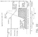
- the visualization system 108includes one or more imaging sensors, one or more image-processing units, one or more storage arrays, and one or more displays that are strategically arranged with respect to the sterile field, as illustrated in FIG. 2 .
- the visualization system 108includes an interface for HL7, PACS, and EMR.
- Various components of the visualization system 108are described under the heading "Advanced Imaging Acquisition Module” in U.S. Provisional Patent Application Serial No. 62/611,341 , titled INTERACTIVE SURGICAL PLATFORM, filed December 28, 2017, the disclosure of which is herein incorporated by reference in its entirety.
- a primary display 119is positioned in the sterile field to be visible to an operator at the operating table 114.
- a visualization tower 111is positioned outside the sterile field.
- the visualization tower 111includes a first non-sterile display 107 and a second non-sterile display 109, which face away from each other.
- the visualization system 108guided by the hub 106, is configured to utilize the displays 107, 109, and 119 to coordinate information flow to operators inside and outside the sterile field.
- the hub 106may cause the visualization system 108 to display a snapshot of a surgical site, as recorded by an imaging device 124, on a non-sterile display 107 or 109, while maintaining a live feed of the surgical site on the primary display 119.
- the snapshot on the non-sterile display 107 or 109can permit a non-sterile operator to perform a diagnostic step relevant to the surgical procedure, for example.
- the hub 106is also configured to route a diagnostic input or feedback entered by a non-sterile operator at the visualization tower 111 to the primary display 119 within the sterile field, where it can be viewed by a sterile operator at the operating table.
- the inputcan be in the form of a modification to the snapshot displayed on the non-sterile display 107 or 109, which can be routed to the primary display 119 by the hub 106.
- a surgical instrument 112is being used in the surgical procedure as part of the surgical system 102.
- the hub 106is also configured to coordinate information flow to a display of the surgical instrument 112.
- a diagnostic input or feedback entered by a non-sterile operator at the visualization tower 111can be routed by the hub 106 to the surgical instrument display 115 within the sterile field, where it can be viewed by the operator of the surgical instrument 112.
- Example surgical instrumentsthat are suitable for use with the surgical system 102 are described under the heading "Surgical Instrument Hardware” and in U.S. Provisional Patent Application Serial No. 62/611,341 , titled INTERACTIVE SURGICAL PLATFORM, filed December 28, 2017, the disclosure of which is herein incorporated by reference in its entirety, for example.
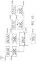
- a hub 106is depicted in communication with a visualization system 108, a robotic system 110, and a handheld intelligent surgical instrument 112.
- the hub 106includes a hub display 135, an imaging module 138, a generator module 140, a communication module 130, a processor module 132, and a storage array 134.
- the hub 106further includes a smoke evacuation module 126 and/or a suction/irrigation module 128.
- the hub modular enclosure 136offers a unified environment for managing the power, data, and fluid lines, which reduces the frequency of entanglement between such lines.
- the surgical hubfor use in a surgical procedure that involves energy application to tissue at a surgical site.
- the surgical hubincludes a hub enclosure and a combo generator module slidably receivable in a docking station of the hub enclosure.
- the docking stationincludes data and power contacts.
- the combo generator moduleincludes two or more of an ultrasonic energy generator component, a bipolar RF energy generator component, and a monopolar RF energy generator component that are housed in a single unit.
- the combo generator modulealso includes a smoke evacuation component, at least one energy delivery cable for connecting the combo generator module to a surgical instrument, at least one smoke evacuation component configured to evacuate smoke, fluid, and/or particulates generated by the application of therapeutic energy to the tissue, and a fluid line extending from the remote surgical site to the smoke evacuation component.
- the fluid lineis a first fluid line and a second fluid line extends from the remote surgical site to a suction and irrigation module slidably received in the hub enclosure.
- the hub enclosurecomprises a fluid interface.
- Certain surgical proceduresmay require the application of more than one energy type to the tissue.
- One energy typemay be more beneficial for cutting the tissue, while another different energy type may be more beneficial for sealing the tissue.
- a bipolar generatorcan be used to seal the tissue while an ultrasonic generator can be used to cut the sealed tissue.
- the modular surgical enclosureincludes a first energy-generator module, configured to generate a first energy for application to the tissue, and a first docking station comprising a first docking port that includes first data and power contacts, wherein the first energy-generator module is slidably movable into an electrical engagement with the power and data contacts and wherein the first energy-generator module is slidably movable out of the electrical engagement with the first power and data contacts.
- the modular surgical enclosurealso includes a second energy-generator module configured to generate a second energy, different than the first energy, for application to the tissue, and a second docking station comprising a second docking port that includes second data and power contacts, wherein the second energy-generator module is slidably movable into an electrical engagement with the power and data contacts, and wherein the second energy-generator module is slidably movable out of the electrical engagement with the second power and data contacts.
- a second energy-generator moduleconfigured to generate a second energy, different than the first energy, for application to the tissue
- a second docking stationcomprising a second docking port that includes second data and power contacts
- the modular surgical enclosurealso includes a communication bus between the first docking port and the second docking port, configured to facilitate communication between the first energy-generator module and the second energy-generator module.
- a hub modular enclosure 136that allows the modular integration of a generator module 140, a smoke evacuation module 126, and a suction/irrigation module 128.
- the hub modular enclosure 136further facilitates interactive communication between the modules 140, 126, 128.
- the generator module 140can be a generator module with integrated monopolar, bipolar, and ultrasonic components supported in a single housing unit 139 slidably insertable into the hub modular enclosure 136.
- the generator module 140can be configured to connect to a monopolar device 146, a bipolar device 147, and an ultrasonic device 148.
- the generator module 140may comprise a series of monopolar, bipolar, and/or ultrasonic generator modules that interact through the hub modular enclosure 136.
- the hub modular enclosure 136can be configured to facilitate the insertion of multiple generators and interactive communication between the generators docked into the hub modular enclosure 136 so that the generators would act as a single generator.
- the hub modular enclosure 136comprises a modular power and communication backplane 149 with external and wireless communication headers to enable the removable attachment of the modules 140, 126, 128 and interactive communication therebetween.
- the hub modular enclosure 136includes docking stations, or drawers, 151, herein also referred to as drawers, which are configured to slidably receive the modules 140, 126, 128.
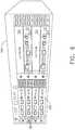
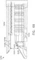
- FIG. 4illustrates a partial perspective view of a surgical hub enclosure 136, and a combo generator module 145 slidably receivable in a docking station 151 of the surgical hub enclosure 136.
- a docking port 152 with power and data contacts on a rear side of the combo generator module 145is configured to engage a corresponding docking port 150 with power and data contacts of a corresponding docking station 151 of the hub modular enclosure 136 as the combo generator module 145 is slid into position within the corresponding docking station 151 of the hub module enclosure 136.
- the combo generator module 145includes a bipolar, ultrasonic, and monopolar module and a smoke evacuation module integrated together into a single housing unit 139, as illustrated in FIG. 5 .
- the smoke evacuation module 126includes a fluid line 154 that conveys captured/collected smoke and/or fluid away from a surgical site and to, for example, the smoke evacuation module 126.
- Vacuum suction originating from the smoke evacuation module 126can draw the smoke into an opening of a utility conduit at the surgical site.
- the utility conduit, coupled to the fluid line,can be in the form of a flexible tube terminating at the smoke evacuation module 126.
- the utility conduit and the fluid linedefine a fluid path extending toward the smoke evacuation module 126 that is received in the hub enclosure 136.
- the suction/irrigation module 128is coupled to a surgical tool comprising an aspiration fluid line and a suction fluid line.
- the aspiration and suction fluid linesare in the form of flexible tubes extending from the surgical site toward the suction/irrigation module 128.
- One or more drive systemscan be configured to cause irrigation and aspiration of fluids to and from the surgical site.
- the surgical toolincludes a shaft having an end effector at a distal end thereof and at least one energy treatment associated with the end effector, an aspiration tube, and an irrigation tube.
- the aspiration tubecan have an inlet port at a distal end thereof and the aspiration tube extends through the shaft.
- an irrigation tubecan extend through the shaft and can have an inlet port in proximity to the energy deliver implement.
- the energy deliver implementis configured to deliver ultrasonic and/or RF energy to the surgical site and is coupled to the generator module 140 by a cable extending initially through the shaft.
- the irrigation tubecan be in fluid communication with a fluid source, and the aspiration tube can be in fluid communication with a vacuum source.
- the fluid source and/or the vacuum sourcecan be housed in the suction/irrigation module 128.
- the fluid source and/or the vacuum sourcecan be housed in the hub enclosure 136 separately from the suction/irrigation module 128.
- a fluid interfacecan be configured to connect the suction/irrigation module 128 to the fluid source and/or the vacuum source.
- the modules 140, 126, 128 and/or their corresponding docking stations on the hub modular enclosure 136may include alignment features that are configured to align the docking ports of the modules into engagement with their counterparts in the docking stations of the hub modular enclosure 136.
- the combo generator module 145includes side brackets 155 that are configured to slidably engage with corresponding brackets 156 of the corresponding docking station 151 of the hub modular enclosure 136. The brackets cooperate to guide the docking port contacts of the combo generator module 145 into an electrical engagement with the docking port contacts of the hub modular enclosure 136.
- the drawers 151 of the hub modular enclosure 136are the same, or substantially the same size, and the modules are adjusted in size to be received in the drawers 151.
- the side brackets 155 and/or 156can be larger or smaller depending on the size of the module.
- the drawers 151are different in size and are each designed to accommodate a particular module.
- the contacts of a particular modulecan be keyed for engagement with the contacts of a particular drawer to avoid inserting a module into a drawer with mismatching contacts.
- the docking port 150 of one drawer 151can be coupled to the docking port 150 of another drawer 151 through a communications link 157 to facilitate an interactive communication between the modules housed in the hub modular enclosure 136.
- the docking ports 150 of the hub modular enclosure 136may alternatively, or additionally, facilitate a wireless interactive communication between the modules housed in the hub modular enclosure 136. Any suitable wireless communication can be employed, such as for example Air Titan-Bluetooth.
- FIG. 6illustrates individual power bus attachments for a plurality of lateral docking ports of a lateral modular housing 160 configured to receive a plurality of modules of a surgical hub 206.
- the lateral modular housing 160is configured to laterally receive and interconnect the modules 161.
- the modules 161are slidably inserted into docking stations 162 of lateral modular housing 160, which includes a backplane for interconnecting the modules 161.
- the modules 161are arranged laterally in the lateral modular housing 160.
- the modules 161may be arranged vertically in a lateral modular housing.
- FIG. 7illustrates a vertical modular housing 164 configured to receive a plurality of modules 165 of the surgical hub 106.
- the modules 165are slidably inserted into docking stations, or drawers, 167 of vertical modular housing 164, which includes a backplane for interconnecting the modules 165.
- the drawers 167 of the vertical modular housing 164are arranged vertically, in certain instances, a vertical modular housing 164 may include drawers that are arranged laterally.
- the modules 165may interact with one another through the docking ports of the vertical modular housing 164.
- a display 177is provided for displaying data relevant to the operation of the modules 165.
- the vertical modular housing 164includes a master module 178 housing a plurality of sub-modules that are slidably received in the master module 178.
- the imaging module 138comprises an integrated video processor and a modular light source and is adapted for use with various imaging devices.
- the imaging deviceis comprised of a modular housing that can be assembled with a light source module and a camera module.
- the housingcan be a disposable housing.
- the disposable housingis removably coupled to a reusable controller, a light source module, and a camera module.
- the light source module and/or the camera modulecan be selectively chosen depending on the type of surgical procedure.
- the camera modulecomprises a CCD sensor.
- the camera modulecomprises a CMOS sensor.
- the camera moduleis configured for scanned beam imaging.
- the light source modulecan be configured to deliver a white light or a different light, depending on the surgical procedure.
- the module imaging device of the present disclosureis configured to permit the replacement of a light source module or a camera module midstream during a surgical procedure, without having to remove the imaging device from the surgical field.
- the imaging devicecomprises a tubular housing that includes a plurality of channels.
- a first channelis configured to slidably receive the camera module, which can be configured for a snap-fit engagement with the first channel.
- a second channelis configured to slidably receive the light source module, which can be configured for a snap-fit engagement with the second channel.
- the camera module and/or the light source modulecan be rotated into a final position within their respective channels.
- a threaded engagementcan be employed in lieu of the snap-fit engagement.
- multiple imaging devicesare placed at different positions in the surgical field to provide multiple views.
- the imaging module 138can be configured to switch between the imaging devices to provide an optimal view.
- the imaging module 138can be configured to integrate the images from the different imaging device.
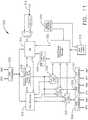
- FIG. 8illustrates a surgical data network 201 comprising a modular communication hub 203 configured to connect modular devices located in one or more operating theaters of a healthcare facility, or any room in a healthcare facility specially equipped for surgical operations, to a cloud-based system (e.g., the cloud 204 that may include a remote server 213 coupled to a storage device 205).
- the modular communication hub 203comprises a network hub 207 and/or a network switch 209 in communication with a network router.
- the modular communication hub 203also can be coupled to a local computer system 210 to provide local computer processing and data manipulation.
- the surgical data network 201may be configured as passive, intelligent, or switching.
- a passive surgical data networkserves as a conduit for the data, enabling it to go from one device (or segment) to another and to the cloud computing resources.
- An intelligent surgical data networkincludes additional features to enable the traffic passing through the surgical data network to be monitored and to configure each port in the network hub 207 or network switch 209.
- An intelligent surgical data networkmay be referred to as a manageable hub or switch.
- a switching hubreads the destination address of each packet and then forwards the packet to the correct port.
- Modular devices 1a-1n located in the operating theatermay be coupled to the modular communication hub 203.
- the network hub 207 and/or the network switch 209may be coupled to a network router 211 to connect the devices 1a-1n to the cloud 204 or the local computer system 210.
- Data associated with the devices 1a-1nmay be transferred to cloud-based computers via the router for remote data processing and manipulation.
- Data associated with the devices 1a-1nmay also be transferred to the local computer system 210 for local data processing and manipulation.
- Modular devices 2a-2m located in the same operating theateralso may be coupled to a network switch 209.
- the network switch 209may be coupled to the network hub 207 and/or the network router 211 to connect to the devices 2a-2m to the cloud 204.
- Data associated with the devices 2a-2nmay be transferred to the cloud 204 via the network router 211 for data processing and manipulation.
- Data associated with the devices 2a-2mmay also be transferred to the local computer system 210 for local data processing and manipulation.
- the surgical data network 201may be expanded by interconnecting multiple network hubs 207 and/or multiple network switches 209 with multiple network routers 211.
- the modular communication hub 203may be contained in a modular control tower configured to receive multiple devices 1a-1n/2a-2m.
- the local computer system 210also may be contained in a modular control tower.
- the modular communication hub 203is connected to a display 212 to display images obtained by some of the devices 1a-1n/2a-2m, for example during surgical procedures.
- the devices 1a-1n/2a-2mmay include, for example, various modules such as an imaging module 138 coupled to an endoscope, a generator module 140 coupled to an energy-based surgical device, a smoke evacuation module 126, a suction/irrigation module 128, a communication module 130, a processor module 132, a storage array 134, a surgical device coupled to a display, and/or a non-contact sensor module, among other modular devices that may be connected to the modular communication hub 203 of the surgical data network 201.
- various modulessuch as an imaging module 138 coupled to an endoscope, a generator module 140 coupled to an energy-based surgical device, a smoke evacuation module 126, a suction/irrigation module 128, a communication module 130, a processor module 132, a storage array 134, a surgical device coupled to a display, and/or a non-contact sensor module, among other modular devices that may be connected to the modular communication hub 203 of the surgical data network 201.
- the surgical data network 201may comprise a combination of network hub(s), network switch(es), and network router(s) connecting the devices 1a-1n/2a-2m to the cloud. Any one of or all of the devices 1a-1n/2a-2m coupled to the network hub or network switch may collect data in real time and transfer the data to cloud computers for data processing and manipulation. It will be appreciated that cloud computing relies on sharing computing resources rather than having local servers or personal devices to handle software applications.
- the word “cloud”may be used as a metaphor for "the Internet,” although the term is not limited as such.
- cloud computingmay be used herein to refer to "a type of Internet-based computing," where different services-such as servers, storage, and applications-are delivered to the modular communication hub 203 and/or computer system 210 located in the surgical theater (e.g., a fixed, mobile, temporary, or field operating room or space) and to devices connected to the modular communication hub 203 and/or computer system 210 through the Internet.
- the cloud infrastructuremay be maintained by a cloud service provider.
- the cloud service providermay be the entity that coordinates the usage and control of the devices 1a-1n/2a-2m located in one or more operating theaters.
- the cloud computing servicescan perform a large number of calculations based on the data gathered by smart surgical instruments, robots, and other computerized devices located in the operating theater.
- the hub hardwareenables multiple devices or connections to be connected to a computer that communicates with the cloud computing resources and storage.
- the surgical data networkprovides improved surgical outcomes, reduced costs, and improved patient satisfaction.
- At least some of the devices 1a-1n/2a-2mmay be employed to view tissue states to assess leaks or perfusion of sealed tissue after a tissue sealing and cutting procedure.
- At least some of the devices 1a-1n/2a-2mmay be employed to identify pathology, such as the effects of diseases, using the cloud-based computing to examine data including images of samples of body tissue for diagnostic purposes. This includes localization and margin confirmation of tissue and phenotypes.
- At least some of the devices 1a-1n/2a-2mmay be employed to identify anatomical structures of the body using a variety of sensors integrated with imaging devices and techniques such as overlaying images captured by multiple imaging devices.
- the data gathered by the devices 1a-1n/2a-2m, including image datamay be transferred to the cloud 204 or the local computer system 210 or both for data processing and manipulation including image processing and manipulation.
- the datamay be analyzed to improve surgical procedure outcomes by determining if further treatment, such as the application of endoscopic intervention, emerging technologies, a targeted radiation, targeted intervention, and precise robotics to tissue-specific sites and conditions, may be pursued.
- Such data analysismay further employ outcome analytics processing, and using standardized approaches may provide beneficial feedback to either confirm surgical treatments and the behavior of the surgeon or suggest modifications to surgical treatments and the behavior of the surgeon.
- the operating theater devices 1a-1nmay be connected to the modular communication hub 203 over a wired channel or a wireless channel depending on the configuration of the devices 1a-1n to a network hub.
- the network hub 207may be implemented, in one aspect, as a local network broadcast device that works on the physical layer of the Open System Interconnection (OSI) model.
- the network hubprovides connectivity to the devices 1a-1n located in the same operating theater network.
- the network hub 207collects data in the form of packets and sends them to the router in half duplex mode.
- the network hub 207does not store any media access control/Internet Protocol (MAC/IP) to transfer the device data. Only one of the devices 1a-1n can send data at a time through the network hub 207.
- MAC/IPmedia access control/Internet Protocol
- the network hub 207has no routing tables or intelligence regarding where to send information and broadcasts all network data across each connection and to a remote server 213 ( FIG. 9 ) over the cloud 204.
- the network hub 207can detect basic network errors such as collisions, but having all information broadcast to multiple ports can be a security risk and cause bottlenecks.
- the operating theater devices 2a-2mmay be connected to a network switch 209 over a wired channel or a wireless channel.
- the network switch 209works in the data link layer of the OSI model.
- the network switch 209is a multicast device for connecting the devices 2a-2m located in the same operating theater to the network.
- the network switch 209sends data in the form of frames to the network router 211 and works in full duplex mode. Multiple devices 2a-2m can send data at the same time through the network switch 209.
- the network switch 209stores and uses MAC addresses of the devices 2a-2m to transfer data.
- the network hub 207 and/or the network switch 209are coupled to the network router 211 for connection to the cloud 204.
- the network router 211works in the network layer of the OSI model.
- the network router 211creates a route for transmitting data packets received from the network hub 207 and/or network switch 211 to cloud-based computer resources for further processing and manipulation of the data collected by any one of or all the devices 1a-1n/2a-2m.
- the network router 211may be employed to connect two or more different networks located in different locations, such as, for example, different operating theaters of the same healthcare facility or different networks located in different operating theaters of different healthcare facilities.
- the network router 211sends data in the form of packets to the cloud 204 and works in full duplex mode. Multiple devices can send data at the same time.
- the network router 211uses IP addresses to transfer data.
- the network hub 207may be implemented as a USB hub, which allows multiple USB devices to be connected to a host computer.
- the USB hubmay expand a single USB port into several tiers so that there are more ports available to connect devices to the host system computer.
- the network hub 207may include wired or wireless capabilities to receive information over a wired channel or a wireless channel.
- a wireless USB short-range, high-bandwidth wireless radio communication protocolmay be employed for communication between the devices 1a-1n and devices 2a-2m located in the operating theater.
- the operating theater devices 1a-1n/2a-2mmay communicate to the modular communication hub 203 via Bluetooth wireless technology standard for exchanging data over short distances (using short-wavelength UHF radio waves in the ISM band from 2.4 to 2.485 GHz) from fixed and mobile devices and building personal area networks (PANs).
- Bluetooth wireless technology standardfor exchanging data over short distances (using short-wavelength UHF radio waves in the ISM band from 2.4 to 2.485 GHz) from fixed and mobile devices and building personal area networks (PANs).
- the operating theater devices 1a-1n/2a-2mmay communicate to the modular communication hub 203 via a number of wireless or wired communication standards or protocols, including but not limited to Wi-Fi (IEEE 802.11 family), WiMAX (IEEE 802.16 family), IEEE 802.20, long-term evolution (LTE), and Ev-DO, HSPA+, HSDPA+, HSUPA+, EDGE, GSM, GPRS, CDMA, TDMA, DECT, and Ethernet derivatives thereof, as well as any other wireless and wired protocols that are designated as 3G, 4G, 5G, and beyond.
- the computing modulemay include a plurality of communication modules.
- a first communication modulemay be dedicated to shorter-range wireless communications such as Wi-Fi and Bluetooth, and a second communication module may be dedicated to longer-range wireless communications such as GPS, EDGE, GPRS, CDMA, WiMAX, LTE, Ev-DO, and others.
- the modular communication hub 203may serve as a central connection for one or all of the operating theater devices 1a-1n/2a-2m and handles a data type known as frames. Frames carry the data generated by the devices 1a-1n/2a-2m. When a frame is received by the modular communication hub 203, it is amplified and transmitted to the network router 211, which transfers the data to the cloud computing resources by using a number of wireless or wired communication standards or protocols, as described herein.
- the modular communication hub 203can be used as a standalone device or be connected to compatible network hubs and network switches to form a larger network.
- the modular communication hub 203is generally easy to install, configure, and maintain, making it a good option for networking the operating theater devices 1a-1n/2a-2m.
- FIG. 9illustrates a computer-implemented interactive surgical system 200.
- the computer-implemented interactive surgical system 200is similar in many respects to the computer-implemented interactive surgical system 100.
- the computer-implemented interactive surgical system 200includes one or more surgical systems 202, which are similar in many respects to the surgical systems 102.
- Each surgical system 202includes at least one surgical hub 206 in communication with a cloud 204 that may include a remote server 213.
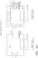
- the computer-implemented interactive surgical system 200comprises a modular control tower 236 connected to multiple operating theater devices such as, for example, intelligent surgical instruments, robots, and other computerized devices located in the operating theater. As shown in FIG.
- the modular control tower 236comprises a modular communication hub 203 coupled to a computer system 210.
- the modular control tower 236is coupled to an imaging module 238 that is coupled to an endoscope 239, a generator module 240 that is coupled to an energy device 241, a smoke evacuator module 226, a suction/irrigation module 228, a communication module 230, a processor module 232, a storage array 234, a smart device/instrument 235 optionally coupled to a display 237, and a non-contact sensor module 242.
- the operating theater devicesare coupled to cloud computing resources and data storage via the modular control tower 236.
- a robot hub 222also may be connected to the modular control tower 236 and to the cloud computing resources.
- the devices/instruments 235, visualization systems 208, among others,may be coupled to the modular control tower 236 via wired or wireless communication standards or protocols, as described herein.
- the modular control tower 236may be coupled to a hub display 215 (e.g., monitor, screen) to display and overlay images received from the imaging module, device/instrument display, and/or other visualization systems 208.
- the hub displayalso may display data received from devices connected to the modular control tower in conjunction with images and overlaid images.
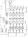
- FIG. 10illustrates a surgical hub 206 comprising a plurality of modules coupled to the modular control tower 236.
- the modular control tower 236comprises a modular communication hub 203, e.g., a network connectivity device, and a computer system 210 to provide local processing, visualization, and imaging, for example.
- the modular communication hub 203may be connected in a tiered configuration to expand the number of modules (e.g., devices) that may be connected to the modular communication hub 203 and transfer data associated with the modules to the computer system 210, cloud computing resources, or both.
- each of the network hubs/switches in the modular communication hub 203includes three downstream ports and one upstream port.
- the upstream network hub/switchis connected to a processor to provide a communication connection to the cloud computing resources and a local display 217. Communication to the cloud 204 may be made either through a wired or a wireless communication channel.
- the surgical hub 206employs a non-contact sensor module 242 to measure the dimensions of the operating theater and generate a map of the surgical theater using either ultrasonic or laser-type non-contact measurement devices.
- An ultrasound-based non-contact sensor modulescans the operating theater by transmitting a burst of ultrasound and receiving the echo when it bounces off the perimeter walls of an operating theater as described under the heading "Surgical Hub Spatial Awareness Within an Operating Room” in U.S. Provisional Patent Application Serial No. 62/611,341 , titled INTERACTIVE SURGICAL PLATFORM, filed December 28, 2017, which is herein incorporated by reference in its entirety, in which the sensor module is configured to determine the size of the operating theater and to adjust Bluetooth-pairing distance limits.
- a laser-based non-contact sensor modulescans the operating theater by transmitting laser light pulses, receiving laser light pulses that bounce off the perimeter walls of the operating theater, and comparing the phase of the transmitted pulse to the received pulse to determine the size of the operating theater and to adjust Bluetooth pairing distance limits, for example.
- the computer system 210comprises a processor 244 and a network interface 245.
- the processor 244is coupled to a communication module 247, storage 248, memory 249, non-volatile memory 250, and input/output interface 251 via a system bus.
- the system buscan be any of several types of bus structure(s) including the memory bus or memory controller, a peripheral bus or external bus, and/or a local bus using any variety of available bus architectures including, but not limited to, 9-bit bus, Industrial Standard Architecture (ISA), Micro-Charmel Architecture (MSA), Extended ISA (EISA), Intelligent Drive Electronics (IDE), VESA Local Bus (VLB), Peripheral Component Interconnect (PCI), USB, Advanced Graphics Port (AGP), Personal Computer Memory Card International Association bus (PCMCIA), Small Computer Systems Interface (SCSI), or any other proprietary bus.
- ISAIndustrial Standard Architecture
- MSAMicro-Charmel Architecture
- EISAExtended ISA
- IDEIntelligent Drive Electronics
- VLBVESA Local Bus
- PCIPe
- the processor 244may be any single-core or multicore processor such as those known under the trade name ARM Cortex by Texas Instruments.
- the processormay be an LM4F230H5QR ARM Cortex-M4F Processor Core, available from Texas Instruments, for example, comprising an on-chip memory of 256 KB single-cycle flash memory, or other non-volatile memory, up to 40 MHz, a prefetch buffer to improve performance above 40 MHz, a 32 KB single-cycle serial random access memory (SRAM), an internal read-only memory (ROM) loaded with StellarisWare® software, a 2 KB electrically erasable programmable read-only memory (EEPROM), and/or one or more pulse width modulation (PWM) modules, one or more quadrature encoder inputs (QEI) analogs, one or more 12-bit analog-to-digital converters (ADCs) with 12 analog input channels, details of which are available for the product datasheet.
- QEIquadrature encoder inputs
- the processor 244may comprise a safety controller comprising two controller-based families such as TMS570 and RM4x, known under the trade name Hercules ARM Cortex R4, also by Texas Instruments.
- the safety controllermay be configured specifically for IEC 61508 and ISO 26262 safety critical applications, among others, to provide advanced integrated safety features while delivering scalable performance, connectivity, and memory options.
- the system memoryincludes volatile memory and non-volatile memory.
- the basic input/output system (BIOS)containing the basic routines to transfer information between elements within the computer system, such as during start-up, is stored in non-volatile memory.
- the non-volatile memorycan include ROM, programmable ROM (PROM), electrically programmable ROM (EPROM), EEPROM, or flash memory.
- Volatile memoryincludes random-access memory (RAM), which acts as external cache memory.
- RAMis available in many forms such as SRAM, dynamic RAM (DRAM), synchronous DRAM (SDRAM), double data rate SDRAM (DDR SDRAM), enhanced SDRAM (ESDRAM), Synchlink DRAM (SLDRAM), and direct Rambus RAM (DRRAM).
- the computer system 210also includes removable/non-removable, volatile/non-volatile computer storage media, such as for example disk storage.
- the disk storageincludes, but is not limited to, devices like a magnetic disk drive, floppy disk drive, tape drive, Jaz drive, Zip drive, LS-60 drive, flash memory card, or memory stick.
- the disk storagecan include storage media separately or in combination with other storage media including, but not limited to, an optical disc drive such as a compact disc ROM device (CD-ROM), compact disc recordable drive (CD-R Drive), compact disc rewritable drive (CD-RW Drive), or a digital versatile disc ROM drive (DVD-ROM).
- CD-ROMcompact disc ROM
- CD-R Drivecompact disc recordable drive
- CD-RW Drivecompact disc rewritable drive
- DVD-ROMdigital versatile disc ROM drive
- a removable or non-removable interfacemay be employed.
- the computer system 210includes software that acts as an intermediary between users and the basic computer resources described in a suitable operating environment.
- Such softwareincludes an operating system.
- the operating systemwhich can be stored on the disk storage, acts to control and allocate resources of the computer system.
- System applicationstake advantage of the management of resources by the operating system through program modules and program data stored either in the system memory or on the disk storage. It is to be appreciated that various components described herein can be implemented with various operating systems or combinations of operating systems.
- a userenters commands or information into the computer system 210 through input device(s) coupled to the I/O interface 251.
- the input devicesinclude, but are not limited to, a pointing device such as a mouse, trackball, stylus, touch pad, keyboard, microphone, joystick, game pad, satellite dish, scanner, TV tuner card, digital camera, digital video camera, web camera, and the like.
- These and other input devicesconnect to the processor through the system bus via interface port(s).
- the interface port(s)include, for example, a serial port, a parallel port, a game port, and a USB.
- the output device(s)use some of the same types of ports as input device(s).
- a USB portmay be used to provide input to the computer system and to output information from the computer system to an output device.
- An output adapteris provided to illustrate that there are some output devices like monitors, displays, speakers, and printers, among other output devices that require special adapters.
- the output adaptersinclude, by way of illustration and not limitation, video and sound cards that provide a means of connection between the output device and the system bus. It should be noted that other devices and/or systems of devices, such as remote computer(s), provide both input and output capabilities.
- the computer system 210can operate in a networked environment using logical connections to one or more remote computers, such as cloud computer(s), or local computers.
- the remote cloud computer(s)can be a personal computer, server, router, network PC, workstation, microprocessor-based appliance, peer device, or other common network node, and the like, and typically includes many or all of the elements described relative to the computer system. For purposes of brevity, only a memory storage device is illustrated with the remote computer(s).
- the remote computer(s)is logically connected to the computer system through a network interface and then physically connected via a communication connection.
- the network interfaceencompasses communication networks such as local area networks (LANs) and wide area networks (WANs).
- LAN technologiesinclude Fiber Distributed Data Interface (FDDI), Copper Distributed Data Interface (CDDI), Ethernet/IEEE 802.3, Token Ring/IEEE 802.5 and the like.
- WAN technologiesinclude, but are not limited to, point-to-point links, circuit-switching networks like Integrated Services Digital Networks (ISDN) and variations thereon, packet-switching networks, and Digital Subscriber Lines (DSL).
- ISDNIntegrated Services Digital Networks
- DSLDigital Subscriber Lines
- the computer system 210 of FIG. 10may comprise an image processor, image-processing engine, media processor, or any specialized digital signal processor (DSP) used for the processing of digital images.
- the image processormay employ parallel computing with single instruction, multiple data (SIMD) or multiple instruction, multiple data (MIMD) technologies to increase speed and efficiency.
- SIMDsingle instruction, multiple data
- MIMDmultiple instruction, multiple data
- the digital image-processing enginecan perform a range of tasks.
- the image processormay be a system on a chip with multicore processor architecture.
- the communication connection(s)refers to the hardware/software employed to connect the network interface to the bus. While the communication connection is shown for illustrative clarity inside the computer system, it can also be external to the computer system 210.
- the hardware/software necessary for connection to the network interfaceincludes, for illustrative purposes only, internal and external technologies such as modems, including regular telephone-grade modems, cable modems, and DSL modems, ISDN adapters, and Ethernet cards.
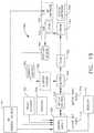
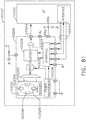
- FIG. 11illustrates a functional block diagram of one aspect of a USB network hub 300 device, in accordance with at least one aspect of the present disclosure.
- the USB network hub device 300employs a TUSB2036 integrated circuit hub by Texas Instruments.
- the USB network hub 300is a CMOS device that provides an upstream USB transceiver port 302 and up to three downstream USB transceiver ports 304, 306, 308 in compliance with the USB 2.0 specification.
- the upstream USB transceiver port 302is a differential root data port comprising a differential data minus (DM0) input paired with a differential data plus (DP0) input.
- the three downstream USB transceiver ports 304, 306, 308are differential data ports where each port includes differential data plus (DP1-DP3) outputs paired with differential data minus (DM1-DM3) outputs.
- the USB network hub 300 deviceis implemented with a digital state machine instead of a microcontroller, and no firmware programming is required. Fully compliant USB transceivers are integrated into the circuit for the upstream USB transceiver port 302 and all downstream USB transceiver ports 304, 306, 308.
- the downstream USB transceiver ports 304, 306, 308support both full-speed and low-speed devices by automatically setting the slew rate according to the speed of the device attached to the ports.
- the USB network hub 300 devicemay be configured either in bus-powered or self-powered mode and includes a hub power logic 312 to manage power.
- the USB network hub 300 deviceincludes a serial interface engine 310 (SIE).
- SIE 310is the front end of the USB network hub 300 hardware and handles most of the protocol described in chapter 8 of the USB specification.
- the SIE 310typically comprehends signaling up to the transaction level.
- the functions that it handlescould include: packet recognition, transaction sequencing, SOP, EOP, RESET, and RESUME signal detection/generation, clock/data separation, non-return-to-zero invert (NRZI) data encoding/decoding and bit-stuffing, CRC generation and checking (token and data), packet ID (PID) generation and checking/decoding, and/or serial-parallel/parallel-serial conversion.
- NRZInon-return-to-zero invert
- the 310receives a clock input 314 and is coupled to a suspend/resume logic and frame timer 316 circuit and a hub repeater circuit 318 to control communication between the upstream USB transceiver port 302 and the downstream USB transceiver ports 304, 306, 308 through port logic circuits 320, 322, 324.
- the SIE 310is coupled to a command decoder 326 via interface logic to control commands from a serial EEPROM via a serial EEPROM interface 330.
- the USB network hub 300can connect 127 functions configured in up to six logical layers (tiers) to a single computer. Further, the USB network hub 300 can connect to all peripherals using a standardized four-wire cable that provides both communication and power distribution.
- the power configurationsare bus-powered and self-powered modes.
- the USB network hub 300may be configured to support four modes of power management: a bus-powered hub, with either individual-port power management or ganged-port power management, and the self-powered hub, with either individual-port power management or ganged-port power management.
- the USB network hub 300, the upstream USB transceiver port 302is plugged into a USB host controller, and the downstream USB transceiver ports 304, 306, 308 are exposed for connecting USB compatible devices, and so forth.
- FIG. 12illustrates a logic diagram of a control system 470 of a surgical instrument or tool in accordance with one or more aspects of the present disclosure.
- the system 470comprises a control circuit.
- the control circuitincludes a microcontroller 461 comprising a processor 462 and a memory 468.
- One or more of sensors 472, 474, 476for example, provide real-time feedback to the processor 462.
- a tracking system 480is configured to determine the position of the longitudinally movable displacement member.
- the position informationis provided to the processor 462, which can be programmed or configured to determine the position of the longitudinally movable drive member as well as the position of a firing member, firing bar, and I-beam knife element. Additional motors may be provided at the tool driver interface to control I-beam firing, closure tube travel, shaft rotation, and articulation.
- a display 473displays a variety of operating conditions of the instruments and may include touch screen functionality for data input. Information displayed on the display 473 may be overlaid with images acquired via endoscopic imaging modules.
- the microcontroller 461may be any single-core or multicore processor such as those known under the trade name ARM Cortex by Texas Instruments.
- the main microcontroller 461may be an LM4F230H5QR ARM Cortex-M4F Processor Core, available from Texas Instruments, for example, comprising an on-chip memory of 256 KB single-cycle flash memory, or other non-volatile memory, up to 40 MHz, a prefetch buffer to improve performance above 40 MHz, a 32 KB single-cycle SRAM, and internal ROM loaded with StellarisWare® software, a 2 KB EEPROM, one or more PWM modules, one or more QEI analogs, and/or one or more 12-bit ADCs with 12 analog input channels, details of which are available for the product datasheet.
- the microcontroller 461may comprise a safety controller comprising two controller-based families such as TMS570 and RM4x, known under the trade name Hercules ARM Cortex R4, also by Texas Instruments.
- the safety controllermay be configured specifically for IEC 61508 and ISO 26262 safety critical applications, among others, to provide advanced integrated safety features while delivering scalable performance, connectivity, and memory options.
- the microcontroller 461may be programmed to perform various functions such as precise control over the speed and position of the knife and articulation systems.
- the microcontroller 461includes a processor 462 and a memory 468.
- the electric motor 482may be a brushed direct current (DC) motor with a gearbox and mechanical links to an articulation or knife system.
- a motor driver 492may be an A3941 available from Allegro Microsystems, Inc. Other motor drivers may be readily substituted for use in the tracking system 480 comprising an absolute positioning system.
- a detailed description of an absolute positioning systemis described in U.S. Patent Application Publication No. 2017/0296213 , titled SYSTEMS AND METHODS FOR CONTROLLING A SURGICAL STAPLING AND CUTTING INSTRUMENT, which published on October 19, 2017, which is herein incorporated by reference in its entirety.
- the microcontroller 461may be programmed to provide precise control over the speed and position of displacement members and articulation systems.
- the microcontroller 461may be configured to compute a response in the software of the microcontroller 461.
- the computed responseis compared to a measured response of the actual system to obtain an "observed" response, which is used for actual feedback decisions.
- the observed responseis a favorable, tuned value that balances the smooth, continuous nature of the simulated response with the measured response, which can detect outside influences on the system.
- the motor 482may be controlled by the motor driver 492 and can be employed by the firing system of the surgical instrument or tool.
- the motor 482may be a brushed DC driving motor having a maximum rotational speed of approximately 25,000 RPM.
- the motor 482may include a brushless motor, a cordless motor, a synchronous motor, a stepper motor, or any other suitable electric motor.
- the motor driver 492may comprise an H-bridge driver comprising field-effect transistors (FETs), for example.
- FETsfield-effect transistors
- the motor 482can be powered by a power assembly releasably mounted to the handle assembly or tool housing for supplying control power to the surgical instrument or tool.
- the power assemblymay comprise a battery which may include a number of battery cells connected in series that can be used as the power source to power the surgical instrument or tool.
- the battery cells of the power assemblymay be replaceable and/or rechargeable.
- the battery cellscan be lithium-ion batteries which can be couplable to and separable from the power assembly.
- the motor driver 492may be an A3941 available from Allegro Microsystems, Inc.
- the A3941 492is a full-bridge controller for use with external N-channel power metal-oxide semiconductor field-effect transistors (MOSFETs) specifically designed for inductive loads, such as brush DC motors.
- the driver 492comprises a unique charge pump regulator that provides full (>10 V) gate drive for battery voltages down to 7 V and allows the A3941 to operate with a reduced gate drive, down to 5.5 V.
- a bootstrap capacitormay be employed to provide the above battery supply voltage required for N-channel MOSFETs.
- An internal charge pump for the high-side driveallows DC (100% duty cycle) operation.
- the full bridgecan be driven in fast or slow decay modes using diode or synchronous rectification.
- current recirculationcan be through the high-side or the lowside FETs.
- the power FETsare protected from shoot-through by resistor-adjustable dead time.
- Integrated diagnosticsprovide indications of undervoltage, overtemperature, and power bridge faults and can be configured to protect the power MOSFETs under most short circuit conditions.
- Other motor driversmay be readily substituted for use in the tracking system 480 comprising an absolute positioning system.
- the tracking system 480comprises a controlled motor drive circuit arrangement comprising a position sensor 472, in accordance with at least one aspect of this disclosure.
- the position sensor 472 for an absolute positioning systemprovides a unique position signal corresponding to the location of a displacement member.
- the displacement memberrepresents a longitudinally movable drive member comprising a rack of drive teeth for meshing engagement with a corresponding drive gear of a gear reducer assembly.
- the displacement memberrepresents the firing member, which could be adapted and configured to include a rack of drive teeth.
- the displacement memberrepresents a firing bar or the I-beam, each of which can be adapted and configured to include a rack of drive teeth.
- the term displacement memberis used generically to refer to any movable member of the surgical instrument or tool such as the drive member, the firing member, the firing bar, the I-beam, or any element that can be displaced.
- the longitudinally movable drive memberis coupled to the firing member, the firing bar, and the I-beam.
- the absolute positioning systemcan, in effect, track the linear displacement of the I-beam by tracking the linear displacement of the longitudinally movable drive member.
- the displacement membermay be coupled to any position sensor 472 suitable for measuring linear displacement.
- the longitudinally movable drive member, the firing member, the firing bar, or the I-beam, or combinations thereofmay be coupled to any suitable linear displacement sensor.
- Linear displacement sensorsmay include contact or non-contact displacement sensors.
- Linear displacement sensorsmay comprise linear variable differential transformers (LVDT), differential variable reluctance transducers (DVRT), a slide potentiometer, a magnetic sensing system comprising a movable magnet and a series of linearly arranged Hall effect sensors, a magnetic sensing system comprising a fixed magnet and a series of movable, linearly arranged Hall effect sensors, an optical sensing system comprising a movable light source and a series of linearly arranged photo diodes or photo detectors, an optical sensing system comprising a fixed light source and a series of movable linearly, arranged photo diodes or photo detectors, or any combination thereof.
- LVDTlinear variable differential transformers
- DVRTdifferential variable reluctance transducers
- slide potentiometera magnetic sensing system comprising a movable magnet and a series of linearly arranged Hall effect sensors
- a magnetic sensing systemcomprising a fixed magnet and
- the electric motor 482can include a rotatable shaft that operably interfaces with a gear assembly that is mounted in meshing engagement with a set, or rack, of drive teeth on the displacement member.
- a sensor elementmay be operably coupled to a gear assembly such that a single revolution of the position sensor 472 element corresponds to some linear longitudinal translation of the displacement member.
- An arrangement of gearing and sensorscan be connected to the linear actuator, via a rack and pinion arrangement, or a rotary actuator, via a spur gear or other connection.
- a power sourcesupplies power to the absolute positioning system and an output indicator may display the output of the absolute positioning system.
- the displacement memberrepresents the longitudinally movable drive member comprising a rack of drive teeth formed thereon for meshing engagement with a corresponding drive gear of the gear reducer assembly.
- the displacement memberrepresents the longitudinally movable firing member, firing bar, I-beam, or combinations thereof.
- a single revolution of the sensor element associated with the position sensor 472is equivalent to a longitudinal linear displacement d1 of the of the displacement member, where d1 is the longitudinal linear distance that the displacement member moves from point "a" to point "b” after a single revolution of the sensor element coupled to the displacement member.
- the sensor arrangementmay be connected via a gear reduction that results in the position sensor 472 completing one or more revolutions for the full stroke of the displacement member.
- the position sensor 472may complete multiple revolutions for the full stroke of the displacement member.
- a series of switchesmay be employed alone or in combination with a gear reduction to provide a unique position signal for more than one revolution of the position sensor 472.
- the state of the switchesare fed back to the microcontroller 461 that applies logic to determine a unique position signal corresponding to the longitudinal linear displacement d1 + d2 + ... dn of the displacement member.
- the output of the position sensor 472is provided to the microcontroller 461.
- the position sensor 472 of the sensor arrangementmay comprise a magnetic sensor, an analog rotary sensor like a potentiometer, or an array of analog Hall-effect elements, which output a unique combination of position signals or values.
- the position sensor 472may comprise any number of magnetic sensing elements, such as, for example, magnetic sensors classified according to whether they measure the total magnetic field or the vector components of the magnetic field.
- the techniques used to produce both types of magnetic sensorsencompass many aspects of physics and electronics.
- the technologies used for magnetic field sensinginclude search coil, fluxgate, optically pumped, nuclear precession, SQUID, Hall-effect, anisotropic magnetoresistance, giant magnetoresistance, magnetic tunnel junctions, giant magnetoimpedance, magnetostrictive/piezoelectric composites, magnetodiode, magnetotransistor, fiber-optic, magneto-optic, and microelectromechanical systems-based magnetic sensors, among others.
- the position sensor 472 for the tracking system 480 comprising an absolute positioning systemcomprises a magnetic rotary absolute positioning system.
- the position sensor 472may be implemented as an AS5055EQFT single-chip magnetic rotary position sensor available from Austria Microsystems, AG.
- the position sensor 472is interfaced with the microcontroller 461 to provide an absolute positioning system.
- the position sensor 472is a low-voltage and low-power component and includes four Hall-effect elements in an area of the position sensor 472 that is located above a magnet.
- a high-resolution ADC and a smart power management controllerare also provided on the chip.
- a coordinate rotation digital computer (CORDIC) processoralso known as the digit-by-digit method and Volder's algorithm, is provided to implement a simple and efficient algorithm to calculate hyperbolic and trigonometric functions that require only addition, subtraction, bitshift, and table lookup operations.
- the angle position, alarm bits, and magnetic field informationare transmitted over a standard serial communication interface, such as a serial peripheral interface (SPI) interface, to the microcontroller 461.
- SPIserial peripheral interface
- the position sensor 472provides 12 or 14 bits of resolution.
- the position sensor 472may be an AS5055 chip provided in a small QFN 16-pin 4x4x0.85mm package.
- the tracking system 480comprising an absolute positioning system may comprise and/or be programmed to implement a feedback controller, such as a PID, state feedback, and adaptive controller.
- a power sourceconverts the signal from the feedback controller into a physical input to the system: in this case the voltage.
- Other examplesinclude a PWM of the voltage, current, and force.
- Other sensor(s)may be provided to measure physical parameters of the physical system in addition to the position measured by the position sensor 472.
- the other sensor(s)can include sensor arrangements such as those described in U.S. Patent No. 9,345,481 , titled STAPLE CARTRIDGE TISSUE THICKNESS SENSOR SYSTEM, which issued on May 24, 2016, which is herein incorporated by reference in its entirety; U.S.
- Patent Application Publication No. 2014/0263552titled STAPLE CARTRIDGE TISSUE THICKNESS SENSOR SYSTEM, which published on September 18, 2014, which is herein incorporated by reference in its entirety; and U.S. Patent Application Serial No. 15/628,175 , titled TECHNIQUES FOR ADAPTIVE CONTROL OF MOTOR VELOCITY OF A SURGICAL STAPLING AND CUTTING INSTRUMENT, filed June 20, 2017, which is herein incorporated by reference in its entirety.
- an absolute positioning systemis coupled to a digital data acquisition system where the output of the absolute positioning system will have a finite resolution and sampling frequency.
- the absolute positioning systemmay comprise a compare-and-combine circuit to combine a computed response with a measured response using algorithms, such as a weighted average and a theoretical control loop, that drive the computed response towards the measured response.
- the computed response of the physical systemtakes into account properties like mass, inertial, viscous friction, inductance resistance, etc., to predict what the states and outputs of the physical system will be by knowing the input.
- the absolute positioning systemprovides an absolute position of the displacement member upon power-up of the instrument, without retracting or advancing the displacement member to a reset (zero or home) position as may be required with conventional rotary encoders that merely count the number of steps forwards or backwards that the motor 482 has taken to infer the position of a device actuator, drive bar, knife, or the like.
- a sensor 474such as, for example, a strain gauge or a micro-strain gauge, is configured to measure one or more parameters of the end effector, such as, for example, the amplitude of the strain exerted on the anvil during a clamping operation, which can be indicative of the closure forces applied to the anvil.
- the measured strainis converted to a digital signal and provided to the processor 462.
- a sensor 476such as, for example, a load sensor, can measure the closure force applied by the closure drive system to the anvil.
- the sensor 476such as, for example, a load sensor, can measure the firing force applied to an I-beam in a firing stroke of the surgical instrument or tool.
- the I-beamis configured to engage a wedge sled, which is configured to upwardly cam staple drivers to force out staples into deforming contact with an anvil.
- the I-beamalso includes a sharpened cutting edge that can be used to sever tissue as the I-beam is advanced distally by the firing bar.
- a current sensor 478can be employed to measure the current drawn by the motor 482.
- the force required to advance the firing membercan correspond to the current drawn by the motor 482, for example.
- the measured forceis converted to a digital signal and provided to the processor 462.
- the strain gauge sensor 474can be used to measure the force applied to the tissue by the end effector.
- a strain gaugecan be coupled to the end effector to measure the force on the tissue being treated by the end effector.
- a system for measuring forces applied to the tissue grasped by the end effectorcomprises a strain gauge sensor 474, such as, for example, a micro-strain gauge, that is configured to measure one or more parameters of the end effector, for example.
- the strain gauge sensor 474can measure the amplitude or magnitude of the strain exerted on a jaw member of an end effector during a clamping operation, which can be indicative of the tissue compression. The measured strain is converted to a digital signal and provided to a processor 462 of the microcontroller 461.
- a load sensor 476can measure the force used to operate the knife element, for example, to cut the tissue captured between the anvil and the staple cartridge.
- a magnetic field sensorcan be employed to measure the thickness of the captured tissue. The measurement of the magnetic field sensor also may be converted to a digital signal and provided to the processor 462.
- a memory 468may store a technique, an equation, and/or a lookup table which can be employed by the microcontroller 461 in the assessment.
- the control system 470 of the surgical instrument or toolalso may comprise wired or wireless communication circuits to communicate with the modular communication hub as shown in FIGS. 8-11 .
- FIG. 13illustrates a control circuit 500 configured to control aspects of the surgical instrument or tool, in accordance with at least one aspect of this disclosure.
- the control circuit 500can be configured to implement various processes described herein.
- the control circuit 500may comprise a microcontroller comprising one or more processors 502 (e.g., microprocessor, microcontroller) coupled to at least one memory circuit 504.
- the memory circuit 504stores machine-executable instructions that, when executed by the processor 502, cause the processor 502 to execute machine instructions to implement various processes described herein.
- the processor 502may be any one of a number of single-core or multicore processors known in the art.
- the memory circuit 504may comprise volatile and non-volatile storage media.
- the processor 502may include an instruction processing unit 506 and an arithmetic unit 508.
- the instruction processing unitmay be configured to receive instructions from the memory circuit 504 of this disclosure.
- FIG. 14illustrates a combinational logic circuit 510 configured to control aspects of the surgical instrument or tool, in accordance with at least one aspect of this disclosure.
- the combinational logic circuit 510can be configured to implement various processes described herein.
- the combinational logic circuit 510may comprise a finite state machine comprising a combinational logic 512 configured to receive data associated with the surgical instrument or tool at an input 514, process the data by the combinational logic 512, and provide an output 516.
- FIG. 15illustrates a sequential logic circuit 520 configured to control aspects of the surgical instrument or tool, in accordance with at least one aspect of this disclosure.
- the sequential logic circuit 520 or the combinational logic 522can be configured to implement various processes described herein.
- the sequential logic circuit 520may comprise a finite state machine.
- the sequential logic circuit 520may comprise a combinational logic 522, at least one memory circuit 524, and a clock 529, for example.
- the at least one memory circuit 524can store a current state of the finite state machine.
- the sequential logic circuit 520may be synchronous or asynchronous.
- the combinational logic 522is configured to receive data associated with the surgical instrument or tool from an input 526, process the data by the combinational logic 522, and provide an output 528.
- the circuitmay comprise a combination of a processor (e.g., processor 502, FIG. 13 ) and a finite state machine to implement various processes herein.
- the finite state machinemay comprise a combination of a combinational logic circuit (e.g., combinational logic circuit 510, FIG. 14 ) and the sequential logic circuit 520.
- FIG. 16illustrates a surgical instrument or tool comprising a plurality of motors which can be activated to perform various functions.
- a first motorcan be activated to perform a first function
- a second motorcan be activated to perform a second function
- a third motorcan be activated to perform a third function
- a fourth motorcan be activated to perform a fourth function, and so on.
- the plurality of motors of robotic surgical instrument 600can be individually activated to cause firing, closure, and/or articulation motions in the end effector. The firing, closure, and/or articulation motions can be transmitted to the end effector through a shaft assembly, for example.
- the surgical instrument system or toolmay include a firing motor 602.
- the firing motor 602may be operably coupled to a firing motor drive assembly 604 which can be configured to transmit firing motions, generated by the motor 602 to the end effector, in particular to displace the I-beam element.
- the firing motions generated by the motor 602may cause the staples to be deployed from the staple cartridge into tissue captured by the end effector and/or the cutting edge of the I-beam element to be advanced to cut the captured tissue, for example.
- the I-beam elementmay be retracted by reversing the direction of the motor 602.
- the surgical instrument or toolmay include a closure motor 603.
- the closure motor 603may be operably coupled to a closure motor drive assembly 605 which can be configured to transmit closure motions, generated by the motor 603 to the end effector, in particular to displace a closure tube to close the anvil and compress tissue between the anvil and the staple cartridge.
- the closure motionsmay cause the end effector to transition from an open configuration to an approximated configuration to capture tissue, for example.
- the end effectormay be transitioned to an open position by reversing the direction of the motor 603.
- the surgical instrument or toolmay include one or more articulation motors 606a, 606b, for example.
- the motors 606a, 606bmay be operably coupled to respective articulation motor drive assemblies 608a, 608b, which can be configured to transmit articulation motions generated by the motors 606a, 606b to the end effector.
- the articulation motionsmay cause the end effector to articulate relative to the shaft, for example.
- the surgical instrument or toolmay include a plurality of motors which may be configured to perform various independent functions.
- the plurality of motors of the surgical instrument or toolcan be individually or separately activated to perform one or more functions while the other motors remain inactive.
- the articulation motors 606a, 606bcan be activated to cause the end effector to be articulated while the firing motor 602 remains inactive.
- the firing motor 602can be activated to fire the plurality of staples, and/or to advance the cutting edge, while the articulation motor 606 remains inactive.
- the closure motor 603may be activated simultaneously with the firing motor 602 to cause the closure tube and the I-beam element to advance distally as described in more detail hereinbelow.
- the surgical instrument or toolmay include a common control module 610 which can be employed with a plurality of motors of the surgical instrument or tool.
- the common control module 610may accommodate one of the plurality of motors at a time.
- the common control module 610can be couplable to and separable from the plurality of motors of the robotic surgical instrument individually.
- a plurality of the motors of the surgical instrument or toolmay share one or more common control modules such as the common control module 610.
- a plurality of motors of the surgical instrument or toolcan be individually and selectively engaged with the common control module 610.
- the common control module 610can be selectively switched from interfacing with one of a plurality of motors of the surgical instrument or tool to interfacing with another one of the plurality of motors of the surgical instrument or tool.
- the common control module 610can be selectively switched between operable engagement with the articulation motors 606a, 606b and operable engagement with either the firing motor 602 or the closure motor 603.
- a switch 614can be moved or transitioned between a plurality of positions and/or states.
- the switch 614may electrically couple the common control module 610 to the firing motor 602; in a second position 617, the switch 614 may electrically couple the common control module 610 to the closure motor 603; in a third position 618a, the switch 614 may electrically couple the common control module 610 to the first articulation motor 606a; and in a fourth position 618b, the switch 614 may electrically couple the common control module 610 to the second articulation motor 606b, for example.
- separate common control modules 610can be electrically coupled to the firing motor 602, the closure motor 603, and the articulations motor 606a, 606b at the same time.
- the switch 614may be a mechanical switch, an electromechanical switch, a solid-state switch, or any suitable switching mechanism.
- Each of the motors 602, 603, 606a, 606bmay comprise a torque sensor to measure the output torque on the shaft of the motor.
- the force on an end effectormay be sensed in any conventional manner, such as by force sensors on the outer sides of the jaws or by a torque sensor for the motor actuating the jaws.
- the common control module 610may comprise a motor driver 626 which may comprise one or more H-Bridge FETs.
- the motor driver 626may modulate the power transmitted from a power source 628 to a motor coupled to the common control module 610 based on input from a microcontroller 620 (the "controller"), for example.
- the microcontroller 620can be employed to determine the current drawn by the motor, for example, while the motor is coupled to the common control module 610, as described above.
- the microcontroller 620may include a microprocessor 622 (the "processor") and one or more non-transitory computer-readable mediums or memory units 624 (the “memory").
- the memory 624may store various program instructions, which when executed may cause the processor 622 to perform a plurality of functions and/or calculations described herein.
- one or more of the memory units 624may be coupled to the processor 622, for example.
- the power source 628can be employed to supply power to the microcontroller 620, for example.
- the power source 628may comprise a battery (or "battery pack” or “power pack"), such as a lithium-ion battery, for example.
- the battery packmay be configured to be releasably mounted to a handle for supplying power to the surgical instrument 600.
- a number of battery cells connected in seriesmay be used as the power source 628.
- the power source 628may be replaceable and/or rechargeable, for example.
- the processor 622may control the motor driver 626 to control the position, direction of rotation, and/or velocity of a motor that is coupled to the common control module 610. In certain instances, the processor 622 can signal the motor driver 626 to stop and/or disable a motor that is coupled to the common control module 610.
- processorincludes any suitable microprocessor, microcontroller, or other basic computing device that incorporates the functions of a computer's central processing unit (CPU) on an integrated circuit or, at most, a few integrated circuits.
- the processoris a multipurpose, programmable device that accepts digital data as input, processes it according to instructions stored in its memory, and provides results as output. It is an example of sequential digital logic, as it has internal memory. Processors operate on numbers and symbols represented in the binary numeral system.
- the processor 622may be any single-core or multicore processor such as those known under the trade name ARM Cortex by Texas Instruments.
- the microcontroller 620may be an LM 4F230H5QR, available from Texas Instruments, for example.
- the Texas Instruments LM4F230H5QRis an ARM Cortex-M4F Processor Core comprising an on-chip memory of 256 KB single-cycle flash memory, or other non-volatile memory, up to 40 MHz, a prefetch buffer to improve performance above 40 MHz, a 32 KB single-cycle SRAM, an internal ROM loaded with StellarisWare® software, a 2 KB EEPROM, one or more PWM modules, one or more QEI analogs, one or more 12-bit ADCs with 12 analog input channels, among other features that are readily available for the product datasheet.
- Other microcontrollersmay be readily substituted for use with the module 4410. Accordingly, the present disclosure should not be limited in this context.
- the memory 624may include program instructions for controlling each of the motors of the surgical instrument 600 that are couplable to the common control module 610.
- the memory 624may include program instructions for controlling the firing motor 602, the closure motor 603, and the articulation motors 606a, 606b.
- Such program instructionsmay cause the processor 622 to control the firing, closure, and articulation functions in accordance with inputs from algorithms or control programs of the surgical instrument or tool.
- one or more mechanisms and/or sensorssuch as, for example, sensors 630 can be employed to alert the processor 622 to the program instructions that should be used in a particular setting.
- the sensors 630may alert the processor 622 to use the program instructions associated with firing, closing, and articulating the end effector.
- the sensors 630may comprise position sensors which can be employed to sense the position of the switch 614, for example.
- the processor 622may use the program instructions associated with firing the I-beam of the end effector upon detecting, through the sensors 630 for example, that the switch 614 is in the first position 616; the processor 622 may use the program instructions associated with closing the anvil upon detecting, through the sensors 630 for example, that the switch 614 is in the second position 617; and the processor 622 may use the program instructions associated with articulating the end effector upon detecting, through the sensors 630 for example, that the switch 614 is in the third or fourth position 618a, 618b.
- FIG. 17is a schematic diagram of a robotic surgical instrument 700 configured to operate a surgical tool described herein, in accordance with at least one aspect of this disclosure.
- the robotic surgical instrument 700may be programmed or configured to control distal/proximal translation of a displacement member, distal/proximal displacement of a closure tube, shaft rotation, and articulation, either with single or multiple articulation drive links.
- the surgical instrument 700may be programmed or configured to individually control a firing member, a closure member, a shaft member, and/or one or more articulation members.
- the surgical instrument 700comprises a control circuit 710 configured to control motor-driven firing members, closure members, shaft members, and/or one or more articulation members.
- the robotic surgical instrument 700comprises a control circuit 710 configured to control an anvil 716 and an I-beam 714 (including a sharp cutting edge) portion of an end effector 702, a removable staple cartridge 718, a shaft 740, and one or more articulation members 742a, 742b via a plurality of motors 704a-704e.
- a position sensor 734may be configured to provide position feedback of the I-beam 714 to the control circuit 710.
- Other sensors 738may be configured to provide feedback to the control circuit 710.
- a timer/counter 731provides timing and counting information to the control circuit 710.
- An energy source 712may be provided to operate the motors 704a-704e, and a current sensor 736 provides motor current feedback to the control circuit 710.
- the motors 704a-704ecan be operated individually by the control circuit 710 in an open-loop or closed-loop feedback control.
- control circuit 710may comprise one or more microcontrollers, microprocessors, or other suitable processors for executing instructions that cause the processor or processors to perform one or more tasks.
- a timer/counter 731provides an output signal, such as the elapsed time or a digital count, to the control circuit 710 to correlate the position of the I-beam 714 as determined by the position sensor 734 with the output of the timer/counter 731 such that the control circuit 710 can determine the position of the I-beam 714 at a specific time (t) relative to a starting position or the time (t) when the I-beam 714 is at a specific position relative to a starting position.
- the timer/counter 731may be configured to measure elapsed time, count external events, or time external events.
- control circuit 710may be programmed to control functions of the end effector 702 based on one or more tissue conditions.
- the control circuit 710may be programmed to sense tissue conditions, such as thickness, either directly or indirectly, as described herein.
- the control circuit 710may be programmed to select a firing control program or closure control program based on tissue conditions.
- a firing control programmay describe the distal motion of the displacement member. Different firing control programs may be selected to better treat different tissue conditions. For example, when thicker tissue is present, the control circuit 710 may be programmed to translate the displacement member at a lower velocity and/or with lower power. When thinner tissue is present, the control circuit 710 may be programmed to translate the displacement member at a higher velocity and/or with higher power.
- a closure control programmay control the closure force applied to the tissue by the anvil 716. Other control programs control the rotation of the shaft 740 and the articulation members 742a, 742b.
- the control circuit 710may generate motor set point signals.
- the motor set point signalsmay be provided to various motor controllers 708a-708e.
- the motor controllers 708a-708emay comprise one or more circuits configured to provide motor drive signals to the motors 704a-704e to drive the motors 704a-704e as described herein.
- the motors 704a-704emay be brushed DC electric motors.
- the velocity of the motors 704a-704emay be proportional to the respective motor drive signals.
- the motors 704a-704emay be brushless DC electric motors, and the respective motor drive signals may comprise a PWM signal provided to one or more stator windings of the motors 704a-704e.
- the motor controllers 708a-708emay be omitted and the control circuit 710 may generate the motor drive signals directly.
- control circuit 710may initially operate each of the motors 704a-704e in an open-loop configuration for a first open-loop portion of a stroke of the displacement member. Based on the response of the robotic surgical instrument 700 during the open-loop portion of the stroke, the control circuit 710 may select a firing control program in a closed-loop configuration.
- the response of the instrumentmay include a translation distance of the displacement member during the open-loop portion, a time elapsed during the open-loop portion, the energy provided to one of the motors 704a-704e during the open-loop portion, a sum of pulse widths of a motor drive signal, etc.
- the control circuit 710may implement the selected firing control program for a second portion of the displacement member stroke. For example, during a closed-loop portion of the stroke, the control circuit 710 may modulate one of the motors 704a-704e based on translation data describing a position of the displacement member in a closed-loop manner to translate the displacement member at a constant velocity.
- the motors 704a-704emay receive power from an energy source 712.
- the energy source 712may be a DC power supply driven by a main alternating current power source, a battery, a super capacitor, or any other suitable energy source.
- the motors 704a-704emay be mechanically coupled to individual movable mechanical elements such as the I-beam 714, anvil 716, shaft 740, articulation 742a, and articulation 742b via respective transmissions 706a-706e.
- the transmissions 706a-706emay include one or more gears or other linkage components to couple the motors 704a-704e to movable mechanical elements.
- a position sensor 734may sense a position of the I-beam 714.
- the position sensor 734may be or include any type of sensor that is capable of generating position data that indicate a position of the I-beam 714.
- the position sensor 734may include an encoder configured to provide a series of pulses to the control circuit 710 as the I-beam 714 translates distally and proximally.
- the control circuit 710may track the pulses to determine the position of the I-beam 714.
- Other suitable position sensorsmay be used, including, for example, a proximity sensor.
- Other types of position sensorsmay provide other signals indicating motion of the I-beam 714.
- the position sensor 734may be omitted.
- the control circuit 710may track the position of the I-beam 714 by aggregating the number and direction of steps that the motor 704 has been instructed to execute.
- the position sensor 734may be located in the end effector 702 or at any other portion of the instrument.
- the outputs of each of the motors 704a-704einclude a torque sensor 744a-744e to sense force and have an encoder to sense rotation of the drive shaft.
- control circuit 710is configured to drive a firing member such as the I-beam 714 portion of the end effector 702.
- the control circuit 710provides a motor set point to a motor control 708a, which provides a drive signal to the motor 704a.
- the output shaft of the motor 704ais coupled to a torque sensor 744a.
- the torque sensor 744ais coupled to a transmission 706a which is coupled to the I-beam 714.
- the transmission 706acomprises movable mechanical elements such as rotating elements and a firing member to control the movement of the I-beam 714 distally and proximally along a longitudinal axis of the end effector 702.
- the motor 704amay be coupled to the knife gear assembly, which includes a knife gear reduction set that includes a first knife drive gear and a second knife drive gear.
- a torque sensor 744aprovides a firing force feedback signal to the control circuit 710.
- the firing force signalrepresents the force required to fire or displace the I-beam 714.
- a position sensor 734may be configured to provide the position of the I-beam 714 along the firing stroke or the position of the firing member as a feedback signal to the control circuit 710.
- the end effector 702may include additional sensors 738 configured to provide feedback signals to the control circuit 710. When ready to use, the control circuit 710 may provide a firing signal to the motor control 708a.
- the motor 704amay drive the firing member distally along the longitudinal axis of the end effector 702 from a proximal stroke start position to a stroke end position distal to the stroke start position.
- an I-beam 714With a cutting element positioned at a distal end, advances distally to cut tissue located between the staple cartridge 718 and the anvil 716.
- control circuit 710is configured to drive a closure member such as the anvil 716 portion of the end effector 702.
- the control circuit 710provides a motor set point to a motor control 708b, which provides a drive signal to the motor 704b.
- the output shaft of the motor 704bis coupled to a torque sensor 744b.
- the torque sensor 744bis coupled to a transmission 706b which is coupled to the anvil 716.
- the transmission 706bcomprises movable mechanical elements such as rotating elements and a closure member to control the movement of the anvil 716 from the open and closed positions.
- the motor 704bis coupled to a closure gear assembly, which includes a closure reduction gear set that is supported in meshing engagement with the closure spur gear.
- the torque sensor 744bprovides a closure force feedback signal to the control circuit 710.
- the closure force feedback signalrepresents the closure force applied to the anvil 716.
- the position sensor 734may be configured to provide the position of the closure member as a feedback signal to the control circuit 710. Additional sensors 738 in the end effector 702 may provide the closure force feedback signal to the control circuit 710.
- the pivotable anvil 716is positioned opposite the staple cartridge 718.
- the control circuit 710may provide a closure signal to the motor control 708b.
- the motor 704badvances a closure member to grasp tissue between the anvil 716 and the staple cartridge 718.
- control circuit 710is configured to rotate a shaft member such as the shaft 740 to rotate the end effector 702.
- the control circuit 710provides a motor set point to a motor control 708c, which provides a drive signal to the motor 704c.
- the output shaft of the motor 704cis coupled to a torque sensor 744c.
- the torque sensor 744cis coupled to a transmission 706c which is coupled to the shaft 740.
- the transmission 706ccomprises movable mechanical elements such as rotating elements to control the rotation of the shaft 740 clockwise or counterclockwise up to and over 360°.
- the motor 704cis coupled to the rotational transmission assembly, which includes a tube gear segment that is formed on (or attached to) the proximal end of the proximal closure tube for operable engagement by a rotational gear assembly that is operably supported on the tool mounting plate.
- the torque sensor 744cprovides a rotation force feedback signal to the control circuit 710.
- the rotation force feedback signalrepresents the rotation force applied to the shaft 740.
- the position sensor 734may be configured to provide the position of the closure member as a feedback signal to the control circuit 710. Additional sensors 738 such as a shaft encoder may provide the rotational position of the shaft 740 to the control circuit 710.
- control circuit 710is configured to articulate the end effector 702.
- the control circuit 710provides a motor set point to a motor control 708d, which provides a drive signal to the motor 704d.
- the output shaft of the motor 704dis coupled to a torque sensor 744d.
- the torque sensor 744dis coupled to a transmission 706d which is coupled to an articulation member 742a.
- the transmission 706dcomprises movable mechanical elements such as articulation elements to control the articulation of the end effector 702 ⁇ 65°.
- the motor 704dis coupled to an articulation nut, which is rotatably journaled on the proximal end portion of the distal spine portion and is rotatably driven thereon by an articulation gear assembly.
- the torque sensor 744dprovides an articulation force feedback signal to the control circuit 710.
- the articulation force feedback signalrepresents the articulation force applied to the end effector 702.
- Sensors 738such as an articulation encoder, may provide the articulation position of the end effector 702 to the control circuit 710.
- the articulation function of the robotic surgical system 700may comprise two articulation members, or links, 742a, 742b. These articulation members 742a, 742b are driven by separate disks on the robot interface (the rack) which are driven by the two motors 708d, 708e.
- each of articulation links 742a, 742bcan be antagonistically driven with respect to the other link in order to provide a resistive holding motion and a load to the head when it is not moving and to provide an articulation motion as the head is articulated.
- the articulation members 742a, 742battach to the head at a fixed radius as the head is rotated. Accordingly, the mechanical advantage of the push-and-pull link changes as the head is rotated. This change in the mechanical advantage may be more pronounced with other articulation link drive systems.
- the one or more motors 704a-704emay comprise a brushed DC motor with a gearbox and mechanical links to a firing member, closure member, or articulation member.
- Another exampleincludes electric motors 704a-704e that operate the movable mechanical elements such as the displacement member, articulation links, closure tube, and shaft.
- An outside influenceis an unmeasured, unpredictable influence of things like tissue, surrounding bodies, and friction on the physical system. Such outside influence can be referred to as drag, which acts in opposition to one of electric motors 704a-704e.
- the outside influence, such as dragmay cause the operation of the physical system to deviate from a desired operation of the physical system.
- the position sensor 734may be implemented as an absolute positioning system.
- the position sensor 734may comprise a magnetic rotary absolute positioning system implemented as an AS5055EQFT single-chip magnetic rotary position sensor available from Austria Microsystems, AG.
- the position sensor 734may interface with the control circuit 710 to provide an absolute positioning system.
- the positionmay include multiple Hall-effect elements located above a magnet and coupled to a CORDIC processor, also known as the digit-by-digit method and Volder's algorithm, that is provided to implement a simple and efficient algorithm to calculate hyperbolic and trigonometric functions that require only addition, subtraction, bitshift, and table lookup operations.
- CORDIC processoralso known as the digit-by-digit method and Volder's algorithm
- the control circuit 710may be in communication with one or more sensors 738.
- the sensors 738may be positioned on the end effector 702 and adapted to operate with the robotic surgical instrument 700 to measure the various derived parameters such as the gap distance versus time, tissue compression versus time, and anvil strain versus time.
- the sensors 738may comprise a magnetic sensor, a magnetic field sensor, a strain gauge, a load cell, a pressure sensor, a force sensor, a torque sensor, an inductive sensor such as an eddy current sensor, a resistive sensor, a capacitive sensor, an optical sensor, and/or any other suitable sensor for measuring one or more parameters of the end effector 702.
- the sensors 738may include one or more sensors.
- the sensors 738may be located on the staple cartridge 718 deck to determine tissue location using segmented electrodes.
- the torque sensors 744a-744emay be configured to sense force such as firing force, closure force, and/or articulation force, among others. Accordingly, the control circuit 710 can sense (1) the closure load experienced by the distal closure tube and its position, (2) the firing member at the rack and its position, (3) what portion of the staple cartridge 718 has tissue on it, and (4) the load and position on both articulation rods.
- the one or more sensors 738may comprise a strain gauge, such as a micro-strain gauge, configured to measure the magnitude of the strain in the anvil 716 during a clamped condition.
- the strain gaugeprovides an electrical signal whose amplitude varies with the magnitude of the strain.
- the sensors 738may comprise a pressure sensor configured to detect a pressure generated by the presence of compressed tissue between the anvil 716 and the staple cartridge 718.
- the sensors 738may be configured to detect impedance of a tissue section located between the anvil 716 and the staple cartridge 718 that is indicative of the thickness and/or fullness of tissue located therebetween.
- the sensors 738may be implemented as one or more limit switches, electromechanical devices, solid-state switches, Hall-effect devices, magneto-resistive (MR) devices, giant magneto-resistive (GMR) devices, magnetometers, among others.
- the sensors 738may be implemented as solid-state switches that operate under the influence of light, such as optical sensors, IR sensors, ultraviolet sensors, among others.
- the switchesmay be solid-state devices such as transistors (e.g., FET, junction FET, MOSFET, bipolar, and the like).
- the sensors 738may include electrical conductorless switches, ultrasonic switches, accelerometers, and inertial sensors, among others.
- the sensors 738may be configured to measure forces exerted on the anvil 716 by the closure drive system.
- one or more sensors 738can be at an interaction point between the closure tube and the anvil 716 to detect the closure forces applied by the closure tube to the anvil 716.
- the forces exerted on the anvil 716can be representative of the tissue compression experienced by the tissue section captured between the anvil 716 and the staple cartridge 718.
- the one or more sensors 738can be positioned at various interaction points along the closure drive system to detect the closure forces applied to the anvil 716 by the closure drive system.
- the one or more sensors 738may be sampled in real time during a clamping operation by the processor of the control circuit 710.
- the control circuit 710receives real-time sample measurements to provide and analyze time-based information and assess, in real time, closure forces applied to the anvil 716.
- a current sensor 736can be employed to measure the current drawn by each of the motors 704a-704e.
- the force required to advance any of the movable mechanical elements such as the I-beam 714corresponds to the current drawn by one of the motors 704a-704e.
- the forceis converted to a digital signal and provided to the control circuit 710.
- the control circuit 710can be configured to simulate the response of the actual system of the instrument in the software of the controller.
- a displacement membercan be actuated to move an I-beam 714 in the end effector 702 at or near a target velocity.
- the robotic surgical instrument 700can include a feedback controller, which can be one of any feedback controllers, including, but not limited to a PID, a state feedback, a linear-quadratic (LQR), and/or an adaptive controller, for example.
- the robotic surgical instrument 700can include a power source to convert the signal from the feedback controller into a physical input such as case voltage, PWM voltage, frequency modulated voltage, current, torque, and/or force, for example. Additional details are disclosed in U.S. Patent Application Serial No. 15/636,829 , titled CLOSED LOOP VELOCITY CONTROL TECHNIQUES FOR ROBOTIC SURGICAL INSTRUMENT, filed June 29, 2017, which is herein incorporated by reference in its entirety.
- FIG. 18illustrates a block diagram of a surgical instrument 750 programmed to control the distal translation of a displacement member, in accordance with at least one aspect of this disclosure.
- the surgical instrument 750is programmed to control the distal translation of a displacement member such as the I-beam 764.
- the surgical instrument 750comprises an end effector 752 that may comprise an anvil 766, an I-beam 764 (including a sharp cutting edge), and a removable staple cartridge 768.
- the position, movement, displacement, and/or translation of a linear displacement member, such as the I-beam 764can be measured by an absolute positioning system, sensor arrangement, and position sensor 784. Because the I-beam 764 is coupled to a longitudinally movable drive member, the position of the I-beam 764 can be determined by measuring the position of the longitudinally movable drive member employing the position sensor 784. Accordingly, in the following description, the position, displacement, and/or translation of the I-beam 764 can be achieved by the position sensor 784 as described herein.
- a control circuit 760may be programmed to control the translation of the displacement member, such as the I-beam 764.
- the control circuit 760may comprise one or more microcontrollers, microprocessors, or other suitable processors for executing instructions that cause the processor or processors to control the displacement member, e.g., the I-beam 764, in the manner described.
- a timer/counter 781provides an output signal, such as the elapsed time or a digital count, to the control circuit 760 to correlate the position of the I-beam 764 as determined by the position sensor 784 with the output of the timer/counter 781 such that the control circuit 760 can determine the position of the I-beam 764 at a specific time (t) relative to a starting position.
- the timer/counter 781may be configured to measure elapsed time, count external events, or time external events.
- the control circuit 760may generate a motor set point signal 772.
- the motor set point signal 772may be provided to a motor controller 758.
- the motor controller 758may comprise one or more circuits configured to provide a motor drive signal 774 to the motor 754 to drive the motor 754 as described herein.
- the motor 754may be a brushed DC electric motor.
- the velocity of the motor 754may be proportional to the motor drive signal 774.
- the motor 754may be a brushless DC electric motor and the motor drive signal 774 may comprise a PWM signal provided to one or more stator windings of the motor 754.
- the motor controller 758may be omitted, and the control circuit 760 may generate the motor drive signal 774 directly.
- the motor 754may receive power from an energy source 762.
- the energy source 762may be or include a battery, a super capacitor, or any other suitable energy source.
- the motor 754may be mechanically coupled to the I-beam 764 via a transmission 756.
- the transmission 756may include one or more gears or other linkage components to couple the motor 754 to the I-beam 764.
- a position sensor 784may sense a position of the I-beam 764.
- the position sensor 784may be or include any type of sensor that is capable of generating position data that indicate a position of the I-beam 764.
- the position sensor 784may include an encoder configured to provide a series of pulses to the control circuit 760 as the I-beam 764 translates distally and proximally.
- the control circuit 760may track the pulses to determine the position of the I-beam 764.
- Other suitable position sensorsmay be used, including, for example, a proximity sensor. Other types of position sensors may provide other signals indicating motion of the I-beam 764.
- the position sensor 784may be omitted. Where the motor 754 is a stepper motor, the control circuit 760 may track the position of the I-beam 764 by aggregating the number and direction of steps that the motor 754 has been instructed to execute.
- the position sensor 784may be located in the end effector 752 or at any other portion of the instrument.
- the control circuit 760may be in communication with one or more sensors 788.
- the sensors 788may be positioned on the end effector 752 and adapted to operate with the surgical instrument 750 to measure the various derived parameters such as gap distance versus time, tissue compression versus time, and anvil strain versus time.
- the sensors 788may comprise a magnetic sensor, a magnetic field sensor, a strain gauge, a pressure sensor, a force sensor, an inductive sensor such as an eddy current sensor, a resistive sensor, a capacitive sensor, an optical sensor, and/or any other suitable sensor for measuring one or more parameters of the end effector 752.
- the sensors 788may include one or more sensors.
- the one or more sensors 788may comprise a strain gauge, such as a micro-strain gauge, configured to measure the magnitude of the strain in the anvil 766 during a clamped condition.
- the strain gaugeprovides an electrical signal whose amplitude varies with the magnitude of the strain.
- the sensors 788may comprise a pressure sensor configured to detect a pressure generated by the presence of compressed tissue between the anvil 766 and the staple cartridge 768.
- the sensors 788may be configured to detect impedance of a tissue section located between the anvil 766 and the staple cartridge 768 that is indicative of the thickness and/or fullness of tissue located therebetween.
- the sensors 788may be is configured to measure forces exerted on the anvil 766 by a closure drive system.
- one or more sensors 788can be at an interaction point between a closure tube and the anvil 766 to detect the closure forces applied by a closure tube to the anvil 766.
- the forces exerted on the anvil 766can be representative of the tissue compression experienced by the tissue section captured between the anvil 766 and the staple cartridge 768.
- the one or more sensors 788can be positioned at various interaction points along the closure drive system to detect the closure forces applied to the anvil 766 by the closure drive system.
- the one or more sensors 788may be sampled in real time during a clamping operation by a processor of the control circuit 760.
- the control circuit 760receives real-time sample measurements to provide and analyze time-based information and assess, in real time, closure forces applied to the anvil 766.
- a current sensor 786can be employed to measure the current drawn by the motor 754.
- the force required to advance the I-beam 764corresponds to the current drawn by the motor 754.
- the forceis converted to a digital signal and provided to the control circuit 760.
- the control circuit 760can be configured to simulate the response of the actual system of the instrument in the software of the controller.
- a displacement membercan be actuated to move an I-beam 764 in the end effector 752 at or near a target velocity.
- the surgical instrument 750can include a feedback controller, which can be one of any feedback controllers, including, but not limited to a PID, a state feedback, LQR, and/or an adaptive controller, for example.
- the surgical instrument 750can include a power source to convert the signal from the feedback controller into a physical input such as case voltage, PWM voltage, frequency modulated voltage, current, torque, and/or force, for example.
- the actual drive system of the surgical instrument 750is configured to drive the displacement member, cutting member, or I-beam 764, by a brushed DC motor with gearbox and mechanical links to an articulation and/or knife system.
- a brushed DC motor with gearbox and mechanical linksto an articulation and/or knife system.
- the electric motor 754that operates the displacement member and the articulation driver, for example, of an interchangeable shaft assembly.
- An outside influenceis an unmeasured, unpredictable influence of things like tissue, surrounding bodies and friction on the physical system. Such outside influence can be referred to as drag which acts in opposition to the electric motor 754.
- the outside influence, such as dragmay cause the operation of the physical system to deviate from a desired operation of the physical system.
- a surgical instrument 750comprising an end effector 752 with motor-driven surgical stapling and cutting implements.
- a motor 754may drive a displacement member distally and proximally along a longitudinal axis of the end effector 752.
- the end effector 752may comprise a pivotable anvil 766 and, when configured for use, a staple cartridge 768 positioned opposite the anvil 766.
- a clinicianmay grasp tissue between the anvil 766 and the staple cartridge 768, as described herein.
- the clinicianmay provide a firing signal, for example by depressing a trigger of the instrument 750.
- the motor 754may drive the displacement member distally along the longitudinal axis of the end effector 752 from a proximal stroke begin position to a stroke end position distal of the stroke begin position.
- an I-beam 764 with a cutting element positioned at a distal endmay cut the tissue between the staple cartridge 768 and the anvil 766.
- the surgical instrument 750may comprise a control circuit 760 programmed to control the distal translation of the displacement member, such as the I-beam 764, for example, based on one or more tissue conditions.
- the control circuit 760may be programmed to sense tissue conditions, such as thickness, either directly or indirectly, as described herein.
- the control circuit 760may be programmed to select a firing control program based on tissue conditions.
- a firing control programmay describe the distal motion of the displacement member. Different firing control programs may be selected to better treat different tissue conditions. For example, when thicker tissue is present, the control circuit 760 may be programmed to translate the displacement member at a lower velocity and/or with lower power. When thinner tissue is present, the control circuit 760 may be programmed to translate the displacement member at a higher velocity and/or with higher power.
- control circuit 760may initially operate the motor 754 in an open loop configuration for a first open loop portion of a stroke of the displacement member. Based on a response of the instrument 750 during the open loop portion of the stroke, the control circuit 760 may select a firing control program.
- the response of the instrumentmay include, a translation distance of the displacement member during the open loop portion, a time elapsed during the open loop portion, energy provided to the motor 754 during the open loop portion, a sum of pulse widths of a motor drive signal, etc.
- the control circuit 760may implement the selected firing control program for a second portion of the displacement member stroke.
- control circuit 760may modulate the motor 754 based on translation data describing a position of the displacement member in a closed loop manner to translate the displacement member at a constant velocity. Additional details are disclosed in U.S. Patent Application Serial No. 15/720,852 , titled SYSTEM AND METHODS FOR CONTROLLING A DISPLAY OF A SURGICAL INSTRUMENT, filed September 29, 2017, which is herein incorporated by reference in its entirety.
- FIG. 19is a schematic diagram of a surgical instrument 790 configured to control various functions, in accordance with at least one aspect of this disclosure.
- the surgical instrument 790is programmed to control distal translation of a displacement member such as the I-beam 764.
- the surgical instrument 790comprises an end effector 792 that may comprise an anvil 766, an I-beam 764, and a removable staple cartridge 768 which may be interchanged with an RF cartridge 796 (shown in dashed line).
- sensors 788may be implemented as a limit switch, electromechanical device, solid-state switches, Hall-effect devices, MR devices, GMR devices, magnetometers, among others.
- the sensors 638may be solid-state switches that operate under the influence of light, such as optical sensors, IR sensors, ultraviolet sensors, among others.
- the switchesmay be solid-state devices such as transistors (e.g., FET, junction FET, MOSFET, bipolar, and the like).
- the sensors 788may include electrical conductorless switches, ultrasonic switches, accelerometers, and inertial sensors, among others.
- the position sensor 784may be implemented as an absolute positioning system comprising a magnetic rotary absolute positioning system implemented as an AS5055EQFT single-chip magnetic rotary position sensor available from Austria Microsystems, AG.
- the position sensor 784may interface with the control circuit 760 to provide an absolute positioning system.
- the positionmay include multiple Hall-effect elements located above a magnet and coupled to a CORDIC processor, also known as the digit-by-digit method and Volder's algorithm, that is provided to implement a simple and efficient algorithm to calculate hyperbolic and trigonometric functions that require only addition, subtraction, bitshift, and table lookup operations.
- CORDIC processoralso known as the digit-by-digit method and Volder's algorithm
- the I-beam 764may be implemented as a knife member comprising a knife body that operably supports a tissue cutting blade thereon and may further include anvil engagement tabs or features and channel engagement features or a foot.
- the staple cartridge 768may be implemented as a standard (mechanical) surgical fastener cartridge.
- the RF cartridge 796may be implemented as an RF cartridge.
- the position, movement, displacement, and/or translation of a linear displacement member, such as the I-beam 764,can be measured by an absolute positioning system, sensor arrangement, and position sensor represented as position sensor 784. Because the I-beam 764 is coupled to the longitudinally movable drive member, the position of the I-beam 764 can be determined by measuring the position of the longitudinally movable drive member employing the position sensor 784. Accordingly, in the following description, the position, displacement, and/or translation of the I-beam 764 can be achieved by the position sensor 784 as described herein.
- a control circuit 760may be programmed to control the translation of the displacement member, such as the I-beam 764, as described herein.
- the control circuit 760may comprise one or more microcontrollers, microprocessors, or other suitable processors for executing instructions that cause the processor or processors to control the displacement member, e.g., the I-beam 764, in the manner described.
- a timer/counter 781provides an output signal, such as the elapsed time or a digital count, to the control circuit 760 to correlate the position of the I-beam 764 as determined by the position sensor 784 with the output of the timer/counter 781 such that the control circuit 760 can determine the position of the I-beam 764 at a specific time (t) relative to a starting position.
- the timer/counter 781may be configured to measure elapsed time, count external events, or time external events.
- the control circuit 760may generate a motor set point signal 772.
- the motor set point signal 772may be provided to a motor controller 758.
- the motor controller 758may comprise one or more circuits configured to provide a motor drive signal 774 to the motor 754 to drive the motor 754 as described herein.
- the motor 754may be a brushed DC electric motor.
- the velocity of the motor 754may be proportional to the motor drive signal 774.
- the motor 754may be a brushless DC electric motor and the motor drive signal 774 may comprise a PWM signal provided to one or more stator windings of the motor 754.
- the motor controller 758may be omitted, and the control circuit 760 may generate the motor drive signal 774 directly.
- the motor 754may receive power from an energy source 762.
- the energy source 762may be or include a battery, a super capacitor, or any other suitable energy source.
- the motor 754may be mechanically coupled to the I-beam 764 via a transmission 756.
- the transmission 756may include one or more gears or other linkage components to couple the motor 754 to the I-beam 764.
- a position sensor 784may sense a position of the I-beam 764.
- the position sensor 784may be or include any type of sensor that is capable of generating position data that indicate a position of the I-beam 764.
- the position sensor 784may include an encoder configured to provide a series of pulses to the control circuit 760 as the I-beam 764 translates distally and proximally.
- the control circuit 760may track the pulses to determine the position of the I-beam 764.
- Other suitable position sensorsmay be used, including, for example, a proximity sensor. Other types of position sensors may provide other signals indicating motion of the I-beam 764.
- the position sensor 784may be omitted. Where the motor 754 is a stepper motor, the control circuit 760 may track the position of the I-beam 764 by aggregating the number and direction of steps that the motor has been instructed to execute.
- the position sensor 784may be located in the end effector 792 or at any other portion of the instrument.
- the control circuit 760may be in communication with one or more sensors 788.
- the sensors 788may be positioned on the end effector 792 and adapted to operate with the surgical instrument 790 to measure the various derived parameters such as gap distance versus time, tissue compression versus time, and anvil strain versus time.
- the sensors 788may comprise a magnetic sensor, a magnetic field sensor, a strain gauge, a pressure sensor, a force sensor, an inductive sensor such as an eddy current sensor, a resistive sensor, a capacitive sensor, an optical sensor, and/or any other suitable sensor for measuring one or more parameters of the end effector 792.
- the sensors 788may include one or more sensors.
- the one or more sensors 788may comprise a strain gauge, such as a micro-strain gauge, configured to measure the magnitude of the strain in the anvil 766 during a clamped condition.
- the strain gaugeprovides an electrical signal whose amplitude varies with the magnitude of the strain.
- the sensors 788may comprise a pressure sensor configured to detect a pressure generated by the presence of compressed tissue between the anvil 766 and the staple cartridge 768.
- the sensors 788may be configured to detect impedance of a tissue section located between the anvil 766 and the staple cartridge 768 that is indicative of the thickness and/or fullness of tissue located therebetween.
- the sensors 788may be is configured to measure forces exerted on the anvil 766 by the closure drive system.
- one or more sensors 788can be at an interaction point between a closure tube and the anvil 766 to detect the closure forces applied by a closure tube to the anvil 766.
- the forces exerted on the anvil 766can be representative of the tissue compression experienced by the tissue section captured between the anvil 766 and the staple cartridge 768.
- the one or more sensors 788can be positioned at various interaction points along the closure drive system to detect the closure forces applied to the anvil 766 by the closure drive system.
- the one or more sensors 788may be sampled in real time during a clamping operation by a processor portion of the control circuit 760.
- the control circuit 760receives real-time sample measurements to provide and analyze time-based information and assess, in real time, closure forces applied to the anvil 766.
- a current sensor 786can be employed to measure the current drawn by the motor 754.
- the force required to advance the I-beam 764corresponds to the current drawn by the motor 754.
- the forceis converted to a digital signal and provided to the control circuit 760.
- An RF energy source 794is coupled to the end effector 792 and is applied to the RF cartridge 796 when the RF cartridge 796 is loaded in the end effector 792 in place of the staple cartridge 768.
- the control circuit 760controls the delivery of the RF energy to the RF cartridge 796.
- FIG. 20illustrates a stroke length graph 20740 showing how a control system can modify the stroke length of a closure tube assembly based on the articulation angle ⁇ .
- Such modifying of the stroke lengthincludes shortening the stroke length to a compensated stroke length (e.g., defined along the y-axis) as the articulation angle ⁇ increases (e.g., defined along the x-axis).
- the compensated stroke lengthdefines a length of travel of the closure tube assembly in the distal direction to close the jaws of an end effector, which is dependent upon the articulation angle ⁇ and prevents over-travel of the closure tube assembly causing damage to the surgical device.
- the stroke length of the closure tube assembly to close the jawsis approximately .250 inches when the end effector is not articulated, and the compensated stroke length is approximately .242 inches when the articulation angle ⁇ is approximately 60 degrees.
- Such measurementsare provided as examples only and can include any of a variety of angles and corresponding stroke lengths and compensated stroke lengths without departing from the scope of this disclosure.
- the relationship between the articulation angles ⁇ and compensated stroke lengthsis non-linear and the rate at which the compensated stroke length shortens increases as the articulation angle increases.
- the decrease in compensated stroke lengths between 45 degrees and 60 degrees articulationis greater than the decrease in compensated stroke lengths between zero degrees and 15 degrees articulation.
- the control systemis adjusting the stroke length based on the articulation angle ⁇ to prevent damage to the surgical device (e.g., jamming the distal end of the closure tube assembly in a distal position), the distal closure tube is still allowed to advance during articulation, thereby potentially at least partly closing the jaws.
- FIG. 21illustrates a closure tube assembly positioning graph 20750 showing one aspect in which a control system modifies a longitudinal position of a closure tube assembly based on the articulation angle ⁇ .
- modifying of the longitudinal position of the closure tube assemblyincludes proximally retracting the closure tube assembly by a compensation distance (e.g., defined along the y-axis) as the end effector articulates and based on the articulation angle 8 (e.g., defined along the x-axis).
- the compensation distance that the closure tube assembly is proximally retractedprevents distal advancement of the distal closure tube thereby maintaining the jaws in the open position during articulation.
- the closure tube assemblycan travel the stroke length starting form the proximally retracted position to close the jaws upon activation of the closure assembly.
- the compensation distance when the end effector is not articulatedis zero and the compensation distance when the articulation angle ⁇ is approximately 60 degrees is approximately .008 inches.
- the closure tube assemblyis retracted by a .008 inch compensation distance during articulation.
- the closure tube assemblycan advance the stoke length starting from this retracted position.
- Such measurementsare provided for example purposes only and can include any of a variety of angles and corresponding compensation distances without departing from the scope of the disclosure.
- the relationship between the articulation angle ⁇ and the compensation distanceis non-linear and the rate at which the compensation distance lengthens increases as the articulation angle ⁇ increases. For example, the increase in compensation distance between 45 degrees and 60 degrees is greater than the increase in compensation distance between zero degrees and 15 degrees.
- FIG. 22is a graph illustrating the power applied to tissue during compression at a constant anvil closure rate (i.e.; without controlled tissue compression (CTC)) vs. the power applied to tissue during compression with a variable anvil closure rate (i.e.; with CTC).
- CTCcontrolled tissue compression
- the closure ratemay be adjusted to control tissue compression so that the power imparted into the tissue remains constant over a portion of the compression.
- the peak power imparted into the tissue according to FIG. 22is much lower when a variable anvil closure rate is utilized.
- the force exerted by the surgical device(or a parameter related to or proportional to the force) may be calculated.
- the powermay be limited such that the force exerted through the surgical device, e.g., through the jaws of a linear stapler, do not exceed a yield force or pressure that results in splaying of the jaws such that the tissue gap is not within an acceptable range along the entire stapling length when in the fully closed position.
- the jawsshould be parallel or close enough to parallel that the tissue gap remains within the acceptable or target range for all staple positions along the entire length of the jaws.
- the limitation of the exerted poweravoids, or at least minimizes, trauma or damage to tissue.
- the total energy exerted in the method without CTCis the same as the total energy exerted in the method with CTC, i.e., the areas under the power curves of FIG. 22 are the same or substantially the same.
- the difference in the power profiles utilizedis, however, substantial, as the peak power is much lower in the example with CTC as compared to the example without CTC.
- the limiting of poweris achieved in the example with CTC by slowing the closing rate, as illustrated by line 20760. It is noted that the compression time B' is longer than the closing time B.
- a device and method that provides a constant closure ratei.e.; without CTC
- the device and method that provide for a constant closure ratemay achieve the compressive force at the desired tissue gap in a shorter time period as compared with a device and method using a variable closure rate, this results in the spike in power applied to the tissue, as shown in FIG. 22 .
- the example aspect illustrated with CTCbegins slowing the rate of closure to limit the amount of power applied to the tissue below a certain level. By limiting the power applied to the tissue, tissue trauma may be minimized with respect to the system and method that does not use CTC.
- FIG. 22 and additional exemplificationsare further described in U.S. Patent No. 8,499,992, filed June 1, 2012 , titled DEVICE AND METHOD FOR CONTROLLING COMPRESSION OF TISSUE, which issued August 6, 2013, the entire disclosure of which is incorporated by reference herein.
- a control systemcan include a plurality of predefined force thresholds that assist the control system in determining a position of an E-beam and/or articulation angle of a firing shaft and appropriately controlling at least one motor based on such determination.
- the force thresholdscan change depending on a length of travel of the firing bar configured to translate the firing shaft, and such force thresholds can be compared to a measured torsional force of the one or more motors in communication with the control system. Comparison of the measured torsional forces against the force thresholds can provide a dependable way for the control system to determine a location of the E-beam and/or articulation of the end effector.
- control systemcan appropriately control the one or more motors (e.g., reduce or stop torsional loads) to ensure proper firing of the firing assembly and articulation of the end effector, as well as prevent against damage to the system, as will be described in greater detail below.
- motorse.g., reduce or stop torsional loads
- FIG. 23illustrates a force and displacement graph 20800 including measured forces in section A that are related to measured displacements in section B.
- Both section A and Bhave an x-axis defining time (e.g., seconds).
- the y-axis of section Bdefines a travel displacement (e.g., in millimeters) of a firing rod and the y-axis of section A defines a force applied to the firing bar to thereby advance the firing shaft.
- travel of the firing bar within a first articulation range 20902e.g., a first approximately 12 mm of travel
- a first articulation range 20902causes the end effector to articulate.
- the end effectoris fully articulated to the right and is mechanically unable to articulate further.
- the control systemcan sense an articulation force peak 20802 that exceeds a predefined articulation threshold 20804, as shown in section A.
- the control systemcan include more than one predefined articulation threshold 20804 for sensing more than one max articulation direction (e.g., left articulation and right articulation).
- the control systemcan reduce or stop actuation of the motor thereby protecting at least the motor from damage.
- a shifting mechanism within the surgical staplercan cause further distal travel of the firing bar to cause distal travel of the firing shaft.
- travel between approximately 12mm and 70mm of travel displacementcan cause the E-beam to advance along a firing stroke 20904 and cut tissue captured between the jaws, however, other lengths of travel are within the scope of this disclosure.
- a maximum firing stroke position 20906 of the E-beamoccurs at 70mm travel.
- the E-beam or knifeabuts a distal end of the cartridge or jaw thereby increasing torsional forces on the motor and causing a knife travel force peak 20806, as shown in section A, to be sensed by the control system.
- control systemcan include a motor threshold 20808 and an end of knife travel threshold 20810 that branches off from the motor threshold 20808 and decreases (e.g., non-linearly) as the E-beam approaches the maximum firing stroke position 20906.
- the control systemcan be configured to monitor the sensed motor torsional force during at least the last part of distal travel 20907 (e.g., last 10 percent of the firing stroke 904) of the E-beam before reaching the maximum firing stroke position 20906. While monitoring along such last part of distal travel 20907, the control system can cause the motor to reduce torsional forces to thereby reduce the load on the E-beam. This can protect damage to the surgical stapler, including the E-beam, by reducing loads on the E-beam as the E-beam approaches the maximum firing stroke position 20906 thereby reducing impact of the E-beam against the distal end of the cartridge or jaw.
- such impactcan cause a knife travel force peak 20806, which can exceed the knife travel threshold 20810 but not the motor threshold 20808 thereby not damaging the motor.
- the control systemcan stop actuation of the motor after the knife travel force peak 20806 exceeds the knife travel threshold 20810 and before the knife travel force peak 20806 exceeds the motor threshold 20808 thereby protecting the motor from damage.
- the increasing reduction in the knife travel threshold 20810prevents the control system from preliminarily thinking that the E-beam has reached the maximum firing stroke position 20906.
- the control systemcan confirm a position of the E-beam (e.g., at 70 mm displacement and/or at end of firing stroke 20904) and can retract the firing bar based on such known displacement position to reset the E-beam in a most proximal position 20908 (e.g., 0 mm displacement).
- a knife retraction force peak 20812that exceeds a predefined knife retraction threshold 20814, as shown in section A, can be sensed by the control system.
- control systemcan recalibrate, if needed, and associate the position of the E-beam as being in a home position where subsequent advancement of the firing rod in the distal direction (e.g., approximately 12 mm in length) will cause the shifter to disengage the E-beam from the firing bar. Once disengaged, firing bar travel within the articulation range 20902 will again cause articulation of the end effector.
- control systemcan sense torsional forces on the motor controlling travel of the firing bar and compare such sensed torsional forces against a plurality of thresholds to determine a position of the E-beam or angle of articulation of the end effector and thereby appropriately control the motor to prevent damage to the motor, as well as confirm positioning of the firing bar and/or E-beam.
- tissue contact or pressure sensorsdetermine when the jaw members initially come into contact with the tissue "T". This enables a surgeon to determine the initial thickness of the tissue “T” and/or the thickness of the tissue “T” prior to clamping.
- contact of the jaw members with tissue “T”closes a sensing circuit "SC” that is otherwise open, by establishing contacting with a pair of opposed plates “P1, P2" provided on the jaw members.
- the contact sensorsmay also include sensitive force transducers that determine the amount of force being applied to the sensor, which may be assumed to be the same amount of force being applied to the tissue "T”. Such force being applied to the tissue, may then be translated into an amount of tissue compression.
- the force sensorsmeasure the amount of compression a tissue is under and provide a surgeon with information about the force applied to the tissue "T". Excessive tissue compression may have a negative impact on the tissue "T” being operated on. For example, excessive compression of tissue “T” may result in tissue necrosis and, in certain procedures, staple line failure. Information regarding the pressure being applied to tissue “T” enables a surgeon to better determine that excessive pressure is not being applied to tissue "T”.
- any of the contact sensors disclosed hereinmay include, and are not limited to, electrical contacts placed on an inner surface of a jaw which, when in contact with tissue, close a sensing circuit that is otherwise open.
- the contact sensorsmay also include sensitive force transducers that detect when the tissue being clamped first resists compression.
- Force transducersmay include, and are not limited to, piezoelectric elements, piezoresistive elements, metal film or semiconductor strain gauges, inductive pressure sensors, capacitive pressure sensors, and potentiometric pressure transducers that use bourbon tubes, capsules or bellows to drive a wiper arm on a resistive element.
- any one of the aforementioned surgical instrumentsmay include one or more piezoelectric elements to detect a change in pressure occurring on the jaw members.
- Piezoelectric elementsare bi-directional transducers which convert stress into an electrical potential. Elements may consist of metallized quartz or ceramics. In operation, when stress is applied to the crystals there is a change in the charge distribution of the material resulting in a generation of voltage across the material. Piezoelectric elements may be used to indicate when any one or both of the jaw members makes contact with the tissue "T" and the amount of pressure exerted on the tissue "T” after contact is established.
- any one of the aforementioned surgical instrumentsmay include or be provided with one or more metallic strain gauges placed within or upon a portion of the body thereof.
- Metallic strain gaugesoperate on the principle that the resistance of the material depends upon length, width and thickness. Accordingly, when the material of the metallic strain gauge undergoes strain the resistance of the material changes. Thus, a resistor made of this material incorporated into a circuit will convert strain to a change in an electrical signal.
- the strain gaugemay be placed on the surgical instruments such that pressure applied to the tissue effects the strain gauge.
- one or more semiconductor strain gaugesmay be used in a similar manner as the metallic strain gauge described above, although the mode of transduction differs.
- the piezoresistive effectwhen a crystal lattice structure of the semiconductor strain gauge is deformed, as a result of an applied stress, the resistance of the material changes. This phenomenon is referred to as the piezoresistive effect.
- any one of the aforementioned surgical instrumentsmay include or be provided with one or more inductive pressure sensors to transduce pressure or force into motion of inductive elements relative to each other. This motion of the inductive elements relative to one another alters the overall inductance or inductive coupling. Capacitive pressure transducers similarly transduce pressure or force into motion of capacitive elements relative to each other altering the overall capacitance.
- any one of the aforementioned surgical instrumentsmay include or be provided with one or more capacitive pressure transducers to transduce pressure or force into motion of capacitive elements relative to each other altering an overall capacitance.
- any one of the aforementioned surgical instrumentsmay include or be provided with one or more mechanical pressure transducers to transduce pressure or force into motion.
- a motion of a mechanical elementis used to deflect a pointer or dial on a gauge. This movement of the pointer or dial may be representative of the pressure or force applied to the tissue "T".
- mechanical elementsinclude and are not limited to bourbon tubes, capsules or bellows.
- mechanical elementsmay be coupled with other measuring and/or sensing elements, such as a potentiometer pressure transducer.
- the mechanical elementis coupled with a wiper on the variable resistor.
- pressure or forcemay be transduced into mechanical motion which deflects the wiper on the potentiometer thus changing the resistance to reflect the applied pressure or force.
- the combination of the above aspectsprovides the surgeon with feedback information and/or real-time information regarding the condition of the operative site and/or target tissue "T".
- information regarding the initial thickness of the tissue "T”may guide the surgeon in selecting an appropriate staple size
- information regarding the clamped thickness of the tissue "T”may let the surgeon know if the selected staple will form properly
- information relating to the initial thickness and clamped thickness of the tissue "T”may be used to determine the amount of compression or strain on the tissue "T”
- information relating to the strain on the tissue "T”may be used this strain to avoid compressing tissue to excessive strain values and/or stapling into tissue that has undergone excessive strain.
- force sensorsmay be used to provide the surgeon with the amount of pressure applied to the tissue. The surgeon may use this information to avoid applying excessive pressure on the tissue "T” or stapling into tissue "T” which has experienced excessive strain.
- FIG. 24 and additional exemplificationsare further described in U.S. Patent No. 8,181,839, filed June 27, 2011 , titled SURGICAL INSTRUMENT EMPLOYING SENSORS, which issued May 5, 2012, the entire disclosure of which is incorporated by reference herein.
- proximal and distalare relative to a clinician manipulating the handle of the surgical instrument where “proximal” refers to the portion closer to the clinician and “distal” refers to the portion located further from the clinician.
- proximalrefers to the portion closer to the clinician and “distal” refers to the portion located further from the clinician.
- spatial terms “vertical,” “horizontal,” “up,” and “down” used with respect to the drawingsare not intended to be limiting and/or absolute, because surgical instruments can used in many orientations and positions.
- Example devices and methodsare provided for performing laparoscopic and minimally invasive surgical procedures. Such devices and methods, however, can be used in other surgical procedures and applications including open surgical procedures, for example.
- the surgical instrumentscan be inserted into a through a natural orifice or through an incision or puncture hole formed in tissue.
- the working portions or end effector portions of the instrumentscan be inserted directly into the body or through an access device that has a working channel through which the end effector and elongated shaft of the surgical instrument can be advanced.
- FIGS. 25 to 28depict a motor-driven surgical instrument 150010 for cutting and fastening that may or may not be reused.
- the surgical instrument 150010includes a housing 150012 that comprises a handle assembly 150014 that is configured to be grasped, manipulated, and actuated by the clinician.
- the housing 150012is configured for operable attachment to an interchangeable shaft assembly 150200 that has an end effector 150300 operably coupled thereto that is configured to perform one or more surgical tasks or procedures.
- various forms of interchangeable shaft assembliesmay be effectively employed in connection with robotically controlled surgical systems.
- housingmay encompass a housing or similar portion of a robotic system that houses or otherwise operably supports at least one drive system configured to generate and apply at least one control motion that could be used to actuate interchangeable shaft assemblies.
- framemay refer to a portion of a handheld surgical instrument.
- framealso may represent a portion of a robotically controlled surgical instrument and/or a portion of the robotic system that may be used to operably control a surgical instrument.
- Interchangeable shaft assembliesmay be employed with various robotic systems, instruments, components, and methods disclosed in U.S. Patent No. 9,072,535 , titled SURGICAL STAPLING INSTRUMENTS WITH ROTATABLE STAPLE DEPLOYMENT ARRANGEMENTS, which is herein incorporated by reference in its entirety.
- FIG. 25is a perspective view of a surgical instrument 150010 that has an interchangeable shaft assembly 150200 operably coupled thereto, in accordance with at least one aspect of this disclosure.
- the housing 150012includes an end effector 150300 that comprises a surgical cutting and fastening device configured to operably support a surgical staple cartridge 150304 therein.
- the housing 150012may be configured for use in connection with interchangeable shaft assemblies that include end effectors that are adapted to support different sizes and types of staple cartridges, have different shaft lengths, sizes, and types.
- the housing 150012may be employed with a variety of interchangeable shaft assemblies, including assemblies configured to apply other motions and forms of energy such as, radio frequency (RF) energy, ultrasonic energy, and/or motion to end effector arrangements adapted for use in connection with various surgical applications and procedures.
- RFradio frequency
- the end effectors, shaft assemblies, handles, surgical instruments, and/or surgical instrument systemscan utilize any suitable fastener, or fasteners, to fasten tissue.
- a fastener cartridgecomprising a plurality of fasteners removably stored therein can be removably inserted into and/or attached to the end effector of a shaft assembly.
- the handle assembly 150014may comprise a pair of interconnectable handle housing segments 150016, 150018 interconnected by screws, snap features, adhesive, etc.
- the handle housing segments 150016, 150018cooperate to form a pistol grip portion 150019 that can be gripped and manipulated by the clinician.
- the handle assembly 150014operably supports a plurality of drive systems configured to generate and apply control motions to corresponding portions of the interchangeable shaft assembly that is operably attached thereto.
- a displaymay be provided below a cover 150045.
- FIG. 26is an exploded assembly view of a portion of the surgical instrument 150010 of FIG. 25 , in accordance with at least one aspect of this disclosure.
- the handle assembly 150014may include a frame 150020 that operably supports a plurality of drive systems.
- the frame 150020can operably support a "first" or closure drive system 150030, which can apply closing and opening motions to the interchangeable shaft assembly 150200.
- the closure drive system 150030may include an actuator such as a closure trigger 150032 pivotally supported by the frame 150020.
- the closure trigger 150032is pivotally coupled to the handle assembly 150014 by a pivot pin 150033 to enable the closure trigger 150032 to be manipulated by a clinician.
- the closure trigger 150032can pivot from a starting or "unactuated” position to an "actuated” position and more particularly to a fully compressed or fully actuated position.
- the handle assembly 150014 and the frame 150020may operably support a firing drive system 150080 configured to apply firing motions to corresponding portions of the interchangeable shaft assembly attached thereto.
- the firing drive system 150080may employ an electric motor 150082 located in the pistol grip portion 150019 of the handle assembly 150014.
- the electric motor 150082may be a DC brushed motor having a maximum rotational speed of approximately 25,000 RPM, for example. In other arrangements, the motor may include a brushless motor, a cordless motor, a synchronous motor, a stepper motor, or any other suitable electric motor.
- the electric motor 150082may be powered by a power source 150090 that may comprise a removable power pack 150092.
- the removable power pack 150092may comprise a proximal housing portion 150094 configured to attach to a distal housing portion 150096.
- the proximal housing portion 150094 and the distal housing portion 150096are configured to operably support a plurality of batteries 150098 therein.
- Batteries 150098may each comprise, for example, a Lithium Ion (LI) or other suitable battery.
- the distal housing portion 150096is configured for removable operable attachment to a control circuit board 150100, which is operably coupled to the electric motor 150082. Several batteries 150098 connected in series may power the surgical instrument 150010.
- the power source 150090may be replaceable and/or rechargeable.
- a display 150043which is located below the cover 150045, is electrically coupled to the control circuit board 150100. The cover 150045 may be removed to expose the display 150043.
- the electric motor 150082can include a rotatable shaft (not shown) that operably interfaces with a gear reducer assembly 150084 mounted in meshing engagement with a with a set, or rack, of drive teeth 150122 on a longitudinally movable drive member 150120.
- the longitudinally movable drive member 150120has a rack of drive teeth 150122 formed thereon for meshing engagement with a corresponding drive gear 150086 of the gear reducer assembly 150084.
- a voltage polarity provided by the power source 150090can operate the electric motor 150082 in a clockwise direction wherein the voltage polarity applied to the electric motor by the battery can be reversed in order to operate the electric motor 150082 in a counter-clockwise direction.
- the longitudinally movable drive member 150120When the electric motor 150082 is rotated in one direction, the longitudinally movable drive member 150120 will be axially driven in the distal direction "DD.” When the electric motor 150082 is driven in the opposite rotary direction, the longitudinally movable drive member 150120 will be axially driven in a proximal direction "PD.”
- the handle assembly 150014can include a switch that can be configured to reverse the polarity applied to the electric motor 150082 by the power source 150090.
- the handle assembly 150014may include a sensor configured to detect the position of the longitudinally movable drive member 150120 and/or the direction in which the longitudinally movable drive member 150120 is being moved.
- Actuation of the electric motor 150082can be controlled by a firing trigger 150130 that is pivotally supported on the handle assembly 150014.
- the firing trigger 150130may be pivoted between an unactuated position and an actuated position.
- the interchangeable shaft assembly 150200includes an end effector 150300 comprising an elongated channel 150302 configured to operably support a surgical staple cartridge 150304 therein.
- the end effector 150300may include an anvil 150306 that is pivotally supported relative to the elongated channel 150302.
- the interchangeable shaft assembly 150200may include an articulation joint 150270. Construction and operation of the end effector 150300 and the articulation joint 150270 are set forth in U.S. Patent Application Publication No. 2014/0263541 , titled ARTICULATABLE SURGICAL INSTRUMENT COMPRISING AN ARTICULATION LOCK, which is herein incorporated by reference in its entirety.
- the interchangeable shaft assembly 150200may include a proximal housing or nozzle 150201 comprised of nozzle portions 150202, 150203.
- the interchangeable shaft assembly 150200may include a closure tube 150260 extending along a shaft axis SA that can be utilized to close and/or open the anvil 150306 of the end effector 150300.
- the closure tube 150260is translated distally (direction "DD") to close the anvil 150306, for example, in response to the actuation of the closure trigger 150032 in the manner described in the aforementioned reference U.S. Patent Application Publication No. 2014/0263541 .
- the anvil 150306is opened by proximally translating the closure tube 150260. In the anvil-open position, the closure tube 150260 is moved to its proximal position.
- FIG. 27is another exploded assembly view of portions of the interchangeable shaft assembly 150200, in accordance with at least one aspect of this disclosure.
- the interchangeable shaft assembly 150200may include a firing member 150220 supported for axial travel within the spine 150210.
- the firing member 150220includes an intermediate firing shaft 150222 configured to attach to a distal cutting portion or knife bar 150280.
- the firing member 150220may be referred to as a "second shaft” or a "second shaft assembly”.
- the intermediate firing shaft 150222may include a longitudinal slot 150223 in a distal end configured to receive a tab 150284 on the proximal end 150282 of the knife bar 150280.
- the longitudinal slot 150223 and the proximal end 150282may be configured to permit relative movement there between and can comprise a slip joint 150286.
- the slip joint 150286can permit the intermediate firing shaft 150222 of the firing member 150220 to articulate the end effector 150300 about the articulation joint 150270 without moving, or at least substantially moving, the knife bar 150280.
- the intermediate firing shaft 150222can be advanced distally until a proximal sidewall of the longitudinal slot 150223 contacts the tab 150284 to advance the knife bar 150280 and fire the staple cartridge positioned within the channel 150302.
- the spine 150210has an elongated opening or window 150213 therein to facilitate assembly and insertion of the intermediate firing shaft 150222 into the spine 150210. Once the intermediate firing shaft 150222 has been inserted therein, a top frame segment 150215 may be engaged with the shaft frame 150212 to enclose the intermediate firing shaft 150222 and knife bar 150280 therein. Operation of the firing member 150220 may be found in U.S. Patent Application Publication No. 2014/0263541 .
- a spine 150210can be configured to slidably support a firing member 150220 and the closure tube 150260 that extends around the spine 150210. The spine 150210 may slidably support an articulation driver 150230.
- the interchangeable shaft assembly 150200can include a clutch assembly 150400 configured to selectively and releasably couple the articulation driver 150230 to the firing member 150220.
- the clutch assembly 150400includes a lock collar, or lock sleeve 150402, positioned around the firing member 150220 wherein the lock sleeve 150402 can be rotated between an engaged position in which the lock sleeve 150402 couples the articulation driver 150230 to the firing member 150220 and a disengaged position in which the articulation driver 150230 is not operably coupled to the firing member 150220.
- nozzle 150201may be employed to operably engage and disengage the articulation drive system with the firing drive system in the various manners described in U.S. Patent Application Publication No. 2014/0263541 .
- the interchangeable shaft assembly 150200can comprise a slip ring assembly 150600 which can be configured to conduct electrical power to and/or from the end effector 150300 and/or communicate signals to and/or from the end effector 150300, for example.
- the slip ring assembly 150600can comprise a proximal connector flange 150604 and a distal connector flange 150601 positioned within a slot defined in the nozzle portions 150202, 150203.
- the proximal connector flange 150604can comprise a first face and the distal connector flange 150601 can comprise a second face positioned adjacent to and movable relative to the first face.
- the distal connector flange 150601can rotate relative to the proximal connector flange 150604 about the shaft axis SA-SA ( FIG. 25 ).
- the proximal connector flange 150604can comprise a plurality of concentric, or at least substantially concentric, conductors 150602 defined in the first face thereof.
- a connector 150607can be mounted on the proximal side of the distal connector flange 150601 and may have a plurality of contacts wherein each contact corresponds to and is in electrical contact with one of the conductors 150602. Such an arrangement permits relative rotation between the proximal connector flange 150604 and the distal connector flange 150601 while maintaining electrical contact there between.
- the proximal connector flange 150604can include an electrical connector 150606 that can place the conductors 150602 in signal communication with a shaft circuit board, for example.
- a wiring harnesscomprising a plurality of conductors can extend between the electrical connector 150606 and the shaft circuit board.
- the electrical connector 150606may extend proximally through a connector opening defined in the chassis mounting flange.
- slip ring assembly 150600is incorporated by reference in its entirety. Further details regarding slip ring assembly 150600 may be found in U.S. Patent Application Publication No. 2014/0263541 .
- the interchangeable shaft assembly 150200can include a proximal portion fixably mounted to the handle assembly 150014 and a distal portion that is rotatable about a longitudinal axis.
- the rotatable distal shaft portioncan be rotated relative to the proximal portion about the slip ring assembly 150600.
- the distal connector flange 150601 of the slip ring assembly 150600can be positioned within the rotatable distal shaft portion.
- FIG. 28is an exploded view of one aspect of an end effector 150300 of the surgical instrument 150010 of FIG. 25 , in accordance with at least one aspect of this disclosure.
- the end effector 150300may include the anvil 150306 and the surgical staple cartridge 150304.
- the anvil 150306may be coupled to an elongated channel 150302.
- Apertures 150199can be defined in the elongated channel 150302 to receive pins 150152 extending from the anvil 150306 to allow the anvil 150306 to pivot from an open position to a closed position relative to the elongated channel 150302 and surgical staple cartridge 150304.
- a firing bar 150172is configured to longitudinally translate into the end effector 150300.
- the firing bar 150172may be constructed from one solid section, or may include a laminate material comprising a stack of steel plates.
- the firing bar 150172comprises an I-beam 150178 and a cutting edge 150182 at a distal end thereof.
- a distally projecting end of the firing bar 150172can be attached to the I-beam 150178 to assist in spacing the anvil 150306 from a surgical staple cartridge 150304 positioned in the elongated channel 150302 when the anvil 150306 is in a closed position.
- the I-beam 150178may include a sharpened cutting edge 150182 to sever tissue as the I-beam 150178 is advanced distally by the firing bar 150172. In operation, the I-beam 150178 may, or fire, the surgical staple cartridge 150304.
- the surgical staple cartridge 150304can include a molded cartridge body 150194 that holds a plurality of staples 150191 resting upon staple drivers 150192 within respective upwardly open staple cavities 150195.
- a wedge sled 150190is driven distally by the I-beam 150178, sliding upon a cartridge tray 150196 of the surgical staple cartridge 150304.
- the wedge sled 150190upwardly cams the staple drivers 150192 to force out the staples 150191 into deforming contact with the anvil 150306 while the cutting edge 150182 of the I-beam 150178 severs clamped tissue.
- the I-beam 150178can include upper pins 150180 that engage the anvil 150306 during firing.
- the I-beam 150178may include middle pins 150184 and a bottom foot 150186 to engage portions of the cartridge body 150194, cartridge tray 150196, and elongated channel 150302.
- a slot 150193 defined in the cartridge body 150194can be aligned with a longitudinal slot 150197 defined in the cartridge tray 150196 and a slot 150189 defined in the elongated channel 150302.
- the I-beam 150178can slide through the aligned longitudinal slots 150193, 150197, and 150189 wherein, as indicated in FIG.
- the bottom foot 150186 of the I-beam 150178can engage a groove running along the bottom surface of elongated channel 150302 along the length of slot 150189, the middle pins 150184 can engage the top surfaces of cartridge tray 150196 along the length of longitudinal slot 150197, and the upper pins 150180 can engage the anvil 150306.
- the I-beam 150178can space, or limit the relative movement between, the anvil 150306 and the surgical staple cartridge 150304 as the firing bar 150172 is advanced distally to fire the staples from the surgical staple cartridge 150304 and/or incise the tissue captured between the anvil 150306 and the surgical staple cartridge 150304.
- the firing bar 150172 and the I-beam 150178can be retracted proximally allowing the anvil 150306 to be opened to release the two stapled and severed tissue portions.
- FIGS. 29A and 29Bis a block diagram of a control circuit 150700 of the surgical instrument 150010 of FIG. 25 spanning two drawing sheets, in accordance with at least one aspect of this disclosure.
- a handle assembly 150702may include a motor 150714 which can be controlled by a motor driver 150715 and can be employed by the firing system of the surgical instrument 150010.
- the motor 150714may be a DC brushed driving motor having a maximum rotational speed of approximately 25,000 RPM.
- the motor 150714may include a brushless motor, a cordless motor, a synchronous motor, a stepper motor, or any other suitable electric motor.
- the motor driver 150715may comprise an H-Bridge driver comprising field-effect transistors (FETs) 150719, for example.
- the motor 150714can be powered by the power assembly 150706 releasably mounted to the handle assembly 150200 for supplying control power to the surgical instrument 150010.
- the power assembly 150706may comprise a battery which may include a number of battery cells connected in series that can be used as the power source to power the surgical instrument 150010. In certain circumstances, the battery cells of the power assembly 150706 may be replaceable and/or rechargeable. In at least one example, the battery cells can be Lithium-Ion batteries which can be separably couplable to the power assembly 150706.
- the shaft assembly 150704may include a shaft assembly controller 150722 which can communicate with a safety controller and power management controller 150716 through an interface while the shaft assembly 150704 and the power assembly 150706 are coupled to the handle assembly 150702.
- the interfacemay comprise a first interface portion 150725 which may include one or more electric connectors for coupling engagement with corresponding shaft assembly electric connectors and a second interface portion 150727 which may include one or more electric connectors for coupling engagement with corresponding power assembly electric connectors to permit electrical communication between the shaft assembly controller 150722 and the power management controller 150716 while the shaft assembly 150704 and the power assembly 150706 are coupled to the handle assembly 150702.
- One or more communication signalscan be transmitted through the interface to communicate one or more of the power requirements of the attached interchangeable shaft assembly 150704 to the power management controller 150716.
- the power management controllermay modulate the power output of the battery of the power assembly 150706, as described below in greater detail, in accordance with the power requirements of the attached shaft assembly 150704.
- the connectorsmay comprise switches which can be activated after mechanical coupling engagement of the handle assembly 150702 to the shaft assembly 150704 and/or to the power assembly 150706 to allow electrical communication between the shaft assembly controller 150722 and the power management controller 150716.
- the interfacecan facilitate transmission of the one or more communication signals between the power management controller 150716 and the shaft assembly controller 150722 by routing such communication signals through a main controller 150717 residing in the handle assembly 150702, for example.
- the interfacecan facilitate a direct line of communication between the power management controller 150716 and the shaft assembly controller 150722 through the handle assembly 150702 while the shaft assembly 150704 and the power assembly 150706 are coupled to the handle assembly 150702.
- the main controller 150717may be any single core or multicore processor such as those known under the trade name ARM Cortex by Texas Instruments.
- the main controller 150717may be an LM4F230H5QR ARM Cortex-M4F Processor Core, available from Texas Instruments, for example, comprising on-chip memory of 256 KB single-cycle flash memory, or other non-volatile memory, up to 40 MHz, a prefetch buffer to improve performance above 40 MHz, a 32 KB single-cycle serial random access memory (SRAM), internal read-only memory (ROM) loaded with StellarisWare® software, 2 KB electrically erasable programmable read-only memory (EEPROM), one or more pulse width modulation (PWM) modules, one or more quadrature encoder inputs (QEI) analog, one or more 12-bit Analog-to-Digital Converters (ADC) with 12 analog input channels, details of which are available for the product datasheet.
- the safety controllermay be a safety controller platform comprising two controller-based families such as TMS570 and RM4x known under the trade name Hercules ARM Cortex R4, also by Texas Instruments.
- the safety controllermay be configured specifically for IEC 61508 and ISO 26262 safety critical applications, among others, to provide advanced integrated safety features while delivering scalable performance, connectivity, and memory options.
- the power assembly 150706may include a power management circuit which may comprise the power management controller 150716, a power modulator 150738, and a current sense circuit 150736.
- the power management circuitcan be configured to modulate power output of the battery based on the power requirements of the shaft assembly 150704 while the shaft assembly 150704 and the power assembly 150706 are coupled to the handle assembly 150702.
- the power management controller 150716can be programmed to control the power modulator 150738 of the power output of the power assembly 150706 and the current sense circuit 150736 can be employed to monitor power output of the power assembly 150706 to provide feedback to the power management controller 150716 about the power output of the battery so that the power management controller 150716 may adjust the power output of the power assembly 150706 to maintain a desired output.
- the power management controller 150716 and/or the shaft assembly controller 150722each may comprise one or more processors and/or memory units which may store a number of software modules.
- the surgical instrument 150010may comprise an output device 150742 which may include devices for providing a sensory feedback to a user. Such devices may comprise, for example, visual feedback devices (e.g., an LCD display screen, LED indicators), audio feedback devices (e.g., a speaker, a buzzer) or tactile feedback devices (e.g., haptic actuators).
- the output device 150742may comprise a display 150743 which may be included in the handle assembly 150702.
- the shaft assembly controller 150722 and/or the power management controller 150716can provide feedback to a user of the surgical instrument 150010 through the output device 150742.
- the interfacecan be configured to connect the shaft assembly controller 150722 and/or the power management controller 150716 to the output device 150742.
- the output device 150742can instead be integrated with the power assembly 150706. In such circumstances, communication between the output device 150742 and the shaft assembly controller 150722 may be accomplished through the interface while the shaft assembly 150704 is coupled to the handle assembly 150702.
- the control circuit 150700comprises circuit segments configured to control operations of the powered surgical instrument 150010.
- a safety controller segment(Segment 1) comprises a safety controller and the main controller 150717 segment (Segment 2).
- the safety controller and/or the main controller 150717are configured to interact with one or more additional circuit segments such as an acceleration segment, a display segment, a shaft segment, an encoder segment, a motor segment, and a power segment.
- Each of the circuit segmentsmay be coupled to the safety controller and/or the main controller 150717.
- the main controller 150717is also coupled to a flash memory.
- the main controller 150717also comprises a serial communication interface.
- the main controller 150717comprises a plurality of inputs coupled to, for example, one or more circuit segments, a battery, and/or a plurality of switches.
- the segmented circuitmay be implemented by any suitable circuit, such as, for example, a printed circuit board assembly (PCBA) within the powered surgical instrument 150010.
- PCBAprinted circuit board assembly
- processorincludes any microprocessor, processors, controller, controllers, or other basic computing device that incorporates the functions of a computer's central processing unit (CPU) on an integrated circuit or at most a few integrated circuits.
- the main controller 150717is a multipurpose, programmable device that accepts digital data as input, processes it according to instructions stored in its memory, and provides results as output. It is an example of sequential digital logic, as it has internal memory.
- the control circuit 150700can be configured to implement one or more of the processes described herein.
- the acceleration segment(Segment 3) comprises an accelerometer.
- the accelerometeris configured to detect movement or acceleration of the powered surgical instrument 150010. Input from the accelerometer may be used to transition to and from a sleep mode, identify an orientation of the powered surgical instrument, and/or identify when the surgical instrument has been dropped.
- the acceleration segmentis coupled to the safety controller and/or the main controller 150717.
- the display segment(Segment 4) comprises a display connector coupled to the main controller 150717.
- the display connectorcouples the main controller 150717 to a display through one or more integrated circuit drivers of the display.
- the integrated circuit drivers of the displaymay be integrated with the display and/or may be located separately from the display.
- the displaymay comprise any suitable display, such as, for example, an organic light-emitting diode (OLED) display, a liquid-crystal display (LCD), and/or any other suitable display.
- the display segmentis coupled to the safety controller.
- the shaft segment(Segment 5) comprises controls for an interchangeable shaft assembly 150200 ( FIGS. 25 and 27 ) coupled to the surgical instrument 150010 ( FIGS. 25 to 28 ) and/or one or more controls for an end effector 150300 coupled to the interchangeable shaft assembly 150200.
- the shaft segmentcomprises a shaft connector configured to couple the main controller 150717 to a shaft PCBA.
- the shaft PCBAcomprises a low-power microcontroller with a ferroelectric random access memory (FRAM), an articulation switch, a shaft release Hall effect switch, and a shaft PCBA EEPROM.
- the shaft PCBA EEPROMcomprises one or more parameters, routines, and/or programs specific to the interchangeable shaft assembly 150200 and/or the shaft PCBA.
- the shaft PCBAmay be coupled to the interchangeable shaft assembly 150200 and/or integral with the surgical instrument 150010.
- the shaft segmentcomprises a second shaft EEPROM.
- the second shaft EEPROMcomprises a plurality of algorithms, routines, parameters, and/or other data corresponding to one or more shaft assemblies 150200 and/or end effectors 150300 that may be interfaced with the powered surgical instrument 150010.
- the position encoder segment(Segment 6) comprises one or more magnetic angle rotary position encoders.
- the one or more magnetic angle rotary position encodersare configured to identify the rotational position of the motor 150714, an interchangeable shaft assembly 150200 ( FIGS. 25 and 27 ), and/or an end effector 150300 of the surgical instrument 150010 ( FIGS. 25 to 28 ).
- the magnetic angle rotary position encodersmay be coupled to the safety controller and/or the main controller 150717.
- the motor circuit segment(Segment 7) comprises a motor 150714 configured to control movements of the powered surgical instrument 150010 ( FIGS. 25 to 28 ).
- the motor 150714is coupled to the main microcontroller processor 150717 by an H-bridge driver comprising one or more H-bridge field-effect transistors (FETs) and a motor controller.
- the H-bridge driveris also coupled to the safety controller.
- a motor current sensoris coupled in series with the motor to measure the current draw of the motor.
- the motor current sensoris in signal communication with the main controller 150717 and/or the safety controller.
- the motor 150714is coupled to a motor electromagnetic interference (EMI) filter.
- EMImotor electromagnetic interference
- the motor controllercontrols a first motor flag and a second motor flag to indicate the status and position of the motor 150714 to the main controller 150717.
- the main controller 150717provides a pulse-width modulation (PWM) high signal, a PWM low signal, a direction signal, a synchronize signal, and a motor reset signal to the motor controller through a buffer.
- PWMpulse-width modulation
- the power segmentis configured to provide a segment voltage to each of the circuit segments.
- the power segment(Segment 8) comprises a battery coupled to the safety controller, the main controller 150717, and additional circuit segments.
- the batteryis coupled to the segmented circuit by a battery connector and a current sensor.
- the current sensoris configured to measure the total current draw of the segmented circuit.
- one or more voltage convertersare configured to provide predetermined voltage values to one or more circuit segments.
- the segmented circuitmay comprise 3.3V voltage converters and/or 5V voltage converters.
- a boost converteris configured to provide a boost voltage up to a predetermined amount, such as, for example, up to 13V.
- the boost converteris configured to provide additional voltage and/or current during power intensive operations and prevent brownout or low-power conditions.
- a plurality of switchesare coupled to the safety controller and/or the main controller 150717.
- the switchesmay be configured to control operations of the surgical instrument 150010 ( FIGS. 25 to 28 ), of the segmented circuit, and/or indicate a status of the surgical instrument 150010.
- a bail-out door switch and Hall effect switch for bailoutare configured to indicate the status of a bail-out door.
- a plurality of articulation switchessuch as, for example, a left side articulation left switch, a left side articulation right switch, a left side articulation center switch, a right side articulation left switch, a right side articulation right switch, and a right side articulation center switch are configured to control articulation of an interchangeable shaft assembly 150200 ( FIGS.
- a left side reverse switch and a right side reverse switchare coupled to the main controller 150717.
- the left side switchescomprising the left side articulation left switch, the left side articulation right switch, the left side articulation center switch, and the left side reverse switch are coupled to the main controller 150717 by a left flex connector.
- the right side switchescomprising the right side articulation left switch, the right side articulation right switch, the right side articulation center switch, and the right side reverse switch are coupled to the main controller 150717 by a right flex connector.
- a firing switch, a clamp release switch, and a shaft engaged switchare coupled to the main controller 150717.
- any suitable mechanical, electromechanical, or solid state switchesmay be employed to implement the plurality of switches, in any combination.
- the switchesmay be limit switches operated by the motion of components associated with the surgical instrument 150010 ( FIGS. 25 to 28 ) or the presence of an object.
- Such switchesmay be employed to control various functions associated with the surgical instrument 150010.
- a limit switchis an electromechanical device that consists of an actuator mechanically linked to a set of contacts. When an object comes into contact with the actuator, the device operates the contacts to make or break an electrical connection.
- Limit switchesare used in a variety of applications and environments because of their ruggedness, ease of installation, and reliability of operation. They can determine the presence or absence, passing, positioning, and end of travel of an object.
- the switchesmay be solid state switches that operate under the influence of a magnetic field such as Hall-effect devices, magneto-resistive (MR) devices, giant magneto-resistive (GMR) devices, magnetometers, among others.
- the switchesmay be solid state switches that operate under the influence of light, such as optical sensors, infrared sensors, ultraviolet sensors, among others.
- the switchesmay be solid state devices such as transistors (e.g., FET, Junction-FET, metal-oxide semiconductor-FET (MOSFET), bipolar, and the like).
- Other switchesmay include wireless switches, ultrasonic switches, accelerometers, inertial sensors, among others.
- FIG. 30is another block diagram of the control circuit 150700 of the surgical instrument of FIG. 25 illustrating interfaces between the handle assembly 150702 and the power assembly 150706 and between the handle assembly 150702 and the interchangeable shaft assembly 150704, in accordance with at least one aspect of this disclosure.
- the handle assembly 150702may comprise a main controller 150717, a shaft assembly connector 150726 and a power assembly connector 150730.
- the power assembly 150706may include a power assembly connector 150732, a power management circuit 150734 that may comprise the power management controller 150716, a power modulator 150738, and a current sense circuit 150736.
- the shaft assembly connectors 150730, 150732form an interface 150727.
- the power management circuit 150734can be configured to modulate power output of the battery 150707 based on the power requirements of the interchangeable shaft assembly 150704 while the interchangeable shaft assembly 150704 and the power assembly 150706 are coupled to the handle assembly 150702.
- the power management controller 150716can be programmed to control the power modulator 150738 of the power output of the power assembly 150706 and the current sense circuit 150736 can be employed to monitor power output of the power assembly 150706 to provide feedback to the power management controller 150716 about the power output of the battery 150707 so that the power management controller 150716 may adjust the power output of the power assembly 150706 to maintain a desired output.
- the shaft assembly 150704comprises a shaft processor 150720 coupled to a non-volatile memory 150721 and shaft assembly connector 150728 to electrically couple the shaft assembly 150704 to the handle assembly 150702.
- the shaft assembly connectors 150726, 150728form interface 150725.
- the main controller 150717, the shaft processor 150720, and/or the power management controller 150716can be configured to implement one or more of the processes described herein.
- the surgical instrument 150010may comprise an output device 150742 to a sensory feedback to a user.
- Such devicesmay comprise visual feedback devices (e.g., an LCD display screen, LED indicators), audio feedback devices (e.g., a speaker, a buzzer), or tactile feedback devices (e.g., haptic actuators).
- the output device 150742may comprise a display 150743 that may be included in the handle assembly 150702.
- the shaft assembly controller 150722 and/or the power management controller 150716can provide feedback to a user of the surgical instrument 150010 through the output device 150742.
- the interface 150727can be configured to connect the shaft assembly controller 150722 and/or the power management controller 150716 to the output device 150742.
- the output device 150742can be integrated with the power assembly 150706. Communication between the output device 150742 and the shaft assembly controller 150722 may be accomplished through the interface 150725 while the interchangeable shaft assembly 150704 is coupled to the handle assembly 150702. Having described a control circuit 150700 ( FIGS. 29A and 29B and 6 ) for controlling the operation of the surgical instrument 150010 ( FIGS. 25 to 28 ), the disclosure now turns to various configurations of the surgical instrument 150010 ( FIGS. 25 to 28 ) and control circuit 150700.
- a surgical stapler 151000may include a handle component 151002, a shaft component 151004, and an end-effector component 151006.
- the surgical stapler 151000is similarly constructed and equipped as the motor-driven surgical cutting and fastening instrument 150010 described in connection with FIG. 25 . Accordingly, for conciseness and clarity the details of operation and construction will not be repeated here.
- the end-effector 151006may be used to compress, cut, or staple tissue.
- an end-effector 151030may be positioned by a physician to surround tissue 151032 prior to compression, cutting, or stapling. As shown in FIG. 32 , no compression may be applied to the tissue while preparing to use the end-effector. Referring now to FIG.
- the physicianmay use the end-effector 151030 to compress the tissue 151032.
- the tissue 151032may be compressed to its maximum threshold, as shown in FIG. 33 .
- various forcesmay be applied to the tissue 151032 by the end-effector 151030.
- vertical forces F1 and F2may be applied by the anvil 151034 and the channel frame 151036 of the end-effector 151030 as tissue 151032 is compressed between the two.
- various diagonal and/or lateral forcesalso may be applied to the tissue 151032 when compressed by the end-effector 151030.
- force F3may be applied.
- itmay be desirable to sense or calculate the various forms of compression being applied to the tissue by the end-effector.
- knowledge of vertical or lateral compressionmay allow the end-effector to more precisely or accurately apply a staple operation or may inform the operator of the surgical stapler such that the surgical stapler can be used more properly or safely.
- the compression through tissue 151032may be determined from an impedance of tissue 151032. At various levels of compression, the impedance Z of tissue 151032 may increase or decrease. By applying a voltage V and a current I to the tissue 151032, the impedance Z of the tissue 151032 may be determined at various levels of compression. For example, impedance Z may be calculated by dividing the applied voltage V by the current I.
- an RF electrode 151038may be positioned on the end-effector 151030 (e.g., on a staple cartridge, knife, or channel frame of the end-effector 151030).
- an electrical contact 151040may be positioned on the anvil 151034 of the end-effector 151030. In one aspect, the electrical contact may be positioned on the channel frame of the end-effector.
- an impedance Z of the tissue 151032changes.
- the vertical tissue compression 151042 caused by the end-effector 151030may be measured as a function of the impedance Z of the tissue 151032.
- an electrical contact 151044may be positioned on an opposite end of the anvil 151034 of the end-effector 151030 as the RF electrode 151038 is positioned.
- an impedance Z of the tissue 151032changes.
- the lateral tissue compression 151046 caused by the end-effector 151030may be measured as a function of the impedance Z of the tissue 151032.
- electrical contact 151050may be positioned on the anvil 151034 and electrical contact 151052 may be positioned on an opposite end of the end-effector 151030 at channel frame 151036.
- RF electrode 151048may be positioned laterally to the central to the end-effector 151030.
- the lateral compression or angular compressions 151054 and 151056 on either side of the RF electrode 151048may be caused by the end-effector 151030 and may be measured as a function of different impedances Z of the tissue 151032, based on the relative positioning of the RF electrode 151048 and electrical contacts 151050 and 151052.
- a frequency generator 151222may receive power or current from a power source 151221 and may supply one or more RF signals to one or more RF electrodes 151224.
- the one or more RF electrodesmay be positioned at various locations or components on an end-effector or surgical stapler, such as a staple cartridge or channel frame.
- One or more electrical contacts, such as electrical contacts 151226 or 151228may be positioned on a channel frame or an anvil of an end-effector.
- one or more filters, such as filters 151230 or 151232may be communicatively coupled to the electrical contacts 151226 or 151228.
- the filters 151230 and 151232may filter one or more RF signals supplied by the frequency generator 151222 before joining a single return path 151234.
- a voltage V and a current I associated with the one or more RF signalsmay be used to calculate an impedance Z associated with a tissue that may be compressed and/or communicatively coupled between the one or more RF electrodes 151224 and the electrical contacts 151226 or 151228.
- various components of the tissue compression sensor system described hereinmay be located in a handle 151236 of a surgical stapler.
- frequency generator 151222may be located in the handle 151236 and receives power from power source 151221.
- current I1 and current I2may be measured on a return path corresponding to electrical contacts 151228 and 151226.
- impedances Z1 and Z2may be calculated.
- Z1may correspond to an impedance of a tissue compressed and/or communicatively coupled between one or more of RF electrodes 151224 and electrical contact 151228.
- a power source at a handle 151252 of a surgical staplermay provide power to a frequency generator 151254.
- the frequency generator 151254may generate one or more RF signals.
- the one or more RF signalsmay be multiplexed or overlaid at a multiplexer 151256, which may be in a shaft 151258 of the surgical stapler. In this way, two or more RF signals may be overlaid (or, e.g., nested or modulated together) and transmitted to the end-effector.
- the one or more RF signalsmay energize one or more RF electrodes 151260 at an end-effector 151262 (e.g., positioned in a staple cartridge) of the surgical stapler.
- a tissue(not shown) may be compressed and/or communicatively coupled between the one or more of RF electrodes 151260 and one or more electrical contacts.
- the tissuemay be compressed and/or communicatively coupled between the one or more RF electrodes 151260 and the electrical contact 151264 positioned in a channel frame of the end-effector 151262 or the electrical contact 151266 positioned in an anvil of the end-effector 151262.
- a filter 151268may be communicatively coupled to the electrical contact 151264 and a filter 151270 may be communicatively coupled to the electrical contact 151266.
- a voltage V and a current I associated with the one or more RF signalsmay be used to calculate an impedance Z associated with a tissue that may be compressed between the staple cartridge (and communicatively coupled to one or more RF electrodes 151260) and the channel frame or anvil (and communicatively coupled to one or more of electrical contacts 151264 or 151266).
- various components of the tissue compression sensor system described hereinmay be located in a shaft 151258 of the surgical stapler.
- an impedance calculator 151272, a controller 151274, a non-volatile memory 151276, and a communication channel 151278may be located in the shaft 151258.
- the frequency generator 151254, impedance calculator 151272, controller 151274, non-volatile memory 151276, and communication channel 151278may be positioned on a circuit board in the shaft 151258.
- the two or more RF signalsmay be returned on a common path via the electrical contacts. Further, the two or more RF signals may be filtered prior to the joining of the RF signals on the common path to differentiate separate tissue impedances represented by the two or more RF signals.
- Current I1 and current I2may be measured on a return path corresponding to electrical contacts 151264 and 151266. Using a voltage V applied between the supply and return paths, impedances Z1 and Z2 may be calculated.
- Z1may correspond to an impedance of a tissue compressed and/or communicatively coupled between one or more of RF electrodes 151260 and electrical contact 151264.
- Z2may correspond to an impedance of the tissue compressed and/or communicatively coupled between one or more of RF electrodes 151260 and electrical contact 151266.
- the impedances Z1 and Z2may be calculated by the impedance calculator 151272.
- the impedances Z1 and Z2may be used to calculate various compression levels of the tissue.
- the frequency graph 151290shows a frequency modulation to nest two RF signals.
- the two RF signalsmay be nested before reaching RF electrodes at an end-effector as described above.
- an RF signal with Frequency 1 and an RF signal with Frequency 2may be nested together.
- the resulting nested RF signalis shown in frequency graph 151300.
- the compound signal shown in frequency graph 151300includes the two RF signals of frequency graph 151290 compounded.
- a frequency graph 151400is shown.
- Frequency graph 151400shows the RF signals with Frequencies 1 and 2 after being filtered (by, e.g., filters 151268 and 151270). The resulting RF signals can be used to make separate impedance calculations or measurements on a return path, as described above.
- Frequency 1may be 150kHz and Frequency 2 may be 300kHz.
- a viable impedance measurement rangemay be 100kHz - 20 MHz.
- other sophisticated techniquessuch as correlation, quadrature detection, etc., may be used to separate the RF signals.
- a single energized electrode on a staple cartridge or an isolated knife of an end-effectormay be used to make multiple tissue compression measurements simultaneously. If two or more RF signals are overlaid or multiplexed (or nested or modulated), they may be transmitted down a single power side of the end-effector and may return on either the channel frame or the anvil of the end-effector. If a filter were built into the anvil and channel contacts before they join a common return path, the tissue impedance represented by both paths could be differentiated. This may provide a measure of vertical tissue vs lateral tissue compression. This approach also may provide proximal and distal tissue compression depending on placement of the filters and location of the metallic return paths. A frequency generator and signal processor may be located on one or more chips on a circuit board or a sub board (which may already exist in a surgical stapler).
- the present disclosureprovides an instrument 150010 (described in connection with FIGS. 25-30 ) configured with various sensing systems. Accordingly, for conciseness and clarity the details of operation and construction will not be repeated here.
- the sensing systemincludes a viscoelasticity/rate of change sensing system to monitor knife acceleration, rate of change of impedance, and rate of change of tissue contact.
- the rate of change of knife accelerationcan be used as a measure of for tissue type.
- the rate of change of impedancecan be measures with a pulse sensor ad can be employed as a measure for compressibility.
- the rate of change of tissue contactcan be measured with a sensor based on knife firing rate to measure tissue flow.
- the rate of change of a sensed parameter or stated otherwise, how much time is necessary for a tissue parameter to reach an asymptotic steady state value,is a separate measurement in itself and may be more valuable than the sensed parameter it was derived from.
- the present disclosureprovides a novel technique for employing the derivate of the measure such as the rate of change of the tissue parameter.
- Rate of change measures of impedancemay be combined with strain measurements in the anvil to relate force and compression applied to the tissue grasped between the jaw members of the end effector such as the anvil and the staple cartridge.
- the rate of change measurecan be employed by the endosurgical device to determine the tissue type and not merely the tissue compression.
- stomach and lung tissuesometimes have similar thicknesses, and even similar compressive properties when the lung tissue is calcified, an instrument may be able to distinguish these tissue types by employing a combination of measurements such as gap, compression, force applied, tissue contact area, and rate of change of compression or rate of change of gap. If any of these measurements were used alone, it may be difficult for the endosurgical device to distinguish one tissue type form another. Rate of change of compression also may be helpful to enable the device to determine if the tissue is "normal” or if some abnormality exists. Measuring not only how much time has passed but the variation of the sensor signals and determining the derivative of the signal would provide another measurement to enable the endosurgical device to measure the signal.
- Rate of change informationalso may be employed in determining when a steady state has been achieved to signal the next step in a process. For example, after clamping the tissue between the jaw members of the end effector such as the anvil and the staple cartridge, when tissue compression reaches a steady state (e.g., about 15 seconds), an indicator or trigger to start firing the device can be enabled.
- a steady statee.g., about 15 seconds
- a surgical instrumentsuch as the stapler illustrated in FIG. 25
- a surgical instrumentcan include a variety of sensors for measuring operational parameters, such as jaw gap size or distance, firing current, tissue compression, the amount of the jaw that is covered by tissue, anvil strain, and trigger force, to name a few. These sensed measurements are important for automatic control of the surgical instrument and for providing feedback to the clinician.
- FIGS. 30-49may be employed to measure the various derived parameters such as gap distance versus time, tissue compression versus time, and anvil strain versus time. Motor current may be monitored employing a current sensor in series with the battery 2308.
- a motor-driven surgical cutting and fastening instrument 151310is depicted that may or may not be reused.
- the motor-driven surgical cutting and fastening instrument 151310is similarly constructed and equipped as the motor-driven surgical cutting and fastening instrument 150010 described in connection with FIGS. 25-30 .
- the instrument 151310includes a housing 151312 that comprises a handle assembly 151314 that is configured to be grasped, manipulated and actuated by the clinician.
- the housing 151312is configured for operable attachment to an interchangeable shaft assembly 151500 that has a surgical end effector 151600 operably coupled thereto that is configured to perform one or more surgical tasks or procedures. Since the motor-driven surgical cutting and fastening instrument 151310 is similarly constructed and equipped as the motor-driven surgical cutting and fastening instrument 150010 described in connection with FIGS. 25-30 , for conciseness and clarity the details of operation and construction will not be repeated here.
- the housing 151312 depicted in FIG. 44is shown in connection with an interchangeable shaft assembly 151500 that includes an end effector 151600 that comprises a surgical cutting and fastening device that is configured to operably support a surgical staple cartridge 151304 therein.
- the housing 151312may be configured for use in connection with interchangeable shaft assemblies that include end effectors that are adapted to support different sizes and types of staple cartridges, have different shaft lengths, sizes, and types, etc.
- the housing 151312also may be effectively employed with a variety of other interchangeable shaft assemblies including those assemblies that are configured to apply other motions and forms of energy such as, for example, radio frequency (RF) energy, ultrasonic energy and/or motion to end effector arrangements adapted for use in connection with various surgical applications and procedures.
- RFradio frequency
- end effectors, shaft assemblies, handles, surgical instruments, and/or surgical instrument systemscan utilize any suitable fastener, or fasteners, to fasten tissue.
- a fastener cartridgecomprising a plurality of fasteners removably stored therein can be removably inserted into and/or attached to the end effector of a shaft assembly.
- FIG. 44illustrates the surgical instrument 151310 with an interchangeable shaft assembly 151500 operably coupled thereto.
- the handle housingforms a pistol grip portion 151319 that can be gripped and manipulated by the clinician.
- the handle assembly 151314operably supports a plurality of drive systems therein that are configured to generate and apply various control motions to corresponding portions of the interchangeable shaft assembly that is operably attached thereto.
- Trigger 151332is operably associated with the pistol grip for controlling various of these control motions.
- the interchangeable shaft assembly 151500includes a surgical end effector 151600 that comprises an elongated channel 151302 that is configured to operably support a staple cartridge 151304 therein.
- the end effector 151600may further include an anvil 151306 that is pivotally supported relative to the elongated channel 151302.
- derived parameterscan be even more useful for controlling a surgical instrument, such as the instrument illustrated in FIG. 44 , than the sensed parameter(s) upon which the derived parameter is based.
- Non-limiting examples of derived parametersinclude the rate of change of a sensed parameter (e.g., jaw gap distance) and how much time elapses before a tissue parameter reaches an asymptotic steady state value (e.g., 15 seconds).
- Derived parameters, such as rate of changeare particularly useful because they dramatically improve measurement accuracy and also provide information not otherwise evident directly from sensed parameters.
- impedance (i.e., tissue compression) rate of changecan be combined with strain in the anvil to relate compression and force, which enables the microcontroller to determine the tissue type and not merely the amount of tissue compression.
- tissue compressioni.e., tissue compression
- any derived parameterscan be combined with one or more sensed parameters to provide more accurate information about tissue types (e.g., stomach vs. lung), tissue health (calcified vs. normal), and operational status of the surgical device (e.g., clamping complete).
- tissue typese.g., stomach vs. lung
- tissue healthcalcified vs. normal
- operational status of the surgical devicee.g., clamping complete.
- Different tissueshave unique viscoelastic properties and unique rates of change, making these and other parameters discussed herein useful indicia for monitoring and automatically adjusting a surgical procedure.
- FIG. 46is an illustrative graph showing gap distance over time, where the gap is the space between the jaws being occupied by clamped tissue.
- the vertical (y) axisis distance and the horizontal (x) axis is time.
- the gap distance 151340is the distance between the anvil 151306 and the elongated channel 151302 of the end effector. In the open jaw position, at time zero, the gap 151340 between the anvil 151306 and the elongated member is at its maximum distance. The width of the gap 151340 decreases as the anvil 151306 closes, such as during tissue clamping.
- the gap distance rate of changecan vary because tissue has non-uniform resiliency.
- tissue typesmay initially show rapid compression, resulting in a faster rate of change.
- the viscoelastic properties of the tissuecan cause the rate of change to decrease until the tissue cannot be compressed further, at which point the gap distance will remain substantially constant.
- the gapdecreases over time as the tissue is squeezed between the anvil 151306 and the staple cartridge 151304 of the end effector 151340.
- a magnetic field sensorsuch as, for example, a magnetic field sensor, a strain gauge, a pressure sensor, a force sensor, an inductive sensor such as, for example, an eddy current sensor, a resistive sensor, a capacitive sensor, an optical sensor, and/or any other suitable sensor
- an inductive sensorsuch as, for example, an eddy current sensor, a resistive sensor, a capacitive sensor, an optical sensor, and/or any other suitable sensor
- FIG. 47is an illustrative graph showing firing current of the end effector jaws.
- the vertical (y) axisis current and the horizontal (x) axis is time.
- the surgical instrument and/or the microcontrolleras shown and described in connection with FIG. 25 , thereof can include a current sensor that detects the current utilized during various operations, such as clamping, cutting, and/or stapling tissue. For example, when tissue resistance increases, the instrument's electric motor can require more current to clamp, cut, and/or staple the tissue. Similarly, if resistance is lower, the electric motor can require less current to clamp, cut, and/or staple the tissue. As a result, firing current can be used as an approximation of tissue resistance.
- the sensed currentcan be used alone or more preferably in conjunction with other measurements to provide feedback about the target tissue.
- firing currentinitially is high at time zero but decreases over time.
- currentmay increase over time if the motor draws more current to overcome increasing mechanical load.
- the rate of change of firing currentis can be used as an indicator that the tissue is transitioning from one state to another state. Accordingly, firing current and, in particular, the rate of change of firing current can be used to monitor device operation.
- the firing currentdecreases over time as the knife cuts through the tissue. The rate of change of firing current can vary if the tissue being cut provides more or less resistance due to tissue properties or sharpness of the knife 151305 ( FIG. 45 ).
- a current sensormay be may be employed to measure the firing current over time while the knife 151305 is firing as represented graphically in FIG. 47 .
- the motor currentmay be monitored employing a current sensor.
- the current sensorsmay be adapted and configured to measure the motor firing current "i" over time “t” as represented graphically in FIG. 47 .
- FIG. 48is an illustrative graph of impedance over time.
- the vertical (y) axisis impedance and the horizontal (x) axis is time.
- impedanceis low but increases over time as tissue pressure increases under manipulation (e.g., clamping and stapling).
- the rate of changevaries over time as because as the tissue between the anvil 151306 and the staple cartridge 151304 of the end effector 151340 is severed by the knife or is sealed using RF energy between electrodes located between the anvil 151306 and the staple cartridge 151304 of the end effector 151340. For example, as the tissue is cut the electrical impedance increases and reaches infinity when the tissue is completely severed by the knife.
- the electrical impedance of the tissueincreases as energy is delivered through the tissue between the anvil 151306 and the staple cartridge 151304 of the end effector 151340.
- the electrical impedanceincrease as the energy through the tissue dries out the tissue by vaporizing moistures in the tissue.
- the impedanceincreases to a very high value or infinity when the tissue is severed.
- different tissuescan have unique compression properties, such as rate of compression, that distinguish tissues.
- the tissue impedancecan be measured by driving a sub-therapeutic RF current through the tissue grasped between the first and second jaw members 9014, 9016.
- One or more electrodescan be positioned on either or both the anvil 151306 and the staple cartridge 151304.
- the tissue compression / impedance of the tissue between the anvil 151306 and the staple cartridge 151304can be measured over time as represented graphically in FIG. 48 .
- a magnetic field sensorsuch as, for example, a magnetic field sensor, a strain gauge, a pressure sensor, a force sensor, an inductive sensor such as, for example, an eddy current sensor, a resistive sensor, a capacitive sensor, an optical sensor, and/or any other suitable sensor
- the sensorsmay be adapted and configured to measure tissue impedance "Z" over time "t" as represented graphically in FIG. 48 .
- FIG. 49is an illustrative graph of anvil 151306 ( FIGS. 44, 45 ) strain over time.
- the vertical (y) axisis strain and the horizontal (x) axis is time.
- anvil 151306 straininitially is high but decreases as the tissue reaches a steady state and exerts less pressure on the anvil 151306.
- the rate of change of anvil 151306 straincan be measured by a pressure sensor or strain gauge positioned on either or both the anvil 151306 and the staple cartridge 151304 ( FIGS. 44, 45 ) to measure the pressure or strain applied to the tissue grasped between the anvil 151306 and the staple cartridge 151304.
- the anvil 151306 straincan be measured over time as represented graphically in FIG. 49 .
- FIG. 50is an illustrative graph of trigger force over time.
- the vertical (y) axisis trigger force and the horizontal (x) axis is time.
- trigger forceis progressive, to provide the clinician tactile feedback.
- trigger 151320 ( FIG. 44 ) pressuremay be at its lowest and trigger pressure may increase until completion of an operation (e.g., clamping, cutting, or stapling).
- the rate of change trigger forcecan be measured by a pressure sensor or strain gauge positioned on the trigger 151302 of the handle 151319 of the instrument 151310 ( FIG. 44 ) to measure the force required to drive the knife 151305 ( FIG.
- the trigger 151332 forcecan be measured over time as represented graphically in FIG. 50 .
- stomach and lung tissuecan be differentiated even though these tissue can have similar thicknesses, and can have similar compressive properties if the lung tissue is calcified.
- Stomach and lung tissuescan be distinguished by analyzing jaw gap distance, tissue compression, force applied, tissue contact area, compression rate of change, and jaw gap rate of change.
- FIG. 51shows a graph of tissue pressure "P" versus tissue displacement for various tissues.
- the vertical (y) axisis tissue pressure and the horizontal (x) axis is tissue displacement.
- tissue pressurereaches a predetermined threshold, such as 50-100 pounds per square inch (psi)
- psipounds per square inch
- the amount of tissue displacement as well as the rate of tissue displacement before reaching the thresholdcan be used to differentiate tissues.
- blood vessel tissuereaches the predetermined pressure threshold with less tissue displacement and with a faster rate of change than colon, lung, or stomach tissue.
- rate of changetissue pressure over displacement
- the rate of change for blood vessel tissueis nearly asymptotic at a threshold of 50-100 psi
- the rate of change for colon, lung, and stomachis not asymptotic at a threshold of 50-100 psi.
- any pressure thresholdcan be used such as, for example, between 1 and 1000 psi, more preferably between 10 and 500 psi, and more preferably still between 50 and 100 psi.
- multiple thresholds or progressive thresholdscan be used to provide further resolution of tissue types that have similar viscoelastic properties.
- Compression rate of changealso can enable the microcontroller to determine if the tissue is "normal” or if some abnormality exists, such as calcification. For example, referring to FIG. 52 , compression of calcified lung tissue follows a different curve than compression of normal lung tissue. Tissue displacement and rate of change of tissue displacement therefore can be used to diagnose and/or differentiate calcified lung tissue from normal lung tissue.
- certain sensed measurementsmay benefit from additional sensory input. For example, in the case of jaw gap, knowing how much of the jaw is covered with tissue can make the gap measurement more useful and accurate. If a small portion of the jaw is covered in tissue, tissue compression may appear to be less than if the entire jaw is covered in tissue. Thus, the amount of jaw coverage can be taken into account by the microcontroller when analyzing tissue compression and other sensed parameters.
- elapsed timealso can be an important parameter. Measuring how much time has passed, together with sensed parameters, and derivative parameters (e.g., rate of change) provides further useful information. For example, if jaw gap rate of change remains constant after a set period of time (e.g., 5 seconds), then the parameter may have reached its asymptotic value.
- a set period of timee.g. 5 seconds
- Rate of change informationalso is useful in determining when a steady state has been achieved, thus signaling a next step in a process. For example, during clamping, when tissue compression reaches a steady state-e.g., no significant rate of change occurs after a set period of time-the microcontroller can send a signal to the display alerting the clinician to start the next step in the operation, such as staple firing. Alternatively, the microcontroller can be programmed to automatically start the next stage of operation (e.g., staple firing) once a steady state is reached.
- a steady statee.g., no significant rate of change occurs after a set period of time-the microcontroller can send a signal to the display alerting the clinician to start the next step in the operation, such as staple firing.
- the microcontrollercan be programmed to automatically start the next stage of operation (e.g., staple firing) once a steady state is reached.
- impedance rate of changecan be combined with strain in the anvil to relate force and compression.
- the rate of changewould allow the device to determine the tissue type rather than merely measure the compression value.
- stomach and lungsometimes have similar thicknesses, and even similar compressive properties if the lung is calcified.
- the combination of one or more sensed parameters with derived parametersprovides more reliable and accurate assessment of tissue types and tissue health, and allows for better device monitoring, control, and clinician feedback.
- FIG. 53illustrates one embodiment of an end effector 152000 comprising a first sensor 152008a and a second sensor 152008b.
- the end effector 152000is similar to the end effector 150300 described above.
- the end effector 152000comprises a first jaw member, or anvil, 152002 pivotally coupled to a second jaw member 152004.
- the second jaw member 152004is configured to receive a staple cartridge 152006 therein.
- the staple cartridge 152006comprises a plurality of staples (not shown).
- the plurality of staplesis deployable from the staple cartridge 152006 during a surgical operation.
- the end effector 152000comprises a first sensor 152008a.
- the first sensor 152008ais configured to measure one or more parameters of the end effector 152000.
- the first sensor 152008ais configured to measure the gap 152010 between the anvil 152002 and the second jaw member 152004.
- the first sensor 152008amay comprise, for example, a Hall effect sensor configured to detect a magnetic field generated by a magnet 152012 embedded in the second jaw member 152004 and/or the staple cartridge 152006.
- the first sensor 152008ais configured to measure one or more forces exerted on the anvil 152002 by the second jaw member 152004 and/or tissue clamped between the anvil 152002 and the second jaw member 152004.
- the end effector 152000comprises a second sensor 152008b.
- the second sensor 152008bis configured to measure one or more parameters of the end effector 152000.
- the second sensor 152008bmay comprise a strain gauge configured to measure the magnitude of the strain in the anvil 152002 during a clamped condition.
- the strain gaugeprovides an electrical signal whose amplitude varies with the magnitude of the strain.
- the first sensor 152008a and/or the second sensor 152008bmay comprise, for example, a magnetic sensor such as, for example, a Hall effect sensor, a strain gauge, a pressure sensor, a force sensor, an inductive sensor such as, for example, an eddy current sensor, a resistive sensor, a capacitive sensor, an optical sensor, and/or any other suitable sensor for measuring one or more parameters of the end effector 152000.
- the first sensor 152008a and the second sensor 152008bmay be arranged in a series configuration and/or a parallel configuration. In a series configuration, the second sensor 152008b may be configured to directly affect the output of the first sensor 152008a. In a parallel configuration, the second sensor 152008b may be configured to indirectly affect the output of the first sensor 152008a.
- the one or more parameters measured by the first sensor 152008aare related to the one or more parameters measured by the second sensor 152008b.
- the first sensor 152008ais configured to measure the gap 152010 between the anvil 152002 and the second jaw member 152004.
- the gap 152010is representative of the thickness and/or compressibility of a tissue section clamped between the anvil 152002 and the staple cartridge 152006.
- the first sensor 152008amay comprise, for example, a Hall effect sensor configured to detect a magnetic field generated by the magnet 152012 coupled to the second jaw member 152004 and/or the staple cartridge 152006.
- Measuring at a single locationaccurately describes the compressed tissue thickness for a calibrated full bit of tissue, but may provide inaccurate results when a partial bite of tissue is placed between the anvil 152002 and the second jaw member 152004.
- a partial bite of tissueeither a proximal partial bite or a distal partial bite, changes the clamping geometry of the anvil 152002.
- the second sensor 152008bis configured to detect one or more parameters indicative of a type of tissue bite, for example, a full bite, a partial proximal bite, and/or a partial distal bite.
- the measurement of the second sensor 152008bmay be used to adjust the measurement of the first sensor 152008a to accurately represent a proximal or distal positioned partial bite's true compressed tissue thickness.
- the second sensor 152008bcomprises a strain gauge, such as, for example, a micro-strain gauge, configured to monitor the amplitude of the strain in the anvil during a clamped condition.
- the amplitude of the strain of the anvil 152002is used to modify the output of the first sensor 152008a, for example, a Hall effect sensor, to accurately represent a proximal or distal positioned partial bite's true compressed tissue thickness.
- the first sensor 152008a and the second sensor 152008bmay be measured in real-time during a clamping operation. Real-time measurement allows time based information to be analyzed, for example, by a primary processor (e.g., processor 462 ( FIG. 12 ), for example), and used to select one or more algorithms and/or look-up tables to recognize tissue characteristics and clamping positioning to dynamically adjust tissue thickness measurements.
- the thickness measurement of the first sensor 152008amay be provided to an output device of a surgical instrument 150010 coupled to the end effector 152000.
- the end effector 152000is coupled to the surgical instrument 150010 comprising a display (e.g., display 473 ( FIG. 12 ), for example).
- the measurement of the first sensor 152008ais provided to a processor, for example, the primary processor.
- the primary processoradjusts the measurement of the first sensor 152008a based on the measurement of the second sensor 152008b to reflect the true tissue thickness of a tissue section clamped between the anvil 152002 and the staple cartridge 152006.
- the primary processoroutputs the adjusted tissue thickness measurement and an indication of full or partial bite to the display. An operator may determine whether or not to deploy the staples in the staple cartridge 152006 based on the displayed values.
- the first sensor 152008a and the second sensor 152008bmay be located in different environments, such as, for example, the first sensor 152008a being located within a patient at a treatment site and the second sensor 152008b being located externally to the patient.
- the second sensor 152008bmay be configured to calibrate and/or modify the output of the first sensor 152008a.
- the first sensor 152008a and/or the second sensor 152008bmay comprise, for example, an environmental sensor.
- Environmental sensorsmay comprise, for example, temperature sensors, humidity sensors, pressure sensors, and/or any other suitable environmental sensor.
- FIG. 54is a logic diagram illustrating one embodiment of a process 152020 for adjusting the measurement of a first sensor 152008a based on input from a second sensor 152008b.
- a first signal 152022ais captured by the first sensor 152008a.
- the first signal 152022amay be conditioned based on one or more predetermined parameters, such as, for example, a smoothing function, a look-up table, and/or any other suitable conditioning parameters.
- a second signal 152022bis captured by the second sensor 152008b.
- the second signal 152022bmay be conditioned based on one or more predetermined conditioning parameters.
- the first signal 152022a and the second signal 152022bare provided to a processor, such as, for example, the primary processor.
- the processoradjusts the measurement of the first sensor 152008a, as represented by the first signal 152022a, based on the second signal 152022b from the second sensor.
- the first sensor 152008acomprises a Hall effect sensor and the second sensor 152008b comprises a strain gauge.
- the distance measurement of the first sensor 152008ais adjusted by the amplitude of the strain measured by the second sensor 152008b to determine the fullness of the bite of tissue in the end effector 152000.
- the adjusted measurementis displayed 152026 to an operator by, for example, a display embedded in the surgical instrument 150010.
- FIG. 55is a logic diagram illustrating one embodiment of a process 152030 for determining a look-up table for a first sensor 152008a based on the input from a second sensor 152008b.
- the first sensor 152008acaptures a signal 152022a indicative of one or more parameters of the end effector 152000.
- the first signal 152022amay be conditioned based on one or more predetermined parameters, such as, for example, a smoothing function, a look-up table, and/or any other suitable conditioning parameters.
- a second signal 152022bis captured by the second sensor 152008b.
- the second signal 152022bmay be conditioned based on one or more predetermined conditioning parameters.
- the first signal 152022a and the second signal 152022bare provided to a processor, such as, for example, the primary processor.
- the processorselects a look-up table from one or more available look-up tables 152034a, 152034b based on the value of the second signal.
- the selected look-up tableis used to convert the first signal into a thickness measurement of the tissue located between the anvil 152002 and the staple cartridge 152006.
- the adjusted measurementis displayed 152026 to an operator by, for example, a display embedded in the surgical instrument 150010.
- FIG. 56is a logic diagram illustrating one embodiment of a process 152040 for calibrating a first sensor 152008a in response to an input from a second sensor 152008b.
- the first sensor 152008ais configured to capture a signal 152022a indicative of one or more parameters of the end effector 152000.
- the first signal 152022amay be conditioned based on one or more predetermined parameters, such as, for example, a smoothing function, a look-up table, and/or any other suitable conditioning parameters.
- a second signal 152022bis captured by the second sensor 152008b.
- the second signal 152022bmay be conditioned based on one or more predetermined conditioning parameters.
- the first signal 152022a and the second signal 152022bare provided to a processor, such as, for example, the primary processor.
- the primary processorcalibrates 152042 the first signal 152022a in response to the second signal 152022b.
- the first signal 152022ais calibrated 152042 to reflect the fullness of the bite of tissue in the end effector 152000.
- the calibrated signalis displayed 152026 to an operator by, for example, a display embedded in the surgical instrument 150010.
- FIG. 57is a logic diagram illustrating one embodiment of a process 152050 for determining and displaying the thickness of a tissue section clamped between the anvil 152002 and the staple cartridge 152006 of the end effector 152000.
- the process 152050comprises obtaining a Hall effect voltage 152052, for example, through a Hall effect sensor located at the distal tip of the anvil 152002.
- the Hall effect voltage 152052is provided to an analog to digital convertor 152054 and converted into a digital signal.
- the digital signalis provided to a processor, such as, for example, the primary processor.
- the primary processorcalibrates 152056 the curve input of the Hall effect voltage 152052 signal.
- a strain gauge 152058such as, for example, a micro-strain gauge, is configured to measure one or more parameters of the end effector 152000, such as, for example, the amplitude of the strain exerted on the anvil 152002 during a clamping operation.
- the measured strainis converted 152060 to a digital signal and provided to the processor, such as, for example, the primary processor.
- the primary processoruses one or more algorithms and/or lookup tables to adjust the Hall effect voltage 152052 in response to the strain measured by the strain gauge 152058 to reflect the true thickness and fullness of the bite of tissue clamped by the anvil 152002 and the staple cartridge 152006.
- the adjusted thicknessis displayed 152026 to an operator by, for example, a display embedded in the surgical instrument 150010.
- the surgical instrumentcan further comprise a load cell or sensor 152082.
- the load sensor 152082can be located, for instance, in the shaft assembly 150200, described above, or in the housing 150012, also described above.
- FIG. 58is a logic diagram illustrating one embodiment of a process 152070 for determining and displaying the thickness of a tissue section clamped between the anvil 152002 and the staple cartridge 152006 of the end effector 152000.
- the processcomprises obtaining a Hall effect voltage 152072, for example, through a Hall effect sensor located at the distal tip of the anvil 152002.
- the Hall effect voltage 152072is provided to an analog to digital convertor 152074 and converted into a digital signal.
- the digital signalis provided to a processor, such as, for example, the primary processor.
- the primary processorcalibrates 152076 the curve input of the Hall effect voltage 152072 signal.
- a strain gauge 152078such as, for example, a micro-strain gauge, is configured to measure one or more parameters of the end effector 152000, such as, for example, the amplitude of the strain exerted on the anvil 152002 during a clamping operation. The measured strain is converted 152080 to a digital signal and provided to the processor, such as, for example, the primary processor.
- the load sensor 152082measures the clamping force of the anvil 152002 against the staple cartridge 152006. The measured clamping force is converted 152084 to a digital signal and provided to the processor, such as for example, the primary processor.
- the primary processoruses one or more algorithms and/or lookup tables to adjust the Hall effect voltage 152072 in response to the strain measured by the strain gauge 152078 and the clamping force measured by the load sensor 152082 to reflect the true thickness and fullness of the bite of tissue clamped by the anvil 152002 and the staple cartridge 152006.
- the adjusted thicknessis displayed 152026 to an operator by, for example, a display embedded in the surgical instrument 150010.
- FIG. 59is a graph 152090 illustrating an adjusted Hall effect thickness measurement 152092 compared to an unmodified Hall effect thickness measurement 152094.
- the unmodified Hall effect thickness measurement 152094indicates a thicker tissue measurement, as the single sensor is unable to compensate for partial distal/proximal bites that result in incorrect thickness measurements.
- the adjusted thickness measurement 152092is generated by, for example, the process 152050 illustrated in FIG. 57 .
- the adjusted Hall effect thickness measurement 152092is calibrated based on input from one or more additional sensors, such as, for example, a strain gauge.
- the adjusted Hall effect thickness 152092reflects the true thickness of the tissue located between an anvil 152002 and a staple cartridge 152006.
- FIG. 60illustrates one embodiment of an end effector 152100 comprising a first sensor 152108a and a second sensor 152108b.
- the end effector 152100is similar to the end effector 152000 illustrated in FIG. 53 .
- the end effector 152100comprises a first jaw member, or anvil, 152102 pivotally coupled to a second jaw member 152104.
- the second jaw member 152104is configured to receive a staple cartridge 152106 therein.
- the end effector 152100comprises a first sensor 152108a coupled to the anvil 152102.
- the first sensor 152108ais configured to measure one or more parameters of the end effector 152100, such as, for example, the gap 152110 between the anvil 152102 and the staple cartridge 152106.
- the gap 152110may correspond to, for example, a thickness of tissue clamped between the anvil 152102 and the staple cartridge 152106.
- the first sensor 152108amay comprise any suitable sensor for measuring one or more parameters of the end effector.
- the first sensor 152108amay comprise a magnetic sensor, such as a Hall effect sensor, a strain gauge, a pressure sensor, an inductive sensor, such as an eddy current sensor, a resistive sensor, a capacitive sensor, an optical sensor, and/or any other suitable sensor.
- the end effector 152100comprises a second sensor 152108b.
- the second sensor 152108bis coupled to second jaw member 152104 and/or the staple cartridge 152106.
- the second sensor 152108bis configured to detect one or more parameters of the end effector 152100.
- the second sensor 152108bis configured to detect one or more instrument conditions such as, for example, a color of the staple cartridge 152106 coupled to the second jaw member 152104, a length of the staple cartridge 152106, a clamping condition of the end effector 152100, the number of uses/number of remaining uses of the end effector 152100 and/or the staple cartridge 152106, and/or any other suitable instrument condition.
- the second sensor 152108bmay comprise any suitable sensor for detecting one or more instrument conditions, such as, for example, a magnetic sensor, such as a Hall effect sensor, a strain gauge, a pressure sensor, an inductive sensor, such as an eddy current sensor, a resistive sensor, a capacitive sensor, an optical sensor, and/or any other suitable sensor.
- a magnetic sensorsuch as a Hall effect sensor, a strain gauge, a pressure sensor, an inductive sensor, such as an eddy current sensor, a resistive sensor, a capacitive sensor, an optical sensor, and/or any other suitable sensor.
- the end effector 152100may be used in conjunction with any of the processes shown in FIGS. 54 to 57 .
- input from the second sensor 152108bmay be used to calibrate the input of the first sensor 152108a.
- the second sensor 152108bmay be configured to detect one or more parameters of the staple cartridge 152106, such as, for example, the color and/or length of the staple cartridge 152106.
- the detected parameters, such as the color and/or the length of the staple cartridge 152106may correspond to one or more properties of the cartridge, such as, for example, the height of the cartridge deck, the thickness of tissue useable/optimal for the staple cartridge, and/or the pattern of the staples in the staple cartridge 152106.
- the known parameters of the staple cartridge 152106may be used to adjust the thickness measurement provided by the first sensor 152108a. For example, if the staple cartridge 152106 has a higher deck height, the thickness measurement provided by the first sensor 152108a may be reduced to compensate for the added deck height.
- the adjusted thicknessmay be displayed to an operator, for example, through a display coupled to the surgical instrument 150010.
- FIG. 61illustrates one embodiment of an end effector 152150 comprising a first sensor 152158 and a plurality of second sensors 152160a, 152160b.
- the end effector 152150comprises a first jaw member, or anvil, 152152 and a second jaw member 152154.
- the second jaw member 152154is configured to receive a staple cartridge 152156.
- the anvil 152152is pivotally moveable with respect to the second jaw member 152154 to clamp tissue between the anvil 152152 and the staple cartridge 152156.
- the anvilcomprises a first sensor 152158.
- the first sensor 152158is configured to detect one or more parameters of the end effector 152150, such as, for example, the gap 152110 between the anvil 152152 and the staple cartridge 152156.
- the gap 152110may correspond to, for example, a thickness of tissue clamped between the anvil 152152 and the staple cartridge 152156.
- the first sensor 152158may comprise any suitable sensor for measuring one or more parameters of the end effector.
- the first sensor 152158may comprise a magnetic sensor, such as a Hall effect sensor, a strain gauge, a pressure sensor, an inductive sensor, such as an eddy current sensor, a resistive sensor, a capacitive sensor, an optical sensor, and/or any other suitable sensor.
- the end effector 152150comprises a plurality of secondary sensors 152160a, 152160b.
- the secondary sensors 152160a, 152160bare configured to detect one or more parameters of the end effector 152150.
- the secondary sensors 152160a, 152160bare configured to measure an amplitude of strain exerted on the anvil 152152 during a clamping procedure.
- the secondary sensors 152160a, 152160bmay comprise a magnetic sensor, such as a Hall effect sensor, a strain gauge, a pressure sensor, an inductive sensor, such as an eddy current sensor, a resistive sensor, a capacitive sensor, an optical sensor, and/or any other suitable sensor.
- the secondary sensors 152160a, 152160bmay be configured to measure one or more identical parameters at different locations of the anvil 152152, different parameters at identical locations on the anvil 152152, and/or different parameters at different locations on the anvil 152152.
- FIG. 62is a logic diagram illustrating one embodiment of a process 152170 for adjusting a measurement of a first sensor 152158 in response to a plurality of secondary sensors 152160a, 152160b.
- a Hall effect voltageis obtained 152172, for example, by a Hall effect sensor.
- the Hall effect voltageis converted 152174 by an analog to digital convertor.
- the converted Hall effect voltage signalis calibrated 152176.
- the calibrated curverepresents the thickness of a tissue section located between the anvil 152152 and the staple cartridge 152156.
- a plurality of secondary measurementsare obtained 152178a, 152178b by a plurality of secondary sensors, such as, for example, a plurality of strain gauges.
- the input of the strain gaugesis converted 152180a, 152180b into one or more digital signals, for example, by a plurality of electronic ⁇ Strain conversion circuits.
- the calibrated Hall effect voltage and the plurality of secondary measurementsare provided to a processor, such as, for example, the primary processor.
- the primary processorutilizes the secondary measurements to adjust 152182 the Hall effect voltage, for example, by applying an algorithm and/or utilizing one or more look-up tables.
- the adjusted Hall effect voltagerepresents the true thickness and fullness of the bite of tissue clamped by the anvil 152152 and the staple cartridge 152156.
- the adjusted thicknessis displayed 152026 to an operator by, for example, a display embedded in the surgical instrument 150010.
- FIG. 63illustrates one embodiment of a circuit 152190 configured to convert signals from the first sensor 152158 and the plurality of secondary sensors 152160a, 152160b into digital signals receivable by a processor, such as, for example, the primary processor.
- the circuit 152190comprises an analog-to-digital convertor 152194.
- the analog-to-digital convertor 152194comprises a 4-channel, 18-bit analog to digital convertor.
- the analog-to-digital convertor 152194may comprise any suitable number of channels and/or bits to convert one or more inputs from analog to digital signals.
- the circuit 152190comprises one or more level shifting resistors 152196 configured to receive an input from the first sensor 152158, such as, for example, a Hall effect sensor.
- the level shifting resistors 152196adjust the input from the first sensor, shifting the value to a higher or lower voltage depending on the input.
- the level shifting resistors 152196provide the level-shifted input from the first sensor 152158 to the analog-to-digital convertor.
- a plurality of secondary sensors 152160a, 152160bare coupled to a plurality of bridges 152192a, 152192b within the circuit 152190.
- the plurality of bridges 152192a, 152192bmay provide filtering of the input from the plurality of secondary sensors 152160a, 152160b. After filtering the input signals, the plurality of bridges 152192a, 152192b provide the inputs from the plurality of secondary sensors 152160a, 152160b to the analog-to-digital convertor 152194.
- a switch 152198 coupled to one or more level shifting resistorsmay be coupled to the analog-to-digital convertor 152194.
- the switch 152198is configured to calibrate one or more of the input signals, such as, for example, an input from a Hall effect sensor.
- the switch 152198may be engaged to provide one or more level shifting signals to adjust the input of one or more of the sensors, such as, for example, to calibrate the input of a Hall effect sensor. In some embodiments, the adjustment is not necessary, and the switch 152198 is left in the open position to decouple the level shifting resistors.
- the switch 152198is coupled to the analog-to-digital convertor 152194.
- the analog-to-digital convertor 152194provides an output to one or more processors, such as, for example, the primary processor.
- the primary processorcalculates one or more parameters of the end effector 152150 based on the input from the analog-to-digital convertor 152194. For example, in one embodiment, the primary processor calculates a thickness of tissue located between the anvil 152152 and the staple cartridge 152156 based on input from one or more sensors 152158, 152160a, 152160b.
- FIG. 64illustrates one embodiment of an end effector 152200 comprising a plurality of sensors 152208a-152208d.
- the end effector 152200comprises an anvil 152202 pivotally coupled to a second jaw member 152204.
- the second jaw member 152204is configured to receive a staple cartridge 152206 therein.
- the anvil 152202comprises a plurality of sensors 152208a-152208d thereon.
- the plurality of sensors 152208a-152208dis configured to detect one or more parameters of the end effector 152200, such as, for example, the anvil 152202.
- the plurality of sensors 152208a-152208dmay comprise one or more identical sensors and/or different sensors.
- the plurality of sensors 152208a-152208dmay comprise, for example, magnetic sensors, such as a Hall effect sensor, strain gauges, pressure sensors, inductive sensors, such as an eddy current sensor, resistive sensors, capacitive sensors, optical sensors, and/or any other suitable sensors or combination thereof.
- the plurality of sensors 152208a-152208dmay comprise a plurality of strain gauges.
- the plurality of sensors 152208a-152208dallows a robust tissue thickness sensing process to be implemented. By detecting various parameters along the length of the anvil 152202, the plurality of sensors 152208a-152208d allow a surgical instrument, such as, for example, the surgical instrument 150010, to calculate the tissue thickness in the jaws regardless of the bite, for example, a partial or full bite.
- the plurality of sensors 152208a-152208dcomprises a plurality of strain gauges. The plurality of strain gauges is configured to measure the strain at various points on the anvil 152202.
- the amplitude and/or the slope of the strain at each of the various points on the anvil 152202can be used to determine the thickness of tissue in between the anvil 152202 and the staple cartridge 152206.
- the plurality of strain gaugesmay be configured to optimize maximum amplitude and/or slope differences based on clamping dynamics to determine thickness, tissue placement, and/or material properties of the tissue.
- Time based monitoring of the plurality of sensors 152208a-152208d during clampingallows a processor, such as, for example, the primary processor, to utilize algorithms and look-up tables to recognize tissue characteristics and clamping positions and dynamically adjust the end effector 152200 and/or tissue clamped between the anvil 152202 and the staple cartridge 152206.
- FIG. 65is a logic diagram illustrating one embodiment of a process 152220 for determining one or more tissue properties based on a plurality of sensors 152208a-152208d.
- a plurality of sensors 152208a-152208dgenerate 152222a-152222d a plurality of signals indicative of one or more parameters of the end effector 152200.
- the plurality of generated signalsis converted 152224a-152224d to digital signals and provided to a processor.
- a processorfor example, in one embodiment comprising a plurality of strain gauges, a plurality of electronic ⁇ Strain (micro-strain) conversion circuits convert 152224a-152224d the strain gauge signals to digital signals.
- the digital signalsare provided to a processor, such as, for example, the primary processor.
- the primary processordetermines 152226 one or more tissue characteristics based on the plurality of signals.
- the processormay determine the one or more tissue characteristics by applying an algorithm and/or a look-up table.
- the one or more tissue characteristicsare displayed 152026 to an operator, for example, by a display embedded in the surgical instrument 150010.
- FIG. 66illustrates one embodiment of an end effector 152250 comprising a plurality of sensors 152260a-152260d coupled to a second jaw member 3254.
- the end effector 152250comprises an anvil 152252 pivotally coupled to a second jaw member 152254.
- the anvil 152252is moveable relative to the second jaw member 152254 to clamp one or more materials, such as, for example, a tissue section 152264, therebetween.
- the second jaw member 152254is configured to receive a staple cartridge 152256.
- a first sensor 152258is coupled to the anvil 152252.
- the first sensoris configured to detect one or more parameters of the end effector 152150, such as, for example, the gap 152110 between the anvil 152252 and the staple cartridge 152256.
- the gap 152110may correspond to, for example, a thickness of tissue clamped between the anvil 152252 and the staple cartridge 152256.
- the first sensor 152258may comprise any suitable sensor for measuring one or more parameters of the end effector.
- the first sensor 152258may comprise a magnetic sensor, such as a Hall effect sensor, a strain gauge, a pressure sensor, an inductive sensor, such as an eddy current sensor, a resistive sensor, a capacitive sensor, an optical sensor, and/or any other suitable sensor.
- a plurality of secondary sensors 152260a-152260dis coupled to the second jaw member 152254.
- the plurality of secondary sensors 152260a-152260dmay be formed integrally with the second jaw member 152254 and/or the staple cartridge 152256.
- the plurality of secondary sensors 152260a-152260dis disposed on an outer row of the staple cartridge 152256 (see FIG. 67 ).
- the plurality of secondary sensors 152260a-152260dare configured to detect one or more parameters of the end effector 152250 and/or a tissue section 152264 clamped between the anvil 152252 and the staple cartridge 152256.
- the plurality of secondary sensors 152260a-152260dmay comprise any suitable sensors for detecting one or more parameters of the end effector 152250 and/or the tissue section 152264, such as, for example, magnetic sensors, such as a Hall effect sensor, strain gauges, pressure sensors, inductive sensors, such as an eddy current sensor, resistive sensors, capacitive sensors, optical sensors, and/or any other suitable sensors or combination thereof.
- the plurality of secondary sensors 152260a-152260dmay comprise identical sensors and/or different sensors.
- the plurality of secondary sensors 152260a-152260dcomprises dual purpose sensors and tissue stabilizing elements.
- the plurality of secondary sensors 152260a-152260dcomprise electrodes and/or sensing geometries configured to create a stabilized tissue condition when the plurality of secondary sensors 152260a-152260d are engaged with a tissue section 152264, such as, for example, during a clamping operation.
- one or more of the plurality of secondary sensors 152260a-152260dmay be replaced with non-sensing tissue stabilizing elements.
- the secondary sensors 152260a-152260dcreate a stabilized tissue condition by controlling tissue flow, staple formation, and/or other tissue conditions during a clamping, stapling, and/or other treatment process.
- FIG. 67illustrates one embodiment of a staple cartridge 152270 comprising a plurality of sensors 152272a-152272h formed integrally therein.
- the staple cartridge 152270comprises a plurality of rows containing a plurality of holes for storing staples therein. One or more of the holes in the outer row 152278 are replaced with one of the plurality of sensors 152272a-152272h.
- a cut-away sectionis shown to illustrate a sensor 152272f coupled to a sensor wire 152276b.
- the sensor wires 152276a, 152276bmay comprise a plurality of wires for coupling the plurality of sensors 152272a-152272h to one or more circuits of a surgical instrument, such as, for example, the surgical instrument 150010.
- one or more of the plurality of sensors 152272a-152272hcomprise dual purpose sensor and tissue stabilizing elements having electrodes and/or sensing geometries configured to provide tissue stabilization.
- the plurality of sensors 152272a-152272hmay be replaced with and/or co-populated with a plurality of tissue stabilizing elements. Tissue stabilization may be provided by, for example, controlling tissue flow and/or staple formation during a clamping and/or stapling process.
- the plurality of sensors 152272a-152272hprovide signals to one or more circuits of the surgical instrument 150010 to enhance feedback of stapling performance and/or tissue thickness sensing.
- FIG. 68is a logic diagram illustrating one embodiment of a process 152280 for determining one or more parameters of a tissue section 152264 clamped within an end effector, such as, for example, the end effector 152250 illustrated in FIG. 66 .
- a first sensor 152258is configured to detect one or more parameters of the end effector 152250 and/or a tissue section 152264 located between the anvil 152252 and the staple cartridge 152256.
- a first signalis generated 152282 by the first sensors 152258.
- the first signalis indicative of the one or more parameters detected by the first sensor 152258.
- One or more secondary sensors 152260are configured to detect one or more parameters of the end effector 152250 and/or the tissue section 152264.
- the secondary sensors 152260may be configured to detect the same parameters, additional parameters, or different parameters as the first sensor 152258.
- Secondary signals 152284are generated by the secondary sensors 152260.
- the secondary signals 152284are indicative of the one or more parameters detected by the secondary sensors 152260.
- the first signal and the secondary signalsare provided to a processor, such as, for example, the primary processor.
- the processoradjusts 152286 the first signal generated by the first sensor 152258 based on input generated by the secondary sensors 152260.
- the adjusted signalmay be indicative of, for example, the true thickness of a tissue section 152264 and the fullness of the bite.
- the adjusted signalis displayed 152026 to an operator by, for example, a display embedded in the surgical instrument 150010.
- FIG. 69illustrates one embodiment of an end effector 152300 comprising a plurality of redundant sensors 152308a, 152308b.
- the end effector 152300comprises a first jaw member, or anvil, 152302 pivotally coupled to a second jaw member 152304.
- the second jaw member 152304is configured to receive a staple cartridge 152306 therein.
- the anvil 152302is moveable with respect to the staple cartridge 152306 to grasp a material, such as, for example, a tissue section, between the anvil 152302 and the staple cartridge 152306.
- a plurality of sensors 152308a, 152308bis coupled to the anvil.
- the plurality of sensors 152308a, 152308bare configured to detect one or more parameters of the end effector 152300 and/or a tissue section located between the anvil 152302 and the staple cartridge 152306. In some embodiments, the plurality of sensors 152308a, 152308b are configured to detect a gap 152310 between the anvil 152302 and the staple cartridge 152306. The gap 152310 may correspond to, for example, the thickness of tissue located between the anvil 152302 and the staple cartridge 152306. The plurality of sensors 152308a, 152308b may detect the gap 152310 by, for example, detecting a magnetic field generated by a magnet 152312 coupled to the second jaw member 152304.
- the plurality of sensors 152308a, 152308bcomprise redundant sensors.
- the redundant sensorsare configured to detect the same properties of the end effector 152300 and/or a tissue section located between the anvil 152302 and the staple cartridge 152306.
- the redundant sensorsmay comprise, for example, Hall effect sensors configured to detect the gap 152310 between the anvil 152302 and the staple cartridge 152306.
- the redundant sensorsprovide signals representative of one or more parameters allowing a processor, such as, for example, the primary processor, to evaluate the multiple inputs and determine the most reliable input.
- the redundant sensorsare used to reduce noise, false signals, and/or drift.
- Each of the redundant sensorsmay be measured in real-time during clamping, allowing time-based information to be analyzed and algorithms and/or look-up tables to recognize tissue characteristics and clamping positioning dynamically.
- the input of one or more of the redundant sensorsmay be adjusted and/or selected to identify the true tissue thickness and bite of a tissue section located between the anvil 152302 and the staple cartridge 152306.
- FIG. 70is a logic diagram illustrating one embodiment of a process 152320 for selecting the most reliable output from a plurality of redundant sensors, such as, for example, the plurality of sensors 152308a, 152308b illustrated in FIG. 69 .
- a first signalis generated by a first sensor 152308a.
- the first signalis converted 152322a by an analog-to-digital convertor.
- One or more additional signalsare generated by one or more redundant sensors 152308b.
- the one or more additional signalsare converted 152322b by an analog-to-digital convertor.
- the converted signalsare provided to a processor, such as, for example, the primary processor.
- the primary processorevaluates 152324 the redundant inputs to determine the most reliable output.
- the most reliable outputmay be selected based on one or more parameters, such as, for example, algorithms, look-up tables, input from additional sensors, and/or instrument conditions.
- the processormay adjust the output based on one or more additional sensors to reflect, for example, the true thickness and bite of a tissue section located between the anvil 152302 and the staple cartridge 152306.
- the adjusted most reliable outputis displayed 152026 to an operator by, for example, a display embedded in the surgical instrument 150010.
- FIG. 71illustrates one embodiment of an end effector 152350 comprising a sensor 152358 comprising a specific sampling rate to limit or eliminate false signals.
- the end effector 152350comprises a first jaw member, or anvil, 152352 pivotably coupled to a second jaw member 152354.
- the second jaw member 152354is configured to receive a staple cartridge 152356 therein.
- the staple cartridge 152356contains a plurality of staples that may be delivered to a tissue section located between the anvil 152352 and the staple cartridge 152356.
- a sensor 152358is coupled to the anvil 152352.
- the sensor 152358is configured to detect one or more parameters of the end effector 152350, such as, for example, the gap 152364 between the anvil 152352 and the staple cartridge 152356.
- the gap 152364may correspond to the thickness of a material, such as, for example, a tissue section, and/or the fullness of a bite of material located between the anvil 152352 and the staple cartridge 152356.
- the sensor 152358may comprise any suitable sensor for detecting one or more parameters of the end effector 152350, such as, for example, a magnetic sensor, such as a Hall effect sensor, a strain gauge, a pressure sensor, an inductive sensor, such as an eddy current sensor, a resistive sensor, a capacitive sensor, an optical sensor, and/or any other suitable sensor.
- a magnetic sensorsuch as a Hall effect sensor, a strain gauge, a pressure sensor, an inductive sensor, such as an eddy current sensor, a resistive sensor, a capacitive sensor, an optical sensor, and/or any other suitable sensor.
- the sensor 152358comprises a magnetic sensor configured to detect a magnetic field generated by an electromagnetic source 152360 coupled to the second jaw member 152354 and/or the staple cartridge 152356.
- the electromagnetic source 152360generates a magnetic field detected by the sensor 152358.
- the strength of the detected magnetic fieldmay correspond to, for example, the thickness and/or fullness of a bite of tissue located between the anvil 152352 and the staple cartridge 152356.
- the electromagnetic source 152360generates a signal at a known frequency, such as, for example, 1 MHz.
- the signal generated by the electromagnetic source 152360may be adjustable based on, for example, the type of staple cartridge 152356 installed in the second jaw member 152354, one or more additional sensor, an algorithm, and/or one or more parameters.
- a signal processor 152362is coupled to the end effector 152350, such as, for example, the anvil 152352.
- the signal processor 152362is configured to process the signal generated by the sensor 152358 to eliminate false signals and to boost the input from the sensor 152358.
- the signal processor 152362may be located separately from the end effector 152350, such as, for example, in the handle 150014 of the surgical instrument 150010.
- the signal processor 152362is formed integrally with and/or comprises an algorithm executed by a general processor, such as, for example, the primary processor.
- the signal processor 152362is configured to process the signal from the sensor 152358 at a frequency substantially equal to the frequency of the signal generated by the electromagnetic source 152360.
- the electromagnetic source 152360generates a signal at a frequency of 1 MHz.
- the signalis detected by the sensor 152358.
- the sensor 152358generates a signal indicative of the detected magnetic field which is provided to the signal processor 152362.
- the signalis processed by the signal processor 152362 at a frequency of 1 MHz to eliminate false signals.
- the processed signalis provided to a processor, such as, for example, the primary processor.
- the primary processorcorrelates the received signal to one or more parameters of the end effector 152350, such as, for example, the gap 152364 between the anvil 152352 and the staple cartridge 152356.
- FIG. 72is a logic diagram illustrating one embodiment of a process 152370 for generating a thickness measurement for a tissue section located between an anvil and a staple cartridge of an end effector, such as, for example, the end effector 152350 illustrated in FIG. 71 .
- a signalis generated 152372 by a modulated electromagnetic source 152360.
- the generated signalmay comprise, for example, a 1 MHz signal.
- a magnetic sensor 152358is configured to detect 152374 the signal generated by the electromagnetic source 152360.
- the magnetic sensor 152358generates a signal indicative of the detected magnetic field and provides the signal to a signal processor 152362.
- the signal processor 152362processes 152376 the signal to remove noise, false signals, and/or to boost the signal.
- the processed signalis provided to an analog-to-digital convertor for conversion 152378 to a digital signal.
- the digital signalmay be calibrated 152380, for example, by application of a calibration curve input algorithm and/or look-up table.
- the signal processing 152376, conversion 152378, and calibration 152380may be performed by one or more circuits.
- the calibrated signalis displayed 152026 to a user by, for example, a display formed integrally with the surgical instrument 150010.
- FIGS. 73 and 74illustrate one embodiment of an end effector 152400 comprising a sensor 152408 for identifying staple cartridges 152406 of different types.
- the end effector 152400comprises a first jaw member or anvil 152402, pivotally coupled to a second jaw member or elongated channel 152404.
- the elongated channel 152404is configured to operably support a staple cartridge 152406 therein.
- the end effector 152400further comprises a sensor 152408 located in the proximal area.
- the sensor 152408can be any of an optical sensor, a magnetic sensor, an electrical sensor, or any other suitable sensor.
- the sensor 152408can be operable to detect a property of the staple cartridge 152406 and thereby identify the staple cartridge 152406 type.
- FIG. 74illustrates an example where the sensor 152408 is an optical emitter and detector 152410.
- the body of the staple cartridge 152406can be different colors, such that the color identifies the staple cartridge 152406 type.
- An optical emitter and detector 152410can be operable to interrogate the color of the staple cartridge 152406 body.
- the optical emitter and detector 152410can detect white 152412 by receiving reflected light in the red, green, and blue spectrums in equal intensity.
- the optical emitter and detector 152410can detect red 152414 by receiving very little reflected light in the green and blue spectrums while receiving light in the red spectrum in greater intensity.
- the optical emitter and detector 152410can interrogate and identify some other symbol or marking on the staple cartridge 152406.
- the symbol or markingcan be any one of a barcode, a shape or character, a color-coded emblem, or any other suitable marking.
- the information read by the sensor 152408can be communicated to a microcontroller in the surgical device 150010, such as for instance a microcontroller (e.g., microcontroller 461 ( FIG. 12 ), for example).
- the microcontrollercan be configured to communicate information about the staple cartridge 152406 to the operator of the instrument.
- the identified staple cartridge 152406may not be appropriate for a given application; in such case, the operator of the instrument can be informed, and/or a function of the instrument s inappropriate.
- the microcontrollercan optionally be configured to disable a function of surgical instrument can be disabled.
- the microcontrollercan be configured to inform the operator of the surgical instrument 150010 of the parameters of the identified staple cartridge 152406 type, such as for instance the length of the staple cartridge 152406, or information about the staples, such as the height and length.
- FIG. 75illustrates one aspect of a segmented flexible circuit 153430 configured to fixedly attach to a jaw member 153434 of an end effector.
- the segmented flexible circuit 153430comprises a distal segment 153432a and lateral segments 153432b, 153432c that include individually addressable sensors to provide local tissue presence detection.
- the segments 153432a, 153432b, 153432care individually addressable to detect tissue and to measure tissue parameters based on individual sensors located within each of the segments 153432a, 153432b, 153432c.
- the segments 153432a, 153432b, 153432c of the segmented flexible circuit 153430are mounted to the jaw member 153434 and are electrically coupled to an energy source such as an electrical circuit via electrical conductive elements 153436.
- a Hall effect sensor 153438or any suitable magnetic sensor, is located on a distal end of the jaw member 153434.
- the Hall effect sensor 153438operates in conjunction with a magnet to provide a measurement of an aperture defined by the jaw member 153434, which otherwise may be referred to as a tissue gap, as shown with particularity in FIG. 77 .
- the segmented flexible circuit 153430may be employed to measure tissue thickness, force, displacement, compression, tissue impedance, and tissue location within an end effector.
- FIG. 76illustrates one aspect of a segmented flexible circuit 153440 configured to mount to a jaw member 153444 of an end effector.
- the segmented flexible circuit 153440comprises a distal segment 153442a and lateral segments 153442b, 153442c that include individually addressable sensors for tissue control.
- the segments 153442a, 153442b, 153442care individually addressable to treat tissue and to read individual sensors located within each of the segments 153442a, 153442b, 153442c.
- the segments 153442a, 153442b, 153442c of the segmented flexible circuit 153440are mounted to the jaw member 153444 and are electrically coupled to an energy source, via electrical conductive elements 153446.
- a Hall effect sensor 153448is provided on a distal end of the jaw member 153444.
- the Hall effect sensor 153448operates in conjunction with a magnet to provide a measurement of an aperture defined by the jaw member 153444 of the end effector or tissue gap as shown with particularity in FIG. 77 .
- a plurality of lateral asymmetric temperature sensors 153450a, 153450bare mounted on or formally integrally with the segmented flexible circuit 153440 to provide tissue temperature feedback to the control circuit.
- the segmented flexible circuit 153440may be employed to measure tissue thickness, force, displacement, compression, tissue impedance, and tissue location within an end effector.
- FIG. 77illustrates one aspect of an end effector 153460 configured to measure a tissue gap G T .
- the end effector 153460comprises a jaw member 153462 and a jaw member 153444.
- the flexible circuit 153440 as described in FIG. 76is mounted to the jaw member 153444.
- the flexible circuit 153440comprises a Hall effect sensor 153448 that operates with a magnet 153464 mounted to the jaw member 153462 to measure the tissue gap G T . This technique can be employed to measure the aperture defined between the jaw member 153444 and the jaw member 153462.
- the jaw member 153462may be a staple cartridge.
- FIG. 78illustrates one aspect of an end effector 153470 comprising a segmented flexible circuit 153468.
- the end effector 153470comprises a jaw member 153472 and a staple cartridge 153474.
- the segmented flexible circuit 153468is mounted to the jaw member 153472.
- Each of the sensors disposed within the segments 1-5are configured to detect the presence of tissue positioned between the jaw member 153472 and the staple cartridge 153474 and represent tissue zones 1-5.
- the end effector 153470is shown in an open position ready to receive or grasp tissue between the jaw member 153472 and the staple cartridge 153474.
- the segmented flexible circuit 153468may be employed to measure tissue thickness, force, displacement, compression, tissue impedance, and tissue location within the end effector 153470.
- FIG. 79illustrates the end effector 153470 shown in FIG. 78 with the jaw member 153472 clamping tissue 153476 between the jaw members 153472, e.g., the anvil and the staple cartridge.
- the tissue 153476is positioned between segments 1-3 and represents tissue zones 1-3. Accordingly, tissue 153476 is detected by the sensors in segments 1-3 and the absence of tissue (empty) is detected in section 153469 by segments 4-5.
- the information regarding the presence and absence of tissue 153476 positioned within certain segments 1-3 and 4-5, respectively,is communicated to a control circuit as described herein via interface circuits, for example.
- the control circuitis configured to detect tissue located in segments 1-3.
- the segments 1-5may contain any suitable temperature, force/pressure, and/or Hall effect magnetic sensors to measure tissue parameters of tissue located within certain segments 1-5 and electrodes to deliver energy to tissue located in certain segments 1-5.
- the segmented flexible circuit 153468may be employed to measure tissue thickness, force, displacement, compression, tissue impedance, and tissue location within the end effector 153470.
- FIG. 80is a diagram of an absolute positioning system 153100 that can be used with a surgical instrument or system in accordance with the present disclosure.
- the absolute positioning system 153100comprises a controlled motor drive circuit arrangement comprising a sensor arrangement 153102, in accordance with at least one aspect of this disclosure.
- the sensor arrangement 153102 for an absolute positioning system 153100provides a unique position signal corresponding to the location of a displacement member 153111.
- the displacement member 153111represents the longitudinally movable drive member coupled to the cutting instrument or knife (e.g., a cutting instrument, an I-beam, and/or I-beam 153514 ( FIG. 82 )).
- the displacement member 153111represents a firing member coupled to the cutting instrument or knife, which could be adapted and configured to include a rack of drive teeth.
- the displacement member 153111represents a firing bar or an I-beam, each of which can be adapted and configured to include a rack of drive teeth.
- the term displacement memberis used generically to refer to any movable member of a surgical instrument or system as described herein, such as a drive member, firing member, firing bar, cutting instrument, knife, and/or I-beam, or any element that can be displaced.
- the absolute positioning system 153100can, in effect, track the displacement of the cutting instrument I-beam 153514 ( FIG. 82 ) by tracking the displacement of a longitudinally movable drive member.
- the displacement member 153111may be coupled to any sensor suitable for measuring displacement.
- a longitudinally movable drive member, firing member, the firing bar, or I-beam, or combinations thereofmay be coupled to any suitable displacement sensor.
- Displacement sensorsmay include contact or non-contact displacement sensors.
- Displacement sensorsmay comprise linear variable differential transformers (LVDT), differential variable reluctance transducers (DVRT), a slide potentiometer, a magnetic sensing system comprising a movable magnet and a series of linearly arranged Hall effect sensors, a magnetic sensing system comprising a fixed magnet and a series of movable linearly arranged Hall effect sensors, an optical sensing system comprising a movable light source and a series of linearly arranged photo diodes or photo detectors, or an optical sensing system comprising a fixed light source and a series of movable linearly arranged photo diodes or photo detectors, or any combination thereof.
- LVDTlinear variable differential transformers
- DVRTdifferential variable reluctance transducers
- a slide potentiometera magnetic sensing system comprising a movable magnet and a series of linearly arranged Hall effect sensors
- a magnetic sensing systemcomprising a fixed magnet and
- An electric motor 153120can include a rotatable shaft 153116 that operably interfaces with a gear assembly 153114 that is mounted in meshing engagement with a set, or rack, of drive teeth on the displacement member 153111.
- a sensor element 153126may be operably coupled to the gear assembly 153114 such that a single revolution of the sensor element 153126 corresponds to some linear longitudinal translation of the displacement member 153111.
- An arrangement of gearing and sensors 153118can be connected to the linear actuator via a rack and pinion arrangement or a rotary actuator via a spur gear or other connection.
- a power source 153129supplies power to the absolute positioning system 153100 and an output indicator 153128 may display the output of the absolute positioning system 153100.
- a single revolution of the sensor element 153126 associated with the position sensor 153112is equivalent to a longitudinal displacement d 1 of the of the displacement member 153111, where d 1 is the longitudinal distance that the displacement member 153111 moves from point "a" to point "b” after a single revolution of the sensor element 153126 coupled to the displacement member 153111.
- the sensor arrangement 153102may be connected via a gear reduction that results in the position sensor 153112 completing one or more revolutions for the full stroke of the displacement member 153111.
- the position sensor 153112may complete multiple revolutions for the full stroke of the displacement member 153111.
- a series of switches 153122a-153122nmay be employed alone or in combination with gear reduction to provide a unique position signal for more than one revolution of the position sensor 153112.
- the state of the switches 153122a-153122nare fed back to a controller 153110 that applies logic to determine a unique position signal corresponding to the longitudinal displacement d 1 + d 2 + ... d n of the displacement member 153111.
- the output 153124 of the position sensor 153112is provided to the controller 153110.
- the position sensor 153112 of the sensor arrangement 153102may comprise a magnetic sensor, an analog rotary sensor like a potentiometer, an array of analog Hall-effect elements, which output a unique combination of position signals or values.
- the controller 153110may be contained within a master controller or may be contained within a tool mounting portion housing of a surgical instrument or system in accordance with the present disclosure.
- the absolute positioning system 153100provides an absolute position of the displacement member 153111 upon power up of the surgical instrument or system without retracting or advancing the displacement member 153111 to a reset (zero or home) position as may be required with conventional rotary encoders that merely count the number of steps forwards or backwards that the motor 153120 has taken to infer the position of a device actuator, drive bar, knife, and the like.
- the controller 153110may be programmed to perform various functions such as precise control over the speed and position of the knife and articulation systems.
- the controller 153110includes a processor 153108 and a memory 153106.
- the electric motor 153120may be a brushed DC motor with a gearbox and mechanical links to an articulation or knife system.
- a motor driver 153110may be an A3941 available from Allegro Microsystems, Inc. Other motor drivers may be readily substituted for use in the absolute positioning system 153100.
- the controller 153110may be programmed to provide precise control over the speed and position of the displacement member 153111 and articulation systems.
- the controller 153110may be configured to compute a response in the software of the controller 153110.
- the computed responseis compared to a measured response of the actual system to obtain an "observed" response, which is used for actual feedback decisions.
- the observed responseis a favorable, tuned, value that balances the smooth, continuous nature of the simulated response with the measured response, which can detect outside influences on the system.
- the absolute positioning system 153100may comprise and/or be programmed to implement a feedback controller, such as a PID, state feedback, and adaptive controller.
- a power source 153129converts the signal from the feedback controller into a physical input to the system, in this case voltage.
- Other examplesinclude pulse width modulation (PWM) of the voltage, current, and force.
- Other sensor(s) 153118may be provided to measure physical parameters of the physical system in addition to position measured by the position sensor 153112.
- absolute positioning system 153100is coupled to a digital data acquisition system where the output of the absolute positioning system 153100 will have finite resolution and sampling frequency.
- the absolute positioning system 153100may comprise a compare and combine circuit to combine a computed response with a measured response using algorithms such as weighted average and theoretical control loop that drives the computed response towards the measured response.
- the computed response of the physical systemtakes into account properties like mass, inertial, viscous friction, inductance resistance, etc., to predict what the states and outputs of the physical system will be by knowing the input.
- the motor driver 153110may be an A3941 available from Allegro Microsystems, Inc.
- the A3941 driver 153110is a full-bridge controller for use with external N-channel power metal oxide semiconductor field effect transistors (MOSFETs) specifically designed for inductive loads, such as brush DC motors.
- the driver 153110comprises a unique charge pump regulator provides full (>10 V) gate drive for battery voltages down to 7 V and allows the A3941 to operate with a reduced gate drive, down to 5.5 V.
- a bootstrap capacitormay be employed to provide the above-battery supply voltage required for N-channel MOSFETs.
- An internal charge pump for the high-side driveallows DC (100% duty cycle) operation.
- the full bridgecan be driven in fast or slow decay modes using diode or synchronous rectification.
- current recirculationcan be through the high-side or the lowside FETs.
- the power FETsare protected from shoot-through by resistor adjustable dead time.
- Integrated diagnosticsprovide indication of undervoltage, overtemperature, and power bridge faults, and can be configured to protect the power MOSFETs under most short circuit conditions.
- Other motor driversmay be readily substituted for use in the absolute positioning system 153100.
- FIG. 81is a diagram of a position sensor 153200 for an absolute positioning system 153100' comprising a magnetic rotary absolute positioning system, in accordance with at least one aspect of this disclosure.
- the absolute positioning system 153100'is similar in many respects to the absolute positioning system 153100.
- the position sensor 153200may be implemented as an AS5055EQFT single-chip magnetic rotary position sensor available from Austria Microsystems, AG.
- the position sensor 153200is interfaced with the controller 153110 to provide the absolute positioning system 153100'.
- the position sensor 153200is a low-voltage and low-power component and includes four Hall-effect elements 153228A, 153228B, 153228C, 153228D in an area 153230 of the position sensor 153200 that is located above a magnet positioned on a rotating element associated with a displacement member such as, for example, a knife drive gear and/or a closure drive gear such that the displacement of a firing member and/or a closure member can be precisely tracked.
- a high-resolution ADC 153232 and a smart power management controller 153238are also provided on the chip.
- a CORDIC processor 153236for Coordinate Rotation Digital Computer, also known as the digit-by-digit method and Volder's algorithm, is provided to implement a simple and efficient algorithm to calculate hyperbolic and trigonometric functions that require only addition, subtraction, bitshift, and table lookup operations.
- the angle position, alarm bits, and magnetic field informationare transmitted over a standard serial communication interface such as an SPI interface 153234 to the controller 153110.
- the position sensor 153200provides 12 or 14 bits of resolution.
- the position sensor 153200may be an AS5055 chip provided in a small QFN 16-pin 4x4x0.85mm package.
- the Hall-effect elements 153228A, 153228B, 153228C, 153228Dare located directly above the rotating magnet.
- the Hall-effectis a well-known effect and for expediency will not be described in detail herein, however, generally, the Hall-effect produces a voltage difference (the Hall voltage) across an electrical conductor transverse to an electric current in the conductor and a magnetic field perpendicular to the current.
- a Hall coefficientis defined as the ratio of the induced electric field to the product of the current density and the applied magnetic field. It is a characteristic of the material from which the conductor is made, since its value depends on the type, number, and properties of the charge carriers that constitute the current.
- the Hall-effect elements 153228A, 153228B, 153228C, 153228Dare capable producing a voltage signal that is indicative of the absolute position of the magnet in terms of the angle over a single revolution of the magnet.
- This value of the angle, which is unique position signal,is calculated by the CORDIC processor 153236 is stored onboard the AS5055 position sensor 153200 in a register or memory.
- the value of the angle that is indicative of the position of the magnet over one revolutionis provided to the controller 153110 in a variety of techniques, e.g., upon power up or upon request by the controller 153110.
- the AS5055 position sensor 153200requires only a few external components to operate when connected to the controller 153110. Six wires are needed for a simple application using a single power supply: two wires for power and four wires 153240 for the SPI interface 153234 with the controller 153110. A seventh connection can be added in order to send an interrupt to the controller 153110 to inform that a new valid angle can be read.
- the AS5055 position sensor 153200Upon power-up, the AS5055 position sensor 153200 performs a full power-up sequence including one angle measurement. The completion of this cycle is indicated as an INT output 153242, and the angle value is stored in an internal register. Once this output is set, the AS5055 position sensor 153200 suspends to sleep mode.
- the controller 153110can respond to the INT request at the INT output 153242 by reading the angle value from the AS5055 position sensor 153200 over the SPI interface 153234. Once the angle value is read by the controller 153110, the INT output 153242 is cleared again. Sending a "read angle" command by the SPI interface 153234 by the controller 153110 to the position sensor 153200 also automatically powers up the chip and starts another angle measurement. As soon as the controller 153110 has completed reading of the angle value, the INT output 153242 is cleared and a new result is stored in the angle register. The completion of the angle measurement is again indicated by setting the INT output 153242 and a corresponding flag in the status register.
- the angle jittercan be reduced by averaging of several angle samples in the controller 153110. For example, an averaging of four samples reduces the jitter by 6dB (50%).
- FIG. 82is a section view of an end effector 153502 showing an I-beam 153514 firing stroke relative to tissue 153526 grasped within the end effector 153502, in accordance with at least one aspect of this disclosure.
- the end effector 153502is configured to operate with any of the surgical instruments or systems in accordance with the present disclosure.
- the end effector 153502comprises an anvil 153516 and an elongated channel 153503 with a staple cartridge 153518 positioned in the elongated channel 153503.
- a firing bar 153520is translatable distally and proximally along a longitudinal axis 153515 of the end effector 153502.
- An I-beam 153514comprising a cutting edge 153509 is illustrated at a distal portion of the firing bar 153520.
- a wedge sled 153513is positioned in the staple cartridge 153518.
- the cutting edge 153509contacts and may cut tissue 153526 positioned between the anvil 153516 and the staple cartridge 153518.
- the I-beam 153514contacts the wedge sled 153513 and pushes it distally, causing the wedge sled 153513 to contact staple drivers 153511.
- the staple drivers 153511may be driven up into staples 153505, causing the staples 153505 to advance through tissue and into pockets 153507 defined in the anvil 153516, which shape the staples 153505.
- An example I-beam 153514 firing strokeis illustrated by a chart 153529 aligned with the end effector 153502.
- Example tissue 153526is also shown aligned with the end effector 153502.
- the firing member strokemay comprise a stroke begin position 153527 and a stroke end position 153528.
- the I-beam 153514may be advanced distally from the stroke begin position 153527 to the stroke end position 153528.
- the I-beam 153514is shown at one example location of a stroke begin position 153527.
- the I-beam 153514 firing member stroke chart 153529illustrates five firing member stroke regions 153517, 153519, 153521, 153523, 153525.
- the I-beam 153514may begin to advance distally.
- the I-beam 153514may contact the wedge sled 153513 and begin to move it distally. While in the first region, however, the cutting edge 153509 may not contact tissue and the wedge sled 153513 may not contact a staple driver 153511. After static friction is overcome, the force to drive the I-beam 153514 in the first region 153517 may be substantially constant.
- the cutting edge 153509may begin to contact and cut tissue 153526.
- the wedge sled 153513may begin to contact staple drivers 153511 to drive staples 153505.
- Force to drive the I-beam 153514may begin to ramp up.
- tissue encountered initiallymay be compressed and/or thinner because of the way that the anvil 153516 pivots relative to the staple cartridge 153518.
- the cutting edge 153509may continuously contact and cut tissue 153526 and the wedge sled 153513 may repeatedly contact staple drivers 153511. Force to drive the I-beam 153514 may plateau in the third region 153521.
- tissue in the portion of the end effector 153502 corresponding to the fourth firing region 153523may be less compressed than tissue closer to the pivot point of the anvil 153516, requiring less force to cut.
- the cutting edge 153509 and wedge sled 153513may reach the end of the tissue 153526 while in the fourth region 153523.
- the tissue 153526may be completely severed.
- the wedge sled 153513may contact one or more staple drivers 153511 at or near the end of the tissue.
- Force to advance the I-beam 153514 through the fifth region 153525may be reduced and, in some examples, may be similar to the force to drive the I-beam 153514 in the first region 153517.
- the I-beam 153514may reach the stroke end position 153528.
- the positioning of firing member stroke regions 153517, 153519, 153521, 153523, 153525 in FIG. 82is just one example. In some examples, different regions may begin at different positions along the end effector longitudinal axis 153515, for example, based on the positioning of tissue between the anvil 153516 and the staple cartridge 153518.
- the electric motor 153120positioned within a master controller of the surgical instrument and can be utilized to advance and/or retract the firing system of the shaft assembly, including the I-beam 153514, relative to the end effector 153502 of the shaft assembly in order to staple and/or incise tissue captured within the end effector 153502.
- the I-beam 153514may be advanced or retracted at a desired speed, or within a range of desired speeds.
- the controller 153110may be configured to control the speed of the I-beam 153514.
- the controller 153110may be configured to predict the speed of the I-beam 153514 based on various parameters of the power supplied to the electric motor 153120, such as voltage and/or current, for example, and/or other operating parameters of the electric motor 153120 or external influences.
- the controller 153110may be configured to predict the current speed of the I-beam 153514 based on the previous values of the current and/or voltage supplied to the electric motor 153120, and/or previous states of the system like velocity, acceleration, and/or position.
- the controller 153110may be configured to sense the speed of the I-beam 153514 utilizing the absolute positioning sensor system described herein.
- the controllercan be configured to compare the predicted speed of the I-beam 153514 and the sensed speed of the I-beam 153514 to determine whether the power to the electric motor 153120 should be increased in order to increase the speed of the I-beam 153514 and/or decreased in order to decrease the speed of the I-beam 153514.
- the I-beam 153514 forcemay be determined using various techniques.
- the I-beam 153514 forcemay be determined by measuring the motor 153120 current, where the motor 153120 current is based on the load experienced by the I-beam 153514 as it advances distally.
- the I-beam 153514 forcemay be determined by positioning a strain gauge on the drive member, the firing member, I-beam 153514, the firing bar, and/or on a proximal end of the cutting edge 153509.
- the I-beam 153514 forcemay be determined by monitoring the actual position of the I-beam 153514 moving at an expected velocity based on the current set velocity of the motor 153120 after a predetermined elapsed period T 1 and comparing the actual position of the I-beam 153514 relative to the expected position of the I-beam 153514 based on the current set velocity of the motor 153120 at the end of the period T 1 . Thus, if the actual position of the I-beam 153514 is less than the expected position of the I-beam 153514, the force on the I-beam 153514 is greater than a nominal force.
- the force on the I-beam 153514is less than the nominal force.
- the difference between the actual and expected positions of the I-beam 153514is proportional to the deviation of the force on the I-beam 153514 from the nominal force.
- FIG. 83is a graph 153600 depicting two closure force (FTC) plots 153606, 153608 depicting the force applied to a closure member to close on thick and thin tissue during a closure phase and a graph 153601 depicting two firing force (FTF) plots 153622, 153624 depicting the force applied to a firing member to fire through thick and thin tissue during a firing phase.
- FTCclosure force
- FTFfiring force
- the graph 153600depicts an example of the force applied to thick and thin tissue during a closure stroke to close the end effector 153502 relative to tissue grasped between the anvil 153516 and the staple cartridge 153518, where the closure force is plotted as a function of time.
- the closure force plots 153606, 153608are plotted on two axes.
- a vertical axis 153602indicates the closure force (FTC) the end effector 153502 in Newtons (N).
- a horizontal axis 153604indicates time in seconds and labeled t 0 to t 13 for clarity of description.
- the first closure force plot 153606is an example of the force applied to thick tissue during a closure stroke to close the end effector 153502 relative to tissue grasped between the anvil 153516 and the staple cartridge 153518 and a second plot 153608 is an example of the force applied to thin tissue during a closure stroke to close the end effector 153502 relative to tissue grasped between the anvil 153516 and the staple cartridge 153518.
- the first and second closure force plots 153606, 153608are divided into three phases, a close stroke (CLOSE), a waiting period (WAIT), and a firing stroke (FIRE).
- a closure tubeis translated distally (direction "DD") to move the anvil 153516, for example, relative to the staple cartridge 153518 in response to the actuation of the closure stroke by a closure motor.
- the closure strokeinvolves moving the staple cartridge 153518 relative to an anvil 153516 in response to the actuation of the closure motor and in other instances the closure stroke involves moving the staple cartridge 153518 and the anvil 153516 in response to the actuation of the closure motor.
- the closure force 153610increases from 0 up to a maximum force F 1 from time t 0 to t 1 .
- the closure force 153616increases from 0 up to a maximum force F 3 from time t 0 to t 1 .
- the relative difference between the maximum forces F 1 and F 3is due to the difference in closure force necessary for thick tissue relative to thin tissue, where greater force is required to close the anvil onto thick tissue versus thin tissue.
- the first and second closure force plots 153606, 153608indicate that the closure force in the end effector 153502 increases during an initial clamping time period ending at a time (t 1 ).
- the closure forcereaches a maximum force (F 1 , F 3 ) at the time (t 1 ).
- the initial clamping time periodcan be about one second, for example.
- a waiting periodcan be applied prior to initiating a firing stroke. The waiting period allows fluid egress from tissue compressed by the end effector 153502, which reduces the thickness of the compressed tissue yielding a smaller gap between the anvil 153516 and the staple cartridge 153518 and a reduced closure force at the end of the waiting period.
- first closure force plot 153606there is a nominal drop in closure force 153612 from F 1 to F 2 during the waiting period between t 1 to t 4 .
- the closure force 153618drops nominally from F 3 to F 4 during the waiting period between t 1 to t 4 .
- a waiting period(t 1 to t 4 ) selected from a range of about 10 seconds to about 20 seconds is typically employed.
- a period of time of about 15 secondsis employed.
- the waiting periodis followed by the firing stroke, which typically lasts a period of time selected from a range of about 3 seconds, for example, to about 5 seconds, for example.
- the closure forcedecreases as the I-beam 153514 is advanced relative to the end effector through the firing stroke.
- the closure force 153614, 153620 of the first and second closure force plots 153606, 153608, respectivelythe closure force 153614, 153620 exerted on the closure tube drops precipitously from about time t 4 to about time t 5 .
- Time t 4represents the moment where the I-beam 153514 couples into the anvil 153516 and begins to take over the closing load. Accordingly, the closure force decreases as the firing force increases as shown by the first and second firing force plots 153622, 153624.
- FIG. 83also depicts a graph 153601 of first and second firing force plots 153622, 153624 that plot the force applied to advance the I-beam 153514 during the firing stroke of a surgical instrument or system in accordance with the present disclosure.
- the firing force plots 153622, 153624are plotted on two axes.
- a vertical axis 153626indicates the firing force, in Newtons (N), applied to advance the I-beam 153514 during the firing stroke.
- the I-beam 153514is configured to advance a knife or cutting element and motivate drivers to deploy staples during the firing stroke.
- a horizontal axis 153605indicates the time in seconds on the same time scale as the horizontal axis 153604 of the upper graph 153600.
- the closure tube forcedrops precipitously from time t 4 to about time t 5 , which represents the moment the I-beam 153514 couples into the anvil 153516 and begins to take load and the closure force decreases as the firing force increases as shown by the first and second firing force plots 153622, 153624.
- the I-beam 153514is advanced from the stroke begin position at time t 4 to the stroke end positions between t 8 and t 9 for the firing force plot 153624 for thin tissue and at t 13 for the firing force plot 153622 for thick tissue.
- the closure assemblysurrenders control of the staple cartridge 153518 and the anvil 153516 to the firing assembly, which causes the firing force to increase and the closure force to decrease.
- a first segment 153628indicates the firing force as it increases from 0 at t 4 to a peak force F 1 ' just prior to t 5 .
- the first segment 153628is the firing force during the initial phase of the firing stroke where the I-beam 153514 advances distally from the top of the closure ramp until the I-beam 153514 contacts tissue.
- a second segment 153630indicates the firing force during a second phase of the firing stroke where the I-beam 153514 is advancing distally deploying staples and cutting the tissue. During the second phase of the firing stroke the firing force drops from F 1 ' to F 2 ' at about t 12 .
- a third segment 153632indicates the firing force during the third and final phase of the firing stroke where the I-beam 153514 leaves the tissue and advances to the end of stroke in a tissue free zone.
- the firing forcedrops to from F 2 ' to zero (0) at about t 13 where the I-beam 153514 reaches the end of stroke.
- the firing forcerises dramatically as the I-beam 153514 enters a tissue zone, decrease steadily in the tissue zone during the stapling and cutting operation, and drops dramatically as the I-beam 153514 exits the tissue zone and enters a tissue free zone at the end of stroke.
- the thin tissue firing force plot 153624follows a similar pattern as the thick tissue firing force plot 153622.
- the firing force 153634increases dramatically from 0 to F 3 ' at about t 5 .
- the firing force 153636drops steadily from F 3 ' to F 4 ' at about t 8 .
- the firing force 153638drops dramatically from F' 4 to 0 between t 8 and t 9 .
- the closure tubemay be advanced distally while the firing member such as the I-beam 153514 is advancing distally.
- the closure tubeis represented as a transmission element that applies a closure force to the anvil 153516.
- a control circuitapplies motor set points to the motor control which applies a motor control signal to the motor to drive the transmission element and advance the closure tube distally to apply a closing force to the anvil 153516.
- a torque sensor coupled to an output shaft of the motorcan be used to measure the force applied to the closure tube.
- the closure forcecan be measured with a strain gauge, load cell, or other suitable force sensor.
- FIG. 84is a diagram of a control system 153950 configured to provide progressive closure of a closure member (e.g., a closure tube) when the firing member (e.g., I-beam 153514) advances distally and couples into a clamp arm (e.g., anvil 153516) to lower the closure force load on the closure member at a desired rate and decrease the firing force load on the firing member, in accordance with at least one aspect of this disclosure.
- the control system 153950may be implemented as a nested PID feedback controller.
- a PID controlleris a control loop feedback mechanism (controller) to continuously calculate an error value as the difference between a desired set point and a measured process variable and applies a correction based on proportional, integral, and derivative terms (sometimes denoted P, I, and D respectively).
- the nested PID controller feedback control system 153950includes a primary controller 153952, in a primary (outer) feedback loop 153954 and a secondary controller 153955 in a secondary (inner) feedback loop 153956.
- the primary controller 153952may be a PID controller 153972 as shown in FIG. 84
- the secondary controller 153955also may be a PID controller 153972 as shown in FIG. 85 .
- the primary controller 153952controls a primary process 153958 and the secondary controller 153955 controls a secondary process 153960.
- the output 153966 of the primary process 153958(OUTPUT) is subtracted from a primary set point SP 1 by a first summer 153962.
- the firt summer 153962produces a single sum output signal which is applied to the primary controller 153952.
- the output of the primary controller 153952is the secondary set point SP 2 .
- the output 153968 of the secondary process 153960is subtracted from the secondary set point SP 2 by a second summer 153964.
- control system 153950may be configured such that the primary set point SP 1 is a desired closure force value and the primary controller 153952 is configured to receive the closure force from the torque sensor coupled to the output of the closure motor and determine a set point SP 2 motor velocity for the closure motor.
- the closure forcemay be measured with strain gauges, load cells, or other suitable force sensors.
- the closure motor velocity set point SP 2is compared to the actual velocity of the closure tube, which is determined by the secondary controller 153955.
- the actual velocity of the closure tubemay be measured by comparing the displacement of the closure tube with the position sensor and measuring elapsed time with the timer/counter. Other techniques, such as linear or rotary encoders may be employed to measure displacement of the closure tube.
- the output 153968 of the secondary process 153960is the actual velocity of the closure tube.
- This closure tube velocity output 153968is provided to the primary process 153958 which determines the force acting on the closure tube and is fed back to the adder 153962, which subtracts the measured closure force from the primary set point SP 1 .
- the primary set point SP 1may be an upper threshold or a lower threshold.
- the primary controller 153952controls the velocity and direction of the closure tube motor as described herein.
- the secondary controller 153955controls the velocity of the closure motor based on the actual velocity of closure tube measured by the secondary process 153960 and the secondary set point SP 2 , which is based on a comparison of the actual firing force and the firing force upper and lower thresholds.
- FIG. 85illustrates a PID feedback control system 153970, in accordance with at least one aspect of this disclosure.
- the primary controller 153952 or the secondary controller 153955, or both,may be implemented as a PID controller 153972.
- the PID controller 153972may comprise a proportional element 153974 (P), an integral element 153976 (I), and a derivative element 153978 (D).
- Pproportional element
- Iintegral element
- Dderivative element 153978
- the outputs of the P, I, D elements 153974, 153976, 153978are summed by a summer 153986, which provides the control variable u(t) to the process 153980.
- the output of the process 153980is the process variable y(t).
- the summer 153984calculates the difference between a desired set point r(t) and a measured process variable y(t).
- the PID controller 153972continuously calculates an error value e(t) (e.g., difference between closure force threshold and measured closure force) as the difference between a desired set point r(t) (e.g., closure force threshold) and a measured process variable y(t) (e.g., velocity and direction of closure tube) and applies a correction based on the proportional, integral, and derivative terms calculated by the proportional element 153974 (P), integral element 153976 (I), and derivative element 153978 (D), respectively.
- the PID controller 153972attempts to minimize the error e(t) over time by adjustment of the control variable u(t) (e.g., velocity and direction of the closure tube).
- the "P" element 153974accounts for present values of the error. For example, if the error is large and positive, the control output will also be large and positive. In accordance with the present disclosure, the error term e(t) is the different between the desired closure force and the measured closure force of the closure tube.
- the "I” element 153976accounts for past values of the error. For example, if the current output is not sufficiently strong, the integral of the error will accumulate over time, and the controller will respond by applying a stronger action.
- the "D” element 153978accounts for possible future trends of the error, based on its current rate of change.
- the large positive control outputsucceeds in bringing the error closer to zero, it also puts the process on a path to large negative error in the near future.
- the derivativeturns negative and the D module reduces the strength of the action to prevent this overshoot.
- the adaptive closure member velocity control algorithm described hereinmay measure at least two of the following parameters: firing member stroke location, firing member load, displacement of cutting element, velocity of cutting element, closure tube stroke location, closure tube load, among others.
- FIG. 86is a logic flow diagram depicting a process 153990 of a control program or a logic configuration for determining the velocity of a closure member, in accordance with at least one aspect of this disclosure.
- a control circuit of a surgical instrument or system in accordance with the present disclosureis configured to determine 153992 the actual closure force of a closure member.
- the control circuitcompares 153994 the actual closure force to a threshold closure force and determines 153996 a set point velocity to displace the closure member based on the comparison.
- the control circuitcontrols 153998 the actual velocity of the closure member based on the set point velocity.
- the control circuitcomprises a proportional, integral, and derivative (PID) feedback control system 153950, 153970.
- the PID feedback control system 153950, 153970comprises a primary PID feedback loop 153954 and a secondary PID feedback loop 153956.
- the primary feedback loop 153954determines a first error between the actual closure force of the closure member and a threshold closure force SP 1 and sets the closure member velocity set point SP 2 based on the first error.
- the secondary feedback loop 153956determines a second error between the actual velocity of the closure member and the set point velocity of the closure member an sets the closure member velocity based on the second error.
- the threshold closure force SP 1comprises an upper threshold and a lower threshold.
- the set point velocity SP 2is configured to advance the closure member distally when the actual closure force is less than the lower threshold and the set point velocity is configured to retract the closure member proximally when the actual closure force is greater than the lower threshold.
- the set point velocityis configured to hold the closure member in place when the actual closure force is between the upper and lower thresholds.
- control systemfurther comprises a force sensor (e.g., any of sensors 472, 474, 476 ( FIG. 12 ), for example) coupled to the control circuit.
- the force sensoris configured measure the closure force.
- the force sensorcomprises a torque sensor coupled to an output shaft of a motor coupled to the closure member.
- the force sensorcomprises a strain gauge coupled to the closure member.
- the force sensorcomprises a load cell coupled to the closure member.
- the control systemcomprises a position sensor coupled to the closure member, wherein the position sensor is configured to measure the position of the closure member.
- control systemcomprises a first motor configured to couple to the closure member and the control circuit is configured to advance the closure member during at least a portion of a firing stroke.
- Parts of this disclosuremay be presented in terms of instructions that operate on data stored in a computer memory.
- An algorithmrefers to a self-consistent sequence of steps leading to a desired result, where a "step” refers to a manipulation of physical quantities which may take the form of electrical or magnetic signals capable of being stored, transferred, combined, compared, and otherwise manipulated. These signals may be referred to as bits, values, elements, symbols, characters, terms, numbers. These and similar terms may be associated with the appropriate physical quantities and are merely convenient labels applied to these quantities.
- electrical circuitryincludes electrical circuitry having at least one discrete electrical circuit, electrical circuitry having at least one integrated circuit, electrical circuitry having at least one application specific integrated circuit, electrical circuitry forming a general purpose computing device configured by a computer program (e.g., a general purpose computer or processor configured by a computer program which at least partially carries out processes and/or devices described herein, electrical circuitry forming a memory device (e.g., forms of random access memory), and/or electrical circuitry forming a communications device (e.g., a modem, communications switch, or optical-electrical equipment).
- a computer programe.g., a general purpose computer or processor configured by a computer program which at least partially carries out processes and/or devices described herein
- electrical circuitry forming a memory devicee.g., forms of random access memory
- communications devicee.g., a modem, communications switch, or optical-electrical equipment
- ASICsApplication Specific Integrated Circuits
- FPGAsField Programmable Gate Arrays
- DSPsdigital signal processors
- PLDsProgrammable Logic Devices
- Logic gatesor other integrated formats.
- Some aspects disclosed herein, in whole or in part,can be equivalently implemented in integrated circuits, as one or more computer programs running on one or more computers (e.g., as one or more programs running on one or more computer systems), as one or more programs running on one or more processors (e.g., as one or more programs running on one or more microprocessors), as firmware, or as virtually any combination thereof, and that designing the circuitry and/or writing the code for the software and or firmware would be well within the skill of one of skill in the art in light of this disclosure.
- a signal bearing mediumexamples include the following: a recordable type medium such as a floppy disk, a hard disk drive, a Compact Disc (CD), a Digital Video Disk (DVD), a digital tape, a computer memory, etc.; and a transmission type medium such as a digital and/or an analog communication medium (e.g., a fiber optic cable, a waveguide, a wired communications link, a wireless communication link (e.g., transmitter, receiver, transmission logic, reception logic, etc.).
- a recordable type mediumsuch as a floppy disk, a hard disk drive, a Compact Disc (CD), a Digital Video Disk (DVD), a digital tape, a computer memory, etc.
- a transmission type mediumsuch as a digital and/or an analog communication medium (e.g., a fiber optic cable, a waveguide, a wired communications link, a wireless communication link (e.g., transmitter, receiver, transmission logic, reception logic, etc.).
- Situational awarenessis the ability of some aspects of a surgical system to determine or infer information related to a surgical procedure from data received from databases and/or instruments.
- the informationcan include the type of procedure being undertaken, the type of tissue being operated on, or the body cavity that is the subject of the procedure.
- the surgical systemcan, for example, improve the manner in which it controls the modular devices (e.g. a robotic arm and/or robotic surgical tool) that are connected to it and provide contextualized information or suggestions to the surgeon during the course of the surgical procedure.
- a timeline 5200 depicting situational awareness of a hubsuch as the surgical hub 106 or 206, for example.
- the timeline 5200is an illustrative surgical procedure and the contextual information that the surgical hub 106, 206 can derive from the data received from the data sources at each step in the surgical procedure.
- the timeline 5200depicts the typical steps that would be taken by the nurses, surgeons, and other medical personnel during the course of a lung segmentectomy procedure, beginning with setting up the operating theater and ending with transferring the patient to a post-operative recovery room.
- the situationally aware surgical hub 106, 206receives data from the data sources throughout the course of the surgical procedure, including data generated each time medical personnel utilize a modular device that is paired with the surgical hub 106, 206.
- the surgical hub 106, 206can receive this data from the paired modular devices and other data sources and continually derive inferences (i.e., contextual information) about the ongoing procedure as new data is received, such as which step of the procedure is being performed at any given time.
- the situational awareness system of the surgical hub 106, 206is able to, for example, record data pertaining to the procedure for generating reports, verify the steps being taken by the medical personnel, provide data or prompts (e.g., via a display screen) that may be pertinent for the particular procedural step, adjust modular devices based on the context (e.g., activate monitors, adjust the field of view (FOV) of the medical imaging device, or change the energy level of an ultrasonic surgical instrument or RF electrosurgical instrument), and take any other such action described above.
- record data pertaining to the procedure for generating reportsverify the steps being taken by the medical personnel, provide data or prompts (e.g., via a display screen) that may be pertinent for the particular procedural step, adjust modular devices based on the context (e.g., activate monitors, adjust the field of view (FOV) of the medical imaging device, or change the energy level of an ultrasonic surgical instrument or RF electrosurgical instrument), and take any other such action described above.
- FOVfield of view
- the hospital staff membersretrieve the patient's EMR from the hospital's EMR database. Based on select patient data in the EMR, the surgical hub 106, 206 determines that the procedure to be performed is a thoracic procedure.
- Second step 5204the staff members scan the incoming medical supplies for the procedure.
- the surgical hub 106, 206cross-references the scanned supplies with a list of supplies that are utilized in various types of procedures and confirms that the mix of supplies corresponds to a thoracic procedure. Further, the surgical hub 106, 206 is also able to determine that the procedure is not a wedge procedure (because the incoming supplies either lack certain supplies that are necessary for a thoracic wedge procedure or do not otherwise correspond to a thoracic wedge procedure).
- Third step 5206the medical personnel scan the patient band via a scanner that is communicably connected to the surgical hub 106, 206.
- the surgical hub 106, 206can then confirm the patient's identity based on the scanned data.
- the medical staffturns on the auxiliary equipment.
- the auxiliary equipment being utilizedcan vary according to the type of surgical procedure and the techniques to be used by the surgeon, but in this illustrative case they include a smoke evacuator, insufflator, and medical imaging device.
- the auxiliary equipment that are modular devicescan automatically pair with the surgical hub 106, 206 that is located within a particular vicinity of the modular devices as part of their initialization process.
- the surgical hub 106, 206can then derive contextual information about the surgical procedure by detecting the types of modular devices that pair with it during this pre-operative or initialization phase. In this particular example, the surgical hub 106, 206 determines that the surgical procedure is a VATS procedure based on this particular combination of paired modular devices.
- the surgical hub 106, 206can generally infer the specific procedure that the surgical team will be performing. Once the surgical hub 106, 206 knows what specific procedure is being performed, the surgical hub 106, 206 can then retrieve the steps of that procedure from a memory or from the cloud and then cross-reference the data it subsequently receives from the connected data sources (e.g., modular devices and patient monitoring devices) to infer what step of the surgical procedure the surgical team is performing.
- the connected data sourcese.g., modular devices and patient monitoring devices
- the staff membersattach the EKG electrodes and other patient monitoring devices to the patient.
- the EKG electrodes and other patient monitoring devicesare able to pair with the surgical hub 106, 206.
- the surgical hub 106, 206begins receiving data from the patient monitoring devices, the surgical hub 106, 206 thus confirms that the patient is in the operating theater.
- the medical personnelinduce anesthesia in the patient.
- the surgical hub 106, 206can infer that the patient is under anesthesia based on data from the modular devices and/or patient monitoring devices, including EKG data, blood pressure data, ventilator data, or combinations thereof, for example.
- the pre-operative portion of the lung segmentectomy procedureis completed and the operative portion begins.
- the patient's lung that is being operated onis collapsed (while ventilation is switched to the contralateral lung).
- the surgical hub 106, 206can infer from the ventilator data that the patient's lung has been collapsed, for example.
- the surgical hub 106, 206can infer that the operative portion of the procedure has commenced as it can compare the detection of the patient's lung collapsing to the expected steps of the procedure (which can be accessed or retrieved previously) and thereby determine that collapsing the lung is the first operative step in this particular procedure.
- the medical imaging devicee.g., a scope
- receives the medical imaging device datai.e., video or image data
- the surgical hub 106, 206can determine that the laparoscopic portion of the surgical procedure has commenced. Further, the surgical hub 106, 206 can determine that the particular procedure being performed is a segmentectomy, as opposed to a lobectomy (note that a wedge procedure has already been discounted by the surgical hub 106, 206 based on data received at the second step 5204 of the procedure).
- the data from the medical imaging device 124FIG.
- the medical imaging device 2can be utilized to determine contextual information regarding the type of procedure being performed in a number of different ways, including by determining the angle at which the medical imaging device is oriented with respect to the visualization of the patient's anatomy, monitoring the number or medical imaging devices being utilized (i.e., that are activated and paired with the surgical hub 106, 206), and monitoring the types of visualization devices utilized.
- one technique for performing a VATS lobectomyplaces the camera in the lower anterior corner of the patient's chest cavity above the diaphragm
- one technique for performing a VATS segmentectomyplaces the camera in an anterior intercostal position relative to the segmental fissure.
- the situational awareness systemcan be trained to recognize the positioning of the medical imaging device according to the visualization of the patient's anatomy.
- one technique for performing a VATS lobectomyutilizes a single medical imaging device, whereas another technique for performing a VATS segmentectomy utilizes multiple cameras.
- one technique for performing a VATS segmentectomyutilizes an infrared light source (which can be communicably coupled to the surgical hub as part of the visualization system) to visualize the segmental fissure, which is not utilized in a VATS lobectomy.
- the surgical hub 106, 206can thereby determine the specific type of surgical procedure being performed and/or the technique being used for a particular type of surgical procedure.
- the surgical teambegins the dissection step of the procedure.
- the surgical hub 106, 206can infer that the surgeon is in the process of dissecting to mobilize the patient's lung because it receives data from the RF or ultrasonic generator indicating that an energy instrument is being fired.
- the surgical hub 106, 206can cross-reference the received data with the retrieved steps of the surgical procedure to determine that an energy instrument being fired at this point in the process (i.e., after the completion of the previously discussed steps of the procedure) corresponds to the dissection step.
- the energy instrumentcan be an energy tool mounted to a robotic arm of a robotic surgical system.
- the surgical teamproceeds to the ligation step of the procedure.
- the surgical hub 106, 206can infer that the surgeon is ligating arteries and veins because it receives data from the surgical stapling and cutting instrument indicating that the instrument is being fired. Similarly to the prior step, the surgical hub 106, 206 can derive this inference by cross-referencing the receipt of data from the surgical stapling and cutting instrument with the retrieved steps in the process.
- the surgical instrumentcan be a surgical tool mounted to a robotic arm of a robotic surgical system.
- the segmentectomy portion of the procedureis performed.
- the surgical hub 106, 206can infer that the surgeon is transecting the parenchyma based on data from the surgical stapling and cutting instrument, including data from its cartridge.
- the cartridge datacan correspond to the size or type of staple being fired by the instrument, for example.
- the cartridge datacan thus indicate the type of tissue being stapled and/or transected.
- the type of staple being firedis utilized for parenchyma (or other similar tissue types), which allows the surgical hub 106, 206 to infer that the segmentectomy portion of the procedure is being performed.
- the node dissection stepis then performed.
- the surgical hub 106, 206can infer that the surgical team is dissecting the node and performing a leak test based on data received from the generator indicating that an RF or ultrasonic instrument is being fired.
- an RF or ultrasonic instrument being utilized after parenchyma was transectedcorresponds to the node dissection step, which allows the surgical hub 106, 206 to make this inference.
- surgeonsregularly switch back and forth between surgical stapling/cutting instruments and surgical energy (i.e., RF or ultrasonic) instruments depending upon the particular step in the procedure because different instruments are better adapted for particular tasks.
- the particular sequence in which the stapling/cutting instruments and surgical energy instruments are usedcan indicate what step of the procedure the surgeon is performing.
- robotic toolscan be utilized for one or more steps in a surgical procedure and/or handheld surgical instruments can be utilized for one or more steps in the surgical procedure.
- the surgeon(s)can alternate between robotic tools and handheld surgical instruments and/or can use the devices concurrently, for example.
- the patient's anesthesiais reversed.
- the surgical hub 106, 206can infer that the patient is emerging from the anesthesia based on the ventilator data (i.e., the patient's breathing rate begins increasing), for example.
- the fourteenth step 5228is that the medical personnel remove the various patient monitoring devices from the patient.
- the surgical hub 106, 206can thus infer that the patient is being transferred to a recovery room when the hub loses EKG, BP, and other data from the patient monitoring devices.
- the surgical hub 106, 206can determine or infer when each step of a given surgical procedure is taking place according to data received from the various data sources that are communicably coupled to the surgical hub 106, 206.
- a userplaces the jaws of the end effector around tissue to clamp and staple the tissue.
- the majority of the tissue clamped between the jaws of the surgical stapling instrumentcan be concentrated in a portion of the gap between the jaws while the remainder of the gap remains unoccupied or slightly occupied.
- Irregularities in distribution of tissue positioned between the jaws of a surgical stapling instrumentcan reduce stapling outcome consistency.
- the irregular tissue distributioncan lead to excessive tissue compression in parts of the clamped tissue, and insufficient tissue compression in other parts of the clamped tissue, which may have a negative impact on the tissue being operated on.
- excessive compression of tissuemay result in tissue necrosis and, in certain procedures, staple line failure. Insufficient tissue compression also negatively impacts staple deployment and formation, and may cause the stapled tissue to leak or heal improperly.
- a surgical stapling instrumentthat includes an end effector configured to staple tissue clamped between a first jaw and a second jaw of the end effector.
- the surgical stapling instrumentis configured to sense and indicate irregularities in tissue distribution with respect to a number of predetermined zones between the first jaw and the second jaw, within the end effector.
- the surgical stapling instrumentis further configured to sense and indicate irregularities in the amount and location of the tissue among the predetermined zones.
- the surgical stapling instrumentis configured to provide feedback on the most appropriate location and positioning of tissue in situations where tissue irregularities are detected.
- Absolute measurements of the tissue impedance at the predetermined zonesmay be significantly influenced by the environment in which the end effector is immersed. For example, an end effector immersed in a fluid such as blood, for example, will yield different tissue impedance measurements than an end effector not immersed in blood. Also, an end effector clamped around a previously stapled tissue will yield different tissue impedance measurements than an end effector clamped around unstapled tissue.
- the present disclosureaddresses such discrepancies when assessing tissue distribution in different predetermined zones by evaluating the tissue impedance measurements at the different predetermined zones in comparison to one another.
- irregularities in the tissue clamped between the jaws of the surgical stapling instrumentyield different tissue compressions at the predetermined zones.
- aspects of the present disclosurepresent a surgical stapling instrument including a tissue-distribution assessment circuit configured to sense and indicate irregularities in the tissue compression among the predetermined zones by measuring impedance between the jaws of the end effector at each of the predetermined zones.
- the tissue-distribution assessment circuit of the surgical stapling instrumentcomprises one or more tissue contact circuits at each of the predetermined zones configured to measure tissue impedance to assess position and amount of the clamped tissue.
- one or more of the embodiments of the present disclosureare described in connection with a specific type of surgical instruments. This should not be construed, however, as limiting.
- the embodiments of the present disclosureare applicable to various types of surgical stapling instruments such as, for example, linear surgical stapling instruments, curved surgical stapling instruments, and/or circular stapling instruments.
- the embodiments of the present disclosureare also equally applicable to surgical instrument that applies therapeutic energy to tissue such as, for example, ultrasonic or radio frequency (RF) energy.
- RFradio frequency
- an end effector 25002 extending from a shaft 25004 of a curved surgical stapling instrumentis depicted.
- the end effector 25002includes a first jaw 25006 defining an anvil 25007 and a second jaw 25008 that includes a staple cartridge 25009.
- the staple cartridge 25009 and the anvil 25007have as an arc-like shape in the cross-sectional plane.
- the staple cartridge 25009can be removed from the rest of the end effector 25002 and is mounted in a cartridge holder slidably mounted in a guide portion.
- An arm 250010 supporting the anvilis rigidly connected to one end of the guide portion and runs in parallel to a longitudinal axis L defined by the shaft 25004.
- Tissueis clamped between the anvil 25007 and the staple cartridge 25009 by moving the staple cartridge 25009 distally toward the anvil 25007.
- the anvil 25007is moved proximally toward the staple cartridge 25009 to clamp the tissue therebetween.
- the anvil and the staple cartridgeare moved relative to one another to clamp the tissue therebetween.
- the anvil 25007 and staple cartridge 25009define a stapling plane perpendicular to the longitudinal axis L. Staples are deployed in curved rows from the staple cartridge 25009 into tissue clamped between the staple cartridge 25009 and the anvil 25007.
- Zone 1which is also referred to herein as the crotch zone, is an inner zone residing closest to the arm 25010 while zone 3 is an outer zone, and is farther away from the arm 25010 than Zone 1.
- Zone 2is an intermediate zone extending between Zone 1 and Zone 3.
- Zone 1 and Zone 3each extend along about one quarter of the curved length of the anvil 25007.
- Zone 2extends along about one half of the curved length of the anvil between Zone 1 and Zone 3.
- FIG. 89is a partial cross-sectional view of the end effector of FIG. 88 shown grasping tissue between its jaws at the three tissue-distribution assessment zones (Zone 1, Zone 2, Zone 3).
- FIG. 90illustrates a perspective view of an end effector 25020 of a surgical stapling and cutting instrument including tissue-distribution assessment zones (Zone 1, Zone 2, Zone 3), which are similar in many respects to the tissue-distribution assessment zones (Zone 1, Zone 2, Zone 3) of the end effector 25002..
- the anvil 25007has a tissue contacting surface 25012 that is divided into the three zones (Zone 1, Zone 2, Zone 3). Tissue impedance measurements at the three zones represent tissue distribution within the end effector 25002.
- the number of zonescan be greater or less than three.
- a surgical stapling instrumentmay include four zones, as illustrated in FIG. 103 .
- a surgical stapling instrumentmay include eight zones, as illustrated in FIG. 104 .
- the size of the zonescan be the same, or at least substantially the same. Alternatively, the size of the zones may vary, as illustrated in FIG. 88 .
- a linear surgical stapling instrumentmay include an inner or proximal zone, which is closest to the shaft, an outer or distal zone, which is farthest from the shaft, and one or more intermediate zones between the inner zone and the outer zone.
- tissue-distribution assessment zonesmay be defined with respect to a tissue contacting surface of a staple cartridge.
- the tissue contacting surface of the staple cartridgecan be divided into predetermined zones for the purpose of assessing tissue distribution within an end effector.
- Each of the three zones of the embodiment of FIG. 88includes one or more tissue contact circuits that are configured to measure impedance of a tissue portion residing at the predetermined zone.
- An example tissue contacting circuitis illustrated in FIG. 24 .
- Tissue "T” contact with the anvil 25007 and staple cartridge 25009 at a predetermined zonecloses the sensing circuit "SC" at the predetermined zone, which is otherwise open, by simultaneously establishing contact with a pair of opposed plates "P1, P2" provided on the anvil 25007 and staple cartridge 25009 at the predetermined zone.
- any of the contact circuits disclosed hereinmay include, and are not limited to, electrical contacts placed on an inner surface of a jaw which, when in contact with tissue, close a sensing circuit that is otherwise open.
- the contact circuitsmay also include sensitive force transducers that determine the amount of force being applied to the sensor, which may be assumed to be the same amount of force being applied to the tissue "T". Such force being applied to the tissue “T” may then be translated into an amount of tissue compression.
- the force sensorsmeasure the amount of compression a tissue “T” is under, and provide a surgeon with information about the force applied to the tissue "T".
- tissue compressionmay have a negative impact on the tissue "T” being operated on.
- excessive compression of tissue “T”may result in tissue necrosis and, in certain procedures, staple line failure.
- Information regarding the pressure being applied to tissue “T”enables a surgeon to better determine that excessive pressure is not being applied to tissue "T”.
- the force transducers of the contact circuitsmay include, and are not limited to, piezoelectric elements, piezoresistive elements, metal film or semiconductor strain gauges, inductive pressure sensors, capacitive pressure sensors, and potentiometric pressure transducers that use bourbon tubes, capsules or bellows to drive a wiper arm on a resistive element.
- the predetermined zones within an end effector 25002may comprise one or more segmented flexible circuit configured to fixedly attach to at least one jaw member of the end effector 25002. Examples of suitable segmented flexible circuits are described in connection with FIG. 75 of the present disclosure. To measure tissue impedances, the segmented flexible circuit pass sub-therapeutic electrical signals through the tissue at each of the predetermined zones.
- FIGS. 91-96illustrate three tissue distribution examples (T1, T2, T3) within an end effector 25002.
- Straightened cross-sectional views of the end effector 25002 in FIGS. 91-93illustrate an initial distribution of tissue among the three zones (Zone 1, Zone 2, Zone 3) within the end effector 25002 according to each of the three examples.
- Straightened cross-sectional views of the end effector in FIGS. 94-96illustrate the tissue of the three examples under an initial compression to close the sensing contact circuits between the tissue-contacting surfaces of the anvil 25007 and the staple cartridge 25009.
- insulating elements 25014can be positioned between adjacent plates (p) to separate adjacent sensing circuits. Although three sensing circuits are represented in FIG. 89 , the number of sensing circuits can be different than three. In various examples, an end effector may include an "n" number of sensing circuits corresponding to an "n" number of predetermined zones, wherein "n” is an integer greater than or equal to the number 3.
- FIG. 97illustrates a logic flow diagram of a process 25030 depicting a control program or a logic configuration for identifying irregularities in tissue distribution within an end effector 25002 of a surgical instrument, in accordance with at least one aspect of the present disclosure.
- the process 25030is executed by a control circuit 500 ( FIG. 13 ).
- the process 25030can be executed by a combinational logic circuit 510 ( FIG. 14 ).
- the process 25030can be executed by a sequential logic circuit 520 ( FIG. 15 ).
- the process 25030includes receiving 25032 senor signals from sensor circuits of a sensing circuit assembly 25471 corresponding to predetermined zones (e.g. zone 1, Zone 2, and Zone 3) within the end effector 25002, determining 25034 tissue impedance Z tissue of tissue portions at such zones based on the received sensor signals.
- FIG. 98illustrates tissue impedance Z tissue curves 25001, 25003, 25005, which correspond to the tissue examples T1, T2, T3, respectively.
- the process 25030further includes conditional steps 25036, 25038. If it is determined that the average of the tissue impedances of an inner zone (e.g. Zone 1) and an outer zone (e.g. Zone 3) is greater than the tissue impedance of the intermediate zone (e.g. Zone 2), then tissue distribution is considered to be inadequate, instructions are provided for releasing 25040 the grasped tissue and repositioning the end effector 25002, as illustrated by the example in FIGS. 92 , 95 , 98 , 100 . In certain instances, during the release cycle the grasped tissue is only released to a minimum threshold and then re-clamped so that the tissue does not slip out of the end effector 25002.
- an inner zonee.g. Zone 1
- an outer zonee.g. Zone 3
- the tissue distributionis considered to be inadequate
- instructionsare provided for releasing 25040 the grasped tissue and repositioning the end effector 25002, as illustrated by the example in FIGS. 92 , 95 , 98 , 100
- tissue distributionis considered to be adequate, and the end effector closure is continued 25042 while maintaining a predetermined Force-To-Close (FTC) threshold rate, as illustrated by the example of FIGS. 91 , 94 , 98 , 99 .
- FTCForce-To-Close
- tissue distributionis considered to be adequate, but the FTC threshold rate is reduced 25044 to a slower rate, as illustrated by the example of FIGS. 93 , 96 , 98 , 101 .
- FIG. 102illustrates a logic diagram of a control system 25470, which can be employed to execute the process of FIG. 97 .
- the control system 25470is similar in many respects to the control system 470 ( FIG. 12 ).
- the control system 25470includes a sensing circuit assembly 25471 that includes an "n" number of sensing circuits S 1 -S n , wherein "n" is an integer greater than two.
- the sensing circuits S 1 -S ndefine predetermined zones within an end effector, as described above.
- the sensing circuit assembly 25471includes an "n” number of continuity sensors, wherein “n” is an integer greater than two.
- the continuity sensorsdefine predetermined zones within an end effector, as described above.
- sensing circuits S 1 -S ncan be configured to provide sensor signals indicative of tissue compression using impedance measurements.
- Continuity sensors S 1 -S ncan be used to inform whether sufficient tissue extends within an end effector 25002.
- FTC sensorscan be used in assessing tissue creep rates in order to determine tissue distribution within an end effector 25002.
- the sensing circuits S 1 -S ncan be configured to measure tissue impedance by driving a sub-therapeutic RF current through the tissue grasped by an end effector 25002.
- One or more electrodescan be positioned on either or both jaws of the end effector 25002. The tissue compression/impedance of the grasped tissue can be measured over time.
- various sensorssuch as a magnetic field sensor, a strain gauge, a pressure sensor, a force sensor, an inductive sensor such as, for example, an eddy current sensor, a resistive sensor, a capacitive sensor, an optical sensor, and/or any other suitable sensor, may be adapted and configured to measure tissue compression/impedance at predetermined zones within an end effector.
- the rate of closure system advancementis changed by the microcontroller 461 if more tissue is sensed in an inner zone than an outer zone of an end effector 25002.
- the closure rateis slowed down to improve tissue distribution by allowing time for the tissue in the inner zone to creep outward within the end effector 25002.
- monitoring the change in impedance as closure gap changesmay be used to inform tissue properties and positioning as well.
- FIG. 99illustrates a graph 25400 depicting end effector FTC 25402 and closure velocity 25404 verse time 25406 for an illustrative firing of an end effector 25002 of a surgical instrument, in accordance with at least one aspect of the present disclosure.
- FIGS. 91 , 94 , 97The illustrative firings described herein are for the purpose of demonstrating the concepts discussed above with respect to FIGS. 91 , 94 , 97 and should not be interpreted as limiting in any way.
- a firing of the end effector 25002can be represented by a FTC curve 25408 and a corresponding velocity curve 25408', which illustrate the change in FTC and closure velocity over time during the course of the firing, respectively.
- the firingcan represent, for example, a firing of the end effector 25002 of a surgical instrument that includes a control circuit executing the process 25030 depicted in FIG. 97 .
- the processor 462controls the motor 482 to begin driving the anvil 25007 from its open position, causing the closure velocity of the anvil 25007 to sharply increase 25416 until it plateaus 25418 at a particular closure velocity.
- the FTCincreases 25410 until it peaks 25412 at a particular time. From the peak 25412, the FTC decreases 25414 until the tissue "T1" is fully clamped, at which point the processor 462 controls the motor 482 to halt the closure of the anvil 25007 and the closure velocity drops 25420 to zero.
- FIGS. 91 , 94thus represents a firing of the end effector 25002 wherein tissue distribution between the jaws 25006, 25008 is within acceptable limits.
- the firing of FIGS. 91 , 94stays within all control parameters during the course of the jaw closure.
- the processor 462does not pause the anvil 25007, adjust the closure velocity of the anvil 25007, or take any other corrective action during the course.
- FIG. 14illustrates a graph 25422 depicting end effector FTC 25402 and closure velocity 25404 verse time 25406 for an illustrative firing of an end effector 25007 of a surgical instrument, in accordance with at least one aspect of the present disclosure.
- FIGS. 92 , 95 , 97The illustrative firings described herein are for the purpose of demonstrating the concepts discussed above with respect to FIGS. 92 , 95 , 97 and should not be interpreted as limiting in anyway.
- a firing of the end effector 25002can be represented by an FTC curve 25424 and a corresponding velocity curve 25424', which illustrate the change in FTC and closure velocity over time during the course of the firing, respectively.
- the firing of FIGS. 92 , 95can represent, for example, a firing of an end effector 25007 of a surgical instrument that includes a control circuit executing the process 25030 depicted in FIG. 97 .
- the processor 462controls the motor 482 to begin driving the anvil 25007 from its open position, causing the closure velocity of the anvil 25007 to sharply increase 25432 until it reaches a particular closure velocity.
- the FTCincreases 25426 until it peaks 25428 at a particular time.
- the processor 462receives input from the sensing circuit assembly 25471 indicating that tissue distribution between the jaws 25006, 2008 is skewed toward the third zone, as illustrated in FIGS. 92 , 95 .
- the processor 462instructs, through display 473, the operator of the end effector 25007 of the surgical instrument to open the jaws 25006, 25008 in order to readjust the tissue "T2" therein.
- the closure velocitydrops 25434 until it reaches a negative closure velocity, indicating that the jaws 25006, 25008 are being opened in order to, for example, easily permit the tissue "T2" to be readjusted within the jaws 25006, 25008.
- the closure velocitythen returns 25436 back to zero, the jaws 25006, 25008 stopped.
- the FTCdecreases 25430 to zero as the jaws 25006, 25008 are released from the tissue "T2".
- FIG. 101illustrates a graph 25438 depicting end effector FTC 25402 and closure velocity 25404 verse time 25406 for an illustrative firing of a surgical instrument, in accordance with at least one aspect of the present disclosure.
- FIGS. 93 , 96 , 97The illustrative firings described herein are for the purpose of demonstrating the concepts discussed above with respect to FIGS. 93 , 96 , 97 and should not be interpreted as limiting in anyway.
- a firing of the end effector 25002, as illustrated in FIGS. 93 , 96 , 97can be represented by an FTC curve 21440 and a corresponding velocity curve 25440', which illustrate the change in FTC and closure velocity over time during the course of the firing, respectively.
- the firing of FIGS. 93 , 96can represent, for example, an end effector 25002 of a surgical instrument that includes a control circuit executing the process 25030 depicted in FIG. 11 .
- the processor 462controls the motor 482 to begin driving the anvil 25007 from its open position, causing the closure velocity of the anvil 25007 to sharply increase 25450 to a first closure velocity v1.
- the FTCincreases 21442 until time t1.
- the control circuit 21002determines that tissue distribution is skewed toward zone 1, as depicted in FIGS. 93 , 96 .
- the processor 462may adjust the speed of the motor 482 to allow the tissue "T3" sufficient time to creep outward toward the zone 2 and/or zone 3.
- FIG. 103illustrates a diagram 6000 of a surgical instrument 6002 centered on a staple line 6003 using the benefit of centering tools and techniques described in connection with FIGS. 104-114 , in accordance with at least one aspect of the present disclosure.
- a staple linemay include multiple rows of staggered staples and typically includes two or three rows of staggered staples, without limitation.
- the staple linemay be a double staple line 6004 formed using a double-stapling technique as described in connection with FIGS. 104-108 or may be a linear staple line 6052 formed using a linear transection technique as described in connection with FIGS. 109-114 .
- the centering tools and techniques described hereincan be used to align the instrument 6002 located in one part of the anatomy with either the staple line 6003 or with another instrument located in another part of the anatomy without the benefit of a line of sight.
- the centering tools and techniquesinclude displaying the current alignment of the instrument 6002 adjacent to previous operations.
- the centering toolis useful, for example, during laparoscopic-assisted rectal surgery that employ a double-stapling technique, also referred to as an overlapping stapling technique.
- a circular stapler 6002is positioned in the rectum 6006 of a patient within the pelvic cavity 6008 and a laparoscope is positioned in the peritoneal cavity.
- the colonis transected and sealed by the staple line 6003 having a length "I.”
- the double-stapling techniqueuses the circular stapler 6002 to create an end-to-end anastomosis and is currently used widely in laparoscopic-assisted rectal surgery.
- the anvil trocar 6010 of the circular stapler 6002should be aligned with the center "I/2" of the staple line 6003 transection before puncturing through the center "I/2" of the staple line 6003 and/or fully clamping on the tissue before firing the circular stapler 6002 to cut out the staple overlap portion 6012 and forming the anastomosis.
- Misalignment of the anvil trocar 6010 to the center of the staple line 6003 transectionmay result in a high rate of anastomotic failures.
- This techniquemay be applied to ultrasonic instruments, electrosurgical instruments, combination ultrasonic/electrosurgical instruments, and/or combination surgical stapler/electrosurgical instruments.
- Several techniquesare now described for aligning the anvil trocar 6010 of the circular stapler 6002 to the center "I/2" of the staple line 6003.
- the present disclosureprovides an apparatus and method for detecting the overlapping portion of the double staple line 6004 in a laparoscopic-assisted rectal surgery colorectal transection using a double stapling technique.
- the overlapping portion of the double staple line 6004is detected and the current location of the anvil trocar 6010 of the circular stapler 6002 is displayed on a surgical hub display 215 coupled to the surgical hub 206.
- the surgical hub display 215displays the alignment of a circular stapler 6002 cartridge relative to the overlapping portion of the double staple line 6004, which is located at the center of the double staple line 6004.
- the surgical hub display 215displays a circular image centered around the overlapping double staple line 6004 region to ensure that the overlapping portion of the double staple line 6004 is contained within the knife of the circular stapler 6002 and therefore removed following the circular firing.
- the surgeonaligns the anvil trocar 6010 with the center of the double staple line 6004 before puncturing through the center of the double staple line 6004 and/or fully clamping on the tissue before firing the circular stapler 6002 to cut out the staple overlap portion 6012 and form the anastomosis.
- FIGS. 104-108illustrate a process of aligning an anvil trocar 6010 of a circular stapler 6022 to a staple overlap portion 6012 of a double staple line 6004 created by a double-stapling technique, in accordance with at least one aspect of the present disclosure.
- the staple overlap portion 6012is centered on the double staple line 6004 formed by a double-stapling technique.
- the circular stapler 6002is inserted into the colon 6020 below the double staple line 6004 and a laparoscope 6014 is inserted through the abdomen above the double staple line 6004.
- a laparoscope 6014 and a non-contact sensor 6022are used to determine an anvil trocar 6010 location relative to the staple overlap portion 6012 of the double staple line 6004.
- the laparoscope 6014includes an image sensor to generate an image of the double staple line 6004.
- the image sensor imageis transmitted to the surgical hub 206 via the imaging module 238.
- the sensor 6022generates a signal 6024 that detects the metal staples using inductive or capacitive metal sensing technology.
- the signal 6024varies based on the position of the anvil trocar 6010 relative to the staple overlap portion 6004.
- a centering tool 6030presents an image 6038 of the double staple line 6004 and a target alignment ring 6032 circumscribing the image 6038 of the double staple line 6004 centered about an image 6040 of the staple overlap portion 6012 on the surgical hub display 215.
- the centering tool 6030also presents a projected cut path 6034 of an anvil knife of a circular stapler 6002.
- the alignment processincludes displaying an image 6038 of the double staple line 6004 and a target alignment ring 6032 circumscribing the image 6038 of the double staple line 6004 centered on the image 6040 of the staple overlap portion 6012 to be cut out by the circular knife of the circular stapler 6002. Also displayed is an image of a crosshair 6036 (X) relative to the image 6040 of the staple overlap portion 6012.
- FIG. 104illustrates an anvil trocar 6010 of a circular stapler 6002 that is not aligned with a staple overlap portion 6012 of a double staple line 6004 created by a double-stapling technique.
- the double staple line 6004has a length "I” and the staple overlap portion 6012 is located midway along the double staple line 6004 at "I/2.”
- the circular stapler 6002is inserted into a section of the colon 6020 and is positioned just below the double staple line 6004 transection.
- a laparoscope 6014is positioned above the double staple line 6004 transection and feeds an image of the double staple line 6004 and staple overlap portion 6012 within the field of view 6016 of the laparoscope 6014 to the surgical hub display 215.
- the position of the anvil trocar 6010 relative to the staple overlap portion 6012is detected by a sensor 6022 located on the circular stapler 6002.
- the sensor 6022also provides the position of the anvil trocar 6010 relative to the staple overlap portion 6012 to the surgical hub display 215.
- the projected path 6018 of the anvil trocar 6010is shown along a broken line to a position marked by an X. As shown in FIG. 104 , the projected path 6018 of the anvil trocar 6010 is not aligned with the staple overlap portion 6012. Puncturing the anvil trocar 6010 through the double staple line 6044 at a point off the staple overlap portion 6012 could lead to an anastomotic failure.
- the surgeoncan align the anvil trocar 6010 with the staple overlap portion 6012 using the images displayed by the centering tool 6030.
- the sensor 6022is an inductive sensor.
- the signal 6024is maximum when the sensor 6022 is aligned with and proximate to the staple overlap portion 6012.
- the sensor 6022provides a signal to the surgical hub 206 that indicates the location of the anvil trocar 6010 relative to the staple overlap portion 6012.
- the output signalis converted to a visualization of the location of the anvil trocar 6010 relative to the staple overlap portion 6012 that is displayed on the surgical hub display 215.
- the anvil trocar 6010is aligned with the staple overlap portion 6012 at the center of the double staple line 6004 created by a double-stapling technique.
- the surgeoncan now puncture the anvil trocar 6010 through the staple overlap portion 6012 of the double staple line 6004 and/or fully clamp on the tissue before firing the circular stapler 6002 to cut out the staple overlap portion 6012 and form an anastomosis.
- FIG. 106illustrates a centering tool 6030 displayed on a surgical hub display 215, the centering tool providing a display of a staple overlap portion 6012 of a double staple line 6004 created by a double-staling technique, where the anvil trocar 6010 is not aligned with the staple overlap portion 6012 of the double staple line 6004 as shown in FIG. 104 .
- the centering tool 6030presents an image 6038 on the surgical hub display 215 of the double staple line 6004 and an image 6040 of the staple overlap portion 6012 received from the laparoscope 6014.
- a target alignment ring 6032 centered about the image 6040 of the staple overlap portion 6012circumscribes the image 6038 of the double staple line 6004 to ensure that the staple overlap portion 6012 is located within the circumference of the projected cut path 6034 of the circular stapler 6002 knife when the projected cut path 6034 is aligned to the target alignment ring 6032.
- the crosshair 6036 (X)represents the location of the anvil trocar 6010 relative to the staple overlap portion 6012.
- the crosshair 6036 (X)indicates the point through the double staple line 6004 where the anvil trocar 6010 would puncture if it were advanced from its current location.
- the anvil trocar 6010is not aligned with the desired puncture through location designated by the image 6040 of the staple overlap portion 6012.
- the surgeonmanipulates the circular stapler 6002 until the projected cut path 6034 overlaps the target alignment ring 6032 and the crosshair 6036 (X) is centered on the image 6040 of the staple overlap portion 6012.
- the surgeonpunctures the anvil trocar 6010 through the staple overlap portion 6012 of the double staple line 6004 and/or fully clamps on the tissue before firing the circular stapler 6002 to cut out the staple overlap portion 6012 and form the anastomosis.
- the sensor 6022is configured to detect the position of the anvil trocar 6010 relative to the staple overlap portion 6012. Accordingly, the location of the crosshair 6036 (X) presented on the surgical hub display 215 is determined by the surgical stapler sensor 6022.
- the sensor 6022may be located on the laparoscope 6014, where the sensor 6022 is configured to detect the tip of the anvil trocar 6010.
- the sensor 6022may be located either on the circular stapler 6022 or the laparoscope 6014, or both, to determine the location of the anvil trocar 6010 relative to the staple overlap portion 6012 and provide the information to the surgical hub display 215 via the surgical hub 206.
- FIGS. 107 and 108illustrate a before image 6042 and an after image 6043 of a centering tool 6030, in accordance with at least one aspect of the present disclosure.
- FIG. 107illustrates an image of a projected cut path 6034 of an anvil trocar 6010 and circular knife before alignment with the target alignment ring 6032 circumscribing the image 6038 of the double staple line 6004 over the image 6040 of the staple overlap portion 6040 presented on a surgical hub display 215.
- FIG. 108illustrates an image of a projected cut path 6034 of an anvil trocar 6010 and circular knife after alignment with the target alignment ring 6032 circumscribing the image 6038 of the double staple line 6004 over the image 6040 of the staple overlap portion 6040 presented on a surgical hub display 215.
- the current location of the anvil trocar 6010is marked by the crosshair 6036 (X), which as shown in FIG. 107 , is positioned below and to the left of center of the image 6040 of the staple overlap portion 6040.
- the projected cut path 6034aligns with the target alignment ring 6032.
- the target alignment ring 6032may be displayed as a greyed out alignment circle overlaid over the current position of the anvil trocar 6010 relative to the center of the double staple line 6004, for example.
- the imagemay include indication marks as to which direction to move.
- the target alignment ring 6032may be shown in bold, change color or highlight when it is located within a predetermined distance of center within acceptable limits.
- the senor 6022may be configured to detect the beginning and end of a linear staple line in a colorectal transection and to provide the position of the current location of the anvil trocar 6010 of the circular stapler 6002.
- the present disclosureprovides a surgical hub display 215 to present the circular stapler 6002 centered on the linear staple line, which would create even dog ears, and to provide the current position of the anvil trocar 6010 to allow the surgeon to center or align the anvil trocar 6010 as desired before puncturing and/or fully clamping on tissue prior to firing the circular stapler 6002.
- the beginning and end of the linear staple line 6052is detected and the current location of the anvil trocar 6010 of the circular stapler 6002 is displayed on a surgical hub display 215 coupled to the surgical hub 206.
- the surgical hub display 215displays a circular image centered on the double staple line 6004, which would create even dog ears and the current position of the anvil trocar 6002 is displayed to allow the surgeon to center or align the anvil trocar 6010 before puncturing through the linear staple line 6052 and/or fully clamping on the tissue before firing the circular stapler 6002 to cut out the center 6050 of the linear staple line 6052 to form an anastomosis.
- FIGS. 109-112illustrate a process of aligning an anvil trocar 6010 of a circular stapler 6022 to a center 6050 of a linear staple line 6052 created by a linear stapling technique, in accordance with at least one aspect of the present disclosure.
- FIGS. 109 and 110illustrate a laparoscope 6014 and a sensor 6022 located on the circular stapler 6022 to determine the location of the anvil trocar 6010 relative to the center 6050 of the linear staple line 6052.
- the anvil trocar 6010 and the sensor 6022is inserted into the colon 6020 below the linear staple line 6052 and the laparoscope 6014 is inserted through the abdomen above the linear staple line 6052.
- FIG. 109illustrates the anvil trocar 6010 out of alignment with the center 6050 of the linear staple line 6052
- FIG. 110illustrates the anvil trocar 6010 in alignment with the center 6050 of the linear staple line 6052.
- the sensor 6022is used to detect the center 6050 of the linear staple line 6052 to align the anvil trocar 6010 with the center of the staple line 6052.
- the center 6050 of the linear staple line 6052may be located by moving the circular stapler 6002 until one end of the linear staple line 6052 is detected. An end may be detected when there are no more staples in the path of the sensor 6022.
- the circular stapler 6002is moved along the linear staple line 6053 until the opposite end is detected and the length "I" of the linear staple line 6052 is determined by measurement or by counting individual staples by the sensor 6022. Once the length of the linear staple line 6052 is determined, the center 6050 of the linear staple line 6052 can be determined by dividing the length by two "I/2.”
- FIG. 111illustrates a centering tool 6054 displayed on a surgical hub display 215, the centering tool providing a display of a linear staple line 6052, where the anvil trocar 6010 is not aligned with the staple overlap portion 6012 of the double staple line 6004 as shown in FIG. 109 .
- the surgical hub display 215presents a standard reticle field of view 6056 of the laparoscopic field of view 6016 of the linear staple line 6052 and a portion of the colon 6020.
- the surgical hub display 215also presents a target ring 6062 circumscribing the image center of the linear staple line and a projected cut path 6064 of the anvil trocar and circular knife.
- the crosshair 6066represents the location of the anvil trocar 6010 relative to the center 6050 of the linear staple line 6052.
- the crosshair 6036 (X)indicates the point through the linear staple line 6052 where the anvil trocar 6010 would puncture if it were advanced from its current location.
- the anvil trocar 6010is not aligned with the desired puncture through location designated by the offset between the target ring 6062 and the projected cut path 6064.
- the surgeonmanipulates the circular stapler 6002 until the projected cut path 6064 overlaps the target alignment ring 6062 and the crosshair 6066 is centered on the image 6040 of the staple overlap portion 6012.
- the surgeonpunctures the anvil trocar 6010 through the center 6050 of the linear staple line 6052 and/or fully clamps on the tissue before firing the circular stapler 6002 to cut out the staple overlap portion 6012 and form the anastomosis.
- the present disclosureprovides an apparatus and method for displaying an image of an linear staple line 6052 using a linear transection technique and an alignment ring or bullseye positioned as if the anvil trocar 6010 of the circular stapler 6022 were centered appropriately along the linear staple line 6052.
- the apparatusdisplays a greyed out alignment ring overlaid over the current position of the anvil trocar 6010 relative to the center 6050 of the linear staple line 6052.
- the imagemay include indication marks to assist the alignment process by indication which direction to move. the anvil trocar 6010.
- the target alignment ring 6032may be shown in bold, change color or may be highlighted when it is located within a predetermined distance of center within acceptable limits.
- FIG. 112is an image 6080 of a standard reticle field view 6080 of a linear staple line 6052 transection of a surgical as viewed through a laparoscope 6014 displayed on the surgical hub display 215, in accordance with at least one aspect of the present disclosure.
- a standard reticle view 6080it is difficult to see the linear staple line 6052 in the standard reticle field of view 6056.
- This viewdoes not show an alignment circle or alignment mark to indicate if the circular stapler is centered appropriately and does not show the projected trocar path. In this view it also difficult to see the staples because there is no contrast with the background image.
- FIG. 113is an image 6082 of a laser-assisted reticle field of view 6072 of the surgical site shown in FIG. 112 before the anvil trocar 6010 and circular knife of the circular stapler 6002 are aligned to the center 6050 of the linear staple line 6052, in accordance with at least one aspect of the present disclosure.
- the laser-assisted reticle field of view 6072provides an alignment mark or crosshair 6066 (X), currently positioned below and to the left of center of the linear staple line 6052 showing the projected path of the anvil trocar 6010 to assist positioning of the anvil trocar 6010.
- the image 6082displays the staples of the linear staple line 6052 in a contrast color to make them more visible against the background.
- the linear staple line 6052is highlighted and a bullseye target 6070 is displayed over the center 6050 of the linear staple line 6052.
- the image 6082displays a status warning box 6068, a suggestion box 6074, a target ring 6062, and the current alignment position of the anvil trocar 6010 marked by the crosshair 6066 relative to the center 6050 of the linear staple line 6052.
- the status warning box 6068indicates that the trocar is "MISALIGNED" and the suggestion box 6074 states "Adjust trocar to center staple line.”
- FIG. 114is an image 6084 of a laser-assisted reticle field of view 6072 of the surgical site shown in FIG. 113 after the anvil trocar 6010 and circular knife of the circular stapler 6002 are aligned to the center 6050 of the linear staple line 6052, in accordance with at least one aspect of the present disclosure.
- the laser-assisted reticle field of view 6072provides an alignment mark or crosshair 6066 (X), currently positioned below and to the left of center of the linear staple line 6052 showing the projected path of the anvil trocar 6010 to assist positioning of the anvil trocar 6010.
- the image 6082displays the staples of the linear staple line 6052 in a contrast color to make them more visible against the background.
- the linear staple line 6052is highlighted and a bullseye target 6070 is displayed over the center 6050 of the linear staple line 6052.
- the image 6082displays a status warning box 6068, a suggestion box 6074, a target ring 6062, and the current alignment position of the anvil trocar 6010 marked by the crosshair 6066 relative to the center 6050 of the linear staple line 6052.
- the status warning box 6068indicates that the trocar is "MISALIGNED" and the suggestion box 6074 states "Adjust trocar to center staple line.”
- FIG. 114is a laser assisted view of the surgical site shown in FIG. 113 after the anvil trocar 6010 and circular knife are aligned to the center of the staple line 6052.
- the alignment mark crosshair 6066 (X)is positioned over the center of the staple line 6052 and the highlighted bullseye target to indicate alignment of the trocar to the center of the staple line.
- the status warning boxindicates that the trocar is "ALIGNED" and the suggestion is "Proceed trocar introduction.”
- tissuecan affect the stapling outcome but also the nature, type, or state of the tissue.
- irregular tissue distributionalso manifests in situations that involve stapling previously stapled tissue such as, for example, in J-Pouch procedures, also known as Ileal Pouch Anal Anastomosis, and End-To End anastomosis procedures. Poor positioning and distribution of the previously stapled tissue within the end effector of a staple cartridge may cause the previously fired staple lines to be concentrated in one zone over another within the end effector, which negatively affects the outcome of such procedures.
- aspects of the present disclosurepresent a surgical stapling instrument that includes an end effector configured to staple tissue clamped between a first jaw and a second jaw of the end effector.
- positioning and orientation of previously stapled tissue within the end effectoris determined by measuring and comparing tissue impedance at a number of predetermined zones within the end effector.
- tissue impedance measurementscan also be utilized to identify overlapped layers of tissue and their position within an end effector.
- FIGS. 115 , 117 , 118illustrate an end effector 25500 of a circular stapler that includes a staple cartridge 25502 and an anvil 25504 configured to grasp tissue therebetween.
- the anvil 25504 and staple cavities 25505 of the staple cartridge 25502are removed from FIG. 115 to highlight other features of the end effector 25500.
- the staple cartridge 25502includes four predetermined zones (Zone 1, Zone 2, Zone 3, Zone4) defined by sensing circuits (Si, S 2 , S 3 , S 4 ), in accordance with the present disclosure.
- FIG. 116illustrates another end effector 25510 of a circular stapler that includes staple cartridge 25512 and an anvil configured to grasp tissue therebetween.
- the anvil and staple cavities of the staple cartridge 25512are removed to highlight other features of the end effector 25510.
- the staple cartridge 25512includes eight predetermined zones (Zone 1- Zone 8) defined by sensing circuits (S 1 -Ss), in accordance with the present disclosure.
- the zones defined in each of the circular staplers of FIGS. 115 and 116are equal, or at least substantially equal, in size, and are arranged circumferentially around a longitudinal axis extending longitudinally through shafts of the circular staplers.
- a previously stapled tissueis a tissue that includes staples that were previously deployed into the tissue.
- Circular staplersare often utilized in stapling previously stapled tissue to unstapled tissue (e.g. J-pouch procedures), as illustrated in FIG. 118 , and stapling previously stapled tissue to other previously stapled tissue (e.g. End-To-End Anastomosis procedures), as illustrated in FIG. 117 .
- the presence of the staples in tissueaffects the tissue impedance as the staples usually have different conductivity than tissue.
- the present disclosurepresents various tools and techniques for monitoring and comparing tissue impedances at the predetermined zones of an end effector (e.g. end effectors 25500, 25510) of a circular stapler to determine an optimal positioning and orientation of a previously-stapled tissue with respect to the end effector.
- an end effectore.g. end effectors 25500, 25510
- FIGS. 117 , 118demonstrate properly positioned and oriented previously-stapled tissue with respect to predetermined zones of a circular stapler.
- the previously-stapled tissueproperly extends through the center of the staple cartridge 25502, and only once intersects a predetermined zone.
- the bottom left side of FIGS. 117 , 118demonstrate staples 25508 of the staple cartridge 25502 deployed into properly positioned and oriented previously-stapled tissue.
- FIGS. 117 , 118demonstrate poorly positioned and oriented previously-stapled tissue.
- the previously-stapled tissueis off center ( FIG. 118 ) or overlaps ( FIG. 31 ) at one or more predetermined zones.
- the bottom right side of FIGS. 117 , 118demonstrate staples 25508 of the staple cartridge 25502 deployed into poorly positioned and oriented previously-stapled tissue.
- a staple linemay include multiple rows of staggered staples and typically includes two or three rows of staggered staples, without limitation.
- a circular stapler of FIG. 115is utilized to staple two tissues that include previously deployed staple lines SL1, SL2.
- each of Zone 1 through Zone 4receives a discrete portion of one of the staple lines SL1, SL2.
- the first staple line SL1extends across Zone 2 and Zone 4, while the second staple line SL2, which intersects the first staple line SL1 at a central point, extends across Zone 1 and Zone 3. Accordingly, the measured impedances in the four zones will be equal, or at least substantially equal, to one another, and will be less than the impedance of an unstapled tissue.
- FIG. 119 and 120illustrate staple lines SL1, SL2 in an End-To-End anastomosis procedure performed by an end effector 25510 of a circular stapler of FIG. 116 that includes eight predetermined zones (zone 1 - Zone 8) defined by eight sensing circuits S 1 -S 8 , as described above.
- the anvil of the end effector 25510 and staple cavities of the staple cartridge 25512are removed from FIGS. 119 and 120 to highlight other features of the end effector 25510.
- FIG. 121 and 122illustrate measured tissue impedances based on sensor signals from the sensing circuits S 1 -S 8 .
- the individual measurementsdefine tissue impedance signatures.
- Vertical axes 25520, 25520'represent an angle of orientation ( ⁇ ), while vertical axes 25522, 25522' list corresponding predetermined zones (Zone 1 - Zone 8).
- Tissue impedance (Z)is depicted on horizontal axes 25524, 25524'.
- the impedance measurementsrepresent properly positioned and orientated staple lines SL1, SL2.
- the staple lines SL1, SL2extend through Zone 1, Zone 3, Zone 5, and Zone 7, and only overlap at a central point of the staple cartridge 25512. Since the previously-stapled tissue is evenly distributed among Zone 1, Zone 3, Zone 5, and Zone 7, tissue impedance measurements at such zones are the same, or at least substantially the same, in magnitude, and are significantly less than tissue impedance measurements at Zone 2, Zone 4, Zone 6, and Zone 8, which did not receive previously-stapled tissue.
- the impedance measurementsrepresent improperly positioned and orientated staple lines SL1, SL2.
- the staple lines SL1, SL2overlap on top of one another extending only through Zone 1 and Zone 5. Accordingly, tissue impedance measurements at Zone 1 and Zone 5 are significantly lower in magnitude than the remaining zones, which did not receive previously-stapled tissue.
- FIGS. 123 and 124illustrate a staple line SL3 in a J-Pouch procedure performed by an end effector 25510 of a circular stapler of FIG. 116 that includes eight predetermined zones (Zone 1 - Zone 8) defined by eight sensing circuits S 1 -S 8 , as described above.
- the anvil of the end effector 25510 and staple cavities of the staple cartridge 25512are removed from FIGS. 123 and 124 to highlight other features of the end effector 25510.
- FIG. 125 and 126illustrate measured tissue impedances based on sensor signals from the sensing circuits S 1 -S 8 .
- the individual measurementsdefine tissue impedance signatures.
- Vertical axes 25526, 25526'represent an angle of orientation ( ⁇ ), while vertical axes 25528, 25528' list corresponding predetermined zones (Zone 1 - Zone 8).
- Tissue impedance (Z)is depicted on horizontal axes 25530, 25530'.
- the impedance measurementsrepresent a properly positioned and orientated staple line SL3.
- the staple line SL3extends only through Zone 1 and Zone 5. Since the previously-stapled tissue is evenly distributed among Zone 1 and Zone 5, tissue impedance measurements at such zones are the same, or at least substantially the same, in magnitude, and are significantly less than tissue impedance measurements at the remaining zones, which did not receive previously-stapled tissue.
- the impedance measurementsrepresent an improperly positioned and orientated staple line SL3.
- the staple line SL3extends through Zone 4, Zone 5, and Zone 6, which are all on one side of the staple cartridge 25510. Accordingly, tissue impedance measurements at Zone 4, Zone 5, and Zone 6 are significantly lower in magnitude than the remaining zones, which did not receive previously-stapled tissue.
- a circular stapler(e.g. the circular stapler of FIG. 115 and the circular stapler of FIG. 116 ) further includes a control system 25470 ( FIG. 102 ), which can be configured to further analyze impedance measurements determined from the received sensor signals of the sensing circuits of the circular stapler.
- the control system 25470includes a microcontroller 461 that can be configured to determine a geometric parameter of one or more previously deployed staple lines, as shown in connection with FIGS. 115-126 .
- the microcontroller 461can also be configured to determine an alignment aspect of the circular stapler, as shown in connection with FIGS. 103-114 .
- the microcontroller 461can also be configured to determine the location of a circular trocar of the circular staple, the length and centerline of a pre-existing staple line, and/or the center intersection of two sequential lines, as shown in in connection with FIGS. 103-114 .
- the microcontroller 461may alert the surgical operator through the display 473, for example, of a detected improper positioning and/or orientation of previously stapled tissue. Other audio, haptic, and/or visual means can also be employed. The microcontroller 461 may also take steps to prevent the tissue stapling. For example, the microcontroller 461 may signal the motor driver 492 to deactivate the motor 482. In certain instances, the microcontroller 461 may recommend a new position and/or orientation to the surgical operator.
- the circular staplers of the present disclosureare communicatively coupled to a surgical hub 106 ( FIG. 3 , FIG, 4 ), 206 (FIG. 206) through a wired and/or wireless communication channel. Data gathered by such circular stapler can be transmitted to the surgical hub 106, 206, which may further transmit the data to a cloud based system 104, 204, for additional analysis.
- FIG. 127illustrates a logic flow diagram of a process 25600 depicting a control program or a logic configuration for properly positioning a previously-stapled tissue within an end effector (e.g. end effectors 25500, 25510) of a surgical stapler.
- the process 25600is executed by a control circuit 500 ( FIG. 13 ).
- the process 25600is executed by a combinational logic circuit 510 ( FIG. 14 ).
- the process 25600is executed by a sequential logic circuit 520 ( FIG. 15 ).
- the following descriptiondepicts the process 25600 as being executable by a control circuit that includes a controller 461, which includes a processor 461.
- a memory 468stores program instructions, which are executable by the processor 461 to perform the process 25600.
- the process 25600determines 25602 the type of surgical procedure being performed by the surgical stapler.
- the surgical procedure typecan be determined using various techniques described under the heading "Situational Awareness”.
- the processor 25600selects 25604, based on the determined surgical procedure type, a tissue impedance signature for a properly positioned previously-stapled tissue.
- a properly positioned previously-stapled tissue in a J-pouch procedurefor example, comprises a different tissue impedance signature than in an End-To-End Anastomosis procedure, for example.
- the process 25600determines 25606 whether measured tissue impedances in the predetermined zones correspond to the selected tissue impedance signature. If not, the processor 461 may alert 25608 the user and/or override 25610 the tissue treatment. In one aspect, the processor 461 may alert 25608 the user through the display 473. In addition, the processor 461 may override 25610 the tissue treatment by preventing the end effector from completing its firing, which can be accomplished by causing the motor driver 492 to stop the motor 482 ( FIG. 102 ), for example.
- the processor 461permits the end effector to proceed 25612 with the tissue treatment.
- tissue overhangis a phenomenon that occurs when tissue such as, for example, a blood vessel (BV), which is grasped between the jaws of a surgical end effector, extends beyond an optimal treatment region of the end effector. As such, the overhanging tissue may not receive the treatment applied by the end effector. In cases where the tissue includes a blood vessel, and the treatment involves sealing and cutting the blood vessel (BV), the unsealed overhanging portion of the blood vessel may leak leading to undesirable consequences.
- tissuesuch as, for example, a blood vessel (BV)
- BVblood vessel
- the unsealed overhanging portion of the blood vesselmay leak leading to undesirable consequences.
- aspects of the present disclosurepresent a surgical instrument including a circuit configured to detect overhanging tissue in an end effector of the surgical instrument. Aspects of the present disclosure also present a surgical instrument including a circuit configured to detect tissue extending beyond a predetermined treatment region in an end effector of the surgical instrument.
- an end effector 25700 of a surgical instrument 25701includes a first jaw 25702 and a second jaw 25704.
- the 25701is similar in many respects to other surgical instruments discloses elsewhere herein such as, for example, the surgical instrument 150010.
- At least one of the first jaw 25702 and the second jaw 25704is movable to transition the end effector 25700 between an open configuration ( FIGS. 128, 129 , 132 ) to a closed configuration ( FIGS. 130, 131 , 133, 134 ).
- the end effector 25700includes a staple cartridge 25708 including staples deployable into tissue grasped between the jaws 25702 and 25704, and deformable by an anvil 25710.
- an end effector in accordance with the present disclosuremay treat tissue by application of ultrasonic and/or radiofrequency energy.
- the end effector 25700further includes a flex circuit 25706 comprising a continuity sensor for detecting overhanging tissue.
- the overhanging tissuewhen in contact with the continuity sensor, as illustrated in FIGS. 131 , 134 , establishes an electrical path that causes a flow of current through the flex circuit 25706. The current flow indicates the presence of overhanging tissue.
- the jaws 25702, 25704define a treatment region 25714 therebetween where tissue treatment is applied in the closed configuration, as illustrated in FIGS. 131 , 134 .
- Bent tips or noses 25716, 25718are defined in the jaws 25702, 25704 distal to the treatment region 25714.
- a stepped feature 25720maintains a minimum distance or gap between the jaws 25702 and 25704 at the bent noses 25716, 25718 in the closed configuration.
- the flex circuit 25706is nestled in the nose 25716 of the first jaw 25702 such that, in the absence of tissue, a gap 25724 is maintained above the flex circuit 25706 by the stepped feature 25720.
- the end effector 25700includes a treatment region 25714 residing between the anvil 25710 and the staple cartridge 25708.
- a treatment region of an end effector 25700may seal tissue by application of radiofrequency and/or ultrasonic energy to tissue at a treatment region.
- a continuity sensoris disposed onto a distal portion of the staple cartridge 25708, and is defined by an insulated flex circuit 25706 wired through contacts coupled to corresponding contacts in a channel 25726 of the first jaw 25702 that is configured to receive the staple cartridge.
- a sensor signal indicative of the presence of overhanding tissuepasses through the contacts to a control system such as, for example, the control system 470 ( FIG. 12 ).
- the flex circuit 25706extends distally from a flat, or substantially flat, portion 25728 of the staple cartridge 25708 between the stepped feature 25720 and the bent nose 25716.
- the flex circuit 25706further extends down a ramp 25730 defined by the bent nose 25716, and extending from a distal edge of the flat portion 25728. Tissue extending beyond the stepped feature 25720 onto the flat portion 25728 and/or the ramp 25730, triggers the continuity sensor causing a sensor signal to be transmitted to the control system 470 ( FIG. 12 ).
- Distal ends of the bent nosesinclude corresponding alignment features 25722, 25732 positioned distal to the continuity sensor.
- the alignment feature 25722comprises a raised surface and the alignment feature 25732 comprises a corresponding recessed surface configured to receive the raised surface of the alignment feature 25722.
- the continuity sensoris disposed onto the staple cartridge 25708, this should not be construed as limiting.
- the continuity sensorcan be disposed onto the distal nose 25718 of the anvil 25710.
- a surgical instrument including an end effector 25700can be a handheld surgical instrument.
- end effector 25700can be incorporated into a robotic system as a component of a robotic arm. Additional details on robotic systems are disclosed in U.S. Provisional Patent Application No. 62/611,339, filed December 28, 2017 , which is incorporated herein by reference in its entirety.
- a surgical instrument 25701 including an end effector 25700can be communicatively coupled to a surgical hub (e.g. surgical hubs 106 ( FIG. 3 , FIG, 4 ), 206 (FIG. 206)) through a wired and/or wireless communication channel, as described in greater detail in connection with FIGS. 1-11 .
- a surgical hube.g. surgical hubs 106 ( FIG. 3 , FIG, 4 ), 206 (FIG. 206)
- a wired and/or wireless communication channelas described in greater detail in connection with FIGS. 1-11 .
- a display 473may show at least a partial view of the end effector 25700 such as, for example, a cartridge deck of the staple cartridge 25708 with tissue overhanging therefrom.
- impedance or another tissue compression estimation sensing means or 3D stacking or another visualization meanscan be employed to further indicate the amount of overhanging tissue sensed between the bent noses 25716, 25718.
- a machine-readable mediummay include any mechanism for storing or transmitting information in a form readable by a machine (e.g., a computer), but is not limited to, floppy diskettes, optical disks, compact disc, read-only memory (CD-ROMs), and magneto-optical disks, read-only memory (ROMs), random access memory (RAM), erasable programmable read-only memory (EPROM), electrically erasable programmable read-only memory (EEPROM), magnetic or optical cards, flash memory, or a tangible, machine-readable storage used in the transmission of information over the Internet via electrical, optical, acoustical or other forms of propagated signals (e.g., carrier waves, infrared signals, digital signals, etc.). Accordingly, the non-
- control circuitmay refer to, for example, hardwired circuitry, programmable circuitry (e.g., a computer processor comprising one or more individual instruction processing cores, processing unit, processor, microcontroller, microcontroller unit, controller, digital signal processor (DSP), programmable logic device (PLD), programmable logic array (PLA), or field programmable gate array (FPGA)), state machine circuitry, firmware that stores instructions executed by programmable circuitry, and any combination thereof.
- programmable circuitrye.g., a computer processor comprising one or more individual instruction processing cores, processing unit, processor, microcontroller, microcontroller unit, controller, digital signal processor (DSP), programmable logic device (PLD), programmable logic array (PLA), or field programmable gate array (FPGA)
- state machine circuitryfirmware that stores instructions executed by programmable circuitry, and any combination thereof.
- the control circuitmay, collectively or individually, be embodied as circuitry that forms part of a larger system, for example, an integrated circuit (IC), an application-specific integrated circuit (ASIC), a system on-chip (SoC), desktop computers, laptop computers, tablet computers, servers, smart phones, etc.
- ICintegrated circuit
- ASICapplication-specific integrated circuit
- SoCsystem on-chip
- control circuitincludes, but is not limited to, electrical circuitry having at least one discrete electrical circuit, electrical circuitry having at least one integrated circuit, electrical circuitry having at least one application specific integrated circuit, electrical circuitry forming a general purpose computing device configured by a computer program (e.g., a general purpose computer configured by a computer program which at least partially carries out processes and/or devices described herein, or a microprocessor configured by a computer program which at least partially carries out processes and/or devices described herein), electrical circuitry forming a memory device (e.g., forms of random access memory), and/or electrical circuitry forming a communications device (e.g., a modem, communications switch, or optical-electrical equipment).
- a computer programe.g., a general purpose computer configured by a computer program which at least partially carries out processes and/or devices described herein, or a microprocessor configured by a computer program which at least partially carries out processes and/or devices described herein
- electrical circuitry forming a memory device
- logicmay refer to an app, software, firmware and/or circuitry configured to perform any of the aforementioned operations.
- Softwaremay be embodied as a software package, code, instructions, instruction sets and/or data recorded on non-transitory computer readable storage medium.
- Firmwaremay be embodied as code, instructions or instruction sets and/or data that are hard-coded (e.g., nonvolatile) in memory devices.
- the terms "component,” “system,” “module” and the likecan refer to a computer-related entity, either hardware, a combination of hardware and software, software, or software in execution.
- an “algorithm”refers to a self-consistent sequence of steps leading to a desired result, where a “step” refers to a manipulation of physical quantities and/or logic states which may, though need not necessarily, take the form of electrical or magnetic signals capable of being stored, transferred, combined, compared, and otherwise manipulated. It is common usage to refer to these signals as bits, values, elements, symbols, characters, terms, numbers, or the like. These and similar terms may be associated with the appropriate physical quantities and are merely convenient labels applied to these quantities and/or states.
- a networkmay include a packet switched network.
- the communication devicesmay be capable of communicating with each other using a selected packet switched network communications protocol.
- One example communications protocolmay include an Ethernet communications protocol which may be capable permitting communication using a Transmission Control Protocol/Internet Protocol (TCP/IP).
- TCP/IPTransmission Control Protocol/Internet Protocol
- the Ethernet protocolmay comply or be compatible with the Ethernet standard published by the Institute of Electrical and Electronics Engineers (IEEE) titled "IEEE 802.3 Standard", published in December, 2008 and/or later versions of this standard.
- the communication devicesmay be capable of communicating with each other using an X.25 communications protocol.
- the X.25 communications protocolmay comply or be compatible with a standard promulgated by the International Telecommunication Union-Telecommunication Standardization Sector (ITU-T).
- the communication devicesmay be capable of communicating with each other using a frame relay communications protocol.
- the frame relay communications protocolmay comply or be compatible with a standard promulgated by Consultative Committee for International Circuit and Telephone (CCITT) and/or the American National Standards Institute (ANSI).
- the transceiversmay be capable of communicating with each other using an Asynchronous Transfer Mode (ATM) communications protocol.
- ATMAsynchronous Transfer Mode
- the ATM communications protocolmay comply or be compatible with an ATM standard published by the ATM Forum titled "ATM-MPLS Network Interworking 2.0" published August 2001 , and/or later versions of this standard.
- ATM-MPLS Network Interworking 2.0published August 2001
- One or more componentsmay be referred to herein as “configured to,” “configurable to,” “operable/operative to,” “adapted/adaptable,” “able to,” “conformable/conformed to,” etc.
- “configured to”can generally encompass active-state components and/or inactive-state components and/or standby-state components, unless context requires otherwise.
- proximal and distalare used herein with reference to a clinician manipulating the handle portion of the surgical instrument.
- proximalrefers to the portion closest to the clinician and the term “distal” refers to the portion located away from the clinician.
- distalrefers to the portion located away from the clinician.
- spatial termssuch as “vertical”, “horizontal”, “up”, and “down” may be used herein with respect to the drawings.
- surgical instrumentsare used in many orientations and positions, and these terms are not intended to be limiting and/or absolute.
- any reference to “one aspect,” “an aspect,” “an exemplification,” “one exemplification,” and the likemeans that a particular feature, structure, or characteristic described in connection with the aspect is included in at least one aspect.
- appearances of the phrases “in one aspect,” “in an aspect,” “in an exemplification,” and “in one exemplification” in various places throughout the specificationare not necessarily all referring to the same aspect.
- the particular features, structures or characteristicsmay be combined in any suitable manner in one or more aspects.
Landscapes
- Health & Medical Sciences (AREA)
- Surgery (AREA)
- Life Sciences & Earth Sciences (AREA)
- Engineering & Computer Science (AREA)
- Biomedical Technology (AREA)
- Nuclear Medicine, Radiotherapy & Molecular Imaging (AREA)
- Public Health (AREA)
- General Health & Medical Sciences (AREA)
- Medical Informatics (AREA)
- Molecular Biology (AREA)
- Animal Behavior & Ethology (AREA)
- Heart & Thoracic Surgery (AREA)
- Veterinary Medicine (AREA)
- Robotics (AREA)
- Pathology (AREA)
- Oral & Maxillofacial Surgery (AREA)
- Physics & Mathematics (AREA)
- Otolaryngology (AREA)
- Plasma & Fusion (AREA)
- Radiology & Medical Imaging (AREA)
- Gynecology & Obstetrics (AREA)
- Epidemiology (AREA)
- Primary Health Care (AREA)
- General Business, Economics & Management (AREA)
- Business, Economics & Management (AREA)
- Dentistry (AREA)
- Mechanical Engineering (AREA)
- Ophthalmology & Optometry (AREA)
- Surgical Instruments (AREA)
Abstract
Description
- This application claims the benefit of priority under 35 U.S.C. § 119(e) to
U.S. Provisional Patent Application Serial No. 62/691,227 - This application claims the benefit of priority under 35 U.S.C. § 119(e) to
U.S. Provisional Patent Application Serial No. 62/650,887 U.S. Provisional Patent Application Serial No. 62/650,877 U.S. Provisional Patent Application Serial No. 62/650,882 U.S. Provisional Patent Application Serial No. 62/650,898 - This application also claims the benefit of priority under 35 U.S.C. § 119(e) to
U.S. Provisional Patent Application Serial No. 62/640,417 62/640,415 - This application also claims the benefit of priority under 35 U.S.C. § 119(e) to
U.S. Provisional Patent Application Serial No. 62/611,341 U.S. Provisional Patent Application Serial No. 62/611,340 U.S. Provisional Patent Application Serial No. 62/611,339 - The present disclosure relates to various surgical systems.
- In various aspects, a surgical stapling instrument comprising an end effector is disclosed. The end effector comprises a first jaw and a second jaw movable relative to the first jaw between an open configuration and a closed configuration to grasp tissue between the first jaw and the second jaw. The end effector further comprises an anvil and a staple cartridge. The staple cartridge comprises staples deployable into the tissue and deformable by the anvil. The surgical stapling system further comprises a control circuit. The control circuit is configured to determine tissue impedances at predetermined zones, detect an irregularity in tissue distribution within the end effector based on the tissue impedances, and adjust a closure parameter of the end effector in accordance with the irregularity.
- In various aspects, a surgical stapling instrument for stapling a previously-stapled tissue is disclosed. The surgical stapling instrument comprises a shaft defining a longitudinal axis extending there through, and an end effector extending from the shaft. The end effector comprises a first jaw and a second jaw movable relative to the first jaw between an open configuration and a closed configuration to grasp tissue between the first jaw and the second jaw. The end effector further comprises an anvil and a staple cartridge. The staple cartridge comprises staples deployable into the previously-stapled tissue and deformable by the anvil. The end effector further comprises predetermined zones between the anvil and the staple cartridge. The surgical stapling instrument further comprises a circuit. The circuit is configured to measure tissue impedances at the predetermined zones, compare the measured tissue impedances to a predetermined tissue impedance signature of the predetermined zones, and detect an irregularity in at least one of position and orientation of the previously-stapled tissue within the end effector from the comparison.
- In various aspects, a surgical stapling instrument comprising an end effector is disclosed. The end effector comprises a first jaw and a second jaw movable relative to the first jaw between an open configuration and a closed configuration to grasp tissue between the first jaw and the second jaw. The end effector further comprises an anvil and a staple cartridge. The staple cartridge comprises staples deployable into the tissue and deformable by the anvil. The end effector further comprises predetermined zones between the anvil and the staple cartridge. The surgical stapling instrument further comprises a control circuit. The control circuit is configured to determine an electrical parameter of the tissue at each of the predetermined zones, detect an irregularity in tissue distribution within the end effector based on the determined electrical parameters, and adjust a closure parameter of the end effector in accordance with the irregularity.
- The features of various aspects are set forth with particularity in the appended claims. The various aspects, however, both as to organization and methods of operation, together with further objects and advantages thereof, may best be understood by reference to the following description, taken in conjunction with the accompanying drawings as follows.
FIG. 1 is a block diagram of a computer-implemented interactive surgical system, in accordance with at least one aspect of the present disclosure.FIG. 2 is a surgical system being used to perform a surgical procedure in an operating room, in accordance with at least one aspect of the present disclosure.FIG. 3 is a surgical hub paired with a visualization system, a robotic system, and an intelligent instrument, in accordance with at least one aspect of the present disclosure.FIG. 4 is a partial perspective view of a surgical hub enclosure, and of a combo generator module slidably receivable in a drawer of the surgical hub enclosure, in accordance with at least one aspect of the present disclosure.FIG. 5 is a perspective view of a combo generator module with bipolar, ultrasonic, and monopolar contacts and a smoke evacuation component, in accordance with at least one aspect of the present disclosure.FIG. 6 illustrates individual power bus attachments for a plurality of lateral docking ports of a lateral modular housing configured to receive a plurality of modules, in accordance with at least one aspect of the present disclosure.FIG. 7 illustrates a vertical modular housing configured to receive a plurality of modules, in accordance with at least one aspect of the present disclosure.FIG. 8 illustrates a surgical data network comprising a modular communication hub configured to connect modular devices located in one or more operating theaters of a healthcare facility, or any room in a healthcare facility specially equipped for surgical operations, to the cloud, in accordance with at least one aspect of the present disclosure.FIG. 9 illustrates a computer-implemented interactive surgical system, in accordance with at least one aspect of the present disclosure.FIG. 10 illustrates a surgical hub comprising a plurality of modules coupled to the modular control tower, in accordance with at least one aspect of the present disclosure.FIG. 11 illustrates one aspect of a Universal Serial Bus (USB) network hub device, in accordance with at least one aspect of the present disclosure.FIG. 12 illustrates a logic diagram of a control system of a surgical instrument or tool, in accordance with at least one aspect of the present disclosure.FIG. 13 illustrates a control circuit configured to control aspects of the surgical instrument or tool, in accordance with at least one aspect of the present disclosure.FIG. 14 illustrates a combinational logic circuit configured to control aspects of the surgical instrument or tool, in accordance with at least one aspect of the present disclosure.FIG. 15 illustrates a sequential logic circuit configured to control aspects of the surgical instrument or tool, in accordance with at least one aspect of the present disclosure.FIG. 16 illustrates a surgical instrument or tool comprising a plurality of motors which can be activated to perform various functions, in accordance with at least one aspect of the present disclosure.FIG. 17 is a schematic diagram of a robotic surgical instrument configured to operate a surgical tool described herein, in accordance with at least one aspect of the present disclosure.FIG. 18 illustrates a block diagram of a surgical instrument programmed to control the distal translation of a displacement member, in accordance with at least one aspect of the present disclosure.FIG. 19 is a schematic diagram of a surgical instrument configured to control various functions, in accordance with at least one aspect of the present disclosure.FIG. 20 is a stroke length graph showing an example of a control system modifying the stroke length of a clamping assembly based on the articulation angle.FIG. 21 is a closure tube assembly positioning graph showing an example of a control system modifying a longitudinal position of the closure tube assembly based on the articulation angle;FIG. 22 is a comparison of a stapling method utilizing controlled tissue compression versus a stapling method without controlled tissue compression.FIG. 23 is a force graph shown in section A and a related displacement graph shown in section B, where the force graph and the displacement graph have an x-axis defining time, a y-axis of the displacement graph defines a travel displacement of a firing rod, and a y-axis of the force graph defines a sensed torsional force on a motor that is configured to advance the firing rod.FIG. 24 is a schematic illustration of a tissue contact circuit showing the completion of the circuit upon contact with tissue a pair of spaced apart contact plates.FIG. 25 is a perspective view of a surgical instrument that has an interchangeable shaft assembly operably coupled thereto, in accordance with at least one aspect of this disclosure.FIG. 26 is an exploded assembly view of a portion of the surgical instrument ofFIG. 25 , in accordance with at least one aspect of this disclosure.FIG. 27 is an exploded assembly view of portions of the interchangeable shaft assembly, in accordance with at least one aspect of this disclosure.FIG. 28 is an exploded view of an end effector of the surgical instrument ofFIG. 25 , in accordance with at least one aspect of this disclosure.FIG. 29A is a block diagram of a control circuit of the surgical instrument ofFIG. 25 spanning two drawing sheets, in accordance with at least one aspect of this disclosure.FIG. 29B is a block diagram of a control circuit of the surgical instrument ofFIG. 25 spanning two drawing sheets, in accordance with at least one aspect of this disclosure.FIG. 30 is a block diagram of the control circuit of the surgical instrument ofFIG. 25 illustrating interfaces between the handle assembly, the power assembly, and the handle assembly and the interchangeable shaft assembly, in accordance with at least one aspect of this disclosure.FIG. 31 depicts an example medical device that can include one or more aspects of the present disclosure.FIG. 32 depicts an example end-effector of a medical device surrounding tissue in accordance with one or more aspects of the present disclosure.FIG. 33 depicts an example end-effector of a medical device compressing tissue in accordance with one or more aspects of the present disclosure.FIG. 34 depicts example forces exerted by an end-effector of a medical device compressing tissue in accordance with one or more aspects of the present disclosure.FIG. 35 also depicts example forces exerted by an end-effector of a medical device compressing tissue in accordance with one or more aspects of the present disclosure.FIG. 36 depicts an example tissue compression sensor system in accordance with one or more aspects of the present disclosure.FIG. 37 also depicts an example tissue compression sensor system in accordance with one or more aspects of the present disclosure.FIG. 38 also depicts an example tissue compression sensor system in accordance with one or more aspects of the present disclosure.FIG. 39 is also an example circuit diagram in accordance with one or more aspects of the present disclosure.FIG. 40 is also an example circuit diagram in accordance with one or more aspects of the present disclosure.FIG. 41 is graph depicting an example frequency modulation in accordance with one or more aspects of the present disclosure.FIG. 42 is graph depicting a compound RF signal in accordance with one or more aspects of the present disclosure.FIG. 43 is graph depicting filtered RF signals in accordance with one or more aspects of the present disclosure.FIG. 44 is a perspective view of a surgical instrument with an articulable, interchangeable shaft.FIG. 45 is a side view of the tip of the surgical instrument.FIGS. 46 to 50 are graphs plotting gap size over time (FIG. 46 ), firing current over time (FIG. 47 ), tissue compression over time (FIG. 48 ), anvil strain over time (FIG. 49 ), and trigger force over time (FIG. 50 ).FIG. 51 is a graph plotting tissue displacement as a function of tissue compression for normal tissues.FIG. 52 is a graph plotting tissue displacement as a function of tissue compression to distinguish normal and diseased tissues.FIG. 53 illustrates one embodiment of an end effector comprising a first sensor and a second sensor.FIG. 54 is a logic diagram illustrating one embodiment of a process for adjusting the measurement of the first sensor based on input from the second sensor of the end effector illustrated inFIG. 53 .FIG. 55 is a logic diagram illustrating one embodiment of a process for determining a look-up table for a first sensor based on the input from a second sensor.FIG. 56 is a logic diagram illustrating one embodiment of a process for calibrating a first sensor in response to an input from a second sensor.FIG. 57 is a logic diagram illustrating one embodiment of a process for determining and displaying the thickness of a tissue section clamped between an anvil and a staple cartridge of an end effector.FIG. 58 is a logic diagram illustrating one embodiment of a process for determining and displaying the thickness of a tissue section clamped between the anvil and the staple cartridge of the end effector.FIG. 59 is a graph illustrating an adjusted Hall effect thickness measurement compared to an unmodified Hall effect thickness measurement.FIG. 60 illustrates one embodiment of an end effector comprising a first sensor and a second sensor.FIG. 61 illustrates one embodiment of an end effector comprising a first sensor and a plurality of second sensors.FIG. 62 is a logic diagram illustrating one embodiment of a process for adjusting a measurement of a first sensor in response to a plurality of secondary sensors.FIG. 63 illustrates one embodiment of a circuit configured to convert signals from a first sensor and a plurality of secondary sensors into digital signals receivable by a processor.FIG. 64 illustrates one embodiment of an end effector comprising a plurality of sensors.FIG. 65 is a logic diagram illustrating one embodiment of a process for determining one or more tissue properties based on a plurality of sensors.FIG. 66 illustrates one embodiment of an end effector comprising a plurality of sensors coupled to a second jaw member.FIG. 67 illustrates one embodiment of a staple cartridge comprising a plurality of sensors formed integrally therein.FIG. 68 is a logic diagram illustrating one embodiment of a process for determining one or more parameters of a tissue section clamped within an end effector.FIG. 69 illustrates one embodiment of an end effector comprising a plurality of redundant sensors.FIG. 70 is a logic diagram illustrating one embodiment of a process for selecting the most reliable output from a plurality of redundant sensors.FIG. 71 illustrates one embodiment of an end effector comprising a sensor comprising a specific sampling rate to limit or eliminate false signals.FIG. 72 is a logic diagram illustrating one embodiment of a process for generating a thickness measurement for a tissue section located between an anvil and a staple cartridge of an end effector.FIGS. 73 and 74 illustrate one embodiment of an end effector comprising a sensor for identifying staple cartridges of different types.FIG. 75 illustrates one aspect of a segmented flexible circuit configured to fixedly attach to a jaw member of an end effector, in accordance with at least one aspect of this disclosure.FIG. 76 illustrates one aspect of a segmented flexible circuit configured to mount to a jaw member of an end effector, in accordance with at least one aspect of this disclosure.FIG. 77 illustrates one aspect of an end effector configured to measure a tissue gap GT, in accordance with at least one aspect of this disclosure.FIG. 78 illustrates one aspect of an end effector comprising segmented flexible circuit, in accordance with at least one aspect of this present disclosure.FIG. 79 illustrates the end effector shown inFIG. 78 with the jaw member clamping tissue between the jaw member and the staple cartridge, in accordance with at least one aspect of this disclosure.FIG. 80 is a diagram of an absolute positioning system of a surgical instrument where the absolute positioning system comprises a controlled motor drive circuit arrangement comprising a sensor arrangement, in accordance with at least one aspect of this disclosure.FIG. 81 is a diagram of a position sensor comprising a magnetic rotary absolute positioning system, in accordance with at least one aspect of this disclosure.FIG. 82 is a section view of an end effector of a surgical instrument showing a firing member stroke relative to tissue grasped within the end effector, in accordance with at least one aspect of this disclosure.FIG. 83 is a first graph of two closure force (FTC) plots depicting the force applied to a closure member to close on thick and thin tissue during a closure phase and a second graph of two firing force (FTF) plots depicting the force applied to a firing member to fire through thick and thin tissue during a firing phase.FIG. 84 is a graph of a control system configured to provide progressive closure of a closure member during a firing stroke when the firing member advances distally and couples into a clamp arm to lower the closure force load on the closure member at a desired rate and decrease the firing force load on the firing member, in accordance with at least one aspect of this disclosure.FIG. 85 illustrates a proportional-integral-derivative (PID) controller feedback control system, in accordance with at least one aspect of this disclosure.FIG. 86 is a logic flow diagram depicting a process of a control program or a logic configuration for determining the velocity of a closure member, in accordance with at least one aspect of this disclosure.FIG. 87 is a timeline depicting situational awareness of a surgical hub, in accordance with at least one aspect of the present disclosure.FIG. 88 illustrates a perspective view of an end effector of a curved surgical stapling and cutting instrument including predetermined zones, in accordance with at least one aspect of the present disclosure.FIG. 89 illustrates a straightened partial cross-sectional of the end effector of the curved surgical stapling and cutting instrument ofFIG. 88 with tissue grasped by the end effector, in accordance with at least one aspect of the present disclosure.FIG. 90 illustrates a perspective view of an end effector of a surgical stapling and cutting instrument including predetermined zones, in accordance with at least one aspect of the present disclosure, in accordance with at least one aspect of the present disclosure.FIG. 91 illustrates a straightened partial cross-sectional of the end effector of the curved surgical stapling and cutting instrument ofFIG. 88 with a tissue disposed between jaws of the end effector, in accordance with at least one aspect of the present disclosure.FIG. 92 illustrates a straightened partial cross-sectional of the end effector of the curved surgical stapling and cutting instrument ofFIG. 88 with a tissue disposed between jaws of the end effector, in accordance with at least one aspect of the present disclosure.FIG. 93 illustrates a straightened partial cross-sectional of the end effector of the curved surgical stapling and cutting instrument ofFIG. 88 with a tissue disposed between jaws of the end effector, in accordance with at least one aspect of the present disclosure.FIG. 94 illustrates the tissue ofFIG. 91 being grasped by the end effector ofFIG. 88 , in accordance with at least one aspect of the present disclosure.FIG. 95 illustrates the tissue ofFIG. 92 being grasped by the end effector ofFIG. 88 , in accordance with at least one aspect of the present disclosure.FIG. 96 illustrates the tissue ofFIG. 93 being grasped by the end effector ofFIG. 88 , in accordance with at least one aspect of the present disclosure.FIG. 97 illustrates a logic flow diagram of a process depicting a control program or a logic configuration for identifying irregularities in tissue distribution within an end effector of a surgical instrument, in accordance with at least one aspect of the present disclosure.FIG. 98 is a graph representing tissue impedance measurements at the three predetermined of the end effector ofFIG. 88 over time, in accordance with at least one aspect of the present disclosure.FIG. 99 is a graph representing Force-To-Close the end effector ofFIG. 88 around the tissue ofFIG. 91 and motor speed of a motor effecting the end effector closure plotted against time, in accordance with at least one aspect of the present disclosure.FIG. 100 is a graph representing Force-To-Close the end effector ofFIG. 88 around the tissue ofFIG. 92 and motor speed of a motor effecting the end effector closure plotted against time, in accordance with at least one aspect of the present disclosure.FIG. 101 is a graph representing Force-To-Close the end effector ofFIG. 88 around the tissue ofFIG. 93 and motor speed of a motor effecting the end effector closure plotted against time, in accordance with at least one aspect of the present disclosure.FIG. 102 illustrates a control system of a surgical instrument, in accordance with at least one aspect of the present disclosure.FIG. 103 illustrates a diagram of a surgical instrument centered on a linear staple transection line using the benefit of centering tools and techniques described in connection withFIGS. 104-106 , in accordance with at least one aspect of the present disclosure.FIGS. 104-106 illustrate a process of aligning an anvil trocar of a circular stapler to a staple overlap portion of a linear staple line created by a double-stapling technique, in accordance with at least one aspect of the present disclosure, where:FIG. 104 illustrates an anvil trocar of a circular stapler that is not aligned with a staple overlap portion of a linear staple line created by a double-stapling technique;FIG. 105 illustrates an anvil trocar of a circular stapler that is aligned with the center of the staple overlap portion of the linear staple line created by a double-stapling technique; andFIG. 106 illustrates a centering tool displayed on a surgical hub display showing a staple overlap portion of a linear staple line created by a double-stapling technique to be cut out by a circular stapler, where the anvil trocar is not aligned with the staple overlap portion of the double staple line as shown inFIG. 104 .FIGS. 107 and 108 illustrate a before image and an after image of a centering tool, in accordance with at least one aspect of the present disclosure, where:FIG. 107 illustrates an image of a projected cut path of an anvil trocar and circular knife before alignment with the target alignment ring circumscribing the image of the linear staple line over the image of the staple overlap portion presented on a surgical hub display;FIG. 108 illustrates an image of a projected cut path of an anvil trocar and circular knife after alignment with the target alignment ring circumscribing the image of the linear staple line over the image of the staple overlap portion presented on a surgical hub display.FIGS. 109-111 illustrate a process of aligning an anvil trocar of a circular stapler to a center of a linear staple line, in accordance with at least one aspect of the present disclosure, where:FIG. 109 illustrates the anvil trocar out of alignment with the center of the linear staple line;FIG. 110 illustrates the anvil trocar in alignment with the center of the linear staple line;FIG. 111 illustrates a centering tool displayed on a surgical hub display of a linear staple line, where the anvil trocar is not aligned with the staple overlap portion of the double staple line as shown inFIG. 109 .FIG. 112 is an image of a standard reticle field view of a linear staple line transection of a surgical as viewed through a laparoscope displayed on the surgical hub display, in accordance with at least one aspect of the present disclosure.FIG. 113 is an image of a laser-assisted reticle field of view of the surgical site shown inFIG. 112 before the anvil trocar and circular knife of the circular stapler are aligned to the center of the linear staple line, in accordance with at least one aspect of the present disclosure.FIG. 114 is an image of a laser-assisted reticle field of view of the surgical site shown inFIG. 113 after the anvil trocar and circular knife of the circular stapler are aligned to the center of the linear staple line, in accordance with at least one aspect of the present disclosure.FIG. 115 illustrates a partial perspective view of a circular stapler showing a circular stapler trocar including a staple cartridge, which has four predetermined zones, in accordance with at least one aspect of the present disclosure.FIG. 116 illustrates a partial perspective view of a circular stapler showing a circular stapler trocar including a staple cartridge, which has eight predetermined zones, in accordance with at least one aspect of the present disclosure.FIG. 117 illustrates, on the left, two tissues including previously deployed staples properly disposed onto the staple cartridge ofFIG. 115 , and on the right, two tissues including previously deployed staples properly disposed onto the staple cartridge ofFIG. 115 , in accordance with at least one aspect of the present disclosure.FIG. 118 illustrates, on the left, a tissue including previously deployed staples properly disposed onto the staple cartridge ofFIG. 115 , and on the right, a tissue including previously deployed staples properly disposed onto the staple cartridge ofFIG. 115 , in accordance with at least one aspect of the present disclosure.FIG. 119 illustrates two tissues including previously deployed staples properly disposed onto the staple cartridge ofFIG. 116 , in accordance with at least one aspect of the present disclosure.FIG. 120 illustrates two tissues including previously deployed staples improperly disposed onto the staple cartridge ofFIG. 116 , in accordance with at least one aspect of the present disclosure.FIG. 121 is a graph depicting a tissue impedance signature of the properly disposed tissues ofFIG. 119 , in accordance with at least one aspect of the present disclosure.FIG. 122 is a graph depicting a tissue impedance signature of the improperly disposed tissues ofFIG. 120 , in accordance with at least one aspect of the present disclosure.FIG. 123 illustrates a tissue including previously deployed staples properly disposed onto the staple cartridge ofFIG. 116 , in accordance with at least one aspect of the present disclosure.FIG. 124 illustrates a tissue including previously deployed staples improperly disposed onto the staple cartridge ofFIG. 116 , in accordance with at least one aspect of the present disclosure.FIG. 125 is a graph depicting a tissue impedance signature of the properly disposed tissue ofFIG. 123 , in accordance with at least one aspect of the present disclosure.FIG. 126 is a graph depicting a tissue impedance signature of the improperly disposed tissue ofFIG. 124 , in accordance with at least one aspect of the present disclosure.FIG. 127 illustrates a logic flow diagram of aprocess 25600 depicting a control program or a logic configuration for properly positioning a previously-stapled tissue within an end effector, in accordance with at least one aspect of the present disclosure.FIG. 128 illustrates an end effector extending from a shaft of a surgical instrument in an open configuration, in accordance with at least one aspect of the present disclosure.FIG. 129 illustrates the end effector ofFIG. 128 with a blood vessel (BV) extending between the jaws of the end effector, in accordance with at least one aspect of the present disclosure.FIG. 130 illustrates the end effector ofFIG. 128 in a closed configuration without tissue, in accordance with at least one aspect of the present disclosure.FIG. 131 illustrates the end effector ofFIG. 128 with tissue grasped between the jaws of the end effector, in accordance with at least one aspect of the present disclosure.FIG. 132 illustrates an end effector extending from a shaft of a surgical instrument in an open configuration, in accordance with at least one aspect of the present disclosure.FIG. 133 illustrates the end effector ofFIG. 128 in a closed configuration without tissue, in accordance with at least one aspect of the present disclosure.FIG. 134 illustrates the end effector ofFIG. 128 with tissue grasped between the jaws of the end effector, in accordance with at least one aspect of the present disclosure.- Applicant of the present application owns the following U.S. Patent Applications, filed on June 29, 2018, the disclosure of each of which is herein incorporated by reference in its entirety:
- U.S. Patent Application Serial No._, titled CAPACITIVE COUPLED RETURN PATH PAD WITH SEPARABLE ARRAY ELEMENTS, Attorney Docket No. END8542USNP/170755;
- U.S. Patent Application Serial No._, titled CONTROLLING A SURGICAL INSTRUMENT ACCORDING TO SENSED CLOSURE PARAMETERS, Attorney Docket No. END8543USNP/170760;
- U.S. Patent Application Serial No._, titled SYSTEMS FOR ADJUSTING END EFFECTOR PARAMETERS BASED ON PERIOPERATIVE INFORMATION, Attorney Docket No. END8543USNP1/170760-1;
- U.S. Patent Application Serial No._, titled SAFETY SYSTEMS FOR SMART POWERED SURGICAL STAPLING, Attorney Docket No. END8543USNP2/170760-2;
- U.S. Patent Application Serial No._, titled SAFETY SYSTEMS FOR SMART POWERED SURGICAL STAPLING, Attorney Docket No. END8543USNP3/170760-3;
- U.S. Patent Application Serial No._, titled SURGICAL SYSTEMS FOR DETECTING END EFFECTOR TISSUE DISTRIBUTION IRREGULARITIES, Attorney Docket No. END8543USNP4/170760-4;
- U.S. Patent Application Serial No._, titled SYSTEMS FOR DETECTING PROXIMITY OF SURGICAL END EFFECTOR TO CANCEROUS TISSUE, Attorney Docket No. END8543USNP5/170760-5;
- U.S. Patent Application Serial No._, titled SURGICAL INSTRUMENT CARTRIDGE SENSOR ASSEMBLIES, Attorney Docket No. END8543USNP6/170760-6;
- U.S. Patent Application Serial No._, titled VARIABLE OUTPUT CARTRIDGE SENSOR ASSEMBLY, Attorney Docket No. END8543USNP7/170760-7;
- U.S. Patent Application Serial No._, titled SURGICAL INSTRUMENT HAVING A FLEXIBLE ELECTRODE, Attorney Docket No. END8544USNP/170761;
- U.S. Patent Application Serial No._, titled SURGICAL INSTRUMENT HAVING A FLEXIBLE CIRCUIT, Attorney Docket No. END8544USNP1/170761-1;
- U.S. Patent Application Serial No._, titled SURGICAL INSTRUMENT WITH A TISSUE MARKING ASSEMBLY, Attorney Docket No. END8544USNP2/170761-2;
- U.S. Patent Application Serial No._, titled SURGICAL SYSTEMS WITH PRIORITIZED DATA TRANSMISSION CAPABILITIES, Attorney Docket No. END8544USNP3/170761-3;
- U.S. Patent Application Serial No._, titled SURGICAL EVACUATION SENSING AND MOTOR CONTROL, Attorney Docket No. END8545USNP/170762;
- U.S. Patent Application Serial No._, titled SURGICAL EVACUATION SENSOR ARRANGEMENTS, Attorney Docket No. END8545USNP1/170762-1;
- U.S. Patent Application Serial No._, titled SURGICAL EVACUATION FLOW PATHS, Attorney Docket No. END8545USNP2/170762-2;
- U.S. Patent Application Serial No._, titled SURGICAL EVACUATION SENSING AND GENERATOR CONTROL, Attorney Docket No. END8545USNP3/170762-3;
- U.S. Patent Application Serial No._, titled SURGICAL EVACUATION SENSING AND DISPLAY, Attorney Docket No. END8545USNP4/170762-4;
- U.S. Patent Application Serial No._, titled COMMUNICATION OF SMOKE EVACUATION SYSTEM PARAMETERS TO HUB OR CLOUD IN SMOKE EVACUATION MODULE FOR INTERACTIVE SURGICAL PLATFORM, Attorney Docket No. END8546USNP/170763;
- U.S. Patent Application Serial No._, titled SMOKE EVACUATION SYSTEM INCLUDING A SEGMENTED CONTROL CIRCUIT FOR INTERACTIVE SURGICAL PLATFORM, Attorney Docket No. END8546USNP1/170763-1;
- U.S. Patent Application Serial No._, titled SURGICAL EVACUATION SYSTEM WITH A COMMUNICATION CIRCUIT FOR COMMUNICATION BETWEEN A FILTER AND A SMOKE EVACUATION DEVICE, Attorney Docket No. END8547USNP/170764; and
- U.S. Patent Application Serial No._, titled DUAL IN-SERIES LARGE AND SMALL DROPLET FILTERS, Attorney Docket No. END8548USNP/170765.
- Applicant of the present application owns the following U.S. Provisional Patent Applications, filed on June 28, 2018, the disclosure of each of which is herein incorporated by reference in its entirety:
U.S. Provisional Patent Application Serial No. 62/691,228 U.S. Provisional Patent Application Serial No. 62/691,230 U.S. Provisional Patent Application Serial No. 62/691,219 U.S. Provisional Patent Application Serial No. 62/691,257 U.S. Provisional Patent Application Serial No. 62/691,262 U.S. Provisional Patent Application Serial No. 62/691,251 - Applicant of the present application owns the following U.S. Patent Applications, filed on March 29, 2018, the disclosure of each of which is herein incorporated by reference in its entirety:
U.S. Patent Application Serial No. 15/940,641 U.S. Patent Application Serial No. 15/940,648 U.S. Patent Application Serial No. 15/940,656 U.S. Patent Application Serial No. 15/940,666 U.S. Patent Application Serial No. 15/940,670 U.S. Patent Application Serial No. 15/940,677 U.S. Patent Application Serial No. 15/940,632 U.S. Patent Application Serial No. 15/940,640 U.S. Patent Application Serial No. 15/940,645 U.S. Patent Application Serial No. 15/940,649 U.S. Patent Application Serial No. 15/940,654 U.S. Patent Application Serial No. 15/940,663 U.S. Patent Application Serial No. 15/940,668 U.S. Patent Application Serial No. 15/940,671 U.S. Patent Application Serial No. 15/940,686 U.S. Patent Application Serial No. 15/940,700 U.S. Patent Application Serial No. 15/940,629 U.S. Patent Application Serial No. 15/940,704 U.S. Patent Application Serial No. 15/940,722 U.S. Patent Application Serial No. 15/940,742 - Applicant of the present application owns the following U.S. Patent Applications, filed on March 29, 2018, the disclosure of each of which is herein incorporated by reference in its entirety:
U.S. Patent Application Serial No. 15/940,636 U.S. Patent Application Serial No. 15/940,653 U.S. Patent Application Serial No. 15/940,660 U.S. Patent Application Serial No. 15/940,679 U.S. Patent Application Serial No. 15/940,694 U.S. Patent Application Serial No. 15/940,634 U.S. Patent Application Serial No. 15/940,706 U.S. Patent Application Serial No. 15/940,675 - Applicant of the present application owns the following U.S. Patent Applications, filed on March 29, 2018, the disclosure of each of which is herein incorporated by reference in its entirety:
U.S. Patent Application Serial No. 15/940,627 U.S. Patent Application Serial No. 15/940,637 U.S. Patent Application Serial No. 15/940,642 U.S. Patent Application Serial No. 15/940,676 U.S. Patent Application Serial No. 15/940,680 U.S. Patent Application Serial No. 15/940,683 U.S. Patent Application Serial No. 15/940,690 U.S. Patent Application Serial No. 15/940,711 - Applicant of the present application owns the following U.S. Provisional Patent Applications, filed on March 28, 2018, the disclosure of each of which is herein incorporated by reference in its entirety:
U.S. Provisional Patent Application Serial No. 62/649,302 U.S. Provisional Patent Application Serial No. 62/649,294 U.S. Provisional Patent Application Serial No. 62/649,300 U.S. Provisional Patent Application Serial No. 62/649,309 U.S. Provisional Patent Application Serial No. 62/649,310 U.S. Provisional Patent Application Serial No. 62/649,291 U.S. Provisional Patent Application Serial No. 62/649,296 U.S. Provisional Patent Application Serial No. 62/649,333 U.S. Provisional Patent Application Serial No. 62/649,327 U.S. Provisional Patent Application Serial No. 62/649,315 U.S. Provisional Patent Application Serial No. 62/649,313 U.S. Provisional Patent Application Serial No. 62/649,320 U.S. Provisional Patent Application Serial No. 62/649,307 U.S. Provisional Patent Application Serial No. 62/649,323 - Applicant of the present application owns the following U.S. Provisional Patent Application, filed on April 19, 2018, the disclosure of each of which is herein incorporated by reference in its entirety:
U.S. Provisional Patent Application Serial No. 62/659,900 - Applicant of the present application owns the following U.S. Provisional Patent Applications, filed on March 30, 2018, the disclosure of each of which is herein incorporated by reference in its entirety:
U.S. Provisional Patent Application Serial No. 62/650,887 U.S. Provisional Patent Application Serial No. 62/650,877 U.S. Provisional Patent Application Serial No. 62/650,882 U.S. Provisional Patent Application Serial No. 62/650,898 - Applicant of the present application owns the following U.S. Provisional Patent Applications, filed on March 8, 2018, the disclosure of each of which is herein incorporated by reference in its entirety:
U.S. Provisional Patent Application Serial No. 62/640,417 U.S. Provisional Patent Application Serial No. 62/640,415 - Applicant of the present application owns the following U.S. Provisional Patent Applications, filed on December 28, 2017, the disclosure of each of which is herein incorporated by reference in its entirety:
U.S. Provisional Patent Application Serial No. 62/611,341 U.S. Provisional Patent Application Serial No. 62/611,340 U.S. Provisional Patent Application Serial No. 62/611,339 - Before explaining various aspects of surgical devices and generators in detail, it should be noted that the illustrative examples are not limited in application or use to the details of construction and arrangement of parts illustrated in the accompanying drawings and description. The illustrative examples may be implemented or incorporated in other aspects, variations and modifications, and may be practiced or carried out in various ways. Further, unless otherwise indicated, the terms and expressions employed herein have been chosen for the purpose of describing the illustrative examples for the convenience of the reader and are not for the purpose of limitation thereof. Also, it will be appreciated that one or more of the following-described aspects, expressions of aspects, and/or examples, can be combined with any one or more of the other following-described aspects, expressions of aspects and/or examples.
- Referring to
FIG. 1 , a computer-implemented interactivesurgical system 100 includes one or moresurgical systems 102 and a cloud-based system (e.g., thecloud 104 that may include aremote server 113 coupled to a storage device 105). Eachsurgical system 102 includes at least onesurgical hub 106 in communication with thecloud 104 that may include aremote server 113. In one example, as illustrated inFIG. 1 , thesurgical system 102 includes avisualization system 108, arobotic system 110, and a handheld intelligentsurgical instrument 112, which are configured to communicate with one another and/or thehub 106. In some aspects, asurgical system 102 may include an M number ofhubs 106, an N number ofvisualization systems 108, an O number ofrobotic systems 110, and a P number of handheld intelligentsurgical instruments 112, where M, N, O, and P are integers greater than or equal to one. FIG. 3 depicts an example of asurgical system 102 being used to perform a surgical procedure on a patient who is lying down on an operating table 114 in asurgical operating room 116. Arobotic system 110 is used in the surgical procedure as a part of thesurgical system 102. Therobotic system 110 includes a surgeon'sconsole 118, a patient side cart 120 (surgical robot), and a surgicalrobotic hub 122. Thepatient side cart 120 can manipulate at least one removably coupledsurgical tool 117 through a minimally invasive incision in the body of the patient while the surgeon views the surgical site through the surgeon'sconsole 118. An image of the surgical site can be obtained by amedical imaging device 124, which can be manipulated by thepatient side cart 120 to orient theimaging device 124. Therobotic hub 122 can be used to process the images of the surgical site for subsequent display to the surgeon through the surgeon'sconsole 118.- Other types of robotic systems can be readily adapted for use with the
surgical system 102. Various examples of robotic systems and surgical tools that are suitable for use with the present disclosure are described inU.S. Provisional Patent Application Serial No. 62/611,339 - Various examples of cloud-based analytics that are performed by the
cloud 104, and are suitable for use with the present disclosure, are described inU.S. Provisional Patent Application Serial No. 62/611,340 - In various aspects, the
imaging device 124 includes at least one image sensor and one or more optical components. Suitable image sensors include, but are not limited to, Charge-Coupled Device (CCD) sensors and Complementary Metal-Oxide Semiconductor (CMOS) sensors. - The optical components of the
imaging device 124 may include one or more illumination sources and/or one or more lenses. The one or more illumination sources may be directed to illuminate portions of the surgical field. The one or more image sensors may receive light reflected or refracted from the surgical field, including light reflected or refracted from tissue and/or surgical instruments. - The one or more illumination sources may be configured to radiate electromagnetic energy in the visible spectrum as well as the invisible spectrum. The visible spectrum, sometimes referred to as the optical spectrum or luminous spectrum, is that portion of the electromagnetic spectrum that is visible to (i.e., can be detected by) the human eye and may be referred to as visible light or simply light. A typical human eye will respond to wavelengths in air that are from about 380 nm to about 750 nm.
- The invisible spectrum (i.e., the non-luminous spectrum) is that portion of the electromagnetic spectrum that lies below and above the visible spectrum (i.e., wavelengths below about 380 nm and above about 750 nm). The invisible spectrum is not detectable by the human eye. Wavelengths greater than about 750 nm are longer than the red visible spectrum, and they become invisible infrared (IR), microwave, and radio electromagnetic radiation. Wavelengths less than about 380 nm are shorter than the violet spectrum, and they become invisible ultraviolet, x-ray, and gamma ray electromagnetic radiation.
- In various aspects, the
imaging device 124 is configured for use in a minimally invasive procedure. Examples of imaging devices suitable for use with the present disclosure include, but not limited to, an arthroscope, angioscope, bronchoscope, choledochoscope, colonoscope, cytoscope, duodenoscope, enteroscope, esophagogastro-duodenoscope (gastroscope), endoscope, laryngoscope, nasopharyngo-neproscope, sigmoidoscope, thoracoscope, and ureteroscope. - In one aspect, the imaging device employs multi-spectrum monitoring to discriminate topography and underlying structures. A multi-spectral image is one that captures image data within specific wavelength ranges across the electromagnetic spectrum. The wavelengths may be separated by filters or by the use of instruments that are sensitive to particular wavelengths, including light from frequencies beyond the visible light range, e.g., IR and ultraviolet. Spectral imaging can allow extraction of additional information the human eye fails to capture with its receptors for red, green, and blue. The use of multi-spectral imaging is described in greater detail under the heading "Advanced Imaging Acquisition Module" in
U.S. Provisional Patent Application Serial No. 62/611,341 - It is axiomatic that strict sterilization of the operating room and surgical equipment is required during any surgery. The strict hygiene and sterilization conditions required in a "surgical theater," i.e., an operating or treatment room, necessitate the highest possible sterility of all medical devices and equipment. Part of that sterilization process is the need to sterilize anything that comes in contact with the patient or penetrates the sterile field, including the
imaging device 124 and its attachments and components. It will be appreciated that the sterile field may be considered a specified area, such as within a tray or on a sterile towel, that is considered free of microorganisms, or the sterile field may be considered an area, immediately around a patient, who has been prepared for a surgical procedure. The sterile field may include the scrubbed team members, who are properly attired, and all furniture and fixtures in the area. - In various aspects, the
visualization system 108 includes one or more imaging sensors, one or more image-processing units, one or more storage arrays, and one or more displays that are strategically arranged with respect to the sterile field, as illustrated inFIG. 2 . In one aspect, thevisualization system 108 includes an interface for HL7, PACS, and EMR. Various components of thevisualization system 108 are described under the heading "Advanced Imaging Acquisition Module" inU.S. Provisional Patent Application Serial No. 62/611,341 - As illustrated in
FIG. 2 , aprimary display 119 is positioned in the sterile field to be visible to an operator at the operating table 114. In addition, avisualization tower 111 is positioned outside the sterile field. Thevisualization tower 111 includes a firstnon-sterile display 107 and a secondnon-sterile display 109, which face away from each other. Thevisualization system 108, guided by thehub 106, is configured to utilize thedisplays hub 106 may cause thevisualization system 108 to display a snapshot of a surgical site, as recorded by animaging device 124, on anon-sterile display primary display 119. The snapshot on thenon-sterile display - In one aspect, the
hub 106 is also configured to route a diagnostic input or feedback entered by a non-sterile operator at thevisualization tower 111 to theprimary display 119 within the sterile field, where it can be viewed by a sterile operator at the operating table. In one example, the input can be in the form of a modification to the snapshot displayed on thenon-sterile display primary display 119 by thehub 106. - Referring to
FIG. 2 , asurgical instrument 112 is being used in the surgical procedure as part of thesurgical system 102. Thehub 106 is also configured to coordinate information flow to a display of thesurgical instrument 112. For example, inU.S. Provisional Patent Application Serial No. 62/611,341 visualization tower 111 can be routed by thehub 106 to the surgical instrument display 115 within the sterile field, where it can be viewed by the operator of thesurgical instrument 112. Example surgical instruments that are suitable for use with thesurgical system 102 are described under the heading "Surgical Instrument Hardware" and inU.S. Provisional Patent Application Serial No. 62/611,341 - Referring now to
FIG. 3 , ahub 106 is depicted in communication with avisualization system 108, arobotic system 110, and a handheld intelligentsurgical instrument 112. Thehub 106 includes ahub display 135, animaging module 138, agenerator module 140, acommunication module 130, aprocessor module 132, and astorage array 134. In certain aspects, as illustrated inFIG. 3 , thehub 106 further includes asmoke evacuation module 126 and/or a suction/irrigation module 128. - During a surgical procedure, energy application to tissue, for sealing and/or cutting, is generally associated with smoke evacuation, suction of excess fluid, and/or irrigation of the tissue. Fluid, power, and/or data lines from different sources are often entangled during the surgical procedure. Valuable time can be lost addressing this issue during a surgical procedure. Detangling the lines may necessitate disconnecting the lines from their respective modules, which may require resetting the modules. The hub
modular enclosure 136 offers a unified environment for managing the power, data, and fluid lines, which reduces the frequency of entanglement between such lines. - Aspects of the present disclosure present a surgical hub for use in a surgical procedure that involves energy application to tissue at a surgical site. The surgical hub includes a hub enclosure and a combo generator module slidably receivable in a docking station of the hub enclosure. The docking station includes data and power contacts. The combo generator module includes two or more of an ultrasonic energy generator component, a bipolar RF energy generator component, and a monopolar RF energy generator component that are housed in a single unit. In one aspect, the combo generator module also includes a smoke evacuation component, at least one energy delivery cable for connecting the combo generator module to a surgical instrument, at least one smoke evacuation component configured to evacuate smoke, fluid, and/or particulates generated by the application of therapeutic energy to the tissue, and a fluid line extending from the remote surgical site to the smoke evacuation component.
- In one aspect, the fluid line is a first fluid line and a second fluid line extends from the remote surgical site to a suction and irrigation module slidably received in the hub enclosure. In one aspect, the hub enclosure comprises a fluid interface.
- Certain surgical procedures may require the application of more than one energy type to the tissue. One energy type may be more beneficial for cutting the tissue, while another different energy type may be more beneficial for sealing the tissue. For example, a bipolar generator can be used to seal the tissue while an ultrasonic generator can be used to cut the sealed tissue. Aspects of the present disclosure present a solution where a hub
modular enclosure 136 is configured to accommodate different generators, and facilitate an interactive communication therebetween. One of the advantages of the hubmodular enclosure 136 is enabling the quick removal and/or replacement of various modules. - Aspects of the present disclosure present a modular surgical enclosure for use in a surgical procedure that involves energy application to tissue. The modular surgical enclosure includes a first energy-generator module, configured to generate a first energy for application to the tissue, and a first docking station comprising a first docking port that includes first data and power contacts, wherein the first energy-generator module is slidably movable into an electrical engagement with the power and data contacts and wherein the first energy-generator module is slidably movable out of the electrical engagement with the first power and data contacts.
- Further to the above, the modular surgical enclosure also includes a second energy-generator module configured to generate a second energy, different than the first energy, for application to the tissue, and a second docking station comprising a second docking port that includes second data and power contacts, wherein the second energy-generator module is slidably movable into an electrical engagement with the power and data contacts, and wherein the second energy-generator module is slidably movable out of the electrical engagement with the second power and data contacts.
- In addition, the modular surgical enclosure also includes a communication bus between the first docking port and the second docking port, configured to facilitate communication between the first energy-generator module and the second energy-generator module.
- Referring to
FIGS. 3-7 , aspects of the present disclosure are presented for a hubmodular enclosure 136 that allows the modular integration of agenerator module 140, asmoke evacuation module 126, and a suction/irrigation module 128. The hubmodular enclosure 136 further facilitates interactive communication between themodules FIG. 5 , thegenerator module 140 can be a generator module with integrated monopolar, bipolar, and ultrasonic components supported in asingle housing unit 139 slidably insertable into the hubmodular enclosure 136. As illustrated inFIG. 5 , thegenerator module 140 can be configured to connect to amonopolar device 146, abipolar device 147, and anultrasonic device 148. Alternatively, thegenerator module 140 may comprise a series of monopolar, bipolar, and/or ultrasonic generator modules that interact through the hubmodular enclosure 136. The hubmodular enclosure 136 can be configured to facilitate the insertion of multiple generators and interactive communication between the generators docked into the hubmodular enclosure 136 so that the generators would act as a single generator. - In one aspect, the hub
modular enclosure 136 comprises a modular power andcommunication backplane 149 with external and wireless communication headers to enable the removable attachment of themodules - In one aspect, the hub
modular enclosure 136 includes docking stations, or drawers, 151, herein also referred to as drawers, which are configured to slidably receive themodules FIG. 4 illustrates a partial perspective view of asurgical hub enclosure 136, and acombo generator module 145 slidably receivable in adocking station 151 of thesurgical hub enclosure 136. Adocking port 152 with power and data contacts on a rear side of thecombo generator module 145 is configured to engage acorresponding docking port 150 with power and data contacts of acorresponding docking station 151 of the hubmodular enclosure 136 as thecombo generator module 145 is slid into position within thecorresponding docking station 151 of thehub module enclosure 136. In one aspect, thecombo generator module 145 includes a bipolar, ultrasonic, and monopolar module and a smoke evacuation module integrated together into asingle housing unit 139, as illustrated inFIG. 5 . - In various aspects, the
smoke evacuation module 126 includes afluid line 154 that conveys captured/collected smoke and/or fluid away from a surgical site and to, for example, thesmoke evacuation module 126. Vacuum suction originating from thesmoke evacuation module 126 can draw the smoke into an opening of a utility conduit at the surgical site. The utility conduit, coupled to the fluid line, can be in the form of a flexible tube terminating at thesmoke evacuation module 126. The utility conduit and the fluid line define a fluid path extending toward thesmoke evacuation module 126 that is received in thehub enclosure 136. - In various aspects, the suction/
irrigation module 128 is coupled to a surgical tool comprising an aspiration fluid line and a suction fluid line. In one example, the aspiration and suction fluid lines are in the form of flexible tubes extending from the surgical site toward the suction/irrigation module 128. One or more drive systems can be configured to cause irrigation and aspiration of fluids to and from the surgical site. - In one aspect, the surgical tool includes a shaft having an end effector at a distal end thereof and at least one energy treatment associated with the end effector, an aspiration tube, and an irrigation tube. The aspiration tube can have an inlet port at a distal end thereof and the aspiration tube extends through the shaft. Similarly, an irrigation tube can extend through the shaft and can have an inlet port in proximity to the energy deliver implement. The energy deliver implement is configured to deliver ultrasonic and/or RF energy to the surgical site and is coupled to the
generator module 140 by a cable extending initially through the shaft. - The irrigation tube can be in fluid communication with a fluid source, and the aspiration tube can be in fluid communication with a vacuum source. The fluid source and/or the vacuum source can be housed in the suction/
irrigation module 128. In one example, the fluid source and/or the vacuum source can be housed in thehub enclosure 136 separately from the suction/irrigation module 128. In such example, a fluid interface can be configured to connect the suction/irrigation module 128 to the fluid source and/or the vacuum source. - In one aspect, the
modules modular enclosure 136 may include alignment features that are configured to align the docking ports of the modules into engagement with their counterparts in the docking stations of the hubmodular enclosure 136. For example, as illustrated inFIG. 4 , thecombo generator module 145 includesside brackets 155 that are configured to slidably engage withcorresponding brackets 156 of thecorresponding docking station 151 of the hubmodular enclosure 136. The brackets cooperate to guide the docking port contacts of thecombo generator module 145 into an electrical engagement with the docking port contacts of the hubmodular enclosure 136. - In some aspects, the
drawers 151 of the hubmodular enclosure 136 are the same, or substantially the same size, and the modules are adjusted in size to be received in thedrawers 151. For example, theside brackets 155 and/or 156 can be larger or smaller depending on the size of the module. In other aspects, thedrawers 151 are different in size and are each designed to accommodate a particular module. - Furthermore, the contacts of a particular module can be keyed for engagement with the contacts of a particular drawer to avoid inserting a module into a drawer with mismatching contacts.
- As illustrated in
FIG. 4 , thedocking port 150 of onedrawer 151 can be coupled to thedocking port 150 of anotherdrawer 151 through a communications link 157 to facilitate an interactive communication between the modules housed in the hubmodular enclosure 136. Thedocking ports 150 of the hubmodular enclosure 136 may alternatively, or additionally, facilitate a wireless interactive communication between the modules housed in the hubmodular enclosure 136. Any suitable wireless communication can be employed, such as for example Air Titan-Bluetooth. FIG. 6 illustrates individual power bus attachments for a plurality of lateral docking ports of a lateralmodular housing 160 configured to receive a plurality of modules of asurgical hub 206. The lateralmodular housing 160 is configured to laterally receive and interconnect themodules 161. Themodules 161 are slidably inserted intodocking stations 162 of lateralmodular housing 160, which includes a backplane for interconnecting themodules 161. As illustrated inFIG. 6 , themodules 161 are arranged laterally in the lateralmodular housing 160. Alternatively, themodules 161 may be arranged vertically in a lateral modular housing.FIG. 7 illustrates a verticalmodular housing 164 configured to receive a plurality ofmodules 165 of thesurgical hub 106. Themodules 165 are slidably inserted into docking stations, or drawers, 167 of verticalmodular housing 164, which includes a backplane for interconnecting themodules 165. Although thedrawers 167 of the verticalmodular housing 164 are arranged vertically, in certain instances, a verticalmodular housing 164 may include drawers that are arranged laterally. Furthermore, themodules 165 may interact with one another through the docking ports of the verticalmodular housing 164. In the example ofFIG. 7 , adisplay 177 is provided for displaying data relevant to the operation of themodules 165. In addition, the verticalmodular housing 164 includes amaster module 178 housing a plurality of sub-modules that are slidably received in themaster module 178.- In various aspects, the
imaging module 138 comprises an integrated video processor and a modular light source and is adapted for use with various imaging devices. In one aspect, the imaging device is comprised of a modular housing that can be assembled with a light source module and a camera module. The housing can be a disposable housing. In at least one example, the disposable housing is removably coupled to a reusable controller, a light source module, and a camera module. The light source module and/or the camera module can be selectively chosen depending on the type of surgical procedure. In one aspect, the camera module comprises a CCD sensor. In another aspect, the camera module comprises a CMOS sensor. In another aspect, the camera module is configured for scanned beam imaging. Likewise, the light source module can be configured to deliver a white light or a different light, depending on the surgical procedure. - During a surgical procedure, removing a surgical device from the surgical field and replacing it with another surgical device that includes a different camera or a different light source can be inefficient. Temporarily losing sight of the surgical field may lead to undesirable consequences. The module imaging device of the present disclosure is configured to permit the replacement of a light source module or a camera module midstream during a surgical procedure, without having to remove the imaging device from the surgical field.
- In one aspect, the imaging device comprises a tubular housing that includes a plurality of channels. A first channel is configured to slidably receive the camera module, which can be configured for a snap-fit engagement with the first channel. A second channel is configured to slidably receive the light source module, which can be configured for a snap-fit engagement with the second channel. In another example, the camera module and/or the light source module can be rotated into a final position within their respective channels. A threaded engagement can be employed in lieu of the snap-fit engagement.
- In various examples, multiple imaging devices are placed at different positions in the surgical field to provide multiple views. The
imaging module 138 can be configured to switch between the imaging devices to provide an optimal view. In various aspects, theimaging module 138 can be configured to integrate the images from the different imaging device. - Various image processors and imaging devices suitable for use with the present disclosure are described in
U.S. Patent No. 7,995,045 , titled COMBINED SBI AND CONVENTIONAL IMAGE PROCESSOR, which issued on August 9, 2011, which is herein incorporated by reference in its entirety. In addition,U.S. Patent No. 7,982,776 , titled SBI MOTION ARTIFACT REMOVAL APPARATUS AND METHOD, which issued on July 19, 2011, which is herein incorporated by reference in its entirety, describes various systems for removing motion artifacts from image data. Such systems can be integrated with theimaging module 138. Furthermore,U.S. Patent Application Publication No. 2011/0306840 , titled CONTROLLABLE MAGNETIC SOURCE TO FIXTURE INTRACORPOREAL APPARATUS, which published on December 15, 2011, andU.S. Patent Application Publication No. 2014/0243597 , titled SYSTEM FOR PERFORMING A MINIMALLY INVASIVE SURGICAL PROCEDURE, which published on August 28, 2014, the disclosure of each of which is herein incorporated by reference in its entirety. FIG. 8 illustrates asurgical data network 201 comprising amodular communication hub 203 configured to connect modular devices located in one or more operating theaters of a healthcare facility, or any room in a healthcare facility specially equipped for surgical operations, to a cloud-based system (e.g., thecloud 204 that may include aremote server 213 coupled to a storage device 205). In one aspect, themodular communication hub 203 comprises anetwork hub 207 and/or anetwork switch 209 in communication with a network router. Themodular communication hub 203 also can be coupled to alocal computer system 210 to provide local computer processing and data manipulation. Thesurgical data network 201 may be configured as passive, intelligent, or switching. A passive surgical data network serves as a conduit for the data, enabling it to go from one device (or segment) to another and to the cloud computing resources. An intelligent surgical data network includes additional features to enable the traffic passing through the surgical data network to be monitored and to configure each port in thenetwork hub 207 ornetwork switch 209. An intelligent surgical data network may be referred to as a manageable hub or switch. A switching hub reads the destination address of each packet and then forwards the packet to the correct port.- Modular devices 1a-1n located in the operating theater may be coupled to the
modular communication hub 203. Thenetwork hub 207 and/or thenetwork switch 209 may be coupled to anetwork router 211 to connect the devices 1a-1n to thecloud 204 or thelocal computer system 210. Data associated with the devices 1a-1n may be transferred to cloud-based computers via the router for remote data processing and manipulation. Data associated with the devices 1a-1n may also be transferred to thelocal computer system 210 for local data processing and manipulation.Modular devices 2a-2m located in the same operating theater also may be coupled to anetwork switch 209. Thenetwork switch 209 may be coupled to thenetwork hub 207 and/or thenetwork router 211 to connect to thedevices 2a-2m to thecloud 204. Data associated with thedevices 2a-2n may be transferred to thecloud 204 via thenetwork router 211 for data processing and manipulation. Data associated with thedevices 2a-2m may also be transferred to thelocal computer system 210 for local data processing and manipulation. - It will be appreciated that the
surgical data network 201 may be expanded by interconnectingmultiple network hubs 207 and/or multiple network switches 209 withmultiple network routers 211. Themodular communication hub 203 may be contained in a modular control tower configured to receive multiple devices 1a-1n/2a-2m. Thelocal computer system 210 also may be contained in a modular control tower. Themodular communication hub 203 is connected to a display 212 to display images obtained by some of the devices 1a-1n/2a-2m, for example during surgical procedures. In various aspects, the devices 1a-1n/2a-2m may include, for example, various modules such as animaging module 138 coupled to an endoscope, agenerator module 140 coupled to an energy-based surgical device, asmoke evacuation module 126, a suction/irrigation module 128, acommunication module 130, aprocessor module 132, astorage array 134, a surgical device coupled to a display, and/or a non-contact sensor module, among other modular devices that may be connected to themodular communication hub 203 of thesurgical data network 201. - In one aspect, the
surgical data network 201 may comprise a combination of network hub(s), network switch(es), and network router(s) connecting the devices 1a-1n/2a-2m to the cloud. Any one of or all of the devices 1a-1n/2a-2m coupled to the network hub or network switch may collect data in real time and transfer the data to cloud computers for data processing and manipulation. It will be appreciated that cloud computing relies on sharing computing resources rather than having local servers or personal devices to handle software applications. The word "cloud" may be used as a metaphor for "the Internet," although the term is not limited as such. Accordingly, the term "cloud computing" may be used herein to refer to "a type of Internet-based computing," where different services-such as servers, storage, and applications-are delivered to themodular communication hub 203 and/orcomputer system 210 located in the surgical theater (e.g., a fixed, mobile, temporary, or field operating room or space) and to devices connected to themodular communication hub 203 and/orcomputer system 210 through the Internet. The cloud infrastructure may be maintained by a cloud service provider. In this context, the cloud service provider may be the entity that coordinates the usage and control of the devices 1a-1n/2a-2m located in one or more operating theaters. The cloud computing services can perform a large number of calculations based on the data gathered by smart surgical instruments, robots, and other computerized devices located in the operating theater. The hub hardware enables multiple devices or connections to be connected to a computer that communicates with the cloud computing resources and storage. - Applying cloud computer data processing techniques on the data collected by the devices 1a-1n/2a-2m, the surgical data network provides improved surgical outcomes, reduced costs, and improved patient satisfaction. At least some of the devices 1a-1n/2a-2m may be employed to view tissue states to assess leaks or perfusion of sealed tissue after a tissue sealing and cutting procedure. At least some of the devices 1a-1n/2a-2m may be employed to identify pathology, such as the effects of diseases, using the cloud-based computing to examine data including images of samples of body tissue for diagnostic purposes. This includes localization and margin confirmation of tissue and phenotypes. At least some of the devices 1a-1n/2a-2m may be employed to identify anatomical structures of the body using a variety of sensors integrated with imaging devices and techniques such as overlaying images captured by multiple imaging devices. The data gathered by the devices 1a-1n/2a-2m, including image data, may be transferred to the
cloud 204 or thelocal computer system 210 or both for data processing and manipulation including image processing and manipulation. The data may be analyzed to improve surgical procedure outcomes by determining if further treatment, such as the application of endoscopic intervention, emerging technologies, a targeted radiation, targeted intervention, and precise robotics to tissue-specific sites and conditions, may be pursued. Such data analysis may further employ outcome analytics processing, and using standardized approaches may provide beneficial feedback to either confirm surgical treatments and the behavior of the surgeon or suggest modifications to surgical treatments and the behavior of the surgeon. - In one implementation, the operating theater devices 1a-1n may be connected to the
modular communication hub 203 over a wired channel or a wireless channel depending on the configuration of the devices 1a-1n to a network hub. Thenetwork hub 207 may be implemented, in one aspect, as a local network broadcast device that works on the physical layer of the Open System Interconnection (OSI) model. The network hub provides connectivity to the devices 1a-1n located in the same operating theater network. Thenetwork hub 207 collects data in the form of packets and sends them to the router in half duplex mode. Thenetwork hub 207 does not store any media access control/Internet Protocol (MAC/IP) to transfer the device data. Only one of the devices 1a-1n can send data at a time through thenetwork hub 207. Thenetwork hub 207 has no routing tables or intelligence regarding where to send information and broadcasts all network data across each connection and to a remote server 213 (FIG. 9 ) over thecloud 204. Thenetwork hub 207 can detect basic network errors such as collisions, but having all information broadcast to multiple ports can be a security risk and cause bottlenecks. - In another implementation, the
operating theater devices 2a-2m may be connected to anetwork switch 209 over a wired channel or a wireless channel. Thenetwork switch 209 works in the data link layer of the OSI model. Thenetwork switch 209 is a multicast device for connecting thedevices 2a-2m located in the same operating theater to the network. Thenetwork switch 209 sends data in the form of frames to thenetwork router 211 and works in full duplex mode.Multiple devices 2a-2m can send data at the same time through thenetwork switch 209. Thenetwork switch 209 stores and uses MAC addresses of thedevices 2a-2m to transfer data. - The
network hub 207 and/or thenetwork switch 209 are coupled to thenetwork router 211 for connection to thecloud 204. Thenetwork router 211 works in the network layer of the OSI model. Thenetwork router 211 creates a route for transmitting data packets received from thenetwork hub 207 and/ornetwork switch 211 to cloud-based computer resources for further processing and manipulation of the data collected by any one of or all the devices 1a-1n/2a-2m. Thenetwork router 211 may be employed to connect two or more different networks located in different locations, such as, for example, different operating theaters of the same healthcare facility or different networks located in different operating theaters of different healthcare facilities. Thenetwork router 211 sends data in the form of packets to thecloud 204 and works in full duplex mode. Multiple devices can send data at the same time. Thenetwork router 211 uses IP addresses to transfer data. - In one example, the
network hub 207 may be implemented as a USB hub, which allows multiple USB devices to be connected to a host computer. The USB hub may expand a single USB port into several tiers so that there are more ports available to connect devices to the host system computer. Thenetwork hub 207 may include wired or wireless capabilities to receive information over a wired channel or a wireless channel. In one aspect, a wireless USB short-range, high-bandwidth wireless radio communication protocol may be employed for communication between the devices 1a-1n anddevices 2a-2m located in the operating theater. - In other examples, the operating theater devices 1a-1n/2a-2m may communicate to the
modular communication hub 203 via Bluetooth wireless technology standard for exchanging data over short distances (using short-wavelength UHF radio waves in the ISM band from 2.4 to 2.485 GHz) from fixed and mobile devices and building personal area networks (PANs). In other aspects, the operating theater devices 1a-1n/2a-2m may communicate to themodular communication hub 203 via a number of wireless or wired communication standards or protocols, including but not limited to Wi-Fi (IEEE 802.11 family), WiMAX (IEEE 802.16 family), IEEE 802.20, long-term evolution (LTE), and Ev-DO, HSPA+, HSDPA+, HSUPA+, EDGE, GSM, GPRS, CDMA, TDMA, DECT, and Ethernet derivatives thereof, as well as any other wireless and wired protocols that are designated as 3G, 4G, 5G, and beyond. The computing module may include a plurality of communication modules. For instance, a first communication module may be dedicated to shorter-range wireless communications such as Wi-Fi and Bluetooth, and a second communication module may be dedicated to longer-range wireless communications such as GPS, EDGE, GPRS, CDMA, WiMAX, LTE, Ev-DO, and others. - The
modular communication hub 203 may serve as a central connection for one or all of the operating theater devices 1a-1n/2a-2m and handles a data type known as frames. Frames carry the data generated by the devices 1a-1n/2a-2m. When a frame is received by themodular communication hub 203, it is amplified and transmitted to thenetwork router 211, which transfers the data to the cloud computing resources by using a number of wireless or wired communication standards or protocols, as described herein. - The
modular communication hub 203 can be used as a standalone device or be connected to compatible network hubs and network switches to form a larger network. Themodular communication hub 203 is generally easy to install, configure, and maintain, making it a good option for networking the operating theater devices 1a-1n/2a-2m. FIG. 9 illustrates a computer-implemented interactivesurgical system 200. The computer-implemented interactivesurgical system 200 is similar in many respects to the computer-implemented interactivesurgical system 100. For example, the computer-implemented interactivesurgical system 200 includes one or more surgical systems 202, which are similar in many respects to thesurgical systems 102. Each surgical system 202 includes at least onesurgical hub 206 in communication with acloud 204 that may include aremote server 213. In one aspect, the computer-implemented interactivesurgical system 200 comprises amodular control tower 236 connected to multiple operating theater devices such as, for example, intelligent surgical instruments, robots, and other computerized devices located in the operating theater. As shown inFIG. 10 , themodular control tower 236 comprises amodular communication hub 203 coupled to acomputer system 210. As illustrated in the example ofFIG. 9 , themodular control tower 236 is coupled to animaging module 238 that is coupled to anendoscope 239, agenerator module 240 that is coupled to anenergy device 241, asmoke evacuator module 226, a suction/irrigation module 228, acommunication module 230, aprocessor module 232, astorage array 234, a smart device/instrument 235 optionally coupled to adisplay 237, and anon-contact sensor module 242. The operating theater devices are coupled to cloud computing resources and data storage via themodular control tower 236. Arobot hub 222 also may be connected to themodular control tower 236 and to the cloud computing resources. The devices/instruments 235, visualization systems 208, among others, may be coupled to themodular control tower 236 via wired or wireless communication standards or protocols, as described herein. Themodular control tower 236 may be coupled to a hub display 215 (e.g., monitor, screen) to display and overlay images received from the imaging module, device/instrument display, and/or other visualization systems 208. The hub display also may display data received from devices connected to the modular control tower in conjunction with images and overlaid images.FIG. 10 illustrates asurgical hub 206 comprising a plurality of modules coupled to themodular control tower 236. Themodular control tower 236 comprises amodular communication hub 203, e.g., a network connectivity device, and acomputer system 210 to provide local processing, visualization, and imaging, for example. As shown inFIG. 10 , themodular communication hub 203 may be connected in a tiered configuration to expand the number of modules (e.g., devices) that may be connected to themodular communication hub 203 and transfer data associated with the modules to thecomputer system 210, cloud computing resources, or both. As shown inFIG. 10 , each of the network hubs/switches in themodular communication hub 203 includes three downstream ports and one upstream port. The upstream network hub/switch is connected to a processor to provide a communication connection to the cloud computing resources and alocal display 217. Communication to thecloud 204 may be made either through a wired or a wireless communication channel.- The
surgical hub 206 employs anon-contact sensor module 242 to measure the dimensions of the operating theater and generate a map of the surgical theater using either ultrasonic or laser-type non-contact measurement devices. An ultrasound-based non-contact sensor module scans the operating theater by transmitting a burst of ultrasound and receiving the echo when it bounces off the perimeter walls of an operating theater as described under the heading "Surgical Hub Spatial Awareness Within an Operating Room" inU.S. Provisional Patent Application Serial No. 62/611,341 - The
computer system 210 comprises aprocessor 244 and anetwork interface 245. Theprocessor 244 is coupled to acommunication module 247,storage 248,memory 249,non-volatile memory 250, and input/output interface 251 via a system bus. The system bus can be any of several types of bus structure(s) including the memory bus or memory controller, a peripheral bus or external bus, and/or a local bus using any variety of available bus architectures including, but not limited to, 9-bit bus, Industrial Standard Architecture (ISA), Micro-Charmel Architecture (MSA), Extended ISA (EISA), Intelligent Drive Electronics (IDE), VESA Local Bus (VLB), Peripheral Component Interconnect (PCI), USB, Advanced Graphics Port (AGP), Personal Computer Memory Card International Association bus (PCMCIA), Small Computer Systems Interface (SCSI), or any other proprietary bus. - The
processor 244 may be any single-core or multicore processor such as those known under the trade name ARM Cortex by Texas Instruments. In one aspect, the processor may be an LM4F230H5QR ARM Cortex-M4F Processor Core, available from Texas Instruments, for example, comprising an on-chip memory of 256 KB single-cycle flash memory, or other non-volatile memory, up to 40 MHz, a prefetch buffer to improve performance above 40 MHz, a 32 KB single-cycle serial random access memory (SRAM), an internal read-only memory (ROM) loaded with StellarisWare® software, a 2 KB electrically erasable programmable read-only memory (EEPROM), and/or one or more pulse width modulation (PWM) modules, one or more quadrature encoder inputs (QEI) analogs, one or more 12-bit analog-to-digital converters (ADCs) with 12 analog input channels, details of which are available for the product datasheet. - In one aspect, the
processor 244 may comprise a safety controller comprising two controller-based families such as TMS570 and RM4x, known under the trade name Hercules ARM Cortex R4, also by Texas Instruments. The safety controller may be configured specifically for IEC 61508 and ISO 26262 safety critical applications, among others, to provide advanced integrated safety features while delivering scalable performance, connectivity, and memory options. - The system memory includes volatile memory and non-volatile memory. The basic input/output system (BIOS), containing the basic routines to transfer information between elements within the computer system, such as during start-up, is stored in non-volatile memory. For example, the non-volatile memory can include ROM, programmable ROM (PROM), electrically programmable ROM (EPROM), EEPROM, or flash memory. Volatile memory includes random-access memory (RAM), which acts as external cache memory. Moreover, RAM is available in many forms such as SRAM, dynamic RAM (DRAM), synchronous DRAM (SDRAM), double data rate SDRAM (DDR SDRAM), enhanced SDRAM (ESDRAM), Synchlink DRAM (SLDRAM), and direct Rambus RAM (DRRAM).
- The
computer system 210 also includes removable/non-removable, volatile/non-volatile computer storage media, such as for example disk storage. The disk storage includes, but is not limited to, devices like a magnetic disk drive, floppy disk drive, tape drive, Jaz drive, Zip drive, LS-60 drive, flash memory card, or memory stick. In addition, the disk storage can include storage media separately or in combination with other storage media including, but not limited to, an optical disc drive such as a compact disc ROM device (CD-ROM), compact disc recordable drive (CD-R Drive), compact disc rewritable drive (CD-RW Drive), or a digital versatile disc ROM drive (DVD-ROM). To facilitate the connection of the disk storage devices to the system bus, a removable or non-removable interface may be employed. - It is to be appreciated that the
computer system 210 includes software that acts as an intermediary between users and the basic computer resources described in a suitable operating environment. Such software includes an operating system. The operating system, which can be stored on the disk storage, acts to control and allocate resources of the computer system. System applications take advantage of the management of resources by the operating system through program modules and program data stored either in the system memory or on the disk storage. It is to be appreciated that various components described herein can be implemented with various operating systems or combinations of operating systems. - A user enters commands or information into the
computer system 210 through input device(s) coupled to the I/O interface 251. The input devices include, but are not limited to, a pointing device such as a mouse, trackball, stylus, touch pad, keyboard, microphone, joystick, game pad, satellite dish, scanner, TV tuner card, digital camera, digital video camera, web camera, and the like. These and other input devices connect to the processor through the system bus via interface port(s). The interface port(s) include, for example, a serial port, a parallel port, a game port, and a USB. The output device(s) use some of the same types of ports as input device(s). Thus, for example, a USB port may be used to provide input to the computer system and to output information from the computer system to an output device. An output adapter is provided to illustrate that there are some output devices like monitors, displays, speakers, and printers, among other output devices that require special adapters. The output adapters include, by way of illustration and not limitation, video and sound cards that provide a means of connection between the output device and the system bus. It should be noted that other devices and/or systems of devices, such as remote computer(s), provide both input and output capabilities. - The
computer system 210 can operate in a networked environment using logical connections to one or more remote computers, such as cloud computer(s), or local computers. The remote cloud computer(s) can be a personal computer, server, router, network PC, workstation, microprocessor-based appliance, peer device, or other common network node, and the like, and typically includes many or all of the elements described relative to the computer system. For purposes of brevity, only a memory storage device is illustrated with the remote computer(s). The remote computer(s) is logically connected to the computer system through a network interface and then physically connected via a communication connection. The network interface encompasses communication networks such as local area networks (LANs) and wide area networks (WANs). LAN technologies include Fiber Distributed Data Interface (FDDI), Copper Distributed Data Interface (CDDI), Ethernet/IEEE 802.3, Token Ring/IEEE 802.5 and the like. WAN technologies include, but are not limited to, point-to-point links, circuit-switching networks like Integrated Services Digital Networks (ISDN) and variations thereon, packet-switching networks, and Digital Subscriber Lines (DSL). - In various aspects, the
computer system 210 ofFIG. 10 , theimaging module 238 and/or visualization system 208, and/or theprocessor module 232 ofFIGS. 9-10 , may comprise an image processor, image-processing engine, media processor, or any specialized digital signal processor (DSP) used for the processing of digital images. The image processor may employ parallel computing with single instruction, multiple data (SIMD) or multiple instruction, multiple data (MIMD) technologies to increase speed and efficiency. The digital image-processing engine can perform a range of tasks. The image processor may be a system on a chip with multicore processor architecture. - The communication connection(s) refers to the hardware/software employed to connect the network interface to the bus. While the communication connection is shown for illustrative clarity inside the computer system, it can also be external to the
computer system 210. The hardware/software necessary for connection to the network interface includes, for illustrative purposes only, internal and external technologies such as modems, including regular telephone-grade modems, cable modems, and DSL modems, ISDN adapters, and Ethernet cards. FIG. 11 illustrates a functional block diagram of one aspect of aUSB network hub 300 device,, in accordance with at least one aspect of the present disclosure. In the illustrated aspect, the USBnetwork hub device 300 employs a TUSB2036 integrated circuit hub by Texas Instruments. TheUSB network hub 300 is a CMOS device that provides an upstreamUSB transceiver port 302 and up to three downstreamUSB transceiver ports USB transceiver port 302 is a differential root data port comprising a differential data minus (DM0) input paired with a differential data plus (DP0) input. The three downstreamUSB transceiver ports - The
USB network hub 300 device is implemented with a digital state machine instead of a microcontroller, and no firmware programming is required. Fully compliant USB transceivers are integrated into the circuit for the upstreamUSB transceiver port 302 and all downstreamUSB transceiver ports USB transceiver ports USB network hub 300 device may be configured either in bus-powered or self-powered mode and includes ahub power logic 312 to manage power. - The
USB network hub 300 device includes a serial interface engine 310 (SIE). TheSIE 310 is the front end of theUSB network hub 300 hardware and handles most of the protocol described inchapter 8 of the USB specification. TheSIE 310 typically comprehends signaling up to the transaction level. The functions that it handles could include: packet recognition, transaction sequencing, SOP, EOP, RESET, and RESUME signal detection/generation, clock/data separation, non-return-to-zero invert (NRZI) data encoding/decoding and bit-stuffing, CRC generation and checking (token and data), packet ID (PID) generation and checking/decoding, and/or serial-parallel/parallel-serial conversion. The 310 receives aclock input 314 and is coupled to a suspend/resume logic andframe timer 316 circuit and ahub repeater circuit 318 to control communication between the upstreamUSB transceiver port 302 and the downstreamUSB transceiver ports port logic circuits SIE 310 is coupled to acommand decoder 326 via interface logic to control commands from a serial EEPROM via aserial EEPROM interface 330. - In various aspects, the
USB network hub 300 can connect 127 functions configured in up to six logical layers (tiers) to a single computer. Further, theUSB network hub 300 can connect to all peripherals using a standardized four-wire cable that provides both communication and power distribution. The power configurations are bus-powered and self-powered modes. TheUSB network hub 300 may be configured to support four modes of power management: a bus-powered hub, with either individual-port power management or ganged-port power management, and the self-powered hub, with either individual-port power management or ganged-port power management. In one aspect, using a USB cable, theUSB network hub 300, the upstreamUSB transceiver port 302 is plugged into a USB host controller, and the downstreamUSB transceiver ports FIG. 12 illustrates a logic diagram of acontrol system 470 of a surgical instrument or tool in accordance with one or more aspects of the present disclosure. Thesystem 470 comprises a control circuit. The control circuit includes amicrocontroller 461 comprising aprocessor 462 and amemory 468. One or more ofsensors processor 462. Amotor 482, driven by amotor driver 492, operably couples a longitudinally movable displacement member to drive the I-beam knife element. Atracking system 480 is configured to determine the position of the longitudinally movable displacement member. The position information is provided to theprocessor 462, which can be programmed or configured to determine the position of the longitudinally movable drive member as well as the position of a firing member, firing bar, and I-beam knife element. Additional motors may be provided at the tool driver interface to control I-beam firing, closure tube travel, shaft rotation, and articulation. Adisplay 473 displays a variety of operating conditions of the instruments and may include touch screen functionality for data input. Information displayed on thedisplay 473 may be overlaid with images acquired via endoscopic imaging modules.- In one aspect, the
microcontroller 461 may be any single-core or multicore processor such as those known under the trade name ARM Cortex by Texas Instruments. In one aspect, themain microcontroller 461 may be an LM4F230H5QR ARM Cortex-M4F Processor Core, available from Texas Instruments, for example, comprising an on-chip memory of 256 KB single-cycle flash memory, or other non-volatile memory, up to 40 MHz, a prefetch buffer to improve performance above 40 MHz, a 32 KB single-cycle SRAM, and internal ROM loaded with StellarisWare® software, a 2 KB EEPROM, one or more PWM modules, one or more QEI analogs, and/or one or more 12-bit ADCs with 12 analog input channels, details of which are available for the product datasheet. - In one aspect, the
microcontroller 461 may comprise a safety controller comprising two controller-based families such as TMS570 and RM4x, known under the trade name Hercules ARM Cortex R4, also by Texas Instruments. The safety controller may be configured specifically for IEC 61508 and ISO 26262 safety critical applications, among others, to provide advanced integrated safety features while delivering scalable performance, connectivity, and memory options. - The
microcontroller 461 may be programmed to perform various functions such as precise control over the speed and position of the knife and articulation systems. In one aspect, themicrocontroller 461 includes aprocessor 462 and amemory 468. Theelectric motor 482 may be a brushed direct current (DC) motor with a gearbox and mechanical links to an articulation or knife system. In one aspect, amotor driver 492 may be an A3941 available from Allegro Microsystems, Inc. Other motor drivers may be readily substituted for use in thetracking system 480 comprising an absolute positioning system. A detailed description of an absolute positioning system is described inU.S. Patent Application Publication No. 2017/0296213 , titled SYSTEMS AND METHODS FOR CONTROLLING A SURGICAL STAPLING AND CUTTING INSTRUMENT, which published on October 19, 2017, which is herein incorporated by reference in its entirety. - The
microcontroller 461 may be programmed to provide precise control over the speed and position of displacement members and articulation systems. Themicrocontroller 461 may be configured to compute a response in the software of themicrocontroller 461. The computed response is compared to a measured response of the actual system to obtain an "observed" response, which is used for actual feedback decisions. The observed response is a favorable, tuned value that balances the smooth, continuous nature of the simulated response with the measured response, which can detect outside influences on the system. - In one aspect, the
motor 482 may be controlled by themotor driver 492 and can be employed by the firing system of the surgical instrument or tool. In various forms, themotor 482 may be a brushed DC driving motor having a maximum rotational speed of approximately 25,000 RPM. In other arrangements, themotor 482 may include a brushless motor, a cordless motor, a synchronous motor, a stepper motor, or any other suitable electric motor. Themotor driver 492 may comprise an H-bridge driver comprising field-effect transistors (FETs), for example. Themotor 482 can be powered by a power assembly releasably mounted to the handle assembly or tool housing for supplying control power to the surgical instrument or tool. The power assembly may comprise a battery which may include a number of battery cells connected in series that can be used as the power source to power the surgical instrument or tool. In certain circumstances, the battery cells of the power assembly may be replaceable and/or rechargeable. In at least one example, the battery cells can be lithium-ion batteries which can be couplable to and separable from the power assembly. - The
motor driver 492 may be an A3941 available from Allegro Microsystems, Inc. TheA3941 492 is a full-bridge controller for use with external N-channel power metal-oxide semiconductor field-effect transistors (MOSFETs) specifically designed for inductive loads, such as brush DC motors. Thedriver 492 comprises a unique charge pump regulator that provides full (>10 V) gate drive for battery voltages down to 7 V and allows the A3941 to operate with a reduced gate drive, down to 5.5 V. A bootstrap capacitor may be employed to provide the above battery supply voltage required for N-channel MOSFETs. An internal charge pump for the high-side drive allows DC (100% duty cycle) operation. The full bridge can be driven in fast or slow decay modes using diode or synchronous rectification. In the slow decay mode, current recirculation can be through the high-side or the lowside FETs. The power FETs are protected from shoot-through by resistor-adjustable dead time. Integrated diagnostics provide indications of undervoltage, overtemperature, and power bridge faults and can be configured to protect the power MOSFETs under most short circuit conditions. Other motor drivers may be readily substituted for use in thetracking system 480 comprising an absolute positioning system. - The
tracking system 480 comprises a controlled motor drive circuit arrangement comprising aposition sensor 472, in accordance with at least one aspect of this disclosure. Theposition sensor 472 for an absolute positioning system provides a unique position signal corresponding to the location of a displacement member. In one aspect, the displacement member represents a longitudinally movable drive member comprising a rack of drive teeth for meshing engagement with a corresponding drive gear of a gear reducer assembly. In other aspects, the displacement member represents the firing member, which could be adapted and configured to include a rack of drive teeth. In yet another aspect, the displacement member represents a firing bar or the I-beam, each of which can be adapted and configured to include a rack of drive teeth. Accordingly, as used herein, the term displacement member is used generically to refer to any movable member of the surgical instrument or tool such as the drive member, the firing member, the firing bar, the I-beam, or any element that can be displaced. In one aspect, the longitudinally movable drive member is coupled to the firing member, the firing bar, and the I-beam. Accordingly, the absolute positioning system can, in effect, track the linear displacement of the I-beam by tracking the linear displacement of the longitudinally movable drive member. In various other aspects, the displacement member may be coupled to anyposition sensor 472 suitable for measuring linear displacement. Thus, the longitudinally movable drive member, the firing member, the firing bar, or the I-beam, or combinations thereof, may be coupled to any suitable linear displacement sensor. Linear displacement sensors may include contact or non-contact displacement sensors. Linear displacement sensors may comprise linear variable differential transformers (LVDT), differential variable reluctance transducers (DVRT), a slide potentiometer, a magnetic sensing system comprising a movable magnet and a series of linearly arranged Hall effect sensors, a magnetic sensing system comprising a fixed magnet and a series of movable, linearly arranged Hall effect sensors, an optical sensing system comprising a movable light source and a series of linearly arranged photo diodes or photo detectors, an optical sensing system comprising a fixed light source and a series of movable linearly, arranged photo diodes or photo detectors, or any combination thereof. - The
electric motor 482 can include a rotatable shaft that operably interfaces with a gear assembly that is mounted in meshing engagement with a set, or rack, of drive teeth on the displacement member. A sensor element may be operably coupled to a gear assembly such that a single revolution of theposition sensor 472 element corresponds to some linear longitudinal translation of the displacement member. An arrangement of gearing and sensors can be connected to the linear actuator, via a rack and pinion arrangement, or a rotary actuator, via a spur gear or other connection. A power source supplies power to the absolute positioning system and an output indicator may display the output of the absolute positioning system. The displacement member represents the longitudinally movable drive member comprising a rack of drive teeth formed thereon for meshing engagement with a corresponding drive gear of the gear reducer assembly. The displacement member represents the longitudinally movable firing member, firing bar, I-beam, or combinations thereof. - A single revolution of the sensor element associated with the
position sensor 472 is equivalent to a longitudinal linear displacement d1 of the of the displacement member, where d1 is the longitudinal linear distance that the displacement member moves from point "a" to point "b" after a single revolution of the sensor element coupled to the displacement member. The sensor arrangement may be connected via a gear reduction that results in theposition sensor 472 completing one or more revolutions for the full stroke of the displacement member. Theposition sensor 472 may complete multiple revolutions for the full stroke of the displacement member. - A series of switches, where n is an integer greater than one, may be employed alone or in combination with a gear reduction to provide a unique position signal for more than one revolution of the
position sensor 472. The state of the switches are fed back to themicrocontroller 461 that applies logic to determine a unique position signal corresponding to the longitudinal linear displacement d1 + d2 + ... dn of the displacement member. The output of theposition sensor 472 is provided to themicrocontroller 461. Theposition sensor 472 of the sensor arrangement may comprise a magnetic sensor, an analog rotary sensor like a potentiometer, or an array of analog Hall-effect elements, which output a unique combination of position signals or values. - The
position sensor 472 may comprise any number of magnetic sensing elements, such as, for example, magnetic sensors classified according to whether they measure the total magnetic field or the vector components of the magnetic field. The techniques used to produce both types of magnetic sensors encompass many aspects of physics and electronics. The technologies used for magnetic field sensing include search coil, fluxgate, optically pumped, nuclear precession, SQUID, Hall-effect, anisotropic magnetoresistance, giant magnetoresistance, magnetic tunnel junctions, giant magnetoimpedance, magnetostrictive/piezoelectric composites, magnetodiode, magnetotransistor, fiber-optic, magneto-optic, and microelectromechanical systems-based magnetic sensors, among others. - In one aspect, the
position sensor 472 for thetracking system 480 comprising an absolute positioning system comprises a magnetic rotary absolute positioning system. Theposition sensor 472 may be implemented as an AS5055EQFT single-chip magnetic rotary position sensor available from Austria Microsystems, AG. Theposition sensor 472 is interfaced with themicrocontroller 461 to provide an absolute positioning system. Theposition sensor 472 is a low-voltage and low-power component and includes four Hall-effect elements in an area of theposition sensor 472 that is located above a magnet. A high-resolution ADC and a smart power management controller are also provided on the chip. A coordinate rotation digital computer (CORDIC) processor, also known as the digit-by-digit method and Volder's algorithm, is provided to implement a simple and efficient algorithm to calculate hyperbolic and trigonometric functions that require only addition, subtraction, bitshift, and table lookup operations. The angle position, alarm bits, and magnetic field information are transmitted over a standard serial communication interface, such as a serial peripheral interface (SPI) interface, to themicrocontroller 461. Theposition sensor 472 provides 12 or 14 bits of resolution. Theposition sensor 472 may be an AS5055 chip provided in a small QFN 16-pin 4x4x0.85mm package. - The
tracking system 480 comprising an absolute positioning system may comprise and/or be programmed to implement a feedback controller, such as a PID, state feedback, and adaptive controller. A power source converts the signal from the feedback controller into a physical input to the system: in this case the voltage. Other examples include a PWM of the voltage, current, and force. Other sensor(s) may be provided to measure physical parameters of the physical system in addition to the position measured by theposition sensor 472. In some aspects, the other sensor(s) can include sensor arrangements such as those described inU.S. Patent No. 9,345,481 U.S. Patent Application Publication No. 2014/0263552 , titled STAPLE CARTRIDGE TISSUE THICKNESS SENSOR SYSTEM, which published on September 18, 2014, which is herein incorporated by reference in its entirety; andU.S. Patent Application Serial No. 15/628,175 - The absolute positioning system provides an absolute position of the displacement member upon power-up of the instrument, without retracting or advancing the displacement member to a reset (zero or home) position as may be required with conventional rotary encoders that merely count the number of steps forwards or backwards that the
motor 482 has taken to infer the position of a device actuator, drive bar, knife, or the like. - A
sensor 474, such as, for example, a strain gauge or a micro-strain gauge, is configured to measure one or more parameters of the end effector, such as, for example, the amplitude of the strain exerted on the anvil during a clamping operation, which can be indicative of the closure forces applied to the anvil. The measured strain is converted to a digital signal and provided to theprocessor 462. Alternatively, or in addition to thesensor 474, asensor 476, such as, for example, a load sensor, can measure the closure force applied by the closure drive system to the anvil. Thesensor 476, such as, for example, a load sensor, can measure the firing force applied to an I-beam in a firing stroke of the surgical instrument or tool. The I-beam is configured to engage a wedge sled, which is configured to upwardly cam staple drivers to force out staples into deforming contact with an anvil. The I-beam also includes a sharpened cutting edge that can be used to sever tissue as the I-beam is advanced distally by the firing bar. Alternatively, acurrent sensor 478 can be employed to measure the current drawn by themotor 482. The force required to advance the firing member can correspond to the current drawn by themotor 482, for example. The measured force is converted to a digital signal and provided to theprocessor 462. - In one form, the
strain gauge sensor 474 can be used to measure the force applied to the tissue by the end effector. A strain gauge can be coupled to the end effector to measure the force on the tissue being treated by the end effector. A system for measuring forces applied to the tissue grasped by the end effector comprises astrain gauge sensor 474, such as, for example, a micro-strain gauge, that is configured to measure one or more parameters of the end effector, for example. In one aspect, thestrain gauge sensor 474 can measure the amplitude or magnitude of the strain exerted on a jaw member of an end effector during a clamping operation, which can be indicative of the tissue compression. The measured strain is converted to a digital signal and provided to aprocessor 462 of themicrocontroller 461. Aload sensor 476 can measure the force used to operate the knife element, for example, to cut the tissue captured between the anvil and the staple cartridge. A magnetic field sensor can be employed to measure the thickness of the captured tissue. The measurement of the magnetic field sensor also may be converted to a digital signal and provided to theprocessor 462. - The measurements of the tissue compression, the tissue thickness, and/or the force required to close the end effector on the tissue, as respectively measured by the
sensors microcontroller 461 to characterize the selected position of the firing member and/or the corresponding value of the speed of the firing member. In one instance, amemory 468 may store a technique, an equation, and/or a lookup table which can be employed by themicrocontroller 461 in the assessment. - The
control system 470 of the surgical instrument or tool also may comprise wired or wireless communication circuits to communicate with the modular communication hub as shown inFIGS. 8-11 . FIG. 13 illustrates acontrol circuit 500 configured to control aspects of the surgical instrument or tool, in accordance with at least one aspect of this disclosure. Thecontrol circuit 500 can be configured to implement various processes described herein. Thecontrol circuit 500 may comprise a microcontroller comprising one or more processors 502 (e.g., microprocessor, microcontroller) coupled to at least onememory circuit 504. Thememory circuit 504 stores machine-executable instructions that, when executed by theprocessor 502, cause theprocessor 502 to execute machine instructions to implement various processes described herein. Theprocessor 502 may be any one of a number of single-core or multicore processors known in the art. Thememory circuit 504 may comprise volatile and non-volatile storage media. Theprocessor 502 may include aninstruction processing unit 506 and anarithmetic unit 508. The instruction processing unit may be configured to receive instructions from thememory circuit 504 of this disclosure.FIG. 14 illustrates acombinational logic circuit 510 configured to control aspects of the surgical instrument or tool, in accordance with at least one aspect of this disclosure. Thecombinational logic circuit 510 can be configured to implement various processes described herein. Thecombinational logic circuit 510 may comprise a finite state machine comprising acombinational logic 512 configured to receive data associated with the surgical instrument or tool at aninput 514, process the data by thecombinational logic 512, and provide anoutput 516.FIG. 15 illustrates asequential logic circuit 520 configured to control aspects of the surgical instrument or tool, in accordance with at least one aspect of this disclosure. Thesequential logic circuit 520 or thecombinational logic 522 can be configured to implement various processes described herein. Thesequential logic circuit 520 may comprise a finite state machine. Thesequential logic circuit 520 may comprise acombinational logic 522, at least onememory circuit 524, and aclock 529, for example. The at least onememory circuit 524 can store a current state of the finite state machine. In certain instances, thesequential logic circuit 520 may be synchronous or asynchronous. Thecombinational logic 522 is configured to receive data associated with the surgical instrument or tool from aninput 526, process the data by thecombinational logic 522, and provide anoutput 528. In other aspects, the circuit may comprise a combination of a processor (e.g.,processor 502,FIG. 13 ) and a finite state machine to implement various processes herein. In other aspects, the finite state machine may comprise a combination of a combinational logic circuit (e.g.,combinational logic circuit 510,FIG. 14 ) and thesequential logic circuit 520.FIG. 16 illustrates a surgical instrument or tool comprising a plurality of motors which can be activated to perform various functions. In certain instances, a first motor can be activated to perform a first function, a second motor can be activated to perform a second function, a third motor can be activated to perform a third function, a fourth motor can be activated to perform a fourth function, and so on. In certain instances, the plurality of motors of roboticsurgical instrument 600 can be individually activated to cause firing, closure, and/or articulation motions in the end effector. The firing, closure, and/or articulation motions can be transmitted to the end effector through a shaft assembly, for example.- In certain instances, the surgical instrument system or tool may include a firing
motor 602. The firingmotor 602 may be operably coupled to a firingmotor drive assembly 604 which can be configured to transmit firing motions, generated by themotor 602 to the end effector, in particular to displace the I-beam element. In certain instances, the firing motions generated by themotor 602 may cause the staples to be deployed from the staple cartridge into tissue captured by the end effector and/or the cutting edge of the I-beam element to be advanced to cut the captured tissue, for example. The I-beam element may be retracted by reversing the direction of themotor 602. - In certain instances, the surgical instrument or tool may include a
closure motor 603. Theclosure motor 603 may be operably coupled to a closuremotor drive assembly 605 which can be configured to transmit closure motions, generated by themotor 603 to the end effector, in particular to displace a closure tube to close the anvil and compress tissue between the anvil and the staple cartridge. The closure motions may cause the end effector to transition from an open configuration to an approximated configuration to capture tissue, for example. The end effector may be transitioned to an open position by reversing the direction of themotor 603. - In certain instances, the surgical instrument or tool may include one or
more articulation motors motors motor drive assemblies motors - As described above, the surgical instrument or tool may include a plurality of motors which may be configured to perform various independent functions. In certain instances, the plurality of motors of the surgical instrument or tool can be individually or separately activated to perform one or more functions while the other motors remain inactive. For example, the
articulation motors motor 602 remains inactive. Alternatively, the firingmotor 602 can be activated to fire the plurality of staples, and/or to advance the cutting edge, while the articulation motor 606 remains inactive. Furthermore, theclosure motor 603 may be activated simultaneously with the firingmotor 602 to cause the closure tube and the I-beam element to advance distally as described in more detail hereinbelow. - In certain instances, the surgical instrument or tool may include a
common control module 610 which can be employed with a plurality of motors of the surgical instrument or tool. In certain instances, thecommon control module 610 may accommodate one of the plurality of motors at a time. For example, thecommon control module 610 can be couplable to and separable from the plurality of motors of the robotic surgical instrument individually. In certain instances, a plurality of the motors of the surgical instrument or tool may share one or more common control modules such as thecommon control module 610. In certain instances, a plurality of motors of the surgical instrument or tool can be individually and selectively engaged with thecommon control module 610. In certain instances, thecommon control module 610 can be selectively switched from interfacing with one of a plurality of motors of the surgical instrument or tool to interfacing with another one of the plurality of motors of the surgical instrument or tool. - In at least one example, the
common control module 610 can be selectively switched between operable engagement with thearticulation motors motor 602 or theclosure motor 603. In at least one example, as illustrated inFIG. 16 , aswitch 614 can be moved or transitioned between a plurality of positions and/or states. In afirst position 616, theswitch 614 may electrically couple thecommon control module 610 to the firingmotor 602; in asecond position 617, theswitch 614 may electrically couple thecommon control module 610 to theclosure motor 603; in athird position 618a, theswitch 614 may electrically couple thecommon control module 610 to thefirst articulation motor 606a; and in afourth position 618b, theswitch 614 may electrically couple thecommon control module 610 to thesecond articulation motor 606b, for example. In certain instances, separatecommon control modules 610 can be electrically coupled to the firingmotor 602, theclosure motor 603, and thearticulations motor switch 614 may be a mechanical switch, an electromechanical switch, a solid-state switch, or any suitable switching mechanism. - Each of the
motors - In various instances, as illustrated in
FIG. 16 , thecommon control module 610 may comprise amotor driver 626 which may comprise one or more H-Bridge FETs. Themotor driver 626 may modulate the power transmitted from apower source 628 to a motor coupled to thecommon control module 610 based on input from a microcontroller 620 (the "controller"), for example. In certain instances, themicrocontroller 620 can be employed to determine the current drawn by the motor, for example, while the motor is coupled to thecommon control module 610, as described above. - In certain instances, the
microcontroller 620 may include a microprocessor 622 (the "processor") and one or more non-transitory computer-readable mediums or memory units 624 (the "memory"). In certain instances, thememory 624 may store various program instructions, which when executed may cause theprocessor 622 to perform a plurality of functions and/or calculations described herein. In certain instances, one or more of thememory units 624 may be coupled to theprocessor 622, for example. - In certain instances, the
power source 628 can be employed to supply power to themicrocontroller 620, for example. In certain instances, thepower source 628 may comprise a battery (or "battery pack" or "power pack"), such as a lithium-ion battery, for example. In certain instances, the battery pack may be configured to be releasably mounted to a handle for supplying power to thesurgical instrument 600. A number of battery cells connected in series may be used as thepower source 628. In certain instances, thepower source 628 may be replaceable and/or rechargeable, for example. - In various instances, the
processor 622 may control themotor driver 626 to control the position, direction of rotation, and/or velocity of a motor that is coupled to thecommon control module 610. In certain instances, theprocessor 622 can signal themotor driver 626 to stop and/or disable a motor that is coupled to thecommon control module 610. It should be understood that the term "processor" as used herein includes any suitable microprocessor, microcontroller, or other basic computing device that incorporates the functions of a computer's central processing unit (CPU) on an integrated circuit or, at most, a few integrated circuits. The processor is a multipurpose, programmable device that accepts digital data as input, processes it according to instructions stored in its memory, and provides results as output. It is an example of sequential digital logic, as it has internal memory. Processors operate on numbers and symbols represented in the binary numeral system. - In one instance, the
processor 622 may be any single-core or multicore processor such as those known under the trade name ARM Cortex by Texas Instruments. In certain instances, themicrocontroller 620 may be an LM 4F230H5QR, available from Texas Instruments, for example. In at least one example, the Texas Instruments LM4F230H5QR is an ARM Cortex-M4F Processor Core comprising an on-chip memory of 256 KB single-cycle flash memory, or other non-volatile memory, up to 40 MHz, a prefetch buffer to improve performance above 40 MHz, a 32 KB single-cycle SRAM, an internal ROM loaded with StellarisWare® software, a 2 KB EEPROM, one or more PWM modules, one or more QEI analogs, one or more 12-bit ADCs with 12 analog input channels, among other features that are readily available for the product datasheet. Other microcontrollers may be readily substituted for use with the module 4410. Accordingly, the present disclosure should not be limited in this context. - In certain instances, the
memory 624 may include program instructions for controlling each of the motors of thesurgical instrument 600 that are couplable to thecommon control module 610. For example, thememory 624 may include program instructions for controlling the firingmotor 602, theclosure motor 603, and thearticulation motors processor 622 to control the firing, closure, and articulation functions in accordance with inputs from algorithms or control programs of the surgical instrument or tool. - In certain instances, one or more mechanisms and/or sensors such as, for example,
sensors 630 can be employed to alert theprocessor 622 to the program instructions that should be used in a particular setting. For example, thesensors 630 may alert theprocessor 622 to use the program instructions associated with firing, closing, and articulating the end effector. In certain instances, thesensors 630 may comprise position sensors which can be employed to sense the position of theswitch 614, for example. Accordingly, theprocessor 622 may use the program instructions associated with firing the I-beam of the end effector upon detecting, through thesensors 630 for example, that theswitch 614 is in thefirst position 616; theprocessor 622 may use the program instructions associated with closing the anvil upon detecting, through thesensors 630 for example, that theswitch 614 is in thesecond position 617; and theprocessor 622 may use the program instructions associated with articulating the end effector upon detecting, through thesensors 630 for example, that theswitch 614 is in the third orfourth position FIG. 17 is a schematic diagram of a roboticsurgical instrument 700 configured to operate a surgical tool described herein, in accordance with at least one aspect of this disclosure. The roboticsurgical instrument 700 may be programmed or configured to control distal/proximal translation of a displacement member, distal/proximal displacement of a closure tube, shaft rotation, and articulation, either with single or multiple articulation drive links. In one aspect, thesurgical instrument 700 may be programmed or configured to individually control a firing member, a closure member, a shaft member, and/or one or more articulation members. Thesurgical instrument 700 comprises acontrol circuit 710 configured to control motor-driven firing members, closure members, shaft members, and/or one or more articulation members.- In one aspect, the robotic
surgical instrument 700 comprises acontrol circuit 710 configured to control ananvil 716 and an I-beam 714 (including a sharp cutting edge) portion of anend effector 702, a removablestaple cartridge 718, ashaft 740, and one ormore articulation members motors 704a-704e. Aposition sensor 734 may be configured to provide position feedback of the I-beam 714 to thecontrol circuit 710.Other sensors 738 may be configured to provide feedback to thecontrol circuit 710. A timer/counter 731 provides timing and counting information to thecontrol circuit 710. An energy source 712 may be provided to operate themotors 704a-704e, and acurrent sensor 736 provides motor current feedback to thecontrol circuit 710. Themotors 704a-704e can be operated individually by thecontrol circuit 710 in an open-loop or closed-loop feedback control. - In one aspect, the
control circuit 710 may comprise one or more microcontrollers, microprocessors, or other suitable processors for executing instructions that cause the processor or processors to perform one or more tasks. In one aspect, a timer/counter 731 provides an output signal, such as the elapsed time or a digital count, to thecontrol circuit 710 to correlate the position of the I-beam 714 as determined by theposition sensor 734 with the output of the timer/counter 731 such that thecontrol circuit 710 can determine the position of the I-beam 714 at a specific time (t) relative to a starting position or the time (t) when the I-beam 714 is at a specific position relative to a starting position. The timer/counter 731 may be configured to measure elapsed time, count external events, or time external events. - In one aspect, the
control circuit 710 may be programmed to control functions of theend effector 702 based on one or more tissue conditions. Thecontrol circuit 710 may be programmed to sense tissue conditions, such as thickness, either directly or indirectly, as described herein. Thecontrol circuit 710 may be programmed to select a firing control program or closure control program based on tissue conditions. A firing control program may describe the distal motion of the displacement member. Different firing control programs may be selected to better treat different tissue conditions. For example, when thicker tissue is present, thecontrol circuit 710 may be programmed to translate the displacement member at a lower velocity and/or with lower power. When thinner tissue is present, thecontrol circuit 710 may be programmed to translate the displacement member at a higher velocity and/or with higher power. A closure control program may control the closure force applied to the tissue by theanvil 716. Other control programs control the rotation of theshaft 740 and thearticulation members - In one aspect, the
control circuit 710 may generate motor set point signals. The motor set point signals may be provided tovarious motor controllers 708a-708e. Themotor controllers 708a-708e may comprise one or more circuits configured to provide motor drive signals to themotors 704a-704e to drive themotors 704a-704e as described herein. In some examples, themotors 704a-704e may be brushed DC electric motors. For example, the velocity of themotors 704a-704e may be proportional to the respective motor drive signals. In some examples, themotors 704a-704e may be brushless DC electric motors, and the respective motor drive signals may comprise a PWM signal provided to one or more stator windings of themotors 704a-704e. Also, in some examples, themotor controllers 708a-708e may be omitted and thecontrol circuit 710 may generate the motor drive signals directly. - In one aspect, the
control circuit 710 may initially operate each of themotors 704a-704e in an open-loop configuration for a first open-loop portion of a stroke of the displacement member. Based on the response of the roboticsurgical instrument 700 during the open-loop portion of the stroke, thecontrol circuit 710 may select a firing control program in a closed-loop configuration. The response of the instrument may include a translation distance of the displacement member during the open-loop portion, a time elapsed during the open-loop portion, the energy provided to one of themotors 704a-704e during the open-loop portion, a sum of pulse widths of a motor drive signal, etc. After the open-loop portion, thecontrol circuit 710 may implement the selected firing control program for a second portion of the displacement member stroke. For example, during a closed-loop portion of the stroke, thecontrol circuit 710 may modulate one of themotors 704a-704e based on translation data describing a position of the displacement member in a closed-loop manner to translate the displacement member at a constant velocity. - In one aspect, the
motors 704a-704e may receive power from an energy source 712. The energy source 712 may be a DC power supply driven by a main alternating current power source, a battery, a super capacitor, or any other suitable energy source. Themotors 704a-704e may be mechanically coupled to individual movable mechanical elements such as the I-beam 714,anvil 716,shaft 740,articulation 742a, andarticulation 742b viarespective transmissions 706a-706e. Thetransmissions 706a-706e may include one or more gears or other linkage components to couple themotors 704a-704e to movable mechanical elements. Aposition sensor 734 may sense a position of the I-beam 714. Theposition sensor 734 may be or include any type of sensor that is capable of generating position data that indicate a position of the I-beam 714. In some examples, theposition sensor 734 may include an encoder configured to provide a series of pulses to thecontrol circuit 710 as the I-beam 714 translates distally and proximally. Thecontrol circuit 710 may track the pulses to determine the position of the I-beam 714. Other suitable position sensors may be used, including, for example, a proximity sensor. Other types of position sensors may provide other signals indicating motion of the I-beam 714. Also, in some examples, theposition sensor 734 may be omitted. Where any of themotors 704a-704e is a stepper motor, thecontrol circuit 710 may track the position of the I-beam 714 by aggregating the number and direction of steps that the motor 704 has been instructed to execute. Theposition sensor 734 may be located in theend effector 702 or at any other portion of the instrument. The outputs of each of themotors 704a-704e include atorque sensor 744a-744e to sense force and have an encoder to sense rotation of the drive shaft. - In one aspect, the
control circuit 710 is configured to drive a firing member such as the I-beam 714 portion of theend effector 702. Thecontrol circuit 710 provides a motor set point to amotor control 708a, which provides a drive signal to themotor 704a. The output shaft of themotor 704a is coupled to atorque sensor 744a. Thetorque sensor 744a is coupled to atransmission 706a which is coupled to the I-beam 714. Thetransmission 706a comprises movable mechanical elements such as rotating elements and a firing member to control the movement of the I-beam 714 distally and proximally along a longitudinal axis of theend effector 702. In one aspect, themotor 704a may be coupled to the knife gear assembly, which includes a knife gear reduction set that includes a first knife drive gear and a second knife drive gear. Atorque sensor 744a provides a firing force feedback signal to thecontrol circuit 710. The firing force signal represents the force required to fire or displace the I-beam 714. Aposition sensor 734 may be configured to provide the position of the I-beam 714 along the firing stroke or the position of the firing member as a feedback signal to thecontrol circuit 710. Theend effector 702 may includeadditional sensors 738 configured to provide feedback signals to thecontrol circuit 710. When ready to use, thecontrol circuit 710 may provide a firing signal to themotor control 708a. In response to the firing signal, themotor 704a may drive the firing member distally along the longitudinal axis of theend effector 702 from a proximal stroke start position to a stroke end position distal to the stroke start position. As the firing member translates distally, an I-beam 714, with a cutting element positioned at a distal end, advances distally to cut tissue located between thestaple cartridge 718 and theanvil 716. - In one aspect, the
control circuit 710 is configured to drive a closure member such as theanvil 716 portion of theend effector 702. Thecontrol circuit 710 provides a motor set point to amotor control 708b, which provides a drive signal to themotor 704b. The output shaft of themotor 704b is coupled to atorque sensor 744b. Thetorque sensor 744b is coupled to atransmission 706b which is coupled to theanvil 716. Thetransmission 706b comprises movable mechanical elements such as rotating elements and a closure member to control the movement of theanvil 716 from the open and closed positions. In one aspect, themotor 704b is coupled to a closure gear assembly, which includes a closure reduction gear set that is supported in meshing engagement with the closure spur gear. Thetorque sensor 744b provides a closure force feedback signal to thecontrol circuit 710. The closure force feedback signal represents the closure force applied to theanvil 716. Theposition sensor 734 may be configured to provide the position of the closure member as a feedback signal to thecontrol circuit 710.Additional sensors 738 in theend effector 702 may provide the closure force feedback signal to thecontrol circuit 710. Thepivotable anvil 716 is positioned opposite thestaple cartridge 718. When ready to use, thecontrol circuit 710 may provide a closure signal to themotor control 708b. In response to the closure signal, themotor 704b advances a closure member to grasp tissue between theanvil 716 and thestaple cartridge 718. - In one aspect, the
control circuit 710 is configured to rotate a shaft member such as theshaft 740 to rotate theend effector 702. Thecontrol circuit 710 provides a motor set point to amotor control 708c, which provides a drive signal to themotor 704c. The output shaft of themotor 704c is coupled to atorque sensor 744c. Thetorque sensor 744c is coupled to atransmission 706c which is coupled to theshaft 740. Thetransmission 706c comprises movable mechanical elements such as rotating elements to control the rotation of theshaft 740 clockwise or counterclockwise up to and over 360°. In one aspect, themotor 704c is coupled to the rotational transmission assembly, which includes a tube gear segment that is formed on (or attached to) the proximal end of the proximal closure tube for operable engagement by a rotational gear assembly that is operably supported on the tool mounting plate. Thetorque sensor 744c provides a rotation force feedback signal to thecontrol circuit 710. The rotation force feedback signal represents the rotation force applied to theshaft 740. Theposition sensor 734 may be configured to provide the position of the closure member as a feedback signal to thecontrol circuit 710.Additional sensors 738 such as a shaft encoder may provide the rotational position of theshaft 740 to thecontrol circuit 710. - In one aspect, the
control circuit 710 is configured to articulate theend effector 702. Thecontrol circuit 710 provides a motor set point to amotor control 708d, which provides a drive signal to themotor 704d. The output shaft of themotor 704d is coupled to atorque sensor 744d. Thetorque sensor 744d is coupled to atransmission 706d which is coupled to anarticulation member 742a. Thetransmission 706d comprises movable mechanical elements such as articulation elements to control the articulation of theend effector 702 ±65°. In one aspect, themotor 704d is coupled to an articulation nut, which is rotatably journaled on the proximal end portion of the distal spine portion and is rotatably driven thereon by an articulation gear assembly. Thetorque sensor 744d provides an articulation force feedback signal to thecontrol circuit 710. The articulation force feedback signal represents the articulation force applied to theend effector 702.Sensors 738, such as an articulation encoder, may provide the articulation position of theend effector 702 to thecontrol circuit 710. - In another aspect, the articulation function of the robotic
surgical system 700 may comprise two articulation members, or links, 742a, 742b. Thesearticulation members motors separate firing motor 704a is provided, each ofarticulation links articulation members - In one aspect, the one or
more motors 704a-704e may comprise a brushed DC motor with a gearbox and mechanical links to a firing member, closure member, or articulation member. Another example includeselectric motors 704a-704e that operate the movable mechanical elements such as the displacement member, articulation links, closure tube, and shaft. An outside influence is an unmeasured, unpredictable influence of things like tissue, surrounding bodies, and friction on the physical system. Such outside influence can be referred to as drag, which acts in opposition to one ofelectric motors 704a-704e. The outside influence, such as drag, may cause the operation of the physical system to deviate from a desired operation of the physical system. - In one aspect, the
position sensor 734 may be implemented as an absolute positioning system. In one aspect, theposition sensor 734 may comprise a magnetic rotary absolute positioning system implemented as an AS5055EQFT single-chip magnetic rotary position sensor available from Austria Microsystems, AG. Theposition sensor 734 may interface with thecontrol circuit 710 to provide an absolute positioning system. The position may include multiple Hall-effect elements located above a magnet and coupled to a CORDIC processor, also known as the digit-by-digit method and Volder's algorithm, that is provided to implement a simple and efficient algorithm to calculate hyperbolic and trigonometric functions that require only addition, subtraction, bitshift, and table lookup operations. - In one aspect, the
control circuit 710 may be in communication with one ormore sensors 738. Thesensors 738 may be positioned on theend effector 702 and adapted to operate with the roboticsurgical instrument 700 to measure the various derived parameters such as the gap distance versus time, tissue compression versus time, and anvil strain versus time. Thesensors 738 may comprise a magnetic sensor, a magnetic field sensor, a strain gauge, a load cell, a pressure sensor, a force sensor, a torque sensor, an inductive sensor such as an eddy current sensor, a resistive sensor, a capacitive sensor, an optical sensor, and/or any other suitable sensor for measuring one or more parameters of theend effector 702. Thesensors 738 may include one or more sensors. Thesensors 738 may be located on thestaple cartridge 718 deck to determine tissue location using segmented electrodes. Thetorque sensors 744a-744e may be configured to sense force such as firing force, closure force, and/or articulation force, among others. Accordingly, thecontrol circuit 710 can sense (1) the closure load experienced by the distal closure tube and its position, (2) the firing member at the rack and its position, (3) what portion of thestaple cartridge 718 has tissue on it, and (4) the load and position on both articulation rods. - In one aspect, the one or
more sensors 738 may comprise a strain gauge, such as a micro-strain gauge, configured to measure the magnitude of the strain in theanvil 716 during a clamped condition. The strain gauge provides an electrical signal whose amplitude varies with the magnitude of the strain. Thesensors 738 may comprise a pressure sensor configured to detect a pressure generated by the presence of compressed tissue between theanvil 716 and thestaple cartridge 718. Thesensors 738 may be configured to detect impedance of a tissue section located between theanvil 716 and thestaple cartridge 718 that is indicative of the thickness and/or fullness of tissue located therebetween. - In one aspect, the
sensors 738 may be implemented as one or more limit switches, electromechanical devices, solid-state switches, Hall-effect devices, magneto-resistive (MR) devices, giant magneto-resistive (GMR) devices, magnetometers, among others. In other implementations, thesensors 738 may be implemented as solid-state switches that operate under the influence of light, such as optical sensors, IR sensors, ultraviolet sensors, among others. Still, the switches may be solid-state devices such as transistors (e.g., FET, junction FET, MOSFET, bipolar, and the like). In other implementations, thesensors 738 may include electrical conductorless switches, ultrasonic switches, accelerometers, and inertial sensors, among others. - In one aspect, the
sensors 738 may be configured to measure forces exerted on theanvil 716 by the closure drive system. For example, one ormore sensors 738 can be at an interaction point between the closure tube and theanvil 716 to detect the closure forces applied by the closure tube to theanvil 716. The forces exerted on theanvil 716 can be representative of the tissue compression experienced by the tissue section captured between theanvil 716 and thestaple cartridge 718. The one ormore sensors 738 can be positioned at various interaction points along the closure drive system to detect the closure forces applied to theanvil 716 by the closure drive system. The one ormore sensors 738 may be sampled in real time during a clamping operation by the processor of thecontrol circuit 710. Thecontrol circuit 710 receives real-time sample measurements to provide and analyze time-based information and assess, in real time, closure forces applied to theanvil 716. - In one aspect, a
current sensor 736 can be employed to measure the current drawn by each of themotors 704a-704e. The force required to advance any of the movable mechanical elements such as the I-beam 714 corresponds to the current drawn by one of themotors 704a-704e. The force is converted to a digital signal and provided to thecontrol circuit 710. Thecontrol circuit 710 can be configured to simulate the response of the actual system of the instrument in the software of the controller. A displacement member can be actuated to move an I-beam 714 in theend effector 702 at or near a target velocity. The roboticsurgical instrument 700 can include a feedback controller, which can be one of any feedback controllers, including, but not limited to a PID, a state feedback, a linear-quadratic (LQR), and/or an adaptive controller, for example. The roboticsurgical instrument 700 can include a power source to convert the signal from the feedback controller into a physical input such as case voltage, PWM voltage, frequency modulated voltage, current, torque, and/or force, for example. Additional details are disclosed inU.S. Patent Application Serial No. 15/636,829 FIG. 18 illustrates a block diagram of asurgical instrument 750 programmed to control the distal translation of a displacement member, in accordance with at least one aspect of this disclosure. In one aspect, thesurgical instrument 750 is programmed to control the distal translation of a displacement member such as the I-beam 764. Thesurgical instrument 750 comprises anend effector 752 that may comprise ananvil 766, an I-beam 764 (including a sharp cutting edge), and a removable staple cartridge 768.- The position, movement, displacement, and/or translation of a linear displacement member, such as the I-
beam 764, can be measured by an absolute positioning system, sensor arrangement, andposition sensor 784. Because the I-beam 764 is coupled to a longitudinally movable drive member, the position of the I-beam 764 can be determined by measuring the position of the longitudinally movable drive member employing theposition sensor 784. Accordingly, in the following description, the position, displacement, and/or translation of the I-beam 764 can be achieved by theposition sensor 784 as described herein. Acontrol circuit 760 may be programmed to control the translation of the displacement member, such as the I-beam 764. Thecontrol circuit 760, in some examples, may comprise one or more microcontrollers, microprocessors, or other suitable processors for executing instructions that cause the processor or processors to control the displacement member, e.g., the I-beam 764, in the manner described. In one aspect, a timer/counter 781 provides an output signal, such as the elapsed time or a digital count, to thecontrol circuit 760 to correlate the position of the I-beam 764 as determined by theposition sensor 784 with the output of the timer/counter 781 such that thecontrol circuit 760 can determine the position of the I-beam 764 at a specific time (t) relative to a starting position. The timer/counter 781 may be configured to measure elapsed time, count external events, or time external events. - The
control circuit 760 may generate a motor setpoint signal 772. The motor setpoint signal 772 may be provided to amotor controller 758. Themotor controller 758 may comprise one or more circuits configured to provide amotor drive signal 774 to themotor 754 to drive themotor 754 as described herein. In some examples, themotor 754 may be a brushed DC electric motor. For example, the velocity of themotor 754 may be proportional to themotor drive signal 774. In some examples, themotor 754 may be a brushless DC electric motor and themotor drive signal 774 may comprise a PWM signal provided to one or more stator windings of themotor 754. Also, in some examples, themotor controller 758 may be omitted, and thecontrol circuit 760 may generate themotor drive signal 774 directly. - The
motor 754 may receive power from anenergy source 762. Theenergy source 762 may be or include a battery, a super capacitor, or any other suitable energy source. Themotor 754 may be mechanically coupled to the I-beam 764 via atransmission 756. Thetransmission 756 may include one or more gears or other linkage components to couple themotor 754 to the I-beam 764. Aposition sensor 784 may sense a position of the I-beam 764. Theposition sensor 784 may be or include any type of sensor that is capable of generating position data that indicate a position of the I-beam 764. In some examples, theposition sensor 784 may include an encoder configured to provide a series of pulses to thecontrol circuit 760 as the I-beam 764 translates distally and proximally. Thecontrol circuit 760 may track the pulses to determine the position of the I-beam 764. Other suitable position sensors may be used, including, for example, a proximity sensor. Other types of position sensors may provide other signals indicating motion of the I-beam 764. Also, in some examples, theposition sensor 784 may be omitted. Where themotor 754 is a stepper motor, thecontrol circuit 760 may track the position of the I-beam 764 by aggregating the number and direction of steps that themotor 754 has been instructed to execute. Theposition sensor 784 may be located in theend effector 752 or at any other portion of the instrument. - The
control circuit 760 may be in communication with one ormore sensors 788. Thesensors 788 may be positioned on theend effector 752 and adapted to operate with thesurgical instrument 750 to measure the various derived parameters such as gap distance versus time, tissue compression versus time, and anvil strain versus time. Thesensors 788 may comprise a magnetic sensor, a magnetic field sensor, a strain gauge, a pressure sensor, a force sensor, an inductive sensor such as an eddy current sensor, a resistive sensor, a capacitive sensor, an optical sensor, and/or any other suitable sensor for measuring one or more parameters of theend effector 752. Thesensors 788 may include one or more sensors. - The one or
more sensors 788 may comprise a strain gauge, such as a micro-strain gauge, configured to measure the magnitude of the strain in theanvil 766 during a clamped condition. The strain gauge provides an electrical signal whose amplitude varies with the magnitude of the strain. Thesensors 788 may comprise a pressure sensor configured to detect a pressure generated by the presence of compressed tissue between theanvil 766 and the staple cartridge 768. Thesensors 788 may be configured to detect impedance of a tissue section located between theanvil 766 and the staple cartridge 768 that is indicative of the thickness and/or fullness of tissue located therebetween. - The
sensors 788 may be is configured to measure forces exerted on theanvil 766 by a closure drive system. For example, one ormore sensors 788 can be at an interaction point between a closure tube and theanvil 766 to detect the closure forces applied by a closure tube to theanvil 766. The forces exerted on theanvil 766 can be representative of the tissue compression experienced by the tissue section captured between theanvil 766 and the staple cartridge 768. The one ormore sensors 788 can be positioned at various interaction points along the closure drive system to detect the closure forces applied to theanvil 766 by the closure drive system. The one ormore sensors 788 may be sampled in real time during a clamping operation by a processor of thecontrol circuit 760. Thecontrol circuit 760 receives real-time sample measurements to provide and analyze time-based information and assess, in real time, closure forces applied to theanvil 766. - A
current sensor 786 can be employed to measure the current drawn by themotor 754. The force required to advance the I-beam 764 corresponds to the current drawn by themotor 754. The force is converted to a digital signal and provided to thecontrol circuit 760. - The
control circuit 760 can be configured to simulate the response of the actual system of the instrument in the software of the controller. A displacement member can be actuated to move an I-beam 764 in theend effector 752 at or near a target velocity. Thesurgical instrument 750 can include a feedback controller, which can be one of any feedback controllers, including, but not limited to a PID, a state feedback, LQR, and/or an adaptive controller, for example. Thesurgical instrument 750 can include a power source to convert the signal from the feedback controller into a physical input such as case voltage, PWM voltage, frequency modulated voltage, current, torque, and/or force, for example. - The actual drive system of the
surgical instrument 750 is configured to drive the displacement member, cutting member, or I-beam 764, by a brushed DC motor with gearbox and mechanical links to an articulation and/or knife system. Another example is theelectric motor 754 that operates the displacement member and the articulation driver, for example, of an interchangeable shaft assembly. An outside influence is an unmeasured, unpredictable influence of things like tissue, surrounding bodies and friction on the physical system. Such outside influence can be referred to as drag which acts in opposition to theelectric motor 754. The outside influence, such as drag, may cause the operation of the physical system to deviate from a desired operation of the physical system. - Various example aspects are directed to a
surgical instrument 750 comprising anend effector 752 with motor-driven surgical stapling and cutting implements. For example, amotor 754 may drive a displacement member distally and proximally along a longitudinal axis of theend effector 752. Theend effector 752 may comprise apivotable anvil 766 and, when configured for use, a staple cartridge 768 positioned opposite theanvil 766. A clinician may grasp tissue between theanvil 766 and the staple cartridge 768, as described herein. When ready to use theinstrument 750, the clinician may provide a firing signal, for example by depressing a trigger of theinstrument 750. In response to the firing signal, themotor 754 may drive the displacement member distally along the longitudinal axis of theend effector 752 from a proximal stroke begin position to a stroke end position distal of the stroke begin position. As the displacement member translates distally, an I-beam 764 with a cutting element positioned at a distal end, may cut the tissue between the staple cartridge 768 and theanvil 766. - In various examples, the
surgical instrument 750 may comprise acontrol circuit 760 programmed to control the distal translation of the displacement member, such as the I-beam 764, for example, based on one or more tissue conditions. Thecontrol circuit 760 may be programmed to sense tissue conditions, such as thickness, either directly or indirectly, as described herein. Thecontrol circuit 760 may be programmed to select a firing control program based on tissue conditions. A firing control program may describe the distal motion of the displacement member. Different firing control programs may be selected to better treat different tissue conditions. For example, when thicker tissue is present, thecontrol circuit 760 may be programmed to translate the displacement member at a lower velocity and/or with lower power. When thinner tissue is present, thecontrol circuit 760 may be programmed to translate the displacement member at a higher velocity and/or with higher power. - In some examples, the
control circuit 760 may initially operate themotor 754 in an open loop configuration for a first open loop portion of a stroke of the displacement member. Based on a response of theinstrument 750 during the open loop portion of the stroke, thecontrol circuit 760 may select a firing control program. The response of the instrument may include, a translation distance of the displacement member during the open loop portion, a time elapsed during the open loop portion, energy provided to themotor 754 during the open loop portion, a sum of pulse widths of a motor drive signal, etc. After the open loop portion, thecontrol circuit 760 may implement the selected firing control program for a second portion of the displacement member stroke. For example, during the closed loop portion of the stroke, thecontrol circuit 760 may modulate themotor 754 based on translation data describing a position of the displacement member in a closed loop manner to translate the displacement member at a constant velocity. Additional details are disclosed inU.S. Patent Application Serial No. 15/720,852 FIG. 19 is a schematic diagram of asurgical instrument 790 configured to control various functions, in accordance with at least one aspect of this disclosure. In one aspect, thesurgical instrument 790 is programmed to control distal translation of a displacement member such as the I-beam 764. Thesurgical instrument 790 comprises anend effector 792 that may comprise ananvil 766, an I-beam 764, and a removable staple cartridge 768 which may be interchanged with an RF cartridge 796 (shown in dashed line).- In one aspect,
sensors 788 may be implemented as a limit switch, electromechanical device, solid-state switches, Hall-effect devices, MR devices, GMR devices, magnetometers, among others. In other implementations, the sensors 638 may be solid-state switches that operate under the influence of light, such as optical sensors, IR sensors, ultraviolet sensors, among others. Still, the switches may be solid-state devices such as transistors (e.g., FET, junction FET, MOSFET, bipolar, and the like). In other implementations, thesensors 788 may include electrical conductorless switches, ultrasonic switches, accelerometers, and inertial sensors, among others. - In one aspect, the
position sensor 784 may be implemented as an absolute positioning system comprising a magnetic rotary absolute positioning system implemented as an AS5055EQFT single-chip magnetic rotary position sensor available from Austria Microsystems, AG. Theposition sensor 784 may interface with thecontrol circuit 760 to provide an absolute positioning system. The position may include multiple Hall-effect elements located above a magnet and coupled to a CORDIC processor, also known as the digit-by-digit method and Volder's algorithm, that is provided to implement a simple and efficient algorithm to calculate hyperbolic and trigonometric functions that require only addition, subtraction, bitshift, and table lookup operations. - In one aspect, the I-
beam 764 may be implemented as a knife member comprising a knife body that operably supports a tissue cutting blade thereon and may further include anvil engagement tabs or features and channel engagement features or a foot. In one aspect, the staple cartridge 768 may be implemented as a standard (mechanical) surgical fastener cartridge. In one aspect, theRF cartridge 796 may be implemented as an RF cartridge. These and other sensors arrangements are described in commonly ownedU.S. Patent Application Serial No. 15/628,175 - The position, movement, displacement, and/or translation of a linear displacement member, such as the I-
beam 764, can be measured by an absolute positioning system, sensor arrangement, and position sensor represented asposition sensor 784. Because the I-beam 764 is coupled to the longitudinally movable drive member, the position of the I-beam 764 can be determined by measuring the position of the longitudinally movable drive member employing theposition sensor 784. Accordingly, in the following description, the position, displacement, and/or translation of the I-beam 764 can be achieved by theposition sensor 784 as described herein. Acontrol circuit 760 may be programmed to control the translation of the displacement member, such as the I-beam 764, as described herein. Thecontrol circuit 760, in some examples, may comprise one or more microcontrollers, microprocessors, or other suitable processors for executing instructions that cause the processor or processors to control the displacement member, e.g., the I-beam 764, in the manner described. In one aspect, a timer/counter 781 provides an output signal, such as the elapsed time or a digital count, to thecontrol circuit 760 to correlate the position of the I-beam 764 as determined by theposition sensor 784 with the output of the timer/counter 781 such that thecontrol circuit 760 can determine the position of the I-beam 764 at a specific time (t) relative to a starting position. The timer/counter 781 may be configured to measure elapsed time, count external events, or time external events. - The
control circuit 760 may generate a motor setpoint signal 772. The motor setpoint signal 772 may be provided to amotor controller 758. Themotor controller 758 may comprise one or more circuits configured to provide amotor drive signal 774 to themotor 754 to drive themotor 754 as described herein. In some examples, themotor 754 may be a brushed DC electric motor. For example, the velocity of themotor 754 may be proportional to themotor drive signal 774. In some examples, themotor 754 may be a brushless DC electric motor and themotor drive signal 774 may comprise a PWM signal provided to one or more stator windings of themotor 754. Also, in some examples, themotor controller 758 may be omitted, and thecontrol circuit 760 may generate themotor drive signal 774 directly. - The
motor 754 may receive power from anenergy source 762. Theenergy source 762 may be or include a battery, a super capacitor, or any other suitable energy source. Themotor 754 may be mechanically coupled to the I-beam 764 via atransmission 756. Thetransmission 756 may include one or more gears or other linkage components to couple themotor 754 to the I-beam 764. Aposition sensor 784 may sense a position of the I-beam 764. Theposition sensor 784 may be or include any type of sensor that is capable of generating position data that indicate a position of the I-beam 764. In some examples, theposition sensor 784 may include an encoder configured to provide a series of pulses to thecontrol circuit 760 as the I-beam 764 translates distally and proximally. Thecontrol circuit 760 may track the pulses to determine the position of the I-beam 764. Other suitable position sensors may be used, including, for example, a proximity sensor. Other types of position sensors may provide other signals indicating motion of the I-beam 764. Also, in some examples, theposition sensor 784 may be omitted. Where themotor 754 is a stepper motor, thecontrol circuit 760 may track the position of the I-beam 764 by aggregating the number and direction of steps that the motor has been instructed to execute. Theposition sensor 784 may be located in theend effector 792 or at any other portion of the instrument. - The
control circuit 760 may be in communication with one ormore sensors 788. Thesensors 788 may be positioned on theend effector 792 and adapted to operate with thesurgical instrument 790 to measure the various derived parameters such as gap distance versus time, tissue compression versus time, and anvil strain versus time. Thesensors 788 may comprise a magnetic sensor, a magnetic field sensor, a strain gauge, a pressure sensor, a force sensor, an inductive sensor such as an eddy current sensor, a resistive sensor, a capacitive sensor, an optical sensor, and/or any other suitable sensor for measuring one or more parameters of theend effector 792. Thesensors 788 may include one or more sensors. - The one or
more sensors 788 may comprise a strain gauge, such as a micro-strain gauge, configured to measure the magnitude of the strain in theanvil 766 during a clamped condition. The strain gauge provides an electrical signal whose amplitude varies with the magnitude of the strain. Thesensors 788 may comprise a pressure sensor configured to detect a pressure generated by the presence of compressed tissue between theanvil 766 and the staple cartridge 768. Thesensors 788 may be configured to detect impedance of a tissue section located between theanvil 766 and the staple cartridge 768 that is indicative of the thickness and/or fullness of tissue located therebetween. - The
sensors 788 may be is configured to measure forces exerted on theanvil 766 by the closure drive system. For example, one ormore sensors 788 can be at an interaction point between a closure tube and theanvil 766 to detect the closure forces applied by a closure tube to theanvil 766. The forces exerted on theanvil 766 can be representative of the tissue compression experienced by the tissue section captured between theanvil 766 and the staple cartridge 768. The one ormore sensors 788 can be positioned at various interaction points along the closure drive system to detect the closure forces applied to theanvil 766 by the closure drive system. The one ormore sensors 788 may be sampled in real time during a clamping operation by a processor portion of thecontrol circuit 760. Thecontrol circuit 760 receives real-time sample measurements to provide and analyze time-based information and assess, in real time, closure forces applied to theanvil 766. - A
current sensor 786 can be employed to measure the current drawn by themotor 754. The force required to advance the I-beam 764 corresponds to the current drawn by themotor 754. The force is converted to a digital signal and provided to thecontrol circuit 760. - An
RF energy source 794 is coupled to theend effector 792 and is applied to theRF cartridge 796 when theRF cartridge 796 is loaded in theend effector 792 in place of the staple cartridge 768. Thecontrol circuit 760 controls the delivery of the RF energy to theRF cartridge 796. - Additional details are disclosed in
U.S. Patent Application Serial No. 15/636,096 FIG. 20 illustrates astroke length graph 20740 showing how a control system can modify the stroke length of a closure tube assembly based on the articulation angle θ. Such modifying of the stroke length includes shortening the stroke length to a compensated stroke length (e.g., defined along the y-axis) as the articulation angle θ increases (e.g., defined along the x-axis). The compensated stroke length defines a length of travel of the closure tube assembly in the distal direction to close the jaws of an end effector, which is dependent upon the articulation angle θ and prevents over-travel of the closure tube assembly causing damage to the surgical device.- For example, as shown in the
stroke length graph 20740, the stroke length of the closure tube assembly to close the jaws is approximately .250 inches when the end effector is not articulated, and the compensated stroke length is approximately .242 inches when the articulation angle θ is approximately 60 degrees. Such measurements are provided as examples only and can include any of a variety of angles and corresponding stroke lengths and compensated stroke lengths without departing from the scope of this disclosure. Furthermore, the relationship between the articulation angles θ and compensated stroke lengths is non-linear and the rate at which the compensated stroke length shortens increases as the articulation angle increases. For example, the decrease in compensated stroke lengths between 45 degrees and 60 degrees articulation is greater than the decrease in compensated stroke lengths between zero degrees and 15 degrees articulation. Although with this approach the control system is adjusting the stroke length based on the articulation angle θ to prevent damage to the surgical device (e.g., jamming the distal end of the closure tube assembly in a distal position), the distal closure tube is still allowed to advance during articulation, thereby potentially at least partly closing the jaws. FIG. 21 illustrates a closure tubeassembly positioning graph 20750 showing one aspect in which a control system modifies a longitudinal position of a closure tube assembly based on the articulation angle θ. Such modifying of the longitudinal position of the closure tube assembly includes proximally retracting the closure tube assembly by a compensation distance (e.g., defined along the y-axis) as the end effector articulates and based on the articulation angle 8 (e.g., defined along the x-axis). The compensation distance that the closure tube assembly is proximally retracted prevents distal advancement of the distal closure tube thereby maintaining the jaws in the open position during articulation. By proximally retracting the closure tube assembly by the compensation distance during articulation, the closure tube assembly can travel the stroke length starting form the proximally retracted position to close the jaws upon activation of the closure assembly.- For example, as shown in the closure tube
assembly positioning graph 20750, the compensation distance when the end effector is not articulated is zero and the compensation distance when the articulation angle θ is approximately 60 degrees is approximately .008 inches. In this example, the closure tube assembly is retracted by a .008 inch compensation distance during articulation. As such, to close the jaws, the closure tube assembly can advance the stoke length starting from this retracted position. Such measurements are provided for example purposes only and can include any of a variety of angles and corresponding compensation distances without departing from the scope of the disclosure. As shown inFIG. 21 , the relationship between the articulation angle θ and the compensation distance is non-linear and the rate at which the compensation distance lengthens increases as the articulation angle θ increases. For example, the increase in compensation distance between 45 degrees and 60 degrees is greater than the increase in compensation distance between zero degrees and 15 degrees. - When clamping patient tissue, forces exerted through the clamping device, e.g., a linear stapler, and the tissue may reach an unacceptably high level. For example, when a constant closure rate is employed, the force may become high enough to cause excess trauma to the clamped tissue and may cause deformation in the clamping device such that an acceptable tissue gap is not maintained across the stapling path.
FIG. 22 is a graph illustrating the power applied to tissue during compression at a constant anvil closure rate (i.e.; without controlled tissue compression (CTC)) vs. the power applied to tissue during compression with a variable anvil closure rate (i.e.; with CTC). The closure rate may be adjusted to control tissue compression so that the power imparted into the tissue remains constant over a portion of the compression. The peak power imparted into the tissue according toFIG. 22 is much lower when a variable anvil closure rate is utilized. Based on the imparted power, the force exerted by the surgical device (or a parameter related to or proportional to the force) may be calculated. In this regard, the power may be limited such that the force exerted through the surgical device, e.g., through the jaws of a linear stapler, do not exceed a yield force or pressure that results in splaying of the jaws such that the tissue gap is not within an acceptable range along the entire stapling length when in the fully closed position. For example, the jaws should be parallel or close enough to parallel that the tissue gap remains within the acceptable or target range for all staple positions along the entire length of the jaws. Further, the limitation of the exerted power avoids, or at least minimizes, trauma or damage to tissue. - In
FIG. 22 , the total energy exerted in the method without CTC is the same as the total energy exerted in the method with CTC, i.e., the areas under the power curves ofFIG. 22 are the same or substantially the same. The difference in the power profiles utilized is, however, substantial, as the peak power is much lower in the example with CTC as compared to the example without CTC. - The limiting of power is achieved in the example with CTC by slowing the closing rate, as illustrated by
line 20760. It is noted that the compression time B' is longer than the closing time B. As illustrated inFIG. 22 , a device and method that provides a constant closure rate (i.e.; without CTC) achieves the same 50lb of compressive force at the same 1 mm tissue gap as the device and method that provides a variable closure rate (i.e.; with CTC). While the device and method that provide for a constant closure rate may achieve the compressive force at the desired tissue gap in a shorter time period as compared with a device and method using a variable closure rate, this results in the spike in power applied to the tissue, as shown inFIG. 22 . In contrast, the example aspect illustrated with CTC begins slowing the rate of closure to limit the amount of power applied to the tissue below a certain level. By limiting the power applied to the tissue, tissue trauma may be minimized with respect to the system and method that does not use CTC. FIG. 22 and additional exemplifications are further described inU.S. Patent No. 8,499,992, filed June 1, 2012 , titled DEVICE AND METHOD FOR CONTROLLING COMPRESSION OF TISSUE, which issued August 6, 2013, the entire disclosure of which is incorporated by reference herein.- In some aspects, a control system can include a plurality of predefined force thresholds that assist the control system in determining a position of an E-beam and/or articulation angle of a firing shaft and appropriately controlling at least one motor based on such determination. For example, the force thresholds can change depending on a length of travel of the firing bar configured to translate the firing shaft, and such force thresholds can be compared to a measured torsional force of the one or more motors in communication with the control system. Comparison of the measured torsional forces against the force thresholds can provide a dependable way for the control system to determine a location of the E-beam and/or articulation of the end effector. This can allow the control system to appropriately control the one or more motors (e.g., reduce or stop torsional loads) to ensure proper firing of the firing assembly and articulation of the end effector, as well as prevent against damage to the system, as will be described in greater detail below.
FIG. 23 illustrates a force anddisplacement graph 20800 including measured forces in section A that are related to measured displacements in section B. Both section A and B have an x-axis defining time (e.g., seconds). The y-axis of section B defines a travel displacement (e.g., in millimeters) of a firing rod and the y-axis of section A defines a force applied to the firing bar to thereby advance the firing shaft. As shown in section A, travel of the firing bar within a first articulation range 20902 (e.g., a first approximately 12 mm of travel) causes the end effector to articulate. For example, at the 12 mm displacement position the end effector is fully articulated to the right and is mechanically unable to articulate further. As a result of being at full articulation the torsional force on the motor will increase and the control system can sense anarticulation force peak 20802 that exceeds apredefined articulation threshold 20804, as shown in section A. The control system can include more than onepredefined articulation threshold 20804 for sensing more than one max articulation direction (e.g., left articulation and right articulation). After the control system detects anarticulation force peak 20802 that exceeds thepredetermined articulation threshold 20804, the control system can reduce or stop actuation of the motor thereby protecting at least the motor from damage.- After the firing bar advances past the
articulation range 20902, a shifting mechanism within the surgical stapler can cause further distal travel of the firing bar to cause distal travel of the firing shaft. For example, as shown in section B, travel between approximately 12mm and 70mm of travel displacement can cause the E-beam to advance along afiring stroke 20904 and cut tissue captured between the jaws, however, other lengths of travel are within the scope of this disclosure. In this example, a maximumfiring stroke position 20906 of the E-beam occurs at 70mm travel. At this point, the E-beam or knife abuts a distal end of the cartridge or jaw thereby increasing torsional forces on the motor and causing a knifetravel force peak 20806, as shown in section A, to be sensed by the control system. As shown in section A, the control system can include amotor threshold 20808 and an end ofknife travel threshold 20810 that branches off from themotor threshold 20808 and decreases (e.g., non-linearly) as the E-beam approaches the maximumfiring stroke position 20906. - The control system can be configured to monitor the sensed motor torsional force during at least the last part of distal travel 20907 (e.g., last 10 percent of the firing stroke 904) of the E-beam before reaching the maximum
firing stroke position 20906. While monitoring along such last part ofdistal travel 20907, the control system can cause the motor to reduce torsional forces to thereby reduce the load on the E-beam. This can protect damage to the surgical stapler, including the E-beam, by reducing loads on the E-beam as the E-beam approaches the maximumfiring stroke position 20906 thereby reducing impact of the E-beam against the distal end of the cartridge or jaw. As mentioned above, such impact can cause a knifetravel force peak 20806, which can exceed theknife travel threshold 20810 but not themotor threshold 20808 thereby not damaging the motor. As such, the control system can stop actuation of the motor after the knifetravel force peak 20806 exceeds theknife travel threshold 20810 and before the knifetravel force peak 20806 exceeds themotor threshold 20808 thereby protecting the motor from damage. Furthermore, the increasing reduction in theknife travel threshold 20810 prevents the control system from preliminarily thinking that the E-beam has reached the maximumfiring stroke position 20906. - After the control system has detected a knife
travel force peak 20806 exceeding theknife travel threshold 20810, the control system can confirm a position of the E-beam (e.g., at 70 mm displacement and/or at end of firing stroke 20904) and can retract the firing bar based on such known displacement position to reset the E-beam in a most proximal position 20908 (e.g., 0 mm displacement). At the mostproximal position 20908, a kniferetraction force peak 20812 that exceeds a predefinedknife retraction threshold 20814, as shown in section A, can be sensed by the control system. At this point, the control system can recalibrate, if needed, and associate the position of the E-beam as being in a home position where subsequent advancement of the firing rod in the distal direction (e.g., approximately 12 mm in length) will cause the shifter to disengage the E-beam from the firing bar. Once disengaged, firing bar travel within thearticulation range 20902 will again cause articulation of the end effector. - As such, the control system can sense torsional forces on the motor controlling travel of the firing bar and compare such sensed torsional forces against a plurality of thresholds to determine a position of the E-beam or angle of articulation of the end effector and thereby appropriately control the motor to prevent damage to the motor, as well as confirm positioning of the firing bar and/or E-beam.
- As described supra, tissue contact or pressure sensors determine when the jaw members initially come into contact with the tissue "T". This enables a surgeon to determine the initial thickness of the tissue "T" and/or the thickness of the tissue "T" prior to clamping. In any of the surgical instrument aspects described above, as seen in
FIG. 24 , contact of the jaw members with tissue "T" closes a sensing circuit "SC" that is otherwise open, by establishing contacting with a pair of opposed plates "P1, P2" provided on the jaw members. The contact sensors may also include sensitive force transducers that determine the amount of force being applied to the sensor, which may be assumed to be the same amount of force being applied to the tissue "T". Such force being applied to the tissue, may then be translated into an amount of tissue compression. The force sensors measure the amount of compression a tissue is under and provide a surgeon with information about the force applied to the tissue "T". Excessive tissue compression may have a negative impact on the tissue "T" being operated on. For example, excessive compression of tissue "T" may result in tissue necrosis and, in certain procedures, staple line failure. Information regarding the pressure being applied to tissue "T" enables a surgeon to better determine that excessive pressure is not being applied to tissue "T". - Any of the contact sensors disclosed herein may include, and are not limited to, electrical contacts placed on an inner surface of a jaw which, when in contact with tissue, close a sensing circuit that is otherwise open. The contact sensors may also include sensitive force transducers that detect when the tissue being clamped first resists compression. Force transducers may include, and are not limited to, piezoelectric elements, piezoresistive elements, metal film or semiconductor strain gauges, inductive pressure sensors, capacitive pressure sensors, and potentiometric pressure transducers that use bourbon tubes, capsules or bellows to drive a wiper arm on a resistive element.
- In an aspect, any one of the aforementioned surgical instruments may include one or more piezoelectric elements to detect a change in pressure occurring on the jaw members. Piezoelectric elements are bi-directional transducers which convert stress into an electrical potential. Elements may consist of metallized quartz or ceramics. In operation, when stress is applied to the crystals there is a change in the charge distribution of the material resulting in a generation of voltage across the material. Piezoelectric elements may be used to indicate when any one or both of the jaw members makes contact with the tissue "T" and the amount of pressure exerted on the tissue "T" after contact is established.
- In an aspect, any one of the aforementioned surgical instruments may include or be provided with one or more metallic strain gauges placed within or upon a portion of the body thereof. Metallic strain gauges operate on the principle that the resistance of the material depends upon length, width and thickness. Accordingly, when the material of the metallic strain gauge undergoes strain the resistance of the material changes. Thus, a resistor made of this material incorporated into a circuit will convert strain to a change in an electrical signal. Desirably, the strain gauge may be placed on the surgical instruments such that pressure applied to the tissue effects the strain gauge.
- Alternatively, in another aspect, one or more semiconductor strain gauges may be used in a similar manner as the metallic strain gauge described above, although the mode of transduction differs. In operation, when a crystal lattice structure of the semiconductor strain gauge is deformed, as a result of an applied stress, the resistance of the material changes. This phenomenon is referred to as the piezoresistive effect.
- In yet another aspect, any one of the aforementioned surgical instruments may include or be provided with one or more inductive pressure sensors to transduce pressure or force into motion of inductive elements relative to each other. This motion of the inductive elements relative to one another alters the overall inductance or inductive coupling. Capacitive pressure transducers similarly transduce pressure or force into motion of capacitive elements relative to each other altering the overall capacitance.
- In still another aspect, any one of the aforementioned surgical instruments may include or be provided with one or more capacitive pressure transducers to transduce pressure or force into motion of capacitive elements relative to each other altering an overall capacitance.
- In an aspect, any one of the aforementioned surgical instruments may include or be provided with one or more mechanical pressure transducers to transduce pressure or force into motion. In use, a motion of a mechanical element is used to deflect a pointer or dial on a gauge. This movement of the pointer or dial may be representative of the pressure or force applied to the tissue "T". Examples of mechanical elements include and are not limited to bourbon tubes, capsules or bellows. By way of example, mechanical elements may be coupled with other measuring and/or sensing elements, such as a potentiometer pressure transducer. In this example the mechanical element is coupled with a wiper on the variable resistor. In use, pressure or force may be transduced into mechanical motion which deflects the wiper on the potentiometer thus changing the resistance to reflect the applied pressure or force.
- The combination of the above aspects, in particular the combination of the gap and tissue contact sensors, provides the surgeon with feedback information and/or real-time information regarding the condition of the operative site and/or target tissue "T". For example, information regarding the initial thickness of the tissue "T" may guide the surgeon in selecting an appropriate staple size, information regarding the clamped thickness of the tissue "T" may let the surgeon know if the selected staple will form properly, information relating to the initial thickness and clamped thickness of the tissue "T" may be used to determine the amount of compression or strain on the tissue "T", and information relating to the strain on the tissue "T" may be used this strain to avoid compressing tissue to excessive strain values and/or stapling into tissue that has undergone excessive strain.
- Additionally, force sensors may be used to provide the surgeon with the amount of pressure applied to the tissue. The surgeon may use this information to avoid applying excessive pressure on the tissue "T" or stapling into tissue "T" which has experienced excessive strain.
FIG. 24 and additional exemplifications are further described inU.S. Patent No. 8,181,839, filed June 27, 2011 , titled SURGICAL INSTRUMENT EMPLOYING SENSORS, which issued May 5, 2012, the entire disclosure of which is incorporated by reference herein.- Certain aspects are shown and described to provide an understanding of the structure, function, manufacture, and use of the disclosed devices and methods. Features shown or described in one example may be combined with features of other examples and modifications and variations are within the scope of this disclosure.
- The terms "proximal" and "distal" are relative to a clinician manipulating the handle of the surgical instrument where "proximal" refers to the portion closer to the clinician and "distal" refers to the portion located further from the clinician. For expediency, spatial terms "vertical," "horizontal," "up," and "down" used with respect to the drawings are not intended to be limiting and/or absolute, because surgical instruments can used in many orientations and positions.
- Example devices and methods are provided for performing laparoscopic and minimally invasive surgical procedures. Such devices and methods, however, can be used in other surgical procedures and applications including open surgical procedures, for example. The surgical instruments can be inserted into a through a natural orifice or through an incision or puncture hole formed in tissue. The working portions or end effector portions of the instruments can be inserted directly into the body or through an access device that has a working channel through which the end effector and elongated shaft of the surgical instrument can be advanced.
FIGS. 25 to 28 depict a motor-drivensurgical instrument 150010 for cutting and fastening that may or may not be reused. In the illustrated examples, thesurgical instrument 150010 includes ahousing 150012 that comprises ahandle assembly 150014 that is configured to be grasped, manipulated, and actuated by the clinician. Thehousing 150012 is configured for operable attachment to aninterchangeable shaft assembly 150200 that has anend effector 150300 operably coupled thereto that is configured to perform one or more surgical tasks or procedures. In accordance with the present disclosure, various forms of interchangeable shaft assemblies may be effectively employed in connection with robotically controlled surgical systems. The term "housing" may encompass a housing or similar portion of a robotic system that houses or otherwise operably supports at least one drive system configured to generate and apply at least one control motion that could be used to actuate interchangeable shaft assemblies. The term "frame" may refer to a portion of a handheld surgical instrument. The term "frame" also may represent a portion of a robotically controlled surgical instrument and/or a portion of the robotic system that may be used to operably control a surgical instrument. Interchangeable shaft assemblies may be employed with various robotic systems, instruments, components, and methods disclosed inU.S. Patent No. 9,072,535 FIG. 25 is a perspective view of asurgical instrument 150010 that has aninterchangeable shaft assembly 150200 operably coupled thereto, in accordance with at least one aspect of this disclosure. Thehousing 150012 includes anend effector 150300 that comprises a surgical cutting and fastening device configured to operably support a surgicalstaple cartridge 150304 therein. Thehousing 150012 may be configured for use in connection with interchangeable shaft assemblies that include end effectors that are adapted to support different sizes and types of staple cartridges, have different shaft lengths, sizes, and types. Thehousing 150012 may be employed with a variety of interchangeable shaft assemblies, including assemblies configured to apply other motions and forms of energy such as, radio frequency (RF) energy, ultrasonic energy, and/or motion to end effector arrangements adapted for use in connection with various surgical applications and procedures. The end effectors, shaft assemblies, handles, surgical instruments, and/or surgical instrument systems can utilize any suitable fastener, or fasteners, to fasten tissue. For instance, a fastener cartridge comprising a plurality of fasteners removably stored therein can be removably inserted into and/or attached to the end effector of a shaft assembly.- The
handle assembly 150014 may comprise a pair of interconnectable handlehousing segments handle housing segments pistol grip portion 150019 that can be gripped and manipulated by the clinician. Thehandle assembly 150014 operably supports a plurality of drive systems configured to generate and apply control motions to corresponding portions of the interchangeable shaft assembly that is operably attached thereto. A display may be provided below acover 150045. FIG. 26 is an exploded assembly view of a portion of thesurgical instrument 150010 ofFIG. 25 , in accordance with at least one aspect of this disclosure. Thehandle assembly 150014 may include aframe 150020 that operably supports a plurality of drive systems. Theframe 150020 can operably support a "first" orclosure drive system 150030, which can apply closing and opening motions to theinterchangeable shaft assembly 150200. Theclosure drive system 150030 may include an actuator such as aclosure trigger 150032 pivotally supported by theframe 150020. Theclosure trigger 150032 is pivotally coupled to thehandle assembly 150014 by apivot pin 150033 to enable theclosure trigger 150032 to be manipulated by a clinician. When the clinician grips thepistol grip portion 150019 of thehandle assembly 150014, theclosure trigger 150032 can pivot from a starting or "unactuated" position to an "actuated" position and more particularly to a fully compressed or fully actuated position.- The
handle assembly 150014 and theframe 150020 may operably support a firing drive system 150080 configured to apply firing motions to corresponding portions of the interchangeable shaft assembly attached thereto. The firing drive system 150080 may employ anelectric motor 150082 located in thepistol grip portion 150019 of thehandle assembly 150014. Theelectric motor 150082 may be a DC brushed motor having a maximum rotational speed of approximately 25,000 RPM, for example. In other arrangements, the motor may include a brushless motor, a cordless motor, a synchronous motor, a stepper motor, or any other suitable electric motor. Theelectric motor 150082 may be powered by apower source 150090 that may comprise aremovable power pack 150092. Theremovable power pack 150092 may comprise aproximal housing portion 150094 configured to attach to adistal housing portion 150096. Theproximal housing portion 150094 and thedistal housing portion 150096 are configured to operably support a plurality ofbatteries 150098 therein.Batteries 150098 may each comprise, for example, a Lithium Ion (LI) or other suitable battery. Thedistal housing portion 150096 is configured for removable operable attachment to acontrol circuit board 150100, which is operably coupled to theelectric motor 150082.Several batteries 150098 connected in series may power thesurgical instrument 150010. Thepower source 150090 may be replaceable and/or rechargeable. Adisplay 150043, which is located below thecover 150045, is electrically coupled to thecontrol circuit board 150100. Thecover 150045 may be removed to expose thedisplay 150043. - The
electric motor 150082 can include a rotatable shaft (not shown) that operably interfaces with agear reducer assembly 150084 mounted in meshing engagement with a with a set, or rack, ofdrive teeth 150122 on a longitudinallymovable drive member 150120. The longitudinallymovable drive member 150120 has a rack ofdrive teeth 150122 formed thereon for meshing engagement with acorresponding drive gear 150086 of thegear reducer assembly 150084. - In use, a voltage polarity provided by the
power source 150090 can operate theelectric motor 150082 in a clockwise direction wherein the voltage polarity applied to the electric motor by the battery can be reversed in order to operate theelectric motor 150082 in a counter-clockwise direction. When theelectric motor 150082 is rotated in one direction, the longitudinallymovable drive member 150120 will be axially driven in the distal direction "DD." When theelectric motor 150082 is driven in the opposite rotary direction, the longitudinallymovable drive member 150120 will be axially driven in a proximal direction "PD." Thehandle assembly 150014 can include a switch that can be configured to reverse the polarity applied to theelectric motor 150082 by thepower source 150090. Thehandle assembly 150014 may include a sensor configured to detect the position of the longitudinallymovable drive member 150120 and/or the direction in which the longitudinallymovable drive member 150120 is being moved. - Actuation of the
electric motor 150082 can be controlled by a firingtrigger 150130 that is pivotally supported on thehandle assembly 150014. The firingtrigger 150130 may be pivoted between an unactuated position and an actuated position. - Turning back to
FIG. 25 , theinterchangeable shaft assembly 150200 includes anend effector 150300 comprising anelongated channel 150302 configured to operably support a surgicalstaple cartridge 150304 therein. Theend effector 150300 may include ananvil 150306 that is pivotally supported relative to theelongated channel 150302. Theinterchangeable shaft assembly 150200 may include anarticulation joint 150270. Construction and operation of theend effector 150300 and the articulation joint 150270 are set forth inU.S. Patent Application Publication No. 2014/0263541 , titled ARTICULATABLE SURGICAL INSTRUMENT COMPRISING AN ARTICULATION LOCK, which is herein incorporated by reference in its entirety. Theinterchangeable shaft assembly 150200 may include a proximal housing ornozzle 150201 comprised ofnozzle portions interchangeable shaft assembly 150200 may include aclosure tube 150260 extending along a shaft axis SA that can be utilized to close and/or open theanvil 150306 of theend effector 150300. - Turning back to
FIG. 25 , theclosure tube 150260 is translated distally (direction "DD") to close theanvil 150306, for example, in response to the actuation of theclosure trigger 150032 in the manner described in the aforementioned referenceU.S. Patent Application Publication No. 2014/0263541 . Theanvil 150306 is opened by proximally translating theclosure tube 150260. In the anvil-open position, theclosure tube 150260 is moved to its proximal position. FIG. 27 is another exploded assembly view of portions of theinterchangeable shaft assembly 150200, in accordance with at least one aspect of this disclosure. Theinterchangeable shaft assembly 150200 may include a firingmember 150220 supported for axial travel within thespine 150210. The firingmember 150220 includes an intermediate firing shaft 150222 configured to attach to a distal cutting portion orknife bar 150280. The firingmember 150220 may be referred to as a "second shaft" or a "second shaft assembly". The intermediate firing shaft 150222 may include alongitudinal slot 150223 in a distal end configured to receive atab 150284 on theproximal end 150282 of theknife bar 150280. Thelongitudinal slot 150223 and theproximal end 150282 may be configured to permit relative movement there between and can comprise aslip joint 150286. The slip joint 150286 can permit the intermediate firing shaft 150222 of the firingmember 150220 to articulate theend effector 150300 about the articulation joint 150270 without moving, or at least substantially moving, theknife bar 150280. Once theend effector 150300 has been suitably oriented, the intermediate firing shaft 150222 can be advanced distally until a proximal sidewall of thelongitudinal slot 150223 contacts thetab 150284 to advance theknife bar 150280 and fire the staple cartridge positioned within thechannel 150302. Thespine 150210 has an elongated opening orwindow 150213 therein to facilitate assembly and insertion of the intermediate firing shaft 150222 into thespine 150210. Once the intermediate firing shaft 150222 has been inserted therein, atop frame segment 150215 may be engaged with theshaft frame 150212 to enclose the intermediate firing shaft 150222 andknife bar 150280 therein. Operation of the firingmember 150220 may be found inU.S. Patent Application Publication No. 2014/0263541 . Aspine 150210 can be configured to slidably support a firingmember 150220 and theclosure tube 150260 that extends around thespine 150210. Thespine 150210 may slidably support anarticulation driver 150230.- The
interchangeable shaft assembly 150200 can include aclutch assembly 150400 configured to selectively and releasably couple thearticulation driver 150230 to the firingmember 150220. Theclutch assembly 150400 includes a lock collar, or locksleeve 150402, positioned around the firingmember 150220 wherein thelock sleeve 150402 can be rotated between an engaged position in which thelock sleeve 150402 couples thearticulation driver 150230 to the firingmember 150220 and a disengaged position in which thearticulation driver 150230 is not operably coupled to the firingmember 150220. When thelock sleeve 150402 is in the engaged position, distal movement of the firingmember 150220 can move thearticulation driver 150230 distally and, correspondingly, proximal movement of the firingmember 150220 can move thearticulation driver 150230 proximally. When thelock sleeve 150402 is in the disengaged position, movement of the firingmember 150220 is not transmitted to thearticulation driver 150230 and, as a result, the firingmember 150220 can move independently of thearticulation driver 150230. Thenozzle 150201 may be employed to operably engage and disengage the articulation drive system with the firing drive system in the various manners described inU.S. Patent Application Publication No. 2014/0263541 . - The
interchangeable shaft assembly 150200 can comprise aslip ring assembly 150600 which can be configured to conduct electrical power to and/or from theend effector 150300 and/or communicate signals to and/or from theend effector 150300, for example. Theslip ring assembly 150600 can comprise aproximal connector flange 150604 and a distal connector flange 150601 positioned within a slot defined in thenozzle portions proximal connector flange 150604 can comprise a first face and the distal connector flange 150601 can comprise a second face positioned adjacent to and movable relative to the first face. The distal connector flange 150601 can rotate relative to theproximal connector flange 150604 about the shaft axis SA-SA (FIG. 25 ). Theproximal connector flange 150604 can comprise a plurality of concentric, or at least substantially concentric,conductors 150602 defined in the first face thereof. Aconnector 150607 can be mounted on the proximal side of the distal connector flange 150601 and may have a plurality of contacts wherein each contact corresponds to and is in electrical contact with one of theconductors 150602. Such an arrangement permits relative rotation between theproximal connector flange 150604 and the distal connector flange 150601 while maintaining electrical contact there between. Theproximal connector flange 150604 can include anelectrical connector 150606 that can place theconductors 150602 in signal communication with a shaft circuit board, for example. In at least one instance, a wiring harness comprising a plurality of conductors can extend between theelectrical connector 150606 and the shaft circuit board. Theelectrical connector 150606 may extend proximally through a connector opening defined in the chassis mounting flange.U.S. Patent Application Publication No. 2014/0263551 , titled STAPLE CARTRIDGE TISSUE THICKNESS SENSOR SYSTEM, is incorporated herein by reference in its entirety.U.S. Patent Application Publication No. 2014/0263552 , titled STAPLE CARTRIDGE TISSUE THICKNESS SENSOR SYSTEM, is incorporated by reference in its entirety. Further details regardingslip ring assembly 150600 may be found inU.S. Patent Application Publication No. 2014/0263541 . - The
interchangeable shaft assembly 150200 can include a proximal portion fixably mounted to thehandle assembly 150014 and a distal portion that is rotatable about a longitudinal axis. The rotatable distal shaft portion can be rotated relative to the proximal portion about theslip ring assembly 150600. The distal connector flange 150601 of theslip ring assembly 150600 can be positioned within the rotatable distal shaft portion. FIG. 28 is an exploded view of one aspect of anend effector 150300 of thesurgical instrument 150010 ofFIG. 25 , in accordance with at least one aspect of this disclosure. Theend effector 150300 may include theanvil 150306 and the surgicalstaple cartridge 150304. Theanvil 150306 may be coupled to anelongated channel 150302.Apertures 150199 can be defined in theelongated channel 150302 to receivepins 150152 extending from theanvil 150306 to allow theanvil 150306 to pivot from an open position to a closed position relative to theelongated channel 150302 and surgicalstaple cartridge 150304. A firingbar 150172 is configured to longitudinally translate into theend effector 150300. The firingbar 150172 may be constructed from one solid section, or may include a laminate material comprising a stack of steel plates. The firingbar 150172 comprises an I-beam 150178 and acutting edge 150182 at a distal end thereof. A distally projecting end of the firingbar 150172 can be attached to the I-beam 150178 to assist in spacing theanvil 150306 from a surgicalstaple cartridge 150304 positioned in theelongated channel 150302 when theanvil 150306 is in a closed position. The I-beam 150178 may include a sharpenedcutting edge 150182 to sever tissue as the I-beam 150178 is advanced distally by the firingbar 150172. In operation, the I-beam 150178 may, or fire, the surgicalstaple cartridge 150304. The surgicalstaple cartridge 150304 can include a moldedcartridge body 150194 that holds a plurality ofstaples 150191 resting uponstaple drivers 150192 within respective upwardly openstaple cavities 150195. Awedge sled 150190 is driven distally by the I-beam 150178, sliding upon a cartridge tray 150196 of the surgicalstaple cartridge 150304. Thewedge sled 150190 upwardly cams thestaple drivers 150192 to force out thestaples 150191 into deforming contact with theanvil 150306 while thecutting edge 150182 of the I-beam 150178 severs clamped tissue.- The I-
beam 150178 can includeupper pins 150180 that engage theanvil 150306 during firing. The I-beam 150178 may includemiddle pins 150184 and abottom foot 150186 to engage portions of thecartridge body 150194, cartridge tray 150196, andelongated channel 150302. When a surgicalstaple cartridge 150304 is positioned within theelongated channel 150302, aslot 150193 defined in thecartridge body 150194 can be aligned with a longitudinal slot 150197 defined in the cartridge tray 150196 and aslot 150189 defined in theelongated channel 150302. In use, the I-beam 150178 can slide through the alignedlongitudinal slots FIG. 28 , thebottom foot 150186 of the I-beam 150178 can engage a groove running along the bottom surface ofelongated channel 150302 along the length ofslot 150189, themiddle pins 150184 can engage the top surfaces of cartridge tray 150196 along the length of longitudinal slot 150197, and theupper pins 150180 can engage theanvil 150306. The I-beam 150178 can space, or limit the relative movement between, theanvil 150306 and the surgicalstaple cartridge 150304 as the firingbar 150172 is advanced distally to fire the staples from the surgicalstaple cartridge 150304 and/or incise the tissue captured between theanvil 150306 and the surgicalstaple cartridge 150304. The firingbar 150172 and the I-beam 150178 can be retracted proximally allowing theanvil 150306 to be opened to release the two stapled and severed tissue portions. FIGS. 29A and29B is a block diagram of acontrol circuit 150700 of thesurgical instrument 150010 ofFIG. 25 spanning two drawing sheets, in accordance with at least one aspect of this disclosure. Referring primarily toFIGS. 29A and29B , ahandle assembly 150702 may include amotor 150714 which can be controlled by amotor driver 150715 and can be employed by the firing system of thesurgical instrument 150010. In various forms, themotor 150714 may be a DC brushed driving motor having a maximum rotational speed of approximately 25,000 RPM. In other arrangements, themotor 150714 may include a brushless motor, a cordless motor, a synchronous motor, a stepper motor, or any other suitable electric motor. Themotor driver 150715 may comprise an H-Bridge driver comprising field-effect transistors (FETs) 150719, for example. Themotor 150714 can be powered by thepower assembly 150706 releasably mounted to thehandle assembly 150200 for supplying control power to thesurgical instrument 150010. Thepower assembly 150706 may comprise a battery which may include a number of battery cells connected in series that can be used as the power source to power thesurgical instrument 150010. In certain circumstances, the battery cells of thepower assembly 150706 may be replaceable and/or rechargeable. In at least one example, the battery cells can be Lithium-Ion batteries which can be separably couplable to thepower assembly 150706.- The
shaft assembly 150704 may include ashaft assembly controller 150722 which can communicate with a safety controller andpower management controller 150716 through an interface while theshaft assembly 150704 and thepower assembly 150706 are coupled to thehandle assembly 150702. For example, the interface may comprise afirst interface portion 150725 which may include one or more electric connectors for coupling engagement with corresponding shaft assembly electric connectors and asecond interface portion 150727 which may include one or more electric connectors for coupling engagement with corresponding power assembly electric connectors to permit electrical communication between theshaft assembly controller 150722 and thepower management controller 150716 while theshaft assembly 150704 and thepower assembly 150706 are coupled to thehandle assembly 150702. One or more communication signals can be transmitted through the interface to communicate one or more of the power requirements of the attachedinterchangeable shaft assembly 150704 to thepower management controller 150716. In response, the power management controller may modulate the power output of the battery of thepower assembly 150706, as described below in greater detail, in accordance with the power requirements of the attachedshaft assembly 150704. The connectors may comprise switches which can be activated after mechanical coupling engagement of thehandle assembly 150702 to theshaft assembly 150704 and/or to thepower assembly 150706 to allow electrical communication between theshaft assembly controller 150722 and thepower management controller 150716. - The interface can facilitate transmission of the one or more communication signals between the
power management controller 150716 and theshaft assembly controller 150722 by routing such communication signals through amain controller 150717 residing in thehandle assembly 150702, for example. In other circumstances, the interface can facilitate a direct line of communication between thepower management controller 150716 and theshaft assembly controller 150722 through thehandle assembly 150702 while theshaft assembly 150704 and thepower assembly 150706 are coupled to thehandle assembly 150702. - The
main controller 150717 may be any single core or multicore processor such as those known under the trade name ARM Cortex by Texas Instruments. In one aspect, themain controller 150717 may be an LM4F230H5QR ARM Cortex-M4F Processor Core, available from Texas Instruments, for example, comprising on-chip memory of 256 KB single-cycle flash memory, or other non-volatile memory, up to 40 MHz, a prefetch buffer to improve performance above 40 MHz, a 32 KB single-cycle serial random access memory (SRAM), internal read-only memory (ROM) loaded with StellarisWare® software, 2 KB electrically erasable programmable read-only memory (EEPROM), one or more pulse width modulation (PWM) modules, one or more quadrature encoder inputs (QEI) analog, one or more 12-bit Analog-to-Digital Converters (ADC) with 12 analog input channels, details of which are available for the product datasheet. - The safety controller may be a safety controller platform comprising two controller-based families such as TMS570 and RM4x known under the trade name Hercules ARM Cortex R4, also by Texas Instruments. The safety controller may be configured specifically for IEC 61508 and ISO 26262 safety critical applications, among others, to provide advanced integrated safety features while delivering scalable performance, connectivity, and memory options.
- The
power assembly 150706 may include a power management circuit which may comprise thepower management controller 150716, apower modulator 150738, and acurrent sense circuit 150736. The power management circuit can be configured to modulate power output of the battery based on the power requirements of theshaft assembly 150704 while theshaft assembly 150704 and thepower assembly 150706 are coupled to thehandle assembly 150702. Thepower management controller 150716 can be programmed to control thepower modulator 150738 of the power output of thepower assembly 150706 and thecurrent sense circuit 150736 can be employed to monitor power output of thepower assembly 150706 to provide feedback to thepower management controller 150716 about the power output of the battery so that thepower management controller 150716 may adjust the power output of thepower assembly 150706 to maintain a desired output. Thepower management controller 150716 and/or theshaft assembly controller 150722 each may comprise one or more processors and/or memory units which may store a number of software modules. - The surgical instrument 150010 (
FIGS. 25 to 28 ) may comprise anoutput device 150742 which may include devices for providing a sensory feedback to a user. Such devices may comprise, for example, visual feedback devices (e.g., an LCD display screen, LED indicators), audio feedback devices (e.g., a speaker, a buzzer) or tactile feedback devices (e.g., haptic actuators). In certain circumstances, theoutput device 150742 may comprise adisplay 150743 which may be included in thehandle assembly 150702. Theshaft assembly controller 150722 and/or thepower management controller 150716 can provide feedback to a user of thesurgical instrument 150010 through theoutput device 150742. The interface can be configured to connect theshaft assembly controller 150722 and/or thepower management controller 150716 to theoutput device 150742. Theoutput device 150742 can instead be integrated with thepower assembly 150706. In such circumstances, communication between theoutput device 150742 and theshaft assembly controller 150722 may be accomplished through the interface while theshaft assembly 150704 is coupled to thehandle assembly 150702. - The
control circuit 150700 comprises circuit segments configured to control operations of the poweredsurgical instrument 150010. A safety controller segment (Segment 1) comprises a safety controller and themain controller 150717 segment (Segment 2). The safety controller and/or themain controller 150717 are configured to interact with one or more additional circuit segments such as an acceleration segment, a display segment, a shaft segment, an encoder segment, a motor segment, and a power segment. Each of the circuit segments may be coupled to the safety controller and/or themain controller 150717. Themain controller 150717 is also coupled to a flash memory. Themain controller 150717 also comprises a serial communication interface. Themain controller 150717 comprises a plurality of inputs coupled to, for example, one or more circuit segments, a battery, and/or a plurality of switches. The segmented circuit may be implemented by any suitable circuit, such as, for example, a printed circuit board assembly (PCBA) within the poweredsurgical instrument 150010. It should be understood that the term processor as used herein includes any microprocessor, processors, controller, controllers, or other basic computing device that incorporates the functions of a computer's central processing unit (CPU) on an integrated circuit or at most a few integrated circuits. Themain controller 150717 is a multipurpose, programmable device that accepts digital data as input, processes it according to instructions stored in its memory, and provides results as output. It is an example of sequential digital logic, as it has internal memory. Thecontrol circuit 150700 can be configured to implement one or more of the processes described herein. - The acceleration segment (Segment 3) comprises an accelerometer. The accelerometer is configured to detect movement or acceleration of the powered
surgical instrument 150010. Input from the accelerometer may be used to transition to and from a sleep mode, identify an orientation of the powered surgical instrument, and/or identify when the surgical instrument has been dropped. In some examples, the acceleration segment is coupled to the safety controller and/or themain controller 150717. - The display segment (Segment 4) comprises a display connector coupled to the
main controller 150717. The display connector couples themain controller 150717 to a display through one or more integrated circuit drivers of the display. The integrated circuit drivers of the display may be integrated with the display and/or may be located separately from the display. The display may comprise any suitable display, such as, for example, an organic light-emitting diode (OLED) display, a liquid-crystal display (LCD), and/or any other suitable display. In some examples, the display segment is coupled to the safety controller. - The shaft segment (Segment 5) comprises controls for an interchangeable shaft assembly 150200 (
FIGS. 25 and27 ) coupled to the surgical instrument 150010 (FIGS. 25 to 28 ) and/or one or more controls for anend effector 150300 coupled to theinterchangeable shaft assembly 150200. The shaft segment comprises a shaft connector configured to couple themain controller 150717 to a shaft PCBA. The shaft PCBA comprises a low-power microcontroller with a ferroelectric random access memory (FRAM), an articulation switch, a shaft release Hall effect switch, and a shaft PCBA EEPROM. The shaft PCBA EEPROM comprises one or more parameters, routines, and/or programs specific to theinterchangeable shaft assembly 150200 and/or the shaft PCBA. The shaft PCBA may be coupled to theinterchangeable shaft assembly 150200 and/or integral with thesurgical instrument 150010. In some examples, the shaft segment comprises a second shaft EEPROM. The second shaft EEPROM comprises a plurality of algorithms, routines, parameters, and/or other data corresponding to one ormore shaft assemblies 150200 and/or endeffectors 150300 that may be interfaced with the poweredsurgical instrument 150010. - The position encoder segment (Segment 6) comprises one or more magnetic angle rotary position encoders. The one or more magnetic angle rotary position encoders are configured to identify the rotational position of the
motor 150714, an interchangeable shaft assembly 150200 (FIGS. 25 and27 ), and/or anend effector 150300 of the surgical instrument 150010 (FIGS. 25 to 28 ). In some examples, the magnetic angle rotary position encoders may be coupled to the safety controller and/or themain controller 150717. - The motor circuit segment (Segment 7) comprises a
motor 150714 configured to control movements of the powered surgical instrument 150010 (FIGS. 25 to 28 ). Themotor 150714 is coupled to themain microcontroller processor 150717 by an H-bridge driver comprising one or more H-bridge field-effect transistors (FETs) and a motor controller. The H-bridge driver is also coupled to the safety controller. A motor current sensor is coupled in series with the motor to measure the current draw of the motor. The motor current sensor is in signal communication with themain controller 150717 and/or the safety controller. In some examples, themotor 150714 is coupled to a motor electromagnetic interference (EMI) filter. - The motor controller controls a first motor flag and a second motor flag to indicate the status and position of the
motor 150714 to themain controller 150717. Themain controller 150717 provides a pulse-width modulation (PWM) high signal, a PWM low signal, a direction signal, a synchronize signal, and a motor reset signal to the motor controller through a buffer. The power segment is configured to provide a segment voltage to each of the circuit segments. - The power segment (Segment 8) comprises a battery coupled to the safety controller, the
main controller 150717, and additional circuit segments. The battery is coupled to the segmented circuit by a battery connector and a current sensor. The current sensor is configured to measure the total current draw of the segmented circuit. In some examples, one or more voltage converters are configured to provide predetermined voltage values to one or more circuit segments. For example, in some examples, the segmented circuit may comprise 3.3V voltage converters and/or 5V voltage converters. A boost converter is configured to provide a boost voltage up to a predetermined amount, such as, for example, up to 13V. The boost converter is configured to provide additional voltage and/or current during power intensive operations and prevent brownout or low-power conditions. - A plurality of switches are coupled to the safety controller and/or the
main controller 150717. The switches may be configured to control operations of the surgical instrument 150010 (FIGS. 25 to 28 ), of the segmented circuit, and/or indicate a status of thesurgical instrument 150010. A bail-out door switch and Hall effect switch for bailout are configured to indicate the status of a bail-out door. A plurality of articulation switches, such as, for example, a left side articulation left switch, a left side articulation right switch, a left side articulation center switch, a right side articulation left switch, a right side articulation right switch, and a right side articulation center switch are configured to control articulation of an interchangeable shaft assembly 150200 (FIGS. 25 and27 ) and/or the end effector 150300 (FIGS. 25 and28 ). A left side reverse switch and a right side reverse switch are coupled to themain controller 150717. The left side switches comprising the left side articulation left switch, the left side articulation right switch, the left side articulation center switch, and the left side reverse switch are coupled to themain controller 150717 by a left flex connector. The right side switches comprising the right side articulation left switch, the right side articulation right switch, the right side articulation center switch, and the right side reverse switch are coupled to themain controller 150717 by a right flex connector. A firing switch, a clamp release switch, and a shaft engaged switch are coupled to themain controller 150717. - Any suitable mechanical, electromechanical, or solid state switches may be employed to implement the plurality of switches, in any combination. For example, the switches may be limit switches operated by the motion of components associated with the surgical instrument 150010 (
FIGS. 25 to 28 ) or the presence of an object. Such switches may be employed to control various functions associated with thesurgical instrument 150010. A limit switch is an electromechanical device that consists of an actuator mechanically linked to a set of contacts. When an object comes into contact with the actuator, the device operates the contacts to make or break an electrical connection. Limit switches are used in a variety of applications and environments because of their ruggedness, ease of installation, and reliability of operation. They can determine the presence or absence, passing, positioning, and end of travel of an object. In other implementations, the switches may be solid state switches that operate under the influence of a magnetic field such as Hall-effect devices, magneto-resistive (MR) devices, giant magneto-resistive (GMR) devices, magnetometers, among others. In other implementations, the switches may be solid state switches that operate under the influence of light, such as optical sensors, infrared sensors, ultraviolet sensors, among others. Still, the switches may be solid state devices such as transistors (e.g., FET, Junction-FET, metal-oxide semiconductor-FET (MOSFET), bipolar, and the like). Other switches may include wireless switches, ultrasonic switches, accelerometers, inertial sensors, among others. FIG. 30 is another block diagram of thecontrol circuit 150700 of the surgical instrument ofFIG. 25 illustrating interfaces between thehandle assembly 150702 and thepower assembly 150706 and between thehandle assembly 150702 and theinterchangeable shaft assembly 150704, in accordance with at least one aspect of this disclosure. Thehandle assembly 150702 may comprise amain controller 150717, ashaft assembly connector 150726 and apower assembly connector 150730. Thepower assembly 150706 may include apower assembly connector 150732, apower management circuit 150734 that may comprise thepower management controller 150716, apower modulator 150738, and acurrent sense circuit 150736. Theshaft assembly connectors interface 150727. Thepower management circuit 150734 can be configured to modulate power output of thebattery 150707 based on the power requirements of theinterchangeable shaft assembly 150704 while theinterchangeable shaft assembly 150704 and thepower assembly 150706 are coupled to thehandle assembly 150702. Thepower management controller 150716 can be programmed to control thepower modulator 150738 of the power output of thepower assembly 150706 and thecurrent sense circuit 150736 can be employed to monitor power output of thepower assembly 150706 to provide feedback to thepower management controller 150716 about the power output of thebattery 150707 so that thepower management controller 150716 may adjust the power output of thepower assembly 150706 to maintain a desired output. Theshaft assembly 150704 comprises a shaft processor 150720 coupled to anon-volatile memory 150721 and shaft assembly connector 150728 to electrically couple theshaft assembly 150704 to thehandle assembly 150702. Theshaft assembly connectors 150726, 150728form interface 150725. Themain controller 150717, the shaft processor 150720, and/or thepower management controller 150716 can be configured to implement one or more of the processes described herein.- The surgical instrument 150010 (
FIGS. 25 to 28 ) may comprise anoutput device 150742 to a sensory feedback to a user. Such devices may comprise visual feedback devices (e.g., an LCD display screen, LED indicators), audio feedback devices (e.g., a speaker, a buzzer), or tactile feedback devices (e.g., haptic actuators). In certain circumstances, theoutput device 150742 may comprise adisplay 150743 that may be included in thehandle assembly 150702. Theshaft assembly controller 150722 and/or thepower management controller 150716 can provide feedback to a user of thesurgical instrument 150010 through theoutput device 150742. Theinterface 150727 can be configured to connect theshaft assembly controller 150722 and/or thepower management controller 150716 to theoutput device 150742. Theoutput device 150742 can be integrated with thepower assembly 150706. Communication between theoutput device 150742 and theshaft assembly controller 150722 may be accomplished through theinterface 150725 while theinterchangeable shaft assembly 150704 is coupled to thehandle assembly 150702. Having described a control circuit 150700 (FIGS. 29A and29B and6 ) for controlling the operation of the surgical instrument 150010 (FIGS. 25 to 28 ), the disclosure now turns to various configurations of the surgical instrument 150010 (FIGS. 25 to 28 ) andcontrol circuit 150700. - Referring to
FIG. 31 , asurgical stapler 151000 may include ahandle component 151002, ashaft component 151004, and an end-effector component 151006. Thesurgical stapler 151000 is similarly constructed and equipped as the motor-driven surgical cutting andfastening instrument 150010 described in connection withFIG. 25 . Accordingly, for conciseness and clarity the details of operation and construction will not be repeated here. The end-effector 151006 may be used to compress, cut, or staple tissue. Referring now toFIG. 32 , an end-effector 151030 may be positioned by a physician to surroundtissue 151032 prior to compression, cutting, or stapling. As shown inFIG. 32 , no compression may be applied to the tissue while preparing to use the end-effector. Referring now toFIG. 33 , by engaging the handle (e.g., handle 151002) of the surgical stapler, the physician may use the end-effector 151030 to compress thetissue 151032. In one aspect, thetissue 151032 may be compressed to its maximum threshold, as shown inFIG. 33 . - Referring to
FIG. 34 , various forces may be applied to thetissue 151032 by the end-effector 151030. For example, vertical forces F1 and F2 may be applied by theanvil 151034 and thechannel frame 151036 of the end-effector 151030 astissue 151032 is compressed between the two. Referring now toFIG. 35 , various diagonal and/or lateral forces also may be applied to thetissue 151032 when compressed by the end-effector 151030. For example, force F3 may be applied. For the purposes of operating a medical device such assurgical stapler 151000, it may be desirable to sense or calculate the various forms of compression being applied to the tissue by the end-effector. For example, knowledge of vertical or lateral compression may allow the end-effector to more precisely or accurately apply a staple operation or may inform the operator of the surgical stapler such that the surgical stapler can be used more properly or safely. - The compression through
tissue 151032 may be determined from an impedance oftissue 151032. At various levels of compression, the impedance Z oftissue 151032 may increase or decrease. By applying a voltage V and a current I to thetissue 151032, the impedance Z of thetissue 151032 may be determined at various levels of compression. For example, impedance Z may be calculated by dividing the applied voltage V by the current I. - Referring now to
FIG. 36 , in one aspect, anRF electrode 151038 may be positioned on the end-effector 151030 (e.g., on a staple cartridge, knife, or channel frame of the end-effector 151030). Further, anelectrical contact 151040 may be positioned on theanvil 151034 of the end-effector 151030. In one aspect, the electrical contact may be positioned on the channel frame of the end-effector. As thetissue 151032 is compressed between theanvil 151034 and, for example, thechannel frame 151036 of the end-effector 151030, an impedance Z of thetissue 151032 changes. Thevertical tissue compression 151042 caused by the end-effector 151030 may be measured as a function of the impedance Z of thetissue 151032. - Referring now to
FIG. 37 , in one aspect, anelectrical contact 151044 may be positioned on an opposite end of theanvil 151034 of the end-effector 151030 as theRF electrode 151038 is positioned. As thetissue 151032 is compressed between theanvil 151034 and, for example, thechannel frame 151036 of the end-effector 151030, an impedance Z of thetissue 151032 changes. Thelateral tissue compression 151046 caused by the end-effector 151030 may be measured as a function of the impedance Z of thetissue 151032. - Referring now to
FIG. 38 , in one aspect,electrical contact 151050 may be positioned on theanvil 151034 andelectrical contact 151052 may be positioned on an opposite end of the end-effector 151030 atchannel frame 151036. RF electrode 151048 may be positioned laterally to the central to the end-effector 151030. As thetissue 151032 is compressed between theanvil 151034 and, for example, thechannel frame 151036 of the end-effector 151030, an impedance Z of thetissue 151032 changes. The lateral compression orangular compressions effector 151030 and may be measured as a function of different impedances Z of thetissue 151032, based on the relative positioning of the RF electrode 151048 andelectrical contacts - Referring now to
FIG. 39 , afrequency generator 151222 may receive power or current from apower source 151221 and may supply one or more RF signals to one ormore RF electrodes 151224. As discussed above, the one or more RF electrodes may be positioned at various locations or components on an end-effector or surgical stapler, such as a staple cartridge or channel frame. One or more electrical contacts, such aselectrical contacts filters 151230 or 151232 may be communicatively coupled to theelectrical contacts filters 151230 and 151232 may filter one or more RF signals supplied by thefrequency generator 151222 before joining a single return path 151234. A voltage V and a current I associated with the one or more RF signals may be used to calculate an impedance Z associated with a tissue that may be compressed and/or communicatively coupled between the one ormore RF electrodes 151224 and theelectrical contacts - Referring still to
FIG. 39 , various components of the tissue compression sensor system described herein may be located in a handle 151236 of a surgical stapler. For example, as shown in circuit diagram 151220a,frequency generator 151222 may be located in the handle 151236 and receives power frompower source 151221. Also, current I1 and current I2 may be measured on a return path corresponding toelectrical contacts RF electrodes 151224 andelectrical contact 151228. Further, Z2 may correspond to an impedance of a tissue compressed and/or communicatively coupled between one or more ofRF electrodes 151224 andelectrical contact 151226. Applying the formulas Z1 = V/I1 and Z2 = V/I2, impedances Z1 and Z2 corresponding to different compression levels of a tissue compressed by an end-effector may be calculated. - Referring now to
FIG. 40 , one or more aspects of the present disclosure are described in circuit diagram 151250. In an implementation, a power source at ahandle 151252 of a surgical stapler may provide power to afrequency generator 151254. Thefrequency generator 151254 may generate one or more RF signals. The one or more RF signals may be multiplexed or overlaid at amultiplexer 151256, which may be in ashaft 151258 of the surgical stapler. In this way, two or more RF signals may be overlaid (or, e.g., nested or modulated together) and transmitted to the end-effector. The one or more RF signals may energize one ormore RF electrodes 151260 at an end-effector 151262 (e.g., positioned in a staple cartridge) of the surgical stapler. A tissue (not shown) may be compressed and/or communicatively coupled between the one or more ofRF electrodes 151260 and one or more electrical contacts. For example, the tissue may be compressed and/or communicatively coupled between the one ormore RF electrodes 151260 and theelectrical contact 151264 positioned in a channel frame of the end-effector 151262 or theelectrical contact 151266 positioned in an anvil of the end-effector 151262. Afilter 151268 may be communicatively coupled to theelectrical contact 151264 and afilter 151270 may be communicatively coupled to theelectrical contact 151266. - A voltage V and a current I associated with the one or more RF signals may be used to calculate an impedance Z associated with a tissue that may be compressed between the staple cartridge (and communicatively coupled to one or more RF electrodes 151260) and the channel frame or anvil (and communicatively coupled to one or more of
electrical contacts 151264 or 151266). - In one aspect, various components of the tissue compression sensor system described herein may be located in a
shaft 151258 of the surgical stapler. For example, as shown in circuit diagram 151250 (and in addition to the frequency generator 151254), an impedance calculator 151272, a controller 151274, anon-volatile memory 151276, and acommunication channel 151278 may be located in theshaft 151258. In one example, thefrequency generator 151254, impedance calculator 151272, controller 151274,non-volatile memory 151276, andcommunication channel 151278 may be positioned on a circuit board in theshaft 151258. - The two or more RF signals may be returned on a common path via the electrical contacts. Further, the two or more RF signals may be filtered prior to the joining of the RF signals on the common path to differentiate separate tissue impedances represented by the two or more RF signals. Current I1 and current I2 may be measured on a return path corresponding to
electrical contacts RF electrodes 151260 andelectrical contact 151264. Further, Z2 may correspond to an impedance of the tissue compressed and/or communicatively coupled between one or more ofRF electrodes 151260 andelectrical contact 151266. Applying the formulas Z1 = V/I1 and Z2 = V/I2, impedances Z1 and Z2 corresponding to different compressions of a tissue compressed by an end-effector 151262 may be calculated. In example, the impedances Z1 and Z2 may be calculated by the impedance calculator 151272. The impedances Z1 and Z2 may be used to calculate various compression levels of the tissue. - Referring now to
FIG. 41 , afrequency graph 151290 is shown. Thefrequency graph 151290 shows a frequency modulation to nest two RF signals. The two RF signals may be nested before reaching RF electrodes at an end-effector as described above. For example, an RF signal withFrequency 1 and an RF signal withFrequency 2 may be nested together. Referring now toFIG. 42 , the resulting nested RF signal is shown infrequency graph 151300. The compound signal shown infrequency graph 151300 includes the two RF signals offrequency graph 151290 compounded. Referring now toFIG. 43 , afrequency graph 151400 is shown.Frequency graph 151400 shows the RF signals withFrequencies - In one aspect, filters 151268 and 151270 may be High Q filters such that the filter range may be narrow (e.g., Q=10). Q may be defined by the Center frequency (Wo) / Bandwidth (BW) where Q= Wo/BW. In one example,
Frequency 1 may be 150kHz andFrequency 2 may be 300kHz. A viable impedance measurement range may be 100kHz - 20 MHz. In various examples, other sophisticated techniques, such as correlation, quadrature detection, etc., may be used to separate the RF signals. - Using one or more of the techniques and features described herein, a single energized electrode on a staple cartridge or an isolated knife of an end-effector may be used to make multiple tissue compression measurements simultaneously. If two or more RF signals are overlaid or multiplexed (or nested or modulated), they may be transmitted down a single power side of the end-effector and may return on either the channel frame or the anvil of the end-effector. If a filter were built into the anvil and channel contacts before they join a common return path, the tissue impedance represented by both paths could be differentiated. This may provide a measure of vertical tissue vs lateral tissue compression. This approach also may provide proximal and distal tissue compression depending on placement of the filters and location of the metallic return paths. A frequency generator and signal processor may be located on one or more chips on a circuit board or a sub board (which may already exist in a surgical stapler).
- In one aspect, the present disclosure provides an instrument 150010 (described in connection with
FIGS. 25-30 ) configured with various sensing systems. Accordingly, for conciseness and clarity the details of operation and construction will not be repeated here. In one aspect, the sensing system includes a viscoelasticity/rate of change sensing system to monitor knife acceleration, rate of change of impedance, and rate of change of tissue contact. In one example, the rate of change of knife acceleration can be used as a measure of for tissue type. In another example, the rate of change of impedance can be measures with a pulse sensor ad can be employed as a measure for compressibility. Finally, the rate of change of tissue contact can be measured with a sensor based on knife firing rate to measure tissue flow. - The rate of change of a sensed parameter or stated otherwise, how much time is necessary for a tissue parameter to reach an asymptotic steady state value, is a separate measurement in itself and may be more valuable than the sensed parameter it was derived from. To enhance measurement of tissue parameters such as waiting a predetermined amount of time before making a measurement, the present disclosure provides a novel technique for employing the derivate of the measure such as the rate of change of the tissue parameter.
- The derivative technique or rate of change measure becomes most useful with the understanding that there is no single measurement that can be employed alone to dramatically improve staple formation. It is the combination of multiple measurements that make the measurements valid. In the case of tissue gap it is helpful to know how much of the jaw is covered with tissue to make the gap measure relevant. Rate of change measures of impedance may be combined with strain measurements in the anvil to relate force and compression applied to the tissue grasped between the jaw members of the end effector such as the anvil and the staple cartridge. The rate of change measure can be employed by the endosurgical device to determine the tissue type and not merely the tissue compression. Although stomach and lung tissue sometimes have similar thicknesses, and even similar compressive properties when the lung tissue is calcified, an instrument may be able to distinguish these tissue types by employing a combination of measurements such as gap, compression, force applied, tissue contact area, and rate of change of compression or rate of change of gap. If any of these measurements were used alone, it may be difficult for the endosurgical device to distinguish one tissue type form another. Rate of change of compression also may be helpful to enable the device to determine if the tissue is "normal" or if some abnormality exists. Measuring not only how much time has passed but the variation of the sensor signals and determining the derivative of the signal would provide another measurement to enable the endosurgical device to measure the signal. Rate of change information also may be employed in determining when a steady state has been achieved to signal the next step in a process. For example, after clamping the tissue between the jaw members of the end effector such as the anvil and the staple cartridge, when tissue compression reaches a steady state (e.g., about 15 seconds), an indicator or trigger to start firing the device can be enabled.
- Also provided herein are methods, devices, and systems for time dependent evaluation of sensor data to determine stability, creep, and viscoelastic characteristics of tissue during surgical instrument operation. A surgical instrument, such as the stapler illustrated in
FIG. 25 , can include a variety of sensors for measuring operational parameters, such as jaw gap size or distance, firing current, tissue compression, the amount of the jaw that is covered by tissue, anvil strain, and trigger force, to name a few. These sensed measurements are important for automatic control of the surgical instrument and for providing feedback to the clinician. - The examples shown in connection with
FIGS. 30-49 may be employed to measure the various derived parameters such as gap distance versus time, tissue compression versus time, and anvil strain versus time. Motor current may be monitored employing a current sensor in series with the battery 2308. - Turning now to
FIG. 44 , a motor-driven surgical cutting andfastening instrument 151310 is depicted that may or may not be reused. The motor-driven surgical cutting andfastening instrument 151310 is similarly constructed and equipped as the motor-driven surgical cutting andfastening instrument 150010 described in connection withFIGS. 25-30 . In the example illustrated inFIG. 44 , theinstrument 151310 includes ahousing 151312 that comprises ahandle assembly 151314 that is configured to be grasped, manipulated and actuated by the clinician. Thehousing 151312 is configured for operable attachment to aninterchangeable shaft assembly 151500 that has a surgical end effector 151600 operably coupled thereto that is configured to perform one or more surgical tasks or procedures. Since the motor-driven surgical cutting andfastening instrument 151310 is similarly constructed and equipped as the motor-driven surgical cutting andfastening instrument 150010 described in connection withFIGS. 25-30 , for conciseness and clarity the details of operation and construction will not be repeated here. - The
housing 151312 depicted inFIG. 44 is shown in connection with aninterchangeable shaft assembly 151500 that includes an end effector 151600 that comprises a surgical cutting and fastening device that is configured to operably support a surgicalstaple cartridge 151304 therein. Thehousing 151312 may be configured for use in connection with interchangeable shaft assemblies that include end effectors that are adapted to support different sizes and types of staple cartridges, have different shaft lengths, sizes, and types, etc. In addition, thehousing 151312 also may be effectively employed with a variety of other interchangeable shaft assemblies including those assemblies that are configured to apply other motions and forms of energy such as, for example, radio frequency (RF) energy, ultrasonic energy and/or motion to end effector arrangements adapted for use in connection with various surgical applications and procedures. Furthermore, the end effectors, shaft assemblies, handles, surgical instruments, and/or surgical instrument systems can utilize any suitable fastener, or fasteners, to fasten tissue. For instance, a fastener cartridge comprising a plurality of fasteners removably stored therein can be removably inserted into and/or attached to the end effector of a shaft assembly. FIG. 44 illustrates thesurgical instrument 151310 with aninterchangeable shaft assembly 151500 operably coupled thereto. In the illustrated arrangement, the handle housing forms apistol grip portion 151319 that can be gripped and manipulated by the clinician. Thehandle assembly 151314 operably supports a plurality of drive systems therein that are configured to generate and apply various control motions to corresponding portions of the interchangeable shaft assembly that is operably attached thereto.Trigger 151332 is operably associated with the pistol grip for controlling various of these control motions.- With continued reference to
FIG. 44 , theinterchangeable shaft assembly 151500 includes a surgical end effector 151600 that comprises anelongated channel 151302 that is configured to operably support astaple cartridge 151304 therein. The end effector 151600 may further include ananvil 151306 that is pivotally supported relative to theelongated channel 151302. - The inventors have discovered that derived parameters can be even more useful for controlling a surgical instrument, such as the instrument illustrated in
FIG. 44 , than the sensed parameter(s) upon which the derived parameter is based. Non-limiting examples of derived parameters include the rate of change of a sensed parameter (e.g., jaw gap distance) and how much time elapses before a tissue parameter reaches an asymptotic steady state value (e.g., 15 seconds). Derived parameters, such as rate of change, are particularly useful because they dramatically improve measurement accuracy and also provide information not otherwise evident directly from sensed parameters. For example, impedance (i.e., tissue compression) rate of change can be combined with strain in the anvil to relate compression and force, which enables the microcontroller to determine the tissue type and not merely the amount of tissue compression. This example is illustrative only, and any derived parameters can be combined with one or more sensed parameters to provide more accurate information about tissue types (e.g., stomach vs. lung), tissue health (calcified vs. normal), and operational status of the surgical device (e.g., clamping complete). Different tissues have unique viscoelastic properties and unique rates of change, making these and other parameters discussed herein useful indicia for monitoring and automatically adjusting a surgical procedure. FIG. 46 is an illustrative graph showing gap distance over time, where the gap is the space between the jaws being occupied by clamped tissue. The vertical (y) axis is distance and the horizontal (x) axis is time. Specifically, referring toFIGS. 44 and 45 , thegap distance 151340 is the distance between theanvil 151306 and theelongated channel 151302 of the end effector. In the open jaw position, at time zero, thegap 151340 between theanvil 151306 and the elongated member is at its maximum distance. The width of thegap 151340 decreases as theanvil 151306 closes, such as during tissue clamping. The gap distance rate of change can vary because tissue has non-uniform resiliency. For example, certain tissue types may initially show rapid compression, resulting in a faster rate of change. However, as tissue is continually compressed, the viscoelastic properties of the tissue can cause the rate of change to decrease until the tissue cannot be compressed further, at which point the gap distance will remain substantially constant. The gap decreases over time as the tissue is squeezed between theanvil 151306 and thestaple cartridge 151304 of theend effector 151340. The one or more sensors described in connection withFIGS. 31 to 43 such as, for example, a magnetic field sensor, a strain gauge, a pressure sensor, a force sensor, an inductive sensor such as, for example, an eddy current sensor, a resistive sensor, a capacitive sensor, an optical sensor, and/or any other suitable sensor, may be adapted and configured to measure the gap distance "d" between theanvil 151306 and thestaple cartridge 151304 over time "t" as represented graphically inFIG. 46 . The rate of change of the gap distance "d" over time "t" is the Slope of the curve shown inFIG. 46 , where Slope = Δd / Δt.FIG. 47 is an illustrative graph showing firing current of the end effector jaws. The vertical (y) axis is current and the horizontal (x) axis is time. As discussed herein, the surgical instrument and/or the microcontroller, as shown and described in connection withFIG. 25 , thereof can include a current sensor that detects the current utilized during various operations, such as clamping, cutting, and/or stapling tissue. For example, when tissue resistance increases, the instrument's electric motor can require more current to clamp, cut, and/or staple the tissue. Similarly, if resistance is lower, the electric motor can require less current to clamp, cut, and/or staple the tissue. As a result, firing current can be used as an approximation of tissue resistance. The sensed current can be used alone or more preferably in conjunction with other measurements to provide feedback about the target tissue. Referring still toFIG. 47 , during some operations, such as stapling, firing current initially is high at time zero but decreases over time. During other device operations, current may increase over time if the motor draws more current to overcome increasing mechanical load. In addition, the rate of change of firing current is can be used as an indicator that the tissue is transitioning from one state to another state. Accordingly, firing current and, in particular, the rate of change of firing current can be used to monitor device operation. The firing current decreases over time as the knife cuts through the tissue. The rate of change of firing current can vary if the tissue being cut provides more or less resistance due to tissue properties or sharpness of the knife 151305 (FIG. 45 ). As the cutting conditions vary, the work being done by the motor varies and hence will vary the firing current over time. A current sensor may be may be employed to measure the firing current over time while theknife 151305 is firing as represented graphically inFIG. 47 . For example, the motor current may be monitored employing a current sensor. The current sensors may be adapted and configured to measure the motor firing current "i" over time "t" as represented graphically inFIG. 47 . The rate of change of the firing current "i" over time "t" is the Slope of the curve shown inFIG. 47 , where Slope = Δi / Δt.FIG. 48 is an illustrative graph of impedance over time. The vertical (y) axis is impedance and the horizontal (x) axis is time. At time zero, impedance is low but increases over time as tissue pressure increases under manipulation (e.g., clamping and stapling). The rate of change varies over time as because as the tissue between theanvil 151306 and thestaple cartridge 151304 of theend effector 151340 is severed by the knife or is sealed using RF energy between electrodes located between theanvil 151306 and thestaple cartridge 151304 of theend effector 151340. For example, as the tissue is cut the electrical impedance increases and reaches infinity when the tissue is completely severed by the knife. Also, if theend effector 151340 includes electrodes coupled to an RF energy source, the electrical impedance of the tissue increases as energy is delivered through the tissue between theanvil 151306 and thestaple cartridge 151304 of theend effector 151340. The electrical impedance increase as the energy through the tissue dries out the tissue by vaporizing moistures in the tissue. Eventually, when a suitable amount of energy is delivered to the tissue, the impedance increases to a very high value or infinity when the tissue is severed. In addition, as illustrated inFIG. 48 , different tissues can have unique compression properties, such as rate of compression, that distinguish tissues. The tissue impedance can be measured by driving a sub-therapeutic RF current through the tissue grasped between the first and second jaw members 9014, 9016. One or more electrodes can be positioned on either or both theanvil 151306 and thestaple cartridge 151304. The tissue compression / impedance of the tissue between theanvil 151306 and thestaple cartridge 151304 can be measured over time as represented graphically inFIG. 48 . The sensors described in connection withFIGS. 31 to 43 such as, for example, a magnetic field sensor, a strain gauge, a pressure sensor, a force sensor, an inductive sensor such as, for example, an eddy current sensor, a resistive sensor, a capacitive sensor, an optical sensor, and/or any other suitable sensor, may be adapted and configured to measure tissue compression / impedance. The sensors may be adapted and configured to measure tissue impedance "Z" over time "t" as represented graphically inFIG. 48 .FIG. 49 is an illustrative graph of anvil 151306 (FIGS. 44, 45 ) strain over time. The vertical (y) axis is strain and the horizontal (x) axis is time. During stapling, for example,anvil 151306 strain initially is high but decreases as the tissue reaches a steady state and exerts less pressure on theanvil 151306. The rate of change ofanvil 151306 strain can be measured by a pressure sensor or strain gauge positioned on either or both theanvil 151306 and the staple cartridge 151304 (FIGS. 44, 45 ) to measure the pressure or strain applied to the tissue grasped between theanvil 151306 and thestaple cartridge 151304. Theanvil 151306 strain can be measured over time as represented graphically inFIG. 49 . The rate of change of strain "S" over time "t" is the Slope of the curve shown inFIG. 49 , where Slope = ΔS / Δt.FIG. 50 is an illustrative graph of trigger force over time. The vertical (y) axis is trigger force and the horizontal (x) axis is time. In certain examples, trigger force is progressive, to provide the clinician tactile feedback. Thus, at time zero, trigger 151320 (FIG. 44 ) pressure may be at its lowest and trigger pressure may increase until completion of an operation (e.g., clamping, cutting, or stapling). The rate of change trigger force can be measured by a pressure sensor or strain gauge positioned on thetrigger 151302 of thehandle 151319 of the instrument 151310 (FIG. 44 ) to measure the force required to drive the knife 151305 (FIG. 45 ) through the tissue grasped between theanvil 151306 and the staple cartridge 151304.Thetrigger 151332 force can be measured over time as represented graphically inFIG. 50 . The rate of change of strain trigger force "F" over time "t" is the Slope of the curve shown inFIG. 50 , where Slope = ΔF / Δt.- For example, stomach and lung tissue can be differentiated even though these tissue can have similar thicknesses, and can have similar compressive properties if the lung tissue is calcified. Stomach and lung tissues can be distinguished by analyzing jaw gap distance, tissue compression, force applied, tissue contact area, compression rate of change, and jaw gap rate of change. For example,
FIG. 51 shows a graph of tissue pressure "P" versus tissue displacement for various tissues. The vertical (y) axis is tissue pressure and the horizontal (x) axis is tissue displacement. When tissue pressure reaches a predetermined threshold, such as 50-100 pounds per square inch (psi), the amount of tissue displacement as well as the rate of tissue displacement before reaching the threshold can be used to differentiate tissues. For instance, blood vessel tissue reaches the predetermined pressure threshold with less tissue displacement and with a faster rate of change than colon, lung, or stomach tissue. In addition, the rate of change (tissue pressure over displacement) for blood vessel tissue is nearly asymptotic at a threshold of 50-100 psi, whereas the rate of change for colon, lung, and stomach is not asymptotic at a threshold of 50-100 psi. As will be appreciated, any pressure threshold can be used such as, for example, between 1 and 1000 psi, more preferably between 10 and 500 psi, and more preferably still between 50 and 100 psi. In addition, multiple thresholds or progressive thresholds can be used to provide further resolution of tissue types that have similar viscoelastic properties. - Compression rate of change also can enable the microcontroller to determine if the tissue is "normal" or if some abnormality exists, such as calcification. For example, referring to
FIG. 52 , compression of calcified lung tissue follows a different curve than compression of normal lung tissue. Tissue displacement and rate of change of tissue displacement therefore can be used to diagnose and/or differentiate calcified lung tissue from normal lung tissue. - In addition, certain sensed measurements may benefit from additional sensory input. For example, in the case of jaw gap, knowing how much of the jaw is covered with tissue can make the gap measurement more useful and accurate. If a small portion of the jaw is covered in tissue, tissue compression may appear to be less than if the entire jaw is covered in tissue. Thus, the amount of jaw coverage can be taken into account by the microcontroller when analyzing tissue compression and other sensed parameters.
- In certain circumstances, elapsed time also can be an important parameter. Measuring how much time has passed, together with sensed parameters, and derivative parameters (e.g., rate of change) provides further useful information. For example, if jaw gap rate of change remains constant after a set period of time (e.g., 5 seconds), then the parameter may have reached its asymptotic value.
- Rate of change information also is useful in determining when a steady state has been achieved, thus signaling a next step in a process. For example, during clamping, when tissue compression reaches a steady state-e.g., no significant rate of change occurs after a set period of time-the microcontroller can send a signal to the display alerting the clinician to start the next step in the operation, such as staple firing. Alternatively, the microcontroller can be programmed to automatically start the next stage of operation (e.g., staple firing) once a steady state is reached.
- Similarly, impedance rate of change can be combined with strain in the anvil to relate force and compression. The rate of change would allow the device to determine the tissue type rather than merely measure the compression value. For example, stomach and lung sometimes have similar thicknesses, and even similar compressive properties if the lung is calcified.
- The combination of one or more sensed parameters with derived parameters provides more reliable and accurate assessment of tissue types and tissue health, and allows for better device monitoring, control, and clinician feedback.
FIG. 53 illustrates one embodiment of anend effector 152000 comprising afirst sensor 152008a and asecond sensor 152008b. Theend effector 152000 is similar to theend effector 150300 described above. Theend effector 152000 comprises a first jaw member, or anvil, 152002 pivotally coupled to asecond jaw member 152004. Thesecond jaw member 152004 is configured to receive astaple cartridge 152006 therein. Thestaple cartridge 152006 comprises a plurality of staples (not shown). The plurality of staples is deployable from thestaple cartridge 152006 during a surgical operation. Theend effector 152000 comprises afirst sensor 152008a. Thefirst sensor 152008a is configured to measure one or more parameters of theend effector 152000. For example, in one embodiment, thefirst sensor 152008a is configured to measure thegap 152010 between theanvil 152002 and thesecond jaw member 152004. Thefirst sensor 152008a may comprise, for example, a Hall effect sensor configured to detect a magnetic field generated by amagnet 152012 embedded in thesecond jaw member 152004 and/or thestaple cartridge 152006. As another example, in one embodiment, thefirst sensor 152008a is configured to measure one or more forces exerted on theanvil 152002 by thesecond jaw member 152004 and/or tissue clamped between theanvil 152002 and thesecond jaw member 152004.- The
end effector 152000 comprises asecond sensor 152008b. Thesecond sensor 152008b is configured to measure one or more parameters of theend effector 152000. For example, in various embodiments, thesecond sensor 152008b may comprise a strain gauge configured to measure the magnitude of the strain in theanvil 152002 during a clamped condition. The strain gauge provides an electrical signal whose amplitude varies with the magnitude of the strain. In various embodiments, thefirst sensor 152008a and/or thesecond sensor 152008b may comprise, for example, a magnetic sensor such as, for example, a Hall effect sensor, a strain gauge, a pressure sensor, a force sensor, an inductive sensor such as, for example, an eddy current sensor, a resistive sensor, a capacitive sensor, an optical sensor, and/or any other suitable sensor for measuring one or more parameters of theend effector 152000. Thefirst sensor 152008a and thesecond sensor 152008b may be arranged in a series configuration and/or a parallel configuration. In a series configuration, thesecond sensor 152008b may be configured to directly affect the output of thefirst sensor 152008a. In a parallel configuration, thesecond sensor 152008b may be configured to indirectly affect the output of thefirst sensor 152008a. - In one embodiment, the one or more parameters measured by the
first sensor 152008a are related to the one or more parameters measured by thesecond sensor 152008b. For example, in one embodiment, thefirst sensor 152008a is configured to measure thegap 152010 between theanvil 152002 and thesecond jaw member 152004. Thegap 152010 is representative of the thickness and/or compressibility of a tissue section clamped between theanvil 152002 and thestaple cartridge 152006. Thefirst sensor 152008a may comprise, for example, a Hall effect sensor configured to detect a magnetic field generated by themagnet 152012 coupled to thesecond jaw member 152004 and/or thestaple cartridge 152006. Measuring at a single location accurately describes the compressed tissue thickness for a calibrated full bit of tissue, but may provide inaccurate results when a partial bite of tissue is placed between theanvil 152002 and thesecond jaw member 152004. A partial bite of tissue, either a proximal partial bite or a distal partial bite, changes the clamping geometry of theanvil 152002. - In some embodiments, the
second sensor 152008b is configured to detect one or more parameters indicative of a type of tissue bite, for example, a full bite, a partial proximal bite, and/or a partial distal bite. The measurement of thesecond sensor 152008b may be used to adjust the measurement of thefirst sensor 152008a to accurately represent a proximal or distal positioned partial bite's true compressed tissue thickness. For example, in one embodiment, thesecond sensor 152008b comprises a strain gauge, such as, for example, a micro-strain gauge, configured to monitor the amplitude of the strain in the anvil during a clamped condition. The amplitude of the strain of theanvil 152002 is used to modify the output of thefirst sensor 152008a, for example, a Hall effect sensor, to accurately represent a proximal or distal positioned partial bite's true compressed tissue thickness. Thefirst sensor 152008a and thesecond sensor 152008b may be measured in real-time during a clamping operation. Real-time measurement allows time based information to be analyzed, for example, by a primary processor (e.g., processor 462 (FIG. 12 ), for example), and used to select one or more algorithms and/or look-up tables to recognize tissue characteristics and clamping positioning to dynamically adjust tissue thickness measurements. - In some embodiments, the thickness measurement of the
first sensor 152008a may be provided to an output device of asurgical instrument 150010 coupled to theend effector 152000. For example, in one embodiment, theend effector 152000 is coupled to thesurgical instrument 150010 comprising a display (e.g., display 473 (FIG. 12 ), for example). The measurement of thefirst sensor 152008a is provided to a processor, for example, the primary processor. The primary processor adjusts the measurement of thefirst sensor 152008a based on the measurement of thesecond sensor 152008b to reflect the true tissue thickness of a tissue section clamped between theanvil 152002 and thestaple cartridge 152006. The primary processor outputs the adjusted tissue thickness measurement and an indication of full or partial bite to the display. An operator may determine whether or not to deploy the staples in thestaple cartridge 152006 based on the displayed values. - In some embodiments, the
first sensor 152008a and thesecond sensor 152008b may be located in different environments, such as, for example, thefirst sensor 152008a being located within a patient at a treatment site and thesecond sensor 152008b being located externally to the patient. Thesecond sensor 152008b may be configured to calibrate and/or modify the output of thefirst sensor 152008a. Thefirst sensor 152008a and/or thesecond sensor 152008b may comprise, for example, an environmental sensor. Environmental sensors may comprise, for example, temperature sensors, humidity sensors, pressure sensors, and/or any other suitable environmental sensor. FIG. 54 is a logic diagram illustrating one embodiment of aprocess 152020 for adjusting the measurement of afirst sensor 152008a based on input from asecond sensor 152008b. Afirst signal 152022a is captured by thefirst sensor 152008a. Thefirst signal 152022a may be conditioned based on one or more predetermined parameters, such as, for example, a smoothing function, a look-up table, and/or any other suitable conditioning parameters. Asecond signal 152022b is captured by thesecond sensor 152008b. Thesecond signal 152022b may be conditioned based on one or more predetermined conditioning parameters. Thefirst signal 152022a and thesecond signal 152022b are provided to a processor, such as, for example, the primary processor. The processor adjusts the measurement of thefirst sensor 152008a, as represented by thefirst signal 152022a, based on thesecond signal 152022b from the second sensor. For example, in one embodiment, thefirst sensor 152008a comprises a Hall effect sensor and thesecond sensor 152008b comprises a strain gauge. The distance measurement of thefirst sensor 152008a is adjusted by the amplitude of the strain measured by thesecond sensor 152008b to determine the fullness of the bite of tissue in theend effector 152000. The adjusted measurement is displayed 152026 to an operator by, for example, a display embedded in thesurgical instrument 150010.FIG. 55 is a logic diagram illustrating one embodiment of aprocess 152030 for determining a look-up table for afirst sensor 152008a based on the input from asecond sensor 152008b. Thefirst sensor 152008a captures asignal 152022a indicative of one or more parameters of theend effector 152000. Thefirst signal 152022a may be conditioned based on one or more predetermined parameters, such as, for example, a smoothing function, a look-up table, and/or any other suitable conditioning parameters. Asecond signal 152022b is captured by thesecond sensor 152008b. Thesecond signal 152022b may be conditioned based on one or more predetermined conditioning parameters. Thefirst signal 152022a and thesecond signal 152022b are provided to a processor, such as, for example, the primary processor. The processor selects a look-up table from one or more available look-up tables 152034a, 152034b based on the value of the second signal. The selected look-up table is used to convert the first signal into a thickness measurement of the tissue located between theanvil 152002 and thestaple cartridge 152006. The adjusted measurement is displayed 152026 to an operator by, for example, a display embedded in thesurgical instrument 150010.FIG. 56 is a logic diagram illustrating one embodiment of aprocess 152040 for calibrating afirst sensor 152008a in response to an input from asecond sensor 152008b. Thefirst sensor 152008a is configured to capture asignal 152022a indicative of one or more parameters of theend effector 152000. Thefirst signal 152022a may be conditioned based on one or more predetermined parameters, such as, for example, a smoothing function, a look-up table, and/or any other suitable conditioning parameters. Asecond signal 152022b is captured by thesecond sensor 152008b. Thesecond signal 152022b may be conditioned based on one or more predetermined conditioning parameters. Thefirst signal 152022a and thesecond signal 152022b are provided to a processor, such as, for example, the primary processor. The primary processor calibrates 152042 thefirst signal 152022a in response to thesecond signal 152022b. Thefirst signal 152022a is calibrated 152042 to reflect the fullness of the bite of tissue in theend effector 152000. The calibrated signal is displayed 152026 to an operator by, for example, a display embedded in thesurgical instrument 150010.FIG. 57 is a logic diagram illustrating one embodiment of aprocess 152050 for determining and displaying the thickness of a tissue section clamped between theanvil 152002 and thestaple cartridge 152006 of theend effector 152000. Theprocess 152050 comprises obtaining aHall effect voltage 152052, for example, through a Hall effect sensor located at the distal tip of theanvil 152002. TheHall effect voltage 152052 is provided to an analog todigital convertor 152054 and converted into a digital signal. The digital signal is provided to a processor, such as, for example, the primary processor. The primary processor calibrates 152056 the curve input of theHall effect voltage 152052 signal. Astrain gauge 152058, such as, for example, a micro-strain gauge, is configured to measure one or more parameters of theend effector 152000, such as, for example, the amplitude of the strain exerted on theanvil 152002 during a clamping operation. The measured strain is converted 152060 to a digital signal and provided to the processor, such as, for example, the primary processor. The primary processor uses one or more algorithms and/or lookup tables to adjust theHall effect voltage 152052 in response to the strain measured by thestrain gauge 152058 to reflect the true thickness and fullness of the bite of tissue clamped by theanvil 152002 and thestaple cartridge 152006. The adjusted thickness is displayed 152026 to an operator by, for example, a display embedded in thesurgical instrument 150010.- In some embodiments, the surgical instrument can further comprise a load cell or
sensor 152082. Theload sensor 152082 can be located, for instance, in theshaft assembly 150200, described above, or in thehousing 150012, also described above.FIG. 58 is a logic diagram illustrating one embodiment of aprocess 152070 for determining and displaying the thickness of a tissue section clamped between theanvil 152002 and thestaple cartridge 152006 of theend effector 152000. The process comprises obtaining aHall effect voltage 152072, for example, through a Hall effect sensor located at the distal tip of theanvil 152002. TheHall effect voltage 152072 is provided to an analog todigital convertor 152074 and converted into a digital signal. The digital signal is provided to a processor, such as, for example, the primary processor. The primary processor calibrates 152076 the curve input of theHall effect voltage 152072 signal. Astrain gauge 152078, such as, for example, a micro-strain gauge, is configured to measure one or more parameters of theend effector 152000, such as, for example, the amplitude of the strain exerted on theanvil 152002 during a clamping operation. The measured strain is converted 152080 to a digital signal and provided to the processor, such as, for example, the primary processor. Theload sensor 152082 measures the clamping force of theanvil 152002 against thestaple cartridge 152006. The measured clamping force is converted 152084 to a digital signal and provided to the processor, such as for example, the primary processor. The primary processor uses one or more algorithms and/or lookup tables to adjust theHall effect voltage 152072 in response to the strain measured by thestrain gauge 152078 and the clamping force measured by theload sensor 152082 to reflect the true thickness and fullness of the bite of tissue clamped by theanvil 152002 and thestaple cartridge 152006. The adjusted thickness is displayed 152026 to an operator by, for example, a display embedded in thesurgical instrument 150010. FIG. 59 is agraph 152090 illustrating an adjusted Halleffect thickness measurement 152092 compared to an unmodified Halleffect thickness measurement 152094. As shown inFIG. 59 , the unmodified Halleffect thickness measurement 152094 indicates a thicker tissue measurement, as the single sensor is unable to compensate for partial distal/proximal bites that result in incorrect thickness measurements. The adjustedthickness measurement 152092 is generated by, for example, theprocess 152050 illustrated inFIG. 57 . The adjusted Halleffect thickness measurement 152092 is calibrated based on input from one or more additional sensors, such as, for example, a strain gauge. The adjustedHall effect thickness 152092 reflects the true thickness of the tissue located between ananvil 152002 and astaple cartridge 152006.FIG. 60 illustrates one embodiment of anend effector 152100 comprising afirst sensor 152108a and asecond sensor 152108b. Theend effector 152100 is similar to theend effector 152000 illustrated inFIG. 53 . Theend effector 152100 comprises a first jaw member, or anvil, 152102 pivotally coupled to asecond jaw member 152104. Thesecond jaw member 152104 is configured to receive astaple cartridge 152106 therein. Theend effector 152100 comprises afirst sensor 152108a coupled to theanvil 152102. Thefirst sensor 152108a is configured to measure one or more parameters of theend effector 152100, such as, for example, thegap 152110 between theanvil 152102 and thestaple cartridge 152106. Thegap 152110 may correspond to, for example, a thickness of tissue clamped between theanvil 152102 and thestaple cartridge 152106. Thefirst sensor 152108a may comprise any suitable sensor for measuring one or more parameters of the end effector. For example, in various embodiments, thefirst sensor 152108a may comprise a magnetic sensor, such as a Hall effect sensor, a strain gauge, a pressure sensor, an inductive sensor, such as an eddy current sensor, a resistive sensor, a capacitive sensor, an optical sensor, and/or any other suitable sensor.- In some embodiments, the
end effector 152100 comprises asecond sensor 152108b. Thesecond sensor 152108b is coupled tosecond jaw member 152104 and/or thestaple cartridge 152106. Thesecond sensor 152108b is configured to detect one or more parameters of theend effector 152100. For example, in some embodiments, thesecond sensor 152108b is configured to detect one or more instrument conditions such as, for example, a color of thestaple cartridge 152106 coupled to thesecond jaw member 152104, a length of thestaple cartridge 152106, a clamping condition of theend effector 152100, the number of uses/number of remaining uses of theend effector 152100 and/or thestaple cartridge 152106, and/or any other suitable instrument condition. Thesecond sensor 152108b may comprise any suitable sensor for detecting one or more instrument conditions, such as, for example, a magnetic sensor, such as a Hall effect sensor, a strain gauge, a pressure sensor, an inductive sensor, such as an eddy current sensor, a resistive sensor, a capacitive sensor, an optical sensor, and/or any other suitable sensor. - The
end effector 152100 may be used in conjunction with any of the processes shown inFIGS. 54 to 57 . For example, in one embodiment, input from thesecond sensor 152108b may be used to calibrate the input of thefirst sensor 152108a. Thesecond sensor 152108b may be configured to detect one or more parameters of thestaple cartridge 152106, such as, for example, the color and/or length of thestaple cartridge 152106. The detected parameters, such as the color and/or the length of thestaple cartridge 152106, may correspond to one or more properties of the cartridge, such as, for example, the height of the cartridge deck, the thickness of tissue useable/optimal for the staple cartridge, and/or the pattern of the staples in thestaple cartridge 152106. The known parameters of thestaple cartridge 152106 may be used to adjust the thickness measurement provided by thefirst sensor 152108a. For example, if thestaple cartridge 152106 has a higher deck height, the thickness measurement provided by thefirst sensor 152108a may be reduced to compensate for the added deck height. The adjusted thickness may be displayed to an operator, for example, through a display coupled to thesurgical instrument 150010. FIG. 61 illustrates one embodiment of anend effector 152150 comprising afirst sensor 152158 and a plurality ofsecond sensors end effector 152150 comprises a first jaw member, or anvil, 152152 and asecond jaw member 152154. Thesecond jaw member 152154 is configured to receive astaple cartridge 152156. Theanvil 152152 is pivotally moveable with respect to thesecond jaw member 152154 to clamp tissue between theanvil 152152 and thestaple cartridge 152156. The anvil comprises afirst sensor 152158. Thefirst sensor 152158 is configured to detect one or more parameters of theend effector 152150, such as, for example, thegap 152110 between theanvil 152152 and thestaple cartridge 152156. Thegap 152110 may correspond to, for example, a thickness of tissue clamped between theanvil 152152 and thestaple cartridge 152156. Thefirst sensor 152158 may comprise any suitable sensor for measuring one or more parameters of the end effector. For example, in various embodiments, thefirst sensor 152158 may comprise a magnetic sensor, such as a Hall effect sensor, a strain gauge, a pressure sensor, an inductive sensor, such as an eddy current sensor, a resistive sensor, a capacitive sensor, an optical sensor, and/or any other suitable sensor.- In some embodiments, the
end effector 152150 comprises a plurality ofsecondary sensors secondary sensors end effector 152150. For example, in some embodiments, thesecondary sensors anvil 152152 during a clamping procedure. In various embodiments, thesecondary sensors secondary sensors anvil 152152, different parameters at identical locations on theanvil 152152, and/or different parameters at different locations on theanvil 152152. FIG. 62 is a logic diagram illustrating one embodiment of aprocess 152170 for adjusting a measurement of afirst sensor 152158 in response to a plurality ofsecondary sensors anvil 152152 and thestaple cartridge 152156. A plurality of secondary measurements are obtained 152178a, 152178b by a plurality of secondary sensors, such as, for example, a plurality of strain gauges. The input of the strain gauges is converted 152180a, 152180b into one or more digital signals, for example, by a plurality of electronic µStrain conversion circuits. The calibrated Hall effect voltage and the plurality of secondary measurements are provided to a processor, such as, for example, the primary processor. The primary processor utilizes the secondary measurements to adjust 152182 the Hall effect voltage, for example, by applying an algorithm and/or utilizing one or more look-up tables. The adjusted Hall effect voltage represents the true thickness and fullness of the bite of tissue clamped by theanvil 152152 and thestaple cartridge 152156. The adjusted thickness is displayed 152026 to an operator by, for example, a display embedded in thesurgical instrument 150010.FIG. 63 illustrates one embodiment of acircuit 152190 configured to convert signals from thefirst sensor 152158 and the plurality ofsecondary sensors circuit 152190 comprises an analog-to-digital convertor 152194. In some embodiments, the analog-to-digital convertor 152194 comprises a 4-channel, 18-bit analog to digital convertor. Those skilled in the art will recognize that the analog-to-digital convertor 152194 may comprise any suitable number of channels and/or bits to convert one or more inputs from analog to digital signals. Thecircuit 152190 comprises one or morelevel shifting resistors 152196 configured to receive an input from thefirst sensor 152158, such as, for example, a Hall effect sensor. Thelevel shifting resistors 152196 adjust the input from the first sensor, shifting the value to a higher or lower voltage depending on the input. Thelevel shifting resistors 152196 provide the level-shifted input from thefirst sensor 152158 to the analog-to-digital convertor.- In some embodiments, a plurality of
secondary sensors bridges 152192a, 152192b within thecircuit 152190. The plurality ofbridges 152192a, 152192b may provide filtering of the input from the plurality ofsecondary sensors bridges 152192a, 152192b provide the inputs from the plurality ofsecondary sensors digital convertor 152194. In some embodiments, aswitch 152198 coupled to one or more level shifting resistors may be coupled to the analog-to-digital convertor 152194. Theswitch 152198 is configured to calibrate one or more of the input signals, such as, for example, an input from a Hall effect sensor. Theswitch 152198 may be engaged to provide one or more level shifting signals to adjust the input of one or more of the sensors, such as, for example, to calibrate the input of a Hall effect sensor. In some embodiments, the adjustment is not necessary, and theswitch 152198 is left in the open position to decouple the level shifting resistors. Theswitch 152198 is coupled to the analog-to-digital convertor 152194. The analog-to-digital convertor 152194 provides an output to one or more processors, such as, for example, the primary processor. The primary processor calculates one or more parameters of theend effector 152150 based on the input from the analog-to-digital convertor 152194. For example, in one embodiment, the primary processor calculates a thickness of tissue located between theanvil 152152 and thestaple cartridge 152156 based on input from one ormore sensors FIG. 64 illustrates one embodiment of anend effector 152200 comprising a plurality ofsensors 152208a-152208d. Theend effector 152200 comprises ananvil 152202 pivotally coupled to asecond jaw member 152204. Thesecond jaw member 152204 is configured to receive astaple cartridge 152206 therein. Theanvil 152202 comprises a plurality ofsensors 152208a-152208d thereon. The plurality ofsensors 152208a-152208d is configured to detect one or more parameters of theend effector 152200, such as, for example, theanvil 152202. The plurality ofsensors 152208a-152208d may comprise one or more identical sensors and/or different sensors. The plurality ofsensors 152208a-152208d may comprise, for example, magnetic sensors, such as a Hall effect sensor, strain gauges, pressure sensors, inductive sensors, such as an eddy current sensor, resistive sensors, capacitive sensors, optical sensors, and/or any other suitable sensors or combination thereof. For example, in one embodiment, the plurality ofsensors 152208a-152208d may comprise a plurality of strain gauges.- In one embodiment, the plurality of
sensors 152208a-152208d allows a robust tissue thickness sensing process to be implemented. By detecting various parameters along the length of theanvil 152202, the plurality ofsensors 152208a-152208d allow a surgical instrument, such as, for example, thesurgical instrument 150010, to calculate the tissue thickness in the jaws regardless of the bite, for example, a partial or full bite. In some embodiments, the plurality ofsensors 152208a-152208d comprises a plurality of strain gauges. The plurality of strain gauges is configured to measure the strain at various points on theanvil 152202. The amplitude and/or the slope of the strain at each of the various points on theanvil 152202 can be used to determine the thickness of tissue in between theanvil 152202 and thestaple cartridge 152206. The plurality of strain gauges may be configured to optimize maximum amplitude and/or slope differences based on clamping dynamics to determine thickness, tissue placement, and/or material properties of the tissue. Time based monitoring of the plurality ofsensors 152208a-152208d during clamping allows a processor, such as, for example, the primary processor, to utilize algorithms and look-up tables to recognize tissue characteristics and clamping positions and dynamically adjust theend effector 152200 and/or tissue clamped between theanvil 152202 and thestaple cartridge 152206. FIG. 65 is a logic diagram illustrating one embodiment of aprocess 152220 for determining one or more tissue properties based on a plurality ofsensors 152208a-152208d. In one embodiment, a plurality ofsensors 152208a-152208d generate 152222a-152222d a plurality of signals indicative of one or more parameters of theend effector 152200. The plurality of generated signals is converted 152224a-152224d to digital signals and provided to a processor. For example, in one embodiment comprising a plurality of strain gauges, a plurality of electronic µStrain (micro-strain) conversion circuits convert 152224a-152224d the strain gauge signals to digital signals. The digital signals are provided to a processor, such as, for example, the primary processor. The primary processor determines 152226 one or more tissue characteristics based on the plurality of signals. The processor may determine the one or more tissue characteristics by applying an algorithm and/or a look-up table. The one or more tissue characteristics are displayed 152026 to an operator, for example, by a display embedded in thesurgical instrument 150010.FIG. 66 illustrates one embodiment of anend effector 152250 comprising a plurality ofsensors 152260a-152260d coupled to a second jaw member 3254. Theend effector 152250 comprises ananvil 152252 pivotally coupled to asecond jaw member 152254. Theanvil 152252 is moveable relative to thesecond jaw member 152254 to clamp one or more materials, such as, for example, atissue section 152264, therebetween. Thesecond jaw member 152254 is configured to receive astaple cartridge 152256. Afirst sensor 152258 is coupled to theanvil 152252. The first sensor is configured to detect one or more parameters of theend effector 152150, such as, for example, thegap 152110 between theanvil 152252 and thestaple cartridge 152256. Thegap 152110 may correspond to, for example, a thickness of tissue clamped between theanvil 152252 and thestaple cartridge 152256. Thefirst sensor 152258 may comprise any suitable sensor for measuring one or more parameters of the end effector. For example, in various embodiments, thefirst sensor 152258 may comprise a magnetic sensor, such as a Hall effect sensor, a strain gauge, a pressure sensor, an inductive sensor, such as an eddy current sensor, a resistive sensor, a capacitive sensor, an optical sensor, and/or any other suitable sensor.- A plurality of
secondary sensors 152260a-152260d is coupled to thesecond jaw member 152254. The plurality ofsecondary sensors 152260a-152260d may be formed integrally with thesecond jaw member 152254 and/or thestaple cartridge 152256. For example, in one embodiment, the plurality ofsecondary sensors 152260a-152260d is disposed on an outer row of the staple cartridge 152256 (seeFIG. 67 ). The plurality ofsecondary sensors 152260a-152260d are configured to detect one or more parameters of theend effector 152250 and/or atissue section 152264 clamped between theanvil 152252 and thestaple cartridge 152256. The plurality ofsecondary sensors 152260a-152260d may comprise any suitable sensors for detecting one or more parameters of theend effector 152250 and/or thetissue section 152264, such as, for example, magnetic sensors, such as a Hall effect sensor, strain gauges, pressure sensors, inductive sensors, such as an eddy current sensor, resistive sensors, capacitive sensors, optical sensors, and/or any other suitable sensors or combination thereof. The plurality ofsecondary sensors 152260a-152260d may comprise identical sensors and/or different sensors. - In some embodiments, the plurality of
secondary sensors 152260a-152260d comprises dual purpose sensors and tissue stabilizing elements. The plurality ofsecondary sensors 152260a-152260d comprise electrodes and/or sensing geometries configured to create a stabilized tissue condition when the plurality ofsecondary sensors 152260a-152260d are engaged with atissue section 152264, such as, for example, during a clamping operation. In some embodiments, one or more of the plurality ofsecondary sensors 152260a-152260d may be replaced with non-sensing tissue stabilizing elements. Thesecondary sensors 152260a-152260d create a stabilized tissue condition by controlling tissue flow, staple formation, and/or other tissue conditions during a clamping, stapling, and/or other treatment process. FIG. 67 illustrates one embodiment of astaple cartridge 152270 comprising a plurality ofsensors 152272a-152272h formed integrally therein. Thestaple cartridge 152270 comprises a plurality of rows containing a plurality of holes for storing staples therein. One or more of the holes in theouter row 152278 are replaced with one of the plurality ofsensors 152272a-152272h. A cut-away section is shown to illustrate asensor 152272f coupled to asensor wire 152276b. Thesensor wires 152276a, 152276b may comprise a plurality of wires for coupling the plurality ofsensors 152272a-152272h to one or more circuits of a surgical instrument, such as, for example, thesurgical instrument 150010. In some embodiments, one or more of the plurality ofsensors 152272a-152272h comprise dual purpose sensor and tissue stabilizing elements having electrodes and/or sensing geometries configured to provide tissue stabilization. In some embodiments, the plurality ofsensors 152272a-152272h may be replaced with and/or co-populated with a plurality of tissue stabilizing elements. Tissue stabilization may be provided by, for example, controlling tissue flow and/or staple formation during a clamping and/or stapling process. The plurality ofsensors 152272a-152272h provide signals to one or more circuits of thesurgical instrument 150010 to enhance feedback of stapling performance and/or tissue thickness sensing.FIG. 68 is a logic diagram illustrating one embodiment of aprocess 152280 for determining one or more parameters of atissue section 152264 clamped within an end effector, such as, for example, theend effector 152250 illustrated inFIG. 66 . In one embodiment, afirst sensor 152258 is configured to detect one or more parameters of theend effector 152250 and/or atissue section 152264 located between theanvil 152252 and thestaple cartridge 152256. A first signal is generated 152282 by thefirst sensors 152258. The first signal is indicative of the one or more parameters detected by thefirst sensor 152258. One or moresecondary sensors 152260 are configured to detect one or more parameters of theend effector 152250 and/or thetissue section 152264. Thesecondary sensors 152260 may be configured to detect the same parameters, additional parameters, or different parameters as thefirst sensor 152258.Secondary signals 152284 are generated by thesecondary sensors 152260. Thesecondary signals 152284 are indicative of the one or more parameters detected by thesecondary sensors 152260. The first signal and the secondary signals are provided to a processor, such as, for example, the primary processor. The processor adjusts 152286 the first signal generated by thefirst sensor 152258 based on input generated by thesecondary sensors 152260. The adjusted signal may be indicative of, for example, the true thickness of atissue section 152264 and the fullness of the bite. The adjusted signal is displayed 152026 to an operator by, for example, a display embedded in thesurgical instrument 150010.FIG. 69 illustrates one embodiment of anend effector 152300 comprising a plurality ofredundant sensors end effector 152300 comprises a first jaw member, or anvil, 152302 pivotally coupled to asecond jaw member 152304. Thesecond jaw member 152304 is configured to receive astaple cartridge 152306 therein. Theanvil 152302 is moveable with respect to thestaple cartridge 152306 to grasp a material, such as, for example, a tissue section, between theanvil 152302 and thestaple cartridge 152306. A plurality ofsensors sensors end effector 152300 and/or a tissue section located between theanvil 152302 and thestaple cartridge 152306. In some embodiments, the plurality ofsensors gap 152310 between theanvil 152302 and thestaple cartridge 152306. Thegap 152310 may correspond to, for example, the thickness of tissue located between theanvil 152302 and thestaple cartridge 152306. The plurality ofsensors gap 152310 by, for example, detecting a magnetic field generated by amagnet 152312 coupled to thesecond jaw member 152304.- In some embodiments, the plurality of
sensors end effector 152300 and/or a tissue section located between theanvil 152302 and thestaple cartridge 152306. The redundant sensors may comprise, for example, Hall effect sensors configured to detect thegap 152310 between theanvil 152302 and thestaple cartridge 152306. The redundant sensors provide signals representative of one or more parameters allowing a processor, such as, for example, the primary processor, to evaluate the multiple inputs and determine the most reliable input. In some embodiments, the redundant sensors are used to reduce noise, false signals, and/or drift. Each of the redundant sensors may be measured in real-time during clamping, allowing time-based information to be analyzed and algorithms and/or look-up tables to recognize tissue characteristics and clamping positioning dynamically. The input of one or more of the redundant sensors may be adjusted and/or selected to identify the true tissue thickness and bite of a tissue section located between theanvil 152302 and thestaple cartridge 152306. FIG. 70 is a logic diagram illustrating one embodiment of aprocess 152320 for selecting the most reliable output from a plurality of redundant sensors, such as, for example, the plurality ofsensors FIG. 69 . In one embodiment, a first signal is generated by afirst sensor 152308a. The first signal is converted 152322a by an analog-to-digital convertor. One or more additional signals are generated by one or moreredundant sensors 152308b. The one or more additional signals are converted 152322b by an analog-to-digital convertor. The converted signals are provided to a processor, such as, for example, the primary processor. The primary processor evaluates 152324 the redundant inputs to determine the most reliable output. The most reliable output may be selected based on one or more parameters, such as, for example, algorithms, look-up tables, input from additional sensors, and/or instrument conditions. After selecting the most reliable output, the processor may adjust the output based on one or more additional sensors to reflect, for example, the true thickness and bite of a tissue section located between theanvil 152302 and thestaple cartridge 152306. The adjusted most reliable output is displayed 152026 to an operator by, for example, a display embedded in thesurgical instrument 150010.FIG. 71 illustrates one embodiment of anend effector 152350 comprising asensor 152358 comprising a specific sampling rate to limit or eliminate false signals. Theend effector 152350 comprises a first jaw member, or anvil, 152352 pivotably coupled to asecond jaw member 152354. Thesecond jaw member 152354 is configured to receive astaple cartridge 152356 therein. Thestaple cartridge 152356 contains a plurality of staples that may be delivered to a tissue section located between theanvil 152352 and thestaple cartridge 152356. Asensor 152358 is coupled to theanvil 152352. Thesensor 152358 is configured to detect one or more parameters of theend effector 152350, such as, for example, thegap 152364 between theanvil 152352 and thestaple cartridge 152356. Thegap 152364 may correspond to the thickness of a material, such as, for example, a tissue section, and/or the fullness of a bite of material located between theanvil 152352 and thestaple cartridge 152356. Thesensor 152358 may comprise any suitable sensor for detecting one or more parameters of theend effector 152350, such as, for example, a magnetic sensor, such as a Hall effect sensor, a strain gauge, a pressure sensor, an inductive sensor, such as an eddy current sensor, a resistive sensor, a capacitive sensor, an optical sensor, and/or any other suitable sensor.- In one embodiment, the
sensor 152358 comprises a magnetic sensor configured to detect a magnetic field generated by anelectromagnetic source 152360 coupled to thesecond jaw member 152354 and/or thestaple cartridge 152356. Theelectromagnetic source 152360 generates a magnetic field detected by thesensor 152358. The strength of the detected magnetic field may correspond to, for example, the thickness and/or fullness of a bite of tissue located between theanvil 152352 and thestaple cartridge 152356. In some embodiments, theelectromagnetic source 152360 generates a signal at a known frequency, such as, for example, 1 MHz. In other embodiments, the signal generated by theelectromagnetic source 152360 may be adjustable based on, for example, the type ofstaple cartridge 152356 installed in thesecond jaw member 152354, one or more additional sensor, an algorithm, and/or one or more parameters. - In one embodiment, a
signal processor 152362 is coupled to theend effector 152350, such as, for example, theanvil 152352. Thesignal processor 152362 is configured to process the signal generated by thesensor 152358 to eliminate false signals and to boost the input from thesensor 152358. In some embodiments, thesignal processor 152362 may be located separately from theend effector 152350, such as, for example, in thehandle 150014 of thesurgical instrument 150010. In some embodiments, thesignal processor 152362 is formed integrally with and/or comprises an algorithm executed by a general processor, such as, for example, the primary processor. Thesignal processor 152362 is configured to process the signal from thesensor 152358 at a frequency substantially equal to the frequency of the signal generated by theelectromagnetic source 152360. For example, in one embodiment, theelectromagnetic source 152360 generates a signal at a frequency of 1 MHz. The signal is detected by thesensor 152358. Thesensor 152358 generates a signal indicative of the detected magnetic field which is provided to thesignal processor 152362. The signal is processed by thesignal processor 152362 at a frequency of 1 MHz to eliminate false signals. The processed signal is provided to a processor, such as, for example, the primary processor. The primary processor correlates the received signal to one or more parameters of theend effector 152350, such as, for example, thegap 152364 between theanvil 152352 and thestaple cartridge 152356. FIG. 72 is a logic diagram illustrating one embodiment of aprocess 152370 for generating a thickness measurement for a tissue section located between an anvil and a staple cartridge of an end effector, such as, for example, theend effector 152350 illustrated inFIG. 71 . In one embodiment of theprocess 152370, a signal is generated 152372 by a modulatedelectromagnetic source 152360. The generated signal may comprise, for example, a 1 MHz signal. Amagnetic sensor 152358 is configured to detect 152374 the signal generated by theelectromagnetic source 152360. Themagnetic sensor 152358 generates a signal indicative of the detected magnetic field and provides the signal to asignal processor 152362. Thesignal processor 152362processes 152376 the signal to remove noise, false signals, and/or to boost the signal. The processed signal is provided to an analog-to-digital convertor forconversion 152378 to a digital signal. The digital signal may be calibrated 152380, for example, by application of a calibration curve input algorithm and/or look-up table. Thesignal processing 152376,conversion 152378, andcalibration 152380 may be performed by one or more circuits. The calibrated signal is displayed 152026 to a user by, for example, a display formed integrally with thesurgical instrument 150010.FIGS. 73 and 74 illustrate one embodiment of anend effector 152400 comprising a sensor 152408 for identifying staple cartridges 152406 of different types. Theend effector 152400 comprises a first jaw member or anvil 152402, pivotally coupled to a second jaw member or elongated channel 152404. The elongated channel 152404 is configured to operably support a staple cartridge 152406 therein. Theend effector 152400 further comprises a sensor 152408 located in the proximal area. The sensor 152408 can be any of an optical sensor, a magnetic sensor, an electrical sensor, or any other suitable sensor.- The sensor 152408 can be operable to detect a property of the staple cartridge 152406 and thereby identify the staple cartridge 152406 type.
FIG. 74 illustrates an example where the sensor 152408 is an optical emitter and detector 152410. The body of the staple cartridge 152406 can be different colors, such that the color identifies the staple cartridge 152406 type. An optical emitter and detector 152410 can be operable to interrogate the color of the staple cartridge 152406 body. In the illustrated example, the optical emitter and detector 152410 can detect white 152412 by receiving reflected light in the red, green, and blue spectrums in equal intensity. The optical emitter and detector 152410 can detect red 152414 by receiving very little reflected light in the green and blue spectrums while receiving light in the red spectrum in greater intensity. - Alternately or additionally, the optical emitter and detector 152410, or another suitable sensor 152408, can interrogate and identify some other symbol or marking on the staple cartridge 152406. The symbol or marking can be any one of a barcode, a shape or character, a color-coded emblem, or any other suitable marking. The information read by the sensor 152408 can be communicated to a microcontroller in the
surgical device 150010, such as for instance a microcontroller (e.g., microcontroller 461 (FIG. 12 ), for example). The microcontroller can be configured to communicate information about the staple cartridge 152406 to the operator of the instrument. For instance, the identified staple cartridge 152406 may not be appropriate for a given application; in such case, the operator of the instrument can be informed, and/or a function of the instrument s inappropriate. In such instance, the microcontroller can optionally be configured to disable a function of surgical instrument can be disabled. Alternatively or additionally, the microcontroller can be configured to inform the operator of thesurgical instrument 150010 of the parameters of the identified staple cartridge 152406 type, such as for instance the length of the staple cartridge 152406, or information about the staples, such as the height and length. FIG. 75 illustrates one aspect of a segmentedflexible circuit 153430 configured to fixedly attach to ajaw member 153434 of an end effector. The segmentedflexible circuit 153430 comprises adistal segment 153432a andlateral segments segments segments segments flexible circuit 153430 are mounted to thejaw member 153434 and are electrically coupled to an energy source such as an electrical circuit via electricalconductive elements 153436. AHall effect sensor 153438, or any suitable magnetic sensor, is located on a distal end of thejaw member 153434. TheHall effect sensor 153438 operates in conjunction with a magnet to provide a measurement of an aperture defined by thejaw member 153434, which otherwise may be referred to as a tissue gap, as shown with particularity inFIG. 77 . The segmentedflexible circuit 153430 may be employed to measure tissue thickness, force, displacement, compression, tissue impedance, and tissue location within an end effector.FIG. 76 illustrates one aspect of a segmentedflexible circuit 153440 configured to mount to ajaw member 153444 of an end effector. The segmentedflexible circuit 153440 comprises adistal segment 153442a andlateral segments segments segments segments flexible circuit 153440 are mounted to thejaw member 153444 and are electrically coupled to an energy source, via electrical conductive elements 153446. AHall effect sensor 153448, or other suitable magnetic sensor, is provided on a distal end of thejaw member 153444. TheHall effect sensor 153448 operates in conjunction with a magnet to provide a measurement of an aperture defined by thejaw member 153444 of the end effector or tissue gap as shown with particularity inFIG. 77 . In addition, a plurality of lateralasymmetric temperature sensors flexible circuit 153440 to provide tissue temperature feedback to the control circuit. The segmentedflexible circuit 153440 may be employed to measure tissue thickness, force, displacement, compression, tissue impedance, and tissue location within an end effector.FIG. 77 illustrates one aspect of anend effector 153460 configured to measure a tissue gap GT. Theend effector 153460 comprises ajaw member 153462 and ajaw member 153444. Theflexible circuit 153440 as described inFIG. 76 is mounted to thejaw member 153444. Theflexible circuit 153440 comprises aHall effect sensor 153448 that operates with amagnet 153464 mounted to thejaw member 153462 to measure the tissue gap GT. This technique can be employed to measure the aperture defined between thejaw member 153444 and thejaw member 153462. Thejaw member 153462 may be a staple cartridge.FIG. 78 illustrates one aspect of anend effector 153470 comprising a segmentedflexible circuit 153468. Theend effector 153470 comprises ajaw member 153472 and astaple cartridge 153474. The segmentedflexible circuit 153468 is mounted to thejaw member 153472. Each of the sensors disposed within the segments 1-5 are configured to detect the presence of tissue positioned between thejaw member 153472 and thestaple cartridge 153474 and represent tissue zones 1-5. In the configuration shown inFIG. 78 , theend effector 153470 is shown in an open position ready to receive or grasp tissue between thejaw member 153472 and thestaple cartridge 153474. The segmentedflexible circuit 153468 may be employed to measure tissue thickness, force, displacement, compression, tissue impedance, and tissue location within theend effector 153470.FIG. 79 illustrates theend effector 153470 shown inFIG. 78 with thejaw member 153472 clampingtissue 153476 between thejaw members 153472, e.g., the anvil and the staple cartridge. As shown inFIG. 79 , thetissue 153476 is positioned between segments 1-3 and represents tissue zones 1-3. Accordingly,tissue 153476 is detected by the sensors in segments 1-3 and the absence of tissue (empty) is detected in section 153469 by segments 4-5. The information regarding the presence and absence oftissue 153476 positioned within certain segments 1-3 and 4-5, respectively, is communicated to a control circuit as described herein via interface circuits, for example. The control circuit is configured to detect tissue located in segments 1-3. It will be appreciated that the segments 1-5 may contain any suitable temperature, force/pressure, and/or Hall effect magnetic sensors to measure tissue parameters of tissue located within certain segments 1-5 and electrodes to deliver energy to tissue located in certain segments 1-5. The segmentedflexible circuit 153468 may be employed to measure tissue thickness, force, displacement, compression, tissue impedance, and tissue location within theend effector 153470.FIG. 80 is a diagram of anabsolute positioning system 153100 that can be used with a surgical instrument or system in accordance with the present disclosure. Theabsolute positioning system 153100 comprises a controlled motor drive circuit arrangement comprising asensor arrangement 153102, in accordance with at least one aspect of this disclosure. Thesensor arrangement 153102 for anabsolute positioning system 153100 provides a unique position signal corresponding to the location of adisplacement member 153111. In one aspect thedisplacement member 153111 represents the longitudinally movable drive member coupled to the cutting instrument or knife (e.g., a cutting instrument, an I-beam, and/or I-beam 153514 (FIG. 82 )). In other aspects, thedisplacement member 153111 represents a firing member coupled to the cutting instrument or knife, which could be adapted and configured to include a rack of drive teeth. In yet another aspect, thedisplacement member 153111 represents a firing bar or an I-beam, each of which can be adapted and configured to include a rack of drive teeth.- Accordingly, as used herein, the term displacement member is used generically to refer to any movable member of a surgical instrument or system as described herein, such as a drive member, firing member, firing bar, cutting instrument, knife, and/or I-beam, or any element that can be displaced. Accordingly, the
absolute positioning system 153100 can, in effect, track the displacement of the cutting instrument I-beam 153514 (FIG. 82 ) by tracking the displacement of a longitudinally movable drive member. In various other aspects, thedisplacement member 153111 may be coupled to any sensor suitable for measuring displacement. Thus, a longitudinally movable drive member, firing member, the firing bar, or I-beam, or combinations thereof, may be coupled to any suitable displacement sensor. Displacement sensors may include contact or non-contact displacement sensors. Displacement sensors may comprise linear variable differential transformers (LVDT), differential variable reluctance transducers (DVRT), a slide potentiometer, a magnetic sensing system comprising a movable magnet and a series of linearly arranged Hall effect sensors, a magnetic sensing system comprising a fixed magnet and a series of movable linearly arranged Hall effect sensors, an optical sensing system comprising a movable light source and a series of linearly arranged photo diodes or photo detectors, or an optical sensing system comprising a fixed light source and a series of movable linearly arranged photo diodes or photo detectors, or any combination thereof. - An
electric motor 153120 can include arotatable shaft 153116 that operably interfaces with agear assembly 153114 that is mounted in meshing engagement with a set, or rack, of drive teeth on thedisplacement member 153111. Asensor element 153126 may be operably coupled to thegear assembly 153114 such that a single revolution of thesensor element 153126 corresponds to some linear longitudinal translation of thedisplacement member 153111. An arrangement of gearing andsensors 153118 can be connected to the linear actuator via a rack and pinion arrangement or a rotary actuator via a spur gear or other connection. Apower source 153129 supplies power to theabsolute positioning system 153100 and anoutput indicator 153128 may display the output of theabsolute positioning system 153100. - A single revolution of the
sensor element 153126 associated with theposition sensor 153112 is equivalent to a longitudinal displacement d1 of the of thedisplacement member 153111, where d1 is the longitudinal distance that thedisplacement member 153111 moves from point "a" to point "b" after a single revolution of thesensor element 153126 coupled to thedisplacement member 153111. Thesensor arrangement 153102 may be connected via a gear reduction that results in theposition sensor 153112 completing one or more revolutions for the full stroke of thedisplacement member 153111. Theposition sensor 153112 may complete multiple revolutions for the full stroke of thedisplacement member 153111. - A series of switches 153122a-153122n, where n is an integer greater than one, may be employed alone or in combination with gear reduction to provide a unique position signal for more than one revolution of the
position sensor 153112. The state of the switches 153122a-153122n are fed back to acontroller 153110 that applies logic to determine a unique position signal corresponding to the longitudinal displacement d1 + d2 + ... dn of thedisplacement member 153111. Theoutput 153124 of theposition sensor 153112 is provided to thecontroller 153110. Theposition sensor 153112 of thesensor arrangement 153102 may comprise a magnetic sensor, an analog rotary sensor like a potentiometer, an array of analog Hall-effect elements, which output a unique combination of position signals or values. Thecontroller 153110 may be contained within a master controller or may be contained within a tool mounting portion housing of a surgical instrument or system in accordance with the present disclosure. - The
absolute positioning system 153100 provides an absolute position of thedisplacement member 153111 upon power up of the surgical instrument or system without retracting or advancing thedisplacement member 153111 to a reset (zero or home) position as may be required with conventional rotary encoders that merely count the number of steps forwards or backwards that themotor 153120 has taken to infer the position of a device actuator, drive bar, knife, and the like. - The
controller 153110 may be programmed to perform various functions such as precise control over the speed and position of the knife and articulation systems. In one aspect, thecontroller 153110 includes aprocessor 153108 and amemory 153106. Theelectric motor 153120 may be a brushed DC motor with a gearbox and mechanical links to an articulation or knife system. In one aspect, amotor driver 153110 may be an A3941 available from Allegro Microsystems, Inc. Other motor drivers may be readily substituted for use in theabsolute positioning system 153100. - The
controller 153110 may be programmed to provide precise control over the speed and position of thedisplacement member 153111 and articulation systems. Thecontroller 153110 may be configured to compute a response in the software of thecontroller 153110. The computed response is compared to a measured response of the actual system to obtain an "observed" response, which is used for actual feedback decisions. The observed response is a favorable, tuned, value that balances the smooth, continuous nature of the simulated response with the measured response, which can detect outside influences on the system. - The
absolute positioning system 153100 may comprise and/or be programmed to implement a feedback controller, such as a PID, state feedback, and adaptive controller. Apower source 153129 converts the signal from the feedback controller into a physical input to the system, in this case voltage. Other examples include pulse width modulation (PWM) of the voltage, current, and force. Other sensor(s) 153118 may be provided to measure physical parameters of the physical system in addition to position measured by theposition sensor 153112. In a digital signal processing system,absolute positioning system 153100 is coupled to a digital data acquisition system where the output of theabsolute positioning system 153100 will have finite resolution and sampling frequency. Theabsolute positioning system 153100 may comprise a compare and combine circuit to combine a computed response with a measured response using algorithms such as weighted average and theoretical control loop that drives the computed response towards the measured response. The computed response of the physical system takes into account properties like mass, inertial, viscous friction, inductance resistance, etc., to predict what the states and outputs of the physical system will be by knowing the input. - The
motor driver 153110 may be an A3941 available from Allegro Microsystems, Inc. TheA3941 driver 153110 is a full-bridge controller for use with external N-channel power metal oxide semiconductor field effect transistors (MOSFETs) specifically designed for inductive loads, such as brush DC motors. Thedriver 153110 comprises a unique charge pump regulator provides full (>10 V) gate drive for battery voltages down to 7 V and allows the A3941 to operate with a reduced gate drive, down to 5.5 V. A bootstrap capacitor may be employed to provide the above-battery supply voltage required for N-channel MOSFETs. An internal charge pump for the high-side drive allows DC (100% duty cycle) operation. The full bridge can be driven in fast or slow decay modes using diode or synchronous rectification. In the slow decay mode, current recirculation can be through the high-side or the lowside FETs. The power FETs are protected from shoot-through by resistor adjustable dead time. Integrated diagnostics provide indication of undervoltage, overtemperature, and power bridge faults, and can be configured to protect the power MOSFETs under most short circuit conditions. Other motor drivers may be readily substituted for use in theabsolute positioning system 153100. FIG. 81 is a diagram of aposition sensor 153200 for an absolute positioning system 153100' comprising a magnetic rotary absolute positioning system, in accordance with at least one aspect of this disclosure. The absolute positioning system 153100' is similar in many respects to theabsolute positioning system 153100. Theposition sensor 153200 may be implemented as an AS5055EQFT single-chip magnetic rotary position sensor available from Austria Microsystems, AG. Theposition sensor 153200 is interfaced with thecontroller 153110 to provide the absolute positioning system 153100'. Theposition sensor 153200 is a low-voltage and low-power component and includes four Hall-effect elements area 153230 of theposition sensor 153200 that is located above a magnet positioned on a rotating element associated with a displacement member such as, for example, a knife drive gear and/or a closure drive gear such that the displacement of a firing member and/or a closure member can be precisely tracked. A high-resolution ADC 153232 and a smartpower management controller 153238 are also provided on the chip. A CORDIC processor 153236 (for Coordinate Rotation Digital Computer), also known as the digit-by-digit method and Volder's algorithm, is provided to implement a simple and efficient algorithm to calculate hyperbolic and trigonometric functions that require only addition, subtraction, bitshift, and table lookup operations. The angle position, alarm bits, and magnetic field information are transmitted over a standard serial communication interface such as anSPI interface 153234 to thecontroller 153110. Theposition sensor 153200 provides 12 or 14 bits of resolution. Theposition sensor 153200 may be an AS5055 chip provided in a small QFN 16-pin 4x4x0.85mm package.- The Hall-
effect elements AS5055 position sensor 153200, the Hall-effect elements CORDIC processor 153236 is stored onboard theAS5055 position sensor 153200 in a register or memory. The value of the angle that is indicative of the position of the magnet over one revolution is provided to thecontroller 153110 in a variety of techniques, e.g., upon power up or upon request by thecontroller 153110. - The
AS5055 position sensor 153200 requires only a few external components to operate when connected to thecontroller 153110. Six wires are needed for a simple application using a single power supply: two wires for power and fourwires 153240 for theSPI interface 153234 with thecontroller 153110. A seventh connection can be added in order to send an interrupt to thecontroller 153110 to inform that a new valid angle can be read. Upon power-up, theAS5055 position sensor 153200 performs a full power-up sequence including one angle measurement. The completion of this cycle is indicated as anINT output 153242, and the angle value is stored in an internal register. Once this output is set, theAS5055 position sensor 153200 suspends to sleep mode. Thecontroller 153110 can respond to the INT request at theINT output 153242 by reading the angle value from theAS5055 position sensor 153200 over theSPI interface 153234. Once the angle value is read by thecontroller 153110, theINT output 153242 is cleared again. Sending a "read angle" command by theSPI interface 153234 by thecontroller 153110 to theposition sensor 153200 also automatically powers up the chip and starts another angle measurement. As soon as thecontroller 153110 has completed reading of the angle value, theINT output 153242 is cleared and a new result is stored in the angle register. The completion of the angle measurement is again indicated by setting theINT output 153242 and a corresponding flag in the status register. - Due to the measurement principle of the
AS5055 position sensor 153200, only a single angle measurement is performed in very short time (∼600µs) after each power-up sequence. As soon as the measurement of one angle is completed, theAS5055 position sensor 153200 suspends to power-down state. An on-chip filtering of the angle value by digital averaging is not implemented, as this would require more than one angle measurement and, consequently, a longer power-up time that is not desired in low-power applications. The angle jitter can be reduced by averaging of several angle samples in thecontroller 153110. For example, an averaging of four samples reduces the jitter by 6dB (50%). FIG. 82 is a section view of anend effector 153502 showing an I-beam 153514 firing stroke relative totissue 153526 grasped within theend effector 153502, in accordance with at least one aspect of this disclosure. Theend effector 153502 is configured to operate with any of the surgical instruments or systems in accordance with the present disclosure. Theend effector 153502 comprises ananvil 153516 and anelongated channel 153503 with astaple cartridge 153518 positioned in theelongated channel 153503. A firingbar 153520 is translatable distally and proximally along a longitudinal axis 153515 of theend effector 153502. When theend effector 153502 is not articulated, theend effector 153502 is in line with the shaft of the instrument. An I-beam 153514 comprising acutting edge 153509 is illustrated at a distal portion of the firingbar 153520. Awedge sled 153513 is positioned in thestaple cartridge 153518. As the I-beam 153514 translates distally, thecutting edge 153509 contacts and may cuttissue 153526 positioned between theanvil 153516 and thestaple cartridge 153518. Also, the I-beam 153514 contacts thewedge sled 153513 and pushes it distally, causing thewedge sled 153513 to contactstaple drivers 153511. Thestaple drivers 153511 may be driven up intostaples 153505, causing thestaples 153505 to advance through tissue and into pockets 153507 defined in theanvil 153516, which shape thestaples 153505.- An example I-
beam 153514 firing stroke is illustrated by achart 153529 aligned with theend effector 153502.Example tissue 153526 is also shown aligned with theend effector 153502. The firing member stroke may comprise astroke begin position 153527 and astroke end position 153528. During an I-beam 153514 firing stroke, the I-beam 153514 may be advanced distally from the stroke beginposition 153527 to thestroke end position 153528. The I-beam 153514 is shown at one example location of astroke begin position 153527. The I-beam 153514 firingmember stroke chart 153529 illustrates five firingmember stroke regions firing stroke region 153517, the I-beam 153514 may begin to advance distally. In the firstfiring stroke region 153517, the I-beam 153514 may contact thewedge sled 153513 and begin to move it distally. While in the first region, however, thecutting edge 153509 may not contact tissue and thewedge sled 153513 may not contact astaple driver 153511. After static friction is overcome, the force to drive the I-beam 153514 in thefirst region 153517 may be substantially constant. - In the second firing
member stroke region 153519, thecutting edge 153509 may begin to contact and cuttissue 153526. Also, thewedge sled 153513 may begin to contactstaple drivers 153511 to drivestaples 153505. Force to drive the I-beam 153514 may begin to ramp up. As shown, tissue encountered initially may be compressed and/or thinner because of the way that theanvil 153516 pivots relative to thestaple cartridge 153518. In the third firingmember stroke region 153521, thecutting edge 153509 may continuously contact and cuttissue 153526 and thewedge sled 153513 may repeatedly contactstaple drivers 153511. Force to drive the I-beam 153514 may plateau in thethird region 153521. By the fourth firing stroke region 153523, force to drive the I-beam 153514 may begin to decline. For example, tissue in the portion of theend effector 153502 corresponding to the fourth firing region 153523 may be less compressed than tissue closer to the pivot point of theanvil 153516, requiring less force to cut. Also, thecutting edge 153509 andwedge sled 153513 may reach the end of thetissue 153526 while in the fourth region 153523. When the I-beam 153514 reaches thefifth region 153525, thetissue 153526 may be completely severed. Thewedge sled 153513 may contact one or morestaple drivers 153511 at or near the end of the tissue. Force to advance the I-beam 153514 through thefifth region 153525 may be reduced and, in some examples, may be similar to the force to drive the I-beam 153514 in thefirst region 153517. At the conclusion of the firing member stroke, the I-beam 153514 may reach thestroke end position 153528. The positioning of firingmember stroke regions FIG. 82 is just one example. In some examples, different regions may begin at different positions along the end effector longitudinal axis 153515, for example, based on the positioning of tissue between theanvil 153516 and thestaple cartridge 153518. - As discussed above and with reference now to
FIGS. 80 to 82 , theelectric motor 153120 positioned within a master controller of the surgical instrument and can be utilized to advance and/or retract the firing system of the shaft assembly, including the I-beam 153514, relative to theend effector 153502 of the shaft assembly in order to staple and/or incise tissue captured within theend effector 153502. The I-beam 153514 may be advanced or retracted at a desired speed, or within a range of desired speeds. Thecontroller 153110 may be configured to control the speed of the I-beam 153514. Thecontroller 153110 may be configured to predict the speed of the I-beam 153514 based on various parameters of the power supplied to theelectric motor 153120, such as voltage and/or current, for example, and/or other operating parameters of theelectric motor 153120 or external influences. Thecontroller 153110 may be configured to predict the current speed of the I-beam 153514 based on the previous values of the current and/or voltage supplied to theelectric motor 153120, and/or previous states of the system like velocity, acceleration, and/or position. Thecontroller 153110 may be configured to sense the speed of the I-beam 153514 utilizing the absolute positioning sensor system described herein. The controller can be configured to compare the predicted speed of the I-beam 153514 and the sensed speed of the I-beam 153514 to determine whether the power to theelectric motor 153120 should be increased in order to increase the speed of the I-beam 153514 and/or decreased in order to decrease the speed of the I-beam 153514. - Force acting on the I-
beam 153514 may be determined using various techniques. The I-beam 153514 force may be determined by measuring themotor 153120 current, where themotor 153120 current is based on the load experienced by the I-beam 153514 as it advances distally. The I-beam 153514 force may be determined by positioning a strain gauge on the drive member, the firing member, I-beam 153514, the firing bar, and/or on a proximal end of thecutting edge 153509. The I-beam 153514 force may be determined by monitoring the actual position of the I-beam 153514 moving at an expected velocity based on the current set velocity of themotor 153120 after a predetermined elapsed period T1 and comparing the actual position of the I-beam 153514 relative to the expected position of the I-beam 153514 based on the current set velocity of themotor 153120 at the end of the period T1. Thus, if the actual position of the I-beam 153514 is less than the expected position of the I-beam 153514, the force on the I-beam 153514 is greater than a nominal force. Conversely, if the actual position of the I-beam 153514 is greater than the expected position of the I-beam 153514, the force on the I-beam 153514 is less than the nominal force. The difference between the actual and expected positions of the I-beam 153514 is proportional to the deviation of the force on the I-beam 153514 from the nominal force. - Prior to turning to a description of closed loop control techniques of the closure tube and firing member, the description turns briefly to
FIG. 83. FIG. 83 is agraph 153600 depicting two closure force (FTC) plots 153606, 153608 depicting the force applied to a closure member to close on thick and thin tissue during a closure phase and agraph 153601 depicting two firing force (FTF) plots 153622, 153624 depicting the force applied to a firing member to fire through thick and thin tissue during a firing phase. Referring toFIG. 83 , thegraph 153600 depicts an example of the force applied to thick and thin tissue during a closure stroke to close theend effector 153502 relative to tissue grasped between theanvil 153516 and thestaple cartridge 153518, where the closure force is plotted as a function of time. Theclosure force plots 153606, 153608 are plotted on two axes. Avertical axis 153602 indicates the closure force (FTC) theend effector 153502 in Newtons (N). A horizontal axis 153604 indicates time in seconds and labeled t0 to t13 for clarity of description. The firstclosure force plot 153606 is an example of the force applied to thick tissue during a closure stroke to close theend effector 153502 relative to tissue grasped between theanvil 153516 and thestaple cartridge 153518 and a second plot 153608 is an example of the force applied to thin tissue during a closure stroke to close theend effector 153502 relative to tissue grasped between theanvil 153516 and thestaple cartridge 153518. The first and secondclosure force plots 153606, 153608 are divided into three phases, a close stroke (CLOSE), a waiting period (WAIT), and a firing stroke (FIRE). During the closure stroke, a closure tube is translated distally (direction "DD") to move theanvil 153516, for example, relative to thestaple cartridge 153518 in response to the actuation of the closure stroke by a closure motor. In other instances, the closure stroke involves moving thestaple cartridge 153518 relative to ananvil 153516 in response to the actuation of the closure motor and in other instances the closure stroke involves moving thestaple cartridge 153518 and theanvil 153516 in response to the actuation of the closure motor. With reference to the firstclosure force plot 153606, during the closure stroke theclosure force 153610 increases from 0 up to a maximum force F1 from time t0 to t1. With reference to the second closure force graph 153608, during the closure stroke theclosure force 153616 increases from 0 up to a maximum force F3 from time t0 to t1. The relative difference between the maximum forces F1 and F3 is due to the difference in closure force necessary for thick tissue relative to thin tissue, where greater force is required to close the anvil onto thick tissue versus thin tissue. - The first and second
closure force plots 153606, 153608 indicate that the closure force in theend effector 153502 increases during an initial clamping time period ending at a time (t1). The closure force reaches a maximum force (F1, F3) at the time (t1). The initial clamping time period can be about one second, for example. A waiting period can be applied prior to initiating a firing stroke. The waiting period allows fluid egress from tissue compressed by theend effector 153502, which reduces the thickness of the compressed tissue yielding a smaller gap between theanvil 153516 and thestaple cartridge 153518 and a reduced closure force at the end of the waiting period. With reference to the firstclosure force plot 153606, there is a nominal drop in closure force 153612 from F1 to F2 during the waiting period between t1 to t4. Similarly, with reference to the second closure force plot 153608, theclosure force 153618 drops nominally from F3 to F4 during the waiting period between t1 to t4. In some examples, a waiting period (t1 to t4) selected from a range of about 10 seconds to about 20 seconds is typically employed. In the example first and secondclosure force plots 153606, 153608, a period of time of about 15 seconds is employed. The waiting period is followed by the firing stroke, which typically lasts a period of time selected from a range of about 3 seconds, for example, to about 5 seconds, for example. The closure force decreases as the I-beam 153514 is advanced relative to the end effector through the firing stroke. As indicated by theclosure force closure force plots 153606, 153608, respectively, theclosure force beam 153514 couples into theanvil 153516 and begins to take over the closing load. Accordingly, the closure force decreases as the firing force increases as shown by the first and second firingforce plots FIG. 83 also depicts agraph 153601 of first and second firingforce plots beam 153514 during the firing stroke of a surgical instrument or system in accordance with the present disclosure. The firingforce plots vertical axis 153626 indicates the firing force, in Newtons (N), applied to advance the I-beam 153514 during the firing stroke. The I-beam 153514 is configured to advance a knife or cutting element and motivate drivers to deploy staples during the firing stroke. Ahorizontal axis 153605 indicates the time in seconds on the same time scale as the horizontal axis 153604 of theupper graph 153600.- As previously described, the closure tube force drops precipitously from time t4 to about time t5, which represents the moment the I-
beam 153514 couples into theanvil 153516 and begins to take load and the closure force decreases as the firing force increases as shown by the first and second firingforce plots beam 153514 is advanced from the stroke begin position at time t4 to the stroke end positions between t8 and t9 for the firingforce plot 153624 for thin tissue and at t13 for the firingforce plot 153622 for thick tissue. As the I-beam 153514 is advanced distally during the firing stroke, the closure assembly surrenders control of thestaple cartridge 153518 and theanvil 153516 to the firing assembly, which causes the firing force to increase and the closure force to decrease. - In the thick tissue firing
force plot 153622, during the firing period (FIRE) theplot 153622 is divided into three distinct segments. Afirst segment 153628 indicates the firing force as it increases from 0 at t4 to a peak force F1' just prior to t5. Thefirst segment 153628 is the firing force during the initial phase of the firing stroke where the I-beam 153514 advances distally from the top of the closure ramp until the I-beam 153514 contacts tissue. Asecond segment 153630 indicates the firing force during a second phase of the firing stroke where the I-beam 153514 is advancing distally deploying staples and cutting the tissue. During the second phase of the firing stroke the firing force drops from F1' to F2' at about t12. Athird segment 153632 indicates the firing force during the third and final phase of the firing stroke where the I-beam 153514 leaves the tissue and advances to the end of stroke in a tissue free zone. During the third phase of the firing stroke the firing force drops to from F2' to zero (0) at about t13 where the I-beam 153514 reaches the end of stroke. In summary, during the firing stroke, the firing force rises dramatically as the I-beam 153514 enters a tissue zone, decrease steadily in the tissue zone during the stapling and cutting operation, and drops dramatically as the I-beam 153514 exits the tissue zone and enters a tissue free zone at the end of stroke. - The thin tissue firing
force plot 153624 follows a similar pattern as the thick tissue firingforce plot 153622. Thus, during the first phase of the firing stroke the firingforce 153634 increases dramatically from 0 to F3' at about t5. During the second phase of the firing stroke, the firingforce 153636 drops steadily from F3' to F4' at about t8. During the final phase of the firing stroke the firingforce 153638 drops dramatically from F'4 to 0 between t8 and t9. - To overcome the precipitous drop in closure force from time t4 to about time t5, which represents the moment the I-
beam 153514 couples into theanvil 153516 and begins to take load and the closure force decreases as the firing force increases, as shown by the first and second firingforce plots beam 153514 is advancing distally. The closure tube is represented as a transmission element that applies a closure force to theanvil 153516. As described herein, a control circuit applies motor set points to the motor control which applies a motor control signal to the motor to drive the transmission element and advance the closure tube distally to apply a closing force to theanvil 153516. A torque sensor coupled to an output shaft of the motor can be used to measure the force applied to the closure tube. In other aspects, the closure force can be measured with a strain gauge, load cell, or other suitable force sensor. FIG. 84 is a diagram of acontrol system 153950 configured to provide progressive closure of a closure member (e.g., a closure tube) when the firing member (e.g., I-beam 153514) advances distally and couples into a clamp arm (e.g., anvil 153516) to lower the closure force load on the closure member at a desired rate and decrease the firing force load on the firing member, in accordance with at least one aspect of this disclosure. In one aspect, thecontrol system 153950 may be implemented as a nested PID feedback controller. A PID controller is a control loop feedback mechanism (controller) to continuously calculate an error value as the difference between a desired set point and a measured process variable and applies a correction based on proportional, integral, and derivative terms (sometimes denoted P, I, and D respectively). The nested PID controllerfeedback control system 153950 includes aprimary controller 153952, in a primary (outer)feedback loop 153954 and asecondary controller 153955 in a secondary (inner)feedback loop 153956. Theprimary controller 153952 may be aPID controller 153972 as shown inFIG. 84 , and thesecondary controller 153955 also may be aPID controller 153972 as shown inFIG. 85 . Theprimary controller 153952 controls aprimary process 153958 and thesecondary controller 153955 controls asecondary process 153960. Theoutput 153966 of the primary process 153958 (OUTPUT) is subtracted from a primary set point SP1 by afirst summer 153962. Thefirt summer 153962 produces a single sum output signal which is applied to theprimary controller 153952. The output of theprimary controller 153952 is the secondary set point SP2. Theoutput 153968 of thesecondary process 153960 is subtracted from the secondary set point SP2 by asecond summer 153964.- In the context of controlling the displacement of the closure tube, the
control system 153950 may be configured such that the primary set point SP1 is a desired closure force value and theprimary controller 153952 is configured to receive the closure force from the torque sensor coupled to the output of the closure motor and determine a set point SP2 motor velocity for the closure motor. In other aspects, the closure force may be measured with strain gauges, load cells, or other suitable force sensors. The closure motor velocity set point SP2 is compared to the actual velocity of the closure tube, which is determined by thesecondary controller 153955. The actual velocity of the closure tube may be measured by comparing the displacement of the closure tube with the position sensor and measuring elapsed time with the timer/counter. Other techniques, such as linear or rotary encoders may be employed to measure displacement of the closure tube. Theoutput 153968 of thesecondary process 153960 is the actual velocity of the closure tube. This closuretube velocity output 153968 is provided to theprimary process 153958 which determines the force acting on the closure tube and is fed back to theadder 153962, which subtracts the measured closure force from the primary set point SP1. The primary set point SP1 may be an upper threshold or a lower threshold. Based on the output of theadder 153962, theprimary controller 153952 controls the velocity and direction of the closure tube motor as described herein. Thesecondary controller 153955 controls the velocity of the closure motor based on the actual velocity of closure tube measured by thesecondary process 153960 and the secondary set point SP2, which is based on a comparison of the actual firing force and the firing force upper and lower thresholds. FIG. 85 illustrates a PIDfeedback control system 153970, in accordance with at least one aspect of this disclosure. Theprimary controller 153952 or thesecondary controller 153955, or both, may be implemented as aPID controller 153972. In one aspect, thePID controller 153972 may comprise a proportional element 153974 (P), an integral element 153976 (I), and a derivative element 153978 (D). The outputs of the P, I,D elements summer 153986, which provides the control variableu(t) to theprocess 153980. The output of theprocess 153980 is the process variabley(t). Thesummer 153984 calculates the difference between a desired set pointr(t) and a measured process variabley(t). ThePID controller 153972 continuously calculates an error valuee(t) (e.g., difference between closure force threshold and measured closure force) as the difference between a desired set pointr(t) (e.g., closure force threshold) and a measured process variabley(t) (e.g., velocity and direction of closure tube) and applies a correction based on the proportional, integral, and derivative terms calculated by the proportional element 153974 (P), integral element 153976 (I), and derivative element 153978 (D), respectively. ThePID controller 153972 attempts to minimize the errore(t) over time by adjustment of the control variableu(t) (e.g., velocity and direction of the closure tube).- In accordance with the PID algorithm, the "P"
element 153974 accounts for present values of the error. For example, if the error is large and positive, the control output will also be large and positive. In accordance with the present disclosure, the error terme(t) is the different between the desired closure force and the measured closure force of the closure tube. The "I"element 153976 accounts for past values of the error. For example, if the current output is not sufficiently strong, the integral of the error will accumulate over time, and the controller will respond by applying a stronger action. The "D"element 153978 accounts for possible future trends of the error, based on its current rate of change. For example, continuing the P example above, when the large positive control output succeeds in bringing the error closer to zero, it also puts the process on a path to large negative error in the near future. In this case, the derivative turns negative and the D module reduces the strength of the action to prevent this overshoot. - It will be appreciated that other variables and set points may be monitored and controlled in accordance with the
feedback control systems FIG. 86 is a logic flow diagram depicting aprocess 153990 of a control program or a logic configuration for determining the velocity of a closure member, in accordance with at least one aspect of this disclosure. A control circuit of a surgical instrument or system in accordance with the present disclosure is configured to determine 153992 the actual closure force of a closure member. The control circuit compares 153994 the actual closure force to a threshold closure force and determines 153996 a set point velocity to displace the closure member based on the comparison. The control circuit controls 153998 the actual velocity of the closure member based on the set point velocity.- With reference now also to
FIGS. 84 and 85 , in one aspect, the control circuit comprises a proportional, integral, and derivative (PID)feedback control system feedback control system PID feedback loop 153954 and a secondaryPID feedback loop 153956. Theprimary feedback loop 153954 determines a first error between the actual closure force of the closure member and a threshold closure force SP1 and sets the closure member velocity set point SP2 based on the first error. Thesecondary feedback loop 153956 determines a second error between the actual velocity of the closure member and the set point velocity of the closure member an sets the closure member velocity based on the second error. - In one aspect, the threshold closure force SP1 comprises an upper threshold and a lower threshold. The set point velocity SP2 is configured to advance the closure member distally when the actual closure force is less than the lower threshold and the set point velocity is configured to retract the closure member proximally when the actual closure force is greater than the lower threshold. In one aspect, the set point velocity is configured to hold the closure member in place when the actual closure force is between the upper and lower thresholds.
- In one aspect, the control system further comprises a force sensor (e.g., any of
sensors FIG. 12 ), for example) coupled to the control circuit. The force sensor is configured measure the closure force. In one aspect, the force sensor comprises a torque sensor coupled to an output shaft of a motor coupled to the closure member. In one aspect, the force sensor comprises a strain gauge coupled to the closure member. In one aspect, the force sensor comprises a load cell coupled to the closure member. In one aspect, the control system comprises a position sensor coupled to the closure member, wherein the position sensor is configured to measure the position of the closure member. - In one aspect, the control system comprises a first motor configured to couple to the closure member and the control circuit is configured to advance the closure member during at least a portion of a firing stroke.
- The functions or processes 153990 described herein may be executed by any of the processing circuits described herein. Aspects of the motorized surgical instrument may be practiced without the specific details disclosed herein. Some aspects have been shown as block diagrams rather than detail.
- Parts of this disclosure may be presented in terms of instructions that operate on data stored in a computer memory. An algorithm refers to a self-consistent sequence of steps leading to a desired result, where a "step" refers to a manipulation of physical quantities which may take the form of electrical or magnetic signals capable of being stored, transferred, combined, compared, and otherwise manipulated. These signals may be referred to as bits, values, elements, symbols, characters, terms, numbers. These and similar terms may be associated with the appropriate physical quantities and are merely convenient labels applied to these quantities.
- Generally, aspects described herein which can be implemented, individually and/or collectively, by a wide range of hardware, software, firmware, or any combination thereof can be viewed as being composed of various types of "electrical circuitry." Consequently, "electrical circuitry" includes electrical circuitry having at least one discrete electrical circuit, electrical circuitry having at least one integrated circuit, electrical circuitry having at least one application specific integrated circuit, electrical circuitry forming a general purpose computing device configured by a computer program (e.g., a general purpose computer or processor configured by a computer program which at least partially carries out processes and/or devices described herein, electrical circuitry forming a memory device (e.g., forms of random access memory), and/or electrical circuitry forming a communications device (e.g., a modem, communications switch, or optical-electrical equipment). These aspects may be implemented in analog or digital form, or combinations thereof.
- The foregoing description has set forth aspects of devices and/or processes via the use of block diagrams, flowcharts, and/or examples, which may contain one or more functions and/or operation. Each function and/or operation within such block diagrams, flowcharts, or examples can be implemented, individually and/or collectively, by a wide range of hardware, software, firmware, or virtually any combination thereof. In one aspect, several portions of the subject matter described herein may be implemented via Application Specific Integrated Circuits (ASICs), Field Programmable Gate Arrays (FPGAs), digital signal processors (DSPs), Programmable Logic Devices (PLDs), circuits, registers and/or software components, e.g., programs, subroutines, logic and/or combinations of hardware and software components. Logic gates, or other integrated formats. Some aspects disclosed herein, in whole or in part, can be equivalently implemented in integrated circuits, as one or more computer programs running on one or more computers (e.g., as one or more programs running on one or more computer systems), as one or more programs running on one or more processors (e.g., as one or more programs running on one or more microprocessors), as firmware, or as virtually any combination thereof, and that designing the circuitry and/or writing the code for the software and or firmware would be well within the skill of one of skill in the art in light of this disclosure.
- The mechanisms of the disclosed subject matter are capable of being distributed as a program product in a variety of forms, and that an illustrative aspect of the subject matter described herein applies regardless of the particular type of signal bearing medium used to actually carry out the distribution. Examples of a signal bearing medium include the following: a recordable type medium such as a floppy disk, a hard disk drive, a Compact Disc (CD), a Digital Video Disk (DVD), a digital tape, a computer memory, etc.; and a transmission type medium such as a digital and/or an analog communication medium (e.g., a fiber optic cable, a waveguide, a wired communications link, a wireless communication link (e.g., transmitter, receiver, transmission logic, reception logic, etc.).
- The foregoing description of these aspects has been presented for purposes of illustration and description. It is not intended to be exhaustive or limiting to the precise form disclosed. Modifications or variations are possible in light of the above teachings. These aspects were chosen and described in order to illustrate principles and practical application to thereby enable one of ordinary skill in the art to utilize the aspects and with modifications as are suited to the particular use contemplated. It is intended that the claims submitted herewith define the overall scope.
- Situational awareness is the ability of some aspects of a surgical system to determine or infer information related to a surgical procedure from data received from databases and/or instruments. The information can include the type of procedure being undertaken, the type of tissue being operated on, or the body cavity that is the subject of the procedure. With the contextual information related to the surgical procedure, the surgical system can, for example, improve the manner in which it controls the modular devices (e.g. a robotic arm and/or robotic surgical tool) that are connected to it and provide contextualized information or suggestions to the surgeon during the course of the surgical procedure.
- Referring now to
FIG. 87 , atimeline 5200 depicting situational awareness of a hub, such as thesurgical hub timeline 5200 is an illustrative surgical procedure and the contextual information that thesurgical hub timeline 5200 depicts the typical steps that would be taken by the nurses, surgeons, and other medical personnel during the course of a lung segmentectomy procedure, beginning with setting up the operating theater and ending with transferring the patient to a post-operative recovery room. - The situationally aware
surgical hub surgical hub surgical hub surgical hub - As the first step 5202 in this illustrative procedure, the hospital staff members retrieve the patient's EMR from the hospital's EMR database. Based on select patient data in the EMR, the
surgical hub Second step 5204, the staff members scan the incoming medical supplies for the procedure. Thesurgical hub surgical hub Third step 5206, the medical personnel scan the patient band via a scanner that is communicably connected to thesurgical hub surgical hub Fourth step 5208, the medical staff turns on the auxiliary equipment. The auxiliary equipment being utilized can vary according to the type of surgical procedure and the techniques to be used by the surgeon, but in this illustrative case they include a smoke evacuator, insufflator, and medical imaging device. When activated, the auxiliary equipment that are modular devices can automatically pair with thesurgical hub surgical hub surgical hub surgical hub surgical hub surgical hub - Fifth step 5210, the staff members attach the EKG electrodes and other patient monitoring devices to the patient. The EKG electrodes and other patient monitoring devices are able to pair with the
surgical hub surgical hub surgical hub - Sixth step 5212, the medical personnel induce anesthesia in the patient. The
surgical hub - Seventh step 5214, the patient's lung that is being operated on is collapsed (while ventilation is switched to the contralateral lung). The
surgical hub surgical hub Eighth step 5216, the medical imaging device (e.g., a scope) is inserted and video from the medical imaging device is initiated. Thesurgical hub surgical hub surgical hub surgical hub second step 5204 of the procedure). The data from the medical imaging device 124 (FIG. 2 ) can be utilized to determine contextual information regarding the type of procedure being performed in a number of different ways, including by determining the angle at which the medical imaging device is oriented with respect to the visualization of the patient's anatomy, monitoring the number or medical imaging devices being utilized (i.e., that are activated and paired with thesurgical hub 106, 206), and monitoring the types of visualization devices utilized. For example, one technique for performing a VATS lobectomy places the camera in the lower anterior corner of the patient's chest cavity above the diaphragm, whereas one technique for performing a VATS segmentectomy places the camera in an anterior intercostal position relative to the segmental fissure. Using pattern recognition or machine learning techniques, for example, the situational awareness system can be trained to recognize the positioning of the medical imaging device according to the visualization of the patient's anatomy. As another example, one technique for performing a VATS lobectomy utilizes a single medical imaging device, whereas another technique for performing a VATS segmentectomy utilizes multiple cameras. As yet another example, one technique for performing a VATS segmentectomy utilizes an infrared light source (which can be communicably coupled to the surgical hub as part of the visualization system) to visualize the segmental fissure, which is not utilized in a VATS lobectomy. By tracking any or all of this data from the medical imaging device, thesurgical hub - Ninth step 5218, the surgical team begins the dissection step of the procedure. The
surgical hub surgical hub Tenth step 5220, the surgical team proceeds to the ligation step of the procedure. Thesurgical hub surgical hub Eleventh step 5222, the segmentectomy portion of the procedure is performed. Thesurgical hub surgical hub - Twelfth step 5224, the node dissection step is then performed. The
surgical hub surgical hub - Thirteenth step 5226, the patient's anesthesia is reversed. The
surgical hub - Lastly, the
fourteenth step 5228 is that the medical personnel remove the various patient monitoring devices from the patient. Thesurgical hub surgical hub surgical hub - Situational awareness is further described in
U.S. Provisional Patent Application Serial No. 62/611,341 hub cloud 104. - Typically, in a surgical stapling procedure, a user places the jaws of the end effector around tissue to clamp and staple the tissue. In some instances, the majority of the tissue clamped between the jaws of the surgical stapling instrument can be concentrated in a portion of the gap between the jaws while the remainder of the gap remains unoccupied or slightly occupied. Irregularities in distribution of tissue positioned between the jaws of a surgical stapling instrument can reduce stapling outcome consistency. For example, the irregular tissue distribution can lead to excessive tissue compression in parts of the clamped tissue, and insufficient tissue compression in other parts of the clamped tissue, which may have a negative impact on the tissue being operated on. For example, excessive compression of tissue may result in tissue necrosis and, in certain procedures, staple line failure. Insufficient tissue compression also negatively impacts staple deployment and formation, and may cause the stapled tissue to leak or heal improperly.
- Aspects of the present disclosure present a surgical stapling instrument that includes an end effector configured to staple tissue clamped between a first jaw and a second jaw of the end effector. The surgical stapling instrument is configured to sense and indicate irregularities in tissue distribution with respect to a number of predetermined zones between the first jaw and the second jaw, within the end effector. The surgical stapling instrument is further configured to sense and indicate irregularities in the amount and location of the tissue among the predetermined zones.
- In one aspect, the surgical stapling instrument is configured to provide feedback on the most appropriate location and positioning of tissue in situations where tissue irregularities are detected.
- Absolute measurements of the tissue impedance at the predetermined zones may be significantly influenced by the environment in which the end effector is immersed. For example, an end effector immersed in a fluid such as blood, for example, will yield different tissue impedance measurements than an end effector not immersed in blood. Also, an end effector clamped around a previously stapled tissue will yield different tissue impedance measurements than an end effector clamped around unstapled tissue. The present disclosure addresses such discrepancies when assessing tissue distribution in different predetermined zones by evaluating the tissue impedance measurements at the different predetermined zones in comparison to one another.
- In one aspect, irregularities in the tissue clamped between the jaws of the surgical stapling instrument yield different tissue compressions at the predetermined zones. Aspects of the present disclosure present a surgical stapling instrument including a tissue-distribution assessment circuit configured to sense and indicate irregularities in the tissue compression among the predetermined zones by measuring impedance between the jaws of the end effector at each of the predetermined zones.
- In one aspect, the tissue-distribution assessment circuit of the surgical stapling instrument comprises one or more tissue contact circuits at each of the predetermined zones configured to measure tissue impedance to assess position and amount of the clamped tissue.
- For brevity, one or more of the embodiments of the present disclosure are described in connection with a specific type of surgical instruments. This should not be construed, however, as limiting. The embodiments of the present disclosure are applicable to various types of surgical stapling instruments such as, for example, linear surgical stapling instruments, curved surgical stapling instruments, and/or circular stapling instruments. The embodiments of the present disclosure are also equally applicable to surgical instrument that applies therapeutic energy to tissue such as, for example, ultrasonic or radio frequency (RF) energy.
- Referring to
FIG. 88 , anend effector 25002 extending from ashaft 25004 of a curved surgical stapling instrument is depicted. Theend effector 25002 includes afirst jaw 25006 defining ananvil 25007 and asecond jaw 25008 that includes astaple cartridge 25009. Thestaple cartridge 25009 and theanvil 25007 have as an arc-like shape in the cross-sectional plane. Thestaple cartridge 25009 can be removed from the rest of theend effector 25002 and is mounted in a cartridge holder slidably mounted in a guide portion. An arm 250010 supporting the anvil is rigidly connected to one end of the guide portion and runs in parallel to a longitudinal axis L defined by theshaft 25004. - Tissue is clamped between the
anvil 25007 and thestaple cartridge 25009 by moving thestaple cartridge 25009 distally toward theanvil 25007. In certain aspects, theanvil 25007 is moved proximally toward thestaple cartridge 25009 to clamp the tissue therebetween. In other aspects, the anvil and the staple cartridge are moved relative to one another to clamp the tissue therebetween. As illustrated inFIG. 88 , theanvil 25007 andstaple cartridge 25009 define a stapling plane perpendicular to the longitudinal axis L. Staples are deployed in curved rows from thestaple cartridge 25009 into tissue clamped between thestaple cartridge 25009 and theanvil 25007. - Referring again to
FIG. 88 , three tissue-distribution assessment zones (Zone 1,Zone 2, Zone 3) are defined along the curved length of theanvil 25007. Each of the three zones extends along a portion of the curved length of theanvil 25007. Tissue impedance is measured at each of the three zones to assess irregularities in tissue distribution between theanvil 25007 and thestaple cartridge 25009.Zone 1, which is also referred to herein as the crotch zone, is an inner zone residing closest to thearm 25010 whilezone 3 is an outer zone, and is farther away from thearm 25010 thanZone 1.Zone 2 is an intermediate zone extending betweenZone 1 andZone 3.Zone 1 andZone 3 each extend along about one quarter of the curved length of theanvil 25007. On the other hand,Zone 2 extends along about one half of the curved length of the anvil betweenZone 1 andZone 3. FIG. 89 is a partial cross-sectional view of the end effector ofFIG. 88 shown grasping tissue between its jaws at the three tissue-distribution assessment zones (Zone 1,Zone 2, Zone 3).FIG. 90 illustrates a perspective view of anend effector 25020 of a surgical stapling and cutting instrument including tissue-distribution assessment zones (Zone 1,Zone 2, Zone 3), which are similar in many respects to the tissue-distribution assessment zones (Zone 1,Zone 2, Zone 3) of theend effector 25002..- In the embodiment of
FIG. 88 , theanvil 25007 has atissue contacting surface 25012 that is divided into the three zones (Zone 1,Zone 2, Zone 3). Tissue impedance measurements at the three zones represent tissue distribution within theend effector 25002. In various aspects, the number of zones can be greater or less than three. In one example, a surgical stapling instrument may include four zones, as illustrated inFIG. 103 . In another examples, a surgical stapling instrument may include eight zones, as illustrated inFIG. 104 . The size of the zones can be the same, or at least substantially the same. Alternatively, the size of the zones may vary, as illustrated inFIG. 88 . - A suitable number, size, and location of the zones may be selected depending on the type of surgical instrument. For example, a linear surgical stapling instrument may include an inner or proximal zone, which is closest to the shaft, an outer or distal zone, which is farthest from the shaft, and one or more intermediate zones between the inner zone and the outer zone.
- The three zones of the embodiment of
FIG. 88 are defined with respect to thetissue contacting surface 25012 of theanvil 25007. In other embodiments, however, tissue-distribution assessment zones may be defined with respect to a tissue contacting surface of a staple cartridge. In other words, the tissue contacting surface of the staple cartridge can be divided into predetermined zones for the purpose of assessing tissue distribution within an end effector. - Each of the three zones of the embodiment of
FIG. 88 includes one or more tissue contact circuits that are configured to measure impedance of a tissue portion residing at the predetermined zone. An example tissue contacting circuit is illustrated inFIG. 24 . Tissue "T" contact with theanvil 25007 andstaple cartridge 25009 at a predetermined zone closes the sensing circuit "SC" at the predetermined zone, which is otherwise open, by simultaneously establishing contact with a pair of opposed plates "P1, P2" provided on theanvil 25007 andstaple cartridge 25009 at the predetermined zone. - Any of the contact circuits disclosed herein may include, and are not limited to, electrical contacts placed on an inner surface of a jaw which, when in contact with tissue, close a sensing circuit that is otherwise open.
- The contact circuits may also include sensitive force transducers that determine the amount of force being applied to the sensor, which may be assumed to be the same amount of force being applied to the tissue "T". Such force being applied to the tissue "T" may then be translated into an amount of tissue compression. The force sensors measure the amount of compression a tissue "T" is under, and provide a surgeon with information about the force applied to the tissue "T".
- As described above, excessive tissue compression may have a negative impact on the tissue "T" being operated on. For example, excessive compression of tissue "T" may result in tissue necrosis and, in certain procedures, staple line failure. Information regarding the pressure being applied to tissue "T" enables a surgeon to better determine that excessive pressure is not being applied to tissue "T".
- The force transducers of the contact circuits may include, and are not limited to, piezoelectric elements, piezoresistive elements, metal film or semiconductor strain gauges, inductive pressure sensors, capacitive pressure sensors, and potentiometric pressure transducers that use bourbon tubes, capsules or bellows to drive a wiper arm on a resistive element.
- In various aspects, the predetermined zones within an
end effector 25002 may comprise one or more segmented flexible circuit configured to fixedly attach to at least one jaw member of theend effector 25002. Examples of suitable segmented flexible circuits are described in connection withFIG. 75 of the present disclosure. To measure tissue impedances, the segmented flexible circuit pass sub-therapeutic electrical signals through the tissue at each of the predetermined zones. FIGS. 91-96 illustrate three tissue distribution examples (T1, T2, T3) within anend effector 25002. Straightened cross-sectional views of theend effector 25002 inFIGS. 91-93 illustrate an initial distribution of tissue among the three zones (Zone 1,Zone 2, Zone 3) within theend effector 25002 according to each of the three examples. Straightened cross-sectional views of the end effector inFIGS. 94-96 illustrate the tissue of the three examples under an initial compression to close the sensing contact circuits between the tissue-contacting surfaces of theanvil 25007 and thestaple cartridge 25009.- As described above, establishing contact between the tissue "T" and the tissue contacting surfaces of the
anvil 25007 and thestaple cartridge 25009 at a predetermined zone closes a sensing circuit at the predetermined zone. The closure of the sensing circuit causes a current to pass through the tissue "T" at the predetermined zone, as illustrated inFIG. 89 , and the sensing circuit. Impedance of the tissue "T" at the predetermined zone can be calculated from the formula:
- As illustrated in
FIG. 89 , insulatingelements 25014 can be positioned between adjacent plates (p) to separate adjacent sensing circuits. Although three sensing circuits are represented inFIG. 89 , the number of sensing circuits can be different than three. In various examples, an end effector may include an "n" number of sensing circuits corresponding to an "n" number of predetermined zones, wherein "n" is an integer greater than or equal to thenumber 3. FIG. 97 illustrates a logic flow diagram of aprocess 25030 depicting a control program or a logic configuration for identifying irregularities in tissue distribution within anend effector 25002 of a surgical instrument, in accordance with at least one aspect of the present disclosure. In one aspect, theprocess 25030 is executed by a control circuit 500 (FIG. 13 ). In another aspect, theprocess 25030 can be executed by a combinational logic circuit 510 (FIG. 14 ). In yet another aspect, theprocess 25030 can be executed by a sequential logic circuit 520 (FIG. 15 ).- The
process 25030 includes receiving 25032 senor signals from sensor circuits of asensing circuit assembly 25471 corresponding to predetermined zones (e.g.zone 1,Zone 2, and Zone 3) within theend effector 25002, determining 25034 tissue impedanceZtissue of tissue portions at such zones based on the received sensor signals.FIG. 98 illustrates tissue impedanceZtissue curves 25001, 25003, 25005, which correspond to the tissue examples T1, T2, T3, respectively. - The
process 25030 further includesconditional steps end effector 25002, as illustrated by the example inFIGS. 92 ,95 ,98 ,100 . In certain instances, during the release cycle the grasped tissue is only released to a minimum threshold and then re-clamped so that the tissue does not slip out of theend effector 25002. - If, however, the average of the tissue impedances of an outer zone (e.g. Zone 1) and an inner zone (e.g. Zone 3) is less than or equal to the tissue impedance of an intermediate zone (e.g. Zone 2), and tissue impedance of the inner zone is less than or equal to the tissue impedance of the outer zone, then tissue distribution is considered to be adequate, and the end effector closure is continued 25042 while maintaining a predetermined Force-To-Close (FTC) threshold rate, as illustrated by the example of
FIGS. 91 ,94 ,98 ,99 . - If, however, the average of the tissue impedances of an outer zone (e.g. Zone 1) and an inner zone (e.g. Zone 3) is less than or equal to the tissue impedance of an intermediate zone (e.g. Zone 2), and tissue impedance of the inner zone is greater than the tissue impedance of the outer zone, then tissue distribution is considered to be adequate, but the FTC threshold rate is reduced 25044 to a slower rate, as illustrated by the example of
FIGS. 93 ,96 ,98 ,101 . FIG. 102 illustrates a logic diagram of acontrol system 25470, which can be employed to execute the process ofFIG. 97 . Thecontrol system 25470 is similar in many respects to the control system 470 (FIG. 12 ). In addition, thecontrol system 25470 includes asensing circuit assembly 25471 that includes an "n" number of sensing circuits S1-Sn, wherein "n" is an integer greater than two. The sensing circuits S1-Sn define predetermined zones within an end effector, as described above.- In various examples, the
sensing circuit assembly 25471 includes an "n" number of continuity sensors, wherein "n" is an integer greater than two. The continuity sensors define predetermined zones within an end effector, as described above. - In various examples, sensing circuits S1-Sn can be configured to provide sensor signals indicative of tissue compression using impedance measurements. Continuity sensors S1-Sn can be used to inform whether sufficient tissue extends within an
end effector 25002. In addition, FTC sensors can be used in assessing tissue creep rates in order to determine tissue distribution within anend effector 25002. - In various aspects, the sensing circuits S1-Sn can be configured to measure tissue impedance by driving a sub-therapeutic RF current through the tissue grasped by an
end effector 25002. One or more electrodes can be positioned on either or both jaws of theend effector 25002. The tissue compression/impedance of the grasped tissue can be measured over time. - In various aspects, various sensors such as a magnetic field sensor, a strain gauge, a pressure sensor, a force sensor, an inductive sensor such as, for example, an eddy current sensor, a resistive sensor, a capacitive sensor, an optical sensor, and/or any other suitable sensor, may be adapted and configured to measure tissue compression/impedance at predetermined zones within an end effector.
- In various aspects, the rate of closure system advancement is changed by the
microcontroller 461 if more tissue is sensed in an inner zone than an outer zone of anend effector 25002. The closure rate is slowed down to improve tissue distribution by allowing time for the tissue in the inner zone to creep outward within theend effector 25002. - In various aspects, monitoring the change in impedance as closure gap changes may be used to inform tissue properties and positioning as well.
FIG. 99 illustrates agraph 25400 depictingend effector FTC 25402 andclosure velocity 25404verse time 25406 for an illustrative firing of anend effector 25002 of a surgical instrument, in accordance with at least one aspect of the present disclosure. In the following description of thegraph 25400, reference should also be made toFIGS. 91 ,94 ,97 . The illustrative firings described herein are for the purpose of demonstrating the concepts discussed above with respect toFIGS. 91 ,94 ,97 and should not be interpreted as limiting in any way.- A firing of the
end effector 25002, as illustrated inFIGS. 91 ,94 , can be represented by aFTC curve 25408 and a corresponding velocity curve 25408', which illustrate the change in FTC and closure velocity over time during the course of the firing, respectively. The firing can represent, for example, a firing of theend effector 25002 of a surgical instrument that includes a control circuit executing theprocess 25030 depicted inFIG. 97 . As firing of theend effector 25002 is initiated, theprocessor 462 controls themotor 482 to begin driving theanvil 25007 from its open position, causing the closure velocity of theanvil 25007 to sharply increase 25416 until it plateaus 25418 at a particular closure velocity. As theanvil 25007 closes, the FTC increases 25410 until it peaks 25412 at a particular time. From the peak 25412, the FTC decreases 25414 until the tissue "T1" is fully clamped, at which point theprocessor 462 controls themotor 482 to halt the closure of theanvil 25007 and the closure velocity drops 25420 to zero. - The firing of
FIGS. 91 ,94 thus represents a firing of theend effector 25002 wherein tissue distribution between thejaws FIGS. 91 ,94 stays within all control parameters during the course of the jaw closure. Thus, theprocessor 462 does not pause theanvil 25007, adjust the closure velocity of theanvil 25007, or take any other corrective action during the course. FIG. 14 illustrates agraph 25422 depictingend effector FTC 25402 andclosure velocity 25404verse time 25406 for an illustrative firing of anend effector 25007 of a surgical instrument, in accordance with at least one aspect of the present disclosure. In the following description of thegraph 25422, reference should also be made toFIGS. 92 ,95 ,97 . The illustrative firings described herein are for the purpose of demonstrating the concepts discussed above with respect toFIGS. 92 ,95 ,97 and should not be interpreted as limiting in anyway.- A firing of the
end effector 25002, as illustrated inFIGS. 92 ,95 ,97 , can be represented by anFTC curve 25424 and a corresponding velocity curve 25424', which illustrate the change in FTC and closure velocity over time during the course of the firing, respectively. The firing ofFIGS. 92 ,95 can represent, for example, a firing of anend effector 25007 of a surgical instrument that includes a control circuit executing theprocess 25030 depicted inFIG. 97 . As firing of theend effector 25007 is initiated, theprocessor 462 controls themotor 482 to begin driving theanvil 25007 from its open position, causing the closure velocity of theanvil 25007 to sharply increase 25432 until it reaches a particular closure velocity. As theanvil 25012 closes, the FTC increases 25426 until it peaks 25428 at a particular time. In this instance, theprocessor 462 receives input from thesensing circuit assembly 25471 indicating that tissue distribution between thejaws 25006, 2008 is skewed toward the third zone, as illustrated inFIGS. 92 ,95 . - In response, as outlined in the
process 25030, theprocessor 462 instructs, throughdisplay 473, the operator of theend effector 25007 of the surgical instrument to open thejaws jaws jaws jaws jaws FIG. 101 illustrates agraph 25438 depictingend effector FTC 25402 andclosure velocity 25404verse time 25406 for an illustrative firing of a surgical instrument, in accordance with at least one aspect of the present disclosure. In the following description of theseventh graph 25438, reference should also be made toFIGS. 93 ,96 ,97 . The illustrative firings described herein are for the purpose of demonstrating the concepts discussed above with respect toFIGS. 93 ,96 ,97 and should not be interpreted as limiting in anyway.- A firing of the
end effector 25002, as illustrated inFIGS. 93 ,96 ,97 can be represented by an FTC curve 21440 and a corresponding velocity curve 25440', which illustrate the change in FTC and closure velocity over time during the course of the firing, respectively. The firing ofFIGS. 93 ,96 can represent, for example, anend effector 25002 of a surgical instrument that includes a control circuit executing theprocess 25030 depicted inFIG. 11 . As firing of theend effector 25002 is initiated, theprocessor 462 controls themotor 482 to begin driving theanvil 25007 from its open position, causing the closure velocity of theanvil 25007 to sharply increase 25450 to a first closure velocity v1. As theanvil 25007 closes, the FTC increases 21442 until time t1. At time t1, the control circuit 21002 determines that tissue distribution is skewed towardzone 1, as depicted inFIGS. 93 ,96 . In response, as indicated by theprocess 25030, theprocessor 462 may adjust the speed of themotor 482 to allow the tissue "T3" sufficient time to creep outward toward thezone 2 and/orzone 3. FIG. 103 illustrates a diagram 6000 of asurgical instrument 6002 centered on astaple line 6003 using the benefit of centering tools and techniques described in connection withFIGS. 104-114 , in accordance with at least one aspect of the present disclosure. As used in the following description ofFIGS. 104-114 a staple line may include multiple rows of staggered staples and typically includes two or three rows of staggered staples, without limitation. The staple line may be a double staple line 6004 formed using a double-stapling technique as described in connection withFIGS. 104-108 or may be alinear staple line 6052 formed using a linear transection technique as described in connection withFIGS. 109-114 . The centering tools and techniques described herein can be used to align theinstrument 6002 located in one part of the anatomy with either thestaple line 6003 or with another instrument located in another part of the anatomy without the benefit of a line of sight. The centering tools and techniques include displaying the current alignment of theinstrument 6002 adjacent to previous operations. The centering tool is useful, for example, during laparoscopic-assisted rectal surgery that employ a double-stapling technique, also referred to as an overlapping stapling technique. In the illustrated example, during a laparoscopic-assisted rectal surgical procedure, acircular stapler 6002 is positioned in the rectum 6006 of a patient within thepelvic cavity 6008 and a laparoscope is positioned in the peritoneal cavity.- During the laparoscopic-assisted rectal surgery, the colon is transected and sealed by the
staple line 6003 having a length "I." The double-stapling technique uses thecircular stapler 6002 to create an end-to-end anastomosis and is currently used widely in laparoscopic-assisted rectal surgery. For a successful formation of an anastomosis using acircular stapler 6002, theanvil trocar 6010 of thecircular stapler 6002 should be aligned with the center "I/2" of thestaple line 6003 transection before puncturing through the center "I/2" of thestaple line 6003 and/or fully clamping on the tissue before firing thecircular stapler 6002 to cut out thestaple overlap portion 6012 and forming the anastomosis. Misalignment of theanvil trocar 6010 to the center of thestaple line 6003 transection may result in a high rate of anastomotic failures. This technique may be applied to ultrasonic instruments, electrosurgical instruments, combination ultrasonic/electrosurgical instruments, and/or combination surgical stapler/electrosurgical instruments. Several techniques are now described for aligning theanvil trocar 6010 of thecircular stapler 6002 to the center "I/2" of thestaple line 6003. - In one aspect, as described in
FIGS. 104-106 and with reference also toFIGS. 1-11 , to show interaction with an interactivesurgical system 100 environment including asurgical hub anvil trocar 6010 of thecircular stapler 6002 is displayed on asurgical hub display 215 coupled to thesurgical hub 206. Thesurgical hub display 215 displays the alignment of acircular stapler 6002 cartridge relative to the overlapping portion of the double staple line 6004, which is located at the center of the double staple line 6004. Thesurgical hub display 215 displays a circular image centered around the overlapping double staple line 6004 region to ensure that the overlapping portion of the double staple line 6004 is contained within the knife of thecircular stapler 6002 and therefore removed following the circular firing. Using the display, the surgeon aligns theanvil trocar 6010 with the center of the double staple line 6004 before puncturing through the center of the double staple line 6004 and/or fully clamping on the tissue before firing thecircular stapler 6002 to cut out thestaple overlap portion 6012 and form the anastomosis. FIGS. 104-108 illustrate a process of aligning ananvil trocar 6010 of acircular stapler 6022 to astaple overlap portion 6012 of a double staple line 6004 created by a double-stapling technique, in accordance with at least one aspect of the present disclosure. Thestaple overlap portion 6012 is centered on the double staple line 6004 formed by a double-stapling technique. Thecircular stapler 6002 is inserted into thecolon 6020 below the double staple line 6004 and alaparoscope 6014 is inserted through the abdomen above the double staple line 6004. Alaparoscope 6014 and anon-contact sensor 6022 are used to determine ananvil trocar 6010 location relative to thestaple overlap portion 6012 of the double staple line 6004. Thelaparoscope 6014 includes an image sensor to generate an image of the double staple line 6004. The image sensor image is transmitted to thesurgical hub 206 via theimaging module 238. Thesensor 6022 generates asignal 6024 that detects the metal staples using inductive or capacitive metal sensing technology. Thesignal 6024 varies based on the position of theanvil trocar 6010 relative to the staple overlap portion 6004. A centeringtool 6030 presents animage 6038 of the double staple line 6004 and atarget alignment ring 6032 circumscribing theimage 6038 of the double staple line 6004 centered about animage 6040 of thestaple overlap portion 6012 on thesurgical hub display 215. The centeringtool 6030 also presents a projectedcut path 6034 of an anvil knife of acircular stapler 6002. The alignment process includes displaying animage 6038 of the double staple line 6004 and atarget alignment ring 6032 circumscribing theimage 6038 of the double staple line 6004 centered on theimage 6040 of thestaple overlap portion 6012 to be cut out by the circular knife of thecircular stapler 6002. Also displayed is an image of a crosshair 6036 (X) relative to theimage 6040 of thestaple overlap portion 6012.FIG. 104 illustrates ananvil trocar 6010 of acircular stapler 6002 that is not aligned with astaple overlap portion 6012 of a double staple line 6004 created by a double-stapling technique. The double staple line 6004 has a length "I" and thestaple overlap portion 6012 is located midway along the double staple line 6004 at "I/2." As shown inFIG. 104 , thecircular stapler 6002 is inserted into a section of thecolon 6020 and is positioned just below the double staple line 6004 transection. Alaparoscope 6014 is positioned above the double staple line 6004 transection and feeds an image of the double staple line 6004 andstaple overlap portion 6012 within the field ofview 6016 of thelaparoscope 6014 to thesurgical hub display 215. The position of theanvil trocar 6010 relative to thestaple overlap portion 6012 is detected by asensor 6022 located on thecircular stapler 6002. Thesensor 6022 also provides the position of theanvil trocar 6010 relative to thestaple overlap portion 6012 to thesurgical hub display 215.- As shown in In
FIG. 104 , the projectedpath 6018 of theanvil trocar 6010 is shown along a broken line to a position marked by an X. As shown inFIG. 104 , the projectedpath 6018 of theanvil trocar 6010 is not aligned with thestaple overlap portion 6012. Puncturing theanvil trocar 6010 through thedouble staple line 6044 at a point off thestaple overlap portion 6012 could lead to an anastomotic failure. Using theanvil trocar 6010 centeringtool 6030 described inFIG. 106 , the surgeon can align theanvil trocar 6010 with thestaple overlap portion 6012 using the images displayed by the centeringtool 6030. For example, in one implementation thesensor 6022 is an inductive sensor. Since thestaple overlap portion 6012 contains more metal than the rest of the lateral portions of the double staple line 6004, thesignal 6024 is maximum when thesensor 6022 is aligned with and proximate to thestaple overlap portion 6012. Thesensor 6022 provides a signal to thesurgical hub 206 that indicates the location of theanvil trocar 6010 relative to thestaple overlap portion 6012. The output signal is converted to a visualization of the location of theanvil trocar 6010 relative to thestaple overlap portion 6012 that is displayed on thesurgical hub display 215. - As shown in
FIG. 105 , theanvil trocar 6010 is aligned with thestaple overlap portion 6012 at the center of the double staple line 6004 created by a double-stapling technique. The surgeon can now puncture theanvil trocar 6010 through thestaple overlap portion 6012 of the double staple line 6004 and/or fully clamp on the tissue before firing thecircular stapler 6002 to cut out thestaple overlap portion 6012 and form an anastomosis. FIG. 106 illustrates a centeringtool 6030 displayed on asurgical hub display 215, the centering tool providing a display of astaple overlap portion 6012 of a double staple line 6004 created by a double-staling technique, where theanvil trocar 6010 is not aligned with thestaple overlap portion 6012 of the double staple line 6004 as shown inFIG. 104 . The centeringtool 6030 presents animage 6038 on thesurgical hub display 215 of the double staple line 6004 and animage 6040 of thestaple overlap portion 6012 received from thelaparoscope 6014. Atarget alignment ring 6032 centered about theimage 6040 of thestaple overlap portion 6012 circumscribes theimage 6038 of the double staple line 6004 to ensure that thestaple overlap portion 6012 is located within the circumference of the projectedcut path 6034 of thecircular stapler 6002 knife when the projectedcut path 6034 is aligned to thetarget alignment ring 6032. The crosshair 6036 (X) represents the location of theanvil trocar 6010 relative to thestaple overlap portion 6012. The crosshair 6036 (X) indicates the point through the double staple line 6004 where theanvil trocar 6010 would puncture if it were advanced from its current location.- As shown in
FIG. 106 , theanvil trocar 6010 is not aligned with the desired puncture through location designated by theimage 6040 of thestaple overlap portion 6012. To align theanvil trocar 6010 with thestaple overlap portion 6012 the surgeon manipulates thecircular stapler 6002 until the projectedcut path 6034 overlaps thetarget alignment ring 6032 and the crosshair 6036 (X) is centered on theimage 6040 of thestaple overlap portion 6012. Once alignment is complete, the surgeon punctures theanvil trocar 6010 through thestaple overlap portion 6012 of the double staple line 6004 and/or fully clamps on the tissue before firing thecircular stapler 6002 to cut out thestaple overlap portion 6012 and form the anastomosis. - As discussed above, the
sensor 6022 is configured to detect the position of theanvil trocar 6010 relative to thestaple overlap portion 6012. Accordingly, the location of the crosshair 6036 (X) presented on thesurgical hub display 215 is determined by thesurgical stapler sensor 6022. In another aspect, thesensor 6022 may be located on thelaparoscope 6014, where thesensor 6022 is configured to detect the tip of theanvil trocar 6010. In other aspects, thesensor 6022 may be located either on thecircular stapler 6022 or thelaparoscope 6014, or both, to determine the location of theanvil trocar 6010 relative to thestaple overlap portion 6012 and provide the information to thesurgical hub display 215 via thesurgical hub 206. FIGS. 107 and 108 illustrate abefore image 6042 and an afterimage 6043 of a centeringtool 6030, in accordance with at least one aspect of the present disclosure.FIG. 107 illustrates an image of a projectedcut path 6034 of ananvil trocar 6010 and circular knife before alignment with thetarget alignment ring 6032 circumscribing theimage 6038 of the double staple line 6004 over theimage 6040 of thestaple overlap portion 6040 presented on asurgical hub display 215.FIG. 108 illustrates an image of a projectedcut path 6034 of ananvil trocar 6010 and circular knife after alignment with thetarget alignment ring 6032 circumscribing theimage 6038 of the double staple line 6004 over theimage 6040 of thestaple overlap portion 6040 presented on asurgical hub display 215. The current location of theanvil trocar 6010 is marked by the crosshair 6036 (X), which as shown inFIG. 107 , is positioned below and to the left of center of theimage 6040 of thestaple overlap portion 6040. As shown inFIG. 108 , as the surgeon moves theanvil trocar 6010 of the along the projectedpath 6046, the projectedcut path 6034 aligns with thetarget alignment ring 6032. Thetarget alignment ring 6032 may be displayed as a greyed out alignment circle overlaid over the current position of theanvil trocar 6010 relative to the center of the double staple line 6004, for example. The image may include indication marks as to which direction to move. Thetarget alignment ring 6032 may be shown in bold, change color or highlight when it is located within a predetermined distance of center within acceptable limits.- In another aspect, the
sensor 6022 may be configured to detect the beginning and end of a linear staple line in a colorectal transection and to provide the position of the current location of theanvil trocar 6010 of thecircular stapler 6002. In another aspect, the present disclosure provides asurgical hub display 215 to present thecircular stapler 6002 centered on the linear staple line, which would create even dog ears, and to provide the current position of theanvil trocar 6010 to allow the surgeon to center or align theanvil trocar 6010 as desired before puncturing and/or fully clamping on tissue prior to firing thecircular stapler 6002. - In another aspect, as described in
FIGS. 109-111 and with reference also toFIGS. 1-11 , in a laparoscopic-assisted rectal surgery colorectal transection using a linear stapling technique, the beginning and end of thelinear staple line 6052 is detected and the current location of theanvil trocar 6010 of thecircular stapler 6002 is displayed on asurgical hub display 215 coupled to thesurgical hub 206. Thesurgical hub display 215 displays a circular image centered on the double staple line 6004, which would create even dog ears and the current position of theanvil trocar 6002 is displayed to allow the surgeon to center or align theanvil trocar 6010 before puncturing through thelinear staple line 6052 and/or fully clamping on the tissue before firing thecircular stapler 6002 to cut out thecenter 6050 of thelinear staple line 6052 to form an anastomosis. FIGS. 109-112 illustrate a process of aligning ananvil trocar 6010 of acircular stapler 6022 to acenter 6050 of alinear staple line 6052 created by a linear stapling technique, in accordance with at least one aspect of the present disclosure.FIGS. 109 and 110 illustrate alaparoscope 6014 and asensor 6022 located on thecircular stapler 6022 to determine the location of theanvil trocar 6010 relative to thecenter 6050 of thelinear staple line 6052. Theanvil trocar 6010 and thesensor 6022 is inserted into thecolon 6020 below thelinear staple line 6052 and thelaparoscope 6014 is inserted through the abdomen above thelinear staple line 6052.FIG. 109 illustrates theanvil trocar 6010 out of alignment with thecenter 6050 of thelinear staple line 6052 andFIG. 110 illustrates theanvil trocar 6010 in alignment with thecenter 6050 of thelinear staple line 6052. Thesensor 6022 is used to detect thecenter 6050 of thelinear staple line 6052 to align theanvil trocar 6010 with the center of thestaple line 6052. In one aspect, thecenter 6050 of thelinear staple line 6052 may be located by moving thecircular stapler 6002 until one end of thelinear staple line 6052 is detected. An end may be detected when there are no more staples in the path of thesensor 6022. Once one of the ends is reached, thecircular stapler 6002 is moved along the linear staple line 6053 until the opposite end is detected and the length "I" of thelinear staple line 6052 is determined by measurement or by counting individual staples by thesensor 6022. Once the length of thelinear staple line 6052 is determined, thecenter 6050 of thelinear staple line 6052 can be determined by dividing the length by two "I/2."FIG. 111 illustrates a centeringtool 6054 displayed on asurgical hub display 215, the centering tool providing a display of alinear staple line 6052, where theanvil trocar 6010 is not aligned with thestaple overlap portion 6012 of the double staple line 6004 as shown inFIG. 109 . Thesurgical hub display 215 presents a standard reticle field ofview 6056 of the laparoscopic field ofview 6016 of thelinear staple line 6052 and a portion of thecolon 6020. Thesurgical hub display 215 also presents atarget ring 6062 circumscribing the image center of the linear staple line and a projectedcut path 6064 of the anvil trocar and circular knife. Thecrosshair 6066 represents the location of theanvil trocar 6010 relative to thecenter 6050 of thelinear staple line 6052. The crosshair 6036 (X) indicates the point through thelinear staple line 6052 where theanvil trocar 6010 would puncture if it were advanced from its current location.- As shown in
FIG. 111 , theanvil trocar 6010 is not aligned with the desired puncture through location designated by the offset between thetarget ring 6062 and the projectedcut path 6064. To align theanvil trocar 6010 with thecenter 6050 of thelinear staple line 6052 the surgeon manipulates thecircular stapler 6002 until the projectedcut path 6064 overlaps thetarget alignment ring 6062 and thecrosshair 6066 is centered on theimage 6040 of thestaple overlap portion 6012. Once alignment is complete, the surgeon punctures theanvil trocar 6010 through thecenter 6050 of thelinear staple line 6052 and/or fully clamps on the tissue before firing thecircular stapler 6002 to cut out thestaple overlap portion 6012 and form the anastomosis. - In one aspect, the present disclosure provides an apparatus and method for displaying an image of an
linear staple line 6052 using a linear transection technique and an alignment ring or bullseye positioned as if theanvil trocar 6010 of thecircular stapler 6022 were centered appropriately along thelinear staple line 6052. The apparatus displays a greyed out alignment ring overlaid over the current position of theanvil trocar 6010 relative to thecenter 6050 of thelinear staple line 6052. The image may include indication marks to assist the alignment process by indication which direction to move. theanvil trocar 6010. Thetarget alignment ring 6032 may be shown in bold, change color or may be highlighted when it is located within a predetermined distance of center within acceptable limits. - With reference now to
FIGS. 109-112 ,FIG. 112 is animage 6080 of a standardreticle field view 6080 of alinear staple line 6052 transection of a surgical as viewed through alaparoscope 6014 displayed on thesurgical hub display 215, in accordance with at least one aspect of the present disclosure. In astandard reticle view 6080, it is difficult to see thelinear staple line 6052 in the standard reticle field ofview 6056. Further, there are no alignment aids to assist with alignment and introduction of theanvil trocar 6010 to thecenter 6050 of the linear staple line. This view does not show an alignment circle or alignment mark to indicate if the circular stapler is centered appropriately and does not show the projected trocar path. In this view it also difficult to see the staples because there is no contrast with the background image. - With reference now to
FIGS. 109-113 ,FIG. 113 is animage 6082 of a laser-assisted reticle field ofview 6072 of the surgical site shown inFIG. 112 before theanvil trocar 6010 and circular knife of thecircular stapler 6002 are aligned to thecenter 6050 of thelinear staple line 6052, in accordance with at least one aspect of the present disclosure. The laser-assisted reticle field ofview 6072 provides an alignment mark or crosshair 6066 (X), currently positioned below and to the left of center of thelinear staple line 6052 showing the projected path of theanvil trocar 6010 to assist positioning of theanvil trocar 6010. In addition to the projected path marked by thecrosshair 6066 of theanvil trocar 6010, theimage 6082 displays the staples of thelinear staple line 6052 in a contrast color to make them more visible against the background. Thelinear staple line 6052 is highlighted and abullseye target 6070 is displayed over thecenter 6050 of thelinear staple line 6052. Outside of the laser-assisted reticle field ofview 6072, theimage 6082 displays astatus warning box 6068, asuggestion box 6074, atarget ring 6062, and the current alignment position of theanvil trocar 6010 marked by thecrosshair 6066 relative to thecenter 6050 of thelinear staple line 6052. As shown inFIG. 113 , thestatus warning box 6068 indicates that the trocar is "MISALIGNED" and thesuggestion box 6074 states "Adjust trocar to center staple line." - With reference now to
FIGS. 109-114 ,FIG. 114 is animage 6084 of a laser-assisted reticle field ofview 6072 of the surgical site shown inFIG. 113 after theanvil trocar 6010 and circular knife of thecircular stapler 6002 are aligned to thecenter 6050 of thelinear staple line 6052, in accordance with at least one aspect of the present disclosure. The laser-assisted reticle field ofview 6072 provides an alignment mark or crosshair 6066 (X), currently positioned below and to the left of center of thelinear staple line 6052 showing the projected path of theanvil trocar 6010 to assist positioning of theanvil trocar 6010. In addition to the projected path marked by thecrosshair 6066 of theanvil trocar 6010, theimage 6082 displays the staples of thelinear staple line 6052 in a contrast color to make them more visible against the background. Thelinear staple line 6052 is highlighted and abullseye target 6070 is displayed over thecenter 6050 of thelinear staple line 6052. Outside of the laser-assisted reticle field ofview 6072, theimage 6082 displays astatus warning box 6068, asuggestion box 6074, atarget ring 6062, and the current alignment position of theanvil trocar 6010 marked by thecrosshair 6066 relative to thecenter 6050 of thelinear staple line 6052. As shown inFIG. 113 , thestatus warning box 6068 indicates that the trocar is "MISALIGNED" and thesuggestion box 6074 states "Adjust trocar to center staple line." FIG. 114 is a laser assisted view of the surgical site shown inFIG. 113 after theanvil trocar 6010 and circular knife are aligned to the center of thestaple line 6052. In this view, inside the field ofview 6072 of the laser-assisted reticle, the alignment mark crosshair 6066 (X) is positioned over the center of thestaple line 6052 and the highlighted bullseye target to indicate alignment of the trocar to the center of the staple line. Outside the field ofview 6072 of the laser-assisted reticle, the status warning box indicates that the trocar is "ALIGNED" and the suggestion is "Proceed trocar introduction."- Referring now to
FIGS. 115-119 , not only the amount and location of the tissue can affect the stapling outcome but also the nature, type, or state of the tissue. For example, irregular tissue distribution also manifests in situations that involve stapling previously stapled tissue such as, for example, in J-Pouch procedures, also known as Ileal Pouch Anal Anastomosis, and End-To End anastomosis procedures. Poor positioning and distribution of the previously stapled tissue within the end effector of a staple cartridge may cause the previously fired staple lines to be concentrated in one zone over another within the end effector, which negatively affects the outcome of such procedures. - Aspects of the present disclosure present a surgical stapling instrument that includes an end effector configured to staple tissue clamped between a first jaw and a second jaw of the end effector. In one aspect, positioning and orientation of previously stapled tissue within the end effector is determined by measuring and comparing tissue impedance at a number of predetermined zones within the end effector. In various aspects, tissue impedance measurements can also be utilized to identify overlapped layers of tissue and their position within an end effector.
FIGS. 115 ,117 ,118 illustrate anend effector 25500 of a circular stapler that includes astaple cartridge 25502 and ananvil 25504 configured to grasp tissue therebetween. Theanvil 25504 and staple cavities 25505 of thestaple cartridge 25502 are removed fromFIG. 115 to highlight other features of theend effector 25500. Thestaple cartridge 25502 includes four predetermined zones (Zone 1,Zone 2,Zone 3, Zone4) defined by sensing circuits (Si, S2, S3, S4), in accordance with the present disclosure.FIG. 116 illustrates anotherend effector 25510 of a circular stapler that includesstaple cartridge 25512 and an anvil configured to grasp tissue therebetween. The anvil and staple cavities of thestaple cartridge 25512 are removed to highlight other features of theend effector 25510. Thestaple cartridge 25512 includes eight predetermined zones (Zone 1- Zone 8) defined by sensing circuits (S1-Ss), in accordance with the present disclosure. The zones defined in each of the circular staplers ofFIGS. 115 and116 are equal, or at least substantially equal, in size, and are arranged circumferentially around a longitudinal axis extending longitudinally through shafts of the circular staplers.- As described above, a previously stapled tissue is a tissue that includes staples that were previously deployed into the tissue. Circular staplers are often utilized in stapling previously stapled tissue to unstapled tissue (e.g. J-pouch procedures), as illustrated in
FIG. 118 , and stapling previously stapled tissue to other previously stapled tissue (e.g. End-To-End Anastomosis procedures), as illustrated inFIG. 117 . - The presence of the staples in tissue affects the tissue impedance as the staples usually have different conductivity than tissue. The present disclosure presents various tools and techniques for monitoring and comparing tissue impedances at the predetermined zones of an end effector (
e.g. end effectors 25500, 25510) of a circular stapler to determine an optimal positioning and orientation of a previously-stapled tissue with respect to the end effector. - The examples on the left sides of
FIGS. 117 ,118 demonstrate properly positioned and oriented previously-stapled tissue with respect to predetermined zones of a circular stapler. The previously-stapled tissue properly extends through the center of thestaple cartridge 25502, and only once intersects a predetermined zone. The bottom left side ofFIGS. 117 ,118 demonstratestaples 25508 of thestaple cartridge 25502 deployed into properly positioned and oriented previously-stapled tissue. - The examples on the right sides of
FIGS. 117 ,118 demonstrate poorly positioned and oriented previously-stapled tissue. The previously-stapled tissue is off center (FIG. 118 ) or overlaps (FIG. 31 ) at one or more predetermined zones. The bottom right side ofFIGS. 117 ,118 demonstratestaples 25508 of thestaple cartridge 25502 deployed into poorly positioned and oriented previously-stapled tissue. - As used in connection with
FIGS. 115-119 a staple line may include multiple rows of staggered staples and typically includes two or three rows of staggered staples, without limitation. In the examples ofFIG. 117 , a circular stapler ofFIG. 115 is utilized to staple two tissues that include previously deployed staple lines SL1, SL2. In the example to the left ofFIG. 117 , which represents properly positioned and orientated staple lines SL1, SL2, each ofZone 1 throughZone 4 receives a discrete portion of one of the staple lines SL1, SL2. The first staple line SL1 extends acrossZone 2 andZone 4, while the second staple line SL2, which intersects the first staple line SL1 at a central point, extends acrossZone 1 andZone 3. Accordingly, the measured impedances in the four zones will be equal, or at least substantially equal, to one another, and will be less than the impedance of an unstapled tissue. - On the contrary, in the example to the right of
FIG. 117 , which represents improperly positioned and orientated staple lines SL1, SL2, the staple lines SL1, SL2 overlap, or extend substantially on top of one another, acrossZone 1 andZone 3 yielding lower impedance measurements inzone 1 andZone 3 as compared toZone 2 andZone 4. FIG. 119 and 120 illustrate staple lines SL1, SL2 in an End-To-End anastomosis procedure performed by anend effector 25510 of a circular stapler ofFIG. 116 that includes eight predetermined zones (zone 1 - Zone 8) defined by eight sensing circuits S1-S8, as described above. The anvil of theend effector 25510 and staple cavities of thestaple cartridge 25512 are removed fromFIGS. 119 and 120 to highlight other features of theend effector 25510.FIG. 121 and 122 illustrate measured tissue impedances based on sensor signals from the sensing circuits S1-S8. The individual measurements define tissue impedance signatures.Vertical axes 25520, 25520' represent an angle of orientation (θ), whilevertical axes 25522, 25522' list corresponding predetermined zones (Zone 1 - Zone 8). Tissue impedance (Z) is depicted onhorizontal axes 25524, 25524'.- In the example of
FIGS. 119 and121 , the impedance measurements represent properly positioned and orientated staple lines SL1, SL2. As illustrated inFIG. 119 , the staple lines SL1, SL2 extend throughZone 1,Zone 3,Zone 5, andZone 7, and only overlap at a central point of thestaple cartridge 25512. Since the previously-stapled tissue is evenly distributed amongZone 1,Zone 3,Zone 5, andZone 7, tissue impedance measurements at such zones are the same, or at least substantially the same, in magnitude, and are significantly less than tissue impedance measurements atZone 2,Zone 4,Zone 6, andZone 8, which did not receive previously-stapled tissue. - Conversely, in the example of
FIGS. 120 ,122 , the impedance measurements represent improperly positioned and orientated staple lines SL1, SL2. As illustrated inFIG. 120 , the staple lines SL1, SL2 overlap on top of one another extending only throughZone 1 andZone 5. Accordingly, tissue impedance measurements atZone 1 andZone 5 are significantly lower in magnitude than the remaining zones, which did not receive previously-stapled tissue. FIGS. 123 and 124 illustrate a staple line SL3 in a J-Pouch procedure performed by anend effector 25510 of a circular stapler ofFIG. 116 that includes eight predetermined zones (Zone 1 - Zone 8) defined by eight sensing circuits S1-S8, as described above. The anvil of theend effector 25510 and staple cavities of thestaple cartridge 25512 are removed fromFIGS. 123 and 124 to highlight other features of theend effector 25510.FIG. 125 and 126 illustrate measured tissue impedances based on sensor signals from the sensing circuits S1-S8. The individual measurements define tissue impedance signatures.Vertical axes 25526, 25526' represent an angle of orientation (θ), whilevertical axes 25528, 25528' list corresponding predetermined zones (Zone 1 - Zone 8). Tissue impedance (Z) is depicted onhorizontal axes 25530, 25530'.- In the example of
FIGS. 123 and125 , the impedance measurements represent a properly positioned and orientated staple line SL3. As illustrated inFIG. 123 , the staple line SL3 extends only throughZone 1 andZone 5. Since the previously-stapled tissue is evenly distributed amongZone 1 andZone 5, tissue impedance measurements at such zones are the same, or at least substantially the same, in magnitude, and are significantly less than tissue impedance measurements at the remaining zones, which did not receive previously-stapled tissue. - Conversely, in the example of
FIGS. 124 ,126 , the impedance measurements represent an improperly positioned and orientated staple line SL3. As illustrated inFIG. 124 , the staple line SL3 extends throughZone 4,Zone 5, andZone 6, which are all on one side of thestaple cartridge 25510. Accordingly, tissue impedance measurements atZone 4,Zone 5, andZone 6 are significantly lower in magnitude than the remaining zones, which did not receive previously-stapled tissue. - In various aspects, a circular stapler (e.g. the circular stapler of
FIG. 115 and the circular stapler ofFIG. 116 ) further includes a control system 25470 (FIG. 102 ), which can be configured to further analyze impedance measurements determined from the received sensor signals of the sensing circuits of the circular stapler. In certain aspects, thecontrol system 25470, as illustrated inFIG. 102 , includes amicrocontroller 461 that can be configured to determine a geometric parameter of one or more previously deployed staple lines, as shown in connection withFIGS. 115-126 . In certain instances, themicrocontroller 461 can also be configured to determine an alignment aspect of the circular stapler, as shown in connection withFIGS. 103-114 . In certain instances, themicrocontroller 461 can also be configured to determine the location of a circular trocar of the circular staple, the length and centerline of a pre-existing staple line, and/or the center intersection of two sequential lines, as shown in in connection withFIGS. 103-114 . - The
microcontroller 461 may alert the surgical operator through thedisplay 473, for example, of a detected improper positioning and/or orientation of previously stapled tissue. Other audio, haptic, and/or visual means can also be employed. Themicrocontroller 461 may also take steps to prevent the tissue stapling. For example, themicrocontroller 461 may signal themotor driver 492 to deactivate themotor 482. In certain instances, themicrocontroller 461 may recommend a new position and/or orientation to the surgical operator. - In various aspects, the circular staplers of the present disclosure are communicatively coupled to a surgical hub 106 (
FIG. 3 ,FIG, 4 ), 206 (FIG. 206) through a wired and/or wireless communication channel. Data gathered by such circular stapler can be transmitted to thesurgical hub system FIG. 127 illustrates a logic flow diagram of aprocess 25600 depicting a control program or a logic configuration for properly positioning a previously-stapled tissue within an end effector (e.g. end effectors 25500, 25510) of a surgical stapler. In one aspect, theprocess 25600 is executed by a control circuit 500 (FIG. 13 ). In another aspect, theprocess 25600 is executed by a combinational logic circuit 510 (FIG. 14 ). In yet another aspect, theprocess 25600 is executed by a sequential logic circuit 520 (FIG. 15 ).- For illustrative purposes, the following description depicts the
process 25600 as being executable by a control circuit that includes acontroller 461, which includes aprocessor 461. Amemory 468 stores program instructions, which are executable by theprocessor 461 to perform theprocess 25600. - The
process 25600 determines 25602 the type of surgical procedure being performed by the surgical stapler. The surgical procedure type can be determined using various techniques described under the heading "Situational Awareness". Theprocessor 25600 then selects 25604, based on the determined surgical procedure type, a tissue impedance signature for a properly positioned previously-stapled tissue. As described above, a properly positioned previously-stapled tissue in a J-pouch procedure, for example, comprises a different tissue impedance signature than in an End-To-End Anastomosis procedure, for example. - The
process 25600 then determines 25606 whether measured tissue impedances in the predetermined zones correspond to the selected tissue impedance signature. If not, theprocessor 461 may alert 25608 the user and/oroverride 25610 the tissue treatment. In one aspect, theprocessor 461 may alert 25608 the user through thedisplay 473. In addition, theprocessor 461 may override 25610 the tissue treatment by preventing the end effector from completing its firing, which can be accomplished by causing themotor driver 492 to stop the motor 482 (FIG. 102 ), for example. - If, however, the measured tissue impedances in the predetermined zones correspond to the selected tissue impedance signature, the
processor 461 permits the end effector to proceed 25612 with the tissue treatment. - Referring generally to
FIGS. 128-134 , tissue overhang is a phenomenon that occurs when tissue such as, for example, a blood vessel (BV), which is grasped between the jaws of a surgical end effector, extends beyond an optimal treatment region of the end effector. As such, the overhanging tissue may not receive the treatment applied by the end effector. In cases where the tissue includes a blood vessel, and the treatment involves sealing and cutting the blood vessel (BV), the unsealed overhanging portion of the blood vessel may leak leading to undesirable consequences. - Aspects of the present disclosure present a surgical instrument including a circuit configured to detect overhanging tissue in an end effector of the surgical instrument. Aspects of the present disclosure also present a surgical instrument including a circuit configured to detect tissue extending beyond a predetermined treatment region in an end effector of the surgical instrument.
- In various examples, an
end effector 25700 of asurgical instrument 25701 includes afirst jaw 25702 and asecond jaw 25704. The 25701 is similar in many respects to other surgical instruments discloses elsewhere herein such as, for example, thesurgical instrument 150010. At least one of thefirst jaw 25702 and thesecond jaw 25704 is movable to transition theend effector 25700 between an open configuration (FIGS. 128, 129 ,132 ) to a closed configuration (FIGS. 130, 131 ,133, 134 ). In the example ofFIGS. 128-134 , theend effector 25700 includes astaple cartridge 25708 including staples deployable into tissue grasped between thejaws anvil 25710. In other examples, an end effector in accordance with the present disclosure, may treat tissue by application of ultrasonic and/or radiofrequency energy. - The
end effector 25700 further includes aflex circuit 25706 comprising a continuity sensor for detecting overhanging tissue. The overhanging tissue, when in contact with the continuity sensor, as illustrated inFIGS. 131 ,134 , establishes an electrical path that causes a flow of current through theflex circuit 25706. The current flow indicates the presence of overhanging tissue. - The
jaws treatment region 25714 therebetween where tissue treatment is applied in the closed configuration, as illustrated inFIGS. 131 ,134 . - Bent tips or
noses jaws treatment region 25714. A steppedfeature 25720 maintains a minimum distance or gap between thejaws bent noses - The
flex circuit 25706 is nestled in thenose 25716 of thefirst jaw 25702 such that, in the absence of tissue, agap 25724 is maintained above theflex circuit 25706 by the steppedfeature 25720. - In the example of
FIG. 128-134 , theend effector 25700 includes atreatment region 25714 residing between theanvil 25710 and thestaple cartridge 25708. To staple tissue grasped by theend effector 25700 in thetreatment region 25714, staples are deployed from thestaple cartridge 25708 into the tissue, and are deformed by theanvil 25710. In other example, a treatment region of anend effector 25700 may seal tissue by application of radiofrequency and/or ultrasonic energy to tissue at a treatment region. - In the example of
FIGS. 128-134 , a continuity sensor is disposed onto a distal portion of thestaple cartridge 25708, and is defined by aninsulated flex circuit 25706 wired through contacts coupled to corresponding contacts in achannel 25726 of thefirst jaw 25702 that is configured to receive the staple cartridge. A sensor signal indicative of the presence of overhanding tissue passes through the contacts to a control system such as, for example, the control system 470 (FIG. 12 ). - The
flex circuit 25706 extends distally from a flat, or substantially flat,portion 25728 of thestaple cartridge 25708 between the steppedfeature 25720 and thebent nose 25716. Theflex circuit 25706 further extends down aramp 25730 defined by thebent nose 25716, and extending from a distal edge of theflat portion 25728. Tissue extending beyond the steppedfeature 25720 onto theflat portion 25728 and/or theramp 25730, triggers the continuity sensor causing a sensor signal to be transmitted to the control system 470 (FIG. 12 ). - Distal ends of the bent noses include corresponding alignment features 25722, 25732 positioned distal to the continuity sensor. In the example of
FIGS. 128-134 , thealignment feature 25722 comprises a raised surface and thealignment feature 25732 comprises a corresponding recessed surface configured to receive the raised surface of thealignment feature 25722. - Although the continuity sensor is disposed onto the
staple cartridge 25708, this should not be construed as limiting. For example, in certain instances, the continuity sensor can be disposed onto thedistal nose 25718 of theanvil 25710. - In various aspects, a surgical instrument including an
end effector 25700, as shown inFIGS. 128-134 can be a handheld surgical instrument. Alternatively,end effector 25700 can be incorporated into a robotic system as a component of a robotic arm. Additional details on robotic systems are disclosed inU.S. Provisional Patent Application No. 62/611,339, filed December 28, 2017 - In certain instances, a
surgical instrument 25701 including anend effector 25700, as shown inFIGS. 128-134 , can be communicatively coupled to a surgical hub (e.g. surgical hubs 106 (FIG. 3 ,FIG, 4 ), 206 (FIG. 206)) through a wired and/or wireless communication channel, as described in greater detail in connection withFIGS. 1-11 . - In various aspects, when tissue overhanging is detected, a
display 473 may show at least a partial view of theend effector 25700 such as, for example, a cartridge deck of thestaple cartridge 25708 with tissue overhanging therefrom. Furthermore, impedance or another tissue compression estimation sensing means or 3D stacking or another visualization means can be employed to further indicate the amount of overhanging tissue sensed between thebent noses - Various aspects of the subject matter described herein are set out in the following examples, which may or may not be claimed:
- Example 1 - A surgical stapling instrument comprises an end effector. The end effector comprises a first jaw and a second jaw movable relative to the first jaw between an open configuration and a closed configuration to grasp tissue between the first jaw and the second jaw. The end effector further comprises an anvil and a staple cartridge. The staple cartridge comprises staples deployable into the tissue and deformable by the anvil. The surgical stapling system further comprises a control circuit. The control circuit is configured to determine tissue impedances at predetermined zones, detect an irregularity in tissue distribution within the end effector based on the tissue impedances, and adjust a closure parameter of the end effector in accordance with the irregularity.
- Example 2 - The surgical stapling instrument of Example 1, wherein the end effector comprises sensing circuits at the predetermined zones.
- Example 3 - The surgical stapling instrument of Example 1 or 2, wherein the predetermined zones are separated by insulating elements.
- Example 4 - The surgical stapling instrument of Example 1, 2, or 3, wherein the predetermined zones comprise an inner predetermined zone, an outer predetermined zone, and an intermediate predetermined zone between the inner predetermined zone and the outer predetermined zone.
- Example 5 - The surgical stapling instrument of Example 4, wherein detecting the irregularity in tissue distribution within the end effector comprises determining that an average of the tissue impedances at the inner predetermined zone and the outer predetermined zone is greater than the tissue impedance at the intermediate predetermined zone.
- Example 6 - The surgical stapling instrument of Example 1, 2, 3, 4, or 5, wherein detecting the irregularity in tissue distribution within the end effector causes the control circuit to alert a user to release and reposition the tissue grasped by the end effector.
- Example 7 - The surgical stapling instrument of Example 4, wherein detecting the irregularity in tissue distribution within the end effector comprises determining that an average of the tissue impedances at the inner predetermined zone and the outer predetermined zone is less than or equal to the tissue impedance at the intermediate predetermined zone. Detecting the irregularity in tissue distribution within the end effector further comprises determining that the tissue impedance of the inner predetermined zone is greater than the tissue impedance of the outer predetermined zone.
- Example 8 - The surgical stapling instrument of Example 1, 2, 3, 4, 5, 6, or 7, further comprising a motor configured to motivate the end effector to transition to the closed configuration, wherein detecting the irregularity in tissue distribution within the end effector causes the control circuit to reduce a speed of the motor.
- Example 9 - The surgical stapling instrument of Example 1, 2, 3, 4, 5, 6, 7, or 8, wherein the closure parameter is closure velocity.
- Example 10 - The surgical stapling instrument of Example 1, 2, 3, 4, 5, 6, 7, 8, or 9, wherein the control circuit is configured to pass at least one therapeutic signal through tissue at each of the predetermined zones to determine the tissue impedances.
- Example 11 - A surgical stapling instrument for stapling a previously-stapled tissue comprises a shaft defining a longitudinal axis extending there through, and an end effector extending from the shaft. The end effector comprises a first jaw and a second jaw movable relative to the first jaw between an open configuration and a closed configuration to grasp tissue between the first jaw and the second jaw. The end effector further comprises an anvil and a staple cartridge. The staple cartridge comprises staples deployable into the previously-stapled tissue and deformable by the anvil. The end effector further comprises predetermined zones between the anvil and the staple cartridge. The surgical stapling instrument further comprises a circuit. The circuit is configured to measure tissue impedances at the predetermined zones, compare the measured tissue impedances to a predetermined tissue impedance signature of the predetermined zones, and detect an irregularity in at least one of position and orientation of the previously-stapled tissue within the end effector from the comparison.
- Example 12 - The surgical stapling instrument of Example 11, wherein the end effector comprises sensing circuits at the predetermined zones.
- Example 13 - The surgical stapling instrument of Example 11 or 12, wherein the predetermined zones are separated by insulating elements.
- Example 14 - The surgical stapling instrument of Example 11, 12, or 13, wherein the predetermined zones are circumferentially arranged about the longitudinal axis.
- Example 15 - The surgical stapling instrument of Example 11, 12, 13, or 14, wherein detecting the irregularity causes the control circuit to alert a user.
- Example 16 - The surgical stapling instrument of Example 11, 12, 13, 14, or 15, wherein the control circuit is configured to pass at least one therapeutic signal through tissue at each of the predetermined zones to determine the tissue impedances.
- Example 17 - A surgical stapling instrument comprises an end effector. The end effector comprises a first jaw and a second jaw movable relative to the first jaw between an open configuration and a closed configuration to grasp tissue between the first jaw and the second jaw. The end effector further comprises an anvil and a staple cartridge. The staple cartridge comprises staples deployable into the tissue and deformable by the anvil. The end effector further comprises predetermined zones between the anvil and the staple cartridge. The surgical stapling instrument further comprises a control circuit. The control circuit is configured to determine an electrical parameter of the tissue at each of the predetermined zones, detect an irregularity in tissue distribution within the end effector based on the determined electrical parameters, and adjust a closure parameter of the end effector in accordance with the irregularity.
- Example 18 - The surgical stapling instrument of Example 17, wherein the end effector comprises sensing circuits at the predetermined zones.
- Example 19 - The surgical stapling instrument of Example 17 or 18, wherein the predetermined zones are separated by insulating elements.
- Example 20 - The surgical stapling instrument of Example 17, 18, or 19, wherein the closure parameter is closure velocity.
- The foregoing detailed description has set forth various forms of the devices and/or processes via the use of block diagrams, flowcharts, and/or examples. Insofar as such block diagrams, flowcharts, and/or examples contain one or more functions and/or operations, it will be understood by those within the art that each function and/or operation within such block diagrams, flowcharts, and/or examples can be implemented, individually and/or collectively, by a wide range of hardware, software, firmware, or virtually any combination thereof. Those skilled in the art will recognize that some aspects of the forms disclosed herein, in whole or in part, can be equivalently implemented in integrated circuits, as one or more computer programs running on one or more computers (e.g., as one or more programs running on one or more computer systems), as one or more programs running on one or more processors (e.g., as one or more programs running on one or more microprocessors), as firmware, or as virtually any combination thereof, and that designing the circuitry and/or writing the code for the software and or firmware would be well within the skill of one of skill in the art in light of this disclosure. In addition, those skilled in the art will appreciate that the mechanisms of the subject matter described herein are capable of being distributed as one or more program products in a variety of forms, and that an illustrative form of the subject matter described herein applies regardless of the particular type of signal bearing medium used to actually carry out the distribution.
- Instructions used to program logic to perform various disclosed aspects can be stored within a memory in the system, such as dynamic random access memory (DRAM), cache, flash memory, or other storage. Furthermore, the instructions can be distributed via a network or by way of other computer readable media. Thus a machine-readable medium may include any mechanism for storing or transmitting information in a form readable by a machine (e.g., a computer), but is not limited to, floppy diskettes, optical disks, compact disc, read-only memory (CD-ROMs), and magneto-optical disks, read-only memory (ROMs), random access memory (RAM), erasable programmable read-only memory (EPROM), electrically erasable programmable read-only memory (EEPROM), magnetic or optical cards, flash memory, or a tangible, machine-readable storage used in the transmission of information over the Internet via electrical, optical, acoustical or other forms of propagated signals (e.g., carrier waves, infrared signals, digital signals, etc.). Accordingly, the non-transitory computer-readable medium includes any type of tangible machine-readable medium suitable for storing or transmitting electronic instructions or information in a form readable by a machine (e.g., a computer).
- As used in any aspect herein, the term "control circuit" may refer to, for example, hardwired circuitry, programmable circuitry (e.g., a computer processor comprising one or more individual instruction processing cores, processing unit, processor, microcontroller, microcontroller unit, controller, digital signal processor (DSP), programmable logic device (PLD), programmable logic array (PLA), or field programmable gate array (FPGA)), state machine circuitry, firmware that stores instructions executed by programmable circuitry, and any combination thereof. The control circuit may, collectively or individually, be embodied as circuitry that forms part of a larger system, for example, an integrated circuit (IC), an application-specific integrated circuit (ASIC), a system on-chip (SoC), desktop computers, laptop computers, tablet computers, servers, smart phones, etc. Accordingly, as used herein "control circuit" includes, but is not limited to, electrical circuitry having at least one discrete electrical circuit, electrical circuitry having at least one integrated circuit, electrical circuitry having at least one application specific integrated circuit, electrical circuitry forming a general purpose computing device configured by a computer program (e.g., a general purpose computer configured by a computer program which at least partially carries out processes and/or devices described herein, or a microprocessor configured by a computer program which at least partially carries out processes and/or devices described herein), electrical circuitry forming a memory device (e.g., forms of random access memory), and/or electrical circuitry forming a communications device (e.g., a modem, communications switch, or optical-electrical equipment). Those having skill in the art will recognize that the subject matter described herein may be implemented in an analog or digital fashion or some combination thereof.
- As used in any aspect herein, the term "logic" may refer to an app, software, firmware and/or circuitry configured to perform any of the aforementioned operations. Software may be embodied as a software package, code, instructions, instruction sets and/or data recorded on non-transitory computer readable storage medium. Firmware may be embodied as code, instructions or instruction sets and/or data that are hard-coded (e.g., nonvolatile) in memory devices.
- As used in any aspect herein, the terms "component," "system," "module" and the like can refer to a computer-related entity, either hardware, a combination of hardware and software, software, or software in execution.
- As used in any aspect herein, an "algorithm" refers to a self-consistent sequence of steps leading to a desired result, where a "step" refers to a manipulation of physical quantities and/or logic states which may, though need not necessarily, take the form of electrical or magnetic signals capable of being stored, transferred, combined, compared, and otherwise manipulated. It is common usage to refer to these signals as bits, values, elements, symbols, characters, terms, numbers, or the like. These and similar terms may be associated with the appropriate physical quantities and are merely convenient labels applied to these quantities and/or states.
- A network may include a packet switched network. The communication devices may be capable of communicating with each other using a selected packet switched network communications protocol. One example communications protocol may include an Ethernet communications protocol which may be capable permitting communication using a Transmission Control Protocol/Internet Protocol (TCP/IP). The Ethernet protocol may comply or be compatible with the Ethernet standard published by the Institute of Electrical and Electronics Engineers (IEEE) titled "IEEE 802.3 Standard", published in December, 2008 and/or later versions of this standard. Alternatively or additionally, the communication devices may be capable of communicating with each other using an X.25 communications protocol. The X.25 communications protocol may comply or be compatible with a standard promulgated by the International Telecommunication Union-Telecommunication Standardization Sector (ITU-T). Alternatively or additionally, the communication devices may be capable of communicating with each other using a frame relay communications protocol. The frame relay communications protocol may comply or be compatible with a standard promulgated by Consultative Committee for International Telegraph and Telephone (CCITT) and/or the American National Standards Institute (ANSI). Alternatively or additionally, the transceivers may be capable of communicating with each other using an Asynchronous Transfer Mode (ATM) communications protocol. The ATM communications protocol may comply or be compatible with anATM standard published by the ATM Forum titled "ATM-MPLS Network Interworking 2.0" published August 2001, and/or later versions of this standard. Of course, different and/or after-developed connection-oriented network communication protocols are equally contemplated herein.
- Unless specifically stated otherwise as apparent from the foregoing disclosure, it is appreciated that, throughout the foregoing disclosure, discussions using terms such as "processing," "computing," "calculating," "determining," "displaying," or the like, refer to the action and processes of a computer system, or similar electronic computing device, that manipulates and transforms data represented as physical (electronic) quantities within the computer system's registers and memories into other data similarly represented as physical quantities within the computer system memories or registers or other such information storage, transmission or display devices.
- One or more components may be referred to herein as "configured to," "configurable to," "operable/operative to," "adapted/adaptable," "able to," "conformable/conformed to," etc. Those skilled in the art will recognize that "configured to" can generally encompass active-state components and/or inactive-state components and/or standby-state components, unless context requires otherwise.
- The terms "proximal" and "distal" are used herein with reference to a clinician manipulating the handle portion of the surgical instrument. The term "proximal" refers to the portion closest to the clinician and the term "distal" refers to the portion located away from the clinician. It will be further appreciated that, for convenience and clarity, spatial terms such as "vertical", "horizontal", "up", and "down" may be used herein with respect to the drawings. However, surgical instruments are used in many orientations and positions, and these terms are not intended to be limiting and/or absolute.
- Those skilled in the art will recognize that, in general, terms used herein, and especially in the appended claims (e.g., bodies of the appended claims) are generally intended as "open" terms (e.g., the term "including" should be interpreted as "including but not limited to," the term "having" should be interpreted as "having at least," the term "includes" should be interpreted as "includes but is not limited to," etc.). It will be further understood by those within the art that if a specific number of an introduced claim recitation is intended, such an intent will be explicitly recited in the claim, and in the absence of such recitation no such intent is present. For example, as an aid to understanding, the following appended claims may contain usage of the introductory phrases "at least one" and "one or more" to introduce claim recitations. However, the use of such phrases should not be construed to imply that the introduction of a claim recitation by the indefinite articles "a" or "an" limits any particular claim containing such introduced claim recitation to claims containing only one such recitation, even when the same claim includes the introductory phrases "one or more" or "at least one" and indefinite articles such as "a" or "an" (e.g., "a" and/or "an" should typically be interpreted to mean "at least one" or "one or more"); the same holds true for the use of definite articles used to introduce claim recitations.
- In addition, even if a specific number of an introduced claim recitation is explicitly recited, those skilled in the art will recognize that such recitation should typically be interpreted to mean at least the recited number (e.g., the bare recitation of "two recitations," without other modifiers, typically means at least two recitations, or two or more recitations). Furthermore, in those instances where a convention analogous to "at least one of A, B, and C, etc." is used, in general such a construction is intended in the sense one having skill in the art would understand the convention (e.g., "a system having at least one of A, B, and C" would include but not be limited to systems that have A alone, B alone, C alone, A and B together, A and C together, B and C together, and/or A, B, and C together, etc.). In those instances where a convention analogous to "at least one of A, B, or C, etc." is used, in general such a construction is intended in the sense one having skill in the art would understand the convention (e.g., "a system having at least one of A, B, or C" would include but not be limited to systems that have A alone, B alone, C alone, A and B together, A and C together, B and C together, and/or A, B, and C together, etc.). It will be further understood by those within the art that typically a disjunctive word and/or phrase presenting two or more alternative terms, whether in the description, claims, or drawings, should be understood to contemplate the possibilities of including one of the terms, either of the terms, or both terms unless context dictates otherwise. For example, the phrase "A or B" will be typically understood to include the possibilities of "A" or "B" or "A and B."
- With respect to the appended claims, those skilled in the art will appreciate that recited operations therein may generally be performed in any order. Also, although various operational flow diagrams are presented in a sequence(s), it should be understood that the various operations may be performed in other orders than those which are illustrated, or may be performed concurrently. Examples of such alternate orderings may include overlapping, interleaved, interrupted, reordered, incremental, preparatory, supplemental, simultaneous, reverse, or other variant orderings, unless context dictates otherwise. Furthermore, terms like "responsive to," "related to," or other past-tense adjectives are generally not intended to exclude such variants, unless context dictates otherwise.
- It is worthy to note that any reference to "one aspect," "an aspect," "an exemplification," "one exemplification," and the like means that a particular feature, structure, or characteristic described in connection with the aspect is included in at least one aspect. Thus, appearances of the phrases "in one aspect," "in an aspect," "in an exemplification," and "in one exemplification" in various places throughout the specification are not necessarily all referring to the same aspect. Furthermore, the particular features, structures or characteristics may be combined in any suitable manner in one or more aspects.
- Any patent application, patent, non-patent publication, or other disclosure material referred to in this specification and/or listed in any Application Data Sheet is incorporated by reference herein, to the extent that the incorporated materials is not inconsistent herewith. As such, and to the extent necessary, the disclosure as explicitly set forth herein supersedes any conflicting material incorporated herein by reference. Any material, or portion thereof, that is said to be incorporated by reference herein, but which conflicts with existing definitions, statements, or other disclosure material set forth herein will only be incorporated to the extent that no conflict arises between that incorporated material and the existing disclosure material.
- In summary, numerous benefits have been described which result from employing the concepts described herein. The foregoing description of the one or more forms has been presented for purposes of illustration and description. It is not intended to be exhaustive or limiting to the precise form disclosed. Modifications or variations are possible in light of the above teachings. The one or more forms were chosen and described in order to illustrate principles and practical application to thereby enable one of ordinary skill in the art to utilize the various forms and with various modifications as are suited to the particular use contemplated. It is intended that the claims submitted herewith define the overall scope.

Claims (13)
- A surgical stapling instrument, comprising
an end effector, comprising:a first jaw;a second jaw movable relative to the first jaw between an open configuration and a closed configuration to grasp tissue between the first jaw and the second jaw;an anvil; anda staple cartridge comprising staples deployable into the tissue and deformable by the anvil; anda control circuit configured to:determine electrical parameters, preferably tissue impedances, at predetermined zones;detect an irregularity in tissue distribution within the end effector based on the determined electrical parameters; andoptionally adjust a closure parameter of the end effector in accordance with the irregularity. - The surgical stapling instrument of Claim 1, wherein the instrument is for stapling a previously-stapled tissue, the instrument further comprising:a shaft defining a longitudinal axis extending there through, the end effector extending from the shaft,wherein the predetermined zones are between the anvil and the staple cartridge, the circuit configured to measure electrical parameters, preferably tissue impedances, at the predetermined zones;wherein the circuit is configured to compare the measured electrical parameters to a predetermined electrical parameter signature of the predetermined zones, and detect an irregularity in at least one of position and orientation of the previously-stapled tissue within the end effector from the comparison.
- The surgical stapling instrument of Claim 1 or Claim 2, wherein the end effector comprises sensing circuits at the predetermined zones.
- The surgical stapling instrument of any preceding Claim, wherein the predetermined zones are separated by insulating elements.
- The surgical stapling instrument of any preceding Claim, wherein the predetermined zones are circumferentially arranged about the longitudinal axis.
- The surgical stapling instrument of any preceding Claim, wherein the predetermined zones comprise:an inner predetermined zone;an outer predetermined zone; andan intermediate predetermined zone between the inner predetermined zone and the outer predetermined zone.
- The surgical stapling instrument of any preceding Claim, wherein the electrical parameter is tissue impedance, and wherein detecting the irregularity in tissue distribution within the end effector comprises determining that an average of the tissue impedances at the inner predetermined zone and the outer predetermined zone is greater than the tissue impedance at the intermediate predetermined zone.
- The surgical stapling instrument of any preceding Claim, wherein detecting the irregularity causes the control circuit to alert a user.
- The surgical stapling instrument of Claim 8, wherein detecting the irregularity in tissue distribution within the end effector causes the control circuit to alert a user to release and reposition the tissue grasped by the end effector.
- The surgical stapling instrument of any preceding Claim, wherein the electrical parameter is tissue impedance, and wherein detecting the irregularity in tissue distribution within the end effector comprises:determining that an average of the tissue impedances at the inner predetermined zone and the outer predetermined zone is less than or equal to the tissue impedance at the intermediate predetermined zone; anddetermining that the tissue impedance of the inner predetermined zone is greater than the tissue impedance of the outer predetermined zone.
- The surgical stapling instrument of any preceding Claim, further comprising a motor configured to motivate the end effector to transition to the closed configuration, wherein detecting the irregularity in tissue distribution within the end effector causes the control circuit to reduce a speed of the motor.
- The surgical stapling instrument of any preceding Claim, wherein the closure parameter is closure velocity.
- The surgical stapling instrument of any preceding Claim, wherein the control circuit is configured to pass at least one therapeutic signal through tissue at each of the predetermined zones to determine the electrical parameter.
Applications Claiming Priority (11)
| Application Number | Priority Date | Filing Date | Title |
|---|---|---|---|
| US201762611341P | 2017-12-28 | 2017-12-28 | |
| US201762611340P | 2017-12-28 | 2017-12-28 | |
| US201762611339P | 2017-12-28 | 2017-12-28 | |
| US201862640417P | 2018-03-08 | 2018-03-08 | |
| US201862640415P | 2018-03-08 | 2018-03-08 | |
| US201862650887P | 2018-03-30 | 2018-03-30 | |
| US201862650882P | 2018-03-30 | 2018-03-30 | |
| US201862650877P | 2018-03-30 | 2018-03-30 | |
| US201862650898P | 2018-03-30 | 2018-03-30 | |
| US201862691227P | 2018-06-28 | 2018-06-28 | |
| US16/024,094US11311306B2 (en) | 2017-12-28 | 2018-06-29 | Surgical systems for detecting end effector tissue distribution irregularities |
Publications (2)
| Publication Number | Publication Date |
|---|---|
| EP3506274A1true EP3506274A1 (en) | 2019-07-03 |
| EP3506274B1 EP3506274B1 (en) | 2023-06-28 |
Family
ID=64734044
Family Applications (1)
| Application Number | Title | Priority Date | Filing Date |
|---|---|---|---|
| EP18275222.0AActiveEP3506274B1 (en) | 2017-12-28 | 2018-12-28 | Surgical systems for detecting end effector tissue distribution irregularities |
Country Status (2)
| Country | Link |
|---|---|
| US (2) | US11311306B2 (en) |
| EP (1) | EP3506274B1 (en) |
Cited By (5)
| Publication number | Priority date | Publication date | Assignee | Title |
|---|---|---|---|---|
| WO2021137050A1 (en)* | 2019-12-30 | 2021-07-08 | Ethicon Llc | Surgical instrument comprising a feedback control circuit |
| EP3845145A3 (en)* | 2019-12-30 | 2021-09-08 | Ethicon LLC | Surgical instrument comprising a control system responsive to software configurations |
| US20230076424A1 (en)* | 2021-09-08 | 2023-03-09 | Covidien Lp | Systems and methods for post-operative anastomotic leak detection |
| WO2023073664A1 (en)* | 2021-11-01 | 2023-05-04 | Cilag Gmbh International | Devices, systems, and methods for detecting tissue and foreign objects during a surgical operation |
| US11957342B2 (en) | 2021-11-01 | 2024-04-16 | Cilag Gmbh International | Devices, systems, and methods for detecting tissue and foreign objects during a surgical operation |
Families Citing this family (398)
| Publication number | Priority date | Publication date | Assignee | Title |
|---|---|---|---|---|
| US20070084897A1 (en) | 2003-05-20 | 2007-04-19 | Shelton Frederick E Iv | Articulating surgical stapling instrument incorporating a two-piece e-beam firing mechanism |
| US9060770B2 (en) | 2003-05-20 | 2015-06-23 | Ethicon Endo-Surgery, Inc. | Robotically-driven surgical instrument with E-beam driver |
| US11998198B2 (en) | 2004-07-28 | 2024-06-04 | Cilag Gmbh International | Surgical stapling instrument incorporating a two-piece E-beam firing mechanism |
| US11890012B2 (en) | 2004-07-28 | 2024-02-06 | Cilag Gmbh International | Staple cartridge comprising cartridge body and attached support |
| US9072535B2 (en) | 2011-05-27 | 2015-07-07 | Ethicon Endo-Surgery, Inc. | Surgical stapling instruments with rotatable staple deployment arrangements |
| US7669746B2 (en) | 2005-08-31 | 2010-03-02 | Ethicon Endo-Surgery, Inc. | Staple cartridges for forming staples having differing formed staple heights |
| US11246590B2 (en) | 2005-08-31 | 2022-02-15 | Cilag Gmbh International | Staple cartridge including staple drivers having different unfired heights |
| US10159482B2 (en) | 2005-08-31 | 2018-12-25 | Ethicon Llc | Fastener cartridge assembly comprising a fixed anvil and different staple heights |
| US20070106317A1 (en) | 2005-11-09 | 2007-05-10 | Shelton Frederick E Iv | Hydraulically and electrically actuated articulation joints for surgical instruments |
| US8186555B2 (en) | 2006-01-31 | 2012-05-29 | Ethicon Endo-Surgery, Inc. | Motor-driven surgical cutting and fastening instrument with mechanical closure system |
| US20120292367A1 (en) | 2006-01-31 | 2012-11-22 | Ethicon Endo-Surgery, Inc. | Robotically-controlled end effector |
| US20110295295A1 (en) | 2006-01-31 | 2011-12-01 | Ethicon Endo-Surgery, Inc. | Robotically-controlled surgical instrument having recording capabilities |
| US7845537B2 (en) | 2006-01-31 | 2010-12-07 | Ethicon Endo-Surgery, Inc. | Surgical instrument having recording capabilities |
| US11793518B2 (en) | 2006-01-31 | 2023-10-24 | Cilag Gmbh International | Powered surgical instruments with firing system lockout arrangements |
| US8820603B2 (en) | 2006-01-31 | 2014-09-02 | Ethicon Endo-Surgery, Inc. | Accessing data stored in a memory of a surgical instrument |
| US8708213B2 (en) | 2006-01-31 | 2014-04-29 | Ethicon Endo-Surgery, Inc. | Surgical instrument having a feedback system |
| US8992422B2 (en) | 2006-03-23 | 2015-03-31 | Ethicon Endo-Surgery, Inc. | Robotically-controlled endoscopic accessory channel |
| US10568652B2 (en) | 2006-09-29 | 2020-02-25 | Ethicon Llc | Surgical staples having attached drivers of different heights and stapling instruments for deploying the same |
| US11980366B2 (en) | 2006-10-03 | 2024-05-14 | Cilag Gmbh International | Surgical instrument |
| US8684253B2 (en) | 2007-01-10 | 2014-04-01 | Ethicon Endo-Surgery, Inc. | Surgical instrument with wireless communication between a control unit of a robotic system and remote sensor |
| US8632535B2 (en) | 2007-01-10 | 2014-01-21 | Ethicon Endo-Surgery, Inc. | Interlock and surgical instrument including same |
| US20080169333A1 (en) | 2007-01-11 | 2008-07-17 | Shelton Frederick E | Surgical stapler end effector with tapered distal end |
| US8931682B2 (en) | 2007-06-04 | 2015-01-13 | Ethicon Endo-Surgery, Inc. | Robotically-controlled shaft based rotary drive systems for surgical instruments |
| US11564682B2 (en) | 2007-06-04 | 2023-01-31 | Cilag Gmbh International | Surgical stapler device |
| US7753245B2 (en) | 2007-06-22 | 2010-07-13 | Ethicon Endo-Surgery, Inc. | Surgical stapling instruments |
| US11849941B2 (en) | 2007-06-29 | 2023-12-26 | Cilag Gmbh International | Staple cartridge having staple cavities extending at a transverse angle relative to a longitudinal cartridge axis |
| US8636736B2 (en) | 2008-02-14 | 2014-01-28 | Ethicon Endo-Surgery, Inc. | Motorized surgical cutting and fastening instrument |
| US11986183B2 (en) | 2008-02-14 | 2024-05-21 | Cilag Gmbh International | Surgical cutting and fastening instrument comprising a plurality of sensors to measure an electrical parameter |
| JP5410110B2 (en) | 2008-02-14 | 2014-02-05 | エシコン・エンド−サージェリィ・インコーポレイテッド | Surgical cutting / fixing instrument with RF electrode |
| US8573465B2 (en) | 2008-02-14 | 2013-11-05 | Ethicon Endo-Surgery, Inc. | Robotically-controlled surgical end effector system with rotary actuated closure systems |
| US9585657B2 (en) | 2008-02-15 | 2017-03-07 | Ethicon Endo-Surgery, Llc | Actuator for releasing a layer of material from a surgical end effector |
| US11648005B2 (en) | 2008-09-23 | 2023-05-16 | Cilag Gmbh International | Robotically-controlled motorized surgical instrument with an end effector |
| US8210411B2 (en) | 2008-09-23 | 2012-07-03 | Ethicon Endo-Surgery, Inc. | Motor-driven surgical cutting instrument |
| US9386983B2 (en) | 2008-09-23 | 2016-07-12 | Ethicon Endo-Surgery, Llc | Robotically-controlled motorized surgical instrument |
| US9005230B2 (en) | 2008-09-23 | 2015-04-14 | Ethicon Endo-Surgery, Inc. | Motorized surgical instrument |
| US8608045B2 (en) | 2008-10-10 | 2013-12-17 | Ethicon Endo-Sugery, Inc. | Powered surgical cutting and stapling apparatus with manually retractable firing system |
| US8663220B2 (en) | 2009-07-15 | 2014-03-04 | Ethicon Endo-Surgery, Inc. | Ultrasonic surgical instruments |
| US11090104B2 (en) | 2009-10-09 | 2021-08-17 | Cilag Gmbh International | Surgical generator for ultrasonic and electrosurgical devices |
| US8220688B2 (en) | 2009-12-24 | 2012-07-17 | Ethicon Endo-Surgery, Inc. | Motor-driven surgical cutting instrument with electric actuator directional control assembly |
| US11812965B2 (en) | 2010-09-30 | 2023-11-14 | Cilag Gmbh International | Layer of material for a surgical end effector |
| US9386988B2 (en) | 2010-09-30 | 2016-07-12 | Ethicon End-Surgery, LLC | Retainer assembly including a tissue thickness compensator |
| US10945731B2 (en) | 2010-09-30 | 2021-03-16 | Ethicon Llc | Tissue thickness compensator comprising controlled release and expansion |
| US9788834B2 (en) | 2010-09-30 | 2017-10-17 | Ethicon Llc | Layer comprising deployable attachment members |
| US11925354B2 (en) | 2010-09-30 | 2024-03-12 | Cilag Gmbh International | Staple cartridge comprising staples positioned within a compressible portion thereof |
| US9629814B2 (en) | 2010-09-30 | 2017-04-25 | Ethicon Endo-Surgery, Llc | Tissue thickness compensator configured to redistribute compressive forces |
| US12213666B2 (en) | 2010-09-30 | 2025-02-04 | Cilag Gmbh International | Tissue thickness compensator comprising layers |
| US9016542B2 (en) | 2010-09-30 | 2015-04-28 | Ethicon Endo-Surgery, Inc. | Staple cartridge comprising compressible distortion resistant components |
| AU2012250197B2 (en) | 2011-04-29 | 2017-08-10 | Ethicon Endo-Surgery, Inc. | Staple cartridge comprising staples positioned within a compressible portion thereof |
| US11207064B2 (en) | 2011-05-27 | 2021-12-28 | Cilag Gmbh International | Automated end effector component reloading system for use with a robotic system |
| BR112014024098B1 (en) | 2012-03-28 | 2021-05-25 | Ethicon Endo-Surgery, Inc. | staple cartridge |
| MX358135B (en) | 2012-03-28 | 2018-08-06 | Ethicon Endo Surgery Inc | Tissue thickness compensator comprising a plurality of layers. |
| US9439668B2 (en) | 2012-04-09 | 2016-09-13 | Ethicon Endo-Surgery, Llc | Switch arrangements for ultrasonic surgical instruments |
| US11871901B2 (en) | 2012-05-20 | 2024-01-16 | Cilag Gmbh International | Method for situational awareness for surgical network or surgical network connected device capable of adjusting function based on a sensed situation or usage |
| US12226070B2 (en) | 2012-05-20 | 2025-02-18 | Cilag Gmbh International | System comprising control circuit to determine a property of a fluid at a surgical site |
| US9101358B2 (en) | 2012-06-15 | 2015-08-11 | Ethicon Endo-Surgery, Inc. | Articulatable surgical instrument comprising a firing drive |
| US9282974B2 (en) | 2012-06-28 | 2016-03-15 | Ethicon Endo-Surgery, Llc | Empty clip cartridge lockout |
| US9289256B2 (en) | 2012-06-28 | 2016-03-22 | Ethicon Endo-Surgery, Llc | Surgical end effectors having angled tissue-contacting surfaces |
| US9408606B2 (en) | 2012-06-28 | 2016-08-09 | Ethicon Endo-Surgery, Llc | Robotically powered surgical device with manually-actuatable reversing system |
| US20140005705A1 (en) | 2012-06-29 | 2014-01-02 | Ethicon Endo-Surgery, Inc. | Surgical instruments with articulating shafts |
| US20140001231A1 (en) | 2012-06-28 | 2014-01-02 | Ethicon Endo-Surgery, Inc. | Firing system lockout arrangements for surgical instruments |
| US12383267B2 (en) | 2012-06-28 | 2025-08-12 | Cilag Gmbh International | Robotically powered surgical device with manually-actuatable reversing system |
| US9393037B2 (en) | 2012-06-29 | 2016-07-19 | Ethicon Endo-Surgery, Llc | Surgical instruments with articulating shafts |
| US9408622B2 (en) | 2012-06-29 | 2016-08-09 | Ethicon Endo-Surgery, Llc | Surgical instruments with articulating shafts |
| BR112015021082B1 (en) | 2013-03-01 | 2022-05-10 | Ethicon Endo-Surgery, Inc | surgical instrument |
| RU2672520C2 (en) | 2013-03-01 | 2018-11-15 | Этикон Эндо-Серджери, Инк. | Hingedly turnable surgical instruments with conducting ways for signal transfer |
| US9629629B2 (en) | 2013-03-14 | 2017-04-25 | Ethicon Endo-Surgey, LLC | Control systems for surgical instruments |
| BR112015026109B1 (en) | 2013-04-16 | 2022-02-22 | Ethicon Endo-Surgery, Inc | surgical instrument |
| US9775609B2 (en) | 2013-08-23 | 2017-10-03 | Ethicon Llc | Tamper proof circuit for surgical instrument battery pack |
| US10013049B2 (en) | 2014-03-26 | 2018-07-03 | Ethicon Llc | Power management through sleep options of segmented circuit and wake up control |
| US12232723B2 (en) | 2014-03-26 | 2025-02-25 | Cilag Gmbh International | Systems and methods for controlling a segmented circuit |
| US20150272580A1 (en) | 2014-03-26 | 2015-10-01 | Ethicon Endo-Surgery, Inc. | Verification of number of battery exchanges/procedure count |
| US9737355B2 (en) | 2014-03-31 | 2017-08-22 | Ethicon Llc | Controlling impedance rise in electrosurgical medical devices |
| BR112016023825B1 (en) | 2014-04-16 | 2022-08-02 | Ethicon Endo-Surgery, Llc | STAPLE CARTRIDGE FOR USE WITH A SURGICAL STAPLER AND STAPLE CARTRIDGE FOR USE WITH A SURGICAL INSTRUMENT |
| CN106456159B (en) | 2014-04-16 | 2019-03-08 | 伊西康内外科有限责任公司 | Fastener Cartridge Assembly and Nail Retainer Cover Arrangement |
| US10327764B2 (en) | 2014-09-26 | 2019-06-25 | Ethicon Llc | Method for creating a flexible staple line |
| CN106456176B (en) | 2014-04-16 | 2019-06-28 | 伊西康内外科有限责任公司 | Fastener Cartridge Including Extensions With Different Configurations |
| US20150297225A1 (en) | 2014-04-16 | 2015-10-22 | Ethicon Endo-Surgery, Inc. | Fastener cartridges including extensions having different configurations |
| US10135242B2 (en) | 2014-09-05 | 2018-11-20 | Ethicon Llc | Smart cartridge wake up operation and data retention |
| US11311294B2 (en) | 2014-09-05 | 2022-04-26 | Cilag Gmbh International | Powered medical device including measurement of closure state of jaws |
| BR112017004361B1 (en) | 2014-09-05 | 2023-04-11 | Ethicon Llc | ELECTRONIC SYSTEM FOR A SURGICAL INSTRUMENT |
| US10105142B2 (en) | 2014-09-18 | 2018-10-23 | Ethicon Llc | Surgical stapler with plurality of cutting elements |
| US11523821B2 (en) | 2014-09-26 | 2022-12-13 | Cilag Gmbh International | Method for creating a flexible staple line |
| US9924944B2 (en) | 2014-10-16 | 2018-03-27 | Ethicon Llc | Staple cartridge comprising an adjunct material |
| US10517594B2 (en) | 2014-10-29 | 2019-12-31 | Ethicon Llc | Cartridge assemblies for surgical staplers |
| US11141153B2 (en) | 2014-10-29 | 2021-10-12 | Cilag Gmbh International | Staple cartridges comprising driver arrangements |
| US11504192B2 (en) | 2014-10-30 | 2022-11-22 | Cilag Gmbh International | Method of hub communication with surgical instrument systems |
| US10736636B2 (en) | 2014-12-10 | 2020-08-11 | Ethicon Llc | Articulatable surgical instrument system |
| US9987000B2 (en) | 2014-12-18 | 2018-06-05 | Ethicon Llc | Surgical instrument assembly comprising a flexible articulation system |
| US9943309B2 (en) | 2014-12-18 | 2018-04-17 | Ethicon Llc | Surgical instruments with articulatable end effectors and movable firing beam support arrangements |
| MX389118B (en) | 2014-12-18 | 2025-03-20 | Ethicon Llc | SURGICAL INSTRUMENT WITH AN ANVIL THAT CAN BE SELECTIVELY MOVED ON A DISCRETE, NON-MOBILE AXIS RELATIVE TO A STAPLE CARTRIDGE. |
| US10085748B2 (en) | 2014-12-18 | 2018-10-02 | Ethicon Llc | Locking arrangements for detachable shaft assemblies with articulatable surgical end effectors |
| US11154301B2 (en) | 2015-02-27 | 2021-10-26 | Cilag Gmbh International | Modular stapling assembly |
| JP2020121162A (en) | 2015-03-06 | 2020-08-13 | エシコン エルエルシーEthicon LLC | Time dependent evaluation of sensor data to determine stability element, creep element and viscoelastic element of measurement |
| US10441279B2 (en) | 2015-03-06 | 2019-10-15 | Ethicon Llc | Multiple level thresholds to modify operation of powered surgical instruments |
| US10433844B2 (en) | 2015-03-31 | 2019-10-08 | Ethicon Llc | Surgical instrument with selectively disengageable threaded drive systems |
| US10105139B2 (en) | 2015-09-23 | 2018-10-23 | Ethicon Llc | Surgical stapler having downstream current-based motor control |
| US10299878B2 (en) | 2015-09-25 | 2019-05-28 | Ethicon Llc | Implantable adjunct systems for determining adjunct skew |
| US11890015B2 (en) | 2015-09-30 | 2024-02-06 | Cilag Gmbh International | Compressible adjunct with crossing spacer fibers |
| US10433846B2 (en) | 2015-09-30 | 2019-10-08 | Ethicon Llc | Compressible adjunct with crossing spacer fibers |
| US10194973B2 (en) | 2015-09-30 | 2019-02-05 | Ethicon Llc | Generator for digitally generating electrical signal waveforms for electrosurgical and ultrasonic surgical instruments |
| US10478188B2 (en) | 2015-09-30 | 2019-11-19 | Ethicon Llc | Implantable layer comprising a constricted configuration |
| US10595930B2 (en) | 2015-10-16 | 2020-03-24 | Ethicon Llc | Electrode wiping surgical device |
| US10265068B2 (en) | 2015-12-30 | 2019-04-23 | Ethicon Llc | Surgical instruments with separable motors and motor control circuits |
| US10292704B2 (en) | 2015-12-30 | 2019-05-21 | Ethicon Llc | Mechanisms for compensating for battery pack failure in powered surgical instruments |
| US11129670B2 (en) | 2016-01-15 | 2021-09-28 | Cilag Gmbh International | Modular battery powered handheld surgical instrument with selective application of energy based on button displacement, intensity, or local tissue characterization |
| US11051840B2 (en) | 2016-01-15 | 2021-07-06 | Ethicon Llc | Modular battery powered handheld surgical instrument with reusable asymmetric handle housing |
| US12193698B2 (en) | 2016-01-15 | 2025-01-14 | Cilag Gmbh International | Method for self-diagnosing operation of a control switch in a surgical instrument system |
| US11229471B2 (en) | 2016-01-15 | 2022-01-25 | Cilag Gmbh International | Modular battery powered handheld surgical instrument with selective application of energy based on tissue characterization |
| US11213293B2 (en) | 2016-02-09 | 2022-01-04 | Cilag Gmbh International | Articulatable surgical instruments with single articulation link arrangements |
| US10448948B2 (en) | 2016-02-12 | 2019-10-22 | Ethicon Llc | Mechanisms for compensating for drivetrain failure in powered surgical instruments |
| US10357247B2 (en) | 2016-04-15 | 2019-07-23 | Ethicon Llc | Surgical instrument with multiple program responses during a firing motion |
| US10828028B2 (en) | 2016-04-15 | 2020-11-10 | Ethicon Llc | Surgical instrument with multiple program responses during a firing motion |
| US10363037B2 (en) | 2016-04-18 | 2019-07-30 | Ethicon Llc | Surgical instrument system comprising a magnetic lockout |
| US20170296173A1 (en) | 2016-04-18 | 2017-10-19 | Ethicon Endo-Surgery, Llc | Method for operating a surgical instrument |
| US10456193B2 (en) | 2016-05-03 | 2019-10-29 | Ethicon Llc | Medical device with a bilateral jaw configuration for nerve stimulation |
| US10376305B2 (en) | 2016-08-05 | 2019-08-13 | Ethicon Llc | Methods and systems for advanced harmonic energy |
| US10500000B2 (en) | 2016-08-16 | 2019-12-10 | Ethicon Llc | Surgical tool with manual control of end effector jaws |
| US11266430B2 (en) | 2016-11-29 | 2022-03-08 | Cilag Gmbh International | End effector control and calibration |
| US10973516B2 (en) | 2016-12-21 | 2021-04-13 | Ethicon Llc | Surgical end effectors and adaptable firing members therefor |
| US20180168615A1 (en) | 2016-12-21 | 2018-06-21 | Ethicon Endo-Surgery, Llc | Method of deforming staples from two different types of staple cartridges with the same surgical stapling instrument |
| US11090048B2 (en) | 2016-12-21 | 2021-08-17 | Cilag Gmbh International | Method for resetting a fuse of a surgical instrument shaft |
| MX2019007295A (en) | 2016-12-21 | 2019-10-15 | Ethicon Llc | Surgical instrument system comprising an end effector lockout and a firing assembly lockout. |
| JP7010957B2 (en) | 2016-12-21 | 2022-01-26 | エシコン エルエルシー | Shaft assembly with lockout |
| JP2020501815A (en) | 2016-12-21 | 2020-01-23 | エシコン エルエルシーEthicon LLC | Surgical stapling system |
| US10542982B2 (en) | 2016-12-21 | 2020-01-28 | Ethicon Llc | Shaft assembly comprising first and second articulation lockouts |
| US10582928B2 (en) | 2016-12-21 | 2020-03-10 | Ethicon Llc | Articulation lock arrangements for locking an end effector in an articulated position in response to actuation of a jaw closure system |
| JP7010956B2 (en) | 2016-12-21 | 2022-01-26 | エシコン エルエルシー | How to staple tissue |
| US20180168625A1 (en) | 2016-12-21 | 2018-06-21 | Ethicon Endo-Surgery, Llc | Surgical stapling instruments with smart staple cartridges |
| US10813638B2 (en) | 2016-12-21 | 2020-10-27 | Ethicon Llc | Surgical end effectors with expandable tissue stop arrangements |
| US10307170B2 (en) | 2017-06-20 | 2019-06-04 | Ethicon Llc | Method for closed loop control of motor velocity of a surgical stapling and cutting instrument |
| US10881399B2 (en) | 2017-06-20 | 2021-01-05 | Ethicon Llc | Techniques for adaptive control of motor velocity of a surgical stapling and cutting instrument |
| US11653914B2 (en) | 2017-06-20 | 2023-05-23 | Cilag Gmbh International | Systems and methods for controlling motor velocity of a surgical stapling and cutting instrument according to articulation angle of end effector |
| US10779820B2 (en) | 2017-06-20 | 2020-09-22 | Ethicon Llc | Systems and methods for controlling motor speed according to user input for a surgical instrument |
| US10993716B2 (en) | 2017-06-27 | 2021-05-04 | Ethicon Llc | Surgical anvil arrangements |
| US11266405B2 (en) | 2017-06-27 | 2022-03-08 | Cilag Gmbh International | Surgical anvil manufacturing methods |
| US10765427B2 (en) | 2017-06-28 | 2020-09-08 | Ethicon Llc | Method for articulating a surgical instrument |
| USD906355S1 (en) | 2017-06-28 | 2020-12-29 | Ethicon Llc | Display screen or portion thereof with a graphical user interface for a surgical instrument |
| EP3420947B1 (en) | 2017-06-28 | 2022-05-25 | Cilag GmbH International | Surgical instrument comprising selectively actuatable rotatable couplers |
| US11484310B2 (en) | 2017-06-28 | 2022-11-01 | Cilag Gmbh International | Surgical instrument comprising a shaft including a closure tube profile |
| US11564686B2 (en) | 2017-06-28 | 2023-01-31 | Cilag Gmbh International | Surgical shaft assemblies with flexible interfaces |
| US10932772B2 (en) | 2017-06-29 | 2021-03-02 | Ethicon Llc | Methods for closed loop velocity control for robotic surgical instrument |
| US11944300B2 (en) | 2017-08-03 | 2024-04-02 | Cilag Gmbh International | Method for operating a surgical system bailout |
| US11974742B2 (en) | 2017-08-03 | 2024-05-07 | Cilag Gmbh International | Surgical system comprising an articulation bailout |
| US11510741B2 (en) | 2017-10-30 | 2022-11-29 | Cilag Gmbh International | Method for producing a surgical instrument comprising a smart electrical system |
| US11564756B2 (en) | 2017-10-30 | 2023-01-31 | Cilag Gmbh International | Method of hub communication with surgical instrument systems |
| US11317919B2 (en) | 2017-10-30 | 2022-05-03 | Cilag Gmbh International | Clip applier comprising a clip crimping system |
| US11911045B2 (en) | 2017-10-30 | 2024-02-27 | Cllag GmbH International | Method for operating a powered articulating multi-clip applier |
| US11229436B2 (en) | 2017-10-30 | 2022-01-25 | Cilag Gmbh International | Surgical system comprising a surgical tool and a surgical hub |
| US11134944B2 (en) | 2017-10-30 | 2021-10-05 | Cilag Gmbh International | Surgical stapler knife motion controls |
| US11925373B2 (en) | 2017-10-30 | 2024-03-12 | Cilag Gmbh International | Surgical suturing instrument comprising a non-circular needle |
| US11026687B2 (en) | 2017-10-30 | 2021-06-08 | Cilag Gmbh International | Clip applier comprising clip advancing systems |
| US11801098B2 (en) | 2017-10-30 | 2023-10-31 | Cilag Gmbh International | Method of hub communication with surgical instrument systems |
| US11291510B2 (en) | 2017-10-30 | 2022-04-05 | Cilag Gmbh International | Method of hub communication with surgical instrument systems |
| US11311342B2 (en) | 2017-10-30 | 2022-04-26 | Cilag Gmbh International | Method for communicating with surgical instrument systems |
| US10842490B2 (en) | 2017-10-31 | 2020-11-24 | Ethicon Llc | Cartridge body design with force reduction based on firing completion |
| US10779826B2 (en) | 2017-12-15 | 2020-09-22 | Ethicon Llc | Methods of operating surgical end effectors |
| US10835330B2 (en) | 2017-12-19 | 2020-11-17 | Ethicon Llc | Method for determining the position of a rotatable jaw of a surgical instrument attachment assembly |
| US12336705B2 (en) | 2017-12-21 | 2025-06-24 | Cilag Gmbh International | Continuous use self-propelled stapling instrument |
| US11179151B2 (en) | 2017-12-21 | 2021-11-23 | Cilag Gmbh International | Surgical instrument comprising a display |
| US11896322B2 (en) | 2017-12-28 | 2024-02-13 | Cilag Gmbh International | Sensing the patient position and contact utilizing the mono-polar return pad electrode to provide situational awareness to the hub |
| US11234756B2 (en) | 2017-12-28 | 2022-02-01 | Cilag Gmbh International | Powered surgical tool with predefined adjustable control algorithm for controlling end effector parameter |
| US20190206569A1 (en) | 2017-12-28 | 2019-07-04 | Ethicon Llc | Method of cloud based data analytics for use with the hub |
| US11304763B2 (en) | 2017-12-28 | 2022-04-19 | Cilag Gmbh International | Image capturing of the areas outside the abdomen to improve placement and control of a surgical device in use |
| US11529187B2 (en) | 2017-12-28 | 2022-12-20 | Cilag Gmbh International | Surgical evacuation sensor arrangements |
| US11786245B2 (en) | 2017-12-28 | 2023-10-17 | Cilag Gmbh International | Surgical systems with prioritized data transmission capabilities |
| US11026751B2 (en) | 2017-12-28 | 2021-06-08 | Cilag Gmbh International | Display of alignment of staple cartridge to prior linear staple line |
| US20190201142A1 (en) | 2017-12-28 | 2019-07-04 | Ethicon Llc | Automatic tool adjustments for robot-assisted surgical platforms |
| US11602393B2 (en) | 2017-12-28 | 2023-03-14 | Cilag Gmbh International | Surgical evacuation sensing and generator control |
| US10898622B2 (en) | 2017-12-28 | 2021-01-26 | Ethicon Llc | Surgical evacuation system with a communication circuit for communication between a filter and a smoke evacuation device |
| US11464559B2 (en) | 2017-12-28 | 2022-10-11 | Cilag Gmbh International | Estimating state of ultrasonic end effector and control system therefor |
| US11832899B2 (en) | 2017-12-28 | 2023-12-05 | Cilag Gmbh International | Surgical systems with autonomously adjustable control programs |
| US11051876B2 (en) | 2017-12-28 | 2021-07-06 | Cilag Gmbh International | Surgical evacuation flow paths |
| US11013563B2 (en) | 2017-12-28 | 2021-05-25 | Ethicon Llc | Drive arrangements for robot-assisted surgical platforms |
| US11540855B2 (en) | 2017-12-28 | 2023-01-03 | Cilag Gmbh International | Controlling activation of an ultrasonic surgical instrument according to the presence of tissue |
| US12127729B2 (en) | 2017-12-28 | 2024-10-29 | Cilag Gmbh International | Method for smoke evacuation for surgical hub |
| US11069012B2 (en) | 2017-12-28 | 2021-07-20 | Cilag Gmbh International | Interactive surgical systems with condition handling of devices and data capabilities |
| US10892995B2 (en) | 2017-12-28 | 2021-01-12 | Ethicon Llc | Surgical network determination of prioritization of communication, interaction, or processing based on system or device needs |
| US11284936B2 (en) | 2017-12-28 | 2022-03-29 | Cilag Gmbh International | Surgical instrument having a flexible electrode |
| US11786251B2 (en) | 2017-12-28 | 2023-10-17 | Cilag Gmbh International | Method for adaptive control schemes for surgical network control and interaction |
| US11304745B2 (en) | 2017-12-28 | 2022-04-19 | Cilag Gmbh International | Surgical evacuation sensing and display |
| US11446052B2 (en) | 2017-12-28 | 2022-09-20 | Cilag Gmbh International | Variation of radio frequency and ultrasonic power level in cooperation with varying clamp arm pressure to achieve predefined heat flux or power applied to tissue |
| US12396806B2 (en) | 2017-12-28 | 2025-08-26 | Cilag Gmbh International | Adjustment of a surgical device function based on situational awareness |
| US11257589B2 (en) | 2017-12-28 | 2022-02-22 | Cilag Gmbh International | Real-time analysis of comprehensive cost of all instrumentation used in surgery utilizing data fluidity to track instruments through stocking and in-house processes |
| US11291495B2 (en) | 2017-12-28 | 2022-04-05 | Cilag Gmbh International | Interruption of energy due to inadvertent capacitive coupling |
| US11832840B2 (en) | 2017-12-28 | 2023-12-05 | Cilag Gmbh International | Surgical instrument having a flexible circuit |
| US10849697B2 (en) | 2017-12-28 | 2020-12-01 | Ethicon Llc | Cloud interface for coupled surgical devices |
| US11376002B2 (en) | 2017-12-28 | 2022-07-05 | Cilag Gmbh International | Surgical instrument cartridge sensor assemblies |
| US11304699B2 (en) | 2017-12-28 | 2022-04-19 | Cilag Gmbh International | Method for adaptive control schemes for surgical network control and interaction |
| US11612444B2 (en) | 2017-12-28 | 2023-03-28 | Cilag Gmbh International | Adjustment of a surgical device function based on situational awareness |
| US11253315B2 (en) | 2017-12-28 | 2022-02-22 | Cilag Gmbh International | Increasing radio frequency to create pad-less monopolar loop |
| US11160605B2 (en) | 2017-12-28 | 2021-11-02 | Cilag Gmbh International | Surgical evacuation sensing and motor control |
| US11304720B2 (en) | 2017-12-28 | 2022-04-19 | Cilag Gmbh International | Activation of energy devices |
| US11324557B2 (en) | 2017-12-28 | 2022-05-10 | Cilag Gmbh International | Surgical instrument with a sensing array |
| US11571234B2 (en) | 2017-12-28 | 2023-02-07 | Cilag Gmbh International | Temperature control of ultrasonic end effector and control system therefor |
| US11666331B2 (en) | 2017-12-28 | 2023-06-06 | Cilag Gmbh International | Systems for detecting proximity of surgical end effector to cancerous tissue |
| US11278281B2 (en) | 2017-12-28 | 2022-03-22 | Cilag Gmbh International | Interactive surgical system |
| US11308075B2 (en) | 2017-12-28 | 2022-04-19 | Cilag Gmbh International | Surgical network, instrument, and cloud responses based on validation of received dataset and authentication of its source and integrity |
| US12376855B2 (en) | 2017-12-28 | 2025-08-05 | Cilag Gmbh International | Safety systems for smart powered surgical stapling |
| US10755813B2 (en) | 2017-12-28 | 2020-08-25 | Ethicon Llc | Communication of smoke evacuation system parameters to hub or cloud in smoke evacuation module for interactive surgical platform |
| US11109866B2 (en) | 2017-12-28 | 2021-09-07 | Cilag Gmbh International | Method for circular stapler control algorithm adjustment based on situational awareness |
| US11969142B2 (en) | 2017-12-28 | 2024-04-30 | Cilag Gmbh International | Method of compressing tissue within a stapling device and simultaneously displaying the location of the tissue within the jaws |
| US11132462B2 (en) | 2017-12-28 | 2021-09-28 | Cilag Gmbh International | Data stripping method to interrogate patient records and create anonymized record |
| US12062442B2 (en) | 2017-12-28 | 2024-08-13 | Cilag Gmbh International | Method for operating surgical instrument systems |
| US11969216B2 (en) | 2017-12-28 | 2024-04-30 | Cilag Gmbh International | Surgical network recommendations from real time analysis of procedure variables against a baseline highlighting differences from the optimal solution |
| US11389164B2 (en) | 2017-12-28 | 2022-07-19 | Cilag Gmbh International | Method of using reinforced flexible circuits with multiple sensors to optimize performance of radio frequency devices |
| US11659023B2 (en) | 2017-12-28 | 2023-05-23 | Cilag Gmbh International | Method of hub communication |
| US11419630B2 (en) | 2017-12-28 | 2022-08-23 | Cilag Gmbh International | Surgical system distributed processing |
| US11273001B2 (en) | 2017-12-28 | 2022-03-15 | Cilag Gmbh International | Surgical hub and modular device response adjustment based on situational awareness |
| US11266468B2 (en) | 2017-12-28 | 2022-03-08 | Cilag Gmbh International | Cooperative utilization of data derived from secondary sources by intelligent surgical hubs |
| US12290231B2 (en) | 2017-12-28 | 2025-05-06 | Cilag Gmbh International | Method of hub communication, processing, storage and display |
| WO2019133144A1 (en) | 2017-12-28 | 2019-07-04 | Ethicon Llc | Detection and escalation of security responses of surgical instruments to increasing severity threats |
| US11432885B2 (en) | 2017-12-28 | 2022-09-06 | Cilag Gmbh International | Sensing arrangements for robot-assisted surgical platforms |
| US11364075B2 (en) | 2017-12-28 | 2022-06-21 | Cilag Gmbh International | Radio frequency energy device for delivering combined electrical signals |
| US10944728B2 (en) | 2017-12-28 | 2021-03-09 | Ethicon Llc | Interactive surgical systems with encrypted communication capabilities |
| US10966791B2 (en) | 2017-12-28 | 2021-04-06 | Ethicon Llc | Cloud-based medical analytics for medical facility segmented individualization of instrument function |
| US11311306B2 (en) | 2017-12-28 | 2022-04-26 | Cilag Gmbh International | Surgical systems for detecting end effector tissue distribution irregularities |
| US11166772B2 (en) | 2017-12-28 | 2021-11-09 | Cilag Gmbh International | Surgical hub coordination of control and communication of operating room devices |
| US11076921B2 (en) | 2017-12-28 | 2021-08-03 | Cilag Gmbh International | Adaptive control program updates for surgical hubs |
| US12096916B2 (en) | 2017-12-28 | 2024-09-24 | Cilag Gmbh International | Method of sensing particulate from smoke evacuated from a patient, adjusting the pump speed based on the sensed information, and communicating the functional parameters of the system to the hub |
| US11424027B2 (en) | 2017-12-28 | 2022-08-23 | Cilag Gmbh International | Method for operating surgical instrument systems |
| US10987178B2 (en) | 2017-12-28 | 2021-04-27 | Ethicon Llc | Surgical hub control arrangements |
| US11937769B2 (en) | 2017-12-28 | 2024-03-26 | Cilag Gmbh International | Method of hub communication, processing, storage and display |
| US11744604B2 (en) | 2017-12-28 | 2023-09-05 | Cilag Gmbh International | Surgical instrument with a hardware-only control circuit |
| US11056244B2 (en) | 2017-12-28 | 2021-07-06 | Cilag Gmbh International | Automated data scaling, alignment, and organizing based on predefined parameters within surgical networks |
| US11202570B2 (en) | 2017-12-28 | 2021-12-21 | Cilag Gmbh International | Communication hub and storage device for storing parameters and status of a surgical device to be shared with cloud based analytics systems |
| US20190201039A1 (en) | 2017-12-28 | 2019-07-04 | Ethicon Llc | Situational awareness of electrosurgical systems |
| US11559308B2 (en) | 2017-12-28 | 2023-01-24 | Cilag Gmbh International | Method for smart energy device infrastructure |
| US11317937B2 (en) | 2018-03-08 | 2022-05-03 | Cilag Gmbh International | Determining the state of an ultrasonic end effector |
| US11678881B2 (en) | 2017-12-28 | 2023-06-20 | Cilag Gmbh International | Spatial awareness of surgical hubs in operating rooms |
| US11179175B2 (en) | 2017-12-28 | 2021-11-23 | Cilag Gmbh International | Controlling an ultrasonic surgical instrument according to tissue location |
| US10943454B2 (en) | 2017-12-28 | 2021-03-09 | Ethicon Llc | Detection and escalation of security responses of surgical instruments to increasing severity threats |
| US11857152B2 (en) | 2017-12-28 | 2024-01-02 | Cilag Gmbh International | Surgical hub spatial awareness to determine devices in operating theater |
| US11589888B2 (en) | 2017-12-28 | 2023-02-28 | Cilag Gmbh International | Method for controlling smart energy devices |
| US11903601B2 (en) | 2017-12-28 | 2024-02-20 | Cilag Gmbh International | Surgical instrument comprising a plurality of drive systems |
| US11998193B2 (en) | 2017-12-28 | 2024-06-04 | Cilag Gmbh International | Method for usage of the shroud as an aspect of sensing or controlling a powered surgical device, and a control algorithm to adjust its default operation |
| US11696760B2 (en) | 2017-12-28 | 2023-07-11 | Cilag Gmbh International | Safety systems for smart powered surgical stapling |
| US11818052B2 (en) | 2017-12-28 | 2023-11-14 | Cilag Gmbh International | Surgical network determination of prioritization of communication, interaction, or processing based on system or device needs |
| US11419667B2 (en) | 2017-12-28 | 2022-08-23 | Cilag Gmbh International | Ultrasonic energy device which varies pressure applied by clamp arm to provide threshold control pressure at a cut progression location |
| US11423007B2 (en) | 2017-12-28 | 2022-08-23 | Cilag Gmbh International | Adjustment of device control programs based on stratified contextual data in addition to the data |
| US20190201034A1 (en) | 2017-12-28 | 2019-07-04 | Ethicon Llc | Powered stapling device configured to adjust force, advancement speed, and overall stroke of cutting member based on sensed parameter of firing or clamping |
| US11464535B2 (en) | 2017-12-28 | 2022-10-11 | Cilag Gmbh International | Detection of end effector emersion in liquid |
| US11559307B2 (en) | 2017-12-28 | 2023-01-24 | Cilag Gmbh International | Method of robotic hub communication, detection, and control |
| US10695081B2 (en) | 2017-12-28 | 2020-06-30 | Ethicon Llc | Controlling a surgical instrument according to sensed closure parameters |
| US11147607B2 (en) | 2017-12-28 | 2021-10-19 | Cilag Gmbh International | Bipolar combination device that automatically adjusts pressure based on energy modality |
| US20190201090A1 (en) | 2017-12-28 | 2019-07-04 | Ethicon Llc | Capacitive coupled return path pad with separable array elements |
| US11410259B2 (en) | 2017-12-28 | 2022-08-09 | Cilag Gmbh International | Adaptive control program updates for surgical devices |
| US11179208B2 (en) | 2017-12-28 | 2021-11-23 | Cilag Gmbh International | Cloud-based medical analytics for security and authentication trends and reactive measures |
| US11896443B2 (en) | 2017-12-28 | 2024-02-13 | Cilag Gmbh International | Control of a surgical system through a surgical barrier |
| US11100631B2 (en) | 2017-12-28 | 2021-08-24 | Cilag Gmbh International | Use of laser light and red-green-blue coloration to determine properties of back scattered light |
| US11633237B2 (en) | 2017-12-28 | 2023-04-25 | Cilag Gmbh International | Usage and technique analysis of surgeon / staff performance against a baseline to optimize device utilization and performance for both current and future procedures |
| US11864728B2 (en) | 2017-12-28 | 2024-01-09 | Cilag Gmbh International | Characterization of tissue irregularities through the use of mono-chromatic light refractivity |
| US10758310B2 (en) | 2017-12-28 | 2020-09-01 | Ethicon Llc | Wireless pairing of a surgical device with another device within a sterile surgical field based on the usage and situational awareness of devices |
| US10918310B2 (en) | 2018-01-03 | 2021-02-16 | Biosense Webster (Israel) Ltd. | Fast anatomical mapping (FAM) using volume filling |
| US20190201112A1 (en) | 2017-12-28 | 2019-07-04 | Ethicon Llc | Computer implemented interactive surgical systems |
| US10932872B2 (en) | 2017-12-28 | 2021-03-02 | Ethicon Llc | Cloud-based medical analytics for linking of local usage trends with the resource acquisition behaviors of larger data set |
| US10892899B2 (en) | 2017-12-28 | 2021-01-12 | Ethicon Llc | Self describing data packets generated at an issuing instrument |
| US11576677B2 (en) | 2017-12-28 | 2023-02-14 | Cilag Gmbh International | Method of hub communication, processing, display, and cloud analytics |
| US11096693B2 (en) | 2017-12-28 | 2021-08-24 | Cilag Gmbh International | Adjustment of staple height of at least one row of staples based on the sensed tissue thickness or force in closing |
| US12303159B2 (en) | 2018-03-08 | 2025-05-20 | Cilag Gmbh International | Methods for estimating and controlling state of ultrasonic end effector |
| US11259830B2 (en) | 2018-03-08 | 2022-03-01 | Cilag Gmbh International | Methods for controlling temperature in ultrasonic device |
| US11534196B2 (en) | 2018-03-08 | 2022-12-27 | Cilag Gmbh International | Using spectroscopy to determine device use state in combo instrument |
| US11986233B2 (en) | 2018-03-08 | 2024-05-21 | Cilag Gmbh International | Adjustment of complex impedance to compensate for lost power in an articulating ultrasonic device |
| US11278280B2 (en) | 2018-03-28 | 2022-03-22 | Cilag Gmbh International | Surgical instrument comprising a jaw closure lockout |
| US11219453B2 (en) | 2018-03-28 | 2022-01-11 | Cilag Gmbh International | Surgical stapling devices with cartridge compatible closure and firing lockout arrangements |
| US11207067B2 (en) | 2018-03-28 | 2021-12-28 | Cilag Gmbh International | Surgical stapling device with separate rotary driven closure and firing systems and firing member that engages both jaws while firing |
| US11589865B2 (en) | 2018-03-28 | 2023-02-28 | Cilag Gmbh International | Methods for controlling a powered surgical stapler that has separate rotary closure and firing systems |
| US11213294B2 (en) | 2018-03-28 | 2022-01-04 | Cilag Gmbh International | Surgical instrument comprising co-operating lockout features |
| US11096688B2 (en) | 2018-03-28 | 2021-08-24 | Cilag Gmbh International | Rotary driven firing members with different anvil and channel engagement features |
| US11090047B2 (en) | 2018-03-28 | 2021-08-17 | Cilag Gmbh International | Surgical instrument comprising an adaptive control system |
| US11471156B2 (en) | 2018-03-28 | 2022-10-18 | Cilag Gmbh International | Surgical stapling devices with improved rotary driven closure systems |
| US10973520B2 (en) | 2018-03-28 | 2021-04-13 | Ethicon Llc | Surgical staple cartridge with firing member driven camming assembly that has an onboard tissue cutting feature |
| US20200054321A1 (en) | 2018-08-20 | 2020-02-20 | Ethicon Llc | Surgical instruments with progressive jaw closure arrangements |
| US11291440B2 (en) | 2018-08-20 | 2022-04-05 | Cilag Gmbh International | Method for operating a powered articulatable surgical instrument |
| US11207065B2 (en) | 2018-08-20 | 2021-12-28 | Cilag Gmbh International | Method for fabricating surgical stapler anvils |
| CN119791782A (en)* | 2018-09-24 | 2025-04-11 | 史赛克公司 | Ultrasonic surgical handpiece assembly |
| US11317915B2 (en) | 2019-02-19 | 2022-05-03 | Cilag Gmbh International | Universal cartridge based key feature that unlocks multiple lockout arrangements in different surgical staplers |
| US11464511B2 (en) | 2019-02-19 | 2022-10-11 | Cilag Gmbh International | Surgical staple cartridges with movable authentication key arrangements |
| US11369377B2 (en) | 2019-02-19 | 2022-06-28 | Cilag Gmbh International | Surgical stapling assembly with cartridge based retainer configured to unlock a firing lockout |
| US11357503B2 (en) | 2019-02-19 | 2022-06-14 | Cilag Gmbh International | Staple cartridge retainers with frangible retention features and methods of using same |
| US11331100B2 (en) | 2019-02-19 | 2022-05-17 | Cilag Gmbh International | Staple cartridge retainer system with authentication keys |
| US11696761B2 (en) | 2019-03-25 | 2023-07-11 | Cilag Gmbh International | Firing drive arrangements for surgical systems |
| US11903581B2 (en) | 2019-04-30 | 2024-02-20 | Cilag Gmbh International | Methods for stapling tissue using a surgical instrument |
| US20200345359A1 (en) | 2019-04-30 | 2020-11-05 | Ethicon Llc | Tissue stop for a surgical instrument |
| USD952144S1 (en) | 2019-06-25 | 2022-05-17 | Cilag Gmbh International | Surgical staple cartridge retainer with firing system authentication key |
| USD950728S1 (en) | 2019-06-25 | 2022-05-03 | Cilag Gmbh International | Surgical staple cartridge |
| USD964564S1 (en) | 2019-06-25 | 2022-09-20 | Cilag Gmbh International | Surgical staple cartridge retainer with a closure system authentication key |
| US11553971B2 (en) | 2019-06-28 | 2023-01-17 | Cilag Gmbh International | Surgical RFID assemblies for display and communication |
| US12004740B2 (en) | 2019-06-28 | 2024-06-11 | Cilag Gmbh International | Surgical stapling system having an information decryption protocol |
| US11638587B2 (en) | 2019-06-28 | 2023-05-02 | Cilag Gmbh International | RFID identification systems for surgical instruments |
| US11771419B2 (en) | 2019-06-28 | 2023-10-03 | Cilag Gmbh International | Packaging for a replaceable component of a surgical stapling system |
| US11627959B2 (en) | 2019-06-28 | 2023-04-18 | Cilag Gmbh International | Surgical instruments including manual and powered system lockouts |
| US11660163B2 (en) | 2019-06-28 | 2023-05-30 | Cilag Gmbh International | Surgical system with RFID tags for updating motor assembly parameters |
| US11684434B2 (en) | 2019-06-28 | 2023-06-27 | Cilag Gmbh International | Surgical RFID assemblies for instrument operational setting control |
| US11241235B2 (en) | 2019-06-28 | 2022-02-08 | Cilag Gmbh International | Method of using multiple RFID chips with a surgical assembly |
| US12035913B2 (en) | 2019-12-19 | 2024-07-16 | Cilag Gmbh International | Staple cartridge comprising a deployable knife |
| US11559304B2 (en) | 2019-12-19 | 2023-01-24 | Cilag Gmbh International | Surgical instrument comprising a rapid closure mechanism |
| US11701111B2 (en) | 2019-12-19 | 2023-07-18 | Cilag Gmbh International | Method for operating a surgical stapling instrument |
| US11576672B2 (en) | 2019-12-19 | 2023-02-14 | Cilag Gmbh International | Surgical instrument comprising a closure system including a closure member and an opening member driven by a drive screw |
| US11844520B2 (en) | 2019-12-19 | 2023-12-19 | Cilag Gmbh International | Staple cartridge comprising driver retention members |
| US11529137B2 (en) | 2019-12-19 | 2022-12-20 | Cilag Gmbh International | Staple cartridge comprising driver retention members |
| US11911032B2 (en) | 2019-12-19 | 2024-02-27 | Cilag Gmbh International | Staple cartridge comprising a seating cam |
| US20210196357A1 (en) | 2019-12-30 | 2021-07-01 | Ethicon Llc | Electrosurgical instrument with asynchronous energizing electrodes |
| US12114912B2 (en) | 2019-12-30 | 2024-10-15 | Cilag Gmbh International | Non-biased deflectable electrode to minimize contact between ultrasonic blade and electrode |
| US11986201B2 (en) | 2019-12-30 | 2024-05-21 | Cilag Gmbh International | Method for operating a surgical instrument |
| US11937866B2 (en) | 2019-12-30 | 2024-03-26 | Cilag Gmbh International | Method for an electrosurgical procedure |
| US20210196362A1 (en) | 2019-12-30 | 2021-07-01 | Ethicon Llc | Electrosurgical end effectors with thermally insulative and thermally conductive portions |
| US11937863B2 (en) | 2019-12-30 | 2024-03-26 | Cilag Gmbh International | Deflectable electrode with variable compression bias along the length of the deflectable electrode |
| US12023086B2 (en) | 2019-12-30 | 2024-07-02 | Cilag Gmbh International | Electrosurgical instrument for delivering blended energy modalities to tissue |
| US12262937B2 (en) | 2019-12-30 | 2025-04-01 | Cilag Gmbh International | User interface for surgical instrument with combination energy modality end-effector |
| US11786291B2 (en) | 2019-12-30 | 2023-10-17 | Cilag Gmbh International | Deflectable support of RF energy electrode with respect to opposing ultrasonic blade |
| US12336747B2 (en) | 2019-12-30 | 2025-06-24 | Cilag Gmbh International | Method of operating a combination ultrasonic / bipolar RF surgical device with a combination energy modality end-effector |
| US12053224B2 (en) | 2019-12-30 | 2024-08-06 | Cilag Gmbh International | Variation in electrode parameters and deflectable electrode to modify energy density and tissue interaction |
| US12076006B2 (en) | 2019-12-30 | 2024-09-03 | Cilag Gmbh International | Surgical instrument comprising an orientation detection system |
| US11660089B2 (en) | 2019-12-30 | 2023-05-30 | Cilag Gmbh International | Surgical instrument comprising a sensing system |
| US12343063B2 (en) | 2019-12-30 | 2025-07-01 | Cilag Gmbh International | Multi-layer clamp arm pad for enhanced versatility and performance of a surgical device |
| US11779329B2 (en) | 2019-12-30 | 2023-10-10 | Cilag Gmbh International | Surgical instrument comprising a flex circuit including a sensor system |
| US11452525B2 (en) | 2019-12-30 | 2022-09-27 | Cilag Gmbh International | Surgical instrument comprising an adjustment system |
| US11812957B2 (en) | 2019-12-30 | 2023-11-14 | Cilag Gmbh International | Surgical instrument comprising a signal interference resolution system |
| US11779387B2 (en) | 2019-12-30 | 2023-10-10 | Cilag Gmbh International | Clamp arm jaw to minimize tissue sticking and improve tissue control |
| US11950797B2 (en) | 2019-12-30 | 2024-04-09 | Cilag Gmbh International | Deflectable electrode with higher distal bias relative to proximal bias |
| US11944366B2 (en) | 2019-12-30 | 2024-04-02 | Cilag Gmbh International | Asymmetric segmented ultrasonic support pad for cooperative engagement with a movable RF electrode |
| US11786294B2 (en) | 2019-12-30 | 2023-10-17 | Cilag Gmbh International | Control program for modular combination energy device |
| US11684412B2 (en) | 2019-12-30 | 2023-06-27 | Cilag Gmbh International | Surgical instrument with rotatable and articulatable surgical end effector |
| US11696776B2 (en) | 2019-12-30 | 2023-07-11 | Cilag Gmbh International | Articulatable surgical instrument |
| USD975850S1 (en) | 2020-06-02 | 2023-01-17 | Cilag Gmbh International | Staple cartridge |
| USD975851S1 (en) | 2020-06-02 | 2023-01-17 | Cilag Gmbh International | Staple cartridge |
| USD974560S1 (en) | 2020-06-02 | 2023-01-03 | Cilag Gmbh International | Staple cartridge |
| USD976401S1 (en) | 2020-06-02 | 2023-01-24 | Cilag Gmbh International | Staple cartridge |
| US11622769B2 (en)* | 2020-07-27 | 2023-04-11 | Covidien Lp | Systems and methods for suture failure detection during surgical stapling |
| US11871925B2 (en) | 2020-07-28 | 2024-01-16 | Cilag Gmbh International | Surgical instruments with dual spherical articulation joint arrangements |
| US20220104820A1 (en)* | 2020-10-02 | 2022-04-07 | Ethicon Llc | Surgical instrument with adaptive motor control |
| US11844518B2 (en) | 2020-10-29 | 2023-12-19 | Cilag Gmbh International | Method for operating a surgical instrument |
| US11534259B2 (en) | 2020-10-29 | 2022-12-27 | Cilag Gmbh International | Surgical instrument comprising an articulation indicator |
| US11896217B2 (en) | 2020-10-29 | 2024-02-13 | Cilag Gmbh International | Surgical instrument comprising an articulation lock |
| US11931025B2 (en) | 2020-10-29 | 2024-03-19 | Cilag Gmbh International | Surgical instrument comprising a releasable closure drive lock |
| US11617577B2 (en) | 2020-10-29 | 2023-04-04 | Cilag Gmbh International | Surgical instrument comprising a sensor configured to sense whether an articulation drive of the surgical instrument is actuatable |
| US11779330B2 (en) | 2020-10-29 | 2023-10-10 | Cilag Gmbh International | Surgical instrument comprising a jaw alignment system |
| USD980425S1 (en) | 2020-10-29 | 2023-03-07 | Cilag Gmbh International | Surgical instrument assembly |
| USD1013170S1 (en) | 2020-10-29 | 2024-01-30 | Cilag Gmbh International | Surgical instrument assembly |
| US12053175B2 (en) | 2020-10-29 | 2024-08-06 | Cilag Gmbh International | Surgical instrument comprising a stowed closure actuator stop |
| US11717289B2 (en) | 2020-10-29 | 2023-08-08 | Cilag Gmbh International | Surgical instrument comprising an indicator which indicates that an articulation drive is actuatable |
| US11744581B2 (en) | 2020-12-02 | 2023-09-05 | Cilag Gmbh International | Powered surgical instruments with multi-phase tissue treatment |
| US11944296B2 (en) | 2020-12-02 | 2024-04-02 | Cilag Gmbh International | Powered surgical instruments with external connectors |
| US11627960B2 (en) | 2020-12-02 | 2023-04-18 | Cilag Gmbh International | Powered surgical instruments with smart reload with separately attachable exteriorly mounted wiring connections |
| US11849943B2 (en) | 2020-12-02 | 2023-12-26 | Cilag Gmbh International | Surgical instrument with cartridge release mechanisms |
| US11890010B2 (en) | 2020-12-02 | 2024-02-06 | Cllag GmbH International | Dual-sided reinforced reload for surgical instruments |
| US11737751B2 (en) | 2020-12-02 | 2023-08-29 | Cilag Gmbh International | Devices and methods of managing energy dissipated within sterile barriers of surgical instrument housings |
| US11678882B2 (en) | 2020-12-02 | 2023-06-20 | Cilag Gmbh International | Surgical instruments with interactive features to remedy incidental sled movements |
| US11653915B2 (en) | 2020-12-02 | 2023-05-23 | Cilag Gmbh International | Surgical instruments with sled location detection and adjustment features |
| US11653920B2 (en) | 2020-12-02 | 2023-05-23 | Cilag Gmbh International | Powered surgical instruments with communication interfaces through sterile barrier |
| US12108951B2 (en) | 2021-02-26 | 2024-10-08 | Cilag Gmbh International | Staple cartridge comprising a sensing array and a temperature control system |
| US11701113B2 (en) | 2021-02-26 | 2023-07-18 | Cilag Gmbh International | Stapling instrument comprising a separate power antenna and a data transfer antenna |
| US11730473B2 (en) | 2021-02-26 | 2023-08-22 | Cilag Gmbh International | Monitoring of manufacturing life-cycle |
| US11950779B2 (en) | 2021-02-26 | 2024-04-09 | Cilag Gmbh International | Method of powering and communicating with a staple cartridge |
| US11749877B2 (en) | 2021-02-26 | 2023-09-05 | Cilag Gmbh International | Stapling instrument comprising a signal antenna |
| US11696757B2 (en) | 2021-02-26 | 2023-07-11 | Cilag Gmbh International | Monitoring of internal systems to detect and track cartridge motion status |
| US12324580B2 (en) | 2021-02-26 | 2025-06-10 | Cilag Gmbh International | Method of powering and communicating with a staple cartridge |
| US11793514B2 (en) | 2021-02-26 | 2023-10-24 | Cilag Gmbh International | Staple cartridge comprising sensor array which may be embedded in cartridge body |
| US11744583B2 (en) | 2021-02-26 | 2023-09-05 | Cilag Gmbh International | Distal communication array to tune frequency of RF systems |
| US11980362B2 (en) | 2021-02-26 | 2024-05-14 | Cilag Gmbh International | Surgical instrument system comprising a power transfer coil |
| US11751869B2 (en)* | 2021-02-26 | 2023-09-12 | Cilag Gmbh International | Monitoring of multiple sensors over time to detect moving characteristics of tissue |
| US11925349B2 (en) | 2021-02-26 | 2024-03-12 | Cilag Gmbh International | Adjustment to transfer parameters to improve available power |
| US11723657B2 (en) | 2021-02-26 | 2023-08-15 | Cilag Gmbh International | Adjustable communication based on available bandwidth and power capacity |
| US11950777B2 (en) | 2021-02-26 | 2024-04-09 | Cilag Gmbh International | Staple cartridge comprising an information access control system |
| US11812964B2 (en) | 2021-02-26 | 2023-11-14 | Cilag Gmbh International | Staple cartridge comprising a power management circuit |
| US11826012B2 (en) | 2021-03-22 | 2023-11-28 | Cilag Gmbh International | Stapling instrument comprising a pulsed motor-driven firing rack |
| US11737749B2 (en) | 2021-03-22 | 2023-08-29 | Cilag Gmbh International | Surgical stapling instrument comprising a retraction system |
| US11826042B2 (en) | 2021-03-22 | 2023-11-28 | Cilag Gmbh International | Surgical instrument comprising a firing drive including a selectable leverage mechanism |
| US11717291B2 (en) | 2021-03-22 | 2023-08-08 | Cilag Gmbh International | Staple cartridge comprising staples configured to apply different tissue compression |
| US11759202B2 (en) | 2021-03-22 | 2023-09-19 | Cilag Gmbh International | Staple cartridge comprising an implantable layer |
| US11806011B2 (en) | 2021-03-22 | 2023-11-07 | Cilag Gmbh International | Stapling instrument comprising tissue compression systems |
| US11723658B2 (en) | 2021-03-22 | 2023-08-15 | Cilag Gmbh International | Staple cartridge comprising a firing lockout |
| US11786239B2 (en) | 2021-03-24 | 2023-10-17 | Cilag Gmbh International | Surgical instrument articulation joint arrangements comprising multiple moving linkage features |
| US11944336B2 (en) | 2021-03-24 | 2024-04-02 | Cilag Gmbh International | Joint arrangements for multi-planar alignment and support of operational drive shafts in articulatable surgical instruments |
| US11786243B2 (en) | 2021-03-24 | 2023-10-17 | Cilag Gmbh International | Firing members having flexible portions for adapting to a load during a surgical firing stroke |
| US11744603B2 (en) | 2021-03-24 | 2023-09-05 | Cilag Gmbh International | Multi-axis pivot joints for surgical instruments and methods for manufacturing same |
| US11896218B2 (en) | 2021-03-24 | 2024-02-13 | Cilag Gmbh International | Method of using a powered stapling device |
| US11832816B2 (en) | 2021-03-24 | 2023-12-05 | Cilag Gmbh International | Surgical stapling assembly comprising nonplanar staples and planar staples |
| US11849945B2 (en) | 2021-03-24 | 2023-12-26 | Cilag Gmbh International | Rotary-driven surgical stapling assembly comprising eccentrically driven firing member |
| US11849944B2 (en) | 2021-03-24 | 2023-12-26 | Cilag Gmbh International | Drivers for fastener cartridge assemblies having rotary drive screws |
| US11896219B2 (en) | 2021-03-24 | 2024-02-13 | Cilag Gmbh International | Mating features between drivers and underside of a cartridge deck |
| US12102323B2 (en) | 2021-03-24 | 2024-10-01 | Cilag Gmbh International | Rotary-driven surgical stapling assembly comprising a floatable component |
| US11903582B2 (en) | 2021-03-24 | 2024-02-20 | Cilag Gmbh International | Leveraging surfaces for cartridge installation |
| US11857183B2 (en) | 2021-03-24 | 2024-01-02 | Cilag Gmbh International | Stapling assembly components having metal substrates and plastic bodies |
| US11793516B2 (en) | 2021-03-24 | 2023-10-24 | Cilag Gmbh International | Surgical staple cartridge comprising longitudinal support beam |
| US11826047B2 (en) | 2021-05-28 | 2023-11-28 | Cilag Gmbh International | Stapling instrument comprising jaw mounts |
| US11684362B2 (en)* | 2021-06-07 | 2023-06-27 | Covidien Lp | Handheld electromechanical surgical system |
| US11744592B2 (en)* | 2021-08-05 | 2023-09-05 | Covidien Lp | Handheld electromechanical stapler with tissue thickness detection |
| US20230081874A1 (en)* | 2021-09-15 | 2023-03-16 | Covidien Lp | Vessel sealer with smart cutting |
| US11717312B2 (en) | 2021-10-01 | 2023-08-08 | Covidien Lp | Surgical system including blade visualization markings |
| US11980363B2 (en) | 2021-10-18 | 2024-05-14 | Cilag Gmbh International | Row-to-row staple array variations |
| US12433588B2 (en)* | 2021-10-19 | 2025-10-07 | Verb Surgical | Integrated sensors for surgical staplers |
| US11937816B2 (en) | 2021-10-28 | 2024-03-26 | Cilag Gmbh International | Electrical lead arrangements for surgical instruments |
| US12089841B2 (en) | 2021-10-28 | 2024-09-17 | Cilag CmbH International | Staple cartridge identification systems |
| US12432790B2 (en) | 2021-10-28 | 2025-09-30 | Cilag Gmbh International | Method and device for transmitting UART communications over a security short range wireless communication |
| US20230404572A1 (en)* | 2022-06-17 | 2023-12-21 | Cilag Gmbh International | Smart circular staplers |
| US12254977B2 (en)* | 2022-12-30 | 2025-03-18 | Cilag Gmbh International | Detection of knock-off or counterfeit surgical devices |
| US20250013972A1 (en) | 2023-07-07 | 2025-01-09 | Cilag Gmbh International | System and method for selectively adjustable data exchange between a smart package and a requesting system |
Citations (12)
| Publication number | Priority date | Publication date | Assignee | Title |
|---|---|---|---|---|
| US7982776B2 (en) | 2007-07-13 | 2011-07-19 | Ethicon Endo-Surgery, Inc. | SBI motion artifact removal apparatus and method |
| US7995045B2 (en) | 2007-04-13 | 2011-08-09 | Ethicon Endo-Surgery, Inc. | Combined SBI and conventional image processor |
| US20110306840A1 (en) | 2009-01-30 | 2011-12-15 | The Trustees Of Columbia University In The City Of New York | Controllable magnetic source to fixture intracorporeal apparatus. |
| US8181839B2 (en) | 2005-06-03 | 2012-05-22 | Tyco Healthcare Group Lp | Surgical instruments employing sensors |
| US8499992B2 (en) | 2009-04-27 | 2013-08-06 | Covidien Lp | Device and method for controlling compression of tissue |
| US20140243597A1 (en) | 2013-02-27 | 2014-08-28 | Ethicon Endo-Surgery, Inc. | System for performing a minimally invasive surgical procedure |
| US20140263552A1 (en) | 2013-03-13 | 2014-09-18 | Ethicon Endo-Surgery, Inc. | Staple cartridge tissue thickness sensor system |
| US20140263541A1 (en) | 2013-03-14 | 2014-09-18 | Ethicon Endo-Surgery, Inc. | Articulatable surgical instrument comprising an articulation lock |
| US9072535B2 (en) | 2011-05-27 | 2015-07-07 | Ethicon Endo-Surgery, Inc. | Surgical stapling instruments with rotatable staple deployment arrangements |
| WO2016144685A1 (en)* | 2015-03-06 | 2016-09-15 | Ethicon Endo-Surgery, Llc | Powered surgical instrument |
| WO2017180434A2 (en)* | 2016-04-15 | 2017-10-19 | Ethicon Llc | Staple formation detection mechanisms |
| US20170296213A1 (en) | 2016-04-15 | 2017-10-19 | Ethicon Endo-Surgery, Llc | Systems and methods for controlling a surgical stapling and cutting instrument |
Family Cites Families (2401)
| Publication number | Priority date | Publication date | Assignee | Title |
|---|---|---|---|---|
| US1853416A (en) | 1931-01-24 | 1932-04-12 | Ada P Hall | Tattoo marker |
| US2222125A (en) | 1940-03-19 | 1940-11-19 | Rudolph J Stehlik | Nail driver |
| US3082426A (en) | 1960-06-17 | 1963-03-26 | George Oliver Halsted | Surgical stapling device |
| US3503396A (en) | 1967-09-21 | 1970-03-31 | American Hospital Supply Corp | Atraumatic surgical clamp |
| US3584628A (en) | 1968-10-11 | 1971-06-15 | United States Surgical Corp | Wire suture wrapping instrument |
| US3633584A (en) | 1969-06-10 | 1972-01-11 | Research Corp | Method and means for marking animals for identification |
| US4041362A (en) | 1970-01-23 | 1977-08-09 | Canon Kabushiki Kaisha | Motor control system |
| US3626457A (en) | 1970-03-05 | 1971-12-07 | Koppers Co Inc | Sentinel control for cutoff apparatus |
| DE2037167A1 (en) | 1970-07-27 | 1972-02-03 | Kretschmer H | |
| US3759017A (en) | 1971-10-22 | 1973-09-18 | American Air Filter Co | Latch for a filter apparatus |
| US3863118A (en) | 1973-01-26 | 1975-01-28 | Warner Electric Brake & Clutch | Closed-loop speed control for step motors |
| US3898545A (en) | 1973-05-25 | 1975-08-05 | Mohawk Data Sciences Corp | Motor control circuit |
| US3932812A (en) | 1974-03-20 | 1976-01-13 | Peripheral Equipment Corporation | Motor speed indicator |
| US3912121A (en) | 1974-08-14 | 1975-10-14 | Dickey John Corp | Controlled population monitor |
| US3915271A (en) | 1974-09-25 | 1975-10-28 | Koppers Co Inc | Method and apparatus for electronically controlling the engagement of coacting propulsion systems |
| JPS5523525Y2 (en) | 1975-01-22 | 1980-06-05 | ||
| US4052649A (en) | 1975-06-18 | 1977-10-04 | Lear Motors Corporation | Hand held variable speed drill motor and control system therefor |
| AT340039B (en) | 1975-09-18 | 1977-11-25 | Viennatone Gmbh | MYOELECTRIC CONTROL CIRCUIT |
| US4096006A (en) | 1976-09-22 | 1978-06-20 | Spectra-Strip Corporation | Method and apparatus for making twisted pair multi-conductor ribbon cable with intermittent straight sections |
| US4412539A (en) | 1976-10-08 | 1983-11-01 | United States Surgical Corporation | Repeating hemostatic clip applying instruments and multi-clip cartridges therefor |
| US4171700A (en) | 1976-10-13 | 1979-10-23 | Erbe Elektromedizin Gmbh & Co. Kg | High-frequency surgical apparatus |
| JPS6056394B2 (en) | 1976-12-10 | 1985-12-10 | ソニー株式会社 | Motor control device |
| US4157859A (en) | 1977-05-26 | 1979-06-12 | Clifford Terry | Surgical microscope system |
| CA1124605A (en) | 1977-08-05 | 1982-06-01 | Charles H. Klieman | Surgical stapler |
| DE2944730A1 (en) | 1978-11-16 | 1980-05-29 | Corning Glass Works | SURGICAL INSTRUMENT |
| DE3016131A1 (en) | 1980-04-23 | 1981-10-29 | Siemens AG, 1000 Berlin und 8000 München | Telecommunications cable with humidity detector - comprising one bare conductor and one conductor insulated with water-soluble material |
| JPS57185848A (en) | 1981-05-12 | 1982-11-16 | Olympus Optical Co | High frequency output apparatus for electric knife |
| DE3204522A1 (en) | 1982-02-10 | 1983-08-25 | B. Braun Melsungen Ag, 3508 Melsungen | SURGICAL SKIN CLIP DEVICE |
| US4448193A (en) | 1982-02-26 | 1984-05-15 | Ethicon, Inc. | Surgical clip applier with circular clip magazine |
| JPS58207752A (en) | 1982-05-27 | 1983-12-03 | Mitsubishi Electric Corp | information transmission device |
| US5385544A (en) | 1992-08-12 | 1995-01-31 | Vidamed, Inc. | BPH ablation method and apparatus |
| JP2544880B2 (en) | 1992-10-16 | 1996-10-16 | オリンパス光学工業株式会社 | Smoke removal system for pneumoperitoneum |
| US4614366A (en) | 1983-11-18 | 1986-09-30 | Exactident, Inc. | Nail identification wafer |
| US4633874A (en) | 1984-10-19 | 1987-01-06 | Senmed, Inc. | Surgical stapling instrument with jaw latching mechanism and disposable staple cartridge |
| US4608160A (en) | 1984-11-05 | 1986-08-26 | Nelson Industries, Inc. | System for separating liquids |
| DE3523871C3 (en) | 1985-07-04 | 1994-07-28 | Erbe Elektromedizin | High frequency surgical device |
| US4701193A (en) | 1985-09-11 | 1987-10-20 | Xanar, Inc. | Smoke evacuator system for use in laser surgery |
| GB2180972A (en) | 1985-09-27 | 1987-04-08 | Philips Electronic Associated | Generating addresses for circuit units |
| US5047043A (en) | 1986-03-11 | 1991-09-10 | Olympus Optical Co., Ltd. | Resecting device for living organism tissue utilizing ultrasonic vibrations |
| US4827911A (en) | 1986-04-02 | 1989-05-09 | Cooper Lasersonics, Inc. | Method and apparatus for ultrasonic surgical fragmentation and removal of tissue |
| US4735603A (en) | 1986-09-10 | 1988-04-05 | James H. Goodson | Laser smoke evacuation system and method |
| USD303787S (en) | 1986-10-31 | 1989-10-03 | Messenger Ronald L | Connector strain relieving back shell |
| EP0270819A3 (en) | 1986-11-07 | 1989-01-11 | Alcon Laboratories, Inc. | Linear power control for ultrasonic probe with tuned reactance |
| GB8704265D0 (en) | 1987-02-24 | 1987-04-01 | Yang T H | Manual electric tools(1) |
| US5084057A (en) | 1989-07-18 | 1992-01-28 | United States Surgical Corporation | Apparatus and method for applying surgical clips in laparoscopic or endoscopic procedures |
| US5158585A (en) | 1988-04-13 | 1992-10-27 | Hitachi, Ltd. | Compressor unit and separator therefor |
| DE3824913A1 (en) | 1988-07-22 | 1990-02-01 | Thomas Hill | Device for monitoring high-frequency (radio-frequency) electric leakage currents |
| JPH071130Y2 (en) | 1988-10-25 | 1995-01-18 | オリンパス光学工業株式会社 | Ultrasonic treatment device |
| US4892244A (en) | 1988-11-07 | 1990-01-09 | Ethicon, Inc. | Surgical stapler cartridge lockout device |
| US4962681A (en) | 1988-11-09 | 1990-10-16 | Yang Tai Her | Modular manual electric appliance |
| US4955959A (en) | 1989-05-26 | 1990-09-11 | United States Surgical Corporation | Locking mechanism for a surgical fastening apparatus |
| FR2647683B1 (en) | 1989-05-31 | 1993-02-12 | Kyocera Corp | BLOOD WATERPROOFING / COAGULATION DEVICE OUTSIDE BLOOD VESSELS |
| JPH0341943A (en) | 1989-07-10 | 1991-02-22 | Topcon Corp | Laser surgical operation device |
| US5010341A (en) | 1989-10-04 | 1991-04-23 | The United States Of America As Represented By The Secretary Of The Navy | High pulse repetition frequency radar early warning receiver |
| DE4002843C1 (en) | 1990-02-01 | 1991-04-18 | Gesellschaft Fuer Geraetebau Mbh, 4600 Dortmund, De | Protective breathing mask with filter - having gas sensors in-front and behind with difference in their signals providing signal for change of filter |
| US5391144A (en) | 1990-02-02 | 1995-02-21 | Olympus Optical Co., Ltd. | Ultrasonic treatment apparatus |
| US5035692A (en) | 1990-02-13 | 1991-07-30 | Nicholas Herbert | Hemostasis clip applicator |
| US5026387A (en) | 1990-03-12 | 1991-06-25 | Ultracision Inc. | Method and apparatus for ultrasonic surgical cutting and hemostatis |
| US5318516A (en) | 1990-05-23 | 1994-06-07 | Ioan Cosmescu | Radio frequency sensor for automatic smoke evacuator system for a surgical laser and/or electrical apparatus and method therefor |
| DE4026452C2 (en) | 1990-08-21 | 1993-12-02 | Schott Glaswerke | Device for recognizing and distinguishing medical disposable applicators that can be connected to a laser under a plug connection |
| US5204669A (en) | 1990-08-30 | 1993-04-20 | Datacard Corporation | Automatic station identification where function modules automatically initialize |
| US5253793A (en) | 1990-09-17 | 1993-10-19 | United States Surgical Corporation | Apparatus for applying two-part surgical fasteners |
| US5156315A (en) | 1990-09-17 | 1992-10-20 | United States Surgical Corporation | Arcuate apparatus for applying two-part surgical fasteners |
| US5100402A (en) | 1990-10-05 | 1992-03-31 | Megadyne Medical Products, Inc. | Electrosurgical laparoscopic cauterization electrode |
| US5129570A (en) | 1990-11-30 | 1992-07-14 | Ethicon, Inc. | Surgical stapler |
| BR9107241A (en) | 1990-12-18 | 1994-02-16 | Minnesota Mining & Mfg | CLAMP CARTRIDGE SET ADAPTED FOR USE IN A SURGICAL STAPLER |
| USD399561S (en) | 1991-01-24 | 1998-10-13 | Megadyne Medical Products, Inc. | Electrical surgical forceps handle |
| US5217003A (en) | 1991-03-18 | 1993-06-08 | Wilk Peter J | Automated surgical system and apparatus |
| US5423192A (en) | 1993-08-18 | 1995-06-13 | General Electric Company | Electronically commutated motor for driving a compressor |
| US5171247A (en) | 1991-04-04 | 1992-12-15 | Ethicon, Inc. | Endoscopic multiple ligating clip applier with rotating shaft |
| US5396900A (en) | 1991-04-04 | 1995-03-14 | Symbiosis Corporation | Endoscopic end effectors constructed from a combination of conductive and non-conductive materials and useful for selective endoscopic cautery |
| US5189277A (en) | 1991-04-08 | 1993-02-23 | Thermal Dynamics Corporation | Modular, stackable plasma cutting apparatus |
| US5160334A (en) | 1991-04-30 | 1992-11-03 | Utah Medical Products, Inc. | Electrosurgical generator and suction apparatus |
| US5413267A (en) | 1991-05-14 | 1995-05-09 | United States Surgical Corporation | Surgical stapler with spent cartridge sensing and lockout means |
| US5197962A (en) | 1991-06-05 | 1993-03-30 | Megadyne Medical Products, Inc. | Composite electrosurgical medical instrument |
| US5417210A (en) | 1992-05-27 | 1995-05-23 | International Business Machines Corporation | System and method for augmentation of endoscopic surgery |
| USD327061S (en) | 1991-07-29 | 1992-06-16 | Motorola, Inc. | Radio telephone controller or similar article |
| US5397046A (en) | 1991-10-18 | 1995-03-14 | United States Surgical Corporation | Lockout mechanism for surgical apparatus |
| US6250532B1 (en) | 1991-10-18 | 2001-06-26 | United States Surgical Corporation | Surgical stapling apparatus |
| US5307976A (en) | 1991-10-18 | 1994-05-03 | Ethicon, Inc. | Linear stapling mechanism with cutting means |
| EP0642376A4 (en) | 1991-11-01 | 1995-04-12 | Sorenson Laboratories, Inc. | Dual mode laser smoke evacuation system with sequential filter monitor and vacuum compensation. |
| US7497828B1 (en) | 1992-01-10 | 2009-03-03 | Wilk Ultrasound Of Canada, Inc. | Ultrasonic medical device and associated method |
| US5383880A (en) | 1992-01-17 | 1995-01-24 | Ethicon, Inc. | Endoscopic surgical system with sensing means |
| US5271543A (en) | 1992-02-07 | 1993-12-21 | Ethicon, Inc. | Surgical anastomosis stapling instrument with flexible support shaft and anvil adjusting mechanism |
| US5906625A (en) | 1992-06-04 | 1999-05-25 | Olympus Optical Co., Ltd. | Tissue-fixing surgical instrument, tissue-fixing device, and method of fixing tissue |
| US5318563A (en) | 1992-06-04 | 1994-06-07 | Valley Forge Scientific Corporation | Bipolar RF generator |
| US5762458A (en) | 1996-02-20 | 1998-06-09 | Computer Motion, Inc. | Method and apparatus for performing minimally invasive cardiac procedures |
| US5772597A (en) | 1992-09-14 | 1998-06-30 | Sextant Medical Corporation | Surgical tool end effector |
| FR2696089B1 (en) | 1992-09-25 | 1994-11-25 | Gen Electric Cgr | Device for handling a radiology device. |
| US5626587A (en) | 1992-10-09 | 1997-05-06 | Ethicon Endo-Surgery, Inc. | Method for operating a surgical instrument |
| DE4304353A1 (en) | 1992-10-24 | 1994-04-28 | Helmut Dipl Ing Wurster | Suturing device used in endoscopic surgical operations - has helical needle with fixed non-traumatic thread held and rotated by rollers attached to instrument head extended into patients body. |
| US5610811A (en) | 1992-11-09 | 1997-03-11 | Niti-On Medical Supply Co., Ltd. | Surgical instrument file system |
| JPH06142113A (en) | 1992-11-09 | 1994-05-24 | Aika:Kk | Electric surgery appliance and electromagnetic wave fault preventing device to medical electronic apparatus by electric surgery appliance |
| JP3230615B2 (en) | 1992-11-30 | 2001-11-19 | オリンパス光学工業株式会社 | Palpation device |
| US5417699A (en) | 1992-12-10 | 1995-05-23 | Perclose Incorporated | Device and method for the percutaneous suturing of a vascular puncture site |
| US5697926A (en) | 1992-12-17 | 1997-12-16 | Megadyne Medical Products, Inc. | Cautery medical instrument |
| US5403312A (en) | 1993-07-22 | 1995-04-04 | Ethicon, Inc. | Electrosurgical hemostatic device |
| US5807393A (en) | 1992-12-22 | 1998-09-15 | Ethicon Endo-Surgery, Inc. | Surgical tissue treating device with locking mechanism |
| US5403327A (en) | 1992-12-31 | 1995-04-04 | Pilling Weck Incorporated | Surgical clip applier |
| US5322055B1 (en) | 1993-01-27 | 1997-10-14 | Ultracision Inc | Clamp coagulator/cutting system for ultrasonic surgical instruments |
| US5987346A (en) | 1993-02-26 | 1999-11-16 | Benaron; David A. | Device and method for classification of tissue |
| US5467911A (en) | 1993-04-27 | 1995-11-21 | Olympus Optical Co., Ltd. | Surgical device for stapling and fastening body tissues |
| ES2122282T3 (en) | 1993-04-30 | 1998-12-16 | United States Surgical Corp | SURGICAL INSTRUMENT THAT HAS AN ARTICULATED JAW STRUCTURE. |
| GB9309142D0 (en) | 1993-05-04 | 1993-06-16 | Gyrus Medical Ltd | Laparoscopic instrument |
| US5364003A (en) | 1993-05-05 | 1994-11-15 | Ethicon Endo-Surgery | Staple cartridge for a surgical stapler |
| US5439468A (en) | 1993-05-07 | 1995-08-08 | Ethicon Endo-Surgery | Surgical clip applier |
| EP0706345B1 (en) | 1993-07-01 | 2003-02-19 | Boston Scientific Limited | Imaging, electrical potential sensing, and ablation catheters |
| GR940100335A (en) | 1993-07-22 | 1996-05-22 | Ethicon Inc. | Electrosurgical device for placing staples. |
| US5817093A (en) | 1993-07-22 | 1998-10-06 | Ethicon Endo-Surgery, Inc. | Impedance feedback monitor with query electrode for electrosurgical instrument |
| ATE172370T1 (en) | 1993-07-26 | 1998-11-15 | Technomed Medical Systems | ENDOSCOPIC IMAGING AND THERAPY PROBE AND ITS TREATMENT SYSTEM |
| JPH07132122A (en) | 1993-11-09 | 1995-05-23 | Olympus Optical Co Ltd | Control system for medical treatment |
| US5342349A (en) | 1993-08-18 | 1994-08-30 | Sorenson Laboratories, Inc. | Apparatus and system for coordinating a surgical plume evacuator and power generator |
| US5503320A (en) | 1993-08-19 | 1996-04-02 | United States Surgical Corporation | Surgical apparatus with indicator |
| ZA948393B (en) | 1993-11-01 | 1995-06-26 | Polartechnics Ltd | Method and apparatus for tissue type recognition |
| US5462545A (en) | 1994-01-31 | 1995-10-31 | New England Medical Center Hospitals, Inc. | Catheter electrodes |
| US5560372A (en) | 1994-02-02 | 1996-10-01 | Cory; Philip C. | Non-invasive, peripheral nerve mapping device and method of use |
| US5465895A (en) | 1994-02-03 | 1995-11-14 | Ethicon Endo-Surgery, Inc. | Surgical stapler instrument |
| US5507773A (en) | 1994-02-18 | 1996-04-16 | Ethicon Endo-Surgery | Cable-actuated jaw assembly for surgical instruments |
| US5415335A (en) | 1994-04-07 | 1995-05-16 | Ethicon Endo-Surgery | Surgical stapler cartridge containing lockout mechanism |
| US5529235A (en) | 1994-04-28 | 1996-06-25 | Ethicon Endo-Surgery, Inc. | Identification device for surgical instrument |
| US5474566A (en) | 1994-05-05 | 1995-12-12 | United States Surgical Corporation | Self-contained powered surgical apparatus |
| DE69530642T2 (en) | 1994-07-29 | 2004-04-01 | Olympus Optical Co., Ltd. | Medical instrument for use in combination with endoscopes |
| US5496315A (en) | 1994-08-26 | 1996-03-05 | Megadyne Medical Products, Inc. | Medical electrode insulating system |
| JPH0871072A (en) | 1994-09-01 | 1996-03-19 | Olympus Optical Co Ltd | Manipulator system for operation |
| US7053752B2 (en) | 1996-08-06 | 2006-05-30 | Intuitive Surgical | General purpose distributed operating room control system |
| US6646541B1 (en) | 1996-06-24 | 2003-11-11 | Computer Motion, Inc. | General purpose distributed operating room control system |
| DE4434864C2 (en) | 1994-09-29 | 1997-06-19 | United States Surgical Corp | Surgical staple applicator with interchangeable staple magazine |
| US6678552B2 (en) | 1994-10-24 | 2004-01-13 | Transscan Medical Ltd. | Tissue characterization based on impedance images and on impedance measurements |
| US5846237A (en) | 1994-11-18 | 1998-12-08 | Megadyne Medical Products, Inc. | Insulated implement |
| US5531743A (en) | 1994-11-18 | 1996-07-02 | Megadyne Medical Products, Inc. | Resposable electrode |
| JPH08164148A (en) | 1994-12-13 | 1996-06-25 | Olympus Optical Co Ltd | Surgical operation device under endoscope |
| JP3618413B2 (en) | 1995-05-15 | 2005-02-09 | オリンパス株式会社 | Endoscope device |
| JP3506809B2 (en) | 1995-06-08 | 2004-03-15 | オリンパス株式会社 | Body cavity observation device |
| US5836869A (en) | 1994-12-13 | 1998-11-17 | Olympus Optical Co., Ltd. | Image tracking endoscope system |
| US5632432A (en) | 1994-12-19 | 1997-05-27 | Ethicon Endo-Surgery, Inc. | Surgical instrument |
| US5613966A (en) | 1994-12-21 | 1997-03-25 | Valleylab Inc | System and method for accessory rate control |
| DE19503702B4 (en) | 1995-02-04 | 2005-10-27 | Nicolay Verwaltungs-Gmbh | Liquid and gas-tight encapsulated switch, in particular for electrosurgical instruments |
| US5654750A (en) | 1995-02-23 | 1997-08-05 | Videorec Technologies, Inc. | Automatic recording system |
| US5735445A (en) | 1995-03-07 | 1998-04-07 | United States Surgical Corporation | Surgical stapler |
| US5695505A (en) | 1995-03-09 | 1997-12-09 | Yoon; Inbae | Multifunctional spring clips and cartridges and applicators therefor |
| US5942333A (en) | 1995-03-27 | 1999-08-24 | Texas Research Institute | Non-conductive coatings for underwater connector backshells |
| US5624452A (en) | 1995-04-07 | 1997-04-29 | Ethicon Endo-Surgery, Inc. | Hemostatic surgical cutting or stapling instrument |
| US5775331A (en) | 1995-06-07 | 1998-07-07 | Uromed Corporation | Apparatus and method for locating a nerve |
| US5752644A (en) | 1995-07-11 | 1998-05-19 | United States Surgical Corporation | Disposable loading unit for surgical stapler |
| US5706998A (en) | 1995-07-17 | 1998-01-13 | United States Surgical Corporation | Surgical stapler with alignment pin locking mechanism |
| US5718359A (en) | 1995-08-14 | 1998-02-17 | United States Of America Surgical Corporation | Surgical stapler with lockout mechanism |
| US5693052A (en) | 1995-09-01 | 1997-12-02 | Megadyne Medical Products, Inc. | Coated bipolar electrocautery |
| USD379346S (en) | 1995-09-05 | 1997-05-20 | International Business Machines Corporation | Battery charger |
| US5796188A (en) | 1995-10-05 | 1998-08-18 | Xomed Surgical Products, Inc. | Battery-powered medical instrument with power booster |
| GB9521772D0 (en) | 1995-10-24 | 1996-01-03 | Gyrus Medical Ltd | An electrosurgical instrument |
| US6283960B1 (en) | 1995-10-24 | 2001-09-04 | Oratec Interventions, Inc. | Apparatus for delivery of energy to a surgical site |
| NZ299133A (en) | 1995-12-11 | 1997-09-22 | Megadyne Med Prod Inc | Electrocautery instrument; details relating to an insulation covering overlaid by a conducting layer, the layers being on a metallic shaft component of the instrument |
| DE19546707A1 (en) | 1995-12-14 | 1997-06-19 | Bayerische Motoren Werke Ag | Drive device for a motor vehicle |
| US5746209A (en) | 1996-01-26 | 1998-05-05 | The United States Of America As Represented By The Administrator Of The National Aeronautics And Space Administration | Method of and apparatus for histological human tissue characterizationusing ultrasound |
| US5725536A (en) | 1996-02-20 | 1998-03-10 | Richard-Allen Medical Industries, Inc. | Articulated surgical instrument with improved articulation control mechanism |
| US5797537A (en) | 1996-02-20 | 1998-08-25 | Richard-Allan Medical Industries, Inc. | Articulated surgical instrument with improved firing mechanism |
| US5820009A (en) | 1996-02-20 | 1998-10-13 | Richard-Allan Medical Industries, Inc. | Articulated surgical instrument with improved jaw closure mechanism |
| US5762255A (en) | 1996-02-20 | 1998-06-09 | Richard-Allan Medical Industries, Inc. | Surgical instrument with improvement safety lockout mechanisms |
| US6010054A (en) | 1996-02-20 | 2000-01-04 | Imagyn Medical Technologies | Linear stapling instrument with improved staple cartridge |
| US6099537A (en) | 1996-02-26 | 2000-08-08 | Olympus Optical Co., Ltd. | Medical treatment instrument |
| US5673842A (en) | 1996-03-05 | 1997-10-07 | Ethicon Endo-Surgery | Surgical stapler with locking mechanism |
| IL117607A0 (en) | 1996-03-21 | 1996-07-23 | Dev Of Advanced Medical Produc | Surgical stapler and method of surgical fastening |
| WO1997038634A1 (en) | 1996-04-18 | 1997-10-23 | Applied Medical Resources Corporation | Malleable clip applier and method |
| US6911916B1 (en) | 1996-06-24 | 2005-06-28 | The Cleveland Clinic Foundation | Method and apparatus for accessing medical data over a network |
| US6167296A (en) | 1996-06-28 | 2000-12-26 | The Board Of Trustees Of The Leland Stanford Junior University | Method for volumetric image navigation |
| US6017354A (en) | 1996-08-15 | 2000-01-25 | Stryker Corporation | Integrated system for powered surgical tools |
| US5997528A (en) | 1996-08-29 | 1999-12-07 | Bausch & Lomb Surgical, Inc. | Surgical system providing automatic reconfiguration |
| DE69728793T2 (en) | 1996-08-29 | 2004-09-23 | Bausch & Lomb Surgical, Inc. | FREQUENCY AND POWER CONTROL ARRANGEMENT WITH DOUBLE CIRCLE |
| US5724468A (en) | 1996-09-09 | 1998-03-03 | Lucent Technologies Inc. | Electronic backplane device for a fiber distribution shelf in an optical fiber administration system |
| US7030146B2 (en) | 1996-09-10 | 2006-04-18 | University Of South Carolina | Methods for treating diabetic neuropathy |
| US5836909A (en) | 1996-09-13 | 1998-11-17 | Cosmescu; Ioan | Automatic fluid control system for use in open and laparoscopic laser surgery and electrosurgery and method therefor |
| US6109500A (en) | 1996-10-04 | 2000-08-29 | United States Surgical Corporation | Lockout mechanism for a surgical stapler |
| US5843080A (en) | 1996-10-16 | 1998-12-01 | Megadyne Medical Products, Inc. | Bipolar instrument with multi-coated electrodes |
| US6582424B2 (en) | 1996-10-30 | 2003-06-24 | Megadyne Medical Products, Inc. | Capacitive reusable electrosurgical return electrode |
| US6053910A (en) | 1996-10-30 | 2000-04-25 | Megadyne Medical Products, Inc. | Capacitive reusable electrosurgical return electrode |
| US7054674B2 (en) | 1996-11-19 | 2006-05-30 | Astron Clinica Limited | Method of and apparatus for investigating tissue histology |
| US5766186A (en) | 1996-12-03 | 1998-06-16 | Simon Fraser University | Suturing device |
| US9050119B2 (en) | 2005-12-20 | 2015-06-09 | Intuitive Surgical Operations, Inc. | Cable tensioning in a robotic surgical system |
| US6331181B1 (en) | 1998-12-08 | 2001-12-18 | Intuitive Surgical, Inc. | Surgical robotic tools, data architecture, and use |
| US8183998B2 (en) | 1996-12-16 | 2012-05-22 | Ip Holdings, Inc. | System for seamless and secure networking of implantable medical devices, electronic patch devices and wearable devices |
| EP0864348A1 (en) | 1997-03-11 | 1998-09-16 | Philips Electronics N.V. | Gas purifier |
| US6699187B2 (en) | 1997-03-27 | 2004-03-02 | Medtronic, Inc. | System and method for providing remote expert communications and video capabilities for use during a medical procedure |
| US7041941B2 (en) | 1997-04-07 | 2006-05-09 | Patented Medical Solutions, Llc | Medical item thermal treatment systems and method of monitoring medical items for compliance with prescribed requirements |
| US5947996A (en) | 1997-06-23 | 1999-09-07 | Medicor Corporation | Yoke for surgical instrument |
| DE19731894C1 (en) | 1997-07-24 | 1999-05-12 | Storz Karl Gmbh & Co | Endoscopic instrument for performing endoscopic interventions or examinations and endoscopic instruments containing such an endoscopic instrument |
| US5878938A (en) | 1997-08-11 | 1999-03-09 | Ethicon Endo-Surgery, Inc. | Surgical stapler with improved locking mechanism |
| US6102907A (en) | 1997-08-15 | 2000-08-15 | Somnus Medical Technologies, Inc. | Apparatus and device for use therein and method for ablation of tissue |
| US5865361A (en) | 1997-09-23 | 1999-02-02 | United States Surgical Corporation | Surgical stapling apparatus |
| US6039735A (en) | 1997-10-03 | 2000-03-21 | Megadyne Medical Products, Inc. | Electric field concentrated electrosurgical electrode |
| US5873873A (en) | 1997-10-10 | 1999-02-23 | Ethicon Endo-Surgery, Inc. | Ultrasonic clamp coagulator apparatus having improved clamp mechanism |
| US5980510A (en) | 1997-10-10 | 1999-11-09 | Ethicon Endo-Surgery, Inc. | Ultrasonic clamp coagulator apparatus having improved clamp arm pivot mount |
| JPH11151247A (en) | 1997-11-21 | 1999-06-08 | Slt Japan:Kk | Laser treatment device |
| US6068627A (en) | 1997-12-10 | 2000-05-30 | Valleylab, Inc. | Smart recognition apparatus and method |
| JPH11197159A (en) | 1998-01-13 | 1999-07-27 | Hitachi Ltd | Surgery support system |
| US6273887B1 (en) | 1998-01-23 | 2001-08-14 | Olympus Optical Co., Ltd. | High-frequency treatment tool |
| US6457625B1 (en) | 1998-02-17 | 2002-10-01 | Bionx Implants, Oy | Device for installing a tissue fastener |
| AU2769399A (en) | 1998-02-17 | 1999-08-30 | James A. Baker Jr. | Radiofrequency medical instrument for vessel welding |
| US6126658A (en) | 1998-02-19 | 2000-10-03 | Baker; James A. | Radiofrequency medical instrument and methods for vessel welding |
| JPH11267133A (en) | 1998-03-25 | 1999-10-05 | Olympus Optical Co Ltd | Therapeutic apparatus |
| US5968032A (en) | 1998-03-30 | 1999-10-19 | Sleister; Dennis R. | Smoke evacuator for a surgical laser or cautery plume |
| US6482217B1 (en) | 1998-04-10 | 2002-11-19 | Endicor Medical, Inc. | Neuro thrombectomy catheter |
| JP3686765B2 (en) | 1998-04-16 | 2005-08-24 | オリンパス株式会社 | Ultrasonic treatment device |
| JPH11309156A (en) | 1998-04-27 | 1999-11-09 | Olympus Optical Co Ltd | Smoke exhauster |
| US8688188B2 (en) | 1998-04-30 | 2014-04-01 | Abbott Diabetes Care Inc. | Analyte monitoring device and methods of use |
| US6059799A (en) | 1998-06-25 | 2000-05-09 | United States Surgical Corporation | Apparatus for applying surgical clips |
| US6341164B1 (en) | 1998-07-22 | 2002-01-22 | Entrust Technologies Limited | Method and apparatus for correcting improper encryption and/or for reducing memory storage |
| JP2000058355A (en) | 1998-08-17 | 2000-02-25 | Ooita Ken | Transformer for power supply to rotating body |
| US6126592A (en) | 1998-09-12 | 2000-10-03 | Smith & Nephew, Inc. | Endoscope cleaning and irrigation sheath |
| US6090107A (en) | 1998-10-20 | 2000-07-18 | Megadyne Medical Products, Inc. | Resposable electrosurgical instrument |
| US20100042093A9 (en) | 1998-10-23 | 2010-02-18 | Wham Robert H | System and method for terminating treatment in impedance feedback algorithm |
| US7901400B2 (en) | 1998-10-23 | 2011-03-08 | Covidien Ag | Method and system for controlling output of RF medical generator |
| WO2000024322A1 (en) | 1998-10-23 | 2000-05-04 | Applied Medical Resources Corporation | Surgical grasper with inserts and method of using same |
| US7137980B2 (en) | 1998-10-23 | 2006-11-21 | Sherwood Services Ag | Method and system for controlling output of RF medical generator |
| JP4101951B2 (en) | 1998-11-10 | 2008-06-18 | オリンパス株式会社 | Surgical microscope |
| US6451015B1 (en) | 1998-11-18 | 2002-09-17 | Sherwood Services Ag | Method and system for menu-driven two-dimensional display lesion generator |
| US6659939B2 (en) | 1998-11-20 | 2003-12-09 | Intuitive Surgical, Inc. | Cooperative minimally invasive telesurgical system |
| US6325808B1 (en) | 1998-12-08 | 2001-12-04 | Advanced Realtime Control Systems, Inc. | Robotic system, docking station, and surgical tool for collaborative control in minimally invasive surgery |
| US6522906B1 (en) | 1998-12-08 | 2003-02-18 | Intuitive Surgical, Inc. | Devices and methods for presenting and regulating auxiliary information on an image display of a telesurgical system to assist an operator in performing a surgical procedure |
| DE19860689C2 (en) | 1998-12-29 | 2001-07-05 | Erbe Elektromedizin | Method for controlling a device for removing smoke and device for carrying out the method |
| CA2358387C (en) | 1998-12-31 | 2007-11-13 | Jeffrey E. Yeung | Tissue fastening devices and delivery means |
| US7731677B2 (en) | 1999-01-19 | 2010-06-08 | Olympus Corporation | Ultrasonic surgical system |
| US6423057B1 (en) | 1999-01-25 | 2002-07-23 | The Arizona Board Of Regents On Behalf Of The University Of Arizona | Method and apparatus for monitoring and controlling tissue temperature and lesion formation in radio-frequency ablation procedures |
| GB2351884B (en) | 1999-04-10 | 2002-07-31 | Peter Strong | Data transmission method |
| US6308089B1 (en) | 1999-04-14 | 2001-10-23 | O.B. Scientific, Inc. | Limited use medical probe |
| US6301495B1 (en) | 1999-04-27 | 2001-10-09 | International Business Machines Corporation | System and method for intra-operative, image-based, interactive verification of a pre-operative surgical plan |
| US6461352B2 (en) | 1999-05-11 | 2002-10-08 | Stryker Corporation | Surgical handpiece with self-sealing switch assembly |
| US6454781B1 (en) | 1999-05-26 | 2002-09-24 | Ethicon Endo-Surgery, Inc. | Feedback control in an ultrasonic surgical instrument for improved tissue effects |
| US8025199B2 (en) | 2004-02-23 | 2011-09-27 | Tyco Healthcare Group Lp | Surgical cutting and stapling device |
| US8241322B2 (en) | 2005-07-27 | 2012-08-14 | Tyco Healthcare Group Lp | Surgical device |
| US6793652B1 (en) | 1999-06-02 | 2004-09-21 | Power Medical Interventions, Inc. | Electro-mechanical surgical device |
| US7032798B2 (en) | 1999-06-02 | 2006-04-25 | Power Medical Interventions, Inc. | Electro-mechanical surgical device |
| US6264087B1 (en) | 1999-07-12 | 2001-07-24 | Powermed, Inc. | Expanding parallel jaw device for use with an electromechanical driver device |
| US6716233B1 (en) | 1999-06-02 | 2004-04-06 | Power Medical Interventions, Inc. | Electromechanical driver and remote surgical instrument attachment having computer assisted control capabilities |
| US6443973B1 (en) | 1999-06-02 | 2002-09-03 | Power Medical Interventions, Inc. | Electromechanical driver device for use with anastomosing, stapling, and resecting instruments |
| US8229549B2 (en) | 2004-07-09 | 2012-07-24 | Tyco Healthcare Group Lp | Surgical imaging device |
| US6491201B1 (en) | 2000-02-22 | 2002-12-10 | Power Medical Interventions, Inc. | Fluid delivery mechanism for use with anastomosing, stapling, and resecting instruments |
| US6619406B1 (en) | 1999-07-14 | 2003-09-16 | Cyra Technologies, Inc. | Advanced applications for 3-D autoscanning LIDAR system |
| JP2001029353A (en) | 1999-07-21 | 2001-02-06 | Olympus Optical Co Ltd | Ultrasonic treating device |
| WO2001008578A1 (en) | 1999-07-30 | 2001-02-08 | Vivant Medical, Inc. | Device and method for safe location and marking of a cavity and sentinel lymph nodes |
| DE19935904C1 (en) | 1999-07-30 | 2001-07-12 | Karlsruhe Forschzent | Applicator tip of a surgical applicator for placing clips / clips for the connection of tissue |
| US6269411B1 (en) | 1999-08-12 | 2001-07-31 | Hewlett-Packard Company | System for enabling stacking of autochanger modules |
| AU7880600A (en) | 1999-08-12 | 2001-03-13 | Somnus Medical Technologies, Inc. | Nerve stimulation and tissue ablation apparatus and method |
| US6611793B1 (en) | 1999-09-07 | 2003-08-26 | Scimed Life Systems, Inc. | Systems and methods to identify and disable re-use single use devices based on detecting environmental changes |
| WO2001020892A2 (en) | 1999-09-13 | 2001-03-22 | Fernway Limited | A method for transmitting data between respective first and second modems in a telecommunications system, and a telecommunications system |
| US8004229B2 (en) | 2005-05-19 | 2011-08-23 | Intuitive Surgical Operations, Inc. | Software center and highly configurable robotic systems for surgery and other uses |
| US6325811B1 (en) | 1999-10-05 | 2001-12-04 | Ethicon Endo-Surgery, Inc. | Blades with functional balance asymmetries for use with ultrasonic surgical instruments |
| US20040078236A1 (en) | 1999-10-30 | 2004-04-22 | Medtamic Holdings | Storage and access of aggregate patient data for analysis |
| US6466817B1 (en) | 1999-11-24 | 2002-10-15 | Nuvasive, Inc. | Nerve proximity and status detection system and method |
| DK1246665T3 (en) | 2000-01-07 | 2006-01-09 | Biowave Corp | Electromagnetic Therapy Device |
| JP3901900B2 (en) | 2000-01-11 | 2007-04-04 | 三菱電機株式会社 | Number reading verification device |
| US6569109B2 (en) | 2000-02-04 | 2003-05-27 | Olympus Optical Co., Ltd. | Ultrasonic operation apparatus for performing follow-up control of resonance frequency drive of ultrasonic oscillator by digital PLL system using DDS (direct digital synthesizer) |
| US6911033B2 (en) | 2001-08-21 | 2005-06-28 | Microline Pentax Inc. | Medical clip applying device |
| US8016855B2 (en) | 2002-01-08 | 2011-09-13 | Tyco Healthcare Group Lp | Surgical device |
| US7770773B2 (en) | 2005-07-27 | 2010-08-10 | Power Medical Interventions, Llc | Surgical device |
| JP4391706B2 (en) | 2000-02-29 | 2009-12-24 | オリンパス株式会社 | Surgical system |
| AUPQ600100A0 (en) | 2000-03-03 | 2000-03-23 | Macropace Products Pty. Ltd. | Animation technology |
| US6689131B2 (en) | 2001-03-08 | 2004-02-10 | Tissuelink Medical, Inc. | Electrosurgical device having a tissue reduction sensor |
| US6391102B1 (en) | 2000-03-21 | 2002-05-21 | Stackhouse, Inc. | Air filtration system with filter efficiency management |
| JP3875841B2 (en) | 2000-03-28 | 2007-01-31 | アロカ株式会社 | Medical system |
| US6778846B1 (en) | 2000-03-30 | 2004-08-17 | Medtronic, Inc. | Method of guiding a medical device and system regarding same |
| JP4723156B2 (en) | 2000-03-31 | 2011-07-13 | アンジオ ダイナミクス インコーポレイテッド | Tissue biopsy and treatment equipment |
| US6905498B2 (en) | 2000-04-27 | 2005-06-14 | Atricure Inc. | Transmural ablation device with EKG sensor and pacing electrode |
| US7252664B2 (en) | 2000-05-12 | 2007-08-07 | Cardima, Inc. | System and method for multi-channel RF energy delivery with coagulum reduction |
| EP1289415A4 (en) | 2000-05-18 | 2008-12-03 | Nuvasive Inc | Tissue discrimination and applications in medical procedures |
| DE10025285A1 (en) | 2000-05-22 | 2001-12-06 | Siemens Ag | Fully automatic, robot-assisted camera guidance using position sensors for laparoscopic interventions |
| US6742895B2 (en) | 2000-07-06 | 2004-06-01 | Alan L. Robin | Internet-based glaucoma diagnostic system |
| JP2004520865A (en) | 2000-07-25 | 2004-07-15 | リタ メディカル システムズ インコーポレイテッド | Apparatus for tumor detection and treatment using localized impedance measurements |
| ATE369800T1 (en) | 2000-09-24 | 2007-09-15 | Medtronic Inc | MOTOR CONTROL SYSTEM FOR A SURGICAL HANDPIECE |
| WO2003079909A2 (en) | 2002-03-19 | 2003-10-02 | Tyco Healthcare Group, Lp | Surgical fastener applying apparatus |
| US7055730B2 (en) | 2000-10-13 | 2006-06-06 | Tyco Healthcare Group Lp | Surgical fastener applying apparatus |
| US7334717B2 (en) | 2001-10-05 | 2008-02-26 | Tyco Healthcare Group Lp | Surgical fastener applying apparatus |
| US6628989B1 (en) | 2000-10-16 | 2003-09-30 | Remon Medical Technologies, Ltd. | Acoustic switch and apparatus and methods for using acoustic switches within a body |
| US20020049551A1 (en) | 2000-10-20 | 2002-04-25 | Ethicon Endo-Surgery, Inc. | Method for differentiating between burdened and cracked ultrasonically tuned blades |
| CA2359742C (en) | 2000-10-20 | 2010-09-28 | Ethicon Endo-Surgery, Inc. | Method for calculating transducer capacitance to determine transducer temperature |
| US6633234B2 (en) | 2000-10-20 | 2003-10-14 | Ethicon Endo-Surgery, Inc. | Method for detecting blade breakage using rate and/or impedance information |
| US6679899B2 (en) | 2000-10-20 | 2004-01-20 | Ethicon Endo-Surgery, Inc. | Method for detecting transverse vibrations in an ultrasonic hand piece |
| CA2702198C (en) | 2000-10-20 | 2013-12-17 | Ethicon Endo-Surgery, Inc. | Detection circuitry for surgical handpiece system |
| US6480796B2 (en) | 2000-10-20 | 2002-11-12 | Ethicon Endo-Surgery, Inc. | Method for improving the start up of an ultrasonic system under zero load conditions |
| US6945981B2 (en) | 2000-10-20 | 2005-09-20 | Ethicon-Endo Surgery, Inc. | Finger operated switch for controlling a surgical handpiece |
| US7077853B2 (en) | 2000-10-20 | 2006-07-18 | Ethicon Endo-Surgery, Inc. | Method for calculating transducer capacitance to determine transducer temperature |
| ATE326802T1 (en) | 2000-11-28 | 2006-06-15 | Flash Networks Ltd | SYSTEM AND METHOD FOR TRANSMISSION RATE CONTROL |
| US7232445B2 (en) | 2000-12-06 | 2007-06-19 | Id, Llc | Apparatus for the endoluminal treatment of gastroesophageal reflux disease (GERD) |
| US6558380B2 (en) | 2000-12-08 | 2003-05-06 | Gfd Gesellschaft Fur Diamantprodukte Mbh | Instrument for surgical purposes and method of cleaning same |
| EP1216651A1 (en) | 2000-12-21 | 2002-06-26 | BrainLAB AG | Wireless medical acquisition and treatment system |
| US20050004559A1 (en) | 2003-06-03 | 2005-01-06 | Senorx, Inc. | Universal medical device control console |
| US6618626B2 (en) | 2001-01-16 | 2003-09-09 | Hs West Investments, Llc | Apparatus and methods for protecting the axillary nerve during thermal capsullorhaphy |
| US6551243B2 (en) | 2001-01-24 | 2003-04-22 | Siemens Medical Solutions Health Services Corporation | System and user interface for use in providing medical information and health care delivery support |
| WO2002067798A1 (en)* | 2001-02-26 | 2002-09-06 | Ntero Surgical, Inc. | System and method for reducing post-surgical complications |
| DE60232315D1 (en) | 2001-02-27 | 2009-06-25 | Smith & Nephew Inc | SURGICAL NAVIGATION SYSTEM FOR PARTIAL KNEE JOINT CONSTRUCTION |
| EP1235471A1 (en) | 2001-02-27 | 2002-08-28 | STMicroelectronics Limited | A stackable module |
| US7422586B2 (en) | 2001-02-28 | 2008-09-09 | Angiodynamics, Inc. | Tissue surface treatment apparatus and method |
| EP1367958B1 (en) | 2001-03-14 | 2007-11-07 | Braun GmbH | Device for cleaning teeth |
| JP3660887B2 (en) | 2001-03-19 | 2005-06-15 | 株式会社日立製作所 | Surgery support device |
| JP2002288105A (en) | 2001-03-26 | 2002-10-04 | Hitachi Ltd | Storage area network system, operation method thereof, storage, data transfer amount monitoring device |
| US6743225B2 (en) | 2001-03-27 | 2004-06-01 | Uab Research Foundation | Electrophysiologic measure of endpoints for ablation lesions created in fibrillating substrates |
| US8161143B2 (en) | 2001-03-30 | 2012-04-17 | International Business Machines Corporation | Prioritization of networks for preferred groups |
| US6783524B2 (en) | 2001-04-19 | 2004-08-31 | Intuitive Surgical, Inc. | Robotic surgical tool with ultrasound cauterizing and cutting instrument |
| JP4617059B2 (en) | 2001-04-20 | 2011-01-19 | パワー メディカル インターベンションズ, エルエルシー | Imaging device |
| ATE551955T1 (en) | 2001-04-20 | 2012-04-15 | Tyco Healthcare | SURGICAL DEVICE HAVING BIPOLAR OR ULTRASONIC FEATURES |
| US20020169584A1 (en) | 2001-05-14 | 2002-11-14 | Zhongsu Fu | Mobile monitoring system |
| US11229472B2 (en) | 2001-06-12 | 2022-01-25 | Cilag Gmbh International | Modular battery powered handheld surgical instrument with multiple magnetic position sensors |
| WO2002100247A2 (en) | 2001-06-13 | 2002-12-19 | Ckm Diagnostics, Inc. | Non-invasive method and apparatus for tissue detection |
| US20020194023A1 (en) | 2001-06-14 | 2002-12-19 | Turley Troy A. | Online fracture management system and associated method |
| AU2002315397A1 (en) | 2001-06-20 | 2003-01-08 | Power Medical Interventions, Inc. | A method and system for integrated medical tracking |
| US7044911B2 (en) | 2001-06-29 | 2006-05-16 | Philometron, Inc. | Gateway platform for biological monitoring and delivery of therapeutic compounds |
| US20040243147A1 (en) | 2001-07-03 | 2004-12-02 | Lipow Kenneth I. | Surgical robot and robotic controller |
| WO2003013374A1 (en) | 2001-08-06 | 2003-02-20 | Penn State Research Foundation | Multifunctional tool and method for minimally invasive surgery |
| EP2314233B1 (en) | 2001-08-08 | 2013-06-12 | Stryker Corporation | A surgical tool system with an intermediate attachment located between the handpiece and an accessory or an implant, the attachment able to transmit energy from the handpiece to the accessory or the implant and the transmission of data signals from the accessory or implant to the handpiece |
| US7344532B2 (en) | 2001-08-27 | 2008-03-18 | Gyrus Medical Limited | Electrosurgical generator and system |
| JP2003061975A (en) | 2001-08-29 | 2003-03-04 | Olympus Optical Co Ltd | Ultrasonic diagnostic/treatment system |
| US20030046109A1 (en) | 2001-08-30 | 2003-03-06 | Olympus Optical Co., Ltd. | Medical information system for improving efficiency of clinical record creating operations |
| US7104949B2 (en) | 2001-08-31 | 2006-09-12 | Ams Research Corporation | Surgical articles for placing an implant about a tubular tissue structure and methods |
| US20030093503A1 (en) | 2001-09-05 | 2003-05-15 | Olympus Optical Co., Ltd. | System for controling medical instruments |
| JP2003070921A (en) | 2001-09-06 | 2003-03-11 | Mitsubishi Electric Corp | Radiation treatment planning method and radiation treatment system |
| JP4450622B2 (en) | 2001-09-28 | 2010-04-14 | アンジオ ダイナミクス インコーポレイテッド | Impedance-controlled tissue peeling device and method |
| CN1561244A (en) | 2001-09-28 | 2005-01-05 | 密根医药公司 | Method and apparatus for securing and/or identifying a link to a percutaneous probe |
| US6524307B1 (en) | 2001-10-05 | 2003-02-25 | Medtek Devices, Inc. | Smoke evacuation apparatus |
| US6635056B2 (en) | 2001-10-09 | 2003-10-21 | Cardiac Pacemakers, Inc. | RF ablation apparatus and method using amplitude control |
| DE10151269B4 (en) | 2001-10-17 | 2005-08-25 | Sartorius Ag | Method for monitoring the integrity of filtration plants |
| US10285694B2 (en) | 2001-10-20 | 2019-05-14 | Covidien Lp | Surgical stapler with timer and feedback display |
| US7464847B2 (en) | 2005-06-03 | 2008-12-16 | Tyco Healthcare Group Lp | Surgical stapler with timer and feedback display |
| US8075558B2 (en) | 2002-04-30 | 2011-12-13 | Surgrx, Inc. | Electrosurgical instrument and method |
| US6770072B1 (en) | 2001-10-22 | 2004-08-03 | Surgrx, Inc. | Electrosurgical jaw structure for controlled energy delivery |
| WO2003038566A2 (en) | 2001-11-01 | 2003-05-08 | Scott Laboratories, Inc. | User interface for sedation and analgesia delivery systems and methods |
| US7383088B2 (en) | 2001-11-07 | 2008-06-03 | Cardiac Pacemakers, Inc. | Centralized management system for programmable medical devices |
| US7409354B2 (en) | 2001-11-29 | 2008-08-05 | Medison Online Inc. | Method and apparatus for operative event documentation and related data management |
| US12121289B2 (en) | 2008-05-09 | 2024-10-22 | Atricure, Inc. | Conduction block systems and methods |
| EP1453432B1 (en) | 2001-12-04 | 2012-08-01 | Tyco Healthcare Group LP | System and method for calibrating a surgical instrument |
| US6783525B2 (en) | 2001-12-12 | 2004-08-31 | Megadyne Medical Products, Inc. | Application and utilization of a water-soluble polymer on a surface |
| US20030114851A1 (en) | 2001-12-13 | 2003-06-19 | Csaba Truckai | Electrosurgical jaws for controlled application of clamping pressure |
| US6939358B2 (en) | 2001-12-20 | 2005-09-06 | Gore Enterprise Holdings, Inc. | Apparatus and method for applying reinforcement material to a surgical stapler |
| US6869435B2 (en) | 2002-01-17 | 2005-03-22 | Blake, Iii John W | Repeating multi-clip applier |
| US8775196B2 (en) | 2002-01-29 | 2014-07-08 | Baxter International Inc. | System and method for notification and escalation of medical data |
| US6585791B1 (en) | 2002-01-29 | 2003-07-01 | Jon C. Garito | Smoke plume evacuation filtration system |
| EP1334699A1 (en) | 2002-02-11 | 2003-08-13 | Led S.p.A. | Apparatus for electrosurgery |
| US6685704B2 (en) | 2002-02-26 | 2004-02-03 | Megadyne Medical Products, Inc. | Utilization of an active catalyst in a surface coating of an electrosurgical instrument |
| US20030210812A1 (en) | 2002-02-26 | 2003-11-13 | Ali Khamene | Apparatus and method for surgical navigation |
| US8010180B2 (en) | 2002-03-06 | 2011-08-30 | Mako Surgical Corp. | Haptic guidance system and method |
| US7527590B2 (en) | 2002-03-19 | 2009-05-05 | Olympus Corporation | Anastomosis system |
| US7343565B2 (en) | 2002-03-20 | 2008-03-11 | Mercurymd, Inc. | Handheld device graphical user interfaces for displaying patient medical records |
| US6641039B2 (en) | 2002-03-21 | 2003-11-04 | Alcon, Inc. | Surgical procedure identification system |
| FR2838234A1 (en) | 2002-04-03 | 2003-10-10 | Sylea | Flat electric cable, uses two layers with alternating wave layout for flattened conductors to provide electromagnetic cancellation |
| US7258688B1 (en) | 2002-04-16 | 2007-08-21 | Baylis Medical Company Inc. | Computerized electrical signal generator |
| WO2003090630A2 (en)* | 2002-04-25 | 2003-11-06 | Tyco Healthcare Group, Lp | Surgical instruments including micro-electromechanical systems (mems) |
| US7457804B2 (en) | 2002-05-10 | 2008-11-25 | Medrad, Inc. | System and method for automated benchmarking for the recognition of best medical practices and products and for establishing standards for medical procedures |
| EP2292151B1 (en) | 2002-05-10 | 2014-08-27 | Covidien LP | Surgical stapling apparatus having a wound closure material applicator assembly |
| US20030223877A1 (en) | 2002-06-04 | 2003-12-04 | Ametek, Inc. | Blower assembly with closed-loop feedback |
| US7442198B2 (en) | 2002-06-12 | 2008-10-28 | Boston Scientific Scimed, Inc. | Suturing instrument with multi-load cartridge |
| CA2489727C (en) | 2002-06-14 | 2011-04-26 | Power Medical Interventions, Inc. | Surgical device |
| US6849074B2 (en) | 2002-06-17 | 2005-02-01 | Medconx, Inc. | Disposable surgical devices |
| US6951559B1 (en) | 2002-06-21 | 2005-10-04 | Megadyne Medical Products, Inc. | Utilization of a hybrid material in a surface coating of an electrosurgical instrument |
| WO2004001569A2 (en) | 2002-06-21 | 2003-12-31 | Cedara Software Corp. | Computer assisted system and method for minimal invasive hip, uni knee and total knee replacement |
| US7121460B1 (en) | 2002-07-16 | 2006-10-17 | Diebold Self-Service Systems Division Of Diebold, Incorporated | Automated banking machine component authentication system and method |
| US6852219B2 (en) | 2002-07-22 | 2005-02-08 | John M. Hammond | Fluid separation and delivery apparatus and method |
| US20060116908A1 (en) | 2002-07-30 | 2006-06-01 | Dew Douglas K | Web-based data entry system and method for generating medical records |
| US6824539B2 (en) | 2002-08-02 | 2004-11-30 | Storz Endoskop Produktions Gmbh | Touchscreen controlling medical equipment from multiple manufacturers |
| US9271753B2 (en) | 2002-08-08 | 2016-03-01 | Atropos Limited | Surgical device |
| AU2003257309A1 (en) | 2002-08-13 | 2004-02-25 | Microbotics Corporation | Microsurgical robot system |
| JP2004118664A (en) | 2002-09-27 | 2004-04-15 | Fujitsu Ltd | Medical treatment planning device |
| JP4217215B2 (en) | 2002-10-02 | 2009-01-28 | オリンパス株式会社 | Surgery system |
| ES2730694T3 (en) | 2002-10-04 | 2019-11-12 | Covidien Lp | Surgical stapler with universal joint and prior tissue support |
| US7493154B2 (en) | 2002-10-23 | 2009-02-17 | Medtronic, Inc. | Methods and apparatus for locating body vessels and occlusions in body vessels |
| US20040092992A1 (en) | 2002-10-23 | 2004-05-13 | Kenneth Adams | Disposable battery powered rotary tissue cutting instruments and methods therefor |
| EP1561299B1 (en) | 2002-10-28 | 2009-09-16 | Nokia Corporation | Device keys |
| US6913471B2 (en) | 2002-11-12 | 2005-07-05 | Gateway Inc. | Offset stackable pass-through signal connector |
| US7073765B2 (en) | 2002-11-13 | 2006-07-11 | Hill-Rom Services, Inc. | Apparatus for carrying medical equipment |
| KR100486596B1 (en) | 2002-12-06 | 2005-05-03 | 엘지전자 주식회사 | Apparatus and control method for driving of reciprocating compressor |
| US7009511B2 (en) | 2002-12-17 | 2006-03-07 | Cardiac Pacemakers, Inc. | Repeater device for communications with an implantable medical device |
| JP3769752B2 (en) | 2002-12-24 | 2006-04-26 | ソニー株式会社 | Information processing apparatus and information processing method, data communication system, and program |
| EP1590447B1 (en) | 2003-01-03 | 2012-03-14 | The Texas A & M University System | Stem-regulated, plant defense promoter and uses thereof in tissue-specific expression in monocots |
| US7081096B2 (en) | 2003-01-24 | 2006-07-25 | Medtronic Vascular, Inc. | Temperature mapping balloon |
| US7230529B2 (en) | 2003-02-07 | 2007-06-12 | Theradoc, Inc. | System, method, and computer program for interfacing an expert system to a clinical information system |
| US7104834B2 (en) | 2003-02-20 | 2006-09-12 | Sherwood Services Ag | System and method for connecting an electrosurgical instrument to a generator |
| US7182775B2 (en) | 2003-02-27 | 2007-02-27 | Microline Pentax, Inc. | Super atraumatic grasper apparatus |
| US20080114212A1 (en) | 2006-10-10 | 2008-05-15 | General Electric Company | Detecting surgical phases and/or interventions |
| JP2004267461A (en) | 2003-03-07 | 2004-09-30 | Olympus Corp | Endoscopic surgery system |
| US8882657B2 (en) | 2003-03-07 | 2014-11-11 | Intuitive Surgical Operations, Inc. | Instrument having radio frequency identification systems and methods for use |
| US6980419B2 (en) | 2003-03-12 | 2005-12-27 | Zonare Medical Systems, Inc. | Portable ultrasound unit and docking station |
| US20040206365A1 (en) | 2003-03-31 | 2004-10-21 | Knowlton Edward Wells | Method for treatment of tissue |
| US9149322B2 (en) | 2003-03-31 | 2015-10-06 | Edward Wells Knowlton | Method for treatment of tissue |
| US20040199180A1 (en) | 2003-04-02 | 2004-10-07 | Knodel Bryan D. | Method of using surgical device for anastomosis |
| WO2004091419A2 (en) | 2003-04-08 | 2004-10-28 | Wasielewski Ray C | Use of micro-and miniature position sensing devices for use in tka and tha |
| US20070192139A1 (en) | 2003-04-22 | 2007-08-16 | Ammon Cookson | Systems and methods for patient re-identification |
| CA2523675C (en) | 2003-05-01 | 2016-04-26 | Sherwood Services Ag | Electrosurgical instrument which reduces thermal damage to adjacent tissue |
| JP5137230B2 (en) | 2003-05-15 | 2013-02-06 | コヴィディエン・アクチェンゲゼルシャフト | Tissue sealer with non-conductive variable stop member and method for sealing tissue |
| US7140528B2 (en) | 2003-05-20 | 2006-11-28 | Ethicon Endo-Surgery, Inc. | Surgical stapling instrument having an electroactive polymer actuated single lockout mechanism for prevention of firing |
| US6978921B2 (en) | 2003-05-20 | 2005-12-27 | Ethicon Endo-Surgery, Inc. | Surgical stapling instrument incorporating an E-beam firing mechanism |
| US7380695B2 (en) | 2003-05-20 | 2008-06-03 | Ethicon Endo-Surgery, Inc. | Surgical stapling instrument having a single lockout mechanism for prevention of firing |
| US20070084897A1 (en) | 2003-05-20 | 2007-04-19 | Shelton Frederick E Iv | Articulating surgical stapling instrument incorporating a two-piece e-beam firing mechanism |
| US6988649B2 (en) | 2003-05-20 | 2006-01-24 | Ethicon Endo-Surgery, Inc. | Surgical stapling instrument having a spent cartridge lockout |
| US9060770B2 (en) | 2003-05-20 | 2015-06-23 | Ethicon Endo-Surgery, Inc. | Robotically-driven surgical instrument with E-beam driver |
| US20070010838A1 (en) | 2003-05-20 | 2007-01-11 | Shelton Frederick E Iv | Surgical stapling instrument having a firing lockout for an unclosed anvil |
| US7143923B2 (en) | 2003-05-20 | 2006-12-05 | Ethicon Endo-Surgery, Inc. | Surgical stapling instrument having a firing lockout for an unclosed anvil |
| US7044352B2 (en) | 2003-05-20 | 2006-05-16 | Ethicon Endo-Surgery, Inc. | Surgical stapling instrument having a single lockout mechanism for prevention of firing |
| US20040243435A1 (en) | 2003-05-29 | 2004-12-02 | Med-Sched, Inc. | Medical information management system |
| SE0301718L (en) | 2003-06-13 | 2005-02-11 | Atos Medical Ab | Method and device for determining body condition |
| US9035741B2 (en) | 2003-06-27 | 2015-05-19 | Stryker Corporation | Foot-operated control console for wirelessly controlling medical devices |
| US9002518B2 (en) | 2003-06-30 | 2015-04-07 | Intuitive Surgical Operations, Inc. | Maximum torque driving of robotic surgical tools in robotic surgical systems |
| US20050020909A1 (en) | 2003-07-10 | 2005-01-27 | Moctezuma De La Barrera Jose Luis | Display device for surgery and method for using the same |
| US8200775B2 (en) | 2005-02-01 | 2012-06-12 | Newsilike Media Group, Inc | Enhanced syndication |
| US8055323B2 (en) | 2003-08-05 | 2011-11-08 | Imquant, Inc. | Stereotactic system and method for defining a tumor treatment region |
| JP2005058616A (en) | 2003-08-19 | 2005-03-10 | Olympus Corp | Control device for medical system and method of control for medical system |
| KR100724837B1 (en) | 2003-08-25 | 2007-06-04 | 엘지전자 주식회사 | How to manage audio level information recording and adjust audio output level in digital audio equipment |
| US20050182655A1 (en) | 2003-09-02 | 2005-08-18 | Qcmetrix, Inc. | System and methods to collect, store, analyze, report, and present data |
| US20050065438A1 (en) | 2003-09-08 | 2005-03-24 | Miller Landon C.G. | System and method of capturing and managing information during a medical diagnostic imaging procedure |
| AU2004273890A1 (en) | 2003-09-15 | 2005-03-31 | Robert O. Dean | Operating room smoke evacuator with integrated vacuum motor and filter |
| US8147486B2 (en) | 2003-09-22 | 2012-04-03 | St. Jude Medical, Atrial Fibrillation Division, Inc. | Medical device with flexible printed circuit |
| EP1517117A1 (en) | 2003-09-22 | 2005-03-23 | Leica Geosystems AG | Method and system for the determination of the actual position of a positioning apparatus |
| US20050063575A1 (en) | 2003-09-22 | 2005-03-24 | Ge Medical Systems Global Technology, Llc | System and method for enabling a software developer to introduce informational attributes for selective inclusion within image headers for medical imaging apparatus applications |
| JP4129217B2 (en) | 2003-09-29 | 2008-08-06 | オリンパス株式会社 | Ultrasonic surgery system, abnormality detection method and abnormality detection program thereof |
| JP2005111080A (en) | 2003-10-09 | 2005-04-28 | Olympus Corp | Surgery support system |
| JP2005111085A (en) | 2003-10-09 | 2005-04-28 | Olympus Corp | Operation supporting system |
| US10041822B2 (en) | 2007-10-05 | 2018-08-07 | Covidien Lp | Methods to shorten calibration times for powered devices |
| US9055943B2 (en) | 2007-09-21 | 2015-06-16 | Covidien Lp | Hand held surgical handle assembly, surgical adapters for use between surgical handle assembly and surgical end effectors, and methods of use |
| US10105140B2 (en) | 2009-11-20 | 2018-10-23 | Covidien Lp | Surgical console and hand-held surgical device |
| US9113880B2 (en) | 2007-10-05 | 2015-08-25 | Covidien Lp | Internal backbone structural chassis for a surgical device |
| US10588629B2 (en) | 2009-11-20 | 2020-03-17 | Covidien Lp | Surgical console and hand-held surgical device |
| US20090090763A1 (en) | 2007-10-05 | 2009-04-09 | Tyco Healthcare Group Lp | Powered surgical stapling device |
| US8968276B2 (en) | 2007-09-21 | 2015-03-03 | Covidien Lp | Hand held surgical handle assembly, surgical adapters for use between surgical handle assembly and surgical end effectors, and methods of use |
| CA2543613A1 (en) | 2003-10-28 | 2005-05-12 | Uab Research Foundation | Electrosurgical control system |
| US7169145B2 (en) | 2003-11-21 | 2007-01-30 | Megadyne Medical Products, Inc. | Tuned return electrode with matching inductor |
| US7118564B2 (en) | 2003-11-26 | 2006-10-10 | Ethicon Endo-Surgery, Inc. | Medical treatment system with energy delivery device for limiting reuse |
| US7317955B2 (en) | 2003-12-12 | 2008-01-08 | Conmed Corporation | Virtual operating room integration |
| JP2005205184A (en) | 2003-12-22 | 2005-08-04 | Pentax Corp | Diagnosis support device |
| US7766207B2 (en) | 2003-12-30 | 2010-08-03 | Ethicon Endo-Surgery, Inc. | Articulating curved cutter stapler |
| US6988650B2 (en) | 2003-12-30 | 2006-01-24 | Ethicon Endo-Surgery, Inc. | Retaining pin lever advancement mechanism for a curved cutter stapler |
| US7147139B2 (en) | 2003-12-30 | 2006-12-12 | Ethicon Endo-Surgery, Inc | Closure plate lockout for a curved cutter stapler |
| US7207472B2 (en) | 2003-12-30 | 2007-04-24 | Ethicon Endo-Surgery, Inc. | Cartridge with locking knife for a curved cutter stapler |
| US20050143759A1 (en) | 2003-12-30 | 2005-06-30 | Kelly William D. | Curved cutter stapler shaped for male pelvis |
| US20050149356A1 (en) | 2004-01-02 | 2005-07-07 | Cyr Keneth K. | System and method for management of clinical supply operations |
| US7094231B1 (en) | 2004-01-22 | 2006-08-22 | Ellman Alan G | Dual-mode electrosurgical instrument |
| CN100490750C (en) | 2004-01-23 | 2009-05-27 | Ams研究公司 | Tissue Binding and Cutting Tools |
| US7766905B2 (en) | 2004-02-12 | 2010-08-03 | Covidien Ag | Method and system for continuity testing of medical electrodes |
| ES2285586T3 (en) | 2004-02-17 | 2007-11-16 | Tyco Healthcare Group Lp | SURGICAL ENGRAVING DEVICE WITH LOCKING MECHANISM. |
| US7774044B2 (en) | 2004-02-17 | 2010-08-10 | Siemens Medical Solutions Usa, Inc. | System and method for augmented reality navigation in a medical intervention procedure |
| US20050192610A1 (en) | 2004-02-27 | 2005-09-01 | Houser Kevin L. | Ultrasonic surgical shears and tissue pad for same |
| JP2005309702A (en) | 2004-04-20 | 2005-11-04 | Olympus Corp | Medical equipment management system and medical equipment management method |
| US8583449B2 (en) | 2004-03-22 | 2013-11-12 | Avaya Inc. | Method and apparatus for providing network based load balancing of medical image data |
| US7625388B2 (en) | 2004-03-22 | 2009-12-01 | Alcon, Inc. | Method of controlling a surgical system based on a load on the cutting tip of a handpiece |
| US7904145B2 (en) | 2004-03-23 | 2011-03-08 | Dune Medical Devices Ltd. | Clean margin assessment tool |
| JP2007531124A (en) | 2004-03-26 | 2007-11-01 | コンヴァージェンス シーティー | System and method for controlling access and use of patient medical data records |
| US20050222631A1 (en) | 2004-04-06 | 2005-10-06 | Nirav Dalal | Hierarchical data storage and analysis system for implantable medical devices |
| US7248909B2 (en) | 2004-04-13 | 2007-07-24 | The Regents Of The University Of California | Method and apparatus for dynamically monitoring multiple in vivo tissue chromophores |
| US7379790B2 (en) | 2004-05-04 | 2008-05-27 | Intuitive Surgical, Inc. | Tool memory-based software upgrades for robotic surgery |
| US20050251233A1 (en) | 2004-05-07 | 2005-11-10 | John Kanzius | System and method for RF-induced hyperthermia |
| US7945065B2 (en) | 2004-05-07 | 2011-05-17 | Phonak Ag | Method for deploying hearing instrument fitting software, and hearing instrument adapted therefor |
| US20070179482A1 (en) | 2004-05-07 | 2007-08-02 | Anderson Robert S | Apparatuses and methods to treat biological external tissue |
| EP1753357B1 (en) | 2004-05-11 | 2014-11-26 | Wisconsin Alumni Research Foundation | Radiofrequency ablation with independently controllable ground pad conductors |
| DE102004026004B4 (en) | 2004-05-27 | 2006-09-21 | Stm Medizintechnik Starnberg Gmbh | Endoscope with visual device for all-round view |
| JP2005348797A (en) | 2004-06-08 | 2005-12-22 | Olympus Corp | Medical practice recording system and medical practice recording device |
| US20050277913A1 (en) | 2004-06-09 | 2005-12-15 | Mccary Brian D | Heads-up display for displaying surgical parameters in a surgical microscope |
| US20050283148A1 (en) | 2004-06-17 | 2005-12-22 | Janssen William M | Ablation apparatus and system to limit nerve conduction |
| KR100597897B1 (en) | 2004-06-19 | 2006-07-06 | 한국타이어 주식회사 | Fuel Cell Separator Molding Material, Manufacturing Method and Fuel Cell Separator and Fuel Cell Produced therefrom |
| KR20070039065A (en) | 2004-06-24 | 2007-04-11 | 필립 엘. 길덴버그 | Anti-robot sealing device |
| JP2006010581A (en) | 2004-06-28 | 2006-01-12 | Aisin Seiki Co Ltd | Passenger detection device of vehicle |
| US7818041B2 (en) | 2004-07-07 | 2010-10-19 | Young Kim | System and method for efficient diagnostic analysis of ophthalmic examinations |
| CA2513202C (en) | 2004-07-23 | 2015-03-31 | Mehran Anvari | Multi-purpose robotic operating system and method |
| US7143925B2 (en) | 2004-07-28 | 2006-12-05 | Ethicon Endo-Surgery, Inc. | Surgical instrument incorporating EAP blocking lockout mechanism |
| US7147138B2 (en) | 2004-07-28 | 2006-12-12 | Ethicon Endo-Surgery, Inc. | Surgical stapling instrument having an electroactive polymer actuated buttress deployment mechanism |
| US7407074B2 (en) | 2004-07-28 | 2008-08-05 | Ethicon Endo-Surgery, Inc. | Electroactive polymer-based actuation mechanism for multi-fire surgical fastening instrument |
| US7879070B2 (en) | 2004-07-28 | 2011-02-01 | Ethicon Endo-Surgery, Inc. | Electroactive polymer-based actuation mechanism for grasper |
| US8905977B2 (en) | 2004-07-28 | 2014-12-09 | Ethicon Endo-Surgery, Inc. | Surgical stapling instrument having an electroactive polymer actuated medical substance dispenser |
| JP2006077626A (en) | 2004-09-08 | 2006-03-23 | Fuji Heavy Ind Ltd | Exhaust purification device |
| JP4873384B2 (en) | 2004-09-16 | 2012-02-08 | オリンパス株式会社 | Medical practice management method, management server and medical practice management system using the same |
| US7993354B1 (en) | 2010-10-01 | 2011-08-09 | Endoevolution, Llc | Devices and methods for minimally invasive suturing |
| US8123764B2 (en) | 2004-09-20 | 2012-02-28 | Endoevolution, Llc | Apparatus and method for minimally invasive suturing |
| WO2008147555A2 (en) | 2007-05-24 | 2008-12-04 | Suturtek Incorporated | Apparatus and method for minimally invasive suturing |
| US9119907B2 (en) | 2004-09-21 | 2015-09-01 | Zoll Medical Corporation | Digitally controlled aspirator |
| US7782789B2 (en) | 2004-09-23 | 2010-08-24 | Harris Corporation | Adaptive bandwidth utilization for telemetered data |
| US20080015664A1 (en) | 2004-10-06 | 2008-01-17 | Podhajsky Ronald J | Systems and methods for thermally profiling radiofrequency electrodes |
| US20060079879A1 (en) | 2004-10-08 | 2006-04-13 | Faller Craig N | Actuation mechanism for use with an ultrasonic surgical instrument |
| US20060079872A1 (en) | 2004-10-08 | 2006-04-13 | Eggleston Jeffrey L | Devices for detecting heating under a patient return electrode |
| US7865236B2 (en) | 2004-10-20 | 2011-01-04 | Nervonix, Inc. | Active electrode, bio-impedance based, tissue discrimination system and methods of use |
| JP2006117143A (en) | 2004-10-22 | 2006-05-11 | Denso Corp | Communication system and wheel side radio transmission device |
| US8641738B1 (en) | 2004-10-28 | 2014-02-04 | James W. Ogilvie | Method of treating scoliosis using a biological implant |
| JP4828919B2 (en) | 2004-11-09 | 2011-11-30 | 株式会社東芝 | Medical information system |
| JP2006158525A (en) | 2004-12-03 | 2006-06-22 | Olympus Medical Systems Corp | Ultrasonic surgical apparatus and driving method of ultrasonic treatment instrument |
| US7371227B2 (en) | 2004-12-17 | 2008-05-13 | Ethicon Endo-Surgery, Inc. | Trocar seal assembly |
| US20060136622A1 (en) | 2004-12-21 | 2006-06-22 | Spx Corporation | Modular controller apparatus and method |
| US7896869B2 (en) | 2004-12-29 | 2011-03-01 | Depuy Products, Inc. | System and method for ensuring proper medical instrument use in an operating room |
| US7294116B1 (en) | 2005-01-03 | 2007-11-13 | Ellman Alan G | Surgical smoke plume evacuation system |
| USD521936S1 (en) | 2005-01-07 | 2006-05-30 | Apple Computer, Inc. | Connector system |
| US8027710B1 (en) | 2005-01-28 | 2011-09-27 | Patrick Dannan | Imaging system for endoscopic surgery |
| US20080040151A1 (en) | 2005-02-01 | 2008-02-14 | Moore James F | Uses of managed health care data |
| US20070168461A1 (en) | 2005-02-01 | 2007-07-19 | Moore James F | Syndicating surgical data in a healthcare environment |
| EP1848332A4 (en) | 2005-02-03 | 2011-11-02 | Christopher Sakezles | Models and methods of using same for testing medical devices |
| US20060287645A1 (en) | 2005-02-09 | 2006-12-21 | Olympus Medical Systems Corp. | System and controller for controlling operating room |
| US20060241399A1 (en) | 2005-02-10 | 2006-10-26 | Fabian Carl E | Multiplex system for the detection of surgical implements within the wound cavity |
| US7884735B2 (en) | 2005-02-11 | 2011-02-08 | Hill-Rom Services, Inc. | Transferable patient care equipment support |
| JP4681908B2 (en) | 2005-02-14 | 2011-05-11 | オリンパス株式会社 | Surgical device controller and surgical system using the same |
| JP2006223375A (en) | 2005-02-15 | 2006-08-31 | Olympus Corp | Surgery data recorder, surgery data display device and surgery data recording and displaying method |
| WO2006093807A2 (en) | 2005-02-28 | 2006-09-08 | Michael Rothman | A system and method for improving hospital patient care by providing a continual measurement of health |
| US8206345B2 (en) | 2005-03-07 | 2012-06-26 | Medtronic Cryocath Lp | Fluid control system for a medical device |
| US7784663B2 (en) | 2005-03-17 | 2010-08-31 | Ethicon Endo-Surgery, Inc. | Surgical stapling instrument having load sensing control circuitry |
| US8945095B2 (en) | 2005-03-30 | 2015-02-03 | Intuitive Surgical Operations, Inc. | Force and torque sensing for surgical instruments |
| JP2006280804A (en) | 2005-04-04 | 2006-10-19 | Olympus Medical Systems Corp | Endoscope system |
| JP2006288431A (en) | 2005-04-05 | 2006-10-26 | Olympus Medical Systems Corp | Ultrasonic surgical device |
| US7699860B2 (en) | 2005-04-14 | 2010-04-20 | Ethicon Endo-Surgery, Inc. | Surgical clip |
| US8038686B2 (en) | 2005-04-14 | 2011-10-18 | Ethicon Endo-Surgery, Inc. | Clip applier configured to prevent clip fallout |
| US7297149B2 (en) | 2005-04-14 | 2007-11-20 | Ethicon Endo-Surgery, Inc. | Surgical clip applier methods |
| US9204830B2 (en) | 2005-04-15 | 2015-12-08 | Surgisense Corporation | Surgical instruments with sensors for detecting tissue properties, and system using such instruments |
| US7362228B2 (en) | 2005-04-28 | 2008-04-22 | Warsaw Orthepedic, Inc. | Smart instrument tray RFID reader |
| US7515961B2 (en) | 2005-04-29 | 2009-04-07 | Medtronic, Inc. | Method and apparatus for dynamically monitoring, detecting and diagnosing lead conditions |
| US9526587B2 (en) | 2008-12-31 | 2016-12-27 | Intuitive Surgical Operations, Inc. | Fiducial marker design and detection for locating surgical instrument in images |
| US8398541B2 (en) | 2006-06-06 | 2013-03-19 | Intuitive Surgical Operations, Inc. | Interactive user interfaces for robotic minimally invasive surgical systems |
| US20060282097A1 (en) | 2005-06-13 | 2006-12-14 | Ortiz Mark S | Surgical suturing apparatus with a non-visible spectrum sensing member |
| US8468030B2 (en) | 2005-06-27 | 2013-06-18 | Children's Mercy Hospital | System and method for collecting, organizing, and presenting date-oriented medical information |
| US20070005002A1 (en) | 2005-06-30 | 2007-01-04 | Intuitive Surgical Inc. | Robotic surgical instruments for irrigation, aspiration, and blowing |
| US8603083B2 (en) | 2005-07-15 | 2013-12-10 | Atricure, Inc. | Matrix router for surgical ablation |
| US20160374747A9 (en) | 2005-07-15 | 2016-12-29 | Atricure, Inc. | Ablation Device with Sensor |
| US7554343B2 (en) | 2005-07-25 | 2009-06-30 | Piezoinnovations | Ultrasonic transducer control method and system |
| US8627993B2 (en) | 2007-02-12 | 2014-01-14 | Ethicon Endo-Surgery, Inc. | Active braking electrical surgical instrument and method for braking such an instrument |
| US9662116B2 (en) | 2006-05-19 | 2017-05-30 | Ethicon, Llc | Electrically self-powered surgical instrument with cryptographic identification of interchangeable part |
| US8627995B2 (en) | 2006-05-19 | 2014-01-14 | Ethicon Endo-Sugery, Inc. | Electrically self-powered surgical instrument with cryptographic identification of interchangeable part |
| US8573462B2 (en) | 2006-05-19 | 2013-11-05 | Ethicon Endo-Surgery, Inc. | Electrical surgical instrument with optimized power supply and drive |
| CN101495046B (en) | 2005-07-27 | 2012-12-12 | Tyco医疗健康集团 | e.g. shafts for electromechanical surgical equipment |
| US7621192B2 (en) | 2005-07-29 | 2009-11-24 | Dynatek Laboratories, Inc. | Medical device durability test apparatus having an integrated particle counter and method of use |
| KR20080045165A (en) | 2005-07-29 | 2008-05-22 | 알콘, 인코퍼레이티드 | Method and system for configuring a surgical device and entering data |
| US7641092B2 (en) | 2005-08-05 | 2010-01-05 | Ethicon Endo - Surgery, Inc. | Swing gate for device lockout in a curved cutter stapler |
| US7445620B2 (en) | 2005-08-11 | 2008-11-04 | The Cleveland Clinic Foundation | Apparatus and method for protecting nontarget tissue of a patient during electrocautery surgery |
| US7407075B2 (en) | 2005-08-15 | 2008-08-05 | Tyco Healthcare Group Lp | Staple cartridge having multiple staple sizes for a surgical stapling instrument |
| US20070049947A1 (en) | 2005-08-25 | 2007-03-01 | Microline Pentax Inc. | Cinch control device |
| US7720306B2 (en) | 2005-08-29 | 2010-05-18 | Photomed Technologies, Inc. | Systems and methods for displaying changes in biological responses to therapy |
| US9237891B2 (en) | 2005-08-31 | 2016-01-19 | Ethicon Endo-Surgery, Inc. | Robotically-controlled surgical stapling devices that produce formed staples having different lengths |
| US8800838B2 (en) | 2005-08-31 | 2014-08-12 | Ethicon Endo-Surgery, Inc. | Robotically-controlled cable-based surgical end effectors |
| US7934630B2 (en) | 2005-08-31 | 2011-05-03 | Ethicon Endo-Surgery, Inc. | Staple cartridges for forming staples having differing formed staple heights |
| US20070066970A1 (en) | 2005-09-16 | 2007-03-22 | Leonard Ineson | Integrated electrosurgical cart and surgical smoke evacuator unit |
| US20070078678A1 (en) | 2005-09-30 | 2007-04-05 | Disilvestro Mark R | System and method for performing a computer assisted orthopaedic surgical procedure |
| CA2625359A1 (en) | 2005-10-11 | 2007-04-19 | Blake Podaima | Smart medical compliance method and system |
| US8096459B2 (en) | 2005-10-11 | 2012-01-17 | Ethicon Endo-Surgery, Inc. | Surgical stapler with an end effector support |
| US20070191713A1 (en) | 2005-10-14 | 2007-08-16 | Eichmann Stephen E | Ultrasonic device for cutting and coagulating |
| US8000772B2 (en) | 2005-10-19 | 2011-08-16 | Biosense Webster, Inc. | Metal immunity in a reverse magnetic system |
| WO2007047782A2 (en) | 2005-10-20 | 2007-04-26 | Intuitive Surgical, Inc | Auxiliary image display and manipulation on a computer display in a medical robotic system |
| US7966269B2 (en) | 2005-10-20 | 2011-06-21 | Bauer James D | Intelligent human-machine interface |
| DE202005021068U1 (en) | 2005-10-25 | 2007-02-15 | Olympus Winter & Ibe Gmbh | Surgical gripping or cutting tool, comprises gripping or cutting elements and joint area separately made of different material |
| JP4676864B2 (en) | 2005-10-26 | 2011-04-27 | 株式会社フジクラ | Circuit structure using flexible wiring board |
| US7328828B2 (en) | 2005-11-04 | 2008-02-12 | Ethicon Endo-Surgery, Inc, | Lockout mechanisms and surgical instruments including same |
| CN1964187B (en) | 2005-11-11 | 2011-09-28 | 鸿富锦精密工业(深圳)有限公司 | A system, device and method to manage sound volume |
| US8411034B2 (en) | 2009-03-12 | 2013-04-02 | Marc Boillot | Sterile networked interface for medical systems |
| JP4916160B2 (en) | 2005-11-14 | 2012-04-11 | オリンパス株式会社 | Endoscope device |
| US7761164B2 (en) | 2005-11-30 | 2010-07-20 | Medtronic, Inc. | Communication system for medical devices |
| US7246734B2 (en) | 2005-12-05 | 2007-07-24 | Ethicon Endo-Surgery, Inc. | Rotary hydraulic pump actuated multi-stroke surgical instrument |
| JP2009519104A (en) | 2005-12-12 | 2009-05-14 | クック クリティカル ケア インコーポレーテッド | High intensity echo stimulation block needle |
| CA2867838C (en) | 2005-12-14 | 2016-08-02 | Stryker Corporation | Medical surgical waste collection and disposal system including a rover and a docker, the docker having features facilitating the alignment of the docker with the rover |
| US7757028B2 (en) | 2005-12-22 | 2010-07-13 | Intuitive Surgical Operations, Inc. | Multi-priority messaging |
| US8054752B2 (en) | 2005-12-22 | 2011-11-08 | Intuitive Surgical Operations, Inc. | Synchronous data communication |
| JP2007175231A (en) | 2005-12-27 | 2007-07-12 | Olympus Medical Systems Corp | Medical system |
| WO2007075091A2 (en) | 2005-12-29 | 2007-07-05 | Rikshospitalet - Radiumhospitalet Hf | Method and apparatus for determining local tissue impedance for positioning of a needle |
| US8628518B2 (en) | 2005-12-30 | 2014-01-14 | Intuitive Surgical Operations, Inc. | Wireless force sensor on a distal portion of a surgical instrument and method |
| US7930065B2 (en) | 2005-12-30 | 2011-04-19 | Intuitive Surgical Operations, Inc. | Robotic surgery system including position sensors using fiber bragg gratings |
| US7907166B2 (en) | 2005-12-30 | 2011-03-15 | Intuitive Surgical Operations, Inc. | Stereo telestration for robotic surgery |
| US20070167702A1 (en) | 2005-12-30 | 2007-07-19 | Intuitive Surgical Inc. | Medical robotic system providing three-dimensional telestration |
| US7670334B2 (en) | 2006-01-10 | 2010-03-02 | Ethicon Endo-Surgery, Inc. | Surgical instrument having an articulating end effector |
| US8216223B2 (en) | 2006-01-24 | 2012-07-10 | Covidien Ag | System and method for tissue sealing |
| CA2574935A1 (en) | 2006-01-24 | 2007-07-24 | Sherwood Services Ag | A method and system for controlling an output of a radio-frequency medical generator having an impedance based control algorithm |
| CA2854625C (en) | 2006-01-27 | 2017-01-24 | Suturtek Incorporated | Apparatus and method for tissue closure |
| US7644848B2 (en) | 2006-01-31 | 2010-01-12 | Ethicon Endo-Surgery, Inc. | Electronic lockouts and surgical instrument including same |
| US7422139B2 (en) | 2006-01-31 | 2008-09-09 | Ethicon Endo-Surgery, Inc. | Motor-driven surgical cutting fastening instrument with tactile position feedback |
| US7575144B2 (en) | 2006-01-31 | 2009-08-18 | Ethicon Endo-Surgery, Inc. | Surgical fastener and cutter with single cable actuator |
| US20070175951A1 (en) | 2006-01-31 | 2007-08-02 | Shelton Frederick E Iv | Gearing selector for a powered surgical cutting and fastening instrument |
| US8708213B2 (en) | 2006-01-31 | 2014-04-29 | Ethicon Endo-Surgery, Inc. | Surgical instrument having a feedback system |
| US8820603B2 (en) | 2006-01-31 | 2014-09-02 | Ethicon Endo-Surgery, Inc. | Accessing data stored in a memory of a surgical instrument |
| US7845537B2 (en) | 2006-01-31 | 2010-12-07 | Ethicon Endo-Surgery, Inc. | Surgical instrument having recording capabilities |
| US8763879B2 (en) | 2006-01-31 | 2014-07-01 | Ethicon Endo-Surgery, Inc. | Accessing data stored in a memory of surgical instrument |
| US8161977B2 (en) | 2006-01-31 | 2012-04-24 | Ethicon Endo-Surgery, Inc. | Accessing data stored in a memory of a surgical instrument |
| US20120292367A1 (en) | 2006-01-31 | 2012-11-22 | Ethicon Endo-Surgery, Inc. | Robotically-controlled end effector |
| US20070175955A1 (en) | 2006-01-31 | 2007-08-02 | Shelton Frederick E Iv | Surgical cutting and fastening instrument with closure trigger locking mechanism |
| US9861359B2 (en) | 2006-01-31 | 2018-01-09 | Ethicon Llc | Powered surgical instruments with firing system lockout arrangements |
| US7464849B2 (en) | 2006-01-31 | 2008-12-16 | Ethicon Endo-Surgery, Inc. | Electro-mechanical surgical instrument with closure system and anvil alignment components |
| US7568603B2 (en) | 2006-01-31 | 2009-08-04 | Ethicon Endo-Surgery, Inc. | Motor-driven surgical cutting and fastening instrument with articulatable end effector |
| US10357184B2 (en) | 2012-06-21 | 2019-07-23 | Globus Medical, Inc. | Surgical tool systems and method |
| US20070203744A1 (en) | 2006-02-28 | 2007-08-30 | Stefan Scholl | Clinical workflow simulation tool and method |
| CA2644983C (en) | 2006-03-16 | 2015-09-29 | Boston Scientific Limited | System and method for treating tissue wall prolapse |
| US8992422B2 (en) | 2006-03-23 | 2015-03-31 | Ethicon Endo-Surgery, Inc. | Robotically-controlled endoscopic accessory channel |
| US20070225556A1 (en) | 2006-03-23 | 2007-09-27 | Ethicon Endo-Surgery, Inc. | Disposable endoscope devices |
| US9636188B2 (en) | 2006-03-24 | 2017-05-02 | Stryker Corporation | System and method for 3-D tracking of surgical instrument in relation to patient body |
| US20070270660A1 (en) | 2006-03-29 | 2007-11-22 | Caylor Edward J Iii | System and method for determining a location of an orthopaedic medical device |
| US9675375B2 (en) | 2006-03-29 | 2017-06-13 | Ethicon Llc | Ultrasonic surgical system and method |
| US20080015912A1 (en) | 2006-03-30 | 2008-01-17 | Meryl Rosenthal | Systems and methods for workforce management |
| US7667839B2 (en) | 2006-03-30 | 2010-02-23 | Particle Measuring Systems, Inc. | Aerosol particle sensor with axial fan |
| FR2899932A1 (en) | 2006-04-14 | 2007-10-19 | Renault Sas | METHOD AND DEVICE FOR CONTROLLING THE REGENERATION OF A DEPOLLUTION SYSTEM |
| US20070244478A1 (en) | 2006-04-18 | 2007-10-18 | Sherwood Services Ag | System and method for reducing patient return electrode current concentrations |
| US20070249990A1 (en) | 2006-04-20 | 2007-10-25 | Ioan Cosmescu | Automatic smoke evacuator and insufflation system for surgical procedures |
| CN101060315B (en) | 2006-04-21 | 2010-09-29 | 鸿富锦精密工业(深圳)有限公司 | Volume management system and method |
| US7278563B1 (en) | 2006-04-25 | 2007-10-09 | Green David T | Surgical instrument for progressively stapling and incising tissue |
| US8007494B1 (en) | 2006-04-27 | 2011-08-30 | Encision, Inc. | Device and method to prevent surgical burns |
| JP2007300312A (en) | 2006-04-28 | 2007-11-15 | Matsushita Electric Ind Co Ltd | Key exchange control method in telemedicine system |
| US8574229B2 (en) | 2006-05-02 | 2013-11-05 | Aesculap Ag | Surgical tool |
| US7841980B2 (en) | 2006-05-11 | 2010-11-30 | Olympus Medical Systems Corp. | Treatment system, trocar, treatment method and calibration method |
| US7920162B2 (en) | 2006-05-16 | 2011-04-05 | Stryker Leibinger Gmbh & Co. Kg | Display method and system for surgical procedures |
| WO2007136769A2 (en) | 2006-05-19 | 2007-11-29 | Mako Surgical Corp. | Method and apparatus for controlling a haptic device |
| EP2486862B1 (en) | 2006-05-19 | 2019-03-27 | Ethicon Endo-Surgery, Inc. | Electrical surgical instrument |
| US20070293218A1 (en) | 2006-05-22 | 2007-12-20 | Qualcomm Incorporated | Collision avoidance for traffic in a wireless network |
| US8366727B2 (en) | 2006-06-01 | 2013-02-05 | Ethicon Endo-Surgery, Inc. | Tissue pad ultrasonic surgical instrument |
| ES2354632T3 (en) | 2006-06-03 | 2011-03-16 | B. BRAUN MEDIZINELEKTRONIK GMBH & CO. KG | DEVICE AND PROCEDURE FOR THE PROTECTION OF A MEDICAL DEVICE AND A PATIENT TREATED WITH SUCH DEVICE, AGAINST HAZARDOUS INFLUENCES FROM A NETWORK OF COMMUNICATIONS. |
| JP4504332B2 (en) | 2006-06-12 | 2010-07-14 | オリンパスメディカルシステムズ株式会社 | Surgical system and system operation information notification method |
| US9561045B2 (en) | 2006-06-13 | 2017-02-07 | Intuitive Surgical Operations, Inc. | Tool with rotation lock |
| US8560047B2 (en) | 2006-06-16 | 2013-10-15 | Board Of Regents Of The University Of Nebraska | Method and apparatus for computer aided surgery |
| WO2007149559A2 (en) | 2006-06-22 | 2007-12-27 | Board Of Regents Of The University Of Nebraska | Magnetically coupleable robotic devices and related methods |
| CN103222894B (en) | 2006-06-28 | 2015-07-01 | 美敦力Af卢森堡公司 | Methods and systems for thermally-induced renal neuromodulation |
| US10258425B2 (en) | 2008-06-27 | 2019-04-16 | Intuitive Surgical Operations, Inc. | Medical robotic system providing an auxiliary view of articulatable instruments extending out of a distal end of an entry guide |
| US20080059658A1 (en) | 2006-06-29 | 2008-03-06 | Nokia Corporation | Controlling the feeding of data from a feed buffer |
| US7391173B2 (en) | 2006-06-30 | 2008-06-24 | Intuitive Surgical, Inc | Mechanically decoupled capstan drive |
| JP2009543299A (en) | 2006-06-30 | 2009-12-03 | モレックス インコーポレイテド | Compliant pin control module and manufacturing method thereof |
| CA2692368C (en) | 2006-07-03 | 2016-09-20 | Beth Israel Deaconess Medical Center | Multi-channel medical imaging systems |
| US7776037B2 (en) | 2006-07-07 | 2010-08-17 | Covidien Ag | System and method for controlling electrode gap during tissue sealing |
| US20080013460A1 (en) | 2006-07-17 | 2008-01-17 | Geoffrey Benjamin Allen | Coordinated upload of content from multimedia capture devices based on a transmission rule |
| JP4643510B2 (en) | 2006-07-18 | 2011-03-02 | オリンパスメディカルシステムズ株式会社 | Surgical system control device and surgical device timeout value setting method |
| JP2008026051A (en) | 2006-07-19 | 2008-02-07 | Furuno Electric Co Ltd | Biochemical autoanalyzer |
| US7740159B2 (en) | 2006-08-02 | 2010-06-22 | Ethicon Endo-Surgery, Inc. | Pneumatically powered surgical cutting and fastening instrument with a variable control of the actuating rate of firing with mechanical power assist |
| US20080033404A1 (en) | 2006-08-03 | 2008-02-07 | Romoda Laszlo O | Surgical machine with removable display |
| US9757142B2 (en) | 2006-08-09 | 2017-09-12 | Olympus Corporation | Relay device and ultrasonic-surgical and electrosurgical system |
| EP2054852B1 (en) | 2006-08-21 | 2010-06-23 | STI Medical Systems, LLC | Computer aided analysis using video from endoscopes |
| US7771429B2 (en) | 2006-08-25 | 2010-08-10 | Warsaw Orthopedic, Inc. | Surgical tool for holding and inserting fasteners |
| ATE440549T1 (en) | 2006-09-08 | 2009-09-15 | Ethicon Endo Surgery Inc | SURGICAL INSTRUMENT AND ACTUATING DEVICE FOR TRANSMITTING MOTION THEREFOR |
| US8652086B2 (en) | 2006-09-08 | 2014-02-18 | Abbott Medical Optics Inc. | Systems and methods for power and flow rate control |
| US7637907B2 (en) | 2006-09-19 | 2009-12-29 | Covidien Ag | System and method for return electrode monitoring |
| USD584688S1 (en) | 2006-09-26 | 2009-01-13 | Hosiden Corporation | Photoelectric-transfer connector for optical fiber |
| US7722603B2 (en) | 2006-09-28 | 2010-05-25 | Covidien Ag | Smart return electrode pad |
| US10130359B2 (en) | 2006-09-29 | 2018-11-20 | Ethicon Llc | Method for forming a staple |
| US7506791B2 (en) | 2006-09-29 | 2009-03-24 | Ethicon Endo-Surgery, Inc. | Surgical stapling instrument with mechanical mechanism for limiting maximum tissue compression |
| US8733614B2 (en) | 2006-10-06 | 2014-05-27 | Covidien Lp | End effector identification by mechanical features |
| US8584921B2 (en) | 2006-10-06 | 2013-11-19 | Covidien Lp | Surgical instrument with articulating tool assembly |
| EP1911391B1 (en) | 2006-10-11 | 2012-08-08 | Alka Kumar | System for evacuating detached tissue in continuous flow irrigation endoscopic procedures |
| CA2605135C (en) | 2006-10-17 | 2014-12-30 | Tyco Healthcare Group Lp | Apparatus for applying surgical clips |
| US8229767B2 (en) | 2006-10-18 | 2012-07-24 | Hartford Fire Insurance Company | System and method for salvage calculation, fraud prevention and insurance adjustment |
| EP2455036B1 (en) | 2006-10-18 | 2015-07-15 | Vessix Vascular, Inc. | Tuned RF energy and electrical tissue characterization for selective treatment of target tissues |
| US8126728B2 (en) | 2006-10-24 | 2012-02-28 | Medapps, Inc. | Systems and methods for processing and transmittal of medical data through an intermediary device |
| JP5085996B2 (en) | 2006-10-25 | 2012-11-28 | テルモ株式会社 | Manipulator system |
| US8214007B2 (en) | 2006-11-01 | 2012-07-03 | Welch Allyn, Inc. | Body worn physiological sensor device having a disposable electrode module |
| IL179051A0 (en) | 2006-11-05 | 2007-03-08 | Gyrus Group Plc | Modular surgical workstation |
| WO2008056618A2 (en) | 2006-11-06 | 2008-05-15 | Johnson & Johnson Kabushiki Kaisha | Stapling instrument |
| WO2008069816A1 (en) | 2006-12-06 | 2008-06-12 | Ryan Timothy J | Apparatus and methods for delivering sutures |
| US8062306B2 (en) | 2006-12-14 | 2011-11-22 | Ethicon Endo-Surgery, Inc. | Manually articulating devices |
| WO2008097407A2 (en) | 2006-12-18 | 2008-08-14 | Trillium Precision Surgical, Inc. | Intraoperative tissue mapping and dissection systems, devices, methods, and kits |
| US8571598B2 (en) | 2006-12-18 | 2013-10-29 | Intel Corporation | Method and apparatus for location-based wireless connection and pairing |
| WO2008076079A1 (en) | 2006-12-19 | 2008-06-26 | Bracco Imaging S.P.A. | Methods and apparatuses for cursor control in image guided surgery |
| US7617137B2 (en) | 2006-12-19 | 2009-11-10 | At&T Intellectual Property I, L.P. | Surgical suite radio frequency identification methods and systems |
| US7900805B2 (en) | 2007-01-10 | 2011-03-08 | Ethicon Endo-Surgery, Inc. | Surgical instrument with enhanced battery performance |
| US8632535B2 (en) | 2007-01-10 | 2014-01-21 | Ethicon Endo-Surgery, Inc. | Interlock and surgical instrument including same |
| US11291441B2 (en) | 2007-01-10 | 2022-04-05 | Cilag Gmbh International | Surgical instrument with wireless communication between control unit and remote sensor |
| US7721931B2 (en) | 2007-01-10 | 2010-05-25 | Ethicon Endo-Surgery, Inc. | Prevention of cartridge reuse in a surgical instrument |
| US7954682B2 (en) | 2007-01-10 | 2011-06-07 | Ethicon Endo-Surgery, Inc. | Surgical instrument with elements to communicate between control unit and end effector |
| US7721936B2 (en) | 2007-01-10 | 2010-05-25 | Ethicon Endo-Surgery, Inc. | Interlock and surgical instrument including same |
| US8684253B2 (en) | 2007-01-10 | 2014-04-01 | Ethicon Endo-Surgery, Inc. | Surgical instrument with wireless communication between a control unit of a robotic system and remote sensor |
| JP5165696B2 (en) | 2007-01-16 | 2013-03-21 | エシコン・エンド−サージェリィ・インコーポレイテッド | Ultrasonic device for cutting and coagulation |
| US20080177362A1 (en) | 2007-01-18 | 2008-07-24 | Medtronic, Inc. | Screening device and lead delivery system |
| US20080177258A1 (en) | 2007-01-18 | 2008-07-24 | Assaf Govari | Catheter with microphone |
| US20090017910A1 (en) | 2007-06-22 | 2009-01-15 | Broadcom Corporation | Position and motion tracking of an object |
| US7836085B2 (en) | 2007-02-05 | 2010-11-16 | Google Inc. | Searching structured geographical data |
| US20110125149A1 (en) | 2007-02-06 | 2011-05-26 | Rizk El-Galley | Universal surgical function control system |
| RU2428208C2 (en) | 2007-02-09 | 2011-09-10 | КейСиАй Лайсензинг Инк. | System and method of low pressure control in tissue area |
| US20080306759A1 (en) | 2007-02-09 | 2008-12-11 | Hakan Mehmel Ilkin | Patient workflow process messaging notification apparatus, system, and method |
| US8930203B2 (en) | 2007-02-18 | 2015-01-06 | Abbott Diabetes Care Inc. | Multi-function analyte test device and methods therefor |
| DK2117621T3 (en) | 2007-03-01 | 2013-12-09 | Buffalo Filter Llc | Weights and relief valve for laparoscopic disposable smoke evacuation system |
| EP3087929B1 (en) | 2007-03-06 | 2020-04-29 | Covidien LP | Surgical stapling apparatus |
| US8690864B2 (en) | 2007-03-09 | 2014-04-08 | Covidien Lp | System and method for controlling tissue treatment |
| US7422136B1 (en) | 2007-03-15 | 2008-09-09 | Tyco Healthcare Group Lp | Powered surgical stapling device |
| US7673782B2 (en) | 2007-03-15 | 2010-03-09 | Ethicon Endo-Surgery, Inc. | Surgical stapling instrument having a releasable buttress material |
| US20080235052A1 (en) | 2007-03-19 | 2008-09-25 | General Electric Company | System and method for sharing medical information between image-guided surgery systems |
| US8142461B2 (en) | 2007-03-22 | 2012-03-27 | Ethicon Endo-Surgery, Inc. | Surgical instruments |
| US8057498B2 (en) | 2007-11-30 | 2011-11-15 | Ethicon Endo-Surgery, Inc. | Ultrasonic surgical instrument blades |
| US7862560B2 (en) | 2007-03-23 | 2011-01-04 | Arthrocare Corporation | Ablation apparatus having reduced nerve stimulation and related methods |
| US8893946B2 (en) | 2007-03-28 | 2014-11-25 | Ethicon Endo-Surgery, Inc. | Laparoscopic tissue thickness and clamp load measuring devices |
| WO2008124079A1 (en) | 2007-04-03 | 2008-10-16 | Nuvasive, Inc. | Neurophysiologic monitoring system |
| EP2156718B1 (en) | 2007-04-03 | 2015-06-03 | Optis Wireless Technology, LLC | Backplane to mate boards with different widths |
| CN102327136B (en) | 2007-04-11 | 2014-04-23 | 柯惠Lp公司 | Surgical clip applier |
| US20080255413A1 (en) | 2007-04-13 | 2008-10-16 | Michael Zemlok | Powered surgical instrument |
| US7950560B2 (en) | 2007-04-13 | 2011-05-31 | Tyco Healthcare Group Lp | Powered surgical instrument |
| US8170396B2 (en) | 2007-04-16 | 2012-05-01 | Adobe Systems Incorporated | Changing video playback rate |
| WO2009040677A2 (en) | 2007-04-16 | 2009-04-02 | The Governors Of The University Of Calgary | Methods, devices, and systems useful in registration |
| US20080281301A1 (en) | 2007-04-20 | 2008-11-13 | Deboer Charles | Personal Surgical Center |
| US20100174415A1 (en) | 2007-04-20 | 2010-07-08 | Mark Humayun | Sterile surgical tray |
| US7823760B2 (en) | 2007-05-01 | 2010-11-02 | Tyco Healthcare Group Lp | Powered surgical stapling device platform |
| DE102007021185B4 (en) | 2007-05-05 | 2012-09-20 | Ziehm Imaging Gmbh | X-ray diagnostic device with a plurality of coded marks and a method for determining the position of device parts of the X-ray diagnostic device |
| US8083685B2 (en) | 2007-05-08 | 2011-12-27 | Propep, Llc | System and method for laparoscopic nerve detection |
| US20080281678A1 (en) | 2007-05-09 | 2008-11-13 | Mclagan Partners, Inc. | Practice management analysis tool for financial advisors |
| US9042978B2 (en) | 2007-05-11 | 2015-05-26 | Neurometrix, Inc. | Method and apparatus for quantitative nerve localization |
| US8768251B2 (en) | 2007-05-17 | 2014-07-01 | Abbott Medical Optics Inc. | Exclusive pairing technique for Bluetooth compliant medical devices |
| US7518502B2 (en) | 2007-05-24 | 2009-04-14 | Smith & Nephew, Inc. | System and method for tracking surgical assets |
| WO2008147567A1 (en) | 2007-05-25 | 2008-12-04 | The Charles Stark Draper Laboratory, Inc. | Integration and control of medical devices in a clinical environment |
| US20080296346A1 (en) | 2007-05-31 | 2008-12-04 | Shelton Iv Frederick E | Pneumatically powered surgical cutting and fastening instrument with electrical control and recording mechanisms |
| US8157145B2 (en) | 2007-05-31 | 2012-04-17 | Ethicon Endo-Surgery, Inc. | Pneumatically powered surgical cutting and fastening instrument with electrical feedback |
| US8931682B2 (en) | 2007-06-04 | 2015-01-13 | Ethicon Endo-Surgery, Inc. | Robotically-controlled shaft based rotary drive systems for surgical instruments |
| EP2001188A1 (en) | 2007-06-08 | 2008-12-10 | F.Hoffmann-La Roche Ag | Method for authenticating a medical device and a remote device |
| US8620473B2 (en) | 2007-06-13 | 2013-12-31 | Intuitive Surgical Operations, Inc. | Medical robotic system with coupled control modes |
| US9138129B2 (en) | 2007-06-13 | 2015-09-22 | Intuitive Surgical Operations, Inc. | Method and system for moving a plurality of articulated instruments in tandem back towards an entry guide |
| US20080312953A1 (en) | 2007-06-14 | 2008-12-18 | Advanced Medical Optics, Inc. | Database design for collection of medical instrument parameters |
| US8160690B2 (en) | 2007-06-14 | 2012-04-17 | Hansen Medical, Inc. | System and method for determining electrode-tissue contact based on amplitude modulation of sensed signal |
| EP2157929A4 (en) | 2007-06-15 | 2017-11-15 | Orthosoft, Inc. | Computer-assisted surgery system and method |
| US7753245B2 (en) | 2007-06-22 | 2010-07-13 | Ethicon Endo-Surgery, Inc. | Surgical stapling instruments |
| US8408439B2 (en) | 2007-06-22 | 2013-04-02 | Ethicon Endo-Surgery, Inc. | Surgical stapling instrument with an articulatable end effector |
| US8062330B2 (en) | 2007-06-27 | 2011-11-22 | Tyco Healthcare Group Lp | Buttress and surgical stapling apparatus |
| GB0715211D0 (en) | 2007-08-06 | 2007-09-12 | Smith & Nephew | Apparatus |
| US9861354B2 (en) | 2011-05-06 | 2018-01-09 | Ceterix Orthopaedics, Inc. | Meniscus repair |
| US20160184054A1 (en) | 2007-07-05 | 2016-06-30 | Orthoaccel Technologies, Inc. | Pulsatile orthodontic device and methods |
| JP5435532B2 (en) | 2007-07-17 | 2014-03-05 | 富士フイルム株式会社 | Image processing system |
| US8808319B2 (en) | 2007-07-27 | 2014-08-19 | Ethicon Endo-Surgery, Inc. | Surgical instruments |
| US8035685B2 (en) | 2007-07-30 | 2011-10-11 | General Electric Company | Systems and methods for communicating video data between a mobile imaging system and a fixed monitor system |
| US8512365B2 (en) | 2007-07-31 | 2013-08-20 | Ethicon Endo-Surgery, Inc. | Surgical instruments |
| US8604709B2 (en) | 2007-07-31 | 2013-12-10 | Lsi Industries, Inc. | Methods and systems for controlling electrical power to DC loads |
| US9044261B2 (en) | 2007-07-31 | 2015-06-02 | Ethicon Endo-Surgery, Inc. | Temperature controlled ultrasonic surgical instruments |
| US8801703B2 (en) | 2007-08-01 | 2014-08-12 | Covidien Lp | System and method for return electrode monitoring |
| US9020240B2 (en) | 2007-08-10 | 2015-04-28 | Leica Geosystems Ag | Method and surveying system for noncontact coordinate measurement on an object surface |
| WO2009023634A2 (en) | 2007-08-10 | 2009-02-19 | Smiths Medical Md, Inc. | System for controlling medical devices |
| US20090046146A1 (en) | 2007-08-13 | 2009-02-19 | Jonathan Hoyt | Surgical communication and control system |
| US20090048595A1 (en) | 2007-08-14 | 2009-02-19 | Takashi Mihori | Electric processing system |
| US20090048589A1 (en) | 2007-08-14 | 2009-02-19 | Tomoyuki Takashino | Treatment device and treatment method for living tissue |
| FR2920086A1 (en) | 2007-08-24 | 2009-02-27 | Univ Grenoble 1 | ANALYSIS SYSTEM AND METHOD FOR ENDOSCOPY SURGICAL OPERATION |
| US9848058B2 (en) | 2007-08-31 | 2017-12-19 | Cardiac Pacemakers, Inc. | Medical data transport over wireless life critical network employing dynamic communication link mapping |
| JP2009070096A (en) | 2007-09-12 | 2009-04-02 | Michio Kimura | Integrated database system of genome information and clinical information, and method for making database provided therewith |
| GB0718291D0 (en) | 2007-09-19 | 2007-10-31 | King S College London | Imaging apparatus and method |
| CN102793571B (en) | 2007-09-21 | 2014-12-17 | 柯惠Lp公司 | Surgical device |
| AU2008302043B2 (en) | 2007-09-21 | 2013-06-27 | Covidien Lp | Surgical device |
| US9050120B2 (en) | 2007-09-30 | 2015-06-09 | Intuitive Surgical Operations, Inc. | Apparatus and method of user interface with alternate tool mode for robotic surgical tools |
| US20090112618A1 (en) | 2007-10-01 | 2009-04-30 | Johnson Christopher D | Systems and methods for viewing biometrical information and dynamically adapting schedule and process interdependencies with clinical process decisioning |
| EP2217157A2 (en) | 2007-10-05 | 2010-08-18 | Ethicon Endo-Surgery, Inc. | Ergonomic surgical instruments |
| US10498269B2 (en) | 2007-10-05 | 2019-12-03 | Covidien Lp | Powered surgical stapling device |
| US20130214025A1 (en) | 2007-10-05 | 2013-08-22 | Covidien Lp | Powered surgical stapling device |
| US10271844B2 (en) | 2009-04-27 | 2019-04-30 | Covidien Lp | Surgical stapling apparatus employing a predictive stapling algorithm |
| US8960520B2 (en) | 2007-10-05 | 2015-02-24 | Covidien Lp | Method and apparatus for determining parameters of linear motion in a surgical instrument |
| US20110022032A1 (en) | 2007-10-05 | 2011-01-27 | Tyco Healthcare Group Lp | Battery ejection design for a surgical device |
| US8967443B2 (en) | 2007-10-05 | 2015-03-03 | Covidien Lp | Method and apparatus for determining parameters of linear motion in a surgical instrument |
| US10779818B2 (en) | 2007-10-05 | 2020-09-22 | Covidien Lp | Powered surgical stapling device |
| US8343065B2 (en) | 2007-10-18 | 2013-01-01 | Innovative Surgical Solutions, Llc | Neural event detection |
| US8321581B2 (en) | 2007-10-19 | 2012-11-27 | Voxer Ip Llc | Telecommunication and multimedia management method and apparatus |
| DE102007050232B4 (en) | 2007-10-20 | 2024-05-02 | Deutsches Zentrum für Luft- und Raumfahrt e.V. | Handling robot and method for controlling a handling robot |
| EP2053353A1 (en) | 2007-10-26 | 2009-04-29 | Leica Geosystems AG | Distance measuring method and corresponding device |
| US7922063B2 (en) | 2007-10-31 | 2011-04-12 | Tyco Healthcare Group, Lp | Powered surgical instrument |
| US7954685B2 (en) | 2007-11-06 | 2011-06-07 | Tyco Healthcare Group Lp | Articulation and firing force mechanisms |
| US7954687B2 (en) | 2007-11-06 | 2011-06-07 | Tyco Healthcare Group Lp | Coated surgical staples and an illuminated staple cartridge for a surgical stapling instrument |
| EP2060986B1 (en) | 2007-11-13 | 2019-01-02 | Karl Storz SE & Co. KG | System and method for management of processes in a hospital and/or in an operating room |
| US8252021B2 (en) | 2007-11-16 | 2012-08-28 | Microline Surgical, Inc. | Fenestrated super atraumatic grasper apparatus |
| US8125168B2 (en) | 2007-11-19 | 2012-02-28 | Honeywell International Inc. | Motor having controllable torque |
| DE102007057033A1 (en) | 2007-11-27 | 2009-05-28 | Robert Bosch Gmbh | Electrically drivable hand tool machine |
| JP2011505364A (en) | 2007-11-30 | 2011-02-24 | ミレニアム・ファーマシューティカルズ・インコーポレイテッド | Method for producing 5-cyclopropyl-5,11-dihydro [1] benzoxepino [3,4-b] -pyridin-5-ol using TMEDA |
| US9314261B2 (en) | 2007-12-03 | 2016-04-19 | Covidien Ag | Battery-powered hand-held ultrasonic surgical cautery cutting device |
| JP5278854B2 (en) | 2007-12-10 | 2013-09-04 | 富士フイルム株式会社 | Image processing system and program |
| DE102008061418A1 (en) | 2007-12-12 | 2009-06-18 | Erbe Elektromedizin Gmbh | Apparatus for contactless communication and use of a memory device |
| FR2924917B1 (en) | 2007-12-13 | 2011-02-11 | Microval | APPARATUS FOR INSTALLING SUTURE SPIERS RESULTING FROM A SHAPE MEMORY METAL WIRE. |
| CA2709634C (en) | 2007-12-21 | 2017-04-25 | Benny Hon Bun Yeung | Surgical manipulator |
| EP2075096A1 (en) | 2007-12-27 | 2009-07-01 | Leica Geosystems AG | Method and system for extremely precise positioning of at least one object in the end position of a space |
| US20110264000A1 (en) | 2007-12-28 | 2011-10-27 | Saurav Paul | System and method for determining tissue type and mapping tissue morphology |
| US20090182577A1 (en) | 2008-01-15 | 2009-07-16 | Carestream Health, Inc. | Automated information management process |
| US8740840B2 (en) | 2008-01-16 | 2014-06-03 | Catheter Robotics Inc. | Remotely controlled catheter insertion system |
| US9089422B2 (en) | 2008-01-24 | 2015-07-28 | Medtronic, Inc. | Markers for prosthetic heart valves |
| CA2712607A1 (en) | 2008-01-25 | 2009-07-30 | Mcmaster University | Surgical guidance utilizing tissue feedback |
| US8256080B2 (en) | 2008-01-28 | 2012-09-04 | Tyco Healthcare Group Lp | System and method for manufacturing a medical instrument |
| JP5154961B2 (en) | 2008-01-29 | 2013-02-27 | テルモ株式会社 | Surgery system |
| US9336385B1 (en) | 2008-02-11 | 2016-05-10 | Adaptive Cyber Security Instruments, Inc. | System for real-time threat detection and management |
| US8561870B2 (en) | 2008-02-13 | 2013-10-22 | Ethicon Endo-Surgery, Inc. | Surgical stapling instrument |
| US8636736B2 (en) | 2008-02-14 | 2014-01-28 | Ethicon Endo-Surgery, Inc. | Motorized surgical cutting and fastening instrument |
| US7913891B2 (en) | 2008-02-14 | 2011-03-29 | Ethicon Endo-Surgery, Inc. | Disposable loading unit with user feedback features and surgical instrument for use therewith |
| US7819298B2 (en) | 2008-02-14 | 2010-10-26 | Ethicon Endo-Surgery, Inc. | Surgical stapling apparatus with control features operable with one hand |
| US7810692B2 (en) | 2008-02-14 | 2010-10-12 | Ethicon Endo-Surgery, Inc. | Disposable loading unit with firing indicator |
| US8752749B2 (en) | 2008-02-14 | 2014-06-17 | Ethicon Endo-Surgery, Inc. | Robotically-controlled disposable motor-driven loading unit |
| US9179912B2 (en) | 2008-02-14 | 2015-11-10 | Ethicon Endo-Surgery, Inc. | Robotically-controlled motorized surgical cutting and fastening instrument |
| US8573465B2 (en) | 2008-02-14 | 2013-11-05 | Ethicon Endo-Surgery, Inc. | Robotically-controlled surgical end effector system with rotary actuated closure systems |
| US7857185B2 (en) | 2008-02-14 | 2010-12-28 | Ethicon Endo-Surgery, Inc. | Disposable loading unit for surgical stapling apparatus |
| US8608044B2 (en) | 2008-02-15 | 2013-12-17 | Ethicon Endo-Surgery, Inc. | Feedback and lockout mechanism for surgical instrument |
| US9585657B2 (en) | 2008-02-15 | 2017-03-07 | Ethicon Endo-Surgery, Llc | Actuator for releasing a layer of material from a surgical end effector |
| US20090206131A1 (en) | 2008-02-15 | 2009-08-20 | Ethicon Endo-Surgery, Inc. | End effector coupling arrangements for a surgical cutting and stapling instrument |
| US7980443B2 (en) | 2008-02-15 | 2011-07-19 | Ethicon Endo-Surgery, Inc. | End effectors for a surgical cutting and stapling instrument |
| US20090217932A1 (en) | 2008-03-03 | 2009-09-03 | Ethicon Endo-Surgery, Inc. | Intraluminal tissue markers |
| US8118206B2 (en) | 2008-03-15 | 2012-02-21 | Surgisense Corporation | Sensing adjunct for surgical staplers |
| US20090234352A1 (en) | 2008-03-17 | 2009-09-17 | Tyco Healthcare Group Lp | Variable Capacitive Electrode Pad |
| US9987072B2 (en) | 2008-03-17 | 2018-06-05 | Covidien Lp | System and method for detecting a fault in a capacitive return electrode for use in electrosurgery |
| WO2009120953A2 (en) | 2008-03-27 | 2009-10-01 | Mayo Foundation For Medical Education And Research | Navigation and tissue capture systems and methods |
| US8343096B2 (en) | 2008-03-27 | 2013-01-01 | St. Jude Medical, Atrial Fibrillation Division, Inc. | Robotic catheter system |
| US8155479B2 (en) | 2008-03-28 | 2012-04-10 | Intuitive Surgical Operations Inc. | Automated panning and digital zooming for robotic surgical systems |
| ES2442241T3 (en) | 2008-03-31 | 2014-02-10 | Applied Medical Resources Corporation | Electrosurgical system with a switching mechanism |
| USD583328S1 (en) | 2008-04-01 | 2008-12-23 | Cheng Uei Precision Industry Co., Ltd. | Receptacle connector |
| WO2009126553A2 (en) | 2008-04-08 | 2009-10-15 | The Quantum Group, Inc. | Dynamic integration of disparate health-related processes and data |
| DE102008018262B9 (en) | 2008-04-10 | 2013-07-18 | Erbe Elektromedizin Gmbh | Surgical device with nerve test device |
| US20090259221A1 (en) | 2008-04-15 | 2009-10-15 | Naoko Tahara | Power supply apparatus for operation |
| US20090259149A1 (en) | 2008-04-15 | 2009-10-15 | Naoko Tahara | Power supply apparatus for operation |
| US8095327B2 (en) | 2008-04-15 | 2012-01-10 | Olympus Medical Systems Corp. | Power supply apparatus for operation |
| US9526407B2 (en) | 2008-04-25 | 2016-12-27 | Karl Storz Imaging, Inc. | Wirelessly powered medical devices and instruments |
| US8169468B2 (en) | 2008-04-26 | 2012-05-01 | Intuitive Surgical Operations, Inc. | Augmented stereoscopic visualization for a surgical robot |
| WO2009140092A1 (en) | 2008-05-13 | 2009-11-19 | The Medicines Company | Maintenance of platelet inhibition during antiplatelet therapy |
| EP2793154B1 (en) | 2008-05-27 | 2021-03-31 | Stryker Corporation | Wireless medical room control arrangement for control of a plurality of medical devices |
| DE602009001103D1 (en) | 2008-06-04 | 2011-06-01 | Fujifilm Corp | Lighting device for use in endoscopes |
| EP2304555A2 (en) | 2008-06-05 | 2011-04-06 | Alcon Research, Ltd. | Wireless network and methods of wireless communication for ophthalmic surgical consoles |
| US7942303B2 (en) | 2008-06-06 | 2011-05-17 | Tyco Healthcare Group Lp | Knife lockout mechanisms for surgical instrument |
| US7789283B2 (en) | 2008-06-06 | 2010-09-07 | Tyco Healthcare Group Lp | Knife/firing rod connection for surgical instrument |
| US8622951B2 (en) | 2008-06-09 | 2014-01-07 | Abbott Medical Optics Inc. | Controlling a phacoemulsification system based on real-time analysis of image data |
| US8007513B2 (en) | 2008-06-12 | 2011-08-30 | Ethicon Endo-Surgery, Inc. | Partially reusable surgical stapler |
| US7932826B2 (en) | 2008-06-12 | 2011-04-26 | Abbott Laboratories Inc. | System for tracking the location of components, assemblies, and subassemblies in an automated diagnostic analyzer |
| JP5216429B2 (en) | 2008-06-13 | 2013-06-19 | 富士フイルム株式会社 | Light source device and endoscope device |
| US8628545B2 (en) | 2008-06-13 | 2014-01-14 | Covidien Lp | Endoscopic stitching devices |
| US20090326321A1 (en) | 2008-06-18 | 2009-12-31 | Jacobsen Stephen C | Miniaturized Imaging Device Including Multiple GRIN Lenses Optically Coupled to Multiple SSIDs |
| US9168104B2 (en) | 2008-06-23 | 2015-10-27 | John Richard Dein | Intra-operative system for identifying and tracking surgical sharp objects, instruments, and sponges |
| US20090326336A1 (en) | 2008-06-25 | 2009-12-31 | Heinz Ulrich Lemke | Process for comprehensive surgical assist system by means of a therapy imaging and model management system (TIMMS) |
| CN101617950A (en) | 2008-07-01 | 2010-01-06 | 王爱娣 | Repeating titanium clamp pincers |
| US8771270B2 (en) | 2008-07-16 | 2014-07-08 | Intuitive Surgical Operations, Inc. | Bipolar cautery instrument |
| US8074858B2 (en) | 2008-07-17 | 2011-12-13 | Tyco Healthcare Group Lp | Surgical retraction mechanism |
| US8054184B2 (en) | 2008-07-31 | 2011-11-08 | Intuitive Surgical Operations, Inc. | Identification of surgical instrument attached to surgical robot |
| US8058771B2 (en) | 2008-08-06 | 2011-11-15 | Ethicon Endo-Surgery, Inc. | Ultrasonic device for cutting and coagulating with stepped output |
| US9089360B2 (en) | 2008-08-06 | 2015-07-28 | Ethicon Endo-Surgery, Inc. | Devices and techniques for cutting and coagulating tissue |
| US8406859B2 (en) | 2008-08-10 | 2013-03-26 | Board Of Regents, The University Of Texas System | Digital light processing hyperspectral imaging apparatus |
| US8172836B2 (en) | 2008-08-11 | 2012-05-08 | Tyco Healthcare Group Lp | Electrosurgical system having a sensor for monitoring smoke or aerosols |
| US20100217991A1 (en) | 2008-08-14 | 2010-08-26 | Seung Wook Choi | Surgery robot system of server and client type |
| US8257387B2 (en) | 2008-08-15 | 2012-09-04 | Tyco Healthcare Group Lp | Method of transferring pressure in an articulating surgical instrument |
| US8500728B2 (en) | 2008-08-18 | 2013-08-06 | Encision, Inc. | Enhanced control systems including flexible shielding and support systems for electrosurgical applications |
| US8409223B2 (en) | 2008-08-29 | 2013-04-02 | Covidien Lp | Endoscopic surgical clip applier with clip retention |
| US8208707B2 (en) | 2008-09-02 | 2012-06-26 | General Electric Company | Tissue classification in medical images |
| JP5231902B2 (en) | 2008-09-02 | 2013-07-10 | 株式会社ニデック | Vitreous surgery device |
| US9107688B2 (en) | 2008-09-12 | 2015-08-18 | Ethicon Endo-Surgery, Inc. | Activation feature for surgical instrument with pencil grip |
| CN101672648A (en) | 2008-09-12 | 2010-03-17 | 富士通天株式会社 | Information processing device and image processing device |
| US20100070417A1 (en) | 2008-09-12 | 2010-03-18 | At&T Mobility Ii Llc | Network registration for content transactions |
| WO2010030850A2 (en) | 2008-09-12 | 2010-03-18 | Ethicon Endo-Surgery, Inc. | Ultrasonic device for fingertip control |
| EP2163209A1 (en) | 2008-09-15 | 2010-03-17 | Zhiqiang Weng | Lockout mechanism for a surgical stapler |
| US20100069939A1 (en) | 2008-09-15 | 2010-03-18 | Olympus Medical Systems Corp. | Operation system |
| US20100069942A1 (en) | 2008-09-18 | 2010-03-18 | Ethicon Endo-Surgery, Inc. | Surgical instrument with apparatus for measuring elapsed time between actions |
| US7954686B2 (en) | 2008-09-19 | 2011-06-07 | Ethicon Endo-Surgery, Inc. | Surgical stapler with apparatus for adjusting staple height |
| US8005947B2 (en) | 2008-09-22 | 2011-08-23 | Abbott Medical Optics Inc. | Systems and methods for providing remote diagnostics and support for surgical systems |
| US9050083B2 (en) | 2008-09-23 | 2015-06-09 | Ethicon Endo-Surgery, Inc. | Motorized surgical instrument |
| US8210411B2 (en) | 2008-09-23 | 2012-07-03 | Ethicon Endo-Surgery, Inc. | Motor-driven surgical cutting instrument |
| US9005230B2 (en) | 2008-09-23 | 2015-04-14 | Ethicon Endo-Surgery, Inc. | Motorized surgical instrument |
| US9386983B2 (en) | 2008-09-23 | 2016-07-12 | Ethicon Endo-Surgery, Llc | Robotically-controlled motorized surgical instrument |
| US7988028B2 (en) | 2008-09-23 | 2011-08-02 | Tyco Healthcare Group Lp | Surgical instrument having an asymmetric dynamic clamping member |
| US7910399B1 (en) | 2008-09-30 | 2011-03-22 | Stion Corporation | Thermal management and method for large scale processing of CIS and/or CIGS based thin films overlying glass substrates |
| CN102216430B (en) | 2008-10-01 | 2014-07-09 | 雪佛龙美国公司 | A process to manufacture a base stock and a base oil manufacturing plant |
| US9545216B2 (en) | 2011-08-05 | 2017-01-17 | Mc10, Inc. | Catheter balloon methods and apparatus employing sensing elements |
| US8608045B2 (en) | 2008-10-10 | 2013-12-17 | Ethicon Endo-Sugery, Inc. | Powered surgical cutting and stapling apparatus with manually retractable firing system |
| US8808308B2 (en) | 2008-10-13 | 2014-08-19 | Alcon Research, Ltd. | Automated intraocular lens injector device |
| US7918377B2 (en) | 2008-10-16 | 2011-04-05 | Ethicon Endo-Surgery, Inc. | Surgical stapling instrument with apparatus for providing anvil position feedback |
| US8239066B2 (en) | 2008-10-27 | 2012-08-07 | Lennox Industries Inc. | System and method of use for a user interface dashboard of a heating, ventilation and air conditioning network |
| US8021890B2 (en) | 2008-11-03 | 2011-09-20 | Petty Jon A | Colorimetric test for brake system corrosion |
| US8231042B2 (en) | 2008-11-06 | 2012-07-31 | Tyco Healthcare Group Lp | Surgical stapler |
| US8295902B2 (en) | 2008-11-11 | 2012-10-23 | Shifamed Holdings, Llc | Low profile electrode assembly |
| US20100137845A1 (en) | 2008-12-03 | 2010-06-03 | Immersion Corporation | Tool Having Multiple Feedback Devices |
| JP5282343B2 (en) | 2008-12-05 | 2013-09-04 | 富士フイルム株式会社 | Imaging apparatus and program |
| US8515520B2 (en) | 2008-12-08 | 2013-08-20 | Medtronic Xomed, Inc. | Nerve electrode |
| US10080578B2 (en) | 2008-12-16 | 2018-09-25 | Nico Corporation | Tissue removal device with adjustable delivery sleeve for neurosurgical and spinal surgery applications |
| US8627483B2 (en) | 2008-12-18 | 2014-01-07 | Accenture Global Services Limited | Data anonymization based on guessing anonymity |
| CA2747309C (en) | 2008-12-23 | 2023-09-26 | F. Hoffmann-La Roche Ag | Structured testing method for diagnostic or therapy support of a patient with a chronic disease and devices thereof |
| US8335590B2 (en) | 2008-12-23 | 2012-12-18 | Intuitive Surgical Operations, Inc. | System and method for adjusting an image capturing device attribute using an unused degree-of-freedom of a master control device |
| US8211100B2 (en) | 2009-01-12 | 2012-07-03 | Tyco Healthcare Group Lp | Energy delivery algorithm for medical devices based on maintaining a fixed position on a tissue electrical conductivity v. temperature curve |
| US8160098B1 (en) | 2009-01-14 | 2012-04-17 | Cisco Technology, Inc. | Dynamically allocating channel bandwidth between interfaces |
| US11075754B2 (en) | 2009-01-15 | 2021-07-27 | International Business Machines Corporation | Universal personal medical database access control |
| US20100191100A1 (en) | 2009-01-23 | 2010-07-29 | Warsaw Orthopedic, Inc. | Methods and systems for diagnosing, treating, or tracking spinal disorders |
| US20110278343A1 (en) | 2009-01-29 | 2011-11-17 | Cardica, Inc. | Clamping of Hybrid Surgical Instrument |
| CN102300516B (en) | 2009-01-30 | 2014-07-23 | 皇家飞利浦电子股份有限公司 | Check device |
| US20100198200A1 (en) | 2009-01-30 | 2010-08-05 | Christopher Horvath | Smart Illumination for Surgical Devices |
| US20100194574A1 (en) | 2009-01-30 | 2010-08-05 | David James Monk | Particle detection system and method of detecting particles |
| US8799009B2 (en) | 2009-02-02 | 2014-08-05 | Mckesson Financial Holdings | Systems, methods and apparatuses for predicting capacity of resources in an institution |
| US20100198248A1 (en) | 2009-02-02 | 2010-08-05 | Ethicon Endo-Surgery, Inc. | Surgical dissector |
| US9636096B1 (en) | 2009-02-04 | 2017-05-02 | Vioptix, Inc. | Retractor systems with closed loop control |
| EP2215980B1 (en) | 2009-02-04 | 2012-12-19 | Stryker Leibinger GmbH & Co. KG | Surgical electric tool and actuation components for same |
| US8517239B2 (en) | 2009-02-05 | 2013-08-27 | Ethicon Endo-Surgery, Inc. | Surgical stapling instrument comprising a magnetic element driver |
| US20100204717A1 (en) | 2009-02-12 | 2010-08-12 | Cardica, Inc. | Surgical Device for Multiple Clip Application |
| US8641621B2 (en) | 2009-02-17 | 2014-02-04 | Inneroptic Technology, Inc. | Systems, methods, apparatuses, and computer-readable media for image management in image-guided medical procedures |
| US9141758B2 (en) | 2009-02-20 | 2015-09-22 | Ims Health Incorporated | System and method for encrypting provider identifiers on medical service claim transactions |
| US8858547B2 (en) | 2009-03-05 | 2014-10-14 | Intuitive Surgical Operations, Inc. | Cut and seal instrument |
| US9848904B2 (en) | 2009-03-06 | 2017-12-26 | Procept Biorobotics Corporation | Tissue resection and treatment with shedding pulses |
| TW201129129A (en) | 2009-03-06 | 2011-08-16 | Interdigital Patent Holdings | Platform validation and management of wireless devices |
| US8892191B2 (en) | 2009-03-08 | 2014-11-18 | Oprobe, Llc | Methods of determining motion and distance during medical and veterinary procedures |
| US8423182B2 (en) | 2009-03-09 | 2013-04-16 | Intuitive Surgical Operations, Inc. | Adaptable integrated energy control system for electrosurgical tools in robotic surgical systems |
| US8120301B2 (en) | 2009-03-09 | 2012-02-21 | Intuitive Surgical Operations, Inc. | Ergonomic surgeon control console in robotic surgical systems |
| US8418073B2 (en) | 2009-03-09 | 2013-04-09 | Intuitive Surgical Operations, Inc. | User interfaces for electrosurgical tools in robotic surgical systems |
| US8918207B2 (en) | 2009-03-09 | 2014-12-23 | Intuitive Surgical Operations, Inc. | Operator input device for a robotic surgical system |
| US9226689B2 (en) | 2009-03-10 | 2016-01-05 | Medtronic Xomed, Inc. | Flexible circuit sheet |
| US20100235689A1 (en) | 2009-03-16 | 2010-09-16 | Qualcomm Incorporated | Apparatus and method for employing codes for telecommunications |
| US20100250276A1 (en) | 2009-03-26 | 2010-09-30 | Jay Pierce | System and method for an orthopedic dynamic data repository and registry for clinical |
| CN102422552B (en) | 2009-03-26 | 2016-05-04 | Xped控股股份有限公司 | Arrangement for managing wireless communication between devices |
| US9277969B2 (en) | 2009-04-01 | 2016-03-08 | Covidien Lp | Microwave ablation system with user-controlled ablation size and method of use |
| US8945163B2 (en) | 2009-04-01 | 2015-02-03 | Ethicon Endo-Surgery, Inc. | Methods and devices for cutting and fastening tissue |
| US8277446B2 (en) | 2009-04-24 | 2012-10-02 | Tyco Healthcare Group Lp | Electrosurgical tissue sealer and cutter |
| US8365975B1 (en) | 2009-05-05 | 2013-02-05 | Cardica, Inc. | Cam-controlled knife for surgical instrument |
| AU2010245667B2 (en) | 2009-05-08 | 2015-03-12 | Johnson & Johnson Surgical Vision, Inc. | Self-learning engine for the refinement and optimization of surgical settings |
| GB2470189B (en) | 2009-05-11 | 2013-10-16 | Gyrus Medical Ltd | Electrosurgical generator |
| US9656092B2 (en) | 2009-05-12 | 2017-05-23 | Chronicmobile, Inc. | Methods and systems for managing, controlling and monitoring medical devices via one or more software applications functioning in a secure environment |
| GB0908368D0 (en) | 2009-05-15 | 2009-06-24 | Univ Leuven Kath | Adjustable remote center of motion positioner |
| US20100292684A1 (en) | 2009-05-15 | 2010-11-18 | Cybulski James S | Tissue modification devices and methods of the same |
| US20100292535A1 (en) | 2009-05-18 | 2010-11-18 | Larry Paskar | Endoscope with multiple fields of view |
| JP2010269067A (en) | 2009-05-25 | 2010-12-02 | Hitachi Medical Corp | Treatment support device |
| US10758314B2 (en) | 2011-12-12 | 2020-09-01 | Jack Wade | Enhanced video enabled software tools for medical environments |
| WO2010141922A1 (en) | 2009-06-04 | 2010-12-09 | Abbott Diabetes Care Inc. | Method and system for updating a medical device |
| US9277961B2 (en) | 2009-06-12 | 2016-03-08 | Advanced Cardiac Therapeutics, Inc. | Systems and methods of radiometrically determining a hot-spot temperature of tissue being treated |
| US9226791B2 (en) | 2012-03-12 | 2016-01-05 | Advanced Cardiac Therapeutics, Inc. | Systems for temperature-controlled ablation using radiometric feedback |
| US20110077512A1 (en) | 2009-06-16 | 2011-03-31 | Dept. Of Veterans Affairs | Biopsy marker composition and method of use |
| US9532827B2 (en) | 2009-06-17 | 2017-01-03 | Nuortho Surgical Inc. | Connection of a bipolar electrosurgical hand piece to a monopolar output of an electrosurgical generator |
| US9872609B2 (en) | 2009-06-18 | 2018-01-23 | Endochoice Innovation Center Ltd. | Multi-camera endoscope |
| WO2010146587A1 (en) | 2009-06-18 | 2010-12-23 | Peer Medical Ltd. | Multi-camera endoscope |
| US8827134B2 (en) | 2009-06-19 | 2014-09-09 | Covidien Lp | Flexible surgical stapler with motor in the head |
| US8473066B2 (en) | 2009-07-06 | 2013-06-25 | Boston Scientific Neuromodulation Company | External charger for a medical implantable device using field sensing coils to improve coupling |
| US8344847B2 (en) | 2009-07-09 | 2013-01-01 | Medtronic Minimed, Inc. | Coordination of control commands in a medical device system having at least one therapy delivery device and at least one wireless controller device |
| WO2011007271A1 (en) | 2009-07-15 | 2011-01-20 | Koninklijke Philips Electronics N.V. | Method for automatic setting time varying parameter alert and alarm limits |
| CN102497827B (en) | 2009-07-15 | 2016-06-01 | 伊西康内外科公司 | Electrosurgical generator for ultrasonic surgical instrument |
| US9017326B2 (en) | 2009-07-15 | 2015-04-28 | Ethicon Endo-Surgery, Inc. | Impedance monitoring apparatus, system, and method for ultrasonic surgical instruments |
| US8461744B2 (en) | 2009-07-15 | 2013-06-11 | Ethicon Endo-Surgery, Inc. | Rotating transducer mount for ultrasonic surgical instruments |
| US8663220B2 (en) | 2009-07-15 | 2014-03-04 | Ethicon Endo-Surgery, Inc. | Ultrasonic surgical instruments |
| US9439736B2 (en) | 2009-07-22 | 2016-09-13 | St. Jude Medical, Atrial Fibrillation Division, Inc. | System and method for controlling a remote medical device guidance system in three-dimensions using gestures |
| WO2011014687A2 (en) | 2009-07-31 | 2011-02-03 | Inneroptic Technology, Inc. | Dual-tube stereoscope |
| FR2948594B1 (en) | 2009-07-31 | 2012-07-20 | Dexterite Surgical | ERGONOMIC AND SEMI-AUTOMATIC MANIPULATOR AND INSTRUMENT APPLICATIONS FOR MINI-INVASIVE SURGERY |
| US8934684B2 (en) | 2009-07-31 | 2015-01-13 | Siemens Aktiengesellschaft | Method and system for facilitating an image guided medical procedure |
| US20110046618A1 (en) | 2009-08-04 | 2011-02-24 | Minar Christopher D | Methods and systems for treating occluded blood vessels and other body cannula |
| US8968358B2 (en) | 2009-08-05 | 2015-03-03 | Covidien Lp | Blunt tissue dissection surgical instrument jaw designs |
| GB0913930D0 (en) | 2009-08-07 | 2009-09-16 | Ucl Business Plc | Apparatus and method for registering two medical images |
| US8955732B2 (en) | 2009-08-11 | 2015-02-17 | Covidien Lp | Surgical stapling apparatus |
| US8360299B2 (en) | 2009-08-11 | 2013-01-29 | Covidien Lp | Surgical stapling apparatus |
| US7956620B2 (en) | 2009-08-12 | 2011-06-07 | Tyco Healthcare Group Lp | System and method for augmented impedance sensing |
| US8733612B2 (en) | 2009-08-17 | 2014-05-27 | Covidien Lp | Safety method for powered surgical instruments |
| US20140148729A1 (en) | 2012-11-29 | 2014-05-29 | Gregory P. Schmitz | Micro-mechanical devices and methods for brain tumor removal |
| US8886790B2 (en) | 2009-08-19 | 2014-11-11 | Opanga Networks, Inc. | Systems and methods for optimizing channel resources by coordinating data transfers based on data type and traffic |
| US9636239B2 (en) | 2009-08-20 | 2017-05-02 | Case Western Reserve University | System and method for mapping activity in peripheral nerves |
| US20110166883A1 (en) | 2009-09-01 | 2011-07-07 | Palmer Robert D | Systems and Methods for Modeling Healthcare Costs, Predicting Same, and Targeting Improved Healthcare Quality and Profitability |
| SE0901166A1 (en) | 2009-09-10 | 2011-03-11 | Cathprint Ab | Flexible catheter lead carrier provided with such lead carrier |
| US9265429B2 (en) | 2009-09-18 | 2016-02-23 | Welch Allyn, Inc. | Physiological parameter measuring platform device supporting multiple workflows |
| US9750563B2 (en) | 2009-09-22 | 2017-09-05 | Mederi Therapeutics, Inc. | Systems and methods for treating tissue with radiofrequency energy |
| US9474565B2 (en) | 2009-09-22 | 2016-10-25 | Mederi Therapeutics, Inc. | Systems and methods for treating tissue with radiofrequency energy |
| US10386990B2 (en) | 2009-09-22 | 2019-08-20 | Mederi Rf, Llc | Systems and methods for treating tissue with radiofrequency energy |
| WO2011035816A1 (en) | 2009-09-28 | 2011-03-31 | Johnson & Johnson Medical S.P.A. | Method and system for monitoring the flow and usage of medical devices |
| WO2011035817A1 (en) | 2009-09-28 | 2011-03-31 | Johnson & Johnson Medical S.P.A. | Method and system for monitoring the flow and usage of medical devices |
| EP2329786A2 (en) | 2009-10-01 | 2011-06-08 | Navotek Medical Ltd. | Guided surgery |
| US20110125519A1 (en) | 2009-10-02 | 2011-05-26 | Rabin Chandra Kemp Dhoble | Apparatuses, methods and systems for a mobile healthcare manager-based patient feedback driven prescription optimizer |
| US10441345B2 (en) | 2009-10-09 | 2019-10-15 | Ethicon Llc | Surgical generator for ultrasonic and electrosurgical devices |
| US9050093B2 (en) | 2009-10-09 | 2015-06-09 | Ethicon Endo-Surgery, Inc. | Surgical generator for ultrasonic and electrosurgical devices |
| US9168054B2 (en) | 2009-10-09 | 2015-10-27 | Ethicon Endo-Surgery, Inc. | Surgical generator for ultrasonic and electrosurgical devices |
| US20140074076A1 (en) | 2009-10-12 | 2014-03-13 | Kona Medical, Inc. | Non-invasive autonomic nervous system modulation |
| US8635088B2 (en) | 2009-10-14 | 2014-01-21 | Cincinnati Children's Hospital Medical Center | Medical facility bed availability |
| US8157151B2 (en) | 2009-10-15 | 2012-04-17 | Tyco Healthcare Group Lp | Staple line reinforcement for anvil and cartridge |
| AU2010306622A1 (en) | 2009-10-16 | 2012-05-24 | Nanomedapps Llc | Item and user tracking |
| US8038693B2 (en) | 2009-10-21 | 2011-10-18 | Tyco Healthcare Group Ip | Methods for ultrasonic tissue sensing and feedback |
| US8322590B2 (en) | 2009-10-28 | 2012-12-04 | Covidien Lp | Surgical stapling instrument |
| WO2011052390A1 (en) | 2009-10-28 | 2011-05-05 | オリンパスメディカルシステムズ株式会社 | Medical device |
| US8225979B2 (en) | 2009-10-30 | 2012-07-24 | Tyco Healthcare Group Lp | Locking shipping wedge |
| US8398633B2 (en) | 2009-10-30 | 2013-03-19 | Covidien Lp | Jaw roll joint |
| WO2011053921A2 (en) | 2009-10-30 | 2011-05-05 | The Johns Hopkins University | Visual tracking and annotation of clinically important anatomical landmarks for surgical interventions |
| IL209090A0 (en) | 2009-11-04 | 2011-01-31 | Chair Trainer Ltd | Multi-traomer for swivel chairs on castors |
| DK2320621T3 (en) | 2009-11-06 | 2016-12-19 | Hoffmann La Roche | A method of establishing a cryptographic communication between a remote device and a medical device and system for carrying out this method |
| KR102152042B1 (en) | 2009-11-13 | 2020-09-04 | 인튜어티브 서지컬 오퍼레이션즈 인코포레이티드 | Surgical tool with a compact wrist |
| US20110118708A1 (en) | 2009-11-13 | 2011-05-19 | Intuitive Surgical Operations, Inc. | Double universal joint |
| EP2467065B1 (en) | 2009-11-13 | 2020-01-08 | Intuitive Surgical Operations, Inc. | End effector with redundant closing mechanisms |
| US8682489B2 (en) | 2009-11-13 | 2014-03-25 | Intuitive Sugical Operations, Inc. | Method and system for hand control of a teleoperated minimally invasive slave surgical instrument |
| US8521331B2 (en) | 2009-11-13 | 2013-08-27 | Intuitive Surgical Operations, Inc. | Patient-side surgeon interface for a minimally invasive, teleoperated surgical instrument |
| US9649089B2 (en) | 2009-11-17 | 2017-05-16 | B-K Medical Aps | Portable ultrasound scanner and docking system |
| US20110114697A1 (en) | 2009-11-19 | 2011-05-19 | Ethicon Endo-Surgery, Inc. | Circular stapler introducer with multi-lumen sheath |
| US9241730B2 (en) | 2009-11-25 | 2016-01-26 | Eliaz Babaev | Ultrasound surgical saw |
| US8540709B2 (en) | 2009-12-07 | 2013-09-24 | Covidien Lp | Removable ink for surgical instrument |
| US8136712B2 (en) | 2009-12-10 | 2012-03-20 | Ethicon Endo-Surgery, Inc. | Surgical stapler with discrete staple height adjustment and tactile feedback |
| US20110152712A1 (en) | 2009-12-21 | 2011-06-23 | Hong Cao | Impedance Measurement Tissue Identification in Blood Vessels |
| US8851354B2 (en) | 2009-12-24 | 2014-10-07 | Ethicon Endo-Surgery, Inc. | Surgical cutting instrument that analyzes tissue thickness |
| US8220688B2 (en) | 2009-12-24 | 2012-07-17 | Ethicon Endo-Surgery, Inc. | Motor-driven surgical cutting instrument with electric actuator directional control assembly |
| USD657368S1 (en) | 2009-12-31 | 2012-04-10 | Welch Allyn, Inc. | Patient monitoring device with graphical user interface |
| US20110162048A1 (en) | 2009-12-31 | 2011-06-30 | Apple Inc. | Local device awareness |
| US8608046B2 (en) | 2010-01-07 | 2013-12-17 | Ethicon Endo-Surgery, Inc. | Test device for a surgical tool |
| WO2011089606A1 (en) | 2010-01-20 | 2011-07-28 | Creative Team Instruments Ltd. | Orientation dector for use with a hand-held surgical or dental tool |
| US8476227B2 (en) | 2010-01-22 | 2013-07-02 | Ethicon Endo-Surgery, Inc. | Methods of activating a melanocortin-4 receptor pathway in obese subjects |
| WO2011089718A1 (en) | 2010-01-22 | 2011-07-28 | オリンパスメディカルシステムズ株式会社 | Treatment tool, treatment device, and treatment method |
| US8439910B2 (en) | 2010-01-22 | 2013-05-14 | Megadyne Medical Products Inc. | Electrosurgical electrode with electric field concentrating flash edge |
| US11881307B2 (en) | 2012-05-24 | 2024-01-23 | Deka Products Limited Partnership | System, method, and apparatus for electronic patient care |
| US8556929B2 (en) | 2010-01-29 | 2013-10-15 | Covidien Lp | Surgical forceps capable of adjusting seal plate width based on vessel size |
| GB2477515B (en) | 2010-02-03 | 2012-09-26 | Orbital Multi Media Holdings Corp | Data flow control method and apparatus |
| ES2436516T3 (en) | 2010-02-04 | 2014-01-02 | Aesculap Ag | Laparoscopic radiofrequency surgical device |
| US8951272B2 (en) | 2010-02-11 | 2015-02-10 | Ethicon Endo-Surgery, Inc. | Seal arrangements for ultrasonically powered surgical instruments |
| US8486096B2 (en) | 2010-02-11 | 2013-07-16 | Ethicon Endo-Surgery, Inc. | Dual purpose surgical instrument for cutting and coagulating tissue |
| US20110209128A1 (en) | 2010-02-24 | 2011-08-25 | Nokia Corporation | Systems, methods and apparatuses for facilitating targeted compilation of source code |
| US8403945B2 (en) | 2010-02-25 | 2013-03-26 | Covidien Lp | Articulating endoscopic surgical clip applier |
| US8512325B2 (en) | 2010-02-26 | 2013-08-20 | Covidien Lp | Frequency shifting multi mode ultrasonic dissector |
| US9610412B2 (en) | 2010-03-02 | 2017-04-04 | Covidien Lp | Internally pressurized medical devices |
| US8556891B2 (en) | 2010-03-03 | 2013-10-15 | Medtronic Ablation Frontiers Llc | Variable-output radiofrequency ablation power supply |
| US9107684B2 (en) | 2010-03-05 | 2015-08-18 | Covidien Lp | System and method for transferring power to intrabody instruments |
| USD673117S1 (en) | 2010-03-09 | 2012-12-25 | Wago Verwaltungsgesellschaft Mbh | Electrical connectors |
| US8864761B2 (en) | 2010-03-10 | 2014-10-21 | Covidien Lp | System and method for determining proximity relative to a critical structure |
| WO2011112931A1 (en) | 2010-03-12 | 2011-09-15 | The Board Of Trustees Of The University Of Illinois | Waterproof stretchable optoelectronics |
| US9888864B2 (en) | 2010-03-12 | 2018-02-13 | Inspire Medical Systems, Inc. | Method and system for identifying a location for nerve stimulation |
| WO2011116332A2 (en) | 2010-03-18 | 2011-09-22 | SPI Surgical, Inc. | Surgical cockpit comprising multisensory and multimodal interfaces for robotic surgery and methods related thereto |
| US9023032B2 (en) | 2010-03-25 | 2015-05-05 | Covidien Lp | Shaped circuit boards suitable for use in electrosurgical devices and rotatable assemblies including same |
| WO2011119840A1 (en) | 2010-03-25 | 2011-09-29 | The Research Foundation Of State University Of New York | Method and system for guided, efficient treatment |
| JP5405373B2 (en) | 2010-03-26 | 2014-02-05 | 富士フイルム株式会社 | Electronic endoscope system |
| JP5606120B2 (en) | 2010-03-29 | 2014-10-15 | 富士フイルム株式会社 | Endoscope device |
| USD678304S1 (en) | 2010-03-31 | 2013-03-19 | Spintso International Ab | Display screen or portion thereof with graphical user interface |
| US8834518B2 (en) | 2010-04-12 | 2014-09-16 | Ethicon Endo-Surgery, Inc. | Electrosurgical cutting and sealing instruments with cam-actuated jaws |
| WO2011128766A2 (en) | 2010-04-13 | 2011-10-20 | Picard Frederic | Methods and systems for object tracking |
| WO2011128796A1 (en) | 2010-04-13 | 2011-10-20 | Koninklijke Philips Electronics N.V. | Medical body area network (mban) with key-based control of spectrum usage |
| EP2558016A2 (en) | 2010-04-14 | 2013-02-20 | Boston Scientific Scimed, Inc. | Renal artery denervation apparatus employing helical shaping arrangement |
| US9498298B2 (en) | 2010-04-23 | 2016-11-22 | Kenneth I. Lipow | Ring form surgical effector |
| JP2011230239A (en) | 2010-04-28 | 2011-11-17 | Honda Motor Co Ltd | Workpiece holding method |
| US10631912B2 (en) | 2010-04-30 | 2020-04-28 | Medtronic Xomed, Inc. | Interface module for use with nerve monitoring and electrosurgery |
| US9795406B2 (en) | 2010-05-13 | 2017-10-24 | Rex Medical, L.P. | Rotational thrombectomy wire |
| US8685020B2 (en) | 2010-05-17 | 2014-04-01 | Ethicon Endo-Surgery, Inc. | Surgical instruments and end effectors therefor |
| USD631252S1 (en) | 2010-05-26 | 2011-01-25 | Leslie Henry E | Glove holder for engaging a garment |
| US9052809B2 (en) | 2010-05-26 | 2015-06-09 | General Electric Company | Systems and methods for situational application development and deployment with patient event monitoring |
| US9091588B2 (en) | 2010-05-28 | 2015-07-28 | Prognost Systems Gmbh | System and method of mechanical fault detection based on signature detection |
| US20110307274A1 (en) | 2010-06-09 | 2011-12-15 | Medtronic, Inc. | Integrated health care system for managing medical device information |
| AU2015201140B2 (en) | 2010-06-11 | 2017-02-09 | Ethicon, Llc | Suture delivery tools for endoscopic and robot-assisted surgery and methods |
| US20120130217A1 (en) | 2010-11-23 | 2012-05-24 | Kauphusman James V | Medical devices having electrodes mounted thereon and methods of manufacturing therefor |
| US8596515B2 (en) | 2010-06-18 | 2013-12-03 | Covidien Lp | Staple position sensor system |
| RU2579737C2 (en) | 2010-06-24 | 2016-04-10 | Конинклейке Филипс Электроникс Н.В. | Real-time hifu therapy monitoring and control in set of measurements |
| US8429153B2 (en) | 2010-06-25 | 2013-04-23 | The United States Of America As Represented By The Secretary Of The Army | Method and apparatus for classifying known specimens and media using spectral properties and identifying unknown specimens and media |
| US8453906B2 (en) | 2010-07-14 | 2013-06-04 | Ethicon Endo-Surgery, Inc. | Surgical instruments with electrodes |
| FR2963148A1 (en) | 2010-07-20 | 2012-01-27 | Maquet S A | EQUIPMENT MANAGEMENT SYSTEM OF AN OPERATIVE BLOCK AND USE THEREOF |
| US20120022519A1 (en) | 2010-07-22 | 2012-01-26 | Ethicon Endo-Surgery, Inc. | Surgical cutting and sealing instrument with controlled energy delivery |
| US8968337B2 (en) | 2010-07-28 | 2015-03-03 | Covidien Lp | Articulating clip applier |
| US8403946B2 (en) | 2010-07-28 | 2013-03-26 | Covidien Lp | Articulating clip applier cartridge |
| US8827136B2 (en) | 2010-08-11 | 2014-09-09 | Covidien Lp | Endoscopic purse string surgical device |
| US10137245B2 (en) | 2010-08-17 | 2018-11-27 | University Of Florida Research Foundation, Inc. | Central site photoplethysmography, medication administration, and safety |
| US8814864B2 (en) | 2010-08-23 | 2014-08-26 | Covidien Lp | Method of manufacturing tissue sealing electrodes |
| JP2012053508A (en) | 2010-08-31 | 2012-03-15 | Mitsubishi Heavy Ind Ltd | Numerically controlled machine tool |
| US11544652B2 (en) | 2010-09-01 | 2023-01-03 | Apixio, Inc. | Systems and methods for enhancing workflow efficiency in a healthcare management system |
| US20120059684A1 (en) | 2010-09-02 | 2012-03-08 | International Business Machines Corporation | Spatial-Temporal Optimization of Physical Asset Maintenance |
| US8663222B2 (en) | 2010-09-07 | 2014-03-04 | Covidien Lp | Dynamic and static bipolar electrical sealing and cutting device |
| JP5384453B2 (en) | 2010-09-09 | 2014-01-08 | シャープ株式会社 | Measuring device, measuring system, measuring method, control program, and recording medium |
| US8360296B2 (en) | 2010-09-09 | 2013-01-29 | Ethicon Endo-Surgery, Inc. | Surgical stapling head assembly with firing lockout for a surgical stapler |
| US9289212B2 (en) | 2010-09-17 | 2016-03-22 | Ethicon Endo-Surgery, Inc. | Surgical instruments and batteries for surgical instruments |
| US8632525B2 (en) | 2010-09-17 | 2014-01-21 | Ethicon Endo-Surgery, Inc. | Power control arrangements for surgical instruments and batteries |
| WO2012044410A2 (en) | 2010-09-20 | 2012-04-05 | Surgiquest, Inc. | Multi-flow filtration system |
| JP2012065698A (en) | 2010-09-21 | 2012-04-05 | Fujifilm Corp | Operation support system, and operation support method using the same |
| US9220559B2 (en) | 2010-09-24 | 2015-12-29 | Ethicon Endo-Surgery, Inc. | Articulation joint features for articulating surgical device |
| US8733613B2 (en) | 2010-09-29 | 2014-05-27 | Ethicon Endo-Surgery, Inc. | Staple cartridge |
| JP2013542002A (en) | 2010-09-29 | 2013-11-21 | サウンド サージカル テクノロジーズ エルエルシー | Fat removing device and fat removing method |
| US20120100517A1 (en) | 2010-09-30 | 2012-04-26 | Andrew Bowditch | Real-time, interactive, three-dimensional virtual surgery system and method thereof |
| US9301753B2 (en) | 2010-09-30 | 2016-04-05 | Ethicon Endo-Surgery, Llc | Expandable tissue thickness compensator |
| US9113862B2 (en) | 2010-09-30 | 2015-08-25 | Ethicon Endo-Surgery, Inc. | Surgical stapling instrument with a variable staple forming system |
| US9351730B2 (en) | 2011-04-29 | 2016-05-31 | Ethicon Endo-Surgery, Llc | Tissue thickness compensator comprising channels |
| US9788834B2 (en) | 2010-09-30 | 2017-10-17 | Ethicon Llc | Layer comprising deployable attachment members |
| US9016542B2 (en) | 2010-09-30 | 2015-04-28 | Ethicon Endo-Surgery, Inc. | Staple cartridge comprising compressible distortion resistant components |
| US9386988B2 (en) | 2010-09-30 | 2016-07-12 | Ethicon End-Surgery, LLC | Retainer assembly including a tissue thickness compensator |
| US9314246B2 (en) | 2010-09-30 | 2016-04-19 | Ethicon Endo-Surgery, Llc | Tissue stapler having a thickness compensator incorporating an anti-inflammatory agent |
| US8893949B2 (en) | 2010-09-30 | 2014-11-25 | Ethicon Endo-Surgery, Inc. | Surgical stapler with floating anvil |
| RU2013119928A (en) | 2010-09-30 | 2014-11-10 | Этикон Эндо-Серджери, Инк. | A STAPLING SYSTEM CONTAINING A RETAINING MATRIX AND A LEVELING MATRIX |
| EP3120781B1 (en) | 2010-09-30 | 2018-03-21 | Ethicon LLC | Surgical stapling instrument with interchangeable staple cartridge arrangements |
| AU2011308509B8 (en) | 2010-10-01 | 2015-04-02 | Applied Medical Resources Corporation | Electrosurgical instrument |
| US8979890B2 (en) | 2010-10-01 | 2015-03-17 | Ethicon Endo-Surgery, Inc. | Surgical instrument with jaw member |
| US9655672B2 (en) | 2010-10-04 | 2017-05-23 | Covidien Lp | Vessel sealing instrument |
| BR112013008763B1 (en) | 2010-10-11 | 2021-02-17 | Cook Medical Technologies LLC. | medical device for engaging a tissue |
| TWI513451B (en) | 2010-10-25 | 2015-12-21 | Medtronic Ardian Luxembourg | Devices, systems and methods for evaluation and feedback of neuromodulation treatment |
| US8628529B2 (en) | 2010-10-26 | 2014-01-14 | Ethicon Endo-Surgery, Inc. | Surgical instrument with magnetic clamping force |
| US9155503B2 (en) | 2010-10-27 | 2015-10-13 | Cadwell Labs | Apparatus, system, and method for mapping the location of a nerve |
| US20140287393A1 (en) | 2010-11-04 | 2014-09-25 | The Johns Hopkins University | System and method for the evaluation of or improvement of minimally invasive surgery skills |
| US20120116381A1 (en) | 2010-11-05 | 2012-05-10 | Houser Kevin L | Surgical instrument with charging station and wireless communication |
| US20120116265A1 (en) | 2010-11-05 | 2012-05-10 | Houser Kevin L | Surgical instrument with charging devices |
| US9782214B2 (en) | 2010-11-05 | 2017-10-10 | Ethicon Llc | Surgical instrument with sensor and powered control |
| US9161803B2 (en) | 2010-11-05 | 2015-10-20 | Ethicon Endo-Surgery, Inc. | Motor driven electrosurgical device with mechanical and electrical feedback |
| US9011471B2 (en) | 2010-11-05 | 2015-04-21 | Ethicon Endo-Surgery, Inc. | Surgical instrument with pivoting coupling to modular shaft and end effector |
| US10959769B2 (en) | 2010-11-05 | 2021-03-30 | Ethicon Llc | Surgical instrument with slip ring assembly to power ultrasonic transducer |
| US9072523B2 (en) | 2010-11-05 | 2015-07-07 | Ethicon Endo-Surgery, Inc. | Medical device with feature for sterile acceptance of non-sterile reusable component |
| US9381058B2 (en) | 2010-11-05 | 2016-07-05 | Ethicon Endo-Surgery, Llc | Recharge system for medical devices |
| CA140107S (en) | 2010-11-11 | 2011-11-30 | Hosiden Corp | Electrical connector |
| EP2640301B1 (en) | 2010-11-15 | 2016-03-30 | Intuitive Surgical Operations, Inc. | Decoupling instrument shaft roll and end effector actuation in a surgical instrument |
| EP2458328B1 (en) | 2010-11-24 | 2016-01-27 | Leica Geosystems AG | Construction measuring device with an automatic plumbing point finding function |
| US8694100B2 (en) | 2010-11-30 | 2014-04-08 | Physio-Control, Inc. | Medical device including setup option reporting |
| US8814996B2 (en) | 2010-12-01 | 2014-08-26 | University Of South Carolina | Methods and sensors for the detection of active carbon filters degradation with EMIS-ECIS PWAS |
| US8523043B2 (en) | 2010-12-07 | 2013-09-03 | Immersion Corporation | Surgical stapler having haptic feedback |
| US8714352B2 (en) | 2010-12-10 | 2014-05-06 | Covidien Lp | Cartridge shipping aid |
| US9044244B2 (en) | 2010-12-10 | 2015-06-02 | Biosense Webster (Israel), Ltd. | System and method for detection of metal disturbance based on mutual inductance measurement |
| US9364171B2 (en) | 2010-12-22 | 2016-06-14 | Veebot Systems, Inc. | Systems and methods for autonomous intravenous needle insertion |
| DE112011104539T5 (en) | 2010-12-22 | 2013-09-26 | Cooper Technologies Company | Pre-filtering and maintenance detection for explosion-proof enclosures |
| US9119655B2 (en) | 2012-08-03 | 2015-09-01 | Stryker Corporation | Surgical manipulator capable of controlling a surgical instrument in multiple modes |
| US8936614B2 (en) | 2010-12-30 | 2015-01-20 | Covidien Lp | Combined unilateral/bilateral jaws on a surgical instrument |
| USD678196S1 (en) | 2011-01-07 | 2013-03-19 | Seiko Epson Corporation | Input signal selector for projector |
| US8951266B2 (en) | 2011-01-07 | 2015-02-10 | Restoration Robotics, Inc. | Methods and systems for modifying a parameter of an automated procedure |
| EP3113692B1 (en) | 2011-01-11 | 2025-09-10 | Amsel Medical Corporation | Apparatus for occluding a blood vessel and/or other tubular structures |
| US8818556B2 (en) | 2011-01-13 | 2014-08-26 | Microsoft Corporation | Multi-state model for robot and user interaction |
| US20150099458A1 (en) | 2011-01-14 | 2015-04-09 | Covidien Lp | Network-Capable Medical Device for Remote Monitoring Systems |
| US8798527B2 (en) | 2011-01-14 | 2014-08-05 | Covidien Lp | Wireless relay module for remote monitoring systems |
| US20120191162A1 (en) | 2011-01-20 | 2012-07-26 | Cristiano Villa | System of Remote Controlling a Medical Laser Generator Unit with a Portable Computing Device |
| US20120191091A1 (en) | 2011-01-24 | 2012-07-26 | Tyco Healthcare Group Lp | Reusable Medical Device with Advanced Counting Capability |
| US9875339B2 (en) | 2011-01-27 | 2018-01-23 | Simbionix Ltd. | System and method for generating a patient-specific digital image-based model of an anatomical structure |
| WO2012106310A1 (en) | 2011-02-04 | 2012-08-09 | The Penn State Research Foundation | Method and device for determining the location of an endoscope |
| US9990856B2 (en) | 2011-02-08 | 2018-06-05 | The Trustees Of The University Of Pennsylvania | Systems and methods for providing vibration feedback in robotic systems |
| CA2827044A1 (en) | 2011-02-10 | 2012-08-16 | Actuated Medical, Inc. | Medical tool with electromechanical control and feedback |
| WO2012112251A1 (en) | 2011-02-15 | 2012-08-23 | Intuitive Surgical Operations, Inc. | Systems for indicating a clamping prediction |
| US9216062B2 (en) | 2011-02-15 | 2015-12-22 | Intuitive Surgical Operations, Inc. | Seals and sealing methods for a surgical instrument having an articulated end effector actuated by a drive shaft |
| KR102359695B1 (en) | 2011-02-15 | 2022-02-09 | 인튜어티브 서지컬 오퍼레이션즈 인코포레이티드 | Systems for detecting clamping or firing failure |
| US9393017B2 (en) | 2011-02-15 | 2016-07-19 | Intuitive Surgical Operations, Inc. | Methods and systems for detecting staple cartridge misfire or failure |
| US20120211542A1 (en) | 2011-02-23 | 2012-08-23 | Tyco Healthcare Group I.P | Controlled tissue compression systems and methods |
| USD687146S1 (en) | 2011-03-02 | 2013-07-30 | Baylis Medical Company Inc. | Electrosurgical generator |
| AU2012225668A1 (en) | 2011-03-07 | 2013-10-10 | Passer Stitch, Llc | Suture passing devices and methods |
| US20120232549A1 (en) | 2011-03-09 | 2012-09-13 | Vivant Medical, Inc. | Systems for thermal-feedback-controlled rate of fluid flow to fluid-cooled antenna assembly and methods of directing energy to tissue using same |
| US8397972B2 (en) | 2011-03-18 | 2013-03-19 | Covidien Lp | Shipping wedge with lockout |
| US20120245958A1 (en) | 2011-03-25 | 2012-09-27 | Surgichart, Llc | Case-Centric Medical Records System with Social Networking |
| US10729458B2 (en) | 2011-03-30 | 2020-08-04 | Covidien Lp | Ultrasonic surgical instruments |
| US20120253847A1 (en) | 2011-03-31 | 2012-10-04 | General Electric Company | Health information telecommunications system and method |
| EP2509276B1 (en) | 2011-04-05 | 2013-11-20 | F. Hoffmann-La Roche AG | Method for secure transmission of electronic data over a data communication connection between one device and another |
| BR112013026603A8 (en) | 2011-04-15 | 2018-03-06 | Infobionic Inc | multi-layer analysis remote data collection and monitoring system |
| US20150051452A1 (en) | 2011-04-26 | 2015-02-19 | The Trustees Of Columbia University In The City Of New York | Apparatus, method and computer-accessible medium for transform analysis of biomedical data |
| US9649113B2 (en) | 2011-04-27 | 2017-05-16 | Covidien Lp | Device for monitoring physiological parameters in vivo |
| US9561316B2 (en) | 2011-04-29 | 2017-02-07 | Medtronic, Inc. | Intersession monitoring for blood fluid removal therapy |
| AU2012250197B2 (en) | 2011-04-29 | 2017-08-10 | Ethicon Endo-Surgery, Inc. | Staple cartridge comprising staples positioned within a compressible portion thereof |
| JP5816457B2 (en) | 2011-05-12 | 2015-11-18 | オリンパス株式会社 | Surgical device |
| US9820741B2 (en) | 2011-05-12 | 2017-11-21 | Covidien Lp | Replaceable staple cartridge |
| JP2012240158A (en) | 2011-05-19 | 2012-12-10 | Tokyo Institute Of Technology | Rotational wave motion mechanism |
| JP2012239669A (en) | 2011-05-20 | 2012-12-10 | Konica Minolta Advanced Layers Inc | Probe and diagnostic system |
| US10542978B2 (en) | 2011-05-27 | 2020-01-28 | Covidien Lp | Method of internally potting or sealing a handheld medical device |
| US9202078B2 (en) | 2011-05-27 | 2015-12-01 | International Business Machines Corporation | Data perturbation and anonymization using one way hash |
| JP5865606B2 (en) | 2011-05-27 | 2016-02-17 | オリンパス株式会社 | Endoscope apparatus and method for operating endoscope apparatus |
| KR102109615B1 (en) | 2011-05-31 | 2020-05-12 | 인튜어티브 서지컬 오퍼레이션즈 인코포레이티드 | Positive control of robotic surgical instrument end effector |
| WO2012174539A1 (en) | 2011-06-17 | 2012-12-20 | Parallax Enterprises | Consolidated healthcare and resource management system |
| US9615877B2 (en) | 2011-06-17 | 2017-04-11 | Covidien Lp | Tissue sealing forceps |
| US9498231B2 (en) | 2011-06-27 | 2016-11-22 | Board Of Regents Of The University Of Nebraska | On-board tool tracking system and methods of computer assisted surgery |
| JP6093761B2 (en) | 2011-06-28 | 2017-03-08 | コーニンクレッカ フィリップス エヌ ヴェKoninklijke Philips N.V. | Apparatus for optical analysis of relevant tissue samples |
| US20130001121A1 (en) | 2011-07-01 | 2013-01-03 | Biomet Manufacturing Corp. | Backup kit for a patient-specific arthroplasty kit assembly |
| BR112013033943A2 (en) | 2011-07-01 | 2017-02-14 | Baxter Corp Englewood | system for use with one or more affiliated patient data sources, methods for updating a patient-specific guidance data set, updating a plurality of patient interface device databases, operating a patient interface device, administering data in a system and patient interface device |
| JP5623348B2 (en) | 2011-07-06 | 2014-11-12 | 富士フイルム株式会社 | Endoscope system, processor device for endoscope system, and method for operating endoscope system |
| US20130008677A1 (en) | 2011-07-08 | 2013-01-10 | Chen Huifu | Multi-head power tool |
| US9652655B2 (en) | 2011-07-09 | 2017-05-16 | Gauss Surgical, Inc. | System and method for estimating extracorporeal blood volume in a physical sample |
| JP5502812B2 (en) | 2011-07-14 | 2014-05-28 | 富士フイルム株式会社 | Biological information acquisition system and method of operating biological information acquisition system |
| JP5936914B2 (en) | 2011-08-04 | 2016-06-22 | オリンパス株式会社 | Operation input device and manipulator system including the same |
| JP6021353B2 (en) | 2011-08-04 | 2016-11-09 | オリンパス株式会社 | Surgery support device |
| US9312618B2 (en) | 2011-08-08 | 2016-04-12 | Molex, Llc | Connector with tuned channel |
| US9539007B2 (en) | 2011-08-08 | 2017-01-10 | Covidien Lp | Surgical fastener applying aparatus |
| US9724095B2 (en) | 2011-08-08 | 2017-08-08 | Covidien Lp | Surgical fastener applying apparatus |
| US20130112618A1 (en) | 2011-08-08 | 2013-05-09 | Mamadou S. Diallo | Filtration membranes, related nano and/or micro fibers, composites methods and systems |
| US9123155B2 (en) | 2011-08-09 | 2015-09-01 | Covidien Lp | Apparatus and method for using augmented reality vision system in surgical procedures |
| US9125644B2 (en) | 2011-08-14 | 2015-09-08 | SafePath Medical, Inc. | Apparatus and method for suturing tissue |
| US20130046182A1 (en) | 2011-08-16 | 2013-02-21 | Elwha LLC, a limited liability company of the State of Delaware | Devices and Methods for Recording Information on a Subject's Body |
| US20130046279A1 (en) | 2011-08-16 | 2013-02-21 | Paul J. Niklewski | User interface feature for drug delivery system |
| US9028492B2 (en) | 2011-08-18 | 2015-05-12 | Covidien Lp | Surgical instruments with removable components |
| US8685056B2 (en) | 2011-08-18 | 2014-04-01 | Covidien Lp | Surgical forceps |
| WO2013027202A2 (en) | 2011-08-21 | 2013-02-28 | M.S.T. Medical Surgery Technologies Ltd. | Device and method for asissting laparoscopic surgery - rule based approach |
| JP5833864B2 (en) | 2011-08-25 | 2015-12-16 | 株式会社日本自動車部品総合研究所 | Exhaust gas treatment method and exhaust gas treatment control system for internal combustion engine |
| WO2013036496A1 (en) | 2011-09-09 | 2013-03-14 | Depuy Spine, Inc. | Systems and methods for surgical support and management |
| US9099863B2 (en) | 2011-09-09 | 2015-08-04 | Covidien Lp | Surgical generator and related method for mitigating overcurrent conditions |
| US9101359B2 (en) | 2011-09-13 | 2015-08-11 | Ethicon Endo-Surgery, Inc. | Surgical staple cartridge with self-dispensing staple buttress |
| EP2755576B1 (en) | 2011-09-15 | 2019-05-22 | Teleflex Medical Incorporated | Automatic surgical ligation clip applier |
| US9414940B2 (en) | 2011-09-23 | 2016-08-16 | Orthosensor Inc. | Sensored head for a measurement tool for the muscular-skeletal system |
| WO2013049386A1 (en) | 2011-09-27 | 2013-04-04 | Allied Minds Devices Llc | Instruct-or |
| US11154559B2 (en) | 2011-09-29 | 2021-10-26 | Ethicon Endo-Surgery, Inc. | Methods and compositions of bile acids |
| JP5888924B2 (en) | 2011-10-03 | 2016-03-22 | 富士機械製造株式会社 | Anomaly detection device |
| US9579503B2 (en) | 2011-10-05 | 2017-02-28 | Medtronic Xomed, Inc. | Interface module allowing delivery of tissue stimulation and electrosurgery through a common surgical instrument |
| US9463646B2 (en) | 2011-10-07 | 2016-10-11 | Transact Technologies Incorporated | Tilting touch screen for printer and printer with tilting touch screen |
| US8856936B2 (en) | 2011-10-14 | 2014-10-07 | Albeado Inc. | Pervasive, domain and situational-aware, adaptive, automated, and coordinated analysis and control of enterprise-wide computers, networks, and applications for mitigation of business and operational risks and enhancement of cyber security |
| US8931679B2 (en) | 2011-10-17 | 2015-01-13 | Covidien Lp | Surgical stapling apparatus |
| US8585631B2 (en) | 2011-10-18 | 2013-11-19 | Alcon Research, Ltd. | Active bimodal valve system for real-time IOP control |
| EP2768418B1 (en) | 2011-10-19 | 2017-07-19 | Ethicon Endo-Surgery, Inc. | Clip applier adapted for use with a surgical robot |
| US8657177B2 (en) | 2011-10-25 | 2014-02-25 | Covidien Lp | Surgical apparatus and method for endoscopic surgery |
| US9492146B2 (en) | 2011-10-25 | 2016-11-15 | Covidien Lp | Apparatus for endoscopic procedures |
| US9480492B2 (en) | 2011-10-25 | 2016-11-01 | Covidien Lp | Apparatus for endoscopic procedures |
| US9016539B2 (en) | 2011-10-25 | 2015-04-28 | Covidien Lp | Multi-use loading unit |
| EP2770937B1 (en) | 2011-10-26 | 2016-10-05 | Intuitive Surgical Operations, Inc. | Cartridge status and presence detection |
| US8912746B2 (en) | 2011-10-26 | 2014-12-16 | Intuitive Surgical Operations, Inc. | Surgical instrument motor pack latch |
| KR102019754B1 (en) | 2011-10-26 | 2019-09-10 | 인튜어티브 서지컬 오퍼레이션즈 인코포레이티드 | Surgical instrument with integral knife blade |
| US9364231B2 (en) | 2011-10-27 | 2016-06-14 | Covidien Lp | System and method of using simulation reload to optimize staple formation |
| US10404801B2 (en) | 2011-11-08 | 2019-09-03 | DISH Technologies L.L.C. | Reconfiguring remote controls for different devices in a network |
| US9277956B2 (en) | 2011-11-09 | 2016-03-08 | Siemens Medical Solutions Usa, Inc. | System for automatic medical ablation control |
| US8968309B2 (en) | 2011-11-10 | 2015-03-03 | Covidien Lp | Surgical forceps |
| CN111281457B (en) | 2011-11-15 | 2023-10-20 | 直观外科手术操作公司 | Surgical instrument with retracting blade |
| US8968312B2 (en) | 2011-11-16 | 2015-03-03 | Covidien Lp | Surgical device with powered articulation wrist rotation |
| EP2781195B1 (en) | 2011-11-16 | 2016-10-26 | Olympus Corporation | Medical instrument |
| WO2013076714A1 (en) | 2011-11-24 | 2013-05-30 | Synerom Medical Ltd | A safe skin treatment apparatus for personal use and method for its use |
| WO2013086036A1 (en) | 2011-12-05 | 2013-06-13 | Qualcomm Incorporated | Telehealth wireless communication hub device and service platform system |
| JP5965151B2 (en) | 2012-01-16 | 2016-08-03 | リオン株式会社 | Bioparticle counter for dialysis, bioparticle counting method for dialysis, and dialysate monitoring system |
| US9259268B2 (en) | 2011-12-06 | 2016-02-16 | Covidien Lp | Vessel sealing using microwave energy |
| US8968336B2 (en) | 2011-12-07 | 2015-03-03 | Edwards Lifesciences Corporation | Self-cinching surgical clips and delivery system |
| US9010608B2 (en) | 2011-12-14 | 2015-04-21 | Covidien Lp | Releasable buttress retention on a surgical stapler |
| US9237892B2 (en) | 2011-12-14 | 2016-01-19 | Covidien Lp | Buttress attachment to the cartridge surface |
| US9220505B2 (en) | 2011-12-16 | 2015-12-29 | Ethicon Endo-Surgery, Inc. | Surgical stapling instrument with locking feature to lock anvil actuator |
| US20130165776A1 (en) | 2011-12-22 | 2013-06-27 | Andreas Blomqvist | Contraction status assessment |
| US9220502B2 (en) | 2011-12-28 | 2015-12-29 | Covidien Lp | Staple formation recognition for a surgical device |
| JP5859849B2 (en) | 2011-12-28 | 2016-02-16 | タイコエレクトロニクスジャパン合同会社 | Electrical connector |
| JP2013135738A (en) | 2011-12-28 | 2013-07-11 | Hitachi Medical Corp | Operation support system |
| US20130178853A1 (en) | 2012-01-05 | 2013-07-11 | International Business Machines Corporation | Surgical tool management |
| US9867914B2 (en) | 2012-01-10 | 2018-01-16 | Buffalo Filter Llc | Fluid filtration device and system |
| US8962062B2 (en) | 2012-01-10 | 2015-02-24 | Covidien Lp | Methods of manufacturing end effectors for energy-based surgical instruments |
| CN103841910B (en) | 2012-01-19 | 2017-02-15 | 奥林巴斯株式会社 | Medical system |
| US20130191154A1 (en) | 2012-01-22 | 2013-07-25 | Dobkin William R. | Medical data system generating automated surgical reports |
| US9113897B2 (en) | 2012-01-23 | 2015-08-25 | Covidien Lp | Partitioned surgical instrument |
| US20130191647A1 (en) | 2012-01-23 | 2013-07-25 | Michael N. Ferrara, JR. | Secure Wireless Access to Medical Data |
| WO2013111244A1 (en) | 2012-01-25 | 2013-08-01 | パナソニック株式会社 | Consumer electronic appliance information management device, consumer electronic appliance information sharing method and consumer electronic appliance information sharing system |
| JP5815426B2 (en) | 2012-01-25 | 2015-11-17 | 富士フイルム株式会社 | Endoscope system, processor device for endoscope system, and image processing method |
| US9649064B2 (en) | 2012-01-26 | 2017-05-16 | Autonomix Medical, Inc. | Controlled sympathectomy and micro-ablation systems and methods |
| CA2862862C (en) | 2012-01-26 | 2022-06-14 | Robert Schwartz | Controlled sympathectomy and micro-ablation systems and methods |
| US9183723B2 (en) | 2012-01-31 | 2015-11-10 | Cleanalert, Llc | Filter clog detection and notification system |
| US9710644B2 (en) | 2012-02-01 | 2017-07-18 | Servicenow, Inc. | Techniques for sharing network security event information |
| US20130196703A1 (en) | 2012-02-01 | 2013-08-01 | Medtronic, Inc. | System and communication hub for a plurality of medical devices and method therefore |
| US9038882B2 (en) | 2012-02-03 | 2015-05-26 | Covidien Lp | Circular stapling instrument |
| US20140066700A1 (en) | 2012-02-06 | 2014-03-06 | Vantage Surgical Systems Inc. | Stereoscopic System for Minimally Invasive Surgery Visualization |
| US20130201356A1 (en) | 2012-02-07 | 2013-08-08 | Arthrex Inc. | Tablet controlled camera system |
| US8682049B2 (en) | 2012-02-14 | 2014-03-25 | Terarecon, Inc. | Cloud-based medical image processing system with access control |
| US20130206813A1 (en) | 2012-02-14 | 2013-08-15 | Ethicon Endo-Surgery, Inc. | Linear stapler |
| US9192375B2 (en) | 2012-02-29 | 2015-11-24 | Marker Medical, Llc | Surgical apparatus and method |
| US9486271B2 (en) | 2012-03-05 | 2016-11-08 | Covidien Lp | Method and apparatus for identification using capacitive elements |
| US20150066000A1 (en) | 2012-03-06 | 2015-03-05 | Briteseed Llc | Surgical Tool With Integrated Sensor |
| US11399898B2 (en) | 2012-03-06 | 2022-08-02 | Briteseed, Llc | User interface for a system used to determine tissue or artifact characteristics |
| US9864839B2 (en) | 2012-03-14 | 2018-01-09 | El Wha Llc. | Systems, devices, and method for determining treatment compliance including tracking, registering, etc. of medical staff, patients, instrumentation, events, etc. according to a treatment staging plan |
| US9119617B2 (en) | 2012-03-16 | 2015-09-01 | Ethicon, Inc. | Clamping devices for dispensing surgical fasteners into soft media |
| US20130253480A1 (en) | 2012-03-22 | 2013-09-26 | Cory G. Kimball | Surgical instrument usage data management |
| US9198711B2 (en) | 2012-03-22 | 2015-12-01 | Covidien Lp | Electrosurgical system for communicating information embedded in an audio tone |
| US9364249B2 (en) | 2012-03-22 | 2016-06-14 | Ethicon Endo-Surgery, Llc | Method and apparatus for programming modular surgical instrument |
| US9381003B2 (en) | 2012-03-23 | 2016-07-05 | Integrated Medical Systems International, Inc. | Digital controller for surgical handpiece |
| US9078653B2 (en) | 2012-03-26 | 2015-07-14 | Ethicon Endo-Surgery, Inc. | Surgical stapling device with lockout system for preventing actuation in the absence of an installed staple cartridge |
| US9375282B2 (en) | 2012-03-26 | 2016-06-28 | Covidien Lp | Light energy sealing, cutting and sensing surgical device |
| WO2013143573A1 (en) | 2012-03-26 | 2013-10-03 | Brainlab Ag | Pairing medical devices within a working environment |
| US20130256373A1 (en) | 2012-03-28 | 2013-10-03 | Ethicon Endo-Surgery, Inc. | Devices and methods for attaching tissue thickness compensating materials to surgical stapling instruments |
| MX358135B (en) | 2012-03-28 | 2018-08-06 | Ethicon Endo Surgery Inc | Tissue thickness compensator comprising a plurality of layers. |
| JP2013202313A (en) | 2012-03-29 | 2013-10-07 | Panasonic Corp | Surgery support device and surgery support program |
| CN103619233B (en) | 2012-03-30 | 2016-08-17 | 奥林巴斯株式会社 | endoscopic device |
| US9050063B2 (en) | 2012-03-30 | 2015-06-09 | Sandance Technology Llc | Systems and methods for determining suitability of a mechanical implant for a medical procedure |
| KR101365357B1 (en) | 2012-04-02 | 2014-02-20 | 주식회사 모바수 | Instrument for Minimally Invasive Surgery Having Articulation Fixing Structure |
| USD772252S1 (en) | 2012-04-05 | 2016-11-22 | Welch Allyn, Inc. | Patient monitoring device with a graphical user interface |
| US20130268283A1 (en) | 2012-04-05 | 2013-10-10 | Welch Allyn, Inc. | Process to Streamline Workflow for Continuous Monitoring of a Patient |
| US9055870B2 (en) | 2012-04-05 | 2015-06-16 | Welch Allyn, Inc. | Physiological parameter measuring platform device supporting multiple workflows |
| US9237921B2 (en) | 2012-04-09 | 2016-01-19 | Ethicon Endo-Surgery, Inc. | Devices and techniques for cutting and coagulating tissue |
| US9439668B2 (en) | 2012-04-09 | 2016-09-13 | Ethicon Endo-Surgery, Llc | Switch arrangements for ultrasonic surgical instruments |
| US20130267874A1 (en) | 2012-04-09 | 2013-10-10 | Amy L. Marcotte | Surgical instrument with nerve detection feature |
| US9724118B2 (en) | 2012-04-09 | 2017-08-08 | Ethicon Endo-Surgery, Llc | Techniques for cutting and coagulating tissue for ultrasonic surgical instruments |
| US9226766B2 (en) | 2012-04-09 | 2016-01-05 | Ethicon Endo-Surgery, Inc. | Serial communication protocol for medical device |
| US9241731B2 (en) | 2012-04-09 | 2016-01-26 | Ethicon Endo-Surgery, Inc. | Rotatable electrical connection for ultrasonic surgical instruments |
| US9814457B2 (en) | 2012-04-10 | 2017-11-14 | Ethicon Llc | Control interface for laparoscopic suturing instrument |
| US9186141B2 (en) | 2012-04-12 | 2015-11-17 | Covidien Lp | Circular anastomosis stapling apparatus utilizing a two stroke firing sequence |
| JP5940864B2 (en) | 2012-04-12 | 2016-06-29 | カール シュトルツ ゲゼルシャフト ミット ベシュレンクテル ハフツング ウント コンパニー コマンディートゲゼルシャフト | Medical manipulator |
| US10357304B2 (en) | 2012-04-18 | 2019-07-23 | CardioSonic Ltd. | Tissue treatment |
| JP5997365B2 (en) | 2012-04-18 | 2016-09-28 | カーディカ インコーポレイテッド | Safety lockout for surgical staplers |
| US9788851B2 (en) | 2012-04-18 | 2017-10-17 | Ethicon Llc | Surgical instrument with tissue density sensing |
| US20150133945A1 (en) | 2012-05-02 | 2015-05-14 | Stryker Global Technology Center | Handheld tracking system and devices for aligning implant systems during surgery |
| WO2013168149A1 (en) | 2012-05-09 | 2013-11-14 | Technion Research & Development Foundation Limited | System and method for optical coherence tomography |
| US11871901B2 (en) | 2012-05-20 | 2024-01-16 | Cilag Gmbh International | Method for situational awareness for surgical network or surgical network connected device capable of adjusting function based on a sensed situation or usage |
| US9439622B2 (en) | 2012-05-22 | 2016-09-13 | Covidien Lp | Surgical navigation system |
| US9498182B2 (en) | 2012-05-22 | 2016-11-22 | Covidien Lp | Systems and methods for planning and navigation |
| US9493807B2 (en) | 2012-05-25 | 2016-11-15 | Medtronic Minimed, Inc. | Foldover sensors and methods for making and using them |
| US9572592B2 (en) | 2012-05-31 | 2017-02-21 | Ethicon Endo-Surgery, Llc | Surgical instrument with orientation sensing |
| EP2854687B1 (en) | 2012-06-01 | 2022-08-24 | Intuitive Surgical Operations, Inc. | Systems for avoiding collisions between manipulator arms using a null-space |
| US9084606B2 (en) | 2012-06-01 | 2015-07-21 | Megadyne Medical Products, Inc. | Electrosurgical scissors |
| KR20130136184A (en) | 2012-06-04 | 2013-12-12 | 삼성전자주식회사 | Method for contents backup and an electronic device thereof |
| US10453573B2 (en) | 2012-06-05 | 2019-10-22 | Dexcom, Inc. | Dynamic report building |
| US11076880B2 (en) | 2012-06-11 | 2021-08-03 | Covidien Lp | Temperature estimation and tissue detection of an ultrasonic dissector from frequency response monitoring |
| US10677764B2 (en) | 2012-06-11 | 2020-06-09 | Covidien Lp | Temperature estimation and tissue detection of an ultrasonic dissector from frequency response monitoring |
| US20130331875A1 (en) | 2012-06-11 | 2013-12-12 | Covidien Lp | Temperature estimation and tissue detection of an ultrasonic dissector from frequency response monitoring |
| US9101358B2 (en) | 2012-06-15 | 2015-08-11 | Ethicon Endo-Surgery, Inc. | Articulatable surgical instrument comprising a firing drive |
| US20190000569A1 (en) | 2012-06-21 | 2019-01-03 | Globus Medical, Inc. | Controlling a surgical robot to avoid robotic arm collision |
| US10136954B2 (en) | 2012-06-21 | 2018-11-27 | Globus Medical, Inc. | Surgical tool systems and method |
| US10799298B2 (en) | 2012-06-21 | 2020-10-13 | Globus Medical Inc. | Robotic fluoroscopic navigation |
| US9483618B2 (en) | 2012-06-22 | 2016-11-01 | Exco Intouch Limited | Systems, methods and computer program products for providing disease and/or condition specific adaptive mobile health content, applications and/or solutions |
| US20140107697A1 (en) | 2012-06-25 | 2014-04-17 | Castle Surgical, Inc. | Clamping Forceps and Associated Methods |
| US8968296B2 (en) | 2012-06-26 | 2015-03-03 | Covidien Lp | Energy-harvesting system, apparatus and methods |
| US9615728B2 (en) | 2012-06-27 | 2017-04-11 | Camplex, Inc. | Surgical visualization system with camera tracking |
| US9642606B2 (en) | 2012-06-27 | 2017-05-09 | Camplex, Inc. | Surgical visualization system |
| US20140006132A1 (en) | 2012-06-28 | 2014-01-02 | Jason W. Barker | Systems and methods for managing promotional offers |
| US9072536B2 (en) | 2012-06-28 | 2015-07-07 | Ethicon Endo-Surgery, Inc. | Differential locking arrangements for rotary powered surgical instruments |
| US20140001231A1 (en) | 2012-06-28 | 2014-01-02 | Ethicon Endo-Surgery, Inc. | Firing system lockout arrangements for surgical instruments |
| US8747238B2 (en) | 2012-06-28 | 2014-06-10 | Ethicon Endo-Surgery, Inc. | Rotary drive shaft assemblies for surgical instruments with articulatable end effectors |
| BR112014032776B1 (en) | 2012-06-28 | 2021-09-08 | Ethicon Endo-Surgery, Inc | SURGICAL INSTRUMENT SYSTEM AND SURGICAL KIT FOR USE WITH A SURGICAL INSTRUMENT SYSTEM |
| US9119657B2 (en) | 2012-06-28 | 2015-09-01 | Ethicon Endo-Surgery, Inc. | Rotary actuatable closure arrangement for surgical end effector |
| US20140005640A1 (en) | 2012-06-28 | 2014-01-02 | Ethicon Endo-Surgery, Inc. | Surgical end effector jaw and electrode configurations |
| US9561038B2 (en) | 2012-06-28 | 2017-02-07 | Ethicon Endo-Surgery, Llc | Interchangeable clip applier |
| JP6290201B2 (en) | 2012-06-28 | 2018-03-07 | エシコン・エンド−サージェリィ・インコーポレイテッドEthicon Endo−Surgery,Inc. | Lockout for empty clip cartridge |
| US9028494B2 (en) | 2012-06-28 | 2015-05-12 | Ethicon Endo-Surgery, Inc. | Interchangeable end effector coupling arrangement |
| US10930400B2 (en) | 2012-06-28 | 2021-02-23 | LiveData, Inc. | Operating room checklist system |
| US9408606B2 (en) | 2012-06-28 | 2016-08-09 | Ethicon Endo-Surgery, Llc | Robotically powered surgical device with manually-actuatable reversing system |
| US9282974B2 (en) | 2012-06-28 | 2016-03-15 | Ethicon Endo-Surgery, Llc | Empty clip cartridge lockout |
| US20140005718A1 (en) | 2012-06-28 | 2014-01-02 | Ethicon Endo-Surgery, Inc. | Multi-functional powered surgical device with external dissection features |
| US9393037B2 (en) | 2012-06-29 | 2016-07-19 | Ethicon Endo-Surgery, Llc | Surgical instruments with articulating shafts |
| US9283045B2 (en) | 2012-06-29 | 2016-03-15 | Ethicon Endo-Surgery, Llc | Surgical instruments with fluid management system |
| US9226767B2 (en) | 2012-06-29 | 2016-01-05 | Ethicon Endo-Surgery, Inc. | Closed feedback control for electrosurgical device |
| DE102012220116A1 (en) | 2012-06-29 | 2014-01-02 | Fraunhofer-Gesellschaft zur Förderung der angewandten Forschung e.V. | Mobile device, in particular for processing or observation of a body, and method for handling, in particular calibration, of a device |
| US9820768B2 (en) | 2012-06-29 | 2017-11-21 | Ethicon Llc | Ultrasonic surgical instruments with control mechanisms |
| TWM444669U (en) | 2012-07-03 | 2013-01-01 | Sercomm Corp | Multi-module combination communication device |
| CN104755010A (en) | 2012-07-04 | 2015-07-01 | 西比姆公司 | Devices and systems for carotid body ablation |
| US20140013565A1 (en) | 2012-07-10 | 2014-01-16 | Eileen B. MacDonald | Customized process for facilitating successful total knee arthroplasty with outcomes analysis |
| KR101806195B1 (en) | 2012-07-10 | 2018-01-11 | 큐렉소 주식회사 | Surgical Robot System and Method for Controlling Surgical Robot |
| US10194907B2 (en) | 2012-07-18 | 2019-02-05 | Covidien Lp | Multi-fire stapler with electronic counter, lockout, and visual indicator |
| MX346174B (en) | 2012-07-26 | 2017-03-10 | Depuy Synthes Products Inc | YCBCR PULSED LIGHTING SCHEME IN A DEFICIENT LIGHT ENVIRONMENT. |
| US20140029411A1 (en) | 2012-07-27 | 2014-01-30 | Samsung Electronics Co., Ltd. | Method and system to provide seamless data transmission |
| US8917513B1 (en) | 2012-07-30 | 2014-12-23 | Methode Electronics, Inc. | Data center equipment cabinet information center and updateable asset tracking system |
| US10314649B2 (en) | 2012-08-02 | 2019-06-11 | Ethicon Endo-Surgery, Inc. | Flexible expandable electrode and method of intraluminal delivery of pulsed power |
| US20140033926A1 (en) | 2012-08-03 | 2014-02-06 | Robert Scott Fassel | Filtration System |
| CA2880277A1 (en) | 2012-08-03 | 2014-02-06 | Applied Medical Resources Corporation | Simulated stapling and energy based ligation for surgical training |
| EP2883510B1 (en) | 2012-08-07 | 2017-09-27 | Olympus Corporation | Medical control system |
| US8761717B1 (en) | 2012-08-07 | 2014-06-24 | Brian K. Buchheit | Safety feature to disable an electronic device when a wireless implantable medical device (IMD) is proximate |
| JP6257930B2 (en) | 2012-08-07 | 2018-01-10 | 東芝メディカルシステムズ株式会社 | Ultrasonic diagnostic apparatus and ultrasonic probe |
| US9101374B1 (en) | 2012-08-07 | 2015-08-11 | David Harris Hoch | Method for guiding an ablation catheter based on real time intracardiac electrical signals and apparatus for performing the method |
| EP4218647A1 (en) | 2012-08-08 | 2023-08-02 | Ortoma AB | System for computer assisted surgery |
| US8795001B1 (en) | 2012-08-10 | 2014-08-05 | Cisco Technology, Inc. | Connector for providing pass-through power |
| EP2698602A1 (en) | 2012-08-16 | 2014-02-19 | Leica Geosystems AG | Hand-held distance measuring device with angle calculation unit |
| WO2014031800A1 (en) | 2012-08-22 | 2014-02-27 | Energize Medical Llc | Therapeutic energy systems |
| BR112015004353A2 (en) | 2012-08-27 | 2017-07-04 | Univ Houston | robotic device and software, system hardware and methods of use for robot-guided and image-guided surgery |
| USD729267S1 (en) | 2012-08-28 | 2015-05-12 | Samsung Electronics Co., Ltd. | Oven display screen with a graphical user interface |
| AU2012388657B2 (en) | 2012-08-28 | 2017-09-07 | Covidien Lp | Adjustable electrosurgical pencil |
| US9198835B2 (en) | 2012-09-07 | 2015-12-01 | Covidien Lp | Catheter with imaging assembly with placement aid and related methods therefor |
| US20140073893A1 (en) | 2012-09-12 | 2014-03-13 | Boston Scientific Scimed Inc. | Open irrigated-mapping linear ablation catheter |
| US9131957B2 (en) | 2012-09-12 | 2015-09-15 | Gyrus Acmi, Inc. | Automatic tool marking |
| US10496788B2 (en) | 2012-09-13 | 2019-12-03 | Parkland Center For Clinical Innovation | Holistic hospital patient care and management system and method for automated patient monitoring |
| CN202875416U (en) | 2012-09-14 | 2013-04-17 | 苏州天臣国际医疗科技有限公司 | Staple chamber of linear stitching and cutting device |
| US20140081659A1 (en) | 2012-09-17 | 2014-03-20 | Depuy Orthopaedics, Inc. | Systems and methods for surgical and interventional planning, support, post-operative follow-up, and functional recovery tracking |
| US20140087999A1 (en) | 2012-09-21 | 2014-03-27 | The General Hospital Corporation D/B/A Massachusetts General Hospital | Clinical predictors of weight loss |
| US9250172B2 (en) | 2012-09-21 | 2016-02-02 | Ethicon Endo-Surgery, Inc. | Systems and methods for predicting metabolic and bariatric surgery outcomes |
| US20140084949A1 (en) | 2012-09-24 | 2014-03-27 | Access Business Group International Llc | Surface impedance systems and methods |
| JP5719819B2 (en) | 2012-09-28 | 2015-05-20 | 日本光電工業株式会社 | Surgery support system |
| US9106270B2 (en) | 2012-10-02 | 2015-08-11 | Covidien Lp | Transmitting data across a patient isolation barrier using an electric-field capacitive coupler module |
| DE102012109459A1 (en) | 2012-10-04 | 2014-04-10 | Aesculap Ag | Adjustable blade for transapical aortic valve resection |
| CA2887029A1 (en) | 2012-10-04 | 2014-04-10 | Spacelabs Healthcare Llc | System and method for providing patient care |
| US20140108035A1 (en) | 2012-10-11 | 2014-04-17 | Kunter Seref Akbay | System and method to automatically assign resources in a network of healthcare enterprises |
| US9107573B2 (en) | 2012-10-17 | 2015-08-18 | Karl Storz Endovision, Inc. | Detachable shaft flexible endoscope |
| US10478182B2 (en) | 2012-10-18 | 2019-11-19 | Covidien Lp | Surgical device identification |
| US9421014B2 (en) | 2012-10-18 | 2016-08-23 | Covidien Lp | Loading unit velocity and position feedback |
| US10201365B2 (en) | 2012-10-22 | 2019-02-12 | Ethicon Llc | Surgeon feedback sensing and display methods |
| US9095367B2 (en) | 2012-10-22 | 2015-08-04 | Ethicon Endo-Surgery, Inc. | Flexible harmonic waveguides/blades for surgical instruments |
| US9265585B2 (en) | 2012-10-23 | 2016-02-23 | Covidien Lp | Surgical instrument with rapid post event detection |
| EP4257159A3 (en) | 2012-10-24 | 2023-10-25 | Stryker Corporation | Mobile cart of a waste collection system |
| US9918788B2 (en) | 2012-10-31 | 2018-03-20 | St. Jude Medical, Atrial Fibrillation Division, Inc. | Electrogram-based ablation control |
| US9572529B2 (en) | 2012-10-31 | 2017-02-21 | Covidien Lp | Surgical devices and methods utilizing optical coherence tomography (OCT) to monitor and control tissue sealing |
| US9686306B2 (en) | 2012-11-02 | 2017-06-20 | University Of Washington Through Its Center For Commercialization | Using supplemental encrypted signals to mitigate man-in-the-middle attacks on teleoperated systems |
| KR102359702B1 (en) | 2012-11-02 | 2022-02-09 | 인튜어티브 서지컬 오퍼레이션즈 인코포레이티드 | Flux transmission connectors and systems, flux disambiguation, and systems and methods for mapping flux supply paths |
| US10631939B2 (en) | 2012-11-02 | 2020-04-28 | Intuitive Surgical Operations, Inc. | Systems and methods for mapping flux supply paths |
| CN104902836B (en) | 2012-11-05 | 2017-08-08 | 毕达哥拉斯医疗有限公司 | controlled tissue ablation |
| CA2795323C (en) | 2012-11-09 | 2019-09-24 | Covidien Lp | Multi-use loading unit |
| ES2736004T3 (en) | 2012-11-14 | 2019-12-23 | Covidien Lp | Multipurpose Charging Unit |
| WO2014081783A1 (en) | 2012-11-20 | 2014-05-30 | Surgiquest, Inc. | Systems and methods for conducting smoke evacuation during laparoscopic surgical procedures |
| US9546662B2 (en) | 2012-11-20 | 2017-01-17 | Smith & Nephew, Inc. | Medical pump |
| CN104813622B (en) | 2012-11-22 | 2016-10-19 | 三菱电机株式会社 | Data Collection-Forwarding Device |
| US20140148803A1 (en) | 2012-11-28 | 2014-05-29 | Covidien Lp | External actuator for an electrosurgical instrument |
| US9724100B2 (en) | 2012-12-04 | 2017-08-08 | Ethicon Llc | Circular anvil introduction system with alignment feature |
| EP2928406B1 (en) | 2012-12-07 | 2019-02-20 | University of Houston System | Surgical procedure management systems |
| CN105188590B (en) | 2012-12-10 | 2019-04-26 | 直观外科手术操作公司 | Collision avoidance during controlled movement of an image capture device and an actuatable device movable arm |
| US9743016B2 (en) | 2012-12-10 | 2017-08-22 | Intel Corporation | Techniques for improved focusing of camera arrays |
| US9398905B2 (en) | 2012-12-13 | 2016-07-26 | Ethicon Endo-Surgery, Llc | Circular needle applier with offset needle and carrier tracks |
| FR2999757A1 (en) | 2012-12-13 | 2014-06-20 | Patrick Coudert | METHOD FOR SECURE ACCESS TO CONFIDENTIAL MEDICAL DATA, AND STORAGE MEDIUM FOR SAID METHOD |
| US9320534B2 (en) | 2012-12-13 | 2016-04-26 | Alcon Research, Ltd. | Fine membrane forceps with integral scraping feature |
| CN202953237U (en) | 2012-12-14 | 2013-05-29 | 纬创资通股份有限公司 | carton structure |
| US10722222B2 (en) | 2012-12-14 | 2020-07-28 | Covidien Lp | Surgical system including a plurality of handle assemblies |
| JP2014134530A (en) | 2012-12-14 | 2014-07-24 | Panasonic Corp | Force measurement device, force measurement method, force measurement program, force measurement integrated electronic circuit and master-slave device |
| US9463022B2 (en) | 2012-12-17 | 2016-10-11 | Ethicon Endo-Surgery, Llc | Motor driven rotary input circular stapler with lockable flexible shaft |
| US9597081B2 (en) | 2012-12-17 | 2017-03-21 | Ethicon Endo-Surgery, Llc | Motor driven rotary input circular stapler with modular end effector |
| DE102012025102A1 (en) | 2012-12-20 | 2014-06-26 | avateramedical GmBH | Endoscope with a multi-camera system for minimally invasive surgery |
| US10332228B2 (en) | 2012-12-21 | 2019-06-25 | Volcano Corporation | System and method for graphical processing of medical data |
| MX365363B (en) | 2012-12-21 | 2019-05-30 | Deka Products Lp | System, method, and apparatus for communicating data. |
| US10588597B2 (en) | 2012-12-31 | 2020-03-17 | Intuitive Surgical Operations, Inc. | Systems and methods for interventional procedure planning |
| US10028788B2 (en) | 2012-12-31 | 2018-07-24 | Mako Surgical Corp. | System for image-based robotic surgery |
| US20140187856A1 (en) | 2012-12-31 | 2014-07-03 | Lee D. Holoien | Control System For Modular Imaging Device |
| JP6297060B2 (en) | 2012-12-31 | 2018-03-20 | インテュイティブ サージカル オペレーションズ, インコーポレイテッド | Surgical staple cartridge with enhanced knife clearance |
| US9717141B1 (en) | 2013-01-03 | 2017-07-25 | St. Jude Medical, Atrial Fibrillation Division, Inc. | Flexible printed circuit with removable testing portion |
| WO2014107548A1 (en) | 2013-01-05 | 2014-07-10 | Foundation Medicine, Inc. | System and method for outcome tracking and analysis |
| GB2509523A (en) | 2013-01-07 | 2014-07-09 | Anish Kumar Mampetta | Surgical instrument with flexible members and a motor |
| JP6112300B2 (en) | 2013-01-10 | 2017-04-12 | パナソニックIpマネジメント株式会社 | Master-slave robot control device and control method, master-slave robot, and control program |
| US9675354B2 (en) | 2013-01-14 | 2017-06-13 | Intuitive Surgical Operations, Inc. | Torque compensation |
| US9522003B2 (en) | 2013-01-14 | 2016-12-20 | Intuitive Surgical Operations, Inc. | Clamping instrument |
| US10265090B2 (en) | 2013-01-16 | 2019-04-23 | Covidien Lp | Hand held electromechanical surgical system including battery compartment diagnostic display |
| US9750500B2 (en) | 2013-01-18 | 2017-09-05 | Covidien Lp | Surgical clip applier |
| USD716333S1 (en) | 2013-01-24 | 2014-10-28 | Broadbandtv, Corp. | Display screen or portion thereof with a graphical user interface |
| AU2014209251B2 (en) | 2013-01-25 | 2018-10-25 | Medtronic Xomed, Inc. | Surgical instrument with tracking device connected via a flexible circuit |
| US9610114B2 (en) | 2013-01-29 | 2017-04-04 | Ethicon Endo-Surgery, Llc | Bipolar electrosurgical hand shears |
| US9370248B2 (en) | 2013-01-31 | 2016-06-21 | Enrique Ramirez Magaña | Theater seating system with reclining seats and comfort divider |
| US9386984B2 (en) | 2013-02-08 | 2016-07-12 | Ethicon Endo-Surgery, Llc | Staple cartridge comprising a releasable cover |
| CN105358070B (en) | 2013-02-08 | 2018-03-23 | 阿库图森医疗有限公司 | Expandable catheter assembly with flexible printed circuit board |
| US20140226572A1 (en) | 2013-02-13 | 2014-08-14 | Qualcomm Incorporated | Smart WiFi Access Point That Selects The Best Channel For WiFi Clients Having Multi-Radio Co-Existence Problems |
| JP6299067B2 (en) | 2013-02-14 | 2018-03-28 | セイコーエプソン株式会社 | Head-mounted display device and method for controlling head-mounted display device |
| KR101451970B1 (en) | 2013-02-19 | 2014-10-23 | 주식회사 루트로닉 | An ophthalmic surgical apparatus and an method for controlling that |
| ES2980140T3 (en) | 2013-02-21 | 2024-09-30 | Boston Scient Scimed Inc | Devices for forming an anastomosis |
| US20140243809A1 (en) | 2013-02-22 | 2014-08-28 | Mark Gelfand | Endovascular catheters for trans-superficial temporal artery transmural carotid body modulation |
| WO2014134196A1 (en) | 2013-02-26 | 2014-09-04 | Eastern Virginia Medical School | Augmented shared situational awareness system |
| US20140243799A1 (en) | 2013-02-27 | 2014-08-28 | Ethicon Endo-Surgery, Inc. | Percutaneous Instrument with Tapered Shaft |
| US9375262B2 (en) | 2013-02-27 | 2016-06-28 | Covidien Lp | Limited use medical devices |
| US9808248B2 (en) | 2013-02-28 | 2017-11-07 | Ethicon Llc | Installation features for surgical instrument end effector cartridge |
| US9717497B2 (en) | 2013-02-28 | 2017-08-01 | Ethicon Llc | Lockout feature for movable cutting member of surgical instrument |
| RU2672520C2 (en) | 2013-03-01 | 2018-11-15 | Этикон Эндо-Серджери, Инк. | Hingedly turnable surgical instruments with conducting ways for signal transfer |
| BR112015021082B1 (en) | 2013-03-01 | 2022-05-10 | Ethicon Endo-Surgery, Inc | surgical instrument |
| US9468438B2 (en) | 2013-03-01 | 2016-10-18 | Eticon Endo-Surgery, LLC | Sensor straightened end effector during removal through trocar |
| US20140252064A1 (en) | 2013-03-05 | 2014-09-11 | Covidien Lp | Surgical stapling device including adjustable fastener crimping |
| US9414776B2 (en) | 2013-03-06 | 2016-08-16 | Navigated Technologies, LLC | Patient permission-based mobile health-linked information collection and exchange systems and methods |
| KR102117270B1 (en) | 2013-03-06 | 2020-06-01 | 삼성전자주식회사 | Surgical robot system and method for controlling the same |
| US9706993B2 (en) | 2013-03-08 | 2017-07-18 | Covidien Lp | Staple cartridge with shipping wedge |
| US9204995B2 (en) | 2013-03-12 | 2015-12-08 | Katalyst Surgical, Llc | Membrane removing forceps |
| WO2014164819A1 (en) | 2013-03-12 | 2014-10-09 | Dmitri Boutoussov | Dental laser unit with communication link to assistance center |
| US9717498B2 (en) | 2013-03-13 | 2017-08-01 | Covidien Lp | Surgical stapling apparatus |
| KR20140112207A (en) | 2013-03-13 | 2014-09-23 | 삼성전자주식회사 | Augmented reality imaging display system and surgical robot system comprising the same |
| US9814463B2 (en) | 2013-03-13 | 2017-11-14 | Covidien Lp | Surgical stapling apparatus |
| KR102060390B1 (en) | 2013-03-13 | 2019-12-30 | 스트리커 코포레이션 | System for establishing virtual constraint boundaries |
| MX380610B (en) | 2013-03-13 | 2025-03-12 | Ethicon Endo Surgery Inc | STAPLE CARTRIDGE FABRIC THICKNESS SENSOR SYSTEM. |
| EP3135225B1 (en) | 2013-03-13 | 2019-08-14 | Covidien LP | Surgical stapling apparatus |
| US9314308B2 (en) | 2013-03-13 | 2016-04-19 | Ethicon Endo-Surgery, Llc | Robotic ultrasonic surgical device with articulating end effector |
| US9629628B2 (en) | 2013-03-13 | 2017-04-25 | Covidien Lp | Surgical stapling apparatus |
| US9668729B2 (en) | 2013-03-13 | 2017-06-06 | Covidien Lp | Surgical stapling apparatus |
| WO2014142926A1 (en) | 2013-03-14 | 2014-09-18 | Empire Technology Development Llc | Identification of surgical smoke |
| US9114494B1 (en) | 2013-03-14 | 2015-08-25 | Kenneth Jack Mah | Electronic drill guide |
| US9629629B2 (en) | 2013-03-14 | 2017-04-25 | Ethicon Endo-Surgey, LLC | Control systems for surgical instruments |
| US9299138B2 (en) | 2013-03-14 | 2016-03-29 | DePuy Synthes Products, Inc. | Generating a patient-specific orthopaedic surgical plan from medical image data |
| WO2014142925A1 (en) | 2013-03-14 | 2014-09-18 | Empire Technology Development Llc | Identification of surgical smoke |
| EP2967564B1 (en) | 2013-03-14 | 2018-09-12 | Applied Medical Resources Corporation | Surgical stapler with partial pockets |
| US9116597B1 (en) | 2013-03-15 | 2015-08-25 | Ca, Inc. | Information management software |
| WO2014145695A1 (en) | 2013-03-15 | 2014-09-18 | Peerbridge Health, Inc. | System and method for monitoring and diagnosing patient condition based on wireless sensor monitoring data |
| MY177299A (en) | 2013-03-15 | 2020-09-11 | Synaptive Medical Inc | Surgical imaging systems |
| US20160038253A1 (en) | 2013-03-15 | 2016-02-11 | Cameron Anthony Piron | Method, system and apparatus for controlling a surgical navigation system |
| EP2967347B1 (en) | 2013-03-15 | 2023-09-06 | Synaptive Medical Inc. | Intramodal synchronization of surgical data |
| US9600138B2 (en) | 2013-03-15 | 2017-03-21 | Synaptive Medical (Barbados) Inc. | Planning, navigation and simulation systems and methods for minimally invasive therapy |
| KR102526549B1 (en) | 2013-03-15 | 2023-04-27 | 어플라이드 메디컬 리소시스 코포레이션 | Surgical stapler having actuation mechanism with rotatable shaft |
| US9498291B2 (en) | 2013-03-15 | 2016-11-22 | Hansen Medical, Inc. | Touch-free catheter user interface controller |
| US9668765B2 (en) | 2013-03-15 | 2017-06-06 | The Spectranetics Corporation | Retractable blade for lead removal device |
| US10105149B2 (en) | 2013-03-15 | 2018-10-23 | Board Of Regents Of The University Of Nebraska | On-board tool tracking system and methods of computer assisted surgery |
| US9283028B2 (en) | 2013-03-15 | 2016-03-15 | Covidien Lp | Crest-factor control of phase-shifted inverter |
| US20140278219A1 (en) | 2013-03-15 | 2014-09-18 | Focus Ventures, Inc. | System and Method For Monitoring Movements of a User |
| US10929939B2 (en) | 2013-03-15 | 2021-02-23 | Breg, Inc. | Business intelligence portal |
| US9179974B2 (en) | 2013-03-15 | 2015-11-10 | Medtronic Ardian Luxembourg S.A.R.L. | Helical push wire electrode |
| CN105050527B (en) | 2013-03-15 | 2018-03-27 | 圣纳普医疗(巴巴多斯)公司 | Intelligent positioning system and method therefor |
| WO2014144947A1 (en) | 2013-03-15 | 2014-09-18 | Olive Medical Corporation | Super resolution and color motion artifact correction in a pulsed color imaging system |
| WO2014144946A2 (en) | 2013-03-15 | 2014-09-18 | John Alberti | Force responsive power tool |
| WO2014145249A1 (en) | 2013-03-15 | 2014-09-18 | Olive Medical Corporation | Controlling the integral light energy of a laser pulse |
| US10561470B2 (en) | 2013-03-15 | 2020-02-18 | Intuitive Surgical Operations, Inc. | Software configurable manipulator degrees of freedom |
| US11278353B2 (en) | 2016-03-16 | 2022-03-22 | Synaptive Medical Inc. | Trajectory alignment system and methods |
| CN105392436A (en) | 2013-03-15 | 2016-03-09 | 圣纳普医疗(巴巴多斯)公司 | Systems and methods for detecting deformation of tissue and fiber bundles |
| US9788906B2 (en) | 2013-03-15 | 2017-10-17 | Synaptive Medical (Barbados) Inc. | Context aware surgical systems for intraoperatively configuring imaging devices |
| US9485475B2 (en) | 2013-03-15 | 2016-11-01 | Arthrex, Inc. | Surgical imaging system and method for processing surgical images |
| JP6396987B2 (en) | 2013-03-15 | 2018-09-26 | エスアールアイ インターナショナルSRI International | Super elaborate surgical system |
| WO2014145661A1 (en) | 2013-03-15 | 2014-09-18 | Pentair Water Pool And Spa, Inc. | Dissolved oxygen control system for aquaculture |
| US9241728B2 (en) | 2013-03-15 | 2016-01-26 | Ethicon Endo-Surgery, Inc. | Surgical instrument with multiple clamping mechanisms |
| US9420967B2 (en) | 2013-03-19 | 2016-08-23 | Surgisense Corporation | Apparatus, systems and methods for determining tissue oxygenation |
| US20140364691A1 (en) | 2013-03-28 | 2014-12-11 | Endochoice, Inc. | Circuit Board Assembly of A Multiple Viewing Elements Endoscope |
| US11289188B2 (en) | 2013-03-29 | 2022-03-29 | Koninklijke Philips N.V. | Context driven summary view of radiology findings |
| US20140296694A1 (en) | 2013-04-02 | 2014-10-02 | General Electric Company | Method and system for ultrasound needle guidance |
| US20140303660A1 (en) | 2013-04-04 | 2014-10-09 | Elwha Llc | Active tremor control in surgical instruments |
| US20140303990A1 (en) | 2013-04-05 | 2014-10-09 | Biomet Manufacturing Corp. | Integrated orthopedic planning and management process |
| US10349824B2 (en) | 2013-04-08 | 2019-07-16 | Apama Medical, Inc. | Tissue mapping and visualization systems |
| US9826976B2 (en) | 2013-04-16 | 2017-11-28 | Ethicon Llc | Motor driven surgical instruments with lockable dual drive shafts |
| US9271797B2 (en) | 2013-07-02 | 2016-03-01 | Gyrus Acmi, Inc. | Robotic surgery |
| US9561982B2 (en) | 2013-04-30 | 2017-02-07 | Corning Incorporated | Method of cleaning glass substrates |
| US9592095B2 (en) | 2013-05-16 | 2017-03-14 | Intuitive Surgical Operations, Inc. | Systems and methods for robotic medical system integration with external imaging |
| US9111548B2 (en) | 2013-05-23 | 2015-08-18 | Knowles Electronics, Llc | Synchronization of buffered data in multiple microphones |
| US10722292B2 (en) | 2013-05-31 | 2020-07-28 | Covidien Lp | Surgical device with an end-effector assembly and system for monitoring of tissue during a surgical procedure |
| JP6599317B2 (en) | 2013-06-05 | 2019-10-30 | ザ アリゾナ ボード オブ リージェンツ オン ビハーフ オブ ザ ユニバーシティー オブ アリゾナ | Imaging probe |
| AU2014288938B2 (en) | 2013-06-17 | 2019-03-14 | Nyxoah SA | Dynamic modification of modulation throughout a therapy period |
| US9820699B2 (en) | 2013-06-18 | 2017-11-21 | Koninklijke Philips N.V. | Processing status information of a medical device |
| US9797486B2 (en) | 2013-06-20 | 2017-10-24 | Covidien Lp | Adapter direct drive with manual retraction, lockout and connection mechanisms |
| EP2639580B1 (en) | 2013-06-20 | 2017-08-16 | Siemens Schweiz AG | Monitoring the function of an electrolytic gas sensor with three electrodes and a hazard warning device and gas measuring device |
| WO2014205254A2 (en) | 2013-06-21 | 2014-12-24 | Virtual Radiologic Corporation | Radiology data processing and standardization techniques |
| US9509566B2 (en) | 2013-06-27 | 2016-11-29 | Yokogawa Electric Corporation | System and method for generating output data |
| US11195598B2 (en) | 2013-06-28 | 2021-12-07 | Carefusion 303, Inc. | System for providing aggregated patient data |
| US10335042B2 (en) | 2013-06-28 | 2019-07-02 | Cardiovascular Systems, Inc. | Methods, devices and systems for sensing, measuring and/or characterizing vessel and/or lesion compliance and/or elastance changes during vascular procedures |
| US9910963B2 (en) | 2013-07-02 | 2018-03-06 | Quintiles Ims Incorporated | Market measures and outcomes for app prescribing |
| US9750503B2 (en) | 2013-07-11 | 2017-09-05 | Covidien Lp | Methods and devices for performing a surgical anastomosis |
| EP2827099A1 (en) | 2013-07-16 | 2015-01-21 | Leica Geosystems AG | Laser tracker with target searching functionality |
| US10097578B2 (en) | 2013-07-23 | 2018-10-09 | Oasis Technology, Inc. | Anti-cyber hacking defense system |
| CN105431093B (en) | 2013-08-06 | 2019-03-29 | 奥林巴斯株式会社 | Pneumoperitoneum device |
| WO2015021333A1 (en) | 2013-08-07 | 2015-02-12 | Cornell Universty | Semiconductor tweezers and instrumentation for tissue detection and characterization |
| AU2014304991B2 (en) | 2013-08-08 | 2019-03-21 | Bloom Technologies NV | Wireless pregnancy monitor |
| US9439717B2 (en) | 2013-08-13 | 2016-09-13 | Covidien Lp | Surgical forceps including thermal spread control |
| WO2015023732A1 (en) | 2013-08-13 | 2015-02-19 | H. Lee Moffitt Cancer Center And Research Institute, Inc. | Systems, methods and devices for analyzing quantitative information obtained from radiological images |
| US9750522B2 (en) | 2013-08-15 | 2017-09-05 | Ethicon Llc | Surgical instrument with clips having transecting blades |
| US9636112B2 (en) | 2013-08-16 | 2017-05-02 | Covidien Lp | Chip assembly for reusable surgical instruments |
| KR102299245B1 (en) | 2013-08-16 | 2021-09-08 | 인튜어티브 서지컬 오퍼레이션즈 인코포레이티드 | System and method for coordinated motion among heterogeneous devices |
| GB201314774D0 (en) | 2013-08-19 | 2013-10-02 | Fish Engineering Ltd | Distributor apparatus |
| US9675419B2 (en) | 2013-08-21 | 2017-06-13 | Brachium, Inc. | System and method for automating medical procedures |
| US9775609B2 (en) | 2013-08-23 | 2017-10-03 | Ethicon Llc | Tamper proof circuit for surgical instrument battery pack |
| MX369362B (en) | 2013-08-23 | 2019-11-06 | Ethicon Endo Surgery Llc | Firing member retraction devices for powered surgical instruments. |
| CN105636527B (en) | 2013-08-23 | 2018-07-13 | 伊西康内外科有限责任公司 | interactive display for surgical instruments |
| US9539006B2 (en) | 2013-08-27 | 2017-01-10 | Covidien Lp | Hand held electromechanical surgical handle assembly for use with surgical end effectors, and methods of use |
| WO2015030157A1 (en) | 2013-08-29 | 2015-03-05 | 国立大学法人京都大学 | Surgery support system and surgery support device |
| US9295514B2 (en) | 2013-08-30 | 2016-03-29 | Ethicon Endo-Surgery, Llc | Surgical devices with close quarter articulation features |
| JP2015047277A (en) | 2013-08-30 | 2015-03-16 | パナソニックIpマネジメント株式会社 | Endoscope and endoscope system |
| US9326816B2 (en) | 2013-08-30 | 2016-05-03 | Medtronic Ardian Luxembourg S.A.R.L. | Neuromodulation systems having nerve monitoring assemblies and associated devices, systems, and methods |
| US9313274B2 (en) | 2013-09-05 | 2016-04-12 | Google Inc. | Isolating clients of distributed storage systems |
| EP3041427B1 (en) | 2013-09-06 | 2024-11-06 | Brigham and Women's Hospital, Inc. | System for a tissue resection margin measurement device |
| US9916942B2 (en) | 2013-09-10 | 2018-03-13 | Apple Inc. | Sealed button for an electronic device |
| US9861428B2 (en) | 2013-09-16 | 2018-01-09 | Ethicon Llc | Integrated systems for electrosurgical steam or smoke control |
| US9962157B2 (en) | 2013-09-18 | 2018-05-08 | Covidien Lp | Apparatus and method for differentiating between tissue and mechanical obstruction in a surgical instrument |
| US9830424B2 (en) | 2013-09-18 | 2017-11-28 | Hill-Rom Services, Inc. | Bed/room/patient association systems and methods |
| US10073515B2 (en) | 2013-09-18 | 2018-09-11 | Nanophthalmos, Llc | Surgical navigation system and method |
| US9622684B2 (en) | 2013-09-20 | 2017-04-18 | Innovative Surgical Solutions, Llc | Neural locating system |
| US9907552B2 (en) | 2013-09-23 | 2018-03-06 | Ethicon Llc | Control features for motorized surgical stapling instrument |
| US10478189B2 (en) | 2015-06-26 | 2019-11-19 | Ethicon Llc | Method of applying an annular array of staples to tissue |
| US9513861B2 (en) | 2013-09-24 | 2016-12-06 | Intel Corporation | Systems and methods for discovering wireless display devices using inaudible audio signals |
| US9717548B2 (en) | 2013-09-24 | 2017-08-01 | Covidien Lp | Electrode for use in a bipolar electrosurgical instrument |
| US10130412B2 (en) | 2013-09-26 | 2018-11-20 | Covidien Lp | Systems and methods for estimating tissue parameters using surgical devices |
| US9936942B2 (en) | 2013-09-26 | 2018-04-10 | Surgimatix, Inc. | Laparoscopic suture device with release mechanism |
| US9867651B2 (en) | 2013-09-26 | 2018-01-16 | Covidien Lp | Systems and methods for estimating tissue parameters using surgical devices |
| DE102013016063A1 (en) | 2013-09-27 | 2015-04-02 | W. O. M. World of Medicine GmbH | Pressure-retaining smoke evacuation in an insufflator |
| US20140035762A1 (en) | 2013-10-01 | 2014-02-06 | Ethicon Endo-Surgery, Inc. | Providing Near Real Time Feedback To A User Of A Surgical Instrument |
| DE102013110847B3 (en) | 2013-10-01 | 2015-01-22 | gomtec GmbH | Control device and method for controlling a robot system by means of gesture control |
| US20160235303A1 (en) | 2013-10-11 | 2016-08-18 | The Trustees Of Columbia University In The City Of New York | System, method and computer-accessible medium for characterization of tissue |
| JP6591406B2 (en) | 2013-10-11 | 2019-10-16 | マシモ・コーポレイション | System for displaying medical monitoring data |
| US10037715B2 (en) | 2013-10-16 | 2018-07-31 | Simulab Corporation | Detecting insertion of needle into simulated vessel using a conductive fluid |
| US10463365B2 (en) | 2013-10-17 | 2019-11-05 | Covidien Lp | Chip assembly for surgical instruments |
| US20150108198A1 (en) | 2013-10-17 | 2015-04-23 | Covidien Lp | Surgical instrument, loading unit and fasteners for use therewith |
| US10022090B2 (en) | 2013-10-18 | 2018-07-17 | Atlantic Health System, Inc. | Nerve protecting dissection device |
| EP3060157B1 (en) | 2013-10-24 | 2019-12-11 | Auris Health, Inc. | System for robotic-assisted endolumenal surgery |
| JP2015085454A (en) | 2013-10-31 | 2015-05-07 | セイコーエプソン株式会社 | Robot |
| WO2015066565A1 (en) | 2013-10-31 | 2015-05-07 | Health Research, Inc. | System and method for a situation and awareness-based intelligent surgical system |
| EP3063684B1 (en) | 2013-11-01 | 2019-08-28 | Koninklijke Philips N.V. | Patient feedback for use of therapeutic device |
| EP3065824A4 (en) | 2013-11-04 | 2017-07-05 | Guided Interventions, Inc. | Method and apparatus for performance of thermal bronchiplasty with unfocused ultrasound |
| CN105682568B (en) | 2013-11-04 | 2018-10-23 | 柯惠Lp公司 | Surgical fasteners bringing device |
| US9922304B2 (en) | 2013-11-05 | 2018-03-20 | Deroyal Industries, Inc. | System for sensing and recording consumption of medical items during medical procedure |
| US9544744B2 (en) | 2013-11-15 | 2017-01-10 | Richard Postrel | Method and system for pre and post processing of beacon ID signals |
| USD783675S1 (en) | 2013-11-18 | 2017-04-11 | Mitsubishi Electric Corporation | Information display for an automotive vehicle with a computer generated icon |
| US9974601B2 (en) | 2013-11-19 | 2018-05-22 | Covidien Lp | Vessel sealing instrument with suction system |
| EP2876885A1 (en) | 2013-11-21 | 2015-05-27 | Axis AB | Method and apparatus in a motion video capturing system |
| US9949785B2 (en) | 2013-11-21 | 2018-04-24 | Ethicon Llc | Ultrasonic surgical instrument with electrosurgical feature |
| US10368892B2 (en) | 2013-11-22 | 2019-08-06 | Ethicon Llc | Features for coupling surgical instrument shaft assembly with instrument body |
| US10552574B2 (en) | 2013-11-22 | 2020-02-04 | Spinal Generations, Llc | System and method for identifying a medical device |
| US9105174B2 (en) | 2013-11-25 | 2015-08-11 | Mark Matthew Harris | System and methods for nonverbally communicating patient comfort data |
| WO2015081038A1 (en) | 2013-11-26 | 2015-06-04 | Ethicon Endo-Surgery, Inc. | Features to apply fluid to an ultrasonic blade of a surgical instrument |
| US9943325B2 (en) | 2013-11-26 | 2018-04-17 | Ethicon Llc | Handpiece and blade configurations for ultrasonic surgical instrument |
| WO2015081086A1 (en) | 2013-11-27 | 2015-06-04 | The Johns Hopkins University | System and method for medical data analysis and sharing |
| US9713503B2 (en) | 2013-12-04 | 2017-07-25 | Novartis Ag | Surgical utility connector |
| FR3014636A1 (en) | 2013-12-05 | 2015-06-12 | Sagemcom Broadband Sas | ELECTRIC MODULE |
| KR101527176B1 (en) | 2013-12-09 | 2015-06-09 | (주)미래컴퍼니 | Surgical Robot Apparatus and Method for Controlling Surgical Robot Apparatus |
| US10159044B2 (en) | 2013-12-09 | 2018-12-18 | GM Global Technology Operations LLC | Method and apparatus for controlling operating states of bluetooth interfaces of a bluetooth module |
| NZ720549A (en) | 2013-12-10 | 2019-11-29 | Buckman Laboratories Int Inc | Adhesive formulation and creping methods using same |
| CN105813582B (en) | 2013-12-11 | 2019-05-28 | 柯惠Lp公司 | Wrist and jaw assemblies for robotic surgical systems |
| CN110448377A (en) | 2013-12-12 | 2019-11-15 | 柯惠Lp公司 | Gear train for robotic surgical system |
| US9808245B2 (en) | 2013-12-13 | 2017-11-07 | Covidien Lp | Coupling assembly for interconnecting an adapter assembly and a surgical device, and surgical systems thereof |
| GB2521228A (en) | 2013-12-16 | 2015-06-17 | Ethicon Endo Surgery Inc | Medical device |
| US9743946B2 (en) | 2013-12-17 | 2017-08-29 | Ethicon Llc | Rotation features for ultrasonic surgical instrument |
| WO2015095715A1 (en) | 2013-12-20 | 2015-06-25 | Intuitive Surgical Operations, Inc. | Simulator system for medical procedure training |
| US9642620B2 (en) | 2013-12-23 | 2017-05-09 | Ethicon Endo-Surgery, Llc | Surgical cutting and stapling instruments with articulatable end effectors |
| US9681870B2 (en) | 2013-12-23 | 2017-06-20 | Ethicon Llc | Articulatable surgical instruments with separate and distinct closing and firing systems |
| US9839428B2 (en) | 2013-12-23 | 2017-12-12 | Ethicon Llc | Surgical cutting and stapling instruments with independent jaw control features |
| US20150173756A1 (en) | 2013-12-23 | 2015-06-25 | Ethicon Endo-Surgery, Inc. | Surgical cutting and stapling methods |
| US10039546B2 (en) | 2013-12-23 | 2018-08-07 | Covidien Lp | Loading unit including shipping member |
| US20150297311A1 (en) | 2013-12-23 | 2015-10-22 | Camplex, Inc. | Surgical visualization systems |
| US9539020B2 (en) | 2013-12-27 | 2017-01-10 | Ethicon Endo-Surgery, Llc | Coupling features for ultrasonic surgical instrument |
| TWI548388B (en) | 2013-12-30 | 2016-09-11 | 國立臺灣大學 | A handheld robot for orthopedic surgery and a control method thereof |
| US20150201918A1 (en) | 2014-01-02 | 2015-07-23 | Osseodyne Surgical Solutions, Llc | Surgical Handpiece |
| US9579099B2 (en) | 2014-01-07 | 2017-02-28 | Covidien Lp | Shipping member for loading unit |
| US9795436B2 (en) | 2014-01-07 | 2017-10-24 | Ethicon Llc | Harvesting energy from a surgical generator |
| KR20150085251A (en) | 2014-01-15 | 2015-07-23 | 엘지전자 주식회사 | Display device and method for controlling the same |
| US9839424B2 (en) | 2014-01-17 | 2017-12-12 | Covidien Lp | Electromechanical surgical assembly |
| US9655616B2 (en) | 2014-01-22 | 2017-05-23 | Covidien Lp | Apparatus for endoscopic procedures |
| US20150208934A1 (en) | 2014-01-24 | 2015-07-30 | Genevieve Sztrubel | Method And Apparatus For The Detection Of Neural Tissue |
| US9907550B2 (en) | 2014-01-27 | 2018-03-06 | Covidien Lp | Stitching device with long needle delivery |
| WO2015116687A1 (en) | 2014-01-28 | 2015-08-06 | St. Jude Medical, Cardiology Division, Inc. | Elongate medical devices incorporating a flexible substrate, a sensor, and electrically-conductive traces |
| US9468454B2 (en) | 2014-01-28 | 2016-10-18 | Ethicon Endo-Surgery, Inc. | Motor control and feedback in powered surgical devices |
| US9801679B2 (en) | 2014-01-28 | 2017-10-31 | Ethicon Llc | Methods and devices for controlling motorized surgical devices |
| US9700312B2 (en) | 2014-01-28 | 2017-07-11 | Covidien Lp | Surgical apparatus |
| US9802033B2 (en) | 2014-01-28 | 2017-10-31 | Ethicon Llc | Surgical devices having controlled tissue cutting and sealing |
| US9358685B2 (en) | 2014-02-03 | 2016-06-07 | Brain Corporation | Apparatus and methods for control of robot actions based on corrective user inputs |
| US9706674B2 (en) | 2014-02-04 | 2017-07-11 | Covidien Lp | Authentication system for reusable surgical instruments |
| US10213266B2 (en) | 2014-02-07 | 2019-02-26 | Covidien Lp | Robotic surgical assemblies and adapter assemblies thereof |
| JP6305088B2 (en) | 2014-02-07 | 2018-04-04 | オリンパス株式会社 | Surgical system and method of operating the surgical system |
| US11090109B2 (en) | 2014-02-11 | 2021-08-17 | Covidien Lp | Temperature-sensing electrically-conductive tissue-contacting plate configured for use in an electrosurgical jaw member, electrosurgical system including same, and methods of controlling vessel sealing using same |
| US10548630B2 (en) | 2014-02-11 | 2020-02-04 | Vanderbilt University | System, method, and apparatus for configuration, design, and operation of an active cannula robot |
| US9962161B2 (en) | 2014-02-12 | 2018-05-08 | Ethicon Llc | Deliverable surgical instrument |
| JP5942045B2 (en) | 2014-02-17 | 2016-06-29 | オリンパス株式会社 | Ultrasonic treatment device |
| US9301691B2 (en) | 2014-02-21 | 2016-04-05 | Covidien Lp | Instrument for optically detecting tissue attributes |
| US20140166724A1 (en) | 2014-02-24 | 2014-06-19 | Ethicon Endo-Surgery, Inc. | Staple cartridge including a barbed staple |
| JP6462004B2 (en) | 2014-02-24 | 2019-01-30 | エシコン エルエルシー | Fastening system with launcher lockout |
| US10973682B2 (en) | 2014-02-24 | 2021-04-13 | Alcon Inc. | Surgical instrument with adhesion optimized edge condition |
| US10499994B2 (en) | 2014-02-27 | 2019-12-10 | University Surgical Associates, Inc. | Interactive display for surgery with mother and daughter video feeds |
| JP2015163172A (en) | 2014-02-28 | 2015-09-10 | オリンパス株式会社 | Exclusion device and robot system |
| US9603277B2 (en) | 2014-03-06 | 2017-03-21 | Adtran, Inc. | Field-reconfigurable backplane system |
| WO2015134749A2 (en) | 2014-03-06 | 2015-09-11 | Stryker Corporation | Medical/surgical waste collection unit with a light assembly separate from the primary display, the light assembly presenting informatin about the operation of the system by selectively outputting light |
| GB2523831B (en) | 2014-03-07 | 2020-09-30 | Cmr Surgical Ltd | Surgical arm |
| US20160374710A1 (en) | 2014-03-12 | 2016-12-29 | Yegor D. Sinelnikov | Carotid body ablation with a transvenous ultrasound imaging and ablation catheter |
| US10342623B2 (en) | 2014-03-12 | 2019-07-09 | Proximed, Llc | Surgical guidance systems, devices, and methods |
| JP2015173729A (en) | 2014-03-13 | 2015-10-05 | オリンパス株式会社 | Tissue excision device |
| KR20170035831A (en) | 2014-03-14 | 2017-03-31 | 시냅티브 메디컬 (바베이도스) 아이엔씨. | Intelligent positioning system and methods therefore |
| CN106068175B (en) | 2014-03-14 | 2020-04-28 | 索尼公司 | Robot arm device, robot arm control method, and program |
| KR102360482B1 (en) | 2014-03-17 | 2022-02-10 | 인튜어티브 서지컬 오퍼레이션즈 인코포레이티드 | Methods and devices for tele-surgical table registration |
| KR102553082B1 (en) | 2014-03-17 | 2023-07-10 | 인튜어티브 서지컬 오퍼레이션즈 인코포레이티드 | Surgical cannula mounts and related systems and methods |
| WO2015142953A1 (en) | 2014-03-17 | 2015-09-24 | Intuitive Surgical Operations, Inc. | System and method for recentering imaging devices and input controls |
| US10166061B2 (en) | 2014-03-17 | 2019-01-01 | Intuitive Surgical Operations, Inc. | Teleoperated surgical system equipment with user interface |
| KR102395425B1 (en) | 2014-03-17 | 2022-05-09 | 인튜어티브 서지컬 오퍼레이션즈 인코포레이티드 | Alignment and engagement for teleoperated actuated surgical instruments |
| KR102536576B1 (en) | 2014-03-17 | 2023-05-26 | 인튜어티브 서지컬 오퍼레이션즈 인코포레이티드 | Surgical cannulas and related systems and methods of identifying surgical cannulas |
| JP6725424B2 (en) | 2014-03-17 | 2020-07-15 | インテュイティブ サージカル オペレーションズ, インコーポレイテッド | Guidance setup for teleoperated medical system |
| US10182873B2 (en) | 2014-03-17 | 2019-01-22 | Intuitive Surgical Operations, Inc. | Structural adjustment systems and methods for a teleoperational medical system |
| US9554854B2 (en) | 2014-03-18 | 2017-01-31 | Ethicon Endo-Surgery, Llc | Detecting short circuits in electrosurgical medical devices |
| JP2017508590A (en) | 2014-03-20 | 2017-03-30 | ステップワイズ エルティーディーStepwise Ltd | Convertible surgical tissue stapler and application method thereof |
| CN106413578B (en) | 2014-03-26 | 2019-09-06 | 伊西康内外科有限责任公司 | Surgery suturing appliance system |
| US20150272580A1 (en) | 2014-03-26 | 2015-10-01 | Ethicon Endo-Surgery, Inc. | Verification of number of battery exchanges/procedure count |
| US9913642B2 (en) | 2014-03-26 | 2018-03-13 | Ethicon Llc | Surgical instrument comprising a sensor system |
| US10004497B2 (en) | 2014-03-26 | 2018-06-26 | Ethicon Llc | Interface systems for use with surgical instruments |
| US10013049B2 (en) | 2014-03-26 | 2018-07-03 | Ethicon Llc | Power management through sleep options of segmented circuit and wake up control |
| US10159140B2 (en) | 2014-03-27 | 2018-12-18 | Fagerhults Belysning Ab | Lighting system for providing light in a room |
| US10197803B2 (en) | 2014-03-28 | 2019-02-05 | Alma Mater Studiorum—Universita' di Bologna | Augmented reality glasses for medical applications and corresponding augmented reality system |
| CN106163445B (en) | 2014-03-31 | 2019-11-29 | 直观外科手术操作公司 | Surgical instruments with switchable drives |
| US9757126B2 (en) | 2014-03-31 | 2017-09-12 | Covidien Lp | Surgical stapling apparatus with firing lockout mechanism |
| US9737355B2 (en) | 2014-03-31 | 2017-08-22 | Ethicon Llc | Controlling impedance rise in electrosurgical medical devices |
| CN106163444B (en) | 2014-04-01 | 2019-06-28 | 直观外科手术操作公司 | Control Input Accuracy of Teleoperated Surgical Instruments |
| US10722137B2 (en) | 2014-04-02 | 2020-07-28 | University Of Virginia Patent Foundation | Systems and methods for accelerated MR thermometry |
| US9987068B2 (en) | 2014-04-04 | 2018-06-05 | Covidien Lp | Systems and methods for optimizing emissions from simultaneous activation of electrosurgery generators |
| US9974595B2 (en) | 2014-04-04 | 2018-05-22 | Covidien Lp | Systems and methods for optimizing emissions from simultaneous activation of electrosurgery generators |
| US20170027603A1 (en) | 2014-04-08 | 2017-02-02 | Ams Research Corporation | Flexible devices for blunt dissection and related methods |
| US9918730B2 (en) | 2014-04-08 | 2018-03-20 | Ethicon Llc | Methods and devices for controlling motorized surgical devices |
| US9980769B2 (en) | 2014-04-08 | 2018-05-29 | Ethicon Llc | Methods and devices for controlling motorized surgical devices |
| US9433427B2 (en) | 2014-04-08 | 2016-09-06 | Incuvate, Llc | Systems and methods for management of thrombosis |
| EP3128941B1 (en) | 2014-04-09 | 2020-11-18 | Gyrus ACMI, Inc. (D.B.A. Olympus Surgical Technologies America) | Enforcement device for limited usage product |
| US10765376B2 (en) | 2014-04-09 | 2020-09-08 | University Of Rochester | Method and apparatus to diagnose the metastatic or progressive potential of cancer, fibrosis and other diseases |
| US9913680B2 (en) | 2014-04-15 | 2018-03-13 | Ethicon Llc | Software algorithms for electrosurgical instruments |
| US10470768B2 (en) | 2014-04-16 | 2019-11-12 | Ethicon Llc | Fastener cartridge including a layer attached thereto |
| US10327764B2 (en) | 2014-09-26 | 2019-06-25 | Ethicon Llc | Method for creating a flexible staple line |
| BR112016023825B1 (en) | 2014-04-16 | 2022-08-02 | Ethicon Endo-Surgery, Llc | STAPLE CARTRIDGE FOR USE WITH A SURGICAL STAPLER AND STAPLE CARTRIDGE FOR USE WITH A SURGICAL INSTRUMENT |
| US20150297225A1 (en) | 2014-04-16 | 2015-10-22 | Ethicon Endo-Surgery, Inc. | Fastener cartridges including extensions having different configurations |
| US20150297200A1 (en) | 2014-04-17 | 2015-10-22 | Covidien Lp | End of life transmission system for surgical instruments |
| US10164466B2 (en) | 2014-04-17 | 2018-12-25 | Covidien Lp | Non-contact surgical adapter electrical interface |
| US20150302157A1 (en) | 2014-04-17 | 2015-10-22 | Ryan Mitchell Collar | Apparatus, Method, and System for Counting Packaged, Consumable, Medical Items Such as Surgical Suture Cartridges |
| US10258363B2 (en) | 2014-04-22 | 2019-04-16 | Ethicon Llc | Method of operating an articulating ultrasonic surgical instrument |
| AU2015249277B2 (en) | 2014-04-25 | 2020-01-30 | Sharp Fluidics Inc. | Systems and methods for increased operating room efficiency |
| EP3134038A4 (en) | 2014-04-25 | 2017-11-29 | The Trustees of Columbia University in the City of New York | Spinal treatment devices, methods, and systems |
| WO2015167740A1 (en) | 2014-04-28 | 2015-11-05 | Covidien Lp | Surgical assemblies for housing force transmitting members |
| US10133248B2 (en) | 2014-04-28 | 2018-11-20 | Covidien Lp | Systems and methods for determining an end of life state for surgical devices |
| KR101570857B1 (en) | 2014-04-29 | 2015-11-24 | 큐렉소 주식회사 | Apparatus for adjusting robot surgery plans |
| US20150317899A1 (en) | 2014-05-01 | 2015-11-05 | Covidien Lp | System and method for using rfid tags to determine sterilization of devices |
| US10175127B2 (en) | 2014-05-05 | 2019-01-08 | Covidien Lp | End-effector force measurement drive circuit |
| US9861366B2 (en) | 2014-05-06 | 2018-01-09 | Covidien Lp | Ejecting assembly for a surgical stapler |
| US20150324114A1 (en) | 2014-05-06 | 2015-11-12 | Conceptualiz Inc. | System and method for interactive 3d surgical planning and modelling of surgical implants |
| US10342606B2 (en) | 2014-05-06 | 2019-07-09 | Cosman Instruments, Llc | Electrosurgical generator |
| WO2015175570A1 (en) | 2014-05-12 | 2015-11-19 | Virginia Tech Intellectual Properties, Inc. | Selective modulation of intracellular effects of cells using pulsed electric fields |
| CN106456257B (en) | 2014-05-13 | 2019-11-05 | 柯惠Lp公司 | Robot arm for operation support system and application method |
| US20150331995A1 (en) | 2014-05-14 | 2015-11-19 | Tiecheng Zhao | Evolving contextual clinical data engine for medical data processing |
| US9753568B2 (en) | 2014-05-15 | 2017-09-05 | Bebop Sensors, Inc. | Flexible sensors and applications |
| US11977998B2 (en) | 2014-05-15 | 2024-05-07 | Storz Endoskop Produktions Gmbh | Surgical workflow support system |
| US9770541B2 (en) | 2014-05-15 | 2017-09-26 | Thermedx, Llc | Fluid management system with pass-through fluid volume measurement |
| EP3142569B1 (en) | 2014-05-15 | 2023-12-27 | Covidien LP | Surgical fastener applying apparatus |
| US9943918B2 (en) | 2014-05-16 | 2018-04-17 | Powdermet, Inc. | Heterogeneous composite bodies with isolated cermet regions formed by high temperature, rapid consolidation |
| US20150332003A1 (en) | 2014-05-19 | 2015-11-19 | Unitedhealth Group Incorporated | Computer readable storage media for utilizing derived medical records and methods and systems for same |
| US9883877B2 (en) | 2014-05-19 | 2018-02-06 | Walk Vascular, Llc | Systems and methods for removal of blood and thrombotic material |
| WO2015184146A1 (en) | 2014-05-30 | 2015-12-03 | Sameh Mesallum | Systems for automated biomechanical computerized surgery |
| JP6735272B2 (en) | 2014-05-30 | 2020-08-05 | アプライド メディカル リソーシーズ コーポレイション | Electrosurgical sealing and incision system |
| US9549781B2 (en) | 2014-05-30 | 2017-01-24 | The Johns Hopkins University | Multi-force sensing surgical instrument and method of use for robotic surgical systems |
| SG10201912585TA (en) | 2014-05-30 | 2020-02-27 | Semiconductor Energy Lab | Semiconductor device and method for manufacturing the same |
| US9325732B1 (en) | 2014-06-02 | 2016-04-26 | Amazon Technologies, Inc. | Computer security threat sharing |
| US9331422B2 (en) | 2014-06-09 | 2016-05-03 | Apple Inc. | Electronic device with hidden connector |
| US10251725B2 (en) | 2014-06-09 | 2019-04-09 | Covidien Lp | Authentication and information system for reusable surgical instruments |
| WO2015191562A1 (en) | 2014-06-09 | 2015-12-17 | Revon Systems, Llc | Systems and methods for health tracking and management |
| ES2861258T3 (en) | 2014-06-11 | 2021-10-06 | Applied Med Resources | Circumferential Shot Surgical Stapler |
| WO2015191718A1 (en) | 2014-06-11 | 2015-12-17 | University Of Houston | Systems and methods for medical procedure monitoring |
| US10045781B2 (en) | 2014-06-13 | 2018-08-14 | Ethicon Llc | Closure lockout systems for surgical instruments |
| US11437125B2 (en) | 2014-06-13 | 2022-09-06 | University Hospitals Cleveland Medical Center | Artificial-intelligence-based facilitation of healthcare delivery |
| KR101587721B1 (en) | 2014-06-17 | 2016-01-22 | 에스엔유 프리시젼 주식회사 | Apparatus and method for controlling surgical burr cutter |
| JP2016007275A (en) | 2014-06-23 | 2016-01-18 | オリンパス株式会社 | Surgical system, medical device, and control method for surgical system |
| US10335147B2 (en) | 2014-06-25 | 2019-07-02 | Ethicon Llc | Method of using lockout features for surgical stapler cartridge |
| US10314577B2 (en) | 2014-06-25 | 2019-06-11 | Ethicon Llc | Lockout engagement features for surgical stapler |
| US9636825B2 (en) | 2014-06-26 | 2017-05-02 | Robotex Inc. | Robotic logistics system |
| US11728013B2 (en) | 2014-07-16 | 2023-08-15 | InteliChart, LLC | Systems and methods for managing, storing, and exchanging healthcare information across heterogeneous healthcare systems |
| CN105813589B (en) | 2014-07-24 | 2018-10-16 | 奥林巴斯株式会社 | Ultrasonic treatment system, energy unit and method of operation of the energy unit |
| CN112862775A (en) | 2014-07-25 | 2021-05-28 | 柯惠Lp公司 | Augmenting surgical reality environment |
| US20160034648A1 (en) | 2014-07-30 | 2016-02-04 | Verras Healthcare International, LLC | System and method for reducing clinical variation |
| US10748115B2 (en) | 2014-08-01 | 2020-08-18 | Smith & Nephew, Inc. | Providing implants for surgical procedures |
| US10422727B2 (en) | 2014-08-10 | 2019-09-24 | Harry Leon Pliskin | Contaminant monitoring and air filtration system |
| US10478243B2 (en) | 2014-08-11 | 2019-11-19 | Covidien Lp | Surgical instruments and methods for performing tonsillectomy and adenoidectomy procedures |
| EP3179952B1 (en) | 2014-08-13 | 2019-03-20 | Covidien LP | Robotically controlled mechanical advantage gripper |
| US9877776B2 (en) | 2014-08-25 | 2018-01-30 | Ethicon Llc | Simultaneous I-beam and spring driven cam jaw closure mechanism |
| US10194972B2 (en) | 2014-08-26 | 2019-02-05 | Ethicon Llc | Managing tissue treatment |
| CN105449719B (en) | 2014-08-26 | 2019-01-04 | 珠海格力电器股份有限公司 | distributed energy power supply control method, device and system |
| KR20170045286A (en) | 2014-08-26 | 2017-04-26 | 아벤트, 인크. | Method and system for identification of source of chronic pain and treatment |
| US9700320B2 (en) | 2014-09-02 | 2017-07-11 | Ethicon Llc | Devices and methods for removably coupling a cartridge to an end effector of a surgical device |
| US9943312B2 (en) | 2014-09-02 | 2018-04-17 | Ethicon Llc | Methods and devices for locking a surgical device based on loading of a fastener cartridge in the surgical device |
| US9848877B2 (en) | 2014-09-02 | 2017-12-26 | Ethicon Llc | Methods and devices for adjusting a tissue gap of an end effector of a surgical device |
| US10004500B2 (en) | 2014-09-02 | 2018-06-26 | Ethicon Llc | Devices and methods for manually retracting a drive shaft, drive beam, and associated components of a surgical fastening device |
| US9795380B2 (en) | 2014-09-02 | 2017-10-24 | Ethicon Llc | Devices and methods for facilitating closing and clamping of an end effector of a surgical device |
| US9788835B2 (en) | 2014-09-02 | 2017-10-17 | Ethicon Llc | Devices and methods for facilitating ejection of surgical fasteners from cartridges |
| US9280884B1 (en) | 2014-09-03 | 2016-03-08 | Oberon, Inc. | Environmental sensor device with alarms |
| US10135242B2 (en) | 2014-09-05 | 2018-11-20 | Ethicon Llc | Smart cartridge wake up operation and data retention |
| BR112017004282A2 (en) | 2014-09-05 | 2017-12-05 | Ethicon Llc | adjunct with integrated sensors to quantify tissue compression |
| CN106999190B (en) | 2014-09-05 | 2019-12-13 | 伊西康有限责任公司 | Polarity of Hall magnet for detecting mis-loaded bin |
| US11311294B2 (en) | 2014-09-05 | 2022-04-26 | Cilag Gmbh International | Powered medical device including measurement of closure state of jaws |
| US11273290B2 (en) | 2014-09-10 | 2022-03-15 | Intuitive Surgical Operations, Inc. | Flexible instrument with nested conduits |
| KR102773368B1 (en) | 2014-09-15 | 2025-02-27 | 어플라이드 메디컬 리소시스 코포레이션 | Surgical stapler with self-adjusting staple height |
| EP3193767B1 (en) | 2014-09-15 | 2022-04-20 | Covidien LP | Robotically controlling surgical assemblies |
| CA2957091C (en) | 2014-09-15 | 2021-08-10 | Synaptive Medical (Barbados) Inc. | System and method for collection, storage and management of medical data |
| US10105142B2 (en) | 2014-09-18 | 2018-10-23 | Ethicon Llc | Surgical stapler with plurality of cutting elements |
| WO2016044920A1 (en) | 2014-09-23 | 2016-03-31 | Surgical Safety Technologies Inc. | Operating room black-box device, system, method and computer readable medium |
| US12114986B2 (en) | 2014-09-23 | 2024-10-15 | SST Canada Inc. | System and method for biometric data capture for event prediction |
| WO2016149794A1 (en) | 2015-03-26 | 2016-09-29 | Surgical Safety Technologies Inc. | Operating room black-box device, system, method and computer readable medium |
| EP3626279A1 (en) | 2014-09-25 | 2020-03-25 | NxStage Medical Inc. | Medicament preparation and treatment devices, methods, and systems |
| US9936961B2 (en) | 2014-09-26 | 2018-04-10 | DePuy Synthes Products, Inc. | Surgical tool with feedback |
| CN106714722A (en) | 2014-09-29 | 2017-05-24 | 柯惠Lp公司 | Dynamic Input Scaling for Controlling Robotic Surgical Systems |
| EP3200718A4 (en) | 2014-09-30 | 2018-04-25 | Auris Surgical Robotics, Inc | Configurable robotic surgical system with virtual rail and flexible endoscope |
| US10039564B2 (en) | 2014-09-30 | 2018-08-07 | Ethicon Llc | Surgical devices having power-assisted jaw closure and methods for compressing and sensing tissue |
| US9901406B2 (en) | 2014-10-02 | 2018-02-27 | Inneroptic Technology, Inc. | Affected region display associated with a medical device |
| US9630318B2 (en) | 2014-10-02 | 2017-04-25 | Brain Corporation | Feature detection apparatus and methods for training of robotic navigation |
| US9833254B1 (en) | 2014-10-03 | 2017-12-05 | Verily Life Sciences Llc | Controlled dissection of biological tissue |
| US10603128B2 (en) | 2014-10-07 | 2020-03-31 | Covidien Lp | Handheld electromechanical surgical system |
| US10292758B2 (en) | 2014-10-10 | 2019-05-21 | Ethicon Llc | Methods and devices for articulating laparoscopic energy device |
| GB201417963D0 (en) | 2014-10-10 | 2014-11-26 | Univ Oslo Hf | Measurement of impedance of body tissue |
| US10076325B2 (en) | 2014-10-13 | 2018-09-18 | Ethicon Llc | Surgical stapling apparatus comprising a tissue stop |
| US10102926B1 (en) | 2014-10-14 | 2018-10-16 | Sentry Data Systems, Inc. | Detecting, analyzing and impacting improvement opportunities related to total cost of care, clinical quality and revenue integrity |
| US9924944B2 (en) | 2014-10-16 | 2018-03-27 | Ethicon Llc | Staple cartridge comprising an adjunct material |
| US10226254B2 (en) | 2014-10-21 | 2019-03-12 | Covidien Lp | Adapter, extension, and connector assemblies for surgical devices |
| WO2016064632A1 (en) | 2014-10-24 | 2016-04-28 | Covidien Lp | Sensorizing robotic surgical system access ports |
| CN110236853B (en) | 2014-10-27 | 2021-06-04 | 直观外科手术操作公司 | System and method for registration to an operating table |
| US9717417B2 (en) | 2014-10-29 | 2017-08-01 | Spectral Md, Inc. | Reflective mode multi-spectral time-resolved optical imaging methods and apparatuses for tissue classification |
| US11504192B2 (en) | 2014-10-30 | 2022-11-22 | Cilag Gmbh International | Method of hub communication with surgical instrument systems |
| WO2016067800A1 (en) | 2014-10-31 | 2016-05-06 | オリンパス株式会社 | Energy processing device |
| DE112014006992T5 (en) | 2014-10-31 | 2017-06-14 | Olympus Corporation | Medical treatment device |
| CN104436911A (en) | 2014-11-03 | 2015-03-25 | 佛山市顺德区阿波罗环保器材有限公司 | Air purifier capable of preventing faking based on filter element recognition |
| US9844376B2 (en) | 2014-11-06 | 2017-12-19 | Ethicon Llc | Staple cartridge comprising a releasable adjunct material |
| JP2016087248A (en) | 2014-11-07 | 2016-05-23 | ソニー株式会社 | Observation device and observation system |
| CN107004043B (en) | 2014-11-07 | 2022-07-29 | 皇家飞利浦有限公司 | System and method for optimized detection and labeling of anatomical structures of interest |
| US10792422B2 (en) | 2014-11-10 | 2020-10-06 | White Bear Medical LLC | Dynamically controlled treatment protocols for autonomous treatment systems |
| JP6614456B2 (en) | 2014-11-19 | 2019-12-04 | 国立大学法人九州大学 | High frequency forceps |
| US10092355B1 (en) | 2014-11-21 | 2018-10-09 | Verily Life Sciences Llc | Biophotonic surgical probe |
| US10433863B2 (en) | 2014-11-25 | 2019-10-08 | Ethicon Llc | Ultrasonic surgical instrument with blade cooling through retraction |
| US9782212B2 (en) | 2014-12-02 | 2017-10-10 | Covidien Lp | High level algorithms |
| CA2969129A1 (en) | 2014-12-03 | 2016-06-09 | Metavention, Inc. | Systems and methods for modulating nerves or other tissue |
| US9247996B1 (en) | 2014-12-10 | 2016-02-02 | F21, Llc | System, method, and apparatus for refurbishment of robotic surgical arms |
| US10736636B2 (en) | 2014-12-10 | 2020-08-11 | Ethicon Llc | Articulatable surgical instrument system |
| JPWO2016093049A1 (en) | 2014-12-10 | 2017-04-27 | オリンパス株式会社 | Manipulator system |
| US10188467B2 (en) | 2014-12-12 | 2019-01-29 | Inneroptic Technology, Inc. | Surgical guidance intersection display |
| US10095942B2 (en) | 2014-12-15 | 2018-10-09 | Reflex Robotics, Inc | Vision based real-time object tracking system for robotic gimbal control |
| WO2016100214A1 (en) | 2014-12-16 | 2016-06-23 | Intuitive Surgical Operations, Inc. | Ureter detection using waveband-selective imaging |
| WO2016100719A1 (en) | 2014-12-17 | 2016-06-23 | Maquet Cardiovascular Llc | Surgical device |
| CN104490448B (en) | 2014-12-17 | 2017-03-15 | 徐保利 | Surgical ligation clip applier |
| US10010366B2 (en) | 2014-12-17 | 2018-07-03 | Ethicon Llc | Surgical devices and methods for tissue cutting and sealing |
| US9160853B1 (en) | 2014-12-17 | 2015-10-13 | Noble Systems Corporation | Dynamic display of real time speech analytics agent alert indications in a contact center |
| US9987000B2 (en) | 2014-12-18 | 2018-06-05 | Ethicon Llc | Surgical instrument assembly comprising a flexible articulation system |
| US10085748B2 (en) | 2014-12-18 | 2018-10-02 | Ethicon Llc | Locking arrangements for detachable shaft assemblies with articulatable surgical end effectors |
| US10117649B2 (en) | 2014-12-18 | 2018-11-06 | Ethicon Llc | Surgical instrument assembly comprising a lockable articulation system |
| US9844374B2 (en) | 2014-12-18 | 2017-12-19 | Ethicon Llc | Surgical instrument systems comprising an articulatable end effector and means for adjusting the firing stroke of a firing member |
| US9943309B2 (en) | 2014-12-18 | 2018-04-17 | Ethicon Llc | Surgical instruments with articulatable end effectors and movable firing beam support arrangements |
| US9844375B2 (en) | 2014-12-18 | 2017-12-19 | Ethicon Llc | Drive arrangements for articulatable surgical instruments |
| US10188385B2 (en) | 2014-12-18 | 2019-01-29 | Ethicon Llc | Surgical instrument system comprising lockable systems |
| US20160180045A1 (en) | 2014-12-19 | 2016-06-23 | Ebay Inc. | Wireless beacon devices used to track medical information at a hospital |
| US20160224760A1 (en) | 2014-12-24 | 2016-08-04 | Oncompass Gmbh | System and method for adaptive medical decision support |
| ES2971142T3 (en) | 2014-12-30 | 2024-06-03 | Touchstone International Medical Science Co Ltd | Stapling head and suturing and cutting apparatus set for endoscopic surgery |
| EP3241166A4 (en) | 2014-12-31 | 2018-10-03 | Vector Medical, LLC | Process and apparatus for managing medical device selection and implantation |
| US9775611B2 (en) | 2015-01-06 | 2017-10-03 | Covidien Lp | Clam shell surgical stapling loading unit |
| US9931124B2 (en) | 2015-01-07 | 2018-04-03 | Covidien Lp | Reposable clip applier |
| US10362179B2 (en) | 2015-01-09 | 2019-07-23 | Tracfone Wireless, Inc. | Peel and stick activation code for activating service for a wireless device |
| WO2016115409A1 (en) | 2015-01-14 | 2016-07-21 | Datto, Inc. | Remotely configurable routers with failover features, and methods and apparatus for reliable web-based administration of same |
| GB2535627B (en) | 2015-01-14 | 2017-06-28 | Gyrus Medical Ltd | Electrosurgical system |
| US9931040B2 (en) | 2015-01-14 | 2018-04-03 | Verily Life Sciences Llc | Applications of hyperspectral laser speckle imaging |
| CN107205747B (en) | 2015-01-15 | 2020-09-08 | 柯惠有限合伙公司 | Reusable endoscopic surgical clip applier |
| AU2016200084B2 (en) | 2015-01-16 | 2020-01-16 | Covidien Lp | Powered surgical stapling device |
| US10656720B1 (en) | 2015-01-16 | 2020-05-19 | Ultrahaptics IP Two Limited | Mode switching for integrated gestural interaction and multi-user collaboration in immersive virtual reality environments |
| US10187742B2 (en) | 2015-01-19 | 2019-01-22 | Haldor Advanced Technologies Ltd | System and method for tracking and monitoring surgical tools |
| GB2534558B (en) | 2015-01-21 | 2020-12-30 | Cmr Surgical Ltd | Robot tool retraction |
| EP3247298A4 (en) | 2015-01-21 | 2018-12-26 | Serene Medical, Inc. | Systems and devices to identify and limit nerve conduction |
| US20160206362A1 (en) | 2015-01-21 | 2016-07-21 | Serene Medical, Inc. | Systems and devices to identify and limit nerve conduction |
| US10159809B2 (en) | 2015-01-30 | 2018-12-25 | Surgiquest, Inc. | Multipath filter assembly with integrated gaseous seal for multimodal surgical gas delivery system |
| US9387295B1 (en) | 2015-01-30 | 2016-07-12 | SurgiQues, Inc. | Filter cartridge with internal gaseous seal for multimodal surgical gas delivery system having a smoke evacuation mode |
| CN107209805A (en) | 2015-02-02 | 2017-09-26 | 思想外科有限公司 | Method and system for managed care data |
| EP3254640A4 (en) | 2015-02-05 | 2018-08-08 | Olympus Corporation | Manipulator |
| US9713424B2 (en) | 2015-02-06 | 2017-07-25 | Richard F. Spaide | Volume analysis and display of information in optical coherence tomography angiography |
| US20160228061A1 (en) | 2015-02-10 | 2016-08-11 | Cathprint Ab | Low profile medical device with integrated flexible circuit and methods of making the same |
| JP6389774B2 (en) | 2015-02-10 | 2018-09-12 | 東芝テック株式会社 | Product sales data processing device |
| US20160270732A1 (en) | 2015-03-17 | 2016-09-22 | Cathprint Ab | Low profile medical device with bonded base for electrical components |
| US10111658B2 (en) | 2015-02-12 | 2018-10-30 | Covidien Lp | Display screens for medical devices |
| EP3872525A1 (en) | 2015-02-13 | 2021-09-01 | Zoller & Fröhlich GmbH | Scanning assembly and method for scanning an object |
| US9805472B2 (en) | 2015-02-18 | 2017-10-31 | Sony Corporation | System and method for smoke detection during anatomical surgery |
| US9905000B2 (en) | 2015-02-19 | 2018-02-27 | Sony Corporation | Method and system for surgical tool localization during anatomical surgery |
| US10111665B2 (en) | 2015-02-19 | 2018-10-30 | Covidien Lp | Electromechanical surgical systems |
| US20160242836A1 (en) | 2015-02-23 | 2016-08-25 | Hemostatix Medical Technologies, LLC | Apparatus, System and Method for Excision of Soft Tissue |
| US10285698B2 (en) | 2015-02-26 | 2019-05-14 | Covidien Lp | Surgical apparatus |
| US10085749B2 (en) | 2015-02-26 | 2018-10-02 | Covidien Lp | Surgical apparatus with conductor strain relief |
| JP6440816B2 (en) | 2015-02-27 | 2018-12-19 | オリンパス株式会社 | MEDICAL TREATMENT DEVICE AND METHOD OF OPERATING MEDICAL TREATMENT DEVICE |
| US10159483B2 (en) | 2015-02-27 | 2018-12-25 | Ethicon Llc | Surgical apparatus configured to track an end-of-life parameter |
| US10180463B2 (en) | 2015-02-27 | 2019-01-15 | Ethicon Llc | Surgical apparatus configured to assess whether a performance parameter of the surgical apparatus is within an acceptable performance band |
| US9993258B2 (en) | 2015-02-27 | 2018-06-12 | Ethicon Llc | Adaptable surgical instrument handle |
| US10733267B2 (en) | 2015-02-27 | 2020-08-04 | Surgical Black Box Llc | Surgical data control system |
| CN106687059B (en) | 2015-03-02 | 2019-06-28 | 奥林巴斯株式会社 | For the power supply device of high-frequency treatment utensil, high-frequency treatment system and for the control method of power supply device |
| WO2016140039A1 (en) | 2015-03-04 | 2016-09-09 | オリンパス株式会社 | Insertion tool and medical treatment system |
| US10617412B2 (en) | 2015-03-06 | 2020-04-14 | Ethicon Llc | System for detecting the mis-insertion of a staple cartridge into a surgical stapler |
| US9901342B2 (en) | 2015-03-06 | 2018-02-27 | Ethicon Endo-Surgery, Llc | Signal and power communication system positioned on a rotatable shaft |
| KR101956496B1 (en) | 2015-03-06 | 2019-03-08 | 마이크로매스 유케이 리미티드 | Liquid trap or separator for electrosurgical applications |
| US9993248B2 (en) | 2015-03-06 | 2018-06-12 | Ethicon Endo-Surgery, Llc | Smart sensors with local signal processing |
| US10687806B2 (en) | 2015-03-06 | 2020-06-23 | Ethicon Llc | Adaptive tissue compression techniques to adjust closure rates for multiple tissue types |
| US10045776B2 (en) | 2015-03-06 | 2018-08-14 | Ethicon Llc | Control techniques and sub-processor contained within modular shaft with select control processing from handle |
| US10245033B2 (en) | 2015-03-06 | 2019-04-02 | Ethicon Llc | Surgical instrument comprising a lockable battery housing |
| US9895148B2 (en) | 2015-03-06 | 2018-02-20 | Ethicon Endo-Surgery, Llc | Monitoring speed control and precision incrementing of motor for powered surgical instruments |
| US9924961B2 (en) | 2015-03-06 | 2018-03-27 | Ethicon Endo-Surgery, Llc | Interactive feedback system for powered surgical instruments |
| US10548504B2 (en) | 2015-03-06 | 2020-02-04 | Ethicon Llc | Overlaid multi sensor radio frequency (RF) electrode system to measure tissue compression |
| US10441279B2 (en) | 2015-03-06 | 2019-10-15 | Ethicon Llc | Multiple level thresholds to modify operation of powered surgical instruments |
| JP6360803B2 (en) | 2015-03-10 | 2018-07-18 | 富士フイルム株式会社 | Medical data management apparatus, its operating method and operating program |
| ES2779523T3 (en) | 2015-03-10 | 2020-08-18 | Covidien Lp | Robotic Surgical Systems, Instrument Drive Units, and Drive Assemblies |
| WO2016144937A1 (en) | 2015-03-10 | 2016-09-15 | Covidien Lp | Measuring health of a connector member of a robotic surgical system |
| US10190888B2 (en) | 2015-03-11 | 2019-01-29 | Covidien Lp | Surgical stapling instruments with linear position assembly |
| US10653476B2 (en) | 2015-03-12 | 2020-05-19 | Covidien Lp | Mapping vessels for resecting body tissue |
| US9717525B2 (en) | 2015-03-17 | 2017-08-01 | Prabhat Kumar Ahluwalia | Uterine manipulator |
| US10342602B2 (en) | 2015-03-17 | 2019-07-09 | Ethicon Llc | Managing tissue treatment |
| US9619618B2 (en) | 2015-03-18 | 2017-04-11 | Covidien Lp | Systems and methods for credit-based usage of surgical instruments and components thereof |
| JP6285383B2 (en) | 2015-03-20 | 2018-02-28 | 富士フイルム株式会社 | Image processing apparatus, endoscope system, operation method of image processing apparatus, and operation method of endoscope system |
| US20160270842A1 (en) | 2015-03-20 | 2016-09-22 | Ethicon Endo-Surgery, Llc | Electrosurgical device having controllable current paths |
| US10390718B2 (en) | 2015-03-20 | 2019-08-27 | East Carolina University | Multi-spectral physiologic visualization (MSPV) using laser imaging methods and systems for blood flow and perfusion imaging and quantification in an endoscopic design |
| US10172618B2 (en) | 2015-03-25 | 2019-01-08 | Ethicon Llc | Low glass transition temperature bioabsorbable polymer adhesive for releasably attaching a staple buttress to a surgical stapler |
| US10568621B2 (en) | 2015-03-25 | 2020-02-25 | Ethicon Llc | Surgical staple buttress with integral adhesive for releasably attaching to a surgical stapler |
| US9636164B2 (en) | 2015-03-25 | 2017-05-02 | Advanced Cardiac Therapeutics, Inc. | Contact sensing systems and methods |
| US10349939B2 (en) | 2015-03-25 | 2019-07-16 | Ethicon Llc | Method of applying a buttress to a surgical stapler |
| US10863984B2 (en) | 2015-03-25 | 2020-12-15 | Ethicon Llc | Low inherent viscosity bioabsorbable polymer adhesive for releasably attaching a staple buttress to a surgical stapler |
| US10136891B2 (en) | 2015-03-25 | 2018-11-27 | Ethicon Llc | Naturally derived bioabsorbable polymer gel adhesive for releasably attaching a staple buttress to a surgical stapler |
| JP6485694B2 (en) | 2015-03-26 | 2019-03-20 | ソニー株式会社 | Information processing apparatus and method |
| US10813684B2 (en) | 2015-03-30 | 2020-10-27 | Ethicon Llc | Control of cutting and sealing based on tissue mapped by segmented electrode |
| EP3278256A4 (en) | 2015-03-30 | 2018-11-21 | Zoll Medical Corporation | Clinical data handoff in device management and data sharing |
| US10383518B2 (en) | 2015-03-31 | 2019-08-20 | Midmark Corporation | Electronic ecosystem for medical examination room |
| US10433844B2 (en) | 2015-03-31 | 2019-10-08 | Ethicon Llc | Surgical instrument with selectively disengageable threaded drive systems |
| US20160287337A1 (en) | 2015-03-31 | 2016-10-06 | Luke J. Aram | Orthopaedic surgical system and method for patient-specific surgical procedure |
| EP3777745B1 (en) | 2015-03-31 | 2024-06-05 | St. Jude Medical, Cardiology Division, Inc. | Device for delivering pulsed rf energy during catheter ablation |
| US20160292456A1 (en) | 2015-04-01 | 2016-10-06 | Abbvie Inc. | Systems and methods for generating longitudinal data profiles from multiple data sources |
| EP3280315B1 (en) | 2015-04-06 | 2020-11-18 | Thomas Jefferson University | Implantable vital sign sensor |
| US20160299213A1 (en) | 2015-04-10 | 2016-10-13 | Enovate Medical, Llc | Asset tags |
| US10327779B2 (en) | 2015-04-10 | 2019-06-25 | Covidien Lp | Adapter, extension, and connector assemblies for surgical devices |
| US10117702B2 (en) | 2015-04-10 | 2018-11-06 | Ethicon Llc | Surgical generator systems and related methods |
| EP3280345B1 (en) | 2015-04-10 | 2024-08-07 | MAKO Surgical Corp. | System of controlling a surgical tool during autonomous movement of the surgical tool |
| US20160296246A1 (en) | 2015-04-13 | 2016-10-13 | Novartis Ag | Forceps with metal and polymeric arms |
| JP2018512967A (en) | 2015-04-20 | 2018-05-24 | メドロボティクス コーポレイション | Articulated robotic probe, system and method for incorporating a probe, and method for performing a surgical procedure |
| EP3202315A4 (en) | 2015-04-21 | 2018-06-20 | Olympus Corporation | Medical device and operating method for medical device |
| US10806506B2 (en) | 2015-04-21 | 2020-10-20 | Smith & Nephew, Inc. | Vessel sealing algorithm and modes |
| EP3741309A1 (en) | 2015-04-22 | 2020-11-25 | Covidien LP | Handheld electromechanical surgical system |
| US10617463B2 (en) | 2015-04-23 | 2020-04-14 | Covidien Lp | Systems and methods for controlling power in an electrosurgical generator |
| CN107708595B (en) | 2015-04-23 | 2020-08-04 | Sri国际公司 | Ultra-dexterous surgical system user interface device |
| US20160342753A1 (en) | 2015-04-24 | 2016-11-24 | Starslide | Method and apparatus for healthcare predictive decision technology platform |
| US20160314712A1 (en) | 2015-04-27 | 2016-10-27 | KindHeart, Inc. | Telerobotic surgery system for remote surgeon training using robotic surgery station and remote surgeon station and associated methods |
| US20160314717A1 (en) | 2015-04-27 | 2016-10-27 | KindHeart, Inc. | Telerobotic surgery system for remote surgeon training using robotic surgery station coupled to remote surgeon trainee and instructor stations and associated methods |
| US20160323283A1 (en) | 2015-04-30 | 2016-11-03 | Samsung Electronics Co., Ltd. | Semiconductor device for controlling access right to resource based on pairing technique and method thereof |
| JP6501915B2 (en) | 2015-05-07 | 2019-04-17 | ノバダック テクノロジーズ ユーエルシー | Method and system for laser speckle imaging of tissue using color image sensor |
| CN107735044B (en) | 2015-05-11 | 2021-02-05 | 柯惠Lp公司 | Coupling instrument drive unit and robotic surgical instrument |
| US10235737B2 (en) | 2015-05-11 | 2019-03-19 | Elwha Llc | Interactive surgical drape, system, and related methods |
| JP6930062B2 (en) | 2015-05-12 | 2021-09-01 | レビー、エイブラハム | Dynamic field endoscope |
| US9566708B2 (en) | 2015-05-14 | 2017-02-14 | Daniel Kurnianto | Control mechanism for end-effector maneuver |
| GB2538497B (en) | 2015-05-14 | 2020-10-28 | Cmr Surgical Ltd | Torque sensing in a surgical robotic wrist |
| US10555675B2 (en) | 2015-05-15 | 2020-02-11 | Gauss Surgical, Inc. | Method for projecting blood loss of a patient during a surgery |
| EP4434690A3 (en) | 2015-05-15 | 2024-12-18 | Mako Surgical Corp. | Systems for providing guidance for a robotic medical procedure |
| JP2016214553A (en) | 2015-05-20 | 2016-12-22 | ソニー株式会社 | Electrosurgical treatment device, control method of electrosurgical treatment device, and electrosurgical system |
| US20160342916A1 (en) | 2015-05-20 | 2016-11-24 | Schlumberger Technology Corporation | Downhole tool management system |
| CA3029355A1 (en) | 2015-05-22 | 2016-11-22 | Covidien Lp | Surgical instruments and methods for performing tonsillectomy, adenoidectomy, and other surgical procedures |
| US9519753B1 (en) | 2015-05-26 | 2016-12-13 | Virtual Radiologic Corporation | Radiology workflow coordination techniques |
| US10022120B2 (en) | 2015-05-26 | 2018-07-17 | Ethicon Llc | Surgical needle with recessed features |
| US9918326B2 (en) | 2015-05-27 | 2018-03-13 | Comcast Cable Communications, Llc | Optimizing resources in data transmission |
| US10349941B2 (en) | 2015-05-27 | 2019-07-16 | Covidien Lp | Multi-fire lead screw stapling device |
| GB201509341D0 (en) | 2015-05-29 | 2015-07-15 | Cambridge Medical Robotics Ltd | Characterising robot environments |
| CN107635452B (en) | 2015-06-02 | 2019-09-13 | 奥林巴斯株式会社 | Special light endoscope device |
| US20160354162A1 (en) | 2015-06-02 | 2016-12-08 | National Taiwan University | Drilling control system and drilling control method |
| US10426555B2 (en) | 2015-06-03 | 2019-10-01 | Covidien Lp | Medical instrument with sensor for use in a system and method for electromagnetic navigation |
| CN107666859A (en) | 2015-06-03 | 2018-02-06 | 圣犹达医疗用品国际控股有限公司 | Active magnetic position sensor |
| US10959788B2 (en) | 2015-06-03 | 2021-03-30 | Covidien Lp | Offset instrument drive unit |
| EP4179997A3 (en) | 2015-06-08 | 2023-08-30 | Covidien LP | Mounting device for surgical systems and method of use |
| US10118119B2 (en) | 2015-06-08 | 2018-11-06 | Cts Corporation | Radio frequency process sensing, control, and diagnostics network and system |
| CN114376733B (en) | 2015-06-09 | 2025-01-10 | 直观外科手术操作公司 | Configuring surgical systems using surgical procedure atlases |
| EP3307197B1 (en) | 2015-06-10 | 2024-06-26 | Intuitive Surgical Operations, Inc. | System for patient-side instrument control |
| US20160361070A1 (en) | 2015-06-10 | 2016-12-15 | OrthoDrill Medical Ltd. | Sensor technologies with alignment to body movements |
| CN107921618B (en) | 2015-06-15 | 2022-10-28 | 米沃奇电动工具公司 | Electric tool communication system |
| US10004491B2 (en) | 2015-06-15 | 2018-06-26 | Ethicon Llc | Suturing instrument with needle motion indicator |
| US9782164B2 (en) | 2015-06-16 | 2017-10-10 | Ethicon Endo-Surgery, Llc | Suturing instrument with multi-mode cartridges |
| CA2987637C (en) | 2015-06-16 | 2023-10-03 | Covidien Lp | Robotic surgical system torque transduction sensing |
| US9839419B2 (en) | 2015-06-16 | 2017-12-12 | Ethicon Endo-Surgery, Llc | Suturing instrument with jaw having integral cartridge component |
| US9888914B2 (en) | 2015-06-16 | 2018-02-13 | Ethicon Endo-Surgery, Llc | Suturing instrument with motorized needle drive |
| US9861422B2 (en) | 2015-06-17 | 2018-01-09 | Medtronic, Inc. | Catheter breach loop feedback fault detection with active and inactive driver system |
| US10154841B2 (en) | 2015-06-18 | 2018-12-18 | Ethicon Llc | Surgical stapling instruments with lockout arrangements for preventing firing system actuation when a cartridge is spent or missing |
| US10512499B2 (en) | 2015-06-19 | 2019-12-24 | Covidien Lp | Systems and methods for detecting opening of the jaws of a vessel sealer mid-seal |
| JP6697487B2 (en) | 2015-06-19 | 2020-05-20 | コヴィディエン リミテッド パートナーシップ | Robotic surgery assembly |
| JP6771494B2 (en) | 2015-06-19 | 2020-10-21 | コヴィディエン リミテッド パートナーシップ | Control method for robotic surgical instruments with bidirectional connections |
| EP3313315B1 (en) | 2015-06-23 | 2024-04-10 | Covidien LP | Robotic surgical assemblies |
| US10792118B2 (en) | 2015-06-23 | 2020-10-06 | Matrix It Medical Tracking Systems, Inc. | Sterile implant tracking device, system and method of use |
| WO2016206015A1 (en) | 2015-06-24 | 2016-12-29 | Covidien Lp | Surgical clip applier with multiple clip feeding mechanism |
| US10528840B2 (en) | 2015-06-24 | 2020-01-07 | Stryker Corporation | Method and system for surgical instrumentation setup and user preferences |
| US10905415B2 (en) | 2015-06-26 | 2021-02-02 | Ethicon Llc | Surgical stapler with electromechanical lockout |
| US10265066B2 (en) | 2015-06-26 | 2019-04-23 | Ethicon Llc | Surgical stapler with incomplete firing indicator |
| US11129669B2 (en) | 2015-06-30 | 2021-09-28 | Cilag Gmbh International | Surgical system with user adaptable techniques based on tissue type |
| US10034704B2 (en) | 2015-06-30 | 2018-07-31 | Ethicon Llc | Surgical instrument with user adaptable algorithms |
| US10898256B2 (en) | 2015-06-30 | 2021-01-26 | Ethicon Llc | Surgical system with user adaptable techniques based on tissue impedance |
| US11051873B2 (en) | 2015-06-30 | 2021-07-06 | Cilag Gmbh International | Surgical system with user adaptable techniques employing multiple energy modalities based on tissue parameters |
| US9839470B2 (en) | 2015-06-30 | 2017-12-12 | Covidien Lp | Electrosurgical generator for minimizing neuromuscular stimulation |
| US11141213B2 (en) | 2015-06-30 | 2021-10-12 | Cilag Gmbh International | Surgical instrument with user adaptable techniques |
| US9843501B2 (en) | 2015-07-02 | 2017-12-12 | Qualcomm Incorporated | Systems and methods for incorporating devices into a medical data network |
| KR101726054B1 (en) | 2015-07-08 | 2017-04-12 | 성균관대학교산학협력단 | Apparatus and method for discriminating biological tissue, surgical apparatus using the apparatus |
| WO2017011576A2 (en) | 2015-07-13 | 2017-01-19 | Mako Surgical Corp. | Lower extremities leg length calculation method |
| WO2017011382A1 (en) | 2015-07-13 | 2017-01-19 | Surgimatix, Inc. | Laparoscopic suture device with release mechanism |
| WO2017011646A1 (en) | 2015-07-14 | 2017-01-19 | Smith & Nephew, Inc. | Instrumentation identification and re-ordering system |
| JP7346029B2 (en) | 2015-07-16 | 2023-09-19 | コーニンクレッカ フィリップス エヌ ヴェ | Pairing a wireless ultrasound probe with a mobile ultrasound system |
| US10136246B2 (en) | 2015-07-21 | 2018-11-20 | Vitanet Japan, Inc. | Selective pairing of wireless devices using shared keys |
| GB2541369B (en) | 2015-07-22 | 2021-03-31 | Cmr Surgical Ltd | Drive mechanisms for robot arms |
| GB2540756B (en) | 2015-07-22 | 2021-03-31 | Cmr Surgical Ltd | Gear packaging for robot arms |
| US10045782B2 (en) | 2015-07-30 | 2018-08-14 | Covidien Lp | Surgical stapling loading unit with stroke counter and lockout |
| US10194913B2 (en) | 2015-07-30 | 2019-02-05 | Ethicon Llc | Surgical instrument comprising systems for assuring the proper sequential operation of the surgical instrument |
| CN107920853A (en) | 2015-08-05 | 2018-04-17 | 奥林巴斯株式会社 | Treatment apparatus |
| US10679758B2 (en) | 2015-08-07 | 2020-06-09 | Abbott Cardiovascular Systems Inc. | System and method for supporting decisions during a catheterization procedure |
| US9532845B1 (en) | 2015-08-11 | 2017-01-03 | ITKR Software LLC | Methods for facilitating individualized kinematically aligned total knee replacements and devices thereof |
| EP3334510B1 (en) | 2015-08-14 | 2020-02-12 | 3M Innovative Properties Company | Identification of filter media within a filtration system |
| US10136949B2 (en) | 2015-08-17 | 2018-11-27 | Ethicon Llc | Gathering and analyzing data for robotic surgical systems |
| US11351001B2 (en) | 2015-08-17 | 2022-06-07 | Intuitive Surgical Operations, Inc. | Ungrounded master control devices and methods of use |
| US10205708B1 (en) | 2015-08-21 | 2019-02-12 | Teletracking Technologies, Inc. | Systems and methods for digital content protection and security in multi-computer networks |
| US10639039B2 (en) | 2015-08-24 | 2020-05-05 | Ethicon Llc | Surgical stapler buttress applicator with multi-zone platform for pressure focused release |
| WO2017033365A1 (en) | 2015-08-25 | 2017-03-02 | 川崎重工業株式会社 | Remote control robot system |
| US10980538B2 (en) | 2015-08-26 | 2021-04-20 | Ethicon Llc | Surgical stapling configurations for curved and circular stapling instruments |
| WO2017037705A1 (en) | 2015-08-30 | 2017-03-09 | M.S.T. Medical Surgery Technologies Ltd | An intelligent surgical tool control system for laparoscopic surgeries |
| JP6894431B2 (en) | 2015-08-31 | 2021-06-30 | ケービー メディカル エスアー | Robotic surgical system and method |
| JP5989877B1 (en) | 2015-09-03 | 2016-09-07 | 株式会社メディカルプラットフォーム | Information processing apparatus, information processing method, and information processing program |
| US20170068792A1 (en) | 2015-09-03 | 2017-03-09 | Bruce Reiner | System and method for medical device security, data tracking and outcomes analysis |
| JP7041052B6 (en) | 2015-09-09 | 2022-05-30 | コーニンクレッカ フィリップス エヌ ヴェ | Systems and methods for planning and executing repetitive intervention procedures |
| EP3346940B1 (en) | 2015-09-11 | 2021-08-18 | Covidien LP | Robotic surgical system control scheme for manipulating robotic end effctors |
| EP3141181B1 (en) | 2015-09-11 | 2018-06-20 | Bernard Boon Chye Lim | Ablation catheter apparatus with a basket comprising electrodes, an optical emitting element and an optical receiving element |
| DE102015115559A1 (en) | 2015-09-15 | 2017-03-16 | Karl Storz Gmbh & Co. Kg | Manipulation system and handling device for surgical instruments |
| US10076326B2 (en) | 2015-09-23 | 2018-09-18 | Ethicon Llc | Surgical stapler having current mirror-based motor control |
| US10639111B2 (en) | 2015-09-25 | 2020-05-05 | Covidien Lp | Surgical robotic assemblies and instrument adapters thereof |
| US11076909B2 (en) | 2015-09-25 | 2021-08-03 | Gyrus Acmi, Inc. | Multifunctional medical device |
| US10130432B2 (en) | 2015-09-25 | 2018-11-20 | Ethicon Llc | Hybrid robotic surgery with locking mode |
| CN108289713B (en) | 2015-09-25 | 2021-07-27 | 柯惠Lp公司 | Robotic surgical components and their electromechanical instruments |
| CN108024834A (en) | 2015-09-25 | 2018-05-11 | 柯惠Lp公司 | Elastic Surgical Interfaces for Robotic Surgical Systems |
| AU2016326371B2 (en) | 2015-09-25 | 2020-07-23 | Covidien Lp | Robotic surgical assemblies and instrument drive connectors thereof |
| EP3355816B1 (en) | 2015-09-30 | 2022-06-15 | Ethicon LLC | Generator for digitally generating combined electrical signal waveforms for ultrasonic surgical instruments |
| US9900787B2 (en) | 2015-09-30 | 2018-02-20 | George Ou | Multicomputer data transferring system with a base station |
| US10194973B2 (en) | 2015-09-30 | 2019-02-05 | Ethicon Llc | Generator for digitally generating electrical signal waveforms for electrosurgical and ultrasonic surgical instruments |
| JP7123791B2 (en) | 2015-09-30 | 2022-08-23 | エシコン エルエルシー | Circuit topology for compound generator |
| US10433846B2 (en) | 2015-09-30 | 2019-10-08 | Ethicon Llc | Compressible adjunct with crossing spacer fibers |
| US11083399B2 (en) | 2015-10-05 | 2021-08-10 | Infobionic, Inc. | Electrode patch for health monitoring |
| CN107613897B (en) | 2015-10-14 | 2021-12-17 | 外科手术室公司 | Augmented reality surgical navigation |
| US10595930B2 (en) | 2015-10-16 | 2020-03-24 | Ethicon Llc | Electrode wiping surgical device |
| US11020200B2 (en) | 2015-10-19 | 2021-06-01 | Ethicon Llc | Surgical instrument with dual mode end effector and compound lever with detents |
| US10058393B2 (en) | 2015-10-21 | 2018-08-28 | P Tech, Llc | Systems and methods for navigation and visualization |
| EP3364904A4 (en) | 2015-10-22 | 2019-06-19 | Covidien LP | VARIABLE SCAN FOR INPUT DEVICES |
| US20170116873A1 (en) | 2015-10-26 | 2017-04-27 | C-SATS, Inc. | Crowd-sourced assessment of performance of an activity |
| US10639027B2 (en) | 2015-10-27 | 2020-05-05 | Ethicon Llc | Suturing instrument cartridge with torque limiting features |
| WO2017075541A1 (en) | 2015-10-29 | 2017-05-04 | Sharp Fluidics Llc | Systems and methods for data capture in an operating room |
| CN108348303B (en) | 2015-10-30 | 2021-03-05 | 柯惠Lp公司 | Input handle for robotic surgical system with visual feedback |
| EP3367948B1 (en) | 2015-10-30 | 2024-04-24 | Covidien LP | Haptic fedback controls for a robotic surgical system interface |
| WO2017075176A1 (en) | 2015-10-30 | 2017-05-04 | Cedars-Sinai Medical Center | Methods and systems for performing tissue classification using multi-channel tr-lifs and multivariate analysis |
| US10818383B2 (en) | 2015-10-30 | 2020-10-27 | Koninklijke Philips N.V. | Hospital matching of de-identified healthcare databases without obvious quasi-identifiers |
| WO2017079044A1 (en) | 2015-11-06 | 2017-05-11 | Intuitive Surgical Operations, Inc. | Knife with mechanical fuse |
| US20170132785A1 (en) | 2015-11-09 | 2017-05-11 | Xerox Corporation | Method and system for evaluating the quality of a surgical procedure from in-vivo video |
| US10084833B2 (en) | 2015-11-09 | 2018-09-25 | Cisco Technology, Inc. | Initiating a collaboration session between devices using an audible message |
| US10390831B2 (en) | 2015-11-10 | 2019-08-27 | Covidien Lp | Endoscopic reposable surgical clip applier |
| EP3373811A4 (en) | 2015-11-10 | 2019-09-04 | Novanta Inc. | Cordless and wireless surgical display system |
| AU2016354489A1 (en) | 2015-11-11 | 2018-06-07 | Johnson & Johnson Surgical Vision, Inc. | Systems and methods for providing virtual access to a surgical console |
| US20170132374A1 (en) | 2015-11-11 | 2017-05-11 | Zyno Medical, Llc | System for Collecting Medical Data Using Proxy Inputs |
| EP3373834A4 (en) | 2015-11-12 | 2019-07-31 | Intuitive Surgical Operations Inc. | Surgical system with training or assist functions |
| US10199126B2 (en) | 2015-11-12 | 2019-02-05 | Vivante Health, Inc. | Systems and methods for developing individualized health improvement plans |
| US10772630B2 (en) | 2015-11-13 | 2020-09-15 | Intuitive Surgical Operations, Inc. | Staple pusher with lost motion between ramps |
| AU2016354610B2 (en) | 2015-11-13 | 2021-05-27 | Capsa Solutions Llc | A medical technology station and method of use |
| EP3373831B1 (en) | 2015-11-13 | 2024-01-03 | Intuitive Surgical Operations, Inc. | Push-pull stapler with two degree of freedom wrist |
| US10973517B2 (en) | 2015-11-13 | 2021-04-13 | Intuitive Surgical Operations, Inc. | Stapler with composite cardan and screw drive |
| JP6621062B2 (en) | 2015-11-20 | 2019-12-18 | 国立大学法人東京工業大学 | Interference drive type transmission and interference drive type speed change drive device using the same |
| US10037407B2 (en) | 2015-11-23 | 2018-07-31 | Koninklijke Philips N.V. | Structured finding objects for integration of third party applications in the image interpretation workflow |
| US20170147759A1 (en) | 2015-11-24 | 2017-05-25 | Raj R. Iyer | Patient Centered Medical Home for Perioperative Hospital Surgical Care |
| US20170143284A1 (en) | 2015-11-25 | 2017-05-25 | Carestream Health, Inc. | Method to detect a retained surgical object |
| US10639059B2 (en) | 2015-11-25 | 2020-05-05 | Ethicon Llc | Restricted usage features for surgical instrument |
| WO2017091704A1 (en) | 2015-11-25 | 2017-06-01 | Camplex, Inc. | Surgical visualization systems and displays |
| KR102374677B1 (en) | 2015-11-27 | 2022-03-15 | 삼성전자 주식회사 | Method and apparatus for managing terminal using wireless communication |
| US10143526B2 (en) | 2015-11-30 | 2018-12-04 | Auris Health, Inc. | Robot-assisted driving systems and methods |
| US9888975B2 (en) | 2015-12-04 | 2018-02-13 | Ethicon Endo-Surgery, Llc | Methods, systems, and devices for control of surgical tools in a robotic surgical system |
| KR102535081B1 (en) | 2015-12-09 | 2023-05-22 | 삼성전자주식회사 | Watch-type wearable device |
| US10311036B1 (en) | 2015-12-09 | 2019-06-04 | Universal Research Solutions, Llc | Database management for a logical registry |
| GB201521805D0 (en) | 2015-12-10 | 2016-01-27 | Cambridge Medical Robotics Ltd | Guiding engagement of a robot arm and surgical instrument |
| GB201521804D0 (en) | 2015-12-10 | 2016-01-27 | Cambridge Medical Robotics Ltd | Pulley arrangement for articulating a surgical instrument |
| US20170164997A1 (en) | 2015-12-10 | 2017-06-15 | Ethicon Endo-Surgery, Llc | Method of treating tissue using end effector with ultrasonic and electrosurgical features |
| US11045223B2 (en) | 2015-12-11 | 2021-06-29 | Reach Surgical, Inc. | Modular signal interface system and powered trocar |
| US10265130B2 (en) | 2015-12-11 | 2019-04-23 | Ethicon Llc | Systems, devices, and methods for coupling end effectors to surgical devices and loading devices |
| AU2016367922B2 (en) | 2015-12-11 | 2019-08-08 | Servicenow, Inc. | Computer network threat assessment |
| JP6876065B2 (en) | 2015-12-14 | 2021-05-26 | ニューヴェイジヴ,インコーポレイテッド | 3D visualization during surgery with reduced radiation |
| CA3005094C (en) | 2015-12-14 | 2021-05-25 | Buffalo Filter Llc | Method and apparatus for attachment and evacuation |
| US10238413B2 (en) | 2015-12-16 | 2019-03-26 | Ethicon Llc | Surgical instrument with multi-function button |
| US20170172614A1 (en) | 2015-12-17 | 2017-06-22 | Ethicon Endo-Surgery, Llc | Surgical instrument with multi-functioning trigger |
| AU2016262637B2 (en) | 2015-12-17 | 2020-12-10 | Covidien Lp | Multi-fire stapler with electronic counter, lockout, and visual indicator |
| US10991070B2 (en) | 2015-12-18 | 2021-04-27 | OrthoGrid Systems, Inc | Method of providing surgical guidance |
| US10482413B2 (en) | 2015-12-18 | 2019-11-19 | Amazon Technologies, Inc. | Data transfer tool for secure client-side data transfer to a shippable storage device |
| US10624616B2 (en) | 2015-12-18 | 2020-04-21 | Covidien Lp | Surgical instruments including sensors |
| US10368894B2 (en) | 2015-12-21 | 2019-08-06 | Ethicon Llc | Surgical instrument with variable clamping force |
| US20170177806A1 (en) | 2015-12-21 | 2017-06-22 | Gavin Fabian | System and method for optimizing surgical team composition and surgical team procedure resource management |
| WO2017111890A1 (en) | 2015-12-21 | 2017-06-29 | GYRUS ACMI, INC. (d/b/a OLYMPUS SURGICAL TECHNOLOGIES AMERICA) | High surface energy portion on a medical instrument |
| JP6657933B2 (en) | 2015-12-25 | 2020-03-04 | ソニー株式会社 | Medical imaging device and surgical navigation system |
| US20170185732A1 (en) | 2015-12-29 | 2017-06-29 | Ethicon Endo-Surgery, Inc. | Patient monitoring system with network of treatment equipment |
| US10779900B2 (en) | 2015-12-29 | 2020-09-22 | Covidien Lp | Robotic surgical systems and instrument drive assemblies |
| US10368865B2 (en) | 2015-12-30 | 2019-08-06 | Ethicon Llc | Mechanisms for compensating for drivetrain failure in powered surgical instruments |
| US10265068B2 (en) | 2015-12-30 | 2019-04-23 | Ethicon Llc | Surgical instruments with separable motors and motor control circuits |
| US10292704B2 (en) | 2015-12-30 | 2019-05-21 | Ethicon Llc | Mechanisms for compensating for battery pack failure in powered surgical instruments |
| US10470791B2 (en) | 2015-12-30 | 2019-11-12 | Ethicon Llc | Surgical instrument with staged application of electrosurgical and ultrasonic energy |
| EP3399902B1 (en) | 2016-01-08 | 2024-06-12 | Levita Magnetics International Corp. | One-operator surgical system |
| US20210275129A1 (en) | 2016-01-11 | 2021-09-09 | Kambiz Behzadi | In situ system and method for sensing or monitoring |
| US11229471B2 (en) | 2016-01-15 | 2022-01-25 | Cilag Gmbh International | Modular battery powered handheld surgical instrument with selective application of energy based on tissue characterization |
| US10716615B2 (en) | 2016-01-15 | 2020-07-21 | Ethicon Llc | Modular battery powered handheld surgical instrument with curved end effectors having asymmetric engagement between jaw and blade |
| US11051840B2 (en) | 2016-01-15 | 2021-07-06 | Ethicon Llc | Modular battery powered handheld surgical instrument with reusable asymmetric handle housing |
| US20170202595A1 (en) | 2016-01-15 | 2017-07-20 | Ethicon Endo-Surgery, Llc | Modular battery powered handheld surgical instrument with a plurality of control programs |
| US11129670B2 (en) | 2016-01-15 | 2021-09-28 | Cilag Gmbh International | Modular battery powered handheld surgical instrument with selective application of energy based on button displacement, intensity, or local tissue characterization |
| WO2017124177A1 (en) | 2016-01-19 | 2017-07-27 | Titan Medical Inc. | Graphical user interface for a robotic surgical system |
| US11022421B2 (en) | 2016-01-20 | 2021-06-01 | Lucent Medical Systems, Inc. | Low-frequency electromagnetic tracking |
| US10582962B2 (en) | 2016-01-23 | 2020-03-10 | Covidien Lp | System and method for harmonic control of dual-output generators |
| KR102760033B1 (en) | 2016-01-29 | 2025-02-03 | 인튜어티브 서지컬 오퍼레이션즈 인코포레이티드 | Systems and methods for variable speed surgical devices |
| CN108601623B (en) | 2016-01-29 | 2021-11-02 | 波士顿科学医学有限公司 | Medical User Interface |
| US11273006B2 (en) | 2016-01-29 | 2022-03-15 | Millennium Healthcare Technologies, Inc. | Laser-assisted periodontics |
| US20170215944A1 (en) | 2016-01-29 | 2017-08-03 | Covidien Lp | Jaw aperture position sensor for electrosurgical forceps |
| JP6864011B2 (en) | 2016-02-02 | 2021-04-21 | インテュイティブ サージカル オペレーションズ, インコーポレイテッド | Instrument force sensor using strain gauge on Faraday cage |
| USD784270S1 (en) | 2016-02-08 | 2017-04-18 | Vivint, Inc. | Control panel |
| US10413291B2 (en) | 2016-02-09 | 2019-09-17 | Ethicon Llc | Surgical instrument articulation mechanism with slotted secondary constraint |
| US11213293B2 (en) | 2016-02-09 | 2022-01-04 | Cilag Gmbh International | Articulatable surgical instruments with single articulation link arrangements |
| US10420559B2 (en) | 2016-02-11 | 2019-09-24 | Covidien Lp | Surgical stapler with small diameter endoscopic portion |
| US9980140B1 (en) | 2016-02-11 | 2018-05-22 | Bigfoot Biomedical, Inc. | Secure communication architecture for medical devices |
| US20170231628A1 (en) | 2016-02-12 | 2017-08-17 | Ethicon Endo-Surgery, Llc | Mechanisms for compensating for drivetrain failure in powered surgical instruments |
| US10258331B2 (en) | 2016-02-12 | 2019-04-16 | Ethicon Llc | Mechanisms for compensating for drivetrain failure in powered surgical instruments |
| US10448948B2 (en) | 2016-02-12 | 2019-10-22 | Ethicon Llc | Mechanisms for compensating for drivetrain failure in powered surgical instruments |
| US11224426B2 (en) | 2016-02-12 | 2022-01-18 | Cilag Gmbh International | Mechanisms for compensating for drivetrain failure in powered surgical instruments |
| US10555769B2 (en) | 2016-02-22 | 2020-02-11 | Ethicon Llc | Flexible circuits for electrosurgical instrument |
| CA2958160A1 (en) | 2016-02-24 | 2017-08-24 | Covidien Lp | Endoscopic reposable surgical clip applier |
| US10717194B2 (en) | 2016-02-26 | 2020-07-21 | Intuitive Surgical Operations, Inc. | System and method for collision avoidance using virtual boundaries |
| AU2017224228B2 (en) | 2016-02-26 | 2022-03-24 | Think Surgical, Inc. | Method and system for guiding user positioning of a robot |
| CN108697468B (en) | 2016-02-26 | 2021-06-08 | 柯惠Lp公司 | Robotic surgical system and its robotic arm |
| US10786298B2 (en) | 2016-03-01 | 2020-09-29 | Covidien Lp | Surgical instruments and systems incorporating machine learning based tissue identification and methods thereof |
| US10561753B2 (en) | 2016-03-02 | 2020-02-18 | Asp Global Manufacturing Gmbh | Method of sterilizing medical devices, analyzing biological indicators, and linking medical device sterilization equipment |
| EP3422990A4 (en) | 2016-03-04 | 2019-11-13 | Covidien LP | REVERSE KINEMATIC CONTROL SYSTEMS FOR SURGICAL ROBOTIC SYSTEM |
| AU2017225996B2 (en) | 2016-03-04 | 2021-05-20 | Covidien Lp | Electromechanical surgical systems and robotic surgical instruments thereof |
| EP3422983B1 (en) | 2016-03-04 | 2021-09-22 | Covidien LP | Ultrasonic instruments for robotic surgical systems |
| WO2017155999A1 (en) | 2016-03-07 | 2017-09-14 | Hansa Medical Products, Inc. | Apparatus and method for forming an opening in patient's tissue |
| JP6488249B2 (en) | 2016-03-08 | 2019-03-20 | 富士フイルム株式会社 | Blood vessel information acquisition apparatus, endoscope system, and blood vessel information acquisition method |
| WO2017154091A1 (en) | 2016-03-08 | 2017-09-14 | 株式会社日立製作所 | Rotary machine diagnostic device and diagnostic method |
| CA2960535C (en) | 2016-03-11 | 2019-08-20 | The Toronto-Dominion Bank | Application platform security enforcement in cross device and ownership structures |
| WO2017160808A1 (en) | 2016-03-15 | 2017-09-21 | Advanced Cardiac Therapeutics, Inc. | Improved devices, systems and methods for irrigated ablation |
| US10631858B2 (en) | 2016-03-17 | 2020-04-28 | Intuitive Surgical Operations, Inc. | Stapler with cable-driven advanceable clamping element and distal pulley |
| US10350016B2 (en) | 2016-03-17 | 2019-07-16 | Intuitive Surgical Operations, Inc. | Stapler with cable-driven advanceable clamping element and dual distal pulleys |
| CN108885904A (en) | 2016-03-22 | 2018-11-23 | 皇家飞利浦有限公司 | Automatic flow determination and decision making |
| CN108601670B (en) | 2016-03-30 | 2021-03-23 | 索尼公司 | Image processing device and method, surgical system, and surgical member |
| JP2017176611A (en) | 2016-03-31 | 2017-10-05 | ソニー株式会社 | Tool holding device and medical observation device |
| CA3007516C (en) | 2016-03-31 | 2021-11-23 | Dexcom, Inc. | Systems and methods for display device and sensor electronics unit communication |
| US10175096B2 (en) | 2016-04-01 | 2019-01-08 | Ethicon Llc | System and method to enable re-use of surgical instrument |
| US10420552B2 (en) | 2016-04-01 | 2019-09-24 | Ethicon Llc | Surgical stapling system configured to provide selective cutting of tissue |
| US10390082B2 (en) | 2016-04-01 | 2019-08-20 | Oath Inc. | Computerized system and method for automatically detecting and rendering highlights from streaming videos |
| US10413297B2 (en) | 2016-04-01 | 2019-09-17 | Ethicon Llc | Surgical stapling system configured to apply annular rows of staples having different heights |
| US10531874B2 (en) | 2016-04-01 | 2020-01-14 | Ethicon Llc | Surgical cutting and stapling end effector with anvil concentric drive member |
| US11284890B2 (en) | 2016-04-01 | 2022-03-29 | Cilag Gmbh International | Circular stapling system comprising an incisable tissue support |
| US10617413B2 (en) | 2016-04-01 | 2020-04-14 | Ethicon Llc | Closure system arrangements for surgical cutting and stapling devices with separate and distinct firing shafts |
| US10722233B2 (en) | 2016-04-07 | 2020-07-28 | Intuitive Surgical Operations, Inc. | Stapling cartridge |
| KR102388183B1 (en) | 2016-04-12 | 2022-04-19 | 어플라이드 메디컬 리소시스 코포레이션 | Reload Shaft Assembly for Surgical Stapler |
| US10492783B2 (en) | 2016-04-15 | 2019-12-03 | Ethicon, Llc | Surgical instrument with improved stop/start control during a firing motion |
| US10828028B2 (en) | 2016-04-15 | 2020-11-10 | Ethicon Llc | Surgical instrument with multiple program responses during a firing motion |
| US10357247B2 (en) | 2016-04-15 | 2019-07-23 | Ethicon Llc | Surgical instrument with multiple program responses during a firing motion |
| US11179150B2 (en) | 2016-04-15 | 2021-11-23 | Cilag Gmbh International | Systems and methods for controlling a surgical stapling and cutting instrument |
| US10405859B2 (en) | 2016-04-15 | 2019-09-10 | Ethicon Llc | Surgical instrument with adjustable stop/start control during a firing motion |
| US10426467B2 (en) | 2016-04-15 | 2019-10-01 | Ethicon Llc | Surgical instrument with detection sensors |
| US20170296173A1 (en) | 2016-04-18 | 2017-10-19 | Ethicon Endo-Surgery, Llc | Method for operating a surgical instrument |
| US10363037B2 (en) | 2016-04-18 | 2019-07-30 | Ethicon Llc | Surgical instrument system comprising a magnetic lockout |
| JP6355875B2 (en) | 2016-04-19 | 2018-07-11 | オリンパス株式会社 | Endoscope system |
| EP3445978B1 (en) | 2016-04-19 | 2021-03-10 | Clearmotion, Inc. | Active hydraulec ripple cancellation methods and systems |
| US20170304020A1 (en) | 2016-04-20 | 2017-10-26 | Samson Ng | Navigation arm system and methods |
| US10285700B2 (en) | 2016-04-20 | 2019-05-14 | Ethicon Llc | Surgical staple cartridge with hydraulic staple deployment |
| US10363032B2 (en) | 2016-04-20 | 2019-07-30 | Ethicon Llc | Surgical stapler with hydraulic deck control |
| WO2017189317A1 (en) | 2016-04-26 | 2017-11-02 | KindHeart, Inc. | Telerobotic surgery system for remote surgeon training using robotic surgery station and remote surgeon station and an animating device |
| US20170312456A1 (en) | 2016-04-27 | 2017-11-02 | David Bruce PHILLIPS | Skin Desensitizing Device |
| US10772673B2 (en) | 2016-05-02 | 2020-09-15 | Covidien Lp | Surgical energy system with universal connection features |
| DE102016207666B4 (en) | 2016-05-03 | 2023-03-02 | Olympus Winter & Ibe Gmbh | Medical smoke evacuation apparatus and method of operating the same |
| US10456193B2 (en) | 2016-05-03 | 2019-10-29 | Ethicon Llc | Medical device with a bilateral jaw configuration for nerve stimulation |
| US10505756B2 (en) | 2017-02-10 | 2019-12-10 | Johnson Controls Technology Company | Building management system with space graphs |
| CN105785611A (en) | 2016-05-04 | 2016-07-20 | 深圳市华星光电技术有限公司 | Backboard and mould used for manufacturing backboard brackets |
| US20200348662A1 (en) | 2016-05-09 | 2020-11-05 | Strong Force Iot Portfolio 2016, Llc | Platform for facilitating development of intelligence in an industrial internet of things system |
| US20170325878A1 (en) | 2016-05-11 | 2017-11-16 | Ethicon Llc | Suction and irrigation sealing grasper |
| CA3024623A1 (en) | 2016-05-18 | 2017-11-23 | Virtual Incision Corporation | Robotic surgical devices, systems and related methods |
| US11369450B2 (en) | 2016-05-20 | 2022-06-28 | Intuitive Surgical Operations, Inc. | Instrument drape |
| US10624667B2 (en) | 2016-05-20 | 2020-04-21 | Ethicon Llc | System and method to track usage of surgical instrument |
| CN107411818B (en) | 2016-05-23 | 2020-11-03 | 波士顿科学医学有限公司 | Fluidic devices, methods, and systems |
| US10555748B2 (en) | 2016-05-25 | 2020-02-11 | Ethicon Llc | Features and methods to control delivery of cooling fluid to end effector of ultrasonic surgical instrument |
| EP3463143A4 (en) | 2016-05-26 | 2020-01-22 | Covidien LP | ROBOTIC SURGICAL ARRANGEMENTS |
| EP3463159B1 (en) | 2016-05-26 | 2024-01-03 | Covidien LP | Instrument drive units |
| EP3463158B1 (en) | 2016-05-26 | 2023-08-30 | Covidien LP | Cannula assemblies for use with robotic surgical systems |
| WO2017205481A1 (en) | 2016-05-26 | 2017-11-30 | Covidien Lp | Robotic surgical assemblies and instrument drive units thereof |
| GB201609467D0 (en) | 2016-05-30 | 2016-07-13 | Givaudan Sa | Improvements in or relating to organic compounds |
| DE102016209576B4 (en) | 2016-06-01 | 2024-06-13 | Siemens Healthineers Ag | Motion control for a mobile medical device |
| CN107735040B (en) | 2016-06-03 | 2021-06-18 | 柯惠Lp公司 | Control Arms for Robotic Surgical Systems |
| CN107708594B (en) | 2016-06-03 | 2021-03-05 | 柯惠Lp公司 | Control arm assembly for robotic surgical system |
| US11272992B2 (en) | 2016-06-03 | 2022-03-15 | Covidien Lp | Robotic surgical assemblies and instrument drive units thereof |
| CN107920849A (en) | 2016-06-03 | 2018-04-17 | 奥林巴斯株式会社 | Medical device |
| US11090125B2 (en) | 2016-06-03 | 2021-08-17 | Covidien Lp | Passive axis system for robotic surgical systems |
| CA3023266A1 (en) | 2016-06-03 | 2017-12-07 | Covidien Lp | Systems, methods, and computer-readable storage media for controlling aspects of a robotic surgical device and viewer adaptive stereoscopic display |
| US10898105B2 (en) | 2016-06-06 | 2021-01-26 | Temple University—Of the Commonwealth System of Higher Education | Magnetometer surgical device |
| US20170348047A1 (en) | 2016-06-06 | 2017-12-07 | Buffalo Filter Llc | Sensor systems for use in connection with medical procedures |
| US11056219B2 (en) | 2016-06-08 | 2021-07-06 | Health Value Analytics, Inc. | System and method for determining and indicating value of healthcare |
| US10561360B2 (en) | 2016-06-15 | 2020-02-18 | Biomet Manufacturing, Llc | Implants, systems and methods for surgical planning and assessment |
| US11617611B2 (en) | 2016-06-17 | 2023-04-04 | Megadayne Medical Products, Inc. | Hand-held instrument with dual zone fluid removal |
| US11515030B2 (en) | 2016-06-23 | 2022-11-29 | Siemens Healthcare Gmbh | System and method for artificial agent based cognitive operating rooms |
| USD850617S1 (en) | 2016-06-24 | 2019-06-04 | Ethicon Llc | Surgical fastener cartridge |
| USD847989S1 (en) | 2016-06-24 | 2019-05-07 | Ethicon Llc | Surgical fastener cartridge |
| USD826405S1 (en) | 2016-06-24 | 2018-08-21 | Ethicon Llc | Surgical fastener |
| USD822206S1 (en) | 2016-06-24 | 2018-07-03 | Ethicon Llc | Surgical fastener |
| US11125553B2 (en) | 2016-06-24 | 2021-09-21 | Syracuse University | Motion sensor assisted room shape reconstruction and self-localization using first-order acoustic echoes |
| US10893863B2 (en) | 2016-06-24 | 2021-01-19 | Ethicon Llc | Staple cartridge comprising offset longitudinal staple rows |
| CN106027664B (en) | 2016-06-29 | 2019-05-10 | 上海信麟信息科技有限公司 | Medical Devices operation management system and method |
| CN113425344A (en) | 2016-06-30 | 2021-09-24 | 直观外科手术操作公司 | System and method for fault reaction mechanism for medical robotic system |
| US10313137B2 (en) | 2016-07-05 | 2019-06-04 | General Electric Company | Method for authenticating devices in a medical network |
| CN206097107U (en) | 2016-07-08 | 2017-04-12 | 山东威瑞外科医用制品有限公司 | Ultrasonic knife frequency tracking device |
| US10258362B2 (en) | 2016-07-12 | 2019-04-16 | Ethicon Llc | Ultrasonic surgical instrument with AD HOC formed blade |
| US10842522B2 (en) | 2016-07-15 | 2020-11-24 | Ethicon Llc | Ultrasonic surgical instruments having offset blades |
| JP7146733B2 (en) | 2016-07-18 | 2022-10-04 | ビオプティックス・インコーポレイテッド | Oxygen measurement device with laparoscopic dilation |
| WO2018020553A1 (en) | 2016-07-25 | 2018-02-01 | オリンパス株式会社 | Energy control device and treatment system |
| JP6665299B2 (en) | 2016-07-26 | 2020-03-13 | オリンパス株式会社 | Energy control device, treatment system, and method of operating energy control device |
| US10378893B2 (en) | 2016-07-29 | 2019-08-13 | Ca, Inc. | Location detection sensors for physical devices |
| US9844321B1 (en) | 2016-08-04 | 2017-12-19 | Novartis Ag | Enhanced ophthalmic surgical experience using a virtual reality head-mounted display |
| US10376305B2 (en) | 2016-08-05 | 2019-08-13 | Ethicon Llc | Methods and systems for advanced harmonic energy |
| US11006997B2 (en) | 2016-08-09 | 2021-05-18 | Covidien Lp | Ultrasonic and radiofrequency energy production and control from a single power converter |
| US10037641B2 (en) | 2016-08-10 | 2018-07-31 | Elwha Llc | Systems and methods for individual identification and authorization utilizing conformable electronics |
| EP3497544B1 (en) | 2016-08-12 | 2021-09-22 | Boston Scientific Scimed, Inc. | Distributed interactive medical visualization system with primary/secondary interaction features |
| US10231775B2 (en) | 2016-08-16 | 2019-03-19 | Ethicon Llc | Robotic surgical system with tool lift control |
| US10398517B2 (en) | 2016-08-16 | 2019-09-03 | Ethicon Llc | Surgical tool positioning based on sensed parameters |
| US10813703B2 (en) | 2016-08-16 | 2020-10-27 | Ethicon Llc | Robotic surgical system with energy application controls |
| US10390895B2 (en) | 2016-08-16 | 2019-08-27 | Ethicon Llc | Control of advancement rate and application force based on measured forces |
| US9943377B2 (en) | 2016-08-16 | 2018-04-17 | Ethicon Endo-Surgery, Llc | Methods, systems, and devices for causing end effector motion with a robotic surgical system |
| US10500000B2 (en) | 2016-08-16 | 2019-12-10 | Ethicon Llc | Surgical tool with manual control of end effector jaws |
| US10531929B2 (en) | 2016-08-16 | 2020-01-14 | Ethicon Llc | Control of robotic arm motion based on sensed load on cutting tool |
| US11285314B2 (en) | 2016-08-19 | 2022-03-29 | Cochlear Limited | Advanced electrode array insertion |
| US10861605B2 (en) | 2016-08-22 | 2020-12-08 | Aic Innovations Group, Inc. | Method and apparatus for determining health status |
| US10695134B2 (en) | 2016-08-25 | 2020-06-30 | Verily Life Sciences Llc | Motion execution of a robotic system |
| US10555750B2 (en) | 2016-08-25 | 2020-02-11 | Ethicon Llc | Ultrasonic surgical instrument with replaceable blade having identification feature |
| US10736649B2 (en) | 2016-08-25 | 2020-08-11 | Ethicon Llc | Electrical and thermal connections for ultrasonic transducer |
| US20180056496A1 (en) | 2016-08-26 | 2018-03-01 | Robert Bosch Tool Corporation | Modular Handheld Power Tool |
| KR102299132B1 (en) | 2016-08-30 | 2021-09-08 | 마코 서지컬 코포레이션 | Intraoperative pelvic registration systems and methods |
| US11370113B2 (en) | 2016-09-06 | 2022-06-28 | Verily Life Sciences Llc | Systems and methods for prevention of surgical mistakes |
| US11291384B2 (en) | 2016-09-09 | 2022-04-05 | Sunnybrook Research Institute | System and method for magnetic occult lesion localization and imaging |
| CN109788977B (en) | 2016-09-13 | 2022-05-03 | 奥林巴斯株式会社 | Energy disposal system and output control method thereof |
| US10568703B2 (en) | 2016-09-21 | 2020-02-25 | Verb Surgical Inc. | User arm support for use in a robotic surgical system |
| US10440346B2 (en) | 2016-09-30 | 2019-10-08 | Medi Plus Inc. | Medical video display system |
| US10069633B2 (en) | 2016-09-30 | 2018-09-04 | Data I/O Corporation | Unified programming environment for programmable devices |
| KR102265060B1 (en) | 2016-10-03 | 2021-06-16 | 버브 서지컬 인크. | Immersive 3D display for robotic surgery |
| US20180098816A1 (en) | 2016-10-06 | 2018-04-12 | Biosense Webster (Israel) Ltd. | Pre-Operative Registration of Anatomical Images with a Position-Tracking System Using Ultrasound |
| US10278778B2 (en) | 2016-10-27 | 2019-05-07 | Inneroptic Technology, Inc. | Medical device navigation using a virtual 3D space |
| EP3534817A4 (en) | 2016-11-04 | 2020-07-29 | Intuitive Surgical Operations Inc. | RECONFIGURABLE DISPLAY IN COMPUTER-BASED REMOTE-CONTROLLED SURGERY |
| US10492784B2 (en) | 2016-11-08 | 2019-12-03 | Covidien Lp | Surgical tool assembly with compact firing assembly |
| WO2018089812A1 (en) | 2016-11-11 | 2018-05-17 | Intuitive Surgical Operations, Inc. | Teleoperated surgical system with patient health records based instrument control |
| WO2018089986A2 (en) | 2016-11-14 | 2018-05-17 | Conmed Corporation | Multimodal surgical gas delivery system having continuous pressure monitoring of a continuous flow of gas to a body cavity |
| US11147935B2 (en) | 2016-11-14 | 2021-10-19 | Conmed Corporation | Smoke evacuation system for continuously removing gas from a body cavity |
| US10296880B2 (en) | 2016-11-21 | 2019-05-21 | Lisa Therese Miller | Invoice analytics system |
| US11003988B2 (en) | 2016-11-23 | 2021-05-11 | General Electric Company | Hardware system design improvement using deep learning algorithms |
| CN106777916B (en) | 2016-11-29 | 2021-07-13 | 上海市质子重离子医院有限公司 | Method for flow management and equipment operation of radiotherapy system |
| US10463371B2 (en) | 2016-11-29 | 2019-11-05 | Covidien Lp | Reload assembly with spent reload indicator |
| DE112017006128T5 (en) | 2016-12-01 | 2019-08-14 | Kinze Manufacturing, Inc. | A system, method and / or apparatus for providing a display unit and an interface for use with an agricultural implement |
| WO2018106809A2 (en) | 2016-12-06 | 2018-06-14 | Fellowes, Inc. | Air purifier with intelligent sensors and airflow |
| US10881446B2 (en) | 2016-12-19 | 2021-01-05 | Ethicon Llc | Visual displays of electrical pathways |
| US10782114B2 (en) | 2016-12-20 | 2020-09-22 | Boston Scientific Scimed Inc. | Hybrid navigation sensor |
| US10318763B2 (en) | 2016-12-20 | 2019-06-11 | Privacy Analytics Inc. | Smart de-identification using date jittering |
| BR112019010623B1 (en) | 2016-12-20 | 2023-01-24 | Verb Surgical Inc | SYSTEM FOR USE IN A ROBOTIC SURGICAL SYSTEM AND METHOD OF OPERATING A ROBOTIC SURGICAL SYSTEM |
| US11419606B2 (en) | 2016-12-21 | 2022-08-23 | Cilag Gmbh International | Shaft assembly comprising a clutch configured to adapt the output of a rotary firing member to two different systems |
| US10973516B2 (en) | 2016-12-21 | 2021-04-13 | Ethicon Llc | Surgical end effectors and adaptable firing members therefor |
| US10695055B2 (en) | 2016-12-21 | 2020-06-30 | Ethicon Llc | Firing assembly comprising a lockout |
| US11134942B2 (en) | 2016-12-21 | 2021-10-05 | Cilag Gmbh International | Surgical stapling instruments and staple-forming anvils |
| US11090048B2 (en) | 2016-12-21 | 2021-08-17 | Cilag Gmbh International | Method for resetting a fuse of a surgical instrument shaft |
| US10945727B2 (en) | 2016-12-21 | 2021-03-16 | Ethicon Llc | Staple cartridge with deformable driver retention features |
| US10813638B2 (en) | 2016-12-21 | 2020-10-27 | Ethicon Llc | Surgical end effectors with expandable tissue stop arrangements |
| US10898186B2 (en) | 2016-12-21 | 2021-01-26 | Ethicon Llc | Staple forming pocket arrangements comprising primary sidewalls and pocket sidewalls |
| US20180168648A1 (en) | 2016-12-21 | 2018-06-21 | Ethicon Endo-Surgery, Llc | Durability features for end effectors and firing assemblies of surgical stapling instruments |
| US10542982B2 (en) | 2016-12-21 | 2020-01-28 | Ethicon Llc | Shaft assembly comprising first and second articulation lockouts |
| US10993715B2 (en) | 2016-12-21 | 2021-05-04 | Ethicon Llc | Staple cartridge comprising staples with different clamping breadths |
| US10582928B2 (en) | 2016-12-21 | 2020-03-10 | Ethicon Llc | Articulation lock arrangements for locking an end effector in an articulated position in response to actuation of a jaw closure system |
| US10687810B2 (en) | 2016-12-21 | 2020-06-23 | Ethicon Llc | Stepped staple cartridge with tissue retention and gap setting features |
| US10568625B2 (en) | 2016-12-21 | 2020-02-25 | Ethicon Llc | Staple cartridges and arrangements of staples and staple cavities therein |
| US20180168615A1 (en) | 2016-12-21 | 2018-06-21 | Ethicon Endo-Surgery, Llc | Method of deforming staples from two different types of staple cartridges with the same surgical stapling instrument |
| US10485543B2 (en) | 2016-12-21 | 2019-11-26 | Ethicon Llc | Anvil having a knife slot width |
| US10426471B2 (en) | 2016-12-21 | 2019-10-01 | Ethicon Llc | Surgical instrument with multiple failure response modes |
| US20180168625A1 (en) | 2016-12-21 | 2018-06-21 | Ethicon Endo-Surgery, Llc | Surgical stapling instruments with smart staple cartridges |
| US10758229B2 (en) | 2016-12-21 | 2020-09-01 | Ethicon Llc | Surgical instrument comprising improved jaw control |
| US10980536B2 (en) | 2016-12-21 | 2021-04-20 | Ethicon Llc | No-cartridge and spent cartridge lockout arrangements for surgical staplers |
| US11523857B2 (en) | 2016-12-22 | 2022-12-13 | Medtronic, Inc. | Multiplexing algorithm with power allocation |
| US10244926B2 (en) | 2016-12-28 | 2019-04-02 | Auris Health, Inc. | Detecting endolumenal buckling of flexible instruments |
| US10536345B2 (en) | 2016-12-28 | 2020-01-14 | Google Llc | Auto-prioritization of device traffic across local network |
| US10610654B2 (en) | 2017-01-10 | 2020-04-07 | General Electric Company | Lung protective ventilation control |
| US10842897B2 (en) | 2017-01-20 | 2020-11-24 | Éclair Medical Systems, Inc. | Disinfecting articles with ozone |
| US20180211013A1 (en) | 2017-01-25 | 2018-07-26 | International Business Machines Corporation | Patient Communication Priority By Compliance Dates, Risk Scores, and Organizational Goals |
| JP7136471B2 (en) | 2017-02-09 | 2022-09-13 | ノルレーズ アーペーエス | photothermal ophthalmic treatment device |
| CN110139619A (en) | 2017-02-15 | 2019-08-16 | 柯惠Lp公司 | Anti-Crush Systems and Devices for Medical Robotics Applications |
| US11158415B2 (en) | 2017-02-16 | 2021-10-26 | Mako Surgical Corporation | Surgical procedure planning system with multiple feedback loops |
| KR102471422B1 (en) | 2017-02-17 | 2022-11-30 | 엔제트 테크놀러지스 인크. | Method and system for non-contact control in surgical environment |
| US20180242967A1 (en) | 2017-02-26 | 2018-08-30 | Endoevolution, Llc | Apparatus and method for minimally invasive suturing |
| WO2018156928A1 (en) | 2017-02-27 | 2018-08-30 | Applied Logic, Inc. | System and method for managing the use of surgical instruments |
| US9922172B1 (en) | 2017-02-28 | 2018-03-20 | Digital Surgery Limited | Surgical guidance system based on a pre-coded surgical procedural map |
| US20170173262A1 (en) | 2017-03-01 | 2017-06-22 | François Paul VELTZ | Medical systems, devices and methods |
| US10813710B2 (en) | 2017-03-02 | 2020-10-27 | KindHeart, Inc. | Telerobotic surgery system using minimally invasive surgical tool with variable force scaling and feedback and relayed communications between remote surgeon and surgery station |
| US10675100B2 (en) | 2017-03-06 | 2020-06-09 | Covidien Lp | Systems and methods for improving medical instruments and devices |
| US10497472B1 (en) | 2017-03-08 | 2019-12-03 | Deborah T. Bullington | Directional signal fencing for medical appointment progress tracking |
| EP4252697A3 (en) | 2017-03-14 | 2024-03-27 | Stephen B. Murphy | Systems and methods for determining leg length change during hip surgery |
| WO2018167878A1 (en) | 2017-03-15 | 2018-09-20 | オリンパス株式会社 | Energy source device |
| CN110402111A (en) | 2017-03-17 | 2019-11-01 | 柯惠有限合伙公司 | Cutting boards for surgical stapling instruments |
| US11017906B2 (en) | 2017-03-20 | 2021-05-25 | Amino, Inc. | Machine learning models in location based episode prediction |
| US10028402B1 (en) | 2017-03-22 | 2018-07-17 | Seagate Technology Llc | Planar expansion card assembly |
| WO2018176414A1 (en) | 2017-03-31 | 2018-10-04 | Fengh Medical Co., Ltd. | Staple cartridge assembly and surgical instrument with the same |
| CN108652695B (en) | 2017-03-31 | 2020-02-14 | 江苏风和医疗器材股份有限公司 | Surgical instrument |
| US20180294060A1 (en) | 2017-04-10 | 2018-10-11 | Ghassan S. Kassab | Technological devices and systems and methods to use the same to obtain biological information |
| EP3609424A1 (en) | 2017-04-14 | 2020-02-19 | Stryker Corporation | Surgical systems and methods for facilitating ad-hoc intraoperative planning of surgical procedures |
| JP2018181039A (en) | 2017-04-17 | 2018-11-15 | 富士通株式会社 | INFORMATION PROCESSING APPARATUS, INFORMATION PROCESSING SYSTEM, AND PROGRAM |
| JP2018176387A (en) | 2017-04-19 | 2018-11-15 | 富士ゼロックス株式会社 | Robot device and program |
| EP3612122B1 (en) | 2017-04-21 | 2023-12-20 | Medicrea International | A system for developing one or more patient-specific spinal implants |
| US20180315492A1 (en) | 2017-04-26 | 2018-11-01 | Darroch Medical Solutions, Inc. | Communication devices and systems and methods of analyzing, authenticating, and transmitting medical information |
| CN117373636A (en) | 2017-05-08 | 2024-01-09 | 梅西莫股份有限公司 | System for pairing a medical system with a network controller using an adapter |
| AU2018266132A1 (en) | 2017-05-09 | 2019-10-10 | Boston Scientific Scimed, Inc. | Operating room devices, methods, and systems |
| US11065062B2 (en) | 2017-05-17 | 2021-07-20 | Covidien Lp | Systems and methods of tracking and analyzing use of medical instruments |
| USD834541S1 (en) | 2017-05-19 | 2018-11-27 | Universal Remote Control, Inc. | Remote control |
| CN110650675B (en) | 2017-05-22 | 2022-12-06 | 贝克顿·迪金森公司 | System, apparatus and method for secure wireless pairing between two devices using embedded out-of-band key generation |
| US11266455B2 (en) | 2017-05-22 | 2022-03-08 | Cilag Gmbh International | Combination ultrasonic and electrosurgical instrument with a production clamp force based ultrasonic seal process and related methods |
| US10806532B2 (en) | 2017-05-24 | 2020-10-20 | KindHeart, Inc. | Surgical simulation system using force sensing and optical tracking and robotic surgery system |
| US10478185B2 (en) | 2017-06-02 | 2019-11-19 | Covidien Lp | Tool assembly with minimal dead space |
| US10992698B2 (en) | 2017-06-05 | 2021-04-27 | Meditechsafe, Inc. | Device vulnerability management |
| US20180357383A1 (en) | 2017-06-07 | 2018-12-13 | International Business Machines Corporation | Sorting Medical Concepts According to Priority |
| US10932784B2 (en) | 2017-06-09 | 2021-03-02 | Covidien Lp | Handheld electromechanical surgical system |
| US11045199B2 (en) | 2017-06-09 | 2021-06-29 | Covidien Lp | Handheld electromechanical surgical system |
| CA3064576A1 (en) | 2017-06-09 | 2018-12-13 | Stryker Corporation | Surgical systems with twist-lock battery connection |
| US11596400B2 (en) | 2017-06-09 | 2023-03-07 | Covidien Lp | Handheld electromechanical surgical system |
| US10307170B2 (en) | 2017-06-20 | 2019-06-04 | Ethicon Llc | Method for closed loop control of motor velocity of a surgical stapling and cutting instrument |
| US10881399B2 (en) | 2017-06-20 | 2021-01-05 | Ethicon Llc | Techniques for adaptive control of motor velocity of a surgical stapling and cutting instrument |
| US20180360456A1 (en) | 2017-06-20 | 2018-12-20 | Ethicon Llc | Surgical instrument having controllable articulation velocity |
| US10888321B2 (en) | 2017-06-20 | 2021-01-12 | Ethicon Llc | Systems and methods for controlling velocity of a displacement member of a surgical stapling and cutting instrument |
| US10980537B2 (en) | 2017-06-20 | 2021-04-20 | Ethicon Llc | Closed loop feedback control of motor velocity of a surgical stapling and cutting instrument based on measured time over a specified number of shaft rotations |
| US11229496B2 (en) | 2017-06-22 | 2022-01-25 | Navlab Holdings Ii, Llc | Systems and methods of providing assistance to a surgeon for minimizing errors during a surgical procedure |
| US10758232B2 (en) | 2017-06-28 | 2020-09-01 | Ethicon Llc | Surgical instrument with positive jaw opening features |
| US10903685B2 (en) | 2017-06-28 | 2021-01-26 | Ethicon Llc | Surgical shaft assemblies with slip ring assemblies forming capacitive channels |
| US10765427B2 (en) | 2017-06-28 | 2020-09-08 | Ethicon Llc | Method for articulating a surgical instrument |
| US11298128B2 (en) | 2017-06-28 | 2022-04-12 | Cilag Gmbh International | Surgical system couplable with staple cartridge and radio frequency cartridge, and method of using same |
| US10299870B2 (en) | 2017-06-28 | 2019-05-28 | Auris Health, Inc. | Instrument insertion compensation |
| USD893717S1 (en) | 2017-06-28 | 2020-08-18 | Ethicon Llc | Staple cartridge for surgical instrument |
| US10898183B2 (en) | 2017-06-29 | 2021-01-26 | Ethicon Llc | Robotic surgical instrument with closed loop feedback techniques for advancement of closure member during firing |
| US10258418B2 (en) | 2017-06-29 | 2019-04-16 | Ethicon Llc | System for controlling articulation forces |
| US11007022B2 (en) | 2017-06-29 | 2021-05-18 | Ethicon Llc | Closed loop velocity control techniques based on sensed tissue parameters for robotic surgical instrument |
| US10932772B2 (en) | 2017-06-29 | 2021-03-02 | Ethicon Llc | Methods for closed loop velocity control for robotic surgical instrument |
| US10398434B2 (en) | 2017-06-29 | 2019-09-03 | Ethicon Llc | Closed loop velocity control of closure member for robotic surgical instrument |
| US11153076B2 (en) | 2017-07-17 | 2021-10-19 | Thirdwayv, Inc. | Secure communication for medical devices |
| JP6901342B2 (en) | 2017-07-21 | 2021-07-14 | 東芝テック株式会社 | Information processing device |
| US10751052B2 (en) | 2017-08-10 | 2020-08-25 | Ethicon Llc | Surgical device with overload mechanism |
| US10959732B2 (en) | 2017-08-10 | 2021-03-30 | Ethicon Llc | Jaw for clip applier |
| US11213353B2 (en) | 2017-08-22 | 2022-01-04 | Covidien Lp | Systems and methods for planning a surgical procedure and evaluating the performance of a surgical procedure |
| US20190059986A1 (en) | 2017-08-29 | 2019-02-28 | Ethicon Llc | Methods, systems, and devices for controlling electrosurgical tools |
| US10912567B2 (en) | 2017-08-29 | 2021-02-09 | Ethicon Llc | Circular stapler |
| EP3662810A4 (en) | 2017-08-31 | 2020-07-08 | Sony Corporation | DEVICE FOR PROCESSING MEDICAL IMAGES, SYSTEM FOR PROCESSING MEDICAL IMAGES AND CONTROL METHOD OF A DEVICE FOR PROCESSING MEDICAL IMAGES |
| US11027432B2 (en) | 2017-09-06 | 2021-06-08 | Stryker Corporation | Techniques for controlling position of an end effector of a robotic device relative to a virtual constraint |
| USD831209S1 (en) | 2017-09-14 | 2018-10-16 | Ethicon Llc | Surgical stapler cartridge |
| US10624707B2 (en) | 2017-09-18 | 2020-04-21 | Verb Surgical Inc. | Robotic surgical system and method for communicating synchronous and asynchronous information to and from nodes of a robotic arm |
| US20190087544A1 (en) | 2017-09-21 | 2019-03-21 | General Electric Company | Surgery Digital Twin |
| US10874460B2 (en) | 2017-09-29 | 2020-12-29 | K2M, Inc. | Systems and methods for modeling spines and treating spines based on spine models |
| US10743872B2 (en) | 2017-09-29 | 2020-08-18 | Ethicon Llc | System and methods for controlling a display of a surgical instrument |
| JP6861604B2 (en) | 2017-10-02 | 2021-04-21 | 株式会社オカムラ | Management system and control method |
| US11147636B2 (en) | 2017-10-04 | 2021-10-19 | Alcon Inc. | Surgical suite integration and optimization |
| JP2019093119A (en) | 2017-10-05 | 2019-06-20 | キヤノン ユーエスエイ, インコーポレイテッドCanon U.S.A., Inc | Medical continuum robot with multiple bendable sections |
| WO2019074722A2 (en) | 2017-10-10 | 2019-04-18 | Miki Roberto Augusto | Universal orthopedic clamp |
| WO2019079179A1 (en) | 2017-10-16 | 2019-04-25 | Cryterion Medical, Inc. | Fluid detection assembly for a medical device |
| WO2019079126A1 (en) | 2017-10-17 | 2019-04-25 | Verily Life Sciences Llc | Display of preoperative and intraoperative images |
| WO2019079430A1 (en) | 2017-10-17 | 2019-04-25 | Verily Life Sciences Llc | Systems and methods for segmenting surgical videos |
| EP3697356B1 (en) | 2017-10-17 | 2023-02-15 | Alcon Inc. | Customized ophthalmic surgical profiles |
| US10398348B2 (en) | 2017-10-19 | 2019-09-03 | Biosense Webster (Israel) Ltd. | Baseline impedance maps for tissue proximity indications |
| US11229436B2 (en) | 2017-10-30 | 2022-01-25 | Cilag Gmbh International | Surgical system comprising a surgical tool and a surgical hub |
| US11925373B2 (en) | 2017-10-30 | 2024-03-12 | Cilag Gmbh International | Surgical suturing instrument comprising a non-circular needle |
| US11129634B2 (en) | 2017-10-30 | 2021-09-28 | Cilag Gmbh International | Surgical instrument with rotary drive selectively actuating multiple end effector functions |
| US11564756B2 (en) | 2017-10-30 | 2023-01-31 | Cilag Gmbh International | Method of hub communication with surgical instrument systems |
| US10932804B2 (en) | 2017-10-30 | 2021-03-02 | Ethicon Llc | Surgical instrument with sensor and/or control systems |
| US11026687B2 (en) | 2017-10-30 | 2021-06-08 | Cilag Gmbh International | Clip applier comprising clip advancing systems |
| US11801098B2 (en) | 2017-10-30 | 2023-10-31 | Cilag Gmbh International | Method of hub communication with surgical instrument systems |
| US11291510B2 (en) | 2017-10-30 | 2022-04-05 | Cilag Gmbh International | Method of hub communication with surgical instrument systems |
| US11911045B2 (en) | 2017-10-30 | 2024-02-27 | Cllag GmbH International | Method for operating a powered articulating multi-clip applier |
| US11090075B2 (en) | 2017-10-30 | 2021-08-17 | Cilag Gmbh International | Articulation features for surgical end effector |
| US20230146947A1 (en) | 2017-10-30 | 2023-05-11 | Cilag Gmbh International | Method of hub communication with surgical instrument systems |
| US11311342B2 (en) | 2017-10-30 | 2022-04-26 | Cilag Gmbh International | Method for communicating with surgical instrument systems |
| US11317919B2 (en) | 2017-10-30 | 2022-05-03 | Cilag Gmbh International | Clip applier comprising a clip crimping system |
| US10736616B2 (en) | 2017-10-30 | 2020-08-11 | Ethicon Llc | Surgical instrument with remote release |
| US11510741B2 (en) | 2017-10-30 | 2022-11-29 | Cilag Gmbh International | Method for producing a surgical instrument comprising a smart electrical system |
| CN107811710B (en) | 2017-10-31 | 2019-09-17 | 微创(上海)医疗机器人有限公司 | Operation aided positioning system |
| US10842490B2 (en) | 2017-10-31 | 2020-11-24 | Ethicon Llc | Cartridge body design with force reduction based on firing completion |
| US10783634B2 (en) | 2017-11-22 | 2020-09-22 | General Electric Company | Systems and methods to deliver point of care alerts for radiological findings |
| US10937551B2 (en) | 2017-11-27 | 2021-03-02 | International Business Machines Corporation | Medical concept sorting based on machine learning of attribute value differentiation |
| US10631916B2 (en) | 2017-11-29 | 2020-04-28 | Megadyne Medical Products, Inc. | Filter connection for a smoke evacuation device |
| US10786317B2 (en) | 2017-12-11 | 2020-09-29 | Verb Surgical Inc. | Active backdriving for a robotic arm |
| US11071595B2 (en) | 2017-12-14 | 2021-07-27 | Verb Surgical Inc. | Multi-panel graphical user interface for a robotic surgical system |
| US10729509B2 (en) | 2017-12-19 | 2020-08-04 | Ethicon Llc | Surgical instrument comprising closure and firing locking mechanism |
| US11179151B2 (en) | 2017-12-21 | 2021-11-23 | Cilag Gmbh International | Surgical instrument comprising a display |
| US11026751B2 (en) | 2017-12-28 | 2021-06-08 | Cilag Gmbh International | Display of alignment of staple cartridge to prior linear staple line |
| US20190201140A1 (en) | 2017-12-28 | 2019-07-04 | Ethicon Llc | Surgical hub situational awareness |
| US11308075B2 (en) | 2017-12-28 | 2022-04-19 | Cilag Gmbh International | Surgical network, instrument, and cloud responses based on validation of received dataset and authentication of its source and integrity |
| US11013563B2 (en) | 2017-12-28 | 2021-05-25 | Ethicon Llc | Drive arrangements for robot-assisted surgical platforms |
| US11304720B2 (en) | 2017-12-28 | 2022-04-19 | Cilag Gmbh International | Activation of energy devices |
| US11273001B2 (en) | 2017-12-28 | 2022-03-15 | Cilag Gmbh International | Surgical hub and modular device response adjustment based on situational awareness |
| US11257589B2 (en) | 2017-12-28 | 2022-02-22 | Cilag Gmbh International | Real-time analysis of comprehensive cost of all instrumentation used in surgery utilizing data fluidity to track instruments through stocking and in-house processes |
| US20190206564A1 (en) | 2017-12-28 | 2019-07-04 | Ethicon Llc | Method for facility data collection and interpretation |
| US11446052B2 (en) | 2017-12-28 | 2022-09-20 | Cilag Gmbh International | Variation of radio frequency and ultrasonic power level in cooperation with varying clamp arm pressure to achieve predefined heat flux or power applied to tissue |
| US11109866B2 (en) | 2017-12-28 | 2021-09-07 | Cilag Gmbh International | Method for circular stapler control algorithm adjustment based on situational awareness |
| US11304699B2 (en) | 2017-12-28 | 2022-04-19 | Cilag Gmbh International | Method for adaptive control schemes for surgical network control and interaction |
| US11969142B2 (en) | 2017-12-28 | 2024-04-30 | Cilag Gmbh International | Method of compressing tissue within a stapling device and simultaneously displaying the location of the tissue within the jaws |
| US10898622B2 (en) | 2017-12-28 | 2021-01-26 | Ethicon Llc | Surgical evacuation system with a communication circuit for communication between a filter and a smoke evacuation device |
| US11179175B2 (en) | 2017-12-28 | 2021-11-23 | Cilag Gmbh International | Controlling an ultrasonic surgical instrument according to tissue location |
| US11324557B2 (en) | 2017-12-28 | 2022-05-10 | Cilag Gmbh International | Surgical instrument with a sensing array |
| US20190200906A1 (en) | 2017-12-28 | 2019-07-04 | Ethicon Llc | Dual cmos array imaging |
| US11559308B2 (en) | 2017-12-28 | 2023-01-24 | Cilag Gmbh International | Method for smart energy device infrastructure |
| US11389164B2 (en) | 2017-12-28 | 2022-07-19 | Cilag Gmbh International | Method of using reinforced flexible circuits with multiple sensors to optimize performance of radio frequency devices |
| US11696760B2 (en) | 2017-12-28 | 2023-07-11 | Cilag Gmbh International | Safety systems for smart powered surgical stapling |
| US10892899B2 (en) | 2017-12-28 | 2021-01-12 | Ethicon Llc | Self describing data packets generated at an issuing instrument |
| US20190206555A1 (en) | 2017-12-28 | 2019-07-04 | Ethicon Llc | Cloud-based medical analytics for customization and recommendations to a user |
| US11744604B2 (en) | 2017-12-28 | 2023-09-05 | Cilag Gmbh International | Surgical instrument with a hardware-only control circuit |
| US20190201115A1 (en) | 2017-12-28 | 2019-07-04 | Ethicon Llc | Aggregation and reporting of surgical hub data |
| WO2019133144A1 (en) | 2017-12-28 | 2019-07-04 | Ethicon Llc | Detection and escalation of security responses of surgical instruments to increasing severity threats |
| US11432885B2 (en) | 2017-12-28 | 2022-09-06 | Cilag Gmbh International | Sensing arrangements for robot-assisted surgical platforms |
| US11612444B2 (en) | 2017-12-28 | 2023-03-28 | Cilag Gmbh International | Adjustment of a surgical device function based on situational awareness |
| US11311306B2 (en) | 2017-12-28 | 2022-04-26 | Cilag Gmbh International | Surgical systems for detecting end effector tissue distribution irregularities |
| US11464535B2 (en) | 2017-12-28 | 2022-10-11 | Cilag Gmbh International | Detection of end effector emersion in liquid |
| US12127729B2 (en) | 2017-12-28 | 2024-10-29 | Cilag Gmbh International | Method for smoke evacuation for surgical hub |
| US11278281B2 (en) | 2017-12-28 | 2022-03-22 | Cilag Gmbh International | Interactive surgical system |
| US20230171304A1 (en) | 2017-12-28 | 2023-06-01 | Cilag Gmbh International | Method of robotic hub communication, detection, and control |
| US10943454B2 (en) | 2017-12-28 | 2021-03-09 | Ethicon Llc | Detection and escalation of security responses of surgical instruments to increasing severity threats |
| US11234756B2 (en) | 2017-12-28 | 2022-02-01 | Cilag Gmbh International | Powered surgical tool with predefined adjustable control algorithm for controlling end effector parameter |
| US10944728B2 (en) | 2017-12-28 | 2021-03-09 | Ethicon Llc | Interactive surgical systems with encrypted communication capabilities |
| US11678881B2 (en) | 2017-12-28 | 2023-06-20 | Cilag Gmbh International | Spatial awareness of surgical hubs in operating rooms |
| US11069012B2 (en) | 2017-12-28 | 2021-07-20 | Cilag Gmbh International | Interactive surgical systems with condition handling of devices and data capabilities |
| US11589888B2 (en) | 2017-12-28 | 2023-02-28 | Cilag Gmbh International | Method for controlling smart energy devices |
| US20190201112A1 (en) | 2017-12-28 | 2019-07-04 | Ethicon Llc | Computer implemented interactive surgical systems |
| US11166772B2 (en) | 2017-12-28 | 2021-11-09 | Cilag Gmbh International | Surgical hub coordination of control and communication of operating room devices |
| US11423007B2 (en) | 2017-12-28 | 2022-08-23 | Cilag Gmbh International | Adjustment of device control programs based on stratified contextual data in addition to the data |
| US11202570B2 (en) | 2017-12-28 | 2021-12-21 | Cilag Gmbh International | Communication hub and storage device for storing parameters and status of a surgical device to be shared with cloud based analytics systems |
| US20190201039A1 (en) | 2017-12-28 | 2019-07-04 | Ethicon Llc | Situational awareness of electrosurgical systems |
| US11056244B2 (en) | 2017-12-28 | 2021-07-06 | Cilag Gmbh International | Automated data scaling, alignment, and organizing based on predefined parameters within surgical networks |
| US11076921B2 (en) | 2017-12-28 | 2021-08-03 | Cilag Gmbh International | Adaptive control program updates for surgical hubs |
| US11896443B2 (en) | 2017-12-28 | 2024-02-13 | Cilag Gmbh International | Control of a surgical system through a surgical barrier |
| US10966791B2 (en) | 2017-12-28 | 2021-04-06 | Ethicon Llc | Cloud-based medical analytics for medical facility segmented individualization of instrument function |
| US20190205567A1 (en) | 2017-12-28 | 2019-07-04 | Ethicon Llc | Data pairing to interconnect a device measured parameter with an outcome |
| US11100631B2 (en) | 2017-12-28 | 2021-08-24 | Cilag Gmbh International | Use of laser light and red-green-blue coloration to determine properties of back scattered light |
| US10918310B2 (en) | 2018-01-03 | 2021-02-16 | Biosense Webster (Israel) Ltd. | Fast anatomical mapping (FAM) using volume filling |
| US11659023B2 (en) | 2017-12-28 | 2023-05-23 | Cilag Gmbh International | Method of hub communication |
| US11633237B2 (en) | 2017-12-28 | 2023-04-25 | Cilag Gmbh International | Usage and technique analysis of surgeon / staff performance against a baseline to optimize device utilization and performance for both current and future procedures |
| US11317937B2 (en) | 2018-03-08 | 2022-05-03 | Cilag Gmbh International | Determining the state of an ultrasonic end effector |
| US10755813B2 (en) | 2017-12-28 | 2020-08-25 | Ethicon Llc | Communication of smoke evacuation system parameters to hub or cloud in smoke evacuation module for interactive surgical platform |
| US11304763B2 (en) | 2017-12-28 | 2022-04-19 | Cilag Gmbh International | Image capturing of the areas outside the abdomen to improve placement and control of a surgical device in use |
| US11786245B2 (en) | 2017-12-28 | 2023-10-17 | Cilag Gmbh International | Surgical systems with prioritized data transmission capabilities |
| US11857152B2 (en) | 2017-12-28 | 2024-01-02 | Cilag Gmbh International | Surgical hub spatial awareness to determine devices in operating theater |
| US11571234B2 (en) | 2017-12-28 | 2023-02-07 | Cilag Gmbh International | Temperature control of ultrasonic end effector and control system therefor |
| US11291495B2 (en) | 2017-12-28 | 2022-04-05 | Cilag Gmbh International | Interruption of energy due to inadvertent capacitive coupling |
| US11284936B2 (en) | 2017-12-28 | 2022-03-29 | Cilag Gmbh International | Surgical instrument having a flexible electrode |
| US11786251B2 (en) | 2017-12-28 | 2023-10-17 | Cilag Gmbh International | Method for adaptive control schemes for surgical network control and interaction |
| US20190201090A1 (en) | 2017-12-28 | 2019-07-04 | Ethicon Llc | Capacitive coupled return path pad with separable array elements |
| US20190201142A1 (en) | 2017-12-28 | 2019-07-04 | Ethicon Llc | Automatic tool adjustments for robot-assisted surgical platforms |
| US11096693B2 (en) | 2017-12-28 | 2021-08-24 | Cilag Gmbh International | Adjustment of staple height of at least one row of staples based on the sensed tissue thickness or force in closing |
| US11576677B2 (en) | 2017-12-28 | 2023-02-14 | Cilag Gmbh International | Method of hub communication, processing, display, and cloud analytics |
| US11376002B2 (en) | 2017-12-28 | 2022-07-05 | Cilag Gmbh International | Surgical instrument cartridge sensor assemblies |
| US20190201034A1 (en) | 2017-12-28 | 2019-07-04 | Ethicon Llc | Powered stapling device configured to adjust force, advancement speed, and overall stroke of cutting member based on sensed parameter of firing or clamping |
| US10932872B2 (en) | 2017-12-28 | 2021-03-02 | Ethicon Llc | Cloud-based medical analytics for linking of local usage trends with the resource acquisition behaviors of larger data set |
| US11147607B2 (en) | 2017-12-28 | 2021-10-19 | Cilag Gmbh International | Bipolar combination device that automatically adjusts pressure based on energy modality |
| US20190201027A1 (en) | 2017-12-28 | 2019-07-04 | Ethicon Llc | Surgical instrument with acoustic-based motor control |
| US10758310B2 (en) | 2017-12-28 | 2020-09-01 | Ethicon Llc | Wireless pairing of a surgical device with another device within a sterile surgical field based on the usage and situational awareness of devices |
| US10695081B2 (en) | 2017-12-28 | 2020-06-30 | Ethicon Llc | Controlling a surgical instrument according to sensed closure parameters |
| US20190200987A1 (en) | 2017-12-28 | 2019-07-04 | Ethicon Llc | Variable output cartridge sensor assembly |
| US11559307B2 (en) | 2017-12-28 | 2023-01-24 | Cilag Gmbh International | Method of robotic hub communication, detection, and control |
| US11051876B2 (en) | 2017-12-28 | 2021-07-06 | Cilag Gmbh International | Surgical evacuation flow paths |
| US11419667B2 (en) | 2017-12-28 | 2022-08-23 | Cilag Gmbh International | Ultrasonic energy device which varies pressure applied by clamp arm to provide threshold control pressure at a cut progression location |
| US11464559B2 (en) | 2017-12-28 | 2022-10-11 | Cilag Gmbh International | Estimating state of ultrasonic end effector and control system therefor |
| US20190206569A1 (en) | 2017-12-28 | 2019-07-04 | Ethicon Llc | Method of cloud based data analytics for use with the hub |
| US11903601B2 (en) | 2017-12-28 | 2024-02-20 | Cilag Gmbh International | Surgical instrument comprising a plurality of drive systems |
| US11364075B2 (en) | 2017-12-28 | 2022-06-21 | Cilag Gmbh International | Radio frequency energy device for delivering combined electrical signals |
| US11998193B2 (en) | 2017-12-28 | 2024-06-04 | Cilag Gmbh International | Method for usage of the shroud as an aspect of sensing or controlling a powered surgical device, and a control algorithm to adjust its default operation |
| US11937769B2 (en) | 2017-12-28 | 2024-03-26 | Cilag Gmbh International | Method of hub communication, processing, storage and display |
| US11529187B2 (en) | 2017-12-28 | 2022-12-20 | Cilag Gmbh International | Surgical evacuation sensor arrangements |
| US11864728B2 (en) | 2017-12-28 | 2024-01-09 | Cilag Gmbh International | Characterization of tissue irregularities through the use of mono-chromatic light refractivity |
| US11602393B2 (en) | 2017-12-28 | 2023-03-14 | Cilag Gmbh International | Surgical evacuation sensing and generator control |
| US10987178B2 (en) | 2017-12-28 | 2021-04-27 | Ethicon Llc | Surgical hub control arrangements |
| US11424027B2 (en) | 2017-12-28 | 2022-08-23 | Cilag Gmbh International | Method for operating surgical instrument systems |
| US11832899B2 (en) | 2017-12-28 | 2023-12-05 | Cilag Gmbh International | Surgical systems with autonomously adjustable control programs |
| US11253315B2 (en) | 2017-12-28 | 2022-02-22 | Cilag Gmbh International | Increasing radio frequency to create pad-less monopolar loop |
| US11540855B2 (en) | 2017-12-28 | 2023-01-03 | Cilag Gmbh International | Controlling activation of an ultrasonic surgical instrument according to the presence of tissue |
| US12096916B2 (en) | 2017-12-28 | 2024-09-24 | Cilag Gmbh International | Method of sensing particulate from smoke evacuated from a patient, adjusting the pump speed based on the sensed information, and communicating the functional parameters of the system to the hub |
| US11160605B2 (en) | 2017-12-28 | 2021-11-02 | Cilag Gmbh International | Surgical evacuation sensing and motor control |
| US10892995B2 (en) | 2017-12-28 | 2021-01-12 | Ethicon Llc | Surgical network determination of prioritization of communication, interaction, or processing based on system or device needs |
| US11832840B2 (en) | 2017-12-28 | 2023-12-05 | Cilag Gmbh International | Surgical instrument having a flexible circuit |
| US20190200997A1 (en) | 2017-12-28 | 2019-07-04 | Ethicon Llc | Stapling device with both compulsory and discretionary lockouts based on sensed parameters |
| US20190201130A1 (en) | 2017-12-28 | 2019-07-04 | Ethicon Llc | Communication of data where a surgical network is using context of the data and requirements of a receiving system / user to influence inclusion or linkage of data and metadata to establish continuity |
| US20230037577A1 (en) | 2017-12-28 | 2023-02-09 | Cilag Gmbh International | Activation of energy devices |
| US10512094B2 (en) | 2017-12-28 | 2019-12-17 | Intel Corporation | Assessment and mitigation of radio frequency interference of networked devices |
| US11969216B2 (en) | 2017-12-28 | 2024-04-30 | Cilag Gmbh International | Surgical network recommendations from real time analysis of procedure variables against a baseline highlighting differences from the optimal solution |
| US10849697B2 (en) | 2017-12-28 | 2020-12-01 | Ethicon Llc | Cloud interface for coupled surgical devices |
| US11266468B2 (en) | 2017-12-28 | 2022-03-08 | Cilag Gmbh International | Cooperative utilization of data derived from secondary sources by intelligent surgical hubs |
| US11410259B2 (en) | 2017-12-28 | 2022-08-09 | Cilag Gmbh International | Adaptive control program updates for surgical devices |
| US11179208B2 (en) | 2017-12-28 | 2021-11-23 | Cilag Gmbh International | Cloud-based medical analytics for security and authentication trends and reactive measures |
| US11666331B2 (en) | 2017-12-28 | 2023-06-06 | Cilag Gmbh International | Systems for detecting proximity of surgical end effector to cancerous tissue |
| US20190200980A1 (en) | 2017-12-28 | 2019-07-04 | Ethicon Llc | Surgical system for presenting information interpreted from external data |
| US11419630B2 (en) | 2017-12-28 | 2022-08-23 | Cilag Gmbh International | Surgical system distributed processing |
| US12062442B2 (en) | 2017-12-28 | 2024-08-13 | Cilag Gmbh International | Method for operating surgical instrument systems |
| US11304745B2 (en) | 2017-12-28 | 2022-04-19 | Cilag Gmbh International | Surgical evacuation sensing and display |
| US11132462B2 (en) | 2017-12-28 | 2021-09-28 | Cilag Gmbh International | Data stripping method to interrogate patient records and create anonymized record |
| US11896322B2 (en) | 2017-12-28 | 2024-02-13 | Cilag Gmbh International | Sensing the patient position and contact utilizing the mono-polar return pad electrode to provide situational awareness to the hub |
| US20190206561A1 (en) | 2017-12-28 | 2019-07-04 | Ethicon Llc | Data handling and prioritization in a cloud analytics network |
| WO2019143856A2 (en) | 2018-01-17 | 2019-07-25 | Zoll Medical Corporation | Systems and methods for assisting patient airway management |
| US10856768B2 (en) | 2018-01-25 | 2020-12-08 | Biosense Webster (Israel) Ltd. | Intra-cardiac scar tissue identification using impedance sensing and contact measurement |
| US12004831B2 (en) | 2018-02-02 | 2024-06-11 | Covidien Lp | Surgical robotic system including synchronous and asynchronous networks and a method employing the same |
| WO2019152898A1 (en) | 2018-02-03 | 2019-08-08 | Caze Technologies | Surgical systems with sensing and machine learning capabilities and methods thereof |
| US10682139B2 (en) | 2018-02-11 | 2020-06-16 | Chul Hi Park | Device and method for assisting selection of surgical staple height |
| KR20250038836A (en) | 2018-02-27 | 2025-03-19 | 어플라이드 메디컬 리소시스 코포레이션 | Surgical stapler having a powered handle |
| US11967422B2 (en) | 2018-03-05 | 2024-04-23 | Medtech S.A. | Robotically-assisted surgical procedure feedback techniques |
| US12303159B2 (en) | 2018-03-08 | 2025-05-20 | Cilag Gmbh International | Methods for estimating and controlling state of ultrasonic end effector |
| US11259830B2 (en) | 2018-03-08 | 2022-03-01 | Cilag Gmbh International | Methods for controlling temperature in ultrasonic device |
| US11986233B2 (en) | 2018-03-08 | 2024-05-21 | Cilag Gmbh International | Adjustment of complex impedance to compensate for lost power in an articulating ultrasonic device |
| US11534196B2 (en) | 2018-03-08 | 2022-12-27 | Cilag Gmbh International | Using spectroscopy to determine device use state in combo instrument |
| US11471156B2 (en) | 2018-03-28 | 2022-10-18 | Cilag Gmbh International | Surgical stapling devices with improved rotary driven closure systems |
| US10973520B2 (en) | 2018-03-28 | 2021-04-13 | Ethicon Llc | Surgical staple cartridge with firing member driven camming assembly that has an onboard tissue cutting feature |
| US11589865B2 (en) | 2018-03-28 | 2023-02-28 | Cilag Gmbh International | Methods for controlling a powered surgical stapler that has separate rotary closure and firing systems |
| US11278280B2 (en) | 2018-03-28 | 2022-03-22 | Cilag Gmbh International | Surgical instrument comprising a jaw closure lockout |
| US11096688B2 (en) | 2018-03-28 | 2021-08-24 | Cilag Gmbh International | Rotary driven firing members with different anvil and channel engagement features |
| US11219453B2 (en) | 2018-03-28 | 2022-01-11 | Cilag Gmbh International | Surgical stapling devices with cartridge compatible closure and firing lockout arrangements |
| US11090047B2 (en) | 2018-03-28 | 2021-08-17 | Cilag Gmbh International | Surgical instrument comprising an adaptive control system |
| US11207067B2 (en) | 2018-03-28 | 2021-12-28 | Cilag Gmbh International | Surgical stapling device with separate rotary driven closure and firing systems and firing member that engages both jaws while firing |
| US11213294B2 (en) | 2018-03-28 | 2022-01-04 | Cilag Gmbh International | Surgical instrument comprising co-operating lockout features |
| US20190298353A1 (en) | 2018-03-28 | 2019-10-03 | Ethicon Llc | Surgical stapling devices with asymmetric closure features |
| US11141232B2 (en) | 2018-03-29 | 2021-10-12 | Intuitive Surgical Operations, Inc. | Teleoperated surgical instruments |
| USD876466S1 (en) | 2018-03-29 | 2020-02-25 | Mitsubishi Electric Corporation | Display screen with graphical user interface |
| JP7108449B2 (en) | 2018-04-10 | 2022-07-28 | Dgshape株式会社 | Surgical instrument management system |
| US11278274B2 (en) | 2018-05-04 | 2022-03-22 | Arch Day Design, Llc | Suture passing device |
| US11642183B2 (en) | 2018-06-06 | 2023-05-09 | Verily Life Sciences Llc | Systems and methods for fleet management of robotic surgical systems |
| US12119110B2 (en) | 2018-06-06 | 2024-10-15 | Verily Life Sciences Llc | Robotic surgery using multi-user authentication without credentials |
| WO2019236847A1 (en) | 2018-06-08 | 2019-12-12 | East Carolina University | Determining peripheral oxygen saturation (spo2) and hemoglobin concentration using multi-spectral laser imaging (msli) methods and systems |
| US10292769B1 (en) | 2018-08-07 | 2019-05-21 | Sony Corporation | Surgical assistive device and method for providing assistance in surgery of anatomical portions of internal organ affected by intraoperative shift |
| US11278285B2 (en) | 2018-08-13 | 2022-03-22 | Cilag GbmH International | Clamping assembly for linear surgical stapler |
| US11596496B2 (en) | 2018-08-13 | 2023-03-07 | Covidien Lp | Surgical devices with moisture control |
| USD904612S1 (en) | 2018-08-13 | 2020-12-08 | Ethicon Llc | Cartridge for linear surgical stapler |
| US11207065B2 (en) | 2018-08-20 | 2021-12-28 | Cilag Gmbh International | Method for fabricating surgical stapler anvils |
| US10842492B2 (en) | 2018-08-20 | 2020-11-24 | Ethicon Llc | Powered articulatable surgical instruments with clutching and locking arrangements for linking an articulation drive system to a firing drive system |
| US10856870B2 (en) | 2018-08-20 | 2020-12-08 | Ethicon Llc | Switching arrangements for motor powered articulatable surgical instruments |
| USD914878S1 (en) | 2018-08-20 | 2021-03-30 | Ethicon Llc | Surgical instrument anvil |
| US11039834B2 (en) | 2018-08-20 | 2021-06-22 | Cilag Gmbh International | Surgical stapler anvils with staple directing protrusions and tissue stability features |
| US10779821B2 (en) | 2018-08-20 | 2020-09-22 | Ethicon Llc | Surgical stapler anvils with tissue stop features configured to avoid tissue pinch |
| US11045192B2 (en) | 2018-08-20 | 2021-06-29 | Cilag Gmbh International | Fabricating techniques for surgical stapler anvils |
| US11083458B2 (en) | 2018-08-20 | 2021-08-10 | Cilag Gmbh International | Powered surgical instruments with clutching arrangements to convert linear drive motions to rotary drive motions |
| US10912559B2 (en) | 2018-08-20 | 2021-02-09 | Ethicon Llc | Reinforced deformable anvil tip for surgical stapler anvil |
| US11253256B2 (en) | 2018-08-20 | 2022-02-22 | Cilag Gmbh International | Articulatable motor powered surgical instruments with dedicated articulation motor arrangements |
| US11291440B2 (en) | 2018-08-20 | 2022-04-05 | Cilag Gmbh International | Method for operating a powered articulatable surgical instrument |
| US20200054321A1 (en) | 2018-08-20 | 2020-02-20 | Ethicon Llc | Surgical instruments with progressive jaw closure arrangements |
| US11510720B2 (en) | 2018-09-07 | 2022-11-29 | Cilag Gmbh International | Managing simultaneous monopolar outputs using duty cycle and synchronization |
| US11804679B2 (en) | 2018-09-07 | 2023-10-31 | Cilag Gmbh International | Flexible hand-switch circuit |
| US12144136B2 (en) | 2018-09-07 | 2024-11-12 | Cilag Gmbh International | Modular surgical energy system with module positional awareness with digital logic |
| US11923084B2 (en) | 2018-09-07 | 2024-03-05 | Cilag Gmbh International | First and second communication protocol arrangement for driving primary and secondary devices through a single port |
| US20200078113A1 (en) | 2018-09-07 | 2020-03-12 | Ethicon Llc | Port presence detection system for modular energy system |
| US11514576B2 (en) | 2018-12-14 | 2022-11-29 | Acclarent, Inc. | Surgical system with combination of sensor-based navigation and endoscopy |
| US11605455B2 (en) | 2018-12-22 | 2023-03-14 | GE Precision Healthcare LLC | Systems and methods for predicting outcomes using raw data |
| US11605161B2 (en) | 2019-01-10 | 2023-03-14 | Verily Life Sciences Llc | Surgical workflow and activity detection based on surgical videos |
| US11357503B2 (en) | 2019-02-19 | 2022-06-14 | Cilag Gmbh International | Staple cartridge retainers with frangible retention features and methods of using same |
| US11317915B2 (en) | 2019-02-19 | 2022-05-03 | Cilag Gmbh International | Universal cartridge based key feature that unlocks multiple lockout arrangements in different surgical staplers |
| US11464511B2 (en) | 2019-02-19 | 2022-10-11 | Cilag Gmbh International | Surgical staple cartridges with movable authentication key arrangements |
| US11331100B2 (en) | 2019-02-19 | 2022-05-17 | Cilag Gmbh International | Staple cartridge retainer system with authentication keys |
| US11369377B2 (en) | 2019-02-19 | 2022-06-28 | Cilag Gmbh International | Surgical stapling assembly with cartridge based retainer configured to unlock a firing lockout |
| US20200305924A1 (en) | 2019-03-29 | 2020-10-01 | Ethicon Llc | Automatic ultrasonic energy activation circuit design for modular surgical systems |
| US11218822B2 (en) | 2019-03-29 | 2022-01-04 | Cilag Gmbh International | Audio tone construction for an energy module of a modular energy system |
| US20200388385A1 (en) | 2019-06-07 | 2020-12-10 | Emblemhealth, Inc. | Efficient diagnosis confirmation of a suspect condition for certification and/or re-certification by a clinician |
| USD950728S1 (en) | 2019-06-25 | 2022-05-03 | Cilag Gmbh International | Surgical staple cartridge |
| USD964564S1 (en) | 2019-06-25 | 2022-09-20 | Cilag Gmbh International | Surgical staple cartridge retainer with a closure system authentication key |
| USD952144S1 (en) | 2019-06-25 | 2022-05-17 | Cilag Gmbh International | Surgical staple cartridge retainer with firing system authentication key |
| US11547468B2 (en) | 2019-06-27 | 2023-01-10 | Cilag Gmbh International | Robotic surgical system with safety and cooperative sensing control |
| US11376098B2 (en) | 2019-06-28 | 2022-07-05 | Cilag Gmbh International | Surgical instrument system comprising an RFID system |
| US11253255B2 (en) | 2019-07-26 | 2022-02-22 | Covidien Lp | Knife lockout wedge |
| US20210128149A1 (en) | 2019-11-01 | 2021-05-06 | Covidien Lp | Surgical staple cartridge |
| US10902944B1 (en) | 2020-01-06 | 2021-01-26 | Carlsmed, Inc. | Patient-specific medical procedures and devices, and associated systems and methods |
| DE102020214610B4 (en) | 2020-11-19 | 2025-04-17 | Carl Zeiss Meditec Ag | Method for controlling a microscope and microscope |
| US12058151B2 (en) | 2021-11-26 | 2024-08-06 | At&T Intellectual Property Ii, L.P. | Method and system for predicting cyber threats using deep artificial intelligence (AI)-driven analytics |
- 2018
- 2018-06-29USUS16/024,094patent/US11311306B2/enactiveActive
- 2018-12-28EPEP18275222.0Apatent/EP3506274B1/enactiveActive
- 2022
- 2022-04-21USUS17/725,784patent/US12144518B2/enactiveActive
Patent Citations (14)
| Publication number | Priority date | Publication date | Assignee | Title |
|---|---|---|---|---|
| US8181839B2 (en) | 2005-06-03 | 2012-05-22 | Tyco Healthcare Group Lp | Surgical instruments employing sensors |
| US7995045B2 (en) | 2007-04-13 | 2011-08-09 | Ethicon Endo-Surgery, Inc. | Combined SBI and conventional image processor |
| US7982776B2 (en) | 2007-07-13 | 2011-07-19 | Ethicon Endo-Surgery, Inc. | SBI motion artifact removal apparatus and method |
| US20110306840A1 (en) | 2009-01-30 | 2011-12-15 | The Trustees Of Columbia University In The City Of New York | Controllable magnetic source to fixture intracorporeal apparatus. |
| US8499992B2 (en) | 2009-04-27 | 2013-08-06 | Covidien Lp | Device and method for controlling compression of tissue |
| US9072535B2 (en) | 2011-05-27 | 2015-07-07 | Ethicon Endo-Surgery, Inc. | Surgical stapling instruments with rotatable staple deployment arrangements |
| US20140243597A1 (en) | 2013-02-27 | 2014-08-28 | Ethicon Endo-Surgery, Inc. | System for performing a minimally invasive surgical procedure |
| US20140263552A1 (en) | 2013-03-13 | 2014-09-18 | Ethicon Endo-Surgery, Inc. | Staple cartridge tissue thickness sensor system |
| US20140263551A1 (en) | 2013-03-13 | 2014-09-18 | Ethicon Endo-Surgery, Inc. | Staple cartridge tissue thickness sensor system |
| US9345481B2 (en) | 2013-03-13 | 2016-05-24 | Ethicon Endo-Surgery, Llc | Staple cartridge tissue thickness sensor system |
| US20140263541A1 (en) | 2013-03-14 | 2014-09-18 | Ethicon Endo-Surgery, Inc. | Articulatable surgical instrument comprising an articulation lock |
| WO2016144685A1 (en)* | 2015-03-06 | 2016-09-15 | Ethicon Endo-Surgery, Llc | Powered surgical instrument |
| WO2017180434A2 (en)* | 2016-04-15 | 2017-10-19 | Ethicon Llc | Staple formation detection mechanisms |
| US20170296213A1 (en) | 2016-04-15 | 2017-10-19 | Ethicon Endo-Surgery, Llc | Systems and methods for controlling a surgical stapling and cutting instrument |
Cited By (7)
| Publication number | Priority date | Publication date | Assignee | Title |
|---|---|---|---|---|
| WO2021137050A1 (en)* | 2019-12-30 | 2021-07-08 | Ethicon Llc | Surgical instrument comprising a feedback control circuit |
| EP3845145A3 (en)* | 2019-12-30 | 2021-09-08 | Ethicon LLC | Surgical instrument comprising a control system responsive to software configurations |
| EP3845144A3 (en)* | 2019-12-30 | 2021-11-10 | Ethicon LLC | Surgical instrument comprising a feedback control circuit |
| US20230076424A1 (en)* | 2021-09-08 | 2023-03-09 | Covidien Lp | Systems and methods for post-operative anastomotic leak detection |
| US11883028B2 (en)* | 2021-09-08 | 2024-01-30 | Covidien Lp | Systems and methods for post-operative anastomotic leak detection |
| WO2023073664A1 (en)* | 2021-11-01 | 2023-05-04 | Cilag Gmbh International | Devices, systems, and methods for detecting tissue and foreign objects during a surgical operation |
| US11957342B2 (en) | 2021-11-01 | 2024-04-16 | Cilag Gmbh International | Devices, systems, and methods for detecting tissue and foreign objects during a surgical operation |
Also Published As
| Publication number | Publication date |
|---|---|
| EP3506274B1 (en) | 2023-06-28 |
| US11311306B2 (en) | 2022-04-26 |
| US20190201020A1 (en) | 2019-07-04 |
| US12144518B2 (en) | 2024-11-19 |
| US20220323092A1 (en) | 2022-10-13 |
Similar Documents
| Publication | Publication Date | Title |
|---|---|---|
| US12144518B2 (en) | Surgical systems for detecting end effector tissue distribution irregularities | |
| EP3505085B1 (en) | Controlling a surgical instrument according to sensed closure parameters | |
| EP3506273B1 (en) | Systems for adjusting end effector parameters based on perioperative information | |
| JP7225249B2 (en) | Surgical system for detecting irregularities in end effector tissue distribution | |
| US12433508B2 (en) | Surgical system having a surgical instrument controlled based on comparison of sensor and database data | |
| EP3508140B1 (en) | Variable output cartridge sensor assembly | |
| US20240423615A1 (en) | Surgical instrument cartridge sensor assemblies | |
| US11596291B2 (en) | Method of compressing tissue within a stapling device and simultaneously displaying of the location of the tissue within the jaws | |
| WO2019130089A1 (en) | Surgical instrument cartridge sensor assemblies | |
| WO2019130090A1 (en) | Variable output cartridge sensor assembly | |
| WO2019130085A1 (en) | Safety systems for smart powered surgical stapling | |
| WO2019186500A2 (en) | Method of compressing tissue within a stapling device and simultaneously displaying the location of the tissue within the jaws | |
| JP7669625B2 (en) | System for adjusting end effector parameters based on perioperative information - Patents.com | |
| EP3545862A2 (en) | Method of compressing tissue within a stapling device and simultaneously displaying the location of the tissue within the jaws | |
| WO2019130083A1 (en) | Controlling a surgical instrument according to sensed closure parameters | |
| WO2019130086A1 (en) | Safety systems for smart powered surgical stapling | |
| US12376855B2 (en) | Safety systems for smart powered surgical stapling | |
| US20250169817A1 (en) | Safety systems for smart powered surgical stapling |
Legal Events
| Date | Code | Title | Description |
|---|---|---|---|
| PUAI | Public reference made under article 153(3) epc to a published international application that has entered the european phase | Free format text:ORIGINAL CODE: 0009012 | |
| STAA | Information on the status of an ep patent application or granted ep patent | Free format text:STATUS: THE APPLICATION HAS BEEN PUBLISHED | |
| AK | Designated contracting states | Kind code of ref document:A1 Designated state(s):AL AT BE BG CH CY CZ DE DK EE ES FI FR GB GR HR HU IE IS IT LI LT LU LV MC MK MT NL NO PL PT RO RS SE SI SK SM TR | |
| AX | Request for extension of the european patent | Extension state:BA ME | |
| STAA | Information on the status of an ep patent application or granted ep patent | Free format text:STATUS: REQUEST FOR EXAMINATION WAS MADE | |
| 17P | Request for examination filed | Effective date:20200103 | |
| RBV | Designated contracting states (corrected) | Designated state(s):AL AT BE BG CH CY CZ DE DK EE ES FI FR GB GR HR HU IE IS IT LI LT LU LV MC MK MT NL NO PL PT RO RS SE SI SK SM TR | |
| STAA | Information on the status of an ep patent application or granted ep patent | Free format text:STATUS: EXAMINATION IS IN PROGRESS | |
| 17Q | First examination report despatched | Effective date:20200511 | |
| REG | Reference to a national code | Ref country code:DE Ref legal event code:R079 Ref document number:602018052381 Country of ref document:DE Free format text:PREVIOUS MAIN CLASS: G16H0020400000 Ipc:A61B0017115000 | |
| GRAP | Despatch of communication of intention to grant a patent | Free format text:ORIGINAL CODE: EPIDOSNIGR1 | |
| STAA | Information on the status of an ep patent application or granted ep patent | Free format text:STATUS: GRANT OF PATENT IS INTENDED | |
| RIC1 | Information provided on ipc code assigned before grant | Ipc:A61B 17/29 20060101ALN20221216BHEP Ipc:A61B 34/30 20160101ALN20221216BHEP Ipc:A61B 34/20 20160101ALN20221216BHEP Ipc:A61B 18/00 20060101ALN20221216BHEP Ipc:A61B 17/072 20060101ALN20221216BHEP Ipc:A61B 17/00 20060101ALN20221216BHEP Ipc:G16H 40/63 20180101ALI20221216BHEP Ipc:A61B 90/00 20160101ALI20221216BHEP Ipc:A61B 34/00 20160101ALI20221216BHEP Ipc:A61B 34/37 20160101ALI20221216BHEP Ipc:A61B 18/14 20060101ALI20221216BHEP Ipc:A61B 17/115 20060101AFI20221216BHEP | |
| INTG | Intention to grant announced | Effective date:20230112 | |
| RIN1 | Information on inventor provided before grant (corrected) | Inventor name:BAXTER, III CHESTER O. Inventor name:ECKERT, CHAD E. Inventor name:WIDENHOUSE, TAMARA Inventor name:YATES, DAVID C. Inventor name:HARRIS, JASON L. Inventor name:SHELTON, IV FREDERICK E. | |
| GRAS | Grant fee paid | Free format text:ORIGINAL CODE: EPIDOSNIGR3 | |
| GRAA | (expected) grant | Free format text:ORIGINAL CODE: 0009210 | |
| STAA | Information on the status of an ep patent application or granted ep patent | Free format text:STATUS: THE PATENT HAS BEEN GRANTED | |
| AK | Designated contracting states | Kind code of ref document:B1 Designated state(s):AL AT BE BG CH CY CZ DE DK EE ES FI FR GB GR HR HU IE IS IT LI LT LU LV MC MK MT NL NO PL PT RO RS SE SI SK SM TR | |
| REG | Reference to a national code | Ref country code:CH Ref legal event code:EP | |
| REG | Reference to a national code | Ref country code:AT Ref legal event code:REF Ref document number:1582007 Country of ref document:AT Kind code of ref document:T Effective date:20230715 | |
| REG | Reference to a national code | Ref country code:IE Ref legal event code:FG4D | |
| REG | Reference to a national code | Ref country code:DE Ref legal event code:R096 Ref document number:602018052381 Country of ref document:DE | |
| REG | Reference to a national code | Ref country code:LT Ref legal event code:MG9D | |
| PG25 | Lapsed in a contracting state [announced via postgrant information from national office to epo] | Ref country code:SE Free format text:LAPSE BECAUSE OF FAILURE TO SUBMIT A TRANSLATION OF THE DESCRIPTION OR TO PAY THE FEE WITHIN THE PRESCRIBED TIME-LIMIT Effective date:20230628 Ref country code:NO Free format text:LAPSE BECAUSE OF FAILURE TO SUBMIT A TRANSLATION OF THE DESCRIPTION OR TO PAY THE FEE WITHIN THE PRESCRIBED TIME-LIMIT Effective date:20230928 | |
| REG | Reference to a national code | Ref country code:NL Ref legal event code:MP Effective date:20230628 | |
| REG | Reference to a national code | Ref country code:AT Ref legal event code:MK05 Ref document number:1582007 Country of ref document:AT Kind code of ref document:T Effective date:20230628 | |
| PG25 | Lapsed in a contracting state [announced via postgrant information from national office to epo] | Ref country code:RS Free format text:LAPSE BECAUSE OF FAILURE TO SUBMIT A TRANSLATION OF THE DESCRIPTION OR TO PAY THE FEE WITHIN THE PRESCRIBED TIME-LIMIT Effective date:20230628 Ref country code:NL Free format text:LAPSE BECAUSE OF FAILURE TO SUBMIT A TRANSLATION OF THE DESCRIPTION OR TO PAY THE FEE WITHIN THE PRESCRIBED TIME-LIMIT Effective date:20230628 Ref country code:LV Free format text:LAPSE BECAUSE OF FAILURE TO SUBMIT A TRANSLATION OF THE DESCRIPTION OR TO PAY THE FEE WITHIN THE PRESCRIBED TIME-LIMIT Effective date:20230628 Ref country code:LT Free format text:LAPSE BECAUSE OF FAILURE TO SUBMIT A TRANSLATION OF THE DESCRIPTION OR TO PAY THE FEE WITHIN THE PRESCRIBED TIME-LIMIT Effective date:20230628 Ref country code:HR Free format text:LAPSE BECAUSE OF FAILURE TO SUBMIT A TRANSLATION OF THE DESCRIPTION OR TO PAY THE FEE WITHIN THE PRESCRIBED TIME-LIMIT Effective date:20230628 Ref country code:GR Free format text:LAPSE BECAUSE OF FAILURE TO SUBMIT A TRANSLATION OF THE DESCRIPTION OR TO PAY THE FEE WITHIN THE PRESCRIBED TIME-LIMIT Effective date:20230929 | |
| PG25 | Lapsed in a contracting state [announced via postgrant information from national office to epo] | Ref country code:FI Free format text:LAPSE BECAUSE OF FAILURE TO SUBMIT A TRANSLATION OF THE DESCRIPTION OR TO PAY THE FEE WITHIN THE PRESCRIBED TIME-LIMIT Effective date:20230628 | |
| PG25 | Lapsed in a contracting state [announced via postgrant information from national office to epo] | Ref country code:SK Free format text:LAPSE BECAUSE OF FAILURE TO SUBMIT A TRANSLATION OF THE DESCRIPTION OR TO PAY THE FEE WITHIN THE PRESCRIBED TIME-LIMIT Effective date:20230628 | |
| PG25 | Lapsed in a contracting state [announced via postgrant information from national office to epo] | Ref country code:ES Free format text:LAPSE BECAUSE OF FAILURE TO SUBMIT A TRANSLATION OF THE DESCRIPTION OR TO PAY THE FEE WITHIN THE PRESCRIBED TIME-LIMIT Effective date:20230628 | |
| PG25 | Lapsed in a contracting state [announced via postgrant information from national office to epo] | Ref country code:IS Free format text:LAPSE BECAUSE OF FAILURE TO SUBMIT A TRANSLATION OF THE DESCRIPTION OR TO PAY THE FEE WITHIN THE PRESCRIBED TIME-LIMIT Effective date:20231028 | |
| PG25 | Lapsed in a contracting state [announced via postgrant information from national office to epo] | Ref country code:SM Free format text:LAPSE BECAUSE OF FAILURE TO SUBMIT A TRANSLATION OF THE DESCRIPTION OR TO PAY THE FEE WITHIN THE PRESCRIBED TIME-LIMIT Effective date:20230628 Ref country code:SK Free format text:LAPSE BECAUSE OF FAILURE TO SUBMIT A TRANSLATION OF THE DESCRIPTION OR TO PAY THE FEE WITHIN THE PRESCRIBED TIME-LIMIT Effective date:20230628 Ref country code:RO Free format text:LAPSE BECAUSE OF FAILURE TO SUBMIT A TRANSLATION OF THE DESCRIPTION OR TO PAY THE FEE WITHIN THE PRESCRIBED TIME-LIMIT Effective date:20230628 Ref country code:PT Free format text:LAPSE BECAUSE OF FAILURE TO SUBMIT A TRANSLATION OF THE DESCRIPTION OR TO PAY THE FEE WITHIN THE PRESCRIBED TIME-LIMIT Effective date:20231030 Ref country code:IS Free format text:LAPSE BECAUSE OF FAILURE TO SUBMIT A TRANSLATION OF THE DESCRIPTION OR TO PAY THE FEE WITHIN THE PRESCRIBED TIME-LIMIT Effective date:20231028 Ref country code:ES Free format text:LAPSE BECAUSE OF FAILURE TO SUBMIT A TRANSLATION OF THE DESCRIPTION OR TO PAY THE FEE WITHIN THE PRESCRIBED TIME-LIMIT Effective date:20230628 Ref country code:EE Free format text:LAPSE BECAUSE OF FAILURE TO SUBMIT A TRANSLATION OF THE DESCRIPTION OR TO PAY THE FEE WITHIN THE PRESCRIBED TIME-LIMIT Effective date:20230628 Ref country code:CZ Free format text:LAPSE BECAUSE OF FAILURE TO SUBMIT A TRANSLATION OF THE DESCRIPTION OR TO PAY THE FEE WITHIN THE PRESCRIBED TIME-LIMIT Effective date:20230628 Ref country code:AT Free format text:LAPSE BECAUSE OF FAILURE TO SUBMIT A TRANSLATION OF THE DESCRIPTION OR TO PAY THE FEE WITHIN THE PRESCRIBED TIME-LIMIT Effective date:20230628 | |
| PG25 | Lapsed in a contracting state [announced via postgrant information from national office to epo] | Ref country code:PL Free format text:LAPSE BECAUSE OF FAILURE TO SUBMIT A TRANSLATION OF THE DESCRIPTION OR TO PAY THE FEE WITHIN THE PRESCRIBED TIME-LIMIT Effective date:20230628 | |
| REG | Reference to a national code | Ref country code:DE Ref legal event code:R097 Ref document number:602018052381 Country of ref document:DE | |
| PG25 | Lapsed in a contracting state [announced via postgrant information from national office to epo] | Ref country code:DK Free format text:LAPSE BECAUSE OF FAILURE TO SUBMIT A TRANSLATION OF THE DESCRIPTION OR TO PAY THE FEE WITHIN THE PRESCRIBED TIME-LIMIT Effective date:20230628 | |
| PLBE | No opposition filed within time limit | Free format text:ORIGINAL CODE: 0009261 | |
| STAA | Information on the status of an ep patent application or granted ep patent | Free format text:STATUS: NO OPPOSITION FILED WITHIN TIME LIMIT | |
| PG25 | Lapsed in a contracting state [announced via postgrant information from national office to epo] | Ref country code:IT Free format text:LAPSE BECAUSE OF FAILURE TO SUBMIT A TRANSLATION OF THE DESCRIPTION OR TO PAY THE FEE WITHIN THE PRESCRIBED TIME-LIMIT Effective date:20230628 | |
| 26N | No opposition filed | Effective date:20240402 | |
| PG25 | Lapsed in a contracting state [announced via postgrant information from national office to epo] | Ref country code:SI Free format text:LAPSE BECAUSE OF FAILURE TO SUBMIT A TRANSLATION OF THE DESCRIPTION OR TO PAY THE FEE WITHIN THE PRESCRIBED TIME-LIMIT Effective date:20230628 | |
| REG | Reference to a national code | Ref country code:CH Ref legal event code:PL | |
| PG25 | Lapsed in a contracting state [announced via postgrant information from national office to epo] | Ref country code:LU Free format text:LAPSE BECAUSE OF NON-PAYMENT OF DUE FEES Effective date:20231228 | |
| PG25 | Lapsed in a contracting state [announced via postgrant information from national office to epo] | Ref country code:MC Free format text:LAPSE BECAUSE OF FAILURE TO SUBMIT A TRANSLATION OF THE DESCRIPTION OR TO PAY THE FEE WITHIN THE PRESCRIBED TIME-LIMIT Effective date:20230628 | |
| REG | Reference to a national code | Ref country code:BE Ref legal event code:MM Effective date:20231231 | |
| PG25 | Lapsed in a contracting state [announced via postgrant information from national office to epo] | Ref country code:MC Free format text:LAPSE BECAUSE OF FAILURE TO SUBMIT A TRANSLATION OF THE DESCRIPTION OR TO PAY THE FEE WITHIN THE PRESCRIBED TIME-LIMIT Effective date:20230628 Ref country code:LU Free format text:LAPSE BECAUSE OF NON-PAYMENT OF DUE FEES Effective date:20231228 | |
| REG | Reference to a national code | Ref country code:IE Ref legal event code:MM4A | |
| PG25 | Lapsed in a contracting state [announced via postgrant information from national office to epo] | Ref country code:IE Free format text:LAPSE BECAUSE OF NON-PAYMENT OF DUE FEES Effective date:20231228 | |
| PG25 | Lapsed in a contracting state [announced via postgrant information from national office to epo] | Ref country code:BE Free format text:LAPSE BECAUSE OF NON-PAYMENT OF DUE FEES Effective date:20231231 | |
| PG25 | Lapsed in a contracting state [announced via postgrant information from national office to epo] | Ref country code:CH Free format text:LAPSE BECAUSE OF NON-PAYMENT OF DUE FEES Effective date:20231231 | |
| PG25 | Lapsed in a contracting state [announced via postgrant information from national office to epo] | Ref country code:IE Free format text:LAPSE BECAUSE OF NON-PAYMENT OF DUE FEES Effective date:20231228 Ref country code:CH Free format text:LAPSE BECAUSE OF NON-PAYMENT OF DUE FEES Effective date:20231231 Ref country code:BE Free format text:LAPSE BECAUSE OF NON-PAYMENT OF DUE FEES Effective date:20231231 | |
| PG25 | Lapsed in a contracting state [announced via postgrant information from national office to epo] | Ref country code:BG Free format text:LAPSE BECAUSE OF FAILURE TO SUBMIT A TRANSLATION OF THE DESCRIPTION OR TO PAY THE FEE WITHIN THE PRESCRIBED TIME-LIMIT Effective date:20230628 | |
| PG25 | Lapsed in a contracting state [announced via postgrant information from national office to epo] | Ref country code:BG Free format text:LAPSE BECAUSE OF FAILURE TO SUBMIT A TRANSLATION OF THE DESCRIPTION OR TO PAY THE FEE WITHIN THE PRESCRIBED TIME-LIMIT Effective date:20230628 | |
| PGFP | Annual fee paid to national office [announced via postgrant information from national office to epo] | Ref country code:DE Payment date:20241105 Year of fee payment:7 | |
| PGFP | Annual fee paid to national office [announced via postgrant information from national office to epo] | Ref country code:GB Payment date:20241107 Year of fee payment:7 | |
| PGFP | Annual fee paid to national office [announced via postgrant information from national office to epo] | Ref country code:FR Payment date:20241111 Year of fee payment:7 | |
| PG25 | Lapsed in a contracting state [announced via postgrant information from national office to epo] | Ref country code:CY Free format text:LAPSE BECAUSE OF FAILURE TO SUBMIT A TRANSLATION OF THE DESCRIPTION OR TO PAY THE FEE WITHIN THE PRESCRIBED TIME-LIMIT; INVALID AB INITIO Effective date:20181228 | |
| PG25 | Lapsed in a contracting state [announced via postgrant information from national office to epo] | Ref country code:HU Free format text:LAPSE BECAUSE OF FAILURE TO SUBMIT A TRANSLATION OF THE DESCRIPTION OR TO PAY THE FEE WITHIN THE PRESCRIBED TIME-LIMIT; INVALID AB INITIO Effective date:20181228 |