EP3505213B1 - Joint structure and catheter having said joint structure - Google Patents
Joint structure and catheter having said joint structureDownload PDFInfo
- Publication number
- EP3505213B1 EP3505213B1EP16856453.2AEP16856453AEP3505213B1EP 3505213 B1EP3505213 B1EP 3505213B1EP 16856453 AEP16856453 AEP 16856453AEP 3505213 B1EP3505213 B1EP 3505213B1
- Authority
- EP
- European Patent Office
- Prior art keywords
- tubular member
- radial
- region
- junction structure
- catheter
- Prior art date
- Legal status (The legal status is an assumption and is not a legal conclusion. Google has not performed a legal analysis and makes no representation as to the accuracy of the status listed.)
- Active
Links
Images


Classifications
- A—HUMAN NECESSITIES
- A61—MEDICAL OR VETERINARY SCIENCE; HYGIENE
- A61M—DEVICES FOR INTRODUCING MEDIA INTO, OR ONTO, THE BODY; DEVICES FOR TRANSDUCING BODY MEDIA OR FOR TAKING MEDIA FROM THE BODY; DEVICES FOR PRODUCING OR ENDING SLEEP OR STUPOR
- A61M25/00—Catheters; Hollow probes
- A61M25/0043—Catheters; Hollow probes characterised by structural features
- A61M25/005—Catheters; Hollow probes characterised by structural features with embedded materials for reinforcement, e.g. wires, coils, braids
- A—HUMAN NECESSITIES
- A61—MEDICAL OR VETERINARY SCIENCE; HYGIENE
- A61M—DEVICES FOR INTRODUCING MEDIA INTO, OR ONTO, THE BODY; DEVICES FOR TRANSDUCING BODY MEDIA OR FOR TAKING MEDIA FROM THE BODY; DEVICES FOR PRODUCING OR ENDING SLEEP OR STUPOR
- A61M25/00—Catheters; Hollow probes
- A61M25/0009—Making of catheters or other medical or surgical tubes
- A61M25/0012—Making of catheters or other medical or surgical tubes with embedded structures, e.g. coils, braids, meshes, strands or radiopaque coils
- A—HUMAN NECESSITIES
- A61—MEDICAL OR VETERINARY SCIENCE; HYGIENE
- A61M—DEVICES FOR INTRODUCING MEDIA INTO, OR ONTO, THE BODY; DEVICES FOR TRANSDUCING BODY MEDIA OR FOR TAKING MEDIA FROM THE BODY; DEVICES FOR PRODUCING OR ENDING SLEEP OR STUPOR
- A61M25/00—Catheters; Hollow probes
- A61M25/0043—Catheters; Hollow probes characterised by structural features
- A61M25/005—Catheters; Hollow probes characterised by structural features with embedded materials for reinforcement, e.g. wires, coils, braids
- A61M25/0053—Catheters; Hollow probes characterised by structural features with embedded materials for reinforcement, e.g. wires, coils, braids having a variable stiffness along the longitudinal axis, e.g. by varying the pitch of the coil or braid
- A—HUMAN NECESSITIES
- A61—MEDICAL OR VETERINARY SCIENCE; HYGIENE
- A61M—DEVICES FOR INTRODUCING MEDIA INTO, OR ONTO, THE BODY; DEVICES FOR TRANSDUCING BODY MEDIA OR FOR TAKING MEDIA FROM THE BODY; DEVICES FOR PRODUCING OR ENDING SLEEP OR STUPOR
- A61M25/00—Catheters; Hollow probes
- A61M25/0043—Catheters; Hollow probes characterised by structural features
- A61M25/0054—Catheters; Hollow probes characterised by structural features with regions for increasing flexibility
- A—HUMAN NECESSITIES
- A61—MEDICAL OR VETERINARY SCIENCE; HYGIENE
- A61M—DEVICES FOR INTRODUCING MEDIA INTO, OR ONTO, THE BODY; DEVICES FOR TRANSDUCING BODY MEDIA OR FOR TAKING MEDIA FROM THE BODY; DEVICES FOR PRODUCING OR ENDING SLEEP OR STUPOR
- A61M39/00—Tubes, tube connectors, tube couplings, valves, access sites or the like, specially adapted for medical use
- A61M39/10—Tube connectors; Tube couplings
- A61M2039/1027—Quick-acting type connectors
- A—HUMAN NECESSITIES
- A61—MEDICAL OR VETERINARY SCIENCE; HYGIENE
- A61M—DEVICES FOR INTRODUCING MEDIA INTO, OR ONTO, THE BODY; DEVICES FOR TRANSDUCING BODY MEDIA OR FOR TAKING MEDIA FROM THE BODY; DEVICES FOR PRODUCING OR ENDING SLEEP OR STUPOR
- A61M25/00—Catheters; Hollow probes
- A61M25/0009—Making of catheters or other medical or surgical tubes
Definitions
- the present inventionrelates to a junction structure for joining corresponding end portions of two tubular members, and a catheter having the junction structure.
- a catheter to be inserted into a lumen in the body such as blood vessel, ureter, and the like of a patient at the time of proceduregenerally includes a tube member, a front end tip joined to the front end of the tube member, and a connector joined to the base end of the tube member.
- tubular members having different hardnessesare provided such that a tubular member having a lower hardness is sequentially joined in series toward the front end in order to gradually increase flexibility toward the front end.
- the joined tubular membersneed to have a joining strength sufficient for preventing detachment of the joined tubular members even when the catheter inserted into a body lumen of a patient is bent along the curvature of the body lumen.
- JP 2005 334542 Adescribes medical tubes used for medical devices such as catheters, in which the medical tubes are joined via a joining area increased at each end of the medical tubes to enhance their joining strength when corresponding ends of the medical tubes are joined (see Fig. 1 and others).
- the joining strengthis weak against a pressure in the radial direction.
- the joined tapered portionsare susceptible to formation of a crack upon bending the medical tubes; and when joined via stepped portions each formed at the end portions (see Fig. 5 ), the joined stepped portions are susceptible to formation of a crack upon bending the medical tubes.
- WO 97/14466 A1WO 2014/099899 A1 and WO 2009/125575 A1 each disclose a junction structure between a first tubular member and a second tubular member.
- An interface between the first tubular member and the second tubular memberhas an uneven shape in a long axis direction along a circumferential direction in a front view.
- EP 2135634 A1discloses a lumen layer consisting of several parts.
- US 6 103 037 Adiscloses a junction structure according to the preamble of claim 1.
- US 5 584 821 Adiscloses a junction structure between nylon plies and a tip polyether block amide (PEBA).
- An object of the present inventionis to provide a junction structure in which the joining strength thereof is further improved by adding an enhanced joining strength against a pressure in the radial direction.
- Another object of the present inventionis to provide a catheter having the above junction structure.
- Preferred embodiments of the present inventionare the subject-matter of dependent claims.
- an interface between the first tubular member made of resin and the second tubular member made of resinhas a protrusion-depression shape in the long axis direction along the circumferential direction in a front view, and any one of the first tubular member and the second tubular member is configured to enter into the other tubular member at a region between a radial-direction outer edge and a radial-direction inner edge of the other tubular member when in a cross sectional view along the long axis direction.
- Thiscan enhance the joining strength between the first tubular member and the second tubular member against a pressure in the radial direction.
- Thiscan also increase a joining area to enhance the joining strength between the first tubular member and the second tubular member.
- the effect of the subject matter of claim 1can be provided.
- thiscan prevent projection of a surface of the convex tip from a surface of the tubular member.
- catheter according to claim 3can benefit from the effect of the first or second aspect of the present invention.
- the catheter according to claim 4can further enhance the joining strength between the first tubular member and the second tubular member.
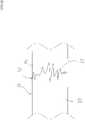
- Fig. 1shows a perspective view of the junction structure according to the first embodiment of the present invention
- Fig. 2shows a cross sectional view near the joining region when the junction structure of Fig. 1 is cut in the direction of A-A
- Fig. 3shows a front view near the joining region of the junction structure according to the first embodiment
- Fig. 4shows a front view near the joining region in which entering tops are shown in Fig. 3 .
- a tubular member 3 made of resin and a tubular member 5 made of resinare joined at a junction structure 1.
- An interface 7 between the tubular member 3 and the tubular member 5 at a joining region 2has a protrusion-depression shape in the long axis direction along the circumferential direction of the tubular members.
- the protrusion-depression shape in this embodimentis approximately rectangular along the circumferential direction of the tubular members as shown in Fig. 1 .
- the interface 7 between the tubular member 3 and the tubular member 5is configured to have a protrusion-depression shape in the long axis direction along the circumferential direction of the tubular members in order to increase a joining area between the tubular member 3 and the tubular member 5 as much as possible. This can improve the joining strength between the tubular member 3 and the tubular member 5.
- Fig. 2shows a cross sectional view near the joining region when the junction structure 1 shown in Fig. 1 is cut in the direction of A-A.
- the tubular member 3 and the tubular member 5each have a inner cavity 9, the inner cavities 9 communicating mutually, and at the interface 7 between the tubular member 3 and the tubular member 5, the tubular member 3 is configured to enter at a region between the radial-direction outer edge and the radial-direction inner edge of the tubular member 5 (a top 4 represents a forefront of the entering portion) in the upper portion of the figure, and the tubular member 5 is configured to enter at a region between the radial-direction outer edge and the radial-direction inner edge of the tubular member 3 (the top 4 represents a forefront of the entering portion) in the lower portion of the figure.
- the tubular member 3 or the tubular member 5 formed to have a convex shapeis configured to enter into the other tubular member at a region between the radial-direction outer edge and the radial-direction inner edge of the other tubular member.
- one of the tubular member 3 or the tubular member 5is configured to enter at a region between the radial-direction outer edge and the radial-direction inner edge of the other tubular member in order to improve the joining strength between the tubular member 3 and the tubular member 5 when a force is applied to the interface 7 between the tubular member 3 and the tubular member 5 in the radial direction (the outward or inward direction from a line radially extending from the center of the tubular member, i.e., the vertical direction in Fig. 2 ).
- tubular member 3 or the tubular member 5 formed to have a convex shapeis configured to enter into the other tubular member at a region between the radial-direction outer edge and the radial-direction inner edge of the other tubular member particularly in order to prevent projection of a surface of the convex tip from a surface of the tubular member.
- tubular member 3 or the tubular member 5 formed to have a convex shapeis also configured to enter into the other tubular member at a region between the radial-direction outer edge and the radial-direction inner edge of the other tubular member as described above in order to increase a joining area between the tubular member 3 and the tubular member 5 as much as possible. This can improve the joining strength between the tubular member 3 and the tubular member 5.
- Fig. 3shows a front view near the joining region of the junction structure according to the first embodiment
- Fig. 4shows a front view near the joining region in which the configuration of the entering top 4 drawn in dotted lines is added to Fig. 3 .
- the top 4 of the tubular member 3 or the tubular member 5 formed to have a convex shapeenters into the other tubular member.
- the entering resinsare interchanged at the middle position of a laterally adjacent protrusion-depression in Fig. 4 . That is, the resin of the tubular member 5 enters into the resin of the tubular member 3 in the left-side region relative to the middle position while the resin of the tubular member 3 enters into the resin of the tubular member 5 in the right-side region relative to the middle position.
- Fig. 5shows a front view near the joining region in which an entering top 14 is shown in a junction structure 11 according to the second embodiment.
- a tubular member 13 made of resin and a tubular member 15 made of resinare joined at the junction structure 11.
- An interface 17 between the tubular member 13 and the tubular member 15 at a joining region 12has a protrusion-depression shape in the long axis direction along the circumferential direction of the tubular members.
- protrusion-depression shape in this embodimentis also approximately rectangular along the circumferential direction of the tubular members as in the junction structure 1 according to the first embodiment.
- the interface 17 between the tubular member 13 and the tubular member 15 at the joining region 12also has a protrusion-depression shape in the long axis direction along the circumferential direction in the junction structure 11 according to this embodiment. This can increase a joining area to enhance the joining strength between the first tubular member and the second tubular member.
- the tubular member 15enters at a region between the radial-direction outer edge and the radial-direction inner edge of the tubular member 13 entirely in the circumferential direction. That is, in the junction structure 11 according to this embodiment, the top 14 of the tubular member 15 formed to have a convex shape enters at a region between the radial-direction outer edge and the radial-direction inner edge of the tubular member 13 entirely in the circumferential direction as shown in Fig. 5 .
- the joining strength between the tubular member 13 and the tubular member 15can be improved even when a force is applied to the interface 17 between the tubular member 13 and the tubular member 15 in the radial direction.
- top 14 of the tubular member 15 formed to have a convex shapeenters at a region between the radial-direction outer edge and the radial-direction inner edge of the tubular member 13 entirely in the circumferential direction. This can also increase a joining area between the tubular member 13 and the tubular member 15 as much as possible to improve the joining strength between the tubular member 13 and the tubular member 15.
- Fig. 6shows a front view near the joining region of a junction structure 21 according to the third embodiment
- Fig. 7shows a front view near the joining region in which an entering top 24 drawn in dotted lines is added to Fig. 6 .
- a tubular member 23 made of resin and a tubular member 25 made of resinare joined at the junction structure 21.
- An interface 27 between the tubular member 23 and the tubular member 25 at a joining region 22has a protrusion-depression shape in the long axis direction along the circumferential direction of the tubular members.
- protrusion-depression shape in this embodimentis corrugated along the circumferential direction of the tubular members as shown in Fig. 6 .
- the interface 27 between the tubular member 23 and the tubular member 25is configured to have a protrusion-depression shape in the long axis direction along the circumferential direction of the tubular members in order to increase a joining area between the tubular member 23 and the tubular member 25 as much as possible as in the first and second embodiments. This can improve the joining strength between the tubular member 23 and the tubular member 25.
- the interface between the tubular member 23 and the tubular member 25has a portion in which the tubular member 23 or the tubular member 25 is configured to enter at a region between the radial-direction outer edge and the radial-direction inner edge of the other tubular member in a cross section (the top 24 represents a forefront of the entering portion).
- the tubular member 23 or the tubular member 25 formed to have a convex shapeis configured to enter into the other tubular member at a region between the radial-direction outer edge and the radial-direction inner edge of the other tubular member.
- one of the tubular member 23 or the tubular member 25is configured to enter at a region between the radial-direction outer edge and the radial-direction inner edge of the other tubular member in order to improve the joining strength between the tubular member 23 and the tubular member 25 when a force is applied to the interface 27 between the tubular member 23 and the tubular member 25 in the radial direction as in the first and second embodiments.
- tubular member 23 or the tubular member 25 formed to have a convex shapeis configured to enter into the other tubular member at a region other than the both edges of the other tubular member particularly in order to prevent projection of a surface of the convex tip from a surface of the tubular member.
- tubular member 23 or the tubular member 25 formed to have a convex shapeis configured to enter into the other tubular member at a region other than the both edges of the other tubular member particularly in order to increase a joining area between the tubular member 23 and the tubular member 25 as much as possible. This can also improve the joining strength between the tubular member 23 and the tubular member 25.
- the top 24 of the tubular member 23 or the tubular member 25 formed to have a convex shapeenters into the other tubular member.
- the entering resinsare interchanged at the middle position of a laterally adjacent protrusion-depression in Fig. 7 . That is, the resin of the tubular member 25 enters into the resin of the tubular member 23 in the left-side region relative to the middle position while the resin of the tubular member 23 enters into the resin of the tubular member 25 in the right-side region relative to the middle position.
- Fig. 8shows a front view near the joining region of a junction structure 31 according to the fourth embodiment
- Fig. 9shows a front view near the joining region in which an entering top 34 is shown in Fig. 8 .
- a tubular member 33 made of resin and a tubular member 35 made of resinare joined at the junction structure 31.
- An interface 37 between the tubular member 33 and the tubular member 35 at a joining region 32has a protrusion-depression shape in the long axis direction along the circumferential direction of the tubular members.
- the interface 37 between the tubular member 33 and the tubular member 35is configured to have a protrusion-depression shape in the long axis direction along the circumferential direction of the tubular members in order to increase a joining area between the tubular member 33 and the tubular member 35 as much as possible as in the first to third embodiments. This can improve the joining strength between the tubular member 33 and the tubular member 35.
- the interface between the tubular member 33 and the tubular member 35has a portion in which the tubular member 33 or the tubular member 35 enters at a region between the radial-direction outer edge and the radial-direction inner edge of the tubular member of the other tubular member in a cross section (the top 34 represents a forefront of the entering portion).
- the tubular member 33 or the tubular member 35 formed to have a convex shapeis configured to enter into the other tubular member at a region between the radial-direction outer edge and the radial-direction inner edge of the other tubular member.
- one of the tubular member 33 or the tubular member 35is configured to enter at a region between the radial-direction outer edge and the radial-direction inner edge of the other tubular member in order to improve the joining strength between the tubular member 33 and the tubular member 35 when a force is applied to the interface 37 between the tubular member 33 and the tubular member 35 in the radial direction.
- tubular member 33 or the tubular member 35 formed to have a convex shapeis configured to enter into the other tubular member at a region between the radial-direction outer edge and the radial-direction inner edge of the other tubular member particularly in order to prevent projection of a surface of the convex tip from a surface of the tubular member.
- one of the tubular member 33 or the tubular member 35is configured to enter at a region between the radial-direction outer edge and the radial-direction inner edge of the other tubular member in order to increase a joining area between the tubular member 33 and the tubular member 35 as much as possible. This can also improve the joining strength between the tubular member 33 and the tubular member 35.
- the top 34 of the tubular member 33 or the tubular member 35 formed to have a convex shapeenters into the other tubular member.
- the entering resinsare interchanged at the middle position of a laterally adjacent protrusion-depression in Fig. 9 . That is, the resin of the tubular member 35 enters into the resin of the tubular member 33 in the left-side region relative to the middle position while the resin of the tubular member 33 enters into the resin of the tubular member 35 in the right-side region relative to the middle position.
- Fig. 10shows the overall view of a catheter 41 according to the fifth embodiment.
- the catheter 41includes a catheter tube body 40, a front end tip 49 connected to the front end of the catheter tube body 40, and a connector 48 connected to the base end of the catheter tube body 40.
- the catheter tube body 40is configured such that multiple tubular members made of different resin materials are joined so that the catheter tube body 40 becomes increasingly more flexible toward the front end from the base end.
- the catheter tube body 40includes a tubular member 46, a tubular member 45, a tubular member 44, a tubular member 43, and a tubular member 42 in this order from the base end.
- the resin of the tubular member 46is hardest, and the resins are softer in the order of the tubular member 45, the tubular member 44, the tubular member 43, and the tubular member 42.
- the resin of the tubular member 42is softest.
- the catheter tube body 40 according to this embodimentin which the junction structures 1 according to the first embodiment are used at 4 positions, includes an interface 47d, an interface 47c, an interface 47b, and an interface 47a in this order from the base end.
- the catheter tube body 40includes the junction structures 1. This can further improve the joining strength between the tubular member 42 and the tubular member 43, the joining strength between the tubular member 43 and the tubular member 44, the joining strength between the tubular member 44 and the tubular member 45, and the joining strength between the tubular member 45 and the tubular member 46 by adding an improved joining strength against a pressure in the radial direction. This, in turn, can improve the joining strength of the catheter tube body 40.
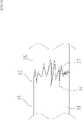
- Fig. 11shows a cross sectional view near the joining region (corresponding to the B region in Fig. 10 ) in a catheter 51 according to the sixth embodiment.
- the catheter 51includes a catheter tube body 50, a front end tip (not shown) connected to the front end of the catheter tube body 50, and a connector (not shown) connected to the base end of the catheter tube body 50 as in the catheter 41 according to the fifth embodiment.
- the catheter tube body 50 according to this embodimentis not formed with a monolayer tubular member, but includes an inner layer 56, a coil body 52 wound around the outer periphery of the inner layer 56, and outer layers 53 and 55 covering the outer peripheries of the inner layer 56 and the coil body 52, and has an inner cavity 59.
- the inner layer 56, the coil body 54, and the outer layers 53 and 55are each tubular members, and the outer layers 53 and 55 have the junction structure 1 according to Embodiment 1.
- the outer layers 53 and 55are formed such that a top 54 of one of the tubular members enters at a region between the radial-direction outer edge and the radial-direction inner edge of the other tubular member, and the radial-direction inner edge of the outer layer 53 or the outer layer 55 enters between the coil body 52 and the inner layer 56.
- catheter tube body 50multiple tubular members made of different resin materials are joined so that the catheter tube body 50 becomes increasingly more flexible toward the front end from the base end.
- four tubular membersare joined as in the catheter tube 40 according to the fifth embodiment.
- tubular member 55 in the base end sideis shown in Fig. 11 .
- the catheter 51includes an inner layer 56, a coil body 52 wound around the outer periphery of the inner layer 56, and outer layers 53 and 55 covering the outer peripheries of the inner layer 56 and the coil body 52, in which the outer layers 53 and 55 are formed such that one of the outer layers enters at a region between the radial-direction outer edge and the radial-direction inner edge of the other outer layer in a cross sectional view, and the inner edge of the outer layer 53 or the outer layer 55 enters between the coil body and the inner layer 56.
- Thiscan further enhance the joining strength between the outer layer 53 and the outer layer 55, which in turn can improve the joining strength of the catheter tube body 50.
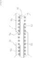
- Fig. 12shows a cross sectional view near the joining region (corresponding to the B region in Fig. 10 ) in a catheter 61 according to the seventh embodiment.
- the catheter 61includes a catheter tube body 60, a front end tip (not shown) connected to the front end of the catheter tube body 60, and a connector (not shown) connected to the base end of the catheter tube body 60 as in the catheter 41 according to the fifth embodiment.
- the catheter tube body 60is not formed with a monolayer tubular member, but includes an inner layer 66, a braid 62 wound around the outer periphery of the inner layer 66, and outer layers 63 and 65 covering the outer peripheries of the inner layer 66 and the braid 62, and has an inner cavity 69.
- the inner layer 66, the braid 62, and the outer layers 63 and 65are each tubular members, and the outer layers 63 and 65 have the junction structure 1 according to Embodiment 1.
- the outer layers 63 and 65are formed such that a top 64 of one of the tubular members enters at a region between the radial-direction outer edge and the radial-direction inner edge of the other tubular member, and the radial-direction inner edge of the outer layer 63 or the outer layer 65 enters between the braid 62 and the inner layer 66.
- catheter tube body 60multiple tubular members made of different resin materials are joined so that the catheter tube body 60 becomes increasingly more flexible toward the front end from the base end.
- four tubular membersare joined as in the catheter tube 41 according to the fifth embodiment.
- tubular member 65 in the base end sideis shown in Fig. 12 .
- the catheter 61includes an inner layer 66, a braid 62 wound around the outer periphery of the inner layer 66, and outer layers 63 and 65 covering the outer peripheries of the inner layer 66 and the braid 62, in which the outer layers 63 and 65 are configured such that one of the outer layers enters at a region between the radial-direction outer edge and the radial-direction inner edge of the other outer layer in a cross sectional view, and the radial-direction inner edge of the outer layer 63 or the outer layer 65 enters between the braid 62 and the inner layer 66.
- Thiscan further enhance the joining strength between the outer layer 63 and the outer layer 65, which in turn can improve the joining strength of the catheter tube body 60.
- the catheters according to the fifth to seventh embodiments described aboveinclude the junction structures 1 according to the first embodiment, but the junction structure 11 according to the second embodiment, the junction structure 21 according to the third embodiment, or the junction structure 31 according to the fourth embodiment may be used.
- the catheter tube 40 according to the fifth embodiment, the catheter tube 50 according to the sixth embodiment, and the catheter tube 60 according to the seventh embodimentcan benefit from the aforementioned effects expected from the junction structures used.
- catheters according to the fifth to seventh embodiments described aboveare configured to have four joined tubular members.
- the number of tubular membersis not limited to four, and any number of tubular members may be used.
Landscapes
- Health & Medical Sciences (AREA)
- Life Sciences & Earth Sciences (AREA)
- Heart & Thoracic Surgery (AREA)
- Biomedical Technology (AREA)
- Engineering & Computer Science (AREA)
- Anesthesiology (AREA)
- Pulmonology (AREA)
- Hematology (AREA)
- Animal Behavior & Ethology (AREA)
- General Health & Medical Sciences (AREA)
- Public Health (AREA)
- Veterinary Medicine (AREA)
- Biophysics (AREA)
- Media Introduction/Drainage Providing Device (AREA)
- Rigid Pipes And Flexible Pipes (AREA)
Description
- The present invention relates to a junction structure for joining corresponding end portions of two tubular members, and a catheter having the junction structure.
- A catheter to be inserted into a lumen in the body such as blood vessel, ureter, and the like of a patient at the time of procedure generally includes a tube member, a front end tip joined to the front end of the tube member, and a connector joined to the base end of the tube member.
- Further, in such a catheter, multiple tubular members having different hardnesses are provided such that a tubular member having a lower hardness is sequentially joined in series toward the front end in order to gradually increase flexibility toward the front end.
- For a tube member of a catheter manufactured by sequentially joining multiple tubular members as described above, the joined tubular members need to have a joining strength sufficient for preventing detachment of the joined tubular members even when the catheter inserted into a body lumen of a patient is bent along the curvature of the body lumen.
- For example,
JP 2005 334542 A Fig. 1 and others). - However, in the medical tubes described in
JP 2005 334542 A Fig. 5 ), the joined stepped portions are susceptible to formation of a crack upon bending the medical tubes. - Incidentally,
WO 97/14466 A1 WO 2014/099899 A1 andWO 2009/125575 A1 each disclose a junction structure between a first tubular member and a second tubular member. An interface between the first tubular member and the second tubular member has an uneven shape in a long axis direction along a circumferential direction in a front view.EP 2135634 A1 discloses a lumen layer consisting of several parts. US 6 103 037 A discloses a junction structure according to the preamble of claim 1.US 5 584 821 A discloses a junction structure between nylon plies and a tip polyether block amide (PEBA).- The present invention is made to solve the above problems. An object of the present invention is to provide a junction structure in which the joining strength thereof is further improved by adding an enhanced joining strength against a pressure in the radial direction. Another object of the present invention is to provide a catheter having the above junction structure.
- The above described technical problem is solved by the subject-matter of claim 1.
- Preferred embodiments of the present invention are the subject-matter of dependent claims.
- In the junction structure between the first tubular member made of resin and the second tubular member made of resin according to the subject-matter of claim 1, an interface between the first tubular member and the second tubular member has a protrusion-depression shape in the long axis direction along the circumferential direction in a front view, and any one of the first tubular member and the second tubular member is configured to enter into the other tubular member at a region between a radial-direction outer edge and a radial-direction inner edge of the other tubular member when in a cross sectional view along the long axis direction. This can enhance the joining strength between the first tubular member and the second tubular member against a pressure in the radial direction. This can also increase a joining area to enhance the joining strength between the first tubular member and the second tubular member.
- According to the junction structure of
claim 2, the effect of the subject matter of claim 1 can be provided. In addition, this can prevent projection of a surface of the convex tip from a surface of the tubular member. - Further, the catheter according to
claim 3 can benefit from the effect of the first or second aspect of the present invention. - Further, the catheter according to
claim 4 can further enhance the joining strength between the first tubular member and the second tubular member. Fig. 1 shows a perspective view of a junction structure according to the first embodiment of the present invention.Fig. 2 shows a cross sectional view near the joining region when the junction structure ofFig. 1 is cut in the direction of A-A.Fig. 3 shows a front view near the joining region of the junction structure according to the first embodiment.Fig. 4 shows a front view near the joining region in which entering tops are shown inFig. 3 .Fig. 5 shows a front view near the joining region in which entering tops are shown in a junction structure according to the second embodiment.Fig. 6 shows a front view near the joining region of a junction structure according to the third embodiment.Fig. 7 shows a front view near the joining region in which entering tops are shown inFig. 6 .Fig. 8 shows a front view near the joining region of a junction structure according to the fourth embodiment.Fig. 9 shows a front view near the joining region in which entering tops are shown inFig. 8 .Fig. 10 shows the overall view of a catheter according to the fifth embodiment.Fig. 11 shows a cross sectional view near the joining region of a catheter according to the sixth embodiment.Fig. 12 shows a cross sectional view near the joining region of a catheter according to the seventh embodiment.- Below, the aforementioned embodiments of the present invention will be described with reference to the drawings.
Fig. 1 shows a perspective view of the junction structure according to the first embodiment of the present invention, andFig. 2 shows a cross sectional view near the joining region when the junction structure ofFig. 1 is cut in the direction of A-A, andFig. 3 shows a front view near the joining region of the junction structure according to the first embodiment, andFig. 4 shows a front view near the joining region in which entering tops are shown inFig. 3 .- With reference to
Fig. 1 , atubular member 3 made of resin and atubular member 5 made of resin are joined at a junction structure 1. Aninterface 7 between thetubular member 3 and thetubular member 5 at a joiningregion 2 has a protrusion-depression shape in the long axis direction along the circumferential direction of the tubular members. - It is noted that the protrusion-depression shape in this embodiment is approximately rectangular along the circumferential direction of the tubular members as shown in
Fig. 1 . - Here, the
interface 7 between thetubular member 3 and thetubular member 5 is configured to have a protrusion-depression shape in the long axis direction along the circumferential direction of the tubular members in order to increase a joining area between thetubular member 3 and thetubular member 5 as much as possible. This can improve the joining strength between thetubular member 3 and thetubular member 5. Fig. 2 shows a cross sectional view near the joining region when the junction structure 1 shown inFig. 1 is cut in the direction of A-A. With reference toFig. 2 , thetubular member 3 and thetubular member 5 each have a inner cavity 9, the inner cavities 9 communicating mutually, and at theinterface 7 between thetubular member 3 and thetubular member 5, thetubular member 3 is configured to enter at a region between the radial-direction outer edge and the radial-direction inner edge of the tubular member 5 (atop 4 represents a forefront of the entering portion) in the upper portion of the figure, and thetubular member 5 is configured to enter at a region between the radial-direction outer edge and the radial-direction inner edge of the tubular member 3 (thetop 4 represents a forefront of the entering portion) in the lower portion of the figure.- That is, in this embodiment, the
tubular member 3 or thetubular member 5 formed to have a convex shape is configured to enter into the other tubular member at a region between the radial-direction outer edge and the radial-direction inner edge of the other tubular member. - Here, one of the
tubular member 3 or thetubular member 5 is configured to enter at a region between the radial-direction outer edge and the radial-direction inner edge of the other tubular member in order to improve the joining strength between thetubular member 3 and thetubular member 5 when a force is applied to theinterface 7 between thetubular member 3 and thetubular member 5 in the radial direction (the outward or inward direction from a line radially extending from the center of the tubular member, i.e., the vertical direction inFig. 2 ). - Further, the
tubular member 3 or thetubular member 5 formed to have a convex shape is configured to enter into the other tubular member at a region between the radial-direction outer edge and the radial-direction inner edge of the other tubular member particularly in order to prevent projection of a surface of the convex tip from a surface of the tubular member. - Further, the
tubular member 3 or thetubular member 5 formed to have a convex shape is also configured to enter into the other tubular member at a region between the radial-direction outer edge and the radial-direction inner edge of the other tubular member as described above in order to increase a joining area between thetubular member 3 and thetubular member 5 as much as possible. This can improve the joining strength between thetubular member 3 and thetubular member 5. Fig. 3 shows a front view near the joining region of the junction structure according to the first embodiment, andFig. 4 shows a front view near the joining region in which the configuration of the enteringtop 4 drawn in dotted lines is added toFig. 3 .- As clearly shown in
Fig. 4 , thetop 4 of thetubular member 3 or thetubular member 5 formed to have a convex shape enters into the other tubular member. - It is noted that the entering resins are interchanged at the middle position of a laterally adjacent protrusion-depression in
Fig. 4 . That is, the resin of thetubular member 5 enters into the resin of thetubular member 3 in the left-side region relative to the middle position while the resin of thetubular member 3 enters into the resin of thetubular member 5 in the right-side region relative to the middle position. - Below, the second embodiment of the present invention will be described.
Fig. 5 shows a front view near the joining region in which an enteringtop 14 is shown in ajunction structure 11 according to the second embodiment. - With reference to
Fig. 5 , atubular member 13 made of resin and atubular member 15 made of resin are joined at thejunction structure 11. Aninterface 17 between thetubular member 13 and thetubular member 15 at a joiningregion 12 has a protrusion-depression shape in the long axis direction along the circumferential direction of the tubular members. - It is noted that the protrusion-depression shape in this embodiment is also approximately rectangular along the circumferential direction of the tubular members as in the junction structure 1 according to the first embodiment.
- Therefore, the
interface 17 between thetubular member 13 and thetubular member 15 at the joiningregion 12 also has a protrusion-depression shape in the long axis direction along the circumferential direction in thejunction structure 11 according to this embodiment. This can increase a joining area to enhance the joining strength between the first tubular member and the second tubular member. - It is noted that in the
junction structure 11 according to this embodiment, thetubular member 15 enters at a region between the radial-direction outer edge and the radial-direction inner edge of thetubular member 13 entirely in the circumferential direction. That is, in thejunction structure 11 according to this embodiment, the top 14 of thetubular member 15 formed to have a convex shape enters at a region between the radial-direction outer edge and the radial-direction inner edge of thetubular member 13 entirely in the circumferential direction as shown inFig. 5 . - Therefore, again in the
junction structure 11 according to this embodiment, the joining strength between thetubular member 13 and thetubular member 15 can be improved even when a force is applied to theinterface 17 between thetubular member 13 and thetubular member 15 in the radial direction. - Further, the top 14 of the
tubular member 15 formed to have a convex shape enters at a region between the radial-direction outer edge and the radial-direction inner edge of thetubular member 13 entirely in the circumferential direction. This can also increase a joining area between thetubular member 13 and thetubular member 15 as much as possible to improve the joining strength between thetubular member 13 and thetubular member 15. - Below, the third embodiment of the present invention will be described.
Fig. 6 shows a front view near the joining region of ajunction structure 21 according to the third embodiment, andFig. 7 shows a front view near the joining region in which an entering top 24 drawn in dotted lines is added toFig. 6 . - With reference to
Fig. 6 , atubular member 23 made of resin and atubular member 25 made of resin are joined at thejunction structure 21. Aninterface 27 between thetubular member 23 and thetubular member 25 at a joiningregion 22 has a protrusion-depression shape in the long axis direction along the circumferential direction of the tubular members. - It is noted that the protrusion-depression shape in this embodiment is corrugated along the circumferential direction of the tubular members as shown in
Fig. 6 . - Here, the
interface 27 between thetubular member 23 and thetubular member 25 is configured to have a protrusion-depression shape in the long axis direction along the circumferential direction of the tubular members in order to increase a joining area between thetubular member 23 and thetubular member 25 as much as possible as in the first and second embodiments. This can improve the joining strength between thetubular member 23 and thetubular member 25. - Again, in this embodiment, the interface between the
tubular member 23 and thetubular member 25 has a portion in which thetubular member 23 or thetubular member 25 is configured to enter at a region between the radial-direction outer edge and the radial-direction inner edge of the other tubular member in a cross section (the top 24 represents a forefront of the entering portion). - That is, in this embodiment, the
tubular member 23 or thetubular member 25 formed to have a convex shape is configured to enter into the other tubular member at a region between the radial-direction outer edge and the radial-direction inner edge of the other tubular member. - Here, one of the
tubular member 23 or thetubular member 25 is configured to enter at a region between the radial-direction outer edge and the radial-direction inner edge of the other tubular member in order to improve the joining strength between thetubular member 23 and thetubular member 25 when a force is applied to theinterface 27 between thetubular member 23 and thetubular member 25 in the radial direction as in the first and second embodiments. - Further, the
tubular member 23 or thetubular member 25 formed to have a convex shape is configured to enter into the other tubular member at a region other than the both edges of the other tubular member particularly in order to prevent projection of a surface of the convex tip from a surface of the tubular member. - Further, the
tubular member 23 or thetubular member 25 formed to have a convex shape is configured to enter into the other tubular member at a region other than the both edges of the other tubular member particularly in order to increase a joining area between thetubular member 23 and thetubular member 25 as much as possible. This can also improve the joining strength between thetubular member 23 and thetubular member 25. - As clearly shown in
Fig. 7 , the top 24 of thetubular member 23 or thetubular member 25 formed to have a convex shape enters into the other tubular member. - It is noted that the entering resins are interchanged at the middle position of a laterally adjacent protrusion-depression in
Fig. 7 . That is, the resin of thetubular member 25 enters into the resin of thetubular member 23 in the left-side region relative to the middle position while the resin of thetubular member 23 enters into the resin of thetubular member 25 in the right-side region relative to the middle position. - Below, the fourth embodiment of the present invention will be described.
Fig. 8 shows a front view near the joining region of ajunction structure 31 according to the fourth embodiment, andFig. 9 shows a front view near the joining region in which an enteringtop 34 is shown inFig. 8 . - With reference to
Fig. 8 , atubular member 33 made of resin and atubular member 35 made of resin are joined at thejunction structure 31. Aninterface 37 between thetubular member 33 and thetubular member 35 at a joiningregion 32 has a protrusion-depression shape in the long axis direction along the circumferential direction of the tubular members. - Here, the
interface 37 between thetubular member 33 and thetubular member 35 is configured to have a protrusion-depression shape in the long axis direction along the circumferential direction of the tubular members in order to increase a joining area between thetubular member 33 and thetubular member 35 as much as possible as in the first to third embodiments. This can improve the joining strength between thetubular member 33 and thetubular member 35. - Again, in this embodiment, the interface between the
tubular member 33 and thetubular member 35 has a portion in which thetubular member 33 or thetubular member 35 enters at a region between the radial-direction outer edge and the radial-direction inner edge of the tubular member of the other tubular member in a cross section (the top 34 represents a forefront of the entering portion). - That is, in this embodiment, the
tubular member 33 or thetubular member 35 formed to have a convex shape is configured to enter into the other tubular member at a region between the radial-direction outer edge and the radial-direction inner edge of the other tubular member. - Here, as in the first to third embodiments, one of the
tubular member 33 or thetubular member 35 is configured to enter at a region between the radial-direction outer edge and the radial-direction inner edge of the other tubular member in order to improve the joining strength between thetubular member 33 and thetubular member 35 when a force is applied to theinterface 37 between thetubular member 33 and thetubular member 35 in the radial direction. - Further, the
tubular member 33 or thetubular member 35 formed to have a convex shape is configured to enter into the other tubular member at a region between the radial-direction outer edge and the radial-direction inner edge of the other tubular member particularly in order to prevent projection of a surface of the convex tip from a surface of the tubular member. - Further, one of the
tubular member 33 or thetubular member 35 is configured to enter at a region between the radial-direction outer edge and the radial-direction inner edge of the other tubular member in order to increase a joining area between thetubular member 33 and thetubular member 35 as much as possible. This can also improve the joining strength between thetubular member 33 and thetubular member 35. - As clearly shown in
Fig. 9 , the top 34 of thetubular member 33 or thetubular member 35 formed to have a convex shape enters into the other tubular member. - It is noted that the entering resins are interchanged at the middle position of a laterally adjacent protrusion-depression in
Fig. 9 . That is, the resin of thetubular member 35 enters into the resin of thetubular member 33 in the left-side region relative to the middle position while the resin of thetubular member 33 enters into the resin of thetubular member 35 in the right-side region relative to the middle position. - Below, the fifth embodiment of the present invention will be described.
Fig. 10 shows the overall view of acatheter 41 according to the fifth embodiment. - With reference to
Fig. 10 , thecatheter 41 includes acatheter tube body 40, afront end tip 49 connected to the front end of thecatheter tube body 40, and aconnector 48 connected to the base end of thecatheter tube body 40. - The
catheter tube body 40 is configured such that multiple tubular members made of different resin materials are joined so that thecatheter tube body 40 becomes increasingly more flexible toward the front end from the base end. In this embodiment, thecatheter tube body 40 includes atubular member 46, atubular member 45, atubular member 44, atubular member 43, and atubular member 42 in this order from the base end. - That is, in this embodiment, the resin of the
tubular member 46 is hardest, and the resins are softer in the order of thetubular member 45, thetubular member 44, thetubular member 43, and thetubular member 42. The resin of thetubular member 42 is softest. - Further, the
catheter tube body 40 according to this embodiment, in which the junction structures 1 according to the first embodiment are used at 4 positions, includes an interface 47d, an interface 47c, aninterface 47b, and aninterface 47a in this order from the base end. - According to the
catheter 41 according to this embodiment, thecatheter tube body 40 includes the junction structures 1. This can further improve the joining strength between thetubular member 42 and thetubular member 43, the joining strength between thetubular member 43 and thetubular member 44, the joining strength between thetubular member 44 and thetubular member 45, and the joining strength between thetubular member 45 and thetubular member 46 by adding an improved joining strength against a pressure in the radial direction. This, in turn, can improve the joining strength of thecatheter tube body 40. - Below, the sixth embodiment of the present invention will be described.
Fig. 11 shows a cross sectional view near the joining region (corresponding to the B region inFig. 10 ) in acatheter 51 according to the sixth embodiment. - It is noted that the
catheter 51 according to this embodiment includes acatheter tube body 50, a front end tip (not shown) connected to the front end of thecatheter tube body 50, and a connector (not shown) connected to the base end of thecatheter tube body 50 as in thecatheter 41 according to the fifth embodiment. - With reference to
Fig. 11 , thecatheter tube body 50 according to this embodiment, unlike thecatheter tube 40 according to the fifth embodiment, is not formed with a monolayer tubular member, but includes aninner layer 56, acoil body 52 wound around the outer periphery of theinner layer 56, andouter layers inner layer 56 and thecoil body 52, and has aninner cavity 59. - The
inner layer 56, thecoil body 54, and theouter layers outer layers - Here, the
outer layers outer layer 53 or theouter layer 55 enters between thecoil body 52 and theinner layer 56. - Further, in the
catheter tube body 50, multiple tubular members made of different resin materials are joined so that thecatheter tube body 50 becomes increasingly more flexible toward the front end from the base end. In this embodiment, four tubular members are joined as in thecatheter tube 40 according to the fifth embodiment. - It is noted that among the four tubular members, the
tubular member 55 in the base end side, and thetubular member 53 in the front end side are shown inFig. 11 . - The
catheter 51 according to this embodiment includes aninner layer 56, acoil body 52 wound around the outer periphery of theinner layer 56, andouter layers inner layer 56 and thecoil body 52, in which theouter layers outer layer 53 or theouter layer 55 enters between the coil body and theinner layer 56. This can further enhance the joining strength between theouter layer 53 and theouter layer 55, which in turn can improve the joining strength of thecatheter tube body 50. - Below, the seventh embodiment of the present invention will be described.
Fig. 12 shows a cross sectional view near the joining region (corresponding to the B region inFig. 10 ) in acatheter 61 according to the seventh embodiment. - It is noted that the
catheter 61 according to this embodiment includes acatheter tube body 60, a front end tip (not shown) connected to the front end of thecatheter tube body 60, and a connector (not shown) connected to the base end of thecatheter tube body 60 as in thecatheter 41 according to the fifth embodiment. - With reference to
Fig. 12 , thecatheter tube body 60, unlike thecatheter tube 40 according to the fifth embodiment, is not formed with a monolayer tubular member, but includes aninner layer 66, abraid 62 wound around the outer periphery of theinner layer 66, andouter layers inner layer 66 and thebraid 62, and has aninner cavity 69. - The
inner layer 66, thebraid 62, and theouter layers outer layers - Here, the
outer layers outer layer 63 or theouter layer 65 enters between thebraid 62 and theinner layer 66. - Further, in the
catheter tube body 60, multiple tubular members made of different resin materials are joined so that thecatheter tube body 60 becomes increasingly more flexible toward the front end from the base end. In this embodiment, four tubular members are joined as in thecatheter tube 41 according to the fifth embodiment. - It is noted that among the four tubular members, the
tubular member 65 in the base end side, and thetubular member 63 in the front end side are shown inFig. 12 . - The
catheter 61 according to this embodiment includes aninner layer 66, abraid 62 wound around the outer periphery of theinner layer 66, andouter layers inner layer 66 and thebraid 62, in which theouter layers outer layer 63 or theouter layer 65 enters between thebraid 62 and theinner layer 66. This can further enhance the joining strength between theouter layer 63 and theouter layer 65, which in turn can improve the joining strength of thecatheter tube body 60. - For example, the catheters according to the fifth to seventh embodiments described above include the junction structures 1 according to the first embodiment, but the
junction structure 11 according to the second embodiment, thejunction structure 21 according to the third embodiment, or thejunction structure 31 according to the fourth embodiment may be used. In these cases, thecatheter tube 40 according to the fifth embodiment, thecatheter tube 50 according to the sixth embodiment, and thecatheter tube 60 according to the seventh embodiment can benefit from the aforementioned effects expected from the junction structures used. - Further, the catheters according to the fifth to seventh embodiments described above are configured to have four joined tubular members. However, the number of tubular members is not limited to four, and any number of tubular members may be used.
- 1, 11, 21, 31 Junction structure
- 2, 22, 32 Joining region
- 3, 5, 13, 15, 23, 25, 33, 35, 42, 43, 44, 45, 46 Tubular member
- 4, 14, 24, 34, 54, 64 Top
- 7, 17, 27, 37, 47a, 47b, 47c, 47d Interface
- 9, 59, 69 Inner cavity
- 40, 50, 60 Catheter tube
- 41,51,61 Catheter
- 48 Connector
- 49 Front end tip
- 52 Coil body
- 53, 55, 63, 65 Outer layer
- 56, 66 Inner layer
- 62 Braid
Claims (4)
- A junction structure (1; 11; 21; 31) between a first tubular member (3, 13, 23, 33, 42-45) made of resin and a second tubular member (5; 15; 25; 35; 43-46) made of resin,wherein an interface (7; 17; 27; 37; 47a, 47b, 47c, 47d) between the first tubular member (3, 13, 23, 33, 42-45) and the second tubular member (5; 15; 25; 35; 43-46) has a protrusion-depression shape in a long axis direction, protrusions and depressions of the protrusion-depression shape being laterally adjacent to each other along a circumferential direction in a front view,characterised in thatany one of the first tubular member (3, 13, 23, 33, 42-45) and the second tubular member (5; 15; 25; 35; 43-46) is configured to enter into the other tubular member at a region between a radial-direction outer edge and a radial-direction inner edge of the other tubular member in a cross sectional view along the long axis direction and is formed to have a convex shape in the cross sectional view along the long axis direction,.
- The junction structure (1; 11; 21; 31) according to claim 1, wherein any one of the first tubular member (3, 13, 23, 33, 42-45) and the second tubular member (5; 15; 25; 35; 43-46) is configured to enter into the other tubular member at the entire region having the protrusion-depression shape.
- A catheter (41; 51; 61) having the junction structure (1; 11; 21; 31) according to claim 1 or 2.
- The catheter (51; 61) according to claim 3, comprisingan inner layer (56; 66),a braid (62) or a coil body (54) wound around the outer periphery of the inner layer (56; 66), andouter layers (53, 55; 63, 65) covering the outer peripheries of the inner layer (56; 66) and the braid (62) or the coil body (54), wherein:the outer layers (53, 55; 63, 65) have the junction structure (1; 11; 21; 31) according to claim 1 or 2, andthe radial-direction inner edge of the other tubular member receiving intrusion at a region between the both edges enters between the braid (62) or the coil body (54) and the inner layer (56; 66).
Applications Claiming Priority (1)
| Application Number | Priority Date | Filing Date | Title |
|---|---|---|---|
| PCT/JP2016/074490WO2018037475A1 (en) | 2016-08-23 | 2016-08-23 | Joint structure and catheter having said joint structure |
Publications (3)
| Publication Number | Publication Date |
|---|---|
| EP3505213A1 EP3505213A1 (en) | 2019-07-03 |
| EP3505213A4 EP3505213A4 (en) | 2020-09-02 |
| EP3505213B1true EP3505213B1 (en) | 2022-11-30 |
Family
ID=61158424
Family Applications (1)
| Application Number | Title | Priority Date | Filing Date |
|---|---|---|---|
| EP16856453.2AActiveEP3505213B1 (en) | 2016-08-23 | 2016-08-23 | Joint structure and catheter having said joint structure |
Country Status (6)
| Country | Link |
|---|---|
| US (2) | US10569048B2 (en) |
| EP (1) | EP3505213B1 (en) |
| JP (1) | JP6275921B1 (en) |
| KR (1) | KR102163659B1 (en) |
| CN (1) | CN109069789B (en) |
| WO (1) | WO2018037475A1 (en) |
Families Citing this family (5)
| Publication number | Priority date | Publication date | Assignee | Title |
|---|---|---|---|---|
| CN110650767B (en)* | 2017-05-26 | 2023-02-28 | 住友电木株式会社 | Catheter tube |
| JP6965579B2 (en)* | 2017-05-26 | 2021-11-10 | 住友ベークライト株式会社 | catheter |
| US12102773B2 (en)* | 2018-06-28 | 2024-10-01 | Biosense Webster (Israel) Ltd. | Catheter elements for bond-strength enhancement |
| EP3865172A4 (en)* | 2018-10-11 | 2022-06-08 | Asahi Intecc Co., Ltd. | MEDICAL MULTI-LIGHT TUBE AND METHOD FOR PRODUCTION THEREOF |
| WO2020208702A1 (en)* | 2019-04-09 | 2020-10-15 | 朝日インテック株式会社 | Catheter |
Citations (1)
| Publication number | Priority date | Publication date | Assignee | Title |
|---|---|---|---|---|
| US5584821A (en)* | 1992-06-02 | 1996-12-17 | E-Z-Em, Inc. | Soft tip catheter |
Family Cites Families (22)
| Publication number | Priority date | Publication date | Assignee | Title |
|---|---|---|---|---|
| DE3541052A1 (en)* | 1985-11-19 | 1987-05-21 | Marquet & Cie Noel | FOAM PANELS AND BLOCKS FROM HOLLOW PROFILES, THEIR PRODUCTION AND THEIR USE AS INSULATING AND / OR DRAINAGE PANELS |
| US5160559A (en)* | 1990-10-31 | 1992-11-03 | Scimed Life Systems, Inc. | Method for forming a guide catheter tip bond |
| US5533985A (en) | 1994-04-20 | 1996-07-09 | Wang; James C. | Tubing |
| US5403292A (en)* | 1994-05-18 | 1995-04-04 | Schneider (Usa) Inc. | Thin wall catheter having enhanced torqueability characteristics |
| JPH0884776A (en)* | 1994-09-16 | 1996-04-02 | Nippon Zeon Co Ltd | Guide wire joining method, guide wire used in the method, joining aid, and heat welding apparatus |
| AU4605896A (en)* | 1995-01-04 | 1996-07-24 | Medtronic, Inc. | Improved method of soft tip forming |
| US5662622A (en)* | 1995-04-04 | 1997-09-02 | Cordis Corporation | Intravascular catheter |
| AU7386996A (en)* | 1995-10-17 | 1997-05-07 | Medtronic, Inc. | Guide catheter with soft distal segment |
| US6103037A (en)* | 1995-12-12 | 2000-08-15 | Medi-Dyne Inc. | Method for making a catheter having overlapping welds |
| US6027528A (en)* | 1996-05-28 | 2000-02-22 | Cordis Corporation | Composite material endoprosthesis |
| US5938653A (en)* | 1997-06-09 | 1999-08-17 | Scimed Life Systems, Inc. | Catheter having controlled flexibility and method of manufacture |
| US6007478A (en)* | 1997-11-13 | 1999-12-28 | Impella Cardiotechnik Aktiengesellschaft | Cannula having constant wall thickness with increasing distal flexibility and method of making |
| JP4106287B2 (en)* | 2003-02-14 | 2008-06-25 | ニチアス株式会社 | Method for joining heat-fusible tubular bodies |
| JP2004301197A (en)* | 2003-03-31 | 2004-10-28 | Nichias Corp | Joint of heat-fusible tubular body |
| JP2005334542A (en) | 2004-05-31 | 2005-12-08 | Piolax Medical Device:Kk | Medical tube and its joining method |
| JP2006137069A (en)* | 2004-11-11 | 2006-06-01 | Shiizu Kk | Method for joining fluorocarbon resin molding and fluorocarbon resin joined body |
| US10220187B2 (en) | 2010-06-16 | 2019-03-05 | St. Jude Medical, Llc | Ablation catheter having flexible tip with multiple flexible electrode segments |
| US10492729B2 (en)* | 2007-05-23 | 2019-12-03 | St. Jude Medical, Cardiology Division, Inc. | Flexible high-density mapping catheter tips and flexible ablation catheter tips with onboard high-density mapping electrodes |
| JP4362536B2 (en)* | 2008-04-11 | 2009-11-11 | 日本ライフライン株式会社 | catheter |
| ATE529151T1 (en)* | 2008-06-16 | 2011-11-15 | Greatbatch Ltd | BIDIRECTIONAL ASYMMETRIC STEERING SHELL |
| ES2733273T3 (en)* | 2012-10-22 | 2019-11-28 | Medtronic Ardian Luxembourg | Catheters with improved flexibility |
| EP2934311B1 (en)* | 2012-12-20 | 2020-04-15 | Volcano Corporation | Smooth transition catheters |
- 2016
- 2016-08-23EPEP16856453.2Apatent/EP3505213B1/enactiveActive
- 2016-08-23JPJP2017510595Apatent/JP6275921B1/enactiveActive
- 2016-08-23CNCN201680003496.5Apatent/CN109069789B/enactiveActive
- 2016-08-23WOPCT/JP2016/074490patent/WO2018037475A1/ennot_activeCeased
- 2016-08-23KRKR1020177014416Apatent/KR102163659B1/enactiveActive
- 2017
- 2017-07-03USUS15/640,803patent/US10569048B2/enactiveActive
- 2020
- 2020-01-27USUS16/752,970patent/US20200155797A1/ennot_activeAbandoned
Patent Citations (1)
| Publication number | Priority date | Publication date | Assignee | Title |
|---|---|---|---|---|
| US5584821A (en)* | 1992-06-02 | 1996-12-17 | E-Z-Em, Inc. | Soft tip catheter |
Also Published As
| Publication number | Publication date |
|---|---|
| JPWO2018037475A1 (en) | 2018-09-13 |
| US20180056032A1 (en) | 2018-03-01 |
| US10569048B2 (en) | 2020-02-25 |
| JP6275921B1 (en) | 2018-02-07 |
| EP3505213A4 (en) | 2020-09-02 |
| US20200155797A1 (en) | 2020-05-21 |
| CN109069789A (en) | 2018-12-21 |
| KR102163659B1 (en) | 2020-10-08 |
| EP3505213A1 (en) | 2019-07-03 |
| WO2018037475A1 (en) | 2018-03-01 |
| KR20180040510A (en) | 2018-04-20 |
| CN109069789B (en) | 2021-08-13 |
Similar Documents
| Publication | Publication Date | Title |
|---|---|---|
| EP3505213B1 (en) | Joint structure and catheter having said joint structure | |
| EP3281669B1 (en) | Balloon catheter | |
| JP6434495B2 (en) | Medical tube | |
| US20130237962A1 (en) | Catheter assembly | |
| KR102184238B1 (en) | Longitudinal Medical Device | |
| KR20110102314A (en) | Medical tube | |
| CN104884117A (en) | Suction catheter | |
| US10722682B2 (en) | Catheter and balloon catheter | |
| US10888341B2 (en) | Balloon catheter | |
| JP6886751B2 (en) | catheter | |
| US10617856B2 (en) | Balloon catheter | |
| US20050187574A1 (en) | Balloon catheter | |
| JP6507077B2 (en) | catheter | |
| WO2021033673A1 (en) | Catheter | |
| JP7469928B2 (en) | Balloon catheter | |
| JP6108626B2 (en) | catheter | |
| CN103889322A (en) | Electrode catheter | |
| JP7148308B2 (en) | balloon catheter | |
| WO2024199631A1 (en) | Catheters having a tube and a functional element | |
| JP2018051373A (en) | Joining structure and catheter having the same | |
| JP2017104391A (en) | Tube for catheter and balloon catheter | |
| JP2019122819A (en) | catheter |
Legal Events
| Date | Code | Title | Description |
|---|---|---|---|
| STAA | Information on the status of an ep patent application or granted ep patent | Free format text:STATUS: UNKNOWN | |
| STAA | Information on the status of an ep patent application or granted ep patent | Free format text:STATUS: THE INTERNATIONAL PUBLICATION HAS BEEN MADE | |
| PUAI | Public reference made under article 153(3) epc to a published international application that has entered the european phase | Free format text:ORIGINAL CODE: 0009012 | |
| STAA | Information on the status of an ep patent application or granted ep patent | Free format text:STATUS: REQUEST FOR EXAMINATION WAS MADE | |
| 17P | Request for examination filed | Effective date:20170424 | |
| AK | Designated contracting states | Kind code of ref document:A1 Designated state(s):AL AT BE BG CH CY CZ DE DK EE ES FI FR GB GR HR HU IE IS IT LI LT LU LV MC MK MT NL NO PL PT RO RS SE SI SK SM TR | |
| AX | Request for extension of the european patent | Extension state:BA ME | |
| DAV | Request for validation of the european patent (deleted) | ||
| DAX | Request for extension of the european patent (deleted) | ||
| R17P | Request for examination filed (corrected) | Effective date:20170424 | |
| A4 | Supplementary search report drawn up and despatched | Effective date:20200731 | |
| RIC1 | Information provided on ipc code assigned before grant | Ipc:B29C 65/58 20060101ALI20200727BHEP Ipc:F16L 13/10 20060101ALI20200727BHEP Ipc:A61M 39/10 20060101ALI20200727BHEP Ipc:A61M 25/00 20060101AFI20200727BHEP | |
| STAA | Information on the status of an ep patent application or granted ep patent | Free format text:STATUS: EXAMINATION IS IN PROGRESS | |
| 17Q | First examination report despatched | Effective date:20210610 | |
| GRAP | Despatch of communication of intention to grant a patent | Free format text:ORIGINAL CODE: EPIDOSNIGR1 | |
| STAA | Information on the status of an ep patent application or granted ep patent | Free format text:STATUS: GRANT OF PATENT IS INTENDED | |
| INTG | Intention to grant announced | Effective date:20220623 | |
| GRAS | Grant fee paid | Free format text:ORIGINAL CODE: EPIDOSNIGR3 | |
| GRAA | (expected) grant | Free format text:ORIGINAL CODE: 0009210 | |
| STAA | Information on the status of an ep patent application or granted ep patent | Free format text:STATUS: THE PATENT HAS BEEN GRANTED | |
| RAP3 | Party data changed (applicant data changed or rights of an application transferred) | Owner name:ASAHI INTECC CO., LTD. | |
| RIN1 | Information on inventor provided before grant (corrected) | Inventor name:SHIMIZU, YUSUKE | |
| AK | Designated contracting states | Kind code of ref document:B1 Designated state(s):AL AT BE BG CH CY CZ DE DK EE ES FI FR GB GR HR HU IE IS IT LI LT LU LV MC MK MT NL NO PL PT RO RS SE SI SK SM TR | |
| REG | Reference to a national code | Ref country code:CH Ref legal event code:EP Ref country code:GB Ref legal event code:FG4D | |
| REG | Reference to a national code | Ref country code:AT Ref legal event code:REF Ref document number:1534191 Country of ref document:AT Kind code of ref document:T Effective date:20221215 | |
| REG | Reference to a national code | Ref country code:IE Ref legal event code:FG4D | |
| REG | Reference to a national code | Ref country code:DE Ref legal event code:R096 Ref document number:602016076673 Country of ref document:DE | |
| REG | Reference to a national code | Ref country code:LT Ref legal event code:MG9D | |
| REG | Reference to a national code | Ref country code:NL Ref legal event code:MP Effective date:20221130 | |
| PG25 | Lapsed in a contracting state [announced via postgrant information from national office to epo] | Ref country code:SE Free format text:LAPSE BECAUSE OF FAILURE TO SUBMIT A TRANSLATION OF THE DESCRIPTION OR TO PAY THE FEE WITHIN THE PRESCRIBED TIME-LIMIT Effective date:20221130 Ref country code:PT Free format text:LAPSE BECAUSE OF FAILURE TO SUBMIT A TRANSLATION OF THE DESCRIPTION OR TO PAY THE FEE WITHIN THE PRESCRIBED TIME-LIMIT Effective date:20230331 Ref country code:NO Free format text:LAPSE BECAUSE OF FAILURE TO SUBMIT A TRANSLATION OF THE DESCRIPTION OR TO PAY THE FEE WITHIN THE PRESCRIBED TIME-LIMIT Effective date:20230228 Ref country code:LT Free format text:LAPSE BECAUSE OF FAILURE TO SUBMIT A TRANSLATION OF THE DESCRIPTION OR TO PAY THE FEE WITHIN THE PRESCRIBED TIME-LIMIT Effective date:20221130 Ref country code:FI Free format text:LAPSE BECAUSE OF FAILURE TO SUBMIT A TRANSLATION OF THE DESCRIPTION OR TO PAY THE FEE WITHIN THE PRESCRIBED TIME-LIMIT Effective date:20221130 Ref country code:ES Free format text:LAPSE BECAUSE OF FAILURE TO SUBMIT A TRANSLATION OF THE DESCRIPTION OR TO PAY THE FEE WITHIN THE PRESCRIBED TIME-LIMIT Effective date:20221130 | |
| REG | Reference to a national code | Ref country code:AT Ref legal event code:MK05 Ref document number:1534191 Country of ref document:AT Kind code of ref document:T Effective date:20221130 | |
| PG25 | Lapsed in a contracting state [announced via postgrant information from national office to epo] | Ref country code:RS Free format text:LAPSE BECAUSE OF FAILURE TO SUBMIT A TRANSLATION OF THE DESCRIPTION OR TO PAY THE FEE WITHIN THE PRESCRIBED TIME-LIMIT Effective date:20221130 Ref country code:PL Free format text:LAPSE BECAUSE OF FAILURE TO SUBMIT A TRANSLATION OF THE DESCRIPTION OR TO PAY THE FEE WITHIN THE PRESCRIBED TIME-LIMIT Effective date:20221130 Ref country code:LV Free format text:LAPSE BECAUSE OF FAILURE TO SUBMIT A TRANSLATION OF THE DESCRIPTION OR TO PAY THE FEE WITHIN THE PRESCRIBED TIME-LIMIT Effective date:20221130 Ref country code:IS Free format text:LAPSE BECAUSE OF FAILURE TO SUBMIT A TRANSLATION OF THE DESCRIPTION OR TO PAY THE FEE WITHIN THE PRESCRIBED TIME-LIMIT Effective date:20230330 Ref country code:HR Free format text:LAPSE BECAUSE OF FAILURE TO SUBMIT A TRANSLATION OF THE DESCRIPTION OR TO PAY THE FEE WITHIN THE PRESCRIBED TIME-LIMIT Effective date:20221130 Ref country code:GR Free format text:LAPSE BECAUSE OF FAILURE TO SUBMIT A TRANSLATION OF THE DESCRIPTION OR TO PAY THE FEE WITHIN THE PRESCRIBED TIME-LIMIT Effective date:20230301 | |
| PG25 | Lapsed in a contracting state [announced via postgrant information from national office to epo] | Ref country code:NL Free format text:LAPSE BECAUSE OF FAILURE TO SUBMIT A TRANSLATION OF THE DESCRIPTION OR TO PAY THE FEE WITHIN THE PRESCRIBED TIME-LIMIT Effective date:20221130 | |
| PG25 | Lapsed in a contracting state [announced via postgrant information from national office to epo] | Ref country code:SM Free format text:LAPSE BECAUSE OF FAILURE TO SUBMIT A TRANSLATION OF THE DESCRIPTION OR TO PAY THE FEE WITHIN THE PRESCRIBED TIME-LIMIT Effective date:20221130 Ref country code:RO Free format text:LAPSE BECAUSE OF FAILURE TO SUBMIT A TRANSLATION OF THE DESCRIPTION OR TO PAY THE FEE WITHIN THE PRESCRIBED TIME-LIMIT Effective date:20221130 Ref country code:EE Free format text:LAPSE BECAUSE OF FAILURE TO SUBMIT A TRANSLATION OF THE DESCRIPTION OR TO PAY THE FEE WITHIN THE PRESCRIBED TIME-LIMIT Effective date:20221130 Ref country code:DK Free format text:LAPSE BECAUSE OF FAILURE TO SUBMIT A TRANSLATION OF THE DESCRIPTION OR TO PAY THE FEE WITHIN THE PRESCRIBED TIME-LIMIT Effective date:20221130 Ref country code:CZ Free format text:LAPSE BECAUSE OF FAILURE TO SUBMIT A TRANSLATION OF THE DESCRIPTION OR TO PAY THE FEE WITHIN THE PRESCRIBED TIME-LIMIT Effective date:20221130 Ref country code:AT Free format text:LAPSE BECAUSE OF FAILURE TO SUBMIT A TRANSLATION OF THE DESCRIPTION OR TO PAY THE FEE WITHIN THE PRESCRIBED TIME-LIMIT Effective date:20221130 | |
| PG25 | Lapsed in a contracting state [announced via postgrant information from national office to epo] | Ref country code:SK Free format text:LAPSE BECAUSE OF FAILURE TO SUBMIT A TRANSLATION OF THE DESCRIPTION OR TO PAY THE FEE WITHIN THE PRESCRIBED TIME-LIMIT Effective date:20221130 Ref country code:AL Free format text:LAPSE BECAUSE OF FAILURE TO SUBMIT A TRANSLATION OF THE DESCRIPTION OR TO PAY THE FEE WITHIN THE PRESCRIBED TIME-LIMIT Effective date:20221130 | |
| REG | Reference to a national code | Ref country code:DE Ref legal event code:R097 Ref document number:602016076673 Country of ref document:DE | |
| PLBE | No opposition filed within time limit | Free format text:ORIGINAL CODE: 0009261 | |
| STAA | Information on the status of an ep patent application or granted ep patent | Free format text:STATUS: NO OPPOSITION FILED WITHIN TIME LIMIT | |
| 26N | No opposition filed | Effective date:20230831 | |
| PG25 | Lapsed in a contracting state [announced via postgrant information from national office to epo] | Ref country code:SI Free format text:LAPSE BECAUSE OF FAILURE TO SUBMIT A TRANSLATION OF THE DESCRIPTION OR TO PAY THE FEE WITHIN THE PRESCRIBED TIME-LIMIT Effective date:20221130 | |
| PG25 | Lapsed in a contracting state [announced via postgrant information from national office to epo] | Ref country code:MC Free format text:LAPSE BECAUSE OF FAILURE TO SUBMIT A TRANSLATION OF THE DESCRIPTION OR TO PAY THE FEE WITHIN THE PRESCRIBED TIME-LIMIT Effective date:20221130 | |
| REG | Reference to a national code | Ref country code:CH Ref legal event code:PL | |
| PG25 | Lapsed in a contracting state [announced via postgrant information from national office to epo] | Ref country code:MC Free format text:LAPSE BECAUSE OF FAILURE TO SUBMIT A TRANSLATION OF THE DESCRIPTION OR TO PAY THE FEE WITHIN THE PRESCRIBED TIME-LIMIT Effective date:20221130 | |
| PG25 | Lapsed in a contracting state [announced via postgrant information from national office to epo] | Ref country code:LU Free format text:LAPSE BECAUSE OF NON-PAYMENT OF DUE FEES Effective date:20230823 | |
| PG25 | Lapsed in a contracting state [announced via postgrant information from national office to epo] | Ref country code:LU Free format text:LAPSE BECAUSE OF NON-PAYMENT OF DUE FEES Effective date:20230823 Ref country code:CH Free format text:LAPSE BECAUSE OF NON-PAYMENT OF DUE FEES Effective date:20230831 | |
| REG | Reference to a national code | Ref country code:BE Ref legal event code:MM Effective date:20230831 | |
| REG | Reference to a national code | Ref country code:IE Ref legal event code:MM4A | |
| PG25 | Lapsed in a contracting state [announced via postgrant information from national office to epo] | Ref country code:IT Free format text:LAPSE BECAUSE OF FAILURE TO SUBMIT A TRANSLATION OF THE DESCRIPTION OR TO PAY THE FEE WITHIN THE PRESCRIBED TIME-LIMIT Effective date:20221130 | |
| PG25 | Lapsed in a contracting state [announced via postgrant information from national office to epo] | Ref country code:IE Free format text:LAPSE BECAUSE OF NON-PAYMENT OF DUE FEES Effective date:20230823 | |
| PG25 | Lapsed in a contracting state [announced via postgrant information from national office to epo] | Ref country code:IE Free format text:LAPSE BECAUSE OF NON-PAYMENT OF DUE FEES Effective date:20230823 | |
| PG25 | Lapsed in a contracting state [announced via postgrant information from national office to epo] | Ref country code:BE Free format text:LAPSE BECAUSE OF NON-PAYMENT OF DUE FEES Effective date:20230831 | |
| PGFP | Annual fee paid to national office [announced via postgrant information from national office to epo] | Ref country code:DE Payment date:20240821 Year of fee payment:9 | |
| PGFP | Annual fee paid to national office [announced via postgrant information from national office to epo] | Ref country code:GB Payment date:20240826 Year of fee payment:9 | |
| PGFP | Annual fee paid to national office [announced via postgrant information from national office to epo] | Ref country code:FR Payment date:20240829 Year of fee payment:9 | |
| PG25 | Lapsed in a contracting state [announced via postgrant information from national office to epo] | Ref country code:BG Free format text:LAPSE BECAUSE OF FAILURE TO SUBMIT A TRANSLATION OF THE DESCRIPTION OR TO PAY THE FEE WITHIN THE PRESCRIBED TIME-LIMIT Effective date:20221130 | |
| PG25 | Lapsed in a contracting state [announced via postgrant information from national office to epo] | Ref country code:BG Free format text:LAPSE BECAUSE OF FAILURE TO SUBMIT A TRANSLATION OF THE DESCRIPTION OR TO PAY THE FEE WITHIN THE PRESCRIBED TIME-LIMIT Effective date:20221130 | |
| PG25 | Lapsed in a contracting state [announced via postgrant information from national office to epo] | Ref country code:CY Free format text:LAPSE BECAUSE OF FAILURE TO SUBMIT A TRANSLATION OF THE DESCRIPTION OR TO PAY THE FEE WITHIN THE PRESCRIBED TIME-LIMIT; INVALID AB INITIO Effective date:20160823 | |
| PG25 | Lapsed in a contracting state [announced via postgrant information from national office to epo] | Ref country code:HU Free format text:LAPSE BECAUSE OF FAILURE TO SUBMIT A TRANSLATION OF THE DESCRIPTION OR TO PAY THE FEE WITHIN THE PRESCRIBED TIME-LIMIT; INVALID AB INITIO Effective date:20160823 |