EP3505105A1 - Ultrasonic energy device which varies pressure applied by clamp arm to provide threshold control pressure at a cut progression location - Google Patents
Ultrasonic energy device which varies pressure applied by clamp arm to provide threshold control pressure at a cut progression locationDownload PDFInfo
- Publication number
- EP3505105A1 EP3505105A1EP18275254.3AEP18275254AEP3505105A1EP 3505105 A1EP3505105 A1EP 3505105A1EP 18275254 AEP18275254 AEP 18275254AEP 3505105 A1EP3505105 A1EP 3505105A1
- Authority
- EP
- European Patent Office
- Prior art keywords
- surgical
- tissue
- end effector
- clamp arm
- control circuit
- Prior art date
- Legal status (The legal status is an assumption and is not a legal conclusion. Google has not performed a legal analysis and makes no representation as to the accuracy of the status listed.)
- Granted
Links
- 239000012636effectorSubstances0.000claimsabstractdescription303
- 238000000034methodMethods0.000claimsabstractdescription144
- 230000004044responseEffects0.000claimsabstractdescription34
- 230000008859changeEffects0.000claimsabstractdescription24
- 238000004422calculation algorithmMethods0.000claimsdescription42
- 238000011068loading methodMethods0.000claimsdescription13
- 230000010355oscillationEffects0.000claimsdescription3
- 210000001519tissueAnatomy0.000description299
- 238000004891communicationMethods0.000description118
- 238000001356surgical procedureMethods0.000description91
- 238000006073displacement reactionMethods0.000description84
- 230000015654memoryEffects0.000description55
- 230000006870functionEffects0.000description41
- 230000002452interceptive effectEffects0.000description38
- 238000005520cutting processMethods0.000description36
- 238000003384imaging methodMethods0.000description34
- 239000000779smokeSubstances0.000description34
- 238000012545processingMethods0.000description33
- 238000010304firingMethods0.000description30
- 238000003032molecular dockingMethods0.000description28
- 239000012530fluidSubstances0.000description27
- 238000003860storageMethods0.000description26
- 238000012800visualizationMethods0.000description25
- 230000005540biological transmissionEffects0.000description24
- 238000005345coagulationMethods0.000description24
- 230000015271coagulationEffects0.000description24
- 238000010586diagramMethods0.000description21
- 238000013519translationMethods0.000description21
- 238000002059diagnostic imagingMethods0.000description18
- 230000033001locomotionEffects0.000description18
- 230000002262irrigationEffects0.000description16
- 238000003973irrigationMethods0.000description16
- 238000012517data analyticsMethods0.000description15
- 239000000463materialSubstances0.000description15
- 230000008569processEffects0.000description15
- 238000012806monitoring deviceMethods0.000description13
- 230000003287optical effectEffects0.000description13
- 238000001228spectrumMethods0.000description12
- 238000013475authorizationMethods0.000description11
- 230000008901benefitEffects0.000description11
- 230000006835compressionEffects0.000description11
- 238000007906compressionMethods0.000description11
- 210000004072lungAnatomy0.000description11
- 238000005259measurementMethods0.000description11
- 238000012544monitoring processMethods0.000description11
- 238000007789sealingMethods0.000description11
- 238000011282treatmentMethods0.000description11
- 238000004458analytical methodMethods0.000description10
- 230000004048modificationEffects0.000description10
- 238000012986modificationMethods0.000description10
- 230000005355Hall effectEffects0.000description9
- 238000009826distributionMethods0.000description9
- 230000003993interactionEffects0.000description9
- 230000002093peripheral effectEffects0.000description9
- 230000002829reductive effectEffects0.000description9
- 238000012546transferMethods0.000description9
- 238000012384transportation and deliveryMethods0.000description9
- 230000000007visual effectEffects0.000description9
- 230000002776aggregationEffects0.000description8
- 238000004220aggregationMethods0.000description8
- 230000001976improved effectEffects0.000description8
- 230000001965increasing effectEffects0.000description8
- 238000002955isolationMethods0.000description8
- 230000000116mitigating effectEffects0.000description8
- 238000012913prioritisationMethods0.000description8
- 239000000523sampleSubstances0.000description8
- 238000013538segmental resectionMethods0.000description8
- 210000000115thoracic cavityAnatomy0.000description8
- 230000009471actionEffects0.000description7
- 230000003044adaptive effectEffects0.000description7
- 238000013480data collectionMethods0.000description7
- 238000001514detection methodMethods0.000description7
- 238000007726management methodMethods0.000description7
- 238000011144upstream manufacturingMethods0.000description7
- 208000025247virus-associated trichodysplasia spinulosaDiseases0.000description7
- 230000004913activationEffects0.000description6
- 230000036772blood pressureEffects0.000description6
- 230000000694effectsEffects0.000description6
- 238000002565electrocardiographyMethods0.000description6
- 238000005516engineering processMethods0.000description6
- 230000009467reductionEffects0.000description6
- OKTJSMMVPCPJKN-UHFFFAOYSA-NCarbonChemical compound[C]OKTJSMMVPCPJKN-UHFFFAOYSA-N0.000description5
- 238000010801machine learningMethods0.000description5
- SYHGEUNFJIGTRX-UHFFFAOYSA-NmethylenedioxypyrovaleroneChemical compoundC=1C=C2OCOC2=CC=1C(=O)C(CCC)N1CCCC1SYHGEUNFJIGTRX-UHFFFAOYSA-N0.000description5
- 238000005457optimizationMethods0.000description5
- 230000007704transitionEffects0.000description5
- 238000004804windingMethods0.000description5
- 206010002091AnaesthesiaDiseases0.000description4
- 230000004931aggregating effectEffects0.000description4
- 230000037005anaesthesiaEffects0.000description4
- 230000009286beneficial effectEffects0.000description4
- 230000000740bleeding effectEffects0.000description4
- 239000003990capacitorSubstances0.000description4
- 238000004590computer programMethods0.000description4
- 238000010276constructionMethods0.000description4
- 238000007405data analysisMethods0.000description4
- 238000002224dissectionMethods0.000description4
- 230000001939inductive effectEffects0.000description4
- 230000007246mechanismEffects0.000description4
- 230000002441reversible effectEffects0.000description4
- 238000005070samplingMethods0.000description4
- 238000001429visible spectrumMethods0.000description4
- 230000003187abdominal effectEffects0.000description3
- 230000003213activating effectEffects0.000description3
- 210000003484anatomyAnatomy0.000description3
- 238000013459approachMethods0.000description3
- 238000000418atomic force spectrumMethods0.000description3
- 238000004364calculation methodMethods0.000description3
- 229910052799carbonInorganic materials0.000description3
- 230000001112coagulating effectEffects0.000description3
- 210000002808connective tissueAnatomy0.000description3
- 230000008878couplingEffects0.000description3
- 238000010168coupling processMethods0.000description3
- 238000005859coupling reactionMethods0.000description3
- 230000009977dual effectEffects0.000description3
- 230000005670electromagnetic radiationEffects0.000description3
- 238000004520electroporationMethods0.000description3
- 230000014509gene expressionEffects0.000description3
- 230000023597hemostasisEffects0.000description3
- 238000005286illuminationMethods0.000description3
- 230000002427irreversible effectEffects0.000description3
- 230000000670limiting effectEffects0.000description3
- PWPJGUXAGUPAHP-UHFFFAOYSA-NlufenuronChemical compoundC1=C(Cl)C(OC(F)(F)C(C(F)(F)F)F)=CC(Cl)=C1NC(=O)NC(=O)C1=C(F)C=CC=C1FPWPJGUXAGUPAHP-UHFFFAOYSA-N0.000description3
- 229910052751metalInorganic materials0.000description3
- 239000002184metalSubstances0.000description3
- 238000010223real-time analysisMethods0.000description3
- 230000001954sterilising effectEffects0.000description3
- 238000004659sterilization and disinfectionMethods0.000description3
- 210000002784stomachAnatomy0.000description3
- 230000001225therapeutic effectEffects0.000description3
- 229910045601alloyInorganic materials0.000description2
- 239000000956alloySubstances0.000description2
- 230000003321amplificationEffects0.000description2
- 230000003466anti-cipated effectEffects0.000description2
- 230000006399behaviorEffects0.000description2
- 238000005452bendingMethods0.000description2
- 210000004204blood vesselAnatomy0.000description2
- 229910021393carbon nanotubeInorganic materials0.000description2
- 239000002041carbon nanotubeSubstances0.000description2
- 238000000701chemical imagingMethods0.000description2
- 239000003795chemical substances by applicationSubstances0.000description2
- 239000011231conductive fillerSubstances0.000description2
- 230000001186cumulative effectEffects0.000description2
- 230000007423decreaseEffects0.000description2
- 230000008021depositionEffects0.000description2
- 230000000881depressing effectEffects0.000description2
- 230000006866deteriorationEffects0.000description2
- 238000001914filtrationMethods0.000description2
- 230000007774longtermEffects0.000description2
- 239000013528metallic particleSubstances0.000description2
- 239000000203mixtureSubstances0.000description2
- 238000003199nucleic acid amplification methodMethods0.000description2
- 230000036961partial effectEffects0.000description2
- 238000003909pattern recognitionMethods0.000description2
- 230000002980postoperative effectEffects0.000description2
- 238000011084recoveryMethods0.000description2
- 239000010935stainless steelSubstances0.000description2
- 229910001220stainless steelInorganic materials0.000description2
- 238000006467substitution reactionMethods0.000description2
- 238000012360testing methodMethods0.000description2
- 238000002604ultrasonographyMethods0.000description2
- 238000012935AveragingMethods0.000description1
- 229910001040Beta-titaniumInorganic materials0.000description1
- RYGMFSIKBFXOCR-UHFFFAOYSA-NCopperChemical compound[Cu]RYGMFSIKBFXOCR-UHFFFAOYSA-N0.000description1
- 101100458289Drosophila melanogaster msps geneProteins0.000description1
- 102000009123FibrinHuman genes0.000description1
- 108010073385FibrinProteins0.000description1
- BWGVNKXGVNDBDI-UHFFFAOYSA-NFibrin monomerChemical compoundCNC(=O)CNC(=O)CNBWGVNKXGVNDBDI-UHFFFAOYSA-N0.000description1
- 206010042635SuspiciousnessDiseases0.000description1
- 229920006362Teflon®Polymers0.000description1
- 229910001069Ti alloyInorganic materials0.000description1
- RTAQQCXQSZGOHL-UHFFFAOYSA-NTitaniumChemical compound[Ti]RTAQQCXQSZGOHL-UHFFFAOYSA-N0.000description1
- 210000001015abdomenAnatomy0.000description1
- 238000009825accumulationMethods0.000description1
- 238000003491arrayMethods0.000description1
- 210000001367arteryAnatomy0.000description1
- 238000013528artificial neural networkMethods0.000description1
- 230000000712assemblyEffects0.000description1
- 238000000429assemblyMethods0.000description1
- 230000004888barrier functionEffects0.000description1
- 230000003139buffering effectEffects0.000description1
- 238000012512characterization methodMethods0.000description1
- 238000006243chemical reactionMethods0.000description1
- 230000000295complement effectEffects0.000description1
- 230000001143conditioned effectEffects0.000description1
- 230000003750conditioning effectEffects0.000description1
- 238000012790confirmationMethods0.000description1
- 229910052802copperInorganic materials0.000description1
- 239000010949copperSubstances0.000description1
- 238000013500data storageMethods0.000description1
- 230000007547defectEffects0.000description1
- 230000000994depressogenic effectEffects0.000description1
- 230000003745detangling effectEffects0.000description1
- 201000010099diseaseDiseases0.000description1
- 208000037265diseases, disorders, signs and symptomsDiseases0.000description1
- 238000010336energy treatmentMethods0.000description1
- 230000002708enhancing effectEffects0.000description1
- 230000007717exclusionEffects0.000description1
- 238000000605extractionMethods0.000description1
- 239000000835fiberSubstances0.000description1
- 229950003499fibrinDrugs0.000description1
- 230000004907fluxEffects0.000description1
- 239000002783friction materialSubstances0.000description1
- 230000005251gamma rayEffects0.000description1
- 230000013632homeostatic processEffects0.000description1
- 238000007654immersionMethods0.000description1
- 230000006872improvementEffects0.000description1
- 230000036512infertilityEffects0.000description1
- 238000003780insertionMethods0.000description1
- 230000037431insertionEffects0.000description1
- 230000010354integrationEffects0.000description1
- 230000003601intercostal effectEffects0.000description1
- 239000007788liquidSubstances0.000description1
- 230000004807localizationEffects0.000description1
- 238000004519manufacturing processMethods0.000description1
- 238000013507mappingMethods0.000description1
- 230000005055memory storageEffects0.000description1
- 229910044991metal oxideInorganic materials0.000description1
- 150000004706metal oxidesChemical class0.000description1
- 244000005700microbiomeSpecies0.000description1
- 238000002324minimally invasive surgeryMethods0.000description1
- 238000012978minimally invasive surgical procedureMethods0.000description1
- 239000003607modifierSubstances0.000description1
- 210000003205muscleAnatomy0.000description1
- 230000006855networkingEffects0.000description1
- 230000008520organizationEffects0.000description1
- 230000003071parasitic effectEffects0.000description1
- 239000002245particleSubstances0.000description1
- 230000007170pathologyEffects0.000description1
- 230000010412perfusionEffects0.000description1
- 229920001343polytetrafluoroethylenePolymers0.000description1
- 230000000750progressive effectEffects0.000description1
- 230000000644propagated effectEffects0.000description1
- 230000005855radiationEffects0.000description1
- 230000029058respiratory gaseous exchangeEffects0.000description1
- 239000004065semiconductorSubstances0.000description1
- 238000000926separation methodMethods0.000description1
- 238000012163sequencing techniqueMethods0.000description1
- 230000011664signalingEffects0.000description1
- 239000007787solidSubstances0.000description1
- 230000006641stabilisationEffects0.000description1
- 238000011105stabilizationMethods0.000description1
- 230000003068static effectEffects0.000description1
- 239000000758substrateSubstances0.000description1
- 230000000153supplemental effectEffects0.000description1
- 230000008093supporting effectEffects0.000description1
- 230000001360synchronised effectEffects0.000description1
- 239000010936titaniumSubstances0.000description1
- 229910052719titaniumInorganic materials0.000description1
- 238000012876topographyMethods0.000description1
- 238000012549trainingMethods0.000description1
- 230000001960triggered effectEffects0.000description1
- 238000010200validation analysisMethods0.000description1
- 210000003462veinAnatomy0.000description1
- 238000009423ventilationMethods0.000description1
- 238000012795verificationMethods0.000description1
- 238000003466weldingMethods0.000description1
Images


Classifications
- A—HUMAN NECESSITIES
- A61—MEDICAL OR VETERINARY SCIENCE; HYGIENE
- A61B—DIAGNOSIS; SURGERY; IDENTIFICATION
- A61B18/00—Surgical instruments, devices or methods for transferring non-mechanical forms of energy to or from the body
- A61B18/04—Surgical instruments, devices or methods for transferring non-mechanical forms of energy to or from the body by heating
- A61B18/12—Surgical instruments, devices or methods for transferring non-mechanical forms of energy to or from the body by heating by passing a current through the tissue to be heated, e.g. high-frequency current
- A61B18/14—Probes or electrodes therefor
- A61B18/1442—Probes having pivoting end effectors, e.g. forceps
- A61B18/1445—Probes having pivoting end effectors, e.g. forceps at the distal end of a shaft, e.g. forceps or scissors at the end of a rigid rod
- A—HUMAN NECESSITIES
- A61—MEDICAL OR VETERINARY SCIENCE; HYGIENE
- A61B—DIAGNOSIS; SURGERY; IDENTIFICATION
- A61B17/00—Surgical instruments, devices or methods
- A61B17/32—Surgical cutting instruments
- A61B17/320068—Surgical cutting instruments using mechanical vibrations, e.g. ultrasonic
- A—HUMAN NECESSITIES
- A61—MEDICAL OR VETERINARY SCIENCE; HYGIENE
- A61B—DIAGNOSIS; SURGERY; IDENTIFICATION
- A61B17/00—Surgical instruments, devices or methods
- A61B17/32—Surgical cutting instruments
- A61B17/320068—Surgical cutting instruments using mechanical vibrations, e.g. ultrasonic
- A61B17/320092—Surgical cutting instruments using mechanical vibrations, e.g. ultrasonic with additional movable means for clamping or cutting tissue, e.g. with a pivoting jaw
- A—HUMAN NECESSITIES
- A61—MEDICAL OR VETERINARY SCIENCE; HYGIENE
- A61B—DIAGNOSIS; SURGERY; IDENTIFICATION
- A61B18/00—Surgical instruments, devices or methods for transferring non-mechanical forms of energy to or from the body
- A61B18/04—Surgical instruments, devices or methods for transferring non-mechanical forms of energy to or from the body by heating
- A61B18/12—Surgical instruments, devices or methods for transferring non-mechanical forms of energy to or from the body by heating by passing a current through the tissue to be heated, e.g. high-frequency current
- A61B18/1206—Generators therefor
- A—HUMAN NECESSITIES
- A61—MEDICAL OR VETERINARY SCIENCE; HYGIENE
- A61B—DIAGNOSIS; SURGERY; IDENTIFICATION
- A61B17/00—Surgical instruments, devices or methods
- A61B2017/00017—Electrical control of surgical instruments
- A—HUMAN NECESSITIES
- A61—MEDICAL OR VETERINARY SCIENCE; HYGIENE
- A61B—DIAGNOSIS; SURGERY; IDENTIFICATION
- A61B17/00—Surgical instruments, devices or methods
- A61B2017/00017—Electrical control of surgical instruments
- A61B2017/00022—Sensing or detecting at the treatment site
- A—HUMAN NECESSITIES
- A61—MEDICAL OR VETERINARY SCIENCE; HYGIENE
- A61B—DIAGNOSIS; SURGERY; IDENTIFICATION
- A61B17/00—Surgical instruments, devices or methods
- A61B2017/00017—Electrical control of surgical instruments
- A61B2017/00199—Electrical control of surgical instruments with a console, e.g. a control panel with a display
- A—HUMAN NECESSITIES
- A61—MEDICAL OR VETERINARY SCIENCE; HYGIENE
- A61B—DIAGNOSIS; SURGERY; IDENTIFICATION
- A61B17/00—Surgical instruments, devices or methods
- A61B17/00491—Surgical glue applicators
- A61B2017/00504—Tissue welding
- A—HUMAN NECESSITIES
- A61—MEDICAL OR VETERINARY SCIENCE; HYGIENE
- A61B—DIAGNOSIS; SURGERY; IDENTIFICATION
- A61B17/00—Surgical instruments, devices or methods
- A61B17/32—Surgical cutting instruments
- A61B17/320068—Surgical cutting instruments using mechanical vibrations, e.g. ultrasonic
- A61B2017/320072—Working tips with special features, e.g. extending parts
- A61B2017/320073—Working tips with special features, e.g. extending parts probe
- A—HUMAN NECESSITIES
- A61—MEDICAL OR VETERINARY SCIENCE; HYGIENE
- A61B—DIAGNOSIS; SURGERY; IDENTIFICATION
- A61B17/00—Surgical instruments, devices or methods
- A61B17/32—Surgical cutting instruments
- A61B17/320068—Surgical cutting instruments using mechanical vibrations, e.g. ultrasonic
- A61B17/320092—Surgical cutting instruments using mechanical vibrations, e.g. ultrasonic with additional movable means for clamping or cutting tissue, e.g. with a pivoting jaw
- A61B2017/320094—Surgical cutting instruments using mechanical vibrations, e.g. ultrasonic with additional movable means for clamping or cutting tissue, e.g. with a pivoting jaw additional movable means performing clamping operation
- A—HUMAN NECESSITIES
- A61—MEDICAL OR VETERINARY SCIENCE; HYGIENE
- A61B—DIAGNOSIS; SURGERY; IDENTIFICATION
- A61B17/00—Surgical instruments, devices or methods
- A61B17/32—Surgical cutting instruments
- A61B17/320068—Surgical cutting instruments using mechanical vibrations, e.g. ultrasonic
- A61B17/320092—Surgical cutting instruments using mechanical vibrations, e.g. ultrasonic with additional movable means for clamping or cutting tissue, e.g. with a pivoting jaw
- A61B2017/320095—Surgical cutting instruments using mechanical vibrations, e.g. ultrasonic with additional movable means for clamping or cutting tissue, e.g. with a pivoting jaw with sealing or cauterizing means
- A—HUMAN NECESSITIES
- A61—MEDICAL OR VETERINARY SCIENCE; HYGIENE
- A61B—DIAGNOSIS; SURGERY; IDENTIFICATION
- A61B18/00—Surgical instruments, devices or methods for transferring non-mechanical forms of energy to or from the body
- A61B2018/00571—Surgical instruments, devices or methods for transferring non-mechanical forms of energy to or from the body for achieving a particular surgical effect
- A61B2018/00619—Welding
- A—HUMAN NECESSITIES
- A61—MEDICAL OR VETERINARY SCIENCE; HYGIENE
- A61B—DIAGNOSIS; SURGERY; IDENTIFICATION
- A61B18/00—Surgical instruments, devices or methods for transferring non-mechanical forms of energy to or from the body
- A61B2018/00636—Sensing and controlling the application of energy
- A—HUMAN NECESSITIES
- A61—MEDICAL OR VETERINARY SCIENCE; HYGIENE
- A61B—DIAGNOSIS; SURGERY; IDENTIFICATION
- A61B18/00—Surgical instruments, devices or methods for transferring non-mechanical forms of energy to or from the body
- A61B2018/00636—Sensing and controlling the application of energy
- A61B2018/00642—Sensing and controlling the application of energy with feedback, i.e. closed loop control
- A—HUMAN NECESSITIES
- A61—MEDICAL OR VETERINARY SCIENCE; HYGIENE
- A61B—DIAGNOSIS; SURGERY; IDENTIFICATION
- A61B18/00—Surgical instruments, devices or methods for transferring non-mechanical forms of energy to or from the body
- A61B2018/00636—Sensing and controlling the application of energy
- A61B2018/00666—Sensing and controlling the application of energy using a threshold value
- A61B2018/00678—Sensing and controlling the application of energy using a threshold value upper
- A—HUMAN NECESSITIES
- A61—MEDICAL OR VETERINARY SCIENCE; HYGIENE
- A61B—DIAGNOSIS; SURGERY; IDENTIFICATION
- A61B18/00—Surgical instruments, devices or methods for transferring non-mechanical forms of energy to or from the body
- A61B2018/00636—Sensing and controlling the application of energy
- A61B2018/00696—Controlled or regulated parameters
- A61B2018/00702—Power or energy
- A—HUMAN NECESSITIES
- A61—MEDICAL OR VETERINARY SCIENCE; HYGIENE
- A61B—DIAGNOSIS; SURGERY; IDENTIFICATION
- A61B18/00—Surgical instruments, devices or methods for transferring non-mechanical forms of energy to or from the body
- A61B2018/00636—Sensing and controlling the application of energy
- A61B2018/00773—Sensed parameters
- A61B2018/00875—Resistance or impedance
- A—HUMAN NECESSITIES
- A61—MEDICAL OR VETERINARY SCIENCE; HYGIENE
- A61B—DIAGNOSIS; SURGERY; IDENTIFICATION
- A61B18/00—Surgical instruments, devices or methods for transferring non-mechanical forms of energy to or from the body
- A61B2018/00636—Sensing and controlling the application of energy
- A61B2018/00773—Sensed parameters
- A61B2018/0088—Vibration
- A—HUMAN NECESSITIES
- A61—MEDICAL OR VETERINARY SCIENCE; HYGIENE
- A61B—DIAGNOSIS; SURGERY; IDENTIFICATION
- A61B18/00—Surgical instruments, devices or methods for transferring non-mechanical forms of energy to or from the body
- A61B2018/00994—Surgical instruments, devices or methods for transferring non-mechanical forms of energy to or from the body combining two or more different kinds of non-mechanical energy or combining one or more non-mechanical energies with ultrasound
- A—HUMAN NECESSITIES
- A61—MEDICAL OR VETERINARY SCIENCE; HYGIENE
- A61B—DIAGNOSIS; SURGERY; IDENTIFICATION
- A61B18/00—Surgical instruments, devices or methods for transferring non-mechanical forms of energy to or from the body
- A61B18/04—Surgical instruments, devices or methods for transferring non-mechanical forms of energy to or from the body by heating
- A61B18/12—Surgical instruments, devices or methods for transferring non-mechanical forms of energy to or from the body by heating by passing a current through the tissue to be heated, e.g. high-frequency current
- A61B18/1206—Generators therefor
- A61B2018/1246—Generators therefor characterised by the output polarity
- A61B2018/1253—Generators therefor characterised by the output polarity monopolar
- A—HUMAN NECESSITIES
- A61—MEDICAL OR VETERINARY SCIENCE; HYGIENE
- A61B—DIAGNOSIS; SURGERY; IDENTIFICATION
- A61B18/00—Surgical instruments, devices or methods for transferring non-mechanical forms of energy to or from the body
- A61B18/04—Surgical instruments, devices or methods for transferring non-mechanical forms of energy to or from the body by heating
- A61B18/12—Surgical instruments, devices or methods for transferring non-mechanical forms of energy to or from the body by heating by passing a current through the tissue to be heated, e.g. high-frequency current
- A61B18/1206—Generators therefor
- A61B2018/1246—Generators therefor characterised by the output polarity
- A61B2018/126—Generators therefor characterised by the output polarity bipolar
- A—HUMAN NECESSITIES
- A61—MEDICAL OR VETERINARY SCIENCE; HYGIENE
- A61B—DIAGNOSIS; SURGERY; IDENTIFICATION
- A61B18/00—Surgical instruments, devices or methods for transferring non-mechanical forms of energy to or from the body
- A61B18/04—Surgical instruments, devices or methods for transferring non-mechanical forms of energy to or from the body by heating
- A61B18/12—Surgical instruments, devices or methods for transferring non-mechanical forms of energy to or from the body by heating by passing a current through the tissue to be heated, e.g. high-frequency current
- A61B18/1206—Generators therefor
- A61B2018/1273—Generators therefor including multiple generators in one device
- A—HUMAN NECESSITIES
- A61—MEDICAL OR VETERINARY SCIENCE; HYGIENE
- A61B—DIAGNOSIS; SURGERY; IDENTIFICATION
- A61B50/00—Containers, covers, furniture or holders specially adapted for surgical or diagnostic appliances or instruments, e.g. sterile covers
- A61B50/10—Furniture specially adapted for surgical or diagnostic appliances or instruments
- A61B50/18—Cupboards; Drawers therefor
- A61B2050/185—Drawers
- A—HUMAN NECESSITIES
- A61—MEDICAL OR VETERINARY SCIENCE; HYGIENE
- A61B—DIAGNOSIS; SURGERY; IDENTIFICATION
- A61B90/00—Instruments, implements or accessories specially adapted for surgery or diagnosis and not covered by any of the groups A61B1/00 - A61B50/00, e.g. for luxation treatment or for protecting wound edges
- A61B90/03—Automatic limiting or abutting means, e.g. for safety
- A61B2090/032—Automatic limiting or abutting means, e.g. for safety pressure limiting, e.g. hydrostatic
- A—HUMAN NECESSITIES
- A61—MEDICAL OR VETERINARY SCIENCE; HYGIENE
- A61B—DIAGNOSIS; SURGERY; IDENTIFICATION
- A61B90/00—Instruments, implements or accessories specially adapted for surgery or diagnosis and not covered by any of the groups A61B1/00 - A61B50/00, e.g. for luxation treatment or for protecting wound edges
- A61B90/36—Image-producing devices or illumination devices not otherwise provided for
- A61B90/37—Surgical systems with images on a monitor during operation
- A61B2090/376—Surgical systems with images on a monitor during operation using X-rays, e.g. fluoroscopy
- A—HUMAN NECESSITIES
- A61—MEDICAL OR VETERINARY SCIENCE; HYGIENE
- A61B—DIAGNOSIS; SURGERY; IDENTIFICATION
- A61B2218/00—Details of surgical instruments, devices or methods for transferring non-mechanical forms of energy to or from the body
- A61B2218/001—Details of surgical instruments, devices or methods for transferring non-mechanical forms of energy to or from the body having means for irrigation and/or aspiration of substances to and/or from the surgical site
- A61B2218/002—Irrigation
- A—HUMAN NECESSITIES
- A61—MEDICAL OR VETERINARY SCIENCE; HYGIENE
- A61B—DIAGNOSIS; SURGERY; IDENTIFICATION
- A61B2218/00—Details of surgical instruments, devices or methods for transferring non-mechanical forms of energy to or from the body
- A61B2218/001—Details of surgical instruments, devices or methods for transferring non-mechanical forms of energy to or from the body having means for irrigation and/or aspiration of substances to and/or from the surgical site
- A61B2218/007—Aspiration
- A61B2218/008—Aspiration for smoke evacuation
- A—HUMAN NECESSITIES
- A61—MEDICAL OR VETERINARY SCIENCE; HYGIENE
- A61B—DIAGNOSIS; SURGERY; IDENTIFICATION
- A61B34/00—Computer-aided surgery; Manipulators or robots specially adapted for use in surgery
- A61B34/30—Surgical robots
- A—HUMAN NECESSITIES
- A61—MEDICAL OR VETERINARY SCIENCE; HYGIENE
- A61B—DIAGNOSIS; SURGERY; IDENTIFICATION
- A61B34/00—Computer-aided surgery; Manipulators or robots specially adapted for use in surgery
- A61B34/30—Surgical robots
- A61B34/37—Leader-follower robots
- A—HUMAN NECESSITIES
- A61—MEDICAL OR VETERINARY SCIENCE; HYGIENE
- A61B—DIAGNOSIS; SURGERY; IDENTIFICATION
- A61B50/00—Containers, covers, furniture or holders specially adapted for surgical or diagnostic appliances or instruments, e.g. sterile covers
- A61B50/10—Furniture specially adapted for surgical or diagnostic appliances or instruments
- A61B50/13—Trolleys, e.g. carts
- A—HUMAN NECESSITIES
- A61—MEDICAL OR VETERINARY SCIENCE; HYGIENE
- A61B—DIAGNOSIS; SURGERY; IDENTIFICATION
- A61B90/00—Instruments, implements or accessories specially adapted for surgery or diagnosis and not covered by any of the groups A61B1/00 - A61B50/00, e.g. for luxation treatment or for protecting wound edges
- A61B90/36—Image-producing devices or illumination devices not otherwise provided for
- A61B90/361—Image-producing devices, e.g. surgical cameras
- A—HUMAN NECESSITIES
- A61—MEDICAL OR VETERINARY SCIENCE; HYGIENE
- A61B—DIAGNOSIS; SURGERY; IDENTIFICATION
- A61B90/00—Instruments, implements or accessories specially adapted for surgery or diagnosis and not covered by any of the groups A61B1/00 - A61B50/00, e.g. for luxation treatment or for protecting wound edges
- A61B90/36—Image-producing devices or illumination devices not otherwise provided for
- A61B90/37—Surgical systems with images on a monitor during operation
- G—PHYSICS
- G16—INFORMATION AND COMMUNICATION TECHNOLOGY [ICT] SPECIALLY ADAPTED FOR SPECIFIC APPLICATION FIELDS
- G16H—HEALTHCARE INFORMATICS, i.e. INFORMATION AND COMMUNICATION TECHNOLOGY [ICT] SPECIALLY ADAPTED FOR THE HANDLING OR PROCESSING OF MEDICAL OR HEALTHCARE DATA
- G16H40/00—ICT specially adapted for the management or administration of healthcare resources or facilities; ICT specially adapted for the management or operation of medical equipment or devices
- G16H40/60—ICT specially adapted for the management or administration of healthcare resources or facilities; ICT specially adapted for the management or operation of medical equipment or devices for the operation of medical equipment or devices
- G16H40/63—ICT specially adapted for the management or administration of healthcare resources or facilities; ICT specially adapted for the management or operation of medical equipment or devices for the operation of medical equipment or devices for local operation
- G—PHYSICS
- G16—INFORMATION AND COMMUNICATION TECHNOLOGY [ICT] SPECIALLY ADAPTED FOR SPECIFIC APPLICATION FIELDS
- G16H—HEALTHCARE INFORMATICS, i.e. INFORMATION AND COMMUNICATION TECHNOLOGY [ICT] SPECIALLY ADAPTED FOR THE HANDLING OR PROCESSING OF MEDICAL OR HEALTHCARE DATA
- G16H40/00—ICT specially adapted for the management or administration of healthcare resources or facilities; ICT specially adapted for the management or operation of medical equipment or devices
- G16H40/60—ICT specially adapted for the management or administration of healthcare resources or facilities; ICT specially adapted for the management or operation of medical equipment or devices for the operation of medical equipment or devices
- G16H40/67—ICT specially adapted for the management or administration of healthcare resources or facilities; ICT specially adapted for the management or operation of medical equipment or devices for the operation of medical equipment or devices for remote operation
- H—ELECTRICITY
- H04—ELECTRIC COMMUNICATION TECHNIQUE
- H04L—TRANSMISSION OF DIGITAL INFORMATION, e.g. TELEGRAPHIC COMMUNICATION
- H04L67/00—Network arrangements or protocols for supporting network services or applications
- H04L67/01—Protocols
- H04L67/10—Protocols in which an application is distributed across nodes in the network
Definitions
- Surgical proceduresare typically performed in surgical operating theaters or rooms in a healthcare facility such as, for example, a hospital.
- a sterile fieldis typically created around the patient.
- the sterile fieldmay include the scrubbed team members, who are properly attired, and all furniture and fixtures in the area.
- Various surgical devices and systemsare utilized in performance of a surgical procedure.
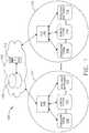
- a computer-implemented interactive surgical system 100includes one or more surgical systems 102 and a cloud-based system (e.g., the cloud 104 that may include a remote server 113 coupled to a storage device 105).
- Each surgical system 102includes at least one surgical hub 106 in communication with the cloud 104 that may include a remote server 113.
- the surgical system 102includes a visualization system 108, a robotic system 110, and a handheld intelligent surgical instrument 112, which are configured to communicate with one another and/or the hub 106.
- a surgical system 102may include an M number of hubs 106, an N number of visualization systems 108, an O number of robotic systems 110, and a P number of handheld intelligent surgical instruments 112, where M, N, O, and P are integers greater than or equal to one.
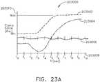
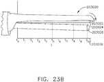
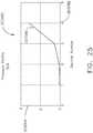
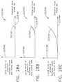
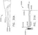
- the intelligent instruments 112 as described herein with reference to FIGS. 1-7may be implemented as ultrasonic surgical instruments and combination energy surgical instruments 7012 as described in FIGS. 23A-23B , 24A-24B , 25-26 , 27A-27C , 28A-28C , 29A-29C , 30A-30D, 31A-31D , 32A-32E .
- the intelligent instruments 112e.g., devices 1a-1n
- ultrasonic/combination surgical instruments 7012as described in FIGS.
- 23A-23B , 24A-24B , 25-26 , 27A-27C , 28A-28C , 29A-29C , 30A-30D, 31A-31D , 32A-32Eare configured to operate in a surgical data network 201 as described with reference to FIG. 8 .
- FIG. 2depicts an example of a surgical system 102 being used to perform a surgical procedure on a patient who is lying down on an operating table 114 in a surgical operating room 116.
- a robotic system 110is used in the surgical procedure as a part of the surgical system 102.
- the robotic system 110includes a surgeon's console 118, a patient side cart 120 (surgical robot), and a surgical robotic hub 122.
- the patient side cart 120can manipulate at least one removably coupled surgical tool 117 through a minimally invasive incision in the body of the patient while the surgeon views the surgical site through the surgeon's console 118.
- An image of the surgical sitecan be obtained by a medical imaging device 124, which can be manipulated by the patient side cart 120 to orient the imaging device 124.
- the robotic hub 122can be used to process the images of the surgical site for subsequent display to the surgeon through the surgeon's console 118.
- the imaging device 124includes at least one image sensor and one or more optical components.
- Suitable image sensorsinclude, but are not limited to, Charge-Coupled Device (CCD) sensors and Complementary Metal-Oxide Semiconductor (CMOS) sensors.
- CCDCharge-Coupled Device
- CMOSComplementary Metal-Oxide Semiconductor
- the optical components of the imaging device 124may include one or more illumination sources and/or one or more lenses.
- the one or more illumination sourcesmay be directed to illuminate portions of the surgical field.
- the one or more image sensorsmay receive light reflected or refracted from the surgical field, including light reflected or refracted from tissue and/or surgical instruments.
- the one or more illumination sourcesmay be configured to radiate electromagnetic energy in the visible spectrum as well as the invisible spectrum.
- the visible spectrumsometimes referred to as the optical spectrum or luminous spectrum, is that portion of the electromagnetic spectrum that is visible to (i.e., can be detected by) the human eye and may be referred to as visible light or simply light.
- a typical human eyewill respond to wavelengths in air that are from about 380 nm to about 750 nm.
- the invisible spectrumis that portion of the electromagnetic spectrum that lies below and above the visible spectrum (i.e., wavelengths below about 380 nm and above about 750 nm).
- the invisible spectrumis not detectable by the human eye.
- Wavelengths greater than about 750 nmare longer than the red visible spectrum, and they become invisible infrared (IR), microwave, and radio electromagnetic radiation.
- Wavelengths less than about 380 nmare shorter than the violet spectrum, and they become invisible ultraviolet, x-ray, and gamma ray electromagnetic radiation.
- the imaging device 124is configured for use in a minimally invasive procedure.
- imaging devices suitable for use with the present disclosureinclude, but not limited to, an arthroscope, angioscope, bronchoscope, choledochoscope, colonoscope, cytoscope, duodenoscope, enteroscope, esophagogastro-duodenoscope (gastroscope), endoscope, laryngoscope, nasopharyngo-neproscope, sigmoidoscope, thoracoscope, and ureteroscope.
- the imaging deviceemploys multi-spectrum monitoring to discriminate topography and underlying structures.
- a multi-spectral imageis one that captures image data within specific wavelength ranges across the electromagnetic spectrum. The wavelengths may be separated by filters or by the use of instruments that are sensitive to particular wavelengths, including light from frequencies beyond the visible light range, e.g., IR and ultraviolet. Spectral imaging can allow extraction of additional information the human eye fails to capture with its receptors for red, green, and blue.
- the use of multi-spectral imagingis described in greater detail under the heading "Advanced Imaging Acquisition Module" in U.S. Provisional Patent Application Serial No.
- Multi-spectrum monitoringcan be a useful tool in relocating a surgical field after a surgical task is completed to perform one or more of the previously described tests on the treated tissue.
- the sterile fieldmay be considered a specified area, such as within a tray or on a sterile towel, that is considered free of microorganisms, or the sterile field may be considered an area, immediately around a patient, who has been prepared for a surgical procedure.
- the sterile fieldmay include the scrubbed team members, who are properly attired, and all furniture and fixtures in the area.
- the visualization system 108includes one or more imaging sensors, one or more image-processing units, one or more storage arrays, and one or more displays that are strategically arranged with respect to the sterile field, as illustrated in FIG. 2 .
- the visualization system 108includes an interface for HL7, PACS, and EMR.
- Various components of the visualization system 108are described under the heading "Advanced Imaging Acquisition Module” in U.S. Provisional Patent Application Serial No. 62/611,341 , titled INTERACTIVE SURGICAL PLATFORM, filed December 28, 2017, the disclosure of which is herein incorporated by reference in its entirety.
- a primary display 119is positioned in the sterile field to be visible to an operator at the operating table 114.
- a visualization tower 111is positioned outside the sterile field.
- the visualization tower 111includes a first non-sterile display 107 and a second non-sterile display 109, which face away from each other.
- the visualization system 108guided by the hub 106, is configured to utilize the displays 107, 109, and 119 to coordinate information flow to operators inside and outside the sterile field.
- the hub 106may cause the visualization system 108 to display a snapshot of a surgical site, as recorded by an imaging device 124, on a non-sterile display 107 or 109, while maintaining a live feed of the surgical site on the primary display 119.
- the snapshot on the non-sterile display 107 or 109can permit a non-sterile operator to perform a diagnostic step relevant to the surgical procedure, for example.
- the hub 106is also configured to route a diagnostic input or feedback entered by a non-sterile operator at the visualization tower 111 to the primary display 119 within the sterile field, where it can be viewed by a sterile operator at the operating table.
- the inputcan be in the form of a modification to the snapshot displayed on the non-sterile display 107 or 109, which can be routed to the primary display 119 by the hub 106.
- a surgical instrument 112is being used in the surgical procedure as part of the surgical system 102.
- the hub 106is also configured to coordinate information flow to a display of the surgical instrument 112.
- coordinate information flowis further described in U.S. Provisional Patent Application Serial No. 62/611,341 , titled INTERACTIVE SURGICAL PLATFORM, filed December 28, 2017, the disclosure of which is herein incorporated by reference in its entirety.
- a diagnostic input or feedback entered by a non-sterile operator at the visualization tower 111can be routed by the hub 106 to the surgical instrument display 115 within the sterile field, where it can be viewed by the operator of the surgical instrument 112.
- Example surgical instrumentsthat are suitable for use with the surgical system 102 are described under the heading "Surgical Instrument Hardware” in U.S. Provisional Patent Application Serial No. 62/611,341 , titled INTERACTIVE SURGICAL PLATFORM, filed December 28, 2017, the disclosure of which is herein incorporated by reference in its entirety, for example.
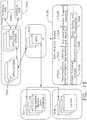
- a hub 106is depicted in communication with a visualization system 108, a robotic system 110, and a handheld intelligent surgical instrument 112.
- the hub 106includes a hub display 135, an imaging module 138, a generator module 140 (which can include a monopolar generator 142, a bipolar generator 144, and/or an ultrasonic generator 143), a communication module 130, a processor module 132, and a storage array 134.
- the hub 106further includes a smoke evacuation module 126, a suction/irrigation module 128, and/or an OR mapping module 133.
- the hub modular enclosure 136offers a unified environment for managing the power, data, and fluid lines, which reduces the frequency of entanglement between such lines.
- the surgical hubfor use in a surgical procedure that involves energy application to tissue at a surgical site.
- the surgical hubincludes a hub enclosure and a combo generator module slidably receivable in a docking station of the hub enclosure.
- the docking stationincludes data and power contacts.
- the combo generator moduleincludes two or more of an ultrasonic energy generator component, a bipolar RF energy generator component, and a monopolar RF energy generator component that are housed in a single unit.
- the combo generator modulealso includes a smoke evacuation component, at least one energy delivery cable for connecting the combo generator module to a surgical instrument, at least one smoke evacuation component configured to evacuate smoke, fluid, and/or particulates generated by the application of therapeutic energy to the tissue, and a fluid line extending from the remote surgical site to the smoke evacuation component.
- the fluid lineis a first fluid line and a second fluid line extends from the remote surgical site to a suction and irrigation module slidably received in the hub enclosure.
- the hub enclosurecomprises a fluid interface.
- Certain surgical proceduresmay require the application of more than one energy type to the tissue.
- One energy typemay be more beneficial for cutting the tissue, while another different energy type may be more beneficial for sealing the tissue.
- a bipolar generatorcan be used to seal the tissue while an ultrasonic generator can be used to cut the sealed tissue.
- the modular surgical enclosureincludes a first energy-generator module, configured to generate a first energy for application to the tissue, and a first docking station comprising a first docking port that includes first data and power contacts, wherein the first energy-generator module is slidably movable into an electrical engagement with the power and data contacts and wherein the first energy-generator module is slidably movable out of the electrical engagement with the first power and data contacts,
- the modular surgical enclosurealso includes a second energy-generator module configured to generate a second energy, different than the first energy, for application to the tissue, and a second docking station comprising a second docking port that includes second data and power contacts, wherein the second energy-generator module is slidably movable into an electrical engagement with the power and data contacts, and wherein the second energy-generator module is slidably movable out of the electrical engagement with the second power and data contacts.
- a second energy-generator moduleconfigured to generate a second energy, different than the first energy, for application to the tissue
- a second docking stationcomprising a second docking port that includes second data and power contacts
- the modular surgical enclosurealso includes a communication bus between the first docking port and the second docking port, configured to facilitate communication between the first energy-generator module and the second energy-generator module.
- a hub modular enclosure 136that allows the modular integration of a generator module 140, a smoke evacuation module 126, and a suction/irrigation module 128.
- the hub modular enclosure 136further facilitates interactive communication between the modules 140, 126, 128.
- the generator module 140can be a generator module with integrated monopolar, bipolar, and ultrasonic components supported in a single housing unit 139 slidably insertable into the hub modular enclosure 136.
- the generator module 140can be configured to connect to a monopolar device 146, a bipolar device 147, and an ultrasonic device 148.
- the generator module 140may comprise a series of monopolar, bipolar, and/or ultrasonic generator modules that interact through the hub modular enclosure 136.
- the hub modular enclosure 136can be configured to facilitate the insertion of multiple generators and interactive communication between the generators docked into the hub modular enclosure 136 so that the generators would act as a single generator.
- the hub modular enclosure 136comprises a modular power and communication backplane 149 with external and wireless communication headers to enable the removable attachment of the modules 140, 126, 128 and interactive communication therebetween.
- the hub modular enclosure 136includes docking stations, or drawers, 151, herein also referred to as drawers, which are configured to slidably receive the modules 140, 126, 128.
- FIG. 4illustrates a partial perspective view of a surgical hub enclosure 136, and a combo generator module 145 slidably receivable in a docking station 151 of the surgical hub enclosure 136.
- a docking port 152 with power and data contacts on a rear side of the combo generator module 145is configured to engage a corresponding docking port 150 with power and data contacts of a corresponding docking station 151 of the hub modular enclosure 136 as the combo generator module 145 is slid into position within the corresponding docking station 151 of the hub module enclosure 136.
- the combo generator module 145includes a bipolar, ultrasonic, and monopolar module and a smoke evacuation module integrated together into a single housing unit 139, as illustrated in FIG. 5 .
- the smoke evacuation module 126includes a fluid line 154 that conveys captured/collected smoke and/or fluid away from a surgical site and to, for example, the smoke evacuation module 126.
- Vacuum suction originating from the smoke evacuation module 126can draw the smoke into an opening of a utility conduit at the surgical site.
- the utility conduit, coupled to the fluid line,can be in the form of a flexible tube terminating at the smoke evacuation module 126.
- the utility conduit and the fluid linedefine a fluid path extending toward the smoke evacuation module 126 that is received in the hub enclosure 136.
- the suction/irrigation module 128is coupled to a surgical tool comprising an aspiration fluid line and a suction fluid line.
- the aspiration and suction fluid linesare in the form of flexible tubes extending from the surgical site toward the suction/irrigation module 128.
- One or more drive systemscan be configured to cause irrigation and aspiration of fluids to and from the surgical site.
- the surgical toolincludes a shaft having an end effector at a distal end thereof and at least one energy treatment associated with the end effector, an aspiration tube, and an irrigation tube.
- the aspiration tubecan have an inlet port at a distal end thereof and the aspiration tube extends through the shaft.
- an irrigation tubecan extend through the shaft and can have an inlet port in proximity to the energy deliver implement.
- the energy deliver implementis configured to deliver ultrasonic and/or RF energy to the surgical site and is coupled to the generator module 140 by a cable extending initially through the shaft.
- the irrigation tubecan be in fluid communication with a fluid source, and the aspiration tube can be in fluid communication with a vacuum source.
- the fluid source and/or the vacuum sourcecan be housed in the suction/irrigation module 128.
- the fluid source and/or the vacuum sourcecan be housed in the hub enclosure 136 separately from the suction/irrigation module 128.
- a fluid interfacecan be configured to connect the suction/irrigation module 128 to the fluid source and/or the vacuum source.
- the modules 140, 126, 128 and/or their corresponding docking stations on the hub modular enclosure 136may include alignment features that are configured to align the docking ports of the modules into engagement with their counterparts in the docking stations of the hub modular enclosure 136.
- the combo generator module 145includes side brackets 155 that are configured to slidably engage with corresponding brackets 156 of the corresponding docking station 151 of the hub modular enclosure 136. The brackets cooperate to guide the docking port contacts of the combo generator module 145 into an electrical engagement with the docking port contacts of the hub modular enclosure 136.
- the drawers 151 of the hub modular enclosure 136are the same, or substantially the same size, and the modules are adjusted in size to be received in the drawers 151.
- the side brackets 155 and/or 156can be larger or smaller depending on the size of the module.
- the drawers 151are different in size and are each designed to accommodate a particular module.
- the contacts of a particular modulecan be keyed for engagement with the contacts of a particular drawer to avoid inserting a module into a drawer with mismatching contacts.
- the docking port 150 of one drawer 151can be coupled to the docking port 150 of another drawer 151 through a communications link 157 to facilitate an interactive communication between the modules housed in the hub modular enclosure 136.
- the docking ports 150 of the hub modular enclosure 136may alternatively, or additionally, facilitate a wireless interactive communication between the modules housed in the hub modular enclosure 136. Any suitable wireless communication can be employed, such as for example Air Titan-Bluetooth.
- FIG. 6illustrates individual power bus attachments for a plurality of lateral docking ports of a lateral modular housing 160 configured to receive a plurality of modules of a surgical hub 206.
- the lateral modular housing 160is configured to laterally receive and interconnect the modules 161.
- the modules 161are slidably inserted into docking stations 162 of lateral modular housing 160, which includes a backplane for interconnecting the modules 161.
- the modules 161are arranged laterally in the lateral modular housing 160.
- the modules 161may be arranged vertically in a lateral modular housing.
- FIG. 7illustrates a vertical modular housing 164 configured to receive a plurality of modules 165 of the surgical hub 106.
- the modules 165are slidably inserted into docking stations, or drawers, 167 of vertical modular housing 164, which includes a backplane for interconnecting the modules 165.
- the drawers 167 of the vertical modular housing 164are arranged vertically, in certain instances, a vertical modular housing 164 may include drawers that are arranged laterally.
- the modules 165may interact with one another through the docking ports of the vertical modular housing 164.
- a display 177is provided for displaying data relevant to the operation of the modules 165.
- the vertical modular housing 164includes a master module 178 housing a plurality of sub-modules that are slidably received in the master module 178.
- the imaging module 138comprises an integrated video processor and a modular light source and is adapted for use with various imaging devices.
- the imaging deviceis comprised of a modular housing that can be assembled with a light source module and a camera module.
- the housingcan be a disposable housing.
- the disposable housingis removably coupled to a reusable controller, a light source module, and a camera module.
- the light source module and/or the camera modulecan be selectively chosen depending on the type of surgical procedure.
- the camera modulecomprises a CCD sensor.
- the camera modulecomprises a CMOS sensor.
- the camera moduleis configured for scanned beam imaging.
- the light source modulecan be configured to deliver a white light or a different light, depending on the surgical procedure.
- the module imaging device of the present disclosureis configured to permit the replacement of a light source module or a camera module midstream during a surgical procedure, without having to remove the imaging device from the surgical field.
- the imaging devicecomprises a tubular housing that includes a plurality of channels.
- a first channelis configured to slidably receive the camera module, which can be configured for a snap-fit engagement with the first channel.
- a second channelis configured to slidably receive the light source module, which can be configured for a snap-fit engagement with the second channel.
- the camera module and/or the light source modulecan be rotated into a final position within their respective channels.
- a threaded engagementcan be employed in lieu of the snap-fit engagement.
- multiple imaging devicesare placed at different positions in the surgical field to provide multiple views.
- the imaging module 138can be configured to switch between the imaging devices to provide an optimal view.
- the imaging module 138can be configured to integrate the images from the different imaging device.
- FIG. 8illustrates a surgical data network 201 comprising a modular communication hub 203 configured to connect modular devices located in one or more operating theaters of a healthcare facility, or any room in a healthcare facility specially equipped for surgical operations, to a cloud-based system (e.g., the cloud 204 that may include a remote server 213 coupled to a storage device 205).
- the modular communication hub 203comprises a network hub 207 and/or a network switch 209 in communication with a network router.
- the modular communication hub 203also can be coupled to a local computer system 210 to provide local computer processing and data manipulation.
- the surgical data network 201may be configured as passive, intelligent, or switching.
- a passive surgical data networkserves as a conduit for the data, enabling it to go from one device (or segment) to another and to the cloud computing resources.
- An intelligent surgical data networkincludes additional features to enable the traffic passing through the surgical data network to be monitored and to configure each port in the network hub 207 or network switch 209.
- An intelligent surgical data networkmay be referred to as a manageable hub or switch.
- a switching hubreads the destination address of each packet and then forwards the packet to the correct port.
- Modular devices 1a-1n located in the operating theatermay be coupled to the modular communication hub 203.
- the network hub 207 and/or the network switch 209may be coupled to a network router 211 to connect the devices 1a-1n to the cloud 204 or the local computer system 210.
- Data associated with the devices 1a-1nmay be transferred to cloud-based computers via the router for remote data processing and manipulation.
- Data associated with the devices 1a-1nmay also be transferred to the local computer system 210 for local data processing and manipulation.
- Modular devices 2a-2m located in the same operating theateralso may be coupled to a network switch 209.
- the network switch 209may be coupled to the network hub 207 and/or the network router 211 to connect to the devices 2a-2m to the cloud 204.
- Data associated with the devices 2a-2nmay be transferred to the cloud 204 via the network router 211 for data processing and manipulation.
- Data associated with the devices 2a-2mmay also be transferred to the local computer system 210 for local data processing and manipulation.
- the surgical data network 201may be expanded by interconnecting multiple network hubs 207 and/or multiple network switches 209 with multiple network routers 211.
- the modular communication hub 203may be contained in a modular control tower configured to receive multiple devices 1a-1n/2a-2m.
- the local computer system 210also may be contained in a modular control tower.
- the modular communication hub 203is connected to a display 212 to display images obtained by some of the devices 1a-1n/2a-2m, for example during surgical procedures.
- the devices 1a-1n/2a-2mmay include, for example, various modules such as an imaging module 138 coupled to an endoscope, a generator module 140 coupled to an energy-based surgical device, a smoke evacuation module 126, a suction/irrigation module 128, a communication module 130, a processor module 132, a storage array 134, a surgical device coupled to a display, and/or a non-contact sensor module, among other modular devices that may be connected to the modular communication hub 203 of the surgical data network 201.
- various modulessuch as an imaging module 138 coupled to an endoscope, a generator module 140 coupled to an energy-based surgical device, a smoke evacuation module 126, a suction/irrigation module 128, a communication module 130, a processor module 132, a storage array 134, a surgical device coupled to a display, and/or a non-contact sensor module, among other modular devices that may be connected to the modular communication hub 203 of the surgical data network 201.
- the surgical data network 201may comprise a combination of network hub(s), network switch(es), and network router(s) connecting the devices 1a-1n/2a-2m to the cloud. Any one of or all of the devices 1a-1n/2a-2m coupled to the network hub or network switch may collect data in real time and transfer the data to cloud computers for data processing and manipulation. It will be appreciated that cloud computing relies on sharing computing resources rather than having local servers or personal devices to handle software applications.
- the word “cloud”may be used as a metaphor for "the Internet,” although the term is not limited as such.
- cloud computingmay be used herein to refer to "a type of Internet-based computing," where different services-such as servers, storage, and applications-are delivered to the modular communication hub 203 and/or computer system 210 located in the surgical theater (e.g., a fixed, mobile, temporary, or field operating room or space) and to devices connected to the modular communication hub 203 and/or computer system 210 through the Internet.
- the cloud infrastructuremay be maintained by a cloud service provider.
- the cloud service providermay be the entity that coordinates the usage and control of the devices 1a-1n/2a-2m located in one or more operating theaters.
- the cloud computing servicescan perform a large number of calculations based on the data gathered by smart surgical instruments, robots, and other computerized devices located in the operating theater.
- the hub hardwareenables multiple devices or connections to be connected to a computer that communicates with the cloud computing resources and storage.
- the surgical data networkprovides improved surgical outcomes, reduced costs, and improved patient satisfaction.
- At least some of the devices 1a-1n/2a-2mmay be employed to view tissue states to assess leaks or perfusion of sealed tissue after a tissue sealing and cutting procedure.
- At least some of the devices 1a-1n/2a-2mmay be employed to identify pathology, such as the effects of diseases, using the cloud-based computing to examine data including images of samples of body tissue for diagnostic purposes. This includes localization and margin confirmation of tissue and phenotypes.
- At least some of the devices 1a-1n/2a-2mmay be employed to identify anatomical structures of the body using a variety of sensors integrated with imaging devices and techniques such as overlaying images captured by multiple imaging devices.
- the data gathered by the devices 1a-1n/2a-2m, including image datamay be transferred to the cloud 204 or the local computer system 210 or both for data processing and manipulation including image processing and manipulation.
- the datamay be analyzed to improve surgical procedure outcomes by determining if further treatment, such as the application of endoscopic intervention, emerging technologies, a targeted radiation, targeted intervention, and precise robotics to tissue-specific sites and conditions, may be pursued.
- Such data analysismay further employ outcome analytics processing, and using standardized approaches may provide beneficial feedback to either confirm surgical treatments and the behavior of the surgeon or suggest modifications to surgical treatments and the behavior of the surgeon.
- the operating theater devices 1a-1nmay be connected to the modular communication hub 203 over a wired channel or a wireless channel depending on the configuration of the devices 1a-1n to a network hub.
- the network hub 207may be implemented, in one aspect, as a local network broadcast device that works on the physical layer of the Open System Interconnection (OSI) model.
- the network hubprovides connectivity to the devices 1a-1n located in the same operating theater network.
- the network hub 207collects data in the form of packets and sends them to the router in half duplex mode.
- the network hub 207does not store any media access control/Internet Protocol (MAC/IP) to transfer the device data. Only one of the devices 1a-1n can send data at a time through the network hub 207.
- MAC/IPmedia access control/Internet Protocol
- the network hub 207has no routing tables or intelligence regarding where to send information and broadcasts all network data across each connection and to a remote server 213 ( FIG. 9 ) over the cloud 204.
- the network hub 207can detect basic network errors such as collisions, but having all information broadcast to multiple ports can be a security risk and cause bottlenecks.
- the operating theater devices 2a-2mmay be connected to a network switch 209 over a wired channel or a wireless channel.
- the network switch 209works in the data link layer of the OSI model.
- the network switch 209is a multicast device for connecting the devices 2a-2m located in the same operating theater to the network.
- the network switch 209sends data in the form of frames to the network router 211 and works in full duplex mode. Multiple devices 2a-2m can send data at the same time through the network switch 209.
- the network switch 209stores and uses MAC addresses of the devices 2a-2m to transfer data.
- the network hub 207 and/or the network switch 209are coupled to the network router 211 for connection to the cloud 204.
- the network router 211works in the network layer of the OSI model.
- the network router 211creates a route for transmitting data packets received from the network hub 207 and/or network switch 211 to cloud-based computer resources for further processing and manipulation of the data collected by any one of or all the devices 1a-1n/2a-2m.
- the network router 211may be employed to connect two or more different networks located in different locations, such as, for example, different operating theaters of the same healthcare facility or different networks located in different operating theaters of different healthcare facilities.
- the network router 211sends data in the form of packets to the cloud 204 and works in full duplex mode. Multiple devices can send data at the same time.
- the network router 211uses IP addresses to transfer data.
- the network hub 207may be implemented as a USB hub, which allows multiple USB devices to be connected to a host computer.
- the USB hubmay expand a single USB port into several tiers so that there are more ports available to connect devices to the host system computer.
- the network hub 207may include wired or wireless capabilities to receive information over a wired channel or a wireless channel.
- a wireless USB short-range, high-bandwidth wireless radio communication protocolmay be employed for communication between the devices 1a-1n and devices 2a-2m located in the operating theater.
- the operating theater devices 1a-1n/2a-2mmay communicate to the modular communication hub 203 via Bluetooth wireless technology standard for exchanging data over short distances (using short-wavelength UHF radio waves in the ISM band from 2.4 to 2.485 GHz) from fixed and mobile devices and building personal area networks (PANs).
- Bluetooth wireless technology standardfor exchanging data over short distances (using short-wavelength UHF radio waves in the ISM band from 2.4 to 2.485 GHz) from fixed and mobile devices and building personal area networks (PANs).
- the operating theater devices 1a-1n/2a-2mmay communicate to the modular communication hub 203 via a number of wireless or wired communication standards or protocols, including but not limited to Wi-Fi (IEEE 802.11 family), WiMAX (IEEE 802.16 family), IEEE 802.20, long-term evolution (LTE), and Ev-DO, HSPA+, HSDPA+, HSUPA+, EDGE, GSM, GPRS, CDMA, TDMA, DECT, and Ethernet derivatives thereof, as well as any other wireless and wired protocols that are designated as 3G, 4G, 5G, and beyond.
- the computing modulemay include a plurality of communication modules.
- a first communication modulemay be dedicated to shorter-range wireless communications such as Wi-Fi and Bluetooth, and a second communication module may be dedicated to longer-range wireless communications such as GPS, EDGE, GPRS, CDMA, WiMAX, LTE, Ev-DO, and others.
- the computer system 210comprises a processor 244 and a network interface 245.
- the processor 244is coupled to a communication module 247, storage 248, memory 249, non-volatile memory 250, and input/output interface 251 via a system bus.
- the system buscan be any of several types of bus structure(s) including the memory bus or memory controller, a peripheral bus or external bus, and/or a local bus using any variety of available bus architectures including, but not limited to, 9-bit bus, Industrial Standard Architecture (ISA), Micro-Charmel Architecture (MSA), Extended ISA (EISA), Intelligent Drive Electronics (IDE), VESA Local Bus (VLB), Peripheral Component Interconnect (PCI), USB, Advanced Graphics Port (AGP), Personal Computer Memory Card International Association bus (PCMCIA), Small Computer Systems Interface (SCSI), or any other proprietary bus.
- ISAIndustrial Standard Architecture
- MSAMicro-Charmel Architecture
- EISAExtended ISA
- IDEIntelligent Drive Electronics
- VLBVESA Local Bus
- PCIPe
- the processor 244may comprise a safety controller comprising two controller-based families such as TMS570 and RM4x, known under the trade name Hercules ARM Cortex R4, also by Texas Instruments.
- the safety controllermay be configured specifically for IEC 61508 and ISO 26262 safety critical applications, among others, to provide advanced integrated safety features while delivering scalable performance, connectivity, and memory options.
- the communication connection(s)refers to the hardware/software employed to connect the network interface to the bus. While the communication connection is shown for illustrative clarity inside the computer system, it can also be external to the computer system 210.
- the hardware/software necessary for connection to the network interfaceincludes, for illustrative purposes only, internal and external technologies such as modems, including regular telephone-grade modems, cable modems, and DSL modems, ISDN adapters, and Ethernet cards.
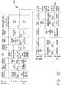
- FIG. 11illustrates a functional block diagram of one aspect of a USB network hub 300 device, in accordance with at least one aspect of the present disclosure.
- the USB network hub device 300employs a TUSB2036 integrated circuit hub by Texas Instruments.
- the USB network hub 300is a CMOS device that provides an upstream USB transceiver port 302 and up to three downstream USB transceiver ports 304, 306, 308 in compliance with the USB 2.0 specification.
- the upstream USB transceiver port 302is a differential root data port comprising a differential data minus (DM0) input paired with a differential data plus (DP0) input.
- the three downstream USB transceiver ports 304, 306, 308are differential data ports where each port includes differential data plus (DP1-DP3) outputs paired with differential data minus (DM1-DM3) outputs.
- the USB network hub 300 deviceis implemented with a digital state machine instead of a microcontroller, and no firmware programming is required. Fully compliant USB transceivers are integrated into the circuit for the upstream USB transceiver port 302 and all downstream USB transceiver ports 304, 306, 308.
- the downstream USB transceiver ports 304, 306, 308support both full-speed and low-speed devices by automatically setting the slew rate according to the speed of the device attached to the ports.
- the USB network hub 300 devicemay be configured either in bus-powered or self-powered mode and includes a hub power logic 312 to manage power.
- the 310receives a clock input 314 and is coupled to a suspend/resume logic and frame timer 316 circuit and a hub repeater circuit 318 to control communication between the upstream USB transceiver port 302 and the downstream USB transceiver ports 304, 306, 308 through port logic circuits 320, 322, 324.
- the SIE 310is coupled to a command decoder 326 via interface logic 328 to control commands from a serial EEPROM via a serial EEPROM interface 330.
- the USB network hub 300can connect 127 functions configured in up to six logical layers (tiers) to a single computer. Further, the USB network hub 300 can connect to all peripherals using a standardized four-wire cable that provides both communication and power distribution.
- the power configurationsare bus-powered and self-powered modes.
- the USB network hub 300may be configured to support four modes of power management: a bus-powered hub, with either individual-port power management or ganged-port power management, and the self-powered hub, with either individual-port power management or ganged-port power management.
- the USB network hub 300, the upstream USB transceiver port 302is plugged into a USB host controller, and the downstream USB transceiver ports 304, 306, 308 are exposed for connecting USB compatible devices, and so forth.
- FIG. 12is a block diagram of the computer-implemented interactive surgical system, in accordance with at least one aspect of the present disclosure.
- the computer-implemented interactive surgical systemis configured to monitor and analyze data related to the operation of various surgical systems that include surgical hubs, surgical instruments, robotic devices and operating theaters or healthcare facilities.
- the computer-implemented interactive surgical systemcomprises a cloud-based analytics system.
- the cloud-based analytics systemis described as a surgical system, it is not necessarily limited as such and could be a cloud-based medical system generally. As illustrated in FIG.
- the cloud-based analytics systemcomprises a plurality of surgical instruments 7012 (may be the same or similar to instruments 112), a plurality of surgical hubs 7006 (may be the same or similar to hubs 106), and a surgical data network 7001 (may be the same or similar to network 201) to couple the surgical hubs 7006 to the cloud 7004 (may be the same or similar to cloud 204).
- Each of the plurality of surgical hubs 7006is communicatively coupled to one or more surgical instruments 7012.
- the hubs 7006are also communicatively coupled to the cloud 7004 of the computer-implemented interactive surgical system via the network 7001.
- the cloud 7004is a remote centralized source of hardware and software for storing, manipulating, and communicating data generated based on the operation of various surgical systems.
- Surgical hubs 7006 that are coupled to the cloud 7004can be considered the client side of the cloud computing system (i.e., cloud-based analytics system).
- Surgical instruments 7012are paired with the surgical hubs 7006 for control and implementation of various surgical procedures or operations as described herein.
- the I/O interface 7007can be configured to transfer information between the surgical hubs 7006 and the aggregated medical data databases 7011. Accordingly, the I/O interface 7007 may facilitate read/write operations of the cloud-based analytics system. Such read/write operations may be executed in response to requests from hubs 7006. These requests could be transmitted to the hubs 7006 through the hub applications.
- the I/O interface 7007may include one or more high speed data ports, which may include universal serial bus (USB) ports, IEEE 1394 ports, as well as Wi-Fi and Bluetooth I/O interfaces for connecting the cloud 7004 to hubs 7006.
- the hub application servers 7002 of the cloud 7004are configured to host and supply shared capabilities to software applications (e.g. hub applications) executed by surgical hubs 7006. For example, the hub application servers 7002 may manage requests made by the hub applications through the hubs 7006, control access to the aggregated medical data databases 7011, and perform load balancing.
- the data analytics modules 7034are described in further detail with reference to FIG. 13 .
- the aggregated self-describing datamay correspond to individual data received from various groups or subgroups of surgical hubs 7006. Accordingly, the data collection and aggregation module 7022 can generate aggregated metadata or other organized data based on raw data received from the surgical hubs 7006. To this end, the processors 7008 can be operationally coupled to the hub applications 7014 and aggregated medical data databases 7011 for executing the data analytics modules 7034. The data collection and aggregation module 7022 may store the aggregated organized data into the aggregated medical data databases 2212.
- the resource optimization module 7020can be configured to analyze this aggregated data to determine an optimal usage of resources for a particular or group of healthcare facilities. For example, the resource optimization module 7020 may determine an optimal order point of surgical stapling instruments 7012 for a group of healthcare facilities based on corresponding predicted demand of such instruments 7012. The resource optimization module 7020 might also assess the resource usage or other operational configurations of various healthcare facilities to determine whether resource usage could be improved. Similarly, the recommendations module 7030 can be configured to analyze aggregated organized data from the data collection and aggregation module 7022 to provide recommendations.
- the recommendations module 7030could recommend to healthcare facilities (e.g., medical service providers such as hospitals) that a particular surgical instrument 7012 should be upgraded to an improved version based on a higher than expected error rate, for example.
- the recommendations module 7030 and/or resource optimization module 7020could recommend better supply chain parameters such as product reorder points and provide suggestions of different surgical instrument 7012, uses thereof, or procedure steps to improve surgical outcomes.
- the healthcare facilitiescan receive such recommendations via corresponding surgical hubs 7006. More specific recommendations regarding parameters or configurations of various surgical instruments 7012 can also be provided.
- Hubs 7006 and/or surgical instruments 7012each could also have display screens that display data or recommendations provided by the cloud 7004.
- the control program updating module 7026could be configured to implement various surgical instrument 7012 recommendations when corresponding control programs are updated.
- the patient outcome analysis module 7028could identify correlations linking specific control parameters with successful (or unsuccessful) results. Such correlations may be addressed when updated control programs are transmitted to surgical instruments 7012 via the control program updating module 7026. Updates to instruments 7012 that are transmitted via a corresponding hub 7006 may incorporate aggregated performance data that was gathered and analyzed by the data collection and aggregation module 7022 of the cloud 7004. Additionally, the patient outcome analysis module 7028 and recommendations module 7030 could identify improved methods of using instruments 7012 based on aggregated performance data.
- the cloud-based analytics systemmay include security features implemented by the cloud 7004. These security features may be managed by the authorization and security module 7024.
- Each surgical hub 7006can have associated unique credentials such as username, password, and other suitable security credentials. These credentials could be stored in the memory 7010 and be associated with a permitted cloud access level. For example, based on providing accurate credentials, a surgical hub 7006 may be granted access to communicate with the cloud to a predetermined extent (e.g., may only engage in transmitting or receiving certain defined types of information).
- the aggregated medical data databases 7011 of the cloud 7004may comprise a database of authorized credentials for verifying the accuracy of provided credentials. Different credentials may be associated with varying levels of permission for interaction with the cloud 7004, such as a predetermined access level for receiving the data analytics generated by the cloud 7004.
- the surgical instruments 7012may use wireless transceivers to transmit wireless signals that may represent, for example, authorization credentials for access to corresponding hubs 7006 and the cloud 7004. Wired transceivers may also be used to transmit signals. Such authorization credentials can be stored in the respective memory devices of the surgical instruments 7012.
- the authorization and security module 7024can determine whether the authorization credentials are accurate or counterfeit.
- the authorization and security module 7024may also dynamically generate authorization credentials for enhanced security.
- the credentialscould also be encrypted, such as by using hash based encryption.
- the surgical instruments 7012may transmit a signal to the corresponding hubs 7006 and ultimately the cloud 7004 to indicate that the instruments 7012 are ready to obtain and transmit medical data.
- the cloud-based analytics systemmay allow for monitoring multiple healthcare facilities (e.g., medical facilities like hospitals) to determine improved practices and recommend changes (via the recommendations module 2030, for example) accordingly.
- the processors 7008 of the cloud 7004can analyze data associated with an individual healthcare facility to identify the facility and aggregate the data with other data associated with other healthcare facilities in a group. Groups could be defined based on similar operating practices or geographical location, for example. In this way, the cloud 7004 may provide healthcare facility group wide analysis and recommendations.
- the cloud-based analytics systemcould also be used for enhanced situational awareness.
- the processors 7008may predictively model the effects of recommendations on the cost and effectiveness for a particular facility (relative to overall operations and/or various medical procedures). The cost and effectiveness associated with that particular facility can also be compared to a corresponding local region of other facilities or any other comparable facilities.
- the data sorting and prioritization module 7032may prioritize and sort data based on criticality (e.g., the severity of a medical event associated with the data, unexpectedness, suspiciousness). This sorting and prioritization may be used in conjunction with the functions of the other data analytics modules 7034 described above to improve the cloud-based analytics and operations described herein. For example, the data sorting and prioritization module 7032 can assign a priority to the data analysis performed by the data collection and aggregation module 7022 and patient outcome analysis modules 7028. Different prioritization levels can result in particular responses from the cloud 7004 (corresponding to a level of urgency) such as escalation for an expedited response, special processing, exclusion from the aggregated medical data databases 7011, or other suitable responses.
- criticalitye.g., the severity of a medical event associated with the data, unexpectedness, suspiciousness.
- This sorting and prioritizationmay be used in conjunction with the functions of the other data analytics modules 7034 described above to improve the cloud-based analytics and operations described herein.
- the surgical instrument(s) 7012 described above with reference to FIGS. 12 and 13may be implemented as ultrasonic surgical instruments and combination energy surgical instruments 7012 as described in FIGS. 23A-23B , 24A-24B , 25-26 , 27A-27C , 28A-28C , 29A-29C , 30A-30D, 31A-31D , 32A-32E . Accordingly, the as ultrasonic surgical instrument and combination energy surgical instrument 7012 as described in FIGS.
- an "intelligent" device including control algorithms that respond to sensed datacan be an improvement over a "dumb” device that operates without accounting for sensed data
- some sensed datacan be incomplete or inconclusive when considered in isolation, i.e., without the context of the type of surgical procedure being performed or the type of tissue that is being operated on.
- the control algorithmmay control the modular device incorrectly or suboptimally given the particular context-free sensed data.
- the optimal manner for a control algorithm to control a surgical instrument in response to a particular sensed parametercan vary according to the particular tissue type being operated on.
- tissue typeshave different properties (e.g., resistance to tearing) and thus respond differently to actions taken by surgical instruments. Therefore, it may be desirable for a surgical instrument to take different actions even when the same measurement for a particular parameter is sensed.
- the optimal manner in which to control a surgical stapling and cutting instrument in response to the instrument sensing an unexpectedly high force to close its end effectorwill vary depending upon whether the tissue type is susceptible or resistant to tearing. For tissues that are susceptible to tearing, such as lung tissue, the instrument's control algorithm would optimally ramp down the motor in response to an unexpectedly high force to close to avoid tearing the tissue.
- the instrument's control algorithmwould optimally ramp up the motor in response to an unexpectedly high force to close to ensure that the end effector is clamped properly on the tissue. Without knowing whether lung or stomach tissue has been clamped, the control algorithm may make a suboptimal decision.
- FIG. 14illustrates a diagram of a situationally aware surgical system 5100, in accordance with at least one aspect of the present disclosure.
- the data sources 5126include, for example, the modular devices 5102 (which can include sensors configured to detect parameters associated with the patient and/or the modular device itself), databases 5122 (e.g., an EMR database containing patient records), and patient monitoring devices 5124 (e.g., a blood pressure (BP) monitor and an electrocardiography (EKG) monitor).
- the modular devices 5102which can include sensors configured to detect parameters associated with the patient and/or the modular device itself
- databases 5122e.g., an EMR database containing patient records
- patient monitoring devices 5124e.g., a blood pressure (BP) monitor and an electrocardiography (EKG) monitor.
- BPblood pressure
- EKGelectrocardiography
- a surgical hub 5104which may be similar to the hub 106 in many respects, can be configured to derive the contextual information pertaining to the surgical procedure from the data based upon, for example, the particular combination(s) of received data or the particular order in which the data is received from the data sources 5126.
- the contextual information inferred from the received datacan include, for example, the type of surgical procedure being performed, the particular step of the surgical procedure that the surgeon is performing, the type of tissue being operated on, or the body cavity that is the subject of the procedure.
- the situational awareness system of the surgical hub 5104can be configured to derive the contextual information from the data received from the data sources 5126 in a variety of different ways.
- the situational awareness systemincludes a pattern recognition system, or machine learning system (e.g., an artificial neural network), that has been trained on training data to correlate various inputs (e.g., data from databases 5122, patient monitoring devices 5124, and/or modular devices 5102) to corresponding contextual information regarding a surgical procedure.
- a machine learning systemcan be trained to accurately derive contextual information regarding a surgical procedure from the provided inputs.
- the situational awareness systemcan include a lookup table storing pre-characterized contextual information regarding a surgical procedure in association with one or more inputs (or ranges of inputs) corresponding to the contextual information.
- the lookup tablecan return the corresponding contextual information for the situational awareness system for controlling the modular devices 5102.
- the contextual information received by the situational awareness system of the surgical hub 5104is associated with a particular control adjustment or set of control adjustments for one or more modular devices 5102.
- the situational awareness systemincludes a further machine learning system, lookup table, or other such system, which generates or retrieves one or more control adjustments for one or more modular devices 5102 when provided the contextual information as input.
- a surgical hub 5104 incorporating a situational awareness systemprovides a number of benefits for the surgical system 5100.
- One benefitincludes improving the interpretation of sensed and collected data, which would in turn improve the processing accuracy and/or the usage of the data during the course of a surgical procedure.
- a situationally aware surgical hub 5104could determine what type of tissue was being operated on; therefore, when an unexpectedly high force to close the surgical instrument's end effector is detected, the situationally aware surgical hub 5104 could correctly ramp up or ramp down the motor of the surgical instrument for the type of tissue.
- the type of tissue being operatedcan affect the adjustments that are made to the compression rate and load thresholds of a surgical stapling and cutting instrument for a particular tissue gap measurement.
- a situationally aware surgical hub 5104could infer whether a surgical procedure being performed is a thoracic or an abdominal procedure, allowing the surgical hub 5104 to determine whether the tissue clamped by an end effector of the surgical stapling and cutting instrument is lung (for a thoracic procedure) or stomach (for an abdominal procedure) tissue. The surgical hub 5104 could then adjust the compression rate and load thresholds of the surgical stapling and cutting instrument appropriately for the type of tissue.
- the type of body cavity being operated in during an insufflation procedurecan affect the function of a smoke evacuator.
- a situationally aware surgical hub 5104could determine whether the surgical site is under pressure (by determining that the surgical procedure is utilizing insufflation) and determine the procedure type. As a procedure type is generally performed in a specific body cavity, the surgical hub 5104 could then control the motor rate of the smoke evacuator appropriately for the body cavity being operated in. Thus, a situationally aware surgical hub 5104 could provide a consistent amount of smoke evacuation for both thoracic and abdominal procedures.
- the type of procedure being performedcan affect the optimal energy level for an ultrasonic surgical instrument or radio frequency (RF) electrosurgical instrument to operate at.
- Arthroscopic proceduresfor example, require higher energy levels because the end effector of the ultrasonic surgical instrument or RF electrosurgical instrument is immersed in fluid.
- a situationally aware surgical hub 5104could determine whether the surgical procedure is an arthroscopic procedure. The surgical hub 5104 could then adjust the RF power level or the ultrasonic amplitude of the generator (i.e., "energy level") to compensate for the fluid filled environment.
- the type of tissue being operated oncan affect the optimal energy level for an ultrasonic surgical instrument or RF electrosurgical instrument to operate at.
- a situationally aware surgical hub 5104could determine what type of surgical procedure is being performed and then customize the energy level for the ultrasonic surgical instrument or RF electrosurgical instrument, respectively, according to the expected tissue profile for the surgical procedure. Furthermore, a situationally aware surgical hub 5104 can be configured to adjust the energy level for the ultrasonic surgical instrument or RF electrosurgical instrument throughout the course of a surgical procedure, rather than just on a procedure-by-procedure basis. A situationally aware surgical hub 5104 could determine what step of the surgical procedure is being performed or will subsequently be performed and then update the control algorithms for the generator and/or ultrasonic surgical instrument or RF electrosurgical instrument to set the energy level at a value appropriate for the expected tissue type according to the surgical procedure step.
- the surgical hub 5104can be further configured to compare a physiologic measurement (e.g., blood pressure sensed by a BP monitor communicably connected to the surgical hub 5104) with the visual or image data of hemostasis (e.g., from a medical imaging device 124 ( FIG. 2 ) communicably coupled to the surgical hub 5104) to make a determination on the integrity of the staple line or tissue weld.
- a physiologic measuremente.g., blood pressure sensed by a BP monitor communicably connected to the surgical hub 5104
- the visual or image data of hemostasise.g., from a medical imaging device 124 ( FIG. 2 ) communicably coupled to the surgical hub 5104
- the situational awareness system of the surgical hub 5104can consider the physiological measurement data to provide additional context in analyzing the visualization data.
- the additional contextcan be useful when the visualization data may be inconclusive or incomplete on its own.
- Another benefitincludes proactively and automatically controlling the paired modular devices 5102 according to the particular step of the surgical procedure that is being performed to reduce the number of times that medical personnel are required to interact with or control the surgical system 5100 during the course of a surgical procedure.
- a situationally aware surgical hub 5104could proactively activate the generator to which an RF electrosurgical instrument is connected if it determines that a subsequent step of the procedure requires the use of the instrument. Proactively activating the energy source allows the instrument to be ready for use a soon as the preceding step of the procedure is completed.
- a situationally aware surgical hub 5104could determine whether the current or subsequent step of the surgical procedure requires a different view or degree of magnification on the display according to the feature(s) at the surgical site that the surgeon is expected to need to view. The surgical hub 5104 could then proactively change the displayed view (supplied by, e.g., a medical imaging device for the visualization system 108) accordingly so that the display automatically adjusts throughout the surgical procedure.
- a situationally aware surgical hub 5104could determine which step of the surgical procedure is being performed or will subsequently be performed and whether particular data or comparisons between data will be required for that step of the surgical procedure.
- the surgical hub 5104can be configured to automatically call up data screens based upon the step of the surgical procedure being performed, without waiting for the surgeon to ask for the particular information.
- a situationally aware surgical hub 5104could determine whether the surgeon (or other medical personnel) was making an error or otherwise deviating from the expected course of action during the course of a surgical procedure.
- the surgical hub 5104can be configured to determine the type of surgical procedure being performed, retrieve the corresponding list of steps or order of equipment usage (e.g., from a memory), and then compare the steps being performed or the equipment being used during the course of the surgical procedure to the expected steps or equipment for the type of surgical procedure that the surgical hub 5104 determined is being performed.
- the surgical hub 5104can be configured to provide an alert indicating that an unexpected action is being performed or an unexpected device is being utilized at the particular step in the surgical procedure.
- a timeline 5200 depicting situational awareness of a hubsuch as the surgical hub 106 or 206 ( FIGS. 1-11 ), for example.
- the timeline 5200is an illustrative surgical procedure and the contextual information that the surgical hub 106, 206 can derive from the data received from the data sources at each step in the surgical procedure.
- the timeline 5200depicts the typical steps that would be taken by the nurses, surgeons, and other medical personnel during the course of a lung segmentectomy procedure, beginning with setting up the operating theater and ending with transferring the patient to a post-operative recovery room.
- the situationally aware surgical hub 106, 206receives data from the data sources throughout the course of the surgical procedure, including data generated each time medical personnel utilize a modular device that is paired with the surgical hub 106, 206.
- the surgical hub 106, 206can receive this data from the paired modular devices and other data sources and continually derive inferences (i.e., contextual information) about the ongoing procedure as new data is received, such as which step of the procedure is being performed at any given time.
- the medical staffturns on the auxiliary equipment.
- the auxiliary equipment being utilizedcan vary according to the type of surgical procedure and the techniques to be used by the surgeon, but in this illustrative case they include a smoke evacuator, insufflator, and medical imaging device.
- the auxiliary equipment that are modular devicescan automatically pair with the surgical hub 106, 206 that is located within a particular vicinity of the modular devices as part of their initialization process.
- the surgical hub 106, 206can then derive contextual information about the surgical procedure by detecting the types of modular devices that pair with it during this pre-operative or initialization phase. In this particular example, the surgical hub 106, 206 determines that the surgical procedure is a VATS procedure based on this particular combination of paired modular devices.
- the surgical hub 106, 206can generally infer the specific procedure that the surgical team will be performing. Once the surgical hub 106, 206 knows what specific procedure is being performed, the surgical hub 106, 206 can then retrieve the steps of that procedure from a memory or from the cloud and then cross-reference the data it subsequently receives from the connected data sources (e.g., modular devices and patient monitoring devices) to infer what step of the surgical procedure the surgical team is performing.
- the connected data sourcese.g., modular devices and patient monitoring devices
- the staff membersattach the EKG electrodes and other patient monitoring devices to the patient.
- the EKG electrodes and other patient monitoring devicesare able to pair with the surgical hub 106, 206.
- the surgical hub 106, 206begins receiving data from the patient monitoring devices, the surgical hub 106, 206 thus confirms that the patient is in the operating theater.
- the medical personnelinduce anesthesia in the patient.
- the surgical hub 106, 206can infer that the patient is under anesthesia based on data from the modular devices and/or patient monitoring devices, including EKG data, blood pressure data, ventilator data, or combinations thereof, for example.
- the pre-operative portion of the lung segmentectomy procedureis completed and the operative portion begins.
- the patient's lung that is being operated onis collapsed (while ventilation is switched to the contralateral lung).
- the surgical hub 106, 206can infer from the ventilator data that the patient's lung has been collapsed, for example.
- the surgical hub 106, 206can infer that the operative portion of the procedure has commenced as it can compare the detection of the patient's lung collapsing to the expected steps of the procedure (which can be accessed or retrieved previously) and thereby determine that collapsing the lung is the first operative step in this particular procedure.
- the medical imaging device 2can be utilized to determine contextual information regarding the type of procedure being performed in a number of different ways, including by determining the angle at which the medical imaging device is oriented with respect to the visualization of the patient's anatomy, monitoring the number or medical imaging devices being utilized (i.e., that are activated and paired with the surgical hub 106, 206), and monitoring the types of visualization devices utilized.
- one technique for performing a VATS lobectomyplaces the camera in the lower anterior corner of the patient's chest cavity above the diaphragm
- one technique for performing a VATS segmentectomyplaces the camera in an anterior intercostal position relative to the segmental fissure.
- the situational awareness systemcan be trained to recognize the positioning of the medical imaging device according to the visualization of the patient's anatomy.
- one technique for performing a VATS lobectomyutilizes a single medical imaging device, whereas another technique for performing a VATS segmentectomy utilizes multiple cameras.
- one technique for performing a VATS segmentectomyutilizes an infrared light source (which can be communicably coupled to the surgical hub as part of the visualization system) to visualize the segmental fissure, which is not utilized in a VATS lobectomy.
- the surgical hub 106, 206can thereby determine the specific type of surgical procedure being performed and/or the technique being used for a particular type of surgical procedure.
- the segmentectomy portion of the procedureis performed.
- the surgical hub 106, 206can infer that the surgeon is transecting the parenchyma based on data from the surgical stapling and cutting instrument, including data from its cartridge.
- the cartridge datacan correspond to the size or type of staple being fired by the instrument, for example.
- the cartridge datacan thus indicate the type of tissue being stapled and/or transected.
- the type of staple being firedis utilized for parenchyma (or other similar tissue types), which allows the surgical hub 106, 206 to infer that the segmentectomy portion of the procedure is being performed.
- the patient's anesthesiais reversed.
- the surgical hub 106, 206can infer that the patient is emerging from the anesthesia based on the ventilator data (i.e., the patient's breathing rate begins increasing), for example.
- the fourteenth step 5228is that the medical personnel remove the various patient monitoring devices from the patient.
- the surgical hub 106, 206can thus infer that the patient is being transferred to a recovery room when the hub loses EKG, BP, and other data from the patient monitoring devices.
- the surgical hub 106, 206can determine or infer when each step of a given surgical procedure is taking place according to data received from the various data sources that are communicably coupled to the surgical hub 106, 206.
- the modular device 5102is implemented as ultrasonic surgical instruments and combination energy surgical instruments 7012 as described in FIGS. 23A-23B , 24A-24B , 25-26 , 27A-27C , 28A-28C , 29A-29C , 30A-30D, 31A-31D , 32A-32E . Accordingly, the modular device 5102 implemented as an ultrasonic surgical instrument and combination energy surgical instrument 7012 as described in FIGS.
- 23A-23B , 24A-24B , 25-26 , 27A-27C , 28A-28C , 29A-29C , 30A-30D , 31A-31D , 32A-32Eis further configured to interact with the surgical hub 5104 to provide information (e.g., data and control) to the surgical hub 5104 and receive information (e.g., data and control) from the surgical hub 5104.
- informatione.g., data and control
- the modular device 5102is implemented as ultrasonic surgical instruments and combination energy surgical instruments 7012 as described in FIGS. 23A-23B , 24A-24B , 25-26 , 27A-27C , 28A-28C , 29A-29C , 30A-30D, 31A-31D , 32A-32E . Accordingly, the modular device 5102 implemented as a ultrasonic surgical instrument and combination energy surgical instrument 7012 as described in FIGS.
- the modular device 5102implemented as a ultrasonic surgical instrument and combination energy surgical instrument 7012 as described in FIGS.
- the robotic surgical instrument 700comprises a control circuit 710 configured to control a clamp arm 716 and a closure member 714 portion of an end effector 702, an ultrasonic blade 718 coupled to an ultrasonic transducer 719 excited by an ultrasonic generator 721, a shaft 740, and one or more articulation members 742a, 742b via a plurality of motors 704a-704e.
- a position sensor 734may be configured to provide position feedback of the closure member 714 to the control circuit 710.
- Other sensors 738may be configured to provide feedback to the control circuit 710.
- a timer/counter 731provides timing and counting information to the control circuit 710.
- An energy source 712may be provided to operate the motors 704a-704e, and a current sensor 736 provides motor current feedback to the control circuit 710.
- the motors 704a-704ecan be operated individually by the control circuit 710 in an open-loop or closed-loop feedback control.
- control circuit 710may comprise one or more microcontrollers, microprocessors, or other suitable processors for executing instructions that cause the processor or processors to perform one or more tasks.
- a timer/counter 731provides an output signal, such as the elapsed time or a digital count, to the control circuit 710 to correlate the position of the closure member 714 as determined by the position sensor 734 with the output of the timer/counter 731 such that the control circuit 710 can determine the position of the closure member 714 at a specific time (t) relative to a starting position or the time (t) when the closure member 714 is at a specific position relative to a starting position.
- the timer/counter 731may be configured to measure elapsed time, count external events, or time external events.
- the control circuit 710may generate motor set point signals.
- the motor set point signalsmay be provided to various motor controllers 708a-708e.
- the motor controllers 708a-708emay comprise one or more circuits configured to provide motor drive signals to the motors 704a-704e to drive the motors 704a-704e as described herein.
- the motors 704a-704emay be brushed DC electric motors.
- the velocity of the motors 704a-704emay be proportional to the respective motor drive signals.
- the motors 704a-704emay be brushless DC electric motors, and the respective motor drive signals may comprise a PWM signal provided to one or more stator windings of the motors 704a-704e.
- the motor controllers 708a-708emay be omitted and the control circuit 710 may generate the motor drive signals directly.
- control circuit 710may initially operate each of the motors 704a-704e in an open-loop configuration for a first open-loop portion of a stroke of the displacement member. Based on the response of the robotic surgical instrument 700 during the open-loop portion of the stroke, the control circuit 710 may select a firing control program in a closed-loop configuration.
- the response of the instrumentmay include a translation distance of the displacement member during the open-loop portion, a time elapsed during the open-loop portion, the energy provided to one of the motors 704a-704e during the open-loop portion, a sum of pulse widths of a motor drive signal, etc.
- the control circuit 710may implement the selected firing control program for a second portion of the displacement member stroke. For example, during a closed-loop portion of the stroke, the control circuit 710 may modulate one of the motors 704a-704e based on translation data describing a position of the displacement member in a closed-loop manner to translate the displacement member at a constant velocity.
- the motors 704a-704emay receive power from an energy source 712.
- the energy source 712may be a DC power supply driven by a main alternating current power source, a battery, a super capacitor, or any other suitable energy source.
- the motors 704a-704emay be mechanically coupled to individual movable mechanical elements such as the closure member 714, clamp arm 716, shaft 740, articulation 742a, and articulation 742b via respective transmissions 706a-706e.
- the transmissions 706a-706emay include one or more gears or other linkage components to couple the motors 704a-704e to movable mechanical elements.
- a position sensor 734may sense a position of the closure member 714.
- the position sensor 734may be or include any type of sensor that is capable of generating position data that indicate a position of the closure member 714.
- the position sensor 734may include an encoder configured to provide a series of pulses to the control circuit 710 as the closure member 714 translates distally and proximally.
- the control circuit 710may track the pulses to determine the position of the closure member 714.
- Other suitable position sensorsmay be used, including, for example, a proximity sensor.
- Other types of position sensorsmay provide other signals indicating motion of the closure member 714.
- the position sensor 734may be omitted.
- the control circuit 710may track the position of the closure member 714 by aggregating the number and direction of steps that the motor 704 has been instructed to execute.
- the position sensor 734may be located in the end effector 702 or at any other portion of the instrument.
- the outputs of each of the motors 704a-704einclude a torque sensor 744a-744e to sense force and have an encoder to sense rotation of the drive shaft.
- control circuit 710is configured to drive a firing member such as the closure member 714 portion of the end effector 702.
- the control circuit 710provides a motor set point to a motor control 708a, which provides a drive signal to the motor 704a.
- the output shaft of the motor 704ais coupled to a torque sensor 744a.
- the torque sensor 744ais coupled to a transmission 706a which is coupled to the closure member 714.
- the transmission 706acomprises movable mechanical elements such as rotating elements and a firing member to control the movement of the closure member 714 distally and proximally along a longitudinal axis of the end effector 702.
- the motor 704amay be coupled to the knife gear assembly, which includes a knife gear reduction set that includes a first knife drive gear and a second knife drive gear.
- a torque sensor 744aprovides a firing force feedback signal to the control circuit 710.
- the firing force signalrepresents the force required to fire or displace the closure member 714.
- a position sensor 734may be configured to provide the position of the closure member 714 along the firing stroke or the position of the firing member as a feedback signal to the control circuit 710.
- the end effector 702may include additional sensors 738 configured to provide feedback signals to the control circuit 710. When ready to use, the control circuit 710 may provide a firing signal to the motor control 708a.
- the motor 704amay drive the firing member distally along the longitudinal axis of the end effector 702 from a proximal stroke start position to a stroke end position distal to the stroke start position.
- the clamp arm 716closes towards the ultrasonic blade 718.
- control circuit 710is configured to drive a closure member such as the clamp arm 716 portion of the end effector 702.
- the control circuit 710provides a motor set point to a motor control 708b, which provides a drive signal to the motor 704b.
- the output shaft of the motor 704bis coupled to a torque sensor 744b.
- the torque sensor 744bis coupled to a transmission 706b which is coupled to the clamp arm 716.
- the transmission 706bcomprises movable mechanical elements such as rotating elements and a closure member to control the movement of the clamp arm 716 from the open and closed positions.
- the motor 704bis coupled to a closure gear assembly, which includes a closure reduction gear set that is supported in meshing engagement with the closure spur gear.
- the torque sensor 744bprovides a closure force feedback signal to the control circuit 710.
- the closure force feedback signalrepresents the closure force applied to the clamp arm 716.
- the position sensor 734may be configured to provide the position of the closure member as a feedback signal to the control circuit 710. Additional sensors 738 in the end effector 702 may provide the closure force feedback signal to the control circuit 710.
- the pivotable clamp arm 716is positioned opposite the ultrasonic blade 718.
- the control circuit 710may provide a closure signal to the motor control 708b.
- the motor 704badvances a closure member to grasp tissue between the clamp arm 716 and the ultrasonic blade 718.
- control circuit 710is configured to rotate a shaft member such as the shaft 740 to rotate the end effector 702.
- the control circuit 710provides a motor set point to a motor control 708c, which provides a drive signal to the motor 704c.
- the output shaft of the motor 704cis coupled to a torque sensor 744c.
- the torque sensor 744cis coupled to a transmission 706c which is coupled to the shaft 740.
- the transmission 706ccomprises movable mechanical elements such as rotating elements to control the rotation of the shaft 740 clockwise or counterclockwise up to and over 360°.
- the motor 704cis coupled to the rotational transmission assembly, which includes a tube gear segment that is formed on (or attached to) the proximal end of the proximal closure tube for operable engagement by a rotational gear assembly that is operably supported on the tool mounting plate.
- the torque sensor 744cprovides a rotation force feedback signal to the control circuit 710.
- the rotation force feedback signalrepresents the rotation force applied to the shaft 740.
- the position sensor 734may be configured to provide the position of the closure member as a feedback signal to the control circuit 710. Additional sensors 738 such as a shaft encoder may provide the rotational position of the shaft 740 to the control circuit 710.
- control circuit 710is configured to articulate the end effector 702.
- the control circuit 710provides a motor set point to a motor control 708d, which provides a drive signal to the motor 704d.
- the output shaft of the motor 704dis coupled to a torque sensor 744d.
- the torque sensor 744dis coupled to a transmission 706d which is coupled to an articulation member 742a.
- the transmission 706dcomprises movable mechanical elements such as articulation elements to control the articulation of the end effector 702 ⁇ 65°.
- the motor 704dis coupled to an articulation nut, which is rotatably journaled on the proximal end portion of the distal spine portion and is rotatably driven thereon by an articulation gear assembly.
- the torque sensor 744dprovides an articulation force feedback signal to the control circuit 710.
- the articulation force feedback signalrepresents the articulation force applied to the end effector 702.
- Sensors 738such as an articulation encoder, may provide the articulation position of the end effector 702 to the control circuit 710.
- the articulation function of the robotic surgical system 700may comprise two articulation members, or links, 742a, 742b. These articulation members 742a, 742b are driven by separate disks on the robot interface (the rack) which are driven by the two motors 708d, 708e.
- each of articulation links 742a, 742bcan be antagonistically driven with respect to the other link in order to provide a resistive holding motion and a load to the head when it is not moving and to provide an articulation motion as the head is articulated.
- the articulation members 742a, 742battach to the head at a fixed radius as the head is rotated. Accordingly, the mechanical advantage of the push-and-pull link changes as the head is rotated. This change in the mechanical advantage may be more pronounced with other articulation link drive systems.
- the one or more motors 704a-704emay comprise a brushed DC motor with a gearbox and mechanical links to a firing member, closure member, or articulation member.
- Another exampleincludes electric motors 704a-704e that operate the movable mechanical elements such as the displacement member, articulation links, closure tube, and shaft.
- An outside influenceis an unmeasured, unpredictable influence of things like tissue, surrounding bodies, and friction on the physical system. Such outside influence can be referred to as drag, which acts in opposition to one of electric motors 704a-704e.
- the outside influence, such as dragmay cause the operation of the physical system to deviate from a desired operation of the physical system.
- the position sensor 734may be implemented as an absolute positioning system.
- the position sensor 734may comprise a magnetic rotary absolute positioning system implemented as an AS5055EQFT single-chip magnetic rotary position sensor available from Austria Microsystems, AG.
- the position sensor 734may interface with the control circuit 710 to provide an absolute positioning system.
- the positionmay include multiple Hall-effect elements located above a magnet and coupled to a CORDIC processor, also known as the digit-by-digit method and Volder's algorithm, that is provided to implement a simple and efficient algorithm to calculate hyperbolic and trigonometric functions that require only addition, subtraction, bitshift, and table lookup operations.
- CORDIC processoralso known as the digit-by-digit method and Volder's algorithm
- the control circuit 710may be in communication with one or more sensors 738.
- the sensors 738may be positioned on the end effector 702 and adapted to operate with the robotic surgical instrument 700 to measure the various derived parameters such as the gap distance versus time, tissue compression versus time, and anvil strain versus time.
- the sensors 738may comprise a magnetic sensor, a magnetic field sensor, a strain gauge, a load cell, a pressure sensor, a force sensor, a torque sensor, an inductive sensor such as an eddy current sensor, a resistive sensor, a capacitive sensor, an optical sensor, and/or any other suitable sensor for measuring one or more parameters of the end effector 702.
- the sensors 738may include one or more sensors.
- the sensors 738may be located on the clamp arm 716 to determine tissue location using segmented electrodes.
- the torque sensors 744a-744emay be configured to sense force such as firing force, closure force, and/or articulation force, among others. Accordingly, the control circuit 710 can sense (1) the closure load experienced by the distal closure tube and its position, (2) the firing member at the rack and its position, (3) what portion of the ultrasonic blade 718 has tissue on it, and (4) the load and position on both articulation rods.
- the one or more sensors 738may comprise a strain gauge, such as a micro-strain gauge, configured to measure the magnitude of the strain in the clamp arm 716 during a clamped condition.
- the strain gaugeprovides an electrical signal whose amplitude varies with the magnitude of the strain.
- the sensors 738may comprise a pressure sensor configured to detect a pressure generated by the presence of compressed tissue between the clamp arm 716 and the ultrasonic blade 718.
- the sensors 738may be configured to detect impedance of a tissue section located between the clamp arm 716 and the ultrasonic blade 718 that is indicative of the thickness and/or fullness of tissue located therebetween.
- the sensors 738may be implemented as one or more limit switches, electromechanical devices, solid-state switches, Hall-effect devices, magneto-resistive (MR) devices, giant magneto-resistive (GMR) devices, magnetometers, among others.
- the sensors 738may be implemented as solid-state switches that operate under the influence of light, such as optical sensors, IR sensors, ultraviolet sensors, among others.
- the switchesmay be solid-state devices such as transistors (e.g., FET, junction FET, MOSFET, bipolar, and the like).
- the sensors 738may include electrical conductorless switches, ultrasonic switches, accelerometers, and inertial sensors, among others.
- the sensors 738may be configured to measure forces exerted on the clamp arm 716 by the closure drive system.
- one or more sensors 738can be at an interaction point between the closure tube and the clamp arm 716 to detect the closure forces applied by the closure tube to the clamp arm 716.
- the forces exerted on the clamp arm 716can be representative of the tissue compression experienced by the tissue section captured between the clamp arm 716 and the ultrasonic blade 718.
- the one or more sensors 738can be positioned at various interaction points along the closure drive system to detect the closure forces applied to the clamp arm 716 by the closure drive system.
- the one or more sensors 738may be sampled in real time during a clamping operation by the processor of the control circuit 710.
- the control circuit 710receives real-time sample measurements to provide and analyze time-based information and assess, in real time, closure forces applied to the clamp arm 716.
- a current sensor 736can be employed to measure the current drawn by each of the motors 704a-704e.
- the force required to advance any of the movable mechanical elements such as the closure member 714corresponds to the current drawn by one of the motors 704a-704e.
- the forceis converted to a digital signal and provided to the control circuit 710.
- the control circuit 710can be configured to simulate the response of the actual system of the instrument in the software of the controller.
- a displacement membercan be actuated to move the closure member 714 in the end effector 702 at or near a target velocity.
- the robotic surgical instrument 700can include a feedback controller, which can be one of any feedback controllers, including, but not limited to a PID, a state feedback, a linear-quadratic (LQR), and/or an adaptive controller, for example.
- the robotic surgical instrument 700can include a power source to convert the signal from the feedback controller into a physical input such as case voltage, PWM voltage, frequency modulated voltage, current, torque, and/or force, for example. Additional details are disclosed in U.S. Patent Application Serial No. 15/636,829 , titled CLOSED LOOP VELOCITY CONTROL TECHNIQUES FOR ROBOTIC SURGICAL INSTRUMENT, filed June 29, 2017, which is herein incorporated by reference in its entirety.
- FIG. 17illustrates a schematic diagram of a surgical instrument 750 configured to control the distal translation of a displacement member according to one aspect of this disclosure.
- the surgical instrument 750is programmed to control the distal translation of a displacement member such as the closure member 764.
- the surgical instrument 750comprises an end effector 752 that may comprise a clamp arm 766, a closure member 764, and an ultrasonic blade 768 coupled to an ultrasonic transducer 769 driven by an ultrasonic generator 771.
- the position, movement, displacement, and/or translation of a linear displacement member, such as the closure member 764can be measured by an absolute positioning system, sensor arrangement, and position sensor 784. Because the closure member 764 is coupled to a longitudinally movable drive member, the position of the closure member 764 can be determined by measuring the position of the longitudinally movable drive member employing the position sensor 784. Accordingly, in the following description, the position, displacement, and/or translation of the closure member 764 can be achieved by the position sensor 784 as described herein.
- a control circuit 760may be programmed to control the translation of the displacement member, such as the closure member 764.
- the control circuit 760may comprise one or more microcontrollers, microprocessors, or other suitable processors for executing instructions that cause the processor or processors to control the displacement member, e.g., the closure member 764, in the manner described.
- a timer/counter 781provides an output signal, such as the elapsed time or a digital count, to the control circuit 760 to correlate the position of the closure member 764 as determined by the position sensor 784 with the output of the timer/counter 781 such that the control circuit 760 can determine the position of the closure member 764 at a specific time (t) relative to a starting position.
- the timer/counter 781may be configured to measure elapsed time, count external events, or time external events.
- the control circuit 760may generate a motor set point signal 772.
- the motor set point signal 772may be provided to a motor controller 758.
- the motor controller 758may comprise one or more circuits configured to provide a motor drive signal 774 to the motor 754 to drive the motor 754 as described herein.
- the motor 754may be a brushed DC electric motor.
- the velocity of the motor 754may be proportional to the motor drive signal 774.
- the motor 754may be a brushless DC electric motor and the motor drive signal 774 may comprise a PWM signal provided to one or more stator windings of the motor 754.
- the motor controller 758may be omitted, and the control circuit 760 may generate the motor drive signal 774 directly.
- the motor 754may receive power from an energy source 762.
- the energy source 762may be or include a battery, a super capacitor, or any other suitable energy source.
- the motor 754may be mechanically coupled to the closure member 764 via a transmission 756.
- the transmission 756may include one or more gears or other linkage components to couple the motor 754 to the closure member 764.
- a position sensor 784may sense a position of the closure member 764.
- the position sensor 784may be or include any type of sensor that is capable of generating position data that indicate a position of the closure member 764.
- the position sensor 784may include an encoder configured to provide a series of pulses to the control circuit 760 as the closure member 764 translates distally and proximally.
- the control circuit 760may track the pulses to determine the position of the closure member 764.
- Other suitable position sensorsmay be used, including, for example, a proximity sensor. Other types of position sensors may provide other signals indicating motion of the closure member 764.
- the position sensor 784may be omitted.
- the control circuit 760may track the position of the closure member 764 by aggregating the number and direction of steps that the motor 754 has been instructed to execute.
- the position sensor 784may be located in the end effector 752 or at any other portion of the instrument.
- the control circuit 760may be in communication with one or more sensors 788.
- the sensors 788may be positioned on the end effector 752 and adapted to operate with the surgical instrument 750 to measure the various derived parameters such as gap distance versus time, tissue compression versus time, and anvil strain versus time.
- the sensors 788may comprise a magnetic sensor, a magnetic field sensor, a strain gauge, a pressure sensor, a force sensor, an inductive sensor such as an eddy current sensor, a resistive sensor, a capacitive sensor, an optical sensor, and/or any other suitable sensor for measuring one or more parameters of the end effector 752.
- the sensors 788may include one or more sensors.
- the one or more sensors 788may comprise a strain gauge, such as a micro-strain gauge, configured to measure the magnitude of the strain in the clamp arm 766 during a clamped condition.
- the strain gaugeprovides an electrical signal whose amplitude varies with the magnitude of the strain.
- the sensors 788may comprise a pressure sensor configured to detect a pressure generated by the presence of compressed tissue between the clamp arm 766 and the ultrasonic blade 768.
- the sensors 788may be configured to detect impedance of a tissue section located between the clamp arm 766 and the ultrasonic blade 768 that is indicative of the thickness and/or fullness of tissue located therebetween.
- the sensors 788may be is configured to measure forces exerted on the clamp arm 766 by a closure drive system.
- one or more sensors 788can be at an interaction point between a closure tube and the clamp arm 766 to detect the closure forces applied by a closure tube to the clamp arm 766.
- the forces exerted on the clamp arm 766can be representative of the tissue compression experienced by the tissue section captured between the clamp arm 766 and the ultrasonic blade 768.
- the one or more sensors 788can be positioned at various interaction points along the closure drive system to detect the closure forces applied to the clamp arm 766 by the closure drive system.
- the one or more sensors 788may be sampled in real time during a clamping operation by a processor of the control circuit 760.
- the control circuit 760receives real-time sample measurements to provide and analyze time-based information and assess, in real time, closure forces applied to the clamp arm 766.
- a current sensor 786can be employed to measure the current drawn by the motor 754.
- the force required to advance the closure member 764corresponds to the current drawn by the motor 754.
- the forceis converted to a digital signal and provided to the control circuit 760.
- the control circuit 760can be configured to simulate the response of the actual system of the instrument in the software of the controller.
- a displacement membercan be actuated to move a closure member 764 in the end effector 752 at or near a target velocity.
- the surgical instrument 750can include a feedback controller, which can be one of any feedback controllers, including, but not limited to a PID, a state feedback, LQR, and/or an adaptive controller, for example.
- the surgical instrument 750can include a power source to convert the signal from the feedback controller into a physical input such as case voltage, PWM voltage, frequency modulated voltage, current, torque, and/or force, for example.
- the actual drive system of the surgical instrument 750is configured to drive the displacement member, cutting member, or closure member 764, by a brushed DC motor with gearbox and mechanical links to an articulation and/or knife system.
- a brushed DC motor with gearbox and mechanical linksto an articulation and/or knife system.
- the electric motor 754that operates the displacement member and the articulation driver, for example, of an interchangeable shaft assembly.
- An outside influenceis an unmeasured, unpredictable influence of things like tissue, surrounding bodies and friction on the physical system. Such outside influence can be referred to as drag which acts in opposition to the electric motor 754.
- the outside influence, such as dragmay cause the operation of the physical system to deviate from a desired operation of the physical system.
- a surgical instrument 750comprising an end effector 752 with motor-driven surgical sealing and cutting implements.
- a motor 754may drive a displacement member distally and proximally along a longitudinal axis of the end effector 752.
- the end effector 752may comprise a pivotable clamp arm 766 and, when configured for use, an ultrasonic blade 768 positioned opposite the clamp arm 766.
- a clinicianmay grasp tissue between the clamp arm 766 and the ultrasonic blade 768, as described herein.
- the clinicianmay provide a firing signal, for example by depressing a trigger of the instrument 750.
- the motor 754may drive the displacement member distally along the longitudinal axis of the end effector 752 from a proximal stroke begin position to a stroke end position distal of the stroke begin position.
- the closure member 764 with a cutting element positioned at a distal endmay cut the tissue between the ultrasonic blade 768 and the clamp arm 766.
- the surgical instrument 750may comprise a control circuit 760 programmed to control the distal translation of the displacement member, such as the closure member 764, for example, based on one or more tissue conditions.
- the control circuit 760may be programmed to sense tissue conditions, such as thickness, either directly or indirectly, as described herein.
- the control circuit 760may be programmed to select a control program based on tissue conditions.
- a control programmay describe the distal motion of the displacement member. Different control programs may be selected to better treat different tissue conditions. For example, when thicker tissue is present, the control circuit 760 may be programmed to translate the displacement member at a lower velocity and/or with lower power. When thinner tissue is present, the control circuit 760 may be programmed to translate the displacement member at a higher velocity and/or with higher power.
- control circuit 760may initially operate the motor 754 in an open loop configuration for a first open loop portion of a stroke of the displacement member. Based on a response of the instrument 750 during the open loop portion of the stroke, the control circuit 760 may select a firing control program.
- the response of the instrumentmay include, a translation distance of the displacement member during the open loop portion, a time elapsed during the open loop portion, energy provided to the motor 754 during the open loop portion, a sum of pulse widths of a motor drive signal, etc.
- the control circuit 760may implement the selected firing control program for a second portion of the displacement member stroke.
- control circuit 760may modulate the motor 754 based on translation data describing a position of the displacement member in a closed loop manner to translate the displacement member at a constant velocity. Additional details are disclosed in U.S. Patent Application Serial No. 15/720,852 , titled SYSTEM AND METHODS FOR CONTROLLING A DISPLAY OF A SURGICAL INSTRUMENT, filed September 29, 2017, which is herein incorporated by reference in its entirety.
- FIG. 18illustrates a schematic diagram of a surgical instrument 750 configured to control the distal translation of a displacement member according to one aspect of this disclosure.
- the surgical instrument 750is programmed to control the distal translation of a displacement member such as the closure member 764.
- the surgical instrument 750comprises an end effector 752 that may comprise a clamp arm 766, a closure member 764, and an ultrasonic blade 768 coupled to an ultrasonic transducer 769 driven by an ultrasonic generator 771.
- the position, movement, displacement, and/or translation of a linear displacement member, such as the closure member 764can be measured by an absolute positioning system, sensor arrangement, and position sensor 784. Because the closure member 764 is coupled to a longitudinally movable drive member, the position of the closure member 764 can be determined by measuring the position of the longitudinally movable drive member employing the position sensor 784. Accordingly, in the following description, the position, displacement, and/or translation of the closure member 764 can be achieved by the position sensor 784 as described herein.
- a control circuit 760may be programmed to control the translation of the displacement member, such as the closure member 764.
- the control circuit 760may comprise one or more microcontrollers, microprocessors, or other suitable processors for executing instructions that cause the processor or processors to control the displacement member, e.g., the closure member 764, in the manner described.
- a timer/counter 781provides an output signal, such as the elapsed time or a digital count, to the control circuit 760 to correlate the position of the closure member 764 as determined by the position sensor 784 with the output of the timer/counter 781 such that the control circuit 760 can determine the position of the closure member 764 at a specific time (t) relative to a starting position.
- the timer/counter 781may be configured to measure elapsed time, count external events, or time external events.
- the control circuit 760may generate a motor set point signal 772.
- the motor set point signal 772may be provided to a motor controller 758.
- the motor controller 758may comprise one or more circuits configured to provide a motor drive signal 774 to the motor 754 to drive the motor 754 as described herein.
- the motor 754may be a brushed DC electric motor.
- the velocity of the motor 754may be proportional to the motor drive signal 774.
- the motor 754may be a brushless DC electric motor and the motor drive signal 774 may comprise a PWM signal provided to one or more stator windings of the motor 754.
- the motor controller 758may be omitted, and the control circuit 760 may generate the motor drive signal 774 directly.
- the motor 754may receive power from an energy source 762.
- the energy source 762may be or include a battery, a super capacitor, or any other suitable energy source.
- the motor 754may be mechanically coupled to the closure member 764 via a transmission 756.
- the transmission 756may include one or more gears or other linkage components to couple the motor 754 to the closure member 764.
- a position sensor 784may sense a position of the closure member 764.
- the position sensor 784may be or include any type of sensor that is capable of generating position data that indicate a position of the closure member 764.
- the position sensor 784may include an encoder configured to provide a series of pulses to the control circuit 760 as the closure member 764 translates distally and proximally.
- the control circuit 760may track the pulses to determine the position of the closure member 764.
- Other suitable position sensorsmay be used, including, for example, a proximity sensor. Other types of position sensors may provide other signals indicating motion of the closure member 764.
- the position sensor 784may be omitted.
- the control circuit 760may track the position of the closure member 764 by aggregating the number and direction of steps that the motor 754 has been instructed to execute.
- the position sensor 784may be located in the end effector 752 or at any other portion of the instrument.
- the control circuit 760may be in communication with one or more sensors 788.
- the sensors 788may be positioned on the end effector 752 and adapted to operate with the surgical instrument 750 to measure the various derived parameters such as gap distance versus time, tissue compression versus time, and anvil strain versus time.
- the sensors 788may comprise a magnetic sensor, a magnetic field sensor, a strain gauge, a pressure sensor, a force sensor, an inductive sensor such as an eddy current sensor, a resistive sensor, a capacitive sensor, an optical sensor, and/or any other suitable sensor for measuring one or more parameters of the end effector 752.
- the sensors 788may include one or more sensors.
- the one or more sensors 788may comprise a strain gauge, such as a micro-strain gauge, configured to measure the magnitude of the strain in the clamp arm 766 during a clamped condition.
- the strain gaugeprovides an electrical signal whose amplitude varies with the magnitude of the strain.
- the sensors 788may comprise a pressure sensor configured to detect a pressure generated by the presence of compressed tissue between the clamp arm 766 and the ultrasonic blade 768.
- the sensors 788may be configured to detect impedance of a tissue section located between the clamp arm 766 and the ultrasonic blade 768 that is indicative of the thickness and/or fullness of tissue located therebetween.
- the sensors 788may be is configured to measure forces exerted on the clamp arm 766 by a closure drive system.
- one or more sensors 788can be at an interaction point between a closure tube and the clamp arm 766 to detect the closure forces applied by a closure tube to the clamp arm 766.
- the forces exerted on the clamp arm 766can be representative of the tissue compression experienced by the tissue section captured between the clamp arm 766 and the ultrasonic blade 768.
- the one or more sensors 788can be positioned at various interaction points along the closure drive system to detect the closure forces applied to the clamp arm 766 by the closure drive system.
- the one or more sensors 788may be sampled in real time during a clamping operation by a processor of the control circuit 760.
- the control circuit 760receives real-time sample measurements to provide and analyze time-based information and assess, in real time, closure forces applied to the clamp arm 766.
- a current sensor 786can be employed to measure the current drawn by the motor 754.
- the force required to advance the closure member 764corresponds to the current drawn by the motor 754.
- the forceis converted to a digital signal and provided to the control circuit 760.
- the control circuit 760can be configured to simulate the response of the actual system of the instrument in the software of the controller.
- a displacement membercan be actuated to move a closure member 764 in the end effector 752 at or near a target velocity.
- the surgical instrument 750can include a feedback controller, which can be one of any feedback controllers, including, but not limited to a PID, a state feedback, LQR, and/or an adaptive controller, for example.
- the surgical instrument 750can include a power source to convert the signal from the feedback controller into a physical input such as case voltage, PWM voltage, frequency modulated voltage, current, torque, and/or force, for example.
- the actual drive system of the surgical instrument 750is configured to drive the displacement member, cutting member, or closure member 764, by a brushed DC motor with gearbox and mechanical links to an articulation and/or knife system.
- a brushed DC motor with gearbox and mechanical linksto an articulation and/or knife system.
- the electric motor 754that operates the displacement member and the articulation driver, for example, of an interchangeable shaft assembly.
- An outside influenceis an unmeasured, unpredictable influence of things like tissue, surrounding bodies and friction on the physical system. Such outside influence can be referred to as drag which acts in opposition to the electric motor 754.
- the outside influence, such as dragmay cause the operation of the physical system to deviate from a desired operation of the physical system.
- a surgical instrument 750comprising an end effector 752 with motor-driven surgical sealing and cutting implements.
- a motor 754may drive a displacement member distally and proximally along a longitudinal axis of the end effector 752.
- the end effector 752may comprise a pivotable clamp arm 766 and, when configured for use, an ultrasonic blade 768 positioned opposite the clamp arm 766.
- a clinicianmay grasp tissue between the clamp arm 766 and the ultrasonic blade 768, as described herein.
- the clinicianmay provide a firing signal, for example by depressing a trigger of the instrument 750.
- the motor 754may drive the displacement member distally along the longitudinal axis of the end effector 752 from a proximal stroke begin position to a stroke end position distal of the stroke begin position.
- the closure member 764 with a cutting element positioned at a distal endmay cut the tissue between the ultrasonic blade 768 and the clamp arm 766.
- the surgical instrument 750may comprise a control circuit 760 programmed to control the distal translation of the displacement member, such as the closure member 764, for example, based on one or more tissue conditions.
- the control circuit 760may be programmed to sense tissue conditions, such as thickness, either directly or indirectly, as described herein.
- the control circuit 760may be programmed to select a control program based on tissue conditions.
- a control programmay describe the distal motion of the displacement member. Different control programs may be selected to better treat different tissue conditions. For example, when thicker tissue is present, the control circuit 760 may be programmed to translate the displacement member at a lower velocity and/or with lower power. When thinner tissue is present, the control circuit 760 may be programmed to translate the displacement member at a higher velocity and/or with higher power.
- control circuit 760may initially operate the motor 754 in an open loop configuration for a first open loop portion of a stroke of the displacement member. Based on a response of the instrument 750 during the open loop portion of the stroke, the control circuit 760 may select a firing control program.
- the response of the instrumentmay include, a translation distance of the displacement member during the open loop portion, a time elapsed during the open loop portion, energy provided to the motor 754 during the open loop portion, a sum of pulse widths of a motor drive signal, etc.
- the control circuit 760may implement the selected firing control program for a second portion of the displacement member stroke.
- control circuit 760may modulate the motor 754 based on translation data describing a position of the displacement member in a closed loop manner to translate the displacement member at a constant velocity. Additional details are disclosed in U.S. Patent Application Serial No. 15/720,852 , titled SYSTEM AND METHODS FOR CONTROLLING A DISPLAY OF A SURGICAL INSTRUMENT, filed September 29, 2017, which is herein incorporated by reference in its entirety.
- FIG. 18is a schematic diagram of a surgical instrument 790 configured to control various functions according to one aspect of this disclosure.
- the surgical instrument 790is programmed to control distal translation of a displacement member such as the closure member 764.
- the surgical instrument 790comprises an end effector 792 that may comprise a clamp arm 766, a closure member 764, and an ultrasonic blade 768 which may be interchanged with or work in conjunction with one or more RF electrodes 796 (shown in dashed line).
- the ultrasonic blade 768is coupled to an ultrasonic transducer 769 driven by an ultrasonic generator 771.
- sensors 788may be implemented as a limit switch, electromechanical device, solid-state switches, Hall-effect devices, MR devices, GMR devices, magnetometers, among others.
- the sensors 638may be solid-state switches that operate under the influence of light, such as optical sensors, IR sensors, ultraviolet sensors, among others.
- the switchesmay be solid-state devices such as transistors (e.g., FET, junction FET, MOSFET, bipolar, and the like).
- the sensors 788may include electrical conductorless switches, ultrasonic switches, accelerometers, and inertial sensors, among others.
- the position sensor 784may be implemented as an absolute positioning system comprising a magnetic rotary absolute positioning system implemented as an AS5055EQFT single-chip magnetic rotary position sensor available from Austria Microsystems, AG.
- the position sensor 784may interface with the control circuit 760 to provide an absolute positioning system.
- the positionmay include multiple Hall-effect elements located above a magnet and coupled to a CORDIC processor, also known as the digit-by-digit method and Volder's algorithm, that is provided to implement a simple and efficient algorithm to calculate hyperbolic and trigonometric functions that require only addition, subtraction, bitshift, and table lookup operations.
- CORDIC processoralso known as the digit-by-digit method and Volder's algorithm
- the position sensor 784may be omitted.
- the control circuit 760may track the position of the closure member 764 by aggregating the number and direction of steps that the motor has been instructed to execute.
- the position sensor 784may be located in the end effector 792 or at any other portion of the instrument.
- the control circuit 760may be in communication with one or more sensors 788.
- the sensors 788may be positioned on the end effector 792 and adapted to operate with the surgical instrument 790 to measure the various derived parameters such as gap distance versus time, tissue compression versus time, and anvil strain versus time.
- the sensors 788may comprise a magnetic sensor, a magnetic field sensor, a strain gauge, a pressure sensor, a force sensor, an inductive sensor such as an eddy current sensor, a resistive sensor, a capacitive sensor, an optical sensor, and/or any other suitable sensor for measuring one or more parameters of the end effector 792.
- the sensors 788may include one or more sensors.
- An RF energy source 794is coupled to the end effector 792 and is applied to the RF electrode 796 when the RF electrode 796 is provided in the end effector 792 in place of the ultrasonic blade 768 or to work in conjunction with the ultrasonic blade 768.
- the ultrasonic bladeis made of electrically conductive metal and may be employed as the return path for electrosurgical RF current.
- the control circuit 760controls the delivery of the RF energy to the RF electrode 796.
- FIG. 19illustrates an example of a generator 900, which is one form of a generator configured to couple to an ultrasonic instrument and further configured to execute adaptive ultrasonic blade control algorithms in a surgical data network comprising a modular communication hub.
- the generator 900is configured to deliver multiple energy modalities to a surgical instrument.
- the generator 900provides RF and ultrasonic signals for delivering energy to a surgical instrument either independently or simultaneously.
- the RF and ultrasonic signalsmay be provided alone or in combination and may be provided simultaneously.
- At least one generator outputcan deliver multiple energy modalities (e.g., ultrasonic, bipolar or monopolar RF, irreversible and/or reversible electroporation, and/or microwave energy, among others) through a single port, and these signals can be delivered separately or simultaneously to the end effector to treat tissue.
- the generator 900comprises a processor 902 coupled to a waveform generator 904.
- the processor 902 and waveform generator 904are configured to generate a variety of signal waveforms based on information stored in a memory coupled to the processor 902, not shown for clarity of disclosure.
- the digital information associated with a waveformis provided to the waveform generator 904 which includes one or more DAC circuits to convert the digital input into an analog output.
- the analog outputis fed to an amplifier 1106 for signal conditioning and amplification.
- the conditioned and amplified output of the amplifier 906is coupled to a power transformer 908.
- the signalsare coupled across the power transformer 908 to the secondary side, which is in the patient isolation side.
- a first signal of a first energy modalityis provided to the surgical instrument between the terminals labeled ENERGY 1 and RETURN.
- a second signal of a second energy modalityis coupled across a capacitor 910 and is provided to the surgical instrument between the terminals labeled ENERGY 2 and RETURN.
- nmay be used to designate that up to n ENERGY n terminals may be provided, where n is a positive integer greater than 1. It also will be appreciated that up to "n” return paths RETURN n may be provided without departing from the scope of the present disclosure.
- a first voltage sensing circuit 912is coupled across the terminals labeled ENERGY 1 and the RETURN path to measure the output voltage therebetween.
- a second voltage sensing circuit 924is coupled across the terminals labeled ENERGY 2 and the RETURN path to measure the output voltage therebetween.
- a current sensing circuit 914is disposed in series with the RETURN leg of the secondary side of the power transformer 908 as shown to measure the output current for either energy modality. If different return paths are provided for each energy modality, then a separate current sensing circuit should be provided in each return leg.
- the outputs of the first and second voltage sensing circuits 912, 924are provided to respective isolation transformers 916, 922 and the output of the current sensing circuit 914 is provided to another isolation transformer 918.
- the outputs of the isolation transformers 916, 928, 922 in the on the primary side of the power transformer 908 (non-patient isolated side)are provided to a one or more ADC circuit 926.
- the digitized output of the ADC circuit 926is provided to the processor 902 for further processing and computation.
- the output voltages and output current feedback informationcan be employed to adjust the output voltage and current provided to the surgical instrument and to compute output impedance, among other parameters.
- Input/output communications between the processor 902 and patient isolated circuitsis provided through an interface circuit 920. Sensors also may be in electrical communication with the processor 902 by way of the interface circuit 920.
- the impedancemay be determined by the processor 902 by dividing the output of either the first voltage sensing circuit 912 coupled across the terminals labeled ENERGY 1 /RETURN or the second voltage sensing circuit 924 coupled across the terminals labeled ENERGY 2 /RETURN by the output of the current sensing circuit 914 disposed in series with the RETURN leg of the secondary side of the power transformer 908.
- the outputs of the first and second voltage sensing circuits 912, 924are provided to separate isolations transformers 916, 922 and the output of the current sensing circuit 914 is provided to another isolation transformer 916.
- the digitized voltage and current sensing measurements from the ADC circuit 926are provided the processor 902 for computing impedance.
- the first energy modality ENERGY 1may be ultrasonic energy and the second energy modality ENERGY 2 may be RF energy.
- other energy modalitiesinclude irreversible and/or reversible electroporation and/or microwave energy, among others.
- FIG. 19shows a single return path RETURN may be provided for two or more energy modalities, in other aspects, multiple return paths RETURN n may be provided for each energy modality ENERGY n .
- the ultrasonic transducer impedancemay be measured by dividing the output of the first voltage sensing circuit 912 by the current sensing circuit 914 and the tissue impedance may be measured by dividing the output of the second voltage sensing circuit 924 by the current sensing circuit 914.
- the generator 900comprising at least one output port can include a power transformer 908 with a single output and with multiple taps to provide power in the form of one or more energy modalities, such as ultrasonic, bipolar or monopolar RF, irreversible and/or reversible electroporation, and/or microwave energy, among others, for example, to the end effector depending on the type of treatment of tissue being performed.
- the generator 900can deliver energy with higher voltage and lower current to drive an ultrasonic transducer, with lower voltage and higher current to drive RF electrodes for sealing tissue, or with a coagulation waveform for spot coagulation using either monopolar or bipolar RF electrosurgical electrodes.
- the output waveform from the generator 900can be steered, switched, or filtered to provide the frequency to the end effector of the surgical instrument.
- the connection of an ultrasonic transducer to the generator 900 outputwould be preferably located between the output labeled ENERGY 1 and RETURN as shown in FIG. 18 .
- a connection of RF bipolar electrodes to the generator 900 outputwould be preferably located between the output labeled ENERGY 2 and RETURN.
- the preferred connectionswould be active electrode (e.g., pencil or other probe) to the ENERGY 2 output and a suitable return pad connected to the RETURN output.
- wirelessand its derivatives may be used to describe circuits, devices, systems, methods, techniques, communications channels, etc., that may communicate data through the use of modulated electromagnetic radiation through a non-solid medium. The term does not imply that the associated devices do not contain any wires, although in some aspects they might not.
- the communication modulemay implement any of a number of wireless or wired communication standards or protocols, including but not limited to Wi-Fi (IEEE 802.11 family), WiMAX (IEEE 802.16 family), IEEE 802.20, long term evolution (LTE), Ev-DO, HSPA+, HSDPA+, HSUPA+, EDGE, GSM, GPRS, CDMA, TDMA, DECT, Bluetooth, Ethernet derivatives thereof, as well as any other wireless and wired protocols that are designated as 3G, 4G, 5G, and beyond.
- the computing modulemay include a plurality of communication modules.
- a first communication modulemay be dedicated to shorter range wireless communications such as Wi-Fi and Bluetooth and a second communication module may be dedicated to longer range wireless communications such as GPS, EDGE, GPRS, CDMA, WiMAX, LTE, Ev-DO, and others.
- processor or processing unitis an electronic circuit which performs operations on some external data source, usually memory or some other data stream.
- the termis used herein to refer to the central processor (central processing unit) in a system or computer systems (especially systems on a chip (SoCs)) that combine a number of specialized "processors.”
- SoCsystem on a chip or system on chip
- SOCsystem on chip
- ICintegrated circuit
- a SoCintegrates a microcontroller (or microprocessor) with advanced peripherals like graphics processing unit (GPU), Wi-Fi module, or coprocessor.
- a SoCmay or may not contain built-in memory.
- a microcontroller or controlleris a system that integrates a microprocessor with peripheral circuits and memory.
- a microcontroller(or MCU for microcontroller unit) may be implemented as a small computer on a single integrated circuit. It may be similar to a SoC; an SoC may include a microcontroller as one of its components.
- a microcontrollermay contain one or more core processing units (CPUs) along with memory and programmable input/output peripherals. Program memory in the form of Ferroelectric RAM, NOR flash or OTP ROM is also often included on chip, as well as a small amount of RAM.
- Microcontrollersmay be employed for embedded applications, in contrast to the microprocessors used in personal computers or other general purpose applications consisting of various discrete chips.
- controller or microcontrollermay be a stand-alone IC or chip device that interfaces with a peripheral device. This may be a link between two parts of a computer or a controller on an external device that manages the operation of (and connection with) that device.
- processors or microcontrollers described hereinmay be implemented by any single core or multicore processor such as those known under the trade name ARM Cortex by Texas Instruments.
- the processormay be an LM4F230H5QR ARM Cortex-M4F Processor Core, available from Texas Instruments, for example, comprising on-chip memory of 256 KB single-cycle flash memory, or other non-volatile memory, up to 40 MHz, a prefetch buffer to improve performance above 40 MHz, a 32 KB single-cycle serial random access memory (SRAM), internal read-only memory (ROM) loaded with StellarisWare® software, 2 KB electrically erasable programmable read-only memory (EEPROM), one or more pulse width modulation (PWM) modules, one or more quadrature encoder inputs (QEI) analog, one or more 12-bit Analog-to-Digital Converters (ADC) with 12 analog input channels, details of which are available for the product datasheet.
- the processormay comprise a safety controller comprising two controller-based families such as TMS570 and RM4x known under the trade name Hercules ARM Cortex R4, also by Texas Instruments.
- the safety controllermay be configured specifically for IEC 61508 and ISO 26262 safety critical applications, among others, to provide advanced integrated safety features while delivering scalable performance, connectivity, and memory options.
- Modular devicesinclude the modules (as described in connection with FIGS. 3 and 9 , for example) that are receivable within a surgical hub and the surgical devices or instruments that can be connected to the various modules in order to connect or pair with the corresponding surgical hub.
- the modular devicesinclude, for example, intelligent surgical instruments, medical imaging devices, suction/irrigation devices, smoke evacuators, energy generators, ventilators, insufflators, and displays.
- the modular devices described hereincan be controlled by control algorithms. The control algorithms can be executed on the modular device itself, on the surgical hub to which the particular modular device is paired, or on both the modular device and the surgical hub (e.g., via a distributed computing architecture).
- the modular devices' control algorithmscontrol the devices based on data sensed by the modular device itself (i.e., by sensors in, on, or connected to the modular device). This data can be related to the patient being operated on (e.g., tissue properties or insufflation pressure) or the modular device itself (e.g., the rate at which a knife is being advanced, motor current, or energy levels).
- a control algorithm for a surgical stapling and cutting instrumentcan control the rate at which the instrument's motor drives its knife through tissue according to resistance encountered by the knife as it advances.
- FIG. 20is a simplified block diagram of one aspect of the generator 1100 for providing inductorless tuning as described above, among other benefits.
- the generator 1100may comprise a patient isolated stage 1520 in communication with a non-isolated stage 1540 via a power transformer 1560.
- a secondary winding 1580 of the power transformer 1560is contained in the isolated stage 1520 and may comprise a tapped configuration (e.g., a center-tapped or non-center tapped configuration) to define drive signal outputs 1600a, 1600b, 1600c for outputting drive signals to different surgical devices, such as, for example, an ultrasonic surgical device 1104 and an electrosurgical device 1106.
- drive signal outputs 1600a, 1600b, 1600cmay output a drive signal (e.g., a 420V RMS drive signal) to an ultrasonic surgical device 1104, and drive signal outputs 1600a, 1600b, 1600c may output a drive signal (e.g., a 100V RMS drive signal) to an electrosurgical device 1106, with output 1600b corresponding to the center tap of the power transformer 1560.
- the non-isolated stage 1540may comprise a power amplifier 1620 having an output connected to a primary winding 1640 of the power transformer 1560.
- the power amplifier 1620may comprise a push-pull amplifier, for example.
- the non-isolated stage 1540may further comprise a programmable logic device 1660 for supplying a digital output to a digital-to-analog converter (DAC) 1680, which in turn supplies a corresponding analog signal to an input of the power amplifier 1620.
- the programmable logic device 1660may comprise a field-programmable gate array (FPGA), for example.
- FPGAfield-programmable gate array
- the programmable logic device 1660by virtue of controlling the power amplifier's 1620 input via the DAC 1680, may therefore control any of a number of parameters (e.g., frequency, waveform shape, waveform amplitude) of drive signals appearing at the drive signal outputs 1600a, 1600b, 1600c.
- the programmable logic device 1660in conjunction with a processor (e.g., processor 1740 discussed below), may implement a number of digital signal processing (DSP)-based and/or other control algorithms to control parameters of the drive signals output by the generator 1100.
- DSPdigital signal processing
- Powermay be supplied to a power rail of the power amplifier 1620 by a switch-mode regulator 1700.
- the switch-mode regulator 1700may comprise an adjustable buck regulator, for example.
- the non-isolated stage 1540may further comprise a processor 1740, which in one aspect may comprise a DSP processor such as an ADSP-21469 SHARC DSP, available from Analog Devices, Norwood, Mass., for example.
- the processor 1740may control operation of the switch-mode power converter 1700 responsive to voltage feedback data received from the power amplifier 1620 by the processor 1740 via an analog-to-digital converter (ADC) 1760.
- ADCanalog-to-digital converter
- the processor 1740may receive as input, via the ADC 1760, the waveform envelope of a signal (e.g., an RF signal) being amplified by the power amplifier 1620.
- the processor 1740may then control the switch-mode regulator 1700 (e.g., via a pulse-width modulated (PWM) output) such that the rail voltage supplied to the power amplifier 1620 tracks the waveform envelope of the amplified signal.
- PWMpulse-width modulated
- the processor 1740may be configured for wired or wireless communication.
- the programmable logic device 1660in conjunction with the processor 1740, may implement a direct digital synthesizer (DDS) control scheme to control the waveform shape, frequency and/or amplitude of drive signals output by the generator 1100.
- DDSdirect digital synthesizer
- the programmable logic device 1660may implement a DDS control algorithm by recalling waveform samples stored in a dynamically-updated look-up table (LUT), such as a RAM LUT which may be embedded in an FPGA.
- LUTdynamically-updated look-up table
- This control algorithmis particularly useful for ultrasonic applications in which an ultrasonic transducer, such as the ultrasonic transducer 1120, may be driven by a clean sinusoidal current at its resonant frequency.
- minimizing or reducing the total distortion of the motional branch currentmay correspondingly minimize or reduce undesirable resonance effects.
- voltage and current feedback data based on the drive signalmay be input into an algorithm, such as an error control algorithm implemented by the processor 1740, which compensates for distortion by suitably pre-distorting or modifying the waveform samples stored in the LUT on a dynamic, ongoing basis (e.g., in real-time).
- the amount or degree of pre-distortion applied to the LUT samplesmay be based on the error between a computed motional branch current and a desired current waveform shape, with the error being determined on a sample-by sample basis.
- the pre-distorted LUT sampleswhen processed through the drive circuit, may result in a motional branch drive signal having the desired waveform shape (e.g., sinusoidal) for optimally driving the ultrasonic transducer.
- the LUT waveform sampleswill therefore not represent the desired waveform shape of the drive signal, but rather the waveform shape that is required to ultimately produce the desired waveform shape of the motional branch drive signal when distortion effects are taken into account.
- the non-isolated stage 1540may further comprise an ADC 1780 and an ADC 1800 coupled to the output of the power transformer 1560 via respective isolation transformers 1820, 1840 for respectively sampling the voltage and current of drive signals output by the generator 1100.
- the ADCs 1780, 1800may be configured to sample at high speeds (e.g., 80 Msps) to enable oversampling of the drive signals.
- the sampling speed of the ADCs 1780, 1800may enable approximately 200X (depending on drive frequency) oversampling of the drive signals.
- the sampling operations of the ADCs 1780, 1800may be performed by a single ADC receiving input voltage and current signals via a two-way multiplexer.
- High-speed sampling in aspects of the generator 1100may enable, among other things, calculation of the complex current flowing through the motional branch (which may be used in certain aspects to implement DDS-based waveform shape control described above), accurate digital filtering of the sampled signals, and calculation of real power consumption with a high degree of precision.
- Voltage and current feedback data output by the ADCs 1780, 1800may be received and processed (e.g., FIFO buffering, multiplexing) by the programmable logic device 1660 and stored in data memory for subsequent retrieval by, for example, the processor 1740.
- voltage and current feedback datamay be used as input to an algorithm for pre-distorting or modifying LUT waveform samples on a dynamic and ongoing basis.
- thismay require each stored voltage and current feedback data pair to be indexed based on, or otherwise associated with, a corresponding LUT sample that was output by the programmable logic device 1660 when the voltage and current feedback data pair was acquired. Synchronization of the LUT samples and the voltage and current feedback data in this manner contributes to the correct timing and stability of the pre-distortion algorithm.
- the voltage and current feedback datamay be used to control the frequency and/or amplitude (e.g., current amplitude) of the drive signals.
- voltage and current feedback datamay be used to determine impedance phase, e.g., the phase difference between the voltage and current drive signals.
- the frequency of the drive signalmay then be controlled to minimize or reduce the difference between the determined impedance phase and an impedance phase setpoint (e.g., 0°), thereby minimizing or reducing the effects of harmonic distortion and correspondingly enhancing impedance phase measurement accuracy.
- the determination of phase impedance and a frequency control signalmay be implemented in the processor 1740, for example, with the frequency control signal being supplied as input to a DDS control algorithm implemented by the programmable logic device 1660.
- the impedance phasemay be determined through Fourier analysis.
- the phase difference between the generator voltage V g (t) and generator current I g (t) driving signalsmay be determined using the Fast Fourier Transform (FFT) or the Discrete Fourier Transform (DFT) as follows:
- FFTFast Fourier Transform
- DFTDiscrete Fourier Transform
- V g tA 1 cos 2 ⁇ f 0 t + ⁇ 1
- I g tA 2 cos 2 ⁇ f 0 t + ⁇ 2
- V g fA 1 2 ⁇ f ⁇ f 0 + ⁇ f + f 0 exp j 2 ⁇ f ⁇ 1 2 ⁇ f 0
- I g fA 2 2 ⁇ f ⁇ f 0 + ⁇ f + f 0 exp j 2 ⁇ f ⁇ 2 2 ⁇ f 0
- V g f 0A 1 2 ⁇ 0 exp j ⁇ 1 arg
- I f 0⁇ 2
- ⁇is the phase angle
- fis the frequency
- tis time
- phase difference between the voltage V g (t) and current I g (t) signalsis the zero-crossing method and produces highly accurate results.
- each negative to positive zero-crossing of voltage signal V g (t)triggers the start of a pulse
- each negative to positive zero-crossing of current signal I g (t)triggers the end of the pulse.
- the resultis a pulse train with a pulse width proportional to the phase angle between the voltage signal and the current signal.
- the pulse trainmay be passed through an averaging filter to yield a measure of the phase difference.
- the analog voltage V g (t) and current I g (t) signalsare converted to digital signals that are high if the analog signal is positive and low if the analog signal is negative. High accuracy phase estimates require sharp transitions between high and low.
- a Schmitt trigger along with an RC stabilization networkmay be employed to convert the analog signals into digital signals.
- an edge triggered RS flip-flop and ancillary circuitrymay be employed.
- the zero-crossing techniquemay employ an eXclusive OR (XOR) gate.
- phase difference between the voltage and current signalsinclude Lissajous figures and monitoring the image; methods such as the three-voltmeter method, the crossed-coil method, vector voltmeter and vector impedance methods; and using phase standard instruments, phase-locked loops, and other techniques as described in Phase Measurement, Peter O'Shea, 2000 CRC Press LLC, ⁇ http://www.engnetbase.com> , which is incorporated herein by reference.
- the current feedback datamay be monitored in order to maintain the current amplitude of the drive signal at a current amplitude setpoint.
- the current amplitude setpointmay be specified directly or determined indirectly based on specified voltage amplitude and power setpoints.
- control of the current amplitudemay be implemented by control algorithm, such as, for example, a proportional-integral-derivative (PID) control algorithm, in the processor 1740.
- PIDproportional-integral-derivative
- Variables controlled by the control algorithm to suitably control the current amplitude of the drive signalmay include, for example, the scaling of the LUT waveform samples stored in the programmable logic device 1660 and/or the full-scale output voltage of the DAC 1680 (which supplies the input to the power amplifier 1620) via a DAC 1860.
- the non-isolated stage 1540may further comprise a processor 1900 for providing, among other things, user interface (Ul) functionality.
- the processor 1900may comprise an Atmel AT91 SAM9263 processor having an ARM 926EJ-S core, available from Atmel Corporation, San Jose, Calif., for example.
- Ul functionality supported by the processor 1900may include audible and visual user feedback, communication with peripheral devices (e.g., via a Universal Serial Bus (USB) interface), communication with a foot switch 1430, communication with an input device 2150 (e.g., a touch screen display) and communication with an output device 2140 (e.g., a speaker).
- USBUniversal Serial Bus
- the processor 1900may communicate with the processor 1740 and the programmable logic device (e.g., via a serial peripheral interface (SPI) bus). Although the processor 1900 may primarily support Ul functionality, it may also coordinate with the processor 1740 to implement hazard mitigation in certain aspects. For example, the processor 1900 may be programmed to monitor various aspects of user input and/or other inputs (e.g., touch screen inputs 2150, foot switch 1430 inputs, temperature sensor inputs 2160) and may disable the drive output of the generator 1100 when an erroneous condition is detected.
- SPIserial peripheral interface
- FIG. 21illustrates a generator circuit 3500 partitioned into multiple stages where a first stage circuit 3504 is common to the second stage circuit 3506, in accordance with at least one aspect of the present disclosure.
- the surgical instruments of surgical system 1000 described hereinmay comprise generator circuit 3500 partitioned into multiple stages.
- the surgical instruments of surgical system 1000may comprise the generator circuit 3500 partitioned into at least two circuits: the first stage circuit 3504 and the second stage circuit 3506 of amplification enabling operation of high-frequency (RF) energy only, ultrasonic energy only, and/or a combination of RF energy and ultrasonic energy.
- RFhigh-frequency
- a combination modular shaft assembly 3514may be powered by a common first stage circuit 3504 located within the handle assembly 3512 and a modular second stage circuit 3506 integral to the modular shaft assembly 3514.
- a battery assembly 3510 and the shaft assembly 3514are configured to mechanically and electrically connect to the handle assembly 3512.
- the end effector assemblyis configured to mechanically and electrically connect the shaft assembly 3514.
- the battery assembly 3510 portion of the surgical instrumentcomprises a first control circuit 3502, which includes the control circuit 3200 previously described.
- the handle assembly 3512which connects to the battery assembly 3510, comprises a common first stage drive circuit 3420.
- the first stage drive circuit 3420is configured to drive ultrasonic, high-frequency (RF) current, and sensor loads.
- the output of the common first stage drive circuit 3420can drive any one of the second stage circuits 3506 such as the second stage ultrasonic drive circuit 3430, the second stage high-frequency (RF) current drive circuit 3432, and/or the second stage sensor drive circuit 3434.
- the common first stage drive circuit 3420detects which second stage circuit 3506 is located in the shaft assembly 3514 when the shaft assembly 3514 is connected to the handle assembly 3512. Upon the shaft assembly 3514 being connected to the handle assembly 3512, the common first stage drive circuit 3420 determines which one of the second stage circuits 3506 (e.g., the second stage ultrasonic drive circuit 3430, the second stage RF drive circuit 3432, and/or the second stage sensor drive circuit 3434) is located in the shaft assembly 3514. The information is provided to the control circuit 3200 located in the handle assembly 3512 in order to supply a suitable digital waveform to the second stage circuit 3506 to drive the appropriate load, e.g., ultrasonic, RF, or sensor.
- the appropriate loade.g., ultrasonic, RF, or sensor.
- identification circuitsmay be included in various assemblies 3516 in third stage circuit 3508 such as the ultrasonic transducer 1120, the electrodes 3074a, 3074b, or the sensors 3440.
- the second stage circuit 3506knows the type of load that is required based on the identification information.
- FIG. 22illustrates a diagram of a surgical system 4000, which represents one aspect of the surgical system 1000, comprising a feedback system for use with any one of the surgical instruments of surgical system 1000, which may include or implement many of the features described herein.
- the surgical system 4000may include a generator 4002 coupled to a surgical instrument that includes an end effector 4006, which may be activated when a clinician operates a trigger 4010.
- the end effector 4006may include an ultrasonic blade to deliver ultrasonic vibration to carry out surgical coagulation/cutting treatments on living tissue.
- the end effector 4006may include electrically conductive elements coupled to an electrosurgical high-frequency current energy source to carry out surgical coagulation or cauterization treatments on living tissue and either a mechanical knife with a sharp edge or an ultrasonic blade to carry out cutting treatments on living tissue.
- a force sensor 4012may generate a signal indicating the amount of force being applied to the trigger 4010.
- the surgical instrumentmay include a position sensor 4013, which may generate a signal indicating the position of the trigger 4010 (e.g., how far the trigger has been depressed or otherwise actuated).
- the position sensor 4013may be a sensor positioned with an outer tubular sheath or reciprocating tubular actuating member located within the outer tubular sheath of the surgical instrument.
- the sensormay be a Hall-effect sensor or any suitable transducer that varies its output voltage in response to a magnetic field.
- the Hall-effect sensormay be used for proximity switching, positioning, speed detection, and current sensing applications.
- the Hall-effect sensoroperates as an analog transducer, directly returning a voltage. With a known magnetic field, its distance from the Hall plate can be determined.
- a control circuit 4008may receive the signals from the sensors 4012 and/or 4013.
- the control circuit 4008may include any suitable analog or digital circuit components.
- the control circuit 4008also may communicate with the generator 4002 and/or a transducer 4004 to modulate the power delivered to the end effector 4006 and/or the generator level or ultrasonic blade amplitude of the end effector 4006 based on the force applied to the trigger 4010 and/or the position of the trigger 4010 and/or the position of the outer tubular sheath described above relative to a reciprocating tubular actuating member located within an outer tubular sheath (e.g., as measured by a Hall-effect sensor and magnet combination). For example, as more force is applied to the trigger 4010, more power and/or higher ultrasonic blade amplitude may be delivered to the end effector 4006.
- the force sensor 4012may be replaced by a multi-position switch.
- the end effector 4006may include a clamp or clamping mechanism.
- the clamping mechanismmay close, clamping tissue between a clamp arm and the end effector 4006.
- the control circuit 4008may increase the power delivered to the end effector 4006 by the transducer 4004 and/or the generator level or ultrasonic blade amplitude brought about in the end effector 4006.
- trigger positionas sensed by position sensor 4013 or clamp or clamp arm position, as sensed by position sensor 4013 (e.g., with a Hall-effect sensor), may be used by the control circuit 4008 to set the power and/or amplitude of the end effector 4006.
- the control circuit 4008may be used by the control circuit 4008 to set the power and/or amplitude of the end effector 4006.
- the power and/or amplitude of the end effector 4006may be increased.
- the surgical instrument of the surgical system 4000also may include one or more feedback devices for indicating the amount of power delivered to the end effector 4006.
- a speaker 4014may emit a signal indicative of the end effector power.
- the speaker 4014may emit a series of pulse sounds, where the frequency of the sounds indicates power.
- the surgical instrumentmay include a visual display 4016.
- the visual display 4016may indicate end effector power according to any suitable method.
- the visual display 4016may include a series of LEDs, where end effector power is indicated by the number of illuminated LEDs.
- the speaker 4014 and/or visual display 4016may be driven by the control circuit 4008.
- the surgical instrumentmay include a ratcheting device connected to the trigger 4010.
- the ratcheting devicemay generate an audible sound as more force is applied to the trigger 4010, providing an indirect indication of end effector power.
- the surgical instrumentmay include other features that may enhance safety.
- the control circuit 4008may be configured to prevent power from being delivered to the end effector 4006 in excess of a predetermined threshold.
- the control circuit 4008may implement a delay between the time when a change in end effector power is indicated (e.g., by speaker 4014 or visual display 4016), and the time when the change in end effector power is delivered. In this way, a clinician may have ample warning that the level of ultrasonic power that is to be delivered to the end effector 4006 is about to change.
- the ultrasonic or high-frequency current generators of the surgical system 1000may be configured to generate the electrical signal waveform digitally such that the desired using a predetermined number of phase points stored in a lookup table to digitize the wave shape.
- the phase pointsmay be stored in a table defined in a memory, a field programmable gate array (FPGA), or any suitable non-volatile memory.
- ultrasonic surgical instruments and combination energy surgical instrumentse.g., ultrasonic/monopolar surgical instruments, monopolar/bipolar surgical instruments, ultrasonic/bipolar surgical instruments, and other such combination energy devices
- combination energy surgical instrumentse.g., ultrasonic/monopolar surgical instruments, monopolar/bipolar surgical instruments, ultrasonic/bipolar surgical instruments, and other such combination energy devices
- surgical instrumentswill be referenced as surgical instrument 7012 in this section of the present disclosure, although the disclosure of this section could also apply to other surgical instruments referenced above such as surgical instrument 112, 700.
- a control algorithm for an ultrasonic surgical instrument 7012can be configured to apply a variable clamp arm pressure over the cycle time or the tissue coagulation/cut process of a surgical operation to create a constant proximal-to-distal pressure profile.
- the constant pressure profilemeans that each portion of tissue held within the end effector of surgical instrument 7012 along the proximal to distal end of the end effector experiences the same or substantially same pressure resulting from the force applied by the end effector clamp arm. This may advantageously result in better coagulation of surgically cut tissue.
- the control algorithmcan be applied by a control circuit and/or a surgical hub.
- the constant proximal-to-distal pressure profilemay involve applying the control algorithm to vary the pressure applied by the clamp arm to provide a threshold control pressure at the cut progression location.
- the cut progression locationcan be represented by the progression of a corresponding weld/coagulation focal point determined by the control circuit and/or surgical hub.
- the pressuremay be varied based on the focal point.
- the threshold control pressuremay be a constant pressure applied to the tissue regardless of the amount of the end effector that is active. That is, the applied pressure does not change (or at least does not significantly change) despite any changes in the extent of tissue loading of the end effector.
- a tissue bite or portion of tissuemay be loaded into the end effector for surgical treatment, such as by loading the distal end of the end effector with tissue first. In this way, contact may initially be made at a distal point of the end effector.
- a distal portion of one or more of the ultrasonic blade and clamp armcould grasp the tissue at this distal point.
- the initial pressure applied by the clamp armmay be determined or adjusted (e.g., from a default pressure level) by a control circuit and/or surgical hub based on the size of the tissue bite initially being grasped, which corresponds to an amount of the blade being utilized at the start (an initial tissue loading of the end effector).
- surgical coagulation/sealingmay be performed by the surgical instrument 7012, such as by ultrasonic vibration of the ultrasonic blade and/or delivery of an RF electrical signal waveform output from the generator to RF electrodes.
- the progression of the weldmay be used to adjust the applied clamp pressure.
- the pressure of the clamp armcan adjust over the progression of the weld as the cut/weld focal point shifts along the blade.
- one or more of the blade and clamp armcould be biased or offset to create a preferential initial contact point at the distal end. Subsequently, the remaining portion of the clamp arm may then be broadly loaded in a distal to proximal manner. Stated differently, in this distal start closure stroke configuration, the offset ultrasonic blade may deflect so as to fully close against the tissue and clamp arm fully at the end effector distal end followed by deflecting further in the proximal direction. The deflections of the blade and clamp arm may be approximately equal or balanced relative to each other.
- the distal start closure stroke configurationis described in more detail below.
- the clamp arm pressurecan also be varied from the initial pressure by the control circuit and/or surgical hub based on the degree that the end effector is loaded with the tissue and the progression through the weld. Also, the clamp arm pressure can be varied based on the measured tissue impedance (e.g., via a pressure, resistive, or other suitable sensor 788 in the end effector). Moreover, depending on which energy modality or modalities of the surgical instrument 7012 are selected, the power level of one or more of RF and ultrasonic energy delivered to the end effector can also be varied based on the measured tissue impedance. Other types of electrosurgical energy besides RF and ultrasonic energy could also be used.
- the tissue loadingmight commence at the tip or distal end of the end effector such that the first contact between the ultrasonic blade and the clamp arm is at the tip.
- the surgical hub and/or control circuitcan be configured to vary pressure applied by the clamp arm based on the extent of blade utilization, which could be determined via position sensor 784 (referred to in this portion of the present disclosure as position sensor 784, although position sensor 784 may also refer to position sensor 734, 4013 or others as described above).
- position sensor 784referred to in this portion of the present disclosure as position sensor 784, although position sensor 784 may also refer to position sensor 734, 4013 or others as described above.
- the application of clamp pressurecan be controlled so that the clamp arm and ultrasonic blade do not apply pressure at portions of the end effector that do not contain tissue.
- the application of clamp pressureis tailored to those portions of the end effector in which tissue is located between the ultrasonic blade and clamp arm.
- the generatordelivers energy to the end effector
- the portions of the end effector in which tissue is not locatedreceive a relatively lower force so energy delivered to these portions is reduced. Consequently, after activating the generator, the peak temperatures and heat of the ultrasonic blade are reduced.
- This targeted application of force by the clamp armcan be achieved based on motorized or manual closure control, tip first closure of the end effector, and feedback provided to the control circuit and/or surgical hub.
- the feedbackcould include thermally induced changes in the resonant frequency and electrical continuity (or discontinuity).
- the feedbackcould be received by the control circuit via circuitry that comprises the ultrasonic blade and a clamp arm/ultrasonic blade interface (e.g., clamp tissue pad).
- the changes or shift in the resonant frequency of the transducermay be used as feedback to determine the extent of the tissue loading. In this way, the feedback may be used to adjust applied clamp pressure.
- control circuitmay control the motor of the surgical instrument to implement the closure stroke so that the end effector closes at a point which is distal to the proximal-most point of the grasped tissue. In this way, a gap may be maintained between the clamp arm and ultrasonic blade at a point which is proximal to the proximal-most point of the grasped tissue.
- Sensors 788(referenced as sensors 788 in this portion of the present disclosure, although they could also refer to sensors 738 or other sensors described above) of the surgical instrument 7012 may provide end effector closure signals as input to the control circuit. Using this input, the control circuit can determine the current closure position of the end effector. When the control circuit determines that the end effector is merely closed at the tip portions (e.g., distal tip or proximal tip) or at some other sub-portion of the end effector length (e.g., the distal half of the end effector), the control circuit may reduce displacement of the ultrasonic blade. To this end, power provided to the ultrasonic transducer may be reduced.
- the control circuitmay reduce displacement of the ultrasonic blade. To this end, power provided to the ultrasonic transducer may be reduced.
- This reduction in displacementmight beneficially prevent or reduce excessive wear of the clamp arm tissue pad at the distal tip.
- This excessive weargenerally is caused by high distal forces or pressure at the distal tip (corresponding to the distal start closure stroke configuration) and inherent high distal displacement corresponding to displacement profiles associated with ultrasonic blades.
- the adjustment in clamp arm pressureenables relatively more electrosurgical energy to be directed towards the tissue rather than undesirably being transmitted to other parts of the end effector. Because the pressure applied by the clamp arm is controlled based on the extent of tissue loading, a constant pressure may be applied to the tissue regardless of how much of the end effector is in an active state. The pressure may further be adjusted based on progression of the surgical coagulation/cutting treatment by the surgical instrument 7012.
- the feedback circuitrycomprising the ultrasonic blade and clamp pad can also comprise sensor 788 for sensing impedance of the tissue located between the clamp arm and the ultrasonic blade.
- the ultrasonic blade and associated waveguide that terminates at the bladecould serve as part of the return path for the feedback circuitry.
- the sensed impedancecan indicate a status of the coagulation/cut cycle. That is, for example, comparing the tissue impedance to a threshold may be indicative of a weld progression of the tissue, such as a progression of the weld/coagulation focal point. The focal point may be ndicative of how well formed a fibrin clot is for coagulation, for example. In this way, the detected tissue impedance can enable the control circuit and/or surgical hub to adjust power provided to the ultrasonic transducer and the force applied by the clamp arm.
- control circuit 710the control circuit of surgical instrument 7012 in this portion of the present disclosure is labeled control circuit 710, although control circuit 710 can be the same or similar to control circuits 760, 3200, 3502, 4008.
- Control circuit 710may be a part of the generator 4002 itself (referred to as generator 4002 for clarity although generator 4002 can be the same or similar to generator 140, 145, 240, 721, 771, 900, 1100) or another part of the surgical instrument 7012 that is remote from the generator 4002.
- the surgical instrument 7012(e.g, ultrasonic surgical instrument) as described in FIGS. 23A-23B , 24A-24B , 25-26 , 27A-27C , 28A-28C , 29A-29C , 30A-30D, 31A-31D , 32A-32E , is configured to operate with situational awareness in a hub environment, such as the surgical hub 106 or 206 ( FIGS. 1-11 ), for example, as depicted by the timeline 5200.
- a hub environmentsuch as the surgical hub 106 or 206 ( FIGS. 1-11 ), for example, as depicted by the timeline 5200.
- FIG. 23A-23Bare graphs 203000, 203020 including a graph of clamp force as a function of time and an associated graph of a coagulation/cut focal point, in accordance with at least one aspect of the present disclosure.
- the y-axis 203010denotes force while the x-axis 203008 denotes time.
- the dashed line 203002represents the force applied by the clamp arm over time and tracks the application of force by the clamp arm from the minimum force at time t 0 to maximum force at time t 10 .
- Clamp forcemay be measured in suitable units, such as pounds (lbs).
- the time spanning initial time t 0 to time t 10can define a surgical cycle of the surgical instrument 7012.
- the dash-and-dot line 203004represents the measured tissue impedance over the surgical cycle. As can be seen on graph 203000, the measured tissue impedance decreases from its initial level at time t o to the low point at time t 3 , demonstrating the drop in impedance resulting from the commencement of surgical treatment (the so-called "bathtub" portion of the impedance curve). After time t 3 , the tissue impedance line 203004 rises as the tissue being treated begins to dry out. This desiccation results in an increase in tissue impedance. FIG. 23A shows how this increase in tissue impedance line 203004 corresponds to an increase in the applied force line 203002. The increase in applied force may assist in cutting the tissue and welding the denatured tissue as the surgical cycle is completed.
- control circuit 710may execute the control algorithm to provide a constant proximal-to-distal pressure profile.
- the tissue seal formed during the coagulation stageadvantageously may be more uniform and secure.
- the solid line 203006which indicates a measured pressure applied to the tissue in the end effector, stays the same or roughly constant throughout the surgical cycle.
- the tissue pressure line 203006may correspond to the pressure applied at the leading edge of the end effector, where surgical coagulation and cutting occur. Clamp force can be a function of the progress of the tissue coagulation process. This relationship may be used to provide the constant tissue pressure.
- the control circuitmay control the clamp arm to progressive closure, which is demonstrated by graph 203000. Also, the clamp arm may be cambered to the ultrasonic wave guide that terminates into the ultrasonic blade.
- FIG. 23Bshows that the focal point of the surgical coagulation and cutting operation on the tissue shifts along the length of ultrasonic blade 203026 (similar to or the same as ultrasonic blade 718, 768 or other ultrasonic blades described above) over the course of the surgical cycle.
- the focal pointshifts in a proximal to distal direction over time, but the focal point could also shift in a distal to proximal direction.
- the former possibilitycorresponds to a proximal start closure stroke configuration while the latter corresponds to a distal start closure stroke configuration.
- the control circuit 710may be configured to determine the cut/weld focal point based on one or more of the resonant frequency and electrical continuity feedback measures.
- Clamp arm 203022can comprise clamp tissue pad 203024, which may be formed from TEFLON® or some other suitable low-friction material.
- the pad 203024may be mounted for cooperation with the blade 203026, with pivotal movement of the clamp arm 203022 positioning the clamp pad 203024 in substantially parallel relationship to, and in contact with, the ultrasonic blade 203026.
- a tissue bite to be clampedmay be grasped between the tissue pad 203024 and the ultrasonic blade 203026.
- the tissue pad 203024may be provided with a sawtooth-like configuration including a plurality of axially spaced, proximally extending gripping teeth to enhance the gripping of tissue in cooperation with the ultrasonic blade 203026.
- the control circuit 710may control the clamp arm 203022 to transition from between an open position and a closed position, including various intermediate positions in between.
- the control circuit 710may vary the pressure applied by the clamp arm 203022 based on a shift in the weld focal point along the ultrasonic blade 203026 or an extent of tissue loading in the end effector.
- the x-axis 203028 of graph 203020represents the surgical cycle in the same manner that x-axis 203008 does.
- FIGS. 24A-24Bare graphs 203040, 203060 including a graph 203040 of clamp force as a function of distance from the distal tip of the end effector and a graph 203060 of blade displacement as a function of distance from the distal tip, in accordance with at least one aspect of the present disclosure.
- FIG. 24Aillustrates how the clamp pressure between the ultrasonic blade 203026 and clamp arm 203022 varies as a function of the distance from the distal tip relative to the tissue.
- the graph 203040includes a plurality of clamp pressure curves 203042A-203042D showing how the control circuit 710 can adjust the applied clamp pressure depending on the position of the tissue.
- control circuit 710may determine the closure position of one or more of the ultrasonic blade 203026 and clamp arm 203022.
- the x-axis 203044, 203064denotes distance from the distal tip of the end effector while the y-axis 203046, 203066 denotes applied clamp force.
- the applied clamp pressurerolls in a distal direction during the closure motion so that the closure stroke is at the fully clamped state at the distal tip.
- the clamp pressuremay be maximal when the distance from the distal tip is minimal.
- High amplitude of clamp pressuremay be necessarily to surgically manipulate the tissue such as manipulating the structure of a blood vessel as desired.
- FIG. 24Billustrates the corresponding displacement profile of the ultrasonic blade 203026 as a function of distance from the tip of the end effector.
- the x-axis 203064again denotes distance from the distal tip while the y-axis 203066 denotes the magnitude of displacement of the ultrasonic blade 203026.
- the zero point of the x-axiscorresponds an anti-node 203062 while the maximal point corresponds to a node 203068 of the ultrasonic blade 203026.
- the anti-node 203062can be defined as a local absolute maximum in which the displacement or vibration of the ultrasonic blade 203026 is maximal.
- the node 203068can be defined as a local absolute minimum in which the displacement or vibration of the ultrasonic blade 203026 is minimal.
- the distance between the adjacent node and anti-nodescan be one-quarter wavelength of the drive or resonant frequency of the ultrasonic blade 203026.
- the occurrence of the positive maximum extent of ultrasonic vibration of the ultrasonic blade 203026overlaps with the maximal distance away from the distal tip. This would also occur at the next anti-node corresponding to the negative maximum extent of ultrasonic vibration, although this is not shown in FIG. 24B .
- the ultrasonic vibrationis minimal so as to fully clamp or grasp tissue between the ultrasonic blade 203026 and clamp arm 203022.
- This change in ultrasonic displacement as a function of distance of tipis represented by displacement line 203070.
- the present disclosuremay contemplate a distal start closure stroke configuration in which first closing the distal tip of the end effector ultimately assists in advantageously attaining heat mitigation.
- Heat mitigationcan occur by configuring the control circuit 710 to control clamp pressure according to the extent of tissue loading in the end effector. Specifically, pressure may be provided only at points of intersection where ultrasonic blade 203026 and clamp arm 203022 grasp tissue therebetween. By preventing or reducing pressure at portions of the end effector where no tissue resides, peak temperatures and residual heat after energy delivery from the generator 4002 are reduced. In this way, relatively more energy is transmitted to the tissue instead of the electrically conductive clamp arm tissue pad 203024.
- the clamp pad 203024may be formed of a molded, carbon filled polytetraflouroethylene or some other suitable material and additionally may be secured to the underside of clamp arm 203022, as described in U.S. Publication No. 2017/0164997 , titled METHOD OF TREATING TISSUE USING END EFFECTOR WITH ULTRASONIC AND ELECTROSURGICAL FEATURES, published on June 15, 2017, which is herein incorporated by reference in its entirety.
- the clamp tissue pad 203024may be electrically conducive based on the use of conductive fillers (e.g. carbon, carbon nanotubes, metallic particles, etc.). Electrical current could flow through the surgical instrument 7012 from the ultrasonic blade 203026 to the tissue pad 203024 via isolated electrical circuitry, which enables the application of therapeutic or sub-therapeutic RF energy to the tissue by the end effector (e.g., via RF electrode 796).
- the control circuit 710can be configured to adjust one or more of a power level of the RF energy and a power level of the electrosurgical energy based on determined tissue impedance. More details regarding conductive pads may be found in U.S. Patent No.
- the control circuit 710may control the motor of the surgical instrument 7012 to adjust the closure of the clamp arm 203022 and/or the movement of the ultrasonic blade 203026 for heat mitigation and energy efficiency.
- only a part of the full length of the end effectorcould be used to grasp and treat tissue.
- only the distal end of the end effectorcould initially close on a tissue bite followed by progressively more tissue loading in the proximal direction.
- the applied force by the clamp armis increased until reaching the full closure stroke threshold while the clamp arm 203022 and/or ultrasonic blade 203026 gradually deform to fully compress against tissue while maintaining a slight gap therebetween in portions of the end effector that do not contain tissue.
- the clamp tissue pad 203024may contact the entire length of the tissue treating portion of the ultrasonic blade 203026.
- the control circuitcan be configured to close the end effector at a distal end of the end effector prior to closing non-distal end portions of the end effector.
- the pressure profile of the tissue treating or end effecting portion of the ultrasonic blade 203026is described in more detail below.
- An offset, sloping, or otherwise curved ultrasonic blade 203026can assist in facilitating distal tip first closure of the clamp arm 203022. More detail regarding closing the distal tip of the end effector first (distal start closure stroke configuration) and the offset ultrasonic blade 203026 may be found in U.S. Patent No. 8,444,663 , titled ULTRASONIC SURGICAL SHEARS AND TISSUE PAD FOR THE SAME, issued on May 21, 2013; U.S. Patent No. 10,004,527 , titled ULTRASONIC SURGICAL INSTRUMENT WITH STAGED CLAMPING, issued on June 26, 2018; U.S. Publication No.
- 2018/0153574titled HEADPIECE AND BLADE CONFIGURATIONS FOR ULTRASONIC SURGICAL INSTRUMENT, published on June 7, 2018;
- U.S. Publication No. 2018/0153574titled HEADPIECE AND BLADE CONFIGURATIONS FOR ULTRASONIC SURGICAL INSTRUMENT, issued on June 7, 2018;
- U.S. Publication No. 2018/0014848titled ULTRASONIC SURGICAL INSTRUMENTS HAVING OFFSET BLADES, published on January 18, 2018, all of which are herein incorporated by reference in their entirety.
- the ultrasonic blade 203026 and/or clamp arm 203022may be compliant so that the control circuit 710 causes the ultrasonic blade 203026 and/or clamp arm 203022 to deform as the applied clamp force increases.
- FIGS. 32A-32Eillustrate how this deformation may occur as tissue treatment proceeds.
- the end effectorshould be in a full closure state prior to application of electrosurgical energy.
- a first deflection of the offset ultrasonic bladecan correspond to a second deflection of the offset clamp arm.
- the first and second deflectioncould be shaped according to a closure pressure profile implemented by the control circuit 710 to provide relatively greater pressure in the proximal portion of the end effector.
- the control circuit 710may use feedback to control the end effector for heat mitigation as described above.
- the control circuit 710could monitor the resonant frequency of the ultrasonic blade 203026.
- the generator 4002may include a tuning inductor for tuning out the static capacitance at a resonant frequency so that substantially all of generator's current output flows into the motional branch.
- the motional branch currentalong with the drive voltage, define the impedance and phase magnitude. Accordingly, the current output of the generator 4002 represents the motional branch current, thus enabling the generator 4002 to maintain its drive output at the ultrasonic transducer's resonant frequency.
- the control circuit 710can monitor drive signals of the generator 4002 that correlate to the resonant frequency.
- the generator 4002may deliver electrosurgical energy to the end effector to weld tissue based on generating the drive signal.
- the resonant frequencychanges due to changes in the material stiffness of the tissue.
- the change in material stiffnessoccurs because of the rapid accumulation of thermal energy in the ultrasonic blade 203026, as electrosurgical energy is being delivered.
- the control circuit 710is configured to evaluate this dynamic thermal response via frequency changes or frequency slope (e.g., first derivative of frequency or frequency change with respect to time), such as based on comparison to a frequency threshold parameter value. Additionally or alternatively, the control circuit 710 can compare the change in resonant frequency relative to an initial frequency value determined at the start of electrosurgical energy activation, which can be recorded to the memory of the surgical instrument 7012. Based on electrical signals generated by the generator 4002, the control circuit 710 may determine and compare frequency slope or frequency changes against corresponding thresholds. Specifically, the control circuit 710 may determine: (i) when the frequency slope is above the associated threshold parameter value and (ii) when the frequency change is above a frequency floor.
- frequency changes or frequency slopee.g., first derivative of frequency or frequency change with respect to time
- a frequency floormeans, for example, that the drop in frequency does not exceed a predetermined threshold drop relative to the determined initial frequency value.
- the control circuit 710e.g., via the motor
- the control circuit 710may determine a resonant frequency measure indicative of a thermally induced change in resonant frequency to calculate a tissue weld/seal focal point.
- control circuit 710causes the applied clamp force or pressure to "back off", to beneficially minimize the delivery of thermal energy to the clamp pad 203024 at locations that are proximal to the proximal extent of the grasped tissue. More details regarding resonant frequency monitoring can be found in U.S. Patent No. 8,512,365 , titled SURGICAL INSTRUMENTS, issued August 20, 2013; and U.S. Patent No. 9,788,851 , titled SURGICAL INSTRUMENT WITH TISSUE DENSITY SENSING, issued on October 17, 2017; both of which are herein incorporated by reference in their entirety.
- control circuit 710can be programed to follow a set limit defining the permissible extent to which the control circuit 710 backs off on closure force or stroke.
- the set limitcould be determined in order to prevent tissue from slipping out or otherwise escaping from the grasp of the end effector.
- the surgical instrument 7012could be designed to provide user feedback such as visual, audible, tactile, haptic, vibratory, or some other feedback to the user that is indicative of the current closure state.
- the user feedbacke.g., light emitting diode, graphical user interface, buzzer, computer generated sound, handle vibration etc.
- this user feedbackcan be particularly helpful to inform the user of closure status.
- the control circuit 710could monitor the electrical impedance of the surgical instrument 7012.
- the surgical instrument 7012may conduct electrical current between the ultrasonic blade 203026 and the clamp arm tissue pad 203024 for delivery of electrosurgical energy.
- the control circuit 710may determine the amount of tissue loading in the end effector.
- the control circuit 710may be programmed to detect and maintain an impedance of the circuit comprising the blade 203026 and the clamp arm tissue pad 203024 above a predetermined threshold. This maintained impedance can correspond or approximately correspond to an electrical short.
- the electrical shortmeans electrical discontinuity exists between the ultrasonic blade 203026 and the clamp arm tissue pad 203024. Therefore, minimal thermal energy is delivered to the portion of the clamp arm tissue pad 203024 located proximally to the proximal extent of the grasped tissue.
- the control circuit 710could perform the reduction or backing off of the closure force or stroke as described above. As such, the control circuit 710 may determine an electrical continuity measure to calculate a tissue weld/seal focal point.
- the feedback received by the control circuit 710may be used to reduce the output of the generator 4002.
- the output of the generator 4002might be ultrasonic and/or bipolar RF electrosurgical energy, depending on the energy modality configuration of the surgical instrument 7012.
- the control circuit 710may prevent or lower instances of relatively high power densities at the distal tip of the end effector. This is especially true given that the ultrasonic vibration of ultrasonic blade 203026 is generally relatively high at the distal tip. In any case, avoiding these high power densities may advantageously stop or reduce excessive wearing or deterioration of the clamp arm tissue pad 203024.
- the acoustic drive impedance of the ultrasonic blade 203026could also be used to assess jaw closure state.
- a closure switch of the surgical instrument 7012such as a handle closure switch could indicate when the clamp arm 203022 and/or ultrasonic blade 203026 is closed, as described for example in U.S. Patent No. 9,724,118 , titled TECHNIQUES FOR CUTTING AND COAGULATING TISSUE FOR ULTRASONIC SURGICAL INSTRUMENTS, issued on August 8, 2017, which is herein incorporated by reference in its entirety.
- Position sensor 734 or motor currentalso could be used to determine jaw closure state.
- FIG. 25is a graph 203080 of a clamp force distribution as a function of various sections along the length of the end effector, in accordance with at least one aspect of the present disclosure.
- the x-axis 203082denotes a section along the length of the end effector, including section numbers 1 through 5.
- the y-axis 203084denotes gradients of pressure measured in suitable units ranging from 1 through 4. The units could be pounds (lbs), for example. Section 1 represents the distal-most portion while section 4 represents the proximal-most portion of the end effector.
- the measured forcecan be determined by the control circuit 710 based on the sensor 788, such as a pressure sensor.
- the pressure output signal of pressure sensor 788 used to generate graph 203080has been averaged or summed to smooth the clamp pressure line 203086.
- peaks and valleys in the pressure line 203086 that might result from irregularities in the pad 203024 (e.g., teeth in the clamp pad 203024) or sensor 788are softened or smoothed out in graph 203080.
- the force distribution in the proximal half of the end effectoris relatively higher than the force distribution in the distal half of the end effector.
- the pressure profile ratio of the end effectoris below the value 1.
- the pressure profile ratiocan be defined as the sum of pressure applied in the distal portion divided by the sum of pressure applied in the proximal portion of the end effector. Therefore, pressure profile ratios >1 indicate that the end effector is distal tip loaded while pressure profile ratios ⁇ 1 indicate proximal loaded status.
- a distal tip loaded end effectormay have more cumulative pressure on the distal half while a proximal loaded end effector has more cumulative pressure on the proximal half.
- the end effector measured by pressure sensor 788is proximally loaded.
- the proximally loaded statusmay be assessed from a position in which no tissue is contained within the end effector. One such example can be seen in FIG. 32A .
- the relatively higher force applied in the proximal portion of the end effectormay result from the greater degree of curvature or offset between the ultrasonic blade 203026 and clamp arm 203022 in the distal portion relative to the proximal portion.
- Proximally loading the end effectormay be desirable because the ultrasonic blade 203026 generally may ultrasonically vibrate to a greater extent towards to the distal portions. That is, the displacement of the ultrasonic blade 203026 might be greater at the distal portion than the proximal portion of the end effector.
- the relatively high clamp pressure applied at the proximal portioncan advantageously ensure a more uniform application of electrosurgical energy to the tissue, thereby attaining a more secure cutting/coagulation surgical treatment.
- FIG. 26is a graph 203100 of blade displacement profile as a function of distance from the distal tip of the end effector, in accordance with at least one aspect of the present disclosure.
- the x-axis 203102denotes distance from the distal tip of the end effector, which is shown in units of millimeters (mm) on graph 203100.
- the y-axis 203104denotes the normalized velocity (on a scale ranging from 0 to 1) of the ultrasonic blade 203026. When normalized, the velocity profile as shown in 203100 is coterminous or overlaps with the displacement profile of the ultrasonic blade 203026.
- the driven resonant frequency 203108 of the ultrasonic blade 203026defines the effective wavelength of the displacement or velocity profile.
- the driven resonant frequency 203108is 55.5 kilohertz (kHz), although other suitable resonant frequency values are possible as well.
- the driven resonant frequency 203108is a factor of the material, geometry, and thermal condition of the surgical instrument 7012.
- the tissue treatment border 203110 of the end effectorindicates the length of the tissue treating (e.g., cutting and coagulation) portion of the end effector and is approximately 15 mm from the distal tip in graph 203100.
- the velocity-distance line 203106represents the change in normalized velocity as a function of distance from the distal tip.
- the tissue treating portionspans 15 mm from the distal tip of the end effector, as measured in the proximal direction.
- the velocity and/or displacement profile as portrayed in graph 203100demonstrates that the velocity and/or displacement of the ultrasonic blade 203026 is maximal at the distal tip and decreases to the minimal value as the distance from the distal tip increases to the maximum. Accordingly, providing a preferential distribution of clamp force towards the proximal portion of the end effector as shown in FIG. 25 , can allow for a more uniform power deposition along the length of the end effector. Power deposition is a function of the coefficient of friction, the velocity, and the applied force or pressure.
- FIGS. 27A-27Care sectional views of end effector 203120 that illustrate a closure stroke of the end effector, in accordance with at least one aspect of the present disclosure.
- the progression of the closure stroke as portrayed in FIGS. 27A-27Cdemonstrates a proximal start configuration closure stroke.
- the end effector 203120(which may be the same or similar to end effectors described above, including end effector 702, 752, 792, 4006) is at a more open position than in FIGS. 27B-27C .
- Clamp arm 203122includes clamp arm tissue pad 203124, which may be the same or similar as pad 203024.
- the clamp arm 203122is spaced away from the ultrasonic blade 203126 so that clamp arm tissue pad 203124 initially begins to contact or touch the blade at the most proximal portion of the clamp arm tissue pad 203124.
- the clamp arm 203122is sloped or angled upwards relative to a horizontal axis defined by the end effector 203120. Accordingly, the opening between the clamp arm 203122 and ultrasonic blade 203126 increases in the distal direction away from pivot point 203128.
- the clamp arm 203122 and ultrasonic blade 203126may pivot about pivot point 203128.
- FIG. 27Adoes not depict tissue grasped by the end effector 203120
- tissuemay be located in end effector 203120 such that the end effector 203120 compresses against tissue at the proximal-most extent of pad 203124 to being tissue treatment in FIG. 27A .
- the clamp arm 203122is further along in the closure stroke of the end effector 203120. As such, most or all of the proximal portion of the end effector is in the closed position. Accordingly, FIG.
- FIG. 27Bshows that the proximal-most extent of the pad 203124 contacts the ultrasonic blade 203126, while the portions of the pad 203124 immediately distal to the proximal-most extent are also almost closed or contacting the ultrasonic blade 203126. Again, the gap between the clamp arm 203122 and the ultrasonic blade 203126 increases in the distal direction away from pivot point 203128.
- FIG. 27Cillustrates the full closure position of the end effector 203120. In FIG. 27C , the full extent of the clamp arm 203122 and pad 203124 contacts the ultrasonic blade 203126 to obtain the full closure stroke. Thus, clamp pressure is applied to all portions of the end effector 203120, as reflected in FIG. 28C .
- the closure progression of the proximal start configuration as depicted in FIGS. 27A-27Cdemonstrates how clamp pressure or force rolls in the distal direction.
- FIGS. 28A-28Care graphs 203140, 203160, 203180 of clamp force applied between the blade and clamp arm as a function of distance from the distal tip of the end effector 203120 corresponding to the sectional views of FIGS. 27A-27C , in accordance with at least one aspect of the present disclosure.
- the applied clamp pressure or force plotted in graphs 203140, 203160, 203180can be measured by pressure sensor 788.
- the x-axis 203144, 203164, 203184denotes the distance from the distal tip of end effector 203120.
- the y-axis 203146, 203166, 203186denotes the clamp arm pressure or force applied between the clamp arm 203122 and the ultrasonic blade 203126.
- the applied clamp force line 203142, 203162, 203184illustrates the clamp pressure as a function of distance from the distal tip of end effector 203120. As described above, the applied clamp pressure first begins at the proximal-most extent of clamp arm tissue pad 203124, adjacent to pivot point 203128. This is demonstrated by FIG. 28A . In FIG. 28B , the clamp pressure has begun to spread distally. Accordingly, the applied clamp force line 203162 starts at a more leftward point than that of applied clamp force line 203142.
- clamp pressure at the proximal-most extent of clamp arm tissue pad 20312is greater in FIG. 28B than in FIG. 28A . That is, the amplitude at the rightmost portion of the applied clamp force line 203162 is greater than the corresponding amplitude of applied clamp force line 203142.
- the applied clamp force line 203182starts at an even more leftward point than that of applied clamp force line 203162.
- clamp pressureis applied at all points spanning the x-axis 203184.
- the clamp pressure at the proximal-most extent of clamp arm tissue pad 20312is greater in FIG. 28C than either of FIG. 28B and FIG. 28A .
- the graph 203180 of FIG. 28Cillustrates the applied pressure in a full closure stroke or position of the end effector 203120. In the full closure state of the end effector 203120, it may be desirable for the control circuit 710 to implement computer executable logic or rules that ensure the end effector 203120 reaches the full closure stroke prior to application of energy by the generator 4002.
- the full closure strokeis achieved when the end effector 203120 closes along its entire available length.
- electrosurgical energyBy delivering electrosurgical energy to the tissue only after attaining the full closure position, better tissue sealing may be performed.
- homeostasiscan be maximized or improved based on the full closure stroke laterally displacing the inner layers and approximating the outer layers of the tissue so that these layers may be joined during delivery of electrosurgical energy. That is, optimum vessel sealing may occur when the inner muscle layer of a vessel is separated and moved away from the adventitia layer prior to the application of electrosurgical energy.
- the outer tissue layerscould form more reliable tissue welds or seals (e.g., tunica adventitia, serosal covering, etc.).
- control circuit 710includes a rule in which if the user activates the large vessel or advanced hemostasis mode of the surgical instrument 7012, the control circuit 710 verifies that the end effector 203120 has reaches the full closure stroke. This verification could occur via a handle closure or full closure switch of the surgical instrument 7012, for example. When the closure switch is not in the closed position, this indicates the end effector 203120 is not fully closed. Consequently, the surgical instrument 7012 may generate an alert such as an audible beeping sound or visual, audible, tactile, haptic, vibratory alert, or some other suitable alert.
- the surgical instrument 7012may have mechanical components to control application of relatively high clamp force for displacing vessel structure (e.g., approximating adventitia) and of relatively low clamp force for energy delivery. More details regarding such rules and vessel structure manipulation for cutting and sealing tissue may be found in U.S. Patent No. 8,779,648 , titled ULTRASONIC DEVICE FOR CUTTING AND COAGULATING WITH STEPPED OUTPUT, issued on July 15, 2014; U.S. Patent No. 9,241,728 , titled SURGICAL INSTRUMENT WITH MULTIPLE CLAMPING MECHANISMS, issued on January 26, 2016; U.S. Patent No. 9,743,947 , titled END EFFECTOR WITH A CLAMP ARM ASSEMBLY AND BLADE, issued on August 29, 2017; all of which are herein incorporated by reference in their entirety.
- FIGS. 29A-29Care sectional views of the end effector 203200 that illustrate a proximal start closure stroke configuration, in accordance with at least one aspect of the present disclosure.
- the end effector 203200starts in an open position in which clamp arm 203202 and ultrasonic blade 203206 define a relatively large gap in between each other.
- Clamp arm 203202includes clamp arm tissue pad 203204, which may the same or similar as pad 203024, 203124.
- FIG. 29Bthe clamp arm 203202 has pivoted inwards with respect to pivot point 203208 so that the proximal portion of clamp arm tissue pad 203204 contacts tissue (not shown) located on the pad 203204.
- the end effector 203200closes proximally first so as to apply full clamp pressure to only the proximal portion of the grasped tissue while clamp force progressively rolls or expands in the distal direction.
- the end effector 203000reaches the full closure stroke depicted in FIG. 29C , more clamp pressure is gradually distally.
- the full closure pressure profile or force distributionis achieved in the full closure position of end effector 203000.
- relatively more clamp pressurecan be applied in the proximal portion of the end effecting portion of the ultrasonic blade 203026 to account for the relatively low proximal velocity of the ultrasonic blade 203026, for example.
- FIGS. 30A-30Dare sectional views of the end effector 203220 that illustrate a distal start closure stroke configuration and indicate associated part stresses, in accordance with at least one aspect of the present disclosure.
- the end effector 203220first closes at the distal tip, as illustrated in FIG. 30A and as described above.
- the control circuitis configured to control closure of the clamp arm 203224 by pivoting the clamp arm 203224 to create an initial contact point of the ultrasonic blade 203226 and clamp arm 203224 at a distal end of the end effector 203220.
- the distal tip of clamp arm 203224contacts ultrasonic blade 203226.
- FIG. 30Bdepicts the end effector 203220 starting to apply more clamp pressure at the clamp arm tissue pad 203224, moving in the proximal direction.
- the contours 203228illustrate the associated part stresses in response to this increased bending of the clamp arm 203224.
- tissue treating portionmay refer to the portion of the end effector that includes the clamp arm tissue pad 203224.
- the pad 203224does not extend to the intersection between the clamp arm 203224 and ultrasonic blade 203226 at the proximal portion of end effector 203220.
- the end effectorhas a slight proximal gap 203230, which can be beneficial for heat mitigation as described above.
- the end effector 203220has achieved the full closure stroke, while advantageously maintaining the proximal gap 203230.
- the end effector 203220progressively approaches a full closure position, one or more of the clamp arm 203224 and ultrasonic blade 203226 progressively realizes greater part stresses arising from the increased bending force that is exerted.
- the part stressesgradually increase in correspondence with the transition from FIGS. 30A , 30C , 30C to 30D . Consequently, the greatest occurrence of contours 203228 occurs in FIG. 30D . As illustrated in FIGS.
- FIG. 30Dthe entire available surface area of pad 203224 is used to compress against grasped tissue and ultrasonic blade 203226 while the portion of the end effector 203220 that is proximal to the proximal extent of the pad 203224 and grasped tissue defines the proximal gap 203230.
- the pad 203224may terminate at the distal-most extent of the proximal gap 203230, the pad 203224 could also extend into the proximal gap 203230.
- the clamp arm 203222is recessed to assist in defining the proximal gap 203230.
- less electrosurgical energyis delivered, which may advantageously reduce the temperatures and heat residing in the ultrasonic blade 203226 after activating energy delivery by the generator 4002.
- the control circuit 710may be configured to execute matching or corresponding deflections of the clamp arm 203224 and ultrasonic blade 203226 such that each of the clamp arm 203224 and ultrasonic blade 203226 deform, deflect, or bend to the same extent in transitioning from the configuration of FIG. 30A to FIG. 30D .
- the applied clamp pressure as well as displacement and velocity of ultrasonic blade 203226can be controlled depending on the progression of the closure stroke. For example, when the end effector 203220 is only closed at the distal tip or approximately only the distal portion (e.g., in FIGS. 30A-30B ), the displacement and/or velocity of the ultrasonic blade 203226 can be reduced in order to prevent excessive wear or deterioration of the pad 203224. Thus, ultrasonic oscillation can be reduced when the end effector 203220 is not fully closed. As described above, displacement may be relatively high at the distal tip portion, so reduction in blade displacement may be desirable for the distal start closure configuration of the end effector 203220.
- control circuit 710may be configured to control closure of one or more of the clamp arm 203222 and ultrasonic blade 203226 to vary the pressure applied to provide a threshold control pressure based on the cut progression location (e.g., corresponding weld focal point).
- a surgical cut or coagulation focal pointmay shift along the length of the ultrasonic blade 203226, which can be used to adjust applied clamp pressure. The shift may be proximal or distal, depending on the selected closure stroke configuration, for example.
- the focal pointis at the center portion of the distal half of the end effector 203220, for example, relatively more pressure may be applied at that center portion while relative less pressure might be applied at locations distal to the center portion.
- the control circuit 710may generally apply a relatively lower distal pressure and higher proximal force to address the displacement or velocity profile of the ultrasonic blade 203226.
- the displacement or velocity of the ultrasonic blade 203226is relatively higher at distal portions, so applied forces may be lower at those portions compared to proximal portions.
- the ultrasonic blade 203226may be made of a suitable material, such as titanium metal or alloy. More specifically, the titanium alloy could be a grade 5 alpha/beta titanium alloy such as Ti-6AI-4V or it could be some other suitable metal.
- the clamp arm 203224could also be made of a suitable material such as stainless steel and more particularly, a precipitation-hardened 17-4 stainless steel.
- the clamp arm tissue pad 203224may be electrically conductive based on conductive fillers (e.g., carbon, carbon nanotubes, metallic particles) so that the surgical instrument 7012 can conduct electrical current from the ultrasonic blade 203226 to the pad 203224 via isolated electrical conduits after the end effector 203220 is fully closed. This way, electrosurgical energy such as therapeutic or sub-therapeutic RF can be delivered to the grasped tissue.
- FIGS. 31A-31Dare graphs 203240, 203260, 203280, 203300 of clamp force applied between the ultrasonic blade 203226 and clamp arm 203224 as a function of distance from the distal tip of the end effector 203220 corresponding to the sectional views of FIGS. 30A-30D , in accordance with at least one aspect of the present disclosure.
- the graphs 203240, 203260, 203280, 203300contain legends 203250, 203270, 203290, 203310, respectively, which has different dot patterns denoting the associated degree of force due to compression between the ultrasonic blade 203226 and clamp arm 203224, for example.
- Pressure contours 203308are plotted along the corresponding blade models 203252, 203272, 203292, 203312, which are a generic depiction of the length of ultrasonic blade 203226.
- the pressure contours 203308may be indicative of the amount and location of component stresses applied relative to the distance away from the distal tip of the end effector 203220.
- the dotted line 203254, 203274, 203294, 203314denotes the proximal end of the tissue effecting portion (e.g., the proximal end of the pad 203224) of the end effector 203220. As can be seen in FIGS.
- the pressure contours 203308start at the distal tip of the end effector 203220 and transition proximally towards the dotted line 203254, 203274, 203294, 203314.
- the x-axis 203244, 203264, 203284, 203304denotes the distance from the distal tip of the end effector 203220.
- the y-axis 203246, 203266, 203286, 203306denotes the applied clamp force resulting from contact between the ultrasonic blade 203226 and clamp arm 203224.
- the applied forceis represented by the applied force line 203242, 203262, 203282, 203302.
- the applied clamp forceonly occurs at the distal tip, which corresponds to the distal tip first closure of the distal start closure stroke configuration.
- the application of the clamp forcegradually shifts proximally, as illustrated by the change in applied force line 203242, 203262, 203282, 203302 from FIGS. 31A to 31D .
- the amplitude of the applied clamp forcealso gradually increases from FIGS. 31A to 31D .
- the graphs 203240, 203260, 203280, 203300may display a similar progression in clamp force as that depicted in FIGS. 28A-28C , except that the two series of graphs progress in opposite directions. Nonetheless, the distributed force or pressure profile depicted in graph 203300 may mirror that of graph 203180. That is, although FIGS. 31A to 31D depict applied pressure transitioning proximally while FIGS. 28A-28C depict pressure transitioning distally, the force profile when the full closure stroke is achieved is the same or similar regardless of the selected closure stroke configuration.
- the component stresses of the closure stroke according to FIGS. 31A-31Dare represented by indicators 203248, 203268, 203288, 203308.
- the position sensor 784 or other sensor 788could be used to detect the vessel location along the length of the ultrasonic blade 203226 for grasped tissue. This detection might be used to adjust the closure stroke in real-time so as to target the blood vessel for application of maximum force on top of the vessel. This detection could also be used to refrain from applying power into portions of the end effector 203220 that do not contact tissue. This could be useful for heat mitigation.
- FIGS. 32A-32Eare sectional views of the end effector 203340 that illustrate a distal start closure stroke configuration and indicate associated part stresses, in accordance with at least one aspect of the present disclosure.
- the ultrasonic blade 203346is curved and is deformable so that the curvature of ultrasonic blade 203346 flattens or bottoms out in the full closure stroke, as depicted in FIGS. 32D-32E . Accordingly, the axis of ultrasonic blade 203346 is offset.
- the ultrasonic blade 203346 and clamp arm 203342pivot about pivot point 203348.
- the clamp arm 203342includes clamp arm tissue pad 203344.
- 32A-32Eillustrate the progression of distal tip first closure on tissue 203350 for application of electrosurgical energy through pad 203344.
- the distal tip of curved ultrasonic blade 203346contacts the distal tip of clamp arm 203342 based on pivoting one or more of ultrasonic blade 203346 and clamp arm 203342 toward each other.
- the ultrasonic blade 203346 and clamp arm 203342may move approximately an equal distance towards each other during the duration of the closure stroke.
- the end effector 203340may compress against the proximal-most extent of the tissue 203350 at this point.
- the control circuit 710may be configured to determine an initial clamp pressure to be applied based on the size of the tissue 203350 initially loaded into end effector 203340.
- the deflection of curved ultrasonic blade 203346continues and rolls proximally. Simultaneously, more of the tissue 203350 is grasped.
- the deflectionmay comprise bottoming out the curved ultrasonic blade 203346 by incrementally reducing the instantaneous curvature of the curved ultrasonic blade 203346.
- the curved ultrasonic blade 203346is fully bottomed out such that the end effector 203340 is fully closed (i.e, reached the full closure stroke).
- a portion of the grasped tissue 203350is fully compressed against the ultrasonic blade 203346 and clamp arm 203342 in the full closure position so that electrosurgical energy can be delivered through the pad 203344 for cutting and coagulation.
- the distal to proximal span of the grasped tissue within the end effector 203340defines the tissue contact area. This tissue contact area may generate a significant amount of heat.
- the end effector 203340maintains a deflection of the ultrasonic blade 203346 that is proximal to the proximal most portion of the tissue contact area. This is shown in FIGS. 32A-32E .
- control circuit 7012may maintain a gap between the ultrasonic blade 203346 and clamp arm 203342 at a point proximal to a proximal end of the tissue.
- the portions of the pad 203344 that are not treating tissuedo not receive as much thermal energy. Consequently, peak temperatures and heat residing in the ultrasonic blade 203346 after application of electrosurgical energy is reduced.
- ultrasonic blade 203346Also shown in ultrasonic blade 203346 are blade models 203352, 203372, 203392, 203412, which illustrate the progression of clamp force along the length of the end effector 203340.
- First dotted line 203356represents the distal tip while second dotted line 203358 represents the proximal end of the end effector 203340.
- the second dotted line 203358also may represent the proximal-most extent of the tissue 203350 or where the tissue 203350 stops.
- no forceis applied to the ultrasonic blade 203346.
- the distal tip of the ultrasonic blade 203346contacts the corresponding portion of clamp arm 203342, so some force is applied to the distal portion of the ultrasonic blade 203346. Areas of greater applied force may be denoted by darker shading of the pressure contours 203376, 203396, 203416. Accordingly, relatively high force represented by pressure contour 203376 is applied to the distal tip in blade model 203372.
- the end effector 203340is more partially closed in the proximal direction, so the pressure contour 203396 spans a greater length of the end effector 203340.
- the pressure contour 203396may vary depending on the location of the cut/weld focal point so as to provide a constant threshold pressure on the tissue 203350.
- the end effector 203340is fully closed and applied clamp force has completed moving proximally during the closure motion. Consequently, the pressure contour 203396 spans an even greater length and terminates at the second dotted line 203358.
- a machine-readable mediummay include any mechanism for storing or transmitting information in a form readable by a machine (e.g., a computer), but is not limited to, floppy diskettes, optical disks, compact disc, read-only memory (CD-ROMs), and magneto-optical disks, read-only memory (ROMs), random access memory (RAM), erasable programmable read-only memory (EPROM), electrically erasable programmable read-only memory (EEPROM), magnetic or optical cards, flash memory, or a tangible, machine-readable storage used in the transmission of information over the Internet via electrical, optical, acoustical or other forms of propagated signals (e.g., carrier waves, infrared signals, digital signals, etc.). Accordingly, the non-
- control circuitmay refer to, for example, hardwired circuitry, programmable circuitry (e.g., a computer processor including one or more individual instruction processing cores, processing unit, processor, microcontroller, microcontroller unit, controller, digital signal processor (DSP), programmable logic device (PLD), programmable logic array (PLA), or field programmable gate array (FPGA)), state machine circuitry, firmware that stores instructions executed by programmable circuitry, and any combination thereof.
- programmable circuitrye.g., a computer processor including one or more individual instruction processing cores, processing unit, processor, microcontroller, microcontroller unit, controller, digital signal processor (DSP), programmable logic device (PLD), programmable logic array (PLA), or field programmable gate array (FPGA)
- state machine circuitryfirmware that stores instructions executed by programmable circuitry, and any combination thereof.
- the control circuitmay, collectively or individually, be embodied as circuitry that forms part of a larger system, for example, an integrated circuit (IC), an application-specific integrated circuit (ASIC), a system on-chip (SoC), desktop computers, laptop computers, tablet computers, servers, smart phones, etc.
- ICintegrated circuit
- ASICapplication-specific integrated circuit
- SoCsystem on-chip
- control circuitincludes, but is not limited to, electrical circuitry having at least one discrete electrical circuit, electrical circuitry having at least one integrated circuit, electrical circuitry having at least one application specific integrated circuit, electrical circuitry forming a general purpose computing device configured by a computer program (e.g., a general purpose computer configured by a computer program which at least partially carries out processes and/or devices described herein, or a microprocessor configured by a computer program which at least partially carries out processes and/or devices described herein), electrical circuitry forming a memory device (e.g., forms of random access memory), and/or electrical circuitry forming a communications device (e.g., a modem, communications switch, or optical-electrical equipment).
- a computer programe.g., a general purpose computer configured by a computer program which at least partially carries out processes and/or devices described herein, or a microprocessor configured by a computer program which at least partially carries out processes and/or devices described herein
- electrical circuitry forming a memory device
- logicmay refer to an app, software, firmware and/or circuitry configured to perform any of the aforementioned operations.
- Softwaremay be embodied as a software package, code, instructions, instruction sets and/or data recorded on non-transitory computer readable storage medium.
- Firmwaremay be embodied as code, instructions or instruction sets and/or data that are hard-coded (e.g., nonvolatile) in memory devices.
- the terms "component,” “system,” “module” and the likecan refer to a computer-related entity, either hardware, a combination of hardware and software, software, or software in execution.
- an “algorithm”refers to a self-consistent sequence of steps leading to a desired result, where a “step” refers to a manipulation of physical quantities and/or logic states which may, though need not necessarily, take the form of electrical or magnetic signals capable of being stored, transferred, combined, compared, and otherwise manipulated. It is common usage to refer to these signals as bits, values, elements, symbols, characters, terms, numbers, or the like. These and similar terms may be associated with the appropriate physical quantities and are merely convenient labels applied to these quantities and/or states.
- a networkmay include a packet switched network.
- the communication devicesmay be capable of communicating with each other using a selected packet switched network communications protocol.
- One example communications protocolmay include an Ethernet communications protocol which may be capable permitting communication using a Transmission Control Protocol/Internet Protocol (TCP/IP).
- TCP/IPTransmission Control Protocol/Internet Protocol
- the Ethernet protocolmay comply or be compatible with the Ethernet standard published by the Institute of Electrical and Electronics Engineers (IEEE) titled "IEEE 802.3 Standard", published in December, 2008 and/or later versions of this standard.
- the communication devicesmay be capable of communicating with each other using an X.25 communications protocol.
- the X.25 communications protocolmay comply or be compatible with a standard promulgated by the International Telecommunication Union-Telecommunication Standardization Sector (ITU-T).
- the communication devicesmay be capable of communicating with each other using a frame relay communications protocol.
- the frame relay communications protocolmay comply or be compatible with a standard promulgated by Consultative Committee for International Circuit and Telephone (CCITT) and/or the American National Standards Institute (ANSI).
- the transceiversmay be capable of communicating with each other using an Asynchronous Transfer Mode (ATM) communications protocol.
- ATMAsynchronous Transfer Mode
- the ATM communications protocolmay comply or be compatible with an ATM standard published by the ATM Forum titled "ATM-MPLS Network Interworking 2.0" published August 2001, and/or later versions of this standard.
- ATM-MPLS Network Interworking 2.0published August 2001
- One or more componentsmay be referred to herein as “configured to,” “configurable to,” “operable/operative to,” “adapted/adaptable,” “able to,” “conformable/conformed to,” etc.
- “configured to”can generally encompass active-state components and/or inactive-state components and/or standby-state components, unless context requires otherwise.
- proximal and distalare used herein with reference to a clinician manipulating the handle portion of the surgical instrument.
- proximalrefers to the portion closest to the clinician and the term “distal” refers to the portion located away from the clinician.
- distalrefers to the portion located away from the clinician.
- spatial termssuch as “vertical”, “horizontal”, “up”, and “down” may be used herein with respect to the drawings.
- surgical instrumentsare used in many orientations and positions, and these terms are not intended to be limiting and/or absolute.
- any reference to “one aspect,” “an aspect,” “an exemplification,” “one exemplification,” and the likemeans that a particular feature, structure, or characteristic described in connection with the aspect is included in at least one aspect.
- appearances of the phrases “in one aspect,” “in an aspect,” “in an exemplification,” and “in one exemplification” in various places throughout the specificationare not necessarily all referring to the same aspect.
- the particular features, structures or characteristicsmay be combined in any suitable manner in one or more aspects.
Landscapes
- Health & Medical Sciences (AREA)
- Surgery (AREA)
- Engineering & Computer Science (AREA)
- Life Sciences & Earth Sciences (AREA)
- Molecular Biology (AREA)
- Animal Behavior & Ethology (AREA)
- Veterinary Medicine (AREA)
- Biomedical Technology (AREA)
- Heart & Thoracic Surgery (AREA)
- Medical Informatics (AREA)
- Public Health (AREA)
- Nuclear Medicine, Radiotherapy & Molecular Imaging (AREA)
- General Health & Medical Sciences (AREA)
- Dentistry (AREA)
- Mechanical Engineering (AREA)
- Physics & Mathematics (AREA)
- Plasma & Fusion (AREA)
- Otolaryngology (AREA)
- Surgical Instruments (AREA)
- Manipulator (AREA)
Abstract
Description
- The present application claims priority under 35 U.S.C. § 119(e) to
U.S. Provisional Patent Application No. 62/729,195 - The present application also claims priority under 35 U.S.C. § 119(e) to
U.S. Provisional Patent Application No. 62/692,747 U.S. Provisional Patent Application No. 62/692,748 U.S. Provisional Patent Application No. 62/692,768 - The present application also claims priority under 35 U.S.C. § 119(e) to
U.S. Provisional Patent Application No. 62/659,900 - The present application also claims priority under 35 U.S.C. § 119(e) to
U.S. Provisional Patent Application No. 62/650,898 U.S. Provisional Patent Application Serial No. 62/650,887 U.S. Provisional Patent Application Serial No. 62/650,882 U.S. Provisional Patent Application Serial No. 62/650,877 - The present application also claims priority under 35 U.S.C. § 119(e) to
U.S. Provisional Patent Application Serial No. 62/640,417 U.S. Provisional Patent Application Serial No. 62/640,415 - The present application also claims priority under 35 U.S.C. § 119(e) to
U.S. Provisional Patent Application Serial No. 62/611,341 U.S. Provisional Patent Application Serial No. 62/611,340 U.S. Provisional Patent Application Serial No. 62/611,339 - The present disclosure relates to various surgical systems. Surgical procedures are typically performed in surgical operating theaters or rooms in a healthcare facility such as, for example, a hospital. A sterile field is typically created around the patient. The sterile field may include the scrubbed team members, who are properly attired, and all furniture and fixtures in the area. Various surgical devices and systems are utilized in performance of a surgical procedure.
- The various aspects described herein, both as to organization and methods of operation, together with further objects and advantages thereof, may best be understood by reference to the following description, taken in conjunction with the accompanying drawings as follows.
FIG. 1 is a block diagram of a computer-implemented interactive surgical system, in accordance with at least one aspect of the present disclosure.FIG. 2 is a surgical system being used to perform a surgical procedure in an operating room, in accordance with at least one aspect of the present disclosure.FIG. 3 is a surgical hub paired with a visualization system, a robotic system, and an intelligent instrument, in accordance with at least one aspect of the present disclosure.FIG. 4 is a partial perspective view of a surgical hub enclosure, and of a combo generator module slidably receivable in a drawer of the surgical hub enclosure, in accordance with at least one aspect of the present disclosure.FIG. 5 is a perspective view of a combo generator module with bipolar, ultrasonic, and monopolar contacts and a smoke evacuation component, in accordance with at least one aspect of the present disclosure.FIG. 6 illustrates individual power bus attachments for a plurality of lateral docking ports of a lateral modular housing configured to receive a plurality of modules, in accordance with at least one aspect of the present disclosure.FIG. 7 illustrates a vertical modular housing configured to receive a plurality of modules, in accordance with at least one aspect of the present disclosure.FIG. 8 illustrates a surgical data network comprising a modular communication hub configured to connect modular devices located in one or more operating theaters of a healthcare facility, or any room in a healthcare facility specially equipped for surgical operations, to the cloud, in accordance with at least one aspect of the present disclosure.FIG. 9 illustrates a computer-implemented interactive surgical system, in accordance with at least one aspect of the present disclosure.FIG. 10 illustrates a surgical hub comprising a plurality of modules coupled to the modular control tower, in accordance with at least one aspect of the present disclosure.FIG. 11 illustrates one aspect of a Universal Serial Bus (USB) network hub device, in accordance with at least one aspect of the present disclosure.FIG. 12 is a block diagram of a cloud computing system comprising a plurality of smart surgical instruments coupled to surgical hubs that may connect to the cloud component of the cloud computing system, in accordance with at least one aspect of the present disclosure.FIG. 13 is a functional module architecture of a cloud computing system, in accordance with at least one aspect of the present disclosure.FIG. 14 illustrates a diagram of a situationally aware surgical system, in accordance with at least one aspect of the present disclosure.FIG. 15 is a timeline depicting situational awareness of a surgical hub, in accordance with at least one aspect of the present disclosure.FIG. 16 is a schematic diagram of a robotic surgical instrument configured to operate a surgical tool described herein, in accordance with at least one aspect of the present disclosure.FIG. 17 illustrates a block diagram of a surgical instrument programmed to control the distal translation of a displacement member, in accordance with at least one aspect of the present disclosure.FIG. 18 is a schematic diagram of a surgical instrument configured to control various functions, in accordance with at least one aspect of the present disclosure.FIG. 19 illustrates an example of a generator, in accordance with at least one aspect of the present disclosure.FIG. 20 is a structural view of a generator architecture, in accordance with at least one aspect of the present disclosure.FIG. 21 illustrates a generator circuit partitioned into multiple stages where a first stage circuit is common to the second stage circuit, in accordance with at least one aspect of the present disclosure.FIG. 22 illustrates a diagram of one aspect of a surgical instrument comprising a feedback system for use with a surgical instrument, according to one aspect of the present disclosure.FIG. 23A-23B are graphs including a graph of clamp force as a function of time and an associated graph of a coagulation/cut focal point, in accordance with at least one aspect of the present disclosure.FIGS. 24A-24B are graphs including a graph of clamp force as a function of distance from the distal tip of the end effector and a graph of blade displacement as a function of distance from the distal tip, in accordance with at least one aspect of the present disclosure.FIG. 25 is a graph of a clamp force distribution as a function of various sections along the length of the end effector, in accordance with at least one aspect of the present disclosure.FIG. 26 is a graph of blade displacement profile as a function of distance from the distal tip of the end effector, in accordance with at least one aspect of the present disclosure.FIGS. 27A-27C are sectional views of end effector that illustrate a closure stroke of the end effector, in accordance with at least one aspect of the present disclosure.FIGS. 28A-28C are graphs of clamp force applied between the blade and clamp arm as a function of distance from the distal tip of the end effector corresponding to the sectional views ofFIGS. 27A-27C , in accordance with at least one aspect of the present disclosure.FIGS. 29A-29C are sectional views of the end effector that illustrate a proximal start closure stroke configuration, in accordance with at least one aspect of the present disclosure.FIGS. 30A-30D are sectional views of the end effector that illustrate a distal start closure stroke configuration and indicate associated part stresses, in accordance with at least one aspect of the present disclosure.FIGS. 31A-31D are graphs of clamp force applied between the ultrasonic blade and clamp arm as a function of distance from the distal tip of the end effector corresponding to the sectional views ofFIGS. 30A-30D , in accordance with at least one aspect of the present disclosure.FIG. 32A-32E are sectional views of the end effector that illustrate a distal start closure stroke configuration and indicate associated part stresses, in accordance with at least one aspect of the present disclosure.- Applicant of the present application owns the following U.S. Patent Applications, filed on November 6, 2018, the disclosure of each of which is herein incorporated by reference in its entirety:
- U.S. Patent Application No. , titled SURGICAL NETWORK, INSTRUMENT, AND CLOUD RESPONSES BASED ON VALIDATION OF RECEIVED DATASET AND AUTHENTICATION OF ITS SOURCE AND INTEGRITY, Attorney Docket No. END9012USNP1/180511-1 ;
- U.S. Patent Application No. , titled SURGICAL SYSTEM FOR PRESENTING INFORMATION INTERPRETED FROM EXTERNAL DATA, Attorney Docket No. END9012USNP2/180511-2;
- U.S. Patent Application No._, titled MODIFICATION OF SURGICAL SYSTEMS CONTROL PROGRAMS BASED ON MACHINE LEARNING, Attorney Docket No. END9012USNP3/180511-3;
- U.S. Patent Application No._, titled ADJUSTMENT OF DEVICE CONTROL PROGRAMS BASED ON STRATIFIED CONTEXTUAL DATA IN ADDITION TO THE DATA, Attorney Docket No. END9012USNP4/180511-4;
- U.S. Patent Application No. _, titled SURGICAL HUB AND MODULAR DEVICE RESPONSE ADJUSTMENT BASED ON SITUATIONAL AWARENESS, Attorney Docket No. END9012USNP5/180511-5;
- U.S. Patent Application No._, titled DETECTION AND ESCALATION OF SECURITY RESPONSES OF SURGICAL INSTRUMENTS TO INCREASING SEVERITY THREATS, Attorney Docket No. END9012USNP6/180511-6;
- U.S. Patent Application No._, titled INTERACTIVE SURGICAL SYSTEM, Attorney Docket No. END9012USNP7/180511-7;
- U.S. Patent Application No._, titled AUTOMATED DATA SCALING, ALIGNMENT, AND ORGANIZING BASED ON PREDEFINED PARAMETERS WITHIN SURGICAL NETWORKS, Attorney Docket No. END9012USNP8/180511-8;
- U.S. Patent Application No._, titled SENSING THE PATIENT POSITION AND CONTACT UTILIZING THE MONO-POLAR RETURN PAD ELECTRODE TO PROVIDE SITUATIONAL AWARENESS TO A SURGICAL NETWORK, Attorney Docket No. END9013USNP1/180512-1;
- U.S. Patent Application No._, titled POWERED SURGICAL TOOL WITH PREDEFINED ADJUSTABLE CONTROL ALGORITHM FOR CONTROLLING END EFFECTOR PARAMETER, Attorney Docket No. END9014USNP1/180513-1;
- U.S. Patent Application No._, titled ADJUSTMENTS BASED ON AIRBORNE PARTICLE PROPERTIES, Attorney Docket No. END9016USNP1/180515-1;
- U.S. Patent Application No._, titled ADJUSTMENT OF A SURGICAL DEVICE FUNCTION BASED ON SITUATIONAL AWARENESS, Attorney Docket No. END9016USNP2/180515-2;
- U.S. Patent Application No. , titled REAL-TIME ANALYSIS OF COMPREHENSIVE COST OF ALL INSTRUMENTATION USED IN SURGERY UTILIZING DATA FLUIDITY TO TRACK INSTRUMENTS THROUGH STOCKING AND IN-HOUSE PROCESSES, Attorney Docket No. END9018USNP1/180517-1;
- U.S. Patent Application No._, titled USAGE AND TECHNIQUE ANALYSIS OF SURGEON / STAFF PERFORMANCE AGAINST A BASELINE TO OPTIMIZE DEVICE UTILIZATION AND PERFORMANCE FOR BOTH CURRENT AND FUTURE PROCEDURES, Attorney Docket No. END9018USNP2/180517-2;
- U.S. Patent Application No._, titled IMAGE CAPTURING OF THE AREAS OUTSIDE THE ABDOMEN TO IMPROVE PLACEMENT AND CONTROL OF A SURGICAL DEVICE IN USE, Attorney Docket No. END9018USNP3/180517-3;
- U.S. Patent Application No._, titled COMMUNICATION OF DATA WHERE A SURGICAL NETWORK IS USING CONTEXT OF THE DATA AND REQUIREMENTS OF A RECEIVING SYSTEM / USER TO INFLUENCE INCLUSION OR LINKAGE OF DATA AND METADATA TO ESTABLISH CONTINUITY, Attorney Docket No. END9018USNP4/180517-4;
- U.S. Patent Application No. , titled SURGICAL NETWORK RECOMMENDATIONS FROM REAL TIME ANALYSIS OF PROCEDURE VARIABLES AGAINST A BASELINE HIGHLIGHTING DIFFERENCES FROM THE OPTIMAL SOLUTION, Attorney Docket No. END9018USNP5/180517-5;
- U.S. Patent Application No._, titled CONTROL OF A SURGICAL SYSTEM THROUGH A SURGICAL BARRIER, Attorney Docket No. END9019USNP1/180518-1;
- U.S. Patent Application No._, titled SURGICAL NETWORK DETERMINATION OF PRIORITIZATION OF COMMUNICATION, INTERACTION, OR PROCESSING BASED ON SYSTEM OR DEVICE NEEDS, Attorney Docket No. END9032USNP1/180519-1;
- U.S. Patent Application No. , titled WIRELESS PAIRING OF A SURGICAL DEVICE WITH ANOTHER DEVICE WITHIN A STERILE SURGICAL FIELD BASED ON THE USAGE AND SITUATIONAL AWARENESS OF DEVICES, Attorney Docket No. END9032USNP2/180519-2;
- U.S. Patent Application No. , titled ADJUSTMENT OF STAPLE HEIGHT OF AT LEAST ONE ROW OF STAPLES BASED ON THE SENSED TISSUE THICKNESS OR FORCE IN CLOSING, Attorney Docket No. END9034USNP1/180521-1;
- U.S. Patent Application No._, titled STAPLING DEVICE WITH BOTH COMPULSORY AND DISCRETIONARY LOCKOUTS BASED ON SENSED PARAMETERS, Attorney Docket No. END9034USNP2/180521-2;
- U.S. Patent Application No._, titled POWERED STAPLING DEVICE CONFIGURED TO ADJUST FORCE, ADVANCEMENT SPEED, AND OVERALL STROKE OF CUTTING MEMBER BASED ON SENSED PARAMETER OF FIRING OR CLAMPING, Attorney Docket No. END9034USNP3/180521-3; and
- U.S. Patent Application No._, titled VARIATION OF RADIO FREQUENCY AND ULTRASONIC POWER LEVEL IN COOPERATION WITH VARYING CLAMP ARM PRESSURE TO ACHIEVE PREDEFINED HEAT FLUX OR POWER APPLIED TO TISSUE, Attorney Docket No. END9035USNP1/180522-1;
- Applicant of the present application owns the following U.S. Patent Applications, filed on September 10, 2018, the disclosure of each of which is herein incorporated by reference in its entirety:
U.S. Provisional Patent Application No. 62/729,183 U.S. Provisional Patent Application No. 62/729,177 U.S. Provisional Patent Application No. 62/729,176 U.S. Provisional Patent Application No. 62/729,185 U.S. Provisional Patent Application No. 62/729,184 U.S. Provisional Patent Application No. 62/729,182 U.S. Provisional Patent Application No. 62/729,191 U.S. Provisional Patent Application No. 62/729,195 U.S. Provisional Patent Application No. 62/729,186 - Applicant of the present application owns the following U.S. Patent Applications, filed on August 28, 2018, the disclosure of each of which is herein incorporated by reference in its entirety:
U.S. Patent Application No. 16/115,214 U.S. Patent Application No. 16/115,205 U.S. Patent Application No. 16/115,233 U.S. Patent Application No. 16/115,208 U.S. Patent Application No. 16/115,220 U.S. Patent Application No. 16/115,232 U.S. Patent Application No. 16/115,239 U.S. Patent Application No. 16/115,247 U.S. Patent Application No. 16/115,211 U.S. Patent Application No. 16/115,226 U.S. Patent Application No. 16/115,240 U.S. Patent Application No. 16/115,249 U.S. Patent Application No. 16/115,256 U.S. Patent Application No. 16/115,223 U.S. Patent Application No. 16/115,238 - Applicant of the present application owns the following U.S. Patent Applications, filed on August 23, 2018, the disclosure of each of which is herein incorporated by reference in its entirety:
U.S. Provisional Patent Application No. 62/721,995 U.S. Provisional Patent Application No. 62/721,998 U.S. Provisional Patent Application No. 62/721,999 U.S. Provisional Patent Application No. 62/721,994 U.S. Provisional Patent Application No. 62/721,996 - Applicant of the present application owns the following U.S. Patent Applications, filed on June 30, 2018, the disclosure of each of which is herein incorporated by reference in its entirety:
U.S. Provisional Patent Application No. 62/692,747 U.S. Provisional Patent Application No. 62/692,748 U.S. Provisional Patent Application No. 62/692,768 - Applicant of the present application owns the following U.S. Patent Applications, filed on June 29, 2018, the disclosure of each of which is herein incorporated by reference in its entirety:
U.S. Patent Application Serial No. 16/024,090 , titled CAPACITIVE COUPLED RETURN PATH PAD WITH SEPARABLE ARRAY ELEMENTS;U.S. Patent Application Serial No. 16/024,057 , titled CONTROLLING A SURGICAL INSTRUMENT ACCORDING TO SENSED CLOSURE PARAMETERS;U.S. Patent Application Serial No. 16/024,067 , titled SYSTEMS FOR ADJUSTING END EFFECTOR PARAMETERS BASED ON PERIOPERATIVE INFORMATION;U.S. Patent Application Serial No. 16/024,075 , titled SAFETY SYSTEMS FOR SMART POWERED SURGICAL STAPLING;U.S. Patent Application Serial No. 16/024,083 , titled SAFETY SYSTEMS FOR SMART POWERED SURGICAL STAPLING;U.S. Patent Application Serial No. 16/024,094 , titled SURGICAL SYSTEMS FOR DETECTING END EFFECTOR TISSUE DISTRIBUTION IRREGULARITIES;U.S. Patent Application Serial No. 16/024,138 , titled SYSTEMS FOR DETECTING PROXIMITY OF SURGICAL END EFFECTOR TO CANCEROUS TISSUE;U.S. Patent Application Serial No. 16/024,150 , titled SURGICAL INSTRUMENT CARTRIDGE SENSOR ASSEMBLIES;U.S. Patent Application Serial No. 16/024,160 , titled VARIABLE OUTPUT CARTRIDGE SENSOR ASSEMBLY;U.S. Patent Application Serial No. 16/024,124 , titled SURGICAL INSTRUMENT HAVING A FLEXIBLE ELECTRODE;U.S. Patent Application Serial No. 16/024,132 , titled SURGICAL INSTRUMENT HAVING A FLEXIBLE CIRCUIT;U.S. Patent Application Serial No. 16/024,141 , titled SURGICAL INSTRUMENT WITH A TISSUE MARKING ASSEMBLY;U.S. Patent Application Serial No. 16/024,162 , titled SURGICAL SYSTEMS WITH PRIORITIZED DATA TRANSMISSION CAPABILITIES;U.S. Patent Application Serial No. 16/024,066 , titled SURGICAL EVACUATION SENSING AND MOTOR CONTROL;U.S. Patent Application Serial No. 16/024,096 , titled SURGICAL EVACUATION SENSOR ARRANGEMENTS;U.S. Patent Application Serial No. 16/024,116 , titled SURGICAL EVACUATION FLOW PATHS;U.S. Patent Application Serial No. 16/024,149 , titled SURGICAL EVACUATION SENSING AND GENERATOR CONTROL;U.S. Patent Application Serial No. 16/024,180 , titled SURGICAL EVACUATION SENSING AND DISPLAY;U.S. Patent Application Serial No. 16/024,245 , titled COMMUNICATION OF SMOKE EVACUATION SYSTEM PARAMETERS TO HUB OR CLOUD IN SMOKE EVACUATION MODULE FOR INTERACTIVE SURGICAL PLATFORM;U.S. Patent Application Serial No. 16/024,258 , titled SMOKE EVACUATION SYSTEM INCLUDING A SEGMENTED CONTROL CIRCUIT FOR INTERACTIVE SURGICAL PLATFORM;U.S. Patent Application Serial No. 16/024,265 , titled SURGICAL EVACUATION SYSTEM WITH A COMMUNICATION CIRCUIT FOR COMMUNICATION BETWEEN A FILTER AND A SMOKE EVACUATION DEVICE; andU.S. Patent Application Serial No. 16/024,273 , titled DUAL IN-SERIES LARGE AND SMALL DROPLET FILTERS.- Applicant of the present application owns the following U.S. Provisional Patent Applications, filed on June 28, 2018, the disclosure of each of which is herein incorporated by reference in its entirety:
U.S. Provisional Patent Application Serial No. 62/691,228 U.S. Provisional Patent Application Serial No. 62/691,227 U.S. Provisional Patent Application Serial No. 62/691,230 U.S. Provisional Patent Application Serial No. 62/691,219 U.S. Provisional Patent Application Serial No. 62/691,257 U.S. Provisional Patent Application Serial No. 62/691,262 U.S. Provisional Patent Application Serial No. 62/691,251 - Applicant of the present application owns the following U.S. Provisional Patent Application, filed on April 19, 2018, the disclosure of which is herein incorporated by reference in its entirety:
U.S. Provisional Patent Application Serial No. 62/659,900 - Applicant of the present application owns the following U.S. Provisional Patent Applications, filed on March 30, 2018, the disclosure of each of which is herein incorporated by reference in its entirety:
U.S. Provisional Patent Application No. 62/650,898 filed on March 30, 2018 U.S. Provisional Patent Application Serial No. 62/650,887 U.S. Provisional Patent Application Serial No. 62/650,882 U.S. Provisional Patent Application Serial No. 62/650,877 - Applicant of the present application owns the following U.S. Patent Applications, filed on March 29, 2018, the disclosure of each of which is herein incorporated by reference in its entirety:
U.S. Patent Application Serial No. 15/940,641 U.S. Patent Application Serial No. 15/940,648 U.S. Patent Application Serial No. 15/940,656 U.S. Patent Application Serial No. 15/940,666 U.S. Patent Application Serial No. 15/940,670 U.S. Patent Application Serial No. 15/940,677 U.S. Patent Application Serial No. 15/940,632 U.S. Patent Application Serial No. 15/940,640 U.S. Patent Application Serial No. 15/940,645 U.S. Patent Application Serial No. 15/940,649 U.S. Patent Application Serial No. 15/940,654 U.S. Patent Application Serial No. 15/940,663 U.S. Patent Application Serial No. 15/940,668 U.S. Patent Application Serial No. 15/940,671 U.S. Patent Application Serial No. 15/940,686 U.S. Patent Application Serial No. 15/940,700 U.S. Patent Application Serial No. 15/940,629 U.S. Patent Application Serial No. 15/940,704 U.S. Patent Application Serial No. 15/940,722 U.S. Patent Application Serial No. 15/940,742 U.S. Patent Application Serial No. 15/940,636 U.S. Patent Application Serial No. 15/940,653 U.S. Patent Application Serial No. 15/940,660 U.S. Patent Application Serial No. 15/940,679 U.S. Patent Application Serial No. 15/940,694 U.S. Patent Application Serial No. 15/940,634 U.S. Patent Application Serial No. 15/940,706 U.S. Patent Application Serial No. 15/940,675 U.S. Patent Application Serial No. 15/940,627 U.S. Patent Application Serial No. 15/940,637 U.S. Patent Application Serial No. 15/940,642 U.S. Patent Application Serial No. 15/940,676 U.S. Patent Application Serial No. 15/940,680 U.S. Patent Application Serial No. 15/940,683 U.S. Patent Application Serial No. 15/940,690 U.S. Patent Application Serial No. 15/940,711 - Applicant of the present application owns the following U.S. Provisional Patent Applications, filed on March 28, 2018, the disclosure of each of which is herein incorporated by reference in its entirety:
U.S. Provisional Patent Application Serial No. 62/649,302 U.S. Provisional Patent Application Serial No. 62/649,294 U.S. Provisional Patent Application Serial No. 62/649,300 U.S. Provisional Patent Application Serial No. 62/649,309 U.S. Provisional Patent Application Serial No. 62/649,310 U.S. Provisional Patent Application Serial No. 62/649,291 U.S. Provisional Patent Application Serial No. 62/649,296 U.S. Provisional Patent Application Serial No. 62/649,333 U.S. Provisional Patent Application Serial No. 62/649,327 U.S. Provisional Patent Application Serial No. 62/649,315 U.S. Provisional Patent Application Serial No. 62/649,313 U.S. Provisional Patent Application Serial No. 62/649,320 U.S. Provisional Patent Application Serial No. 62/649,307 U.S. Provisional Patent Application Serial No. 62/649,323 - Applicant of the present application owns the following U.S. Provisional Patent Applications, filed on March 8, 2018, the disclosure of each of which is herein incorporated by reference in its entirety:
U.S. Provisional Patent Application Serial No. 62/640,417 U.S. Provisional Patent Application Serial No. 62/640,415 - Applicant of the present application owns the following U.S. Provisional Patent Applications, filed on December 28, 2017, the disclosure of each of which is herein incorporated by reference in its entirety:
U.S. Provisional Patent Application Serial No. U.S. Provisional Patent Application Serial No. 62/611,341 U.S. Provisional Patent Application Serial No. 62/611,340 U.S. Provisional Patent Application Serial No. 62/611,339 - Before explaining various aspects of surgical devices and generators in detail, it should be noted that the illustrative examples are not limited in application or use to the details of construction and arrangement of parts illustrated in the accompanying drawings and description. The illustrative examples may be implemented or incorporated in other aspects, variations and modifications, and may be practiced or carried out in various ways. Further, unless otherwise indicated, the terms and expressions employed herein have been chosen for the purpose of describing the illustrative examples for the convenience of the reader and are not for the purpose of limitation thereof. Also, it will be appreciated that one or more of the following-described aspects, expressions of aspects, and/or examples, can be combined with any one or more of the other following-described aspects, expressions of aspects and/or examples.
- Referring to
FIG. 1 , a computer-implemented interactivesurgical system 100 includes one or moresurgical systems 102 and a cloud-based system (e.g., thecloud 104 that may include aremote server 113 coupled to a storage device 105). Eachsurgical system 102 includes at least onesurgical hub 106 in communication with thecloud 104 that may include aremote server 113. In one example, as illustrated inFIG. 1 , thesurgical system 102 includes avisualization system 108, arobotic system 110, and a handheld intelligentsurgical instrument 112, which are configured to communicate with one another and/or thehub 106. In some aspects, asurgical system 102 may include an M number ofhubs 106, an N number ofvisualization systems 108, an O number ofrobotic systems 110, and a P number of handheld intelligentsurgical instruments 112, where M, N, O, and P are integers greater than or equal to one. - In various aspects, the
intelligent instruments 112 as described herein with reference toFIGS. 1-7 may be implemented as ultrasonic surgical instruments and combination energysurgical instruments 7012 as described inFIGS. 23A-23B ,24A-24B ,25-26 ,27A-27C ,28A-28C ,29A-29C ,30A-30D, 31A-31D ,32A-32E . The intelligent instruments 112 (e.g., devices 1a-1n) such as ultrasonic/combinationsurgical instruments 7012 as described inFIGS. 23A-23B ,24A-24B ,25-26 ,27A-27C ,28A-28C ,29A-29C ,30A-30D, 31A-31D ,32A-32E are configured to operate in asurgical data network 201 as described with reference toFIG. 8 . FIG. 2 depicts an example of asurgical system 102 being used to perform a surgical procedure on a patient who is lying down on an operating table 114 in asurgical operating room 116. Arobotic system 110 is used in the surgical procedure as a part of thesurgical system 102. Therobotic system 110 includes a surgeon'sconsole 118, a patient side cart 120 (surgical robot), and a surgicalrobotic hub 122. Thepatient side cart 120 can manipulate at least one removably coupledsurgical tool 117 through a minimally invasive incision in the body of the patient while the surgeon views the surgical site through the surgeon'sconsole 118. An image of the surgical site can be obtained by amedical imaging device 124, which can be manipulated by thepatient side cart 120 to orient theimaging device 124. Therobotic hub 122 can be used to process the images of the surgical site for subsequent display to the surgeon through the surgeon'sconsole 118.- Other types of robotic systems can be readily adapted for use with the
surgical system 102. Various examples of robotic systems and surgical tools that are suitable for use with the present disclosure are described inU.S. Provisional Patent Application Serial No. 62/611,339 - Various examples of cloud-based analytics that are performed by the
cloud 104, and are suitable for use with the present disclosure, are described inU.S. Provisional Patent Application Serial No. 62/611,340 - In various aspects, the
imaging device 124 includes at least one image sensor and one or more optical components. Suitable image sensors include, but are not limited to, Charge-Coupled Device (CCD) sensors and Complementary Metal-Oxide Semiconductor (CMOS) sensors. - The optical components of the
imaging device 124 may include one or more illumination sources and/or one or more lenses. The one or more illumination sources may be directed to illuminate portions of the surgical field. The one or more image sensors may receive light reflected or refracted from the surgical field, including light reflected or refracted from tissue and/or surgical instruments. - The one or more illumination sources may be configured to radiate electromagnetic energy in the visible spectrum as well as the invisible spectrum. The visible spectrum, sometimes referred to as the optical spectrum or luminous spectrum, is that portion of the electromagnetic spectrum that is visible to (i.e., can be detected by) the human eye and may be referred to as visible light or simply light. A typical human eye will respond to wavelengths in air that are from about 380 nm to about 750 nm.
- The invisible spectrum (i.e., the non-luminous spectrum) is that portion of the electromagnetic spectrum that lies below and above the visible spectrum (i.e., wavelengths below about 380 nm and above about 750 nm). The invisible spectrum is not detectable by the human eye. Wavelengths greater than about 750 nm are longer than the red visible spectrum, and they become invisible infrared (IR), microwave, and radio electromagnetic radiation. Wavelengths less than about 380 nm are shorter than the violet spectrum, and they become invisible ultraviolet, x-ray, and gamma ray electromagnetic radiation.
- In various aspects, the
imaging device 124 is configured for use in a minimally invasive procedure. Examples of imaging devices suitable for use with the present disclosure include, but not limited to, an arthroscope, angioscope, bronchoscope, choledochoscope, colonoscope, cytoscope, duodenoscope, enteroscope, esophagogastro-duodenoscope (gastroscope), endoscope, laryngoscope, nasopharyngo-neproscope, sigmoidoscope, thoracoscope, and ureteroscope. - In one aspect, the imaging device employs multi-spectrum monitoring to discriminate topography and underlying structures. A multi-spectral image is one that captures image data within specific wavelength ranges across the electromagnetic spectrum. The wavelengths may be separated by filters or by the use of instruments that are sensitive to particular wavelengths, including light from frequencies beyond the visible light range, e.g., IR and ultraviolet. Spectral imaging can allow extraction of additional information the human eye fails to capture with its receptors for red, green, and blue. The use of multi-spectral imaging is described in greater detail under the heading "Advanced Imaging Acquisition Module" in
U.S. Provisional Patent Application Serial No. 62/611,341 - It is axiomatic that strict sterilization of the operating room and surgical equipment is required during any surgery. The strict hygiene and sterilization conditions required in a "surgical theater," i.e., an operating or treatment room, necessitate the highest possible sterility of all medical devices and equipment. Part of that sterilization process is the need to sterilize anything that comes in contact with the patient or penetrates the sterile field, including the
imaging device 124 and its attachments and components. It will be appreciated that the sterile field may be considered a specified area, such as within a tray or on a sterile towel, that is considered free of microorganisms, or the sterile field may be considered an area, immediately around a patient, who has been prepared for a surgical procedure. The sterile field may include the scrubbed team members, who are properly attired, and all furniture and fixtures in the area. - In various aspects, the
visualization system 108 includes one or more imaging sensors, one or more image-processing units, one or more storage arrays, and one or more displays that are strategically arranged with respect to the sterile field, as illustrated inFIG. 2 . In one aspect, thevisualization system 108 includes an interface for HL7, PACS, and EMR. Various components of thevisualization system 108 are described under the heading "Advanced Imaging Acquisition Module" inU.S. Provisional Patent Application Serial No. 62/611,341 - As illustrated in
FIG. 2 , aprimary display 119 is positioned in the sterile field to be visible to an operator at the operating table 114. In addition, avisualization tower 111 is positioned outside the sterile field. Thevisualization tower 111 includes a firstnon-sterile display 107 and a secondnon-sterile display 109, which face away from each other. Thevisualization system 108, guided by thehub 106, is configured to utilize thedisplays hub 106 may cause thevisualization system 108 to display a snapshot of a surgical site, as recorded by animaging device 124, on anon-sterile display primary display 119. The snapshot on thenon-sterile display - In one aspect, the
hub 106 is also configured to route a diagnostic input or feedback entered by a non-sterile operator at thevisualization tower 111 to theprimary display 119 within the sterile field, where it can be viewed by a sterile operator at the operating table. In one example, the input can be in the form of a modification to the snapshot displayed on thenon-sterile display primary display 119 by thehub 106. - Referring to
FIG. 2 , asurgical instrument 112 is being used in the surgical procedure as part of thesurgical system 102. Thehub 106 is also configured to coordinate information flow to a display of thesurgical instrument 112. For example, coordinate information flow is further described inU.S. Provisional Patent Application Serial No. 62/611,341 visualization tower 111 can be routed by thehub 106 to the surgical instrument display 115 within the sterile field, where it can be viewed by the operator of thesurgical instrument 112. Example surgical instruments that are suitable for use with thesurgical system 102 are described under the heading "Surgical Instrument Hardware" inU.S. Provisional Patent Application Serial No. 62/611,341 - Referring now to
FIG. 3 , ahub 106 is depicted in communication with avisualization system 108, arobotic system 110, and a handheld intelligentsurgical instrument 112. Thehub 106 includes ahub display 135, animaging module 138, a generator module 140 (which can include amonopolar generator 142, abipolar generator 144, and/or an ultrasonic generator 143), acommunication module 130, aprocessor module 132, and astorage array 134. In certain aspects, as illustrated inFIG. 3 , thehub 106 further includes asmoke evacuation module 126, a suction/irrigation module 128, and/or an ORmapping module 133. - During a surgical procedure, energy application to tissue, for sealing and/or cutting, is generally associated with smoke evacuation, suction of excess fluid, and/or irrigation of the tissue. Fluid, power, and/or data lines from different sources are often entangled during the surgical procedure. Valuable time can be lost addressing this issue during a surgical procedure. Detangling the lines may necessitate disconnecting the lines from their respective modules, which may require resetting the modules. The hub
modular enclosure 136 offers a unified environment for managing the power, data, and fluid lines, which reduces the frequency of entanglement between such lines. - Aspects of the present disclosure present a surgical hub for use in a surgical procedure that involves energy application to tissue at a surgical site. The surgical hub includes a hub enclosure and a combo generator module slidably receivable in a docking station of the hub enclosure. The docking station includes data and power contacts. The combo generator module includes two or more of an ultrasonic energy generator component, a bipolar RF energy generator component, and a monopolar RF energy generator component that are housed in a single unit. In one aspect, the combo generator module also includes a smoke evacuation component, at least one energy delivery cable for connecting the combo generator module to a surgical instrument, at least one smoke evacuation component configured to evacuate smoke, fluid, and/or particulates generated by the application of therapeutic energy to the tissue, and a fluid line extending from the remote surgical site to the smoke evacuation component.
- In one aspect, the fluid line is a first fluid line and a second fluid line extends from the remote surgical site to a suction and irrigation module slidably received in the hub enclosure. In one aspect, the hub enclosure comprises a fluid interface.
- Certain surgical procedures may require the application of more than one energy type to the tissue. One energy type may be more beneficial for cutting the tissue, while another different energy type may be more beneficial for sealing the tissue. For example, a bipolar generator can be used to seal the tissue while an ultrasonic generator can be used to cut the sealed tissue. Aspects of the present disclosure present a solution where a hub
modular enclosure 136 is configured to accommodate different generators, and facilitate an interactive communication therebetween. One of the advantages of the hubmodular enclosure 136 is enabling the quick removal and/or replacement of various modules. - Aspects of the present disclosure present a modular surgical enclosure for use in a surgical procedure that involves energy application to tissue. The modular surgical enclosure includes a first energy-generator module, configured to generate a first energy for application to the tissue, and a first docking station comprising a first docking port that includes first data and power contacts, wherein the first energy-generator module is slidably movable into an electrical engagement with the power and data contacts and wherein the first energy-generator module is slidably movable out of the electrical engagement with the first power and data contacts,
- Further to the above, the modular surgical enclosure also includes a second energy-generator module configured to generate a second energy, different than the first energy, for application to the tissue, and a second docking station comprising a second docking port that includes second data and power contacts, wherein the second energy-generator module is slidably movable into an electrical engagement with the power and data contacts, and wherein the second energy-generator module is slidably movable out of the electrical engagement with the second power and data contacts.
- In addition, the modular surgical enclosure also includes a communication bus between the first docking port and the second docking port, configured to facilitate communication between the first energy-generator module and the second energy-generator module.
- Referring to
FIGS. 3-7 , aspects of the present disclosure are presented for a hubmodular enclosure 136 that allows the modular integration of agenerator module 140, asmoke evacuation module 126, and a suction/irrigation module 128. The hubmodular enclosure 136 further facilitates interactive communication between themodules FIG. 5 , thegenerator module 140 can be a generator module with integrated monopolar, bipolar, and ultrasonic components supported in asingle housing unit 139 slidably insertable into the hubmodular enclosure 136. As illustrated inFIG. 5 , thegenerator module 140 can be configured to connect to a monopolar device 146, abipolar device 147, and anultrasonic device 148. Alternatively, thegenerator module 140 may comprise a series of monopolar, bipolar, and/or ultrasonic generator modules that interact through the hubmodular enclosure 136. The hubmodular enclosure 136 can be configured to facilitate the insertion of multiple generators and interactive communication between the generators docked into the hubmodular enclosure 136 so that the generators would act as a single generator. - In one aspect, the hub
modular enclosure 136 comprises a modular power andcommunication backplane 149 with external and wireless communication headers to enable the removable attachment of themodules - In one aspect, the hub
modular enclosure 136 includes docking stations, or drawers, 151, herein also referred to as drawers, which are configured to slidably receive themodules FIG. 4 illustrates a partial perspective view of asurgical hub enclosure 136, and acombo generator module 145 slidably receivable in adocking station 151 of thesurgical hub enclosure 136. Adocking port 152 with power and data contacts on a rear side of thecombo generator module 145 is configured to engage acorresponding docking port 150 with power and data contacts of acorresponding docking station 151 of the hubmodular enclosure 136 as thecombo generator module 145 is slid into position within thecorresponding docking station 151 of thehub module enclosure 136. In one aspect, thecombo generator module 145 includes a bipolar, ultrasonic, and monopolar module and a smoke evacuation module integrated together into asingle housing unit 139, as illustrated inFIG. 5 . - In various aspects, the
smoke evacuation module 126 includes afluid line 154 that conveys captured/collected smoke and/or fluid away from a surgical site and to, for example, thesmoke evacuation module 126. Vacuum suction originating from thesmoke evacuation module 126 can draw the smoke into an opening of a utility conduit at the surgical site. The utility conduit, coupled to the fluid line, can be in the form of a flexible tube terminating at thesmoke evacuation module 126. The utility conduit and the fluid line define a fluid path extending toward thesmoke evacuation module 126 that is received in thehub enclosure 136. - In various aspects, the suction/
irrigation module 128 is coupled to a surgical tool comprising an aspiration fluid line and a suction fluid line. In one example, the aspiration and suction fluid lines are in the form of flexible tubes extending from the surgical site toward the suction/irrigation module 128. One or more drive systems can be configured to cause irrigation and aspiration of fluids to and from the surgical site. - In one aspect, the surgical tool includes a shaft having an end effector at a distal end thereof and at least one energy treatment associated with the end effector, an aspiration tube, and an irrigation tube. The aspiration tube can have an inlet port at a distal end thereof and the aspiration tube extends through the shaft. Similarly, an irrigation tube can extend through the shaft and can have an inlet port in proximity to the energy deliver implement. The energy deliver implement is configured to deliver ultrasonic and/or RF energy to the surgical site and is coupled to the
generator module 140 by a cable extending initially through the shaft. - The irrigation tube can be in fluid communication with a fluid source, and the aspiration tube can be in fluid communication with a vacuum source. The fluid source and/or the vacuum source can be housed in the suction/
irrigation module 128. In one example, the fluid source and/or the vacuum source can be housed in thehub enclosure 136 separately from the suction/irrigation module 128. In such example, a fluid interface can be configured to connect the suction/irrigation module 128 to the fluid source and/or the vacuum source. - In one aspect, the
modules modular enclosure 136 may include alignment features that are configured to align the docking ports of the modules into engagement with their counterparts in the docking stations of the hubmodular enclosure 136. For example, as illustrated inFIG. 4 , thecombo generator module 145 includesside brackets 155 that are configured to slidably engage withcorresponding brackets 156 of thecorresponding docking station 151 of the hubmodular enclosure 136. The brackets cooperate to guide the docking port contacts of thecombo generator module 145 into an electrical engagement with the docking port contacts of the hubmodular enclosure 136. - In some aspects, the
drawers 151 of the hubmodular enclosure 136 are the same, or substantially the same size, and the modules are adjusted in size to be received in thedrawers 151. For example, theside brackets 155 and/or 156 can be larger or smaller depending on the size of the module. In other aspects, thedrawers 151 are different in size and are each designed to accommodate a particular module. - Furthermore, the contacts of a particular module can be keyed for engagement with the contacts of a particular drawer to avoid inserting a module into a drawer with mismatching contacts.
- As illustrated in
FIG. 4 , thedocking port 150 of onedrawer 151 can be coupled to thedocking port 150 of anotherdrawer 151 through a communications link 157 to facilitate an interactive communication between the modules housed in the hubmodular enclosure 136. Thedocking ports 150 of the hubmodular enclosure 136 may alternatively, or additionally, facilitate a wireless interactive communication between the modules housed in the hubmodular enclosure 136. Any suitable wireless communication can be employed, such as for example Air Titan-Bluetooth. FIG. 6 illustrates individual power bus attachments for a plurality of lateral docking ports of a lateralmodular housing 160 configured to receive a plurality of modules of asurgical hub 206. The lateralmodular housing 160 is configured to laterally receive and interconnect themodules 161. Themodules 161 are slidably inserted intodocking stations 162 of lateralmodular housing 160, which includes a backplane for interconnecting themodules 161. As illustrated inFIG. 6 , themodules 161 are arranged laterally in the lateralmodular housing 160. Alternatively, themodules 161 may be arranged vertically in a lateral modular housing.FIG. 7 illustrates a verticalmodular housing 164 configured to receive a plurality ofmodules 165 of thesurgical hub 106. Themodules 165 are slidably inserted into docking stations, or drawers, 167 of verticalmodular housing 164, which includes a backplane for interconnecting themodules 165. Although thedrawers 167 of the verticalmodular housing 164 are arranged vertically, in certain instances, a verticalmodular housing 164 may include drawers that are arranged laterally. Furthermore, themodules 165 may interact with one another through the docking ports of the verticalmodular housing 164. In the example ofFIG. 7 , adisplay 177 is provided for displaying data relevant to the operation of themodules 165. In addition, the verticalmodular housing 164 includes amaster module 178 housing a plurality of sub-modules that are slidably received in themaster module 178.- In various aspects, the
imaging module 138 comprises an integrated video processor and a modular light source and is adapted for use with various imaging devices. In one aspect, the imaging device is comprised of a modular housing that can be assembled with a light source module and a camera module. The housing can be a disposable housing. In at least one example, the disposable housing is removably coupled to a reusable controller, a light source module, and a camera module. The light source module and/or the camera module can be selectively chosen depending on the type of surgical procedure. In one aspect, the camera module comprises a CCD sensor. In another aspect, the camera module comprises a CMOS sensor. In another aspect, the camera module is configured for scanned beam imaging. Likewise, the light source module can be configured to deliver a white light or a different light, depending on the surgical procedure. - During a surgical procedure, removing a surgical device from the surgical field and replacing it with another surgical device that includes a different camera or a different light source can be inefficient. Temporarily losing sight of the surgical field may lead to undesirable consequences. The module imaging device of the present disclosure is configured to permit the replacement of a light source module or a camera module midstream during a surgical procedure, without having to remove the imaging device from the surgical field.
- In one aspect, the imaging device comprises a tubular housing that includes a plurality of channels. A first channel is configured to slidably receive the camera module, which can be configured for a snap-fit engagement with the first channel. A second channel is configured to slidably receive the light source module, which can be configured for a snap-fit engagement with the second channel. In another example, the camera module and/or the light source module can be rotated into a final position within their respective channels. A threaded engagement can be employed in lieu of the snap-fit engagement.
- In various examples, multiple imaging devices are placed at different positions in the surgical field to provide multiple views. The
imaging module 138 can be configured to switch between the imaging devices to provide an optimal view. In various aspects, theimaging module 138 can be configured to integrate the images from the different imaging device. - Various image processors and imaging devices suitable for use with the present disclosure are described in
U.S. Patent No. 7,995,045 , titled COMBINED SBI AND CONVENTIONAL IMAGE PROCESSOR, which issued on August 9, 2011, which is herein incorporated by reference in its entirety. In addition,U.S. Patent No. 7,982,776 , titled SBI MOTION ARTIFACT REMOVAL APPARATUS AND METHOD, which issued on July 19, 2011, which is herein incorporated by reference in its entirety, describes various systems for removing motion artifacts from image data. Such systems can be integrated with theimaging module 138. Furthermore,U.S. Patent Application Publication No. 2011/0306840 , titled CONTROLLABLE MAGNETIC SOURCE TO FIXTURE INTRACORPOREAL APPARATUS, which published on December 15, 2011, andU.S. Patent Application Publication No. 2014/0243597 , titled SYSTEM FOR PERFORMING A MINIMALLY INVASIVE SURGICAL PROCEDURE, which published on August 28, 2014, each of which is herein incorporated by reference in its entirety. FIG. 8 illustrates asurgical data network 201 comprising amodular communication hub 203 configured to connect modular devices located in one or more operating theaters of a healthcare facility, or any room in a healthcare facility specially equipped for surgical operations, to a cloud-based system (e.g., thecloud 204 that may include aremote server 213 coupled to a storage device 205). In one aspect, themodular communication hub 203 comprises anetwork hub 207 and/or anetwork switch 209 in communication with a network router. Themodular communication hub 203 also can be coupled to alocal computer system 210 to provide local computer processing and data manipulation. Thesurgical data network 201 may be configured as passive, intelligent, or switching. A passive surgical data network serves as a conduit for the data, enabling it to go from one device (or segment) to another and to the cloud computing resources. An intelligent surgical data network includes additional features to enable the traffic passing through the surgical data network to be monitored and to configure each port in thenetwork hub 207 ornetwork switch 209. An intelligent surgical data network may be referred to as a manageable hub or switch. A switching hub reads the destination address of each packet and then forwards the packet to the correct port.- Modular devices 1a-1n located in the operating theater may be coupled to the
modular communication hub 203. Thenetwork hub 207 and/or thenetwork switch 209 may be coupled to anetwork router 211 to connect the devices 1a-1n to thecloud 204 or thelocal computer system 210. Data associated with the devices 1a-1n may be transferred to cloud-based computers via the router for remote data processing and manipulation. Data associated with the devices 1a-1n may also be transferred to thelocal computer system 210 for local data processing and manipulation.Modular devices 2a-2m located in the same operating theater also may be coupled to anetwork switch 209. Thenetwork switch 209 may be coupled to thenetwork hub 207 and/or thenetwork router 211 to connect to thedevices 2a-2m to thecloud 204. Data associated with thedevices 2a-2n may be transferred to thecloud 204 via thenetwork router 211 for data processing and manipulation. Data associated with thedevices 2a-2m may also be transferred to thelocal computer system 210 for local data processing and manipulation. - It will be appreciated that the
surgical data network 201 may be expanded by interconnectingmultiple network hubs 207 and/or multiple network switches 209 withmultiple network routers 211. Themodular communication hub 203 may be contained in a modular control tower configured to receive multiple devices 1a-1n/2a-2m. Thelocal computer system 210 also may be contained in a modular control tower. Themodular communication hub 203 is connected to adisplay 212 to display images obtained by some of the devices 1a-1n/2a-2m, for example during surgical procedures. In various aspects, the devices 1a-1n/2a-2m may include, for example, various modules such as animaging module 138 coupled to an endoscope, agenerator module 140 coupled to an energy-based surgical device, asmoke evacuation module 126, a suction/irrigation module 128, acommunication module 130, aprocessor module 132, astorage array 134, a surgical device coupled to a display, and/or a non-contact sensor module, among other modular devices that may be connected to themodular communication hub 203 of thesurgical data network 201. - In one aspect, the
surgical data network 201 may comprise a combination of network hub(s), network switch(es), and network router(s) connecting the devices 1a-1n/2a-2m to the cloud. Any one of or all of the devices 1a-1n/2a-2m coupled to the network hub or network switch may collect data in real time and transfer the data to cloud computers for data processing and manipulation. It will be appreciated that cloud computing relies on sharing computing resources rather than having local servers or personal devices to handle software applications. The word "cloud" may be used as a metaphor for "the Internet," although the term is not limited as such. Accordingly, the term "cloud computing" may be used herein to refer to "a type of Internet-based computing," where different services-such as servers, storage, and applications-are delivered to themodular communication hub 203 and/orcomputer system 210 located in the surgical theater (e.g., a fixed, mobile, temporary, or field operating room or space) and to devices connected to themodular communication hub 203 and/orcomputer system 210 through the Internet. The cloud infrastructure may be maintained by a cloud service provider. In this context, the cloud service provider may be the entity that coordinates the usage and control of the devices 1a-1n/2a-2m located in one or more operating theaters. The cloud computing services can perform a large number of calculations based on the data gathered by smart surgical instruments, robots, and other computerized devices located in the operating theater. The hub hardware enables multiple devices or connections to be connected to a computer that communicates with the cloud computing resources and storage. - Applying cloud computer data processing techniques on the data collected by the devices 1a-1n/2a-2m, the surgical data network provides improved surgical outcomes, reduced costs, and improved patient satisfaction. At least some of the devices 1a-1n/2a-2m may be employed to view tissue states to assess leaks or perfusion of sealed tissue after a tissue sealing and cutting procedure. At least some of the devices 1a-1n/2a-2m may be employed to identify pathology, such as the effects of diseases, using the cloud-based computing to examine data including images of samples of body tissue for diagnostic purposes. This includes localization and margin confirmation of tissue and phenotypes. At least some of the devices 1a-1n/2a-2m may be employed to identify anatomical structures of the body using a variety of sensors integrated with imaging devices and techniques such as overlaying images captured by multiple imaging devices. The data gathered by the devices 1a-1n/2a-2m, including image data, may be transferred to the
cloud 204 or thelocal computer system 210 or both for data processing and manipulation including image processing and manipulation. The data may be analyzed to improve surgical procedure outcomes by determining if further treatment, such as the application of endoscopic intervention, emerging technologies, a targeted radiation, targeted intervention, and precise robotics to tissue-specific sites and conditions, may be pursued. Such data analysis may further employ outcome analytics processing, and using standardized approaches may provide beneficial feedback to either confirm surgical treatments and the behavior of the surgeon or suggest modifications to surgical treatments and the behavior of the surgeon. - In one implementation, the operating theater devices 1a-1n may be connected to the
modular communication hub 203 over a wired channel or a wireless channel depending on the configuration of the devices 1a-1n to a network hub. Thenetwork hub 207 may be implemented, in one aspect, as a local network broadcast device that works on the physical layer of the Open System Interconnection (OSI) model. The network hub provides connectivity to the devices 1a-1n located in the same operating theater network. Thenetwork hub 207 collects data in the form of packets and sends them to the router in half duplex mode. Thenetwork hub 207 does not store any media access control/Internet Protocol (MAC/IP) to transfer the device data. Only one of the devices 1a-1n can send data at a time through thenetwork hub 207. Thenetwork hub 207 has no routing tables or intelligence regarding where to send information and broadcasts all network data across each connection and to a remote server 213 (FIG. 9 ) over thecloud 204. Thenetwork hub 207 can detect basic network errors such as collisions, but having all information broadcast to multiple ports can be a security risk and cause bottlenecks. - In another implementation, the
operating theater devices 2a-2m may be connected to anetwork switch 209 over a wired channel or a wireless channel. Thenetwork switch 209 works in the data link layer of the OSI model. Thenetwork switch 209 is a multicast device for connecting thedevices 2a-2m located in the same operating theater to the network. Thenetwork switch 209 sends data in the form of frames to thenetwork router 211 and works in full duplex mode.Multiple devices 2a-2m can send data at the same time through thenetwork switch 209. Thenetwork switch 209 stores and uses MAC addresses of thedevices 2a-2m to transfer data. - The
network hub 207 and/or thenetwork switch 209 are coupled to thenetwork router 211 for connection to thecloud 204. Thenetwork router 211 works in the network layer of the OSI model. Thenetwork router 211 creates a route for transmitting data packets received from thenetwork hub 207 and/ornetwork switch 211 to cloud-based computer resources for further processing and manipulation of the data collected by any one of or all the devices 1a-1n/2a-2m. Thenetwork router 211 may be employed to connect two or more different networks located in different locations, such as, for example, different operating theaters of the same healthcare facility or different networks located in different operating theaters of different healthcare facilities. Thenetwork router 211 sends data in the form of packets to thecloud 204 and works in full duplex mode. Multiple devices can send data at the same time. Thenetwork router 211 uses IP addresses to transfer data. - In one example, the
network hub 207 may be implemented as a USB hub, which allows multiple USB devices to be connected to a host computer. The USB hub may expand a single USB port into several tiers so that there are more ports available to connect devices to the host system computer. Thenetwork hub 207 may include wired or wireless capabilities to receive information over a wired channel or a wireless channel. In one aspect, a wireless USB short-range, high-bandwidth wireless radio communication protocol may be employed for communication between the devices 1a-1n anddevices 2a-2m located in the operating theater. - In other examples, the operating theater devices 1a-1n/2a-2m may communicate to the
modular communication hub 203 via Bluetooth wireless technology standard for exchanging data over short distances (using short-wavelength UHF radio waves in the ISM band from 2.4 to 2.485 GHz) from fixed and mobile devices and building personal area networks (PANs). In other aspects, the operating theater devices 1a-1n/2a-2m may communicate to themodular communication hub 203 via a number of wireless or wired communication standards or protocols, including but not limited to Wi-Fi (IEEE 802.11 family), WiMAX (IEEE 802.16 family), IEEE 802.20, long-term evolution (LTE), and Ev-DO, HSPA+, HSDPA+, HSUPA+, EDGE, GSM, GPRS, CDMA, TDMA, DECT, and Ethernet derivatives thereof, as well as any other wireless and wired protocols that are designated as 3G, 4G, 5G, and beyond. The computing module may include a plurality of communication modules. For instance, a first communication module may be dedicated to shorter-range wireless communications such as Wi-Fi and Bluetooth, and a second communication module may be dedicated to longer-range wireless communications such as GPS, EDGE, GPRS, CDMA, WiMAX, LTE, Ev-DO, and others. - The
modular communication hub 203 may serve as a central connection for one or all of the operating theater devices 1a-1n/2a-2m and handles a data type known as frames. Frames carry the data generated by the devices 1a-1n/2a-2m. When a frame is received by themodular communication hub 203, it is amplified and transmitted to thenetwork router 211, which transfers the data to the cloud computing resources by using a number of wireless or wired communication standards or protocols, as described herein. - The
modular communication hub 203 can be used as a standalone device or be connected to compatible network hubs and network switches to form a larger network. Themodular communication hub 203 is generally easy to install, configure, and maintain, making it a good option for networking the operating theater devices 1a-1n/2a-2m. FIG. 9 illustrates a computer-implemented interactivesurgical system 200. The computer-implemented interactivesurgical system 200 is similar in many respects to the computer-implemented interactivesurgical system 100. For example, the computer-implemented interactivesurgical system 200 includes one or moresurgical systems 202, which are similar in many respects to thesurgical systems 102. Eachsurgical system 202 includes at least onesurgical hub 206 in communication with acloud 204 that may include aremote server 213. In one aspect, the computer-implemented interactivesurgical system 200 comprises amodular control tower 236 connected to multiple operating theater devices such as, for example, intelligent surgical instruments, robots, and other computerized devices located in the operating theater. As shown inFIG. 10 , themodular control tower 236 comprises amodular communication hub 203 coupled to acomputer system 210. As illustrated in the example ofFIG. 9 , themodular control tower 236 is coupled to animaging module 238 that is coupled to anendoscope 239, agenerator module 240 that is coupled to anenergy device 241, asmoke evacuator module 226, a suction/irrigation module 228, acommunication module 230, aprocessor module 232, astorage array 234, a smart device/instrument 235 optionally coupled to adisplay 237, and anon-contact sensor module 242. The operating theater devices are coupled to cloud computing resources and data storage via themodular control tower 236. Arobot hub 222 also may be connected to themodular control tower 236 and to the cloud computing resources. The devices/instruments 235,visualization systems 208, among others, may be coupled to themodular control tower 236 via wired or wireless communication standards or protocols, as described herein. Themodular control tower 236 may be coupled to a hub display 215 (e.g., monitor, screen) to display and overlay images received from the imaging module, device/instrument display, and/orother visualization systems 208. The hub display also may display data received from devices connected to the modular control tower in conjunction with images and overlaid images.FIG. 10 illustrates asurgical hub 206 comprising a plurality of modules coupled to themodular control tower 236. Themodular control tower 236 comprises amodular communication hub 203, e.g., a network connectivity device, and acomputer system 210 to provide local processing, visualization, and imaging, for example. As shown inFIG. 10 , themodular communication hub 203 may be connected in a tiered configuration to expand the number of modules (e.g., devices) that may be connected to themodular communication hub 203 and transfer data associated with the modules to thecomputer system 210, cloud computing resources, or both. As shown inFIG. 10 , each of the network hubs/switches in themodular communication hub 203 includes three downstream ports and one upstream port. The upstream network hub/switch is connected to a processor to provide a communication connection to the cloud computing resources and alocal display 217. Communication to thecloud 204 may be made either through a wired or a wireless communication channel.- The
surgical hub 206 employs anon-contact sensor module 242 to measure the dimensions of the operating theater and generate a map of the surgical theater using either ultrasonic or laser-type non-contact measurement devices. An ultrasound-based non-contact sensor module scans the operating theater by transmitting a burst of ultrasound and receiving the echo when it bounces off the perimeter walls of an operating theater as described under the heading "Surgical Hub Spatial Awareness Within an Operating Room" inU.S. Provisional Patent Application Serial No. 62/611,341 - The
computer system 210 comprises aprocessor 244 and anetwork interface 245. Theprocessor 244 is coupled to acommunication module 247,storage 248,memory 249,non-volatile memory 250, and input/output interface 251 via a system bus. The system bus can be any of several types of bus structure(s) including the memory bus or memory controller, a peripheral bus or external bus, and/or a local bus using any variety of available bus architectures including, but not limited to, 9-bit bus, Industrial Standard Architecture (ISA), Micro-Charmel Architecture (MSA), Extended ISA (EISA), Intelligent Drive Electronics (IDE), VESA Local Bus (VLB), Peripheral Component Interconnect (PCI), USB, Advanced Graphics Port (AGP), Personal Computer Memory Card International Association bus (PCMCIA), Small Computer Systems Interface (SCSI), or any other proprietary bus. - The
processor 244 may be any single-core or multicore processor such as those known under the trade name ARM Cortex by Texas Instruments. In one aspect, the processor may be an LM4F230H5QR ARM Cortex-M4F Processor Core, available from Texas Instruments, for example, comprising an on-chip memory of 256 KB single-cycle flash memory, or other non-volatile memory, up to 40 MHz, a prefetch buffer to improve performance above 40 MHz, a 32 KB single-cycle serial random access memory (SRAM), an internal read-only memory (ROM) loaded with StellarisWare® software, a 2 KB electrically erasable programmable read-only memory (EEPROM), and/or one or more pulse width modulation (PWM) modules, one or more quadrature encoder inputs (QEI) analogs, one or more 12-bit analog-to-digital converters (ADCs) with 12 analog input channels, details of which are available for the product datasheet. - In one aspect, the
processor 244 may comprise a safety controller comprising two controller-based families such as TMS570 and RM4x, known under the trade name Hercules ARM Cortex R4, also by Texas Instruments. The safety controller may be configured specifically for IEC 61508 and ISO 26262 safety critical applications, among others, to provide advanced integrated safety features while delivering scalable performance, connectivity, and memory options. - The system memory includes volatile memory and non-volatile memory. The basic input/output system (BIOS), containing the basic routines to transfer information between elements within the computer system, such as during start-up, is stored in non-volatile memory. For example, the non-volatile memory can include ROM, programmable ROM (PROM), electrically programmable ROM (EPROM), EEPROM, or flash memory. Volatile memory includes random-access memory (RAM), which acts as external cache memory. Moreover, RAM is available in many forms such as SRAM, dynamic RAM (DRAM), synchronous DRAM (SDRAM), double data rate SDRAM (DDR SDRAM), enhanced SDRAM (ESDRAM), Synchlink DRAM (SLDRAM), and direct Rambus RAM (DRRAM).
- The
computer system 210 also includes removable/non-removable, volatile/non-volatile computer storage media, such as for example disk storage. The disk storage includes, but is not limited to, devices like a magnetic disk drive, floppy disk drive, tape drive, Jaz drive, Zip drive, LS-60 drive, flash memory card, or memory stick. In addition, the disk storage can include storage media separately or in combination with other storage media including, but not limited to, an optical disc drive such as a compact disc ROM device (CD-ROM), compact disc recordable drive (CD-R Drive), compact disc rewritable drive (CD-RW Drive), or a digital versatile disc ROM drive (DVD-ROM). To facilitate the connection of the disk storage devices to the system bus, a removable or non-removable interface may be employed. - It is to be appreciated that the
computer system 210 includes software that acts as an intermediary between users and the basic computer resources described in a suitable operating environment. Such software includes an operating system. The operating system, which can be stored on the disk storage, acts to control and allocate resources of the computer system. System applications take advantage of the management of resources by the operating system through program modules and program data stored either in the system memory or on the disk storage. It is to be appreciated that various components described herein can be implemented with various operating systems or combinations of operating systems. - A user enters commands or information into the
computer system 210 through input device(s) coupled to the I/O interface 251. The input devices include, but are not limited to, a pointing device such as a mouse, trackball, stylus, touch pad, keyboard, microphone, joystick, game pad, satellite dish, scanner, TV tuner card, digital camera, digital video camera, web camera, and the like. These and other input devices connect to the processor through the system bus via interface port(s). The interface port(s) include, for example, a serial port, a parallel port, a game port, and a USB. The output device(s) use some of the same types of ports as input device(s). Thus, for example, a USB port may be used to provide input to the computer system and to output information from the computer system to an output device. An output adapter is provided to illustrate that there are some output devices like monitors, displays, speakers, and printers, among other output devices that require special adapters. The output adapters include, by way of illustration and not limitation, video and sound cards that provide a means of connection between the output device and the system bus. It should be noted that other devices and/or systems of devices, such as remote computer(s), provide both input and output capabilities. - The
computer system 210 can operate in a networked environment using logical connections to one or more remote computers, such as cloud computer(s), or local computers. The remote cloud computer(s) can be a personal computer, server, router, network PC, workstation, microprocessor-based appliance, peer device, or other common network node, and the like, and typically includes many or all of the elements described relative to the computer system. For purposes of brevity, only a memory storage device is illustrated with the remote computer(s). The remote computer(s) is logically connected to the computer system through a network interface and then physically connected via a communication connection. The network interface encompasses communication networks such as local area networks (LANs) and wide area networks (WANs). LAN technologies include Fiber Distributed Data Interface (FDDI), Copper Distributed Data Interface (CDDI), Ethernet/IEEE 802.3, Token Ring/IEEE 802.5 and the like. WAN technologies include, but are not limited to, point-to-point links, circuit-switching networks like Integrated Services Digital Networks (ISDN) and variations thereon, packet-switching networks, and Digital Subscriber Lines (DSL). - In various aspects, the
computer system 210 ofFIG. 10 , theimaging module 238 and/orvisualization system 208, and/or theprocessor module 232 ofFIGS. 9-10 , may comprise an image processor, image-processing engine, media processor, or any specialized digital signal processor (DSP) used for the processing of digital images. The image processor may employ parallel computing with single instruction, multiple data (SIMD) or multiple instruction, multiple data (MIMD) technologies to increase speed and efficiency. The digital image-processing engine can perform a range of tasks. The image processor may be a system on a chip with multicore processor architecture. - The communication connection(s) refers to the hardware/software employed to connect the network interface to the bus. While the communication connection is shown for illustrative clarity inside the computer system, it can also be external to the
computer system 210. The hardware/software necessary for connection to the network interface includes, for illustrative purposes only, internal and external technologies such as modems, including regular telephone-grade modems, cable modems, and DSL modems, ISDN adapters, and Ethernet cards. - In various aspects, the devices/
instruments 235 described with reference toFIGS. 9-10 , may be implemented as ultrasonic surgical instruments and combination energysurgical instruments 7012 as described inFIGS. 23A-23B ,24A-24B ,25-26 ,27A-27C ,28A-28C ,29A-29C ,30A-30D, 31A-31D ,32A-32E . Accordingly, the ultrasonic/combinationsurgical instrument 7012 as described inFIGS. 23A-23B ,24A-24B ,25-26 ,27A-27C ,28A-28C ,29A-29C ,30A-30D, 31A-31D ,32A-32E is configured to interface with themodular control tower 236 and thesurgical hub 206. Once connected to thesurgical hub 206, the ultrasonic/combinationsurgical instrument 7012 as described inFIGS. 23A-23B ,24A-24B ,25-26 ,27A-27C ,28A-28C ,29A-29C ,30A-30D, 31A-31D ,32A-32E is configured to interface with thecloud 204, theserver 213, other hub connected instruments, thehub display 215, or thevisualization system 209, or combinations thereof. Further, once connected tohub 206, the ultrasonic/combinationsurgical instrument 7012 as described inFIGS. 23A-23B ,24A-24B ,25-26 ,27A-27C ,28A-28C ,29A-29C ,30A-30D, 31A-31D ,32A-32E may utilize the processing circuits available in the hublocal computer system 210. FIG. 11 illustrates a functional block diagram of one aspect of aUSB network hub 300 device, in accordance with at least one aspect of the present disclosure. In the illustrated aspect, the USBnetwork hub device 300 employs a TUSB2036 integrated circuit hub by Texas Instruments. TheUSB network hub 300 is a CMOS device that provides an upstreamUSB transceiver port 302 and up to three downstreamUSB transceiver ports USB transceiver port 302 is a differential root data port comprising a differential data minus (DM0) input paired with a differential data plus (DP0) input. The three downstreamUSB transceiver ports - The
USB network hub 300 device is implemented with a digital state machine instead of a microcontroller, and no firmware programming is required. Fully compliant USB transceivers are integrated into the circuit for the upstreamUSB transceiver port 302 and all downstreamUSB transceiver ports USB transceiver ports USB network hub 300 device may be configured either in bus-powered or self-powered mode and includes ahub power logic 312 to manage power. - The
USB network hub 300 device includes a serial interface engine 310 (SIE). TheSIE 310 is the front end of theUSB network hub 300 hardware and handles most of the protocol described in chapter 8 of the USB specification. TheSIE 310 typically comprehends signaling up to the transaction level. The functions that it handles could include: packet recognition, transaction sequencing, SOP, EOP, RESET, and RESUME signal detection/generation, clock/data separation, non-return-to-zero invert (NRZI) data encoding/decoding and bit-stuffing, CRC generation and checking (token and data), packet ID (PID) generation and checking/decoding, and/or serial-parallel/parallel-serial conversion. The 310 receives aclock input 314 and is coupled to a suspend/resume logic andframe timer 316 circuit and ahub repeater circuit 318 to control communication between the upstreamUSB transceiver port 302 and the downstreamUSB transceiver ports port logic circuits SIE 310 is coupled to acommand decoder 326 viainterface logic 328 to control commands from a serial EEPROM via aserial EEPROM interface 330. - In various aspects, the
USB network hub 300 can connect 127 functions configured in up to six logical layers (tiers) to a single computer. Further, theUSB network hub 300 can connect to all peripherals using a standardized four-wire cable that provides both communication and power distribution. The power configurations are bus-powered and self-powered modes. TheUSB network hub 300 may be configured to support four modes of power management: a bus-powered hub, with either individual-port power management or ganged-port power management, and the self-powered hub, with either individual-port power management or ganged-port power management. In one aspect, using a USB cable, theUSB network hub 300, the upstreamUSB transceiver port 302 is plugged into a USB host controller, and the downstreamUSB transceiver ports - Additional details regarding the structure and function of the surgical hub and/or surgical hub networks can be found in
U.S. Provisional Patent Application No. 62/659,900 FIG. 12 is a block diagram of the computer-implemented interactive surgical system, in accordance with at least one aspect of the present disclosure. In one aspect, the computer-implemented interactive surgical system is configured to monitor and analyze data related to the operation of various surgical systems that include surgical hubs, surgical instruments, robotic devices and operating theaters or healthcare facilities. The computer-implemented interactive surgical system comprises a cloud-based analytics system. Although the cloud-based analytics system is described as a surgical system, it is not necessarily limited as such and could be a cloud-based medical system generally. As illustrated inFIG. 12 , the cloud-based analytics system comprises a plurality of surgical instruments 7012 (may be the same or similar to instruments 112), a plurality of surgical hubs 7006 (may be the same or similar to hubs 106), and a surgical data network 7001 (may be the same or similar to network 201) to couple thesurgical hubs 7006 to the cloud 7004 (may be the same or similar to cloud 204). Each of the plurality ofsurgical hubs 7006 is communicatively coupled to one or moresurgical instruments 7012. Thehubs 7006 are also communicatively coupled to the cloud 7004 of the computer-implemented interactive surgical system via thenetwork 7001. The cloud 7004 is a remote centralized source of hardware and software for storing, manipulating, and communicating data generated based on the operation of various surgical systems. As shown inFIG. 12 , access to the cloud 7004 is achieved via thenetwork 7001, which may be the Internet or some other suitable computer network.Surgical hubs 7006 that are coupled to the cloud 7004 can be considered the client side of the cloud computing system (i.e., cloud-based analytics system).Surgical instruments 7012 are paired with thesurgical hubs 7006 for control and implementation of various surgical procedures or operations as described herein.- In addition,
surgical instruments 7012 may comprise transceivers for data transmission to and from their corresponding surgical hubs 7006 (which may also comprise transceivers). Combinations ofsurgical instruments 7012 and correspondinghubs 7006 may indicate particular locations, such as operating theaters in healthcare facilities (e.g., hospitals), for providing medical operations. For example, the memory of asurgical hub 7006 may store location data. As shown inFIG. 12 , the cloud 7004 comprises central servers 7013 (which may be same or similar toremote server 113 inFIG. 1 and/orremote server 213 inFIG. 9 ),hub application servers 7002,data analytics modules 7034, and an input/output ("I/O")interface 7007. Thecentral servers 7013 of the cloud 7004 collectively administer the cloud computing system, which includes monitoring requests by clientsurgical hubs 7006 and managing the processing capacity of the cloud 7004 for executing the requests. Each of thecentral servers 7013 comprises one ormore processors 7008 coupled tosuitable memory devices 7010 which can include volatile memory such as random-access memory (RAM) and non-volatile memory such as magnetic storage devices. Thememory devices 7010 may comprise machine executable instructions that when executed cause theprocessors 7008 to execute thedata analytics modules 7034 for the cloud-based data analysis, operations, recommendations and other operations described below. Moreover, theprocessors 7008 can execute thedata analytics modules 7034 independently or in conjunction with hub applications independently executed by thehubs 7006. Thecentral servers 7013 also comprise aggregated medical data databases 2212, which can reside in the memory 2210. - Based on connections to various
surgical hubs 7006 via thenetwork 7001, the cloud 7004 can aggregate data from specific data generated by varioussurgical instruments 7012 and theircorresponding hubs 7006. Such aggregated data may be stored within the aggregatedmedical databases 7011 of the cloud 7004. In particular, the cloud 7004 may advantageously perform data analysis and operations on the aggregated data to yield insights and/or perform functions thatindividual hubs 7006 could not achieve on their own. To this end, as shown inFIG. 12 , the cloud 7004 and thesurgical hubs 7006 are communicatively coupled to transmit and receive information. The I/O interface 7007 is connected to the plurality ofsurgical hubs 7006 via thenetwork 7001. In this way, the I/O interface 7007 can be configured to transfer information between thesurgical hubs 7006 and the aggregatedmedical data databases 7011. Accordingly, the I/O interface 7007 may facilitate read/write operations of the cloud-based analytics system. Such read/write operations may be executed in response to requests fromhubs 7006. These requests could be transmitted to thehubs 7006 through the hub applications. The I/O interface 7007 may include one or more high speed data ports, which may include universal serial bus (USB) ports, IEEE 1394 ports, as well as Wi-Fi and Bluetooth I/O interfaces for connecting the cloud 7004 tohubs 7006. Thehub application servers 7002 of the cloud 7004 are configured to host and supply shared capabilities to software applications (e.g. hub applications) executed bysurgical hubs 7006. For example, thehub application servers 7002 may manage requests made by the hub applications through thehubs 7006, control access to the aggregatedmedical data databases 7011, and perform load balancing. Thedata analytics modules 7034 are described in further detail with reference toFIG. 13 . - The particular cloud computing system configuration described in the present disclosure is specifically designed to address various issues arising in the context of medical operations and procedures performed using medical devices, such as the
surgical instruments surgical instruments 7012 may be digital surgical devices configured to interact with the cloud 7004 for implementing techniques to improve the performance of surgical operations. Varioussurgical instruments 7012 and/orsurgical hubs 7006 may comprise touch controlled user interfaces such that clinicians may control aspects of interaction between thesurgical instruments 7012 and the cloud 7004. Other suitable user interfaces for control such as auditory controlled user interfaces can also be used. FIG. 13 is a block diagram which illustrates the functional architecture of the computer-implemented interactive surgical system, in accordance with at least one aspect of the present disclosure. The cloud-based analytics system includes a plurality ofdata analytics modules 7034 that may be executed by theprocessors 7008 of the cloud 7004 for providing data analytic solutions to problems specifically arising in the medical field. As shown inFIG. 13 , the functions of the cloud-baseddata analytics modules 7034 may be assisted viahub applications 7014 hosted by thehub application servers 7002 that may be accessed onsurgical hubs 7006. Thecloud processors 7008 andhub applications 7014 may operate in conjunction to execute thedata analytics modules 7034. Application program interfaces (APIs) 7016 define the set of protocols and routines corresponding to thehub applications 7014. Additionally, theAPIs 7016 manage the storing and retrieval of data into and from the aggregatedmedical data databases 7011 for the operations of theapplications 7014. Thecaches 7018 also store data (e.g., temporarily) and are coupled to theAPIs 7016 for more efficient retrieval of data used by theapplications 7014. Thedata analytics modules 7034 inFIG. 13 include modules forresource optimization 7020, data collection andaggregation 7022, authorization andsecurity 7024, control program updating 7026,patient outcome analysis 7028,recommendations 7030, and data sorting andprioritization 7032. Other suitable data analytics modules could also be implemented by the cloud 7004, according to some aspects. In one aspect, the data analytics modules are used for specific recommendations based on analyzing trends, outcomes, and other data.- For example, the data collection and
aggregation module 7022 could be used to generate self-describing data (e.g., metadata) including identification of notable features or configuration (e.g., trends), management of redundant data sets, and storage of the data in paired data sets which can be grouped by surgery but not necessarily keyed to actual surgical dates and surgeons. In particular, pair data sets generated from operations ofsurgical instruments 7012 can comprise applying a binary classification, e.g., a bleeding or a non-bleeding event. More generally, the binary classification may be characterized as either a desirable event (e.g., a successful surgical procedure) or an undesirable event (e.g., a misfired or misused surgical instrument 7012). The aggregated self-describing data may correspond to individual data received from various groups or subgroups ofsurgical hubs 7006. Accordingly, the data collection andaggregation module 7022 can generate aggregated metadata or other organized data based on raw data received from thesurgical hubs 7006. To this end, theprocessors 7008 can be operationally coupled to thehub applications 7014 and aggregatedmedical data databases 7011 for executing thedata analytics modules 7034. The data collection andaggregation module 7022 may store the aggregated organized data into the aggregated medical data databases 2212. - The
resource optimization module 7020 can be configured to analyze this aggregated data to determine an optimal usage of resources for a particular or group of healthcare facilities. For example, theresource optimization module 7020 may determine an optimal order point ofsurgical stapling instruments 7012 for a group of healthcare facilities based on corresponding predicted demand ofsuch instruments 7012. Theresource optimization module 7020 might also assess the resource usage or other operational configurations of various healthcare facilities to determine whether resource usage could be improved. Similarly, therecommendations module 7030 can be configured to analyze aggregated organized data from the data collection andaggregation module 7022 to provide recommendations. For example, therecommendations module 7030 could recommend to healthcare facilities (e.g., medical service providers such as hospitals) that a particularsurgical instrument 7012 should be upgraded to an improved version based on a higher than expected error rate, for example. Additionally, therecommendations module 7030 and/orresource optimization module 7020 could recommend better supply chain parameters such as product reorder points and provide suggestions of differentsurgical instrument 7012, uses thereof, or procedure steps to improve surgical outcomes. The healthcare facilities can receive such recommendations via correspondingsurgical hubs 7006. More specific recommendations regarding parameters or configurations of varioussurgical instruments 7012 can also be provided.Hubs 7006 and/orsurgical instruments 7012 each could also have display screens that display data or recommendations provided by the cloud 7004. - The patient
outcome analysis module 7028 can analyze surgical outcomes associated with currently used operational parameters ofsurgical instruments 7012. The patientoutcome analysis module 7028 may also analyze and assess other potential operational parameters. In this connection, therecommendations module 7030 could recommend using these other potential operational parameters based on yielding better surgical outcomes, such as better sealing or less bleeding. For example, therecommendations module 7030 could transmit recommendations to asurgical hub 7006 regarding when to use a particular cartridge for a corresponding staplingsurgical instrument 7012. Thus, the cloud-based analytics system, while controlling for common variables, may be configured to analyze the large collection of raw data and to provide centralized recommendations over multiple healthcare facilities (advantageously determined based on aggregated data). For example, the cloud-based analytics system could analyze, evaluate, and/or aggregate data based on type of medical practice, type of patient, number of patients, geographic similarity between medical providers, which medical providers/facilities use similar types of instruments, etc., in a way that no single healthcare facility alone would be able to analyze independently. - The control
program updating module 7026 could be configured to implement varioussurgical instrument 7012 recommendations when corresponding control programs are updated. For example, the patientoutcome analysis module 7028 could identify correlations linking specific control parameters with successful (or unsuccessful) results. Such correlations may be addressed when updated control programs are transmitted tosurgical instruments 7012 via the controlprogram updating module 7026. Updates toinstruments 7012 that are transmitted via a correspondinghub 7006 may incorporate aggregated performance data that was gathered and analyzed by the data collection andaggregation module 7022 of the cloud 7004. Additionally, the patientoutcome analysis module 7028 andrecommendations module 7030 could identify improved methods of usinginstruments 7012 based on aggregated performance data. - The cloud-based analytics system may include security features implemented by the cloud 7004. These security features may be managed by the authorization and
security module 7024. Eachsurgical hub 7006 can have associated unique credentials such as username, password, and other suitable security credentials. These credentials could be stored in thememory 7010 and be associated with a permitted cloud access level. For example, based on providing accurate credentials, asurgical hub 7006 may be granted access to communicate with the cloud to a predetermined extent (e.g., may only engage in transmitting or receiving certain defined types of information). To this end, the aggregatedmedical data databases 7011 of the cloud 7004 may comprise a database of authorized credentials for verifying the accuracy of provided credentials. Different credentials may be associated with varying levels of permission for interaction with the cloud 7004, such as a predetermined access level for receiving the data analytics generated by the cloud 7004. - Furthermore, for security purposes, the cloud could maintain a database of
hubs 7006,instruments 7012, and other devices that may comprise a "black list" of prohibited devices. In particular, asurgical hub 7006 listed on the black list may not be permitted to interact with the cloud, whilesurgical instruments 7012 listed on the black list may not have functional access to acorresponding hub 7006 and/or may be prevented from fully functioning when paired to itscorresponding hub 7006. Additionally or alternatively, the cloud 7004 may flaginstruments 7012 based on incompatibility or other specified criteria. In this manner, counterfeit medical devices and improper reuse of such devices throughout the cloud-based analytics system can be identified and addressed. - The
surgical instruments 7012 may use wireless transceivers to transmit wireless signals that may represent, for example, authorization credentials for access tocorresponding hubs 7006 and the cloud 7004. Wired transceivers may also be used to transmit signals. Such authorization credentials can be stored in the respective memory devices of thesurgical instruments 7012. The authorization andsecurity module 7024 can determine whether the authorization credentials are accurate or counterfeit. The authorization andsecurity module 7024 may also dynamically generate authorization credentials for enhanced security. The credentials could also be encrypted, such as by using hash based encryption. Upon transmitting proper authorization, thesurgical instruments 7012 may transmit a signal to thecorresponding hubs 7006 and ultimately the cloud 7004 to indicate that theinstruments 7012 are ready to obtain and transmit medical data. In response, the cloud 7004 may transition into a state enabled for receiving medical data for storage into the aggregatedmedical data databases 7011. This data transmission readiness could be indicated by a light indicator on theinstruments 7012, for example. The cloud 7004 can also transmit signals tosurgical instruments 7012 for updating their associated control programs. The cloud 7004 can transmit signals that are directed to a particular class of surgical instruments 7012 (e.g., electrosurgical instruments) so that software updates to control programs are only transmitted to the appropriatesurgical instruments 7012. Moreover, the cloud 7004 could be used to implement system wide solutions to address local or global problems based on selective data transmission and authorization credentials. For example, if a group ofsurgical instruments 7012 are identified as having a common manufacturing defect, the cloud 7004 may change the authorization credentials corresponding to this group to implement an operational lockout of the group. - The cloud-based analytics system may allow for monitoring multiple healthcare facilities (e.g., medical facilities like hospitals) to determine improved practices and recommend changes (via the recommendations module 2030, for example) accordingly. Thus, the
processors 7008 of the cloud 7004 can analyze data associated with an individual healthcare facility to identify the facility and aggregate the data with other data associated with other healthcare facilities in a group. Groups could be defined based on similar operating practices or geographical location, for example. In this way, the cloud 7004 may provide healthcare facility group wide analysis and recommendations. The cloud-based analytics system could also be used for enhanced situational awareness. For example, theprocessors 7008 may predictively model the effects of recommendations on the cost and effectiveness for a particular facility (relative to overall operations and/or various medical procedures). The cost and effectiveness associated with that particular facility can also be compared to a corresponding local region of other facilities or any other comparable facilities. - The data sorting and
prioritization module 7032 may prioritize and sort data based on criticality (e.g., the severity of a medical event associated with the data, unexpectedness, suspiciousness). This sorting and prioritization may be used in conjunction with the functions of the otherdata analytics modules 7034 described above to improve the cloud-based analytics and operations described herein. For example, the data sorting andprioritization module 7032 can assign a priority to the data analysis performed by the data collection andaggregation module 7022 and patientoutcome analysis modules 7028. Different prioritization levels can result in particular responses from the cloud 7004 (corresponding to a level of urgency) such as escalation for an expedited response, special processing, exclusion from the aggregatedmedical data databases 7011, or other suitable responses. Moreover, if necessary, the cloud 7004 can transmit a request (e.g. a push message) through the hub application servers for additional data from correspondingsurgical instruments 7012. The push message can result in a notification displayed on thecorresponding hubs 7006 for requesting supporting or additional data. This push message may be required in situations in which the cloud detects a significant irregularity or outlier and the cloud cannot determine the cause of the irregularity. Thecentral servers 7013 may be programmed to trigger this push message in certain significant circumstances, such as when data is determined to be different from an expected value beyond a predetermined threshold or when it appears security has been comprised, for example. - In various aspects, the surgical instrument(s) 7012 described above with reference to
FIGS. 12 and13 , may be implemented as ultrasonic surgical instruments and combination energysurgical instruments 7012 as described inFIGS. 23A-23B ,24A-24B ,25-26 ,27A-27C ,28A-28C ,29A-29C ,30A-30D, 31A-31D ,32A-32E . Accordingly, the as ultrasonic surgical instrument and combination energysurgical instrument 7012 as described inFIGS. 23A-23B ,24A-24B ,25-26 ,27A-27C ,28A-28C ,29A-29C ,30A-30D, 31A-31D ,32A-32E is configured to interface with thesurgical hub 7006 and the network 2001, which is configured to interface with cloud 7004. Accordingly, the processing power provided by thecentral servers 7013 and thedata analytics module 7034 are configured to process information (e.g., data and control) from the as ultrasonic surgical instrument and combination energysurgical instrument 7012 as described inFIGS. 23A-23B ,24A-24B ,25-26 ,27A-27C ,28A-28C ,29A-29C ,30A-30D, 31A-31D ,32A-32E . - Additional details regarding the cloud analysis system can be found in
U.S. Provisional Patent Application No. 62/659,900 - Although an "intelligent" device including control algorithms that respond to sensed data can be an improvement over a "dumb" device that operates without accounting for sensed data, some sensed data can be incomplete or inconclusive when considered in isolation, i.e., without the context of the type of surgical procedure being performed or the type of tissue that is being operated on. Without knowing the procedural context (e.g., knowing the type of tissue being operated on or the type of procedure being performed), the control algorithm may control the modular device incorrectly or suboptimally given the particular context-free sensed data. For example, the optimal manner for a control algorithm to control a surgical instrument in response to a particular sensed parameter can vary according to the particular tissue type being operated on. This is due to the fact that different tissue types have different properties (e.g., resistance to tearing) and thus respond differently to actions taken by surgical instruments. Therefore, it may be desirable for a surgical instrument to take different actions even when the same measurement for a particular parameter is sensed. As one specific example, the optimal manner in which to control a surgical stapling and cutting instrument in response to the instrument sensing an unexpectedly high force to close its end effector will vary depending upon whether the tissue type is susceptible or resistant to tearing. For tissues that are susceptible to tearing, such as lung tissue, the instrument's control algorithm would optimally ramp down the motor in response to an unexpectedly high force to close to avoid tearing the tissue. For tissues that are resistant to tearing, such as stomach tissue, the instrument's control algorithm would optimally ramp up the motor in response to an unexpectedly high force to close to ensure that the end effector is clamped properly on the tissue. Without knowing whether lung or stomach tissue has been clamped, the control algorithm may make a suboptimal decision.
- One solution utilizes a surgical hub including a system that is configured to derive information about the surgical procedure being performed based on data received from various data sources and then control the paired modular devices accordingly. In other words, the surgical hub is configured to infer information about the surgical procedure from received data and then control the modular devices paired to the surgical hub based upon the inferred context of the surgical procedure.
FIG. 14 illustrates a diagram of a situationally awaresurgical system 5100, in accordance with at least one aspect of the present disclosure. In some exemplifications, thedata sources 5126 include, for example, the modular devices 5102 (which can include sensors configured to detect parameters associated with the patient and/or the modular device itself), databases 5122 (e.g., an EMR database containing patient records), and patient monitoring devices 5124 (e.g., a blood pressure (BP) monitor and an electrocardiography (EKG) monitor). - A
surgical hub 5104, which may be similar to thehub 106 in many respects, can be configured to derive the contextual information pertaining to the surgical procedure from the data based upon, for example, the particular combination(s) of received data or the particular order in which the data is received from the data sources 5126. The contextual information inferred from the received data can include, for example, the type of surgical procedure being performed, the particular step of the surgical procedure that the surgeon is performing, the type of tissue being operated on, or the body cavity that is the subject of the procedure. This ability by some aspects of thesurgical hub 5104 to derive or infer information related to the surgical procedure from received data can be referred to as "situational awareness." In one exemplification, thesurgical hub 5104 can incorporate a situational awareness system, which is the hardware and/or programming associated with thesurgical hub 5104 that derives contextual information pertaining to the surgical procedure from the received data. - The situational awareness system of the
surgical hub 5104 can be configured to derive the contextual information from the data received from thedata sources 5126 in a variety of different ways. In one exemplification, the situational awareness system includes a pattern recognition system, or machine learning system (e.g., an artificial neural network), that has been trained on training data to correlate various inputs (e.g., data fromdatabases 5122,patient monitoring devices 5124, and/or modular devices 5102) to corresponding contextual information regarding a surgical procedure. In other words, a machine learning system can be trained to accurately derive contextual information regarding a surgical procedure from the provided inputs. In another exemplification, the situational awareness system can include a lookup table storing pre-characterized contextual information regarding a surgical procedure in association with one or more inputs (or ranges of inputs) corresponding to the contextual information. In response to a query with one or more inputs, the lookup table can return the corresponding contextual information for the situational awareness system for controlling themodular devices 5102. In one exemplification, the contextual information received by the situational awareness system of thesurgical hub 5104 is associated with a particular control adjustment or set of control adjustments for one or moremodular devices 5102. In another exemplification, the situational awareness system includes a further machine learning system, lookup table, or other such system, which generates or retrieves one or more control adjustments for one or moremodular devices 5102 when provided the contextual information as input. - A
surgical hub 5104 incorporating a situational awareness system provides a number of benefits for thesurgical system 5100. One benefit includes improving the interpretation of sensed and collected data, which would in turn improve the processing accuracy and/or the usage of the data during the course of a surgical procedure. To return to a previous example, a situationally awaresurgical hub 5104 could determine what type of tissue was being operated on; therefore, when an unexpectedly high force to close the surgical instrument's end effector is detected, the situationally awaresurgical hub 5104 could correctly ramp up or ramp down the motor of the surgical instrument for the type of tissue. - As another example, the type of tissue being operated can affect the adjustments that are made to the compression rate and load thresholds of a surgical stapling and cutting instrument for a particular tissue gap measurement. A situationally aware
surgical hub 5104 could infer whether a surgical procedure being performed is a thoracic or an abdominal procedure, allowing thesurgical hub 5104 to determine whether the tissue clamped by an end effector of the surgical stapling and cutting instrument is lung (for a thoracic procedure) or stomach (for an abdominal procedure) tissue. Thesurgical hub 5104 could then adjust the compression rate and load thresholds of the surgical stapling and cutting instrument appropriately for the type of tissue. - As yet another example, the type of body cavity being operated in during an insufflation procedure can affect the function of a smoke evacuator. A situationally aware
surgical hub 5104 could determine whether the surgical site is under pressure (by determining that the surgical procedure is utilizing insufflation) and determine the procedure type. As a procedure type is generally performed in a specific body cavity, thesurgical hub 5104 could then control the motor rate of the smoke evacuator appropriately for the body cavity being operated in. Thus, a situationally awaresurgical hub 5104 could provide a consistent amount of smoke evacuation for both thoracic and abdominal procedures. - As yet another example, the type of procedure being performed can affect the optimal energy level for an ultrasonic surgical instrument or radio frequency (RF) electrosurgical instrument to operate at. Arthroscopic procedures, for example, require higher energy levels because the end effector of the ultrasonic surgical instrument or RF electrosurgical instrument is immersed in fluid. A situationally aware
surgical hub 5104 could determine whether the surgical procedure is an arthroscopic procedure. Thesurgical hub 5104 could then adjust the RF power level or the ultrasonic amplitude of the generator (i.e., "energy level") to compensate for the fluid filled environment. Relatedly, the type of tissue being operated on can affect the optimal energy level for an ultrasonic surgical instrument or RF electrosurgical instrument to operate at. A situationally awaresurgical hub 5104 could determine what type of surgical procedure is being performed and then customize the energy level for the ultrasonic surgical instrument or RF electrosurgical instrument, respectively, according to the expected tissue profile for the surgical procedure. Furthermore, a situationally awaresurgical hub 5104 can be configured to adjust the energy level for the ultrasonic surgical instrument or RF electrosurgical instrument throughout the course of a surgical procedure, rather than just on a procedure-by-procedure basis. A situationally awaresurgical hub 5104 could determine what step of the surgical procedure is being performed or will subsequently be performed and then update the control algorithms for the generator and/or ultrasonic surgical instrument or RF electrosurgical instrument to set the energy level at a value appropriate for the expected tissue type according to the surgical procedure step. - As yet another example, data can be drawn from
additional data sources 5126 to improve the conclusions that thesurgical hub 5104 draws from onedata source 5126. A situationally awaresurgical hub 5104 could augment data that it receives from themodular devices 5102 with contextual information that it has built up regarding the surgical procedure fromother data sources 5126. For example, a situationally awaresurgical hub 5104 can be configured to determine whether hemostasis has occurred (i.e., whether bleeding at a surgical site has stopped) according to video or image data received from a medical imaging device. However, in some cases the video or image data can be inconclusive. Therefore, in one exemplification, thesurgical hub 5104 can be further configured to compare a physiologic measurement (e.g., blood pressure sensed by a BP monitor communicably connected to the surgical hub 5104) with the visual or image data of hemostasis (e.g., from a medical imaging device 124 (FIG. 2 ) communicably coupled to the surgical hub 5104) to make a determination on the integrity of the staple line or tissue weld. In other words, the situational awareness system of thesurgical hub 5104 can consider the physiological measurement data to provide additional context in analyzing the visualization data. The additional context can be useful when the visualization data may be inconclusive or incomplete on its own. - Another benefit includes proactively and automatically controlling the paired
modular devices 5102 according to the particular step of the surgical procedure that is being performed to reduce the number of times that medical personnel are required to interact with or control thesurgical system 5100 during the course of a surgical procedure. For example, a situationally awaresurgical hub 5104 could proactively activate the generator to which an RF electrosurgical instrument is connected if it determines that a subsequent step of the procedure requires the use of the instrument. Proactively activating the energy source allows the instrument to be ready for use a soon as the preceding step of the procedure is completed. - As another example, a situationally aware
surgical hub 5104 could determine whether the current or subsequent step of the surgical procedure requires a different view or degree of magnification on the display according to the feature(s) at the surgical site that the surgeon is expected to need to view. Thesurgical hub 5104 could then proactively change the displayed view (supplied by, e.g., a medical imaging device for the visualization system 108) accordingly so that the display automatically adjusts throughout the surgical procedure. - As yet another example, a situationally aware
surgical hub 5104 could determine which step of the surgical procedure is being performed or will subsequently be performed and whether particular data or comparisons between data will be required for that step of the surgical procedure. Thesurgical hub 5104 can be configured to automatically call up data screens based upon the step of the surgical procedure being performed, without waiting for the surgeon to ask for the particular information. - Another benefit includes checking for errors during the setup of the surgical procedure or during the course of the surgical procedure. For example, a situationally aware
surgical hub 5104 could determine whether the operating theater is setup properly or optimally for the surgical procedure to be performed. Thesurgical hub 5104 can be configured to determine the type of surgical procedure being performed, retrieve the corresponding checklists, product location, or setup needs (e.g., from a memory), and then compare the current operating theater layout to the standard layout for the type of surgical procedure that thesurgical hub 5104 determines is being performed. In one exemplification, thesurgical hub 5104 can be configured to compare the list of items for the procedure scanned by a suitable scanner, for example, and/or a list of devices paired with thesurgical hub 5104 to a recommended or anticipated manifest of items and/or devices for the given surgical procedure. If there are any discontinuities between the lists, thesurgical hub 5104 can be configured to provide an alert indicating that a particularmodular device 5102,patient monitoring device 5124, and/or other surgical item is missing. In one exemplification, thesurgical hub 5104 can be configured to determine the relative distance or position of themodular devices 5102 andpatient monitoring devices 5124 via proximity sensors, for example. Thesurgical hub 5104 can compare the relative positions of the devices to a recommended or anticipated layout for the particular surgical procedure. If there are any discontinuities between the layouts, thesurgical hub 5104 can be configured to provide an alert indicating that the current layout for the surgical procedure deviates from the recommended layout. - As another example, a situationally aware
surgical hub 5104 could determine whether the surgeon (or other medical personnel) was making an error or otherwise deviating from the expected course of action during the course of a surgical procedure. For example, thesurgical hub 5104 can be configured to determine the type of surgical procedure being performed, retrieve the corresponding list of steps or order of equipment usage (e.g., from a memory), and then compare the steps being performed or the equipment being used during the course of the surgical procedure to the expected steps or equipment for the type of surgical procedure that thesurgical hub 5104 determined is being performed. In one exemplification, thesurgical hub 5104 can be configured to provide an alert indicating that an unexpected action is being performed or an unexpected device is being utilized at the particular step in the surgical procedure. - Overall, the situational awareness system for the
surgical hub 5104 improves surgical procedure outcomes by adjusting the surgical instruments (and other modular devices 5102) for the particular context of each surgical procedure (such as adjusting to different tissue types) and validating actions during a surgical procedure. The situational awareness system also improves surgeons' efficiency in performing surgical procedures by automatically suggesting next steps, providing data, and adjusting displays and othermodular devices 5102 in the surgical theater according to the specific context of the procedure. - Referring now to
FIG. 15 , atimeline 5200 depicting situational awareness of a hub, such as thesurgical hub 106 or 206 (FIGS. 1-11 ), for example, is depicted. Thetimeline 5200 is an illustrative surgical procedure and the contextual information that thesurgical hub timeline 5200 depicts the typical steps that would be taken by the nurses, surgeons, and other medical personnel during the course of a lung segmentectomy procedure, beginning with setting up the operating theater and ending with transferring the patient to a post-operative recovery room. - The situationally aware
surgical hub surgical hub surgical hub surgical hub - As the first step 5202 in this illustrative procedure, the hospital staff members retrieve the patient's EMR from the hospital's EMR database. Based on select patient data in the EMR, the
surgical hub Second step 5204, the staff members scan the incoming medical supplies for the procedure. Thesurgical hub surgical hub Third step 5206, the medical personnel scan the patient band via a scanner that is communicably connected to thesurgical hub surgical hub Fourth step 5208, the medical staff turns on the auxiliary equipment. The auxiliary equipment being utilized can vary according to the type of surgical procedure and the techniques to be used by the surgeon, but in this illustrative case they include a smoke evacuator, insufflator, and medical imaging device. When activated, the auxiliary equipment that are modular devices can automatically pair with thesurgical hub surgical hub surgical hub surgical hub surgical hub surgical hub - Fifth step 5210, the staff members attach the EKG electrodes and other patient monitoring devices to the patient. The EKG electrodes and other patient monitoring devices are able to pair with the
surgical hub surgical hub surgical hub - Sixth step 5212, the medical personnel induce anesthesia in the patient. The
surgical hub - Seventh step 5214, the patient's lung that is being operated on is collapsed (while ventilation is switched to the contralateral lung). The
surgical hub surgical hub Eighth step 5216, the medical imaging device (e.g., a scope) is inserted and video from the medical imaging device is initiated. Thesurgical hub surgical hub surgical hub surgical hub second step 5204 of the procedure). The data from the medical imaging device 124 (FIG. 2 ) can be utilized to determine contextual information regarding the type of procedure being performed in a number of different ways, including by determining the angle at which the medical imaging device is oriented with respect to the visualization of the patient's anatomy, monitoring the number or medical imaging devices being utilized (i.e., that are activated and paired with thesurgical hub 106, 206), and monitoring the types of visualization devices utilized. For example, one technique for performing a VATS lobectomy places the camera in the lower anterior corner of the patient's chest cavity above the diaphragm, whereas one technique for performing a VATS segmentectomy places the camera in an anterior intercostal position relative to the segmental fissure. Using pattern recognition or machine learning techniques, for example, the situational awareness system can be trained to recognize the positioning of the medical imaging device according to the visualization of the patient's anatomy. As another example, one technique for performing a VATS lobectomy utilizes a single medical imaging device, whereas another technique for performing a VATS segmentectomy utilizes multiple cameras. As yet another example, one technique for performing a VATS segmentectomy utilizes an infrared light source (which can be communicably coupled to the surgical hub as part of the visualization system) to visualize the segmental fissure, which is not utilized in a VATS lobectomy. By tracking any or all of this data from the medical imaging device, thesurgical hub - Ninth step 5218, the surgical team begins the dissection step of the procedure. The
surgical hub surgical hub Tenth step 5220, the surgical team proceeds to the ligation step of the procedure. Thesurgical hub surgical hub Eleventh step 5222, the segmentectomy portion of the procedure is performed. Thesurgical hub surgical hub Twelfth step 5224, the node dissection step is then performed. Thesurgical hub surgical hub twelfth step 5224, the incisions are closed up and the post-operative portion of the procedure begins.- Thirteenth step 5226, the patient's anesthesia is reversed. The
surgical hub - Lastly, the
fourteenth step 5228 is that the medical personnel remove the various patient monitoring devices from the patient. Thesurgical hub surgical hub surgical hub - Situational awareness is further described in
U.S. Provisional Patent Application Serial No. 62/659,900 hub cloud 104. - In one aspect, as described hereinbelow with reference to
FIGS. 24-40 , themodular device 5102 is implemented as ultrasonic surgical instruments and combination energysurgical instruments 7012 as described inFIGS. 23A-23B ,24A-24B ,25-26 ,27A-27C ,28A-28C ,29A-29C ,30A-30D, 31A-31D ,32A-32E . Accordingly, themodular device 5102 implemented as an ultrasonic surgical instrument and combination energysurgical instrument 7012 as described inFIGS. 23A-23B ,24A-24B ,25-26 ,27A-27C ,28A-28C ,29A-29C ,30A-30D, 31A-31D ,32A-32E is configured to operate as adata source 5126 and to interact with thedatabase 5122 andpatient monitoring devices 5124. Themodular device 5102 implemented as a ultrasonic surgical instrument and combination energysurgical instrument 7012 as described inFIGS. 23A-23B ,24A-24B ,25-26 ,27A-27C ,28A-28C ,29A-29C ,30A-30D ,31A-31D ,32A-32E is further configured to interact with thesurgical hub 5104 to provide information (e.g., data and control) to thesurgical hub 5104 and receive information (e.g., data and control) from thesurgical hub 5104. - In one aspect, as described hereinbelow with reference to
FIGS. 24-40 , themodular device 5102 is implemented as ultrasonic surgical instruments and combination energysurgical instruments 7012 as described inFIGS. 23A-23B ,24A-24B ,25-26 ,27A-27C ,28A-28C ,29A-29C ,30A-30D, 31A-31D ,32A-32E . Accordingly, themodular device 5102 implemented as a ultrasonic surgical instrument and combination energysurgical instrument 7012 as described inFIGS. 23A-23B ,24A-24B ,25-26 ,27A-27C ,28A-28C ,29A-29C ,30A-30D, 31A-31D ,32A-32E is configured to operate as adata source 5126 and to interact with thedatabase 5122 andpatient monitoring devices 5124. Themodular device 5102 implemented as a ultrasonic surgical instrument and combination energysurgical instrument 7012 as described inFIGS. 23A-23B ,24A-24B ,25-26 ,27A-27C ,28A-28C ,29A-29C ,30A-30D, 31A-31D ,32A-32E is further configured to interact with thesurgical hub 5104 to provide information (e.g., data and control) to thesurgical hub 5104 and receive information (e.g., data and control) from thesurgical hub 5104. FIG. 16 is a schematic diagram of a roboticsurgical instrument 700 configured to operate a surgical tool described herein according to one aspect of this disclosure. The roboticsurgical instrument 700 may be programmed or configured to control distal/proximal translation of a displacement member, distal/proximal displacement of a closure tube, shaft rotation, and articulation, either with single or multiple articulation drive links. In one aspect, thesurgical instrument 700 may be programmed or configured to individually control a firing member, a closure member, a shaft member, or one or more articulation members, or combinations thereof. Thesurgical instrument 700 comprises acontrol circuit 710 configured to control motor-driven firing members, closure members, shaft members, or one or more articulation members, or combinations thereof.- In one aspect, the robotic
surgical instrument 700 comprises acontrol circuit 710 configured to control aclamp arm 716 and aclosure member 714 portion of anend effector 702, anultrasonic blade 718 coupled to anultrasonic transducer 719 excited by anultrasonic generator 721, ashaft 740, and one ormore articulation members motors 704a-704e. Aposition sensor 734 may be configured to provide position feedback of theclosure member 714 to thecontrol circuit 710.Other sensors 738 may be configured to provide feedback to thecontrol circuit 710. A timer/counter 731 provides timing and counting information to thecontrol circuit 710. Anenergy source 712 may be provided to operate themotors 704a-704e, and acurrent sensor 736 provides motor current feedback to thecontrol circuit 710. Themotors 704a-704e can be operated individually by thecontrol circuit 710 in an open-loop or closed-loop feedback control. - In one aspect, the
control circuit 710 may comprise one or more microcontrollers, microprocessors, or other suitable processors for executing instructions that cause the processor or processors to perform one or more tasks. In one aspect, a timer/counter 731 provides an output signal, such as the elapsed time or a digital count, to thecontrol circuit 710 to correlate the position of theclosure member 714 as determined by theposition sensor 734 with the output of the timer/counter 731 such that thecontrol circuit 710 can determine the position of theclosure member 714 at a specific time (t) relative to a starting position or the time (t) when theclosure member 714 is at a specific position relative to a starting position. The timer/counter 731 may be configured to measure elapsed time, count external events, or time external events. - In one aspect, the
control circuit 710 may be programmed to control functions of theend effector 702 based on one or more tissue conditions. Thecontrol circuit 710 may be programmed to sense tissue conditions, such as thickness, either directly or indirectly, as described herein. Thecontrol circuit 710 may be programmed to select a firing control program or closure control program based on tissue conditions. A firing control program may describe the distal motion of the displacement member. Different firing control programs may be selected to better treat different tissue conditions. For example, when thicker tissue is present, thecontrol circuit 710 may be programmed to translate the displacement member at a lower velocity and/or with lower power. When thinner tissue is present, thecontrol circuit 710 may be programmed to translate the displacement member at a higher velocity and/or with higher power. A closure control program may control the closure force applied to the tissue by theclamp arm 716. Other control programs control the rotation of theshaft 740 and thearticulation members - In one aspect, the
control circuit 710 may generate motor set point signals. The motor set point signals may be provided tovarious motor controllers 708a-708e. Themotor controllers 708a-708e may comprise one or more circuits configured to provide motor drive signals to themotors 704a-704e to drive themotors 704a-704e as described herein. In some examples, themotors 704a-704e may be brushed DC electric motors. For example, the velocity of themotors 704a-704e may be proportional to the respective motor drive signals. In some examples, themotors 704a-704e may be brushless DC electric motors, and the respective motor drive signals may comprise a PWM signal provided to one or more stator windings of themotors 704a-704e. Also, in some examples, themotor controllers 708a-708e may be omitted and thecontrol circuit 710 may generate the motor drive signals directly. - In one aspect, the
control circuit 710 may initially operate each of themotors 704a-704e in an open-loop configuration for a first open-loop portion of a stroke of the displacement member. Based on the response of the roboticsurgical instrument 700 during the open-loop portion of the stroke, thecontrol circuit 710 may select a firing control program in a closed-loop configuration. The response of the instrument may include a translation distance of the displacement member during the open-loop portion, a time elapsed during the open-loop portion, the energy provided to one of themotors 704a-704e during the open-loop portion, a sum of pulse widths of a motor drive signal, etc. After the open-loop portion, thecontrol circuit 710 may implement the selected firing control program for a second portion of the displacement member stroke. For example, during a closed-loop portion of the stroke, thecontrol circuit 710 may modulate one of themotors 704a-704e based on translation data describing a position of the displacement member in a closed-loop manner to translate the displacement member at a constant velocity. - In one aspect, the
motors 704a-704e may receive power from anenergy source 712. Theenergy source 712 may be a DC power supply driven by a main alternating current power source, a battery, a super capacitor, or any other suitable energy source. Themotors 704a-704e may be mechanically coupled to individual movable mechanical elements such as theclosure member 714,clamp arm 716,shaft 740,articulation 742a, andarticulation 742b viarespective transmissions 706a-706e. Thetransmissions 706a-706e may include one or more gears or other linkage components to couple themotors 704a-704e to movable mechanical elements. Aposition sensor 734 may sense a position of theclosure member 714. Theposition sensor 734 may be or include any type of sensor that is capable of generating position data that indicate a position of theclosure member 714. In some examples, theposition sensor 734 may include an encoder configured to provide a series of pulses to thecontrol circuit 710 as theclosure member 714 translates distally and proximally. Thecontrol circuit 710 may track the pulses to determine the position of theclosure member 714. Other suitable position sensors may be used, including, for example, a proximity sensor. Other types of position sensors may provide other signals indicating motion of theclosure member 714. Also, in some examples, theposition sensor 734 may be omitted. Where any of themotors 704a-704e is a stepper motor, thecontrol circuit 710 may track the position of theclosure member 714 by aggregating the number and direction of steps that the motor 704 has been instructed to execute. Theposition sensor 734 may be located in theend effector 702 or at any other portion of the instrument. The outputs of each of themotors 704a-704e include atorque sensor 744a-744e to sense force and have an encoder to sense rotation of the drive shaft. - In one aspect, the
control circuit 710 is configured to drive a firing member such as theclosure member 714 portion of theend effector 702. Thecontrol circuit 710 provides a motor set point to amotor control 708a, which provides a drive signal to themotor 704a. The output shaft of themotor 704a is coupled to atorque sensor 744a. Thetorque sensor 744a is coupled to atransmission 706a which is coupled to theclosure member 714. Thetransmission 706a comprises movable mechanical elements such as rotating elements and a firing member to control the movement of theclosure member 714 distally and proximally along a longitudinal axis of theend effector 702. In one aspect, themotor 704a may be coupled to the knife gear assembly, which includes a knife gear reduction set that includes a first knife drive gear and a second knife drive gear. Atorque sensor 744a provides a firing force feedback signal to thecontrol circuit 710. The firing force signal represents the force required to fire or displace theclosure member 714. Aposition sensor 734 may be configured to provide the position of theclosure member 714 along the firing stroke or the position of the firing member as a feedback signal to thecontrol circuit 710. Theend effector 702 may includeadditional sensors 738 configured to provide feedback signals to thecontrol circuit 710. When ready to use, thecontrol circuit 710 may provide a firing signal to themotor control 708a. In response to the firing signal, themotor 704a may drive the firing member distally along the longitudinal axis of theend effector 702 from a proximal stroke start position to a stroke end position distal to the stroke start position. As theclosure member 714 translates distally, theclamp arm 716 closes towards theultrasonic blade 718. - In one aspect, the
control circuit 710 is configured to drive a closure member such as theclamp arm 716 portion of theend effector 702. Thecontrol circuit 710 provides a motor set point to amotor control 708b, which provides a drive signal to themotor 704b. The output shaft of themotor 704b is coupled to atorque sensor 744b. Thetorque sensor 744b is coupled to atransmission 706b which is coupled to theclamp arm 716. Thetransmission 706b comprises movable mechanical elements such as rotating elements and a closure member to control the movement of theclamp arm 716 from the open and closed positions. In one aspect, themotor 704b is coupled to a closure gear assembly, which includes a closure reduction gear set that is supported in meshing engagement with the closure spur gear. Thetorque sensor 744b provides a closure force feedback signal to thecontrol circuit 710. The closure force feedback signal represents the closure force applied to theclamp arm 716. Theposition sensor 734 may be configured to provide the position of the closure member as a feedback signal to thecontrol circuit 710.Additional sensors 738 in theend effector 702 may provide the closure force feedback signal to thecontrol circuit 710. Thepivotable clamp arm 716 is positioned opposite theultrasonic blade 718. When ready to use, thecontrol circuit 710 may provide a closure signal to themotor control 708b. In response to the closure signal, themotor 704b advances a closure member to grasp tissue between theclamp arm 716 and theultrasonic blade 718. - In one aspect, the
control circuit 710 is configured to rotate a shaft member such as theshaft 740 to rotate theend effector 702. Thecontrol circuit 710 provides a motor set point to amotor control 708c, which provides a drive signal to themotor 704c. The output shaft of themotor 704c is coupled to atorque sensor 744c. Thetorque sensor 744c is coupled to atransmission 706c which is coupled to theshaft 740. Thetransmission 706c comprises movable mechanical elements such as rotating elements to control the rotation of theshaft 740 clockwise or counterclockwise up to and over 360°. In one aspect, themotor 704c is coupled to the rotational transmission assembly, which includes a tube gear segment that is formed on (or attached to) the proximal end of the proximal closure tube for operable engagement by a rotational gear assembly that is operably supported on the tool mounting plate. Thetorque sensor 744c provides a rotation force feedback signal to thecontrol circuit 710. The rotation force feedback signal represents the rotation force applied to theshaft 740. Theposition sensor 734 may be configured to provide the position of the closure member as a feedback signal to thecontrol circuit 710.Additional sensors 738 such as a shaft encoder may provide the rotational position of theshaft 740 to thecontrol circuit 710. - In one aspect, the
control circuit 710 is configured to articulate theend effector 702. Thecontrol circuit 710 provides a motor set point to amotor control 708d, which provides a drive signal to themotor 704d. The output shaft of themotor 704d is coupled to atorque sensor 744d. Thetorque sensor 744d is coupled to atransmission 706d which is coupled to anarticulation member 742a. Thetransmission 706d comprises movable mechanical elements such as articulation elements to control the articulation of theend effector 702 ±65°. In one aspect, themotor 704d is coupled to an articulation nut, which is rotatably journaled on the proximal end portion of the distal spine portion and is rotatably driven thereon by an articulation gear assembly. Thetorque sensor 744d provides an articulation force feedback signal to thecontrol circuit 710. The articulation force feedback signal represents the articulation force applied to theend effector 702.Sensors 738, such as an articulation encoder, may provide the articulation position of theend effector 702 to thecontrol circuit 710. - In another aspect, the articulation function of the robotic
surgical system 700 may comprise two articulation members, or links, 742a, 742b. Thesearticulation members motors separate firing motor 704a is provided, each ofarticulation links articulation members - In one aspect, the one or
more motors 704a-704e may comprise a brushed DC motor with a gearbox and mechanical links to a firing member, closure member, or articulation member. Another example includeselectric motors 704a-704e that operate the movable mechanical elements such as the displacement member, articulation links, closure tube, and shaft. An outside influence is an unmeasured, unpredictable influence of things like tissue, surrounding bodies, and friction on the physical system. Such outside influence can be referred to as drag, which acts in opposition to one ofelectric motors 704a-704e. The outside influence, such as drag, may cause the operation of the physical system to deviate from a desired operation of the physical system. - In one aspect, the
position sensor 734 may be implemented as an absolute positioning system. In one aspect, theposition sensor 734 may comprise a magnetic rotary absolute positioning system implemented as an AS5055EQFT single-chip magnetic rotary position sensor available from Austria Microsystems, AG. Theposition sensor 734 may interface with thecontrol circuit 710 to provide an absolute positioning system. The position may include multiple Hall-effect elements located above a magnet and coupled to a CORDIC processor, also known as the digit-by-digit method and Volder's algorithm, that is provided to implement a simple and efficient algorithm to calculate hyperbolic and trigonometric functions that require only addition, subtraction, bitshift, and table lookup operations. - In one aspect, the
control circuit 710 may be in communication with one ormore sensors 738. Thesensors 738 may be positioned on theend effector 702 and adapted to operate with the roboticsurgical instrument 700 to measure the various derived parameters such as the gap distance versus time, tissue compression versus time, and anvil strain versus time. Thesensors 738 may comprise a magnetic sensor, a magnetic field sensor, a strain gauge, a load cell, a pressure sensor, a force sensor, a torque sensor, an inductive sensor such as an eddy current sensor, a resistive sensor, a capacitive sensor, an optical sensor, and/or any other suitable sensor for measuring one or more parameters of theend effector 702. Thesensors 738 may include one or more sensors. Thesensors 738 may be located on theclamp arm 716 to determine tissue location using segmented electrodes. Thetorque sensors 744a-744e may be configured to sense force such as firing force, closure force, and/or articulation force, among others. Accordingly, thecontrol circuit 710 can sense (1) the closure load experienced by the distal closure tube and its position, (2) the firing member at the rack and its position, (3) what portion of theultrasonic blade 718 has tissue on it, and (4) the load and position on both articulation rods. - In one aspect, the one or
more sensors 738 may comprise a strain gauge, such as a micro-strain gauge, configured to measure the magnitude of the strain in theclamp arm 716 during a clamped condition. The strain gauge provides an electrical signal whose amplitude varies with the magnitude of the strain. Thesensors 738 may comprise a pressure sensor configured to detect a pressure generated by the presence of compressed tissue between theclamp arm 716 and theultrasonic blade 718. Thesensors 738 may be configured to detect impedance of a tissue section located between theclamp arm 716 and theultrasonic blade 718 that is indicative of the thickness and/or fullness of tissue located therebetween. - In one aspect, the
sensors 738 may be implemented as one or more limit switches, electromechanical devices, solid-state switches, Hall-effect devices, magneto-resistive (MR) devices, giant magneto-resistive (GMR) devices, magnetometers, among others. In other implementations, thesensors 738 may be implemented as solid-state switches that operate under the influence of light, such as optical sensors, IR sensors, ultraviolet sensors, among others. Still, the switches may be solid-state devices such as transistors (e.g., FET, junction FET, MOSFET, bipolar, and the like). In other implementations, thesensors 738 may include electrical conductorless switches, ultrasonic switches, accelerometers, and inertial sensors, among others. - In one aspect, the
sensors 738 may be configured to measure forces exerted on theclamp arm 716 by the closure drive system. For example, one ormore sensors 738 can be at an interaction point between the closure tube and theclamp arm 716 to detect the closure forces applied by the closure tube to theclamp arm 716. The forces exerted on theclamp arm 716 can be representative of the tissue compression experienced by the tissue section captured between theclamp arm 716 and theultrasonic blade 718. The one ormore sensors 738 can be positioned at various interaction points along the closure drive system to detect the closure forces applied to theclamp arm 716 by the closure drive system. The one ormore sensors 738 may be sampled in real time during a clamping operation by the processor of thecontrol circuit 710. Thecontrol circuit 710 receives real-time sample measurements to provide and analyze time-based information and assess, in real time, closure forces applied to theclamp arm 716. - In one aspect, a
current sensor 736 can be employed to measure the current drawn by each of themotors 704a-704e. The force required to advance any of the movable mechanical elements such as theclosure member 714 corresponds to the current drawn by one of themotors 704a-704e. The force is converted to a digital signal and provided to thecontrol circuit 710. Thecontrol circuit 710 can be configured to simulate the response of the actual system of the instrument in the software of the controller. A displacement member can be actuated to move theclosure member 714 in theend effector 702 at or near a target velocity. The roboticsurgical instrument 700 can include a feedback controller, which can be one of any feedback controllers, including, but not limited to a PID, a state feedback, a linear-quadratic (LQR), and/or an adaptive controller, for example. The roboticsurgical instrument 700 can include a power source to convert the signal from the feedback controller into a physical input such as case voltage, PWM voltage, frequency modulated voltage, current, torque, and/or force, for example. Additional details are disclosed inU.S. Patent Application Serial No. 15/636,829 FIG. 17 illustrates a schematic diagram of asurgical instrument 750 configured to control the distal translation of a displacement member according to one aspect of this disclosure. In one aspect, thesurgical instrument 750 is programmed to control the distal translation of a displacement member such as theclosure member 764. Thesurgical instrument 750 comprises anend effector 752 that may comprise aclamp arm 766, aclosure member 764, and anultrasonic blade 768 coupled to anultrasonic transducer 769 driven by anultrasonic generator 771.- The position, movement, displacement, and/or translation of a linear displacement member, such as the
closure member 764, can be measured by an absolute positioning system, sensor arrangement, andposition sensor 784. Because theclosure member 764 is coupled to a longitudinally movable drive member, the position of theclosure member 764 can be determined by measuring the position of the longitudinally movable drive member employing theposition sensor 784. Accordingly, in the following description, the position, displacement, and/or translation of theclosure member 764 can be achieved by theposition sensor 784 as described herein. Acontrol circuit 760 may be programmed to control the translation of the displacement member, such as theclosure member 764. Thecontrol circuit 760, in some examples, may comprise one or more microcontrollers, microprocessors, or other suitable processors for executing instructions that cause the processor or processors to control the displacement member, e.g., theclosure member 764, in the manner described. In one aspect, a timer/counter 781 provides an output signal, such as the elapsed time or a digital count, to thecontrol circuit 760 to correlate the position of theclosure member 764 as determined by theposition sensor 784 with the output of the timer/counter 781 such that thecontrol circuit 760 can determine the position of theclosure member 764 at a specific time (t) relative to a starting position. The timer/counter 781 may be configured to measure elapsed time, count external events, or time external events. - The
control circuit 760 may generate a motor setpoint signal 772. The motor setpoint signal 772 may be provided to amotor controller 758. Themotor controller 758 may comprise one or more circuits configured to provide amotor drive signal 774 to themotor 754 to drive themotor 754 as described herein. In some examples, themotor 754 may be a brushed DC electric motor. For example, the velocity of themotor 754 may be proportional to themotor drive signal 774. In some examples, themotor 754 may be a brushless DC electric motor and themotor drive signal 774 may comprise a PWM signal provided to one or more stator windings of themotor 754. Also, in some examples, themotor controller 758 may be omitted, and thecontrol circuit 760 may generate themotor drive signal 774 directly. - The
motor 754 may receive power from anenergy source 762. Theenergy source 762 may be or include a battery, a super capacitor, or any other suitable energy source. Themotor 754 may be mechanically coupled to theclosure member 764 via atransmission 756. Thetransmission 756 may include one or more gears or other linkage components to couple themotor 754 to theclosure member 764. Aposition sensor 784 may sense a position of theclosure member 764. Theposition sensor 784 may be or include any type of sensor that is capable of generating position data that indicate a position of theclosure member 764. In some examples, theposition sensor 784 may include an encoder configured to provide a series of pulses to thecontrol circuit 760 as theclosure member 764 translates distally and proximally. Thecontrol circuit 760 may track the pulses to determine the position of theclosure member 764. Other suitable position sensors may be used, including, for example, a proximity sensor. Other types of position sensors may provide other signals indicating motion of theclosure member 764. Also, in some examples, theposition sensor 784 may be omitted. Where themotor 754 is a stepper motor, thecontrol circuit 760 may track the position of theclosure member 764 by aggregating the number and direction of steps that themotor 754 has been instructed to execute. Theposition sensor 784 may be located in theend effector 752 or at any other portion of the instrument. - The
control circuit 760 may be in communication with one ormore sensors 788. Thesensors 788 may be positioned on theend effector 752 and adapted to operate with thesurgical instrument 750 to measure the various derived parameters such as gap distance versus time, tissue compression versus time, and anvil strain versus time. Thesensors 788 may comprise a magnetic sensor, a magnetic field sensor, a strain gauge, a pressure sensor, a force sensor, an inductive sensor such as an eddy current sensor, a resistive sensor, a capacitive sensor, an optical sensor, and/or any other suitable sensor for measuring one or more parameters of theend effector 752. Thesensors 788 may include one or more sensors. - The one or
more sensors 788 may comprise a strain gauge, such as a micro-strain gauge, configured to measure the magnitude of the strain in theclamp arm 766 during a clamped condition. The strain gauge provides an electrical signal whose amplitude varies with the magnitude of the strain. Thesensors 788 may comprise a pressure sensor configured to detect a pressure generated by the presence of compressed tissue between theclamp arm 766 and theultrasonic blade 768. Thesensors 788 may be configured to detect impedance of a tissue section located between theclamp arm 766 and theultrasonic blade 768 that is indicative of the thickness and/or fullness of tissue located therebetween. - The
sensors 788 may be is configured to measure forces exerted on theclamp arm 766 by a closure drive system. For example, one ormore sensors 788 can be at an interaction point between a closure tube and theclamp arm 766 to detect the closure forces applied by a closure tube to theclamp arm 766. The forces exerted on theclamp arm 766 can be representative of the tissue compression experienced by the tissue section captured between theclamp arm 766 and theultrasonic blade 768. The one ormore sensors 788 can be positioned at various interaction points along the closure drive system to detect the closure forces applied to theclamp arm 766 by the closure drive system. The one ormore sensors 788 may be sampled in real time during a clamping operation by a processor of thecontrol circuit 760. Thecontrol circuit 760 receives real-time sample measurements to provide and analyze time-based information and assess, in real time, closure forces applied to theclamp arm 766. - A
current sensor 786 can be employed to measure the current drawn by themotor 754. The force required to advance theclosure member 764 corresponds to the current drawn by themotor 754. The force is converted to a digital signal and provided to thecontrol circuit 760. - The
control circuit 760 can be configured to simulate the response of the actual system of the instrument in the software of the controller. A displacement member can be actuated to move aclosure member 764 in theend effector 752 at or near a target velocity. Thesurgical instrument 750 can include a feedback controller, which can be one of any feedback controllers, including, but not limited to a PID, a state feedback, LQR, and/or an adaptive controller, for example. Thesurgical instrument 750 can include a power source to convert the signal from the feedback controller into a physical input such as case voltage, PWM voltage, frequency modulated voltage, current, torque, and/or force, for example. - The actual drive system of the
surgical instrument 750 is configured to drive the displacement member, cutting member, orclosure member 764, by a brushed DC motor with gearbox and mechanical links to an articulation and/or knife system. Another example is theelectric motor 754 that operates the displacement member and the articulation driver, for example, of an interchangeable shaft assembly. An outside influence is an unmeasured, unpredictable influence of things like tissue, surrounding bodies and friction on the physical system. Such outside influence can be referred to as drag which acts in opposition to theelectric motor 754. The outside influence, such as drag, may cause the operation of the physical system to deviate from a desired operation of the physical system. - Various example aspects are directed to a
surgical instrument 750 comprising anend effector 752 with motor-driven surgical sealing and cutting implements. For example, amotor 754 may drive a displacement member distally and proximally along a longitudinal axis of theend effector 752. Theend effector 752 may comprise apivotable clamp arm 766 and, when configured for use, anultrasonic blade 768 positioned opposite theclamp arm 766. A clinician may grasp tissue between theclamp arm 766 and theultrasonic blade 768, as described herein. When ready to use theinstrument 750, the clinician may provide a firing signal, for example by depressing a trigger of theinstrument 750. In response to the firing signal, themotor 754 may drive the displacement member distally along the longitudinal axis of theend effector 752 from a proximal stroke begin position to a stroke end position distal of the stroke begin position. As the displacement member translates distally, theclosure member 764 with a cutting element positioned at a distal end, may cut the tissue between theultrasonic blade 768 and theclamp arm 766. - In various examples, the
surgical instrument 750 may comprise acontrol circuit 760 programmed to control the distal translation of the displacement member, such as theclosure member 764, for example, based on one or more tissue conditions. Thecontrol circuit 760 may be programmed to sense tissue conditions, such as thickness, either directly or indirectly, as described herein. Thecontrol circuit 760 may be programmed to select a control program based on tissue conditions. A control program may describe the distal motion of the displacement member. Different control programs may be selected to better treat different tissue conditions. For example, when thicker tissue is present, thecontrol circuit 760 may be programmed to translate the displacement member at a lower velocity and/or with lower power. When thinner tissue is present, thecontrol circuit 760 may be programmed to translate the displacement member at a higher velocity and/or with higher power. - In some examples, the
control circuit 760 may initially operate themotor 754 in an open loop configuration for a first open loop portion of a stroke of the displacement member. Based on a response of theinstrument 750 during the open loop portion of the stroke, thecontrol circuit 760 may select a firing control program. The response of the instrument may include, a translation distance of the displacement member during the open loop portion, a time elapsed during the open loop portion, energy provided to themotor 754 during the open loop portion, a sum of pulse widths of a motor drive signal, etc. After the open loop portion, thecontrol circuit 760 may implement the selected firing control program for a second portion of the displacement member stroke. For example, during the closed loop portion of the stroke, thecontrol circuit 760 may modulate themotor 754 based on translation data describing a position of the displacement member in a closed loop manner to translate the displacement member at a constant velocity. Additional details are disclosed inU.S. Patent Application Serial No. 15/720,852 FIG. 18 illustrates a schematic diagram of asurgical instrument 750 configured to control the distal translation of a displacement member according to one aspect of this disclosure. In one aspect, thesurgical instrument 750 is programmed to control the distal translation of a displacement member such as theclosure member 764. Thesurgical instrument 750 comprises anend effector 752 that may comprise aclamp arm 766, aclosure member 764, and anultrasonic blade 768 coupled to anultrasonic transducer 769 driven by anultrasonic generator 771.- The position, movement, displacement, and/or translation of a linear displacement member, such as the
closure member 764, can be measured by an absolute positioning system, sensor arrangement, andposition sensor 784. Because theclosure member 764 is coupled to a longitudinally movable drive member, the position of theclosure member 764 can be determined by measuring the position of the longitudinally movable drive member employing theposition sensor 784. Accordingly, in the following description, the position, displacement, and/or translation of theclosure member 764 can be achieved by theposition sensor 784 as described herein. Acontrol circuit 760 may be programmed to control the translation of the displacement member, such as theclosure member 764. Thecontrol circuit 760, in some examples, may comprise one or more microcontrollers, microprocessors, or other suitable processors for executing instructions that cause the processor or processors to control the displacement member, e.g., theclosure member 764, in the manner described. In one aspect, a timer/counter 781 provides an output signal, such as the elapsed time or a digital count, to thecontrol circuit 760 to correlate the position of theclosure member 764 as determined by theposition sensor 784 with the output of the timer/counter 781 such that thecontrol circuit 760 can determine the position of theclosure member 764 at a specific time (t) relative to a starting position. The timer/counter 781 may be configured to measure elapsed time, count external events, or time external events. - The
control circuit 760 may generate a motor setpoint signal 772. The motor setpoint signal 772 may be provided to amotor controller 758. Themotor controller 758 may comprise one or more circuits configured to provide amotor drive signal 774 to themotor 754 to drive themotor 754 as described herein. In some examples, themotor 754 may be a brushed DC electric motor. For example, the velocity of themotor 754 may be proportional to themotor drive signal 774. In some examples, themotor 754 may be a brushless DC electric motor and themotor drive signal 774 may comprise a PWM signal provided to one or more stator windings of themotor 754. Also, in some examples, themotor controller 758 may be omitted, and thecontrol circuit 760 may generate themotor drive signal 774 directly. - The
motor 754 may receive power from anenergy source 762. Theenergy source 762 may be or include a battery, a super capacitor, or any other suitable energy source. Themotor 754 may be mechanically coupled to theclosure member 764 via atransmission 756. Thetransmission 756 may include one or more gears or other linkage components to couple themotor 754 to theclosure member 764. Aposition sensor 784 may sense a position of theclosure member 764. Theposition sensor 784 may be or include any type of sensor that is capable of generating position data that indicate a position of theclosure member 764. In some examples, theposition sensor 784 may include an encoder configured to provide a series of pulses to thecontrol circuit 760 as theclosure member 764 translates distally and proximally. Thecontrol circuit 760 may track the pulses to determine the position of theclosure member 764. Other suitable position sensors may be used, including, for example, a proximity sensor. Other types of position sensors may provide other signals indicating motion of theclosure member 764. Also, in some examples, theposition sensor 784 may be omitted. Where themotor 754 is a stepper motor, thecontrol circuit 760 may track the position of theclosure member 764 by aggregating the number and direction of steps that themotor 754 has been instructed to execute. Theposition sensor 784 may be located in theend effector 752 or at any other portion of the instrument. - The
control circuit 760 may be in communication with one ormore sensors 788. Thesensors 788 may be positioned on theend effector 752 and adapted to operate with thesurgical instrument 750 to measure the various derived parameters such as gap distance versus time, tissue compression versus time, and anvil strain versus time. Thesensors 788 may comprise a magnetic sensor, a magnetic field sensor, a strain gauge, a pressure sensor, a force sensor, an inductive sensor such as an eddy current sensor, a resistive sensor, a capacitive sensor, an optical sensor, and/or any other suitable sensor for measuring one or more parameters of theend effector 752. Thesensors 788 may include one or more sensors. - The one or
more sensors 788 may comprise a strain gauge, such as a micro-strain gauge, configured to measure the magnitude of the strain in theclamp arm 766 during a clamped condition. The strain gauge provides an electrical signal whose amplitude varies with the magnitude of the strain. Thesensors 788 may comprise a pressure sensor configured to detect a pressure generated by the presence of compressed tissue between theclamp arm 766 and theultrasonic blade 768. Thesensors 788 may be configured to detect impedance of a tissue section located between theclamp arm 766 and theultrasonic blade 768 that is indicative of the thickness and/or fullness of tissue located therebetween. - The
sensors 788 may be is configured to measure forces exerted on theclamp arm 766 by a closure drive system. For example, one ormore sensors 788 can be at an interaction point between a closure tube and theclamp arm 766 to detect the closure forces applied by a closure tube to theclamp arm 766. The forces exerted on theclamp arm 766 can be representative of the tissue compression experienced by the tissue section captured between theclamp arm 766 and theultrasonic blade 768. The one ormore sensors 788 can be positioned at various interaction points along the closure drive system to detect the closure forces applied to theclamp arm 766 by the closure drive system. The one ormore sensors 788 may be sampled in real time during a clamping operation by a processor of thecontrol circuit 760. Thecontrol circuit 760 receives real-time sample measurements to provide and analyze time-based information and assess, in real time, closure forces applied to theclamp arm 766. - A
current sensor 786 can be employed to measure the current drawn by themotor 754. The force required to advance theclosure member 764 corresponds to the current drawn by themotor 754. The force is converted to a digital signal and provided to thecontrol circuit 760. - The
control circuit 760 can be configured to simulate the response of the actual system of the instrument in the software of the controller. A displacement member can be actuated to move aclosure member 764 in theend effector 752 at or near a target velocity. Thesurgical instrument 750 can include a feedback controller, which can be one of any feedback controllers, including, but not limited to a PID, a state feedback, LQR, and/or an adaptive controller, for example. Thesurgical instrument 750 can include a power source to convert the signal from the feedback controller into a physical input such as case voltage, PWM voltage, frequency modulated voltage, current, torque, and/or force, for example. - The actual drive system of the
surgical instrument 750 is configured to drive the displacement member, cutting member, orclosure member 764, by a brushed DC motor with gearbox and mechanical links to an articulation and/or knife system. Another example is theelectric motor 754 that operates the displacement member and the articulation driver, for example, of an interchangeable shaft assembly. An outside influence is an unmeasured, unpredictable influence of things like tissue, surrounding bodies and friction on the physical system. Such outside influence can be referred to as drag which acts in opposition to theelectric motor 754. The outside influence, such as drag, may cause the operation of the physical system to deviate from a desired operation of the physical system. - Various example aspects are directed to a
surgical instrument 750 comprising anend effector 752 with motor-driven surgical sealing and cutting implements. For example, amotor 754 may drive a displacement member distally and proximally along a longitudinal axis of theend effector 752. Theend effector 752 may comprise apivotable clamp arm 766 and, when configured for use, anultrasonic blade 768 positioned opposite theclamp arm 766. A clinician may grasp tissue between theclamp arm 766 and theultrasonic blade 768, as described herein. When ready to use theinstrument 750, the clinician may provide a firing signal, for example by depressing a trigger of theinstrument 750. In response to the firing signal, themotor 754 may drive the displacement member distally along the longitudinal axis of theend effector 752 from a proximal stroke begin position to a stroke end position distal of the stroke begin position. As the displacement member translates distally, theclosure member 764 with a cutting element positioned at a distal end, may cut the tissue between theultrasonic blade 768 and theclamp arm 766. - In various examples, the
surgical instrument 750 may comprise acontrol circuit 760 programmed to control the distal translation of the displacement member, such as theclosure member 764, for example, based on one or more tissue conditions. Thecontrol circuit 760 may be programmed to sense tissue conditions, such as thickness, either directly or indirectly, as described herein. Thecontrol circuit 760 may be programmed to select a control program based on tissue conditions. A control program may describe the distal motion of the displacement member. Different control programs may be selected to better treat different tissue conditions. For example, when thicker tissue is present, thecontrol circuit 760 may be programmed to translate the displacement member at a lower velocity and/or with lower power. When thinner tissue is present, thecontrol circuit 760 may be programmed to translate the displacement member at a higher velocity and/or with higher power. - In some examples, the
control circuit 760 may initially operate themotor 754 in an open loop configuration for a first open loop portion of a stroke of the displacement member. Based on a response of theinstrument 750 during the open loop portion of the stroke, thecontrol circuit 760 may select a firing control program. The response of the instrument may include, a translation distance of the displacement member during the open loop portion, a time elapsed during the open loop portion, energy provided to themotor 754 during the open loop portion, a sum of pulse widths of a motor drive signal, etc. After the open loop portion, thecontrol circuit 760 may implement the selected firing control program for a second portion of the displacement member stroke. For example, during the closed loop portion of the stroke, thecontrol circuit 760 may modulate themotor 754 based on translation data describing a position of the displacement member in a closed loop manner to translate the displacement member at a constant velocity. Additional details are disclosed inU.S. Patent Application Serial No. 15/720,852 FIG. 18 is a schematic diagram of asurgical instrument 790 configured to control various functions according to one aspect of this disclosure. In one aspect, thesurgical instrument 790 is programmed to control distal translation of a displacement member such as theclosure member 764. Thesurgical instrument 790 comprises anend effector 792 that may comprise aclamp arm 766, aclosure member 764, and anultrasonic blade 768 which may be interchanged with or work in conjunction with one or more RF electrodes 796 (shown in dashed line). Theultrasonic blade 768 is coupled to anultrasonic transducer 769 driven by anultrasonic generator 771.- In one aspect,
sensors 788 may be implemented as a limit switch, electromechanical device, solid-state switches, Hall-effect devices, MR devices, GMR devices, magnetometers, among others. In other implementations, the sensors 638 may be solid-state switches that operate under the influence of light, such as optical sensors, IR sensors, ultraviolet sensors, among others. Still, the switches may be solid-state devices such as transistors (e.g., FET, junction FET, MOSFET, bipolar, and the like). In other implementations, thesensors 788 may include electrical conductorless switches, ultrasonic switches, accelerometers, and inertial sensors, among others. - In one aspect, the
position sensor 784 may be implemented as an absolute positioning system comprising a magnetic rotary absolute positioning system implemented as an AS5055EQFT single-chip magnetic rotary position sensor available from Austria Microsystems, AG. Theposition sensor 784 may interface with thecontrol circuit 760 to provide an absolute positioning system. The position may include multiple Hall-effect elements located above a magnet and coupled to a CORDIC processor, also known as the digit-by-digit method and Volder's algorithm, that is provided to implement a simple and efficient algorithm to calculate hyperbolic and trigonometric functions that require only addition, subtraction, bitshift, and table lookup operations. - In some examples, the
position sensor 784 may be omitted. Where themotor 754 is a stepper motor, thecontrol circuit 760 may track the position of theclosure member 764 by aggregating the number and direction of steps that the motor has been instructed to execute. Theposition sensor 784 may be located in theend effector 792 or at any other portion of the instrument. - The
control circuit 760 may be in communication with one ormore sensors 788. Thesensors 788 may be positioned on theend effector 792 and adapted to operate with thesurgical instrument 790 to measure the various derived parameters such as gap distance versus time, tissue compression versus time, and anvil strain versus time. Thesensors 788 may comprise a magnetic sensor, a magnetic field sensor, a strain gauge, a pressure sensor, a force sensor, an inductive sensor such as an eddy current sensor, a resistive sensor, a capacitive sensor, an optical sensor, and/or any other suitable sensor for measuring one or more parameters of theend effector 792. Thesensors 788 may include one or more sensors. - An
RF energy source 794 is coupled to theend effector 792 and is applied to theRF electrode 796 when theRF electrode 796 is provided in theend effector 792 in place of theultrasonic blade 768 or to work in conjunction with theultrasonic blade 768. For example, the ultrasonic blade is made of electrically conductive metal and may be employed as the return path for electrosurgical RF current. Thecontrol circuit 760 controls the delivery of the RF energy to theRF electrode 796. - Additional details are disclosed in
U.S. Patent Application Serial No. 15/636,096 FIG. 19 illustrates an example of agenerator 900, which is one form of a generator configured to couple to an ultrasonic instrument and further configured to execute adaptive ultrasonic blade control algorithms in a surgical data network comprising a modular communication hub. Thegenerator 900 is configured to deliver multiple energy modalities to a surgical instrument. Thegenerator 900 provides RF and ultrasonic signals for delivering energy to a surgical instrument either independently or simultaneously. The RF and ultrasonic signals may be provided alone or in combination and may be provided simultaneously. As noted above, at least one generator output can deliver multiple energy modalities (e.g., ultrasonic, bipolar or monopolar RF, irreversible and/or reversible electroporation, and/or microwave energy, among others) through a single port, and these signals can be delivered separately or simultaneously to the end effector to treat tissue. Thegenerator 900 comprises aprocessor 902 coupled to awaveform generator 904. Theprocessor 902 andwaveform generator 904 are configured to generate a variety of signal waveforms based on information stored in a memory coupled to theprocessor 902, not shown for clarity of disclosure. The digital information associated with a waveform is provided to thewaveform generator 904 which includes one or more DAC circuits to convert the digital input into an analog output. The analog output is fed to an amplifier 1106 for signal conditioning and amplification. The conditioned and amplified output of theamplifier 906 is coupled to apower transformer 908. The signals are coupled across thepower transformer 908 to the secondary side, which is in the patient isolation side. A first signal of a first energy modality is provided to the surgical instrument between the terminals labeled ENERGY1 and RETURN. A second signal of a second energy modality is coupled across acapacitor 910 and is provided to the surgical instrument between the terminals labeled ENERGY2 and RETURN. It will be appreciated that more than two energy modalities may be output and thus the subscript "n" may be used to designate that up to n ENERGYn terminals may be provided, where n is a positive integer greater than 1. It also will be appreciated that up to "n" return paths RETURNn may be provided without departing from the scope of the present disclosure.- A first
voltage sensing circuit 912 is coupled across the terminals labeled ENERGY1 and the RETURN path to measure the output voltage therebetween. A secondvoltage sensing circuit 924 is coupled across the terminals labeled ENERGY2 and the RETURN path to measure the output voltage therebetween. Acurrent sensing circuit 914 is disposed in series with the RETURN leg of the secondary side of thepower transformer 908 as shown to measure the output current for either energy modality. If different return paths are provided for each energy modality, then a separate current sensing circuit should be provided in each return leg. The outputs of the first and secondvoltage sensing circuits respective isolation transformers current sensing circuit 914 is provided to another isolation transformer 918. The outputs of theisolation transformers more ADC circuit 926. The digitized output of theADC circuit 926 is provided to theprocessor 902 for further processing and computation. The output voltages and output current feedback information can be employed to adjust the output voltage and current provided to the surgical instrument and to compute output impedance, among other parameters. Input/output communications between theprocessor 902 and patient isolated circuits is provided through aninterface circuit 920. Sensors also may be in electrical communication with theprocessor 902 by way of theinterface circuit 920. - In one aspect, the impedance may be determined by the
processor 902 by dividing the output of either the firstvoltage sensing circuit 912 coupled across the terminals labeled ENERGY1/RETURN or the secondvoltage sensing circuit 924 coupled across the terminals labeled ENERGY2/RETURN by the output of thecurrent sensing circuit 914 disposed in series with the RETURN leg of the secondary side of thepower transformer 908. The outputs of the first and secondvoltage sensing circuits isolations transformers current sensing circuit 914 is provided to anotherisolation transformer 916. The digitized voltage and current sensing measurements from theADC circuit 926 are provided theprocessor 902 for computing impedance. As an example, the first energy modality ENERGY1 may be ultrasonic energy and the second energy modality ENERGY2 may be RF energy. Nevertheless, in addition to ultrasonic and bipolar or monopolar RF energy modalities, other energy modalities include irreversible and/or reversible electroporation and/or microwave energy, among others. Also, although the example illustrated inFIG. 19 shows a single return path RETURN may be provided for two or more energy modalities, in other aspects, multiple return paths RETURNn may be provided for each energy modality ENERGYn. Thus, as described herein, the ultrasonic transducer impedance may be measured by dividing the output of the firstvoltage sensing circuit 912 by thecurrent sensing circuit 914 and the tissue impedance may be measured by dividing the output of the secondvoltage sensing circuit 924 by thecurrent sensing circuit 914. - As shown in
FIG. 19 , thegenerator 900 comprising at least one output port can include apower transformer 908 with a single output and with multiple taps to provide power in the form of one or more energy modalities, such as ultrasonic, bipolar or monopolar RF, irreversible and/or reversible electroporation, and/or microwave energy, among others, for example, to the end effector depending on the type of treatment of tissue being performed. For example, thegenerator 900 can deliver energy with higher voltage and lower current to drive an ultrasonic transducer, with lower voltage and higher current to drive RF electrodes for sealing tissue, or with a coagulation waveform for spot coagulation using either monopolar or bipolar RF electrosurgical electrodes. The output waveform from thegenerator 900 can be steered, switched, or filtered to provide the frequency to the end effector of the surgical instrument. The connection of an ultrasonic transducer to thegenerator 900 output would be preferably located between the output labeled ENERGY1 and RETURN as shown inFIG. 18 . In one example, a connection of RF bipolar electrodes to thegenerator 900 output would be preferably located between the output labeled ENERGY2 and RETURN. In the case of monopolar output, the preferred connections would be active electrode (e.g., pencil or other probe) to the ENERGY2 output and a suitable return pad connected to the RETURN output. - Additional details are disclosed in
U.S. Patent Application Publication No. 2017/0086914 , titled TECHNIQUES FOR OPERATING GENERATOR FOR DIGITALLY GENERATING ELECTRICAL SIGNAL WAVEFORMS AND SURGICAL INSTRUMENTS, which published on March 30, 2017, which is herein incorporated by reference in its entirety. - As used throughout this description, the term "wireless" and its derivatives may be used to describe circuits, devices, systems, methods, techniques, communications channels, etc., that may communicate data through the use of modulated electromagnetic radiation through a non-solid medium. The term does not imply that the associated devices do not contain any wires, although in some aspects they might not. The communication module may implement any of a number of wireless or wired communication standards or protocols, including but not limited to Wi-Fi (IEEE 802.11 family), WiMAX (IEEE 802.16 family), IEEE 802.20, long term evolution (LTE), Ev-DO, HSPA+, HSDPA+, HSUPA+, EDGE, GSM, GPRS, CDMA, TDMA, DECT, Bluetooth, Ethernet derivatives thereof, as well as any other wireless and wired protocols that are designated as 3G, 4G, 5G, and beyond. The computing module may include a plurality of communication modules. For instance, a first communication module may be dedicated to shorter range wireless communications such as Wi-Fi and Bluetooth and a second communication module may be dedicated to longer range wireless communications such as GPS, EDGE, GPRS, CDMA, WiMAX, LTE, Ev-DO, and others.
- As used herein a processor or processing unit is an electronic circuit which performs operations on some external data source, usually memory or some other data stream. The term is used herein to refer to the central processor (central processing unit) in a system or computer systems (especially systems on a chip (SoCs)) that combine a number of specialized "processors."
- As used herein, a system on a chip or system on chip (SoC or SOC) is an integrated circuit (also known as an "IC" or "chip") that integrates all components of a computer or other electronic systems. It may contain digital, analog, mixed-signal, and often radio-frequency functions-all on a single substrate. A SoC integrates a microcontroller (or microprocessor) with advanced peripherals like graphics processing unit (GPU), Wi-Fi module, or coprocessor. A SoC may or may not contain built-in memory.
- As used herein, a microcontroller or controller is a system that integrates a microprocessor with peripheral circuits and memory. A microcontroller (or MCU for microcontroller unit) may be implemented as a small computer on a single integrated circuit. It may be similar to a SoC; an SoC may include a microcontroller as one of its components. A microcontroller may contain one or more core processing units (CPUs) along with memory and programmable input/output peripherals. Program memory in the form of Ferroelectric RAM, NOR flash or OTP ROM is also often included on chip, as well as a small amount of RAM. Microcontrollers may be employed for embedded applications, in contrast to the microprocessors used in personal computers or other general purpose applications consisting of various discrete chips.
- As used herein, the term controller or microcontroller may be a stand-alone IC or chip device that interfaces with a peripheral device. This may be a link between two parts of a computer or a controller on an external device that manages the operation of (and connection with) that device.
- Any of the processors or microcontrollers described herein, may be implemented by any single core or multicore processor such as those known under the trade name ARM Cortex by Texas Instruments. In one aspect, the processor may be an LM4F230H5QR ARM Cortex-M4F Processor Core, available from Texas Instruments, for example, comprising on-chip memory of 256 KB single-cycle flash memory, or other non-volatile memory, up to 40 MHz, a prefetch buffer to improve performance above 40 MHz, a 32 KB single-cycle serial random access memory (SRAM), internal read-only memory (ROM) loaded with StellarisWare® software, 2 KB electrically erasable programmable read-only memory (EEPROM), one or more pulse width modulation (PWM) modules, one or more quadrature encoder inputs (QEI) analog, one or more 12-bit Analog-to-Digital Converters (ADC) with 12 analog input channels, details of which are available for the product datasheet.
- In one aspect, the processor may comprise a safety controller comprising two controller-based families such as TMS570 and RM4x known under the trade name Hercules ARM Cortex R4, also by Texas Instruments. The safety controller may be configured specifically for IEC 61508 and ISO 26262 safety critical applications, among others, to provide advanced integrated safety features while delivering scalable performance, connectivity, and memory options.
- Modular devices include the modules (as described in connection with
FIGS. 3 and9 , for example) that are receivable within a surgical hub and the surgical devices or instruments that can be connected to the various modules in order to connect or pair with the corresponding surgical hub. The modular devices include, for example, intelligent surgical instruments, medical imaging devices, suction/irrigation devices, smoke evacuators, energy generators, ventilators, insufflators, and displays. The modular devices described herein can be controlled by control algorithms. The control algorithms can be executed on the modular device itself, on the surgical hub to which the particular modular device is paired, or on both the modular device and the surgical hub (e.g., via a distributed computing architecture). In some exemplifications, the modular devices' control algorithms control the devices based on data sensed by the modular device itself (i.e., by sensors in, on, or connected to the modular device). This data can be related to the patient being operated on (e.g., tissue properties or insufflation pressure) or the modular device itself (e.g., the rate at which a knife is being advanced, motor current, or energy levels). For example, a control algorithm for a surgical stapling and cutting instrument can control the rate at which the instrument's motor drives its knife through tissue according to resistance encountered by the knife as it advances. FIG. 20 is a simplified block diagram of one aspect of thegenerator 1100 for providing inductorless tuning as described above, among other benefits. With reference toFIG. 20 , thegenerator 1100 may comprise a patientisolated stage 1520 in communication with anon-isolated stage 1540 via apower transformer 1560. A secondary winding 1580 of thepower transformer 1560 is contained in theisolated stage 1520 and may comprise a tapped configuration (e.g., a center-tapped or non-center tapped configuration) to definedrive signal outputs drive signal outputs signal outputs output 1600b corresponding to the center tap of thepower transformer 1560. Thenon-isolated stage 1540 may comprise apower amplifier 1620 having an output connected to a primary winding 1640 of thepower transformer 1560. In certain aspects thepower amplifier 1620 may comprise a push-pull amplifier, for example. Thenon-isolated stage 1540 may further comprise aprogrammable logic device 1660 for supplying a digital output to a digital-to-analog converter (DAC) 1680, which in turn supplies a corresponding analog signal to an input of thepower amplifier 1620. In certain aspects theprogrammable logic device 1660 may comprise a field-programmable gate array (FPGA), for example. Theprogrammable logic device 1660, by virtue of controlling the power amplifier's 1620 input via theDAC 1680, may therefore control any of a number of parameters (e.g., frequency, waveform shape, waveform amplitude) of drive signals appearing at thedrive signal outputs programmable logic device 1660, in conjunction with a processor (e.g.,processor 1740 discussed below), may implement a number of digital signal processing (DSP)-based and/or other control algorithms to control parameters of the drive signals output by thegenerator 1100.- Power may be supplied to a power rail of the
power amplifier 1620 by a switch-mode regulator 1700. In certain aspects the switch-mode regulator 1700 may comprise an adjustable buck regulator, for example. As discussed above, thenon-isolated stage 1540 may further comprise aprocessor 1740, which in one aspect may comprise a DSP processor such as an ADSP-21469 SHARC DSP, available from Analog Devices, Norwood, Mass., for example. In certain aspects theprocessor 1740 may control operation of the switch-mode power converter 1700 responsive to voltage feedback data received from thepower amplifier 1620 by theprocessor 1740 via an analog-to-digital converter (ADC) 1760. In one aspect, for example, theprocessor 1740 may receive as input, via theADC 1760, the waveform envelope of a signal (e.g., an RF signal) being amplified by thepower amplifier 1620. Theprocessor 1740 may then control the switch-mode regulator 1700 (e.g., via a pulse-width modulated (PWM) output) such that the rail voltage supplied to thepower amplifier 1620 tracks the waveform envelope of the amplified signal. By dynamically modulating the rail voltage of thepower amplifier 1620 based on the waveform envelope, the efficiency of thepower amplifier 1620 may be significantly improved relative to a fixed rail voltage amplifier scheme. Theprocessor 1740 may be configured for wired or wireless communication. - In certain aspects, the
programmable logic device 1660, in conjunction with theprocessor 1740, may implement a direct digital synthesizer (DDS) control scheme to control the waveform shape, frequency and/or amplitude of drive signals output by thegenerator 1100. In one aspect, for example, theprogrammable logic device 1660 may implement a DDS control algorithm by recalling waveform samples stored in a dynamically-updated look-up table (LUT), such as a RAM LUT which may be embedded in an FPGA. This control algorithm is particularly useful for ultrasonic applications in which an ultrasonic transducer, such as theultrasonic transducer 1120, may be driven by a clean sinusoidal current at its resonant frequency. Because other frequencies may excite parasitic resonances, minimizing or reducing the total distortion of the motional branch current may correspondingly minimize or reduce undesirable resonance effects. Because the waveform shape of a drive signal output by thegenerator 1100 is impacted by various sources of distortion present in the output drive circuit (e.g., thepower transformer 1560, the power amplifier 1620), voltage and current feedback data based on the drive signal may be input into an algorithm, such as an error control algorithm implemented by theprocessor 1740, which compensates for distortion by suitably pre-distorting or modifying the waveform samples stored in the LUT on a dynamic, ongoing basis (e.g., in real-time). In one aspect, the amount or degree of pre-distortion applied to the LUT samples may be based on the error between a computed motional branch current and a desired current waveform shape, with the error being determined on a sample-by sample basis. In this way, the pre-distorted LUT samples, when processed through the drive circuit, may result in a motional branch drive signal having the desired waveform shape (e.g., sinusoidal) for optimally driving the ultrasonic transducer. In such aspects, the LUT waveform samples will therefore not represent the desired waveform shape of the drive signal, but rather the waveform shape that is required to ultimately produce the desired waveform shape of the motional branch drive signal when distortion effects are taken into account. - The
non-isolated stage 1540 may further comprise anADC 1780 and anADC 1800 coupled to the output of thepower transformer 1560 viarespective isolation transformers 1820, 1840 for respectively sampling the voltage and current of drive signals output by thegenerator 1100. In certain aspects, theADCs ADCs ADCs generator 1100 may enable, among other things, calculation of the complex current flowing through the motional branch (which may be used in certain aspects to implement DDS-based waveform shape control described above), accurate digital filtering of the sampled signals, and calculation of real power consumption with a high degree of precision. Voltage and current feedback data output by theADCs programmable logic device 1660 and stored in data memory for subsequent retrieval by, for example, theprocessor 1740. As noted above, voltage and current feedback data may be used as input to an algorithm for pre-distorting or modifying LUT waveform samples on a dynamic and ongoing basis. In certain aspects, this may require each stored voltage and current feedback data pair to be indexed based on, or otherwise associated with, a corresponding LUT sample that was output by theprogrammable logic device 1660 when the voltage and current feedback data pair was acquired. Synchronization of the LUT samples and the voltage and current feedback data in this manner contributes to the correct timing and stability of the pre-distortion algorithm. - In certain aspects, the voltage and current feedback data may be used to control the frequency and/or amplitude (e.g., current amplitude) of the drive signals. In one aspect, for example, voltage and current feedback data may be used to determine impedance phase, e.g., the phase difference between the voltage and current drive signals. The frequency of the drive signal may then be controlled to minimize or reduce the difference between the determined impedance phase and an impedance phase setpoint (e.g., 0°), thereby minimizing or reducing the effects of harmonic distortion and correspondingly enhancing impedance phase measurement accuracy. The determination of phase impedance and a frequency control signal may be implemented in the
processor 1740, for example, with the frequency control signal being supplied as input to a DDS control algorithm implemented by theprogrammable logic device 1660. - The impedance phase may be determined through Fourier analysis. In one aspect, the phase difference between the generator voltageVg(t) and generator currentIg(t) driving signals may be determined using the Fast Fourier Transform (FFT) or the Discrete Fourier Transform (DFT) as follows:


- Evaluating the Fourier Transform at the frequency of the sinusoid yields:


- Other approaches include weighted least-squares estimation, Kalman filtering, and space-vector-based techniques. Virtually all of the processing in an FFT or DFT technique may be performed in the digital domain with the aid of the 2-channel
high speed ADC 
- Whereϕ is the phase angle,f is the frequency,t is time, andϕ0 is the phase att = 0.
- Another technique for determining the phase difference between the voltageVg(t) and currentIg(t) signals is the zero-crossing method and produces highly accurate results. For voltageVg(t) and currentIg(t) signals having the same frequency, each negative to positive zero-crossing of voltage signalVg(t) triggers the start of a pulse, while each negative to positive zero-crossing of current signalIg(t) triggers the end of the pulse. The result is a pulse train with a pulse width proportional to the phase angle between the voltage signal and the current signal. In one aspect, the pulse train may be passed through an averaging filter to yield a measure of the phase difference. Furthermore, if the positive to negative zero crossings also are used in a similar manner, and the results averaged, any effects of DC and harmonic components can be reduced. In one implementation, the analog voltageVg(t) and currentIg(t) signals are converted to digital signals that are high if the analog signal is positive and low if the analog signal is negative. High accuracy phase estimates require sharp transitions between high and low. In one aspect, a Schmitt trigger along with an RC stabilization network may be employed to convert the analog signals into digital signals. In other aspects, an edge triggered RS flip-flop and ancillary circuitry may be employed. In yet another aspect, the zero-crossing technique may employ an eXclusive OR (XOR) gate.
- Other techniques for determining the phase difference between the voltage and current signals include Lissajous figures and monitoring the image; methods such as the three-voltmeter method, the crossed-coil method, vector voltmeter and vector impedance methods; and using phase standard instruments, phase-locked loops, and other techniques as described inPhase Measurement, Peter O'Shea, 2000 CRC Press LLC, <http://www.engnetbase.com>, which is incorporated herein by reference.
- In another aspect, for example, the current feedback data may be monitored in order to maintain the current amplitude of the drive signal at a current amplitude setpoint. The current amplitude setpoint may be specified directly or determined indirectly based on specified voltage amplitude and power setpoints. In certain aspects, control of the current amplitude may be implemented by control algorithm, such as, for example, a proportional-integral-derivative (PID) control algorithm, in the
processor 1740. Variables controlled by the control algorithm to suitably control the current amplitude of the drive signal may include, for example, the scaling of the LUT waveform samples stored in theprogrammable logic device 1660 and/or the full-scale output voltage of the DAC 1680 (which supplies the input to the power amplifier 1620) via aDAC 1860. - The
non-isolated stage 1540 may further comprise aprocessor 1900 for providing, among other things, user interface (Ul) functionality. In one aspect, theprocessor 1900 may comprise an Atmel AT91 SAM9263 processor having an ARM 926EJ-S core, available from Atmel Corporation, San Jose, Calif., for example. Examples of Ul functionality supported by theprocessor 1900 may include audible and visual user feedback, communication with peripheral devices (e.g., via a Universal Serial Bus (USB) interface), communication with a foot switch 1430, communication with an input device 2150 (e.g., a touch screen display) and communication with an output device 2140 (e.g., a speaker). Theprocessor 1900 may communicate with theprocessor 1740 and the programmable logic device (e.g., via a serial peripheral interface (SPI) bus). Although theprocessor 1900 may primarily support Ul functionality, it may also coordinate with theprocessor 1740 to implement hazard mitigation in certain aspects. For example, theprocessor 1900 may be programmed to monitor various aspects of user input and/or other inputs (e.g., touch screen inputs 2150, foot switch 1430 inputs, temperature sensor inputs 2160) and may disable the drive output of thegenerator 1100 when an erroneous condition is detected. FIG. 21 illustrates agenerator circuit 3500 partitioned into multiple stages where afirst stage circuit 3504 is common to thesecond stage circuit 3506, in accordance with at least one aspect of the present disclosure. In one aspect, the surgical instruments of surgical system 1000 described herein may comprisegenerator circuit 3500 partitioned into multiple stages. For example, the surgical instruments of surgical system 1000 may comprise thegenerator circuit 3500 partitioned into at least two circuits: thefirst stage circuit 3504 and thesecond stage circuit 3506 of amplification enabling operation of high-frequency (RF) energy only, ultrasonic energy only, and/or a combination of RF energy and ultrasonic energy. A combinationmodular shaft assembly 3514 may be powered by a commonfirst stage circuit 3504 located within thehandle assembly 3512 and a modularsecond stage circuit 3506 integral to themodular shaft assembly 3514. As previously discussed throughout this description in connection with the surgical instruments of surgical system 1000, abattery assembly 3510 and theshaft assembly 3514 are configured to mechanically and electrically connect to thehandle assembly 3512. The end effector assembly is configured to mechanically and electrically connect theshaft assembly 3514.- As shown in the example of
FIG. 21 , thebattery assembly 3510 portion of the surgical instrument comprises a first control circuit 3502, which includes thecontrol circuit 3200 previously described. Thehandle assembly 3512, which connects to thebattery assembly 3510, comprises a common firststage drive circuit 3420. As previously discussed, the firststage drive circuit 3420 is configured to drive ultrasonic, high-frequency (RF) current, and sensor loads. The output of the common firststage drive circuit 3420 can drive any one of thesecond stage circuits 3506 such as the second stage ultrasonic drive circuit 3430, the second stage high-frequency (RF)current drive circuit 3432, and/or the second stagesensor drive circuit 3434. The common firststage drive circuit 3420 detects whichsecond stage circuit 3506 is located in theshaft assembly 3514 when theshaft assembly 3514 is connected to thehandle assembly 3512. Upon theshaft assembly 3514 being connected to thehandle assembly 3512, the common firststage drive circuit 3420 determines which one of the second stage circuits 3506 (e.g., the second stage ultrasonic drive circuit 3430, the second stageRF drive circuit 3432, and/or the second stage sensor drive circuit 3434) is located in theshaft assembly 3514. The information is provided to thecontrol circuit 3200 located in thehandle assembly 3512 in order to supply a suitable digital waveform to thesecond stage circuit 3506 to drive the appropriate load, e.g., ultrasonic, RF, or sensor. It will be appreciated that identification circuits may be included invarious assemblies 3516 inthird stage circuit 3508 such as theultrasonic transducer 1120, theelectrodes 3074a, 3074b, or the sensors 3440. Thus, when athird stage circuit 3508 is connected to asecond stage circuit 3506, thesecond stage circuit 3506 knows the type of load that is required based on the identification information. FIG. 22 illustrates a diagram of asurgical system 4000, which represents one aspect of the surgical system 1000, comprising a feedback system for use with any one of the surgical instruments of surgical system 1000, which may include or implement many of the features described herein. Thesurgical system 4000 may include agenerator 4002 coupled to a surgical instrument that includes anend effector 4006, which may be activated when a clinician operates atrigger 4010. In various aspects, theend effector 4006 may include an ultrasonic blade to deliver ultrasonic vibration to carry out surgical coagulation/cutting treatments on living tissue. In other aspects theend effector 4006 may include electrically conductive elements coupled to an electrosurgical high-frequency current energy source to carry out surgical coagulation or cauterization treatments on living tissue and either a mechanical knife with a sharp edge or an ultrasonic blade to carry out cutting treatments on living tissue. When thetrigger 4010 is actuated, aforce sensor 4012 may generate a signal indicating the amount of force being applied to thetrigger 4010. In addition to, or instead of aforce sensor 4012, the surgical instrument may include aposition sensor 4013, which may generate a signal indicating the position of the trigger 4010 (e.g., how far the trigger has been depressed or otherwise actuated). In one aspect, theposition sensor 4013 may be a sensor positioned with an outer tubular sheath or reciprocating tubular actuating member located within the outer tubular sheath of the surgical instrument. In one aspect, the sensor may be a Hall-effect sensor or any suitable transducer that varies its output voltage in response to a magnetic field. The Hall-effect sensor may be used for proximity switching, positioning, speed detection, and current sensing applications. In one aspect, the Hall-effect sensor operates as an analog transducer, directly returning a voltage. With a known magnetic field, its distance from the Hall plate can be determined.- A
control circuit 4008 may receive the signals from thesensors 4012 and/or 4013. Thecontrol circuit 4008 may include any suitable analog or digital circuit components. Thecontrol circuit 4008 also may communicate with thegenerator 4002 and/or atransducer 4004 to modulate the power delivered to theend effector 4006 and/or the generator level or ultrasonic blade amplitude of theend effector 4006 based on the force applied to thetrigger 4010 and/or the position of thetrigger 4010 and/or the position of the outer tubular sheath described above relative to a reciprocating tubular actuating member located within an outer tubular sheath (e.g., as measured by a Hall-effect sensor and magnet combination). For example, as more force is applied to thetrigger 4010, more power and/or higher ultrasonic blade amplitude may be delivered to theend effector 4006. According to various aspects, theforce sensor 4012 may be replaced by a multi-position switch. - According to various aspects, the
end effector 4006 may include a clamp or clamping mechanism. When thetrigger 4010 is initially actuated, the clamping mechanism may close, clamping tissue between a clamp arm and theend effector 4006. As the force applied to the trigger increases (e.g., as sensed by force sensor 4012) thecontrol circuit 4008 may increase the power delivered to theend effector 4006 by thetransducer 4004 and/or the generator level or ultrasonic blade amplitude brought about in theend effector 4006. In one aspect, trigger position, as sensed byposition sensor 4013 or clamp or clamp arm position, as sensed by position sensor 4013 (e.g., with a Hall-effect sensor), may be used by thecontrol circuit 4008 to set the power and/or amplitude of theend effector 4006. For example, as the trigger is moved further towards a fully actuated position, or the clamp or clamp arm moves further towards the ultrasonic blade (or end effector 4006), the power and/or amplitude of theend effector 4006 may be increased. - According to various aspects, the surgical instrument of the
surgical system 4000 also may include one or more feedback devices for indicating the amount of power delivered to theend effector 4006. For example, aspeaker 4014 may emit a signal indicative of the end effector power. According to various aspects, thespeaker 4014 may emit a series of pulse sounds, where the frequency of the sounds indicates power. In addition to, or instead of thespeaker 4014, the surgical instrument may include avisual display 4016. Thevisual display 4016 may indicate end effector power according to any suitable method. For example, thevisual display 4016 may include a series of LEDs, where end effector power is indicated by the number of illuminated LEDs. Thespeaker 4014 and/orvisual display 4016 may be driven by thecontrol circuit 4008. According to various aspects, the surgical instrument may include a ratcheting device connected to thetrigger 4010. The ratcheting device may generate an audible sound as more force is applied to thetrigger 4010, providing an indirect indication of end effector power. The surgical instrument may include other features that may enhance safety. For example, thecontrol circuit 4008 may be configured to prevent power from being delivered to theend effector 4006 in excess of a predetermined threshold. Also, thecontrol circuit 4008 may implement a delay between the time when a change in end effector power is indicated (e.g., byspeaker 4014 or visual display 4016), and the time when the change in end effector power is delivered. In this way, a clinician may have ample warning that the level of ultrasonic power that is to be delivered to theend effector 4006 is about to change. - In one aspect, the ultrasonic or high-frequency current generators of the surgical system 1000 may be configured to generate the electrical signal waveform digitally such that the desired using a predetermined number of phase points stored in a lookup table to digitize the wave shape. The phase points may be stored in a table defined in a memory, a field programmable gate array (FPGA), or any suitable non-volatile memory.
- Various control algorithms for ultrasonic surgical instruments and combination energy surgical instruments (e.g., ultrasonic/monopolar surgical instruments, monopolar/bipolar surgical instruments, ultrasonic/bipolar surgical instruments, and other such combination energy devices) are described herein. For the sake of clarity, surgical instruments will be referenced as
surgical instrument 7012 in this section of the present disclosure, although the disclosure of this section could also apply to other surgical instruments referenced above such assurgical instrument - In various aspects, a control algorithm for an ultrasonic
surgical instrument 7012 can be configured to apply a variable clamp arm pressure over the cycle time or the tissue coagulation/cut process of a surgical operation to create a constant proximal-to-distal pressure profile. The constant pressure profile means that each portion of tissue held within the end effector ofsurgical instrument 7012 along the proximal to distal end of the end effector experiences the same or substantially same pressure resulting from the force applied by the end effector clamp arm. This may advantageously result in better coagulation of surgically cut tissue. The control algorithm can be applied by a control circuit and/or a surgical hub. The constant proximal-to-distal pressure profile may involve applying the control algorithm to vary the pressure applied by the clamp arm to provide a threshold control pressure at the cut progression location. The cut progression location can be represented by the progression of a corresponding weld/coagulation focal point determined by the control circuit and/or surgical hub. Thus, the pressure may be varied based on the focal point. The threshold control pressure may be a constant pressure applied to the tissue regardless of the amount of the end effector that is active. That is, the applied pressure does not change (or at least does not significantly change) despite any changes in the extent of tissue loading of the end effector. - A tissue bite or portion of tissue may be loaded into the end effector for surgical treatment, such as by loading the distal end of the end effector with tissue first. In this way, contact may initially be made at a distal point of the end effector. A distal portion of one or more of the ultrasonic blade and clamp arm could grasp the tissue at this distal point. The initial pressure applied by the clamp arm may be determined or adjusted (e.g., from a default pressure level) by a control circuit and/or surgical hub based on the size of the tissue bite initially being grasped, which corresponds to an amount of the blade being utilized at the start (an initial tissue loading of the end effector). After surgical cutting of tissue, surgical coagulation/sealing may be performed by the
surgical instrument 7012, such as by ultrasonic vibration of the ultrasonic blade and/or delivery of an RF electrical signal waveform output from the generator to RF electrodes. In the coagulation process, the progression of the weld may be used to adjust the applied clamp pressure. Specifically, the pressure of the clamp arm can adjust over the progression of the weld as the cut/weld focal point shifts along the blade. - In order to better grasp the tissue at the distal point, one or more of the blade and clamp arm could be biased or offset to create a preferential initial contact point at the distal end. Subsequently, the remaining portion of the clamp arm may then be broadly loaded in a distal to proximal manner. Stated differently, in this distal start closure stroke configuration, the offset ultrasonic blade may deflect so as to fully close against the tissue and clamp arm fully at the end effector distal end followed by deflecting further in the proximal direction. The deflections of the blade and clamp arm may be approximately equal or balanced relative to each other. The distal start closure stroke configuration is described in more detail below. The clamp arm pressure can also be varied from the initial pressure by the control circuit and/or surgical hub based on the degree that the end effector is loaded with the tissue and the progression through the weld. Also, the clamp arm pressure can be varied based on the measured tissue impedance (e.g., via a pressure, resistive, or other
suitable sensor 788 in the end effector). Moreover, depending on which energy modality or modalities of thesurgical instrument 7012 are selected, the power level of one or more of RF and ultrasonic energy delivered to the end effector can also be varied based on the measured tissue impedance. Other types of electrosurgical energy besides RF and ultrasonic energy could also be used. - As discussed above, the tissue loading might commence at the tip or distal end of the end effector such that the first contact between the ultrasonic blade and the clamp arm is at the tip. The surgical hub and/or control circuit can be configured to vary pressure applied by the clamp arm based on the extent of blade utilization, which could be determined via position sensor 784 (referred to in this portion of the present disclosure as
position sensor 784, althoughposition sensor 784 may also refer to positionsensor surgical instrument 7012. To elaborate further, when the generator delivers energy to the end effector, the portions of the end effector in which tissue is not located receive a relatively lower force so energy delivered to these portions is reduced. Consequently, after activating the generator, the peak temperatures and heat of the ultrasonic blade are reduced. - This targeted application of force by the clamp arm can be achieved based on motorized or manual closure control, tip first closure of the end effector, and feedback provided to the control circuit and/or surgical hub. The feedback could include thermally induced changes in the resonant frequency and electrical continuity (or discontinuity). The feedback could be received by the control circuit via circuitry that comprises the ultrasonic blade and a clamp arm/ultrasonic blade interface (e.g., clamp tissue pad). The changes or shift in the resonant frequency of the transducer may be used as feedback to determine the extent of the tissue loading. In this way, the feedback may be used to adjust applied clamp pressure. Furthermore, the control circuit may control the motor of the surgical instrument to implement the closure stroke so that the end effector closes at a point which is distal to the proximal-most point of the grasped tissue. In this way, a gap may be maintained between the clamp arm and ultrasonic blade at a point which is proximal to the proximal-most point of the grasped tissue.
- Sensors 788 (referenced as
sensors 788 in this portion of the present disclosure, although they could also refer tosensors 738 or other sensors described above) of thesurgical instrument 7012 may provide end effector closure signals as input to the control circuit. Using this input, the control circuit can determine the current closure position of the end effector. When the control circuit determines that the end effector is merely closed at the tip portions (e.g., distal tip or proximal tip) or at some other sub-portion of the end effector length (e.g., the distal half of the end effector), the control circuit may reduce displacement of the ultrasonic blade. To this end, power provided to the ultrasonic transducer may be reduced. This reduction in displacement might beneficially prevent or reduce excessive wear of the clamp arm tissue pad at the distal tip. This excessive wear generally is caused by high distal forces or pressure at the distal tip (corresponding to the distal start closure stroke configuration) and inherent high distal displacement corresponding to displacement profiles associated with ultrasonic blades. - In general, when the tissue does not fully occupy the space between the jaws of the end effector, reducing the surface area of the clamp arm being compressed against the blade reduces the wasteful transmission of electrosurgical energy (e.g., including ultrasonic and RF energy) to the clamp arm and/or tissue pad. In other words, the adjustment in clamp arm pressure enables relatively more electrosurgical energy to be directed towards the tissue rather than undesirably being transmitted to other parts of the end effector. Because the pressure applied by the clamp arm is controlled based on the extent of tissue loading, a constant pressure may be applied to the tissue regardless of how much of the end effector is in an active state. The pressure may further be adjusted based on progression of the surgical coagulation/cutting treatment by the
surgical instrument 7012. - Furthermore, the feedback circuitry comprising the ultrasonic blade and clamp pad can also comprise
sensor 788 for sensing impedance of the tissue located between the clamp arm and the ultrasonic blade. In this case, the ultrasonic blade and associated waveguide that terminates at the blade could serve as part of the return path for the feedback circuitry. The sensed impedance can indicate a status of the coagulation/cut cycle. That is, for example, comparing the tissue impedance to a threshold may be indicative of a weld progression of the tissue, such as a progression of the weld/coagulation focal point. The focal point may be ndicative of how well formed a fibrin clot is for coagulation, for example. In this way, the detected tissue impedance can enable the control circuit and/or surgical hub to adjust power provided to the ultrasonic transducer and the force applied by the clamp arm. - Although at least some portion of the control algorithm(s) disclosed herein can be performed by surgical hubs (alone or in conjunction with associated control circuits of surgical instruments), the functions of the control algorithm(s) are described as performed by control circuits for the sake of clarity. Also for clarity, the control circuit of
surgical instrument 7012 in this portion of the present disclosure is labeledcontrol circuit 710, althoughcontrol circuit 710 can be the same or similar to controlcircuits Control circuit 710 may be a part of thegenerator 4002 itself (referred to asgenerator 4002 for clarity althoughgenerator 4002 can be the same or similar togenerator surgical instrument 7012 that is remote from thegenerator 4002. In various aspects, the surgical instrument 7012 (e.g, ultrasonic surgical instrument) as described inFIGS. 23A-23B ,24A-24B ,25-26 ,27A-27C ,28A-28C ,29A-29C ,30A-30D, 31A-31D ,32A-32E , is configured to operate with situational awareness in a hub environment, such as thesurgical hub 106 or 206 (FIGS. 1-11 ), for example, as depicted by thetimeline 5200. FIG. 23A-23B aregraphs FIG. 23A , the y-axis 203010 denotes force while the x-axis 203008 denotes time. The dashedline 203002 represents the force applied by the clamp arm over time and tracks the application of force by the clamp arm from the minimum force at time t0 to maximum force at time t10. Clamp force may be measured in suitable units, such as pounds (lbs). The time spanning initial time t0 to time t10 can define a surgical cycle of thesurgical instrument 7012. The dash-and-dot line 203004 represents the measured tissue impedance over the surgical cycle. As can be seen ongraph 203000, the measured tissue impedance decreases from its initial level at time to to the low point at time t3, demonstrating the drop in impedance resulting from the commencement of surgical treatment (the so-called "bathtub" portion of the impedance curve). After time t3, thetissue impedance line 203004 rises as the tissue being treated begins to dry out. This desiccation results in an increase in tissue impedance.FIG. 23A shows how this increase intissue impedance line 203004 corresponds to an increase in the appliedforce line 203002. The increase in applied force may assist in cutting the tissue and welding the denatured tissue as the surgical cycle is completed.- In particular, the
control circuit 710 may execute the control algorithm to provide a constant proximal-to-distal pressure profile. By providing such a threshold control pressure, the tissue seal formed during the coagulation stage advantageously may be more uniform and secure. Accordingly, thesolid line 203006, which indicates a measured pressure applied to the tissue in the end effector, stays the same or roughly constant throughout the surgical cycle. Thetissue pressure line 203006 may correspond to the pressure applied at the leading edge of the end effector, where surgical coagulation and cutting occur. Clamp force can be a function of the progress of the tissue coagulation process. This relationship may be used to provide the constant tissue pressure. Thus, while tissue may be coagulated and cut at the proximal sections of the end effector, increasing clamp force at the distal section results in better coupling of the tissue to the distal sections of the ultrasonic blade. In this way, each section of tissue (which spans the proximal to distal sections of the end effector) could experience the same or approximately similar pressure. As the tissue weld progresses, the control circuit may control the clamp arm to progressive closure, which is demonstrated bygraph 203000. Also, the clamp arm may be cambered to the ultrasonic wave guide that terminates into the ultrasonic blade. FIG. 23B shows that the focal point of the surgical coagulation and cutting operation on the tissue shifts along the length of ultrasonic blade 203026 (similar to or the same asultrasonic blade FIG. 23B , the focal point shifts in a proximal to distal direction over time, but the focal point could also shift in a distal to proximal direction. The former possibility corresponds to a proximal start closure stroke configuration while the latter corresponds to a distal start closure stroke configuration. As discussed above, thecontrol circuit 710 may be configured to determine the cut/weld focal point based on one or more of the resonant frequency and electrical continuity feedback measures.Graph 203020 also portrays clamp arm 203022 (similar to the same asclamp arm Clamp arm 203022 can comprise clamp tissue pad 203024, which may be formed from TEFLON® or some other suitable low-friction material. The pad 203024 may be mounted for cooperation with theblade 203026, with pivotal movement of theclamp arm 203022 positioning the clamp pad 203024 in substantially parallel relationship to, and in contact with, theultrasonic blade 203026. By this construction, a tissue bite to be clamped may be grasped between the tissue pad 203024 and theultrasonic blade 203026. The tissue pad 203024 may be provided with a sawtooth-like configuration including a plurality of axially spaced, proximally extending gripping teeth to enhance the gripping of tissue in cooperation with theultrasonic blade 203026. Thecontrol circuit 710 may control theclamp arm 203022 to transition from between an open position and a closed position, including various intermediate positions in between. Thecontrol circuit 710 may vary the pressure applied by theclamp arm 203022 based on a shift in the weld focal point along theultrasonic blade 203026 or an extent of tissue loading in the end effector.Thex-axis 203028 ofgraph 203020 represents the surgical cycle in the same manner that x-axis 203008 does.FIGS. 24A-24B aregraphs graph 203040 of clamp force as a function of distance from the distal tip of the end effector and agraph 203060 of blade displacement as a function of distance from the distal tip, in accordance with at least one aspect of the present disclosure.FIG. 24A illustrates how the clamp pressure between theultrasonic blade 203026 and clamparm 203022 varies as a function of the distance from the distal tip relative to the tissue. Specifically, thegraph 203040 includes a plurality of clamp pressure curves 203042A-203042D showing how thecontrol circuit 710 can adjust the applied clamp pressure depending on the position of the tissue. To this end, thecontrol circuit 710 may determine the closure position of one or more of theultrasonic blade 203026 and clamparm 203022. Thex-axis axis FIG. 24A , the applied clamp pressure rolls in a distal direction during the closure motion so that the closure stroke is at the fully clamped state at the distal tip. Put differently, the clamp pressure may be maximal when the distance from the distal tip is minimal. High amplitude of clamp pressure may be necessarily to surgically manipulate the tissue such as manipulating the structure of a blood vessel as desired.FIG. 24B illustrates the corresponding displacement profile of theultrasonic blade 203026 as a function of distance from the tip of the end effector. In thegraph 203060, thex-axis 203064 again denotes distance from the distal tip while the y-axis 203066 denotes the magnitude of displacement of theultrasonic blade 203026. Relatedly, the zero point of the x-axis corresponds ananti-node 203062 while the maximal point corresponds to anode 203068 of theultrasonic blade 203026. Theanti-node 203062 can be defined as a local absolute maximum in which the displacement or vibration of theultrasonic blade 203026 is maximal. Thenode 203068 can be defined as a local absolute minimum in which the displacement or vibration of theultrasonic blade 203026 is minimal. In general, the distance between the adjacent node and anti-nodes can be one-quarter wavelength of the drive or resonant frequency of theultrasonic blade 203026. As illustrated by thegraph 203060, at theanti-node 203062, the occurrence of the positive maximum extent of ultrasonic vibration of theultrasonic blade 203026 overlaps with the maximal distance away from the distal tip. This would also occur at the next anti-node corresponding to the negative maximum extent of ultrasonic vibration, although this is not shown inFIG. 24B . At the point (node 203068) of minimum distance away from the distal tip, the ultrasonic vibration is minimal so as to fully clamp or grasp tissue between theultrasonic blade 203026 and clamparm 203022. This change in ultrasonic displacement as a function of distance of tip is represented bydisplacement line 203070.- In contrast to the proximal start closure stroke configuration, the present disclosure may contemplate a distal start closure stroke configuration in which first closing the distal tip of the end effector ultimately assists in advantageously attaining heat mitigation. Heat mitigation can occur by configuring the
control circuit 710 to control clamp pressure according to the extent of tissue loading in the end effector. Specifically, pressure may be provided only at points of intersection whereultrasonic blade 203026 and clamparm 203022 grasp tissue therebetween. By preventing or reducing pressure at portions of the end effector where no tissue resides, peak temperatures and residual heat after energy delivery from thegenerator 4002 are reduced. In this way, relatively more energy is transmitted to the tissue instead of the electrically conductive clamp arm tissue pad 203024. The clamp pad 203024 may be formed of a molded, carbon filled polytetraflouroethylene or some other suitable material and additionally may be secured to the underside ofclamp arm 203022, as described inU.S. Publication No. 2017/0164997 , titled METHOD OF TREATING TISSUE USING END EFFECTOR WITH ULTRASONIC AND ELECTROSURGICAL FEATURES, published on June 15, 2017, which is herein incorporated by reference in its entirety. - Also, the clamp tissue pad 203024 may be electrically conducive based on the use of conductive fillers (e.g. carbon, carbon nanotubes, metallic particles, etc.). Electrical current could flow through the
surgical instrument 7012 from theultrasonic blade 203026 to the tissue pad 203024 via isolated electrical circuitry, which enables the application of therapeutic or sub-therapeutic RF energy to the tissue by the end effector (e.g., via RF electrode 796). When thesurgical instrument 7012 includesRF electrode 796, thecontrol circuit 710 can be configured to adjust one or more of a power level of the RF energy and a power level of the electrosurgical energy based on determined tissue impedance. More details regarding conductive pads may be found inU.S. Patent No. 9,764,164 surgical instrument 7012 are described inU.S. Patent No. 9,017,326 U.S. Patent No. 10,022,568 U.S. Publication No. 2017/0164997 , titled METHOD OF TREATING TISSUE USING END EFFECTOR WITH ULTRASONIC AND ELECTROSURGICAL FEATURES, published on June 15, 2017, all of which are herein incorporated by reference in their entirety. - The
control circuit 710 may control the motor of thesurgical instrument 7012 to adjust the closure of theclamp arm 203022 and/or the movement of theultrasonic blade 203026 for heat mitigation and energy efficiency. To this end, only a part of the full length of the end effector could be used to grasp and treat tissue. For example, only the distal end of the end effector could initially close on a tissue bite followed by progressively more tissue loading in the proximal direction. In this distal start closure stroke configuration, the applied force by the clamp arm is increased until reaching the full closure stroke threshold while theclamp arm 203022 and/orultrasonic blade 203026 gradually deform to fully compress against tissue while maintaining a slight gap therebetween in portions of the end effector that do not contain tissue. When the full closure stroke of the end effector is attained, the clamp tissue pad 203024 may contact the entire length of the tissue treating portion of theultrasonic blade 203026. In this way, the control circuit can be configured to close the end effector at a distal end of the end effector prior to closing non-distal end portions of the end effector. The pressure profile of the tissue treating or end effecting portion of theultrasonic blade 203026 is described in more detail below. - An offset, sloping, or otherwise curved
ultrasonic blade 203026 can assist in facilitating distal tip first closure of theclamp arm 203022. More detail regarding closing the distal tip of the end effector first (distal start closure stroke configuration) and the offsetultrasonic blade 203026 may be found inU.S. Patent No. 8,444,663 , titled ULTRASONIC SURGICAL SHEARS AND TISSUE PAD FOR THE SAME, issued on May 21, 2013;U.S. Patent No. 10,004,527 U.S. Publication No. 2018/0153574 , titled HEADPIECE AND BLADE CONFIGURATIONS FOR ULTRASONIC SURGICAL INSTRUMENT, published on June 7, 2018;U.S. Publication No. 2018/0153574 , titled HEADPIECE AND BLADE CONFIGURATIONS FOR ULTRASONIC SURGICAL INSTRUMENT, issued on June 7, 2018; andU.S. Publication No. 2018/0014848 , titled ULTRASONIC SURGICAL INSTRUMENTS HAVING OFFSET BLADES, published on January 18, 2018, all of which are herein incorporated by reference in their entirety. As discussed above, theultrasonic blade 203026 and/or clamparm 203022 may be compliant so that thecontrol circuit 710 causes theultrasonic blade 203026 and/or clamparm 203022 to deform as the applied clamp force increases.FIGS. 32A-32E illustrate how this deformation may occur as tissue treatment proceeds. In general, the end effector should be in a full closure state prior to application of electrosurgical energy. Also, a first deflection of the offset ultrasonic blade can correspond to a second deflection of the offset clamp arm. The first and second deflection could be shaped according to a closure pressure profile implemented by thecontrol circuit 710 to provide relatively greater pressure in the proximal portion of the end effector. - The
control circuit 710 may use feedback to control the end effector for heat mitigation as described above. For example, thecontrol circuit 710 could monitor the resonant frequency of theultrasonic blade 203026. In particular, thegenerator 4002 may include a tuning inductor for tuning out the static capacitance at a resonant frequency so that substantially all of generator's current output flows into the motional branch. The motional branch current, along with the drive voltage, define the impedance and phase magnitude. Accordingly, the current output of thegenerator 4002 represents the motional branch current, thus enabling thegenerator 4002 to maintain its drive output at the ultrasonic transducer's resonant frequency. Thecontrol circuit 710 can monitor drive signals of thegenerator 4002 that correlate to the resonant frequency. Thegenerator 4002 may deliver electrosurgical energy to the end effector to weld tissue based on generating the drive signal. As a surgical treatment cycle proceeds, the resonant frequency changes due to changes in the material stiffness of the tissue. In turn, the change in material stiffness occurs because of the rapid accumulation of thermal energy in theultrasonic blade 203026, as electrosurgical energy is being delivered. - The
control circuit 710 is configured to evaluate this dynamic thermal response via frequency changes or frequency slope (e.g., first derivative of frequency or frequency change with respect to time), such as based on comparison to a frequency threshold parameter value. Additionally or alternatively, thecontrol circuit 710 can compare the change in resonant frequency relative to an initial frequency value determined at the start of electrosurgical energy activation, which can be recorded to the memory of thesurgical instrument 7012. Based on electrical signals generated by thegenerator 4002, thecontrol circuit 710 may determine and compare frequency slope or frequency changes against corresponding thresholds. Specifically, thecontrol circuit 710 may determine: (i) when the frequency slope is above the associated threshold parameter value and (ii) when the frequency change is above a frequency floor. Above a frequency floor means, for example, that the drop in frequency does not exceed a predetermined threshold drop relative to the determined initial frequency value. Based on one or more of these determinations, the control circuit 710 (e.g., via the motor) can control theultrasonic blade 203026 and/or clamparm 203022 to reduce closure force/stroke when the frequency monitoring conditions (i), (ii) are met. As such, thecontrol circuit 710 may determine a resonant frequency measure indicative of a thermally induced change in resonant frequency to calculate a tissue weld/seal focal point. - In this way, the
control circuit 710 causes the applied clamp force or pressure to "back off", to beneficially minimize the delivery of thermal energy to the clamp pad 203024 at locations that are proximal to the proximal extent of the grasped tissue. More details regarding resonant frequency monitoring can be found inU.S. Patent No. 8,512,365 , titled SURGICAL INSTRUMENTS, issued August 20, 2013; andU.S. Patent No. 9,788,851 control circuit 710 can be programed to follow a set limit defining the permissible extent to which thecontrol circuit 710 backs off on closure force or stroke. The set limit could be determined in order to prevent tissue from slipping out or otherwise escaping from the grasp of the end effector. In addition, thesurgical instrument 7012 could be designed to provide user feedback such as visual, audible, tactile, haptic, vibratory, or some other feedback to the user that is indicative of the current closure state. For example, the user feedback (e.g., light emitting diode, graphical user interface, buzzer, computer generated sound, handle vibration etc.) might indicate when the end effector closes at a point proximal the proximal extent of the grasped tissue. In situations where the user selects an override setting for overriding the automatic closure control feature of thesurgical instrument 7012, this user feedback can be particularly helpful to inform the user of closure status. - As another example of feedback, the
control circuit 710 could monitor the electrical impedance of thesurgical instrument 7012. In various aspects, thesurgical instrument 7012 may conduct electrical current between theultrasonic blade 203026 and the clamp arm tissue pad 203024 for delivery of electrosurgical energy. By monitoring this electrical current (or lack thereof), tissue impedance, or transducer impedance based on anend effector sensor 788 and/or drive signal ofgenerator 4002, thecontrol circuit 710 may determine the amount of tissue loading in the end effector. In particular, thecontrol circuit 710 may be programmed to detect and maintain an impedance of the circuit comprising theblade 203026 and the clamp arm tissue pad 203024 above a predetermined threshold. This maintained impedance can correspond or approximately correspond to an electrical short. As such, the electrical short means electrical discontinuity exists between theultrasonic blade 203026 and the clamp arm tissue pad 203024. Therefore, minimal thermal energy is delivered to the portion of the clamp arm tissue pad 203024 located proximally to the proximal extent of the grasped tissue. To arrive at this desired lack of electrical continuity, thecontrol circuit 710 could perform the reduction or backing off of the closure force or stroke as described above. As such, thecontrol circuit 710 may determine an electrical continuity measure to calculate a tissue weld/seal focal point. - On the other hand, when the end effector is not fully closed, the feedback received by the
control circuit 710 may be used to reduce the output of thegenerator 4002. The output of thegenerator 4002 might be ultrasonic and/or bipolar RF electrosurgical energy, depending on the energy modality configuration of thesurgical instrument 7012. By reducing the ultrasonic displacement ofultrasonic blade 203026 and/or RF power conducted viaRF electrode 796, thecontrol circuit 710 may prevent or lower instances of relatively high power densities at the distal tip of the end effector. This is especially true given that the ultrasonic vibration ofultrasonic blade 203026 is generally relatively high at the distal tip. In any case, avoiding these high power densities may advantageously stop or reduce excessive wearing or deterioration of the clamp arm tissue pad 203024. The acoustic drive impedance of theultrasonic blade 203026 could also be used to assess jaw closure state. Additionally or alternatively, a closure switch of thesurgical instrument 7012 such as a handle closure switch could indicate when theclamp arm 203022 and/orultrasonic blade 203026 is closed, as described for example inU.S. Patent No. 9,724,118 Position sensor 734 or motor current also could be used to determine jaw closure state. FIG. 25 is agraph 203080 of a clamp force distribution as a function of various sections along the length of the end effector, in accordance with at least one aspect of the present disclosure. Thex-axis 203082 denotes a section along the length of the end effector, includingsection numbers 1 through 5. The y-axis 203084 denotes gradients of pressure measured in suitable units ranging from 1 through 4. The units could be pounds (lbs), for example.Section 1 represents the distal-most portion whilesection 4 represents the proximal-most portion of the end effector. The measured force can be determined by thecontrol circuit 710 based on thesensor 788, such as a pressure sensor. The pressure output signal ofpressure sensor 788 used to generategraph 203080 has been averaged or summed to smooth theclamp pressure line 203086. In other words, peaks and valleys in thepressure line 203086 that might result from irregularities in the pad 203024 (e.g., teeth in the clamp pad 203024) orsensor 788 are softened or smoothed out ingraph 203080. As illustrated bygraph 203080, the force distribution in the proximal half of the end effector is relatively higher than the force distribution in the distal half of the end effector. In other words, the pressure profile ratio of the end effector is below thevalue 1.- The pressure profile ratio can be defined as the sum of pressure applied in the distal portion divided by the sum of pressure applied in the proximal portion of the end effector. Therefore, pressure profile ratios >1 indicate that the end effector is distal tip loaded while pressure profile ratios <1 indicate proximal loaded status. A distal tip loaded end effector may have more cumulative pressure on the distal half while a proximal loaded end effector has more cumulative pressure on the proximal half. As demonstrated by
graph 203080, the end effector measured bypressure sensor 788 is proximally loaded. The proximally loaded status may be assessed from a position in which no tissue is contained within the end effector. One such example can be seen inFIG. 32A . The relatively higher force applied in the proximal portion of the end effector may result from the greater degree of curvature or offset between theultrasonic blade 203026 and clamparm 203022 in the distal portion relative to the proximal portion. Proximally loading the end effector may be desirable because theultrasonic blade 203026 generally may ultrasonically vibrate to a greater extent towards to the distal portions. That is, the displacement of theultrasonic blade 203026 might be greater at the distal portion than the proximal portion of the end effector. The relatively high clamp pressure applied at the proximal portion can advantageously ensure a more uniform application of electrosurgical energy to the tissue, thereby attaining a more secure cutting/coagulation surgical treatment. FIG. 26 is agraph 203100 of blade displacement profile as a function of distance from the distal tip of the end effector, in accordance with at least one aspect of the present disclosure. Thex-axis 203102 denotes distance from the distal tip of the end effector, which is shown in units of millimeters (mm) ongraph 203100. The y-axis 203104 denotes the normalized velocity (on a scale ranging from 0 to 1) of theultrasonic blade 203026. When normalized, the velocity profile as shown in 203100 is coterminous or overlaps with the displacement profile of theultrasonic blade 203026. In addition, the drivenresonant frequency 203108 of theultrasonic blade 203026 defines the effective wavelength of the displacement or velocity profile. As shown inFIG. 26 , the drivenresonant frequency 203108 is 55.5 kilohertz (kHz), although other suitable resonant frequency values are possible as well. The drivenresonant frequency 203108 is a factor of the material, geometry, and thermal condition of thesurgical instrument 7012. Also shown inFIG. 26 is thetissue treatment border 203110 of the end effector. Thetissue treatment border 203110 indicates the length of the tissue treating (e.g., cutting and coagulation) portion of the end effector and is approximately 15 mm from the distal tip ingraph 203100. The velocity-distance line 203106 represents the change in normalized velocity as a function of distance from the distal tip.- Stated another way, the tissue treating portion spans 15 mm from the distal tip of the end effector, as measured in the proximal direction. The velocity and/or displacement profile as portrayed in
graph 203100 demonstrates that the velocity and/or displacement of theultrasonic blade 203026 is maximal at the distal tip and decreases to the minimal value as the distance from the distal tip increases to the maximum. Accordingly, providing a preferential distribution of clamp force towards the proximal portion of the end effector as shown inFIG. 25 , can allow for a more uniform power deposition along the length of the end effector. Power deposition is a function of the coefficient of friction, the velocity, and the applied force or pressure. Thus, as discussed above, matching the relatively high distal velocity to a relatively low distal pressure and matching the relatively low proximal velocity to a relatively high proximal pressure can result in more uniform cutting of tissue, as determined with respect to time. When the end effector is fully closed such that it has reached the full closure stroke, the resulting pressure or force profile is higher in the proximal half or quarter of the end effector, sograph 203080 shows how the pressure or force profile ratio is <1. Also, the deflections of theultrasonic blade 203026 and clamparm 203022 can be equivalent or match over the course of the closure stroke of the end effector. FIGS. 27A-27C are sectional views ofend effector 203120 that illustrate a closure stroke of the end effector, in accordance with at least one aspect of the present disclosure. The progression of the closure stroke as portrayed inFIGS. 27A-27C demonstrates a proximal start configuration closure stroke. InFIG. 27A , the end effector 203120 (which may be the same or similar to end effectors described above, includingend effector FIGS. 27B-27C .Clamp arm 203122 includes clamparm tissue pad 203124, which may be the same or similar as pad 203024. InFIG. 27A , theclamp arm 203122 is spaced away from theultrasonic blade 203126 so that clamparm tissue pad 203124 initially begins to contact or touch the blade at the most proximal portion of the clamparm tissue pad 203124. Theclamp arm 203122 is sloped or angled upwards relative to a horizontal axis defined by theend effector 203120. Accordingly, the opening between theclamp arm 203122 andultrasonic blade 203126 increases in the distal direction away frompivot point 203128. Theclamp arm 203122 andultrasonic blade 203126 may pivot aboutpivot point 203128.- Although
FIG. 27A does not depict tissue grasped by theend effector 203120, in operation, tissue may be located inend effector 203120 such that theend effector 203120 compresses against tissue at the proximal-most extent ofpad 203124 to being tissue treatment inFIG. 27A . InFIG. 27B , theclamp arm 203122 is further along in the closure stroke of theend effector 203120. As such, most or all of the proximal portion of the end effector is in the closed position. Accordingly,FIG. 27B shows that the proximal-most extent of thepad 203124 contacts theultrasonic blade 203126, while the portions of thepad 203124 immediately distal to the proximal-most extent are also almost closed or contacting theultrasonic blade 203126. Again, the gap between theclamp arm 203122 and theultrasonic blade 203126 increases in the distal direction away frompivot point 203128.FIG. 27C illustrates the full closure position of theend effector 203120. InFIG. 27C , the full extent of theclamp arm 203122 and pad 203124 contacts theultrasonic blade 203126 to obtain the full closure stroke. Thus, clamp pressure is applied to all portions of theend effector 203120, as reflected inFIG. 28C . The closure progression of the proximal start configuration as depicted inFIGS. 27A-27C demonstrates how clamp pressure or force rolls in the distal direction. FIGS. 28A-28C aregraphs end effector 203120 corresponding to the sectional views ofFIGS. 27A-27C , in accordance with at least one aspect of the present disclosure. The applied clamp pressure or force plotted ingraphs pressure sensor 788. In thegraphs x-axis end effector 203120. The y-axis clamp arm 203122 and theultrasonic blade 203126. The appliedclamp force line end effector 203120. As described above, the applied clamp pressure first begins at the proximal-most extent of clamparm tissue pad 203124, adjacent to pivotpoint 203128. This is demonstrated byFIG. 28A . InFIG. 28B , the clamp pressure has begun to spread distally. Accordingly, the appliedclamp force line 203162 starts at a more leftward point than that of appliedclamp force line 203142. Moreover, the clamp pressure at the proximal-most extent of clamp arm tissue pad 20312 is greater inFIG. 28B than inFIG. 28A . That is, the amplitude at the rightmost portion of the appliedclamp force line 203162 is greater than the corresponding amplitude of appliedclamp force line 203142.- In
FIG. 28C , the appliedclamp force line 203182 starts at an even more leftward point than that of appliedclamp force line 203162. In fact, clamp pressure is applied at all points spanning thex-axis 203184. The clamp pressure at the proximal-most extent of clamp arm tissue pad 20312 is greater inFIG. 28C than either ofFIG. 28B and FIG. 28A . Thegraph 203180 ofFIG. 28C illustrates the applied pressure in a full closure stroke or position of theend effector 203120. In the full closure state of theend effector 203120, it may be desirable for thecontrol circuit 710 to implement computer executable logic or rules that ensure theend effector 203120 reaches the full closure stroke prior to application of energy by thegenerator 4002. As discussed above, the full closure stroke is achieved when theend effector 203120 closes along its entire available length. By delivering electrosurgical energy to the tissue only after attaining the full closure position, better tissue sealing may be performed. In particular, homeostasis can be maximized or improved based on the full closure stroke laterally displacing the inner layers and approximating the outer layers of the tissue so that these layers may be joined during delivery of electrosurgical energy. That is, optimum vessel sealing may occur when the inner muscle layer of a vessel is separated and moved away from the adventitia layer prior to the application of electrosurgical energy. The outer tissue layers could form more reliable tissue welds or seals (e.g., tunica adventitia, serosal covering, etc.). - One example of such rules executed by the
control circuit 710 includes a rule in which if the user activates the large vessel or advanced hemostasis mode of thesurgical instrument 7012, thecontrol circuit 710 verifies that theend effector 203120 has reaches the full closure stroke. This verification could occur via a handle closure or full closure switch of thesurgical instrument 7012, for example. When the closure switch is not in the closed position, this indicates theend effector 203120 is not fully closed. Consequently, thesurgical instrument 7012 may generate an alert such as an audible beeping sound or visual, audible, tactile, haptic, vibratory alert, or some other suitable alert. In some aspects, thesurgical instrument 7012 may have mechanical components to control application of relatively high clamp force for displacing vessel structure (e.g., approximating adventitia) and of relatively low clamp force for energy delivery. More details regarding such rules and vessel structure manipulation for cutting and sealing tissue may be found inU.S. Patent No. 8,779,648 , titled ULTRASONIC DEVICE FOR CUTTING AND COAGULATING WITH STEPPED OUTPUT, issued on July 15, 2014;U.S. Patent No. 9,241,728 U.S. Patent No. 9,743,947 FIGS. 29A-29C are sectional views of theend effector 203200 that illustrate a proximal start closure stroke configuration, in accordance with at least one aspect of the present disclosure. As shown inFIG. 29A , theend effector 203200 starts in an open position in which clamparm 203202 andultrasonic blade 203206 define a relatively large gap in between each other.Clamp arm 203202 includes clamparm tissue pad 203204, which may the same or similar aspad 203024, 203124. InFIG. 29B , theclamp arm 203202 has pivoted inwards with respect to pivotpoint 203208 so that the proximal portion of clamparm tissue pad 203204 contacts tissue (not shown) located on thepad 203204. In other words, theend effector 203200 closes proximally first so as to apply full clamp pressure to only the proximal portion of the grasped tissue while clamp force progressively rolls or expands in the distal direction. As theend effector 203000 reaches the full closure stroke depicted inFIG. 29C , more clamp pressure is gradually distally. InFIG. 29C , the full closure pressure profile or force distribution is achieved in the full closure position ofend effector 203000. As discussed above, relatively more clamp pressure can be applied in the proximal portion of the end effecting portion of theultrasonic blade 203026 to account for the relatively low proximal velocity of theultrasonic blade 203026, for example.FIGS. 30A-30D are sectional views of theend effector 203220 that illustrate a distal start closure stroke configuration and indicate associated part stresses, in accordance with at least one aspect of the present disclosure. In the distal start closure stroke configuration, theend effector 203220 first closes at the distal tip, as illustrated inFIG. 30A and as described above. Thus, the control circuit is configured to control closure of theclamp arm 203224 by pivoting theclamp arm 203224 to create an initial contact point of theultrasonic blade 203226 and clamparm 203224 at a distal end of theend effector 203220. InFIG. 30A , the distal tip ofclamp arm 203224 contactsultrasonic blade 203226. In this way, the clamparm tissue pad 203224 ofclamp arm 203224 compresses against the grasped tissue at the distal portion first. Unlike inFIGS. 29A-29C , the applied clamp pressure inFIGS. 30A-30D rolls in the proximal direction. Also, theultrasonic blade 203226 may be curved, sloped, or otherwise offset to allow for closing at the distal tip first.FIG. 30B depicts theend effector 203220 starting to apply more clamp pressure at the clamparm tissue pad 203224, moving in the proximal direction. As such, thecontours 203228 illustrate the associated part stresses in response to this increased bending of theclamp arm 203224.FIG. 30C shows the continued progression of the applied clamp pressure, in which a majority of the tissue treating portion of theend effector 203220 is in the fully compression position. The tissue treating portion may refer to the portion of the end effector that includes the clamparm tissue pad 203224. As can be seen inFIGS. 30A-30D , thepad 203224 does not extend to the intersection between theclamp arm 203224 andultrasonic blade 203226 at the proximal portion ofend effector 203220. Based on this configuration, the end effector has a slight proximal gap 203230, which can be beneficial for heat mitigation as described above.- In
FIG. 30D , theend effector 203220 has achieved the full closure stroke, while advantageously maintaining the proximal gap 203230. As theend effector 203220 progressively approaches a full closure position, one or more of theclamp arm 203224 andultrasonic blade 203226 progressively realizes greater part stresses arising from the increased bending force that is exerted. In accordance, the part stresses gradually increase in correspondence with the transition fromFIGS. 30A ,30C ,30C to 30D . Consequently, the greatest occurrence ofcontours 203228 occurs inFIG. 30D . As illustrated inFIGS. 30A-30D and moving in a proximal direction, incrementally more of the clamparm tissue pad 203224 becomes active as more of theend effector 203220 closes. The depicted closure sequence culminates inFIG. 30D in which the entire available surface area ofpad 203224 is used to compress against grasped tissue andultrasonic blade 203226 while the portion of theend effector 203220 that is proximal to the proximal extent of thepad 203224 and grasped tissue defines the proximal gap 203230. Although thepad 203224 may terminate at the distal-most extent of the proximal gap 203230, thepad 203224 could also extend into the proximal gap 203230. Even where thepad 203224 extends in this way, theclamp arm 203222 is recessed to assist in defining the proximal gap 203230. In the proximal gap 203230, less electrosurgical energy is delivered, which may advantageously reduce the temperatures and heat residing in theultrasonic blade 203226 after activating energy delivery by thegenerator 4002. Thecontrol circuit 710 may be configured to execute matching or corresponding deflections of theclamp arm 203224 andultrasonic blade 203226 such that each of theclamp arm 203224 andultrasonic blade 203226 deform, deflect, or bend to the same extent in transitioning from the configuration ofFIG. 30A to FIG. 30D . - Moreover, the applied clamp pressure as well as displacement and velocity of
ultrasonic blade 203226 can be controlled depending on the progression of the closure stroke. For example, when theend effector 203220 is only closed at the distal tip or approximately only the distal portion (e.g., inFIGS. 30A-30B ), the displacement and/or velocity of theultrasonic blade 203226 can be reduced in order to prevent excessive wear or deterioration of thepad 203224. Thus, ultrasonic oscillation can be reduced when theend effector 203220 is not fully closed. As described above, displacement may be relatively high at the distal tip portion, so reduction in blade displacement may be desirable for the distal start closure configuration of theend effector 203220. Additionally, thecontrol circuit 710 may be configured to control closure of one or more of theclamp arm 203222 andultrasonic blade 203226 to vary the pressure applied to provide a threshold control pressure based on the cut progression location (e.g., corresponding weld focal point). For example, as theend effector 203220 advances fromFIGS. 30A to 30D , a surgical cut or coagulation focal point may shift along the length of theultrasonic blade 203226, which can be used to adjust applied clamp pressure. The shift may be proximal or distal, depending on the selected closure stroke configuration, for example. When the focal point is at the center portion of the distal half of theend effector 203220, for example, relatively more pressure may be applied at that center portion while relative less pressure might be applied at locations distal to the center portion. - Additionally or alternatively to adjustments to clamp arm forces based on cut/coagulation focal point, the
control circuit 710 may generally apply a relatively lower distal pressure and higher proximal force to address the displacement or velocity profile of theultrasonic blade 203226. As discussed above, the displacement or velocity of theultrasonic blade 203226 is relatively higher at distal portions, so applied forces may be lower at those portions compared to proximal portions. Theultrasonic blade 203226 may be made of a suitable material, such as titanium metal or alloy. More specifically, the titanium alloy could be agrade 5 alpha/beta titanium alloy such as Ti-6AI-4V or it could be some other suitable metal. Theclamp arm 203224 could also be made of a suitable material such as stainless steel and more particularly, a precipitation-hardened 17-4 stainless steel. Also, the clamparm tissue pad 203224 may be electrically conductive based on conductive fillers (e.g., carbon, carbon nanotubes, metallic particles) so that thesurgical instrument 7012 can conduct electrical current from theultrasonic blade 203226 to thepad 203224 via isolated electrical conduits after theend effector 203220 is fully closed. This way, electrosurgical energy such as therapeutic or sub-therapeutic RF can be delivered to the grasped tissue. FIGS. 31A-31D aregraphs ultrasonic blade 203226 and clamparm 203224 as a function of distance from the distal tip of theend effector 203220 corresponding to the sectional views ofFIGS. 30A-30D , in accordance with at least one aspect of the present disclosure. Thegraphs legends ultrasonic blade 203226 and clamparm 203224, for example.Pressure contours 203308 are plotted along thecorresponding blade models ultrasonic blade 203226. Thepressure contours 203308 may be indicative of the amount and location of component stresses applied relative to the distance away from the distal tip of theend effector 203220. The dottedline end effector 203220. As can be seen inFIGS. 31A-31D , thepressure contours 203308 start at the distal tip of theend effector 203220 and transition proximally towards the dottedline graphs x-axis 203244, 203264, 203284, 203304 denotes the distance from the distal tip of theend effector 203220.- The y-
axis ultrasonic blade 203226 and clamparm 203224. The applied force is represented by the appliedforce line FIG. 14A , the applied clamp force only occurs at the distal tip, which corresponds to the distal tip first closure of the distal start closure stroke configuration. The application of the clamp force gradually shifts proximally, as illustrated by the change in appliedforce line FIGS. 31A to 31D . Furthermore, the amplitude of the applied clamp force also gradually increases fromFIGS. 31A to 31D . Thegraphs FIGS. 28A-28C , except that the two series of graphs progress in opposite directions. Nonetheless, the distributed force or pressure profile depicted ingraph 203300 may mirror that ofgraph 203180. That is, althoughFIGS. 31A to 31D depict applied pressure transitioning proximally whileFIGS. 28A-28C depict pressure transitioning distally, the force profile when the full closure stroke is achieved is the same or similar regardless of the selected closure stroke configuration. The component stresses of the closure stroke according toFIGS. 31A-31D are represented byindicators position sensor 784 orother sensor 788 could be used to detect the vessel location along the length of theultrasonic blade 203226 for grasped tissue. This detection might be used to adjust the closure stroke in real-time so as to target the blood vessel for application of maximum force on top of the vessel. This detection could also be used to refrain from applying power into portions of theend effector 203220 that do not contact tissue. This could be useful for heat mitigation. FIGS. 32A-32E are sectional views of theend effector 203340 that illustrate a distal start closure stroke configuration and indicate associated part stresses, in accordance with at least one aspect of the present disclosure. As can be seen inFIG. 32A-32E , theultrasonic blade 203346 is curved and is deformable so that the curvature ofultrasonic blade 203346 flattens or bottoms out in the full closure stroke, as depicted inFIGS. 32D-32E . Accordingly, the axis ofultrasonic blade 203346 is offset. Theultrasonic blade 203346 and clamparm 203342 pivot aboutpivot point 203348. Theclamp arm 203342 includes clamparm tissue pad 203344.FIGS. 32A-32E illustrate the progression of distal tip first closure ontissue 203350 for application of electrosurgical energy throughpad 203344. InFIG. 32B , the distal tip of curvedultrasonic blade 203346 contacts the distal tip ofclamp arm 203342 based on pivoting one or more ofultrasonic blade 203346 and clamparm 203342 toward each other. Theultrasonic blade 203346 and clamparm 203342 may move approximately an equal distance towards each other during the duration of the closure stroke. Theend effector 203340 may compress against the proximal-most extent of thetissue 203350 at this point. Thecontrol circuit 710 may be configured to determine an initial clamp pressure to be applied based on the size of thetissue 203350 initially loaded intoend effector 203340.- As can be seen in
FIGS. 32B-32C , the deflection of curvedultrasonic blade 203346 continues and rolls proximally. Simultaneously, more of thetissue 203350 is grasped. The deflection may comprise bottoming out the curvedultrasonic blade 203346 by incrementally reducing the instantaneous curvature of the curvedultrasonic blade 203346. AtFIG. 32D , the curvedultrasonic blade 203346 is fully bottomed out such that theend effector 203340 is fully closed (i.e, reached the full closure stroke). A portion of the graspedtissue 203350 is fully compressed against theultrasonic blade 203346 and clamparm 203342 in the full closure position so that electrosurgical energy can be delivered through thepad 203344 for cutting and coagulation. The distal to proximal span of the grasped tissue within theend effector 203340 defines the tissue contact area. This tissue contact area may generate a significant amount of heat. For thermal mitigation or reduction, instead of fully bottoming out, theend effector 203340 maintains a deflection of theultrasonic blade 203346 that is proximal to the proximal most portion of the tissue contact area. This is shown inFIGS. 32A-32E . Thus, thecontrol circuit 7012 may maintain a gap between theultrasonic blade 203346 and clamparm 203342 at a point proximal to a proximal end of the tissue. As compared to the fully closed position depicted inFIG. 32D , the portions of thepad 203344 that are not treating tissue (the portions ofpad 203344 proximal to the proximal-most extent of tissue contact area) do not receive as much thermal energy. Consequently, peak temperatures and heat residing in theultrasonic blade 203346 after application of electrosurgical energy is reduced. - Also shown in
ultrasonic blade 203346 areblade models end effector 203340. First dotted line 203356 represents the distal tip while second dottedline 203358 represents the proximal end of theend effector 203340. The seconddotted line 203358 also may represent the proximal-most extent of thetissue 203350 or where thetissue 203350 stops. In theblade model 203352, no force is applied to theultrasonic blade 203346. In theblade model 203372, the distal tip of theultrasonic blade 203346 contacts the corresponding portion ofclamp arm 203342, so some force is applied to the distal portion of theultrasonic blade 203346. Areas of greater applied force may be denoted by darker shading of thepressure contours pressure contour 203376 is applied to the distal tip inblade model 203372. In theblade model 203392, theend effector 203340 is more partially closed in the proximal direction, so the pressure contour 203396 spans a greater length of theend effector 203340. The pressure contour 203396 may vary depending on the location of the cut/weld focal point so as to provide a constant threshold pressure on thetissue 203350. In theblade model 203392, theend effector 203340 is fully closed and applied clamp force has completed moving proximally during the closure motion. Consequently, the pressure contour 203396 spans an even greater length and terminates at the seconddotted line 203358. - Various aspects of the subject matter described herein are set out in the following numbered examples, which may or may not be claimed:
- Example 1- A surgical instrument comprises an end effector, an ultrasonic transducer, a control circuit, and the control circuit coupled to the end effector. The end effector comprises: an ultrasonic blade configured to ultrasonically oscillate against tissue; and a clamp arm configured to pivot relative to the ultrasonic blade. The ultrasonic transducer is acoustically coupled to the ultrasonic blade. The ultrasonic transducer is configured to ultrasonically oscillate the ultrasonic blade in response to a drive signal from a generator. The end effector is configured to receive electrosurgical energy from the generator to treat tissue based on the drive signal. The control circuit is configured to: determine one or more of a resonant frequency measure indicative of a thermally induced change in resonant frequency and an electrical continuity measure; calculate a weld focal point based on one or more of the resonant frequency measure and electrical continuity measure; control closure of the clamp arm to vary a pressure applied by the clamp arm to provide a threshold control pressure to the tissue loaded into the end effector, wherein the pressure is varied based on a corresponding weld focal point; and maintain a gap between the ultrasonic blade and clamp arm at a point proximal to a proximal end of the tissue.
- Example 2- The surgical instrument of Example 1, wherein the control circuit is further configured to determine an initial pressure applied by the clamp arm based on a size of the tissue initially loaded into the end effector.
- Example 3- The surgical instrument of Examples 1 or 2, wherein the control circuit is further configured to vary the pressure applied by the clamp arm based on a shift in the weld focal point along the ultrasonic blade.
- Example 4- The surgical instrument of Example 3, wherein the control circuit is further configured to vary the pressure applied by the clamp arm based on an extent of the tissue loaded into the end effector.
- Example 5- The surgical instrument of Examples 1, 2, 3, or 4, wherein the control circuit is further configured to control closure of the clamp arm by pivoting the clamp arm to create an initial contact point of the ultrasonic blade and clamp arm at a distal end of the end effector.
- Example 6- The surgical instrument of Examples 1, 2, 3, 4, or 5, further comprising the generator configured to deliver electrosurgical energy to the end effector to treat tissue based on generating the drive signal.
- Example 7- The surgical instrument of Examples 1, 2, 3, 4, 5, or 6, further comprising a radio frequency (RF) electrode configured to deliver RF energy to the tissue, wherein the control circuit is further configured to adjust one or more of a power level of the RF energy and a power level of the electrosurgical energy based on tissue impedancel.
- Example 8- A method of using a surgical instrument to provide a threshold control pressure, wherein the surgical instrument comprises: an end effector comprising: a ultrasonic blade configured to ultrasonically oscillate against tissue; and a clamp arm configured to pivot relative to the ultrasonic blade; an ultrasonic transducer acoustically coupled to the ultrasonic blade, the ultrasonic transducer configured to ultrasonically oscillate the ultrasonic blade in response to the drive signal; and a control circuit coupled to the end effector, wherein the end effector is configured to receive electrosurgical energy from a generator to weld tissue based on a generated drive signal and wherein the method comprises: determining, by the control circuit, one or more of a resonant frequency measure indicative of a thermally induced change in resonant frequency and a electrical continuity measure; calculating, by the control circuit, a weld focal point based on one or more of the resonant frequency measure and electrical continuity measure; controlling, by the control circuit, closure of the clamp arm to vary a pressure applied by the clamp arm to provide the threshold control pressure to the tissue loaded into the end effector, wherein the pressure is varied based on a corresponding weld focal point; and maintaining, by the control circuit, a gap between the ultrasonic blade and clamp arm at a point proximal to a proximal end of the tissue.
- Example 9- The method of Example 8, further comprising determining, by the control circuit, an initial pressure applied by the clamp arm based on a size of the tissue initially loaded into the end effector.
- Example 10- The method of Examples 8 or 9, further comprising varying, by the control circuit, the pressure applied by the clamp arm based on a shift in the weld focal point along the ultrasonic blade.
- Example 11- The method of Example 10, further comprising varying, by the control circuit, the pressure applied by the clamp arm based on an extent of the tissue loaded into the end effector.
- Example 12-The method of Examples 8, 9, 10, or 11 further comprising controlling, by the control circuit, closure of the clamp arm by pivoting the clamp arm to create an initial contact point of the ultrasonic blade and clamp arm at a distal end of the end effector.
- Example 13-The method of Examples 8, 9, 10, 11, or 12, further comprising loading the tissue into the end effector from the distal end to a proximal end of the end effector.
- Example 14-The method of Examples 8, 9, 10, 11, 12, or 13, further comprising adjusting, by the control circuit, one or more of a power level of RF energy and a power level of the electrosurgical energy based on tissue impedance, wherein the surgical instrument further comprises a radio frequency (RF) electrode configured to deliver RF energy to the tissue.
- Example 15- A surgical system comprising: a surgical hub configured to receive a clamp pressure algorithm transmitted from a cloud computing system, wherein the surgical hub is communicatively coupled to the cloud computing system; and a surgical instrument communicatively coupled to the surgical hub, wherein the surgical instrument comprises:an end effector comprising: an offset ultrasonic blade configured to ultrasonically oscillate against tissue; and an offset clamp arm configured to pivot relative to the ultrasonic blade; and an ultrasonic transducer acoustically coupled to the ultrasonic blade, the ultrasonic transducer configured to ultrasonically oscillate the ultrasonic blade in response to a drive signal from a generator, wherein the end effector is configured to receive electrosurgical energy from the generator to weld tissue based on the drive signal; and a control circuit configured to perform the clamp pressure algorithm to: determine one or more of a resonant frequency measure indicative of a thermally induced change in resonant frequency and a electrical continuity measure; calculate an extent of tissue loaded into the end effector based on one or more of the resonant frequency measure and electrical continuity measure; and vary pressure applied by the clamp arm according to a closure pressure profile comprising a first pressure in a proximal half of the end effector that is greater than a second pressure in a distal half of the end effector and to maintain a gap between the ultrasonic blade and clamp arm at a point proximal to a proximal end of the tissue loaded into the end effector when the end effector is fully closed.
- Example 16- The surgical system of Example 15, wherein the control circuit is further configured to close the end effector at a distal end of the end effector prior to closing non-distal end portions of the end effector.
- Example 17- The surgical system of Examples 15 or 16, further comprising: terminating, by the generator, application of the third power level for a third dwell time; determining, by the control circuit, a fourth tissue impedance point; and applying, by the generator, a fourth power level to reach the fourth tissue impedance point.
- Example 18- The surgical system of Example 17, wherein the first and second deflection are shaped according to the closure pressure profile to provide the first pressure.
- Example 19-The surgical system of Examples 15, 16, 17, or 18, wherein the control circuit is further configured to determine a closure position of the clamp arm.
- Example 20- The method of Example 19, wherein the control circuit is further configured to reduce the ultrasonic oscillation of the ultrasonic blade when the end effector is not in fully closed.
- While several forms have been illustrated and described, it is not the intention of Applicant to restrict or limit the scope of the appended claims to such detail. Numerous modifications, variations, changes, substitutions, combinations, and equivalents to those forms may be implemented and will occur to those skilled in the art without departing from the scope of the present disclosure. Moreover, the structure of each element associated with the described forms can be alternatively described as a means for providing the function performed by the element. Also, where materials are disclosed for certain components, other materials may be used. It is therefore to be understood that the foregoing description and the appended claims are intended to cover all such modifications, combinations, and variations as falling within the scope of the disclosed forms. The appended claims are intended to cover all such modifications, variations, changes, substitutions, modifications, and equivalents.
- The foregoing detailed description has set forth various forms of the devices and/or processes via the use of block diagrams, flowcharts, and/or examples. Insofar as such block diagrams, flowcharts, and/or examples contain one or more functions and/or operations, it will be understood by those within the art that each function and/or operation within such block diagrams, flowcharts, and/or examples can be implemented, individually and/or collectively, by a wide range of hardware, software, firmware, or virtually any combination thereof. Those skilled in the art will recognize that some aspects of the forms disclosed herein, in whole or in part, can be equivalently implemented in integrated circuits, as one or more computer programs running on one or more computers (e.g., as one or more programs running on one or more computer systems), as one or more programs running on one or more processors (e.g., as one or more programs running on one or more microprocessors), as firmware, or as virtually any combination thereof, and that designing the circuitry and/or writing the code for the software and or firmware would be well within the skill of one of skill in the art in light of this disclosure. In addition, those skilled in the art will appreciate that the mechanisms of the subject matter described herein are capable of being distributed as one or more program products in a variety of forms, and that an illustrative form of the subject matter described herein applies regardless of the particular type of signal bearing medium used to actually carry out the distribution.
- Instructions used to program logic to perform various disclosed aspects can be stored within a memory in the system, such as dynamic random access memory (DRAM), cache, flash memory, or other storage. Furthermore, the instructions can be distributed via a network or by way of other computer readable media. Thus a machine-readable medium may include any mechanism for storing or transmitting information in a form readable by a machine (e.g., a computer), but is not limited to, floppy diskettes, optical disks, compact disc, read-only memory (CD-ROMs), and magneto-optical disks, read-only memory (ROMs), random access memory (RAM), erasable programmable read-only memory (EPROM), electrically erasable programmable read-only memory (EEPROM), magnetic or optical cards, flash memory, or a tangible, machine-readable storage used in the transmission of information over the Internet via electrical, optical, acoustical or other forms of propagated signals (e.g., carrier waves, infrared signals, digital signals, etc.). Accordingly, the non-transitory computer-readable medium includes any type of tangible machine-readable medium suitable for storing or transmitting electronic instructions or information in a form readable by a machine (e.g., a computer).
- As used in any aspect herein, the term "control circuit" may refer to, for example, hardwired circuitry, programmable circuitry (e.g., a computer processor including one or more individual instruction processing cores, processing unit, processor, microcontroller, microcontroller unit, controller, digital signal processor (DSP), programmable logic device (PLD), programmable logic array (PLA), or field programmable gate array (FPGA)), state machine circuitry, firmware that stores instructions executed by programmable circuitry, and any combination thereof. The control circuit may, collectively or individually, be embodied as circuitry that forms part of a larger system, for example, an integrated circuit (IC), an application-specific integrated circuit (ASIC), a system on-chip (SoC), desktop computers, laptop computers, tablet computers, servers, smart phones, etc. Accordingly, as used herein "control circuit" includes, but is not limited to, electrical circuitry having at least one discrete electrical circuit, electrical circuitry having at least one integrated circuit, electrical circuitry having at least one application specific integrated circuit, electrical circuitry forming a general purpose computing device configured by a computer program (e.g., a general purpose computer configured by a computer program which at least partially carries out processes and/or devices described herein, or a microprocessor configured by a computer program which at least partially carries out processes and/or devices described herein), electrical circuitry forming a memory device (e.g., forms of random access memory), and/or electrical circuitry forming a communications device (e.g., a modem, communications switch, or optical-electrical equipment). Those having skill in the art will recognize that the subject matter described herein may be implemented in an analog or digital fashion or some combination thereof.
- As used in any aspect herein, the term "logic" may refer to an app, software, firmware and/or circuitry configured to perform any of the aforementioned operations. Software may be embodied as a software package, code, instructions, instruction sets and/or data recorded on non-transitory computer readable storage medium. Firmware may be embodied as code, instructions or instruction sets and/or data that are hard-coded (e.g., nonvolatile) in memory devices.
- As used in any aspect herein, the terms "component," "system," "module" and the like can refer to a computer-related entity, either hardware, a combination of hardware and software, software, or software in execution.
- As used in any aspect herein, an "algorithm" refers to a self-consistent sequence of steps leading to a desired result, where a "step" refers to a manipulation of physical quantities and/or logic states which may, though need not necessarily, take the form of electrical or magnetic signals capable of being stored, transferred, combined, compared, and otherwise manipulated. It is common usage to refer to these signals as bits, values, elements, symbols, characters, terms, numbers, or the like. These and similar terms may be associated with the appropriate physical quantities and are merely convenient labels applied to these quantities and/or states.
- A network may include a packet switched network. The communication devices may be capable of communicating with each other using a selected packet switched network communications protocol. One example communications protocol may include an Ethernet communications protocol which may be capable permitting communication using a Transmission Control Protocol/Internet Protocol (TCP/IP). The Ethernet protocol may comply or be compatible with the Ethernet standard published by the Institute of Electrical and Electronics Engineers (IEEE) titled "IEEE 802.3 Standard", published in December, 2008 and/or later versions of this standard. Alternatively or additionally, the communication devices may be capable of communicating with each other using an X.25 communications protocol. The X.25 communications protocol may comply or be compatible with a standard promulgated by the International Telecommunication Union-Telecommunication Standardization Sector (ITU-T). Alternatively or additionally, the communication devices may be capable of communicating with each other using a frame relay communications protocol. The frame relay communications protocol may comply or be compatible with a standard promulgated by Consultative Committee for International Telegraph and Telephone (CCITT) and/or the American National Standards Institute (ANSI). Alternatively or additionally, the transceivers may be capable of communicating with each other using an Asynchronous Transfer Mode (ATM) communications protocol. The ATM communications protocol may comply or be compatible with an ATM standard published by the ATM Forum titled "ATM-MPLS Network Interworking 2.0" published August 2001, and/or later versions of this standard. Of course, different and/or after-developed connection-oriented network communication protocols are equally contemplated herein.
- Unless specifically stated otherwise as apparent from the foregoing disclosure, it is appreciated that, throughout the foregoing disclosure, discussions using terms such as "processing," "computing," "calculating," "determining," "displaying," or the like, refer to the action and processes of a computer system, or similar electronic computing device, that manipulates and transforms data represented as physical (electronic) quantities within the computer system's registers and memories into other data similarly represented as physical quantities within the computer system memories or registers or other such information storage, transmission or display devices.
- One or more components may be referred to herein as "configured to," "configurable to," "operable/operative to," "adapted/adaptable," "able to," "conformable/conformed to," etc. Those skilled in the art will recognize that "configured to" can generally encompass active-state components and/or inactive-state components and/or standby-state components, unless context requires otherwise.
- The terms "proximal" and "distal" are used herein with reference to a clinician manipulating the handle portion of the surgical instrument. The term "proximal" refers to the portion closest to the clinician and the term "distal" refers to the portion located away from the clinician. It will be further appreciated that, for convenience and clarity, spatial terms such as "vertical", "horizontal", "up", and "down" may be used herein with respect to the drawings. However, surgical instruments are used in many orientations and positions, and these terms are not intended to be limiting and/or absolute.
- Those skilled in the art will recognize that, in general, terms used herein, and especially in the appended claims (e.g., bodies of the appended claims) are generally intended as "open" terms (e.g., the term "including" should be interpreted as "including but not limited to," the term "having" should be interpreted as "having at least," the term "includes" should be interpreted as "includes but is not limited to," etc.). It will be further understood by those within the art that if a specific number of an introduced claim recitation is intended, such an intent will be explicitly recited in the claim, and in the absence of such recitation no such intent is present. For example, as an aid to understanding, the following appended claims may contain usage of the introductory phrases "at least one" and "one or more" to introduce claim recitations. However, the use of such phrases should not be construed to imply that the introduction of a claim recitation by the indefinite articles "a" or "an" limits any particular claim containing such introduced claim recitation to claims containing only one such recitation, even when the same claim includes the introductory phrases "one or more" or "at least one" and indefinite articles such as "a" or "an" (e.g., "a" and/or "an" should typically be interpreted to mean "at least one" or "one or more"); the same holds true for the use of definite articles used to introduce claim recitations.
- In addition, even if a specific number of an introduced claim recitation is explicitly recited, those skilled in the art will recognize that such recitation should typically be interpreted to mean at least the recited number (e.g., the bare recitation of "two recitations," without other modifiers, typically means at least two recitations, or two or more recitations). Furthermore, in those instances where a convention analogous to "at least one of A, B, and C, etc." is used, in general such a construction is intended in the sense one having skill in the art would understand the convention (e.g., "a system having at least one of A, B, and C" would include but not be limited to systems that have A alone, B alone, C alone, A and B together, A and C together, B and C together, and/or A, B, and C together, etc.). In those instances where a convention analogous to "at least one of A, B, or C, etc." is used, in general such a construction is intended in the sense one having skill in the art would understand the convention (e.g., "a system having at least one of A, B, or C" would include but not be limited to systems that have A alone, B alone, C alone, A and B together, A and C together, B and C together, and/or A, B, and C together, etc.). It will be further understood by those within the art that typically a disjunctive word and/or phrase presenting two or more alternative terms, whether in the description, claims, or drawings, should be understood to contemplate the possibilities of including one of the terms, either of the terms, or both terms unless context dictates otherwise. For example, the phrase "A or B" will be typically understood to include the possibilities of "A" or "B" or "A and B."
- With respect to the appended claims, those skilled in the art will appreciate that recited operations therein may generally be performed in any order. Also, although various operational flow diagrams are presented in a sequence(s), it should be understood that the various operations may be performed in other orders than those which are illustrated, or may be performed concurrently. Examples of such alternate orderings may include overlapping, interleaved, interrupted, reordered, incremental, preparatory, supplemental, simultaneous, reverse, or other variant orderings, unless context dictates otherwise. Furthermore, terms like "responsive to," "related to," or other past-tense adjectives are generally not intended to exclude such variants, unless context dictates otherwise.
- It is worthy to note that any reference to "one aspect," "an aspect," "an exemplification," "one exemplification," and the like means that a particular feature, structure, or characteristic described in connection with the aspect is included in at least one aspect. Thus, appearances of the phrases "in one aspect," "in an aspect," "in an exemplification," and "in one exemplification" in various places throughout the specification are not necessarily all referring to the same aspect. Furthermore, the particular features, structures or characteristics may be combined in any suitable manner in one or more aspects.
- Any patent application, patent, non-patent publication, or other disclosure material referred to in this specification and/or listed in any Application Data Sheet is incorporated by reference herein, to the extent that the incorporated materials is not inconsistent herewith. As such, and to the extent necessary, the disclosure as explicitly set forth herein supersedes any conflicting material incorporated herein by reference. Any material, or portion thereof, that is said to be incorporated by reference herein, but which conflicts with existing definitions, statements, or other disclosure material set forth herein will only be incorporated to the extent that no conflict arises between that incorporated material and the existing disclosure material.
- In summary, numerous benefits have been described which result from employing the concepts described herein. The foregoing description of the one or more forms has been presented for purposes of illustration and description. It is not intended to be exhaustive or limiting to the precise form disclosed. Modifications or variations are possible in light of the above teachings. The one or more forms were chosen and described in order to illustrate principles and practical application to thereby enable one of ordinary skill in the art to utilize the various forms and with various modifications as are suited to the particular use contemplated. It is intended that the claims submitted herewith define the overall scope.


Claims (20)
- A surgical instrument comprising:an end effector comprising:a ultrasonic blade configured to ultrasonically oscillate against tissue; anda clamp arm configured to pivot relative to the ultrasonic blade;an ultrasonic transducer acoustically coupled to the ultrasonic blade, the ultrasonic transducer configured to ultrasonically oscillate the ultrasonic blade in response to a drive signal from a generator, wherein the end effector is configured to receive electrosurgical energy from the generator to treat tissue based on the drive signal; anda control circuit coupled to the end effector, the control circuit configured to:determine one or more of a resonant frequency measure indicative of a thermally induced change in resonant frequency and an electrical continuity measure;calculate a weld focal point based on one or more of the resonant frequency measure and electrical continuity measure;control closure of the clamp arm to vary a pressure applied by the clamp arm to provide a threshold control pressure to the tissue loaded into the end effector, wherein the pressure is varied based on a corresponding weld focal point; andmaintain a gap between the ultrasonic blade and clamp arm at a point proximal to a proximal end of the tissue.
- The surgical instrument of claim 1, wherein the control circuit is further configured to determine an initial pressure applied by the clamp arm based on a size of the tissue initially loaded into the end effector.
- The surgical instrument of claim 1 or claim 2, wherein the control circuit is further configured to vary the pressure applied by the clamp arm based on a shift in the weld focal point along the ultrasonic blade.
- The surgical instrument of any preceding claim, wherein the control circuit is further configured to vary the pressure applied by the clamp arm based on an extent of the tissue loaded into the end effector.
- The surgical instrument of any preceding claim, wherein the control circuit is further configured to control closure of the clamp arm by pivoting the clamp arm to create an initial contact point of the ultrasonic blade and clamp arm at a distal end of the end effector.
- The surgical instrument of any preceding claim, further comprising the generator configured to deliver electrosurgical energy to the end effector to treat tissue based on generating the drive signal.
- The surgical instrument of any preceding claim, further comprising a radio frequency (RF) electrode configured to deliver RF energy to the tissue, wherein the control circuit is further configured to adjust one or more of a power level of the RF energy and a power level of the electrosurgical energy based on tissue impedance.
- A method of using a surgical instrument to provide a threshold control pressure, wherein the surgical instrument comprises: an end effector comprising: a ultrasonic blade configured to ultrasonically oscillate against tissue; and a clamp arm configured to pivot relative to the ultrasonic blade; an ultrasonic transducer acoustically coupled to the ultrasonic blade, the ultrasonic transducer configured to ultrasonically oscillate the ultrasonic blade in response to the drive signal; and a control circuit coupled to the end effector, wherein the end effector is configured to receive electrosurgical energy from a generator to weld tissue based on a generated drive signal and wherein the method comprises:determining, by the control circuit, one or more of a resonant frequency measure indicative of a thermally induced change in resonant frequency and a electrical continuity measure;calculating, by the control circuit, a weld focal point based on one or more of the resonant frequency measure and electrical continuity measure;controlling, by the control circuit, closure of the clamp arm to vary a pressure applied by the clamp arm to provide the threshold control pressure to the tissue loaded into the end effector, wherein the pressure is varied based on a corresponding weld focal point; andmaintaining, by the control circuit, a gap between the ultrasonic blade and clamp arm at a point proximal to a proximal end of the tissue.
- The method of claim 8, further comprising determining, by the control circuit, an initial pressure applied by the clamp arm based on a size of the tissue initially loaded into the end effector.
- The method of claim 8 or claim 9, further comprising varying, by the control circuit, the pressure applied by the clamp arm based on a shift in the weld focal point along the ultrasonic blade.
- The method of any one of claims 8 to 10, further comprising varying, by the control circuit, the pressure applied by the clamp arm based on an extent of the tissue loaded into the end effector.
- The method of any one of claims 8 to 11, further comprising controlling, by the control circuit, closure of the clamp arm by pivoting the clamp arm to create an initial contact point of the ultrasonic blade and clamp arm at a distal end of the end effector.
- The method of any one of claims 8 to 12, further comprising loading the tissue into the end effector from the distal end to a proximal end of the end effector.
- The method of any one of claims 8 to 13, further comprising adjusting, by the control circuit, one or more of a power level of RF energy and a power level of the electrosurgical energy based on tissue impedance, wherein the surgical instrument further comprises a radio frequency (RF) electrode configured to deliver RF energy to the tissue .
- A surgical system comprising:a surgical hub configured to receive a clamp pressure algorithm transmitted from a cloud computing system, wherein the surgical hub is communicatively coupled to the cloud computing system; anda surgical instrument communicatively coupled to the surgical hub, wherein the surgical instrument comprises:an end effector comprising:an offset ultrasonic blade configured to ultrasonically oscillate against tissue; andan offset clamp arm configured to pivot relative to the ultrasonic blade;andan ultrasonic transducer acoustically coupled to the ultrasonic blade, the ultrasonic transducer configured to ultrasonically oscillate the ultrasonic blade in response to a drive signal from a generator, wherein the end effector is configured to receive electrosurgical energy from the generator to weld tissue based on the drive signal; anda control circuit configured to perform the clamp pressure algorithm to:determine one or more of a resonant frequency measure indicative of a thermally induced change in resonant frequency and a electrical continuity measure;calculate an extent of tissue loaded into the end effector based on one or more of the resonant frequency measure and electrical continuity measure; andvary pressure applied by the clamp arm according to a closure pressure profile comprising a first pressure in a proximal half of the end effector that is greater than a second pressure in a distal half of the end effector and to maintain a gap between the ultrasonic blade and clamp arm at a point proximal to a proximal end of the tissue loaded into the end effector when the end effector is fully closed.
- The surgical system of claim 15, wherein the control circuit is further configured to close the end effector at a distal end of the end effector prior to closing non-distal end portions of the end effector.
- The surgical system of claim 15 of claim 16, wherein a first deflection of the offset ultrasonic blade corresponds to a second deflection of the offset clamp arm.
- The surgical system of claim 17, wherein the first and second deflection are shaped according to the closure pressure profile to provide the first pressure.
- The surgical system of any one of claims 15 to 18, wherein the control circuit is further configured to determine a closure position of the clamp arm.
- The surgical system of claim 19, wherein the control circuit is further configured to reduce the ultrasonic oscillation of the ultrasonic blade when the end effector is not in fully closed.
Applications Claiming Priority (15)
| Application Number | Priority Date | Filing Date | Title |
|---|---|---|---|
| US201762611340P | 2017-12-28 | 2017-12-28 | |
| US201762611339P | 2017-12-28 | 2017-12-28 | |
| US201762611341P | 2017-12-28 | 2017-12-28 | |
| US201862640417P | 2018-03-08 | 2018-03-08 | |
| US201862640415P | 2018-03-08 | 2018-03-08 | |
| US201862650877P | 2018-03-30 | 2018-03-30 | |
| US201862650887P | 2018-03-30 | 2018-03-30 | |
| US201862650882P | 2018-03-30 | 2018-03-30 | |
| US201862650898P | 2018-03-30 | 2018-03-30 | |
| US201862659900P | 2018-04-19 | 2018-04-19 | |
| US201862692747P | 2018-06-30 | 2018-06-30 | |
| US201862692768P | 2018-06-30 | 2018-06-30 | |
| US201862692748P | 2018-06-30 | 2018-06-30 | |
| US201862729195P | 2018-09-10 | 2018-09-10 | |
| US16/182,238US11419667B2 (en) | 2017-12-28 | 2018-11-06 | Ultrasonic energy device which varies pressure applied by clamp arm to provide threshold control pressure at a cut progression location |
Publications (2)
| Publication Number | Publication Date |
|---|---|
| EP3505105A1true EP3505105A1 (en) | 2019-07-03 |
| EP3505105B1 EP3505105B1 (en) | 2020-04-29 |
Family
ID=64734065
Family Applications (1)
| Application Number | Title | Priority Date | Filing Date |
|---|---|---|---|
| EP18275254.3AActiveEP3505105B1 (en) | 2017-12-28 | 2018-12-28 | Ultrasonic energy device which varies pressure applied by clamp arm to provide threshold control pressure at a cut progression location |
Country Status (5)
| Country | Link |
|---|---|
| US (2) | US11419667B2 (en) |
| EP (1) | EP3505105B1 (en) |
| JP (2) | JP2021509056A (en) |
| CN (1) | CN111712203B (en) |
| WO (1) | WO2019133142A1 (en) |
Cited By (2)
| Publication number | Priority date | Publication date | Assignee | Title |
|---|---|---|---|---|
| CN112690900A (en)* | 2019-10-23 | 2021-04-23 | 美好罗伯特有限公司 | Surgical instrument and method of assembling surgical instrument |
| WO2022005411A1 (en)* | 2020-07-02 | 2022-01-06 | Soylu Selen | Measuring device to detect the pressure value of vascular clamp to tissue |
Families Citing this family (148)
| Publication number | Priority date | Publication date | Assignee | Title |
|---|---|---|---|---|
| US11871901B2 (en) | 2012-05-20 | 2024-01-16 | Cilag Gmbh International | Method for situational awareness for surgical network or surgical network connected device capable of adjusting function based on a sensed situation or usage |
| US12226070B2 (en) | 2012-05-20 | 2025-02-18 | Cilag Gmbh International | System comprising control circuit to determine a property of a fluid at a surgical site |
| US11504192B2 (en) | 2014-10-30 | 2022-11-22 | Cilag Gmbh International | Method of hub communication with surgical instrument systems |
| US11317919B2 (en) | 2017-10-30 | 2022-05-03 | Cilag Gmbh International | Clip applier comprising a clip crimping system |
| US11229436B2 (en) | 2017-10-30 | 2022-01-25 | Cilag Gmbh International | Surgical system comprising a surgical tool and a surgical hub |
| US11026687B2 (en) | 2017-10-30 | 2021-06-08 | Cilag Gmbh International | Clip applier comprising clip advancing systems |
| US11911045B2 (en) | 2017-10-30 | 2024-02-27 | Cllag GmbH International | Method for operating a powered articulating multi-clip applier |
| US11564756B2 (en) | 2017-10-30 | 2023-01-31 | Cilag Gmbh International | Method of hub communication with surgical instrument systems |
| US11510741B2 (en) | 2017-10-30 | 2022-11-29 | Cilag Gmbh International | Method for producing a surgical instrument comprising a smart electrical system |
| US11925373B2 (en) | 2017-10-30 | 2024-03-12 | Cilag Gmbh International | Surgical suturing instrument comprising a non-circular needle |
| US11801098B2 (en) | 2017-10-30 | 2023-10-31 | Cilag Gmbh International | Method of hub communication with surgical instrument systems |
| US11311342B2 (en) | 2017-10-30 | 2022-04-26 | Cilag Gmbh International | Method for communicating with surgical instrument systems |
| US11291510B2 (en) | 2017-10-30 | 2022-04-05 | Cilag Gmbh International | Method of hub communication with surgical instrument systems |
| US11166772B2 (en) | 2017-12-28 | 2021-11-09 | Cilag Gmbh International | Surgical hub coordination of control and communication of operating room devices |
| US11786245B2 (en) | 2017-12-28 | 2023-10-17 | Cilag Gmbh International | Surgical systems with prioritized data transmission capabilities |
| US11304745B2 (en) | 2017-12-28 | 2022-04-19 | Cilag Gmbh International | Surgical evacuation sensing and display |
| US11304699B2 (en) | 2017-12-28 | 2022-04-19 | Cilag Gmbh International | Method for adaptive control schemes for surgical network control and interaction |
| US11324557B2 (en) | 2017-12-28 | 2022-05-10 | Cilag Gmbh International | Surgical instrument with a sensing array |
| US20190201034A1 (en) | 2017-12-28 | 2019-07-04 | Ethicon Llc | Powered stapling device configured to adjust force, advancement speed, and overall stroke of cutting member based on sensed parameter of firing or clamping |
| US10892995B2 (en) | 2017-12-28 | 2021-01-12 | Ethicon Llc | Surgical network determination of prioritization of communication, interaction, or processing based on system or device needs |
| US11446052B2 (en) | 2017-12-28 | 2022-09-20 | Cilag Gmbh International | Variation of radio frequency and ultrasonic power level in cooperation with varying clamp arm pressure to achieve predefined heat flux or power applied to tissue |
| US20190201090A1 (en) | 2017-12-28 | 2019-07-04 | Ethicon Llc | Capacitive coupled return path pad with separable array elements |
| US11160605B2 (en) | 2017-12-28 | 2021-11-02 | Cilag Gmbh International | Surgical evacuation sensing and motor control |
| US11633237B2 (en) | 2017-12-28 | 2023-04-25 | Cilag Gmbh International | Usage and technique analysis of surgeon / staff performance against a baseline to optimize device utilization and performance for both current and future procedures |
| US10918310B2 (en) | 2018-01-03 | 2021-02-16 | Biosense Webster (Israel) Ltd. | Fast anatomical mapping (FAM) using volume filling |
| US20190201112A1 (en) | 2017-12-28 | 2019-07-04 | Ethicon Llc | Computer implemented interactive surgical systems |
| US11744604B2 (en) | 2017-12-28 | 2023-09-05 | Cilag Gmbh International | Surgical instrument with a hardware-only control circuit |
| US11389164B2 (en) | 2017-12-28 | 2022-07-19 | Cilag Gmbh International | Method of using reinforced flexible circuits with multiple sensors to optimize performance of radio frequency devices |
| US11559308B2 (en) | 2017-12-28 | 2023-01-24 | Cilag Gmbh International | Method for smart energy device infrastructure |
| US11026751B2 (en) | 2017-12-28 | 2021-06-08 | Cilag Gmbh International | Display of alignment of staple cartridge to prior linear staple line |
| US11969216B2 (en) | 2017-12-28 | 2024-04-30 | Cilag Gmbh International | Surgical network recommendations from real time analysis of procedure variables against a baseline highlighting differences from the optimal solution |
| US11013563B2 (en) | 2017-12-28 | 2021-05-25 | Ethicon Llc | Drive arrangements for robot-assisted surgical platforms |
| US11308075B2 (en) | 2017-12-28 | 2022-04-19 | Cilag Gmbh International | Surgical network, instrument, and cloud responses based on validation of received dataset and authentication of its source and integrity |
| US11273001B2 (en) | 2017-12-28 | 2022-03-15 | Cilag Gmbh International | Surgical hub and modular device response adjustment based on situational awareness |
| WO2019133144A1 (en) | 2017-12-28 | 2019-07-04 | Ethicon Llc | Detection and escalation of security responses of surgical instruments to increasing severity threats |
| US20190201142A1 (en) | 2017-12-28 | 2019-07-04 | Ethicon Llc | Automatic tool adjustments for robot-assisted surgical platforms |
| US12127729B2 (en) | 2017-12-28 | 2024-10-29 | Cilag Gmbh International | Method for smoke evacuation for surgical hub |
| US11832899B2 (en) | 2017-12-28 | 2023-12-05 | Cilag Gmbh International | Surgical systems with autonomously adjustable control programs |
| US11179175B2 (en) | 2017-12-28 | 2021-11-23 | Cilag Gmbh International | Controlling an ultrasonic surgical instrument according to tissue location |
| US11696760B2 (en) | 2017-12-28 | 2023-07-11 | Cilag Gmbh International | Safety systems for smart powered surgical stapling |
| US10892899B2 (en) | 2017-12-28 | 2021-01-12 | Ethicon Llc | Self describing data packets generated at an issuing instrument |
| US11464535B2 (en) | 2017-12-28 | 2022-10-11 | Cilag Gmbh International | Detection of end effector emersion in liquid |
| US10943454B2 (en) | 2017-12-28 | 2021-03-09 | Ethicon Llc | Detection and escalation of security responses of surgical instruments to increasing severity threats |
| US11234756B2 (en) | 2017-12-28 | 2022-02-01 | Cilag Gmbh International | Powered surgical tool with predefined adjustable control algorithm for controlling end effector parameter |
| US11202570B2 (en) | 2017-12-28 | 2021-12-21 | Cilag Gmbh International | Communication hub and storage device for storing parameters and status of a surgical device to be shared with cloud based analytics systems |
| US11056244B2 (en) | 2017-12-28 | 2021-07-06 | Cilag Gmbh International | Automated data scaling, alignment, and organizing based on predefined parameters within surgical networks |
| US11076921B2 (en) | 2017-12-28 | 2021-08-03 | Cilag Gmbh International | Adaptive control program updates for surgical hubs |
| US10966791B2 (en) | 2017-12-28 | 2021-04-06 | Ethicon Llc | Cloud-based medical analytics for medical facility segmented individualization of instrument function |
| US10944728B2 (en) | 2017-12-28 | 2021-03-09 | Ethicon Llc | Interactive surgical systems with encrypted communication capabilities |
| US12290231B2 (en) | 2017-12-28 | 2025-05-06 | Cilag Gmbh International | Method of hub communication, processing, storage and display |
| US11659023B2 (en) | 2017-12-28 | 2023-05-23 | Cilag Gmbh International | Method of hub communication |
| US20190201039A1 (en) | 2017-12-28 | 2019-07-04 | Ethicon Llc | Situational awareness of electrosurgical systems |
| US10898622B2 (en) | 2017-12-28 | 2021-01-26 | Ethicon Llc | Surgical evacuation system with a communication circuit for communication between a filter and a smoke evacuation device |
| US11571234B2 (en) | 2017-12-28 | 2023-02-07 | Cilag Gmbh International | Temperature control of ultrasonic end effector and control system therefor |
| US11291495B2 (en) | 2017-12-28 | 2022-04-05 | Cilag Gmbh International | Interruption of energy due to inadvertent capacitive coupling |
| US11786251B2 (en) | 2017-12-28 | 2023-10-17 | Cilag Gmbh International | Method for adaptive control schemes for surgical network control and interaction |
| US11257589B2 (en) | 2017-12-28 | 2022-02-22 | Cilag Gmbh International | Real-time analysis of comprehensive cost of all instrumentation used in surgery utilizing data fluidity to track instruments through stocking and in-house processes |
| US11051876B2 (en) | 2017-12-28 | 2021-07-06 | Cilag Gmbh International | Surgical evacuation flow paths |
| US11464559B2 (en) | 2017-12-28 | 2022-10-11 | Cilag Gmbh International | Estimating state of ultrasonic end effector and control system therefor |
| US20190206569A1 (en) | 2017-12-28 | 2019-07-04 | Ethicon Llc | Method of cloud based data analytics for use with the hub |
| US11903601B2 (en) | 2017-12-28 | 2024-02-20 | Cilag Gmbh International | Surgical instrument comprising a plurality of drive systems |
| US11529187B2 (en) | 2017-12-28 | 2022-12-20 | Cilag Gmbh International | Surgical evacuation sensor arrangements |
| US11602393B2 (en) | 2017-12-28 | 2023-03-14 | Cilag Gmbh International | Surgical evacuation sensing and generator control |
| US10755813B2 (en) | 2017-12-28 | 2020-08-25 | Ethicon Llc | Communication of smoke evacuation system parameters to hub or cloud in smoke evacuation module for interactive surgical platform |
| US11364075B2 (en) | 2017-12-28 | 2022-06-21 | Cilag Gmbh International | Radio frequency energy device for delivering combined electrical signals |
| US11304720B2 (en) | 2017-12-28 | 2022-04-19 | Cilag Gmbh International | Activation of energy devices |
| US11540855B2 (en) | 2017-12-28 | 2023-01-03 | Cilag Gmbh International | Controlling activation of an ultrasonic surgical instrument according to the presence of tissue |
| US11317937B2 (en) | 2018-03-08 | 2022-05-03 | Cilag Gmbh International | Determining the state of an ultrasonic end effector |
| US11857152B2 (en) | 2017-12-28 | 2024-01-02 | Cilag Gmbh International | Surgical hub spatial awareness to determine devices in operating theater |
| US12396806B2 (en) | 2017-12-28 | 2025-08-26 | Cilag Gmbh International | Adjustment of a surgical device function based on situational awareness |
| US11253315B2 (en) | 2017-12-28 | 2022-02-22 | Cilag Gmbh International | Increasing radio frequency to create pad-less monopolar loop |
| US11832840B2 (en) | 2017-12-28 | 2023-12-05 | Cilag Gmbh International | Surgical instrument having a flexible circuit |
| US10849697B2 (en) | 2017-12-28 | 2020-12-01 | Ethicon Llc | Cloud interface for coupled surgical devices |
| US11666331B2 (en) | 2017-12-28 | 2023-06-06 | Cilag Gmbh International | Systems for detecting proximity of surgical end effector to cancerous tissue |
| US11410259B2 (en) | 2017-12-28 | 2022-08-09 | Cilag Gmbh International | Adaptive control program updates for surgical devices |
| US12376855B2 (en) | 2017-12-28 | 2025-08-05 | Cilag Gmbh International | Safety systems for smart powered surgical stapling |
| US11896322B2 (en) | 2017-12-28 | 2024-02-13 | Cilag Gmbh International | Sensing the patient position and contact utilizing the mono-polar return pad electrode to provide situational awareness to the hub |
| US11376002B2 (en) | 2017-12-28 | 2022-07-05 | Cilag Gmbh International | Surgical instrument cartridge sensor assemblies |
| US11132462B2 (en) | 2017-12-28 | 2021-09-28 | Cilag Gmbh International | Data stripping method to interrogate patient records and create anonymized record |
| US12062442B2 (en) | 2017-12-28 | 2024-08-13 | Cilag Gmbh International | Method for operating surgical instrument systems |
| US11419630B2 (en) | 2017-12-28 | 2022-08-23 | Cilag Gmbh International | Surgical system distributed processing |
| US11179208B2 (en) | 2017-12-28 | 2021-11-23 | Cilag Gmbh International | Cloud-based medical analytics for security and authentication trends and reactive measures |
| US11266468B2 (en) | 2017-12-28 | 2022-03-08 | Cilag Gmbh International | Cooperative utilization of data derived from secondary sources by intelligent surgical hubs |
| US11864728B2 (en) | 2017-12-28 | 2024-01-09 | Cilag Gmbh International | Characterization of tissue irregularities through the use of mono-chromatic light refractivity |
| US12096916B2 (en) | 2017-12-28 | 2024-09-24 | Cilag Gmbh International | Method of sensing particulate from smoke evacuated from a patient, adjusting the pump speed based on the sensed information, and communicating the functional parameters of the system to the hub |
| US11424027B2 (en) | 2017-12-28 | 2022-08-23 | Cilag Gmbh International | Method for operating surgical instrument systems |
| US10987178B2 (en) | 2017-12-28 | 2021-04-27 | Ethicon Llc | Surgical hub control arrangements |
| US11937769B2 (en) | 2017-12-28 | 2024-03-26 | Cilag Gmbh International | Method of hub communication, processing, storage and display |
| US11304763B2 (en) | 2017-12-28 | 2022-04-19 | Cilag Gmbh International | Image capturing of the areas outside the abdomen to improve placement and control of a surgical device in use |
| US11284936B2 (en) | 2017-12-28 | 2022-03-29 | Cilag Gmbh International | Surgical instrument having a flexible electrode |
| US10758310B2 (en) | 2017-12-28 | 2020-09-01 | Ethicon Llc | Wireless pairing of a surgical device with another device within a sterile surgical field based on the usage and situational awareness of devices |
| US11109866B2 (en) | 2017-12-28 | 2021-09-07 | Cilag Gmbh International | Method for circular stapler control algorithm adjustment based on situational awareness |
| US11998193B2 (en) | 2017-12-28 | 2024-06-04 | Cilag Gmbh International | Method for usage of the shroud as an aspect of sensing or controlling a powered surgical device, and a control algorithm to adjust its default operation |
| US11818052B2 (en) | 2017-12-28 | 2023-11-14 | Cilag Gmbh International | Surgical network determination of prioritization of communication, interaction, or processing based on system or device needs |
| US11559307B2 (en) | 2017-12-28 | 2023-01-24 | Cilag Gmbh International | Method of robotic hub communication, detection, and control |
| US10695081B2 (en) | 2017-12-28 | 2020-06-30 | Ethicon Llc | Controlling a surgical instrument according to sensed closure parameters |
| US11147607B2 (en) | 2017-12-28 | 2021-10-19 | Cilag Gmbh International | Bipolar combination device that automatically adjusts pressure based on energy modality |
| US10932872B2 (en) | 2017-12-28 | 2021-03-02 | Ethicon Llc | Cloud-based medical analytics for linking of local usage trends with the resource acquisition behaviors of larger data set |
| US11311306B2 (en) | 2017-12-28 | 2022-04-26 | Cilag Gmbh International | Surgical systems for detecting end effector tissue distribution irregularities |
| US11576677B2 (en) | 2017-12-28 | 2023-02-14 | Cilag Gmbh International | Method of hub communication, processing, display, and cloud analytics |
| US11432885B2 (en) | 2017-12-28 | 2022-09-06 | Cilag Gmbh International | Sensing arrangements for robot-assisted surgical platforms |
| US11096693B2 (en) | 2017-12-28 | 2021-08-24 | Cilag Gmbh International | Adjustment of staple height of at least one row of staples based on the sensed tissue thickness or force in closing |
| US11100631B2 (en) | 2017-12-28 | 2021-08-24 | Cilag Gmbh International | Use of laser light and red-green-blue coloration to determine properties of back scattered light |
| US11896443B2 (en) | 2017-12-28 | 2024-02-13 | Cilag Gmbh International | Control of a surgical system through a surgical barrier |
| US11423007B2 (en) | 2017-12-28 | 2022-08-23 | Cilag Gmbh International | Adjustment of device control programs based on stratified contextual data in addition to the data |
| US11589888B2 (en) | 2017-12-28 | 2023-02-28 | Cilag Gmbh International | Method for controlling smart energy devices |
| US11969142B2 (en) | 2017-12-28 | 2024-04-30 | Cilag Gmbh International | Method of compressing tissue within a stapling device and simultaneously displaying the location of the tissue within the jaws |
| US11678881B2 (en) | 2017-12-28 | 2023-06-20 | Cilag Gmbh International | Spatial awareness of surgical hubs in operating rooms |
| US11069012B2 (en) | 2017-12-28 | 2021-07-20 | Cilag Gmbh International | Interactive surgical systems with condition handling of devices and data capabilities |
| US11278281B2 (en) | 2017-12-28 | 2022-03-22 | Cilag Gmbh International | Interactive surgical system |
| US11612444B2 (en) | 2017-12-28 | 2023-03-28 | Cilag Gmbh International | Adjustment of a surgical device function based on situational awareness |
| US11534196B2 (en) | 2018-03-08 | 2022-12-27 | Cilag Gmbh International | Using spectroscopy to determine device use state in combo instrument |
| US11259830B2 (en) | 2018-03-08 | 2022-03-01 | Cilag Gmbh International | Methods for controlling temperature in ultrasonic device |
| US11986233B2 (en) | 2018-03-08 | 2024-05-21 | Cilag Gmbh International | Adjustment of complex impedance to compensate for lost power in an articulating ultrasonic device |
| US12303159B2 (en) | 2018-03-08 | 2025-05-20 | Cilag Gmbh International | Methods for estimating and controlling state of ultrasonic end effector |
| US10973520B2 (en) | 2018-03-28 | 2021-04-13 | Ethicon Llc | Surgical staple cartridge with firing member driven camming assembly that has an onboard tissue cutting feature |
| US11207067B2 (en) | 2018-03-28 | 2021-12-28 | Cilag Gmbh International | Surgical stapling device with separate rotary driven closure and firing systems and firing member that engages both jaws while firing |
| US11096688B2 (en) | 2018-03-28 | 2021-08-24 | Cilag Gmbh International | Rotary driven firing members with different anvil and channel engagement features |
| US11589865B2 (en) | 2018-03-28 | 2023-02-28 | Cilag Gmbh International | Methods for controlling a powered surgical stapler that has separate rotary closure and firing systems |
| US11471156B2 (en) | 2018-03-28 | 2022-10-18 | Cilag Gmbh International | Surgical stapling devices with improved rotary driven closure systems |
| US11219453B2 (en) | 2018-03-28 | 2022-01-11 | Cilag Gmbh International | Surgical stapling devices with cartridge compatible closure and firing lockout arrangements |
| US11090047B2 (en) | 2018-03-28 | 2021-08-17 | Cilag Gmbh International | Surgical instrument comprising an adaptive control system |
| US11278280B2 (en) | 2018-03-28 | 2022-03-22 | Cilag Gmbh International | Surgical instrument comprising a jaw closure lockout |
| US11213294B2 (en) | 2018-03-28 | 2022-01-04 | Cilag Gmbh International | Surgical instrument comprising co-operating lockout features |
| US11464511B2 (en) | 2019-02-19 | 2022-10-11 | Cilag Gmbh International | Surgical staple cartridges with movable authentication key arrangements |
| US11357503B2 (en) | 2019-02-19 | 2022-06-14 | Cilag Gmbh International | Staple cartridge retainers with frangible retention features and methods of using same |
| US11331100B2 (en) | 2019-02-19 | 2022-05-17 | Cilag Gmbh International | Staple cartridge retainer system with authentication keys |
| US11317915B2 (en) | 2019-02-19 | 2022-05-03 | Cilag Gmbh International | Universal cartridge based key feature that unlocks multiple lockout arrangements in different surgical staplers |
| US11369377B2 (en) | 2019-02-19 | 2022-06-28 | Cilag Gmbh International | Surgical stapling assembly with cartridge based retainer configured to unlock a firing lockout |
| USD964564S1 (en) | 2019-06-25 | 2022-09-20 | Cilag Gmbh International | Surgical staple cartridge retainer with a closure system authentication key |
| USD950728S1 (en) | 2019-06-25 | 2022-05-03 | Cilag Gmbh International | Surgical staple cartridge |
| USD952144S1 (en) | 2019-06-25 | 2022-05-17 | Cilag Gmbh International | Surgical staple cartridge retainer with firing system authentication key |
| WO2021111394A1 (en)* | 2019-12-05 | 2021-06-10 | Memic Innovative Surgery Ltd. | Orientation of user-input devices for controlling surgical arms |
| US12336747B2 (en) | 2019-12-30 | 2025-06-24 | Cilag Gmbh International | Method of operating a combination ultrasonic / bipolar RF surgical device with a combination energy modality end-effector |
| US12343063B2 (en) | 2019-12-30 | 2025-07-01 | Cilag Gmbh International | Multi-layer clamp arm pad for enhanced versatility and performance of a surgical device |
| CN113633352A (en)* | 2021-04-22 | 2021-11-12 | 厚凯(北京)医疗科技有限公司 | An electric ultrasonic knife |
| US12433588B2 (en)* | 2021-10-19 | 2025-10-07 | Verb Surgical | Integrated sensors for surgical staplers |
| US20240006048A1 (en) | 2022-06-30 | 2024-01-04 | Cilag Gmbh International | Method of reclaiming portions of surgical instruments for remanufacturing and sustainability |
| US20240000526A1 (en) | 2022-06-30 | 2024-01-04 | Cilag Gmbh International | Robotic surgical system with removable portion and method of disassembling same |
| US20240000475A1 (en) | 2022-06-30 | 2024-01-04 | Cilag Gmbh International | Surgical instrument with various alignment features and method for improved disassembly and assembly |
| US12218459B2 (en) | 2022-06-30 | 2025-02-04 | Cilag Gmbh International | Surgical instrument with removable cable and associated couplings |
| US20240003820A1 (en) | 2022-06-30 | 2024-01-04 | Cilag Gmbh International | Surgical system and methods for instrument assessment and cleaning |
| US20240000491A1 (en) | 2022-06-30 | 2024-01-04 | Cilag Gmbh International | Reclamation packaging for surgical instrument and related methods |
| US20240001416A1 (en) | 2022-06-30 | 2024-01-04 | Cilag Gmbh International | System for determining disposal of surgical instrument and related methods |
| US20240000476A1 (en) | 2022-06-30 | 2024-01-04 | Cilag Gmbh International | Surgical system and methods of assembly and disassembly of surgical instrument |
| US20240000474A1 (en) | 2022-06-30 | 2024-01-04 | Cilag Gmbh International | Surgical instrument with predetermined separation feature for waste stream utilization and related methods |
| CN116236284A (en)* | 2022-12-15 | 2023-06-09 | 嘉善飞阔医疗科技有限公司 | Clamping force self-adaptive control system method for robot ultrasonic surgical knife |
| US12254977B2 (en)* | 2022-12-30 | 2025-03-18 | Cilag Gmbh International | Detection of knock-off or counterfeit surgical devices |
Citations (22)
| Publication number | Priority date | Publication date | Assignee | Title |
|---|---|---|---|---|
| US7982776B2 (en) | 2007-07-13 | 2011-07-19 | Ethicon Endo-Surgery, Inc. | SBI motion artifact removal apparatus and method |
| US7995045B2 (en) | 2007-04-13 | 2011-08-09 | Ethicon Endo-Surgery, Inc. | Combined SBI and conventional image processor |
| US20110306840A1 (en) | 2009-01-30 | 2011-12-15 | The Trustees Of Columbia University In The City Of New York | Controllable magnetic source to fixture intracorporeal apparatus. |
| EP2578172A2 (en)* | 2011-10-03 | 2013-04-10 | Ethicon Endo-Surgery, Inc. | Surgical generator for ultrasonic and electrosurgical devices |
| US8444663B2 (en) | 2004-02-27 | 2013-05-21 | Ethicon Endo-Surgery, Inc. | Ultrasonic surgical shears and tissue pad for same |
| US8512365B2 (en) | 2007-07-31 | 2013-08-20 | Ethicon Endo-Surgery, Inc. | Surgical instruments |
| US8779648B2 (en) | 2008-08-06 | 2014-07-15 | Ethicon Endo-Surgery, Inc. | Ultrasonic device for cutting and coagulating with stepped output |
| US20140243597A1 (en) | 2013-02-27 | 2014-08-28 | Ethicon Endo-Surgery, Inc. | System for performing a minimally invasive surgical procedure |
| US9017326B2 (en) | 2009-07-15 | 2015-04-28 | Ethicon Endo-Surgery, Inc. | Impedance monitoring apparatus, system, and method for ultrasonic surgical instruments |
| US9241728B2 (en) | 2013-03-15 | 2016-01-26 | Ethicon Endo-Surgery, Inc. | Surgical instrument with multiple clamping mechanisms |
| WO2016201123A1 (en)* | 2015-06-09 | 2016-12-15 | Intuitive Surgical Operations, Inc. | Configuring surgical system with surgical procedures atlas |
| US20170000516A1 (en)* | 2015-06-30 | 2017-01-05 | Ethicon Endo-Surgery, Llc | Surgical system with user adaptable techniques based on tissue type |
| US20170086914A1 (en) | 2015-09-30 | 2017-03-30 | Ethicon Endo-Surgery, Llc | Techniques for operating generator for digitally generating electrical signal waveforms and surgical instruments |
| US20170164997A1 (en) | 2015-12-10 | 2017-06-15 | Ethicon Endo-Surgery, Llc | Method of treating tissue using end effector with ultrasonic and electrosurgical features |
| US9724118B2 (en) | 2012-04-09 | 2017-08-08 | Ethicon Endo-Surgery, Llc | Techniques for cutting and coagulating tissue for ultrasonic surgical instruments |
| US20170238991A1 (en)* | 2016-02-22 | 2017-08-24 | Ethicon Endo-Surgery, Llc | Flexible circuits for electrosurgical instrument |
| US9764164B2 (en) | 2009-07-15 | 2017-09-19 | Ethicon Llc | Ultrasonic surgical instruments |
| US9788851B2 (en) | 2012-04-18 | 2017-10-17 | Ethicon Llc | Surgical instrument with tissue density sensing |
| US20180014848A1 (en) | 2016-07-15 | 2018-01-18 | Ethicon Endo-Surgery, Llc | Ultrasonic surgical instruments having offset blades |
| US20180153574A1 (en) | 2013-11-26 | 2018-06-07 | Ethicon Llc | Handpiece and blade configurations for ultrasonic surgical instrument |
| US10004527B2 (en) | 2013-11-26 | 2018-06-26 | Ethicon Llc | Ultrasonic surgical instrument with staged clamping |
| US10022568B2 (en) | 2008-08-06 | 2018-07-17 | Ethicon Llc | Devices and techniques for cutting and coagulating tissue |
Family Cites Families (1979)
| Publication number | Priority date | Publication date | Assignee | Title |
|---|---|---|---|---|
| US1853416A (en) | 1931-01-24 | 1932-04-12 | Ada P Hall | Tattoo marker |
| US2222125A (en) | 1940-03-19 | 1940-11-19 | Rudolph J Stehlik | Nail driver |
| US3082426A (en) | 1960-06-17 | 1963-03-26 | George Oliver Halsted | Surgical stapling device |
| US3503396A (en) | 1967-09-21 | 1970-03-31 | American Hospital Supply Corp | Atraumatic surgical clamp |
| US3584628A (en) | 1968-10-11 | 1971-06-15 | United States Surgical Corp | Wire suture wrapping instrument |
| US3633584A (en) | 1969-06-10 | 1972-01-11 | Research Corp | Method and means for marking animals for identification |
| US4041362A (en) | 1970-01-23 | 1977-08-09 | Canon Kabushiki Kaisha | Motor control system |
| US3626457A (en) | 1970-03-05 | 1971-12-07 | Koppers Co Inc | Sentinel control for cutoff apparatus |
| DE2037167A1 (en) | 1970-07-27 | 1972-02-03 | Kretschmer H | |
| US3759017A (en) | 1971-10-22 | 1973-09-18 | American Air Filter Co | Latch for a filter apparatus |
| US3863118A (en) | 1973-01-26 | 1975-01-28 | Warner Electric Brake & Clutch | Closed-loop speed control for step motors |
| US3898545A (en) | 1973-05-25 | 1975-08-05 | Mohawk Data Sciences Corp | Motor control circuit |
| US3932812A (en) | 1974-03-20 | 1976-01-13 | Peripheral Equipment Corporation | Motor speed indicator |
| US3912121A (en) | 1974-08-14 | 1975-10-14 | Dickey John Corp | Controlled population monitor |
| US3915271A (en) | 1974-09-25 | 1975-10-28 | Koppers Co Inc | Method and apparatus for electronically controlling the engagement of coacting propulsion systems |
| US4052649A (en) | 1975-06-18 | 1977-10-04 | Lear Motors Corporation | Hand held variable speed drill motor and control system therefor |
| AT340039B (en) | 1975-09-18 | 1977-11-25 | Viennatone Gmbh | MYOELECTRIC CONTROL CIRCUIT |
| US4096006A (en) | 1976-09-22 | 1978-06-20 | Spectra-Strip Corporation | Method and apparatus for making twisted pair multi-conductor ribbon cable with intermittent straight sections |
| US4412539A (en) | 1976-10-08 | 1983-11-01 | United States Surgical Corporation | Repeating hemostatic clip applying instruments and multi-clip cartridges therefor |
| US4171700A (en) | 1976-10-13 | 1979-10-23 | Erbe Elektromedizin Gmbh & Co. Kg | High-frequency surgical apparatus |
| JPS6056394B2 (en) | 1976-12-10 | 1985-12-10 | ソニー株式会社 | Motor control device |
| US4157859A (en) | 1977-05-26 | 1979-06-12 | Clifford Terry | Surgical microscope system |
| CA1124605A (en) | 1977-08-05 | 1982-06-01 | Charles H. Klieman | Surgical stapler |
| DE3016131A1 (en) | 1980-04-23 | 1981-10-29 | Siemens AG, 1000 Berlin und 8000 München | Telecommunications cable with humidity detector - comprising one bare conductor and one conductor insulated with water-soluble material |
| DE3204522A1 (en) | 1982-02-10 | 1983-08-25 | B. Braun Melsungen Ag, 3508 Melsungen | SURGICAL SKIN CLIP DEVICE |
| US4448193A (en) | 1982-02-26 | 1984-05-15 | Ethicon, Inc. | Surgical clip applier with circular clip magazine |
| US5385544A (en) | 1992-08-12 | 1995-01-31 | Vidamed, Inc. | BPH ablation method and apparatus |
| US4614366A (en) | 1983-11-18 | 1986-09-30 | Exactident, Inc. | Nail identification wafer |
| US4633874A (en) | 1984-10-19 | 1987-01-06 | Senmed, Inc. | Surgical stapling instrument with jaw latching mechanism and disposable staple cartridge |
| US4608160A (en) | 1984-11-05 | 1986-08-26 | Nelson Industries, Inc. | System for separating liquids |
| DE3523871C3 (en) | 1985-07-04 | 1994-07-28 | Erbe Elektromedizin | High frequency surgical device |
| US4701193A (en) | 1985-09-11 | 1987-10-20 | Xanar, Inc. | Smoke evacuator system for use in laser surgery |
| GB2180972A (en) | 1985-09-27 | 1987-04-08 | Philips Electronic Associated | Generating addresses for circuit units |
| US5047043A (en) | 1986-03-11 | 1991-09-10 | Olympus Optical Co., Ltd. | Resecting device for living organism tissue utilizing ultrasonic vibrations |
| US4735603A (en) | 1986-09-10 | 1988-04-05 | James H. Goodson | Laser smoke evacuation system and method |
| USD303787S (en) | 1986-10-31 | 1989-10-03 | Messenger Ronald L | Connector strain relieving back shell |
| GB8704265D0 (en) | 1987-02-24 | 1987-04-01 | Yang T H | Manual electric tools(1) |
| US5084057A (en) | 1989-07-18 | 1992-01-28 | United States Surgical Corporation | Apparatus and method for applying surgical clips in laparoscopic or endoscopic procedures |
| US5158585A (en) | 1988-04-13 | 1992-10-27 | Hitachi, Ltd. | Compressor unit and separator therefor |
| DE3824913A1 (en) | 1988-07-22 | 1990-02-01 | Thomas Hill | Device for monitoring high-frequency (radio-frequency) electric leakage currents |
| JPH071130Y2 (en) | 1988-10-25 | 1995-01-18 | オリンパス光学工業株式会社 | Ultrasonic treatment device |
| US4892244A (en) | 1988-11-07 | 1990-01-09 | Ethicon, Inc. | Surgical stapler cartridge lockout device |
| US4955959A (en) | 1989-05-26 | 1990-09-11 | United States Surgical Corporation | Locking mechanism for a surgical fastening apparatus |
| FR2647683B1 (en) | 1989-05-31 | 1993-02-12 | Kyocera Corp | BLOOD WATERPROOFING / COAGULATION DEVICE OUTSIDE BLOOD VESSELS |
| JPH0341943A (en) | 1989-07-10 | 1991-02-22 | Topcon Corp | Laser surgical operation device |
| US5010341A (en) | 1989-10-04 | 1991-04-23 | The United States Of America As Represented By The Secretary Of The Navy | High pulse repetition frequency radar early warning receiver |
| DE4002843C1 (en) | 1990-02-01 | 1991-04-18 | Gesellschaft Fuer Geraetebau Mbh, 4600 Dortmund, De | Protective breathing mask with filter - having gas sensors in-front and behind with difference in their signals providing signal for change of filter |
| US5035692A (en) | 1990-02-13 | 1991-07-30 | Nicholas Herbert | Hemostasis clip applicator |
| US5026387A (en) | 1990-03-12 | 1991-06-25 | Ultracision Inc. | Method and apparatus for ultrasonic surgical cutting and hemostatis |
| US5318516A (en) | 1990-05-23 | 1994-06-07 | Ioan Cosmescu | Radio frequency sensor for automatic smoke evacuator system for a surgical laser and/or electrical apparatus and method therefor |
| DE4026452C2 (en) | 1990-08-21 | 1993-12-02 | Schott Glaswerke | Device for recognizing and distinguishing medical disposable applicators that can be connected to a laser under a plug connection |
| US5204669A (en) | 1990-08-30 | 1993-04-20 | Datacard Corporation | Automatic station identification where function modules automatically initialize |
| US5253793A (en) | 1990-09-17 | 1993-10-19 | United States Surgical Corporation | Apparatus for applying two-part surgical fasteners |
| US5156315A (en) | 1990-09-17 | 1992-10-20 | United States Surgical Corporation | Arcuate apparatus for applying two-part surgical fasteners |
| US5100402A (en) | 1990-10-05 | 1992-03-31 | Megadyne Medical Products, Inc. | Electrosurgical laparoscopic cauterization electrode |
| US5129570A (en) | 1990-11-30 | 1992-07-14 | Ethicon, Inc. | Surgical stapler |
| BR9107241A (en) | 1990-12-18 | 1994-02-16 | Minnesota Mining & Mfg | CLAMP CARTRIDGE SET ADAPTED FOR USE IN A SURGICAL STAPLER |
| USD399561S (en) | 1991-01-24 | 1998-10-13 | Megadyne Medical Products, Inc. | Electrical surgical forceps handle |
| US5423192A (en) | 1993-08-18 | 1995-06-13 | General Electric Company | Electronically commutated motor for driving a compressor |
| US5171247A (en) | 1991-04-04 | 1992-12-15 | Ethicon, Inc. | Endoscopic multiple ligating clip applier with rotating shaft |
| US5396900A (en) | 1991-04-04 | 1995-03-14 | Symbiosis Corporation | Endoscopic end effectors constructed from a combination of conductive and non-conductive materials and useful for selective endoscopic cautery |
| US5189277A (en) | 1991-04-08 | 1993-02-23 | Thermal Dynamics Corporation | Modular, stackable plasma cutting apparatus |
| US5413267A (en) | 1991-05-14 | 1995-05-09 | United States Surgical Corporation | Surgical stapler with spent cartridge sensing and lockout means |
| US5197962A (en) | 1991-06-05 | 1993-03-30 | Megadyne Medical Products, Inc. | Composite electrosurgical medical instrument |
| US5417210A (en) | 1992-05-27 | 1995-05-23 | International Business Machines Corporation | System and method for augmentation of endoscopic surgery |
| USD327061S (en) | 1991-07-29 | 1992-06-16 | Motorola, Inc. | Radio telephone controller or similar article |
| US5307976A (en) | 1991-10-18 | 1994-05-03 | Ethicon, Inc. | Linear stapling mechanism with cutting means |
| US6250532B1 (en) | 1991-10-18 | 2001-06-26 | United States Surgical Corporation | Surgical stapling apparatus |
| US5397046A (en) | 1991-10-18 | 1995-03-14 | United States Surgical Corporation | Lockout mechanism for surgical apparatus |
| EP0642376A4 (en) | 1991-11-01 | 1995-04-12 | Sorenson Laboratories, Inc. | Dual mode laser smoke evacuation system with sequential filter monitor and vacuum compensation. |
| US5383880A (en) | 1992-01-17 | 1995-01-24 | Ethicon, Inc. | Endoscopic surgical system with sensing means |
| US5271543A (en) | 1992-02-07 | 1993-12-21 | Ethicon, Inc. | Surgical anastomosis stapling instrument with flexible support shaft and anvil adjusting mechanism |
| US5906625A (en) | 1992-06-04 | 1999-05-25 | Olympus Optical Co., Ltd. | Tissue-fixing surgical instrument, tissue-fixing device, and method of fixing tissue |
| US5318563A (en) | 1992-06-04 | 1994-06-07 | Valley Forge Scientific Corporation | Bipolar RF generator |
| US5762458A (en) | 1996-02-20 | 1998-06-09 | Computer Motion, Inc. | Method and apparatus for performing minimally invasive cardiac procedures |
| US5772597A (en) | 1992-09-14 | 1998-06-30 | Sextant Medical Corporation | Surgical tool end effector |
| FR2696089B1 (en) | 1992-09-25 | 1994-11-25 | Gen Electric Cgr | Device for handling a radiology device. |
| US5626587A (en) | 1992-10-09 | 1997-05-06 | Ethicon Endo-Surgery, Inc. | Method for operating a surgical instrument |
| DE4304353A1 (en) | 1992-10-24 | 1994-04-28 | Helmut Dipl Ing Wurster | Suturing device used in endoscopic surgical operations - has helical needle with fixed non-traumatic thread held and rotated by rollers attached to instrument head extended into patients body. |
| US5610811A (en) | 1992-11-09 | 1997-03-11 | Niti-On Medical Supply Co., Ltd. | Surgical instrument file system |
| US5417699A (en) | 1992-12-10 | 1995-05-23 | Perclose Incorporated | Device and method for the percutaneous suturing of a vascular puncture site |
| US5697926A (en) | 1992-12-17 | 1997-12-16 | Megadyne Medical Products, Inc. | Cautery medical instrument |
| US5403312A (en) | 1993-07-22 | 1995-04-04 | Ethicon, Inc. | Electrosurgical hemostatic device |
| US5403327A (en) | 1992-12-31 | 1995-04-04 | Pilling Weck Incorporated | Surgical clip applier |
| US5322055B1 (en) | 1993-01-27 | 1997-10-14 | Ultracision Inc | Clamp coagulator/cutting system for ultrasonic surgical instruments |
| US5987346A (en) | 1993-02-26 | 1999-11-16 | Benaron; David A. | Device and method for classification of tissue |
| US5467911A (en) | 1993-04-27 | 1995-11-21 | Olympus Optical Co., Ltd. | Surgical device for stapling and fastening body tissues |
| ES2122282T3 (en) | 1993-04-30 | 1998-12-16 | United States Surgical Corp | SURGICAL INSTRUMENT THAT HAS AN ARTICULATED JAW STRUCTURE. |
| GB9309142D0 (en) | 1993-05-04 | 1993-06-16 | Gyrus Medical Ltd | Laparoscopic instrument |
| US5364003A (en) | 1993-05-05 | 1994-11-15 | Ethicon Endo-Surgery | Staple cartridge for a surgical stapler |
| US5439468A (en) | 1993-05-07 | 1995-08-08 | Ethicon Endo-Surgery | Surgical clip applier |
| EP0706345B1 (en) | 1993-07-01 | 2003-02-19 | Boston Scientific Limited | Imaging, electrical potential sensing, and ablation catheters |
| GR940100335A (en) | 1993-07-22 | 1996-05-22 | Ethicon Inc. | Electrosurgical device for placing staples. |
| US5817093A (en) | 1993-07-22 | 1998-10-06 | Ethicon Endo-Surgery, Inc. | Impedance feedback monitor with query electrode for electrosurgical instrument |
| US5342349A (en) | 1993-08-18 | 1994-08-30 | Sorenson Laboratories, Inc. | Apparatus and system for coordinating a surgical plume evacuator and power generator |
| US5503320A (en) | 1993-08-19 | 1996-04-02 | United States Surgical Corporation | Surgical apparatus with indicator |
| ZA948393B (en) | 1993-11-01 | 1995-06-26 | Polartechnics Ltd | Method and apparatus for tissue type recognition |
| US5462545A (en) | 1994-01-31 | 1995-10-31 | New England Medical Center Hospitals, Inc. | Catheter electrodes |
| US5560372A (en) | 1994-02-02 | 1996-10-01 | Cory; Philip C. | Non-invasive, peripheral nerve mapping device and method of use |
| US5465895A (en) | 1994-02-03 | 1995-11-14 | Ethicon Endo-Surgery, Inc. | Surgical stapler instrument |
| US5415335A (en) | 1994-04-07 | 1995-05-16 | Ethicon Endo-Surgery | Surgical stapler cartridge containing lockout mechanism |
| US5529235A (en) | 1994-04-28 | 1996-06-25 | Ethicon Endo-Surgery, Inc. | Identification device for surgical instrument |
| US5474566A (en) | 1994-05-05 | 1995-12-12 | United States Surgical Corporation | Self-contained powered surgical apparatus |
| DE69530642T2 (en) | 1994-07-29 | 2004-04-01 | Olympus Optical Co., Ltd. | Medical instrument for use in combination with endoscopes |
| US5496315A (en) | 1994-08-26 | 1996-03-05 | Megadyne Medical Products, Inc. | Medical electrode insulating system |
| US7053752B2 (en) | 1996-08-06 | 2006-05-30 | Intuitive Surgical | General purpose distributed operating room control system |
| US6646541B1 (en) | 1996-06-24 | 2003-11-11 | Computer Motion, Inc. | General purpose distributed operating room control system |
| DE4434864C2 (en) | 1994-09-29 | 1997-06-19 | United States Surgical Corp | Surgical staple applicator with interchangeable staple magazine |
| US6678552B2 (en) | 1994-10-24 | 2004-01-13 | Transscan Medical Ltd. | Tissue characterization based on impedance images and on impedance measurements |
| US5531743A (en) | 1994-11-18 | 1996-07-02 | Megadyne Medical Products, Inc. | Resposable electrode |
| US5846237A (en) | 1994-11-18 | 1998-12-08 | Megadyne Medical Products, Inc. | Insulated implement |
| JPH08164148A (en) | 1994-12-13 | 1996-06-25 | Olympus Optical Co Ltd | Surgical operation device under endoscope |
| US5836869A (en) | 1994-12-13 | 1998-11-17 | Olympus Optical Co., Ltd. | Image tracking endoscope system |
| US5632432A (en) | 1994-12-19 | 1997-05-27 | Ethicon Endo-Surgery, Inc. | Surgical instrument |
| US5613966A (en) | 1994-12-21 | 1997-03-25 | Valleylab Inc | System and method for accessory rate control |
| DE19503702B4 (en) | 1995-02-04 | 2005-10-27 | Nicolay Verwaltungs-Gmbh | Liquid and gas-tight encapsulated switch, in particular for electrosurgical instruments |
| US5654750A (en) | 1995-02-23 | 1997-08-05 | Videorec Technologies, Inc. | Automatic recording system |
| US5735445A (en) | 1995-03-07 | 1998-04-07 | United States Surgical Corporation | Surgical stapler |
| US5695505A (en) | 1995-03-09 | 1997-12-09 | Yoon; Inbae | Multifunctional spring clips and cartridges and applicators therefor |
| US5942333A (en) | 1995-03-27 | 1999-08-24 | Texas Research Institute | Non-conductive coatings for underwater connector backshells |
| US5624452A (en) | 1995-04-07 | 1997-04-29 | Ethicon Endo-Surgery, Inc. | Hemostatic surgical cutting or stapling instrument |
| US5775331A (en) | 1995-06-07 | 1998-07-07 | Uromed Corporation | Apparatus and method for locating a nerve |
| US5752644A (en) | 1995-07-11 | 1998-05-19 | United States Surgical Corporation | Disposable loading unit for surgical stapler |
| US5706998A (en) | 1995-07-17 | 1998-01-13 | United States Surgical Corporation | Surgical stapler with alignment pin locking mechanism |
| US5718359A (en) | 1995-08-14 | 1998-02-17 | United States Of America Surgical Corporation | Surgical stapler with lockout mechanism |
| US5693052A (en) | 1995-09-01 | 1997-12-02 | Megadyne Medical Products, Inc. | Coated bipolar electrocautery |
| USD379346S (en) | 1995-09-05 | 1997-05-20 | International Business Machines Corporation | Battery charger |
| US6283960B1 (en) | 1995-10-24 | 2001-09-04 | Oratec Interventions, Inc. | Apparatus for delivery of energy to a surgical site |
| GB9521772D0 (en) | 1995-10-24 | 1996-01-03 | Gyrus Medical Ltd | An electrosurgical instrument |
| DE19546707A1 (en) | 1995-12-14 | 1997-06-19 | Bayerische Motoren Werke Ag | Drive device for a motor vehicle |
| US5746209A (en) | 1996-01-26 | 1998-05-05 | The United States Of America As Represented By The Administrator Of The National Aeronautics And Space Administration | Method of and apparatus for histological human tissue characterizationusing ultrasound |
| US5797537A (en) | 1996-02-20 | 1998-08-25 | Richard-Allan Medical Industries, Inc. | Articulated surgical instrument with improved firing mechanism |
| US5762255A (en) | 1996-02-20 | 1998-06-09 | Richard-Allan Medical Industries, Inc. | Surgical instrument with improvement safety lockout mechanisms |
| US6010054A (en) | 1996-02-20 | 2000-01-04 | Imagyn Medical Technologies | Linear stapling instrument with improved staple cartridge |
| US5820009A (en) | 1996-02-20 | 1998-10-13 | Richard-Allan Medical Industries, Inc. | Articulated surgical instrument with improved jaw closure mechanism |
| US5725536A (en) | 1996-02-20 | 1998-03-10 | Richard-Allen Medical Industries, Inc. | Articulated surgical instrument with improved articulation control mechanism |
| US6099537A (en) | 1996-02-26 | 2000-08-08 | Olympus Optical Co., Ltd. | Medical treatment instrument |
| US5673842A (en) | 1996-03-05 | 1997-10-07 | Ethicon Endo-Surgery | Surgical stapler with locking mechanism |
| IL117607A0 (en) | 1996-03-21 | 1996-07-23 | Dev Of Advanced Medical Produc | Surgical stapler and method of surgical fastening |
| WO1997038634A1 (en) | 1996-04-18 | 1997-10-23 | Applied Medical Resources Corporation | Malleable clip applier and method |
| US6911916B1 (en) | 1996-06-24 | 2005-06-28 | The Cleveland Clinic Foundation | Method and apparatus for accessing medical data over a network |
| US6017354A (en) | 1996-08-15 | 2000-01-25 | Stryker Corporation | Integrated system for powered surgical tools |
| US5997528A (en) | 1996-08-29 | 1999-12-07 | Bausch & Lomb Surgical, Inc. | Surgical system providing automatic reconfiguration |
| DE69728793T2 (en) | 1996-08-29 | 2004-09-23 | Bausch & Lomb Surgical, Inc. | FREQUENCY AND POWER CONTROL ARRANGEMENT WITH DOUBLE CIRCLE |
| US5724468A (en) | 1996-09-09 | 1998-03-03 | Lucent Technologies Inc. | Electronic backplane device for a fiber distribution shelf in an optical fiber administration system |
| US7030146B2 (en) | 1996-09-10 | 2006-04-18 | University Of South Carolina | Methods for treating diabetic neuropathy |
| US5836909A (en) | 1996-09-13 | 1998-11-17 | Cosmescu; Ioan | Automatic fluid control system for use in open and laparoscopic laser surgery and electrosurgery and method therefor |
| US6109500A (en) | 1996-10-04 | 2000-08-29 | United States Surgical Corporation | Lockout mechanism for a surgical stapler |
| US5843080A (en) | 1996-10-16 | 1998-12-01 | Megadyne Medical Products, Inc. | Bipolar instrument with multi-coated electrodes |
| US6582424B2 (en) | 1996-10-30 | 2003-06-24 | Megadyne Medical Products, Inc. | Capacitive reusable electrosurgical return electrode |
| US6053910A (en) | 1996-10-30 | 2000-04-25 | Megadyne Medical Products, Inc. | Capacitive reusable electrosurgical return electrode |
| US5766186A (en) | 1996-12-03 | 1998-06-16 | Simon Fraser University | Suturing device |
| US9050119B2 (en) | 2005-12-20 | 2015-06-09 | Intuitive Surgical Operations, Inc. | Cable tensioning in a robotic surgical system |
| US6331181B1 (en) | 1998-12-08 | 2001-12-18 | Intuitive Surgical, Inc. | Surgical robotic tools, data architecture, and use |
| US8183998B2 (en) | 1996-12-16 | 2012-05-22 | Ip Holdings, Inc. | System for seamless and secure networking of implantable medical devices, electronic patch devices and wearable devices |
| EP0864348A1 (en) | 1997-03-11 | 1998-09-16 | Philips Electronics N.V. | Gas purifier |
| US6699187B2 (en) | 1997-03-27 | 2004-03-02 | Medtronic, Inc. | System and method for providing remote expert communications and video capabilities for use during a medical procedure |
| US7041941B2 (en) | 1997-04-07 | 2006-05-09 | Patented Medical Solutions, Llc | Medical item thermal treatment systems and method of monitoring medical items for compliance with prescribed requirements |
| US5947996A (en) | 1997-06-23 | 1999-09-07 | Medicor Corporation | Yoke for surgical instrument |
| DE19731894C1 (en) | 1997-07-24 | 1999-05-12 | Storz Karl Gmbh & Co | Endoscopic instrument for performing endoscopic interventions or examinations and endoscopic instruments containing such an endoscopic instrument |
| US5878938A (en) | 1997-08-11 | 1999-03-09 | Ethicon Endo-Surgery, Inc. | Surgical stapler with improved locking mechanism |
| US6102907A (en) | 1997-08-15 | 2000-08-15 | Somnus Medical Technologies, Inc. | Apparatus and device for use therein and method for ablation of tissue |
| US5865361A (en) | 1997-09-23 | 1999-02-02 | United States Surgical Corporation | Surgical stapling apparatus |
| US6039735A (en) | 1997-10-03 | 2000-03-21 | Megadyne Medical Products, Inc. | Electric field concentrated electrosurgical electrode |
| US5873873A (en) | 1997-10-10 | 1999-02-23 | Ethicon Endo-Surgery, Inc. | Ultrasonic clamp coagulator apparatus having improved clamp mechanism |
| US5980510A (en) | 1997-10-10 | 1999-11-09 | Ethicon Endo-Surgery, Inc. | Ultrasonic clamp coagulator apparatus having improved clamp arm pivot mount |
| US6068627A (en) | 1997-12-10 | 2000-05-30 | Valleylab, Inc. | Smart recognition apparatus and method |
| US6273887B1 (en) | 1998-01-23 | 2001-08-14 | Olympus Optical Co., Ltd. | High-frequency treatment tool |
| AU2769399A (en) | 1998-02-17 | 1999-08-30 | James A. Baker Jr. | Radiofrequency medical instrument for vessel welding |
| US6457625B1 (en) | 1998-02-17 | 2002-10-01 | Bionx Implants, Oy | Device for installing a tissue fastener |
| US6126658A (en) | 1998-02-19 | 2000-10-03 | Baker; James A. | Radiofrequency medical instrument and methods for vessel welding |
| JPH11267133A (en) | 1998-03-25 | 1999-10-05 | Olympus Optical Co Ltd | Therapeutic apparatus |
| US5968032A (en) | 1998-03-30 | 1999-10-19 | Sleister; Dennis R. | Smoke evacuator for a surgical laser or cautery plume |
| US8688188B2 (en) | 1998-04-30 | 2014-04-01 | Abbott Diabetes Care Inc. | Analyte monitoring device and methods of use |
| US6059799A (en) | 1998-06-25 | 2000-05-09 | United States Surgical Corporation | Apparatus for applying surgical clips |
| US6341164B1 (en) | 1998-07-22 | 2002-01-22 | Entrust Technologies Limited | Method and apparatus for correcting improper encryption and/or for reducing memory storage |
| US6126592A (en) | 1998-09-12 | 2000-10-03 | Smith & Nephew, Inc. | Endoscope cleaning and irrigation sheath |
| US6090107A (en) | 1998-10-20 | 2000-07-18 | Megadyne Medical Products, Inc. | Resposable electrosurgical instrument |
| US20100042093A9 (en) | 1998-10-23 | 2010-02-18 | Wham Robert H | System and method for terminating treatment in impedance feedback algorithm |
| US7901400B2 (en) | 1998-10-23 | 2011-03-08 | Covidien Ag | Method and system for controlling output of RF medical generator |
| US7137980B2 (en) | 1998-10-23 | 2006-11-21 | Sherwood Services Ag | Method and system for controlling output of RF medical generator |
| WO2000024322A1 (en) | 1998-10-23 | 2000-05-04 | Applied Medical Resources Corporation | Surgical grasper with inserts and method of using same |
| JP4101951B2 (en) | 1998-11-10 | 2008-06-18 | オリンパス株式会社 | Surgical microscope |
| US6451015B1 (en) | 1998-11-18 | 2002-09-17 | Sherwood Services Ag | Method and system for menu-driven two-dimensional display lesion generator |
| US6659939B2 (en) | 1998-11-20 | 2003-12-09 | Intuitive Surgical, Inc. | Cooperative minimally invasive telesurgical system |
| US6325808B1 (en) | 1998-12-08 | 2001-12-04 | Advanced Realtime Control Systems, Inc. | Robotic system, docking station, and surgical tool for collaborative control in minimally invasive surgery |
| DE19860689C2 (en) | 1998-12-29 | 2001-07-05 | Erbe Elektromedizin | Method for controlling a device for removing smoke and device for carrying out the method |
| CA2358387C (en) | 1998-12-31 | 2007-11-13 | Jeffrey E. Yeung | Tissue fastening devices and delivery means |
| GB2351884B (en) | 1999-04-10 | 2002-07-31 | Peter Strong | Data transmission method |
| US6308089B1 (en) | 1999-04-14 | 2001-10-23 | O.B. Scientific, Inc. | Limited use medical probe |
| US6301495B1 (en) | 1999-04-27 | 2001-10-09 | International Business Machines Corporation | System and method for intra-operative, image-based, interactive verification of a pre-operative surgical plan |
| US6461352B2 (en) | 1999-05-11 | 2002-10-08 | Stryker Corporation | Surgical handpiece with self-sealing switch assembly |
| US6454781B1 (en) | 1999-05-26 | 2002-09-24 | Ethicon Endo-Surgery, Inc. | Feedback control in an ultrasonic surgical instrument for improved tissue effects |
| US6264087B1 (en) | 1999-07-12 | 2001-07-24 | Powermed, Inc. | Expanding parallel jaw device for use with an electromechanical driver device |
| US6793652B1 (en) | 1999-06-02 | 2004-09-21 | Power Medical Interventions, Inc. | Electro-mechanical surgical device |
| US7032798B2 (en) | 1999-06-02 | 2006-04-25 | Power Medical Interventions, Inc. | Electro-mechanical surgical device |
| US8229549B2 (en) | 2004-07-09 | 2012-07-24 | Tyco Healthcare Group Lp | Surgical imaging device |
| US6716233B1 (en) | 1999-06-02 | 2004-04-06 | Power Medical Interventions, Inc. | Electromechanical driver and remote surgical instrument attachment having computer assisted control capabilities |
| US8025199B2 (en) | 2004-02-23 | 2011-09-27 | Tyco Healthcare Group Lp | Surgical cutting and stapling device |
| US8241322B2 (en) | 2005-07-27 | 2012-08-14 | Tyco Healthcare Group Lp | Surgical device |
| US6443973B1 (en) | 1999-06-02 | 2002-09-03 | Power Medical Interventions, Inc. | Electromechanical driver device for use with anastomosing, stapling, and resecting instruments |
| US6619406B1 (en) | 1999-07-14 | 2003-09-16 | Cyra Technologies, Inc. | Advanced applications for 3-D autoscanning LIDAR system |
| JP2001029353A (en) | 1999-07-21 | 2001-02-06 | Olympus Optical Co Ltd | Ultrasonic treating device |
| DE19935904C1 (en) | 1999-07-30 | 2001-07-12 | Karlsruhe Forschzent | Applicator tip of a surgical applicator for placing clips / clips for the connection of tissue |
| WO2001008578A1 (en) | 1999-07-30 | 2001-02-08 | Vivant Medical, Inc. | Device and method for safe location and marking of a cavity and sentinel lymph nodes |
| AU7880600A (en) | 1999-08-12 | 2001-03-13 | Somnus Medical Technologies, Inc. | Nerve stimulation and tissue ablation apparatus and method |
| US6269411B1 (en) | 1999-08-12 | 2001-07-31 | Hewlett-Packard Company | System for enabling stacking of autochanger modules |
| US6611793B1 (en) | 1999-09-07 | 2003-08-26 | Scimed Life Systems, Inc. | Systems and methods to identify and disable re-use single use devices based on detecting environmental changes |
| WO2001020892A2 (en) | 1999-09-13 | 2001-03-22 | Fernway Limited | A method for transmitting data between respective first and second modems in a telecommunications system, and a telecommunications system |
| US8004229B2 (en) | 2005-05-19 | 2011-08-23 | Intuitive Surgical Operations, Inc. | Software center and highly configurable robotic systems for surgery and other uses |
| US6325811B1 (en) | 1999-10-05 | 2001-12-04 | Ethicon Endo-Surgery, Inc. | Blades with functional balance asymmetries for use with ultrasonic surgical instruments |
| US20040078236A1 (en) | 1999-10-30 | 2004-04-22 | Medtamic Holdings | Storage and access of aggregate patient data for analysis |
| US6466817B1 (en) | 1999-11-24 | 2002-10-15 | Nuvasive, Inc. | Nerve proximity and status detection system and method |
| DK1246665T3 (en) | 2000-01-07 | 2006-01-09 | Biowave Corp | Electromagnetic Therapy Device |
| US6569109B2 (en) | 2000-02-04 | 2003-05-27 | Olympus Optical Co., Ltd. | Ultrasonic operation apparatus for performing follow-up control of resonance frequency drive of ultrasonic oscillator by digital PLL system using DDS (direct digital synthesizer) |
| US6911033B2 (en) | 2001-08-21 | 2005-06-28 | Microline Pentax Inc. | Medical clip applying device |
| US8016855B2 (en) | 2002-01-08 | 2011-09-13 | Tyco Healthcare Group Lp | Surgical device |
| US7770773B2 (en) | 2005-07-27 | 2010-08-10 | Power Medical Interventions, Llc | Surgical device |
| AUPQ600100A0 (en) | 2000-03-03 | 2000-03-23 | Macropace Products Pty. Ltd. | Animation technology |
| US6689131B2 (en) | 2001-03-08 | 2004-02-10 | Tissuelink Medical, Inc. | Electrosurgical device having a tissue reduction sensor |
| US6391102B1 (en) | 2000-03-21 | 2002-05-21 | Stackhouse, Inc. | Air filtration system with filter efficiency management |
| US6778846B1 (en) | 2000-03-30 | 2004-08-17 | Medtronic, Inc. | Method of guiding a medical device and system regarding same |
| JP4723156B2 (en) | 2000-03-31 | 2011-07-13 | アンジオ ダイナミクス インコーポレイテッド | Tissue biopsy and treatment equipment |
| US6905498B2 (en) | 2000-04-27 | 2005-06-14 | Atricure Inc. | Transmural ablation device with EKG sensor and pacing electrode |
| US7252664B2 (en) | 2000-05-12 | 2007-08-07 | Cardima, Inc. | System and method for multi-channel RF energy delivery with coagulum reduction |
| EP1289415A4 (en) | 2000-05-18 | 2008-12-03 | Nuvasive Inc | Tissue discrimination and applications in medical procedures |
| US6742895B2 (en) | 2000-07-06 | 2004-06-01 | Alan L. Robin | Internet-based glaucoma diagnostic system |
| JP2004520865A (en) | 2000-07-25 | 2004-07-15 | リタ メディカル システムズ インコーポレイテッド | Apparatus for tumor detection and treatment using localized impedance measurements |
| ATE369800T1 (en) | 2000-09-24 | 2007-09-15 | Medtronic Inc | MOTOR CONTROL SYSTEM FOR A SURGICAL HANDPIECE |
| WO2003079909A2 (en) | 2002-03-19 | 2003-10-02 | Tyco Healthcare Group, Lp | Surgical fastener applying apparatus |
| US7334717B2 (en) | 2001-10-05 | 2008-02-26 | Tyco Healthcare Group Lp | Surgical fastener applying apparatus |
| US7055730B2 (en) | 2000-10-13 | 2006-06-06 | Tyco Healthcare Group Lp | Surgical fastener applying apparatus |
| US7077853B2 (en) | 2000-10-20 | 2006-07-18 | Ethicon Endo-Surgery, Inc. | Method for calculating transducer capacitance to determine transducer temperature |
| US6945981B2 (en) | 2000-10-20 | 2005-09-20 | Ethicon-Endo Surgery, Inc. | Finger operated switch for controlling a surgical handpiece |
| US6679899B2 (en) | 2000-10-20 | 2004-01-20 | Ethicon Endo-Surgery, Inc. | Method for detecting transverse vibrations in an ultrasonic hand piece |
| US20020049551A1 (en) | 2000-10-20 | 2002-04-25 | Ethicon Endo-Surgery, Inc. | Method for differentiating between burdened and cracked ultrasonically tuned blades |
| US6633234B2 (en) | 2000-10-20 | 2003-10-14 | Ethicon Endo-Surgery, Inc. | Method for detecting blade breakage using rate and/or impedance information |
| CA2702198C (en) | 2000-10-20 | 2013-12-17 | Ethicon Endo-Surgery, Inc. | Detection circuitry for surgical handpiece system |
| US6480796B2 (en) | 2000-10-20 | 2002-11-12 | Ethicon Endo-Surgery, Inc. | Method for improving the start up of an ultrasonic system under zero load conditions |
| ATE326802T1 (en) | 2000-11-28 | 2006-06-15 | Flash Networks Ltd | SYSTEM AND METHOD FOR TRANSMISSION RATE CONTROL |
| US7232445B2 (en) | 2000-12-06 | 2007-06-19 | Id, Llc | Apparatus for the endoluminal treatment of gastroesophageal reflux disease (GERD) |
| US6558380B2 (en) | 2000-12-08 | 2003-05-06 | Gfd Gesellschaft Fur Diamantprodukte Mbh | Instrument for surgical purposes and method of cleaning same |
| EP1216651A1 (en) | 2000-12-21 | 2002-06-26 | BrainLAB AG | Wireless medical acquisition and treatment system |
| US20050004559A1 (en) | 2003-06-03 | 2005-01-06 | Senorx, Inc. | Universal medical device control console |
| US6618626B2 (en) | 2001-01-16 | 2003-09-09 | Hs West Investments, Llc | Apparatus and methods for protecting the axillary nerve during thermal capsullorhaphy |
| US6551243B2 (en) | 2001-01-24 | 2003-04-22 | Siemens Medical Solutions Health Services Corporation | System and user interface for use in providing medical information and health care delivery support |
| WO2002067798A1 (en) | 2001-02-26 | 2002-09-06 | Ntero Surgical, Inc. | System and method for reducing post-surgical complications |
| DE60232315D1 (en) | 2001-02-27 | 2009-06-25 | Smith & Nephew Inc | SURGICAL NAVIGATION SYSTEM FOR PARTIAL KNEE JOINT CONSTRUCTION |
| EP1235471A1 (en) | 2001-02-27 | 2002-08-28 | STMicroelectronics Limited | A stackable module |
| EP1367958B1 (en) | 2001-03-14 | 2007-11-07 | Braun GmbH | Device for cleaning teeth |
| JP2002288105A (en) | 2001-03-26 | 2002-10-04 | Hitachi Ltd | Storage area network system, operation method thereof, storage, data transfer amount monitoring device |
| US6783524B2 (en) | 2001-04-19 | 2004-08-31 | Intuitive Surgical, Inc. | Robotic surgical tool with ultrasound cauterizing and cutting instrument |
| JP4617059B2 (en) | 2001-04-20 | 2011-01-19 | パワー メディカル インターベンションズ, エルエルシー | Imaging device |
| ATE551955T1 (en) | 2001-04-20 | 2012-04-15 | Tyco Healthcare | SURGICAL DEVICE HAVING BIPOLAR OR ULTRASONIC FEATURES |
| US11229472B2 (en) | 2001-06-12 | 2022-01-25 | Cilag Gmbh International | Modular battery powered handheld surgical instrument with multiple magnetic position sensors |
| WO2002100247A2 (en) | 2001-06-13 | 2002-12-19 | Ckm Diagnostics, Inc. | Non-invasive method and apparatus for tissue detection |
| US7044911B2 (en) | 2001-06-29 | 2006-05-16 | Philometron, Inc. | Gateway platform for biological monitoring and delivery of therapeutic compounds |
| WO2003013374A1 (en) | 2001-08-06 | 2003-02-20 | Penn State Research Foundation | Multifunctional tool and method for minimally invasive surgery |
| EP2314233B1 (en) | 2001-08-08 | 2013-06-12 | Stryker Corporation | A surgical tool system with an intermediate attachment located between the handpiece and an accessory or an implant, the attachment able to transmit energy from the handpiece to the accessory or the implant and the transmission of data signals from the accessory or implant to the handpiece |
| US7344532B2 (en) | 2001-08-27 | 2008-03-18 | Gyrus Medical Limited | Electrosurgical generator and system |
| US20030046109A1 (en) | 2001-08-30 | 2003-03-06 | Olympus Optical Co., Ltd. | Medical information system for improving efficiency of clinical record creating operations |
| US7104949B2 (en) | 2001-08-31 | 2006-09-12 | Ams Research Corporation | Surgical articles for placing an implant about a tubular tissue structure and methods |
| US20030093503A1 (en) | 2001-09-05 | 2003-05-15 | Olympus Optical Co., Ltd. | System for controling medical instruments |
| JP4450622B2 (en) | 2001-09-28 | 2010-04-14 | アンジオ ダイナミクス インコーポレイテッド | Impedance-controlled tissue peeling device and method |
| CN1561244A (en) | 2001-09-28 | 2005-01-05 | 密根医药公司 | Method and apparatus for securing and/or identifying a link to a percutaneous probe |
| US6524307B1 (en) | 2001-10-05 | 2003-02-25 | Medtek Devices, Inc. | Smoke evacuation apparatus |
| US6635056B2 (en) | 2001-10-09 | 2003-10-21 | Cardiac Pacemakers, Inc. | RF ablation apparatus and method using amplitude control |
| DE10151269B4 (en) | 2001-10-17 | 2005-08-25 | Sartorius Ag | Method for monitoring the integrity of filtration plants |
| US10285694B2 (en) | 2001-10-20 | 2019-05-14 | Covidien Lp | Surgical stapler with timer and feedback display |
| US7464847B2 (en) | 2005-06-03 | 2008-12-16 | Tyco Healthcare Group Lp | Surgical stapler with timer and feedback display |
| US6770072B1 (en) | 2001-10-22 | 2004-08-03 | Surgrx, Inc. | Electrosurgical jaw structure for controlled energy delivery |
| WO2003038566A2 (en) | 2001-11-01 | 2003-05-08 | Scott Laboratories, Inc. | User interface for sedation and analgesia delivery systems and methods |
| US7383088B2 (en) | 2001-11-07 | 2008-06-03 | Cardiac Pacemakers, Inc. | Centralized management system for programmable medical devices |
| US7409354B2 (en) | 2001-11-29 | 2008-08-05 | Medison Online Inc. | Method and apparatus for operative event documentation and related data management |
| EP1453432B1 (en) | 2001-12-04 | 2012-08-01 | Tyco Healthcare Group LP | System and method for calibrating a surgical instrument |
| US6783525B2 (en) | 2001-12-12 | 2004-08-31 | Megadyne Medical Products, Inc. | Application and utilization of a water-soluble polymer on a surface |
| US20030114851A1 (en) | 2001-12-13 | 2003-06-19 | Csaba Truckai | Electrosurgical jaws for controlled application of clamping pressure |
| US6869435B2 (en) | 2002-01-17 | 2005-03-22 | Blake, Iii John W | Repeating multi-clip applier |
| US8775196B2 (en) | 2002-01-29 | 2014-07-08 | Baxter International Inc. | System and method for notification and escalation of medical data |
| US6585791B1 (en) | 2002-01-29 | 2003-07-01 | Jon C. Garito | Smoke plume evacuation filtration system |
| EP1334699A1 (en) | 2002-02-11 | 2003-08-13 | Led S.p.A. | Apparatus for electrosurgery |
| US6685704B2 (en) | 2002-02-26 | 2004-02-03 | Megadyne Medical Products, Inc. | Utilization of an active catalyst in a surface coating of an electrosurgical instrument |
| US20030210812A1 (en) | 2002-02-26 | 2003-11-13 | Ali Khamene | Apparatus and method for surgical navigation |
| US8010180B2 (en) | 2002-03-06 | 2011-08-30 | Mako Surgical Corp. | Haptic guidance system and method |
| US7527590B2 (en) | 2002-03-19 | 2009-05-05 | Olympus Corporation | Anastomosis system |
| US7343565B2 (en) | 2002-03-20 | 2008-03-11 | Mercurymd, Inc. | Handheld device graphical user interfaces for displaying patient medical records |
| US6641039B2 (en) | 2002-03-21 | 2003-11-04 | Alcon, Inc. | Surgical procedure identification system |
| FR2838234A1 (en) | 2002-04-03 | 2003-10-10 | Sylea | Flat electric cable, uses two layers with alternating wave layout for flattened conductors to provide electromagnetic cancellation |
| US7258688B1 (en) | 2002-04-16 | 2007-08-21 | Baylis Medical Company Inc. | Computerized electrical signal generator |
| WO2003090630A2 (en) | 2002-04-25 | 2003-11-06 | Tyco Healthcare Group, Lp | Surgical instruments including micro-electromechanical systems (mems) |
| US7457804B2 (en) | 2002-05-10 | 2008-11-25 | Medrad, Inc. | System and method for automated benchmarking for the recognition of best medical practices and products and for establishing standards for medical procedures |
| EP2292151B1 (en) | 2002-05-10 | 2014-08-27 | Covidien LP | Surgical stapling apparatus having a wound closure material applicator assembly |
| US20030223877A1 (en) | 2002-06-04 | 2003-12-04 | Ametek, Inc. | Blower assembly with closed-loop feedback |
| US7442198B2 (en) | 2002-06-12 | 2008-10-28 | Boston Scientific Scimed, Inc. | Suturing instrument with multi-load cartridge |
| CA2489727C (en) | 2002-06-14 | 2011-04-26 | Power Medical Interventions, Inc. | Surgical device |
| US6849074B2 (en) | 2002-06-17 | 2005-02-01 | Medconx, Inc. | Disposable surgical devices |
| US6951559B1 (en) | 2002-06-21 | 2005-10-04 | Megadyne Medical Products, Inc. | Utilization of a hybrid material in a surface coating of an electrosurgical instrument |
| WO2004001569A2 (en) | 2002-06-21 | 2003-12-31 | Cedara Software Corp. | Computer assisted system and method for minimal invasive hip, uni knee and total knee replacement |
| US7121460B1 (en) | 2002-07-16 | 2006-10-17 | Diebold Self-Service Systems Division Of Diebold, Incorporated | Automated banking machine component authentication system and method |
| US6852219B2 (en) | 2002-07-22 | 2005-02-08 | John M. Hammond | Fluid separation and delivery apparatus and method |
| US20060116908A1 (en) | 2002-07-30 | 2006-06-01 | Dew Douglas K | Web-based data entry system and method for generating medical records |
| US6824539B2 (en) | 2002-08-02 | 2004-11-30 | Storz Endoskop Produktions Gmbh | Touchscreen controlling medical equipment from multiple manufacturers |
| US9271753B2 (en) | 2002-08-08 | 2016-03-01 | Atropos Limited | Surgical device |
| AU2003257309A1 (en) | 2002-08-13 | 2004-02-25 | Microbotics Corporation | Microsurgical robot system |
| JP4217215B2 (en) | 2002-10-02 | 2009-01-28 | オリンパス株式会社 | Surgery system |
| ES2730694T3 (en) | 2002-10-04 | 2019-11-12 | Covidien Lp | Surgical stapler with universal joint and prior tissue support |
| EP1561299B1 (en) | 2002-10-28 | 2009-09-16 | Nokia Corporation | Device keys |
| US6913471B2 (en) | 2002-11-12 | 2005-07-05 | Gateway Inc. | Offset stackable pass-through signal connector |
| US7073765B2 (en) | 2002-11-13 | 2006-07-11 | Hill-Rom Services, Inc. | Apparatus for carrying medical equipment |
| US7009511B2 (en) | 2002-12-17 | 2006-03-07 | Cardiac Pacemakers, Inc. | Repeater device for communications with an implantable medical device |
| JP3769752B2 (en) | 2002-12-24 | 2006-04-26 | ソニー株式会社 | Information processing apparatus and information processing method, data communication system, and program |
| US7081096B2 (en) | 2003-01-24 | 2006-07-25 | Medtronic Vascular, Inc. | Temperature mapping balloon |
| US7230529B2 (en) | 2003-02-07 | 2007-06-12 | Theradoc, Inc. | System, method, and computer program for interfacing an expert system to a clinical information system |
| US7182775B2 (en) | 2003-02-27 | 2007-02-27 | Microline Pentax, Inc. | Super atraumatic grasper apparatus |
| US20080114212A1 (en) | 2006-10-10 | 2008-05-15 | General Electric Company | Detecting surgical phases and/or interventions |
| US8882657B2 (en) | 2003-03-07 | 2014-11-11 | Intuitive Surgical Operations, Inc. | Instrument having radio frequency identification systems and methods for use |
| US9149322B2 (en) | 2003-03-31 | 2015-10-06 | Edward Wells Knowlton | Method for treatment of tissue |
| US20040206365A1 (en) | 2003-03-31 | 2004-10-21 | Knowlton Edward Wells | Method for treatment of tissue |
| US20040199180A1 (en) | 2003-04-02 | 2004-10-07 | Knodel Bryan D. | Method of using surgical device for anastomosis |
| WO2004091419A2 (en) | 2003-04-08 | 2004-10-28 | Wasielewski Ray C | Use of micro-and miniature position sensing devices for use in tka and tha |
| CA2523675C (en) | 2003-05-01 | 2016-04-26 | Sherwood Services Ag | Electrosurgical instrument which reduces thermal damage to adjacent tissue |
| JP5137230B2 (en) | 2003-05-15 | 2013-02-06 | コヴィディエン・アクチェンゲゼルシャフト | Tissue sealer with non-conductive variable stop member and method for sealing tissue |
| US7140528B2 (en) | 2003-05-20 | 2006-11-28 | Ethicon Endo-Surgery, Inc. | Surgical stapling instrument having an electroactive polymer actuated single lockout mechanism for prevention of firing |
| US20070084897A1 (en) | 2003-05-20 | 2007-04-19 | Shelton Frederick E Iv | Articulating surgical stapling instrument incorporating a two-piece e-beam firing mechanism |
| US7380695B2 (en) | 2003-05-20 | 2008-06-03 | Ethicon Endo-Surgery, Inc. | Surgical stapling instrument having a single lockout mechanism for prevention of firing |
| US7044352B2 (en) | 2003-05-20 | 2006-05-16 | Ethicon Endo-Surgery, Inc. | Surgical stapling instrument having a single lockout mechanism for prevention of firing |
| US20070010838A1 (en) | 2003-05-20 | 2007-01-11 | Shelton Frederick E Iv | Surgical stapling instrument having a firing lockout for an unclosed anvil |
| US6988649B2 (en) | 2003-05-20 | 2006-01-24 | Ethicon Endo-Surgery, Inc. | Surgical stapling instrument having a spent cartridge lockout |
| US7143923B2 (en) | 2003-05-20 | 2006-12-05 | Ethicon Endo-Surgery, Inc. | Surgical stapling instrument having a firing lockout for an unclosed anvil |
| US9060770B2 (en) | 2003-05-20 | 2015-06-23 | Ethicon Endo-Surgery, Inc. | Robotically-driven surgical instrument with E-beam driver |
| US6978921B2 (en) | 2003-05-20 | 2005-12-27 | Ethicon Endo-Surgery, Inc. | Surgical stapling instrument incorporating an E-beam firing mechanism |
| US20040243435A1 (en) | 2003-05-29 | 2004-12-02 | Med-Sched, Inc. | Medical information management system |
| US9035741B2 (en) | 2003-06-27 | 2015-05-19 | Stryker Corporation | Foot-operated control console for wirelessly controlling medical devices |
| US9002518B2 (en) | 2003-06-30 | 2015-04-07 | Intuitive Surgical Operations, Inc. | Maximum torque driving of robotic surgical tools in robotic surgical systems |
| US20050020909A1 (en) | 2003-07-10 | 2005-01-27 | Moctezuma De La Barrera Jose Luis | Display device for surgery and method for using the same |
| US8200775B2 (en) | 2005-02-01 | 2012-06-12 | Newsilike Media Group, Inc | Enhanced syndication |
| JP2005058616A (en) | 2003-08-19 | 2005-03-10 | Olympus Corp | Control device for medical system and method of control for medical system |
| KR100724837B1 (en) | 2003-08-25 | 2007-06-04 | 엘지전자 주식회사 | How to manage audio level information recording and adjust audio output level in digital audio equipment |
| US20050182655A1 (en) | 2003-09-02 | 2005-08-18 | Qcmetrix, Inc. | System and methods to collect, store, analyze, report, and present data |
| US20050065438A1 (en) | 2003-09-08 | 2005-03-24 | Miller Landon C.G. | System and method of capturing and managing information during a medical diagnostic imaging procedure |
| AU2004273890A1 (en) | 2003-09-15 | 2005-03-31 | Robert O. Dean | Operating room smoke evacuator with integrated vacuum motor and filter |
| EP1517117A1 (en) | 2003-09-22 | 2005-03-23 | Leica Geosystems AG | Method and system for the determination of the actual position of a positioning apparatus |
| US20050063575A1 (en) | 2003-09-22 | 2005-03-24 | Ge Medical Systems Global Technology, Llc | System and method for enabling a software developer to introduce informational attributes for selective inclusion within image headers for medical imaging apparatus applications |
| US8147486B2 (en) | 2003-09-22 | 2012-04-03 | St. Jude Medical, Atrial Fibrillation Division, Inc. | Medical device with flexible printed circuit |
| JP2005111085A (en) | 2003-10-09 | 2005-04-28 | Olympus Corp | Operation supporting system |
| US10105140B2 (en) | 2009-11-20 | 2018-10-23 | Covidien Lp | Surgical console and hand-held surgical device |
| US20090090763A1 (en) | 2007-10-05 | 2009-04-09 | Tyco Healthcare Group Lp | Powered surgical stapling device |
| US10588629B2 (en) | 2009-11-20 | 2020-03-17 | Covidien Lp | Surgical console and hand-held surgical device |
| US9113880B2 (en) | 2007-10-05 | 2015-08-25 | Covidien Lp | Internal backbone structural chassis for a surgical device |
| US9055943B2 (en) | 2007-09-21 | 2015-06-16 | Covidien Lp | Hand held surgical handle assembly, surgical adapters for use between surgical handle assembly and surgical end effectors, and methods of use |
| US8968276B2 (en) | 2007-09-21 | 2015-03-03 | Covidien Lp | Hand held surgical handle assembly, surgical adapters for use between surgical handle assembly and surgical end effectors, and methods of use |
| US10041822B2 (en) | 2007-10-05 | 2018-08-07 | Covidien Lp | Methods to shorten calibration times for powered devices |
| CA2543613A1 (en) | 2003-10-28 | 2005-05-12 | Uab Research Foundation | Electrosurgical control system |
| US7169145B2 (en) | 2003-11-21 | 2007-01-30 | Megadyne Medical Products, Inc. | Tuned return electrode with matching inductor |
| US7118564B2 (en) | 2003-11-26 | 2006-10-10 | Ethicon Endo-Surgery, Inc. | Medical treatment system with energy delivery device for limiting reuse |
| US7317955B2 (en) | 2003-12-12 | 2008-01-08 | Conmed Corporation | Virtual operating room integration |
| US7766207B2 (en) | 2003-12-30 | 2010-08-03 | Ethicon Endo-Surgery, Inc. | Articulating curved cutter stapler |
| US7147139B2 (en) | 2003-12-30 | 2006-12-12 | Ethicon Endo-Surgery, Inc | Closure plate lockout for a curved cutter stapler |
| US20050143759A1 (en) | 2003-12-30 | 2005-06-30 | Kelly William D. | Curved cutter stapler shaped for male pelvis |
| US7207472B2 (en) | 2003-12-30 | 2007-04-24 | Ethicon Endo-Surgery, Inc. | Cartridge with locking knife for a curved cutter stapler |
| US20050149356A1 (en) | 2004-01-02 | 2005-07-07 | Cyr Keneth K. | System and method for management of clinical supply operations |
| CN100490750C (en) | 2004-01-23 | 2009-05-27 | Ams研究公司 | Tissue Binding and Cutting Tools |
| US7766905B2 (en) | 2004-02-12 | 2010-08-03 | Covidien Ag | Method and system for continuity testing of medical electrodes |
| US7774044B2 (en) | 2004-02-17 | 2010-08-10 | Siemens Medical Solutions Usa, Inc. | System and method for augmented reality navigation in a medical intervention procedure |
| ES2285586T3 (en) | 2004-02-17 | 2007-11-16 | Tyco Healthcare Group Lp | SURGICAL ENGRAVING DEVICE WITH LOCKING MECHANISM. |
| US7625388B2 (en) | 2004-03-22 | 2009-12-01 | Alcon, Inc. | Method of controlling a surgical system based on a load on the cutting tip of a handpiece |
| JP2007531124A (en) | 2004-03-26 | 2007-11-01 | コンヴァージェンス シーティー | System and method for controlling access and use of patient medical data records |
| US20050222631A1 (en) | 2004-04-06 | 2005-10-06 | Nirav Dalal | Hierarchical data storage and analysis system for implantable medical devices |
| US7379790B2 (en) | 2004-05-04 | 2008-05-27 | Intuitive Surgical, Inc. | Tool memory-based software upgrades for robotic surgery |
| US20070179482A1 (en) | 2004-05-07 | 2007-08-02 | Anderson Robert S | Apparatuses and methods to treat biological external tissue |
| US20050251233A1 (en) | 2004-05-07 | 2005-11-10 | John Kanzius | System and method for RF-induced hyperthermia |
| US7945065B2 (en) | 2004-05-07 | 2011-05-17 | Phonak Ag | Method for deploying hearing instrument fitting software, and hearing instrument adapted therefor |
| EP1753357B1 (en) | 2004-05-11 | 2014-11-26 | Wisconsin Alumni Research Foundation | Radiofrequency ablation with independently controllable ground pad conductors |
| US20050277913A1 (en) | 2004-06-09 | 2005-12-15 | Mccary Brian D | Heads-up display for displaying surgical parameters in a surgical microscope |
| US20050283148A1 (en) | 2004-06-17 | 2005-12-22 | Janssen William M | Ablation apparatus and system to limit nerve conduction |
| KR20070039065A (en) | 2004-06-24 | 2007-04-11 | 필립 엘. 길덴버그 | Anti-robot sealing device |
| US7818041B2 (en) | 2004-07-07 | 2010-10-19 | Young Kim | System and method for efficient diagnostic analysis of ophthalmic examinations |
| CA2513202C (en) | 2004-07-23 | 2015-03-31 | Mehran Anvari | Multi-purpose robotic operating system and method |
| US7147138B2 (en) | 2004-07-28 | 2006-12-12 | Ethicon Endo-Surgery, Inc. | Surgical stapling instrument having an electroactive polymer actuated buttress deployment mechanism |
| US7879070B2 (en) | 2004-07-28 | 2011-02-01 | Ethicon Endo-Surgery, Inc. | Electroactive polymer-based actuation mechanism for grasper |
| US7143925B2 (en) | 2004-07-28 | 2006-12-05 | Ethicon Endo-Surgery, Inc. | Surgical instrument incorporating EAP blocking lockout mechanism |
| US8905977B2 (en) | 2004-07-28 | 2014-12-09 | Ethicon Endo-Surgery, Inc. | Surgical stapling instrument having an electroactive polymer actuated medical substance dispenser |
| US7407074B2 (en) | 2004-07-28 | 2008-08-05 | Ethicon Endo-Surgery, Inc. | Electroactive polymer-based actuation mechanism for multi-fire surgical fastening instrument |
| US9072535B2 (en) | 2011-05-27 | 2015-07-07 | Ethicon Endo-Surgery, Inc. | Surgical stapling instruments with rotatable staple deployment arrangements |
| JP4873384B2 (en) | 2004-09-16 | 2012-02-08 | オリンパス株式会社 | Medical practice management method, management server and medical practice management system using the same |
| US8123764B2 (en) | 2004-09-20 | 2012-02-28 | Endoevolution, Llc | Apparatus and method for minimally invasive suturing |
| WO2008147555A2 (en) | 2007-05-24 | 2008-12-04 | Suturtek Incorporated | Apparatus and method for minimally invasive suturing |
| US7782789B2 (en) | 2004-09-23 | 2010-08-24 | Harris Corporation | Adaptive bandwidth utilization for telemetered data |
| US20080015664A1 (en) | 2004-10-06 | 2008-01-17 | Podhajsky Ronald J | Systems and methods for thermally profiling radiofrequency electrodes |
| US20060079872A1 (en) | 2004-10-08 | 2006-04-13 | Eggleston Jeffrey L | Devices for detecting heating under a patient return electrode |
| US20060079879A1 (en) | 2004-10-08 | 2006-04-13 | Faller Craig N | Actuation mechanism for use with an ultrasonic surgical instrument |
| US7865236B2 (en) | 2004-10-20 | 2011-01-04 | Nervonix, Inc. | Active electrode, bio-impedance based, tissue discrimination system and methods of use |
| US8641738B1 (en) | 2004-10-28 | 2014-02-04 | James W. Ogilvie | Method of treating scoliosis using a biological implant |
| JP2006158525A (en) | 2004-12-03 | 2006-06-22 | Olympus Medical Systems Corp | Ultrasonic surgical apparatus and driving method of ultrasonic treatment instrument |
| US7371227B2 (en) | 2004-12-17 | 2008-05-13 | Ethicon Endo-Surgery, Inc. | Trocar seal assembly |
| US20060136622A1 (en) | 2004-12-21 | 2006-06-22 | Spx Corporation | Modular controller apparatus and method |
| US7294116B1 (en) | 2005-01-03 | 2007-11-13 | Ellman Alan G | Surgical smoke plume evacuation system |
| USD521936S1 (en) | 2005-01-07 | 2006-05-30 | Apple Computer, Inc. | Connector system |
| US8027710B1 (en) | 2005-01-28 | 2011-09-27 | Patrick Dannan | Imaging system for endoscopic surgery |
| US20080040151A1 (en) | 2005-02-01 | 2008-02-14 | Moore James F | Uses of managed health care data |
| US20070168461A1 (en) | 2005-02-01 | 2007-07-19 | Moore James F | Syndicating surgical data in a healthcare environment |
| EP1848332A4 (en) | 2005-02-03 | 2011-11-02 | Christopher Sakezles | Models and methods of using same for testing medical devices |
| US20060241399A1 (en) | 2005-02-10 | 2006-10-26 | Fabian Carl E | Multiplex system for the detection of surgical implements within the wound cavity |
| US7884735B2 (en) | 2005-02-11 | 2011-02-08 | Hill-Rom Services, Inc. | Transferable patient care equipment support |
| JP4681908B2 (en) | 2005-02-14 | 2011-05-11 | オリンパス株式会社 | Surgical device controller and surgical system using the same |
| JP2006223375A (en) | 2005-02-15 | 2006-08-31 | Olympus Corp | Surgery data recorder, surgery data display device and surgery data recording and displaying method |
| WO2006093807A2 (en) | 2005-02-28 | 2006-09-08 | Michael Rothman | A system and method for improving hospital patient care by providing a continual measurement of health |
| US8206345B2 (en) | 2005-03-07 | 2012-06-26 | Medtronic Cryocath Lp | Fluid control system for a medical device |
| US7784663B2 (en) | 2005-03-17 | 2010-08-31 | Ethicon Endo-Surgery, Inc. | Surgical stapling instrument having load sensing control circuitry |
| US8945095B2 (en) | 2005-03-30 | 2015-02-03 | Intuitive Surgical Operations, Inc. | Force and torque sensing for surgical instruments |
| US7699860B2 (en) | 2005-04-14 | 2010-04-20 | Ethicon Endo-Surgery, Inc. | Surgical clip |
| US8038686B2 (en) | 2005-04-14 | 2011-10-18 | Ethicon Endo-Surgery, Inc. | Clip applier configured to prevent clip fallout |
| US7297149B2 (en) | 2005-04-14 | 2007-11-20 | Ethicon Endo-Surgery, Inc. | Surgical clip applier methods |
| US9204830B2 (en) | 2005-04-15 | 2015-12-08 | Surgisense Corporation | Surgical instruments with sensors for detecting tissue properties, and system using such instruments |
| US7362228B2 (en) | 2005-04-28 | 2008-04-22 | Warsaw Orthepedic, Inc. | Smart instrument tray RFID reader |
| US7515961B2 (en) | 2005-04-29 | 2009-04-07 | Medtronic, Inc. | Method and apparatus for dynamically monitoring, detecting and diagnosing lead conditions |
| US9526587B2 (en) | 2008-12-31 | 2016-12-27 | Intuitive Surgical Operations, Inc. | Fiducial marker design and detection for locating surgical instrument in images |
| US7717312B2 (en) | 2005-06-03 | 2010-05-18 | Tyco Healthcare Group Lp | Surgical instruments employing sensors |
| US8398541B2 (en) | 2006-06-06 | 2013-03-19 | Intuitive Surgical Operations, Inc. | Interactive user interfaces for robotic minimally invasive surgical systems |
| US20060282097A1 (en) | 2005-06-13 | 2006-12-14 | Ortiz Mark S | Surgical suturing apparatus with a non-visible spectrum sensing member |
| US8468030B2 (en) | 2005-06-27 | 2013-06-18 | Children's Mercy Hospital | System and method for collecting, organizing, and presenting date-oriented medical information |
| US20160374747A9 (en) | 2005-07-15 | 2016-12-29 | Atricure, Inc. | Ablation Device with Sensor |
| US8603083B2 (en) | 2005-07-15 | 2013-12-10 | Atricure, Inc. | Matrix router for surgical ablation |
| US7554343B2 (en) | 2005-07-25 | 2009-06-30 | Piezoinnovations | Ultrasonic transducer control method and system |
| US8573462B2 (en) | 2006-05-19 | 2013-11-05 | Ethicon Endo-Surgery, Inc. | Electrical surgical instrument with optimized power supply and drive |
| US8627993B2 (en) | 2007-02-12 | 2014-01-14 | Ethicon Endo-Surgery, Inc. | Active braking electrical surgical instrument and method for braking such an instrument |
| US9662116B2 (en) | 2006-05-19 | 2017-05-30 | Ethicon, Llc | Electrically self-powered surgical instrument with cryptographic identification of interchangeable part |
| US8627995B2 (en) | 2006-05-19 | 2014-01-14 | Ethicon Endo-Sugery, Inc. | Electrically self-powered surgical instrument with cryptographic identification of interchangeable part |
| CN101495046B (en) | 2005-07-27 | 2012-12-12 | Tyco医疗健康集团 | e.g. shafts for electromechanical surgical equipment |
| KR20080045165A (en) | 2005-07-29 | 2008-05-22 | 알콘, 인코퍼레이티드 | Method and system for configuring a surgical device and entering data |
| US7621192B2 (en) | 2005-07-29 | 2009-11-24 | Dynatek Laboratories, Inc. | Medical device durability test apparatus having an integrated particle counter and method of use |
| US7641092B2 (en) | 2005-08-05 | 2010-01-05 | Ethicon Endo - Surgery, Inc. | Swing gate for device lockout in a curved cutter stapler |
| US7407075B2 (en) | 2005-08-15 | 2008-08-05 | Tyco Healthcare Group Lp | Staple cartridge having multiple staple sizes for a surgical stapling instrument |
| US20070049947A1 (en) | 2005-08-25 | 2007-03-01 | Microline Pentax Inc. | Cinch control device |
| US7720306B2 (en) | 2005-08-29 | 2010-05-18 | Photomed Technologies, Inc. | Systems and methods for displaying changes in biological responses to therapy |
| US9237891B2 (en) | 2005-08-31 | 2016-01-19 | Ethicon Endo-Surgery, Inc. | Robotically-controlled surgical stapling devices that produce formed staples having different lengths |
| US8800838B2 (en) | 2005-08-31 | 2014-08-12 | Ethicon Endo-Surgery, Inc. | Robotically-controlled cable-based surgical end effectors |
| US20070066970A1 (en) | 2005-09-16 | 2007-03-22 | Leonard Ineson | Integrated electrosurgical cart and surgical smoke evacuator unit |
| US20070078678A1 (en) | 2005-09-30 | 2007-04-05 | Disilvestro Mark R | System and method for performing a computer assisted orthopaedic surgical procedure |
| CA2625359A1 (en) | 2005-10-11 | 2007-04-19 | Blake Podaima | Smart medical compliance method and system |
| US8096459B2 (en) | 2005-10-11 | 2012-01-17 | Ethicon Endo-Surgery, Inc. | Surgical stapler with an end effector support |
| US20070191713A1 (en) | 2005-10-14 | 2007-08-16 | Eichmann Stephen E | Ultrasonic device for cutting and coagulating |
| US7966269B2 (en) | 2005-10-20 | 2011-06-21 | Bauer James D | Intelligent human-machine interface |
| DE202005021068U1 (en) | 2005-10-25 | 2007-02-15 | Olympus Winter & Ibe Gmbh | Surgical gripping or cutting tool, comprises gripping or cutting elements and joint area separately made of different material |
| JP4676864B2 (en) | 2005-10-26 | 2011-04-27 | 株式会社フジクラ | Circuit structure using flexible wiring board |
| US7328828B2 (en) | 2005-11-04 | 2008-02-12 | Ethicon Endo-Surgery, Inc, | Lockout mechanisms and surgical instruments including same |
| CN1964187B (en) | 2005-11-11 | 2011-09-28 | 鸿富锦精密工业(深圳)有限公司 | A system, device and method to manage sound volume |
| US8411034B2 (en) | 2009-03-12 | 2013-04-02 | Marc Boillot | Sterile networked interface for medical systems |
| US7761164B2 (en) | 2005-11-30 | 2010-07-20 | Medtronic, Inc. | Communication system for medical devices |
| US7246734B2 (en) | 2005-12-05 | 2007-07-24 | Ethicon Endo-Surgery, Inc. | Rotary hydraulic pump actuated multi-stroke surgical instrument |
| JP2009519104A (en) | 2005-12-12 | 2009-05-14 | クック クリティカル ケア インコーポレーテッド | High intensity echo stimulation block needle |
| CA2867838C (en) | 2005-12-14 | 2016-08-02 | Stryker Corporation | Medical surgical waste collection and disposal system including a rover and a docker, the docker having features facilitating the alignment of the docker with the rover |
| US8054752B2 (en) | 2005-12-22 | 2011-11-08 | Intuitive Surgical Operations, Inc. | Synchronous data communication |
| US7757028B2 (en) | 2005-12-22 | 2010-07-13 | Intuitive Surgical Operations, Inc. | Multi-priority messaging |
| JP2007175231A (en) | 2005-12-27 | 2007-07-12 | Olympus Medical Systems Corp | Medical system |
| WO2007075091A2 (en) | 2005-12-29 | 2007-07-05 | Rikshospitalet - Radiumhospitalet Hf | Method and apparatus for determining local tissue impedance for positioning of a needle |
| US7907166B2 (en) | 2005-12-30 | 2011-03-15 | Intuitive Surgical Operations, Inc. | Stereo telestration for robotic surgery |
| US20070167702A1 (en) | 2005-12-30 | 2007-07-19 | Intuitive Surgical Inc. | Medical robotic system providing three-dimensional telestration |
| US8628518B2 (en) | 2005-12-30 | 2014-01-14 | Intuitive Surgical Operations, Inc. | Wireless force sensor on a distal portion of a surgical instrument and method |
| US7670334B2 (en) | 2006-01-10 | 2010-03-02 | Ethicon Endo-Surgery, Inc. | Surgical instrument having an articulating end effector |
| CA2574935A1 (en) | 2006-01-24 | 2007-07-24 | Sherwood Services Ag | A method and system for controlling an output of a radio-frequency medical generator having an impedance based control algorithm |
| CA2854625C (en) | 2006-01-27 | 2017-01-24 | Suturtek Incorporated | Apparatus and method for tissue closure |
| US7575144B2 (en) | 2006-01-31 | 2009-08-18 | Ethicon Endo-Surgery, Inc. | Surgical fastener and cutter with single cable actuator |
| US8820603B2 (en) | 2006-01-31 | 2014-09-02 | Ethicon Endo-Surgery, Inc. | Accessing data stored in a memory of a surgical instrument |
| US20120292367A1 (en) | 2006-01-31 | 2012-11-22 | Ethicon Endo-Surgery, Inc. | Robotically-controlled end effector |
| US8763879B2 (en) | 2006-01-31 | 2014-07-01 | Ethicon Endo-Surgery, Inc. | Accessing data stored in a memory of surgical instrument |
| US7644848B2 (en) | 2006-01-31 | 2010-01-12 | Ethicon Endo-Surgery, Inc. | Electronic lockouts and surgical instrument including same |
| US20070175955A1 (en) | 2006-01-31 | 2007-08-02 | Shelton Frederick E Iv | Surgical cutting and fastening instrument with closure trigger locking mechanism |
| US7422139B2 (en) | 2006-01-31 | 2008-09-09 | Ethicon Endo-Surgery, Inc. | Motor-driven surgical cutting fastening instrument with tactile position feedback |
| US8161977B2 (en) | 2006-01-31 | 2012-04-24 | Ethicon Endo-Surgery, Inc. | Accessing data stored in a memory of a surgical instrument |
| US7464849B2 (en) | 2006-01-31 | 2008-12-16 | Ethicon Endo-Surgery, Inc. | Electro-mechanical surgical instrument with closure system and anvil alignment components |
| US7845537B2 (en) | 2006-01-31 | 2010-12-07 | Ethicon Endo-Surgery, Inc. | Surgical instrument having recording capabilities |
| US7568603B2 (en) | 2006-01-31 | 2009-08-04 | Ethicon Endo-Surgery, Inc. | Motor-driven surgical cutting and fastening instrument with articulatable end effector |
| US10357184B2 (en) | 2012-06-21 | 2019-07-23 | Globus Medical, Inc. | Surgical tool systems and method |
| US20070203744A1 (en) | 2006-02-28 | 2007-08-30 | Stefan Scholl | Clinical workflow simulation tool and method |
| CA2644983C (en) | 2006-03-16 | 2015-09-29 | Boston Scientific Limited | System and method for treating tissue wall prolapse |
| US8992422B2 (en) | 2006-03-23 | 2015-03-31 | Ethicon Endo-Surgery, Inc. | Robotically-controlled endoscopic accessory channel |
| US20070225556A1 (en) | 2006-03-23 | 2007-09-27 | Ethicon Endo-Surgery, Inc. | Disposable endoscope devices |
| US9636188B2 (en) | 2006-03-24 | 2017-05-02 | Stryker Corporation | System and method for 3-D tracking of surgical instrument in relation to patient body |
| US9675375B2 (en) | 2006-03-29 | 2017-06-13 | Ethicon Llc | Ultrasonic surgical system and method |
| US20070270660A1 (en) | 2006-03-29 | 2007-11-22 | Caylor Edward J Iii | System and method for determining a location of an orthopaedic medical device |
| US7667839B2 (en) | 2006-03-30 | 2010-02-23 | Particle Measuring Systems, Inc. | Aerosol particle sensor with axial fan |
| US20080015912A1 (en) | 2006-03-30 | 2008-01-17 | Meryl Rosenthal | Systems and methods for workforce management |
| FR2899932A1 (en) | 2006-04-14 | 2007-10-19 | Renault Sas | METHOD AND DEVICE FOR CONTROLLING THE REGENERATION OF A DEPOLLUTION SYSTEM |
| US20070244478A1 (en) | 2006-04-18 | 2007-10-18 | Sherwood Services Ag | System and method for reducing patient return electrode current concentrations |
| US20070249990A1 (en) | 2006-04-20 | 2007-10-25 | Ioan Cosmescu | Automatic smoke evacuator and insufflation system for surgical procedures |
| CN101060315B (en) | 2006-04-21 | 2010-09-29 | 鸿富锦精密工业(深圳)有限公司 | Volume management system and method |
| US7278563B1 (en) | 2006-04-25 | 2007-10-09 | Green David T | Surgical instrument for progressively stapling and incising tissue |
| US8007494B1 (en) | 2006-04-27 | 2011-08-30 | Encision, Inc. | Device and method to prevent surgical burns |
| US8574229B2 (en) | 2006-05-02 | 2013-11-05 | Aesculap Ag | Surgical tool |
| US7841980B2 (en) | 2006-05-11 | 2010-11-30 | Olympus Medical Systems Corp. | Treatment system, trocar, treatment method and calibration method |
| US7920162B2 (en) | 2006-05-16 | 2011-04-05 | Stryker Leibinger Gmbh & Co. Kg | Display method and system for surgical procedures |
| EP2486862B1 (en) | 2006-05-19 | 2019-03-27 | Ethicon Endo-Surgery, Inc. | Electrical surgical instrument |
| WO2007136769A2 (en) | 2006-05-19 | 2007-11-29 | Mako Surgical Corp. | Method and apparatus for controlling a haptic device |
| US20070293218A1 (en) | 2006-05-22 | 2007-12-20 | Qualcomm Incorporated | Collision avoidance for traffic in a wireless network |
| US8366727B2 (en) | 2006-06-01 | 2013-02-05 | Ethicon Endo-Surgery, Inc. | Tissue pad ultrasonic surgical instrument |
| JP4504332B2 (en) | 2006-06-12 | 2010-07-14 | オリンパスメディカルシステムズ株式会社 | Surgical system and system operation information notification method |
| US9561045B2 (en) | 2006-06-13 | 2017-02-07 | Intuitive Surgical Operations, Inc. | Tool with rotation lock |
| US8560047B2 (en) | 2006-06-16 | 2013-10-15 | Board Of Regents Of The University Of Nebraska | Method and apparatus for computer aided surgery |
| WO2007149559A2 (en) | 2006-06-22 | 2007-12-27 | Board Of Regents Of The University Of Nebraska | Magnetically coupleable robotic devices and related methods |
| CN103222894B (en) | 2006-06-28 | 2015-07-01 | 美敦力Af卢森堡公司 | Methods and systems for thermally-induced renal neuromodulation |
| US20080059658A1 (en) | 2006-06-29 | 2008-03-06 | Nokia Corporation | Controlling the feeding of data from a feed buffer |
| US10258425B2 (en) | 2008-06-27 | 2019-04-16 | Intuitive Surgical Operations, Inc. | Medical robotic system providing an auxiliary view of articulatable instruments extending out of a distal end of an entry guide |
| JP2009543299A (en) | 2006-06-30 | 2009-12-03 | モレックス インコーポレイテド | Compliant pin control module and manufacturing method thereof |
| US7391173B2 (en) | 2006-06-30 | 2008-06-24 | Intuitive Surgical, Inc | Mechanically decoupled capstan drive |
| CA2692368C (en) | 2006-07-03 | 2016-09-20 | Beth Israel Deaconess Medical Center | Multi-channel medical imaging systems |
| US7776037B2 (en) | 2006-07-07 | 2010-08-17 | Covidien Ag | System and method for controlling electrode gap during tissue sealing |
| US20080013460A1 (en) | 2006-07-17 | 2008-01-17 | Geoffrey Benjamin Allen | Coordinated upload of content from multimedia capture devices based on a transmission rule |
| JP2008026051A (en) | 2006-07-19 | 2008-02-07 | Furuno Electric Co Ltd | Biochemical autoanalyzer |
| US7740159B2 (en) | 2006-08-02 | 2010-06-22 | Ethicon Endo-Surgery, Inc. | Pneumatically powered surgical cutting and fastening instrument with a variable control of the actuating rate of firing with mechanical power assist |
| US20080033404A1 (en) | 2006-08-03 | 2008-02-07 | Romoda Laszlo O | Surgical machine with removable display |
| US9757142B2 (en) | 2006-08-09 | 2017-09-12 | Olympus Corporation | Relay device and ultrasonic-surgical and electrosurgical system |
| US7771429B2 (en) | 2006-08-25 | 2010-08-10 | Warsaw Orthopedic, Inc. | Surgical tool for holding and inserting fasteners |
| US8652086B2 (en) | 2006-09-08 | 2014-02-18 | Abbott Medical Optics Inc. | Systems and methods for power and flow rate control |
| US7637907B2 (en) | 2006-09-19 | 2009-12-29 | Covidien Ag | System and method for return electrode monitoring |
| USD584688S1 (en) | 2006-09-26 | 2009-01-13 | Hosiden Corporation | Photoelectric-transfer connector for optical fiber |
| US10130359B2 (en) | 2006-09-29 | 2018-11-20 | Ethicon Llc | Method for forming a staple |
| US7506791B2 (en) | 2006-09-29 | 2009-03-24 | Ethicon Endo-Surgery, Inc. | Surgical stapling instrument with mechanical mechanism for limiting maximum tissue compression |
| US8733614B2 (en) | 2006-10-06 | 2014-05-27 | Covidien Lp | End effector identification by mechanical features |
| US8584921B2 (en) | 2006-10-06 | 2013-11-19 | Covidien Lp | Surgical instrument with articulating tool assembly |
| EP1911391B1 (en) | 2006-10-11 | 2012-08-08 | Alka Kumar | System for evacuating detached tissue in continuous flow irrigation endoscopic procedures |
| CA2605135C (en) | 2006-10-17 | 2014-12-30 | Tyco Healthcare Group Lp | Apparatus for applying surgical clips |
| US8229767B2 (en) | 2006-10-18 | 2012-07-24 | Hartford Fire Insurance Company | System and method for salvage calculation, fraud prevention and insurance adjustment |
| EP2455036B1 (en) | 2006-10-18 | 2015-07-15 | Vessix Vascular, Inc. | Tuned RF energy and electrical tissue characterization for selective treatment of target tissues |
| US8126728B2 (en) | 2006-10-24 | 2012-02-28 | Medapps, Inc. | Systems and methods for processing and transmittal of medical data through an intermediary device |
| JP5085996B2 (en) | 2006-10-25 | 2012-11-28 | テルモ株式会社 | Manipulator system |
| US8214007B2 (en) | 2006-11-01 | 2012-07-03 | Welch Allyn, Inc. | Body worn physiological sensor device having a disposable electrode module |
| IL179051A0 (en) | 2006-11-05 | 2007-03-08 | Gyrus Group Plc | Modular surgical workstation |
| WO2008056618A2 (en) | 2006-11-06 | 2008-05-15 | Johnson & Johnson Kabushiki Kaisha | Stapling instrument |
| WO2008069816A1 (en) | 2006-12-06 | 2008-06-12 | Ryan Timothy J | Apparatus and methods for delivering sutures |
| US8062306B2 (en) | 2006-12-14 | 2011-11-22 | Ethicon Endo-Surgery, Inc. | Manually articulating devices |
| US8571598B2 (en) | 2006-12-18 | 2013-10-29 | Intel Corporation | Method and apparatus for location-based wireless connection and pairing |
| WO2008097407A2 (en) | 2006-12-18 | 2008-08-14 | Trillium Precision Surgical, Inc. | Intraoperative tissue mapping and dissection systems, devices, methods, and kits |
| US7617137B2 (en) | 2006-12-19 | 2009-11-10 | At&T Intellectual Property I, L.P. | Surgical suite radio frequency identification methods and systems |
| US7954682B2 (en) | 2007-01-10 | 2011-06-07 | Ethicon Endo-Surgery, Inc. | Surgical instrument with elements to communicate between control unit and end effector |
| US8684253B2 (en) | 2007-01-10 | 2014-04-01 | Ethicon Endo-Surgery, Inc. | Surgical instrument with wireless communication between a control unit of a robotic system and remote sensor |
| US7721936B2 (en) | 2007-01-10 | 2010-05-25 | Ethicon Endo-Surgery, Inc. | Interlock and surgical instrument including same |
| US11291441B2 (en) | 2007-01-10 | 2022-04-05 | Cilag Gmbh International | Surgical instrument with wireless communication between control unit and remote sensor |
| JP5165696B2 (en) | 2007-01-16 | 2013-03-21 | エシコン・エンド−サージェリィ・インコーポレイテッド | Ultrasonic device for cutting and coagulation |
| US20080177258A1 (en) | 2007-01-18 | 2008-07-24 | Assaf Govari | Catheter with microphone |
| US20080177362A1 (en) | 2007-01-18 | 2008-07-24 | Medtronic, Inc. | Screening device and lead delivery system |
| US20090017910A1 (en) | 2007-06-22 | 2009-01-15 | Broadcom Corporation | Position and motion tracking of an object |
| US7836085B2 (en) | 2007-02-05 | 2010-11-16 | Google Inc. | Searching structured geographical data |
| US20110125149A1 (en) | 2007-02-06 | 2011-05-26 | Rizk El-Galley | Universal surgical function control system |
| US20080306759A1 (en) | 2007-02-09 | 2008-12-11 | Hakan Mehmel Ilkin | Patient workflow process messaging notification apparatus, system, and method |
| US8930203B2 (en) | 2007-02-18 | 2015-01-06 | Abbott Diabetes Care Inc. | Multi-function analyte test device and methods therefor |
| DK2117621T3 (en) | 2007-03-01 | 2013-12-09 | Buffalo Filter Llc | Weights and relief valve for laparoscopic disposable smoke evacuation system |
| EP3087929B1 (en) | 2007-03-06 | 2020-04-29 | Covidien LP | Surgical stapling apparatus |
| US8690864B2 (en) | 2007-03-09 | 2014-04-08 | Covidien Lp | System and method for controlling tissue treatment |
| US7422136B1 (en) | 2007-03-15 | 2008-09-09 | Tyco Healthcare Group Lp | Powered surgical stapling device |
| US7673782B2 (en) | 2007-03-15 | 2010-03-09 | Ethicon Endo-Surgery, Inc. | Surgical stapling instrument having a releasable buttress material |
| US8057498B2 (en) | 2007-11-30 | 2011-11-15 | Ethicon Endo-Surgery, Inc. | Ultrasonic surgical instrument blades |
| US8142461B2 (en) | 2007-03-22 | 2012-03-27 | Ethicon Endo-Surgery, Inc. | Surgical instruments |
| US7862560B2 (en) | 2007-03-23 | 2011-01-04 | Arthrocare Corporation | Ablation apparatus having reduced nerve stimulation and related methods |
| WO2008124079A1 (en) | 2007-04-03 | 2008-10-16 | Nuvasive, Inc. | Neurophysiologic monitoring system |
| EP2156718B1 (en) | 2007-04-03 | 2015-06-03 | Optis Wireless Technology, LLC | Backplane to mate boards with different widths |
| CN102327136B (en) | 2007-04-11 | 2014-04-23 | 柯惠Lp公司 | Surgical clip applier |
| US20080255413A1 (en) | 2007-04-13 | 2008-10-16 | Michael Zemlok | Powered surgical instrument |
| US7950560B2 (en) | 2007-04-13 | 2011-05-31 | Tyco Healthcare Group Lp | Powered surgical instrument |
| US8170396B2 (en) | 2007-04-16 | 2012-05-01 | Adobe Systems Incorporated | Changing video playback rate |
| WO2009040677A2 (en) | 2007-04-16 | 2009-04-02 | The Governors Of The University Of Calgary | Methods, devices, and systems useful in registration |
| US20080281301A1 (en) | 2007-04-20 | 2008-11-13 | Deboer Charles | Personal Surgical Center |
| US7823760B2 (en) | 2007-05-01 | 2010-11-02 | Tyco Healthcare Group Lp | Powered surgical stapling device platform |
| DE102007021185B4 (en) | 2007-05-05 | 2012-09-20 | Ziehm Imaging Gmbh | X-ray diagnostic device with a plurality of coded marks and a method for determining the position of device parts of the X-ray diagnostic device |
| US8083685B2 (en) | 2007-05-08 | 2011-12-27 | Propep, Llc | System and method for laparoscopic nerve detection |
| US20080281678A1 (en) | 2007-05-09 | 2008-11-13 | Mclagan Partners, Inc. | Practice management analysis tool for financial advisors |
| US9042978B2 (en) | 2007-05-11 | 2015-05-26 | Neurometrix, Inc. | Method and apparatus for quantitative nerve localization |
| US8768251B2 (en) | 2007-05-17 | 2014-07-01 | Abbott Medical Optics Inc. | Exclusive pairing technique for Bluetooth compliant medical devices |
| US7518502B2 (en) | 2007-05-24 | 2009-04-14 | Smith & Nephew, Inc. | System and method for tracking surgical assets |
| WO2008147567A1 (en) | 2007-05-25 | 2008-12-04 | The Charles Stark Draper Laboratory, Inc. | Integration and control of medical devices in a clinical environment |
| US8157145B2 (en) | 2007-05-31 | 2012-04-17 | Ethicon Endo-Surgery, Inc. | Pneumatically powered surgical cutting and fastening instrument with electrical feedback |
| US20080296346A1 (en) | 2007-05-31 | 2008-12-04 | Shelton Iv Frederick E | Pneumatically powered surgical cutting and fastening instrument with electrical control and recording mechanisms |
| US8931682B2 (en) | 2007-06-04 | 2015-01-13 | Ethicon Endo-Surgery, Inc. | Robotically-controlled shaft based rotary drive systems for surgical instruments |
| US9138129B2 (en) | 2007-06-13 | 2015-09-22 | Intuitive Surgical Operations, Inc. | Method and system for moving a plurality of articulated instruments in tandem back towards an entry guide |
| US8620473B2 (en) | 2007-06-13 | 2013-12-31 | Intuitive Surgical Operations, Inc. | Medical robotic system with coupled control modes |
| US8160690B2 (en) | 2007-06-14 | 2012-04-17 | Hansen Medical, Inc. | System and method for determining electrode-tissue contact based on amplitude modulation of sensed signal |
| US20080312953A1 (en) | 2007-06-14 | 2008-12-18 | Advanced Medical Optics, Inc. | Database design for collection of medical instrument parameters |
| US8408439B2 (en) | 2007-06-22 | 2013-04-02 | Ethicon Endo-Surgery, Inc. | Surgical stapling instrument with an articulatable end effector |
| US7753245B2 (en) | 2007-06-22 | 2010-07-13 | Ethicon Endo-Surgery, Inc. | Surgical stapling instruments |
| US8062330B2 (en) | 2007-06-27 | 2011-11-22 | Tyco Healthcare Group Lp | Buttress and surgical stapling apparatus |
| GB0715211D0 (en) | 2007-08-06 | 2007-09-12 | Smith & Nephew | Apparatus |
| US9861354B2 (en) | 2011-05-06 | 2018-01-09 | Ceterix Orthopaedics, Inc. | Meniscus repair |
| US20160184054A1 (en) | 2007-07-05 | 2016-06-30 | Orthoaccel Technologies, Inc. | Pulsatile orthodontic device and methods |
| US8808319B2 (en) | 2007-07-27 | 2014-08-19 | Ethicon Endo-Surgery, Inc. | Surgical instruments |
| US8035685B2 (en) | 2007-07-30 | 2011-10-11 | General Electric Company | Systems and methods for communicating video data between a mobile imaging system and a fixed monitor system |
| US9044261B2 (en) | 2007-07-31 | 2015-06-02 | Ethicon Endo-Surgery, Inc. | Temperature controlled ultrasonic surgical instruments |
| US8604709B2 (en) | 2007-07-31 | 2013-12-10 | Lsi Industries, Inc. | Methods and systems for controlling electrical power to DC loads |
| US8801703B2 (en) | 2007-08-01 | 2014-08-12 | Covidien Lp | System and method for return electrode monitoring |
| US9020240B2 (en) | 2007-08-10 | 2015-04-28 | Leica Geosystems Ag | Method and surveying system for noncontact coordinate measurement on an object surface |
| WO2009023634A2 (en) | 2007-08-10 | 2009-02-19 | Smiths Medical Md, Inc. | System for controlling medical devices |
| US20090046146A1 (en) | 2007-08-13 | 2009-02-19 | Jonathan Hoyt | Surgical communication and control system |
| US20090048589A1 (en) | 2007-08-14 | 2009-02-19 | Tomoyuki Takashino | Treatment device and treatment method for living tissue |
| FR2920086A1 (en) | 2007-08-24 | 2009-02-27 | Univ Grenoble 1 | ANALYSIS SYSTEM AND METHOD FOR ENDOSCOPY SURGICAL OPERATION |
| US9848058B2 (en) | 2007-08-31 | 2017-12-19 | Cardiac Pacemakers, Inc. | Medical data transport over wireless life critical network employing dynamic communication link mapping |
| GB0718291D0 (en) | 2007-09-19 | 2007-10-31 | King S College London | Imaging apparatus and method |
| CN102793571B (en) | 2007-09-21 | 2014-12-17 | 柯惠Lp公司 | Surgical device |
| AU2008302043B2 (en) | 2007-09-21 | 2013-06-27 | Covidien Lp | Surgical device |
| US9050120B2 (en) | 2007-09-30 | 2015-06-09 | Intuitive Surgical Operations, Inc. | Apparatus and method of user interface with alternate tool mode for robotic surgical tools |
| US20090112618A1 (en) | 2007-10-01 | 2009-04-30 | Johnson Christopher D | Systems and methods for viewing biometrical information and dynamically adapting schedule and process interdependencies with clinical process decisioning |
| US10271844B2 (en) | 2009-04-27 | 2019-04-30 | Covidien Lp | Surgical stapling apparatus employing a predictive stapling algorithm |
| US10498269B2 (en) | 2007-10-05 | 2019-12-03 | Covidien Lp | Powered surgical stapling device |
| US8960520B2 (en) | 2007-10-05 | 2015-02-24 | Covidien Lp | Method and apparatus for determining parameters of linear motion in a surgical instrument |
| US8012170B2 (en) | 2009-04-27 | 2011-09-06 | Tyco Healthcare Group Lp | Device and method for controlling compression of tissue |
| US20130214025A1 (en) | 2007-10-05 | 2013-08-22 | Covidien Lp | Powered surgical stapling device |
| EP2217157A2 (en) | 2007-10-05 | 2010-08-18 | Ethicon Endo-Surgery, Inc. | Ergonomic surgical instruments |
| US8967443B2 (en) | 2007-10-05 | 2015-03-03 | Covidien Lp | Method and apparatus for determining parameters of linear motion in a surgical instrument |
| US10779818B2 (en) | 2007-10-05 | 2020-09-22 | Covidien Lp | Powered surgical stapling device |
| US20110022032A1 (en) | 2007-10-05 | 2011-01-27 | Tyco Healthcare Group Lp | Battery ejection design for a surgical device |
| US8343065B2 (en) | 2007-10-18 | 2013-01-01 | Innovative Surgical Solutions, Llc | Neural event detection |
| US8321581B2 (en) | 2007-10-19 | 2012-11-27 | Voxer Ip Llc | Telecommunication and multimedia management method and apparatus |
| DE102007050232B4 (en) | 2007-10-20 | 2024-05-02 | Deutsches Zentrum für Luft- und Raumfahrt e.V. | Handling robot and method for controlling a handling robot |
| EP2053353A1 (en) | 2007-10-26 | 2009-04-29 | Leica Geosystems AG | Distance measuring method and corresponding device |
| EP2060986B1 (en) | 2007-11-13 | 2019-01-02 | Karl Storz SE & Co. KG | System and method for management of processes in a hospital and/or in an operating room |
| DE102007057033A1 (en) | 2007-11-27 | 2009-05-28 | Robert Bosch Gmbh | Electrically drivable hand tool machine |
| JP5278854B2 (en) | 2007-12-10 | 2013-09-04 | 富士フイルム株式会社 | Image processing system and program |
| DE102008061418A1 (en) | 2007-12-12 | 2009-06-18 | Erbe Elektromedizin Gmbh | Apparatus for contactless communication and use of a memory device |
| FR2924917B1 (en) | 2007-12-13 | 2011-02-11 | Microval | APPARATUS FOR INSTALLING SUTURE SPIERS RESULTING FROM A SHAPE MEMORY METAL WIRE. |
| EP2075096A1 (en) | 2007-12-27 | 2009-07-01 | Leica Geosystems AG | Method and system for extremely precise positioning of at least one object in the end position of a space |
| US20110264000A1 (en) | 2007-12-28 | 2011-10-27 | Saurav Paul | System and method for determining tissue type and mapping tissue morphology |
| US20090182577A1 (en) | 2008-01-15 | 2009-07-16 | Carestream Health, Inc. | Automated information management process |
| US8740840B2 (en) | 2008-01-16 | 2014-06-03 | Catheter Robotics Inc. | Remotely controlled catheter insertion system |
| JP5154961B2 (en) | 2008-01-29 | 2013-02-27 | テルモ株式会社 | Surgery system |
| US9336385B1 (en) | 2008-02-11 | 2016-05-10 | Adaptive Cyber Security Instruments, Inc. | System for real-time threat detection and management |
| US8561870B2 (en) | 2008-02-13 | 2013-10-22 | Ethicon Endo-Surgery, Inc. | Surgical stapling instrument |
| US8573465B2 (en) | 2008-02-14 | 2013-11-05 | Ethicon Endo-Surgery, Inc. | Robotically-controlled surgical end effector system with rotary actuated closure systems |
| US8752749B2 (en) | 2008-02-14 | 2014-06-17 | Ethicon Endo-Surgery, Inc. | Robotically-controlled disposable motor-driven loading unit |
| US7810692B2 (en) | 2008-02-14 | 2010-10-12 | Ethicon Endo-Surgery, Inc. | Disposable loading unit with firing indicator |
| US7857185B2 (en) | 2008-02-14 | 2010-12-28 | Ethicon Endo-Surgery, Inc. | Disposable loading unit for surgical stapling apparatus |
| US9179912B2 (en) | 2008-02-14 | 2015-11-10 | Ethicon Endo-Surgery, Inc. | Robotically-controlled motorized surgical cutting and fastening instrument |
| US7819298B2 (en) | 2008-02-14 | 2010-10-26 | Ethicon Endo-Surgery, Inc. | Surgical stapling apparatus with control features operable with one hand |
| US7913891B2 (en) | 2008-02-14 | 2011-03-29 | Ethicon Endo-Surgery, Inc. | Disposable loading unit with user feedback features and surgical instrument for use therewith |
| US8636736B2 (en) | 2008-02-14 | 2014-01-28 | Ethicon Endo-Surgery, Inc. | Motorized surgical cutting and fastening instrument |
| US7980443B2 (en) | 2008-02-15 | 2011-07-19 | Ethicon Endo-Surgery, Inc. | End effectors for a surgical cutting and stapling instrument |
| US9585657B2 (en) | 2008-02-15 | 2017-03-07 | Ethicon Endo-Surgery, Llc | Actuator for releasing a layer of material from a surgical end effector |
| US20090206131A1 (en) | 2008-02-15 | 2009-08-20 | Ethicon Endo-Surgery, Inc. | End effector coupling arrangements for a surgical cutting and stapling instrument |
| US8608044B2 (en) | 2008-02-15 | 2013-12-17 | Ethicon Endo-Surgery, Inc. | Feedback and lockout mechanism for surgical instrument |
| US20090217932A1 (en) | 2008-03-03 | 2009-09-03 | Ethicon Endo-Surgery, Inc. | Intraluminal tissue markers |
| US8118206B2 (en) | 2008-03-15 | 2012-02-21 | Surgisense Corporation | Sensing adjunct for surgical staplers |
| US9987072B2 (en) | 2008-03-17 | 2018-06-05 | Covidien Lp | System and method for detecting a fault in a capacitive return electrode for use in electrosurgery |
| US20090234352A1 (en) | 2008-03-17 | 2009-09-17 | Tyco Healthcare Group Lp | Variable Capacitive Electrode Pad |
| US8343096B2 (en) | 2008-03-27 | 2013-01-01 | St. Jude Medical, Atrial Fibrillation Division, Inc. | Robotic catheter system |
| US8155479B2 (en) | 2008-03-28 | 2012-04-10 | Intuitive Surgical Operations Inc. | Automated panning and digital zooming for robotic surgical systems |
| ES2442241T3 (en) | 2008-03-31 | 2014-02-10 | Applied Medical Resources Corporation | Electrosurgical system with a switching mechanism |
| USD583328S1 (en) | 2008-04-01 | 2008-12-23 | Cheng Uei Precision Industry Co., Ltd. | Receptacle connector |
| WO2009126553A2 (en) | 2008-04-08 | 2009-10-15 | The Quantum Group, Inc. | Dynamic integration of disparate health-related processes and data |
| US20090259221A1 (en) | 2008-04-15 | 2009-10-15 | Naoko Tahara | Power supply apparatus for operation |
| US20090259149A1 (en) | 2008-04-15 | 2009-10-15 | Naoko Tahara | Power supply apparatus for operation |
| US9526407B2 (en) | 2008-04-25 | 2016-12-27 | Karl Storz Imaging, Inc. | Wirelessly powered medical devices and instruments |
| WO2009140092A1 (en) | 2008-05-13 | 2009-11-19 | The Medicines Company | Maintenance of platelet inhibition during antiplatelet therapy |
| EP2793154B1 (en) | 2008-05-27 | 2021-03-31 | Stryker Corporation | Wireless medical room control arrangement for control of a plurality of medical devices |
| DE602009001103D1 (en) | 2008-06-04 | 2011-06-01 | Fujifilm Corp | Lighting device for use in endoscopes |
| EP2304555A2 (en) | 2008-06-05 | 2011-04-06 | Alcon Research, Ltd. | Wireless network and methods of wireless communication for ophthalmic surgical consoles |
| US7942303B2 (en) | 2008-06-06 | 2011-05-17 | Tyco Healthcare Group Lp | Knife lockout mechanisms for surgical instrument |
| US7789283B2 (en) | 2008-06-06 | 2010-09-07 | Tyco Healthcare Group Lp | Knife/firing rod connection for surgical instrument |
| US8622951B2 (en) | 2008-06-09 | 2014-01-07 | Abbott Medical Optics Inc. | Controlling a phacoemulsification system based on real-time analysis of image data |
| US7932826B2 (en) | 2008-06-12 | 2011-04-26 | Abbott Laboratories Inc. | System for tracking the location of components, assemblies, and subassemblies in an automated diagnostic analyzer |
| US8007513B2 (en) | 2008-06-12 | 2011-08-30 | Ethicon Endo-Surgery, Inc. | Partially reusable surgical stapler |
| US8628545B2 (en) | 2008-06-13 | 2014-01-14 | Covidien Lp | Endoscopic stitching devices |
| JP5216429B2 (en) | 2008-06-13 | 2013-06-19 | 富士フイルム株式会社 | Light source device and endoscope device |
| US20090326321A1 (en) | 2008-06-18 | 2009-12-31 | Jacobsen Stephen C | Miniaturized Imaging Device Including Multiple GRIN Lenses Optically Coupled to Multiple SSIDs |
| US9168104B2 (en) | 2008-06-23 | 2015-10-27 | John Richard Dein | Intra-operative system for identifying and tracking surgical sharp objects, instruments, and sponges |
| US20090326336A1 (en) | 2008-06-25 | 2009-12-31 | Heinz Ulrich Lemke | Process for comprehensive surgical assist system by means of a therapy imaging and model management system (TIMMS) |
| CN101617950A (en) | 2008-07-01 | 2010-01-06 | 王爱娣 | Repeating titanium clamp pincers |
| US8771270B2 (en) | 2008-07-16 | 2014-07-08 | Intuitive Surgical Operations, Inc. | Bipolar cautery instrument |
| US8054184B2 (en) | 2008-07-31 | 2011-11-08 | Intuitive Surgical Operations, Inc. | Identification of surgical instrument attached to surgical robot |
| US8406859B2 (en) | 2008-08-10 | 2013-03-26 | Board Of Regents, The University Of Texas System | Digital light processing hyperspectral imaging apparatus |
| US8172836B2 (en) | 2008-08-11 | 2012-05-08 | Tyco Healthcare Group Lp | Electrosurgical system having a sensor for monitoring smoke or aerosols |
| US20100217991A1 (en) | 2008-08-14 | 2010-08-26 | Seung Wook Choi | Surgery robot system of server and client type |
| US8257387B2 (en) | 2008-08-15 | 2012-09-04 | Tyco Healthcare Group Lp | Method of transferring pressure in an articulating surgical instrument |
| US8500728B2 (en) | 2008-08-18 | 2013-08-06 | Encision, Inc. | Enhanced control systems including flexible shielding and support systems for electrosurgical applications |
| US8795274B2 (en)* | 2008-08-28 | 2014-08-05 | Covidien Lp | Tissue fusion jaw angle improvement |
| US8409223B2 (en) | 2008-08-29 | 2013-04-02 | Covidien Lp | Endoscopic surgical clip applier with clip retention |
| US8208707B2 (en) | 2008-09-02 | 2012-06-26 | General Electric Company | Tissue classification in medical images |
| JP5231902B2 (en) | 2008-09-02 | 2013-07-10 | 株式会社ニデック | Vitreous surgery device |
| US9107688B2 (en) | 2008-09-12 | 2015-08-18 | Ethicon Endo-Surgery, Inc. | Activation feature for surgical instrument with pencil grip |
| WO2010030850A2 (en) | 2008-09-12 | 2010-03-18 | Ethicon Endo-Surgery, Inc. | Ultrasonic device for fingertip control |
| CN101672648A (en) | 2008-09-12 | 2010-03-17 | 富士通天株式会社 | Information processing device and image processing device |
| US20100070417A1 (en) | 2008-09-12 | 2010-03-18 | At&T Mobility Ii Llc | Network registration for content transactions |
| US20100069939A1 (en) | 2008-09-15 | 2010-03-18 | Olympus Medical Systems Corp. | Operation system |
| EP2163209A1 (en) | 2008-09-15 | 2010-03-17 | Zhiqiang Weng | Lockout mechanism for a surgical stapler |
| US20100069942A1 (en) | 2008-09-18 | 2010-03-18 | Ethicon Endo-Surgery, Inc. | Surgical instrument with apparatus for measuring elapsed time between actions |
| US7954686B2 (en) | 2008-09-19 | 2011-06-07 | Ethicon Endo-Surgery, Inc. | Surgical stapler with apparatus for adjusting staple height |
| US8005947B2 (en) | 2008-09-22 | 2011-08-23 | Abbott Medical Optics Inc. | Systems and methods for providing remote diagnostics and support for surgical systems |
| US9050083B2 (en) | 2008-09-23 | 2015-06-09 | Ethicon Endo-Surgery, Inc. | Motorized surgical instrument |
| US8210411B2 (en) | 2008-09-23 | 2012-07-03 | Ethicon Endo-Surgery, Inc. | Motor-driven surgical cutting instrument |
| US9386983B2 (en) | 2008-09-23 | 2016-07-12 | Ethicon Endo-Surgery, Llc | Robotically-controlled motorized surgical instrument |
| US7988028B2 (en) | 2008-09-23 | 2011-08-02 | Tyco Healthcare Group Lp | Surgical instrument having an asymmetric dynamic clamping member |
| CN102216430B (en) | 2008-10-01 | 2014-07-09 | 雪佛龙美国公司 | A process to manufacture a base stock and a base oil manufacturing plant |
| US8608045B2 (en) | 2008-10-10 | 2013-12-17 | Ethicon Endo-Sugery, Inc. | Powered surgical cutting and stapling apparatus with manually retractable firing system |
| US7918377B2 (en) | 2008-10-16 | 2011-04-05 | Ethicon Endo-Surgery, Inc. | Surgical stapling instrument with apparatus for providing anvil position feedback |
| US8239066B2 (en) | 2008-10-27 | 2012-08-07 | Lennox Industries Inc. | System and method of use for a user interface dashboard of a heating, ventilation and air conditioning network |
| US8021890B2 (en) | 2008-11-03 | 2011-09-20 | Petty Jon A | Colorimetric test for brake system corrosion |
| US8231042B2 (en) | 2008-11-06 | 2012-07-31 | Tyco Healthcare Group Lp | Surgical stapler |
| US8295902B2 (en) | 2008-11-11 | 2012-10-23 | Shifamed Holdings, Llc | Low profile electrode assembly |
| US20100137845A1 (en) | 2008-12-03 | 2010-06-03 | Immersion Corporation | Tool Having Multiple Feedback Devices |
| US8515520B2 (en) | 2008-12-08 | 2013-08-20 | Medtronic Xomed, Inc. | Nerve electrode |
| US10080578B2 (en) | 2008-12-16 | 2018-09-25 | Nico Corporation | Tissue removal device with adjustable delivery sleeve for neurosurgical and spinal surgery applications |
| US8627483B2 (en) | 2008-12-18 | 2014-01-07 | Accenture Global Services Limited | Data anonymization based on guessing anonymity |
| US8335590B2 (en) | 2008-12-23 | 2012-12-18 | Intuitive Surgical Operations, Inc. | System and method for adjusting an image capturing device attribute using an unused degree-of-freedom of a master control device |
| US8160098B1 (en) | 2009-01-14 | 2012-04-17 | Cisco Technology, Inc. | Dynamically allocating channel bandwidth between interfaces |
| US11075754B2 (en) | 2009-01-15 | 2021-07-27 | International Business Machines Corporation | Universal personal medical database access control |
| US20100191100A1 (en) | 2009-01-23 | 2010-07-29 | Warsaw Orthopedic, Inc. | Methods and systems for diagnosing, treating, or tracking spinal disorders |
| US20110278343A1 (en) | 2009-01-29 | 2011-11-17 | Cardica, Inc. | Clamping of Hybrid Surgical Instrument |
| CN102300516B (en) | 2009-01-30 | 2014-07-23 | 皇家飞利浦电子股份有限公司 | Check device |
| US20100198200A1 (en) | 2009-01-30 | 2010-08-05 | Christopher Horvath | Smart Illumination for Surgical Devices |
| US20100198248A1 (en) | 2009-02-02 | 2010-08-05 | Ethicon Endo-Surgery, Inc. | Surgical dissector |
| US8799009B2 (en) | 2009-02-02 | 2014-08-05 | Mckesson Financial Holdings | Systems, methods and apparatuses for predicting capacity of resources in an institution |
| EP2215980B1 (en) | 2009-02-04 | 2012-12-19 | Stryker Leibinger GmbH & Co. KG | Surgical electric tool and actuation components for same |
| US8517239B2 (en) | 2009-02-05 | 2013-08-27 | Ethicon Endo-Surgery, Inc. | Surgical stapling instrument comprising a magnetic element driver |
| US8641621B2 (en) | 2009-02-17 | 2014-02-04 | Inneroptic Technology, Inc. | Systems, methods, apparatuses, and computer-readable media for image management in image-guided medical procedures |
| US8858547B2 (en) | 2009-03-05 | 2014-10-14 | Intuitive Surgical Operations, Inc. | Cut and seal instrument |
| US9848904B2 (en) | 2009-03-06 | 2017-12-26 | Procept Biorobotics Corporation | Tissue resection and treatment with shedding pulses |
| TW201129129A (en) | 2009-03-06 | 2011-08-16 | Interdigital Patent Holdings | Platform validation and management of wireless devices |
| US8892191B2 (en) | 2009-03-08 | 2014-11-18 | Oprobe, Llc | Methods of determining motion and distance during medical and veterinary procedures |
| US8423182B2 (en) | 2009-03-09 | 2013-04-16 | Intuitive Surgical Operations, Inc. | Adaptable integrated energy control system for electrosurgical tools in robotic surgical systems |
| US8918207B2 (en) | 2009-03-09 | 2014-12-23 | Intuitive Surgical Operations, Inc. | Operator input device for a robotic surgical system |
| US8120301B2 (en) | 2009-03-09 | 2012-02-21 | Intuitive Surgical Operations, Inc. | Ergonomic surgeon control console in robotic surgical systems |
| US8418073B2 (en) | 2009-03-09 | 2013-04-09 | Intuitive Surgical Operations, Inc. | User interfaces for electrosurgical tools in robotic surgical systems |
| US9226689B2 (en) | 2009-03-10 | 2016-01-05 | Medtronic Xomed, Inc. | Flexible circuit sheet |
| US20100235689A1 (en) | 2009-03-16 | 2010-09-16 | Qualcomm Incorporated | Apparatus and method for employing codes for telecommunications |
| US20100250276A1 (en) | 2009-03-26 | 2010-09-30 | Jay Pierce | System and method for an orthopedic dynamic data repository and registry for clinical |
| CN102422552B (en) | 2009-03-26 | 2016-05-04 | Xped控股股份有限公司 | Arrangement for managing wireless communication between devices |
| US9277969B2 (en) | 2009-04-01 | 2016-03-08 | Covidien Lp | Microwave ablation system with user-controlled ablation size and method of use |
| US8945163B2 (en) | 2009-04-01 | 2015-02-03 | Ethicon Endo-Surgery, Inc. | Methods and devices for cutting and fastening tissue |
| US8277446B2 (en) | 2009-04-24 | 2012-10-02 | Tyco Healthcare Group Lp | Electrosurgical tissue sealer and cutter |
| US8365975B1 (en) | 2009-05-05 | 2013-02-05 | Cardica, Inc. | Cam-controlled knife for surgical instrument |
| AU2010245667B2 (en) | 2009-05-08 | 2015-03-12 | Johnson & Johnson Surgical Vision, Inc. | Self-learning engine for the refinement and optimization of surgical settings |
| GB2470189B (en) | 2009-05-11 | 2013-10-16 | Gyrus Medical Ltd | Electrosurgical generator |
| US9656092B2 (en) | 2009-05-12 | 2017-05-23 | Chronicmobile, Inc. | Methods and systems for managing, controlling and monitoring medical devices via one or more software applications functioning in a secure environment |
| GB0908368D0 (en) | 2009-05-15 | 2009-06-24 | Univ Leuven Kath | Adjustable remote center of motion positioner |
| US20100292684A1 (en) | 2009-05-15 | 2010-11-18 | Cybulski James S | Tissue modification devices and methods of the same |
| US20100292535A1 (en) | 2009-05-18 | 2010-11-18 | Larry Paskar | Endoscope with multiple fields of view |
| WO2010141922A1 (en) | 2009-06-04 | 2010-12-09 | Abbott Diabetes Care Inc. | Method and system for updating a medical device |
| US9226791B2 (en) | 2012-03-12 | 2016-01-05 | Advanced Cardiac Therapeutics, Inc. | Systems for temperature-controlled ablation using radiometric feedback |
| US9277961B2 (en) | 2009-06-12 | 2016-03-08 | Advanced Cardiac Therapeutics, Inc. | Systems and methods of radiometrically determining a hot-spot temperature of tissue being treated |
| US20110077512A1 (en) | 2009-06-16 | 2011-03-31 | Dept. Of Veterans Affairs | Biopsy marker composition and method of use |
| US9532827B2 (en) | 2009-06-17 | 2017-01-03 | Nuortho Surgical Inc. | Connection of a bipolar electrosurgical hand piece to a monopolar output of an electrosurgical generator |
| US9872609B2 (en) | 2009-06-18 | 2018-01-23 | Endochoice Innovation Center Ltd. | Multi-camera endoscope |
| WO2010146587A1 (en) | 2009-06-18 | 2010-12-23 | Peer Medical Ltd. | Multi-camera endoscope |
| US8827134B2 (en) | 2009-06-19 | 2014-09-09 | Covidien Lp | Flexible surgical stapler with motor in the head |
| WO2011007271A1 (en) | 2009-07-15 | 2011-01-20 | Koninklijke Philips Electronics N.V. | Method for automatic setting time varying parameter alert and alarm limits |
| US8461744B2 (en) | 2009-07-15 | 2013-06-11 | Ethicon Endo-Surgery, Inc. | Rotating transducer mount for ultrasonic surgical instruments |
| US9439736B2 (en) | 2009-07-22 | 2016-09-13 | St. Jude Medical, Atrial Fibrillation Division, Inc. | System and method for controlling a remote medical device guidance system in three-dimensions using gestures |
| FR2948594B1 (en) | 2009-07-31 | 2012-07-20 | Dexterite Surgical | ERGONOMIC AND SEMI-AUTOMATIC MANIPULATOR AND INSTRUMENT APPLICATIONS FOR MINI-INVASIVE SURGERY |
| US8968358B2 (en) | 2009-08-05 | 2015-03-03 | Covidien Lp | Blunt tissue dissection surgical instrument jaw designs |
| GB0913930D0 (en) | 2009-08-07 | 2009-09-16 | Ucl Business Plc | Apparatus and method for registering two medical images |
| US8955732B2 (en) | 2009-08-11 | 2015-02-17 | Covidien Lp | Surgical stapling apparatus |
| US8360299B2 (en) | 2009-08-11 | 2013-01-29 | Covidien Lp | Surgical stapling apparatus |
| US7956620B2 (en) | 2009-08-12 | 2011-06-07 | Tyco Healthcare Group Lp | System and method for augmented impedance sensing |
| US20140148729A1 (en) | 2012-11-29 | 2014-05-29 | Gregory P. Schmitz | Micro-mechanical devices and methods for brain tumor removal |
| US8886790B2 (en) | 2009-08-19 | 2014-11-11 | Opanga Networks, Inc. | Systems and methods for optimizing channel resources by coordinating data transfers based on data type and traffic |
| US9636239B2 (en) | 2009-08-20 | 2017-05-02 | Case Western Reserve University | System and method for mapping activity in peripheral nerves |
| US20110166883A1 (en) | 2009-09-01 | 2011-07-07 | Palmer Robert D | Systems and Methods for Modeling Healthcare Costs, Predicting Same, and Targeting Improved Healthcare Quality and Profitability |
| SE0901166A1 (en) | 2009-09-10 | 2011-03-11 | Cathprint Ab | Flexible catheter lead carrier provided with such lead carrier |
| US9265429B2 (en) | 2009-09-18 | 2016-02-23 | Welch Allyn, Inc. | Physiological parameter measuring platform device supporting multiple workflows |
| US10386990B2 (en) | 2009-09-22 | 2019-08-20 | Mederi Rf, Llc | Systems and methods for treating tissue with radiofrequency energy |
| US9474565B2 (en) | 2009-09-22 | 2016-10-25 | Mederi Therapeutics, Inc. | Systems and methods for treating tissue with radiofrequency energy |
| US9750563B2 (en) | 2009-09-22 | 2017-09-05 | Mederi Therapeutics, Inc. | Systems and methods for treating tissue with radiofrequency energy |
| WO2011035817A1 (en) | 2009-09-28 | 2011-03-31 | Johnson & Johnson Medical S.P.A. | Method and system for monitoring the flow and usage of medical devices |
| WO2011035816A1 (en) | 2009-09-28 | 2011-03-31 | Johnson & Johnson Medical S.P.A. | Method and system for monitoring the flow and usage of medical devices |
| EP2329786A2 (en) | 2009-10-01 | 2011-06-08 | Navotek Medical Ltd. | Guided surgery |
| US20110125519A1 (en) | 2009-10-02 | 2011-05-26 | Rabin Chandra Kemp Dhoble | Apparatuses, methods and systems for a mobile healthcare manager-based patient feedback driven prescription optimizer |
| US9168054B2 (en) | 2009-10-09 | 2015-10-27 | Ethicon Endo-Surgery, Inc. | Surgical generator for ultrasonic and electrosurgical devices |
| US9050093B2 (en) | 2009-10-09 | 2015-06-09 | Ethicon Endo-Surgery, Inc. | Surgical generator for ultrasonic and electrosurgical devices |
| US20140074076A1 (en) | 2009-10-12 | 2014-03-13 | Kona Medical, Inc. | Non-invasive autonomic nervous system modulation |
| US8157151B2 (en) | 2009-10-15 | 2012-04-17 | Tyco Healthcare Group Lp | Staple line reinforcement for anvil and cartridge |
| AU2010306622A1 (en) | 2009-10-16 | 2012-05-24 | Nanomedapps Llc | Item and user tracking |
| US8038693B2 (en) | 2009-10-21 | 2011-10-18 | Tyco Healthcare Group Ip | Methods for ultrasonic tissue sensing and feedback |
| WO2011052390A1 (en) | 2009-10-28 | 2011-05-05 | オリンパスメディカルシステムズ株式会社 | Medical device |
| US8322590B2 (en) | 2009-10-28 | 2012-12-04 | Covidien Lp | Surgical stapling instrument |
| WO2011053921A2 (en) | 2009-10-30 | 2011-05-05 | The Johns Hopkins University | Visual tracking and annotation of clinically important anatomical landmarks for surgical interventions |
| US8398633B2 (en) | 2009-10-30 | 2013-03-19 | Covidien Lp | Jaw roll joint |
| US8225979B2 (en) | 2009-10-30 | 2012-07-24 | Tyco Healthcare Group Lp | Locking shipping wedge |
| DK2320621T3 (en) | 2009-11-06 | 2016-12-19 | Hoffmann La Roche | A method of establishing a cryptographic communication between a remote device and a medical device and system for carrying out this method |
| EP2467065B1 (en) | 2009-11-13 | 2020-01-08 | Intuitive Surgical Operations, Inc. | End effector with redundant closing mechanisms |
| US8682489B2 (en) | 2009-11-13 | 2014-03-25 | Intuitive Sugical Operations, Inc. | Method and system for hand control of a teleoperated minimally invasive slave surgical instrument |
| US20110118708A1 (en) | 2009-11-13 | 2011-05-19 | Intuitive Surgical Operations, Inc. | Double universal joint |
| KR102152042B1 (en) | 2009-11-13 | 2020-09-04 | 인튜어티브 서지컬 오퍼레이션즈 인코포레이티드 | Surgical tool with a compact wrist |
| US8521331B2 (en) | 2009-11-13 | 2013-08-27 | Intuitive Surgical Operations, Inc. | Patient-side surgeon interface for a minimally invasive, teleoperated surgical instrument |
| US9241730B2 (en) | 2009-11-25 | 2016-01-26 | Eliaz Babaev | Ultrasound surgical saw |
| US8540709B2 (en) | 2009-12-07 | 2013-09-24 | Covidien Lp | Removable ink for surgical instrument |
| US8136712B2 (en) | 2009-12-10 | 2012-03-20 | Ethicon Endo-Surgery, Inc. | Surgical stapler with discrete staple height adjustment and tactile feedback |
| US20110152712A1 (en) | 2009-12-21 | 2011-06-23 | Hong Cao | Impedance Measurement Tissue Identification in Blood Vessels |
| US8220688B2 (en) | 2009-12-24 | 2012-07-17 | Ethicon Endo-Surgery, Inc. | Motor-driven surgical cutting instrument with electric actuator directional control assembly |
| US8851354B2 (en) | 2009-12-24 | 2014-10-07 | Ethicon Endo-Surgery, Inc. | Surgical cutting instrument that analyzes tissue thickness |
| USD657368S1 (en) | 2009-12-31 | 2012-04-10 | Welch Allyn, Inc. | Patient monitoring device with graphical user interface |
| US20110162048A1 (en) | 2009-12-31 | 2011-06-30 | Apple Inc. | Local device awareness |
| US8608046B2 (en) | 2010-01-07 | 2013-12-17 | Ethicon Endo-Surgery, Inc. | Test device for a surgical tool |
| WO2011089606A1 (en) | 2010-01-20 | 2011-07-28 | Creative Team Instruments Ltd. | Orientation dector for use with a hand-held surgical or dental tool |
| US11881307B2 (en) | 2012-05-24 | 2024-01-23 | Deka Products Limited Partnership | System, method, and apparatus for electronic patient care |
| US8439910B2 (en) | 2010-01-22 | 2013-05-14 | Megadyne Medical Products Inc. | Electrosurgical electrode with electric field concentrating flash edge |
| WO2011089718A1 (en) | 2010-01-22 | 2011-07-28 | オリンパスメディカルシステムズ株式会社 | Treatment tool, treatment device, and treatment method |
| US8476227B2 (en) | 2010-01-22 | 2013-07-02 | Ethicon Endo-Surgery, Inc. | Methods of activating a melanocortin-4 receptor pathway in obese subjects |
| US8556929B2 (en) | 2010-01-29 | 2013-10-15 | Covidien Lp | Surgical forceps capable of adjusting seal plate width based on vessel size |
| GB2477515B (en) | 2010-02-03 | 2012-09-26 | Orbital Multi Media Holdings Corp | Data flow control method and apparatus |
| ES2436516T3 (en) | 2010-02-04 | 2014-01-02 | Aesculap Ag | Laparoscopic radiofrequency surgical device |
| US8486096B2 (en) | 2010-02-11 | 2013-07-16 | Ethicon Endo-Surgery, Inc. | Dual purpose surgical instrument for cutting and coagulating tissue |
| US8951272B2 (en) | 2010-02-11 | 2015-02-10 | Ethicon Endo-Surgery, Inc. | Seal arrangements for ultrasonically powered surgical instruments |
| US8403945B2 (en) | 2010-02-25 | 2013-03-26 | Covidien Lp | Articulating endoscopic surgical clip applier |
| US8512325B2 (en) | 2010-02-26 | 2013-08-20 | Covidien Lp | Frequency shifting multi mode ultrasonic dissector |
| US9610412B2 (en) | 2010-03-02 | 2017-04-04 | Covidien Lp | Internally pressurized medical devices |
| US9107684B2 (en) | 2010-03-05 | 2015-08-18 | Covidien Lp | System and method for transferring power to intrabody instruments |
| USD673117S1 (en) | 2010-03-09 | 2012-12-25 | Wago Verwaltungsgesellschaft Mbh | Electrical connectors |
| WO2011112931A1 (en) | 2010-03-12 | 2011-09-15 | The Board Of Trustees Of The University Of Illinois | Waterproof stretchable optoelectronics |
| US9888864B2 (en) | 2010-03-12 | 2018-02-13 | Inspire Medical Systems, Inc. | Method and system for identifying a location for nerve stimulation |
| US9023032B2 (en) | 2010-03-25 | 2015-05-05 | Covidien Lp | Shaped circuit boards suitable for use in electrosurgical devices and rotatable assemblies including same |
| WO2011119840A1 (en) | 2010-03-25 | 2011-09-29 | The Research Foundation Of State University Of New York | Method and system for guided, efficient treatment |
| JP5405373B2 (en) | 2010-03-26 | 2014-02-05 | 富士フイルム株式会社 | Electronic endoscope system |
| JP5606120B2 (en) | 2010-03-29 | 2014-10-15 | 富士フイルム株式会社 | Endoscope device |
| USD678304S1 (en) | 2010-03-31 | 2013-03-19 | Spintso International Ab | Display screen or portion thereof with graphical user interface |
| US8834518B2 (en) | 2010-04-12 | 2014-09-16 | Ethicon Endo-Surgery, Inc. | Electrosurgical cutting and sealing instruments with cam-actuated jaws |
| WO2011128766A2 (en) | 2010-04-13 | 2011-10-20 | Picard Frederic | Methods and systems for object tracking |
| WO2011128796A1 (en) | 2010-04-13 | 2011-10-20 | Koninklijke Philips Electronics N.V. | Medical body area network (mban) with key-based control of spectrum usage |
| US10631912B2 (en) | 2010-04-30 | 2020-04-28 | Medtronic Xomed, Inc. | Interface module for use with nerve monitoring and electrosurgery |
| US9052809B2 (en) | 2010-05-26 | 2015-06-09 | General Electric Company | Systems and methods for situational application development and deployment with patient event monitoring |
| USD631252S1 (en) | 2010-05-26 | 2011-01-25 | Leslie Henry E | Glove holder for engaging a garment |
| US9091588B2 (en) | 2010-05-28 | 2015-07-28 | Prognost Systems Gmbh | System and method of mechanical fault detection based on signature detection |
| AU2015201140B2 (en) | 2010-06-11 | 2017-02-09 | Ethicon, Llc | Suture delivery tools for endoscopic and robot-assisted surgery and methods |
| US20120130217A1 (en) | 2010-11-23 | 2012-05-24 | Kauphusman James V | Medical devices having electrodes mounted thereon and methods of manufacturing therefor |
| US8596515B2 (en) | 2010-06-18 | 2013-12-03 | Covidien Lp | Staple position sensor system |
| RU2579737C2 (en) | 2010-06-24 | 2016-04-10 | Конинклейке Филипс Электроникс Н.В. | Real-time hifu therapy monitoring and control in set of measurements |
| US8429153B2 (en) | 2010-06-25 | 2013-04-23 | The United States Of America As Represented By The Secretary Of The Army | Method and apparatus for classifying known specimens and media using spectral properties and identifying unknown specimens and media |
| US20120022519A1 (en) | 2010-07-22 | 2012-01-26 | Ethicon Endo-Surgery, Inc. | Surgical cutting and sealing instrument with controlled energy delivery |
| US8968337B2 (en) | 2010-07-28 | 2015-03-03 | Covidien Lp | Articulating clip applier |
| US8403946B2 (en) | 2010-07-28 | 2013-03-26 | Covidien Lp | Articulating clip applier cartridge |
| US10137245B2 (en) | 2010-08-17 | 2018-11-27 | University Of Florida Research Foundation, Inc. | Central site photoplethysmography, medication administration, and safety |
| US8814864B2 (en) | 2010-08-23 | 2014-08-26 | Covidien Lp | Method of manufacturing tissue sealing electrodes |
| US11544652B2 (en) | 2010-09-01 | 2023-01-03 | Apixio, Inc. | Systems and methods for enhancing workflow efficiency in a healthcare management system |
| US20120059684A1 (en) | 2010-09-02 | 2012-03-08 | International Business Machines Corporation | Spatial-Temporal Optimization of Physical Asset Maintenance |
| US8360296B2 (en) | 2010-09-09 | 2013-01-29 | Ethicon Endo-Surgery, Inc. | Surgical stapling head assembly with firing lockout for a surgical stapler |
| US9289212B2 (en) | 2010-09-17 | 2016-03-22 | Ethicon Endo-Surgery, Inc. | Surgical instruments and batteries for surgical instruments |
| US8632525B2 (en) | 2010-09-17 | 2014-01-21 | Ethicon Endo-Surgery, Inc. | Power control arrangements for surgical instruments and batteries |
| WO2012044410A2 (en) | 2010-09-20 | 2012-04-05 | Surgiquest, Inc. | Multi-flow filtration system |
| US9220559B2 (en) | 2010-09-24 | 2015-12-29 | Ethicon Endo-Surgery, Inc. | Articulation joint features for articulating surgical device |
| US8733613B2 (en) | 2010-09-29 | 2014-05-27 | Ethicon Endo-Surgery, Inc. | Staple cartridge |
| US9788834B2 (en) | 2010-09-30 | 2017-10-17 | Ethicon Llc | Layer comprising deployable attachment members |
| US9301753B2 (en) | 2010-09-30 | 2016-04-05 | Ethicon Endo-Surgery, Llc | Expandable tissue thickness compensator |
| US9016542B2 (en) | 2010-09-30 | 2015-04-28 | Ethicon Endo-Surgery, Inc. | Staple cartridge comprising compressible distortion resistant components |
| US8893949B2 (en) | 2010-09-30 | 2014-11-25 | Ethicon Endo-Surgery, Inc. | Surgical stapler with floating anvil |
| US9314246B2 (en) | 2010-09-30 | 2016-04-19 | Ethicon Endo-Surgery, Llc | Tissue stapler having a thickness compensator incorporating an anti-inflammatory agent |
| RU2013119928A (en) | 2010-09-30 | 2014-11-10 | Этикон Эндо-Серджери, Инк. | A STAPLING SYSTEM CONTAINING A RETAINING MATRIX AND A LEVELING MATRIX |
| EP3120781B1 (en) | 2010-09-30 | 2018-03-21 | Ethicon LLC | Surgical stapling instrument with interchangeable staple cartridge arrangements |
| US9113862B2 (en) | 2010-09-30 | 2015-08-25 | Ethicon Endo-Surgery, Inc. | Surgical stapling instrument with a variable staple forming system |
| US9351730B2 (en) | 2011-04-29 | 2016-05-31 | Ethicon Endo-Surgery, Llc | Tissue thickness compensator comprising channels |
| US9386988B2 (en) | 2010-09-30 | 2016-07-12 | Ethicon End-Surgery, LLC | Retainer assembly including a tissue thickness compensator |
| US8979890B2 (en) | 2010-10-01 | 2015-03-17 | Ethicon Endo-Surgery, Inc. | Surgical instrument with jaw member |
| AU2011308509B8 (en) | 2010-10-01 | 2015-04-02 | Applied Medical Resources Corporation | Electrosurgical instrument |
| US9655672B2 (en) | 2010-10-04 | 2017-05-23 | Covidien Lp | Vessel sealing instrument |
| BR112013008763B1 (en) | 2010-10-11 | 2021-02-17 | Cook Medical Technologies LLC. | medical device for engaging a tissue |
| US9155503B2 (en) | 2010-10-27 | 2015-10-13 | Cadwell Labs | Apparatus, system, and method for mapping the location of a nerve |
| US20140287393A1 (en) | 2010-11-04 | 2014-09-25 | The Johns Hopkins University | System and method for the evaluation of or improvement of minimally invasive surgery skills |
| US20120116265A1 (en) | 2010-11-05 | 2012-05-10 | Houser Kevin L | Surgical instrument with charging devices |
| US9161803B2 (en) | 2010-11-05 | 2015-10-20 | Ethicon Endo-Surgery, Inc. | Motor driven electrosurgical device with mechanical and electrical feedback |
| US10959769B2 (en) | 2010-11-05 | 2021-03-30 | Ethicon Llc | Surgical instrument with slip ring assembly to power ultrasonic transducer |
| US9782214B2 (en) | 2010-11-05 | 2017-10-10 | Ethicon Llc | Surgical instrument with sensor and powered control |
| US20120116381A1 (en) | 2010-11-05 | 2012-05-10 | Houser Kevin L | Surgical instrument with charging station and wireless communication |
| US9011471B2 (en) | 2010-11-05 | 2015-04-21 | Ethicon Endo-Surgery, Inc. | Surgical instrument with pivoting coupling to modular shaft and end effector |
| US9072523B2 (en) | 2010-11-05 | 2015-07-07 | Ethicon Endo-Surgery, Inc. | Medical device with feature for sterile acceptance of non-sterile reusable component |
| US9381058B2 (en) | 2010-11-05 | 2016-07-05 | Ethicon Endo-Surgery, Llc | Recharge system for medical devices |
| CA140107S (en) | 2010-11-11 | 2011-11-30 | Hosiden Corp | Electrical connector |
| EP2640301B1 (en) | 2010-11-15 | 2016-03-30 | Intuitive Surgical Operations, Inc. | Decoupling instrument shaft roll and end effector actuation in a surgical instrument |
| EP2458328B1 (en) | 2010-11-24 | 2016-01-27 | Leica Geosystems AG | Construction measuring device with an automatic plumbing point finding function |
| US8814996B2 (en) | 2010-12-01 | 2014-08-26 | University Of South Carolina | Methods and sensors for the detection of active carbon filters degradation with EMIS-ECIS PWAS |
| US8523043B2 (en) | 2010-12-07 | 2013-09-03 | Immersion Corporation | Surgical stapler having haptic feedback |
| US9044244B2 (en) | 2010-12-10 | 2015-06-02 | Biosense Webster (Israel), Ltd. | System and method for detection of metal disturbance based on mutual inductance measurement |
| US8714352B2 (en) | 2010-12-10 | 2014-05-06 | Covidien Lp | Cartridge shipping aid |
| DE112011104539T5 (en) | 2010-12-22 | 2013-09-26 | Cooper Technologies Company | Pre-filtering and maintenance detection for explosion-proof enclosures |
| US9364171B2 (en) | 2010-12-22 | 2016-06-14 | Veebot Systems, Inc. | Systems and methods for autonomous intravenous needle insertion |
| US9119655B2 (en) | 2012-08-03 | 2015-09-01 | Stryker Corporation | Surgical manipulator capable of controlling a surgical instrument in multiple modes |
| US8936614B2 (en) | 2010-12-30 | 2015-01-20 | Covidien Lp | Combined unilateral/bilateral jaws on a surgical instrument |
| USD678196S1 (en) | 2011-01-07 | 2013-03-19 | Seiko Epson Corporation | Input signal selector for projector |
| EP3113692B1 (en) | 2011-01-11 | 2025-09-10 | Amsel Medical Corporation | Apparatus for occluding a blood vessel and/or other tubular structures |
| US8818556B2 (en) | 2011-01-13 | 2014-08-26 | Microsoft Corporation | Multi-state model for robot and user interaction |
| US8798527B2 (en) | 2011-01-14 | 2014-08-05 | Covidien Lp | Wireless relay module for remote monitoring systems |
| EP2665433B1 (en)* | 2011-01-19 | 2021-03-10 | Fractyl Laboratories Inc. | Devices for the treatment of tissue |
| US20120191162A1 (en) | 2011-01-20 | 2012-07-26 | Cristiano Villa | System of Remote Controlling a Medical Laser Generator Unit with a Portable Computing Device |
| US20120191091A1 (en) | 2011-01-24 | 2012-07-26 | Tyco Healthcare Group Lp | Reusable Medical Device with Advanced Counting Capability |
| US9875339B2 (en) | 2011-01-27 | 2018-01-23 | Simbionix Ltd. | System and method for generating a patient-specific digital image-based model of an anatomical structure |
| US9990856B2 (en) | 2011-02-08 | 2018-06-05 | The Trustees Of The University Of Pennsylvania | Systems and methods for providing vibration feedback in robotic systems |
| CA2827044A1 (en) | 2011-02-10 | 2012-08-16 | Actuated Medical, Inc. | Medical tool with electromechanical control and feedback |
| KR102359695B1 (en) | 2011-02-15 | 2022-02-09 | 인튜어티브 서지컬 오퍼레이션즈 인코포레이티드 | Systems for detecting clamping or firing failure |
| US9393017B2 (en) | 2011-02-15 | 2016-07-19 | Intuitive Surgical Operations, Inc. | Methods and systems for detecting staple cartridge misfire or failure |
| US9216062B2 (en) | 2011-02-15 | 2015-12-22 | Intuitive Surgical Operations, Inc. | Seals and sealing methods for a surgical instrument having an articulated end effector actuated by a drive shaft |
| WO2012112251A1 (en) | 2011-02-15 | 2012-08-23 | Intuitive Surgical Operations, Inc. | Systems for indicating a clamping prediction |
| US20120211542A1 (en) | 2011-02-23 | 2012-08-23 | Tyco Healthcare Group I.P | Controlled tissue compression systems and methods |
| USD687146S1 (en) | 2011-03-02 | 2013-07-30 | Baylis Medical Company Inc. | Electrosurgical generator |
| AU2012225668A1 (en) | 2011-03-07 | 2013-10-10 | Passer Stitch, Llc | Suture passing devices and methods |
| US8397972B2 (en) | 2011-03-18 | 2013-03-19 | Covidien Lp | Shipping wedge with lockout |
| US20120245958A1 (en) | 2011-03-25 | 2012-09-27 | Surgichart, Llc | Case-Centric Medical Records System with Social Networking |
| US10729458B2 (en) | 2011-03-30 | 2020-08-04 | Covidien Lp | Ultrasonic surgical instruments |
| EP2509276B1 (en) | 2011-04-05 | 2013-11-20 | F. Hoffmann-La Roche AG | Method for secure transmission of electronic data over a data communication connection between one device and another |
| BR112013026603A8 (en) | 2011-04-15 | 2018-03-06 | Infobionic Inc | multi-layer analysis remote data collection and monitoring system |
| US20150051452A1 (en) | 2011-04-26 | 2015-02-19 | The Trustees Of Columbia University In The City Of New York | Apparatus, method and computer-accessible medium for transform analysis of biomedical data |
| US9649113B2 (en) | 2011-04-27 | 2017-05-16 | Covidien Lp | Device for monitoring physiological parameters in vivo |
| AU2012250197B2 (en) | 2011-04-29 | 2017-08-10 | Ethicon Endo-Surgery, Inc. | Staple cartridge comprising staples positioned within a compressible portion thereof |
| US9561316B2 (en) | 2011-04-29 | 2017-02-07 | Medtronic, Inc. | Intersession monitoring for blood fluid removal therapy |
| JP5816457B2 (en) | 2011-05-12 | 2015-11-18 | オリンパス株式会社 | Surgical device |
| US9820741B2 (en) | 2011-05-12 | 2017-11-21 | Covidien Lp | Replaceable staple cartridge |
| JP5865606B2 (en) | 2011-05-27 | 2016-02-17 | オリンパス株式会社 | Endoscope apparatus and method for operating endoscope apparatus |
| US10542978B2 (en) | 2011-05-27 | 2020-01-28 | Covidien Lp | Method of internally potting or sealing a handheld medical device |
| US9202078B2 (en) | 2011-05-27 | 2015-12-01 | International Business Machines Corporation | Data perturbation and anonymization using one way hash |
| KR102109615B1 (en) | 2011-05-31 | 2020-05-12 | 인튜어티브 서지컬 오퍼레이션즈 인코포레이티드 | Positive control of robotic surgical instrument end effector |
| WO2012174539A1 (en) | 2011-06-17 | 2012-12-20 | Parallax Enterprises | Consolidated healthcare and resource management system |
| US9498231B2 (en) | 2011-06-27 | 2016-11-22 | Board Of Regents Of The University Of Nebraska | On-board tool tracking system and methods of computer assisted surgery |
| US20130008677A1 (en) | 2011-07-08 | 2013-01-10 | Chen Huifu | Multi-head power tool |
| US9652655B2 (en) | 2011-07-09 | 2017-05-16 | Gauss Surgical, Inc. | System and method for estimating extracorporeal blood volume in a physical sample |
| JP6021353B2 (en) | 2011-08-04 | 2016-11-09 | オリンパス株式会社 | Surgery support device |
| JP5936914B2 (en) | 2011-08-04 | 2016-06-22 | オリンパス株式会社 | Operation input device and manipulator system including the same |
| US20130112618A1 (en) | 2011-08-08 | 2013-05-09 | Mamadou S. Diallo | Filtration membranes, related nano and/or micro fibers, composites methods and systems |
| US9539007B2 (en) | 2011-08-08 | 2017-01-10 | Covidien Lp | Surgical fastener applying aparatus |
| US9724095B2 (en) | 2011-08-08 | 2017-08-08 | Covidien Lp | Surgical fastener applying apparatus |
| US9312618B2 (en) | 2011-08-08 | 2016-04-12 | Molex, Llc | Connector with tuned channel |
| US9123155B2 (en) | 2011-08-09 | 2015-09-01 | Covidien Lp | Apparatus and method for using augmented reality vision system in surgical procedures |
| US9125644B2 (en) | 2011-08-14 | 2015-09-08 | SafePath Medical, Inc. | Apparatus and method for suturing tissue |
| US20130046182A1 (en) | 2011-08-16 | 2013-02-21 | Elwha LLC, a limited liability company of the State of Delaware | Devices and Methods for Recording Information on a Subject's Body |
| US20130046279A1 (en) | 2011-08-16 | 2013-02-21 | Paul J. Niklewski | User interface feature for drug delivery system |
| US8685056B2 (en) | 2011-08-18 | 2014-04-01 | Covidien Lp | Surgical forceps |
| WO2013027202A2 (en) | 2011-08-21 | 2013-02-28 | M.S.T. Medical Surgery Technologies Ltd. | Device and method for asissting laparoscopic surgery - rule based approach |
| WO2013036496A1 (en) | 2011-09-09 | 2013-03-14 | Depuy Spine, Inc. | Systems and methods for surgical support and management |
| US9099863B2 (en) | 2011-09-09 | 2015-08-04 | Covidien Lp | Surgical generator and related method for mitigating overcurrent conditions |
| US9101359B2 (en) | 2011-09-13 | 2015-08-11 | Ethicon Endo-Surgery, Inc. | Surgical staple cartridge with self-dispensing staple buttress |
| US9414940B2 (en) | 2011-09-23 | 2016-08-16 | Orthosensor Inc. | Sensored head for a measurement tool for the muscular-skeletal system |
| WO2013049386A1 (en) | 2011-09-27 | 2013-04-04 | Allied Minds Devices Llc | Instruct-or |
| US11154559B2 (en) | 2011-09-29 | 2021-10-26 | Ethicon Endo-Surgery, Inc. | Methods and compositions of bile acids |
| US9579503B2 (en) | 2011-10-05 | 2017-02-28 | Medtronic Xomed, Inc. | Interface module allowing delivery of tissue stimulation and electrosurgery through a common surgical instrument |
| US9463646B2 (en) | 2011-10-07 | 2016-10-11 | Transact Technologies Incorporated | Tilting touch screen for printer and printer with tilting touch screen |
| US8856936B2 (en) | 2011-10-14 | 2014-10-07 | Albeado Inc. | Pervasive, domain and situational-aware, adaptive, automated, and coordinated analysis and control of enterprise-wide computers, networks, and applications for mitigation of business and operational risks and enhancement of cyber security |
| US8931679B2 (en) | 2011-10-17 | 2015-01-13 | Covidien Lp | Surgical stapling apparatus |
| US8585631B2 (en) | 2011-10-18 | 2013-11-19 | Alcon Research, Ltd. | Active bimodal valve system for real-time IOP control |
| EP2768418B1 (en) | 2011-10-19 | 2017-07-19 | Ethicon Endo-Surgery, Inc. | Clip applier adapted for use with a surgical robot |
| US9016539B2 (en) | 2011-10-25 | 2015-04-28 | Covidien Lp | Multi-use loading unit |
| US8657177B2 (en) | 2011-10-25 | 2014-02-25 | Covidien Lp | Surgical apparatus and method for endoscopic surgery |
| US9492146B2 (en) | 2011-10-25 | 2016-11-15 | Covidien Lp | Apparatus for endoscopic procedures |
| US9480492B2 (en) | 2011-10-25 | 2016-11-01 | Covidien Lp | Apparatus for endoscopic procedures |
| US8912746B2 (en) | 2011-10-26 | 2014-12-16 | Intuitive Surgical Operations, Inc. | Surgical instrument motor pack latch |
| EP2770937B1 (en) | 2011-10-26 | 2016-10-05 | Intuitive Surgical Operations, Inc. | Cartridge status and presence detection |
| KR102019754B1 (en) | 2011-10-26 | 2019-09-10 | 인튜어티브 서지컬 오퍼레이션즈 인코포레이티드 | Surgical instrument with integral knife blade |
| US9364231B2 (en) | 2011-10-27 | 2016-06-14 | Covidien Lp | System and method of using simulation reload to optimize staple formation |
| US10404801B2 (en) | 2011-11-08 | 2019-09-03 | DISH Technologies L.L.C. | Reconfiguring remote controls for different devices in a network |
| US9277956B2 (en) | 2011-11-09 | 2016-03-08 | Siemens Medical Solutions Usa, Inc. | System for automatic medical ablation control |
| US8968309B2 (en) | 2011-11-10 | 2015-03-03 | Covidien Lp | Surgical forceps |
| CN111281457B (en) | 2011-11-15 | 2023-10-20 | 直观外科手术操作公司 | Surgical instrument with retracting blade |
| EP2781195B1 (en) | 2011-11-16 | 2016-10-26 | Olympus Corporation | Medical instrument |
| US8968312B2 (en) | 2011-11-16 | 2015-03-03 | Covidien Lp | Surgical device with powered articulation wrist rotation |
| WO2013076714A1 (en) | 2011-11-24 | 2013-05-30 | Synerom Medical Ltd | A safe skin treatment apparatus for personal use and method for its use |
| WO2013086036A1 (en) | 2011-12-05 | 2013-06-13 | Qualcomm Incorporated | Telehealth wireless communication hub device and service platform system |
| US9259268B2 (en) | 2011-12-06 | 2016-02-16 | Covidien Lp | Vessel sealing using microwave energy |
| US8968336B2 (en) | 2011-12-07 | 2015-03-03 | Edwards Lifesciences Corporation | Self-cinching surgical clips and delivery system |
| US20130165776A1 (en) | 2011-12-22 | 2013-06-27 | Andreas Blomqvist | Contraction status assessment |
| JP5859849B2 (en) | 2011-12-28 | 2016-02-16 | タイコエレクトロニクスジャパン合同会社 | Electrical connector |
| US9220502B2 (en) | 2011-12-28 | 2015-12-29 | Covidien Lp | Staple formation recognition for a surgical device |
| US20130178853A1 (en) | 2012-01-05 | 2013-07-11 | International Business Machines Corporation | Surgical tool management |
| US8962062B2 (en) | 2012-01-10 | 2015-02-24 | Covidien Lp | Methods of manufacturing end effectors for energy-based surgical instruments |
| US9867914B2 (en) | 2012-01-10 | 2018-01-16 | Buffalo Filter Llc | Fluid filtration device and system |
| CN103841910B (en) | 2012-01-19 | 2017-02-15 | 奥林巴斯株式会社 | Medical system |
| US20130191154A1 (en) | 2012-01-22 | 2013-07-25 | Dobkin William R. | Medical data system generating automated surgical reports |
| WO2013111244A1 (en) | 2012-01-25 | 2013-08-01 | パナソニック株式会社 | Consumer electronic appliance information management device, consumer electronic appliance information sharing method and consumer electronic appliance information sharing system |
| JP5815426B2 (en) | 2012-01-25 | 2015-11-17 | 富士フイルム株式会社 | Endoscope system, processor device for endoscope system, and image processing method |
| US9649064B2 (en) | 2012-01-26 | 2017-05-16 | Autonomix Medical, Inc. | Controlled sympathectomy and micro-ablation systems and methods |
| US9183723B2 (en) | 2012-01-31 | 2015-11-10 | Cleanalert, Llc | Filter clog detection and notification system |
| US9710644B2 (en) | 2012-02-01 | 2017-07-18 | Servicenow, Inc. | Techniques for sharing network security event information |
| US9038882B2 (en) | 2012-02-03 | 2015-05-26 | Covidien Lp | Circular stapling instrument |
| US20140066700A1 (en) | 2012-02-06 | 2014-03-06 | Vantage Surgical Systems Inc. | Stereoscopic System for Minimally Invasive Surgery Visualization |
| US8682049B2 (en) | 2012-02-14 | 2014-03-25 | Terarecon, Inc. | Cloud-based medical image processing system with access control |
| US20130206813A1 (en) | 2012-02-14 | 2013-08-15 | Ethicon Endo-Surgery, Inc. | Linear stapler |
| US9192375B2 (en) | 2012-02-29 | 2015-11-24 | Marker Medical, Llc | Surgical apparatus and method |
| US9486271B2 (en) | 2012-03-05 | 2016-11-08 | Covidien Lp | Method and apparatus for identification using capacitive elements |
| US20150066000A1 (en) | 2012-03-06 | 2015-03-05 | Briteseed Llc | Surgical Tool With Integrated Sensor |
| US11399898B2 (en) | 2012-03-06 | 2022-08-02 | Briteseed, Llc | User interface for a system used to determine tissue or artifact characteristics |
| US9864839B2 (en) | 2012-03-14 | 2018-01-09 | El Wha Llc. | Systems, devices, and method for determining treatment compliance including tracking, registering, etc. of medical staff, patients, instrumentation, events, etc. according to a treatment staging plan |
| US9119617B2 (en) | 2012-03-16 | 2015-09-01 | Ethicon, Inc. | Clamping devices for dispensing surgical fasteners into soft media |
| US20130253480A1 (en) | 2012-03-22 | 2013-09-26 | Cory G. Kimball | Surgical instrument usage data management |
| US9198711B2 (en) | 2012-03-22 | 2015-12-01 | Covidien Lp | Electrosurgical system for communicating information embedded in an audio tone |
| US9364249B2 (en) | 2012-03-22 | 2016-06-14 | Ethicon Endo-Surgery, Llc | Method and apparatus for programming modular surgical instrument |
| US9381003B2 (en) | 2012-03-23 | 2016-07-05 | Integrated Medical Systems International, Inc. | Digital controller for surgical handpiece |
| WO2013143573A1 (en) | 2012-03-26 | 2013-10-03 | Brainlab Ag | Pairing medical devices within a working environment |
| US9078653B2 (en) | 2012-03-26 | 2015-07-14 | Ethicon Endo-Surgery, Inc. | Surgical stapling device with lockout system for preventing actuation in the absence of an installed staple cartridge |
| US9375282B2 (en) | 2012-03-26 | 2016-06-28 | Covidien Lp | Light energy sealing, cutting and sensing surgical device |
| MX358135B (en) | 2012-03-28 | 2018-08-06 | Ethicon Endo Surgery Inc | Tissue thickness compensator comprising a plurality of layers. |
| US20130256373A1 (en) | 2012-03-28 | 2013-10-03 | Ethicon Endo-Surgery, Inc. | Devices and methods for attaching tissue thickness compensating materials to surgical stapling instruments |
| JP2013202313A (en) | 2012-03-29 | 2013-10-07 | Panasonic Corp | Surgery support device and surgery support program |
| US9050063B2 (en) | 2012-03-30 | 2015-06-09 | Sandance Technology Llc | Systems and methods for determining suitability of a mechanical implant for a medical procedure |
| KR101365357B1 (en) | 2012-04-02 | 2014-02-20 | 주식회사 모바수 | Instrument for Minimally Invasive Surgery Having Articulation Fixing Structure |
| USD772252S1 (en) | 2012-04-05 | 2016-11-22 | Welch Allyn, Inc. | Patient monitoring device with a graphical user interface |
| US20130268283A1 (en) | 2012-04-05 | 2013-10-10 | Welch Allyn, Inc. | Process to Streamline Workflow for Continuous Monitoring of a Patient |
| US9055870B2 (en) | 2012-04-05 | 2015-06-16 | Welch Allyn, Inc. | Physiological parameter measuring platform device supporting multiple workflows |
| US9226766B2 (en) | 2012-04-09 | 2016-01-05 | Ethicon Endo-Surgery, Inc. | Serial communication protocol for medical device |
| US9439668B2 (en) | 2012-04-09 | 2016-09-13 | Ethicon Endo-Surgery, Llc | Switch arrangements for ultrasonic surgical instruments |
| US9241731B2 (en) | 2012-04-09 | 2016-01-26 | Ethicon Endo-Surgery, Inc. | Rotatable electrical connection for ultrasonic surgical instruments |
| US9237921B2 (en) | 2012-04-09 | 2016-01-19 | Ethicon Endo-Surgery, Inc. | Devices and techniques for cutting and coagulating tissue |
| US20130267874A1 (en) | 2012-04-09 | 2013-10-10 | Amy L. Marcotte | Surgical instrument with nerve detection feature |
| US9814457B2 (en) | 2012-04-10 | 2017-11-14 | Ethicon Llc | Control interface for laparoscopic suturing instrument |
| US9186141B2 (en) | 2012-04-12 | 2015-11-17 | Covidien Lp | Circular anastomosis stapling apparatus utilizing a two stroke firing sequence |
| JP5940864B2 (en) | 2012-04-12 | 2016-06-29 | カール シュトルツ ゲゼルシャフト ミット ベシュレンクテル ハフツング ウント コンパニー コマンディートゲゼルシャフト | Medical manipulator |
| JP5997365B2 (en) | 2012-04-18 | 2016-09-28 | カーディカ インコーポレイテッド | Safety lockout for surgical staplers |
| US10357304B2 (en) | 2012-04-18 | 2019-07-23 | CardioSonic Ltd. | Tissue treatment |
| US20150133945A1 (en) | 2012-05-02 | 2015-05-14 | Stryker Global Technology Center | Handheld tracking system and devices for aligning implant systems during surgery |
| US11871901B2 (en) | 2012-05-20 | 2024-01-16 | Cilag Gmbh International | Method for situational awareness for surgical network or surgical network connected device capable of adjusting function based on a sensed situation or usage |
| US9498182B2 (en) | 2012-05-22 | 2016-11-22 | Covidien Lp | Systems and methods for planning and navigation |
| US9439622B2 (en) | 2012-05-22 | 2016-09-13 | Covidien Lp | Surgical navigation system |
| US9493807B2 (en) | 2012-05-25 | 2016-11-15 | Medtronic Minimed, Inc. | Foldover sensors and methods for making and using them |
| US9572592B2 (en) | 2012-05-31 | 2017-02-21 | Ethicon Endo-Surgery, Llc | Surgical instrument with orientation sensing |
| US9084606B2 (en) | 2012-06-01 | 2015-07-21 | Megadyne Medical Products, Inc. | Electrosurgical scissors |
| KR20130136184A (en) | 2012-06-04 | 2013-12-12 | 삼성전자주식회사 | Method for contents backup and an electronic device thereof |
| US10453573B2 (en) | 2012-06-05 | 2019-10-22 | Dexcom, Inc. | Dynamic report building |
| US11076880B2 (en) | 2012-06-11 | 2021-08-03 | Covidien Lp | Temperature estimation and tissue detection of an ultrasonic dissector from frequency response monitoring |
| US10677764B2 (en) | 2012-06-11 | 2020-06-09 | Covidien Lp | Temperature estimation and tissue detection of an ultrasonic dissector from frequency response monitoring |
| US20130331875A1 (en) | 2012-06-11 | 2013-12-12 | Covidien Lp | Temperature estimation and tissue detection of an ultrasonic dissector from frequency response monitoring |
| US9101358B2 (en) | 2012-06-15 | 2015-08-11 | Ethicon Endo-Surgery, Inc. | Articulatable surgical instrument comprising a firing drive |
| US10799298B2 (en) | 2012-06-21 | 2020-10-13 | Globus Medical Inc. | Robotic fluoroscopic navigation |
| US20190000569A1 (en) | 2012-06-21 | 2019-01-03 | Globus Medical, Inc. | Controlling a surgical robot to avoid robotic arm collision |
| US10136954B2 (en) | 2012-06-21 | 2018-11-27 | Globus Medical, Inc. | Surgical tool systems and method |
| US9483618B2 (en) | 2012-06-22 | 2016-11-01 | Exco Intouch Limited | Systems, methods and computer program products for providing disease and/or condition specific adaptive mobile health content, applications and/or solutions |
| US20140107697A1 (en) | 2012-06-25 | 2014-04-17 | Castle Surgical, Inc. | Clamping Forceps and Associated Methods |
| US8968296B2 (en) | 2012-06-26 | 2015-03-03 | Covidien Lp | Energy-harvesting system, apparatus and methods |
| US9642606B2 (en) | 2012-06-27 | 2017-05-09 | Camplex, Inc. | Surgical visualization system |
| US9615728B2 (en) | 2012-06-27 | 2017-04-11 | Camplex, Inc. | Surgical visualization system with camera tracking |
| US9119657B2 (en) | 2012-06-28 | 2015-09-01 | Ethicon Endo-Surgery, Inc. | Rotary actuatable closure arrangement for surgical end effector |
| US9282974B2 (en) | 2012-06-28 | 2016-03-15 | Ethicon Endo-Surgery, Llc | Empty clip cartridge lockout |
| US9408606B2 (en) | 2012-06-28 | 2016-08-09 | Ethicon Endo-Surgery, Llc | Robotically powered surgical device with manually-actuatable reversing system |
| US9028494B2 (en) | 2012-06-28 | 2015-05-12 | Ethicon Endo-Surgery, Inc. | Interchangeable end effector coupling arrangement |
| BR112014032776B1 (en) | 2012-06-28 | 2021-09-08 | Ethicon Endo-Surgery, Inc | SURGICAL INSTRUMENT SYSTEM AND SURGICAL KIT FOR USE WITH A SURGICAL INSTRUMENT SYSTEM |
| US20140001231A1 (en) | 2012-06-28 | 2014-01-02 | Ethicon Endo-Surgery, Inc. | Firing system lockout arrangements for surgical instruments |
| US20140005718A1 (en) | 2012-06-28 | 2014-01-02 | Ethicon Endo-Surgery, Inc. | Multi-functional powered surgical device with external dissection features |
| US20140005640A1 (en) | 2012-06-28 | 2014-01-02 | Ethicon Endo-Surgery, Inc. | Surgical end effector jaw and electrode configurations |
| US20140006132A1 (en) | 2012-06-28 | 2014-01-02 | Jason W. Barker | Systems and methods for managing promotional offers |
| US9561038B2 (en) | 2012-06-28 | 2017-02-07 | Ethicon Endo-Surgery, Llc | Interchangeable clip applier |
| US8747238B2 (en) | 2012-06-28 | 2014-06-10 | Ethicon Endo-Surgery, Inc. | Rotary drive shaft assemblies for surgical instruments with articulatable end effectors |
| JP6290201B2 (en) | 2012-06-28 | 2018-03-07 | エシコン・エンド−サージェリィ・インコーポレイテッドEthicon Endo−Surgery,Inc. | Lockout for empty clip cartridge |
| US10930400B2 (en) | 2012-06-28 | 2021-02-23 | LiveData, Inc. | Operating room checklist system |
| US9072536B2 (en) | 2012-06-28 | 2015-07-07 | Ethicon Endo-Surgery, Inc. | Differential locking arrangements for rotary powered surgical instruments |
| US9283045B2 (en) | 2012-06-29 | 2016-03-15 | Ethicon Endo-Surgery, Llc | Surgical instruments with fluid management system |
| US9226767B2 (en)* | 2012-06-29 | 2016-01-05 | Ethicon Endo-Surgery, Inc. | Closed feedback control for electrosurgical device |
| US9393037B2 (en) | 2012-06-29 | 2016-07-19 | Ethicon Endo-Surgery, Llc | Surgical instruments with articulating shafts |
| TWM444669U (en) | 2012-07-03 | 2013-01-01 | Sercomm Corp | Multi-module combination communication device |
| CN104755010A (en) | 2012-07-04 | 2015-07-01 | 西比姆公司 | Devices and systems for carotid body ablation |
| US20140013565A1 (en) | 2012-07-10 | 2014-01-16 | Eileen B. MacDonald | Customized process for facilitating successful total knee arthroplasty with outcomes analysis |
| US10194907B2 (en) | 2012-07-18 | 2019-02-05 | Covidien Lp | Multi-fire stapler with electronic counter, lockout, and visual indicator |
| MX346174B (en) | 2012-07-26 | 2017-03-10 | Depuy Synthes Products Inc | YCBCR PULSED LIGHTING SCHEME IN A DEFICIENT LIGHT ENVIRONMENT. |
| US20140029411A1 (en) | 2012-07-27 | 2014-01-30 | Samsung Electronics Co., Ltd. | Method and system to provide seamless data transmission |
| US8917513B1 (en) | 2012-07-30 | 2014-12-23 | Methode Electronics, Inc. | Data center equipment cabinet information center and updateable asset tracking system |
| CA2880277A1 (en) | 2012-08-03 | 2014-02-06 | Applied Medical Resources Corporation | Simulated stapling and energy based ligation for surgical training |
| US20140033926A1 (en) | 2012-08-03 | 2014-02-06 | Robert Scott Fassel | Filtration System |
| JP6257930B2 (en) | 2012-08-07 | 2018-01-10 | 東芝メディカルシステムズ株式会社 | Ultrasonic diagnostic apparatus and ultrasonic probe |
| US8761717B1 (en) | 2012-08-07 | 2014-06-24 | Brian K. Buchheit | Safety feature to disable an electronic device when a wireless implantable medical device (IMD) is proximate |
| US9101374B1 (en) | 2012-08-07 | 2015-08-11 | David Harris Hoch | Method for guiding an ablation catheter based on real time intracardiac electrical signals and apparatus for performing the method |
| EP2883510B1 (en) | 2012-08-07 | 2017-09-27 | Olympus Corporation | Medical control system |
| EP4218647A1 (en) | 2012-08-08 | 2023-08-02 | Ortoma AB | System for computer assisted surgery |
| US8795001B1 (en) | 2012-08-10 | 2014-08-05 | Cisco Technology, Inc. | Connector for providing pass-through power |
| EP2698602A1 (en) | 2012-08-16 | 2014-02-19 | Leica Geosystems AG | Hand-held distance measuring device with angle calculation unit |
| WO2014031800A1 (en) | 2012-08-22 | 2014-02-27 | Energize Medical Llc | Therapeutic energy systems |
| USD729267S1 (en) | 2012-08-28 | 2015-05-12 | Samsung Electronics Co., Ltd. | Oven display screen with a graphical user interface |
| AU2012388657B2 (en) | 2012-08-28 | 2017-09-07 | Covidien Lp | Adjustable electrosurgical pencil |
| US9433461B2 (en)* | 2012-09-07 | 2016-09-06 | Covidien Lp | Instruments, systems, and methods for sealing tissue structures |
| US20140073893A1 (en) | 2012-09-12 | 2014-03-13 | Boston Scientific Scimed Inc. | Open irrigated-mapping linear ablation catheter |
| US10496788B2 (en) | 2012-09-13 | 2019-12-03 | Parkland Center For Clinical Innovation | Holistic hospital patient care and management system and method for automated patient monitoring |
| CN202875416U (en) | 2012-09-14 | 2013-04-17 | 苏州天臣国际医疗科技有限公司 | Staple chamber of linear stitching and cutting device |
| US20140081659A1 (en) | 2012-09-17 | 2014-03-20 | Depuy Orthopaedics, Inc. | Systems and methods for surgical and interventional planning, support, post-operative follow-up, and functional recovery tracking |
| US20140087999A1 (en) | 2012-09-21 | 2014-03-27 | The General Hospital Corporation D/B/A Massachusetts General Hospital | Clinical predictors of weight loss |
| US9250172B2 (en) | 2012-09-21 | 2016-02-02 | Ethicon Endo-Surgery, Inc. | Systems and methods for predicting metabolic and bariatric surgery outcomes |
| US20140084949A1 (en) | 2012-09-24 | 2014-03-27 | Access Business Group International Llc | Surface impedance systems and methods |
| JP5719819B2 (en) | 2012-09-28 | 2015-05-20 | 日本光電工業株式会社 | Surgery support system |
| US9106270B2 (en) | 2012-10-02 | 2015-08-11 | Covidien Lp | Transmitting data across a patient isolation barrier using an electric-field capacitive coupler module |
| DE102012109459A1 (en) | 2012-10-04 | 2014-04-10 | Aesculap Ag | Adjustable blade for transapical aortic valve resection |
| US20140108035A1 (en) | 2012-10-11 | 2014-04-17 | Kunter Seref Akbay | System and method to automatically assign resources in a network of healthcare enterprises |
| US9107573B2 (en) | 2012-10-17 | 2015-08-18 | Karl Storz Endovision, Inc. | Detachable shaft flexible endoscope |
| US9421014B2 (en) | 2012-10-18 | 2016-08-23 | Covidien Lp | Loading unit velocity and position feedback |
| US9095367B2 (en) | 2012-10-22 | 2015-08-04 | Ethicon Endo-Surgery, Inc. | Flexible harmonic waveguides/blades for surgical instruments |
| US10201365B2 (en) | 2012-10-22 | 2019-02-12 | Ethicon Llc | Surgeon feedback sensing and display methods |
| US9265585B2 (en) | 2012-10-23 | 2016-02-23 | Covidien Lp | Surgical instrument with rapid post event detection |
| EP4257159A3 (en) | 2012-10-24 | 2023-10-25 | Stryker Corporation | Mobile cart of a waste collection system |
| US9918788B2 (en) | 2012-10-31 | 2018-03-20 | St. Jude Medical, Atrial Fibrillation Division, Inc. | Electrogram-based ablation control |
| US9572529B2 (en) | 2012-10-31 | 2017-02-21 | Covidien Lp | Surgical devices and methods utilizing optical coherence tomography (OCT) to monitor and control tissue sealing |
| US10631939B2 (en) | 2012-11-02 | 2020-04-28 | Intuitive Surgical Operations, Inc. | Systems and methods for mapping flux supply paths |
| US9686306B2 (en) | 2012-11-02 | 2017-06-20 | University Of Washington Through Its Center For Commercialization | Using supplemental encrypted signals to mitigate man-in-the-middle attacks on teleoperated systems |
| KR102359702B1 (en) | 2012-11-02 | 2022-02-09 | 인튜어티브 서지컬 오퍼레이션즈 인코포레이티드 | Flux transmission connectors and systems, flux disambiguation, and systems and methods for mapping flux supply paths |
| CN104902836B (en) | 2012-11-05 | 2017-08-08 | 毕达哥拉斯医疗有限公司 | controlled tissue ablation |
| CA2795323C (en) | 2012-11-09 | 2019-09-24 | Covidien Lp | Multi-use loading unit |
| ES2736004T3 (en) | 2012-11-14 | 2019-12-23 | Covidien Lp | Multipurpose Charging Unit |
| WO2014081783A1 (en) | 2012-11-20 | 2014-05-30 | Surgiquest, Inc. | Systems and methods for conducting smoke evacuation during laparoscopic surgical procedures |
| US9546662B2 (en) | 2012-11-20 | 2017-01-17 | Smith & Nephew, Inc. | Medical pump |
| US9724100B2 (en) | 2012-12-04 | 2017-08-08 | Ethicon Llc | Circular anvil introduction system with alignment feature |
| US9743016B2 (en) | 2012-12-10 | 2017-08-22 | Intel Corporation | Techniques for improved focusing of camera arrays |
| FR2999757A1 (en) | 2012-12-13 | 2014-06-20 | Patrick Coudert | METHOD FOR SECURE ACCESS TO CONFIDENTIAL MEDICAL DATA, AND STORAGE MEDIUM FOR SAID METHOD |
| US9320534B2 (en) | 2012-12-13 | 2016-04-26 | Alcon Research, Ltd. | Fine membrane forceps with integral scraping feature |
| US9398905B2 (en) | 2012-12-13 | 2016-07-26 | Ethicon Endo-Surgery, Llc | Circular needle applier with offset needle and carrier tracks |
| CN202953237U (en) | 2012-12-14 | 2013-05-29 | 纬创资通股份有限公司 | carton structure |
| US10722222B2 (en) | 2012-12-14 | 2020-07-28 | Covidien Lp | Surgical system including a plurality of handle assemblies |
| US9597081B2 (en) | 2012-12-17 | 2017-03-21 | Ethicon Endo-Surgery, Llc | Motor driven rotary input circular stapler with modular end effector |
| US9463022B2 (en) | 2012-12-17 | 2016-10-11 | Ethicon Endo-Surgery, Llc | Motor driven rotary input circular stapler with lockable flexible shaft |
| DE102012025102A1 (en) | 2012-12-20 | 2014-06-26 | avateramedical GmBH | Endoscope with a multi-camera system for minimally invasive surgery |
| MX365363B (en) | 2012-12-21 | 2019-05-30 | Deka Products Lp | System, method, and apparatus for communicating data. |
| JP6297060B2 (en) | 2012-12-31 | 2018-03-20 | インテュイティブ サージカル オペレーションズ, インコーポレイテッド | Surgical staple cartridge with enhanced knife clearance |
| US20140187856A1 (en) | 2012-12-31 | 2014-07-03 | Lee D. Holoien | Control System For Modular Imaging Device |
| US10028788B2 (en) | 2012-12-31 | 2018-07-24 | Mako Surgical Corp. | System for image-based robotic surgery |
| US10588597B2 (en) | 2012-12-31 | 2020-03-17 | Intuitive Surgical Operations, Inc. | Systems and methods for interventional procedure planning |
| US9717141B1 (en) | 2013-01-03 | 2017-07-25 | St. Jude Medical, Atrial Fibrillation Division, Inc. | Flexible printed circuit with removable testing portion |
| WO2014107548A1 (en) | 2013-01-05 | 2014-07-10 | Foundation Medicine, Inc. | System and method for outcome tracking and analysis |
| GB2509523A (en) | 2013-01-07 | 2014-07-09 | Anish Kumar Mampetta | Surgical instrument with flexible members and a motor |
| US9675354B2 (en) | 2013-01-14 | 2017-06-13 | Intuitive Surgical Operations, Inc. | Torque compensation |
| US9522003B2 (en) | 2013-01-14 | 2016-12-20 | Intuitive Surgical Operations, Inc. | Clamping instrument |
| US10265090B2 (en) | 2013-01-16 | 2019-04-23 | Covidien Lp | Hand held electromechanical surgical system including battery compartment diagnostic display |
| US9750500B2 (en) | 2013-01-18 | 2017-09-05 | Covidien Lp | Surgical clip applier |
| USD716333S1 (en) | 2013-01-24 | 2014-10-28 | Broadbandtv, Corp. | Display screen or portion thereof with a graphical user interface |
| US9610114B2 (en) | 2013-01-29 | 2017-04-04 | Ethicon Endo-Surgery, Llc | Bipolar electrosurgical hand shears |
| US9370248B2 (en) | 2013-01-31 | 2016-06-21 | Enrique Ramirez Magaña | Theater seating system with reclining seats and comfort divider |
| CN105358070B (en) | 2013-02-08 | 2018-03-23 | 阿库图森医疗有限公司 | Expandable catheter assembly with flexible printed circuit board |
| US9386984B2 (en) | 2013-02-08 | 2016-07-12 | Ethicon Endo-Surgery, Llc | Staple cartridge comprising a releasable cover |
| US20140226572A1 (en) | 2013-02-13 | 2014-08-14 | Qualcomm Incorporated | Smart WiFi Access Point That Selects The Best Channel For WiFi Clients Having Multi-Radio Co-Existence Problems |
| KR101451970B1 (en) | 2013-02-19 | 2014-10-23 | 주식회사 루트로닉 | An ophthalmic surgical apparatus and an method for controlling that |
| US20140243809A1 (en) | 2013-02-22 | 2014-08-28 | Mark Gelfand | Endovascular catheters for trans-superficial temporal artery transmural carotid body modulation |
| WO2014134196A1 (en) | 2013-02-26 | 2014-09-04 | Eastern Virginia Medical School | Augmented shared situational awareness system |
| US20140243799A1 (en) | 2013-02-27 | 2014-08-28 | Ethicon Endo-Surgery, Inc. | Percutaneous Instrument with Tapered Shaft |
| US9717497B2 (en) | 2013-02-28 | 2017-08-01 | Ethicon Llc | Lockout feature for movable cutting member of surgical instrument |
| US9808248B2 (en) | 2013-02-28 | 2017-11-07 | Ethicon Llc | Installation features for surgical instrument end effector cartridge |
| US9468438B2 (en) | 2013-03-01 | 2016-10-18 | Eticon Endo-Surgery, LLC | Sensor straightened end effector during removal through trocar |
| BR112015021082B1 (en) | 2013-03-01 | 2022-05-10 | Ethicon Endo-Surgery, Inc | surgical instrument |
| RU2672520C2 (en) | 2013-03-01 | 2018-11-15 | Этикон Эндо-Серджери, Инк. | Hingedly turnable surgical instruments with conducting ways for signal transfer |
| US20140252064A1 (en) | 2013-03-05 | 2014-09-11 | Covidien Lp | Surgical stapling device including adjustable fastener crimping |
| KR102117270B1 (en) | 2013-03-06 | 2020-06-01 | 삼성전자주식회사 | Surgical robot system and method for controlling the same |
| US9414776B2 (en) | 2013-03-06 | 2016-08-16 | Navigated Technologies, LLC | Patient permission-based mobile health-linked information collection and exchange systems and methods |
| US9706993B2 (en) | 2013-03-08 | 2017-07-18 | Covidien Lp | Staple cartridge with shipping wedge |
| US9204995B2 (en) | 2013-03-12 | 2015-12-08 | Katalyst Surgical, Llc | Membrane removing forceps |
| US9668729B2 (en) | 2013-03-13 | 2017-06-06 | Covidien Lp | Surgical stapling apparatus |
| EP3135225B1 (en) | 2013-03-13 | 2019-08-14 | Covidien LP | Surgical stapling apparatus |
| US9717498B2 (en) | 2013-03-13 | 2017-08-01 | Covidien Lp | Surgical stapling apparatus |
| US9345481B2 (en) | 2013-03-13 | 2016-05-24 | Ethicon Endo-Surgery, Llc | Staple cartridge tissue thickness sensor system |
| US9629628B2 (en) | 2013-03-13 | 2017-04-25 | Covidien Lp | Surgical stapling apparatus |
| US9814463B2 (en) | 2013-03-13 | 2017-11-14 | Covidien Lp | Surgical stapling apparatus |
| US9314308B2 (en) | 2013-03-13 | 2016-04-19 | Ethicon Endo-Surgery, Llc | Robotic ultrasonic surgical device with articulating end effector |
| US9808244B2 (en) | 2013-03-14 | 2017-11-07 | Ethicon Llc | Sensor arrangements for absolute positioning system for surgical instruments |
| US9629629B2 (en) | 2013-03-14 | 2017-04-25 | Ethicon Endo-Surgey, LLC | Control systems for surgical instruments |
| US9114494B1 (en) | 2013-03-14 | 2015-08-25 | Kenneth Jack Mah | Electronic drill guide |
| WO2014142926A1 (en) | 2013-03-14 | 2014-09-18 | Empire Technology Development Llc | Identification of surgical smoke |
| EP2967564B1 (en) | 2013-03-14 | 2018-09-12 | Applied Medical Resources Corporation | Surgical stapler with partial pockets |
| WO2014142925A1 (en) | 2013-03-14 | 2014-09-18 | Empire Technology Development Llc | Identification of surgical smoke |
| US11278353B2 (en) | 2016-03-16 | 2022-03-22 | Synaptive Medical Inc. | Trajectory alignment system and methods |
| US9485475B2 (en) | 2013-03-15 | 2016-11-01 | Arthrex, Inc. | Surgical imaging system and method for processing surgical images |
| WO2014145695A1 (en) | 2013-03-15 | 2014-09-18 | Peerbridge Health, Inc. | System and method for monitoring and diagnosing patient condition based on wireless sensor monitoring data |
| CN105050527B (en) | 2013-03-15 | 2018-03-27 | 圣纳普医疗(巴巴多斯)公司 | Intelligent positioning system and method therefor |
| WO2014144946A2 (en) | 2013-03-15 | 2014-09-18 | John Alberti | Force responsive power tool |
| WO2014144947A1 (en) | 2013-03-15 | 2014-09-18 | Olive Medical Corporation | Super resolution and color motion artifact correction in a pulsed color imaging system |
| US9283028B2 (en) | 2013-03-15 | 2016-03-15 | Covidien Lp | Crest-factor control of phase-shifted inverter |
| MY177299A (en) | 2013-03-15 | 2020-09-11 | Synaptive Medical Inc | Surgical imaging systems |
| WO2014145249A1 (en) | 2013-03-15 | 2014-09-18 | Olive Medical Corporation | Controlling the integral light energy of a laser pulse |
| US20160038253A1 (en) | 2013-03-15 | 2016-02-11 | Cameron Anthony Piron | Method, system and apparatus for controlling a surgical navigation system |
| WO2014145661A1 (en) | 2013-03-15 | 2014-09-18 | Pentair Water Pool And Spa, Inc. | Dissolved oxygen control system for aquaculture |
| EP2967347B1 (en) | 2013-03-15 | 2023-09-06 | Synaptive Medical Inc. | Intramodal synchronization of surgical data |
| US9668765B2 (en) | 2013-03-15 | 2017-06-06 | The Spectranetics Corporation | Retractable blade for lead removal device |
| US9116597B1 (en) | 2013-03-15 | 2015-08-25 | Ca, Inc. | Information management software |
| US9788906B2 (en) | 2013-03-15 | 2017-10-17 | Synaptive Medical (Barbados) Inc. | Context aware surgical systems for intraoperatively configuring imaging devices |
| KR102526549B1 (en) | 2013-03-15 | 2023-04-27 | 어플라이드 메디컬 리소시스 코포레이션 | Surgical stapler having actuation mechanism with rotatable shaft |
| JP6396987B2 (en) | 2013-03-15 | 2018-09-26 | エスアールアイ インターナショナルSRI International | Super elaborate surgical system |
| US9600138B2 (en) | 2013-03-15 | 2017-03-21 | Synaptive Medical (Barbados) Inc. | Planning, navigation and simulation systems and methods for minimally invasive therapy |
| US9420967B2 (en) | 2013-03-19 | 2016-08-23 | Surgisense Corporation | Apparatus, systems and methods for determining tissue oxygenation |
| US20140364691A1 (en) | 2013-03-28 | 2014-12-11 | Endochoice, Inc. | Circuit Board Assembly of A Multiple Viewing Elements Endoscope |
| US20140303660A1 (en) | 2013-04-04 | 2014-10-09 | Elwha Llc | Active tremor control in surgical instruments |
| US20140303990A1 (en) | 2013-04-05 | 2014-10-09 | Biomet Manufacturing Corp. | Integrated orthopedic planning and management process |
| US10349824B2 (en) | 2013-04-08 | 2019-07-16 | Apama Medical, Inc. | Tissue mapping and visualization systems |
| US9826976B2 (en) | 2013-04-16 | 2017-11-28 | Ethicon Llc | Motor driven surgical instruments with lockable dual drive shafts |
| US9561982B2 (en) | 2013-04-30 | 2017-02-07 | Corning Incorporated | Method of cleaning glass substrates |
| US9592095B2 (en) | 2013-05-16 | 2017-03-14 | Intuitive Surgical Operations, Inc. | Systems and methods for robotic medical system integration with external imaging |
| US9111548B2 (en) | 2013-05-23 | 2015-08-18 | Knowles Electronics, Llc | Synchronization of buffered data in multiple microphones |
| US10722292B2 (en) | 2013-05-31 | 2020-07-28 | Covidien Lp | Surgical device with an end-effector assembly and system for monitoring of tissue during a surgical procedure |
| JP6599317B2 (en) | 2013-06-05 | 2019-10-30 | ザ アリゾナ ボード オブ リージェンツ オン ビハーフ オブ ザ ユニバーシティー オブ アリゾナ | Imaging probe |
| AU2014288938B2 (en) | 2013-06-17 | 2019-03-14 | Nyxoah SA | Dynamic modification of modulation throughout a therapy period |
| US9820699B2 (en) | 2013-06-18 | 2017-11-21 | Koninklijke Philips N.V. | Processing status information of a medical device |
| EP2639580B1 (en) | 2013-06-20 | 2017-08-16 | Siemens Schweiz AG | Monitoring the function of an electrolytic gas sensor with three electrodes and a hazard warning device and gas measuring device |
| US9797486B2 (en) | 2013-06-20 | 2017-10-24 | Covidien Lp | Adapter direct drive with manual retraction, lockout and connection mechanisms |
| WO2014205254A2 (en) | 2013-06-21 | 2014-12-24 | Virtual Radiologic Corporation | Radiology data processing and standardization techniques |
| US11195598B2 (en) | 2013-06-28 | 2021-12-07 | Carefusion 303, Inc. | System for providing aggregated patient data |
| US9910963B2 (en) | 2013-07-02 | 2018-03-06 | Quintiles Ims Incorporated | Market measures and outcomes for app prescribing |
| EP2827099A1 (en) | 2013-07-16 | 2015-01-21 | Leica Geosystems AG | Laser tracker with target searching functionality |
| US10097578B2 (en) | 2013-07-23 | 2018-10-09 | Oasis Technology, Inc. | Anti-cyber hacking defense system |
| CN105431093B (en) | 2013-08-06 | 2019-03-29 | 奥林巴斯株式会社 | Pneumoperitoneum device |
| WO2015021333A1 (en) | 2013-08-07 | 2015-02-12 | Cornell Universty | Semiconductor tweezers and instrumentation for tissue detection and characterization |
| US9439717B2 (en) | 2013-08-13 | 2016-09-13 | Covidien Lp | Surgical forceps including thermal spread control |
| US9750522B2 (en) | 2013-08-15 | 2017-09-05 | Ethicon Llc | Surgical instrument with clips having transecting blades |
| US9636112B2 (en) | 2013-08-16 | 2017-05-02 | Covidien Lp | Chip assembly for reusable surgical instruments |
| KR102299245B1 (en) | 2013-08-16 | 2021-09-08 | 인튜어티브 서지컬 오퍼레이션즈 인코포레이티드 | System and method for coordinated motion among heterogeneous devices |
| GB201314774D0 (en) | 2013-08-19 | 2013-10-02 | Fish Engineering Ltd | Distributor apparatus |
| US9675419B2 (en) | 2013-08-21 | 2017-06-13 | Brachium, Inc. | System and method for automating medical procedures |
| US9775609B2 (en) | 2013-08-23 | 2017-10-03 | Ethicon Llc | Tamper proof circuit for surgical instrument battery pack |
| US9539006B2 (en) | 2013-08-27 | 2017-01-10 | Covidien Lp | Hand held electromechanical surgical handle assembly for use with surgical end effectors, and methods of use |
| US9295514B2 (en) | 2013-08-30 | 2016-03-29 | Ethicon Endo-Surgery, Llc | Surgical devices with close quarter articulation features |
| EP3041427B1 (en) | 2013-09-06 | 2024-11-06 | Brigham and Women's Hospital, Inc. | System for a tissue resection margin measurement device |
| US9916942B2 (en) | 2013-09-10 | 2018-03-13 | Apple Inc. | Sealed button for an electronic device |
| US9861428B2 (en) | 2013-09-16 | 2018-01-09 | Ethicon Llc | Integrated systems for electrosurgical steam or smoke control |
| US9830424B2 (en) | 2013-09-18 | 2017-11-28 | Hill-Rom Services, Inc. | Bed/room/patient association systems and methods |
| US10073515B2 (en) | 2013-09-18 | 2018-09-11 | Nanophthalmos, Llc | Surgical navigation system and method |
| US9962157B2 (en) | 2013-09-18 | 2018-05-08 | Covidien Lp | Apparatus and method for differentiating between tissue and mechanical obstruction in a surgical instrument |
| US9622684B2 (en) | 2013-09-20 | 2017-04-18 | Innovative Surgical Solutions, Llc | Neural locating system |
| US10478189B2 (en) | 2015-06-26 | 2019-11-19 | Ethicon Llc | Method of applying an annular array of staples to tissue |
| US9717548B2 (en) | 2013-09-24 | 2017-08-01 | Covidien Lp | Electrode for use in a bipolar electrosurgical instrument |
| US9513861B2 (en) | 2013-09-24 | 2016-12-06 | Intel Corporation | Systems and methods for discovering wireless display devices using inaudible audio signals |
| US9867651B2 (en) | 2013-09-26 | 2018-01-16 | Covidien Lp | Systems and methods for estimating tissue parameters using surgical devices |
| US9936942B2 (en) | 2013-09-26 | 2018-04-10 | Surgimatix, Inc. | Laparoscopic suture device with release mechanism |
| DE102013016063A1 (en) | 2013-09-27 | 2015-04-02 | W. O. M. World of Medicine GmbH | Pressure-retaining smoke evacuation in an insufflator |
| US20140035762A1 (en) | 2013-10-01 | 2014-02-06 | Ethicon Endo-Surgery, Inc. | Providing Near Real Time Feedback To A User Of A Surgical Instrument |
| US20160235303A1 (en) | 2013-10-11 | 2016-08-18 | The Trustees Of Columbia University In The City Of New York | System, method and computer-accessible medium for characterization of tissue |
| US10037715B2 (en) | 2013-10-16 | 2018-07-31 | Simulab Corporation | Detecting insertion of needle into simulated vessel using a conductive fluid |
| US20150108198A1 (en) | 2013-10-17 | 2015-04-23 | Covidien Lp | Surgical instrument, loading unit and fasteners for use therewith |
| US10463365B2 (en) | 2013-10-17 | 2019-11-05 | Covidien Lp | Chip assembly for surgical instruments |
| US10022090B2 (en) | 2013-10-18 | 2018-07-17 | Atlantic Health System, Inc. | Nerve protecting dissection device |
| EP3060157B1 (en) | 2013-10-24 | 2019-12-11 | Auris Health, Inc. | System for robotic-assisted endolumenal surgery |
| EP3065824A4 (en) | 2013-11-04 | 2017-07-05 | Guided Interventions, Inc. | Method and apparatus for performance of thermal bronchiplasty with unfocused ultrasound |
| US9922304B2 (en) | 2013-11-05 | 2018-03-20 | Deroyal Industries, Inc. | System for sensing and recording consumption of medical items during medical procedure |
| US9544744B2 (en) | 2013-11-15 | 2017-01-10 | Richard Postrel | Method and system for pre and post processing of beacon ID signals |
| USD783675S1 (en) | 2013-11-18 | 2017-04-11 | Mitsubishi Electric Corporation | Information display for an automotive vehicle with a computer generated icon |
| US9949785B2 (en) | 2013-11-21 | 2018-04-24 | Ethicon Llc | Ultrasonic surgical instrument with electrosurgical feature |
| EP2876885A1 (en) | 2013-11-21 | 2015-05-27 | Axis AB | Method and apparatus in a motion video capturing system |
| US10368892B2 (en) | 2013-11-22 | 2019-08-06 | Ethicon Llc | Features for coupling surgical instrument shaft assembly with instrument body |
| US10552574B2 (en) | 2013-11-22 | 2020-02-04 | Spinal Generations, Llc | System and method for identifying a medical device |
| US9105174B2 (en) | 2013-11-25 | 2015-08-11 | Mark Matthew Harris | System and methods for nonverbally communicating patient comfort data |
| WO2015081086A1 (en) | 2013-11-27 | 2015-06-04 | The Johns Hopkins University | System and method for medical data analysis and sharing |
| US9713503B2 (en) | 2013-12-04 | 2017-07-25 | Novartis Ag | Surgical utility connector |
| FR3014636A1 (en) | 2013-12-05 | 2015-06-12 | Sagemcom Broadband Sas | ELECTRIC MODULE |
| US10159044B2 (en) | 2013-12-09 | 2018-12-18 | GM Global Technology Operations LLC | Method and apparatus for controlling operating states of bluetooth interfaces of a bluetooth module |
| KR101527176B1 (en) | 2013-12-09 | 2015-06-09 | (주)미래컴퍼니 | Surgical Robot Apparatus and Method for Controlling Surgical Robot Apparatus |
| CN105813582B (en) | 2013-12-11 | 2019-05-28 | 柯惠Lp公司 | Wrist and jaw assemblies for robotic surgical systems |
| CN110448377A (en) | 2013-12-12 | 2019-11-15 | 柯惠Lp公司 | Gear train for robotic surgical system |
| US9808245B2 (en) | 2013-12-13 | 2017-11-07 | Covidien Lp | Coupling assembly for interconnecting an adapter assembly and a surgical device, and surgical systems thereof |
| GB2521228A (en) | 2013-12-16 | 2015-06-17 | Ethicon Endo Surgery Inc | Medical device |
| US9724120B2 (en) | 2013-12-17 | 2017-08-08 | Ethicon Endo-Surgery, Llc | Clamp arm features for ultrasonic surgical instrument |
| US9743946B2 (en) | 2013-12-17 | 2017-08-29 | Ethicon Llc | Rotation features for ultrasonic surgical instrument |
| US10039546B2 (en) | 2013-12-23 | 2018-08-07 | Covidien Lp | Loading unit including shipping member |
| US20150297311A1 (en) | 2013-12-23 | 2015-10-22 | Camplex, Inc. | Surgical visualization systems |
| US9839428B2 (en) | 2013-12-23 | 2017-12-12 | Ethicon Llc | Surgical cutting and stapling instruments with independent jaw control features |
| US20150173756A1 (en) | 2013-12-23 | 2015-06-25 | Ethicon Endo-Surgery, Inc. | Surgical cutting and stapling methods |
| US9681870B2 (en) | 2013-12-23 | 2017-06-20 | Ethicon Llc | Articulatable surgical instruments with separate and distinct closing and firing systems |
| US9642620B2 (en) | 2013-12-23 | 2017-05-09 | Ethicon Endo-Surgery, Llc | Surgical cutting and stapling instruments with articulatable end effectors |
| US9539020B2 (en) | 2013-12-27 | 2017-01-10 | Ethicon Endo-Surgery, Llc | Coupling features for ultrasonic surgical instrument |
| TWI548388B (en) | 2013-12-30 | 2016-09-11 | 國立臺灣大學 | A handheld robot for orthopedic surgery and a control method thereof |
| US9795436B2 (en) | 2014-01-07 | 2017-10-24 | Ethicon Llc | Harvesting energy from a surgical generator |
| KR20150085251A (en) | 2014-01-15 | 2015-07-23 | 엘지전자 주식회사 | Display device and method for controlling the same |
| US9839424B2 (en) | 2014-01-17 | 2017-12-12 | Covidien Lp | Electromechanical surgical assembly |
| US9655616B2 (en) | 2014-01-22 | 2017-05-23 | Covidien Lp | Apparatus for endoscopic procedures |
| US20150208934A1 (en) | 2014-01-24 | 2015-07-30 | Genevieve Sztrubel | Method And Apparatus For The Detection Of Neural Tissue |
| US9907550B2 (en) | 2014-01-27 | 2018-03-06 | Covidien Lp | Stitching device with long needle delivery |
| US9468454B2 (en) | 2014-01-28 | 2016-10-18 | Ethicon Endo-Surgery, Inc. | Motor control and feedback in powered surgical devices |
| US9802033B2 (en) | 2014-01-28 | 2017-10-31 | Ethicon Llc | Surgical devices having controlled tissue cutting and sealing |
| WO2015116687A1 (en) | 2014-01-28 | 2015-08-06 | St. Jude Medical, Cardiology Division, Inc. | Elongate medical devices incorporating a flexible substrate, a sensor, and electrically-conductive traces |
| US9700312B2 (en) | 2014-01-28 | 2017-07-11 | Covidien Lp | Surgical apparatus |
| US9801679B2 (en) | 2014-01-28 | 2017-10-31 | Ethicon Llc | Methods and devices for controlling motorized surgical devices |
| US9358685B2 (en) | 2014-02-03 | 2016-06-07 | Brain Corporation | Apparatus and methods for control of robot actions based on corrective user inputs |
| US9706674B2 (en) | 2014-02-04 | 2017-07-11 | Covidien Lp | Authentication system for reusable surgical instruments |
| US10213266B2 (en) | 2014-02-07 | 2019-02-26 | Covidien Lp | Robotic surgical assemblies and adapter assemblies thereof |
| US11090109B2 (en) | 2014-02-11 | 2021-08-17 | Covidien Lp | Temperature-sensing electrically-conductive tissue-contacting plate configured for use in an electrosurgical jaw member, electrosurgical system including same, and methods of controlling vessel sealing using same |
| JP5942045B2 (en) | 2014-02-17 | 2016-06-29 | オリンパス株式会社 | Ultrasonic treatment device |
| US9301691B2 (en) | 2014-02-21 | 2016-04-05 | Covidien Lp | Instrument for optically detecting tissue attributes |
| US10973682B2 (en) | 2014-02-24 | 2021-04-13 | Alcon Inc. | Surgical instrument with adhesion optimized edge condition |
| JP6462004B2 (en) | 2014-02-24 | 2019-01-30 | エシコン エルエルシー | Fastening system with launcher lockout |
| US20140166724A1 (en) | 2014-02-24 | 2014-06-19 | Ethicon Endo-Surgery, Inc. | Staple cartridge including a barbed staple |
| US10499994B2 (en) | 2014-02-27 | 2019-12-10 | University Surgical Associates, Inc. | Interactive display for surgery with mother and daughter video feeds |
| JP2015163172A (en) | 2014-02-28 | 2015-09-10 | オリンパス株式会社 | Exclusion device and robot system |
| US9603277B2 (en) | 2014-03-06 | 2017-03-21 | Adtran, Inc. | Field-reconfigurable backplane system |
| WO2015134749A2 (en) | 2014-03-06 | 2015-09-11 | Stryker Corporation | Medical/surgical waste collection unit with a light assembly separate from the primary display, the light assembly presenting informatin about the operation of the system by selectively outputting light |
| GB2523831B (en) | 2014-03-07 | 2020-09-30 | Cmr Surgical Ltd | Surgical arm |
| US10342623B2 (en) | 2014-03-12 | 2019-07-09 | Proximed, Llc | Surgical guidance systems, devices, and methods |
| KR20170035831A (en) | 2014-03-14 | 2017-03-31 | 시냅티브 메디컬 (바베이도스) 아이엔씨. | Intelligent positioning system and methods therefore |
| US10166061B2 (en) | 2014-03-17 | 2019-01-01 | Intuitive Surgical Operations, Inc. | Teleoperated surgical system equipment with user interface |
| WO2015142953A1 (en) | 2014-03-17 | 2015-09-24 | Intuitive Surgical Operations, Inc. | System and method for recentering imaging devices and input controls |
| KR102360482B1 (en) | 2014-03-17 | 2022-02-10 | 인튜어티브 서지컬 오퍼레이션즈 인코포레이티드 | Methods and devices for tele-surgical table registration |
| KR102395425B1 (en) | 2014-03-17 | 2022-05-09 | 인튜어티브 서지컬 오퍼레이션즈 인코포레이티드 | Alignment and engagement for teleoperated actuated surgical instruments |
| KR102553082B1 (en) | 2014-03-17 | 2023-07-10 | 인튜어티브 서지컬 오퍼레이션즈 인코포레이티드 | Surgical cannula mounts and related systems and methods |
| KR102536576B1 (en) | 2014-03-17 | 2023-05-26 | 인튜어티브 서지컬 오퍼레이션즈 인코포레이티드 | Surgical cannulas and related systems and methods of identifying surgical cannulas |
| US9554854B2 (en) | 2014-03-18 | 2017-01-31 | Ethicon Endo-Surgery, Llc | Detecting short circuits in electrosurgical medical devices |
| US10013049B2 (en) | 2014-03-26 | 2018-07-03 | Ethicon Llc | Power management through sleep options of segmented circuit and wake up control |
| US20150272580A1 (en) | 2014-03-26 | 2015-10-01 | Ethicon Endo-Surgery, Inc. | Verification of number of battery exchanges/procedure count |
| US10004497B2 (en) | 2014-03-26 | 2018-06-26 | Ethicon Llc | Interface systems for use with surgical instruments |
| US9913642B2 (en) | 2014-03-26 | 2018-03-13 | Ethicon Llc | Surgical instrument comprising a sensor system |
| US10159140B2 (en) | 2014-03-27 | 2018-12-18 | Fagerhults Belysning Ab | Lighting system for providing light in a room |
| US10197803B2 (en) | 2014-03-28 | 2019-02-05 | Alma Mater Studiorum—Universita' di Bologna | Augmented reality glasses for medical applications and corresponding augmented reality system |
| US9757126B2 (en) | 2014-03-31 | 2017-09-12 | Covidien Lp | Surgical stapling apparatus with firing lockout mechanism |
| CN106163445B (en) | 2014-03-31 | 2019-11-29 | 直观外科手术操作公司 | Surgical instruments with switchable drives |
| US9737355B2 (en) | 2014-03-31 | 2017-08-22 | Ethicon Llc | Controlling impedance rise in electrosurgical medical devices |
| CN106163444B (en) | 2014-04-01 | 2019-06-28 | 直观外科手术操作公司 | Control Input Accuracy of Teleoperated Surgical Instruments |
| US9987068B2 (en) | 2014-04-04 | 2018-06-05 | Covidien Lp | Systems and methods for optimizing emissions from simultaneous activation of electrosurgery generators |
| US9974595B2 (en) | 2014-04-04 | 2018-05-22 | Covidien Lp | Systems and methods for optimizing emissions from simultaneous activation of electrosurgery generators |
| US9918730B2 (en) | 2014-04-08 | 2018-03-20 | Ethicon Llc | Methods and devices for controlling motorized surgical devices |
| US20170027603A1 (en) | 2014-04-08 | 2017-02-02 | Ams Research Corporation | Flexible devices for blunt dissection and related methods |
| US9980769B2 (en) | 2014-04-08 | 2018-05-29 | Ethicon Llc | Methods and devices for controlling motorized surgical devices |
| US9433427B2 (en) | 2014-04-08 | 2016-09-06 | Incuvate, Llc | Systems and methods for management of thrombosis |
| US10765376B2 (en) | 2014-04-09 | 2020-09-08 | University Of Rochester | Method and apparatus to diagnose the metastatic or progressive potential of cancer, fibrosis and other diseases |
| EP3128941B1 (en) | 2014-04-09 | 2020-11-18 | Gyrus ACMI, Inc. (D.B.A. Olympus Surgical Technologies America) | Enforcement device for limited usage product |
| BR112016023825B1 (en) | 2014-04-16 | 2022-08-02 | Ethicon Endo-Surgery, Llc | STAPLE CARTRIDGE FOR USE WITH A SURGICAL STAPLER AND STAPLE CARTRIDGE FOR USE WITH A SURGICAL INSTRUMENT |
| US10470768B2 (en) | 2014-04-16 | 2019-11-12 | Ethicon Llc | Fastener cartridge including a layer attached thereto |
| US10327764B2 (en) | 2014-09-26 | 2019-06-25 | Ethicon Llc | Method for creating a flexible staple line |
| US20150297225A1 (en) | 2014-04-16 | 2015-10-22 | Ethicon Endo-Surgery, Inc. | Fastener cartridges including extensions having different configurations |
| US20150302157A1 (en) | 2014-04-17 | 2015-10-22 | Ryan Mitchell Collar | Apparatus, Method, and System for Counting Packaged, Consumable, Medical Items Such as Surgical Suture Cartridges |
| US20150297200A1 (en) | 2014-04-17 | 2015-10-22 | Covidien Lp | End of life transmission system for surgical instruments |
| US10164466B2 (en) | 2014-04-17 | 2018-12-25 | Covidien Lp | Non-contact surgical adapter electrical interface |
| US10258363B2 (en) | 2014-04-22 | 2019-04-16 | Ethicon Llc | Method of operating an articulating ultrasonic surgical instrument |
| AU2015249277B2 (en) | 2014-04-25 | 2020-01-30 | Sharp Fluidics Inc. | Systems and methods for increased operating room efficiency |
| EP3134038A4 (en) | 2014-04-25 | 2017-11-29 | The Trustees of Columbia University in the City of New York | Spinal treatment devices, methods, and systems |
| US10133248B2 (en) | 2014-04-28 | 2018-11-20 | Covidien Lp | Systems and methods for determining an end of life state for surgical devices |
| US20150317899A1 (en) | 2014-05-01 | 2015-11-05 | Covidien Lp | System and method for using rfid tags to determine sterilization of devices |
| US10175127B2 (en) | 2014-05-05 | 2019-01-08 | Covidien Lp | End-effector force measurement drive circuit |
| US10342606B2 (en) | 2014-05-06 | 2019-07-09 | Cosman Instruments, Llc | Electrosurgical generator |
| US20150324114A1 (en) | 2014-05-06 | 2015-11-12 | Conceptualiz Inc. | System and method for interactive 3d surgical planning and modelling of surgical implants |
| WO2015175570A1 (en) | 2014-05-12 | 2015-11-19 | Virginia Tech Intellectual Properties, Inc. | Selective modulation of intracellular effects of cells using pulsed electric fields |
| CN106456257B (en) | 2014-05-13 | 2019-11-05 | 柯惠Lp公司 | Robot arm for operation support system and application method |
| US9753568B2 (en) | 2014-05-15 | 2017-09-05 | Bebop Sensors, Inc. | Flexible sensors and applications |
| US9770541B2 (en) | 2014-05-15 | 2017-09-26 | Thermedx, Llc | Fluid management system with pass-through fluid volume measurement |
| EP3142569B1 (en) | 2014-05-15 | 2023-12-27 | Covidien LP | Surgical fastener applying apparatus |
| US11977998B2 (en) | 2014-05-15 | 2024-05-07 | Storz Endoskop Produktions Gmbh | Surgical workflow support system |
| US9943918B2 (en) | 2014-05-16 | 2018-04-17 | Powdermet, Inc. | Heterogeneous composite bodies with isolated cermet regions formed by high temperature, rapid consolidation |
| US20150332003A1 (en) | 2014-05-19 | 2015-11-19 | Unitedhealth Group Incorporated | Computer readable storage media for utilizing derived medical records and methods and systems for same |
| US9549781B2 (en) | 2014-05-30 | 2017-01-24 | The Johns Hopkins University | Multi-force sensing surgical instrument and method of use for robotic surgical systems |
| JP6735272B2 (en) | 2014-05-30 | 2020-08-05 | アプライド メディカル リソーシーズ コーポレイション | Electrosurgical sealing and incision system |
| WO2015184146A1 (en) | 2014-05-30 | 2015-12-03 | Sameh Mesallum | Systems for automated biomechanical computerized surgery |
| SG10201912585TA (en) | 2014-05-30 | 2020-02-27 | Semiconductor Energy Lab | Semiconductor device and method for manufacturing the same |
| US9325732B1 (en) | 2014-06-02 | 2016-04-26 | Amazon Technologies, Inc. | Computer security threat sharing |
| US10251725B2 (en) | 2014-06-09 | 2019-04-09 | Covidien Lp | Authentication and information system for reusable surgical instruments |
| US9331422B2 (en) | 2014-06-09 | 2016-05-03 | Apple Inc. | Electronic device with hidden connector |
| WO2015191562A1 (en) | 2014-06-09 | 2015-12-17 | Revon Systems, Llc | Systems and methods for health tracking and management |
| ES2861258T3 (en) | 2014-06-11 | 2021-10-06 | Applied Med Resources | Circumferential Shot Surgical Stapler |
| WO2015191718A1 (en) | 2014-06-11 | 2015-12-17 | University Of Houston | Systems and methods for medical procedure monitoring |
| US10045781B2 (en) | 2014-06-13 | 2018-08-14 | Ethicon Llc | Closure lockout systems for surgical instruments |
| US11437125B2 (en) | 2014-06-13 | 2022-09-06 | University Hospitals Cleveland Medical Center | Artificial-intelligence-based facilitation of healthcare delivery |
| KR101587721B1 (en) | 2014-06-17 | 2016-01-22 | 에스엔유 프리시젼 주식회사 | Apparatus and method for controlling surgical burr cutter |
| US10314577B2 (en) | 2014-06-25 | 2019-06-11 | Ethicon Llc | Lockout engagement features for surgical stapler |
| US10335147B2 (en) | 2014-06-25 | 2019-07-02 | Ethicon Llc | Method of using lockout features for surgical stapler cartridge |
| US9636825B2 (en) | 2014-06-26 | 2017-05-02 | Robotex Inc. | Robotic logistics system |
| CN112862775A (en) | 2014-07-25 | 2021-05-28 | 柯惠Lp公司 | Augmenting surgical reality environment |
| US20160034648A1 (en) | 2014-07-30 | 2016-02-04 | Verras Healthcare International, LLC | System and method for reducing clinical variation |
| US10748115B2 (en) | 2014-08-01 | 2020-08-18 | Smith & Nephew, Inc. | Providing implants for surgical procedures |
| US10422727B2 (en) | 2014-08-10 | 2019-09-24 | Harry Leon Pliskin | Contaminant monitoring and air filtration system |
| EP3179952B1 (en) | 2014-08-13 | 2019-03-20 | Covidien LP | Robotically controlled mechanical advantage gripper |
| CN105449719B (en) | 2014-08-26 | 2019-01-04 | 珠海格力电器股份有限公司 | distributed energy power supply control method, device and system |
| KR20170045286A (en) | 2014-08-26 | 2017-04-26 | 아벤트, 인크. | Method and system for identification of source of chronic pain and treatment |
| US10194972B2 (en) | 2014-08-26 | 2019-02-05 | Ethicon Llc | Managing tissue treatment |
| US9943312B2 (en) | 2014-09-02 | 2018-04-17 | Ethicon Llc | Methods and devices for locking a surgical device based on loading of a fastener cartridge in the surgical device |
| US9848877B2 (en) | 2014-09-02 | 2017-12-26 | Ethicon Llc | Methods and devices for adjusting a tissue gap of an end effector of a surgical device |
| US9700320B2 (en) | 2014-09-02 | 2017-07-11 | Ethicon Llc | Devices and methods for removably coupling a cartridge to an end effector of a surgical device |
| US10004500B2 (en) | 2014-09-02 | 2018-06-26 | Ethicon Llc | Devices and methods for manually retracting a drive shaft, drive beam, and associated components of a surgical fastening device |
| US9788835B2 (en) | 2014-09-02 | 2017-10-17 | Ethicon Llc | Devices and methods for facilitating ejection of surgical fasteners from cartridges |
| US9280884B1 (en) | 2014-09-03 | 2016-03-08 | Oberon, Inc. | Environmental sensor device with alarms |
| US10135242B2 (en) | 2014-09-05 | 2018-11-20 | Ethicon Llc | Smart cartridge wake up operation and data retention |
| KR102773368B1 (en) | 2014-09-15 | 2025-02-27 | 어플라이드 메디컬 리소시스 코포레이션 | Surgical stapler with self-adjusting staple height |
| EP3193767B1 (en) | 2014-09-15 | 2022-04-20 | Covidien LP | Robotically controlling surgical assemblies |
| CA2957091C (en) | 2014-09-15 | 2021-08-10 | Synaptive Medical (Barbados) Inc. | System and method for collection, storage and management of medical data |
| US10105142B2 (en) | 2014-09-18 | 2018-10-23 | Ethicon Llc | Surgical stapler with plurality of cutting elements |
| WO2016044920A1 (en) | 2014-09-23 | 2016-03-31 | Surgical Safety Technologies Inc. | Operating room black-box device, system, method and computer readable medium |
| WO2016149794A1 (en) | 2015-03-26 | 2016-09-29 | Surgical Safety Technologies Inc. | Operating room black-box device, system, method and computer readable medium |
| US12114986B2 (en) | 2014-09-23 | 2024-10-15 | SST Canada Inc. | System and method for biometric data capture for event prediction |
| EP3626279A1 (en) | 2014-09-25 | 2020-03-25 | NxStage Medical Inc. | Medicament preparation and treatment devices, methods, and systems |
| US9936961B2 (en) | 2014-09-26 | 2018-04-10 | DePuy Synthes Products, Inc. | Surgical tool with feedback |
| CN106714722A (en) | 2014-09-29 | 2017-05-24 | 柯惠Lp公司 | Dynamic Input Scaling for Controlling Robotic Surgical Systems |
| US10039564B2 (en) | 2014-09-30 | 2018-08-07 | Ethicon Llc | Surgical devices having power-assisted jaw closure and methods for compressing and sensing tissue |
| US9901406B2 (en) | 2014-10-02 | 2018-02-27 | Inneroptic Technology, Inc. | Affected region display associated with a medical device |
| US9630318B2 (en) | 2014-10-02 | 2017-04-25 | Brain Corporation | Feature detection apparatus and methods for training of robotic navigation |
| US9833254B1 (en) | 2014-10-03 | 2017-12-05 | Verily Life Sciences Llc | Controlled dissection of biological tissue |
| US10603128B2 (en) | 2014-10-07 | 2020-03-31 | Covidien Lp | Handheld electromechanical surgical system |
| GB201417963D0 (en) | 2014-10-10 | 2014-11-26 | Univ Oslo Hf | Measurement of impedance of body tissue |
| US10292758B2 (en) | 2014-10-10 | 2019-05-21 | Ethicon Llc | Methods and devices for articulating laparoscopic energy device |
| US10102926B1 (en) | 2014-10-14 | 2018-10-16 | Sentry Data Systems, Inc. | Detecting, analyzing and impacting improvement opportunities related to total cost of care, clinical quality and revenue integrity |
| US9924944B2 (en) | 2014-10-16 | 2018-03-27 | Ethicon Llc | Staple cartridge comprising an adjunct material |
| CN110236853B (en) | 2014-10-27 | 2021-06-04 | 直观外科手术操作公司 | System and method for registration to an operating table |
| US9717417B2 (en) | 2014-10-29 | 2017-08-01 | Spectral Md, Inc. | Reflective mode multi-spectral time-resolved optical imaging methods and apparatuses for tissue classification |
| US11504192B2 (en) | 2014-10-30 | 2022-11-22 | Cilag Gmbh International | Method of hub communication with surgical instrument systems |
| DE112014006992T5 (en) | 2014-10-31 | 2017-06-14 | Olympus Corporation | Medical treatment device |
| CN104436911A (en) | 2014-11-03 | 2015-03-25 | 佛山市顺德区阿波罗环保器材有限公司 | Air purifier capable of preventing faking based on filter element recognition |
| US9844376B2 (en) | 2014-11-06 | 2017-12-19 | Ethicon Llc | Staple cartridge comprising a releasable adjunct material |
| US10792422B2 (en) | 2014-11-10 | 2020-10-06 | White Bear Medical LLC | Dynamically controlled treatment protocols for autonomous treatment systems |
| JP6614456B2 (en) | 2014-11-19 | 2019-12-04 | 国立大学法人九州大学 | High frequency forceps |
| US10092355B1 (en) | 2014-11-21 | 2018-10-09 | Verily Life Sciences Llc | Biophotonic surgical probe |
| US9782212B2 (en) | 2014-12-02 | 2017-10-10 | Covidien Lp | High level algorithms |
| CA2969129A1 (en) | 2014-12-03 | 2016-06-09 | Metavention, Inc. | Systems and methods for modulating nerves or other tissue |
| US9247996B1 (en) | 2014-12-10 | 2016-02-02 | F21, Llc | System, method, and apparatus for refurbishment of robotic surgical arms |
| US10736636B2 (en) | 2014-12-10 | 2020-08-11 | Ethicon Llc | Articulatable surgical instrument system |
| US10095942B2 (en) | 2014-12-15 | 2018-10-09 | Reflex Robotics, Inc | Vision based real-time object tracking system for robotic gimbal control |
| WO2016100214A1 (en) | 2014-12-16 | 2016-06-23 | Intuitive Surgical Operations, Inc. | Ureter detection using waveband-selective imaging |
| WO2016100719A1 (en) | 2014-12-17 | 2016-06-23 | Maquet Cardiovascular Llc | Surgical device |
| CN104490448B (en) | 2014-12-17 | 2017-03-15 | 徐保利 | Surgical ligation clip applier |
| US9160853B1 (en) | 2014-12-17 | 2015-10-13 | Noble Systems Corporation | Dynamic display of real time speech analytics agent alert indications in a contact center |
| US9987000B2 (en) | 2014-12-18 | 2018-06-05 | Ethicon Llc | Surgical instrument assembly comprising a flexible articulation system |
| US9844375B2 (en) | 2014-12-18 | 2017-12-19 | Ethicon Llc | Drive arrangements for articulatable surgical instruments |
| US9844374B2 (en) | 2014-12-18 | 2017-12-19 | Ethicon Llc | Surgical instrument systems comprising an articulatable end effector and means for adjusting the firing stroke of a firing member |
| US9943309B2 (en) | 2014-12-18 | 2018-04-17 | Ethicon Llc | Surgical instruments with articulatable end effectors and movable firing beam support arrangements |
| US10085748B2 (en) | 2014-12-18 | 2018-10-02 | Ethicon Llc | Locking arrangements for detachable shaft assemblies with articulatable surgical end effectors |
| US10188385B2 (en) | 2014-12-18 | 2019-01-29 | Ethicon Llc | Surgical instrument system comprising lockable systems |
| US10117649B2 (en) | 2014-12-18 | 2018-11-06 | Ethicon Llc | Surgical instrument assembly comprising a lockable articulation system |
| US20160180045A1 (en) | 2014-12-19 | 2016-06-23 | Ebay Inc. | Wireless beacon devices used to track medical information at a hospital |
| US10327796B2 (en)* | 2014-12-19 | 2019-06-25 | Ethicon Llc | Ultrasonic surgical instrument with dual modes |
| US20160224760A1 (en) | 2014-12-24 | 2016-08-04 | Oncompass Gmbh | System and method for adaptive medical decision support |
| ES2971142T3 (en) | 2014-12-30 | 2024-06-03 | Touchstone International Medical Science Co Ltd | Stapling head and suturing and cutting apparatus set for endoscopic surgery |
| EP3241166A4 (en) | 2014-12-31 | 2018-10-03 | Vector Medical, LLC | Process and apparatus for managing medical device selection and implantation |
| US9775611B2 (en) | 2015-01-06 | 2017-10-03 | Covidien Lp | Clam shell surgical stapling loading unit |
| US9931124B2 (en) | 2015-01-07 | 2018-04-03 | Covidien Lp | Reposable clip applier |
| US10362179B2 (en) | 2015-01-09 | 2019-07-23 | Tracfone Wireless, Inc. | Peel and stick activation code for activating service for a wireless device |
| GB2535627B (en) | 2015-01-14 | 2017-06-28 | Gyrus Medical Ltd | Electrosurgical system |
| US9931040B2 (en) | 2015-01-14 | 2018-04-03 | Verily Life Sciences Llc | Applications of hyperspectral laser speckle imaging |
| WO2016115409A1 (en) | 2015-01-14 | 2016-07-21 | Datto, Inc. | Remotely configurable routers with failover features, and methods and apparatus for reliable web-based administration of same |
| CN107205747B (en) | 2015-01-15 | 2020-09-08 | 柯惠有限合伙公司 | Reusable endoscopic surgical clip applier |
| AU2016200084B2 (en) | 2015-01-16 | 2020-01-16 | Covidien Lp | Powered surgical stapling device |
| US10656720B1 (en) | 2015-01-16 | 2020-05-19 | Ultrahaptics IP Two Limited | Mode switching for integrated gestural interaction and multi-user collaboration in immersive virtual reality environments |
| GB2534558B (en) | 2015-01-21 | 2020-12-30 | Cmr Surgical Ltd | Robot tool retraction |
| EP3247298A4 (en) | 2015-01-21 | 2018-12-26 | Serene Medical, Inc. | Systems and devices to identify and limit nerve conduction |
| US9387295B1 (en) | 2015-01-30 | 2016-07-12 | SurgiQues, Inc. | Filter cartridge with internal gaseous seal for multimodal surgical gas delivery system having a smoke evacuation mode |
| US10159809B2 (en) | 2015-01-30 | 2018-12-25 | Surgiquest, Inc. | Multipath filter assembly with integrated gaseous seal for multimodal surgical gas delivery system |
| CN107209805A (en) | 2015-02-02 | 2017-09-26 | 思想外科有限公司 | Method and system for managed care data |
| EP3254640A4 (en) | 2015-02-05 | 2018-08-08 | Olympus Corporation | Manipulator |
| US9713424B2 (en) | 2015-02-06 | 2017-07-25 | Richard F. Spaide | Volume analysis and display of information in optical coherence tomography angiography |
| JP6389774B2 (en) | 2015-02-10 | 2018-09-12 | 東芝テック株式会社 | Product sales data processing device |
| US10111658B2 (en) | 2015-02-12 | 2018-10-30 | Covidien Lp | Display screens for medical devices |
| EP3872525A1 (en) | 2015-02-13 | 2021-09-01 | Zoller & Fröhlich GmbH | Scanning assembly and method for scanning an object |
| US9805472B2 (en) | 2015-02-18 | 2017-10-31 | Sony Corporation | System and method for smoke detection during anatomical surgery |
| US9905000B2 (en) | 2015-02-19 | 2018-02-27 | Sony Corporation | Method and system for surgical tool localization during anatomical surgery |
| US10111665B2 (en) | 2015-02-19 | 2018-10-30 | Covidien Lp | Electromechanical surgical systems |
| US20160242836A1 (en) | 2015-02-23 | 2016-08-25 | Hemostatix Medical Technologies, LLC | Apparatus, System and Method for Excision of Soft Tissue |
| US10285698B2 (en) | 2015-02-26 | 2019-05-14 | Covidien Lp | Surgical apparatus |
| US10085749B2 (en) | 2015-02-26 | 2018-10-02 | Covidien Lp | Surgical apparatus with conductor strain relief |
| US9993258B2 (en) | 2015-02-27 | 2018-06-12 | Ethicon Llc | Adaptable surgical instrument handle |
| US10159483B2 (en) | 2015-02-27 | 2018-12-25 | Ethicon Llc | Surgical apparatus configured to track an end-of-life parameter |
| US10733267B2 (en) | 2015-02-27 | 2020-08-04 | Surgical Black Box Llc | Surgical data control system |
| US10180463B2 (en) | 2015-02-27 | 2019-01-15 | Ethicon Llc | Surgical apparatus configured to assess whether a performance parameter of the surgical apparatus is within an acceptable performance band |
| JP6440816B2 (en) | 2015-02-27 | 2018-12-19 | オリンパス株式会社 | MEDICAL TREATMENT DEVICE AND METHOD OF OPERATING MEDICAL TREATMENT DEVICE |
| US10441279B2 (en) | 2015-03-06 | 2019-10-15 | Ethicon Llc | Multiple level thresholds to modify operation of powered surgical instruments |
| US10687806B2 (en) | 2015-03-06 | 2020-06-23 | Ethicon Llc | Adaptive tissue compression techniques to adjust closure rates for multiple tissue types |
| US9808246B2 (en) | 2015-03-06 | 2017-11-07 | Ethicon Endo-Surgery, Llc | Method of operating a powered surgical instrument |
| US9993248B2 (en) | 2015-03-06 | 2018-06-12 | Ethicon Endo-Surgery, Llc | Smart sensors with local signal processing |
| US9924961B2 (en) | 2015-03-06 | 2018-03-27 | Ethicon Endo-Surgery, Llc | Interactive feedback system for powered surgical instruments |
| US9901342B2 (en) | 2015-03-06 | 2018-02-27 | Ethicon Endo-Surgery, Llc | Signal and power communication system positioned on a rotatable shaft |
| US9895148B2 (en) | 2015-03-06 | 2018-02-20 | Ethicon Endo-Surgery, Llc | Monitoring speed control and precision incrementing of motor for powered surgical instruments |
| US10617412B2 (en) | 2015-03-06 | 2020-04-14 | Ethicon Llc | System for detecting the mis-insertion of a staple cartridge into a surgical stapler |
| US10245033B2 (en) | 2015-03-06 | 2019-04-02 | Ethicon Llc | Surgical instrument comprising a lockable battery housing |
| US10045776B2 (en) | 2015-03-06 | 2018-08-14 | Ethicon Llc | Control techniques and sub-processor contained within modular shaft with select control processing from handle |
| US10548504B2 (en) | 2015-03-06 | 2020-02-04 | Ethicon Llc | Overlaid multi sensor radio frequency (RF) electrode system to measure tissue compression |
| JP6360803B2 (en) | 2015-03-10 | 2018-07-18 | 富士フイルム株式会社 | Medical data management apparatus, its operating method and operating program |
| ES2779523T3 (en) | 2015-03-10 | 2020-08-18 | Covidien Lp | Robotic Surgical Systems, Instrument Drive Units, and Drive Assemblies |
| WO2016144937A1 (en) | 2015-03-10 | 2016-09-15 | Covidien Lp | Measuring health of a connector member of a robotic surgical system |
| US10190888B2 (en) | 2015-03-11 | 2019-01-29 | Covidien Lp | Surgical stapling instruments with linear position assembly |
| US10653476B2 (en) | 2015-03-12 | 2020-05-19 | Covidien Lp | Mapping vessels for resecting body tissue |
| US9717525B2 (en) | 2015-03-17 | 2017-08-01 | Prabhat Kumar Ahluwalia | Uterine manipulator |
| US10342602B2 (en) | 2015-03-17 | 2019-07-09 | Ethicon Llc | Managing tissue treatment |
| US10390718B2 (en) | 2015-03-20 | 2019-08-27 | East Carolina University | Multi-spectral physiologic visualization (MSPV) using laser imaging methods and systems for blood flow and perfusion imaging and quantification in an endoscopic design |
| US10568621B2 (en) | 2015-03-25 | 2020-02-25 | Ethicon Llc | Surgical staple buttress with integral adhesive for releasably attaching to a surgical stapler |
| US10136891B2 (en) | 2015-03-25 | 2018-11-27 | Ethicon Llc | Naturally derived bioabsorbable polymer gel adhesive for releasably attaching a staple buttress to a surgical stapler |
| US9636164B2 (en) | 2015-03-25 | 2017-05-02 | Advanced Cardiac Therapeutics, Inc. | Contact sensing systems and methods |
| US10349939B2 (en) | 2015-03-25 | 2019-07-16 | Ethicon Llc | Method of applying a buttress to a surgical stapler |
| US10172618B2 (en) | 2015-03-25 | 2019-01-08 | Ethicon Llc | Low glass transition temperature bioabsorbable polymer adhesive for releasably attaching a staple buttress to a surgical stapler |
| US10863984B2 (en) | 2015-03-25 | 2020-12-15 | Ethicon Llc | Low inherent viscosity bioabsorbable polymer adhesive for releasably attaching a staple buttress to a surgical stapler |
| US10813684B2 (en) | 2015-03-30 | 2020-10-27 | Ethicon Llc | Control of cutting and sealing based on tissue mapped by segmented electrode |
| EP3278256A4 (en) | 2015-03-30 | 2018-11-21 | Zoll Medical Corporation | Clinical data handoff in device management and data sharing |
| US10383518B2 (en) | 2015-03-31 | 2019-08-20 | Midmark Corporation | Electronic ecosystem for medical examination room |
| US10433844B2 (en) | 2015-03-31 | 2019-10-08 | Ethicon Llc | Surgical instrument with selectively disengageable threaded drive systems |
| EP3777745B1 (en) | 2015-03-31 | 2024-06-05 | St. Jude Medical, Cardiology Division, Inc. | Device for delivering pulsed rf energy during catheter ablation |
| US20160292456A1 (en) | 2015-04-01 | 2016-10-06 | Abbvie Inc. | Systems and methods for generating longitudinal data profiles from multiple data sources |
| EP3280315B1 (en) | 2015-04-06 | 2020-11-18 | Thomas Jefferson University | Implantable vital sign sensor |
| US10117702B2 (en) | 2015-04-10 | 2018-11-06 | Ethicon Llc | Surgical generator systems and related methods |
| US20160299213A1 (en) | 2015-04-10 | 2016-10-13 | Enovate Medical, Llc | Asset tags |
| EP3280345B1 (en) | 2015-04-10 | 2024-08-07 | MAKO Surgical Corp. | System of controlling a surgical tool during autonomous movement of the surgical tool |
| US20160296246A1 (en) | 2015-04-13 | 2016-10-13 | Novartis Ag | Forceps with metal and polymeric arms |
| JP2018512967A (en) | 2015-04-20 | 2018-05-24 | メドロボティクス コーポレイション | Articulated robotic probe, system and method for incorporating a probe, and method for performing a surgical procedure |
| US10806506B2 (en) | 2015-04-21 | 2020-10-20 | Smith & Nephew, Inc. | Vessel sealing algorithm and modes |
| EP3741309A1 (en) | 2015-04-22 | 2020-11-25 | Covidien LP | Handheld electromechanical surgical system |
| CN107708595B (en) | 2015-04-23 | 2020-08-04 | Sri国际公司 | Ultra-dexterous surgical system user interface device |
| US20160342753A1 (en) | 2015-04-24 | 2016-11-24 | Starslide | Method and apparatus for healthcare predictive decision technology platform |
| US20160314712A1 (en) | 2015-04-27 | 2016-10-27 | KindHeart, Inc. | Telerobotic surgery system for remote surgeon training using robotic surgery station and remote surgeon station and associated methods |
| US20160314717A1 (en) | 2015-04-27 | 2016-10-27 | KindHeart, Inc. | Telerobotic surgery system for remote surgeon training using robotic surgery station coupled to remote surgeon trainee and instructor stations and associated methods |
| US20160323283A1 (en) | 2015-04-30 | 2016-11-03 | Samsung Electronics Co., Ltd. | Semiconductor device for controlling access right to resource based on pairing technique and method thereof |
| JP6501915B2 (en) | 2015-05-07 | 2019-04-17 | ノバダック テクノロジーズ ユーエルシー | Method and system for laser speckle imaging of tissue using color image sensor |
| CN107735044B (en) | 2015-05-11 | 2021-02-05 | 柯惠Lp公司 | Coupling instrument drive unit and robotic surgical instrument |
| US10235737B2 (en)* | 2015-05-11 | 2019-03-19 | Elwha Llc | Interactive surgical drape, system, and related methods |
| JP6930062B2 (en) | 2015-05-12 | 2021-09-01 | レビー、エイブラハム | Dynamic field endoscope |
| GB2538497B (en) | 2015-05-14 | 2020-10-28 | Cmr Surgical Ltd | Torque sensing in a surgical robotic wrist |
| US9566708B2 (en) | 2015-05-14 | 2017-02-14 | Daniel Kurnianto | Control mechanism for end-effector maneuver |
| EP4434690A3 (en) | 2015-05-15 | 2024-12-18 | Mako Surgical Corp. | Systems for providing guidance for a robotic medical procedure |
| US10555675B2 (en) | 2015-05-15 | 2020-02-11 | Gauss Surgical, Inc. | Method for projecting blood loss of a patient during a surgery |
| US20160342916A1 (en) | 2015-05-20 | 2016-11-24 | Schlumberger Technology Corporation | Downhole tool management system |
| CA3029355A1 (en) | 2015-05-22 | 2016-11-22 | Covidien Lp | Surgical instruments and methods for performing tonsillectomy, adenoidectomy, and other surgical procedures |
| US10022120B2 (en) | 2015-05-26 | 2018-07-17 | Ethicon Llc | Surgical needle with recessed features |
| US9519753B1 (en) | 2015-05-26 | 2016-12-13 | Virtual Radiologic Corporation | Radiology workflow coordination techniques |
| US10349941B2 (en) | 2015-05-27 | 2019-07-16 | Covidien Lp | Multi-fire lead screw stapling device |
| US9918326B2 (en) | 2015-05-27 | 2018-03-13 | Comcast Cable Communications, Llc | Optimizing resources in data transmission |
| US10959788B2 (en) | 2015-06-03 | 2021-03-30 | Covidien Lp | Offset instrument drive unit |
| US10118119B2 (en) | 2015-06-08 | 2018-11-06 | Cts Corporation | Radio frequency process sensing, control, and diagnostics network and system |
| EP4179997A3 (en) | 2015-06-08 | 2023-08-30 | Covidien LP | Mounting device for surgical systems and method of use |
| US20160361070A1 (en) | 2015-06-10 | 2016-12-15 | OrthoDrill Medical Ltd. | Sensor technologies with alignment to body movements |
| EP3307197B1 (en) | 2015-06-10 | 2024-06-26 | Intuitive Surgical Operations, Inc. | System for patient-side instrument control |
| US10004491B2 (en) | 2015-06-15 | 2018-06-26 | Ethicon Llc | Suturing instrument with needle motion indicator |
| CN107921618B (en) | 2015-06-15 | 2022-10-28 | 米沃奇电动工具公司 | Electric tool communication system |
| US9888914B2 (en) | 2015-06-16 | 2018-02-13 | Ethicon Endo-Surgery, Llc | Suturing instrument with motorized needle drive |
| US9839419B2 (en) | 2015-06-16 | 2017-12-12 | Ethicon Endo-Surgery, Llc | Suturing instrument with jaw having integral cartridge component |
| US9782164B2 (en) | 2015-06-16 | 2017-10-10 | Ethicon Endo-Surgery, Llc | Suturing instrument with multi-mode cartridges |
| CA2987637C (en) | 2015-06-16 | 2023-10-03 | Covidien Lp | Robotic surgical system torque transduction sensing |
| US9861422B2 (en) | 2015-06-17 | 2018-01-09 | Medtronic, Inc. | Catheter breach loop feedback fault detection with active and inactive driver system |
| US10154841B2 (en) | 2015-06-18 | 2018-12-18 | Ethicon Llc | Surgical stapling instruments with lockout arrangements for preventing firing system actuation when a cartridge is spent or missing |
| US10512499B2 (en) | 2015-06-19 | 2019-12-24 | Covidien Lp | Systems and methods for detecting opening of the jaws of a vessel sealer mid-seal |
| JP6697487B2 (en) | 2015-06-19 | 2020-05-20 | コヴィディエン リミテッド パートナーシップ | Robotic surgery assembly |
| JP6771494B2 (en) | 2015-06-19 | 2020-10-21 | コヴィディエン リミテッド パートナーシップ | Control method for robotic surgical instruments with bidirectional connections |
| US10792118B2 (en) | 2015-06-23 | 2020-10-06 | Matrix It Medical Tracking Systems, Inc. | Sterile implant tracking device, system and method of use |
| EP3313315B1 (en) | 2015-06-23 | 2024-04-10 | Covidien LP | Robotic surgical assemblies |
| WO2016206015A1 (en) | 2015-06-24 | 2016-12-29 | Covidien Lp | Surgical clip applier with multiple clip feeding mechanism |
| US10528840B2 (en) | 2015-06-24 | 2020-01-07 | Stryker Corporation | Method and system for surgical instrumentation setup and user preferences |
| US10905415B2 (en) | 2015-06-26 | 2021-02-02 | Ethicon Llc | Surgical stapler with electromechanical lockout |
| US9839470B2 (en) | 2015-06-30 | 2017-12-12 | Covidien Lp | Electrosurgical generator for minimizing neuromuscular stimulation |
| US10034704B2 (en) | 2015-06-30 | 2018-07-31 | Ethicon Llc | Surgical instrument with user adaptable algorithms |
| US11141213B2 (en) | 2015-06-30 | 2021-10-12 | Cilag Gmbh International | Surgical instrument with user adaptable techniques |
| US10898256B2 (en) | 2015-06-30 | 2021-01-26 | Ethicon Llc | Surgical system with user adaptable techniques based on tissue impedance |
| US11051873B2 (en) | 2015-06-30 | 2021-07-06 | Cilag Gmbh International | Surgical system with user adaptable techniques employing multiple energy modalities based on tissue parameters |
| KR101726054B1 (en) | 2015-07-08 | 2017-04-12 | 성균관대학교산학협력단 | Apparatus and method for discriminating biological tissue, surgical apparatus using the apparatus |
| WO2017011382A1 (en) | 2015-07-13 | 2017-01-19 | Surgimatix, Inc. | Laparoscopic suture device with release mechanism |
| WO2017011576A2 (en) | 2015-07-13 | 2017-01-19 | Mako Surgical Corp. | Lower extremities leg length calculation method |
| WO2017011646A1 (en) | 2015-07-14 | 2017-01-19 | Smith & Nephew, Inc. | Instrumentation identification and re-ordering system |
| GB2541369B (en) | 2015-07-22 | 2021-03-31 | Cmr Surgical Ltd | Drive mechanisms for robot arms |
| GB2540756B (en) | 2015-07-22 | 2021-03-31 | Cmr Surgical Ltd | Gear packaging for robot arms |
| US10045782B2 (en) | 2015-07-30 | 2018-08-14 | Covidien Lp | Surgical stapling loading unit with stroke counter and lockout |
| US10194913B2 (en) | 2015-07-30 | 2019-02-05 | Ethicon Llc | Surgical instrument comprising systems for assuring the proper sequential operation of the surgical instrument |
| US10679758B2 (en) | 2015-08-07 | 2020-06-09 | Abbott Cardiovascular Systems Inc. | System and method for supporting decisions during a catheterization procedure |
| US9532845B1 (en) | 2015-08-11 | 2017-01-03 | ITKR Software LLC | Methods for facilitating individualized kinematically aligned total knee replacements and devices thereof |
| EP3334510B1 (en) | 2015-08-14 | 2020-02-12 | 3M Innovative Properties Company | Identification of filter media within a filtration system |
| US11351001B2 (en) | 2015-08-17 | 2022-06-07 | Intuitive Surgical Operations, Inc. | Ungrounded master control devices and methods of use |
| US10136949B2 (en) | 2015-08-17 | 2018-11-27 | Ethicon Llc | Gathering and analyzing data for robotic surgical systems |
| US10205708B1 (en) | 2015-08-21 | 2019-02-12 | Teletracking Technologies, Inc. | Systems and methods for digital content protection and security in multi-computer networks |
| US10639039B2 (en) | 2015-08-24 | 2020-05-05 | Ethicon Llc | Surgical stapler buttress applicator with multi-zone platform for pressure focused release |
| US10980538B2 (en) | 2015-08-26 | 2021-04-20 | Ethicon Llc | Surgical stapling configurations for curved and circular stapling instruments |
| WO2017037705A1 (en) | 2015-08-30 | 2017-03-09 | M.S.T. Medical Surgery Technologies Ltd | An intelligent surgical tool control system for laparoscopic surgeries |
| JP6894431B2 (en) | 2015-08-31 | 2021-06-30 | ケービー メディカル エスアー | Robotic surgical system and method |
| US20170068792A1 (en) | 2015-09-03 | 2017-03-09 | Bruce Reiner | System and method for medical device security, data tracking and outcomes analysis |
| EP3141181B1 (en) | 2015-09-11 | 2018-06-20 | Bernard Boon Chye Lim | Ablation catheter apparatus with a basket comprising electrodes, an optical emitting element and an optical receiving element |
| EP3346940B1 (en) | 2015-09-11 | 2021-08-18 | Covidien LP | Robotic surgical system control scheme for manipulating robotic end effctors |
| DE102015115559A1 (en) | 2015-09-15 | 2017-03-16 | Karl Storz Gmbh & Co. Kg | Manipulation system and handling device for surgical instruments |
| US10076326B2 (en) | 2015-09-23 | 2018-09-18 | Ethicon Llc | Surgical stapler having current mirror-based motor control |
| AU2016326371B2 (en) | 2015-09-25 | 2020-07-23 | Covidien Lp | Robotic surgical assemblies and instrument drive connectors thereof |
| CN108024834A (en) | 2015-09-25 | 2018-05-11 | 柯惠Lp公司 | Elastic Surgical Interfaces for Robotic Surgical Systems |
| US10639111B2 (en) | 2015-09-25 | 2020-05-05 | Covidien Lp | Surgical robotic assemblies and instrument adapters thereof |
| US11076909B2 (en) | 2015-09-25 | 2021-08-03 | Gyrus Acmi, Inc. | Multifunctional medical device |
| CN108289713B (en) | 2015-09-25 | 2021-07-27 | 柯惠Lp公司 | Robotic surgical components and their electromechanical instruments |
| US9900787B2 (en) | 2015-09-30 | 2018-02-20 | George Ou | Multicomputer data transferring system with a base station |
| EP3355816B1 (en) | 2015-09-30 | 2022-06-15 | Ethicon LLC | Generator for digitally generating combined electrical signal waveforms for ultrasonic surgical instruments |
| JP7123791B2 (en) | 2015-09-30 | 2022-08-23 | エシコン エルエルシー | Circuit topology for compound generator |
| US10433846B2 (en) | 2015-09-30 | 2019-10-08 | Ethicon Llc | Compressible adjunct with crossing spacer fibers |
| CN107613897B (en) | 2015-10-14 | 2021-12-17 | 外科手术室公司 | Augmented reality surgical navigation |
| US10595930B2 (en) | 2015-10-16 | 2020-03-24 | Ethicon Llc | Electrode wiping surgical device |
| US11020200B2 (en)* | 2015-10-19 | 2021-06-01 | Ethicon Llc | Surgical instrument with dual mode end effector and compound lever with detents |
| US10058393B2 (en) | 2015-10-21 | 2018-08-28 | P Tech, Llc | Systems and methods for navigation and visualization |
| EP3364904A4 (en) | 2015-10-22 | 2019-06-19 | Covidien LP | VARIABLE SCAN FOR INPUT DEVICES |
| US20170116873A1 (en) | 2015-10-26 | 2017-04-27 | C-SATS, Inc. | Crowd-sourced assessment of performance of an activity |
| US10639027B2 (en) | 2015-10-27 | 2020-05-05 | Ethicon Llc | Suturing instrument cartridge with torque limiting features |
| WO2017075541A1 (en) | 2015-10-29 | 2017-05-04 | Sharp Fluidics Llc | Systems and methods for data capture in an operating room |
| US10818383B2 (en) | 2015-10-30 | 2020-10-27 | Koninklijke Philips N.V. | Hospital matching of de-identified healthcare databases without obvious quasi-identifiers |
| CN108348303B (en) | 2015-10-30 | 2021-03-05 | 柯惠Lp公司 | Input handle for robotic surgical system with visual feedback |
| WO2017075176A1 (en) | 2015-10-30 | 2017-05-04 | Cedars-Sinai Medical Center | Methods and systems for performing tissue classification using multi-channel tr-lifs and multivariate analysis |
| EP3367948B1 (en) | 2015-10-30 | 2024-04-24 | Covidien LP | Haptic fedback controls for a robotic surgical system interface |
| US20170132785A1 (en) | 2015-11-09 | 2017-05-11 | Xerox Corporation | Method and system for evaluating the quality of a surgical procedure from in-vivo video |
| US10084833B2 (en) | 2015-11-09 | 2018-09-25 | Cisco Technology, Inc. | Initiating a collaboration session between devices using an audible message |
| EP3373811A4 (en) | 2015-11-10 | 2019-09-04 | Novanta Inc. | Cordless and wireless surgical display system |
| US10390831B2 (en) | 2015-11-10 | 2019-08-27 | Covidien Lp | Endoscopic reposable surgical clip applier |
| US20170132374A1 (en) | 2015-11-11 | 2017-05-11 | Zyno Medical, Llc | System for Collecting Medical Data Using Proxy Inputs |
| EP3373834A4 (en) | 2015-11-12 | 2019-07-31 | Intuitive Surgical Operations Inc. | Surgical system with training or assist functions |
| US10772630B2 (en) | 2015-11-13 | 2020-09-15 | Intuitive Surgical Operations, Inc. | Staple pusher with lost motion between ramps |
| US10973517B2 (en) | 2015-11-13 | 2021-04-13 | Intuitive Surgical Operations, Inc. | Stapler with composite cardan and screw drive |
| EP3373831B1 (en) | 2015-11-13 | 2024-01-03 | Intuitive Surgical Operations, Inc. | Push-pull stapler with two degree of freedom wrist |
| US20170143284A1 (en) | 2015-11-25 | 2017-05-25 | Carestream Health, Inc. | Method to detect a retained surgical object |
| WO2017091704A1 (en) | 2015-11-25 | 2017-06-01 | Camplex, Inc. | Surgical visualization systems and displays |
| KR102374677B1 (en) | 2015-11-27 | 2022-03-15 | 삼성전자 주식회사 | Method and apparatus for managing terminal using wireless communication |
| US10143526B2 (en) | 2015-11-30 | 2018-12-04 | Auris Health, Inc. | Robot-assisted driving systems and methods |
| US9888975B2 (en) | 2015-12-04 | 2018-02-13 | Ethicon Endo-Surgery, Llc | Methods, systems, and devices for control of surgical tools in a robotic surgical system |
| US10311036B1 (en) | 2015-12-09 | 2019-06-04 | Universal Research Solutions, Llc | Database management for a logical registry |
| KR102535081B1 (en) | 2015-12-09 | 2023-05-22 | 삼성전자주식회사 | Watch-type wearable device |
| GB201521805D0 (en) | 2015-12-10 | 2016-01-27 | Cambridge Medical Robotics Ltd | Guiding engagement of a robot arm and surgical instrument |
| GB201521804D0 (en) | 2015-12-10 | 2016-01-27 | Cambridge Medical Robotics Ltd | Pulley arrangement for articulating a surgical instrument |
| US10265130B2 (en) | 2015-12-11 | 2019-04-23 | Ethicon Llc | Systems, devices, and methods for coupling end effectors to surgical devices and loading devices |
| US11045223B2 (en) | 2015-12-11 | 2021-06-29 | Reach Surgical, Inc. | Modular signal interface system and powered trocar |
| AU2016367922B2 (en) | 2015-12-11 | 2019-08-08 | Servicenow, Inc. | Computer network threat assessment |
| JP6876065B2 (en) | 2015-12-14 | 2021-05-26 | ニューヴェイジヴ,インコーポレイテッド | 3D visualization during surgery with reduced radiation |
| CA3005094C (en) | 2015-12-14 | 2021-05-25 | Buffalo Filter Llc | Method and apparatus for attachment and evacuation |
| US10238413B2 (en) | 2015-12-16 | 2019-03-26 | Ethicon Llc | Surgical instrument with multi-function button |
| US20170172614A1 (en) | 2015-12-17 | 2017-06-22 | Ethicon Endo-Surgery, Llc | Surgical instrument with multi-functioning trigger |
| US10624616B2 (en) | 2015-12-18 | 2020-04-21 | Covidien Lp | Surgical instruments including sensors |
| US10368894B2 (en) | 2015-12-21 | 2019-08-06 | Ethicon Llc | Surgical instrument with variable clamping force |
| WO2017111890A1 (en) | 2015-12-21 | 2017-06-29 | GYRUS ACMI, INC. (d/b/a OLYMPUS SURGICAL TECHNOLOGIES AMERICA) | High surface energy portion on a medical instrument |
| US20170177806A1 (en) | 2015-12-21 | 2017-06-22 | Gavin Fabian | System and method for optimizing surgical team composition and surgical team procedure resource management |
| JP6657933B2 (en) | 2015-12-25 | 2020-03-04 | ソニー株式会社 | Medical imaging device and surgical navigation system |
| US10779900B2 (en) | 2015-12-29 | 2020-09-22 | Covidien Lp | Robotic surgical systems and instrument drive assemblies |
| US10470791B2 (en) | 2015-12-30 | 2019-11-12 | Ethicon Llc | Surgical instrument with staged application of electrosurgical and ultrasonic energy |
| US10292704B2 (en) | 2015-12-30 | 2019-05-21 | Ethicon Llc | Mechanisms for compensating for battery pack failure in powered surgical instruments |
| US10265068B2 (en) | 2015-12-30 | 2019-04-23 | Ethicon Llc | Surgical instruments with separable motors and motor control circuits |
| US10368865B2 (en) | 2015-12-30 | 2019-08-06 | Ethicon Llc | Mechanisms for compensating for drivetrain failure in powered surgical instruments |
| US20210275129A1 (en) | 2016-01-11 | 2021-09-09 | Kambiz Behzadi | In situ system and method for sensing or monitoring |
| US11129670B2 (en) | 2016-01-15 | 2021-09-28 | Cilag Gmbh International | Modular battery powered handheld surgical instrument with selective application of energy based on button displacement, intensity, or local tissue characterization |
| US10716615B2 (en) | 2016-01-15 | 2020-07-21 | Ethicon Llc | Modular battery powered handheld surgical instrument with curved end effectors having asymmetric engagement between jaw and blade |
| US20170202595A1 (en) | 2016-01-15 | 2017-07-20 | Ethicon Endo-Surgery, Llc | Modular battery powered handheld surgical instrument with a plurality of control programs |
| US11229471B2 (en) | 2016-01-15 | 2022-01-25 | Cilag Gmbh International | Modular battery powered handheld surgical instrument with selective application of energy based on tissue characterization |
| US11051840B2 (en) | 2016-01-15 | 2021-07-06 | Ethicon Llc | Modular battery powered handheld surgical instrument with reusable asymmetric handle housing |
| US11022421B2 (en) | 2016-01-20 | 2021-06-01 | Lucent Medical Systems, Inc. | Low-frequency electromagnetic tracking |
| US11273006B2 (en) | 2016-01-29 | 2022-03-15 | Millennium Healthcare Technologies, Inc. | Laser-assisted periodontics |
| CN108601623B (en) | 2016-01-29 | 2021-11-02 | 波士顿科学医学有限公司 | Medical User Interface |
| KR102760033B1 (en) | 2016-01-29 | 2025-02-03 | 인튜어티브 서지컬 오퍼레이션즈 인코포레이티드 | Systems and methods for variable speed surgical devices |
| JP6864011B2 (en) | 2016-02-02 | 2021-04-21 | インテュイティブ サージカル オペレーションズ, インコーポレイテッド | Instrument force sensor using strain gauge on Faraday cage |
| USD784270S1 (en) | 2016-02-08 | 2017-04-18 | Vivint, Inc. | Control panel |
| US10413291B2 (en) | 2016-02-09 | 2019-09-17 | Ethicon Llc | Surgical instrument articulation mechanism with slotted secondary constraint |
| US11213293B2 (en) | 2016-02-09 | 2022-01-04 | Cilag Gmbh International | Articulatable surgical instruments with single articulation link arrangements |
| US9980140B1 (en) | 2016-02-11 | 2018-05-22 | Bigfoot Biomedical, Inc. | Secure communication architecture for medical devices |
| US10420559B2 (en) | 2016-02-11 | 2019-09-24 | Covidien Lp | Surgical stapler with small diameter endoscopic portion |
| US20170231628A1 (en) | 2016-02-12 | 2017-08-17 | Ethicon Endo-Surgery, Llc | Mechanisms for compensating for drivetrain failure in powered surgical instruments |
| US10448948B2 (en) | 2016-02-12 | 2019-10-22 | Ethicon Llc | Mechanisms for compensating for drivetrain failure in powered surgical instruments |
| US10258331B2 (en) | 2016-02-12 | 2019-04-16 | Ethicon Llc | Mechanisms for compensating for drivetrain failure in powered surgical instruments |
| US11224426B2 (en) | 2016-02-12 | 2022-01-18 | Cilag Gmbh International | Mechanisms for compensating for drivetrain failure in powered surgical instruments |
| CA2958160A1 (en) | 2016-02-24 | 2017-08-24 | Covidien Lp | Endoscopic reposable surgical clip applier |
| US10717194B2 (en) | 2016-02-26 | 2020-07-21 | Intuitive Surgical Operations, Inc. | System and method for collision avoidance using virtual boundaries |
| CN108697468B (en) | 2016-02-26 | 2021-06-08 | 柯惠Lp公司 | Robotic surgical system and its robotic arm |
| AU2017224228B2 (en) | 2016-02-26 | 2022-03-24 | Think Surgical, Inc. | Method and system for guiding user positioning of a robot |
| US10786298B2 (en) | 2016-03-01 | 2020-09-29 | Covidien Lp | Surgical instruments and systems incorporating machine learning based tissue identification and methods thereof |
| US10561753B2 (en) | 2016-03-02 | 2020-02-18 | Asp Global Manufacturing Gmbh | Method of sterilizing medical devices, analyzing biological indicators, and linking medical device sterilization equipment |
| EP3422983B1 (en) | 2016-03-04 | 2021-09-22 | Covidien LP | Ultrasonic instruments for robotic surgical systems |
| EP3422990A4 (en) | 2016-03-04 | 2019-11-13 | Covidien LP | REVERSE KINEMATIC CONTROL SYSTEMS FOR SURGICAL ROBOTIC SYSTEM |
| AU2017225996B2 (en) | 2016-03-04 | 2021-05-20 | Covidien Lp | Electromechanical surgical systems and robotic surgical instruments thereof |
| WO2017155999A1 (en) | 2016-03-07 | 2017-09-14 | Hansa Medical Products, Inc. | Apparatus and method for forming an opening in patient's tissue |
| JP6488249B2 (en) | 2016-03-08 | 2019-03-20 | 富士フイルム株式会社 | Blood vessel information acquisition apparatus, endoscope system, and blood vessel information acquisition method |
| CA2960535C (en) | 2016-03-11 | 2019-08-20 | The Toronto-Dominion Bank | Application platform security enforcement in cross device and ownership structures |
| WO2017160808A1 (en) | 2016-03-15 | 2017-09-21 | Advanced Cardiac Therapeutics, Inc. | Improved devices, systems and methods for irrigated ablation |
| US10350016B2 (en) | 2016-03-17 | 2019-07-16 | Intuitive Surgical Operations, Inc. | Stapler with cable-driven advanceable clamping element and dual distal pulleys |
| US10631858B2 (en) | 2016-03-17 | 2020-04-28 | Intuitive Surgical Operations, Inc. | Stapler with cable-driven advanceable clamping element and distal pulley |
| CN108601670B (en) | 2016-03-30 | 2021-03-23 | 索尼公司 | Image processing device and method, surgical system, and surgical member |
| US10175096B2 (en) | 2016-04-01 | 2019-01-08 | Ethicon Llc | System and method to enable re-use of surgical instrument |
| US10413297B2 (en) | 2016-04-01 | 2019-09-17 | Ethicon Llc | Surgical stapling system configured to apply annular rows of staples having different heights |
| US10531874B2 (en) | 2016-04-01 | 2020-01-14 | Ethicon Llc | Surgical cutting and stapling end effector with anvil concentric drive member |
| US10420552B2 (en) | 2016-04-01 | 2019-09-24 | Ethicon Llc | Surgical stapling system configured to provide selective cutting of tissue |
| US11284890B2 (en) | 2016-04-01 | 2022-03-29 | Cilag Gmbh International | Circular stapling system comprising an incisable tissue support |
| US10722233B2 (en) | 2016-04-07 | 2020-07-28 | Intuitive Surgical Operations, Inc. | Stapling cartridge |
| KR102388183B1 (en) | 2016-04-12 | 2022-04-19 | 어플라이드 메디컬 리소시스 코포레이션 | Reload Shaft Assembly for Surgical Stapler |
| US10426467B2 (en) | 2016-04-15 | 2019-10-01 | Ethicon Llc | Surgical instrument with detection sensors |
| US10456137B2 (en) | 2016-04-15 | 2019-10-29 | Ethicon Llc | Staple formation detection mechanisms |
| US10357247B2 (en) | 2016-04-15 | 2019-07-23 | Ethicon Llc | Surgical instrument with multiple program responses during a firing motion |
| US10828028B2 (en) | 2016-04-15 | 2020-11-10 | Ethicon Llc | Surgical instrument with multiple program responses during a firing motion |
| US10492783B2 (en) | 2016-04-15 | 2019-12-03 | Ethicon, Llc | Surgical instrument with improved stop/start control during a firing motion |
| US11607239B2 (en) | 2016-04-15 | 2023-03-21 | Cilag Gmbh International | Systems and methods for controlling a surgical stapling and cutting instrument |
| US11179150B2 (en) | 2016-04-15 | 2021-11-23 | Cilag Gmbh International | Systems and methods for controlling a surgical stapling and cutting instrument |
| US10363037B2 (en) | 2016-04-18 | 2019-07-30 | Ethicon Llc | Surgical instrument system comprising a magnetic lockout |
| US20170296173A1 (en) | 2016-04-18 | 2017-10-19 | Ethicon Endo-Surgery, Llc | Method for operating a surgical instrument |
| EP3445978B1 (en) | 2016-04-19 | 2021-03-10 | Clearmotion, Inc. | Active hydraulec ripple cancellation methods and systems |
| US10285700B2 (en) | 2016-04-20 | 2019-05-14 | Ethicon Llc | Surgical staple cartridge with hydraulic staple deployment |
| US10363032B2 (en) | 2016-04-20 | 2019-07-30 | Ethicon Llc | Surgical stapler with hydraulic deck control |
| US20170304020A1 (en) | 2016-04-20 | 2017-10-26 | Samson Ng | Navigation arm system and methods |
| WO2017189317A1 (en) | 2016-04-26 | 2017-11-02 | KindHeart, Inc. | Telerobotic surgery system for remote surgeon training using robotic surgery station and remote surgeon station and an animating device |
| US20170312456A1 (en) | 2016-04-27 | 2017-11-02 | David Bruce PHILLIPS | Skin Desensitizing Device |
| US10772673B2 (en) | 2016-05-02 | 2020-09-15 | Covidien Lp | Surgical energy system with universal connection features |
| US10456193B2 (en) | 2016-05-03 | 2019-10-29 | Ethicon Llc | Medical device with a bilateral jaw configuration for nerve stimulation |
| DE102016207666B4 (en) | 2016-05-03 | 2023-03-02 | Olympus Winter & Ibe Gmbh | Medical smoke evacuation apparatus and method of operating the same |
| CN105785611A (en) | 2016-05-04 | 2016-07-20 | 深圳市华星光电技术有限公司 | Backboard and mould used for manufacturing backboard brackets |
| US10505756B2 (en) | 2017-02-10 | 2019-12-10 | Johnson Controls Technology Company | Building management system with space graphs |
| US20200348662A1 (en) | 2016-05-09 | 2020-11-05 | Strong Force Iot Portfolio 2016, Llc | Platform for facilitating development of intelligence in an industrial internet of things system |
| US20170325878A1 (en) | 2016-05-11 | 2017-11-16 | Ethicon Llc | Suction and irrigation sealing grasper |
| CA3024623A1 (en) | 2016-05-18 | 2017-11-23 | Virtual Incision Corporation | Robotic surgical devices, systems and related methods |
| US10624667B2 (en) | 2016-05-20 | 2020-04-21 | Ethicon Llc | System and method to track usage of surgical instrument |
| US10555748B2 (en) | 2016-05-25 | 2020-02-11 | Ethicon Llc | Features and methods to control delivery of cooling fluid to end effector of ultrasonic surgical instrument |
| WO2017205481A1 (en) | 2016-05-26 | 2017-11-30 | Covidien Lp | Robotic surgical assemblies and instrument drive units thereof |
| EP3463159B1 (en) | 2016-05-26 | 2024-01-03 | Covidien LP | Instrument drive units |
| EP3463158B1 (en) | 2016-05-26 | 2023-08-30 | Covidien LP | Cannula assemblies for use with robotic surgical systems |
| EP3463143A4 (en) | 2016-05-26 | 2020-01-22 | Covidien LP | ROBOTIC SURGICAL ARRANGEMENTS |
| GB201609467D0 (en) | 2016-05-30 | 2016-07-13 | Givaudan Sa | Improvements in or relating to organic compounds |
| DE102016209576B4 (en) | 2016-06-01 | 2024-06-13 | Siemens Healthineers Ag | Motion control for a mobile medical device |
| CN107735040B (en) | 2016-06-03 | 2021-06-18 | 柯惠Lp公司 | Control Arms for Robotic Surgical Systems |
| CA3023266A1 (en) | 2016-06-03 | 2017-12-07 | Covidien Lp | Systems, methods, and computer-readable storage media for controlling aspects of a robotic surgical device and viewer adaptive stereoscopic display |
| US11272992B2 (en) | 2016-06-03 | 2022-03-15 | Covidien Lp | Robotic surgical assemblies and instrument drive units thereof |
| US11090125B2 (en) | 2016-06-03 | 2021-08-17 | Covidien Lp | Passive axis system for robotic surgical systems |
| CN107708594B (en) | 2016-06-03 | 2021-03-05 | 柯惠Lp公司 | Control arm assembly for robotic surgical system |
| US10561360B2 (en) | 2016-06-15 | 2020-02-18 | Biomet Manufacturing, Llc | Implants, systems and methods for surgical planning and assessment |
| US11617611B2 (en) | 2016-06-17 | 2023-04-04 | Megadayne Medical Products, Inc. | Hand-held instrument with dual zone fluid removal |
| US11515030B2 (en) | 2016-06-23 | 2022-11-29 | Siemens Healthcare Gmbh | System and method for artificial agent based cognitive operating rooms |
| US10893863B2 (en) | 2016-06-24 | 2021-01-19 | Ethicon Llc | Staple cartridge comprising offset longitudinal staple rows |
| USD847989S1 (en) | 2016-06-24 | 2019-05-07 | Ethicon Llc | Surgical fastener cartridge |
| USD850617S1 (en) | 2016-06-24 | 2019-06-04 | Ethicon Llc | Surgical fastener cartridge |
| USD822206S1 (en) | 2016-06-24 | 2018-07-03 | Ethicon Llc | Surgical fastener |
| US11125553B2 (en) | 2016-06-24 | 2021-09-21 | Syracuse University | Motion sensor assisted room shape reconstruction and self-localization using first-order acoustic echoes |
| USD826405S1 (en) | 2016-06-24 | 2018-08-21 | Ethicon Llc | Surgical fastener |
| CN113425344A (en) | 2016-06-30 | 2021-09-24 | 直观外科手术操作公司 | System and method for fault reaction mechanism for medical robotic system |
| US10313137B2 (en) | 2016-07-05 | 2019-06-04 | General Electric Company | Method for authenticating devices in a medical network |
| CN206097107U (en) | 2016-07-08 | 2017-04-12 | 山东威瑞外科医用制品有限公司 | Ultrasonic knife frequency tracking device |
| US10258362B2 (en) | 2016-07-12 | 2019-04-16 | Ethicon Llc | Ultrasonic surgical instrument with AD HOC formed blade |
| WO2018020553A1 (en) | 2016-07-25 | 2018-02-01 | オリンパス株式会社 | Energy control device and treatment system |
| JP6665299B2 (en) | 2016-07-26 | 2020-03-13 | オリンパス株式会社 | Energy control device, treatment system, and method of operating energy control device |
| US10378893B2 (en) | 2016-07-29 | 2019-08-13 | Ca, Inc. | Location detection sensors for physical devices |
| US9844321B1 (en) | 2016-08-04 | 2017-12-19 | Novartis Ag | Enhanced ophthalmic surgical experience using a virtual reality head-mounted display |
| US10376305B2 (en) | 2016-08-05 | 2019-08-13 | Ethicon Llc | Methods and systems for advanced harmonic energy |
| US11006997B2 (en) | 2016-08-09 | 2021-05-18 | Covidien Lp | Ultrasonic and radiofrequency energy production and control from a single power converter |
| US10037641B2 (en) | 2016-08-10 | 2018-07-31 | Elwha Llc | Systems and methods for individual identification and authorization utilizing conformable electronics |
| EP3497544B1 (en) | 2016-08-12 | 2021-09-22 | Boston Scientific Scimed, Inc. | Distributed interactive medical visualization system with primary/secondary interaction features |
| US10531929B2 (en) | 2016-08-16 | 2020-01-14 | Ethicon Llc | Control of robotic arm motion based on sensed load on cutting tool |
| US10813703B2 (en) | 2016-08-16 | 2020-10-27 | Ethicon Llc | Robotic surgical system with energy application controls |
| US10231775B2 (en) | 2016-08-16 | 2019-03-19 | Ethicon Llc | Robotic surgical system with tool lift control |
| US10390895B2 (en) | 2016-08-16 | 2019-08-27 | Ethicon Llc | Control of advancement rate and application force based on measured forces |
| US9943377B2 (en) | 2016-08-16 | 2018-04-17 | Ethicon Endo-Surgery, Llc | Methods, systems, and devices for causing end effector motion with a robotic surgical system |
| US10398517B2 (en) | 2016-08-16 | 2019-09-03 | Ethicon Llc | Surgical tool positioning based on sensed parameters |
| US10500000B2 (en) | 2016-08-16 | 2019-12-10 | Ethicon Llc | Surgical tool with manual control of end effector jaws |
| US11285314B2 (en) | 2016-08-19 | 2022-03-29 | Cochlear Limited | Advanced electrode array insertion |
| US10861605B2 (en) | 2016-08-22 | 2020-12-08 | Aic Innovations Group, Inc. | Method and apparatus for determining health status |
| US10695134B2 (en) | 2016-08-25 | 2020-06-30 | Verily Life Sciences Llc | Motion execution of a robotic system |
| US10736649B2 (en) | 2016-08-25 | 2020-08-11 | Ethicon Llc | Electrical and thermal connections for ultrasonic transducer |
| US10555750B2 (en) | 2016-08-25 | 2020-02-11 | Ethicon Llc | Ultrasonic surgical instrument with replaceable blade having identification feature |
| KR102299132B1 (en) | 2016-08-30 | 2021-09-08 | 마코 서지컬 코포레이션 | Intraoperative pelvic registration systems and methods |
| US11370113B2 (en) | 2016-09-06 | 2022-06-28 | Verily Life Sciences Llc | Systems and methods for prevention of surgical mistakes |
| US10568703B2 (en) | 2016-09-21 | 2020-02-25 | Verb Surgical Inc. | User arm support for use in a robotic surgical system |
| US10069633B2 (en) | 2016-09-30 | 2018-09-04 | Data I/O Corporation | Unified programming environment for programmable devices |
| KR102265060B1 (en) | 2016-10-03 | 2021-06-16 | 버브 서지컬 인크. | Immersive 3D display for robotic surgery |
| US20180098816A1 (en) | 2016-10-06 | 2018-04-12 | Biosense Webster (Israel) Ltd. | Pre-Operative Registration of Anatomical Images with a Position-Tracking System Using Ultrasound |
| US10278778B2 (en) | 2016-10-27 | 2019-05-07 | Inneroptic Technology, Inc. | Medical device navigation using a virtual 3D space |
| EP3534817A4 (en) | 2016-11-04 | 2020-07-29 | Intuitive Surgical Operations Inc. | RECONFIGURABLE DISPLAY IN COMPUTER-BASED REMOTE-CONTROLLED SURGERY |
| US10492784B2 (en) | 2016-11-08 | 2019-12-03 | Covidien Lp | Surgical tool assembly with compact firing assembly |
| WO2018089812A1 (en) | 2016-11-11 | 2018-05-17 | Intuitive Surgical Operations, Inc. | Teleoperated surgical system with patient health records based instrument control |
| US11147935B2 (en) | 2016-11-14 | 2021-10-19 | Conmed Corporation | Smoke evacuation system for continuously removing gas from a body cavity |
| WO2018089986A2 (en) | 2016-11-14 | 2018-05-17 | Conmed Corporation | Multimodal surgical gas delivery system having continuous pressure monitoring of a continuous flow of gas to a body cavity |
| US11003988B2 (en) | 2016-11-23 | 2021-05-11 | General Electric Company | Hardware system design improvement using deep learning algorithms |
| US10463371B2 (en) | 2016-11-29 | 2019-11-05 | Covidien Lp | Reload assembly with spent reload indicator |
| DE112017006128T5 (en) | 2016-12-01 | 2019-08-14 | Kinze Manufacturing, Inc. | A system, method and / or apparatus for providing a display unit and an interface for use with an agricultural implement |
| WO2018106809A2 (en) | 2016-12-06 | 2018-06-14 | Fellowes, Inc. | Air purifier with intelligent sensors and airflow |
| US10881446B2 (en) | 2016-12-19 | 2021-01-05 | Ethicon Llc | Visual displays of electrical pathways |
| BR112019010623B1 (en) | 2016-12-20 | 2023-01-24 | Verb Surgical Inc | SYSTEM FOR USE IN A ROBOTIC SURGICAL SYSTEM AND METHOD OF OPERATING A ROBOTIC SURGICAL SYSTEM |
| US10318763B2 (en) | 2016-12-20 | 2019-06-11 | Privacy Analytics Inc. | Smart de-identification using date jittering |
| US10542982B2 (en) | 2016-12-21 | 2020-01-28 | Ethicon Llc | Shaft assembly comprising first and second articulation lockouts |
| US11134942B2 (en) | 2016-12-21 | 2021-10-05 | Cilag Gmbh International | Surgical stapling instruments and staple-forming anvils |
| US20180168625A1 (en) | 2016-12-21 | 2018-06-21 | Ethicon Endo-Surgery, Llc | Surgical stapling instruments with smart staple cartridges |
| US10993715B2 (en) | 2016-12-21 | 2021-05-04 | Ethicon Llc | Staple cartridge comprising staples with different clamping breadths |
| US20180168615A1 (en) | 2016-12-21 | 2018-06-21 | Ethicon Endo-Surgery, Llc | Method of deforming staples from two different types of staple cartridges with the same surgical stapling instrument |
| US10695055B2 (en) | 2016-12-21 | 2020-06-30 | Ethicon Llc | Firing assembly comprising a lockout |
| US10980536B2 (en) | 2016-12-21 | 2021-04-20 | Ethicon Llc | No-cartridge and spent cartridge lockout arrangements for surgical staplers |
| US10813638B2 (en) | 2016-12-21 | 2020-10-27 | Ethicon Llc | Surgical end effectors with expandable tissue stop arrangements |
| US10945727B2 (en) | 2016-12-21 | 2021-03-16 | Ethicon Llc | Staple cartridge with deformable driver retention features |
| US10898186B2 (en) | 2016-12-21 | 2021-01-26 | Ethicon Llc | Staple forming pocket arrangements comprising primary sidewalls and pocket sidewalls |
| US10426471B2 (en) | 2016-12-21 | 2019-10-01 | Ethicon Llc | Surgical instrument with multiple failure response modes |
| US11419606B2 (en) | 2016-12-21 | 2022-08-23 | Cilag Gmbh International | Shaft assembly comprising a clutch configured to adapt the output of a rotary firing member to two different systems |
| US11090048B2 (en) | 2016-12-21 | 2021-08-17 | Cilag Gmbh International | Method for resetting a fuse of a surgical instrument shaft |
| US20180168648A1 (en) | 2016-12-21 | 2018-06-21 | Ethicon Endo-Surgery, Llc | Durability features for end effectors and firing assemblies of surgical stapling instruments |
| US10973516B2 (en) | 2016-12-21 | 2021-04-13 | Ethicon Llc | Surgical end effectors and adaptable firing members therefor |
| US10687810B2 (en) | 2016-12-21 | 2020-06-23 | Ethicon Llc | Stepped staple cartridge with tissue retention and gap setting features |
| US10568625B2 (en) | 2016-12-21 | 2020-02-25 | Ethicon Llc | Staple cartridges and arrangements of staples and staple cavities therein |
| US10758229B2 (en) | 2016-12-21 | 2020-09-01 | Ethicon Llc | Surgical instrument comprising improved jaw control |
| US10485543B2 (en) | 2016-12-21 | 2019-11-26 | Ethicon Llc | Anvil having a knife slot width |
| US10582928B2 (en) | 2016-12-21 | 2020-03-10 | Ethicon Llc | Articulation lock arrangements for locking an end effector in an articulated position in response to actuation of a jaw closure system |
| US11523857B2 (en) | 2016-12-22 | 2022-12-13 | Medtronic, Inc. | Multiplexing algorithm with power allocation |
| US10244926B2 (en) | 2016-12-28 | 2019-04-02 | Auris Health, Inc. | Detecting endolumenal buckling of flexible instruments |
| US10610654B2 (en) | 2017-01-10 | 2020-04-07 | General Electric Company | Lung protective ventilation control |
| US10842897B2 (en) | 2017-01-20 | 2020-11-24 | Éclair Medical Systems, Inc. | Disinfecting articles with ozone |
| CN110139619A (en) | 2017-02-15 | 2019-08-16 | 柯惠Lp公司 | Anti-Crush Systems and Devices for Medical Robotics Applications |
| US11158415B2 (en) | 2017-02-16 | 2021-10-26 | Mako Surgical Corporation | Surgical procedure planning system with multiple feedback loops |
| KR102471422B1 (en) | 2017-02-17 | 2022-11-30 | 엔제트 테크놀러지스 인크. | Method and system for non-contact control in surgical environment |
| US20180242967A1 (en) | 2017-02-26 | 2018-08-30 | Endoevolution, Llc | Apparatus and method for minimally invasive suturing |
| WO2018156928A1 (en) | 2017-02-27 | 2018-08-30 | Applied Logic, Inc. | System and method for managing the use of surgical instruments |
| US9922172B1 (en) | 2017-02-28 | 2018-03-20 | Digital Surgery Limited | Surgical guidance system based on a pre-coded surgical procedural map |
| US20170173262A1 (en) | 2017-03-01 | 2017-06-22 | François Paul VELTZ | Medical systems, devices and methods |
| US10813710B2 (en) | 2017-03-02 | 2020-10-27 | KindHeart, Inc. | Telerobotic surgery system using minimally invasive surgical tool with variable force scaling and feedback and relayed communications between remote surgeon and surgery station |
| US10675100B2 (en) | 2017-03-06 | 2020-06-09 | Covidien Lp | Systems and methods for improving medical instruments and devices |
| US10497472B1 (en) | 2017-03-08 | 2019-12-03 | Deborah T. Bullington | Directional signal fencing for medical appointment progress tracking |
| WO2018167878A1 (en) | 2017-03-15 | 2018-09-20 | オリンパス株式会社 | Energy source device |
| CN110402111A (en) | 2017-03-17 | 2019-11-01 | 柯惠有限合伙公司 | Cutting boards for surgical stapling instruments |
| US11017906B2 (en) | 2017-03-20 | 2021-05-25 | Amino, Inc. | Machine learning models in location based episode prediction |
| US10028402B1 (en) | 2017-03-22 | 2018-07-17 | Seagate Technology Llc | Planar expansion card assembly |
| WO2018176414A1 (en) | 2017-03-31 | 2018-10-04 | Fengh Medical Co., Ltd. | Staple cartridge assembly and surgical instrument with the same |
| CN108652695B (en) | 2017-03-31 | 2020-02-14 | 江苏风和医疗器材股份有限公司 | Surgical instrument |
| EP3609424A1 (en) | 2017-04-14 | 2020-02-19 | Stryker Corporation | Surgical systems and methods for facilitating ad-hoc intraoperative planning of surgical procedures |
| JP2018176387A (en) | 2017-04-19 | 2018-11-15 | 富士ゼロックス株式会社 | Robot device and program |
| EP3612122B1 (en) | 2017-04-21 | 2023-12-20 | Medicrea International | A system for developing one or more patient-specific spinal implants |
| US20180315492A1 (en) | 2017-04-26 | 2018-11-01 | Darroch Medical Solutions, Inc. | Communication devices and systems and methods of analyzing, authenticating, and transmitting medical information |
| CN117373636A (en) | 2017-05-08 | 2024-01-09 | 梅西莫股份有限公司 | System for pairing a medical system with a network controller using an adapter |
| US11065062B2 (en) | 2017-05-17 | 2021-07-20 | Covidien Lp | Systems and methods of tracking and analyzing use of medical instruments |
| USD834541S1 (en) | 2017-05-19 | 2018-11-27 | Universal Remote Control, Inc. | Remote control |
| CN110650675B (en) | 2017-05-22 | 2022-12-06 | 贝克顿·迪金森公司 | System, apparatus and method for secure wireless pairing between two devices using embedded out-of-band key generation |
| US10806532B2 (en) | 2017-05-24 | 2020-10-20 | KindHeart, Inc. | Surgical simulation system using force sensing and optical tracking and robotic surgery system |
| US10478185B2 (en) | 2017-06-02 | 2019-11-19 | Covidien Lp | Tool assembly with minimal dead space |
| US10992698B2 (en) | 2017-06-05 | 2021-04-27 | Meditechsafe, Inc. | Device vulnerability management |
| US10932784B2 (en) | 2017-06-09 | 2021-03-02 | Covidien Lp | Handheld electromechanical surgical system |
| US10888321B2 (en) | 2017-06-20 | 2021-01-12 | Ethicon Llc | Systems and methods for controlling velocity of a displacement member of a surgical stapling and cutting instrument |
| US10881399B2 (en) | 2017-06-20 | 2021-01-05 | Ethicon Llc | Techniques for adaptive control of motor velocity of a surgical stapling and cutting instrument |
| US10980537B2 (en) | 2017-06-20 | 2021-04-20 | Ethicon Llc | Closed loop feedback control of motor velocity of a surgical stapling and cutting instrument based on measured time over a specified number of shaft rotations |
| US20180360456A1 (en) | 2017-06-20 | 2018-12-20 | Ethicon Llc | Surgical instrument having controllable articulation velocity |
| US10307170B2 (en) | 2017-06-20 | 2019-06-04 | Ethicon Llc | Method for closed loop control of motor velocity of a surgical stapling and cutting instrument |
| US11229496B2 (en) | 2017-06-22 | 2022-01-25 | Navlab Holdings Ii, Llc | Systems and methods of providing assistance to a surgeon for minimizing errors during a surgical procedure |
| US10903685B2 (en) | 2017-06-28 | 2021-01-26 | Ethicon Llc | Surgical shaft assemblies with slip ring assemblies forming capacitive channels |
| US11298128B2 (en) | 2017-06-28 | 2022-04-12 | Cilag Gmbh International | Surgical system couplable with staple cartridge and radio frequency cartridge, and method of using same |
| USD893717S1 (en) | 2017-06-28 | 2020-08-18 | Ethicon Llc | Staple cartridge for surgical instrument |
| US10765427B2 (en) | 2017-06-28 | 2020-09-08 | Ethicon Llc | Method for articulating a surgical instrument |
| US10758232B2 (en) | 2017-06-28 | 2020-09-01 | Ethicon Llc | Surgical instrument with positive jaw opening features |
| US10299870B2 (en) | 2017-06-28 | 2019-05-28 | Auris Health, Inc. | Instrument insertion compensation |
| US10258418B2 (en) | 2017-06-29 | 2019-04-16 | Ethicon Llc | System for controlling articulation forces |
| US10898183B2 (en) | 2017-06-29 | 2021-01-26 | Ethicon Llc | Robotic surgical instrument with closed loop feedback techniques for advancement of closure member during firing |
| US11007022B2 (en) | 2017-06-29 | 2021-05-18 | Ethicon Llc | Closed loop velocity control techniques based on sensed tissue parameters for robotic surgical instrument |
| US10398434B2 (en) | 2017-06-29 | 2019-09-03 | Ethicon Llc | Closed loop velocity control of closure member for robotic surgical instrument |
| US10932772B2 (en) | 2017-06-29 | 2021-03-02 | Ethicon Llc | Methods for closed loop velocity control for robotic surgical instrument |
| US11153076B2 (en) | 2017-07-17 | 2021-10-19 | Thirdwayv, Inc. | Secure communication for medical devices |
| JP6901342B2 (en) | 2017-07-21 | 2021-07-14 | 東芝テック株式会社 | Information processing device |
| US10751052B2 (en) | 2017-08-10 | 2020-08-25 | Ethicon Llc | Surgical device with overload mechanism |
| US10959732B2 (en) | 2017-08-10 | 2021-03-30 | Ethicon Llc | Jaw for clip applier |
| EP3662810A4 (en) | 2017-08-31 | 2020-07-08 | Sony Corporation | DEVICE FOR PROCESSING MEDICAL IMAGES, SYSTEM FOR PROCESSING MEDICAL IMAGES AND CONTROL METHOD OF A DEVICE FOR PROCESSING MEDICAL IMAGES |
| US11027432B2 (en) | 2017-09-06 | 2021-06-08 | Stryker Corporation | Techniques for controlling position of an end effector of a robotic device relative to a virtual constraint |
| USD831209S1 (en) | 2017-09-14 | 2018-10-16 | Ethicon Llc | Surgical stapler cartridge |
| US10624707B2 (en) | 2017-09-18 | 2020-04-21 | Verb Surgical Inc. | Robotic surgical system and method for communicating synchronous and asynchronous information to and from nodes of a robotic arm |
| US20190087544A1 (en) | 2017-09-21 | 2019-03-21 | General Electric Company | Surgery Digital Twin |
| US10743872B2 (en) | 2017-09-29 | 2020-08-18 | Ethicon Llc | System and methods for controlling a display of a surgical instrument |
| US10874460B2 (en) | 2017-09-29 | 2020-12-29 | K2M, Inc. | Systems and methods for modeling spines and treating spines based on spine models |
| WO2019074722A2 (en) | 2017-10-10 | 2019-04-18 | Miki Roberto Augusto | Universal orthopedic clamp |
| WO2019079179A1 (en) | 2017-10-16 | 2019-04-25 | Cryterion Medical, Inc. | Fluid detection assembly for a medical device |
| EP3697356B1 (en) | 2017-10-17 | 2023-02-15 | Alcon Inc. | Customized ophthalmic surgical profiles |
| WO2019079126A1 (en) | 2017-10-17 | 2019-04-25 | Verily Life Sciences Llc | Display of preoperative and intraoperative images |
| US10398348B2 (en) | 2017-10-19 | 2019-09-03 | Biosense Webster (Israel) Ltd. | Baseline impedance maps for tissue proximity indications |
| US11026687B2 (en) | 2017-10-30 | 2021-06-08 | Cilag Gmbh International | Clip applier comprising clip advancing systems |
| US11129634B2 (en) | 2017-10-30 | 2021-09-28 | Cilag Gmbh International | Surgical instrument with rotary drive selectively actuating multiple end effector functions |
| US10932804B2 (en) | 2017-10-30 | 2021-03-02 | Ethicon Llc | Surgical instrument with sensor and/or control systems |
| US10736616B2 (en) | 2017-10-30 | 2020-08-11 | Ethicon Llc | Surgical instrument with remote release |
| US11311342B2 (en) | 2017-10-30 | 2022-04-26 | Cilag Gmbh International | Method for communicating with surgical instrument systems |
| US11510741B2 (en) | 2017-10-30 | 2022-11-29 | Cilag Gmbh International | Method for producing a surgical instrument comprising a smart electrical system |
| US11317919B2 (en) | 2017-10-30 | 2022-05-03 | Cilag Gmbh International | Clip applier comprising a clip crimping system |
| US11564756B2 (en) | 2017-10-30 | 2023-01-31 | Cilag Gmbh International | Method of hub communication with surgical instrument systems |
| US11801098B2 (en) | 2017-10-30 | 2023-10-31 | Cilag Gmbh International | Method of hub communication with surgical instrument systems |
| US11090075B2 (en) | 2017-10-30 | 2021-08-17 | Cilag Gmbh International | Articulation features for surgical end effector |
| US11925373B2 (en) | 2017-10-30 | 2024-03-12 | Cilag Gmbh International | Surgical suturing instrument comprising a non-circular needle |
| US11291510B2 (en) | 2017-10-30 | 2022-04-05 | Cilag Gmbh International | Method of hub communication with surgical instrument systems |
| US11911045B2 (en) | 2017-10-30 | 2024-02-27 | Cllag GmbH International | Method for operating a powered articulating multi-clip applier |
| US11229436B2 (en) | 2017-10-30 | 2022-01-25 | Cilag Gmbh International | Surgical system comprising a surgical tool and a surgical hub |
| US10842490B2 (en) | 2017-10-31 | 2020-11-24 | Ethicon Llc | Cartridge body design with force reduction based on firing completion |
| US10783634B2 (en) | 2017-11-22 | 2020-09-22 | General Electric Company | Systems and methods to deliver point of care alerts for radiological findings |
| US10631916B2 (en) | 2017-11-29 | 2020-04-28 | Megadyne Medical Products, Inc. | Filter connection for a smoke evacuation device |
| US10786317B2 (en) | 2017-12-11 | 2020-09-29 | Verb Surgical Inc. | Active backdriving for a robotic arm |
| US11071595B2 (en) | 2017-12-14 | 2021-07-27 | Verb Surgical Inc. | Multi-panel graphical user interface for a robotic surgical system |
| US10729509B2 (en) | 2017-12-19 | 2020-08-04 | Ethicon Llc | Surgical instrument comprising closure and firing locking mechanism |
| US11179151B2 (en) | 2017-12-21 | 2021-11-23 | Cilag Gmbh International | Surgical instrument comprising a display |
| US20190206555A1 (en) | 2017-12-28 | 2019-07-04 | Ethicon Llc | Cloud-based medical analytics for customization and recommendations to a user |
| US11147607B2 (en) | 2017-12-28 | 2021-10-19 | Cilag Gmbh International | Bipolar combination device that automatically adjusts pressure based on energy modality |
| US20190201039A1 (en) | 2017-12-28 | 2019-07-04 | Ethicon Llc | Situational awareness of electrosurgical systems |
| US11896322B2 (en) | 2017-12-28 | 2024-02-13 | Cilag Gmbh International | Sensing the patient position and contact utilizing the mono-polar return pad electrode to provide situational awareness to the hub |
| US11666331B2 (en) | 2017-12-28 | 2023-06-06 | Cilag Gmbh International | Systems for detecting proximity of surgical end effector to cancerous tissue |
| US11446052B2 (en) | 2017-12-28 | 2022-09-20 | Cilag Gmbh International | Variation of radio frequency and ultrasonic power level in cooperation with varying clamp arm pressure to achieve predefined heat flux or power applied to tissue |
| US11969216B2 (en) | 2017-12-28 | 2024-04-30 | Cilag Gmbh International | Surgical network recommendations from real time analysis of procedure variables against a baseline highlighting differences from the optimal solution |
| US11257589B2 (en) | 2017-12-28 | 2022-02-22 | Cilag Gmbh International | Real-time analysis of comprehensive cost of all instrumentation used in surgery utilizing data fluidity to track instruments through stocking and in-house processes |
| US10898622B2 (en) | 2017-12-28 | 2021-01-26 | Ethicon Llc | Surgical evacuation system with a communication circuit for communication between a filter and a smoke evacuation device |
| US11304720B2 (en) | 2017-12-28 | 2022-04-19 | Cilag Gmbh International | Activation of energy devices |
| US11234756B2 (en) | 2017-12-28 | 2022-02-01 | Cilag Gmbh International | Powered surgical tool with predefined adjustable control algorithm for controlling end effector parameter |
| US20190200906A1 (en) | 2017-12-28 | 2019-07-04 | Ethicon Llc | Dual cmos array imaging |
| US20190206564A1 (en) | 2017-12-28 | 2019-07-04 | Ethicon Llc | Method for facility data collection and interpretation |
| US11132462B2 (en) | 2017-12-28 | 2021-09-28 | Cilag Gmbh International | Data stripping method to interrogate patient records and create anonymized record |
| US11324557B2 (en) | 2017-12-28 | 2022-05-10 | Cilag Gmbh International | Surgical instrument with a sensing array |
| US11317937B2 (en) | 2018-03-08 | 2022-05-03 | Cilag Gmbh International | Determining the state of an ultrasonic end effector |
| US11419630B2 (en) | 2017-12-28 | 2022-08-23 | Cilag Gmbh International | Surgical system distributed processing |
| US11612444B2 (en) | 2017-12-28 | 2023-03-28 | Cilag Gmbh International | Adjustment of a surgical device function based on situational awareness |
| US11202570B2 (en) | 2017-12-28 | 2021-12-21 | Cilag Gmbh International | Communication hub and storage device for storing parameters and status of a surgical device to be shared with cloud based analytics systems |
| US11304699B2 (en) | 2017-12-28 | 2022-04-19 | Cilag Gmbh International | Method for adaptive control schemes for surgical network control and interaction |
| US11278281B2 (en) | 2017-12-28 | 2022-03-22 | Cilag Gmbh International | Interactive surgical system |
| US11857152B2 (en) | 2017-12-28 | 2024-01-02 | Cilag Gmbh International | Surgical hub spatial awareness to determine devices in operating theater |
| US20190200980A1 (en) | 2017-12-28 | 2019-07-04 | Ethicon Llc | Surgical system for presenting information interpreted from external data |
| US11464535B2 (en) | 2017-12-28 | 2022-10-11 | Cilag Gmbh International | Detection of end effector emersion in liquid |
| US10849697B2 (en) | 2017-12-28 | 2020-12-01 | Ethicon Llc | Cloud interface for coupled surgical devices |
| US11109866B2 (en) | 2017-12-28 | 2021-09-07 | Cilag Gmbh International | Method for circular stapler control algorithm adjustment based on situational awareness |
| US11266468B2 (en) | 2017-12-28 | 2022-03-08 | Cilag Gmbh International | Cooperative utilization of data derived from secondary sources by intelligent surgical hubs |
| US11832840B2 (en) | 2017-12-28 | 2023-12-05 | Cilag Gmbh International | Surgical instrument having a flexible circuit |
| US11969142B2 (en) | 2017-12-28 | 2024-04-30 | Cilag Gmbh International | Method of compressing tissue within a stapling device and simultaneously displaying the location of the tissue within the jaws |
| US11432885B2 (en) | 2017-12-28 | 2022-09-06 | Cilag Gmbh International | Sensing arrangements for robot-assisted surgical platforms |
| US11056244B2 (en) | 2017-12-28 | 2021-07-06 | Cilag Gmbh International | Automated data scaling, alignment, and organizing based on predefined parameters within surgical networks |
| US11311306B2 (en) | 2017-12-28 | 2022-04-26 | Cilag Gmbh International | Surgical systems for detecting end effector tissue distribution irregularities |
| US11633237B2 (en) | 2017-12-28 | 2023-04-25 | Cilag Gmbh International | Usage and technique analysis of surgeon / staff performance against a baseline to optimize device utilization and performance for both current and future procedures |
| US11076921B2 (en) | 2017-12-28 | 2021-08-03 | Cilag Gmbh International | Adaptive control program updates for surgical hubs |
| US10966791B2 (en) | 2017-12-28 | 2021-04-06 | Ethicon Llc | Cloud-based medical analytics for medical facility segmented individualization of instrument function |
| US20190201115A1 (en) | 2017-12-28 | 2019-07-04 | Ethicon Llc | Aggregation and reporting of surgical hub data |
| US11304763B2 (en) | 2017-12-28 | 2022-04-19 | Cilag Gmbh International | Image capturing of the areas outside the abdomen to improve placement and control of a surgical device in use |
| US10892899B2 (en) | 2017-12-28 | 2021-01-12 | Ethicon Llc | Self describing data packets generated at an issuing instrument |
| US11678881B2 (en) | 2017-12-28 | 2023-06-20 | Cilag Gmbh International | Spatial awareness of surgical hubs in operating rooms |
| US20190205567A1 (en) | 2017-12-28 | 2019-07-04 | Ethicon Llc | Data pairing to interconnect a device measured parameter with an outcome |
| US11696760B2 (en) | 2017-12-28 | 2023-07-11 | Cilag Gmbh International | Safety systems for smart powered surgical stapling |
| US11786245B2 (en) | 2017-12-28 | 2023-10-17 | Cilag Gmbh International | Surgical systems with prioritized data transmission capabilities |
| US11659023B2 (en) | 2017-12-28 | 2023-05-23 | Cilag Gmbh International | Method of hub communication |
| US20190201090A1 (en) | 2017-12-28 | 2019-07-04 | Ethicon Llc | Capacitive coupled return path pad with separable array elements |
| US10755813B2 (en) | 2017-12-28 | 2020-08-25 | Ethicon Llc | Communication of smoke evacuation system parameters to hub or cloud in smoke evacuation module for interactive surgical platform |
| US20190201142A1 (en) | 2017-12-28 | 2019-07-04 | Ethicon Llc | Automatic tool adjustments for robot-assisted surgical platforms |
| US10758310B2 (en) | 2017-12-28 | 2020-09-01 | Ethicon Llc | Wireless pairing of a surgical device with another device within a sterile surgical field based on the usage and situational awareness of devices |
| US11179175B2 (en) | 2017-12-28 | 2021-11-23 | Cilag Gmbh International | Controlling an ultrasonic surgical instrument according to tissue location |
| US11589888B2 (en) | 2017-12-28 | 2023-02-28 | Cilag Gmbh International | Method for controlling smart energy devices |
| US20190200997A1 (en) | 2017-12-28 | 2019-07-04 | Ethicon Llc | Stapling device with both compulsory and discretionary lockouts based on sensed parameters |
| US12096916B2 (en) | 2017-12-28 | 2024-09-24 | Cilag Gmbh International | Method of sensing particulate from smoke evacuated from a patient, adjusting the pump speed based on the sensed information, and communicating the functional parameters of the system to the hub |
| US11571234B2 (en) | 2017-12-28 | 2023-02-07 | Cilag Gmbh International | Temperature control of ultrasonic end effector and control system therefor |
| US11423007B2 (en) | 2017-12-28 | 2022-08-23 | Cilag Gmbh International | Adjustment of device control programs based on stratified contextual data in addition to the data |
| US11896443B2 (en) | 2017-12-28 | 2024-02-13 | Cilag Gmbh International | Control of a surgical system through a surgical barrier |
| US11166772B2 (en) | 2017-12-28 | 2021-11-09 | Cilag Gmbh International | Surgical hub coordination of control and communication of operating room devices |
| US11100631B2 (en) | 2017-12-28 | 2021-08-24 | Cilag Gmbh International | Use of laser light and red-green-blue coloration to determine properties of back scattered light |
| US12127729B2 (en) | 2017-12-28 | 2024-10-29 | Cilag Gmbh International | Method for smoke evacuation for surgical hub |
| US11160605B2 (en) | 2017-12-28 | 2021-11-02 | Cilag Gmbh International | Surgical evacuation sensing and motor control |
| WO2019133144A1 (en) | 2017-12-28 | 2019-07-04 | Ethicon Llc | Detection and escalation of security responses of surgical instruments to increasing severity threats |
| US20190201140A1 (en) | 2017-12-28 | 2019-07-04 | Ethicon Llc | Surgical hub situational awareness |
| US11096693B2 (en) | 2017-12-28 | 2021-08-24 | Cilag Gmbh International | Adjustment of staple height of at least one row of staples based on the sensed tissue thickness or force in closing |
| US11253315B2 (en) | 2017-12-28 | 2022-02-22 | Cilag Gmbh International | Increasing radio frequency to create pad-less monopolar loop |
| US20190201112A1 (en) | 2017-12-28 | 2019-07-04 | Ethicon Llc | Computer implemented interactive surgical systems |
| US11864728B2 (en) | 2017-12-28 | 2024-01-09 | Cilag Gmbh International | Characterization of tissue irregularities through the use of mono-chromatic light refractivity |
| US11576677B2 (en) | 2017-12-28 | 2023-02-14 | Cilag Gmbh International | Method of hub communication, processing, display, and cloud analytics |
| US11364075B2 (en) | 2017-12-28 | 2022-06-21 | Cilag Gmbh International | Radio frequency energy device for delivering combined electrical signals |
| US11424027B2 (en) | 2017-12-28 | 2022-08-23 | Cilag Gmbh International | Method for operating surgical instrument systems |
| US10932872B2 (en) | 2017-12-28 | 2021-03-02 | Ethicon Llc | Cloud-based medical analytics for linking of local usage trends with the resource acquisition behaviors of larger data set |
| US10987178B2 (en) | 2017-12-28 | 2021-04-27 | Ethicon Llc | Surgical hub control arrangements |
| US11273001B2 (en) | 2017-12-28 | 2022-03-15 | Cilag Gmbh International | Surgical hub and modular device response adjustment based on situational awareness |
| US11937769B2 (en) | 2017-12-28 | 2024-03-26 | Cilag Gmbh International | Method of hub communication, processing, storage and display |
| US20190201034A1 (en) | 2017-12-28 | 2019-07-04 | Ethicon Llc | Powered stapling device configured to adjust force, advancement speed, and overall stroke of cutting member based on sensed parameter of firing or clamping |
| US11291495B2 (en) | 2017-12-28 | 2022-04-05 | Cilag Gmbh International | Interruption of energy due to inadvertent capacitive coupling |
| US10944728B2 (en) | 2017-12-28 | 2021-03-09 | Ethicon Llc | Interactive surgical systems with encrypted communication capabilities |
| US11308075B2 (en) | 2017-12-28 | 2022-04-19 | Cilag Gmbh International | Surgical network, instrument, and cloud responses based on validation of received dataset and authentication of its source and integrity |
| US11069012B2 (en) | 2017-12-28 | 2021-07-20 | Cilag Gmbh International | Interactive surgical systems with condition handling of devices and data capabilities |
| US11013563B2 (en) | 2017-12-28 | 2021-05-25 | Ethicon Llc | Drive arrangements for robot-assisted surgical platforms |
| US11026751B2 (en) | 2017-12-28 | 2021-06-08 | Cilag Gmbh International | Display of alignment of staple cartridge to prior linear staple line |
| US11540855B2 (en) | 2017-12-28 | 2023-01-03 | Cilag Gmbh International | Controlling activation of an ultrasonic surgical instrument according to the presence of tissue |
| US20190206561A1 (en) | 2017-12-28 | 2019-07-04 | Ethicon Llc | Data handling and prioritization in a cloud analytics network |
| US20190201027A1 (en) | 2017-12-28 | 2019-07-04 | Ethicon Llc | Surgical instrument with acoustic-based motor control |
| US10892995B2 (en) | 2017-12-28 | 2021-01-12 | Ethicon Llc | Surgical network determination of prioritization of communication, interaction, or processing based on system or device needs |
| US10943454B2 (en) | 2017-12-28 | 2021-03-09 | Ethicon Llc | Detection and escalation of security responses of surgical instruments to increasing severity threats |
| US11179208B2 (en) | 2017-12-28 | 2021-11-23 | Cilag Gmbh International | Cloud-based medical analytics for security and authentication trends and reactive measures |
| US11559308B2 (en) | 2017-12-28 | 2023-01-24 | Cilag Gmbh International | Method for smart energy device infrastructure |
| US11744604B2 (en) | 2017-12-28 | 2023-09-05 | Cilag Gmbh International | Surgical instrument with a hardware-only control circuit |
| US11832899B2 (en) | 2017-12-28 | 2023-12-05 | Cilag Gmbh International | Surgical systems with autonomously adjustable control programs |
| US11051876B2 (en) | 2017-12-28 | 2021-07-06 | Cilag Gmbh International | Surgical evacuation flow paths |
| US10695081B2 (en) | 2017-12-28 | 2020-06-30 | Ethicon Llc | Controlling a surgical instrument according to sensed closure parameters |
| US20190200987A1 (en) | 2017-12-28 | 2019-07-04 | Ethicon Llc | Variable output cartridge sensor assembly |
| US11559307B2 (en) | 2017-12-28 | 2023-01-24 | Cilag Gmbh International | Method of robotic hub communication, detection, and control |
| US11284936B2 (en) | 2017-12-28 | 2022-03-29 | Cilag Gmbh International | Surgical instrument having a flexible electrode |
| US11410259B2 (en) | 2017-12-28 | 2022-08-09 | Cilag Gmbh International | Adaptive control program updates for surgical devices |
| US11464559B2 (en) | 2017-12-28 | 2022-10-11 | Cilag Gmbh International | Estimating state of ultrasonic end effector and control system therefor |
| US20190206569A1 (en) | 2017-12-28 | 2019-07-04 | Ethicon Llc | Method of cloud based data analytics for use with the hub |
| US11376002B2 (en) | 2017-12-28 | 2022-07-05 | Cilag Gmbh International | Surgical instrument cartridge sensor assemblies |
| US11903601B2 (en) | 2017-12-28 | 2024-02-20 | Cilag Gmbh International | Surgical instrument comprising a plurality of drive systems |
| US11389164B2 (en) | 2017-12-28 | 2022-07-19 | Cilag Gmbh International | Method of using reinforced flexible circuits with multiple sensors to optimize performance of radio frequency devices |
| US11602393B2 (en) | 2017-12-28 | 2023-03-14 | Cilag Gmbh International | Surgical evacuation sensing and generator control |
| US11304745B2 (en) | 2017-12-28 | 2022-04-19 | Cilag Gmbh International | Surgical evacuation sensing and display |
| US11998193B2 (en) | 2017-12-28 | 2024-06-04 | Cilag Gmbh International | Method for usage of the shroud as an aspect of sensing or controlling a powered surgical device, and a control algorithm to adjust its default operation |
| US11529187B2 (en) | 2017-12-28 | 2022-12-20 | Cilag Gmbh International | Surgical evacuation sensor arrangements |
| US20190201130A1 (en) | 2017-12-28 | 2019-07-04 | Ethicon Llc | Communication of data where a surgical network is using context of the data and requirements of a receiving system / user to influence inclusion or linkage of data and metadata to establish continuity |
| WO2019143856A2 (en) | 2018-01-17 | 2019-07-25 | Zoll Medical Corporation | Systems and methods for assisting patient airway management |
| US10856768B2 (en) | 2018-01-25 | 2020-12-08 | Biosense Webster (Israel) Ltd. | Intra-cardiac scar tissue identification using impedance sensing and contact measurement |
| WO2019152898A1 (en) | 2018-02-03 | 2019-08-08 | Caze Technologies | Surgical systems with sensing and machine learning capabilities and methods thereof |
| US10682139B2 (en) | 2018-02-11 | 2020-06-16 | Chul Hi Park | Device and method for assisting selection of surgical staple height |
| KR20250038836A (en) | 2018-02-27 | 2025-03-19 | 어플라이드 메디컬 리소시스 코포레이션 | Surgical stapler having a powered handle |
| US11967422B2 (en) | 2018-03-05 | 2024-04-23 | Medtech S.A. | Robotically-assisted surgical procedure feedback techniques |
| US11986233B2 (en) | 2018-03-08 | 2024-05-21 | Cilag Gmbh International | Adjustment of complex impedance to compensate for lost power in an articulating ultrasonic device |
| US11534196B2 (en) | 2018-03-08 | 2022-12-27 | Cilag Gmbh International | Using spectroscopy to determine device use state in combo instrument |
| US11259830B2 (en) | 2018-03-08 | 2022-03-01 | Cilag Gmbh International | Methods for controlling temperature in ultrasonic device |
| US11207067B2 (en) | 2018-03-28 | 2021-12-28 | Cilag Gmbh International | Surgical stapling device with separate rotary driven closure and firing systems and firing member that engages both jaws while firing |
| US11090047B2 (en) | 2018-03-28 | 2021-08-17 | Cilag Gmbh International | Surgical instrument comprising an adaptive control system |
| US11278280B2 (en) | 2018-03-28 | 2022-03-22 | Cilag Gmbh International | Surgical instrument comprising a jaw closure lockout |
| US11589865B2 (en) | 2018-03-28 | 2023-02-28 | Cilag Gmbh International | Methods for controlling a powered surgical stapler that has separate rotary closure and firing systems |
| US11096688B2 (en) | 2018-03-28 | 2021-08-24 | Cilag Gmbh International | Rotary driven firing members with different anvil and channel engagement features |
| US10973520B2 (en) | 2018-03-28 | 2021-04-13 | Ethicon Llc | Surgical staple cartridge with firing member driven camming assembly that has an onboard tissue cutting feature |
| US20190298353A1 (en) | 2018-03-28 | 2019-10-03 | Ethicon Llc | Surgical stapling devices with asymmetric closure features |
| US11471156B2 (en) | 2018-03-28 | 2022-10-18 | Cilag Gmbh International | Surgical stapling devices with improved rotary driven closure systems |
| US11213294B2 (en) | 2018-03-28 | 2022-01-04 | Cilag Gmbh International | Surgical instrument comprising co-operating lockout features |
| US11219453B2 (en) | 2018-03-28 | 2022-01-11 | Cilag Gmbh International | Surgical stapling devices with cartridge compatible closure and firing lockout arrangements |
| US11141232B2 (en) | 2018-03-29 | 2021-10-12 | Intuitive Surgical Operations, Inc. | Teleoperated surgical instruments |
| USD876466S1 (en) | 2018-03-29 | 2020-02-25 | Mitsubishi Electric Corporation | Display screen with graphical user interface |
| JP7108449B2 (en) | 2018-04-10 | 2022-07-28 | Dgshape株式会社 | Surgical instrument management system |
| US11278274B2 (en) | 2018-05-04 | 2022-03-22 | Arch Day Design, Llc | Suture passing device |
| US12119110B2 (en) | 2018-06-06 | 2024-10-15 | Verily Life Sciences Llc | Robotic surgery using multi-user authentication without credentials |
| WO2019236847A1 (en) | 2018-06-08 | 2019-12-12 | East Carolina University | Determining peripheral oxygen saturation (spo2) and hemoglobin concentration using multi-spectral laser imaging (msli) methods and systems |
| US10292769B1 (en) | 2018-08-07 | 2019-05-21 | Sony Corporation | Surgical assistive device and method for providing assistance in surgery of anatomical portions of internal organ affected by intraoperative shift |
| US11278285B2 (en) | 2018-08-13 | 2022-03-22 | Cilag GbmH International | Clamping assembly for linear surgical stapler |
| USD904612S1 (en) | 2018-08-13 | 2020-12-08 | Ethicon Llc | Cartridge for linear surgical stapler |
| US11253256B2 (en) | 2018-08-20 | 2022-02-22 | Cilag Gmbh International | Articulatable motor powered surgical instruments with dedicated articulation motor arrangements |
| US11291440B2 (en) | 2018-08-20 | 2022-04-05 | Cilag Gmbh International | Method for operating a powered articulatable surgical instrument |
| US11083458B2 (en) | 2018-08-20 | 2021-08-10 | Cilag Gmbh International | Powered surgical instruments with clutching arrangements to convert linear drive motions to rotary drive motions |
| USD914878S1 (en) | 2018-08-20 | 2021-03-30 | Ethicon Llc | Surgical instrument anvil |
| US11045192B2 (en) | 2018-08-20 | 2021-06-29 | Cilag Gmbh International | Fabricating techniques for surgical stapler anvils |
| US11207065B2 (en) | 2018-08-20 | 2021-12-28 | Cilag Gmbh International | Method for fabricating surgical stapler anvils |
| US10912559B2 (en) | 2018-08-20 | 2021-02-09 | Ethicon Llc | Reinforced deformable anvil tip for surgical stapler anvil |
| US10842492B2 (en) | 2018-08-20 | 2020-11-24 | Ethicon Llc | Powered articulatable surgical instruments with clutching and locking arrangements for linking an articulation drive system to a firing drive system |
| US20200054321A1 (en) | 2018-08-20 | 2020-02-20 | Ethicon Llc | Surgical instruments with progressive jaw closure arrangements |
| US10779821B2 (en) | 2018-08-20 | 2020-09-22 | Ethicon Llc | Surgical stapler anvils with tissue stop features configured to avoid tissue pinch |
| US11039834B2 (en) | 2018-08-20 | 2021-06-22 | Cilag Gmbh International | Surgical stapler anvils with staple directing protrusions and tissue stability features |
| US10856870B2 (en) | 2018-08-20 | 2020-12-08 | Ethicon Llc | Switching arrangements for motor powered articulatable surgical instruments |
| US20200078113A1 (en) | 2018-09-07 | 2020-03-12 | Ethicon Llc | Port presence detection system for modular energy system |
| US11923084B2 (en) | 2018-09-07 | 2024-03-05 | Cilag Gmbh International | First and second communication protocol arrangement for driving primary and secondary devices through a single port |
| US11804679B2 (en) | 2018-09-07 | 2023-10-31 | Cilag Gmbh International | Flexible hand-switch circuit |
| US11510720B2 (en) | 2018-09-07 | 2022-11-29 | Cilag Gmbh International | Managing simultaneous monopolar outputs using duty cycle and synchronization |
| US12144136B2 (en) | 2018-09-07 | 2024-11-12 | Cilag Gmbh International | Modular surgical energy system with module positional awareness with digital logic |
| US11605455B2 (en) | 2018-12-22 | 2023-03-14 | GE Precision Healthcare LLC | Systems and methods for predicting outcomes using raw data |
| US11605161B2 (en) | 2019-01-10 | 2023-03-14 | Verily Life Sciences Llc | Surgical workflow and activity detection based on surgical videos |
| US11369377B2 (en) | 2019-02-19 | 2022-06-28 | Cilag Gmbh International | Surgical stapling assembly with cartridge based retainer configured to unlock a firing lockout |
| US11464511B2 (en) | 2019-02-19 | 2022-10-11 | Cilag Gmbh International | Surgical staple cartridges with movable authentication key arrangements |
| US11317915B2 (en) | 2019-02-19 | 2022-05-03 | Cilag Gmbh International | Universal cartridge based key feature that unlocks multiple lockout arrangements in different surgical staplers |
| US11331100B2 (en) | 2019-02-19 | 2022-05-17 | Cilag Gmbh International | Staple cartridge retainer system with authentication keys |
| US11357503B2 (en) | 2019-02-19 | 2022-06-14 | Cilag Gmbh International | Staple cartridge retainers with frangible retention features and methods of using same |
| US11218822B2 (en) | 2019-03-29 | 2022-01-04 | Cilag Gmbh International | Audio tone construction for an energy module of a modular energy system |
| US20200305924A1 (en) | 2019-03-29 | 2020-10-01 | Ethicon Llc | Automatic ultrasonic energy activation circuit design for modular surgical systems |
| US11547468B2 (en) | 2019-06-27 | 2023-01-10 | Cilag Gmbh International | Robotic surgical system with safety and cooperative sensing control |
| US11253255B2 (en) | 2019-07-26 | 2022-02-22 | Covidien Lp | Knife lockout wedge |
| US20210128149A1 (en) | 2019-11-01 | 2021-05-06 | Covidien Lp | Surgical staple cartridge |
| US10902944B1 (en) | 2020-01-06 | 2021-01-26 | Carlsmed, Inc. | Patient-specific medical procedures and devices, and associated systems and methods |
- 2018
- 2018-11-06USUS16/182,238patent/US11419667B2/enactiveActive
- 2018-11-14WOPCT/US2018/060981patent/WO2019133142A1/ennot_activeCeased
- 2018-11-14CNCN201880089181.6Apatent/CN111712203B/enactiveActive
- 2018-11-14JPJP2020536128Apatent/JP2021509056A/enactivePending
- 2018-12-28EPEP18275254.3Apatent/EP3505105B1/enactiveActive
- 2022
- 2022-05-02USUS17/734,496patent/US20220370117A1/enactivePending
- 2023
- 2023-03-03JPJP2023032623Apatent/JP7618713B2/enactiveActive
Patent Citations (23)
| Publication number | Priority date | Publication date | Assignee | Title |
|---|---|---|---|---|
| US8444663B2 (en) | 2004-02-27 | 2013-05-21 | Ethicon Endo-Surgery, Inc. | Ultrasonic surgical shears and tissue pad for same |
| US7995045B2 (en) | 2007-04-13 | 2011-08-09 | Ethicon Endo-Surgery, Inc. | Combined SBI and conventional image processor |
| US7982776B2 (en) | 2007-07-13 | 2011-07-19 | Ethicon Endo-Surgery, Inc. | SBI motion artifact removal apparatus and method |
| US8512365B2 (en) | 2007-07-31 | 2013-08-20 | Ethicon Endo-Surgery, Inc. | Surgical instruments |
| US10022568B2 (en) | 2008-08-06 | 2018-07-17 | Ethicon Llc | Devices and techniques for cutting and coagulating tissue |
| US8779648B2 (en) | 2008-08-06 | 2014-07-15 | Ethicon Endo-Surgery, Inc. | Ultrasonic device for cutting and coagulating with stepped output |
| US20110306840A1 (en) | 2009-01-30 | 2011-12-15 | The Trustees Of Columbia University In The City Of New York | Controllable magnetic source to fixture intracorporeal apparatus. |
| US9017326B2 (en) | 2009-07-15 | 2015-04-28 | Ethicon Endo-Surgery, Inc. | Impedance monitoring apparatus, system, and method for ultrasonic surgical instruments |
| US9764164B2 (en) | 2009-07-15 | 2017-09-19 | Ethicon Llc | Ultrasonic surgical instruments |
| EP2578172A2 (en)* | 2011-10-03 | 2013-04-10 | Ethicon Endo-Surgery, Inc. | Surgical generator for ultrasonic and electrosurgical devices |
| US9724118B2 (en) | 2012-04-09 | 2017-08-08 | Ethicon Endo-Surgery, Llc | Techniques for cutting and coagulating tissue for ultrasonic surgical instruments |
| US9788851B2 (en) | 2012-04-18 | 2017-10-17 | Ethicon Llc | Surgical instrument with tissue density sensing |
| US20140243597A1 (en) | 2013-02-27 | 2014-08-28 | Ethicon Endo-Surgery, Inc. | System for performing a minimally invasive surgical procedure |
| US9241728B2 (en) | 2013-03-15 | 2016-01-26 | Ethicon Endo-Surgery, Inc. | Surgical instrument with multiple clamping mechanisms |
| US9743947B2 (en) | 2013-03-15 | 2017-08-29 | Ethicon Endo-Surgery, Llc | End effector with a clamp arm assembly and blade |
| US10004527B2 (en) | 2013-11-26 | 2018-06-26 | Ethicon Llc | Ultrasonic surgical instrument with staged clamping |
| US20180153574A1 (en) | 2013-11-26 | 2018-06-07 | Ethicon Llc | Handpiece and blade configurations for ultrasonic surgical instrument |
| WO2016201123A1 (en)* | 2015-06-09 | 2016-12-15 | Intuitive Surgical Operations, Inc. | Configuring surgical system with surgical procedures atlas |
| US20170000516A1 (en)* | 2015-06-30 | 2017-01-05 | Ethicon Endo-Surgery, Llc | Surgical system with user adaptable techniques based on tissue type |
| US20170086914A1 (en) | 2015-09-30 | 2017-03-30 | Ethicon Endo-Surgery, Llc | Techniques for operating generator for digitally generating electrical signal waveforms and surgical instruments |
| US20170164997A1 (en) | 2015-12-10 | 2017-06-15 | Ethicon Endo-Surgery, Llc | Method of treating tissue using end effector with ultrasonic and electrosurgical features |
| US20170238991A1 (en)* | 2016-02-22 | 2017-08-24 | Ethicon Endo-Surgery, Llc | Flexible circuits for electrosurgical instrument |
| US20180014848A1 (en) | 2016-07-15 | 2018-01-18 | Ethicon Endo-Surgery, Llc | Ultrasonic surgical instruments having offset blades |
Non-Patent Citations (1)
| Title |
|---|
| PETER O'SHEA: "Phase Measurement", 2000, CRC PRESS LLC |
Cited By (2)
| Publication number | Priority date | Publication date | Assignee | Title |
|---|---|---|---|---|
| CN112690900A (en)* | 2019-10-23 | 2021-04-23 | 美好罗伯特有限公司 | Surgical instrument and method of assembling surgical instrument |
| WO2022005411A1 (en)* | 2020-07-02 | 2022-01-06 | Soylu Selen | Measuring device to detect the pressure value of vascular clamp to tissue |
Also Published As
| Publication number | Publication date |
|---|---|
| CN111712203A (en) | 2020-09-25 |
| WO2019133142A1 (en) | 2019-07-04 |
| US11419667B2 (en) | 2022-08-23 |
| JP7618713B2 (en) | 2025-01-21 |
| US20190201080A1 (en) | 2019-07-04 |
| BR112020013147A2 (en) | 2020-12-01 |
| CN111712203B (en) | 2023-12-15 |
| US20220370117A1 (en) | 2022-11-24 |
| JP2021509056A (en) | 2021-03-18 |
| JP2023065614A (en) | 2023-05-12 |
| EP3505105B1 (en) | 2020-04-29 |
Similar Documents
| Publication | Publication Date | Title |
|---|---|---|
| US20220370117A1 (en) | Ultrasonic energy device which varies pressure applied by clamp arm to provide threshold control pressure at a cut progression location | |
| JP7635316B2 (en) | Variation of radio frequency and ultrasonic power levels in conjunction with different clamp arm pressures to achieve a given heat flux or power applied to the tissue. | |
| US11903587B2 (en) | Adjustment to the surgical stapling control based on situational awareness | |
| US12137991B2 (en) | Display arrangements for robot-assisted surgical platforms | |
| US12048496B2 (en) | Adaptive control program updates for surgical hubs | |
| US11253315B2 (en) | Increasing radio frequency to create pad-less monopolar loop | |
| US11291495B2 (en) | Interruption of energy due to inadvertent capacitive coupling | |
| US20250082357A1 (en) | Controlling an ultrasonic surgical instrument according to tissue location | |
| BR112020013147B1 (en) | SURGICAL INSTRUMENT AND SURGICAL SYSTEM | |
| BR112020013163B1 (en) | SURGICAL INSTRUMENT WITH VARIATION OF RADIOFREQUENCY AND ULTRASONIC POWER LEVEL IN COOPERATION WITH A VARIABLE CLAMPING ARM PRESSURE TO OBTAIN A PREDEFINED HEAT FLOW OR POWER APPLIED TO THE TISSUE |
Legal Events
| Date | Code | Title | Description |
|---|---|---|---|
| PUAI | Public reference made under article 153(3) epc to a published international application that has entered the european phase | Free format text:ORIGINAL CODE: 0009012 | |
| STAA | Information on the status of an ep patent application or granted ep patent | Free format text:STATUS: THE APPLICATION HAS BEEN PUBLISHED | |
| AK | Designated contracting states | Kind code of ref document:A1 Designated state(s):AL AT BE BG CH CY CZ DE DK EE ES FI FR GB GR HR HU IE IS IT LI LT LU LV MC MK MT NL NO PL PT RO RS SE SI SK SM TR | |
| AX | Request for extension of the european patent | Extension state:BA ME | |
| STAA | Information on the status of an ep patent application or granted ep patent | Free format text:STATUS: REQUEST FOR EXAMINATION WAS MADE | |
| 17P | Request for examination filed | Effective date:20190813 | |
| RBV | Designated contracting states (corrected) | Designated state(s):AL AT BE BG CH CY CZ DE DK EE ES FI FR GB GR HR HU IE IS IT LI LT LU LV MC MK MT NL NO PL PT RO RS SE SI SK SM TR | |
| GRAP | Despatch of communication of intention to grant a patent | Free format text:ORIGINAL CODE: EPIDOSNIGR1 | |
| STAA | Information on the status of an ep patent application or granted ep patent | Free format text:STATUS: GRANT OF PATENT IS INTENDED | |
| RIC1 | Information provided on ipc code assigned before grant | Ipc:A61B 17/00 20060101ALI20191007BHEP Ipc:A61B 90/00 20160101ALN20191007BHEP Ipc:A61B 17/32 20060101AFI20191007BHEP Ipc:A61B 18/14 20060101ALI20191007BHEP Ipc:B25J 9/00 20060101ALN20191007BHEP Ipc:A61B 50/18 20160101ALN20191007BHEP Ipc:A61B 18/00 20060101ALI20191007BHEP | |
| INTG | Intention to grant announced | Effective date:20191111 | |
| RIN1 | Information on inventor provided before grant (corrected) | Inventor name:WILSON, JAMES M. Inventor name:YATES, DAVID C. Inventor name:HARRIS, JASON L. Inventor name:MESSERLY, JEFFREY D. Inventor name:SHELTON, IV FREDERICK E. | |
| GRAS | Grant fee paid | Free format text:ORIGINAL CODE: EPIDOSNIGR3 | |
| GRAA | (expected) grant | Free format text:ORIGINAL CODE: 0009210 | |
| STAA | Information on the status of an ep patent application or granted ep patent | Free format text:STATUS: THE PATENT HAS BEEN GRANTED | |
| AK | Designated contracting states | Kind code of ref document:B1 Designated state(s):AL AT BE BG CH CY CZ DE DK EE ES FI FR GB GR HR HU IE IS IT LI LT LU LV MC MK MT NL NO PL PT RO RS SE SI SK SM TR | |
| REG | Reference to a national code | Ref country code:GB Ref legal event code:FG4D | |
| REG | Reference to a national code | Ref country code:CH Ref legal event code:EP | |
| REG | Reference to a national code | Ref country code:DE Ref legal event code:R096 Ref document number:602018004214 Country of ref document:DE | |
| REG | Reference to a national code | Ref country code:AT Ref legal event code:REF Ref document number:1262167 Country of ref document:AT Kind code of ref document:T Effective date:20200515 | |
| REG | Reference to a national code | Ref country code:IE Ref legal event code:FG4D | |
| REG | Reference to a national code | Ref country code:NL Ref legal event code:MP Effective date:20200429 | |
| REG | Reference to a national code | Ref country code:LT Ref legal event code:MG4D | |
| PG25 | Lapsed in a contracting state [announced via postgrant information from national office to epo] | Ref country code:FI Free format text:LAPSE BECAUSE OF FAILURE TO SUBMIT A TRANSLATION OF THE DESCRIPTION OR TO PAY THE FEE WITHIN THE PRESCRIBED TIME-LIMIT Effective date:20200429 Ref country code:LT Free format text:LAPSE BECAUSE OF FAILURE TO SUBMIT A TRANSLATION OF THE DESCRIPTION OR TO PAY THE FEE WITHIN THE PRESCRIBED TIME-LIMIT Effective date:20200429 Ref country code:NO Free format text:LAPSE BECAUSE OF FAILURE TO SUBMIT A TRANSLATION OF THE DESCRIPTION OR TO PAY THE FEE WITHIN THE PRESCRIBED TIME-LIMIT Effective date:20200729 Ref country code:IS Free format text:LAPSE BECAUSE OF FAILURE TO SUBMIT A TRANSLATION OF THE DESCRIPTION OR TO PAY THE FEE WITHIN THE PRESCRIBED TIME-LIMIT Effective date:20200829 Ref country code:PT Free format text:LAPSE BECAUSE OF FAILURE TO SUBMIT A TRANSLATION OF THE DESCRIPTION OR TO PAY THE FEE WITHIN THE PRESCRIBED TIME-LIMIT Effective date:20200831 Ref country code:SE Free format text:LAPSE BECAUSE OF FAILURE TO SUBMIT A TRANSLATION OF THE DESCRIPTION OR TO PAY THE FEE WITHIN THE PRESCRIBED TIME-LIMIT Effective date:20200429 Ref country code:GR Free format text:LAPSE BECAUSE OF FAILURE TO SUBMIT A TRANSLATION OF THE DESCRIPTION OR TO PAY THE FEE WITHIN THE PRESCRIBED TIME-LIMIT Effective date:20200730 | |
| REG | Reference to a national code | Ref country code:AT Ref legal event code:MK05 Ref document number:1262167 Country of ref document:AT Kind code of ref document:T Effective date:20200429 | |
| PG25 | Lapsed in a contracting state [announced via postgrant information from national office to epo] | Ref country code:HR Free format text:LAPSE BECAUSE OF FAILURE TO SUBMIT A TRANSLATION OF THE DESCRIPTION OR TO PAY THE FEE WITHIN THE PRESCRIBED TIME-LIMIT Effective date:20200429 Ref country code:RS Free format text:LAPSE BECAUSE OF FAILURE TO SUBMIT A TRANSLATION OF THE DESCRIPTION OR TO PAY THE FEE WITHIN THE PRESCRIBED TIME-LIMIT Effective date:20200429 Ref country code:LV Free format text:LAPSE BECAUSE OF FAILURE TO SUBMIT A TRANSLATION OF THE DESCRIPTION OR TO PAY THE FEE WITHIN THE PRESCRIBED TIME-LIMIT Effective date:20200429 Ref country code:BG Free format text:LAPSE BECAUSE OF FAILURE TO SUBMIT A TRANSLATION OF THE DESCRIPTION OR TO PAY THE FEE WITHIN THE PRESCRIBED TIME-LIMIT Effective date:20200729 | |
| PG25 | Lapsed in a contracting state [announced via postgrant information from national office to epo] | Ref country code:AL Free format text:LAPSE BECAUSE OF FAILURE TO SUBMIT A TRANSLATION OF THE DESCRIPTION OR TO PAY THE FEE WITHIN THE PRESCRIBED TIME-LIMIT Effective date:20200429 Ref country code:NL Free format text:LAPSE BECAUSE OF FAILURE TO SUBMIT A TRANSLATION OF THE DESCRIPTION OR TO PAY THE FEE WITHIN THE PRESCRIBED TIME-LIMIT Effective date:20200429 | |
| PG25 | Lapsed in a contracting state [announced via postgrant information from national office to epo] | Ref country code:CZ Free format text:LAPSE BECAUSE OF FAILURE TO SUBMIT A TRANSLATION OF THE DESCRIPTION OR TO PAY THE FEE WITHIN THE PRESCRIBED TIME-LIMIT Effective date:20200429 Ref country code:ES Free format text:LAPSE BECAUSE OF FAILURE TO SUBMIT A TRANSLATION OF THE DESCRIPTION OR TO PAY THE FEE WITHIN THE PRESCRIBED TIME-LIMIT Effective date:20200429 Ref country code:AT Free format text:LAPSE BECAUSE OF FAILURE TO SUBMIT A TRANSLATION OF THE DESCRIPTION OR TO PAY THE FEE WITHIN THE PRESCRIBED TIME-LIMIT Effective date:20200429 Ref country code:RO Free format text:LAPSE BECAUSE OF FAILURE TO SUBMIT A TRANSLATION OF THE DESCRIPTION OR TO PAY THE FEE WITHIN THE PRESCRIBED TIME-LIMIT Effective date:20200429 Ref country code:DK Free format text:LAPSE BECAUSE OF FAILURE TO SUBMIT A TRANSLATION OF THE DESCRIPTION OR TO PAY THE FEE WITHIN THE PRESCRIBED TIME-LIMIT Effective date:20200429 Ref country code:EE Free format text:LAPSE BECAUSE OF FAILURE TO SUBMIT A TRANSLATION OF THE DESCRIPTION OR TO PAY THE FEE WITHIN THE PRESCRIBED TIME-LIMIT Effective date:20200429 Ref country code:SM Free format text:LAPSE BECAUSE OF FAILURE TO SUBMIT A TRANSLATION OF THE DESCRIPTION OR TO PAY THE FEE WITHIN THE PRESCRIBED TIME-LIMIT Effective date:20200429 | |
| REG | Reference to a national code | Ref country code:DE Ref legal event code:R097 Ref document number:602018004214 Country of ref document:DE | |
| PG25 | Lapsed in a contracting state [announced via postgrant information from national office to epo] | Ref country code:SK Free format text:LAPSE BECAUSE OF FAILURE TO SUBMIT A TRANSLATION OF THE DESCRIPTION OR TO PAY THE FEE WITHIN THE PRESCRIBED TIME-LIMIT Effective date:20200429 Ref country code:PL Free format text:LAPSE BECAUSE OF FAILURE TO SUBMIT A TRANSLATION OF THE DESCRIPTION OR TO PAY THE FEE WITHIN THE PRESCRIBED TIME-LIMIT Effective date:20200429 | |
| PLBE | No opposition filed within time limit | Free format text:ORIGINAL CODE: 0009261 | |
| STAA | Information on the status of an ep patent application or granted ep patent | Free format text:STATUS: NO OPPOSITION FILED WITHIN TIME LIMIT | |
| 26N | No opposition filed | Effective date:20210201 | |
| PG25 | Lapsed in a contracting state [announced via postgrant information from national office to epo] | Ref country code:SI Free format text:LAPSE BECAUSE OF FAILURE TO SUBMIT A TRANSLATION OF THE DESCRIPTION OR TO PAY THE FEE WITHIN THE PRESCRIBED TIME-LIMIT Effective date:20200429 | |
| PG25 | Lapsed in a contracting state [announced via postgrant information from national office to epo] | Ref country code:MC Free format text:LAPSE BECAUSE OF FAILURE TO SUBMIT A TRANSLATION OF THE DESCRIPTION OR TO PAY THE FEE WITHIN THE PRESCRIBED TIME-LIMIT Effective date:20200429 | |
| REG | Reference to a national code | Ref country code:BE Ref legal event code:MM Effective date:20201231 | |
| PG25 | Lapsed in a contracting state [announced via postgrant information from national office to epo] | Ref country code:LU Free format text:LAPSE BECAUSE OF NON-PAYMENT OF DUE FEES Effective date:20201228 Ref country code:IE Free format text:LAPSE BECAUSE OF NON-PAYMENT OF DUE FEES Effective date:20201228 | |
| PG25 | Lapsed in a contracting state [announced via postgrant information from national office to epo] | Ref country code:TR Free format text:LAPSE BECAUSE OF FAILURE TO SUBMIT A TRANSLATION OF THE DESCRIPTION OR TO PAY THE FEE WITHIN THE PRESCRIBED TIME-LIMIT Effective date:20200429 Ref country code:MT Free format text:LAPSE BECAUSE OF FAILURE TO SUBMIT A TRANSLATION OF THE DESCRIPTION OR TO PAY THE FEE WITHIN THE PRESCRIBED TIME-LIMIT Effective date:20200429 Ref country code:CY Free format text:LAPSE BECAUSE OF FAILURE TO SUBMIT A TRANSLATION OF THE DESCRIPTION OR TO PAY THE FEE WITHIN THE PRESCRIBED TIME-LIMIT Effective date:20200429 | |
| PG25 | Lapsed in a contracting state [announced via postgrant information from national office to epo] | Ref country code:MK Free format text:LAPSE BECAUSE OF FAILURE TO SUBMIT A TRANSLATION OF THE DESCRIPTION OR TO PAY THE FEE WITHIN THE PRESCRIBED TIME-LIMIT Effective date:20200429 | |
| PG25 | Lapsed in a contracting state [announced via postgrant information from national office to epo] | Ref country code:BE Free format text:LAPSE BECAUSE OF NON-PAYMENT OF DUE FEES Effective date:20201231 | |
| REG | Reference to a national code | Ref country code:CH Ref legal event code:PL | |
| PG25 | Lapsed in a contracting state [announced via postgrant information from national office to epo] | Ref country code:LI Free format text:LAPSE BECAUSE OF NON-PAYMENT OF DUE FEES Effective date:20211231 Ref country code:CH Free format text:LAPSE BECAUSE OF NON-PAYMENT OF DUE FEES Effective date:20211231 | |
| PGFP | Annual fee paid to national office [announced via postgrant information from national office to epo] | Ref country code:DE Payment date:20241105 Year of fee payment:7 | |
| PGFP | Annual fee paid to national office [announced via postgrant information from national office to epo] | Ref country code:GB Payment date:20241107 Year of fee payment:7 | |
| PGFP | Annual fee paid to national office [announced via postgrant information from national office to epo] | Ref country code:FR Payment date:20241111 Year of fee payment:7 | |
| PGFP | Annual fee paid to national office [announced via postgrant information from national office to epo] | Ref country code:IT Payment date:20241112 Year of fee payment:7 |