EP3504581B1 - Adjustable nose bridge assembly for headworn computer - Google Patents
Adjustable nose bridge assembly for headworn computerDownload PDFInfo
- Publication number
- EP3504581B1 EP3504581B1EP17847193.4AEP17847193AEP3504581B1EP 3504581 B1EP3504581 B1EP 3504581B1EP 17847193 AEP17847193 AEP 17847193AEP 3504581 B1EP3504581 B1EP 3504581B1
- Authority
- EP
- European Patent Office
- Prior art keywords
- user
- hwc
- adjustable
- head
- adjustment
- Prior art date
- Legal status (The legal status is an assumption and is not a legal conclusion. Google has not performed a legal analysis and makes no representation as to the accuracy of the status listed.)
- Active
Links
Images


Classifications
- G—PHYSICS
- G02—OPTICS
- G02B—OPTICAL ELEMENTS, SYSTEMS OR APPARATUS
- G02B27/00—Optical systems or apparatus not provided for by any of the groups G02B1/00 - G02B26/00, G02B30/00
- G02B27/01—Head-up displays
- G02B27/017—Head mounted
- G02B27/0172—Head mounted characterised by optical features
- G—PHYSICS
- G02—OPTICS
- G02B—OPTICAL ELEMENTS, SYSTEMS OR APPARATUS
- G02B27/00—Optical systems or apparatus not provided for by any of the groups G02B1/00 - G02B26/00, G02B30/00
- G02B27/01—Head-up displays
- G02B27/017—Head mounted
- G02B27/0176—Head mounted characterised by mechanical features
- G—PHYSICS
- G02—OPTICS
- G02C—SPECTACLES; SUNGLASSES OR GOGGLES INSOFAR AS THEY HAVE THE SAME FEATURES AS SPECTACLES; CONTACT LENSES
- G02C5/00—Constructions of non-optical parts
- G02C5/12—Nose pads; Nose-engaging surfaces of bridges or rims
- G02C5/122—Nose pads; Nose-engaging surfaces of bridges or rims with adjustable means
- G02C5/124—Nose pads; Nose-engaging surfaces of bridges or rims with adjustable means for vertically varying the position of the lenses
- G—PHYSICS
- G06—COMPUTING OR CALCULATING; COUNTING
- G06F—ELECTRIC DIGITAL DATA PROCESSING
- G06F1/00—Details not covered by groups G06F3/00 - G06F13/00 and G06F21/00
- G06F1/16—Constructional details or arrangements
- G06F1/1613—Constructional details or arrangements for portable computers
- G06F1/163—Wearable computers, e.g. on a belt
- H—ELECTRICITY
- H04—ELECTRIC COMMUNICATION TECHNIQUE
- H04B—TRANSMISSION
- H04B10/00—Transmission systems employing electromagnetic waves other than radio-waves, e.g. infrared, visible or ultraviolet light, or employing corpuscular radiation, e.g. quantum communication
- H04B10/50—Transmitters
- H04B10/516—Details of coding or modulation
- H04B10/532—Polarisation modulation
- G—PHYSICS
- G02—OPTICS
- G02B—OPTICAL ELEMENTS, SYSTEMS OR APPARATUS
- G02B27/00—Optical systems or apparatus not provided for by any of the groups G02B1/00 - G02B26/00, G02B30/00
- G02B27/01—Head-up displays
- G02B27/0101—Head-up displays characterised by optical features
- G02B2027/014—Head-up displays characterised by optical features comprising information/image processing systems
- G—PHYSICS
- G02—OPTICS
- G02B—OPTICAL ELEMENTS, SYSTEMS OR APPARATUS
- G02B27/00—Optical systems or apparatus not provided for by any of the groups G02B1/00 - G02B26/00, G02B30/00
- G02B27/01—Head-up displays
- G02B27/017—Head mounted
- G02B2027/0178—Eyeglass type
- G—PHYSICS
- G02—OPTICS
- G02C—SPECTACLES; SUNGLASSES OR GOGGLES INSOFAR AS THEY HAVE THE SAME FEATURES AS SPECTACLES; CONTACT LENSES
- G02C11/00—Non-optical adjuncts; Attachment thereof
- G02C11/10—Electronic devices other than hearing aids
- G—PHYSICS
- G02—OPTICS
- G02C—SPECTACLES; SUNGLASSES OR GOGGLES INSOFAR AS THEY HAVE THE SAME FEATURES AS SPECTACLES; CONTACT LENSES
- G02C2200/00—Generic mechanical aspects applicable to one or more of the groups G02C1/00 - G02C5/00 and G02C9/00 - G02C13/00 and their subgroups
- G02C2200/06—Locking elements
- G—PHYSICS
- G02—OPTICS
- G02C—SPECTACLES; SUNGLASSES OR GOGGLES INSOFAR AS THEY HAVE THE SAME FEATURES AS SPECTACLES; CONTACT LENSES
- G02C2200/00—Generic mechanical aspects applicable to one or more of the groups G02C1/00 - G02C5/00 and G02C9/00 - G02C13/00 and their subgroups
- G02C2200/18—Adjustment ridges or notches
Definitions
- This disclosurerelates to head worn computing. More particularly, this disclosure relates to 3-way adjustable nose bridge assemblies for head-worn computers.
- WO 2016/132974 A1discloses a head-worn computer according to the preamble of claim 1.
- US 6,480,174 B1discloses an eyeglass-mount display with a vertical and horizontal adjustment mechanism of a nose pad.
- the inventionis directed to a head worn computer according to claim 1. Further developments of the invention are according to dependent claims 2-6.
- HWChead-worn computing
- the glassesmay be a fully developed computing platform, such as including computer displays presented in each of the lenses of the glasses to the eyes of the user.
- the lenses and displaysmay be configured to allow a person wearing the glasses to see the environment through the lenses while also seeing, simultaneously, digital imagery, which forms an overlaid image that is perceived by the person as a digitally augmented image of the environment, or augmented reality (“AR").
- ARaugmented reality
- HWCinvolves more than just placing a computing system on a person's head.
- the systemmay need to be designed as a lightweight, compact and fully functional computer display, such as wherein the computer display includes a high resolution digital display that provides a high level of emersion comprised of the displayed digital content and the see-through view of the environmental surroundings.
- User interfaces and control systems suited to the HWC devicemay be required that are unlike those used for a more conventional computer such as a laptop.
- the glassesmay be equipped with sensors to determine environmental conditions, geographic location, relative positioning to other points of interest, objects identified by imaging and movement by the user or other users in a connected group, and the like.
- the HWCmay then change the mode of operation to match the conditions, location, positioning, movements, and the like, in a method generally referred to as a contextually aware HWC.
- the glassesalso may need to be connected, wirelessly or otherwise, to other systems either locally or through a network. Controlling the glasses may be achieved through the use of an external device, automatically through contextually gathered information, through user gestures captured by the glasses sensors, and the like. Each technique may be further refined depending on the software application being used in the glasses.
- the glassesmay further be used to control or coordinate with external devices that are associated with the glasses.
- the HWC system 100comprises a HWC 102, which in this instance is configured as glasses to be worn on the head with sensors such that the HWC 102 is aware of the objects and conditions in the environment 114. In this instance, the HWC 102 also receives and interprets control inputs such as gestures and movements 116.
- the HWC 102may communicate with external user interfaces 104.
- the external user interfaces 104may provide a physical user interface to take control instructions from a user of the HWC 102 and the external user interfaces 104 and the HWC 102 may communicate bi-directionally to affect the user's command and provide feedback to the external device 108.
- the HWC 102may also communicate bi-directionally with externally controlled or coordinated local devices 108.
- an external user interface 104may be used in connection with the HWC 102 to control an externally controlled or coordinated local device 108.
- the externally controlled or coordinated local device 108may provide feedback to the HWC 102 and a customized GUI may be presented in the HWC 102 based on the type of device or specifically identified device 108.
- the HWC 102may also interact with remote devices and information sources 112 through a network connection 110.
- the external user interface 104may be used in connection with the HWC 102 to control or otherwise interact with any of the remote devices 108 and information sources 112 in a similar way as when the external user interfaces 104 are used to control or otherwise interact with the externally controlled or coordinated local devices 108.
- HWC 102may interpret gestures 116 (e.g. captured from forward, downward, upward, rearward facing sensors such as camera(s), range finders, IR sensors, etc.) or environmental conditions sensed in the environment 114 to control either local or remote devices 108 or 112.
- the HWC 102is a computing platform intended to be worn on a person's head.
- the HWC 102may take many different forms to fit many different functional requirements.
- the HWC 102will be designed in the form of conventional glasses.
- the glassesmay or may not have active computer graphics displays.
- the displaysmay be configured as see-through displays such that the digital imagery can be overlaid with respect to the user's view of the environment 114.
- see-through optical designsincluding ones that have a reflective display (e.g. LCoS, DLP), emissive displays (e.g. OLED, LED), hologram, TIR waveguides, and the like.
- lighting systems used in connection with the display opticsmay be solid state lighting systems, such as LED, OLED, quantum dot, quantum dot LED, etc.
- the optical configurationmay be monocular or binocular. It may also include vision corrective optical components.
- the opticsmay be packaged as contact lenses.
- the HWC 102may be in the form of a helmet with a see-through shield, sunglasses, safety glasses, goggles, a mask, fire helmet with see-through shield, police helmet with see through shield, military helmet with see-through shield, utility form customized to a certain work task (e.g. inventory control, logistics, repair, maintenance, etc.), and the like.
- the HWC 102may also have a number of integrated computing facilities, such as an integrated processor, integrated power management, communication structures (e.g. cell net, WiFi, Bluetooth, local area connections, mesh connections, remote connections (e.g. client server, etc.)), and the like.
- the HWC 102may also have a number of positional awareness sensors, such as GPS, electronic compass, altimeter, tilt sensor, IMU, and the like. It may also have other sensors such as a camera, rangefinder, hyper-spectral camera, Geiger counter, microphone, spectral illumination detector, temperature sensor, chemical sensor, biologic sensor, moisture sensor, ultrasonic sensor, and the like.
- the HWC 102may also have integrated control technologies.
- the integrated control technologiesmay be contextual based control, passive control, active control, user control, and the like.
- the HWC 102may have an integrated sensor (e.g. camera) that captures user hand or body gestures 116 such that the integrated processing system can interpret the gestures and generate control commands for the HWC 102.
- the HWC 102may have sensors that detect movement (e.g. a nod, head shake, and the like) including accelerometers, gyros and other inertial measurements, where the integrated processor may interpret the movement and generate a control command in response.
- the HWC 102may also automatically control itself based on measured or perceived environmental conditions.
- the HWC 102may increase the brightness or contrast of the displayed image.
- the integrated control technologiesmay be mounted on the HWC 102 such that a user can interact with it directly.
- the HWC 102may have a button(s), touch capacitive interface, and the like.
- the HWC 102may be in communication with external user interfaces 104.
- the external user interfacesmay come in many different forms.
- a cell phone screenmay be adapted to take user input for control of an aspect of the HWC 102.
- the external user interfacemay be a dedicated UI, such as a keyboard, touch surface, button(s), joy stick, and the like.
- the external controllermay be integrated into another device such as a ring, watch, bike, car, and the like.
- the external user interface 104may include sensors (e.g. IMU, accelerometers, compass, altimeter, and the like) to provide additional input for controlling the HWD 104.
- sensorse.g. IMU, accelerometers, compass, altimeter, and the like
- the HWC 102may control or coordinate with other local devices 108.
- the external devices 108may be an audio device, visual device, vehicle, cell phone, computer, and the like.
- the local external device 108may be another HWC 102, where information may then be exchanged between the separate HWCs 108.
- the HWC 102may control or coordinate with remote devices 112, such as the HWC 102 communicating with the remote devices 112 through a network 110.
- the form of the remote device 112may have many forms. Included in these forms is another HWC 102.
- each HWC 102may communicate its GPS position such that all the HWCs 102 know where all of HWC 102 are located.
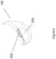
- Figure 2illustrates a HWC 102 with an optical system that includes an upper optical module 202 and a lower optical module 204. While the upper and lower optical modules 202 and 204 will generally be described as separate modules, it should be understood that this is illustrative only and the present disclosure includes other physical configurations, such as that when the two modules are combined into a single module or where the elements making up the two modules are configured into more than two modules.
- the upper module 202includes a computer controlled display (e.g. LCoS, DLP, OLED, etc.) and image light delivery optics.
- the lower moduleincludes eye delivery optics that are configured to receive the upper module's image light and deliver the image light to the eye of a wearer of the HWC.
- the upper and lower optical modules 202 and 204are illustrated in one side of the HWC such that image light can be delivered to one eye of the wearer, that it is envisioned by the present disclosure that embodiments will contain two image light delivery systems, one for each eye.
- the optical modulesas "upper” and “lower” it should be understood that this convention is being used to make it easier for the reader and that the modules are not necessarily located in an upper-lower relationship.
- the image generation modulemay be located above the eye delivery optics, below the eye delivery optics, on a side of the eye delivery optics, or otherwise positioned to satisfy the needs of the situation and/or the HWC 102 mechanical and optical requirements.
- An aspect of the present disclosurerelates to the mechanical and electrical construction of a side arm of a head worn computer.
- a head worn computertakes the form of glasses, sun-glasses, certain goggles, or other such forms
- two side armsare included for mounting and securing the had worn computer on the ears of a person wearing the head worn computer.
- the side armsmay also contain electronics, batteries, wires, antennas, computer processors, computer boards, etc.
- the side armmay include two or more sub-assemblies.
- the side armmay include a temple section and an ear horn section. The two sections may, for example, be mechanically arranged to allow an ear horn section to move such that both side arms can fold into a closed position.
- Figure 3illustrates three separate views 102A, 102B and 102C of a head worn computer 102.
- the head worn computer illustrated as 102Aone side arm of the HWC 102 is folded into its closed position.
- the ear horn section 308 of the side armis rotated relative to its temple section 304 to create space relative to the other side arm 310 so when the other side arm is moved into its closed position it can fully close.
- the ear hornwould physically interfere with the other side arm 310, when the side arm was in the closed position, and prevent the other side arm 310 from fully closing.
- the HWC 102B viewillustrates the HWC 102B with both side arms folded into a fully closed position.
- FIG. 3also illustrates a portion of the HWC 102 where electronics may be housed in a top mount 312.
- the top mountmay contain electronics, sensors, optics, processors, memory, radios, antennas, etc.
- Figure 4illustrates a side arm configuration.
- the side armincludes two sub-assemblies: the temple section 304 and the ear horn 308.
- Figure 4illustrates two views of the side arm assembly, one from an outer perspective and one from a sectioned perspective.
- the ear hornincludes a pin 402 that is designed to fit into a hole 404 and to be secured by connector 408.
- the connector 408is rotatable and in one position locks the pin 402 in place and in another position unsecures the pin 402 such that the ear horn 308 can be removed and re-attached to the temple section 304. This allows the detachment and re-attachment of the ear horn 308 from the temple section 304. This also allows for the sale of different ear horns 308 for replacement, of which a variety of colors and patterns may be offered.
- the temple section 304may include a battery compartment 410 and other electronics, wires, sensors, processors, etc.
- Figure 5illustrates several views of a HWC side arm with temple 304 and ear horn 308 sections. The views include outer perspectives and cross sections as well as various states of the security of the ear horn 308 with the temple section 304.
- Figure set 504illustrates the ear horn 308 and the temple section 304 in a secure un- rotated position. The same pin 402 and connector 408 system described in connection with figure 4 is illustrated in the cross sections of figure 5 . In the secured un-rotated position the pin is pulled internally within the temple section firmly such that it stays in place.
- Figure set 504illustrates a state where the ear horn 308 is separated from the temple section 304. This state is achieved when pressure is used to pull on the ear horn 308.
- the pressureis exerted by a user pulling on the ear horn 308, which compresses a spring 10B that is mechanically associated with the pin 402 in the ear horn 308.
- the mechanismuses the spring to maintain pressure on the pin 402 to maintain connection with the connector 408 when the connector 408 is in a position to lock the pin 402 in position.
- Figure set 508illustrates a state where, after the ear horn 308 has been pulled into the state described in connection with state 504, the ear horn 308 is rotated about the pin 402. This puts the ear horn 308 in a rotated position as described herein such that the first arm, with this rotated ear horn 308, does not interfere with the closure of the other arm 310 when the two arms are folded into the closed position.
- An aspect of the present disclosurerelates to an adjustable nose bridge.
- An adjustable nose bridgemay be important with head worn computers, especially those with computer displays, to ensure comfort and alignment of the displays and/or other portions of the head worn computer.
- Figure 6illustrates a HWC 102 with an adjustable nose bridge 602.
- the nose bridgeis adjustable through a mechanism in the HWC 102.
- the mechanismincludes a fixed notched attachment 604, a movable pin 608 adapted to fit into the notches of the notched attachment 604, and a selection device 610 that is attached to the movable pin 608.
- the movable pin 608 and nose bridge 602are connected such that the as the movable pin 608 shifts in position the nose bridge 602 moves in position as well.
- the selection device 610causes the movable pin 608 to engage and disengage with the fixed notched attachment 604 when presses and allowed to retract. As illustrated in figure 6 , the selection device 610 is not in a pressed position so the movable pin 608 is engaged with the notched attachment 604 such that the nose bridge is securely attached in a stable position.
- Figure 7illustrates a scenario where the selection device is pressed, or activated, such that the moveable pin 608 is no longer engaged with the fixed notched attachment 604. This allows the nose bridge 602 to move up and down with respect to the rest of the HWC 102. Once the movable pin 608 aligns with a notch of the notched attachment 604, the two parts may engage to re-secure the nose bridge in the HWC 102.
- a side arm of the HWC 102may include an audio jack (not shown) and the audio jack may be magnetically attachable to the side arm.
- the temple section 304 or ear horn section 308may have a magnetically attachable audio jack with audio signal wires associated with an audio system in the HWC 102.
- the magnetic attachmentmay include one or more magnets on one end (e.g. on the head phone end or the side arm end) and magnetically conductive material on the other end. In other examples, both ends of the attachment may have magnets, of opposite polarization, to create a stronger magnetic bond for the headphone).
- the audio signal wires or magnetic connectionmay include a sensor circuit to detect when the headphone is detached from the HWC 102.
- the other side's headphonemay play a tone, sound, signal, etc. in the event a headphone is detached.
- an indication of the detachmentmay be displayed in the computer display.
- the HWC 102may have a vibration system that vibrates to alert the wearer of certain sensed conditions.
- the vibration systeme.g. an actuator that moves quickly to cause vibration in the HWC 102
- the vibration systemmay be mounted in a side arm (e.g. the temple portion 304, or ear horn 308), in the top mount 312, etc.
- the vibration systemmaybe capable of causing different vibration modes that may be indicative of different conditions.
- the vibration systemmay include a multimode vibration system, piezo-electric vibration system, variable motor, etc, that can be regulated through computer input and a processor in the HWC 102 may send control signals to the vibration system to generate an appropriate vibration mode.
- the HWC 102may be associated with other devices (e.g.
- the HWC 102may be connected to a car through Bluetooth such that sensor(s) in the car can cause activation of a vibration mode for the vibration system.
- the carmay determine that a risk of accident is present (e.g. risk of the driver falling asleep, car going out of its lane, a car in front of the wearer is stopped or slowing, radar in the car indicates a risk, etc.) and the car's system may then send a command, via the Bluetooth connection, to the HWC 102 to cause a vibratory tone to be initiated in the HWC 102.
- connection between the speaker system and the HWC 102may be positioned other than under the temple section. It may be positioned on a side, top, bottom, end of a section of the side arm, for example. It may be positioned on the front bridge, for example.
- the speaker systemmay be connected to a top or side portion and the speaker may be further positioned to face forward, away from the user's ear. This may be a useful configuration for providing sound to others. For example, such a configuration may be used when the user wants to provide translations to a person nearby. The user may speak in a language, have the language translated, and then spoken through the forward facing speakers.
- the removable nature of the speaker systemsmay be desirable for breakaway situations so a snag does not tear the glasses from the user or pull hard on the user's ear.
- the removable naturemay also be useful for modularity configurations where the user wants to interchange speaker types or attach other accessories.
- the usermay want ear buds at one point and an open ear speaker configuration at another point and the user may be able to make the swap with ease given this configuration.
- the port on the HWC 102may also be adapted for other accessories that include lights or sensors for example.
- the accessorymay have an ambient light sensor to assist with the control of the lighting and contrast systems used in the HWC 102 displays, for example.
- the speaker portmay be used as a charging port for the HWC 102 or data port for the HWC 102.
- Positioning of a head-worn computercan be complicated by the nature of the computer displays that are intended to be positioned in front of the user's eyes along with the fact that people have different shaped heads, noses, eye positions, etc.
- the inventorshave appreciated the difficulties in such positioning and have developed an intuitive mechanism for a multi-axis adjustment system for the head-worn computer.
- the multi-axis adjustment systemprovides for vertical adjustment of the nose bridge, persistent rotational settings for the nose pads, and persistent outward/inward flex of the nose pads.
- Such a systemis designed to be used on a wide variety of nose shapes and head sizes.
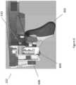
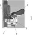
- Figure 8illustrates a portion of a head-worn computer 102 with a mounting area 802 for an adjustable nose bridge assembly 804.
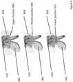
- Figure 9illustrates an adjustable nose bridge assembly 804 in three different vertical positions 904, 908, and 910.
- the adjustable nose bridge 804has a selection device 610 and nose pads 902.
- the selection deviceis a button, or other suitable user interface, and is mechanically arranged such that pushing the button releases the nose bridge such that it can be moved up and down.
- the buttonengages with a tooth or other such feature to hold the nose bridge in place.
- the adjustmentmay be continuous or discrete and may be mechanically, electrically, or otherwise controlled.
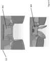
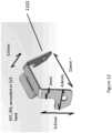
- Figure 10illustrates an engagement mechanism for removing and replacing the nose pads from and to the vertical adjustment portion of the adjustable nose bridge assembly.
- the nose padsare attached to a clip style mechanism that is adapted to mate with the vertical nose bridge adjustment system.
- Figure 10also shows a clear version of one nose pad to illustrate how it is over- molded to a stiff (e.g. metal) member.
- the inventorsappreciate that there are a number of ways to attach the nose pads to the vertical adjustment system and this example is provided as a non-limiting example.
- Figure 11illustrates a system providing two additional movable features for the nose pads. Together with the vertical adjustment portion, this configuration provides for a three-way adjustment system. Adjustment 1002 illustrates how the nose pads may be rotated or otherwise manipulated from a rear facing view. Adjustment 1004 illustrates how the nose pads may be rotated or otherwise manipulated from a top view. Once assembled on the head-worn computer, the vertical adjustment and two nose pad rotational adjustments provide for a system that accommodates many nose, face, and head shapes.
- Figure 12illustrates a nose pad mount 1102.
- the nose padsmay be over-molded on to the ends of a mount.
- the nose padsare over-molded on the ends of the nose pad mount 1102.
- the nose pad mount 1102is designed to be malleable around the 2mm dimension shown. This permits the user to twist, turn, bend, flare, or otherwise manipulate the nose pad mount 1102 to change the positions of the nose pads, which then can accommodate the user's facial structure. While the embodiment shown in figure 12 illustrates a single piece, the inventors have appreciated that this mount may be assembled in multiple pieces.
- HWChas been described in language specific to features, systems, computer processes and/or methods
- the appended claimsare not necessarily limited to the specific features, systems, computer processes and/or methods described. Rather, the specific features, systems, computer processes and/or and methods are disclosed as non-limited example implementations of HWC.
Landscapes
- Physics & Mathematics (AREA)
- Engineering & Computer Science (AREA)
- General Physics & Mathematics (AREA)
- Optics & Photonics (AREA)
- Health & Medical Sciences (AREA)
- Theoretical Computer Science (AREA)
- Computer Hardware Design (AREA)
- Ophthalmology & Optometry (AREA)
- Human Computer Interaction (AREA)
- General Engineering & Computer Science (AREA)
- Acoustics & Sound (AREA)
- Otolaryngology (AREA)
- General Health & Medical Sciences (AREA)
- Electromagnetism (AREA)
- Computer Networks & Wireless Communication (AREA)
- Signal Processing (AREA)
- Eyeglasses (AREA)
- User Interface Of Digital Computer (AREA)
- Yarns And Mechanical Finishing Of Yarns Or Ropes (AREA)
- Golf Clubs (AREA)
Description
- This disclosure relates to head worn computing. More particularly, this disclosure relates to 3-way adjustable nose bridge assemblies for head-worn computers.
WO 2016/132974 A1 discloses a head-worn computer according to the preamble ofclaim 1.US 6,480,174 B1 discloses an eyeglass-mount display with a vertical and horizontal adjustment mechanism of a nose pad.- Wearable computing systems have been developed and are beginning to be commercialized. Many problems persist in the wearable computing field that need to be resolved to make them meet the demands of the market.
- The invention is directed to a head worn computer according to
claim 1. Further developments of the invention are according to dependent claims 2-6. - These and other systems, methods, objects, features, and advantages of the present disclosure will be apparent to those skilled in the art from the following detailed description of the preferred embodiment and the drawings. All documents mentioned herein are hereby incorporated in their entirety by reference.
- Embodiments are described with reference to the following Figures. The same numbers may be used throughout to reference like features and components that are shown in the Figures:
Figure 1 illustrates a head worn computing system in accordance with the principles of the present disclosure.Figure 2 illustrates a head worn computing system with optical system in accordance with the principles of the present disclosure.Figure 3 illustrates three views of a head worn computer in accordance with the principles of the present disclosure.Figure 4 illustrates a temple and ear horn.Figure 5 illustrates a temple and ear horn assembly in various states.Figure 6 illustrates an adjustable nose bridge assembly in accordance with the principles of the present invention.Figure 7 illustrates an adjustable nose bridge assembly in accordance with the principles of the present invention.Figure 8 illustrates adjustable nose bridge assemblies in accordance with the principles of the present invention.Figure 9 illustrates adjustable nose bridge assemblies in accordance with the principles of the present invention.Figure 10 illustrates adjustable nose bridge assemblies in accordance with the principles of the present invention.Figure 11 illustrates a multiple adjustable nose pad assembly in accordance with the principles of the present invention.Figure 12 illustrates a malleable platform use in connection with an adjustable nose bridge assembly in accordance with the principles of the present invention.- While the disclosure has been described in connection with certain preferred embodiments, other embodiments would be understood by one of ordinary skill in the art and are encompassed herein.
- Aspects of the present disclosure relate to head-worn computing ("HWC") systems. HWC involves, in some instances, a system that mimics the appearance of head-worn glasses or sunglasses. The glasses may be a fully developed computing platform, such as including computer displays presented in each of the lenses of the glasses to the eyes of the user. In embodiments, the lenses and displays may be configured to allow a person wearing the glasses to see the environment through the lenses while also seeing, simultaneously, digital imagery, which forms an overlaid image that is perceived by the person as a digitally augmented image of the environment, or augmented reality ("AR").
- HWC involves more than just placing a computing system on a person's head. The system may need to be designed as a lightweight, compact and fully functional computer display, such as wherein the computer display includes a high resolution digital display that provides a high level of emersion comprised of the displayed digital content and the see-through view of the environmental surroundings. User interfaces and control systems suited to the HWC device may be required that are unlike those used for a more conventional computer such as a laptop. For the HWC and associated systems to be most effective, the glasses may be equipped with sensors to determine environmental conditions, geographic location, relative positioning to other points of interest, objects identified by imaging and movement by the user or other users in a connected group, and the like. The HWC may then change the mode of operation to match the conditions, location, positioning, movements, and the like, in a method generally referred to as a contextually aware HWC. The glasses also may need to be connected, wirelessly or otherwise, to other systems either locally or through a network. Controlling the glasses may be achieved through the use of an external device, automatically through contextually gathered information, through user gestures captured by the glasses sensors, and the like. Each technique may be further refined depending on the software application being used in the glasses. The glasses may further be used to control or coordinate with external devices that are associated with the glasses.
- Referring to
Fig. 1 , an overview of the HWCsystem 100 is presented. As shown, the HWCsystem 100 comprises a HWC 102, which in this instance is configured as glasses to be worn on the head with sensors such that the HWC 102 is aware of the objects and conditions in the environment 114. In this instance, the HWC 102 also receives and interprets control inputs such as gestures and movements 116. The HWC 102 may communicate with external user interfaces 104. The external user interfaces 104 may provide a physical user interface to take control instructions from a user of the HWC 102 and the external user interfaces 104 and the HWC 102 may communicate bi-directionally to affect the user's command and provide feedback to theexternal device 108. The HWC 102 may also communicate bi-directionally with externally controlled or coordinatedlocal devices 108. For example, an external user interface 104 may be used in connection with the HWC 102 to control an externally controlled or coordinatedlocal device 108. The externally controlled or coordinatedlocal device 108 may provide feedback to the HWC 102 and a customized GUI may be presented in the HWC 102 based on the type of device or specifically identifieddevice 108. The HWC 102 may also interact with remote devices andinformation sources 112 through anetwork connection 110. Again, the external user interface 104 may be used in connection with the HWC 102 to control or otherwise interact with any of theremote devices 108 andinformation sources 112 in a similar way as when the external user interfaces 104 are used to control or otherwise interact with the externally controlled or coordinatedlocal devices 108. Similarly, HWC 102 may interpret gestures 116 (e.g. captured from forward, downward, upward, rearward facing sensors such as camera(s), range finders, IR sensors, etc.) or environmental conditions sensed in the environment 114 to control either local orremote devices - We will now describe each of the main elements depicted on
Fig. 1 in more detail; however, these descriptions are intended to provide general guidance and should not be construed as limiting. Additional description of each element may also be further described herein. - The HWC 102 is a computing platform intended to be worn on a person's head. The HWC 102 may take many different forms to fit many different functional requirements. In some situations, the HWC 102 will be designed in the form of conventional glasses. The glasses may or may not have active computer graphics displays. In situations where the HWC 102 has integrated computer displays the displays may be configured as see-through displays such that the digital imagery can be overlaid with respect to the user's view of the environment 114. There are a number of see-through optical designs that may be used, including ones that have a reflective display (e.g. LCoS, DLP), emissive displays (e.g. OLED, LED), hologram, TIR waveguides, and the like. In embodiments, lighting systems used in connection with the display optics may be solid state lighting systems, such as LED, OLED, quantum dot, quantum dot LED, etc. In addition, the optical configuration may be monocular or binocular. It may also include vision corrective optical components. In embodiments, the optics may be packaged as contact lenses. In other embodiments, the
HWC 102 may be in the form of a helmet with a see-through shield, sunglasses, safety glasses, goggles, a mask, fire helmet with see-through shield, police helmet with see through shield, military helmet with see-through shield, utility form customized to a certain work task (e.g. inventory control, logistics, repair, maintenance, etc.), and the like. - The
HWC 102 may also have a number of integrated computing facilities, such as an integrated processor, integrated power management, communication structures (e.g. cell net, WiFi, Bluetooth, local area connections, mesh connections, remote connections (e.g. client server, etc.)), and the like. TheHWC 102 may also have a number of positional awareness sensors, such as GPS, electronic compass, altimeter, tilt sensor, IMU, and the like. It may also have other sensors such as a camera, rangefinder, hyper-spectral camera, Geiger counter, microphone, spectral illumination detector, temperature sensor, chemical sensor, biologic sensor, moisture sensor, ultrasonic sensor, and the like. - The
HWC 102 may also have integrated control technologies. The integrated control technologies may be contextual based control, passive control, active control, user control, and the like. For example, theHWC 102 may have an integrated sensor (e.g. camera) that captures user hand or body gestures 116 such that the integrated processing system can interpret the gestures and generate control commands for theHWC 102. In another example, theHWC 102 may have sensors that detect movement (e.g. a nod, head shake, and the like) including accelerometers, gyros and other inertial measurements, where the integrated processor may interpret the movement and generate a control command in response. TheHWC 102 may also automatically control itself based on measured or perceived environmental conditions. For example, if it is bright in the environment theHWC 102 may increase the brightness or contrast of the displayed image. In embodiments, the integrated control technologies may be mounted on theHWC 102 such that a user can interact with it directly. For example, theHWC 102 may have a button(s), touch capacitive interface, and the like. - As described herein, the
HWC 102 may be in communication with external user interfaces 104. The external user interfaces may come in many different forms. For example, a cell phone screen may be adapted to take user input for control of an aspect of theHWC 102. The external user interface may be a dedicated UI, such as a keyboard, touch surface, button(s), joy stick, and the like. In embodiments, the external controller may be integrated into another device such as a ring, watch, bike, car, and the like. In each case, the external user interface 104 may include sensors (e.g. IMU, accelerometers, compass, altimeter, and the like) to provide additional input for controlling the HWD 104. - As described herein, the
HWC 102 may control or coordinate with otherlocal devices 108. Theexternal devices 108 may be an audio device, visual device, vehicle, cell phone, computer, and the like. For instance, the localexternal device 108 may be anotherHWC 102, where information may then be exchanged between theseparate HWCs 108. - Similar to the way the
HWC 102 may control or coordinate with local devices 106, theHWC 102 may control or coordinate withremote devices 112, such as theHWC 102 communicating with theremote devices 112 through anetwork 110. Again, the form of theremote device 112 may have many forms. Included in these forms is anotherHWC 102. For example, eachHWC 102 may communicate its GPS position such that all theHWCs 102 know where all ofHWC 102 are located. Figure 2 illustrates aHWC 102 with an optical system that includes an upperoptical module 202 and a loweroptical module 204. While the upper and loweroptical modules upper module 202 includes a computer controlled display (e.g. LCoS, DLP, OLED, etc.) and image light delivery optics. In embodiments, the lower module includes eye delivery optics that are configured to receive the upper module's image light and deliver the image light to the eye of a wearer of the HWC. Infigure 2 , it should be noted that while the upper and loweroptical modules HWC 102 mechanical and optical requirements.- An aspect of the present disclosure relates to the mechanical and electrical construction of a side arm of a head worn computer. In general, when a head worn computer takes the form of glasses, sun-glasses, certain goggles, or other such forms, two side arms are included for mounting and securing the had worn computer on the ears of a person wearing the head worn computer. In examples, the side arms may also contain electronics, batteries, wires, antennas, computer processors, computer boards, etc. In examples, the side arm may include two or more sub-assemblies. For example, as will be discussed in more detail below, the side arm may include a temple section and an ear horn section. The two sections may, for example, be mechanically arranged to allow an ear horn section to move such that both side arms can fold into a closed position.
Figure 3 illustrates threeseparate views computer 102. Turning to the head worn computer illustrated as 102A, one side arm of theHWC 102 is folded into its closed position. Theear horn section 308 of the side arm is rotated relative to itstemple section 304 to create space relative to theother side arm 310 so when the other side arm is moved into its closed position it can fully close. In a situation where the ear horn did not rotate to create the space (not illustrated) the ear horn would physically interfere with theother side arm 310, when the side arm was in the closed position, and prevent theother side arm 310 from fully closing. TheHWC 102B view illustrates theHWC 102B with both side arms folded into a fully closed position. Note that theear horn 308 is in the rotated position with respect to itstemple section 304 such that theother arm 310 closed without interfering with theear horn 308. TheHWC 102C view also illustrates both arms in closed positions with theear horn 308 rotated to create the space for theother arm 310 to fully close.Figure 3 also illustrates a portion of theHWC 102 where electronics may be housed in atop mount 312. The top mount may contain electronics, sensors, optics, processors, memory, radios, antennas, etc.Figure 4 illustrates a side arm configuration. In this example, the side arm includes two sub-assemblies: thetemple section 304 and theear horn 308.Figure 4 illustrates two views of the side arm assembly, one from an outer perspective and one from a sectioned perspective. The ear horn includes apin 402 that is designed to fit into ahole 404 and to be secured byconnector 408. Theconnector 408 is rotatable and in one position locks thepin 402 in place and in another position unsecures thepin 402 such that theear horn 308 can be removed and re-attached to thetemple section 304. This allows the detachment and re-attachment of theear horn 308 from thetemple section 304. This also allows for the sale ofdifferent ear horns 308 for replacement, of which a variety of colors and patterns may be offered. In examples, thetemple section 304 may include abattery compartment 410 and other electronics, wires, sensors, processors, etc.Figure 5 illustrates several views of a HWC side arm withtemple 304 and ear horn 308 sections. The views include outer perspectives and cross sections as well as various states of the security of theear horn 308 with thetemple section 304. Figure set 504 illustrates theear horn 308 and thetemple section 304 in a secure un- rotated position. Thesame pin 402 andconnector 408 system described in connection withfigure 4 is illustrated in the cross sections offigure 5 . In the secured un-rotated position the pin is pulled internally within the temple section firmly such that it stays in place. Figure set 504 illustrates a state where theear horn 308 is separated from thetemple section 304. This state is achieved when pressure is used to pull on theear horn 308. In examples, the pressure is exerted by a user pulling on theear horn 308, which compresses a spring 10B that is mechanically associated with thepin 402 in theear horn 308. The mechanism uses the spring to maintain pressure on thepin 402 to maintain connection with theconnector 408 when theconnector 408 is in a position to lock thepin 402 in position. Figure set 508 illustrates a state where, after theear horn 308 has been pulled into the state described in connection withstate 504, theear horn 308 is rotated about thepin 402. This puts theear horn 308 in a rotated position as described herein such that the first arm, with this rotatedear horn 308, does not interfere with the closure of theother arm 310 when the two arms are folded into the closed position.- An aspect of the present disclosure relates to an adjustable nose bridge. An adjustable nose bridge may be important with head worn computers, especially those with computer displays, to ensure comfort and alignment of the displays and/or other portions of the head worn computer.
Figure 6 illustrates aHWC 102 with anadjustable nose bridge 602. The nose bridge is adjustable through a mechanism in theHWC 102. In embodiments, the mechanism includes a fixed notchedattachment 604, amovable pin 608 adapted to fit into the notches of the notchedattachment 604, and aselection device 610 that is attached to themovable pin 608. Themovable pin 608 andnose bridge 602 are connected such that the as themovable pin 608 shifts in position thenose bridge 602 moves in position as well. Theselection device 610 causes themovable pin 608 to engage and disengage with the fixed notchedattachment 604 when presses and allowed to retract. As illustrated infigure 6 , theselection device 610 is not in a pressed position so themovable pin 608 is engaged with the notchedattachment 604 such that the nose bridge is securely attached in a stable position.Figure 7 illustrates a scenario where the selection device is pressed, or activated, such that themoveable pin 608 is no longer engaged with the fixed notchedattachment 604. This allows thenose bridge 602 to move up and down with respect to the rest of theHWC 102. Once themovable pin 608 aligns with a notch of the notchedattachment 604, the two parts may engage to re-secure the nose bridge in theHWC 102. - In examples, a side arm of the
HWC 102 may include an audio jack (not shown) and the audio jack may be magnetically attachable to the side arm. For example, thetemple section 304 orear horn section 308 may have a magnetically attachable audio jack with audio signal wires associated with an audio system in theHWC 102. The magnetic attachment may include one or more magnets on one end (e.g. on the head phone end or the side arm end) and magnetically conductive material on the other end. In other examples, both ends of the attachment may have magnets, of opposite polarization, to create a stronger magnetic bond for the headphone). In examples, the audio signal wires or magnetic connection may include a sensor circuit to detect when the headphone is detached from theHWC 102. This may be useful in situations where the wearer is wearing the headphones during a period when there is not constant audio processing (e.g. listening for people to talk with periods of silence). In examples, the other side's headphone may play a tone, sound, signal, etc. in the event a headphone is detached. In examples, an indication of the detachment may be displayed in the computer display. - In examples, the
HWC 102 may have a vibration system that vibrates to alert the wearer of certain sensed conditions. In examples, the vibration system (e.g. an actuator that moves quickly to cause vibration in the HWC 102) may be mounted in a side arm (e.g. thetemple portion 304, or ear horn 308), in thetop mount 312, etc. In examples, the vibration system maybe capable of causing different vibration modes that may be indicative of different conditions. For example, the vibration system may include a multimode vibration system, piezo-electric vibration system, variable motor, etc, that can be regulated through computer input and a processor in theHWC 102 may send control signals to the vibration system to generate an appropriate vibration mode. In examples, theHWC 102 may be associated with other devices (e.g. through Bluetooth, WiFi, etc.) and the vibratory control signals may be associated with sensors associated with the other device. For example, theHWC 102 may be connected to a car through Bluetooth such that sensor(s) in the car can cause activation of a vibration mode for the vibration system. The car, for example, may determine that a risk of accident is present (e.g. risk of the driver falling asleep, car going out of its lane, a car in front of the wearer is stopped or slowing, radar in the car indicates a risk, etc.) and the car's system may then send a command, via the Bluetooth connection, to theHWC 102 to cause a vibratory tone to be initiated in theHWC 102. - In examples, the connection between the speaker system and the
HWC 102 may be positioned other than under the temple section. It may be positioned on a side, top, bottom, end of a section of the side arm, for example. It may be positioned on the front bridge, for example. In examples, the speaker system may be connected to a top or side portion and the speaker may be further positioned to face forward, away from the user's ear. This may be a useful configuration for providing sound to others. For example, such a configuration may be used when the user wants to provide translations to a person nearby. The user may speak in a language, have the language translated, and then spoken through the forward facing speakers. - The removable nature of the speaker systems may be desirable for breakaway situations so a snag does not tear the glasses from the user or pull hard on the user's ear. The removable nature may also be useful for modularity configurations where the user wants to interchange speaker types or attach other accessories. For example, the user may want ear buds at one point and an open ear speaker configuration at another point and the user may be able to make the swap with ease given this configuration. The port on the
HWC 102 may also be adapted for other accessories that include lights or sensors for example. The accessory may have an ambient light sensor to assist with the control of the lighting and contrast systems used in theHWC 102 displays, for example. In examples, the speaker port may be used as a charging port for theHWC 102 or data port for theHWC 102. - Another aspect of the present disclosure relates to an adjustable nose bridge assembly of a head-worn computer. Positioning of a head-worn computer can be complicated by the nature of the computer displays that are intended to be positioned in front of the user's eyes along with the fact that people have different shaped heads, noses, eye positions, etc. The inventors have appreciated the difficulties in such positioning and have developed an intuitive mechanism for a multi-axis adjustment system for the head-worn computer. In examples, the multi-axis adjustment system provides for vertical adjustment of the nose bridge, persistent rotational settings for the nose pads, and persistent outward/inward flex of the nose pads. Such a system is designed to be used on a wide variety of nose shapes and head sizes.
Figure 8 illustrates a portion of a head-worncomputer 102 with a mountingarea 802 for an adjustablenose bridge assembly 804.Figure 9 illustrates an adjustablenose bridge assembly 804 in three differentvertical positions adjustable nose bridge 804 has aselection device 610 andnose pads 902. In embodiments, the selection device is a button, or other suitable user interface, and is mechanically arranged such that pushing the button releases the nose bridge such that it can be moved up and down. In this embodiment, the button engages with a tooth or other such feature to hold the nose bridge in place. In embodiments, the adjustment may be continuous or discrete and may be mechanically, electrically, or otherwise controlled.Figure 10 illustrates an engagement mechanism for removing and replacing the nose pads from and to the vertical adjustment portion of the adjustable nose bridge assembly. As can be seen infigure 10 , the nose pads are attached to a clip style mechanism that is adapted to mate with the vertical nose bridge adjustment system.Figure 10 also shows a clear version of one nose pad to illustrate how it is over- molded to a stiff (e.g. metal) member. The inventors appreciate that there are a number of ways to attach the nose pads to the vertical adjustment system and this example is provided as a non-limiting example.Figure 11 illustrates a system providing two additional movable features for the nose pads. Together with the vertical adjustment portion, this configuration provides for a three-way adjustment system.Adjustment 1002 illustrates how the nose pads may be rotated or otherwise manipulated from a rear facing view.Adjustment 1004 illustrates how the nose pads may be rotated or otherwise manipulated from a top view. Once assembled on the head-worn computer, the vertical adjustment and two nose pad rotational adjustments provide for a system that accommodates many nose, face, and head shapes.Figure 12 illustrates anose pad mount 1102. As previously described, the nose pads may be over-molded on to the ends of a mount. In this embodiment, the nose pads are over-molded on the ends of thenose pad mount 1102. Thenose pad mount 1102 is designed to be malleable around the 2mm dimension shown. This permits the user to twist, turn, bend, flare, or otherwise manipulate thenose pad mount 1102 to change the positions of the nose pads, which then can accommodate the user's facial structure. While the embodiment shown infigure 12 illustrates a single piece, the inventors have appreciated that this mount may be assembled in multiple pieces.- Although embodiments of HWC have been described in language specific to features, systems, computer processes and/or methods, the appended claims are not necessarily limited to the specific features, systems, computer processes and/or methods described. Rather, the specific features, systems, computer processes and/or and methods are disclosed as non-limited example implementations of HWC.
Claims (6)
- A head-worn computer (102), comprisinga display;a removable and replaceable adjustable nose bridge assembly (804), wherein the adjustable nose bridge assembly (804) has at least three user adjustable features to mechanically position the adjustable nose bridge assembly (804) to the user's nose,wherein a first adjustment of the at least three user adjustable features is adapted to move the adjustable nose bridge assembly up and down relative to the display of the head-worn computer,wherein a second adjustment of the at least three user adjustable features is adapted to rotate a nose pad (902) of the adjustable nose bridge assembly about an axis substantially perpendicular to a top frame of the head-worn computer,wherein a third adjustment of the at least three user adjustable features is adapted to flare the nose pad to a side of the axis, andcharacterized in that the nose pad (902) is attached to a clip style mechanism (1002) that is configured to be removably mated with a vertical nose bridge adjustment system (804) providing the first user adjustment of the at least three user adjustable features, the removable mating occurring without affecting the first adjustment.
- The head -worn computer (102) of claim 1, wherein the first adjustment includes a user activated mechanism to release the adjustable nose bridge assembly (804) from the head-worn computer so that the adjustable nose bridge assembly (804) is movable by the user and wherein the user activated mechanism further locks the adjustable nose bridge assembly in place once the move by the user has been completed.
- The head -worn computer (102) of claim 1, wherein the second adjustment includes a malleable member that maintains a persistent position after a user adjustment.
- The head-worn computer (102) of claim 1, wherein the third adjustment includes a malleable member that maintains a persistent position after a user adjustment.
- The head -worn computer (102) of claim 1, wherein the second and third adjustments include a malleable member that maintains a persistent position after a user adjustment, wherein the malleable member performs both the second and third adjustments.
- The head-worn computer of claim 1, wherein the nose pad is mounted on a malleable metal mount, wherein the malleable metal mount maintains a position of the nose pad but is user adjustable.
Applications Claiming Priority (2)
| Application Number | Priority Date | Filing Date | Title |
|---|---|---|---|
| US15/249,637US10690936B2 (en) | 2016-08-29 | 2016-08-29 | Adjustable nose bridge assembly for headworn computer |
| PCT/US2017/046701WO2018044537A1 (en) | 2016-08-29 | 2017-08-14 | Adjustable nose bridge assembly for headworn computer |
Publications (3)
| Publication Number | Publication Date |
|---|---|
| EP3504581A1 EP3504581A1 (en) | 2019-07-03 |
| EP3504581A4 EP3504581A4 (en) | 2020-04-15 |
| EP3504581B1true EP3504581B1 (en) | 2025-04-09 |
Family
ID=61240551
Family Applications (1)
| Application Number | Title | Priority Date | Filing Date |
|---|---|---|---|
| EP17847193.4AActiveEP3504581B1 (en) | 2016-08-29 | 2017-08-14 | Adjustable nose bridge assembly for headworn computer |
Country Status (9)
| Country | Link |
|---|---|
| US (2) | US10690936B2 (en) |
| EP (1) | EP3504581B1 (en) |
| JP (2) | JP7071041B2 (en) |
| CN (2) | CN109791296A (en) |
| AU (1) | AU2017321192B2 (en) |
| CA (1) | CA3035026A1 (en) |
| IL (1) | IL265031B (en) |
| NZ (1) | NZ751200A (en) |
| WO (1) | WO2018044537A1 (en) |
Families Citing this family (58)
| Publication number | Priority date | Publication date | Assignee | Title |
|---|---|---|---|---|
| US9158116B1 (en) | 2014-04-25 | 2015-10-13 | Osterhout Group, Inc. | Temple and ear horn assembly for headworn computer |
| US10684687B2 (en) | 2014-12-03 | 2020-06-16 | Mentor Acquisition One, Llc | See-through computer display systems |
| US9651788B2 (en) | 2014-01-21 | 2017-05-16 | Osterhout Group, Inc. | See-through computer display systems |
| US11892644B2 (en) | 2014-01-21 | 2024-02-06 | Mentor Acquisition One, Llc | See-through computer display systems |
| US9753288B2 (en) | 2014-01-21 | 2017-09-05 | Osterhout Group, Inc. | See-through computer display systems |
| US9423842B2 (en) | 2014-09-18 | 2016-08-23 | Osterhout Group, Inc. | Thermal management for head-worn computer |
| US9651787B2 (en) | 2014-04-25 | 2017-05-16 | Osterhout Group, Inc. | Speaker assembly for headworn computer |
| US20150309534A1 (en) | 2014-04-25 | 2015-10-29 | Osterhout Group, Inc. | Ear horn assembly for headworn computer |
| US9684172B2 (en) | 2014-12-03 | 2017-06-20 | Osterhout Group, Inc. | Head worn computer display systems |
| EP3062142B1 (en) | 2015-02-26 | 2018-10-03 | Nokia Technologies OY | Apparatus for a near-eye display |
| US10824253B2 (en) | 2016-05-09 | 2020-11-03 | Mentor Acquisition One, Llc | User interface systems for head-worn computers |
| US10466491B2 (en) | 2016-06-01 | 2019-11-05 | Mentor Acquisition One, Llc | Modular systems for head-worn computers |
| US10684478B2 (en) | 2016-05-09 | 2020-06-16 | Mentor Acquisition One, Llc | User interface systems for head-worn computers |
| US10690936B2 (en) | 2016-08-29 | 2020-06-23 | Mentor Acquisition One, Llc | Adjustable nose bridge assembly for headworn computer |
| USD840395S1 (en) | 2016-10-17 | 2019-02-12 | Osterhout Group, Inc. | Head-worn computer |
| US10650552B2 (en) | 2016-12-29 | 2020-05-12 | Magic Leap, Inc. | Systems and methods for augmented reality |
| EP4300160A3 (en) | 2016-12-30 | 2024-05-29 | Magic Leap, Inc. | Polychromatic light out-coupling apparatus, near-eye displays comprising the same, and method of out-coupling polychromatic light |
| USD864959S1 (en) | 2017-01-04 | 2019-10-29 | Mentor Acquisition One, Llc | Computer glasses |
| US10578870B2 (en) | 2017-07-26 | 2020-03-03 | Magic Leap, Inc. | Exit pupil expander |
| US11119328B2 (en)* | 2017-08-23 | 2021-09-14 | Flex Ltd. | Light projection engine attachment and alignment |
| KR102858869B1 (en) | 2017-12-10 | 2025-09-11 | 매직 립, 인코포레이티드 | Anti-reflective coatings on optical waveguides |
| CN111712751B (en) | 2017-12-20 | 2022-11-01 | 奇跃公司 | Insert for augmented reality viewing apparatus |
| JP2019129484A (en)* | 2018-01-26 | 2019-08-01 | セイコーエプソン株式会社 | Virtual image display device and nose pad therefor |
| US10755676B2 (en) | 2018-03-15 | 2020-08-25 | Magic Leap, Inc. | Image correction due to deformation of components of a viewing device |
| US11204491B2 (en) | 2018-05-30 | 2021-12-21 | Magic Leap, Inc. | Compact variable focus configurations |
| JP7319303B2 (en) | 2018-05-31 | 2023-08-01 | マジック リープ, インコーポレイテッド | Radar head pose localization |
| US10825424B2 (en) | 2018-06-05 | 2020-11-03 | Magic Leap, Inc. | Homography transformation matrices based temperature calibration of a viewing system |
| US11092812B2 (en) | 2018-06-08 | 2021-08-17 | Magic Leap, Inc. | Augmented reality viewer with automated surface selection placement and content orientation placement |
| US11579441B2 (en) | 2018-07-02 | 2023-02-14 | Magic Leap, Inc. | Pixel intensity modulation using modifying gain values |
| WO2020010226A1 (en) | 2018-07-03 | 2020-01-09 | Magic Leap, Inc. | Systems and methods for virtual and augmented reality |
| US11856479B2 (en) | 2018-07-03 | 2023-12-26 | Magic Leap, Inc. | Systems and methods for virtual and augmented reality along a route with markers |
| CN112585581B (en) | 2018-07-10 | 2024-10-18 | 奇跃公司 | Thread weaving for cross-ISA procedure calls |
| CN119197613A (en) | 2018-07-24 | 2024-12-27 | 奇跃公司 | Temperature-dependent calibration of mobile detection equipment |
| WO2020023543A1 (en) | 2018-07-24 | 2020-01-30 | Magic Leap, Inc. | Viewing device with dust seal integration |
| WO2020028834A1 (en) | 2018-08-02 | 2020-02-06 | Magic Leap, Inc. | A viewing system with interpupillary distance compensation based on head motion |
| CN116820239A (en) | 2018-08-03 | 2023-09-29 | 奇跃公司 | Fusion gesture based drift correction of fusion gestures for totem in a user interaction system |
| WO2020041615A1 (en) | 2018-08-22 | 2020-02-27 | Magic Leap, Inc. | Patient viewing system |
| TWI678557B (en)* | 2018-08-27 | 2019-12-01 | 宏碁股份有限公司 | Nose pad structure and head-mounted device using the same |
| EP3881279A4 (en) | 2018-11-16 | 2022-08-17 | Magic Leap, Inc. | Image size triggered clarification to maintain image sharpness |
| CN118409394A (en) | 2018-12-21 | 2024-07-30 | 奇跃公司 | Cavitation structures for promoting total internal reflection in waveguides |
| RU2707838C1 (en)* | 2019-01-28 | 2019-11-29 | ООО "Оптика-Центр" | Angular frame of spectacle holder |
| WO2020163603A1 (en) | 2019-02-06 | 2020-08-13 | Magic Leap, Inc. | Target intent-based clock speed determination and adjustment to limit total heat generated by multiple processors |
| JP2022523852A (en) | 2019-03-12 | 2022-04-26 | マジック リープ, インコーポレイテッド | Aligning local content between first and second augmented reality viewers |
| CN111856750B (en)* | 2019-04-26 | 2022-01-14 | 华为技术有限公司 | Nose holds in palm subassembly and head-mounted display device |
| WO2020223636A1 (en) | 2019-05-01 | 2020-11-05 | Magic Leap, Inc. | Content provisioning system and method |
| WO2021021670A1 (en) | 2019-07-26 | 2021-02-04 | Magic Leap, Inc. | Systems and methods for augmented reality |
| TWI692657B (en)* | 2019-08-13 | 2020-05-01 | 和碩聯合科技股份有限公司 | glasses |
| JP7363197B2 (en)* | 2019-08-28 | 2023-10-18 | セイコーエプソン株式会社 | Optical devices, wearable display devices and light guide units |
| JP7635230B2 (en) | 2019-11-14 | 2025-02-25 | マジック リープ, インコーポレイテッド | Systems and methods for virtual and augmented reality |
| CN114667538A (en) | 2019-11-15 | 2022-06-24 | 奇跃公司 | Viewing system for use in a surgical environment |
| CN113126318B (en)* | 2020-01-13 | 2024-11-12 | 鸿富锦精密电子(郑州)有限公司 | Spectacle frame and spectacles having the same |
| US11714453B1 (en)* | 2020-06-22 | 2023-08-01 | Apple Inc. | Nosepiece for head-mountable device |
| US11391962B1 (en)* | 2020-12-31 | 2022-07-19 | Lenovo (United States) Inc. | Head mounted display nosepiece |
| CN116661133A (en)* | 2022-02-18 | 2023-08-29 | 北京七鑫易维信息技术有限公司 | Eye moves tracks intelligent glasses |
| US20230350224A1 (en)* | 2022-04-28 | 2023-11-02 | Dell Products, Lp | Method and apparatus for removable magnetic nose bridge |
| US12436408B2 (en) | 2022-11-11 | 2025-10-07 | Htc Corporation | Wearable device |
| CN116360104A (en)* | 2023-02-24 | 2023-06-30 | 歌尔科技有限公司 | Intelligent glasses, nose pad control method thereof and computer readable storage medium |
| EP4513254A1 (en) | 2023-08-19 | 2025-02-26 | MOMES GmbH | Light emitting nosepad |
Family Cites Families (292)
| Publication number | Priority date | Publication date | Assignee | Title |
|---|---|---|---|---|
| US1897833A (en) | 1931-01-26 | 1933-02-14 | William G G Benway | Audiphone |
| US2064604A (en) | 1934-04-04 | 1936-12-15 | Hempel Paul | Spectacle frame |
| US3531190A (en) | 1969-06-18 | 1970-09-29 | Foster Grant Co Inc | Spectacle frame assembly |
| US3671111A (en) | 1970-10-12 | 1972-06-20 | Standard Optical Mfg Co | Biased hinge for spectacle frames |
| US4145125A (en) | 1977-07-20 | 1979-03-20 | Hani Chika | Eyeglass lens with indicia and method of making same |
| US4513812A (en) | 1981-06-25 | 1985-04-30 | Papst-Motoren Gmbh & Co. Kg | Heat sink for electronic devices |
| NL8301864A (en) | 1983-05-26 | 1984-12-17 | Philips Nv | MAIN TV OR EQUIPMENT FOR INDIVIDUAL DISPLAY OF IMAGES. |
| US4842389A (en) | 1987-06-12 | 1989-06-27 | Flight Dynamics, Inc. | Vehicle display system using a holographic windshield prepared to withstand lamination process |
| JPH06141258A (en)* | 1992-10-29 | 1994-05-20 | Sony Corp | Spectacle type video display device |
| WO1994014152A1 (en) | 1992-12-04 | 1994-06-23 | Virtual Vision, Inc. | A head mounted display system |
| US7310072B2 (en) | 1993-10-22 | 2007-12-18 | Kopin Corporation | Portable communication display device |
| US5717422A (en) | 1994-01-25 | 1998-02-10 | Fergason; James L. | Variable intensity high contrast passive display |
| US5606458A (en) | 1994-08-24 | 1997-02-25 | Fergason; James L. | Head mounted display and viewing system using a remote retro-reflector and method of displaying and viewing an image |
| US5625372A (en) | 1994-12-21 | 1997-04-29 | Siliscape, Inc. | Compact compound magnified virtual image electronic display |
| US5808800A (en) | 1994-12-22 | 1998-09-15 | Displaytech, Inc. | Optics arrangements including light source arrangements for an active matrix liquid crystal image generator |
| US5596451A (en) | 1995-01-30 | 1997-01-21 | Displaytech, Inc. | Miniature image generator including optics arrangement |
| US6369952B1 (en) | 1995-07-14 | 2002-04-09 | I-O Display Systems Llc | Head-mounted personal visual display apparatus with image generator and holder |
| USD383148S (en) | 1995-08-15 | 1997-09-02 | Min-Young Wang Lee | Glasses |
| US6847336B1 (en) | 1996-10-02 | 2005-01-25 | Jerome H. Lemelson | Selectively controllable heads-up display system |
| US5808802A (en) | 1996-11-15 | 1998-09-15 | Daewoo Electronics Co. Ltd. | Head-mounted display apparatus with a single image display device |
| US5870166A (en) | 1997-02-25 | 1999-02-09 | Chang; Byung Jin | Versatile optical mounting assembly |
| BR9808560A (en) | 1997-04-15 | 2000-05-23 | Michael T Perkins | Belt to support articles around a user's torso. |
| US6034653A (en) | 1997-08-01 | 2000-03-07 | Colorado Microdisplay, Inc. | Head-set display device |
| US5954642A (en) | 1997-12-23 | 1999-09-21 | Honeywell Inc. | Adjustable head mounted display and system |
| US6076927A (en) | 1998-07-10 | 2000-06-20 | Owens; Raymond L. | Adjustable focal length eye glasses |
| US5971538A (en)* | 1998-10-30 | 1999-10-26 | Hewlett-Packard Company | Articulated nose bridge for head mounted display |
| US6456438B1 (en) | 1999-08-12 | 2002-09-24 | Honeywell Inc. | Variable immersion vignetting display |
| JP4004191B2 (en) | 1999-09-01 | 2007-11-07 | 株式会社ニコンアイウェア | Glasses with a screwless hinge |
| US6480174B1 (en)* | 1999-10-09 | 2002-11-12 | Optimize Incorporated | Eyeglass-mount display having personalized fit module |
| JP2001311904A (en) | 2000-04-28 | 2001-11-09 | Canon Inc | Image display device and image display system |
| US6995753B2 (en) | 2000-06-06 | 2006-02-07 | Semiconductor Energy Laboratory Co., Ltd. | Display device and method of manufacturing the same |
| WO2002000299A2 (en) | 2000-06-23 | 2002-01-03 | Comsonics, Inc. | Diving mask with embedded computer system |
| JP4626019B2 (en) | 2000-07-05 | 2011-02-02 | 株式会社ニコン | Glasses frame |
| WO2002026905A2 (en) | 2000-09-26 | 2002-04-04 | Matsushita Electric Industrial Co., Ltd. | Display unit and drive system thereof and an information display unit |
| US6563648B2 (en) | 2000-10-20 | 2003-05-13 | Three-Five Systems, Inc. | Compact wide field of view imaging system |
| JP4626072B2 (en)* | 2001-03-15 | 2011-02-02 | コニカミノルタホールディングス株式会社 | Video observation device |
| US20020152425A1 (en) | 2001-04-12 | 2002-10-17 | David Chaiken | Distributed restart in a multiple processor system |
| US6957089B2 (en) | 2001-05-31 | 2005-10-18 | Coby Electronics Corporation | Compact hands-free adapter for use with a cellular telephone |
| EP1433160A1 (en) | 2001-09-07 | 2004-06-30 | The Microoptical Corporation | Light weight, compact, remountable face-supported electronic display |
| US7088234B2 (en) | 2001-11-27 | 2006-08-08 | Matsushita Electric Industrial Co., Ltd. | Wearing information notifying unit |
| IL148804A (en) | 2002-03-21 | 2007-02-11 | Yaacov Amitai | Optical device |
| TW594658B (en) | 2002-07-01 | 2004-06-21 | Leadtek Research Inc | Helmet-mounted display |
| US7118212B2 (en) | 2002-08-12 | 2006-10-10 | Scalar Corporation | Image display device |
| US7409234B2 (en) | 2003-03-07 | 2008-08-05 | Cardo Systems, Inc. | Wireless communication headset with exchangeable attachments |
| US6824265B1 (en) | 2003-03-31 | 2004-11-30 | Wesley Stephen Harper | Illuminated safety and work glasses |
| US7760898B2 (en) | 2003-10-09 | 2010-07-20 | Ip Venture, Inc. | Eyeglasses with hearing enhanced and other audio signal-generating capabilities |
| US7922321B2 (en) | 2003-10-09 | 2011-04-12 | Ipventure, Inc. | Eyewear supporting after-market electrical components |
| US8465151B2 (en) | 2003-04-15 | 2013-06-18 | Ipventure, Inc. | Eyewear with multi-part temple for supporting one or more electrical components |
| USD800118S1 (en) | 2003-09-30 | 2017-10-17 | Zhou Tian Xing | Wearable artificial intelligence data processing, augmented reality, virtual reality, and mixed reality communication eyeglass including mobile phone and mobile computing via virtual touch screen gesture control and neuron command |
| EP2148504B1 (en) | 2003-12-03 | 2012-01-25 | Nikon Corporation | Information Display Device |
| WO2005076869A2 (en) | 2004-02-04 | 2005-08-25 | Displaytech, Inc. | Compact electronic viewfinder |
| JP4373286B2 (en) | 2004-05-06 | 2009-11-25 | オリンパス株式会社 | Head-mounted display device |
| IL162572A (en) | 2004-06-17 | 2013-02-28 | Lumus Ltd | High brightness optical device |
| US7241008B2 (en) | 2004-06-21 | 2007-07-10 | Luther James Hammock | Eyeglass frame |
| US6987787B1 (en) | 2004-06-28 | 2006-01-17 | Rockwell Collins | LED brightness control system for a wide-range of luminance control |
| US20060061542A1 (en) | 2004-09-23 | 2006-03-23 | Stokic Dragan Z | Dynamic character display input device |
| US7280364B2 (en) | 2004-11-24 | 2007-10-09 | Hewlett-Packard Development Company, L.P. | Apparatus and method for multiprocessor circuit board |
| USD521493S1 (en) | 2005-01-21 | 2006-05-23 | Koninklikjke Philips Electronics, N.V. | Gaming headphone |
| US7791889B2 (en) | 2005-02-16 | 2010-09-07 | Hewlett-Packard Development Company, L.P. | Redundant power beneath circuit board |
| US7430358B2 (en) | 2005-04-20 | 2008-09-30 | Wavefront Technology, Inc. | Elliptical diffusers used in displays |
| US7707035B2 (en) | 2005-10-13 | 2010-04-27 | Integrated Wave Technologies, Inc. | Autonomous integrated headset and sound processing system for tactical applications |
| US8018579B1 (en) | 2005-10-21 | 2011-09-13 | Apple Inc. | Three-dimensional imaging and display system |
| US7810750B2 (en) | 2006-12-13 | 2010-10-12 | Marcio Marc Abreu | Biologically fit wearable electronics apparatus and methods |
| US8092007B2 (en) | 2006-01-13 | 2012-01-10 | Switch Vision, Llc | Eyewear frames with magnetic lens attachments |
| JP2009524081A (en) | 2006-01-13 | 2009-06-25 | リバティ スポーツ, インコーポレイテッド | Glasses frame with magnetic lens attachment |
| US7637609B1 (en) | 2006-02-24 | 2009-12-29 | Chic Optic, Inc. | Resilient hinge for eyeglasses |
| US8188868B2 (en) | 2006-04-20 | 2012-05-29 | Nike, Inc. | Systems for activating and/or authenticating electronic devices for operation with apparel |
| US7605795B2 (en) | 2006-06-21 | 2009-10-20 | Intel Corporation | Power efficient screens through display size reduction |
| US7928926B2 (en) | 2006-06-27 | 2011-04-19 | Panasonic Corporation | Display apparatus and method for hands free operation that selects a function when window is within field of view |
| US7855743B2 (en) | 2006-09-08 | 2010-12-21 | Sony Corporation | Image capturing and displaying apparatus and image capturing and displaying method |
| JP5017989B2 (en) | 2006-09-27 | 2012-09-05 | ソニー株式会社 | Imaging apparatus and imaging method |
| US7425065B2 (en)* | 2007-01-04 | 2008-09-16 | Protective Optics, Inc. | Eyewear with releasable, adjustable nosepiece |
| CN101632033B (en) | 2007-01-12 | 2013-07-31 | 寇平公司 | Head-mounted monocular display device |
| JP5009361B2 (en) | 2007-03-29 | 2012-08-22 | 京セラ株式会社 | Portable radio |
| US8515728B2 (en) | 2007-03-29 | 2013-08-20 | Microsoft Corporation | Language translation of visual and audio input |
| US8549415B2 (en) | 2007-05-04 | 2013-10-01 | Apple Inc. | Automatically adjusting media display in a personal display system |
| US7934291B2 (en) | 2007-06-07 | 2011-05-03 | Apple Inc. | Multi-position magnetic detents |
| JP4790667B2 (en)* | 2007-06-25 | 2011-10-12 | 正治 杉原 | Bifocal glasses with sensor |
| US8156363B2 (en) | 2007-07-02 | 2012-04-10 | Panasonic Corporation | Information processing device and mobile phone including comparison of power consumption information and remaining power |
| EP2183742A2 (en) | 2007-07-31 | 2010-05-12 | Kopin Corporation | Mobile wireless display providing speech to speech translation and avatar simulating human attributes |
| US7954047B2 (en) | 2007-08-06 | 2011-05-31 | Apple Inc. | Cutting and copying discontiguous selections of cells |
| US20090040296A1 (en) | 2007-08-06 | 2009-02-12 | Moscato Jonathan D | Head mounted display assembly |
| US7904485B2 (en) | 2007-09-06 | 2011-03-08 | Apple Inc. | Graphical representation of assets stored on a portable media device |
| US8286734B2 (en) | 2007-10-23 | 2012-10-16 | Weatherford/Lamb, Inc. | Low profile rotating control device |
| US7800360B2 (en) | 2007-10-31 | 2010-09-21 | Sony Ericsson Mobile Communications Ab | Connector system with magnetic audio volume control and method |
| US7582828B2 (en) | 2007-11-08 | 2009-09-01 | Dana Innovations | Magnetic mount for an electronic device |
| US9158116B1 (en) | 2014-04-25 | 2015-10-13 | Osterhout Group, Inc. | Temple and ear horn assembly for headworn computer |
| US8166421B2 (en) | 2008-01-14 | 2012-04-24 | Primesense Ltd. | Three-dimensional user interface |
| US8384997B2 (en) | 2008-01-21 | 2013-02-26 | Primesense Ltd | Optical pattern projection |
| JP2009171505A (en) | 2008-01-21 | 2009-07-30 | Nikon Corp | Head mounted display |
| US10488660B2 (en) | 2008-03-13 | 2019-11-26 | Everysight Ltd. | Wearable optical display system for unobstructed viewing |
| US20100149073A1 (en) | 2008-11-02 | 2010-06-17 | David Chaum | Near to Eye Display System and Appliance |
| US8423288B2 (en) | 2009-11-30 | 2013-04-16 | Apple Inc. | Dynamic alerts for calendar events |
| US20100045928A1 (en) | 2008-08-25 | 2010-02-25 | Tri-Specs, Inc. | Fashion eyewear frame that houses circuitry to effect wireless audio communication while providing extraneous background noise cancellation capability |
| US20100079508A1 (en) | 2008-09-30 | 2010-04-01 | Andrew Hodge | Electronic devices with gaze detection capabilities |
| US8957835B2 (en) | 2008-09-30 | 2015-02-17 | Apple Inc. | Head-mounted display apparatus for retaining a portable electronic device with display |
| WO2010062479A1 (en) | 2008-11-02 | 2010-06-03 | David Chaum | System and apparatus for eyeglass appliance platform |
| US20150205111A1 (en) | 2014-01-21 | 2015-07-23 | Osterhout Group, Inc. | Optical configurations for head worn computing |
| US8594467B2 (en) | 2008-12-19 | 2013-11-26 | Microsoft Corporation | Interactive virtual display system for ubiquitous devices |
| CN102439510A (en) | 2009-03-02 | 2012-05-02 | 斯博瑞安眼睛及面部保护设备公司 | Safety eyewear |
| US8494215B2 (en) | 2009-03-05 | 2013-07-23 | Microsoft Corporation | Augmenting a field of view in connection with vision-tracking |
| US7878647B2 (en) | 2009-04-09 | 2011-02-01 | Live Eyewear, Inc. | Frame for eyeglasses, associated temple, and method of making the same |
| US8089568B1 (en) | 2009-10-02 | 2012-01-03 | Rockwell Collins, Inc. | Method of and system for providing a head up display (HUD) |
| USD671590S1 (en) | 2010-09-10 | 2012-11-27 | X6D Limited | 3D glasses |
| KR20110055337A (en) | 2009-11-18 | 2011-05-25 | 삼성전자주식회사 | Display device |
| EP2502410B1 (en) | 2009-11-19 | 2019-05-01 | eSight Corporation | A method for augmenting sight |
| US8244311B2 (en) | 2009-12-29 | 2012-08-14 | International Business Machines Corporation | Time-related power systems |
| US8400548B2 (en) | 2010-01-05 | 2013-03-19 | Apple Inc. | Synchronized, interactive augmented reality displays for multifunction devices |
| US8890771B2 (en) | 2010-01-06 | 2014-11-18 | Apple Inc. | Transparent electronic device |
| US8463543B2 (en) | 2010-02-05 | 2013-06-11 | Apple Inc. | Schematic maps |
| US8353729B2 (en) | 2010-02-18 | 2013-01-15 | Apple Inc. | Low profile connector system |
| US20110213664A1 (en) | 2010-02-28 | 2011-09-01 | Osterhout Group, Inc. | Local advertising content on an interactive head-mounted eyepiece |
| WO2011106797A1 (en) | 2010-02-28 | 2011-09-01 | Osterhout Group, Inc. | Projection triggering through an external marker in an augmented reality eyepiece |
| US20120242698A1 (en) | 2010-02-28 | 2012-09-27 | Osterhout Group, Inc. | See-through near-eye display glasses with a multi-segment processor-controlled optical layer |
| US8964298B2 (en) | 2010-02-28 | 2015-02-24 | Microsoft Corporation | Video display modification based on sensor input for a see-through near-to-eye display |
| US9129295B2 (en) | 2010-02-28 | 2015-09-08 | Microsoft Technology Licensing, Llc | See-through near-eye display glasses with a fast response photochromic film system for quick transition from dark to clear |
| US9128281B2 (en) | 2010-09-14 | 2015-09-08 | Microsoft Technology Licensing, Llc | Eyepiece with uniformly illuminated reflective display |
| KR20110101944A (en) | 2010-03-10 | 2011-09-16 | 삼성전자주식회사 | 3D glasses, driving method of 3D glasses and 3D image providing system |
| JP2011203446A (en) | 2010-03-25 | 2011-10-13 | Fujifilm Corp | Head-mounted display device |
| JP5678460B2 (en)* | 2010-04-06 | 2015-03-04 | ソニー株式会社 | Head-mounted display |
| WO2011130374A1 (en) | 2010-04-13 | 2011-10-20 | PixelOptics | Attachable electro-active lens systems |
| USD628616S1 (en) | 2010-05-14 | 2010-12-07 | Hi-Shock Digital Electronics Technologies Co., Ltd. | 3D glasses |
| WO2011143655A1 (en) | 2010-05-14 | 2011-11-17 | Advitech, Inc. | System and method for prevention and control of the effects of spatial disorientation |
| JP2011242685A (en) | 2010-05-20 | 2011-12-01 | Hitachi Consumer Electronics Co Ltd | Image display device |
| US8594425B2 (en) | 2010-05-31 | 2013-11-26 | Primesense Ltd. | Analysis of three-dimensional scenes |
| JP5646238B2 (en) | 2010-07-27 | 2014-12-24 | オリンパス株式会社 | Image display device |
| US8957948B2 (en) | 2010-08-24 | 2015-02-17 | Siemens Corporation | Geometric calibration of head-worn multi-camera eye tracking system |
| JP5459150B2 (en) | 2010-09-03 | 2014-04-02 | セイコーエプソン株式会社 | Light guide plate and virtual image display device including the same |
| US8582206B2 (en) | 2010-09-15 | 2013-11-12 | Microsoft Corporation | Laser-scanning virtual image display |
| US20120078628A1 (en) | 2010-09-28 | 2012-03-29 | Ghulman Mahmoud M | Head-mounted text display system and method for the hearing impaired |
| USD647947S1 (en) | 2010-10-05 | 2011-11-01 | Mengchu Yu | Kind of high definition glasses camera |
| US8837880B2 (en) | 2010-10-08 | 2014-09-16 | Seiko Epson Corporation | Virtual image display device |
| WO2013058776A1 (en) | 2010-10-21 | 2013-04-25 | Hussey Patrick | Flip up interchangeable system |
| US8692845B2 (en) | 2010-10-28 | 2014-04-08 | Eastman Kodak Company | Head-mounted display control with image-content analysis |
| US8576276B2 (en) | 2010-11-18 | 2013-11-05 | Microsoft Corporation | Head-mounted display device which provides surround video |
| WO2012078912A2 (en)* | 2010-12-08 | 2012-06-14 | Vision Jeannie, Llc | Translating multifocal eyeglass lenses |
| US20130154913A1 (en) | 2010-12-16 | 2013-06-20 | Siemens Corporation | Systems and methods for a gaze and gesture interface |
| USD645492S1 (en) | 2010-12-17 | 2011-09-20 | Classic Ltd. | Combined eyeglasses and camera |
| USD645493S1 (en) | 2010-12-23 | 2011-09-20 | Classic Ltd. | Combined eyeglasses and camera |
| US9280938B2 (en) | 2010-12-23 | 2016-03-08 | Microsoft Technology Licensing, Llc | Timed sequence mixed color display |
| US8665214B2 (en) | 2010-12-29 | 2014-03-04 | Qualcomm Incorporated | Extending battery life of a portable electronic device |
| USD646316S1 (en) | 2011-01-14 | 2011-10-04 | Classic Ltd. | Combined eyeglasses and camera |
| US20120188245A1 (en) | 2011-01-20 | 2012-07-26 | Apple Inc. | Display resolution increase with mechanical actuation |
| JP5760465B2 (en) | 2011-02-04 | 2015-08-12 | セイコーエプソン株式会社 | Virtual image display device |
| JP5633406B2 (en) | 2011-02-04 | 2014-12-03 | セイコーエプソン株式会社 | Virtual image display device |
| JP5742263B2 (en) | 2011-02-04 | 2015-07-01 | セイコーエプソン株式会社 | Virtual image display device |
| EP2672880B1 (en) | 2011-02-09 | 2019-05-22 | Apple Inc. | Gaze detection in a 3d mapping environment |
| US20120212593A1 (en) | 2011-02-17 | 2012-08-23 | Orcam Technologies Ltd. | User wearable visual assistance system |
| USD667482S1 (en) | 2011-02-17 | 2012-09-18 | Dolby Laboratories Licensing Corporation | 3D eyeglasses |
| US20120223885A1 (en) | 2011-03-02 | 2012-09-06 | Microsoft Corporation | Immersive display experience |
| US8670183B2 (en) | 2011-03-07 | 2014-03-11 | Microsoft Corporation | Augmented view of advertisements |
| US9081416B2 (en) | 2011-03-24 | 2015-07-14 | Seiko Epson Corporation | Device, head mounted display, control method of device and control method of head mounted display |
| JP2012212990A (en) | 2011-03-30 | 2012-11-01 | Brother Ind Ltd | Head-mounted display |
| US8953242B2 (en) | 2011-03-31 | 2015-02-10 | Honeywell International Inc. | Varible focus stereoscopic display system and method |
| US20120264510A1 (en) | 2011-04-12 | 2012-10-18 | Microsoft Corporation | Integrated virtual environment |
| US9606607B2 (en) | 2011-05-17 | 2017-03-28 | Ignis Innovation Inc. | Systems and methods for display systems with dynamic power control |
| JP2012249097A (en) | 2011-05-27 | 2012-12-13 | Kyocera Corp | Speech output device |
| US20120306850A1 (en) | 2011-06-02 | 2012-12-06 | Microsoft Corporation | Distributed asynchronous localization and mapping for augmented reality |
| USD665838S1 (en) | 2011-06-21 | 2012-08-21 | Lg Electronics Inc. | 3D glasses |
| IL213727A (en) | 2011-06-22 | 2015-01-29 | Elbit Systems Ltd | Helmet mounted display system adjustable for bright ambient light conditions |
| US20120326948A1 (en) | 2011-06-22 | 2012-12-27 | Microsoft Corporation | Environmental-light filter for see-through head-mounted display device |
| US20120327116A1 (en) | 2011-06-23 | 2012-12-27 | Microsoft Corporation | Total field of view classification for head-mounted display |
| USD667483S1 (en) | 2011-08-09 | 2012-09-18 | Psychomed.com S.A. | Audio-visual stimulation spectacles with headphones |
| US8593795B1 (en) | 2011-08-09 | 2013-11-26 | Google Inc. | Weight distribution for wearable computing device |
| US9285592B2 (en) | 2011-08-18 | 2016-03-15 | Google Inc. | Wearable device with input and output structures |
| TW201312200A (en) | 2011-09-14 | 2013-03-16 | Hon Hai Prec Ind Co Ltd | Glass adjust structure |
| JP6127359B2 (en) | 2011-09-15 | 2017-05-17 | セイコーエプソン株式会社 | Virtual image display device and method of manufacturing virtual image display device |
| US8941560B2 (en) | 2011-09-21 | 2015-01-27 | Google Inc. | Wearable computer with superimposed controls and instructions for external device |
| JP5834705B2 (en) | 2011-09-28 | 2015-12-24 | セイコーエプソン株式会社 | Electro-optical device and electronic apparatus |
| JP5786601B2 (en) | 2011-09-28 | 2015-09-30 | セイコーエプソン株式会社 | Electro-optical device and electronic apparatus |
| US9121724B2 (en) | 2011-09-30 | 2015-09-01 | Apple Inc. | 3D position tracking for panoramic imagery navigation |
| US8847988B2 (en) | 2011-09-30 | 2014-09-30 | Microsoft Corporation | Exercising applications for personal audio/visual system |
| JP2013080040A (en) | 2011-10-03 | 2013-05-02 | Seiko Epson Corp | Electrooptical device, method for manufacturing electrooptical device, and electronic equipment |
| US20130088507A1 (en) | 2011-10-06 | 2013-04-11 | Nokia Corporation | Method and apparatus for controlling the visual representation of information upon a see-through display |
| KR20130002363U (en)* | 2011-10-11 | 2013-04-19 | 국제옵티칼 주식회사 | Glasses Frames For Easy Installation And Removal Hanger Nose |
| US8813109B2 (en) | 2011-10-21 | 2014-08-19 | The Nielsen Company (Us), Llc | Methods and apparatus to identify exposure to 3D media presentations |
| USD666237S1 (en) | 2011-10-24 | 2012-08-28 | Google Inc. | Wearable display device |
| US8752963B2 (en) | 2011-11-04 | 2014-06-17 | Microsoft Corporation | See-through display brightness control |
| US8831336B2 (en) | 2011-11-11 | 2014-09-09 | Texas Instruments Incorporated | Method, system and computer program product for detecting an object in response to depth information |
| US8553910B1 (en) | 2011-11-17 | 2013-10-08 | Jianchun Dong | Wearable computing device with behind-ear bone-conduction speaker |
| US20130176626A1 (en) | 2012-01-05 | 2013-07-11 | Google Inc. | Wearable device assembly with input and output structures |
| US8955973B2 (en) | 2012-01-06 | 2015-02-17 | Google Inc. | Method and system for input detection using structured light projection |
| US8942419B1 (en) | 2012-01-06 | 2015-01-27 | Google Inc. | Position estimation using predetermined patterns of light sources |
| USD718304S1 (en) | 2012-01-06 | 2014-11-25 | Google Inc. | Display device component |
| US9529197B2 (en) | 2012-03-21 | 2016-12-27 | Google Inc. | Wearable device with input and output structures |
| US8971023B2 (en) | 2012-03-21 | 2015-03-03 | Google Inc. | Wearable computing device frame |
| EP2806782B1 (en) | 2012-01-26 | 2019-08-14 | Nokia Technologies Oy | Capacitive eye tracking sensor |
| US8894484B2 (en) | 2012-01-30 | 2014-11-25 | Microsoft Corporation | Multiplayer game invitation system |
| US9076368B2 (en) | 2012-02-06 | 2015-07-07 | Battelle Memorial Institute | Image generation systems and image generation methods |
| US8982014B2 (en) | 2012-02-06 | 2015-03-17 | Battelle Memorial Institute | Image generation systems and image generation methods |
| CN104160240B (en) | 2012-02-15 | 2017-02-22 | 苹果公司 | Scanning depth engine |
| US8745058B1 (en) | 2012-02-21 | 2014-06-03 | Google Inc. | Dynamic data item searching |
| US9075249B2 (en)* | 2012-03-07 | 2015-07-07 | Google Inc. | Eyeglass frame with input and output functionality |
| US8866702B1 (en) | 2012-03-13 | 2014-10-21 | Google Inc. | Use of optical display system as a visual indicator for a wearable computing device |
| USD718305S1 (en) | 2012-03-22 | 2014-11-25 | Google Inc. | Wearable display device |
| US9207468B2 (en) | 2012-03-30 | 2015-12-08 | Honeywell International Inc. | Personal protection equipment verification |
| WO2013152205A1 (en) | 2012-04-05 | 2013-10-10 | Augmented Vision Inc. | Wide-field of view (fov) imaging devices with active foveation capability |
| US8937591B2 (en) | 2012-04-06 | 2015-01-20 | Apple Inc. | Systems and methods for counteracting a perceptual fading of a movable indicator |
| US9417660B2 (en) | 2012-04-25 | 2016-08-16 | Kopin Corporation | Collapsible head set computer |
| US20130297460A1 (en) | 2012-05-01 | 2013-11-07 | Zambala Lllp | System and method for facilitating transactions of a physical product or real life service via an augmented reality environment |
| US20130300634A1 (en) | 2012-05-09 | 2013-11-14 | Nokia Corporation | Method and apparatus for determining representations of displayed information based on focus distance |
| WO2013176079A1 (en) | 2012-05-21 | 2013-11-28 | オリンパス株式会社 | Eyeglasses-shaped wearable device and front and temple parts of eyeglasses-shaped wearable device |
| JP5973795B2 (en) | 2012-06-07 | 2016-08-23 | オリンパス株式会社 | Head-mounted display device, image display system, and program |
| US9874936B2 (en) | 2012-06-22 | 2018-01-23 | Cape Evolution Limited | Wearable electronic device |
| JP2014013320A (en) | 2012-07-04 | 2014-01-23 | Sony Corp | Head-mounted type display device and optical unit |
| KR101861380B1 (en) | 2012-07-16 | 2018-05-28 | 마이크로소프트 테크놀로지 라이센싱, 엘엘씨 | A Method of Providing Contents Using Head Mounted Display and a Head Mounted Display Thereof |
| KR20140014895A (en) | 2012-07-27 | 2014-02-06 | 삼성전자주식회사 | Method and apparatus for saving battery of portable terminal |
| CN103576315B (en) | 2012-07-30 | 2017-03-01 | 联想(北京)有限公司 | Display device |
| KR101958778B1 (en) | 2012-08-31 | 2019-03-15 | 엘지전자 주식회사 | A Head Mounted Display and a Method for Controlling a Digital Device Using the Same |
| US9122966B2 (en) | 2012-09-07 | 2015-09-01 | Lawrence F. Glaser | Communication device |
| USD711456S1 (en) | 2012-09-25 | 2014-08-19 | Google Inc. | Wearable display device |
| USD710928S1 (en) | 2012-09-25 | 2014-08-12 | Google Inc. | Wearable display device |
| US10573037B2 (en) | 2012-12-20 | 2020-02-25 | Sri International | Method and apparatus for mentoring via an augmented reality assistant |
| US8750541B1 (en) | 2012-10-31 | 2014-06-10 | Google Inc. | Parametric array for a head-mountable device |
| US20140129328A1 (en) | 2012-11-07 | 2014-05-08 | Microsoft Corporation | Providing augmented purchase schemes |
| US20140146394A1 (en) | 2012-11-28 | 2014-05-29 | Nigel David Tout | Peripheral display for a near-eye display device |
| US9189021B2 (en) | 2012-11-29 | 2015-11-17 | Microsoft Technology Licensing, Llc | Wearable food nutrition feedback system |
| US20140152558A1 (en) | 2012-11-30 | 2014-06-05 | Tom Salter | Direct hologram manipulation using imu |
| US20140152676A1 (en) | 2012-11-30 | 2014-06-05 | Dave Rohn | Low latency image display on multi-display device |
| US20140152530A1 (en) | 2012-12-03 | 2014-06-05 | Honeywell International Inc. | Multimedia near to eye display system |
| US20140160170A1 (en) | 2012-12-06 | 2014-06-12 | Nokia Corporation | Provision of an Image Element on a Display Worn by a User |
| USD685019S1 (en) | 2012-12-11 | 2013-06-25 | Weihua Li | Sunglasses camera |
| US20140160157A1 (en) | 2012-12-11 | 2014-06-12 | Adam G. Poulos | People-triggered holographic reminders |
| US20140160055A1 (en) | 2012-12-12 | 2014-06-12 | Jeffrey Margolis | Wearable multi-modal input device for augmented reality |
| US9081210B2 (en) | 2012-12-12 | 2015-07-14 | Microsoft Technology Licensing, Llc | Head worn device having temple arms to provide long axis compression |
| US10146053B2 (en) | 2012-12-19 | 2018-12-04 | Microsoft Technology Licensing, Llc | Multiplexed hologram tiling in a waveguide display |
| US8971968B2 (en) | 2013-01-18 | 2015-03-03 | Dell Products, Lp | System and method for context aware usability management of human machine interfaces |
| USD692047S1 (en) | 2013-01-31 | 2013-10-22 | Oakley, Inc. | Eyeglass |
| USD723092S1 (en) | 2013-02-06 | 2015-02-24 | Costa Del Mar, Inc. | Eyeglasses |
| USD704764S1 (en) | 2013-04-18 | 2014-05-13 | Cross Optical Group, Inc. | Eyeglasses |
| US9740030B2 (en) | 2013-05-23 | 2017-08-22 | Omnivision Technologies, Inc. | Near-eye display systems, devices and methods |
| USD693398S1 (en) | 2013-05-24 | 2013-11-12 | Wayne L. Rubin | Eyewear |
| FR3006455A1 (en)* | 2013-05-31 | 2014-12-05 | Optinvent | OCULAR VISION SYSTEM WITH OPTICAL GUIDE POSITIONABLE IN TWO POSITIONS |
| US8988345B2 (en) | 2013-06-25 | 2015-03-24 | Microsoft Technology Licensing, Llc | Adaptive event recognition |
| US20160037833A1 (en) | 2013-07-17 | 2016-02-11 | Roger M. Kriesel | Carbon Dioxide Pellet Cooling Safety Helmet and a Flexible Carbon Dioxide Pellet Containment and Vapor Diffusion Fabric Segment |
| KR102086511B1 (en) | 2013-07-25 | 2020-03-09 | 엘지전자 주식회사 | Head Mounted Display and controlling method thereof |
| USD738373S1 (en) | 2013-08-09 | 2015-09-08 | Kopin Corporation | Eyewear viewing device |
| WO2015030797A1 (en) | 2013-08-30 | 2015-03-05 | Intel Corporation | Nausea and seizure detection, prediction, and mitigation for head-mounted displays |
| US10234699B2 (en) | 2013-11-26 | 2019-03-19 | Sony Corporation | Head-mounted display |
| US9390649B2 (en) | 2013-11-27 | 2016-07-12 | Universal Display Corporation | Ruggedized wearable display |
| US9870375B2 (en) | 2013-12-20 | 2018-01-16 | Nvidia Corporation | Image analysis of display content for dynamic adjustment of a continuous scan display |
| USD730975S1 (en) | 2014-01-02 | 2015-06-02 | Lava Limited | Eyewear |
| USD716808S1 (en) | 2014-01-06 | 2014-11-04 | Lg Electronics Inc. | Head mounted display device |
| US10684687B2 (en) | 2014-12-03 | 2020-06-16 | Mentor Acquisition One, Llc | See-through computer display systems |
| US9529195B2 (en) | 2014-01-21 | 2016-12-27 | Osterhout Group, Inc. | See-through computer display systems |
| US20150205135A1 (en) | 2014-01-21 | 2015-07-23 | Osterhout Group, Inc. | See-through computer display systems |
| US9651788B2 (en) | 2014-01-21 | 2017-05-16 | Osterhout Group, Inc. | See-through computer display systems |
| US9846308B2 (en) | 2014-01-24 | 2017-12-19 | Osterhout Group, Inc. | Haptic systems for head-worn computers |
| USD741398S1 (en) | 2014-01-29 | 2015-10-20 | 3M Innovative Properties Company | Eyewear |
| US9342147B2 (en) | 2014-04-10 | 2016-05-17 | Microsoft Technology Licensing, Llc | Non-visual feedback of visual change |
| KR102353766B1 (en) | 2014-04-15 | 2022-01-20 | 삼성전자 주식회사 | Apparatus and method for controlling display |
| US9672210B2 (en) | 2014-04-25 | 2017-06-06 | Osterhout Group, Inc. | Language translation with head-worn computing |
| US9651787B2 (en)* | 2014-04-25 | 2017-05-16 | Osterhout Group, Inc. | Speaker assembly for headworn computer |
| US9423842B2 (en) | 2014-09-18 | 2016-08-23 | Osterhout Group, Inc. | Thermal management for head-worn computer |
| US20150309534A1 (en)* | 2014-04-25 | 2015-10-29 | Osterhout Group, Inc. | Ear horn assembly for headworn computer |
| USD744581S1 (en) | 2014-05-12 | 2015-12-01 | Tenacious Holdings, Inc. | Protective eyewear |
| JP1511166S (en) | 2014-05-21 | 2014-11-10 | ||
| US9323983B2 (en) | 2014-05-29 | 2016-04-26 | Comcast Cable Communications, Llc | Real-time image and audio replacement for visual acquisition devices |
| USD751551S1 (en) | 2014-06-06 | 2016-03-15 | Alpha Primitus, Inc. | Pair of temple arms for an eyeglass frame with mount |
| US9143693B1 (en) | 2014-06-10 | 2015-09-22 | Google Inc. | Systems and methods for push-button slow motion |
| JP1544540S (en) | 2014-06-24 | 2019-02-18 | ||
| US20150382305A1 (en) | 2014-06-27 | 2015-12-31 | Sony Corporation | Silent mode for submerged devices |
| USD769873S1 (en) | 2014-06-27 | 2016-10-25 | Google Inc. | Interchangeable/wearable hinged display device assembly |
| USD723093S1 (en) | 2014-08-13 | 2015-02-24 | Weihua Li | High definition glasses camera |
| US9851567B2 (en) | 2014-08-13 | 2017-12-26 | Google Llc | Interchangeable eyewear/head-mounted device assembly with quick release mechanism |
| US9922236B2 (en) | 2014-09-17 | 2018-03-20 | Toyota Motor Engineering & Manufacturing North America, Inc. | Wearable eyeglasses for providing social and environmental awareness |
| USD747401S1 (en) | 2014-10-10 | 2016-01-12 | Ontel Products Corporation | Eyewear |
| US20160131904A1 (en) | 2014-11-07 | 2016-05-12 | Osterhout Group, Inc. | Power management for head worn computing |
| US9684172B2 (en) | 2014-12-03 | 2017-06-20 | Osterhout Group, Inc. | Head worn computer display systems |
| US9741215B2 (en) | 2014-12-11 | 2017-08-22 | Elwha Llc | Wearable haptic feedback devices and methods of fabricating wearable haptic feedback devices |
| USD751552S1 (en) | 2014-12-31 | 2016-03-15 | Osterhout Group, Inc. | Computer glasses |
| ITPD20150004U1 (en)* | 2015-01-20 | 2016-07-20 | Visottica Ind Spa | NOSE FOR EYEGLASS FRAMES |
| US9545030B2 (en) | 2015-01-20 | 2017-01-10 | Microsoft Technology Licensing, Llc | Flexible thermal conduit for an electronic device |
| WO2016132974A1 (en) | 2015-02-17 | 2016-08-25 | コニカミノルタ株式会社 | Head mounted display |
| USD766895S1 (en) | 2015-03-13 | 2016-09-20 | Samsung Electronics Co., Ltd. | Display device |
| USD765076S1 (en) | 2015-03-16 | 2016-08-30 | Samsung Electronics Co., Ltd. | Display device |
| US10025119B2 (en) | 2015-06-18 | 2018-07-17 | Osterhout Group, Inc. | Mechanical arrangement for head-worn computer |
| USD768759S1 (en) | 2015-08-14 | 2016-10-11 | Costa Del Mar, Inc. | Eyeglasses |
| US9482880B1 (en) | 2015-09-15 | 2016-11-01 | Ashwin-Ushas Corporation, Inc. | Electrochromic eyewear |
| WO2017100074A1 (en) | 2015-12-11 | 2017-06-15 | Osterhout Group, Inc. | Head-worn computer display systems |
| USD795865S1 (en) | 2016-01-06 | 2017-08-29 | Vuzix Corporation | Monocular smart glasses |
| JP1562073S (en) | 2016-02-19 | 2016-10-31 | ||
| USD819026S1 (en) | 2016-04-06 | 2018-05-29 | Allomind, Inc. | Head-mounted display with magnetic battery temples |
| US10466491B2 (en) | 2016-06-01 | 2019-11-05 | Mentor Acquisition One, Llc | Modular systems for head-worn computers |
| US20170343810A1 (en) | 2016-05-24 | 2017-11-30 | Osterhout Group, Inc. | Pre-assembled solid optical assembly for head worn computers |
| JP2017195514A (en) | 2016-04-20 | 2017-10-26 | キヤノン株式会社 | Head mount device and gripping device |
| USD794022S1 (en) | 2016-06-29 | 2017-08-08 | Allomind, Inc. | Head-mounted display with adjustable and swappable battery temples |
| USD793467S1 (en) | 2016-06-29 | 2017-08-01 | Cyclops Gear, LLC | Video-recording eyewear frame |
| US10690936B2 (en) | 2016-08-29 | 2020-06-23 | Mentor Acquisition One, Llc | Adjustable nose bridge assembly for headworn computer |
| USD796506S1 (en) | 2016-09-23 | 2017-09-05 | Magic Leap, Inc. | Head mounted audio-visual display system |
| USD796504S1 (en) | 2016-09-23 | 2017-09-05 | Magic Leap, Inc. | Head mounted audio-visual display system |
| USD803832S1 (en) | 2016-12-22 | 2017-11-28 | Compal Electronics, Inc. | Augmented reality glasses |
- 2016
- 2016-08-29USUS15/249,637patent/US10690936B2/enactiveActive
- 2017
- 2017-08-14NZNZ751200Apatent/NZ751200A/enunknown
- 2017-08-14EPEP17847193.4Apatent/EP3504581B1/enactiveActive
- 2017-08-14ILIL265031Apatent/IL265031B/enunknown
- 2017-08-14WOPCT/US2017/046701patent/WO2018044537A1/ennot_activeCeased
- 2017-08-14CACA3035026Apatent/CA3035026A1/enactivePending
- 2017-08-14JPJP2019511616Apatent/JP7071041B2/enactiveActive
- 2017-08-14AUAU2017321192Apatent/AU2017321192B2/enactiveActive
- 2017-08-14CNCN201780060034.1Apatent/CN109791296A/enactivePending
- 2017-08-14CNCN202410950737.3Apatent/CN118981110A/enactivePending
- 2020
- 2020-05-13USUS15/931,389patent/US11409128B2/enactiveActive
- 2021
- 2021-11-02JPJP2021179292Apatent/JP7273928B2/enactiveActive
Also Published As
| Publication number | Publication date |
|---|---|
| CN118981110A (en) | 2024-11-19 |
| JP2019525261A (en) | 2019-09-05 |
| AU2017321192A1 (en) | 2019-03-21 |
| CA3035026A1 (en) | 2018-03-08 |
| JP7071041B2 (en) | 2022-05-18 |
| CN109791296A (en) | 2019-05-21 |
| NZ751200A (en) | 2022-11-25 |
| WO2018044537A1 (en) | 2018-03-08 |
| EP3504581A4 (en) | 2020-04-15 |
| AU2017321192B2 (en) | 2022-07-14 |
| IL265031A (en) | 2019-04-30 |
| US20180059434A1 (en) | 2018-03-01 |
| US10690936B2 (en) | 2020-06-23 |
| US20210096394A1 (en) | 2021-04-01 |
| JP7273928B2 (en) | 2023-05-15 |
| IL265031B (en) | 2022-08-01 |
| JP2022009899A (en) | 2022-01-14 |
| US11409128B2 (en) | 2022-08-09 |
| EP3504581A1 (en) | 2019-07-03 |
Similar Documents
| Publication | Publication Date | Title |
|---|---|---|
| US11409128B2 (en) | Adjustable nose bridge assembly for headworn computer | |
| US11809022B2 (en) | Temple and ear horn assembly for headworn computer | |
| US12210164B2 (en) | Speaker assembly for headworn computer | |
| US10466492B2 (en) | Ear horn assembly for headworn computer | |
| US20210255677A1 (en) | Thermal management for head-worn computer |
Legal Events
| Date | Code | Title | Description |
|---|---|---|---|
| STAA | Information on the status of an ep patent application or granted ep patent | Free format text:STATUS: THE INTERNATIONAL PUBLICATION HAS BEEN MADE | |
| PUAI | Public reference made under article 153(3) epc to a published international application that has entered the european phase | Free format text:ORIGINAL CODE: 0009012 | |
| STAA | Information on the status of an ep patent application or granted ep patent | Free format text:STATUS: REQUEST FOR EXAMINATION WAS MADE | |
| 17P | Request for examination filed | Effective date:20190225 | |
| AK | Designated contracting states | Kind code of ref document:A1 Designated state(s):AL AT BE BG CH CY CZ DE DK EE ES FI FR GB GR HR HU IE IS IT LI LT LU LV MC MK MT NL NO PL PT RO RS SE SI SK SM TR | |
| AX | Request for extension of the european patent | Extension state:BA ME | |
| RAP1 | Party data changed (applicant data changed or rights of an application transferred) | Owner name:MENTOR ACQUISITION ONE, LLC | |
| DAV | Request for validation of the european patent (deleted) | ||
| DAX | Request for extension of the european patent (deleted) | ||
| A4 | Supplementary search report drawn up and despatched | Effective date:20200313 | |
| RIC1 | Information provided on ipc code assigned before grant | Ipc:G02C 5/02 20060101ALI20200309BHEP Ipc:G02B 27/01 20060101AFI20200309BHEP Ipc:G02C 5/12 20060101ALI20200309BHEP Ipc:G02C 5/06 20060101ALI20200309BHEP Ipc:G02C 5/04 20060101ALI20200309BHEP | |
| STAA | Information on the status of an ep patent application or granted ep patent | Free format text:STATUS: EXAMINATION IS IN PROGRESS | |
| 17Q | First examination report despatched | Effective date:20221205 | |
| GRAP | Despatch of communication of intention to grant a patent | Free format text:ORIGINAL CODE: EPIDOSNIGR1 | |
| STAA | Information on the status of an ep patent application or granted ep patent | Free format text:STATUS: GRANT OF PATENT IS INTENDED | |
| RIC1 | Information provided on ipc code assigned before grant | Ipc:G02C 11/00 20060101ALN20241022BHEP Ipc:G06F 1/16 20060101ALI20241022BHEP Ipc:G02C 5/04 20060101ALI20241022BHEP Ipc:G02C 5/06 20060101ALI20241022BHEP Ipc:G02C 5/12 20060101ALI20241022BHEP Ipc:G02C 5/02 20060101ALI20241022BHEP Ipc:G02B 27/01 20060101AFI20241022BHEP | |
| INTG | Intention to grant announced | Effective date:20241031 | |
| RIN1 | Information on inventor provided before grant (corrected) | Inventor name:HEISEY, ANDREW CARL | |
| GRAS | Grant fee paid | Free format text:ORIGINAL CODE: EPIDOSNIGR3 | |
| P01 | Opt-out of the competence of the unified patent court (upc) registered | Free format text:CASE NUMBER: APP_4162/2025 Effective date:20250127 | |
| GRAA | (expected) grant | Free format text:ORIGINAL CODE: 0009210 | |
| STAA | Information on the status of an ep patent application or granted ep patent | Free format text:STATUS: THE PATENT HAS BEEN GRANTED | |
| AK | Designated contracting states | Kind code of ref document:B1 Designated state(s):AL AT BE BG CH CY CZ DE DK EE ES FI FR GB GR HR HU IE IS IT LI LT LU LV MC MK MT NL NO PL PT RO RS SE SI SK SM TR | |
| REG | Reference to a national code | Ref country code:GB Ref legal event code:FG4D | |
| REG | Reference to a national code | Ref country code:CH Ref legal event code:EP | |
| REG | Reference to a national code | Ref country code:DE Ref legal event code:R096 Ref document number:602017088856 Country of ref document:DE | |
| REG | Reference to a national code | Ref country code:IE Ref legal event code:FG4D | |
| REG | Reference to a national code | Ref country code:NL Ref legal event code:FP | |
| PGFP | Annual fee paid to national office [announced via postgrant information from national office to epo] | Ref country code:NL Payment date:20250723 Year of fee payment:9 | |
| REG | Reference to a national code | Ref country code:AT Ref legal event code:MK05 Ref document number:1784040 Country of ref document:AT Kind code of ref document:T Effective date:20250409 | |
| PG25 | Lapsed in a contracting state [announced via postgrant information from national office to epo] | Ref country code:FI Free format text:LAPSE BECAUSE OF FAILURE TO SUBMIT A TRANSLATION OF THE DESCRIPTION OR TO PAY THE FEE WITHIN THE PRESCRIBED TIME-LIMIT Effective date:20250409 Ref country code:ES Free format text:LAPSE BECAUSE OF FAILURE TO SUBMIT A TRANSLATION OF THE DESCRIPTION OR TO PAY THE FEE WITHIN THE PRESCRIBED TIME-LIMIT Effective date:20250409 Ref country code:PT Free format text:LAPSE BECAUSE OF FAILURE TO SUBMIT A TRANSLATION OF THE DESCRIPTION OR TO PAY THE FEE WITHIN THE PRESCRIBED TIME-LIMIT Effective date:20250811 | |
| REG | Reference to a national code | Ref country code:LT Ref legal event code:MG9D |