EP3503806B1 - A device for obtaining a blood sample - Google Patents
A device for obtaining a blood sampleDownload PDFInfo
- Publication number
- EP3503806B1 EP3503806B1EP17761172.0AEP17761172AEP3503806B1EP 3503806 B1EP3503806 B1EP 3503806B1EP 17761172 AEP17761172 AEP 17761172AEP 3503806 B1EP3503806 B1EP 3503806B1
- Authority
- EP
- European Patent Office
- Prior art keywords
- holder
- finger
- lancet
- container
- blood
- Prior art date
- Legal status (The legal status is an assumption and is not a legal conclusion. Google has not performed a legal analysis and makes no representation as to the accuracy of the status listed.)
- Active
Links
Images


Classifications
- A—HUMAN NECESSITIES
- A61—MEDICAL OR VETERINARY SCIENCE; HYGIENE
- A61B—DIAGNOSIS; SURGERY; IDENTIFICATION
- A61B5/00—Measuring for diagnostic purposes; Identification of persons
- A61B5/15—Devices for taking samples of blood
- A61B5/150007—Details
- A61B5/150015—Source of blood
- A61B5/150022—Source of blood for capillary blood or interstitial fluid
- A—HUMAN NECESSITIES
- A61—MEDICAL OR VETERINARY SCIENCE; HYGIENE
- A61B—DIAGNOSIS; SURGERY; IDENTIFICATION
- A61B5/00—Measuring for diagnostic purposes; Identification of persons
- A61B5/15—Devices for taking samples of blood
- A61B5/151—Devices specially adapted for taking samples of capillary blood, e.g. by lancets, needles or blades
- A—HUMAN NECESSITIES
- A61—MEDICAL OR VETERINARY SCIENCE; HYGIENE
- A61B—DIAGNOSIS; SURGERY; IDENTIFICATION
- A61B5/00—Measuring for diagnostic purposes; Identification of persons
- A61B5/15—Devices for taking samples of blood
- A61B5/150007—Details
- A61B5/150053—Details for enhanced collection of blood or interstitial fluid at the sample site, e.g. by applying compression, heat, vibration, ultrasound, suction or vacuum to tissue; for reduction of pain or discomfort; Skin piercing elements, e.g. blades, needles, lancets or canulas, with adjustable piercing speed
- A61B5/150061—Means for enhancing collection
- A61B5/150068—Means for enhancing collection by tissue compression, e.g. with specially designed surface of device contacting the skin area to be pierced
- A—HUMAN NECESSITIES
- A61—MEDICAL OR VETERINARY SCIENCE; HYGIENE
- A61B—DIAGNOSIS; SURGERY; IDENTIFICATION
- A61B5/00—Measuring for diagnostic purposes; Identification of persons
- A61B5/15—Devices for taking samples of blood
- A61B5/150007—Details
- A61B5/150053—Details for enhanced collection of blood or interstitial fluid at the sample site, e.g. by applying compression, heat, vibration, ultrasound, suction or vacuum to tissue; for reduction of pain or discomfort; Skin piercing elements, e.g. blades, needles, lancets or canulas, with adjustable piercing speed
- A61B5/150106—Means for reducing pain or discomfort applied before puncturing; desensitising the skin at the location where body is to be pierced
- A—HUMAN NECESSITIES
- A61—MEDICAL OR VETERINARY SCIENCE; HYGIENE
- A61B—DIAGNOSIS; SURGERY; IDENTIFICATION
- A61B5/00—Measuring for diagnostic purposes; Identification of persons
- A61B5/15—Devices for taking samples of blood
- A61B5/150007—Details
- A61B5/150206—Construction or design features not otherwise provided for; manufacturing or production; packages; sterilisation of piercing element, piercing device or sampling device
- A61B5/150251—Collection chamber divided into at least two compartments, e.g. for division of samples
- A—HUMAN NECESSITIES
- A61—MEDICAL OR VETERINARY SCIENCE; HYGIENE
- A61B—DIAGNOSIS; SURGERY; IDENTIFICATION
- A61B5/00—Measuring for diagnostic purposes; Identification of persons
- A61B5/15—Devices for taking samples of blood
- A61B5/150007—Details
- A61B5/150206—Construction or design features not otherwise provided for; manufacturing or production; packages; sterilisation of piercing element, piercing device or sampling device
- A61B5/150259—Improved gripping, e.g. with high friction pattern or projections on the housing surface or an ergonometric shape
- A—HUMAN NECESSITIES
- A61—MEDICAL OR VETERINARY SCIENCE; HYGIENE
- A61B—DIAGNOSIS; SURGERY; IDENTIFICATION
- A61B5/00—Measuring for diagnostic purposes; Identification of persons
- A61B5/15—Devices for taking samples of blood
- A61B5/150007—Details
- A61B5/150206—Construction or design features not otherwise provided for; manufacturing or production; packages; sterilisation of piercing element, piercing device or sampling device
- A61B5/150267—Modular design or construction, i.e. subunits are assembled separately before being joined together or the device comprises interchangeable or detachable modules
- A—HUMAN NECESSITIES
- A61—MEDICAL OR VETERINARY SCIENCE; HYGIENE
- A61B—DIAGNOSIS; SURGERY; IDENTIFICATION
- A61B5/00—Measuring for diagnostic purposes; Identification of persons
- A61B5/15—Devices for taking samples of blood
- A61B5/150007—Details
- A61B5/150343—Collection vessels for collecting blood samples from the skin surface, e.g. test tubes, cuvettes
- A—HUMAN NECESSITIES
- A61—MEDICAL OR VETERINARY SCIENCE; HYGIENE
- A61B—DIAGNOSIS; SURGERY; IDENTIFICATION
- A61B5/00—Measuring for diagnostic purposes; Identification of persons
- A61B5/15—Devices for taking samples of blood
- A61B5/150007—Details
- A61B5/150374—Details of piercing elements or protective means for preventing accidental injuries by such piercing elements
- A61B5/150381—Design of piercing elements
- A61B5/150389—Hollow piercing elements, e.g. canulas, needles, for piercing the skin
- A61B5/150396—Specific tip design, e.g. for improved penetration characteristics
- A—HUMAN NECESSITIES
- A61—MEDICAL OR VETERINARY SCIENCE; HYGIENE
- A61B—DIAGNOSIS; SURGERY; IDENTIFICATION
- A61B5/00—Measuring for diagnostic purposes; Identification of persons
- A61B5/15—Devices for taking samples of blood
- A61B5/150007—Details
- A61B5/150374—Details of piercing elements or protective means for preventing accidental injuries by such piercing elements
- A61B5/150381—Design of piercing elements
- A61B5/150389—Hollow piercing elements, e.g. canulas, needles, for piercing the skin
- A61B5/150404—Specific design of proximal end
- A—HUMAN NECESSITIES
- A61—MEDICAL OR VETERINARY SCIENCE; HYGIENE
- A61B—DIAGNOSIS; SURGERY; IDENTIFICATION
- A61B5/00—Measuring for diagnostic purposes; Identification of persons
- A61B5/15—Devices for taking samples of blood
- A61B5/150007—Details
- A61B5/150374—Details of piercing elements or protective means for preventing accidental injuries by such piercing elements
- A61B5/150381—Design of piercing elements
- A61B5/150442—Blade-like piercing elements, e.g. blades, cutters, knives, for cutting the skin
- A61B5/15045—Blade-like piercing elements, e.g. blades, cutters, knives, for cutting the skin comprising means for capillary action
- A—HUMAN NECESSITIES
- A61—MEDICAL OR VETERINARY SCIENCE; HYGIENE
- A61B—DIAGNOSIS; SURGERY; IDENTIFICATION
- A61B5/00—Measuring for diagnostic purposes; Identification of persons
- A61B5/15—Devices for taking samples of blood
- A61B5/150007—Details
- A61B5/150374—Details of piercing elements or protective means for preventing accidental injuries by such piercing elements
- A61B5/150381—Design of piercing elements
- A61B5/150442—Blade-like piercing elements, e.g. blades, cutters, knives, for cutting the skin
- A61B5/150458—Specific blade design, e.g. for improved cutting and penetration characteristics
- A—HUMAN NECESSITIES
- A61—MEDICAL OR VETERINARY SCIENCE; HYGIENE
- A61B—DIAGNOSIS; SURGERY; IDENTIFICATION
- A61B5/00—Measuring for diagnostic purposes; Identification of persons
- A61B5/15—Devices for taking samples of blood
- A61B5/150007—Details
- A61B5/150748—Having means for aiding positioning of the piercing device at a location where the body is to be pierced
- A—HUMAN NECESSITIES
- A61—MEDICAL OR VETERINARY SCIENCE; HYGIENE
- A61B—DIAGNOSIS; SURGERY; IDENTIFICATION
- A61B5/00—Measuring for diagnostic purposes; Identification of persons
- A61B5/15—Devices for taking samples of blood
- A61B5/150007—Details
- A61B5/150755—Blood sample preparation for further analysis, e.g. by separating blood components or by mixing
- A—HUMAN NECESSITIES
- A61—MEDICAL OR VETERINARY SCIENCE; HYGIENE
- A61B—DIAGNOSIS; SURGERY; IDENTIFICATION
- A61B5/00—Measuring for diagnostic purposes; Identification of persons
- A61B5/15—Devices for taking samples of blood
- A61B5/151—Devices specially adapted for taking samples of capillary blood, e.g. by lancets, needles or blades
- A61B5/15101—Details
- A61B5/15103—Piercing procedure
- A61B5/15105—Purely manual piercing, i.e. the user pierces the skin without the assistance of any driving means or driving devices
- A—HUMAN NECESSITIES
- A61—MEDICAL OR VETERINARY SCIENCE; HYGIENE
- A61B—DIAGNOSIS; SURGERY; IDENTIFICATION
- A61B5/00—Measuring for diagnostic purposes; Identification of persons
- A61B5/15—Devices for taking samples of blood
- A61B5/151—Devices specially adapted for taking samples of capillary blood, e.g. by lancets, needles or blades
- A61B5/15142—Devices intended for single use, i.e. disposable
Definitions
- the present disclosurerelates generally to a device for obtaining a biological sample. More particularly, the present disclosure relates to an integrated finger-based capillary blood collection device with the ability to lance and squeeze a finger, collect, stabilize, and dispense a blood sample in a controlled manner.
- Devices for obtaining and collecting biological samplesare commonly used in the medical industry.
- One type of blood collection that is commonly done in the medial fieldis capillary blood collection which is often done to collect blood samples for testing.
- Certain diseases, such as diabetesrequire that the patient's blood be tested on a regular basis to monitor, for example, the patient's blood sugar levels.
- test kitssuch as cholesterol test kits, often require a blood sample for analysis.
- the blood collection procedureusually involves pricking a finger or other suitable body part in order to obtain the blood sample.
- the amount of blood needed for such testsis relatively small and a small puncture wound or incision normally provides a sufficient amount of blood for these tests.
- Various types of lancet deviceshave been developed which are used for puncturing the skin of a patient to obtain a capillary blood sample from the patient.
- lancet devicesare commercially available to hospitals, clinics, doctors' offices, and the like, as well as to individual consumers.
- Such devicestypically include a sharp-pointed member such as a needle, or a sharp-edged member such as a blade, that is used to make a quick puncture wound or incision in the patient's skin in order to provide a small outflow of blood. It is often physiologically and psychologically difficult for many people to prick their own finger with a hand-held needle or blade.
- lancet deviceshave evolved into automatic devices that puncture or cut the skin of the patient upon the actuation of a triggering mechanism.
- the needle or bladeis kept in a standby position until it is triggered by the user, who may be a medical professional in charge of drawing blood from the patient, or the patient himself or herself. Upon triggering, the needle or blade punctures or cuts the skin of the patient, for example, on the finger. Often, a spring is incorporated into the device to provide the "automatic" force necessary to puncture or cut the skin of the patient.
- This lancet deviceincludes a housing and a lancet structure having a puncturing element.
- the lancet structureis disposed within the housing and adapted for movement between a retaining or pre-actuated position wherein the puncturing element is retained within the housing, and a puncturing position wherein the puncturing element extends through a forward end of the housing.
- the lancet deviceincludes a drive spring disposed within the housing for biasing the lancet structure toward the puncturing position, and a retaining hub retaining the lancet structure in the retracted position against the bias of the drive spring.
- the retaining hubincludes a pivotal lever in interference engagement with the lancet structure.
- An actuator within the housingpivots the lever, thereby moving the lancet structure toward the rearward end of the housing to at least partially compress the drive spring, and releasing the lever from interference engagement with the lancet structure.
- the blood sample that is receivedis then collected and/or tested. This testing can be done by a Point-of-Care (POC) testing device or it can be collected and sent to a testing facility.
- POCPoint-of-Care
- capillary blood collection workflowis a complex multi-step process requiring high skill level.
- the multi-step nature of this processintroduces several variables that could cause sample quality issues such as hemolysis, inadequate sample stabilization, and micro-clots.
- the use of lancet devices for obtaining blood samplescan result in several variables that effect the collection of the capillary blood sample, including, but not limited to, holding the lancet still during the testing, obtaining sufficient blood flow from the puncture site, adequately collecting the blood, preventing clotting, and the like.
- Some of the most common sources of process variabilityare: (1) inadequate lancing site cleaning and first drop removal which can potentially result in a contaminated sample; (2) inconsistent lancing location and depth which could potentially result in insufficient sample volume and a large fraction of interstitial fluid; (3) inconsistent squeezing technique and excessive pressure near the lancing site to promote blood extraction (e.g., blood milking) which could potentially result in a hemolyzed sample; (4) variable transfer interfaces and collection technique which could potentially result in a hemolyzed or contaminated sample; and (5) inadequate sample mixing with anticoagulant which could potentially result in micro-clots.
- a devicethat has the ability to lance and squeeze the finger, collect the sample, stabilize the sample, and subsequently dispense the sample in a controlled manner.
- a devicethat simplifies and streamlines the capillary blood collection by eliminating workflow variabilities which are typically associated with low sample quality including hemolysis and micro-clots.
- a closed system collection and transferthat eliminate blood exposure and device reuse.
- a devicethat: (1) introduces flexibility in the accommodation of different capillary blood collection and transfer container; (2) has the capability to generate high quality uniformly mixed/stabilized capillary blood samples; (3) has the capability to generate on-board plasma from capillary plasma samples; (4) has the capability to collect large capillary blood samples (> 50-500 ⁇ L) at reduced pain; (5) contains a unique sample identifier that is paired with patient information at the time of collection; (6) has the capability to collect capillary blood and perform on-board diagnostics; and (7) has multiple collection ports to collect a blood sample into different containers having the same or different anticoagulants.
- the present disclosureis directed to a device for obtaining a biological sample, such as a capillary blood collection device, which meets the needs set forth above and has the ability to lance and squeeze the finger, collect the sample, stabilize the sample, and subsequently dispense the sample in a controlled manner.
- the devicealso simplifies and streamlines the capillary blood collection by eliminating workflow variabilities which are typically associated with low sample quality including hemolysis and micro-clots.
- the present disclosureincludes a self-contained and fully integrated finger-based capillary blood collection device with ability to lance, collect and stabilize high volume capillary blood sample, e.g., up to or above 500 microliters.
- the devicesimplifies and streamlines high volume capillary blood collection by eliminating workflow steps and variabilities which are typically associated with low sample quality including hemolysis, micro-clots, and patient discomfort.
- the devicecomprises a retractable lancing mechanism that can lance the finger and an associated blood flow path which ensures attachment and transfer of the capillary blood from the pricked finger site to the collection container.
- the devicealso includes a holder that can be cyclically squeezed to stimulate, i.e., pump, blood flow out of the finger and also anticoagulant deposited in the flow path or collection container to stabilize collected sample.
- the devicecan comprise discrete components such as a holder, a lancet, and a collection container.
- the lancet and collection containercan be integrated into one device which is then used with the holder.
- the holder, lancet, and collection containercan be integrated into a single system. Any of these designs are envisioned to be used as a self-standing disposable device and/or in association with an external power source for pain reduction control.
- the capillary blood collection devicecan serve as a platform for various capillary blood collection containers ranging from small tubes to capillary dispensers, as well as on-board plasma separation modules. This capability extends the product flexibility to various applications including dispensing to a Point-of-Care (POC) cartridge or to a small collection tube transfer which can be used in a centrifuge or an analytical instrument.
- POCPoint-of-Care
- a device for obtaining a blood sampleincludes a holder for receiving a sample source, the holder having an actuation portion and a port; a lancet housing secured within the port, the lancet housing having an inlet and an interior; a puncturing element moveable between a pre-actuated position wherein the puncturing element is retained within the interior and a puncturing position wherein at least a portion of the puncturing element extends through the inlet; and a container removably connectable to a portion of the lancet housing, the container defining a collection cavity.
- the actuation portionis transitionable between a first position in which the holder defines a first diameter, such as a first elliptical shape, and a second position in which the holder defines a second diameter, such as a second elliptical shape, wherein the second diameter is less than the first diameter, and the first elliptical shape is different from the second elliptical shape.
- the actuation portionincludes a contact member.
- the actuation portionis transitionable between a first position in which the contact member is in a disengaged position and a second position in which the contact member is in an engaged position. In one configuration, with the contact member in the engaged position, the contact member exerts a pressure on the sample source.
- the actuation portionincludes a pumping member for applying pressure to the sample source.
- the pumping membercomprises a pair of opposed tabs.
- the sample sourceis a finger.
- the portis in communication with a portion of the finger.
- the puncturing elementcomprises a hollow needle.
- the lancet housingincludes an outlet.
- the outlet of the lancet housingis in fluid communication with the collection cavity of the container.
- the puncturing elementlances the finger to draw the blood sample.
- the blood sampleflows through the hollow needle to the outlet to the collection cavity.
- the longitudinal axis of the lancet housingis at an angle to the longitudinal axis of the container.
- the deviceincludes a capillary tube.
- the capillary tubeis in fluid communication with the inlet of the lancet housing and the collection cavity of the container.
- the puncturing elementlances the finger to draw the blood sample.
- the blood sampleflows through the capillary tube to the collection cavity.
- a device for obtaining a blood sampleincludes a holder for receiving a sample source, the holder having an actuation portion and a port, wherein the actuation portion is transitionable between a first position in which the holder defines a first diameter, such as a first elliptical shape, and a second position in which the holder defines a second diameter, such as a second elliptical shape, wherein the second diameter is less than the first diameter, and the first elliptical shape is different than the second elliptical shape.
- the actuation portionincludes a contact member. In another configuration, the actuation portion is transitionable between the first position in which the contact member is in a disengaged position and the second position in which the contact member is in an engaged position. In yet another configuration, with the contact member in the engaged position, the contact member exerts a pressure on the sample source. In one configuration, the actuation portion includes a pumping member for applying pressure to the sample source. In another configuration, the pumping member comprises a pair of opposed tabs. In yet another configuration, the sample source is a finger. In one configuration, with the finger received within the holder, the port is in communication with a portion of the finger. In another configuration, the holder includes a stability extension portion.
- the devicein yet another configuration, includes a lancet housing removably connectable to the port, the lancet housing having an inlet and an interior; and a puncturing element moveable between a pre-actuated position wherein the puncturing element is retained within the interior and a puncturing position wherein at least a portion of the puncturing element extends through the inlet.
- the deviceincludes a container removably connectable to the port, the container defining a collection cavity.
- the devicein another configuration, includes a lancet housing removably connectable to the port, the lancet housing having an inlet and an interior; a puncturing element moveable between a pre-actuated position wherein the puncturing element is retained within the interior and a puncturing position wherein at least a portion of the puncturing element extends through the inlet; and a container removably connectable to a portion of the lancet housing, the container defining a collection cavity.
- the present disclosureis directed to a device for obtaining a biological sample, such as a capillary blood collection device, which meets the needs set forth above and has the ability to lance and squeeze the finger, collect the sample, stabilize the sample, and subsequently dispense the sample in a controlled manner.
- the devicealso simplifies and streamlines the capillary blood collection by eliminating workflow variabilities which are typically associated with low sample quality including hemolysis and micro-clots.
- the present disclosureincludes a self-contained and fully integrated finger-based capillary blood collection device with ability to lance, collect and stabilize high volume capillary blood sample, e.g., up to or above 500 microliters.
- the devicesimplifies and streamlines high volume capillary blood collection by eliminating workflow steps and variabilities which are typically associated with low sample quality including hemolysis, micro-clots, and patient discomfort.
- the devicecomprises a retractable lancing mechanism that can lance the finger and an associated blood flow path which ensures attachment and transfer of the capillary blood from the pricked finger site to the collection container.
- the devicealso includes a holder that can be cyclically squeezed to stimulate, i.e., pump, blood flow out of the finger and also anticoagulant deposited in the flow path or collection container to stabilize collected sample.
- the devicecan comprise discrete components such as a holder, a lancet, and a collection container.
- the lancet and collection containercan be integrated into one device which is then used with the holder.
- the holder, lancet, and collection containercan be integrated into a single system. Any of these designs are envisioned to be used as a self-standing disposable device and/or in association with an external power source for pain reduction control.
- the capillary blood collection devicecan serve as a platform for various capillary blood collection containers ranging from small tubes to capillary dispensers, as well as on-board plasma separation modules. This capability extends the product flexibility to various applications including dispensing to a Point-of-Care (POC) cartridge or to a small collection tube transfer which can be used in a centrifuge or an analytical instrument.
- POCPoint-of-Care
- a device 10 of the present disclosureincludes discrete components, e.g., a holder 12 (as shown in Figs. 1-7B ), a lancet housing or lancet 14, and a collection container 16.
- a semi-integrated device 300 of the present disclosurehas an at-angle flow and includes an integrated lancet housing and collection container which can be connected with a separate holder.
- a semi-integrated device 400 of the present disclosurehas an in-line flow and includes an integrated lancet housing and collection container which can be connected with a separate holder.
- an integrated device 100 of the present disclosurehas an at-angle flow and includes an integrated holder, lancet housing, and collection container.
- an integrated device 200 of the present disclosurehas an in-line flow and includes an integrated holder, lancet housing, and collection container.
- a device 10 for obtaining a blood sample 18includes separate components, e.g., a holder 12, a lancet housing or lancet 14, and a collection container 16.
- Figs. 1-7Billustrate exemplary embodiments of a holder or finger housing 12 of the present disclosure.
- a holder 12 of the present disclosuregenerally includes a finger receiving portion 20 having a first opening 22 ( Fig. 5 ), an actuation portion 24, a port 26 having a second opening 28, and a finger end guard 30.
- the finger end guard 30provides a stop portion for properly aligning and securing a finger 19 within the holder 12.
- the first opening 22 of the finger receiving portion 20is configured for receiving a sample source, e.g., a finger 19, for supplying a biological sample, such as a blood sample 18. It can be appreciated that the sample source could include other parts of the body capable of fitting within the first opening 22.
- the port 26is in communication with the finger receiving portion 20. For example, with a finger 19 received within the holder 12, the port 26 is in communication with a portion of the finger 19.
- a holder 12 of the present disclosurecan be sized to accommodate all finger sizes.
- the second opening 28 of the port 26is configured for receiving a lancet housing 14 and a collection container 16 as described in more detail below.
- the port 26includes a locking portion 32 for securely receiving the lancet housing 14 and the collection container 16 within the port 26.
- the actuation portion 24is transitionable between a first position ( Fig. 2 ) in which the holder 12 defines a first diameter and a second position ( Fig. 3 ) in which the holder 12 defines a second diameter, wherein the second diameter is less than the first diameter.
- the actuation portion 24is transitionabel betweent a first position ( Fig. 2 ) in which the holder 12 defines a first elliptical shape, and a second position ( Fig. 3 ) in which the holder 12 defines a second elliptical shape, wherein the first elliptical shape is different than the second elliptical shape. In this manner, with the holder 12 in the second position with a reduced diameter, a portion of the holder 12 contacts the sample source and the actuation portion 24 of the holder 12 is able to pump and/or extract blood 18 as described in more detail below.
- the actuation portion 24includes a contact member 34.
- the contact member 34is in a disengaged position, i.e., the contact member 34 is provided in a first position with respect to a sample source, e.g., the finger 19, such that the contact member 34 may be in slight contact therewith.
- a sample sourcee.g., the finger 19
- the contact member 34is in an engaged position, i.e., the contact member 34 is provided in a second position with respect to the sample source, e.g., the finger 19, such that the contact member 34 is in an applied pressure contact with the finer 19, and the actuation portion 24 of the holder 12 is able to pump and/or extract blood 18.
- the contact member 34exerts a pressure on the sample source.
- the actuation portion 24includes a pumping member 36 for applying pressure to the sample source, e.g., the finger 19.
- the pumping member 36comprises a pair of opposed tabs or wings 38.
- each tab 38may include a contact member 34.
- the holder 12includes a living hinge portion 42. The living hinge portion 42 allows a user to squeeze the wings 38 between a first position ( Fig. 2 ) and a second position ( Fig. 3 ).
- the holder 12 of the present disclosureallow a user to repeatedly squeeze and release the wings 38 to pump and/or extract blood 18 from a finger 19 until a desired amount of blood 18 is filled in a collection container 16.
- the holder 12does not constrict the blood flow and defines lancing and finger squeezing locations.
- the squeezing tabs or wings 38provide a pre-defined range of squeezing pressure that is consistently applied throughout a finger 19. By doing so, the holder 12 provides a gentle controlled finger massage that stimulates blood extraction and minimizes any potential hemolysis.
- the holder 12includes a stability extension portion 40. This provides additional support for the holder 12 to be securely placed onto a finger 19.
- the finger receiving portion 20forms a generally C-shaped member and includes a plurality of inner gripping members for providing additional grip and support for the holder 12 to be securely placed onto a finger 19.
- the finger receiving portion 20is formed of a flexible material. In some embodiments, the finger receiving portion 20 and the port 26 are formed from a flexible material.
- Figs. 4A-7Billustrate other exemplary embodiments of the holder 12 of the present disclosure.
- the holder 12includes a leaf spring 44.
- the holder 12includes a double leaf spring 46.
- the holder 12includes a triple leaf spring 48.
- a device 10 for obtaining a blood sample 18 of the present disclosureincludes a lancet housing or lancet 14 that is removably connectable to a port 26 of a holder 12.
- the lancet housing 14includes an inlet or opening 50, an interior 52, a puncturing element 54, an engagement portion 56, a retractable mechanism 58, and a drive spring 60.
- the puncturing element 54is moveable between a pre-actuated position wherein the puncturing element 54 is retained within the interior 52 of the lancet housing 14 and a puncturing position wherein at least a portion of the puncturing element 54 extends through the inlet 50 of the lancet housing 14 to lance a portion of a finger 19.
- the lancet 14 of the present disclosureis a contact activated lancet and may be constructed in accordance with the features disclosed in U.S. Patent Application Publication No. 2006/0052809 filed May 6, 2005 , entitled “Contact Activated Lancet Device", and commonly assigned with the present application.
- the lancet housing 14may be a separate component from the holder 12 and the collection container 16.
- the collection container 16 and the lancet housing 14form a single component that is removably connectable to the port 26 of the holder 12.
- the collection container 16, the lancet housing 14, and the holder 12form a single component.
- the lancet housing 14is removably connectable to the port 26 of the holder 12.
- the lancet housing 14includes an engagement portion 56.
- the lancet housing 14is pushed into the port 26 of the holder 12 such that the engagement portion 56 of the lancet housing 14 is locked within the locking portion 32 of the holder 12. In this manner, the lancet housing 14 is securely connected and locked to the holder 12 such that the puncturing element 54 of the lancet housing 14 can be activated to lance or puncture a sample source, e.g., a finger 19.
- the port 26 of the holder 12includes a plurality of ribs for securing and locking the lancet 14 or the collection container 16 in the port 26.
- the lancet 14is pushed against a finger 19 to activate a retractable mechanism 58 of the lancet 14 to lance a finger 19.
- the lancet 14 of the present disclosureconsistently delivers correct lancing depth and a pre-defined lancing location, thus ensuring a sufficient sample volume.
- the lancet 14includes a drive spring 60 disposed within the interior 52 of the lancet housing 14 for biasing the puncturing element 54 toward the puncturing position. After puncturing, the puncturing element 54 is immediately retracted and safely secured within the interior 52 of the lancet housing 14.
- the lancet 14 of the present disclosureis used to lance the skin of a finger 19 and then a blood sample 18 is squeezed into a collection container 16 as described in more detail below.
- the lancet housing 14 of the present disclosureis used to lance the skin of a finger 19 along a lance path and then a blood sample 18 flows down a blood flow path at an angle to the lance path as described in more detail below.
- the lancet 14includes a hollow needle 62.
- the lancet housing 14 of the present disclosureis used to lance the skin of a finger 19 along a lance path and then a blood sample 18 flows along a parallel blood flow path through the hollow needle 62 as described in more detail below.
- a device 10 for obtaining a blood sample 18 of the present disclosureincludes a collection container 16 that is removably connectable to the port 26 of the holder 12.
- the collection container 16defines a collection cavity 70 for receiving a blood sample 18, a container engagement portion 72, a blood collector portion 74, and a cap or septum 76.
- a blood collector portion 74is detached from the collection device 10 in order to send a collected sample 18 to a diagnostic instrument and/or testing device.
- the blood collector portion 74is sealed via the cap or septum 76 once removed from the collection device 10 to protectively seal the blood sample 18 within the collection cavity 70.
- the collection container 16may be a separate component from the holder 12 and the lancet housing 14.
- the collection container 16 and the lancet housing 14form a single component that is removably connectable to the port 26 of the holder 12.
- the collection container 16, the lancet housing 14, and the holder 12form a single component.
- the container 16is removably connectable to the port 26 of the holder 12.
- the container 16includes a container engagement portion 72.
- the container 16is pushed into the port 26 of the holder 12 such that the container engagement portion 72 of the container 16 is locked within the locking portion 32 of the holder 12. In this manner, the container 16 is securely connected and locked to the holder 12 such that a blood sample 18 can safely flow from the finger 19 within the holder 12 to the collection cavity 70 of the container 16.
- collection containers 16can be used with the device 10 of the present disclosure. It can also be appreciated that the collection container 16 can be associated with a separate dispensing unit or the collection container 16 can include an integral dispensing portion for dispensing the blood 18 to a testing device.
- a device 10 of the present disclosurehaving discrete components, e.g., a holder 12, a lancet housing or lancet 14, and a collection container 16, will now be described.
- a desired finger 19is cleaned and a holder 12 having an appropriate size for the desired finger 19 is selected and placed onto the finger 19 securely.
- a lancet housing 14is connected to the port 26 of the holder 12.
- the lancet housing 14is pushed into the port 26 of the holder 12 such that the engagement portion 56 of the lancet housing 14 is locked within the locking portion 32 of the holder 12.
- the lancet housing 14is securely connected and locked to the holder 12 such that the puncturing element 54 ( Fig. 13 ) of the lancet housing 14 can be activated to lance or puncture a sample source, e.g., a finger 19.
- the lancetis in communication with the finger 19.
- the lancet 14when it is desired to activate the lancet 14 to lance the skin of a finger 19, the lancet 14 is pushed against a finger 19 to activate a retractable mechanism 58 ( Fig. 13 ) of the lancet 14 to lance a finger 19.
- the lancet 14 of the present disclosureconsistently delivers correct lancing depth and a pre-defined lancing location, thus ensuring a sufficient sample volume.
- the lancet 14is removed from the holder 12 and the collection container 16 is pushed into the port 26 of the holder 12.
- the container 16is pushed into the port 26 of the holder 12 such that the container engagement portion 72 of the container 16 is locked within the locking portion 32 of the holder 12. In this manner, the container 16 is securely connected and locked to the holder 12 such that a blood sample 18 can safely flow from the finger 19 within the holder 12 to the collection cavity 70 of the container 16.
- a useris able to repeatedly squeeze and release the wings 38 of the holder 12 to pump and/or extract blood 18 from a finger 19 until a desired amount of blood 18 is filled in a collection container 16.
- the holder 12does not constrict the blood flow and defines lancing and finger squeezing locations.
- the squeezing tabs or wings 38provide a pre-defined range of squeezing pressure that is consistently applied throughout a finger 19. By doing so, the holder 12 provides a gentle controlled finger 19 massage that stimulates blood extraction and minimizes any potential hemolysis.
- the actuation portion 24includes a contact member 34.
- the contact member 34is in a disengaged position, i.e., the contact member 34 is in the first position with respect to the sample source, e.g., the finger 19.
- the contact member 34is in an engaged position, i.e., the contact member 34 is in the second position and in applied pressure contact with a sample source, e.g., the finger 19, and the actuation portion 24 of the holder 12 is able to pump and/or extract blood 18.
- the contact member 34exerts a pressure on the sample source.
- a blood collector portion 74is detached from the collection device 10 in order to send a collected sample 18 to a diagnostic instrument and/or testing device.
- the blood collector portion 74is sealed via the cap or septum 76 once removed from the collection device 10 to protectively seal the blood sample 18 within the collection cavity 70.
- the devices of the present disclosureare compatible with any known testing device, whether the testing device is off-site or a point-of-care testing device.
- Various point-of-care testing devicesare known in the art. Such point-of-care testing devices include test strips, glass slides, diagnostic cartridges, or other testing devices for testing and analysis. Test strips, glass slides, and diagnostic cartridges are point-of-care testing devices that receive a blood sample and test that blood for one or more physiological and biochemical states.
- testing cartridgesexamples include the i-STAT® testing cartridge from the Abbot group of companies. Testing cartridges such as the i-STAT® cartridges may be used to test for a variety of conditions including the presence of chemicals and electrolytes, hematology, blood gas concentrations, coagulation, or cardiac markers. The results of tests using such cartridges are quickly provided to the clinician.
- the collection container 16may also contain a sample stabilizer, e.g., an anticoagulant, to stabilize a blood sample and/or a component of a blood sample disposed therein.
- the collection container 16may also include at least one fill line(s) corresponding to a predetermined volume of sample.
- the collection containermay also indicate/meter a collected volume of blood.
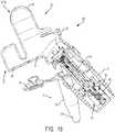
- a device 100 for obtaining a blood sample 18 of the present disclosurehas an at-angle flow and includes an integrated holder 12, lancet housing 14, and collection container 16.
- a userdoes not have to connect a separate lancet housing 14 to the port 26 of the holder 12, remove the lancet 14 after lancing the skin of a finger 19, and then connect a collection container 16 to the port 26 of the holder 12.
- the lancet housing 14is permanently secured within the port 26 of the holder 12.
- the lancet housing 14includes a blood flow channel 120.
- the collection container 16is secured to the lancet housing 14 and includes a blood collector portion 74 that is removably connectable to a portion of the lancet housing 14.
- the longitudinal axis 102 of the lancet housing 14is at an angle to the longitudinal axis 104 of the container 16.
- the lancet housing 14is used to lance the skin of a finger 19 along a lance path 103 and then a blood sample 18 flows down a blood flow path 105 at an angle to the lance path 103.
- the device 100includes a capillary tube 110.
- the capillary tube 110is in fluid communication with the inlet or opening 50 of the lancet housing 14 and the collection cavity 70 of the container 16.
- a portion of the capillary tube 110extends through the blood flow channel 120 of the lancet housing 14.
- the puncturing element 54lances the finger 19 to draw a blood sample 18.
- the lancet 14is pushed against a finger 19 to activate a retractable mechanism 58 of the lancet 14 to lance a finger 19.
- the lancet 14 of the present disclosureconsistently delivers correct lancing depth and a pre-detined lancing location, thus ensuring a sufficient sample volume.
- the blood 18will flow from the finger 19 to the blood flow channel 120 of the lancet housing 14.
- the blood 18flows, via blood flow path 105, at an angle to the lance path 103.
- the blood sample 18flows through the capillary tube 110 to the collection cavity 70 of the container 16.
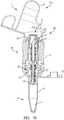
- a device 200 for obtaining a blood sample 18 of the present disclosurehas an in-line flow and includes an integrated holder 12, lancet housing 14, and collection container 16.
- a userdoes not have to connect a separate lancet housing 14 to the port 26 of the holder 12, remove the lancet 14 after lancing the skin of a finger 19, and then connect a collection container 16 to the port 26 of the holder 12.
- the lancet housing 14is permanently secured within the port 26 of the holder 12.
- the lancet housing 14includes a hollow needle 62.
- the puncturing element 54 of the lancet 14comprises a hollow needle 62.
- the collection container 16is secured to the lancet housing 14 and includes a blood collector portion 74 that is removably connectable to a portion of the lancet housing 14.
- a longitudinal axis 202 of the port 26, the lancet housing 14, and the container 16are aligned.
- the lancet 14includes a hollow needle 62.
- the lancet housing 14 of the present disclosureis used to lance the skin of a finger 19 along a lance path 203 and then a blood sample 18 flows along a parallel blood flow path 205 through the hollow needle 62.
- the lancet housing 14includes an outlet 210. With the container 16 connected to the lancet housing 14, the outlet 210 of the lancet housing 14 is in fluid communication with the collection cavity 70 of the container 16.
- the puncturing element 54lances the finger 19 to draw a blood sample 18.
- the lancet 14is pushed against a finger 19 to activate a retractable mechanism 58 of the lancet 14 to lance a finger 19.
- the lancet 14 of the present disclosureconsistently delivers correct lancing depth and a pre-defined lancing location, thus ensuring a sufficient sample volume.
- the blood 18will flow from the finger 19 through the hollow needle 62 to the outlet 210 of the lancet housing 14 to the collection cavity 70 of the container 16.
- the blood 18flows, via blood flow path 205, in line with the lance path 203.
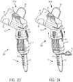
- a device 200 of the present disclosurehaving an in-line flow and including an integrated holder 12, lancet housing 14, and collection container 16, will now be described.
- a desired finger 19is cleaned and a holder 12 having an appropriate size for the desired finger 19 is selected and placed onto the finger 19 securely.
- a separate lancet 14 and container 16do not need to be selected and connected to the port 26 of the holder 12 as each of the holder 12, lancet housing 14, and collection container 16 are integrated into a single component.
- the lancet 14when it is desired to activate the lancet 14 to lance the skin of a finger 19, the lancet 14 is pushed against a finger 19 to activate a retractable mechanism 58 ( Fig. 21 ) of the lancet 14 to lance a finger 19.
- the lancet 14 of the present disclosureconsistently delivers correct lancing depth and a pre-defined lancing location, thus ensuring a sufficient sample volume.
- a useris able to repeatedly squeeze and release the wings 38 of the holder 12 to pump and/or extract blood 18 from a finger 19 until a desired amount of blood 18 is filled in a collection container 16.
- the holder 12does not constrict the blood flow and defines lancing and finger squeezing locations.
- the squeezing tabs or wings 38provide a pre-defined range of squeezing pressure that is consistently applied throughout a finger 19. By doing so, the holder 12 provides a gentle controlled finger 19 massage that stimulates blood 18 extraction and minimizes any potential hemolysis.
- a blood collector portion 74is detached from the collection device 200 and sealed with cap or septum 76 to send a collected sample 18 to a diagnostic instrument and/or testing device.
- the collection container 16may also contain a sample stabilizer, e.g., an anticoagulant, to stabilize blood and fill lines to indicate/meter a collected volume of blood 18.
- the semi-integrated device 300is used in a similar manner as the device 100 having an at-angle flow and including an integrated holder, lancet housing, and collection container described above with reference to Figs. 17-19 .
- a userdoes not have to connect a separate lancet housing 14 to the port 26 of the holder 12, remove the lancet 14 after lancing the skin of a finger 19, and then connect a collection container 16 to the port 26 of the holder 12.
- a useronly needs to connect an integrated lancet housing and collection container component 302 to the port 26 of the holder 12.
- the semi-integrated device 400is used in a similar manner as the device 200 having an in-line flow and including an integrated holder, lancet housing, and collection container described above with reference to Figs. 20-22 .
- a userdoes not have to connect a separate lancet housing 14 to the port 26 of the holder 12, remove the lancet 14 after lancing the skin of a finger 19, and then connect a collection container 16 to the port 26 of the holder 12.
- a useronly needs to connect an integrated lancet housing and collection container component 402 to the port 26 of the holder 12.
- any of the devices for obtaining a blood sample of the present disclosurecan be used as a self-standing disposable device and/or in association with an external power source for pain reduction control.
- a portion of holder 12may include embedded electrodes which receive a signal from an external pain control module to deliver at least one of heat, vibration, or transcutaneous electrical nerve stimulation (TENS) for pain reduction control.
- the devices for obtaining a blood sample of the present disclosuremay also include various options for on-board plasma separation.
- the devices for obtaining a blood sample of the present disclosuremay also include a unique sample identifier that can be paired with patient information at the time of collection.
- the devices for obtaining a blood sample of the present disclosuremay also include on-board diagnostic feedback at the time of collection.
- a device for obtaining a blood sample of the present disclosuremay also allow for dual collection, e.g., the collection of two samples into two separate containers, using multiple collection ports which enable the collection of multiple samples from the same source and treating the samples with different sample stabilizers, such as anticoagulants.
- a device for obtaining a blood sample of the present disclosuresignificantly simplifies and de-skills large volume capillary collection from a finger relative to the conventional capillary collection using lancet and capillary tube.
- the devices of the present disclosureeliminate blood exposure and prevents device reuse.
- the devices for obtaining a blood sample of the present disclosuresimplify, deskill, and streamline the collection process. This is all achieved by a self-contained closed system device which after it is placed onto a finger will provide lancing, blood extraction, stabilization and containment functions, all in one unit.
- the devices for obtaining a blood sample of the present disclosuremay be associated with a self-standing unit that provides automated pumping, controlled finger squeezing, and automated sample labeling and processing.
Landscapes
- Health & Medical Sciences (AREA)
- Life Sciences & Earth Sciences (AREA)
- Engineering & Computer Science (AREA)
- Animal Behavior & Ethology (AREA)
- Public Health (AREA)
- Pathology (AREA)
- Physics & Mathematics (AREA)
- Biomedical Technology (AREA)
- Heart & Thoracic Surgery (AREA)
- Medical Informatics (AREA)
- Molecular Biology (AREA)
- Surgery (AREA)
- Hematology (AREA)
- General Health & Medical Sciences (AREA)
- Biophysics (AREA)
- Veterinary Medicine (AREA)
- Dermatology (AREA)
- Manufacturing & Machinery (AREA)
- Pain & Pain Management (AREA)
- Vascular Medicine (AREA)
- Measurement Of The Respiration, Hearing Ability, Form, And Blood Characteristics Of Living Organisms (AREA)
- Investigating Or Analysing Biological Materials (AREA)
- External Artificial Organs (AREA)
- Sampling And Sample Adjustment (AREA)
Description
- The present application claims priority to United States Provisional Application No.
62/378,971, filed August 24, 2016 - The present disclosure relates generally to a device for obtaining a biological sample. More particularly, the present disclosure relates to an integrated finger-based capillary blood collection device with the ability to lance and squeeze a finger, collect, stabilize, and dispense a blood sample in a controlled manner.
- Devices for obtaining and collecting biological samples, such as blood samples, are commonly used in the medical industry. One type of blood collection that is commonly done in the medial field is capillary blood collection which is often done to collect blood samples for testing. Certain diseases, such as diabetes, require that the patient's blood be tested on a regular basis to monitor, for example, the patient's blood sugar levels. Additionally, test kits, such as cholesterol test kits, often require a blood sample for analysis. The blood collection procedure usually involves pricking a finger or other suitable body part in order to obtain the blood sample. Typically, the amount of blood needed for such tests is relatively small and a small puncture wound or incision normally provides a sufficient amount of blood for these tests. Various types of lancet devices have been developed which are used for puncturing the skin of a patient to obtain a capillary blood sample from the patient.
- Many different types of lancet devices are commercially available to hospitals, clinics, doctors' offices, and the like, as well as to individual consumers. Such devices typically include a sharp-pointed member such as a needle, or a sharp-edged member such as a blade, that is used to make a quick puncture wound or incision in the patient's skin in order to provide a small outflow of blood. It is often physiologically and psychologically difficult for many people to prick their own finger with a hand-held needle or blade. As a result, lancet devices have evolved into automatic devices that puncture or cut the skin of the patient upon the actuation of a triggering mechanism. In some devices, the needle or blade is kept in a standby position until it is triggered by the user, who may be a medical professional in charge of drawing blood from the patient, or the patient himself or herself. Upon triggering, the needle or blade punctures or cuts the skin of the patient, for example, on the finger. Often, a spring is incorporated into the device to provide the "automatic" force necessary to puncture or cut the skin of the patient.
- One type of contact activated lancet device that features automatic ejection and retraction of the puncturing or cutting element from and into the device is
U.S. Patent No. 9,380,975 - Currently, capillary blood collection workflow is a complex multi-step process requiring high skill level. The multi-step nature of this process introduces several variables that could cause sample quality issues such as hemolysis, inadequate sample stabilization, and micro-clots. The use of lancet devices for obtaining blood samples can result in several variables that effect the collection of the capillary blood sample, including, but not limited to, holding the lancet still during the testing, obtaining sufficient blood flow from the puncture site, adequately collecting the blood, preventing clotting, and the like. Some of the most common sources of process variability are: (1) inadequate lancing site cleaning and first drop removal which can potentially result in a contaminated sample; (2) inconsistent lancing location and depth which could potentially result in insufficient sample volume and a large fraction of interstitial fluid; (3) inconsistent squeezing technique and excessive pressure near the lancing site to promote blood extraction (e.g., blood milking) which could potentially result in a hemolyzed sample; (4) variable transfer interfaces and collection technique which could potentially result in a hemolyzed or contaminated sample; and (5) inadequate sample mixing with anticoagulant which could potentially result in micro-clots.
- Thus, there is a need in the art for a device that has the ability to lance and squeeze the finger, collect the sample, stabilize the sample, and subsequently dispense the sample in a controlled manner. There is also a need in the art for a device that simplifies and streamlines the capillary blood collection by eliminating workflow variabilities which are typically associated with low sample quality including hemolysis and micro-clots. There is still a further need in the art for a closed system collection and transfer that eliminate blood exposure and device reuse. There is still a further need in the art for a device that: (1) introduces flexibility in the accommodation of different capillary blood collection and transfer container; (2) has the capability to generate high quality uniformly mixed/stabilized capillary blood samples; (3) has the capability to generate on-board plasma from capillary plasma samples; (4) has the capability to collect large capillary blood samples (> 50-500µL) at reduced pain; (5) contains a unique sample identifier that is paired with patient information at the time of collection; (6) has the capability to collect capillary blood and perform on-board diagnostics; and (7) has multiple collection ports to collect a blood sample into different containers having the same or different anticoagulants.
- The present disclosure is directed to a device for obtaining a biological sample, such as a capillary blood collection device, which meets the needs set forth above and has the ability to lance and squeeze the finger, collect the sample, stabilize the sample, and subsequently dispense the sample in a controlled manner. The device also simplifies and streamlines the capillary blood collection by eliminating workflow variabilities which are typically associated with low sample quality including hemolysis and micro-clots.
- The present disclosure includes a self-contained and fully integrated finger-based capillary blood collection device with ability to lance, collect and stabilize high volume capillary blood sample, e.g., up to or above 500 microliters. The device simplifies and streamlines high volume capillary blood collection by eliminating workflow steps and variabilities which are typically associated with low sample quality including hemolysis, micro-clots, and patient discomfort. The device comprises a retractable lancing mechanism that can lance the finger and an associated blood flow path which ensures attachment and transfer of the capillary blood from the pricked finger site to the collection container. The device also includes a holder that can be cyclically squeezed to stimulate, i.e., pump, blood flow out of the finger and also anticoagulant deposited in the flow path or collection container to stabilize collected sample.
- According to one design, the device can comprise discrete components such as a holder, a lancet, and a collection container. According to another design, the lancet and collection container can be integrated into one device which is then used with the holder. According to yet another design, the holder, lancet, and collection container can be integrated into a single system. Any of these designs are envisioned to be used as a self-standing disposable device and/or in association with an external power source for pain reduction control. The capillary blood collection device can serve as a platform for various capillary blood collection containers ranging from small tubes to capillary dispensers, as well as on-board plasma separation modules. This capability extends the product flexibility to various applications including dispensing to a Point-of-Care (POC) cartridge or to a small collection tube transfer which can be used in a centrifuge or an analytical instrument.
- In accordance with an embodiment of the present invention, a device for obtaining a blood sample includes a holder for receiving a sample source, the holder having an actuation portion and a port; a lancet housing secured within the port, the lancet housing having an inlet and an interior; a puncturing element moveable between a pre-actuated position wherein the puncturing element is retained within the interior and a puncturing position wherein at least a portion of the puncturing element extends through the inlet; and a container removably connectable to a portion of the lancet housing, the container defining a collection cavity.
- In one configuration, the actuation portion is transitionable between a first position in which the holder defines a first diameter, such as a first elliptical shape, and a second position in which the holder defines a second diameter, such as a second elliptical shape, wherein the second diameter is less than the first diameter, and the first elliptical shape is different from the second elliptical shape. In another configuration, the actuation portion includes a contact member. In yet another configuration, the actuation portion is transitionable between a first position in which the contact member is in a disengaged position and a second position in which the contact member is in an engaged position. In one configuration, with the contact member in the engaged position, the contact member exerts a pressure on the sample source. In another configuration, the actuation portion includes a pumping member for applying pressure to the sample source. In yet another configuration, the pumping member comprises a pair of opposed tabs. In one configuration, the sample source is a finger. In another configuration, with the finger received within the holder, the port is in communication with a portion of the finger. In yet another configuration, the puncturing element comprises a hollow needle. In one configuration, with the container connected to the lancet housing, the longitudinal axis of the port, the lancet housing, and the container are aligned. In another configuration, the lancet housing includes an outlet. In yet another configuration, with the container connected to the lancet housing, the outlet of the lancet housing is in fluid communication with the collection cavity of the container. In one configuration, with the finger received within the holder and the puncturing element in the puncturing position, the puncturing element lances the finger to draw the blood sample. In another configuration, the blood sample flows through the hollow needle to the outlet to the collection cavity. In yet another configuration, with the container connected to the lancet housing, the longitudinal axis of the lancet housing is at an angle to the longitudinal axis of the container. In one configuration, the device includes a capillary tube. In another configuration, with the container connected to the lancet housing, the capillary tube is in fluid communication with the inlet of the lancet housing and the collection cavity of the container. In yet another configuration, with the finger received within the holder and the puncturing element in the puncturing position, the puncturing element lances the finger to draw the blood sample. In one configuration, the blood sample flows through the capillary tube to the collection cavity.
- In accordance with an example, a device for obtaining a blood sample includes a holder for receiving a sample source, the holder having an actuation portion and a port, wherein the actuation portion is transitionable between a first position in which the holder defines a first diameter, such as a first elliptical shape, and a second position in which the holder defines a second diameter, such as a second elliptical shape, wherein the second diameter is less than the first diameter, and the first elliptical shape is different than the second elliptical shape.
- In one configuration, the actuation portion includes a contact member. In another configuration, the actuation portion is transitionable between the first position in which the contact member is in a disengaged position and the second position in which the contact member is in an engaged position. In yet another configuration, with the contact member in the engaged position, the contact member exerts a pressure on the sample source. In one configuration, the actuation portion includes a pumping member for applying pressure to the sample source. In another configuration, the pumping member comprises a pair of opposed tabs. In yet another configuration, the sample source is a finger. In one configuration, with the finger received within the holder, the port is in communication with a portion of the finger. In another configuration, the holder includes a stability extension portion. In yet another configuration, the device includes a lancet housing removably connectable to the port, the lancet housing having an inlet and an interior; and a puncturing element moveable between a pre-actuated position wherein the puncturing element is retained within the interior and a puncturing position wherein at least a portion of the puncturing element extends through the inlet. In one configuration, the device includes a container removably connectable to the port, the container defining a collection cavity. In another configuration, the device includes a lancet housing removably connectable to the port, the lancet housing having an inlet and an interior; a puncturing element moveable between a pre-actuated position wherein the puncturing element is retained within the interior and a puncturing position wherein at least a portion of the puncturing element extends through the inlet; and a container removably connectable to a portion of the lancet housing, the container defining a collection cavity.
- The above-mentioned and other features and advantages of this disclosure, and the manner of attaining them, will become more apparent and the disclosure itself will be better understood by reference to the following descriptions of embodiments of the disclosure taken in conjunction with the accompanying drawings, wherein:
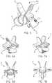
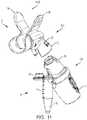
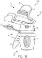
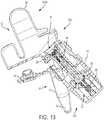
Fig. 1 is a perspective view of a holder in accordance with an embodiment of the present invention.Fig. 2 is a perspective view of a holder in a first position in accordance with an embodiment of the present invention.Fig. 3 is a perspective view of a holder in a second position in accordance with an embodiment of the present invention.Fig. 4A is a perspective view of a holder in accordance with another embodiment of the present invention.Fig. 4B is a perspective view of a holder in accordance with another embodiment of the present invention.Fig. 5 is a perspective view of a holder in accordance with another embodiment of the present invention.Fig. 6A is a perspective view of a holder in accordance with another embodiment of the present invention.Fig. 6B is a perspective view of a holder in accordance with another embodiment of the present invention.Fig. 7A is a perspective view of a holder in accordance with another embodiment of the present invention.Fig. 7B is a perspective view of a holder in accordance with another embodiment of the present invention.Fig. 8 is an exploded, perspective view of a device having discrete components for obtaining a blood sample in accordance with an embodiment of the present invention.Fig. 9 is a perspective view of a holder with a lancet housing secured within a port in accordance with an embodiment of the present invention.Fig. 10 is a perspective view of a holder with a container secured within a port in accordance with an embodiment of the present invention.Fig. 11 is a perspective view of a semi-integrated device for obtaining a blood sample with an at-angle flow in accordance with another embodiment of the present invention.Fig. 12 is a perspective view of a holder with a lancet housing and container secured within a port in accordance with another embodiment of the present invention.Fig. 13 is a cross-sectional view of the device ofFig. 12 in accordance with another embodiment of the present invention.Fig. 14 is a perspective view of a semi-integrated device for obtaining a blood sample with an in-line flow in accordance with another embodiment of the present invention.Fig. 15 is a perspective view of a holder with a lancet housing and container secured within a port in accordance with another embodiment of the present invention.Fig. 16 is a cross-sectional view of the device ofFig. 15 in accordance with another embodiment of the present invention.Fig. 17 is a perspective view of an integrated device for obtaining a blood sample with an at-angle flow in accordance with another embodiment of the present invention.Fig. 18 is a cross-sectional view of the device ofFig. 17 in accordance with another embodiment of the present invention.Fig. 19 is a cross-sectional view of the device ofFig. 17 showing a blood flow path in accordance with another embodiment of the present invention.Fig. 20 is a perspective view of an integrated device for obtaining a blood sample with an in-line flow in accordance with another embodiment of the present invention.Fig. 21 is a cross-sectional view of the device ofFig. 20 in accordance with another embodiment of the present invention.Fig. 22 is a cross-sectional view of the device ofFig. 20 showing a blood flow path in accordance with another embodiment of the present invention.Fig. 23 is a perspective view of a first step of using an integrated device of the present disclosure in accordance with an embodiment of the present invention.Fig. 24 is a perspective view of a second step of using an integrated device of the present disclosure in accordance with an embodiment of the present invention.Fig. 25 is a perspective view of a third step of using an integrated device of the present disclosure in accordance with an embodiment of the present invention.Fig. 26 is a perspective view of a fourth step of using an integrated device of the present disclosure in accordance with an embodiment of the present invention.Fig. 27 is a perspective view of a first step of using a device having discrete components of the present disclosure in accordance with another embodiment of the present invention.Fig. 28 is a perspective view of a second step of using a device having discrete components of the present disclosure in accordance with another embodiment of the present invention.Fig. 29 is a perspective view of a third step of using a device having discrete components of the present disclosure in accordance with another embodiment of the present invention.Fig. 30 is a perspective view of a fourth step of using a device having discrete components of the present disclosure in accordance with another embodiment of the present invention.Fig. 31 is a perspective view of a fifth step of using a device having discrete components of the present disclosure in accordance with another embodiment of the present invention.- Corresponding reference characters indicate corresponding parts throughout the several views. The exemplifications set out herein illustrate exemplary embodiments of the disclosure, and such exemplifications are not to be construed as limiting the scope of the disclosure in any manner.
- The following description is provided to enable those skilled in the art to make and use the described embodiments contemplated for carrying out the invention. Various modifications, equivalents, variations, and alternatives, however, will remain readily apparent to those skilled in the art. Any and all such modifications, variations, equivalents, and alternatives are intended to fall within the scope of the present invention.
- For purposes of the description hereinafter, the terms "upper", "lower", "right", "left", "vertical", "horizontal", "top", "bottom", "lateral", "longitudinal", and derivatives thereof shall relate to the invention as it is oriented in the drawing figures. However, it is to be understood that the invention may assume alternative variations and step sequences, except where expressly specified to the contrary. It is also to be understood that the specific devices and processes illustrated in the attached drawings, and described in the following specification, are simply exemplary embodiments of the invention. Hence, specific dimensions and other physical characteristics related to the embodiments disclosed herein are not to be considered as limiting.
- The present disclosure is directed to a device for obtaining a biological sample, such as a capillary blood collection device, which meets the needs set forth above and has the ability to lance and squeeze the finger, collect the sample, stabilize the sample, and subsequently dispense the sample in a controlled manner. The device also simplifies and streamlines the capillary blood collection by eliminating workflow variabilities which are typically associated with low sample quality including hemolysis and micro-clots.
- The present disclosure includes a self-contained and fully integrated finger-based capillary blood collection device with ability to lance, collect and stabilize high volume capillary blood sample, e.g., up to or above 500 microliters. The device simplifies and streamlines high volume capillary blood collection by eliminating workflow steps and variabilities which are typically associated with low sample quality including hemolysis, micro-clots, and patient discomfort. The device comprises a retractable lancing mechanism that can lance the finger and an associated blood flow path which ensures attachment and transfer of the capillary blood from the pricked finger site to the collection container. The device also includes a holder that can be cyclically squeezed to stimulate, i.e., pump, blood flow out of the finger and also anticoagulant deposited in the flow path or collection container to stabilize collected sample.
- According to one design, the device can comprise discrete components such as a holder, a lancet, and a collection container. According to another design, the lancet and collection container can be integrated into one device which is then used with the holder. According to yet another design, the holder, lancet, and collection container can be integrated into a single system. Any of these designs are envisioned to be used as a self-standing disposable device and/or in association with an external power source for pain reduction control. The capillary blood collection device can serve as a platform for various capillary blood collection containers ranging from small tubes to capillary dispensers, as well as on-board plasma separation modules. This capability extends the product flexibility to various applications including dispensing to a Point-of-Care (POC) cartridge or to a small collection tube transfer which can be used in a centrifuge or an analytical instrument.
- Referring to
Figs. 8-10 , in an exemplary embodiment, adevice 10 of the present disclosure includes discrete components, e.g., a holder 12 (as shown inFigs. 1-7B ), a lancet housing orlancet 14, and acollection container 16. - Referring to
Figs. 11-13 , in another exemplary embodiment, asemi-integrated device 300 of the present disclosure has an at-angle flow and includes an integrated lancet housing and collection container which can be connected with a separate holder. Referring toFigs. 14-16 , in another exemplary embodiment, asemi-integrated device 400 of the present disclosure has an in-line flow and includes an integrated lancet housing and collection container which can be connected with a separate holder. - Referring to
Figs. 17-19 , in another exemplary embodiment, anintegrated device 100 of the present disclosure has an at-angle flow and includes an integrated holder, lancet housing, and collection container. Referring toFigs. 20-22 , in another exemplary embodiment, anintegrated device 200 of the present disclosure has an in-line flow and includes an integrated holder, lancet housing, and collection container. - Referring to
Figs. 8-10 , in an exemplary embodiment, adevice 10 for obtaining ablood sample 18 includes separate components, e.g., aholder 12, a lancet housing orlancet 14, and acollection container 16.Figs. 1-7B illustrate exemplary embodiments of a holder orfinger housing 12 of the present disclosure. - Referring to
Figs. 1-7B , exemplary embodiments ofholders 12 of the present disclosure that are able to receive a sample source, e.g., afinger 19, for supplying a biological sample, such as ablood sample 18. Aholder 12 of the present disclosure generally includes afinger receiving portion 20 having a first opening 22 (Fig. 5 ), an actuation portion 24, aport 26 having asecond opening 28, and afinger end guard 30. In one embodiment, thefinger end guard 30 provides a stop portion for properly aligning and securing afinger 19 within theholder 12. - The
first opening 22 of thefinger receiving portion 20 is configured for receiving a sample source, e.g., afinger 19, for supplying a biological sample, such as ablood sample 18. It can be appreciated that the sample source could include other parts of the body capable of fitting within thefirst opening 22. Theport 26 is in communication with thefinger receiving portion 20. For example, with afinger 19 received within theholder 12, theport 26 is in communication with a portion of thefinger 19. Aholder 12 of the present disclosure can be sized to accommodate all finger sizes. - The
second opening 28 of theport 26 is configured for receiving alancet housing 14 and acollection container 16 as described in more detail below. In one embodiment, theport 26 includes a lockingportion 32 for securely receiving thelancet housing 14 and thecollection container 16 within theport 26. - In one embodiment, the actuation portion 24 is transitionable between a first position (
Fig. 2 ) in which theholder 12 defines a first diameter and a second position (Fig. 3 ) in which theholder 12 defines a second diameter, wherein the second diameter is less than the first diameter. In one embodiment, the actuation portion 24 is transitionabel betweent a first position (Fig. 2 ) in which theholder 12 defines a first elliptical shape, and a second position (Fig. 3 ) in which theholder 12 defines a second elliptical shape, wherein the first elliptical shape is different than the second elliptical shape. In this manner, with theholder 12 in the second position with a reduced diameter, a portion of theholder 12 contacts the sample source and the actuation portion 24 of theholder 12 is able to pump and/or extractblood 18 as described in more detail below. - Referring to
Figs. 2 and 3 , in one embodiment, the actuation portion 24 includes acontact member 34. Referring toFig. 2 , with the actuation portion 24 in the first position, thecontact member 34 is in a disengaged position, i.e., thecontact member 34 is provided in a first position with respect to a sample source, e.g., thefinger 19, such that thecontact member 34 may be in slight contact therewith. Referring toFig. 3 , with the actuation portion 24 in the second position, thecontact member 34 is in an engaged position, i.e., thecontact member 34 is provided in a second position with respect to the sample source, e.g., thefinger 19, such that thecontact member 34 is in an applied pressure contact with the finer 19, and the actuation portion 24 of theholder 12 is able to pump and/or extractblood 18. For example, with thecontact member 34 in the engaged position, thecontact member 34 exerts a pressure on the sample source. - Referring to
Figs. 2 and 3 , in one embodiment, the actuation portion 24 includes a pumping member 36 for applying pressure to the sample source, e.g., thefinger 19. In one embodiment, the pumping member 36 comprises a pair of opposed tabs orwings 38. In such an embodiment, eachtab 38 may include acontact member 34. Referring toFigs. 1-3 , in one embodiment, theholder 12 includes aliving hinge portion 42. The livinghinge portion 42 allows a user to squeeze thewings 38 between a first position (Fig. 2 ) and a second position (Fig. 3 ). - Advantageously, the
holder 12 of the present disclosure allow a user to repeatedly squeeze and release thewings 38 to pump and/or extractblood 18 from afinger 19 until a desired amount ofblood 18 is filled in acollection container 16. - Advantageously, with the
holder 12 placed onto afinger 19, theholder 12 does not constrict the blood flow and defines lancing and finger squeezing locations. The squeezing tabs orwings 38 provide a pre-defined range of squeezing pressure that is consistently applied throughout afinger 19. By doing so, theholder 12 provides a gentle controlled finger massage that stimulates blood extraction and minimizes any potential hemolysis. - Referring to
Fig. 5 , in one embodiment, theholder 12 includes astability extension portion 40. This provides additional support for theholder 12 to be securely placed onto afinger 19. In one embodiment, thefinger receiving portion 20 forms a generally C-shaped member and includes a plurality of inner gripping members for providing additional grip and support for theholder 12 to be securely placed onto afinger 19. - In one embodiment, the
finger receiving portion 20 is formed of a flexible material. In some embodiments, thefinger receiving portion 20 and theport 26 are formed from a flexible material. Figs. 4A-7B illustrate other exemplary embodiments of theholder 12 of the present disclosure. Referring toFigs. 4A-4B , theholder 12 includes aleaf spring 44. Referring toFigs. 6A-6B , theholder 12 includes adouble leaf spring 46. Referring toFigs. 7A-7B , theholder 12 includes atriple leaf spring 48.- A
device 10 for obtaining ablood sample 18 of the present disclosure includes a lancet housing orlancet 14 that is removably connectable to aport 26 of aholder 12. Referring toFigs. 8 ,9 , and13 , in one embodiment, thelancet housing 14 includes an inlet oropening 50, an interior 52, a puncturingelement 54, anengagement portion 56, aretractable mechanism 58, and adrive spring 60. In one embodiment, the puncturingelement 54 is moveable between a pre-actuated position wherein the puncturingelement 54 is retained within theinterior 52 of thelancet housing 14 and a puncturing position wherein at least a portion of the puncturingelement 54 extends through theinlet 50 of thelancet housing 14 to lance a portion of afinger 19. - In one embodiment, the
lancet 14 of the present disclosure is a contact activated lancet and may be constructed in accordance with the features disclosed inU.S. Patent Application Publication No. 2006/0052809 filed May 6, 2005 , entitled "Contact Activated Lancet Device", and commonly assigned with the present application. - Referring to
Figs. 8-10 , in one embodiment, thelancet housing 14 may be a separate component from theholder 12 and thecollection container 16. Referring toFigs. 11-16 , in some embodiments, thecollection container 16 and thelancet housing 14 form a single component that is removably connectable to theport 26 of theholder 12. Referring toFigs. 17-22 , in some embodiments, thecollection container 16, thelancet housing 14, and theholder 12 form a single component. - Referring to
Figs. 8-10 , in one embodiment, with theholder 12 and thelancet housing 14 being separate components, thelancet housing 14 is removably connectable to theport 26 of theholder 12. In such an embodiment, thelancet housing 14 includes anengagement portion 56. Referring toFig. 9 , in one embodiment, thelancet housing 14 is pushed into theport 26 of theholder 12 such that theengagement portion 56 of thelancet housing 14 is locked within the lockingportion 32 of theholder 12. In this manner, thelancet housing 14 is securely connected and locked to theholder 12 such that the puncturingelement 54 of thelancet housing 14 can be activated to lance or puncture a sample source, e.g., afinger 19. In some embodiments, theport 26 of theholder 12 includes a plurality of ribs for securing and locking thelancet 14 or thecollection container 16 in theport 26. - To activate the
lancet 14, thelancet 14 is pushed against afinger 19 to activate aretractable mechanism 58 of thelancet 14 to lance afinger 19. Thelancet 14 of the present disclosure consistently delivers correct lancing depth and a pre-defined lancing location, thus ensuring a sufficient sample volume. - In one embodiment, the
lancet 14 includes adrive spring 60 disposed within theinterior 52 of thelancet housing 14 for biasing the puncturingelement 54 toward the puncturing position. After puncturing, the puncturingelement 54 is immediately retracted and safely secured within theinterior 52 of thelancet housing 14. - Referring to
Figs. 8-10 , in one embodiment, thelancet 14 of the present disclosure is used to lance the skin of afinger 19 and then ablood sample 18 is squeezed into acollection container 16 as described in more detail below. - Referring to
Fig. 19 , in one embodiment, thelancet housing 14 of the present disclosure is used to lance the skin of afinger 19 along a lance path and then ablood sample 18 flows down a blood flow path at an angle to the lance path as described in more detail below. - Referring to
Figs. 21 and22 , in one embodiment, thelancet 14 includes ahollow needle 62. In such an embodiment, thelancet housing 14 of the present disclosure is used to lance the skin of afinger 19 along a lance path and then ablood sample 18 flows along a parallel blood flow path through thehollow needle 62 as described in more detail below. - A
device 10 for obtaining ablood sample 18 of the present disclosure includes acollection container 16 that is removably connectable to theport 26 of theholder 12. Thecollection container 16 defines acollection cavity 70 for receiving ablood sample 18, acontainer engagement portion 72, ablood collector portion 74, and a cap orseptum 76. Once a desired amount ofblood 18 is collected within thecontainer 16, ablood collector portion 74 is detached from thecollection device 10 in order to send a collectedsample 18 to a diagnostic instrument and/or testing device. Theblood collector portion 74 is sealed via the cap orseptum 76 once removed from thecollection device 10 to protectively seal theblood sample 18 within thecollection cavity 70. - Referring to
Figs. 8-10 , in one embodiment, thecollection container 16 may be a separate component from theholder 12 and thelancet housing 14. Referring toFigs. 11-16 , in some embodiments, thecollection container 16 and thelancet housing 14 form a single component that is removably connectable to theport 26 of theholder 12. Referring toFigs. 17-22 , in some embodiments, thecollection container 16, thelancet housing 14, and theholder 12 form a single component. - Referring to
Figs. 8-10 , in one embodiment, with theholder 12 and thecollection container 16 being separate components, thecontainer 16 is removably connectable to theport 26 of theholder 12. In such an embodiment, thecontainer 16 includes acontainer engagement portion 72. Referring toFig. 10 , in one embodiment, thecontainer 16 is pushed into theport 26 of theholder 12 such that thecontainer engagement portion 72 of thecontainer 16 is locked within the lockingportion 32 of theholder 12. In this manner, thecontainer 16 is securely connected and locked to theholder 12 such that ablood sample 18 can safely flow from thefinger 19 within theholder 12 to thecollection cavity 70 of thecontainer 16. - It can be appreciated that several types of
collection containers 16 can be used with thedevice 10 of the present disclosure. It can also be appreciated that thecollection container 16 can be associated with a separate dispensing unit or thecollection container 16 can include an integral dispensing portion for dispensing theblood 18 to a testing device. - Referring to
Figs. 8-10 and27-31 , use of adevice 10 of the present disclosure having discrete components, e.g., aholder 12, a lancet housing orlancet 14, and acollection container 16, will now be described. - Referring to
Fig. 27 , first a desiredfinger 19 is cleaned and aholder 12 having an appropriate size for the desiredfinger 19 is selected and placed onto thefinger 19 securely. Next, referring toFig. 28 , alancet housing 14 is connected to theport 26 of theholder 12. As discussed above, thelancet housing 14 is pushed into theport 26 of theholder 12 such that theengagement portion 56 of thelancet housing 14 is locked within the lockingportion 32 of theholder 12. In this manner, thelancet housing 14 is securely connected and locked to theholder 12 such that the puncturing element 54 (Fig. 13 ) of thelancet housing 14 can be activated to lance or puncture a sample source, e.g., afinger 19. With thelancet 14 connected to theport 26 of theholder 12, the lancet is in communication with thefinger 19. - Referring to
Fig. 28 , when it is desired to activate thelancet 14 to lance the skin of afinger 19, thelancet 14 is pushed against afinger 19 to activate a retractable mechanism 58 (Fig. 13 ) of thelancet 14 to lance afinger 19. Thelancet 14 of the present disclosure consistently delivers correct lancing depth and a pre-defined lancing location, thus ensuring a sufficient sample volume. - After the
finger 19 is lanced to create blood 18 (Fig. 30 ) flow from thefinger 19, thelancet 14 is removed from theholder 12 and thecollection container 16 is pushed into theport 26 of theholder 12. Referring toFig. 29 , thecontainer 16 is pushed into theport 26 of theholder 12 such that thecontainer engagement portion 72 of thecontainer 16 is locked within the lockingportion 32 of theholder 12. In this manner, thecontainer 16 is securely connected and locked to theholder 12 such that ablood sample 18 can safely flow from thefinger 19 within theholder 12 to thecollection cavity 70 of thecontainer 16. - Referring to
Figs. 29 and 30 , with thecontainer 16 properly secured to theholder 12 for collection of ablood sample 18, a user is able to repeatedly squeeze and release thewings 38 of theholder 12 to pump and/or extractblood 18 from afinger 19 until a desired amount ofblood 18 is filled in acollection container 16. Advantageously, with theholder 12 placed onto afinger 19, theholder 12 does not constrict the blood flow and defines lancing and finger squeezing locations. The squeezing tabs orwings 38 provide a pre-defined range of squeezing pressure that is consistently applied throughout afinger 19. By doing so, theholder 12 provides a gentle controlledfinger 19 massage that stimulates blood extraction and minimizes any potential hemolysis. - For example, referring to
Figs. 2 and 3 , in one embodiment, the actuation portion 24 includes acontact member 34. Referring toFig. 2 , with the actuation portion 24 in the first position, thecontact member 34 is in a disengaged position, i.e., thecontact member 34 is in the first position with respect to the sample source, e.g., thefinger 19. Referring toFig. 3 , with the actuation portion 24 in the second position, thecontact member 34 is in an engaged position, i.e., thecontact member 34 is in the second position and in applied pressure contact with a sample source, e.g., thefinger 19, and the actuation portion 24 of theholder 12 is able to pump and/or extractblood 18. For example, with thecontact member 34 in the engaged position, thecontact member 34 exerts a pressure on the sample source. - Referring to
Fig. 31 , once a desired amount ofblood 18 is collected within thecontainer 16, ablood collector portion 74 is detached from thecollection device 10 in order to send a collectedsample 18 to a diagnostic instrument and/or testing device. Theblood collector portion 74 is sealed via the cap orseptum 76 once removed from thecollection device 10 to protectively seal theblood sample 18 within thecollection cavity 70. - The devices of the present disclosure are compatible with any known testing device, whether the testing device is off-site or a point-of-care testing device. Various point-of-care testing devices are known in the art. Such point-of-care testing devices include test strips, glass slides, diagnostic cartridges, or other testing devices for testing and analysis. Test strips, glass slides, and diagnostic cartridges are point-of-care testing devices that receive a blood sample and test that blood for one or more physiological and biochemical states. There are many point-of-care devices that use cartridge based architecture to analyze very small amounts of blood bedside without the need to send the sample to a lab for analysis. This saves time in getting results over the long run, but creates a different set of challenges versus the highly routine lab environment. Examples of such testing cartridges include the i-STAT® testing cartridge from the Abbot group of companies. Testing cartridges such as the i-STAT® cartridges may be used to test for a variety of conditions including the presence of chemicals and electrolytes, hematology, blood gas concentrations, coagulation, or cardiac markers. The results of tests using such cartridges are quickly provided to the clinician.
- The
collection container 16 may also contain a sample stabilizer, e.g., an anticoagulant, to stabilize a blood sample and/or a component of a blood sample disposed therein. Thecollection container 16 may also include at least one fill line(s) corresponding to a predetermined volume of sample. The collection container may also indicate/meter a collected volume of blood. - Referring to
Figs. 17-19 , in another exemplary embodiment, adevice 100 for obtaining ablood sample 18 of the present disclosure has an at-angle flow and includes anintegrated holder 12,lancet housing 14, andcollection container 16. In such an embodiment, a user does not have to connect aseparate lancet housing 14 to theport 26 of theholder 12, remove thelancet 14 after lancing the skin of afinger 19, and then connect acollection container 16 to theport 26 of theholder 12. - Referring to
Figs. 17-19 , thelancet housing 14 is permanently secured within theport 26 of theholder 12. Thelancet housing 14 includes ablood flow channel 120. Thecollection container 16 is secured to thelancet housing 14 and includes ablood collector portion 74 that is removably connectable to a portion of thelancet housing 14. - Referring to
Fig. 19 , in one embodiment, with thecontainer 16 connected to thelancet housing 14, the longitudinal axis 102 of thelancet housing 14 is at an angle to the longitudinal axis 104 of thecontainer 16. Referring toFig. 19 , in one embodiment, thelancet housing 14 is used to lance the skin of afinger 19 along a lance path 103 and then ablood sample 18 flows down a blood flow path 105 at an angle to the lance path 103. - Referring to
Figs. 17-19 , in one embodiment, thedevice 100 includes acapillary tube 110. Referring toFig. 19 , with thecontainer 16, i.e., theblood collector portion 74, connected to thelancet housing 14, thecapillary tube 110 is in fluid communication with the inlet or opening 50 of thelancet housing 14 and thecollection cavity 70 of thecontainer 16. In one embodiment, a portion of thecapillary tube 110 extends through theblood flow channel 120 of thelancet housing 14. - Referring to
Figs. 17-19 , the blood flow path 105 ofdevice 100 will now be described. With afinger 19 received within theholder 12 and the puncturingelement 54 in the puncturing position, the puncturingelement 54 lances thefinger 19 to draw ablood sample 18. For example, when it is desired to activate thelancet 14 to lance the skin of afinger 19, thelancet 14 is pushed against afinger 19 to activate aretractable mechanism 58 of thelancet 14 to lance afinger 19. Thelancet 14 of the present disclosure consistently delivers correct lancing depth and a pre-detined lancing location, thus ensuring a sufficient sample volume. - The
blood 18 will flow from thefinger 19 to theblood flow channel 120 of thelancet housing 14. Theblood 18 flows, via blood flow path 105, at an angle to the lance path 103. For example, theblood sample 18 flows through thecapillary tube 110 to thecollection cavity 70 of thecontainer 16. - Referring to
Figs. 20-22 , in another exemplary embodiment, adevice 200 for obtaining ablood sample 18 of the present disclosure has an in-line flow and includes anintegrated holder 12,lancet housing 14, andcollection container 16. In such an embodiment, a user does not have to connect aseparate lancet housing 14 to theport 26 of theholder 12, remove thelancet 14 after lancing the skin of afinger 19, and then connect acollection container 16 to theport 26 of theholder 12. - Referring to
Figs. 20-22 , thelancet housing 14 is permanently secured within theport 26 of theholder 12. Thelancet housing 14 includes ahollow needle 62. For example, the puncturingelement 54 of thelancet 14 comprises ahollow needle 62. Thecollection container 16 is secured to thelancet housing 14 and includes ablood collector portion 74 that is removably connectable to a portion of thelancet housing 14. - Referring to
Fig. 21 , in one embodiment, with thecontainer 16 connected to thelancet housing 14, alongitudinal axis 202 of theport 26, thelancet housing 14, and thecontainer 16 are aligned. - Referring to
Figs. 21 and22 , in one embodiment, thelancet 14 includes ahollow needle 62. In such an embodiment, thelancet housing 14 of the present disclosure is used to lance the skin of afinger 19 along a lance path 203 and then ablood sample 18 flows along a parallel blood flow path 205 through thehollow needle 62. - Referring to
Figs. 20-22 , in one embodiment, thelancet housing 14 includes anoutlet 210. With thecontainer 16 connected to thelancet housing 14, theoutlet 210 of thelancet housing 14 is in fluid communication with thecollection cavity 70 of thecontainer 16. - Referring to
Figs. 20-22 , the blood flow path 205 ofdevice 200 will now be described. With afinger 19 received within theholder 12 and the puncturingelement 54 in the puncturing position, the puncturingelement 54 lances thefinger 19 to draw ablood sample 18. For example, when it is desired to activate thelancet 14 to lance the skin of afinger 19, thelancet 14 is pushed against afinger 19 to activate aretractable mechanism 58 of thelancet 14 to lance afinger 19. Thelancet 14 of the present disclosure consistently delivers correct lancing depth and a pre-defined lancing location, thus ensuring a sufficient sample volume. - The
blood 18 will flow from thefinger 19 through thehollow needle 62 to theoutlet 210 of thelancet housing 14 to thecollection cavity 70 of thecontainer 16. Theblood 18 flows, via blood flow path 205, in line with the lance path 203. - Referring to
Figs. 23-26 , use of adevice 200 of the present disclosure having an in-line flow and including an integratedholder 12,lancet housing 14, andcollection container 16, will now be described. - Referring to
Fig. 23 , first a desiredfinger 19 is cleaned and aholder 12 having an appropriate size for the desiredfinger 19 is selected and placed onto thefinger 19 securely. In theintegrated device 200 of the present disclosure, aseparate lancet 14 andcontainer 16 do not need to be selected and connected to theport 26 of theholder 12 as each of theholder 12,lancet housing 14, andcollection container 16 are integrated into a single component. - Referring to
Fig. 24 , when it is desired to activate thelancet 14 to lance the skin of afinger 19, thelancet 14 is pushed against afinger 19 to activate a retractable mechanism 58 (Fig. 21 ) of thelancet 14 to lance afinger 19. Thelancet 14 of the present disclosure consistently delivers correct lancing depth and a pre-defined lancing location, thus ensuring a sufficient sample volume. - Referring to
Fig. 25 , after thefinger 19 is lanced to createblood 18 flow from thefinger 19, a user is able to repeatedly squeeze and release thewings 38 of theholder 12 to pump and/or extractblood 18 from afinger 19 until a desired amount ofblood 18 is filled in acollection container 16. Advantageously, with theholder 12 placed onto afinger 19, theholder 12 does not constrict the blood flow and defines lancing and finger squeezing locations. The squeezing tabs orwings 38 provide a pre-defined range of squeezing pressure that is consistently applied throughout afinger 19. By doing so, theholder 12 provides a gentle controlledfinger 19 massage that stimulatesblood 18 extraction and minimizes any potential hemolysis. - Referring to
Fig. 26 , once a desired amount ofblood 18 is collected within thecontainer 16, ablood collector portion 74 is detached from thecollection device 200 and sealed with cap orseptum 76 to send a collectedsample 18 to a diagnostic instrument and/or testing device. As discussed above, thecollection container 16 may also contain a sample stabilizer, e.g., an anticoagulant, to stabilize blood and fill lines to indicate/meter a collected volume ofblood 18. - Referring to
Figs. 11-16 , use of a device 300 (Figs. 11-13 ) having an at-angle flow and including anintegrated lancet housing 14 andcollection container 302 which can be connected with aseparate holder 12; and a device 400 (Figs. 14-16 ) having an in-line flow and including anintegrated lancet housing 14 andcollection container 402 which can be connected with aseparate holder 12 will now be described. - Referring to
Figs. 11-13 , thesemi-integrated device 300 is used in a similar manner as thedevice 100 having an at-angle flow and including an integrated holder, lancet housing, and collection container described above with reference toFigs. 17-19 . With use of thesemi-integrated device 300, a user does not have to connect aseparate lancet housing 14 to theport 26 of theholder 12, remove thelancet 14 after lancing the skin of afinger 19, and then connect acollection container 16 to theport 26 of theholder 12. In the embodiment shown inFigs. 11-13 , a user only needs to connect an integrated lancet housing andcollection container component 302 to theport 26 of theholder 12. - Referring to
Figs. 14-16 , thesemi-integrated device 400 is used in a similar manner as thedevice 200 having an in-line flow and including an integrated holder, lancet housing, and collection container described above with reference toFigs. 20-22 . With use of thesemi-integrated device 400, a user does not have to connect aseparate lancet housing 14 to theport 26 of theholder 12, remove thelancet 14 after lancing the skin of afinger 19, and then connect acollection container 16 to theport 26 of theholder 12. In the embodiment shown inFigs. 14-16 , a user only needs to connect an integrated lancet housing andcollection container component 402 to theport 26 of theholder 12. - Any of the devices for obtaining a blood sample of the present disclosure can be used as a self-standing disposable device and/or in association with an external power source for pain reduction control. For example, a portion of
holder 12 may include embedded electrodes which receive a signal from an external pain control module to deliver at least one of heat, vibration, or transcutaneous electrical nerve stimulation (TENS) for pain reduction control. The devices for obtaining a blood sample of the present disclosure may also include various options for on-board plasma separation. The devices for obtaining a blood sample of the present disclosure may also include a unique sample identifier that can be paired with patient information at the time of collection. The devices for obtaining a blood sample of the present disclosure may also include on-board diagnostic feedback at the time of collection. A device for obtaining a blood sample of the present disclosure may also allow for dual collection, e.g., the collection of two samples into two separate containers, using multiple collection ports which enable the collection of multiple samples from the same source and treating the samples with different sample stabilizers, such as anticoagulants. - A device for obtaining a blood sample of the present disclosure significantly simplifies and de-skills large volume capillary collection from a finger relative to the conventional capillary collection using lancet and capillary tube. The devices of the present disclosure eliminate blood exposure and prevents device reuse.
- The devices for obtaining a blood sample of the present disclosure simplify, deskill, and streamline the collection process. This is all achieved by a self-contained closed system device which after it is placed onto a finger will provide lancing, blood extraction, stabilization and containment functions, all in one unit.
- The devices for obtaining a blood sample of the present disclosure may be associated with a self-standing unit that provides automated pumping, controlled finger squeezing, and automated sample labeling and processing.
- While this disclosure has been described as having exemplary designs, the present disclosure can be further modified within the scope of this disclosure. This application is therefore intended to cover any variations, uses, or adaptations of the disclosure using its general principles. Further, this application is intended to cover such departures from the present disclosure as come within known or customary practice in the art to which this disclosure pertains and which fall within the limits of the appended claims.
Claims (15)
- A device (10) for obtaining a blood sample (18), the device (10) comprising:a holder (12) for receiving a sample source, the holder (12) having an actuation portion (24) and a port (26);a lancet housing (14) secured within the port (26), the lancet housing (14) having an inlet (50) and an interior (52);a puncturing element (54) moveable between a pre-actuated position wherein the puncturing element (54) is retained within the interior (52) and a puncturing position wherein at least a portion of the puncturing element (54) extends through the inlet (50);characterized in that the device (10) further comprises:
a container (16) removably connectable to a portion of the lancet housing (14), the container (16) defining a collection cavity (70). - The device (10) of claim 1, wherein the actuation portion (24) is transitionable between a first position in which the holder (12) defines a first ellipse and a second position in which the holder (12) defines a second ellipse, wherein the second ellipse is different than the first ellipse.
- The device (10) of claim 1, wherein the actuation portion (24) includes a contact member (34).
- The device (10) of claim 3, wherein the actuation portion (24) is transitionable between a first position in which the contact member (34) is in a disengaged position and a second position in which the contact member (34) is in an engaged position, wherein, with the contact member (34) in the engaged position, the contact member (34) preferably exerts a pressure on the sample source.
- The device (10) of claim 1, wherein the actuation portion (24) includes a pumping member (36) for applying pressure to the sample source, wherein the pumping member (36) preferably comprises a pair of opposed tabs (38).
- The device (10) of claim 1, wherein the sample source is a finger (19).
- The device (10) of claim 6, wherein, with the finger (19) received within the holder (12), the port (26) is in communication with a portion of the finger (19).
- The device (10) of claim 1, wherein the puncturing element (54) comprises a hollow needle (62), wherein, with the container (16) connected to the lancet housing (14), the longitudinal axis (202) of the port (26), the lancet housing (14), and the container (16) are preferably aligned.
- The device (10) of claim 7, wherein the lancet housing (14) includes an outlet (210).
- The device (10) of claim 9, wherein, with the container (16) connected to the lancet housing (14), the outlet (210) of the lancet housing (14) is in fluid communication with the collection cavity (70) of the container (16).
- The device (10) of claim 10, wherein, with the finger (19) received within the holder (12) and the puncturing element (54) in the puncturing position, the puncturing element (54) lances the finger (19) to draw the blood sample (18), wherein the blood sample (18) preferably flows through the hollow needle (62) to the outlet to the collection cavity (70).
- The device (10) of claim 1, wherein, with the container (16) connected to the lancet housing (14), the longitudinal axis (102) of the lancet housing (14) is at an angle to the longitudinal axis (104) of the container (16).
- The device (10) of claim 7, further comprising a capillary tube (110).
- The device (10) of claim 13, wherein, with the container (16) connected to the lancet housing (14), the capillary tube (110) is in fluid communication with the inlet (50) of the lancet housing (14) and the collection cavity (70) of the container (16).
- The device (10) of claim 14, wherein, with the finger (19) received within the holder (12) and the puncturing element (54) in the puncturing position, the puncturing element (54) lances the finger (19) to draw the blood sample (18), wherein the blood sample (18) preferably flows through the capillary tube (110) to the collection cavity (70).
Priority Applications (2)
| Application Number | Priority Date | Filing Date | Title |
|---|---|---|---|
| EP20192101.2AEP3760122B1 (en) | 2016-08-24 | 2017-08-23 | A device for obtaining a blood sample |
| EP23167764.2AEP4233722A3 (en) | 2016-08-24 | 2017-08-23 | A device for obtaining a blood sample |
Applications Claiming Priority (2)
| Application Number | Priority Date | Filing Date | Title |
|---|---|---|---|
| US201662378971P | 2016-08-24 | 2016-08-24 | |
| PCT/US2017/048143WO2018039305A1 (en) | 2016-08-24 | 2017-08-23 | A device for obtaining a blood sample |
Related Child Applications (3)
| Application Number | Title | Priority Date | Filing Date |
|---|---|---|---|
| EP20192101.2ADivisionEP3760122B1 (en) | 2016-08-24 | 2017-08-23 | A device for obtaining a blood sample |
| EP20192101.2ADivision-IntoEP3760122B1 (en) | 2016-08-24 | 2017-08-23 | A device for obtaining a blood sample |
| EP23167764.2ADivisionEP4233722A3 (en) | 2016-08-24 | 2017-08-23 | A device for obtaining a blood sample |
Publications (2)
| Publication Number | Publication Date |
|---|---|
| EP3503806A1 EP3503806A1 (en) | 2019-07-03 |
| EP3503806B1true EP3503806B1 (en) | 2020-09-30 |
Family
ID=59746370
Family Applications (7)
| Application Number | Title | Priority Date | Filing Date |
|---|---|---|---|
| EP17761172.0AActiveEP3503806B1 (en) | 2016-08-24 | 2017-08-23 | A device for obtaining a blood sample |
| EP20192101.2AActiveEP3760122B1 (en) | 2016-08-24 | 2017-08-23 | A device for obtaining a blood sample |
| EP23167764.2APendingEP4233722A3 (en) | 2016-08-24 | 2017-08-23 | A device for obtaining a blood sample |
| EP24164531.6APendingEP4364661A3 (en) | 2016-08-24 | 2017-08-23 | A device for the attached flow of blood |
| EP20214283.2AActiveEP3811865B1 (en) | 2016-08-24 | 2017-08-23 | A device for the attached flow of blood |
| EP22172551.8AActiveEP4059427B1 (en) | 2016-08-24 | 2017-08-23 | A device for the attached flow of blood |
| EP17762279.2AActiveEP3503807B1 (en) | 2016-08-24 | 2017-08-23 | A device for the attached flow of blood |
Family Applications After (6)
| Application Number | Title | Priority Date | Filing Date |
|---|---|---|---|
| EP20192101.2AActiveEP3760122B1 (en) | 2016-08-24 | 2017-08-23 | A device for obtaining a blood sample |
| EP23167764.2APendingEP4233722A3 (en) | 2016-08-24 | 2017-08-23 | A device for obtaining a blood sample |
| EP24164531.6APendingEP4364661A3 (en) | 2016-08-24 | 2017-08-23 | A device for the attached flow of blood |
| EP20214283.2AActiveEP3811865B1 (en) | 2016-08-24 | 2017-08-23 | A device for the attached flow of blood |
| EP22172551.8AActiveEP4059427B1 (en) | 2016-08-24 | 2017-08-23 | A device for the attached flow of blood |
| EP17762279.2AActiveEP3503807B1 (en) | 2016-08-24 | 2017-08-23 | A device for the attached flow of blood |
Country Status (13)
| Country | Link |
|---|---|
| US (5) | US11771352B2 (en) |
| EP (7) | EP3503806B1 (en) |
| JP (8) | JP7104026B2 (en) |
| KR (4) | KR102460682B1 (en) |
| CN (4) | CN115192014B (en) |
| AU (4) | AU2017315323B2 (en) |
| BR (2) | BR112019003638A2 (en) |
| CA (2) | CA3034842A1 (en) |
| ES (4) | ES2834078T3 (en) |
| MX (4) | MX2019002218A (en) |
| PL (1) | PL3503807T3 (en) |
| RU (4) | RU2747438C2 (en) |
| WO (2) | WO2018039305A1 (en) |
Families Citing this family (34)
| Publication number | Priority date | Publication date | Assignee | Title |
|---|---|---|---|---|
| US20100256524A1 (en) | 2009-03-02 | 2010-10-07 | Seventh Sense Biosystems, Inc. | Techniques and devices associated with blood sampling |
| US20130158482A1 (en) | 2010-07-26 | 2013-06-20 | Seventh Sense Biosystems, Inc. | Rapid delivery and/or receiving of fluids |
| WO2012021801A2 (en) | 2010-08-13 | 2012-02-16 | Seventh Sense Biosystems, Inc. | Systems and techniques for monitoring subjects |
| WO2012064802A1 (en) | 2010-11-09 | 2012-05-18 | Seventh Sense Biosystems, Inc. | Systems and interfaces for blood sampling |
| CN103874461B (en) | 2011-04-29 | 2017-05-10 | 第七感生物系统有限公司 | Devices for collecting and/or manipulating blood spots or other bodily fluids |
| WO2019067567A1 (en)* | 2017-09-26 | 2019-04-04 | Juno Diagnostics, Inc. | Devices, systems and methods for biomarker analysis |
| US20190099117A1 (en)* | 2017-10-02 | 2019-04-04 | Reliant Immune Diagnostics, Inc | Finger cuff having vibration mechanism for use in performing a finger prick |
| CA3080117A1 (en) | 2017-10-27 | 2019-05-02 | Juno Diagnostics, Inc. | Devices, systems and methods for ultra-low volume liquid biopsy |
| JP6905953B2 (en)* | 2018-05-15 | 2021-07-21 | 富士フイルム株式会社 | Blood sample guide device and blood test kit |
| EP3801259B1 (en)* | 2018-05-25 | 2023-07-19 | Becton, Dickinson and Company | Blood collection assembly with vibration module |
| BR112021004090A2 (en)* | 2018-09-06 | 2021-05-25 | Becton, Dickinson And Company | arterial blood gas collection system |
| BR112021015617A2 (en)* | 2019-02-14 | 2021-10-05 | Becton, Dickinson And Company | CAPILLARY COLLECTOR WITH ROTATING CONNECTION |
| BE1027338B1 (en)* | 2019-06-04 | 2021-01-14 | Inst Of Tropical Medicine | FINGER PRICKER COLLECTOR |
| JP7157711B2 (en)* | 2019-07-19 | 2022-10-20 | 株式会社日立ハイテク | Blood collection device |
| WO2021061751A1 (en) | 2019-09-23 | 2021-04-01 | Gateway Genomics, Llc | Methods, compositions, and kits for determining the sex of a fetus |
| WO2021091380A1 (en)* | 2019-11-07 | 2021-05-14 | Stichting Het Nederlands Kanker Instituut-Antoni van Leeuwenhoek Ziekenhuis | Blood collection device and method for the self-collection of blood by a user |
| JP2023527642A (en)* | 2020-03-31 | 2023-06-30 | プレシヘルス エスアー | Bodily fluid collection device and method of use |
| GB202004718D0 (en)* | 2020-03-31 | 2020-05-13 | Osler Diagnostics Ltd | Capillary blood sampling |
| WO2022043748A2 (en)* | 2020-08-23 | 2022-03-03 | Preci Health Sa | Capillary blood sampling device and method of use |
| GB2598334B (en) | 2020-08-26 | 2022-11-30 | Mowgli Innovations Ltd | Finger receptacle and holding device |
| CN117580506A (en)* | 2021-06-29 | 2024-02-20 | 贝克顿·迪金森公司 | capillary blood collection device |
| WO2023278234A1 (en)* | 2021-06-29 | 2023-01-05 | Becton, Dickinson And Company | Capillary blood collection device |
| CN117597069A (en) | 2021-06-29 | 2024-02-23 | 贝克顿·迪金森公司 | Simulation device for capillary blood collection |
| WO2023278225A1 (en)* | 2021-06-29 | 2023-01-05 | Becton, Dickinson And Company | Capillary blood collection device |
| CN117597195A (en)* | 2021-06-29 | 2024-02-23 | 贝克顿·迪金森公司 | Sample container for capillary blood collection |
| KR20240024243A (en)* | 2021-06-29 | 2024-02-23 | 백톤 디킨슨 앤드 컴퍼니 | Capillary Blood Collection Device |
| US20240315619A1 (en)* | 2021-06-29 | 2024-09-26 | Becton, Dickinson And Company | Blood Collection Kit With Blood Collection Devices of Multiple Sizes and Associated Sizing Systems and Methods |
| EP4362791A4 (en)* | 2021-06-29 | 2025-04-30 | Becton, Dickinson and Company | Capillary blood collection device |
| KR20240024244A (en)* | 2021-06-29 | 2024-02-23 | 백톤 디킨슨 앤드 컴퍼니 | Capillary Blood Collection Device |
| JP2024538133A (en)* | 2021-10-15 | 2024-10-18 | ベクトン・ディキンソン・アンド・カンパニー | Additive mix for blood sample collection |
| US11957465B2 (en) | 2022-08-23 | 2024-04-16 | Reddrop Dx, Inc. | Accelerated ergonomic collection of capillary blood |
| BE1030990B1 (en)* | 2022-10-25 | 2024-05-28 | Inst Voor Tropische Geneeskunde | BLOOD SAMPLING DEVICE FOR COLLECTION OF A BLOOD SAMPLE FROM A FINGER OR TOE |
| EP4491118A1 (en) | 2023-07-13 | 2025-01-15 | Becton, Dickinson and Company | Collector accessory for small volume collection containers and related sample collection methods |
| WO2025064983A1 (en)* | 2023-09-21 | 2025-03-27 | Becton, Dickinson And Company | Lancing finger sleeve |
Family Cites Families (160)
| Publication number | Priority date | Publication date | Assignee | Title |
|---|---|---|---|---|
| US2646799A (en) | 1951-02-14 | 1953-07-28 | Jr George W Jacoby | Blood lancet |
| CH500707A (en)* | 1968-07-26 | 1970-12-31 | Micromedic Systems Inc | Device for performing percutaneous and digital blood sampling |
| CH522395A (en)* | 1968-07-26 | 1972-05-15 | Micromedic Systems Inc | Test tube intended for percutaneous and digital blood sampling |
| US3630191A (en) | 1969-02-27 | 1971-12-28 | Gilford Instr Labor Inc | Apparatus and method for filling capillary tubing with fluids |
| CH538277A (en) | 1970-09-04 | 1973-06-30 | Micromedic Systems Inc | Percutaneous blood test device |
| US4024857A (en) | 1974-12-23 | 1977-05-24 | Becton, Dickinson And Company | Micro blood collection device |
| JPS51122982A (en)* | 1974-12-23 | 1976-10-27 | Becton Dickinson Co | Small blood sampling unit |
| US4411163A (en) | 1981-07-27 | 1983-10-25 | American Hospital Supply Corporation | Ventable sample collection device |
| US4397318A (en) | 1981-08-10 | 1983-08-09 | Becton Dickinson And Company | Blood collector for microcollection container |
| US4620549A (en) | 1985-01-25 | 1986-11-04 | Becton, Dickinson And Company | Blood collection assembly |
| US4646753A (en) | 1985-06-11 | 1987-03-03 | Becton, Dickinson And Company | Blood collector for microcollection container |
| DE3541041A1 (en)* | 1985-11-19 | 1987-05-21 | Sarstedt Kunststoff | BLOOD COLLECTOR |
| US4690153A (en)* | 1985-11-29 | 1987-09-01 | Becton, Dickinson And Company | Flow inducing means for small volume containers |
| US4791938A (en) | 1987-11-16 | 1988-12-20 | Nanci Van Valkenburg | Capillary blood collector and method |
| US5014718A (en) | 1988-01-22 | 1991-05-14 | Safety Diagnostics, Inc. | Blood collection and testing method |
| US5070886A (en) | 1988-01-22 | 1991-12-10 | Safety Diagnostice, Inc. | Blood collection and testing means |
| DE4000968C1 (en)* | 1990-01-16 | 1991-06-20 | Dieter 2090 Drage De Wendelborn | Blood sampling apparatus - has blood observation chamber mounted in sampling vessel stopper |
| US5309924A (en)* | 1992-04-29 | 1994-05-10 | Peabody Alan M | Spill-proof blood collection device |
| US5384096A (en) | 1993-05-12 | 1995-01-24 | Becton, Dickinson And Company | Microcollection tube assembly |
| HU219921B (en) | 1993-10-20 | 2001-09-28 | Ervin Lipscher | Device for making blood test, especially from fingers |
| US5485856A (en) | 1994-04-22 | 1996-01-23 | Buckland; Peter E. | Hand immobilizing and positioning apparatus for x-ray examinations |
| JPH08317918A (en) | 1995-05-25 | 1996-12-03 | Advance Co Ltd | Blood drawing device |
| US5569223A (en) | 1995-06-06 | 1996-10-29 | Home Access Health Corporation | Apparatus and method for enhancing blood flow to obtain a blood sample |
| DE29514084U1 (en) | 1995-09-01 | 1995-11-02 | Biosafe Diagnostics Corp., Lincolnshire, Ill. | Blood collection and test device |
| US5662127A (en) | 1996-01-17 | 1997-09-02 | Bio-Plas, Inc. | Self-contained blood withdrawal apparatus and method |
| US5714125A (en) | 1996-03-07 | 1998-02-03 | Medical Safety Products, Inc. | Device for collecting a blood sample from a plastic segment tube |
| US20020010406A1 (en) | 1996-05-17 | 2002-01-24 | Douglas Joel S. | Methods and apparatus for expressing body fluid from an incision |
| US5951493A (en) | 1997-05-16 | 1999-09-14 | Mercury Diagnostics, Inc. | Methods and apparatus for expressing body fluid from an incision |
| US5951492A (en) | 1996-05-17 | 1999-09-14 | Mercury Diagnostics, Inc. | Methods and apparatus for sampling and analyzing body fluid |
| EP1579814A3 (en) | 1996-05-17 | 2006-06-14 | Roche Diagnostics Operations, Inc. | Methods and apparatus for sampling and analyzing body fluid |
| EP1862116A3 (en) | 1996-05-17 | 2009-02-25 | Roche Diagnostics Operations, Inc. | Disposable element for use in a body fluid sampling device |
| US5857983A (en) | 1996-05-17 | 1999-01-12 | Mercury Diagnostics, Inc. | Methods and apparatus for sampling body fluid |
| US6706000B2 (en) | 1997-11-21 | 2004-03-16 | Amira Medical | Methods and apparatus for expressing body fluid from an incision |
| US6086545A (en) | 1998-04-28 | 2000-07-11 | Amira Medical | Methods and apparatus for suctioning and pumping body fluid from an incision |
| JP4210782B2 (en) | 1999-10-13 | 2009-01-21 | アークレイ株式会社 | Blood sampling position indicator |
| DE10026172A1 (en) | 2000-05-26 | 2001-11-29 | Roche Diagnostics Gmbh | Body fluid withdrawal system |
| DE10026170A1 (en)* | 2000-05-26 | 2001-12-06 | Roche Diagnostics Gmbh | Body fluid withdrawal system |
| RU2269954C2 (en) | 2000-06-09 | 2006-02-20 | Дайэбитиз Дайэгностикс, Инк. | Cap for lancet device for punching dermal tissue (versions), cap for lancet device for punching tip of finger, cap for lancet device for punching curvilinear dermal tissue and lancet device for punching dermal tissue |
| US6551267B1 (en) | 2000-10-18 | 2003-04-22 | Becton, Dickinson And Company | Medical article having blood-contacting surface |
| KR100788305B1 (en) | 2001-01-12 | 2007-12-27 | 아크레이 인코퍼레이티드 | Puncture device, its manufacture method, pump mechanism and suction device |
| JP2002219115A (en) | 2001-01-26 | 2002-08-06 | Matsushita Electric Works Ltd | Blood collecting device |
| US20040092843A1 (en) | 2001-02-22 | 2004-05-13 | Doron Kreiser | Device and method for measuring fetal blood pH |
| US20020188223A1 (en) | 2001-06-08 | 2002-12-12 | Edward Perez | Devices and methods for the expression of bodily fluids from an incision |
| US7749174B2 (en) | 2001-06-12 | 2010-07-06 | Pelikan Technologies, Inc. | Method and apparatus for lancet launching device intergrated onto a blood-sampling cartridge |
| JP2003070771A (en) | 2001-09-07 | 2003-03-11 | Omron Corp | Equipment and system for organism information measurement and method of organism information measurement management |
| CA2461370A1 (en) | 2001-09-26 | 2003-05-15 | F. Hoffmann-La Roche Ag | Method and apparatus for sampling bodily fluid |
| US20030212344A1 (en)* | 2002-05-09 | 2003-11-13 | Vadim Yuzhakov | Physiological sample collection devices and methods of using the same |
| USD488588S1 (en) | 2002-12-13 | 2004-04-13 | James P. Murphy | Finger accessory appliance |
| US20040127818A1 (en) | 2002-12-27 | 2004-07-01 | Roe Steven N. | Precision depth control lancing tip |
| GB0301587D0 (en)* | 2003-01-23 | 2003-02-26 | Epsom & St Helier Nhs Trust | A lancet holding device |
| WO2004078041A2 (en) | 2003-02-13 | 2004-09-16 | Toru Nakayama | Painless blood-collecting method |
| DE10315396A1 (en)* | 2003-04-04 | 2004-10-14 | Lieblein, Martin, Dr. | Automatic blood sugar monitor and warning system, for hypo- and hyperglycemia, has a finger stall containing the electromagnetic pricker and test strips with a glucose enzyme linked to a control |
| USD488232S1 (en) | 2003-06-30 | 2004-04-06 | Nanma Ltd. | Finger massager |
| DE10332283A1 (en) | 2003-07-16 | 2005-02-03 | Roche Diagnostics Gmbh | System for taking body fluid |
| DE10332488A1 (en) | 2003-07-16 | 2005-02-24 | Roche Diagnostics Gmbh | Analyzer and analysis method for body fluids |
| JP2005094425A (en) | 2003-09-18 | 2005-04-07 | Fuji Xerox Co Ltd | Remote control device |
| JP4484669B2 (en) | 2003-10-29 | 2010-06-16 | アークレイ株式会社 | Puncture device |
| JP4762341B2 (en) | 2003-10-29 | 2011-08-31 | アークレイ株式会社 | Puncture device |
| JP4621850B2 (en) | 2003-10-29 | 2011-01-26 | アークレイ株式会社 | Squeezing tool and puncture device |
| GB2409411A (en)* | 2003-12-22 | 2005-06-29 | William Thomas Dennis Bates | Blood collection system |
| WO2005077274A1 (en)* | 2004-02-06 | 2005-08-25 | Bayer Healthcare Llc | Method and apparatus for measuring an analyte in a body fluid |
| US7201723B2 (en) | 2004-03-25 | 2007-04-10 | Roche Diagnostics Operations, Inc. | Pulsating expression cap |
| US20050215923A1 (en) | 2004-03-26 | 2005-09-29 | Wiegel Christopher D | Fingertip conforming fluid expression cap |
| CA2562215A1 (en) | 2004-04-10 | 2005-10-20 | F. Hoffmann-La Roche Ag | Method and system for taking body fluid |
| US20050234488A1 (en) | 2004-04-16 | 2005-10-20 | John Allen | Saddle-contoured cap for a dermal tissue lancing device |
| US20050234486A1 (en) | 2004-04-16 | 2005-10-20 | Allen John J | Apparatus for extracting bodily fluid |
| US20050234491A1 (en) | 2004-04-16 | 2005-10-20 | Allen John J | Method for lancing a dermal tissue target site employing a dermal tissue lancing device with a tiltable cap |
| US9380975B2 (en) | 2004-05-07 | 2016-07-05 | Becton, Dickinson And Company | Contact activated lancet device |
| US7322942B2 (en) | 2004-05-07 | 2008-01-29 | Roche Diagnostics Operations, Inc. | Integrated disposable for automatic or manual blood dosing |
| DE102004024970A1 (en) | 2004-05-21 | 2005-12-08 | Roche Diagnostics Gmbh | Device and method for positioning a body part |
| US20050277849A1 (en) | 2004-06-10 | 2005-12-15 | Daniel Wong | Vacuum sample expression device |
| US7384402B2 (en) | 2004-06-10 | 2008-06-10 | Roche Diagnostics Operations, Inc. | Expression pad |
| JP3926811B2 (en)* | 2004-08-03 | 2007-06-06 | 株式会社ヒポクラテス | Quantitative blood collection tool |
| US20070060842A1 (en) | 2005-08-29 | 2007-03-15 | Manuel Alvarez-Icaza | Lancing cap kit applied pressure sensing cap |
| US20070083130A1 (en) | 2005-09-26 | 2007-04-12 | Anne Thomson | Method for promoting bodily fluid expression from a target site |
| EP1928302B1 (en) | 2005-09-30 | 2012-08-01 | Intuity Medical, Inc. | Fully integrated wearable or handheld monitor |
| US20070093864A1 (en) | 2005-10-20 | 2007-04-26 | Pugh Jerry T | Method for lancing a dermal tissue target site |
| JP4874623B2 (en) | 2005-10-20 | 2012-02-15 | 積水化学工業株式会社 | Blood collection holder |
| US20070093863A1 (en) | 2005-10-20 | 2007-04-26 | Pugh Jerry T | Cap for a dermal tissue lancing device |
| EP1785090A1 (en) | 2005-11-10 | 2007-05-16 | F.Hoffmann-La Roche Ag | Lancet device and system for skin detection |
| US20070112281A1 (en) | 2005-11-17 | 2007-05-17 | Olson Lorin P | Cap with revolving body for a dermal tissue lancing device |
| JPWO2007063948A1 (en) | 2005-12-01 | 2009-05-07 | アークレイ株式会社 | Sensor-lancet integrated device and body fluid collecting method using the same |
| JP4999372B2 (en) | 2006-06-30 | 2012-08-15 | 株式会社サカエ | Liquid collector |
| KR20090031763A (en)* | 2006-07-06 | 2009-03-27 | 라피딕스 리미티드. | Integrated blood sampling and testing device and method |
| JP2008022988A (en)* | 2006-07-19 | 2008-02-07 | Ritsumeikan | Blood collection device |
| US8372015B2 (en) | 2006-08-28 | 2013-02-12 | Intuity Medical, Inc. | Body fluid sampling device with pivotable catalyst member |
| JP2008099991A (en) | 2006-10-20 | 2008-05-01 | Olympus Corp | Blood collection device |
| EP1929948A1 (en) | 2006-12-08 | 2008-06-11 | Roche Diagnostics GmbH | Piercing device |
| USD576277S1 (en) | 2007-03-30 | 2008-09-02 | T.A.G. Medical Products A Limited Partnership. | Finger mounting surgical instrument with spatula retractor |
| USD582037S1 (en) | 2007-03-30 | 2008-12-02 | Ethicon Endo-Surgery, Inc. | Finger mounted specialty grasper |
| USD569514S1 (en) | 2007-03-30 | 2008-05-20 | Ethicon Endo-Surgery, Inc. | Finger mounted locking forceps |
| EP1982653A1 (en) | 2007-04-18 | 2008-10-22 | Roche Diagnostics GmbH | Pricking device and analysis device |
| US20110092854A1 (en) | 2009-10-20 | 2011-04-21 | Uwe Kraemer | Instruments and system for producing a sample of a body fluid and for analysis thereof |
| US7591791B2 (en) | 2007-06-21 | 2009-09-22 | Inverness Medical Switzerland Gmbh | Diagnostic thimble |
| JP4625062B2 (en) | 2007-08-31 | 2011-02-02 | テルモ株式会社 | Aid |
| TW200918022A (en) | 2007-10-26 | 2009-05-01 | Delta Electronics Inc | Bleeding apparatus |
| TW200918021A (en) | 2007-10-26 | 2009-05-01 | Delta Electronics Inc | Bleeding apparatus |
| WO2009076247A1 (en) | 2007-12-10 | 2009-06-18 | Bayer Healthcare Llc | Integrated fluid analyte meter system |
| WO2009081405A2 (en)* | 2007-12-25 | 2009-07-02 | Rapidx Ltd. | Devices and methods for reduced-pain blood sampling |
| US10631771B2 (en) | 2008-01-07 | 2020-04-28 | Morteza Naghavi | Methods and apparatus for blood sampling |
| US7766846B2 (en) | 2008-01-28 | 2010-08-03 | Roche Diagnostics Operations, Inc. | Rapid blood expression and sampling |
| US20090198152A1 (en)* | 2008-02-02 | 2009-08-06 | Stanley Kim | Finger tip tourniquet |
| EP2243427B1 (en) | 2008-02-21 | 2013-04-24 | Terumo Kabushiki Kaisha | Puncture tool with mechanism for relieving needle puncture pain and tool for relieving needle puncture pain |
| EP3616618B1 (en) | 2008-03-05 | 2022-11-30 | Becton, Dickinson and Company | Capillary action collection device |
| MX359080B (en) | 2008-03-05 | 2018-09-06 | Becton Dickinson Co | Co-molded pierceable stopper and method for making the same. |
| FR2929135A1 (en)* | 2008-03-31 | 2009-10-02 | Commissariat Energie Atomique | DEVICE FOR ALIQUOTAGE AND EXEMPTION OF A LIQUID |
| JP4388597B1 (en) | 2008-05-09 | 2009-12-24 | パナソニック株式会社 | Skin incision instrument |
| US9833183B2 (en) | 2008-05-30 | 2017-12-05 | Intuity Medical, Inc. | Body fluid sampling device—sampling site interface |
| WO2009148624A1 (en)* | 2008-06-06 | 2009-12-10 | Intuity Medical, Inc. | Detection meter and mode of operation |
| US20100022916A1 (en) | 2008-07-24 | 2010-01-28 | Javanbakhsh Esfandiari | Method and Apparatus for Collecting and Preparing Biological Samples for Testing |
| EP2181651A1 (en) | 2008-10-29 | 2010-05-05 | Roche Diagnostics GmbH | Instrument and system for producing a sample of a body liquid and for analysis thereof |
| US8956307B2 (en) | 2009-07-01 | 2015-02-17 | Kawasumi Laboratories, Inc. | Blood collection set, sampling holder, and needlestick-preventive needle cover |
| US8926644B2 (en) | 2009-07-30 | 2015-01-06 | Becton, Dickinson And Company | Lancing device having saddle-shaped tip |
| JP2011078518A (en)* | 2009-10-06 | 2011-04-21 | Panasonic Corp | Blood testing instrument |
| US8647357B2 (en) | 2011-02-05 | 2014-02-11 | Birch Narrows Development Llc | Lancet device with flexible cover |
| RU2580295C2 (en) | 2011-06-08 | 2016-04-10 | Бектон, Дикинсон Энд Компани | Blood sampling safety syringe with retractable needle |
| WO2013041705A1 (en) | 2011-09-22 | 2013-03-28 | Sanofi-Aventis Deutschland Gmbh | Eliciting a blood sample |
| US20130211289A1 (en) | 2012-01-25 | 2013-08-15 | Tasso, Inc. | Handheld Device for Drawing, Collecting, and Analyzing Bodily Fluid |
| BR302012006435S1 (en) | 2012-06-15 | 2014-06-03 | Rml Engineering Ltd | CONTAINER CONFIGURATION |
| EP2874942B1 (en) | 2012-07-23 | 2018-09-05 | Tasso, Inc. | Methods and devices relating to open microfluidic channels |
| JP6405305B2 (en) | 2012-08-09 | 2018-10-17 | エモリー ユニバーシティ | Kits and methods for determining physiological levels and / or ranges of hemoglobin and / or disease states |
| US9427184B2 (en) | 2012-09-06 | 2016-08-30 | Theranos, Inc. | Systems, devices, and methods for bodily fluid sample collection |
| CN104470434B (en) | 2012-10-26 | 2016-10-12 | 张建铭 | Integral vacuum lancing device with needle tip guard |
| RU2570750C2 (en)* | 2012-11-20 | 2015-12-10 | Федеральное государственное бюджетное образовательное учреждение высшего профессионального образования "Московский государственный университет имени М.В. Ломоносова" (МГУ) | Set for obtaining, storage and transportation of dry blood samples for further realisation of laboratory test |
| WO2014137895A1 (en) | 2013-03-05 | 2014-09-12 | Carolyn Consulting, LLC | Finger guide for testing blood glucose and associated methods |
| USD732684S1 (en) | 2013-03-25 | 2015-06-23 | Sysmex Corporation | Container for analyzer |
| EP2986218B1 (en)* | 2013-04-15 | 2017-12-20 | Becton, Dickinson and Company | Biological fluid collection device and biological fluid separation and testing system |
| SG11201601547RA (en) | 2013-09-05 | 2016-04-28 | Miyabi Co Ltd | Bodily Fluid Sampler, Bodily Fluid Container And Bodily Fluid Sampling Device |
| TW201513832A (en) | 2013-10-11 | 2015-04-16 | Ysp Co Ltd | Blood collecting apparatus, lancet and lancing device |
| WO2015084729A1 (en) | 2013-12-02 | 2015-06-11 | Praxair Technology, Inc. | Method and system for producing hydrogen using an oxygen transport membrane based reforming system with secondary reforming |
| USD757267S1 (en) | 2013-12-02 | 2016-05-24 | Sterilance Medical (Suzhou) Inc. | Lancet protective cap with two cup-shape openings |
| CA157667S (en) | 2014-03-31 | 2015-04-30 | Htl Strefa Spólka Akcyjna | Lancet device |
| JP6424014B2 (en)* | 2014-05-27 | 2018-11-14 | 株式会社テクノメデイカ | Fingertip blood former |
| US10093918B2 (en) | 2014-06-04 | 2018-10-09 | Lucigen Corporation | Sample collection and analysis devices |
| US20150351676A1 (en)* | 2014-06-10 | 2015-12-10 | Labatm, Inc. | Automatic Blood Collection |
| WO2015191853A1 (en) | 2014-06-13 | 2015-12-17 | Siemens Healthcare Diagnostics Inc. | Sample delivery system |
| US10779757B2 (en)* | 2014-08-01 | 2020-09-22 | Tasso, Inc. | Devices, systems and methods for gravity-enhanced microfluidic collection, handling and transferring of fluids |
| USD800333S1 (en) | 2014-09-23 | 2017-10-17 | Critical Care Diagnostics, Inc. | Blood test kit |
| US10722163B2 (en) | 2015-03-31 | 2020-07-28 | Labrador Diagnostics Llc | Methods, devices, systems, and kits for automated blood collection by fingerstick |
| CN204683616U (en)* | 2015-04-21 | 2015-10-07 | 中国人民解放军第四军医大学 | A kind of safe blood-taking needle for blood-glucose meter |
| USD868269S1 (en) | 2015-05-26 | 2019-11-26 | Serenity Sayre | Finger splint |
| JP6558971B2 (en) | 2015-06-17 | 2019-08-14 | 株式会社日立ハイテクノロジーズ | Blood collection device |
| US10371606B2 (en) | 2015-07-21 | 2019-08-06 | Theraos IP Company, LLC | Bodily fluid sample collection and transport |
| USD856148S1 (en) | 2016-05-05 | 2019-08-13 | Csp Technologies, Inc. | Container for sampling |
| US10136848B2 (en) | 2016-05-20 | 2018-11-27 | Winnoz Technology, Inc. | Device and system of blood collection, and method thereof |
| JP6735161B2 (en) | 2016-06-21 | 2020-08-05 | 株式会社日立ハイテク | Blood collection device and method of operating blood collection device |
| CN110446465B (en) | 2017-03-01 | 2022-04-12 | 汾沃有限公司 | Sample tube holder and systems and methods employing same |
| US11103163B2 (en) | 2017-04-21 | 2021-08-31 | 2Pi-Sigma Corporation | Test cartridge and lancet for automated medical sample collection and testing |
| US10928411B2 (en) | 2017-04-21 | 2021-02-23 | 2Pi-Sigma Corporation | Automated medical sample collection and testing |
| US11202593B2 (en) | 2017-04-21 | 2021-12-21 | 2Pi-Sigma Corp. | Adjustable lancet and test cartridge for automated medical sample collection and testing |
| WO2018218341A1 (en) | 2017-05-29 | 2018-12-06 | Autograph Biosciences, Inc. | System and method for collecting and preserving blood samples for subsequent antibody-independent imaging |
| US20190015030A1 (en) | 2017-07-12 | 2019-01-17 | Michael James Barker | System, method and apparatus to facilitate drawing blood and extracting other bodily fluids |
| US20190099117A1 (en) | 2017-10-02 | 2019-04-04 | Reliant Immune Diagnostics, Inc | Finger cuff having vibration mechanism for use in performing a finger prick |
| USD882113S1 (en) | 2017-11-30 | 2020-04-21 | Biotix, Inc. | Fluid handling tube |
| US11154657B2 (en) | 2017-12-15 | 2021-10-26 | Arkray, Inc. | Method of and apparatus for performing intravenous drip injection |
| USD881410S1 (en) | 2018-01-19 | 2020-04-14 | Biotix, Inc. | Fluid handling tube |
| JP6905953B2 (en) | 2018-05-15 | 2021-07-21 | 富士フイルム株式会社 | Blood sample guide device and blood test kit |
| US11132878B2 (en) | 2018-06-01 | 2021-09-28 | Elizabeth Whitaker | Fingertip medical vibratory device |
| EP3843897A1 (en) | 2018-08-28 | 2021-07-07 | Roche Diagnostics Hematology, Inc. | Striated test tube and method of fluid transfer using the same |
| US10610142B1 (en) | 2019-03-20 | 2020-04-07 | Paulus Holdings Limited | Vibrating tourniquet and methods of collecting blood using same |
- 2017
- 2017-08-23JPJP2019511433Apatent/JP7104026B2/enactiveActive
- 2017-08-23USUS16/327,137patent/US11771352B2/enactiveActive
- 2017-08-23MXMX2019002218Apatent/MX2019002218A/enunknown
- 2017-08-23EPEP17761172.0Apatent/EP3503806B1/enactiveActive
- 2017-08-23EPEP20192101.2Apatent/EP3760122B1/enactiveActive
- 2017-08-23RURU2019108245Apatent/RU2747438C2/enactive
- 2017-08-23CNCN202210870085.3Apatent/CN115192014B/enactiveActive
- 2017-08-23CNCN201780062307.6Apatent/CN109803581B/enactiveActive
- 2017-08-23JPJP2019511425Apatent/JP7092747B2/enactiveActive
- 2017-08-23RURU2019108244Apatent/RU2745436C2/enactive
- 2017-08-23BRBR112019003638-5Apatent/BR112019003638A2/enactiveSearch and Examination
- 2017-08-23EPEP23167764.2Apatent/EP4233722A3/enactivePending
- 2017-08-23ESES17761172Tpatent/ES2834078T3/enactiveActive
- 2017-08-23WOPCT/US2017/048143patent/WO2018039305A1/ennot_activeCeased
- 2017-08-23AUAU2017315323Apatent/AU2017315323B2/enactiveActive
- 2017-08-23BRBR112019003658-0Apatent/BR112019003658A2/enactiveSearch and Examination
- 2017-08-23USUS16/327,100patent/US11399755B2/enactiveActive
- 2017-08-23EPEP24164531.6Apatent/EP4364661A3/enactivePending
- 2017-08-23AUAU2017315340Apatent/AU2017315340B2/enactiveActive
- 2017-08-23CACA3034842Apatent/CA3034842A1/enactivePending
- 2017-08-23CNCN202310272070.1Apatent/CN116211302A/enactivePending
- 2017-08-23EPEP20214283.2Apatent/EP3811865B1/enactiveActive
- 2017-08-23KRKR1020227000413Apatent/KR102460682B1/enactiveActive
- 2017-08-23CACA3034843Apatent/CA3034843A1/enactivePending
- 2017-08-23EPEP22172551.8Apatent/EP4059427B1/enactiveActive
- 2017-08-23MXMX2019002219Apatent/MX2019002219A/enunknown
- 2017-08-23ESES20192101Tpatent/ES2945225T3/enactiveActive
- 2017-08-23WOPCT/US2017/048147patent/WO2018039307A1/ennot_activeCeased
- 2017-08-23KRKR1020197008604Apatent/KR102349487B1/enactiveActive
- 2017-08-23PLPL17762279Tpatent/PL3503807T3/enunknown
- 2017-08-23KRKR1020227000450Apatent/KR102458200B1/enactiveActive
- 2017-08-23RURU2021112145Apatent/RU2770395C2/enactive
- 2017-08-23EPEP17762279.2Apatent/EP3503807B1/enactiveActive
- 2017-08-23KRKR1020197008624Apatent/KR102349711B1/enactiveActive
- 2017-08-23CNCN201780062303.8Apatent/CN109788925B/enactiveActive
- 2017-08-23RURU2021107303Apatent/RU2770394C2/enactive
- 2017-08-23ESES20214283Tpatent/ES2921148T3/enactiveActive
- 2017-08-23ESES17762279Tpatent/ES2858340T3/enactiveActive
- 2019
- 2019-02-22MXMX2023004748Apatent/MX2023004748A/enunknown
- 2019-02-22MXMX2024004534Apatent/MX2024004534A/enunknown
- 2022
- 2022-05-17AUAU2022203293Apatent/AU2022203293B2/enactiveActive
- 2022-06-16JPJP2022097391Apatent/JP7586857B2/enactiveActive
- 2022-06-24USUS17/849,030patent/US12082932B2/enactiveActive
- 2022-07-07JPJP2022109845Apatent/JP7368555B2/enactiveActive
- 2022-10-19AUAU2022256126Apatent/AU2022256126B2/enactiveActive
- 2023
- 2023-08-24USUS18/237,670patent/US20230397857A1/enactivePending
- 2023-10-12JPJP2023176633Apatent/JP7629497B2/enactiveActive
- 2023-11-13JPJP2023193039Apatent/JP7620069B2/enactiveActive
- 2024
- 2024-08-23USUS18/813,650patent/US20240415431A1/enactivePending
- 2025
- 2025-01-09JPJP2025003692Apatent/JP2025061177A/enactivePending
- 2025-01-31JPJP2025014987Apatent/JP2025062007A/enactivePending
Non-Patent Citations (1)
| Title |
|---|
| None* |
Also Published As
Similar Documents
| Publication | Publication Date | Title |
|---|---|---|
| AU2022256126B2 (en) | A device for obtaining a blood sample | |
| AU2022287668B2 (en) | Capillary collector with rotatable connection | |
| US20240324921A1 (en) | Capillary Blood Collection Device | |
| US20240306961A1 (en) | Capillary Blood Collection Device | |
| WO2024206113A1 (en) | Capillary blood collection device |
Legal Events
| Date | Code | Title | Description |
|---|---|---|---|
| STAA | Information on the status of an ep patent application or granted ep patent | Free format text:STATUS: UNKNOWN | |
| STAA | Information on the status of an ep patent application or granted ep patent | Free format text:STATUS: THE INTERNATIONAL PUBLICATION HAS BEEN MADE | |
| PUAI | Public reference made under article 153(3) epc to a published international application that has entered the european phase | Free format text:ORIGINAL CODE: 0009012 | |
| STAA | Information on the status of an ep patent application or granted ep patent | Free format text:STATUS: REQUEST FOR EXAMINATION WAS MADE | |
| 17P | Request for examination filed | Effective date:20190319 | |
| AK | Designated contracting states | Kind code of ref document:A1 Designated state(s):AL AT BE BG CH CY CZ DE DK EE ES FI FR GB GR HR HU IE IS IT LI LT LU LV MC MK MT NL NO PL PT RO RS SE SI SK SM TR | |
| AX | Request for extension of the european patent | Extension state:BA ME | |
| DAV | Request for validation of the european patent (deleted) | ||
| DAX | Request for extension of the european patent (deleted) | ||
| GRAP | Despatch of communication of intention to grant a patent | Free format text:ORIGINAL CODE: EPIDOSNIGR1 | |
| STAA | Information on the status of an ep patent application or granted ep patent | Free format text:STATUS: GRANT OF PATENT IS INTENDED | |
| INTG | Intention to grant announced | Effective date:20200323 | |
| GRAS | Grant fee paid | Free format text:ORIGINAL CODE: EPIDOSNIGR3 | |
| GRAA | (expected) grant | Free format text:ORIGINAL CODE: 0009210 | |
| STAA | Information on the status of an ep patent application or granted ep patent | Free format text:STATUS: THE PATENT HAS BEEN GRANTED | |
| AK | Designated contracting states | Kind code of ref document:B1 Designated state(s):AL AT BE BG CH CY CZ DE DK EE ES FI FR GB GR HR HU IE IS IT LI LT LU LV MC MK MT NL NO PL PT RO RS SE SI SK SM TR | |
| REG | Reference to a national code | Ref country code:CH Ref legal event code:EP Ref country code:GB Ref legal event code:FG4D | |
| REG | Reference to a national code | Ref country code:CH Ref legal event code:NV Representative=s name:ISLER AND PEDRAZZINI AG, CH Ref country code:AT Ref legal event code:REF Ref document number:1317925 Country of ref document:AT Kind code of ref document:T Effective date:20201015 | |
| REG | Reference to a national code | Ref country code:DE Ref legal event code:R096 Ref document number:602017024675 Country of ref document:DE | |
| REG | Reference to a national code | Ref country code:NL Ref legal event code:FP Ref country code:IE Ref legal event code:FG4D | |
| REG | Reference to a national code | Ref country code:SE Ref legal event code:TRGR | |
| PG25 | Lapsed in a contracting state [announced via postgrant information from national office to epo] | Ref country code:HR Free format text:LAPSE BECAUSE OF FAILURE TO SUBMIT A TRANSLATION OF THE DESCRIPTION OR TO PAY THE FEE WITHIN THE PRESCRIBED TIME-LIMIT Effective date:20200930 Ref country code:BG Free format text:LAPSE BECAUSE OF FAILURE TO SUBMIT A TRANSLATION OF THE DESCRIPTION OR TO PAY THE FEE WITHIN THE PRESCRIBED TIME-LIMIT Effective date:20201230 Ref country code:GR Free format text:LAPSE BECAUSE OF FAILURE TO SUBMIT A TRANSLATION OF THE DESCRIPTION OR TO PAY THE FEE WITHIN THE PRESCRIBED TIME-LIMIT Effective date:20201231 Ref country code:NO Free format text:LAPSE BECAUSE OF FAILURE TO SUBMIT A TRANSLATION OF THE DESCRIPTION OR TO PAY THE FEE WITHIN THE PRESCRIBED TIME-LIMIT Effective date:20201230 Ref country code:FI Free format text:LAPSE BECAUSE OF FAILURE TO SUBMIT A TRANSLATION OF THE DESCRIPTION OR TO PAY THE FEE WITHIN THE PRESCRIBED TIME-LIMIT Effective date:20200930 | |
| PG25 | Lapsed in a contracting state [announced via postgrant information from national office to epo] | Ref country code:RS Free format text:LAPSE BECAUSE OF FAILURE TO SUBMIT A TRANSLATION OF THE DESCRIPTION OR TO PAY THE FEE WITHIN THE PRESCRIBED TIME-LIMIT Effective date:20200930 Ref country code:LV Free format text:LAPSE BECAUSE OF FAILURE TO SUBMIT A TRANSLATION OF THE DESCRIPTION OR TO PAY THE FEE WITHIN THE PRESCRIBED TIME-LIMIT Effective date:20200930 | |
| REG | Reference to a national code | Ref country code:LT Ref legal event code:MG4D | |
| PG25 | Lapsed in a contracting state [announced via postgrant information from national office to epo] | Ref country code:RO Free format text:LAPSE BECAUSE OF FAILURE TO SUBMIT A TRANSLATION OF THE DESCRIPTION OR TO PAY THE FEE WITHIN THE PRESCRIBED TIME-LIMIT Effective date:20200930 Ref country code:PT Free format text:LAPSE BECAUSE OF FAILURE TO SUBMIT A TRANSLATION OF THE DESCRIPTION OR TO PAY THE FEE WITHIN THE PRESCRIBED TIME-LIMIT Effective date:20210201 Ref country code:CZ Free format text:LAPSE BECAUSE OF FAILURE TO SUBMIT A TRANSLATION OF THE DESCRIPTION OR TO PAY THE FEE WITHIN THE PRESCRIBED TIME-LIMIT Effective date:20200930 Ref country code:LT Free format text:LAPSE BECAUSE OF FAILURE TO SUBMIT A TRANSLATION OF THE DESCRIPTION OR TO PAY THE FEE WITHIN THE PRESCRIBED TIME-LIMIT Effective date:20200930 Ref country code:EE Free format text:LAPSE BECAUSE OF FAILURE TO SUBMIT A TRANSLATION OF THE DESCRIPTION OR TO PAY THE FEE WITHIN THE PRESCRIBED TIME-LIMIT Effective date:20200930 Ref country code:SM Free format text:LAPSE BECAUSE OF FAILURE TO SUBMIT A TRANSLATION OF THE DESCRIPTION OR TO PAY THE FEE WITHIN THE PRESCRIBED TIME-LIMIT Effective date:20200930 | |
| PG25 | Lapsed in a contracting state [announced via postgrant information from national office to epo] | Ref country code:IS Free format text:LAPSE BECAUSE OF FAILURE TO SUBMIT A TRANSLATION OF THE DESCRIPTION OR TO PAY THE FEE WITHIN THE PRESCRIBED TIME-LIMIT Effective date:20210130 Ref country code:AL Free format text:LAPSE BECAUSE OF FAILURE TO SUBMIT A TRANSLATION OF THE DESCRIPTION OR TO PAY THE FEE WITHIN THE PRESCRIBED TIME-LIMIT Effective date:20200930 | |
| REG | Reference to a national code | Ref country code:ES Ref legal event code:FG2A Ref document number:2834078 Country of ref document:ES Kind code of ref document:T3 Effective date:20210616 | |
| PG25 | Lapsed in a contracting state [announced via postgrant information from national office to epo] | Ref country code:SK Free format text:LAPSE BECAUSE OF FAILURE TO SUBMIT A TRANSLATION OF THE DESCRIPTION OR TO PAY THE FEE WITHIN THE PRESCRIBED TIME-LIMIT Effective date:20200930 | |
| REG | Reference to a national code | Ref country code:DE Ref legal event code:R097 Ref document number:602017024675 Country of ref document:DE | |
| PLBE | No opposition filed within time limit | Free format text:ORIGINAL CODE: 0009261 | |
| STAA | Information on the status of an ep patent application or granted ep patent | Free format text:STATUS: NO OPPOSITION FILED WITHIN TIME LIMIT | |
| PG25 | Lapsed in a contracting state [announced via postgrant information from national office to epo] | Ref country code:DK Free format text:LAPSE BECAUSE OF FAILURE TO SUBMIT A TRANSLATION OF THE DESCRIPTION OR TO PAY THE FEE WITHIN THE PRESCRIBED TIME-LIMIT Effective date:20200930 | |
| 26N | No opposition filed | Effective date:20210701 | |
| PG25 | Lapsed in a contracting state [announced via postgrant information from national office to epo] | Ref country code:SI Free format text:LAPSE BECAUSE OF FAILURE TO SUBMIT A TRANSLATION OF THE DESCRIPTION OR TO PAY THE FEE WITHIN THE PRESCRIBED TIME-LIMIT Effective date:20200930 | |
| PG25 | Lapsed in a contracting state [announced via postgrant information from national office to epo] | Ref country code:MC Free format text:LAPSE BECAUSE OF FAILURE TO SUBMIT A TRANSLATION OF THE DESCRIPTION OR TO PAY THE FEE WITHIN THE PRESCRIBED TIME-LIMIT Effective date:20200930 | |
| PG25 | Lapsed in a contracting state [announced via postgrant information from national office to epo] | Ref country code:IS Free format text:LAPSE BECAUSE OF FAILURE TO SUBMIT A TRANSLATION OF THE DESCRIPTION OR TO PAY THE FEE WITHIN THE PRESCRIBED TIME-LIMIT Effective date:20210130 Ref country code:LU Free format text:LAPSE BECAUSE OF NON-PAYMENT OF DUE FEES Effective date:20210823 | |
| PG25 | Lapsed in a contracting state [announced via postgrant information from national office to epo] | Ref country code:IE Free format text:LAPSE BECAUSE OF NON-PAYMENT OF DUE FEES Effective date:20210823 | |
| REG | Reference to a national code | Ref country code:AT Ref legal event code:UEP Ref document number:1317925 Country of ref document:AT Kind code of ref document:T Effective date:20200930 | |
| PG25 | Lapsed in a contracting state [announced via postgrant information from national office to epo] | Ref country code:CY Free format text:LAPSE BECAUSE OF FAILURE TO SUBMIT A TRANSLATION OF THE DESCRIPTION OR TO PAY THE FEE WITHIN THE PRESCRIBED TIME-LIMIT Effective date:20200930 | |
| PG25 | Lapsed in a contracting state [announced via postgrant information from national office to epo] | Ref country code:HU Free format text:LAPSE BECAUSE OF FAILURE TO SUBMIT A TRANSLATION OF THE DESCRIPTION OR TO PAY THE FEE WITHIN THE PRESCRIBED TIME-LIMIT; INVALID AB INITIO Effective date:20170823 | |
| PG25 | Lapsed in a contracting state [announced via postgrant information from national office to epo] | Ref country code:MK Free format text:LAPSE BECAUSE OF FAILURE TO SUBMIT A TRANSLATION OF THE DESCRIPTION OR TO PAY THE FEE WITHIN THE PRESCRIBED TIME-LIMIT Effective date:20200930 | |
| PG25 | Lapsed in a contracting state [announced via postgrant information from national office to epo] | Ref country code:MT Free format text:LAPSE BECAUSE OF FAILURE TO SUBMIT A TRANSLATION OF THE DESCRIPTION OR TO PAY THE FEE WITHIN THE PRESCRIBED TIME-LIMIT Effective date:20200930 | |
| PGFP | Annual fee paid to national office [announced via postgrant information from national office to epo] | Ref country code:DE Payment date:20240723 Year of fee payment:8 | |
| PGFP | Annual fee paid to national office [announced via postgrant information from national office to epo] | Ref country code:GB Payment date:20240723 Year of fee payment:8 | |
| PGFP | Annual fee paid to national office [announced via postgrant information from national office to epo] | Ref country code:BE Payment date:20240723 Year of fee payment:8 | |
| PGFP | Annual fee paid to national office [announced via postgrant information from national office to epo] | Ref country code:FR Payment date:20240723 Year of fee payment:8 | |
| PGFP | Annual fee paid to national office [announced via postgrant information from national office to epo] | Ref country code:CH Payment date:20240901 Year of fee payment:8 | |
| PGFP | Annual fee paid to national office [announced via postgrant information from national office to epo] | Ref country code:AT Payment date:20240725 Year of fee payment:8 | |
| PGFP | Annual fee paid to national office [announced via postgrant information from national office to epo] | Ref country code:PL Payment date:20240726 Year of fee payment:8 | |
| PGFP | Annual fee paid to national office [announced via postgrant information from national office to epo] | Ref country code:SE Payment date:20240723 Year of fee payment:8 Ref country code:IT Payment date:20240723 Year of fee payment:8 | |
| PGFP | Annual fee paid to national office [announced via postgrant information from national office to epo] | Ref country code:TR Payment date:20240729 Year of fee payment:8 | |
| PGFP | Annual fee paid to national office [announced via postgrant information from national office to epo] | Ref country code:NL Payment date:20250723 Year of fee payment:9 | |
| PGFP | Annual fee paid to national office [announced via postgrant information from national office to epo] | Ref country code:ES Payment date:20250901 Year of fee payment:9 |