EP3500218B1 - Minimally invasive surgical systems for fusion of the sacroiliac joint - Google Patents
Minimally invasive surgical systems for fusion of the sacroiliac jointDownload PDFInfo
- Publication number
- EP3500218B1 EP3500218B1EP17816297.0AEP17816297AEP3500218B1EP 3500218 B1EP3500218 B1EP 3500218B1EP 17816297 AEP17816297 AEP 17816297AEP 3500218 B1EP3500218 B1EP 3500218B1
- Authority
- EP
- European Patent Office
- Prior art keywords
- sifs
- lateral surface
- arm
- junction
- projections
- Prior art date
- Legal status (The legal status is an assumption and is not a legal conclusion. Google has not performed a legal analysis and makes no representation as to the accuracy of the status listed.)
- Not-in-force
Links
- 210000003131sacroiliac jointAnatomy0.000titleclaimsdescription25
- 230000004927fusionEffects0.000titleclaimsdescription21
- 210000000988bone and boneAnatomy0.000claimsdescription23
- 208000010392Bone FracturesDiseases0.000claimsdescription7
- 210000003692iliumAnatomy0.000claimsdescription7
- 239000012634fragmentSubstances0.000claimsdescription5
- 239000003381stabilizerSubstances0.000claimsdescription5
- 238000000034methodMethods0.000description11
- 239000007943implantSubstances0.000description6
- 206010017076FractureDiseases0.000description5
- 208000008930Low Back PainDiseases0.000description4
- 230000035876healingEffects0.000description3
- 238000002513implantationMethods0.000description3
- 230000033001locomotionEffects0.000description3
- 208000008035Back PainDiseases0.000description2
- 208000002193PainDiseases0.000description2
- 230000012010growthEffects0.000description2
- 230000036407painEffects0.000description2
- 239000000758substrateSubstances0.000description2
- 208000024891symptomDiseases0.000description2
- 208000011580syndromic diseaseDiseases0.000description2
- 206010002091AnaesthesiaDiseases0.000description1
- 208000006820ArthralgiaDiseases0.000description1
- VYZAMTAEIAYCRO-UHFFFAOYSA-NChromiumChemical compound[Cr]VYZAMTAEIAYCRO-UHFFFAOYSA-N0.000description1
- 206010061218InflammationDiseases0.000description1
- 206010061246Intervertebral disc degenerationDiseases0.000description1
- ZOKXTWBITQBERF-UHFFFAOYSA-NMolybdenumChemical compound[Mo]ZOKXTWBITQBERF-UHFFFAOYSA-N0.000description1
- 208000002607PseudarthrosisDiseases0.000description1
- RTAQQCXQSZGOHL-UHFFFAOYSA-NTitaniumChemical compound[Ti]RTAQQCXQSZGOHL-UHFFFAOYSA-N0.000description1
- 230000001154acute effectEffects0.000description1
- 229910045601alloyInorganic materials0.000description1
- 239000000956alloySubstances0.000description1
- 230000037005anaesthesiaEffects0.000description1
- 230000003466anti-cipated effectEffects0.000description1
- 230000003110anti-inflammatory effectEffects0.000description1
- 230000008468bone growthEffects0.000description1
- 239000000919ceramicSubstances0.000description1
- 238000009232chiropracticMethods0.000description1
- 229910052804chromiumInorganic materials0.000description1
- 239000011651chromiumSubstances0.000description1
- 230000001684chronic effectEffects0.000description1
- 239000002131composite materialSubstances0.000description1
- 230000001419dependent effectEffects0.000description1
- 238000003748differential diagnosisMethods0.000description1
- 201000010099diseaseDiseases0.000description1
- 208000037265diseases, disorders, signs and symptomsDiseases0.000description1
- 238000005553drillingMethods0.000description1
- 239000003814drugSubstances0.000description1
- 229940079593drugDrugs0.000description1
- 210000001621ilium boneAnatomy0.000description1
- 238000003384imaging methodMethods0.000description1
- 230000004054inflammatory processEffects0.000description1
- 238000002347injectionMethods0.000description1
- 239000007924injectionSubstances0.000description1
- 238000003780insertionMethods0.000description1
- 230000037431insertionEffects0.000description1
- 230000007794irritationEffects0.000description1
- 210000004705lumbosacral regionAnatomy0.000description1
- 238000002595magnetic resonance imagingMethods0.000description1
- 238000002483medicationMethods0.000description1
- 229910001092metal group alloyInorganic materials0.000description1
- 229910052750molybdenumInorganic materials0.000description1
- 239000011733molybdenumSubstances0.000description1
- 208000015122neurodegenerative diseaseDiseases0.000description1
- 229910001000nickel titaniumInorganic materials0.000description1
- HLXZNVUGXRDIFK-UHFFFAOYSA-Nnickel titaniumChemical compound[Ti].[Ti].[Ti].[Ti].[Ti].[Ti].[Ti].[Ti].[Ti].[Ti].[Ti].[Ni].[Ni].[Ni].[Ni].[Ni].[Ni].[Ni].[Ni].[Ni].[Ni].[Ni].[Ni].[Ni].[Ni]HLXZNVUGXRDIFK-UHFFFAOYSA-N0.000description1
- 230000007310pathophysiologyEffects0.000description1
- 229920000728polyesterPolymers0.000description1
- 229910052573porcelainInorganic materials0.000description1
- 230000001737promoting effectEffects0.000description1
- 230000006641stabilisationEffects0.000description1
- 238000011105stabilizationMethods0.000description1
- 239000010935stainless steelSubstances0.000description1
- 229910001220stainless steelInorganic materials0.000description1
- 239000000126substanceSubstances0.000description1
- 238000001356surgical procedureMethods0.000description1
- 239000010936titaniumSubstances0.000description1
- 229910052719titaniumInorganic materials0.000description1
- 230000001052transient effectEffects0.000description1
Images


Classifications
- A—HUMAN NECESSITIES
- A61—MEDICAL OR VETERINARY SCIENCE; HYGIENE
- A61F—FILTERS IMPLANTABLE INTO BLOOD VESSELS; PROSTHESES; DEVICES PROVIDING PATENCY TO, OR PREVENTING COLLAPSING OF, TUBULAR STRUCTURES OF THE BODY, e.g. STENTS; ORTHOPAEDIC, NURSING OR CONTRACEPTIVE DEVICES; FOMENTATION; TREATMENT OR PROTECTION OF EYES OR EARS; BANDAGES, DRESSINGS OR ABSORBENT PADS; FIRST-AID KITS
- A61F2/00—Filters implantable into blood vessels; Prostheses, i.e. artificial substitutes or replacements for parts of the body; Appliances for connecting them with the body; Devices providing patency to, or preventing collapsing of, tubular structures of the body, e.g. stents
- A61F2/02—Prostheses implantable into the body
- A61F2/30—Joints
- A61F2/30988—Other joints not covered by any of the groups A61F2/32 - A61F2/4425
- A—HUMAN NECESSITIES
- A61—MEDICAL OR VETERINARY SCIENCE; HYGIENE
- A61F—FILTERS IMPLANTABLE INTO BLOOD VESSELS; PROSTHESES; DEVICES PROVIDING PATENCY TO, OR PREVENTING COLLAPSING OF, TUBULAR STRUCTURES OF THE BODY, e.g. STENTS; ORTHOPAEDIC, NURSING OR CONTRACEPTIVE DEVICES; FOMENTATION; TREATMENT OR PROTECTION OF EYES OR EARS; BANDAGES, DRESSINGS OR ABSORBENT PADS; FIRST-AID KITS
- A61F2/00—Filters implantable into blood vessels; Prostheses, i.e. artificial substitutes or replacements for parts of the body; Appliances for connecting them with the body; Devices providing patency to, or preventing collapsing of, tubular structures of the body, e.g. stents
- A61F2/02—Prostheses implantable into the body
- A61F2/30—Joints
- A61F2/46—Special tools for implanting artificial joints
- A61F2/4603—Special tools for implanting artificial joints for insertion or extraction of endoprosthetic joints or of accessories thereof
- A—HUMAN NECESSITIES
- A61—MEDICAL OR VETERINARY SCIENCE; HYGIENE
- A61B—DIAGNOSIS; SURGERY; IDENTIFICATION
- A61B17/00—Surgical instruments, devices or methods
- A61B17/56—Surgical instruments or methods for treatment of bones or joints; Devices specially adapted therefor
- A61B17/58—Surgical instruments or methods for treatment of bones or joints; Devices specially adapted therefor for osteosynthesis, e.g. bone plates, screws or setting implements
- A61B17/68—Internal fixation devices, including fasteners and spinal fixators, even if a part thereof projects from the skin
- A—HUMAN NECESSITIES
- A61—MEDICAL OR VETERINARY SCIENCE; HYGIENE
- A61B—DIAGNOSIS; SURGERY; IDENTIFICATION
- A61B17/00—Surgical instruments, devices or methods
- A61B17/16—Instruments for performing osteoclasis; Drills or chisels for bones; Trepans
- A—HUMAN NECESSITIES
- A61—MEDICAL OR VETERINARY SCIENCE; HYGIENE
- A61F—FILTERS IMPLANTABLE INTO BLOOD VESSELS; PROSTHESES; DEVICES PROVIDING PATENCY TO, OR PREVENTING COLLAPSING OF, TUBULAR STRUCTURES OF THE BODY, e.g. STENTS; ORTHOPAEDIC, NURSING OR CONTRACEPTIVE DEVICES; FOMENTATION; TREATMENT OR PROTECTION OF EYES OR EARS; BANDAGES, DRESSINGS OR ABSORBENT PADS; FIRST-AID KITS
- A61F2/00—Filters implantable into blood vessels; Prostheses, i.e. artificial substitutes or replacements for parts of the body; Appliances for connecting them with the body; Devices providing patency to, or preventing collapsing of, tubular structures of the body, e.g. stents
- A61F2/02—Prostheses implantable into the body
- A61F2/30—Joints
- A61F2002/30001—Additional features of subject-matter classified in A61F2/28, A61F2/30 and subgroups thereof
- A61F2002/30108—Shapes
- A61F2002/3011—Cross-sections or two-dimensional shapes
- A61F2002/30112—Rounded shapes, e.g. with rounded corners
- A61F2002/30136—Rounded shapes, e.g. with rounded corners undulated or wavy, e.g. serpentine-shaped or zigzag-shaped
- A—HUMAN NECESSITIES
- A61—MEDICAL OR VETERINARY SCIENCE; HYGIENE
- A61F—FILTERS IMPLANTABLE INTO BLOOD VESSELS; PROSTHESES; DEVICES PROVIDING PATENCY TO, OR PREVENTING COLLAPSING OF, TUBULAR STRUCTURES OF THE BODY, e.g. STENTS; ORTHOPAEDIC, NURSING OR CONTRACEPTIVE DEVICES; FOMENTATION; TREATMENT OR PROTECTION OF EYES OR EARS; BANDAGES, DRESSINGS OR ABSORBENT PADS; FIRST-AID KITS
- A61F2/00—Filters implantable into blood vessels; Prostheses, i.e. artificial substitutes or replacements for parts of the body; Appliances for connecting them with the body; Devices providing patency to, or preventing collapsing of, tubular structures of the body, e.g. stents
- A61F2/02—Prostheses implantable into the body
- A61F2/30—Joints
- A61F2/30988—Other joints not covered by any of the groups A61F2/32 - A61F2/4425
- A61F2002/30995—Other joints not covered by any of the groups A61F2/32 - A61F2/4425 for sacro-iliac joints
Definitions
- SIJsacroiliac joint
- measuressuch as chiropractic adjustments, massage, anti-inflammatory medications, and local injections.
- patientswho do not respond well to these measures, or in whom the response to other measures was merely transient, and in this setting fusion of the lumbar spine is often considered.
- Thisis somewhat controversial; detractors of the procedure point to the fact that this joint is a fixed joint to begin with, and as such there is little movement naturally occurring.
- Proponentssuggest that even a minute amount of movement can cause symptoms, and point to the fact that this procedure was first performed many years ago and has been reliably performed since then with reasonable success. Fusion seems to resolve sacroiliac joint pain syndromes with a fairly high rate of success.
- SIJ pain syndromesA common scenario for SIJ pain syndromes is in the post lumbar fusion patient, particularly patients who have undergone fusion of the L5- S1 segment. Such individuals have had motion eliminated at L5-S1 and are now believed to be passing increased stress along to the SIJ, much the same way that the socalled "adjacent disc disease" inflicts its pathophysiology. Such patients may be candidates for SIJ fusion.
- US 2015/250595 A1was used as a basis for the preamble of claim 1 and discloses an implant having an integrated cutting broach and/or cutting burr.
- the integrated implantmay be inserted without requiring separate steps for drilling and broaching bone.
- the integrated implant assemblymay include an integrated implant, a flexible sheath, a delivery rod, and a delivery pin.
- the implantmay have a core which may have any of a variety of cross-sectional geometries.
- a method for fusing bonemay involve inserting the implant laterally through the ilium, through the sacral-iliac joint, and into the sacrum.
- US 2009/204212 A1relates to a cage to be interposed between a pair of vertebral bodies in place of a degenerative intervertebral disk after it is removed, and, more particularly to a cage with an excellent home position maintaining ability which can be placed between a pair of vertebral bodies easily, and in which after the cage is placed, its home position is maintained without moving the cage.
- the cageis interposed between a pair of vertebral bodies, wherein both left and right side surfaces of a cage body are formed in a smooth surface, both upper and lower surfaces of the cage body are provided with a large number of projections arranged in a longitudinal direction and a lateral direction, tip end surfaces of the large number of projections substantially match with a virtual arc curved surface formed around an axis in the longitudinal direction, and angles of inner end edges of the projections close to left and right side surfaces are more acute.
- a longitudinal through holeis formed in the cage body in its longitudinal direction so as to penetrate the cage body, and both left and right side surfaces and both upper and lower surfaces of the cage body are provided with communication holes which are in communication with the longitudinal through hole.
- the communication holesare circular holes having a common diameter.
- a sacroiliac fusion stabilizerfor fusing a first bone fracture fragment to a second bone fracture fragment is provided as set forth in claim 1.
- This disclosurerelates to the general field of spinal surgery and specifically to a device and method for use by which a surgeon can stabilize and fuse the sacroiliac joint using a minimally invasive technique.
- the same techniquecan be applied to sites of non-healing fractures at other sites.
- the disclosed device and methodfuses the sacroiliac joint using a minimally invasive technique. Once the joint is identified, a guide needle is passed into the joint and the position of the needle is confirmed. A cannulated drill is then disposed over the needle, and advanced until the drill is at the level of the joint. The drill is then activated and a receiving bed is cored out.
- a sacroiliac fusion stabilizer(SIFS) is then disposed over the needle and passed into the joint at the level of the receiving bed.
- the SIFSis then rotated a partial turn and projections of the SIFS engage the bone and lock the SIFS into position.
- the SIFSis then filled with bone fusion substrate.
- the SIFScan also be utilized in the setting of non-healing fractures at other sites.
- the SIFSis implanted into the sacroiliac joint to provide stabilization and promote fusion.
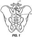
- FIG. 1a posterior view of the right sacroiliac joint is shown. Superior guide needle 11 and inferior guide needle 12 have been inserted into respective target joint spaces. This may be done under radiological guidance. For example, the procedure may be performed under X-rays, CAT scanning, MRI scanning, or any other acceptable imaging techniques. The sacroiliac joint is then identified.
- a cannulated drillis disposed over the superior guide needle 11 and inferior guide needle 12 and cores out a receiving bed for the SIFS.
- FIG. 2in which a cannulated drill 8 is passing over both the superior guide needle 11 and inferior guide needle 12.
- FIG. 3A lateral view of one cannulated drill 8 is provided in FIG. 3 .
- the cannulated drill 8is provided with a leading end 9 which provides a cutting blade of the cannulated drill 8.
- a shaft 10is connected to either a manual actuator or a power-driven actuator which is powered by a pneumatic, electric, or other power source which is known in the art.
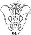
- a receiving bed 13is cored out for implantation of the SIFS as shown in FIG. 4 .
- the receiving bed 13is seen centered over the sacroiliac joint.
- the receiving bed 13is coextensive with both the sacrum and the ilium thus encouraging fusion of the SIJ.
- the SIFSis positioned initially with the long axis of the SIFS being parallel to the long axis of the SIJ.
- the SIFSis then rotated a quarter of a turn, at which point projections engage the bone of the sacrum and the ilium, thus bridging the joint and promoting fusion.
- Additional bonecan be packed around the SIFS.
- Other media, such as BMP,can be utilized instead of the additional bone.
- a similar procedureis utilized when implanting the SIFS into the site of a fracture with a non-union.
- the non-unionwould be radiographically identified, and after anesthesia is established, a needle would be passed into the site of the non-union. Then a small incision would be accomplished, and the drill is disposed over the non-union.
- the SIFSis filled with bone and implanted using the technique described above.
- the SIFSis disposed over the guide needle and rotated approximately one-quarter turn (90°) to lock projections at the lateral ends of the SIFS into the bone of the receiving bed. Additional bone can be packed around the SIFS.
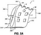
- FIG. 5Adepicts an elevational perspective view a SIFS 1.
- SIFS 1has a first lateral surface 504 and a second lateral surface 506 separated by a depth 508 that defines a first side 510 and a second side 512.
- the first lateral surface 504 and the second lateral surface 506have curvatures that produce the lazy-S shape such that the first lateral surface 504 contacts the second lateral surface 506 at a first junction 514 and a second junction 516.
- the first junction 514is proximate the first lateral surface 504 and the second junction 516 is proximate the second lateral surface 506.
- the SIFS 1is multi-curvilinear in configuration, substantially configured to be shaped like a "Lazy-S" in its appearance.
- the SIFS 1has a central portion, being tapered to a point along its superior and inferior edges.
- the central portionis provided with a central chamber which is hollow. This central chamber may be filled with fusion substrate to promote in-growth of fusion mass through the SIFS 1 and from the ilium to the sacrum.
- the leading endis that portion of the device which is initially placed into the receiving bed.
- the leading endis slightly tapered in contrast to the trailing end, but any geometric configuration is within the spirit and scope of the invention.
- a tapered leading endis more easily implanted within a receiving bed which has been drilled out.
- a prominent feature along the broad lateral surface of the SIFS 1is the presence of multiple fenestrations 4, which communicate with the central chamber. Furthermore, the fenestrations 4 are present on both sides of the SIFS 1 and communicate with each other through the central channel. This presents a large surface area to the SIFS 1 and promotes bony fusion to extend through the central portion. This also promotes bony fusion in the setting of non-healing fractures.
- projections 5are extending from the lateral edges of the SIFS 1.
- the projections 5are slightly curved as viewed from the top view, conforming to and aligning with the curvature created by the tapered ends of the "Lazy S" configuration of the SIFS 1. These curved projections 5 designed to be implanted into a receiving bed.
- the projections 5contribute significantly to the overall function and purpose of the SIFS 1.
- the projections 5are somewhat eccentric in their orientation. Referring to FIG. 5A , the projections 5 include a proximate projection 5A and a distal projection 5B, with the proximate projection 5A being that end of the projections which engages the bone initially during insertional rotation.
- the eccentric orientation of the projection 5is such that the distal projection 5B is slightly closer to the cannulation 3 of the SIFS 1 while the proximate projection 5A is closer to the cannulation 3 of the SIFS 1 (distance 500 is greater than distance 502).
- these projections 5function very much the same as the threading of a screw.
- the function of the projections 5is to secure the SIFS into the target area of the bone, so any embodiment of these projections which achieves that end is acceptable.
- the curved projections 5are configured such that a concave end of the curved projections 5 is the leading end during insertional rotation. This is generally accomplished with rotation of the SIFS during insertion; hence, as viewed from the top view, this would be accomplished with rotation to the viewer's right. Therefore, again as viewed from the top view, the concave surface of the superior projection would be located on the right side of the projection and the convex surface would be on the left. This arrangement would be reversed on the inferior projection. However, other configurations of such a projection would be within the scope of this application.
- the SIFSis positioned into the receiving bed and rotated at least one-quarter turn in order to be locked into place.
- the SIFSmay be gently rotated in a clockwise or counter-clockwise direction.
- these projections 5are of equal size.
- the projects 5may be more robust at the trailing end of the device.
- the SIFSis slightly larger than the receiving bed which has been drilled out. In this way, the SIFS can be secured into the bed with the projections 5 securely engaging the bone, and the SIFS being somewhat compressed in its final position. This will promote bony fusion.
- FIG. 6is a close-up of the implanted SIFS 1 within the right sided sacroiliac joint.
- the projections 5can be seen engaging the bone of the ilium.
- Fenestrations 4 in the SIFS 1promote bone fusion.
- the SIFS 1can also be oriented along the course of the sacroiliac joint as seen in FIG. 7 .
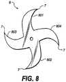
- FIG. 8demonstrates the top view of an alternative embodiment of a SIFS 6 in which there are four arms 7 rather than two such that the overall embodiment resembles an "X shape" rather than a "Lazy S” as viewed from the top perspective.
- the SIFS 6comprises a first arm 801 and a second arm 802. These arms provide a lazy-S shape as described with regard to SIFS 1.
- the SIFS 6comprises a third arm 803 and a fourth arm 804 that provides a second lazy-S shape.
- the SIFS 6consists of four arms with two overlapping lazy-S shapes.
- the SIFS 1consists of two arms with a single lazy-S shape.
- At least two SIFS devicesare used to stabilize and fuse the SIJ and, in some instances, three SIFS may be used. This is a decision left to the judgment of the surgeon.
- a pair of SIFS 1has been disposed over the respective guide needles and into the receiving bed.
- FIG. 10demonstrates an alternative embodiment of the SIFS 6 which has been provided with four arms, and is secured into the sacroiliac joint with two arms 14 engaging the sacrum and two arms 15 engaging the ilium.
- the SIFScould also be utilized to treat fracture sites which suffer from non-union.
- a non-union siteis pictured with an SIFS having been placed in between the bone fracture fragments 16, 17. Because the projections 5 engage the bone, the site is stabilized and bone fusion is promoted.
- all implanted components of the sacroiliac stabilizermay be fabricated from surgical titanium.
- stainless steel, molybdenum, other metal alloyssuch as chromium containing alloys, Nitinol, ceramic, porcelain, composite, polyesters, or any other substance known or acceptable to the art.
Landscapes
- Health & Medical Sciences (AREA)
- Orthopedic Medicine & Surgery (AREA)
- Life Sciences & Earth Sciences (AREA)
- Animal Behavior & Ethology (AREA)
- Transplantation (AREA)
- Veterinary Medicine (AREA)
- Engineering & Computer Science (AREA)
- Biomedical Technology (AREA)
- Heart & Thoracic Surgery (AREA)
- Public Health (AREA)
- General Health & Medical Sciences (AREA)
- Cardiology (AREA)
- Oral & Maxillofacial Surgery (AREA)
- Vascular Medicine (AREA)
- Surgery (AREA)
- Molecular Biology (AREA)
- Medical Informatics (AREA)
- Nuclear Medicine, Radiotherapy & Molecular Imaging (AREA)
- Neurology (AREA)
- Physical Education & Sports Medicine (AREA)
- Surgical Instruments (AREA)
- Prostheses (AREA)
Description
- Many causes of lower back pain have been identified, and the differential diagnosis of low back pain is indeed foreboding when first reviewed. However, most causes can be identified by other associated symptoms and the vast majority of patients with lower back pain are found to have degenerative disease of the spine. More recently, a study performed at the National Institute of Health (NIH) in Bethesda, MD, has shown that upwards of 20% of patients with chronic low back pain actually suffer from inflammation/irritation of one or both of the sacroiliac joints. These are the junctions between the sacrum, which is the base of the spine, and the posterior-medial aspect of the iliac bones. Treatment of pain arising from the sacroiliac joint (SIJ) is usually managed with measures such as chiropractic adjustments, massage, anti-inflammatory medications, and local injections. However, there are a number of patients who do not respond well to these measures, or in whom the response to other measures was merely transient, and in this setting fusion of the lumbar spine is often considered. This is somewhat controversial; detractors of the procedure point to the fact that this joint is a fixed joint to begin with, and as such there is little movement naturally occurring. Proponents suggest that even a minute amount of movement can cause symptoms, and point to the fact that this procedure was first performed many years ago and has been reliably performed since then with reasonable success. Fusion seems to resolve sacroiliac joint pain syndromes with a fairly high rate of success.
- A common scenario for SIJ pain syndromes is in the post lumbar fusion patient, particularly patients who have undergone fusion of the L5- S1 segment. Such individuals have had motion eliminated at L5-S1 and are now believed to be passing increased stress along to the SIJ, much the same way that the socalled "adjacent disc disease" inflicts its pathophysiology. Such patients may be candidates for SIJ fusion.
US 2015/250595 A1 was used as a basis for the preamble of claim 1 and discloses an implant having an integrated cutting broach and/or cutting burr. The integrated implant may be inserted without requiring separate steps for drilling and broaching bone. The integrated implant assembly may include an integrated implant, a flexible sheath, a delivery rod, and a delivery pin. The implant may have a core which may have any of a variety of cross-sectional geometries. A method for fusing bone may involve inserting the implant laterally through the ilium, through the sacral-iliac joint, and into the sacrum.US 2009/204212 A1 relates to a cage to be interposed between a pair of vertebral bodies in place of a degenerative intervertebral disk after it is removed, and, more particularly to a cage with an excellent home position maintaining ability which can be placed between a pair of vertebral bodies easily, and in which after the cage is placed, its home position is maintained without moving the cage. The cage is interposed between a pair of vertebral bodies, wherein both left and right side surfaces of a cage body are formed in a smooth surface, both upper and lower surfaces of the cage body are provided with a large number of projections arranged in a longitudinal direction and a lateral direction, tip end surfaces of the large number of projections substantially match with a virtual arc curved surface formed around an axis in the longitudinal direction, and angles of inner end edges of the projections close to left and right side surfaces are more acute. A longitudinal through hole is formed in the cage body in its longitudinal direction so as to penetrate the cage body, and both left and right side surfaces and both upper and lower surfaces of the cage body are provided with communication holes which are in communication with the longitudinal through hole. The communication holes are circular holes having a common diameter.- According to the present invention, a sacroiliac fusion stabilizer (SIFS) for fusing a first bone fracture fragment to a second bone fracture fragment is provided as set forth in claim 1.
- Preferred embodiments of the present invention may be gathered from the dependent claims.
- This brief description of the invention is intended only to provide a brief overview of subject matter disclosed herein according to one or more illustrative embodiments, and does not serve as a guide to interpreting the claims or to define or limit the scope of the invention, which is defined only by the appended claims. This brief description is provided to introduce an illustrative selection of concepts in a simplified form that are further described below in the detailed description. This brief description is not intended to identify key features or essential features of the claimed subject matter, nor is it intended to be used as an aid in determining the scope of the claimed subject matter. The claimed subject matter is not limited to implementations that solve any or all disadvantages noted in the background.
- So that the manner in which the features of the invention can be understood, a detailed description of the invention may be had by reference to certain embodiments, some of which are illustrated in the accompanying drawings. It is to be noted, however, that the drawings illustrate only certain embodiments of this invention and are therefore not to be considered limiting of its scope, for the scope of the invention encompasses other equally effective embodiments. The drawings are not necessarily to scale, emphasis generally being placed upon illustrating the features of certain embodiments of the invention. In the drawings, like numerals are used to indicate like parts throughout the various views. Thus, for further understanding of the invention, reference can be made to the following detailed description, read in connection with the drawings in which:
FIG. 1 is a posterior view of a right sacroiliac joint with guide needles in position;FIG. 2 depicts a cannulated drill being disposed over the guide needle;FIG. 3 is a lateral view of a cannulated drill;FIG. 4 shows a receiving bed formed in the right sacroiliac joint;FIG. 5A is an elevational perspective view of one embodiment of the sacroiliac fusion stabilizer (SIFS);FIG. 5B is an enlarged view of projections of the SIFS;FIG. 6 shows a SIFS after implantation and rotation;FIG. 7 depicts one embodiment of a SIFS that is oriented along the SI joint axis;FIG. 8 is a top view of another embodiment with four arms on the SIFS;FIG. 9 demonstrates certain sites for placement of two SIFS units;FIG. 10 shows implantation of an alternative embodiment;FIG. 11 shows a SIFS placed into a pseudoarthrosis of a long bone; andFIG. 12 depicts a view of a SIFS placed into the long bone.- This disclosure relates to the general field of spinal surgery and specifically to a device and method for use by which a surgeon can stabilize and fuse the sacroiliac joint using a minimally invasive technique. The same technique can be applied to sites of non-healing fractures at other sites. The disclosed device and method fuses the sacroiliac joint using a minimally invasive technique. Once the joint is identified, a guide needle is passed into the joint and the position of the needle is confirmed. A cannulated drill is then disposed over the needle, and advanced until the drill is at the level of the joint. The drill is then activated and a receiving bed is cored out. A sacroiliac fusion stabilizer (SIFS) is then disposed over the needle and passed into the joint at the level of the receiving bed. The SIFS is then rotated a partial turn and projections of the SIFS engage the bone and lock the SIFS into position. The SIFS is then filled with bone fusion substrate. The SIFS can also be utilized in the setting of non-healing fractures at other sites. A more detailed description follows.
- The SIFS is implanted into the sacroiliac joint to provide stabilization and promote fusion. In
FIG. 1 , a posterior view of the right sacroiliac joint is shown.Superior guide needle 11 andinferior guide needle 12 have been inserted into respective target joint spaces. This may be done under radiological guidance. For example, the procedure may be performed under X-rays, CAT scanning, MRI scanning, or any other acceptable imaging techniques. The sacroiliac joint is then identified. - A cannulated drill is disposed over the
superior guide needle 11 andinferior guide needle 12 and cores out a receiving bed for the SIFS. This can be seen inFIG. 2 , in which a cannulateddrill 8 is passing over both thesuperior guide needle 11 andinferior guide needle 12. A lateral view of one cannulateddrill 8 is provided inFIG. 3 . The cannulateddrill 8 is provided with aleading end 9 which provides a cutting blade of the cannulateddrill 8. Ashaft 10 is connected to either a manual actuator or a power-driven actuator which is powered by a pneumatic, electric, or other power source which is known in the art. In this fashion, a receivingbed 13 is cored out for implantation of the SIFS as shown inFIG. 4 . The receivingbed 13 is seen centered over the sacroiliac joint. The receivingbed 13 is coextensive with both the sacrum and the ilium thus encouraging fusion of the SIJ. - In one embodiment, the SIFS is positioned initially with the long axis of the SIFS being parallel to the long axis of the SIJ. The SIFS is then rotated a quarter of a turn, at which point projections engage the bone of the sacrum and the ilium, thus bridging the joint and promoting fusion. Additional bone can be packed around the SIFS. Other media, such as BMP, can be utilized instead of the additional bone.
- A similar procedure is utilized when implanting the SIFS into the site of a fracture with a non-union. The non-union would be radiographically identified, and after anesthesia is established, a needle would be passed into the site of the non-union. Then a small incision would be accomplished, and the drill is disposed over the non-union. At that point, the SIFS is filled with bone and implanted using the technique described above. The SIFS is disposed over the guide needle and rotated approximately one-quarter turn (90°) to lock projections at the lateral ends of the SIFS into the bone of the receiving bed. Additional bone can be packed around the SIFS.
FIG. 5A depicts an elevational perspective view a SIFS 1. Features noted include the "lazy S" configuration of the body, as well as thecannulation 3 which permits the SIFS 1 to be disposed over a guide needle.Multiple fenestrations 4 are seen in the frame of the SIFS 1 and these are deigned to permit bony growth to be incorporated through the body of the SIFS 1. A leading end of the SIFS 1 has been provided withmultiple projections 5 which engages the bone, stabilizes the construct and promotes bony growth. The large surface area of the SIFS 1 encourages increased bone growth in the area. The SIFS 501 has a firstlateral surface 504 and a secondlateral surface 506 separated by adepth 508 that defines afirst side 510 and asecond side 512. The firstlateral surface 504 and the secondlateral surface 506 have curvatures that produce the lazy-S shape such that the firstlateral surface 504 contacts the secondlateral surface 506 at afirst junction 514 and asecond junction 516. Thefirst junction 514 is proximate the firstlateral surface 504 and thesecond junction 516 is proximate the secondlateral surface 506.- In the embodiment of
FIG. 5A , the SIFS 1 is multi-curvilinear in configuration, substantially configured to be shaped like a "Lazy-S" in its appearance. The SIFS 1 has a central portion, being tapered to a point along its superior and inferior edges. The central portion is provided with a central chamber which is hollow. This central chamber may be filled with fusion substrate to promote in-growth of fusion mass through the SIFS 1 and from the ilium to the sacrum. There is a leading end of the SIFS 1 as well as a trailing end. The leading end is that portion of the device which is initially placed into the receiving bed. In one embodiment, the leading end is slightly tapered in contrast to the trailing end, but any geometric configuration is within the spirit and scope of the invention. A tapered leading end is more easily implanted within a receiving bed which has been drilled out. One can, of course, also envision a somewhat cylindrical configuration composed of multiple "lazy S" configurations. - A prominent feature along the broad lateral surface of the SIFS 1 is the presence of
multiple fenestrations 4, which communicate with the central chamber. Furthermore, thefenestrations 4 are present on both sides of the SIFS 1 and communicate with each other through the central channel. This presents a large surface area to the SIFS 1 and promotes bony fusion to extend through the central portion. This also promotes bony fusion in the setting of non-healing fractures. - Another prominent feature is the presence of
multiple projections 5 are extending from the lateral edges of the SIFS 1. Theprojections 5 are slightly curved as viewed from the top view, conforming to and aligning with the curvature created by the tapered ends of the "Lazy S" configuration of the SIFS 1. Thesecurved projections 5 designed to be implanted into a receiving bed. Theprojections 5 contribute significantly to the overall function and purpose of the SIFS 1. Theprojections 5 are somewhat eccentric in their orientation. Referring toFIG. 5A , theprojections 5 include aproximate projection 5A and adistal projection 5B, with theproximate projection 5A being that end of the projections which engages the bone initially during insertional rotation. In order to engage the bone, the eccentric orientation of theprojection 5 is such that thedistal projection 5B is slightly closer to thecannulation 3 of the SIFS 1 while theproximate projection 5A is closer to thecannulation 3 of the SIFS 1 (distance 500 is greater than distance 502). Referring toFIG. 5B , this offsets theprojections 5 from alateral line 505 with eachprojection 5 being spaced from thelateral line 505 by an increasing distance. In this fashion, theseprojections 5 function very much the same as the threading of a screw. The function of theprojections 5 is to secure the SIFS into the target area of the bone, so any embodiment of these projections which achieves that end is acceptable. - In order to favorably dispose the SIFS 1 into a receiving bed, the
curved projections 5 are configured such that a concave end of thecurved projections 5 is the leading end during insertional rotation. This is generally accomplished with rotation of the SIFS during insertion; hence, as viewed from the top view, this would be accomplished with rotation to the viewer's right. Therefore, again as viewed from the top view, the concave surface of the superior projection would be located on the right side of the projection and the convex surface would be on the left. This arrangement would be reversed on the inferior projection. However, other configurations of such a projection would be within the scope of this application. In one embodiment, the SIFS is positioned into the receiving bed and rotated at least one-quarter turn in order to be locked into place. It need not be rotated a great deal, such that it is not, per se, "screwed" into position. Rather, a partial turn may be utilized to promote engagement of the projections with the bone. From the leading end to the trailing end, the SIFS may be gently rotated in a clockwise or counter-clockwise direction. In the embodiment ofFIG. 5A , theseprojections 5 are of equal size. Alternatively, theprojects 5 may be more robust at the trailing end of the device. - In one embodiment the SIFS is slightly larger than the receiving bed which has been drilled out. In this way, the SIFS can be secured into the bed with the
projections 5 securely engaging the bone, and the SIFS being somewhat compressed in its final position. This will promote bony fusion. - The orientation of the SIFS 1 is further demonstrated in
FIG. 6 , which is a close-up of the implanted SIFS 1 within the right sided sacroiliac joint. Theprojections 5 can be seen engaging the bone of the ilium.Fenestrations 4 in the SIFS 1 promote bone fusion. The SIFS 1 can also be oriented along the course of the sacroiliac joint as seen inFIG. 7 . FIG. 8 demonstrates the top view of an alternative embodiment of aSIFS 6 in which there are fourarms 7 rather than two such that the overall embodiment resembles an "X shape" rather than a "Lazy S" as viewed from the top perspective. This embodiment is otherwise utilized as described elsewhere in this specification. In the embodiment ofFIG. 8 , theSIFS 6 comprises afirst arm 801 and asecond arm 802. These arms provide a lazy-S shape as described with regard to SIFS 1. Likewise, theSIFS 6 comprises athird arm 803 and afourth arm 804 that provides a second lazy-S shape. In this manner, theSIFS 6 consists of four arms with two overlapping lazy-S shapes. In contrast, the SIFS 1 consists of two arms with a single lazy-S shape.- In some embodiments, at least two SIFS devices are used to stabilize and fuse the SIJ and, in some instances, three SIFS may be used. This is a decision left to the judgment of the surgeon. In
FIG. 9 , a pair of SIFS 1 has been disposed over the respective guide needles and into the receiving bed. Likewise,FIG. 10 demonstrates an alternative embodiment of theSIFS 6 which has been provided with four arms, and is secured into the sacroiliac joint with twoarms 14 engaging the sacrum and twoarms 15 engaging the ilium. - As shown in
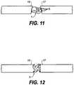
FIG. 11 and FIG. 12 , the SIFS could also be utilized to treat fracture sites which suffer from non-union. In these figures a non-union site is pictured with an SIFS having been placed in between the bone fracture fragments 16, 17. Because theprojections 5 engage the bone, the site is stabilized and bone fusion is promoted. - It is anticipated that all implanted components of the sacroiliac stabilizer may be fabricated from surgical titanium. However, stainless steel, molybdenum, other metal alloys such as chromium containing alloys, Nitinol, ceramic, porcelain, composite, polyesters, or any other substance known or acceptable to the art.
Claims (8)
- A sacroiliac fusion stabilizer, SIFS, (1, 6, 501) for fusing a first bone fracture fragment to a second bone fracture fragment, the SIFS (1, 6, 501) comprising:a first lateral surface (504) having a first curvature;a second lateral surface (506), opposite the first lateral surface (504), having a second curvature, the first lateral surface (504) being spaced from the second lateral surface (506) by a depth (508) that defines a first side (510) and a second side (512);a cannulation (3) that extends from the first side (510), through the SIFS (1, 6, 501) and terminates at the second side (512);wherein the first curvature and the second curvature provide a lazy-S shape such that the first lateral surface (504) contacts the second lateral surface (506) at a first junction (514) and a second junction (516), the first junction (514) being disposed proximate the first lateral surface (504) and the second junction (516) being disposed proximate the second lateral surface (506);characterized in thatthe first junction (514) provides a first plurality of projections (5), and the second junction (516) provides a second plurality of projections; andeach of said plurality of projections (5) is configured so that when said SIFS (1, 6, 501) is rotated at least one of said first projections engages the sacrum and at least one of said second projections engages the bone of the ilium.
- The SIFS as recited in claim 1,wherein each projection in the first plurality of projections (5) is spaced from a first lateral line (505) by a first distance that is unique within the first plurality of projections (5); andwherein each projection in the second plurality of projections is spaced from a second lateral line by a second distance that is unique within the second plurality of projections.
- The SIFS as recited in claim 2, wherein the SIFS (1, 501) consists of a first arm and a second arm, wherein the first junction (514) is disposed at a terminus of the first arm and the second junction (516) is disposed at a terminus of the second arm.
- The SIFS as recited in claim 2, wherein the SIFS (6) consists of a first arm (801), a second arm (802), a third arm (803) and a fourth arm (804), wherein the first junction is disposed at a terminus of the first arm (801) and the second junction is disposed at a terminus of the second arm (802), the SIFS (6) further comprising:a third lateral surface having a third curvature;a fourth lateral surface, opposite the third lateral surface, having a fourth curvature;the third lateral surface being spaced from the fourth lateral surface by a depth that defines a third side and a fourth side;the third curvature and the fourth curvature providing a second lazy-S shape such that the third lateral surface contacts the fourth lateral surface at a third junction and a fourth junction, the third junction being disposed proximate the second lateral surface and the fourth junction being disposed proximate the fourth lateral surface, wherein the third junction is disposed at a terminus of the third arm (803) and the fourth junction is disposed at a terminus of the fourth arm (804).
- The SIFS as recited in claim 2, the SIFS (1, 6, 501) comprising at least a first arm and a second arm defined by:the first lateral surface (504), andthe second lateral surface (506);
wherein the first junction (514) is disposed proximate the first lateral surface (504) to form the first arm and the second junction (516) is disposed proximate the second lateral surface (506) to form the second arm; andwherein the two arms of the lazy-S configuration are configured to penetrate into a sacroiliac joint to hold the sacroiliac joint in a fixed position. - The SIFS as recited in claim 5, wherein the SIFS (1, 501) consists of the first arm and the second arm.
- The SIFS as recited in claim 5, wherein the SIFS (6) further comprises a third arm (803) and a fourth arm (804), the third arm (803) and the fourth arm (804) defining a second lazy-S.
- The SIFS as recited in claim 1, the SIFS (1, 6, 501) comprisingat least a first arm and a second arm defined by the first lateral surface (504) and the second lateral surface (506); anda first plurality of fenestrations (4) in the first lateral surface (504) and a second plurality of fenestrations in the second lateral surface;wherein the first junction (514) is disposed proximate the first lateral surface (504) to form the first arm and the second junction (516) is disposed proximate the second lateral surface (506) to form the second arm.
Applications Claiming Priority (2)
| Application Number | Priority Date | Filing Date | Title |
|---|---|---|---|
| US201662353828P | 2016-06-23 | 2016-06-23 | |
| PCT/US2017/039007WO2017223454A1 (en) | 2016-06-23 | 2017-06-23 | Minimally invasive surgical systems for fusion of the sacroiliac joint |
Publications (3)
| Publication Number | Publication Date |
|---|---|
| EP3500218A1 EP3500218A1 (en) | 2019-06-26 |
| EP3500218A4 EP3500218A4 (en) | 2020-06-03 |
| EP3500218B1true EP3500218B1 (en) | 2021-10-13 |
Family
ID=60783495
Family Applications (1)
| Application Number | Title | Priority Date | Filing Date |
|---|---|---|---|
| EP17816297.0ANot-in-forceEP3500218B1 (en) | 2016-06-23 | 2017-06-23 | Minimally invasive surgical systems for fusion of the sacroiliac joint |
Country Status (4)
| Country | Link |
|---|---|
| US (2) | US20200069431A1 (en) |
| EP (1) | EP3500218B1 (en) |
| CN (1) | CN110114041B (en) |
| WO (1) | WO2017223454A1 (en) |
Families Citing this family (12)
| Publication number | Priority date | Publication date | Assignee | Title |
|---|---|---|---|---|
| US10363140B2 (en) | 2012-03-09 | 2019-07-30 | Si-Bone Inc. | Systems, device, and methods for joint fusion |
| US11147688B2 (en) | 2013-10-15 | 2021-10-19 | Si-Bone Inc. | Implant placement |
| US20240335292A1 (en)* | 2016-06-23 | 2024-10-10 | Frank H. Boehm, Jr. | Minimally invasive direct posterior sacroiliac joint fusion |
| US11116519B2 (en) | 2017-09-26 | 2021-09-14 | Si-Bone Inc. | Systems and methods for decorticating the sacroiliac joint |
| ES3011907T3 (en) | 2018-03-28 | 2025-04-08 | Si Bone Inc | Threaded implants for use across bone segments |
| US11273043B1 (en) | 2018-06-15 | 2022-03-15 | Advance Research System, Llc | System and method for fusion of sacroiliac joint |
| EP4613244A2 (en) | 2019-02-14 | 2025-09-10 | SI-Bone Inc. | Implants for spinal fixation and or fusion |
| JP7646654B2 (en) | 2019-11-21 | 2025-03-17 | エスアイ-ボーン・インコーポレイテッド | Rod coupling assembly for bone stabilization construct - Patent application |
| AU2020392121B2 (en) | 2019-11-27 | 2025-05-22 | Si-Bone, Inc. | Bone stabilizing implants and methods of placement across SI joints |
| EP4072452A4 (en) | 2019-12-09 | 2023-12-20 | SI-Bone, Inc. | Sacro-iliac joint stabilizing implants and methods of implantation |
| EP4259015A4 (en) | 2020-12-09 | 2024-09-11 | SI-Bone, Inc. | SACROILIAC JOINT STABILIZATION IMPLANTS AND METHODS OF IMPLANTATION |
| WO2025038769A1 (en) | 2023-08-15 | 2025-02-20 | Si-Bone Inc. | Pelvic stabilization implants, methods of use and manufacture |
Family Cites Families (17)
| Publication number | Priority date | Publication date | Assignee | Title |
|---|---|---|---|---|
| US6507758B1 (en) | 1999-03-24 | 2003-01-14 | Second Sight, Llc | Logarithmic light intensifier for use with photoreceptor-based implanted retinal prosthetics and those prosthetics |
| US7837732B2 (en)* | 2003-11-20 | 2010-11-23 | Warsaw Orthopedic, Inc. | Intervertebral body fusion cage with keels and implantation methods |
| US20060036251A1 (en)* | 2004-08-09 | 2006-02-16 | Reiley Mark A | Systems and methods for the fixation or fusion of bone |
| US8388667B2 (en) | 2004-08-09 | 2013-03-05 | Si-Bone, Inc. | Systems and methods for the fixation or fusion of bone using compressive implants |
| US7850732B2 (en)* | 2006-12-11 | 2010-12-14 | Warsaw Orthopedic, Inc. | Sacral prosthesis and surgical method |
| US20090024174A1 (en) | 2007-07-17 | 2009-01-22 | Stark John G | Bone screws and particular applications to sacroiliac joint fusion |
| JP5266069B2 (en)* | 2008-02-07 | 2013-08-21 | 昭和医科工業株式会社 | cage |
| US8157865B2 (en)* | 2009-01-22 | 2012-04-17 | Stephen Hochschuler | Apparatus and method for stabilizing adjacent bone portions |
| CA3002234C (en)* | 2010-01-13 | 2020-07-28 | Jcbd, Llc | Sacroiliac joint fixation fusion system |
| US9333090B2 (en)* | 2010-01-13 | 2016-05-10 | Jcbd, Llc | Systems for and methods of fusing a sacroiliac joint |
| US20110184518A1 (en)* | 2010-01-22 | 2011-07-28 | Warsaw Orthopedic, Inc. | Sacro-iliac joint implant |
| US8221428B2 (en)* | 2010-01-26 | 2012-07-17 | Warsaw Orthopedic, Inc. | Sacro-iliac joint implant system, method and instrument |
| EP2720628B1 (en)* | 2011-06-17 | 2021-08-11 | Jcbd, Llc | Sacroiliac joint implant system |
| US9044321B2 (en) | 2012-03-09 | 2015-06-02 | Si-Bone Inc. | Integrated implant |
| EP3818947B1 (en)* | 2012-05-04 | 2023-08-30 | SI-Bone, Inc. | Fenestrated implant |
| US10166033B2 (en)* | 2014-09-18 | 2019-01-01 | Si-Bone Inc. | Implants for bone fixation or fusion |
| JP6542362B2 (en)* | 2014-09-18 | 2019-07-10 | エスアイ−ボーン・インコーポレイテッドSi−Bone, Inc. | Matrix implant |
- 2017
- 2017-06-23EPEP17816297.0Apatent/EP3500218B1/ennot_activeNot-in-force
- 2017-06-23WOPCT/US2017/039007patent/WO2017223454A1/ennot_activeCeased
- 2017-06-23USUS16/312,866patent/US20200069431A1/ennot_activeAbandoned
- 2017-06-23CNCN201780048775.8Apatent/CN110114041B/ennot_activeExpired - Fee Related
- 2021
- 2021-12-22USUS17/559,669patent/US11944548B2/enactiveActive
Also Published As
| Publication number | Publication date |
|---|---|
| EP3500218A4 (en) | 2020-06-03 |
| US20200069431A1 (en) | 2020-03-05 |
| US11944548B2 (en) | 2024-04-02 |
| CN110114041A (en) | 2019-08-09 |
| EP3500218A1 (en) | 2019-06-26 |
| WO2017223454A1 (en) | 2017-12-28 |
| CN110114041B (en) | 2022-02-25 |
| US20220110754A1 (en) | 2022-04-14 |
Similar Documents
| Publication | Publication Date | Title |
|---|---|---|
| EP3500218B1 (en) | Minimally invasive surgical systems for fusion of the sacroiliac joint | |
| US10729552B2 (en) | Implant configured for hammertoe and small bone fixation | |
| US8556975B2 (en) | Device for surgical displacement of vertebrae | |
| US7901439B2 (en) | Allograft spinal facet fusion system | |
| EP2629703B1 (en) | Apparatus for spinal facet fusion | |
| US8771317B2 (en) | Interspinous process implant and method of implantation | |
| US11633291B2 (en) | Interconnected locking plates for adjacent spinal vertebral bodies | |
| EP2155124A1 (en) | Method and apparatus for spinal facet fusion | |
| US9463052B2 (en) | Access assembly for anterior and lateral spinal procedures | |
| US20120239089A1 (en) | Interspinous process implant and method of implantation | |
| US20100286785A1 (en) | Method and apparatus for spinal interbody fusion | |
| CN105682613B (en) | Interspinous process implant with the engagement arm driven by pin | |
| AU2017281696B2 (en) | Method and apparatus for spinal facet fusion | |
| US9326777B2 (en) | Decorticating surgical instruments and guidance systems with tactile feedback | |
| JP2018519977A (en) | Bone element fixation implant | |
| HK40009509A (en) | Minimally invasive surgical systems for fusion of the sacroiliac joint | |
| US9827015B1 (en) | Wireless pedicle screw system and methods of use | |
| EP3215036B1 (en) | Interconnected locking plates for adjacent spinal vertebral bodies |
Legal Events
| Date | Code | Title | Description |
|---|---|---|---|
| STAA | Information on the status of an ep patent application or granted ep patent | Free format text:STATUS: THE INTERNATIONAL PUBLICATION HAS BEEN MADE | |
| PUAI | Public reference made under article 153(3) epc to a published international application that has entered the european phase | Free format text:ORIGINAL CODE: 0009012 | |
| STAA | Information on the status of an ep patent application or granted ep patent | Free format text:STATUS: REQUEST FOR EXAMINATION WAS MADE | |
| 17P | Request for examination filed | Effective date:20190118 | |
| AK | Designated contracting states | Kind code of ref document:A1 Designated state(s):AL AT BE BG CH CY CZ DE DK EE ES FI FR GB GR HR HU IE IS IT LI LT LU LV MC MK MT NL NO PL PT RO RS SE SI SK SM TR | |
| AX | Request for extension of the european patent | Extension state:BA ME | |
| DAV | Request for validation of the european patent (deleted) | ||
| DAX | Request for extension of the european patent (deleted) | ||
| A4 | Supplementary search report drawn up and despatched | Effective date:20200508 | |
| RIC1 | Information provided on ipc code assigned before grant | Ipc:A61F 2/46 20060101AFI20200501BHEP | |
| GRAP | Despatch of communication of intention to grant a patent | Free format text:ORIGINAL CODE: EPIDOSNIGR1 | |
| STAA | Information on the status of an ep patent application or granted ep patent | Free format text:STATUS: GRANT OF PATENT IS INTENDED | |
| INTG | Intention to grant announced | Effective date:20210517 | |
| GRAS | Grant fee paid | Free format text:ORIGINAL CODE: EPIDOSNIGR3 | |
| GRAA | (expected) grant | Free format text:ORIGINAL CODE: 0009210 | |
| STAA | Information on the status of an ep patent application or granted ep patent | Free format text:STATUS: THE PATENT HAS BEEN GRANTED | |
| AK | Designated contracting states | Kind code of ref document:B1 Designated state(s):AL AT BE BG CH CY CZ DE DK EE ES FI FR GB GR HR HU IE IS IT LI LT LU LV MC MK MT NL NO PL PT RO RS SE SI SK SM TR | |
| REG | Reference to a national code | Ref country code:GB Ref legal event code:FG4D | |
| REG | Reference to a national code | Ref country code:CH Ref legal event code:EP | |
| REG | Reference to a national code | Ref country code:DE Ref legal event code:R096 Ref document number:602017047661 Country of ref document:DE | |
| REG | Reference to a national code | Ref country code:IE Ref legal event code:FG4D | |
| REG | Reference to a national code | Ref country code:AT Ref legal event code:REF Ref document number:1437572 Country of ref document:AT Kind code of ref document:T Effective date:20211115 | |
| REG | Reference to a national code | Ref country code:LT Ref legal event code:MG9D | |
| REG | Reference to a national code | Ref country code:NL Ref legal event code:MP Effective date:20211013 | |
| REG | Reference to a national code | Ref country code:AT Ref legal event code:MK05 Ref document number:1437572 Country of ref document:AT Kind code of ref document:T Effective date:20211013 | |
| PG25 | Lapsed in a contracting state [announced via postgrant information from national office to epo] | Ref country code:RS Free format text:LAPSE BECAUSE OF FAILURE TO SUBMIT A TRANSLATION OF THE DESCRIPTION OR TO PAY THE FEE WITHIN THE PRESCRIBED TIME-LIMIT Effective date:20211013 Ref country code:LT Free format text:LAPSE BECAUSE OF FAILURE TO SUBMIT A TRANSLATION OF THE DESCRIPTION OR TO PAY THE FEE WITHIN THE PRESCRIBED TIME-LIMIT Effective date:20211013 Ref country code:FI Free format text:LAPSE BECAUSE OF FAILURE TO SUBMIT A TRANSLATION OF THE DESCRIPTION OR TO PAY THE FEE WITHIN THE PRESCRIBED TIME-LIMIT Effective date:20211013 Ref country code:BG Free format text:LAPSE BECAUSE OF FAILURE TO SUBMIT A TRANSLATION OF THE DESCRIPTION OR TO PAY THE FEE WITHIN THE PRESCRIBED TIME-LIMIT Effective date:20220113 Ref country code:AT Free format text:LAPSE BECAUSE OF FAILURE TO SUBMIT A TRANSLATION OF THE DESCRIPTION OR TO PAY THE FEE WITHIN THE PRESCRIBED TIME-LIMIT Effective date:20211013 | |
| PG25 | Lapsed in a contracting state [announced via postgrant information from national office to epo] | Ref country code:IS Free format text:LAPSE BECAUSE OF FAILURE TO SUBMIT A TRANSLATION OF THE DESCRIPTION OR TO PAY THE FEE WITHIN THE PRESCRIBED TIME-LIMIT Effective date:20220213 Ref country code:SE Free format text:LAPSE BECAUSE OF FAILURE TO SUBMIT A TRANSLATION OF THE DESCRIPTION OR TO PAY THE FEE WITHIN THE PRESCRIBED TIME-LIMIT Effective date:20211013 Ref country code:PT Free format text:LAPSE BECAUSE OF FAILURE TO SUBMIT A TRANSLATION OF THE DESCRIPTION OR TO PAY THE FEE WITHIN THE PRESCRIBED TIME-LIMIT Effective date:20220214 Ref country code:PL Free format text:LAPSE BECAUSE OF FAILURE TO SUBMIT A TRANSLATION OF THE DESCRIPTION OR TO PAY THE FEE WITHIN THE PRESCRIBED TIME-LIMIT Effective date:20211013 Ref country code:NO Free format text:LAPSE BECAUSE OF FAILURE TO SUBMIT A TRANSLATION OF THE DESCRIPTION OR TO PAY THE FEE WITHIN THE PRESCRIBED TIME-LIMIT Effective date:20220113 Ref country code:NL Free format text:LAPSE BECAUSE OF FAILURE TO SUBMIT A TRANSLATION OF THE DESCRIPTION OR TO PAY THE FEE WITHIN THE PRESCRIBED TIME-LIMIT Effective date:20211013 Ref country code:LV Free format text:LAPSE BECAUSE OF FAILURE TO SUBMIT A TRANSLATION OF THE DESCRIPTION OR TO PAY THE FEE WITHIN THE PRESCRIBED TIME-LIMIT Effective date:20211013 Ref country code:HR Free format text:LAPSE BECAUSE OF FAILURE TO SUBMIT A TRANSLATION OF THE DESCRIPTION OR TO PAY THE FEE WITHIN THE PRESCRIBED TIME-LIMIT Effective date:20211013 Ref country code:GR Free format text:LAPSE BECAUSE OF FAILURE TO SUBMIT A TRANSLATION OF THE DESCRIPTION OR TO PAY THE FEE WITHIN THE PRESCRIBED TIME-LIMIT Effective date:20220114 Ref country code:ES Free format text:LAPSE BECAUSE OF FAILURE TO SUBMIT A TRANSLATION OF THE DESCRIPTION OR TO PAY THE FEE WITHIN THE PRESCRIBED TIME-LIMIT Effective date:20211013 | |
| REG | Reference to a national code | Ref country code:DE Ref legal event code:R097 Ref document number:602017047661 Country of ref document:DE | |
| PG25 | Lapsed in a contracting state [announced via postgrant information from national office to epo] | Ref country code:SM Free format text:LAPSE BECAUSE OF FAILURE TO SUBMIT A TRANSLATION OF THE DESCRIPTION OR TO PAY THE FEE WITHIN THE PRESCRIBED TIME-LIMIT Effective date:20211013 Ref country code:SK Free format text:LAPSE BECAUSE OF FAILURE TO SUBMIT A TRANSLATION OF THE DESCRIPTION OR TO PAY THE FEE WITHIN THE PRESCRIBED TIME-LIMIT Effective date:20211013 Ref country code:RO Free format text:LAPSE BECAUSE OF FAILURE TO SUBMIT A TRANSLATION OF THE DESCRIPTION OR TO PAY THE FEE WITHIN THE PRESCRIBED TIME-LIMIT Effective date:20211013 Ref country code:EE Free format text:LAPSE BECAUSE OF FAILURE TO SUBMIT A TRANSLATION OF THE DESCRIPTION OR TO PAY THE FEE WITHIN THE PRESCRIBED TIME-LIMIT Effective date:20211013 Ref country code:DK Free format text:LAPSE BECAUSE OF FAILURE TO SUBMIT A TRANSLATION OF THE DESCRIPTION OR TO PAY THE FEE WITHIN THE PRESCRIBED TIME-LIMIT Effective date:20211013 Ref country code:CZ Free format text:LAPSE BECAUSE OF FAILURE TO SUBMIT A TRANSLATION OF THE DESCRIPTION OR TO PAY THE FEE WITHIN THE PRESCRIBED TIME-LIMIT Effective date:20211013 | |
| PGFP | Annual fee paid to national office [announced via postgrant information from national office to epo] | Ref country code:IT Payment date:20220621 Year of fee payment:6 Ref country code:GB Payment date:20220628 Year of fee payment:6 | |
| PLBE | No opposition filed within time limit | Free format text:ORIGINAL CODE: 0009261 | |
| STAA | Information on the status of an ep patent application or granted ep patent | Free format text:STATUS: NO OPPOSITION FILED WITHIN TIME LIMIT | |
| 26N | No opposition filed | Effective date:20220714 | |
| PGFP | Annual fee paid to national office [announced via postgrant information from national office to epo] | Ref country code:FR Payment date:20220627 Year of fee payment:6 | |
| PG25 | Lapsed in a contracting state [announced via postgrant information from national office to epo] | Ref country code:AL Free format text:LAPSE BECAUSE OF FAILURE TO SUBMIT A TRANSLATION OF THE DESCRIPTION OR TO PAY THE FEE WITHIN THE PRESCRIBED TIME-LIMIT Effective date:20211013 | |
| PGFP | Annual fee paid to national office [announced via postgrant information from national office to epo] | Ref country code:DE Payment date:20220629 Year of fee payment:6 | |
| PG25 | Lapsed in a contracting state [announced via postgrant information from national office to epo] | Ref country code:SI Free format text:LAPSE BECAUSE OF FAILURE TO SUBMIT A TRANSLATION OF THE DESCRIPTION OR TO PAY THE FEE WITHIN THE PRESCRIBED TIME-LIMIT Effective date:20211013 | |
| PG25 | Lapsed in a contracting state [announced via postgrant information from national office to epo] | Ref country code:MC Free format text:LAPSE BECAUSE OF FAILURE TO SUBMIT A TRANSLATION OF THE DESCRIPTION OR TO PAY THE FEE WITHIN THE PRESCRIBED TIME-LIMIT Effective date:20211013 | |
| REG | Reference to a national code | Ref country code:CH Ref legal event code:PL | |
| REG | Reference to a national code | Ref country code:BE Ref legal event code:MM Effective date:20220630 | |
| PG25 | Lapsed in a contracting state [announced via postgrant information from national office to epo] | Ref country code:LU Free format text:LAPSE BECAUSE OF NON-PAYMENT OF DUE FEES Effective date:20220623 Ref country code:LI Free format text:LAPSE BECAUSE OF NON-PAYMENT OF DUE FEES Effective date:20220630 Ref country code:IE Free format text:LAPSE BECAUSE OF NON-PAYMENT OF DUE FEES Effective date:20220623 Ref country code:CH Free format text:LAPSE BECAUSE OF NON-PAYMENT OF DUE FEES Effective date:20220630 | |
| PG25 | Lapsed in a contracting state [announced via postgrant information from national office to epo] | Ref country code:BE Free format text:LAPSE BECAUSE OF NON-PAYMENT OF DUE FEES Effective date:20220630 | |
| REG | Reference to a national code | Ref country code:DE Ref legal event code:R119 Ref document number:602017047661 Country of ref document:DE | |
| GBPC | Gb: european patent ceased through non-payment of renewal fee | Effective date:20230623 | |
| PG25 | Lapsed in a contracting state [announced via postgrant information from national office to epo] | Ref country code:HU Free format text:LAPSE BECAUSE OF FAILURE TO SUBMIT A TRANSLATION OF THE DESCRIPTION OR TO PAY THE FEE WITHIN THE PRESCRIBED TIME-LIMIT; INVALID AB INITIO Effective date:20170623 | |
| PG25 | Lapsed in a contracting state [announced via postgrant information from national office to epo] | Ref country code:MK Free format text:LAPSE BECAUSE OF FAILURE TO SUBMIT A TRANSLATION OF THE DESCRIPTION OR TO PAY THE FEE WITHIN THE PRESCRIBED TIME-LIMIT Effective date:20211013 Ref country code:DE Free format text:LAPSE BECAUSE OF NON-PAYMENT OF DUE FEES Effective date:20240103 Ref country code:CY Free format text:LAPSE BECAUSE OF FAILURE TO SUBMIT A TRANSLATION OF THE DESCRIPTION OR TO PAY THE FEE WITHIN THE PRESCRIBED TIME-LIMIT Effective date:20211013 Ref country code:GB Free format text:LAPSE BECAUSE OF NON-PAYMENT OF DUE FEES Effective date:20230623 | |
| PG25 | Lapsed in a contracting state [announced via postgrant information from national office to epo] | Ref country code:FR Free format text:LAPSE BECAUSE OF NON-PAYMENT OF DUE FEES Effective date:20230630 | |
| PG25 | Lapsed in a contracting state [announced via postgrant information from national office to epo] | Ref country code:TR Free format text:LAPSE BECAUSE OF FAILURE TO SUBMIT A TRANSLATION OF THE DESCRIPTION OR TO PAY THE FEE WITHIN THE PRESCRIBED TIME-LIMIT Effective date:20211013 | |
| PG25 | Lapsed in a contracting state [announced via postgrant information from national office to epo] | Ref country code:IT Free format text:LAPSE BECAUSE OF NON-PAYMENT OF DUE FEES Effective date:20230623 | |
| PG25 | Lapsed in a contracting state [announced via postgrant information from national office to epo] | Ref country code:MT Free format text:LAPSE BECAUSE OF FAILURE TO SUBMIT A TRANSLATION OF THE DESCRIPTION OR TO PAY THE FEE WITHIN THE PRESCRIBED TIME-LIMIT Effective date:20211013 |